Embed Size (px)
Citation preview

HYP MURRAY VALLEY
SAFETY MANAGEMENT PLAN – CONSTRUCTION H2W-Z-PLN-002-012
Rev 0
This document is controlled w ithin the AGIG Document Management System Printed or downloaded copies of this document are deemed uncontrolled.

HYP MURRAY VALLEY SAFETY MANAGEMENT PLAN – CONSTRUCTION
H2W-Z-PLN-002-012 Rev 0 Page 2 of 76
Document History
Rev # Date Prepared Reviewed Approved Description
0 4/10/2021 J Kong Issued for review.
Document Approval
Title Name Signature Date
Prepared Head of Transmission Asset Strategy Jeff Kong
Reviewed Head of Transmission Engineering Hugo Kuhn
Approved Executive General
Manager Transmission Asset Management
Tawake Rakai

H2W-Z-PLN-002-012 Rev 0 Page 3 of 76
ABBREVIATIONS AND DEFINITIONS
AC Alternating Current AGIG Australian Gas Infrastructure Group AFARP As Far As Reasonably Practicable API American Petroleum Institute APGA Australian Pipelines and Gas Association AS Australian Standard ASME American Society of Mechanical Engineers BoD Basis of Design BCR Backup Control Room CMT Crisis Management Team CP Cathodic Protection or Corrosion Protection CSE Confined Space entry DBYD Dial Before You Dig DC Direct Current DCVG Direct Current Voltage Gradient DF Design Factor DoC Depth of Cover DR Disaster Recovery EAP Employee Assistance Program EMT Emergency Management Team EOC Emergency Operations Centre EPCM Engineering, Procurement and Construction Management ERP Emergency Response Plan FEED Front End Engineering Design FFW Fitness for Work FD Facility Description FSA Formal Safety Assessment GC Gas Chromatograph GIS Geographic Information System GPS Global Positioning System HAZID Hazard Identification HAZOP Hazard and Operability HSE Health, Safety and Environment IF Insulating Flange IJ Insulation Joint IMT Incident Management Team INX InControl Incident and Event Recording and Reporting System

HYP MURRAY VALLEY SAFETY MANAGEMENT PLAN – CONSTRUCTION
H2W-Z-PLN-002-012 Rev 0 Page 4 of 76
IRTU Intelligent Remote Terminal Unit IT Information Technology ITR Inspection and Test Records ITP Inspection Test Plan IS Intrinsic Safety ISO International Standards Organization JHA Job Hazard Analysis KPI Key Performance Indicator LEL Lower Explosive Limit LTI Lost Time Injury
MAE Major Accident Event - an event connected with a pipeline operation, including a natural event, having the potential to cause multiple fatalities of persons engaged in the operation or other protected persons.
MAOP Maximum Allowable Operating Pressure MDR Manufacturer’s Data Records MLV Main Line Valve MoC Management of Change MS Meter Station MSDS Material Safety Data Sheet MTI Medical Treatment Injury NATA National Association of Testing Authorities NB Nominal Bore NDT Non Destructive Testing NPI National Pollution Inventory O&M Operation and Maintenance OHS Occupational Health & Safety P&ID Piping and Instrument Diagrams PFD Process Flow Diagram PIG Pipeline Internal Gauge PIO Permit Issuing Officer PISA Pipeline Integrity Supply Authorisation PM Planned Maintenance PMP Project Management Plan POG Pipeline Operators Group PPE Personal Protective Equipment PTW Permit to Work PTWS Permit to Work System SCADA Supervisory Control and Data Acquisition SMS Safety Management System

HYP MURRAY VALLEY SAFETY MANAGEMENT PLAN – CONSTRUCTION
H2W-Z-PLN-002-012 Rev 0 Page 5 of 76
SMYS Specified Minimum Yield Stress TJ/day Terra Joule per day TSCC Transportation Services Control Centre UT Ultrasonic Testing VoC Verification of Competency WT Wall Thickness

HYP MURRAY VALLEY SAFETY MANAGEMENT PLAN – CONSTRUCTION
H2W-Z-PLN-002-012 Rev 0 Page 6 of 76
TABLE OF CONTENTS
1 INTRODUCTION ........................................................................ 9
1.1 PROJECT................................................................................................................................................................. 9 1.2 CONSTRUCTION SAFETY MANAGEMENT PLAN ............................................................................................................. 10
2 PIPELINE OVERVIEW .............................................................. 11
2.1 GENERAL DESCRIPTION ........................................................................................................................................... 11 2.1.1 Pipeline Route ........................................................................................................................................... 13 2.1.2 Site Description ......................................................................................................................................... 16
2.2 KEY DESIGN FEATURES AND RISK CONTROLS ............................................................................................................... 16 2.2.1 Pipeline Design .......................................................................................................................................... 16 2.2.2 Wall Thickness and Penetration Resistance .............................................................................................. 16 2.2.3 External Anti-Corrosion Coating and CP ................................................................................................... 17 2.2.4 Insulating Joints (IJs) ................................................................................................................................. 17 2.2.5 Earthing Protection Systems ..................................................................................................................... 17 2.2.6 Pipeline Pigging Capability ........................................................................................................................ 17 2.2.7 Pipeline Signs ............................................................................................................................................ 18 2.2.8 Pipeline Isolation ....................................................................................................................................... 18 2.2.9 Overpressure Protection ........................................................................................................................... 18 2.2.10 Facilities .................................................................................................................................................... 18 2.2.11 Hazardous Areas ....................................................................................................................................... 18 2.2.12 SCADA and Communications System ........................................................................................................ 18 2.2.13 Pipeline Easement and Access .................................................................................................................. 19 2.2.14 Security ..................................................................................................................................................... 19 2.2.15 Escape Routes and Muster Points ............................................................................................................. 20
2.3 STANDARDS AND CODES .......................................................................................................................................... 20 2.4 PIPELINE CONSTRUCTION SCOPE ............................................................................................................................... 22
2.4.1 Construction Scope and Methodology ...................................................................................................... 22 2.5 PROJECT DOCUMENT REFERENCES ............................................................................................................................ 23 2.6 CONTRACTOR ENGAGEMENT PROCESS ....................................................................................................................... 23 2.7 HAZARDOUS SUBSTANCES AND INVENTORY ................................................................................................................. 23
3 FORMAL SAFETY ASSESSMENT ............................................... 24
3.1 OBJECTIVE AND STRUCTURE ..................................................................................................................................... 24 3.2 GEOGRAPHICAL INFORMATION SYSTEM (GIS) ............................................................................................................. 25 3.3 SAFETY MANAGEMENT STUDIES ............................................................................................................................... 25
3.3.1 Preliminary Safety Management Study .................................................................................................... 25 3.3.2 Detailed Design Safety Management Study ............................................................................................. 26
3.4 FACILITIES SAFETY ASSESSMENTS .............................................................................................................................. 26 3.4.1 HAZOP Studies........................................................................................................................................... 26 3.4.2 HAZID Studies ............................................................................................................................................ 27
3.5 MAJOR ACCIDENT EVENTS (MAE) ............................................................................................................................ 27 3.6 FIRE AND EXPLOSION .............................................................................................................................................. 28
3.6.1 Loss of Containment.................................................................................................................................. 28 3.6.2 Emergency Response ................................................................................................................................ 28 3.6.3 Survivability ............................................................................................................................................... 28
3.7 CONCLUSIONS ....................................................................................................................................................... 28
4 SAFETY MANAGEMENT SYSTEMS ............................................ 29
HYP MURRAY VALLEY SAFETY MANAGEMENT PLAN – CONSTRUCTION
H2W-Z-PLN-002-012 Rev 0 Page 7 of 76
4.1 INTRODUCTION ...................................................................................................................................................... 29 4.1.1 Objectives .................................................................................................................................................. 29 4.1.2 Scope ......................................................................................................................................................... 29 4.1.3 Structure ................................................................................................................................................... 29
4.2 POLICY ................................................................................................................................................................. 30 4.2.1 Key Policies ................................................................................................................................................ 30 4.2.2 Zero Harm Principles ................................................................................................................................. 31
4.3 PLANNING ............................................................................................................................................................ 32 4.3.1 Hazard and Risk Identification, Assessment and Control .......................................................................... 32 4.3.2 Formal Safety Assessment ........................................................................................................................ 33 4.3.3 Task Based Risk Assessments .................................................................................................................... 34 4.3.4 Objectives and Targets .............................................................................................................................. 35
4.4 IMPLEMENTATION .................................................................................................................................................. 35 4.4.1 Structure and Responsibility ..................................................................................................................... 35 4.4.2 Training and Competency ......................................................................................................................... 39 4.4.3 Consultation, Communication and Reporting ........................................................................................... 40 4.4.4 Documentation ......................................................................................................................................... 42
4.5 CONTROL OF KEY RISKS – ASSET INTEGRITY MANAGEMENT ........................................................................................... 42 4.5.1 Project Management Methodology .......................................................................................................... 42 4.5.2 Asset Management Plan ........................................................................................................................... 44
4.6 CONTROL OF KEY RISKS - OSH ................................................................................................................................. 45 4.6.1 Project Mobilisation .................................................................................................................................. 45 4.6.2 Training and Competency ......................................................................................................................... 46 4.6.3 Permit to Work .......................................................................................................................................... 47 4.6.4 Working in High Gas Risk Areas ................................................................................................................ 48 4.6.5 Excavation and Excavation Entry .............................................................................................................. 48 4.6.6 Electrical Safety ......................................................................................................................................... 50 4.6.7 Working at Heights (WAH)........................................................................................................................ 56 4.6.8 Confined Space Entry ................................................................................................................................ 58 4.6.9 Mechanical Lifting ..................................................................................................................................... 59 4.6.10 Mobile Plant .............................................................................................................................................. 60 4.6.11 Traffic Management ................................................................................................................................. 62 4.6.12 Manual Tasks ............................................................................................................................................ 62 4.6.13 Chemicals .................................................................................................................................................. 63 4.6.14 Hot Work ................................................................................................................................................... 63 4.6.15 Security ..................................................................................................................................................... 66 4.6.16 Personal Protective Equipment ................................................................................................................. 66 4.6.17 Fatigue and Heat Stress ............................................................................................................................ 67 4.6.18 Alcohol and Other Drugs ........................................................................................................................... 68 4.6.19 Severe Weather ......................................................................................................................................... 68 4.6.20 Physical Health .......................................................................................................................................... 69
4.7 CONTROL OF KEY RISKS – CONSTRUCTION .................................................................................................................. 69 4.7.1 Pipelines .................................................................................................................................................... 69 4.7.2 Facilities .................................................................................................................................................... 69 4.7.3 Working on Live Assets ............................................................................................................................. 70 4.7.4 Safe Work Methods Statements ............................................................................................................... 70
4.8 MEASUREMENT AND EVALUATION ............................................................................................................................ 70 4.8.1 Workplace Inspections .............................................................................................................................. 70 4.8.2 Health Surveillance ................................................................................................................................... 70 4.8.3 Measurement ............................................................................................................................................ 71 4.8.4 Audit .......................................................................................................................................................... 71
4.9 INCIDENT AND EMERGENCY MANAGEMENT ................................................................................................................ 71 4.9.1 Event Management................................................................................................................................... 71 4.9.2 Emergency Management .......................................................................................................................... 72

HYP MURRAY VALLEY SAFETY MANAGEMENT PLAN – CONSTRUCTION
H2W-Z-PLN-002-012 Rev 0 Page 8 of 76

HYP MURRAY VALLEY SAFETY MANAGEMENT PLAN – CONSTRUCTION
H2W-Z-PLN-002-012 Rev 0 Page 9 of 76
1 INTRODUCTION 1.1 Project Australian Gas Networks (AGN), part of Australian Gas Infrastructure Group (AGIG), partnering with Engie is proposing to construct the Hydrogen Park Murray Valley (HyP Murray Valley) project to the west of Wodonga in Victoria. The plant will be designed to produce 1,968 Nm3/h of hydrogen with nominally 10MW of Proton Exchange Membrane (PEM) electrolyser stacks using electricity supplied from renewable energy sources. The project will enable injection of hydrogen into the existing Wodonga Lateral that feeds the Albury and Wodonga natural gas distribution networks, providing customers in the region blended hydrogen/natural gas. As such, the project will deliver Australia’s largest blended gas project to start to decarbonise Australia’s two largest state gas networks. This is in line with Victorian and New South Wales Governments targets of net zero emissions by 2050, and customer expectations of delivering lowest-cost carbon emission reductions. In future project phases, by-product oxygen gas may be piped to the nearby Wodonga Waste Water Treatment Plant (WWTP) for aerobic wastewater treatment processes and hydrogen may be provided to the nearby Wodonga WWTP or other customers via tube trailer or hydrogen vehicle refuelling. Key components of the project include:
• Hydrogen Production Plant consisting of a 10MW electrolyser and balance of plant; • Provision of a new 66kV power connection from the existing Ausnet electricity network to the Hydrogen
Production Plant; • A new Hydrogen Pipeline (H2 Pipeline) connecting the Hydrogen Production Plant to the hydrogen
injection facility; and • Aboveground facilities on the existing Wodonga Lateral (Pipeline Licence 219) to provide for the
blending of hydrogen into the pipeline for supply and analysis of blended gas to the existing gas distribution networks in Albury and Wodonga.
Figure 1 – HyP Murray Valley Hydrogen Production and Storage Facility

HYP MURRAY VALLEY SAFETY MANAGEMENT PLAN – CONSTRUCTION
H2W-Z-PLN-002-012 Rev 0 Page 10 of 76
1.2 Construction Safety Management Plan This Construction Safety Management Plan (CSMP) has been developed to support AGIG’s application for a pipeline licence for the hydrogen pipeline under the Pipelines Act 2005. The CSMP provides for consistent application of suitable controls based on risk assessments undertaken for the construction of the hydrogen pipeline, as well as reference to controls for managing common hazards associated with construction of a pipeline system, so as to eliminate or minimise the risks to a level that is acceptable and reduced to as far as is reasonably practical (AFARP). The CSMP will undergo further revision subsequent to and incorporating relevant information from detailed design and formal construction hazard identification study and will be submitted to for acceptance by the Energy Safe Victoria. The CSMP will be implemented for all construction activities associated with the hydrogen pipeline as well as required modifications to the Wodonga Lateral including the Injection Facility and Analyser Facility. Compliance with the provisions of the CSMP is mandatory for all personnel involved with the construction activities.

HYP MURRAY VALLEY SAFETY MANAGEMENT PLAN – CONSTRUCTION
H2W-Z-PLN-002-012 Rev 0 Page 11 of 76
2 PIPELINE OVERVIEW 2.1 General Description HyP Murray Valley will be located off the Hume Highway to the west of Wodonga in Victoria. The location was selected based on a multi-criteria assessment led by industry and government bodies as part of the Australian Hydrogen Centre’s Regional Towns Project. HyP Murray Valley integrates gas, electricity and water facilities for the benefit of customers and commencing the decarbonisation of gas consumption. The proposed project involves:
• Plant Interface and Connections: – Connection to electricity supply – Connections to natural gas transmission pipeline – Connection to telecommunications network – Connection to potable water – Connection to waste water disposal
• Design, procurement and construction of hydrogen plant, process equipment and utilities: – Electrolyser package (including water treatment, electrolyser, process cooler, dryer and chiller) – Hydrogen compression packages – Hydrogen buffer tank and storage – Plant control system for production, flow, pressure, storage and pipeline injection – Remote monitoring and control by AGIG Perth Control Centre – Hydrogen pipeline to AGN network with direct injection – Ausnet Switching Station – Electrical supply transformers, switchgear, distribution boards, and switchroom – Utilities including instrument air, water pumps – Buildings including Electrolyser, Administration, MCC, and equipment room

HYP MURRAY VALLEY SAFETY MANAGEMENT PLAN – CONSTRUCTION
H2W-Z-PLN-002-012 Rev 0 Page 12 of 76
Figure 2 – HyP Murray Valley Hydrogen Production and Storage Facility Schematic

HYP MURRAY VALLEY
SAFETY MANAGEMENT PLAN – CONSTRUCTION
H2W-Z-PLN-002-012 Rev 0 Page 13 of 76
2.1.1 Pipeline Route The Hydrogen Pipeline is proposed to head west from the Hydrogen Production Plant across Bidstrup Road before heading south. The pipeline will then cross Old Barnawartha Rd and connect to the existing Wodonga Lateral gas pipeline that runs along the southern boundary of Lot 2 on PS801096.
Figure 3 – Hydrogen Production Plant
An investigation into the proposed pipeline route, consisting of two primary options was conducted and the selected option is shown in Figure 3. The pipeline route selection was based on:
• Least impact on potential development of the property on which the easement will be located;
• Least safety impact due to separation of dwellings/future building from the pipeline; and
• Consent from the land occupier. Two small surface facilities will be required within the existing Wodonga Lateral pipeline easement to blend the hydrogen into the existing pipeline. These surface facilities will fall within the scope of existing Pipeline Licence 219 and shown in

HYP MURRAY VALLEY SAFETY MANAGEMENT PLAN – CONSTRUCTION
H2W-Z-PLN-002-012 Rev 0 Page 14 of 76
Figure 4 – Hydrogen Pipeline Route
Figure 5 – Hydrogen Pipeline Route and Aboveground Facilities on PL209
HYP MURRAY VALLEY SAFETY MANAGEMENT PLAN – CONSTRUCTION
H2W-Z-PLN-002-012 Rev 0 Page 15 of 76
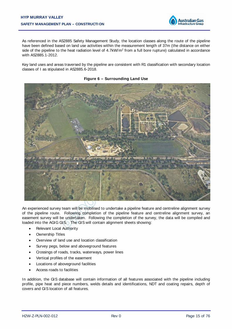
As referenced in the AS2885 Safety Management Study, the location classes along the route of the pipeline have been defined based on land use activities within the measurement length of 37m (the distance on either side of the pipeline to the heat radiation level of 4.7kW/m2 from a full bore rupture) calculated in accordance with AS2885.1-2012. Key land uses and areas traversed by the pipeline are consistent with R1 classification with secondary location classes of I as stipulated in AS2885.6-2018.
Figure 6 – Surrounding Land Use
An experienced survey team will be mobilised to undertake a pipeline feature and centreline alignment survey of the pipeline route. Following completion of the pipeline feature and centreline alignment survey, an easement survey will be undertaken. Following the completion of the survey, the data will be compiled and loaded into the AGIG GIS. The GIS will contain alignment sheets showing:
• Relevant Local Authority • Ownership Titles • Overview of land use and location classification • Survey pegs, below and aboveground features • Crossings of roads, tracks, waterways, power lines • Vertical profiles of the easement • Locations of aboveground facilities • Access roads to facilities
In addition, the GIS database will contain information of all features associated with the pipeline including profile, pipe heat and piece numbers, welds details and identifications, NDT and coating repairs, depth of covers and GIS location of all features.

HYP MURRAY VALLEY SAFETY MANAGEMENT PLAN – CONSTRUCTION
H2W-Z-PLN-002-012 Rev 0 Page 16 of 76
2.1.2 Site Description The proposed site of the Hydrogen Production Facility is located on the western boundary of Lot 1 on PS 416936 adjacent to Bidstrup Road. HyP Murray Valley’s location was selected based on a multi-criteria assessment led by industry and government bodies as part of the Australian Hydrogen Council’s Regional Towns Project.
In addition to its technical suitability, the location offers strategic value as it:
• delivers renewable gas to Australia’s two most populous states, in high-growth regional townswhich have some of the highest gas use per connection nationally
• facilitates a pathway to the technical and commercial viability of renewable hydrogen in Australiaby addressing key market and regulatory barriers in Victoria and NSW
• supports industry to reduce emissions with potential for further decarbonisation through directhydrogen supply to its adjacent industrial parks and other regional users; and
• is located on one of Australia’s busiest road and rail transport routes being the Melbourne-to-Sydney transport corridor, with a clear pathway to develop complementary markets in mobility.
The project will be situated at NEW’s WWWTP, a strategic position providing easy access to land, water, gas and electricity infrastructure while also opening an additional value stream in oxygen for use by NEW in the wastewater treatment process. Subject to further detailed investigation, co-location also provides the potential for additional synergies to be explored in the future, including:
• potential use of reclaimed water in the HyP Murray Valley facility
• potential use of behind-the-meter surplus solar from NEW’s 3MW solar farm (expected to becompleted in 2021) and/or electricity from the bioenergy facility; and
• creation of a world-first Renewable Gas Hub in which hydrogen from HyP Murray Valley is usedwith carbon dioxide from the WWWTP to create synthetic methane, which, along with the planneddelivery of biomethane from the facility can be blended into the nearby gas network (subject toseparate approval and licensing considerations).
2.2 Key Design Features and Risk Controls 2.2.1 Pipeline Design The hydrogen pipeline is designed to ASME B31.12-2019 (Hydrogen Piping and Pipelines) with safety management principles also adopted from AS2885.6-2018 (Pipelines – Gas and Liquid Petroleum). The design ensures safety of the pipeline, general public, and all persons engaged in pipeline construction and operations. Extra protection has been provided to prevent damage from unusual conditions that could be encountered. These include areas along the pipeline route where the pipeline lies within the road reserve and track crossings.
At design MAOP of 5.0MPa with design temperature of 60°C, the design factor of 0.16 (nominal thickness of 6mm) was adopted, which is a no rupture pipeline.
In accordance with B31.12 requirements for agricultural land use, the pipeline will be provided with a depth of cover of 1,219mm (48”).
2.2.2 Wall Thickness and Penetration Resistance Calculations have been performed to determine the size of machinery required to rupture the pipeline and to produce a hole greater than the critical defect length. The penetration resistance calculation results are summarised below.

HYP MURRAY VALLEY SAFETY MANAGEMENT PLAN – CONSTRUCTION
H2W-Z-PLN-002-012 Rev 0 Page 17 of 76
Land Use Class MAOP (MPa) WT nominal
(mm) Design Factor
Minimum Excavator Required for Rupture (tonnes)
General Purpose
Single Penetration
Tooth Tiger – Full Both Points
R1, H 5.0 6 16% >55 >55 >55
The pipeline is located in R1 location with secondary class of H and therefore requirements of T1 are applicable to the design of the pipeline. Accordingly the pipeline is designed as a ‘no rupture’ pipeline with identified-credible external interference threats, to allow long term co-location with the foreseeable development of the land.
2.2.3 External Anti-Corrosion Coating and CP The coating system used in all underground installation is the prime barrier to corrosion from its surrounding environment. FBE coating (TBA) is used for the pipeline. The coating option has been selected and approved after extensive testings and acceptances of factory procedures and application methods in accordance with industry standards. FBE coating is factory applied coating system that has been used extensively in Australia and most importantly, on other AGIG gas transmission assets, which fails safe by not causing shielding of the pipe from the cathodic protection system. The manufactured induction bends are also provided with FBE.
The weld areas will be coated with a liquid epoxy coating system selected to ensure compatibility with the FBE.
Whilst the external coating system forms the primary protection of the pipeline from potential external corrosion, the pipeline is also provided with an impressed current cathodic protection system. Test points are provided to allow measurement of pipe potential to monitor adequacy of cathodic protection.
2.2.4 Insulating Joints (IJs) Insulating joints are used to electrically isolate and sectionalise the pipeline for effective cathodic protection. IJs complete with spark gap devices and polarisation cells are also used for separating facilities that require solid bonded earths from the pipeline – ie electrical isolation from aboveground to belowground.
2.2.5 Earthing Protection Systems Earthing systems installed to protect aboveground facilities are in accordance with the Earthing Philosophy document (TEB-007-0001-01). The key to the design and maintenance of earthing is its assurance of effectiveness to earth fault current as well as ensuring that its compatibility with the cathodic protection system.
Earthing for electrical equipment, enclosures and intrinsically safe equipment is in accordance with AS/NZS3000 and AS/NZS60079 series.
2.2.6 Pipeline Pigging Capability The pipeline is designed to be internally cleaned and inspected. Provisions at the aboveground facilities will be made for connection of launcher and receiver to allow running of intelligent InLine Inspection (ILI) tool.
The pipeline use long radius bends and elbows to accommodate intelligent pigging tools.
All construction features including the pipeline and weld details are logged on the GIS data base for correlation before the running of an ILI tool.

HYP MURRAY VALLEY SAFETY MANAGEMENT PLAN – CONSTRUCTION
H2W-Z-PLN-002-012 Rev 0 Page 18 of 76
2.2.7 Pipeline Signs AS2885 requires that warning signs are installed to indicate the approximate location and alignment of the pipeline. The pipeline is sign posted and details of their locations is captured in the GIS data base. Pipeline signs are part of pipeline visibility and proactive measure to warn third parties of its existence. The signs are double sided and face along the pipeline route at a minimum height to maintain visibility. Spacing of signs will be in accordance with AS2885.1. 2.2.8 Pipeline Isolation Isolation of the pipeline is achieved by provision of remotely operated isolation valves which can be operated from the Transportation Services Control Centre (TSCC) located at the AGIG Head Office in Perth. Remotely operated isolation valves are located at the Hydrogen Plant and Hydrogen Injection compound on the Wodonga Lateral. The pipeline can be depressurised via a cold vent located at the Hydrogen Plant. 2.2.9 Overpressure Protection The operating pressures of the Hydrogen Plant cannot result in stresses above the yield strength of the pipeline and hence overpressure is not credible. 2.2.10 Facilities Piping is in accordance with ASME B31.12 and AS2885, as applicable and AGIG Piping Guide and Rationalised Piping Materials Specification. Pipe and support design have been verified by pipe stress analysis program, CAESER II. Piping and structural support loads have been verified against all flow, dead, thermal, wind and seismic loadings. 2.2.11 Hazardous Areas Hazardous areas at the facilities are classified and managed in accordance with AS3000 and AS/NZS60079.10.1. Therefore, any area that could contain explosive mixtures of flammable materials is classified as a ‘hazardous area’ in accordance with AS/NZS60079.10.1. In defined hazardous area, electrical equipment is selected, installed, maintained and documented in accordance with the Standard. Any electrical equipment within a hazardous area must have ANZEx (AUSEx and SAA for pre-2000) or IECEx certification for use in the area. However, non ANZEx or IECEx certified equipment with European or USA certifications can be used, if a Conformity Assessment Document is provided. 2.2.12 SCADA and Communications System The operation of Hydrogen Plant and Pipeline is incorporated into the AGIG Master Station which utilises a Schneider Electric’s OASyS DNA 7.6.6 system. The AGIG Master Station is kept up-to-date with the latest version of the Schneider Electric software under a Subscription Program. The subscription program allows access to all security and process updates. The SCADA Master Station does not have any internet or corporate facing services. The network is a separate environment segregated by a DMZ (Demilitarised Zone).

HYP MURRAY VALLEY SAFETY MANAGEMENT PLAN – CONSTRUCTION
H2W-Z-PLN-002-012 Rev 0 Page 19 of 76
For HyP Murray Valley project, the primary function of the SCADA system master station is to collect real-time data from Remote Terminal Unit (RTUs) for data acquisition as well as remote operation from the TSCC in Perth, which is manned 24 hours a day, 7 days a week. The Master Station back up (a hot standby system) uses the Disaster Recovery Site located at the Jandakot Facility. The backup system is a hot standby, allowing a controller to relocate to Jandakot and operate the back up control room upon validation of system credentials. The Master Station back up is a direct replication of the Master Station with all alarms and conditions replicated from the main system. When a control room operator logs on at the site, the system will appear exactly the same as the main Master Station. 2.2.13 Pipeline Easement and Access 2.2.13.1 Landowner Liaison Landholders are located along the pipeline route including local government authorities, government departments and landholder. In relation to landowners, key issues considered in setting the maintenance tasks include maintaining an ongoing liaison with all landholders. This provides for the establishment of relationships and the education and awareness of pipeline safety and emergency procedures. On the ground impact of land owner activities will be routinely monitored via pipeline surveillance (currently every business day). 2.2.13.2 Third Party Works Third parties are considered to be any person(s) conducting or proposing to conduct work (other than works undertaken by or at the request of AGIG) in the vicinity of the pipeline within the pipeline easement. Third Party Works (TPW) may proceed in an approved manner where the risks are assessed, mitigated and controlled and AGIG monitors all works to ensure the risks to the pipeline are managed in accordance with the works approval. Managing external works that encroach the pipeline easement include the following:
• All works in the vicinity of the pipeline and within the easement require a prior written approval from AGIG. A ‘prior written approval’ ensures that AGIG has completed an engineering assessment of the proposed works and appropriate conditions are then provided as part of the approval.
• AGIG will monitor all works within the easement to ensure that the threat from the proposed work is eliminated or minimised to an acceptable level. Attending the work site enables AGIG to stop the works should the risk to the pipeline increases to an unacceptable level or outside of the parameters identified in the initial assessment.
• Ensuring that the information of the pipeline is logged and included in the Dial before You Dig information and all contacts are constantly updated.
• Pipeline markers and warning signs are made visible to the general public for awareness of the location of the pipeline.
• Regular pipeline surveillance to identify activities in the vicinity of the pipeline. 2.2.14 Security 2.2.14.1 Physical Security All above ground hazardous area facilities are fenced and secured. Compound signage is provided according to AGIG technical drawing to warn of the existence of natural gas. Entry is controlled via security access locks and keys and managed under the Permit to Work System.

HYP MURRAY VALLEY SAFETY MANAGEMENT PLAN – CONSTRUCTION
H2W-Z-PLN-002-012 Rev 0 Page 20 of 76
2.2.14.2 Information Systems Security Access to all AGIG computer systems, including SCADA is controlled in accordance with the AGIG IT Security Policy. The requirements of the policy include the person must be approved with the following:
• logon identification and password
• authorisation of level of access
• security of data in network
• the protection of connected services from unauthorised access
• security and access controls for all network services and communications In addition, the following security measures have been provided for SCADA:
• SCADA Master Stations protected via usernames and passwords
• Router has Access Control Lists in place protecting from corporate network;
• SCADA Network has no direct access to the Internet
• SCADA domain segregation between DMZ and Corporate Network
• Production and Emergency Backup System are both behind double physical security
• The production system backs up data to an offsite Emergency Backup System at Jandakot every minute
• Full level backups are carried out every week as part of routine maintenance. Full system backups are held offsite at Jandakot
2.2.15 Escape Routes and Muster Points Muster points are located nearby the aboveground facility access gates. Whilst ignited small leaks have no significant impact on the muster points, ignited large releases can have an impact on the muster point in the event that the jet fire is in the direction of the primary muster point. In an unlikely event that this occurs, mustering occurs at safe location at least 40m away from the site. All aboveground sites are provided with at least 2 access gates to allow safe egress in the event of an emergency. The muster points during the construction period will be referenced in a Construction Emergency Response Plan. 2.3 Standards and Codes The key standards and codes are listed the table below, as relevant. It should be noted that the applicable version of standards and codes used in the design is the version that was current at the time of design and/or construction.
Plant/Equipment Standard / Code Title
Pipeline and Facilities
A2885 Pipelines – Gas and Liquid Petroleum (all relevant parts)
ASME B31.2 Hydrogen Piping and Pipelines
Pressure Vessel AS1210 Pressure Vessels

HYP MURRAY VALLEY SAFETY MANAGEMENT PLAN – CONSTRUCTION
H2W-Z-PLN-002-012 Rev 0 Page 21 of 76
Plant/Equipment Standard / Code Title
AS3788 Pressure Equipment – In service Inspection
AS3920.1 Assurance of Product Quality Part 1: Pressure Equipment Manufacture
AS4343 Pressure Equipment – Hazard Levels
Valves
ASME 16.34 Valves – Flanged, Threaded and Welding End
API 6D Specification for Pipeline Valves
API 607 Fire Test for Soft-Seated Quarter-Turn Valves
API 6FA Specification for Fire Test for Valves
API 6FD Specification for Fire Test for Check Valves
Pressure Relief Valves AS1271 Safety Valves, other Valves, Liquid Level Gauges and
other Fittings for Boilers and Unfired Pressure Vessels.
Stud Bolts and Nuts AS/NZS 4680 Hot-Dip galvanized (Zinc) Coatings on Fabricated Ferrous
Articles
ASTM A 123 Specification for Zinc (Hot Dip Galvanized) Coatings on Iron & Steel Products
Line Pipe API 5L Specification for Line Pipe
Flanges ASME B16.5 Pipe Flanges and Flanged Fittings NPS ½ Through NPS 24 Metric / Inch Standard
Civil Structures
AS1170.0 Structural design actions - General Principles
AS1170.1 Structural design actions - Permanent, imposed and other actions
AS1170.2 Structural Design Actions – Wind Loads
AS1170.4 Minimum Design Loads on Structures – Earthquake Loads
AS3600 Concrete Structures
AS4100 Steel Structures
AS1657 Fixed platforms, walkways stairways and ladder – Design, construction and installation
Cathodic Protection AS2832 Cathodic Protection of Metals
BS7361.1 Cathodic Protection Part 1: Code of Practise for Land and Marine Applications
Pipe Coating TBA TBA
Surge Protector AS4117 Surge Protective Devices for Telecommunication Appliances.
Electrical Equipment
AS/NZS 3000 Electrical Installations (SAA Wiring Rules)
AS1020 The Control of Undesirable Static Electricity
AS/NZS 1768 Lightning Protection

HYP MURRAY VALLEY SAFETY MANAGEMENT PLAN – CONSTRUCTION
H2W-Z-PLN-002-012 Rev 0 Page 22 of 76
Plant/Equipment Standard / Code Title
AS1939 Degrees of Protection Provided By Enclosures For Electrical Equipment
AS/NZS 60079 (set) Electrical Apparatus for Explosive Gas Atmosphere
AS 3008.1 Electrical installations - Selection of cables - Cables for alternating voltages up to and including 0.6/1 kV - Typical Australian installation conditions
AS3080 (set) Telecommunications installations
AS4853 Electrical Hazards on Metallic Pipelines
Marking Tape AS 2648.1 Underground Marking Tape
Welding ASME Sec. IX Welding and Brazing Qualifications
Non Destructive Testing
AS2177 Radiography of Welded Butt Joints in Metal Products
AS2207 Methods for Ultrasonic Testing of Fusion Welded Joints in Steel
ASME Sec. V Non Destructive Examination
2.4 Pipeline Construction Scope 2.4.1 Construction Scope and Methodology 2.4.1.1 Pipelines AGIG will engage a construction contractor to undertake the pipeline construction. The installation of the pipeline will largely be by the open trench method. Key steps involved in the construction of the pipeline are outlined below:
• Pre-mobilisation assessments and checks, and mobilisation of labour, materials, plant and site facilities
• Installation of site facilities, support offices, communications, power generation, workshop, fuel and stores, ablutions, spill controls, emergency equipment, laydown yard and other required temporary infrastructure
• Establishment of water supply during the construction phase for dust control and hydrostatic testing of pipelines
• Installation of the Pipeline including: – Survey and setting out of the pipeline route based on alignment sheets – Clear and grade of pipeline route – Stringing of line pipe along pipeline route – Trenching, padding, shading – Pipe fit up and welding – Joint Coating – Provision of 100% NDT of welds – Lowering in of welded line pipe – Jeeping (holiday testing) of the line pipe – Backfilling and installation of marker tape

HYP MURRAY VALLEY SAFETY MANAGEMENT PLAN – CONSTRUCTION
H2W-Z-PLN-002-012 Rev 0 Page 23 of 76
– In-service welding and hot tapping
• Gauging, filling, hydrostatic testing, dewatering and drying of line pipe and pipe which had not previously been shop hydrostatic tested
• Conducting pre-commissioning activities, including flushing, cleaning, drying, purging of systems
• Reinstatement of the easement 2.4.1.2 Facilities The key steps involved in the construction of the Facilities are outlined below:
• Pre-mobilisation assessments and checks, and mobilisation of labour, materials, plant and site facilities
• Earthworks including excavating, compacting, surveying and levelling
• Excavation (and backfilling as required) for and the installation of all underground installations including station pipework, conduits, cables, polarisation cells, earthing grid and footings (precast and onsite pouring)
• Installation of precast concrete foundations
• Installation of steel supports
• Installation of the station pipework, including, tie-in spools, valves, etc
• Installation of station electrical cabling, communications and instrumentation, etc
• Edge preparation, welding and NDT of welds
• Application of touch up paint as required, field coating of welded joints and wrapping of flanged connections
• Testing of electrical installation, including earth resistivity, joint resistance, continuity and point to point testing, etc
• Site clean-up and pre-commissioning
2.5 Project Document References Key Project Document references are provided in Appendix G. The Project Drawing Register is provided in Appendix H. 2.6 Contractor Engagement Process Contractors are selected on their ability to complete the scope of construction and meet the quality and HSE specified requirements. Preference is given to contractors who have a known and acceptable record of product quality, management, familiarity with site and topography, on-time delivery and safety management. 2.7 Hazardous Substances and Inventory Various hazardous substances such as oils, paints, nitrogen, degreasers, lubricants, welding gases etc will be stored and used on site during the construction period. Such substances will be handled in accordance with procedures outlined in the Safety Management System Section (Section 3).

HYP MURRAY VALLEY SAFETY MANAGEMENT PLAN – CONSTRUCTION
H2W-Z-PLN-002-012 Rev 0 Page 24 of 76
3 FORMAL SAFETY ASSESSMENT AGIG has developed a Formal Safety Assessment (FSA) process that is embedded into its systems for managing all phases of the operation of the pipeline. The process applies from initiation through to the end of life stage of the assets, as illustrated in Figure 5 (Section 4.3.1). The map identifies the key business processes that are underpinned by the AMP and Safety Case/Safety Management Plan in managing both process safety and occupational health and safety hazards on AGIG assets including the HyP Murray Valley Project. The Formal Safety Assessment (FSA) process is applicable to every aspect of the Project including design, construction, commissioning, operation and maintenance, where there is potential impact on asset integrity and/or safety of persons from the pipeline or facility operation. 3.1 Objective and Structure The primary purpose of the FSA is to demonstrate that, in relation to Major Accident Events (MAEs – events with multiple fatality potential), all reasonably practicable controls have been implemented in order to ensure that risk is ‘As Far As is Reasonably Practicable’ (AFARP) The objective of the FSA is therefore to:
• Identify hazards associated with the construction and operation of the ; • Assess those hazards to determine high risk hazards and those hazards that could result in credible
MAEs; • Demonstrate that the identified hazards are, eliminated or substituted (where possible), or adequately
controlled and managed; • Demonstrate that the risks from the identified hazards, particularly high risk hazards and hazards
events that could result in multiple fatalities, are reduced to AFARP; and • Demonstrate the case for safety that the pipeline and associated facilities will be operated in a manner
that will ensure that the risk to the life of persons involved in its operation and risks to other protected persons are AFARP.
To ensure an efficient and thorough assessment of the hazards and the associated risks, the safety studies are conducted in a structured manner in line with the framework outlined in Section 4.3.2, involving a number of hazard identification and risk assessments studies, as listed in Table 1.
• Safety Management Study – The safety management study is to identify and mitigate threats to the pipeline from external interference and non-location specific threats that can have an impact on the pipeline integrity, including third party activities. The Pipeline Safety Management Studies were conducted to the requirements of AS2885.6-2018 and ASME B31.12-2019, which are current versions at the time of the conduct of Preliminary and Design Safety Management Studies.
• Hazard and Operability study (HAZOP) – Identification of hazards associated with process deviations to ensure that safeguards are adequate in controlling the deviations or the risks from hazards. HAZOPs were conducted according to AS/IEC61882 Hazard and Operability Studies (HAZOP Studies) – Application Guide
• Hazard Identification study (HAZID) – Identification of hazards and assessment of risks associated with the use of tools, machinery, equipment, Personnel, travel requirements and procedures etc. for construction and commissioning phases (also for operation as required) conducted in line with the requirements of AS/NZS ISO 31000-2018 (Risk Management – Guidelines).
Table 1 – FSA Undertaken
Study Date
Preliminary Safety Management Study 14 September 2021

HYP MURRAY VALLEY SAFETY MANAGEMENT PLAN – CONSTRUCTION
H2W-Z-PLN-002-012 Rev 0 Page 25 of 76
Study Date
Design Safety Management Study TBA
HAZOP – Preliminary Design TBA
HAZOP – Detailed Design TBA
HAZID – Pipeline Construction TBA
3.2 Geographical Information System (GIS) An integrated GIS developed by AGIG assists in pipeline management from project conception through to pipeline operation. The system provides the capability for route planning and field data capture, landholder management, construction administration, progress tracking, integrity of pipeline data and traceability, asset procurement, environmental and cultural heritage management, maintenance planning and management, risk management and emergency response, and asset control. As such, the GIS holds location and attribute information such as:
• As-constructed data – pipe, welds, depth of cover, construction details, test certificates, NDT reports, alignment sheets, engineering drawings, construction photos, etc.
• Topography – roads, aerial photography, etc. • Infrastructure – fences, powerlines, signage, roads, etc. • Landholders – land parcels, tenure, easement details, land use classifications, etc. • Cultural and environmental – culturally and environmentally sensitive locations. etc. • Any other relevant data in the pipeline easement.
AGIG Risk Assessment software (which is an integrated GIS and database application) utilises the GIS by analysing and displaying all map related data along the pipeline. It uses database capabilities to assist in the facilitation of Safety Management Study workshops. The application is also able to display the engineering related data where required and provide electronic filing, action tracking, query and reporting capabilities. 3.3 Safety Management Studies 3.3.1 Preliminary Safety Management Study A Preliminary Safety Management Study was conducted on 14 September 2021 to:
• Review land use and environmental features along the route of the pipeline • Identify significant threats to pipeline that can lead to loss of integrity • Review adequacy of control measures to manage the threats
The workshop confirmed the appropriateness of the controls in place or to be included in design to manage the threats to the pipeline, so as to allow team to continue with the further design work on the pipeline. The study also concluded that there are no MAEs identified from information available at the time of the workshop, as all pipeline failure events were considered to result in a hole rather than rupture due to:
• the design factor incorporated into the design of the pipeline
• limited number of people present around the pipeline and in particular in the immediate vicinity of the pipeline which could be impacted by a pipeline failure resulting in a hole
18 actions were recommended for further consideration prior to the conduct of a detailed design safety management study.

HYP MURRAY VALLEY SAFETY MANAGEMENT PLAN – CONSTRUCTION
H2W-Z-PLN-002-012 Rev 0 Page 26 of 76
The results of the Preliminary Safety Management Study are included in Appendix A. It should be noted that subsequent to the Preliminary Safety Management Study workshop, the design MAOP of the pipeline has been increased to 5.0MPa. The increase in MAOP has no impact on the findings or conclusions made in the workshop, taking into consideration:
• the measurement length has changed from 37m to 45m: – no impact on the land use classification of the pipeline – no changes to consequences from a loss of containment event from threats identified as the
increase in consequence distance is not substantial
• design factor has changed from 10% to 16%: – pipeline remains to be a no rupture pipeline – no impact on penetration resistance of the pipeline to external interference
This change has not been reflected in the Preliminary Safety Management Study Report (Appendix A), however a Detailed Design Safety Management Study will be conducted reflecting the increased MAOP and any other changes resulting from the detailed design process. 3.3.2 Detailed Design Safety Management Study A Detailed Design Safety Management Study will be conducted to identify all credible threats, which may impact the operational pipeline and the associated aboveground facilities and the adequacy of controls to eliminate, and where not practicable, manage the risks to AFARP, based on further refined information. Key control measures to be considered in the assessment include by not limited to:
• Wall thickness
• Separation by burial
• Separation by barrier
• Pipeline awareness
• Project Management Methodology – construction methodology and approved engineering specifications including pipelines specifications, third party inspection, 100% NDT of welds, hydrotesting, jeeping, DCVG (baseline) and MDR validation
• Asset Management requirements, such as: o Road patrols o Third party awareness – regular liaison with landowner, council, emergency services, utilities,
Main Roads, etc according to the type of activities o Dial Before You Dig (DBYD) – AGIG is part of DBYD system o Inline Inspection o CP surveys and pipe inspections including sections under insulation o Aboveground pipework and equipment integrity inspection o TSCC monitoring and alarm
3.4 Facilities Safety Assessments 3.4.1 HAZOP Studies Hazard and Operability (HAZOP) studies will be conducted for the pipeline and associated aboveground facilities. In the conduct of the studies, the design will be broken down into a series of nodes using P&IDs and each node was assessed in detail by systematically applying a set of guidewords to identify deviations from normal
HYP MURRAY VALLEY SAFETY MANAGEMENT PLAN – CONSTRUCTION
H2W-Z-PLN-002-012 Rev 0 Page 27 of 76
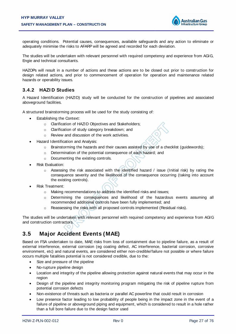
operating conditions. Potential causes, consequences, available safeguards and any action to eliminate or adequately minimise the risks to AFARP will be agreed and recorded for each deviation. The studies will be undertaken with relevant personnel with required competency and experience from AGIG, Engie and technical consultants. HAZOPs will result in a number of actions and these actions are to be closed out prior to construction for design related actions, and prior to commencement of operation for operation and maintenance related hazards or operability issues. 3.4.2 HAZID Studies A Hazard Identification (HAZID) study will be conducted for the construction of pipelines and associated aboveground facilities. A structured brainstorming process will be used for the study consisting of:
• Establishing the Context: o Clarification of HAZID Objectives and Stakeholders; o Clarification of study category breakdown; and o Review and discussion of the work activities.
• Hazard Identification and Analysis: o Brainstorming the hazards and their causes assisted by use of a checklist (guidewords); o Determination of the potential consequence of each hazard; and o Documenting the existing controls.
• Risk Evaluation: o Assessing the risk associated with the identified hazard / issue (Initial risk) by rating the
consequence severity and the likelihood of the consequence occurring (taking into account the existing controls).
• Risk Treatment: o Making recommendations to address the identified risks and issues; o Determining the consequences and likelihood of the hazardous events assuming all
recommended additional controls have been fully implemented; and o Reassessing the risks with all proposed controls implemented (Residual risks).
The studies will be undertaken with relevant personnel with required competency and experience from AGIG and construction contractors. 3.5 Major Accident Events (MAE) Based on FSA undertaken to date, MAE risks from loss of containment due to pipeline failure, as a result of external interference, external corrosion (eg coating defect, AC interference, bacterial corrosion, corrosive environment, etc) and natural events, are considered either non-credible/failure not possible or where failure occurs multiple fatalities potential is not considered credible, due to the:
• Size and pressure of the pipeline • No-rupture pipeline design • Location and integrity of the pipeline allowing protection against natural events that may occur in the
region • Design of the pipeline and integrity monitoring program mitigating the risk of pipeline rupture from
potential corrosion defects • Non-existence of threats such as bacteria or parallel AC powerline that could result in corrosion • Low presence factor leading to low probability of people being in the impact zone in the event of a
failure of pipeline or aboveground piping and equipment, which is considered to result in a hole rather than a full bore failure due to the design factor used

HYP MURRAY VALLEY SAFETY MANAGEMENT PLAN – CONSTRUCTION
H2W-Z-PLN-002-012 Rev 0 Page 28 of 76
3.6 Fire and Explosion 3.6.1 Loss of Containment Threats or hazards that could lead to a fire have been identified and their risks assessed through the Pipeline Safety Management Studies and HAZOP processes. Heat radiation distances have been determined based on the assumption of a rupture of each pipeline and are tabulated below.
Hydrogen Pipeline
Nominal Pipe Size (DN) 100
MAOP (MPa) 5.0
4.7kW/m2 (m) 45 Delayed explosion is not considered credible as the pipeline and facilities are located in wide open area with no potential for confinement. In the event of a significant failure of the pipeline, a sudden drop in pressure will be visible at TSCC via SCADA. TSCC has the ability to isolate the pipeline from the control room. 3.6.2 Emergency Response In the event of an emergency, AGIG has tools available to enable modelling of potential consequences. In-house modelling software and vendor proprietary software allow the determination of release rate and dispersion and/or severity of fires. This includes effects of loss of containment events involving the pipeline and releases from station piping and equipment. This information is used in the formulation of emergency response strategies including establishment of an exclusion zone and minimisation of potential escalation from fire impingement. 3.6.3 Survivability In the event of a loss of containment and subsequent jet fire at an aboveground facility or from a fire from an adjacent pipeline or facility, the ability to shut down supply to the pipeline can be achieved by shutting down the remotely operable isolation valves, which are fail safe valves. 3.7 Conclusions Section 4 presents an overview of the Safety Management System (SMS), which is capable of continually, systematically and effectively identifying, assessing and controlling all hazards associated with the pipeline and associated facilities. It is concluded from the safety studies undertaken that the risks associated with the pipeline and facilities are acceptable and have been reduced to AFARP. Through the application of SMS requirements, these risks can be managed to acceptable and AFARP levels.

HYP MURRAY VALLEY SAFETY MANAGEMENT PLAN – CONSTRUCTION
H2W-Z-PLN-002-012 Rev 0 Page 29 of 76
4 SAFETY MANAGEMENT SYSTEMS 4.1 Introduction 4.1.1 Objectives The objective of this section is to provide a comprehensive overview of AGIG’s Safety Management System (SMS) and demonstrate compliance with all requirements as prescribed by the Petroleum Pipelines Act 1969 and associated regulations. 4.1.2 Scope Unless specified otherwise, all work carried out by any Personnel acting for or on behalf of AGIG is to be done in accordance with this SMS. It should be noted that this section will be updated/revised as the Project progresses making elements of the established AGIG’s Safety Management System relevant. 4.1.3 Structure The structure of the SMS is shown in Figure 4 and comprises:
• the manual (similar to this section) which sets out a description of all systems that AGIG has developed and implemented for the safe Operation of its assets and the interactions between each;
• overarching policies which establish the values underpinning all organisational objectives; • processes and planning which enable the identification of risks; • procedures which detail the method for management of key risks; and • work instructions which provide step by step instructions for the safe completion of specific tasks.
Figure 7 – Overall structure of the AGIG Safety Management System
In association with many of the processes that make up the SMS, additional supporting tools including forms, registers and guidelines may be developed.
SMS
Manual
policiesperformance
standards
processes and
planning procedures work
instructions
additional supporting material eg
forms, registers,
guides

HYP MURRAY VALLEY SAFETY MANAGEMENT PLAN – CONSTRUCTION
H2W-Z-PLN-002-012 Rev 0 Page 30 of 76
All SMS elements that build on the framework described within this section are all accessible by AGIG Staff via the relevant department’s document library, ultimately accessible via AGIG’s Intranet Home Page, and relevant information is also made available to the contractors. Relevant document identifiers for key SMS elements have been referenced where applicable. 4.1.3.1 Procedures To manage aspect specific risks at a more generic level, a series of procedures have been developed. These set out AGIG’s minimum standards for risk management and also assign the key responsibilities across AGIG roles. All risks requiring a procedure have been highlighted in this section and the minimum standards to be governed by this procedure have also been listed. Where a procedure applies to a given activity it must be followed, unless otherwise approved by an Executive General Manager. Acknowledging the potentially severe consequences of any failure to follow a procedure, compliance with this is a Zero Harm Principle (refer Section 4.2.2). 4.1.3.2 Work Instructions A Work Instruction is an activity specific document, which sets out in clear detail the sequence of steps to be undertaken in order to complete a work activity safely. Work Instructions and/or Safe Work Method Statements exist for many routine work activities but will not cover all work. Where a Work Instruction exists for a given activity it must be followed, with any deviation managed via the JHA process (refer Section 4.3.3). Failure to follow a Work Instruction or Safe Work Method Statement, is a breach of a Zero Harm Principle (refer Section 4.2.2). 4.2 Policy 4.2.1 Key Policies In line with the Vision, AGIG has a number of overarching policies which establish the values underpinning all organisational objectives. These are:
• AGIG Health and Safety Policy (AGIG-POL-HSE-0001) - sets organisational goals, identifies high level implementation processes and states AGIG’s values with respect to the management of risks to people through AGIG’s Operations.
• AGIG Environment Policy (AGIG-POL-HSE-0002) - sets organisational goals, identifies high level implementation processes and states AGIG’s values with respect to the management of risks to the environment through AGIG’s Operations.
• AGIG Fitness for Work Policy (AGIG-POL-HSE-0003) – sets out the organisation’s expectations and commitments at a more individual level, with respect to elements such as ergonomics, fatigue management, drugs and alcohol, employee assistance, post injury return to work, wellbeing, stress management and work life balance.
• AGIG Statement of Commitment (AGIG-POL-HSE-0004) – contains senior management’s endorsement of the aforementioned policies and is signed by the Executive Management Team.
A copy of each of these documents is made publically available via the internet and is easily accessible to all Staff via the intranet and HSE document library. These documents are also made readily accessible to contractors working on projects. To ensure Staff understanding, the policies are formally communicated through the AGIG induction (refer Section 4.4.2.2). To further promote the policies, copies are prominently displayed in offices, work sites, Site accommodation and crib rooms. The Executive Management Team is responsible for review of these policies at a minimum of once every two years. The outcomes and explanations for any policy changes must be communicated to all Staff.
HYP MURRAY VALLEY SAFETY MANAGEMENT PLAN – CONSTRUCTION
H2W-Z-PLN-002-012 Rev 0 Page 31 of 76
4.2.2 Zero Harm Principles The Executive Management Team have endorsed a set of Zero Harm Principles to support a collective awareness and understanding of critical safety rules, and to eliminate tolerance for rule breaking and non-compliance relating to high risk activities. The Zero Harm Principles target high-risk activities at work, where it is proven that failure to comply has the highest potential for serious injury or death.
The Zero Harm Principles are reviewed on a periodic basis to ensure ongoing relevance to AGIG core activities and critical risks. As at the date of this document, the Zero Harm Principles are:
• Safety Management System – Always comply with our Safety Management System. If at any time you are unsure, seek clarification. Always strive do the right thing.
• Driving and Remote Travel – Comply with all road laws, complete a journey plan for remote travel and drive to conditions.
• Fitness for Work – Test zero for drugs and alcohol and declare your fitness for work issues before conducting any work. Listen to your body, remember to stretch and stay hydrated.
• Energy Isolation – Conduct, confirm, test, and communicate effective isolation of gas, electrical and other hazardous energy sources before and during work on any plant, equipment or process.
• Confined Spaces – Only enter a confined space with an approved entry permit and required training. Re confirm that it is safe before entering.
• Working in Gaseous Environments – Monitor atmospheric conditions and control ignition sources. Manage priority gas leaks to minimise impacts to people and the environment.
• Working at Height – Protect yourself against a fall or dropped objects. Inspect platforms, scaffolding, fall arrest systems & ladders before use.
• Mechanical Lifting – Secure and stand well clear of suspended loads. Inspect all equipment prior to use and ensure loads are within safe lifting limits.
• Excavation – Identify, locate, mark and communicate underground assets prior to commencing work. Maintain safe shoring and only enter an excavation with safe access and egress in place.
• Mobile Plant – Only operate plant you have been trained and authorised to operate. Establish and remain vigilant of operation and exclusion zones.
• Traffic Management – Plan, communicate and demarcate for the safe movement of vehicles and pedestrians. Procedures and Work Instructions Where a procedure and or work instruction is in place for a task these must be used at all times.
The Zero Harm Principles are non-negotiable and compliance with them is a condition of working for or providing contract services to AGIG. Any breach of a Zero Harm Principle will attract serious investigation and may result in dismissal. Any exemption to the application of a Zero Harm Principle requires a relevant Executive General Manager’s approval. AGIG’s Zero Harm Principles are communicated via a range of methods to ensure that all Personnel understand what is expected of them. This is driven by a detailed online induction and further supported by posters, intranet material and face to face leader communications.

HYP MURRAY VALLEY SAFETY MANAGEMENT PLAN – CONSTRUCTION
H2W-Z-PLN-002-012 Rev 0 Page 32 of 76
4.3 Planning 4.3.1 Hazard and Risk Identification, Assessment and Control In order to ensure the systematic identification, assessment, control and ongoing management of hazards and risks, AGIG has defined and endorsed a Risk Management Policy supported by an AGIG Risk Matrix. Hazard identification and risk management is in accordance with AS/NZS ISO 31000 Risk management – guidelines and AS2885 – Pipelines gas and liquid petroleum set. The overall objective of the hazard identification and risk management process is to ensure that all foreseeable safety hazards, including MAEs are adequately identified and control measures are applied, to reduce the risks resulting from those hazards to an acceptable level that is As Far As Reasonably Practicable (“AFARP”), where ‘reasonable practicability’ is defined as ‘a reasonable course of action giving consideration to:
• the severity of potential harm caused; • the likelihood of harm occurring; • the knowledge of the risk; • the availability and suitability of ways to treat the risk; and finally • whether the cost/practicality of treating the risk is grossly disproportionate to the risk’.
Specific processes for the identification, assessment and control of safety hazards exist for all phases and all aspects of pipeline operation from initiation through to the end of life stage of the assets, as illustrated in Figure 5 below. The map identifies the key business processes that are underpinned by the Safety Management Plan in managing both process and occupational health and safety hazards. Relevant stakeholders with sufficient expertise and experience are involved in the Formal Safety Assessment process to ensure that all credible risks are identified and appropriately assessed and controlled. As such, FSAs are undertaken by multi-discipline team, including design and operational engineers, field personnel, TSCC personnel, Commercial personnel and contractors, as applicable to the study. Where there is a material change to the pipeline operation that may have an impact on the risk levels or may create a significant new hazard, such as external environment, changes to pipeline design, changes to operating conditions, changes to work practices, changes to maintenance regime, the Management of Change process is initiated. The change is assessed using relevant risk assessment methodologies to ensure the risks remain acceptable. Risk assessments are conducted in accordance with the process summarised below: Formal Safety Assessment (FSA) FSA comprises of safety studies to identify hazards that could lead to or contribute to causing a MAE and assessment of the risks to enable selection of adequate control measures. In particular, MAE risks resulting from a loss of containment from a rupture in high consequence areas, must be reduced to an acceptable level and AFARP. The safety studies are conducted in accordance with the current version of AS2885 at the time of the study. In addition, formal risk assessments are also conducted for execution of work, where the work is non-routine and considered to involve high risk activities, such as facility and pipeline construction work. Safety studies or risk assessment processes that form part of FSA include (as appropriate):
• Pipeline Safety Management Study • HAZOP • Layers of Protection Analysis • HAZID

HYP MURRAY VALLEY SAFETY MANAGEMENT PLAN – CONSTRUCTION
H2W-Z-PLN-002-012 Rev 0 Page 33 of 76
Task Based Risk Assessments Job Hazard Analysis and Take 5 tools are used for identification, assessment and control of all hazards that may be present during execution of work, based on a defined scope of work to ensure the risks are managed to AFARP. In the conduct of risk assessments, the following hierarchy of controls is applied:
• Identification of all hazards that could lead to credible scenarios; • Necessary measures are considered for elimination of the identified hazards; • Where elimination of the hazards is not practicable, substitution is required to be considered; • Only when elimination or substitution of the hazard is not practicable, control measures are
implemented to manage the hazards so that the potential for a major accident event is minimised. These measures need to be applied in the following hierarchy of controls:
– Engineering; – Procedural; – Personal protective equipment; and – Emergency management.
4.3.2 Formal Safety Assessment 4.3.2.1 Pipeline Safety Management Study In accordance with AS2885.6 Pipelines – Gas and Liquid Petroleum – Pipeline Safety Management and ASME B31.12-2019 Hydrogen Piping and Pipelines, risks resulting from loss of integrity leading to a potential release of energy, fire and explosion are assessed in the design phase of any new pipeline, using the following methodology:
• Location analysis for determination of type of land use;
• Threats analysis taking into consideration the type of land use, natural events and activities that could occur at the location, as well as non-location specific threats;
• Identification of design and procedural controls to prevent potential threats;
• Failure analysis of credible threats that could not be prevented by design or procedural controls;
• Assessment of risks from events involving loss of integrity, based on failure analysis, using AS/NZS ISO 31000; and
• Management of residual risks by implementation of controls and evaluation of the effectiveness of those controls.
This risk assessment is revisited whenever a major change arises, for example, change in land use or change in the pipeline operation. A summary of Pipeline Safety Management Studies undertaken for the safe operation of the pipeline has been included within Section 3.3. 4.3.2.2 HAZOP – Hazard and Operability Study To ensure the systematic assessment of hazard and operability issues, a HAZOP is conducted for all new designs or design changes with the potential to impact upon pipeline operability. The HAZOP methodology applied by AGIG is consistent with AS IEC 61882 Hazard and Operability Studies (HAZOP Studies) – Application Guide. For all hazardous scenarios identified during the HAZOPs, where instrumented functions are used as safeguards, a Safety Integrity Level (SIL) assessment/determination must be completed. The objective of the SIL study is to determine the risk reduction required for each hazardous scenario so that the residual risk remains within a tolerable risk level.

HYP MURRAY VALLEY SAFETY MANAGEMENT PLAN – CONSTRUCTION
H2W-Z-PLN-002-012 Rev 0 Page 34 of 76
Implementation of HAZOPs and SIL studies as outlined above is a requirement of AS2885 and ASME B31.12. HAZOPs undertaken for the safe operation of the pipeline and associated facilities have been included within Section 3.4.1. 4.3.2.3 HAZID – Hazard Identification Study AS2885 requires the identification and control of risks relevant to the construction and commissioning phase of works. Consistent with AS/NZS ISO 31000 - Risk Management – Guidelines, HAZIDs are carried out to assess implementation risk associated with the tools, equipment, Personnel, travel requirements and procedures etc. for the construction and commissioning phases of work, as well as during operational phase for infrequent work that has potential for significant risk (note, frequently performed work are managed under procedures/work instruction and/or under the JHA/Take 5 process). HAZIDs undertaken for the safe construction of the pipeline and facilities have been included within Section 3.4.2. 4.3.3 Task Based Risk Assessments 4.3.3.1 Job Hazard Analysis and Take 5 AS2885.3 requires that a process to identify, mitigate and communicate activity and specific hazards is carried out prior to commencement of work. This process must involve four steps:
• hazard identification to consider all hazards associated with each step of a particular work scope;
• mitigation to consider all necessary actions to remove or reduce the identified hazards;
• implementation to establish all identified necessary controls; and
• review to assess the residual risk and ensure it is acceptable. Although this process may be carried out off-site, it must at a minimum be reviewed onsite to verify its suitability. All members of the work party must be briefed on the outcomes of the risk assessment process (including the controls to be implemented) prior to commencing work. Should Site circumstances change, work must be suspended and the process reviewed to ensure the level of risk remains acceptable. AGIG enables site based risk assessment via the use of either one of two tools: Take 5 (a mini risk assessment) or JHA (a detailed risk assessment). The appropriate tool to use will vary dependent upon the number of job steps and hazards requiring assessment and control. Both the Take 5 and JHA tools require Personnel to:
• Communicate as a work party;
• Discuss the task to ensure a common understanding;
• Identify hazards with potential for an adverse impact;
• Establish and implement controls to mitigate risk of harm;
• Evaluate residual risk and agree as a work party that it is acceptable;
• Consider the risk assessment regularly throughout the delivery of the task, especially after breaks; and
• Revise the risk assessment whenever a new job step or hazard is identified. The JHA form is designed for complex tasks, by enabling the setting out of each hazard by job step and individual rating of residual risk with reference to the Risk Matrix. As the Take 5 tool is tailored for tasks with few job steps (typically one) and minimal hazards, it is instead on a pocket sized notepad, enabling all identified hazards to be assessed together via a simple yes / no question – can the job be done safely?

HYP MURRAY VALLEY SAFETY MANAGEMENT PLAN – CONSTRUCTION
H2W-Z-PLN-002-012 Rev 0 Page 35 of 76
Where AGIG’s JHA and/or Take 5 forms are not used on a task, equivalent forms accepted by AGIG shall be used. The JHA and Take 5 Procedure (S-PRO-004) sets out the protocol for the completion of a Take 5.
4.3.4 Objectives and Targets Having regard for the performance monitoring set out in Section 4.8.3 and the management review process described in Section 4.4.3, the Executive Management Team establishes organisational objectives and targets reflecting the Vision and Values on an annual basis. The objectives and targets are specific, measurable, attainable, reasonable and timely. They seek to improve upon past performance and target improvement in previously identified problem areas. Established objectives and targets are documented and accessible to all Staff. Performance against set objectives and targets are measured and routinely communicated to all Staff (as well as to Contractor personnel, as relevant via regular meetings). This is achieved through inclusion of safety targets within the business score card, which is reported quarterly at CEO updates to all Staff. 4.4 Implementation 4.4.1 Structure and Responsibility 4.4.1.1 Structure The organisation structure of AGIG comprises of 9 divisions. The divisions with significant responsibilities under the Safety Management Plan are listed below:
• Transmission Asset Management – Establishes and maintains asset management strategies, policies and standards, and monitor and report on process safety, reliability and performance of pipeline operations in accordance with the Asset Management System Framework, and manages the design and delivery of Projects. Also oversees training and HSE advice and has overarching responsibility for the SMS including management of HSE and technical audits to provide compliance assurance.
• Network Operations – Accountable for the construction, maintenance and operation of the Multinet Gas Network and Australian Gas Networks, consisting of with the Network Strategy and Performance team, Asset Development team, Program Management, Engineering and Materials team and the Service Delivery team.
• Transmission Operations – Executes field maintenance in accordance with the Asset Management Plan, manages the project interface with operational areas, monitors and reports on field maintenance delivery, and manages warehousing, purchasing of inventory, contract execution and supplier contracts.
• Commercial – Manages operation of the pipeline through the TSCC, and manages procurement and contracts.
• Customer and Strategy – Supports the identification and retention of Employees through the development, implementation and monitoring of Human Resource policies, plans and programs. Also coordinates development of corporate risk management framework and executes audit and compliance assessment functions.
• Finance and Technology – Provides IT support. 4.4.1.2 Resources In order to appropriately resource the implementation and maintenance of the SMS, AGIG undertakes resource allocation through an annual business planning process. Through this process, key tasks and functions of each

HYP MURRAY VALLEY SAFETY MANAGEMENT PLAN – CONSTRUCTION
H2W-Z-PLN-002-012 Rev 0 Page 36 of 76
division are clearly set out for the year ahead (and at a higher level for the next four years) such that the respective resource requirements may be identified and managed. This process should include a review of the SMS to ensure there are sufficient resources to support its implementation. For Projects, a Project Management Plan is developed in accordance with Project Management Methodology. Resourcing requirements are considered as part of the development and execution of this plan, to ensure that sufficient resources (including external support) are allocated. The Project Management Team in consultation with the Contractor will determine the staffing, plant, equipment and resource requirements to ensure quantity, qualification, type and quality are suitable for the work involved and risks associated with the Project. AGIG engages Personnel across a range of contractual arrangements including as an Employee or Contractor. Across each engagement type, a range of different systems and processes may be utilised in order to meet the minimum requirements of the SMS. 4.4.1.3 Responsibility and Accountability The organisational structure assigns all roles within AGIG against one of four tiers of management, including in order of decreasing seniority: CEO and Executive General Managers; Heads/Managers; Superintendents, Team Leaders and Project Managers; and all Personnel. The responsibilities and accountabilities of each tier with respect to safety are detailed within individual position descriptions and summarised below. 4.4.1.3.1 CEO and Executive General Managers
• Establish, enforce, promote and adhere to the AGIG Zero Harm Principles, Stop Work Authority and HSE Policies to maintain a positive HSE culture.
• Oversee the establishment, maintenance and implementation of a HSE management system suitable to reduce all relevant HSE risks to AFARP and also to ensure ongoing compliance with the HSE Policies and applicable HSE legislation and standards.
• Ensure that the HSE management system is adequately planned, resourced, monitored and reviewed to provide for successful implementation and continuous improvement in consultation with Employees, regulatory bodies, industry fellows and Contractors.
• Set meaningful and relevant objectives and targets for HSE performance.
• Develop, endorse, enforce and adhere to the risk management tools to manage HSE risk through the ongoing identification, communication and control of workplace hazards.
• Resource and enforce the prompt investigation of significant incidents, including the identification and delivery against corrective and preventative actions to address root causes.
• Partake in meaningful leadership engagement with the workforce on matters relating to HSE, to maintain senior management visibility of operational conditions and practices.
• Promote, attend and participate in HSE meetings, seminars and events.
• Ensure the screening of Contractors via a robust pre-qualification process prior to engagement.
• Promote and participate in, the reporting and addressing of all observed incidents, hazards and near misses.
• Develop and participate in HSE training standards and courses as required.
• Develop standards for, and correctly utilize any PPE distributed.
• Exercise a duty of care to prevent harm to yourself or any other person.
• Willingly and transparently participate in HSE audits and event investigations.
• Manage any concerns about, or potential impairment of, your own fitness for work or that of your colleagues.

HYP MURRAY VALLEY SAFETY MANAGEMENT PLAN – CONSTRUCTION
H2W-Z-PLN-002-012 Rev 0 Page 37 of 76
Heads and Managers
• Enforce, promote and adhere to the AGIG Zero Harm Principles, Stop Work Authority and HSE Policies to actively contribute to a positive HSE culture.
• Ensure that all aspects of the HSE management system are understood by all Personnel, adequately resourced, embedded into work processes and effective in implementation.
• Ensure Employee HSE roles, responsibilities and authorities are defined, documented and communicated.
• Develop, endorse, enforce and adhere to the risk management tools to manage HSE risk through ongoing identification, communication and control of workplace hazards.
• Fulfil the role of Event Report Manager within the AGIG event management system (InControl) for all HSE events (including incidents, hazards and near misses) to oversee the appropriateness of reporting and response.
• Sponsor the prompt investigation of significant incidents, including the identification of and delivery against corrective and preventative actions to address root causes.
• Engage with the workforce on matters relating to HSE.
• Ensure the Zero Harm Principles, HSE Policy and SMS are duly considered when amending or implementing new practices, processes, plant or products.
• Make provision for adequate induction, training and supervision of workers such that they may carry out their duties without risk to themselves, their workmates or the environment.
• Ensure the screening of Contractors via a robust pre-qualification process prior to engagement.
• Report and address all observed incidents, hazards and near misses.
• Participate in HSE training as required.
• Correctly utilize any PPE distributed.
• Exercise a duty of care to prevent harm to yourself or any other person.
• Willingly and transparently participate in HSE audits and event investigations.
• Notify your Line Manager of any concerns about, or potential impairment of, your own fitness for work or that of your colleagues.
Superintendents, Team Leaders and Project Managers
• Promote and adhere to the Zero Harm Principles, Stop Work Authority and HSE Policies to actively contribute to a positive HSE culture.
• Understand and comply with the HSE management system as applicable to all work undertaken. Ensure direct reports understand and comply with the HSE management system also.
• Promote a positive reporting culture and ensure that all HSE events (including incidents, hazards and near misses) are captured within the AGIG event management system (InControl).
• Fulfil the role of Event Report Manager within the event management system (InControl) for all HSE events (including incidents, hazards and near misses) to establish (where relevant) and close out any corrective or preventative actions required.
• Ensure the prompt escalation of significant incidents.
• Monitor and manage Employee fitness for work to promote ongoing capacity to conduct normal duties and establish alternative duties where required.
• Facilitate and promote open communication regarding HSE matters, by presenting senior management expectations to Employees and supporting the upward communication of Employee operational issues to senior management.

HYP MURRAY VALLEY SAFETY MANAGEMENT PLAN – CONSTRUCTION
H2W-Z-PLN-002-012 Rev 0 Page 38 of 76
• Ensure the Zero Harm Principles, HSE Policy and SMS are duly considered when amending or implementing new practices, processes, plant or products.
• Ensure that Employees have adequate induction, training and supervision to carry out their duties without risk to themselves, their workmates or the environment.
• Ensure the screening of Contractors via a robust pre-qualification process prior to engagement.
• Endorse, enforce and adhere to the risk management tools to manage HSE risk through ongoing identification, communication and control of workplace hazards.
• Take ownership to report and address all observed incidents, hazards and near misses.
• Participate in HSE training.
• Correctly utilize any PPE distributed.
• Exercise a duty of care to prevent harm to yourself or any other person.
• Willingly and transparently participate in HSE audits and event investigations.
• Notify your Line Manager of any concerns about, or potential impairment of, your own fitness for work or that of your colleagues.
Construction Contractor
• Ensure all construction personnel are aware of and understand the requirements of this plan
• Implement all construction activities in accordance with this plan
• Ensure incident reporting protocols are followed and that construction personnel report Events/Hazards and near misses
• Complete all tracking, sampling and monitoring as required under the PSMP
• Respond to all incidents as required
• Ensure development and implementation of a Corrective Action Register
• Ensure all project personnel are competent for their role and records of this competency are kept and available
Project Manager / Construction Manager
• Ensure all construction personnel are aware of and understand the requirements of this plan
• Implement all construction activities in accordance with this plan
• Ensure incident reporting protocols are followed and that construction personnel report Events/Hazards and near misses
• Complete all tracking, sampling and monitoring as required under the PSMP
• Respond to all incidents as required
• Assist with the classification of all injuries
• Ensure that incident investigations occur (and in a timely manner) All Personnel
• Adhere to the AGIG’s Zero Harm Principles, Stop Work Authority and HSE Policies.
• Understand and comply with the HSE management system as applicable to all work undertaken.
• Adhere to the risk management tools to manage HSE risk through ongoing identification, communication and control of workplace hazards.
• Take ownership to report and address all observed incidents, hazards and near misses.

HYP MURRAY VALLEY SAFETY MANAGEMENT PLAN – CONSTRUCTION
H2W-Z-PLN-002-012 Rev 0 Page 39 of 76
• Participate in HSE training as required by the company.
• Identify and correctly utilize any PPE required for a task.
• Exercise a duty of care to prevent harm to yourself or any other person.
• Willingly and transparently participate in HSE audits and event investigations.
• Notify your Line Manager of any concerns about, or potential impairment of, your own fitness for work or that of your colleagues.
4.4.1.4 Leadership Engagement / Management Interactions Personnel in a leadership position are required to conduct Leadership Engagements on the project. For larger projects these shall include specific targets and form part of the project performance indicators. Leadership engagements are designed for Senior Management to integrate and conduct individual or small group discussions with all staff in relation to safety and AGIG values. These shall be captured and documented for the project in an approved manner (ie InControl). 4.4.2 Training and Competency 4.4.2.1 Recruitment AGIG implements a rigorous assessment process for the recruitment of all Personnel. The process appraises the skills, qualifications, experience and fitness for work (through pre-employment medicals) of the candidate against the identified requirements of the role (refer sections 4.4.2.3 and 4.6.19). For Projects, prior to engagement, Contractors are screened against defined criteria designed to detect any deficiencies in Contractor safety management practices. At a minimum, screening criteria must include proof of insurance, reputation check, Contractor safety management system review for alignment to the AGIG SMS, and benchmarking of safety performance. 4.4.2.2 Induction All Personnel are provided with adequate information to enable the management of relevant HSE risks throughout the course of their work with AGIG. Inductions are tailored to communicate key components of the SMS to relevant roles. This will be achieved through a varied induction programme depending on specific roles. 4.4.2.3 Training A training needs analysis is conducted against all roles (in consultation with the relevant Line Manager/s) to identify the minimum mandatory training requirements and relevant additional competencies. The AGIG Training Matrix records the outcomes of this analysis. The Training and Development Policy sets out the process for achieving this. At a minimum, all Personnel required to work autonomously at Site must be competent in:
• Driving; and • First Aid (HLTAID003 or equivalent).
All Personnel required to hold or issue a Permit to Work must be competent in:
• Permit to Work; • Working at Heights; • Confined Space Entry; • Gas Testing; and • First response to Fire (MSAPMOHS21A or equivalent).

HYP MURRAY VALLEY SAFETY MANAGEMENT PLAN – CONSTRUCTION
H2W-Z-PLN-002-012 Rev 0 Page 40 of 76
Exemption to the above requirements may be made on a case by case basis where there is deemed a negligible risk of harm being caused due to training deficiency, having regard for:
• Any prior training and the time elapsed since expiry;
• Prior demonstrated experience in the area of interest; and
• Availability of support Personnel on site and in the work team with appropriate training. All exemptions must be supported by the written approval of an Executive General Manager, in place prior to the commencement of the relevant works. For construction projects, a Training Matrix is developed, updated and monitored, which provides details of training and competency requirements for all personnel involved in the construction work. 4.4.3 Consultation, Communication and Reporting 4.4.3.1 Consultation To ensure that risk controls are acceptable to the workforce, Staff are regularly consulted regarding the identification and control of workplace hazards. Section 4.3.1 sets out the requirement for worker representation during the planning phase. In the selection of a multidisciplinary team for completion of the FSA it is mandatory to ensure representatives of those likely to undertake the work are invited and enabled to participate. At the task level, completion of a JHA should involve the whole work team, however at a minimum the JHA must be reviewed and signed off by all relevant Personnel. 4.4.3.2 HSE Representatives AGIG has established designated workgroups for the operations phase, within which one nominated member will represent the collective interests of Staff relating to OHS. The structure adopted ensures that grouped roles undertake similar work across similar workplaces and on a similar roster. Each workgroup elects a HSE Representative. If a secret ballot is requested, the HSE Manager shall develop an election protocol, ensuring compliance with the applicable legislation. The HSE Representative Register (S-REG-005) is maintained to document the contact details for each workgroup HSE Representative and the date of their appointment. 4.4.3.3 HSE Committees Acknowledging the number and diversity of workgroups within AGIG, HSE committees have been established to enable discussion and support on HSE issues beyond the established workgroup boundaries. The agreed committee structure adopted within AGIG ensures that each HSE Representative belongs to a committee and that the employer is adequately represented also (ie a minimum of 1 Executive General Manager and up to 50% membership attributed to non-elected Supervisors/Line Managers). Whilst it is encouraged that HSE issues are managed locally within each workgroup, established HSE committees provide a forum for the escalation of sustained issues. HSE committees will meet on a monthly basis. Minutes of each meeting shall be documented and circulated to all committee members. 4.4.3.4 Communication For construction projects, communication of HSE aspects should form part of the project communication process. This includes a variety of communication methods and processes. Table below provides a brief description of the main methods utilised.

HYP MURRAY VALLEY SAFETY MANAGEMENT PLAN – CONSTRUCTION
H2W-Z-PLN-002-012 Rev 0 Page 41 of 76
Communication Method Description
Induction The project specific induction sets out the main HSE aspects and controls on the project including emergency response and duties for both employer and employee.
Daily and Weekly Reports Outline the daily and weekly activities including HSE statistics, incidents or other events and progress to close out actions.
Pre-start meetings
Pre-start meetings provide daily updates on safety events. They can include specific reminders of hazards on the day (ie weather) as well as specific topics (hot work). Pre-starts are also used for commissioning notices (ie Notice of Energisation)
Toolbox Talks
Toolbox tend to be topic specific but provide for greater interaction and feedback from the workforce. These form a reminder process for controls set out in the induction as well as to ensure ongoing understanding of the controls used onsite.
Incident Outcomes / Actions Incident investigations outcomes should, wherever possible be relayed and communicated to personnel on the project to avoid recurrence.
Hazard Alert An Alert should be disseminated to the workforce about HSE events that hold key learnings to the workforce and ensure awareness of the hazard or event.
Leadership Engagement Leadership engagements are a method of communication between senior management and site personnel. These aim to promote a high level of understanding of HSE risks and controls as well as process related safety.
HSE Committee Meeting / HSE Steering Committee
Committee Meetings are designed for project with HSE representatives. These are more formal, minuted meetings that includes project updates, review of HSE statistics and learnings from any incidents, hazards or audit findings. These meetings are designed for representatives to raise any HSE issues with management and provide a key process to address these issues.
4.4.3.5 Reporting 4.4.3.5.1 Internal Reporting
There will be internal reporting on process safety and HSE matters relating to the construction and operation of the HyP Murray Valley pipeline through various mechanisms on weekly, monthly or quarterly frequency as applicable. 4.4.3.5.2 External Reporting Routine and non-routine external reporting requirements relating to process safety and OHS will be established together with the details of timeframes and contact persons within relevant Authorities or organisations. These requirements will be in accordance with the relevant requirements of all applicable acts and regulations.

HYP MURRAY VALLEY SAFETY MANAGEMENT PLAN – CONSTRUCTION
H2W-Z-PLN-002-012 Rev 0 Page 42 of 76
4.4.4 Documentation Documents that are part of a Safety Case or Safety Management Plan must be kept for a period of five years after their approval, revision and/or submission. This includes any Project specific statutory approvals (or associated submissions), event reports (including audits). AGIG Document Control Procedures set out the process for this. The procedures are applicable to all controlled documents including policies, procedures, work instructions, and drawings, whether in hardcopy or electronic format, associated with management of AGIG Transmission Assets (including HyP Murray Valley). All electronic documents are stored on the AGIG corporate network. Data is stored off-site at two separate data centres. 4.5 Control of Key Risks – Asset Integrity Management AGIG utilises an asset management strategy that ensures asset risks (with emphasis on asset safety risks) and associated controls are factored into the management of the assets throughout their lifecycle and by proving a framework for monitoring the effectiveness of controls. This strategy is executed through the Project Management Methodology (DBP-PMM-PR-A-01) and Asset Management Plan or AMP, which give rise to defining specifications and actions required in the development of assets, to keep plant and equipment in their optimal conditions, and appropriate replacement of obsolete equipment (and where required retirement and rehabilitation). 4.5.1 Project Management Methodology Projects are managed from initiation and planning through to delivery and finalisation (ie throughout the Project lifecycle) using the Project Management Methodology (PMM) (an overview of process is outlined in DBP PMM PR A 01) and documents associated with PMM are listed in the DBP PMM Document Index (DBP PMM IN A 00). A fundamental aspect of risk assessment and control of risk, and hence, ensuring safety of people is the control of design, purchasing, fabrication, installation and commissioning of equipment. This ensures that safety risks are eliminated or where not practicable, controls are incorporated into design firstly and then into procedures to manage the residual risks. The integrity of these controls is managed for the remainder of the life cycle through maintenance in accordance with the AMP. Inadvertent disablement of these controls, partially or entirely, during performance of operational or maintenance tasks is minimised via safe work systems including, HAZIDs, work instructions, PTW, JHAs and Take 5s. 4.5.1.1 Basis of Design A design basis is developed based on the Front End Engineering Design (FEED), as appropriate depending on the size and nature of a Project. It defines the criteria, parameters and specifications which the Project is required to meet. A key function of developing a basis of design is for the design team to analyse and apply relevant regulatory requirements, relevant codes and standards (DBP-PMM-PR–E-04), and AGIG’s technical specifications, taking into consideration any additional risks introduced by the new assets. The design is subjected to design review by suitably qualified and experienced Personnel, risk assessed in accordance with AS2885 including conduct of a pipeline safety management study, HAZOP and other safety assessments, as applicable, to ensure that the risks have been minimised to an acceptable level and AFARP (refer to Section 4.3.1). 4.5.1.2 Technical Specifications AGIG’s Standards and Specifications used in the design of equipment are listed in DBP-PMM-PR-E-04. The specifications are based on AGIG’s extensive operational experience, and therefore have the benefit of being subjected to an extensive number of risk assessments and have incorporated ‘lessons learnt’ over time.

HYP MURRAY VALLEY SAFETY MANAGEMENT PLAN – CONSTRUCTION
H2W-Z-PLN-002-012 Rev 0 Page 43 of 76
Technical specifications relevant to a Project are referenced in the basis of design for that Project based on Project Quality Standards and Specifications (DBP PMM PR E 04). This ensures consistent application and maintenance of the structural integrity and reliability. These specifications refer to all applicable standards and codes, including AS, ASME, ASTM, API, BSI, ISO and EN. 4.5.1.3 Procurement The Project Procurement Procedure (DBP-PMM-PR-I-01) details how items are purchased for new facilities and associated equipment. AGIG has a formal vendor evaluation process, whereby relevant suppliers and/or manufacturers are pre-qualified prior to any equipment being purchased. For supply of products that can have an impact on safety and integrity of the asset, the vendors must demonstrate evidence of a proven, reliable track record for producing similar products (and also demonstrate the longevity and quality of previously produced products), and having sufficient quality assurance and control systems in place. It is a requirement for vendors of critical equipment to have ISO 9001 accreditation and evidence of accreditation must be provided. In the event a vendor that supplies equipment cannot demonstrate compliance, an audit of the suppliers work processes, including a workshop visit, is conducted to ensure they are appropriate and fit for purpose for the product/service provided. During the manufacturing of key equipment, such as line pipe, AGIG or a suitably qualified delegate may inspect and witness certain aspects of the manufacturing process to ensure it is in compliance with specifications. This ensures correct materials are utilised by the vendor, appropriate manufacturing processes are followed and the final vendor product is in accordance with the relevant AGIG’s specifications. Delivery of the vendor supplied item must be accompanied by a Manufacturing Data Record (MDR). Review of the MDR is conducted to ensure that equipment delivered meets AGIG’s specifications, which incorporate the outcomes of various risk assessment processes. 4.5.1.4 Construction Construction methodology and specifications are developed, as appropriate, according to the nature and size of the Project. Based on the information, a construction HAZID is conducted and where a HAZID is not required, a detailed JHA will be required prior to commencement of work. Inspection and Test Plans (ITPs) are used during manufacture/fabrication, construction and commissioning phases, including NDT and hydrostatic testing. The Project Quality Procedure (DBP-PMM-PR-E-03) stipulates requirements for ITPs, which include civil, mechanical, piping, structural, electrical, instrumentation, process control, SCADA and telecommunications. New facilities undergo pre-commissioning to ensure that they have been safely constructed and performance tested. Pre-commissioning documentation includes:
• Mark up as-built P&ID’s, plot plans, electrical single line diagrams, safety diagrams which have been signed by the Design Engineer and show all of the systems that have been verified as meeting the quality objectives;
• Field installation checklists referenced against line numbers and equipment that have been signed by the Installers as meeting the quality objectives and criteria;
• Pre-commissioning inspection and testing as required by approved ITPs and relevant AGIG Technical Specifications;
• NATA endorsed certifications where applicable;
• Hydrotest certificates;
• Statutory compliance certificates/approvals; and
• Signed authorization by the Project and statutory authorities, as necessary, that the site and works are safe to allow commissioning.

HYP MURRAY VALLEY SAFETY MANAGEMENT PLAN – CONSTRUCTION
H2W-Z-PLN-002-012 Rev 0 Page 44 of 76
4.5.1.5 Commissioning A commissioning procedure/manual is developed detailing the steps involved in commissioning of the new asset. This document is used as the basis for conducting a Commissioning HAZID, where considered necessary due to the nature of commissioning activities and the size of the Project. Commissioning can only be authorised following sign off of all relevant completion certificates, confirming that the constructed assets meet the requirements of the Basis of Design and all relevant engineering risk controls have been implemented. Upon successful completion of commissioning, verification of functional specification (eg trips, alarms), commissioning records are provided to a selected validator as part of the MDR validation process. The MDRs confirm that all relevant physical risk control measures are functioning as designed and that the asset can be placed into service for the operational phase. 4.5.1.6 Operational Readiness The Project Closure procedure (DBP-PMM-PR-A-06) outlines the main activities to be undertaken to close Projects. The procedure addresses the requirements of AS2885.3 for ‘Handover to Operations’. The operational readiness process ensures transitioning of the new assets to Operations and Maintenance, in a way that the management of the assets is adequately integrated into existing systems and processes, including:
• Compliance with strategies stipulated in the relevant Safety Case/Safety Management Plan;
• Adequacy of safety studies and existence of control measures identified in various formal safety assessment processes;
• Adequate tracking of any outstanding actions;
• Adequate vendor documentation and drawings have been obtained and handed over;
• All required equipment operation and maintenance manuals have been handed over;
• Training of Personnel (where necessary) in operation and maintenance of new equipment;
• Updating and development of new processes and documents, as required;
• Updating of the maintenance schedule, as necessary;
• Provision of commissioning test records;
• Provision of MDR; and
• Provision of as-built drawings. 4.5.2 Asset Management Plan The objectives of an Asset Management Plan (AMP) are to:
• Link the management of assets to business objectives;
• Effectively manage asset related risks by ensuring controls are factored into the management of assets and to provide a framework for monitoring the effectiveness of controls;
• Prescribe the execution requirements including the maintenance regime; and
• Facilitate continuous improvement in the overall asset management process. The asset management philosophies and policies are optimised and prioritised through a risk management process, where controls for managing asset related risks for the entire lifecycle are analysed based on the Risk Model. Based on the risk assessments, a maintenance regime is implemented to ensure the following key requirements are satisfied:
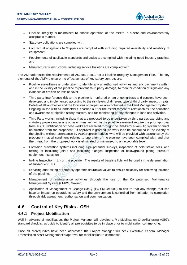
HYP MURRAY VALLEY SAFETY MANAGEMENT PLAN – CONSTRUCTION
H2W-Z-PLN-002-012 Rev 0 Page 45 of 76
• Pipeline integrity is maintained to enable operation of the assets in a safe and environmentally acceptable manner;
• Statutory obligations are complied with;
• Contractual obligations to Shippers are complied with including required availability and reliability of equipment;
• Requirements of applicable standards and codes are complied with including good industry practice; and
• Manufacturer’s instructions, including service bulletins are complied with. The AMP addresses the requirements of AS2885.3-2012 for a Pipeline Integrity Management Plan. The key elements of the AMP to ensure the effectiveness of key safety controls are:
• Pipeline surveillance is undertaken to identify any unauthorised activities and encroachments within and in the vicinity of the pipeline to prevent third party damage, to monitor condition of signs and any evidence of erosion or loss of cover.
• Third party interference risk to the pipeline is monitored on an ongoing basis and controls have been developed and implemented according to the risk levels of different type of third party impact threats. Details of all landholder and the locations of properties are contained in the Land Management System. Ongoing liaison with all landholders is carried out for the establishment of relationships, the education and awareness of pipeline safety matters, and for monitoring of any changes in land use activities.
• Third Party works (including those that are proposed to be undertaken by third parties exercising any statutory powers under any other written law) within the pipeline easement require the prior approval from AGIG. Notification of these works are received through the Dial-Before-You-Dig system or direct notification from the proponent. If approval is granted, no work is to be conducted in the vicinity of the pipeline without attendance by AGIG representatives, who will be provided with assurance by the proponent that all conditions relating to operation of the pipeline have been complied with, and that the threat from the proposed work is eliminated or minimised to an acceptable level.
• Corrosion prevention systems including pipe potential surveys, inspection of polarisation cells, and testing of insulating joints and insulating flanges, inspection of belowground piping, pressure equipment inspection.
• In-line Inspection (ILI) of the pipeline. The results of baseline ILIs will be used in the determination of subsequent ILIs.
• Servicing and testing of remotely operable shutdown valves to ensure reliability for achieving isolation of the pipeline.
• Management of maintenance activities through the use of the Computerised Maintenance Management System (CMMS, Maximo).
• Application of Management of Change (MoC) (PO-CM-OM-001) to ensure that any change that can have an impact on operations, safety and the environment is controlled from initiation to completion through risk assessment, authorisation and communication.
4.6 Control of Key Risks - OSH 4.6.1 Project Mobilisation Well in advance of mobilisation, the Project Manager will develop a Pre-Mobilisation Checklist using AGIG’s standard checklist as guide to identify all prerequisites to be in place prior to mobilisation commencing. Once all prerequisites have been addressed the Project Manager will seek Executive General Manager Transmission Asset Management’s approval for mobilisation to commence.

HYP MURRAY VALLEY SAFETY MANAGEMENT PLAN – CONSTRUCTION
H2W-Z-PLN-002-012 Rev 0 Page 46 of 76
An audit or review of the Pre-Mobilisation Checklist will take place within approximately 1 month of mobilisation to check all systems are in place and functional. 4.6.2 Training and Competency The Contractor Competency Matrix sets out the minimum requirements for personnel conducting work activities on any AGIG Transmission or gas storage related project. As part of the mobilisation process, a Contractor Onboarding Form shall be completed for all personnel to ensure an understanding of all induction and role requirements. This includes a ZHP Statement of Commitment which is required to be signed by all project personnel. The following sets out the definition for workers and what inductions and/or training is required to access site. 4.6.2.1 Visitor / Short term worker A visitor or short term worker is defined as:
5 days and not conducting any high risk work, excavation, confined space or working at heights and fully escorted at all times The required inductions and training for a visitor or short term worker are:
• Construction White / Blue Card • Project or Site Induction or AGIG Contractor Induction
4.6.2.2 Project personnel In addition to the construction white card / blue card and project induction, all mobilised project personnel shall complete a Contractor On-boarding Form and complete the following as a minimum prior to mobilising to site.
• DBP Contractors HSE Induction which consists of: – Safety Case – Environmental Awareness – Event Reporting
• AGIG Zero Harm Principles (ZHP) • Chain of Responsibility • Project Specific Induction • Site Specific/Familiarisation Induction
Project personnel work crews shall also have a mix of competencies in the following:
• First aid – 1:4 ratio on the project (with at least one per work crew) • Fire response – all hot works that requires PTW or mandated by emergency services fire watch - fire
spotters plus at least one per work crew • Gas detector – applied when conducting any work inside a high gas risk or an AGIG operational area
where gas may be present (ie excavation of the pipeline) 4.6.2.3 Role specific Role specific requirements are based on the tasks being completed and ensuring the correct training and competency are in place. Any High Risk Work requires a Verification of Competency (VoC) completed on the specific piece of equipment and within the last three years. Other roles require specific qualifications (eg engineer, electrician)

HYP MURRAY VALLEY SAFETY MANAGEMENT PLAN – CONSTRUCTION
H2W-Z-PLN-002-012 Rev 0 Page 47 of 76
Where determined by risk assessment a VoC process may also be requested for all operators of equipment to cover side booms, graders, excavators and trenching machines. This will be part of the HAZID process for the project. The Project Manager/Construction Manager shall be responsible for ensuring a record of training is kept for all personnel on the project. A Training Matrix or equivalent shall be reviewed as part of the pre-mobilisation audit. 4.6.3 Permit to Work In the implementation of high risk work there is potential for inappropriate planning, training, or conflicting scopes to cause serious consequences. Regulation 15 of the MoSoPO Regulations requires that a documented permit to work system (PTWS) be established to control the safe performance of work through identifying persons having responsibility to authorise and supervise work and ensuring members are competent in the application of that system. The AGIG Permit to Work System (PTWS) is an administrative system used to plan, control and document the completion of high risk work according to safe work practices. The Permit to Work Procedure (S-PRO-001) sets out the roles, responsibilities and framework for the implementation of the PTWS. At a minimum, the PTWS must be applied to any work that requires:
• Pipeline Integrity & Supply Authorisation (PISA) – authorisation for work that could affect supply and/or integrity of the pipeline;
• Isolation – all isolation activities that can affect the integrity of the pipeline or supply;
• Confined Space Entry – entry into any enclosed or partially enclosed space that meets the definition of a confined space (refer section 4.6.7);
• Hot Work – work that can produce a source of ignition within a Hazardous Area (refer section 4.6.12);
• Working at Heights – work at a height greater than 1.5 m in the absence of permanent, purpose-built fall protection infrastructure (refer section 4.6.6);
• Excavation – Any digging or penetration of ground deeper than 150mm in operational areas and 300mm, at any Site under AGIG’s responsibility; or
• Excavation Entry – entry into a constructed excavation site. Exemptions to the above include:
• Work performed within an enclosed and ventilated workshop or work area approved for such work
• Work performed that requires a PISA only due to the potential of causing a SCADA alarm at the TSCC control room (other than a door alarm) and does not meet any of the other criteria above for when a Permit is required. In this case, the PISA number shall be recorded on the Take 5 form completed for the activity; or
• Third Party Work activities not related to the pipeline operation, that is monitored by AGIG Personnel/Contractor to ensure the safety of the pipeline; or
• Construction activities carried out in an approved Greenfield site outside of a live pipeline corridor/easement that is subject to its own AGIG approved risk control system specific to the activities, which must include a clearly defined process for transitioning commissioned systems into operational control and Permit to Work System requirements.

HYP MURRAY VALLEY SAFETY MANAGEMENT PLAN – CONSTRUCTION
H2W-Z-PLN-002-012 Rev 0 Page 48 of 76
Commissioning of temporary buildings (eg construction camps, offices, ablution blocks) does not require a permit for project related work. The In-house Electrical Licence Nominee or Electrical Contractor must approve of all requirements before energisation. Energisations shall only be completed by a licensed electrician. All commissioning shall be completed under the Notice of Energisation Procedure including communication to full workforce during pre-start. Where electrical hazards exist and isolations may be required this shall be managed through application of S-PRO-003 Isolation Locking and Tag out procedure (or a project approved equivalent) but excluding the requirement for a permit. Pre-commissioning activities (hydrotesting, nitrogen leak testing) shall be managed under a JHA/HAZID process. 4.6.4 Working in High Gas Risk Areas AGIG has established High Gas Risk Areas (HGRA) for strict control of ignition sources within existing facilities. To simplify the application of gas risk area controls, HGRA boundaries relate to visible site landmarks such that HGRA may be defined as any area within the fence line at any aboveground facilities otherwise delineated by signage – eg control hut. All Personnel working within a HGRA must wear a Personal Gas Monitor (PGM) capable of detecting and alerting the wearer of the presence of an atmosphere approaching toxic or explosive conditions. In the case of Visitors, up to five individuals may be escorted by an individual who is wearing PGM. In addition to personal gas monitoring, gas detection protocols have been established for high risk activities conducted within HGRA, including:
• Excavation and Excavation Entry (refer Section 4.6.3);
• Confined Space Entry (refer Section 4.6.7); and
• Hot Work (refer Section 4.6.12). The Gas Testing and Monitoring Procedure (S-PRO-038) establishes the minimum requirements for gas monitoring equipment selection, calibration, maintenance and use. The use of any non-intrinsically safe portable electrical equipment (eg mobile phones) is prohibited within HGRA unless managed via risk assessment and issuance of a Hot Work Certificate (refer to Section 4.6.12). 4.6.5 Excavation and Excavation Entry Owing to the predominantly buried nature of its key infrastructure, AGIG regularly undertakes excavation and excavation entry in the installation of new assets and the inspection and maintenance of existing ones. These activities introduce exposure to a range of hazards including:
• interaction with live buried infrastructure; • fall from height; • exposure to a toxic atmosphere; and • cave in causing entrapment.
The Excavation and Excavation Entry Procedure (S-PRO-035) details the specific considerations required by AGIG Personnel in order to ensure that the associated risks are reduced to AFARP. Any excavation or excavation entry must be administered via the issuance of a certificate under the Permit to Work process (as outlined in Section 4.6.1).

HYP MURRAY VALLEY SAFETY MANAGEMENT PLAN – CONSTRUCTION
H2W-Z-PLN-002-012 Rev 0 Page 49 of 76
During the construction phase, it is unlikely that there will be excavation entry activities which are considered confined space entry. Any excavation entry activity will be managed under the relevant Contractor’s PTW system that is accepted by AGIG. Before beginning any excavation all underground services and cabling shall be positively located and identified. These services will be protected and marked (pegged or paint) prior to excavation operations. Where exposure of existing services is required, final exposure must be conducted by hand digging. Excavations near high risk utility services will utilise spotters and have direct line marking of the service to prevent excavator damage of the service. No machine excavation is permitted within 1metre of any gas or electrical services. All excavation within 1 metre of any gas or electrical services is to be undertaken using a hand tool such as a shovel or a kanga (where asset protection is in place). Any service that is exposed during excavation will be identified, assessed for hazard potential and supported sufficiently to prevent stress damage. Any person required to work in an excavated area or other ground opening deeper than 1.5m must be in the company of a standby person for rescue purposes and follow the requirements for excavation entry. The walls and faces of all excavations, and trenches more than 1.5m in depth, in which employees could be exposed to danger from moving ground will be guarded by shoring, battering or benching. Any spoil stockpile shall be more than 1m (Code of Practice; Safework Aust) from the edge of the excavation unless additional controls are applied. The Supervisor will prepare a risk assessment prior to personnel entering any deep excavation.
• All item of plant, equipment, or excavated material or any other load must be safely stored at a distance from the edge of not less than 1 metre or 1/3rd the depth of the excavation or further where there is the potential for the ground to collapse.
• A daily inspection of excavations must be carried out by civil supervision and if evidence of possible cave-in or earth slide is apparent, all work in the excavated area must stop until the necessary precautions have been taken to safeguard the employees.
• Any grade line, rope, chain or possible tripping hazard must be made clearly visible day and night by lamps or coloured survey tape/flagging.
• Where personnel are at risk of falling 3m or more (eg tunnelling pits, deep excavations in rock with near vertical sides), either – handrails are in place, or fall injury prevention systems are used, or the work is managed to prevent personnel having to work where there is the risk of a fall.
• Power poles, walls, buildings, driveways etc (in close proximity to excavations) are secured against collapse, if required.
• Requirements for working around mobile plant will include safety helmets, high visibility vests, and communication/signals.
• For details of requirements for excavation works along an operational pipeline and associated laterals, In areas of ground instability, shoring or shielding shall be installed prior to personnel entering the excavation. In locations where working space is restricted to the point that benching and battering to a standard shown in the figure below is not possible, such as restricted Right of Way areas, shoring and/or shielding shall be installed prior to personnel entering the excavation. All accessible areas of an excavation of more than 150mm below grade level whether temporary or permanent must be adequately signpost and/or protected to identify the hazard potential and prevent unauthorised access.

HYP MURRAY VALLEY SAFETY MANAGEMENT PLAN – CONSTRUCTION
H2W-Z-PLN-002-012 Rev 0 Page 50 of 76
All excavated areas will have adequate facilities to enable employees to enter and exit the excavation in a safe manner, including but not limited to:
• Use of a suitable length ladder; and/or • Excavation of an inclined ramp to allow safe entry and exit.
All excavations will be constructed with appropriate stock crossing points and access ramps to provide for the safe release of wildlife. HDD construction areas (including thrust bore) shall met the minimum benching and shoring requirements. Design shall be provided by the specialist contractor and approved by AGIG. 4.6.5.1 Barricading Materials to be used for barricading will be made available prior to commencing any excavation and erected progressively. Excavated materials may be used to establish a windrow as a barricade.
• Barricading must be constructed to a height of not less than 1 metre and, with the exception of windrow barricades, positioned no less than 1 metre from the edge of an excavated area (Public safety barriers must be in place where required) (Note: barriers to be at least 900mm “paraweb” mesh installed a minimum of 100mm from ground level).
• Materials to be used for barricading must be made available prior to commencing any excavation and erected progressively.
• Excavated materials may be used to establish a windrow as a barricade. • Barriers/Edge Protection may be constructed of any substantial materials. However the following are
considered most suitable for use: – Plastic or metal mesh type fencing supported at regular intervals by upright freestanding posts. – Scaffolding tubing erected in a post and rail type configuration. – Bunting.
• The preferred use of bunting is to highlight a hazard or to demarcate a hazardous area. To highlight the barricading some form of bunting should be attached. The following types are suitable:
– Coloured plastic flagging. – Plastic caution/danger tape.
4.6.5.2 Warning Signs Where an excavation may not be immediately visible to personnel approaching the site, hazard warning signs will be displayed. This applies to excavations that may be obscured by buildings or equipment. 4.6.6 Electrical Safety All electrical equipment including generators, portable electrical equipment, power leads and temporary electrical services, will be inspected and tagged by a licensed electrician. A register will be maintained for all electrical maintenance including information on testing and inspection activities completed. Project electrical registers will be made available to AGIG for review on request. All portable or handheld electrical equipment (intended to be moved when in operation) must be protected by an RCD (Residual Current Device). The RCD will be either:
• Inbuilt to a generator set;
• Built into the construction switchboard;
• Built into the switchboard or the power outlet, in the case of established premises; or
• A portable RCD (note: the RCD must plug directly into the outlet side of the socket outlet, without a power lead in between).
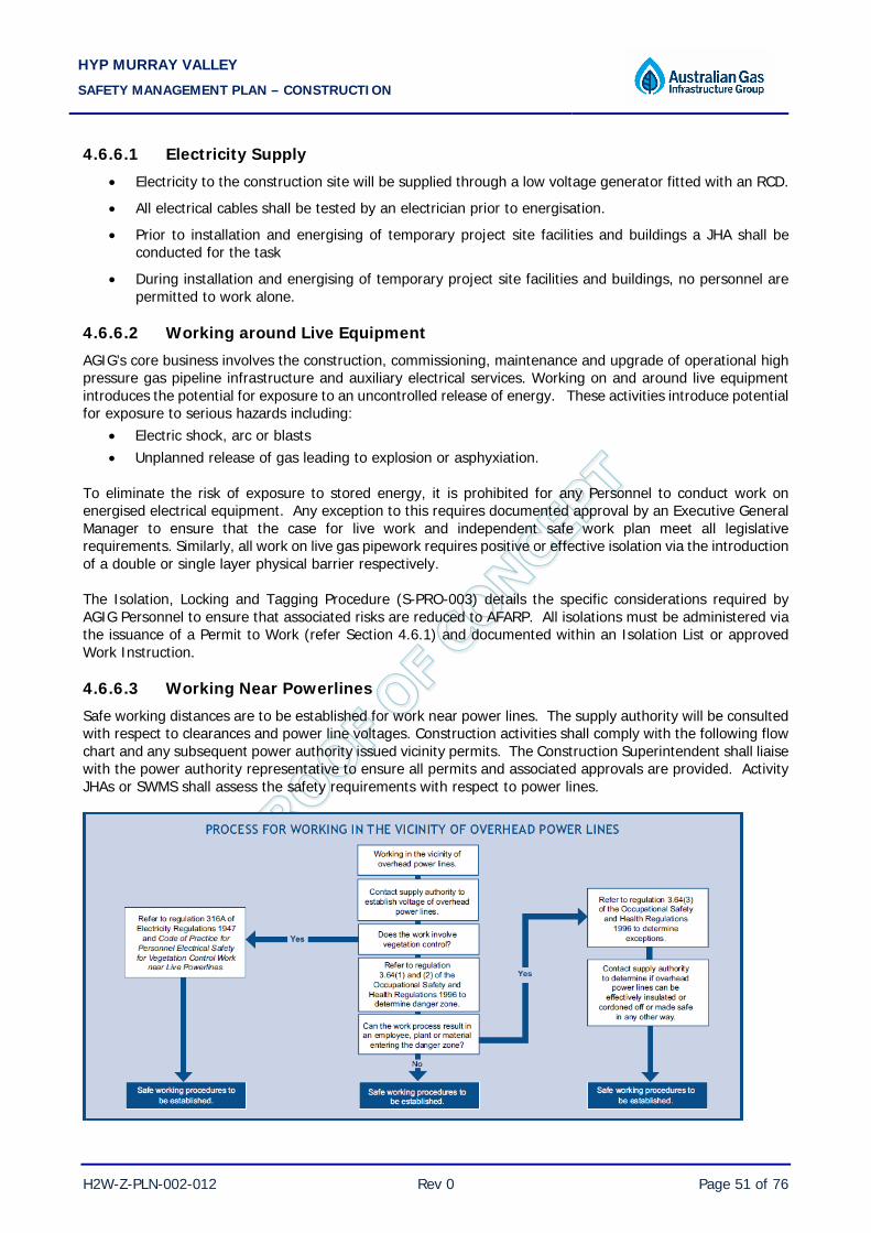
HYP MURRAY VALLEY SAFETY MANAGEMENT PLAN – CONSTRUCTION
H2W-Z-PLN-002-012 Rev 0 Page 51 of 76
4.6.6.1 Electricity Supply • Electricity to the construction site will be supplied through a low voltage generator fitted with an RCD.
• All electrical cables shall be tested by an electrician prior to energisation.
• Prior to installation and energising of temporary project site facilities and buildings a JHA shall be conducted for the task
• During installation and energising of temporary project site facilities and buildings, no personnel are permitted to work alone.
4.6.6.2 Working around Live Equipment AGIG’s core business involves the construction, commissioning, maintenance and upgrade of operational high pressure gas pipeline infrastructure and auxiliary electrical services. Working on and around live equipment introduces the potential for exposure to an uncontrolled release of energy. These activities introduce potential for exposure to serious hazards including:
• Electric shock, arc or blasts • Unplanned release of gas leading to explosion or asphyxiation.
To eliminate the risk of exposure to stored energy, it is prohibited for any Personnel to conduct work on energised electrical equipment. Any exception to this requires documented approval by an Executive General Manager to ensure that the case for live work and independent safe work plan meet all legislative requirements. Similarly, all work on live gas pipework requires positive or effective isolation via the introduction of a double or single layer physical barrier respectively. The Isolation, Locking and Tagging Procedure (S-PRO-003) details the specific considerations required by AGIG Personnel to ensure that associated risks are reduced to AFARP. All isolations must be administered via the issuance of a Permit to Work (refer Section 4.6.1) and documented within an Isolation List or approved Work Instruction. 4.6.6.3 Working Near Powerlines Safe working distances are to be established for work near power lines. The supply authority will be consulted with respect to clearances and power line voltages. Construction activities shall comply with the following flow chart and any subsequent power authority issued vicinity permits. The Construction Superintendent shall liaise with the power authority representative to ensure all permits and associated approvals are provided. Activity JHAs or SWMS shall assess the safety requirements with respect to power lines.

HYP MURRAY VALLEY SAFETY MANAGEMENT PLAN – CONSTRUCTION
H2W-Z-PLN-002-012 Rev 0 Page 52 of 76
Equipotential matting is to be used where pipe may be affected by power line electric fields or cathodic protection potential differences. When working in the vicinity of high voltage powerlines, personnel shall take the following precautions (where applicable):
• Consultation with power authority and establishment of authorised work practices, including electrical power line isolations;
• Observation of minimum separation distances nominated by the power authority; • Catenaries erected to highlight power line presence; • Other warning indications/signs; • Earthing of equipment, materials and work areas by ground earthing mats; • Use of appropriate PPE including rubber soled safety boots; • All personnel making and breaking earth connections will do so whilst wearing long heavy-duty rubber
gloves; • Use of rubber tyred equipment with trailing earth lines; and • Installation of mitigation electrodes to protect against Low Frequency Induction (LFI) currents.
The activity based Supervisor is to ensure the protocol above is complied with. Where the proposed pipeline construction passes under or beside HV power lines the following additional precautions shall be followed:
• The Maximum Safe Length (MSL) of continuous pipe that can be strung between is 1000 metres. If greater than 1000 metres, but not to exceeding 2000 metres, is required to be strung, then earthing electrodes of not greater than 4 ohms resistance to earth shall be installed at each end of the pipe length. These electrodes shall be left connected until the pipe length is welded into the pipeline.
• Temporary connections of the earthing electrode to the pipe shall be made using welding clamps on cleaned pipe metal surfaces.
• Connection cables from welding clamp to earthing electrode should be a minimum of 35mm2 (or 2 x 16mm2) copper cable.
• Welding of continuous pipe strings to the pipeline in the trench within the LFI exposure area should be conducted on equipotential mats connected to the pipeline with 35mm2 (or 2 x 16mm2) copper cable connections until the weld is completed.
• Protective clothing and footwear as described in AS4853:2000 Appendix I clause I5 should be worn by all personnel working on the pipeline.
• In addition, any requirements of the power authority (e.g. restriction on refuelling locations) shall be agreed with the relevant power authority and shall be complied with by all personnel.
4.6.6.3.1 1 Signage and Catenary Installation When working around power lines, signage and the installation of catenaries may be required based on the distance of the overhead power lines. Signage when crossing or working in parallel with power lines that indicate the Power Lines must be placed 10m before and after the crossing and directly under the power line. Signage and catenary requirements are outlined in the below figures. ‘Danger High Voltage Overhead Power Lines’ signs shall be of a standard shown in the figure below.

HYP MURRAY VALLEY SAFETY MANAGEMENT PLAN – CONSTRUCTION
H2W-Z-PLN-002-012 Rev 0 Page 53 of 76
Clearance heights shall be identified on power line danger signs. Clearance heights shall be the distance from ground level to the lowest point of the power lines (see figure below).
Clearance Height
‘Danger High Voltage Overhead Power Lines’ signs shall be erected 20 metres either side of the power lines in a prominent position (see figure below).
High visibility catenary markers/barriers shall be erected 10 metres either side of the power lines. For pipeline construction the catenary markers/barriers shall be positioned across the Right of Way regardless of the angle of the power lines. Where power lines are parallel to a pipeline Right of Way, catenary markers/barriers shall be erected where the power lines first comes within 10 metres of the Right of Way in both directions of travel.

HYP MURRAY VALLEY SAFETY MANAGEMENT PLAN – CONSTRUCTION
H2W-Z-PLN-002-012 Rev 0 Page 54 of 76
Where power lines run parallel to pipeline Right of Way catenary markers/barriers shall be erected in such a manner that the next catenary marker/barrier is clearly visible from the previous catenary marker/barrier, and at intervals not exceeding 500 metres.
500 Metres10 Metres
10 Metres
Catenary markers/barriers shall be constructed of a high visibility bunting flags strung 10 metres in front of the power lines. The height of Catenary Markers/Barriers shall be the clearance height less the “Danger Zone” at the lowest point of the power lines Figure 5 7). Danger Zone (Section 4.6.6.2.2) is dependent on the voltage of the powerline.
Clearance Height
Cantenary
Marker/Barrier Height
Danger Zone
Catenary marker support posts shall be securely supported to prevent them from falling over due to high wind or when the bunting flags are struck and unattached. All personnel shall be responsible for ensuring that catenary markers and signage are maintained in working order. All personnel shall re-erect, repair and/or replace catenary markers and signage where they are found to be damaged and/or knocked down/over. 4.6.6.3.2 Danger Zones Specific restrictions apply when working in the vicinity of overhead power lines as outlined in state legislation. All work must be completed whilst keeping out of the exclusion “Danger Zone”. The "Danger Zone" means anywhere that:

HYP MURRAY VALLEY SAFETY MANAGEMENT PLAN – CONSTRUCTION
H2W-Z-PLN-002-012 Rev 0 Page 55 of 76
• 3m minimum from telegraph type power lines 0v – 33,000v; • 6m minimum from transmission power lines 33,000v – 330,000v; • If required to work within these safe distances the power authority must be contacted to have the
power isolated.
If the mechanical lifting plant accidently touches the power lines the operator must remain in the crane and attempt to slew/boom away from the power lines. The operator must wait until the power is isolated before leaving the crane. 4.6.6.4 Plug and Play Installation for Temporary Buildings Where temporary buildings and associated generators are installed for projects the following controls shall be reviewed and approved prior to energisation.
• Earthing is installed and approved by the AGIG approved Licensed Electrical Contractor • Electrical certificates have been provided for buildings; and • Distribution boards have been inspected within last six months
A Notification of Energisation shall be in place prior to energisation of temporary buildings. 4.6.6.5 Notification of Energisation (NOE) A NOE is required prior to electrical energisation of any new equipment in a greenfield site for the first time. The NOE shall be approved by the Head of Transmission Engineering or a delegate. A NOE shall confirm that:
• The installation is sufficiently complete to enable energisation • The isolations in place are suitable and meet the site requirements

HYP MURRAY VALLEY SAFETY MANAGEMENT PLAN – CONSTRUCTION
H2W-Z-PLN-002-012 Rev 0 Page 56 of 76
• The risk assessment identifies suitable controls and they are managed to AFARP • Personnel are competent • Communication of energisation has occurred to the full workforce and stakeholders • Appropriate safe system of work is in place (eg permit to work) • ITR’s have been completed and approved • Completion certification is in place and signed off (mechanical/electrical) • Walk through has been completed and Category A punch list items have been closed out
For clarity, a NOE is not required for temporary, mobile, field based generators, air compressors or welding units. 4.6.6.5.1 Working with Portable Electric Hand Tools
Prior to commencing work, personnel will inspect portable electrical tools and equipment to ensure it is operationally safe, reporting any defective equipment immediately for repair - every such tool that is suspect of being faulty will be tagged with an Out-of-Service tag detailing the identified fault. As an additional safety measure, after ensuring disconnection from power, the plug is to be cut off and attached to the faulty equipment. All Portable electrical hand tools will be connected to a residual current device (RCD) to protect users from the risk of electrical shock. The RCD can be incorporated into the construction site main electrical switchboard or provided by the use of a portable device.
• Electric power operated tools must be of the approved double insulated type or be properly earthed. • Portable 240V electrical tools will not be used in wet conditions or when the operator is in contact with
water. • Only intrinsically safe electrical tools are to be used in an explosive or suspected explosive atmosphere.
The use of all electrical cords and cables will be in accordance with the following:
• Only heavy duty electrical portable outlet devices and heavy duty supply cables will be used on the construction site.
• Extension flexible cords will not exceed 30m in length (AS/NZS3012) from an electrical switchboard and should be completely extended prior to use. Two 30m cords are not to be used together.
• Flexible electrical cords or cables will be located in positions where they are not subject to damage. • Flexible cords and cables will be supported off the floor or ground where they are located more than
10 metres from an appliance or luminaries, cross passage or access ways or are not in view of the person using the appliance or luminaries to which they are connected.
• All connection plugs and sockets of portable electrical equipment must be: • Of a type that cannot be rewired (pre-moulded), or made of transparent material; and. • No domestic plug boards, double adapters, piggyback plugs or leads are to be used in the workplaces.
All electrical extension leads, flexible cords and cables must, where practicable, be kept off the floor or ground and secured at a height of not less than 2.4m. Where cords trail on the ground they must be physically protected. 4.6.7 Working at Heights (WAH) Working at height is any task conducted where there is a potential to fall from a level greater than 1.5m. During asset design, consideration is given to operational access requirements, with an objective to eliminate the need for WAH either through relocation of the work area or the inclusion of fall protection. Nevertheless, there unfortunately remains a requirement to conduct WAH for a range of different tasks.

HYP MURRAY VALLEY SAFETY MANAGEMENT PLAN – CONSTRUCTION
H2W-Z-PLN-002-012 Rev 0 Page 57 of 76
Working at heights may lead to injury due to fall from heights or being struck by a falling object. Hazards to consider include:
• working on different surfaces, eg stability, fragility, slipperiness and slope; • working on different levels; • working on unstable / uneven ground surfaces; • working on scaffolds or elevated work platforms; • working on unguarded platforms, walkways and plant; and • adverse weather conditions, eg wet and windy conditions.
The following Australian Standards set out the minimum requirements for a range of work scenarios which introduce a risk of fall:
• AS1576 Scaffolding Code; • AS1577 Scaffolding decking components; • AS4576 Guidelines for Scaffolding; • AS1657 Fixed Platforms, Walkways, Stairways and Ladders. Design, Construction and Installation; • AS1892 Portable Ladders; • AS1891.1-4 Industrial Fall Arrest Systems and Devices; • AS2550.10 Safe Use of Cranes and Equipment (EWPs); and • AS2626-1983 Industrial safety belts and harnesses - Selection, use and maintenance.
The Working at Heights Procedure (S-PRO-033) sets out the protocol for conducting WAH in order to ensure that associated risks are reduced to AFARP and that the mandatory requirements of the aforementioned Australian Standards are met. During the construction phase, it is unlikely that there will be WAH activities. However, should there be a WAH activity, the relevant Contractor’s PTW system will be applicable, including the associated certificate. In addition, the following requirements will be applicable:
• Superintendents and Supervisors will identify working at heights by undertaking a Job Hazard Analysis. Each hazard to which a person at the workplace is likely to be exposed in relation to a person falling from one level to another shall assess the risk of injury or harm and consider ways by which the risk may be reduced.
• All employees and contractors will ensure that where any person is likely to be exposed to the danger of being struck by falling equipment or materials, the work area(s) will be barricaded off and warning notices ("DANGER - KEEP CLEAR - WORKERS OVERHEAD") displayed at all approaches to the area(s) in a manner so as to be clearly observed by workers.
• Elimination and engineering controls shall be put in place for fall prevention in preference or in conjunction with, personal protective equipment and administrative (procedural) controls wherever practicable. Scaffolding, edge protection, the use of work platforms, ladders and workboxes are examples of engineering controls for fall prevention (Code of Practice Prevention of falls at workplaces).
• Supervisors will identify by undertaking a JHA, each hazard to which a person at the workplace is likely to be exposed in relation to a person falling from one level to another, assess the risk of injury or harm from each such hazard and consider ways by which the risk may be reduced.
• Where PPE is used as a last resort, fall restraint must be implemented and where this is not possible fall arrest may be used with approval of the Construction Manager.
• The movement of usable or waste material, tools, equipment, etc. to higher or lower levels will be by hand line or hoist apparatus and must not be thrown between levels or be carried by a person climbing between levels.

HYP MURRAY VALLEY SAFETY MANAGEMENT PLAN – CONSTRUCTION
H2W-Z-PLN-002-012 Rev 0 Page 58 of 76
• Makeshift work platforms will not be used - all work will be carried out from properly erected scaffolds with rigid frames and sound planks erected by a Licensed Scaffolder.
• Adequate safe ladder access and egress will be maintained and used at all times.
• Construction Supervision in control of the specific work will ensure that where any person is working in an area where there is a risk of falling, will only work from the confines of a safe working platform and/or wear fall arrest protection subject to the findings of a risk assessment through Job Hazard Analysis.
4.6.8 Confined Space Entry A confined space may be defined as any enclosed or partially enclosed space that is not intended or designed primarily for human occupancy, within which there is a risk of one or more of the following:
• an oxygen concentration outside the safe oxygen range; • a concentration of airborne contaminant that may cause impairment, loss of consciousness or
asphyxiation; • a concentration of flammable airborne contaminant that may cause injury from fire or explosion; or • engulfment in a stored free-flowing solid or a rising level of liquid that may cause suffocation or
drowning. Entry into confined spaces can be a requirement in order to conduct inspection, cleaning and maintenance. Confined Space Entry (CSE) introduces exposure to hazards including:
• oxygen deficient atmosphere (leading to asphyxia); • oxygen enriched atmosphere (leading to explosion); • exposure to a toxic atmosphere; • engulfment or drowning; • lost communications; • excessive noise; • excessive temperature; • inadequate lighting; and • restricted egress.
The Confined Space Code of Practice (Safe Work Australia, 2016) and the AS2865-2009 Confined Spaces set out the minimum requirements for establishing a safe system for entry and the conduct of tasks within a confined space. The Confined Space Procedure (S-PRO-023) sets out the protocol for identifying confined spaces and conducting confined space entry in order to ensure that associated risks are reduced to AFARP and that these mandatory requirements are met. Any entry into a confined space must be administered via the issuance of a CSE certificate under the Permit to Work process outlined in Section 4.6.1. During the construction phase, it is unlikely that there will be any activity requiring a CSE. However, should there be a requirement for CSE, the relevant Contractor’s PTW system will be applicable, including the associated certificate. The Project or Construction Manager shall ensure the assessment of all enclosed or partially enclosed spaces to identify key hazards and enable confined space classification. Such analysis must be undertaken using the Potential Confined Space Assessment Form (S-FRM-023.3), supported by a pre entry gas test. If the space is assessed as a Confined Space, all efforts shall be made to conduct work outside of the space without requiring entry. Where entry is required the Confined Space Certificate and all entry requirements must be met as set out in S-PRO-023 or an approved equivalent procedure.

HYP MURRAY VALLEY SAFETY MANAGEMENT PLAN – CONSTRUCTION
H2W-Z-PLN-002-012 Rev 0 Page 59 of 76
4.6.9 Mechanical Lifting Mechanical lifting refers to any act of utilising a mechanical aid (eg crane, electric winch, hiab, forklift, telehandler etc.) to assist in the raising or relocation of a load. There is a range of legislation and standards in place applicable to the use of mechanical lifting, including:
• Requirements for the inspection and use of cranes are set out in Australian standard 2550 Cranes Safe Use;
• Australian Standard 1418.1-1418.9 Cranes, Hoists and Winches; and • Occupational Safety and Health Regulations 2017.
In the management of mechanical lifting risks, all mechanical lifts have been categorised as Critical, Standard or Basic. A ‘Critical Lift’ is defined as any lift using a mobile slew crane where:
• the Total Suspended Load (TSL) exceeds 20 tonnes; • the TSL is equal to or greater than 85% of the crane’s rated capacity; • the load is suspended over operating facilities; or • the load is suspended using two or more mechanical lifting devices.
Basic Lifts are defined as the use of a fixed gantry cane, vehicle mounted crane, telehandler or forklift (provided the lift does not require a jib to be attached to the equipment) and Standard Lifts cover all other lifts (ie any mechanical lift not falling into the category of Critical Lift or Basic Lift). The Mechanical Lift Procedure (S-PRO-025) sets out the protocol for conducting mechanical lifts in order to ensure that associated risks are reduced to the level of AFARP. At a minimum, it shall be a mandatory requirement for:
• Critical Lifts to be supported by a lift study (undertaken by a qualified engineer); • Standard Lifts to be supported by a lift plan (undertaken by a person verified as competent in the use
of the mechanical lifting aid); and • Basic Lifts to be supported by a documented inspection of the mechanical lifting plant prior to each
use. Whilst AGIG does not employ its own crane operators, it is necessary that any external contractor engaged to do lifting work has a procedure and lifting plan that accommodate the following requirements which apply equally to construction projects and operational work.
• Only qualified operators holding approved and appropriate Crane Driving High Risk Work Licence, are permitted to operate Registered Lifting Equipment;
• Qualified operators are directly responsible for ensuring that all Registered Lifting Equipment is used within its recommended load limitations, and stored in a proper manner when not in use;
• Any person directing a Crane Driver shall be a licensed Dogger or Rigger or using a truck/self-loading crane (HIAB) that does not require operator competency certification;
• Concealed loads are controlled by arrangement of an additional Dogger, indicating lifting requirements to the Crane Driver by means of industry approved hand signals or radio communication;
• Where required by Regulatory Authorities, all cranes and lifting equipment are covered by a valid “Inspection Certificate”. This equipment is inspected on a regular basis; and
• All lifting and rigging equipment, including cranes and the equipment containers shall be certified in accordance with applicable lifting standards. Certificates and log books shall be maintained for all equipment with a lifting capacity exceeding a WLL of 10.0 tonne. Daily logbooks are completed by the Crane Driver and stored in the Crane Cab.

HYP MURRAY VALLEY SAFETY MANAGEMENT PLAN – CONSTRUCTION
H2W-Z-PLN-002-012 Rev 0 Page 60 of 76
Wherever possible, items requiring loading or unloading by crane or mechanical lifting devices shall have the load weight clearly marked on it prior to delivery to site. In circumstances where a load is not known, determination of the load mass, centre of gravity and rigging requirements shall be made by suitably qualified personnel and included in the Contractor’s lifting plan. The weight of the meter skid and control hut shall be clearly marked on them prior to delivery to site. Lifting equipment will only to be used for the purpose for which it is designed and within its rated capacity and a Certified Dogger (or Rigger) will sling loads. If required by the lift, an engineered lifting plan and JHA will be prepared by the contractor. It is the crane operator’s responsibility to assess and comply with this lifting plan. Should minor modifications be required to the lifting plan due to site conditions, these must be approved by the Construction Manager. The crane operator has the full responsibility for a safe operation when using hoisting equipment to make lifts and is required to provide a Lifting Plan, as required, and a JHA for other non-specified lifts. Additionally, the Mechanical Lift Procedure (S-PRO-025) provides for the documented inspection of all lifting and rigging equipment integrity at a minimum of annually, with the exception of soft slings, which shall be undertaken 3 monthly. 4.6.10 Mobile Plant Licensed mobile equipment is maintained in a safe and roadworthy condition. All drivers of vehicles conducting off road will have completed advanced driver training and 4WD training within the previous 12 month period (Validity is limited to annual retraining). All vehicles will carry a current registration certification if travelling on gazette roads and be subject to daily walk around inspection by the driver. All vehicles will undergo a full prestart inspection prior to any remote travel. If a vehicle is based onsite with no remote travel, a prestart inspection is required at a minimum monthly. No vehicle will be permitted to enter a construction activity location without the approval of the Construction Manager. Vehicles carrying hazardous goods or chemicals will be signed in line with the Australian Dangerous Goods Code. 4.6.10.1 Heavy Vehicles and Mobile Plant Only qualified operators holding approved and appropriate competencies, are permitted to operate mobile plant. Licensed mobile equipment is maintained in a safe and roadworthy condition. All major items of plant and equipment shall undergo a pre mobilisation inspection and shall have a plant risk assessment. The Responsible Manager shall ensure all pre-mobilisation inspections are completed. The purpose of these checks is to ensure the plant is in good condition and fit for use. Any plant that is not fit for use on site is immediately quarantined and either rectified to bring it to a serviceable condition or removed from site. As a minimum, all major plant on site must meet the following requirements:
• Plant Log Book; • Plant Operating Manual; • Plant Risk assessment document; • Fire extinguisher 9kg; • Reversing alarms (as required);

HYP MURRAY VALLEY SAFETY MANAGEMENT PLAN – CONSTRUCTION
H2W-Z-PLN-002-012 Rev 0 Page 61 of 76
• Spill kit; and • Amber coloured flashing warning lights (as required).
All load-shifting equipment must be provided with certification and load charts. A minimum distance of 2m is maintained between personnel and the fully extended arm of any active mobile plant. Daily logbooks are completed by the operator and stored in the cab or in a pouch situated near the operator position. Maintenance of all plant shall be as per the plant operating manual and shall be kept up to date. A Plant and Equipment Register is maintained by the construction site supervisor for all site plant and equipment recording the serial number, description, and manufacturer. Where there are provisions for a seatbelts in the original design of the plant the belts must be fitted. Where a machine is fitted with a seatbelt, the driver must wear the seatbelt. Guards, safety appliances or devices shall be replaced as soon as practicable after repairs and adjustments have been completed before vehicle is used. Adequate protection for underground cables and/or pipelines will be confirmed as in place prior to crossing these cables and/or pipelines with heavy equipment and/or loads. Sufficient mats or steel plates will be used, in order to avoid damage to these cables and/or pipelines and as appropriate for the stabilisation of outriggers. 4.6.10.2 Operator Protective Devices Where an item of mobile plant is likely to overturn or an object come in contact with the operator the plant will be fitted with operator protection. Appropriate protection would include a roll-over protective structure and operator restraint if there is a likelihood of the operator being ejected from the seat. Any Roll-over protective structures (ROPS) and fall-on protective structures (FOPS) will comply with the Australian Standards AS 1636 or AS 2294 and/or be designed by a suitably qualified engineer to provide at least the same protection as the standard. Standards approved structures will carry an identification plate. Others should have a certificate or document of design compliance from an engineer. The removal or lowering of a protective structure is only permitted for the specific time needed to pass under a tree or low clearance object. 4.6.10.3 Mobile Plant and Pedestrians Mobile plant that is operating in close proximity to pedestrians will be fitted with an audible warning device for reversing. Where practicable, bunting and warning signs will be used to cordon off mobile plant operation that is in close proximity to high pedestrian traffic. No part of mobile plant, or load, will enter the ‘danger zone’ of an overhead power line. Spotters and radio communication will be considered for operations that require extensive movements and numbers of mobile plant. 4.6.10.4 Hired Plant & Equipment (including Vehicles) Every practicable effort is to be made to ensure compliance with the following requirements for hired plant and equipment (including vehicles) inclusive of:

HYP MURRAY VALLEY SAFETY MANAGEMENT PLAN – CONSTRUCTION
H2W-Z-PLN-002-012 Rev 0 Page 62 of 76
• Ensuring hired equipment supplied to site meets safety requirements and specifications; • Confirming that plant and equipment is inspected prior to acceptance for use on site; • Ensuring hired equipment is subject to a scheduled maintenance and inspection program such that
equipment is kept in safe working condition; • Ensuring personnel are competent to use equipment; • Where electrical equipment is hired, e.g. portable generators, work lights and extension leads, the
responsible person will ensure that the requirements to those required on site are specified to the Hire Company as a condition of the Hire Agreement; and
• Ensuring a copy of the operational manual and Plant Risk Assessment are included. 4.6.11 Traffic Management For each construction project, a Traffic Management Plan detailing site access roads, parking areas and guidelines for the operation of vehicles on the site, must be developed. The Contractor Site Supervisor is responsible for the safe movement and control of vehicles at the construction site. All traffic management that impacts local government or main roads shall have the approval of the relevant authority. A layout plan may be used to set out the layout of the camp, pipeyard or other area and detail the flow of traffic including parking and pedestrian use. Signage including call ups, speed and other warnings shall be installed as per location specific requirements. 4.6.12 Manual Tasks Manual tasks include any activity or sequence of activities that require a person to use their physical body (musculoskeletal system) to perform work, including:
• manual handling (the use of force in lifting, lowering, pushing, pulling, carrying or otherwise moving, holding or restraining anything);
• performing repetitive actions; • adopting awkward or sustained postures; and • using plant, tools or equipment that expose workers to vibration.
Manual tasks undertaken by AGIG Personnel cover a range of activities and work environments. For example, manual handling tasks can include anything from lifting document archive boxes in an office to shifting a tight valve at an operational pipeline site. Failure to identify and manage hazards associated with manual tasks can result in injury or disease of the musculoskeletal system including:
• sprains and strains of muscles, ligaments and tendons (eg back strain); • joint injuries or degeneration (eg frozen shoulder or arthritis of the back); • disc protrusions, disc herniation or disc degeneration of the back or neck; • Nerve injury or compression (eg carpal tunnel syndrome); • muscular and vascular disorders (eg vibration-induced white finger from hand-arm vibration); and • soft tissue injuries.
In order to address the manual task risks identified with work typical of AGIG, all Staff must receive training in the identification and management of ergonomic hazards (including manual tasks). This is further supported by Flex Five, a simple five step stretch routine that is promoted amongst all Staff. All Personnel are responsible

HYP MURRAY VALLEY SAFETY MANAGEMENT PLAN – CONSTRUCTION
H2W-Z-PLN-002-012 Rev 0 Page 63 of 76
for the ongoing self-assessment of their work area set up and self-management of a regular stretching regime. The Manual Handling Procedure (S-PRO-022) sets out the protocol for achieving this. 4.6.13 Chemicals Workplace hazardous chemicals are substances, mixtures and articles used in the workplace that can be classified according to their health and physicochemical hazards. Health hazards include skin irritants, carcinogens and respiratory sensitisers that may have an adverse effect on a worker’s health as a result of direct contact with or exposure to the chemical, usually through inhalation, skin contact or ingestion. Physicochemical hazards include physical or chemical properties, like flammable, corrosive, oxidising or explosive substances. The National Code of Practice for the Control of Workplace Hazardous Substances sets out the minimum standards for management of chemicals in the workplace. In accordance with the mandatory requirements and guidance materials outlined above, the Hazardous Materials Handling and Storage Procedure (S-PRO-016) sets out the requirements for:
• planning and preparation for hazardous materials handling, storage and transport; • obtaining Safety Data Sheets (SDS) before purchasing or bringing onto site any potentially hazardous
substance; • specific data requirements for SDS; • training and competency requirements for all Staff working with hazardous materials; • storage and handling (including separation distances); • labelling; and • clean-up requirements in the event of a spill.
Whilst chemicals used on the pipeline are limited in range and quantity, AGIG utilises ChemAlert to record details of the type, quantity and location of all chemicals stored within its sites. All Staff have access to ChemAlert on the intranet, which provides a wide range of SDS and safety information of all chemicals. For any chemical stored in the workplace, all Personnel must have access to the relevant and up to date SDS. Where there is a new Dangerous Good or Hazardous Substance to be introduced, all aspects of the handling and storage of the product are assessed (including storage facilities, work instructions and PPE), prior to the introduction of the product. ChemAlert is updated when a new hazardous material approved for use or when the maximum allowed quantity of a hazardous material stored at a site is changed. For the construction phase, the required chemicals are recorded on a SDS register/manifest. 4.6.14 Hot Work Hot Work is defined as any activity which may produce a source of ignition during the period that a fuel source is present. Hot Works typically conducted by AGIG include welding or grinding within the vicinity of operational gas pipeline infrastructure. Inherent to the conduct of hot work is a risk of fire or explosion resulting in multiple fatalities. There are some defined areas in the AGIG business that are deemed to have potential of fuel sources present all the time, specifically they are zone 0, zone 1, and zone 2 Hazardous Areas (as identified at each facility). Importantly, fuel sources other than natural gas should also be considered in the conduct of Hot Work eg dry grass or bushland. The Hot Work Procedure (S-PRO-032) sets out the protocol for conducting Hot Work in order to ensure that associated risks are reduced to AFARP. This includes at a minimum the administration of any Hot Work via the issuance of a Hot Work certificate under the Permit to Work process outlined in Section 4.6.1. Issuance of a valid Hot Work certificate must ensure the following are undertaken:

HYP MURRAY VALLEY SAFETY MANAGEMENT PLAN – CONSTRUCTION
H2W-Z-PLN-002-012 Rev 0 Page 64 of 76
• Appropriate provision of fire response equipment; • Initial atmospheric testing; • Establishment of ongoing atmospheric monitoring requirement; and • Cessation of the Hot Work in the event of the concentration of flammable gas in the gas test area
exceeding 5% of the LEL. All persons engaged on heating, cutting, grinding or welding operations will adequately protect themselves from welding flash, burns and slag chipping by correct use of suitable helmets, goggles, spats, aprons, and gloves and or any other necessary safety equipment. Adequate screens shall be used to protect other persons in adjoining areas from arc flash. Only personnel who are fully conversant with the requirements of any issued work permit and are trained in the safe operation of cutting, heating and welding equipment, will be permitted to carry out cutting, heating, grinding and welding operations at or near pressure vessels, piping and electric cables. 4.6.14.1 Arc Welding
• PPE will be worn inclusive of a welding mask, elbow length gloves, and high ankle boots (or spats).The need for a hood, leather jacket, apron, and a respirator will be situational and reviewed by carrying out a Job Hazard Analysis. Clothing will be required to be of cotton or similar flame retardant material, with long sleeve shirt and pants. Elbow length gloves are required for GMAW and MMAW welding.
• Electrical welding equipment will only be connected to the power supply by an approved plug or socket and subject to quarterly electrical inspection.
• All leads will be adequately insulated. • Where practicable, joints to electrical leads will be avoided and will not exceed 9 metres in length. • Makeshift work leads (e.g. Steel rods) will not to be used under any circumstances. • Earthing will be established as close to the welding job as is practicable. • Only all-insulated handpieces will be used. • Welding cables with exposed bar conductors will be replaced or discarded • Welding screens will be used wherever practicable, especially in public areas. • All leads and equipment will be kept clear of water. Where a damp environment cannot be avoided
– the welder will check the condition of leads before each use; – joints in the welding leads will be kept to a minimum, and kept dry; – additional power leads will be kept to a minimum (e.g. lighting); and – the welder will keep as dry as practicable, particularly the gloves.
• All Portable and fixed welding units must be properly maintained. • Welding cables used in work areas, walkways and access ways will be protected against physical
damage. Where possible, cables shall be routed overhead or under elevated walkways to eliminate tripping hazards.
4.6.14.2 Gas Welding
• PPE will be worn inclusive of welding goggles, gloves, and high ankle boots (or spatts).The need for a facemask, hood, leather jacket, apron, and a respirator is situational and reviewed by carrying out a Job Hazard Analysis. Clothing will be of cotton or similar flame retardant material, with long sleeve shirt and pants.
• Equipment will be fitted with flash arresters at the regulator and at the handpiece. • Gas Cylinders in use will be secured, Acetylene cylinders will be maintained in a vertical position.

HYP MURRAY VALLEY SAFETY MANAGEMENT PLAN – CONSTRUCTION
H2W-Z-PLN-002-012 Rev 0 Page 65 of 76
• Gas cylinders will be stored and secured against toppling over (Dangerous Goods Regulations 1992, AS 4332).
4.6.14.3 Fire Protection Adequate precautions will be taken before any cutting or welding is carried out in any location where there is a chance that flame, heat, slag or sparks may come in contact with electrical cables, rubber lined pipes, vessels, or other flammable material. Precautions will include, but are not limited to the following:
• Adequate precautions will be taken to prevent fires, including the assignment of a fire sentry and the availability of adequate fire extinguishers.
• The area within 5 m of the activity must be clear of flammable material including vegetation. • Adequate fire-proof blankets nearby. • Charged 9kg dry chemical extinguishers on the location. • Inspection by the supervisor of such work areas at regular intervals to ensure that fire prevention
methods are maintained. • Regular atmospheric testing in potentially hazardous atmospheres. • The floor in the vicinity kept swept clean. • All flammable materials moved to a safe distance from the location of operations. • All pressure vessels, piping and electric cables in the vicinity will be protected with fire resistant non-
combustible materials. • Precautions will be taken to cover all floor openings, or where this is not practicable, erect drop sheets,
or protect with fire resistant material, all pressure vessels, piping and electric cables at lower levels. • Barricading of personnel entry to hazardous areas at lower work levels will be established. • Suitable containers will be used for the safe disposal of hot electrode stubs and hot metal work cut-
off pieces. • Welders and any other persons concerned with cutting, heating or welding operations will watch for
any fire that may occur, take immediate steps to extinguish it, and initiate an Emergency Alert. • All plant or equipment used in the cutting, heating or welding must be shut down and/or electrically
isolated as the case may be, after the cutting, heating or welding operations have ceased. • Provision of fire water on site for any hot works and where identified through the risk assessment
processes. Total Fire Ban days require additional controls and notifications. These are detailed in the Hot Works Procedure. 4.6.14.4 Ventilation
• Ventilation will be adequate (natural or forced), with fume extractors used where necessary. • Where harmful gases are given off when doing certain types of welding or cutting work, Supervisors
will ensure that a proper atmosphere is maintained or respiratory protection apparatus are available. 4.6.14.5 Grinding In addition to the general precautions for hot work, the following precautions will be observed when grinding:
• Appropriate personal protective clothing inclusive of mono-goggles or double eye protection will be worn by all personnel in the grinding area and immediately down-wind;
• All hand held grinders will incorporate “dead man” switches to: – Automatically stop the machine should the operator lose control; and – Prevent inadvertent starting when power is switched on.

HYP MURRAY VALLEY SAFETY MANAGEMENT PLAN – CONSTRUCTION
H2W-Z-PLN-002-012 Rev 0 Page 66 of 76
4.6.15 Security AGIG has a registered key system that supports all field assets and the Jandakot Facility. The key system (patented EVVA brand) has been installed at AGIG assets. The key system will be used once the facilities become operational. During the construction phase, security will be provided by the Contractors to prevent unauthorised access to the construction areas. 4.6.16 Personal Protective Equipment In order to mitigate the severity of harm in the event of an incident, minimum standards are set for the use of personal protective equipment (PPE) at AGIG Sites. The PPE Procedure (S-PRO-072) sets out the mandatory minimum standards for the provision and use of PPE for all Personnel conducting work at AGIG Sites, which will include:
• High visibility, long sleeved shirt/jacket and long pants OR high visibility coveralls (manufactured to AS/NZS4501.2 standards);
• Steel or composite toe boots, minimum ankle height with leather upper, polyurethane midsole and nitrile rubber outsole (manufactured to AS2210 standards);
• Tinted, clear or transitional safety glasses suitable for low to medium impact (manufactured to AS1337.1 and AS1337.6 standards) (not required in low risk indoor environments);
• A personal gas monitor (PGM) when working within High Gas Risk Areas; and • A pair of general purpose gloves, not necessarily being worn, but kept easily accessible at all times,
preferably on your person through a glove clip or in pockets. An exemption to mandatory PPE requires Manager Approval and must only be authorised following a documented risk assessment for the task that is communicated to all involved Personnel. In addition to the mandatory PPE requirements, task specific risk assessments (conducted in accordance with section 4.3.1) must identify any additional PPE required to reduce the risk of harm to AFARP (eg hard hat, sunscreen). 4.6.16.1 Head Protection On construction projects, a hard hat is normally required, where a risk assessment identifies that the risk is negligible (i.e. based on nature of activities and timing) a hard hat may not be required. A hard hat (manufactured to AS/NZS 1801 standards) shall be worn to mitigate the severity of potential harm. No other headwear, such as caps, bandanas or beanies should be worn under the hard hat. Hard hats which are defective or have been in service for longer than 3 years from the date of issue should be replaced. All Personnel shall ensure that hard hats are inspected prior to each use to assess for expiry and confirm the absence of defects (e.g. discoloration of the shell, cracking or splitting). 4.6.16.2 Hearing Protection Hearing protection shall be used where noise levels are likely to exceed 85dB (A) or over peak levels of 140 dB(C). This may include:
• Disposable expanding foam ear plug (manufactured to AS1270 standards with a reduction rating (SLC 80 Method) minimum of 22db). Class 5 plugs should be used for any activity over 110dB.
• Adjustable heavy duty ear muff (manufactured to AS1270 standards with a reduction rating (SLC 80 Method) minimum of 27db).
Hearing protection shall be available for use at all times when working in areas where noise may occur, as indicated by site signage and/or risk assessment.
HYP MURRAY VALLEY SAFETY MANAGEMENT PLAN – CONSTRUCTION
H2W-Z-PLN-002-012 Rev 0 Page 67 of 76
4.6.16.3 Hand Protection Gloves should be worn for activities where there is a risk of injury to the hand provided the wearing of gloves does not increase the risk of a more severe injury occurring. Where additional or specialized gloves may be required for the task then these shall be sourced prior to work commencing and also be kept ‘at hand’. Gloves shall be manufactured to AS2161 standards. Glove selection shall be in relation to the task being undertaken and the hazards related to the task. Hazards include mechanical (cut/abrasions), chemical, heat/cold or electrical. As such specialized gloves can include:
• Welding, - specialty leather • Chemical resistant (for spills) – PVC, neoprene or nitrile • Rigger style – leather, synthetic • Cut resistant – kevlar or synthetic • Insulating gloves – rubber
4.6.17 Fatigue and Heat Stress Acknowledging the high risk activities undertaken by AGIG, it is imperative that all Personnel conducting work remain alert and not at risk of fatigue. The risk of fatigue is inherent in any work-time arrangement involving long hours of work, shift work, irregular hours or extended work hours, and work that is physically or mentally demanding, repetitive or requires high vigilance. From time to time, these types of work patterns are necessary for the safe operation of AGIG’s assets, and therefore, the risks associated with these work patterns need to be managed. The Fitness for Work Procedure (S-PRO-017) sets out the minimum requirements for mitigating the risk of fatigue including:
• Self-management of adequate sleep periods and declaration of any fatigue related impairment; • Minimum of 10 hours break between the end of one shift and the beginning of the next; • Maximum of 12 hours per shift, with unplanned exceptions requiring Manager approval to ensure
necessary adjustments are made to the next shift to allow for sufficient rest; and • Induction of all Personnel to include the symptoms of and hazards associated with fatigue.
Recognition of heat stress as an impact to fitness for work is a key step in any hazard review. Controls that could be implemented depending on the hazards:
• Allow time to acclimatise; plan low intensity work for your first day or two back in the heat; • Start hydrated and stay hydrated; • Split high intensity work over several days; • Plan low intensity work for hottest parts of the day; • Plan job or break rotations for high intensity work; • Wear a hat, sunscreen and seek shade (if possible); • Take air-conditioned breaks in buildings, vehicles, or huts; • Manage fatigue and declare fitness for work issues; and • Look for symptoms in your workmates and in you.

HYP MURRAY VALLEY SAFETY MANAGEMENT PLAN – CONSTRUCTION
H2W-Z-PLN-002-012 Rev 0 Page 68 of 76
4.6.18 Alcohol and Other Drugs When under the influence of alcohol or other drugs, an individual’s reflexes and decision making may be impaired. Working in an impaired state introduces a risk to health and safety, in particular where the work is high risk. Any person engaged in any work for AGIG (ie Pipeline Operation or other) is prohibited from being under the influence of alcohol or other drugs. This is defined as any detectable trace of alcohol (ie BAC >0.0) or any illicit substance. To provide assurance of compliance with this requirement, drug and alcohol screening must be conducted prior to engagement of new Staff. Random testing shall additionally be undertaken and may extend to any Personnel at any time whilst engaged in work at any AGIG Site. The Alcohol and Other Drugs Procedure (S-PRO-043) establishes the framework for the drug and alcohol screening of all Personnel (both causal and random) and management of any detected non-compliance. At a minimum this must include:
• Facilities for confidential self-testing and voluntary declaration of impairment without the threat of disciplinary action; and
• An issue resolution process which encourages the counselling, treatment and rehabilitation of Employees with drug and alcohol problems.
The procedure also stipulates requirements for prescription medication including the use of medication in accordance with prescription and manufacturer’s recommendations, attainment of medical certificate and notification to the responsible manager and to agree on alternate duties as applicable. Individuals are at all times responsible for the use and security of their own prescribed medication. During the construction phase, breath testing will be undertaken prior to the commencement of work day. Acknowledging the potentially severe consequences of working whilst impaired by alcohol or other drugs, compliance with AGIG’s test zero policy is a Zero Harm Principle (refer Section 4.2.2). 4.6.19 Severe Weather The Severe Weather Procedure (S-PRO-005) sets out the protocol for the operational phase. During the construction phase, the protocol for responding to severe weather will be stipulated in the HyP Murray Valley Emergency Response Plan. In relation to potential bushfires from construction activities, the following controls will be implemented for the duration of the construction period:
• No works are authorised on days of catastrophic fire danger rating • Hot works requirements shall be in place as required for danger rating each day • Fire response resources shall be made available at all times and not used for dual purposes (ie dust
suppression) • All vehicles and mobile equipment shall be equipped with fire-fighting equipment • All personnel completing fire watch or fire spotter duties shall be trained in fire response • Firefighting equipment will be made available and utilised during all welding, grinding or other hot
work activities. • Water trucks/carts, fire extinguishers and fire resistant tarpaulins/mats will be made available and
utilised in high – extreme risk fire danger rating periods. • All vehicles and machinery will be equipped with a portable fire extinguisher/fire blankets. • Appropriate firefighting equipment will be located at all work and will be adequately inspected and
maintained.

HYP MURRAY VALLEY SAFETY MANAGEMENT PLAN – CONSTRUCTION
H2W-Z-PLN-002-012 Rev 0 Page 69 of 76
4.6.20 Physical Health To prevent work related injury, it is necessary to ensure that Personnel are fit to conduct the work expected of their role. Prior to engagement of Staff, a physical assessment must be undertaken against the identified physical capacity requirements of the relevant role category. Similarly, in the event of an injury, further medical assessment against these requirements may also be required. The Fitness for Work Procedure (S-PRO-017) sets out the protocol for ensuring physical fitness for work, including the specific physical requirements of each role category. 4.7 Control of Key Risks – Construction In addition to the controls detailed above, which are implemented for all construction activities, where relevant, Contractor specific plans and procedures will be developed and implemented, which specifically addresses risks identified in the Construction HAZID that are not specifically controlled under the existing AGIG procedures. The procedures listed below or similar are expected to be developed for the project. 4.7.1 Pipelines Below is a list of pipeline construction procedures that are considered as key control measures for reduction of risks from hazards identified:
• Construction Management Plan • Traffic Management Plan • Stringing Procedure • Cold Field Bending Procedure • Welding Procedure Specifications • Trenching and Excavation Procedure • NDT Procedures • Field Joint Coating Procedure • Lower and Lay Procedure • Bedding, Padding and Backfill Procedure • Hydrotesting Management Plan and procedure
4.7.2 Facilities Below is a list of facilities (aboveground compounds) contruction procedures that are considered as key control measures for reduction of risks from hazards identified:
• Hot Work Permit • Working at Heights procedure • Isolation & Tagging procedure • Crane, Rigging and Lifting procedure • Excavation / Penetration Permit • Welding Procedure Specifications • NDT Procedure • Hydrotesting Procedure

HYP MURRAY VALLEY SAFETY MANAGEMENT PLAN – CONSTRUCTION
H2W-Z-PLN-002-012 Rev 0 Page 70 of 76
4.7.3 Working on Live Assets The construction of the hydrogen pipeline will also involve installation of a connection point on the existing Albury/Wodonga Gas Pipeline (PL219) within the Injection Compound for injection of hydrogen from the pipeline as well as for gas sampling tube connection within the Analyser Compound. The installation of a small bore fitting within each compound location will require in-service welding and hot tapping. In the conduct of in-service welding, welding is performed in accordance with a well established AGIG’s In-service Welding procedure, which specifies requirements for modelling for welding parametes, heat sink test, Weld Procedure Specification (WPS) qualification, welder qualification and weld examination. The execution of onsite welding is conducted in accordance with the qualified WPS and with In-Service Welding of Hot Tap Fittings Work Instruction. Subsequent to the installation of hot tap fitting, hot tapping is carried out according to an approved Work Instruction and using a prequalified vendor. 4.7.4 Safe Work Methods Statements In addition to the procedures required in Sections 4.7.1 and 4.7.2, where required under local legislation, a Safe Work Method Statement (SWMS) shall be utilised for high risk construction work. This is defined in the jurisdiction but generally includes most high risk work and working on or near pressurised gas pipelines. All SWMS required for the project shall be approved by AGIG prior to use.
• SWMS must be specific to the works being undertaken on the project; that is, a generic SWMS that has not been made site specific will not meet requirements.
• SWMS must identify the specific hazards relating to the work activity and the control measures to be implemented to control the identified hazards. SWMS must identify how the control measures are to be implemented, monitored and reviewed, and there must be a clear link between identified hazards and associated controls. Grouping of hazards may not enable this.
• Defined control measures in SWMS must eliminate or minimise risks of each identified hazard associated with the work activity in accordance with the Hierarchy of Control.
• Controls must be in accordance with relevant requirements from legislation, Codes of Practice and Australian Standards for the hazards identified and specific to the work being undertaken.
• SWMS must take into account the Safety Case and this Project Safety Management Plan and associated requirements, including the incorporation of the relevant project specific requirements (eg project risk assessment controls, site rules, permit systems, etc)
4.8 Measurement and Evaluation 4.8.1 Workplace Inspections Weekly workplace inspections shall be conducted at a predetermined frequency sufficient to identify new workplace hazards and assess for visible signs of deficiencies in housekeeping. Any non-conformance identified shall be rectified or reported as a hazard. 4.8.2 Health Surveillance Prior to commencing employment with AGIG, all Employees must complete a pre-employment medical to confirm their fitness for work. The pre-employment medical shall have regard for the physical requirements of all tasks associated with the proposed role as set out in Section 4.6.19. At the cessation of employment, all Employees having filled a field based manual duties role must additionally undergo an exit medical to assess for evidence of detrimental effects to health and well-being associated with work undertaken throughout the term of employment. Pre-employment and ongoing random drug and alcohol screening referred to in Section 4.6.16 must be undertaken also. Additionally, health screening may be required prior to engagement of AGIG Personnel to conduct works on behalf of AGIG for other operators.

HYP MURRAY VALLEY SAFETY MANAGEMENT PLAN – CONSTRUCTION
H2W-Z-PLN-002-012 Rev 0 Page 71 of 76
Contractors shall be responsible for ensuring the fitness for work of any contract Personnel attending Site. During their term of employment, all Employees shall have the option to undertake an annual medical assessment at the expense of AGIG in order monitor their ongoing fitness for work and personal health. The Fitness for Work Procedure (S-PRO-017) sets out the protocol for pre-employment, post-employment and for cause fitness for work medical assessments. 4.8.3 Measurement AGIG has implemented a framework for the measurement of safety performance indicators. 4.8.3.1 Lead Indicators Lead indicators are a measure of activities undertaken to prevent harm. They provide a means of assessing the presence of and suitability of safety barriers. At a minimum, the following lead indicators must be measured:
• Leadership Interactions; • New Initiatives; and • HSE Awards.
4.8.3.2 Lag Indicators Tracking and analysis of lag indicators are carried out in order to detect any negative safety performance trends as quickly as possible. Cross industry comparison may be undertaken as part of the continual improvement process. At a minimum, the following lag indicators must be measured and reported on:
• Near Misses; • Lost Time Injury Frequency Rate (LTIFR); and • Total Recordable Injury Frequency Rate (TRIFR) (where Total Recordable Injuries refers to the sum
of all Lost Time, Medical Treatment and Restricted Work injuries).
4.8.4 Audit All work undertaken on this project will be subject to audit and review of compliance with the relevant terms of this Construction Safety Management Plan, including the project specific Contractors’ procedures set out above. One audit will be conducted at an appropriate time during the construction period to ensure optimal effectiveness of the audit. 4.9 Incident and Emergency Management 4.9.1 Event Management 4.9.1.1 Event Reporting and Investigation Hazards, Incidents and Near Misses are collectively referred to as Events. It is a mandatory requirement for all Personnel to report to their Supervisor any Event encountered during work as soon as practicable, and not later than the end of the working shift in which the observation was made. At a minimum, Event reports must record the date, location, consequence, names of Personnel involved, identified causes and corrective/preventative actions required. Relevant details relating to all Events must be routinely communicated to all Staff to promote awareness of work related risks. The Event Reporting and Investigation Procedure (S-PRO-014) sets out the scope, timeframe and process for reporting on all Events and investigation.

HYP MURRAY VALLEY SAFETY MANAGEMENT PLAN – CONSTRUCTION
H2W-Z-PLN-002-012 Rev 0 Page 72 of 76
4.9.1.2 Significant Event Reporting and Investigation AGIG classifies Significant Events as:
• Any Incident where the consequence of actual harm is classified as severe or greater; or • Any Hazard or Near Miss where the risk of potential harm is classified as high or extreme.
It is a mandatory requirement for all Personnel to report to their Line Manager immediately any Significant Event encountered during work conducted for or on behalf of AGIG. The Line Manager must immediately escalate the significant incident to the Head/Manager, Executive General Manager and HSE Manager. In consultation with any other identified relevant roles and having regard for requirements set out in Section 4.4.3.5.2 of this document, this team must assess the event to determine and implement any regulatory or other external reporting requirements. All Significant Events must be assessed by an Executive General Manager to determine if a detailed investigation (typically via the TapRoot process) is required. The Event Reporting and Investigation Procedure (S-PRO-014) sets out the methodology and timeframe for investigation and close out of Significant Events. 4.9.2 Emergency Management AGIG has adopted a three tier approach to emergency response - Incident, Emergency and Crisis – allowing for the escalation of the response as required as outlined in Figure 6.

HYP MURRAY VALLEY SAFETY MANAGEMENT PLAN – CONSTRUCTION
H2W-Z-PLN-002-012 Rev 0 Page 73 of 76
Figure 8 – Incident, Emergency and Crisis Response
IMTIncident
Management Team
IMTIncident
Management Team
Minor Equipment Damage
Minor Equipment Damage
PERSONNELPERSONNEL
Minor injuryMinor injury
Crisis ManagerCrisis Manager
Short Term Impact – no lasting effectsShort Term Impact – no lasting effects
Localised Public Concern
Localised Public Concern
OPERATIONSOPERATIONS
ENVIRONMENTENVIRONMENT
COMMUNITY, GOVERNMENT, REPUTATIONSOCIAL, CULTURE, HERITAGE
COMMUNITY, GOVERNMENT, REPUTATIONSOCIAL, CULTURE, HERITAGE
No Interruption or Curtailment of
supply
No Interruption or Curtailment of
supply
Severe InjurySevere Injury
Short Term Interruption/ Curtailment
Short Term Interruption/ Curtailment
Moderate Damage may require repair or
replacement
Moderate Damage may require repair or
replacement
Serious effectMedium to long
term impact
Serious effectMedium to long
term impact
Cultural Heritage Infringement -
Repairable
Cultural Heritage Infringement -
Repairable
Media Attention Media Attention
Local Community Concerns
Local Community Concerns
Permanent DamageCultural/ Heritage
Items
Permanent DamageCultural/ Heritage
Items
Fatality/ FatalitiesFatality/ Fatalities
Extensive Interruptions or
Curtailment
Extensive Interruptions or
Curtailment
PRTPeople Resources
Team
PRTPeople Resources
Team
Gas Supply Emergency Declaration
Gas Supply Emergency Declaration
Major Damage to Equipment
Major Damage to Equipment
Major offsite impact, long term severe or permanent effects, rectification required
Major offsite impact, long term severe or permanent effects, rectification required
Serious Issues with Political Ramifications
Serious Issues with Political Ramifications
Significant damageor infringement of cultural heritage
Significant damageor infringement of cultural heritage
Banks Foreclosure
Banks Foreclosure
INCIDENTINCIDENT EMERGENCYEMERGENCY CRISISCRISIS
CMTCrisis Management
Team
CMTCrisis Management
Team
CCCall Centre
CCCall Centre
CCTCrisis Communications
Team
CCTCrisis Communications
Team
Field IncidentField Incident
Transportation Services Control
Centre
Transportation Services Control
Centre
EMTEmergency
Management Team
EMTEmergency
Management Team

HYP MURRAY VALLEY SAFETY MANAGEMENT PLAN – CONSTRUCTION
H2W-Z-PLN-002-012 Rev 0 Page 74 of 76
4.9.2.1 Emergency Response Plan The emergency response processes (including storage of emergency response equipment) have been designed to effectively respond to all foreseeable emergency events as identified in various risk assessments (e.g. FSA, HAZOPs, HAZIDs and JHA’s) and from other pipeline construction experience. A project specific emergency management plan shall be in place that interfaces with AGIG Transmission Emergency Response Plan shall be in place to manage events and emergencies so as to limit the consequences of such events so as to:
• Minimise or eliminate any danger or risk to individuals; • Minimise or eliminate any risk to the business; and • Ensure that the project is returned efficiently to a safe condition with minimum impact to supply of
gas and the environment. 4.9.2.2 Emergency Training The performance of the tasks associated with Emergency Procedures for the pipeline and associated facilities are an extension of normal work practices and as such the emergency information in included in all inductions. Selected personnel also conduct training in the completion of emergency response such as first aid and fire response and this is reviewed through regular emergency exercises. Muster drills to test emergency preparedness are conducted to ensure awareness and a review of processes in an emergency situation. 4.9.2.3 Emergency Preparedness and Management The Project Management Team in consultation with the Contractors Project Management Team will assess each project activity and potential external factors or influences that may give rise to identifiable emergency conditions. Systems will then be established and assigned priority to prevent, manage or mitigate emergency events, ie awareness of general fire restrictions, permit to work systems requirements, adverse weather monitoring etc. The preparation for emergency response also includes an assessment of the probability of the type of emergency events identified through the hazard identification process. Project emergency planning and procedures will reference:
• communications/alarm systems; • emergency equipment; • emergency reporting and support contact information; • the frequency of emergency response drills/exercises. • muster points; • provisions to account for personnel on site; • response to specific emergency situations; and • specific roles and responsibilities.
It is a requirement that all Personnel receive training and instruction in responsibilities, reporting of incidents and emergencies, site evacuation and the types of responses to possible site emergencies. This will occur during Project induction and as participants in drills and exercises. 4.9.2.4 First Aid Facilities The Project ERPs will also detail first aid provisions for responding to potential medical emergencies. The first aid arrangements were assessed based on the potential consequences from the hazards identified during the construction HAZID workshops.

HYP MURRAY VALLEY SAFETY MANAGEMENT PLAN – CONSTRUCTION
H2W-Z-PLN-002-012 Rev 0 Page 75 of 76
For construction, there will be a trained Senior First Aider within each work crew. A first aid kit will be located at each site at an easily accessible location. Every field vehicle will also carry a first aid kit.

HYP MURRAY VALLEY SAFETY MANAGEMENT PLAN – CONSTRUCTION
H2W-Z-PLN-002-012 Rev 0 Page 76 of 76
APPENDIX A PRELIMINARY SAFETY MANAGEMENT STUDY REPORT

ER S ENVIRONMENTAL RISK SOLUTIONS
HyMV-1_AGIG_MV Pipeline_SMS_0 Page i of iv 28 Sep 2021
AGIG, HYDROGEN PARK MURRAY VALLEY, PRELIMINARY DESIGN SAFETY MANAGEMENT STUDY (SMS) - HYDROGEN PIPELINE
DOCUMENT NO. : HyMV-1_AGIG_MV Pipeline_SMS
REVISION : 0
DATE : 28 September 2021
Environmental Risk Solutions Pty Ltd ACN 071 462 247 ABN 54 071 462 247 3/16 Moreau Mews, Applecross WA 6153
Telephone: (08) 9364 4832 Email: [email protected]
Web: www.ers.com.au
AGIG
HYDROGEN PARK MURRAY VALLEY
PRELIMINARY DESIGN SAFETY MANAGEMENT STUDY (SMS) -
HYDROGEN PIPELINE

ER S ENVIRONMENTAL RISK SOLUTIONS
HyMV-1_AGIG_MV Pipeline_SMS_0 Page ii of iv 28 Sep 2021
REVISION RECORD
Rev. Date Description Prepared Reviewed Approved
0 28 Sep Issued for Use A Bruce G Penno G Penno
Title AGIG HYDROGEN PARK MURRAY VALLEY
PRELIMINARY DESIGN SAFETY MANAGEMENT STUDY (SMS) -
HYDROGEN PIPELINE
QA Verified C Smith
Date 28/09/21

ER S ENVIRONMENTAL RISK SOLUTIONS
HyMV-1_AGIG_MV Pipeline_SMS_0 Page iii of iv 28 Sep 2021
CONTENTS
FRONT PAGE REVISION RECORD CONTENTS ABBREVIATIONS
1. SUMMARY 1
2. INTRODUCTION 2
3. OBJECTIVES 3
4. SCOPE, TIMING & STUDY TEAM 3
4.1 Scope 3
4.2 Timing & Study Team 3
5. METHODOLOGY 5
6. PIPELINE DESCRIPTION 6
6.1 Pipeline Design 6
7. RESULTS 7
8. CONCLUSION 7 APPENDICES
APPENDIX A WORKSHOP ACTION SUMMARY REPORT
APPENDIX B PRELIMINARY HYDROGEN PIPELINE SAFETY MANAGEMENT STUDY WORKSHEET
APPENDIX C PRESENTATION SLIDES LIST of TABLES
Table 4-1 Preliminary SMS Workshop Team ................................................................ 4 Table 6-1 HyP Murray Valley Hydrogen Pipeline Design Parameters ........................... 6
LIST of FIGURES
Figure 2-1 HyP Murray Valley Graphical Impression ..................................................... 2
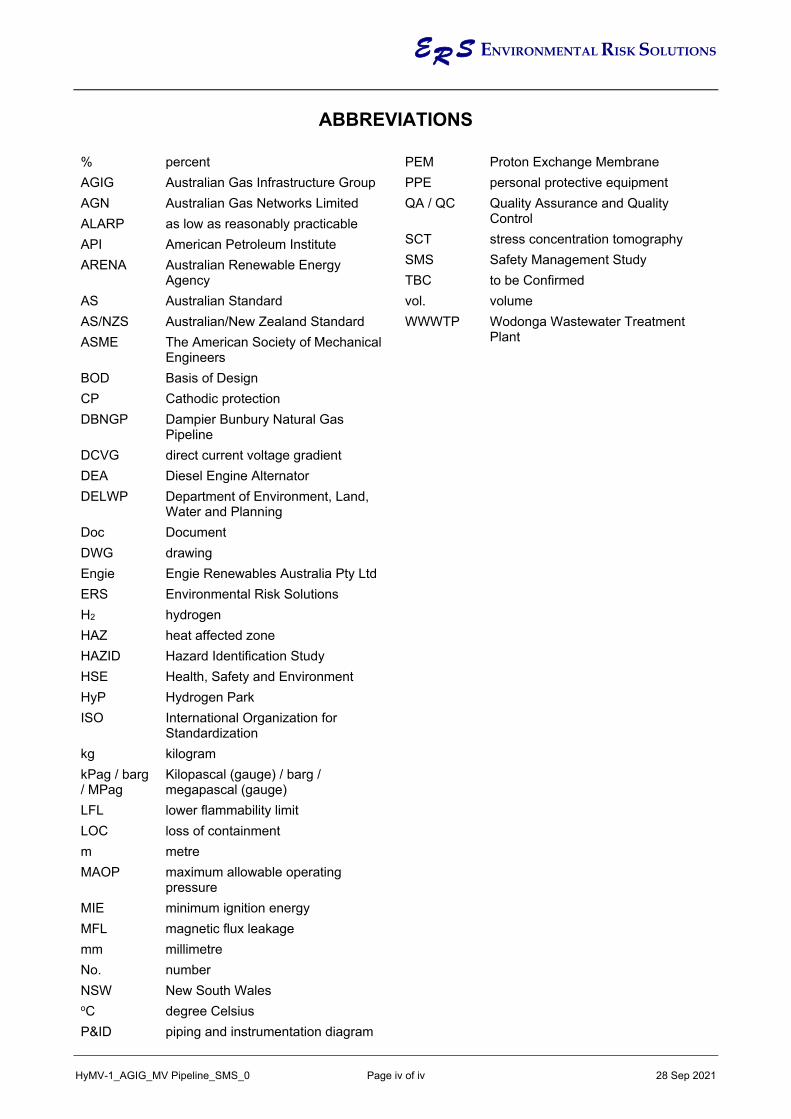
ER S ENVIRONMENTAL RISK SOLUTIONS
HyMV-1_AGIG_MV Pipeline_SMS_0 Page iv of iv 28 Sep 2021
ABBREVIATIONS % percent AGIG Australian Gas Infrastructure Group
AGN Australian Gas Networks Limited
ALARP as low as reasonably practicable
API American Petroleum Institute
ARENA Australian Renewable Energy Agency
AS Australian Standard
AS/NZS Australian/New Zealand Standard
ASME The American Society of Mechanical Engineers
BOD Basis of Design
CP Cathodic protection DBNGP Dampier Bunbury Natural Gas
Pipeline DCVG direct current voltage gradient DEA Diesel Engine Alternator DELWP Department of Environment, Land,
Water and Planning Doc Document DWG drawing
Engie Engie Renewables Australia Pty Ltd
ERS Environmental Risk Solutions
H2 hydrogen
HAZ heat affected zone HAZID Hazard Identification Study
HSE Health, Safety and Environment HyP Hydrogen Park
ISO International Organization for Standardization
kg kilogram
kPag / barg / MPag
Kilopascal (gauge) / barg / megapascal (gauge)
LFL lower flammability limit LOC loss of containment m metre MAOP maximum allowable operating
pressure MIE minimum ignition energy MFL magnetic flux leakage mm millimetre No. number NSW New South Wales oC degree Celsius
P&ID piping and instrumentation diagram
PEM Proton Exchange Membrane
PPE personal protective equipment QA / QC Quality Assurance and Quality
Control SCT stress concentration tomography SMS Safety Management Study TBC to be Confirmed
vol. volume
WWWTP Wodonga Wastewater Treatment Plant

ER S ENVIRONMENTAL RISK SOLUTIONS
HyMV-1_AGIG_MV Pipeline_SMS_0 Page 1 of 7 28 Sep 2021
1. SUMMARY Australian Gas Networks (AGN), part of Australian Gas Infrastructure Group (AGIG) and Engie Renewables Australia Pty Ltd (Engie) have entered a joint venture in the Hydrogen Park Murray Valley project (HyP Murray Valley). HyP Murray Valley produces hydrogen (H2) via a 10 MW vendor supplied electrolyser co-located within the Wodonga Wastewater Treatment Plant (WWWTP). The renewable hydrogen gas will be blended with hydrogen gas at volumes of up to 10% to decarbonise gas supply in the nearby twin cities of Albury, NSW, and Wodonga, Victoria, with the potential to supply industry and transport sectors.
This project will be seeking funding as part of the Australian Renewable Energy Agency (ARENA) projects.
As part of AGIG’s commitment to Health, Safety and Environment (HSE) aspects, AGIG has commissioned Environmental Risk Solutions Pty Ltd (ERS) to undertake a Preliminary Safety Management Study (SMS) to address potential hazards associated with HyP Murray Valley’s hydrogen pipeline. The aim of this SMS is to ensure that all significant HSE hazards associated with the pipeline are reduced to levels that are ‘as low as reasonably practicable’ (ALARP). Additionally, outcomes from the Study will feed into the project design to assist in meeting corporate safety goals, regulatory obligations, and ‘duty of care’ requirements.
The Preliminary SMS was conducted by video conference on the 14th of September 2021 using methodology based on AS 2885.8:2018, ‘Pipelines – Gas and liquid petroleum Pipeline safety management’.
Where there was an opportunity to improve the design of the facility to meet the principle of ALARP, Actions were developed which have been drafted in a format whereby they are standalone and will withstand the test of time with regard to understanding the ‘what, where and why’ of the aspect under consideration. The Workshop generated 18 Actions (provided in Appendix A) identifying opportunities to reduce the level of risk as incumbent with the principles of ALARP.
Key Actions included aspects such as: • Confirming design intent and improving design: by providing slabbing under the
drains alongside the road crossing, confirming design parameters for pipeline aligns with risk assessment in particular aspects of hydrogen embrittlement, reviewing opportunity to minimise fatigue by pressure fluctuations, reviewing provisions for pigging to enable line inspection, reviewing material selection with regard to hydrogen compatibility, reviewing requirements for odorization, reviewing use of tapes at connections to indicate hydrogen leak, reviewing requirement of antistatic PPE, reviewing depths of pipeline with regard to heavy cattle truck loads, reviewing vehicular protection at injection compound, considering requirement for MDR validation (Actions 1, 3, 4, 5, 6, 8, 9, 11, 12, 15 & 18).
• Developing procedures: by developing a construction procedure covering welding with regard to heat affected zones and hydrogen embrittlement (Actions 2).
• Reviewing corrosion protection: by reviewing interaction between connecting pipelines, including in the design any additional cathodic protection with regard to interaction of parallel voltage lines, undertaking AC mitigation study, reviewing interaction of proposed solar panel installation (Actions 7, 13, 14 & 16).
• Considering lessons learnt: by reviewing recommendations from the Kjorbo incident (Actions 10).
• Design verification: by considering requirement for a third-party design review (Actions 17).

ER S ENVIRONMENTAL RISK SOLUTIONS
HyMV-1_AGIG_MV Pipeline_SMS_0 Page 2 of 7 28 Sep 2021
2. INTRODUCTION AGN, part of AGIG, and Engie have entered a joint venture in the HyP Murray Valley Project. HyP Murray Valley produces hydrogen via a 10 MW vendor supplied electrolyser co-located within the Wodonga Wastewater Treatment facility. The renewable hydrogen gas will be blended with hydrogen gas at volumes of up to 10% to decarbonise gas supply in the nearby twin cities of Albury, NSW, and Wodonga, Victoria, with the potential to supply industry and transport sectors.
The major equipment items for the project include: • Vendor supplied Proton Exchange Membrane (PEM) Electrolyser Package • Hydrogen Compressor Package and Cooler • Hydrogen Buffer Storage • Hydrogen Storage Packages • Waste Water and Fire Water Storage Tanks • Diesel Engine Alternator (DEA) • Instrument Air Compressor Package, Dryer and Receiver • Transformers • Tube trailer loading area (Phase 2) • Hydrogen Injection Skid • Hydrogen Pipeline
The hydrogen injection skid is located adjacent to the existing Albury/Wodonga Gas Pipeline approximately 530 m from the Hydrogen Facility. A 600 m DN100 pipeline will be used to supply hydrogen to the injection skid.
Figure 2-1 HyP Murray Valley Graphical Impression

ER S ENVIRONMENTAL RISK SOLUTIONS
HyMV-1_AGIG_MV Pipeline_SMS_0 Page 3 of 7 28 Sep 2021
3. OBJECTIVES The objectives of this SMS were to: • identify and document potential hazards by systematically reviewing relevant drawings
and associated documentation • identify and document potential consequences of realisation of those hazards • identify and document planned or proposed safeguards • identify and document proposed safety measures and providing recommendations
such that the risks would be reduced to ALARP • prepare a report and SMS register detailing the findings of the review
4. SCOPE, TIMING & STUDY TEAM
4.1 Scope
The scope of this SMS includes the HyP Murray Valley hydrogen supply pipeline.
The SMS did not review the following:
1. Construction activity hazards.
2. Commissioning activity hazards.
3. Consideration of any project management risk issues related to schedule, budget or quality in the delivery of the project.
4. Review of the system beyond the nominated battery limits.
5. Review of physical / spatial arrangements, layouts, physical constraints on entry, exit, or maintenance tasks, including lay-down, platforms and ladder access. Note, other design review methods are more appropriate for this task.
6. Review of ancillary systems not directly related to the process (e.g. hydraulic, pneumatic or electrical systems).
4.2 Timing & Study Team
The SMS was conducted via video conference on the 14th of September 2021.
Table 4-1 lists the SMS team comprising personnel from AGIG, Attexo, DELWP, Energy Safe Victoria, HOLD and ERS. There is no signed attendees list because the session was conducted by video conferencing.

ER S ENVIRONMENTAL RISK SOLUTIONS
HyMV-1_AGIG_MV Pipeline_SMS_0 Page 4 of 7 28 Sep 2021
Table 4-1 Preliminary SMS Workshop Team
Company Name Discipline / Position
AGIG
Tim Aujard Head of Asset Performance
Jacques de Michel Senior Corrosion and Protection Engineer
Jeff Kong Asset Strategy
Hugo Kuhn Head of Engineering
Troy Praag Head of Network Strategy and Planning
Jignesh Shah ECI Engineer
Andrew Stanwix Senior Mechanical Engineer
Nghia Truon Pipeline Development Manager
John Quigley Manager, GIS
Attexo Jim Fjeldsoe Principal Consultant
DELWP Kimberley Cooper Senior Policy Officer
Energy Safe Victroia
Enzo Alfonsetti Manager, Gas Applicance Safety
Zubair Cheema Senior Engineer
Louie Li Regulatory Assurance
Hydrogen Consultant Robert Davis Consultant
ERS Geoff Penno Team Lead

ER S ENVIRONMENTAL RISK SOLUTIONS
HyMV-1_AGIG_MV Pipeline_SMS_0 Page 5 of 7 28 Sep 2021
5. METHODOLOGY The SMS procedure consisted of a team-based approach of applying guidewords to assist in identifying hazards, their causes, consequences, and safeguards to prevent or mitigate the hazard. Where a hazard matter was identified and a design solution was established within the study, that solution was recommended as an Action to be undertaken. If a solution was not proposed within a reasonable time-period during the study, then the team recommended that an Action be addressed outside of the study.
The methodology employed for the SMS was based on AS 2885.6 ‘Pipelines – Gas and liquid petroleum, Part 6: Pipeline safety management’.
An AGIG Pipeline SMS template was used for the study. This template includes a list of generic pipeline guidewords. Further taking account the peculiar hazards associated with hydrogen, additional guidewords were added prior to and during the study in the form of a brainstorming exercise to tailor the scope of the study to address the hazards associated with the unique properties exhibited by hydrogen gas.
Appendix B, ‘Preliminary Hydrogen Pipeline SMS Worksheet’, details cause, consequences, and safeguards associated with the list of guidewords relating to potential hazards. Where the level of risk was considered not to have been reduced to ALARP, recommendations were made to achieve the same.
Collectively the study team made the decision to not undertake risk ranking. If required, risk ranking will be undertaken subsequent to the study.

ER S ENVIRONMENTAL RISK SOLUTIONS
HyMV-1_AGIG_MV Pipeline_SMS_0 Page 6 of 7 28 Sep 2021
6. PIPELINE DESCRIPTION
6.1 Pipeline Design
The 600 m DN100 HyP Murray Valley hydrogen pipeline has the following design parameters.
Table 6-1 HyP Murray Valley Hydrogen Pipeline Design Parameters
Parameter Value
Asset Hydrogen Park – Murray Valley Location Wodonga, Victoria Start HyP Murray Valley Plant Finish Injection Compound at PL219 Pipeline Length (m) ~600 Diameter DN100 MAOP (MPag) 3.0MPa Wall Thickness (mm) 6 Pipe Type API 5L X42 Coating Type FBE (TBA) Depth of Cover (mm) 1,219 (48” min) Cathodic Protection Sacrificial Anode (TBA) Design Standard ANSI B31.12 Safety Management Standard
AS2885
Measurement Length – 4.7kW/m2 (m)
37
Design Factor 10% Puncture – GeneralPurpose Tooth (T)
>55
Puncture - Single Tiger / Penetration Tooth (T)
15
Rupture - Single Tiger / Penetration Tooth (T)
>55
Rupture - Tiger (T) >55Odorisation Unodorised

ER S ENVIRONMENTAL RISK SOLUTIONS
HyMV-1_AGIG_MV Pipeline_SMS_0 Page 7 of 7 28 Sep 2021
7. RESULTSAppendix A: contains the Pipeline SMS Action Summary Report that includes a list of
recommended Actions from the study, which are drafted to enable the Action to be understood in a format whereby they are standalone and will withstand the test of time with regard to understanding the ‘what, where and why’ of the aspect under consideration. Close-out of Actions will be documented and managed by AGIG via internal systems, including assignment of priority and responsibility and assurance of adequacy of measures taken within planned timeframes.
Appendix B contains the Pipeline SMS Worksheets. The study sheets detail hazard, cause, consequence, preventative and/or mitigative safeguards, and recommended Actions.
Appendix C: contains the workshop presentation slides.
8. CONCLUSIONThe Pipeline SMS Workshop generated 18 Actions which are summarised in Appendix A.A summary of the key Actions is detailed in the SUMMARY section of this report.

ER S ENVIRONMENTAL RISK SOLUTIONS
HyMV-1_AGIG_MV Pipeline_SMS_0 Appendix A - Page 1 of 2 28 Sep 2021
APPENDIX A
WORKSHOP ACTION SUMMARY REPORT

ER S ENVIRONMENTAL RISK SOLUTIONS
HyMV-1_AGIG_MV Pipeline_SMS_0 Appendix A - Page 2 of 2 28 Sep 2021
PRELIMINARY PIPELINE SMS WORKSHOP ACTION SUMMARY
Action 1: Review and document providing slabbing under the drains alongside the road crossing. Note, decision to be confirmed following site survey. Note, will be incorporated into alignment sheets. Due to potential difficulties with pigging, MFL pigging tools, and impact of hydrogen on the tool there may be an advantage of slabbing with plastic as opposed to concrete (holes so survey technique for line and DCVG and SCT can be undertaken). Note, if pigging is required consideration to be given to pigging backwards using natural gas as the motive force.
Action 2: Develop procedures with regard to construction, in particular with regard to welding and heat affected zones (HAZ) with regard to hydrogen embrittlement.
Action 3: Confirm design parameters for pipeline aligns with risk assessment, particularly with regard to hydrogen embrittlement.
Action 4: Consider and document the opportunity to minimise fatigue, particularly aspects of hydrogen embrittlement by limiting pressure fluctuations.
Action 5: Review and document providing pigging provisions to enable in line inspections including ability to attach pig launcher and receiver and associated bend diameter on pipeline so as to enable detection of hydrogen embrittlement and other factors.
Action 6: As part of the detailed design, review material selection and associated maintenance with regard to hydrogen compatibility e.g. gaskets, diaphragm on pressure regulators. Note, battery limits of pipeline to be confirmed with regard to equipment to be assessed as part of SMS and will be clarified in Detailed Design and to be confirmed with the Regulator. Note, the insulation joint is considered to be the most appropriate battery limit.
Action 7: Review and document the interaction between PL219 and hydrogen pipeline with regard to CP, both physical connection and general proximity.
Action 8: Review and document both regulatory and ALARP requirements for odorization. Note, taking account that AGIGs operation of DBNGP is unodorised (Victoria AGN does not have unodorised pipelines) and that there are no sensitive land users. The Team considered from an ALARP perspective odorization is not required. Note, PL219 is odorised and the 10% hydrogen addition will not impact odourant levels to the effect of affecting minimum limits.
Action 9: Review and document the use of tapes at connections whereby the tape changes colour if there is a hydrogen leak.
Action 10: Review and document avoiding blue metal or similar that may result in an ignition source taking account of the Kjorbo incident (Norway) recommendations on avoidance of blue metal.
Action 11: Review and document the requirement for antistatic PPE taking account the hazards of hydrogen i.e. low minimum ignition energy.
Action 12: Review and document the depth of pipeline and/or cover with regard to farmer’s access road taking account cattle truck loads. Note, this may require a designated access.
Action 13: Include in the design any addition CP requirement with regard to the parallel 66 kV. As part of the study consider earth rise due to fault condition. Note, 11 kV will be placed on same poles. As part of this action also review ~330 kV at a distance (~200 m distance). As part of this action consult with Oznet with regard to proposed and existing infrastructure.
Action 14: Complete AC mitigation study during the design phase.
Action 15: Review and document vehicle collision barriers for injection compound.
Action 16: Review and document the potential impact of the proposed solar panel installation with regard potential impacts on CP.
Action 17: Consider and document requirement for a 3rd party design review.
Action 18: Consider and document requirement for a MDR validation. Note, pre-mobilisaton check is normal practice.

ER S ENVIRONMENTAL RISK SOLUTIONS
HyMV-1_AGIG_MV Pipeline_SMS_0 Appendix B - Page 1 of 17 28 Sep 2021
APPENDIX B
PRELIMINARY HYDROGEN PIPELINE SAFETY MANAGEMENT STUDY WORKSHEET
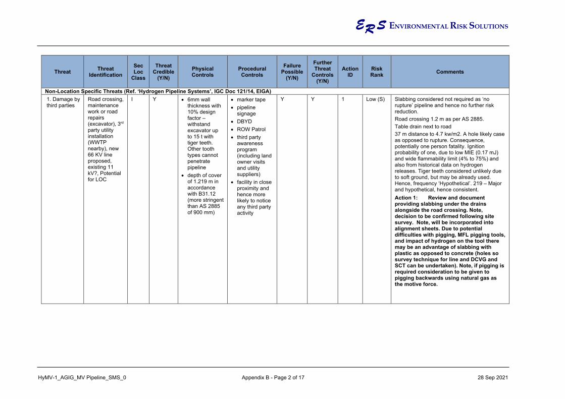
ER S ENVIRONMENTAL RISK SOLUTIONS
HyMV-1_AGIG_MV Pipeline_SMS_0 Appendix B - Page 2 of 17 28 Sep 2021
Threat Threat Identification
Sec Loc
Class
Threat Credible
(Y/N) Physical Controls
Procedural Controls
Failure Possible
(Y/N)
Further Threat
Controls (Y/N)
Action ID
Risk Rank Comments
Non-Location Specific Threats (Ref. ‘Hydrogen Pipeline Systems’, IGC Doc 121/14, EIGA) 1. Damage by third parties
Road crossing, maintenance work or road repairs (excavator), 3rd party utility installation (WWTP nearby), new 66 KV line proposed, existing 11 kV?, Potential for LOC
I Y • 6mm wall thickness with 10% design factor – withstand excavator up to 15 t with tiger teeth. Other tooth types cannot penetrate pipeline
• depth of cover of 1.219 m in accordance with B31.12 (more stringent than AS 2885 of 900 mm)
• marker tape • pipeline
signage • DBYD • ROW Patrol • third party
awareness program (including land owner visits and utility suppliers)
• facility in close proximity and hence more likely to notice any third party activity
Y Y 1 Low (S) Slabbing considered not required as ‘no rupture’ pipeline and hence no further risk reduction. Road crossing 1.2 m as per AS 2885. Table drain next to road 37 m distance to 4.7 kw/m2. A hole likely case as opposed to rupture. Consequence, potentially one person fatality. Ignition probability of one, due to low MIE (0.17 mJ) and wide flammability limit (4% to 75%) and also from historical data on hydrogen releases. Tiger teeth considered unlikely due to soft ground, but may be already used. Hence, frequency ‘Hypothetical’. 219 – Major and hypothetical, hence consistent. Action 1: Review and document providing slabbing under the drains alongside the road crossing. Note, decision to be confirmed following site survey. Note, will be incorporated into alignment sheets. Due to potential difficulties with pigging, MFL pigging tools, and impact of hydrogen on the tool there may be an advantage of slabbing with plastic as opposed to concrete (holes so survey technique for line and DCVG and SCT can be undertaken). Note, if pigging is required consideration to be given to pigging backwards using natural gas as the motive force.

ER S ENVIRONMENTAL RISK SOLUTIONS
HyMV-1_AGIG_MV Pipeline_SMS_0 Appendix B - Page 3 of 17 28 Sep 2021
Threat Threat Identification
Sec Loc
Class
Threat Credible
(Y/N) Physical Controls
Procedural Controls
Failure Possible
(Y/N)
Further Threat
Controls (Y/N)
Action ID
Risk Rank Comments
2. Auguring Installation of or replacement of electricity poles – will be deeper than proposed pipeline depth. Fence posts – typically less than 500 mm Potential LOC
I Y • 6 mm wall thickness with 10% design factor – withstand excavator up to 15 t with tiger teeth. Other tooth types cannot penetrate pipeline, will provide protection for fence pole augers but not power pole augers
• depth of cover of 1.219 m in accordance with B31.12 (more stringent than AS 2885 of 900 mm) for fence posts, not for power line poles.
• separation distance from the poles
• ‘no rupture’ pipe
• circular pipe likely to deflect pipe
• pipeline signage
• DBYD • ROW Patrol • third party
awareness program (including land owner visits and utility suppliers)
• facility in close proximity and hence more likely to notice any third party activity
• permit required and activity will require a site watch (permit officer)
Y Y 1 Low (S) Note, power poles at 50 m and hence risk considered to be lower

ER S ENVIRONMENTAL RISK SOLUTIONS
HyMV-1_AGIG_MV Pipeline_SMS_0 Appendix B - Page 4 of 17 28 Sep 2021
Threat Threat Identification
Sec Loc
Class
Threat Credible
(Y/N) Physical Controls
Procedural Controls
Failure Possible
(Y/N)
Further Threat
Controls (Y/N)
Action ID
Risk Rank Comments
3. First partyinterference
Pipeline inspection works. LOC considered not credible.
• 6 mm wallthickness with10% designfactor –withstandexcavator upto 15 t withtiger teeth.Other toothtypes cannotpenetratepipeline, willprovideprotection forfence poleaugers but notpower poleaugers
• depth of coverof 1.219 m inaccordancewith B31.12(more stringentthan AS 2885of 900 mm) forfence posts,not for powerline poles.
• ‘no rupture’pipe
• marker tape• pipeline
signage• competent
operators• AGIG
permittingsystem (PTW)
• excavationprocedures
• tiger teethexcavator willnot be allowed,hencepuncture willnot occur,damage tocoating only
N N N/A N/A

ER S ENVIRONMENTAL RISK SOLUTIONS
HyMV-1_AGIG_MV Pipeline_SMS_0 Appendix B - Page 5 of 17 28 Sep 2021
Threat Threat Identification
Sec Loc
Class
Threat Credible
(Y/N) Physical Controls
Procedural Controls
Failure Possible
(Y/N)
Further Threat
Controls (Y/N)
Action ID
Risk Rank Comments
3rd party HDD Considered an unlikely event given proposed land uses. Potential for LOC
I Y • 6 mm wall thickness with 10% design factor – withstand excavator up to 15 t with tiger teeth. Other tooth types cannot penetrate pipeline, will provide protection for fence pole augers but not power pole augers
• circular pipe likely to deflect pipe
• pipeline signage (limited credit as may be undertaken at a distance)
• DBYD (limited credit as may be undertaken at a distance)
• ROW Patrol • third party
awareness program (including landowner visits and utility suppliers)
• facility in proximity and hence more likely to notice any third-party activity
Y N N/A Low (S) Hydrogen likely to be through drill path and hence direction jet fire impacting drill operator. Worst case single fatality. Likelihood considered ‘hypothetical’ for a fatality. Ground conditions such that aggressive HDD considered unlikely, however, as not confirmed, no credit given

ER S ENVIRONMENTAL RISK SOLUTIONS
HyMV-1_AGIG_MV Pipeline_SMS_0 Appendix B - Page 6 of 17 28 Sep 2021
Threat Threat Identification
Sec Loc
Class
Threat Credible
(Y/N) Physical Controls
Procedural Controls
Failure Possible
(Y/N)
Further Threat
Controls (Y/N)
Action ID
Risk Rank Comments
Hydrogen embrittlement
Potential for some materials, increased potential for LOC due to other causes.
II Y • part of design, fatigue life will be considered, X42 (or X52) considered appropriate (hydrogen service lower grade preferable). Design Factor of 10
• construction technique with regard to welding material and heat affected zones (HAZ)
• Inspections for cracking/blistering
Y N 2, 3, 4, 5
Low (S) Not large cyclical load and purpose design and overall considered low likelihood and deemed hypothetical. Action 2: Develop procedures with regard to construction, in particular with regard to welding and heat affected zones (HAZ) with regard to hydrogen embrittlement. Action 3: Confirm design parameters for pipeline aligns with risk assessment, particularly with regard to hydrogen embrittlement. Action 4: Consider and document the opportunity to minimise fatigue, particularly aspects of hydrogen embrittlement by limiting pressure fluctuations. Action 5: Review and document providing pigging provisions to enable in line inspections including ability to attach pig launcher and receiver and associated bend diameter on pipeline so as to enable detection of hydrogen embrittlement and other factors.

ER S ENVIRONMENTAL RISK SOLUTIONS
HyMV-1_AGIG_MV Pipeline_SMS_0 Appendix B - Page 7 of 17 28 Sep 2021
Threat Threat Identification
Sec Loc
Class
Threat Credible
(Y/N) Physical Controls
Procedural Controls
Failure Possible
(Y/N)
Further Threat
Controls (Y/N)
Action ID
Risk Rank Comments
Use of non-compatible materials and equipment at all operating conditions
Leak due to failure of incompatible gasket, diaphragm on pressure regulator or other fitting. Certain regulators have material that may become brittle.
I Y • Part of selection of materials, particularly with regard to hydrogen
• Detailed design will reflect maintenance regime for materials that may be affected by hydrogen.
Y Y Risk assessment not undertaken as limited information. Detailed design SMS will address. Action 6: As part of the detailed design, review material selection and associated maintenance with regard to hydrogen compatibility e.g. gaskets, diaphragm on pressure regulators. Note, battery limits of pipeline to be confirmed with regard to equipment to be assessed as part of SMS and will be clarified in Detailed Design and to be confirmed with the Regulator. Note, the insulation joint is considered to be the most appropriate battery limit.

ER S ENVIRONMENTAL RISK SOLUTIONS
HyMV-1_AGIG_MV Pipeline_SMS_0 Appendix B - Page 8 of 17 28 Sep 2021
Threat Threat Identification
Sec Loc
Class
Threat Credible
(Y/N) Physical Controls
Procedural Controls
Failure Possible
(Y/N)
Further Threat
Controls (Y/N)
Action ID
Risk Rank Comments
External corrosion due to improper cathodic protection
Accelerated corrosion due to insufficient CP leading LOC
I Y • Anodes (likely considering power line and length of line) or impressed current
• Pipeline coating
• CP surveys • pipe integrity
assessment program that may include ILI, CP, DCVG, dig up program depending on DCVG results or other
• periodic leakage survey (walk pipeline with gas detector) B31.12 requires min. of 12 monthly
• no blue metal use on site which may result in a spark
Y Y 7 Low (S) Given remote location worst credible would be a fatality. Unlikely if a person was in vicinity and would initially start as a pinhole leak. Hence frequency considered hypothetical. Note, gas not odorised. Note, B31.12 Cl 5.2.1requires line to be either piggable or will require periodically hydrotested. Action 7: Review and document the interaction between PL219 and hydrogen pipeline with regard to CP, both physical connection and general proximity. Action 8: Review and document both regulatory and ALARP requirements for odorization. Note, taking account that AGIGs operation of DBNGP is unodorised (Victoria AGN does not have unodorised pipelines) and that there are no sensitive land users. The Team considered from an ALARP perspective odorization is not required. Note, PL219 is odorised and the 10% hydrogen addition will not impact odourant levels to the effect of affecting minimum limits. Action 9: Review and document the use of tapes at connections whereby the tape changes colour if there is a hydrogen leak. Action 10: Review and document avoiding blue metal or similar that may result in an ignition source taking account of the Kjorbo incident (Norway) recommendations on avoidance of blue metal. Refer to Action for ILI
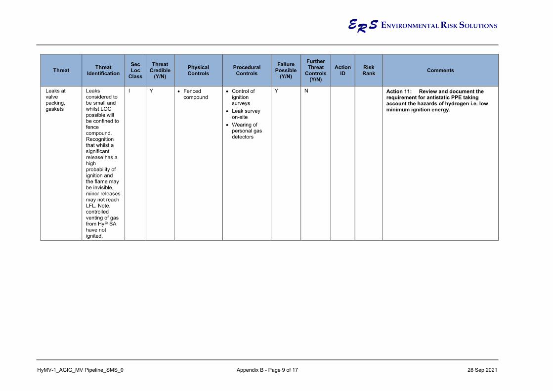
ER S ENVIRONMENTAL RISK SOLUTIONS
HyMV-1_AGIG_MV Pipeline_SMS_0 Appendix B - Page 9 of 17 28 Sep 2021
Threat Threat Identification
Sec Loc
Class
Threat Credible
(Y/N) Physical Controls
Procedural Controls
Failure Possible
(Y/N)
Further Threat
Controls (Y/N)
Action ID
Risk Rank Comments
Leaks at valve packing, gaskets
Leaks considered to be small and whilst LOC possible will be confined to fence compound. Recognition that whilst a significant release has a high probability of ignition and the flame may be invisible, minor releases may not reach LFL. Note, controlled venting of gas from HyP SA have not ignited.
I Y • Fenced compound
• Control of ignition surveys
• Leak survey on-site
• Wearing of personal gas detectors
Y N Action 11: Review and document the requirement for antistatic PPE taking account the hazards of hydrogen i.e. low minimum ignition energy.

ER S ENVIRONMENTAL RISK SOLUTIONS
HyMV-1_AGIG_MV Pipeline_SMS_0 Appendix B - Page 10 of 17 28 Sep 2021
Threat Threat Identification
Sec Loc
Class
Threat Credible
(Y/N) Physical Controls
Procedural Controls
Failure Possible
(Y/N)
Further Threat
Controls (Y/N)
Action ID
Risk Rank Comments
Over pressurisation of the pipeline
Potential failure of pressure regulation from storage
I Y • 21 MPag to 70% design factor, however have 30 MPag in storage cylinders. Note, 30 MPag will result in 98% SYS.
• overpressure protection to meet 10-5 failure frequency to make overpressure threats in the ‘hypothetical range’
• procedures on valve maintenance
Y N
Improper inerting procedure
Part of HAZID study.
Improper operation and maintenance of the pipeline
Failure to follow procedures
I Y • Maintenance program will be monitored for compliance and details to be included in SC for the pipeline. Will be part of the pipeline Licence at a high level.
Y N

ER S ENVIRONMENTAL RISK SOLUTIONS
HyMV-1_AGIG_MV Pipeline_SMS_0 Appendix B - Page 11 of 17 28 Sep 2021
Threat Threat Identification
Sec Loc
Class
Threat Credible
(Y/N) Physical Controls
Procedural Controls
Failure Possible
(Y/N)
Further Threat
Controls (Y/N)
Action ID
Risk Rank Comments
Abnormal loads due to land slide, floods, earthquakes, crossing of roads, railways
Floods – outside of Murray River flood plain Landside – not credible Earthquake – to be part of design Road crossing – e.g. B double cattle truck, road side drainage and reduced depth of cover.
I • Design will include earthquake consideration according to relevant AS
• Crossing loads to be considered and appropriate crossing cover
Risk assessment not undertaken as design preliminary and will be designed to eliminate threats from leading to a pipeline failure. Action 12: Review and document the depth of pipeline and/or cover with regard to farmer’s access road taking account cattle truck loads. Note, this may require a designated access.
Influence of other structures, such as high power electrical lines, electrical railways
High voltage 66 kV running parallel to the pipeline for a distance of ~ 100m and hence potential for induced voltages.
I Y • Design of CP – refer Action
Action 13: Include in the design any addition CP requirement with regard to the parallel 66 kV. As part of the study consider earth rise due to fault condition. Note, 11 kV will be placed on same poles. As part of this action also review ~330 kV at a distance (~200 m distance). As part of this action consult with Oznet with regard to proposed and existing infrastructure. Action 14: Complete AC mitigation study during the design phase.
Damage due to an abnormal event on a parallel pipe
N/A (PL219 considered very short parallel distance)

ER S ENVIRONMENTAL RISK SOLUTIONS
HyMV-1_AGIG_MV Pipeline_SMS_0 Appendix B - Page 12 of 17 28 Sep 2021
Threat Threat Identification
Sec Loc
Class
Threat Credible
(Y/N) Physical Controls
Procedural Controls
Failure Possible
(Y/N)
Further Threat
Controls (Y/N)
Action ID
Risk Rank Comments
Road accident or fire in the vicinity of above ground parts of the pipeline
Vehicle running into the injection compound leading to LOC Analyser compound leading tubing failure with relatively small release – not significant.
I Y Y Y 14 Intermediate
Note, in a 100 km/h zone and on inside bend. Note, limited ability to relocate as need to inject into PL219. Burying valve considered to cause other risk. Potential fatality. Need to hit pipeline, breach pipeline and be in vicinity of fire – overall frequency of ‘remote; Action 15: Review and document vehicle collision barriers for injection compound.
The radiation of a vent fire or a flare
Ignition of vent. Vents at height to not affect on-site and pipeline at a distance from the vent hence no significant threat
Non-Location Specific Threats (General Bacterial Corrosion
Considered not a threat for hydrogen.
Corrosion due to high temp operation
Considered not a threat for hydrogen.
Exceeding 110% MAOP op pipeline
As above
External corrosion caused by AC interference
As above for power lines

ER S ENVIRONMENTAL RISK SOLUTIONS
HyMV-1_AGIG_MV Pipeline_SMS_0 Appendix B - Page 13 of 17 28 Sep 2021
Threat Threat Identification
Sec Loc
Class
Threat Credible
(Y/N) Physical Controls
Procedural Controls
Failure Possible
(Y/N)
Further Threat
Controls (Y/N)
Action ID
Risk Rank Comments
External corrosion caused by coating defects
As above
External corrosion caused by corrosive environments
Soil data indicates relatively standard – agriculture and some biological and low pH, not significant. No Acid Sulphate soils
External corrosion caused by DC/foreign structure interference
Pipeline being tied into, refer to Action on interaction of CP. Solar panel installation
Action 16: Review and document the potential impact of the proposed solar panel installation with regard potential impacts on CP.
External corrosion caused by galvanic effects
Relevant to earthing. Standard approach is to use zinc ribbon (for plant and injection skid) Monolithic joint Part of design
External corrosion caused by hydrogen induced cracking
Refer above

ER S ENVIRONMENTAL RISK SOLUTIONS
HyMV-1_AGIG_MV Pipeline_SMS_0 Appendix B - Page 14 of 17 28 Sep 2021
Threat Threat Identification
Sec Loc
Class
Threat Credible
(Y/N) Physical Controls
Procedural Controls
Failure Possible
(Y/N)
Further Threat
Controls (Y/N)
Action ID
Risk Rank Comments
External corrosion caused by insufficient CP
Refer above
External corrosion caused by stress corrosion cracking
High pH and high temperature conditions and not applicable. Liquid epoxy coating. Overall design considerations
Failure of design and configuration and equipment features
Incorrect design. Whilst credible a 3rd party design validation may be considered.
Action 17: Consider and document requirement for a 3rd party design review.
Failure of maintenance system
Refer above
Failure to install equipment in accordance with specified design
Third party MDR (manufacturers data records) validation may be under Pre-mobilisation check equivalent to Pre Start Safety Review (PSSR)
Battery limit considered to include line up to cosasco fitting flange Action 18: Consider and document requirement for a MDR validation. Note, pre-mobilisaton check is normal practice.

ER S ENVIRONMENTAL RISK SOLUTIONS
HyMV-1_AGIG_MV Pipeline_SMS_0 Appendix B - Page 15 of 17 28 Sep 2021
Threat Threat Identification
Sec Loc
Class
Threat Credible
(Y/N) Physical Controls
Procedural Controls
Failure Possible
(Y/N)
Further Threat
Controls (Y/N)
Action ID
Risk Rank Comments
Incorrect design or engineering analysis
Refer above
Incorrect operation of control and protective equipment
Fail safe design e.g. SDV is a FC valve. Not considered further
Internal corrosion due to contaminants in gas
Water following hydrotest – assessed as part of hydrotest process. Not considered further.
Internal erosion
Designed to below 30 m/s and clean gas. Considered not a threat.
Lightning Surge diverters on monolithic joints and earthing design takes account of hydrogen services.
Undetected or unreported critical weld defects
Refer above with regard to HAZ. All welds 100% NDT. Seamless pipe TBC. Hydrotest undertaken.

ER S ENVIRONMENTAL RISK SOLUTIONS
HyMV-1_AGIG_MV Pipeline_SMS_0 Appendix B - Page 16 of 17 28 Sep 2021
Threat Threat Identification
Sec Loc
Class
Threat Credible
(Y/N) Physical Controls
Procedural Controls
Failure Possible
(Y/N)
Further Threat
Controls (Y/N)
Action ID
Risk Rank Comments
Undetected or unreported damage to pipe
Pipe inspection on arrival. Hydrotest.
Location Specific Threats Road crossing / maintenance
Refer above with regard to farmer access. Refer above where pipeline crossing Bidstrup Road and slabbing.
Utilities crossing / maintenance
Refer above and future industrial development with regard to utilities installation
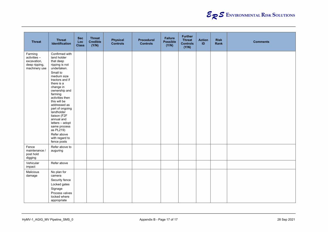
ER S ENVIRONMENTAL RISK SOLUTIONS
HyMV-1_AGIG_MV Pipeline_SMS_0 Appendix B - Page 17 of 17 28 Sep 2021
Threat Threat Identification
Sec Loc
Class
Threat Credible
(Y/N) Physical Controls
Procedural Controls
Failure Possible
(Y/N)
Further Threat
Controls (Y/N)
Action ID
Risk Rank Comments
Farming activities – excavation, deep ripping, machinery use
Confirmed with land holder that deep ripping is not undertaken. Small to medium size tractors and if there is a change in ownership and farming activities then this will be addressed as part of ongoing landholder liaison (F2F annual and letters – adopt same process as PL219) Refer above with regard to fence posts
Fence maintenance / post hold digging
Refer above to auguring
Vehicular impact
Refer above
Malicious damage
No plan for camera Security fence Locked gates Signage Process valves locked where appropriate

ER S ENVIRONMENTAL RISK SOLUTIONS
HyMV-1_AGIG_MV Pipeline_SMS_0 Appendix C – Cover Page 28 September 2021
APPENDIX C
PRESENTATION SLIDES

HyP Murray ValleyPreliminary Safety Management Study – H2 Pipeline
14 September 2021

AGENDA
• SMS Introduction and Project Description
• Overview of Pipeline Route (Location Classification)
• Review of non-location specific threats
• Review of location specific (external interference) threats
• Workshop Closeout
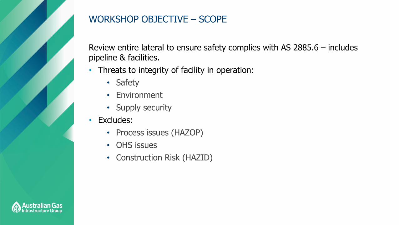
WORKSHOP OBJECTIVE – SCOPE
Review entire lateral to ensure safety complies with AS 2885.6 – includes pipeline & facilities.• Threats to integrity of facility in operation:
• Safety• Environment• Supply security
• Excludes:• Process issues (HAZOP)• OHS issues• Construction Risk (HAZID)

HYDROGEN PARK MURRAY VALLEY - OVERVIEW

HYDROGEN PARK MURRAY VALLEY - PFD

HYDROGEN PARK MURRAY VALLEY – PRESSURE CONTROL

HYDROGEN PARK MURRAY VALLEY – FLOW CONTROL

PIPELINE AND GAS DISTRIBUTION NETWORK

HYDROGEN PARK MURRAY VALLEY

PIPELINE ROUTE

PIPELINE ROUTE

SURROUNDING LAND USE
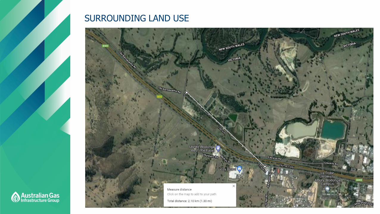
SURROUNDING LAND USE

HYDROGEN PIPELINE
Detail
Asset Hydrogen Park – Murray Valley
Location Wodonga, Victoria
Start HyP Murray Valley Plant
Finish Injection Compound at PL219
Pipeline Length (m) ~600
Diameter DN100
MAOP (MPag) 3.0MPa
Wall Thickness (mm) 6
Pipe Type API 5L X42
Coating Type FBE (TBA)
Depth of Cover (mm) 1,219 (48” min)
Cathodic Protection Sacrificial Anode (TBA)

HYDROGEN PIPELINE
Detail
Design Standard ANSI B31.12
Safety Management Standard AS2885
Measurement Length – 4.7kW/m2 (m) 37
Design Factor 10%
Puncture – General Purpose Tooth (T) >55
Puncture - Single Tiger / Penetration Tooth (T) 15
Rupture - Single Tiger / Penetration Tooth (T) >55
Rupture - Tiger (T) >55
Odorisation Unodorised

AS2885 PROCESS
The workshop conducted in accordance with AS2885.6-2018.

AS2885 PROCESS – THREAT ANALYSIS
• Identify all possible threats
• Usually emphasis on external interference
• But also:• Corrosion• Natural events• Electrical effects• Malicious damage• Operations & maintenance• Defects in design, materials or
construction
THREAT TYPES
Repetitive “Generic” threats
Non-location specific threats
Location/Feature specific threats (line “Walk”)
Facilities
“All controls fail”

AS2885 PROCESS – THREAT ANALYSIS
• Mandatory requirements for protection against damage by external interference
• Physical - (burial, penetration resistance, exclusion barrier)
• Procedural - (awareness, patrols, DBYD, remote intrusion monitoring, etc)
• Where external interference not applicable:
• Design actions• Operational actions
STANDARD THREAT CONTROLS
Excavators, Augers etc
Wall thickness?
Penetration resistance?
Cover?
Operator Patrols?

DESIGN FOR PROTECTION – GENERAL REQUIREMENTS
• External interference protection shall be achieved by selecting a combination of physical and procedural controls:
• R1 and R2 location classes• A minimum of 1 physical control; and• A minimum of 2 procedural controls shall be applied
• T1 and T2 location classes• A minimum of 2 physical controls; and• A minimum of 2 procedural controls shall be applied
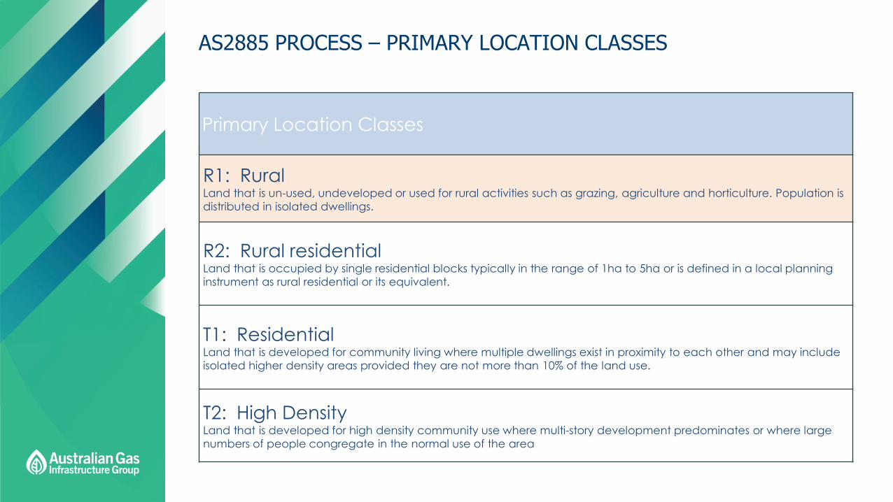
AS2885 PROCESS – PRIMARY LOCATION CLASSES
Primary Location Classes
R1: Rural Land that is un-used, undeveloped or used for rural activities such as grazing, agriculture and horticulture. Population is distributed in isolated dwellings.
R2: Rural residentialLand that is occupied by single residential blocks typically in the range of 1ha to 5ha or is defined in a local planning instrument as rural residential or its equivalent.
T1: Residential Land that is developed for community living where multiple dwellings exist in proximity to each other and may include isolated higher density areas provided they are not more than 10% of the land use.
T2: High DensityLand that is developed for high density community use where multi-story development predominates or where large numbers of people congregate in the normal use of the area

AS2885 PROCESS – SECONDARY LOCATION CLASSES
Secondary Location Classes
S: SensitiveIdentifies land where the consequences of failure may be increased due to the developments associated (e.g.: hospital, school, prison). The design requirements for High Density shall apply.
I: IndustrialLand that is developed for industrial use (e.g.: factories, warehouses, car yards). The design requirements for Residential shall apply.
HI: Heavy IndustrialHeavy industrial use or toxic industrial use lands. Depending on the assessed severity (ie escalation potential for fire, or release of toxic or flammable meterials), the design requirements of R2, T1 or T2 shall be applied.
CIC: Common Infrastructure CorridorLand which because of its function results in multiple parallel infrastructure development within a common easement of reserve, or in easements which are in close proximity
W: SubmergedLand that is continuously or occasionally inundated with water to the extent that the inundation water, or activities associated with it, is considered a design condition affecting the design of the pipeline. Pipeline crossings of lakes, marshes, flood plains and navigable waterways are always included. Pipeline crossings of non-navigable waterways, rivers, creeks and streams, whether permanent or seasonal, are included where appropriate. The submerged class extends only to the estimated high water mark of the inundated area.


Our Role in the Gas IndustryWe deliver for customers across the gas supply chain serving the needs of producers, major energy users, and residential and business users.
AGIG’s ServicesWe design, construct, operate, maintain and manage gas infrastructure.
Our transmission pipelines
Transmission
Production and processing
Gas Supply Chain The process in which gas is produced and used; from the field to users.
Our Tubridgigas storage
Our power generation facilities
Our distribution networks
Our renewable gas facility
RetailRenewable gas
Distribution
Large users and power generationStorage


