Embed Size (px)
Citation preview
Scholars' Mine Scholars' Mine
Masters Theses Student Theses and Dissertations
1948
Hysteresis loss of supermalloy at different temperatures Hysteresis loss of supermalloy at different temperatures
Chester Ray Holland
Follow this and additional works at: https://scholarsmine.mst.edu/masters_theses
Part of the Physics Commons
Department: Department:
Recommended Citation Recommended Citation Holland, Chester Ray, "Hysteresis loss of supermalloy at different temperatures" (1948). Masters Theses. 4868. https://scholarsmine.mst.edu/masters_theses/4868
This thesis is brought to you by Scholars' Mine, a service of the Missouri S&T Library and Learning Resources. This work is protected by U. S. Copyright Law. Unauthorized use including reproduction for redistribution requires the permission of the copyright holder. For more information, please contact [email protected].
HYSTERESIS LOSS OF SUPEl1EALLOY
AT DIFFEHENT TEI';:PEHl':..TUHES
BY
CHESTEli PJl.Y HOLLAIID
A
THESIS
submitted to the faculty of the
SCHOOL OF l/IINES AND HETALLFRGY OF TI-}E UlTIVEi1SITY OF rUSSOURI
in partial :fulfillment of the VloI'k required for the
Degree of
fiL4.STER OF SCn::HCE, PHYSICS }:IAJOR
Rolla, Missouri
1948
Approved by ~1 ',--)--.--+I--':--v--~~~-'----~-:::'r--'---
- ii -
ACKNOWLEDGI,1ENT
The author wishes to express his appreciation to
Dr. Z. V. Harvali1\:, Associate Professor of Physics at
the 2issouri School of Mines and Metallurgy for his
suggestions and guidance throuGhout this investigation.
The cooperation received from the Western Electric
and the Bell Telephone Laboratories in furnishing
samples of their products for testing is deeply and
sincerely appreciated.
May the author thank the following: Dr. L. E.
Woodman, Dr. Z. V. Earvalik, and all members of the
Department of Physics for their interest and assistance
in this problem.
iii
TABLE OF COlTTEHTSPa,:;e
Aclmo\!vledgment.. .. .•• . . . . . . . . . . . . . . . . . . . . . . . . . •.•• ii
List of illustrations. • • • • • • • • • • • • • • • • • • • • • • • • • • • • iv
Lis t of tables.................................... v
Definitions •••••••••••••
Review of literature••••
Introduction•••••••• ..................................................................................
1
3
9
Domain theory of hysteresis loops ••••••••••••••••• 21
Derivation of the working eClua tions •••••• • • • • • • • • • 24
Discussion of the experiment •••••••••••••••••••••• 32
Preparation of the samples •••••••••••••••••••••••• 32
Neutralization of the Earth's magnetic field •••••• 34
The :magnetizing circuit........................... 37
Arrangements for different temperatures ••••••••••• 37
The working equations ••••••••••••••••••••••••••••• 37
Conclusions ••••••• ................................ 65
Errors •••••••••••••••.•••..•••.••••••.••••..•.•••• 68
Slumaary••••••••••••
Bibliography•••••••
...............................
...............................70
72
Curri culuill Vi tae ••••• • • • • • • • • • • • • • • • • • • • • • • • • • • • • • 74
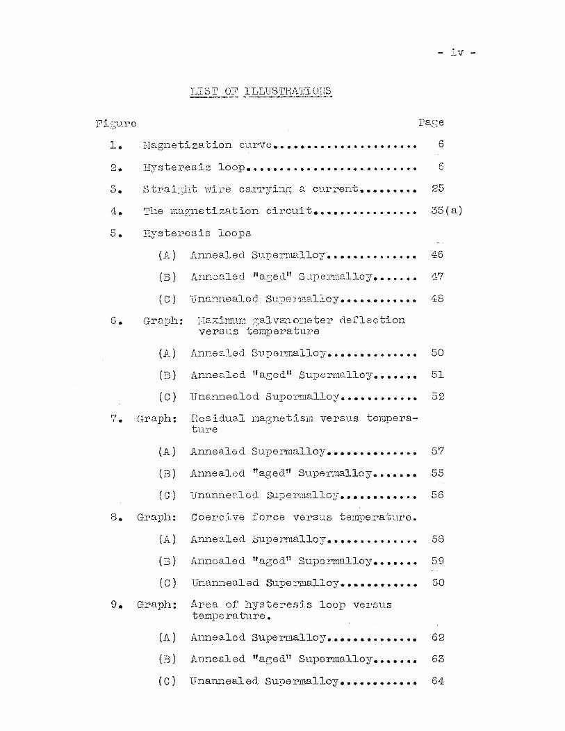
Figu.re
- iv -
Page
:Uagneti zat ion c"U.rve •••••••••••••••••••••• 6
2. Hysteresis loop.......................... 63. Straisht wire carryinG a current......... 25
4. The magnetization circuit•••••••••••••••• 35(a)
5. Hysteresis loops
(A)
(B)
(C)
6. Graph:
(A)
(B)
(C)
7. Graph:
Annealed Supermalloy.............. 46
Annealed llaged" SupeJ:rLilulloy....... 47
Una~Bealod Supermalloy............ 48
I-la.x.imum galV811.0ne'ter deflectionversus temperature
Annealed Supermalloy•••••••••••••• 50
Annealed "aged" Supermalloy••••••• 51
Unannealed Supermalloy•••••••••••• 52
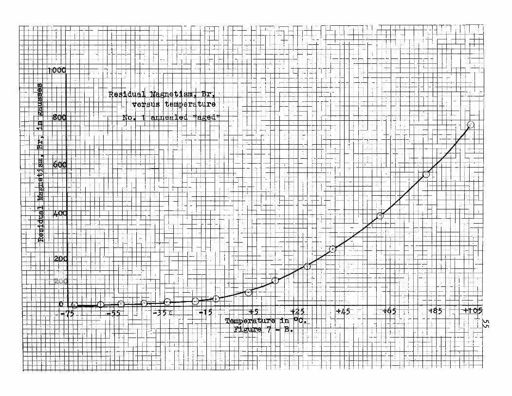
Residual magnetism versus temperature
(A) Annealed Supermalloy.............. 57
(B) Annealed ffaged" Supermalloy••••••• 55
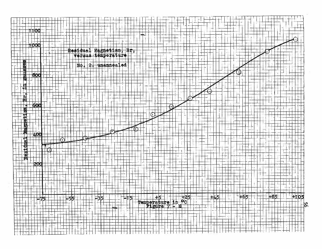
(C) Unannealed SUpennalloy•••••••••••• 56
8. Graph: Coercive force versus temperature.
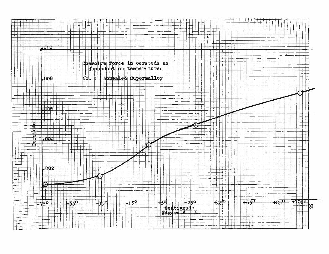
(A) Annealed Supermalloy•••••••••••••• 58
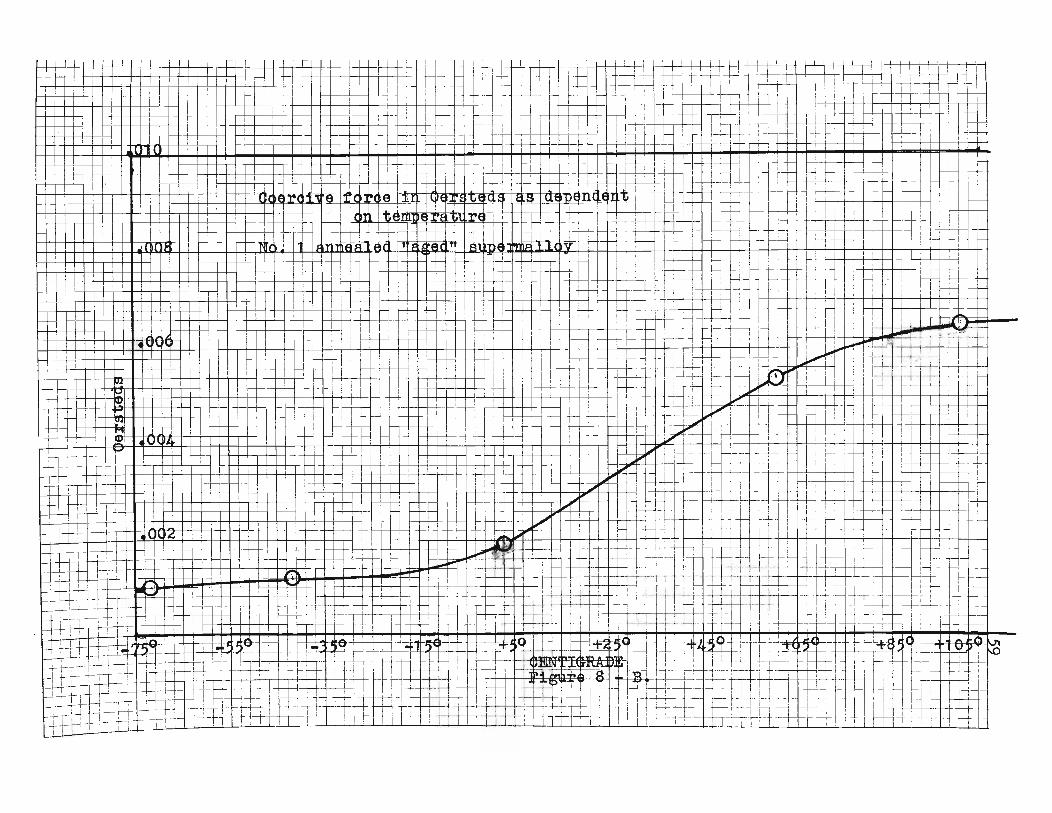
(B) Annealed "aged" Superrnalloy.. ••••• 59
(C) Unannealed Supermalloy............ 60
9. Graph: Area of hysteresis loop versustempe rature.
(A) Annealed Super.malloy•••••••••••••• 62
(B) Annealed "agedtl Supermalloy....... 63
(C) Unannealed Supermalloy............ 64
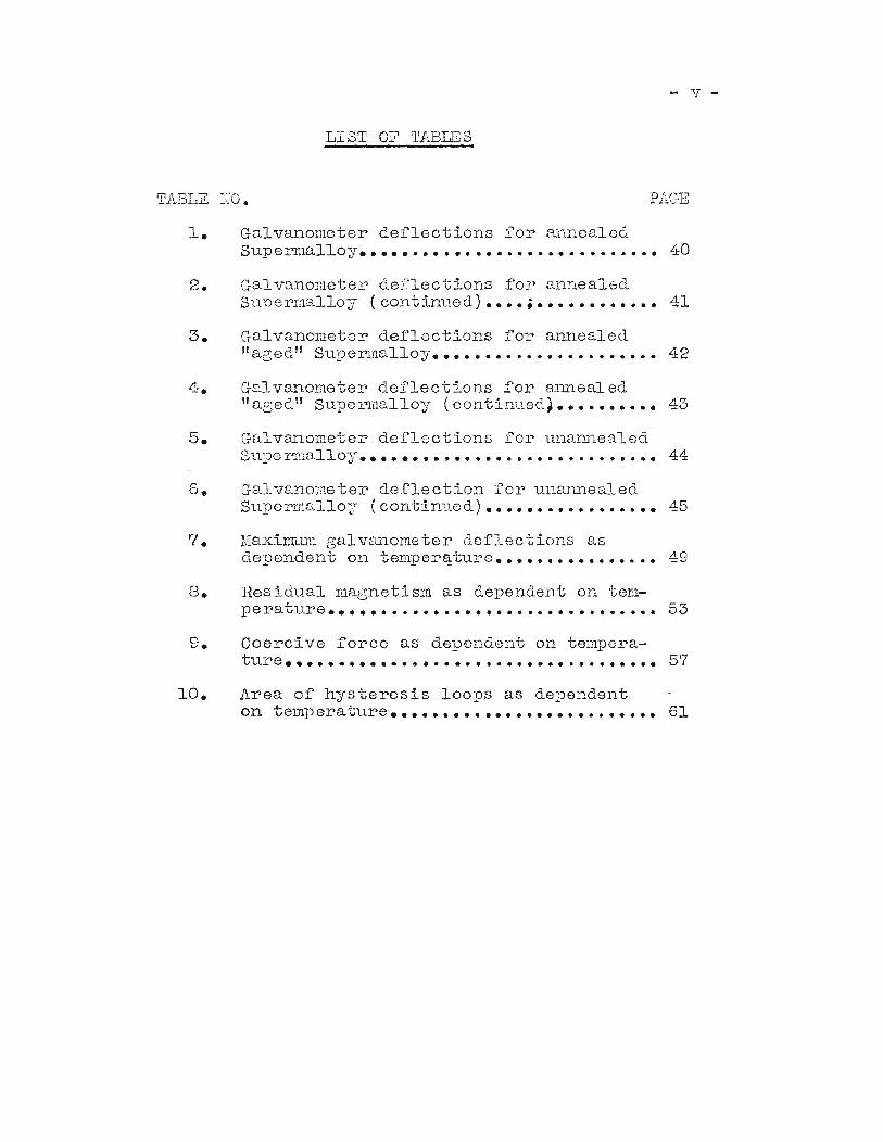
- v -
LIST OF rrABLES
TABLE NO. PAGE
1. Galvanometer deflections for annealedSupennalloy•••••••••••.••.••..••••...••• 40
2. G8-1 vanometer deflections for annealedSupermalloy (continued) •••• ; •••••••••••• 41
3. Galvanometer deflections for annealed"aged" Supermalloy•••••••..•.•••..•••••• 42
4. Galvanometer deflections for annealedlIaged ll Supermalloy (continued~•••••••••• 43
5. Galvanometer deflections for una~~ealed
Slll:)e rrnalloy••••••••••••.•. e.. • • • • • • • • • • •• 44
6. Gal vano:meter deflection for unannealedSuperm[~lloy (continued) ••••••••••••••••• 45
7. MaxirrRun galv2illometer deflections asdependent on temper~ture•••••••••••••••• 49
8. Residual magnetism as dependent on tera-l)eratv.re ••••••..•.•.••••.............. ". 53
9. Coercive force as dependent on tempera-ture •.••••••••....•..•...............•..• 57
10. Area of hysteresis loops as dependenton telnp erature. • • • • • • • • • • • • • • • • • • • • • • • •• 61
- 1 -
INTRODUCTION
The object of this investigation was to measure
the hysteresis loss of supermalloy at different tem
peratures, and to see if temperature had any effect
on hysteresis loss and permeability. The maximum
magnetizing current was held constant for all tem
peratures.
PRACTICAL APPLICATIONS OF HYSTERESIS
Hysteresis curves~ along with the energy-product
curves, the demagnetization curve, coercive force and
residual induction, which are points on the curve or can
be obtained easily from the curve, are of utmost impor
tance 1n determining the characteristics of a specimen
of iron or of any ferro-magnetic material. These
points are used 1n determining the proper heat treatment,
or in finding the stress or strain 1n steel. They are
used in determining the best alloy for a certain job.
For ex~ple; if you want a permanent magnet with certain
characteristics for an ammeter, etc., by running hysteresis
tests and by plotting energy-product curves, the best
alloy for the specified job can be found. In this case
a metal with a large energy-product curve, a large
- 2 -
hysteresis loss along with a large coercive and residual
force would be needed~ and dif£erent tests on dif£erent
allays will determine the proper one. Whereas, for an
alloy £or the use of a core of a radio transformer quite
different properties of the alloy are required as low
hysteresis loss, high permeability, low coercive and
residual force, and a small area within the energy-pro
duct curve, etc. Therefore, hysteresis tests would
determine the best alloy for this use.
By comparison of hysteresis curves of steel which
have been used excessively with standard specimens, any
weakness or expected ruptures can be round.
Hysteresis losses along with eddy current losses
cost the United states a lot of money, and anything that
cuts down on this loss is of great importance. LlOYd(l)
(1) Williams, S. RI Magnetic phenomena. McGraw-HillBook Company, New York, 1931, p. 55.
pointed out in 1910 that America alone had a financial
loss of approximately ten million dollars annually, due
to hysteresis loss. Therefore, a lot of money and research
have been spent and are being spent to find means of
cutting these losses down.
By stUdying the magnetization curves of various
alloys, and in particular the effects on these curves,
- 3 -
when special heat treatments are applied to the metals,
it has been possible to find alloys which will give
certain speciried magnetic properties. This is illustrated
by the discovery of permalloy(2) which possesses a very
(2) Arnold, H. D., and Elman, G. W., Permalloy, analloy o~ remarkable magnetic properties. Journalof Franklin Institute, Vol. 195, pp. 621-632, (1923).
high permeability for small magnetizing ~orces. Similarly,
the discovery of perminvar(3) is another example of what
(3) Elmen, G. W., Magnetic properties o~ perminvar.Journal of Franklin Institute, Vol. 206, pp. 317338, (1928).
can be accomplished along these lines for special uses.
DEFINITIONS
Oersted, in 1819, discovered that a magnetic field
surrounds a wire carrying a current. He also found that
the direction of the field about a current-carrying wire
is tangentially perpendicular to the wire and that the
intensity of the field diminishes in receding from the
wire. The lines of force about an isolated wire are
concentric with it, as can be proved by arranging i~
vertically and moving a suspended magnet or compass
around it.
- ~ -
When an electric current is sent through a solenoid
(a coil of wire wound uniformly in a long helix), the
region inside and near the helix becomes a magnetic
field. The magnetic field H at any point inside or near
the helix may be determined from the strength of the
current and the geometry of the helix. If a bar of any
ferromagnetic material, e.g. a bar of iron, is placed
inside the solenoid the iron becomes magnetized and the
magnetic qualities of the region about the helix are
changed. The magnetic flux through the region occupied
by the bar is much greater than it was before the bar
was placed there. This magnetic flux is referred to as
"lines of induction lt, the expression "lines of force"
being restricted to the flux when there is no magnetic
substance present. The number of lines ot induction
per unit area is called the "magnetic induction" or
"flux density" and is denoted by the symbol B.
Now suppose a ring of some magnetic material like
mild steel is wound uniformly with a magnetizing coil
of wire. Let the iron ring be first completely demag
netized as follows: An alternating current of, e.g.
50 cyoles is passed through the magnetizing coil, P,
having such a strength that the iron becomes magnetized
to saturation. The current is then gradually reduced in
strength by means of a resistance in series with the
coil P, or alternatively by reducing the field strength
- 5-
of the alternator. Atter the current has been reduced
to as low a value as possible in this way, the alternator
is shut down and when it has completely come to rest, the
coil P is disconnected. In this way the iron will have
become thoroughly demagnetized.
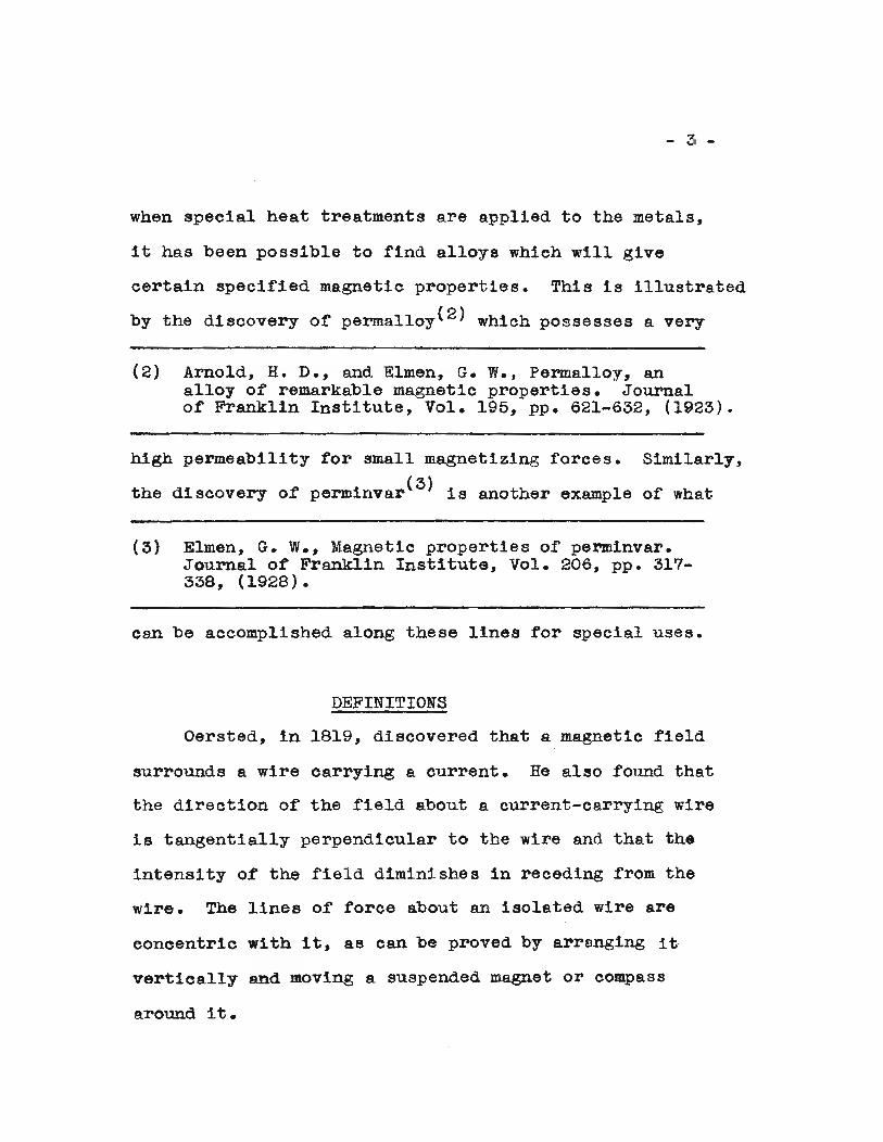
If a small value of direct current be now passed
through the exciting coil the curve connecting the
magnetic induction B and the magnetic force H will take
some such shape as Oa in Figure 1, that is, the values
of B will increase at a moderate rate as the value of
H increases.
When the value of the magnetization force H has
reached a value of one or two oerstads, the curve rises
much more rapidly as shown at ab. For high values ot
H, the curve bends back towards the H axis as shown at
bc. If this given sample of iron is SUbjected to a
uniformly increasing magnetizing field, the resulting
flux density B does not vary linearly with the cor
responding magnetizing field intensity H, but changes
at a variable rate as shown by the curve Oabc in Figure 1.
The connection between B and H shown by the curve
Oabc is the "magnetization curve" o:f the iron. When a
sufficiently large value of the magnetizing field is
reached, as specified by the point C, any further
increase in the magnetizing field produces little or
no increase in the :flux density of the iron and the iron
is said to be magnetically saturated.
6
16,000..- --.,.
14,000
12, 000
10,000
"Cl). 6000
4000
2000
5. 10
H ~Figure 1.
1 5 20
pI-f3 -IIIIIII
k
i 4,000
13,00 d
Figure 2.
)
- or; ..
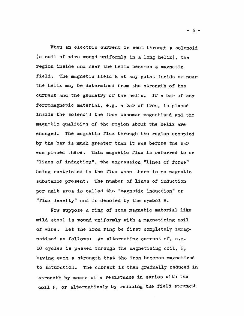
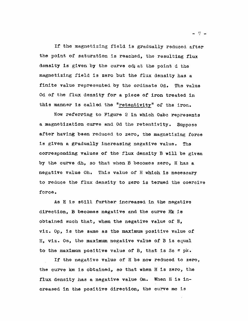
If the magnetizing field is gradually reduced after
the point or saturation is reached, the resulting flux
density is given by the curve c~ at the point d the
magnetizing rield is zero but the rlux density has a
finite value represented by the ordinate Ode The value
Od of the flux density for a piece of iron treated in
this manner is called the "retentivitz" of the iron.
Now referring to Figure 2 in which Oabc represents
a magnetization curve and Od the retentiVity. Suppose
after having been reduced to zero, the magnetizing force
is given a gradually increasing negative value. The
corresponding values of the flux density B will be given
by the curve db, so that when B becomes zero, H has a
negative value Oh. This value of H which is necessary
to reduce the flux density to zero i8 termed the coercive
force.
As H is still further increased in the negative
direction, B becomes negative and the curve Hk is
obtained such that, when the negative value of H,
viz. Op, is the same as the maximum positive value of
H, viz. Os, the maximum negative value of B is equal
to the maximum positive value of B, that is Sc = pk.
If the negative value of H be now reduced to zero,
the curve km is obtained, so that when H is zero, the
flux density has a negative value Om. When H is in
creased in the positive direction, the eurve me is
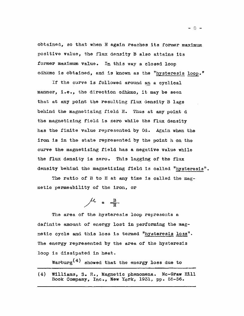
- 8 -
obtained, so that when H again reaches its former maximum
positive value, the flux density B also attains its
former maximum value. In this way a closed loop
cdhkmo is obtained, and is known as the "hysteresis loop."
If the curve is followed around an a cyclical
manner, i.e., the direction cdhkmc, it may be seen
that at any point the resulting flux density B lags
behind the magnetizing field H. Thus at any point d
the magnetizing field is zero while the flux density
has the finite value represented by Ode Again when the
iron is in the state represented by the point h on the
curve the magnetizing field has a negative value while
the flux density is zero. This lagging of the flux
density behind the magnetizing field is called "hysteresis".
The ratio of B to H at any time is called the mag
netic permeability of the iron, or
/= Blr
The area of the hysteresis loop represents a
definite amount of energy lost in performing the mag
netic cycle and this loss is termed "hysteresis ~".
The energy represented by the area of the hysteresis
loop is dissipated in heat.
warburg(4) showed that the energy loss due to
(4) Williams, S. R., Magnetic phenomena. Mc-Graw HillBook Company, Inc., New York, 1931, pp. 55-56.
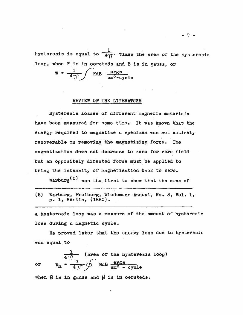
- 9 -
1hysteresis is equal to 4~ times the area of the hysteresis
loop, when H is in oersteds and B is in gauss, or
W = 1 _ I HdB ergs411-I ., cm3-cyele
REVIEW OF THE LITERATURE
Hysteresis losses of different'magnetic materials
have been measured .for some time. It was known that the
energy required to magnetize a specimen was not entirely
recoverable on removing the magnetizing force. The
magnetization does not decrease to zero for zero field
but an oppositely directed force must be applied to
bring the intensity of magnetization back to zero.
warbUrg(5) was the first to show that the area of
(5) Warburg, Freiburg, Wiedemann Annual, No.8, Vol. 1,p. 1, Berlin, (1880).
a hysteresis loop was a measure of the amount of hysteresis
loss during a magnetic cycle.
He proved later that the energy loss due to hysteresis
was equal,to
the hysteresis loop)
or
141/ (area of
W1 _ rI:' HdB ergs
h· 4 yr;/ -c-m~3~--.-e-y""":c1e
when B is in gauss and ~ is in oersteds.
-N-
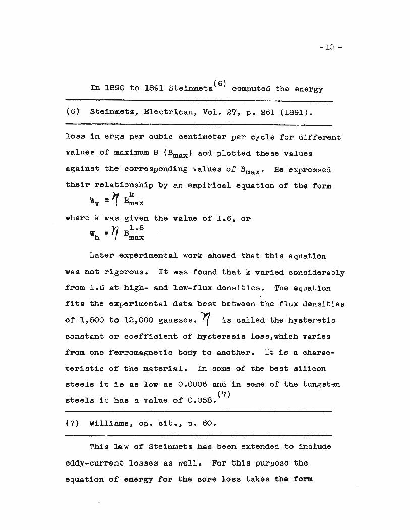
In 1890 to 1891 steinmetz(6) computed the energy
(6) Steinmetz, Electrican, Vol. 27, p. 261 (1891).
loss in ergs per cubic centimeter per cycle for different
values of maximum B (Bmax ) and plotted these values
against the corresponding values of Bmax • He expressed
their relationship by an empirical equation of the form
~=~~~where k was given the value of 1.6, or
~=~~~
Later experimental work showed that this equation
was not rigorous. It was found that k varied considerably
from 1.6 at high- and low-flux densities. The equation
fits the experimental data best between the flux densities
of 1,500 to 12,000 gausses. '7 is called the hysteretic
constant or coefficient of hysteresis loss, which varies
from one ferromagnetic body to another. It is a charac-
teristic of the material. In some of the best silicon
steels it is as low as 0.0006 and in some of the tungsten
steels it has a value of 0.05S.(7)
(7) Williams, op. cit., p. 60.
This law of Steinmetz has been extended to include
eddy-current losses as well. For this purpose the
equation of energy tor the core loss takes the tor.m
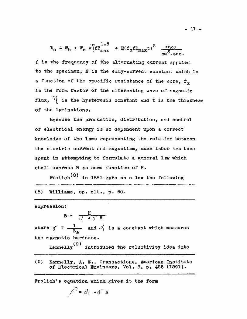
- II -
ergs3cm -sec.
f is the frequency of the alternating current applied
to the specimen, E is the eddy-current constant which 1s
a function of the specific resistance of the core, f xis the form factor of the alternating wave of magnetic
flux, 'Il. is the hysteresis constant and t is the thickness
of the laminations.
Because the production, distribution, and control
of electrical energy is so dependent upon a correct
knowledge of the laws representing the relation between
the electric current and magnetism, much labor has been
spent in attempting to formulate a general law which
shall express B as some function of H.
Frolich(8} in 1881 gave as a law the following
(8) Williams, Ope cit., p. 60.
expression:
the reluctivity idea into
is a constant which measuresand 0{
H
1
B •
Bsmagnetic hardness.
(9)Kennelly introduced
the
where ([ =
(9) Kennelly, A. E., Transactions, American Instituteof Electrical Engineers, Vol. 8, p. 485 (1891).
Frolich's equation which gives it the form
- 12 -
This has been called Kennelly's law. This law was developed
independently by Kennelly and Fleming rrom the assumption
that "permeability is proportional to the magnetizability";
that is,
~ = a (S - B)
Kennelly recognized the fact that it is not the total
induction B, but the intrinsic or ferric induction,9B =B - H) which approaches a saturation value (3)
and developed the reluctivity relationship on that basis.
"Note that the ferric induction)3, or B - H, is 411 times
what is generally called intensity of magnetization or
~gnetic pole.rization. The symbOl)t is here used for
iferric permeability or H and is 4 7f times the mag-
netic susceptibility.
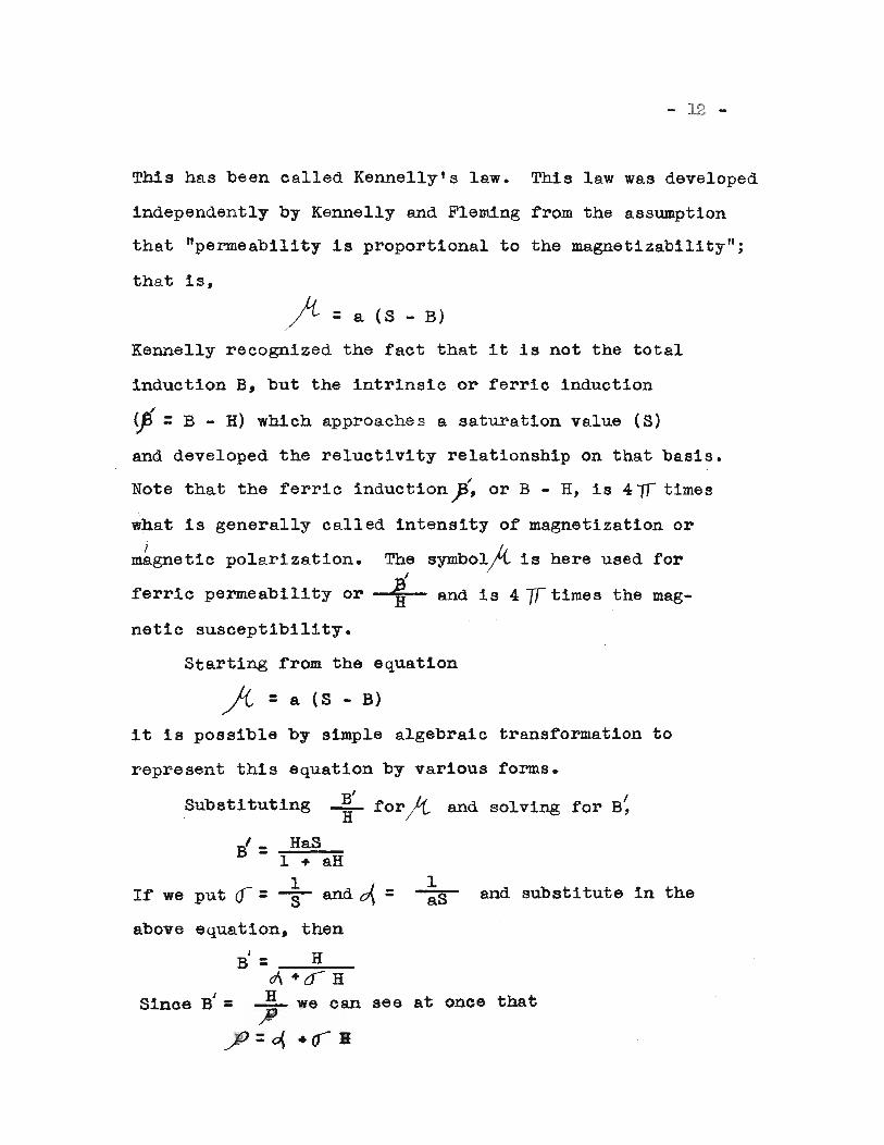
Starting rrom the equation
fi = a (8 - B)
it is possible by simple algebraic transformation to
represent this equation by various forms.
substituting B' IH for)t and solving for 6,
If' we put
Ff = HaS1 + aH
1a=Sand~= and substitute in the
above equation, then
6/ = Hc7\ +0 H
Since B' = ~ we can see at once that
..JV=~ +qB
- 13 -
This is Kennelly's law as usually stated. ~ is the
reciprocal of' the saturation value and cA is a constant
which determines the rate of' approach toward saturation.
Gokhale(lO) discussed all o.f these laws and proposed
(10) Gokhale, Paper presented at meeting of AmericanInstitute of Electrical Engineers, June 21-25,1926.
one of his own. All these men labored under the same
handicap th~t the constants have no physical significance.
All the laws have their limitations. Let us look
at the magnetization curve and see where certain laws
are best suited. The initial portion o~ the magnetization
curve 1s not horizontal at the origin but has a definite
slope called the initial permeability~0' equal to
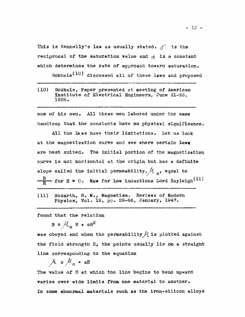
~ for H =o. Now .for low inductions Lord Rayleigh(ll)
(11) Bozarth, R. M., Magnetism. Reviews of ModernPhysics, Vol. 19, pp. 29-86, January, 1947•
.found that the relation
B =fto H + aH2
was obeyed and when the permeabilityj{ is plotted against
the .field strength fl, the points usually lie on a straight
line corresponding to the equation
~ =1-0 ... ali
The value of H at which the line begins to bend upward
varies over wide limits from one material to another.
In some abnormal materials such as the iron-silicon alloys
form used by A. E. Kennelly:
t=~ "0 Hfl
and so a linear relation is
against H. From a graph of
- 14 -
the curve first becomes convex upward before it begins
to rise rapidly at higher values of H. Curves of this
kind are used to determine the value Of~o by extrapo
lating them to H =o.
The upper portion of the magnetization curve bends
over and approaches Bs • In high fields it is found
that B approaches DO definite limit but B - H does
approach a limit, called the saturation induction or
simply saturation, designated Bs • Since B - H = 4 7f I,
I approaches the limit Is, the saturation magnetization.
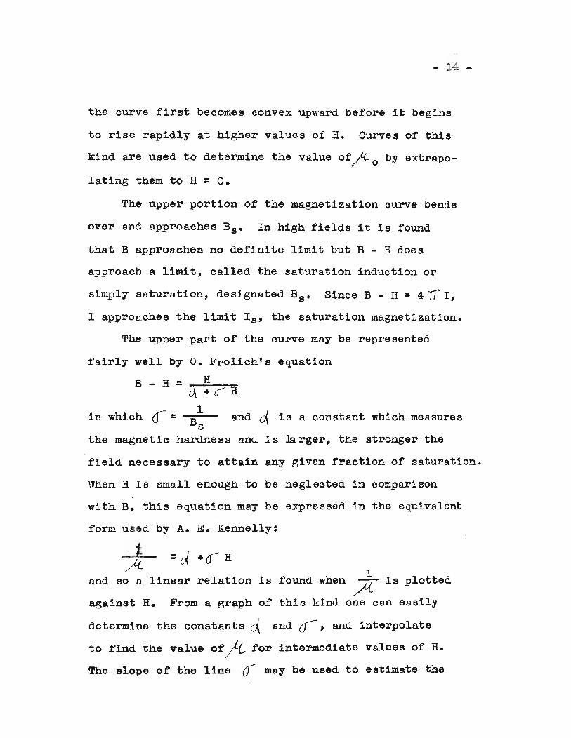
The upper part of the curve may be represented
fairly well by o. Frolich'e equation
B-H=_;;;;;H_~cA+o H
1in which 0-:1: and ..-J is a constant which mea.suresBs U\
the magnetic hardness and is larger, the stronger the
field necessary to attain any given fraction of saturation.
When H is small enough to be neglected in comparison
with B, this equation may be expressed in the eqUivalent
Ifound when A is plotted
this kind one can ea.sily
determine the constants ~ and ur-, and interpolate
to find the value Of~ for intermediate values of H.
The slope of the line 0- may be used to estimate the
- 15 -
saturation induction (O=..!-) but this method cannotBs '
be depended an for accuracy for in some materials such
as iron the slope changes distinctly at inductions close1
to saturation. The term fl is termed the reluctivity.
Now let us discuss further the energy loss due to
hysteresis. It has already been stated that the area
enclosed by a hysteresis loop is proportional to the
energy liberated as heat during one cycle of the loop.
Rayleigh derived the B3 relationship at low induc
tions. He showed that the magnetization curve near the
toe followed the equation;
B -)<-0 H ... AH2
and also that the hysteresis loop with tips at Bmax'
Hmax, and -Bmax, -Hmax was described by parabolic
equations
B =j{ H ... ( ~ ) (~- H2 )
and=J<, H - ( ~ ) (~- H2)B
for the upper and lower halves of the loop, respectively.
(Hereft = Bmax ) .Measurements< 12) have been made fornmax(12) Bozarth, R. M., Magnetism. Reviews of modern
physics, Vol. 19, pp. 29-86, (1947).
values of Bmax as low as 2 gausses, and only slight
deviations from the Rayleigh form observed.
- 16 -
The area o~ a Rayleigh loop may be calculated from
the above equations, and the corresponding hysteresis
loss, expressed in 3ergs i8em - cycle
:3 :3Wh. a HiDa.x = a Bmax
3Tf 3j1/L:3
That temperature has an observable influence upon
the magnetic properties o~ iron has been known from the
time of Gilbert (1540-1603), who discovered that a
needle, when heated red hot, is no longer attracted by
the lodestone, but regains this property when the tem
perature has fallen. This fact was also noted by Canton
and studied qualitatively by Saussure. The first, however,
to attempt quantitative measurement s was Coulom~ (1736
1806), who observed the period of vibration of a heated
magnetic needle in a field of' known intensity.
At the beginning of the nineteenth oentury, the
increasing refinement o~ instruments for stUdying the
earth's ~ie1d made it necessary to know the influence of
temperature upon the deflections of the magnetometer
needle. The ~irst care~ul experiments were those of
Christie who ~ound that the highest temperature to which
a magnet can be heated without sensible 10s8 of magnetism
is about lOOoF., and that di~utlon ot magnetic moment
is not a linear £unction of the temperature, ita rate of
change increasing with the temperature. He also .found
that the moment of a magnet, when pla ced 1n a freezing
- 17 -
mixture, is increased, returning to its original value
when room temperature is restored.
Rowland in the years 1873-74, carried out a long
series of experiments on iron, nickel, and cobalt,
experimenting at two different temperatures, 5°C and
230°C, in the later part of his work. He was able to
determine, however, that the susceptibility ot iron
and nickel in small fields is greater at high tem
peratures than low, while for large fields, just the
reverse is true.
Baur, or Zurich confirmed the results of Rowland
by stUdying iron as it cooled. He found, for small
fields, that the rate of increase of permeability is
greater for high temperatures than low, while a* a
critical temperature is approached, the permeability
decreases very rapidly in all fields, becoming prac-
tically unity.
During the next ten years, the matter was taken
up by Perkins, J. Trowbridge, Berson, Tomlinson and Hop
kinson; by :far the most important work being done by
the last. ' Hopkinson used the ring method of Rowland,
insulating the windings from each other by asbestos,
and estimating temperatures by means of a platinum
thermometer. He determined a very complete temp.rature
series of magnetization curves for wrought iron, mild
steel, hard steel, nickel and cobalt. In the case of
wrought iron, he found that for small fields, e.g., 0.3
- 18 -
dyne, the temperature at which the rapid rise or per-o
meability begins is about 600 C., then fell rapidly to
unity. Mild steel showed essentially the same charac
teristics, except that the permeability had a smallero
maximum, becoming unity at 735 e., while for hard steel,
the decrease in the maximum was still more pronounced,
magnetism disappearing at 690°C. Returning from higher
temperatures, for wrought iron, magnetism reappeared at
practically the same temperature at which it disappeared,
but the steels showed a marked temperature lag which
increased with carbon content.
Between the years 1890 and 1900 a great deal of
work was done, and it will be possible here to briefly
point out only the additions which were made to the
results obtained by Hopkinson. We find a long list of
n~es, the most important of which are the following:
DuBois, Wilde, Rucher, LeChatelier, Curie, Fleming and
Dewar, Morris, Fromme, Guilliaume, Dumont, Dumas, Asmond
and Wills. The physical transformations which take place
in iron were worked out with great detail during this
decade by the metallurgists Osmond, Home, Roberts-Austin,
Rozzeboom and others.
Of those mentioned above, Curie did perhaps the most
important work. He studied not only iron, nickel and
cobalt, but para- and dimagnetic substances, covering
- 19 -
rields rrom 90 to 1,350, and temperatures rrom l50 eto 1400°0. He found that the magnetic transformation
°point for iron to be 760 e., somewhat lower than Hop-
kinson's value, and showed that the susceptibility
does not become zero at this temperature, as previously
supposed, but remains positive, and though small, decreases
rapidly up to 950°0., then slowly to 1280°0., when an
abrupt increase indicated another transformation point.
The transformation near 750°0., was found to be not an
abrupt, but a gradual change, depending upon the field,
the curves showing the variation of susceptibility with
temperature being simdlar in shape to Amagat's curves
ror the density of carbon dioxide near the critical point.
Fleming and Dewar, in l8~6, studied the changes
which were produced in the magnetic qualities of Swedish
iron at low temperatures. In annealed specimens, they
found the permeability in all fields 1e~s at low tem
peratures, while for unannealed and hardened iron, it
increased as the temperature was lowered, the effect
being greater with hardened iron. The hysteresis 10s8
was independent of the temperature. More recently,
Honda and Sh1~zu found for Swedish iron cooled in liqUid
air that the permeability and hysteresis loss decreased
for small fields, but increased for large.
- 20 -
Earle M. Terry(13) round that for low fields, the
(13) Terry, E. M., The effect of temperature upon themagnetic properties of electrolytic iron, PhysicalReview, Vol. 30, 1910, pp. 133-160. .
permeability increased with the temperature for tem-o 0peratures between 25 C. and 97 C. for unannealed specimens.
He also found that the hysteresis loss, retentivity, and
coercive force all decreased with a rise in temperature
for these unannealed specimens. For the annealed speci
mens, he found that the permeability in low fields in-
creased with a rise in temperature for temperatures
between - l210 C. to + 102°0. But the hysteresis loss
and the coercive force decreased with a rise in tem-
perature in this range of temperatures. He found,
however, the retentivity, Br, increased. His specimens
were of electrolytic iron. He found as the temperature
was reduced below standard room temperature, the per-
meability decreased for small fields but increased for
large fields, this effect being greater after annealing.
The hysteresis loss continually inereased as the tem-
perature was lowered, the rate of increase being greater
after annealing. This was entirely at variance with
Fle~ng's and Dewar's results on transformer iron, for
they found no change in hysteresis loss at the temperature
of liquid air. They also found the permeability to
increase for all fields in the case of unannealed and
hardened iron, which again was contrary to E. M. Terry.
- 2
Hysteresis losses of different magnetic materials
have been measured for some time, but as far as the
literature is concerned, hysteresis losses of supermalloy
at different temperatures have not been measured yet.
It was, therefore, of interest to determine these
constants of supermalloy, and this investigation was
the topic of the thesis.(14)
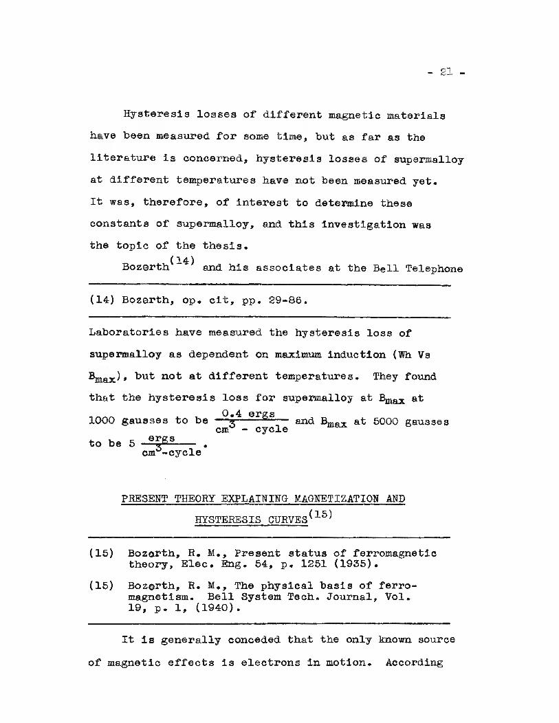
Bozarth and his associates at the Bell Telephone
(14) Bozarth, Ope cit, pp. 29-86.
Laboratories have measured the hysteresis loss of
supermalloy as dependent on maximum induction (Wh Vs
Bmax), but not at different temperatures. They found
that the hysteresis loss for supermalloy at Bmax at0.4 ergs
1000 gausses to be 3 and Bmax at 5000 gaussescm - cycle
to be 5 ergs •cm3-cyc1e
PRESENT THEORY EXPLAINING MAGNETIZATION AND
HYSTERESIS CURVES(15)
(15)
(15)
BozQrth, R. M., Present status of ferromagnetictheory, Elec. Eng. 54, p. 1251 (1935).
Bozorth, R. M., The physical basis of ferromagnetism. Bell System Tech. Journal, Vol.19, p. 1, (1940).
It is generally conceded that the only known source
of magnetic effects is electrons in motion. According
- 22 -
to present theory, ferromagnetic effects are due to
groups of electrons within a ferromagnetic material called
"domains" and consisting of electrons spinning around
their own axes. The magnetic axes or the spinning
electrons in a single domain are held parallel to each
other by mutual forces known as ~exchange forces" so
that each domain behaves as a single unit. The domains
are in effect current-turns and so account for the
magnetomotive forces inherent in ferromagnetic materials.
In the unmagnetized condition the domains are so
oriented with respect to each other that the net magnetic
force is zero in any direction. Under the influence of
a magnetic field, e.g., applied by means of an external
electric current, the magnetic axes of the domains tend
to be oriented more or lJ S8 1n the direction of the
applied field~ so that their effeet is added to that of
the applied field.
The density due to the eombined effeet of the
applied field and the domains is the magnetic induction
B and the effect due to the orientation of the domains
is the intrinsic induction Bi where Bi =4,rJ, where J
is the intensity of magnetization, B • 4/fJ • H or
B =B1 .. H.
Now 1n the part of the magnetization eurve Oa,
Figure 2, B is proportional to H and it' the eurrent
- 23 -
is broken B will return to zero. This is explained by
saying that the axes of the electrons within the domain
are deflected slightly but the exchange ~orces within
the domains pull the axes back in the original position
when the field is released. Now as more and more field
is applied, more and more of the electrons within the
domain orient themselves in the direction of applied field.
This all takes place along the steep part, marked (2)
from a to b of Figure 2 of the magnetization curve.
Now as the iron becomes saturated, the axes of the domain
shift and a further increase in H produces a small increase
in B. This can be explained again by the equation
B =41T~ • H where at saturation the 41fJ or intrinsic
induction becomes a constant which for iron this constant
is equal to (according to wall(16» 21,000 lines per square
(16) Wall, T. F., Applied magnetism, Van Nostrand Company, New York, p. 31 (1927).
centimeter, and the equation becomes B :: 21,000 + H.
If, after saturation is reached, the field is reduced
to zero, the part of the curve from saturation to the
residual force is explained by saying that the domains
themselves shift back to their position previous to
saturation, but the axes of the electrons within the
domains are still oriented. At H • 0, our equation
becomes B = Bi :: 4 yr J • During the demagnetization part
- 24 -
of the curve~ the reverse of the magnetization takes
PA ce except the electrons do not quite go back to
original position and at B = 0 we have 0 = H + 41fJ
and H =4TrJ where the field is equal and opposite to
the intrinsic induction.
The energy loss due to hysteresis is heat causing
a slight temperature change which may be calculated
according to Joules' law.
Work =J X heat = ergs
where heat is expressed in calories and J is the mechanical
equivalent of heat, J =4.2 Joules per calorie.
DERIVATIONS
An electric current through a conductor is always
accompanied by a magnetic field in the region surrounding
the conductor. A magnetic pole placed in this field will
be acted upon by a force.
Laplace(17) assumed that the magnetic field strength
(17) Gilbert, N. E., Electricity ana magnetism, MacMillan Company, New York, pp. 93, 147, 163 (1932)
dB due to a current I through a short element of length
dS is proportional directly to that length and to the
strength of the current, and inversely to the square of
the perpendicular distance from dS. He expressed this
relation in the formula
dR = K (1)
The unit of ourrent strength is so ohosen that K
- 25 -
1="'TO
Then, dE= IdS10 12 (l}
This Is an assumption which has always given oorrect
results.
A conductor carrying a constant current is to be
thought of as stlrrounded by a magnetic field, the lines
of force being represented by ooncentric circles which
lie in planes at right angles to the axis of the con-
ductor. The direction of these lines is clockwise as
one looks along the conductor in the direotion in which
the current flows, and the strength of the field, or the
force on a unit pole, is dete~mined by integrating the
equation
dH=IdS
10 1 2
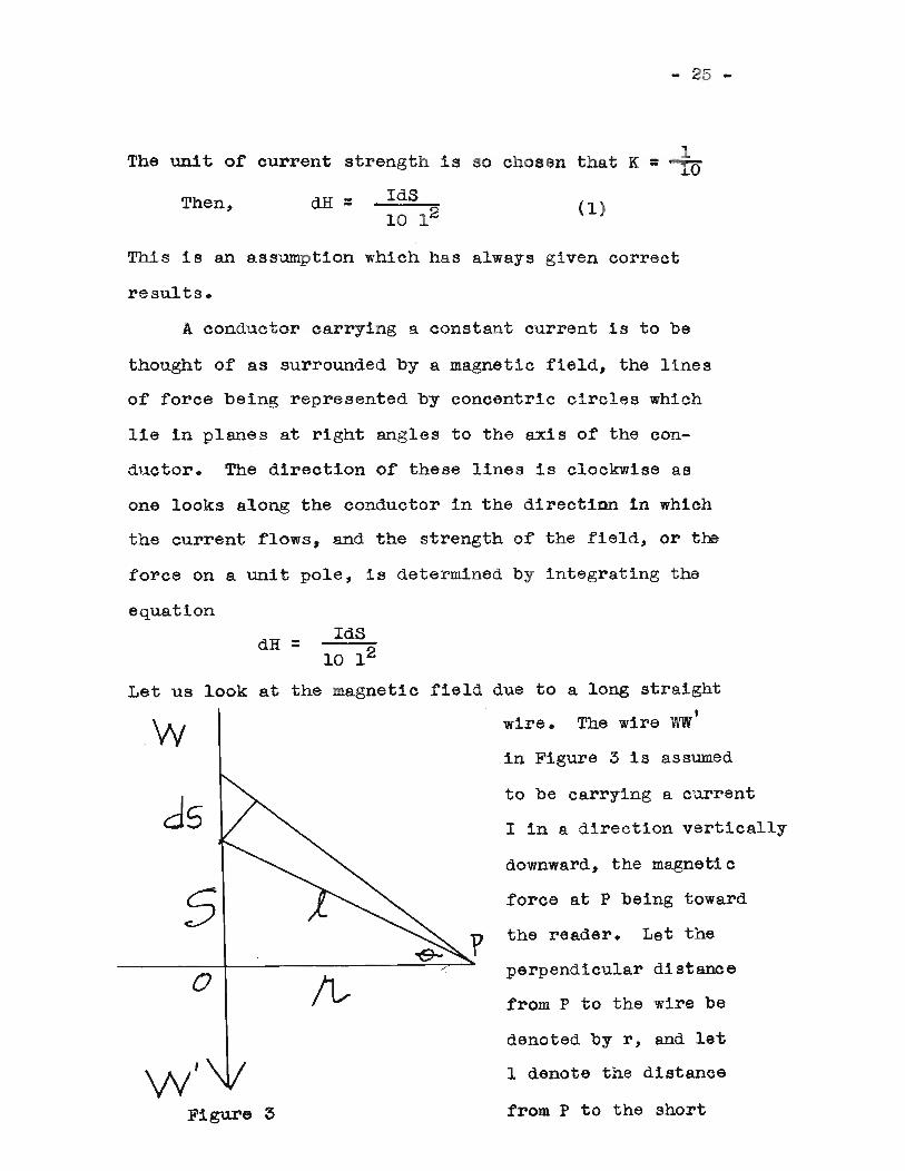
Let us look at the magnetic field due to a long straight,
wire. The wire WW
in Figure 3 is assumed
ds
so
W'Figure 3
to be carrying a current
I in a direction vertically
downward, the magnetic
force at P being toward
the reader. Let the
perpendicular distance
from P to the wire be
denoted by r, and let
1 denote the distance
from P to the short
- 26 -
element of the wire dB. If this element were at right
angles to 1, the force dHp at P would be given by
equation (1), but since the effective length of the
element is dB cos 9, we have instead of this equation,
dHp •IdS
10 12 cos 9 (2)
The total field strength at P, due to that part of the
wire above 0, is given by integrating both sides ot
equation (2) between the limits of zero and infinity.
The results must be doubled in order to include the
(3)
=CA
effect of that part of the wire below O. Rememberingrthat cos Q =-r- and that I 1s a constant, we may write
21 (QO r dS10 :Jo 13"'""
for 1, its value (r2 •
Hp = 21r. ? .dS 3. 1 =10~ 1r~.s~) 1 2
o
• 2Ir r: 110 ~2(~~. 1)1
2Ir 1 = 2110 • r2 ror-
Hp •
SUbstituting
The work done to carry a + 1 pole in a circle haVing
a radius r around a wire carrying a current is force
times distance. The force =1~~ dynes/unit pole,
and the distance equals 211'r.
Work = 21lOr • 2lTr = !1f..!
10
For any radius (r), work 1s 4~I ergs.
- 27 -
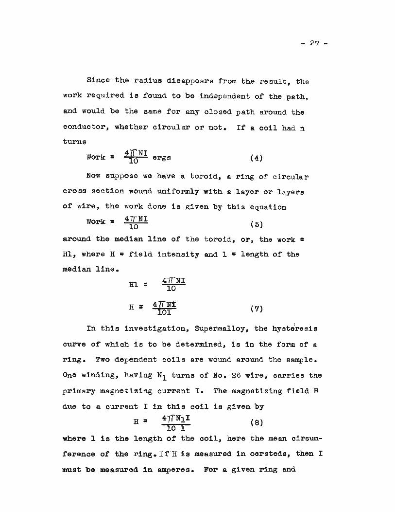
Since the radius disappears from the result, the
work required is found to be independent of the path,
and would be the same for any closed path around the
conductor, whether circular or not. If a coil had n
turns
Work = 4'[NI10 ergs (4)
Now suppose we have a toroid, a "ring of circular
cross section wound uniformly with a layer or layers
of wire, the work done is given by this equation
Work = 4lTNI10 ( 5)
around the median line of the toroid, or, the work =HI, where H • field intensity and 1 • length of the
median line.
HI =
H =
4/fNI10
47rNt101 (7)
In this investigation, Superma1loy, the hysteresis
curve of which is to be determined, is in the form of a
ring. Two dependent coils are wound around the sample.
One winding, having Nl turns of No. 26 wire, carries the
primary magnetizing current I. The magnetizing field H
(8)H ;:
due to a current I in this coil is given by
47TNl 1
10 1where 1 is the length ot the coil, here the mean circum-
ference ot the ring. I fH is measured in oersteds, then I
must be measured 1n amperes. For a given ring and
- 28 -
primary coil the quantity 41f Nl is a constant. Thus10 1
it follows from equation (8) that the magnetizing field
H is proportional to the magnetizing current I, or
H = OIl (9)
where 01 is the constant 41/Nl •10 1
This equation (9) Is one of the working equations
of this investigation.
A second colI with N2 turns, called the secondary,
is wound around the ring and is connected through a
resistance to a ballistic galvanometer. This coil
and ballistic galvanometer measure the change in flux
density of Supermalloy due to changes In the magnetizing
field. A change in the magnetizing current I produces
a corresponding change in the magnetizing field H,
and this effects some change in the flux density of the
ring. Suppose a change 1.1 B occurs in the flux densi ty
of the Supermalloy ring. The change in the flux L1 <P 1s
A·~B where I is the cross-sectional area of the ring.
This flux change induces an electromotive foree E in
the secondary coil as given by
4tPB =N2 4 t (10)
where !1 t is the time in which the flux changes, A<P takes
place. Thus
(11)
If E 1s to be expressed 1n volta wben B is expressed in
gausses, then the right hend member of equation (11) !RUst
- 29 -
8 8be divided by 10 , since 1 volt is equal to 10 abvolts.
ThuB
E (volts) • AJI2iQ8
If the total resistance
L1Be_
Lltin the
(12)
secondary circUit
•is R, then the induced current in the secondary circuit
is
i = AN2 Ll B ( )lOBR f • Lit 12
when Rt is measured in ohms and llB in gausses, then i
is in amperes. This induced current 1 lasts for the
time .L1 t, the time in which the f1we change take s place.
The charge Q which flows around the secondary circuit
due to this flux change is given by
Qa i At =~ .M. t1 t = AN2 {j B (14)lOoR • fJ t lOSR t
If the charge flows through a ballistic galvanometer,
the deflection of the galvanometer coil as measured by
a reflected beam of light on a scale is proportional to
the charge. Thus
Q. Kd (15)
where d is the deflection on the seale due to a charge
Q and K is the charge sensitivity of the ballistic
galvanometer. Substituting Kd for Q in equation (14),
it follows that a change in flux density Ll B in the
ring produces a throw d where
,1B • lO·R1X • d112
(16)
- 30 -
l08R'KSince the quantity AN is a constant for a
2particular circuit, it rollows from equation (16)
that the deflection d on the galvanometer scale 1s
proportional to the change in flux density ~B; that
is,
where 02 is the constant
magnetizing field, which
(17)I08R'K
AN2 • A change in the
from equation (9) is propor-
tional to the change in the primary current I, produces
a change in the magnetic flux density of the ring. This
in turn is, from Equation (17), proportional to the throw
of the ballistic galvanometer connected to the secondary
coil wound around the Supermalloy ring.
If it is desired to obtain the absolute values of
the flux density changes in place of the ballistic
galvanometer thrOws, it is necessary to calibrate the
galvanometer. This may be done by inserting permanently
a known mutual inductanoe ~ series with the ballistic
galvanometer and the secondary coil wound on the ring.
The resistance of the galvanometer, previously called
Rt , now also includes the resistance of the secondary
of the mutual inductance. When a current I)4 is sent
through the primary of the mutual inductance, the flux
through the mutual inductance coils is given by
(18)
- ~l -
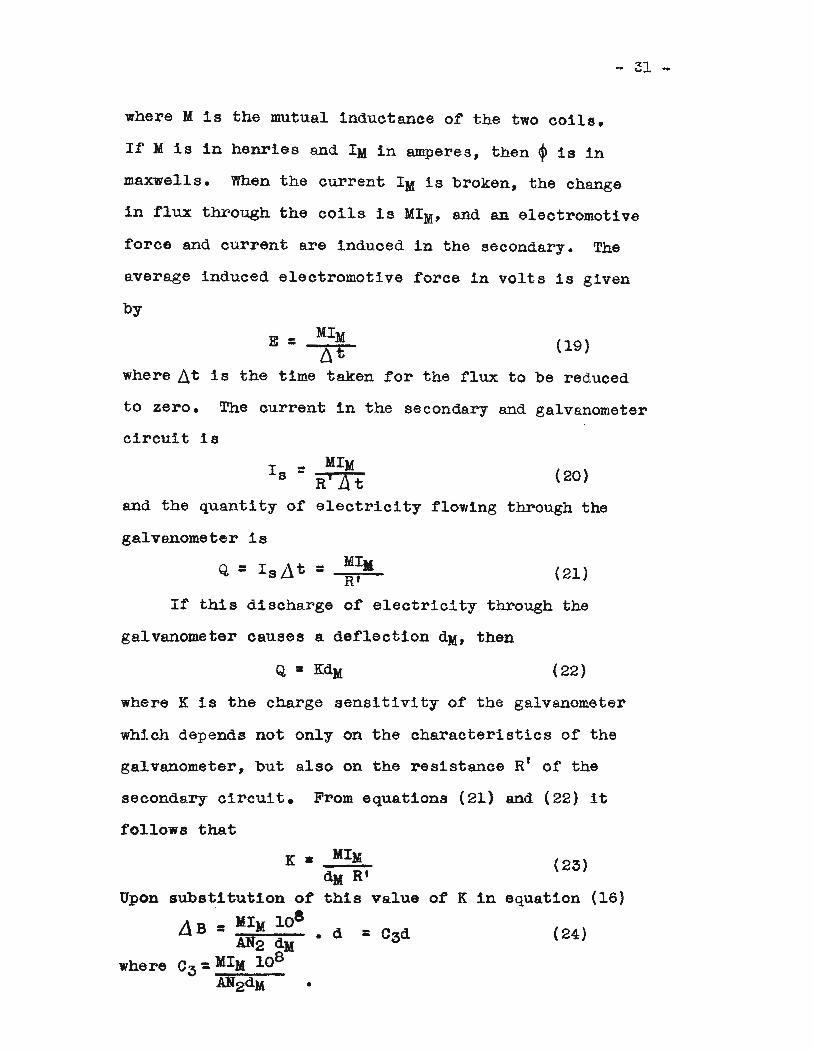
where M is the mutual inductance of the two coils.
1£ M is in henries and 1M in amperes, then ~ is in
maxwells. When the current 1M is broken, the change
in flux through the coils is MIM' and an electromotive
force and current are induced in the secondary. The
average induced electromotive force in volts is given
by
E = 141Ml)t
where Llt is the time taken
(19)
for the flux to be reduced
to zero. The current in the secondary and galvanometer
circuit is
and the quantity of
galvanometer is
141MR' li t
electricity
(20)
flowing through the
Q =1sAt = (21)
If t~s discharge of electricity through the
galvanometer causes a deflection dM, then
(22)
where K is the charge sensitivity of the galvanometer
which depends not only on the characteristics of the
galvanometer, but also on the resistance R' of the
secondary circuit. From equations (21) and (22) it
follows that
(23)
Upon
where
K •
substitution of
L\B= MIM 108
AN2 d)l
03: MIM 108
AN2dM •
MIMdM R'this value of K in equation (16)
(24)
- 32 -
Equation (9) is one ot: the working equations and
equa.tion (24) is the other working equation of this
investigation.
DISCUSSION OF EXPERIMENT
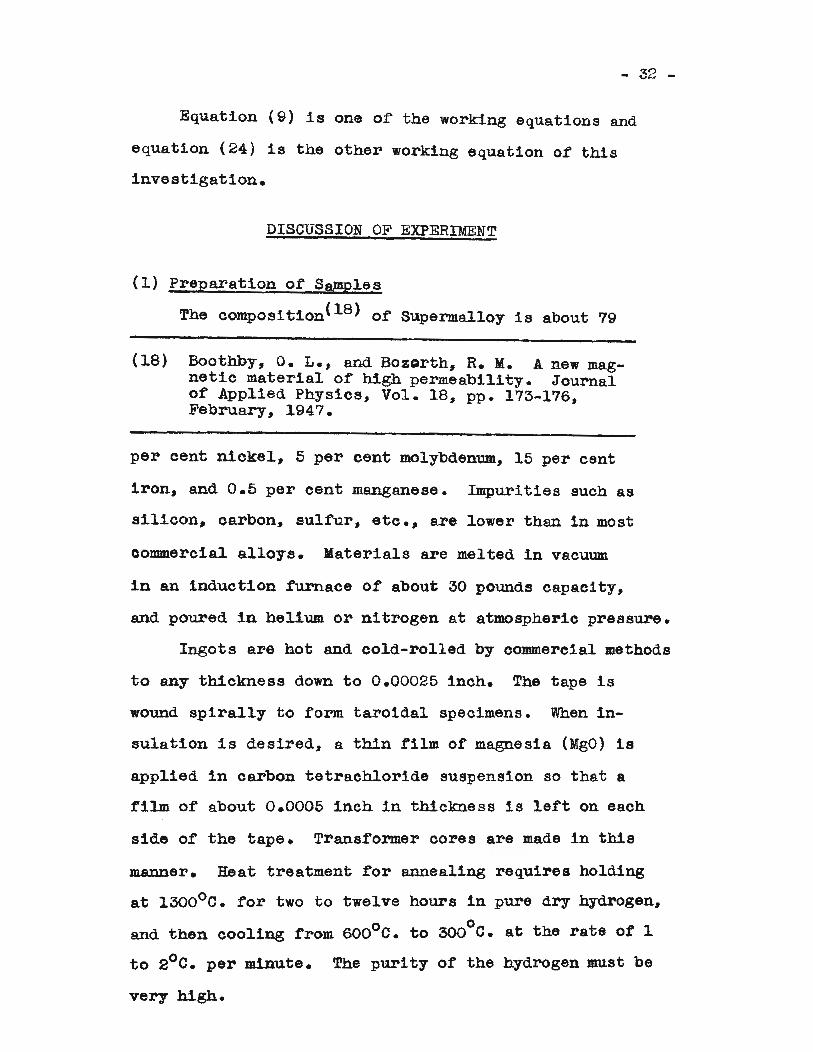
(l) Preparation of Samples
The compos1tion(18) or Superma1loy is about 79
(18) Boothby, O. L., and BozQrth, R. M. A new magnetic material of high permeability. Journalof Applied Physics, Vol. 18, pp. 173-176,February, 1947.
per cent nickel, 5 per cent molybdenum, 15 per cent
iron, and 0.5 per cent manganese. Impurities such as
silicon, carbon, sulfur, etc., are lower than in most
oommercial alloys. Materials are melted in vacuum
in an induction furnace of about 30 pounds capacity,
and poured in helium or nitrogen at atmospheric pressure.
Ingots are hot and cold-rolled by commercial methods
to any thickness do'lm. to 0.00025 inch. The tape is
wound spirally to form taroidal specimens. When in
sulation is desired, a thin fi1m of magnesia (MgO) 1s
applied in carbon tetrachloride suspension so that a
rilm or about 0.0005 inch in thickness is lert on each
side of the tape. Transformer cores are made in this
manner. Heat treatment t:or annealing requires holding
at 1300°0. for two to twelve hours in pure dry" hydrogen,
and then cooling from 600°0. to 300°0. at the rate ot 1
to 2°0. per minute. The purity of the hydrogen must be
very high.
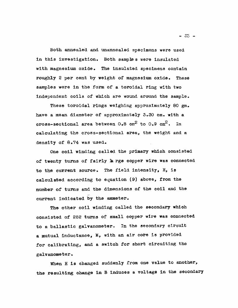
Both annealed and unannealed specimens were used
in this investigation. Both sample s were insula.ted
with magnesium oxide. The insulated specimens contain
roughly 2 per cent by weight o£ magnesium oxide. These
samples were in the rorm of a toroidal ring with two
independent coils or which are wound around the sample.
These toroidal rings weighing approximately 80 gm.
have a mean diameter of approxima.tely 3.30 cm. with a
cross-sectional area between 0.8 cm2 to 0.9 cm2 • In
calculating the cross-sectional area, the weight and a
density of 8.74 was used.
One coil winding called the primary which consisted
of twenty turns of fairly • rge copper wire was connected
to the current source. The £ield intensity. H. is
calcul ated according to equation (9) above, f'rom the
number of turns and the dimensions or the coil and the
current indicated by the ~eter.
The other coil winding called the secondary which
consisted of 252 turns of small eopper wire was connected
to a ballastic galvanometer. In the secondary circuit
a mutual inductance, M, with an air core is provided
for calibrating, and a switeh £or short circuiting the
galvanometer.
When H is changed SUddenly from one value to another,
the resulting change in B induces a voltage in the secondary
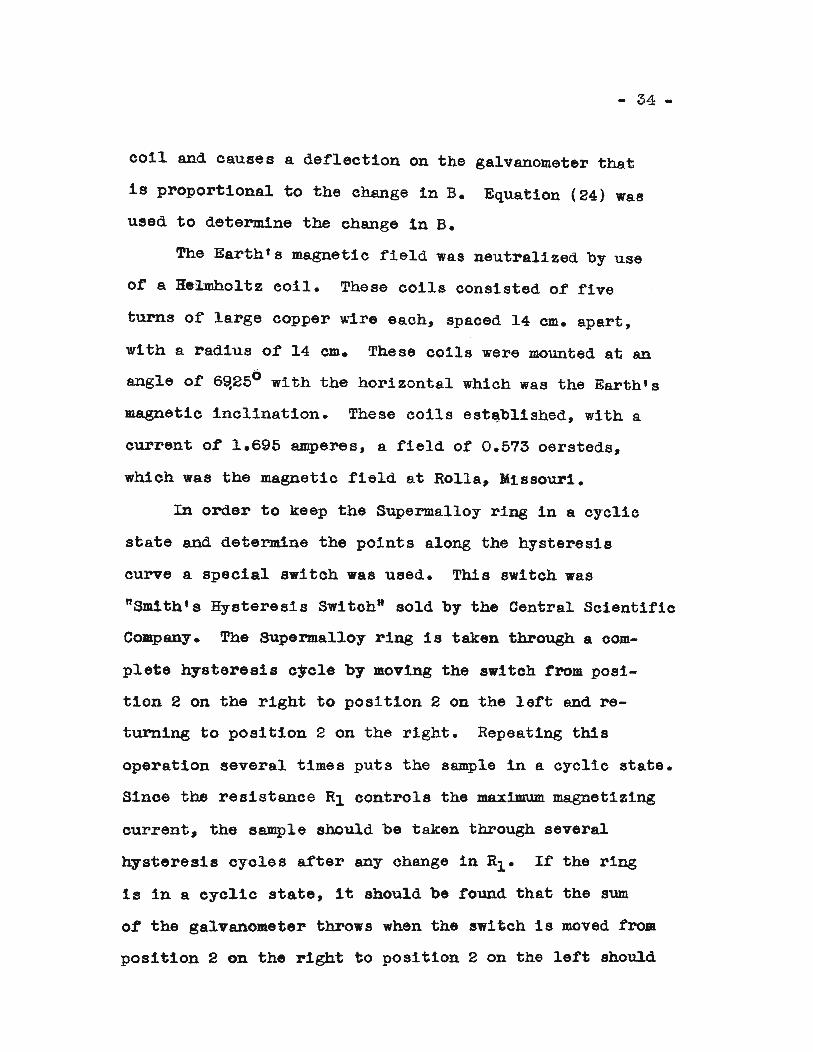
- 34 -
coil and causes a deflection on the galvanometer that
is proportional to the' change in B. Equation (24) was
used to determine the change in B.
The Earth's magnetic field was neutralized by use
of a He1mholtz coil. These coils consisted of five
turns of large copper wire each, spaced 14 em. apart 7
with a radius of 14 em. These coils were mounted at an
angle of 69,250 with the horizontal which was the Earth's
magnetic inclination. These coils est~bIished, with a
current or 1.695 amperes, a field of 0.573 oersteds,
which was the magnetic field at Rolla~ Missouri.
In order to keep the Supermal10y ring in a cyclic
state and determine the points along the hysteresis
curve a special switch was used. This switch was
"Smith's Hysteresis Switch" sold by the Central Scientifio
Company. The Supermalloy ring 1 s taken through a oom
plete hysteresis cycle by moving the switch from posi
tion 2 on the right to position 2 on the le£t and re
turning to position 2 on the right. Repeating this
operation several times puts the sample in a cyclic state.
Since the resistance RI controls the max~ magnetizing
current~ the sample should be taken through several
hysteresis cycles after any change in Rl • If' the ring
is in a cyclic state, it should be found that the sum
of the galvanometer throws when the switch is moved from
position 2 on the right to position 2 on the left should
- Z5 -
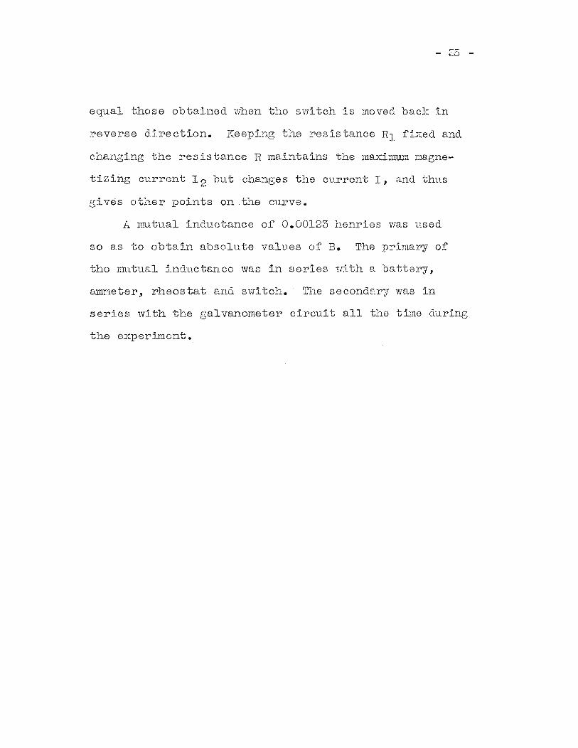
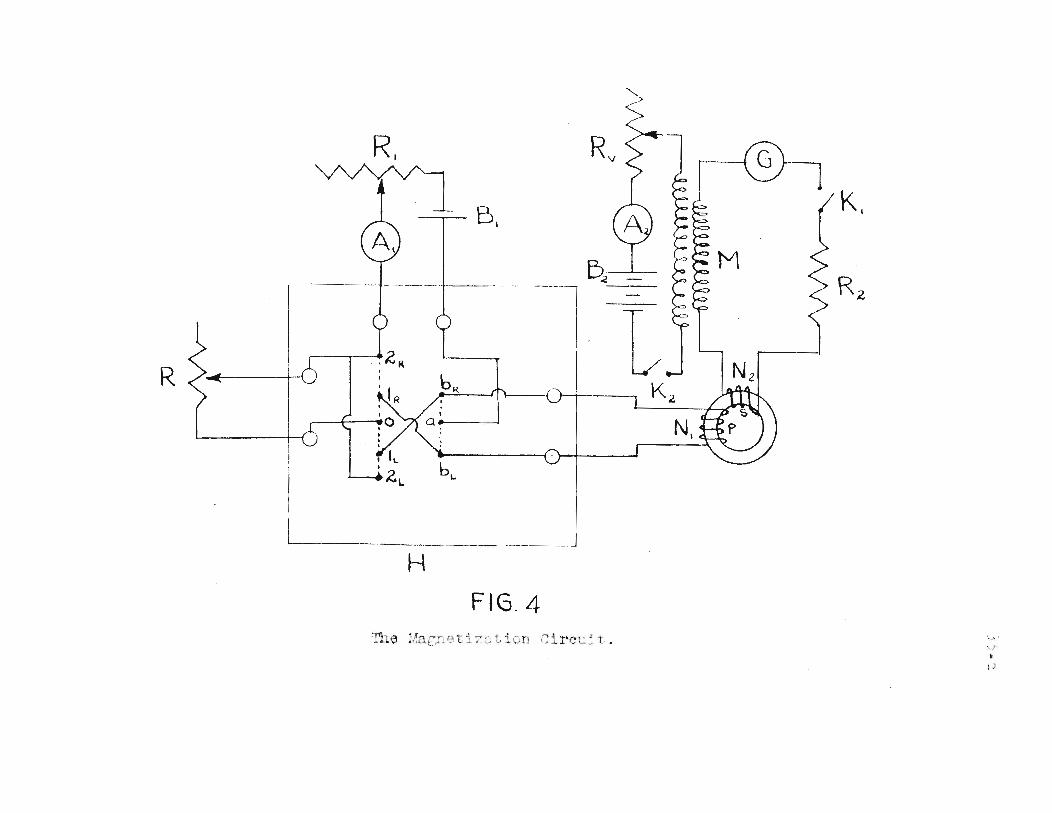
equal those obtained when the switch is moved back in
reverse direction. Keeping the resistance Rl fixed and
changing the resistance R maintains the maximum magne
tizing current 1 2 but changes the current I, and thus
gives other points on the curve.
A nmtual inductance of 0.00123 henries was used
so as to obtain absolute values of B. The primary of
the mutual inductance was in series with a battery,
~~lleter, rheostat and switch. The secondary was in
series with the galvanometer circuit all the time during
the 8xperiluent.
+-='~
\
;.J()
H.....-1C
~~o
In·r
l\J
.,..)nlJ...
r_','-1....,:r.C
'US~~
.-
.+---+----~
rJ)~
/.-------.t---~-
il
!IIIIcO
- 36 -
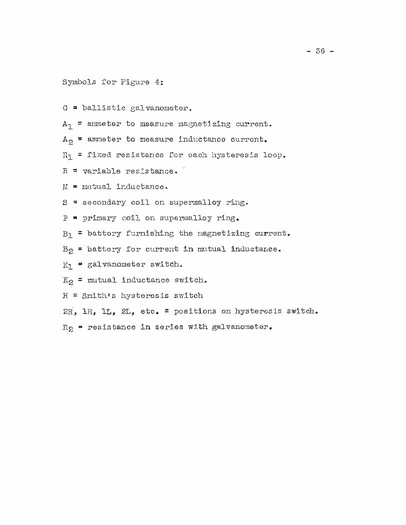
Symbols for Figu~e 4:
G = ballistic galvanometer.
Al = ammeter to measu.re magnetizing current.
A2 = ammeter to measure inductance current.
HI = fixed resistance for each hysteresis loop.
R = variable resistance.
M a mutual inductance.
S = secondary coil on supermalloy ring.
p a primary coil on supercmalloy ring.
Bl = battery furnishing the magnetizing current.
B2 = battery for current in mutual inductance.
Kl a galvanometer switch.
K2 = mutual inductance switch.
R =Smith's hysteresis switch
2R, lR, IL, 2L, etc. = positions on hysteresis switch.
R2 a resistance in series with galvanometer.
- 37 -
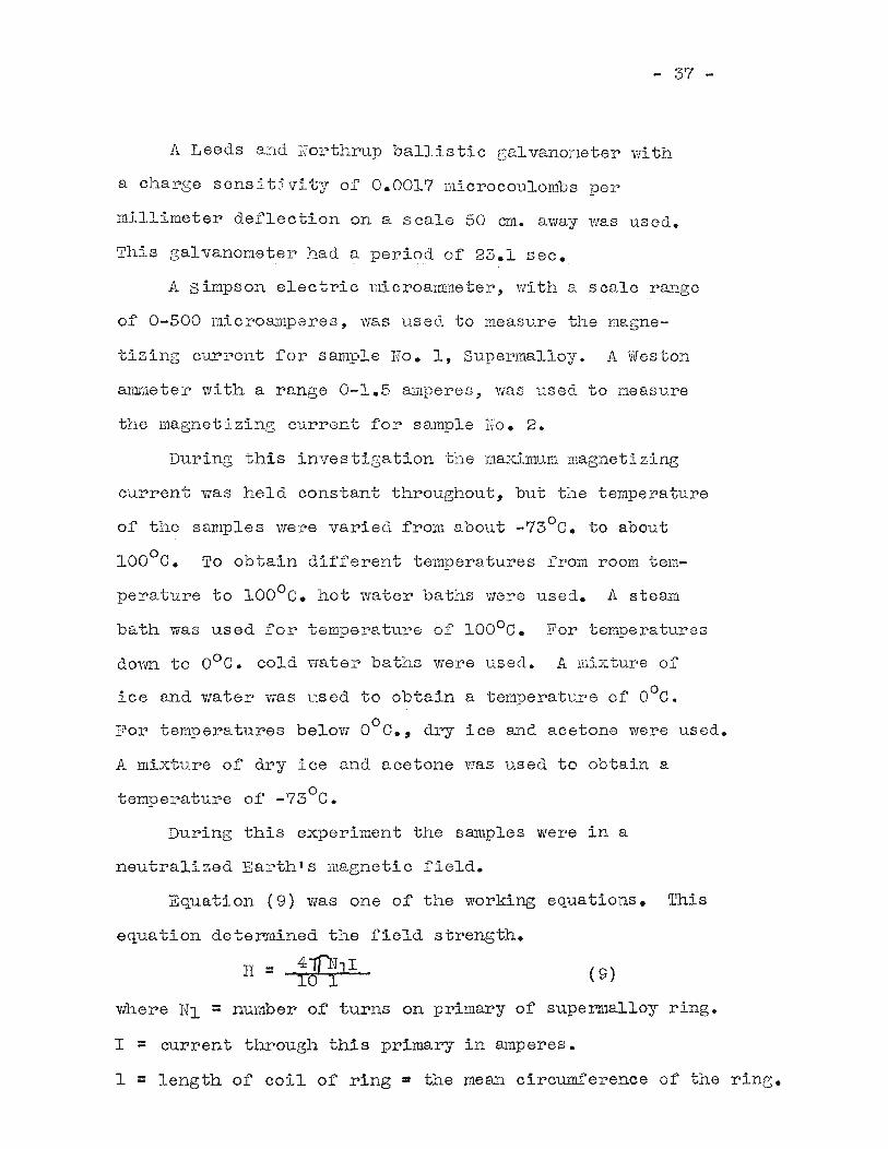
A Leeds and Northrup ballistic galvanometer w~th
a charge sensitivity of 0.0017 microcoulombs per
millimeter deflection on a scale 50 em. away was used.
This galvanometer had a period of 23.1 sec.
A simpson electric microalmneter, with a scale range
of 0-500 microamperes, was used to measure the magne-
tizing current for sample No.1, Supermalloy. A Weston
aYl:Ir.1eter with a range 0-1.5 amperes, was used to meas"U.re
the magnetizing current for sample Ho. 2.
During this investigation the maximum magnetizing
current was held constant throughout, but the temperature
of the samples were varied from about -73°C. to about
100°C. To obtain different temperatures from room tem
perature to 100°C. hot water baths were used. A steam
bath was used for temperature of 100°C. For temperatures
dovm to oOe. cold water baths were used. A mixture of
ice and water was used to obtain a temperature of OOC.
°For temperatures below 0 C., dry ice and acetone were used.
A mixture of dry ice and acetone was used to obtain a
temperature of -73°C.
During this experiment the samples were in a
neutralized Earth's magnetic field.
Equation (9) was one of the working equations. This
equation deter.mined the field strength.
H =-{1J?L (9)
where Nl =number of turns on primary of supermalloy ring.
I = current through this primary in amperes.
1 =length of coil of ring = the mean circumference of the ring.
- 38 -
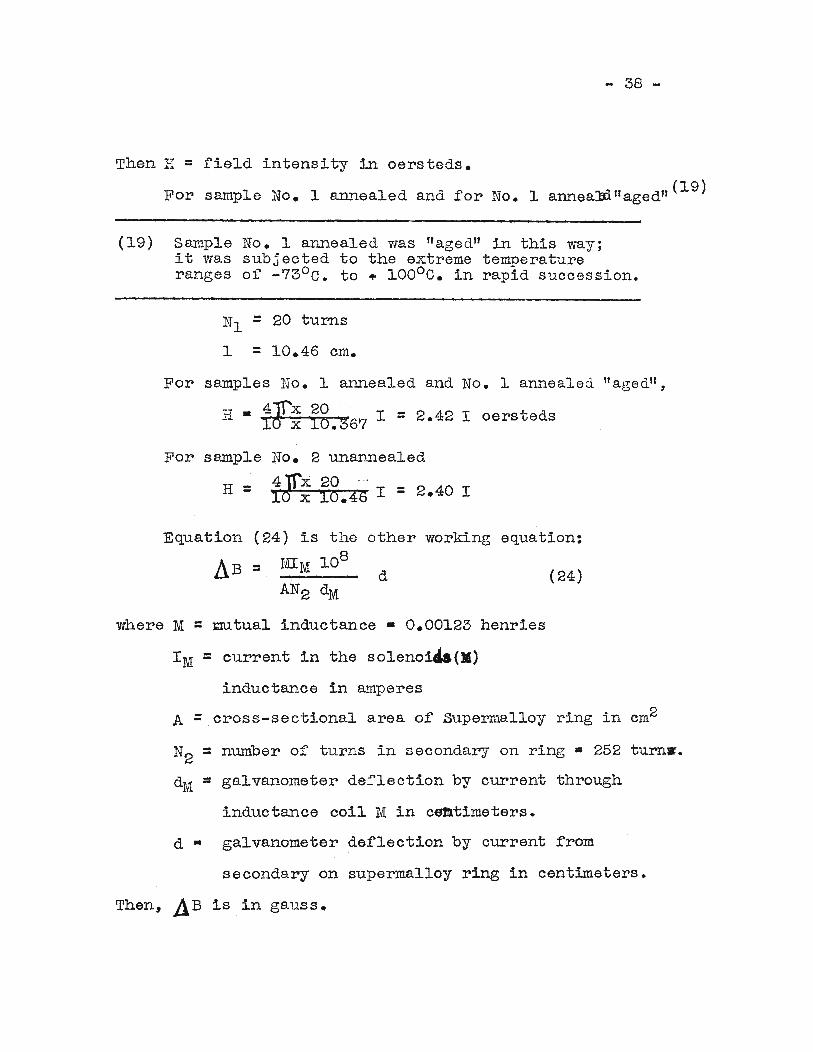
Then H = field intensity in oersteds.
For sample !lo. 1 annealed and for No.1 anneald"agedfl (19)
(19) Sample No. 1 annealed was "aged" in this way;it was subjected to the extreme temperatureranges of -73°c. to + 1000 0. in rapid succession.
Nl = 20 turns
1 =10.46 cm.
For samples No.1 annealed and No.1 annealed "aged",
H • fJC~ ig.367 I =2.42 I oersteds
For sample No. 2 unannealed4'1fx20 0-
H = 'Il>x 10.46 I = 2.40 I
other working equation:Equation (24) is the
I1B = MIM 108
AN2 dMd (24)
where M =mutual inductance • 0.00123 henries
1M =current in the solenoi4a(M)
inductance in amperes
A =cross-sectional area of Supermalloy ring in cm2
N2 =number of turns in secondary on ring = 252 turnw.
dM =galvanometer deflection by current through
inductance coil M in c~timeters.
d. galvanometer deflection by current from
secondary on supermalloy ring in centimeters.
Then, ~B is in gauss.
- 39 -
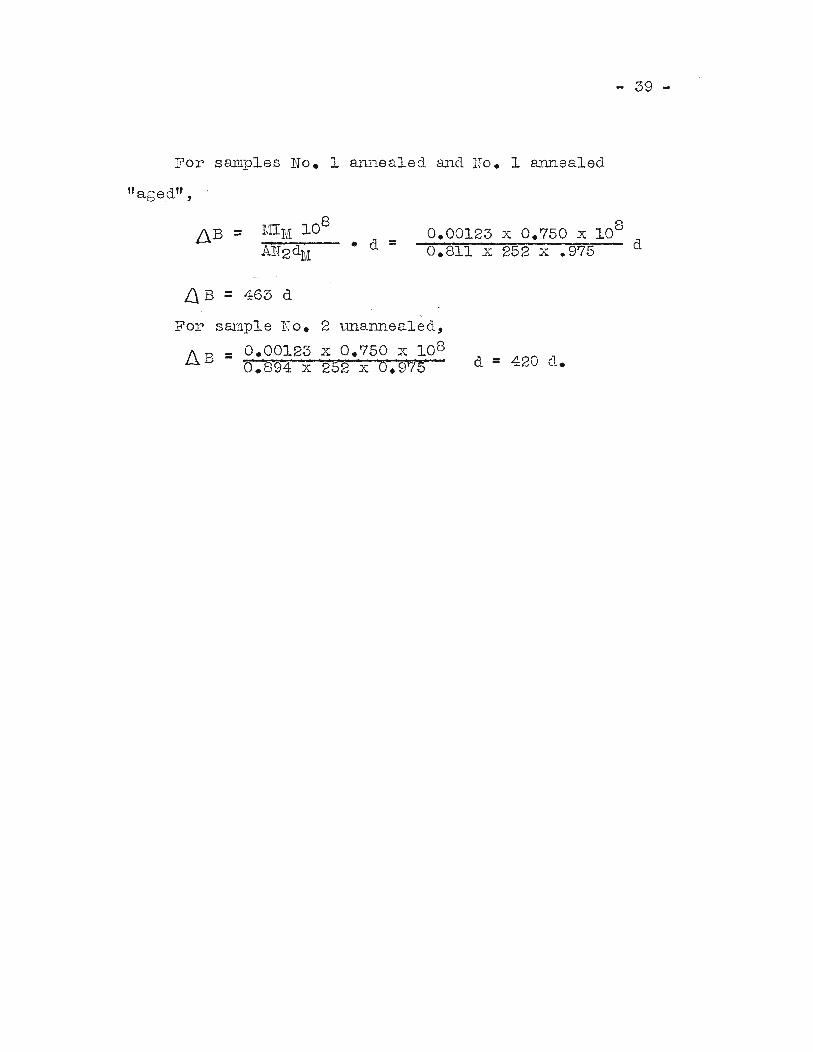
For samples No. 1 annealed and Ho. 1 annealed
lI aged '.' ,
Ll B = 463 d
• d =0.00123 x 0.750 x 108
d0.811 x 252 x .975
For sronp1e No. 2 unannea1ed,
IlB = 0.00123 x 0.750 x 1080.894 x 252 x 6.915 L
d = 420 d.
- 40 -
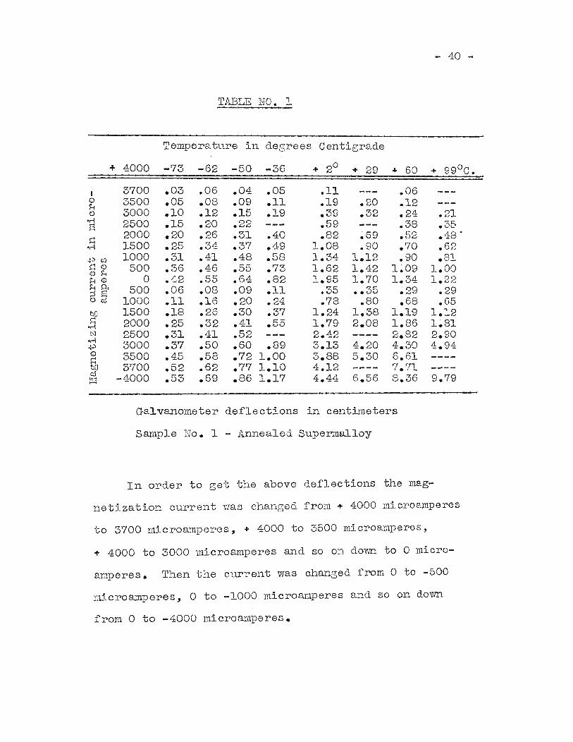
TABLE NO.1
Temperatnre in degrees Centigrade
+ 4000 -73 -62 -50 -36 + 20+ 29 + 60 + 990 C.
J 3700 .03 .06 .04 .05 .11 .060 3500 .05 .OS .09 .11 .19 .20 .12H() 3000 .10 .12 .15 .19 .39 .32 .24 .21
-r-! 2500 .15 .20 .22 .59 .3S .35E~
2000 .20 .26 .31 .40 .S2 .69 .52 .4S--n 1500 .25 .34 .37 .49 1.0S .90 .70 .62.pm 1000 .31 .41 .48 .58 1.34 1.12 .90 .81~ <D 500 .36 .46 .55 .73 1.62 1.42 1.09 1.00<D HH <D 0 .42 .55 .64 .82 1.95 1.70 1.34 1.22HA 500 .06 .08 .09 .11 .35 •• 35 .29 .29;j ElOm 1000 .11 .16 .20 .24 .78 .SO .68 .650.0 1500 .18 .26 .30 .37 1.24 1.38 1.19 1.12~ 2000 .25 .32 .41 .55 1.79 2.08 1.86 1~81.r-!N 2500 .31 .41 .52 2.42 2.82 2.90
-r-! 3000 .37 .50 .60 .89 3.13 4.20 4.30 4.94.p<D 3500 .45 .58 .72 1.00 3.88 5.30 6.61s::to 3700 .52 .62 .77 1.10 4.12 '7.71c;U -4000 .53 .69 .S6 1.17 4.44 6.56 8.36 9.79~
Galvanometer deflections in centimeters
Saraple No. 1 - Annealed Superraalloy
In order to get the above deflections the mag-
netlzation current was changed from + 4000 r'licroamperes
to 3700 microamperes, + 4000 to 3500 microamperes,
+ 4000 to 3000 microamperes and so on dovm to 0 micro
amperes. Then the cu~rent was changed from 0 to -500
microamperes, 0 to -1000 microamperes and so on down
from 0 to -4000 microamperes.
- 41 -
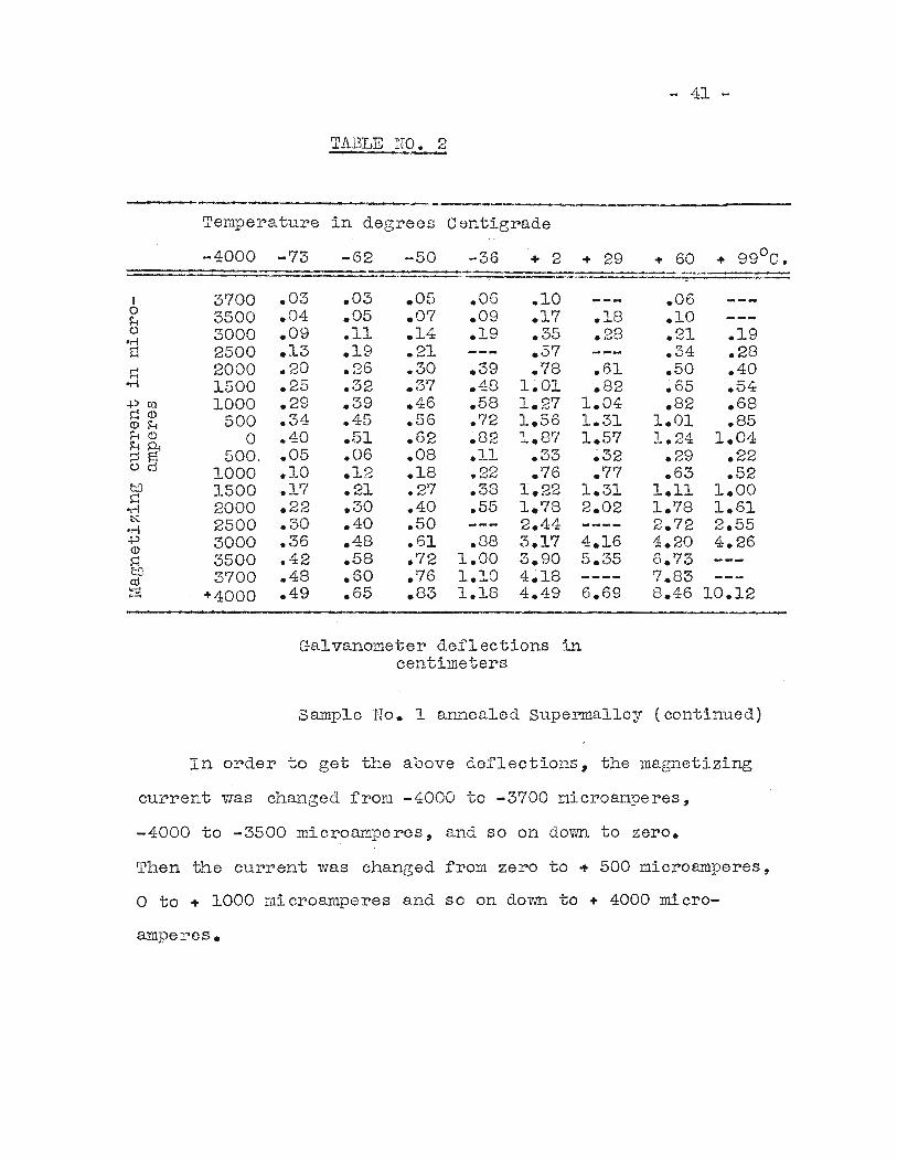
TABLE pO~
-------_.-------_.-._._-------- ----~~-----
Temperature in degrees Centigrade
-4000 -73 -62 -50 -36 + 2 + 29 + 60 o+ 99 C•
.19
.28
.40
.54
.68
.851.04
.22
.521.001.612.554.26
IoHo
.r-!s::1
l=:..-I
.pmS::::<D(l) HH <DHP-i;jl::lOmCDs::::
•..-1N
.r-!
.p(l)
s::::bQa:l~
3700350030002500200015001000
500o
500.1000150020002500300035003700
+4000
.03
.04
.09
.13
.20
.25
.29
.34
.40
.05
.10
.17
.22
.30
.36
.42
.48
.49
.03
.05
.11
.19
.26
.32
.39
.45
.5'1
.06
.12
.21
.30
.40
.48
.58
.60
.65
• 05.07.14.21.30.37.46.56.62.08.18.27.40.50.61.72.76.83
.06
.09
.19
.39
.48
.58
.72
.82
.11
.22
.38
.55
.881.001.101.18
.10
.17
.35
.57
.781.011.271.561.87
.33
.761.221.782.443.173.904.184.49
.18
.28
.61
.821.041.311.57
.32
.771.312.02
.06
.10
.21
.34
.50
.65
.821.011.24
.29
.631.111.782.724.206.737.838.46 10.12
Galvanometer deflections incentimeters
Sample No.1 alLnealed supermal10y (continued)
In order to get the above deflections, the magnetizing
current was changed from -4000 to -3700 microamperes,
-4000 to -3500 microamperes, and so on dOVID to zero.
Then the current was changed from zero to + 500 microamperes,
o to + 1000 microamperes and so on dovID to + 4000 micro-
amperes.
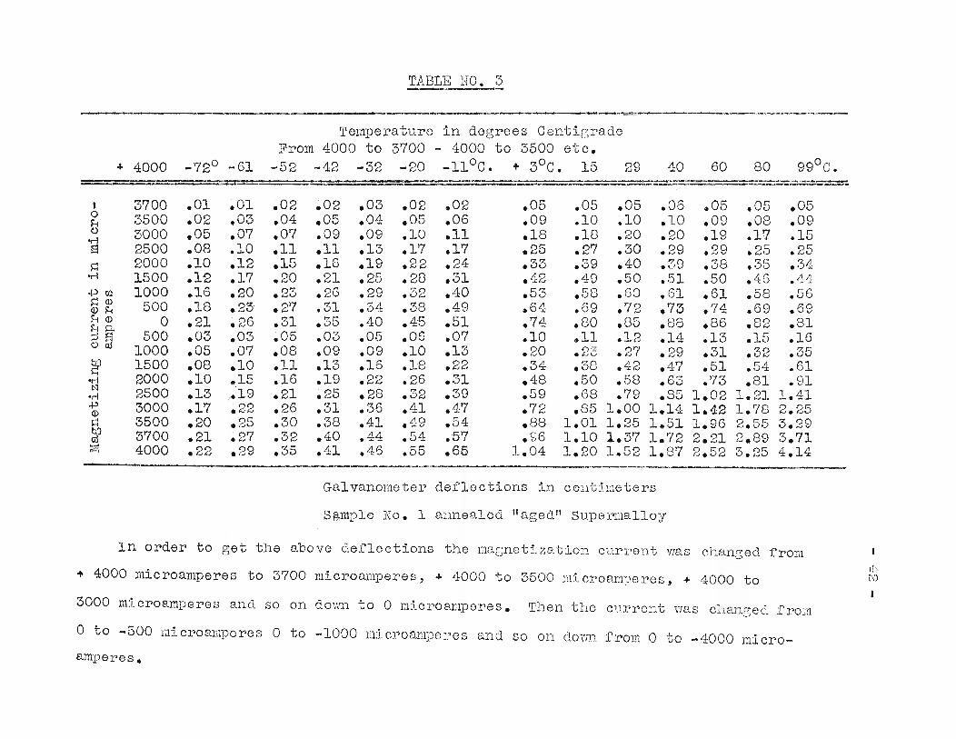
TABLE NO. 3-_.._---._--- . ~ .... ......'.-------.'"
Temperature in degrees CentigradeFrom 4000 to 3700 - 4000 to 3500 etc.
+ 4000 -72° -61 -52 -42 -32 -20 -110 e. + 30 e. 15 29 40 60 80 99°C.--~-- -----~-~-----~----------
_.-.-0,._---_.-. . --_._---I 3700 .01 .01 .02 .02 .03 .02 .02 .05 .05 .05 .06 .05 .05 .050 3500 .02 .03 .04 .05 .04 .05 .06 .09 .10 .10 .10 .09 .08 .09H0 3000 .05 .07 .07 .09 .09 .10 .11 .18 .18 .20 .20 .19 .17 .15-r-!a 2500 .08 .10 .11 .11 .13 .17 .17 .25 .27 .30 .29 .29 .25 .25~ 2000 .10 .12 .15 .16 .19 .22 .24 .33 .39 .40 .39 .38 .35 .34
.r-! 1500 .12 .17 .20 .21 .25 .28 .31 .42 .49 .50 .!51 .50 .46 LL4.~ ~
+JCf) 1000 .16 .20 .23 .26 .29 .32 .40 .53 .58 .60 .61 .61 .58 .56~ Q) 500 .18 .23 .27 .31 .34 .38 .49 .64 .69 .72 .73 .74 .69 .69(I) HH Q) 0 .21 ~ 26 .31 .35 .40 .45 .51 .74 .80 .85 .88 .86 .82 .81HP-<5@ 500 .03 .03 .05 .03 .0.5 .06 .07 .10 .. 11 .12 .14 .13 .15 .16
1000 .05 .07 .08 .09 .09 .10 .13 .20 07: .27 .29 .31 .32 .35."-'U
gp 1500 .08 .10 .11 .13 .16 .18 .22 .34 .38 .42 .47 .51 .54 .61er-J 2000 .10 .. 15 .16 .19 .22 .26 .31 .48 .50 .58 .63 .73 .81 .91t'l 2500 .13 .19 .21 .25 .28 .32 .39 .59 .68 .79 .85 1.02 1.21 1.41-r-!
+J 3000 .17 .22 .26 .31 .36 .41 .47 .72 .85 1.00 1.14 1.42 1.78 2.25(I)
~ 3500 .20 .25 .30 .38 .41 .49 .54 .88 1.01 1.25 1.51 1.96 2.55 3.29M 3700 .21 .27 .32 .40 .44 .54 .57 .96 1.10 1.37 1.72 2.21 2.89 3.710:1~ 4000 .22 .29 .35 .41 .46 .55 .65 1.04 1.20 1.52 1.87 2.52 3.25 4.14
......._--_..
Galvanometer deflections in centimeters
Sg,mple No.1 annealed "aged" SupeI'l1l8.1loy
In order to get the above deflections the masnet:Lzation current vvas chanced Erom
+ 4000 microaTI~eres to 3700 lliicro~nperes,k~'
~ L.WOO to 3500 mi cJ:'oampe pes, ~ 4000 to ('0
I3000 microamperes and so on dovm to 0 ndcro8.l:nperes. rrhen the c1.l.rpent was c~-.:.anGecl from
a to -500 micl>oarnperes 0 to -1000 l1l:lcr'oamperes and so on darn) from 0 to -4000 micro-
amperes.
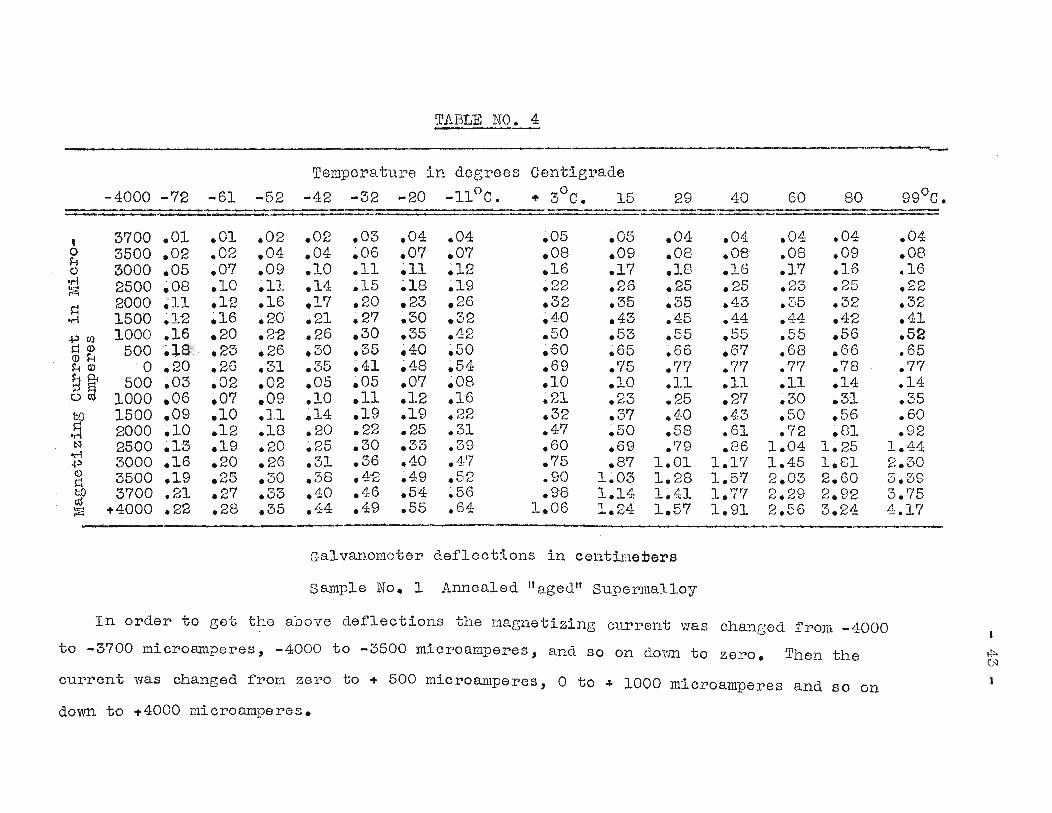
TABLE NO. 4
Temperature in degrees Centigrade
-4000 -72 -61 -52 -42 -32 -20 0 029 40 60 80 99°0.-11 O. + 3 C. 15 --,-_.... _ .._ ..... ....-
, 3700 .01 .01 .02 .02 .05 .04 .04 .05 .05 .04 .04 .04 .04 .040 3500 ~02 .02 .04 .04 ~06 .07 .07 .08 .09 .08 .08 .08 .09 .08H
3000 ~05 .07 .09 .10 .11 ~11 .12 .16 .17 .18 .16 .17 .16 .16Q
or-! 2500 ~08 ~10 .1-1 .14 .15 ~18 ~19 .22 .26 .25 .25 .23 .25 .22:zl~
2000 ~11 .12 .16 .17 .20 .23 .26 .32 .35 .35 .43 .35 .32 .32or-! 1500 ~12 ~16 .20 .21 ~27 .30 .32 .40 ~43 .45 .44 .44 .42 .41.j.)(/) 1000 .16 .20 .2-2 .26 .30 .35 .42 .50 ~53 .55 .55 .55 .56 .52l:j Q) 500~le~: .Z5 .26 .30 .35 ~40 ~50 ~60 ~65 .66 .67 .68 .66 .65(]) HH (]) o .20 .26 ~31 .35 ~41 ~48 .54 .69 .75 .77 .77 .77 .78 .77
8~ 500 ~05 ~O2 .02 .05 ~05 ~07 .08 .10 .10 .11 .11 .11 .14 .140 1000 .06 .07 .09 .10 .11 ~12 .16 .21 .23 .25 .27 .30 .31 .35bD 1500 .09 .10 .11 .14 .19 ~19 .22 .32 .37 .40 .43 .50 .56 .60;i 2000 .10 .12 .18 .20 .22 ~25 .31 .47 .50 .58 .61 .72 .81 .92!:'I 2500 .15 .19 .20 .25 .30 .33 .39 .60 .69 .79 .86 1.04 1.25 1.44'r-! 3000 .16 .20 .26 .31 .36 .40 .47 .75 .87 1.01 1.17 1.45 1.81 2.30.j.)Q) 3500 .19 .25 .50 .38 .42 .49 .52 .90 1.03 1.28 1.57 2.03 2.60 3.39~bO 3700 .21 .27 .33 .40 .46 .54 .56 .98 1.14 1.41 1.77 2.29 2.92 3.75~ +4000 .22 .28 .35 .L14 .49 .55 .64 1.06 1.24 1.57 1.91 2.56 3.24 4.17k:-'
'"'" -Galvanometer deflections in cent~l1eDers
sample No.1 Annealed "aged" Superma110y
In order to get the above deflections the magnetizing current wa.s ch~~ged from -4000
to -3700 microamperes, -4000 to -3500 microamperes, and so on dovm to zero. Then the I+'-(.'1
current was changed from zero to ~ 500 microamperes, o to ~ 1000 microamperes and so on
down to +4000 microamperes.

- 44 -
TABLE NO. 5
Temperature in degrees Centigrade
+1.50 -70 -61 -45 -27 -11 + 10 C. +14 27 40 60 80 990
1.35 .03 .04 .02 .05 ~05 .04 ~06 .07 .06 .06 .05 .071~2 .10 .10 .09 .11 ~11 .11 .12 ~13 .12 .12 .12 .131~0 .18 .19 .19 .20 ~20 .22 .2J. ~20 .21 .22 .2J. .21~9 ~23 ~23 .23 ~25 ~26 .27 .28 .28 .29 .28 .27 .28~8 .28 .29 .28 ~30 .3J. .34 ~32 .33 ~33 .37 .32 .32~7 .31 .35 .33 .34 ~38 .38 ~39 .39 .40 .40 .4J. .40
0)~5 .45 .45 .47 ~45 .50 .50 ~51 .52 .53 .51 .52 .5J.
a>H .4 _--0- __0-
.51 .50 .58 .60 .60 .58 .60 .62 .60 .60a>
~.25 .60 .60 .62 ~62 .69 .69 ~70 .71 .74 .71 .72 ~79
~.10 .70 .71 .72 ~73 ~80 .86 .86 ~85 .86 .83 .91 .96
~.05 .75· .76 .78 .79 .85 .88 ~87 .90 .87 .94 .98 1.00
..-I .0 ~83 .84 .85 ~87 .95 ~94 .96 ~95 .95 ~97 1~01 1.02
.p ~05 .02 .03 .03 .03 ~03 .04 ~04 .06 ~05 .06 .06 .02~ .10 .06 .06 .OY- .07 .09 .10 .10 ~10 ~10 .10 .10 .10a>H ~25 .J.7 .18 .19 .19 .2J.: .25 ~23 .28 .28 .28 .27 .29H .40 ~31 ~32 ~36 ~44 .42 ~46 .49 .50 .49 .49g .50 .38 ~41 .40 ~44 .50 ~56 .56 .61 ~62 .65 .62 .64
gp .70 .65 .70 .73 .72 ~80 .89 .88 ~96 .99 1.04 1.0l: 1.08
..-I .80 .78 .Sl ~80 ~91 .99 1.09 1.08 1.18 1.20 1.28 1.26 1.32N .90 J.~OO 1.06 1.09 1~11 1~21 1~-31 1~32 1~42 1~47 1.58 1~56 1.69
on 1.00 1.16 1.28 1.32 1~37 1.50 1.60 1~64 1.76 1.82 1~97 2.06 2.22.pQ) 1.20 1.61; 1.79 1.91 2.02 2.25 2.40 2~58 ~~71 2.88 3~23 3.71 4.12~~ 1.35 2.06 2.30 2~47 2.63 2~90 3~12 3.35 3~51 3.70 4.29 4.75 5.29~ 1.50 2.34 2.68 2.75 3.01 3.31 3.53 3.81 4.05 4.31 4.94 5.61 6.03
Sample No. 2 - Unannea1ed superma110y
The magnetization current was changed :from 1.50
amperes to 1.35 amperes, 1.50 amperes to 1.2 amperes, 1.5 to 1.0
amperes, and so on down to zero amperes. Then the current
was changed from zer? to.05 ~eres, 0 to 0.10 amperes,
and so on down to -1.50 amperes.
- 45 -
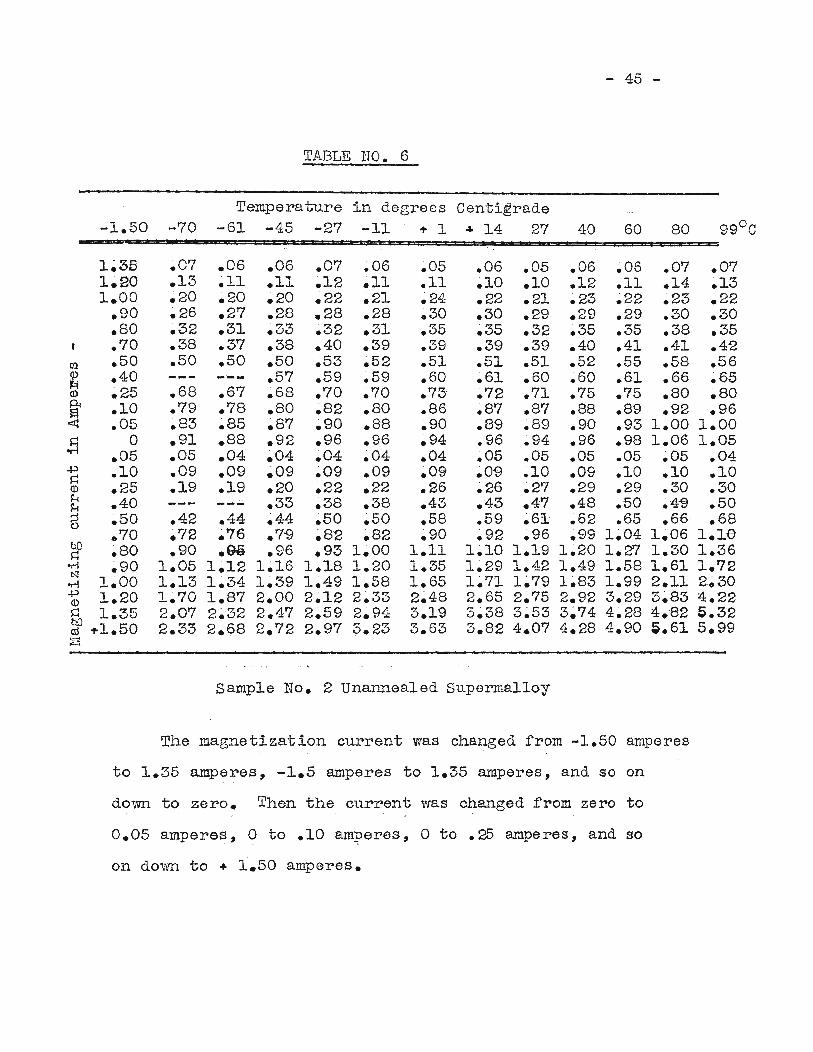
TABLE NO. 6
Temperature in degrees Centigrade-1.50 -70 -61 -45 -27 -11 .,. 1 .&0 14 27 40 60 80 99°C
1~3B .07 .06 .06 .07 .06 .05 .06 .05 .06 .06 .07 .071~20 .13 .11 ~11 .12 .11 .11 .10 .10 .12 .11 .14 .131.00 .20 .20 .20 .22 .21 ~24 .22 .21 ~23 .22 .23 .22
.90 .26 .27 .28 .28 .28 ~30 .30 ~29 .29 .29 .30 .30
.80 .32 .31 .33 .32 .31 .35 .35 .32 .35 .35 .38 .35
.70 .38 .37 ~38 ~40 ~39 .39 .39 .39 .40 .41 .41 .42l'f.l .50 .50 .50 .50 .53 .52 .51 .51 .51 .52 .55 .58 .56~ .40 ----- .57 .59 .59 .60 .61 .60 .60 .61 .66 .65<l) ~25 .68 .67 .68 .70 .70 .73 .72 .71 .75 .75 .80 .80~ .10 .79 .78 .80 ~82 .80 .86 .87 .87 .88 .89 .92 .96~ .05 .83 ~85 ~87 ~90 .88 .90 .89 .89 .90 .93 1.00 1.00l=l 0 .91 .88 .92 .96 .96 .94 .96 .94 .96 .98 1.06 1.05
or-i .05 .05 .04 ~04 ~O4 ~04 .04 .05 .05 .05 .05 .05 .04.p .10 .09 .09 ~09 .09 .09 ~09 .09 ~10 .09 ~10 ~10 .10l=l<l) .25 .19 .19 .20 .22 .22 .26 .26 ~27 .29 .29 .30 .30H .40 .33 ~38 .38 .43 .43 .47 .48 .50 .4"9 .50Hg .50 .42 ~44 ~44 ~50 ~50 .58 .59 ~61 ~62 ~65 .66 .68
070 .72 ~76 .7-9 ~82 ~82 ~90 ~92 .96 .99 1.04 1.06 1.1etill .80 .90 ~ge .96 .93 1.00 1.11 1~10 1.19 1.20 1.27 1.30 1.36s::·rl .90 1.05 1~12 1~16 1.18 1~20 1.35 1.29 1.42 1.49 1.58 1.61 1.72t'J
1.00 1.13 1.34 1~39 1.49 1.58 1~65 1~71 1~79 1~83 1.99 2.11 2~30·rl.p 1.20 1.70 1.87 2.00 2~12 2.33 2~48 2.65 2~75 2.92 3.29 3.83 4.22<l)
s:: 1.35 2.07 2~32 2~47 2~59 2.94 3.19 3~38 3~53 3~74 4~28 4.82 S.32b0 .,.1.50 2.33 2.68 2.72 2.97 3.23 3.63 3.82 4.07 4.28 4.90 ~.61 5.99c:1S~
sample No. Z Unannea1ed superma110y
The magnetization current was changed from -1.50 amperes
to 1.35 amperes, -1.5 amperes to 1.35 amperes, and so on
dovm to zero. Then the current was changed from zero to
0.05 amperes, 0 to .10 am:peres, o to .25 amperes, and so
on down to + 1.50 amperes.
46
...
NOe-+-.-LAnneaLed - D'1750 Supermal1loy . _ -'-+--+--:--:-:--;----1---,--,- ;-1---T----l.-~. ,-
I --=t-=-~.-.~I---t----'--t---+-
1000 I
. QOO
··120
_ 15-CO
_ l250 _
1.(
~OO~
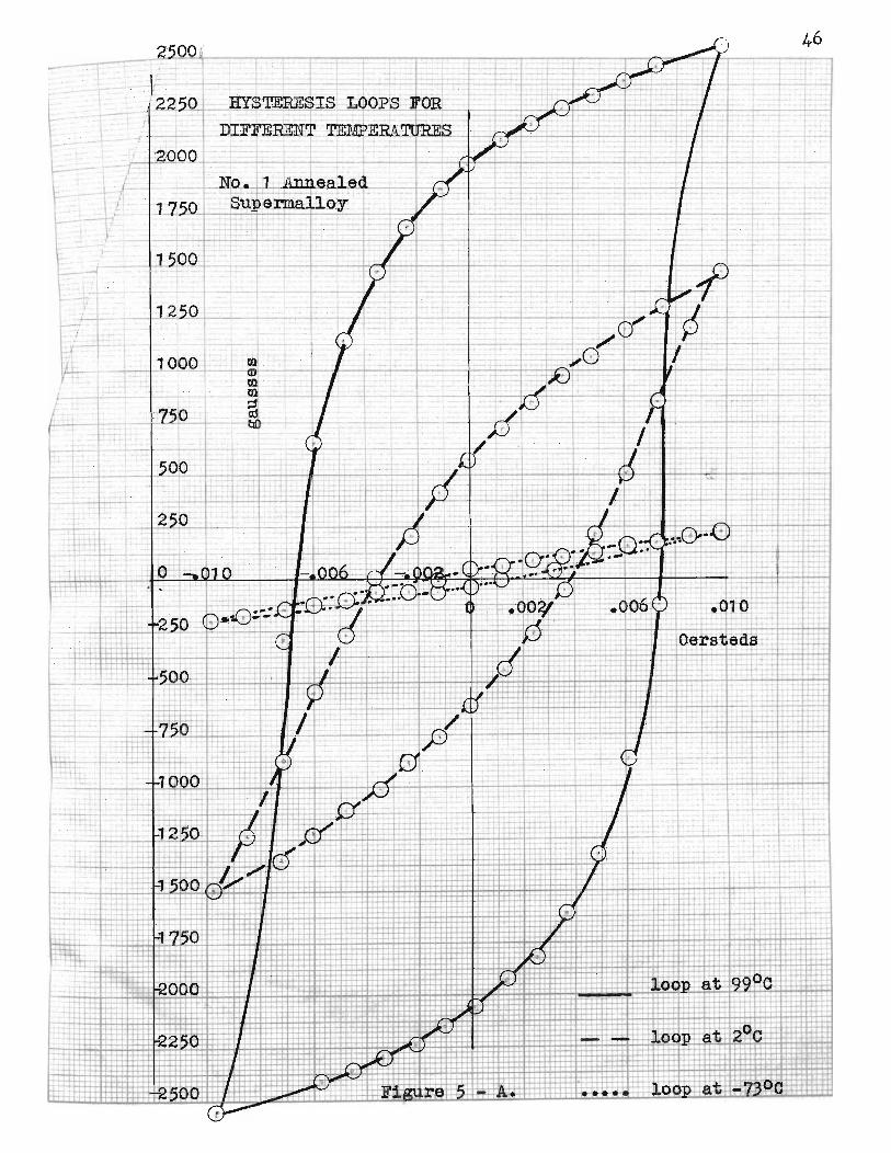
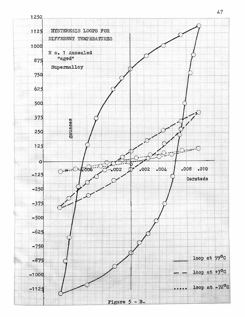
1"\ .. 2250 _ HYSTERESIS LO_OPS OR._~_-,-- r---,,*~1----+---,--t-.'_+
DIFFERENT TEMPERATlJRES
~SIS "OO~ ~OlLT - Jf.__-'-~~.I _~DIFFERENT.. TEMPERA'lURES 1_ I
t
47
J
. .
-;7~V---
,
Superma110y
N o. 1 ±nealed"aged! -
---4----.:..--1--
. -I .
->- - - ._-
.-I
t
- _ .... I-T:~+.-:- ::::_._~., 0+C .~ -<
-- - ~i~ure :--5:i- B.i
-
-j. >=l:h-t-+
.: I' 21-" ..~IBlI;. . ~ ....-,- - E b.; ....
--.~ .....,..-
--
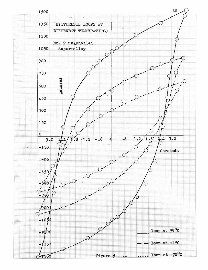
1500
1350 HY$TERESlS LOOPS ATDIFFERENT TEMPERATURES
1200
NQ_.2 unannealed10$0 Supermalloy
900
600
450
300
150
3.0
t--'----i --+
L----=:l~_'""'...::..~_loo~ -70°C
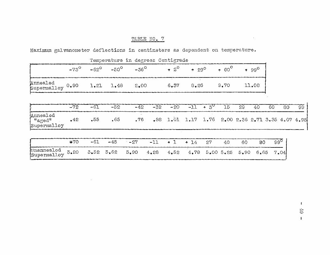
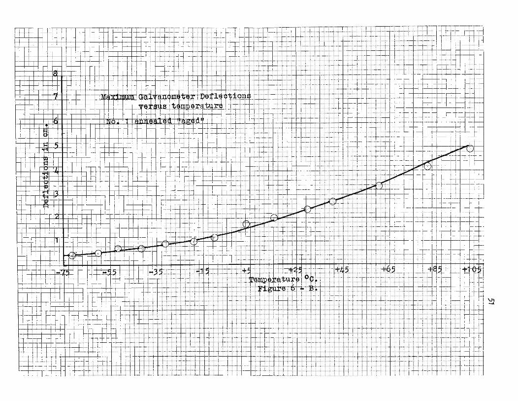
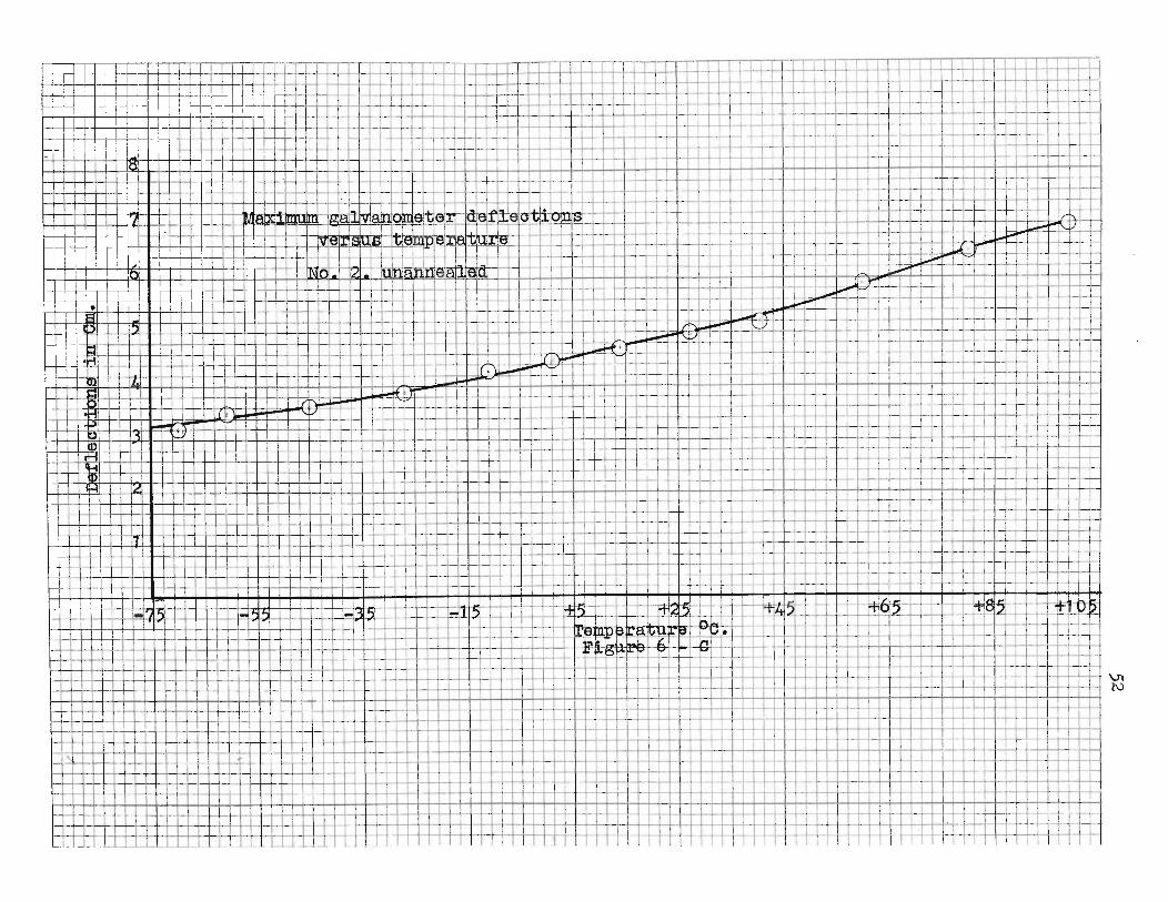
TABLE NO.7,
Maximum galvanometer deflections in centimeters as dependent on temperature.
Temperature in degrees Centigrade
_73 0 _620 _50 0 _36° .,. 2° .,. 29° .,. 60° .,. 990
knne"led 1.21 1.48 2.00 6.37 8.26 9.70 11.08Supermalloy 0.90
-72 -61 -52 -42 -32 -20 -11 + 3 v 15 29 40 60 80 99
Annealed1.Cn" aged" .42 .55 .65 .76 .88 1.17 1.76 2.00 2.36 2.71 3.35 4 Q 07 4.95
Superma110y
*70 -61 -45 . -27 -11 + 1 + 14 27 40 60 80 990.
Unannea1ed 3 20 3.52 3.62 3.90 4.28 4.52 4.78 5.00 5.25 5.90 6.65 7.04superma110y •
It:;.({)
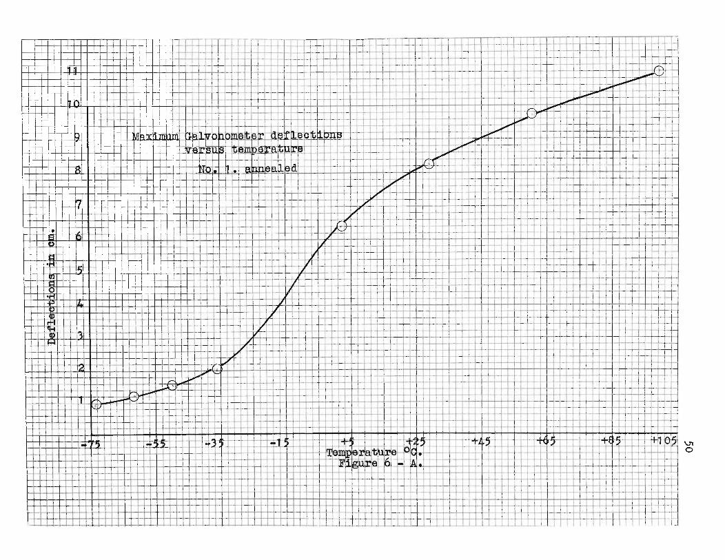
50
=a-I~
~,
!I
;TII~+-H
-H~+-+-L_-+-rI+4--+-rI-l-I-+--t--:-,L1 -++++/----l-T-f-l-+-+++
'n4
-1-1
-,---~r-:=.-
~++-+I-i·I-
·!~'
1'_,.+
i.··t-j-
-J-+
-,
1·-+-+-~'--+'--.--l-+--I.-,-+-f-++--\!-+-H--I--''-1-+-+-iI++-++I-++-+--1'-'--h+-.jI-++tI
II
_I
ir
tI
II
f-H+---++~+++-++-II+-1-r+H-+-l-r1-++-1,-1--1-1
1..-l-·..J-IvL.-!--l---+
-++
-+-h
t-l-+-
~I~I-t
.r-:I
IT
,-T
hrrII',
I'f*''c-
.;
III
!,'--~I.il
'I
Ht-t-
',-.-
.I
f-!-h
r<
TIl
!--j-Ii,
II,
'i
!c-h-:-1
-1-'_
1I'
t!-I-T
irr---t+
,,\11+-1-
1-1
I-I
'I
Lh
-,1-h
+.~
1.
!I
i-I-if'\:'_
I-'
-W_4 '
!,-.-++
r-M-+~'-1-~
i-,:
'I
~~.~::""n-ir
f.l~.J='=I_"--"-'--+--+~
If..-;-r
I..
Ii'"
L~
Ij
1"J..~tiU
_!"_'._
_.:..'~,
IT
I1
---:-1,
Ir
!i\.L
1'1
,,'I
'I'
_t+
.I
r:
i-T-
..~-rr\
';
-;-;-...:-
1-
I,I
':"+-j.I-1-~1-t-+-+
--.,-.-....--r-i-H
--i.....,'-
I-I---i---.-i
I~:f
...-t-+-t-
I~-r-tr+
'f_I_.+-.;..-+'-+-+-;-'~'-+--+~.+..+
-,:~,---r..
If-;H-H-+II--H~..t-t-t-r-t;--:-+l+-t--r---:-~'=t+hl-I;--i·+-r---.-r-.-.'--j
~tq-H
I~r-l-Jt
f=R.t
i-!I
I'
f;I'
T~-~p
~r,
T,l
r
I--I--H-l-+
-+-
+-+·++-+-tl--!l'~lf"'··H,-t·!=rH-J
~-+--+,-:,1-+-+-+-+-+·
I-LI,
~I,
,+t-
i-t-if-l-f-+.i-' +-+-!,'-+-+-I-4,·-I-I-I-'-+--+--+
'+_H
--H'-_I-f-+
-I -++
-+_.i
I..
T-,-+
+-+
+-+
'-l-'1-+-h~H--I-+-..l.Ii--4-'+--I-:'-";-r,1H-~H-+1+
r+-.-t
I-+-..J-~-+I
'-,II,
II
'.~-
-;.-
hl-+
--H,-l-I--'-'+
:-N-I-t-r-.......+
-hf--j......~1~,-1-~--:-+
t·-l-!-+--l-+-~I-!
T'
,I
JI
~"L'+~t-..LI+-I-I--h---t--i-+
---t+-hrl--H
-H1--I-~--!---I'-+-+-r++-+-I-cH-...L....i'G---f-
-f---I--j·h-I--++-j-4-._t_tJi_+-I-++-f_t--j-_+-I-+-I--++-I';-_+-I-t_-+.Ji-='.~t~-t_~U-H-!-H+I~i
+-++1H--t i+
t-f-H-H
~.r-'.~
·Hh-l--_·H~q-I-+-+-t-+L.;-r
Ir..-W-+----
++--+---I-il-++-+-f-H-_+_t-t-·I--I-+-r·t-+--,-'-+I-i,'-+1-.......,.4A..'-I-l-,+
-+-+
-I-!--H-+
-H
1-
H-+
-IY-+
++
+--
I-
.-Ll-l-t-!-~~---W--1-~i-+-I-++-H-+-+++-H++-+-H-t+-I-H-H-H-I:-Hi
1
51
H-+
+-+
1--H-+
--l-f1~"'1--l-+H--hf-++-f9-I-++-I-+
_I
H-f--+--I--c----I-I-+--++++-+-+---c--++-+-+~t-r-
I--+++-L-t-t--+-t----r--'-~_f----+-+-+-1--+--+-++++
-I
_-H-+l
~;~~~~;-:=-c---t--~--j--:+-h+-+---~~::-:f-:-,:-~--+-:t+-+:=i=:I---+--+f--+i-_-1-=-Jr::.-~ltt1--:--+t-'::l--t-t::t-+T+-l-i-+---1'-'_J-1---T-f-~-~--1--,-I---1--H
---~
~Ft-ft~c--
-R=~-1
52
1:_f-I-!....
WW
'Lj
eR=:-11Yh-~'+~
!--!:j-+'
L-l,
hrl''..
-I
4-;--1-H-
~t~.·
+=.1
---
Ih
-',
-j-,
+-.--I
":H
-,.J___
-,:L~-i--i'-r-'+
-i-H-+
-+-i-+
-+-
1-;-+-1-+
-'1I:'
;til;
,'
IT
~-+I'I
m1=1%
+rt'
,...I1i
-cD
,I
:I~"
_.-.-t+t-·
__,!
I-T-t-
-h
i~
--~
::-I
I1"-H
-+
-_~
,I
~-1-:-,-'---
J+-!-I"';'"++-i-,-H-:-.j+::-T~!:
"II)
",;
!'--t,-h
'T
j1~
I
"i'tj
,lit
I'
"1
'1
1,
II
1I
!j
II
!-1H-+++-+--J--jf--l-+--l-+-l--+-1"'1~+-I-+:+,-H
-l-H-'++1
,;,-1-H-++++++++-H--t-t~-r-J.r
T
1-+-+-l--j-++++-+~H--H-++-HH-,H
-++
-t1-l-4
,l++++-H~,H-H-+-+I'+
-+'-H
--t-1H:rotT
rt--t---h+H
---l-I-+-+
+-!-J--I-+
-+-!.-+
-
-11---
--+-'r-1
- 1i\+
--t-r-·y-I-i-+
+-1
-I---H-H
Hi-t+
-++
++
-H---+
---1-rlH
-H--H
-·r-+--l---l--I-+-+-!-H-+-l----+--.H-I-++-+-4,-l-j-+-++-H--Hr-it'f"!~
rr-++-+--j--i--I--+--I'+I+l-H
-HH
--H-+
++
++
t-+-t-H
H-t+
-H--I-i-H
-t-I
"
l
i-~++++-l--l--il-+--I-I-++-H-++-++++-!-+--.
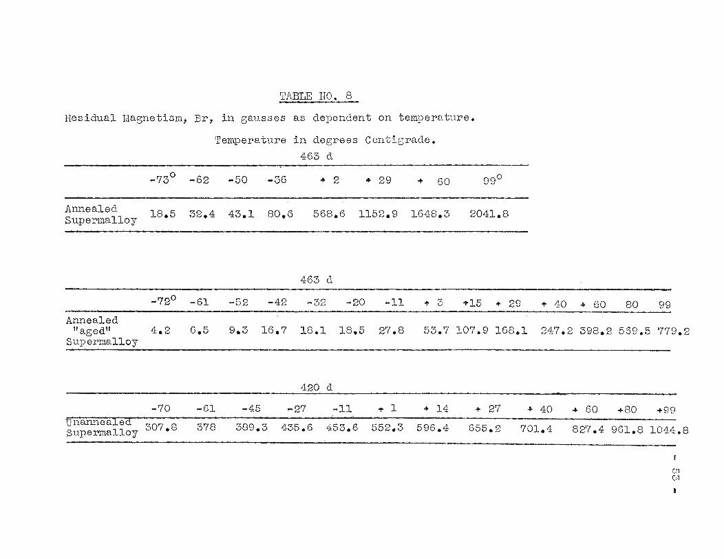
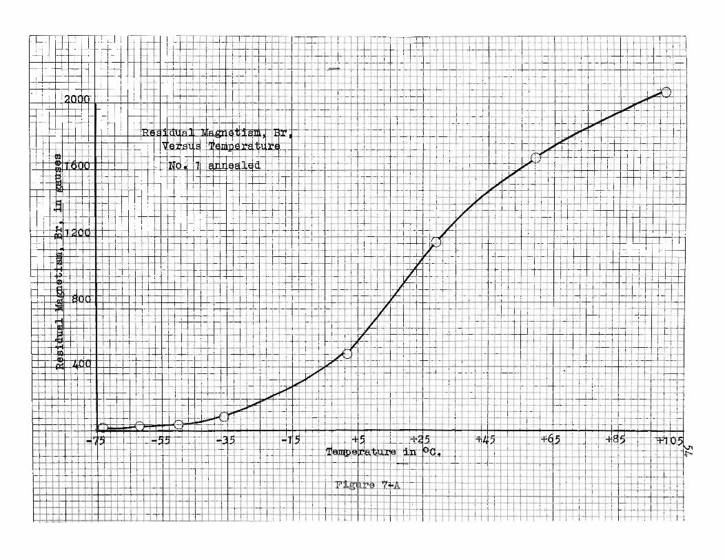
TABLE NO.8
Residual Magnetism, Br, in gausses as dependent on temperature.
Temperature in degrees Centigrade.
463 d
o-73 -62 -50 -36 + 2 + 29 + 60 99°
,AnnealedSupermalloy 18.5 32.4 43.1 80.6 568.6 1152.9 1648.3 2041.8
463 d"4
-720 -61 -52 -42 -32 -20 -11 .,. 3 +15 .,. 29 .,. 40 + 60 80 99--Annealed
II agee." 4.2 6.5 9.3 16.7 18.1 18.5 27.8 53.7 107.9 168.1 247.2 398.2 569.5 779.2Supermal10y
~-------~--
420 d
-70 -61 -45 -27 -11 .,. 1 + 14 + 27 "" 40 "" 60 +80 +99unannealed 307.8Supermal10y 378 389.3 435.6 453.6 552.3 596.4 655.2 701.4 827.4 961.8 1044.8
01CN
l)l._
lI~~~-.1f--+-'n---r'nII"
IL+t-+-J-t"~:
lL!
1-l-!f+I,'---I
II
Ii,"I
i
'r
II
.J...LJ...-j..-H
-+--t-r
TI
.,;~T
TII'
,,
I'
;..,~T
I,-t-
~--t.--LL.L-+-I-+--+-++,-t-t---r--l-T'
TilJ,__
L...L
-LJ.-4,-l-.lH
--lU'-'T
-I--t-+hli'V
-t--,
.L.L1
_1--+-+1
-1-,I-
Hl'\Jj-r
II
-i--"I
II
':
-r
I_
"I.L
.L-l_
-_'I-L _
I-+
--t-
t,I
T-~~-
-I
U-l-"+
+H
---r-L
LW
-++
++
-t-:tiT
5'
-I....
IIi
l-I
I
,-
'!'W"[r
I
I
;
I
I
_.I
iI'
i
,-,I
.-'
f---
I
-T
I,
I
I
I
I~
,I
I
"
I
l.
I
IT
}-+-+-H-+'--l---r-l-
I
LI
II
[_.-
T
I
-t!
IrL
.;I~
.I ,-
+-~-
r--1~lttjj~·+++++++r++:r.tL=1I-
-;!:tj-t=tC±i+H--+-++T=p+~t=jj±ij
!t6
1";'1
IT
TT
I
r
I
I
~
it'
1
I
-
,
~
I
~-
I
I
"\
,.
;;;""...
I
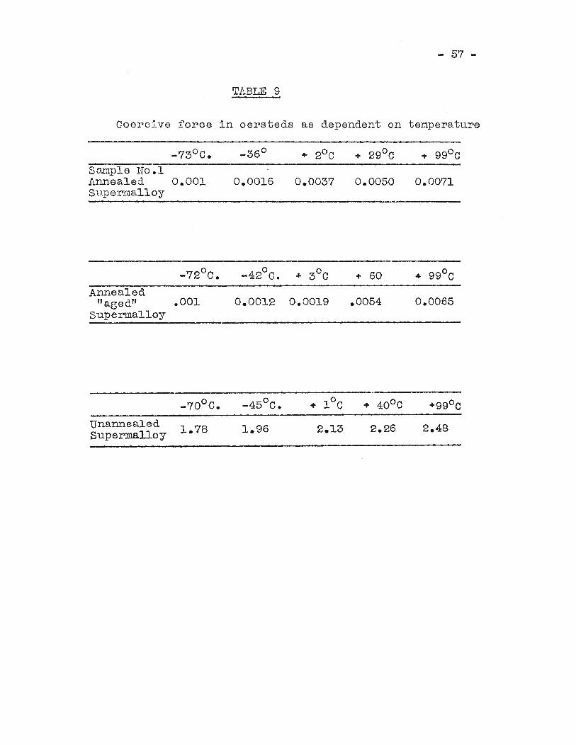
TABLE 9
- 57 -
CoercIve force in oersteds as dependent on temperature
-73°C. _36° + 2°C + 29°C + 99°CSample No.1Annealed 0.001 0.0016 0.0037 0.0050 0.0071Superrnalloy
°-72 C.
Annealedtt aged" .001
superma110y0.0012 0.0019
+ 60
.0054 0.0065
°-70 c.UnannealedSuperma110y
o-45 C.
2.26 2.48
,,I
1
++11-l-+-++++-+-I----1-4-tttliItT
t++
N-H
-+'+
+t-+
--1-w=
rU=
CU
1
!8~
II
-T--+
h-
I":"I
!I
I_LL
III'r'\
II
::JI
I
II
-H-+-+-+-+-+-+
-i-
+~
-H--i--,-t-+
--H-H
I-L-L-1I-l-
Ia
__LL1_--J
II
f.:rT
-HI
-T+1I
-..,-~I-+--f-r,·-~'---'-,
.1-
1-_ 1,.1m---tW
TT+=+++-L4-r++
++
t:r...h-4-+--:-~-,.L~-t-WI:=
I---=
-r-t-H
-rr-
1-
-I-
--
.••R=t-+
;-.f-
-+I
II
rI
'I
L-rl·
t-,-I
I
D
Ij,i
1
I I-t+
;;k-t-e-I..lI-+
-I-+-J-I
-h-+-H
++
-++
+-+
+J-+
-+'Il-+
---:-I-J--·f-'--1--++-.-1-+-+-+-+-4-<
l~;=_~~~=t~~=tt~ji=t±jjttj~=t±,---j-+-Ui-'I-+--t--iIH-+-+-+-+_.~-H-+-H+H++-++l--r_H--+-~--I-tl-+-t-+...J-I-.k+--'H!-+
-t-
I-II
'
I+
---r--
TT
=1=~h--j--
-1
--
---=f-:
tltijj-tHt-l+t-++++l+++~+H~++++=t~~~1=ttj:j=tb-l-~f-+I---i--,--l-l----l--,-+r-+-I--I----I-I.+-+II-
-r--h-t---±.+-
-t-_1
-1
'-
.,T
Tl
-if-
-r~
Ei tlllit+R+R=t=Ri=R=R=rffffirn.m
EEEE933lf±- T1E-H-ffi----H- of-++++-'--l--t--1
I--~
-i-
jj:tjj±H+t-++H+H+H-+t-++H+H+l=t+r++:~+1=+~=ttt=t:ttr:tttJ=-r-tt·1
--
f-f
-f-t-r-
'iCI
I1
II
/I
I-+~:
,,
---1-1
I1
:
T---H--
L,
-1\
'JIii
,
±L
L-Ft+-
H~
+-
---
'_~.-
-...
1.'-'-
--=--±
II
I1
--
1-i--ttn:l=r"±---~l'
-,--L
_"
1I
I---r++;I
,.
rt+-
"I
.Lf-
TT
"J
,!
.I.,-I-f--
~+rl-
±L~=-t-.~
r:-t
I++-,
-1~1_It+--~-::~++
-,_-+
r=tt
~!.=tF
-r++W
---iL-j---i---+------I
,1-H---Ll-H---~-I\H-T,-:-T
-c-t-.Ij
:I
iI
!~-~-
-'+lI-Jr +
-.I.I-f--J-
r -!-
1,
-i-I---I-j-+--~,....
I1+.(-+_._+-;
!;
·~,++.++.;-
~-i-J.
Tr-
r1-'·
+nJ'f-+--i!
T+-r--1_
1,-
-.4--4-H
-,,---ri--t+
-d-+
i~',
;.+-t--~---f-.+r-++-'~f-
+L
f--ti-r_..LL
fl"T
f-'J-
Tr'-
-rT
r-
--
-I
+-C+-Y--r-+-i-f---'-;--~-ti--"-itt--
-I
."~.--_.
'--
'-r-I--.-Lj-~.+
.·t-I-t-,
I,-
it1
~_
.I
11
.l'
If-
-1-+
-t-+,-1---H,-+
+-'--
-+_'.f-
-I-'-++-+-r-++~~!-++--I-,-t-t
r+-lP
t-t--+--r---+
-H+T,--.rt.-1
_.-
-_
+-'k
'2i-+
-.-+-I---I--t---'-j-Jr --t-'
-'-h-.L-,--.+--,--+I-Ll'~-H+~f-rlr+-H:
'-h-ic
-!---H--I
t1W
--~:f-+++-L-1-L.t-+-'-++--.-r+·-'--f--I-r--t--L++--
I--t-+--r--I
._L
f-l--+--'H-+
-~
-bf--+
-tl:fl--r-l---l--+-f--+
---'--r-f-.L-'-.'-+
-t-t--r--;-'-t--+-t--'--t-+
·-'--t-t:
r-;--n-'-,
-L_
L_
_,-.l...L
+__
--l-~-~r--r--+=I""':j-+--H--H--h-++++-r+++++-h-++++++--'-L+--r-++.L-tt++-T~H
-Ht+
-rH
-j-
L~--
-.-1
.II
__j__
IIi-
._
f-__..
"-;_1_
=-P2~-=_t~f__i_-'TL--"=~"~~~-~:=_t_t_-:~
1%'1
-'ITh
±::::-=::,-~~--
I--J-
++....:ti
+-1----L++
1,
1----
,
f-_~~-+
'--1
f-- Lc...L+H-
L-
,
f-1
'-t--'--'-+-+
-+---r-;"
-H--,-+-~~-f---t--!~jf-'f--+-j+
-+-+
-!f-f-t-I
----'---t-++
++
++
-+-+
+-+
1-+-f-H
-H-+
-r-++
-,--t-t-t--'-I-I-HI-+
-+-H
++
+I--Y
-t+-t-H
-+-t-+
-t-++
-Ht-H
+-t-t--tt-'--t-+
-++++-t-+--1--1--+--~U-J--L-).J..-l--H--1--t-+-l--l--t-4-++hH++-r-+-h--r-++++-t-+-+-1H++++++-t--:it-H-t-t-tt-t~f
h~i
~
-J-+-lH
-H--t-I-+
--t+-t-H
HH
--r-+-f~--If-'--t--~-+-+-++~--,-j+-H-+-+-++-++++++-H--H----t-Ht-t-H-++--I-i--f--I-f--I-+-+
t-IT
c-_.H
-I-I-H-!-+
-t-+L
+-+
-+-+
...L+
-+-+
++
-+-
t-'FL+-1-+-1H-t++-+-l-+-++-++++-+-+--H--+--I-+H-+-+++++~.-kiIi--Fi;rl~i'ikTI-t-+--r-+-+---._.
_r-
1-!1+l-=l-tt·tt---+-1--+--I--+++++--I-I---I-i-+-H-++++-H-+-iI--/--H-++-H-+t-+-i-+-H-t-t--+--~-H-t
t-t-+-+-t--t-I----:-t--~~t-t-
+-1
I---~T\=R=-\-\-1-
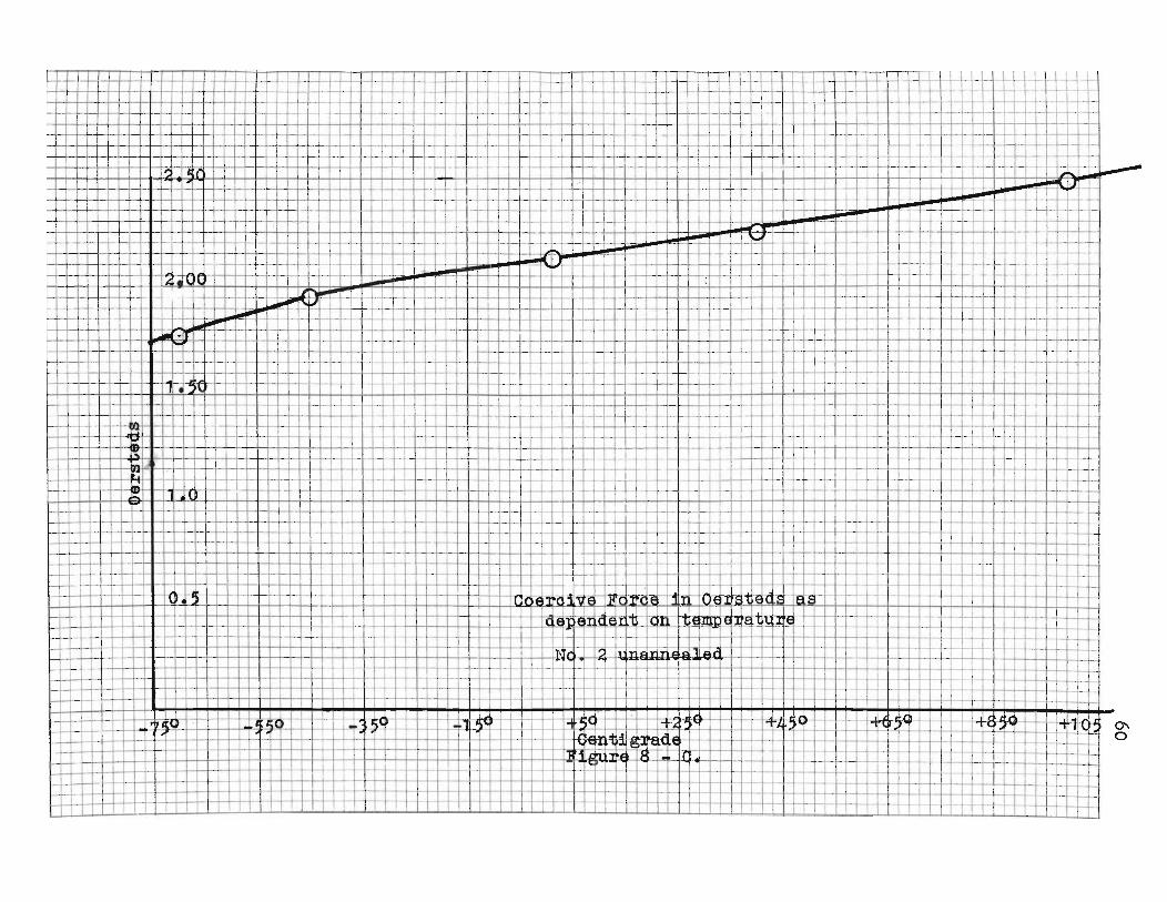
\60
-W--+
1+1-1\
'~i
i1
_I
+I
~L~
.I
'_
,-j-
+!~
,_
I...
rl
'Tr-+
-i
-I--'-+-+-f.:j:-!--+-L+-,.-r+~1
_~-t
-t-f--1--t-+
Ii
-rI--
+-J-.~~:--'-f--l--i-·l--+--r.:...+·-+-r----l
-\-+-
iI
I..
I'
Ii--+
1---+-'-1-+--i--~
+1
-++
-1-1
+t-;-i----1r-++-f-t--+'-+-
e-!-t- I
-+'-+-I-+
..L,...
J-rr:+'-t-t-r-,-H-l-r-+1-t-~+4-:-1-++-!·+~+.l-1
..j.....i'-l--H-'--1
FF~--+-+-+-+,-,-t-,:H''''-L+,t'-ti~;I-tjl~t±i..JI!-++-'
--1-;-I--t-:-I-I-I
H+
J-;-,+ri-~:++-i++-+-+_+-L--1uml--,-J-.-LH-l-l-l-+-IH--·+-'-+--1---+--4...1I
'I
TJ1
.r
j,-H-,--H
-+-t-+
-f-H-t- L1+-+-+-+-+-I-J--l-_l~-·+--t-I
~-i-..-J--I-t!H--+'--L..t-"':""";':-':""+"-1
:,---t-!
1"-
l-'+
-t+
H...-H~+i+
--.;.
.+
-+-,--("'+
.-1-+-'-_U
J·=t---'rm
-+.-H
-+--f-,..-t-lI-u-\H
-l--I--l-...-L-j
'I
"I'
,"
II
'T'
,w,
II~
I;r-r--I-I-1-1-JrU,:"
rf H,--/i.f-,'1'
:I~
I,
,.--r--:-r--+-H-t-'
~i.1,
rll:
'i
Wi'
iH
'-t-H-t-+
-++
-H-H
IH-I--H
++
-l++
-t-l-+--+
_, 1f-.j...1'-;-J";--T
";-
:i
,
riH-t-;++:-+-+'+
1-H
-H--\+
++
'+I---I-:'-+
-I-t-L+
-;-'1-1--I-- TU-+--l--W
---l-.i-'!L+-t+i-;.·H,il_~I,hrrH-H-rI+++-++-h-+--:-I
1+
.T
+f--
!-++++,--;-.+,++++++++++-H-,8=t1-t~,+J-f-l--I-i-h-l-!,--WL.h--J+----+-+-,:--+--1-+---,
f-+-+-+-+-+-+-I-I-+-J,-t
i'
·HI
I..)R
!IT~-i
H-1
,-'HIi+H
+1
-1 +I-i++, +-1--+++-+rr
H+
H+
-'-+-l-H
--HI-+
-,-H-L
-H,++-I.J,-4.--:~~.;1
-:,-+-ir~-"""i--l-1--r-1-~-+--r"\---r-+..+
-H
H--t-t-+-+-++-!~--;:I-I·J"
'......+
hH
-i""-t'--r-h;--l--HH
c!i-- 1++,-a-I-I-+I-+-.~~+.I-+-+-l--1i_1\-1
--1-1
-1-+
'jjttj -H~+f--HH--+I-t-...J.L_+-!+1++-l---H.+I:".~+--j-1:"'1--++-++-j+l-~+f-+14+-i-t--!-+-+-.L,-I---,--J..J..-~iH--t-r;;H+-~--I-l+.fH-+-W-!--H
H-i
H-t-H-+
l-f--
H-
:=tfh-+
I-t'--t-H-+
\-H-l-h
--+-+
++
+4-+-"'+-r-l~-:'Pi-t-trlt'-H-+-H
--t-+--fi,ft,'=+-+-+";'-'-1
t±±±-'~_'-r-f-t:;__+I""'~~~~~++~~~-+l-l-'..j-.f--+'-h-ri-+'+1++,_I-ill=:r-ii-'-l-'t1jj:::::jtt f-ttt::1'j::::jbt+++-+ I-H
H-+----r=i---.!i+---1f-Jr..t+i++J-l---j-;4-J.:+----+.--I---I-l
t~~
I-t--H
--H1r-.+
-,i-''H-t--H-,H---+-H-~Lji-l--+~
-i-l-+-H
,-++
+--i: aHa:-H~-f-!-+-+-hM-rn--I-M-;-I-+-H
,I
i
II
II,
ii
!
-+'~-+-I--r+--j-+,-f;I-+_-+_-f_f-~"-i'--+-+-'-f-I-+
-:I-++
-I-+-f-i--4\-j':-I+
i -l-t-+
+-H
--HI-l--H
++
+--:,·-+
-t+.....H--H
-i--H-+
-I-+-I-I-·I-+
-I-+--l---j
I,
.,I
H,-r.,H
+t--t-t-H
+H
,++
'~H--H,'-i-+,++-+++-+-+,+t-l--l-H-,-+,-+-W
-l-l-l--W,-l-W
,-l-O-t-,-H
H'+
,-+,-+-1H
II
f-l---H-+_1_1H
--+T-r_-H--+-i-,
-j--'-H'-+
-H--'+
H--H
-+-
L1-t-l--H
-4---i'!--+--+-+-+j-+
-+-f,'-:--H
+-t-+--r-4~+-:~-I--l-I-+--r-Irt-1
--1----'-i
+-t-t+
+-i-+
+ I-+;-+-.:.....,~-l--+t~f-t--+-J-I-.j..++-+-t-+-+-I-i--t-f-H+-l-+-+,-++
,-+-H-+-H--I-H--H-l--H-I-l~J+-,--j-f-+1...,....,.....-1
t-r--rl!--r-HI-t-r+++-'H-+h-r-l-+,-tJ~+,-H
+-H
+H
+H
+·H
i +H-+~-H++-+-t-"+-+++++++j+Ih--H
I-i--l--t-~-'H-I
l-t-r--o.....+-+H--+ 1+
i-+--;--.,-!
'I
I
1 =tH
·i......,....+
-t-+-i'-+
-+-+
'-l-Ttr.;.
......-t-l-+-+
'-+-1
-++
l-++-I-+-1'-;--h+
-H+
H-i'+
-H+
H+
H---riH
-+-t-I-H
+=
-4-W-1-1... 1-+
-i-Ir'-H'-+++-~-H+~
1-;'-1-I~""'++-j,--,f-l-'T
1-in:-r-t-h1_j-i-1-H'T
+'-f-I-+
t-++
-f'+t-+-H
r+H-lI+-H
--H+-I-+--r--j+f--I-.-1--l-I
'--.L
Ii
Ii'
,!T
-r-tI
h+l--'-t~-'H--I-.+-.++,++.~j;:tt="~t·+t'-t:l-l-a--i---I--H
-1-H-+
++
+-H
-I-I-+'+-1++-H
-H-+-+++-+-++++-l---j-l-':-+-.I-:\o>H
.--I-1.-J-I--I-!'ii"
,
H-~-+-Hr+-H+
-H+ i+-t++-+I++-li~,IH
++-+++'-l-H--i-j-+
-++
-H-+
l-I--H-l-+
-+-1
-+-+
+-I-+
-H-J-+
-+-l-J-I--i-4
-+-+
-l--h-l
H--H-t-+--++-H--Hf-~++-++1-+-+-H-HI--++-H-,
-+-H
+-H
-,+-H
--f-H--H
-J-+-+
-+-+
-+'-I--H
--l-I-+-I-I-I--I-+
-I-t++
-I-l-+-+
-l--I-I-
H-+,!-++I-+-;;-+_+--+-IIl--+'_'-I-H--t-+--+-I-+-~~+.+-+-t:C-+-HH--H++-I++-+-1-+-++-I-+-H4--I-I+-H-I-H--.L.i4--I-I--l-.J-...I.-I--!-1--+
-!-.j
II
,1
iI
I-
;-t-+-I--+
-+-f-+
+-+-+-+-;.-1--1-+
h-'-t--l-t---I--J--L
\-+-+-+-+-:r-+-+-+-I--+-+-+-+--+-I---l-'-!-!-+-!-+--+-1----t-<~:,..I!",.S·*"~..·
W~H-'
+-1-1-- 1
.,-+-+-+-+--1-1H-+I-t--H+~,-
+--l-..Jt+-H--HH--HI-+-H~+-H:+-+,
+H-+H--i-H-+I-++-I-++-+-'H-+-I~I--I-+--I-+-+-1-+-J-
1-+-1-If-t-,+--I-+-+.L-+-I
r-t-t-H--f-H
--+,-+-+-+++-+++-+++-+++-+++-+++-+++-I-1-+-+-+,+I-+-+,-I-W-+---I-I-+-II-++-I-I-
t--+-1-+.f-+,'-r--H
+-H
--H-+
r
......'f---L
LJ:,,"'-!-IH
_-l--I_e-+-II-J.,..O
I--H
--1'W'~-!-I-.l-~I-++-i-+-H+~++-++I-+-+-Ihjoo~I--l++-+++-+-+i--+-~-A
.,l-.+-1
--+-+
-+-1
-1-'
H--+-+-++-i-'-l-1_+I
]i~'._......+
+-+
-ll-+-t-lh--H
-+'I..t-l-t--H
-t--H-t-.H
-t-+-t+
H+
t-+-H
-+--H....=+-H-+-+-++t-++IH..,~M-I-H-+H-
,"
II
,
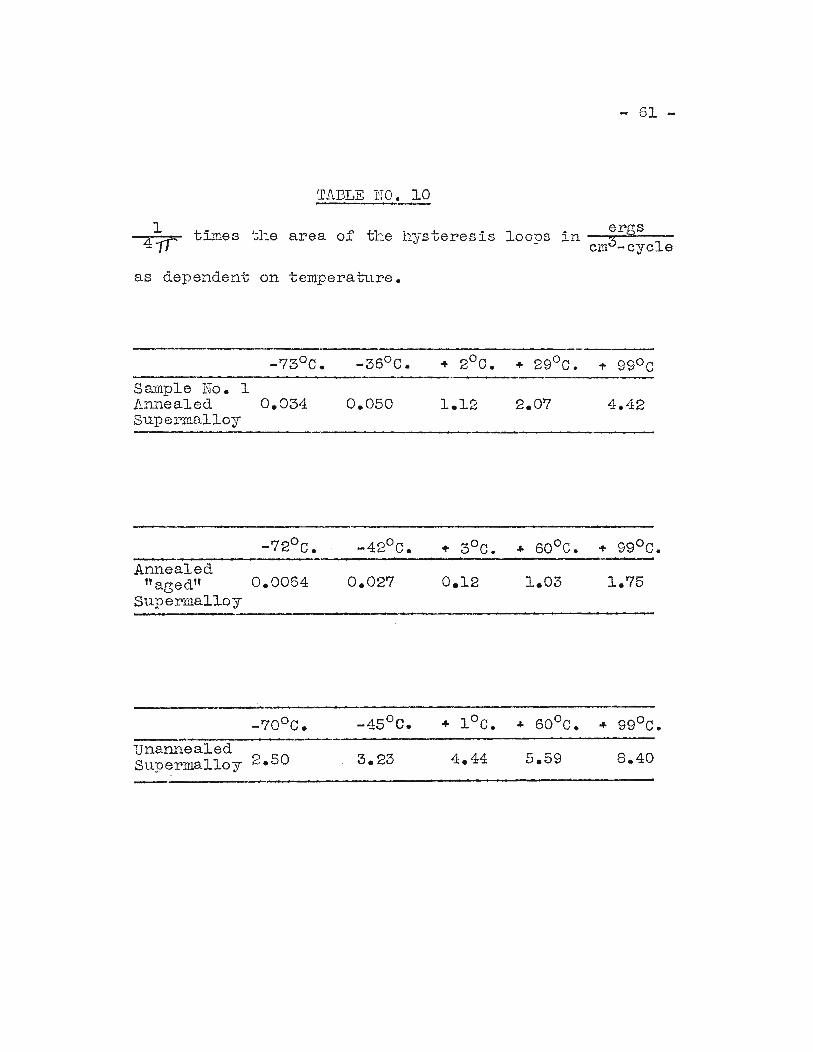
- 61 -
TABLE NO. 10
I times the area of the hysteresis loops in ergscm3-cyc1e
as dependent on temperature.
-73°C. -36°C. ~ 2°C. + 29°C. l' 99°CSample No. IAnrlealed 0.034 0.050 1.12 2.07 4.42Supermalloy
Annealed"aBed" 0.0064
Supermalloy
unannea1edSupermal10y 2.50
0.027 0.12
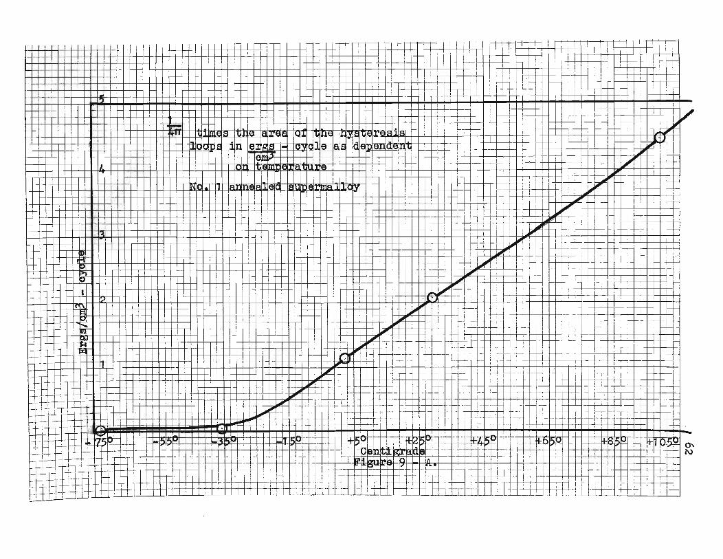
,J
62
+--t-H-L
-...L-t-t-t-·"--t-+-·l-t--j.L
,-+--J__~_~""+d--++-~-+-j-Lj--+--j-_"·L+'-_+I--+-+-I--l-1-1-'+-++--fH--H-+-H--H-.-+-+-I--I--+--I-I--I-J--l--l-I--J--jr::l_++-r-+-H-++-I
+--t--+-~--t-I--
-r-..
'11
--
t-+--+I-'-~I'·+-+-+-I-I-/---IH-·+--+--+-+--+-
r-+
-
-tl-H-+-f--T-·~·++'H+J-++--+-I--+-rl---I--J-+--'--+-+--'---1--+---l.-l--J--I.-+-t-+-+-+-+--I-+
T.-f--+-I-t-~
1-+-+-+-+-+-~-I·-L-j--H-IH-+-I-r-I---+-,,-+-1,-,,-I---i--l---4--H--+-I--fI--"-
+-+
+-L~-+I_+
-++
-+-1
--+-1
.H·
~1
-+1
III
I
I_E+''--I-'-+f--+-T-_L_-r-.t-+
+-+
-l-+-+
++
-i---,,J--+-li
-f-
-I--r-,--j---l-+-+-/---;--J--!.--!--+-I-t-.~-~!~I-~t--I
...1..'++"~-H-I-t---,---I-+--t-+--+++-+--L~-+-+-+-+-+-+_l-,--I-+-I-~I~TI
tI-
-tTHTt-ll+Lf-J'~-L+r++H-+-+--I-++-+-H--+--1-/--L-+-'j..'-rle-'lI'\pj-+l-'-I-IH
-'--l--w'l---.;r
~
I\--I-f-+_
+-+
-+++--1-+-+--+--+-r--'-+-I-+--J-l--+-r--i-~-+-~+'+
-+-I-L
.j--+--!--I-
i..l.f-+
.f--'--f--+
-+-I--H
I-+-I-
f-
'.-t.:f-_.'I-f-+-.~'~++-t~--ILj.-'--I·~tT-t--I-t-t~~l--I..I--+-J
'l...-~f-l-~+--;----+-.r~,~--li-lT!'--t-I-I_t-'....=-1--0--+-I--....:-'-+-I-+--4
"'--'-'L-H
.-r-!-r
II
,-rrr-
--f--f-+-'f--+
-JT1
-.
t
I
T
'"
Ii
H+-+-+-++-t-++-l-o--I-.J,.J-~al~--1+--,-:~-+-+-+-,--.L-,--+-+--++--1-f----jI----l--jI--l-T-I-H--I-~~r+-·-
+T~H-LH+~-+I-++-i-t--J-I
I
t----rl-I-+
-t-iirH-'t--I-R
-hW+
H-t-t-I+
-H-f--H
I--t-+1+-H+.Lf+-H+~+-h+..;.-.J~-H+~~+-I-+t--J-+-t-I
I\.'
I
t
I,
II
I
-t,
II
1\-1
--
t--\-1
itI
Ii
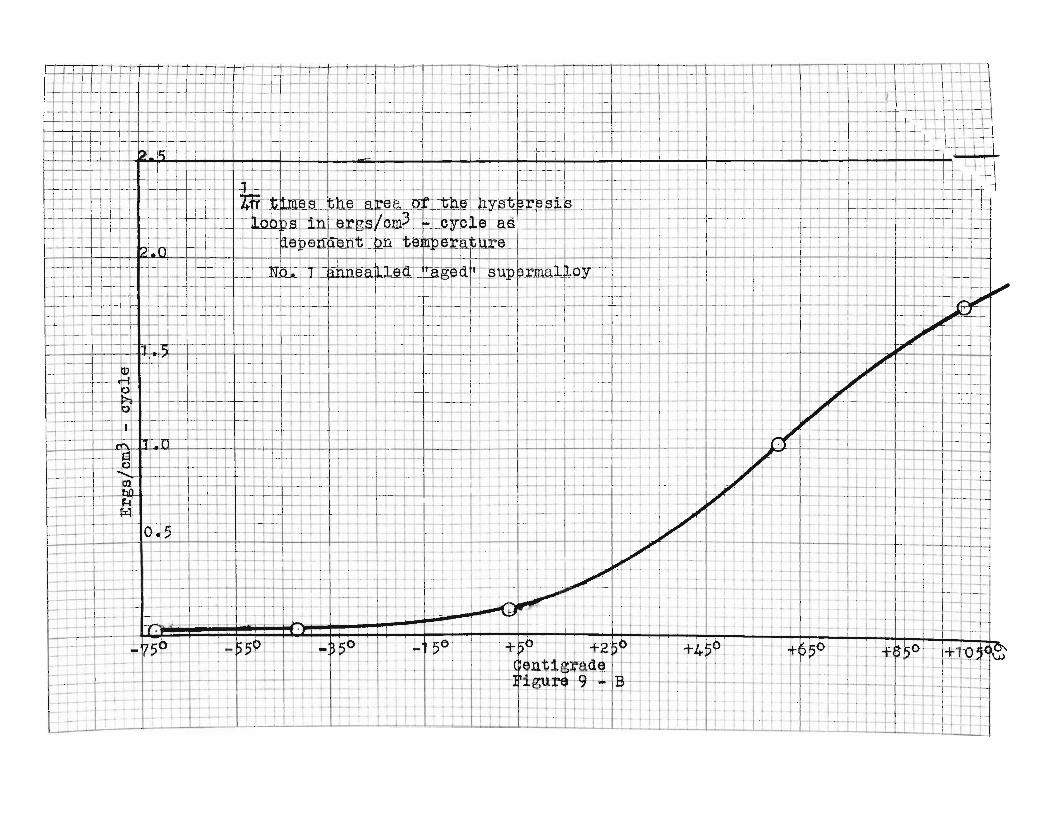
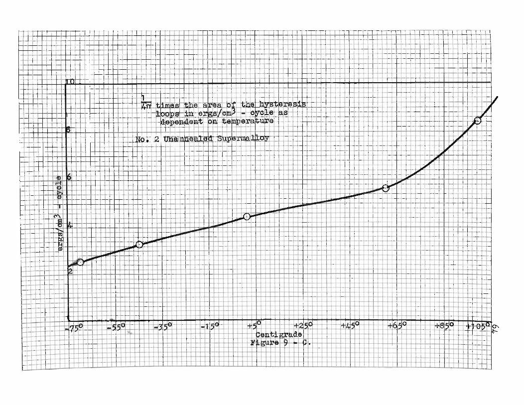
+-'
,
~~l-
-t-+-~..J-L
lllt-+
++
-l-ILJ
,,'l
Ti'-
tT
rt+
-l--l-- lJ
Dr
'
..L~~--i
,+
rl (t-r-ri~-l---L-!-.I
Irr-r---T-ij~..J
.,
T"
'""
\I
,-+fiEiH=H' +ictEEl!Brfi+tJ'ttiuE':=tt
1I;
i-++
-!_
--l-Ll.
T-IT
rTH
-t+-H
-+l-l'--l·+
Bft=t=:J=:j:14,tt;±EI1~HJIf,+~~1tBiE
I,T
d>~I---"lr+---U
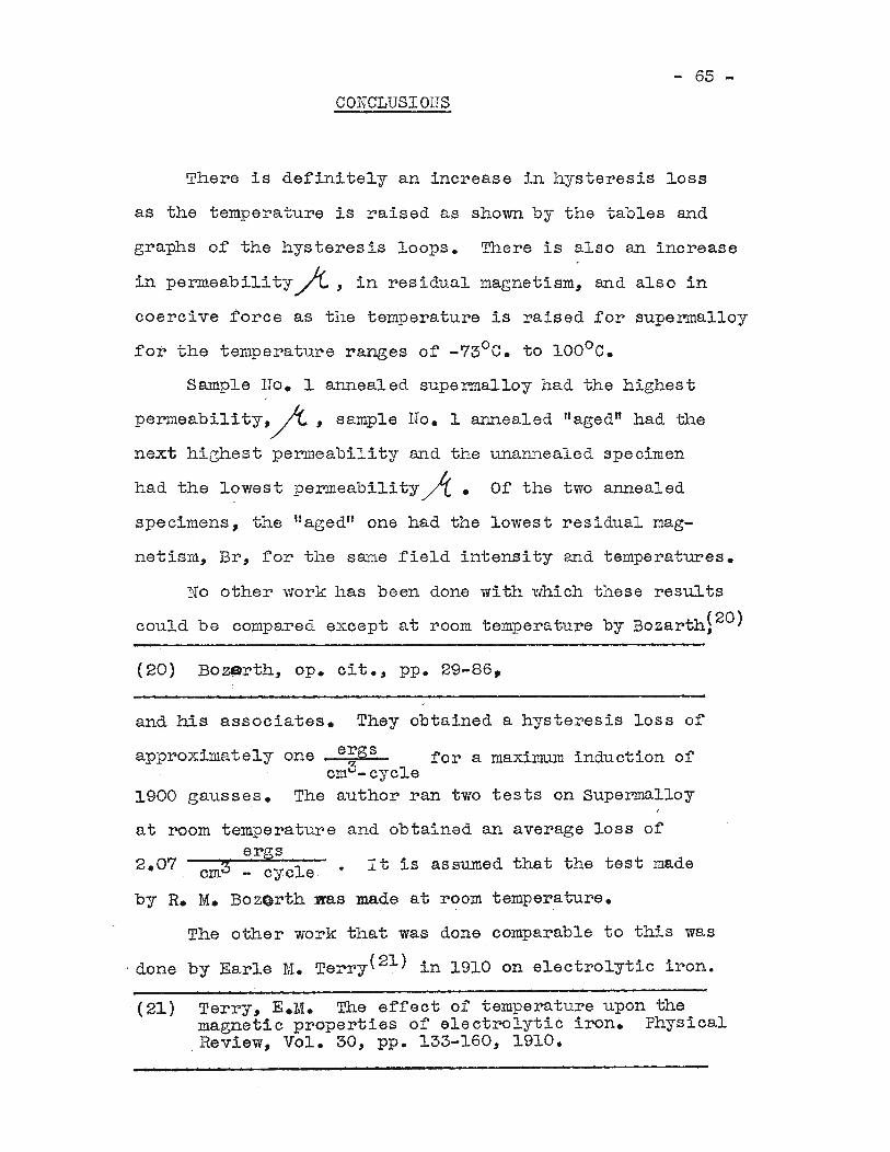
- 65 -
CONCLUSIons
There is derinitely an increase in hysteresis loss
as the temperature is raised as shown by the tables and
graphs of the hysteresis loops. There is also an increase
in permeabilityfi, in residual magnetism, and also in
coercive force as the temperature is raised for supermalloy
for the temperature ranges of -73°C. to 100°C.
Sample Ho. 1 annealed supermalloy had the highest
permeabilitY,~, sample no. 1 annealed "aged" had the
next highest perllleability and the unannealed specimen
had the lowest permeability~. Of the two annealed
specimens, the ffaged" one had the lowest residual mag-
netism, Br, for the s~ne field intensity and temperatures.
No other work has been done with which these results
could be compared except at room temperature by Bozarth~20)
(20) Bo~rth, Ope cit., pp. 29-86.
and his associates. They obtained a hysteresis loss or
approxinlate1y one ergs for a maximum induction ofcm3-cycle
1900 gausses. The author ran two tests on Supermalloy
at room temperature and obtained an average loss ofergs
. (21) Terry, E.M. The effect of temperature upon theTIlagnetic properties of electrolytic iron. PhysicalReview, Vol. 30, pp. 133-160, 1910.
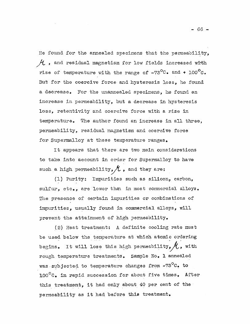
- 66 -
He found for the annealed specimens that the permeabil~ty,
~ , and residual magnetism for low fields increased wrth
rise of temperature with the range of _73°C. and + IOOoe.
But for the coercive force and hysteresis loss, he found
a decrease. For the unannealed specimens, he found an
increase in penneability, but a decrease in hysteresis
loss, retentivity and coercive force with a rise in
temperature. The author found an increase in all three,
permeability, residual magnetism and coercive force
for Supermalloy at these temperature ranges.
It appears that there are two main considerations
to take into account in order for Supermalloy to have
such a high permeabili ty0, and they are:
(1) Purity: Impurities such as silicon, carbon,
sulfur, etc., are 'lower thm in most commercial alloys.
The presence of certain impurities or combinations of
imp~lrities, usually found in commercial alloys, will
prevent the attainment of high permeability.
(2) Heat treatment: A definite cooling rate must
be used below the temperature at which atomic ordering
begins. It will lose this h~gh permeabi~ity:fi: with
rough temperature treatments. Sample No. I annealed
was s~bjected to temp~rature changes from _730 e. to
lOOoe. in rapid succession for about five times. After
this treatment, it had only about 40 per cent of the
permeability as it had before this treatment.
- 67 -
No other vlork has been done with which these results
could be compared but an analysis of' the results for
the tvlO annealed specimens indicates their probable
accuracy. For example at -73°0., the Ifagedl! sample had
about ,10 per cent of' the perrneabili ty as the one before
rough treatnont and at 100°C. it still had ab01J.t 40 per
cent the penneability of' the other.
- 68 -
ERl10RS
Of the various methods that have been used for
magnetic testing, the Rowland ring seemed best suited
for the present work. Since it gives a continuous
magnetic circuit without a joint of any kind, no
correcting for demagnetization effect is necessary,
and with a fairly uniform winding of the magnetizing
coil, it may be safely assumed that the flux crossing
each section of the ring is the srone, and that the
leakage is negligible. It is, however, subject to
three sources or error:
(1) The field is not uniform across the specimen,
and further, the mean field is not the field at the
center of the section calculated from the ampere turns.
(2) Since permeability is a function of field
strength, the mean flux density, calculated from the
deflections of the galvanometer, is not the fllDe
density at the center of the section.
(3) If Supermalloy is like iron as pointed out by
Ewing and Hayleigh for small fields and fields for
which the differential~ is large changes its. magnetic
state slowly, sometimes requiring several seconds, will
introduce a serious error. Since the ballistic method
requires that the total change shall take place before
the galvanometer swings appreciably from its zero posi
tion, a serious error is introduced in testing materials
possessing "magnetic inertia".
- 68 -
The first two errors was reduced to negligible
magnitudes by choosing the width of the ring small in
comparison to its diameter.
There is bOLUld to be error in this experiment due
to the precision measure of the instruments. The
precision measure of the rnicroamrneter used to measure
the magnetizing current for the annealed samples v~s
fifty microamperes, which was better than one per cent
of the value of' current used. The armneter used for the
unannealed specimen had an error of about 0.33 per cent
due to the precision measure. Both these instruments
had an approved acc~~acy of i to 1 per cent. The
precision measure of the galvanometer was 0.5 liM. All
the resistances were accurate within 1 per cent. Errors
were minimized by averaging a 2rge series of readings.
- 70 -
SUMUIAEf
times the area
Warburg was the first to show that the
1due to hysteresis was equal to -----47T
energy loss
of the hysteresis loop when H was in oersteds and B in
gauss. Steirunetz developed the relationship
Wh ='7 ~ax
where k was siven the value of 1.6. Then Kep~elly
advanced what is now called Kennelly law in the forra of
Then Rayleigh round that the law
B =fio H ... aH2
was still a better law.
Earle M. Terry found in 1910 that temperature does
have a marked influence upon the magnetic properties of
iron.
R. M. Bozarth and his associates at the Bell
Telephone Laboratories have done a lot in developing
alloys with h~gh pe~illeability at low fields with small
hysteresis losses.
Magnetization curves and hysteresis loops are
explained today by means of the Domain Theory of M~
netism.
Temperature definitely does have a marked influence
upon the magnetic properties of Supermalloy. Annealed
Supermalloy was found to have a permeability or 196,000
at H =0.0097 oersteds at 99°C. and a hysteresis loss of
about 2 ergs at room temperature.cm3-cycle
- 71 -
There is definitely an increase in pel~eability, ,residual magnetism Br, and coercive force for a rise in
temperature for a range o~ -730 C. to 100°C. in low field
intensity for Supennalloy.
The study of this problem is by no means e~lausted;
I would like very nmch to continue the study of the
effects at different ~ield intensities and different
temperature ranges. Also I would lili:e to measure the
effect on supermalloy vnLen a pressure is applied during
magnetization, both longitudinal and transverse.
- '72 -
BIBLIOGRAPHY
1. Books:
Bitter, F., Introduction to ferromagnetism.:New Yorl;:, ...rcGraw-Hill Book Company. 1937.
Gilbert, N. E. Electricity and magnetism.New York. The MacMillan Company, 1932.
Marshall, R. B. Measul~ements in electricalengineering. John S. Swift Company, Cincinnati,1943.
Sei tz, F. The physics of metals. 1'.lcGrav'l-I-IillBook Company, New York, 1943.
Smith, A. ~. Electrical measurements in theoryand applications. McGraW-Hill Book Company,New York, 1934.
Starling, s. G., Electricity and magnetism.New York. Longmans, Green and Compan:{, 1925.
1;Vall, T. F. Applied m.agnetism. Nevi York.D. Van Nostrand Company, 1927.
~Villiams, S. TI. I':Iar;uetic phenomena. New York,McGraw-Hill Book Company, 1931.
2. Publications of Learned Societies:
Arnold, H. D., and Elmen, G. W., Perrilal1oy, analloy of remarkable magnetic properties, Journalof Franldin Institute, Vol. 195. pp. 621-632,1923.
Boothby, O. L., and Bozarth, R. ill., A new magneticmaterial of high permeability. Journal of AppliedPhysics, Vol. 18, pp. 173-176, February, 1947.
Bozarth, R. M. Present status of ferromagnetictheory. Electrical Engineering, Vol. 54, p. 1251,1935.
Bozarth, R. M., The physical basis of ferromagnetism.Bell System Technical Journal, Vol. 19, pp. 1-39,January, 1940.
Bozorth, R. M. Magnetic resis~ance and domaintheory of iron-nickel alloys. Physical Review,Vol. 70, December 1 and 15, 1946, pp. 923-932.
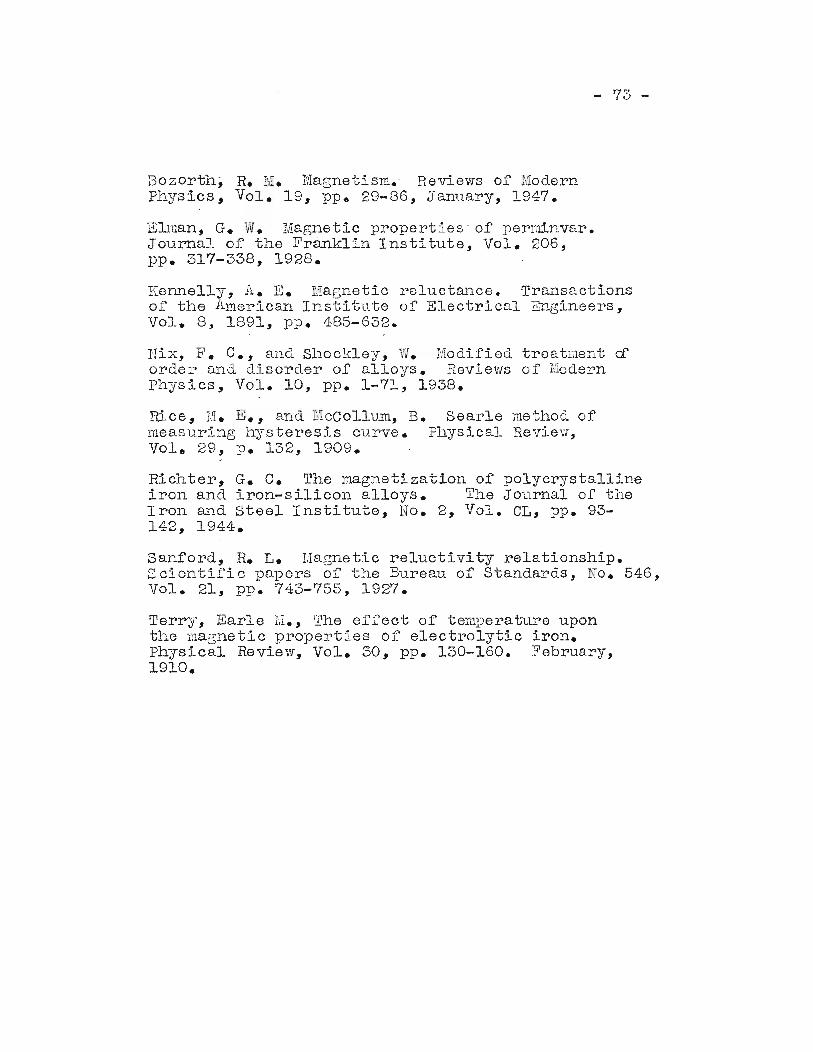
- 73 -
Bozarth, R. M. :rvragnetism.' Reviews of I,IodernPhysics, Vol. 19, pp. 29-86, Janllary, 1947.
EDuan, G. W. Magnetic properties' of perminvar.JournaJ, of the Franklin Institute, Vol. 206,pp. 317-338, 1928.
Kennelly, A. E. Magnetic reluctm~ce. Transactionsof the .A.merican Institute of Electrical Engineers,Vol. 8, 1891, pp. 485-632.
nix, F. C., and. Shockley, liv. l'Iodified treatlilent a:order and disorder of alloys. Reviews of UodernPhysics, Vol. 10, pp. 1-71, 1938.
Rice, 1\1. E., and ECCollum, B. Searle method ofmeasuring hysteresis curve. Physical Review,Vole 29, p. 132, 1909.
Richter, G. C. The magnetization of polycrystallineiron and iron-silicon alloys. The Journal of theIron and Steel Institute, No.2, Vol. CL, pp. 93142, 1944.
Sanford, R. L. Magnetic reluctivity relationship.Scientific papers of the Bureau of Standards, No. 546,Vol. 21, pp. 743-755, 1927.
Terry, Earle M., The effect of temperature uponthe magnetic properties of electrolytic iron.Physical Review, Vol. 30, pp. 130-160. February,1910.
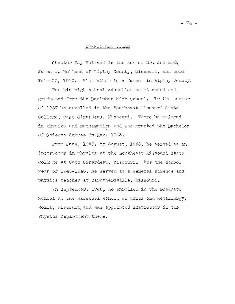
- 74 -
Ohester ~lay Holland is the son of Hr. and I,! s.
James T. Holland of' Hipley Oount-:r, I.1issouri, and born
July 22, 1910. His father is a fanner in Ripley COQDty.
For his high school education he attended aDd
graduated from the Doniphan High School. In the sunnner
of' 1937 he enrolled in the Southeast Uissouri state
College, Cape Girardeau, .:':i sSOl.lri. mhere he ma:i ored
in physics and mathematics a11.(l was granted the Bachelor
of Science degree in Nay, 1943.
FroID June, 1943, to August, 1945, he served as an
instrclctor in physics at the Southeast ~issouri state
Col~ 'e at Cape Girardeau, Missouri. For the school
year of 1945-1946, he served as a general science and
physics teacher at Caruthersville, Missouri.
In September, 1946, he enrolled in the Graduate
School at the Missouri school of Mines and l.1etallul'8Y,
Rolla, Missouri, and was appointed instructor in the
Physics Department there.


