Embed Size (px)
Citation preview
IAQ M
ANUA
L
IAQ Damper/Monitor
Your guide to understanding indoor air quality and the application of Ruskin’s IAQ Damper/Monitor
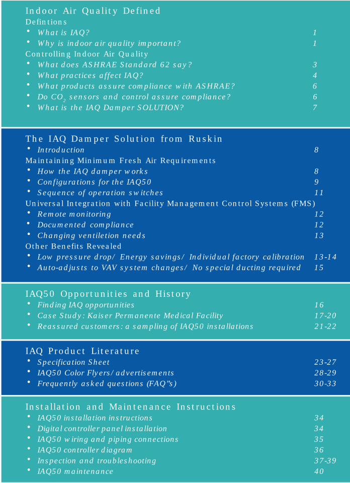
Indoor Air Quality DefinedDefintions
· What is IAQ? 1
· Why is indoor air quality important? 1Controlling Indoor Air Quality
· What does ASHRAE Standard 62 say? 3
· What practices affect IAQ? 4
· What products assure compliance with ASHRAE? 6
· Do CO2 sensors and control assure compliance? 6
· What is the IAQ Damper SOLUTION? 7
The IAQ Damper Solution from Ruskin· Introduction 8Maintaining Minimum Fresh Air Requirements
· How the IAQ damper works 8
· Configurations for the IAQ50 9
· Sequence of operation switches 11Universal Integration with Facility Management Control Systems (FMS)
· Remote monitoring 12
· Documented compliance 12
· Changing ventiletion needs 13Other Benefits Revealed
· Low pressure drop/ Energy savings/ Individual factory calibration 13-14
· Auto-adjusts to VAV system changes/ No special ducting required 15
IAQ50 Opportunities and History· Finding IAQ opportunities 16
· Case Study: Kaiser Permanente Medical Facility 17-20
· Reassured customers: a sampling of IAQ50 installations 21-22
IAQ Product Literature· Specification Sheet 23-27
· IAQ50 Color Flyers/advertisements 28-29
· Frequently asked questions (FAQ”s) 30-33
Installation and Maintenance Instructions· IAQ50 installation instructions 34
· Digital controller panel installation 34
· IAQ50 wiring and piping connections 35
· IAQ50 controller diagram 36
· Inspection and troubleshooting 37-39
· IAQ50 maintenance 40
1. Indoor Air Quality
DEFINITIONS
1.1 What is IAQ?
The term IAQ is a popular acronym for ‘indoor air quality’. One mustunderstand how air has a ‘quality’ to understand fully what IAQ means.Determining the ‘quality’ of anything can be very subjective often relying onindividual tastes and preferences combining to form a consensus. In some ways, theterm indoor air quality is also a relative term. Any consideration of indoor air leadsto an association with outside ambient air. A noticeable difference between the twois a varying level of contaminants that can be attributed to the concentration ofhuman activity and manufactured goods within a closed, indoor space. The closed,indoor space of a building allows gaseous fumes, odors, germs, and even fungi togrow in concentration to the point that the indoor air is qualitatively different fromthe ambient air. It is at this point that it can even affect the health and comfort of abuilding’s occupants.
ASHRAE Standard 62 defines indoor air qualityand how to maintain it through fresh air ventilation.
The American Society for Heating and Refrigeration Engineers (ASHRAE) providesthe following definition of ‘acceptable indoor air quality’: “air in an occupied spacetoward which a substantial majority of occupants express no dissatisfaction andin which there are not likely to be known contaminants at concentrationsleading to exposures that pose a significant health risk. ”
1.2 Why is Indoor Air Quality important?
IAQ is important because the health and the comfort of people workingindoors are important. Building owners interested in IAQ make this a top prioritytoday because a work environment that causes discomfort or health problems(often leading to absenteeism) results in a loss of productivity. Also, poor IAQ maycause tenants to look for building space elsewhere with a better indoorenvironment.
In order to understand how poor IAQ can happen, let us look at a buildingwith little or no outside air ventilation. As air is recirculated within a building,not only does carbon dioxide grow in concentration from human occupancy, butso do odors, bacteria, viruses and germs both dependent and independent ofhuman activity. Such a rise in indoor contaminants within a closed system caninspire acute effects, usually in the form of subjective symptoms such asrespiratory system irritations or drowsiness. People will complain of fatigue,headaches and stuffiness. These signs of discomfort are difficult to confirm andgenerally disappear when the suffering occupant leaves the building. Referred toas ‘Sick Building Syndrome’, this situation is reliant on occupant perceptions.‘Building Related Illness’ is a different term used to describe diagnosedconditions of illness caused by a chronic exposure to poor IAQ. However, manypeople confuse these terms and freely interchange them. What is important toremember is that in either scenario the health and comfort of a building’soccupants are compromised.
Additionally, building codes now include ventilation requirements ofminimum outside air volumes. A consensus has formed around a prescriptiveapproach to ventilation developed by ASHRAE. This approach is ASHRAEStandard 62 and has become the point of reference for engineers and buildingowners interested in maintaining an appropriate indoor environment. ASHRAEand its standards have no coercive force by themselves. Today, however, portionsof ASHRAE Standard 62 have been incorporated into almost every building codein the United States as well as many international codes.
If the indoor air quality is neglected, the health, comfort andproductivity of building occupants become compromised.
Since compliance with building codes is compulsory, one can expect acontroversy from a building being negligent in providing proper indoor air qualityfor its occupants. Such disputes have evolved into litigation against buildingowners as compliance with the standard comes into question. Damages from alawsuit will easily surmount the expense of taking the initial engineering stepsthat would have assured compliance. Although building owners face this risk,many are not aware of potential IAQ hazards and the HVAC product solutions
Potential Contaminants in the Indoor Environment
• Biological: bacteria, mold, fungi• Particulate: pollen, dust, tobacco smoke, man-made fibers.• Gasses: radon, vapors from paints and adhesives, carbon dioxide and
monoxide, human odors and grooming products.

available that create an acceptable indoor air quality environment. The issues ofindoor air quality and compliance with the ASHRAE standard have spanned thepages of HVAC technical trade journals serving notice to such governingorganizations as the EPA and OSHA as well as state and local officials. IAQawareness is increasing and so to are the solutions.
CONTROLLINGINDOOR AIR QUALITY
1.3 What does ASHRAE Standard 62 say?
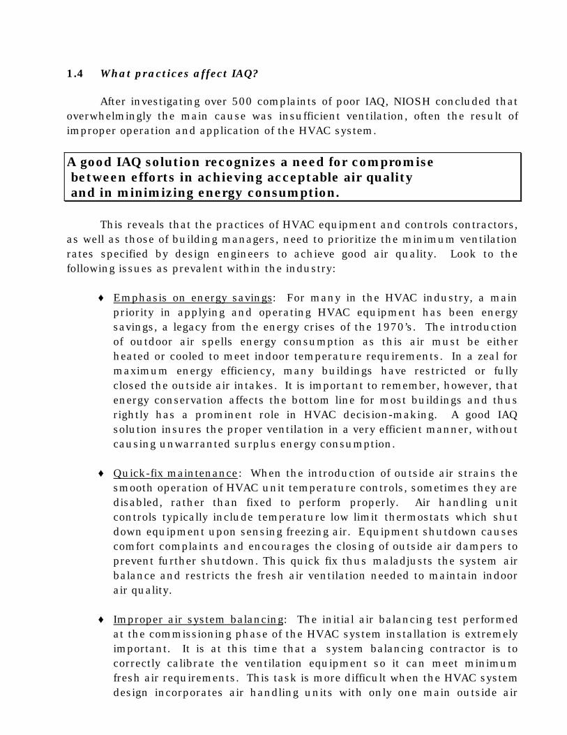
Ventilation is the most important single element of an HVAC system toinsure good IAQ. Generally speaking, what the standard says is that to insuregood IAQ, one must maintain indoor air contaminants below a maximumacceptable threshold. One way to keep the level of contaminants down is byadequate ventilation. ASHRAE has set forth a schedule of outdoor air ventilationrates in CFM per person for a variety of different indoor spaces (see table 1-2).With a design occupancy load for a building, an engineer can easily determine aminimum ventilation rate to specify for the HVAC system. This ventilation rateprocedure is set forth as one path to compliance with the standard. Although thismethod does not involve an actual determination of indoor air quality, thestandard anticipates that if a building’s HVAC system delivers the design level ofoutside air to the interior space, the building is in compliance and indoor airquality will not be degraded. Implicit here is the observation that theseconditions specified by ASHRAE must be observed not only in design of thebuilding but also in its operation. It is the latter which is most often to blamewhen there is an IAQ problem.
Table 1-1: ASHRAE Recommended Outdoor Air Ventilation Rates
Application Outdoor Air RequirementsDining rooms 20 CFM/personCafeterias, fast food 20 CFM/personBars, cocktail lounges 30 CFM/personLaboratories 20 CFM/personLibraries 15 CFM/personAuditoriums 15 CFM/personOffice space 20 CFM/personGambling casino 30 CFM/personHospital operating rooms 30 CFM/personHospital patient rooms 25 CFM/personClassrooms 15 CFM/person
1.4 What practices affect IAQ?
After investigating over 500 complaints of poor IAQ, NIOSH concluded thatoverwhelmingly the main cause was insufficient ventilation, often the result ofimproper operation and application of the HVAC system.
A good IAQ solution recognizes a need for compromise between efforts in achieving acceptable air quality and in minimizing energy consumption.
This reveals that the practices of HVAC equipment and controls contractors,as well as those of building managers, need to prioritize the minimum ventilationrates specified by design engineers to achieve good air quality. Look to thefollowing issues as prevalent within the industry:
♦ Emphasis on energy savings: For many in the HVAC industry, a mainpriority in applying and operating HVAC equipment has been energysavings, a legacy from the energy crises of the 1970’s. The introductionof outdoor air spells energy consumption as this air must be eitherheated or cooled to meet indoor temperature requirements. In a zeal formaximum energy efficiency, many buildings have restricted or fullyclosed the outside air intakes. It is important to remember, however, thatenergy conservation affects the bottom line for most buildings and thusrightly has a prominent role in HVAC decision-making. A good IAQsolution insures the proper ventilation in a very efficient manner, withoutcausing unwarranted surplus energy consumption.
♦ Quick-fix maintenance: When the introduction of outside air strains thesmooth operation of HVAC unit temperature controls, sometimes they aredisabled, rather than fixed to perform properly. Air handling unitcontrols typically include temperature low limit thermostats which shutdown equipment upon sensing freezing air. Equipment shutdown causescomfort complaints and encourages the closing of outside air dampers toprevent further shutdown. This quick fix thus maladjusts the system airbalance and restricts the fresh air ventilation needed to maintain indoorair quality.
♦ Improper air system balancing: The initial air balancing test performedat the commissioning phase of the HVAC system installation is extremelyimportant. It is at this time that a system balancing contractor is tocorrectly calibrate the ventilation equipment so it can meet minimumfresh air requirements. This task is more difficult when the HVAC systemdesign incorporates air handling units with only one main outside air

damper that functions to provide fresh air not only for cooling but also forventilation. Project specifications in this situation call for the main
outside air damper to modulate open to a minimum position duringnormal operation in order to bring in the right amount of outside air.The difficulties encountered here are locating this ‘minimum position’and setting the controls to maintain it. Thus, there is a reliance oncoordination between different contractors that have differentresponsibilities.
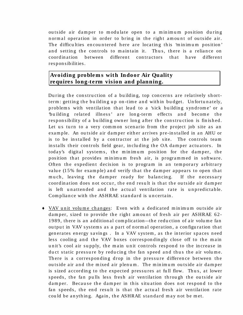
During the construction of a building, top concerns are relatively short-term: getting the building up on-time and within budget. Unfortunately,problems with ventilation that lead to a ‘sick building syndrome’ or a‘building related illness’ are long-term effects and become theresponsibility of a building owner long after the construction is finished.Let us turn to a very common scenario from the project job site as anexample. An outside air damper either arrives pre-installed in an AHU oris to be installed by a contractor at the job site. The controls teaminstalls their controls field gear, including the OA damper actuators. Intoday’s digital systems, the minimum position for the damper, theposition that provides minimum fresh air, is programmed in software.Often the expedient decision is to program in an temporary arbitraryvalue (15% for example) and verify that the damper appears to open thatmuch, leaving the damper ready for balancing. If the necessarycoordination does not occur, the end result is that the outside air damperis left unattended and the actual ventilation rate is unpredictable.Compliance with the ASHRAE standard is uncertain.
♦ VAV unit volume changes: Even with a dedicated minimum outside airdamper, sized to provide the right amount of fresh air per ASHRAE 62-1989, there is an additional complication--the reduction of air volume fanoutput in VAV systems as a part of normal operation, a configuration thatgenerates energy savings . In a VAV system, as the interior spaces needless cooling and the VAV boxes correspondingly close off to the mainunit’s cool air supply, the main unit controls respond to the increase induct static pressure by reducing the fan speed and thus the air volume.There is a corresponding drop in the pressure difference between theoutside air and the mixed air plenum. The minimum outside air damperis sized according to the expected pressures at full flow. Thus, at lowerspeeds, the fan pulls less fresh air ventilation through the outside airdamper. Because the damper in this situation does not respond to thefan speeds, the end result is that the actual fresh air ventilation ratecould be anything. Again, the ASHRAE standard may not be met.
Avoiding problems with Indoor Air Qualityrequires long-term vision and planning.
1.5 What is available to assure compliance with the ASHRAE standard?
The ASHRAE standard identifies the path to compliance applicable to theHVAC community: the Ventilation Rate Procedure. Design engineers andbuilding owners need to prioritize implementing methods that assure that thedesign amount of fresh air enters the building via the ventilation system.Specifically, they must specify a means of measuring and controlling theincoming fresh airflow. Conventional methods include furnishing and installingthree different products from potentially three different suppliers: an air flowmonitor, a control damper, and a programmable controller. This results in higherproduct costs and difficult coordination efforts, which become significant enoughto dissuade building owners and engineers from prioritizing indoor air qualitythrough budget cuts.
In addition, combining these products in the field and not in the factory hasmeant that a project-specific laboratory calibration, which guaranteesperformance, could not be achieved. Often, the use of three separate devices tomeasure and monitor the outside air results in custom air handling design whichalso adds to the overall project costs and schedule delays.
1.6 Do CO2 sensors and CO2 control assures compliance?
Interest in the use of CO2 sensors to measure and control indoor air qualityhas increased dramatically in the past couple years. Although the informationprovided by CO2 monitoring is valuable, merely controlling the level of CO2 belowsome maximum threshold does not construe compliance with ASHRAE Standard62. The reasons why are somewhat complicated because of confusion over thelink between CO2 and indoor air quality. Although ASHRAE has recognized CO2
as a surrogate indicator of body odors and other bioeffluents affecting indoor airquality, the standard does not state that if CO2 concentrations are maintained atacceptable levels then indoor air quality shall be considered acceptable. Rather,the standard declares that “indoor air quality shall be considered acceptable if therequired rates of outdoor air...are provided for the occupied space.” Advocates ofCO2 as an indicator of a ventilation rate argue that if one knows both the CO2
concentration of outdoor air and the CO2 consumption level of occupants, one canmeasure indoor CO2 and derive the ventilation rate. This might be true if outdoorCO2 and human consumption were constant. However, it is not possible toanticipate the various activity levels and breathing capacities of occupants. Thus,
Conventional IAQ solutions can be costly in terms of product cost, coordination time and project delays.

any measured indoor CO2 reading can not as accurately determine ventilationrates as an actual airflow measurement.

These same advocates also argue for CO2 as an actual measure of IAQ. Theassumption here is that if CO2 levels are low, then whatever ventilation that ispresent is probably enough to remove all contaminants. The problem here is thatCO2 is an indicator of human activity and thus measures the human load, not theactual air quality. It does not account for chemicals and various bacteria, molds,and fungi that exist and propagate independently of human activity. Yet CO2
monitoring does provide some valuable benefits. For example, one could use thesensors to trigger increased ventilation above minimum requirements at airmonitoring stations due to poor mixing and/or extra capacity. We quickly seethat the main bulwark of defense for building owners against “sick buildingsyndrome” is continued compliance with the ASHRAE ventilation standard via theVentilation Rate Procedure.
Ruskin’s new IAQ50 damper/monitor provides the best weapon to fightyour indoor air quality battles.
1.7 What is the IAQ Damper solution?
The IAQ damper from Ruskin is an integral airdamper/monitor - a damper assembly where the damperalso acts as an airflow monitoring station. Ruskincombines this assembly with a factory calibratedprogrammable controller specifically designed for thisproduct to form one complete package. Turn now to theSection 2 to look at this unique product in more detailsand to discover its features and benefits.
2. The IAQ50 Damper Solution by
2.1 Introduction
The IAQ50 integral air monitor/damper is the latest model in the new IAQdamper series from Ruskin and is designed to meet the current engineeringdemands for indoor air quality. The IAQ50 damper is an innovative combinationof three different functions into one product: an airfoil control damper thatregulates airflow, an airflow monitoring station, and a programmable controller. Itis designed to provide HVAC system compliance with the ventilation standard asstated in ASHRAE Standard 62-1989. What is most unique about the IAQ50 isthat the airflow monitor is built into the damper. Thus, this patented assembly isboth narrow and compact and affords unmatched versatility. With a wideoperating range and adjustable setpoints, the IAQ50 damper is poised to respondto future ventilation needs.
Maintaining Minimum Outside AirRequirements
2.2 How the IAQ50 works
The unique design of the IAQ50 incorporates air monitoring into theassembly of a high performance, aluminum airfoil blade control damper. A typicalcontrol damper consists of multiple blades which modulate in unison to regulateair flow for various applications. Ruskin has combined modulating blades withstrategically placed airflow sensing blades of special construction. The specialsensing blades designed by Ruskin possess pressure sensing ports located on theblade edge on both the air entering and leaving sides. The multiple pressureports are connected to respective pressure chambers inside the body of thesensing blade for entering and leaving air. The difference between these twopressures corresponds to a velocity pressure of the airstream, and Ruskin’s IAQ50controller (located inside a control panel provided as part of the IAQ50 damper)converts the measurement of this pressure differential into a CFM value.
A differential pressure transducer is mounted inside the IAQ50 controlpanel. Tubing/ piping connections are made between the control panel and themonitor/damper frame (see control panel technical diagram for all wiringinformation) for this device. The transducer converts the pressure signals from the
RUSKINRUSKIN

tubing to a low-voltage analog 2-10VDC signal that connects with the controlleranalog input terminals. The calibration process readies the IAQ50 for the effectsof the position of the modulating blades and the pressure characteristics of each
unique damper as it monitors this signal. The IAQ50 controller monitors bladeposition via a wiring connection to the feedback signal feature of the damperactuator.
Once the controller has computed a value for the CFM, it compares thisvalue within its control logic programming to the CFM setpoint as determined bythe particular mode of operation of the HVAC system. In normal operation, thissetpoint will correspond to the minimum outside air ventilation required by thesystem design to meet ASHRAE Standard 62. Based on the difference betweenthe actual CFM reading and the desired CFM setpoint along with otherprogrammed control parameters, the controller will position the modulatingdamper blades as necessary to ensure that the actual outside air meets thedesired level. Wiring connects a modulating 2-10VDC signal from analog outputterminals on the IAQ50 controller to the damper actuator.
Finally, and most importantly, Ruskin calibrates and tests every IAQ50damper at its factory prior to shipment. This ensures an easy and reliable start-up, and accurate performance.
2.3 IAQ50 Configuration Choices:
Ruskin offers two configurations in the IAQ50 damper family to meet yourparticular application needs:
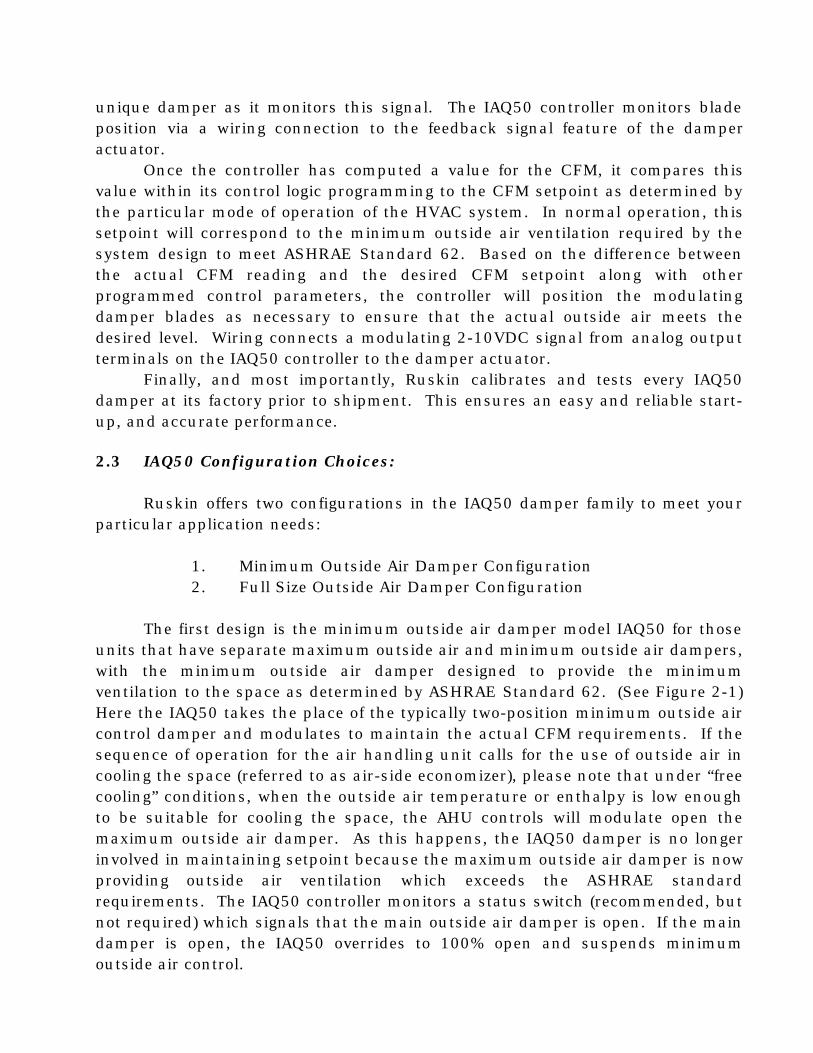
1. Minimum Outside Air Damper Configuration2. Full Size Outside Air Damper Configuration
The first design is the minimum outside air damper model IAQ50 for thoseunits that have separate maximum outside air and minimum outside air dampers,with the minimum outside air damper designed to provide the minimumventilation to the space as determined by ASHRAE Standard 62. (See Figure 2-1)Here the IAQ50 takes the place of the typically two-position minimum outside aircontrol damper and modulates to maintain the actual CFM requirements. If thesequence of operation for the air handling unit calls for the use of outside air incooling the space (referred to as air-side economizer), please note that under “freecooling” conditions, when the outside air temperature or enthalpy is low enoughto be suitable for cooling the space, the AHU controls will modulate open themaximum outside air damper. As this happens, the IAQ50 damper is no longerinvolved in maintaining setpoint because the maximum outside air damper is nowproviding outside air ventilation which exceeds the ASHRAE standardrequirements. The IAQ50 controller monitors a status switch (recommended, butnot required) which signals that the main outside air damper is open. If the maindamper is open, the IAQ50 overrides to 100% open and suspends minimumoutside air control.

Many air handling units have only one main outside air damper, not two. Inthis application, the IAQ50 damper takes the place of the entire outside air intake
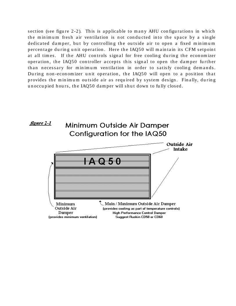
section (see figure 2-2). This is applicable to many AHU configurations in whichthe minimum fresh air ventilation is not conducted into the space by a singlededicated damper, but by controlling the outside air to open a fixed minimumpercentage during unit operation. Here the IAQ50 will maintain its CFM setpointat all times. If the AHU controls signal for free cooling during the economizeroperation, the IAQ50 controller accepts this signal to open the damper furtherthan necessary for minimum ventilation in order to satisfy cooling demands.During non-economizer unit operation, the IAQ50 will open to a position thatprovides the minimum outside air as required by system design. Finally, duringunoccupied hours, the IAQ50 damper will shut down to fully closed.
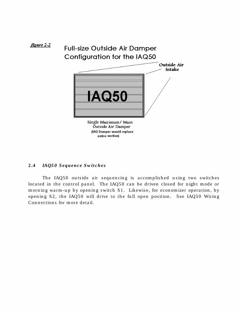
2.4 IAQ50 Sequence Switches
The IAQ50 outside air sequencing is accomplished using two switcheslocated in the control panel. The IAQ50 can be driven closed for night mode ormorning warm-up by opening switch S1. Likewise, for economizer operation, byopening S2, the IAQ50 will drive to the full open position. See IAQ50 WiringConnections for more detail.
Universal Integration with Facility Management Control Systems
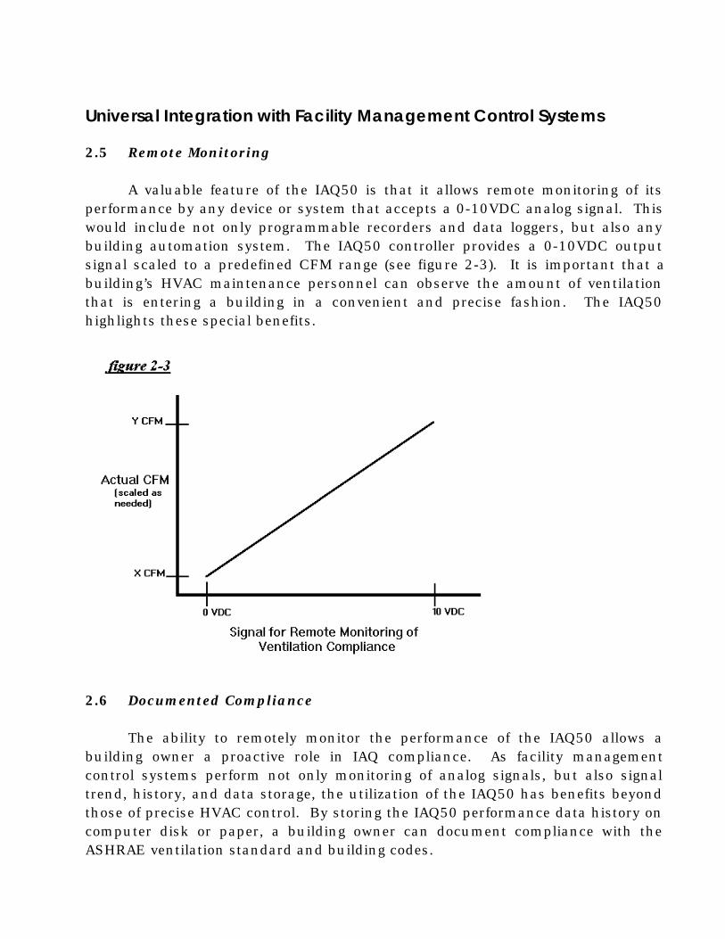
2.5 Remote Monitoring
A valuable feature of the IAQ50 is that it allows remote monitoring of itsperformance by any device or system that accepts a 0-10VDC analog signal. Thiswould include not only programmable recorders and data loggers, but also anybuilding automation system. The IAQ50 controller provides a 0-10VDC outputsignal scaled to a predefined CFM range (see figure 2-3). It is important that abuilding’s HVAC maintenance personnel can observe the amount of ventilationthat is entering a building in a convenient and precise fashion. The IAQ50highlights these special benefits.
2.6 Documented Compliance
The ability to remotely monitor the performance of the IAQ50 allows abuilding owner a proactive role in IAQ compliance. As facility managementcontrol systems perform not only monitoring of analog signals, but also signaltrend, history, and data storage, the utilization of the IAQ50 has benefits beyondthose of precise HVAC control. By storing the IAQ50 performance data history oncomputer disk or paper, a building owner can document compliance with theASHRAE ventilation standard and building codes.
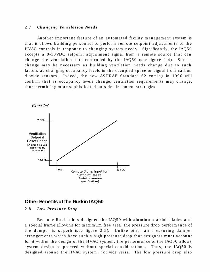
2.7 Changing Ventilation Needs
Another important feature of an automated facility management system isthat it allows building personnel to perform remote setpoint adjustments to theHVAC controls in response to changing system needs. Significantly, the IAQ50accepts a 0-10VDC setpoint adjustment signal from a remote source that canchange the ventilation rate controlled by the IAQ50 (see figure 2-4). Such achange may be necessary as building ventilation needs change due to suchfactors as changing occupancy levels in the occupied space or signal from carbondioxide sensors. Indeed, the new ASHRAE Standard 62 coming in 1996 willconfirm that as occupancy levels change, ventilation requirements may change,thus permitting more sophisticated outside air control strategies.
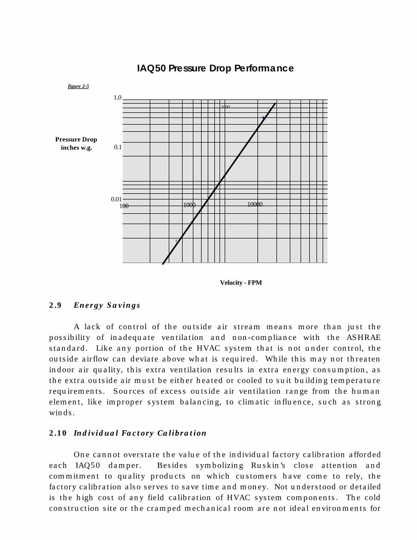
Other Benefits of the Ruskin IAQ502.8 Low Pressure Drop
Because Ruskin has designed the IAQ50 with aluminum airfoil blades anda special frame allowing for maximum free area, the pressure drop performance ofthe damper is superb (see figure 2-5). Unlike other air measuring damperarrangements which have such a high pressure drop that designers must accountfor it within the design of the HVAC system, the performance of the IAQ50 allowssystem design to proceed without special considerations. Thus, the IAQ50 isdesigned around the HVAC system, not vice versa. The low pressure drop also

means that the required airflow can be accomplished with less fan power andconsequently less energy consumption.
1000
2.9 Energy Savings
A lack of control of the outside air stream means more than just thepossibility of inadequate ventilation and non-compliance with the ASHRAEstandard. Like any portion of the HVAC system that is not under control, theoutside airflow can deviate above what is required. While this may not threatenindoor air quality, this extra ventilation results in extra energy consumption, asthe extra outside air must be either heated or cooled to suit building temperaturerequirements. Sources of excess outside air ventilation range from the humanelement, like improper system balancing, to climatic influence, such as strongwinds.
2.10 Individual Factory Calibration
One cannot overstate the value of the individual factory calibration affordedeach IAQ50 damper. Besides symbolizing Ruskin’s close attention andcommitment to quality products on which customers have come to rely, thefactory calibration also serves to save time and money. Not understood or detailedis the high cost of any field calibration of HVAC system components. The coldconstruction site or the cramped mechanical room are not ideal environments for
Velocity - FPM
Pressure Dropinches w.g.
IAQ50 Pressure Drop Performance
1.0
0.1
0.011000 10000100
figure 2-5

the attention to detail and precision available in Ruskin’s AMCA registered
laboratory. Furthermore, field calibration takes longer because of coordinationcosts and the uncertainties of field circumstances. In sum, individual factorycalibration means that the IAQ50 is ready to go upon arrival for the specificapplication for which it was designed.
2.11 Automatic Adjustment to VAV System Changes
Because it is a dynamic control, continuously monitoring the outsideairflow, the IAQ50 is poised to respond to the airflow changes inherent in thepopular VAV system design. As the supply fan of an air handling unit slows downin response to changing cooling demands within the HVAC system, the outsideair plenum static pressure declines resulting in less outside airflow through theoutside air damper. Not addressing this particular phenomenon can be one facetof a lack of compliance with ASHRAE Standard 62. With the full-size IAQ50damper configuration style in service for example, the minimum ventilation isalways maintained. The IAQ50 monitors the reduction in airflow and adjusts to itby opening further to the outside air. If necessary, the same signal that furtheropens the IAQ50 can be used to close down the return air damper, thusincreasing the plenum pressure differential to bring in even more outside air.
2.12 No Special Ducting Requirements
One final, remarkable benefit of the IAQ50 is that the combination of itsinnovative design and its individual factory calibration precludes the necessity ofany straight duct section requirements commonly found with conventional airflowstations. In new construction projects this means once again that the HVACsystem design can proceed unhindered by the special considerations of a singlecomponent. As indicated above, the IAQ50 is designed around the HVAC system,and not vice versa, and this results in lowered costs as compared to conventionmethods. For example, standard AHU construction can be utilized in lieu ofmuch more expensive custom designs. This feature has important ramificationsfor retrofit applications as well. Because an existing building’s HVAC system mayhave structural constraints that preclude the use of conventional airflow stations,the IAQ50 serves as an ideal solution in that its narrow depth and damper designallows it to fit in tight spaces.
3. IAQ Opportunities/Case Studies
3.1 Finding IAQ Opportunities
The versatility of the IAQ50 both in terms of installation and availableconfigurations makes it ideal for all HVAC applications in which an air handlingunit is responsible for supplying some minimum level of outside air forventilation. This goes for both new construction and retrofits. Just as theengineering community is responding to the demand for IAQ solutions in newbuilding designs, owners and managers of existing buildings are likewisebecoming aware of the need to address indoor air quality issues. Think of all theair handling units in service today without a means of monitoring the airflow fromoutside!
Look to these areas as ready to address indoor air quality:
♦ Schools: Good indoor air quality creates a healthy, comfortable, and productivelearning environment. High-density indoor spaces are often the most at riskand warrant the close IAQ scrutiny that the IAQ50 affords.
♦ Medical Facilities: Engineers and building owners are committed to the healthand safety of employees and patients in any medical facility. ASHRAEStandard 62 identifies good indoor air quality methods as critical in abatingmicrobial contaminants.
♦ Performance Contracts: Under a performance contract, a building is renovatedand retrofitted with current technologies and HVAC system strategies.Expected energy savings typically pay for these improvements. Engineersadopt a systemic approach in assessing an owner’s needs and identifyingopportunities to implement solutions to past HVAC problems. This is an idealtime prioritize indoor air quality and offer the IAQ50 as a solution to not onlyair quality concerns but also attendant building pressurization problems.
♦ Clean Rooms: Applications such as these beg for the precise control andmonitoring capabilities that the IAQ50 provides.
♦ Building Pressurization: When a building has its inflows and outflows understable control, true system balancing can easily be achieved and buildingpressurization difficulties can be addressed. Good indoor air quality is thebeneficial result.
These are some suggested strategic action steps:
1. Develop an awareness in the local engineering community of ASHRAEStandard 62 and indoor air quality issues.
2. Work with building owners and those companies in consultation with buildingowners in order for them to realize that they are the caretakers of indoor airquality.
3. Adopt a consultative approach in asking the question, “are your clientsinterested in these issues?” and offering the IAQ50 as an available solution inthe marketplace. Ruskin is not saying that people should have this device butis responding to the genuine needs and interests emanating from theengineering community.
4. When a potential customer is identified, show how the great long-term benefitsof the many features of the IAQ50 far outweigh the initial cost of installing theunit.
5. Follow through with an investigation of the particular HVAC system needs andcharacteristics in order to provide an IAQ50 specially suited for the building inwhich it is to be installed.
3.2 Case Studies
Ruskin’s IAQ Damper Ventilates Denver Hospital
This IAQ package by Ruskin included both the minimum IAQ damper as well asthe maximum fresh air damper as detailed in section 2. The IAQ damper/monitorwas calibrated at Ruskin for accuracy and then shipped as a complete assemblyto the York facility for installation in the air handling unit.
This damper measures and monitors the amount of fresh air entering thebuilding based on the ventilation rates established in ASHRAE Standard 62-89.Because the Ruskin IAQ damper automatically adjusts to maintain the desiredCFM setpoint, energy consumption is saved in the process.
Ruskin’s IAQ monitor/damper can be mounted in commercial air handling units,built-up air handling units, ductwork or behind louvers in the walls of yourbuildings. They can be utilized as part of a building management system orstandalone and are compatible with anyone’s DDC system.
Ruskin Proves To Be a Good Bet For Vegas Casino
In order to build a new way to access the casino, the 4 Queens Hotel and Casinoneeded a 48-foot air curtain. However, this curtain had to be designed aroundexisting structural supports, providing a unique and challenging problem of aircontrol. The air curtain not only had to prevent conditioned air from leaving thebuilding, but it also had to provide comfort and not consume too much energy.Working together with Long and Associates and Harris Consulting Engineers,Ruskin combined their IAQ50 dampers with the air curtain, providing a customdesigned job that maintained consistent airflow around the structural supports.This solution enabled the 4 Queens to open a new accessway, and caused them toexceed revenue projections.
Ruskin Helps Money Store Expansion
When the Money Store built a new headquarters, their architects employed aunique tiered design. Several Ruskin products were employed in the newbuilding. The IAQ50 was installed in the outside air plenums in order to controlthe minimum outside air and report the information to the Building AutomationSystem. They work in conjunction with Ruskin's CD36 low leakage damper,which were installed in the outside air openings of the plenums. This enablesthe building to precisely monitor and control outside air flow.

CASE
STUD
Y
RUSKINRUSKINThe IAQ Damper Series
Indoor Air Quality at a Kaiser Medical Facility
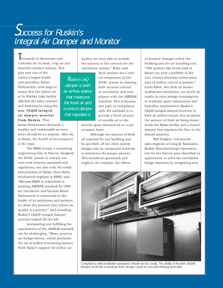
Thousands of Americans visitColorado for its fresh, crisp air andbeautiful outdoor scenery. This past year one of thenation’s largest healthcare providers, KaiserPermanente, took steps toinsure that the indoor airat its Hidden Lake facilityafforded the same comfortand freshness by using thenew IAQ40 integralair damper/monitorfrom Ruskin. ThatKaiser Permanente demands ahealthy and comfortable environ-ment should be no surprise. After all,at Kaiser, the health of its occupantsis the issue.
The RMH Group, a consultingengineering firm in Denver, designedthe HVAC system to comply notonly with industry standards andregulations, but also with the needsand priorities of Kaiser. Dave Kahn,mechanical engineer at RMH, said,“Because RMH is committed tomeeting ASHRAE standard 62-1989for ventilation and because KaiserPermanente is committed to thehealth of its employees and patients,we share the position that indoor airquality is a priority.” And installingRuskin’s IAQ40 integral damper/monitor helped fill the bill.
Interpreting and fulfilling therequirements of the ASHRAE standardcan be challenging. “Many projectsare budget-driven, which precludesthe use of airflow monitoring stations.With Kaiser’s support for indoor air
quality, we were able to include the stations in the controls for theventilation system,” Kahn said.
Such stations are a criti-cal component of theHVAC system in assuringboth accurate control of ventilation and com-pliance with the ASHRAEstandard. This is becauseone path to compliancewith the standard is toprovide a fixed amountof outside air to the
interior space determined on a peroccupant basis.
Although the amount of freshair required for any building may be specified, all too often systemdesigns rely on antiquated methodsto determine the proper amount.This introduces guesswork andneglects, for example, the effects
of pressure changes within the building and the air handling unit.“VAV systems like those used atKaiser can pose a problem as theunit volume decreases unless sometype of airflow control is present,”notes Kahn. Too little air meansinadequate ventilation; too much airresults in extra energy consumptionto maintain space temperature andhumidity requirements. Ruskin’sIAQ40 integral damper/monitor isboth an airflow station that measuresthe amount of fresh air being drawninside the Kaiser facility and a controldamper that regulates the flow to thedesired quantity.
Bob Padgett, commercial sales engineer at Long & Associates,Ruskin Manufacturing’s representa-tive for the Denver area, identified anopportunity to solve the ventilationdesign demands by integrating new
Success for Ruskin’s Integral Air Damper and Monitor
Compliance with ventilation standards should not be costly. The ability of Ruskin’s IAQ40damper to fit into a standard AHU design saved in cost and delivery lead time.
Ruskin’s IAQdamper is both
an airflow stationthat measures
the fresh air anda control damperthat regulates it.
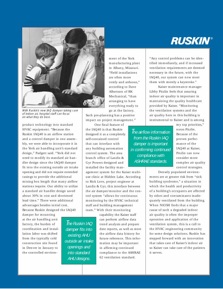
product technology into standardHVAC equipment. “Because theRuskin IAQ40 is an airflow stationand a control damper in one assem-bly, we were able to incorporate it inthe York air handling unit’s standarddesign,” Padgett said. “York did notneed to modify its standard air han-dler design since the IAQ40 damperfit into the existing outside air intakeopening and did not require extendedcasings to provide the additionalmixing box length that many airflowstations require. Our ability to utilizea standard air handler design savedabout 30% in cost and shortenedlead time.” There were additionaladvantages besides initial cost.Because Ruskin designed the IAQ40damper for mounting at the air handling unitfactory, the burden ofcoordination and instal-lation labor was shiftedfrom the typically coldconstruction site foundin Denver in January tothe controlled environ-
ment of the Yorkmanufacturing plantin Albany, Missouri.“Field installationsare often more costly and arduous,”according to DaveAlbertson of RKMechanical, “thanarranging to haveeverything ready togo at the factory.
Such pre-planning has a positiveimpact on project management.”
One final feature of the IAQ40 is that Ruskindesigned it as a completelyself-contained control that can interface withany building automationcontrol system. The areabranch office of Landis &Gyr Powers designed andinstalled the facility man-agement system for the Kaiser multi-use clinic at Hidden Lake. Accordingto Rick Love, project engineer atLandis & Gyr, this interface betweenthe air damper/monitor and the con-trol system “allows for continuousmonitoring by the HVAC technicalstaff and building managementteam.” With their monitoring
capability the Kaiser staffcan perform airflow datatrend analysis and preparedate reports, as well as storethe airflow data history forfuture reference. This infor-mation may be importantin affirming continuedcompliance to the ASHRAE62 ventilation standard.
“Any control problems can be iden-tified immediately, and if increasedventilation requirements are deemednecessary in the future, with theIAQ40, our system can now meetthem with merely a keystroke.”
Kaiser maintenance managerLibby Pitzlin feels that assuringindoor air quality is important inmaintaining the quality healthcareprovided by Kaiser. “Monitoring the ventilation systems and the air quality here in this building isinstrumental to Kaiser and is among
my top priorities,”notes Pitzlin.Because of theproven perfor-mance of theIAQ40 at Kaiser,Pitzlin can nowconsider morecomplex air qualitycontrol strategies.
Densely populated environ-ments are at greater risk from “sickbuilding syndrome,” a situation inwhich the health and productivity of a building’s occupants are affectedby odors and contaminants inade-quately ventilated from the building.When NIOSH finds that a majorcause of such a degraded indoor air quality is often the improperoperation and application of theventilation system, this is a call tothe HVAC engineering communityfor some design solutions. Ruskin hasstepped forward with an innovationthat takes care of Kaiser’s indoor airso Kaiser can take care of the patientsit serves.
R
With Ruskin’s new IAQ damper taking care of indoor air, hospital staff can focus on what they do best.
The Ruskin IAQdamper fits into
existing AHU outside air intake
openings andinto standardAHU designs.
The airflow informationfrom the Ruskin IAQdamper is important
in confirming continuedcompliance with
ASHRAE standards.
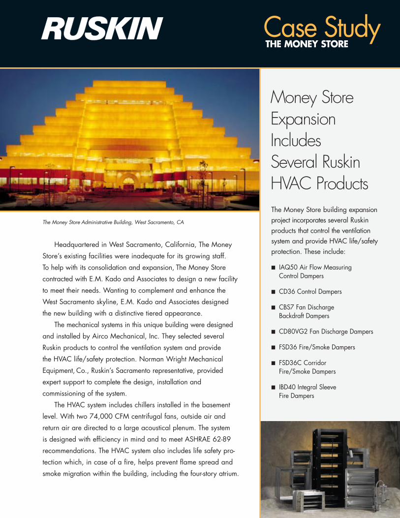
Money StoreExpansion Includes Several RuskinHVAC Products
Case StudyTHE MONEY STORE
Headquartered in West Sacramento, California, The Money
Store’s existing facilities were inadequate for its growing staff.
To help with its consolidation and expansion, The Money Store
contracted with E.M. Kado and Associates to design a new facility
to meet their needs. Wanting to complement and enhance the
West Sacramento skyline, E.M. Kado and Associates designed
the new building with a distinctive tiered appearance.
The mechanical systems in this unique building were designed
and installed by Airco Mechanical, Inc. They selected several
Ruskin products to control the ventilation system and provide
the HVAC life/safety protection. Norman Wright Mechanical
Equipment, Co., Ruskin’s Sacramento representative, provided
expert support to complete the design, installation and
commissioning of the system.
The HVAC system includes chillers installed in the basement
level. With two 74,000 CFM centrifugal fans, outside air and
return air are directed to a large acoustical plenum. The system
is designed with efficiency in mind and to meet ASHRAE 62-89
recommendations. The HVAC system also includes life safety pro-
tection which, in case of a fire, helps prevent flame spread and
smoke migration within the building, including the four-story atrium.
The Money Store building expansionproject incorporates several Ruskinproducts that control the ventilationsystem and provide HVAC life/safetyprotection. These include:
■ IAQ50 Air Flow Measuring Control Dampers
■ CD36 Control Dampers
■ CBS7 Fan Discharge Backdraft Dampers
■ CD80VG2 Fan Discharge Dampers
■ FSD36 Fire/Smoke Dampers
■ FSD36C Corridor Fire/Smoke Dampers
■ IBD40 Integral Sleeve Fire Dampers
The Money Store Administrative Building, West Sacramento, CA
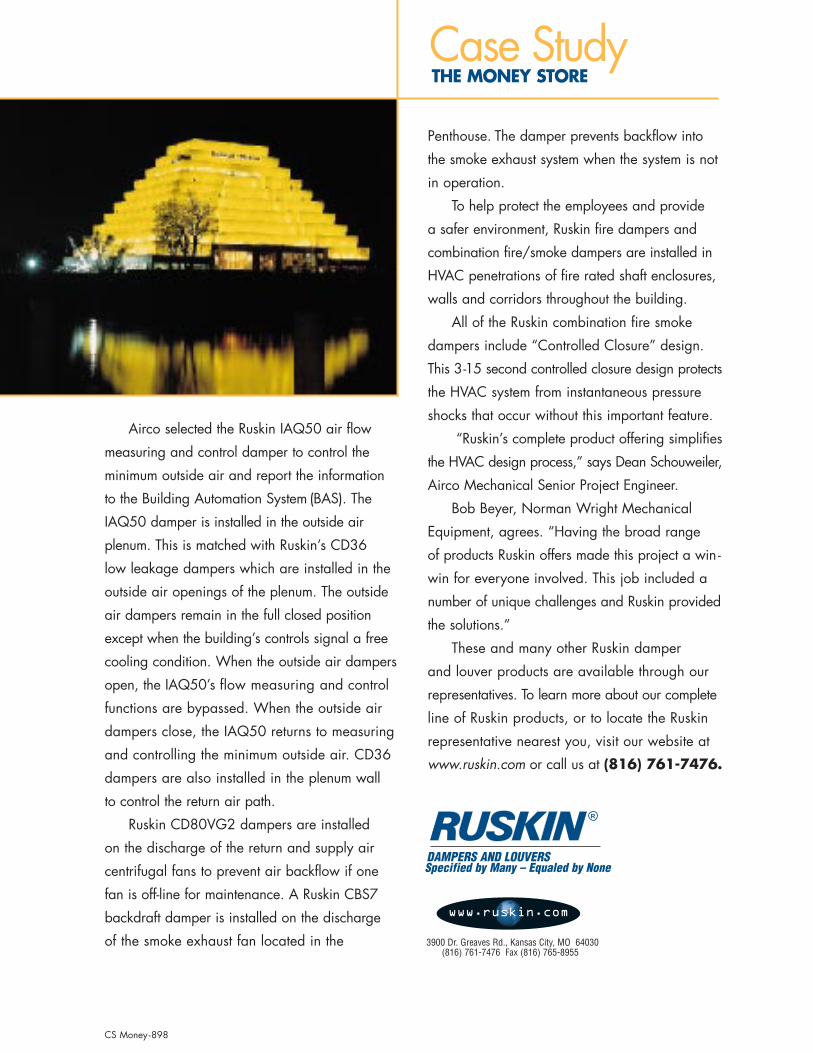
Airco selected the Ruskin IAQ50 air flow
measuring and control damper to control the
minimum outside air and report the information
to the Building Automation System (BAS). The
IAQ50 damper is installed in the outside air
plenum. This is matched with Ruskin’s CD36
low leakage dampers which are installed in the
outside air openings of the plenum. The outside
air dampers remain in the full closed position
except when the building’s controls signal a free
cooling condition. When the outside air dampers
open, the IAQ50’s flow measuring and control
functions are bypassed. When the outside air
dampers close, the IAQ50 returns to measuring
and controlling the minimum outside air. CD36
dampers are also installed in the plenum wall
to control the return air path.
Ruskin CD80VG2 dampers are installed
on the discharge of the return and supply air
centrifugal fans to prevent air backflow if one
fan is off-line for maintenance. A Ruskin CBS7
backdraft damper is installed on the discharge
of the smoke exhaust fan located in the
Penthouse. The damper prevents backflow into
the smoke exhaust system when the system is not
in operation.
To help protect the employees and provide
a safer environment, Ruskin fire dampers and
combination fire/smoke dampers are installed in
HVAC penetrations of fire rated shaft enclosures,
walls and corridors throughout the building.
All of the Ruskin combination fire smoke
dampers include “Controlled Closure” design.
This 3-15 second controlled closure design protects
the HVAC system from instantaneous pressure
shocks that occur without this important feature.
“Ruskin’s complete product offering simplifies
the HVAC design process,” says Dean Schouweiler,
Airco Mechanical Senior Project Engineer.
Bob Beyer, Norman Wright Mechanical
Equipment, agrees. “Having the broad range
of products Ruskin offers made this project a win -
win for everyone involved. This job included a
number of unique challenges and Ruskin provided
the solutions.”
These and many other Ruskin damper
and louver products are available through our
representatives. To learn more about our complete
line of Ruskin products, or to locate the Ruskin
representative nearest you, visit our website at
www.ruskin.com or call us at (816) 761-7476.
R
DAMPERS AND LOUVERSSpecified by Many – Equaled by None
3900 Dr. Greaves Rd., Kansas City, MO 64030 (816) 761-7476 Fax (816) 765-8955
www.ruskin.com
Case StudyTHE MONEY STORE
CS Money -898
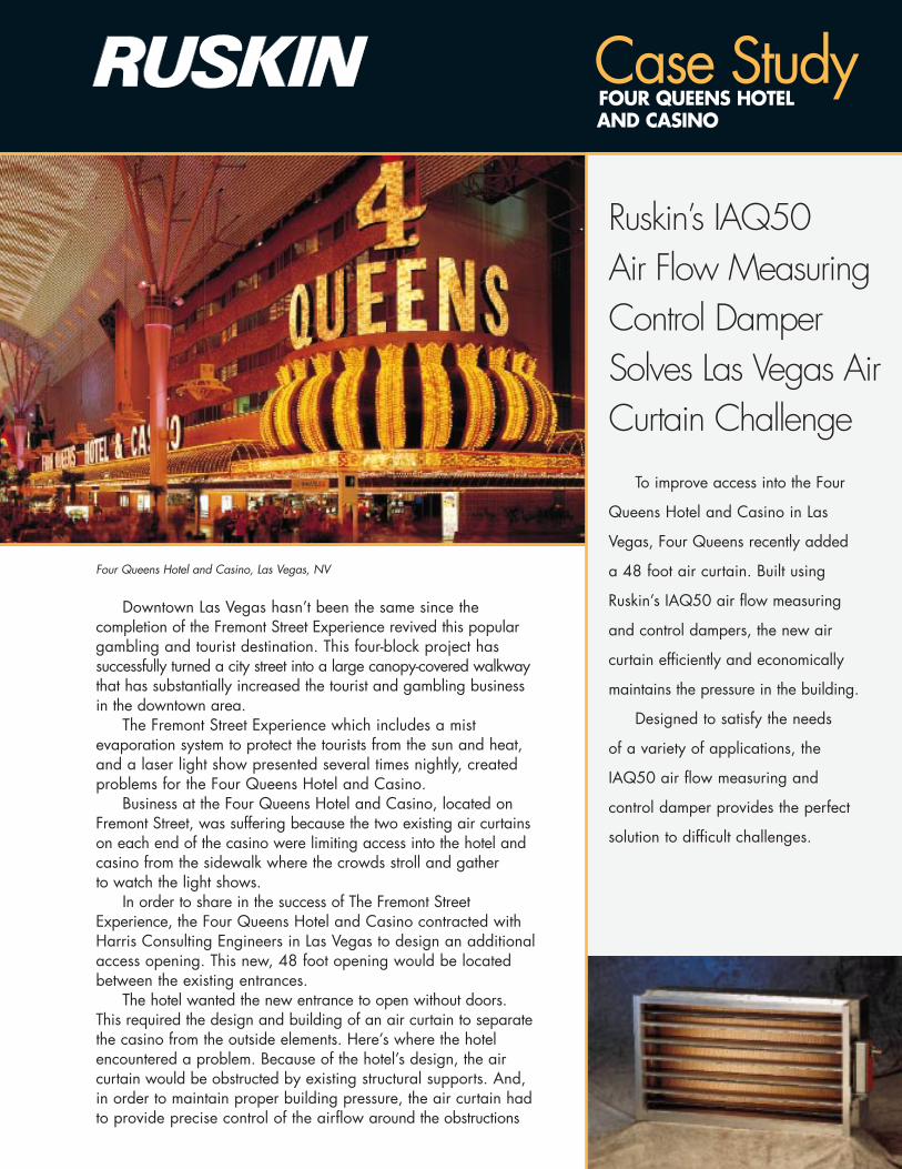
Ruskin’s IAQ50 Air Flow MeasuringControl DamperSolves Las Vegas AirCurtain Challenge
Case StudyFOUR QUEENS HOTEL AND CASINO
Four Queens Hotel and Casino, Las Vegas, NV
To improve access into the Four
Queens Hotel and Casino in Las
Vegas, Four Queens recently added
a 48 foot air curtain. Built using
Ruskin’s IAQ50 air flow measuring
and control dampers, the new air
curtain efficiently and economically
maintains the pressure in the building.
Designed to satisfy the needs
of a variety of applications, the
IAQ50 air flow measuring and
control damper provides the perfect
solution to difficult challenges.
Downtown Las Vegas hasn’t been the same since the completion of the Fremont Street Experience revived this populargambling and tourist destination. This four-block project has successfully turned a city street into a large canopy-covered walkwaythat has substantially increased the tourist and gambling businessin the downtown area.
The Fremont Street Experience which includes a mistevaporation system to protect the tourists from the sun and heat,and a laser light show presented several times nightly, createdproblems for the Four Queens Hotel and Casino.
Business at the Four Queens Hotel and Casino, located onFremont Street, was suffering because the two existing air curtainson each end of the casino were limiting access into the hotel andcasino from the sidewalk where the crowds stroll and gather to watch the light shows.
In order to share in the success of The Fremont StreetExperience, the Four Queens Hotel and Casino contracted withHarris Consulting Engineers in Las Vegas to design an additionalaccess opening. This new, 48 foot opening would be locatedbetween the existing entrances.
The hotel wanted the new entrance to open without doors.This required the design and building of an air curtain to separatethe casino from the outside elements. Here’s where the hotelencountered a problem. Because of the hotel’s design, the air curtain would be obstructed by existing structural supports. And,in order to maintain proper building pressure, the air curtain hadto provide precise control of the airflow around the obstructions
R
DAMPERS AND LOUVERSSpecified by Many – Equaled by None
3900 Dr. Greaves Rd., Kansas City, MO 64030 (816) 761-7476 Fax (816) 765-8955
www.ruskin.com
and down to the return air grate which is also the walkway into the casino.
In addition to maintaining the pressure in the building to prevent the loss of conditioned air from the casino, energy consumption and comfort were significant design criteria.
With the assistance of Long & Associates, Inc., Ruskin’s Las Vegas representative, the Harris team responded to the challenge by designing a custom air curtain that provides precision airflow around the existing structural supports.
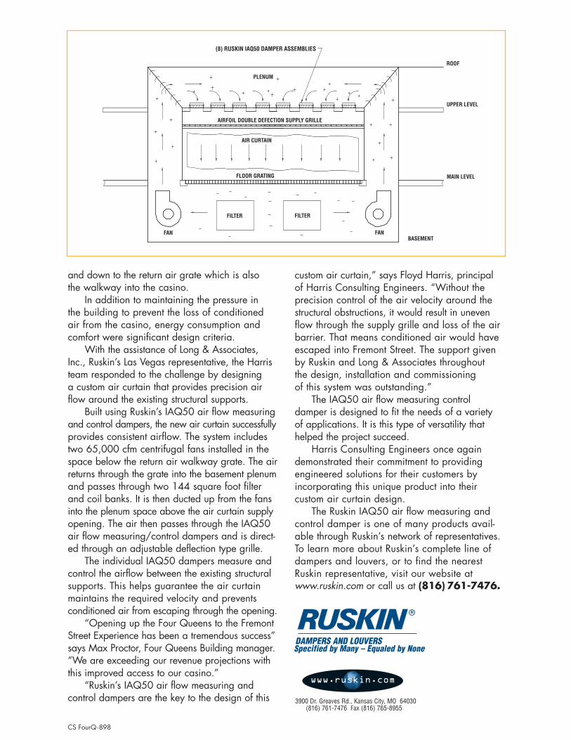
Built using Ruskin’s IAQ50 air flow measuringand control dampers, the new air curtain successfullyprovides consistent airflow. The system includestwo 65,000 cfm centrifugal fans installed in thespace below the return air walkway grate. The airreturns through the grate into the basement plenumand passes through two 144 square foot filterand coil banks. It is then ducted up from the fansinto the plenum space above the air curtain supplyopening. The air then passes through the IAQ50air flow measuring/control dampers and is direct-ed through an adjustable deflection type grille.
The individual IAQ50 dampers measure andcontrol the airflow between the existing structuralsupports. This helps guarantee the air curtainmaintains the required velocity and preventsconditioned air from escaping through the opening.
“Opening up the Four Queens to the FremontStreet Experience has been a tremendous success”says Max Proctor, Four Queens Building manager.“We are exceeding our revenue projections withthis improved access to our casino.”
“Ruskin’s IAQ50 air flow measuring and control dampers are the key to the design of this
custom air curtain,” says Floyd Harris, principal of Harris Consulting Engineers. “Without the precision control of the air velocity around thestructural obstructions, it would result in unevenflow through the supply grille and loss of the airbarrier. That means conditioned air would haveescaped into Fremont Street. The support givenby Ruskin and Long & Associates throughout the design, installation and commissioning of this system was outstanding.”
The IAQ50 air flow measuring controldamper is designed to fit the needs of a variety of applications. It is this type of versatility thathelped the project succeed.
Harris Consulting Engineers once againdemonstrated their commitment to providing engineered solutions for their customers by incorporating this unique product into their custom air curtain design.
The Ruskin IAQ50 air flow measuring andcontrol damper is one of many products avail-able through Ruskin’s network of representatives.To learn more about Ruskin’s complete line ofdampers and louvers, or to find the nearestRuskin representative, visit our website atwww.ruskin.com or call us at (816) 761-7476.
(8) RUSKIN IAQ50 DAMPER ASSEMBLIES
ROOF
UPPER LEVEL
MAIN LEVEL
BASEMENTFAN
FILTERFILTER
FAN
FLOOR GRATING
AIR CURTAIN
AIRFOIL DOUBLE DEFECTION SUPPLY GRILLE
PLENUM
CS FourQ-898
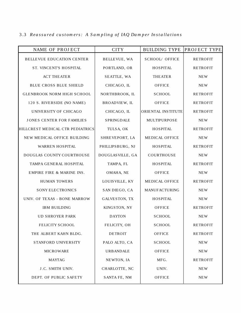
3.3 Reassured customers: A Sampling of IAQ Damper Installations
NAME OF PROJECT CITY BUILDING TYPE PROJECT TYPE
BELLEVUE EDUCATION CENTER BELLEVUE, WA SCHOOL/ OFFICE RETROFIT
ST. VINCENT'S HOSPITAL PORTLAND, OR HOSPITAL RETROFIT
ACT THEATER SEATTLE, WA THEATER NEW
BLUE CROSS BLUE SHIELD CHICAGO, IL OFFICE NEW
GLENBROOK NORM HIGH SCHOOL NORTHBROOK, IL SCHOOL RETROFIT
120 S. RIVERSIDE (NO NAME) BROADVIEW, IL OFFICE RETROFIT
UNIVERSITY OF CHICAGO CHICAGO, IL ORIENTAL INSTITUTE RETROFIT
JONES CENTER FOR FAMILIES SPRINGDALE MULTIPURPOSE NEW
HILLCREST MEDICAL CTR PEDIATRICS TULSA, OK HOSPITAL RETROFIT
NEW MEDICAL OFFICE BUILDING SHREVEPORT, LA MEDICAL OFFICE NEW
WARREN HOSPITAL PHILLIPSBURG, NJ HOSPITAL RETROFIT
DOUGLAS COUNTY COURTHOUSE DOUGLASVILLE, GA COURTHOUSE NEW
TAMPA GENERAL HOSPITAL TAMPA, FL HOSPITAL RETROFIT
EMPIRE FIRE & MARINE INS. OMAHA, NE OFFICE NEW
HUMAN TOWERS LOUISVILLE, KY MEDICAL OFFICE RETROFIT
SONY ELECTRONICS SAN DIEGO, CA MANUFACTURING NEW
UNIV. OF TEXAS - BONE MARROW GALVESTON, TX HOSPITAL NEW
IBM BUILDING KINGSTON, NY OFFICE RETROFIT
UD SHROYER PARK DAYTON SCHOOL NEW
FELICITY SCHOOL FELICITY, OH SCHOOL RETROFIT
THE ALBERT KAHN BLDG. DETROIT OFFICE RETROFIT
STANFORD UNIVERSITY PALO ALTO, CA SCHOOL NEW
MICROWARE URBANDALE OFFICE NEW
MAYTAG NEWTON, IA MFG. RETROFIT
J.C. SMITH UNIV. CHARLOTTE, NC UNIV. NEW
DEPT. OF PUBLIC SAFETY SANTA FE, NM OFFICE NEW
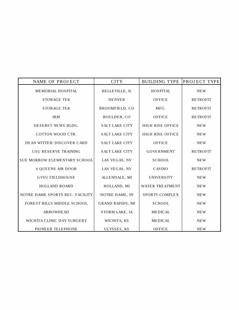
NAME OF PROJECT CITY BUILDING TYPE PROJECT TYPE
MEMORIAL HOSPITAL BELLEVILLE, IL HOSPITAL NEW
STORAGE TEK DENVER OFFICE RETROFIT
STORAGE TEK BROOMFIELD, CO MFG. RETROFIT
IBM BOULDER, CO OFFICE RETROFIT
DESERET NEWS BLDG. SALT LAKE CITY HIGH RISE OFFICE NEW
COTTON WOOD CTR. SALT LAKE CITY HIGH RISE OFFICE NEW
DEAN WITTER/DISCOVER CARD SALT LAKE CITY OFFICE NEW
USU RESERVE TRAINING SALT LAKE CITY GOVERNMENT RETROFIT
SUE MORROW ELEMENTARY SCHOOL LAS VEGAS, NV SCHOOL NEW
4 QUEENS AIR DOOR LAS VEGAS, NV CASINO RETROFIT
GVSU FIELDHOUSE ALLENDALE, MI UNIVERSITY NEW
HOLLAND BOARD HOLLAND, MI WATER TREATMENT NEW
NOTRE DAME SPORTS REC. FACILITY NOTRE DAME, IN SPORTS COMPLEX NEW
FOREST HILLS MIDDLE SCHOOL GRAND RAPIDS, MI SCHOOL NEW
ARROWHEAD STORM LAKE, IA MEDICAL NEW
WICHITA CLINIC DAY SURGERY WICHITA, KS MEDICAL NEW
PIONEER TELEPHONE ULYSSES, KS OFFICE NEW

• Go back to Table of Contents Page 23
4. IAQ50 Product Literature and Specifications
4.2 Specification Sheet (following)4.3 Color Advertisements (following)
ALL STATED SPECIFICATIONS ARE SUBJECT TO CHANGE WITHOUT NOTICE OR OBLIGATION.
3900 Dr. Greaves Rd. • Kansas City, MO 64030 • (816) 761-7476 • FAX (816) 765-8955
IAQ50 INTEGRAL AIRFLOW MONITOR/DAMPEROUTSIDE AIR VENTILATION CONTROLLER FOR
INDOOR AIR QUALITY
© Ruskin Manufacturing 1996
®
Spec IAQ50-796/Replaces IAQ50-0496
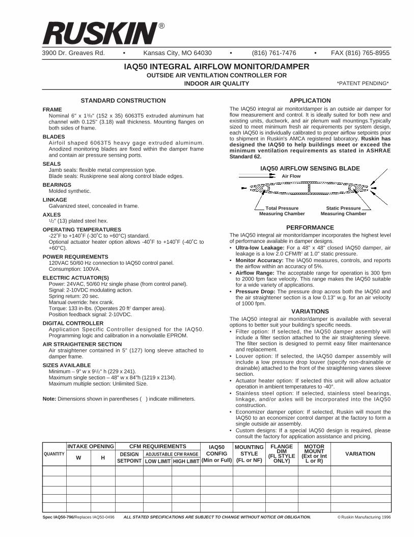
APPLICATIONThe IAQ50 integral air monitor/damper is an outside air damper forflow measurement and control. It is ideally suited for both new andexisting units, ductwork, and air plenum wall mountings.Typicallysized to meet minimum fresh air requirements per system design,each IAQ50 is individually calibrated to proper airflow setpoints priorto shipment in Ruskin's AMCA registered laboratory. Ruskin hasdesigned the IAQ50 to help buildings meet or exceed theminimum ventilation requirements as stated in ASHRAEStandard 62.
PERFORMANCEThe IAQ50 integral air monitor/damper incorporates the highest levelof performance available in damper designs.• Ultra-low Leakage: For a 48" x 48" closed IAQ50 damper, air
leakage is a low 2.0 CFM/ft2 at 1.0" static pressure.• Monitor Accuracy: The IAQ50 measures, controls, and reports
the airflow within an accuracy of 5%.• Airflow Range: The acceptable range for operation is 300 fpm
to 2000 fpm face velocity. This range makes the IAQ50 suitablefor a wide variety of applications.
• Pressure Drop: The pressure drop across both the IAQ50 andthe air straightener section is a low 0.13" w.g. for an air velocityof 1000 fpm.
VARIATIONSThe IAQ50 integral air monitor/damper is available with severaloptions to better suit your building's specific needs.• Filter option: If selected, the IAQ50 damper assembly will
include a filter section attached to the air straightening sleeve.The filter section is designed to permit easy filter maintenanceand replacement.
• Louver option: If selected, the IAQ50 damper assembly willinclude a low pressure drop louver (specify non-drainable ordrainable) attached to the front of the straightening vanes sleevesection.
• Actuator heater option: If selected this unit will allow actuatoroperation in ambient temperatures to -40°.
• Stainless steel option: If selected, stainless steel bearings,linkage, and/or axles will be incorporated into the IAQ50construction.
• Economizer damper option: If selected, Ruskin will mount theIAQ50 to an economizer control damper at the factory to form asingle outside air assembly.
• Custom designs: If a special IAQ50 design is required, pleaseconsult the factory for application assistance and pricing.
STANDARD CONSTRUCTIONFRAME
Nominal 6" x 13/8" (152 x 35) 6063T5 extruded aluminum hatchannel with 0.125" (3.18) wall thickness. Mounting flanges onboth sides of frame.
BLADESAirfoil shaped 6063T5 heavy gage extruded aluminum.Anodized monitoring blades are fixed within the damper frameand contain air pressure sensing ports.
SEALS Jamb seals: flexible metal compression type.Blade seals: Ruskiprene seal along control blade edges.
BEARINGSMolded synthetic.
LINKAGEGalvanized steel, concealed in frame.
AXLES1/2" (13) plated steel hex.
OPERATING TEMPERATURES-22˚F to +140˚F (-30˚C to +60°C) standard.Optional actuator heater option allows -40˚F to +140˚F (-40˚C to+60°C).
POWER REQUIREMENTS120VAC 50/60 Hz connection to IAQ50 control panel.Consumption: 100VA.
ELECTRIC ACTUATOR(S)Power: 24VAC, 50/60 Hz single phase (from control panel).Signal: 2-10VDC modulating action.Spring return: 20 sec.Manual override: hex crank.Torque: 133 in-lbs. (Operates 20 ft2 damper area).Position feedback signal: 2-10VDC.
DIGITAL CONTROLLERApplication Specific Controller designed for the IAQ50.Programming logic and calibration in a nonvolatile EPROM.
AIR STRAIGHTENER SECTIONAir straightener contained in 5" (127) long sleeve attached todamper frame.
SIZES AVAILABLEMinimum – 9" w x 91/2" h (229 x 241).Maximum single section – 48" w x 84"h (1219 x 2134).Maximum multiple section: Unlimited Size.
Note: Dimensions shown in parentheses ( ) indicate millimeters.
QUANTITYW
ADJUSTABLE CFM RANGEDESIGNSETPOINT LOW LIMIT HIGH LIMIT
H
INTAKE OPENING CFM REQUIREMENTS MOUNTINGSTYLE
(FL or NF)
FLANGEDIM
(FL STYLEONLY)
MOTORMOUNT
(Ext or IntL or R)
IAQ50CONFIG
(Min or Full)VARIATION
Air Flow
Total PressureMeasuring Chamber
Static PressureMeasuring Chamber
IAQ50 AIRFLOW SENSING BLADE
*PATENT PENDING*
The unique design of the IAQ50 incorporates an air monitor into theassembly of a high performance, aluminum airfoil blade controldamper. Ruskin has combined modulating airfoil blades withstrategically placed airflow sensing blades to measure the airstreamvelocity pressure. Air tubing/piping connections connect thedamper/monitor frame to a differential pressure transducer located inthe IAQ50 control panel (provided as part of the IAQ50 damper). TheIAQ50 controller also monitors the control blade position using thefeedback signal feature of the damper actuator. With the signal fromthe pressure transducer and the blade position signal, the IAQ50controller converts the pressure differential into an accurate CFMvalue.After computing a value for the CFM, the controller compares this
value to the CFM setpoint as determined by the particular mode ofoperation of the HVAC system. In normal operation, this setpoint willcorrespond to the minimum outside air ventilation required by thesystem design to meet ASHRAE Standard 62. Based on thedifference between the actual CFM reading and the desired CFMsetpoint, the controller will position the modulating damper blades asnecessary to ensure that the actual outside air flow meets thedesired level.
The IAQ50 provides a scaled 0-10VDC signal for remote monitoringof the actual ventilation rate in CFM. Additionally, the IAQ50 canreceive a 0-10VDC setpoint adjustment signal if a ventilation range isdesired.
OPERATION
The IAQ50 integral air monitor/damper incorporates many highquality features of Ruskin's industry leading damper designs.• Narrow total depth of 11" (279) (damper/monitor + air
straightening vane section) means unparalleled versatility inboth retrofit and new construction projects.
• The IAQ50 typically costs less than separate air monitoringstations, controls, and damper construction arrangements.
• Universal interface with building control systems for remotemonitoring and setpoint adjustment.
• The IAQ50 also operates as a fully functional stand alonepackage.
• The response of the IAQ50 to airflow volume changes makes itsuitable for use with VAV systems.
• Complete airfoil design allows for lowest possible pressure drop,and anodized sensing blades provide improved flow characteris-tics and added corrosion resistance.
• Concealed linkage is out of the airstream which requires lessmaintenance and reduced air turbulence.
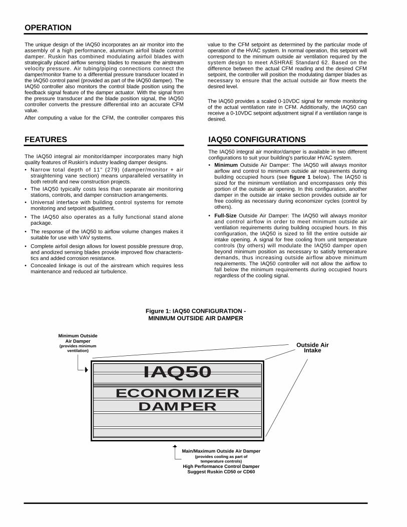
The IAQ50 integral air monitor/damper is available in two differentconfigurations to suit your building's particular HVAC system.• Minimum Outside Air Damper: The IAQ50 will always monitor
airflow and control to minimum outside air requirements duringbuilding occupied hours (see figure 1 below). The IAQ50 issized for the minimum ventilation and encompasses only thisportion of the outside air opening. In this configuration, anotherdamper in the outside air intake section provides outside air forfree cooling as necessary during economizer cycles (control byothers).
• Full-Size Outside Air Damper: The IAQ50 will always monitorand control airflow in order to meet minimum outside airventilation requirements during building occupied hours. In thisconfiguration, the IAQ50 is sized to fill the entire outside airintake opening. A signal for free cooling from unit temperaturecontrols (by others) will modulate the IAQ50 damper openbeyond minimum position as necessary to satisfy temperaturedemands, thus increasing outside airflow above minimumrequirements. The IAQ50 controller will not allow the airflow tofall below the minimum requirements during occupied hoursregardless of the cooling signal.
FEATURES IAQ50 CONFIGURATIONS
Figure 1: IAQ50 CONFIGURATION -MINIMUM OUTSIDE AIR DAMPER
Outside AirIntake
Minimum OutsideAir Damper
(provides minimumventilation)
Main/Maximum Outside Air Damper(provides cooling as part of
temperature controls)High Performance Control Damper
Suggest Ruskin CD50 or CD60
IAQ50ECONOMIZER
DAMPER
IAQ50 MOUNTING STYLES
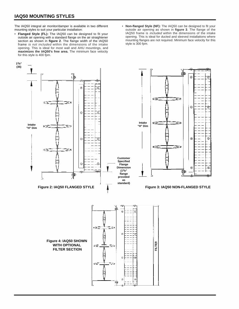
The IAQ50 integral air monitor/damper is available in two differentmounting styles to suit your particular installation:• Flanged Style (FL): The IAQ50 can be designed to fit your
outside air opening with a standard flange on the air straightenersection as shown in figure 2. The flange width of the IAQ50frame is not included within the dimensions of the intakeopening. This is ideal for most wall and AHU mountings, andmaximizes the IAQ50's free area. The minimum face velocityfor this style is 400 fpm.
• Non-flanged Style (NF): The IAQ50 can be designed to fit youroutside air opening as shown in figure 3. The flange of theIAQ50 frame is included within the dimensions of the intakeopening. This is ideal for ducted and sleeved installations wheremounting flanges are not required. Minimum face velocity for thisstyle is 300 fpm.
Figure 2: IAQ50 FLANGED STYLE Figure 3: IAQ50 NON-FLANGED STYLE
Intake"H" Dim
Intake"H" Dim
13/8"(35)
CustomerSpecified
FlangeDimension
(13/8"flange
providedas
standard)
Figure 4: IAQ50 SHOWNWITH OPTIONALFILTER SECTION F
ILT
ER
3900 Dr. Greaves Rd.Kansas City, MO 64030(816) 761-7476FAX (816) 765-8955
®
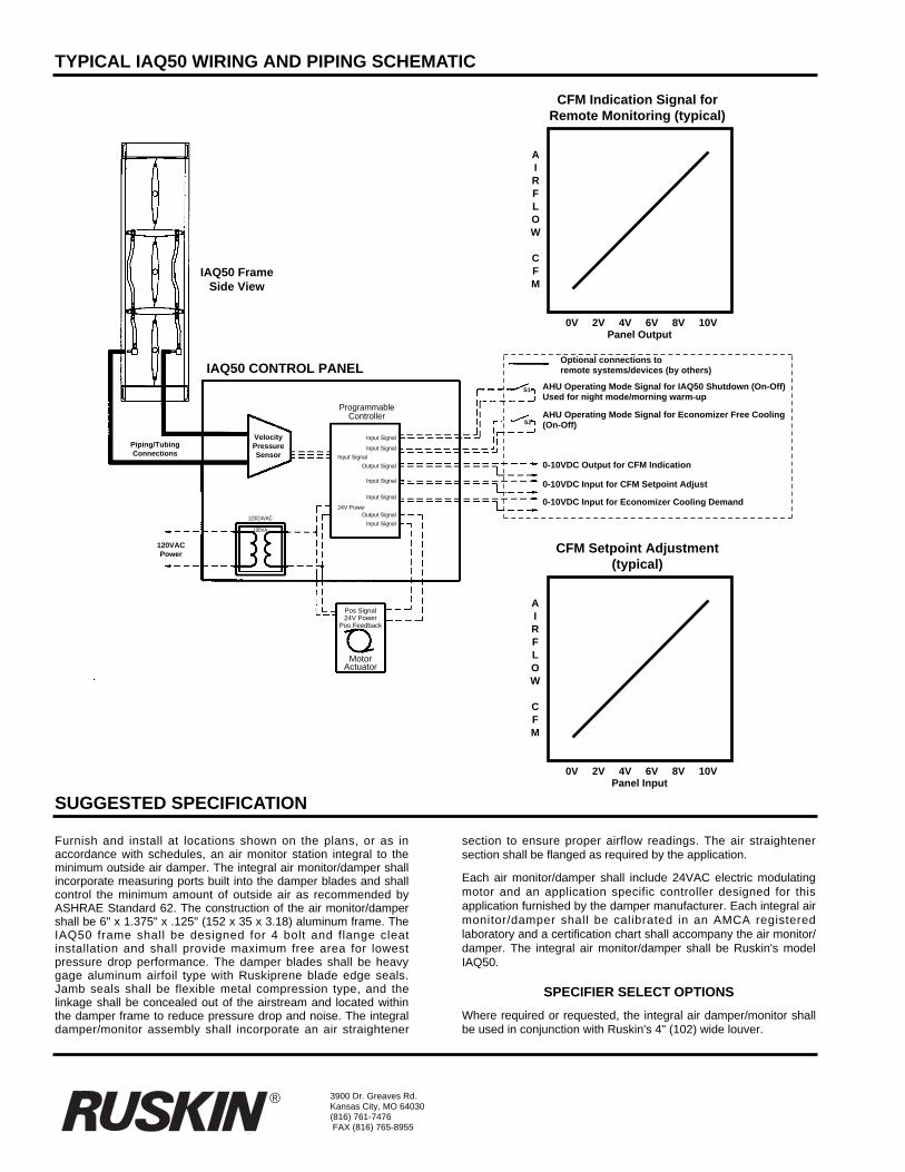
TYPICAL IAQ50 WIRING AND PIPING SCHEMATIC
SUGGESTED SPECIFICATION
Furnish and install at locations shown on the plans, or as inaccordance with schedules, an air monitor station integral to theminimum outside air damper. The integral air monitor/damper shallincorporate measuring ports built into the damper blades and shallcontrol the minimum amount of outside air as recommended byASHRAE Standard 62. The construction of the air monitor/dampershall be 6" x 1.375" x .125" (152 x 35 x 3.18) aluminum frame. TheIAQ50 frame shall be designed for 4 bolt and flange cleatinstallation and shall provide maximum free area for lowestpressure drop performance. The damper blades shall be heavygage aluminum airfoil type with Ruskiprene blade edge seals.Jamb seals shall be flexible metal compression type, and thelinkage shall be concealed out of the airstream and located withinthe damper frame to reduce pressure drop and noise. The integraldamper/monitor assembly shall incorporate an air straightener
section to ensure proper airflow readings. The air straightenersection shall be flanged as required by the application.
Each air monitor/damper shall include 24VAC electric modulatingmotor and an application specific controller designed for thisapplication furnished by the damper manufacturer. Each integral airmonitor/damper shall be calibrated in an AMCA registeredlaboratory and a certification chart shall accompany the air monitor/damper. The integral air monitor/damper shall be Ruskin's modelIAQ50.
SPECIFIER SELECT OPTIONS
Where required or requested, the integral air damper/monitor shallbe used in conjunction with Ruskin's 4" (102) wide louver.
ProgrammableController
Input Signal
Input Signal
Input Signal
Output Signal
Input Signal
Input Signal
24V PowerOutput Signal
Input Signal120/24VAC
100VA
IAQ50 CONTROL PANEL
CFM Indication Signal forRemote Monitoring (typical)
IAQ50 FrameSide View
Optional connections toremote systems/devices (by others)
AHU Operating Mode Signal for IAQ50 Shutdown (On-Off)Used for night mode/morning warm-up
AHU Operating Mode Signal for Economizer Free Cooling(On-Off)
0-10VDC Output for CFM Indication
0-10VDC Input for CFM Setpoint Adjust
0-10VDC Input for Economizer Cooling Demand
0V 2V 4V 6V 8V 10VPanel Output
AIRFLOW
CFM
CFM Setpoint Adjustment(typical)
0V 2V 4V 6V 8V 10VPanel Input
AIRFLOW
CFM
S1
S2
Piping/TubingConnections
120VACPower
Pos Signal24V Power
Pos Feedback
MotorActuator
VelocityPressureSensor
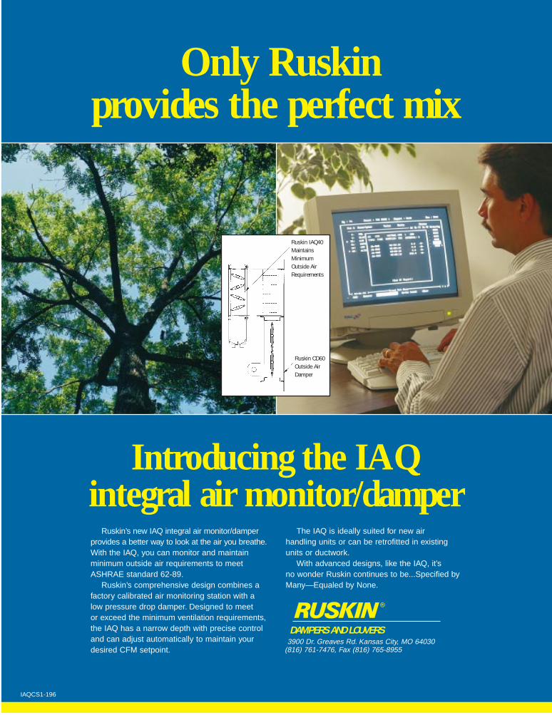
Only Ruskin provides the perfect mix
Ruskin’s new IAQ integral air monitor/damperprovides a better way to look at the air you breathe.With the IAQ, you can monitor and maintain minimum outside air requirements to meetASHRAE standard 62-89.
Ruskin’s comprehensive design combines afactory calibrated air monitoring station with a low pressure drop damper. Designed to meet or exceed the minimum ventilation requirements,the IAQ has a narrow depth with precise controland can adjust automatically to maintain yourdesired CFM setpoint.
The IAQ is ideally suited for new air handling units or can be retrofitted in existingunits or ductwork.
With advanced designs, like the IAQ, it’s no wonder Ruskin continues to be...Specified byMany—Equaled by None.
3900 Dr. Greaves Rd. Kansas City, MO 64030(816) 761-7476, Fax (816) 765-8955
R
Introducing the IAQintegral air monitor/damper
Ruskin IAQ40MaintainsMinimumOutside AirRequirements
Ruskin CD60Outside AirDamper
DAMPERS AND LOUVERS
IAQCS1-196
VISION
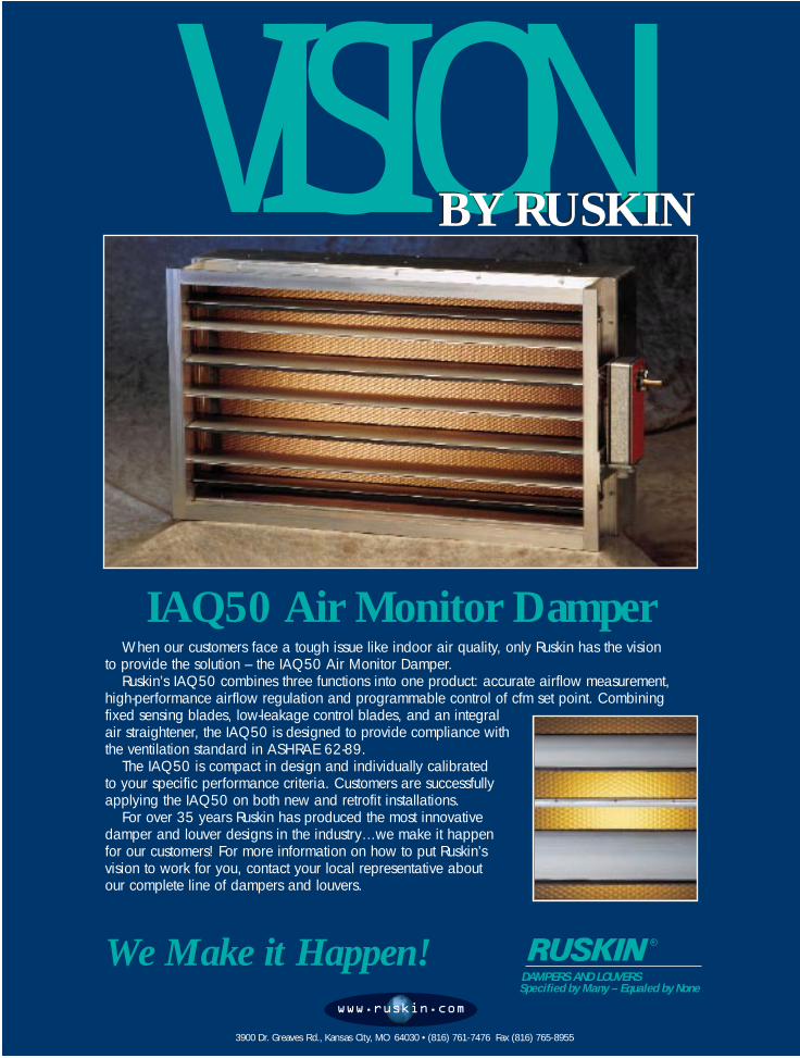
IAQ50 Air Monitor DamperWhen our customers face a tough issue like indoor air quality, only Ruskin has the vision
to provide the solution – the IAQ50 Air Monitor Damper.Ruskin’s IAQ50 combines three functions into one product: accurate airflow measurement,
high-performance airflow regulation and programmable control of cfm set point. Combiningfixed sensing blades, low-leakage control blades, and an integral air straightener, the IAQ50 is designed to provide compliance withthe ventilation standard in ASHRAE 62-89.
The IAQ50 is compact in design and individually calibrated to your specific performance criteria. Customers are successfullyapplying the IAQ50 on both new and retrofit installations.
For over 35 years Ruskin has produced the most innovativedamper and louver designs in the industry…we make it happen for our customers! For more information on how to put Ruskin’svision to work for you, contact your local representative about our complete line of dampers and louvers.
We Make it Happen!
BY RUSKINBY RUSKIN
DAMPERS AND LOUVERSSpecified by Many – Equaled by None
R
3900 Dr. Greaves Rd., Kansas City, MO 64030 • (816) 761-7476 Fax (816) 765-8955
www.ruskin.com
4.3 Frequently Asked Questions - IAQ50
1. Can I put the IAQ damper before or after an elbow or any other transition inthe ductwork? If so, what are the requirements?
• Because the IAQ50 incorporates a honeycomb straightener section on the inletside, direct upstream connections can be made. Airflow downstream requiresa space equal to the radius elbow between the elbow when using an elbow or30” minimum if using rectangular duct.
2. What is the pressure drop through a fully open IAQ and straightener?
• The straightener section also acts to reduce the pressure drop. See thepressure drop curve in section 2.8.
3. If the IAQ sensing blades become plugged, the controller will open thedamper, thus allowing more fresh air than necessary to enter the building.Does the IAQ controller send a signal telling of the plugged blade condition?
• The IAQ50 incorporates a 0-10 vdc output for CFM indication. If pluggingwere to occur, the building’s FMS could be pre-programmed to an alarmcondition if CFM indication goes out of the user specified range. Trendlogging these values on a daily or monthly basis is an excellent method toprevent plugging.
4. Is there a formula I can use to size an IAQ50?
• First identify the outside airflow range that the IAQ50 damper will monitor andcontrol. This information, along with design velocity of the standardeconomizer air dampers, serves as a guide in sizing an IAQ50. The IAQ50should be sized so that the airflow velocities over the desired airflowmonitoring range are within the published limits and correspond to the designvelocity of a standard outside air damper. This will help to ensure a similarpressure drop across each bank of dampers.
5. Can I supply my own controller for the IAQ50?
• Ruskin’s IAQ50 design has 3 integral parts: the air measuring damper, thefeedback actuator and Ruskin’s exclusive DDC controller. Each component isnecessary for a properly functioning factory calibrated product backed byRuskin. Consult Ruskin for other air measuring devices if your jobrequirements differ.
6. Can the IAQ be painted?
• Yes, and these special finishes should only be applied in our factory. Itshould not be painted in the field.
7. Can we get Stainless Steel IAQ’s or any components in the airstream?
• We offer stainless steel straightener and frame. This section is also completelyremovable for cleaning or replacing. We can also provide anodizing andother special finishes for the aluminum components at our factory.
8. Are pneumatic actuators available?
• No and here’s why. Electronics are the key to the accurate measurement ofthe airflow. The inclusion of pneumatic actuators would not only be a designconstraint, but a major cost increase would occur.
9. Can I get other electric actuators besides Belimo brand?
• Not at this time. Please refer back to question 5. The IAQ50 has beendeveloped using this highly reliable and accurate actuator. Other direct-coupled motors may be available in the future.
10. What is the maximum pressure(psi) when cleaning the sensing holes?
• 20-40 psi. Please disconnect the static pressure sensor (refer to maintenanceinstructions, section 5.6 in this manual).
11. What are the minimum and maximum face velocities for the IAQ50?
• Between 300 and 2000 fpm, we will guarantee an accuracy to +/- 5%. TheIAQ50 is operational from 150 to 3000 fpm..
12. Do I really need a straightener, or can I just use my existing louver?
• The straightener is included in the price and improves accuracy at lowervelocities.
13. Can you give me a 4-20ma signal rather than the 0-10v reading?
• Not without adding cost by utilizing an additional electronic control device.
14. What happens if I remove and reinstall the actuator in the field?
• Every IAQ50 control shaft and actuator clamp is permanently marked duringcalibration. Returning them to this exact location will ensure reliable readingsif actuator is removed.
15. How can I tell if my IAQ50 is working correctly?
• Comparing the data from the Setpoint Adjustment and the CFM Indicationsignals is a simple way to determine proper operation.
16. Can I use your output to directly control my return air damper?
• Not directly. Depending on the IAQ50 configuration, full or minimum, the IAQdamper can interface with the economizer temperature or enthalpy controlsystem and therefore dictate the return air damper action. See section 2.3 formore details.
17. How does the IAQ50’s performance stack up to an air monitoring station?
• By incorporating a damper into the air measuring design, the IAQ50 is able toread at low velocities because the pressure signal (static and total) isamplified. Additionally, the IAQ50 utilizes a high quality dead-end pressuretransducer that performs exceptionally well at these low velocities.
18. Do I have to wire motor feedback to the control panel?
• Yes, so that our controller will know the actuator and damper blade position.
19. Can I change the setpoints in the field?
• Yes, via a 0-10v (dc) input. Setpoints can be changed at any time therequirements change in the building.
20. What is the response time on the control? It appears to be slow.
• The response time of the IAQ50 control loop is tuned so as to prevent theactuator from hunting continuously. Maintaining and documenting minimumoutside air does not require rapid response time. 5-10 minutes is typical.
21. I need to access the straightener for periodic cleaning, can you provide anaccess door or slide-in tray?
• Yes. This may require a custom configuration. Please allow extra time toconsult with the Ruskin engineering department.
22. What effect does water carry over have on the IAQ50?
• In vertical applications, water carryover is not a factor. We do not incorporateflow-through sensors which could be susceptible to moisture. If mounting the
IAQ50 horizontally, care should be taken to prevent water from falling on thesensing ports.
23. What type of differential pressure sensor do we use?
• We use an instrument grade high quality dead-ended sensor with a 0-2” wgpressure range. Dead-ended sensors offer high accuracy and more flexibilityin mounting, that is no tubing losses, because flow is not required for pressurereading.
24. If it is a dead-end sensor, how often does one zero out the signal to correctthe read out?
• This sensor does not require an auto-correcting sequence. It does contain anon-board potentiometer, however, so that if a zeroing operation was desiredthe sensor could be measured against its original factory calibration settings.Consult Ruskin for the test procedure.
25. What construction has been proven for coastal environments?
• Anodized aluminum construction for the sensing blade, frame and damperblade.
26. What are the temperature limitations?
• -22°F to 140°F. With optional actuator heater, the low end temperature goes to–40°.
27. Do the IAQ50 ports frost over?
• They shouldn’t because the temperature of the blades should be equal to themixed air temperature which is above freezing. But, in the unlikely event thatfrosting occurs, and pressure readings are not possible, the damper willrespond to the open position thus satisfying the requirements for minimum air.
28. How far downstream should the IAQ be if installed on the supply side of thefan?
• This is not designed for measuring air on the supply side of the fan.
29. What happens to the output signal when the outside air damper opens?
• It continues to show CFM output.
30. Can the IAQ be used in a system to eliminate VAV boxes?

• Please call us for consultation on these applications.
31. If the actuators are replaced in the field, how is the unit recalibrated?
• Recalibration is not necessary. There are two actuator clamps holding theactuator to the control shaft. Removal of the outside clamps only is required toremove the actuator. For other notes on the reinstallation, of the actuator, seequestion 14.
IAQ50 Installation and Maintenance Instructions
(The IAQ50 Air Damper/Monitor unit and digital controller panel may ship inseparate containers. Please verify the receipt of both prior to installation.)
5.1 IAQ50 Air Damper/Monitor Installation Instructions
1. Remove the IAQ50 Air Damper/Monitor from its shipping container andinspect for damage, rust or corrosion. Care must be taken in handling theunit. Always handle the IAQ50 Air Damper/Monitor by its frame. Do not lift itby the blade, linkage, axle, motor or jackshaft. Do not drop, drag, step on, orapply excessive bending, twisting or racking loads to the IAQ50.
2. Inspect the ductwork and/or opening where the IAQ50 Air Damper/Monitorassembly will be installed for any obstruction or irregularities that mightinterfere with blade or linkage rotation, or actuator mounting. If it is to beinstalled in ductwork, the ductwork should be supported in the area of theIAQ50 to prevent sagging due to the unit’s weight.
3. The IAQ50 Air Damper/Monitor must be installed with the frames square andwithout twisting or bending. Unless specifically designed for a vertical bladeapplication, the unit must be mounted with its blade axis horizontal. Thedamper blades, axles, and linkage must be able to operate without binding.
4. The best location for the extended shaft or jackshaft must be determinedbefore installing the damper. The damper may be rotated to get the extendedshaft on the correct side of the ductwork. After the damper is installed theshaft location cannot be changed without removing the damper. The jackshaft,if installed, will always be in the leaving air stream. Unlike other controldampers, which have no airflow orientation, the IAQ50 has a specified inletand outlet. The outside air (or other controlled air stream) enters the unitthrough the air straightener section and exits the unit from the damper frameside.
5. Use appropriate shims between damper frame and duct opening to preventdistortion of the frame by fasteners holding it in place. If creating a multi-section assembly, be sure that all of the sections are fastened together on bothsides.
6. The IAQ50 Air Damper/Monitor is factory calibrated and tested in order toperform correctly in its application immediately following installation. Theelectric actuator should not be moved, adjusted, or altered in any way tofacilitate installation. Such modifications affect the factory calibration of theunit. If the actuator, linkage, or shafting present a problem for installation,please consult your local Ruskin representative or the Ruskin factory. TheIAQ50 should be cycled after installation to assure proper operation.
5.2 Digital Controller Panel Installation

1. The controller enclosure should be mounted securely on an adjacent wall,attached to the air handling unit, or placed within some other suitable controlpanel. The panel should be mounted within 120 feet of the IAQ50 AirDamper/Monitor to prevent pressure signal variations from the IAQ50 to thecontrol panel. If the enclosure must be mounted more than 120 feet from theIAQ50 damper frame, please consult your local Ruskin representative or the
Ruskin factory.
2. Loosen the enclosure’s cover screws and remove the cover.3. Remove the appropriate knockouts for connection of the field wires to the
enclosure’s terminal blocks.4. Fasten the enclosure to the wall or flat surface using the (4)1/4” dia. holes at
the four corners.
5.3 IAQ50 Wiring and Piping Connections (refer to control panel wiringdiagram)
IAQ50 Wiring Connections
1. Connect the 115VAC power supply to IAQ50 control panel terminals L1 andL2.
2. Connect the Belimo AF24-SR motor actuator 24VAC power wires 1 and 2 tocontrol panel terminals 5 and 6, respectively.
3. Connect the motor actuator 0-10V control signal wire 3 to panel terminal 7.4. Connect the motor actuator 2-10V position feedback signal wire 5 to panel
terminal 8.5. (Optional) Connect the 0-10VDC remote setpoint adjustment signal (by
others) to control panel terminals 3 and 4. Terminal 3 is the positive terminal.6. (Optional) Connect the wires to receive 0-10VDC actual CFM signal from the
IAQ50 panel to terminals 1 and 2. Terminal 1 is the positive terminal.7. (Recommended) Connect dry contact/switch to terminals 10 and 11 to activate
the occupied/unoccupied function. A closed contact connection (default withjumper wire) places the IAQ50 digital controller into normal operation/daymode. An open circuit is a shutdown command, and the IAQ50 damper fullycloses. Other applications for an open circuit command are night set-back andmorning warm-up sequences, or any time the outside air damper should beclosed.
8. (Optional) Connect dry contact/switch to terminals 9 and 10 to activateeconomizer override function. When operating in the normal/day mode, aclosed circuit activates minimum fresh air control. A jumper is factoryinstalled to set this default condition. If an open circuit is placed between theterminals, this is an economizer signal asking for free cooling. The IAQ50travels to and remains 100% open.
9. (Optional) Connect the 0-10VDC remote outside air cooling demand signal (byothers) to control panel terminals 12 and 13. Terminal 12 is the positiveterminal. If this signal calls for more outside air than the minimum ventilationsetpoint, the IAQ50 will modulate open beyond minimum position in responseto this signal (0-10VDC scaled to 0-100% damper open). At no time will theIAQ50 digital controller allow airflow below the minimum CFM setpoint.
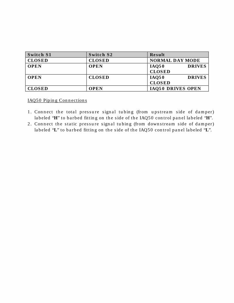
Switch S1 Switch S2 ResultCLOSED CLOSED NORMAL DAY MODEOPEN OPEN IAQ50 DRIVES
CLOSEDOPEN CLOSED IAQ50 DRIVES
CLOSEDCLOSED OPEN IAQ50 DRIVES OPEN
IAQ50 Piping Connections
1. Connect the total pressure signal tubing (from upstream side of damper)labeled “H” to barbed fitting on the side of the IAQ50 control panel labeled “H”.
2. Connect the static pressure signal tubing (from downstream side of damper)labeled “L” to barbed fitting on the side of the IAQ50 control panel labeled “L”.
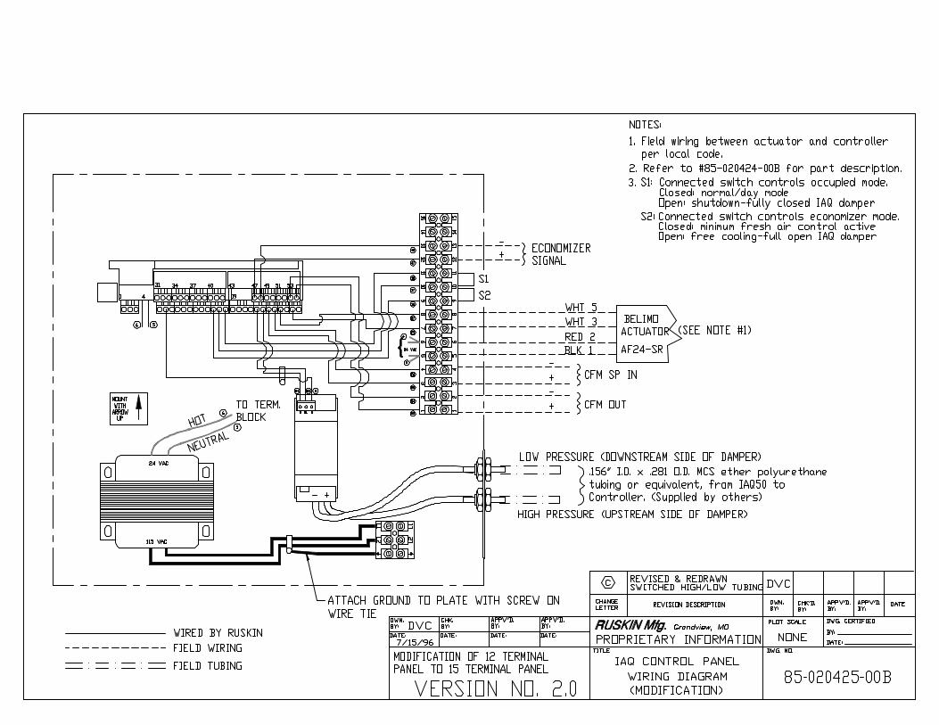
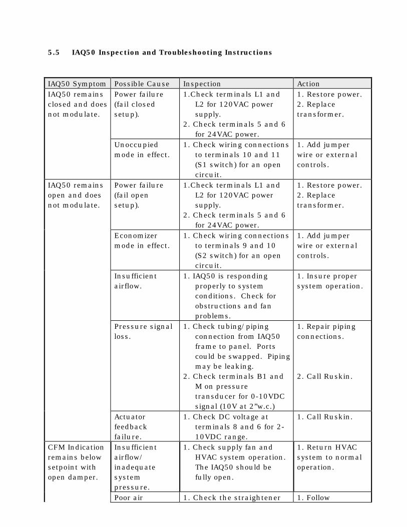
5.5 IAQ50 Inspection and Troubleshooting Instructions
IAQ50 Symptom Possible Cause Inspection ActionIAQ50 remainsclosed and doesnot modulate.
Power failure(fail closedsetup).
1.Check terminals L1 andL2 for 120VAC powersupply.
2. Check terminals 5 and 6for 24VAC power.
1. Restore power.2. Replacetransformer.
Unoccupiedmode in effect.
1. Check wiring connectionsto terminals 10 and 11(S1 switch) for an opencircuit.
1. Add jumperwire or externalcontrols.
IAQ50 remainsopen and doesnot modulate.
Power failure(fail opensetup).
1.Check terminals L1 andL2 for 120VAC powersupply.
2. Check terminals 5 and 6for 24VAC power.
1. Restore power.2. Replacetransformer.
Economizermode in effect.
1. Check wiring connectionsto terminals 9 and 10(S2 switch) for an opencircuit.
1. Add jumperwire or externalcontrols.
Insufficientairflow.
1. IAQ50 is respondingproperly to systemconditions. Check forobstructions and fanproblems.
1. Insure propersystem operation.
Pressure signalloss.
1. Check tubing/pipingconnection from IAQ50frame to panel. Portscould be swapped. Pipingmay be leaking.
2. Check terminals B1 andM on pressuretransducer for 0-10VDCsignal (10V at 2”w.c.)
1. Repair pipingconnections.
2. Call Ruskin.
Actuatorfeedbackfailure.
1. Check DC voltage atterminals 8 and 6 for 2-10VDC range.
1. Call Ruskin.
CFM Indicationremains belowsetpoint withopen damper.
Insufficientairflow/inadequatesystempressure.
1. Check supply fan andHVAC system operation.The IAQ50 should befully open.
1. Return HVACsystem to normaloperation.
Poor air 1. Check the straightener 1. Follow
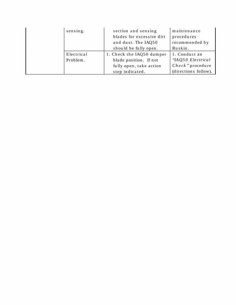
sensing. section and sensingblades for excessive dirtand dust. The IAQ50should be fully open.
maintenanceproceduresrecommended byRuskin.
ElectricalProblem.
1. Check the IAQ50 damperblade position. If notfully open, take actionstep indicated.
1. Conduct an“IAQ50 ElectricalCheck” procedure(directions follow).
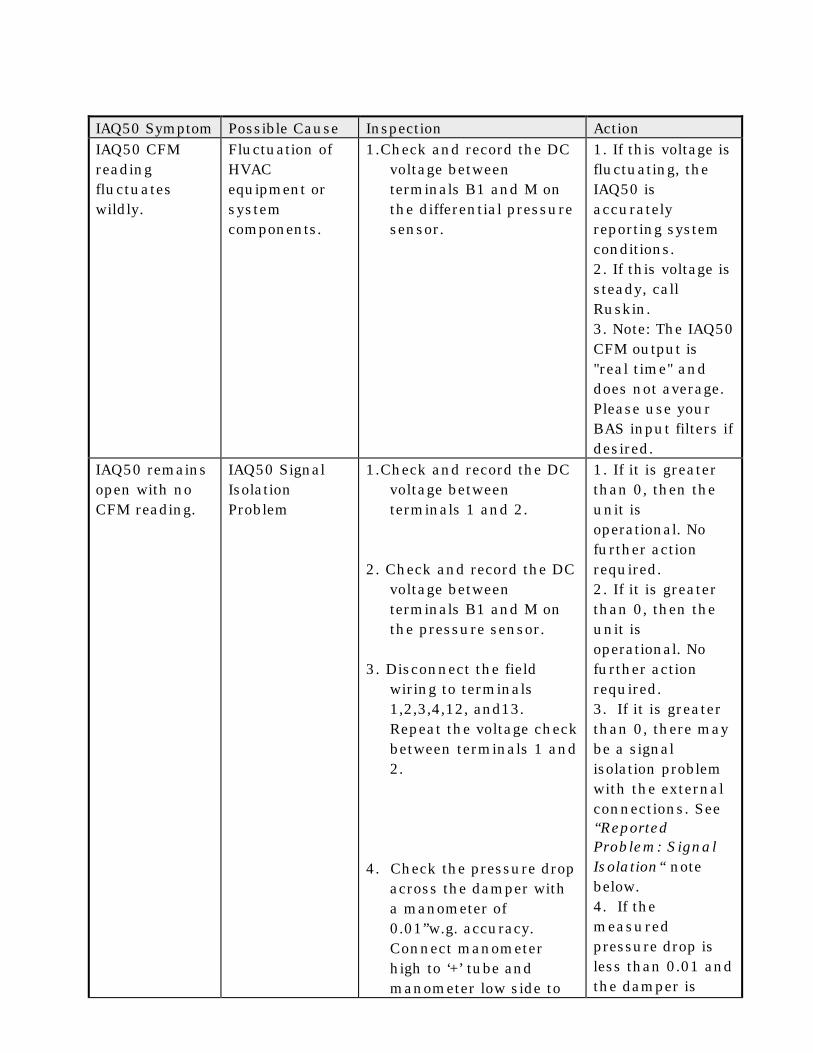
IAQ50 Symptom Possible Cause Inspection ActionIAQ50 CFMreadingfluctuateswildly.
Fluctuation ofHVACequipment orsystemcomponents.
1.Check and record the DCvoltage betweenterminals B1 and M onthe differential pressuresensor.
1. If this voltage isfluctuating, theIAQ50 isaccuratelyreporting systemconditions.2. If this voltage issteady, callRuskin.3. Note: The IAQ50CFM output is"real time" anddoes not average.Please use yourBAS input filters ifdesired.
IAQ50 remainsopen with noCFM reading.
IAQ50 SignalIsolationProblem
1.Check and record the DCvoltage betweenterminals 1 and 2.
2. Check and record the DCvoltage betweenterminals B1 and M onthe pressure sensor.
3. Disconnect the fieldwiring to terminals1,2,3,4,12, and13.Repeat the voltage checkbetween terminals 1 and2.
4. Check the pressure dropacross the damper witha manometer of0.01”w.g. accuracy.Connect manometerhigh to ‘+’ tube andmanometer low side to
1. If it is greaterthan 0, then theunit isoperational. Nofurther actionrequired.2. If it is greaterthan 0, then theunit isoperational. Nofurther actionrequired.3. If it is greaterthan 0, there maybe a signalisolation problemwith the externalconnections. See“ReportedProblem: SignalIsolation“ notebelow.4. If themeasuredpressure drop isless than 0.01 andthe damper is
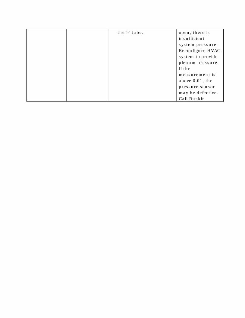
the ‘-‘ tube. open, there isinsufficientsystem pressure.Reconfigure HVACsystem to provideplenum pressure.If themeasurement isabove 0.01, thepressure sensormay be defective.Call Ruskin.
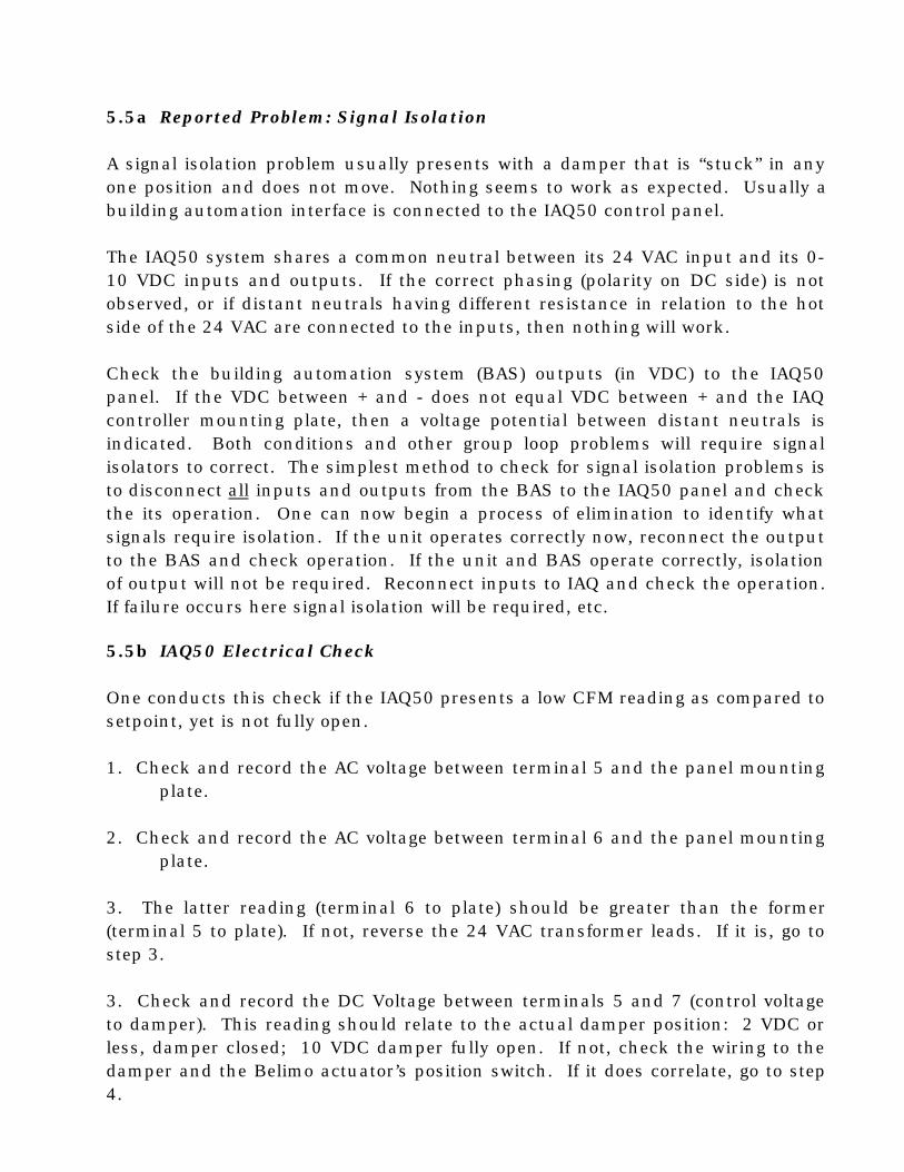
5.5a Reported Problem: Signal Isolation
A signal isolation problem usually presents with a damper that is “stuck” in anyone position and does not move. Nothing seems to work as expected. Usually abuilding automation interface is connected to the IAQ50 control panel.
The IAQ50 system shares a common neutral between its 24 VAC input and its 0-10 VDC inputs and outputs. If the correct phasing (polarity on DC side) is notobserved, or if distant neutrals having different resistance in relation to the hotside of the 24 VAC are connected to the inputs, then nothing will work.
Check the building automation system (BAS) outputs (in VDC) to the IAQ50panel. If the VDC between + and - does not equal VDC between + and the IAQcontroller mounting plate, then a voltage potential between distant neutrals isindicated. Both conditions and other group loop problems will require signalisolators to correct. The simplest method to check for signal isolation problems isto disconnect all inputs and outputs from the BAS to the IAQ50 panel and checkthe its operation. One can now begin a process of elimination to identify whatsignals require isolation. If the unit operates correctly now, reconnect the outputto the BAS and check operation. If the unit and BAS operate correctly, isolationof output will not be required. Reconnect inputs to IAQ and check the operation.If failure occurs here signal isolation will be required, etc.
5.5b IAQ50 Electrical Check
One conducts this check if the IAQ50 presents a low CFM reading as compared tosetpoint, yet is not fully open.
1. Check and record the AC voltage between terminal 5 and the panel mountingplate.
2. Check and record the AC voltage between terminal 6 and the panel mountingplate.
3. The latter reading (terminal 6 to plate) should be greater than the former(terminal 5 to plate). If not, reverse the 24 VAC transformer leads. If it is, go tostep 3.
3. Check and record the DC Voltage between terminals 5 and 7 (control voltageto damper). This reading should relate to the actual damper position: 2 VDC orless, damper closed; 10 VDC damper fully open. If not, check the wiring to thedamper and the Belimo actuator’s position switch. If it does correlate, go to step4.

4. Check and record the DC voltage between terminals 5 and 8 (feedback fromthe damper motor actuator). It should be approximately equal to the previousreading (control voltage to motor, terminals 5 and 7). If it does not, check thewiring to the damper and Belimo actuator’s direction switch. Otherwise, theelectrical connections are appropriate.
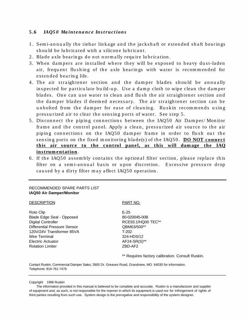
5.6 IAQ50 Maintenance Instructions
1. Semi-annually the tiebar linkage and the jackshaft or extended shaft bearingsshould be lubricated with a silicone lubricant.
2. Blade axle bearings do not normally require lubrication.3. When dampers are installed where they will be exposed to heavy dust-laden
air, frequent flushing of the axle bearings with water is recommended forextended bearing life.
4. The air straightener section and the damper blades should be annuallyinspected for particulate build-up. Use a damp cloth to wipe clean the damperblades. One can use water to clean and flush the air straightener section andthe damper blades if deemed necessary. The air straightener section can beunbolted from the damper for ease of cleaning. Ruskin recommends usingpressurized air to clear the sensing ports of water. See step 5.
5. Disconnect the piping connections between the IAQ50 Air Damper/Monitorframe and the control panel. Apply a clean, pressurized air source to the airpiping connections on the IAQ50 damper frame in order to flush out thesensing ports on the fixed monitoring blade(s) of the IAQ50. DO NOT connectthis air source to the control panel, as this will damage the IAQinstrumentation.
6. If the IAQ50 assembly contains the optional filter section, please replace thisfilter on a semi-annual basis or upon discretion. Excessive pressure dropcaused by a dirty filter may affect IAQ50 operation.
RECOMMENDED SPARE PARTS LISTIAQ50 Air Damper/Monitor
DESCRIPTION PART NO.
Roto Clip E-25Blade Edge Seal - Opposed 80-020045-00BDigital Controller RCE93.1/HQ00 TEC**Differential Pressure Sensor QBM63/500**120V/24V Transformer 85VA T-202Wire Terminal 324-HDS/12Electric Actuator AF24-SR(S)**Rotation Limiter ZBD-AF2
** Requires factory calibration. Consult Ruskin.
Contact Ruskin, Commercial Damper Sales, 3900 Dr. Greaves Road, Grandview, MO 64030 for information.Telephone: 816-761-7476
Copyright 1996 RuskinThe information provided in this manual is believed to be complete and accurate. Ruskin is a manufacturer and supplier
of equipment and, as such, is not responsible for the manner in which its equipment is used nor for infringement of rights ofthird parties resulting from such use. System design is the prerogative and responsibility of the system designer.

All Rights Reserved. A U.S. patent protects the product detailed in this manual. Illustrations and productdescriptions published are not binding in detail. In keeping with its policy of continuous improvement, Ruskinreserves the right to change or modify designs or specifications of products without notice or obligation.


