Embed Size (px)
Citation preview

IBM Spectrum NASVersion 1.7.0.0
Network Guide
SC27-9231-00
IBM
This edition applies to IBM Spectrum NAS, Version 1.7.0.0, and to all subsequent releases and
modifications until otherwise indicated in new editions.
© Copyright IBM Corporation 2018.
US Government Users Restricted Rights – Use, duplication or disclosure restricted by GSA ADP
Schedule Contract with IBM Corp.
IBM Spectrum NAS is a Software-defined storage solution that provides file storage and offers an
active/active storage solution to the end user.
This manual provides a detailed description of the networking layer associated with the IBM Spectrum NAS
solution. It explains the concepts behind the different types of logical networks that can be configured with
the IBM Spectrum NAS Management Tool, and describes the steps required in the network configuration
process. A number of use case examples are included to better illustrate the configuration process.
For installing the nodes, see the IBM Spectrum NAS Installation Guide.
For installing the Management Tool and setting up the storage cluster,
see the IBM Spectrum NAS Quick Setup Guide.
When preparing the network part, refer to the IBM Spectrum NAS Network Check List.

Network Overview ....................................................................................................... 4 Logical Networks ........................................................................................................... 4
Management Network ............................................................................................. 4 Private Network ........................................................................................................ 5 Public Network .......................................................................................................... 5 Antivirus Network ..................................................................................................... 6
File system Networking ................................................................................................ 6 Advanced Network Interface Configuration .............................................................. 7
Bonding ...................................................................................................................... 7 VLAN ........................................................................................................................... 7
Network Configuration How-To .................................................................................. 9 Network Interfaces Configuration ............................................................................... 9
Advanced Network Interface Configuration .......................................................... 9 Enabling IGMP .............................................................................................................. 10 Logical Networks Configuration ................................................................................ 11
Management Network Configuration .................................................................. 11 Private Network Configuration ............................................................................. 14 Public Network Configuration ............................................................................... 14 Antivirus Network Configuration .......................................................................... 15 Deleting Logical Networks ..................................................................................... 16
File System Network Configuration ........................................................................... 16 File system network configuration at creation time ........................................... 16 File system network configuration at a later time .............................................. 18 Multiple Public IPs .................................................................................................. 19
Use Case Examples .................................................................................................... 20 Use Case 1: One File system ...................................................................................... 20 Use Case 2: One File system with Bonding .............................................................. 22 Use Case 3: One File system with Bonding and VLAN ............................................ 24 Use Case 4: Two File systems, isolated with File system mask .............................. 26 Use Case 5: Two File systems, isolated with VLAN .................................................. 28
Getting Help ................................................................................................................ 30 IBM Spectrum NAS Support ....................................................................................... 30
Appendix ..................................................................................................................... 31 Bonding Options .......................................................................................................... 31
IBM Spectrum NAS Network Guide | Version 1.7.0.0

IBM Spectrum NAS Network Guide Version 1.7.0.0 2018
4
In an IBM Spectrum NAS storage solution, there are four types of network traffic to consider:
Management – for managing and monitoring the storage nodes and the cluster
Private – for node-to-node synchronization
Public – for client access to file system shares
Antivirus – for communication between the storage nodes and antivirus servers
Logical Networks
For each type of traffic, there is a Logical Network that is created and configured in the IBM Spectrum NAS
Management Tool:
Management Network
Private Network
Public Network
Antivirus Network
The management network and private network are configured and automatically created during the wizard
that adds storage nodes to a cluster. The public network is created later, prior to creating a file system. The
antivirus network is optional, and can be created prior to enabling antivirus functionality on a file system.
During their creation process, all logical networks are associated with physical interfaces that exist on the
storage nodes. The physical interfaces themselves can be configured to use VLAN and bonding, to improve
performance.
Multiple file systems can be placed on different subnets, accessed by multiple public networks. It is also
possible to place multiple file systems on the same subnet and isolate them by using the File system mask
parameter. Multiple public networks can also be used for adding more than one public network to each file
sysem.
When assigning IP addresses and network masks to the logical networks and the file systems, the various
subnets that are created must be kept separate (i.e. they cannot overlap). It is recommended to have a
complete plan for all subnets that will be created, prior to beginning the installation of the cluster. See the
IBM Spectrum NAS Network Checklist.
Management Network
The main purpose of the management network is to provide a communication path between the IBM
Spectrum NAS Management Tool and the storage nodes. The management tool manages and monitors the
storage. As this network is mainly used for gathering information from the storage nodes and distributing
configuration changes to the nodes when the administrator makes modifications, the requirements for
latency and bandwidth are moderate.
During the wizard that adds storage nodes to a cluster, you must configure the management network for
each node. For each node in the cluster, you pick a network interface, an IP address, a network mask, as well
as DNS, Gateway and NTP addresses. The management network is created automatically and it cannot be
deleted later, throughout the lifetime of the cluster. The interface, the network mask, the IP addresses, as
well as DNS, Gateway and NTP addresses of the management network can be changed later at any time, on
any node. You can have just one management network per cluster.
The management network may be configured on the same network interface and with the same IP address
as the private network. Keeping them separate, however, provides better performance.

IBM Spectrum NAS Network Guide Version 1.7.0.0 2018
5
For the management network to function properly, IGMP must be enabled on all switches. IGMP is a feature
that allows intelligent forwarding of multicast traffic.
The management network is the recommended path to use in the communication between the storage
nodes and a number of external servers:
The NTP server that keeps the time synchronized among nodes (mandatory)
The E-mail server used for sending e-mail management alerts (optional)
The SNMP Trap Receiver that receives management alerts from the nodes (optional)
The Syslog server that receives important log messages (optional)
The reason to prefer the management network for these types of traffic is to avoid using other networks
(Public, Private or Antivirus) which are dedicated to the regular operations of the cluster (data access from
the clients, data synchronization between the nodes).
The decision on which network is used for each type of traffic is influenced by the IP address of the external
server (NTP, E-mail, SNMP or Syslog) and the routing configuration of the node. If the IP of the server is on
the same subnet as the management network, then this network will be used. If the IP is on the same
subnet as another network, that network will be used. If the IP is in a subnet different from all existing
networks, then the default gateway on the management network will be used.
Private Network
The private network is used by the storage nodes to communicate with each other.
During the wizard that adds nodes to a cluster, you must configure the private network for the node. For
each node in the cluster, you pick a network interface, an IP address and a network mask.
During the process, the private network is created automatically and it cannot be deleted later, throughout
the lifetime of the cluster. The interface of the private network can be changed later at any time, on any
node. However, the IP address cannot be changed, on any node. You can create just one private network
per cluster.
The private network may be configured on the same network interface and with the same IP address as the
management network. Keeping them separate, however, provides better performance.
For the private network to function properly, IGMP must be enabled on all switches.
Public Network
The public network is used by external clients to connect to one or more file systems created on top of the
storage. It is also used by the storage nodes to communicate with the Active Directory, when a file system is
joined to the Active Directory.
The existence of a public network is a prerequisite in order to create a file system. When creating a public
network, you choose a name for the public network and, for each node in the cluster, a network interface
for that particular public network. The interface can be changed later, at any time, on any node.
The public network is not assigned IP addresses or network mask at creation time. Instead, the IP range
(with network mask, file system mask, DNS and Gateway address) is configured when the file system is
created. The result is that a file system is created with one primary public network. Additional public
networks can be created and then added to any file system after creation.
It is possible to use the same public network for several file systems. In this case, the traffic is separated by
using the file system mask of each file system, thus creating separated “slices” in a single subnet, one for
each file system. It is also possible to create multiple public networks on a cluster, to support clients in more
than one public network. Each file system can be configured to have one or many public networks assigned
to it.

IBM Spectrum NAS Network Guide Version 1.7.0.0 2018
6
Antivirus Network
The antivirus network is used to optimize the communication between the storage nodes and an external
antivirus server, when the antivirus functionality is enabled on the cluster. There is no need to create an
antivirus network if you do not use the antivirus functionality on the cluster.
It is possible, though not recommended, to enable the antivirus functionality without creating an antivirus
network. In this case, one of the other logical networks will be picked (depending on routing configuration),
which may negatively impact the performance of the cluster.
When creating an antivirus network, you must choose a netmask for the antivirus network and, for each
node in the cluster, a network interface and an IP address for the antivirus network. This must be on a
subnet that is able to reach the antivirus server.
The interface, the netmask and the IP address of the antivirus network can be changed later at any time, on
any node. You can have just one antivirus network per cluster. An antivirus network can be deleted later, at
any time.
File system Networking
In order to create a file system, a public network is required. When created, it is only associated with a
physical interface. All other networking configuration is postponed until a file system is created.
When a file system is created, it is associated with an existing public network and gets assigned a network
mask, a file system mask, a Gateway address and a DNS address (one of each per file system). At the same
time, for each storage node, an IP address is added. These are the IP addresses that external clients connect
to, in order to access the file system shares. This IP range is the primary IP range for the file system.
When choosing the IP addresses and the network mask of the file system, the subnet thus defined must not
overlap with any other subnets in use by any logical network or other file system.
The file system mask parameter can be used to allow several file systems to use the same subnet. The file
system mask effectively “slices” the subnet, so that each file system uses a separate IP range and the traffic
is thus kept isolated among multiple file systems.
Multiple public IPs (multi IP) makes it possible to add more than one network and IP range to each file
system. The main purpose of this is to support clients in different subnets using different IPs when
accessing a file share.
Additional public IP ranges can be added at any time, up to 8 IP ranges in total. Any one of these can be
selected as the primary network for the file system. The primary network is used to determine source IP
when communication is initiated by an IBM Spectrum NAS node, for example in AD, KDC, NIS, LDAP and
Hybrid Cloud traffic. Note that the DNS also needs to be reachable from the primary network. All IP ranges
must be unique and they are not allowed to overlap with any other network (public, private, management or
antivirus).
Use the Virtual IP feature to ensure that all nodes appear to be online when one node becomes offline due
to a rolling update or in case a node goes down. Healthy nodes will automatically be chosen to take
ownership of any public IPs configured for the node going down. Note that this process could be delayed
due to ARP information being updated by the network devices, if clients are to reside behind a router or
other Network Address Translation (NAT) devices, i.e. on a different subnet than the public network they are
accessing.

IBM Spectrum NAS Network Guide Version 1.7.0.0 2018
7
Advanced Network Interface Configuration
Bonding
On each node, any number of physical network interfaces can be bonded to act as one, for fault tolerance
and to achieve increased performance through one interface. You will find this option under the advanced
settings when adding nodes to your cluster. For bonding options, see Appendix: Bonding Options.
VLAN
Networks can be separated by using VLAN with tagging. This is to allow multiple logical networks on the
same physical interface, or to completely separate the access to multiple file systems. Each VLAN is given an
ID from 2 to 4094 (0, 1 and 4095 being reserved). Switches must support VLAN tagging.
Example
Any network interface can be split into VLANs. For example, you can bond two physical interfaces for fault
tolerance and then divide the bonded interface into virtual interfaces in order to separate the public and
private traffic, and further on to separate multiple file systems.
The following figure illustrates different examples of bonding for failover and/or use of VLAN to achieve
three virtual public networks.
Figure 1: Examples of bonding and/or use of VLAN
Examples, left to right:
1. One NIC is used for the private network, the other is divided into three public VLANs. The purpose
could be to use the three VLANs for multitenancy.
2. Two NICs are bonded. The bonded interface is divided into four VLANs. In this example, both the
private and the public networks consist of VLANs.
3. Four NICs are bonded as two and two. One bonded interface is used for the private network and
the other for three public VLANs.
4. Four NICs where one is used for the private network and the other three are bonded and used for
three VLANs.

IBM Spectrum NAS Network Guide Version 1.7.0.0 2018
8
By using VLANs, multiple file systems can be accessed like in the illustration below.
Figure 2: Three file systems accessed through three VLANs

IBM Spectrum NAS Network Guide Version 1.7.0.0 2018
9
Network Interfaces Configuration
The Network Interfaces are assigned IP addresses and network masks for the management network and
private network during the wizard that adds nodes to the cluster. Gateway, DNS and NTP addresses are
assigned to the management network during the same wizard. This procedure is detailed below, in the
sections Management Network Configuration and Private Network Configuration.
The Network Interfaces are also configured at the creation of public network and antivirus network, as well
as at the creation of any file system. For details, see the sections that follow: Public Network Configuration,
Antivirus Network Configuration and File system Networking Configuration.
Besides all these settings that are relevant for the Logical Networks (IP addresses for the nodes, net masks,
DNS, Gateway and NTP addresses), the Network Interfaces allow for some separate, more advanced,
configurations that can improve performance (VLAN and Bonding).
All settings, except the private IP addresses of the nodes, can be modified later, throughout the lifetime of
the cluster.
Advanced Network Interface Configuration
The physical interfaces can be configured to use VLAN and Bonding for improved performance or failover.
The Advanced Network Interface Configuration is reachable during the wizard that adds nodes to the
cluster, at the steps where the management network and the private network are configured, respectively,
by clicking on the Advanced button. The advanced configuration is also reachable later, at any time, by
navigating in the management tool to Cluster > Config > Network > Nodes. Right-click on a Node name and
select Advanced settings.
Bond
Select two or more network interfaces to bond and click Bond. The first created bond is named "bond0", the
second is "bond1", and so on.

IBM Spectrum NAS Network Guide Version 1.7.0.0 2018
10
VLAN
To create a VLAN, select an interface, choose a unique VLAN tag, and click Create VLAN. The interface you
select can be a physical, virtual or a bonded interface from the previous tab.
Enabling IGMP
IGMP is required for the management and private networks. Without, the cluster will not work properly.
IGMP is a feature that allows intelligent forwarding of multicast traffic. Make sure that IGMP is enabled for
all switches. This is especially important for all switches that handle the management and private network
traffic. With IGMP enabled, the switch will forward multicast messages only to nodes that request the traffic.
This prevents the switch from broadcasting to the complete network. It also prevents the nodes from
getting blocked by any switch.
Note: When enabling IGMP, both query master and snooping must be configured correctly,
for each network; see below.
For each network, enable IGMP as follows
1. IGMP snooping enabled on all switches.
2. IGMP query master enabled on one switch, with an IP address assigned (if more switches have an
IGMP querier enabled on them, the one with the lowest IP will be the master).
An IGMP querier must have a unique IP address assigned to it, within the same subnet as the management
network. For example, if the nodes have a range of 172.16.1.1/24 – 172.16.1.20/24 for private, the IP
assigned to the querier must be 172.16.1.x/24. The same applies for the private network.
An IGMP querier can be enabled globally for the switch, but if management network and private network
are on different subnets / interfaces / VLANs, then two querier masters are needed.

IBM Spectrum NAS Network Guide Version 1.7.0.0 2018
11
Logical Networks Configuration
Management Network Configuration
Management Network Configuration at creation time
The initial management network configuration is done in the Configuration wizard, step 2.
For bonding options and/or to create a VLAN, click the Advanced button. See the section Advanced Network
Interface Configuration for details about bonding and VLAN options.
During the wizard that adds storage nodes to a cluster, the management network must be configured,
before being automatically created. Make sure that the management network IP address and the client
where you run the management tool are on the same subnet. Make sure that any planned network is not
going to overlap this subnet.
Select a network interface intended for the management network. Enter the IP address, Netmask, DNS,
Default Gateway, MTU (default if empty), and NTP address.
Management Network Configuration at a later time
The Management Tool communicates with the nodes through the management network. You can choose to
use the same interface and IP addresses as the private network uses or a separate interface. If you need to
change from using the private interface to a separate one – or vice versa – you can do this by modifying the
management network settings. For modifications to apply, the nodes need to be taken offline and then
rebooted. Step-by-step instructions are shown below.
If you are separating the Management and the private networks, make sure you have IGMP snooping and
two IGMP querier IP addresses configured on the switch for the Management and private networks,
respectively.
Warning: Bringing a node offline will make the node and all the content unavailable.

IBM Spectrum NAS Network Guide Version 1.7.0.0 2018
12
Steps to switch interface for the management network
Step 1: Take the nodes offline
Go to Cluster > Maintenance. Multi-select all the nodes and click Take Offline. The cache will be
automatically drained before the node state goes offline.
Step 2: Management Network settings
Go to Cluster > Config > Network > Networks and select the Management Network.
In the Node configuration list, do one of the following:
a) To use a separate network for Management: For all nodes, select the interface intended for the
management network. Then set new IP addresses for all the nodes (press enter to move down the
list). No subnets are allowed to overlap.
b) To use the private network for both: Click Autofill private.
Click Apply. Then confirm.

IBM Spectrum NAS Network Guide Version 1.7.0.0 2018
13
Step 3: Reboot
Return to Cluster > Maintenance. Multi-select all the nodes and click Reboot. This will gracefully reboot the
nodes.
Because of the new settings for the management network, the nodes should now disappear from the Tool.
Continue with the next step to correct this.
Step 4: Change the network interface for the Tool
Right-click IBM Spectrum NAS at the top of the main navigation tree and click Change network interface.
Select the network interface that will connect to the management network and click Apply. Then restart the
Management Tool for the changes to apply.
Step 5: Bring the nodes online
Go to Cluster > Maintenance and see that all the nodes have reappeared. Select all the nodes and click
Bring online.

IBM Spectrum NAS Network Guide Version 1.7.0.0 2018
14
Private Network Configuration
Private Network Configuration at creation time
The initial private network configuration is done in the Configuration wizard, step 3.
For VLAN and bonding, click Advanced to access the Advanced Network Interface Configuration view.
If you want to use the same network as for management, check "Use management network." This can be
modified later.
Otherwise, select a network interface intended for the private network. Enter the IP address, netmask and
MTU (default if empty). Make sure that any planned public network is not going to overlap this subnet.
Click Next to apply the node configuration and proceed.
Private Network Configuration at a later time
For each node, it is allowed to change the Interface of the private network, but the IP address cannot be
changed. Go to Cluster > Config > Network > Networks and select the Private Network. Do the required
modifications and click Apply.
Public Network Configuration
Public Network Configuration at creation time
In the Network Config view (Cluster > Config > Network > Networks), right-click the Public Network icon
below your cluster and select Add Public Network.

IBM Spectrum NAS Network Guide Version 1.7.0.0 2018
15
Enter a name for the new network, and then, by using the drop-down menu, select the interface intended
for the public network, for each node. If needed, enable VLAN and set a unique ID (2-4094).
Note: IP addresses for the public network will not be configured here, but instead when creating a file
system. See below, File system Networking Configuration for details.
Click Create and then confirm the settings.
Public Network Configuration at a later time
Go to Cluster > Config > Network > Networks, expand the Public icon and click on the respective public
network that you want to edit. Make the configuration as described above and click Apply to confirm.
Antivirus Network Configuration
Antivirus Network Configuration at creation time
To create a network for antivirus, right-click the cluster icon and select Add Antivirus Network.
The name is preset: Antivirus. Select a netmask. For each node, enter the IP address and select the interface
to be used. Click Create.

IBM Spectrum NAS Network Guide Version 1.7.0.0 2018
16
Antivirus Network Configuration at a later time
Go to Cluster > Config > Network > Networks, select the antivirus network. Make the configuration as
described above and click Apply to confirm.
Deleting Logical Networks
To delete a Logical Network, right-click on the network and choose Delete Network. Note: Only public and
antivirus networks can be deleted.
File systems will become unavailable if you delete their network. If this happens, then create a new network.
File System Network Configuration
File system network configuration at creation time
In order to create a file system, at least one public network must exist on the cluster. For details on how to
create and configure a public network, see section Public Network Configuration.
You will do the initial networking configuration for the file system during step 2 of the wizard that creates a
file system. The IP range defined here will become the primary IP range for the file system. Additional IP
ranges can be added afterwards, as described in the chapter Multiple Public IPs.
Network and Netmask: Select a public network to be used for the new file system. Select a netmask, note
that IP ranges are not allowed to overlap any other subnets in use.
Hostname: Host names are prefilled automatically for your first file system. For additional file systems, you
may provide a base name for your hosts and click Apply. The base name is then prefilled to all gateways in
your cluster, with a unique number appended. Note: Host names should not contain dots.
Public IP: Enter the public IP address for the first node, press Enter for the following IP addresses to appear.
Examine the usable range displayed above the table before proceeding.

IBM Spectrum NAS Network Guide Version 1.7.0.0 2018
17
Advanced configuration
With Advanced configuration enabled, you can optionally customize a file system mask, gateway and DNS
addresses for your file system. You can use these settings to isolate several file systems inside the same
subnet.
File system mask: If the File system mask is the same as the Netmask, only one file system can be
configured on the subnet defined by the public IPs of the nodes and the Netmask.
When the File system mask is more restrictive than the Netmask (i.e. uses more bits in the network side), it
effectively “slices” the subnet defined by the public IPs of the nodes and the Netmask into several smaller
ranges, so that several file systems can use distinct ranges in order to keep traffic isolated.
Example
Both the Netmask and the File system mask have the value 255.255.255.0 (/24), which is a setup that allows
one file system with 256 host IP addresses within the IP range 192.168.1.0 - 192.168.1.255.
By changing the File system mask to the value 255.255.255.128 (/25), you can have two file systems within
the same /24 subnet but with different IP ranges (hosts in the range 0-127 and 128-255, respectively).
File system 1
Netmask: 255.255.255.0 (/24)
File system mask: 255.255.255.128 (/25)
Usable range: 192.168.1.128 – 192.168.1.255
Public IP for the nodes: 192.168.1.185 – 192.168.1.188 (example with 4 nodes)
File system 2
Netmask: 255.255.255.0 (/24)
File system mask: 255.255.255.128 (/25)
Usable range: 192.168.1.0 – 192.168.1.127
Public IP for the nodes: 192.168.1.51 – 192.168.1.54 (example with 4 nodes)
Since the first filesystem in our example has nodes in the 128-255 range, we can additionally create a
second filesystem with the same Netmask (/24) and the same file system mask (/25), but with the public IP
addresses of the nodes in the 0-127 range, in this example 192.168.1.51, .52, .53 and .54. The two file
systems are completely isolated while sharing the same /24 subnet.
A bit-level notation of the Netmask /24 and File system mask /25 example is provided in the following table:
Dot-decimal Binary Possible IP Range
Netmask 255.255.255.0 11111111. 11111111. 11111111.00000000 x.x.x.0-255
File system mask 255.255.255.128 11111111. 11111111. 11111111.10000000 0-127 or 128-255
Gateway (optional): A Gateway IP address is needed only in the situation when the nodes need to connect
to external hosts, which are not on the same subnet as the file system. An example of such situation is
when the external clients that access the file system shares (e.g. SMB or NFS clients) are on another subnet
than the file system. Another example is when the file system needs to communicate with an external
authentication provider (Active Directory, Kerberos, LDAP, NIS), placed on a different subnet than the file
system.
If this Gateway IP address is filled in, it must be on the same subnet as the file system. If not filled in, clients
outside the file system subnet will not be able to access the file system shares; moreover, the nodes will not
be able to access any host on a subnet different than the file system subnet. This means, for example, that

IBM Spectrum NAS Network Guide Version 1.7.0.0 2018
18
the file system will not be able to join an Active Directory outside the file system subnet. The file system
subnet is the subnet defined by the public IPs of the nodes and the Netmask.
DNS (optional): A DNS IP address is needed in situations when the file system needs to access a dedicated
DNS server (different than the default DNS address of the node). An example is when the file system is
joined to an Active Directory and needs to access the DNS server of the Active Directory.
If this DNS IP address is filled in and the IP address is outside the subnet of the file system, a Gateway IP
address must be filled in as well (with the IP address on the same subnet as the file system), in order for the
nodes to find the way to the external DNS IP address. If not filled in, the default DNS IP address configured
on the node is used whenever the node needs to resolve a DNS name (to see the default DNS IP address of
each node, go to Cluster > Config > Network > Nodes > Node name, and note the value “DNS” in the right
side of the window).
Click Next to enable the configuration.
File system network configuration at a later time
To change the Networking Configuration of the file system, go to Cluster > Config tab > Network tab > File
systems tab. Select the domain to see the network settings for the file system: Here you can see and change
the chosen primary public network and the optional DNS.
In the navigation tree, select one IP range below the domain to see its configuration:

IBM Spectrum NAS Network Guide Version 1.7.0.0 2018
19
Multiple Public IPs
A file system must have at least one IP range and no more than 8 IP ranges. A file system can only have one
primary IP range, one DNS, and one hostname for each node. Make sure that the subnet you choose for
your public IP addresses does not overlap any other subnets in your cluster (other public IP ranges, private,
management or antivirus networks). Note that DNS entries in AD are not automatically updated when IPs
are added, changed or removed.
To add IP ranges, right click the domain and select Add public IPs:
Each IP range is connected to one public network and has a netmask that defines the subnet. Select a public
IP for each node by entering the first and press Enter.
Remove a public IP range
To remove a public IP range, right click on the IP range to be removed and click Remove public IPs. The last
IP range cannot be removed without first adding a new range.

IBM Spectrum NAS Network Guide Version 1.7.0.0 2018
20
Use Case 1: One File system
Overview
This example describes how to set up IBM Spectrum NAS with the following characteristics:
10 Gbit/s interface for private network
10 Gbit/s interface for public network
1 Gbit/s interface for management network
One switch (no redundancy)
1 File system
In this example, each node has two 10 Gbit/s and 1 Gbit/s network interfaces. Only one switch is used,
which means there is no redundancy if the switch would fail. This is not a recommended setup for a
production environment because the switch is a single point of failure that affects the entire service.
IGMP snooping and two IGMP querier IP addresses must be configured on the switch for the Management
and private networks, respectively.
Management tool
Management 172.16.1.0 /24
Private 172.16.2.0 /24
Public 192.168.1.0/24
Switch
Public NetworkDefault Gateway
SMB/NFS Clients
ADDNS
NTP
Syslog
SnmpTrap reciever
Management NetworkDefault Gateway
1Gb 10Gb 10Gb
Node1
1Gb 10Gb 10Gb
Node2
1Gb 10Gb 10Gb
Node3
1Gb 10Gb 10Gb
Node4
Public
Private
Man
agement
Man
agemen
t
Man
agemen
t
Man
agemen
t
Public
Private
Public
Private
Public
Private

IBM Spectrum NAS Network Guide Version 1.7.0.0 2018
21
Configuration steps
For each step, see the Quick Setup Guide for details.
Step 1: Configure the cluster, see "Adding nodes to your cluster". For each node:
Select a node, click Configure node and proceed.
For this example, select the 1 Gbit/s interface for the management network.
Select the 10 Gbit that will be used for the private network.
Complete the wizard for each node in the cluster.
Step 2: Create a public network.
Go to Cluster > Config > Network > Networks, right click Public and select Create Public Network.
For each node, select the second 10 Gbit interface and click Create.
Step 3: Create a file system (start the File System Wizard).
Use the public network from the previous step.
Select a netmask for the public network, for this example: 255.255.255.0 (/24)
Due to gateway and DNS (optional), enable Advanced configuration.
Here, set the file system mask equal to the netmask: 255.255.255.0 (/24)
Enter the Gateway IP address to be used by the file system. Without a gateway address,
the clients outside the file system subnet cannot communicate with the file system shares.
Enter the IP addresses that will be used as the public IPs for the nodes. External clients can
communicate with any of these IPs in order to access the file system shares.
Continue with the wizard until it is completed.
IBM Spectrum NAS Network Guide Version 1.7.0.0 2018
22
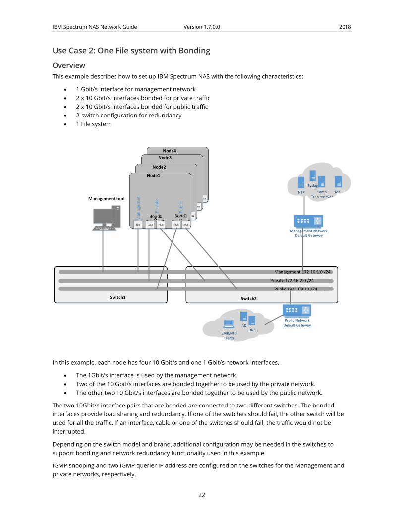
Use Case 2: One File system with Bonding
Overview
This example describes how to set up IBM Spectrum NAS with the following characteristics:
1 Gbit/s interface for management network
2 x 10 Gbit/s interfaces bonded for private traffic
2 x 10 Gbit/s interfaces bonded for public traffic
2-switch configuration for redundancy
1 File system
Node1
1Gb 10Gb 10Gb
Node4
10Gb10Gb
Node3
1Gb 10Gb 10Gb 10Gb10Gb
Node2
1Gb 10Gb 10Gb10Gb 10Gb
Node1
1Gb 10Gb 10Gb 10Gb10Gb
Public 192.168.1.0/24
Management tool
Private 172.16.2.0 /24
SMB/NFS Clients
ADDNS
NTP
Syslog
SnmpTrap reciever
Public 192.168.1.0/24
Bond0
Switch1 Switch2
Management NetworkDefault Gateway
Management 172.16.1.0 /24
Public NetworkDefault Gateway
Man
agem
et
Pri
vate
Pu
blic
Bond1
In this example, each node has four 10 Gbit/s and one 1 Gbit/s network interfaces.
The 1Gbit/s interface is used by the management network.
Two of the 10 Gbit/s interfaces are bonded together to be used by the private network.
The other two 10 Gbit/s interfaces are bonded together to be used by the public network.
The two 10Gbit/s interface pairs that are bonded are connected to two different switches. The bonded
interfaces provide load sharing and redundancy. If one of the switches should fail, the other switch will be
used for all the traffic. If an interface, cable or one of the switches should fail, the traffic would not be
interrupted.
Depending on the switch model and brand, additional configuration may be needed in the switches to
support bonding and network redundancy functionality used in this example.
IGMP snooping and two IGMP querier IP address are configured on the switches for the Management and
private networks, respectively.

IBM Spectrum NAS Network Guide Version 1.7.0.0 2018
23
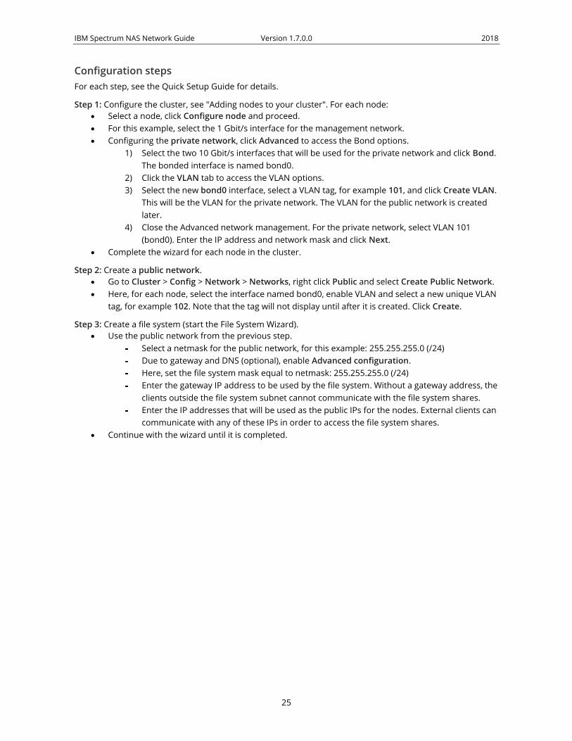
Configuration steps
For each step, see the Quick Setup Guide for details.
Step 1: Configure the cluster, see "Adding nodes to your cluster". For each node:
Select a node, click Configure node and proceed.
For this example, select the 1 Gbit/s interface for the management network.
Configuring the private network, click Advanced to access the Bond options.
1) Select the two 10 Gbit/s interfaces that will be used for the private network and click Bond.
The bonded interface is named bond0.
2) Select the two 10 Gbit/s interfaces that will be used for the public network and click Bond.
The bonded interface is named bond1.
3) Exit Advanced network management. For the private network, select bond0. Enter the
IP address and network mask and click Next.
Complete the wizard for each node in the cluster.
Step 2: Create a public network.
Go to Cluster > Config > Network > Networks, right click Public and select Create Public Network.
Here, for each node, select the interface named bond1 and click Create.
Step 3: Create a file system (start the File System Wizard).
Use the public network from the previous step.
Select a netmask for the public network, for this example: 255.255.255.0 (/24)
Due to gateway and DNS (optional), enable Advanced configuration.
Here, set the file system mask equal to netmask: 255.255.255.0 (/24)
Enter the gateway IP address to be used by the file system. Without a gateway address, the
clients outside the file system subnet cannot communicate with the file system shares.
Enter the IP addresses that will be used as the public IPs for the nodes. External clients can
communicate with any of these IPs in order to access the file system shares.
Continue with the wizard until it is completed.

IBM Spectrum NAS Network Guide Version 1.7.0.0 2018
24
Use Case 3: One File system with Bonding and VLAN
Overview
This example describes how to set up IBM Spectrum NAS with the following characteristics:
2 x 10 Gbit/s bonded interfaces, for private VLAN and public VLAN.
1 Gbit/s interface for management network
2-switch configuration, for redundancy
1 File system
Management tool
VLAN ID 101Private 172.16.2.0 /24
Public NetworkDefault Gateway
SMB/NFS Clients
ADDNS
NTP
Syslog
SnmpTrap reciever
VLAN ID 102 Public 192.168.1.0/24
Node1
Switch1 Switch2
1Gb 10Gb 10Gb
1Gb 10Gb 10Gb
1Gb 10Gb 10Gb
10Gb 10Gb
Node1
Node2Node3
Node4
Management NetworkDefault Gateway
Bond0
1Gb
Public
Man
agemen
t
Private
Management 172.16.1.0 /24
In this example, each node has two 10 Gbit/s interface bonded together for load sharing and redundancy.
On top of the bonded interface, a private VLAN and a public VLAN are created.
By using VLAN on the bonded interface, both the private and public networks will have redundant paths. If
an interface, cable or one of the switches should fail the traffic will use the other connection instead.
The two 10GB interfaces are connected to two different switches for redundancy. If one of the switches is
faulty, the other switch will be used for all the traffic.
Depending on the switch model and brand, additional configuration may be needed in the switches to
support the bonding, VLAN and network redundancy functionalities used in this example.
IGMP snooping and two IGMP querier IP addresses are configured on the switches for the Management and
private networks, respectively.
IBM Spectrum NAS Network Guide Version 1.7.0.0 2018
25
Configuration steps
For each step, see the Quick Setup Guide for details.
Step 1: Configure the cluster, see "Adding nodes to your cluster". For each node:
Select a node, click Configure node and proceed.
For this example, select the 1 Gbit/s interface for the management network.
Configuring the private network, click Advanced to access the Bond options.
1) Select the two 10 Gbit/s interfaces that will be used for the private network and click Bond.
The bonded interface is named bond0.
2) Click the VLAN tab to access the VLAN options.
3) Select the new bond0 interface, select a VLAN tag, for example 101, and click Create VLAN.
This will be the VLAN for the private network. The VLAN for the public network is created
later.
4) Close the Advanced network management. For the private network, select VLAN 101
(bond0). Enter the IP address and network mask and click Next.
Complete the wizard for each node in the cluster.
Step 2: Create a public network.
Go to Cluster > Config > Network > Networks, right click Public and select Create Public Network.
Here, for each node, select the interface named bond0, enable VLAN and select a new unique VLAN
tag, for example 102. Note that the tag will not display until after it is created. Click Create.
Step 3: Create a file system (start the File System Wizard).
Use the public network from the previous step.
Select a netmask for the public network, for this example: 255.255.255.0 (/24)
Due to gateway and DNS (optional), enable Advanced configuration.
Here, set the file system mask equal to netmask: 255.255.255.0 (/24)
Enter the gateway IP address to be used by the file system. Without a gateway address, the
clients outside the file system subnet cannot communicate with the file system shares.
Enter the IP addresses that will be used as the public IPs for the nodes. External clients can
communicate with any of these IPs in order to access the file system shares.
Continue with the wizard until it is completed.

IBM Spectrum NAS Network Guide Version 1.7.0.0 2018
26
Use Case 4: Two File systems, isolated with File system mask
Overview
This example describes how to set up IBM Spectrum NAS with the following characteristics:
Multitenancy with two separate file systems.
Network separation using File system mask
Netmask /24, File system mask /28
Management/Private 172.16.1.0 /24
Public 192.168.1.0/24
Switch
Node1
10Gb 10Gb
Node1
Filesystem AFile system mask: 255.255.255.240 /28Valid IP range 192.168.1.1-192.168.1.15
Public IP A Node1 192.168.1.2Public Gateway A 192.168.1.1
Filesystem BFile system mask: 255.255.255.240 /28
Valid IP range 192.168.1.16-192.168.1.31
Public IP B Node1 192.168.1.17Public Gateway B 192.168.1.16
Public Gateway B 192.168.1.16
SMB/NFS Clients
ADDNS
Public Gateway A 192.168.1.1
SMB/NFS Clients
ADDNS
Enterprise A Enterprise B
Public IP A Node1 192.168.1.2Public IP B Node1 192.168.1.17
Public 192.168.1.0/24
In this example, two file systems are created, to serve two different organizations. Each file system will have
their own public IPs. Different Gateway addresses will be configured for the file systems. The two file
systems are sharing the same public network interface.

IBM Spectrum NAS Network Guide Version 1.7.0.0 2018
27
Configuration steps
For each step, see the Quick Setup Guide for details.
Step 1: Configure the cluster, see "Adding nodes to your cluster". For each node:
Select a node, click Configure node and proceed.
Using the first interface, configure the management and private networks and complete the wizard
for each node in the cluster.
Step 2: Create a public network.
Go to Cluster > Config > Network > Networks, right click Public and select Create Public Network.
Using the second interface, then click Create.
Step 3: Create a file system (start the File System Wizard).
Use the public network from the previous step.
Set a netmask, for example: 255.255.255.0 /24 allowing 256 IP addresses.
Enable Advanced configuration. The File system mask is used to specify a range of public
IPs that this file system is using, for example: 255.255.255.240 /28 giving a possible range
of 0-15 or 16-31, 32-47 etc.
Enter the gateway IP address to be used by the file system. The gateway IP needs to be in
the range of the netmask, for example: 192.168.1.1. Without a gateway address, the clients
outside the file system subnet cannot communicate with the file system shares.
Set public IP for each node, for example starting with 192.168.1.2 (with usable range 0-15).
Continue with the wizard until it is completed.
Step 4: Create a second file system.
Repeat step 3 to create another file system (requires a license with the multitenancy feature),
except this time the gateway used is 192.168.1.16 and the public IP for each node should be in
another range than for the first file system, for example starting with 192.168.1.17. The usable
range is now 16-31 compared to 0-15 of the first file system, given a file system mask of /28.

IBM Spectrum NAS Network Guide Version 1.7.0.0 2018
28
Use Case 5: Two File systems, isolated with VLAN
Overview
This example describes how to set up IBM Spectrum NAS with the following characteristics:
Multitenancy with two separated file systems.
File system mask is the same as the Netmask
Network separation using VLANs
Management/Private 172.16.1.0 /24
VLAN 101 Public1 192.168.1.0/24
Switch
Node1
10Gb 10Gb
Node1
Filesystem ANetwork Mask 255.255.255.0 /24
Public1 IP Node1 192.168.1.2Public1 Gateway A 192.168.1.1
Filesystem BNetwork Mask 255.255.255.0 /24
Public2 IP Node1 192.168.2.2Public2 Gateway 192.168.2.1
Public Gateway B 192.168.2.1
SMB/NFS Clients
ADDNS
Public Gateway A 192.168.1.1
SMB/NFS Clients
ADDNS
Enterprise A Enterprise B
File system A Public1 VLAN 101 IP 192.168.1.2File system B Public2 VLAN 102 IP 192.168.2.2
VLAN 102 Public2 192.168.2.0/24
Network Public1 VLAN 101 192.168.1.0/24
VLAN 102 Public2 192.168.2.0/24
NetworkPublic2 VLAN 102 192.168.2.0/24
In this example, two file systems are created to serve two different organizations. Each file system will have
their own network and public IPs. VLANs will be used to create multiple separated public networks.

IBM Spectrum NAS Network Guide Version 1.7.0.0 2018
29
Configuration steps
For each step, see the Quick Setup Guide for details.
Step 1: Configure the cluster, see "Adding nodes to your cluster". For each node:
Select a node, click Configure node and proceed.
Configure the management and private networks and complete the wizard for each node in the
cluster. The private network uses the same settings as the management network.
Step 2: Create two public networks, one for each file system.
Go to Cluster > Config > Network > Networks, right click Public and select Create Public Network.
Here, set the first network name to, for example, Public A.
Enable VLAN and enter a unique VLAN tag, for example 101.
For each node, select the interface intended for the public networks. Note that the tag will not
display until after it is created. Click Create.
Repeat for the second public network: Public B, only this time enter another tag, for example 102.
Step 3: Create a file system (start the File System Wizard).
Use the first public network from the previous step: Public A.
Select a netmask for the public network, for this example: 255.255.255.0 (/24)
Due to gateway and DNS (optional), enable Advanced configuration.
Here, set the file system mask equal to netmask: 255.255.255.0 (/24)
Enter the gateway IP address to be used by the file system: 192.168.1.1. Without a gateway
address, the clients outside the file system subnet cannot communicate with the file
system shares.
Enter the IP addresses that will be used as the public IPs for the nodes, starting with
192.168.1.2. External clients can communicate with any of these IPs in order to access the
file system shares.
Continue with the wizard until it is completed.
Step 4: Create a second file system.
Repeat step 3 to create another file system (requires a license with the multitenancy feature),
except this time using the network named Public B, gateway 192.168.2.1, and the nodes starting at
192.168.2.2.

IBM Spectrum NAS Network Guide Version 1.7.0.0 2018
30
IBM Spectrum NAS Support
The support service is available to answer your questions by email, phone or web, based on your support
offering.
To get help on troubleshooting, please contact technical support.
Please note that providing us with background information will help us to do preliminary research to
understand your issue better and to make a more efficient interaction possible. We would, therefore, ask
you to provide the following information when you send a support request:
Cluster ID.
Software version of all relevant software.
An approximation of time when the issue first occurred.
Whether the issue is reproducible.
Steps taken so far to solve the problem.
Your location Method of contacting the IBM Support Center In the United States Call 1-800-IBM-SERV for support.
Outside the United States Contact your local IBM Support Center or see the
Directory of worldwide contacts.

IBM Spectrum NAS Network Guide Version 1.7.0.0 2018
31
Bonding Options
Round Robin Transmissions are received and sent out sequentially on each bonded slave
interface, beginning with the first available. For fault tolerance and load
balancing.
Active/Backup Transmissions are received and sent out via the first available bonded slave
interface, and another bonded slave interface is only used if the active bonded
slave interface fails. For fault tolerance.
XOR The interface matches up the incoming request’s MAC address with MAC address
for one of the slave NICs. Once this link is established, transmissions are sent
sequentially, beginning with the first available interface. For fault tolerance and
load balancing.
Broadcast All transmissions are set on all slave interfaces, for fault tolerance
LACP (802.3ad) Creates aggregation groups that share the same speed and duplex settings.
Transmits and receives on all slaves in the active aggregator. Requires a switch
that is 802.3ad compliant.
Adaptive Transmit
Load Balancing
The outgoing traffic is distributed according to the current load on each slave
interface. Incoming traffic is received by the current slave. If the receiving slave
fails, another slave takes over the MAC address of the failed slave. For fault
tolerance and load balancing.
Adaptive Load
Balancing
Includes transmit and receive load balancing for IPV4 traffic. Receive load
balancing is achieved through ARP negotiation. For fault tolerance and load
balancing.
IBM Spectrum NAS Network Guide | 1.7.0.0

Notices
This information was developed for products and services offered in the US. This material might beavailable from IBM in other languages. However, you may be required to own a copy of the product orproduct version in that language in order to access it.
IBM may not offer the products, services, or features discussed in this document in other countries.Consult your local IBM representative for information on the products and services currently available inyour area. Any reference to an IBM product, program, or service is not intended to state or imply thatonly that IBM product, program, or service may be used. Any functionally equivalent product, program,or service that does not infringe any IBM intellectual property right may be used instead. However, it isthe user's responsibility to evaluate and verify the operation of any non-IBM® product, program, orservice.
IBM may have patents or pending patent applications covering subject matter described in thisdocument. The furnishing of this document does not grant you any license to these patents. You can sendlicense inquiries, in writing, to:
IBM Director of Licensing IBM Corporation North Castle Drive, MD-NC119 Armonk, NY 10504-1785 US
For license inquiries regarding double-byte character set (DBCS) information, contact the IBM IntellectualProperty Department in your country or send inquiries, in writing, to:
Intellectual Property Licensing Legal and Intellectual Property Law IBM Japan Ltd. 19-21, Nihonbashi-Hakozakicho, Chuo-ku Tokyo 103-8510, Japan
INTERNATIONAL BUSINESS MACHINES CORPORATION PROVIDES THIS PUBLICATION "AS IS"WITHOUT WARRANTY OF ANY KIND, EITHER EXPRESS OR IMPLIED, INCLUDING, BUT NOTLIMITED TO, THE IMPLIED WARRANTIES OF NON-INFRINGEMENT, MERCHANTABILITY ORFITNESS FOR A PARTICULAR PURPOSE. Some jurisdictions do not allow disclaimer of express orimplied warranties in certain transactions, therefore, this statement may not apply to you.
This information could include technical inaccuracies or typographical errors. Changes are periodicallymade to the information herein; these changes will be incorporated in new editions of the publication.IBM may make improvements and/or changes in the product(s) and/or the program(s) described in thispublication at any time without notice.
Any references in this information to non-IBM websites are provided for convenience only and do not inany manner serve as an endorsement of those websites. The materials at those websites are not part ofthe materials for this IBM product and use of those websites is at your own risk.
IBM may use or distribute any of the information you provide in any way it believes appropriate withoutincurring any obligation to you.
Licensees of this program who wish to have information about it for the purpose of enabling: (i) theexchange of information between independently created programs and other programs (including thisone) and (ii) the mutual use of the information which has been exchanged, should contact:
IBM Director of Licensing IBM Corporation North Castle Drive, MD-NC119 Armonk, NY 10504-1785 US
Such information may be available, subject to appropriate terms and conditions, including in some cases,payment of a fee.
© Copyright IBM Corp. 2018 32

The licensed program described in this document and all licensed material available for it are providedby IBM under terms of the IBM Customer Agreement, IBM International Program License Agreement orany equivalent agreement between us.
The performance data discussed herein is presented as derived under specific operating conditions.Actual results may vary.
Information concerning non-IBM products was obtained from the suppliers of those products, theirpublished announcements or other publicly available sources. IBM has not tested those products andcannot confirm the accuracy of performance, compatibility or any other claims related to non-IBMproducts. Questions on the capabilities of non-IBM products should be addressed to the suppliers ofthose products.
Statements regarding IBM's future direction or intent are subject to change or withdrawal without notice,and represent goals and objectives only.
All IBM prices shown are IBM's suggested retail prices, are current and are subject to change withoutnotice. Dealer prices may vary.
This information is for planning purposes only. The information herein is subject to change before theproducts described become available.
This information contains examples of data and reports used in daily business operations. To illustratethem as completely as possible, the examples include the names of individuals, companies, brands, andproducts. All of these names are fictitious and any similarity to actual people or business enterprises isentirely coincidental.
COPYRIGHT LICENSE:
This information contains sample application programs in source language, which illustrate programmingtechniques on various operating platforms. You may copy, modify, and distribute these sample programsin any form without payment to IBM, for the purposes of developing, using, marketing or distributingapplication programs conforming to the application programming interface for the operating platform forwhich the sample programs are written. These examples have not been thoroughly tested under allconditions. IBM, therefore, cannot guarantee or imply reliability, serviceability, or function of theseprograms. The sample programs are provided "AS IS", without warranty of any kind. IBM shall not beliable for any damages arising out of your use of the sample programs.
Each copy or any portion of these sample programs or any derivative work must includea copyright notice as follows:
© (your company name) (year).Portions of this code are derived from IBM Corp.Sample Programs. © Copyright IBM Corp. _enter the year or years_.
If you are viewing this information softcopy, the photographs and color illustrations may not appear.
TrademarksIBM, the IBM logo, and ibm.com are trademarks or registered trademarks of International BusinessMachines Corp., registered in many jurisdictions worldwide. Other product and service names might betrademarks of IBM or other companies. A current list of IBM trademarks is available on the Web atCopyright and trademark information at www.ibm.com/legal/copytrade.shtml.
Intel is a trademark of Intel Corporation or its subsidiaries in the United States and other countries.
33

Java™ and all Java-based trademarks and logos are trademarks or registered trademarks of Oracle and/orits affiliates.
Linux is a registered trademark of Linus Torvalds in the United States, other countries, or both.
Microsoft and Windows are trademarks of Microsoft Corporation in the United States, other countries, orboth.
UNIX is a registered trademark of the Open Group in the United States and other countries.
Terms and conditions for product documentationPermissions for the use of these publications are granted subject to the following terms and conditions.
Applicability
These terms and conditions are in addition to any terms of use for the IBM website.
Personal use
You may reproduce these publications for your personal, noncommercial use provided that allproprietary notices are preserved. You may not distribute, display or make derivative work of thesepublications, or any portion thereof, without the express consent of IBM.
Commercial use
You may reproduce, distribute and display these publications solely within your enterprise provided thatall proprietary notices are preserved. You may not make derivative works of these publications, orreproduce, distribute or display these publications or any portion thereof outside your enterprise, withoutthe express consent of IBM.
Rights
Except as expressly granted in this permission, no other permissions, licenses or rights are granted, eitherexpress or implied, to the publications or any information, data, software or other intellectual propertycontained therein.
IBM reserves the right to withdraw the permissions granted herein whenever, in its discretion, the use ofthe publications is detrimental to its interest or, as determined by IBM, the above instructions are notbeing properly followed.
You may not download, export or re-export this information except in full compliance with all applicablelaws and regulations, including all United States export laws and regulations.
IBM MAKES NO GUARANTEE ABOUT THE CONTENT OF THESE PUBLICATIONS. THEPUBLICATIONS ARE PROVIDED "AS-IS" AND WITHOUT WARRANTY OF ANY KIND, EITHEREXPRESSED OR IMPLIED, INCLUDING BUT NOT LIMITED TO IMPLIED WARRANTIES OFMERCHANTABILITY, NON-INFRINGEMENT, AND FITNESS FOR A PARTICULAR PURPOSE.
IBM Online Privacy StatementIBM Software products, including software as a service solutions, (“Software Offerings”) may use cookiesor other technologies to collect product usage information, to help improve the end user experience, totailor interactions with the end user or for other purposes. In many cases no personally identifiableinformation is collected by the Software Offerings. Some of our Software Offerings can help enable you to
Notices34

collect personally identifiable information. If this Software Offering uses cookies to collect personallyidentifiable information, specific information about this offering’s use of cookies is set forth below.
This Software Offering does not use cookies or other technologies to collect personally identifiableinformation.
If the configurations deployed for this Software Offering provide you as customer the ability to collectpersonally identifiable information from end users via cookies and other technologies, you should seekyour own legal advice about any laws applicable to such data collection, including any requirements fornotice and consent.
For more information about the use of various technologies, including cookies, for these purposes, SeeIBM’s Privacy Policy at http://www.ibm.com/privacy and IBM’s Online Privacy Statement athttp://www.ibm.com/privacy/details the section entitled “Cookies, Web Beacons and OtherTechnologies” and the “IBM Software Products and Software-as-a-Service Privacy Statement” athttp://www.ibm.com/software/info/product-privacy.
IBM Spectrum NAS: Network Guide 35

Notices

IBM®
Printed in USA
SC27-9231-00


