Embed Size (px)
Citation preview
iglintels.com
Special LintelsIG offers a complete custom design service to ensure your project has the best lintel for the job. Our technical expertise is renowned for delivering solutions with total efficiency.
Standard LintelsIG produces a wide range of standard galvanised steel and stainless steel lintels. All IG standard lintels satisfy the thermal performance requirements of all UK building regulations.
Hi-therm+IG has redefined lintel performance with Hi-therm+, the low cost solution to reduced carbon emissions and improved Fabric Energy Efficiency (FEES).
Cavity TraysThe IG Cavity Tray presents a lightweight, simple to install and long-lasting solution to preventing damp from penetrating below the roof line.
Brick Feature LintelsIG Brick Feature Lintels are a one piece prefabricated unit, manufactured bespoke to order, achieving even the most challenging architectural designs.
Masonry Support & WindpostsIG continues to set the standard for masonry support and windpost systems for a range of building frame configurations. The innovative IG Masonry Support System provides a versatile solution when masonry support is required.
www.iglintels.com
CI/SfB Hh2 (31.9)
COMPLETE GUIDE TO THE IG PRODUCT RANGE
PRODUCT GUIDE
PR
OD
UC
T GU
IDE
Email: [email protected]
LINTEL HOTLINE
01633 486486
IG - SWADLINCOTE Ryder Close, Cadley Hill Industrial Estate Swadlincote, South Derbyshire DE11 9EUT: +44 (0) 1283 200150 F: +44 (0) 1283 223352
IG - CWMBRAN Avondale Road, Cwmbran, Gwent, NP44 1XYT: +44 (0) 1633 486486F: +44 (0) 1633 486465
IG - IRELANDBallyreagh Industrial Estate, Cookstown, Co. Tyrone BT80 9DGT: +44 (0) 28 86762184F: +44 (0) 28 86761011
CERTIFICATE No 05/4192FM 21541EMS 553955
ISO 9001ISO 14001
IG-PG | 01.19
The information contained in this brochure was accurate at the date of going to press. IG Ltd, however, reserves the right, while maintaining the essential performance of the products described, to introduce at any time modifications and changes of details as may be considered necessary to improve the products described.
6mmSpine
CAVITY TRAYS
The IG Cavity Tray is a lightweight, simple to install and long lasting solution to preventing dampness from penetrating below the roof line.
Unique Products with Outstanding Benefits
Flexible: Three sizes cover all roof pitches, cavity widths up to 100mm and building materials.
• Off-the-shelf: Pre-creased, flat packed and easily hand folded onsite.
• Robust: Impact, tear and abuse resistant to last the lifetime of your building.
• Compliant: Meets all current Building Regulations and NHBC requirements.
• Economic: The most cost-effective Cavity Tray system available.
• Durability: Resistant to acid, alkali and sulphate.
RIDGE TRAY
RIGHT HAND TRAY
LEFT HAND TRAY
CATCHMENT TRAY
INTERNAL CORNER TRAY
REFURBISHMENT TRAY
Mastic Sealant Strip
EXTERNAL CORNER TRAY
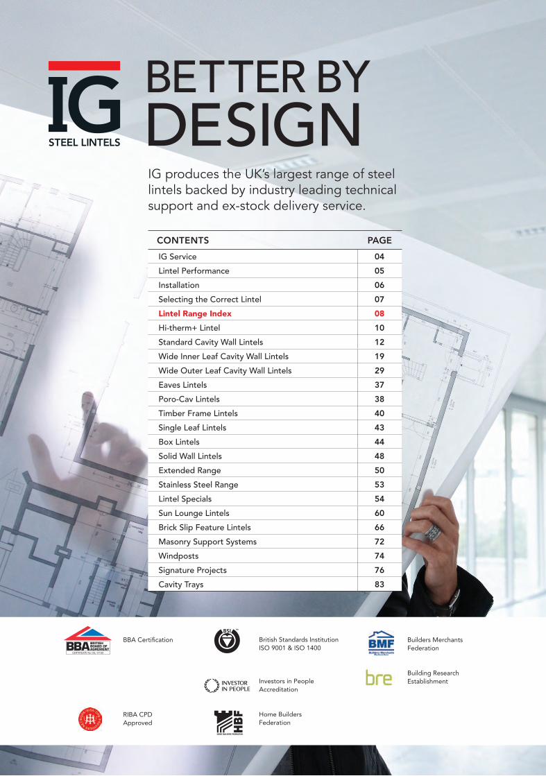
IG produces the UK’s largest range of steel lintels backed by industry leading technical support and ex-stock delivery service.
CONTENTS PAGE
IG Service 04
Lintel Performance 05
Installation 06
Selecting the Correct Lintel 07
Lintel Range Index 08
Hi-therm+ Lintel 10
Standard Cavity Wall Lintels 12
Wide Inner Leaf Cavity Wall Lintels 19
Wide Outer Leaf Cavity Wall Lintels 29
Eaves Lintels 37
Poro-Cav Lintels 38
Timber Frame Lintels 40
Single Leaf Lintels 43
Box Lintels 44
Solid Wall Lintels 48
Extended Range 50
Stainless Steel Range 53
Lintel Specials 54
Sun Lounge Lintels 60
Brick Slip Feature Lintels 66
Masonry Support Systems 72
Windposts 74
Signature Projects 76
Cavity Trays 83
BBA Certification
RIBA CPD Approved
British Standards Institution ISO 9001 & ISO 1400
Investors in People Accreditation
Home BuildersFederation
CERTIFICATE No 05/4192
Builders MerchantsFederation
Building Research Establishment
83
ROBUST AND COST EFFECTIVE CAVITY TRAY SYSTEM
3BETTER BY
DESIGN
www.iglintels.com
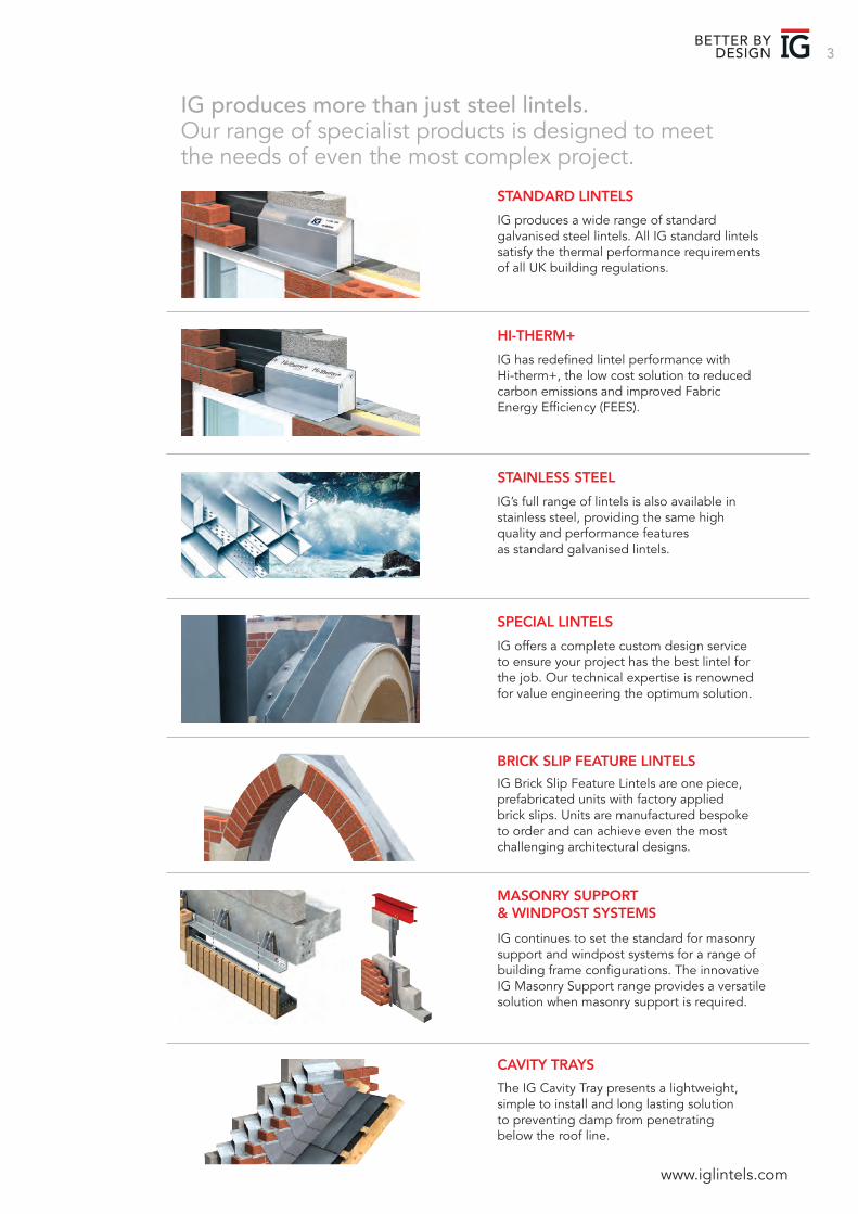
SPECIAL LINTELS
IG offers a complete custom design service to ensure your project has the best lintel for the job. Our technical expertise is renowned for value engineering the optimum solution.
STANDARD LINTELS
IG produces a wide range of standard galvanised steel lintels. All IG standard lintels satisfy the thermal performance requirements of all UK building regulations.
HI-THERM+
STAINLESS STEEL
IG has redefined lintel performance with Hi-therm+, the low cost solution to reduced carbon emissions and improved Fabric Energy Efficiency (FEES).
CAVITY TRAYS
The IG Cavity Tray presents a lightweight, simple to install and long lasting solution to preventing damp from penetrating below the roof line.
BRICK SLIP FEATURE LINTELS
IG Brick Slip Feature Lintels are one piece, prefabricated units with factory applied brick slips. Units are manufactured bespoke to order and can achieve even the most challenging architectural designs.
MASONRY SUPPORT & WINDPOST SYSTEMS
IG continues to set the standard for masonry support and windpost systems for a range of building frame configurations. The innovative IG Masonry Support range provides a versatile solution when masonry support is required.
IG’s full range of lintels is also available in stainless steel, providing the same high quality and performance features as standard galvanised lintels.
IG produces more than just steel lintels. Our range of specialist products is designed to meetthe needs of even the most complex project.

IG 4
TECHNICAL SUPPORTIG provides comprehensive technical support for all products. Our free scheduling and specification service offers fast turnaround on standard lintels, masonry support and windpost systems.
IG leads the market with a bespoke design service for special lintels and brick slip feature lintels, including onsite measurement and technical assistance.
Our in-house experts use the latest thermal modelling software to advise clients on the optimum lintel solution for compliance with and beyond the latest building regulations.
By contacting our engineers at an early stage of your design process, you will potentially gain significantly more design flexibility for the overall project. Please send your drawings to:[email protected]
Please refer to our Fax Back Forms for special lintel requirements. Detailed measuring advice and Fax Back Enquiry Forms are available for download at: www.iglintels.com/technical.
FASTRACK DATABASE FOR CADThe IG Fastrack Database is accessible from the IG website and provides downloads of CAD files for a selection of IG Steel Lintels.
DELIVERYIG’s fast, efficient delivery service is renowned throughout the construction industry. Our logistics solution is recognised by our customers for superior supply chain management.
IG continues to provide the largest range of lintels available, with the shortest lead times in the industry. We have invested in large stock inventories at our three manufacturing and distribution centres reassuring our customers that all our standard lintels are instantly available upon request.
IG has revolutionised the steel lintel industry by manufacturing and delivering ‘special’ lintels with lead-times historically associated with ex-stock items.
IG products are available through a national network of merchant suppliers.
Service
PRODUCT GUIDE
5BETTER BY
DESIGN
Standard Lintel Performance
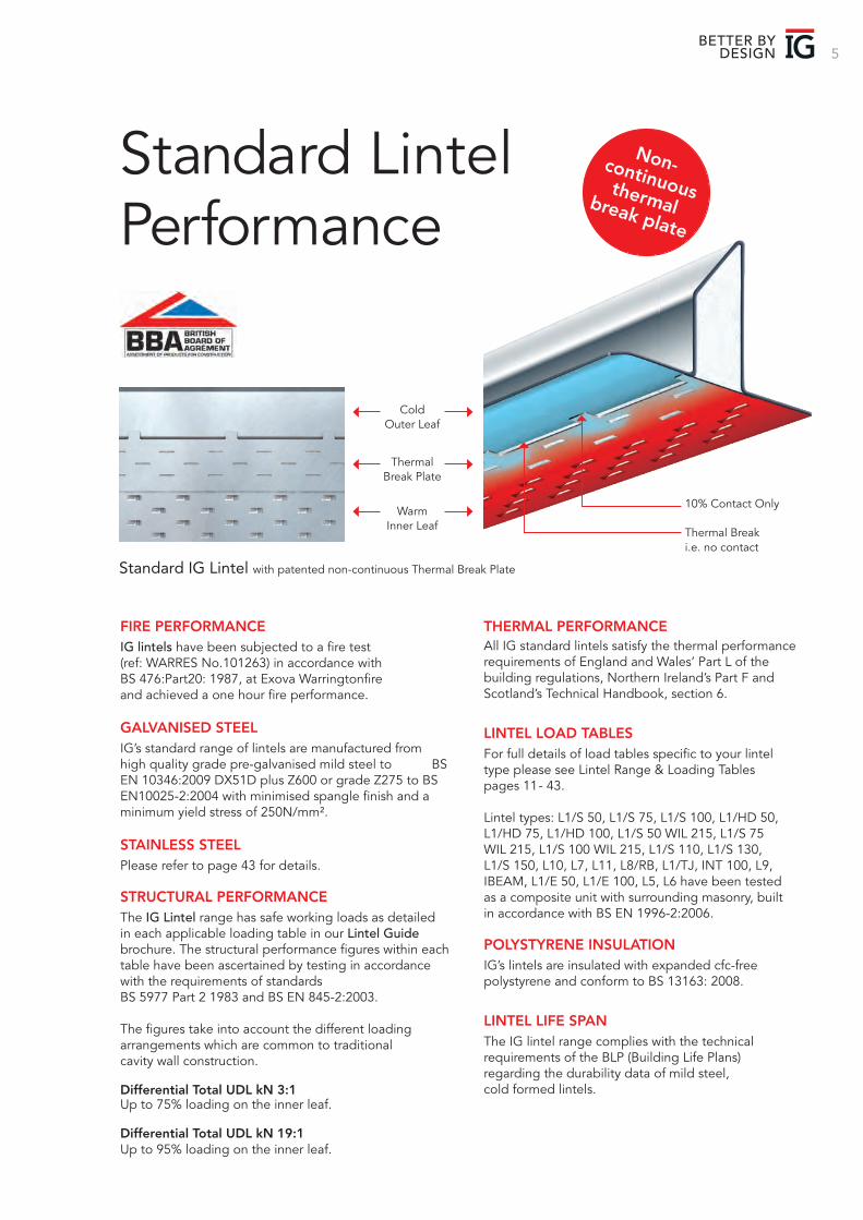
Thermal Break i.e. no contact
10% Contact Only
Cold Outer Leaf
Warm Inner Leaf
Thermal Break Plate
FIRE PERFORMANCEIG lintels have been subjected to a fire test (ref: WARRES No.101263) in accordance with BS 476:Part20: 1987, at Exova Warringtonfire and achieved a one hour fire performance.
GALVANISED STEELIG’s standard range of lintels are manufactured from high quality grade pre-galvanised mild steel to BS EN 10346:2009 DX51D plus Z600 or grade Z275 to BS EN10025-2:2004 with minimised spangle finish and a minimum yield stress of 250N/mm².
STAINLESS STEELPlease refer to page 43 for details.
STRUCTURAL PERFORMANCEThe IG Lintel range has safe working loads as detailed in each applicable loading table in our Lintel Guide brochure. The structural performance figures within each table have been ascertained by testing in accordance with the requirements of standardsBS 5977 Part 2 1983 and BS EN 845-2:2003.
The figures take into account the different loading arrangements which are common to traditional cavity wall construction.
Differential Total UDL kN 3:1Up to 75% loading on the inner leaf.
Differential Total UDL kN 19:1Up to 95% loading on the inner leaf.
THERMAL PERFORMANCEAll IG standard lintels satisfy the thermal performance requirements of England and Wales’ Part L of the building regulations, Northern Ireland’s Part F and Scotland’s Technical Handbook, section 6.
LINTEL LOAD TABLESFor full details of load tables specific to your lintel type please see Lintel Range & Loading Tables pages 11- 43.
Lintel types: L1/S 50, L1/S 75, L1/S 100, L1/HD 50, L1/HD 75, L1/HD 100, L1/S 50 WIL 215, L1/S 75 WIL 215, L1/S 100 WIL 215, L1/S 110, L1/S 130, L1/S 150, L10, L7, L11, L8/RB, L1/TJ, INT 100, L9, IBEAM, L1/E 50, L1/E 100, L5, L6 have been tested as a composite unit with surrounding masonry, built in accordance with BS EN 1996-2:2006.
POLYSTYRENE INSULATIONIG’s lintels are insulated with expanded cfc-free polystyrene and conform to BS 13163: 2008.
LINTEL LIFE SPANThe IG lintel range complies with the technical requirements of the BLP (Building Life Plans) regarding the durability data of mild steel, cold formed lintels.
Standard IG Lintel with patented non-continuous Thermal Break Plate
Non-continuous thermal break plate
IG 6
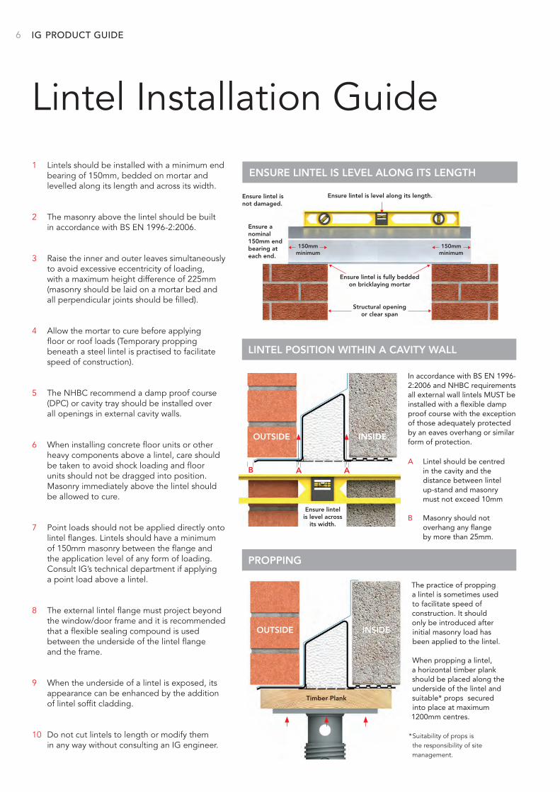
Lintel Installation Guide1 Lintels should be installed with a minimum end
bearing of 150mm, bedded on mortar and levelled along its length and across its width.
2 The masonry above the lintel should be built in accordance with BS EN 1996-2:2006.
3 Raise the inner and outer leaves simultaneously to avoid excessive eccentricity of loading, with a maximum height difference of 225mm (masonry should be laid on a mortar bed and all perpendicular joints should be filled).
4 Allow the mortar to cure before applying floor or roof loads (Temporary propping beneath a steel lintel is practised to facilitate speed of construction).
5 The NHBC recommend a damp proof course (DPC) or cavity tray should be installed over all openings in external cavity walls.
6 When installing concrete floor units or other heavy components above a lintel, care should be taken to avoid shock loading and floor units should not be dragged into position. Masonry immediately above the lintel should be allowed to cure.
7 Point loads should not be applied directly onto lintel flanges. Lintels should have a minimum of 150mm masonry between the flange and the application level of any form of loading. Consult IG’s technical department if applying a point load above a lintel.
8 The external lintel flange must project beyond the window/door frame and it is recommended that a flexible sealing compound is used between the underside of the lintel flange and the frame.
9 When the underside of a lintel is exposed, its appearance can be enhanced by the addition of lintel soffit cladding.
10 Do not cut lintels to length or modify them in any way without consulting an IG engineer.
ENSURE LINTEL IS LEVEL ALONG ITS LENGTH
Ensure lintel is level across
its width.
Ensure lintel is fully bedded on bricklaying mortar
Ensure a nominal 150mm end bearing at each end.
Ensure lintel is not damaged.
150mmminimum
150mmminimum
Structural opening or clear span
Ensure lintel is level along its length.
LINTEL POSITION WITHIN A CAVITY WALL
PROPPING
A Lintel should be centred in the cavity and the distance between lintel up-stand and masonry must not exceed 10mm
B Masonry should not overhang any flange
by more than 25mm.
The practice of propping a lintel is sometimes used to facilitate speed of construction. It should only be introduced after initial masonry load has been applied to the lintel.
When propping a lintel, a horizontal timber plank should be placed along the underside of the lintel and suitable* props secured into place at maximum 1200mm centres.
*Suitability of props is the responsibility of site management.
OUTSIDE INSIDE
AAB
OUTSIDE INSIDE
Timber Plank
In accordance with BS EN 1996-2:2006 and NHBC requirements all external wall lintels MUST be installed with a flexible damp proof course with the exception of those adequately protected by an eaves overhang or similar form of protection.
PRODUCT GUIDE
7BETTER BY
DESIGN
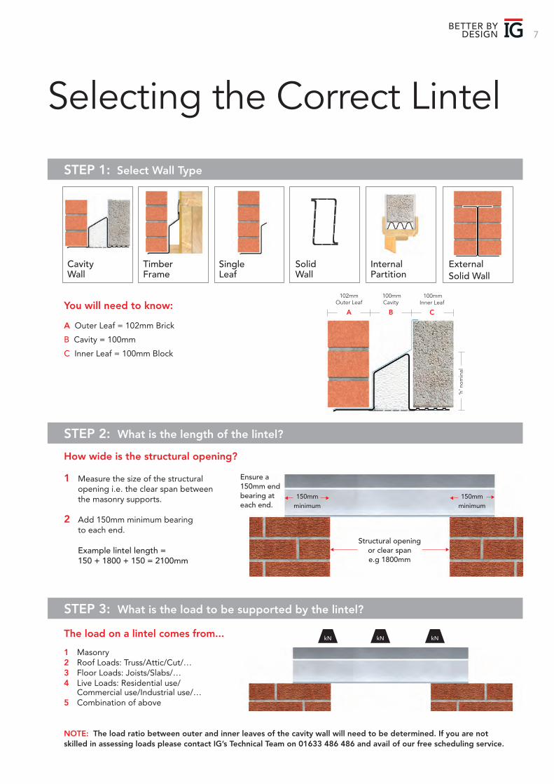
Selecting the Correct Lintel
STEP 1: Select Wall Type
STEP 2: What is the length of the lintel?
Cavity Wall
Timber Frame
Single Leaf
Solid Wall
Internal Partition
ExternalSolid Wall
You will need to know:
A Outer Leaf = 102mm Brick
B Cavity = 100mm
C Inner Leaf = 100mm Block
Box/K - 75 Box/K - 100 HDBox/K - 100 Box/K - 150 HDBox/K - 150
Ensure a 150mm end bearing at each end.
150mmminimum
150mmminimum
Structural opening or clear spane.g 1800mm
1 Measure the size of the structural opening i.e. the clear span between the masonry supports.
2 Add 150mm minimum bearing to each end.
Example lintel length = 150 + 1800 + 150 = 2100mm
How wide is the structural opening?
102mmOuter Leaf
A
100mmCavity
B
100mmInner Leaf
C
‘h’ n
omin
al
STEP 3: What is the load to be supported by the lintel?
kN kNkNThe load on a lintel comes from...
1 Masonry2 Roof Loads: Truss/Attic/Cut/…3 Floor Loads: Joists/Slabs/…4 Live Loads: Residential use/ Commercial use/Industrial use/…5 Combination of above
NOTE: The load ratio between outer and inner leaves of the cavity wall will need to be determined. If you are not skilled in assessing loads please contact IG’s Technical Team on 01633 486 486 and avail of our free scheduling service.
IG 8 LINTEL GUIDE
CAVITY
100mm Inner LeafCavity Width 50-165mm
125 - 150mm Inner LeafCavity Width 50-165mm
125 - 150mm Outer LeafCavity Width 50-165mm
215mm Inner LeafCavity Width 50-165mm
215mm Outer LeafCavity Width 50-165mm
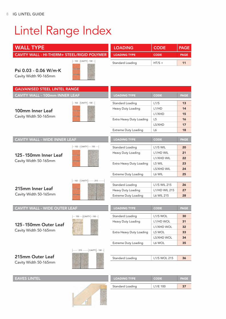
Lintel Range Index
CAVITY WALL - 100mm INNER LEAF
CAVITY WALL - WIDE INNER LEAF
CAVITY WALL - WIDE OUTER LEAF
EAVES LINTEL
CAVITY WALL - HI-THERM+ STEEL/RIGID POLYMER
WALL TYPE
Standard Loading HT/S + 11
Standard Loading L1/E 100 37
LOADING TYPE CODE PAGE
LOADING CODE PAGE
LOADING TYPE CODE PAGE
LOADING TYPE CODE PAGE
LOADING TYPE CODE PAGE
LOADING TYPE CODE PAGE
102 100CAVITY
102 100CAVITY
102 150CAVITY
102 215
215 100
150 100
Psi 0.03 - 0.06 W/m.KCavity Width 90-165mm
CAVITY
CAVITY
GALVANISED STEEL LINTEL RANGE
Standard Loading L1/S 13
Heavy Duty Loading L1/HD 14
L1/XHD 15
Extra Heavy Duty Loading L5 16
L5/XHD 17
Extreme Duty Loading L6 18
Standard Loading L1/S WIL 20
Heavy Duty Loading L1/HD WIL 21
L1/XHD WIL 22
Extra Heavy Duty Loading L5 WIL 23
L5/XHD WIL 24
Extreme Duty Loading L6 WIL 25
Standard Loading L1/S WOL 30
Heavy Duty Loading L1/HD WOL 31
L1/XHD WOL 32
Extra Heavy Duty Loading L5 WOL 33
L5/XHD WOL 34
Extreme Duty Loading L6 WOL 35
Standard Loading L1/S WIL 215 26
Heavy Duty Loading L1/HD WIL 215 27
Extreme Duty Loading L6 WIL 215 28
Standard Loading L1/S WOL 215 36
9BETTER BY
DESIGN
Standard Loading BOX 75 44
BOX 100 45
BOX 140 45
BOX 200 45
Heavy Duty Loading HD BOX 100 46
HD BOX 140 46
HD BOX 200 47
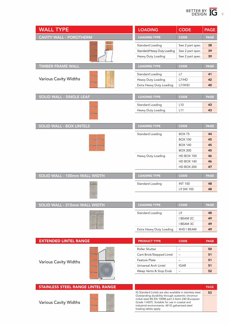
WALL TYPE LOADING CODE PAGE
PRODUCT TYPE CODE PAGE
Roller Shutter – 50
Cant Brick/Stepped Lintel – 51
Feature Plate – 51
Universal Arch Lintel IGAR 51
Weep Vents & Stop Ends – 52
EXTENDED LINTEL RANGE
PAGE STAINLESS STEEL RANGE LINTEL RANGE53IG Standard Lintels are also available in stainless steel.
Outstanding durability through austenitic chromiunnickel steel BS EN 10088-part 2 Astm 240 (European Grade 1.4307). Suitable for use in coastal and industrial environments. All IG galvanised steel loading tables apply.
LOADING TYPE CODE PAGE SOLID WALL - 215mm WALL WIDTH
Standard Loading L9 48
I BEAM 2C 49
I BEAM 3C 49
Extra Heavy Duty Loading XHD I BEAM 49
LOADING TYPE CODE PAGE SOLID WALL - BOX LINTELS
LOADING TYPE CODE PAGE SOLID WALL - 100mm WALL WIDTH
Standard Loading INT 100 48
L9 SW 100 48
LOADING TYPE CODE PAGE
Standard Loading L10 43
Heavy Duty Loading L11 43
SOLID WALL - SINGLE LEAF
LOADING TYPE CODE PAGE
Standard Loading L7 41
Heavy Duty Loading L7/HD 42
Extra Heavy Duty Loading L7/XHD 40
TIMBER FRAME WALL
Standard Loading See 2 part spec. 38
Standard/Heavy Duty Loading See 2 part spec. 39
Heavy Duty Loading See 2 part spec. 39
LOADING TYPE CODE PAGE CAVITY WALL - POROTHERM
Various Cavity Widths
Various Cavity Widths
Various Cavity Widths
10
Hi-therm+ Lintel 100mmINNER LEAF
Cavity WallAvailable for cavity widths from 90mm to 165mm
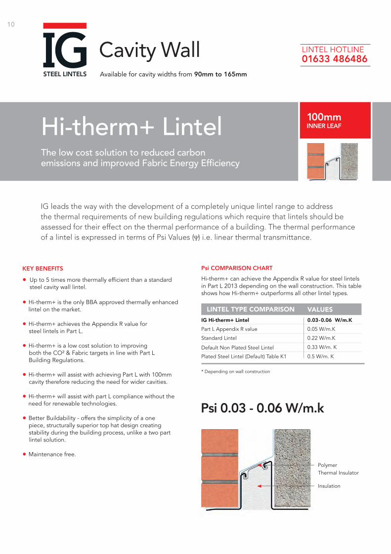
IG leads the way with the development of a completely unique lintel range to address the thermal requirements of new building regulations which require that lintels should be assessed for their effect on the thermal performance of a building. The thermal performance of a lintel is expressed in terms of Psi Values ( ) i.e. linear thermal transmittance.
The low cost solution to reduced carbon emissions and improved Fabric Energy Efficiency
LINTEL HOTLINE 01633 486486
Hi-therm+ can achieve the Appendix R value for steel lintels in Part L 2013 depending on the wall construction. This table shows how Hi-therm+ outperforms all other lintel types.
Default Non Plated Steel Lintel
Plated Steel Lintel (Default) Table K1
* Depending on wall construction
0.33 W/m. K
0.5 W/m. K
Standard Lintel 0.22 W/m.K
0.05 W/m.KPart L Appendix R value
0.03 - 0.06 W/m.KIG Hi-therm+ Lintel
LINTEL TYPE COMPARISON VALUES
Psi COMPARISON CHART
Polymer Thermal Insulator
Insulation
Psi 0.03 - 0.06 W/m.k
KEY BENEFITS
• Up to 5 times more thermally efficient than a standard steel cavity wall lintel.
• Hi-therm+ is the only BBA approved thermally enhanced lintel on the market.
• Hi-therm+ achieves the Appendix R value for steel lintels in Part L.
• Hi-therm+ is a low cost solution to improving both the CO² & Fabric targets in line with Part L Building Regulations.
• Hi-therm+ will assist with achieving Part L with 100mm cavity therefore reducing the need for wider cavities.
• Hi-therm+ will assist with part L compliance without the need for renewable technologies.
• Better Buildability - offers the simplicity of a one piece, structurally superior top hat design creating stability during the building process, unlike a two part lintel solution.
• Maintenance free.
11BETTER BY
DESIGN
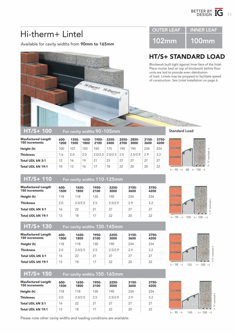
Please note other cavity widths and loading conditions are available.
Standard Load
Height (h)
Thickness
Total UDL kN 3:1
Total UDL kN 19:1
Height (h)
Thickness
Total UDL kN 3:1
Total UDL kN 19:1
Height (h)
Thickness
Total UDL kN 3:1
Total UDL kN 19:1
HT/S+ 100 For cavity widths 90 -105mm
HT/S+ 130 For cavity widths 130 -145mm
HT/S+ 110 For cavity widths 110 -125mm
HT/S+ 150 For cavity widths 150 -165mm
Maufactured Length150 increments
Maufactured Length150 increments
Maufactured Length150 increments
Maufactured Length150 increments
600-1200
600-1500
600-1500
600-1500
1650-1800
1950-2100
1950-2100
1950-2100
100
1.6
12
10
118
2.0
16
13
118
2.0
16
13
118
2.0
16
13
150
2.0
19
16
130
2.5
21
17
130
2.5
21
17
130
2.5
21
17
107
2.0
16
13
118
2.0/2.5
22
18
118
2.0/2.5
22
18
118
2.0/2.5
22
18
150
2.0/2.5
21
17
190
2.5/2.9
27
22
190
2.5/2.9
27
22
190
2.5/2.9
27
22
175
2.0/2.5
23
18
234
2.9
27
20
234
2.9
27
20
234
2.9
27
20
190
2.5
27
22
234
3.2
27
22
234
3.2
27
22
234
3.2
27
22
190
2.5/2.9
27
20
234
2.9
27
20
234
3.2
27
22
1350-1500
1650-1800
1650-1800
1650-1800
1950-2100
2250-3000
2250-3000
2250-3000
2250-2400
3150-3600
3150-3600
3150-3600
2550-2700
3750-4200
3750-4200
3750-4200
2850-3000
3150-3600
3750-4200
Height (h)
Thickness
Total UDL kN 3:1
Total UDL kN 19:1
95
95
95
95
88
105
125
145
100
100
100
100
‘h’ n
omin
al‘h
’ nom
inal
‘h’ n
omin
al‘h
’ nom
inal
OUTER LEAF INNER LEAF
102mm 100mm Hi-therm+ LintelAvailable for cavity widths from 90mm to 165mm
Blockwork built tight against inner face of the lintel. Place mortar bed on top of blockwork before floor units are laid to provide even distribution of load. Lintels may be propped to facilitate speed of construction. See Lintel Installation on page 6.
HT/S+ STANDARD LOAD
12
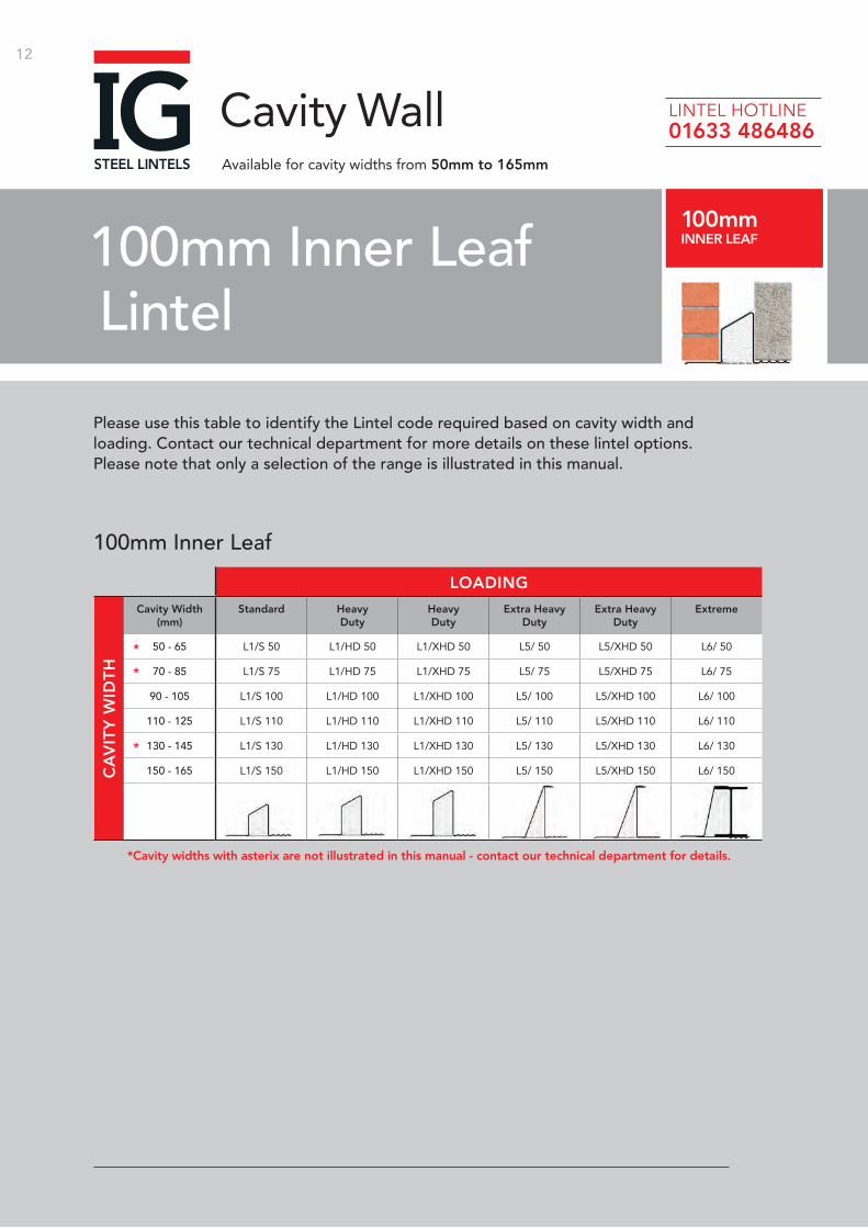
Please use this table to identify the Lintel code required based on cavity width and loading. Contact our technical department for more details on these lintel options. Please note that only a selection of the range is illustrated in this manual.
100mm Inner Leaf Lintel
100mmINNER LEAF
Cavity WallAvailable for cavity widths from 50mm to 165mm
LINTEL HOTLINE 01633 486486
Cavity Width(mm)
Standard HeavyDuty
HeavyDuty
Extra Heavy Duty
Extra Heavy Duty
Extreme
50 - 65 L1/S 50 L1/HD 50 L1/XHD 50 L5/ 50 L5/XHD 50 L6/ 50
70 - 85 L1/S 75 L1/HD 75 L1/XHD 75 L5/ 75 L5/XHD 75 L6/ 75
90 - 105 L1/S 100 L1/HD 100 L1/XHD 100 L5/ 100 L5/XHD 100 L6/ 100
110 - 125 L1/S 110 L1/HD 110 L1/XHD 110 L5/ 110 L5/XHD 110 L6/ 110
130 - 145 L1/S 130 L1/HD 130 L1/XHD 130 L5/ 130 L5/XHD 130 L6/ 130
150 - 165 L1/S 150 L1/HD 150 L1/XHD 150 L5/ 150 L5/XHD 150 L6/ 150
LOADING
100mm Inner Leaf
CA
VIT
Y W
IDT
H
*Cavity widths with asterix are not illustrated in this manual - contact our technical department for details.
*
*
*
13BETTER BY
DESIGN
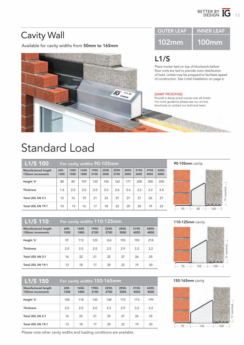
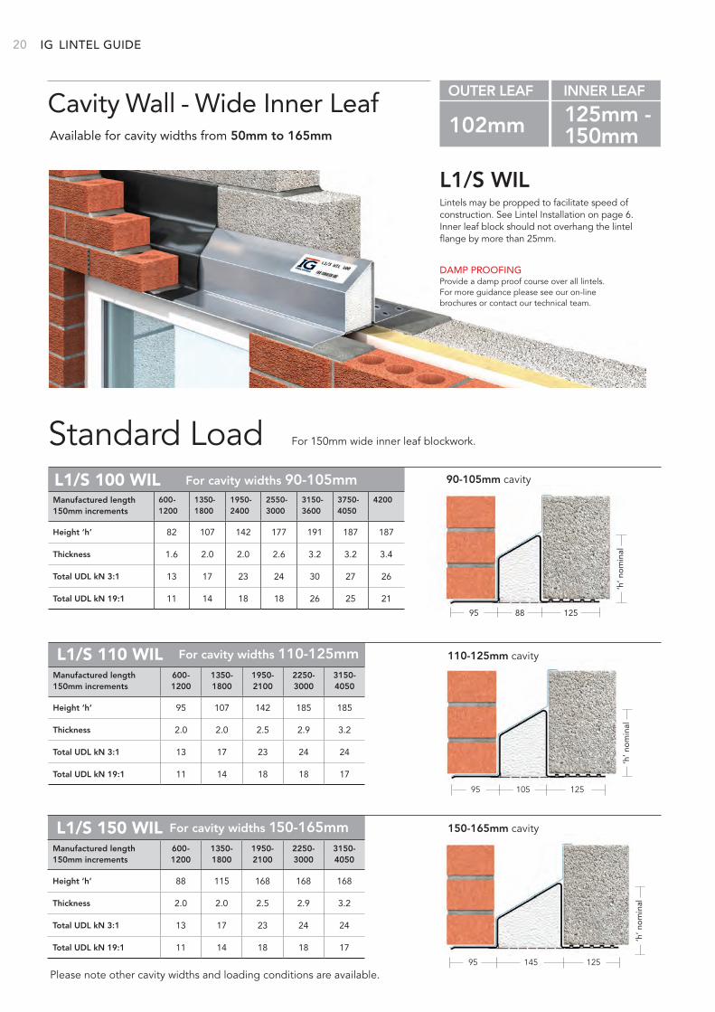
Place mortar bed on top of blockwork before floor units are laid to provide even distribution of load. Lintels may be propped to facilitate speed of construction. See Lintel Installation on page 6.
L1/S
Standard Load
DAMP PROOFINGProvide a damp proof course over all lintels. For more guidance please see our on-line brochures or contact our technical team.
Cavity WallAvailable for cavity widths from 50mm to 165mm
OUTER LEAF INNER LEAF
102mm 100mm
90-105mm cavityL1/S 100
95 100
‘h’ n
omin
al
88
For cavity widths 90-105mm
Height ‘h’ 88 85 107 125 150 162 171 200 200 200
Thickness 1.6 2.0 2.0 2.0 2.0 2.6 2.6 3.2 3.2 3.4
Total UDL kN 3:1 12 16 19 21 23 27 27 27 26 27
Total UDL kN 19:1 10 13 16 17 18 22 20 20 19 22
Manufactured length 600- 1350- 1650- 1950- 2250- 2550- 2850- 3150- 3750- 4200-150mm increments 1200 1500 1800 2100 2400 2700 3000 3600 4050 4800
95 100
‘h’ n
omin
al
145
150-165mm cavityL1/S 150 For cavity widths 150-165mm
Height ‘h’ 100 118 130 148 173 173 199
Thickness 2.0 2.0 2.0 2.5 2.9 3.2 3.2
Total UDL kN 3:1 16 22 21 25 27 26 25
Total UDL kN 19:1 13 18 17 20 22 19 20
Manufactured length 600- 1650- 1950- 2250- 2850- 3150- 4200-150mm increments 1500 1800 2100 2700 3000 4050 4800
110-125mm cavityL1/S 110
95 100
‘h’ n
omin
al
105
For cavity widths 110-125mm
Height ‘h’ 97 113 125 163 193 193 218
Thickness 2.0 2.0 2.0 2.5 2.9 3.2 3.2
Total UDL kN 3:1 16 22 21 25 27 26 25
Total UDL kN 19:1 13 18 17 20 22 19 20
Manufactured length 600- 1650- 1950- 2250- 2850- 3150- 4200-150mm increments 1500 1800 2100 2700 3000 4050 4800
Please note other cavity widths and loading conditions are available.
IG 14
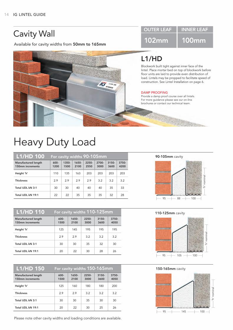
Blockwork built tight against inner face of the lintel. Place mortar bed on top of blockwork before floor units are laid to provide even distribution of load. Lintels may be propped to facilitate speed of construction. See Lintel Installation on page 6.
L1/HD
Heavy Duty Load
DAMP PROOFINGProvide a damp proof course over all lintels. For more guidance please see our on-line brochures or contact our technical team.
Cavity WallAvailable for cavity widths from 50mm to 165mm
OUTER LEAF INNER LEAF
102mm 100mm
Please note other cavity widths and loading conditions are available.
Height ‘h’ 110 135 163 203 203 203 203
Thickness 2.9 2.9 2.9 2.9 3.2 3.2 3.2
Total UDL kN 3:1 30 30 40 40 40 35 33
Total UDL kN 19:1 22 22 35 35 35 32 28
Manufactured length 600- 1350- 1650- 2250- 2700- 3150- 3750-150mm increments 1200 1500 2100 2550 3000 3600 4200
90-105mm cavityL1/HD 100
95 10088
For cavity widths 90-105mm
‘h’ n
omin
al
110-125mm cavityL1/HD 110
95 100105
For cavity widths 110-125mm
Height ‘h’ 125 145 195 195 195
Thickness 2.9 2.9 3.2 3.2 3.2
Total UDL kN 3:1 30 30 35 32 30
Total UDL kN 19:1 20 22 30 28 26
Manufactured length 600- 1650- 2250- 3150- 3750-150mm increments 1500 2100 3000 3600 4050
‘h’ n
omin
al
95 100145
150-165mm cavityL1/HD 150 For cavity widths 150-165mm
Height ‘h’ 125 160 180 180 200
Thickness 2.9 2.9 3.2 3.2 3.2
Total UDL kN 3:1 30 30 35 30 30
Total UDL kN 19:1 20 22 30 25 26
Manufactured length 600- 1650- 2250- 3150- 3750-150mm increments 1500 2100 3000 3600 4050
‘h’ n
omin
al
LINTEL GUIDE
15BETTER BY
DESIGN
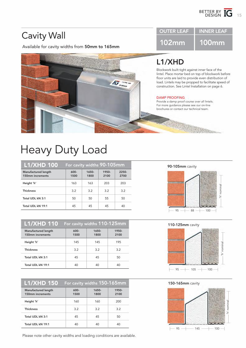
110-125mm cavityL1/XHD 110
95 100105
For cavity widths 110-125mm‘h
’ nom
inalHeight ‘h’ 145 145 195
Thickness 3.2 3.2 3.2
Total UDL kN 3:1 45 45 50
Total UDL kN 19:1 40 40 40
Manufactured length 600- 1650- 1950-150mm increments 1500 1800 2100
95 100145
‘h’ n
omin
al
150-165mm cavityL1/XHD 150 For cavity widths 150-165mm
Height ‘h’ 160 160 200
Thickness 3.2 3.2 3.2
Total UDL kN 3:1 45 45 50
Total UDL kN 19:1 40 40 40
Manufactured length 600- 1650- 1950-150mm increments 1500 1800 2100
Blockwork built tight against inner face of the lintel. Place mortar bed on top of blockwork before floor units are laid to provide even distribution of load. Lintels may be propped to facilitate speed of construction. See Lintel Installation on page 6.
L1/XHD
Heavy Duty Load
DAMP PROOFINGProvide a damp proof course over all lintels. For more guidance please see our on-line brochures or contact our technical team.
Cavity WallAvailable for cavity widths from 50mm to 165mm
OUTER LEAF INNER LEAF
102mm 100mm
Please note other cavity widths and loading conditions are available.
Height ‘h’ 163 163 203 203
Thickness 3.2 3.2 3.2 3.2
Total UDL kN 3:1 50 50 55 50
Total UDL kN 19:1 45 45 45 40
Manufactured length 600- 1650- 1950- 2250-150mm increments 1500 1800 2100 2700
90-105mm cavityL1/XHD 100
95 10088
For cavity widths 90-105mm
‘h’ n
omin
al
IG 16
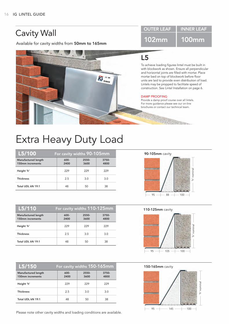
To achieve loading figures lintel must be built in with blockwork as shown. Ensure all perpendicular and horizontal joints are filled with mortar. Place mortar bed on top of blockwork before floor units are laid to provide even distribution of load. Lintels may be propped to facilitate speed of construction. See Lintel Installation on page 6.
L5
Extra Heavy Duty Load
DAMP PROOFINGProvide a damp proof course over all lintels. For more guidance please see our on-line brochures or contact our technical team.
Cavity WallAvailable for cavity widths from 50mm to 165mm
OUTER LEAF INNER LEAF
102mm 100mm
Please note other cavity widths and loading conditions are available.
90-105mm cavityL5/100
95 10088
For cavity widths 90-105mm
Height ‘h’ 229 229 229
Thickness 2.5 3.0 3.0
Total UDL kN 19:1 48 50 38
Manufactured length 600- 2550- 3750-150mm increments 2400 3600 4800
‘h’ n
omin
al
110-125mm cavityL5/110
95 100105
For cavity widths 110-125mm
Height ‘h’ 229 229 229
Thickness 2.5 3.0 3.0
Total UDL kN 19:1 48 50 38
Manufactured length 600- 2550- 3750-150mm increments 2400 3600 4800
95 100145
150-165mm cavityL5/150 For cavity widths 150-165mm
Height ‘h’ 229 229 229
Thickness 2.5 3.0 3.0
Total UDL kN 19:1 48 50 38
Manufactured length 600- 2550- 3750-150mm increments 2400 3600 4800
‘h’ n
omin
al
‘h’ n
omin
al
LINTEL GUIDE
17BETTER BY
DESIGN
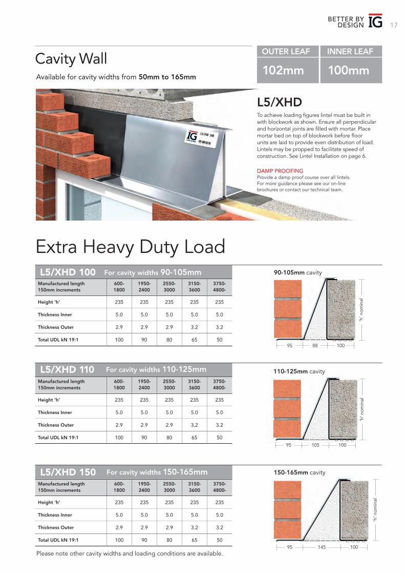
Please note other cavity widths and loading conditions are available.
L5/XHD 150 For cavity widths 150-165mm
Height ‘h’ 235 235 235 235 235
Thickness Inner 5.0 5.0 5.0 5.0 5.0
Thickness Outer 2.9 2.9 2.9 3.2 3.2
Total UDL kN 19:1 100 90 80 65 50
Manufactured length 600- 1950- 2550- 3150- 3750-150mm increments 1800 2400 3000 3600 4800-
110-125mm cavityL5/XHD 110
95 100105
For cavity widths 110-125mm
Height ‘h’ 235 235 235 235 235
Thickness Inner 5.0 5.0 5.0 5.0 5.0
Thickness Outer 2.9 2.9 2.9 3.2 3.2
Total UDL kN 19:1 100 90 80 65 50
Manufactured length 600- 1950- 2550- 3150- 3750-150mm increments 1800 2400 3000 3600 4800-
To achieve loading figures lintel must be built in with blockwork as shown. Ensure all perpendicular and horizontal joints are filled with mortar. Place mortar bed on top of blockwork before floor units are laid to provide even distribution of load. Lintels may be propped to facilitate speed of construction. See Lintel Installation on page 6.
L5/XHD
Extra Heavy Duty Load
DAMP PROOFINGProvide a damp proof course over all lintels. For more guidance please see our on-line brochures or contact our technical team.
Cavity WallAvailable for cavity widths from 50mm to 165mm
OUTER LEAF INNER LEAF
102mm 100mm
90-105mm cavityL5/XHD 100
95 10088
For cavity widths 90-105mm
Height ‘h’ 235 235 235 235 235
Thickness Inner 5.0 5.0 5.0 5.0 5.0
Thickness Outer 2.9 2.9 2.9 3.2 3.2
Total UDL kN 19:1 100 90 80 65 50
Manufactured length 600- 1950- 2550- 3150- 3750-150mm increments 1800 2400 3000 3600 4800-
‘h’ n
omin
al‘h
’ nom
inal
95 100145
150-165mm cavity
‘h’ n
omin
al
IG 18
340
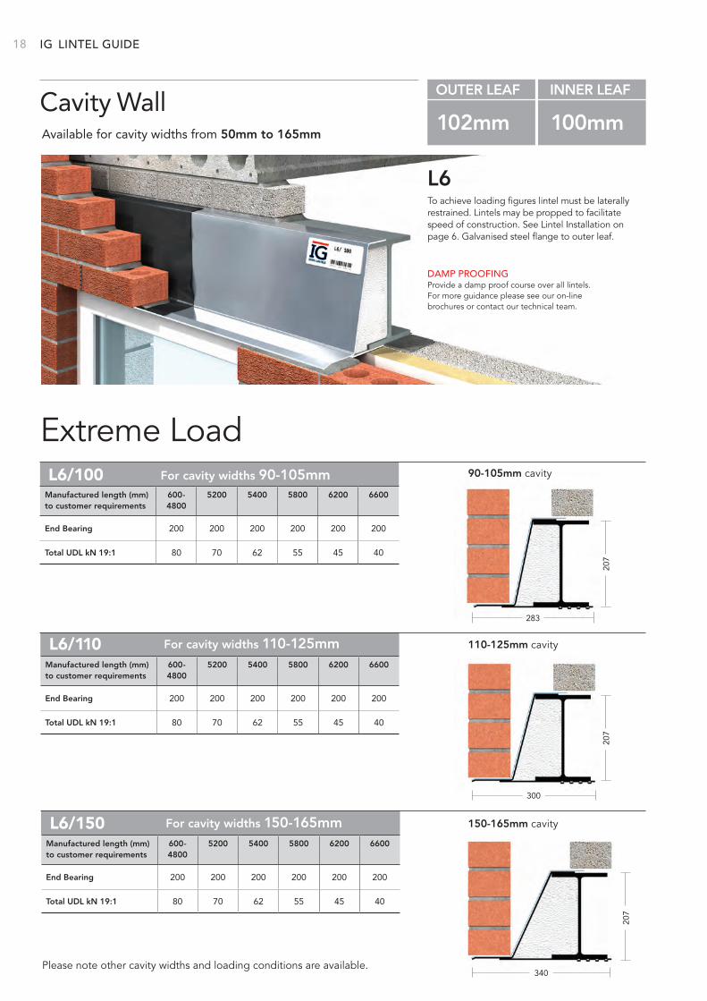
150-165mm cavityL6/150 For cavity widths 150-165mm
End Bearing 200 200 200 200 200 200
Total UDL kN 19:1 80 70 62 55 45 40
Manufactured length (mm) 600- 5200 5400 5800 6200 6600to customer requirements 4800
283
207
207
90-105mm cavityL6/100 For cavity widths 90-105mm
End Bearing 200 200 200 200 200 200
Total UDL kN 19:1 80 70 62 55 45 40
Manufactured length (mm) 600- 5200 5400 5800 6200 6600to customer requirements 4800
To achieve loading figures lintel must be laterally restrained. Lintels may be propped to facilitate speed of construction. See Lintel Installation on page 6. Galvanised steel flange to outer leaf.
L6
Extreme Load
DAMP PROOFINGProvide a damp proof course over all lintels. For more guidance please see our on-line brochures or contact our technical team.
Cavity WallAvailable for cavity widths from 50mm to 165mm
OUTER LEAF INNER LEAF
102mm 100mm
Please note other cavity widths and loading conditions are available.
300
110-125mm cavityL6/110 For cavity widths 110-125mm
End Bearing 200 200 200 200 200 200
Total UDL kN 19:1 80 70 62 55 45 40
Manufactured length (mm) 600- 5200 5400 5800 6200 6600to customer requirements 4800
207
LINTEL GUIDE
19
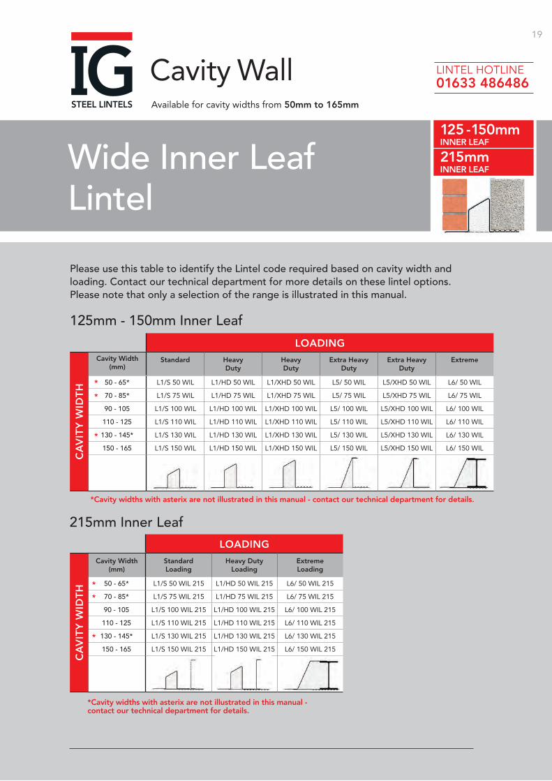
Please use this table to identify the Lintel code required based on cavity width and loading. Contact our technical department for more details on these lintel options. Please note that only a selection of the range is illustrated in this manual.
125mm - 150mm Inner Leaf
215mm Inner Leaf
Cavity Width(mm)
Standard HeavyDuty
HeavyDuty
Extra Heavy Duty
Extra Heavy Duty
Extreme
50 - 65* L1/S 50 WIL L1/HD 50 WIL L1/XHD 50 WIL L5/ 50 WIL L5/XHD 50 WIL L6/ 50 WIL
70 - 85* L1/S 75 WIL L1/HD 75 WIL L1/XHD 75 WIL L5/ 75 WIL L5/XHD 75 WIL L6/ 75 WIL
90 - 105 L1/S 100 WIL L1/HD 100 WIL L1/XHD 100 WIL L5/ 100 WIL L5/XHD 100 WIL L6/ 100 WIL
110 - 125 L1/S 110 WIL L1/HD 110 WIL L1/XHD 110 WIL L5/ 110 WIL L5/XHD 110 WIL L6/ 110 WIL
130 - 145* L1/S 130 WIL L1/HD 130 WIL L1/XHD 130 WIL L5/ 130 WIL L5/XHD 130 WIL L6/ 130 WIL
150 - 165 L1/S 150 WIL L1/HD 150 WIL L1/XHD 150 WIL L5/ 150 WIL L5/XHD 150 WIL L6/ 150 WIL
Cavity Width(mm)
StandardLoading
Heavy DutyLoading
ExtremeLoading
50 - 65* L1/S 50 WIL 215 L1/HD 50 WIL 215 L6/ 50 WIL 215
70 - 85* L1/S 75 WIL 215 L1/HD 75 WIL 215 L6/ 75 WIL 215
90 - 105 L1/S 100 WIL 215 L1/HD 100 WIL 215 L6/ 100 WIL 215
110 - 125 L1/S 110 WIL 215 L1/HD 110 WIL 215 L6/ 110 WIL 215
130 - 145* L1/S 130 WIL 215 L1/HD 130 WIL 215 L6/ 130 WIL 215
150 - 165 L1/S 150 WIL 215 L1/HD 150 WIL 215 L6/ 150 WIL 215
Wide Inner Leaf Lintel
125 - 150mmINNER LEAF
215mmINNER LEAF
Cavity WallAvailable for cavity widths from 50mm to 165mm
LOADING
LOADING
CA
VIT
Y W
IDT
HC
AV
ITY
WID
TH
*Cavity widths with asterix are not illustrated in this manual - contact our technical department for details.
*Cavity widths with asterix are not illustrated in this manual - contact our technical department for details.
*
*
*
*
*
*
LINTEL HOTLINE 01633 486486
IG 20
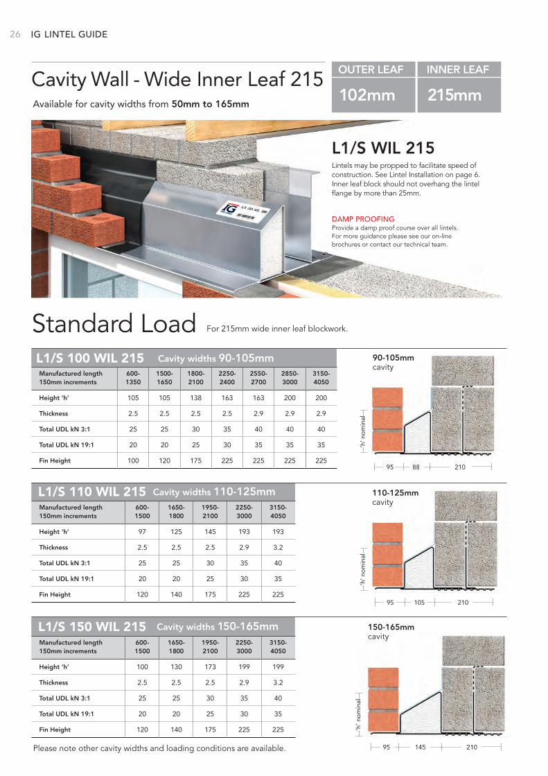
Lintels may be propped to facilitate speed of construction. See Lintel Installation on page 6. Inner leaf block should not overhang the lintel flange by more than 25mm.
L1/S WIL
Standard Load
DAMP PROOFINGProvide a damp proof course over all lintels. For more guidance please see our on-line brochures or contact our technical team.
Cavity Wall - Wide Inner LeafAvailable for cavity widths from 50mm to 165mm
OUTER LEAF INNER LEAF
102mm 125mm - 150mm
Please note other cavity widths and loading conditions are available.
95 125‘h
’ no
min
al88
For cavity widths 90-105mmL1/S 100 WIL
For 150mm wide inner leaf blockwork.
Height ‘h’ 82 107 142 177 191 187 187
Thickness 1.6 2.0 2.0 2.6 3.2 3.2 3.4
Total UDL kN 3:1 13 17 23 24 30 27 26
Total UDL kN 19:1 11 14 18 18 26 25 21
Manufactured length 600- 1350- 1950- 2550- 3150- 3750- 4200150mm increments 1200 1800 2400 3000 3600 4050
90-105mm cavity
110-125mm cavityL1/S 110 WIL
95 125105
For cavity widths 110-125mm
Height ‘h’ 95 107 142 185 185
Thickness 2.0 2.0 2.5 2.9 3.2
Total UDL kN 3:1 13 17 23 24 24
Total UDL kN 19:1 11 14 18 18 17
Manufactured length 600- 1350- 1950- 2250- 3150-150mm increments 1200 1800 2100 3000 4050
‘h’ n
om
inal
95 125145
150-165mm cavityL1/S 150 WIL For cavity widths 150-165mm
Height ‘h’ 88 115 168 168 168
Thickness 2.0 2.0 2.5 2.9 3.2
Total UDL kN 3:1 13 17 23 24 24
Total UDL kN 19:1 11 14 18 18 17
Manufactured length 600- 1350- 1950- 2250- 3150-150mm increments 1200 1800 2100 3000 4050
‘h’ n
om
inal
LINTEL GUIDE
21BETTER BY
DESIGN
95 12588
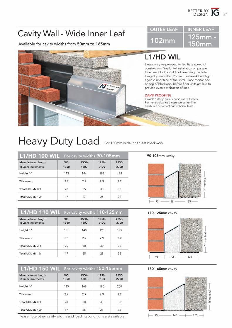
Height ‘h’ 113 144 188 188
Thickness 2.9 2.9 2.9 3.2
Total UDL kN 3:1 20 35 30 36
Total UDL kN 19:1 17 27 25 32
Manufactured length 600- 1500- 1950- 2250-
150mm increments 1350 1800 2100 2700
‘h’ n
om
inal
Lintels may be propped to facilitate speed of construction. See Lintel Installation on page 6. Inner leaf block should not overhang the lintel flange by more than 25mm. Blockwork built tight against inner face of the lintel. Place mortar bed on top of blockwork before floor units are laid to provide even distribution of load.
L1/HD WIL
Heavy Duty Load
DAMP PROOFINGProvide a damp proof course over all lintels. For more guidance please see our on-line brochures or contact our technical team.
Cavity Wall - Wide Inner LeafAvailable for cavity widths from 50mm to 165mm
OUTER LEAF INNER LEAF
102mm 125mm - 150mm
Please note other cavity widths and loading conditions are available.
For cavity widths 90-105mmL1/HD 100 WIL
For 150mm wide inner leaf blockwork.
90-105mm cavity
110-125mm cavityL1/HD 110 WIL For cavity widths 110-125mm
150-165mm cavityL1/HD 150 WIL For cavity widths 150-165mm
95 125105
Height ‘h’ 131 148 195 195
Thickness 2.9 2.9 2.9 3.2
Total UDL kN 3:1 20 30 30 36
Total UDL kN 19:1 17 25 25 32
Manufactured length 600- 1500- 1950- 2250-150mm increments 1350 1800 2100 2700
‘h’ n
om
inal
95 125145
Height ‘h’ 115 168 180 200
Thickness 2.9 2.9 2.9 3.2
Total UDL kN 3:1 20 30 30 36
Total UDL kN 19:1 17 25 25 32
Manufactured length 600- 1500- 1950- 2250-150mm increments 1350 1800 2100 2700
‘h’ n
om
inal
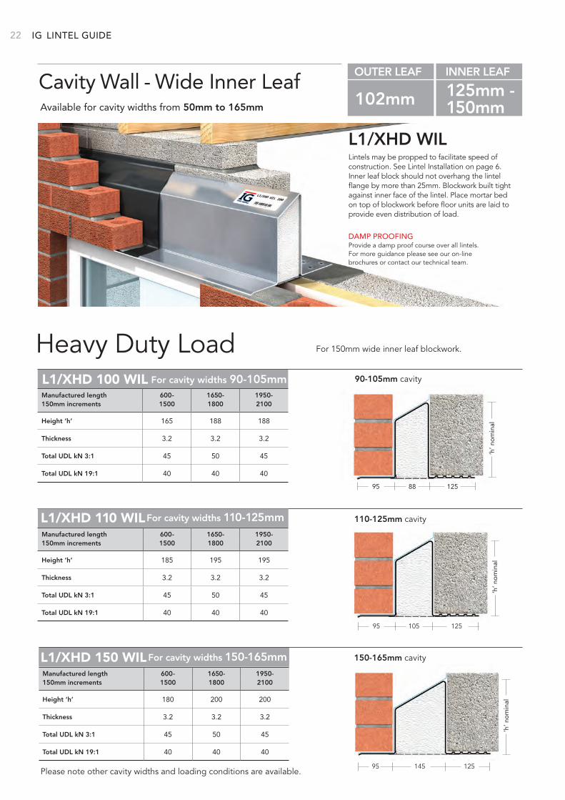
IG 22
Lintels may be propped to facilitate speed of construction. See Lintel Installation on page 6. Inner leaf block should not overhang the lintel flange by more than 25mm. Blockwork built tight against inner face of the lintel. Place mortar bed on top of blockwork before floor units are laid to provide even distribution of load.
L1/XHD WIL
Heavy Duty Load
DAMP PROOFINGProvide a damp proof course over all lintels. For more guidance please see our on-line brochures or contact our technical team.
Cavity Wall - Wide Inner LeafAvailable for cavity widths from 50mm to 165mm
OUTER LEAF INNER LEAF
102mm 125mm - 150mm
Please note other cavity widths and loading conditions are available.
For 150mm wide inner leaf blockwork.
LINTEL GUIDE
95 12588
For cavity widths 90-105mmL1/XHD 100 WIL 90-105mm cavity
Height ‘h’ 165 188 188
Thickness 3.2 3.2 3.2
Total UDL kN 3:1 45 50 45
Total UDL kN 19:1 40 40 40
Manufactured length 600- 1650- 1950-150mm increments 1500 1800 2100
‘h’ n
om
inal
110-125mm cavityL1/XHD 110 WIL
95 125105
For cavity widths 110-125mm
Height ‘h’ 185 195 195
Thickness 3.2 3.2 3.2
Total UDL kN 3:1 45 50 45
Total UDL kN 19:1 40 40 40
Manufactured length 600- 1650- 1950-150mm increments 1500 1800 2100
‘h’ n
om
inal
95 125145
150-165mm cavityL1/XHD 150 WILFor cavity widths 150-165mm
Height ‘h’ 180 200 200
Thickness 3.2 3.2 3.2
Total UDL kN 3:1 45 50 45
Total UDL kN 19:1 40 40 40
Manufactured length 600- 1650- 1950-150mm increments 1500 1800 2100
‘h’ n
om
inal
23BETTER BY
DESIGN
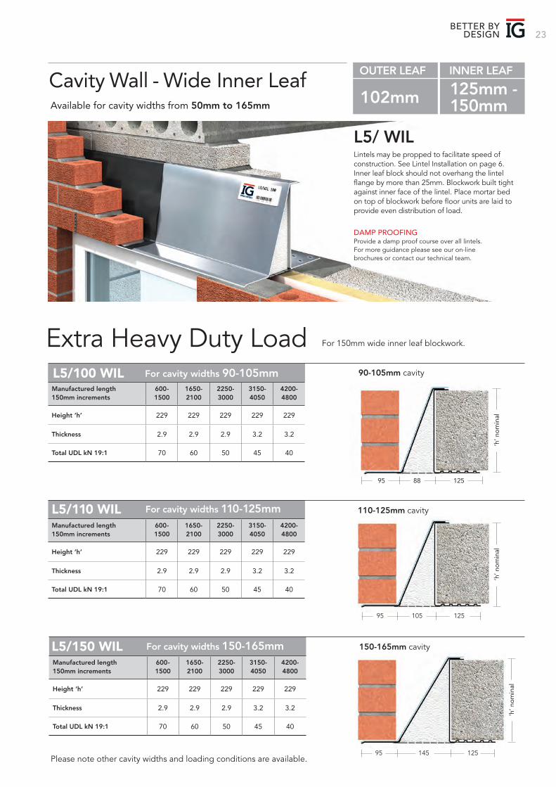
Lintels may be propped to facilitate speed of construction. See Lintel Installation on page 6. Inner leaf block should not overhang the lintel flange by more than 25mm. Blockwork built tight against inner face of the lintel. Place mortar bed on top of blockwork before floor units are laid to provide even distribution of load.
L5/ WIL
Extra Heavy Duty Load
DAMP PROOFINGProvide a damp proof course over all lintels. For more guidance please see our on-line brochures or contact our technical team.
Cavity Wall - Wide Inner LeafAvailable for cavity widths from 50mm to 165mm
OUTER LEAF INNER LEAF
102mm 125mm - 150mm
Please note other cavity widths and loading conditions are available.
For 150mm wide inner leaf blockwork.
95 12588
For cavity widths 90-105mmL5/100 WIL 90-105mm cavity
Height ‘h’ 229 229 229 229 229
Thickness 2.9 2.9 2.9 3.2 3.2
Total UDL kN 19:1 70 60 50 45 40
Manufactured length 600- 1650- 2250- 3150- 4200-150mm increments 1500 2100 3000 4050 4800
‘h’ n
om
inal
‘h’ n
om
inal
110-125mm cavityL5/110 WIL
95 125105
For cavity widths 110-125mm
Height ‘h’ 229 229 229 229 229
Thickness 2.9 2.9 2.9 3.2 3.2
Total UDL kN 19:1 70 60 50 45 40
Manufactured length 600- 1650- 2250- 3150- 4200-150mm increments 1500 2100 3000 4050 4800
95 125145
150-165mm cavityL5/150 WIL For cavity widths 150-165mm
Height ‘h’ 229 229 229 229 229
Thickness 2.9 2.9 2.9 3.2 3.2
Total UDL kN 19:1 70 60 50 45 40
Manufactured length 600- 1650- 2250- 3150- 4200-150mm increments 1500 2100 3000 4050 4800
‘h’ n
om
inal
IG 24
95 12588
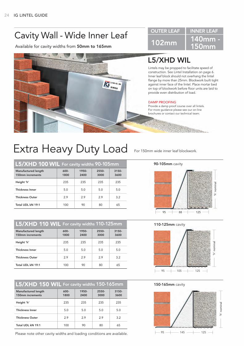
For cavity widths 90-105mmL5/XHD 100 WIL 90-105mm cavity
Height ‘h’ 235 235 235 235
Thickness Inner 5.0 5.0 5.0 5.0
Thickness Outer 2.9 2.9 2.9 3.2
Total UDL kN 19:1 100 90 80 65
Manufactured length 600- 1950- 2550- 3150-150mm increments 1800 2400 3000 3600
‘h’ n
om
inal
LINTEL GUIDE
Lintels may be propped to facilitate speed of construction. See Lintel Installation on page 6. Inner leaf block should not overhang the lintel flange by more than 25mm. Blockwork built tight against inner face of the lintel. Place mortar bed on top of blockwork before floor units are laid to provide even distribution of load.
L5/XHD WIL
Extra Heavy Duty Load
DAMP PROOFINGProvide a damp proof course over all lintels. For more guidance please see our on-line brochures or contact our technical team.
Cavity Wall - Wide Inner LeafAvailable for cavity widths from 50mm to 165mm
OUTER LEAF INNER LEAF
102mm 140mm - 150mm
Please note other cavity widths and loading conditions are available.
For 150mm wide inner leaf blockwork.
‘h’ n
om
inal
110-125mm cavityL5/XHD 110 WIL
95 125105
For cavity widths 110-125mm
Height ‘h’ 235 235 235 235
Thickness Inner 5.0 5.0 5.0 5.0
Thickness Outer 2.9 2.9 2.9 3.2
Total UDL kN 19:1 100 90 80 65
Manufactured length 600- 1950- 2550- 3150-150mm increments 1800 2400 3000 3600
95 125145
150-165mm cavityL5/XHD 150 WIL For cavity widths 150-165mm
‘h’ n
om
inalHeight ‘h’ 235 235 235 235
Thickness Inner 5.0 5.0 5.0 5.0
Thickness Outer 2.9 2.9 2.9 3.2
Total UDL kN 19:1 100 90 80 65
Manufactured length 600- 1950- 2550- 3150-150mm increments 1800 2400 3000 3600
25BETTER BY
DESIGN
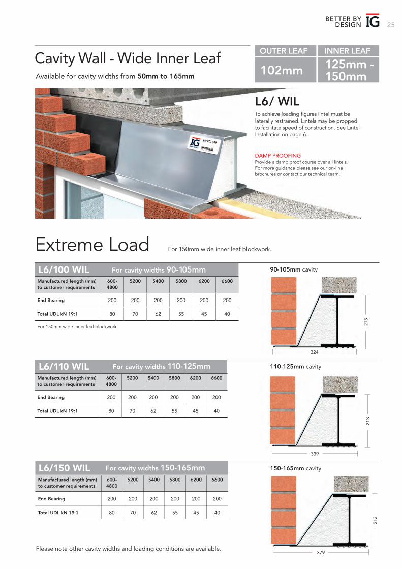
To achieve loading figures lintel must be laterally restrained. Lintels may be propped to facilitate speed of construction. See Lintel Installation on page 6.
L6 / WIL
Extreme Load
DAMP PROOFINGProvide a damp proof course over all lintels. For more guidance please see our on-line brochures or contact our technical team.
Cavity Wall - Wide Inner LeafAvailable for cavity widths from 50mm to 165mm
OUTER LEAF INNER LEAF
102mm 125mm - 150mm
Please note other cavity widths and loading conditions are available.
For cavity widths 90-105mmL6/100 WIL 90-105mm cavity
For 150mm wide inner leaf blockwork.
End Bearing 200 200 200 200 200 200
Total UDL kN 19:1 80 70 62 55 45 40
Manufactured length (mm) 600- 5200 5400 5800 6200 6600to customer requirements 4800
324
213
213
213
For 150mm wide inner leaf blockwork.
339
110-125mm cavityL6/110 WIL For cavity widths 110-125mm
End Bearing 200 200 200 200 200 200
Total UDL kN 19:1 80 70 62 55 45 40
Manufactured length (mm) 600- 5200 5400 5800 6200 6600to customer requirements 4800
379
150-165mm cavityL6/150 WIL For cavity widths 150-165mm
End Bearing 200 200 200 200 200 200
Total UDL kN 19:1 80 70 62 55 45 40
Manufactured length (mm) 600- 5200 5400 5800 6200 6600to customer requirements 4800
IG 26
Lintels may be propped to facilitate speed of construction. See Lintel Installation on page 6. Inner leaf block should not overhang the lintel flange by more than 25mm.
L1/S WIL 215
Standard Load
DAMP PROOFINGProvide a damp proof course over all lintels. For more guidance please see our on-line brochures or contact our technical team.
Cavity Wall - Wide Inner Leaf 215Available for cavity widths from 50mm to 165mm
OUTER LEAF INNER LEAF
102mm 215mm
Please note other cavity widths and loading conditions are available.
Cavity widths 90-105mmL1/S 100 WIL 215 90-105mm cavity
Height ‘h’ 105 105 138 163 163 200 200
Thickness 2.5 2.5 2.5 2.5 2.9 2.9 2.9
Total UDL kN 3:1 25 25 30 35 40 40 40
Total UDL kN 19:1 20 20 25 30 35 35 35
Fin Height 100 120 175 225 225 225 225
Manufactured length 600- 1500- 1800- 2250- 2550- 2850- 3150-150mm increments 1350 1650 2100 2400 2700 3000 4050
For 215mm wide inner leaf blockwork.
95 21088
‘h’ n
om
inal
L1/S 110 WIL 215 Cavity widths 110-125mm
95 210105
110-125mm cavity
Height ‘h’ 97 125 145 193 193
Thickness 2.5 2.5 2.5 2.9 3.2
Total UDL kN 3:1 25 25 30 35 40
Total UDL kN 19:1 20 20 25 30 35
Fin Height 120 140 175 225 225
Manufactured length 600- 1650- 1950- 2250- 3150-150mm increments 1500 1800 2100 3000 4050
‘h’ n
om
inal
L1/S 150 WIL 215 Cavity widths 150-165mm
95 210145
Height ‘h’ 100 130 173 199 199
Thickness 2.5 2.5 2.5 2.9 3.2
Total UDL kN 3:1 25 25 30 35 40
Total UDL kN 19:1 20 20 25 30 35
Fin Height 120 140 175 225 225
Manufactured length 600- 1650- 1950- 2250- 3150-150mm increments 1500 1800 2100 3000 4050
‘h’ n
om
inal
150-165mm cavity
LINTEL GUIDE
27BETTER BY
DESIGN
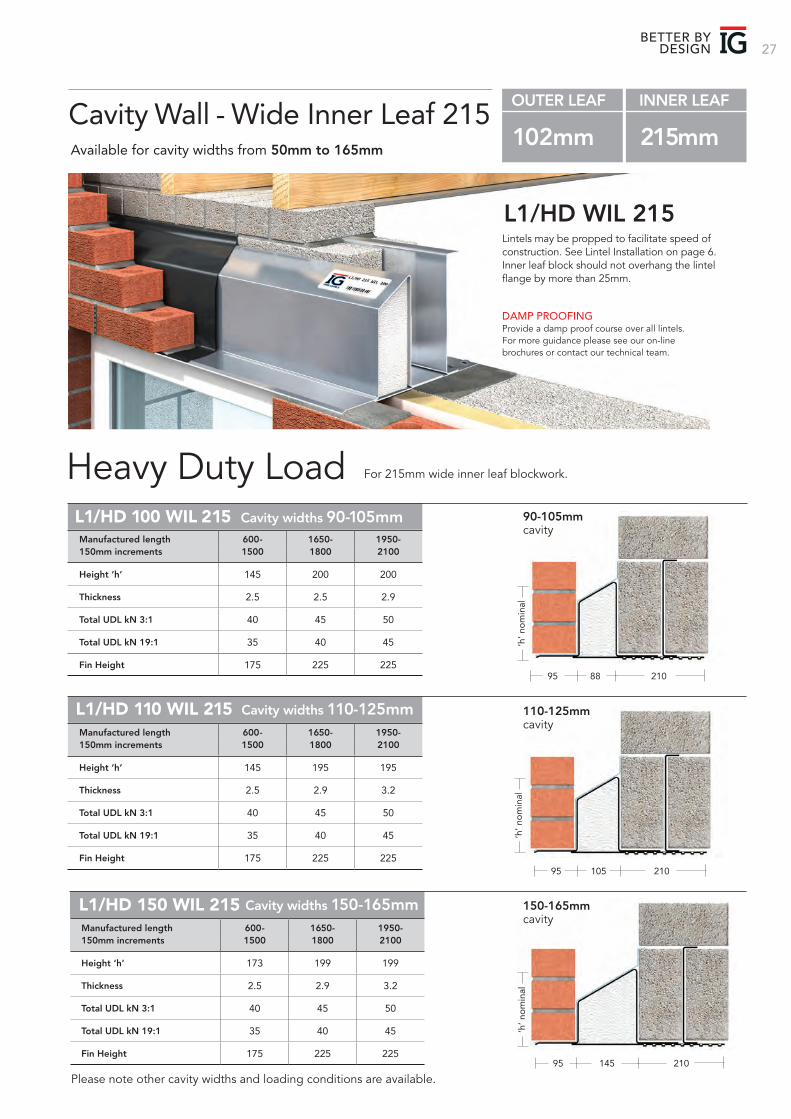
Lintels may be propped to facilitate speed of construction. See Lintel Installation on page 6. Inner leaf block should not overhang the lintel flange by more than 25mm.
L1/HD WIL 215
Heavy Duty Load
DAMP PROOFINGProvide a damp proof course over all lintels. For more guidance please see our on-line brochures or contact our technical team.
Cavity Wall - Wide Inner Leaf 215Available for cavity widths from 50mm to 165mm
OUTER LEAF INNER LEAF
102mm 215mm
Please note other cavity widths and loading conditions are available.
For 215mm wide inner leaf blockwork.
‘h’ n
om
inal
Cavity widths 90-105mmL1/HD 100 WIL 215 90-105mm cavity
Height ‘h’ 145 200 200
Thickness 2.5 2.5 2.9
Total UDL kN 3:1 40 45 50
Total UDL kN 19:1 35 40 45
Fin Height 175 225 225
Manufactured length 600- 1650- 1950-150mm increments 1500 1800 2100
95 21088
L1/HD 110 WIL 215 Cavity widths 110-125mm
Height ‘h’ 145 195 195
Thickness 2.5 2.9 3.2
Total UDL kN 3:1 40 45 50
Total UDL kN 19:1 35 40 45
Fin Height 175 225 225
Manufactured length 600- 1650- 1950-150mm increments 1500 1800 2100
95 210105
110-125mm cavity
‘h’ n
om
inal
L1/HD 150 WIL 215 Cavity widths 150-165mm
Height ‘h’ 173 199 199
Thickness 2.5 2.9 3.2
Total UDL kN 3:1 40 45 50
Total UDL kN 19:1 35 40 45
Fin Height 175 225 225
Manufactured length 600- 1650- 1950-150mm increments 1500 1800 2100
95 210145
150-165mm cavity
‘h’ n
om
inal
IG 28 LINTEL GUIDE
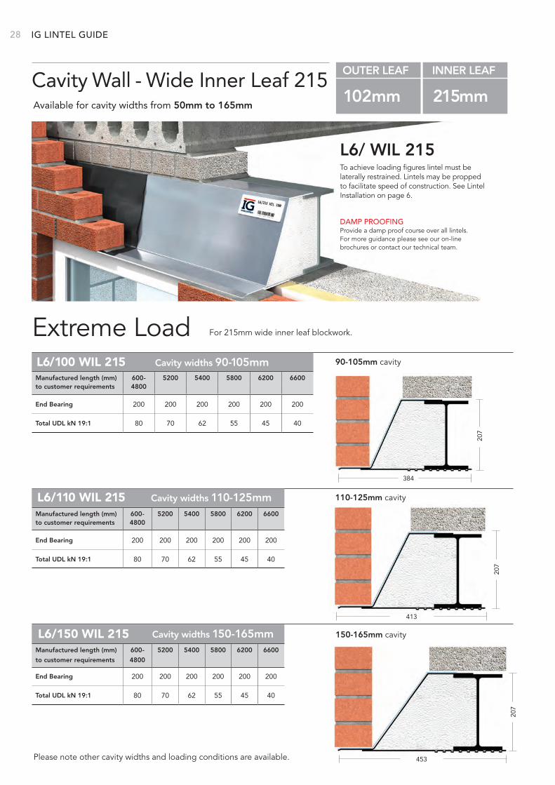
To achieve loading figures lintel must be laterally restrained. Lintels may be propped to facilitate speed of construction. See Lintel Installation on page 6.
L6/ WIL 215
Extreme Load
DAMP PROOFINGProvide a damp proof course over all lintels. For more guidance please see our on-line brochures or contact our technical team.
Cavity Wall - Wide Inner Leaf 215Available for cavity widths from 50mm to 165mm
OUTER LEAF INNER LEAF
102mm 215mm
Please note other cavity widths and loading conditions are available.
For 215mm wide inner leaf blockwork.
Cavity widths 70-85mm
Cavity widths 90-105mmL6/100 WIL 215 90-105mm cavity
End Bearing 200 200 200 200 200 200
Total UDL kN 19:1 80 70 62 55 45 40
Manufactured length (mm) 600- 5200 5400 5800 6200 6600to customer requirements 4800
38420
7
L6/110 WIL 215 Cavity widths 110-125mm 110-125mm cavity
End Bearing 200 200 200 200 200 200
Total UDL kN 19:1 80 70 62 55 45 40
Manufactured length (mm) 600- 5200 5400 5800 6200 6600to customer requirements 4800
413
207
L6/150 WIL 215 Cavity widths 150-165mm 150-165mm cavity
End Bearing 200 200 200 200 200 200
Total UDL kN 19:1 80 70 62 55 45 40
Manufactured length (mm) 600- 5200 5400 5800 6200 6600
to customer requirements 4800
453
207
29
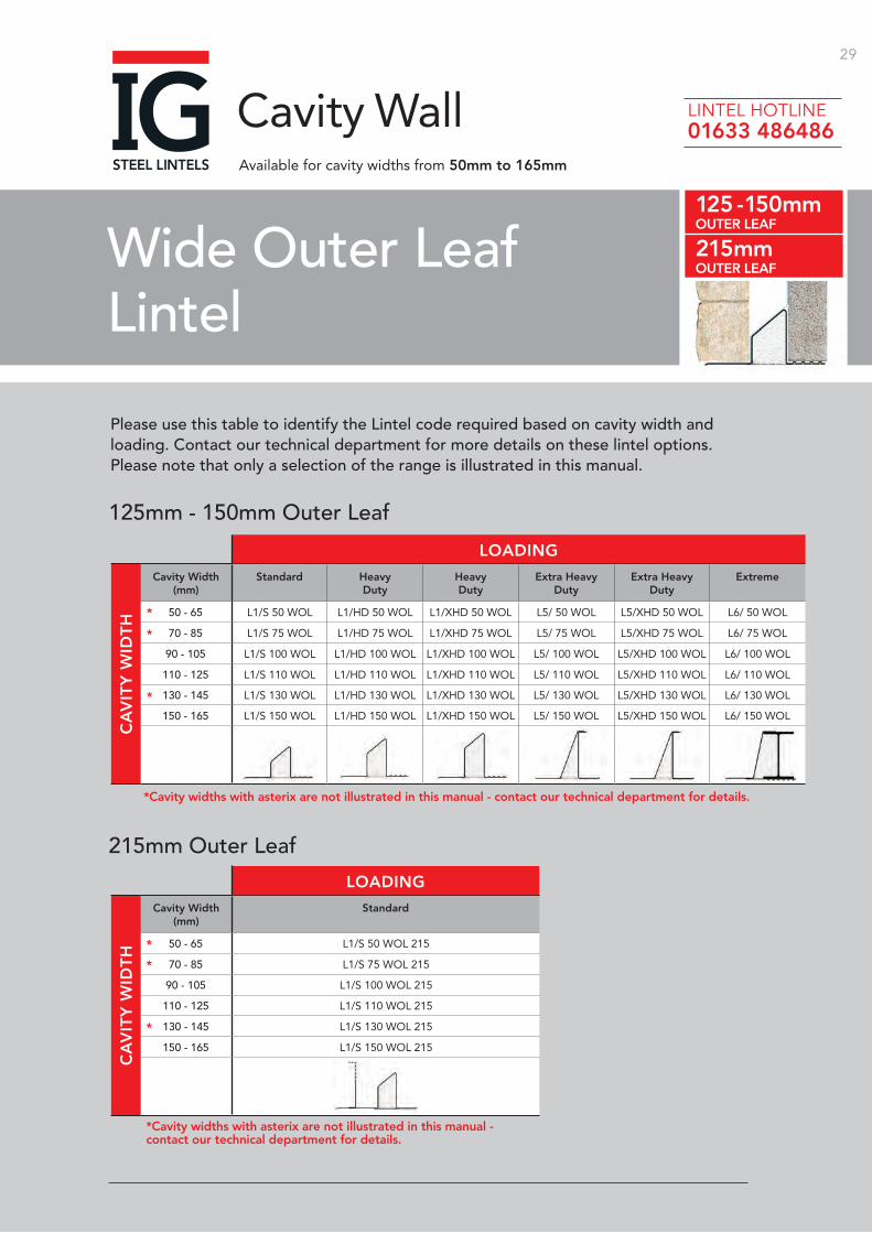
Wide Outer Leaf Lintel
Cavity Wall
Please use this table to identify the Lintel code required based on cavity width and loading. Contact our technical department for more details on these lintel options. Please note that only a selection of the range is illustrated in this manual.
125mm - 150mm Outer Leaf
215mm Outer Leaf
Cavity Width(mm)
Standard HeavyDuty
HeavyDuty
Extra Heavy Duty
Extra Heavy Duty
Extreme
50 - 65 L1/S 50 WOL L1/HD 50 WOL L1/XHD 50 WOL L5/ 50 WOL L5/XHD 50 WOL L6/ 50 WOL
70 - 85 L1/S 75 WOL L1/HD 75 WOL L1/XHD 75 WOL L5/ 75 WOL L5/XHD 75 WOL L6/ 75 WOL
90 - 105 L1/S 100 WOL L1/HD 100 WOL L1/XHD 100 WOL L5/ 100 WOL L5/XHD 100 WOL L6/ 100 WOL
110 - 125 L1/S 110 WOL L1/HD 110 WOL L1/XHD 110 WOL L5/ 110 WOL L5/XHD 110 WOL L6/ 110 WOL
130 - 145 L1/S 130 WOL L1/HD 130 WOL L1/XHD 130 WOL L5/ 130 WOL L5/XHD 130 WOL L6/ 130 WOL
150 - 165 L1/S 150 WOL L1/HD 150 WOL L1/XHD 150 WOL L5/ 150 WOL L5/XHD 150 WOL L6/ 150 WOL
Cavity Width(mm)
Standard
50 - 65 L1/S 50 WOL 215
70 - 85 L1/S 75 WOL 215
90 - 105 L1/S 100 WOL 215
110 - 125 L1/S 110 WOL 215
130 - 145 L1/S 130 WOL 215
150 - 165 L1/S 150 WOL 215
Available for cavity widths from 50mm to 165mm
125 - 150mmOUTER LEAF
215mmOUTER LEAF
LOADING
LOADING
CA
VIT
Y W
IDT
HC
AV
ITY
WID
TH
*Cavity widths with asterix are not illustrated in this manual - contact our technical department for details.
*Cavity widths with asterix are not illustrated in this manual - contact our technical department for details.
*
*
*
*
*
*
LINTEL HOTLINE 01633 486486
IG 30
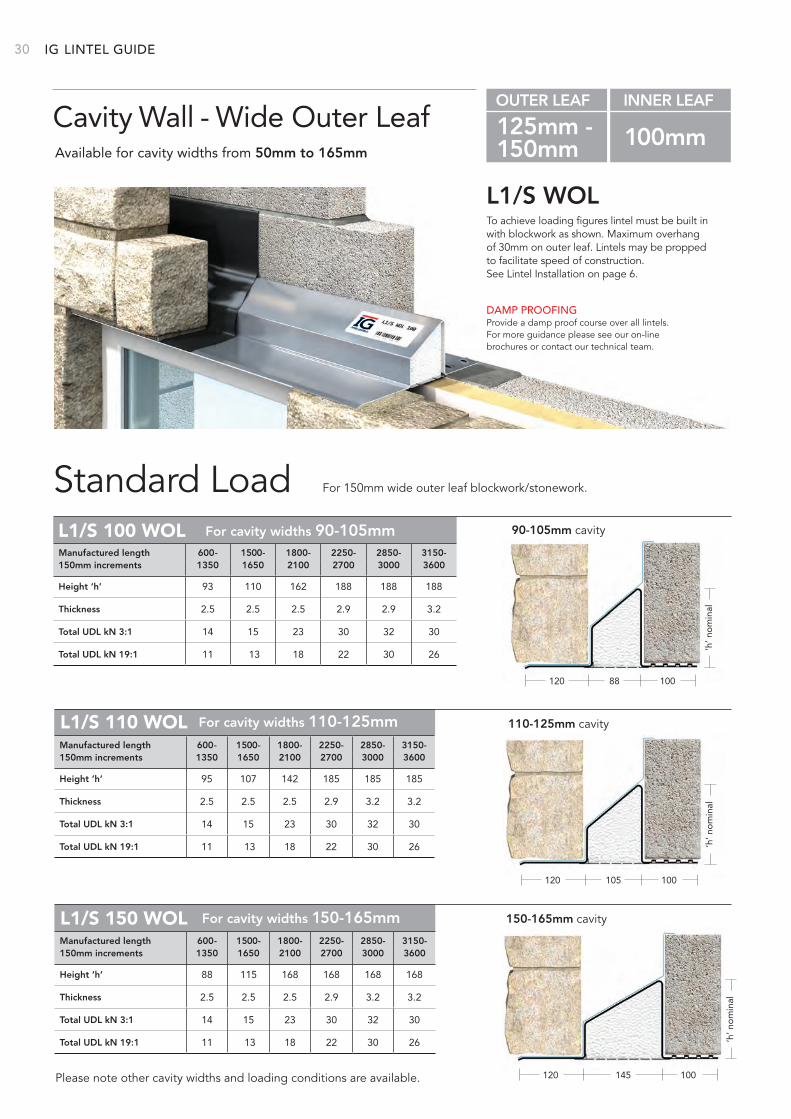
To achieve loading figures lintel must be built in with blockwork as shown. Maximum overhangof 30mm on outer leaf. Lintels may be propped to facilitate speed of construction. See Lintel Installation on page 6.
L1/S WOL
Standard Load
DAMP PROOFINGProvide a damp proof course over all lintels. For more guidance please see our on-line brochures or contact our technical team.
Cavity Wall - Wide Outer LeafAvailable for cavity widths from 50mm to 165mm
OUTER LEAF INNER LEAF
125mm - 100mm150mm
Please note other cavity widths and loading conditions are available.
For 150mm wide outer leaf blockwork/stonework.
120 100
‘h’ n
om
inal
88
For cavity widths 90-105mmL1/S 100 WOL 90-105mm cavity
Height ‘h’ 93 110 162 188 188 188
Thickness 2.5 2.5 2.5 2.9 2.9 3.2
Total UDL kN 3:1 14 15 23 30 32 30
Total UDL kN 19:1 11 13 18 22 30 26
Manufactured length 600- 1500- 1800- 2250- 2850- 3150-150mm increments 1350 1650 2100 2700 3000 3600
110-125mm cavityL1/S 110 WOL For cavity widths 110-125mm
120 100
‘h’ n
om
inal
105
Height ‘h’ 95 107 142 185 185 185
Thickness 2.5 2.5 2.5 2.9 3.2 3.2
Total UDL kN 3:1 14 15 23 30 32 30
Total UDL kN 19:1 11 13 18 22 30 26
Manufactured length 600- 1500- 1800- 2250- 2850- 3150-150mm increments 1350 1650 2100 2700 3000 3600
For cavity widths 150-165mm 150-165mm cavityL1/S 150 WOL
120 100145
‘h’ n
om
inal
Height ‘h’ 88 115 168 168 168 168
Thickness 2.5 2.5 2.5 2.9 3.2 3.2
Total UDL kN 3:1 14 15 23 30 32 30
Total UDL kN 19:1 11 13 18 22 30 26
Manufactured length 600- 1500- 1800- 2250- 2850- 3150-150mm increments 1350 1650 2100 2700 3000 3600
LINTEL GUIDE
31BETTER BY
DESIGN
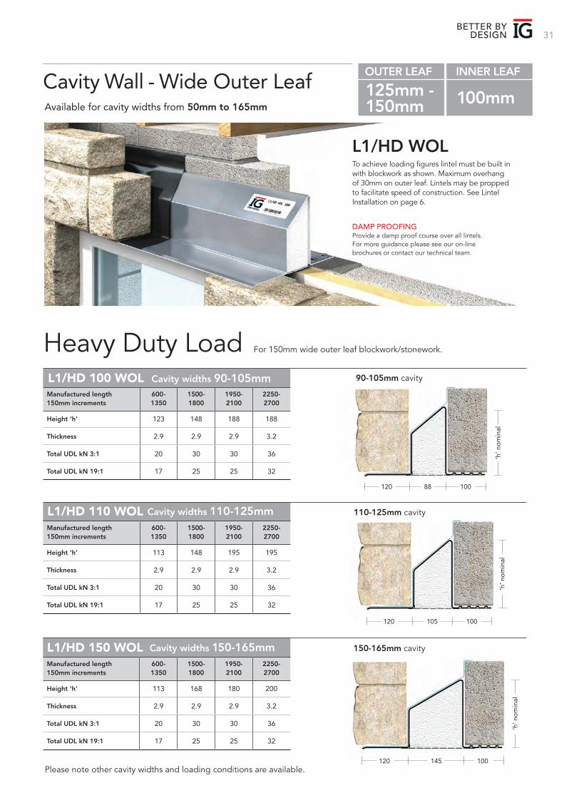
To achieve loading figures lintel must be built in with blockwork as shown. Maximum overhangof 30mm on outer leaf. Lintels may be propped to facilitate speed of construction. See LintelInstallation on page 6.
L1/HD WOL
Heavy Duty Load
DAMP PROOFINGProvide a damp proof course over all lintels. For more guidance please see our on-line brochures or contact our technical team.
Cavity Wall - Wide Outer LeafAvailable for cavity widths from 50mm to 165mm
OUTER LEAF INNER LEAF
125mm - 100mm150mm
Please note other cavity widths and loading conditions are available.
For 150mm wide outer leaf blockwork/stonework.
120 10088
Cavity widths 90-105mmL1/HD 100 WOL 90-105mm cavity
Height ‘h’ 123 148 188 188
Thickness 2.9 2.9 2.9 3.2
Total UDL kN 3:1 20 30 30 36
Total UDL kN 19:1 17 25 25 32
Manufactured length 600- 1500- 1950- 2250-150mm increments 1350 1800 2100 2700
‘h’ n
om
inal
‘h’ n
om
inal
110-125mm cavityL1/HD 110 WOL Cavity widths 110-125mm
120 100105
Height ‘h’ 113 148 195 195
Thickness 2.9 2.9 2.9 3.2
Total UDL kN 3:1 20 30 30 36
Total UDL kN 19:1 17 25 25 32
Manufactured length 600- 1500- 1950- 2250-150mm increments 1350 1800 2100 2700
Cavity widths 150-165mm 150-165mm cavityL1/HD 150 WOL
120 100145
Height ‘h’ 113 168 180 200
Thickness 2.9 2.9 2.9 3.2
Total UDL kN 3:1 20 30 30 36
Total UDL kN 19:1 17 25 25 32
Manufactured length 600- 1500- 1950- 2250-150mm increments 1350 1800 2100 2700
‘h’ n
om
inal
IG 32 LINTEL GUIDE
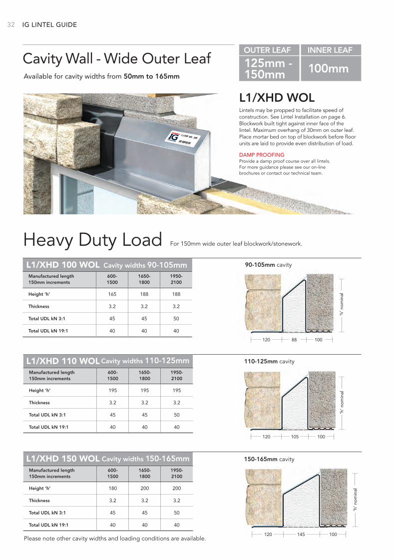
Lintels may be propped to facilitate speed of construction. See Lintel Installation on page 6. Blockwork built tight against inner face of the lintel. Maximum overhang of 30mm on outer leaf. Place mortar bed on top of blockwork before floor units are laid to provide even distribution of load.
L1/XHD WOL
Heavy Duty Load
DAMP PROOFINGProvide a damp proof course over all lintels. For more guidance please see our on-line brochures or contact our technical team.
Cavity Wall - Wide Outer LeafAvailable for cavity widths from 50mm to 165mm
OUTER LEAF INNER LEAF
125mm - 100mm150mm
Please note other cavity widths and loading conditions are available.
For 150mm wide outer leaf blockwork/stonework.
Height ‘h’ 165 188 188
Thickness 3.2 3.2 3.2
Total UDL kN 3:1 45 45 50
Total UDL kN 19:1 40 40 40
120 10088
Cavity widths 90-105mmL1/XHD 100 WOL 90-105mm cavity
Manufactured length 600- 1650- 1950-150mm increments 1500 1800 2100
‘h’ n
om
inal
110-125mm cavityL1/XHD 110 WOL Cavity widths 110-125mm
120 100105
Height ‘h’ 195 195 195
Thickness 3.2 3.2 3.2
Total UDL kN 3:1 45 45 50
Total UDL kN 19:1 40 40 40
Manufactured length 600- 1650- 1950-150mm increments 1500 1800 2100
‘h’ n
om
inal
Cavity widths 150-165mm 150-165mm cavityL1/XHD 150 WOL
120 100145
Height ‘h’ 180 200 200
Thickness 3.2 3.2 3.2
Total UDL kN 3:1 45 45 50
Total UDL kN 19:1 40 40 40
Manufactured length 600- 1650- 1950-150mm increments 1500 1800 2100
‘h’ n
om
inal
33BETTER BY
DESIGN
120 100145
‘h’ n
om
inal
120 100105
‘h’ n
om
inal
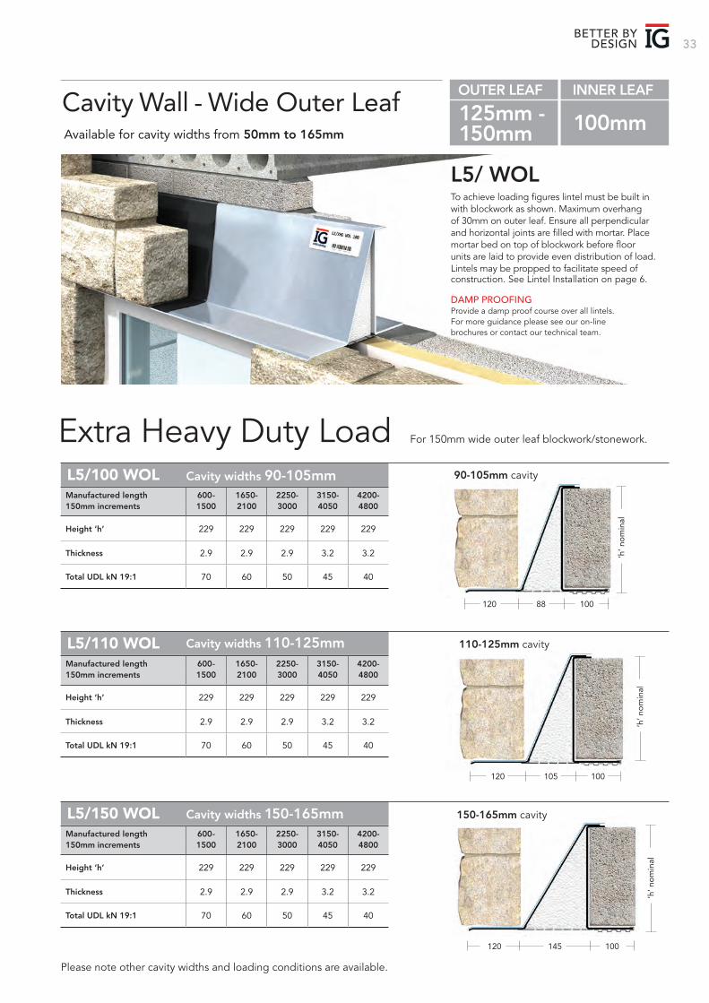
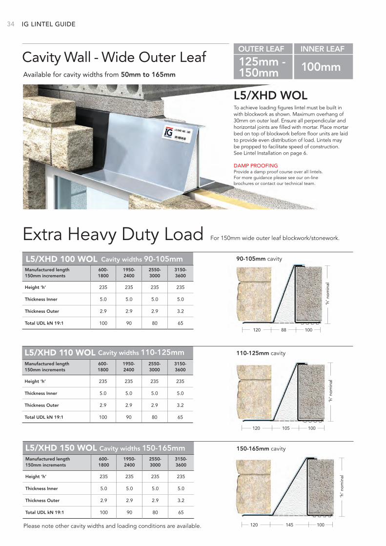
To achieve loading figures lintel must be built in with blockwork as shown. Maximum overhang of 30mm on outer leaf. Ensure all perpendicular and horizontal joints are filled with mortar. Place mortar bed on top of blockwork before floor units are laid to provide even distribution of load. Lintels may be propped to facilitate speed of construction. See Lintel Installation on page 6.
L5/ WOL
Extra Heavy Duty Load
DAMP PROOFINGProvide a damp proof course over all lintels. For more guidance please see our on-line brochures or contact our technical team.
Cavity Wall - Wide Outer LeafAvailable for cavity widths from 50mm to 165mm
OUTER LEAF INNER LEAF
125mm - 100mm150mm
Please note other cavity widths and loading conditions are available.
For 150mm wide outer leaf blockwork/stonework.
L5/100 WOL
Height ‘h’ 229 229 229 229 229
Thickness 2.9 2.9 2.9 3.2 3.2
Total UDL kN 19:1 70 60 50 45 40
Manufactured length 600- 1650- 2250- 3150- 4200-150mm increments 1500 2100 3000 4050 4800
120 10088
Cavity widths 90-105mm 90-105mm cavity
‘h’ n
om
inal
110-125mm cavityCavity widths 110-125mmL5/110 WOL
Height ‘h’ 229 229 229 229 229
Thickness 2.9 2.9 2.9 3.2 3.2
Total UDL kN 19:1 70 60 50 45 40
Manufactured length 600- 1650- 2250- 3150- 4200-150mm increments 1500 2100 3000 4050 4800
150-165mm cavityL5/150 WOL
Height ‘h’ 229 229 229 229 229
Thickness 2.9 2.9 2.9 3.2 3.2
Total UDL kN 19:1 70 60 50 45 40
Manufactured length 600- 1650- 2250- 3150- 4200-150mm increments 1500 2100 3000 4050 4800
Cavity widths 150-165mm
IG 34
To achieve loading figures lintel must be built in with blockwork as shown. Maximum overhang of 30mm on outer leaf. Ensure all perpendicular and horizontal joints are filled with mortar. Place mortar bed on top of blockwork before floor units are laid to provide even distribution of load. Lintels may be propped to facilitate speed of construction. See Lintel Installation on page 6.
L5/XHD WOL
Extra Heavy Duty Load
DAMP PROOFINGProvide a damp proof course over all lintels. For more guidance please see our on-line brochures or contact our technical team.
Cavity Wall - Wide Outer LeafAvailable for cavity widths from 50mm to 165mm
OUTER LEAF INNER LEAF
125mm - 100mm150mm
Please note other cavity widths and loading conditions are available.
For 150mm wide outer leaf blockwork/stonework.
L5/XHD 100 WOL
120 10088
Cavity widths 90-105mm 90-105mm cavity
‘h’ n
om
inal
Height ‘h’ 235 235 235 235
Thickness Inner 5.0 5.0 5.0 5.0
Thickness Outer 2.9 2.9 2.9 3.2
Total UDL kN 19:1 100 90 80 65
Manufactured length 600- 1950- 2550- 3150-150mm increments 1800 2400 3000 3600
110-125mm cavityCavity widths 110-125mmL5/XHD 110 WOL
120 100105
Height ‘h’ 235 235 235 235
Thickness Inner 5.0 5.0 5.0 5.0
Thickness Outer 2.9 2.9 2.9 3.2
Total UDL kN 19:1 100 90 80 65
Manufactured length 600- 1950- 2550- 3150-150mm increments 1800 2400 3000 3600
150-165mm cavityL5/XHD 150 WOL
120 100145
‘h’ n
om
inal
Cavity widths 150-165mm
Height ‘h’ 235 235 235 235
Thickness Inner 5.0 5.0 5.0 5.0
Thickness Outer 2.9 2.9 2.9 3.2
Total UDL kN 19:1 100 90 80 65
Manufactured length 600- 1950- 2550- 3150-150mm increments 1800 2400 3000 3600
‘h’ n
om
inal
LINTEL GUIDE
35BETTER BY
DESIGN
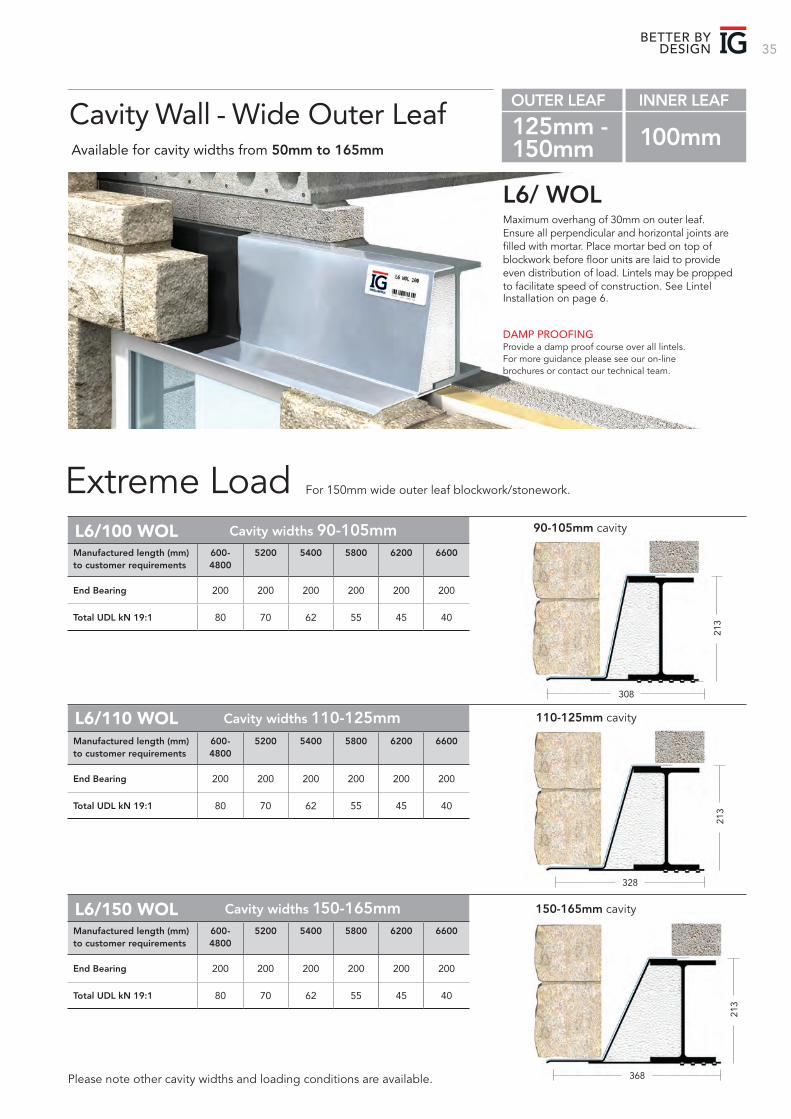
308
213
L6/100 WOL Cavity widths 90-105mm 90-105mm cavity
End Bearing 200 200 200 200 200 200
Total UDL kN 19:1 80 70 62 55 45 40
Manufactured length (mm) 600- 5200 5400 5800 6200 6600to customer requirements 4800
Maximum overhang of 30mm on outer leaf. Ensure all perpendicular and horizontal joints are filled with mortar. Place mortar bed on top of blockwork before floor units are laid to provide even distribution of load. Lintels may be propped to facilitate speed of construction. See Lintel Installation on page 6.
L6/ WOL
Extreme Load
DAMP PROOFINGProvide a damp proof course over all lintels. For more guidance please see our on-line brochures or contact our technical team.
Cavity Wall - Wide Outer LeafAvailable for cavity widths from 50mm to 165mm
OUTER LEAF INNER LEAF
125mm - 100mm150mm
Please note other cavity widths and loading conditions are available.
For 150mm wide outer leaf blockwork/stonework.
L6/110 WOL
328
213
110-125mm cavityCavity widths 110-125mm
End Bearing 200 200 200 200 200 200
Total UDL kN 19:1 80 70 62 55 45 40
Manufactured length (mm) 600- 5200 5400 5800 6200 6600to customer requirements 4800
L6/150 WOL
368
213
150-165mm cavityCavity widths 150-165mm
End Bearing 200 200 200 200 200 200
Total UDL kN 19:1 80 70 62 55 45 40
Manufactured length (mm) 600- 5200 5400 5800 6200 6600to customer requirements 4800
IG 36
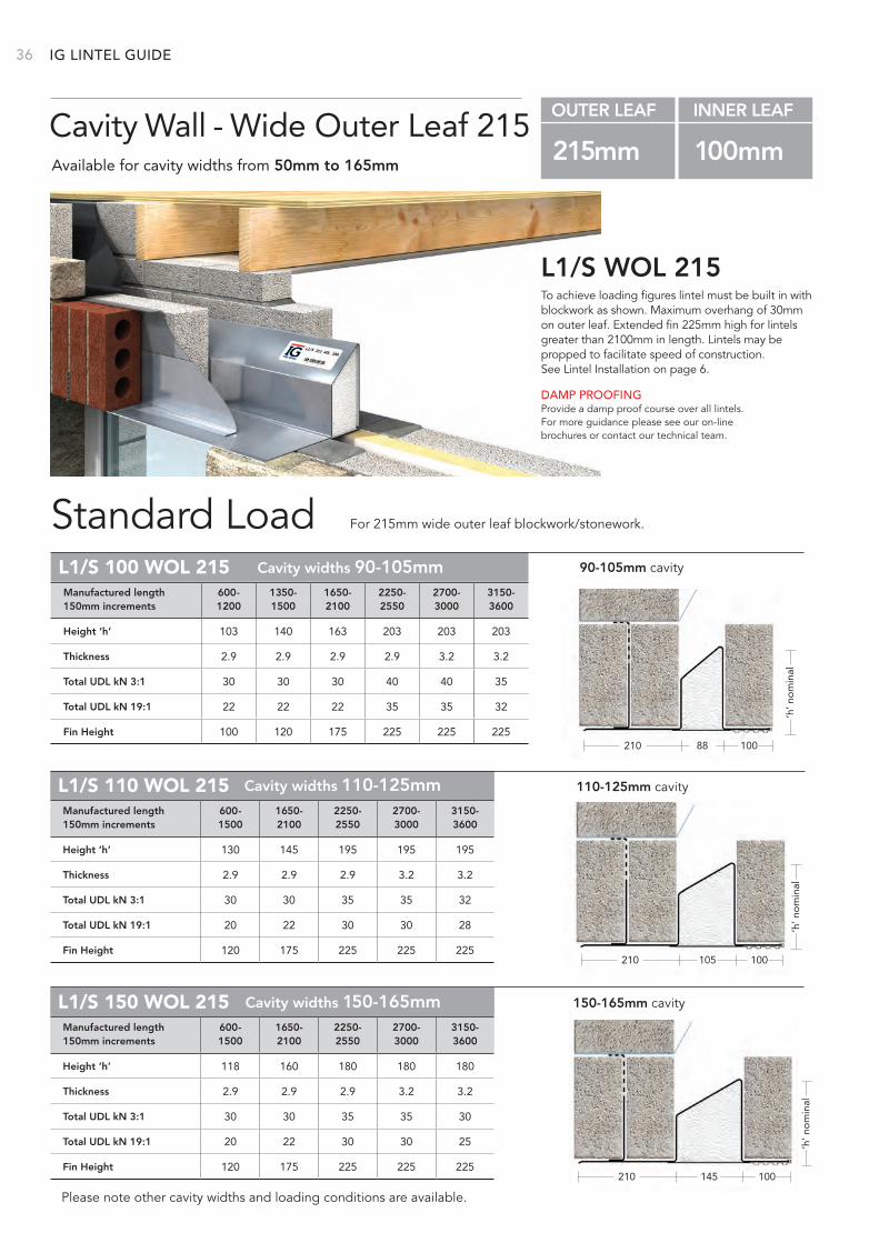
To achieve loading figures lintel must be built in with blockwork as shown. Maximum overhang of 30mm on outer leaf. Extended fin 225mm high for lintels greater than 2100mm in length. Lintels may be propped to facilitate speed of construction. See Lintel Installation on page 6.
L1/S WOL 215
Standard Load
DAMP PROOFINGProvide a damp proof course over all lintels. For more guidance please see our on-line brochures or contact our technical team.
Cavity Wall - Wide Outer Leaf 215Available for cavity widths from 50mm to 165mm
OUTER LEAF INNER LEAF
215mm 100mm
Please note other cavity widths and loading conditions are available.
For 215mm wide outer leaf blockwork/stonework.
100210 88
‘h’ n
om
inal
Cavity widths 90-105mm 90-105mm cavityL1/S 100 WOL 215
Height ‘h’ 103 140 163 203 203 203
Thickness 2.9 2.9 2.9 2.9 3.2 3.2
Total UDL kN 3:1 30 30 30 40 40 35
Total UDL kN 19:1 22 22 22 35 35 32
Fin Height 100 120 175 225 225 225
Manufactured length 600- 1350- 1650- 2250- 2700- 3150-150mm increments 1200 1500 2100 2550 3000 3600
‘h’ n
om
inal
100210 105
110-125mm cavityCavity widths 110-125mmL1/S 110 WOL 215
Height ‘h’ 130 145 195 195 195
Thickness 2.9 2.9 2.9 3.2 3.2
Total UDL kN 3:1 30 30 35 35 32
Total UDL kN 19:1 20 22 30 30 28
Fin Height 120 175 225 225 225
Manufactured length 600- 1650- 2250- 2700- 3150-150mm increments 1500 2100 2550 3000 3600
100210 145
‘h’ n
om
inal
150-165mm cavityL1/S 150 WOL 215 Cavity widths 150-165mm
Height ‘h’ 118 160 180 180 180
Thickness 2.9 2.9 2.9 3.2 3.2
Total UDL kN 3:1 30 30 35 35 30
Total UDL kN 19:1 20 22 30 30 25
Fin Height 120 175 225 225 225
Manufactured length 600- 1650- 2250- 2700- 3150-150mm increments 1500 2100 2550 3000 3600
LINTEL GUIDE
37
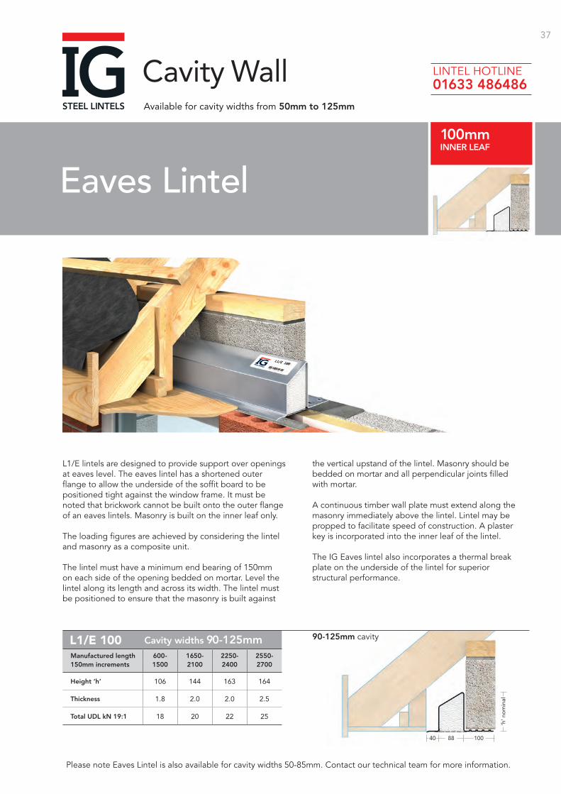
1008840
‘h’ n
om
inal
Cavity widths 90-125mm
Height ‘h’ 106 144 163 164
Thickness 1.8 2.0 2.0 2.5
Total UDL kN 19:1 18 20 22 25
Manufactured length 600- 1650- 2250- 2550-150mm increments 1500 2100 2400 2700
L1/E 100
Please note Eaves Lintel is also available for cavity widths 50-85mm. Contact our technical team for more information.
L1/E lintels are designed to provide support over openings at eaves level. The eaves lintel has a shortened outer flange to allow the underside of the soffit board to be positioned tight against the window frame. It must be noted that brickwork cannot be built onto the outer flange of an eaves lintels. Masonry is built on the inner leaf only.
The loading figures are achieved by considering the lintel and masonry as a composite unit.
The lintel must have a minimum end bearing of 150mm on each side of the opening bedded on mortar. Level the lintel along its length and across its width. The lintel must be positioned to ensure that the masonry is built against
the vertical upstand of the lintel. Masonry should be bedded on mortar and all perpendicular joints filled with mortar.
A continuous timber wall plate must extend along the masonry immediately above the lintel. Lintel may be propped to facilitate speed of construction. A plaster key is incorporated into the inner leaf of the lintel.
The IG Eaves lintel also incorporates a thermal break plate on the underside of the lintel for superior structural performance.
Eaves Lintel100mmINNER LEAF
Cavity WallAvailable for cavity widths from 50mm to 125mm
90-125mm cavity
LINTEL HOTLINE 01633 486486
38
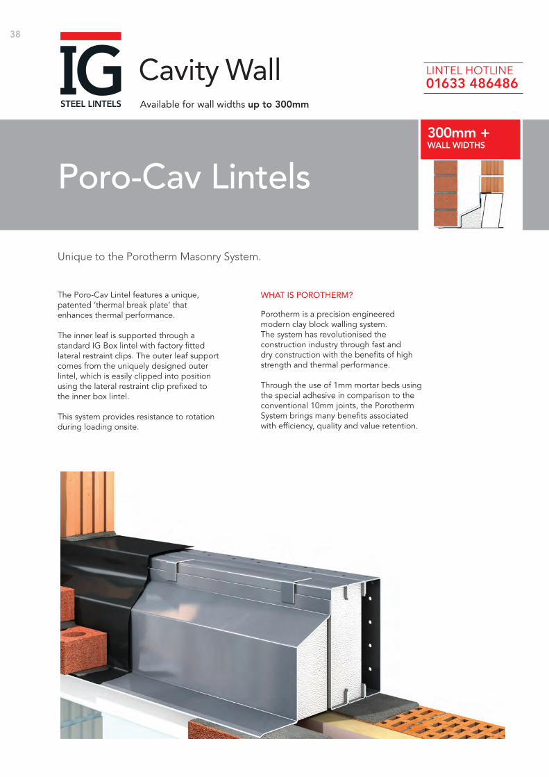
Unique to the Porotherm Masonry System.
Poro-Cav Lintels300mm +WALL WIDTHS
Cavity WallAvailable for wall widths up to 300mm
The Poro-Cav Lintel features a unique, patented ‘thermal break plate’ that enhances thermal performance.
The inner leaf is supported through a standard IG Box lintel with factory fitted lateral restraint clips. The outer leaf support comes from the uniquely designed outer lintel, which is easily clipped into position using the lateral restraint clip prefixed to the inner box lintel.
This system provides resistance to rotation during loading onsite.
WHAT IS POROTHERM?
Porotherm is a precision engineered modern clay block walling system. The system has revolutionised the construction industry through fast and dry construction with the benefits of high strength and thermal performance.
Through the use of 1mm mortar beds using the special adhesive in comparison to the conventional 10mm joints, the Porotherm System brings many benefits associated with efficiency, quality and value retention.
LINTEL HOTLINE 01633 486486
39BETTER BY
DESIGN
PCI L100
PCI L140
PCI L190
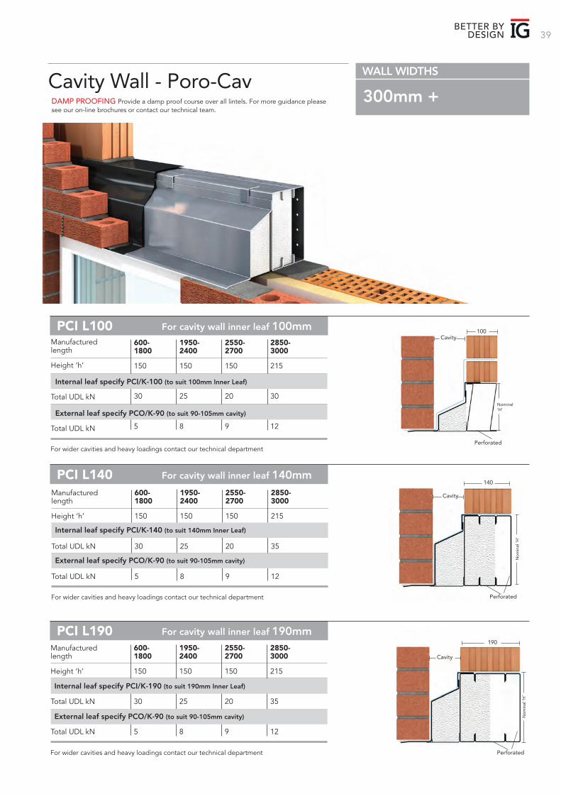
DAMP PROOFING Provide a damp proof course over all lintels. For more guidance please see our on-line brochures or contact our technical team.
Cavity Wall - Poro-CavWALL WIDTHS
300mm +
Cavity100
Nominal ‘H’
Perforated
Cavity
140
Perforated
No
min
al ‘H
’
Cavity
190
Perforated
No
min
al ‘H
’
For cavity wall inner leaf 100mm
For cavity wall inner leaf 140mm
For cavity wall inner leaf 190mm
600- 1800
150
30
5
1950- 2400
150
25
8
2550- 2700
150
20
9
2850- 3000
215
30
12
For wider cavities and heavy loadings contact our technical department
Manufactured length
Height ‘h’
Internal leaf specify PCI/K-100 (to suit 100mm Inner Leaf) Total UDL kN
External leaf specify PCO/K-90 (to suit 90-105mm cavity)
Total UDL kN
600- 1800
150
30
5
1950- 2400
150
25
8
2550- 2700
150
20
9
2850- 3000
215
35
12
For wider cavities and heavy loadings contact our technical department
Manufactured length
Height ‘h’
Total UDL kN
Total UDL kN
Internal leaf specify PCI/K-140 (to suit 140mm Inner Leaf)
External leaf specify PCO/K-90 (to suit 90-105mm cavity)
Manufactured length
Height ‘h’
Total UDL kN
Total UDL kN
600- 1800
150
30
5
1950- 2400
150
25
8
2550- 2700
150
20
9
2850- 3000
215
35
12
For wider cavities and heavy loadings contact our technical department
Internal leaf specify PCI/K-190 (to suit 190mm Inner Leaf)
External leaf specify PCO/K-90 (to suit 90-105mm cavity)
40
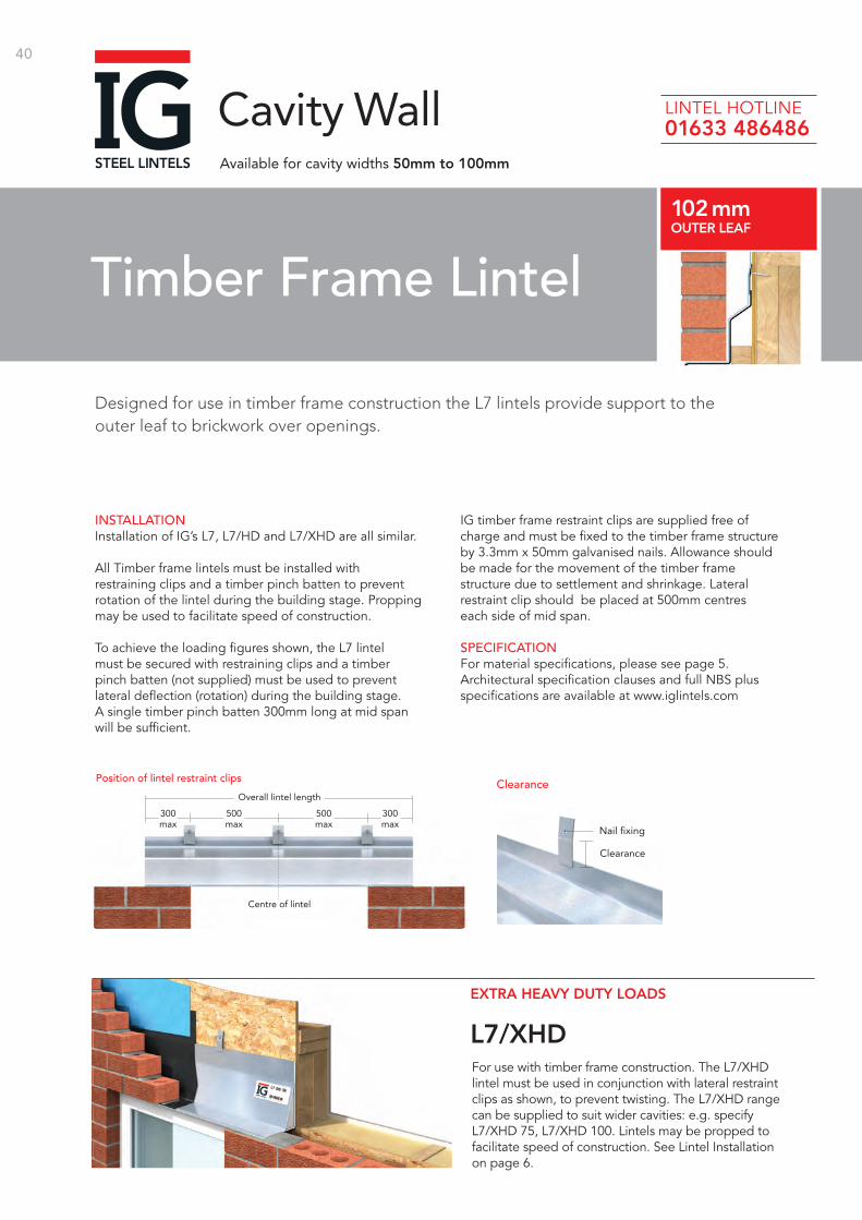
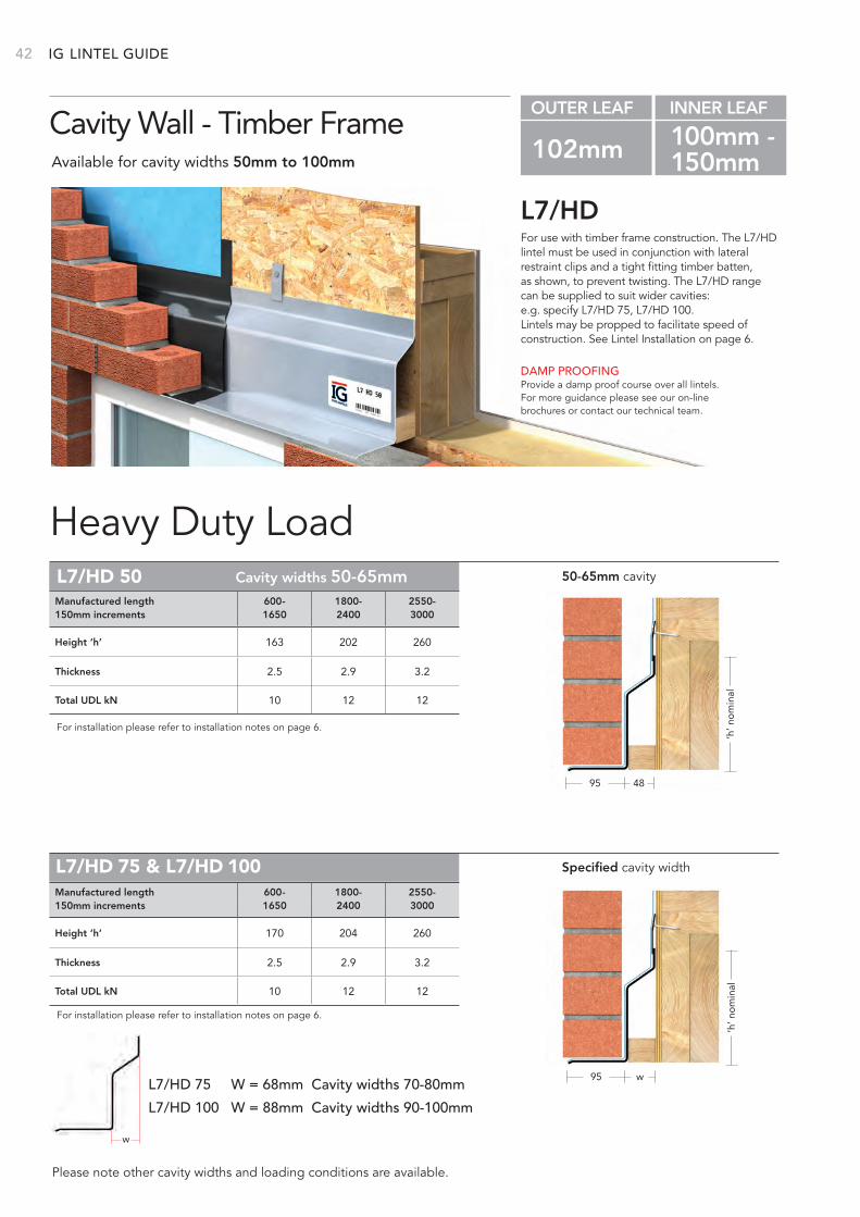
INSTALLATIONInstallation of IG’s L7, L7/HD and L7/XHD are all similar.
All Timber frame lintels must be installed with restraining clips and a timber pinch batten to prevent rotation of the lintel during the building stage. Propping may be used to facilitate speed of construction.
To achieve the loading figures shown, the L7 lintel must be secured with restraining clips and a timber pinch batten (not supplied) must be used to prevent lateral deflection (rotation) during the building stage. A single timber pinch batten 300mm long at mid span will be sufficient.
IG timber frame restraint clips are supplied free of charge and must be fixed to the timber frame structure by 3.3mm x 50mm galvanised nails. Allowance should be made for the movement of the timber frame structure due to settlement and shrinkage. Lateral restraint clip should be placed at 500mm centres each side of mid span.
SPECIFICATIONFor material specifications, please see page 5. Architectural specification clauses and full NBS plus specifications are available at www.iglintels.com
500 max
Overall lintel length
Centre of lintel
500 max
300 max
300 max
Position of lintel restraint clips Clearance
Nail fixing
Clearance
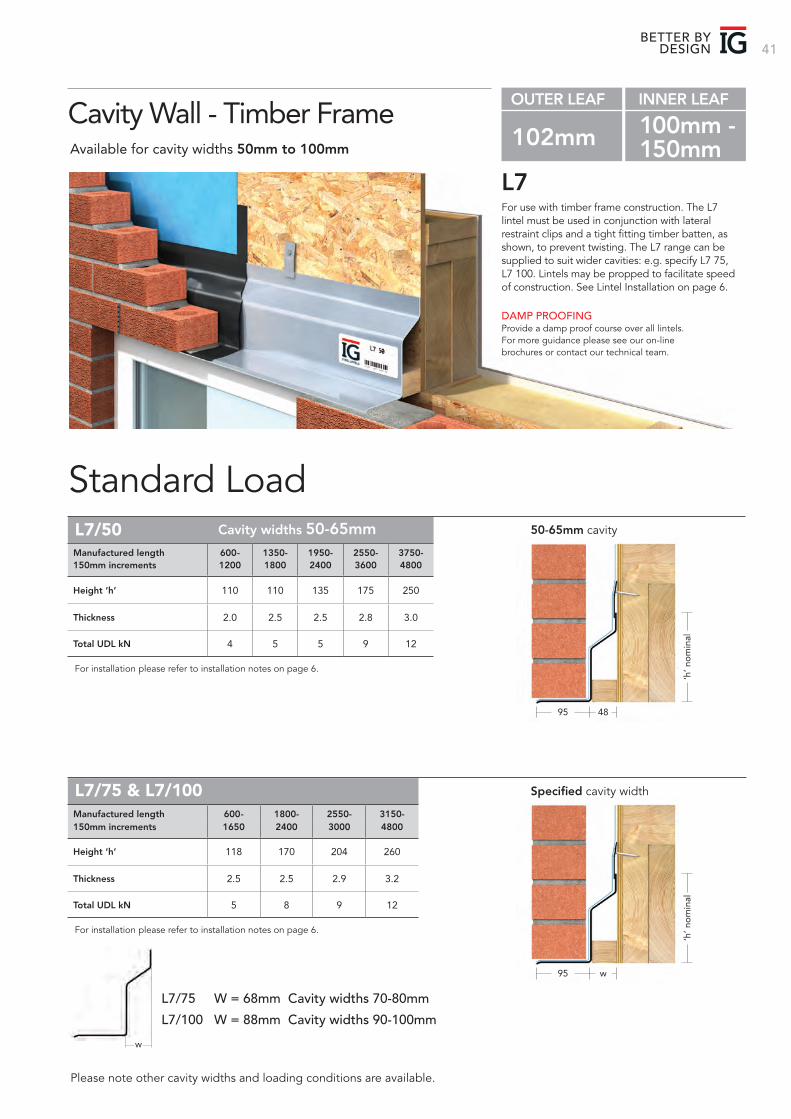
Designed for use in timber frame construction the L7 lintels provide support to the outer leaf to brickwork over openings.
Timber Frame Lintel102 mmOUTER LEAF
Cavity WallAvailable for cavity widths 50mm to 100mm
L7/XHD
EXTRA HEAVY DUTY LOADS
For use with timber frame construction. The L7/XHD lintel must be used in conjunction with lateral restraint clips as shown, to prevent twisting. The L7/XHD range can be supplied to suit wider cavities: e.g. specify L7/XHD 75, L7/XHD 100. Lintels may be propped to facilitate speed of construction. See Lintel Installation on page 6.
LINTEL HOTLINE 01633 486486
41BETTER BY
DESIGN
OUTER LEAF INNER LEAF
102mm 100mm - 150mm
w
‘h’ n
om
inal
For use with timber frame construction. The L7 lintel must be used in conjunction with lateral restraint clips and a tight fitting timber batten, as shown, to prevent twisting. The L7 range can be supplied to suit wider cavities: e.g. specify L7 75, L7 100. Lintels may be propped to facilitate speed of construction. See Lintel Installation on page 6.
L7
Standard Load
DAMP PROOFINGProvide a damp proof course over all lintels. For more guidance please see our on-line brochures or contact our technical team.
Cavity Wall - Timber FrameAvailable for cavity widths 50mm to 100mm
Please note other cavity widths and loading conditions are available.
Height ‘h’ 110 110 135 175 250
Thickness 2.0 2.5 2.5 2.8 3.0
Total UDL kN 4 5 5 9 12
Height ‘h’ 118 170 204 260
Thickness 2.5 2.5 2.9 3.2
Total UDL kN 5 8 9 12
Manufactured length 600- 1350- 1950- 2550- 3750-150mm increments 1200 1800 2400 3600 4800
Manufactured length 600- 1800- 2550- 3150-150mm increments 1650 2400 3000 4800
L7/50
L7/75 & L7/100
For installation please refer to installation notes on page 6.
For installation please refer to installation notes on page 6.
L7/75 W = 68mm Cavity widths 70-80mm
L7/100 W = 88mm Cavity widths 90-100mm
50-65mm cavity
Specified cavity width
‘h’ n
om
inal
95 48
95 w
Cavity widths 50-65mm
IG 42
w
For use with timber frame construction. The L7/HD lintel must be used in conjunction with lateral restraint clips and a tight fitting timber batten, as shown, to prevent twisting. The L7/HD range can be supplied to suit wider cavities:e.g. specify L7/HD 75, L7/HD 100. Lintels may be propped to facilitate speed of construction. See Lintel Installation on page 6.
L7/HD
Heavy Duty Load
DAMP PROOFINGProvide a damp proof course over all lintels. For more guidance please see our on-line brochures or contact our technical team.
Cavity Wall - Timber FrameAvailable for cavity widths 50mm to 100mm
OUTER LEAF INNER LEAF
102mm 100mm - 150mm
Please note other cavity widths and loading conditions are available.
Height ‘h’ 170 204 260
Thickness 2.5 2.9 3.2
Total UDL kN 10 12 12
Height ‘h’ 163 202 260
Thickness 2.5 2.9 3.2
Total UDL kN 10 12 12
Manufactured length 600- 1800- 2550-150mm increments 1650 2400 3000
Manufactured length 600- 1800- 2550-150mm increments 1650 2400 3000
L7/HD 50
L7/HD 75 & L7/HD 100
For installation please refer to installation notes on page 6.
For installation please refer to installation notes on page 6.
50-65mm cavity
Specified cavity width
‘h’ n
om
inal
95 48
‘h’ n
om
inal
95 w
LINTEL GUIDE
L7/HD 75 W = 68mm Cavity widths 70-80mm
L7/HD 100 W = 88mm Cavity widths 90-100mm
Cavity widths 50-65mm
43
‘h’ n
om
inal
95
‘h’ n
om
inal
95
Standard Load
Heavy Duty Load
95
‘h’ n
om
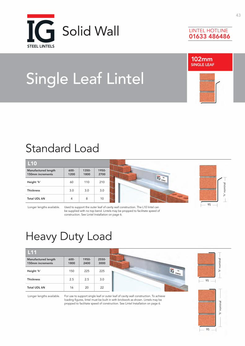
inalHeight ‘h’ 60 110 210
Thickness 3.0 3.0 3.0
Total UDL kN 4 8 10
Manufactured length 600- 1350- 1950-150mm increments 1200 1800 2700
L10
Longer lengths available.
Height ‘h’ 150 225 225
Thickness 2.5 2.5 3.0
Total UDL kN 16 20 22
Manufactured length 600- 1950- 2550-150mm increments 1800 2400 3000
L11
Longer lengths available. For use to support single leaf or outer leaf of cavity wall construction. To achieve loading figures, lintel must be built in with brickwork as shown. Lintels may be propped to facilitate speed of construction. See Lintel Installation on page 6.
Used to support the outer leaf of cavity wall construction. The L10 lintel can be supplied with no top bend. Lintels may be propped to facilitate speed of construction. See Lintel Installation on page 6.
Single Leaf Lintel102mmSINGLE LEAF
Solid Wall LINTEL HOTLINE 01633 486486
44
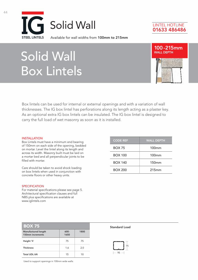
INSTALLATIONBox Lintels must have a minimum end bearing of 150mm on each side of the opening, bedded on mortar. Level the lintel along its length and across its width. Masonry built must be laid on a mortar bed and all perpendicular joints to be filled with mortar.
Care should be taken to avoid shock loading on box lintels when used in conjunction with concrete floors or other heavy units.
SPECIFICATIONFor material specifications please see page 5. Architectural specification clauses and full NBS plus specifications are available at www.iglintels.com
CODE REF WALL DEPTH
BOX 75 100mm
BOX 100 100mm
BOX 140 150mm
BOX 200 215mm
BOX 75
Height ‘h’ 75 75
Thickness 1.6 2.0
Total UDL kN 15 10
Manufactured length 600- 1800150mm increments 1650
Used to support openings in 100mm wide walls.Box/K - 75 Box/K - 100 HDBox/K - 100 Box/K - 150 HDBox/K - 150
75
95
Standard Load
Box lintels can be used for internal or external openings and with a variation of wall thicknesses. The IG box lintel has perforations along its length acting as a plaster key. As an optional extra IG box lintels can be insulated. The IG box lintel is designed to carry the full load of wet masonry as soon as it is installed.
Solid WallBox Lintels
100 - 215mmWALL DEPTH
Solid WallAvailable for wall widths from 100mm to 215mm
LINTEL HOTLINE 01633 486486
45BETTER BY
DESIGN
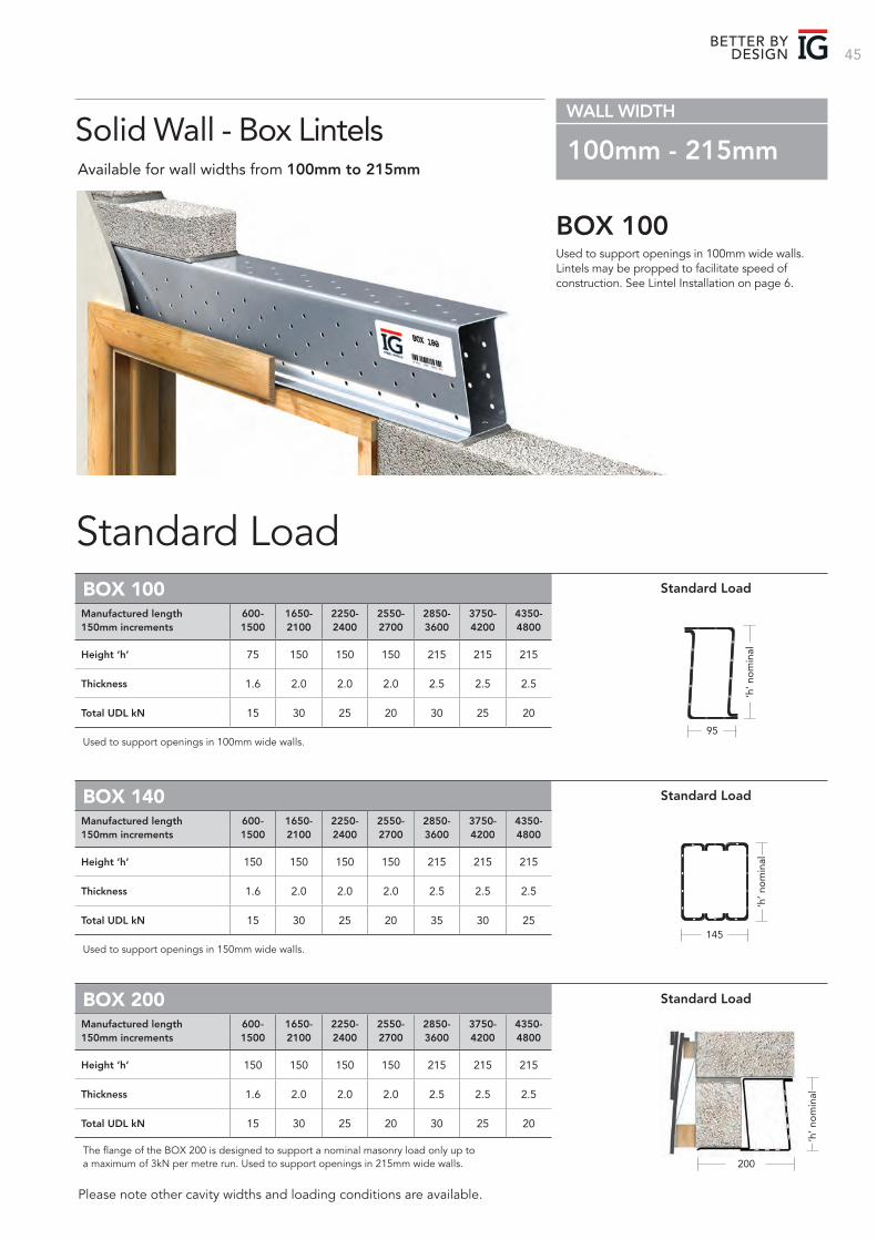
Used to support openings in 100mm wide walls. Lintels may be propped to facilitate speed of construction. See Lintel Installation on page 6.
BOX 100
Standard Load
Solid Wall - Box LintelsAvailable for wall widths from 100mm to 215mm
WALL WIDTH
100mm - 215mm
Please note other cavity widths and loading conditions are available.
Height ‘h’ 75 150 150 150 215 215 215
Thickness 1.6 2.0 2.0 2.0 2.5 2.5 2.5
Total UDL kN 15 30 25 20 30 25 20
Manufactured length 600- 1650- 2250- 2550- 2850- 3750- 4350-150mm increments 1500 2100 2400 2700 3600 4200 4800
BOX 100
Used to support openings in 100mm wide walls. Box/K - 75 Box/K - 100 HDBox/K - 100 Box/K - 150 HDBox/K - 15095
‘h’ n
om
inal
Standard Load
Height ‘h’ 150 150 150 150 215 215 215
Thickness 1.6 2.0 2.0 2.0 2.5 2.5 2.5
Total UDL kN 15 30 25 20 35 30 25
Height ‘h’ 150 150 150 150 215 215 215
Thickness 1.6 2.0 2.0 2.0 2.5 2.5 2.5
Total UDL kN 15 30 25 20 30 25 20
Manufactured length 600- 1650- 2250- 2550- 2850- 3750- 4350-150mm increments 1500 2100 2400 2700 3600 4200 4800
Manufactured length 600- 1650- 2250- 2550- 2850- 3750- 4350-150mm increments 1500 2100 2400 2700 3600 4200 4800
BOX 140
BOX 200
Used to support openings in 150mm wide walls.
The flange of the BOX 200 is designed to support a nominal masonry load only up to a maximum of 3kN per metre run. Used to support openings in 215mm wide walls.
Standard Load
Standard Load
Box/K - 75 Box/K - 100 HDBox/K - 100 Box/K - 150 HDBox/K - 150
145
‘h’ n
om
inal
200
‘h’ n
om
inal
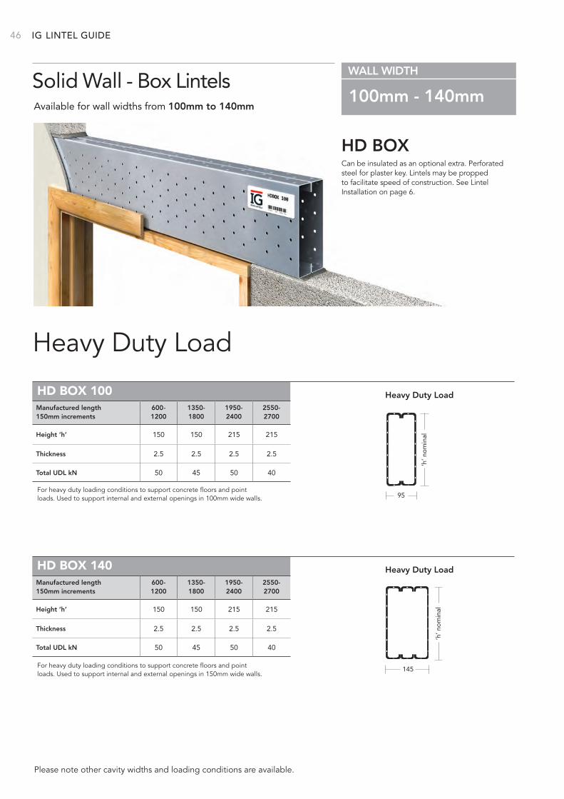
IG 46
Can be insulated as an optional extra. Perforated steel for plaster key. Lintels may be propped to facilitate speed of construction. See Lintel Installation on page 6.
HD BOX
Heavy Duty Load
Solid Wall - Box LintelsAvailable for wall widths from 100mm to 140mm
WALL WIDTH
100mm - 140mm
Please note other cavity widths and loading conditions are available.
HD BOX 100
HD BOX 140
Height ‘h’ 150 150 215 215
Thickness 2.5 2.5 2.5 2.5
Total UDL kN 50 45 50 40
Height ‘h’ 150 150 215 215
Thickness 2.5 2.5 2.5 2.5
Total UDL kN 50 45 50 40
Manufactured length 600- 1350- 1950- 2550-150mm increments 1200 1800 2400 2700
Manufactured length 600- 1350- 1950- 2550-150mm increments 1200 1800 2400 2700
For heavy duty loading conditions to support concrete floors and point loads. Used to support internal and external openings in 100mm wide walls.
For heavy duty loading conditions to support concrete floors and point loads. Used to support internal and external openings in 150mm wide walls.
95
145
Heavy Duty Load
Heavy Duty Load
Box/K - 75 Box/K - 100 HDBox/K - 100 Box/K - 150 HDBox/K - 150
‘h’ n
om
inal
‘h’ n
om
inal
Box/K - 75 Box/K - 100 HDBox/K - 100 Box/K - 150 HDBox/K - 150
LINTEL GUIDE
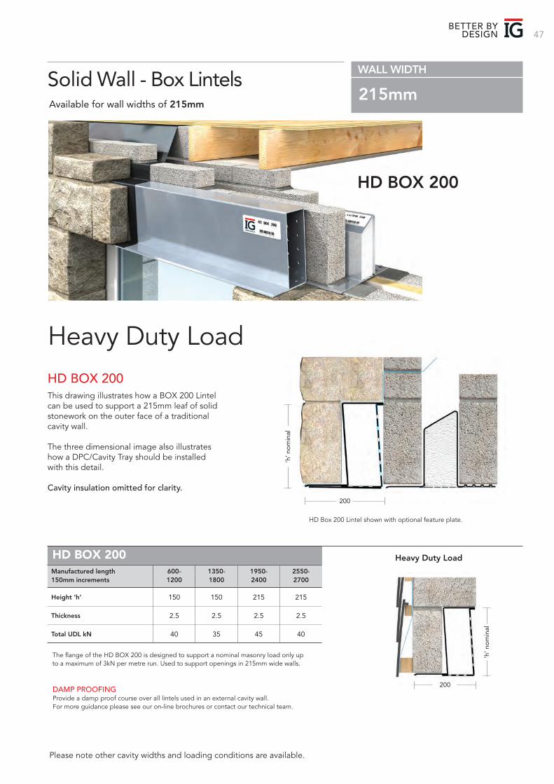
47BETTER BY
DESIGN
HD BOX 200
Heavy Duty Load
DAMP PROOFINGProvide a damp proof course over all lintels used in an external cavity wall. For more guidance please see our on-line brochures or contact our technical team.
Solid Wall - Box LintelsAvailable for wall widths of 215mm
WALL WIDTH
215mm
Please note other cavity widths and loading conditions are available.
Height ‘h’ 150 150 215 215
Thickness 2.5 2.5 2.5 2.5
Total UDL kN 40 35 45 40
Manufactured length 600- 1350- 1950- 2550-150mm increments 1200 1800 2400 2700
HD BOX 200
The flange of the HD BOX 200 is designed to support a nominal masonry load only up to a maximum of 3kN per metre run. Used to support openings in 215mm wide walls.
HD Box 200 Lintel shown with optional feature plate.
Heavy Duty Load
200
‘h’ n
om
inal
200
‘h’ n
om
inal
HD BOX 200This drawing illustrates how a BOX 200 Lintel can be used to support a 215mm leaf of solid stonework on the outer face of a traditional cavity wall.
The three dimensional image also illustrates how a DPC/Cavity Tray should be installed with this detail.
Cavity insulation omitted for clarity.
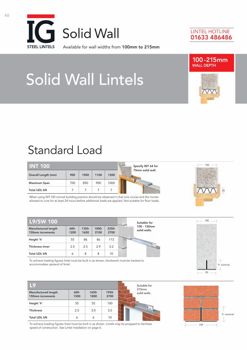
48
Standard Load INT 100
L9/SW 100
To achieve loading figures lintel must be built in as shown, blockwork must be tracked to accommodate upstand of lintel.
Maximum Span 700 850 900 1000
Total UDL kN 7 7 7 7
Overall Length (mm) 900 1050 1100 1200
100
28
Height ‘h’ 55 86 86 113
Thickness Inner 2.5 2.5 2.9 3.2
Total UDL kN 6 8 8 10
Manufactured length 600- 1350- 1800- 2250-150mm increments 1200 1650 2100 2700
‘h’ nominal
95
100
When using INT100 normal building practice should be observed in that one course and the mortar allowed to cure for at least 24 hours before additional loads are applied. Not suitable for floor loads.
L9
To achieve loading figures lintel must be built in as shown. Lintels may be propped to facilitate speed of construction. See Lintel Installation on page 6.
Height ‘h’ 55 55 100
Thickness 2.5 3.0 3.0
Total UDL kN 6 6 10
Manufactured length 600- 1650- 1950-150mm increments 1500 1800 2700
‘h’ nominal
195
Suitable for 215mm solid walls.
Specify INT 64 for 75mm solid wall.
Suitable for 100 - 150mm solid walls.
Solid Wall Lintels100 - 215mmWALL DEPTH
Solid WallAvailable for wall widths from 100mm to 215mm
LINTEL HOTLINE 01633 486486
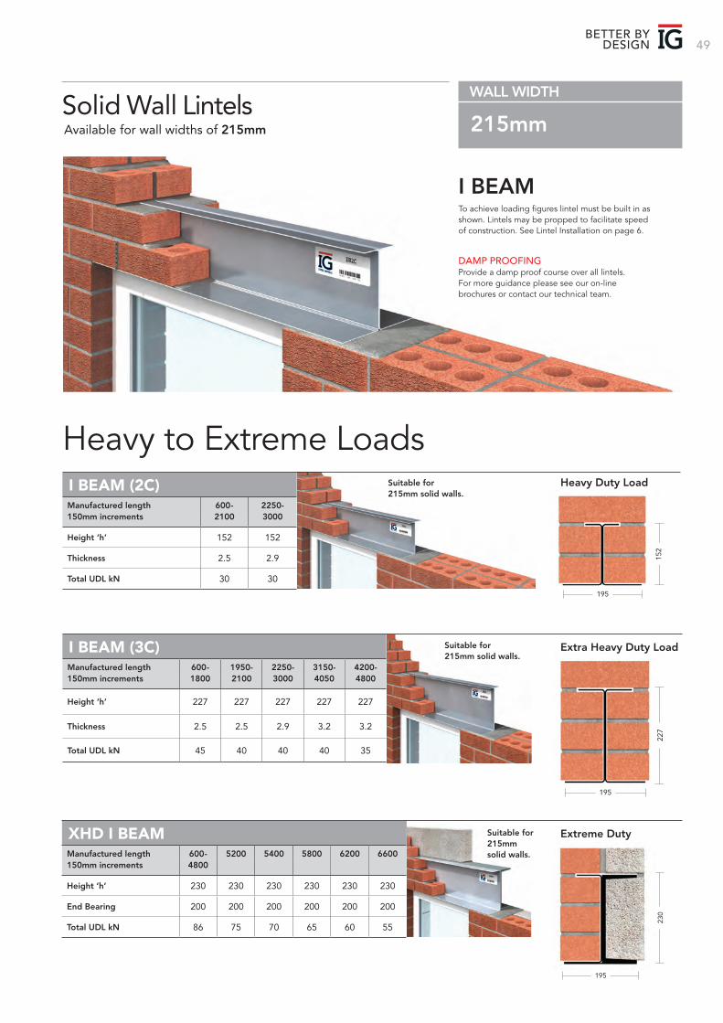
49BETTER BY
DESIGN
195
227
To achieve loading figures lintel must be built in as shown. Lintels may be propped to facilitate speed of construction. See Lintel Installation on page 6.
I BEAM
Heavy to Extreme Loads
DAMP PROOFINGProvide a damp proof course over all lintels. For more guidance please see our on-line brochures or contact our technical team.
Solid Wall LintelsAvailable for wall widths of 215mm
WALL WIDTH
215mm
I BEAM (2C)
I BEAM (3C) Extra Heavy Duty Load
Height ‘h’ 152 152
Thickness 2.5 2.9
Total UDL kN 30 30
Manufactured length 600- 2250-150mm increments 2100 3000
Suitable for 215mm solid walls.
Suitable for 215mm solid walls.
Suitable for 215mm solid walls.
152
195
Height ‘h’ 227 227 227 227 227
Thickness 2.5 2.5 2.9 3.2 3.2
Total UDL kN 45 40 40 40 35
Manufactured length 600- 1950- 2250- 3150- 4200-150mm increments 1800 2100 3000 4050 4800
Heavy Duty Load
XHD I BEAM Extreme Duty
Height ‘h’ 230 230 230 230 230 230
End Bearing 200 200 200 200 200 200
Total UDL kN 86 75 70 65 60 55
Manufactured length 600- 5200 5400 5800 6200 6600150mm increments 4800
195
230
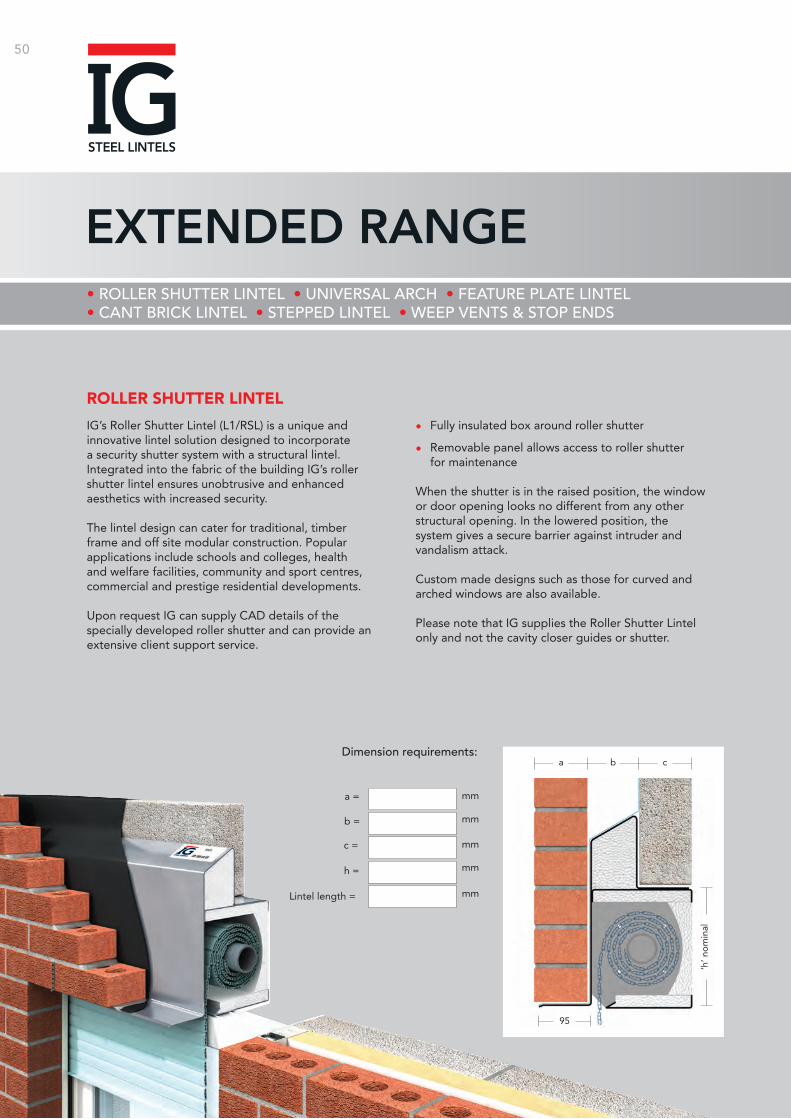
50
EXTENDED RANGE
a =
b =
c =
h =
Lintel length =
mm
mm
mm
mm
mm
Dimension requirements:
95
ca b
‘h’ n
om
inal
ROLLER SHUTTER LINTEL
IG’s Roller Shutter Lintel (L1/RSL) is a unique and innovative lintel solution designed to incorporate a security shutter system with a structural lintel. Integrated into the fabric of the building IG’s roller shutter lintel ensures unobtrusive and enhanced aesthetics with increased security.
The lintel design can cater for traditional, timber frame and off site modular construction. Popular applications include schools and colleges, health and welfare facilities, community and sport centres, commercial and prestige residential developments.
Upon request IG can supply CAD details of the specially developed roller shutter and can provide an extensive client support service.
• Fully insulated box around roller shutter
• Removable panel allows access to roller shutter for maintenance
When the shutter is in the raised position, the window or door opening looks no different from any other structural opening. In the lowered position, the system gives a secure barrier against intruder and vandalism attack.
Custom made designs such as those for curved and arched windows are also available.
Please note that IG supplies the Roller Shutter Lintel only and not the cavity closer guides or shutter.
• ROLLER SHUTTER LINTEL • UNIVERSAL ARCH • FEATURE PLATE LINTEL • CANT BRICK LINTEL • STEPPED LINTEL • WEEP VENTS & STOP ENDS
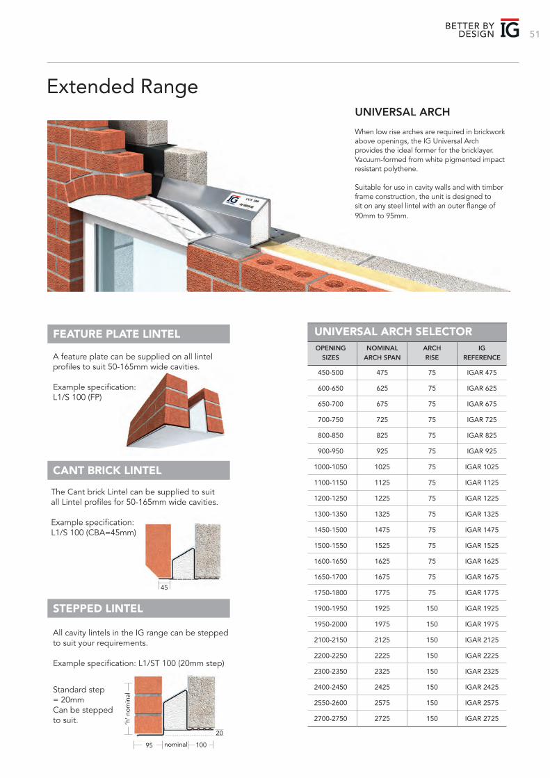
51BETTER BY
DESIGN
When low rise arches are required in brickwork above openings, the IG Universal Arch provides the ideal former for the bricklayer. Vacuum-formed from white pigmented impact resistant polythene.
Suitable for use in cavity walls and with timber frame construction, the unit is designed to sit on any steel lintel with an outer flange of 90mm to 95mm.
UNIVERSAL ARCH
Extended Range
UNIVERSAL ARCH SELECTORFEATURE PLATE LINTEL
CANT BRICK LINTEL
STEPPED LINTEL
450-500 475 75 IGAR 475
600-650 625 75 IGAR 625
650-700 675 75 IGAR 675
700-750 725 75 IGAR 725
800-850 825 75 IGAR 825
900-950 925 75 IGAR 925
1000-1050 1025 75 IGAR 1025
1100-1150 1125 75 IGAR 1125
1200-1250 1225 75 IGAR 1225
1300-1350 1325 75 IGAR 1325
1450-1500 1475 75 IGAR 1475
1500-1550 1525 75 IGAR 1525
1600-1650 1625 75 IGAR 1625
1650-1700 1675 75 IGAR 1675
1750-1800 1775 75 IGAR 1775
1900-1950 1925 150 IGAR 1925
1950-2000 1975 150 IGAR 1975
2100-2150 2125 150 IGAR 2125
2200-2250 2225 150 IGAR 2225
2300-2350 2325 150 IGAR 2325
2400-2450 2425 150 IGAR 2425
2550-2600 2575 150 IGAR 2575
2700-2750 2725 150 IGAR 2725
OPENING NOMINAL ARCH IGSIZES ARCH SPAN RISE REFERENCE
The Cant brick Lintel can be supplied to suit all Lintel profiles for 50-165mm wide cavities.
Example specification: L1/S 100 (CBA=45mm)
All cavity lintels in the IG range can be stepped to suit your requirements.
Example specification: L1/ST 100 (20mm step)
Standard step = 20mmCan be stepped to suit.
A feature plate can be supplied on all lintel profiles to suit 50-165mm wide cavities.
Example specification: L1/S 100 (FP)
‘h’ n
om
inal
95 100nominal
45
20
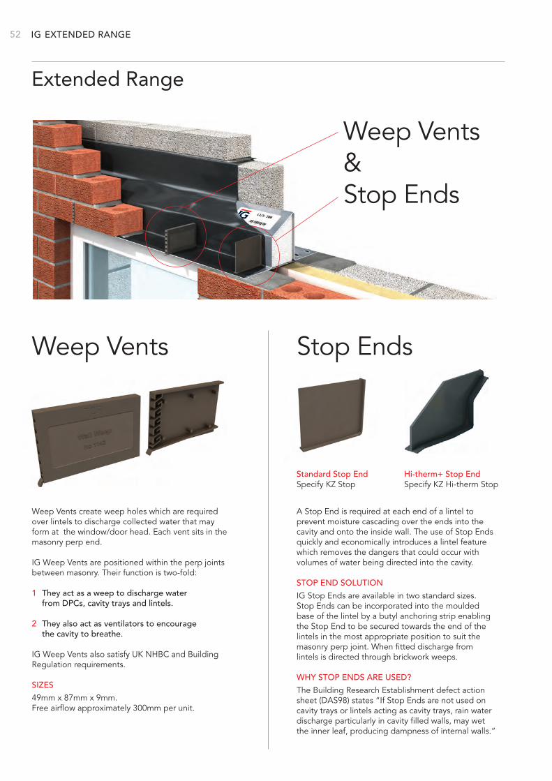
IG 52
Weep Vents Stop Ends
Extended Range
Weep Vents create weep holes which are required over lintels to discharge collected water that may form at the window/door head. Each vent sits in the masonry perp end.
IG Weep Vents are positioned within the perp joints between masonry. Their function is two-fold:
1 They act as a weep to discharge water from DPCs, cavity trays and lintels.
2 They also act as ventilators to encourage the cavity to breathe.
IG Weep Vents also satisfy UK NHBC and Building Regulation requirements.
SIZES
49mm x 87mm x 9mm. Free airflow approximately 300mm per unit.
A Stop End is required at each end of a lintel to prevent moisture cascading over the ends into the cavity and onto the inside wall. The use of Stop Ends quickly and economically introduces a lintel feature which removes the dangers that could occur with volumes of water being directed into the cavity.
STOP END SOLUTION
IG Stop Ends are available in two standard sizes. Stop Ends can be incorporated into the moulded base of the lintel by a butyl anchoring strip enabling the Stop End to be secured towards the end of the lintels in the most appropriate position to suit the masonry perp joint. When fitted discharge from lintels is directed through brickwork weeps.
WHY STOP ENDS ARE USED?
The Building Research Establishment defect action sheet (DAS98) states “If Stop Ends are not used on cavity trays or lintels acting as cavity trays, rain water discharge particularly in cavity filled walls, may wet the inner leaf, producing dampness of internal walls.”
Weep Vents &Stop Ends
EXTENDED RANGE
Standard Stop EndSpecify KZ Stop
Hi-therm+ Stop EndSpecify KZ Hi-therm Stop
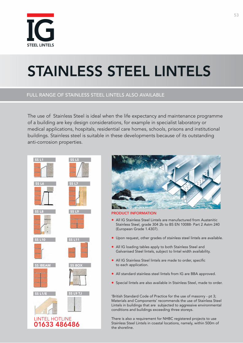
53
STAINLESS STEEL LINTELSFULL RANGE OF STAINLESS STEEL LINTELS ALSO AVAILABLE
PRODUCT INFORMATION
• All IG Stainless Steel Lintels are manufactured from Austenitic Stainless Steel, grade 304 2b to BS EN 10088- Part 2 Astm 240 (European Grade 1.4307).
• Upon request, other grades of stainless steel lintels are available.
• All IG loading tables apply to both Stainless Steel and Galvanised Steel lintels, subject to lintel width availability.
• All IG Stainless Steel lintels are made to order, specific to each application.
• All standard stainless steel lintels from IG are BBA approved.
• Special lintels are also available in Stainless Steel, made to order.
‘British Standard Code of Practice for the use of masonry - pt 3; Materials and Components’ recommends the use of Stainless Steel Lintels in buildings that are subjected to aggressive environmental conditions and buildings exceeding three storeys. There is also a requirement for NHBC registered projects to use Stainless Steel Lintels in coastal locations, namely, within 500m of the shoreline.
The use of Stainless Steel is ideal when the life expectancy and maintenance programme of a building are key design considerations, for example in specialist laboratory or medical applications, hospitals, residential care homes, schools, prisons and institutional buildings. Stainless steel is suitable in these developments because of its outstanding anti-corrosion properties.
SS L1
SS L8
SS IBEAM
SS L1/E
SS L5
SS L9
SS BOX
SS L6
SS L10
SS L9 TJ
SS L7
SS L11
LINTEL HOTLINE 01633 486486
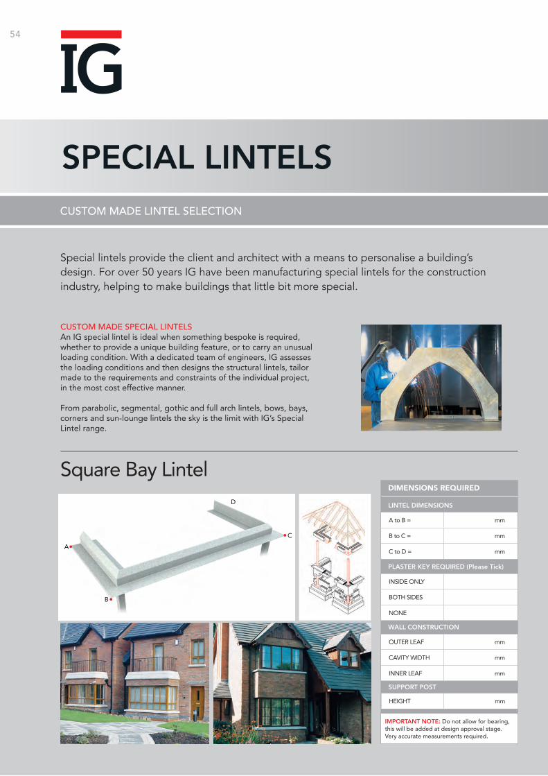
54
SPECIAL LINTELSCUSTOM MADE LINTEL SELECTION
CUSTOM MADE SPECIAL LINTELSAn IG special lintel is ideal when something bespoke is required, whether to provide a unique building feature, or to carry an unusual loading condition. With a dedicated team of engineers, IG assesses the loading conditions and then designs the structural lintels, tailor made to the requirements and constraints of the individual project, in the most cost effective manner.
From parabolic, segmental, gothic and full arch lintels, bows, bays, corners and sun-lounge lintels the sky is the limit with IG’s Special Lintel range.
Special lintels provide the client and architect with a means to personalise a building’s design. For over 50 years IG have been manufacturing special lintels for the construction industry, helping to make buildings that little bit more special.
Square Bay Lintel
A to B = mm
B to C = mm
C to D = mm
INSIDE ONLY
BOTH SIDES
NONE
OUTER LEAF mm
CAVITY WIDTH mm
INNER LEAF mm
DIMENSIONS REQUIRED
LINTEL DIMENSIONS
PLASTER KEY REQUIRED (Please Tick)
WALL CONSTRUCTION
HEIGHT mm
SUPPORT POST
IMPORTANT NOTE: Do not allow for bearing, this will be added at design approval stage. Very accurate measurements required.
A
B
C
D
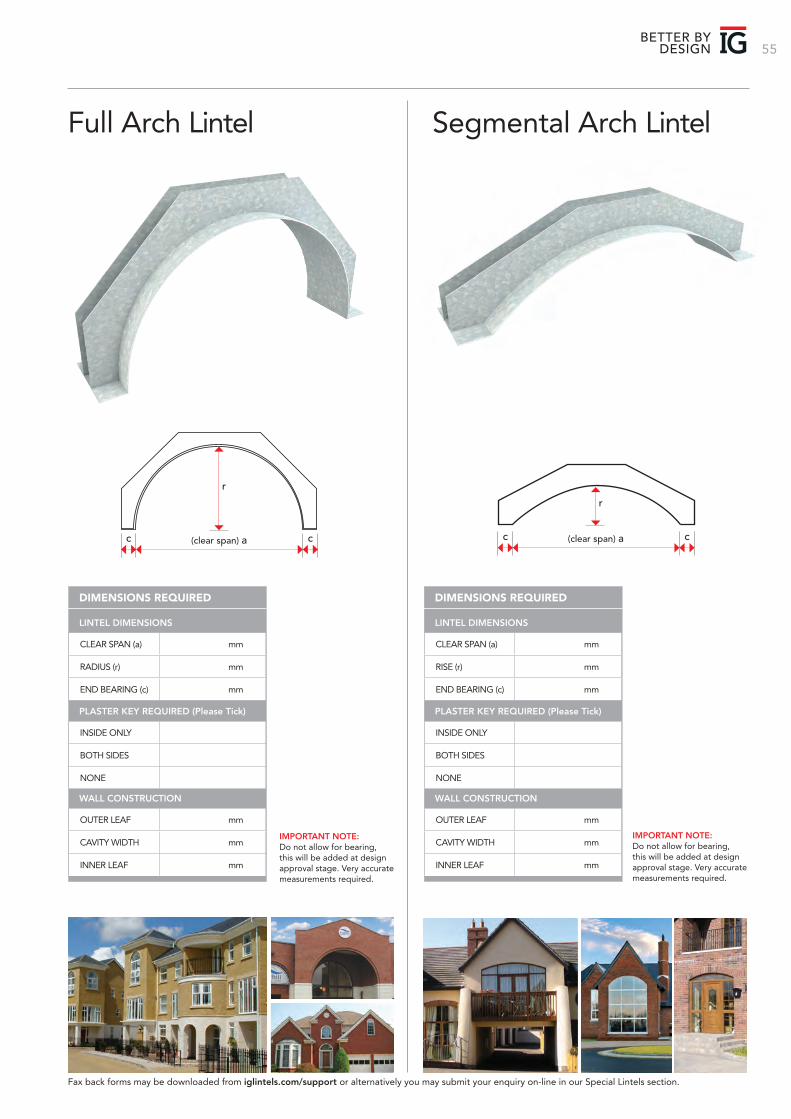
55BETTER BY
DESIGN
Full Arch Lintel Segmental Arch Lintel
(clear span) ac c
r
CLEAR SPAN (a) mm
RADIUS (r) mm
END BEARING (c) mm
INSIDE ONLY
BOTH SIDES
NONE
OUTER LEAF mm
CAVITY WIDTH mm
INNER LEAF mm
DIMENSIONS REQUIRED
LINTEL DIMENSIONS
PLASTER KEY REQUIRED (Please Tick)
WALL CONSTRUCTION
(clear span) ac c
r
CLEAR SPAN (a) mm
RISE (r) mm
END BEARING (c) mm
INSIDE ONLY
BOTH SIDES
NONE
OUTER LEAF mm
CAVITY WIDTH mm
INNER LEAF mm
DIMENSIONS REQUIRED
LINTEL DIMENSIONS
PLASTER KEY REQUIRED (Please Tick)
WALL CONSTRUCTION
Fax back forms may be downloaded from iglintels.com/support or alternatively you may submit your enquiry on-line in our Special Lintels section.
IMPORTANT NOTE: Do not allow for bearing, this will be added at design approval stage. Very accurate measurements required.
IMPORTANT NOTE: Do not allow for bearing, this will be added at design approval stage. Very accurate measurements required.
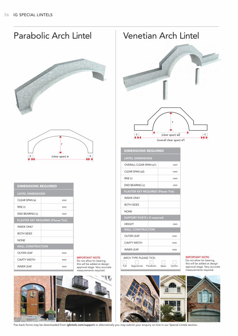
IG 56
Parabolic Arch Lintel Venetian Arch Lintel
CLEAR SPAN (a) mm
RISE (r) mm
END BEARING (c) mm
INSIDE ONLY
BOTH SIDES
NONE
OUTER LEAF mm
CAVITY WIDTH mm
INNER LEAF mm
DIMENSIONS REQUIRED
LINTEL DIMENSIONS
PLASTER KEY REQUIRED (Please Tick)
WALL CONSTRUCTION
(clear span) ac c
r
(clear span) a2
(overall clear span) a1
r
c c
OVERALL CLEAR SPAN (a1) mm
CLEAR SPAN (a2) mm
RISE (r) mm
END BEARING (c) mm
INSIDE ONLY
BOTH SIDES
NONE
OUTER LEAF mm
CAVITY WIDTH mm
INNER LEAF mm
DIMENSIONS REQUIRED
LINTEL DIMENSIONS
PLASTER KEY REQUIRED (Please Tick)
HEIGHT mm
SUPPORT POSTS ( if required)
Full Segmental Parabolic Apex Gothic
ARCH TYPE PLEASE TICK:
WALL CONSTRUCTION
Fax back forms may be downloaded from iglintels.com/support or alternatively you may submit your enquiry on-line in our Special Lintels section.
SPECIAL LINTELS
IMPORTANT NOTE: Do not allow for bearing, this will be added at design approval stage. Very accurate measurements required.
IMPORTANT NOTE: Do not allow for bearing, this will be added at design approval stage. Very accurate measurements required.
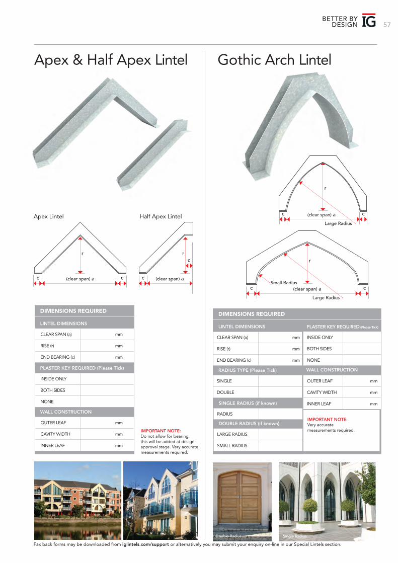
57BETTER BY
DESIGN
Apex & Half Apex Lintel Gothic Arch Lintel
CLEAR SPAN (a) mm
RISE (r) mm
END BEARING (c) mm
INSIDE ONLY
BOTH SIDES
NONE
OUTER LEAF mm
CAVITY WIDTH mm
INNER LEAF mm
DIMENSIONS REQUIRED
LINTEL DIMENSIONS
PLASTER KEY REQUIRED (Please Tick)
WALL CONSTRUCTION
Apex Lintel
(clear span) ac c
r
Half Apex Lintel
(clear span) ac
rc
(clear span) a
Large Radius
Small Radius
r
c c
(clear span) a
Large Radius
r
c c
CLEAR SPAN (a) mm
RISE (r) mm
END BEARING (c) mm
SINGLE
DOUBLE
DIMENSIONS REQUIRED
LINTEL DIMENSIONS
RADIUS TYPE (Please Tick)
RADIUS
LARGE RADIUS
SMALL RADIUS
SINGLE RADIUS (if known)
DOUBLE RADIUS (if known)
Single RadiusDouble Radius
IMPORTANT NOTE: Very accurate measurements required.
INSIDE ONLY
BOTH SIDES
NONE
OUTER LEAF mm
CAVITY WIDTH mm
INNER LEAF mm
PLASTER KEY REQUIRED (Please Tick)
WALL CONSTRUCTION
Fax back forms may be downloaded from iglintels.com/support or alternatively you may submit your enquiry on-line in our Special Lintels section.
IMPORTANT NOTE: Do not allow for bearing, this will be added at design approval stage. Very accurate measurements required.
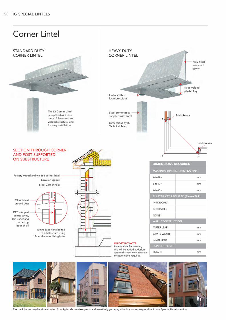
IG 58
Corner Lintel
A to B = mm
B to C = mm
A to C = mm
INSIDE ONLY
BOTH SIDES
NONE
OUTER LEAF mm
CAVITY WIDTH mm
INNER LEAF mm
DIMENSIONS REQUIRED
MASONRY OPENING DIMENSIONS
PLASTER KEY REQUIRED (Please Tick)
WALL CONSTRUCTION
HEIGHT mm
SUPPORT POST
STANDARD DUTY CORNER LINTEL
Steel corner post supplied with lintel
Dimensions by IG Technical Team
Fully filledinsulated cavity
Factory fittedlocation spigot
Spot welded plaster key
The IG Corner Lintel is supplied as a ‘one piece’ fully mitred and welded structural unit for easy installation.
HEAVY DUTY CORNER LINTEL
Brick RevealA
B C
Brick Reveal
SECTION THROUGH CORNER AND POST SUPPORTED ON SUBSTRUCTURE
Factory mitred and welded corner lintel
Location Spigot
Steel Corner Post
10mm Base Plate boltedto substructure using
12mm diameter fixing bolts
DPC stepped across cavity,
laid under andturned up
back of cill
Cill notchedaround post
Fax back forms may be downloaded from iglintels.com/support or alternatively you may submit your enquiry on-line in our Special Lintels section.
SPECIAL LINTELS
IMPORTANT NOTE: Do not allow for bearing, this will be added at design approval stage. Very accurate measurements required.
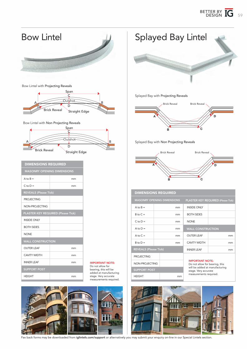
59BETTER BY
DESIGN
Bow Lintel Splayed Bay Lintel
A B
CSpan
Straight EdgeBrick RevealD
Outshot
Bow Lintel with Non Projecting Reveals
A B
CSpan
Straight EdgeBrick RevealD
Outshot
Bow Lintel with Projecting Reveals
A to B = mm
C to D = mm
PROJECTING
NON-PROJECTING
HEIGHT mm
OUTER LEAF mm
CAVITY WIDTH mm
INNER LEAF mm
DIMENSIONS REQUIRED
REVEALS (Please Tick)
SUPPORT POST
WALL CONSTRUCTION
INSIDE ONLY
BOTH SIDES
NONE
PLASTER KEY REQUIRED (Please Tick)
Splayed Bay with Non Projecting Reveals
A to B = mm
B to C = mm
C to D = mm
A to D = mm
A to C = mm
B to D = mm
PROJECTING
NON-PROJECTING
HEIGHT mm
DIMENSIONS REQUIRED
REVEALS (Please Tick)
SUPPORT POST
Splayed Bay with Projecting Reveals
Fax back forms may be downloaded from iglintels.com/support or alternatively you may submit your enquiry on-line in our Special Lintels section.
INSIDE ONLY
BOTH SIDES
NONE
OUTER LEAF mm
CAVITY WIDTH mm
INNER LEAF mm
PLASTER KEY REQUIRED (Please Tick)
WALL CONSTRUCTION
IMPORTANT NOTE: Do not allow for bearing, this will be added at manufacturing stage. Very accurate measurements required.
IMPORTANT NOTE: Do not allow for bearing, this will be added at manufacturing stage. Very accurate measurements required.
Brick Reveal Brick Reveal
D
CB
A
.
Brick Reveal Brick Reveal
D
B
A
C
MASONRY OPENING DIMENSIONS
MASONRY OPENING DIMENSIONS
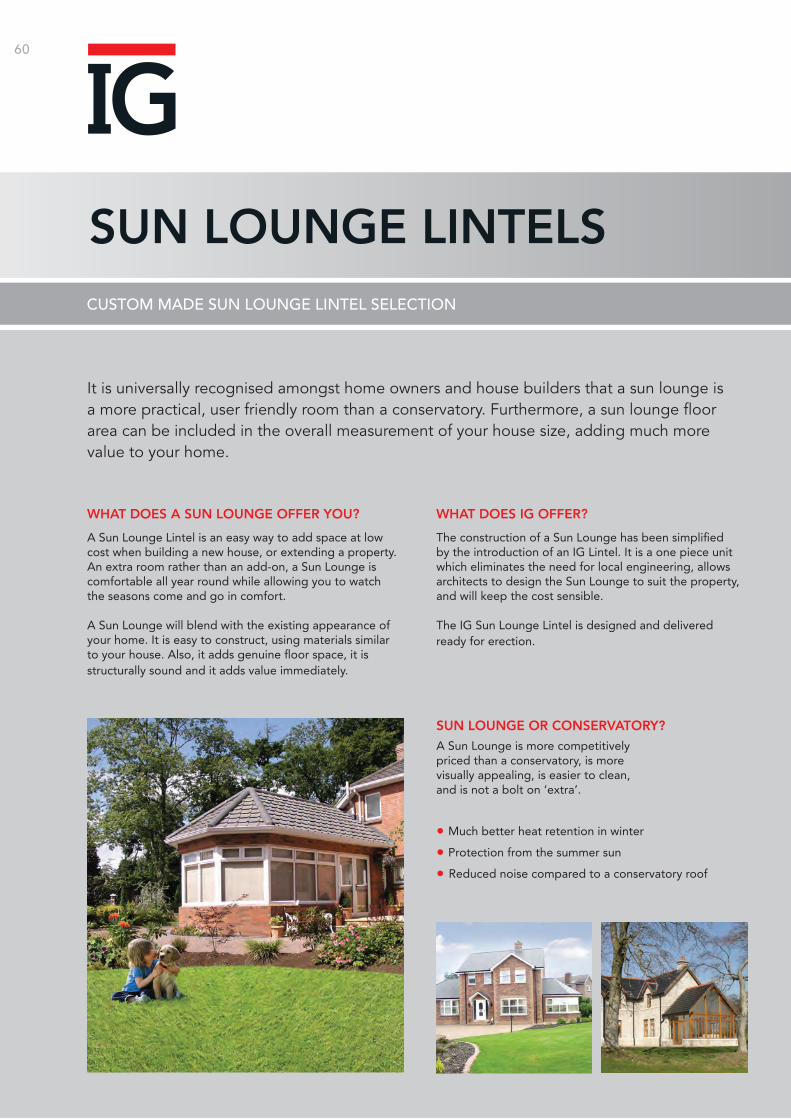
60
SUN LOUNGE LINTELSCUSTOM MADE SUN LOUNGE LINTEL SELECTION
It is universally recognised amongst home owners and house builders that a sun lounge is a more practical, user friendly room than a conservatory. Furthermore, a sun lounge floor area can be included in the overall measurement of your house size, adding much more value to your home.
A Sun Lounge Lintel is an easy way to add space at low cost when building a new house, or extending a property. An extra room rather than an add-on, a Sun Lounge is comfortable all year round while allowing you to watch the seasons come and go in comfort.
A Sun Lounge will blend with the existing appearance of your home. It is easy to construct, using materials similar to your house. Also, it adds genuine floor space, it is structurally sound and it adds value immediately.
The construction of a Sun Lounge has been simplified by the introduction of an IG Lintel. It is a one piece unit which eliminates the need for local engineering, allows architects to design the Sun Lounge to suit the property, and will keep the cost sensible.
The IG Sun Lounge Lintel is designed and delivered ready for erection.
WHAT DOES A SUN LOUNGE OFFER YOU? WHAT DOES IG OFFER?
SUN LOUNGE OR CONSERVATORY?
• Much better heat retention in winter
• Protection from the summer sun
• Reduced noise compared to a conservatory roof
A Sun Lounge is more competitively priced than a conservatory, is more visually appealing, is easier to clean, and is not a bolt on ‘extra’.
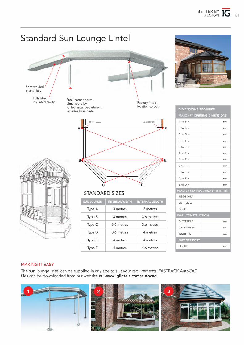
61BETTER BY
DESIGN
MAKING IT EASY
The sun lounge lintel can be supplied in any size to suit your requirements. FASTRACK AutoCAD files can be downloaded from our website at: www.iglintels.com/autocad
Spot welded plaster key
Fully filled insulated cavity
Steel corner postsdimensions by IG Technical DepartmentIncludes base plate
Factory fitted location spigots
A to B = mm
B to C = mm
C to D = mm
D to E = mm
E to F = mm
A to F = mm
A to E = mm
B to F = mm
B to E = mm
C to E = mm
B to D = mm
DIMENSIONS REQUIRED
OUTER LEAF mm
CAVITY WIDTH mm
INNER LEAF mm
HEIGHT mm
WALL CONSTRUCTION
SUPPORT POST
INSIDE ONLY
BOTH SIDES
NONE
PLASTER KEY REQUIRED (Please Tick)
Brick Reveal Brick Reveal
B
A
E
F
C D
STANDARD SIZES
SUN LOUNGE INTERNAL WIDTH INTERNAL LENGTH
Type A 3 metres 3 metres
Type B 3 metres 3.6 metres
Type C 3.6 metres 3.6 metres
Type D 3.6 metres 4 metres
Type E 4 metres 4 metres
Type F 4 metres 4.6 metres
Standard Sun Lounge Lintel
MASONRY OPENING DIMENSIONS
1 2 3
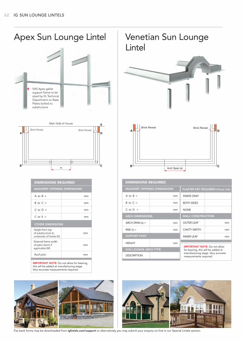
IG 62
INSIDE ONLY
BOTH SIDES
NONE
OUTER LEAF mm
CAVITY WIDTH mm
INNER LEAF mm
PLASTER KEY REQUIRED (Please Tick)
WALL CONSTRUCTION
Apex Sun Lounge Lintel Venetian Sun Lounge Lintel
D
C
A
B
Brick Reveal Brick Reveal
Main Wall of House E
w
A to B = mm
B to C = mm
C to D = mm
C to E = mm
Height from top of substructure to underside of lintels (H)
mm
External frame width of patio doors if applicable (W)
mm
Roof pitch mm
DIMENSIONS REQUIRED
OTHER DIMENSIONS
SHS Apex gable support frame to besized by IG Technical Department on Base Plates bolted to substructure
D
C
A
B
Brick Reveal Brick Reveal
Arch Span (s)
A to B = mm
B to C = mm
C to D = mm
ARCH SPAN (s) = mm
RISE (r) = mm
DESCRIPTION
HEIGHT mm
DIMENSIONS REQUIRED
ARCH DIMENSIONS
SUPPORT POST
SUN LOUNGE ARCH TYPE
SUN LOUNGE LINTELS
IMPORTANT NOTE: Do not allow for bearing, this will be added at manufacturing stage. Very accurate measurements required.
IMPORTANT NOTE: Do not allow for bearing, this will be added at manufacturing stage. Very accurate measurements required.
Fax back forms may be downloaded from iglintels.com/support or alternatively you may submit your enquiry on-line in our Special Lintels section.
MASONRY OPENING DIMENSIONS MASONRY OPENING DIMENSIONS
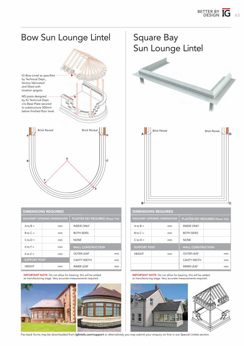
63BETTER BY
DESIGN
OUTER LEAF mm
CAVITY WIDTH mm
INNER LEAF mm
Bow Sun Lounge Lintel Square Bay Sun Lounge Lintel
IG Bow Lintel as specified by Technical Dept., factory fabricated and fitted with location spigots.
MS posts designed by IG Technical Dept. c/w Base Plate secured to substructure 300mm below finished floor level.
D
C
A
B
Z
X
Y
Brick Reveal Brick RevealD
C
A
B
Brick Reveal Brick Reveal
A to B = mm
B to C = mm
C to D = mm
X to Y = mm
X to Z = mm
HEIGHT mm
DIMENSIONS REQUIRED
SUPPORT POST
INSIDE ONLY
BOTH SIDES
NONE
OUTER LEAF mm
CAVITY WIDTH mm
INNER LEAF mm
PLASTER KEY REQUIRED (Please Tick)
WALL CONSTRUCTION
A to B = mm
B to C = mm
C to D = mm
HEIGHT mm
DIMENSIONS REQUIRED
SUPPORT POST
INSIDE ONLY
BOTH SIDES
NONE
OUTER LEAF mm
CAVITY WIDTH mm
INNER LEAF mm
PLASTER KEY REQUIRED (Please Tick)
WALL CONSTRUCTION
IMPORTANT NOTE: Do not allow for bearing, this will be added at manufacturing stage. Very accurate measurements required.
IMPORTANT NOTE: Do not allow for bearing, this will be added at manufacturing stage. Very accurate measurements required.
Fax back forms may be downloaded from iglintels.com/support or alternatively you may submit your enquiry on-line in our Special Lintels section.
MASONRY OPENING DIMENSIONS MASONRY OPENING DIMENSIONS
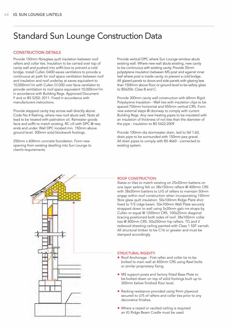
IG 64
Standard Sun Lounge Construction Data
ROOF CONSTRUCTION:Slates or tiles to match existing on 25x50mm battens on one layer sarking felt on 38x150mm rafters @ 400mm CRS with 38x50mm battens to U/S of rafters to maintain 50mm airgap within roof construction when incorporating 150mm fibre glass quilt insulation. 50x100mm Ridge Plate shot fixed to T/S ridge beam. 50x100mm Wall Plate securely strapped down to wall using 5x30mm galv ms straps by Cullen or equal @ 1200mm CRS. 100x25mm diagonal bracing positioned both sides of roof. 38x100mm collar ties @ 400mm CRS. 50x250mm hip rafters. TG and V redwood sheeting ceiling painted with Class 1 SSF varnish. All structural timber to be C16 or greater and must be stamped accordingly.
STRUCTURAL RIGIDITY:• Roof Anchorage - First rafter and collar tie to be bolted to main wall at 450mm CRS using Rawl bolts or similar proprietary fixing.
• MS support posts and factory fitted Base Plate to be bolted down on top of solid footings built up to 300mm below finished floor level.
• Racking resistance provided using 9mm plywood secured to U/S of rafters and collar ties prior to any decorative finishes.
• Where a raised or vaulted ceiling is required an IG Ridge Beam Cradle must be used.
Provide 150mm fibreglass quilt insulation between roof rafters and collar ties. Insulation to be carried over top of cavity wall and pushed into soffit box to prevent a cold bridge. Install Cullen G400 eaves ventilators to provide a continuous air path for roof space ventilation between roof and insulation and roof underlay at eaves equivalent to 10,000mm2/m with Cullen G1200 over facia ventilator to provide ventilation to roof space equivalent 10,000mm2/m in accordance with Building Regs. Approved Document F and or BS 5250: 2011. Fixed in accordance with manufacturers instructions.
Provide stepped cavity tray across wall directly above Code No.4 flashing, where new roof abuts wall. Note all lead to be treated with patination oil. Rainwater goods facia and soffit to match existing. RC cill with DPC @ rear, ends and under. Wall DPC located min. 150mm above ground level. 300mm solid blockwork footings.
250mm x 600mm concrete foundation. Form new opening from existing dwelling into Sun Lounge to client’s requirements.
Provide vertical DPC where Sun Lounge window abuts existing wall. Where new wall abuts existing, new cavity to be continuous with existing cavity. Provide 35mm polystyrene insulation between MS post and against inner leaf where post is inside cavity, to prevent a cold bridge. All glazed panels to doors and side panels with glazing less than 1500mm above floor or ground level to be safety glass to BS6206: Class B and C.
Provide 300mm cavity wall construction with 60mm Rigid Polystyrene Insulation - Wall ties with insulation clips to be spaced 750mm horizontal and 450mm vertical CRS. Form new external steps @ doorway to comply with current Building Regs. Any new heating pipes to be insulated with an insulation of thickness of not less than the diameter of the pipe - insulation to BS 5422:2009.
Provide 100mm dia stormwater drain, laid to fall 1:60, drain pipe to be surrounded with 150mm pea gravel. All drain pipes to comply with BS 4660 - connected to existing system.
CONSTRUCTION DETAILS
SUN LOUNGE LINTELS
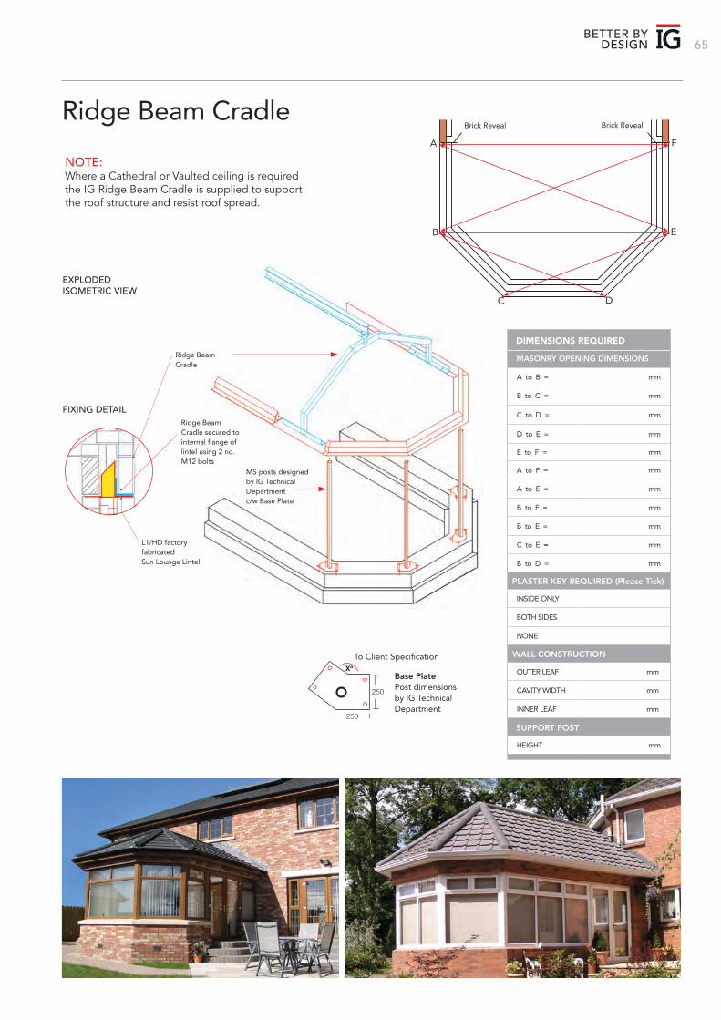
65BETTER BY
DESIGN
Ridge Beam Cradle
A to B = mm
B to C = mm
C to D = mm
D to E = mm
E to F = mm
A to F = mm
A to E = mm
B to F = mm
B to E = mm
C to E = mm
B to D = mm
DIMENSIONS REQUIRED
OUTER LEAF mm
CAVITY WIDTH mm
INNER LEAF mm
HEIGHT mm
WALL CONSTRUCTION
SUPPORT POST
INSIDE ONLY
BOTH SIDES
NONE
PLASTER KEY REQUIRED (Please Tick)
FIXING DETAIL
EXPLODED ISOMETRIC VIEW
Ridge Beam Cradle secured to internal flange of lintel using 2 no. M12 bolts
L1/HD factory fabricatedSun Lounge Lintel
Ridge Beam Cradle
MS posts designed by IG Technical Department c/w Base Plate
To Client Specification
Base PlatePost dimensions by IG Technical Department
250
250
Xº
NOTE:Where a Cathedral or Vaulted ceiling is required the IG Ridge Beam Cradle is supplied to support the roof structure and resist roof spread.
Brick Reveal Brick Reveal
B
A
E
F
C D
MASONRY OPENING DIMENSIONS
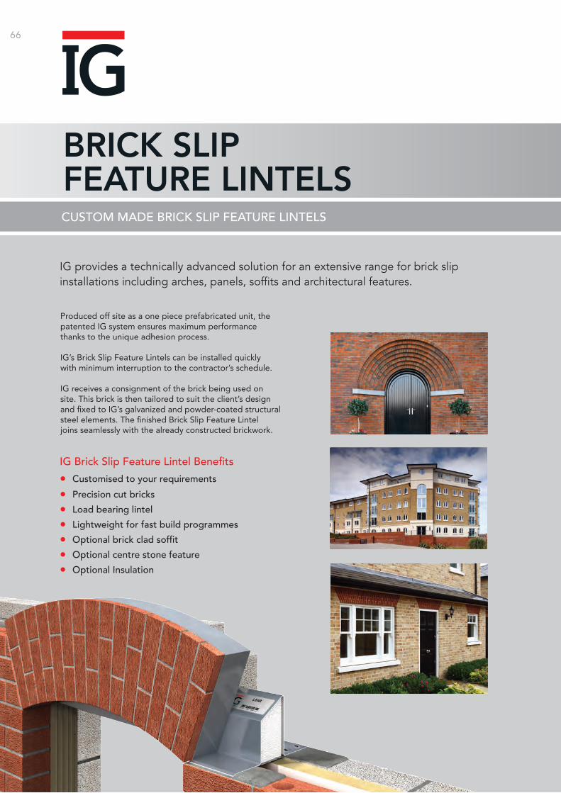
66
BRICK SLIP FEATURE LINTELSCUSTOM MADE BRICK SLIP FEATURE LINTELS
IG provides a technically advanced solution for an extensive range for brick slip installations including arches, panels, soffits and architectural features.
Produced off site as a one piece prefabricated unit, the patented IG system ensures maximum performance thanks to the unique adhesion process.
IG’s Brick Slip Feature Lintels can be installed quickly with minimum interruption to the contractor’s schedule.
IG receives a consignment of the brick being used on site. This brick is then tailored to suit the client’s design and fixed to IG’s galvanized and powder-coated structural steel elements. The finished Brick Slip Feature Lintel joins seamlessly with the already constructed brickwork.
IG Brick Slip Feature Lintel Benefits
• Customised to your requirements
• Precision cut bricks
• Load bearing lintel
• Lightweight for fast build programmes
• Optional brick clad soffit
• Optional centre stone feature
• Optional Insulation
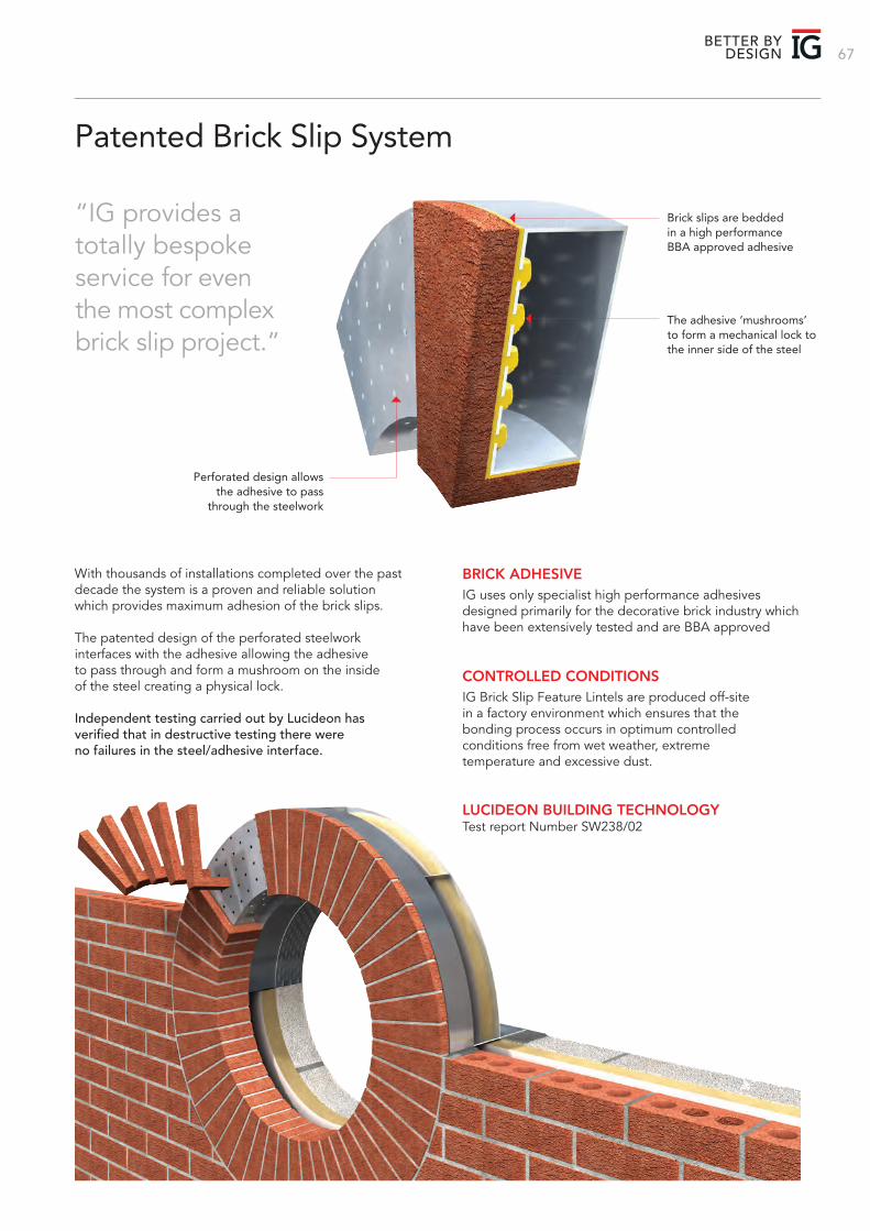
67BETTER BY
DESIGN
Patented Brick Slip System
With thousands of installations completed over the past decade the system is a proven and reliable solution which provides maximum adhesion of the brick slips.
The patented design of the perforated steelwork interfaces with the adhesive allowing the adhesive to pass through and form a mushroom on the inside of the steel creating a physical lock.
Independent testing carried out by Lucideon has verified that in destructive testing there were no failures in the steel/adhesive interface.
BRICK ADHESIVEIG uses only specialist high performance adhesives designed primarily for the decorative brick industry which have been extensively tested and are BBA approved
CONTROLLED CONDITIONSIG Brick Slip Feature Lintels are produced off-site in a factory environment which ensures that the bonding process occurs in optimum controlled conditions free from wet weather, extreme temperature and excessive dust.
LUCIDEON BUILDING TECHNOLOGYTest report Number SW238/02
Perforated design allows the adhesive to pass
through the steelwork
Brick slips are bedded in a high performance BBA approved adhesive
The adhesive ‘mushrooms’ to form a mechanical lock to the inner side of the steel
“IG provides a totally bespoke service for even the most complex brick slip project.”
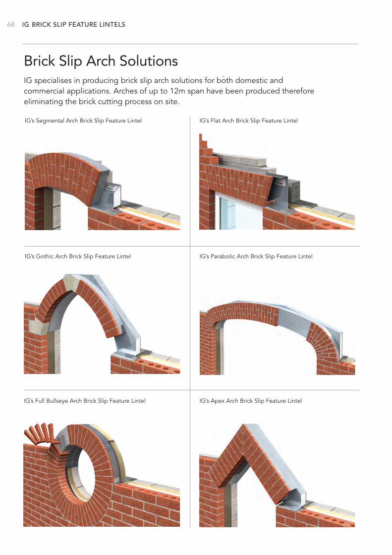
IG 68 BRICK SLIP FEATURE LINTELS
Brick Slip Arch Solutions
IG’s Segmental Arch Brick Slip Feature Lintel IG’s Flat Arch Brick Slip Feature Lintel
IG’s Full Bullseye Arch Brick Slip Feature Lintel IG’s Apex Arch Brick Slip Feature Lintel
IG’s Gothic Arch Brick Slip Feature Lintel IG’s Parabolic Arch Brick Slip Feature Lintel
IG specialises in producing brick slip arch solutions for both domestic and commercial applications. Arches of up to 12m span have been produced therefore eliminating the brick cutting process on site.
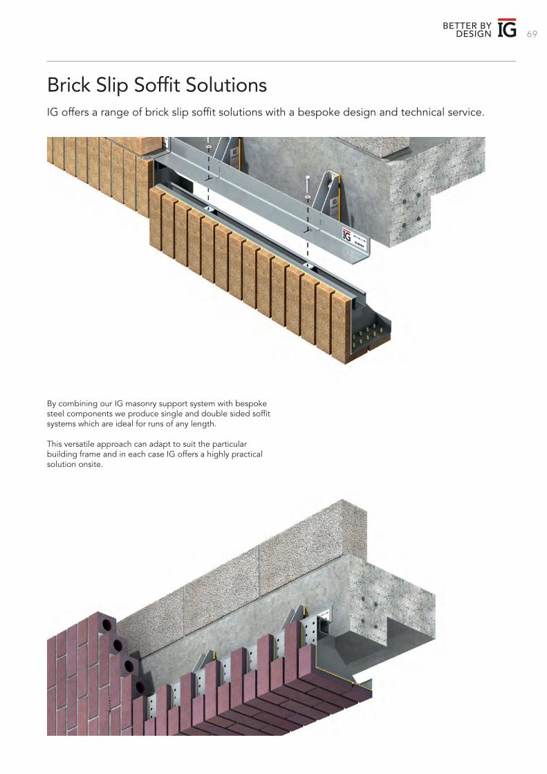
69BETTER BY
DESIGN
Brick Slip Soffit SolutionsIG offers a range of brick slip soffit solutions with a bespoke design and technical service.
By combining our IG masonry support system with bespoke steel components we produce single and double sided soffit systems which are ideal for runs of any length.
This versatile approach can adapt to suit the particular building frame and in each case IG offers a highly practical solution onsite.
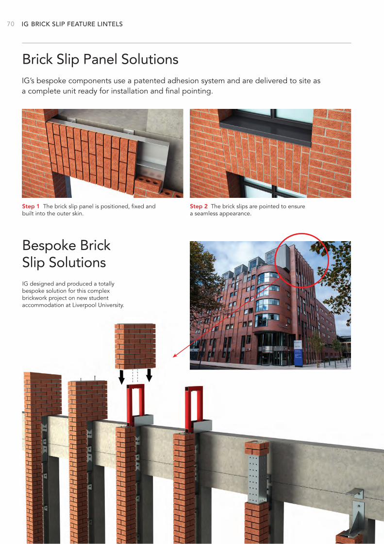
IG 70 BRICK SLIP FEATURE LINTELS
Brick Slip Panel Solutions
Bespoke Brick Slip Solutions
IG’s bespoke components use a patented adhesion system and are delivered to site as a complete unit ready for installation and final pointing.
IG designed and produced a totally bespoke solution for this complex brickwork project on new student accommodation at Liverpool University.
Step 1 The brick slip panel is positioned, fixed and built into the outer skin.
Step 2 The brick slips are pointed to ensure a seamless appearance.
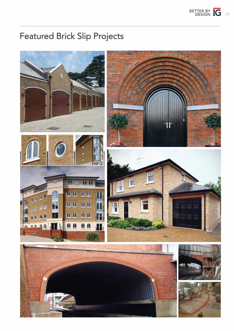
71
Featured Brick Slip Projects
BETTER BY DESIGN
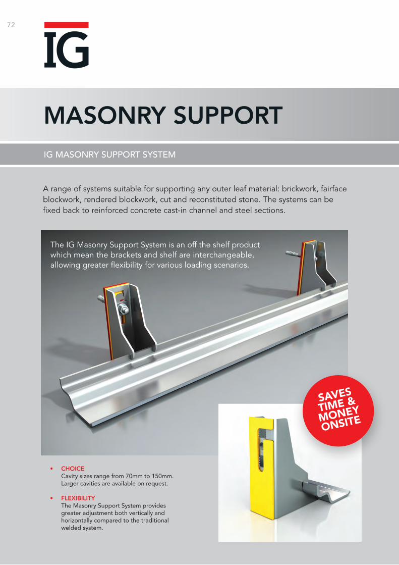
72
MASONRY SUPPORTIG MASONRY SUPPORT SYSTEM
A range of systems suitable for supporting any outer leaf material: brickwork, fairface blockwork, rendered blockwork, cut and reconstituted stone. The systems can be fixed back to reinforced concrete cast-in channel and steel sections.
• CHOICE Cavity sizes range from 70mm to 150mm. Larger cavities are available on request. • FLEXIBILITY The Masonry Support System provides
greater adjustment both vertically and horizontally compared to the traditional welded system.
SAVES
TIME &
MONEY
ONSITE
The IG Masonry Support System is an off the shelf product which mean the brackets and shelf are interchangeable, allowing greater flexibility for various loading scenarios.
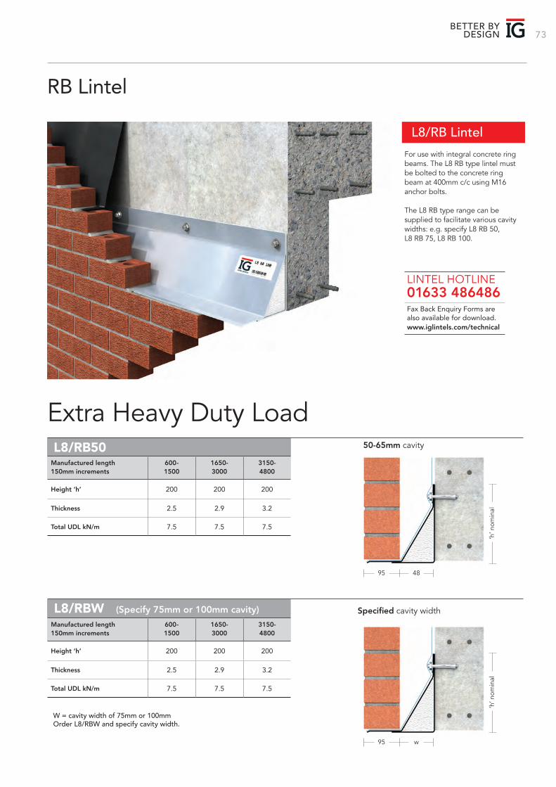
73BETTER BY
DESIGN
L8/RB Lintel
For use with integral concrete ring beams. The L8 RB type lintel must be bolted to the concrete ring beam at 400mm c/c using M16 anchor bolts.
The L8 RB type range can be supplied to facilitate various cavity widths: e.g. specify L8 RB 50, L8 RB 75, L8 RB 100.
Fax Back Enquiry Forms are also available for download.
LINTEL HOTLINE 01633 486486
www.iglintels.com/technical
RB Lintel
Extra Heavy Duty Load 50-65mm cavityL8/RB50
95
95
48
w
Height ‘h’ 200 200 200
Thickness 2.5 2.9 3.2
Total UDL kN/m 7.5 7.5 7.5
Manufactured length 600- 1650- 3150-150mm increments 1500 3000 4800
‘h’ n
omin
al‘h
’ nom
inal
Specified cavity widthL8/RBW (Specify 75mm or 100mm cavity)
Height ‘h’ 200 200 200
Thickness 2.5 2.9 3.2
Total UDL kN/m 7.5 7.5 7.5
Manufactured length 600- 1650- 3150-150mm increments 1500 3000 4800
W = cavity width of 75mm or 100mmOrder L8/RBW and specify cavity width.
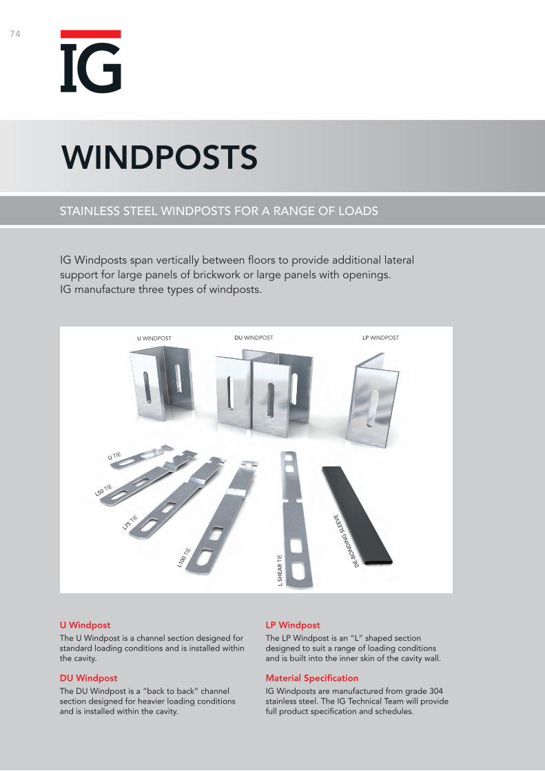
74
WINDPOSTS
U WINDPOST
U TIE
L50 TIE
L75 T
IE
L100
TIE
L SH
EA
R T
IE
DE-
BON
DIN
G S
LEEV
ELP WINDPOSTDU WINDPOST
STAINLESS STEEL WINDPOSTS FOR A RANGE OF LOADS
IG Windposts span vertically between floors to provide additional lateral support for large panels of brickwork or large panels with openings. IG manufacture three types of windposts.
U WindpostThe U Windpost is a channel section designed for standard loading conditions and is installed within the cavity. DU WindpostThe DU Windpost is a “back to back” channel section designed for heavier loading conditions and is installed within the cavity.
LP Windpost The LP Windpost is an “L” shaped section designed to suit a range of loading conditions and is built into the inner skin of the cavity wall.
Material SpecificationIG Windposts are manufactured from grade 304 stainless steel. The IG Technical Team will provide full product specification and schedules.
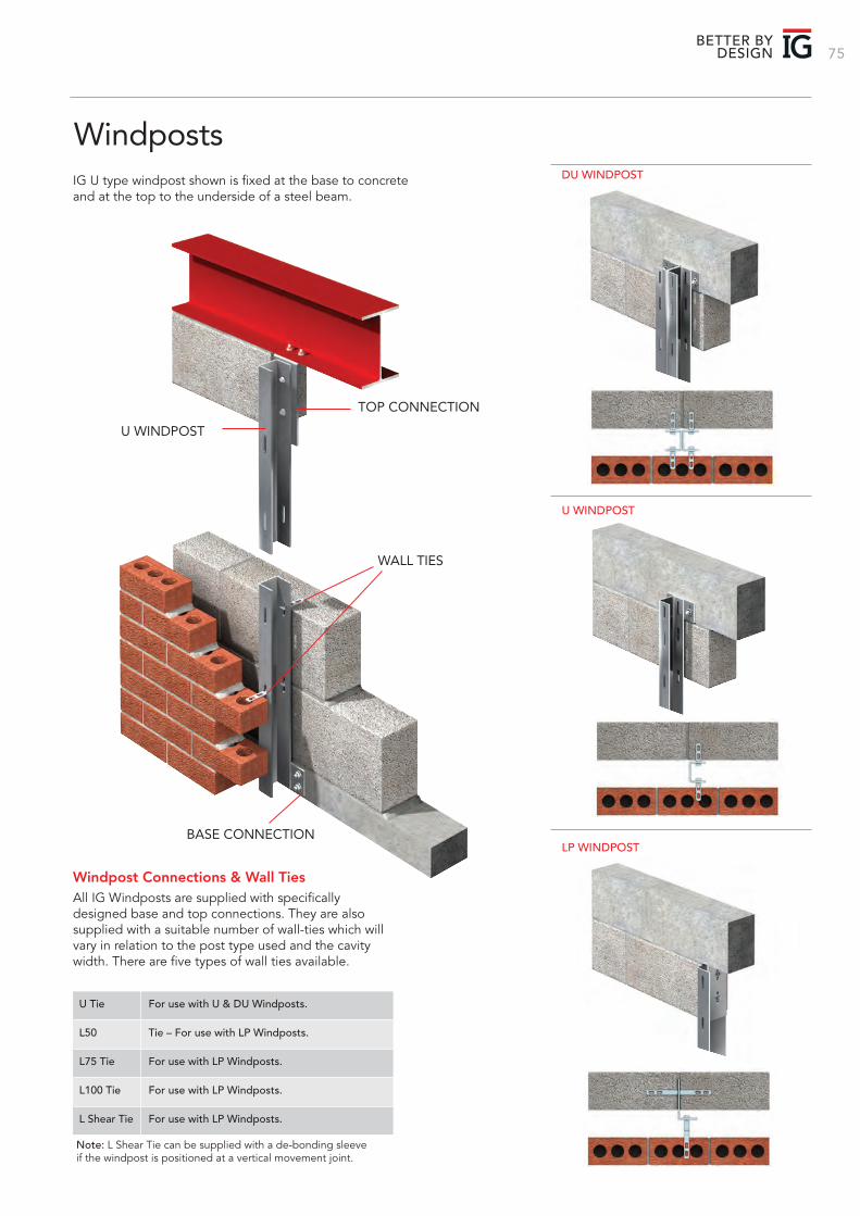
75BETTER BY
DESIGN
WindpostsIG U type windpost shown is fixed at the base to concrete and at the top to the underside of a steel beam.
TOP CONNECTION
U WINDPOST
WALL TIES
BASE CONNECTION
Windpost Connections & Wall TiesAll IG Windposts are supplied with specifically designed base and top connections. They are also supplied with a suitable number of wall-ties which will vary in relation to the post type used and the cavity width. There are five types of wall ties available.
Note: L Shear Tie can be supplied with a de-bonding sleeve if the windpost is positioned at a vertical movement joint.
U Tie For use with U & DU Windposts.
L50 Tie – For use with LP Windposts.
L75 Tie For use with LP Windposts.
L100 Tie For use with LP Windposts.
L Shear Tie For use with LP Windposts.
U WINDPOST
LP WINDPOST
DU WINDPOST
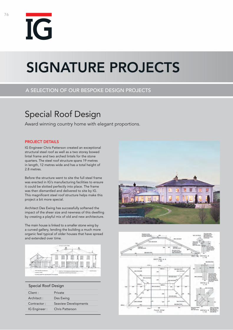
76
SIGNATURE PROJECTSA SELECTION OF OUR BESPOKE DESIGN PROJECTS
Special Roof DesignAward winning country home with elegant proportions.
IG Engineer Chris Patterson created an exceptional structural steel roof as well as a two storey bowed lintel frame and two arched lintels for the stone quarters. The steel roof structure spans 19 metres in length, 12 metres wide and has a total height of 2.8 metres.
Before the structure went to site the full steel frame was erected in IG’s manufacturing facilities to ensure it could be slotted perfectly into place. The frame was then dismantled and delivered to site by IG. This magnificent steel roof structure helps make this project a bit more special.
Architect Des Ewing has successfully softened the impact of the sheer size and newness of this dwelling by creating a playful mix of old and new architecture.
The main house is linked to a smaller stone wing by a curved gallery, lending the building a much more organic feel typical of older houses that have spread and extended over time.
PROJECT DETAILS
Client : Private
Architect : Des Ewing
Contractor : Seaview Developments
IG Engineer : Chris Patterson
Special Roof Design
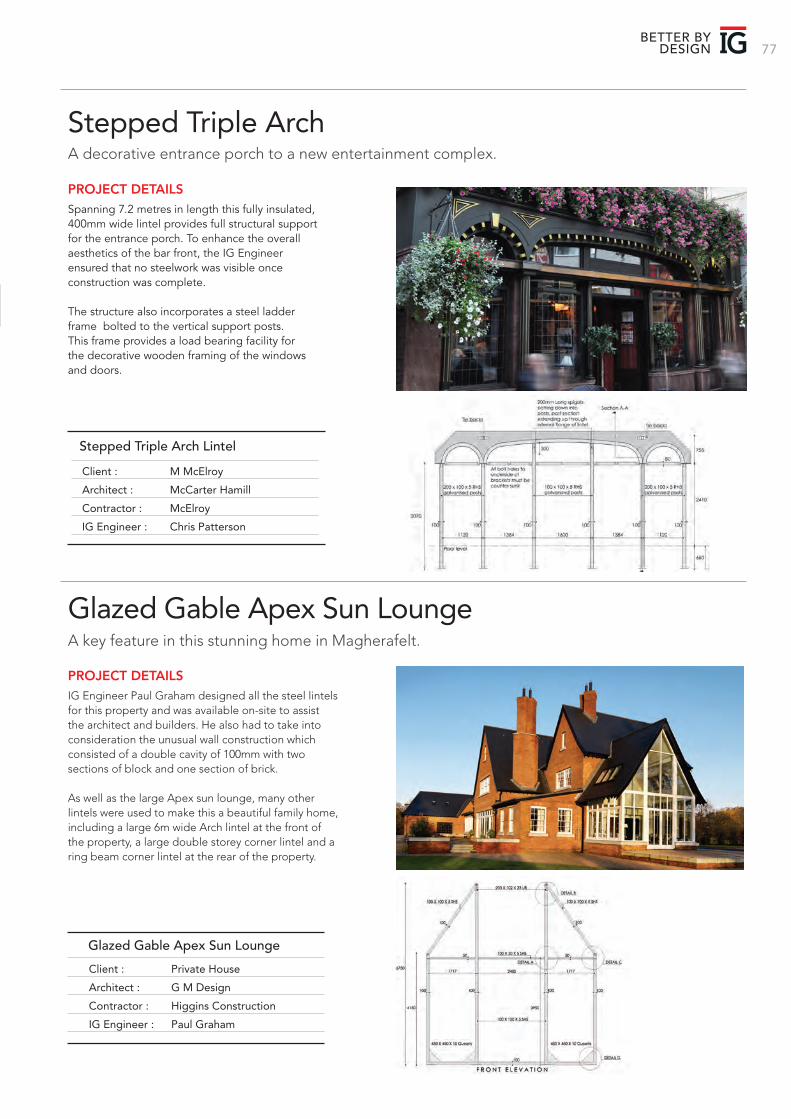
77BETTER BY
DESIGN
Stepped Triple ArchA decorative entrance porch to a new entertainment complex.
Spanning 7.2 metres in length this fully insulated, 400mm wide lintel provides full structural support for the entrance porch. To enhance the overall aesthetics of the bar front, the IG Engineer ensured that no steelwork was visible once construction was complete.
The structure also incorporates a steel ladder frame bolted to the vertical support posts. This frame provides a load bearing facility for the decorative wooden framing of the windows and doors.
PROJECT DETAILS
Client : M McElroy
Architect : McCarter Hamill
Contractor : McElroy
IG Engineer : Chris Patterson
Stepped Triple Arch Lintel
Glazed Gable Apex Sun LoungeA key feature in this stunning home in Magherafelt.
IG Engineer Paul Graham designed all the steel lintels for this property and was available on-site to assist the architect and builders. He also had to take into consideration the unusual wall construction which consisted of a double cavity of 100mm with two sections of block and one section of brick.
As well as the large Apex sun lounge, many other lintels were used to make this a beautiful family home, including a large 6m wide Arch lintel at the front of the property, a large double storey corner lintel and a ring beam corner lintel at the rear of the property.
PROJECT DETAILS
Client : Private House
Architect : G M Design
Contractor : Higgins Construction
IG Engineer : Paul Graham
Glazed Gable Apex Sun Lounge
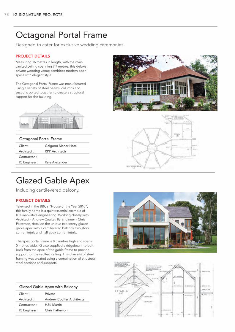
IG 78
Client : Galgorm Manor Hotel
Architect : RPP Architects
Contractor : –
IG Engineer : Kyle Alexander
Octagonal Portal Frame
SIGNATURE PROJECTS
Octagonal Portal FrameDesigned to cater for exclusive wedding ceremonies.
Measuring 16 metres in length, with the main vaulted ceiling spanning 9.7 metres, this deluxe private wedding venue combines modern open space with elegant style.
The Octagonal Portal Frame was manufactured using a variety of steel beams, columns and sections bolted together to create a structural support for the building.
PROJECT DETAILS
Glazed Gable ApexIncluding cantilevered balcony.
Televised in the BBC’s “House of the Year 2010”, this family home is a quintessential example of IG’s innovative engineering. Working closely with Architect - Andrew Coulter, IG Engineer - Chris Patterson, detailed the unique two storey glazed gable apex with a cantilevered balcony, two story corner lintels and half apex corner lintels.
The apex portal frame is 8.5 metres high and spans 5 metres wide. IG also supplied a ridgebeam to bolt back from the apex of the gable frame to provide support for the vaulted ceiling. This diversity of steel framing was created using a combination of structural steel sections and supports.
PROJECT DETAILS
Client : Private
Architect : Andrew Coulter Architects
Contractor : H&J Martin
IG Engineer : Chris Patterson
Glazed Gable Apex with Balcony
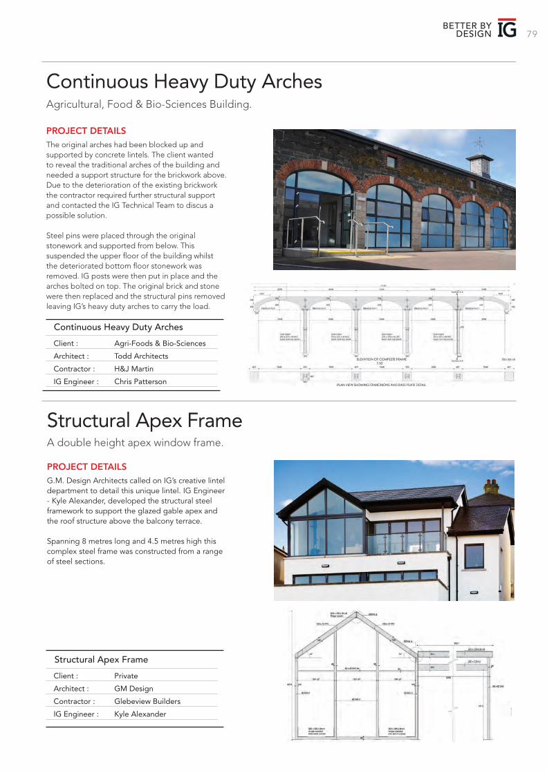
79BETTER BY
DESIGN
Continuous Heavy Duty ArchesAgricultural, Food & Bio-Sciences Building.
The original arches had been blocked up and supported by concrete lintels. The client wanted to reveal the traditional arches of the building and needed a support structure for the brickwork above. Due to the deterioration of the existing brickwork the contractor required further structural support and contacted the IG Technical Team to discus a possible solution. Steel pins were placed through the original stonework and supported from below. This suspended the upper floor of the building whilst the deteriorated bottom floor stonework was removed. IG posts were then put in place and the arches bolted on top. The original brick and stone were then replaced and the structural pins removed leaving IG’s heavy duty arches to carry the load.
PROJECT DETAILS
Structural Apex FrameA double height apex window frame.
G.M. Design Architects called on IG’s creative lintel department to detail this unique lintel. IG Engineer - Kyle Alexander, developed the structural steel framework to support the glazed gable apex and the roof structure above the balcony terrace.
Spanning 8 metres long and 4.5 metres high this complex steel frame was constructed from a range of steel sections.
PROJECT DETAILS
Client : Agri-Foods & Bio-Sciences
Architect : Todd Architects
Contractor : H&J Martin
IG Engineer : Chris Patterson
Continuous Heavy Duty Arches
Client : Private
Architect : GM Design
Contractor : Glebeview Builders
IG Engineer : Kyle Alexander
Structural Apex Frame
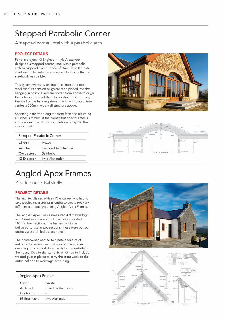
IG 80 SIGNATURE PROJECTS
Stepped Parabolic CornerA stepped corner lintel with a parabolic arch.
For this project, IG Engineer - Kyle Alexander designed a stepped corner lintel with a parabolic arch to suspend over 1 tonne of stone from the outer steel shelf. The lintel was designed to ensure that no steelwork was visible.
This system works by drilling holes into the outer steel shelf. Expansion plugs are then placed into the hanging sandstone and are bolted from above through the holes in the steel shelf. In addition to supporting the load of the hanging stone, the fully insulated lintel carries a 500mm wide wall structure above.
Spanning 7 metres along the front face and returning a further 3 metres at the corner, this special lintel is a prime example of how IG lintels can adapt to the client’s brief.
PROJECT DETAILS
Angled Apex FramesPrivate house, Ballykelly.
The architect liaised with an IG engineer who had to take precise measurements onsite to create two very different but equally stunning Angled Apex Frames.
The Angled Apex Frame measured 4.8 metres high and 4 metres wide and included fully insulated 180mm box sections. The frames had to be delivered to site in two sections, these were bolted onsite via pre-drilled access holes.
The homeowner wanted to create a feature of not only the lintels used but also on the finishes, deciding on a natural stone finish for the outside of the house. Due to the stone finish IG had to include welded gusset plates to carry the stonework on the outer leaf and to resist against sliding.
PROJECT DETAILS
Stepped Parabolic Corner
Client : Private
Architect : Hamilton Architects
Contractor : –
IG Engineer : Kyle Alexander
Angled Apex Frames
Client : Private
Architect : Diamond Architecture
Contractor : Self-build
IG Engineer : Kyle Alexander
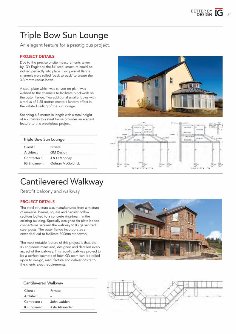
81BETTER BY
DESIGN
Triple Bow Sun LoungeAn elegant feature for a prestigious project.
Due to the precise onsite measurements taken by IG’s Engineer, the full steel structure could be slotted perfectly into place. Two parallel flange channels were rolled ‘back to back’ to create the 3.3 metre radius bows.
A steel plate which was curved on plan, was welded to the channels to facilitate blockwork on the outer flange. Two additional smaller bows with a radius of 1.25 metres create a lantern effect in the valuted ceiling of the sun lounge.
Spanning 6.5 metres in length with a total height of 4.7 metres this steel frame provides an elegant feature to this prestigious project.
PROJECT DETAILS
Cantilevered WalkwayRetrofit balcony and walkway.
The steel structure was manufactured from a mixture of universal beams, square and circular hollow sections bolted to a concrete ring-beam in the existing building. Specially designed fin plate bolted connections secured the walkway to IG galvanized steel posts. The outer flange incorporates an extended leaf to facilitate 300mm stonework.
The most notable feature of this project is that, the IG engineers measured, designed and detailed every aspect of the walkway. This retrofit walkway proved to be a perfect example of how IG’s team can be relied upon to design, manufacture and deliver onsite to the clients exact requirements.
PROJECT DETAILS
Client : Private
Architect : GM Design
Contractor : J & D Mooney
IG Engineer : Odhran McGoldrick
Triple Bow Sun Lounge
Client : Private
Architect : –
Contractor : John Ladden
IG Engineer : Kyle Alexander
Cantilevered Walkway
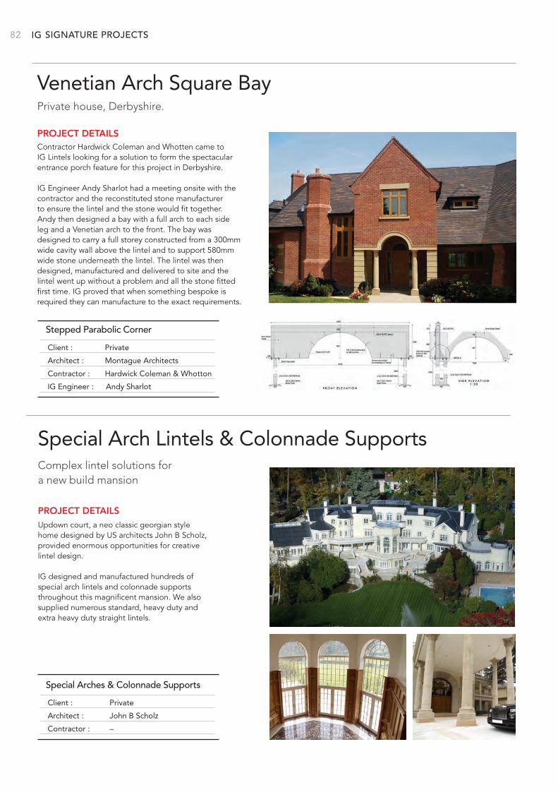
IG 82 SIGNATURE PROJECTS
Venetian Arch Square BayPrivate house, Derbyshire.
Contractor Hardwick Coleman and Whotten came to IG Lintels looking for a solution to form the spectacular entrance porch feature for this project in Derbyshire.
IG Engineer Andy Sharlot had a meeting onsite with the contractor and the reconstituted stone manufacturer to ensure the lintel and the stone would fit together. Andy then designed a bay with a full arch to each side leg and a Venetian arch to the front. The bay was designed to carry a full storey constructed from a 300mm wide cavity wall above the lintel and to support 580mm wide stone underneath the lintel. The lintel was then designed, manufactured and delivered to site and the lintel went up without a problem and all the stone fitted first time. IG proved that when something bespoke is required they can manufacture to the exact requirements.
PROJECT DETAILS
Special Arch Lintels & Colonnade SupportsComplex lintel solutions for a new build mansion
Updown court, a neo classic georgian style home designed by US architects John B Scholz, provided enormous opportunities for creative lintel design.
IG designed and manufactured hundreds of special arch lintels and colonnade supports throughout this magnificent mansion. We also supplied numerous standard, heavy duty and extra heavy duty straight lintels.
PROJECT DETAILS
Stepped Parabolic Corner
Client : Private
Architect : John B Scholz
Contractor : –
Special Arches & Colonnade Supports
Client : Private
Architect : Montague Architects
Contractor : Hardwick Coleman & Whotton
IG Engineer : Andy Sharlot
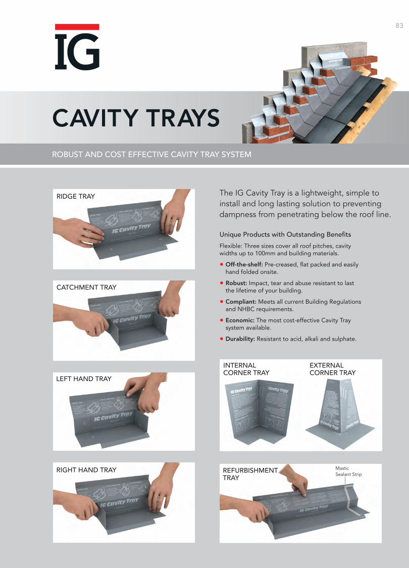
CAVITY TRAYS
The IG Cavity Tray is a lightweight, simple to install and long lasting solution to preventing dampness from penetrating below the roof line.
Unique Products with Outstanding Benefits
Flexible: Three sizes cover all roof pitches, cavity widths up to 100mm and building materials.
• Off-the-shelf: Pre-creased, flat packed and easily hand folded onsite.
• Robust: Impact, tear and abuse resistant to last the lifetime of your building.
• Compliant: Meets all current Building Regulations and NHBC requirements.
• Economic: The most cost-effective Cavity Tray system available.
• Durability: Resistant to acid, alkali and sulphate.
RIDGE TRAY
RIGHT HAND TRAY
LEFT HAND TRAY
CATCHMENT TRAY
INTERNAL CORNER TRAY
REFURBISHMENT TRAY
Mastic Sealant Strip
EXTERNAL CORNER TRAY
IG produces the UK’s largest range of steel lintels backed by industry leading technical support and ex-stock delivery service.
CONTENTS PAGE
IG Service 04
Lintel Performance 05
Installation 06
Selecting the Correct Lintel 07
Lintel Range Index 08
Hi-therm+ Lintel 10
Standard Cavity Wall Lintels 12
Wide Inner Leaf Cavity Wall Lintels 19
Wide Outer Leaf Cavity Wall Lintels 29
Eaves Lintels 37
Poro-Cav Lintels 38
Timber Frame Lintels 40
Single Leaf Lintels 43
Box Lintels 44
Solid Wall Lintels 48
Extended Range 50
Stainless Steel Range 53
Lintel Specials 54
Sun Lounge Lintels 60
Brick Slip Feature Lintels 66
Masonry Support Systems 72
Windposts 74
Signature Projects 76
Cavity Trays 83
BBA Certification
National House Building Council
RIBA CPD Approved
British Standards Institution ISO 9001 & ISO 1400
Investors in People Accreditation
Home BuildersFederation
CERTIFICATE No 05/4192
Builders MerchantsFederation
Building Research Establishment
83
ROBUST AND COST EFFECTIVE CAVITY TRAY SYSTEM
iglintels.com
Special LintelsIG offers a complete custom design service to ensure your project has the best lintel for the job. Our technical expertise is renowned for delivering solutions with total efficiency.
Standard LintelsIG produces a wide range of standard galvanised steel and stainless steel lintels. All IG standard lintels satisfy the thermal performance requirements of all UK building regulations.
Hi-therm+IG has redefined lintel performance with Hi-therm+, the low cost solution to reduced carbon emissions and improved Fabric Energy Efficiency (FEES).
Cavity TraysThe IG Cavity Tray presents a lightweight, simple to install and long-lasting solution to preventing damp from penetrating below the roof line.
Brick Feature LintelsIG Brick Feature Lintels are a one piece prefabricated unit, manufactured bespoke to order, achieving even the most challenging architectural designs.
Masonry Support & WindpostsIG continues to set the standard for masonry support and windpost systems for a range of building frame configurations. The innovative IG Masonry Support System provides a versatile solution when masonry support is required.
www.iglintels.com
CI/SfB Hh2 (31.9)
COMPLETE GUIDE TO THE IG PRODUCT RANGE
PRODUCT GUIDE
PR
OD
UC
T GU
IDE
Email: [email protected]
LINTEL HOTLINE
01633 486486
IG - SWADLINCOTE Ryder Close, Cadley Hill Industrial Estate Swadlincote, South Derbyshire DE11 9EUT: +44 (0) 1283 200150 F: +44 (0) 1283 223352
IG - CWMBRAN Avondale Road, Cwmbran, Gwent, NP44 1XYT: +44 (0) 1633 486486F: +44 (0) 1633 486465
IG - IRELANDBallyreagh Industrial Estate, Cookstown, Co. Tyrone BT80 9DGT: +44 (0) 28 86762184F: +44 (0) 28 86761011
CERTIFICATE No 05/4192FM 21541EMS 553955
ISO 9001ISO 14001
IG-PG | 01.19
The information contained in this brochure was accurate at the date of going to press. IG Ltd, however, reserves the right, while maintaining the essential performance of the products described, to introduce at any time modifications and changes of details as may be considered necessary to improve the products described.


