Embed Size (px)
Citation preview
II B.TECH II SEM /STRENGTH OF MATERIALS LAB MANUAL MECHANICAL DEPARTMENT
MRCET Page 1
MALLA REDDY COLLEGE OF
ENGINEERING & TECHNOLOGY
`
DEPARTMENT OF MECHANICAL ENGINEERING
LABORATORY MANUAL
STRENGTH OF MATERIALS LAB
B.Tech II-II Sem
(As per 2020-21 Academic Regulation)
II B.TECH II SEM /STRENGTH OF MATERIALS LAB MANUAL MECHANICAL DEPARTMENT
MRCET Page 2
VISION
To Become An Innovative Knowledge Center In Mechanical Engineering Through State
Of The Art Teaching –Learning And Research Practices, Promoting Creative Thinking
Professionals.
MISSION
The Department Of Mechanical Engineering Is Dedicated For Transforming The Students
Into Highly Competent Mechanical Engineers to meet the needs of the industry, by
strongly focusing in the fundamentals of engineering sciences for achieving excellent
results in their professional pursuits.
QUALITY POLICY
To Pursuit Global Standards Of Excellence In All Our Endeavors Namely Teaching, Research And
Continuing Educations And To Remain Accountable In Our Core And Support Functions, Through
Processes Of Self-Evaluation And Continuous Improvement.
To Create A Midst Of Excellence For Imparting State Of Art Education, Industry-Oriented Training
Research In The Field Of Technical Education.
II B.TECH II SEM /STRENGTH OF MATERIALS LAB MANUAL MECHANICAL DEPARTMENT
MRCET Page 3
MALLA REDDY COLLEGE OF ENGINEERING & TECHNOLOGY
II Year B. Tech ME - II Sem
(R18A0383) STRENGTH OF MATERIALS LAB
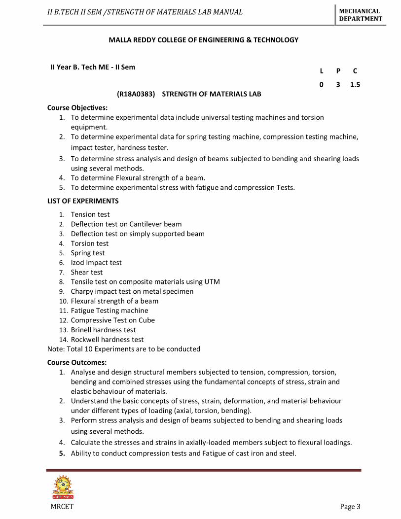
Course Objectives: 1. To determine experimental data include universal testing machines and torsion
equipment. 2. To determine experimental data for spring testing machine, compression testing machine,
impact tester, hardness tester.
3. To determine stress analysis and design of beams subjected to bending and shearing loads using several methods.
4. To determine Flexural strength of a beam. 5. To determine experimental stress with fatigue and compression Tests.
LIST OF EXPERIMENTS
1. Tension test 2. Deflection test on Cantilever beam 3. Deflection test on simply supported beam 4. Torsion test 5. Spring test 6. Izod Impact test 7. Shear test 8. Tensile test on composite materials using UTM 9. Charpy impact test on metal specimen 10. Flexural strength of a beam 11. Fatigue Testing machine 12. Compressive Test on Cube 13. Brinell hardness test 14. Rockwell hardness test
Note: Total 10 Experiments are to be conducted
Course Outcomes: 1. Analyse and design structural members subjected to tension, compression, torsion,
bending and combined stresses using the fundamental concepts of stress, strain and elastic behaviour of materials.
2. Understand the basic concepts of stress, strain, deformation, and material behaviour under different types of loading (axial, torsion, bending).
3. Perform stress analysis and design of beams subjected to bending and shearing loads
using several methods.
4. Calculate the stresses and strains in axially-loaded members subject to flexural loadings.
5. Ability to conduct compression tests and Fatigue of cast iron and steel.
L P C
0 3 1.5

II B.TECH II SEM /STRENGTH OF MATERIALS LAB MANUAL MECHANICAL DEPARTMENT
MRCET Page 4
TIME TABLE
II B.TECH II SEM /STRENGTH OF MATERIALS LAB MANUAL MECHANICAL DEPARTMENT
MRCET Page 5
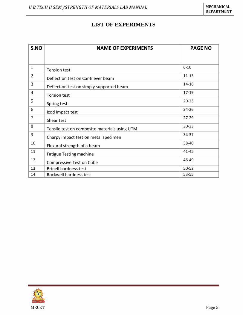
LIST OF EXPERIMENTS
S.NO NAME OF EXPERIMENTS PAGE NO
1 Tension test
6-10
2 Deflection test on Cantilever beam
11-13
3 Deflection test on simply supported beam
14-16
4 Torsion test
17-19
5 Spring test
20-23
6 Izod Impact test
24-26
7 Shear test
27-29
8 Tensile test on composite materials using UTM
30-33
9 Charpy impact test on metal specimen
34-37
10 Flexural strength of a beam
38-40
11 Fatigue Testing machine
41-45
12 Compressive Test on Cube
46-49
13 Brinell hardness test 50-52
14 Rockwell hardness test 53-55
II B.TECH II SEM /STRENGTH OF MATERIALS LAB MANUAL MECHANICAL DEPARTMENT
MRCET Page 6
EXPERIMENT No. 1
TENSION TEST
AIM: Determine tensile Strength of a given specimen using UTM.
OBJECT: To conduct a tensile test on a mild steel specimen and determine the following:
(i) Limit of proportionality
(ii) (ii) Elastic limit
(iii) (iii) Yield strength
(iv) (iv) Ultimate strength
(v) (v) Young’s modulus of elasticity
(vi) (vi) Percentage elongation
(vii) (vii) Percentage reduction in area.
APPARATUS:
(i) Universal Testing Machine (UTM)
(ii) (ii) Mild steel specimens
(iii) (iii) Graph paper
(iv) (iv) Scale
(v) (v) Vernier Caliper
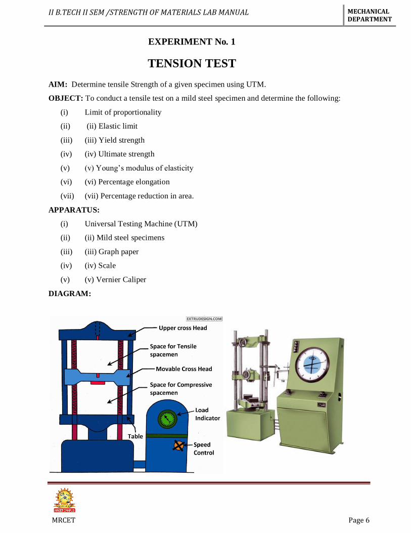
DIAGRAM:
II B.TECH II SEM /STRENGTH OF MATERIALS LAB MANUAL MECHANICAL DEPARTMENT
MRCET Page 7
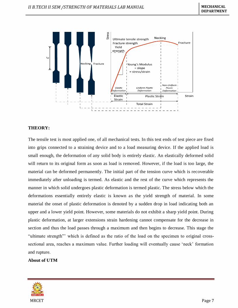
THEORY:
The tensile test is most applied one, of all mechanical tests. In this test ends of test piece are fixed
into grips connected to a straining device and to a load measuring device. If the applied load is
small enough, the deformation of any solid body is entirely elastic. An elastically deformed solid
will return to its original form as soon as load is removed. However, if the load is too large, the
material can be deformed permanently. The initial part of the tension curve which is recoverable
immediately after unloading is termed. As elastic and the rest of the curve which represents the
manner in which solid undergoes plastic deformation is termed plastic. The stress below which the
deformations essentially entirely elastic is known as the yield strength of material. In some
material the onset of plastic deformation is denoted by a sudden drop in load indicating both an
upper and a lower yield point. However, some materials do not exhibit a sharp yield point. During
plastic deformation, at larger extensions strain hardening cannot compensate for the decrease in
section and thus the load passes through a maximum and then begins to decrease. This stage the
“ultimate strength”’ which is defined as the ratio of the load on the specimen to original cross-
sectional area, reaches a maximum value. Further loading will eventually cause ‘neck’ formation
and rupture.
About of UTM
II B.TECH II SEM /STRENGTH OF MATERIALS LAB MANUAL MECHANICAL DEPARTMENT
MRCET Page 8
The tensile test is conducted on UTM. It is hydraulically operates a pump, oil in oil sump, load dial
indicator and central buttons. The left has upper, middle and lower cross heads i.e; specimen grips
(or jaws). Idle cross head can be moved up and down for adjustment. The pipes connecting the lift
and right parts are oil pipes through which the pumped oil under pressure flows on left parts to
more the cross-heads.
SPECIFICATIONS:
1. Load capacity = 0-40 Tones.
2. Least count = 8 kgf.
3. Overall dimension. =
4. Power supply = 440 V
PROCEDURE:
1. Measure the original length and diameter of the specimen. The length may either be length of
gauge section which is marked on the specimen with a preset punch or the total length of the
specimen
2. Insert the specimen into grips of the test machine and attach strain-measuring device to it
3. Begin the load application and record load versus elongation data.
4. Take readings more frequently as yield point is approached.
5. Measure elongation values with the help of dividers and a ruler.
6. Continue the test till Fracture occurs.
7. By joining the two broken halves of the specimen together, measure the final length and
diameter of specimen.
OBSEVATION:
(a) Initial diameter of specimen d1 =
(b) Initial gauge length of specimen L1 =
(c) Initial cross-section area of specimen A1 =
(d) Load of yield point Ft =
(e) Ultimate load after specimen breaking F =
(f) Final length after specimen breaking L2 =
(g) Diameter of specimen at breaking place d2 =
II B.TECH II SEM /STRENGTH OF MATERIALS LAB MANUAL MECHANICAL DEPARTMENT
MRCET Page 9
(h) Cross section area at breaking place A2 =
OBESERVATION TABLE:
S.No Load (N) Original
Gauge
Length
Extension
(mm)
Stress
(N/mm2)
Strain
CALCULATION:
Ultimate tensile strength =…………….𝑁
𝑚𝑚2
Elastic limit = 𝐿𝑜𝑎𝑑 𝑎𝑡 𝑒𝑙𝑎𝑠𝑡𝑖𝑐 𝑙𝑖𝑚𝑖𝑡
𝑜𝑟𝑖𝑔𝑖𝑛𝑎𝑙 𝑎𝑟𝑒𝑎 𝑜𝑓 𝑐𝑟𝑜𝑠 𝑠 𝑠𝑒𝑐𝑡𝑖𝑜𝑛 = ……………
𝑁
𝑚𝑚2
(iii) Modulus of Elasticity (E) = 𝑠𝑡𝑟𝑒𝑠𝑠 𝑏𝑒𝑙𝑜𝑤 𝑝𝑟𝑜𝑝𝑜𝑟𝑡𝑖𝑜𝑛𝑎𝑙 𝑙𝑖𝑚𝑖𝑡
𝑐𝑜𝑟𝑟𝑠𝑝𝑜𝑛𝑑𝑖𝑛𝑔 𝑠𝑡𝑟𝑎𝑖𝑛 =…….………
𝑁
𝑚𝑚2
(iv) Yield Strength = 𝑦𝑖𝑒𝑙𝑑 𝑙𝑜𝑎𝑑
𝑜𝑟𝑖𝑔𝑖𝑛𝑎𝑙 𝑐𝑟𝑜𝑠𝑠 𝑠𝑒𝑐𝑡𝑖𝑜𝑛𝑎𝑙 𝑎𝑟𝑒𝑎 =…………….
𝑁
𝑚𝑚2
% Reduction in area = 𝐴𝑓−𝐴𝑖
𝐴𝑖× 100 = ……………%
Percentage of elongation = 𝑙𝑖−𝑙𝑓
𝑙𝑓× 100 =……………..%
Limit of Propagation = 𝐿𝑜𝑎𝑑 𝑎𝑡 𝑙𝑖𝑚𝑖𝑡 𝑜𝑓 𝑝𝑟𝑜𝑝𝑟𝑡𝑖𝑜𝑛𝑎𝑙𝑖𝑡𝑦
𝑜𝑟𝑖𝑔𝑖𝑛𝑎𝑙 𝑐𝑟𝑜𝑠𝑠 𝑠𝑒𝑐𝑡𝑖𝑜𝑛𝑎𝑙 𝑎𝑟𝑒𝑎
Stress = 𝜎 =𝐿𝑜𝑎𝑑
𝐴𝑟𝑒𝑎 =
𝑃
𝐴 …………………..
𝑁
𝑚𝑚2
Strain = 𝜖 = 𝑐ℎ𝑎𝑛𝑔𝑒 𝑖𝑛 𝑙𝑒𝑛𝑔𝑡ℎ
𝑜𝑟𝑖𝑔𝑖𝑛𝑎𝑙 𝑙𝑒𝑛𝑔𝑡ℎ = …………..
Young’s modulus= E = 𝑠𝑡𝑟𝑠𝑠
𝑠𝑡𝑟𝑎𝑖𝑛 ………….
𝑁
𝑚𝑚2
II B.TECH II SEM /STRENGTH OF MATERIALS LAB MANUAL MECHANICAL DEPARTMENT
MRCET Page 10
PRECAUTIONS:
1. The specimen should be prepared in proper dimensions.
2. The specimen should be properly to get between the jaws.
3. Take reading carefully.
4. After breaking specimen stop to m/c.
RESULT:
( i) Average Breaking Stress =
(ii) Ultimate Stress =
(iii) Average % Elongation =
VIVA-QUESTIONS
1. Which steel have you tested? What is its carbon content?
2. What general information is obtained from tensile test regarding the properties of a material?
3. Which stress have you calculated: nominal stress or true stress?
4. What kind of fracture has occurred in the tensile specimen and why?
5. Which is the most ductile metal? How much is its elongation
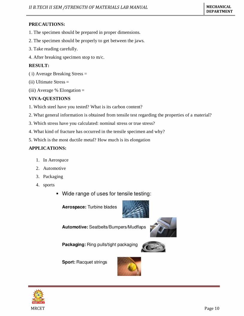
APPLICATIONS:
1. In Aerospace
2. Automotive
3. Packaging
4. sports
II B.TECH II SEM /STRENGTH OF MATERIALS LAB MANUAL MECHANICAL DEPARTMENT
MRCET Page 11
EXPERIMENT No. 2
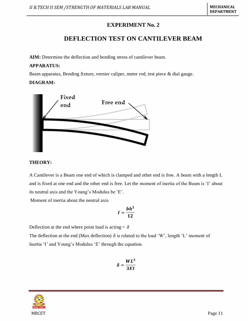
DEFLECTION TEST ON CANTILEVER BEAM
AIM: Determine the deflection and bending stress of cantilever beam.
APPARATUS:
Beam apparatus, Bending fixture, vernier caliper, meter rod, test piece & dial gauge.
DIAGRAM:
THEORY:
A Cantilever is a Beam one end of which is clamped and other end is free. A beam with a length L
and is fixed at one end and the other end is free. Let the moment of inertia of the Beam is ‘I’ about
its neutral axis and the Young’s Modulus be ’E’.
Moment of inertia about the neutral axis
𝑰 =𝒃𝒉𝟑
𝟏𝟐
Deflection at the end where point load is acting = 𝛿
The deflection at the end (Max deflection) 𝛿 is related to the load ‘W’, length ‘L’ moment of
Inertia ‘I’ and Young’s Modulus ‘E’ through the equation.
𝜹 =𝑾𝑳𝟑
𝟑𝑬𝑰
II B.TECH II SEM /STRENGTH OF MATERIALS LAB MANUAL MECHANICAL DEPARTMENT
MRCET Page 12
PROCEDURE:
1. Clamp the Beam horizontally on the clamping support at one end.
2. Measure the length of cantilever L (distance from clamp end to loading point)
3. Fix the dial gauge under the beam at the loading point to Read down-ward Moment and set
o zero.
4. Hang the loading Pan at the free end of the cantilever.
5. Load the cantilever with different loads (W) and note the dial gauge readings (𝛿)
6. Change the length of cantilever for two more different lengths repeat the Experiment.
7. Change the position of cantilever and repeat he experiment for the other value of I for
rectangular cross-section.
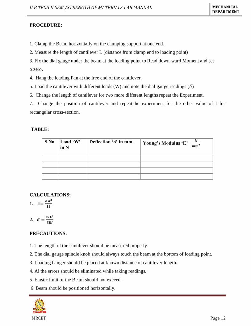
TABLE:
S.No Load ‘W’
in N
Deflection ‘δ’ in mm. Young’s Modulus ‘E’ 𝑵
𝒎𝒎𝟐
CALCULATIONS:
1. I=𝒃 𝒉𝟑
𝟏𝟐
2. 𝜹 =𝑾𝑳𝟑
𝟑𝑬𝑰
PRECAUTIONS:
1. The length of the cantilever should be measured properly.
2. The dial gauge spindle knob should always touch the beam at the bottom of loading point.
3. Loading hanger should be placed at known distance of cantilever length.
4. Al the errors should be eliminated while taking readings.
5. Elastic limit of the Beam should not exceed.
6. Beam should be positioned horizontally.
II B.TECH II SEM /STRENGTH OF MATERIALS LAB MANUAL MECHANICAL DEPARTMENT
MRCET Page 13
RESULT: The Bending strength of given specimen = -------𝑁
𝑚𝑚2
VIVA QUESTIONS:
1. Cantilever beam means?
2. What is the deflection formula of cantilever beam?
3. What is the difference between cantilever and simply supported beam?
4. Write types of loads?
5. Contra flexure means?
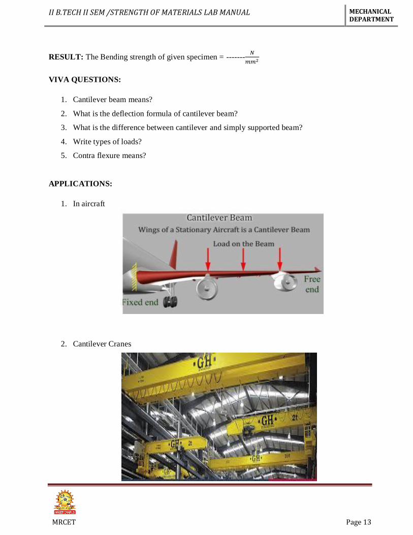
APPLICATIONS:
1. In aircraft
2. Cantilever Cranes
II B.TECH II SEM /STRENGTH OF MATERIALS LAB MANUAL MECHANICAL DEPARTMENT
MRCET Page 14
EXPERIMENT No. 3
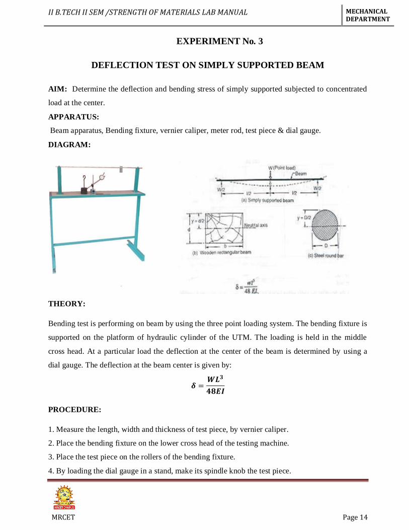
DEFLECTION TEST ON SIMPLY SUPPORTED BEAM
AIM: Determine the deflection and bending stress of simply supported subjected to concentrated
load at the center.
APPARATUS:
Beam apparatus, Bending fixture, vernier caliper, meter rod, test piece & dial gauge.
DIAGRAM:
THEORY:
Bending test is performing on beam by using the three point loading system. The bending fixture is
supported on the platform of hydraulic cylinder of the UTM. The loading is held in the middle
cross head. At a particular load the deflection at the center of the beam is determined by using a
dial gauge. The deflection at the beam center is given by:
𝜹 =𝑾𝑳𝟑
𝟒𝟖𝑬𝑰
PROCEDURE:
1. Measure the length, width and thickness of test piece, by vernier caliper.
2. Place the bending fixture on the lower cross head of the testing machine.
3. Place the test piece on the rollers of the bending fixture.
4. By loading the dial gauge in a stand, make its spindle knob the test piece.
II B.TECH II SEM /STRENGTH OF MATERIALS LAB MANUAL MECHANICAL DEPARTMENT
MRCET Page 15
5. Start the m/c and note down the load and dial gauge readings.
6. Plot the graph between load and deflection.
OBSERVATIONS:
1. Least count of vernier caliper = -----
2. Length of beam (L) = ------
3. Width of beam (b) = ------
4. Thickness of beam (t) = ------
TABLE:
S.No Load ‘W’
in N
Deflection ‘δ’ in mm. Young’s Modulus ‘E’ 𝑵
𝒎𝒎𝟐
CALCULATIONS:
1. I=𝒃 𝒕𝟑
𝟏𝟐
2. 𝜹 =𝑾𝑳𝟑
𝟒𝟖𝑬𝑰
PRECAUTIONS:
1. The length of the simply supported should be measured properly.
2. The dial gauge spindle knob should always touch the beam at the bottom of loading point.
3. Loading hanger should be placed at known distance
4. Al the errors should be eliminated while taking readings.
5. Beam should be positioned horizontally.
RESULT:
The Bending strength of given specimen = -------𝑵
𝒎𝒎𝟐
II B.TECH II SEM /STRENGTH OF MATERIALS LAB MANUAL MECHANICAL DEPARTMENT
MRCET Page 16
VIVA QUESTIONS
1. Types of beams.
2. What is deflection?
3. Write the equation for the Slope for a cantilever beam with point load
4. Write the deflection equation for the simply supported beam with point load at the center
5. How many types of bending are there?
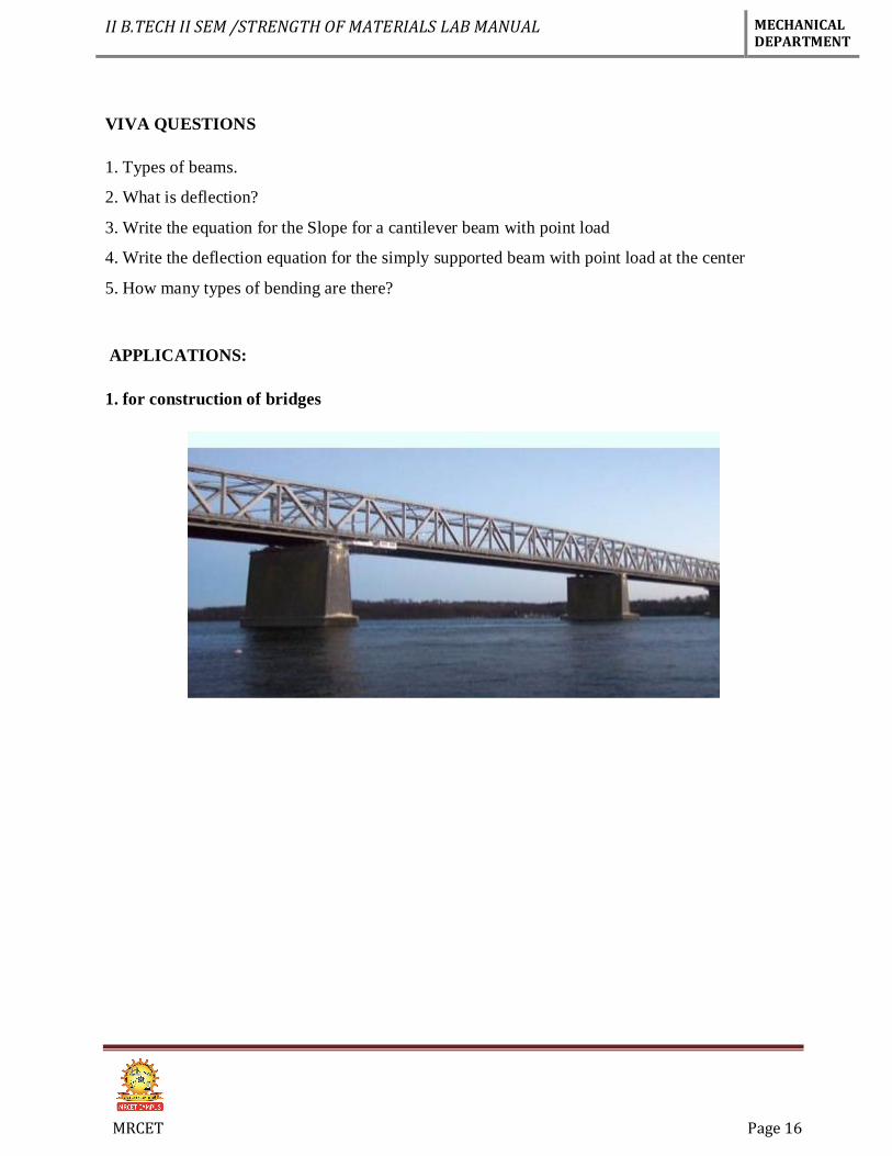
APPLICATIONS:
1. for construction of bridges
II B.TECH II SEM /STRENGTH OF MATERIALS LAB MANUAL MECHANICAL DEPARTMENT
MRCET Page 17
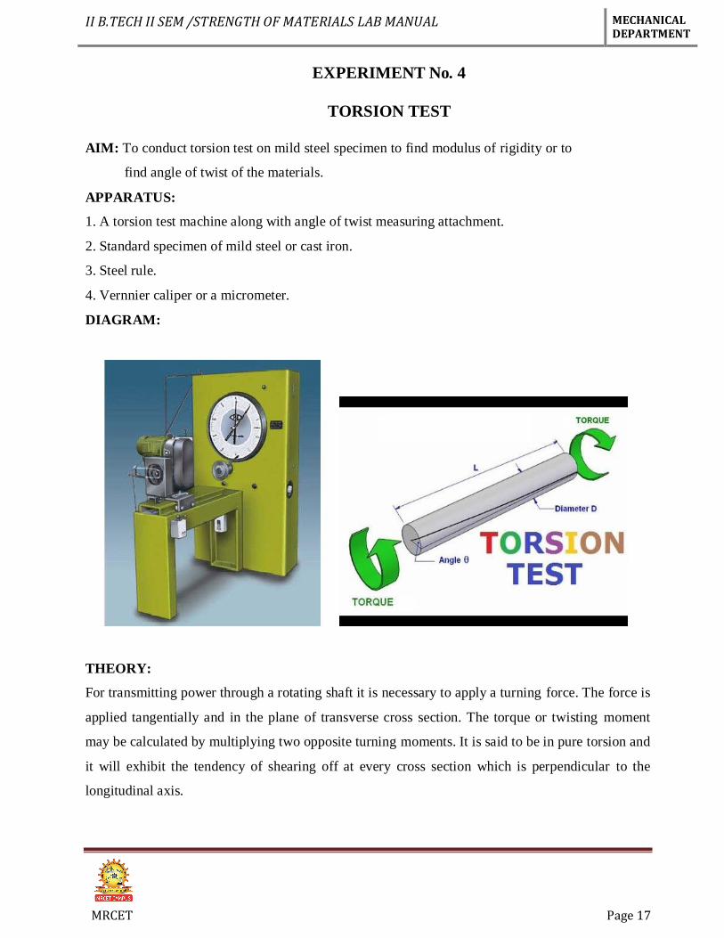
EXPERIMENT No. 4
TORSION TEST
AIM: To conduct torsion test on mild steel specimen to find modulus of rigidity or to
find angle of twist of the materials.
APPARATUS:
1. A torsion test machine along with angle of twist measuring attachment.
2. Standard specimen of mild steel or cast iron.
3. Steel rule.
4. Vernnier caliper or a micrometer.
DIAGRAM:
THEORY:
For transmitting power through a rotating shaft it is necessary to apply a turning force. The force is
applied tangentially and in the plane of transverse cross section. The torque or twisting moment
may be calculated by multiplying two opposite turning moments. It is said to be in pure torsion and
it will exhibit the tendency of shearing off at every cross section which is perpendicular to the
longitudinal axis.
II B.TECH II SEM /STRENGTH OF MATERIALS LAB MANUAL MECHANICAL DEPARTMENT
MRCET Page 18
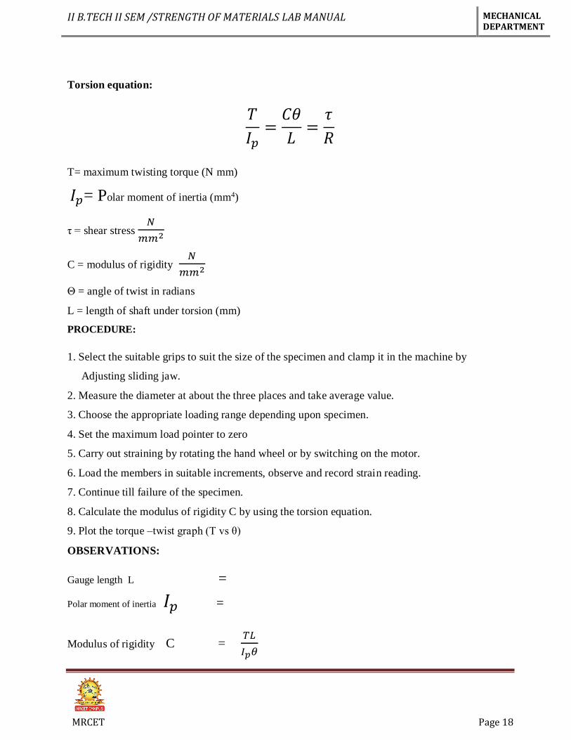
Torsion equation:
𝑇
𝐼𝑝=
𝐶𝜃
𝐿=
𝜏
𝑅
T= maximum twisting torque (N mm)
𝐼𝑝= Polar moment of inertia (mm4)
τ = shear stress 𝑁
𝑚𝑚2
C = modulus of rigidity 𝑁
𝑚𝑚2
Θ = angle of twist in radians
L = length of shaft under torsion (mm)
PROCEDURE:
1. Select the suitable grips to suit the size of the specimen and clamp it in the machine by
Adjusting sliding jaw.
2. Measure the diameter at about the three places and take average value.
3. Choose the appropriate loading range depending upon specimen.
4. Set the maximum load pointer to zero
5. Carry out straining by rotating the hand wheel or by switching on the motor.
6. Load the members in suitable increments, observe and record strain reading.
7. Continue till failure of the specimen.
8. Calculate the modulus of rigidity C by using the torsion equation.
9. Plot the torque –twist graph (T vs θ)
OBSERVATIONS:
Gauge length L =
Polar moment of inertia 𝐼𝑝 =
Modulus of rigidity C = 𝑇𝐿
𝐼𝑝𝜃
II B.TECH II SEM /STRENGTH OF MATERIALS LAB MANUAL MECHANICAL DEPARTMENT
MRCET Page 19
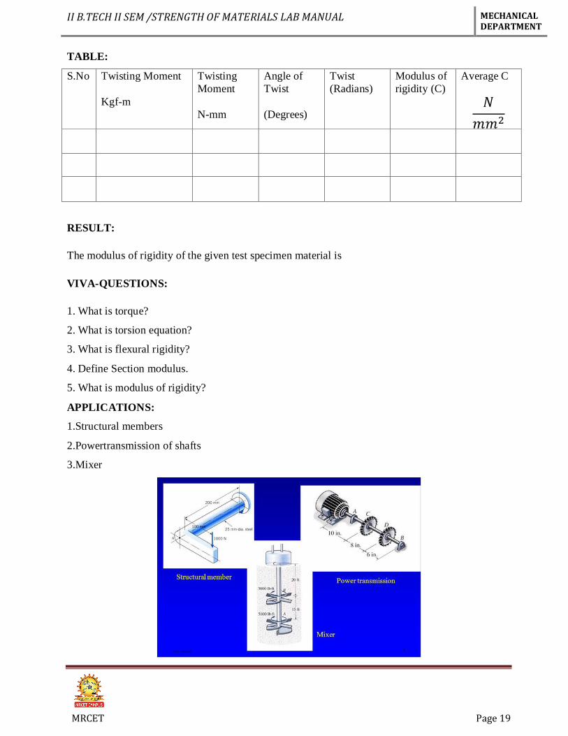
TABLE:
S.No Twisting Moment
Kgf-m
Twisting
Moment
N-mm
Angle of
Twist
(Degrees)
Twist
(Radians)
Modulus of
rigidity (C)
Average C
𝑁
𝑚𝑚2
RESULT:
The modulus of rigidity of the given test specimen material is
VIVA-QUESTIONS:
1. What is torque?
2. What is torsion equation?
3. What is flexural rigidity?
4. Define Section modulus.
5. What is modulus of rigidity?
APPLICATIONS:
1.Structural members
2.Powertransmission of shafts
3.Mixer
II B.TECH II SEM /STRENGTH OF MATERIALS LAB MANUAL MECHANICAL DEPARTMENT
MRCET Page 20
EXPERIMENT No. 5
SPRING TEST AIM: Determine the stiffness of the spring and modulus of rigidity of the spring wire
OBJECT: To determine the stiffness of the spring and modulus of rigidity of the spring
APPARATUS:
i) Spring testing machine.
ii) A spring iii) Vernier caliper,
iii) Scale.
iv) Micrometer.
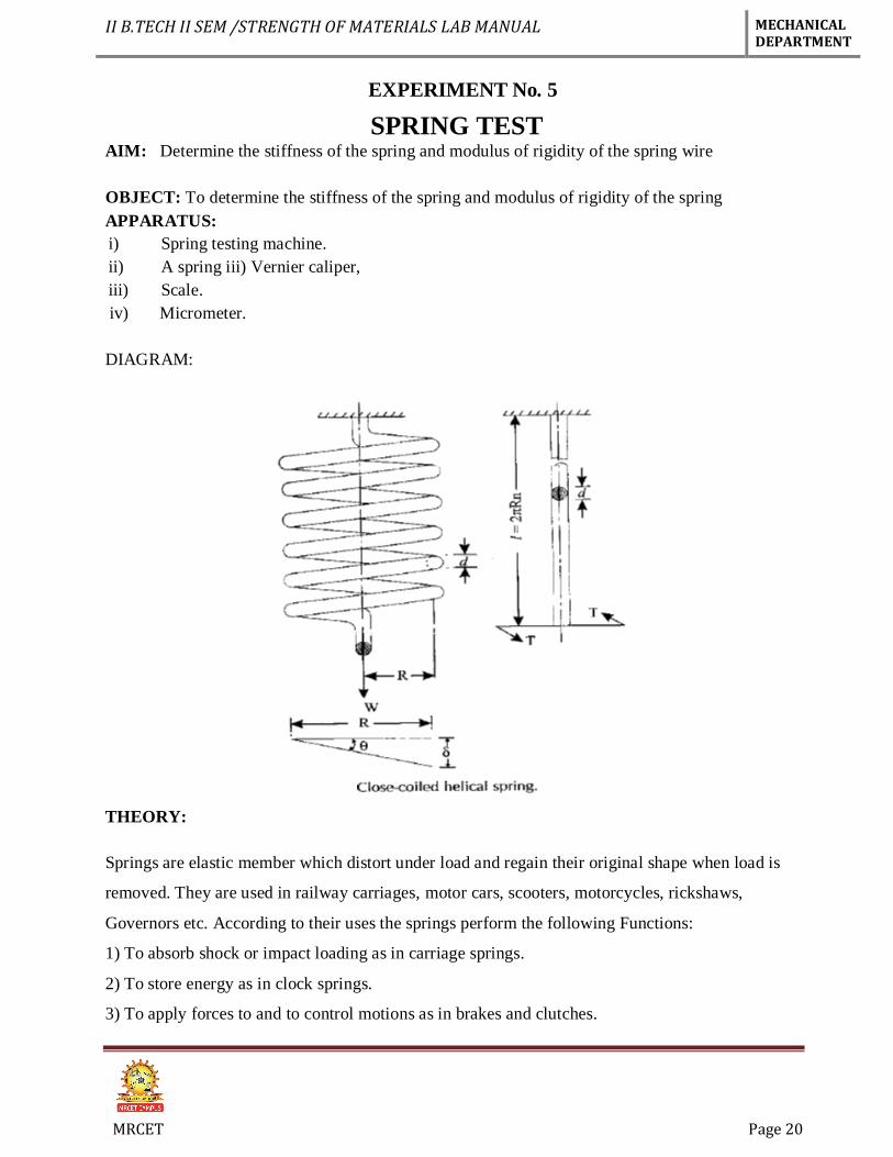
DIAGRAM:
THEORY:
Springs are elastic member which distort under load and regain their original shape when load is
removed. They are used in railway carriages, motor cars, scooters, motorcycles, rickshaws,
Governors etc. According to their uses the springs perform the following Functions:
1) To absorb shock or impact loading as in carriage springs.
2) To store energy as in clock springs.
3) To apply forces to and to control motions as in brakes and clutches.
II B.TECH II SEM /STRENGTH OF MATERIALS LAB MANUAL MECHANICAL DEPARTMENT
MRCET Page 21
4) To measure forces as in spring balances.
5) To change the variations characteristic of a member as in flexible mounting of motors.
The spring is usually made of either high carbon steel (0.7 to 1.0%) or medium carbon alloy steels.
Phosphor bronze, brass, 18/8 stainless steel and Monel and other metal alloys are used for
Corrosion resistance spring. Several types of spring are available for different application. Springs
may classify as helical springs, leaf springs and flat spring depending upon their shape. They are
fabricated of high shear strength materials such as high carbon alloy steels spring form elements of
not only mechanical system but also structural system. In several cases it is essential to idealize
Complex structural systems by suitable spring.
PROCEDURE:
1) Measure the diameter of the wire of the spring by using the micrometer.
2) Measure the diameter of spring coils by using the vernier caliper
3) Count the number of turns.
4) Insert the spring in the spring testing machine and load the spring by a suitable weight and note
the corresponding axial deflection in tension or compression.
5) Increase the load and take the corresponding axial deflection readings.
6) Plot a curve between load and deflection. The shape of the curve gives the stiffness of the
Spring.
OBESERVATION
Least count of micrometer = ………mm
Diameter of the spring wire, d =……… mm (Mean of three readings)
Least count of vernier caliper = ………mm
Diameter of the spring coil, D = ………mm (Mean of three readings)
Mean coil diameter, Dm = D – d =……… mm
Number of turns, n =………
II B.TECH II SEM /STRENGTH OF MATERIALS LAB MANUAL MECHANICAL DEPARTMENT
MRCET Page 22
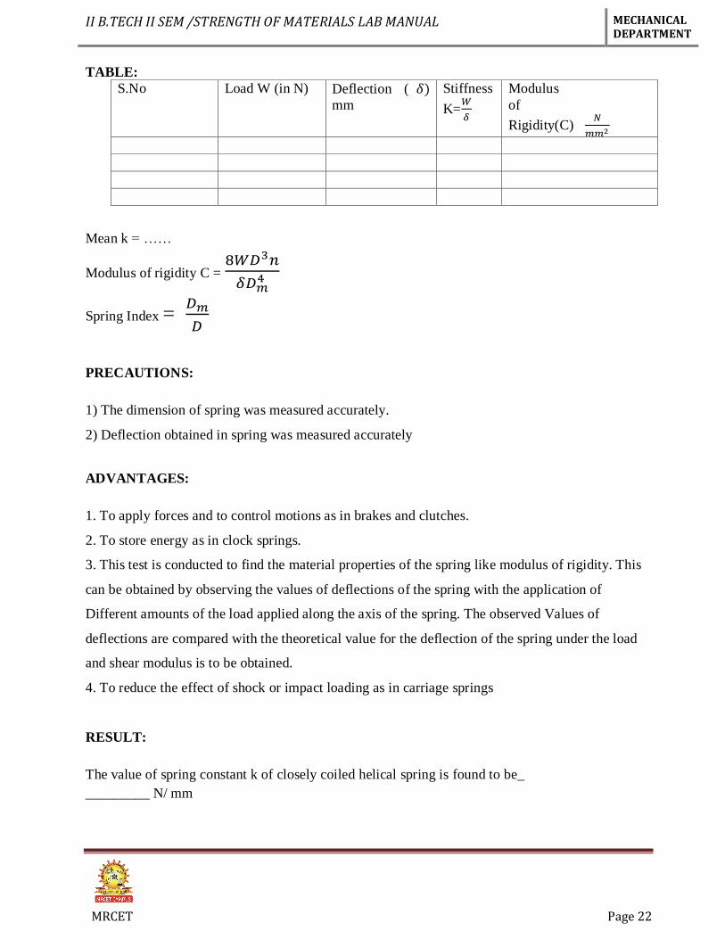
TABLE:
S.No Load W (in N) Deflection ( 𝛿)
mm
Stiffness
K=𝑊
𝛿
Modulus
of
Rigidity(C) 𝑁
𝑚𝑚2
Mean k = ……
Modulus of rigidity C = 8𝑊𝐷3𝑛
𝛿𝐷𝑚4
Spring Index = 𝐷𝑚
𝐷
PRECAUTIONS:
1) The dimension of spring was measured accurately.
2) Deflection obtained in spring was measured accurately
ADVANTAGES:
1. To apply forces and to control motions as in brakes and clutches.
2. To store energy as in clock springs.
3. This test is conducted to find the material properties of the spring like modulus of rigidity. This
can be obtained by observing the values of deflections of the spring with the application of
Different amounts of the load applied along the axis of the spring. The observed Values of
deflections are compared with the theoretical value for the deflection of the spring under the load
and shear modulus is to be obtained.
4. To reduce the effect of shock or impact loading as in carriage springs
RESULT:
The value of spring constant k of closely coiled helical spring is found to be_
_________ N/ mm
II B.TECH II SEM /STRENGTH OF MATERIALS LAB MANUAL MECHANICAL DEPARTMENT
MRCET Page 23
VIVA QUESTIONS:
1. What is meant by stiffness
2. Define deflection
3. What are different types of springs
4. Define helical spring
5. What is the strain energy stored in the springs
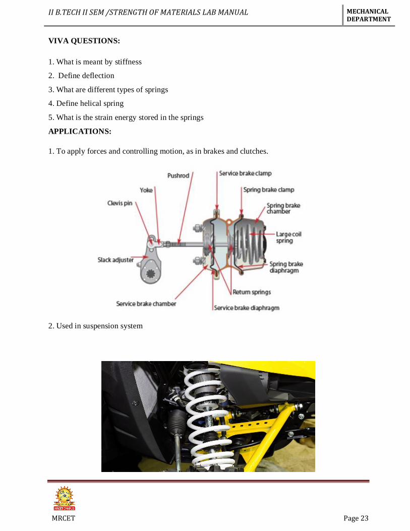
APPLICATIONS:
1. To apply forces and controlling motion, as in brakes and clutches.
2. Used in suspension system
II B.TECH II SEM /STRENGTH OF MATERIALS LAB MANUAL MECHANICAL DEPARTMENT
MRCET Page 24
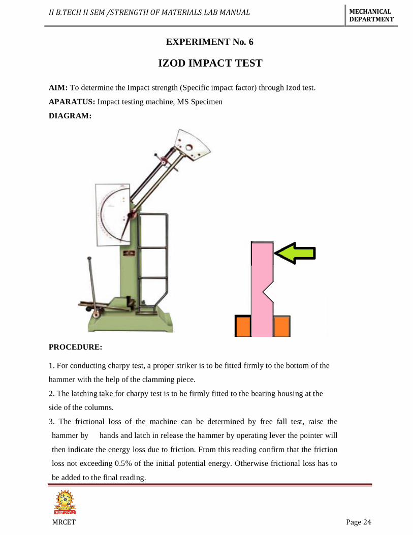
EXPERIMENT No. 6
IZOD IMPACT TEST
AIM: To determine the Impact strength (Specific impact factor) through Izod test.
APARATUS: Impact testing machine, MS Specimen
DIAGRAM:
PROCEDURE:
1. For conducting charpy test, a proper striker is to be fitted firmly to the bottom of the
hammer with the help of the clamming piece.
2. The latching take for charpy test is to be firmly fitted to the bearing housing at the
side of the columns.
3. The frictional loss of the machine can be determined by free fall test, raise the
hammer by hands and latch in release the hammer by operating lever the pointer will
then indicate the energy loss due to friction. From this reading confirm that the friction
loss not exceeding 0.5% of the initial potential energy. Otherwise frictional loss has to
be added to the final reading.
II B.TECH II SEM /STRENGTH OF MATERIALS LAB MANUAL MECHANICAL DEPARTMENT
MRCET Page 25
4. The specimen for izod test is firmly fitted in the specimen support with the help of
clamping screw and élan key. Care should be taken that the notch on the specimen should
face to pendulum striker.
5. After ascertaining that there is no person in the range of swinging pendulum, release
them pendulum to smash the specimen.
6. Carefully operate the pendulum brake when returning after one swing to stop the
oscillations.
7. Read-off position of reading pointer on dial and note indicated value.
8. Remove the broken specimen by loosening the clamping screw.
The notch impact strength depends largely on the shape of the specimen and the notch.
the values determined with other specimens therefore may not be compared with each
other.
TABLE:
S.NO Area of cross section specimen (A) Impact Energy (K) I (Impact strength)
PRECAUTIONS:
1. Measure the dimensions of the specimen carefully.
2. Locate the specimen in such a way that the hammer. Strikes it at the middle.
3. Note down readings carefully.

II B.TECH II SEM /STRENGTH OF MATERIALS LAB MANUAL MECHANICAL DEPARTMENT
MRCET Page 26
RESULT:
The Impact strength of the given specimen is ----------- 𝐽
𝑚2
VIVA QUESTIONS:
1. In what way the values of impact energy will be influenced if the impact tests are conducted
on two specimens, one having smooth surface and the other having scratches on the surface
2. What is the effect of temp? On the values of rupture energy and notch impact strength?
3. What is resilience? How is it different from proof resilience and toughness?
4. What is the necessity of making a notch in impact test specimen?
5. If the sharpness of V-notch is more in one specimen than the other, what will be its effect on
the test result ?
APPLICATIONS:
1. in forging industry.
2. in the rubber industry.
II B.TECH II SEM /STRENGTH OF MATERIALS LAB MANUAL MECHANICAL DEPARTMENT
MRCET Page 27
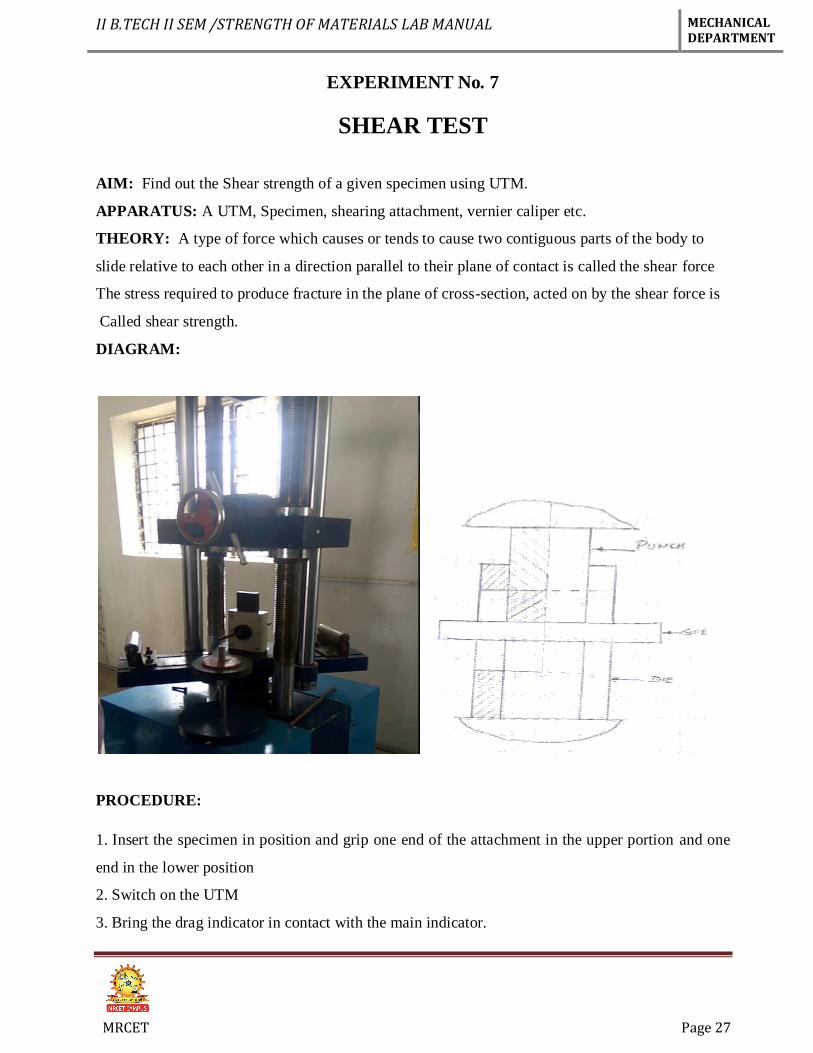
EXPERIMENT No. 7
SHEAR TEST
AIM: Find out the Shear strength of a given specimen using UTM.
APPARATUS: A UTM, Specimen, shearing attachment, vernier caliper etc.
THEORY: A type of force which causes or tends to cause two contiguous parts of the body to
slide relative to each other in a direction parallel to their plane of contact is called the shear force
The stress required to produce fracture in the plane of cross-section, acted on by the shear force is
Called shear strength.
DIAGRAM:
PROCEDURE:
1. Insert the specimen in position and grip one end of the attachment in the upper portion and one
end in the lower position
2. Switch on the UTM
3. Bring the drag indicator in contact with the main indicator.
II B.TECH II SEM /STRENGTH OF MATERIALS LAB MANUAL MECHANICAL DEPARTMENT
MRCET Page 28
4. Select the suitable range of loads and space the corresponding weight in the
Pendulum and balance it if necessary with the help of small balancing weights
5. Operate (push) the button for driving the motor to drive the pump.
6. Gradually move the head control ever in left hand direction till the specimen shears.
7. Note down the load at which the specimen shears.
8. Stop the machine and remove the specimen.
9. Repeat the experiment with other specimens.
OBSERVATION:
1. Applied compressive force (F) = ---------kgf.
2. Diameter of specimen = ---------mm.
3. Cross sectional area of the pin (in double shear) = 2×𝜋×𝑑2
4 mm2
4. Load taken by the specimen at the time of failure, W = …… (N)
5. Strength of the pin against shearing (τ) = 4×𝑊
2×𝜋×𝑑2
PRECAUTIONS:
1. The measuring range should not be changed at any stage during the test.
2. The inner diameter of the hole in the shear stress attachment should be slightly greater than the
specimen.
3. Measure the diameter of the specimen accurately.
4. The method for determining the shear strength consists of subjecting a suitable Length of steel
specimen in full cross-section to double shear, using a suitable test rig, in a testing m/c under a
compressive load or tensile pull and recording the maximum load ‘F’ to fracture.
RESULT:
Shear strength of specimen = --------
II B.TECH II SEM /STRENGTH OF MATERIALS LAB MANUAL MECHANICAL DEPARTMENT
MRCET Page 29
VIVA-QUESTIONS:
1. Does the shear failure in wood occur along the 45° shear plane?
2. What is shear stress?
3. What is single & double shear?
4. What is finding in shear test?
5. What is unit of shear strength?
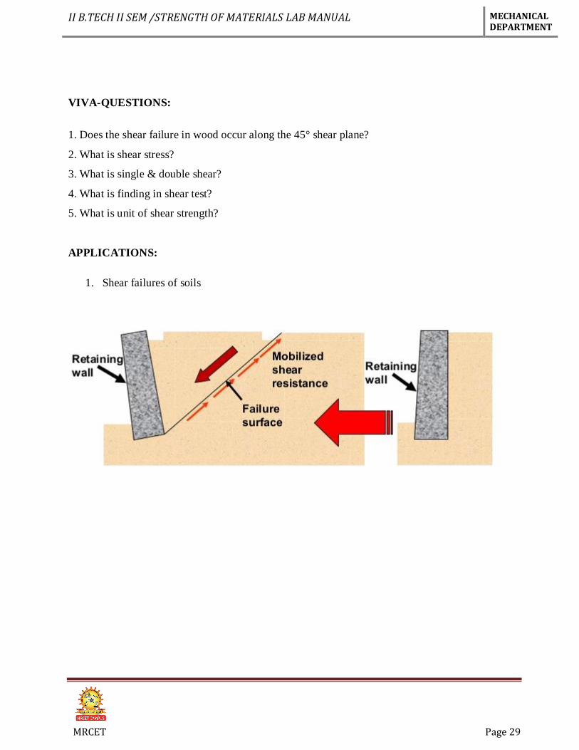
APPLICATIONS:
1. Shear failures of soils
II B.TECH II SEM /STRENGTH OF MATERIALS LAB MANUAL MECHANICAL DEPARTMENT
MRCET Page 30
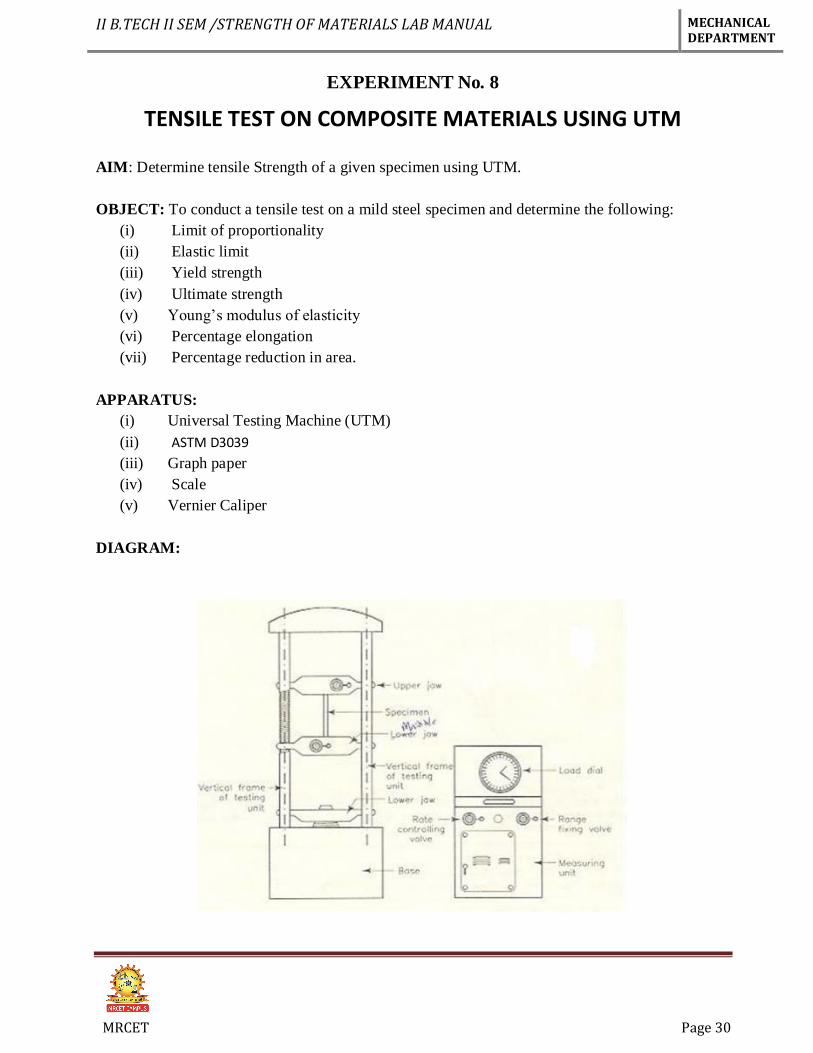
EXPERIMENT No. 8
TENSILE TEST ON COMPOSITE MATERIALS USING UTM
AIM: Determine tensile Strength of a given specimen using UTM.
OBJECT: To conduct a tensile test on a mild steel specimen and determine the following:
(i) Limit of proportionality
(ii) Elastic limit
(iii) Yield strength
(iv) Ultimate strength
(v) Young’s modulus of elasticity
(vi) Percentage elongation
(vii) Percentage reduction in area.
APPARATUS:
(i) Universal Testing Machine (UTM)
(ii) ASTM D3039
(iii) Graph paper
(iv) Scale
(v) Vernier Caliper
DIAGRAM:
II B.TECH II SEM /STRENGTH OF MATERIALS LAB MANUAL MECHANICAL DEPARTMENT
MRCET Page 31
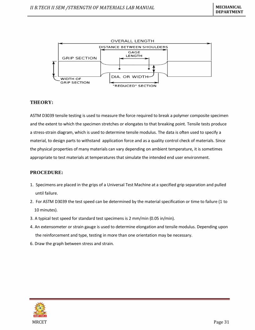
THEORY:
ASTM D3039 tensile testing is used to measure the force required to break a polymer composite specimen
and the extent to which the specimen stretches or elongates to that breaking point. Tensile tests produce
a stress-strain diagram, which is used to determine tensile modulus. The data is often used to specify a
material, to design parts to withstand application force and as a quality control check of materials. Since
the physical properties of many materials can vary depending on ambient temperature, it is sometimes
appropriate to test materials at temperatures that simulate the intended end user environment.
PROCEDURE:
1. Specimens are placed in the grips of a Universal Test Machine at a specified grip separation and pulled
until failure.
2. For ASTM D3039 the test speed can be determined by the material specification or time to failure (1 to
10 minutes).
3. A typical test speed for standard test specimens is 2 mm/min (0.05 in/min).
4. An extensometer or strain gauge is used to determine elongation and tensile modulus. Depending upon
the reinforcement and type, testing in more than one orientation may be necessary.
6. Draw the graph between stress and strain.
II B.TECH II SEM /STRENGTH OF MATERIALS LAB MANUAL MECHANICAL DEPARTMENT
MRCET Page 32
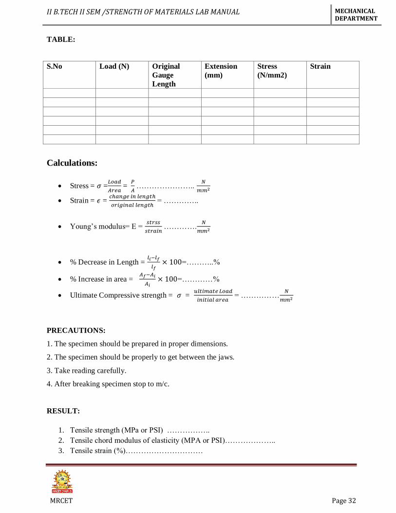
TABLE:
S.No Load (N) Original
Gauge
Length
Extension
(mm)
Stress
(N/mm2)
Strain
Calculations:
Stress = 𝜎 =𝐿𝑜𝑎𝑑
𝐴𝑟𝑒𝑎 =
𝑃
𝐴 …………………..
𝑁
𝑚𝑚2
Strain = 𝜖 = 𝑐ℎ𝑎𝑛𝑔𝑒 𝑖𝑛 𝑙𝑒𝑛𝑔𝑡ℎ
𝑜𝑟𝑖𝑔𝑖𝑛𝑎𝑙 𝑙𝑒𝑛𝑔𝑡ℎ = …………..
Young’s modulus= E = 𝑠𝑡𝑟𝑠𝑠
𝑠𝑡𝑟𝑎𝑖𝑛 ………….
𝑁
𝑚𝑚2
% Decrease in Length = 𝑙𝑖−𝑙𝑓
𝑙𝑓× 100=………..%
% Increase in area = 𝐴𝑓−𝐴𝑖
𝐴𝑖× 100=…………%
Ultimate Compressive strength = 𝜎 = 𝑢𝑙𝑡𝑖𝑚𝑎𝑡𝑒 𝐿𝑜𝑎𝑑
𝑖𝑛𝑖𝑡𝑖𝑎𝑙 𝑎𝑟𝑒𝑎 = ……………
𝑁
𝑚𝑚2
PRECAUTIONS:
1. The specimen should be prepared in proper dimensions.
2. The specimen should be properly to get between the jaws.
3. Take reading carefully.
4. After breaking specimen stop to m/c.
RESULT:
1. Tensile strength (MPa or PSI) ……………..
2. Tensile chord modulus of elasticity (MPA or PSI)………………..
3. Tensile strain (%)…………………………
II B.TECH II SEM /STRENGTH OF MATERIALS LAB MANUAL MECHANICAL DEPARTMENT
MRCET Page 33
VIVA QUESTIONS
1. State the composite materials?
2. ASTM means?
3. Which type of material used in this test?
4. Explain the stress strain curve for composite materials?
5. What is the use of tensile test?
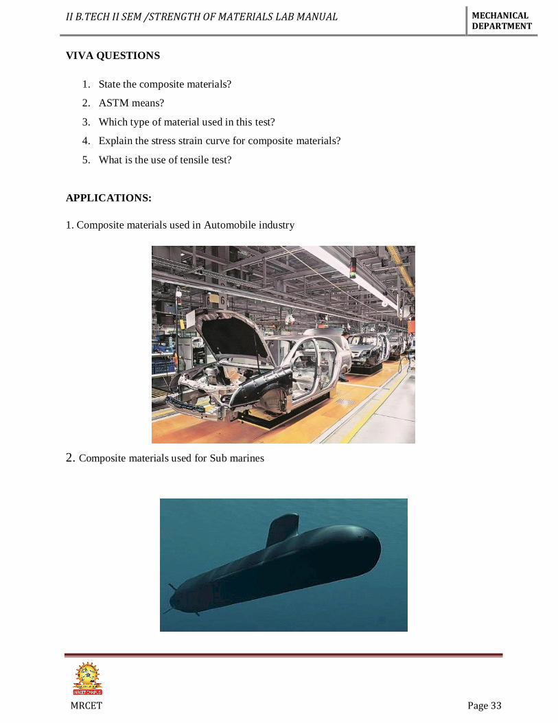
APPLICATIONS:
1. Composite materials used in Automobile industry
2. Composite materials used for Sub marines
II B.TECH II SEM /STRENGTH OF MATERIALS LAB MANUAL MECHANICAL DEPARTMENT
MRCET Page 34
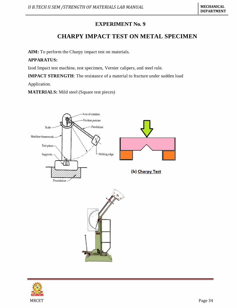
EXPERIMENT No. 9
CHARPY IMPACT TEST ON METAL SPECIMEN
AIM: To perform the Charpy impact test on materials.
APPARATUS:
Izod Impact test machine, test specimen, Vernier calipers, and steel rule.
IMPACT STRENGTH: The resistance of a material to fracture under sudden load
Application.
MATERIALS: Mild steel (Square test pieces)
II B.TECH II SEM /STRENGTH OF MATERIALS LAB MANUAL MECHANICAL DEPARTMENT
MRCET Page 35
THEORY:
An impact test signifies toughness of material that is ability of material to absorb energy
during plastic deformation. The type of test specimen used for this test is a Square
Cross-section. The specimen may have single, two or three notches.
The testing machine should have the following specifications.
The angle 0 between top face of grips and face holding the specimen
vertical=900 The angle of tip of hammer =750±10
The angle between normal to the specimen and underside face of the hammer at
striking point= 100±10
Speed of hammer at impact=3.99 m/sec
Striking energy=168N-m or Joules
Angle of drop 0of pendulum =90
Effective weight of pendulum=21.79kg
Minimum value of scale graduation=2 Joules.
Permissible total friction loss of corresponding energy=0.50%
Distance from the axis of rotation of distance between the base of specimen
notch and the point of specimen hit by the hammer=22mm±0.5mm
The longitudinal axes of the test piece shall lie in the plane of swing
of the center of gravity of the hammer. The notch shall be positioned so that it is in the
plane of the hammer .the notch shall be positioned its plane of symmetry coincides with
the top face of the grips .for setting the specimen the notch impact strength I is
calculated according to the following relation.
Where I= impact strength in joules/m2
PROCEDURE:
1. For conducting charpy test, a proper striker is to be fitted firmly to the bottom of the
hammer with the help of the clamming piece.
2. The latching take for charpy test is to be firmly fitted to the bearing housing at the
side of the columns.
3. The frictional loss of the machine can be determined by free fall test, raise the
hammer by hands and latch in release the hammer by operating lever the pointer will
II B.TECH II SEM /STRENGTH OF MATERIALS LAB MANUAL MECHANICAL DEPARTMENT
MRCET Page 36
then indicate the energy loss due to friction. From this reading confirm that the friction
loss not exceeding 0.5% of the initial potential energy. Otherwise frictional loss has to
be added to the final reading.
4. The specimen for izod test is firmly fitted in the specimen support with the help of
clamping screw and élan key. Care should be taken that the notch on the specimen should
face to pendulum striker.
5. After ascertaining that there is no person in the range of swinging pendulum, release
them pendulum to smash the specimen.
6. Carefully operate the pendulum brake when returning after one swing to stop the
oscillations.
7. Read-off position of reading pointer on dial and note indicated value.
8. Remove the broken specimen by loosening the clamping screw.
9. The notch impact strength depends largely on the shape of the specimen and the
notch. The values determined with other specimens therefore may not be compared with
each other.
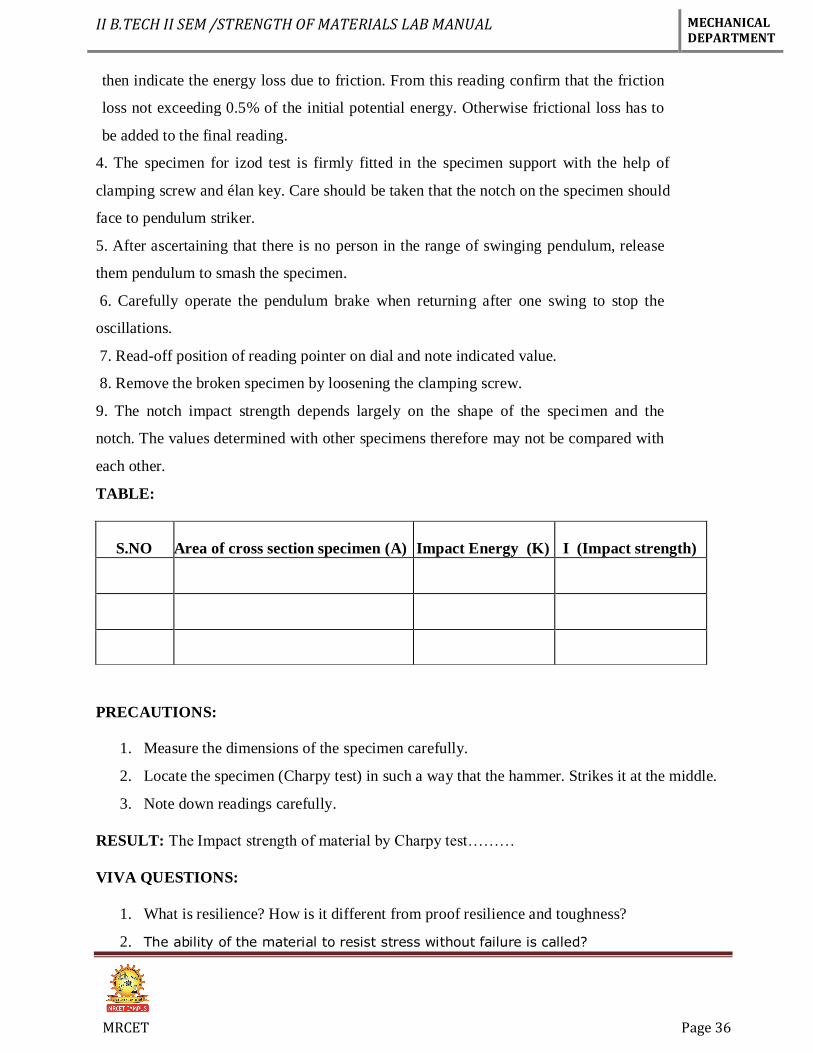
TABLE:
S.NO Area of cross section specimen (A) Impact Energy (K) I (Impact strength)
PRECAUTIONS:
1. Measure the dimensions of the specimen carefully.
2. Locate the specimen (Charpy test) in such a way that the hammer. Strikes it at the middle.
3. Note down readings carefully.
RESULT: The Impact strength of material by Charpy test………
VIVA QUESTIONS:
1. What is resilience? How is it different from proof resilience and toughness?
2. The ability of the material to resist stress without failure is called?

II B.TECH II SEM /STRENGTH OF MATERIALS LAB MANUAL MECHANICAL DEPARTMENT
MRCET Page 37
3. The impact test is done to test _____ of a material?
4. In Charpy impact test, the specimen is kept as______________?
5. In charpy test specimen, the angle of v-notch section is?
APPLICATIONS:
In forging industry:
The Charpy impact test can be used to determine the malleability and ductility of a
material that is being forged.
In plastic industry,
The test is used for analyzing the breaking strength of a sample when it is subjected to a high
impact from a pendulum. This helps in ensuring that the material is best for an application
where it is subjected to such impacts.
II B.TECH II SEM /STRENGTH OF MATERIALS LAB MANUAL MECHANICAL DEPARTMENT
MRCET Page 38
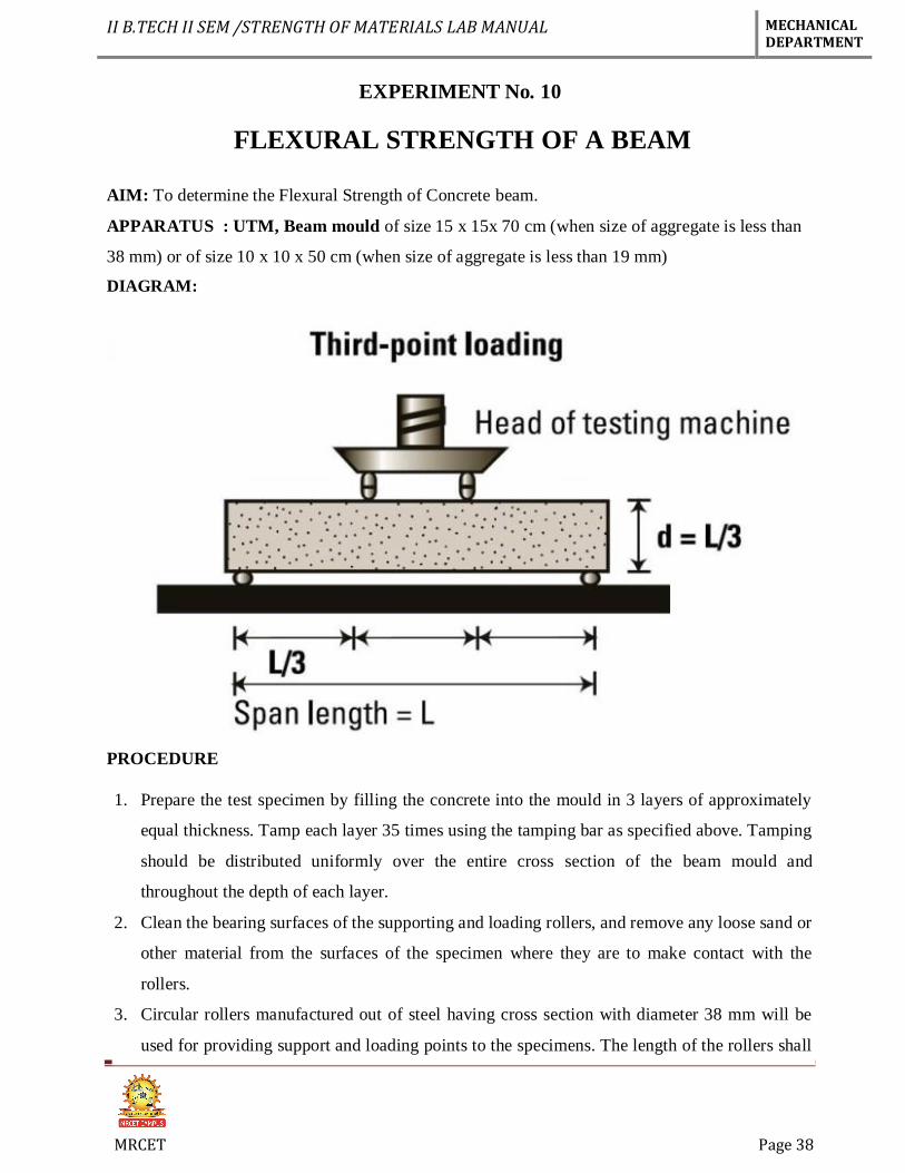
EXPERIMENT No. 10
FLEXURAL STRENGTH OF A BEAM
AIM: To determine the Flexural Strength of Concrete beam.
APPARATUS : UTM, Beam mould of size 15 x 15x 70 cm (when size of aggregate is less than
38 mm) or of size 10 x 10 x 50 cm (when size of aggregate is less than 19 mm)
DIAGRAM:
PROCEDURE
1. Prepare the test specimen by filling the concrete into the mould in 3 layers of approximately
equal thickness. Tamp each layer 35 times using the tamping bar as specified above. Tamping
should be distributed uniformly over the entire cross section of the beam mould and
throughout the depth of each layer.
2. Clean the bearing surfaces of the supporting and loading rollers, and remove any loose sand or
other material from the surfaces of the specimen where they are to make contact with the
rollers.
3. Circular rollers manufactured out of steel having cross section with diameter 38 mm will be
used for providing support and loading points to the specimens. The length of the rollers shall
II B.TECH II SEM /STRENGTH OF MATERIALS LAB MANUAL MECHANICAL DEPARTMENT
MRCET Page 39
be at least 10 mm more than the width of the test specimen. A total of four rollers shall be
used, three out of which shall be capable of rotating along their own axes. The distance
between the outer rollers (i.e. span) shall be 3d and the distance between the inner rollers shall
be d. The inner rollers shall be equally spaced between the outer rollers, such that the entire
system is systematic.
4. The specimen stored in water shall be tested immediately on removal from water; whilst they
are still wet. The test specimen shall be placed in the machine correctly centered with the
longitudinal axis of the specimen at right angles to the rollers. For moulded specimens, the
mould filling direction shall be normal to the direction of loading.
The load shall be applied at a rate of loading of 400 kg/min for the 15.0 cm specimens and at a rate
of 180 kg/min for the 10.0 cm specimens
CALCULATION
The Flexural Strength or modulus of rupture (fb) is given by
fb = 𝑷𝑳
𝒃𝒅𝟐 (when a > 20.0cm for 15.0cm specimen or > 13.0cm for 10cm specimen)
or
fb = 𝟑𝑷𝒂
𝒃𝒅𝟐 (when a < 20.0cm but > 17.0 for 15.0cm specimen or < 13.3 cm but > 11.0cm for
10.0cm specimen.)
Where,
a = the distance between the line of fracture and the nearer support, measured on the center line of
the tensile side of the specimen
b = width of specimen (cm)
d = failure point depth (cm)
l = supported length (cm)
p = max. Load (kg)
PRECAUTIONS:
Use hand gloves while, safety shoes at the time of test.
After test switch off the machine.
Keep all the exposed metal parts greased.
Keep the guide rods firmly fixed to the base & top plate.
II B.TECH II SEM /STRENGTH OF MATERIALS LAB MANUAL MECHANICAL DEPARTMENT
MRCET Page 40
Equipment should be cleaned thoroughly before testing & after testing.
RESULT:
VIVA QUESTIONS:
1. What is the difference between bending and flexural strength
2. Define Beam?
3. What is the use of UTM?
4. Define flexural strength?
5. What is the difference between two point and three point loading?
APPLICATIONS:
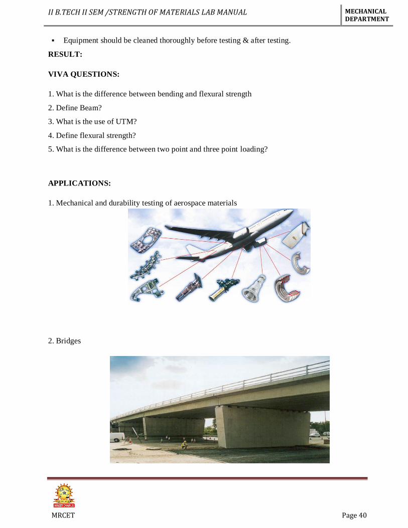
1. Mechanical and durability testing of aerospace materials
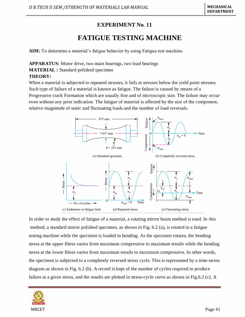
2. Bridges
II B.TECH II SEM /STRENGTH OF MATERIALS LAB MANUAL MECHANICAL DEPARTMENT
MRCET Page 41
EXPERIMENT No. 11
FATIGUE TESTING MACHINE
AIM: To determine a material’s fatigue behavior by using Fatigue test machine.
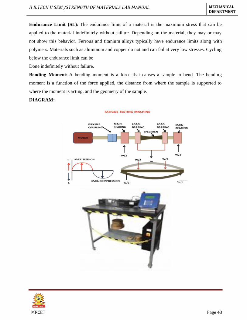
APPARATUS: Motor drive, two main bearings, two load bearings
MATERIAL : Standard polished specimen
THEORY:
When a material is subjected to repeated stresses, it fails at stresses below the yield point stresses.
Such type of failure of a material is known as fatigue. The failure is caused by means of a
Progressive crack Formation which are usually fine and of microscopic size. The failure may occur
even without any prior indication. The fatigue of material is affected by the size of the component,
relative magnitude of static and fluctuating loads and the number of load reversals.
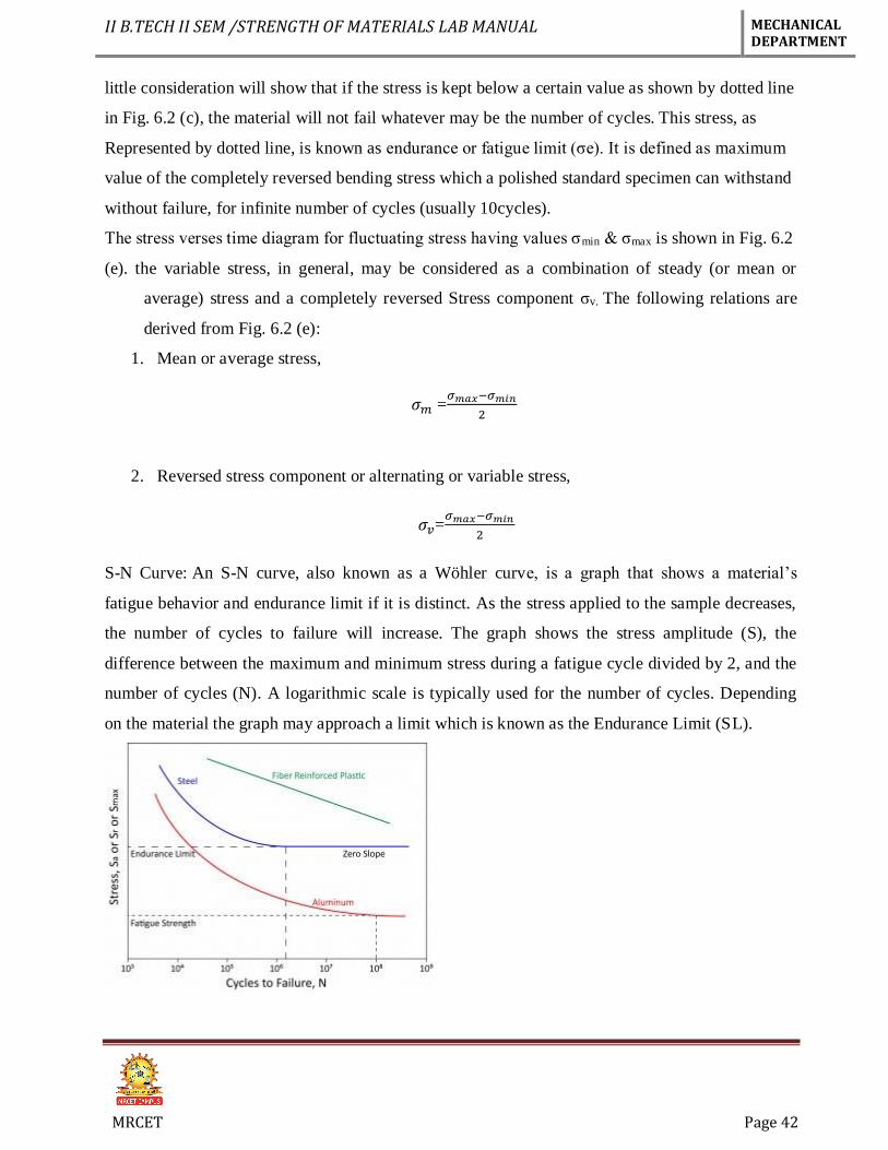
In order to study the effect of fatigue of a material, a rotating mirror beam method is used. In this
method, a standard mirror polished specimen, as shown in Fig. 6.2 (a), is rotated in a fatigue
testing machine while the specimen is loaded in bending. As the specimen rotates, the bending
stress at the upper fibres varies from maximum compressive to maximum tensile while the bending
stress at the lower fibres varies from maximum tensile to maximum compressive. In other words,
the specimen is subjected to a completely reversed stress cycle. This is represented by a time-stress
diagram as shown in Fig. 6.2 (b). A record is kept of the number of cycles required to produce
failure at a given stress, and the results are plotted in stress-cycle curve as shown in Fig.6.2 (c). A
II B.TECH II SEM /STRENGTH OF MATERIALS LAB MANUAL MECHANICAL DEPARTMENT
MRCET Page 42
little consideration will show that if the stress is kept below a certain value as shown by dotted line
in Fig. 6.2 (c), the material will not fail whatever may be the number of cycles. This stress, as
Represented by dotted line, is known as endurance or fatigue limit (σe). It is defined as maximum
value of the completely reversed bending stress which a polished standard specimen can withstand
without failure, for infinite number of cycles (usually 10cycles).
The stress verses time diagram for fluctuating stress having values σmin & σmax is shown in Fig. 6.2
(e). the variable stress, in general, may be considered as a combination of steady (or mean or
average) stress and a completely reversed Stress component σv. The following relations are
derived from Fig. 6.2 (e):
1. Mean or average stress,
𝜎𝑚 =𝜎𝑚𝑎𝑥−𝜎𝑚𝑖𝑛
2
2. Reversed stress component or alternating or variable stress,
𝜎𝑣=𝜎𝑚𝑎𝑥−𝜎𝑚𝑖𝑛
2
S-N Curve: An S-N curve, also known as a Wöhler curve, is a graph that shows a material’s
fatigue behavior and endurance limit if it is distinct. As the stress applied to the sample decreases,
the number of cycles to failure will increase. The graph shows the stress amplitude (S), the
difference between the maximum and minimum stress during a fatigue cycle divided by 2, and the
number of cycles (N). A logarithmic scale is typically used for the number of cycles. Depending
on the material the graph may approach a limit which is known as the Endurance Limit (SL).
II B.TECH II SEM /STRENGTH OF MATERIALS LAB MANUAL MECHANICAL DEPARTMENT
MRCET Page 43
Endurance Limit (SL): The endurance limit of a material is the maximum stress that can be
applied to the material indefinitely without failure. Depending on the material, they may or may
not show this behavior. Ferrous and titanium alloys typically have endurance limits along with
polymers. Materials such as aluminum and copper do not and can fail at very low stresses. Cycling
below the endurance limit can be
Done indefinitely without failure.
Bending Moment: A bending moment is a force that causes a sample to bend. The bending
moment is a function of the force applied, the distance from where the sample is supported to
where the moment is acting, and the geometry of the sample.
DIAGRAM:
II B.TECH II SEM /STRENGTH OF MATERIALS LAB MANUAL MECHANICAL DEPARTMENT
MRCET Page 44
PROCEDURE:
1. Take the specimen in circular shape
2. Take the required dimensions of circular rod
3. A specimen is placed in the machine and a force is applied via a bending moment using
weights hung off the sample
4. The force induces a surface stress that will be tensile on one side of the sample (generally
the top) and compressive on the opposite side.
5. When the test is started, the sample will rotate at the desired rate and this rotation will
cause the surfaces to interchange so that each surface experiences alternating tensile and
compressive stresses
6. The sample is left in the machine until failure at which point ADMET’s eP2 controller will
display the number of cycles it looks for the sample to fail.
7. Finally take the readings.
PRECAUTIONS:
1. Specimen fix into the machine properly
2. Take the readings correctly.
3. Carefully applied loads.
RESULT:
VIVA QUESTIONS:
1. Define fatigue?
2. Define Endurance strength?
3. What is the use of S-N curve?
4. Bending stress means?
5. Cyclic stress means?
II B.TECH II SEM /STRENGTH OF MATERIALS LAB MANUAL MECHANICAL DEPARTMENT
MRCET Page 45
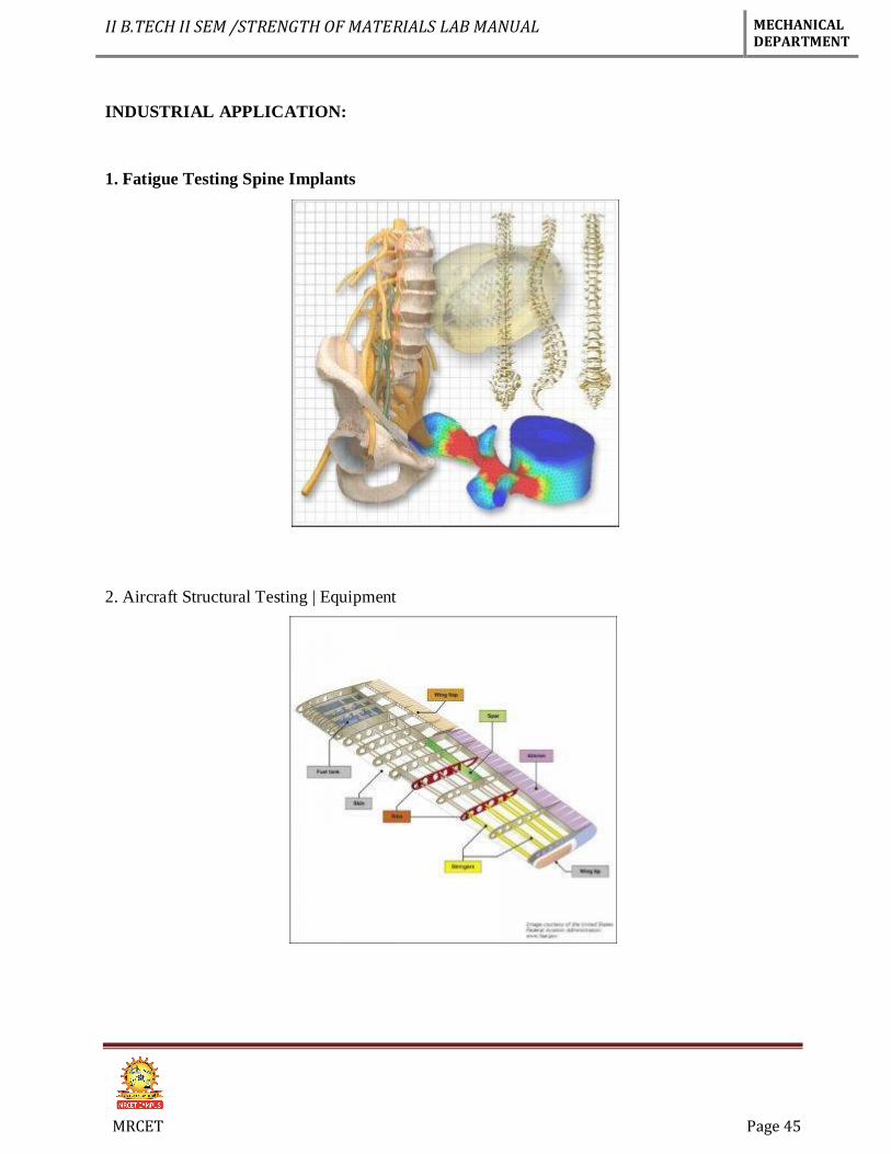
INDUSTRIAL APPLICATION:
1. Fatigue Testing Spine Implants
2. Aircraft Structural Testing | Equipment
II B.TECH II SEM /STRENGTH OF MATERIALS LAB MANUAL MECHANICAL DEPARTMENT
MRCET Page 46
EXPERIMENT No. 12
COMPRESSIVE TEST ON CUBE
AIM: To study the behavior of the given material under Compressive load and to following
Modulus of elasticity
Maximum Compressive strength or ultimate stress
Percentage Decrease in length
Percentage Increase in area
APPARATUS:
Universal Testing machine, Dial gauge, Vernier caliper and scale.
MATERIAL: Wood
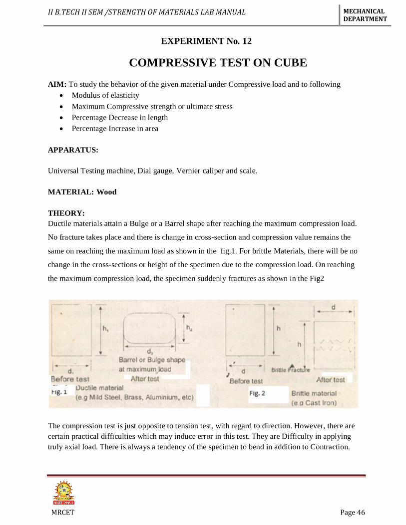
THEORY:
Ductile materials attain a Bulge or a Barrel shape after reaching the maximum compression load.
No fracture takes place and there is change in cross-section and compression value remains the
same on reaching the maximum load as shown in the fig.1. For brittle Materials, there will be no
change in the cross-sections or height of the specimen due to the compression load. On reaching
the maximum compression load, the specimen suddenly fractures as shown in the Fig2
The compression test is just opposite to tension test, with regard to direction. However, there are
certain practical difficulties which may induce error in this test. They are Difficulty in applying
truly axial load. There is always a tendency of the specimen to bend in addition to Contraction.
II B.TECH II SEM /STRENGTH OF MATERIALS LAB MANUAL MECHANICAL DEPARTMENT
MRCET Page 47
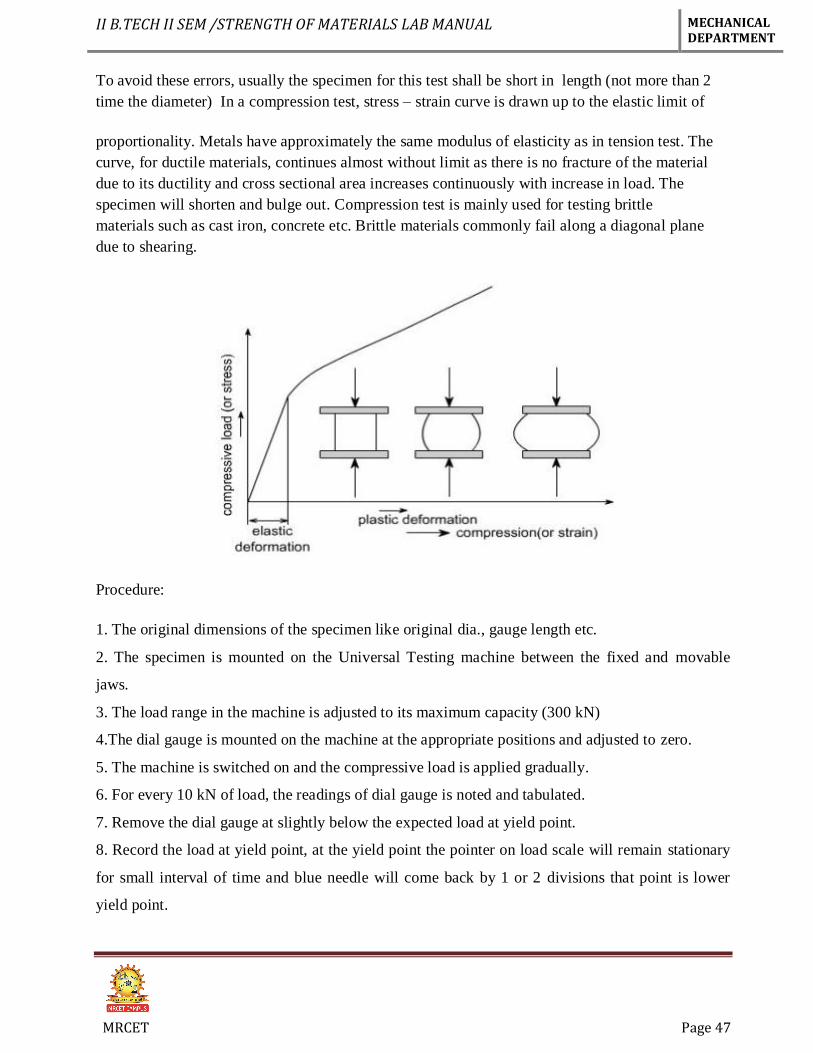
To avoid these errors, usually the specimen for this test shall be short in length (not more than 2
time the diameter) In a compression test, stress – strain curve is drawn up to the elastic limit of
proportionality. Metals have approximately the same modulus of elasticity as in tension test. The
curve, for ductile materials, continues almost without limit as there is no fracture of the material
due to its ductility and cross sectional area increases continuously with increase in load. The
specimen will shorten and bulge out. Compression test is mainly used for testing brittle
materials such as cast iron, concrete etc. Brittle materials commonly fail along a diagonal plane
due to shearing.
Procedure:
1. The original dimensions of the specimen like original dia., gauge length etc.
2. The specimen is mounted on the Universal Testing machine between the fixed and movable
jaws.
3. The load range in the machine is adjusted to its maximum capacity (300 kN)
4.The dial gauge is mounted on the machine at the appropriate positions and adjusted to zero.
5. The machine is switched on and the compressive load is applied gradually.
6. For every 10 kN of load, the readings of dial gauge is noted and tabulated.
7. Remove the dial gauge at slightly below the expected load at yield point.
8. Record the load at yield point, at the yield point the pointer on load scale will remain stationary
for small interval of time and blue needle will come back by 1 or 2 divisions that point is lower
yield point.
II B.TECH II SEM /STRENGTH OF MATERIALS LAB MANUAL MECHANICAL DEPARTMENT
MRCET Page 48
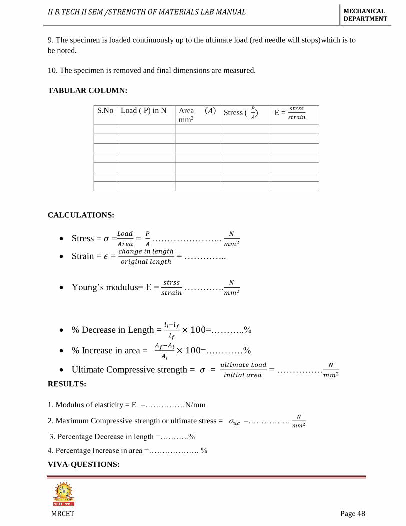
9. The specimen is loaded continuously up to the ultimate load (red needle will stops)which is to
be noted.
10. The specimen is removed and final dimensions are measured.
TABULAR COLUMN:
S.No Load ( P) in N Area (𝐴)
mm2 Stress (
𝑃
𝐴) E =
𝑠𝑡𝑟𝑠𝑠
𝑠𝑡𝑟𝑎𝑖𝑛
CALCULATIONS:
Stress = 𝜎 =𝐿𝑜𝑎𝑑
𝐴𝑟𝑒𝑎 =
𝑃
𝐴 …………………..
𝑁
𝑚𝑚2
Strain = 𝜖 = 𝑐ℎ𝑎𝑛𝑔𝑒 𝑖𝑛 𝑙𝑒𝑛𝑔𝑡ℎ
𝑜𝑟𝑖𝑔𝑖𝑛𝑎𝑙 𝑙𝑒𝑛𝑔𝑡ℎ = …………..
Young’s modulus= E = 𝑠𝑡𝑟𝑠𝑠
𝑠𝑡𝑟𝑎𝑖𝑛 ………….
𝑁
𝑚𝑚2
% Decrease in Length = 𝑙𝑖−𝑙𝑓
𝑙𝑓× 100=………..%
% Increase in area = 𝐴𝑓−𝐴𝑖
𝐴𝑖× 100=…………%
Ultimate Compressive strength = 𝜎 = 𝑢𝑙𝑡𝑖𝑚𝑎𝑡𝑒 𝐿𝑜𝑎𝑑
𝑖𝑛𝑖𝑡𝑖𝑎𝑙 𝑎𝑟𝑒𝑎 = ……………
𝑁
𝑚𝑚2
RESULTS:
1. Modulus of elasticity = E =……………N/mm
2. Maximum Compressive strength or ultimate stress = 𝜎𝑢𝑐 =……………. 𝑁
𝑚𝑚2
3. Percentage Decrease in length =………..%
4. Percentage Increase in area =………………. %
VIVA-QUESTIONS:
II B.TECH II SEM /STRENGTH OF MATERIALS LAB MANUAL MECHANICAL DEPARTMENT
MRCET Page 49
1. Compression tests are generally performed on brittles materials-why?
2. Which will have a higher strength: a small specimen or a full size member made of the same
material?
3. What is column action? How does the h/d ratio of specimen affect the test result?
4. How do ductile and brittle materials in their behavior in compression test?
5. What are bi-modulus materials? Give examples.
APPLICATIONS:
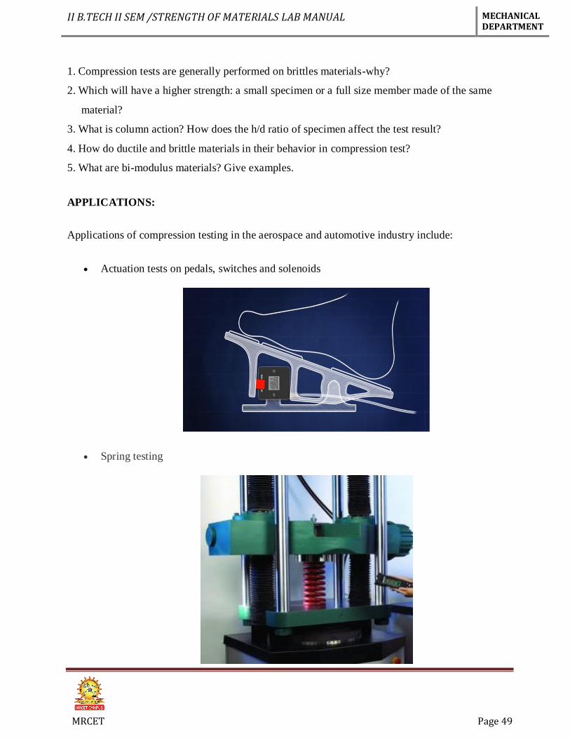
Applications of compression testing in the aerospace and automotive industry include:
Actuation tests on pedals, switches and solenoids
Spring testing
II B.TECH II SEM /STRENGTH OF MATERIALS LAB MANUAL MECHANICAL DEPARTMENT
MRCET Page 50
EXPERIMENT No. 13
BRINELL HARDNESS TEST
AIM: To determine the hardness of the given specimen using Brinell hardness test.
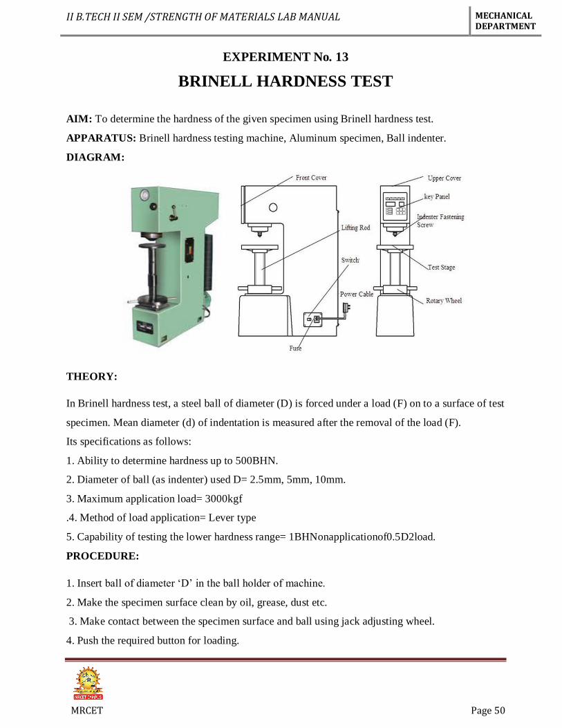
APPARATUS: Brinell hardness testing machine, Aluminum specimen, Ball indenter.
DIAGRAM:
THEORY:
In Brinell hardness test, a steel ball of diameter (D) is forced under a load (F) on to a surface of test
specimen. Mean diameter (d) of indentation is measured after the removal of the load (F).
Its specifications as follows:
1. Ability to determine hardness up to 500BHN.
2. Diameter of ball (as indenter) used D= 2.5mm, 5mm, 10mm.
3. Maximum application load= 3000kgf
.4. Method of load application= Lever type
5. Capability of testing the lower hardness range= 1BHNonapplicationof0.5D2load.
PROCEDURE:
1. Insert ball of diameter ‘D’ in the ball holder of machine.
2. Make the specimen surface clean by oil, grease, dust etc.
3. Make contact between the specimen surface and ball using jack adjusting wheel.
4. Push the required button for loading.
II B.TECH II SEM /STRENGTH OF MATERIALS LAB MANUAL MECHANICAL DEPARTMENT
MRCET Page 51
5. Pull the load release level and wait for 15 seconds.
6. Remove the specimen from the support table and locate the Indentation.
7. View the indentation through microscope and measure the diameter ‘d’ of the indentation using
micrometer fixed on the microscope.
8. Repeat the procedure and take three readings.
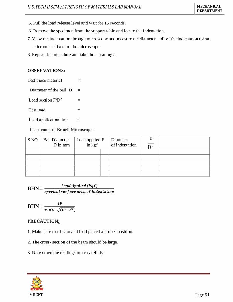
OBSERVATIONS:
Test piece material =
Diameter of the ball D =
Load section F/D2 =
Test load =
Load application time =
Least count of Brinell Microscope =
S.NO Ball Diameter
D in mm
Load applied F
in kgf
Diameter
of indentation
𝑃
D2
BHN=𝑳𝒐𝒂𝒅 𝑨𝒑𝒑𝒍𝒊𝒆𝒅 (𝒌𝒈𝒇)
𝒔𝒑𝒆𝒓𝒊𝒄𝒂𝒍 𝒔𝒖𝒓𝒇𝒂𝒄𝒆 𝒂𝒓𝒆𝒂 𝒐𝒇 𝒊𝒏𝒅𝒆𝒏𝒕𝒂𝒕𝒊𝒐𝒏
BHN=𝟐𝑷
𝝅𝑫(𝑫−√(𝑫𝟐−𝒅𝟐)
PRECAUTION:
1. Make sure that beam and load placed a proper position.
2. The cross- section of the beam should be large.
3. Note down the readings more carefully..
II B.TECH II SEM /STRENGTH OF MATERIALS LAB MANUAL MECHANICAL DEPARTMENT
MRCET Page 52
VIVA QUESTIONS:
1. How to measure the hardness
2. What are the formulae of BHN?
3. Which ball size is recommended for Brinell test?
4. What is the difference between the brinell and Rockwell hardness test?
5. For steel ultimate tensile strength =------------BHN?
APPLICATIONS:
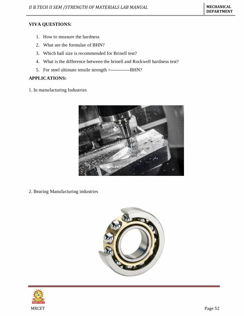
1. In manufacturing Industries
2. Bearing Manufacturing industries
II B.TECH II SEM /STRENGTH OF MATERIALS LAB MANUAL MECHANICAL DEPARTMENT
MRCET Page 53
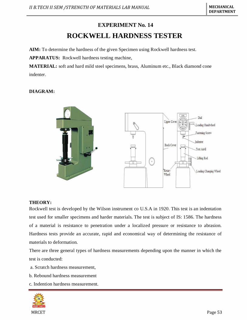
EXPERIMENT No. 14
ROCKWELL HARDNESS TESTER
AIM: To determine the hardness of the given Specimen using Rockwell hardness test.
APPARATUS: Rockwell hardness testing machine,
MATERIAL: soft and hard mild steel specimens, brass, Aluminum etc., Black diamond cone
indenter.
DIAGRAM:
THEORY:
Rockwell test is developed by the Wilson instrument co U.S.A in 1920. This test is an indentation
test used for smaller specimens and harder materials. The test is subject of IS: 1586. The hardness
of a material is resistance to penetration under a localized pressure or resistance to abrasion.
Hardness tests provide an accurate, rapid and economical way of determining the resistance of
materials to deformation.
There are three general types of hardness measurements depending upon the manner in which the
test is conducted:
a. Scratch hardness measurement,
b. Rebound hardness measurement
c. Indention hardness measurement.
II B.TECH II SEM /STRENGTH OF MATERIALS LAB MANUAL MECHANICAL DEPARTMENT
MRCET Page 54
In scratch hardness method the material are rated on their ability to scratch one another and it is
usually used by mineralogists only. In rebound hardness measurement, a standard body is usually
dropped on to the material surface and the hardness is measured in terms of the height of its
rebound .The general means of judging the hardness is measuring the resistance of a material to
indentation. The indenters usually a ball cone or pyramid of a material much harder than that being
used. Hardened steel, sintered tungsten carbide or diamond indenters are generally used in
PROCEDURE:
1. Examine hardness testing machine (fig.1)
2. Place the specimen on platform of a machine. Using the elevating screw raise the platform and
bring the specimen just in contact with the ball. Apply an initial load until the small pointer shows
red mark.
3. Release the operating valve to apply additional load. Immediately after the additional load
applied, bring back operating valve to its position.
4. Read the position of the pointer on the C scale, which gives the hardness number.
5. Repeat the procedure five times on the specimen selecting different points for indentation.
OBSERVATION TABLE:
S.NO Specimens Reading (HRC/) Mean
1 2 3
1 Mild Steel HRB =
2 High Carbon steel HRC =
3 Brass HRB =
4 Aluminum HRB =
PRECAUTIONS:
1. The specimen should be clean properly
2. Take reading more carefully and
3. The test should not be made on specimens so thin that the impression shows through the metal,
nor should impression be made too close to the edge of a specimen.
II B.TECH II SEM /STRENGTH OF MATERIALS LAB MANUAL MECHANICAL DEPARTMENT
MRCET Page 55
VIVA QUESTIONS:
1. Define Hardness
2. Size of the Ball to be used in Ball Indenter of Rockwell Hardness Test.
3. Different Types of Hardness Testing Methods.
4. Applications of Rockwell Hardness A – Scale, B-Scale, C-Scale
5. In Rockwell hardness test the hardness is measured by?
APPLICATIONS:
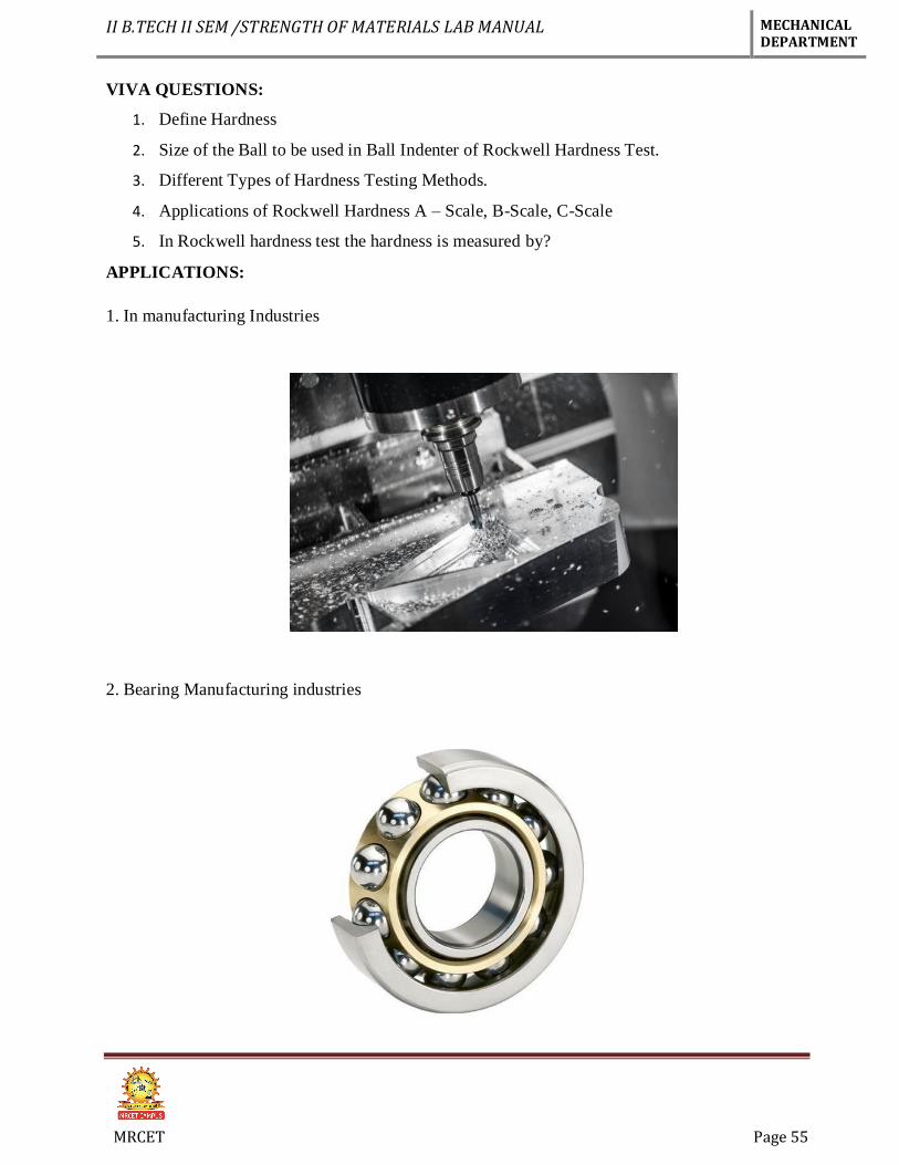
1. In manufacturing Industries
2. Bearing Manufacturing industries