Embed Size (px)
Citation preview

Industrial Router Pro Series
UR32User Guide
2
PrefaceThanks for choosing Milesight UR32 industrial cellular router. The UR32 industrial cellular routerdelivers tenacious connection over network with full-featured design such as automatedfailover/failback, extended operating temperature, dual SIM cards, hardware watchdog, VPN, FastEthernet and beyond.
This guide describes how to configure and operate the UR32 industrial cellular router. You can referto it for detailed functionality and router configuration.
ReadersThis guide is mainly intended for the following users:- Network Planners- On-site technical support and maintenance personnel- Network administrators responsible for network configuration and maintenance
© 2011-2022 Xiamen Milesight IoT Co., Ltd.
All rights reserved.All information in this user guide is protected by copyright law. Whereby, no organization or individualshall copy or reproduce the whole or part of this user guide by any means without writtenauthorization from Xiamen Milesight Iot Co., Ltd.
Related DocumentsDocument Description
UR32 Datasheet Datasheet for the UR32 industrial cellular router.
UR32 Quick Start Guide Quick Installation guide for the UR32 industrial cellular router.
Declaration of ConformityUR32 is in conformity with the essential requirements and other relevant provisions of the CE, FCC,
and RoHS.
3
For assistance, please contactMilesight technical support:Email: [email protected]: 86-592-5085280Fax: 86-592-5023065Address: Building C09, Software Park III,
Xiamen 361024, China
Revision HistoryDate Doc Version DescriptionMay. 16, 2019 V 1.1 Initial versionNov. 14, 2019 V 1.2 Add Python, SMS, IP passthrough functionsMay 11, 2020 V 1.3 Web interfaces upgradeDec. 9, 2020 V 2.0 Layout replace
Sept. 17, 2021 V 2.1
1. Cellular and ping detection support IPv62. Add WAN connection type: DHCPv6 client, DS-Lite3. Add DHCPv6 Server feature4. Add IPv6 static routing feature5. Add Expert Option box in IPsec settings6. Support SMS inbox and outbox record clear
4
ContentsChapter 1 Product Introduction............................................................................................................................8
1.1 Overview....................................................................................................................................................81.2 Advantages...............................................................................................................................................81.3 Specifications...........................................................................................................................................91.4 Dimensions (mm)..................................................................................................................................11
Chapter 2 Access to Web GUI............................................................................................................................12Chapter 3 Web Configuration.............................................................................................................................14
3.1 Status.......................................................................................................................................................143.1.1 Overview...................................................................................................................................... 143.1.2 Cellular......................................................................................................................................... 153.1.3 Network........................................................................................................................................173.1.4 WLAN (Only Applicable to Wi-Fi Version)...............................................................................183.1.5 VPN...............................................................................................................................................193.1.6 Routing.........................................................................................................................................203.1.7 Host List.......................................................................................................................................203.1.8 GPS (Only Applicable to GPS Version)....................................................................................21
3.2 Network...................................................................................................................................................223.2.1 Interface.......................................................................................................................................22
3.2.1.1 Link Failover.....................................................................................................................223.2.1.2 Cellular..............................................................................................................................243.2.1.3 Port....................................................................................................................................263.2.1.4 WAN.................................................................................................................................. 273.2.1.5 Bridge................................................................................................................................323.2.1.6 WLAN (Only Applicable to Wi-Fi Version)................................................................... 323.2.1.7 Switch............................................................................................................................... 353.2.1.8 Loopback..........................................................................................................................35
3.2.2 DHCP............................................................................................................................................363.2.2.1 DHCP/DHCPv6 Server....................................................................................................363.2.2.2 DHCP Relay......................................................................................................................38
3.2.3 Firewall.........................................................................................................................................393.2.3.1 Security.............................................................................................................................393.2.3.2 ACL....................................................................................................................................403.2.3.3 Port Mapping...................................................................................................................413.2.3.4 DMZ...................................................................................................................................423.2.3.5 MAC Binding....................................................................................................................433.2.3.6 Custom Rules.................................................................................................................. 433.2.3.7 SPI..................................................................................................................................... 44
3.2.4 QoS............................................................................................................................................... 453.2.5 VPN...............................................................................................................................................46
3.2.5.1 DMVPN.............................................................................................................................463.2.5.2 IPSec Server.....................................................................................................................473.2.5.3 IPSec.................................................................................................................................51
5
3.2.5.4 GRE....................................................................................................................................533.2.5.5 L2TP..................................................................................................................................543.2.5.6 PPTP................................................................................................................................. 563.2.5.7 OpenVPN Client...............................................................................................................583.2.5.8 OpenVPN Server..............................................................................................................603.2.5.9 Certifications................................................................................................................... 62
3.2.6 IP Passthrough........................................................................................................................... 643.2.7 Routing.........................................................................................................................................64
3.2.7.1 Static Routing.................................................................................................................. 643.2.7.2 RIP..................................................................................................................................... 653.2.7.3 OSPF................................................................................................................................. 683.2.7.4 Routing Filtering..............................................................................................................74
3.2.8 VRRP.............................................................................................................................................743.2.9 DDNS............................................................................................................................................76
3.3 System.....................................................................................................................................................783.3.1 General Settings......................................................................................................................... 78
3.3.1.1 General..............................................................................................................................783.3.1.2 System Time....................................................................................................................793.3.1.3 Email................................................................................................................................. 813.3.1.4 Storage............................................................................................................................. 82
3.3.2 Phone&SMS.................................................................................................................................833.3.2.1 Phone................................................................................................................................833.3.2.2 SMS...................................................................................................................................84
3.3.3 User Management......................................................................................................................853.3.3.1 Account............................................................................................................................ 853.3.3.2 User Management.......................................................................................................... 86
3.3.4 SNMP........................................................................................................................................... 873.3.4.1 SNMP................................................................................................................................873.3.4.2 MIB View...........................................................................................................................883.3.4.3 VACM................................................................................................................................883.3.4.4 Trap...................................................................................................................................893.3.4.5 MIB.................................................................................................................................... 90
3.3.5 AAA...............................................................................................................................................903.3.5.1 Radius...............................................................................................................................903.3.5.2 TACACS+..........................................................................................................................913.3.5.3 LDAP................................................................................................................................. 923.3.5.4 Authentication.................................................................................................................93
3.3.6 Device Management..................................................................................................................933.3.6.1 DeviceHub........................................................................................................................933.3.6.2 Milesight VPN..................................................................................................................94
3.3.7 Events...........................................................................................................................................963.3.7.1 Events............................................................................................................................... 963.3.7.2 Events Settings................................................................................................................96
3.4 Industrial Interface................................................................................................................................ 98
6
3.4.1 I/O................................................................................................................................................. 993.4.1.1 DI........................................................................................................................................993.4.1.2 DO....................................................................................................................................100
3.4.2 Serial Port..................................................................................................................................1003.4.3 Modbus Slave...........................................................................................................................104
3.4.3.1 Modbus TCP..................................................................................................................1043.4.3.2 Modbus RTU..................................................................................................................1053.4.3.3 Modbus RTU Over TCP................................................................................................105
3.4.4 Modbus Master........................................................................................................................1063.4.4.1 Modbus Master.............................................................................................................1063.4.4.2 Channel.......................................................................................................................... 107
3.4.5 GPS (Only Applicable to GPS Version)................................................................................. 1093.4.5.1 GPS................................................................................................................................. 1093.4.5.2 GPS IP Forwarding....................................................................................................... 1103.4.5.3 GPS Serial Forwarding.................................................................................................111
3.5 Maintenance.........................................................................................................................................1123.5.1 Tools.......................................................................................................................................... 112
3.5.1.1 Ping.................................................................................................................................1123.5.1.2 Traceroute......................................................................................................................1123.5.1.3 Packet Analyzer............................................................................................................ 1133.5.1.4 Qxdmlog.........................................................................................................................113
3.5.2 Debugger...................................................................................................................................1143.5.2.1 Cellular Debugger......................................................................................................... 1143.5.2.2 Firewall Debugger.........................................................................................................114
3.5.3 Log..............................................................................................................................................1153.5.3.1 System Log....................................................................................................................1153.5.3.2 Log Download............................................................................................................... 1163.5.3.3 Log Settings...................................................................................................................117
3.5.4 Upgrade..................................................................................................................................... 1183.5.5 Backup and Restore.................................................................................................................1183.5.6 Reboot........................................................................................................................................119
3.6 APP........................................................................................................................................................1203.6.1 Python........................................................................................................................................120
3.6.1.1 Python.............................................................................................................................1203.6.1.2 App Manager Configuration........................................................................................1213.6.1.3 Python App.................................................................................................................... 121
Chapter 4 Application Examples..................................................................................................................... 1234.1 Restore Factory Defaults....................................................................................................................123
4.1.1 Via Web Interface.....................................................................................................................1234.2.2 Via Hardware............................................................................................................................ 124
4.2 Firmware Upgrade...............................................................................................................................1244.3 Events Application Example..............................................................................................................1254.4 SNMP Application Example...............................................................................................................1264.5 Network Connection........................................................................................................................... 129

7
4.5.1 Cellular Connection..................................................................................................................1294.5.2 Ethernet WAN Connection......................................................................................................131
4.6 Wi-Fi Application Example (Only Applicable to Wi-Fi Version).....................................................1334.6.1 AP Mode....................................................................................................................................1334.6.2 Client Mode...............................................................................................................................134
4.7 VRRP Application Example................................................................................................................1354.8 NAT Application Example.................................................................................................................. 1384.9 Access Control Application Example...............................................................................................1384.10 QoS Application Example................................................................................................................ 1404.11 DTU Application Example................................................................................................................ 1414.12 PPTP Application Example..............................................................................................................144
8
Chapter 1 Product Introduction
1.1 Overview
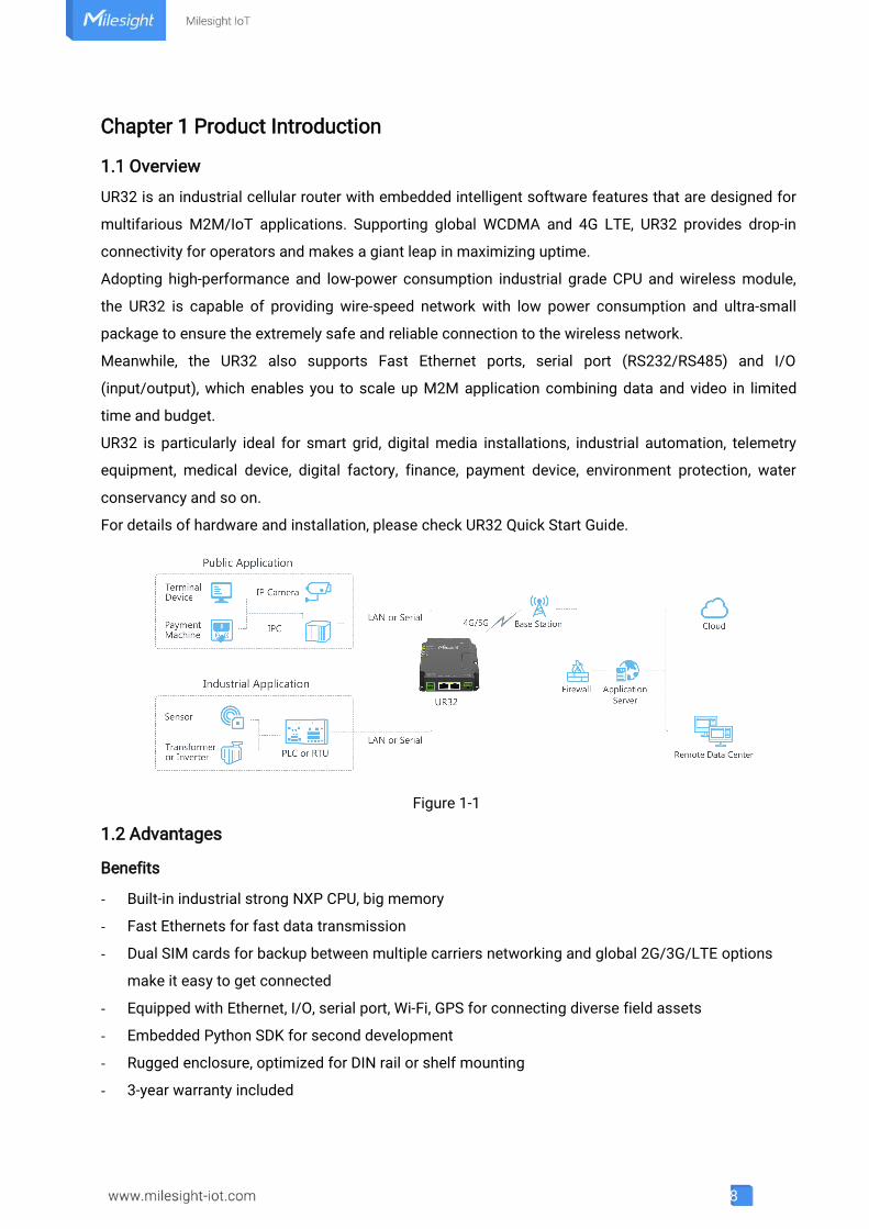
UR32 is an industrial cellular router with embedded intelligent software features that are designed for
multifarious M2M/IoT applications. Supporting global WCDMA and 4G LTE, UR32 provides drop-in
connectivity for operators and makes a giant leap in maximizing uptime.
Adopting high-performance and low-power consumption industrial grade CPU and wireless module,
the UR32 is capable of providing wire-speed network with low power consumption and ultra-small
package to ensure the extremely safe and reliable connection to the wireless network.
Meanwhile, the UR32 also supports Fast Ethernet ports, serial port (RS232/RS485) and I/O
(input/output), which enables you to scale up M2M application combining data and video in limited
time and budget.
UR32 is particularly ideal for smart grid, digital media installations, industrial automation, telemetry
equipment, medical device, digital factory, finance, payment device, environment protection, water
conservancy and so on.
For details of hardware and installation, please check UR32 Quick Start Guide.
Figure 1-1
1.2 Advantages
Benefits
- Built-in industrial strong NXP CPU, big memory
- Fast Ethernets for fast data transmission
- Dual SIM cards for backup between multiple carriers networking and global 2G/3G/LTE options
make it easy to get connected
- Equipped with Ethernet, I/O, serial port, Wi-Fi, GPS for connecting diverse field assets
- Embedded Python SDK for second development
- Rugged enclosure, optimized for DIN rail or shelf mounting
- 3-year warranty included
9
Security & Reliability
- Automated failover/failback between Ethernet and Cellular (dual SIM)
- Enable unit with security frameworks like IPsec/OpenVPN/GRE/L2TP/PPTP/ DMVPN
- Embed hardware watchdog, automatically recovering from various failure, and ensuring highest
level of availability
- Establish a secured mechanism on centralized authentication and authorization of device access
by supporting AAA (TACACS+, Radius, LDAP, local authentication) and multiple levels of user
authority
Easy Maintenance
- Milesight DeviceHub provides easy setup, mass configuration, and centralized management of
remote devices
- The user-friendly web interface design and several upgrade options help administrator to manage
the device as easy as pie
- Web GUI and CLI enable the admin to achieve simple management and quick configuration
among a large quantity of devices
- Efficiently manage the remote routers on the existing platform through the industrial standard
SNMP
Capabilities
- Link remote devices in an environment where communication technologies are constantly
changing
- Industrial 32-bit ARM Cortex-A7 processor, high-performance operating up to 528MHz and 128
MB memory available to support more applications
- Support rich protocols like SNMP, Modbus bridging, RIP, OSPF
- Support wide operating temperature ranging from -40°C to 70°C/-40°F to 158°F
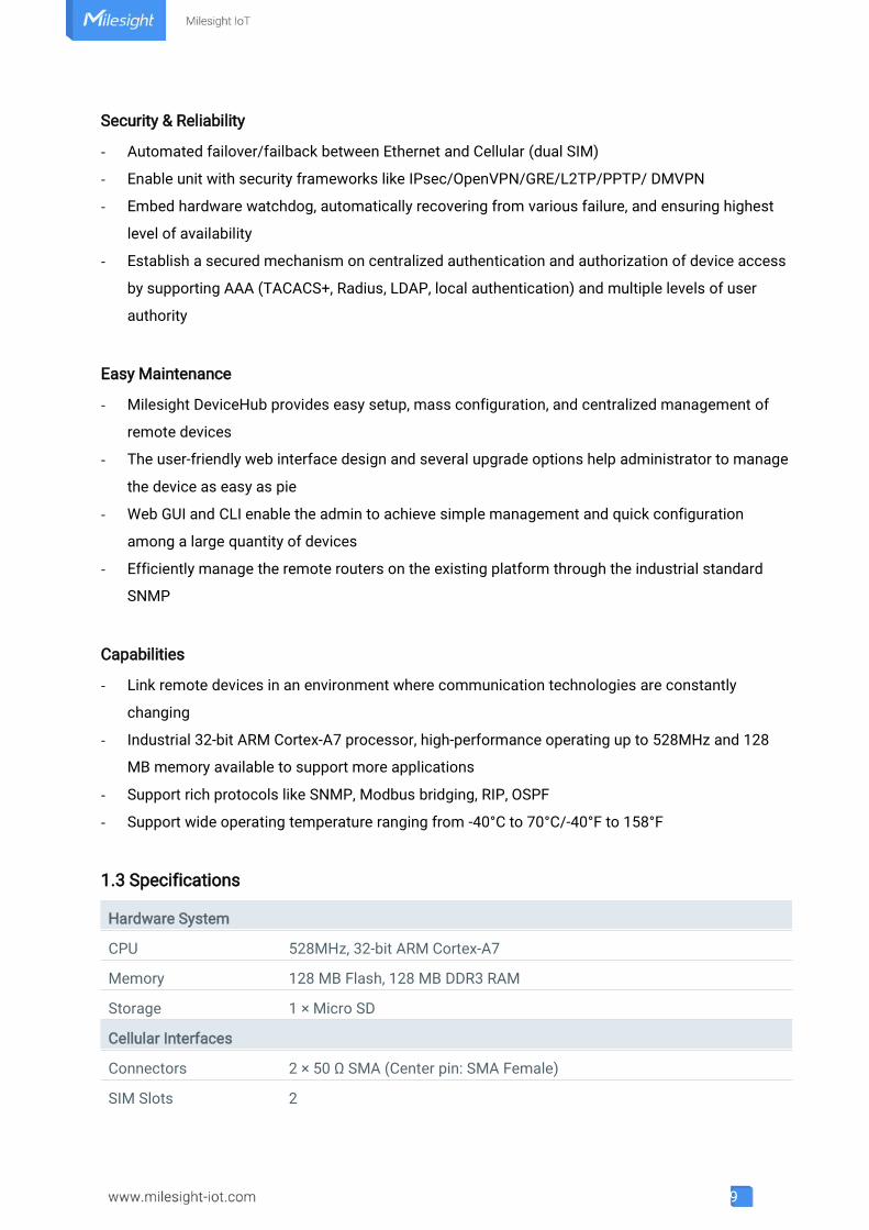
1.3 Specifications
Hardware System
CPU 528MHz, 32-bit ARM Cortex-A7
Memory 128 MB Flash, 128 MB DDR3 RAM
Storage 1 × Micro SD
Cellular Interfaces
Connectors 2 × 50 Ω SMA (Center pin: SMA Female)
SIM Slots 2
10
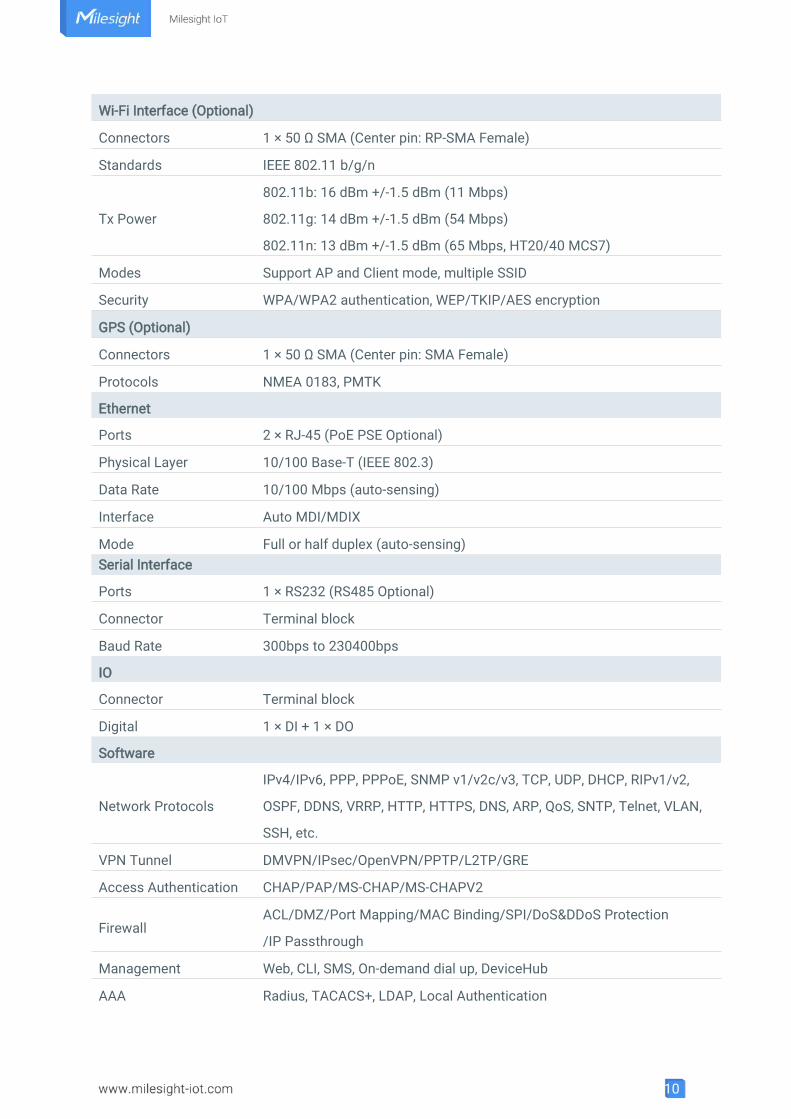
Wi-Fi Interface (Optional)
Connectors 1 × 50 Ω SMA (Center pin: RP-SMA Female)
Standards IEEE 802.11 b/g/n
Tx Power
802.11b: 16 dBm +/-1.5 dBm (11 Mbps)
802.11g: 14 dBm +/-1.5 dBm (54 Mbps)
802.11n: 13 dBm +/-1.5 dBm (65 Mbps, HT20/40 MCS7)
Modes Support AP and Client mode, multiple SSID
Security WPA/WPA2 authentication, WEP/TKIP/AES encryption
GPS (Optional)
Connectors 1 × 50 Ω SMA (Center pin: SMA Female)
Protocols NMEA 0183, PMTK
Ethernet
Ports 2 × RJ-45 (PoE PSE Optional)
Physical Layer 10/100 Base-T (IEEE 802.3)
Data Rate 10/100 Mbps (auto-sensing)
Interface Auto MDI/MDIX
Mode Full or half duplex (auto-sensing)Serial Interface
Ports 1 × RS232 (RS485 Optional)
Connector Terminal block
Baud Rate 300bps to 230400bps
IO
Connector Terminal block
Digital 1 × DI + 1 × DO
Software
Network Protocols
IPv4/IPv6, PPP, PPPoE, SNMP v1/v2c/v3, TCP, UDP, DHCP, RIPv1/v2,
OSPF, DDNS, VRRP, HTTP, HTTPS, DNS, ARP, QoS, SNTP, Telnet, VLAN,
SSH, etc.
VPN Tunnel DMVPN/IPsec/OpenVPN/PPTP/L2TP/GRE
Access Authentication CHAP/PAP/MS-CHAP/MS-CHAPV2
FirewallACL/DMZ/Port Mapping/MAC Binding/SPI/DoS&DDoS Protection
/IP Passthrough
Management Web, CLI, SMS, On-demand dial up, DeviceHub
AAA Radius, TACACS+, LDAP, Local Authentication
11
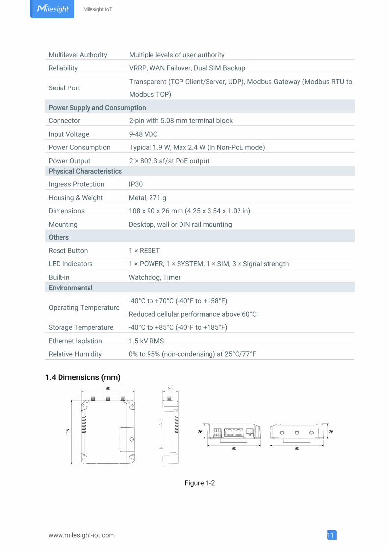
Physical Characteristics
Ingress Protection IP30
Housing & Weight Metal, 271 g
Dimensions 108 x 90 x 26 mm (4.25 x 3.54 x 1.02 in)
Mounting Desktop, wall or DIN rail mounting
Others
Reset Button 1 × RESET
LED Indicators 1 × POWER, 1 × SYSTEM, 1 × SIM, 3 × Signal strength
Built-in Watchdog, TimerEnvironmental
Operating Temperature-40°C to +70°C (-40°F to +158°F)
Reduced cellular performance above 60°C
Storage Temperature -40°C to +85°C (-40°F to +185°F)
Ethernet Isolation 1.5 kV RMS
Relative Humidity 0% to 95% (non-condensing) at 25°C/77°F
1.4 Dimensions (mm)
Figure 1-2
Multilevel Authority Multiple levels of user authority
Reliability VRRP, WAN Failover, Dual SIM Backup
Serial PortTransparent (TCP Client/Server, UDP), Modbus Gateway (Modbus RTU to
Modbus TCP)
Power Supply and Consumption
Connector 2-pin with 5.08 mm terminal block
Input Voltage 9-48 VDC
Power Consumption Typical 1.9 W, Max 2.4 W (In Non-PoE mode)
Power Output 2 × 802.3 af/at PoE output
12
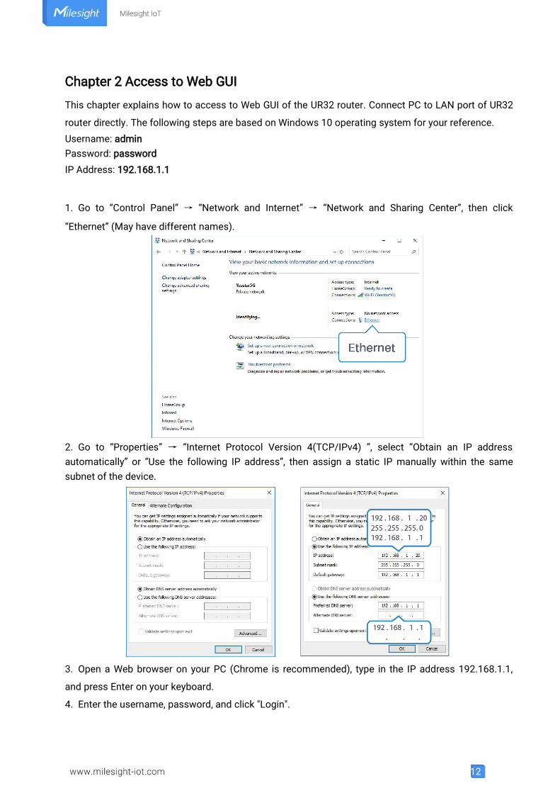
Chapter 2 Access to Web GUI
This chapter explains how to access to Web GUI of the UR32 router. Connect PC to LAN port of UR32
router directly. The following steps are based on Windows 10 operating system for your reference.Username: adminPassword: passwordIP Address: 192.168.1.1
1. Go to “Control Panel” → “Network and Internet” → “Network and Sharing Center”, then click
“Ethernet” (May have different names).
2. Go to “Properties” → “Internet Protocol Version 4(TCP/IPv4) ”, select “Obtain an IP addressautomatically” or “Use the following IP address”, then assign a static IP manually within the samesubnet of the device.
3. Open a Web browser on your PC (Chrome is recommended), type in the IP address 192.168.1.1,
and press Enter on your keyboard.
4. Enter the username, password, and click "Login".
13
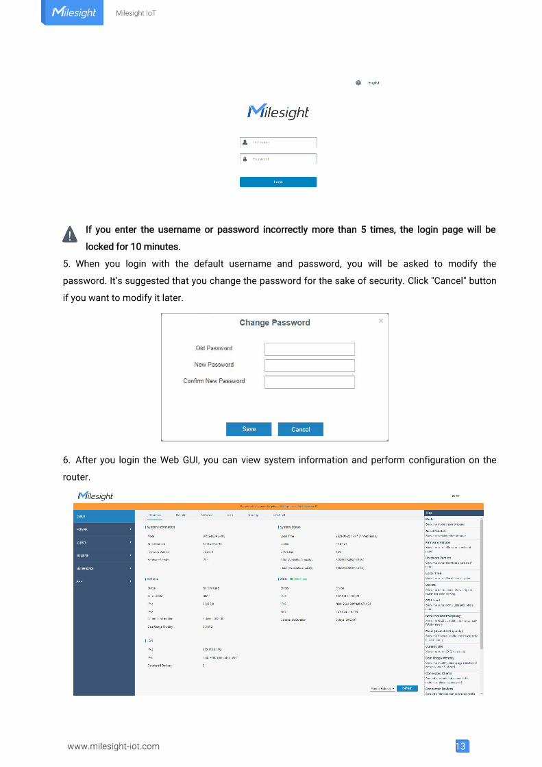
If you enter the username or password incorrectly more than 5 times, the login page will be
locked for 10 minutes.
5. When you login with the default username and password, you will be asked to modify the
password. It’s suggested that you change the password for the sake of security. Click "Cancel" button
if you want to modify it later.
6. After you login the Web GUI, you can view system information and perform configuration on the
router.
14
Chapter 3 Web Configuration
3.1 Status
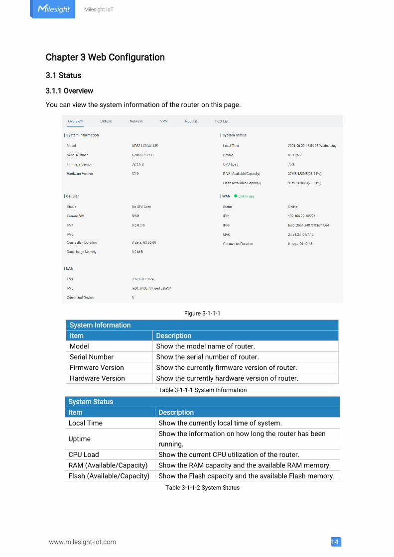
3.1.1 Overview
You can view the system information of the router on this page.
Figure 3-1-1-1
System InformationItem DescriptionModel Show the model name of router.Serial Number Show the serial number of router.Firmware Version Show the currently firmware version of router.Hardware Version Show the currently hardware version of router.
Table 3-1-1-1 System Information
System StatusItem DescriptionLocal Time Show the currently local time of system.
UptimeShow the information on how long the router has beenrunning.
CPU Load Show the current CPU utilization of the router.RAM (Available/Capacity) Show the RAM capacity and the available RAM memory.Flash (Available/Capacity) Show the Flash capacity and the available Flash memory.
Table 3-1-1-2 System Status
15
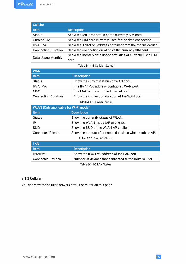
CellularItem DescriptionStatus Show the real-time status of the currently SIM cardCurrent SIM Show the SIM card currently used for the data connection.IPv4/IPv6 Show the IPv4/IPv6 address obtained from the mobile carrier.Connection Duration Show the connection duration of the currently SIM card.
Data Usage MonthlyShow the monthly data usage statistics of currently used SIMcard.
Table 3-1-1-3 Cellular Status
WANItem DescriptionStatus Show the currently status of WAN port.IPv4/IPv6 The IPv4/IPv6 address configured WAN port.MAC The MAC address of the Ethernet port.Connection Duration Show the connection duration of the WAN port.
Table 3-1-1-4 WAN Status
WLAN (Only applicable for Wi-Fi model)Item DescriptionStatus Show the currently status of WLAN.IP Show the WLAN mode (AP or client).SSID Show the SSID of the WLAN AP or client.Connected Clients Show the amount of connected devices when mode is AP.
Table 3-1-1-5 WLAN Status
LANItem DescriptionIP4/IPv6 Show the IP4/IPv6 address of the LAN port.Connected Devices Number of devices that connected to the router's LAN.
Table 3-1-1-6 LAN Status
3.1.2 Cellular
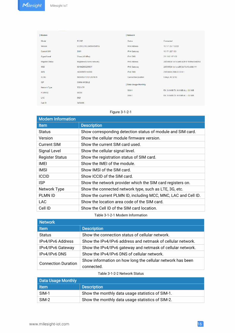
You can view the cellular network status of router on this page.
16
Figure 3-1-2-1
Modem InformationItem DescriptionStatus Show corresponding detection status of module and SIM card.Version Show the cellular module firmware version.Current SIM Show the current SIM card used.Signal Level Show the cellular signal level.Register Status Show the registration status of SIM card.IMEI Show the IMEI of the module.IMSI Show IMSI of the SIM card.ICCID Show ICCID of the SIM card.ISP Show the network provider which the SIM card registers on.Network Type Show the connected network type, such as LTE, 3G, etc.PLMN ID Show the current PLMN ID, including MCC, MNC, LAC and Cell ID.LAC Show the location area code of the SIM card.Cell ID Show the Cell ID of the SIM card location.
Table 3-1-2-1 Modem Information
NetworkItem DescriptionStatus Show the connection status of cellular network.IPv4/IPv6 Address Show the IPv4/IPv6 address and netmask of cellular network.IPv4/IPv6 Gateway Show the IPv4/IPv6 gateway and netmask of cellular network.IPv4/IPv6 DNS Show the IPv4/IPv6 DNS of cellular network.
Connection DurationShow information on how long the cellular network has beenconnected.
Table 3-1-2-2 Network Status
Data Usage MonthlyItem DescriptionSIM-1 Show the monthly data usage statistics of SIM-1.SIM-2 Show the monthly data usage statistics of SIM-2.
17
Table 3-1-2-3 Data Usage Information
3.1.3 Network
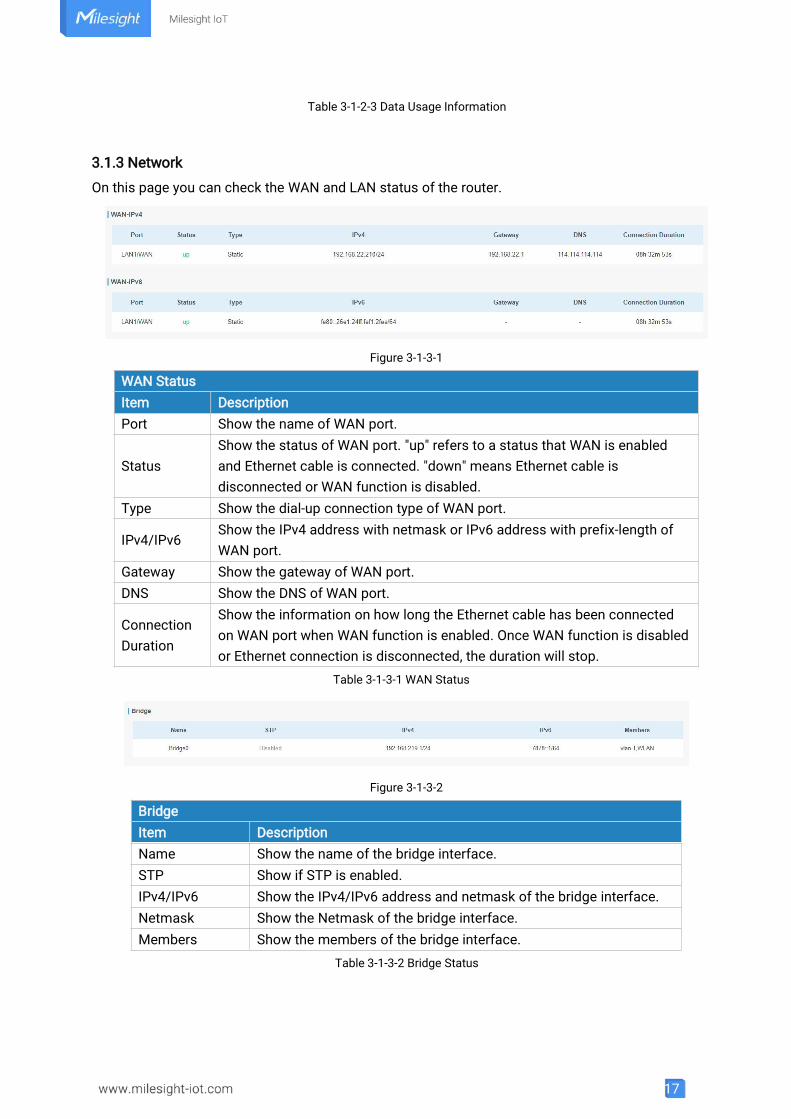
On this page you can check the WAN and LAN status of the router.
Figure 3-1-3-1
WAN StatusItem DescriptionPort Show the name of WAN port.
StatusShow the status of WAN port. "up" refers to a status that WAN is enabledand Ethernet cable is connected. "down" means Ethernet cable isdisconnected or WAN function is disabled.
Type Show the dial-up connection type of WAN port.
IPv4/IPv6Show the IPv4 address with netmask or IPv6 address with prefix-length ofWAN port.
Gateway Show the gateway of WAN port.DNS Show the DNS of WAN port.
ConnectionDuration
Show the information on how long the Ethernet cable has been connectedon WAN port when WAN function is enabled. Once WAN function is disabledor Ethernet connection is disconnected, the duration will stop.
Table 3-1-3-1 WAN Status
Figure 3-1-3-2
BridgeItem DescriptionName Show the name of the bridge interface.STP Show if STP is enabled.IPv4/IPv6 Show the IPv4/IPv6 address and netmask of the bridge interface.Netmask Show the Netmask of the bridge interface.Members Show the members of the bridge interface.
Table 3-1-3-2 Bridge Status
18
3.1.4 WLAN (Only Applicable to Wi-Fi Version)
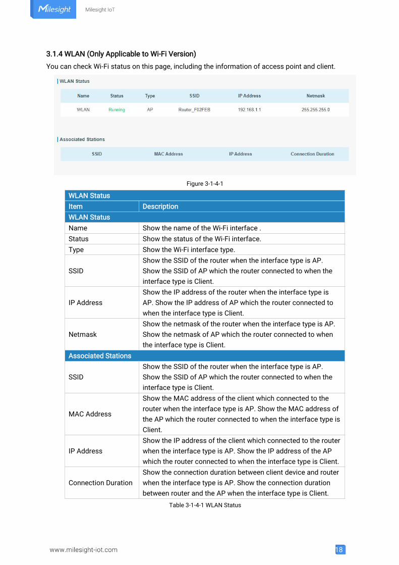
You can check Wi-Fi status on this page, including the information of access point and client.
Figure 3-1-4-1
WLAN StatusItem DescriptionWLAN StatusName Show the name of the Wi-Fi interface .Status Show the status of the Wi-Fi interface.Type Show the Wi-Fi interface type.
SSIDShow the SSID of the router when the interface type is AP.Show the SSID of AP which the router connected to when theinterface type is Client.
IP AddressShow the IP address of the router when the interface type isAP. Show the IP address of AP which the router connected towhen the interface type is Client.
NetmaskShow the netmask of the router when the interface type is AP.Show the netmask of AP which the router connected to whenthe interface type is Client.
Associated Stations
SSIDShow the SSID of the router when the interface type is AP.Show the SSID of AP which the router connected to when theinterface type is Client.
MAC Address
Show the MAC address of the client which connected to therouter when the interface type is AP. Show the MAC address ofthe AP which the router connected to when the interface type isClient.
IP AddressShow the IP address of the client which connected to the routerwhen the interface type is AP. Show the IP address of the APwhich the router connected to when the interface type is Client.
Connection DurationShow the connection duration between client device and routerwhen the interface type is AP. Show the connection durationbetween router and the AP when the interface type is Client.
Table 3-1-4-1 WLAN Status
19
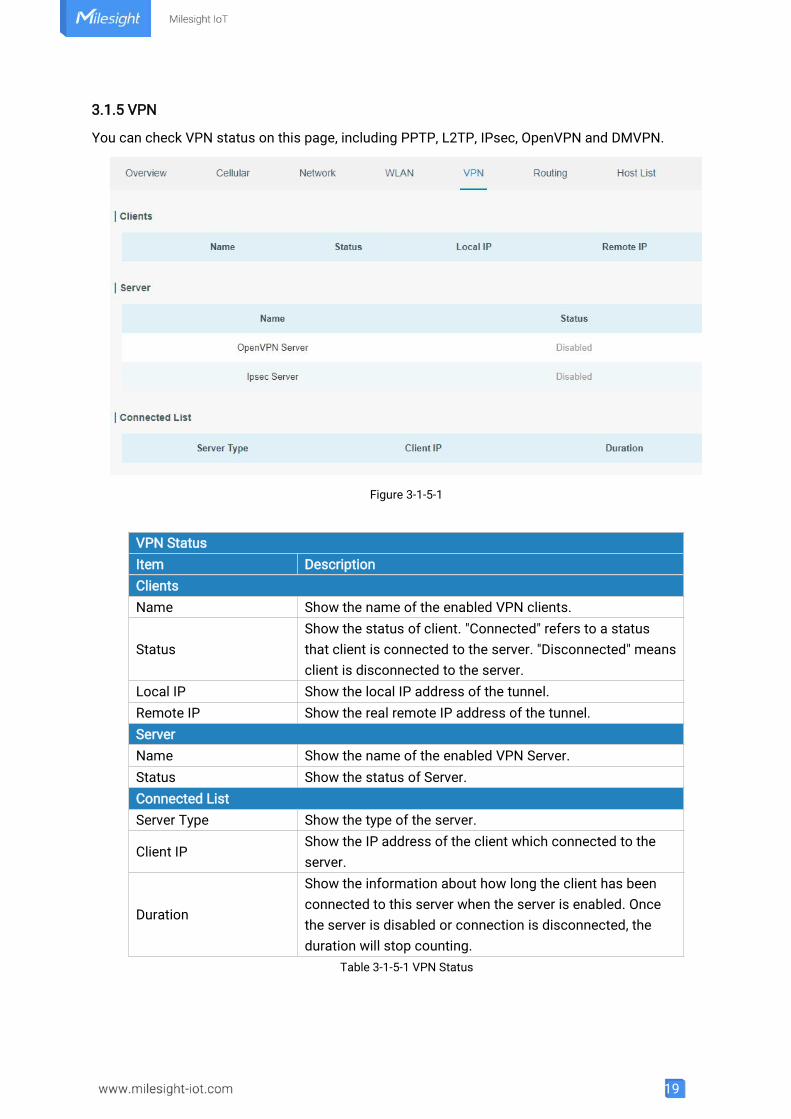
3.1.5 VPN
You can check VPN status on this page, including PPTP, L2TP, IPsec, OpenVPN and DMVPN.
Figure 3-1-5-1
VPN StatusItem DescriptionClientsName Show the name of the enabled VPN clients.
StatusShow the status of client. "Connected" refers to a statusthat client is connected to the server. "Disconnected" meansclient is disconnected to the server.
Local IP Show the local IP address of the tunnel.Remote IP Show the real remote IP address of the tunnel.ServerName Show the name of the enabled VPN Server.Status Show the status of Server.Connected ListServer Type Show the type of the server.
Client IPShow the IP address of the client which connected to theserver.
Duration
Show the information about how long the client has beenconnected to this server when the server is enabled. Oncethe server is disabled or connection is disconnected, theduration will stop counting.
Table 3-1-5-1 VPN Status
20
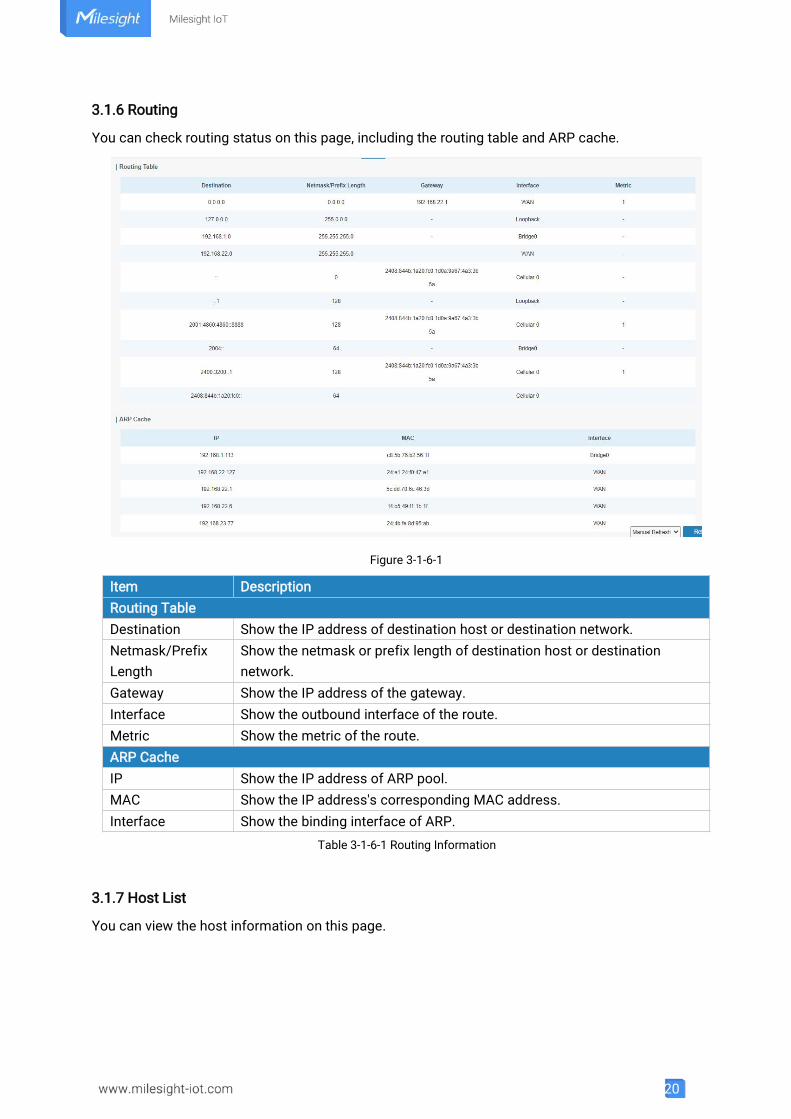
3.1.6 Routing
You can check routing status on this page, including the routing table and ARP cache.
Figure 3-1-6-1
Item DescriptionRouting TableDestination Show the IP address of destination host or destination network.Netmask/PrefixLength
Show the netmask or prefix length of destination host or destinationnetwork.
Gateway Show the IP address of the gateway.Interface Show the outbound interface of the route.Metric Show the metric of the route.ARP CacheIP Show the IP address of ARP pool.MAC Show the IP address's corresponding MAC address.Interface Show the binding interface of ARP.
Table 3-1-6-1 Routing Information
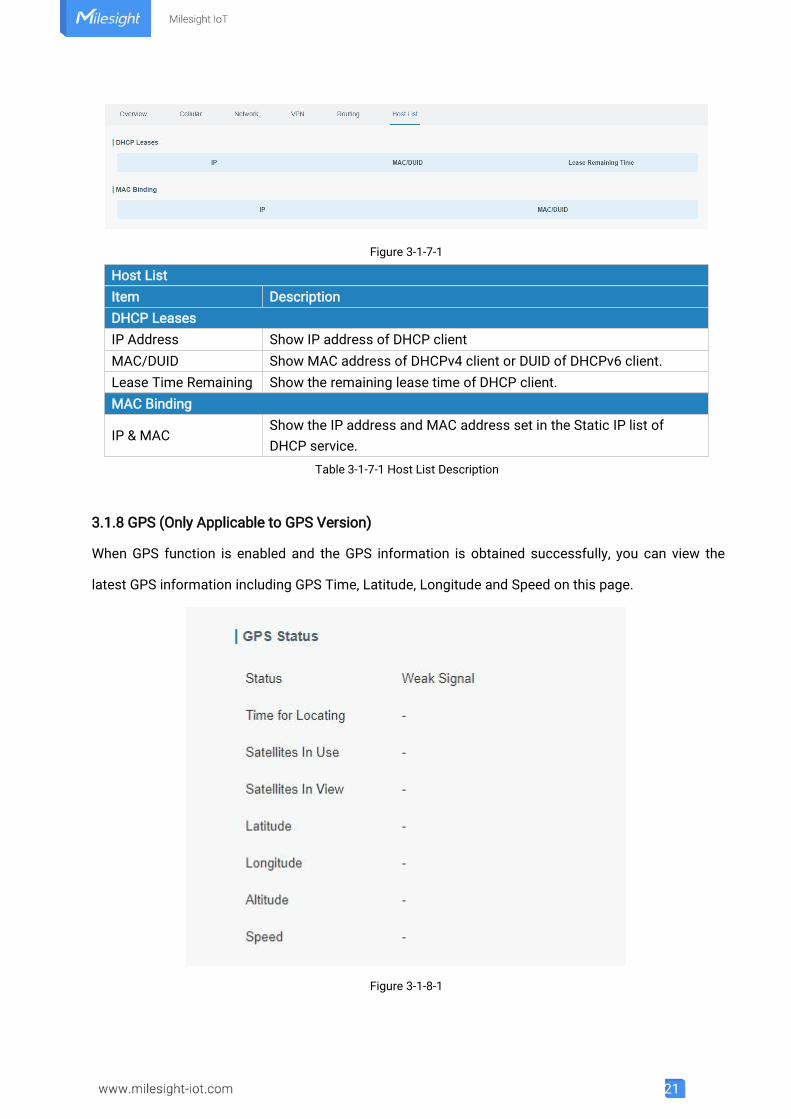
3.1.7 Host List
You can view the host information on this page.
21
Figure 3-1-7-1
Host ListItem DescriptionDHCP LeasesIP Address Show IP address of DHCP clientMAC/DUID Show MAC address of DHCPv4 client or DUID of DHCPv6 client.Lease Time Remaining Show the remaining lease time of DHCP client.MAC Binding
IP & MACShow the IP address and MAC address set in the Static IP list ofDHCP service.
Table 3-1-7-1 Host List Description
3.1.8 GPS (Only Applicable to GPS Version)
When GPS function is enabled and the GPS information is obtained successfully, you can view the
latest GPS information including GPS Time, Latitude, Longitude and Speed on this page.
Figure 3-1-8-1
22
GPS StatusItem DescriptionStatus Show the status of GPS.Time for Locating Show the time for locating.Satellites In Use Show the quantity of satellites in use.Satellites In View Show the quantity of satellites in view.Latitude Show the Latitude of the location.Longitude Show the Longitude of the location.Altitude Show the Altitude of the location.Speed Show the speed of movement.
Table 3-1-8-1 GPS Status Description
3.2 Network
3.2.1 Interface
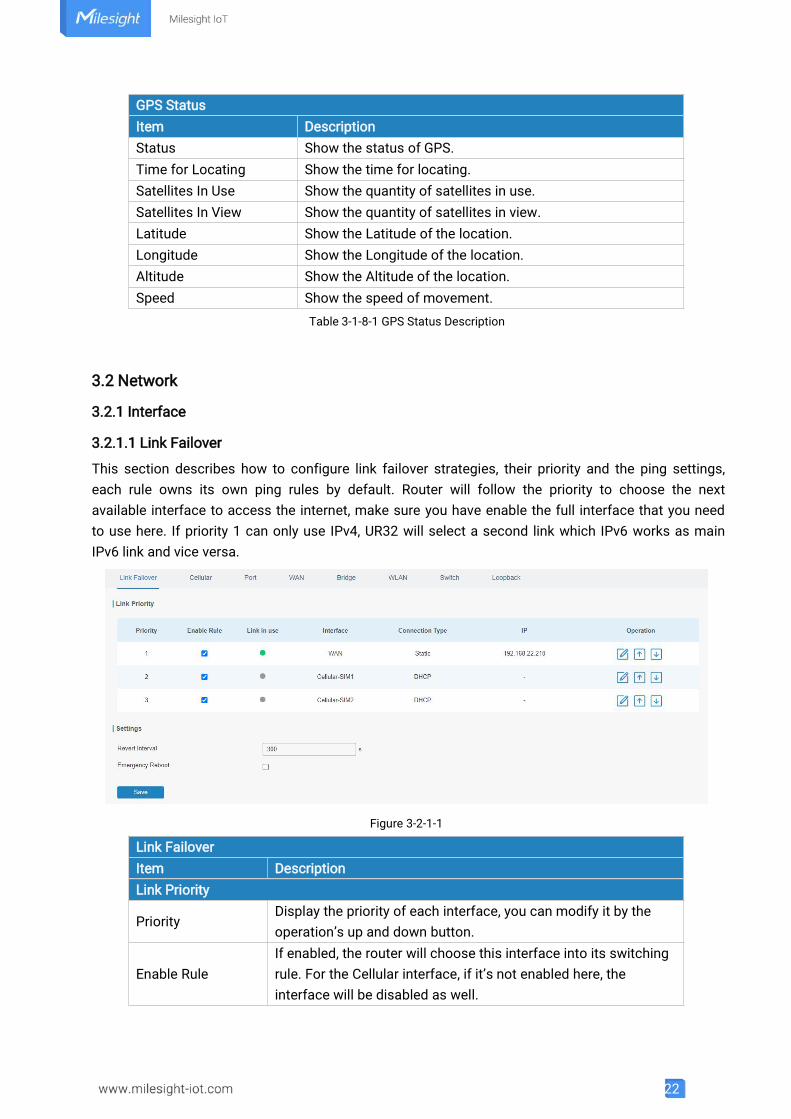
3.2.1.1 Link Failover
This section describes how to configure link failover strategies, their priority and the ping settings,each rule owns its own ping rules by default. Router will follow the priority to choose the nextavailable interface to access the internet, make sure you have enable the full interface that you needto use here. If priority 1 can only use IPv4, UR32 will select a second link which IPv6 works as mainIPv6 link and vice versa.
Figure 3-2-1-1
Link FailoverItem DescriptionLink Priority
PriorityDisplay the priority of each interface, you can modify it by theoperation’s up and down button.
Enable RuleIf enabled, the router will choose this interface into its switchingrule. For the Cellular interface, if it’s not enabled here, theinterface will be disabled as well.
23
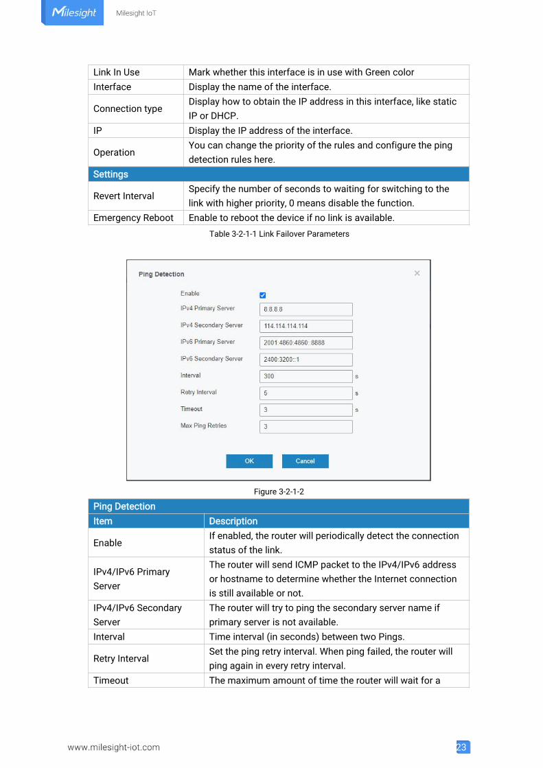
Link In Use Mark whether this interface is in use with Green colorInterface Display the name of the interface.
Connection typeDisplay how to obtain the IP address in this interface, like staticIP or DHCP.
IP Display the IP address of the interface.
OperationYou can change the priority of the rules and configure the pingdetection rules here.
Settings
Revert IntervalSpecify the number of seconds to waiting for switching to thelink with higher priority, 0 means disable the function.
Emergency Reboot Enable to reboot the device if no link is available.Table 3-2-1-1 Link Failover Parameters
Figure 3-2-1-2
Ping DetectionItem Description
EnableIf enabled, the router will periodically detect the connectionstatus of the link.
IPv4/IPv6 PrimaryServer
The router will send ICMP packet to the IPv4/IPv6 addressor hostname to determine whether the Internet connectionis still available or not.
IPv4/IPv6 SecondaryServer
The router will try to ping the secondary server name ifprimary server is not available.
Interval Time interval (in seconds) between two Pings.
Retry IntervalSet the ping retry interval. When ping failed, the router willping again in every retry interval.
Timeout The maximum amount of time the router will wait for a
24
response to a ping request. If it does not receive a responsefor the amount of time defined in this field, the ping requestwill be considered to have failed.
Max Ping RetriesThe retry times of the router sending ping request untildetermining that the connection has failed.Table 3-2-1-2 Ping Detection Parameters
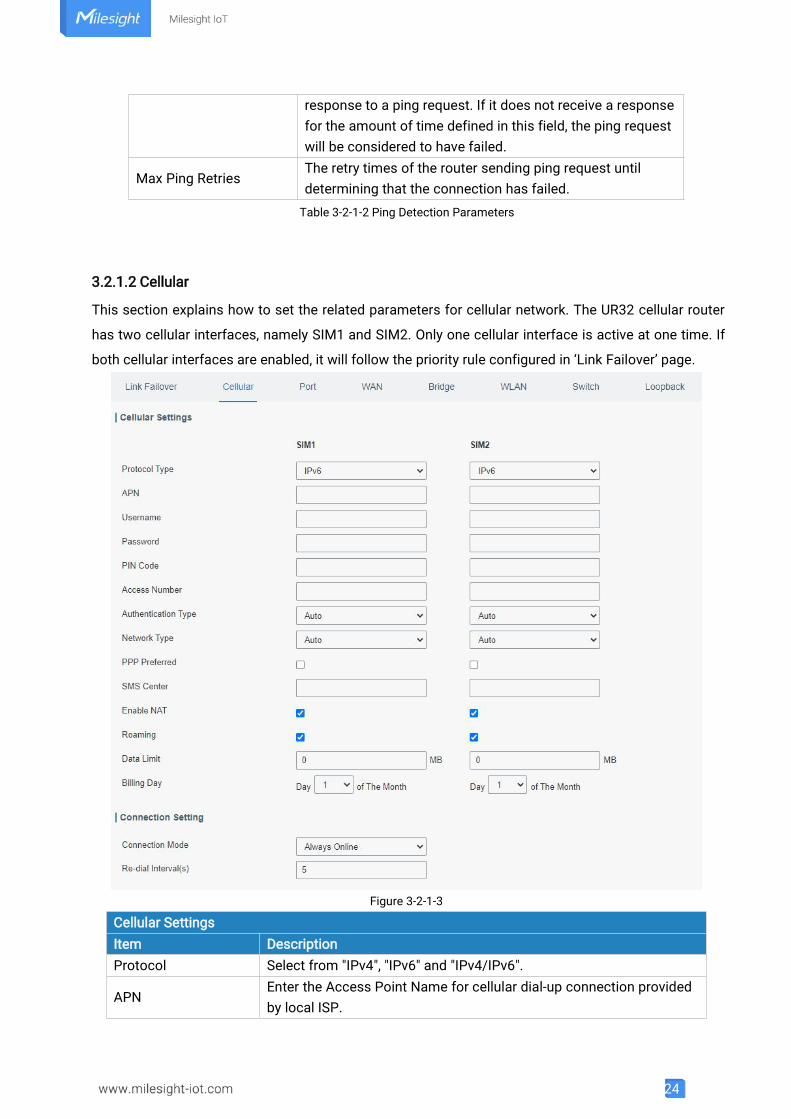
3.2.1.2 Cellular
This section explains how to set the related parameters for cellular network. The UR32 cellular router
has two cellular interfaces, namely SIM1 and SIM2. Only one cellular interface is active at one time. If
both cellular interfaces are enabled, it will follow the priority rule configured in ‘Link Failover’ page.
Figure 3-2-1-3
Cellular SettingsItem DescriptionProtocol Select from "IPv4", "IPv6" and "IPv4/IPv6".
APNEnter the Access Point Name for cellular dial-up connection providedby local ISP.
25
UsernameEnter the username for cellular dial-up connection provided by localISP.
PasswordEnter the password for cellular dial-up connection provided by localISP.
PIN Code Enter a 4-8 characters PIN code to unlock the SIM.
Access NumberEnter the dial-up center NO. For cellular dial-up connection providedby local ISP.
Authentication Type Select from "Auto", "PAP", "CHAP", "MS-CHAP", and "MS-CHAPv2".
Network Type
Select from "Auto", "4G Only", "3G Only", and "2G Only".Auto: connect to the network with the strongest signal automatically.4G Only: connect to 4G network only.And so on.
PPP Preferred The PPP dial-up method is preferred.
SMS CenterEnter the local SMS center number for storing, forwarding, convertingand delivering SMS message.
Enable NAT Enable or disable NAT function.Roaming Enable or disable roaming.
Data LimitWhen you reach the specified data usage limit, the data connection ofcurrently used SIM card will be disabled. 0 means disable thefunction.
Billing DayChoose the billing day of the SIM card, the router will reset the dataused to 0.
Table 3-2-1-3 Cellular Parameters
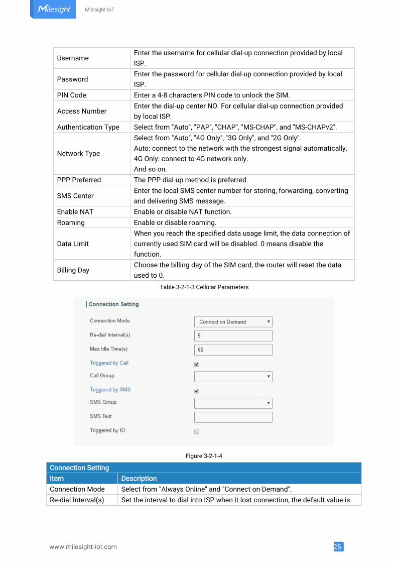
Figure 3-2-1-4
Connection SettingItem DescriptionConnection Mode Select from "Always Online" and "Connect on Demand".Re-dial Interval(s) Set the interval to dial into ISP when it lost connection, the default value is
26
5s.
Max Idle TimesSet the maximum duration of router when current link is under idle status.Range: 10-3600
Triggered by CallThe router will switch from offline mode to cellular network modeautomatically when it receives a call from the specific phone number.
Call GroupSelect a call group for call trigger. Go to "System > Phone&SMS > Phone" toset up phone group.
Triggered by SMSThe router will switch from offline mode to cellular network modeautomatically when it receives a specific SMS from the specific mobilephone.
SMS GroupSelect an SMS group for trigger. Go to "System > Phone&SMS > SMS" to setup SMS group.
SMS Text Fill in the SMS content for triggering.
Triggered by IOThe router will switch from offline mode to cellular network modeautomatically when the DI status is changed. Go to "Industrial > I/O > DI" toconfigure trigger condition.
Table 3-2-1-4 Cellular Parameters
Related TopicsCellular Network ConnectionPhone GroupDI Setting
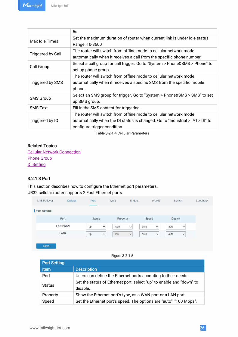
3.2.1.3 Port
This section describes how to configure the Ethernet port parameters.UR32 cellular router supports 2 Fast Ethernet ports.
Figure 3-2-1-5
Port SettingItem DescriptionPort Users can define the Ethernet ports according to their needs.
StatusSet the status of Ethernet port; select "up" to enable and "down" todisable.
Property Show the Ethernet port's type, as a WAN port or a LAN port.Speed Set the Ethernet port's speed. The options are "auto", "100 Mbps",
27
and "10 Mbps".
DuplexSet the Ethernet port's mode. The options are "auto", "full", and"half".
Table 3-2-1-5 Port Parameters
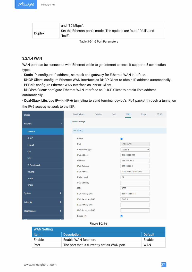
3.2.1.4 WAN
WAN port can be connected with Ethernet cable to get Internet access. It supports 5 connectiontypes.- Static IP: configure IP address, netmask and gateway for Ethernet WAN interface.- DHCP Client: configure Ethernet WAN interface as DHCP Client to obtain IP address automatically.- PPPoE: configure Ethernet WAN interface as PPPoE Client.- DHCPv6 Client: configure Ethernet WAN interface as DHCP Client to obtain IPv6 addressautomatically.- Dual-Stack Lite: use IPv4-in-IPv6 tunneling to send terminal device’s IPv4 packet through a tunnel on
the IPv6 access network to the ISP.
Figure 3-2-1-6
WAN SettingItem Description DefaultEnable Enable WAN function. EnablePort The port that is currently set as WAN port. WAN
28
Connection TypeSelect from "Static IP", "DHCP Client", “DHCPv6Client” , "Dual-Stack Lite" and "PPPoE".
Static IP
MTU Set the maximum transmission unit. 1500IPv4 PrimaryDNS
Set the primary IPv4 DNS server. 8.8.8.8
IPv4 SecondaryDNS
Set the secondary IPv4 DNS server. -- --
IPv6 PrimaryDNS
Set the primary IPv6 DNS server. -- --
IPv6 SecondaryDNS
Set the secondary IPv6 DNS server. -- --
Enable NATEnable or disable NAT function. When enabled, aprivate IP can be translated to a public IP.
Enable
Table 3-2-1-6 WAN Parameters
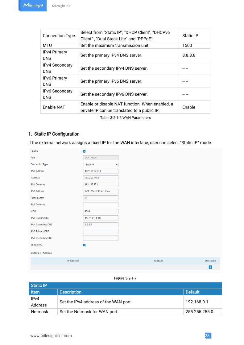
1. Static IP Configuration
If the external network assigns a fixed IP for the WAN interface, user can select “Static IP” mode.
Figure 3-2-1-7
Static IPItem Description DefaultIPv4Address
Set the IPv4 address of the WAN port. 192.168.0.1
Netmask Set the Netmask for WAN port. 255.255.255.0
29
IPv4Gateway
Set the gateway for WAN port's IPv4 address. 192.168.0.2
IPv6Address
Set the IPv6 address which can access Internet.Generated fromMac address
Prefix-length
Set the IPv6 prefix length to identify how many bits of a GlobalUnicast IPv6 address are there in network part. For example, in2001:0DB8:0000:000b::/64, the number 64 is used to identifythat the first 64 bits are in network part.
64
IPv6Gateway
Set the gateway for WAN port's IPv6 address.E.g.2001:DB8:ACAD:4::2.
--
Multiple IPAddress
Set the multiple IP addresses for WAN port. Null
Table 3-2-1-7 Static Parameters
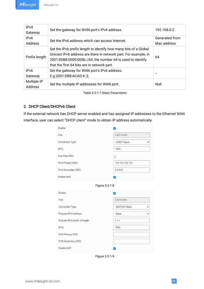
2. DHCP Client/DHCPv6 Client
If the external network has DHCP server enabled and has assigned IP addresses to the Ethernet WAN
interface, user can select “DHCP client” mode to obtain IP address automatically.
Figure 3-2-1-8
Figure 3-2-1-9
30
DHCP ClientItem Description
Use Peer DNSObtain peer DNS automatically during PPP dialing. DNS isnecessary when visiting domain name.
DHCPv6 Client
Request IPv6-address
Choose the ways to obtain the IPv6 address from the DHCPServer. Select from try, force, none.Try: The DHCP Server will assign specific address in priority.Force: The DHCP Server assigns specific address only.None: The DHCP Server will randomly assign address.Thespecific address is relevant to the prefix length of IPv6 addressyou set.
Request prefix length ofIPv6
Set the prefix length of IPv6 address which router is expectedto obtain from DHCP Server.
Table 3-2-1-8 DHCP Client Parameters
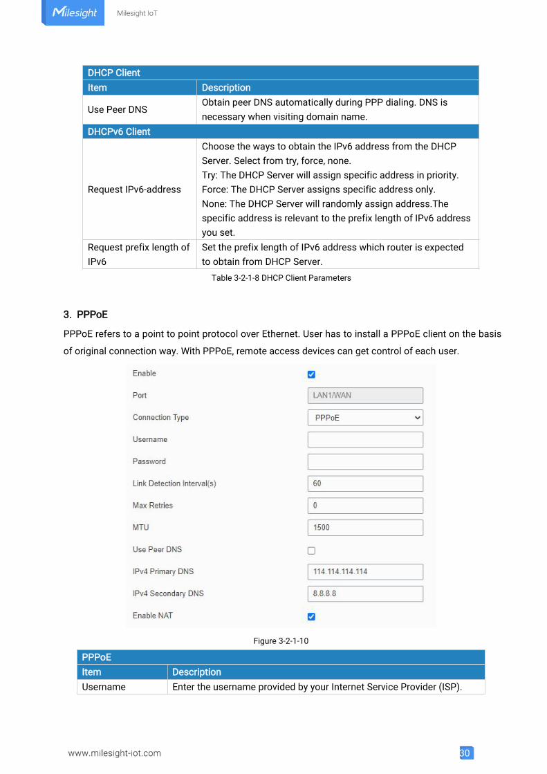
3. PPPoE
PPPoE refers to a point to point protocol over Ethernet. User has to install a PPPoE client on the basis
of original connection way. With PPPoE, remote access devices can get control of each user.
Figure 3-2-1-10
PPPoEItem DescriptionUsername Enter the username provided by your Internet Service Provider (ISP).
31
Password Enter the password provided by your Internet Service Provider (ISP).Link DetectionInterval (s)
Set the heartbeat interval for link detection. Range: 1-600.
Max Retries Set the maximum retry times after it fails to dial up. Range: 0-9.
Use Peer DNSObtain peer DNS automatically during PPP dialing. DNS is necessarywhen visiting domain name.
Table 3-2-1-9 PPPoE Parameters
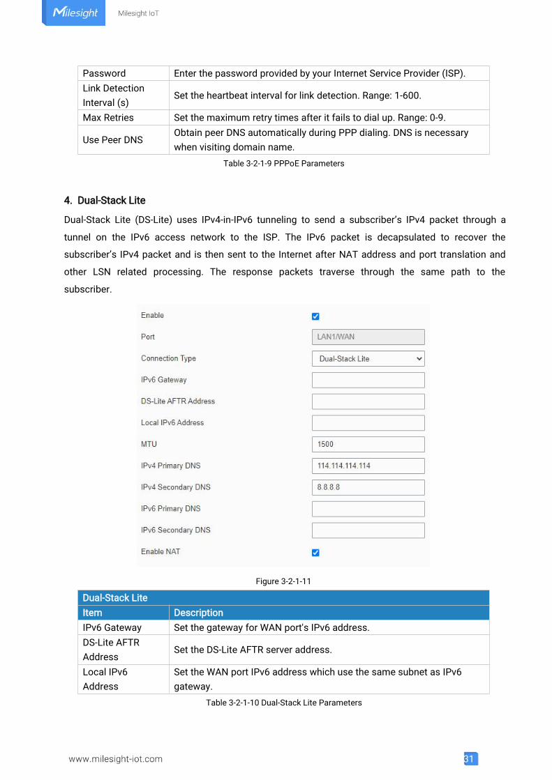
4. Dual-Stack Lite
Dual-Stack Lite (DS-Lite) uses IPv4-in-IPv6 tunneling to send a subscriber’s IPv4 packet through a
tunnel on the IPv6 access network to the ISP. The IPv6 packet is decapsulated to recover the
subscriber’s IPv4 packet and is then sent to the Internet after NAT address and port translation and
other LSN related processing. The response packets traverse through the same path to the
subscriber.
Figure 3-2-1-11
Dual-Stack LiteItem DescriptionIPv6 Gateway Set the gateway for WAN port's IPv6 address.DS-Lite AFTRAddress
Set the DS-Lite AFTR server address.
Local IPv6Address
Set the WAN port IPv6 address which use the same subnet as IPv6gateway.
Table 3-2-1-10 Dual-Stack Lite Parameters
32
Related Configuration Example
Ethernet WAN Connection
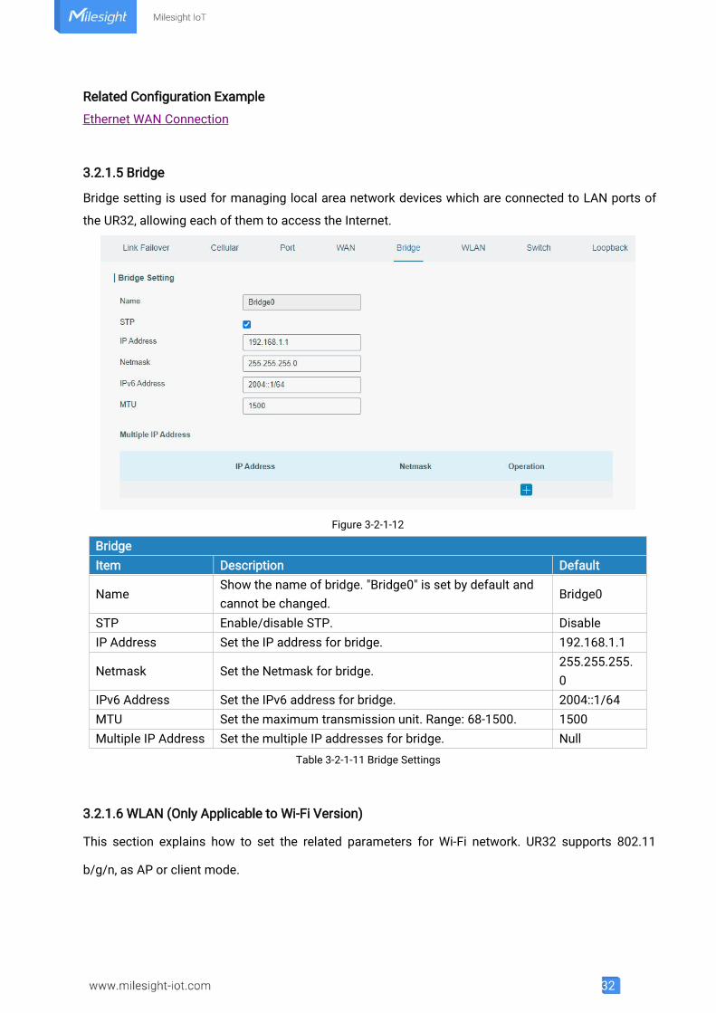
3.2.1.5 Bridge
Bridge setting is used for managing local area network devices which are connected to LAN ports of
the UR32, allowing each of them to access the Internet.
Figure 3-2-1-12
BridgeItem Description Default
NameShow the name of bridge. "Bridge0" is set by default andcannot be changed.
Bridge0
STP Enable/disable STP. DisableIP Address Set the IP address for bridge. 192.168.1.1
Netmask Set the Netmask for bridge.255.255.255.0
IPv6 Address Set the IPv6 address for bridge. 2004::1/64MTU Set the maximum transmission unit. Range: 68-1500. 1500Multiple IP Address Set the multiple IP addresses for bridge. Null
Table 3-2-1-11 Bridge Settings
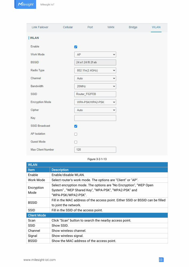
3.2.1.6 WLAN (Only Applicable to Wi-Fi Version)
This section explains how to set the related parameters for Wi-Fi network. UR32 supports 802.11
b/g/n, as AP or client mode.
33
Figure 3-2-1-13
WLANItem DescriptionEnable Enable/disable WLAN.Work Mode Select router's work mode. The options are "Client" or "AP".
EncryptionMode
Select encryption mode. The options are “No Encryption", “WEP OpenSystem" , “WEP Shared Key", “WPA-PSK", “WPA2-PSK" and“WPA-PSK/WPA2-PSK".
BSSIDFill in the MAC address of the access point. Either SSID or BSSID can be filledto joint the network.
SSID Fill in the SSID of the access point.Client ModeScan Click "Scan" button to search the nearby access point.SSID Show SSID.Channel Show wireless channel.Signal Show wireless signal.BSSID Show the MAC address of the access point.
34
Cipher Show the cipher of the access point.Security Show the encryption mode.
Frequency Show the frequency of radio.
Join Network Click the button to join the wireless network.AP Mode
Radio TypeSelect Radio type. The options are “802.11b (2.4 GHz)", “802.11g (2.4 GHz)",“802.11n (2.4 GHz)”.
Channel Select wireless channel. The options are "Auto", "1", "2"......"11".Cipher Select cipher. The options are “Auto", “AES", “TKIP" and “AES/TKIP".Key Fill the pre-shared key of WPA encryption.Bandwidth Select bandwidth. The options are "20MHz" and "40MHz".
SSIDBroadcast
When SSID broadcast is disabled, other wireless devices can't not find theSSID, and users have to enter the SSID manually to access to the wirelessnetwork.
AP IsolationWhen AP isolation is enabled, all users which access to the AP are isolatedwithout communication with each other.
Guest Mode The internal network is not allowed to visit if the guest mode is enabled.Max ClientNumber
Set the maximum number of client to access when the router is configuredas AP.
IP SettingProtocol Set the IP address in wireless network.IP Address Set the IP address in wireless network.Netmask Set the netmask in wireless network.Gateway Set the gateway in wireless network.
Table 3-2-1-12 WLAN Parameters
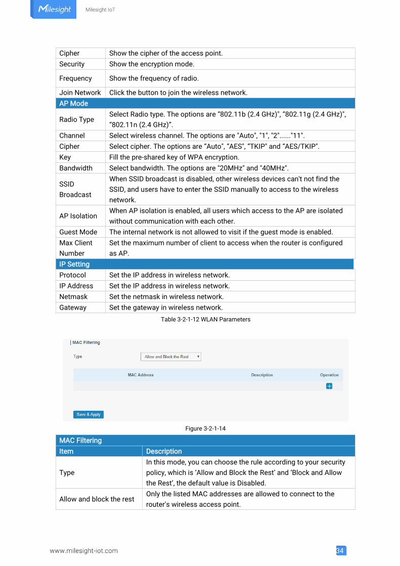
Figure 3-2-1-14
MAC FilteringItem Description
TypeIn this mode, you can choose the rule according to your securitypolicy, which is ‘Allow and Block the Rest’ and ‘Block and Allowthe Rest’, the default value is Disabled.
Allow and block the restOnly the listed MAC addresses are allowed to connect to therouter's wireless access point.
35
Block and allow the restThe listed MAC addresses are not allowed to connect to therouter's wireless access point.Table 3-2-1-13 MAC Filtering Parameters
Related Topic
Wi-Fi Application Example
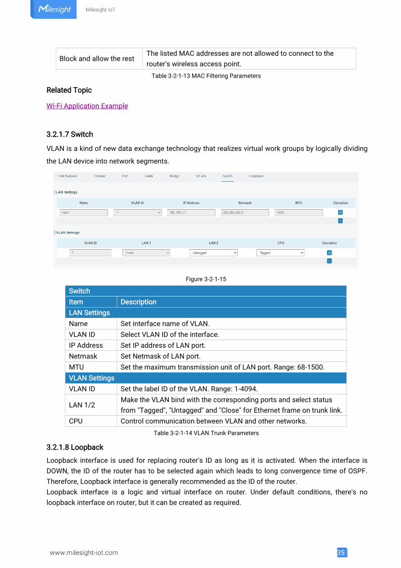
3.2.1.7 Switch
VLAN is a kind of new data exchange technology that realizes virtual work groups by logically dividing
the LAN device into network segments.
Figure 3-2-1-15
SwitchItem DescriptionLAN SettingsName Set interface name of VLAN.VLAN ID Select VLAN ID of the interface.IP Address Set IP address of LAN port.Netmask Set Netmask of LAN port.MTU Set the maximum transmission unit of LAN port. Range: 68-1500.VLAN SettingsVLAN ID Set the label ID of the VLAN. Range: 1-4094.
LAN 1/2Make the VLAN bind with the corresponding ports and select statusfrom "Tagged", "Untagged" and "Close" for Ethernet frame on trunk link.
CPU Control communication between VLAN and other networks.Table 3-2-1-14 VLAN Trunk Parameters
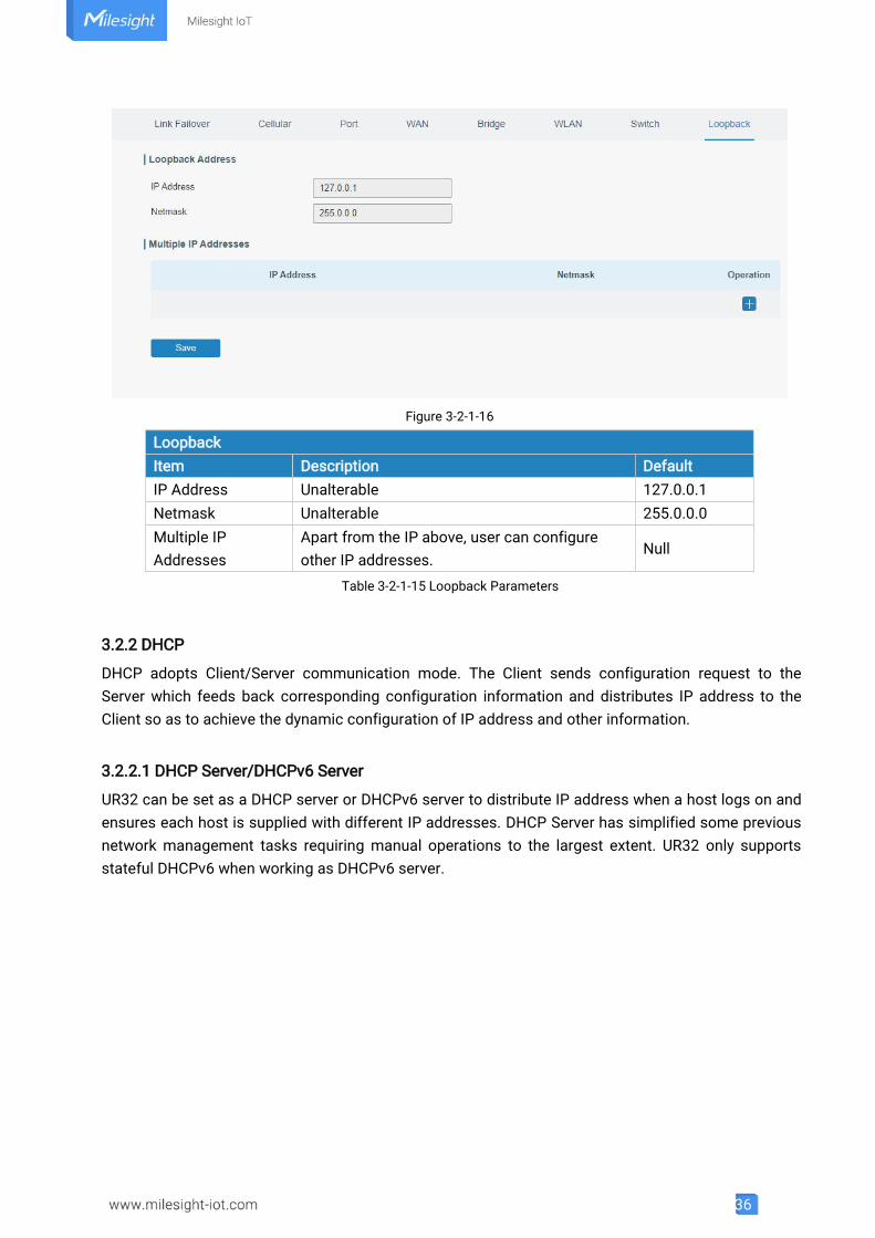
3.2.1.8 Loopback
Loopback interface is used for replacing router's ID as long as it is activated. When the interface isDOWN, the ID of the router has to be selected again which leads to long convergence time of OSPF.Therefore, Loopback interface is generally recommended as the ID of the router.Loopback interface is a logic and virtual interface on router. Under default conditions, there's noloopback interface on router, but it can be created as required.
36
Figure 3-2-1-16
LoopbackItem Description DefaultIP Address Unalterable 127.0.0.1Netmask Unalterable 255.0.0.0Multiple IPAddresses
Apart from the IP above, user can configureother IP addresses.
Null
Table 3-2-1-15 Loopback Parameters
3.2.2 DHCP
DHCP adopts Client/Server communication mode. The Client sends configuration request to theServer which feeds back corresponding configuration information and distributes IP address to theClient so as to achieve the dynamic configuration of IP address and other information.
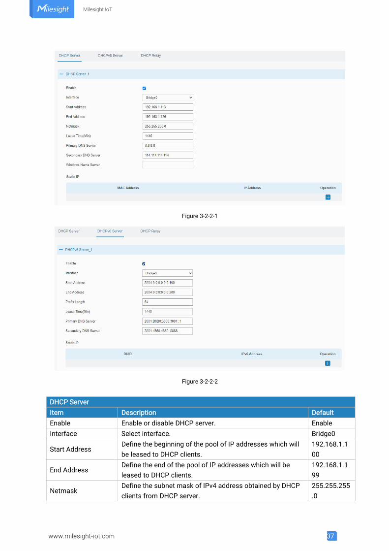
3.2.2.1 DHCP Server/DHCPv6 Server
UR32 can be set as a DHCP server or DHCPv6 server to distribute IP address when a host logs on andensures each host is supplied with different IP addresses. DHCP Server has simplified some previousnetwork management tasks requiring manual operations to the largest extent. UR32 only supportsstateful DHCPv6 when working as DHCPv6 server.
37
Figure 3-2-2-1
Figure 3-2-2-2
DHCP ServerItem Description DefaultEnable Enable or disable DHCP server. EnableInterface Select interface. Bridge0
Start AddressDefine the beginning of the pool of IP addresses which willbe leased to DHCP clients.
192.168.1.100
End AddressDefine the end of the pool of IP addresses which will beleased to DHCP clients.
192.168.1.199
NetmaskDefine the subnet mask of IPv4 address obtained by DHCPclients from DHCP server.
255.255.255.0
38
Table 3-2-2-1 DHCP Server Parameters
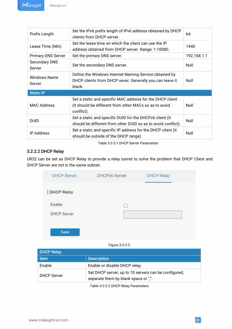
3.2.2.2 DHCP Relay
UR32 can be set as DHCP Relay to provide a relay tunnel to solve the problem that DHCP Client andDHCP Server are not in the same subnet.
Figure 3-2-2-3
DHCP RelayItem Description
Enable Enable or disable DHCP relay.
DHCP ServerSet DHCP server, up to 10 servers can be configured;separate them by blank space or ",".
Table 3-2-2-2 DHCP Relay Parameters
Prefix LengthSet the IPv6 prefix length of IPv6 address obtained by DHCPclients from DHCP server.
64
Lease Time (Min)Set the lease time on which the client can use the IPaddress obtained from DHCP server. Range: 1-10080.
1440
Primary DNS Server Set the primary DNS server. 192.168.1.1Secondary DNSServer
Set the secondary DNS server. Null
Windows NameServer
Define the Windows Internet Naming Service obtained byDHCP clients from DHCP sever. Generally you can leave itblank.
Null
Static IP
MAC AddressSet a static and specific MAC address for the DHCP client(it should be different from other MACs so as to avoidconflict).
Null
DUIDSet a static and specific DUID for the DHCPv6 client (itshould be different from other DUID so as to avoid conflict).
Null
IP AddressSet a static and specific IP address for the DHCP client (itshould be outside of the DHCP range).
Null
39
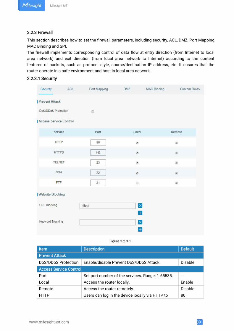
3.2.3 Firewall
This section describes how to set the firewall parameters, including security, ACL, DMZ, Port Mapping,MAC Binding and SPI.The firewall implements corresponding control of data flow at entry direction (from Internet to localarea network) and exit direction (from local area network to Internet) according to the contentfeatures of packets, such as protocol style, source/destination IP address, etc. It ensures that therouter operate in a safe environment and host in local area network.
3.2.3.1 Security
Figure 3-2-3-1
Item Description DefaultPrevent Attack
DoS/DDoS Protection Enable/disable Prevent DoS/DDoS Attack. DisableAccess Service ControlPort Set port number of the services. Range: 1-65535. --Local Access the router locally. EnableRemote Access the router remotely. DisableHTTP Users can log in the device locally via HTTP to 80
40
access and control it through Web after the optionis checked.
HTTPSUsers can log in the device locally and remotelyvia HTTPS to access and control it through Webafter option is checked.
443
TELNETUsers can log in the device locally and remotelyvia Telnet after the option is checked.
23
SSHUsers can log in the device locally and remotelyvia SSH after the option is checked.
22
FTPUsers can log in the device locally and remotelyvia FTP after the option is checked.
21
Website BlockingURL Blocking Enter the HTTP address which you want to block.
Keyword BlockingYou can block specific website by entering keyword. Themaximum number of character allowed is 64.
Table 3-2-3-1 Security Parameters
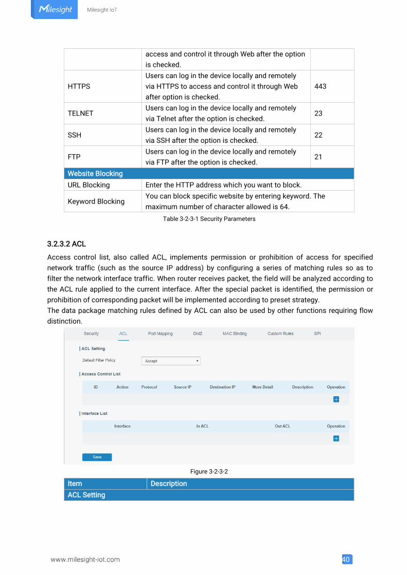
3.2.3.2 ACL
Access control list, also called ACL, implements permission or prohibition of access for specifiednetwork traffic (such as the source IP address) by configuring a series of matching rules so as tofilter the network interface traffic. When router receives packet, the field will be analyzed according tothe ACL rule applied to the current interface. After the special packet is identified, the permission orprohibition of corresponding packet will be implemented according to preset strategy.The data package matching rules defined by ACL can also be used by other functions requiring flowdistinction.
Figure 3-2-3-2
Item DescriptionACL Setting
41
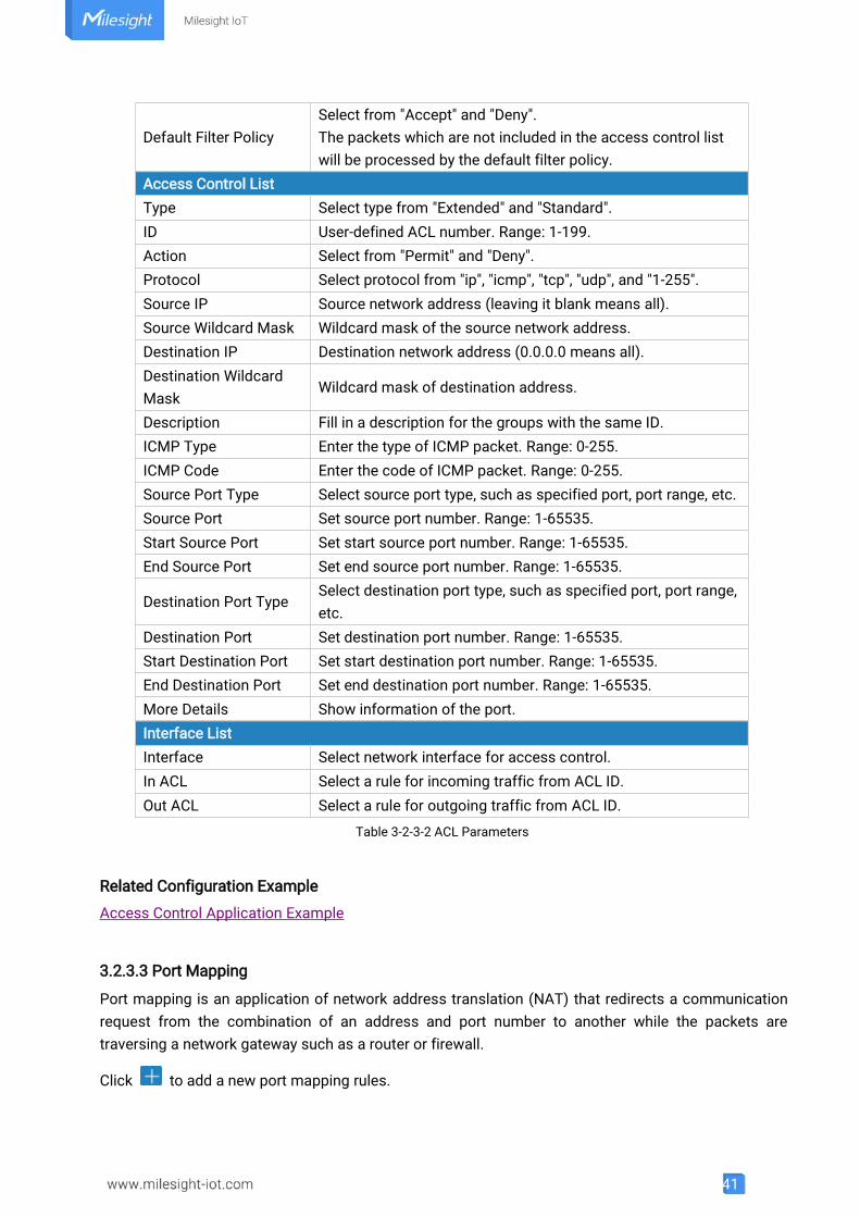
Default Filter PolicySelect from "Accept" and "Deny".The packets which are not included in the access control listwill be processed by the default filter policy.
Access Control ListType Select type from "Extended" and "Standard".ID User-defined ACL number. Range: 1-199.Action Select from "Permit" and "Deny".Protocol Select protocol from "ip", "icmp", "tcp", "udp", and "1-255".Source IP Source network address (leaving it blank means all).Source Wildcard Mask Wildcard mask of the source network address.Destination IP Destination network address (0.0.0.0 means all).Destination WildcardMask
Wildcard mask of destination address.
Description Fill in a description for the groups with the same ID.ICMP Type Enter the type of ICMP packet. Range: 0-255.ICMP Code Enter the code of ICMP packet. Range: 0-255.Source Port Type Select source port type, such as specified port, port range, etc.Source Port Set source port number. Range: 1-65535.Start Source Port Set start source port number. Range: 1-65535.End Source Port Set end source port number. Range: 1-65535.
Destination Port TypeSelect destination port type, such as specified port, port range,etc.
Destination Port Set destination port number. Range: 1-65535.Start Destination Port Set start destination port number. Range: 1-65535.End Destination Port Set end destination port number. Range: 1-65535.More Details Show information of the port.Interface ListInterface Select network interface for access control.In ACL Select a rule for incoming traffic from ACL ID.Out ACL Select a rule for outgoing traffic from ACL ID.
Table 3-2-3-2 ACL Parameters
Related Configuration Example
Access Control Application Example
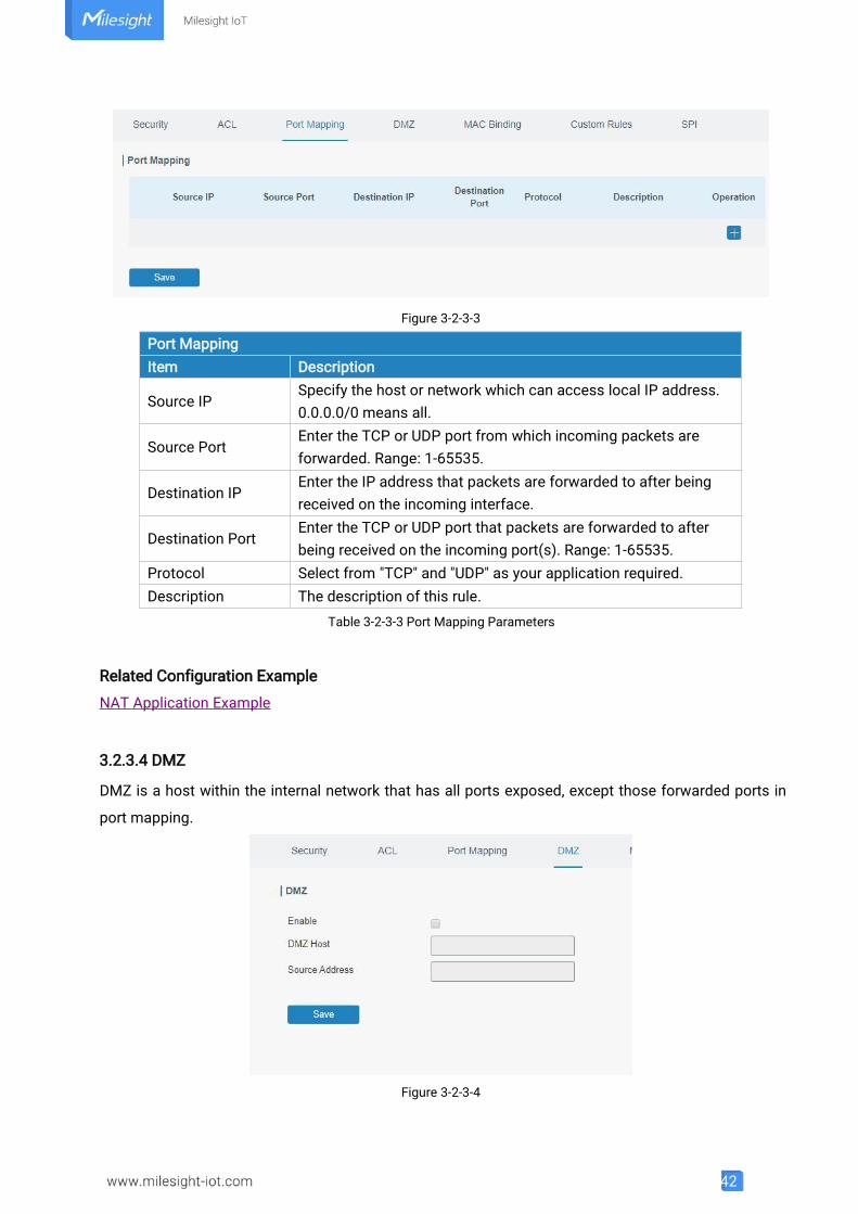
3.2.3.3 Port Mapping
Port mapping is an application of network address translation (NAT) that redirects a communicationrequest from the combination of an address and port number to another while the packets aretraversing a network gateway such as a router or firewall.
Click to add a new port mapping rules.
42
Figure 3-2-3-3
Port MappingItem Description
Source IPSpecify the host or network which can access local IP address.0.0.0.0/0 means all.
Source PortEnter the TCP or UDP port from which incoming packets areforwarded. Range: 1-65535.
Destination IPEnter the IP address that packets are forwarded to after beingreceived on the incoming interface.
Destination PortEnter the TCP or UDP port that packets are forwarded to afterbeing received on the incoming port(s). Range: 1-65535.
Protocol Select from "TCP" and "UDP" as your application required.Description The description of this rule.
Table 3-2-3-3 Port Mapping Parameters
Related Configuration Example
NAT Application Example
3.2.3.4 DMZ
DMZ is a host within the internal network that has all ports exposed, except those forwarded ports in
port mapping.
Figure 3-2-3-4
43
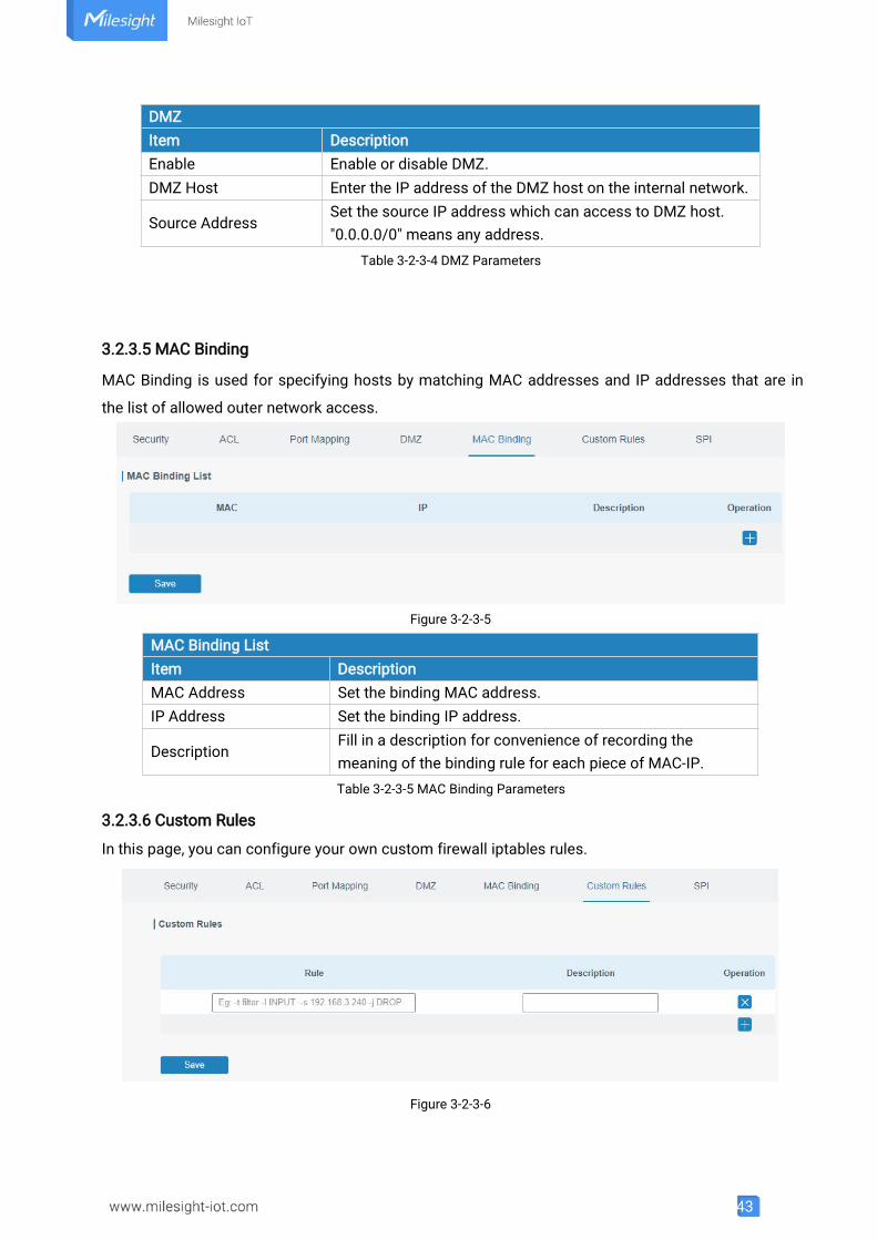
DMZItem DescriptionEnable Enable or disable DMZ.DMZ Host Enter the IP address of the DMZ host on the internal network.
Source AddressSet the source IP address which can access to DMZ host."0.0.0.0/0" means any address.
Table 3-2-3-4 DMZ Parameters
3.2.3.5 MAC Binding
MAC Binding is used for specifying hosts by matching MAC addresses and IP addresses that are in
the list of allowed outer network access.
Figure 3-2-3-5
MAC Binding ListItem DescriptionMAC Address Set the binding MAC address.IP Address Set the binding IP address.
DescriptionFill in a description for convenience of recording themeaning of the binding rule for each piece of MAC-IP.Table 3-2-3-5 MAC Binding Parameters
3.2.3.6 Custom Rules
In this page, you can configure your own custom firewall iptables rules.
Figure 3-2-3-6
44
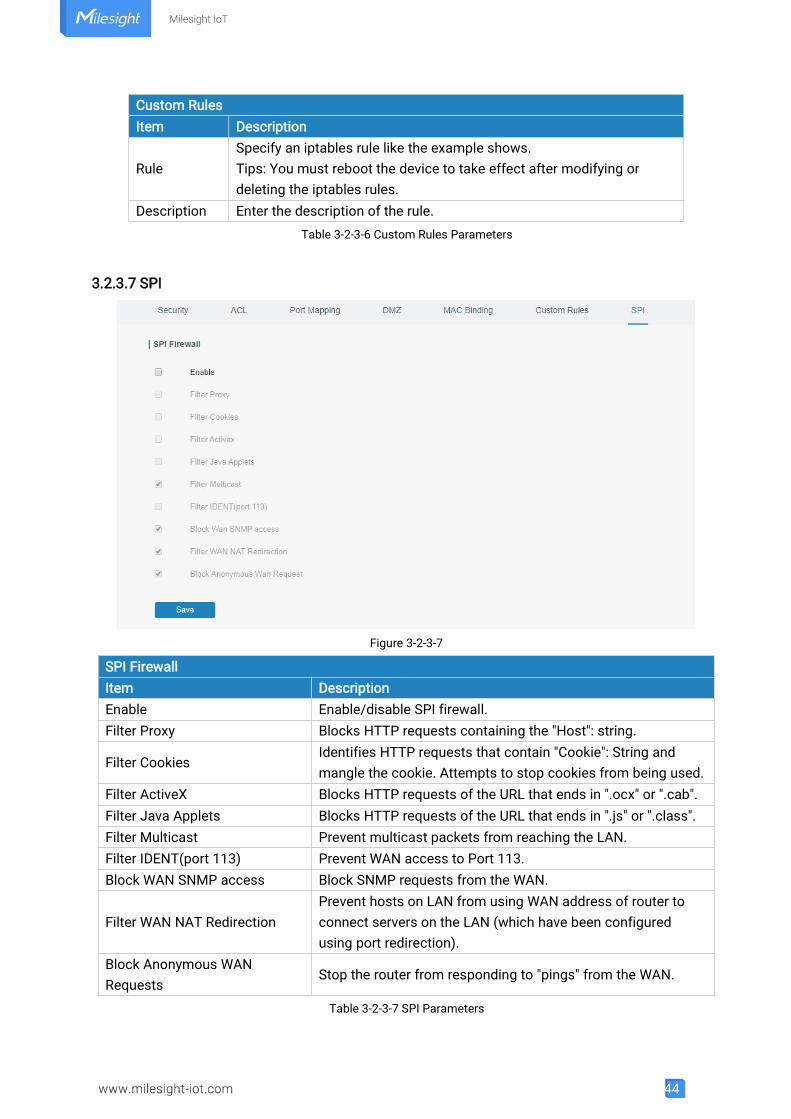
Custom RulesItem Description
RuleSpecify an iptables rule like the example shows.Tips: You must reboot the device to take effect after modifying ordeleting the iptables rules.
Description Enter the description of the rule.Table 3-2-3-6 Custom Rules Parameters
3.2.3.7 SPI
Figure 3-2-3-7
SPI FirewallItem DescriptionEnable Enable/disable SPI firewall.Filter Proxy Blocks HTTP requests containing the "Host": string.
Filter CookiesIdentifies HTTP requests that contain "Cookie": String andmangle the cookie. Attempts to stop cookies from being used.
Filter ActiveX Blocks HTTP requests of the URL that ends in ".ocx" or ".cab".Filter Java Applets Blocks HTTP requests of the URL that ends in ".js" or ".class".Filter Multicast Prevent multicast packets from reaching the LAN.Filter IDENT(port 113) Prevent WAN access to Port 113.Block WAN SNMP access Block SNMP requests from the WAN.
Filter WAN NAT RedirectionPrevent hosts on LAN from using WAN address of router toconnect servers on the LAN (which have been configuredusing port redirection).
Block Anonymous WANRequests
Stop the router from responding to "pings" from the WAN.
Table 3-2-3-7 SPI Parameters
45
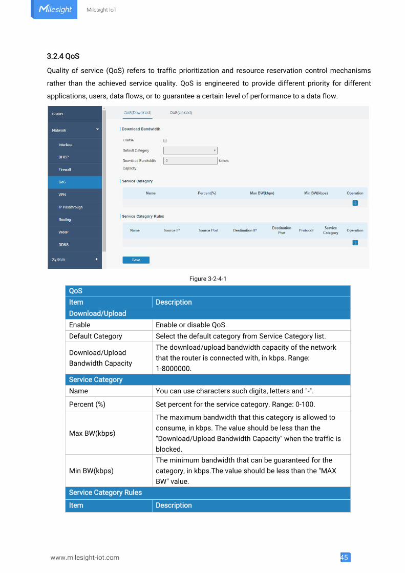
3.2.4 QoS
Quality of service (QoS) refers to traffic prioritization and resource reservation control mechanisms
rather than the achieved service quality. QoS is engineered to provide different priority for different
applications, users, data flows, or to guarantee a certain level of performance to a data flow.
Figure 3-2-4-1
QoSItem DescriptionDownload/UploadEnable Enable or disable QoS.Default Category Select the default category from Service Category list.
Download/UploadBandwidth Capacity
The download/upload bandwidth capacity of the networkthat the router is connected with, in kbps. Range:1-8000000.
Service CategoryName You can use characters such digits, letters and "-".
Percent (%) Set percent for the service category. Range: 0-100.
Max BW(kbps)
The maximum bandwidth that this category is allowed toconsume, in kbps. The value should be less than the"Download/Upload Bandwidth Capacity" when the traffic isblocked.
Min BW(kbps)The minimum bandwidth that can be guaranteed for thecategory, in kbps.The value should be less than the "MAXBW" value.
Service Category Rules
Item Description
46
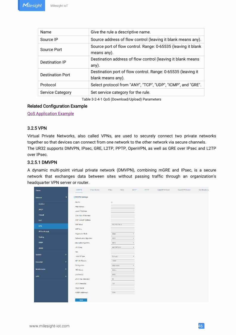
Name Give the rule a descriptive name.
Source IP Source address of flow control (leaving it blank means any).
Source PortSource port of flow control. Range: 0-65535 (leaving it blankmeans any).
Destination IPDestination address of flow control (leaving it blank meansany).
Destination PortDestination port of flow control. Range: 0-65535 (leaving itblank means any).
Protocol Select protocol from "ANY", "TCP", "UDP", "ICMP", and "GRE".
Service Category Set service category for the rule.Table 3-2-4-1 QoS (Download/Upload) Parameters
Related Configuration Example
QoS Application Example
3.2.5 VPN
Virtual Private Networks, also called VPNs, are used to securely connect two private networkstogether so that devices can connect from one network to the other network via secure channels.The UR32 supports DMVPN, IPsec, GRE, L2TP, PPTP, OpenVPN, as well as GRE over IPsec and L2TPover IPsec.
3.2.5.1 DMVPN
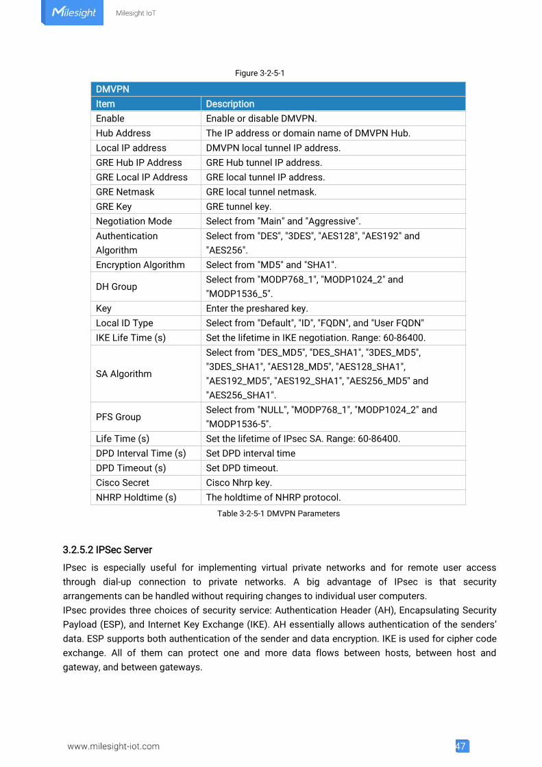
A dynamic multi-point virtual private network (DMVPN), combining mGRE and IPsec, is a securenetwork that exchanges data between sites without passing traffic through an organization'sheadquarter VPN server or router.
47
Figure 3-2-5-1
DMVPNItem DescriptionEnable Enable or disable DMVPN.Hub Address The IP address or domain name of DMVPN Hub.Local IP address DMVPN local tunnel IP address.GRE Hub IP Address GRE Hub tunnel IP address.GRE Local IP Address GRE local tunnel IP address.GRE Netmask GRE local tunnel netmask.GRE Key GRE tunnel key.Negotiation Mode Select from "Main" and "Aggressive".AuthenticationAlgorithm
Select from "DES", "3DES", "AES128", "AES192" and"AES256".
Encryption Algorithm Select from "MD5" and "SHA1".
DH GroupSelect from "MODP768_1", "MODP1024_2" and"MODP1536_5".
Key Enter the preshared key.Local ID Type Select from "Default", "ID", "FQDN", and "User FQDN"IKE Life Time (s) Set the lifetime in IKE negotiation. Range: 60-86400.
SA Algorithm
Select from "DES_MD5", "DES_SHA1", "3DES_MD5","3DES_SHA1", "AES128_MD5", "AES128_SHA1","AES192_MD5", "AES192_SHA1", "AES256_MD5" and"AES256_SHA1".
PFS GroupSelect from "NULL", "MODP768_1", "MODP1024_2" and"MODP1536-5".
Life Time (s) Set the lifetime of IPsec SA. Range: 60-86400.DPD Interval Time (s) Set DPD interval timeDPD Timeout (s) Set DPD timeout.Cisco Secret Cisco Nhrp key.NHRP Holdtime (s) The holdtime of NHRP protocol.
Table 3-2-5-1 DMVPN Parameters
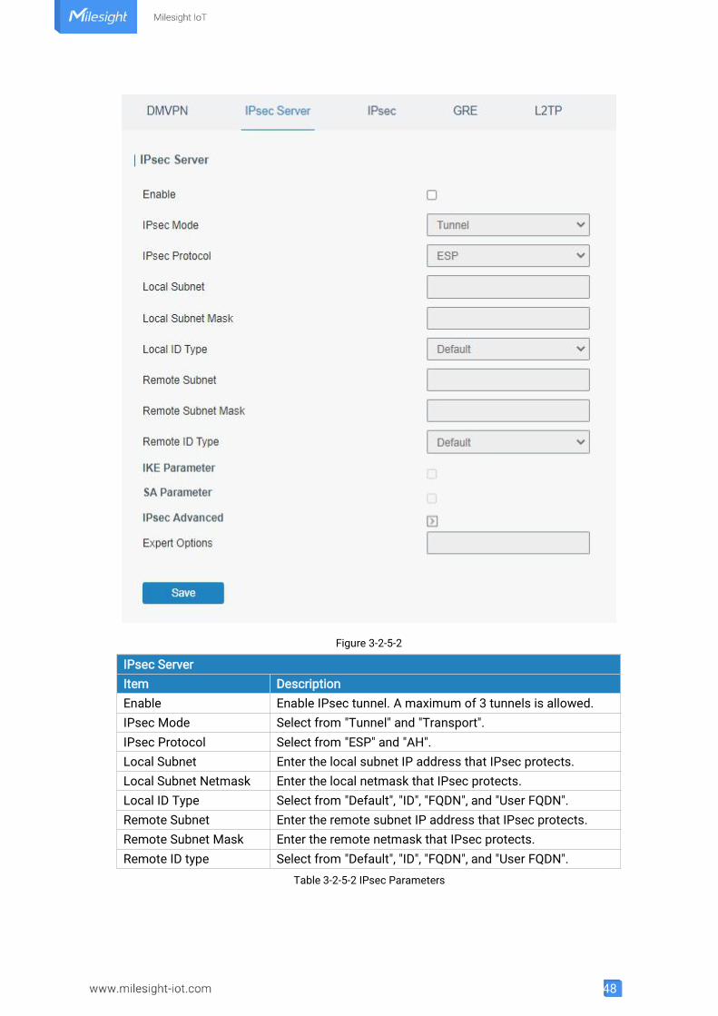
3.2.5.2 IPSec Server
IPsec is especially useful for implementing virtual private networks and for remote user accessthrough dial-up connection to private networks. A big advantage of IPsec is that securityarrangements can be handled without requiring changes to individual user computers.IPsec provides three choices of security service: Authentication Header (AH), Encapsulating SecurityPayload (ESP), and Internet Key Exchange (IKE). AH essentially allows authentication of the senders’data. ESP supports both authentication of the sender and data encryption. IKE is used for cipher codeexchange. All of them can protect one and more data flows between hosts, between host andgateway, and between gateways.
48
Figure 3-2-5-2
IPsec ServerItem DescriptionEnable Enable IPsec tunnel. A maximum of 3 tunnels is allowed.IPsec Mode Select from "Tunnel" and "Transport".IPsec Protocol Select from "ESP" and "AH".Local Subnet Enter the local subnet IP address that IPsec protects.Local Subnet Netmask Enter the local netmask that IPsec protects.Local ID Type Select from "Default", "ID", "FQDN", and "User FQDN".Remote Subnet Enter the remote subnet IP address that IPsec protects.Remote Subnet Mask Enter the remote netmask that IPsec protects.Remote ID type Select from "Default", "ID", "FQDN", and "User FQDN".
Table 3-2-5-2 IPsec Parameters
49
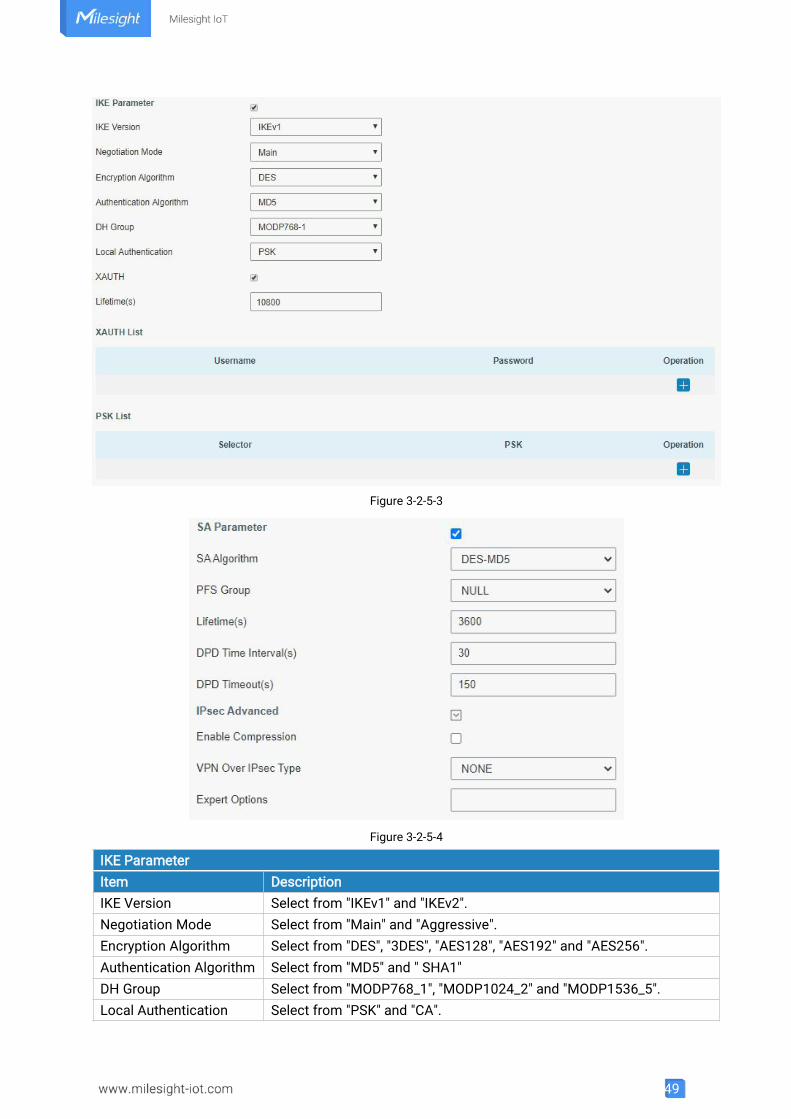
Figure 3-2-5-3
Figure 3-2-5-4
IKE ParameterItem DescriptionIKE Version Select from "IKEv1" and "IKEv2".Negotiation Mode Select from "Main" and "Aggressive".Encryption Algorithm Select from "DES", "3DES", "AES128", "AES192" and "AES256".Authentication Algorithm Select from "MD5" and " SHA1"DH Group Select from "MODP768_1", "MODP1024_2" and "MODP1536_5".Local Authentication Select from "PSK" and "CA".
50
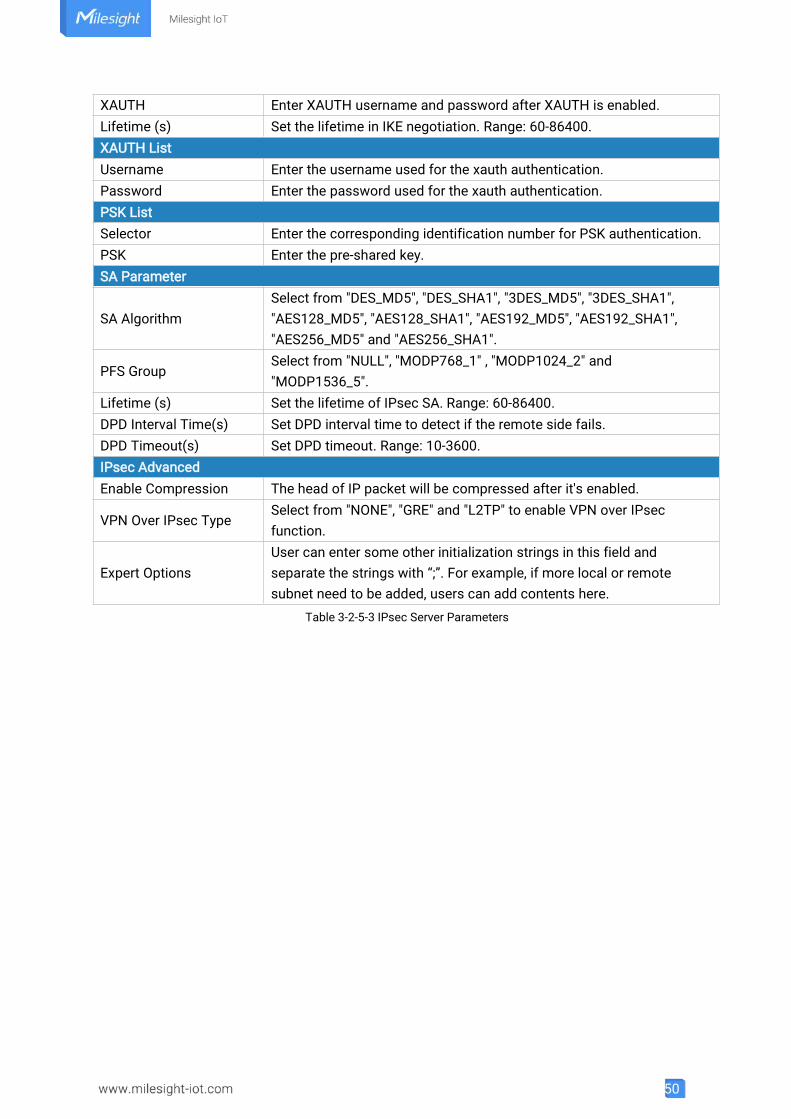
XAUTH Enter XAUTH username and password after XAUTH is enabled.Lifetime (s) Set the lifetime in IKE negotiation. Range: 60-86400.XAUTH ListUsername Enter the username used for the xauth authentication.Password Enter the password used for the xauth authentication.PSK ListSelector Enter the corresponding identification number for PSK authentication.PSK Enter the pre-shared key.SA Parameter
SA AlgorithmSelect from "DES_MD5", "DES_SHA1", "3DES_MD5", "3DES_SHA1","AES128_MD5", "AES128_SHA1", "AES192_MD5", "AES192_SHA1","AES256_MD5" and "AES256_SHA1".
PFS GroupSelect from "NULL", "MODP768_1" , "MODP1024_2" and"MODP1536_5".
Lifetime (s) Set the lifetime of IPsec SA. Range: 60-86400.DPD Interval Time(s) Set DPD interval time to detect if the remote side fails.DPD Timeout(s) Set DPD timeout. Range: 10-3600.IPsec AdvancedEnable Compression The head of IP packet will be compressed after it's enabled.
VPN Over IPsec TypeSelect from "NONE", "GRE" and "L2TP" to enable VPN over IPsecfunction.
Expert OptionsUser can enter some other initialization strings in this field andseparate the strings with “;”. For example, if more local or remotesubnet need to be added, users can add contents here.
Table 3-2-5-3 IPsec Server Parameters
51
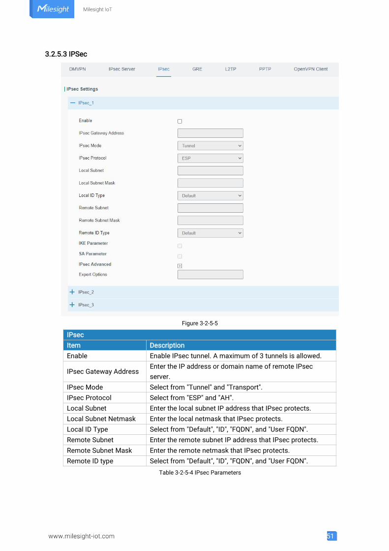
3.2.5.3 IPSec
Figure 3-2-5-5
IPsecItem DescriptionEnable Enable IPsec tunnel. A maximum of 3 tunnels is allowed.
IPsec Gateway AddressEnter the IP address or domain name of remote IPsecserver.
IPsec Mode Select from "Tunnel" and "Transport".IPsec Protocol Select from "ESP" and "AH".Local Subnet Enter the local subnet IP address that IPsec protects.Local Subnet Netmask Enter the local netmask that IPsec protects.Local ID Type Select from "Default", "ID", "FQDN", and "User FQDN".Remote Subnet Enter the remote subnet IP address that IPsec protects.Remote Subnet Mask Enter the remote netmask that IPsec protects.Remote ID type Select from "Default", "ID", "FQDN", and "User FQDN".
Table 3-2-5-4 IPsec Parameters
52
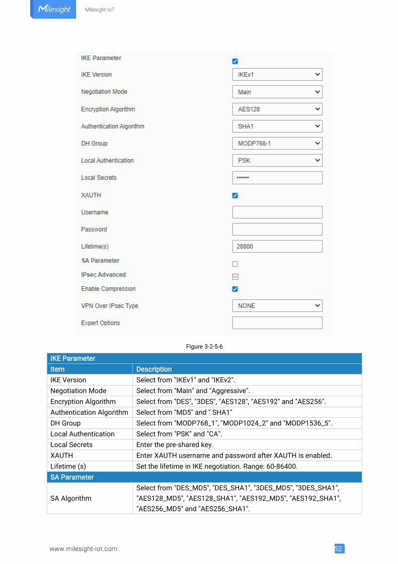
Figure 3-2-5-6
IKE ParameterItem DescriptionIKE Version Select from "IKEv1" and "IKEv2".Negotiation Mode Select from "Main" and "Aggressive".Encryption Algorithm Select from "DES", "3DES", "AES128", "AES192" and "AES256".Authentication Algorithm Select from "MD5" and " SHA1"DH Group Select from "MODP768_1", "MODP1024_2" and "MODP1536_5".Local Authentication Select from "PSK" and "CA".Local Secrets Enter the pre-shared key.XAUTH Enter XAUTH username and password after XAUTH is enabled.Lifetime (s) Set the lifetime in IKE negotiation. Range: 60-86400.SA Parameter
SA AlgorithmSelect from "DES_MD5", "DES_SHA1", "3DES_MD5", "3DES_SHA1","AES128_MD5", "AES128_SHA1", "AES192_MD5", "AES192_SHA1","AES256_MD5" and "AES256_SHA1".
53
PFS GroupSelect from "NULL", "MODP768_1" , "MODP1024_2" and"MODP1536_5".
Lifetime (s) Set the lifetime of IPsec SA. Range: 60-86400.DPD Interval Time(s) Set DPD interval time to detect if the remote side fails.DPD Timeout(s) Set DPD timeout. Range: 10-3600.IPsec AdvancedEnable Compression The head of IP packet will be compressed after it's enabled.
VPN Over IPsec TypeSelect from "NONE", "GRE" and "L2TP" to enable VPN over IPsecfunction.
Expert OptionUser can enter some other initialization strings in this field andseparate the strings with “;”. For example, if more local or remotesubnet need to be added, users can add contents here.
Table 3-2-5-5 IPsec Parameters
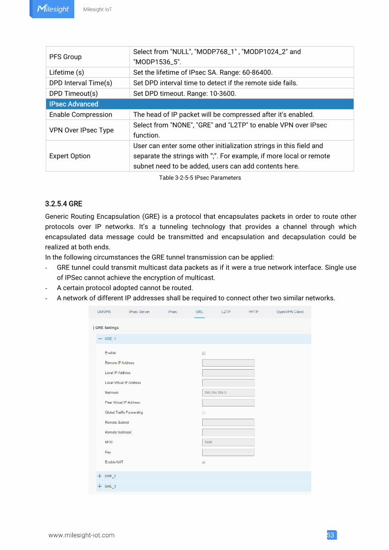
3.2.5.4 GRE
Generic Routing Encapsulation (GRE) is a protocol that encapsulates packets in order to route otherprotocols over IP networks. It’s a tunneling technology that provides a channel through whichencapsulated data message could be transmitted and encapsulation and decapsulation could berealized at both ends.In the following circumstances the GRE tunnel transmission can be applied:- GRE tunnel could transmit multicast data packets as if it were a true network interface. Single use
of IPSec cannot achieve the encryption of multicast.- A certain protocol adopted cannot be routed.- A network of different IP addresses shall be required to connect other two similar networks.
54
Figure 3-2-5-7
GREItem DescriptionEnable Check to enable GRE function.Remote IP Address Enter the real remote IP address of GRE tunnel.Local IP Address Set the local IP address.Local Virtual IPAddress
Set the local tunnel IP address of GRE tunnel.
Netmask Set the local netmask.Peer Virtual IP Address Enter remote tunnel IP address of GRE tunnel.Global TrafficForwarding
All the data traffic will be sent out via GRE tunnel when thisfunction is enabled.
Remote Subnet Enter the remote subnet IP address of GRE tunnel.Remote Netmask Enter the remote netmask of GRE tunnel.MTU Enter the maximum transmission unit. Range: 64-1500.Key Set GRE tunnel key.Enable NAT Enable NAT traversal function.
Table 3-2-5-6 GRE Parameters
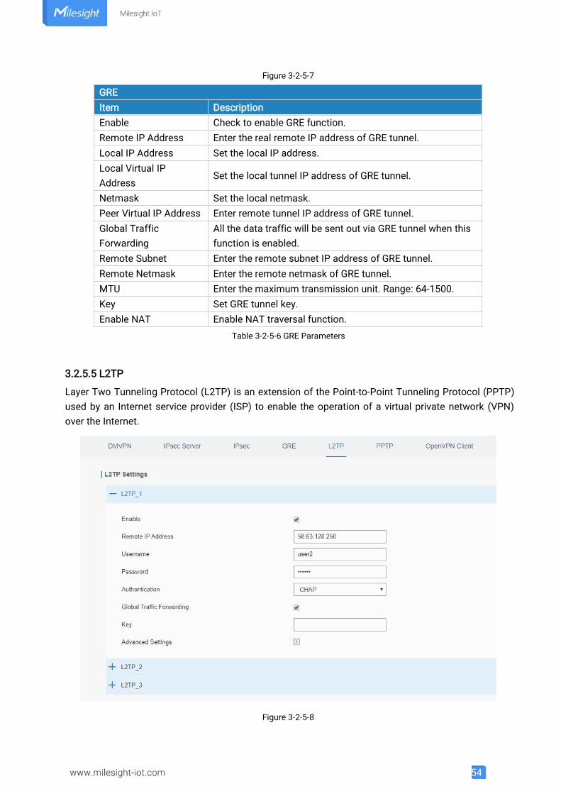
3.2.5.5 L2TP
Layer Two Tunneling Protocol (L2TP) is an extension of the Point-to-Point Tunneling Protocol (PPTP)used by an Internet service provider (ISP) to enable the operation of a virtual private network (VPN)over the Internet.
Figure 3-2-5-8
55
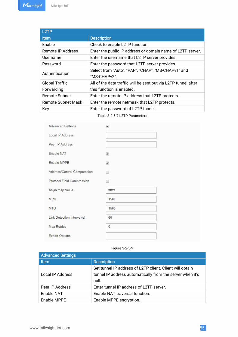
L2TPItem DescriptionEnable Check to enable L2TP function.Remote IP Address Enter the public IP address or domain name of L2TP server.Username Enter the username that L2TP server provides.Password Enter the password that L2TP server provides.
AuthenticationSelect from "Auto", "PAP", "CHAP", "MS-CHAPv1" and"MS-CHAPv2".
Global TrafficForwarding
All of the data traffic will be sent out via L2TP tunnel afterthis function is enabled.
Remote Subnet Enter the remote IP address that L2TP protects.Remote Subnet Mask Enter the remote netmask that L2TP protects.Key Enter the password of L2TP tunnel.
Table 3-2-5-7 L2TP Parameters
Figure 3-2-5-9
Advanced SettingsItem Description
Local IP AddressSet tunnel IP address of L2TP client. Client will obtaintunnel IP address automatically from the server when it'snull.
Peer IP Address Enter tunnel IP address of L2TP server.Enable NAT Enable NAT traversal function.Enable MPPE Enable MPPE encryption.
56
Address/ControlCompression
For PPP initialization. User can keep the default option.
Protocol FieldCompression
For PPP initialization. User can keep the default option.
Asyncmap ValueOne of the PPP protocol initialization strings. User cankeep the default value. Range: 0-ffffffff.
MRU Set the maximum receive unit. Range: 64-1500.MTU Set the maximum transmission unit. Range: 64-1500
Link Detection Interval (s)Set the link detection interval time to ensure tunnelconnection. Range: 0-600.
Max RetriesSet the maximum times of retry to detect the L2TPconnection failure. Range: 0-10.
Expert OptionsUser can enter some other PPP initialization strings in thisfield and separate the strings with blank space.
Table 3-2-5-8 L2TP Parameters
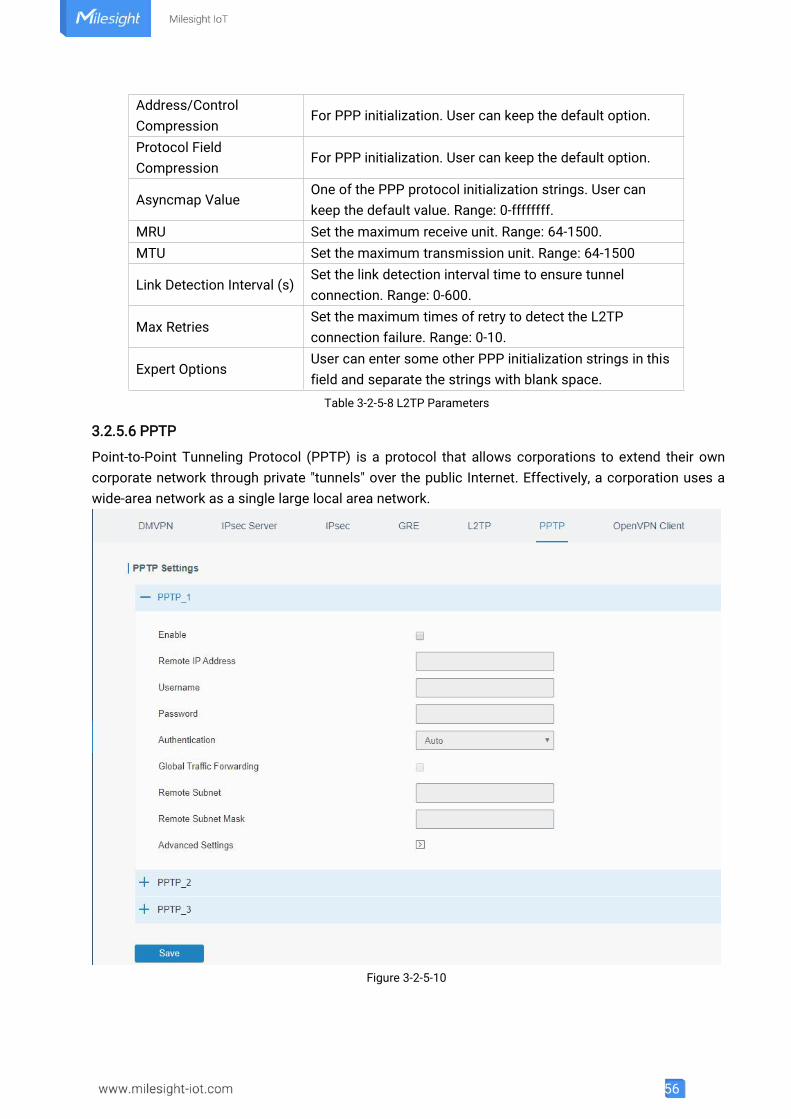
3.2.5.6 PPTP
Point-to-Point Tunneling Protocol (PPTP) is a protocol that allows corporations to extend their owncorporate network through private "tunnels" over the public Internet. Effectively, a corporation uses awide-area network as a single large local area network.
Figure 3-2-5-10
57
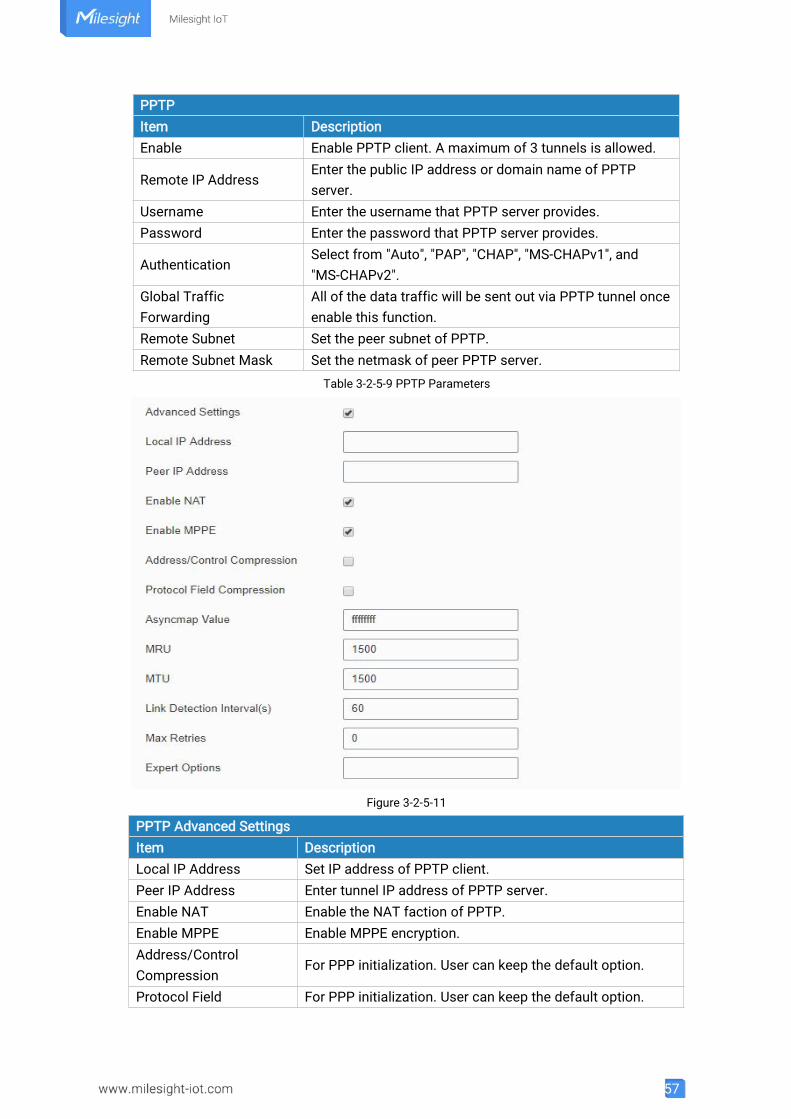
PPTPItem DescriptionEnable Enable PPTP client. A maximum of 3 tunnels is allowed.
Remote IP AddressEnter the public IP address or domain name of PPTPserver.
Username Enter the username that PPTP server provides.Password Enter the password that PPTP server provides.
AuthenticationSelect from "Auto", "PAP", "CHAP", "MS-CHAPv1", and"MS-CHAPv2".
Global TrafficForwarding
All of the data traffic will be sent out via PPTP tunnel onceenable this function.
Remote Subnet Set the peer subnet of PPTP.Remote Subnet Mask Set the netmask of peer PPTP server.
Table 3-2-5-9 PPTP Parameters
Figure 3-2-5-11
PPTP Advanced SettingsItem DescriptionLocal IP Address Set IP address of PPTP client.Peer IP Address Enter tunnel IP address of PPTP server.Enable NAT Enable the NAT faction of PPTP.Enable MPPE Enable MPPE encryption.Address/ControlCompression
For PPP initialization. User can keep the default option.
Protocol Field For PPP initialization. User can keep the default option.
58
Compression
Asyncmap ValueOne of the PPP protocol initialization strings. User can keepthe default value. Range: 0-ffffffff.
MRU Enter the maximum receive unit. Range: 0-1500.MTU Enter the maximum transmission unit. Range: 0-1500.Link Detection Interval(s)
Set the link detection interval time to ensure tunnelconnection. Range: 0-600.
Max RetriesSet the maximum times of retrying to detect the PPTPconnection failure. Range: 0-10.
Expert OptionsUser can enter some other PPP initialization strings in thisfield and separate the strings with blank space.
Table 3-2-5-10 PPTP Parameters
Related Configuration Example
PPTP Application Example
3.2.5.7 OpenVPN Client
OpenVPN is an open source virtual private network (VPN) product that offers a simplified securityframework, modular network design, and cross-platform portability.Advantages of OpenVPN include:- Security provisions that function against both active and passive attacks.- Compatibility with all major operating systems.- High speed (1.4 megabytes per second typically).- Ability to configure multiple servers to handle numerous connections simultaneously.- All encryption and authentication features of the OpenSSL library.- Advanced bandwidth management.- A variety of tunneling options.- Compatibility with smart cards that support the Windows Crypt application program interface
(API).
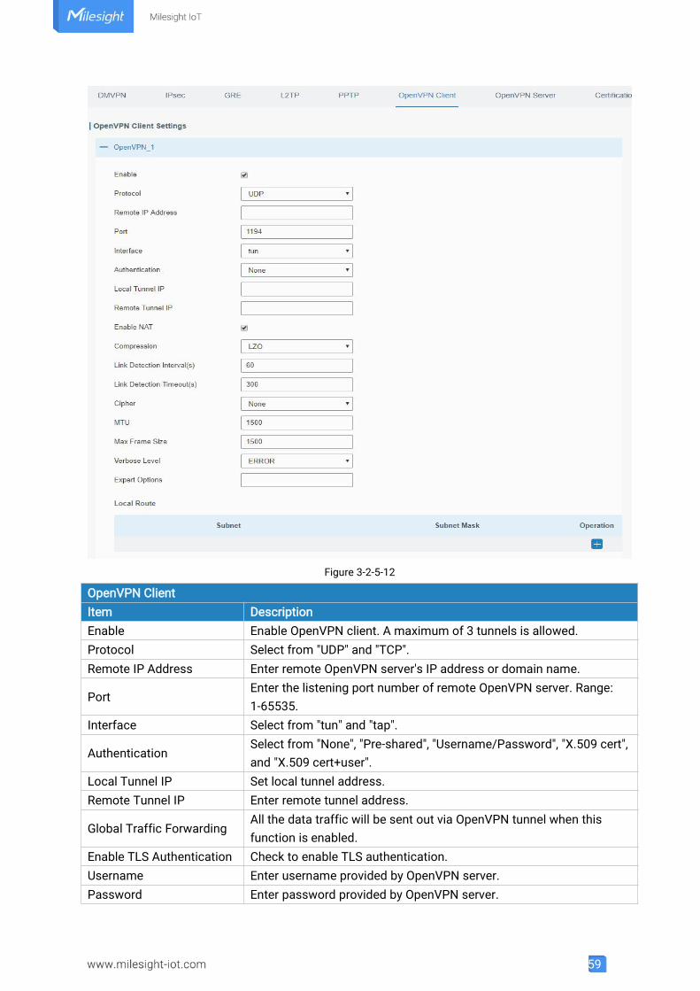
59
Figure 3-2-5-12
OpenVPN ClientItem DescriptionEnable Enable OpenVPN client. A maximum of 3 tunnels is allowed.Protocol Select from "UDP" and "TCP".Remote IP Address Enter remote OpenVPN server's IP address or domain name.
PortEnter the listening port number of remote OpenVPN server. Range:1-65535.
Interface Select from "tun" and "tap".
AuthenticationSelect from "None", "Pre-shared", "Username/Password", "X.509 cert",and "X.509 cert+user".
Local Tunnel IP Set local tunnel address.Remote Tunnel IP Enter remote tunnel address.
Global Traffic ForwardingAll the data traffic will be sent out via OpenVPN tunnel when thisfunction is enabled.
Enable TLS Authentication Check to enable TLS authentication.Username Enter username provided by OpenVPN server.Password Enter password provided by OpenVPN server.
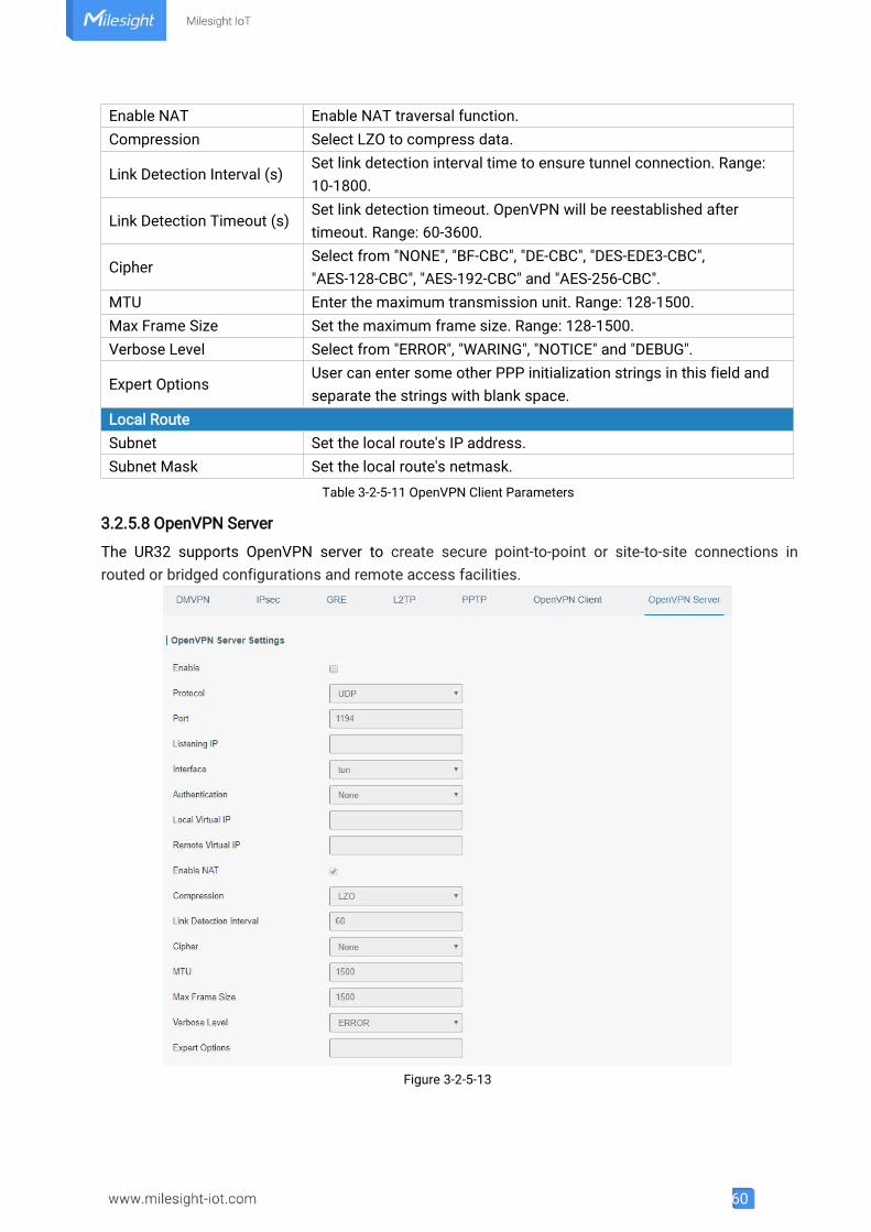
60
Enable NAT Enable NAT traversal function.Compression Select LZO to compress data.
Link Detection Interval (s)Set link detection interval time to ensure tunnel connection. Range:10-1800.
Link Detection Timeout (s)Set link detection timeout. OpenVPN will be reestablished aftertimeout. Range: 60-3600.
CipherSelect from "NONE", "BF-CBC", "DE-CBC", "DES-EDE3-CBC","AES-128-CBC", "AES-192-CBC" and "AES-256-CBC".
MTU Enter the maximum transmission unit. Range: 128-1500.Max Frame Size Set the maximum frame size. Range: 128-1500.Verbose Level Select from "ERROR", "WARING", "NOTICE" and "DEBUG".
Expert OptionsUser can enter some other PPP initialization strings in this field andseparate the strings with blank space.
Local RouteSubnet Set the local route's IP address.Subnet Mask Set the local route's netmask.
Table 3-2-5-11 OpenVPN Client Parameters
3.2.5.8 OpenVPN Server
The UR32 supports OpenVPN server to create secure point-to-point or site-to-site connections inrouted or bridged configurations and remote access facilities.
Figure 3-2-5-13
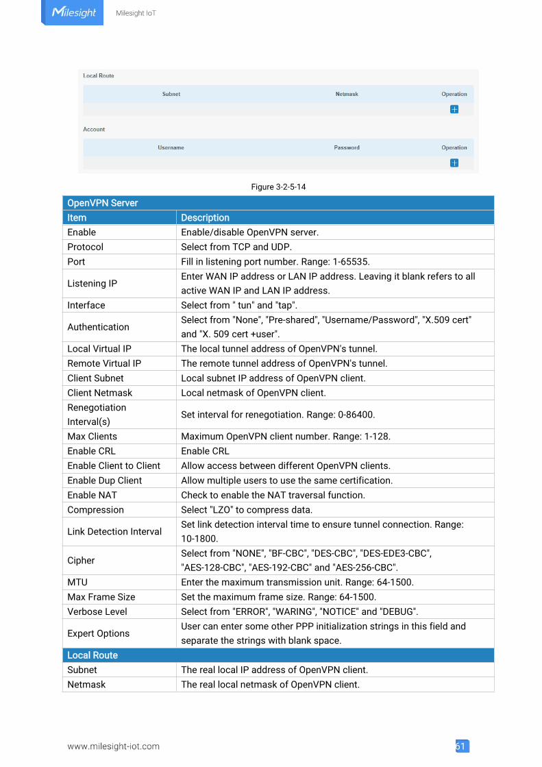
61
Figure 3-2-5-14
OpenVPN ServerItem DescriptionEnable Enable/disable OpenVPN server.Protocol Select from TCP and UDP.Port Fill in listening port number. Range: 1-65535.
Listening IPEnter WAN IP address or LAN IP address. Leaving it blank refers to allactive WAN IP and LAN IP address.
Interface Select from " tun" and "tap".
AuthenticationSelect from "None", "Pre-shared", "Username/Password", "X.509 cert"and "X. 509 cert +user".
Local Virtual IP The local tunnel address of OpenVPN's tunnel.Remote Virtual IP The remote tunnel address of OpenVPN's tunnel.Client Subnet Local subnet IP address of OpenVPN client.Client Netmask Local netmask of OpenVPN client.RenegotiationInterval(s)
Set interval for renegotiation. Range: 0-86400.
Max Clients Maximum OpenVPN client number. Range: 1-128.Enable CRL Enable CRLEnable Client to Client Allow access between different OpenVPN clients.Enable Dup Client Allow multiple users to use the same certification.Enable NAT Check to enable the NAT traversal function.Compression Select "LZO" to compress data.
Link Detection IntervalSet link detection interval time to ensure tunnel connection. Range:10-1800.
CipherSelect from "NONE", "BF-CBC", "DES-CBC", "DES-EDE3-CBC","AES-128-CBC", "AES-192-CBC" and "AES-256-CBC".
MTU Enter the maximum transmission unit. Range: 64-1500.Max Frame Size Set the maximum frame size. Range: 64-1500.Verbose Level Select from "ERROR", "WARING", "NOTICE" and "DEBUG".
Expert OptionsUser can enter some other PPP initialization strings in this field andseparate the strings with blank space.
Local RouteSubnet The real local IP address of OpenVPN client.Netmask The real local netmask of OpenVPN client.
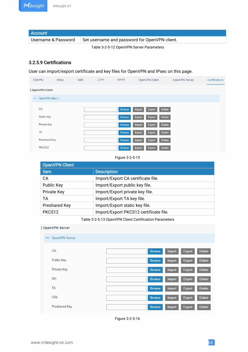
62
AccountUsername & Password Set username and password for OpenVPN client.
Table 3-2-5-12 OpenVPN Server Parameters
3.2.5.9 Certifications
User can import/export certificate and key files for OpenVPN and IPsec on this page.
Figure 3-2-5-15
OpenVPN ClientItem DescriptionCA Import/Export CA certificate file.Public Key Import/Export public key file.Private Key Import/Export private key file.TA Import/Export TA key file.Preshared Key Import/Export static key file.PKCS12 Import/Export PKCS12 certificate file.
Table 3-2-5-13 OpenVPN Client Certification Parameters
Figure 3-2-5-16
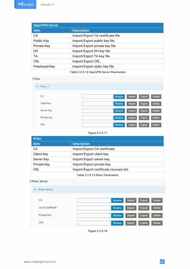
63
OpenVPN ServerItem DescriptionCA Import/Export CA certificate file.Public Key Import/Export public key file.Private Key Import/Export private key file.DH Import/Export DH key file.TA Import/Export TA key file.CRL Import/Export CRL.Preshared Key Import/Export static key file.
Table 3-2-5-14 OpenVPN Server Parameters
Figure 3-2-5-17
IPsecItem DescriptionCA Import/Export CA certificate.Client Key Import/Export client key.Server Key Import/Export server key.Private Key Import/Export private key.CRL Import/Export certificate recovery list.
Table 3-2-5-15 IPsec Parameters
Figure 3-2-5-18
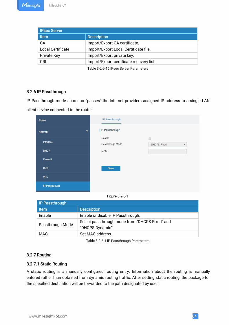
64
IPsec ServerItem DescriptionCA Import/Export CA certificate.Local Certificate Import/Export Local Certificate file.Private Key Import/Export private key.CRL Import/Export certificate recovery list.
Table 3-2-5-16 IPsec Server Parameters
3.2.6 IP Passthrough
IP Passthrough mode shares or "passes" the Internet providers assigned IP address to a single LAN
client device connected to the router.
Figure 3-2-6-1
IP PassthroughItem DescriptionEnable Enable or disable IP Passthrough.
Passthrough ModeSelect passthrough mode from “DHCPS-Fixed” and“DHCPS-Dynamic”.
MAC Set MAC address.Table 3-2-6-1 IP Passthrough Parameters
3.2.7 Routing
3.2.7.1 Static Routing
A static routing is a manually configured routing entry. Information about the routing is manuallyentered rather than obtained from dynamic routing traffic. After setting static routing, the package forthe specified destination will be forwarded to the path designated by user.
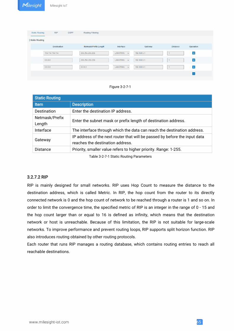
65
Figure 3-2-7-1
Table 3-2-7-1 Static Routing Parameters
3.2.7.2 RIP
RIP is mainly designed for small networks. RIP uses Hop Count to measure the distance to the
destination address, which is called Metric. In RIP, the hop count from the router to its directly
connected network is 0 and the hop count of network to be reached through a router is 1 and so on. In
order to limit the convergence time, the specified metric of RIP is an integer in the range of 0 - 15 and
the hop count larger than or equal to 16 is defined as infinity, which means that the destination
network or host is unreachable. Because of this limitation, the RIP is not suitable for large-scale
networks. To improve performance and prevent routing loops, RIP supports split horizon function. RIP
also introduces routing obtained by other routing protocols.
Each router that runs RIP manages a routing database, which contains routing entries to reach all
reachable destinations.
Static RoutingItem DescriptionDestination Enter the destination IP address.Netmask/PrefixLength
Enter the subnet mask or prefix length of destination address.
Interface The interface through which the data can reach the destination address.
GatewayIP address of the next router that will be passed by before the input datareaches the destination address.
Distance Priority, smaller value refers to higher priority. Range: 1-255.
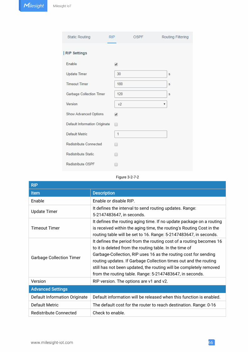
66
Figure 3-2-7-2
RIP
Item Description
Enable Enable or disable RIP.
Update TimerIt defines the interval to send routing updates. Range:5-2147483647, in seconds.
Timeout TimerIt defines the routing aging time. If no update package on a routingis received within the aging time, the routing's Routing Cost in therouting table will be set to 16. Range: 5-2147483647, in seconds.
Garbage Collection Timer
It defines the period from the routing cost of a routing becomes 16to it is deleted from the routing table. In the time ofGarbage-Collection, RIP uses 16 as the routing cost for sendingrouting updates. If Garbage Collection times out and the routingstill has not been updated, the routing will be completely removedfrom the routing table. Range: 5-2147483647, in seconds.
Version RIP version. The options are v1 and v2.
Advanced Settings
Default Information Originate Default information will be released when this function is enabled.
Default Metric The default cost for the router to reach destination. Range: 0-16
Redistribute Connected Check to enable.
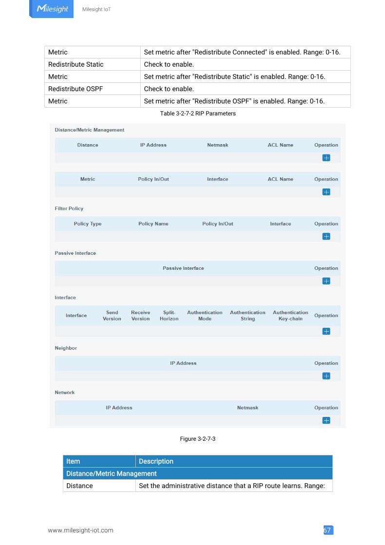
67
Metric Set metric after "Redistribute Connected" is enabled. Range: 0-16.
Redistribute Static Check to enable.
Metric Set metric after "Redistribute Static" is enabled. Range: 0-16.
Redistribute OSPF Check to enable.
Metric Set metric after "Redistribute OSPF" is enabled. Range: 0-16.
Table 3-2-7-2 RIP Parameters
Figure 3-2-7-3
Item Description
Distance/Metric Management
Distance Set the administrative distance that a RIP route learns. Range:
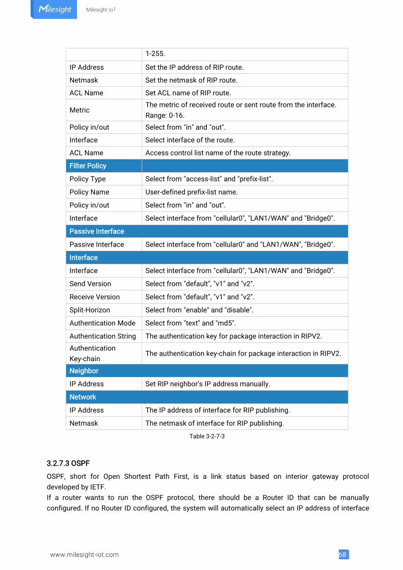
68
1-255.
IP Address Set the IP address of RIP route.
Netmask Set the netmask of RIP route.
ACL Name Set ACL name of RIP route.
MetricThe metric of received route or sent route from the interface.Range: 0-16.
Policy in/out Select from "in" and "out".
Interface Select interface of the route.
ACL Name Access control list name of the route strategy.
Filter Policy
Policy Type Select from "access-list" and "prefix-list".
Policy Name User-defined prefix-list name.
Policy in/out Select from "in" and "out".
Interface Select interface from "cellular0", "LAN1/WAN" and "Bridge0".
Passive Interface
Passive Interface Select interface from "cellular0" and "LAN1/WAN", "Bridge0".
Interface
Interface Select interface from "cellular0", "LAN1/WAN" and "Bridge0".
Send Version Select from "default", "v1" and "v2".
Receive Version Select from "default", "v1" and "v2".
Split-Horizon Select from "enable" and "disable".
Authentication Mode Select from "text" and "md5".
Authentication String The authentication key for package interaction in RIPV2.
AuthenticationKey-chain
The authentication key-chain for package interaction in RIPV2.
Neighbor
IP Address Set RIP neighbor's IP address manually.
Network
IP Address The IP address of interface for RIP publishing.
Netmask The netmask of interface for RIP publishing.
Table 3-2-7-3
3.2.7.3 OSPF
OSPF, short for Open Shortest Path First, is a link status based on interior gateway protocoldeveloped by IETF.If a router wants to run the OSPF protocol, there should be a Router ID that can be manuallyconfigured. If no Router ID configured, the system will automatically select an IP address of interface
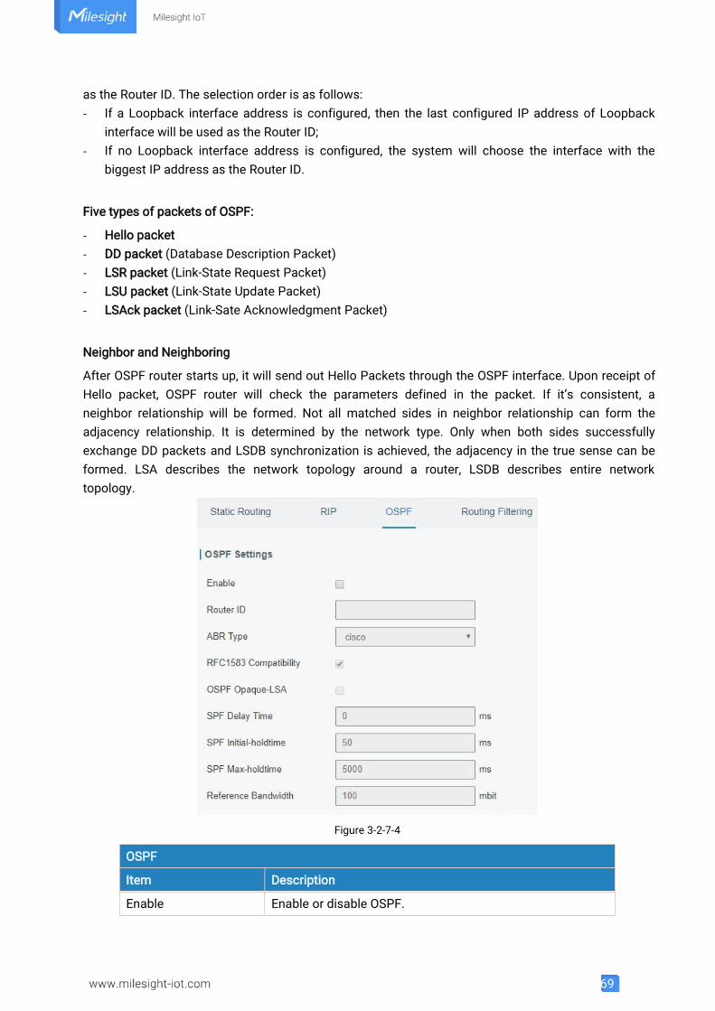
69
as the Router ID. The selection order is as follows:- If a Loopback interface address is configured, then the last configured IP address of Loopback
interface will be used as the Router ID;- If no Loopback interface address is configured, the system will choose the interface with the
biggest IP address as the Router ID.
Five types of packets of OSPF:
- Hello packet- DD packet (Database Description Packet)- LSR packet (Link-State Request Packet)- LSU packet (Link-State Update Packet)- LSAck packet (Link-Sate Acknowledgment Packet)
Neighbor and Neighboring
After OSPF router starts up, it will send out Hello Packets through the OSPF interface. Upon receipt ofHello packet, OSPF router will check the parameters defined in the packet. If it’s consistent, aneighbor relationship will be formed. Not all matched sides in neighbor relationship can form theadjacency relationship. It is determined by the network type. Only when both sides successfullyexchange DD packets and LSDB synchronization is achieved, the adjacency in the true sense can beformed. LSA describes the network topology around a router, LSDB describes entire networktopology.
Figure 3-2-7-4
OSPF
Item Description
Enable Enable or disable OSPF.
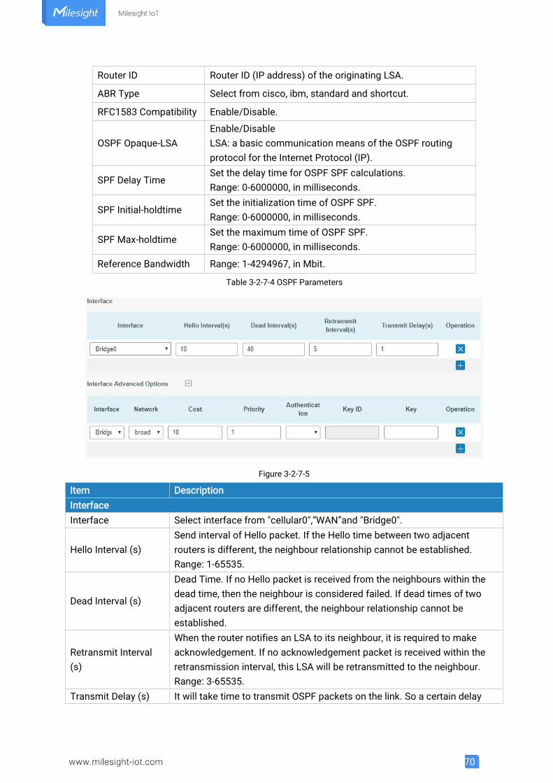
70
Router ID Router ID (IP address) of the originating LSA.
ABR Type Select from cisco, ibm, standard and shortcut.
RFC1583 Compatibility Enable/Disable.
OSPF Opaque-LSAEnable/DisableLSA: a basic communication means of the OSPF routingprotocol for the Internet Protocol (IP).
SPF Delay TimeSet the delay time for OSPF SPF calculations.Range: 0-6000000, in milliseconds.
SPF Initial-holdtimeSet the initialization time of OSPF SPF.Range: 0-6000000, in milliseconds.
SPF Max-holdtimeSet the maximum time of OSPF SPF.Range: 0-6000000, in milliseconds.
Reference Bandwidth Range: 1-4294967, in Mbit.
Table 3-2-7-4 OSPF Parameters
Figure 3-2-7-5
Item DescriptionInterfaceInterface Select interface from "cellular0",”WAN”and "Bridge0".
Hello Interval (s)Send interval of Hello packet. If the Hello time between two adjacentrouters is different, the neighbour relationship cannot be established.Range: 1-65535.
Dead Interval (s)
Dead Time. If no Hello packet is received from the neighbours within thedead time, then the neighbour is considered failed. If dead times of twoadjacent routers are different, the neighbour relationship cannot beestablished.
Retransmit Interval(s)
When the router notifies an LSA to its neighbour, it is required to makeacknowledgement. If no acknowledgement packet is received within theretransmission interval, this LSA will be retransmitted to the neighbour.Range: 3-65535.
Transmit Delay (s) It will take time to transmit OSPF packets on the link. So a certain delay
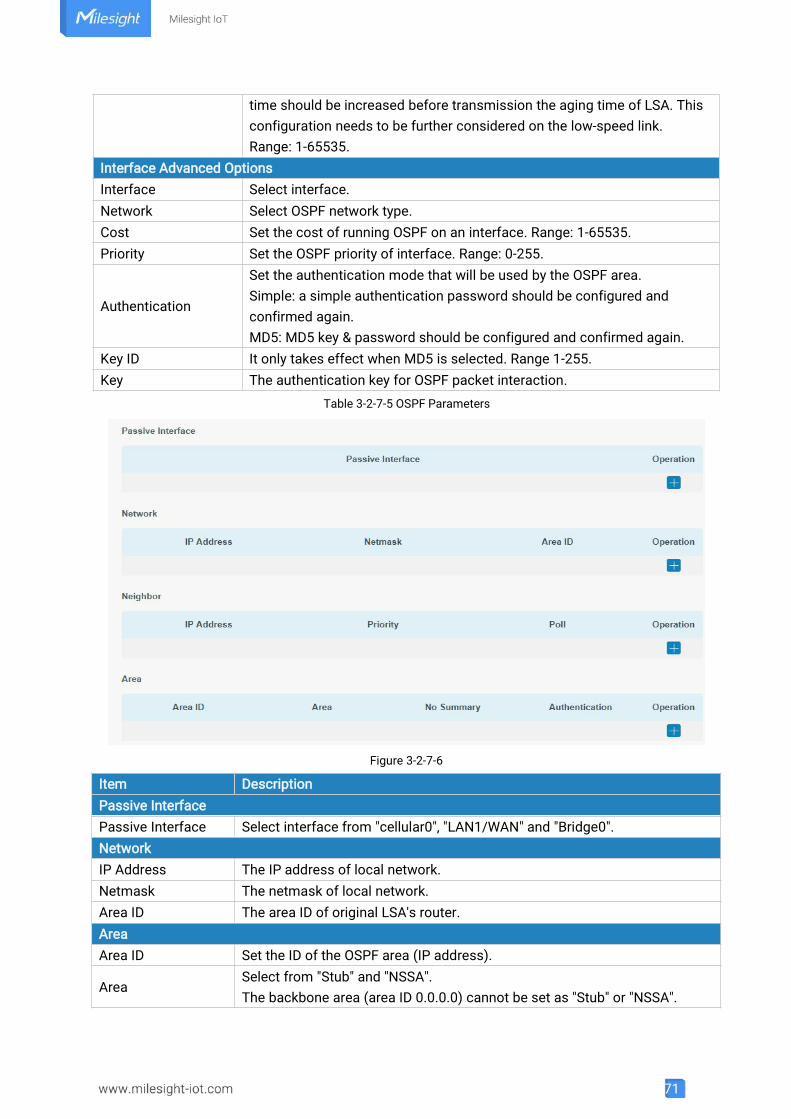
71
time should be increased before transmission the aging time of LSA. Thisconfiguration needs to be further considered on the low-speed link.Range: 1-65535.
Interface Advanced OptionsInterface Select interface.Network Select OSPF network type.Cost Set the cost of running OSPF on an interface. Range: 1-65535.Priority Set the OSPF priority of interface. Range: 0-255.
Authentication
Set the authentication mode that will be used by the OSPF area.Simple: a simple authentication password should be configured andconfirmed again.MD5: MD5 key & password should be configured and confirmed again.
Key ID It only takes effect when MD5 is selected. Range 1-255.Key The authentication key for OSPF packet interaction.
Table 3-2-7-5 OSPF Parameters
Figure 3-2-7-6
Item DescriptionPassive InterfacePassive Interface Select interface from "cellular0", "LAN1/WAN" and "Bridge0".NetworkIP Address The IP address of local network.Netmask The netmask of local network.Area ID The area ID of original LSA's router.AreaArea ID Set the ID of the OSPF area (IP address).
AreaSelect from "Stub" and "NSSA".The backbone area (area ID 0.0.0.0) cannot be set as "Stub" or "NSSA".
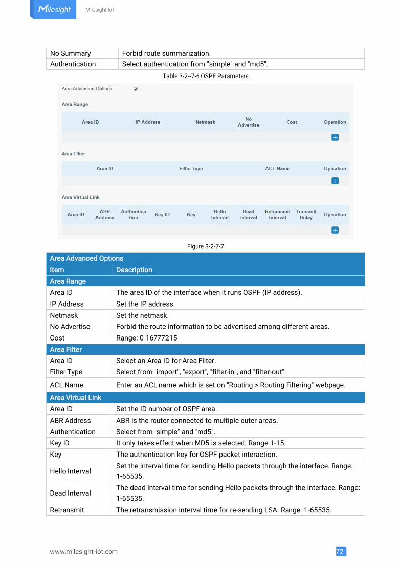
72
No Summary Forbid route summarization.Authentication Select authentication from "simple" and "md5".
Table 3-2--7-6 OSPF Parameters
Figure 3-2-7-7
Area Advanced OptionsItem DescriptionArea RangeArea ID The area ID of the interface when it runs OSPF (IP address).IP Address Set the IP address.Netmask Set the netmask.No Advertise Forbid the route information to be advertised among different areas.Cost Range: 0-16777215Area FilterArea ID Select an Area ID for Area Filter.Filter Type Select from "import", "export", "filter-in", and "filter-out".
ACL Name Enter an ACL name which is set on "Routing > Routing Filtering" webpage.
Area Virtual LinkArea ID Set the ID number of OSPF area.ABR Address ABR is the router connected to multiple outer areas.Authentication Select from "simple" and "md5".Key ID It only takes effect when MD5 is selected. Range 1-15.Key The authentication key for OSPF packet interaction.
Hello IntervalSet the interval time for sending Hello packets through the interface. Range:1-65535.
Dead IntervalThe dead interval time for sending Hello packets through the interface. Range:1-65535.
Retransmit The retransmission interval time for re-sending LSA. Range: 1-65535.
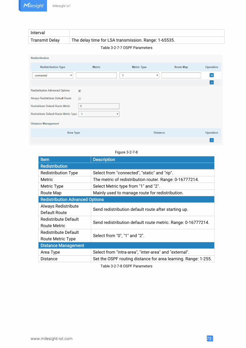
73
Interval
Transmit Delay The delay time for LSA transmission. Range: 1-65535.
Table 3-2-7-7 OSPF Parameters
Figure 3-2-7-8
Item DescriptionRedistributionRedistribution Type Select from "connected", "static" and "rip".Metric The metric of redistribution router. Range: 0-16777214.Metric Type Select Metric type from "1" and "2".Route Map Mainly used to manage route for redistribution.Redistribution Advanced OptionsAlways RedistributeDefault Route
Send redistribution default route after starting up.
Redistribute DefaultRoute Metric
Send redistribution default route metric. Range: 0-16777214.
Redistribute DefaultRoute Metric Type
Select from "0", "1" and "2".
Distance ManagementArea Type Select from "intra-area", "inter-area" and "external".Distance Set the OSPF routing distance for area learning. Range: 1-255.
Table 3-2-7-8 OSPF Parameters
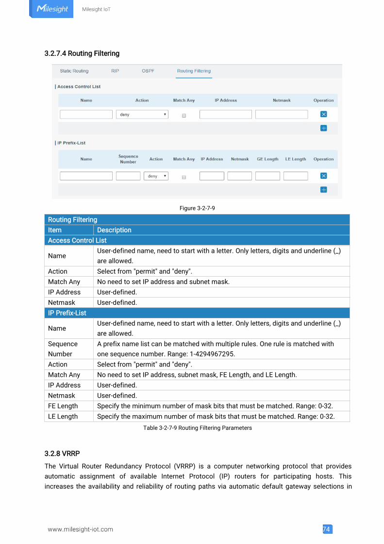
74
3.2.7.4 Routing Filtering
Figure 3-2-7-9
Routing FilteringItem DescriptionAccess Control List
NameUser-defined name, need to start with a letter. Only letters, digits and underline (_)are allowed.
Action Select from "permit" and "deny".Match Any No need to set IP address and subnet mask.IP Address User-defined.Netmask User-defined.IP Prefix-List
NameUser-defined name, need to start with a letter. Only letters, digits and underline (_)are allowed.
SequenceNumber
A prefix name list can be matched with multiple rules. One rule is matched withone sequence number. Range: 1-4294967295.
Action Select from "permit" and "deny".Match Any No need to set IP address, subnet mask, FE Length, and LE Length.IP Address User-defined.Netmask User-defined.FE Length Specify the minimum number of mask bits that must be matched. Range: 0-32.LE Length Specify the maximum number of mask bits that must be matched. Range: 0-32.
Table 3-2-7-9 Routing Filtering Parameters
3.2.8 VRRP
The Virtual Router Redundancy Protocol (VRRP) is a computer networking protocol that providesautomatic assignment of available Internet Protocol (IP) routers for participating hosts. Thisincreases the availability and reliability of routing paths via automatic default gateway selections in
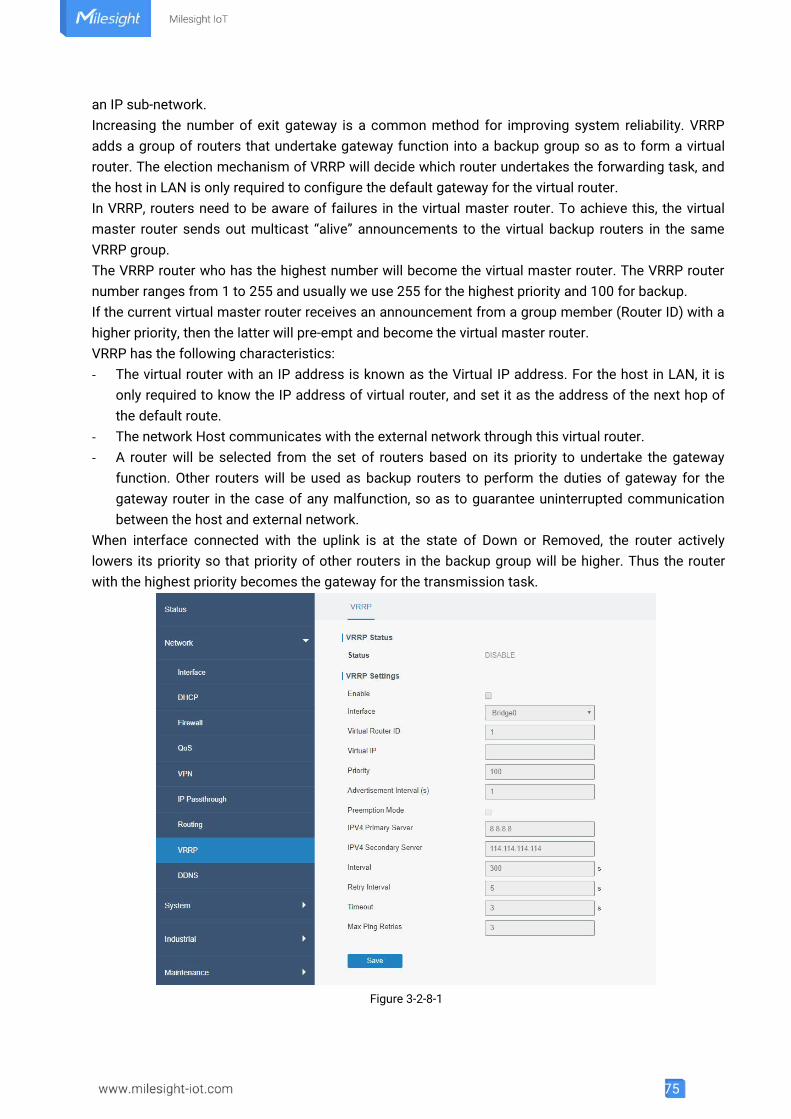
75
an IP sub-network.Increasing the number of exit gateway is a common method for improving system reliability. VRRPadds a group of routers that undertake gateway function into a backup group so as to form a virtualrouter. The election mechanism of VRRP will decide which router undertakes the forwarding task, andthe host in LAN is only required to configure the default gateway for the virtual router.In VRRP, routers need to be aware of failures in the virtual master router. To achieve this, the virtualmaster router sends out multicast “alive” announcements to the virtual backup routers in the sameVRRP group.The VRRP router who has the highest number will become the virtual master router. The VRRP routernumber ranges from 1 to 255 and usually we use 255 for the highest priority and 100 for backup.If the current virtual master router receives an announcement from a group member (Router ID) with ahigher priority, then the latter will pre-empt and become the virtual master router.VRRP has the following characteristics:- The virtual router with an IP address is known as the Virtual IP address. For the host in LAN, it is
only required to know the IP address of virtual router, and set it as the address of the next hop ofthe default route.
- The network Host communicates with the external network through this virtual router.- A router will be selected from the set of routers based on its priority to undertake the gateway
function. Other routers will be used as backup routers to perform the duties of gateway for thegateway router in the case of any malfunction, so as to guarantee uninterrupted communicationbetween the host and external network.
When interface connected with the uplink is at the state of Down or Removed, the router activelylowers its priority so that priority of other routers in the backup group will be higher. Thus the routerwith the highest priority becomes the gateway for the transmission task.
Figure 3-2-8-1
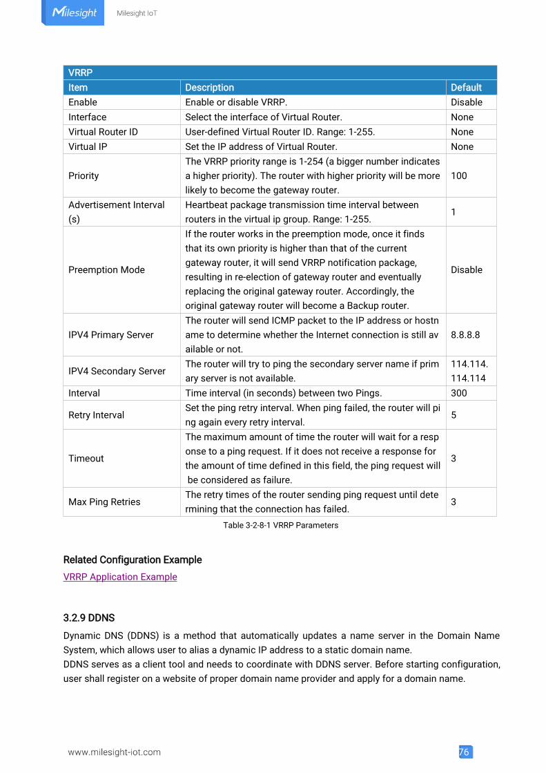
76
VRRPItem Description DefaultEnable Enable or disable VRRP. DisableInterface Select the interface of Virtual Router. NoneVirtual Router ID User-defined Virtual Router ID. Range: 1-255. NoneVirtual IP Set the IP address of Virtual Router. None
PriorityThe VRRP priority range is 1-254 (a bigger number indicatesa higher priority). The router with higher priority will be morelikely to become the gateway router.
100
Advertisement Interval(s)
Heartbeat package transmission time interval betweenrouters in the virtual ip group. Range: 1-255.
1
Preemption Mode
If the router works in the preemption mode, once it findsthat its own priority is higher than that of the currentgateway router, it will send VRRP notification package,resulting in re-election of gateway router and eventuallyreplacing the original gateway router. Accordingly, theoriginal gateway router will become a Backup router.
Disable
IPV4 Primary ServerThe router will send ICMP packet to the IP address or hostname to determine whether the Internet connection is still available or not.
8.8.8.8
IPV4 Secondary ServerThe router will try to ping the secondary server name if primary server is not available.
114.114.114.114
Interval Time interval (in seconds) between two Pings. 300
Retry IntervalSet the ping retry interval. When ping failed, the router will ping again every retry interval.
5
Timeout
The maximum amount of time the router will wait for a response to a ping request. If it does not receive a response forthe amount of time defined in this field, the ping request willbe considered as failure.
3
Max Ping RetriesThe retry times of the router sending ping request until determining that the connection has failed.
3
Table 3-2-8-1 VRRP Parameters
Related Configuration Example
VRRP Application Example
3.2.9 DDNS
Dynamic DNS (DDNS) is a method that automatically updates a name server in the Domain NameSystem, which allows user to alias a dynamic IP address to a static domain name.DDNS serves as a client tool and needs to coordinate with DDNS server. Before starting configuration,user shall register on a website of proper domain name provider and apply for a domain name.
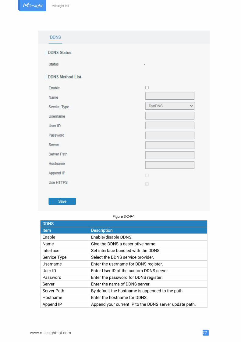
77
Figure 3-2-9-1
DDNSItem DescriptionEnable Enable/disable DDNS.Name Give the DDNS a descriptive name.Interface Set interface bundled with the DDNS.Service Type Select the DDNS service provider.Username Enter the username for DDNS register.User ID Enter User ID of the custom DDNS server.Password Enter the password for DDNS register.Server Enter the name of DDNS server.Server Path By default the hostname is appended to the path.Hostname Enter the hostname for DDNS.Append IP Append your current IP to the DDNS server update path.
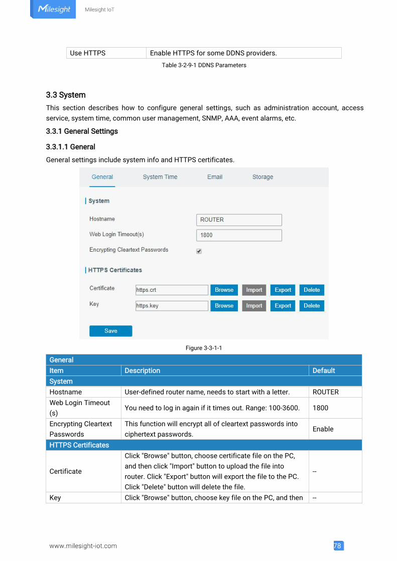
78
Use HTTPS Enable HTTPS for some DDNS providers.
Table 3-2-9-1 DDNS Parameters
3.3 SystemThis section describes how to configure general settings, such as administration account, accessservice, system time, common user management, SNMP, AAA, event alarms, etc.
3.3.1 General Settings
3.3.1.1 General
General settings include system info and HTTPS certificates.
Figure 3-3-1-1
GeneralItem Description DefaultSystemHostname User-defined router name, needs to start with a letter. ROUTERWeb Login Timeout(s)
You need to log in again if it times out. Range: 100-3600. 1800
Encrypting CleartextPasswords
This function will encrypt all of cleartext passwords intociphertext passwords.
Enable
HTTPS Certificates
Certificate
Click "Browse" button, choose certificate file on the PC,and then click "Import" button to upload the file intorouter. Click "Export" button will export the file to the PC.Click "Delete" button will delete the file.
--
Key Click "Browse" button, choose key file on the PC, and then --
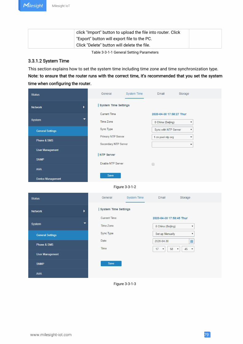
79
click "Import" button to upload the file into router. Click"Export" button will export file to the PC.Click "Delete" button will delete the file.
Table 3-3-1-1 General Setting Parameters
3.3.1.2 System Time
This section explains how to set the system time including time zone and time synchronization type.Note: to ensure that the router runs with the correct time, it’s recommended that you set the system
time when configuring the router.
Figure 3-3-1-2
Figure 3-3-1-3
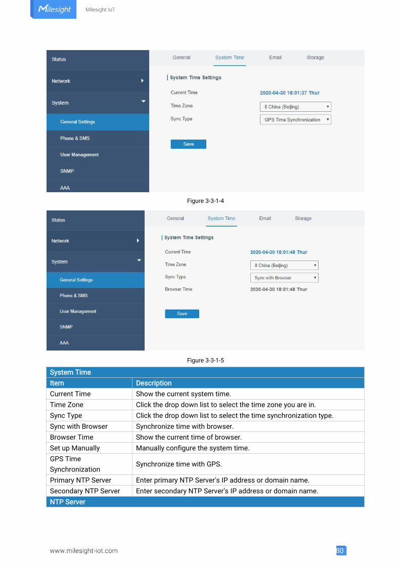
80
Figure 3-3-1-4
Figure 3-3-1-5
System TimeItem DescriptionCurrent Time Show the current system time.Time Zone Click the drop down list to select the time zone you are in.Sync Type Click the drop down list to select the time synchronization type.Sync with Browser Synchronize time with browser.Browser Time Show the current time of browser.Set up Manually Manually configure the system time.GPS TimeSynchronization
Synchronize time with GPS.
Primary NTP Server Enter primary NTP Server's IP address or domain name.Secondary NTP Server Enter secondary NTP Server's IP address or domain name.NTP Server
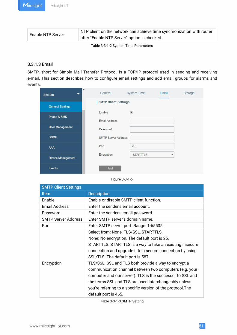
81
Enable NTP ServerNTP client on the network can achieve time synchronization with routerafter "Enable NTP Server" option is checked.
Table 3-3-1-2 System Time Parameters
3.3.1.3 Email
SMTP, short for Simple Mail Transfer Protocol, is a TCP/IP protocol used in sending and receivinge-mail. This section describes how to configure email settings and add email groups for alarms andevents.
Figure 3-3-1-6
SMTP Client SettingsItem DescriptionEnable Enable or disable SMTP client function.Email Address Enter the sender's email account.Password Enter the sender's email password.SMTP Server Address Enter SMTP server's domain name.Port Enter SMTP server port. Range: 1-65535.
Encryption
Select from: None, TLS/SSL, STARTTLS.None: No encryption. The default port is 25.STARTTLS: STARTTLS is a way to take an existing insecureconnection and upgrade it to a secure connection by usingSSL/TLS. The default port is 587.TLS/SSL: SSL and TLS both provide a way to encrypt acommunication channel between two computers (e.g. yourcomputer and our server). TLS is the successor to SSL andthe terms SSL and TLS are used interchangeably unlessyou're referring to a specific version of the protocol.Thedefault port is 465.
Table 3-3-1-3 SMTP Setting
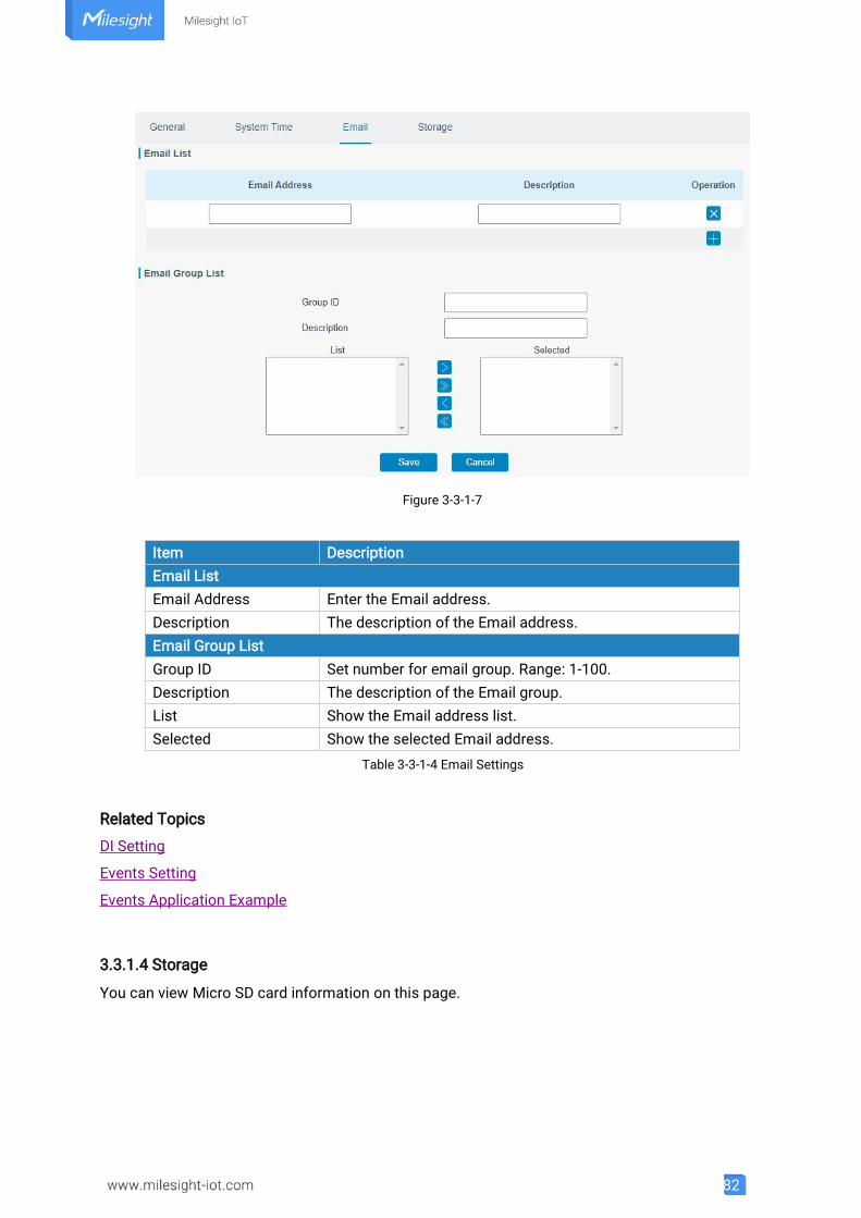
82
Figure 3-3-1-7
Item DescriptionEmail ListEmail Address Enter the Email address.Description The description of the Email address.Email Group ListGroup ID Set number for email group. Range: 1-100.Description The description of the Email group.List Show the Email address list.Selected Show the selected Email address.
Table 3-3-1-4 Email Settings
Related Topics
DI Setting
Events Setting
Events Application Example
3.3.1.4 Storage
You can view Micro SD card information on this page.
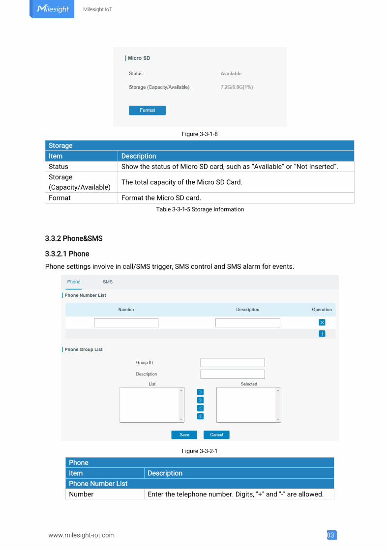
83
Figure 3-3-1-8
StorageItem DescriptionStatus Show the status of Micro SD card, such as “Available” or “Not Inserted”.Storage(Capacity/Available)
The total capacity of the Micro SD Card.
Format Format the Micro SD card.Table 3-3-1-5 Storage Information
3.3.2 Phone&SMS
3.3.2.1 Phone
Phone settings involve in call/SMS trigger, SMS control and SMS alarm for events.
Figure 3-3-2-1
PhoneItem DescriptionPhone Number ListNumber Enter the telephone number. Digits, "+" and "-" are allowed.
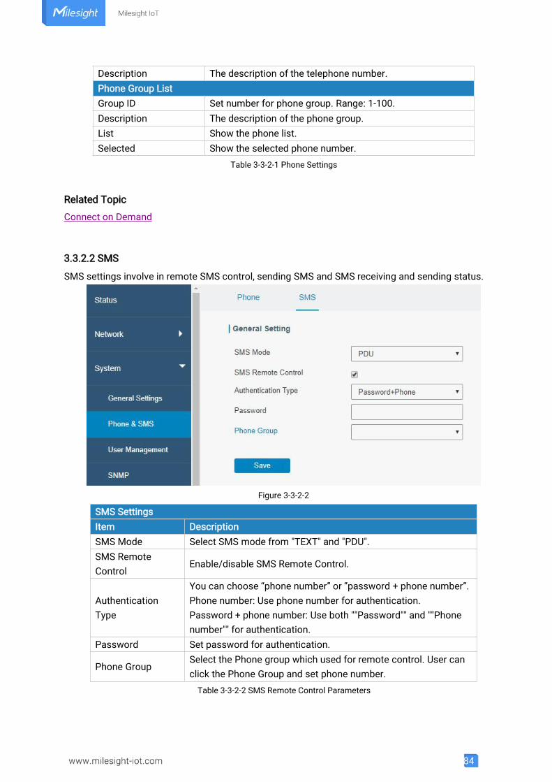
84
Description The description of the telephone number.Phone Group ListGroup ID Set number for phone group. Range: 1-100.Description The description of the phone group.List Show the phone list.Selected Show the selected phone number.
Table 3-3-2-1 Phone Settings
Related Topic
Connect on Demand
3.3.2.2 SMS
SMS settings involve in remote SMS control, sending SMS and SMS receiving and sending status.
Figure 3-3-2-2
SMS SettingsItem DescriptionSMS Mode Select SMS mode from "TEXT" and "PDU".SMS RemoteControl
Enable/disable SMS Remote Control.
AuthenticationType
You can choose “phone number” or ”password + phone number”.Phone number: Use phone number for authentication.Password + phone number: Use both ""Password"" and ""Phonenumber"" for authentication.
Password Set password for authentication.
Phone GroupSelect the Phone group which used for remote control. User canclick the Phone Group and set phone number.Table 3-3-2-2 SMS Remote Control Parameters
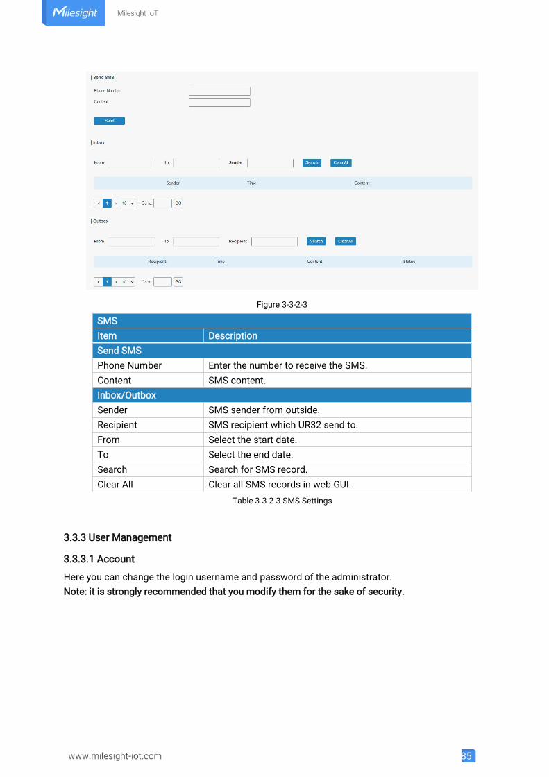
85
Figure 3-3-2-3
SMSItem DescriptionSend SMSPhone Number Enter the number to receive the SMS.Content SMS content.Inbox/OutboxSender SMS sender from outside.Recipient SMS recipient which UR32 send to.From Select the start date.To Select the end date.Search Search for SMS record.Clear All Clear all SMS records in web GUI.
Table 3-3-2-3 SMS Settings
3.3.3 User Management
3.3.3.1 Account
Here you can change the login username and password of the administrator.Note: it is strongly recommended that you modify them for the sake of security.
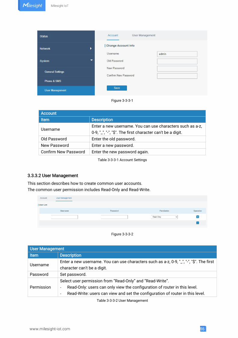
86
Figure 3-3-3-1
AccountItem Description
UsernameEnter a new username. You can use characters such as a-z,0-9, "_", "-", "$". The first character can't be a digit.
Old Password Enter the old password.New Password Enter a new password.Confirm New Password Enter the new password again.
Table 3-3-3-1 Account Settings
3.3.3.2 User Management
This section describes how to create common user accounts.The common user permission includes Read-Only and Read-Write.
Figure 3-3-3-2
User ManagementItem Description
UsernameEnter a new username. You can use characters such as a-z, 0-9, "_", "-", "$". The firstcharacter can't be a digit.
Password Set password.
PermissionSelect user permission from “Read-Only” and “Read-Write”.- Read-Only: users can only view the configuration of router in this level.- Read-Write: users can view and set the configuration of router in this level.
Table 3-3-3-2 User Management
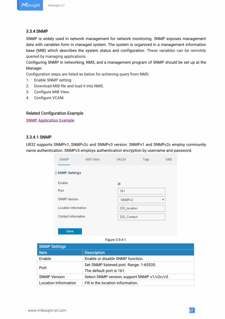
87
3.3.4 SNMP
SNMP is widely used in network management for network monitoring. SNMP exposes managementdata with variables form in managed system. The system is organized in a management informationbase (MIB) which describes the system status and configuration. These variables can be remotelyqueried by managing applications.Configuring SNMP in networking, NMS, and a management program of SNMP should be set up at theManager.Configuration steps are listed as below for achieving query from NMS:1. Enable SNMP setting.2. Download MIB file and load it into NMS.3. Configure MIB View.4. Configure VCAM.
Related Configuration Example
SNMP Application Example
3.3.4.1 SNMP
UR32 supports SNMPv1, SNMPv2c and SNMPv3 version. SNMPv1 and SNMPv2c employ communityname authentication. SNMPv3 employs authentication encryption by username and password.
Figure 3-3-4-1
SNMP SettingsItem DescriptionEnable Enable or disable SNMP function.
PortSet SNMP listened port. Range: 1-65535.The default port is 161.
SNMP Version Select SNMP version; support SNMP v1/v2c/v3.Location Information Fill in the location information.
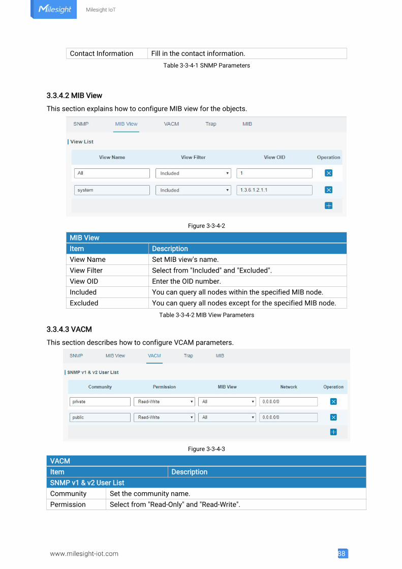
88
Contact Information Fill in the contact information.Table 3-3-4-1 SNMP Parameters
3.3.4.2 MIB View
This section explains how to configure MIB view for the objects.
Figure 3-3-4-2
MIB ViewItem DescriptionView Name Set MIB view's name.View Filter Select from "Included" and "Excluded".View OID Enter the OID number.Included You can query all nodes within the specified MIB node.Excluded You can query all nodes except for the specified MIB node.
Table 3-3-4-2 MIB View Parameters
3.3.4.3 VACM
This section describes how to configure VCAM parameters.
Figure 3-3-4-3
VACMItem DescriptionSNMP v1 & v2 User ListCommunity Set the community name.Permission Select from "Read-Only" and "Read-Write".
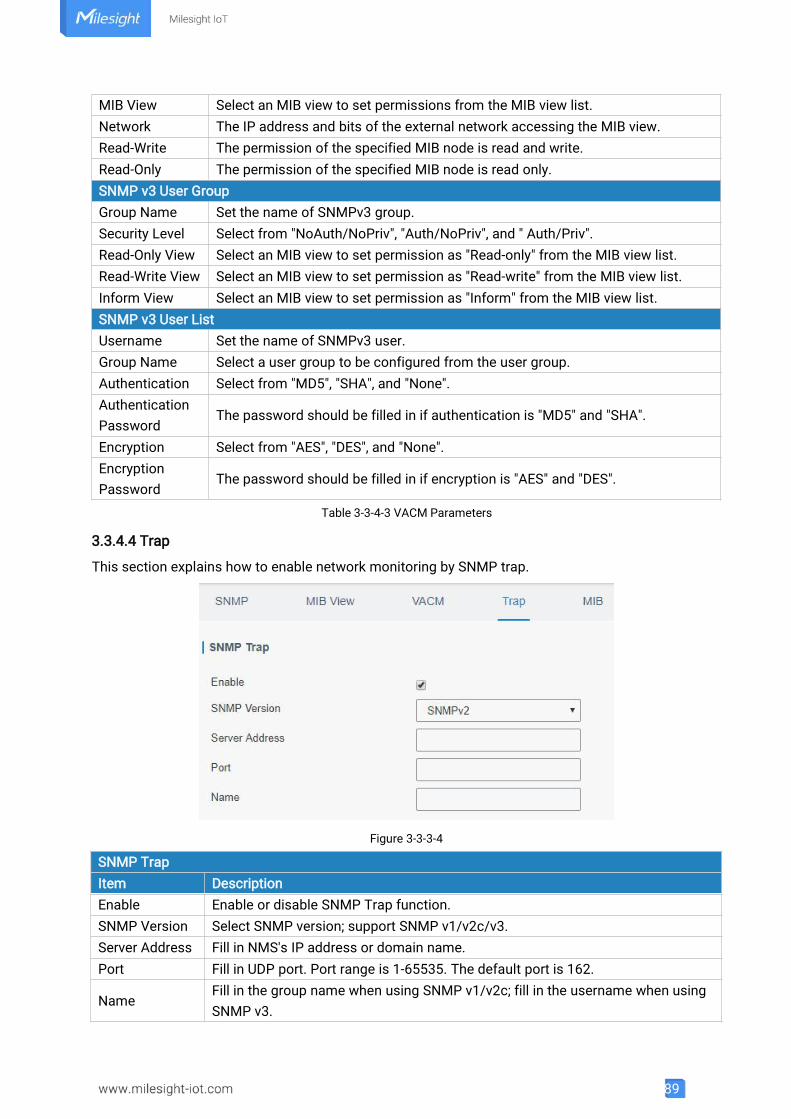
89
MIB View Select an MIB view to set permissions from the MIB view list.Network The IP address and bits of the external network accessing the MIB view.Read-Write The permission of the specified MIB node is read and write.Read-Only The permission of the specified MIB node is read only.SNMP v3 User GroupGroup Name Set the name of SNMPv3 group.Security Level Select from "NoAuth/NoPriv", "Auth/NoPriv", and " Auth/Priv".Read-Only View Select an MIB view to set permission as "Read-only" from the MIB view list.Read-Write View Select an MIB view to set permission as "Read-write" from the MIB view list.Inform View Select an MIB view to set permission as "Inform" from the MIB view list.SNMP v3 User ListUsername Set the name of SNMPv3 user.Group Name Select a user group to be configured from the user group.Authentication Select from "MD5", "SHA", and "None".AuthenticationPassword
The password should be filled in if authentication is "MD5" and "SHA".
Encryption Select from "AES", "DES", and "None".EncryptionPassword
The password should be filled in if encryption is "AES" and "DES".
Table 3-3-4-3 VACM Parameters
3.3.4.4 Trap
This section explains how to enable network monitoring by SNMP trap.
Figure 3-3-3-4
SNMP TrapItem DescriptionEnable Enable or disable SNMP Trap function.SNMP Version Select SNMP version; support SNMP v1/v2c/v3.Server Address Fill in NMS's IP address or domain name.Port Fill in UDP port. Port range is 1-65535. The default port is 162.
NameFill in the group name when using SNMP v1/v2c; fill in the username when usingSNMP v3.
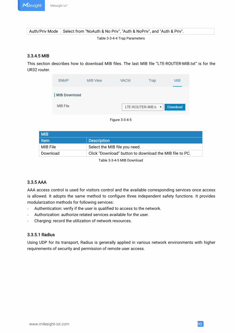
90
Auth/Priv Mode Select from "NoAuth & No Priv", "Auth & NoPriv", and "Auth & Priv".Table 3-3-4-4 Trap Parameters
3.3.4.5 MIB
This section describes how to download MIB files. The last MIB file “LTE-ROUTER-MIB.txt” is for theUR32 router.
Figure 3-3-4-5
MIBItem DescriptionMIB File Select the MIB file you need.Download Click "Download" button to download the MIB file to PC.
Table 3-3-4-5 MIB Download
3.3.5 AAA
AAA access control is used for visitors control and the available corresponding services once accessis allowed. It adopts the same method to configure three independent safety functions. It providesmodularization methods for following services:- Authentication: verify if the user is qualified to access to the network.- Authorization: authorize related services available for the user.- Charging: record the utilization of network resources.
3.3.5.1 Radius
Using UDP for its transport, Radius is generally applied in various network environments with higherrequirements of security and permission of remote user access.
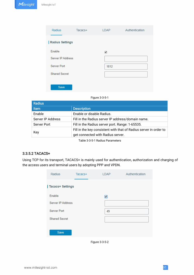
91
Figure 3-3-5-1
RadiusItem DescriptionEnable Enable or disable Radius.Server IP Address Fill in the Radius server IP address/domain name.Server Port Fill in the Radius server port. Range: 1-65535.
KeyFill in the key consistent with that of Radius server in order toget connected with Radius server.
Table 3-3-5-1 Radius Parameters
3.3.5.2 TACACS+
Using TCP for its transport, TACACS+ is mainly used for authentication, authorization and charging ofthe access users and terminal users by adopting PPP and VPDN.
Figure 3-3-5-2
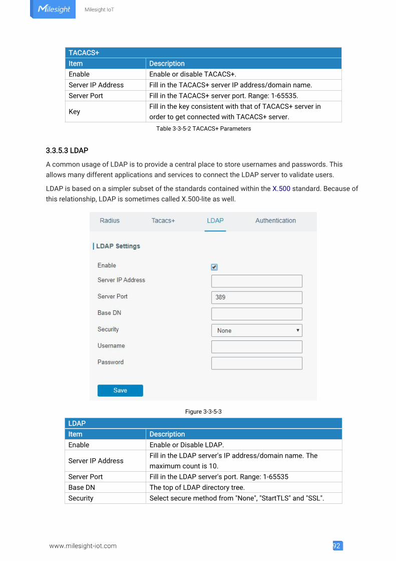
92
TACACS+Item DescriptionEnable Enable or disable TACACS+.Server IP Address Fill in the TACACS+ server IP address/domain name.Server Port Fill in the TACACS+ server port. Range: 1-65535.
KeyFill in the key consistent with that of TACACS+ server inorder to get connected with TACACS+ server.
Table 3-3-5-2 TACACS+ Parameters
3.3.5.3 LDAP
A common usage of LDAP is to provide a central place to store usernames and passwords. Thisallows many different applications and services to connect the LDAP server to validate users.
LDAP is based on a simpler subset of the standards contained within the X.500 standard. Because ofthis relationship, LDAP is sometimes called X.500-lite as well.
Figure 3-3-5-3
LDAPItem DescriptionEnable Enable or Disable LDAP.
Server IP AddressFill in the LDAP server's IP address/domain name. Themaximum count is 10.
Server Port Fill in the LDAP server's port. Range: 1-65535Base DN The top of LDAP directory tree.Security Select secure method from "None", "StartTLS" and "SSL".
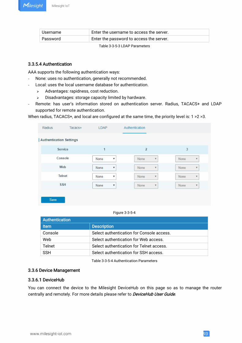
93
Username Enter the username to access the server.Password Enter the password to access the server.
Table 3-3-5-3 LDAP Parameters
3.3.5.4 Authentication
AAA supports the following authentication ways:- None: uses no authentication, generally not recommended.- Local: uses the local username database for authentication.
Advantages: rapidness, cost reduction. Disadvantages: storage capacity limited by hardware.
- Remote: has user’s information stored on authentication server. Radius, TACACS+ and LDAPsupported for remote authentication.
When radius, TACACS+, and local are configured at the same time, the priority level is: 1 >2 >3.
Figure 3-3-5-4
AuthenticationItem DescriptionConsole Select authentication for Console access.Web Select authentication for Web access.Telnet Select authentication for Telnet access.SSH Select authentication for SSH access.
Table 3-3-5-4 Authentication Parameters
3.3.6 Device Management
3.3.6.1 DeviceHub
You can connect the device to the Milesight DeviceHub on this page so as to manage the routercentrally and remotely. For more details please refer to DeviceHub User Guide.
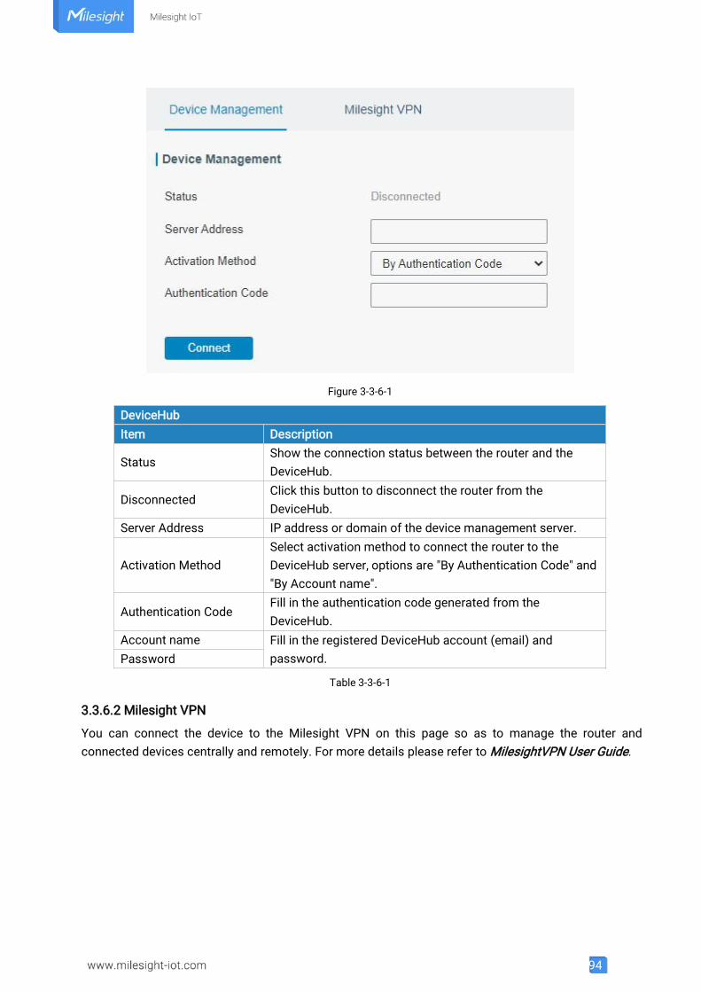
94
Figure 3-3-6-1
DeviceHubItem Description
StatusShow the connection status between the router and theDeviceHub.
DisconnectedClick this button to disconnect the router from theDeviceHub.
Server Address IP address or domain of the device management server.
Activation MethodSelect activation method to connect the router to theDeviceHub server, options are "By Authentication Code" and"By Account name".
Authentication CodeFill in the authentication code generated from theDeviceHub.
Account name Fill in the registered DeviceHub account (email) andpassword.Password
Table 3-3-6-1
3.3.6.2 Milesight VPN
You can connect the device to the Milesight VPN on this page so as to manage the router andconnected devices centrally and remotely. For more details please refer to MilesightVPN User Guide.
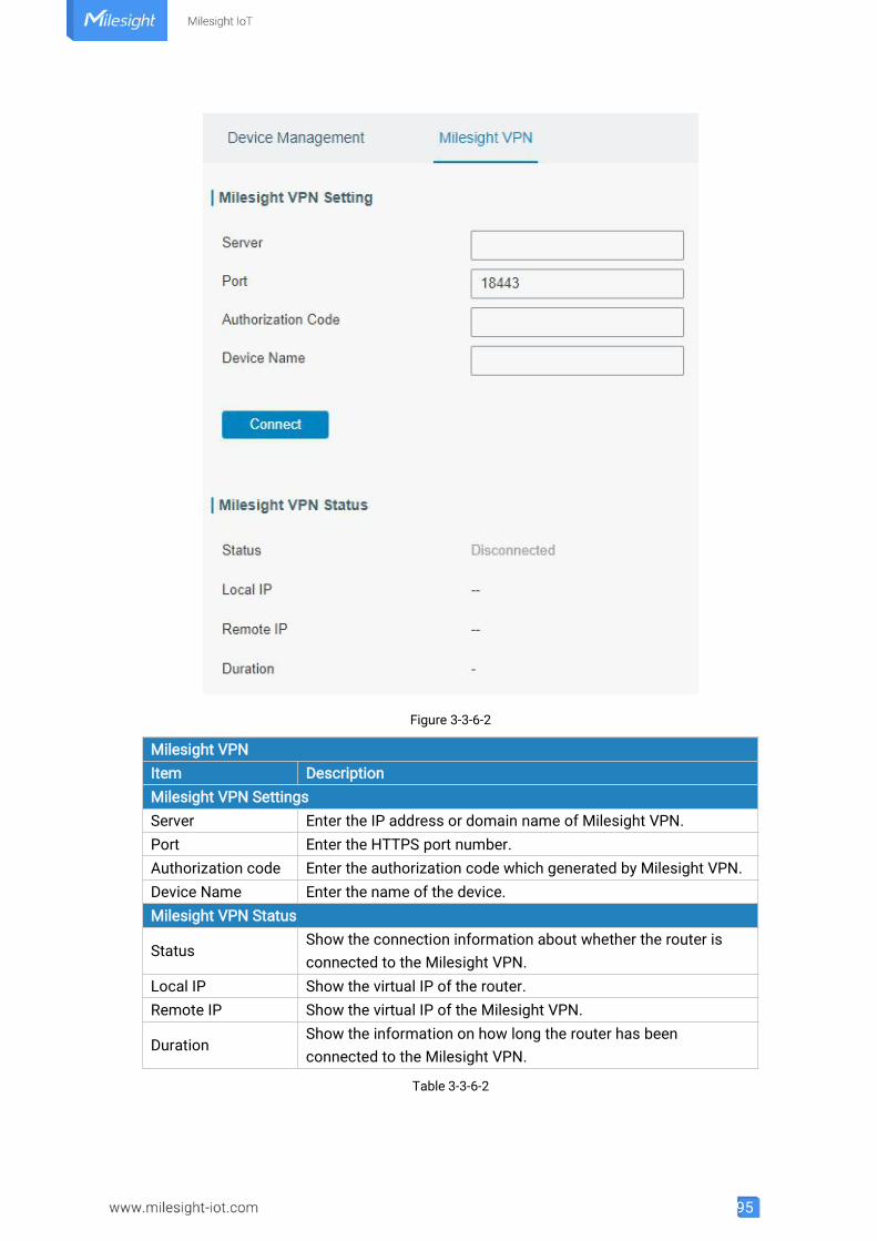
95
Figure 3-3-6-2
Milesight VPNItem DescriptionMilesight VPN SettingsServer Enter the IP address or domain name of Milesight VPN.Port Enter the HTTPS port number.Authorization code Enter the authorization code which generated by Milesight VPN.Device Name Enter the name of the device.Milesight VPN Status
StatusShow the connection information about whether the router isconnected to the Milesight VPN.
Local IP Show the virtual IP of the router.Remote IP Show the virtual IP of the Milesight VPN.
DurationShow the information on how long the router has beenconnected to the Milesight VPN.
Table 3-3-6-2

96
3.3.7 Events
Event feature is capable of sending alerts by Email when certain system events occur.
3.3.7.1 Events
You can view alarm messages on this page.
Figure 3-3-7-1
EventsItem DescriptionMark as Read Mark the selected event alarm as read.Delete Delete the selected event alarm.Mark All as Read Mark all event alarms as read.Delete All Alarms Delete all event alarms.
StatusShow the reading status of the event alarms, such as “Read”and “Unread”.
Type Show the event type that should be alarmed.Time Show the alarm time.Message Show the alarm content.
Table 3-3-7-1 Events Parameters
3.3.7.2 Events Settings
In this section, you can decide what events to record and whether you want to receive email and SMSnotifications when any change occurs.
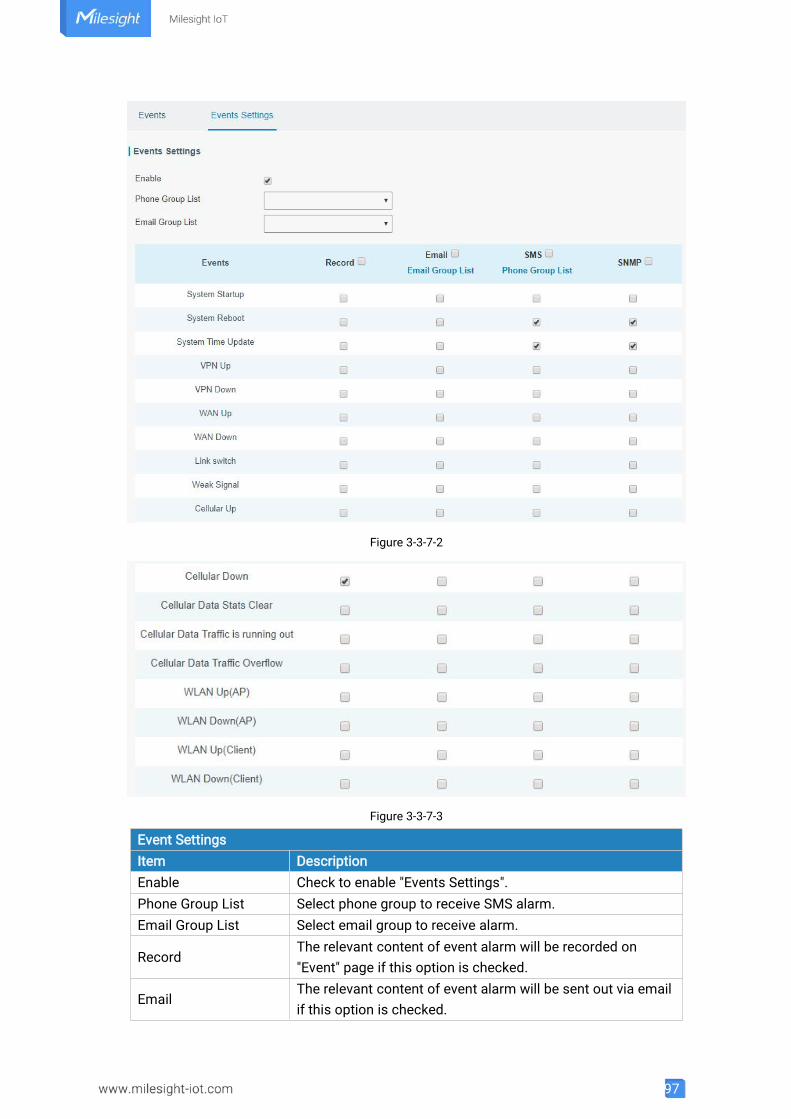
97
Figure 3-3-7-2
Figure 3-3-7-3
Event SettingsItem DescriptionEnable Check to enable "Events Settings".Phone Group List Select phone group to receive SMS alarm.Email Group List Select email group to receive alarm.
RecordThe relevant content of event alarm will be recorded on"Event" page if this option is checked.
EmailThe relevant content of event alarm will be sent out via emailif this option is checked.
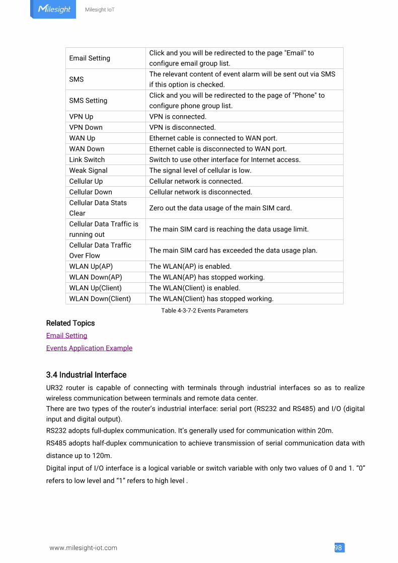
98
Email SettingClick and you will be redirected to the page "Email" toconfigure email group list.
SMSThe relevant content of event alarm will be sent out via SMSif this option is checked.
SMS SettingClick and you will be redirected to the page of "Phone" toconfigure phone group list.
VPN Up VPN is connected.VPN Down VPN is disconnected.WAN Up Ethernet cable is connected to WAN port.WAN Down Ethernet cable is disconnected to WAN port.Link Switch Switch to use other interface for Internet access.Weak Signal The signal level of cellular is low.Cellular Up Cellular network is connected.Cellular Down Cellular network is disconnected.Cellular Data StatsClear
Zero out the data usage of the main SIM card.
Cellular Data Traffic isrunning out
The main SIM card is reaching the data usage limit.
Cellular Data TrafficOver Flow
The main SIM card has exceeded the data usage plan.
WLAN Up(AP) The WLAN(AP) is enabled.WLAN Down(AP) The WLAN(AP) has stopped working.WLAN Up(Client) The WLAN(Client) is enabled.WLAN Down(Client) The WLAN(Client) has stopped working.
Table 4-3-7-2 Events Parameters
Related Topics
Email Setting
Events Application Example
3.4 Industrial InterfaceUR32 router is capable of connecting with terminals through industrial interfaces so as to realizewireless communication between terminals and remote data center.There are two types of the router’s industrial interface: serial port (RS232 and RS485) and I/O (digitalinput and digital output).RS232 adopts full-duplex communication. It’s generally used for communication within 20m.
RS485 adopts half-duplex communication to achieve transmission of serial communication data with
distance up to 120m.
Digital input of I/O interface is a logical variable or switch variable with only two values of 0 and 1. “0”
refers to low level and “1” refers to high level .
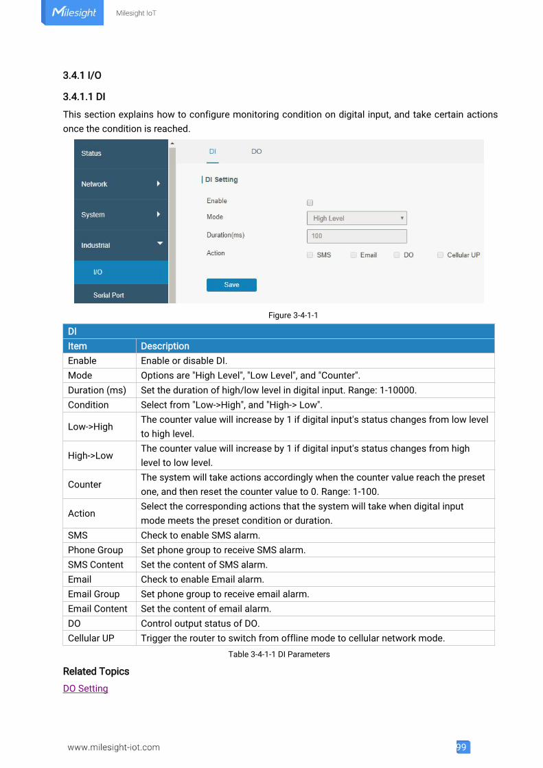
99
3.4.1 I/O
3.4.1.1 DI
This section explains how to configure monitoring condition on digital input, and take certain actionsonce the condition is reached.
Figure 3-4-1-1
DIItem DescriptionEnable Enable or disable DI.Mode Options are "High Level", "Low Level", and "Counter".Duration (ms) Set the duration of high/low level in digital input. Range: 1-10000.Condition Select from "Low->High", and "High-> Low".
Low->HighThe counter value will increase by 1 if digital input's status changes from low levelto high level.
High->LowThe counter value will increase by 1 if digital input's status changes from highlevel to low level.
CounterThe system will take actions accordingly when the counter value reach the presetone, and then reset the counter value to 0. Range: 1-100.
ActionSelect the corresponding actions that the system will take when digital inputmode meets the preset condition or duration.
SMS Check to enable SMS alarm.Phone Group Set phone group to receive SMS alarm.SMS Content Set the content of SMS alarm.Email Check to enable Email alarm.Email Group Set phone group to receive email alarm.Email Content Set the content of email alarm.DO Control output status of DO.Cellular UP Trigger the router to switch from offline mode to cellular network mode.
Table 3-4-1-1 DI Parameters
Related Topics
DO Setting
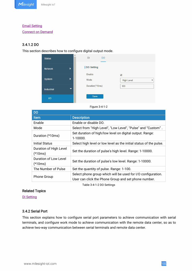
100
Email Setting
Connect on Demand
3.4.1.2 DO
This section describes how to configure digital output mode.
Figure 3-4-1-2
DOItem DescriptionEnable Enable or disable DO.Mode Select from "High Level", "Low Level", "Pulse" and “Custom” .
Duration (*10ms)Set duration of high/low level on digital output. Range:1-10000.
Initial Status Select high level or low level as the initial status of the pulse.Duration of High Level(*10ms)
Set the duration of pulse's high level. Range: 1-10000.
Duration of Low Level(*10ms)
Set the duration of pulse's low level. Range: 1-10000.
The Number of Pulse Set the quantity of pulse. Range: 1-100.
Phone GroupSelect phone group which will be used for I/O configuration.User can click the Phone Group and set phone number.
Table 3-4-1-2 DO Settings
Related Topics
DI Setting
3.4.2 Serial Port
This section explains how to configure serial port parameters to achieve communication with serialterminals, and configure work mode to achieve communication with the remote data center, so as toachieve two-way communication between serial terminals and remote data center.
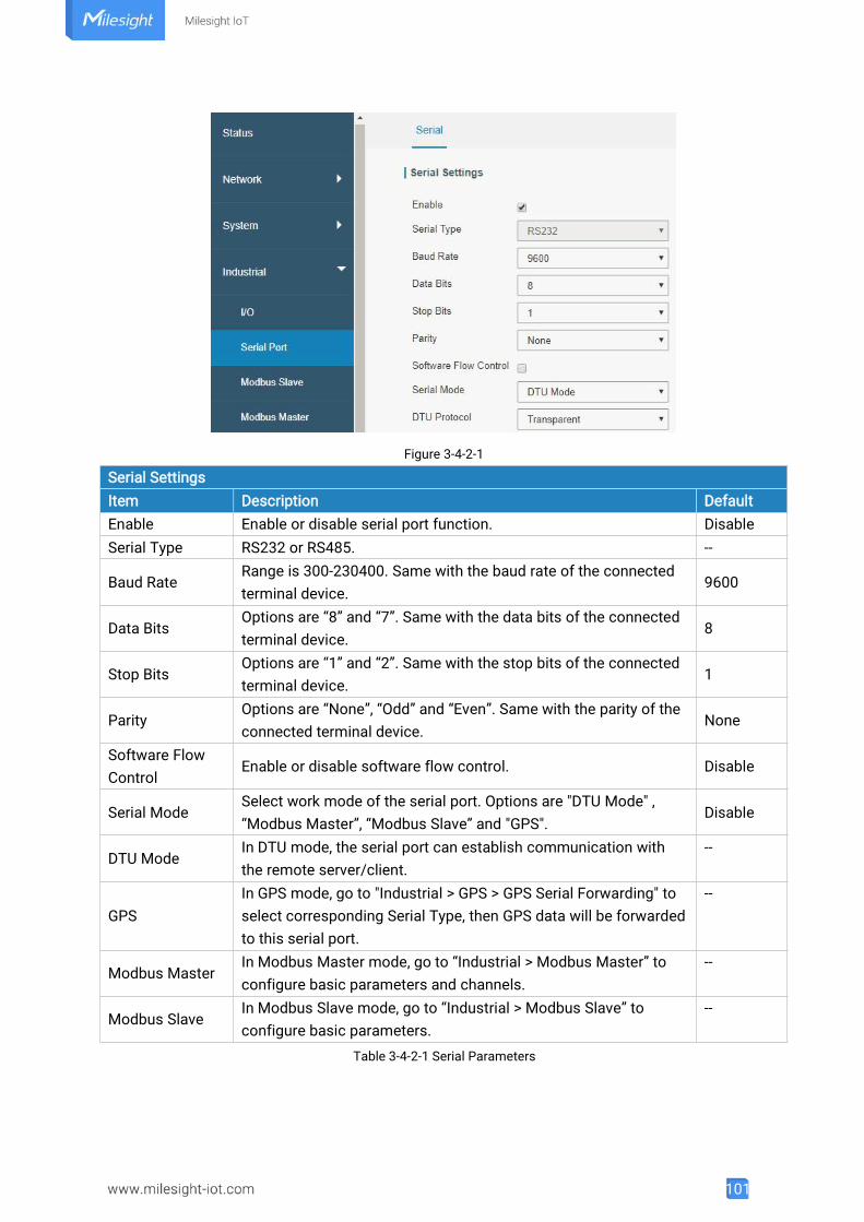
101
Figure 3-4-2-1
Serial SettingsItem Description DefaultEnable Enable or disable serial port function. DisableSerial Type RS232 or RS485. --
Baud RateRange is 300-230400. Same with the baud rate of the connectedterminal device.
9600
Data BitsOptions are “8” and “7”. Same with the data bits of the connectedterminal device.
8
Stop BitsOptions are “1” and “2”. Same with the stop bits of the connectedterminal device.
1
ParityOptions are “None”, “Odd” and “Even”. Same with the parity of theconnected terminal device.
None
Software FlowControl
Enable or disable software flow control. Disable
Serial ModeSelect work mode of the serial port. Options are "DTU Mode" ,“Modbus Master”, “Modbus Slave” and "GPS".
Disable
DTU ModeIn DTU mode, the serial port can establish communication withthe remote server/client.
--
GPSIn GPS mode, go to "Industrial > GPS > GPS Serial Forwarding" toselect corresponding Serial Type, then GPS data will be forwardedto this serial port.
--
Modbus MasterIn Modbus Master mode, go to “Industrial > Modbus Master” toconfigure basic parameters and channels.
--
Modbus SlaveIn Modbus Slave mode, go to “Industrial > Modbus Slave” toconfigure basic parameters.
--
Table 3-4-2-1 Serial Parameters
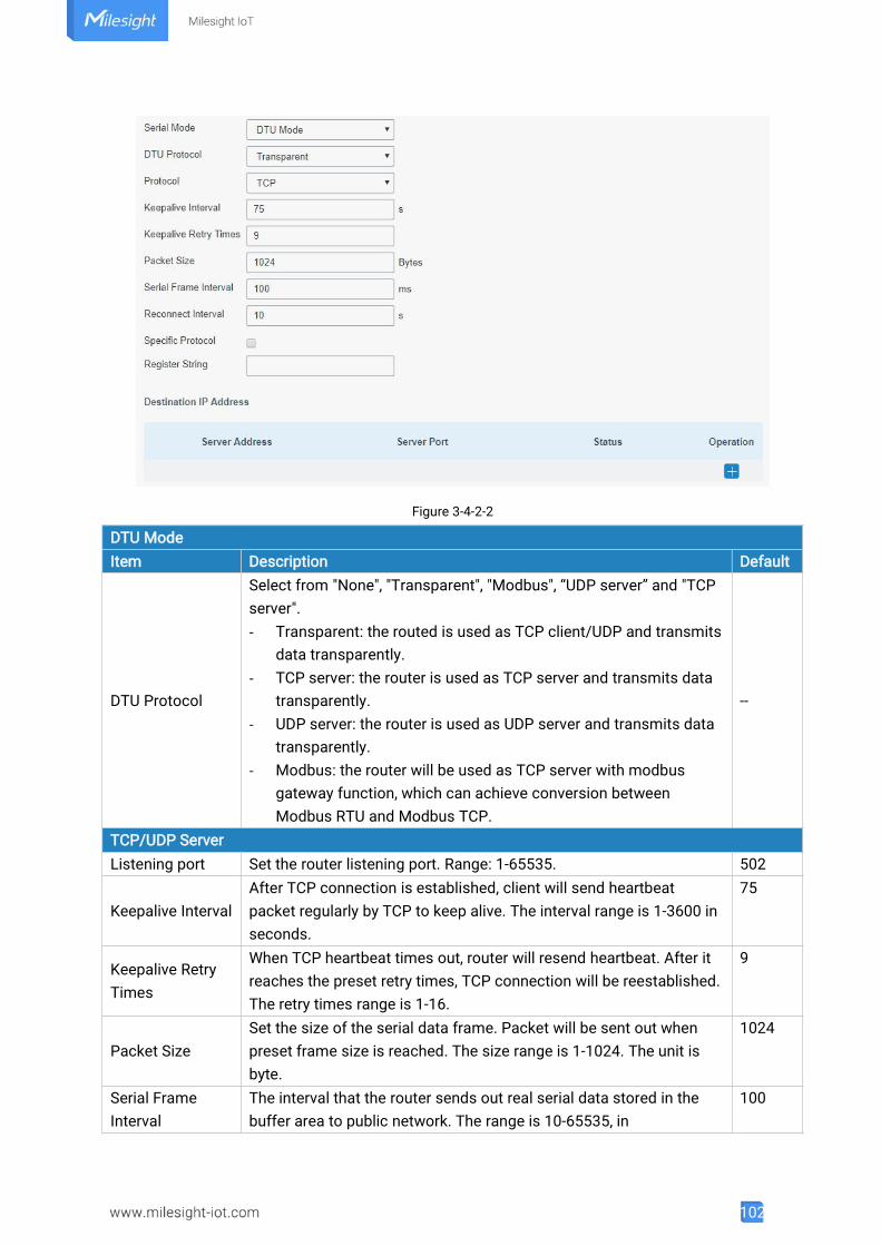
102
Figure 3-4-2-2
DTU ModeItem Description Default
DTU Protocol
Select from "None", "Transparent", "Modbus", “UDP server” and "TCPserver".- Transparent: the routed is used as TCP client/UDP and transmits
data transparently.- TCP server: the router is used as TCP server and transmits data
transparently.- UDP server: the router is used as UDP server and transmits data
transparently.- Modbus: the router will be used as TCP server with modbus
gateway function, which can achieve conversion betweenModbus RTU and Modbus TCP.
--
TCP/UDP ServerListening port Set the router listening port. Range: 1-65535. 502
Keepalive IntervalAfter TCP connection is established, client will send heartbeatpacket regularly by TCP to keep alive. The interval range is 1-3600 inseconds.
75
Keepalive RetryTimes
When TCP heartbeat times out, router will resend heartbeat. After itreaches the preset retry times, TCP connection will be reestablished.The retry times range is 1-16.
9
Packet SizeSet the size of the serial data frame. Packet will be sent out whenpreset frame size is reached. The size range is 1-1024. The unit isbyte.
1024
Serial FrameInterval
The interval that the router sends out real serial data stored in thebuffer area to public network. The range is 10-65535, in
100
103
milliseconds.Note: data will be sent out to public network when real serial datasize reaches the preset packet size, even though it's within the serialframe interval.
Table 3-4-2-2 DTU Parameters
Item Description DefaultTransparentProtocol Select "TCP" or "UDP" protocol. TCP
Keepalive Interval(s)
After TCP client is connected with TCP server, the client will sendheartbeat packet by TCP regularly to keep alive. The interval rangeis 1-3600, in seconds.
75
Keepalive RetryTimes
When TCP heartbeat times out, the router will resend heartbeat.After it reaches the preset retry times, router will reconnect to TCPserver. The range is 1-16.
9
Packet SizeSet the size of the serial data frame. Packet will be sent out whenpreset frame size is reached. The range is 1-1024. The unit is byte.
1024
Serial FrameInterval
The interval that the router sends out real serial data stored in thebuffer area to public network. The range is 10-65535, inmilliseconds.Note: data will be sent out to public network when real serial datasize reaches the preset packet size, even though it's within theserial frame interval.
100
ReconnectInterval
After connection failure, router will reconnect to the server at thepreset interval, in seconds. The range is 10-60.
10
Specific ProtocolBy Specific Protocol, the router will be able to connect to theTCP2COM software.
--
HeartbeatInterval
By Specific Protocol, the router will send heartbeat packet to theserver regularly to keep alive. The interval range is 1-3600, inseconds.
30
IDDefine unique ID of each router. No longer than 63 characterswithout space character.
--
Register String Define register string for connection with the server. NullServer Address Fill in the TCP or UDP server address (IP/domain name). NullServer Port Fill in the TCP or UDP server port. Range: 1-65535. NullStatus Show the connection status between the router and the server. --ModbusLocal Port Set the router listening port. Range: 1-65535. 502Maximum TCPClients
Specify the maximum number of TCP clients allowed to connect the router which act as a TCP server.
32
ConnectionTimeout
If the TCP server does not receive any data from the slave device within the connection timeout period, the TCP connection will be broken.
60
Reading Interval Set the interval for reading remote channels. When a read cycle end 100
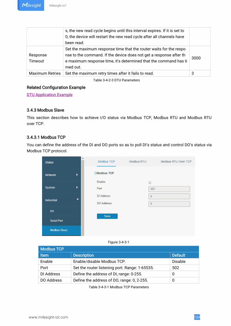
104
s, the new read cycle begins until this interval expires. If it is set to0, the device will restart the new read cycle after all channels havebeen read.
ResponseTimeout
Set the maximum response time that the router waits for the response to the command. If the device does not get a response after the maximum response time, it's determined that the command has timed out.
3000
Maximum Retries Set the maximum retry times after it fails to read. 3Table 3-4-2-3 DTU Parameters
Related Configuration Example
DTU Application Example
3.4.3 Modbus Slave
This section describes how to achieve I/O status via Modbus TCP, Modbus RTU and Modbus RTUover TCP.
3.4.3.1 Modbus TCP
You can define the address of the DI and DO ports so as to poll DI’s status and control DO’s status viaModbus TCP protocol.
Figure 3-4-3-1
Modbus TCPItem Description DefaultEnable Enable/disable Modbus TCP. DisablePort Set the router listening port. Range: 1-65535. 502DI Address Define the address of DI, range: 0-255. 0DO Address Define the address of DO, range: 0, 2-255. 0
Table 3-4-3-1 Modbus TCP Parameters
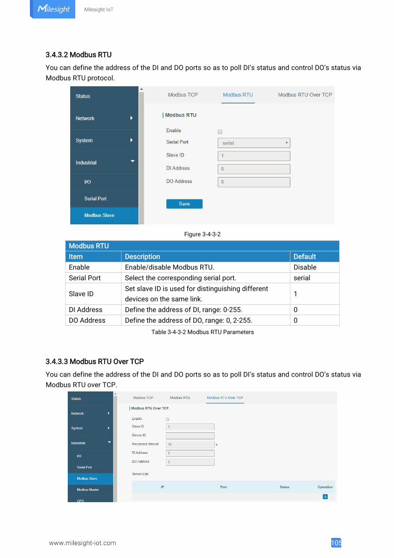
105
3.4.3.2 Modbus RTU
You can define the address of the DI and DO ports so as to poll DI’s status and control DO’s status viaModbus RTU protocol.
Figure 3-4-3-2
Modbus RTUItem Description DefaultEnable Enable/disable Modbus RTU. DisableSerial Port Select the corresponding serial port. serial
Slave IDSet slave ID is used for distinguishing differentdevices on the same link.
1
DI Address Define the address of DI, range: 0-255. 0DO Address Define the address of DO, range: 0, 2-255. 0
Table 3-4-3-2 Modbus RTU Parameters
3.4.3.3 Modbus RTU Over TCP
You can define the address of the DI and DO ports so as to poll DI’s status and control DO’s status viaModbus RTU over TCP.

106
Figure 3-4-3-3
Modbus RTU Over TCPItem Description DefaultEnable Enable/disable Modbus RTU over TCP function. Disable
Slave IDSet slave ID is used for distinguishing differentdevices on the same link.
1
Device IDSet device ID. The server will get the device ID to theserver for identifying identity so that the server canmanage multiple devices.
--
ReconnectionInterval
The reconnection interval when the device and theserver fails to establish connection or disconnected.
10
DI Address Define the address of DI, range: 0-255. 0DO Address Define the address of DO, range: 0, 2-255. 0Server ListIP Enter the IP address of the server.Port Enter the port of the server.Range: 0-65535.Status Show the connection status between the router and the server.
Table 3-4-3-3 Modbus RTU Over TCP Parameters
3.4.4 Modbus Master
UR32 router can be set as Modbus Master to poll the remote Modbus Slave and send alarmaccording to the response.
3.4.4.1 Modbus Master
You can configure Modbus Master’s parameters on this page.
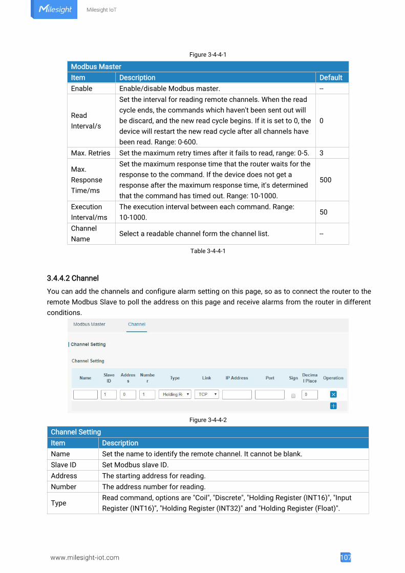
107
Figure 3-4-4-1
Modbus MasterItem Description DefaultEnable Enable/disable Modbus master. --
ReadInterval/s
Set the interval for reading remote channels. When the readcycle ends, the commands which haven't been sent out willbe discard, and the new read cycle begins. If it is set to 0, thedevice will restart the new read cycle after all channels havebeen read. Range: 0-600.
0
Max. Retries Set the maximum retry times after it fails to read, range: 0-5. 3
Max.ResponseTime/ms
Set the maximum response time that the router waits for theresponse to the command. If the device does not get aresponse after the maximum response time, it's determinedthat the command has timed out. Range: 10-1000.
500
ExecutionInterval/ms
The execution interval between each command. Range:10-1000.
50
ChannelName
Select a readable channel form the channel list. --
Table 3-4-4-1
3.4.4.2 Channel
You can add the channels and configure alarm setting on this page, so as to connect the router to theremote Modbus Slave to poll the address on this page and receive alarms from the router in differentconditions.
Figure 3-4-4-2
Channel SettingItem DescriptionName Set the name to identify the remote channel. It cannot be blank.Slave ID Set Modbus slave ID.Address The starting address for reading.Number The address number for reading.
TypeRead command, options are "Coil", "Discrete", "Holding Register (INT16)", "InputRegister (INT16)", "Holding Register (INT32)" and "Holding Register (Float)".
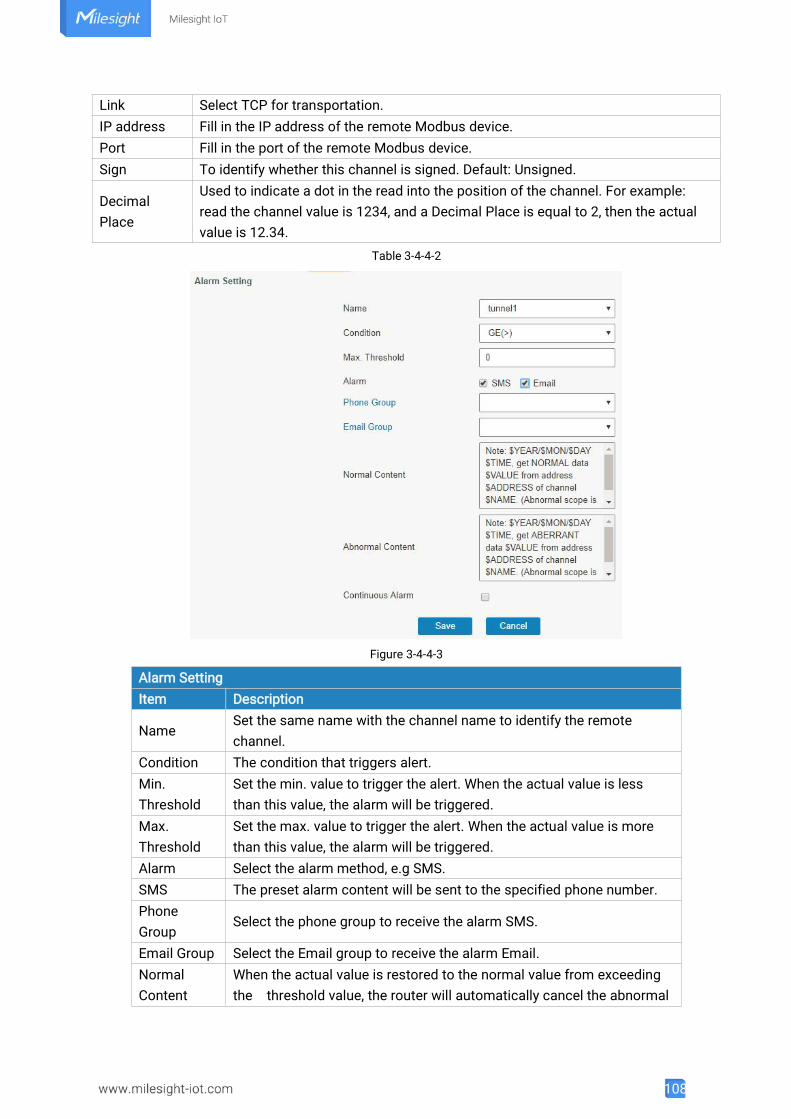
108
Link Select TCP for transportation.IP address Fill in the IP address of the remote Modbus device.Port Fill in the port of the remote Modbus device.Sign To identify whether this channel is signed. Default: Unsigned.
DecimalPlace
Used to indicate a dot in the read into the position of the channel. For example:read the channel value is 1234, and a Decimal Place is equal to 2, then the actualvalue is 12.34.
Table 3-4-4-2
Figure 3-4-4-3
Alarm SettingItem Description
NameSet the same name with the channel name to identify the remotechannel.
Condition The condition that triggers alert.Min.Threshold
Set the min. value to trigger the alert. When the actual value is lessthan this value, the alarm will be triggered.
Max.Threshold
Set the max. value to trigger the alert. When the actual value is morethan this value, the alarm will be triggered.
Alarm Select the alarm method, e.g SMS.SMS The preset alarm content will be sent to the specified phone number.PhoneGroup
Select the phone group to receive the alarm SMS.
Email Group Select the Email group to receive the alarm Email.NormalContent
When the actual value is restored to the normal value from exceedingthe threshold value, the router will automatically cancel the abnormal
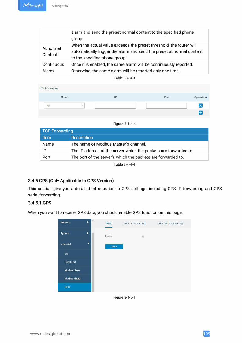
109
alarm and send the preset normal content to the specified phonegroup.
AbnormalContent
When the actual value exceeds the preset threshold, the router willautomatically trigger the alarm and send the preset abnormal contentto the specified phone group.
ContinuousAlarm
Once it is enabled, the same alarm will be continuously reported.Otherwise, the same alarm will be reported only one time.
Table 3-4-4-3
Figure 3-4-4-4
TCP ForwardingItem DescriptionName The name of Modbus Master's channel.IP The IP address of the server which the packets are forwarded to.Port The port of the server's which the packets are forwarded to.
Table 3-4-4-4
3.4.5 GPS (Only Applicable to GPS Version)
This section give you a detailed introduction to GPS settings, including GPS IP forwarding and GPSserial forwarding.
3.4.5.1 GPS
When you want to receive GPS data, you should enable GPS function on this page.
Figure 3-4-5-1
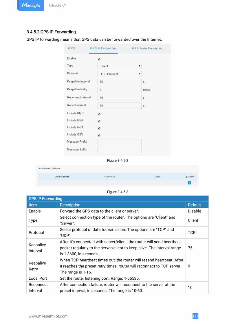
110
3.4.5.2 GPS IP Forwarding
GPS IP forwarding means that GPS data can be forwarded over the Internet.
Figure 3-4-5-2
Figure 3-4-5-3
GPS IP ForwardingItem Description DefaultEnable Forward the GPS data to the client or server. Disable
TypeSelect connection type of the router. The options are "Client" and"Server".
Client
ProtocolSelect protocol of data transmission. The options are "TCP" and"UDP".
TCP
KeepaliveInterval
After it's connected with server/client, the router will send heartbeatpacket regularly to the server/client to keep alive. The interval rangeis 1-3600, in seconds.
75
KeepaliveRetry
When TCP heartbeat times out, the router will resend heartbeat. Afterit reaches the preset retry times, router will reconnect to TCP server.The range is 1-16.
9
Local Port Set the router listening port. Range: 1-65535.ReconnectInterval
After connection failure, router will reconnect to the server at thepreset interval, in seconds. The range is 10-60.
10
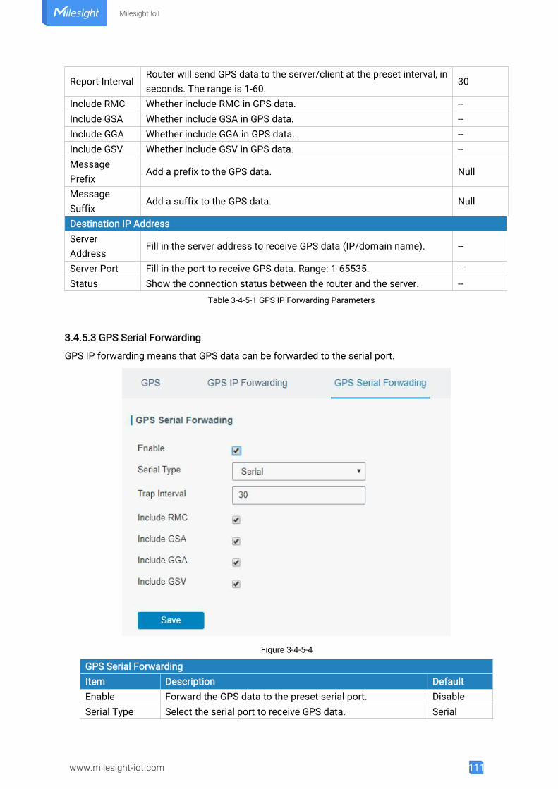
111
Report IntervalRouter will send GPS data to the server/client at the preset interval, inseconds. The range is 1-60.
30
Include RMC Whether include RMC in GPS data. --Include GSA Whether include GSA in GPS data. --Include GGA Whether include GGA in GPS data. --Include GSV Whether include GSV in GPS data. --MessagePrefix
Add a prefix to the GPS data. Null
MessageSuffix
Add a suffix to the GPS data. Null
Destination IP AddressServerAddress
Fill in the server address to receive GPS data (IP/domain name). --
Server Port Fill in the port to receive GPS data. Range: 1-65535. --Status Show the connection status between the router and the server. --
Table 3-4-5-1 GPS IP Forwarding Parameters
3.4.5.3 GPS Serial Forwarding
GPS IP forwarding means that GPS data can be forwarded to the serial port.
Figure 3-4-5-4
GPS Serial ForwardingItem Description DefaultEnable Forward the GPS data to the preset serial port. DisableSerial Type Select the serial port to receive GPS data. Serial
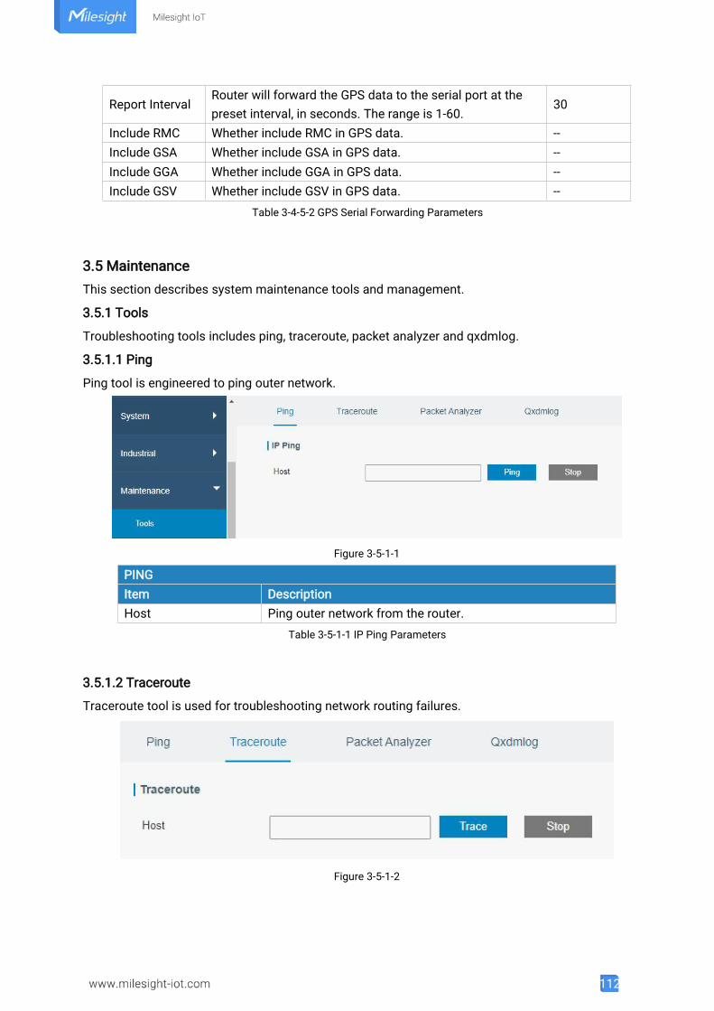
112
Report IntervalRouter will forward the GPS data to the serial port at thepreset interval, in seconds. The range is 1-60.
30
Include RMC Whether include RMC in GPS data. --Include GSA Whether include GSA in GPS data. --Include GGA Whether include GGA in GPS data. --Include GSV Whether include GSV in GPS data. --
Table 3-4-5-2 GPS Serial Forwarding Parameters
3.5 MaintenanceThis section describes system maintenance tools and management.
3.5.1 Tools
Troubleshooting tools includes ping, traceroute, packet analyzer and qxdmlog.
3.5.1.1 Ping
Ping tool is engineered to ping outer network.
Figure 3-5-1-1
PINGItem DescriptionHost Ping outer network from the router.
Table 3-5-1-1 IP Ping Parameters
3.5.1.2 Traceroute
Traceroute tool is used for troubleshooting network routing failures.
Figure 3-5-1-2
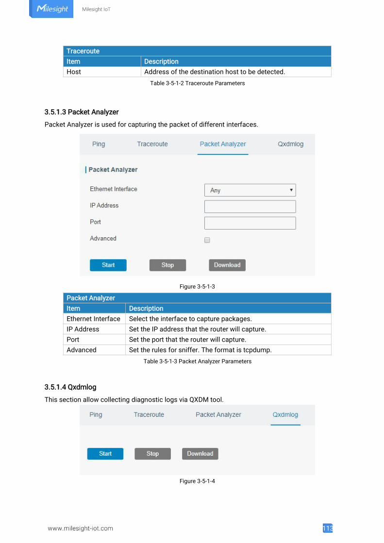
113
TracerouteItem DescriptionHost Address of the destination host to be detected.
Table 3-5-1-2 Traceroute Parameters
3.5.1.3 Packet Analyzer
Packet Analyzer is used for capturing the packet of different interfaces.
Figure 3-5-1-3
Packet AnalyzerItem DescriptionEthernet Interface Select the interface to capture packages.IP Address Set the IP address that the router will capture.Port Set the port that the router will capture.Advanced Set the rules for sniffer. The format is tcpdump.
Table 3-5-1-3 Packet Analyzer Parameters
3.5.1.4 Qxdmlog
This section allow collecting diagnostic logs via QXDM tool.
Figure 3-5-1-4
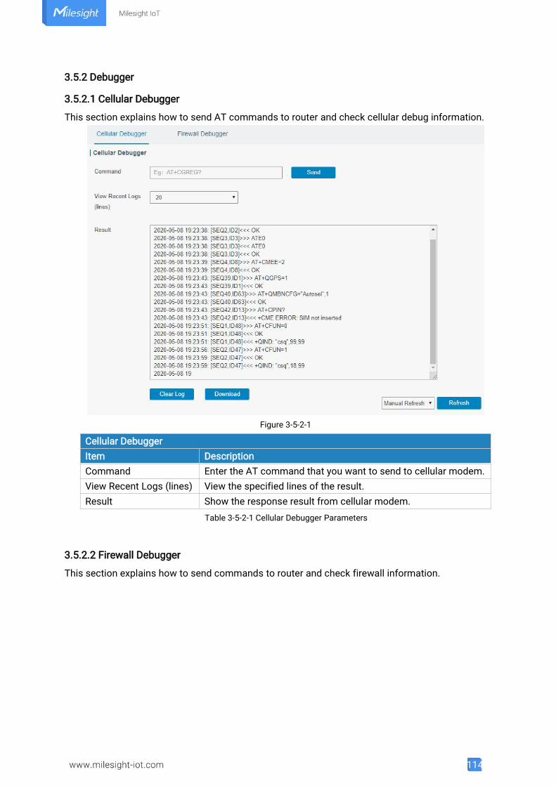
114
3.5.2 Debugger
3.5.2.1 Cellular Debugger
This section explains how to send AT commands to router and check cellular debug information.
Figure 3-5-2-1
Cellular DebuggerItem DescriptionCommand Enter the AT command that you want to send to cellular modem.View Recent Logs (lines) View the specified lines of the result.Result Show the response result from cellular modem.
Table 3-5-2-1 Cellular Debugger Parameters
3.5.2.2 Firewall Debugger
This section explains how to send commands to router and check firewall information.
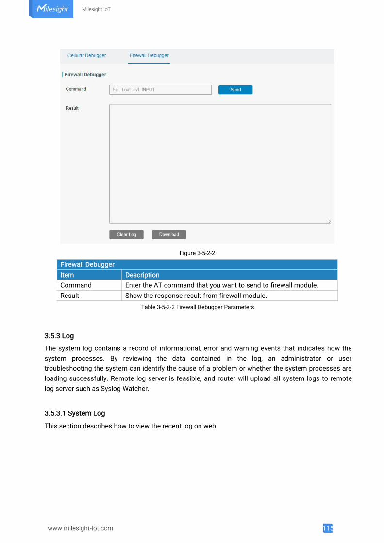
115
Figure 3-5-2-2
Firewall DebuggerItem DescriptionCommand Enter the AT command that you want to send to firewall module.Result Show the response result from firewall module.
Table 3-5-2-2 Firewall Debugger Parameters
3.5.3 Log
The system log contains a record of informational, error and warning events that indicates how thesystem processes. By reviewing the data contained in the log, an administrator or usertroubleshooting the system can identify the cause of a problem or whether the system processes areloading successfully. Remote log server is feasible, and router will upload all system logs to remotelog server such as Syslog Watcher.
3.5.3.1 System Log
This section describes how to view the recent log on web.
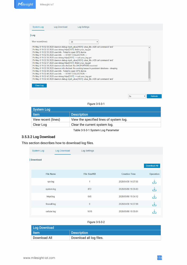
116
Figure 3-5-3-1
System LogItem DescriptionView recent (lines) View the specified lines of system log.Clear Log Clear the current system log.
Table 3-5-3-1 System Log Parameter
3.5.3.2 Log Download
This section describes how to download log files.
Figure 3-5-3-2
Log DownloadItem DescriptionDownload All Download all log files.
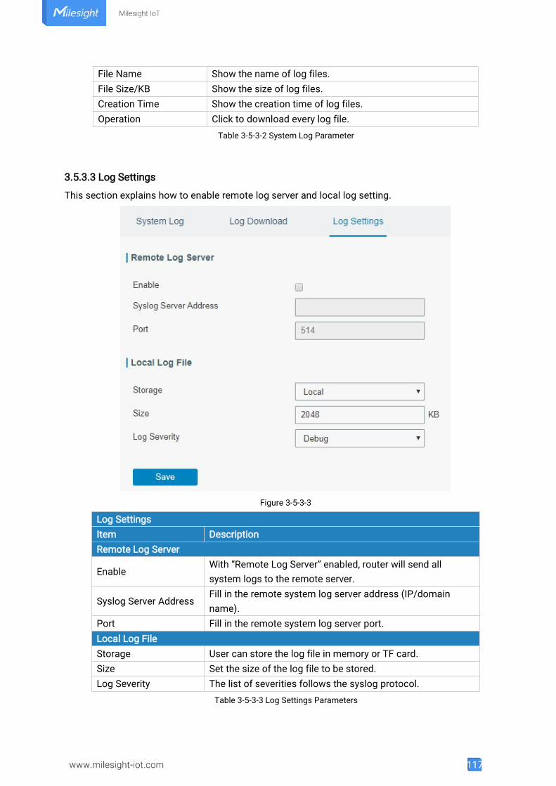
117
File Name Show the name of log files.File Size/KB Show the size of log files.Creation Time Show the creation time of log files.Operation Click to download every log file.
Table 3-5-3-2 System Log Parameter
3.5.3.3 Log Settings
This section explains how to enable remote log server and local log setting.
Figure 3-5-3-3
Log SettingsItem DescriptionRemote Log Server
EnableWith “Remote Log Server” enabled, router will send allsystem logs to the remote server.
Syslog Server AddressFill in the remote system log server address (IP/domainname).
Port Fill in the remote system log server port.Local Log FileStorage User can store the log file in memory or TF card.Size Set the size of the log file to be stored.Log Severity The list of severities follows the syslog protocol.
Table 3-5-3-3 Log Settings Parameters

118
3.5.4 Upgrade
This section describes how to upgrade the router firmware via web. Generally you don’t need to dothe firmware upgrade.Note: any operation on web page is not allowed during firmware upgrade, otherwise the upgrade willbe interrupted, or even the device will break down.
Figure 3-5-4-1
UpgradeItem DescriptionFirmware Version Show the current firmware version.Reset Configuration toFactory Default
When this option is checked, the router will be reset tofactory defaults after upgrade.
Upgrade FirmwareClick "Browse" button to select the new firmware file, andclick "Upgrade" to upgrade firmware.
Table 3-5-4-1 Upgrade Parameters
Related Configuration Example
Firmware Upgrade
3.5.5 Backup and Restore
This section explains how to create a complete backup of the system configurations to a file, restorethe config file to the router and reset to factory defaults.
Figure 3-5-5-1
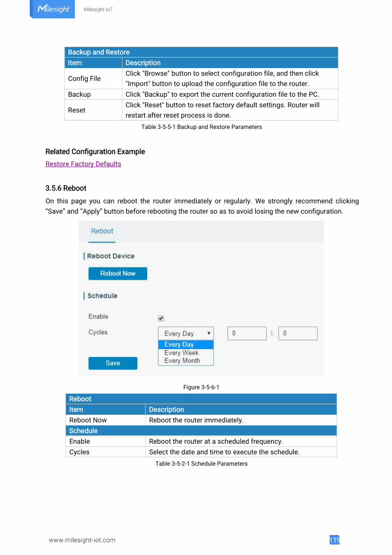
119
Backup and RestoreItem Description
Config FileClick "Browse" button to select configuration file, and then click"Import" button to upload the configuration file to the router.
Backup Click "Backup" to export the current configuration file to the PC.
ResetClick "Reset" button to reset factory default settings. Router willrestart after reset process is done.
Table 3-5-5-1 Backup and Restore Parameters
Related Configuration Example
Restore Factory Defaults
3.5.6 Reboot
On this page you can reboot the router immediately or regularly. We strongly recommend clicking“Save” and “Apply” button before rebooting the router so as to avoid losing the new configuration.
Figure 3-5-6-1
RebootItem DescriptionReboot Now Reboot the router immediately.ScheduleEnable Reboot the router at a scheduled frequency.Cycles Select the date and time to execute the schedule.
Table 3-5-2-1 Schedule Parameters
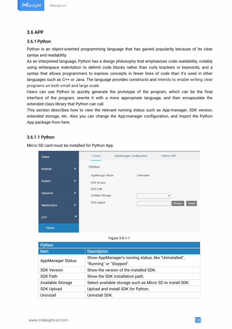
120
3.6 APP
3.6.1 Python
Python is an object-oriented programming language that has gained popularity because of its clearsyntax and readability.As an interpreted language, Python has a design philosophy that emphasizes code readability, notablyusing whitespace indentation to delimit code blocks rather than curly brackets or keywords, and asyntax that allows programmers to express concepts in fewer lines of code than it’s used in otherlanguages such as C++ or Java. The language provides constructs and intends to enable writing clearprograms on both small and large scale.Users can use Python to quickly generate the prototype of the program, which can be the finalinterface of the program, rewrite it with a more appropriate language, and then encapsulate theextended class library that Python can call.This section describes how to view the relevant running status such as App-manager, SDK version,extended storage, etc. Also you can change the App-manager configuration, and import the PythonApp package from here.
3.6.1.1 Python
Micro SD card must be installed for Python App.
Figure 3-6-1-1
PythonItem Description
AppManager StatusShow AppManager's running status, like "Uninstalled","Running" or "Stopped".
SDK Version Show the version of the installed SDK.SDK Path Show the SDK installation path.Available Storage Select available storage such as Micro SD to install SDK.SDK Upload Upload and install SDK for Python.Uninstall Uninstall SDK.
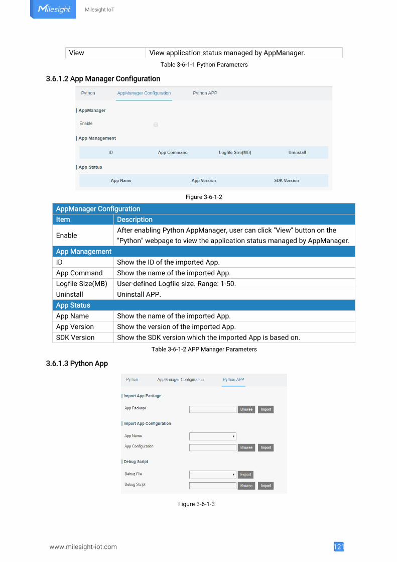
121
View View application status managed by AppManager.Table 3-6-1-1 Python Parameters
3.6.1.2 App Manager Configuration
Figure 3-6-1-2
AppManager ConfigurationItem Description
EnableAfter enabling Python AppManager, user can click "View" button on the"Python" webpage to view the application status managed by AppManager.
App ManagementID Show the ID of the imported App.App Command Show the name of the imported App.Logfile Size(MB) User-defined Logfile size. Range: 1-50.Uninstall Uninstall APP.App StatusApp Name Show the name of the imported App.App Version Show the version of the imported App.SDK Version Show the SDK version which the imported App is based on.
Table 3-6-1-2 APP Manager Parameters
3.6.1.3 Python App
Figure 3-6-1-3
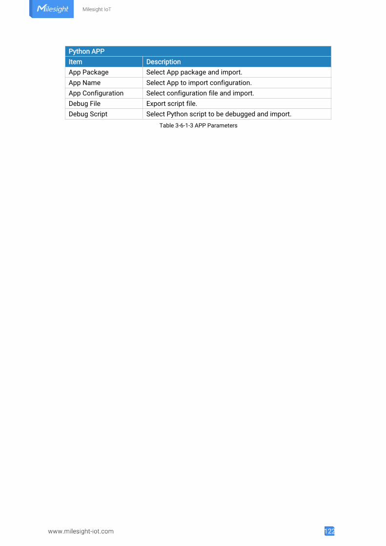
122
Python APPItem DescriptionApp Package Select App package and import.App Name Select App to import configuration.App Configuration Select configuration file and import.Debug File Export script file.Debug Script Select Python script to be debugged and import.
Table 3-6-1-3 APP Parameters
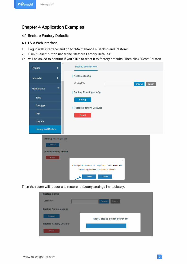
123
Chapter 4 Application Examples
4.1 Restore Factory Defaults
4.1.1 Via Web Interface
1. Log in web interface, and go to “Maintenance > Backup and Restore”.2. Click “Reset” button under the “Restore Factory Defaults”.You will be asked to confirm if you’d like to reset it to factory defaults. Then click “Reset” button.
Then the router will reboot and restore to factory settings immediately.
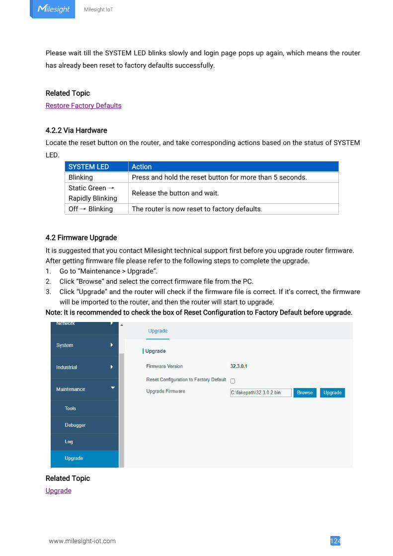
124
Please wait till the SYSTEM LED blinks slowly and login page pops up again, which means the router
has already been reset to factory defaults successfully.
Related Topic
Restore Factory Defaults
4.2.2 Via Hardware
Locate the reset button on the router, and take corresponding actions based on the status of SYSTEM
LED.
SYSTEM LED ActionBlinking Press and hold the reset button for more than 5 seconds.Static Green →
Rapidly BlinkingRelease the button and wait.
Off→ Blinking The router is now reset to factory defaults.
4.2 Firmware Upgrade
It is suggested that you contact Milesight technical support first before you upgrade router firmware.After getting firmware file please refer to the following steps to complete the upgrade.1. Go to “Maintenance > Upgrade”.2. Click “Browse” and select the correct firmware file from the PC.3. Click “Upgrade” and the router will check if the firmware file is correct. If it’s correct, the firmware
will be imported to the router, and then the router will start to upgrade.Note: It is recommended to check the box of Reset Configuration to Factory Default before upgrade.
Related Topic
Upgrade
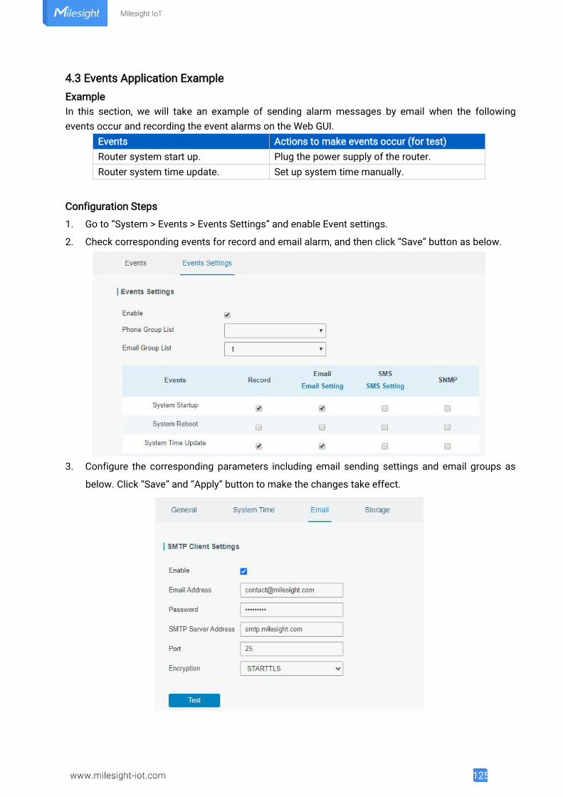
125
4.3 Events Application ExampleExampleIn this section, we will take an example of sending alarm messages by email when the followingevents occur and recording the event alarms on the Web GUI.
Events Actions to make events occur (for test)Router system start up. Plug the power supply of the router.Router system time update. Set up system time manually.
Configuration Steps
1. Go to “System > Events > Events Settings” and enable Event settings.
2. Check corresponding events for record and email alarm, and then click “Save” button as below.
3. Configure the corresponding parameters including email sending settings and email groups as
below. Click “Save” and “Apply” button to make the changes take effect.
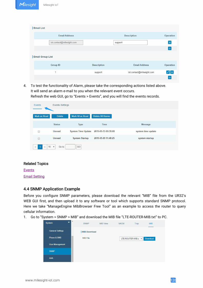
126
4. To test the functionality of Alarm, please take the corresponding actions listed above.It will send an alarm e-mail to you when the relevant event occurs.Refresh the web GUI, go to “Events > Events”, and you will find the events records.
Related Topics
Events
Email Setting
4.4 SNMP Application ExampleBefore you configure SNMP parameters, please download the relevant “MIB” file from the UR32’sWEB GUI first, and then upload it to any software or tool which supports standard SNMP protocol.Here we take “ManageEngine MibBrowser Free Tool” as an example to access the router to querycellular information.1. Go to “System > SNMP > MIB” and download the MIB file “LTE-ROUTER-MIB.txt” to PC.
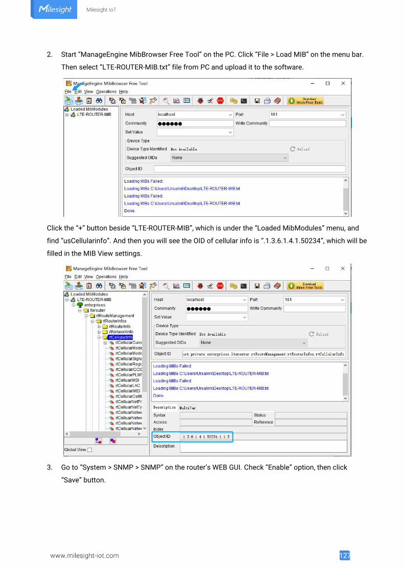
127
2. Start “ManageEngine MibBrowser Free Tool” on the PC. Click “File > Load MIB” on the menu bar.
Then select “LTE-ROUTER-MIB.txt” file from PC and upload it to the software.
Click the “+” button beside “LTE-ROUTER-MIB”, which is under the “Loaded MibModules” menu, and
find “usCellularinfo”. And then you will see the OID of cellular info is “.1.3.6.1.4.1.50234”, which will be
filled in the MIB View settings.
3. Go to “System > SNMP > SNMP” on the router’s WEB GUI. Check “Enable” option, then click
“Save” button.
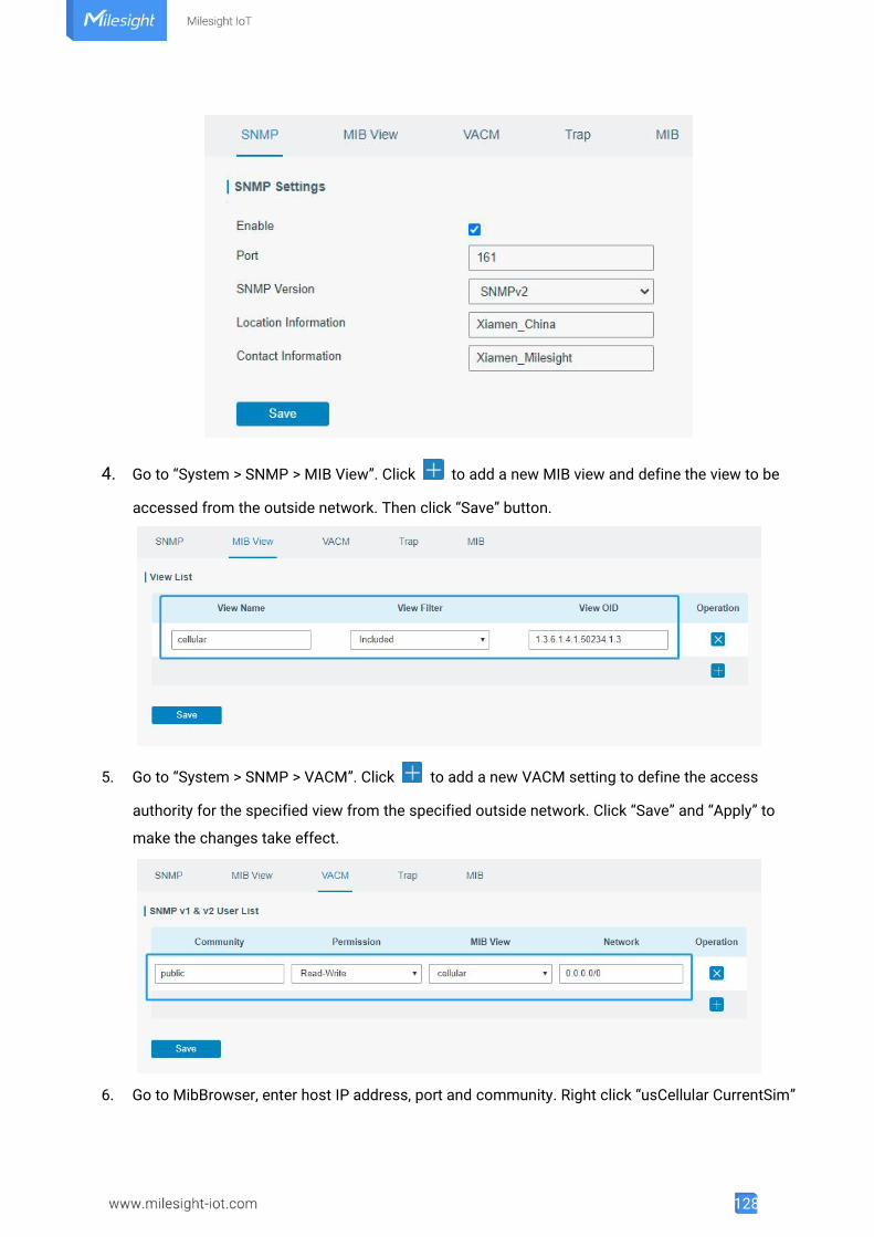
128
4. Go to “System > SNMP > MIB View”. Click to add a new MIB view and define the view to be
accessed from the outside network. Then click “Save” button.
5. Go to “System > SNMP > VACM”. Click to add a new VACM setting to define the access
authority for the specified view from the specified outside network. Click “Save” and “Apply” to
make the changes take effect.
6. Go to MibBrowser, enter host IP address, port and community. Right click “usCellular CurrentSim”
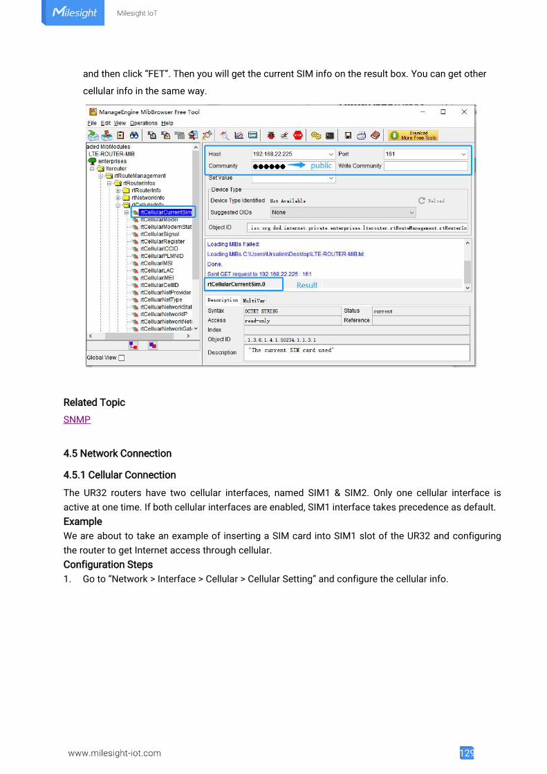
129
and then click “FET”. Then you will get the current SIM info on the result box. You can get other
cellular info in the same way.
Related Topic
SNMP
4.5 Network Connection
4.5.1 Cellular Connection
The UR32 routers have two cellular interfaces, named SIM1 & SIM2. Only one cellular interface isactive at one time. If both cellular interfaces are enabled, SIM1 interface takes precedence as default.ExampleWe are about to take an example of inserting a SIM card into SIM1 slot of the UR32 and configuringthe router to get Internet access through cellular.Configuration Steps1. Go to “Network > Interface > Cellular > Cellular Setting” and configure the cellular info.
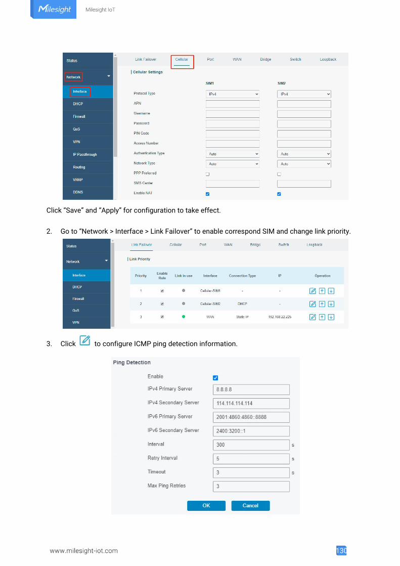
130
Click “Save” and “Apply” for configuration to take effect.
2. Go to “Network > Interface > Link Failover” to enable correspond SIM and change link priority.
3. Click to configure ICMP ping detection information.
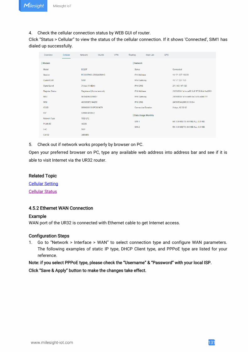
131
4. Check the cellular connection status by WEB GUI of router.Click “Status > Cellular” to view the status of the cellular connection. If it shows 'Connected', SIM1 hasdialed up successfully.
5. Check out if network works properly by browser on PC.
Open your preferred browser on PC, type any available web address into address bar and see if it is
able to visit Internet via the UR32 router.
Related Topic
Cellular Setting
Cellular Status
4.5.2 Ethernet WAN Connection
ExampleWAN port of the UR32 is connected with Ethernet cable to get Internet access.
Configuration Steps1. Go to “Network > Interface > WAN” to select connection type and configure WAN parameters.
The following examples of static IP type, DHCP Client type, and PPPoE type are listed for yourreference.
Note: if you select PPPoE type, please check the “Username” & “Password” with your local ISP.
Click “Save & Apply” button to make the changes take effect.
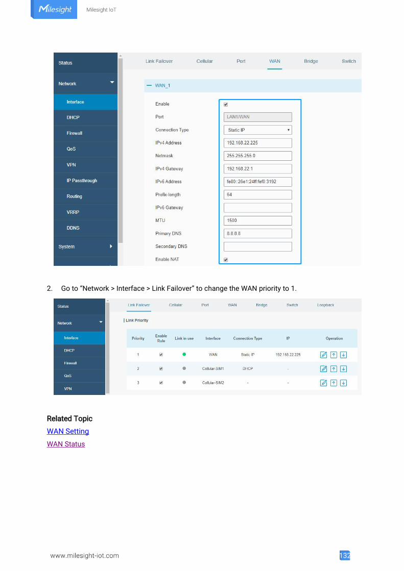
132
2. Go to “Network > Interface > Link Failover” to change the WAN priority to 1.
Related Topic
WAN Setting
WAN Status
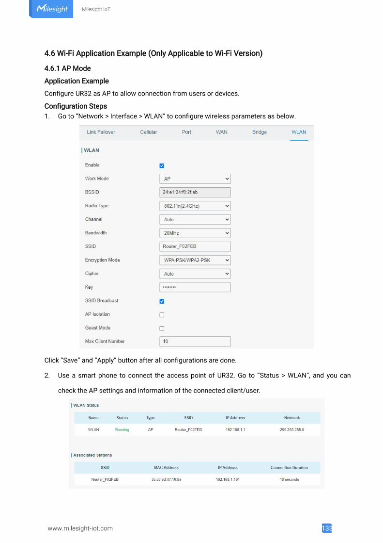
133
4.6 Wi-Fi Application Example (Only Applicable to Wi-Fi Version)
4.6.1 AP Mode
Application Example
Configure UR32 as AP to allow connection from users or devices.
Configuration Steps1. Go to “Network > Interface > WLAN” to configure wireless parameters as below.
Click “Save” and “Apply” button after all configurations are done.
2. Use a smart phone to connect the access point of UR32. Go to “Status > WLAN”, and you can
check the AP settings and information of the connected client/user.
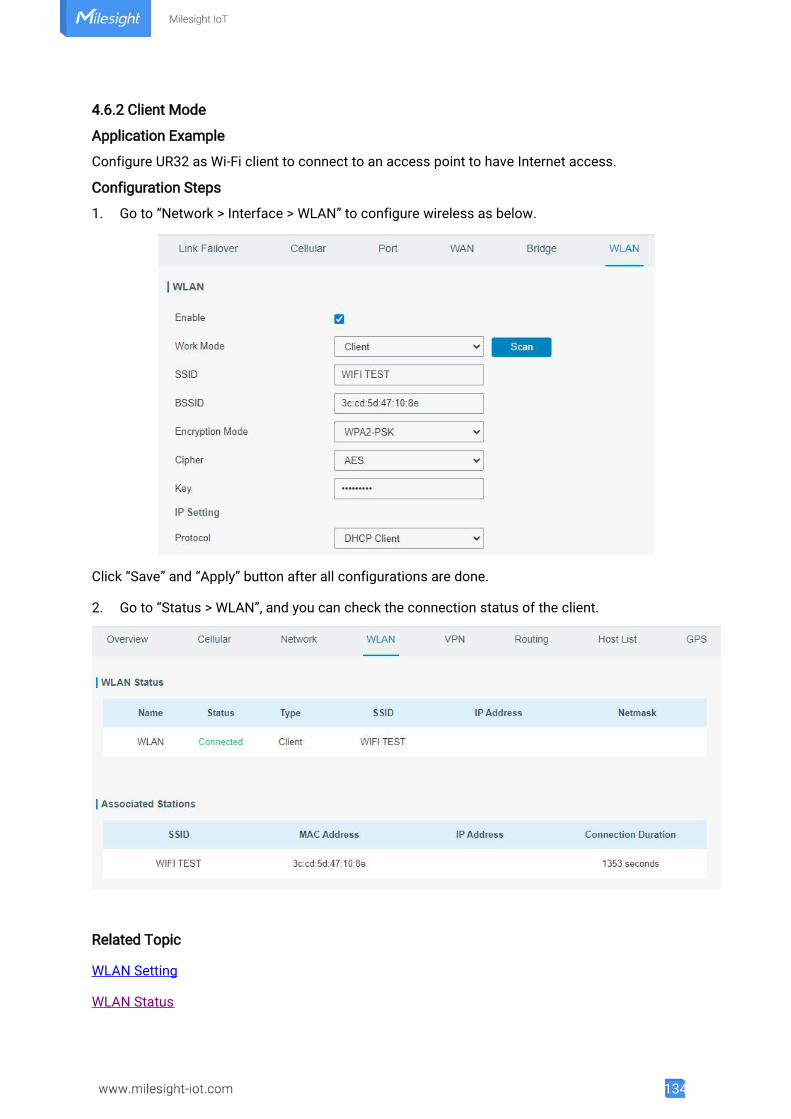
134
4.6.2 Client Mode
Application Example
Configure UR32 as Wi-Fi client to connect to an access point to have Internet access.
Configuration Steps
1. Go to “Network > Interface > WLAN” to configure wireless as below.
Click “Save” and “Apply” button after all configurations are done.
2. Go to “Status > WLAN”, and you can check the connection status of the client.
Related Topic
WLAN Setting
WLAN Status
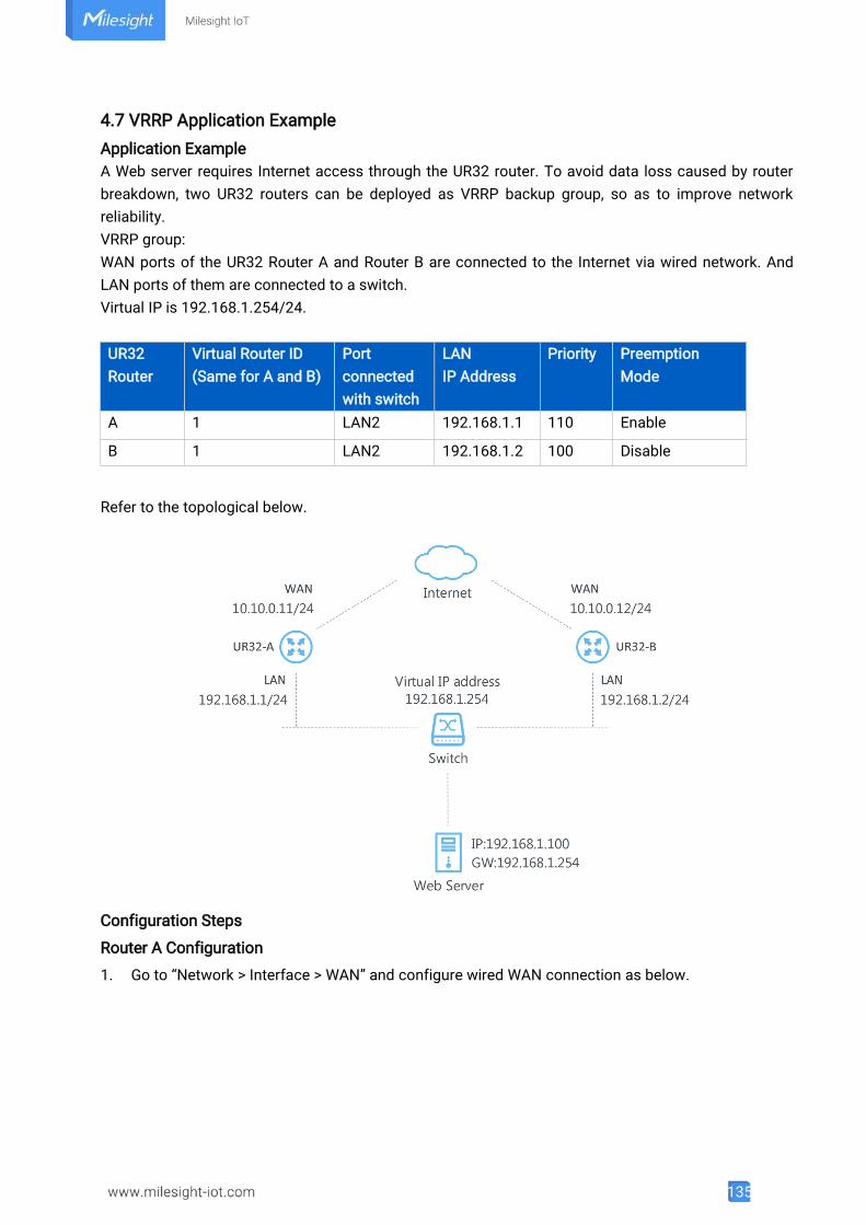
135
4.7 VRRP Application ExampleApplication ExampleA Web server requires Internet access through the UR32 router. To avoid data loss caused by routerbreakdown, two UR32 routers can be deployed as VRRP backup group, so as to improve networkreliability.VRRP group:WAN ports of the UR32 Router A and Router B are connected to the Internet via wired network. AndLAN ports of them are connected to a switch.Virtual IP is 192.168.1.254/24.
UR32Router
Virtual Router ID(Same for A and B)
Portconnectedwith switch
LANIP Address
Priority PreemptionMode
A 1 LAN2 192.168.1.1 110 Enable
B 1 LAN2 192.168.1.2 100 Disable
Refer to the topological below.
Configuration Steps
Router A Configuration
1. Go to “Network > Interface > WAN” and configure wired WAN connection as below.
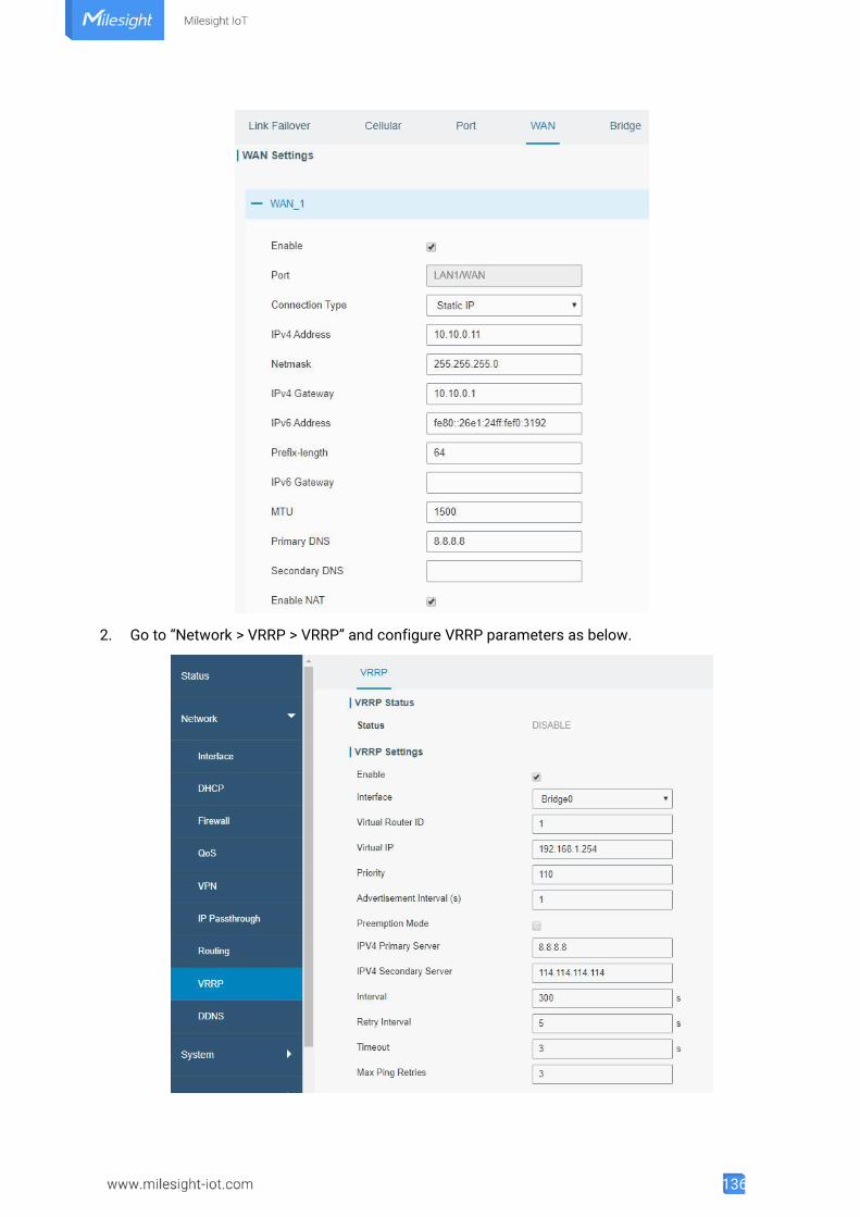
136
2. Go to “Network > VRRP > VRRP” and configure VRRP parameters as below.

137
Router B Configuration1. Go to “Network > Interface > WAN” and configure wired WAN connection as below.
2. Go to “Network > VRRP > VRRP” and configure VRRP parameters as below.
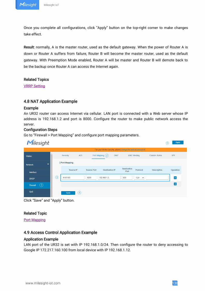
138
Once you complete all configurations, click “Apply” button on the top-right corner to make changes
take effect.
Result: normally, A is the master router, used as the default gateway. When the power of Router A is
down or Router A suffers from failure, Router B will become the master router, used as the default
gateway. With Preemption Mode enabled, Router A will be master and Router B will demote back to
be the backup once Router A can access the Internet again.
Related Topics
VRRP Setting
4.8 NAT Application ExampleExampleAn UR32 router can access Internet via cellular. LAN port is connected with a Web server whose IPaddress is 192.168.1.2 and port is 8000. Configure the router to make public network access theserver.Configuration StepsGo to “Firewall > Port Mapping” and configure port mapping parameters.
Click “Save” and “Apply” button.
Related Topic
Port Mapping
4.9 Access Control Application ExampleApplication ExampleLAN port of the UR32 is set with IP 192.168.1.0/24. Then configure the router to deny accessing toGoogle IP 172.217.160.100 from local device with IP 192.168.1.12.
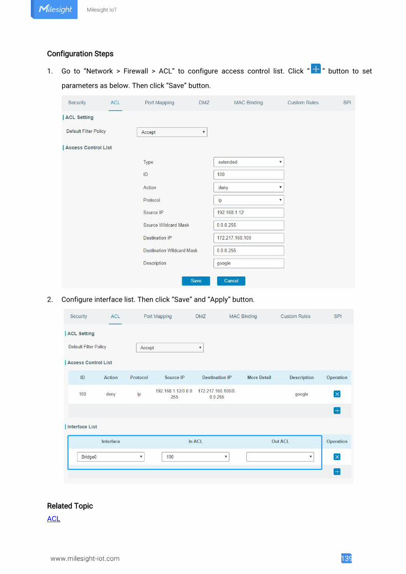
139
Configuration Steps
1. Go to “Network > Firewall > ACL” to configure access control list. Click “ ” button to set
parameters as below. Then click “Save” button.
2. Configure interface list. Then click “Save” and “Apply” button.
Related Topic
ACL
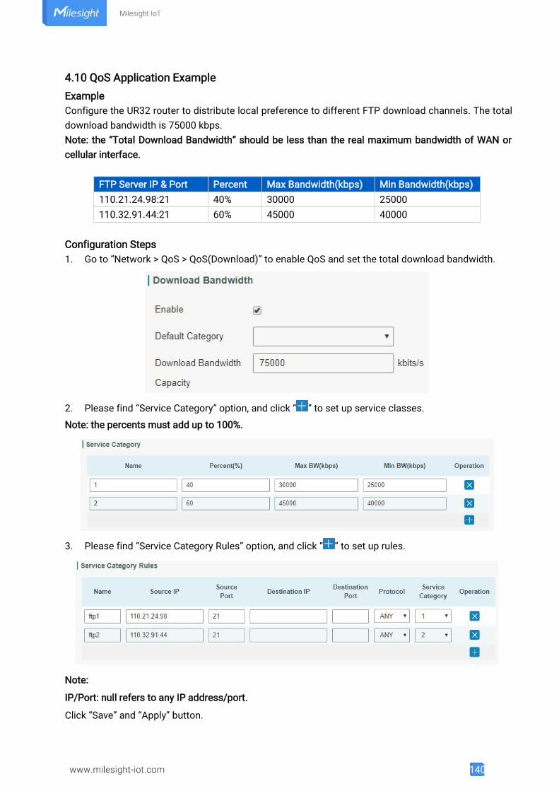
140
4.10 QoS Application ExampleExampleConfigure the UR32 router to distribute local preference to different FTP download channels. The totaldownload bandwidth is 75000 kbps.Note: the “Total Download Bandwidth” should be less than the real maximum bandwidth of WAN orcellular interface.
FTP Server IP & Port Percent Max Bandwidth(kbps) Min Bandwidth(kbps)110.21.24.98:21 40% 30000 25000110.32.91.44:21 60% 45000 40000
Configuration Steps1. Go to “Network > QoS > QoS(Download)” to enable QoS and set the total download bandwidth.
2. Please find “Service Category” option, and click “ ” to set up service classes.
Note: the percents must add up to 100%.
3. Please find “Service Category Rules” option, and click “ ” to set up rules.
Note:
IP/Port: null refers to any IP address/port.
Click “Save” and “Apply” button.
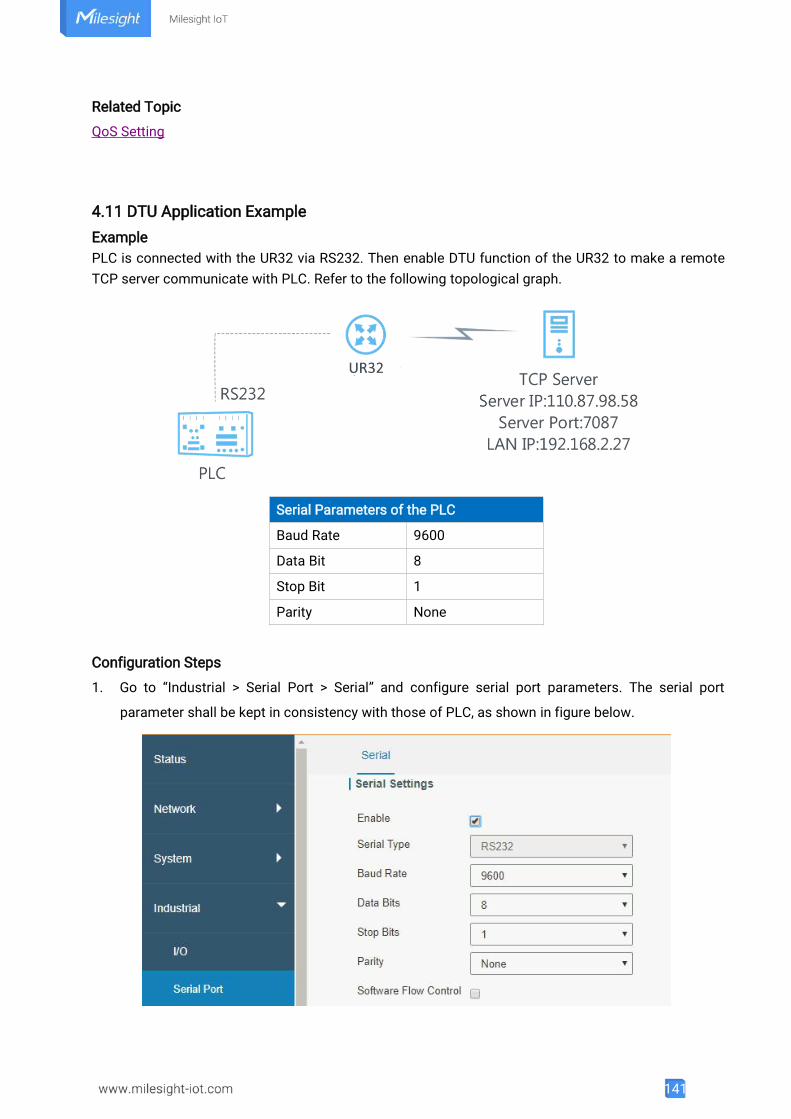
141
Related Topic
QoS Setting
4.11 DTU Application ExampleExamplePLC is connected with the UR32 via RS232. Then enable DTU function of the UR32 to make a remoteTCP server communicate with PLC. Refer to the following topological graph.
Serial Parameters of the PLC
Baud Rate 9600
Data Bit 8
Stop Bit 1
Parity None
Configuration Steps
1. Go to “Industrial > Serial Port > Serial” and configure serial port parameters. The serial port
parameter shall be kept in consistency with those of PLC, as shown in figure below.
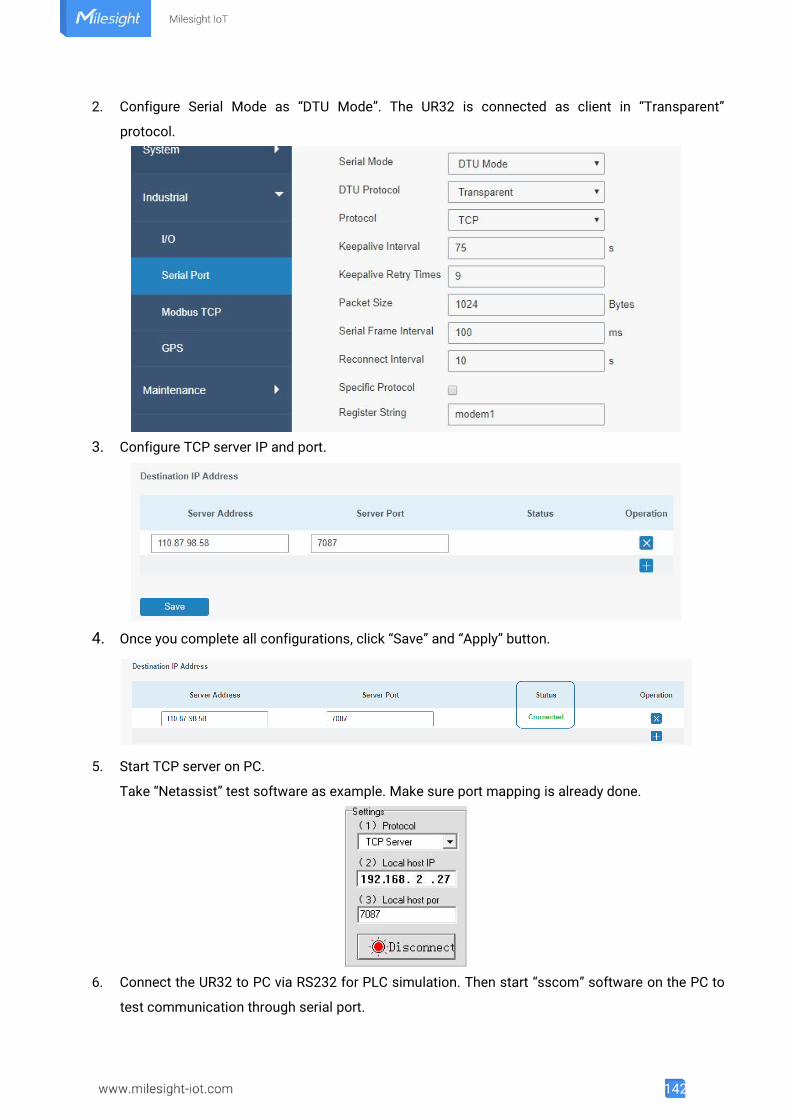
142
2. Configure Serial Mode as “DTU Mode”. The UR32 is connected as client in “Transparent”
protocol.
3. Configure TCP server IP and port.
4. Once you complete all configurations, click “Save” and “Apply” button.
5. Start TCP server on PC.
Take “Netassist” test software as example. Make sure port mapping is already done.
6. Connect the UR32 to PC via RS232 for PLC simulation. Then start “sscom” software on the PC to
test communication through serial port.
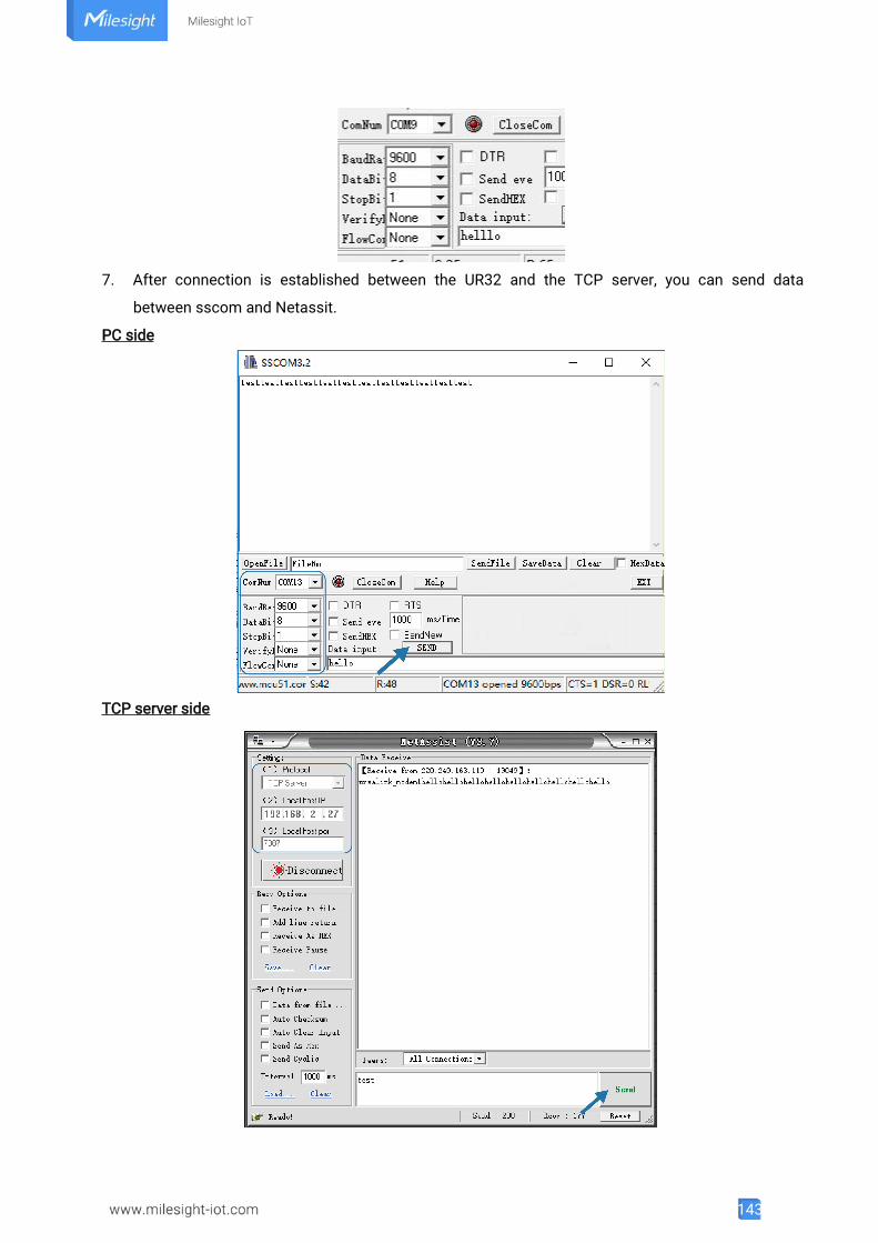
143
7. After connection is established between the UR32 and the TCP server, you can send data
between sscom and Netassit.
PC side
TCP server side
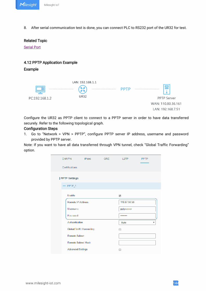
144
8. After serial communication test is done, you can connect PLC to RS232 port of the UR32 for test.
Related Topic
Serial Port
4.12 PPTP Application Example
Example
Configure the UR32 as PPTP client to connect to a PPTP server in order to have data transferredsecurely. Refer to the following topological graph.Configuration Steps1. Go to “Network > VPN > PPTP”, configure PPTP server IP address, username and password
provided by PPTP server.Note: If you want to have all data transferred through VPN tunnel, check “Global Traffic Forwarding”option.
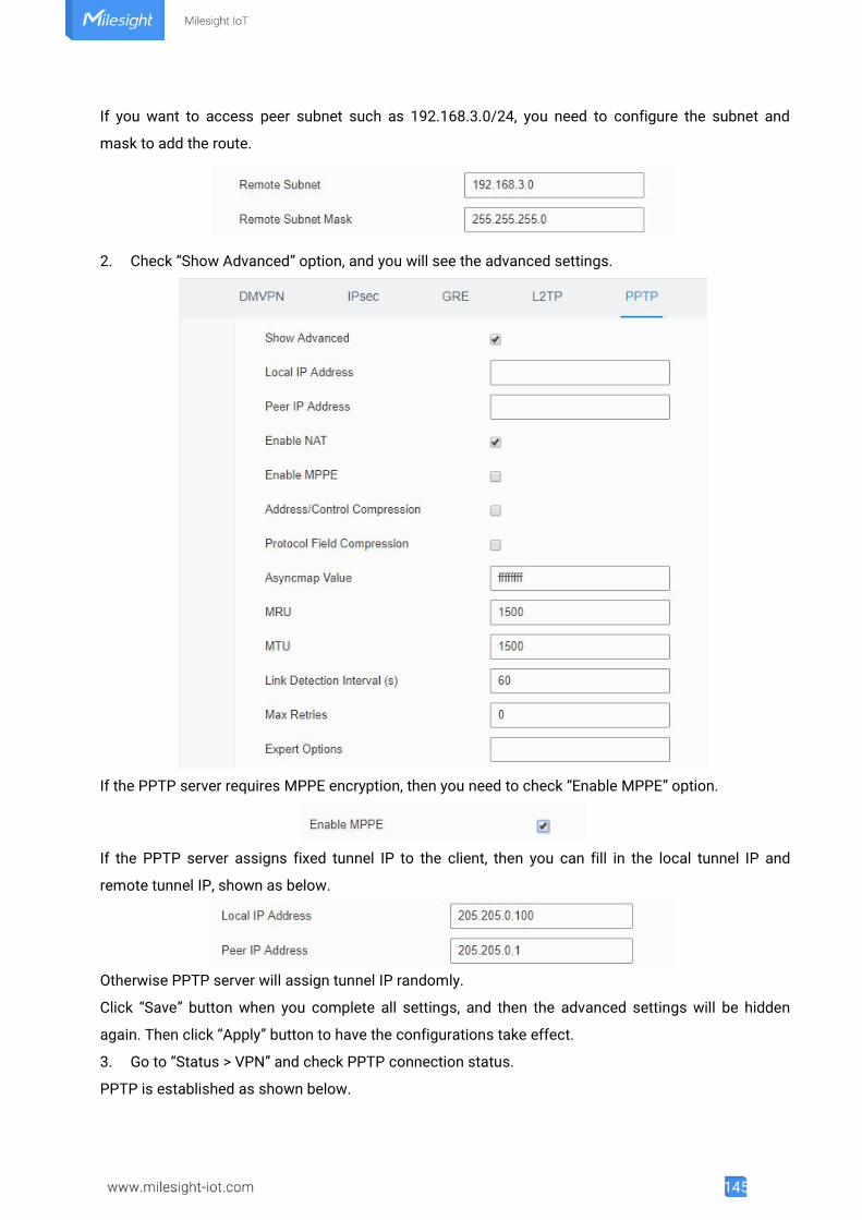
145
If you want to access peer subnet such as 192.168.3.0/24, you need to configure the subnet and
mask to add the route.
2. Check “Show Advanced” option, and you will see the advanced settings.
If the PPTP server requires MPPE encryption, then you need to check “Enable MPPE” option.
If the PPTP server assigns fixed tunnel IP to the client, then you can fill in the local tunnel IP and
remote tunnel IP, shown as below.
Otherwise PPTP server will assign tunnel IP randomly.
Click “Save” button when you complete all settings, and then the advanced settings will be hidden
again. Then click “Apply” button to have the configurations take effect.
3. Go to “Status > VPN” and check PPTP connection status.
PPTP is established as shown below.
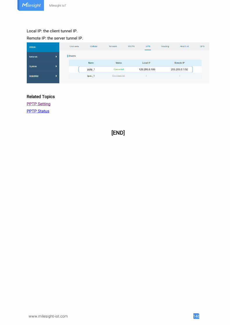
146
Local IP: the client tunnel IP.
Remote IP: the server tunnel IP.
Related Topics
PPTP Setting
PPTP Status
[END]