Embed Size (px)
Citation preview
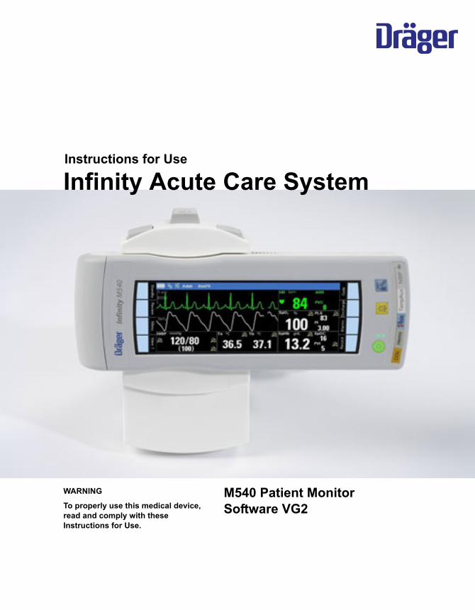
Instructions for Use
Infinity Acute Care System
M540 Patient MonitorSoftware VG2
WARNING
To properly use this medical device, read and comply with these Instructions for Use.
2 Instructions for Use Infinity Acute Care System – M540 Patient Monitor SW VG2
Typographical conventions
Any text shown on the screen and any labelling on the device are printed in bold and italics, for exam-ple, Alarms, or Menu.
The “greater than” symbol > indicates the naviga-tion path in a dialogue window, for example, Menu > Patient setup > Admit date. In this example, Menu represents the fixed key, Patient setup represents a horizontal tab, and Admit date a menu selection.
Screen images
Schematic renderings of screen images are used, which may differ in appearance or in configuration from the actual screen images.
1 Consecutive numbers indicate steps of action, with the numbering restarting with “1” for each new sequence of actions.
Bullet points indicate individual actions or differ-ent options for action.
– Dashes indicate the listing of data, options, or objects.
(A) Letters in parentheses refer to elements in the related illustration.
A Letters in illustrations denote elements referred to in the text.
Instructions for Use Infinity Acute Care System – M540 Patient Monitor SW VG2 3
Trademarks and patents
– Acute Care SystemTM
– DrägerService®
– Infinity®
– Hemo4®
– Hemo2®
– Innovian®
– MCable®
– Medical CockpitTM
– MPod®
– MonoLead®
– TruST®
are trademarks of Dräger.
– Masimo®
– Masimo SET® (Signal Extraction Technology)
– Masimo Rainbow® SET
– PVI®
– SpCO®
– SpHbTM
– SpMet®
– SpOCTM
are registered trademarks of the Masimo corporation.
– DurasensorTM
– Nellcor®
– OxiMax®
– OxiCliqTM
– OxiBandTM
– SoftCareTM
– SatSeconds®
are trademarks of Nellcor Puritan Bennett, LLC.
– ComplianceTM
is a trademark of Cardinal Health, Inc.
– Dismozun®pur
is a trademark of BODE Chemie GmbH.
– Sporox II®
is a trademark of Sultan Healthcare, Inc.
4 Instructions for Use Infinity Acute Care System – M540 Patient Monitor SW VG2
Safety information definitions
Abbreviations and symbols
Please refer to “Device symbols” on page 26 and to “Abbreviations” on page 28 for explanations.
WARNINGA WARNING statement provides important information about a potentially hazardous situation which, if not avoided, could result in death or serious injury.
CAUTIONA CAUTION statement provides important infor-mation about a potentially hazardous situation which, if not avoided, may result in minor or mod-erate injury to the user or patient or in damage to the medical device or other property.
NOTEA NOTE provides additional information intended to avoid inconvenience during operation.
Instructions for Use Infinity Acute Care System – M540 Patient Monitor SW VG2 5
Contents
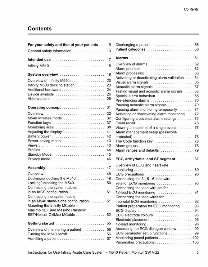
Contents
For your safety and that of your patients . . . 9
General safety information . . . . . . . . . . . . . . . . 13
Intended use . . . . . . . . . . . . . . . . . . . . . . . . . . 17
Infinity M540 . . . . . . . . . . . . . . . . . . . . . . . . . . . 18
System overview . . . . . . . . . . . . . . . . . . . . . . 19
Overview of Infinity M540 . . . . . . . . . . . . . . . . . 20Infinity M500 docking station . . . . . . . . . . . . . . 23Additional hardware . . . . . . . . . . . . . . . . . . . . . 24Device symbols . . . . . . . . . . . . . . . . . . . . . . . . 26Abbreviations . . . . . . . . . . . . . . . . . . . . . . . . . . 28
Operating concept . . . . . . . . . . . . . . . . . . . . . 31
Overview. . . . . . . . . . . . . . . . . . . . . . . . . . . . . . 32M540 wireless mode . . . . . . . . . . . . . . . . . . . . 32Function keys . . . . . . . . . . . . . . . . . . . . . . . . . . 37Monitoring area. . . . . . . . . . . . . . . . . . . . . . . . . 38Adjusting the display. . . . . . . . . . . . . . . . . . . . . 41Battery power . . . . . . . . . . . . . . . . . . . . . . . . . . 42Power-saving mode . . . . . . . . . . . . . . . . . . . . . 43Views . . . . . . . . . . . . . . . . . . . . . . . . . . . . . . . . 43Profiles . . . . . . . . . . . . . . . . . . . . . . . . . . . . . . . 44Standby Mode. . . . . . . . . . . . . . . . . . . . . . . . . . 45Privacy mode . . . . . . . . . . . . . . . . . . . . . . . . . . 46
Assembly. . . . . . . . . . . . . . . . . . . . . . . . . . . . . 47
Overview. . . . . . . . . . . . . . . . . . . . . . . . . . . . . . 48Docking/undocking the M540 . . . . . . . . . . . . . . 49Locking/unlocking the M540. . . . . . . . . . . . . . . 50Connecting the system cablesin an IACS configuration. . . . . . . . . . . . . . . . . . 51Connecting the system cable in an M540 stand-alone configuration . . . . . . . 51Mounting the Infinity MCable – Masimo SET and Masimo Rainbow SET/Nellcor OxiMax MCable . . . . . . . . . . . . . . 52
Getting started . . . . . . . . . . . . . . . . . . . . . . . . 55
Overview of monitoring a patient . . . . . . . . . . . 56Turning the M540 on/off . . . . . . . . . . . . . . . . . . 56Admitting a patient . . . . . . . . . . . . . . . . . . . . . . 57
Discharging a patient. . . . . . . . . . . . . . . . . . . . 58Patient categories . . . . . . . . . . . . . . . . . . . . . . 58
Alarms . . . . . . . . . . . . . . . . . . . . . . . . . . . . . . 61
Overview of alarms . . . . . . . . . . . . . . . . . . . . . 62Alarm priorities . . . . . . . . . . . . . . . . . . . . . . . . 62Alarm processing. . . . . . . . . . . . . . . . . . . . . . . 63Activating or deactivating alarm validation . . . 64Visual alarm signals . . . . . . . . . . . . . . . . . . . . 65Acoustic alarm signals. . . . . . . . . . . . . . . . . . . 67Testing visual and acoustic alarm signals . . . . 68Special alarm behaviour . . . . . . . . . . . . . . . . . 68Pre-silencing alarms . . . . . . . . . . . . . . . . . . . . 70Pausing acoustic alarm signals . . . . . . . . . . . . 70Pausing alarm monitoring temporarily. . . . . . . 71Activating or deactivating alarm monitoring . . . 72Configuring a patient’s alarm settings . . . . . . . 73Event recall . . . . . . . . . . . . . . . . . . . . . . . . . . . 76Viewing a snapshot of a single event . . . . . . . 77Alarm management setup (password-protected) . . . . . . . . . . . . . . . . . . . . . . . . . . . . 78The Code function key . . . . . . . . . . . . . . . . . . 78Alarm groups . . . . . . . . . . . . . . . . . . . . . . . . . . 78Alarm ranges and defaults . . . . . . . . . . . . . . . 79
ECG, arrhythmia, and ST segment. . . . . . . . 87
Overview of ECG and heart rate monitoring . . . . . . . . . . . . . . . . . . . . . . . . . . . . 89ECG precautions . . . . . . . . . . . . . . . . . . . . . . . 90Connecting the 3-, 5-, 6-lead wire sets for ECG monitoring . . . . . . . . . . . . . . . . . 90Connecting the lead wire set for 12-lead ECG monitoring . . . . . . . . . . . . . . . . . 91Connecting the lead wires for neonatal ECG monitoring . . . . . . . . . . . . . . . . 92Patient preparation for ECG monitoring . . . . . 93ECG display . . . . . . . . . . . . . . . . . . . . . . . . . . 94ECG electrode colours . . . . . . . . . . . . . . . . . . 95Electrode placement . . . . . . . . . . . . . . . . . . . . 9512-lead monitoring. . . . . . . . . . . . . . . . . . . . . . 98Accessing the ECG dialogue window . . . . . . . 99ECG parameter setup functions . . . . . . . . . . . 99Monitoring paced patients . . . . . . . . . . . . . . . . 102Pacemaker precautions. . . . . . . . . . . . . . . . . . 103
Contents
6 Instructions for Use Infinity Acute Care System – M540 Patient Monitor SW VG2
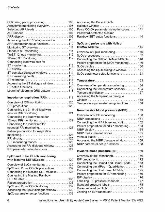
Optimising pacer processing . . . . . . . . . . . . . . 105Arrhythmia monitoring overview . . . . . . . . . . . . 105Selecting ARR leads . . . . . . . . . . . . . . . . . . . . 106ARR modes . . . . . . . . . . . . . . . . . . . . . . . . . . . 107ARR display . . . . . . . . . . . . . . . . . . . . . . . . . . . 109Accessing the ARR dialogue window. . . . . . . . 110ARR parameter setup functions . . . . . . . . . . . . 110Monitoring ST overview . . . . . . . . . . . . . . . . . . 111Standard ST monitoring . . . . . . . . . . . . . . . . . . 111TruST 12-lead monitoring. . . . . . . . . . . . . . . . . 11212-lead ST monitoring . . . . . . . . . . . . . . . . . . . 112Connecting lead wire sets for ST monitoring . . . . . . . . . . . . . . . . . . . . . . . . . . 113ST display. . . . . . . . . . . . . . . . . . . . . . . . . . . . . 113ST-complex dialogue windows . . . . . . . . . . . . . 114ST measuring points . . . . . . . . . . . . . . . . . . . . 115ST reference. . . . . . . . . . . . . . . . . . . . . . . . . . . 115Accessing the ST dialogue window . . . . . . . . . 116ST setup functions . . . . . . . . . . . . . . . . . . . . . . 116Learning/relearning QRS pattern . . . . . . . . . . . 118
Impedance respiration (RRi) . . . . . . . . . . . . . 119
Overview of RRi monitoring . . . . . . . . . . . . . . . 120RRi precautions . . . . . . . . . . . . . . . . . . . . . . . . 120Connecting the 3-, 5-, 6-lead wire sets for RRi monitoring. . . . . . . . . . . . . . . . . . . 121Connecting the lead wire set for 12-lead RRi monitoring. . . . . . . . . . . . . . . . . . . 122Connecting the lead wires for neonatal RRi monitoring. . . . . . . . . . . . . . . . . . 123Patient preparation for respirationmonitoring. . . . . . . . . . . . . . . . . . . . . . . . . . . . . 123RRi display . . . . . . . . . . . . . . . . . . . . . . . . . . . . 125RRi measuring modes . . . . . . . . . . . . . . . . . . . 126Accessing the RRi dialogue window . . . . . . . . 126RRi parameter setup functions. . . . . . . . . . . . . 127
SpO2 and Pulse CO-Ox monitoring with Masimo SET MCables . . . . . . . . . . . . . . 129
Overview of SpO2 monitoring . . . . . . . . . . . . . . 130SpO2 and Pulse CO-Ox precautions . . . . . . . . 132Connecting the Masimo SET MCable . . . . . . . 134Connecting the Masimo Rainbow SET MCable . . . . . . . . . . . . . . . . . . . . . . . . . . . 135Patient preparation . . . . . . . . . . . . . . . . . . . . . . 136SpO2 and Pulse CO-Ox display . . . . . . . . . . . . 137Accessing the SpO2 dialogue window . . . . . . . 139SpO2-parameter setup functions . . . . . . . . . . . 139
Accessing the Pulse CO-Ox dialogue window . . . . . . . . . . . . . . . . . . . . . . . 141Pulse CO-Ox parameter setup functions. . . . . 141Password-protected Masimo Rainbow SET setup functions . . . . . . . . . . . . . 144
SpO2 and pulse rate with Nellcor OxiMax MCable . . . . . . . . . . . . . . . . . . . . . . . 145
Overview of SpO2 monitoring . . . . . . . . . . . . . 146SpO2 precautions . . . . . . . . . . . . . . . . . . . . . . 147Connecting the Nellcor OxiMax MCable . . . . . 148Patient preparation for SpO2 monitoring . . . . . 149SpO2 display . . . . . . . . . . . . . . . . . . . . . . . . . . 150Accessing the SpO2 dialogue window. . . . . . . 151SpO2 parameter setup functions . . . . . . . . . . . 151
Temperature . . . . . . . . . . . . . . . . . . . . . . . . . . 153
Overview of temperature monitoring . . . . . . . . 154Connecting the temperature sensors . . . . . . . 154Temperature display . . . . . . . . . . . . . . . . . . . . 157Accessing the temperature dialogue window . . . . . . . . . . . . . . . . . . . . . . . . . . . . . . 158Temperature parameter setup functions . . . . . 158
Non-invasive blood pressure (NIBP) . . . . . . 159
Overview of NIBP monitoring . . . . . . . . . . . . . 160NIBP precautions . . . . . . . . . . . . . . . . . . . . . . 161Connecting the NIBP hose and cuff . . . . . . . . 162Patient preparation for NIBP monitoring . . . . . 163NIBP display . . . . . . . . . . . . . . . . . . . . . . . . . . 164NIBP measurement modes . . . . . . . . . . . . . . . 165Venous Stasis . . . . . . . . . . . . . . . . . . . . . . . . . 167Accessing the NIBP dialogue window. . . . . . . 168NIBP parameter setup functions . . . . . . . . . . . 168
Invasive blood pressure (IBP) . . . . . . . . . . . 169
Overview of IBP monitoring. . . . . . . . . . . . . . . 170IBP precautions . . . . . . . . . . . . . . . . . . . . . . . . 172Connecting the Hemo4 and Hemo2 pods . . . . 173Connecting the MPod – QuadHemo . . . . . . . . 174Connecting the Dual Hemo MCable . . . . . . . . 175Patient preparation for IBP monitoring . . . . . . 176IBP display . . . . . . . . . . . . . . . . . . . . . . . . . . . 176Labelling IBP pressure channels. . . . . . . . . . . 177Standard pressure labels. . . . . . . . . . . . . . . . . 178Pressure label conflicts . . . . . . . . . . . . . . . . . . 179Zeroing an IBP transducer . . . . . . . . . . . . . . . 179
Instructions for Use Infinity Acute Care System – M540 Patient Monitor SW VG2 7
Contents
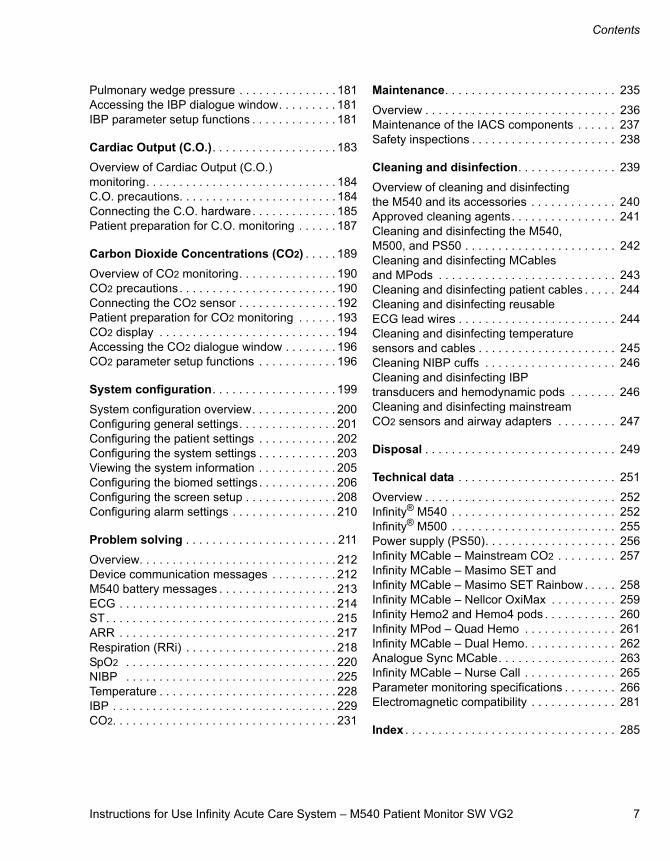
Pulmonary wedge pressure . . . . . . . . . . . . . . . 181Accessing the IBP dialogue window. . . . . . . . . 181IBP parameter setup functions . . . . . . . . . . . . . 181
Cardiac Output (C.O.). . . . . . . . . . . . . . . . . . . 183
Overview of Cardiac Output (C.O.) monitoring. . . . . . . . . . . . . . . . . . . . . . . . . . . . . 184C.O. precautions. . . . . . . . . . . . . . . . . . . . . . . . 184Connecting the C.O. hardware. . . . . . . . . . . . . 185Patient preparation for C.O. monitoring . . . . . . 187
Carbon Dioxide Concentrations (CO2) . . . . . 189
Overview of CO2 monitoring. . . . . . . . . . . . . . . 190CO2 precautions. . . . . . . . . . . . . . . . . . . . . . . . 190Connecting the CO2 sensor . . . . . . . . . . . . . . . 192Patient preparation for CO2 monitoring . . . . . . 193CO2 display . . . . . . . . . . . . . . . . . . . . . . . . . . . 194Accessing the CO2 dialogue window . . . . . . . . 196CO2 parameter setup functions . . . . . . . . . . . . 196
System configuration. . . . . . . . . . . . . . . . . . . 199
System configuration overview. . . . . . . . . . . . . 200Configuring general settings. . . . . . . . . . . . . . . 201Configuring the patient settings . . . . . . . . . . . . 202Configuring the system settings . . . . . . . . . . . . 203Viewing the system information . . . . . . . . . . . . 205Configuring the biomed settings. . . . . . . . . . . . 206Configuring the screen setup . . . . . . . . . . . . . . 208Configuring alarm settings . . . . . . . . . . . . . . . . 210
Problem solving . . . . . . . . . . . . . . . . . . . . . . . 211
Overview. . . . . . . . . . . . . . . . . . . . . . . . . . . . . . 212Device communication messages . . . . . . . . . . 212M540 battery messages . . . . . . . . . . . . . . . . . . 213ECG . . . . . . . . . . . . . . . . . . . . . . . . . . . . . . . . . 214ST. . . . . . . . . . . . . . . . . . . . . . . . . . . . . . . . . . . 215ARR . . . . . . . . . . . . . . . . . . . . . . . . . . . . . . . . . 217Respiration (RRi) . . . . . . . . . . . . . . . . . . . . . . . 218SpO2 . . . . . . . . . . . . . . . . . . . . . . . . . . . . . . . . 220NIBP . . . . . . . . . . . . . . . . . . . . . . . . . . . . . . . . 225Temperature . . . . . . . . . . . . . . . . . . . . . . . . . . . 228IBP . . . . . . . . . . . . . . . . . . . . . . . . . . . . . . . . . . 229CO2. . . . . . . . . . . . . . . . . . . . . . . . . . . . . . . . . . 231
Maintenance. . . . . . . . . . . . . . . . . . . . . . . . . . 235
Overview . . . . . . . . . . . . . . . . . . . . . . . . . . . . . 236Maintenance of the IACS components . . . . . . 237Safety inspections . . . . . . . . . . . . . . . . . . . . . . 238
Cleaning and disinfection. . . . . . . . . . . . . . . 239
Overview of cleaning and disinfecting the M540 and its accessories . . . . . . . . . . . . . 240Approved cleaning agents. . . . . . . . . . . . . . . . 241Cleaning and disinfecting the M540, M500, and PS50 . . . . . . . . . . . . . . . . . . . . . . . 242Cleaning and disinfecting MCables and MPods . . . . . . . . . . . . . . . . . . . . . . . . . . . 243Cleaning and disinfecting patient cables . . . . . 244Cleaning and disinfecting reusable ECG lead wires . . . . . . . . . . . . . . . . . . . . . . . . 244Cleaning and disinfecting temperature sensors and cables . . . . . . . . . . . . . . . . . . . . . 245Cleaning NIBP cuffs . . . . . . . . . . . . . . . . . . . . 246Cleaning and disinfecting IBP transducers and hemodynamic pods . . . . . . . 246Cleaning and disinfecting mainstream CO2 sensors and airway adapters . . . . . . . . . 247
Disposal . . . . . . . . . . . . . . . . . . . . . . . . . . . . . 249
Technical data . . . . . . . . . . . . . . . . . . . . . . . . 251
Overview . . . . . . . . . . . . . . . . . . . . . . . . . . . . . 252Infinity® M540 . . . . . . . . . . . . . . . . . . . . . . . . . 252Infinity® M500 . . . . . . . . . . . . . . . . . . . . . . . . . 255Power supply (PS50). . . . . . . . . . . . . . . . . . . . 256Infinity MCable – Mainstream CO2 . . . . . . . . . 257Infinity MCable – Masimo SET and Infinity MCable – Masimo SET Rainbow . . . . . 258Infinity MCable – Nellcor OxiMax . . . . . . . . . . 259Infinity Hemo2 and Hemo4 pods . . . . . . . . . . . 260Infinity MPod – Quad Hemo . . . . . . . . . . . . . . 261Infinity MCable – Dual Hemo. . . . . . . . . . . . . . 262Analogue Sync MCable. . . . . . . . . . . . . . . . . . 263Infinity MCable – Nurse Call . . . . . . . . . . . . . . 265Parameter monitoring specifications . . . . . . . . 266Electromagnetic compatibility . . . . . . . . . . . . . 281
Index . . . . . . . . . . . . . . . . . . . . . . . . . . . . . . . . 285

8 Instructions for Use Infinity Acute Care System – M540 Patient Monitor SW VG2
This page is intentionally left blank
Instructions for Use Infinity Acute Care System – M540 Patient Monitor SW VG2 9
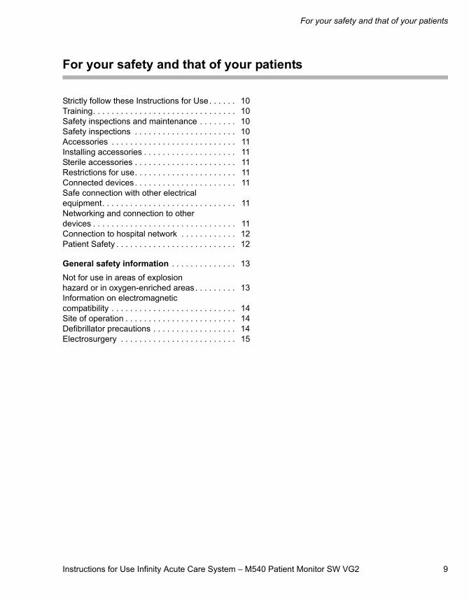
For your safety and that of your patients
For your safety and that of your patients
Strictly follow these Instructions for Use. . . . . . 10Training. . . . . . . . . . . . . . . . . . . . . . . . . . . . . . . 10Safety inspections and maintenance . . . . . . . . 10Safety inspections . . . . . . . . . . . . . . . . . . . . . . 10Accessories . . . . . . . . . . . . . . . . . . . . . . . . . . . 11Installing accessories . . . . . . . . . . . . . . . . . . . . 11Sterile accessories . . . . . . . . . . . . . . . . . . . . . . 11Restrictions for use. . . . . . . . . . . . . . . . . . . . . . 11Connected devices. . . . . . . . . . . . . . . . . . . . . . 11Safe connection with other electrical equipment. . . . . . . . . . . . . . . . . . . . . . . . . . . . . 11Networking and connection to other devices . . . . . . . . . . . . . . . . . . . . . . . . . . . . . . . 11Connection to hospital network . . . . . . . . . . . . 12Patient Safety . . . . . . . . . . . . . . . . . . . . . . . . . . 12
General safety information . . . . . . . . . . . . . . 13
Not for use in areas of explosion hazard or in oxygen-enriched areas . . . . . . . . . 13Information on electromagnetic compatibility . . . . . . . . . . . . . . . . . . . . . . . . . . . 14Site of operation . . . . . . . . . . . . . . . . . . . . . . . . 14Defibrillator precautions . . . . . . . . . . . . . . . . . . 14Electrosurgery . . . . . . . . . . . . . . . . . . . . . . . . . 15
10 Instructions for Use Infinity Acute Care System – M540 Patient Monitor SW VG2
For your safety and that of your patients
Strictly follow these Instructions for Use
Training
Training for users is available from the responsible Dräger organisation. See www.draeger.com for more information.
Safety inspections and maintenance
Safety inspections
The medical device must be subject to regular safety inspections. See the chapter “Maintenance”.
WARNINGAny use of the medical device requires full understanding and strict observation of all sections of these Instructions for Use. The medical device must only be used for the purpose specified under “Intended use” on page 17 and in conjunction with appropri-ate patient monitoring. Strictly observe all WARNING and CAUTION statements through-out these Instructions for Use and all state-ments on medical device labels. Failure to observe these safety information statements constitutes a use of the medical device that is inconsistent with its intended use.
WARNINGEvery medical device must be inspected regularly to ensure it remains safe to use.
This medical device must be inspected and serviced regularly by trained technical per-sonnel. Trained technical personnel should also perform any repairs that are necessary.
Only authentic Dräger repair parts should be used for maintenance. Using non-Dräger repair parts may adversely affect the opera-tion of the device (see the “Maintenance” chapter). Dräger also recommends obtaining a service contract so that all repairs are performed by DrägerService.
Instructions for Use Infinity Acute Care System – M540 Patient Monitor SW VG2 11
For your safety and that of your patients
Accessories
Installing accessories
Strictly observe Assembly instructions and Instruc-tions for Use.
Sterile accessories
Restrictions for use
Connected devices
Safe connection with other electrical equipment
Networking and connection to other devices
When combining Dräger devices with other electri-cal devices, the owner must ensure that the result-ing system meets the requirements of the following standards:– IEC 60601-1 (EN 60601-1)
Medical electrical equipment Part 1: General requirements for safety
– IEC 60601-1-1 (EN 60601-1-1)Medical electrical equipment Part 1-1: General requirements for safetyCollateral standard: Safety requirements for medical electrical systems
– IEC 60601-1-2 (EN 60601-1-2)Medical electrical equipment Part 1-2: General requirements for safetyCollateral standard: Electromagnetic compati-bility; requirements and tests
WARNINGOnly the accessories indicated in the Infinity Acute Care System – M540 Patient Monitor Instructions for Use (latest edition) have been tested and approved for use with the medical device.
Therefore, it is strongly recommended that only these accessories are used in conjunc-tion with the medical device. Otherwise, the correct functioning of the medical device may be compromised.
CAUTIONInstall accessories to the basic device in accord-ance with the Instructions for Use of the basic device. Make sure that there is a safe connection to the basic device system.
CAUTIONDo not use sterile-packaged accessories if the packaging has been opened, is damaged or there are other signs of non-sterility. Disposable articles must not be reprocessed and resterilised. Reuse, reprocessing, or resterilisation can lead to a fail-ure of the medical device and cause injury to the patient.
CAUTIONDevice for use in clinical settings and land ambu-lances only and exclusively by persons with spe-cific training and experience in its use.
WARNINGConnecting devices or combinations of devices in ways not described within these Instructions for Use may adversely affect the operation of any or all of the connected medi-cal devices and may put the patient at risk of receiving an electric shock. Before operating any combination of devices, strictly comply with the Instructions for Use for all connected devices.
CAUTIONElectrical connections to equipment not listed in these Instructions for Use or Assembly Instruc-tions must only be made when approved by each respective manufacturer.
For your safety and that of your patients
12 Instructions for Use Infinity Acute Care System – M540 Patient Monitor SW VG2
– IEC 60601-1-4 (EN 60601-1-4)Medical electrical equipment Part 1-4: General requirements for safetyCollateral standard: Programmable electrical medical systems
Combinations of Dräger devices and third-party devices that are not approved by Dräger may adversely affect operation of those devices and may put the patient at greater risk of injury.
Strictly follow the Assembly Instructions and Instructions for Use for each connected device.
Connection to hospital network
Many medical devices manufactured by Dräger use networks to transmit patient data in real-time and to notify clinical users of alarm conditions. Hospitals should refer to IEC 80000-1 before attempting to connect such medical devices to their IT networks. The technical documentation that IEC 80000-1 requires manufacturers such as Dräger to make available in support of such network connections can be requested. Contact your Dräger representa-tive for that information or to facilitate negotiation of an IEC 80000-1 Responsibility Agreement for addi-tional support from Dräger.
Patient safety
The design of the medical device, the accompany-ing documentation, and the labelling on the medical device are based on the assumption that the purchase and the use of the medical device are restricted to medical professionals, and that certain inherent characteristics of the medical device are known to a clinical user. Instructions and WARNING and CAUTION statements are therefore largely limited to the specifics of the Dräger medical device.
These Instructions for Use do not refer to various hazards which are obvious to a medical profes-sional who operates this medical device as well as references to the consequences of medical device misuse, and to potentially adverse effects in patients with different underlying diseases. Mod-ifying or misusing this medical device can be dan-gerous.
CAUTIONThe medical device must only be used with soft-ware tested and approved by Dräger. Any modifi-cations of the operating system settings can impair operating safety. Responsibility for any such modifications lies with the owner.
Instructions for Use Infinity Acute Care System – M540 Patient Monitor SW VG2 13
For your safety and that of your patients
General safety information
The following WARNING and CAUTION state-ments apply to general operation of the medical device.WARNING and CAUTION statements specific to subsystems or particular features of the medical device appear in the respective sections of these Instructions for Use or in the Instructions for Use of another product being used with this device.
For countries subject to the EU directive 2002/96/EC
This device is subject to EU Directive 2002/96/EC (WEEE). In order to comply with its registration according to this directive, this device may not be disposed of at municipal collection points for waste electrical and electronic equipment. Dräger has authorised a company to collect and dispose of this device.
To initiate collection or for further information, visit Dräger on the Internet at www.draeger.com. Use the Search function with the keyword “WEEE” to find the relevant information. If access to Dräger's website is not possible, contact the local Dräger organisation.
Not for use in areas of explosion hazard or in oxygen-enriched areas
WARNINGFollow local regulations for safe disposal of batteries. To prevent fire or explosion, never dispose of batteries in fire.
WARNINGTo avoid electric shock, inspect all cables before use. Never use cables that appear cracked, worn, or damaged in any way (doing so may compromise performance or put the patient at risk).
CAUTIONTo avoid injuring the patient, disconnect all sen-sors, that will not be used during transport, before moving the patient.
CAUTIONRead all cleaning instructions (for example, origi-nating from the disinfectant manufacturer and the hospital) carefully before cleaning the device. Refer to the chapter entitled “Cleaning and disin-fection” on page 239 for device-specific cleaning instructions. Moisture may damage the circuits, compromise critical performance and present a safety risk.
WARNINGThis medical device is not for use in oxygen-enriched areas or in areas where combustible explosive gas mixtures are likely to occur.
WARNINGWhen placing the device, make sure adequate airflow exists. Do not cover the device with blankets.
For your safety and that of your patients
14 Instructions for Use Infinity Acute Care System – M540 Patient Monitor SW VG2
Information on electromagnetic compatibility
Medical electrical equipment is subject to special precautionary measures concerning electromag-netic compatibility (EMC) and must be installed and put into operation in accordance with the EMC information provided on page 281.
The performance of the medical electrical equip-ment may be affected by using portable or mobile RF communications equipment near it.
Site of operation
Only use devices (monitors, MPods, MCables, and accessories) in areas that meet the environmental requirements outlined in the technical data section.
Defibrillator precautions
The M540 and the peripheral devices are protected against high-frequency interference from defibrilla-tors and electrosurgical units and against 50-Hz and 60-Hz power-line interference.
WARNINGDo not touch the patient while touching other conductive parts, including exposed pins or a con-nector marked with the ESD warn-ing symbol.
WARNINGTo avoid interfering with device operation, do not operate devices (monitors, MPods, MCa-bles, and accessories) within 10 m (33 feet) of equipment that emits microwave or other high-frequency emissions.
WARNINGMake sure that the device is properly mounted and secured to prevent injury. Make sure the requirements for the maximum load and slope of floor are met. Consult the documentation of the mounting manufacturer for detailed information.
WARNINGTo minimise the risk of patient strangulation, carefully position and secure sensor cables. Also position the sensor cables to minimise inductive loops.
CAUTIONTo prevent overheating, do not place the device in direct sunlight or near radiant heaters.
CAUTIONAfter extended exposure in a cold environment, acclimatise the device carefully so that condensa-tion does not form on the electronic parts and damage the device.
CAUTIONTo avoid damaging the touch-sensitive screen, do not allow sharp instruments to touch the front panel of the devices.
CAUTIONTo avoid short-circuiting and otherwise damaging the device, Dräger recommends that no fluids come in contact with the IACS devices when they are connected to a power socket. If fluids are accidentally spilled on the equipment, remove the affected device from service as soon as possible and have technical personnel verify that patient safety is not compromised.
CAUTIONTo prevent burns and electric shock due to rerout-ing of electrical current through electrodes, do not position the defibrillator pads near any electrodes or sensors.
CAUTIONOnly defibrillate across the chest.
Instructions for Use Infinity Acute Care System – M540 Patient Monitor SW VG2 15
For your safety and that of your patients
Electrosurgery
Observe the following precautions during electro-surgery to reduce electrosurgical unit (ESU) inter-ference and improve operator and patient safety.
CAUTIONUsing ECG electrodes and cables specified by Dräger protects the device from damage during defibrillation and reduces noise and other interfer-ence on the ECG waveform.
WARNINGFor better performance and to reduce the hazard of burns during surgery, always use accessories designed for ESU environments. Do not use skin temperature sensors.
WARNINGTo reduce the hazard of burns during electro-surgery, keep the sensor or transducer (ECG, pressure, SpO2) and their associated cables away from the surgical site, the ESU return electrode, and earth ground.
NOTECover internally placed reusable temperature sensors with temperature probe sheaths.

16 Instructions for Use Infinity Acute Care System – M540 Patient Monitor SW VG2
This page is intentionally left blank

Instructions for Use Infinity Acute Care System – M540 Patient Monitor SW VG2 17
Intended use
Intended use
Infinity M540 . . . . . . . . . . . . . . . . . . . . . . . . . . 18
Indications for use . . . . . . . . . . . . . . . . . . . . . . 18
Intended use
18 Instructions for Use Infinity Acute Care System – M540 Patient Monitor SW VG2
Infinity M540
The Infinity M540 (M540) is intended for the monitoring of multi-parameter, physiologic patient information obtained from connected hardware in environments where patient care is provided by trained healthcare professionals.The M540 is intended to monitor one patient at a time.
The M540 is also intended for patient transport inside or outside the hospital in a land ambulance.
The M540 and any connected hardware are not intended for use in the following hospital environments:
– Hyperbaric chambers
– Environments containing MRI equipment
Indications for use
The M540 is capable of monitoring the following parameters:
– Heart rate
– Arrhythmia (adult and paediatric only)
– 12-lead ECG monitoring including TruST
– ST segment analysis (adult and paediatric only)
– 12-lead ST segment analysis (adult and paedi-atric only)
– Apnoea
– Respiratory rate
– Invasive blood pressure
– Non-invasive blood pressure
– Temperature
– Cardiac output (only available when the M540 is docked in an IACS configuration)
– Arterial oxygen saturation (SpO2)
– Pulse rate
– Mainstream etCO2
– Perfusion index (PI)
– Total haemoglobin (SpHb)
– Total oxygen content (SpOC)
– Carboxyhaemoglobin saturation (SpCO)
– Methaemoglobin saturation (SpMet)
– Patient volume index (PVI)
Instructions for Use Infinity Acute Care System – M540 Patient Monitor SW VG2 19
System overview
System overview
Overview of Infinity M540 . . . . . . . . . . . . . . . 20
M540 front panel. . . . . . . . . . . . . . . . . . . . . . . . 21M540 back panel . . . . . . . . . . . . . . . . . . . . . . . 22M540 side panel . . . . . . . . . . . . . . . . . . . . . . . . 22
Infinity M500 docking station . . . . . . . . . . . . 23
M500 front panel. . . . . . . . . . . . . . . . . . . . . . . . 23M500 back panel . . . . . . . . . . . . . . . . . . . . . . . 23M540 docked in the M500 . . . . . . . . . . . . . . . . 24
Additional hardware . . . . . . . . . . . . . . . . . . . . 24
Device symbols . . . . . . . . . . . . . . . . . . . . . . . 26
Wireless symbols . . . . . . . . . . . . . . . . . . . . . . . 27
Abbreviations . . . . . . . . . . . . . . . . . . . . . . . . . 28
System overview
20 Instructions for Use Infinity Acute Care System – M540 Patient Monitor SW VG2
Overview of Infinity M540
These Instructions for Use describe the M540. This monitor is a rugged, light-weight, handheld, trans-portable patient monitor with a touch screen and independent user interface. When docked in the Infinity M500 (see page 49), the M540 is the signal-acquisition and data processing module for the Infinity C500/C700, which is the primary display for the Infinity Acute Care System (IACS).
The M540 also provides seamless patient monitor-ing when it is undocked from the M500 for patient transport (see page 49).
The M540 also comes with a wireless option that allows it to transmit patient data to the ICS (Infinity CentralStation) during transport.
Because the M540 is also part of an IACS configu-ration, some of the IACS components are also described here. For specific information regarding the IACS, refer to Infinity Acute Care System – Monitoring Applications Instructions for Use.
Some terms used in these Instructions for Use:
– Cockpit – refers to the Infinity C700 Medical Cockpit or the Infinity C500 Medical Cockpit which is the display module of the Infinity Acute Care System
– M540 – refers to the Infinity M540 patient mon-itor
– M500 – refers to the Infinity M500 that secures the M540 and charges the internal battery of the M540
– PS50 – refers to the M500 50-W power supply
– Docking the M540 – refers to placing the M540 on the M500
The M540 docked on an M500 can be set up as a stand-alone configuration to charge the battery when the M540 is not part of an IACS configuration.
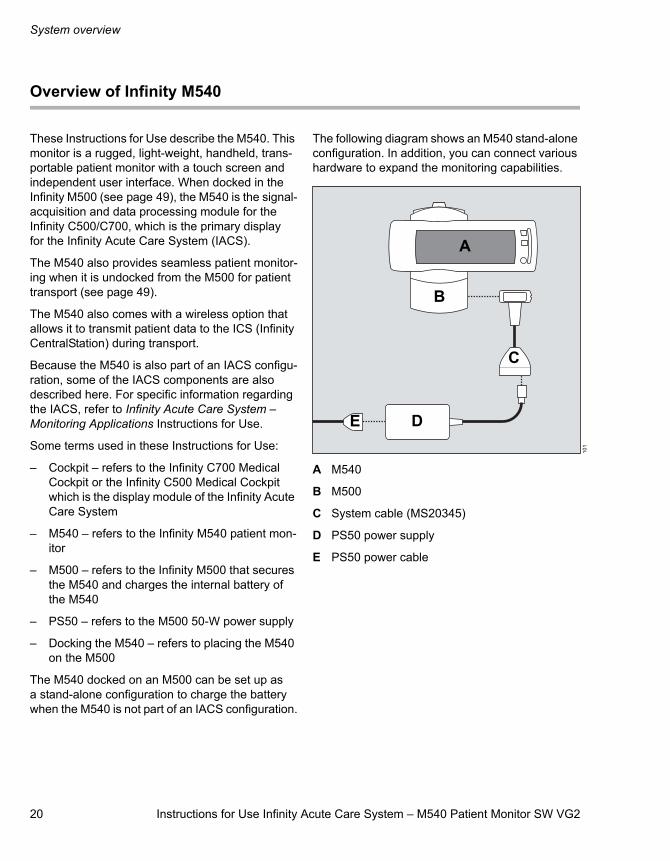
The following diagram shows an M540 stand-alone configuration. In addition, you can connect various hardware to expand the monitoring capabilities.
A M540
B M500
C System cable (MS20345)
D PS50 power supply
E PS50 power cable
101
A
B
E D
C
Instructions for Use Infinity Acute Care System – M540 Patient Monitor SW VG2 21
System overview
M540 front panel
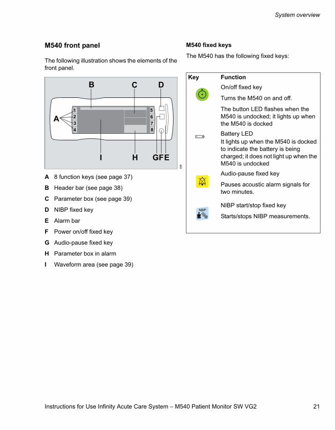
The following illustration shows the elements of the front panel.
A 8 function keys (see page 37)
B Header bar (see page 38)
C Parameter box (see page 39)
D NIBP fixed key
E Alarm bar
F Power on/off fixed key
G Audio-pause fixed key
H Parameter box in alarm
I Waveform area (see page 39)
M540 fixed keys
The M540 has the following fixed keys:
098
A1234
B C D
E
5678
FGHI
Key FunctionOn/off fixed key
Turns the M540 on and off.
The button LED flashes when the M540 is undocked; it lights up when the M540 is docked
Battery LEDIt lights up when the M540 is docked to indicate the battery is being charged; it does not light up when the M540 is undocked
Audio-pause fixed key
Pauses acoustic alarm signals for two minutes.
NIBP start/stop fixed key
Starts/stops NIBP measurements.
System overview
22 Instructions for Use Infinity Acute Care System – M540 Patient Monitor SW VG2
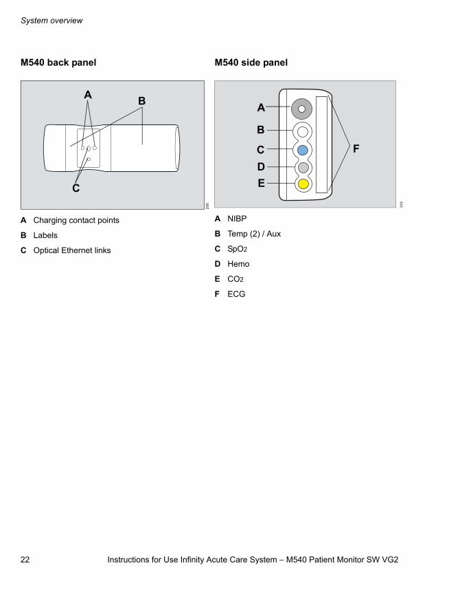
M540 back panel
A Charging contact points
B Labels
C Optical Ethernet links
M540 side panel
A NIBP
B Temp (2) / Aux
C SpO2
D Hemo
E CO2
F ECG
200
A B
C
310
A
B
CDE
F
Instructions for Use Infinity Acute Care System – M540 Patient Monitor SW VG2 23
System overview
Infinity M500 docking station
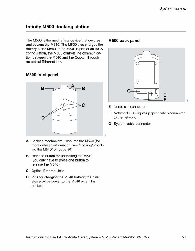
The M500 is the mechanical device that secures and powers the M540. The M500 also charges the battery of the M540. If the M540 is part of an IACS configuration, the M500 controls the communica-tion between the M540 and the Cockpit through an optical Ethernet link.
M500 front panel
A Locking mechanism – secures the M540 (for more detailed information, see “Locking/unlock-ing the M540” on page 50)
B Release button for undocking the M540 (you only have to press one button to release the M540)
C Optical Ethernet links
D Pins for charging the M540 battery; the pins also provide power to the M540 when it is docked
M500 back panel
E Nurse call connector
F Network LED – lights up green when connected to the network
G System cable connector
301
A BB
D
C
302
EF
G
System overview
24 Instructions for Use Infinity Acute Care System – M540 Patient Monitor SW VG2
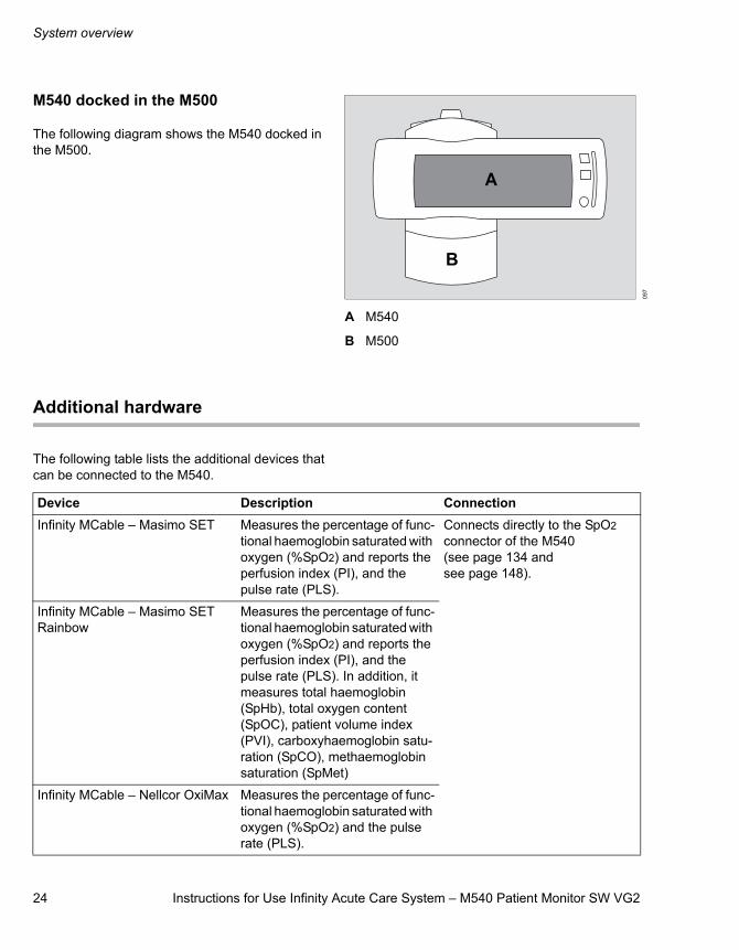
M540 docked in the M500
The following diagram shows the M540 docked in the M500.
A M540
B M500
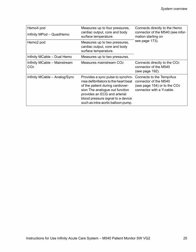
Additional hardware
The following table lists the additional devices that can be connected to the M540.
097
A
B
Device Description ConnectionInfinity MCable – Masimo SET Measures the percentage of func-
tional haemoglobin saturated with oxygen (%SpO2) and reports the perfusion index (PI), and the pulse rate (PLS).
Connects directly to the SpO2 connector of the M540 (see page 134 and see page 148).
Infinity MCable – Masimo SET Rainbow
Measures the percentage of func-tional haemoglobin saturated with oxygen (%SpO2) and reports the perfusion index (PI), and the pulse rate (PLS). In addition, it measures total haemoglobin (SpHb), total oxygen content (SpOC), patient volume index (PVI), carboxyhaemoglobin satu-ration (SpCO), methaemoglobin saturation (SpMet)
Infinity MCable – Nellcor OxiMax Measures the percentage of func-tional haemoglobin saturated with oxygen (%SpO2) and the pulse rate (PLS).
Instructions for Use Infinity Acute Care System – M540 Patient Monitor SW VG2 25
System overview
Hemo4 pod
Infinity MPod – QuadHemo
Measures up to four pressures, cardiac output, core and body surface temperature.
Connects directly to the Hemo connector of the M540 (see infor-mation starting on see page 173).Hemo2 pod Measures up to two pressures,
cardiac output, core and body surface temperature.
Infinity MCable – Dual Hemo Measures up to two pressures.
Infinity MCable – Mainstream CO2
Measures mainstream CO2. Connects directly to the CO2 connector of the M540 (see page 192).
Infinity MCable – Analog/Sync Provides a sync pulse to synchro-nise defibrillators to the heart beat of the patient during cardiover-sion The analogue out function provides an ECG and arterial blood pressure signal to a device such as intra-aortic balloon pump.
Connects to the Temp/Aux connector of the M540 (see page 154) or to the CO2 connector with a Y-cable.
System overview
26 Instructions for Use Infinity Acute Care System – M540 Patient Monitor SW VG2
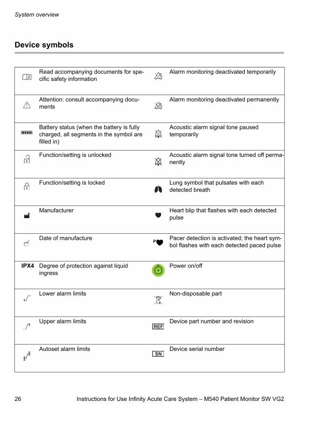
Device symbols
Read accompanying documents for spe-cific safety information
Alarm monitoring deactivated temporarily
Attention: consult accompanying docu-ments
Alarm monitoring deactivated permanently
Battery status (when the battery is fully charged, all segments in the symbol are filled in)
Acoustic alarm signal tone paused temporarily
Function/setting is unlocked Acoustic alarm signal tone turned off perma-nently
Function/setting is locked Lung symbol that pulsates with each detected breath
Manufacturer Heart blip that flashes with each detected pulse
Date of manufacture Pacer detection is activated; the heart sym-bol flashes with each detected paced pulse
IPX4 Degree of protection against liquid ingress
Power on/off
Lower alarm limits Non-disposable part
Upper alarm limits Device part number and revision
Autoset alarm limits Device serial number
Instructions for Use Infinity Acute Care System – M540 Patient Monitor SW VG2 27
System overview
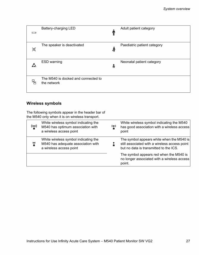
Wireless symbols
The following symbols appear in the header bar of the M540 only when it is on wireless transport.
Battery-charging LED Adult patient category
The speaker is deactivated Paediatric patient category
ESD warning Neonatal patient category
The M540 is docked and connected to the network
White wireless symbol indicating the M540 has optimum association with a wireless access point
White wireless symbol indicating the M540 has good association with a wireless access point
White wireless symbol indicating the M540 has adequate association with a wireless access point
The symbol appears white when the M540 is still associated with a wireless access point but no data is transmitted to the ICS.
The symbol appears red when the M540 is no longer associated with a wireless access point.
System overview
28 Instructions for Use Infinity Acute Care System – M540 Patient Monitor SW VG2
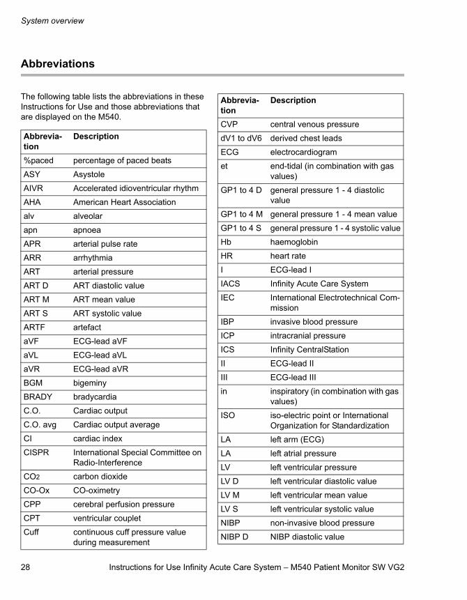
Abbreviations
The following table lists the abbreviations in these Instructions for Use and those abbreviations that are displayed on the M540.
Abbrevia-tion
Description
%paced percentage of paced beats
ASY Asystole
AIVR Accelerated idioventricular rhythm
AHA American Heart Association
alv alveolar
apn apnoea
APR arterial pulse rate
ARR arrhythmia
ART arterial pressure
ART D ART diastolic value
ART M ART mean value
ART S ART systolic value
ARTF artefact
aVF ECG-lead aVF
aVL ECG-lead aVL
aVR ECG-lead aVR
BGM bigeminy
BRADY bradycardia
C.O. Cardiac output
C.O. avg Cardiac output average
CI cardiac index
CISPR International Special Committee on Radio-Interference
CO2 carbon dioxide
CO-Ox CO-oximetry
CPP cerebral perfusion pressure
CPT ventricular couplet
Cuff continuous cuff pressure value during measurement
CVP central venous pressure
dV1 to dV6 derived chest leads
ECG electrocardiogram
et end-tidal (in combination with gas values)
GP1 to 4 D general pressure 1 - 4 diastolic value
GP1 to 4 M general pressure 1 - 4 mean value
GP1 to 4 S general pressure 1 - 4 systolic value
Hb haemoglobin
HR heart rate
I ECG-lead I
IACS Infinity Acute Care System
IEC International Electrotechnical Com-mission
IBP invasive blood pressure
ICP intracranial pressure
ICS Infinity CentralStation
II ECG-lead II
III ECG-lead III
in inspiratory (in combination with gas values)
ISO iso-electric point or International Organization for Standardization
LA left arm (ECG)
LA left atrial pressure
LV left ventricular pressure
LV D left ventricular diastolic value
LV M left ventricular mean value
LV S left ventricular systolic value
NIBP non-invasive blood pressure
NIBP D NIBP diastolic value
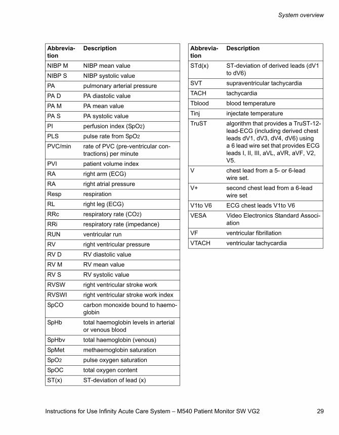
Abbrevia-tion
Description
Instructions for Use Infinity Acute Care System – M540 Patient Monitor SW VG2 29
System overview
NIBP M NIBP mean value
NIBP S NIBP systolic value
PA pulmonary arterial pressure
PA D PA diastolic value
PA M PA mean value
PA S PA systolic value
PI perfusion index (SpO2)
PLS pulse rate from SpO2
PVC/min rate of PVC (pre-ventricular con-tractions) per minute
PVI patient volume index
RA right arm (ECG)
RA right atrial pressure
Resp respiration
RL right leg (ECG)
RRc respiratory rate (CO2)
RRi respiratory rate (impedance)
RUN ventricular run
RV right ventricular pressure
RV D RV diastolic value
RV M RV mean value
RV S RV systolic value
RVSW right ventricular stroke work
RVSWI right ventricular stroke work index
SpCO carbon monoxide bound to haemo-globin
SpHb total haemoglobin levels in arterial or venous blood
SpHbv total haemoglobin (venous)
SpMet methaemoglobin saturation
SpO2 pulse oxygen saturation
SpOC total oxygen content
ST(x) ST-deviation of lead (x)
Abbrevia-tion
Description
STd(x) ST-deviation of derived leads (dV1 to dV6)
SVT supraventricular tachycardia
TACH tachycardia
Tblood blood temperature
Tinj injectate temperature
TruST algorithm that provides a TruST-12-lead-ECG (including derived chest leads dV1, dV3, dV4, dV6) using a 6 lead wire set that provides ECG leads I, II, III, aVL, aVR, aVF, V2, V5.
V chest lead from a 5- or 6-lead wire set.
V+ second chest lead from a 6-lead wire set
V1to V6 ECG chest leads V1to V6
VESA Video Electronics Standard Associ-ation
VF ventricular fibrillation
VTACH ventricular tachycardia
Abbrevia-tion
Description

30 Instructions for Use Infinity Acute Care System – M540 Patient Monitor SW VG2
This page is intentionally left blank
Instructions for Use Infinity Acute Care System – M540 Patient Monitor SW VG2 31
Operating concept
Operating concept
Overview . . . . . . . . . . . . . . . . . . . . . . . . . . . . . 32
M540 wireless mode. . . . . . . . . . . . . . . . . . . . 32
Communicating with the Infinity network . . . . . 33ICS (Infinity CentralStation) communication . . . 33Network communication interruptions . . . . . . . 34Remote control . . . . . . . . . . . . . . . . . . . . . . . . . 35Recordings for M540 on wireless transport . . . . . . . . . . . . . . . . . . . . . . . . . . . . . . 36
Function keys . . . . . . . . . . . . . . . . . . . . . . . . . 37
Default function key assignments. . . . . . . . . . . 37Alternate function key assignments . . . . . . . . . 38
Monitoring Area . . . . . . . . . . . . . . . . . . . . . . . 38
Header bar . . . . . . . . . . . . . . . . . . . . . . . . . . . . 38Parameter boxes . . . . . . . . . . . . . . . . . . . . . . . 39Waveforms . . . . . . . . . . . . . . . . . . . . . . . . . . . . 39Dialogue windows. . . . . . . . . . . . . . . . . . . . . . . 40
Adjusting the display . . . . . . . . . . . . . . . . . . . 41
Calibrating the touchscreen . . . . . . . . . . . . . . . 41
Battery power . . . . . . . . . . . . . . . . . . . . . . . . . 42
Battery-charging times . . . . . . . . . . . . . . . . . . . 42Battery-operating times . . . . . . . . . . . . . . . . . . 42Low-battery conditions . . . . . . . . . . . . . . . . . . . 42
Power-saving mode . . . . . . . . . . . . . . . . . . . . 43
Views . . . . . . . . . . . . . . . . . . . . . . . . . . . . . . . . 43
Selecting a view . . . . . . . . . . . . . . . . . . . . . . . . 43
Profiles . . . . . . . . . . . . . . . . . . . . . . . . . . . . . . 44
Standby Mode . . . . . . . . . . . . . . . . . . . . . . . . . 45
Privacy Mode . . . . . . . . . . . . . . . . . . . . . . . . . 46
32 Instructions for Use Infinity Acute Care System – M540 Patient Monitor SW VG2
Operating concept
Overview
The M540 is a portable patient monitor that accom-panies the patient from the bedside to anywhere in the hospital. This small, lightweight, splash-resist-ant monitor makes transportation less disruptive to the patient, reducing the risks of undetected events, and improving clinician efficiency.
The M540 disconnects (“undocks”) from and recon-nects (“docks”) to the M500 docking station which establishes the data exchange within the Infinity Acute Care System (IACS). When docked, the M540 remains at the bedside and communicates all patient data to the Infinity Medical Cockpit, the main display component of the IACS. For detailed infor-mation on how the M540 functions in an IACS con-figuration, refer to the Instructions for Use entitled ’Infinity Acute Care System – Monitoring Applica-tions’.
When undocked, the M540 continues to monitor the patient. Once redocked, the M540 automati-cally transmits the patient data that was collected during patient transport to the Cockpit.
The M540 also comes with a wireless option that allows it to transmit patient data over the Infinity network to the ICS (Infinity CentralStation) during transport.
The M540 can also be docked in the M500 in a stand-alone configuration for charging the battery only. For more details, see “Connecting the system cable in an M540 stand-alone configuration” on page 51.
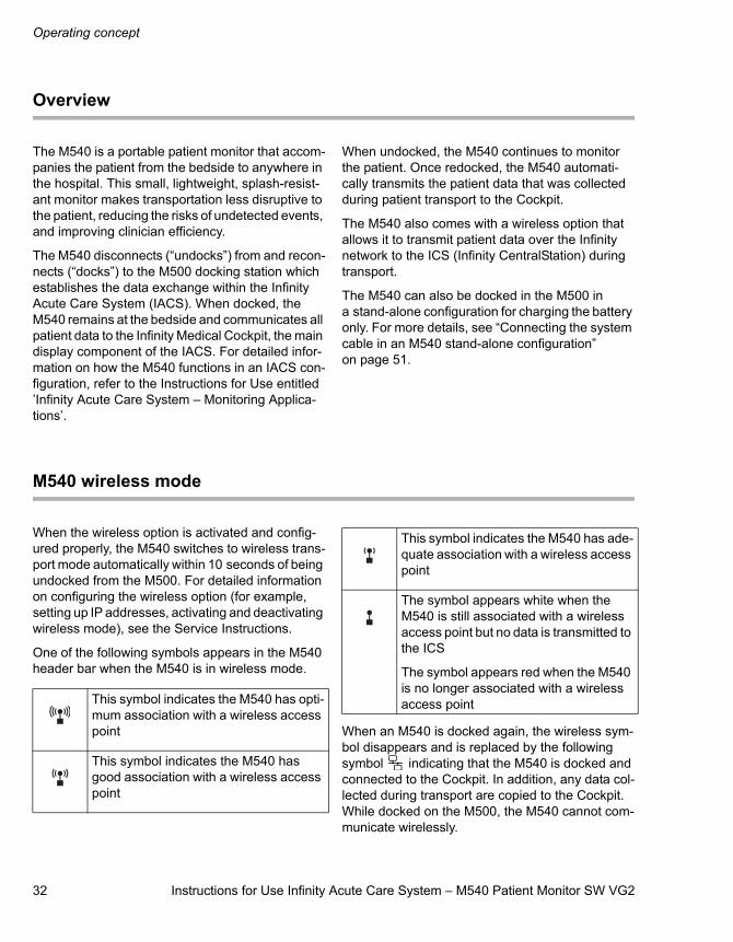
M540 wireless mode
When the wireless option is activated and config-ured properly, the M540 switches to wireless trans-port mode automatically within 10 seconds of being undocked from the M500. For detailed information on configuring the wireless option (for example, setting up IP addresses, activating and deactivating wireless mode), see the Service Instructions.
One of the following symbols appears in the M540 header bar when the M540 is in wireless mode.
When an M540 is docked again, the wireless sym-bol disappears and is replaced by the following symbol indicating that the M540 is docked and connected to the Cockpit. In addition, any data col-lected during transport are copied to the Cockpit. While docked on the M500, the M540 cannot com-municate wirelessly.
This symbol indicates the M540 has opti-mum association with a wireless access point
This symbol indicates the M540 has good association with a wireless access point
This symbol indicates the M540 has ade-quate association with a wireless access point
The symbol appears white when the M540 is still associated with a wireless access point but no data is transmitted to the ICS
The symbol appears red when the M540 is no longer associated with a wireless access point
Instructions for Use Infinity Acute Care System – M540 Patient Monitor SW VG2 33
Operating concept
Communicating with the Infinity network
An M540 with the wireless option activated is Infinity OneNet compatible.
The following data is made available to the Infinity network while the M540 on wireless transport:
– All real-time parameter and waveform informa-tion.
– All alarm information – in case of multiple alarms, the alarm condition with the highest grade alarm is sent to the network.
– M540 trend data (up to 72 hours of trend data for each parameter). The trend data are availa-ble on the network while the M540 is on wire-less transport. Trend data is also available for review at the ICS.
– ST complexes – can be viewed from the ICS and the Symphony application.
– Alarm messages of high, medium, and low pri-ority from devices on the network who are within the configured monitoring unit and the selected alarm group.
– The following banners: All alarms off, All alarms paused (with count-down
timer), HR Limits Off, the patient category identifier (adult, paediatric, neonate), Pacer off, Pacer fusion.
– Alarm limits off symbol .
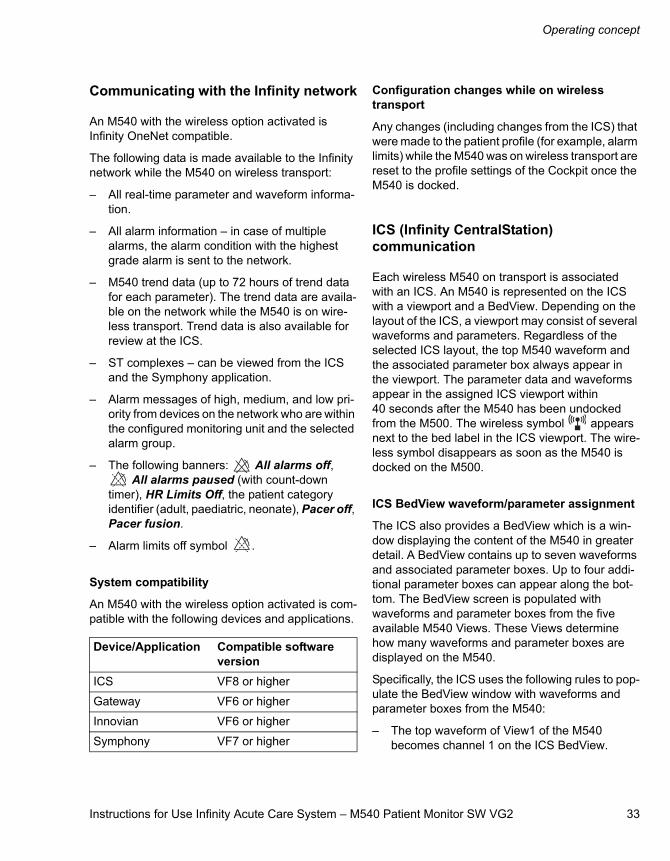
System compatibility
An M540 with the wireless option activated is com-patible with the following devices and applications.
Configuration changes while on wireless transport
Any changes (including changes from the ICS) that were made to the patient profile (for example, alarm limits) while the M540 was on wireless transport are reset to the profile settings of the Cockpit once the M540 is docked.
ICS (Infinity CentralStation) communication
Each wireless M540 on transport is associated with an ICS. An M540 is represented on the ICS with a viewport and a BedView. Depending on the layout of the ICS, a viewport may consist of several waveforms and parameters. Regardless of the selected ICS layout, the top M540 waveform and the associated parameter box always appear in the viewport. The parameter data and waveforms appear in the assigned ICS viewport within 40 seconds after the M540 has been undocked from the M500. The wireless symbol appears next to the bed label in the ICS viewport. The wire-less symbol disappears as soon as the M540 is docked on the M500.
ICS BedView waveform/parameter assignment
The ICS also provides a BedView which is a win-dow displaying the content of the M540 in greater detail. A BedView contains up to seven waveforms and associated parameter boxes. Up to four addi-tional parameter boxes can appear along the bot-tom. The BedView screen is populated with waveforms and parameter boxes from the five available M540 Views. These Views determine how many waveforms and parameter boxes are displayed on the M540.
Specifically, the ICS uses the following rules to pop-ulate the BedView window with waveforms and parameter boxes from the M540:
– The top waveform of View1 of the M540 becomes channel 1 on the ICS BedView.
Device/Application Compatible software version
ICS VF8 or higher
Gateway VF6 or higher
Innovian VF6 or higher
Symphony VF7 or higher
34 Instructions for Use Infinity Acute Care System – M540 Patient Monitor SW VG2
Operating concept
– No waveform and no parameter box are repeated more than once. Therefore, the next unique waveform becomes channel 2 on the ICS BedView. This waveform could originate from the same View or, if no unique waveform is available, from the next View. For example, if the ECGII waveform occupies the top channel in View 1 and the ECGII waveform is repeated in View 2, the View 2 waveform is skipped because it has the same label and is therefore not unique.
– The remaining available slots on BedView con-tinue to be populated by other unique wave-forms on the M540 in the same way.
– Once the waveforms are assigned to the Bed-View, the associated parameter boxes are assigned next to the respective waveforms.
– Lastly, the four available parameter slots located at the bottom of the BedView are filled with unique parameter boxes (no waveforms) starting with the right-most parameter box which appears along the bottom of the M540.
Wireless on transport and the ICS
The patient data of a wireless M540 continue to dis-play at the ICS even after it is undocked. If you dock a different M540 on the now vacant M500, the wire-less M540 continues to be displayed in the same ICS viewport. In addition, the ICS alarm surveil-lance function now monitors the new patient on the Cockpit. The data of the new M540 are now part of an IACS configuration. The data is made available to the Infinity network and the patient can be man-ually assigned to an empty viewport at an ICS where it is displayed without the wireless symbol next to the bed label.
While the M540 is on wireless transport, any events that occur are sent to the ICS event disclosure data base. The M540 also supports the full disclosure application on the ICS which stores waveforms continuously.
The ICS also displays trend data for an M540 on wireless transport. The trend graph and trend table screens on the ICS only display parameters that have trend data available. Parameters with no trend data do not appear at the ICS.
For detailed information about the screens and functions on the ICS, refer to the Instructions for Use entitled ’Infinity CentralStation’.
Network communication interruptions
If the communication between a wireless M540 and the ICS is interrupted because the M540 is outside the range of the wireless access points, the follow-ing happens:
– The alarm tone volume is automatically set to 100 % volume at the M540 and you can no longer deactivate the alarm tone volume. Once the communication between the M540 and the ICS is restored, the alarm volume setting returns to its previous setting.
– The wireless symbol appears red in the M540 header bar.
– The message Offline appears at the ICS in the viewport of the patient.
– The M540 sounds an error tone and displays the message Network alarm error.
When the M540 is connected to the network, but the communication with the ICS is interrupted, the message Not monitored by central appears in the viewport of the ICS and in the M540 header bar.
NOTEFor detailed information about the configuration and operation of wireless components in the Infin-ity network, contact your Dräger representative.
Refer to the Instructions for Use of the ICS for more detailed information on the ICS.
Instructions for Use Infinity Acute Care System – M540 Patient Monitor SW VG2 35
Operating concept
Remote control
You can view the data of an M540 on wireless transport remotely from one of the following devices:
– Other IACS Cockpits
– ICS
– Bedside monitors – Delta/Delta XL/Kappa, Vista XL, and Gamma XXL
When an M540 on wireless transport is controlled remotely by multiple devices simultaneously, the last update takes effect.
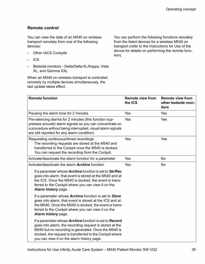
You can perform the following functions remotely from the listed devices for a wireless M540 on transport (refer to the Instructions for Use of the device for details on performing the remote func-tion).
Remote function Remote view from the ICS
Remote view from other bedside mon-itors
Pausing the alarm tone for 2 minutes Yes Yes
Pre-silencing alarms for 2 minutes (this function sup-presses acoustic alarm signals so you can concentrate on a procedure without being interrupted; visual alarm signals are still reported for any alarm condition)
Yes Yes
Requesting continuous/timed recordings The recording requests are stored at the M540 and transferred to the Cockpit once the M540 is docked. You can request the recording from the Cockpit.
Yes Yes
Activate/deactivate the alarm function for a parameter Yes No
Activate/deactivate the alarm Archive function.
If a parameter whose Archive function is set to Str/Rec goes into alarm, that event is stored at the M540 and at the ICS. Once the M540 is docked, the event is trans-ferred to the Cockpit where you can view it on the Alarm history page.
If a parameter whose Archive function is set to Store goes into alarm, that event is stored at the ICS and at the M540. Once the M540 is docked, the event is trans-ferred to the Cockpit where you can view it on the Alarm history page.
If a parameter whose Archive function is set to Record goes into alarm, the recording request is stored at the M540 but no recording is generated. Once the M540 is docked, the request is transferred to the Cockpit where you can view it on the alarm history page.
Yes No
Operating concept
36 Instructions for Use Infinity Acute Care System – M540 Patient Monitor SW VG2
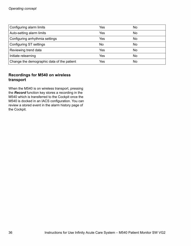
Recordings for M540 on wireless transport
When the M540 is on wireless transport, pressing the Record function key stores a recording in the M540 which is transferred to the Cockpit once the M540 is docked in an IACS configuration. You can review a stored event in the alarm history page of the Cockpit.
Configuring alarm limits Yes No
Auto-setting alarm limits Yes No
Configuring arrhythmia settings Yes No
Configuring ST settings No No
Reviewing trend data Yes No
Initiate relearning Yes No
Change the demographic data of the patient Yes No
Instructions for Use Infinity Acute Care System – M540 Patient Monitor SW VG2 37
Operating concept
Function keys
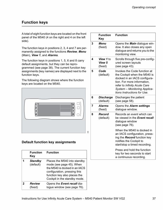
A total of eight function keys are located on the front panel of the M540 (4 on the right and 4 on the left side).
The function keys in positions 2, 3, 4 and 7 are per-manently assigned to the functions Review, Menu (Main), View 1, and Alarms.
The function keys in positions 1, 5, 6 and 8 carry default assignments, but they can be repro-grammed (see page 38). The current function key assignments (key names) are displayed next to the function keys.
The following diagram shows where the function keys are located on the M540.
Default function key assignments
098
Function Key
Function
1 Standby(default)
Places the M540 into standby mode (see page 45). When the M540 is docked in an IACS configuration, pressing this function key also places the Cockpit in the standby mode.
2 Review (fixed)
Opens the Event recall dia-logue window (see page 76).
1234
5678
3 Menu (fixed)
Opens the Main dialogue win-dow. It also closes any open dialogue and returns you to the monitoring view.
4 View 1 to View 5(fixed)
Scrolls through five pre-config-ured screen layouts (see page 43).
5 Code(default)
Invokes the Code function at the Cockpit when the M540 is docked in an IACS configura-tion. For more information, refer to Infinity Acute Care System – Monitoring Applica-tions Instructions for Use.
6 Discharge(default)
Discharges the patient (see page 58).
7 Alarms (fixed)
Opens the Alarm settings dialogue window.
8 Record(default)
Records an event which can be viewed in the Event recall dialogue window (see page 76).
When the M540 is docked in an IACS configuration, press-ing the Record function key notifies the Cockpit to start/stop a timed recording.
Press and hold the function key for two seconds to start a continuous recording.
Function Key
Function
Operating concept
38 Instructions for Use Infinity Acute Care System – M540 Patient Monitor SW VG2
Alternate function key assignments To program a function key
1 Touch the Menu function key.
2 Touch the Screen setup tab >Function keys tab.
3 Touch one of the programmable setup keys (Setup key 1, Setup key 2, Setup key 3, or Setup key 4) and then touch the desired function.
4 Touch X to close the dialogue window.
Monitoring area
The monitoring area of the M540 screen contains a header bar, waveforms, and parameter boxes that report the current vital signs of the patient. The appearance of the monitoring area depends on the selected view, which controls the layout and con-tent of the screen (see page 43).
Header bar
The blue header bar appears along the top of the screen. It is always visible and displays the follow-ing information:
– Remaining battery charge symbol (when the battery is fully charged, all segments in the symbol are filled in; the segments appear empty as the battery charge is depleting)
– Network connection symbol when the M540 is connected to the network
– Patient category (adult, paediatric, neonatal)
– Bed label
– Patient name and alarm message fields
– Current time
– Wireless symbol appears when the M540 is on wireless transport
– The alarm banner field is reserved for one of the following indicators:
– and the message Audio paused plus a count-down timer when the Audio paused fixed key is pressed
– and the message Audio paused when acoustic alarm signals are deactivated
– the message All alarms paused, and a count-down timer when alarm monitoring is deactivated temporarily
– and the messageAll alarms off when alarm monitoring is deactivated perma-nently
Key FunctionPrivacy Places the M540 into privacy
mode (see page 46). This mode is only available when the patient is admitted at the ICS.
Mark Stores an event in the Event recall dialogue window.
Patient Opens the Patient setup dia-logue window (see page 57).
Instructions for Use Infinity Acute Care System – M540 Patient Monitor SW VG2 39
Operating concept
Parameter boxes
Each parameter box contains real-time values of a parameter and a combination of the following information:
– Parameter labels (including dynamic pressure labels)
– Crossed-triangle symbols when alarms are turned off
– Units of measure
– ECG heart blip (and pacer blip for paced pulses), RRi blip, and SpO2 blip
– Countdown timers for NIBP
– Special source labels (for example, PLS for HR signal source for pulse oximetry)
When a parameter is in alarm, the parameter box flashes in the colour of the alarm grade (see page 65) and a corresponding alarm message appears in the header bar. Each parameter chapter describes the parameter boxes for the correspond-ing parameter in greater detail.
When a dialogue window is open, the parameter boxes appear along the right side of the screen. This display behaviour prevents the vital signs from being obscured while you are performing setup tasks.
The X in the upper-right corner of any window closes the open dialogue window and returns you to the main screen.
Waveforms
The main screen of the M540 displays up to three waveforms simultaneously. Waveforms are drawn from left to right and can contain the following infor-mation:
– Signal scales
– Units of measure
– Parameter labels
– Pacer spikes
– QRS synchronisation markers
– Respiration waveform markers to indicate breath detection
To configure the waveforms
1 Touch the waveform area to open the wave-form-channel dialogue window.
2 Touch the Channel 1, Channel 2, or Channel 3 tab to configure the desired channel.
3 Touch Waveform and select the desired parameter in the Waveform dialogue window.
4 Touch Size and then select the desired ampli-tude.
5 Touch X to close the dialogue window.
NOTEIf the acquired signal does not fit in the waveform channel, the top of the waveform may appear clipped.
Operating concept
40 Instructions for Use Infinity Acute Care System – M540 Patient Monitor SW VG2
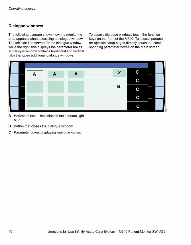
Dialogue windows
The following diagram shows how the monitoring area appears when accessing a dialogue window. The left side is reserved for the dialogue window while the right side displays the parameter boxes. A dialogue window contains horizontal and vertical tabs that open additional dialogue windows.
To access dialogue windows touch the function keys on the front of the M540. To access parame-ter-specific setup pages directly, touch the corre-sponding parameter boxes on the main screen.
A Horizontal tabs – the selected tab appears light blue
B Button that closes the dialogue window
C Parameter boxes displaying real-time values
068
A A A
B
C
C
C
C
C
Instructions for Use Infinity Acute Care System – M540 Patient Monitor SW VG2 41
Operating concept
Adjusting the display
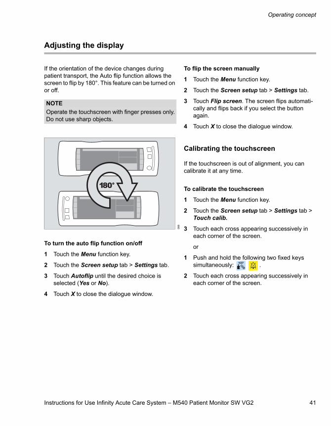
If the orientation of the device changes during patient transport, the Auto flip function allows the screen to flip by 180°. This feature can be turned on or off.
To turn the auto flip function on/off
1 Touch the Menu function key.
2 Touch the Screen setup tab > Settings tab.
3 Touch Autoflip until the desired choice is selected (Yes or No).
4 Touch X to close the dialogue window.
To flip the screen manually
1 Touch the Menu function key.
2 Touch the Screen setup tab > Settings tab.
3 Touch Flip screen. The screen flips automati-cally and flips back if you select the button again.
4 Touch X to close the dialogue window.
Calibrating the touchscreen
If the touchscreen is out of alignment, you can calibrate it at any time.
To calibrate the touchscreen
1 Touch the Menu function key.
2 Touch the Screen setup tab > Settings tab > Touch calib.
3 Touch each cross appearing successively in each corner of the screen.
or
1 Push and hold the following two fixed keys simultaneously: .
2 Touch each cross appearing successively in each corner of the screen.
NOTEOperate the touchscreen with finger presses only. Do not use sharp objects.
099
Operating concept
42 Instructions for Use Infinity Acute Care System – M540 Patient Monitor SW VG2
Battery power
The M540 automatically switches to battery power when it is undocked or if there is a loss of power to the M500.
When the M540 is docked, the M500 continuously charges the internal battery. The battery charge symbol on the M540 front panel lights up green when the battery is being charged.
To continue monitoring during power loss or during patient transport, the battery of the M540 should be fully charged at all times. The battery charge indica-tor in the header bar indicates the remaining battery charge.
Battery-charging times
The following table indicates the required time to charge a depleted battery:
Battery-operating times
The following table lists the operating times of a fully charged internal battery powers an M540 that is monitoring ECG, SpO2, and Temp continu-ously, and NIBP in 15-minute interval mode.
Low-battery conditions
When the remaining battery charge drops to 10 %, Low battery appears in the message area of the header bar. The M540 also sounds an audible alarm signal of low priority. The battery charge indi-cator in the header bar appears red.
When the remaining battery charge drops to 5 %, the message Recharge battery appears in the message area of the header bar. The M540 sounds an audible alarm signal of medium priority. The battery charge indicator in the header bar appears red.
When the battery of an M540 is depleted, it can still monitor a patient as soon as you dock it on an M500 that is receiving power.
Capacity Approximate charging time70 % 4 hours
100 % 6.5 hours
Mode Approximate operating time
Regular bedside mode 3 hours
Power save 4 hours
Instructions for Use Infinity Acute Care System – M540 Patient Monitor SW VG2 43
Operating concept
Power-saving mode
When the M540 is not docked, the power-save mode conserves battery power while continuing to monitor a patient.
When power save mode is activated, the display of the M540 is turned off. The display of the M540 automatically turns back on when:
– You dock the M540 on the M500
– You touch the screen or any fixed key
– The M540 detects an alarm condition of medium- or high-priority
To activate or deactivate interval mode
1 Touch the Menu function key.
2 Touch the Screen setup tab > Settings tab.
3 Touch Power save until the desired choice is selected (Off, 1, 2, 3, 4, 5 min).
4 Touch X to close the dialogue window.
Views
Each M540 supports five pre-configured views, which control the content and the appearance of the screen. You can switch to a different view to adjust the screen layout to the needs of the current monitoring session.
Selecting a view
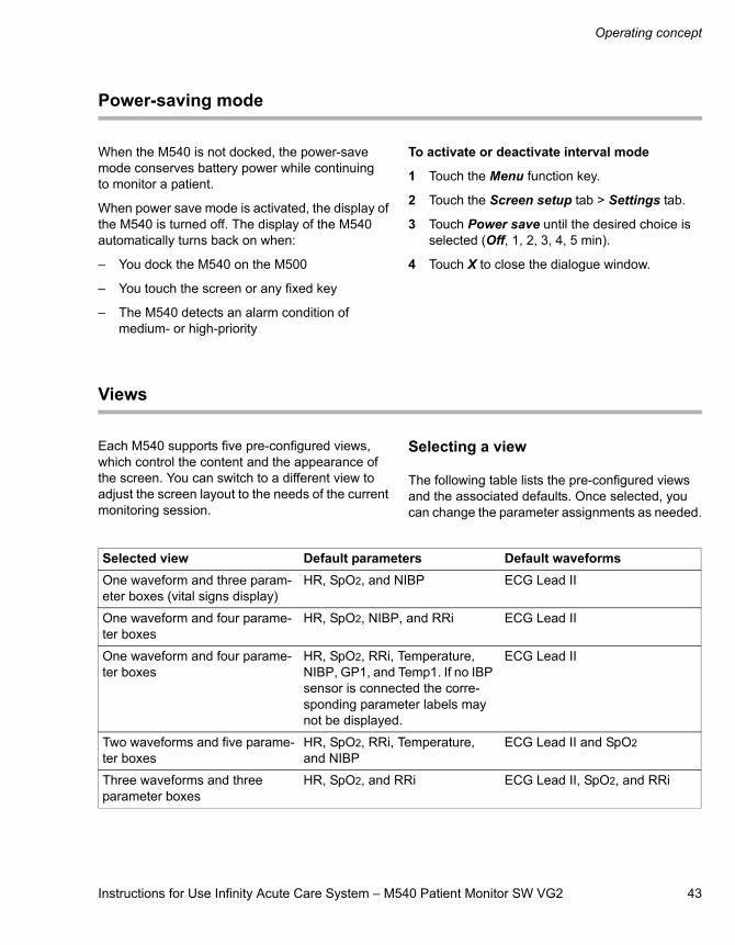
The following table lists the pre-configured views and the associated defaults. Once selected, you can change the parameter assignments as needed.
Selected view Default parameters Default waveformsOne waveform and three param-eter boxes (vital signs display)
HR, SpO2, and NIBP ECG Lead II
One waveform and four parame-ter boxes
HR, SpO2, NIBP, and RRi ECG Lead II
One waveform and four parame-ter boxes
HR, SpO2, RRi, Temperature, NIBP, GP1, and Temp1. If no IBP sensor is connected the corre-sponding parameter labels may not be displayed.
ECG Lead II
Two waveforms and five parame-ter boxes
HR, SpO2, RRi, Temperature, and NIBP
ECG Lead II and SpO2
Three waveforms and three parameter boxes
HR, SpO2, and RRi ECG Lead II, SpO2, and RRi
Operating concept
44 Instructions for Use Infinity Acute Care System – M540 Patient Monitor SW VG2
To select a view
Touch the currently selected function key sev-eral times (for example, View 5) to scroll through the available view labels.
To deactivate a view
You can deactivate up to four views.
1 Touch the Menu function key.
2 Touch the Screen setup tab > Screen views tab.
3 Touch View 1, View 2, View 3, View 4, or View 5, > Off.
4 Touch X to close the dialogue window.
To assign a pre-configured view to a view key
1 Touch the Menu function key.
2 Touch the Screen setup tab > Screen views tab.
3 Touch View 1, View 2, View 3, View 4, or View 5 and then touch the desired configura-tion.
4 Touch X to close the dialogue window.
Profiles
A profile consists of user-defined settings which are customised for each patient category (adult, paedi-atric, neonate). A profile eliminates time-consuming setup tasks that would, otherwise, have to be repeated for each monitoring session.
A profile includes the following settings:
– Alarm limits and alarm archive status for each parameter depending on the selected patient category
– Parameter colour, regardless of the selected patient category
– Settings unique to each parameter that can be set up in the parameter-setup pages for each patient category
Whenever a patient is admitted, a previously defined default profile is automatically assigned for that monitoring session.
When the M540 is docked in an IACS configuration, the profile of the connected Cockpit overwrites any profile settings of the M540. The M540 provides the following profile settings to the Cockpit:
– ECG cable type
– HR source
– SpO2 alarm delay
– Atmospheric pressure value
– IBP labels
– Patient category
After a patient discharge, all patient data is deleted and the default profile is restored.
Instructions for Use Infinity Acute Care System – M540 Patient Monitor SW VG2 45
Operating concept
Standby Mode
You can temporarily interrupt patient monitoring by placing the M540 in standby mode.
The standby mode has the following effect:
– All patient data is removed from the screen
– All monitoring (including acoustic and visual alarm signals) is suppressed
– Active alarms are considered acknowledged by the user
– All recordings are cancelled
– The M540 displays Standby, Touch screen to resume monitoring
When the M540 is docked in an IACS configura-tion, selecting the standby mode automatically activates the standby mode on the Cockpit and vice versa. For more information, refer to Infinity Acute Care System – Monitoring Applications Instructions for Use.
To place the M540 in the standby mode
Press the Standby function key (if available for display, see page 37).
or
1 Press the Menu function key.
2 Touch the Main tab, if not already selected.
3 Touch Standby.
The message Standby, appears in the centre of the M540 screen.
To take the M540 out of the standby mode
Touch the screen to resume monitoring.
Operating concept
46 Instructions for Use Infinity Acute Care System – M540 Patient Monitor SW VG2
Privacy mode
Privacy mode is available when the M540 is docked in an IACS configuration or if it is on wireless trans-port provided the patient is admitted at the Infinity CentralStation (ICS). In privacy mode, patient mon-itoring continues but the patient data is removed from the screen and appear only at the ICS Bed-View.
When the M540 is part of an IACS configuration, Selecting privacy mode on the M540 automatically activates privacy mode on the Cockpit and vice versa. Likewise, taking a patient out of the privacy mode on the M540 does the same on the Cockpit. The privacy mode is cancelled when the connec-tion to the Infinity network is disrupted.
Activating the privacy mode has the following effect:
– All patient data is removed from the display of the M540, but continue to display at the ICS in BedView mode
– The alarm bar is deactivated
– Acoustic alarm signals are only provided at the ICS
– The M540 displays Privacy, Touch screen to resume monitoring
To place the M540 in the privacy mode
Press the Privacy function key (if available for display, see page 37).
or
1 Press the Menu function key.
2 Touch the Main tab, if not already selected.
3 Touch Privacy mode.
The message Privacy, Touch screen to resume monitoring appears in the centre of the M540 screen.
To take the M540 out of the privacy mode
Touch the screen to resume monitoring.
Instructions for Use Infinity Acute Care System – M540 Patient Monitor SW VG2 47
Assembly
Assembly
Overview . . . . . . . . . . . . . . . . . . . . . . . . . . . . . 48
Commercially available M500 mounting solutions . . . . . . . . . . . . . . . . . . . . . . 48
Docking/undocking the M540 . . . . . . . . . . . . 49
Front view. . . . . . . . . . . . . . . . . . . . . . . . . . . . . 49Side view . . . . . . . . . . . . . . . . . . . . . . . . . . . . . 49
Locking/unlocking the M540 . . . . . . . . . . . . . 50
Connecting the system cablesin an IACS configuration . . . . . . . . . . . . . . . . 51
Connecting the system cable in an M540 stand-alone configuration . . . . . 51
Mounting the Infinity MCable – Masimo SET and Masimo Rainbow SET/Nellcor OxiMax MCable . . . . . . . . . . . . . . . . . . . . . . . . 52
Assembly
48 Instructions for Use Infinity Acute Care System – M540 Patient Monitor SW VG2
Overview
This section describes the following basic assem-bly tasks:
– Docking/undocking the M540 from the M500
– Locking/unlocking the M540 into the M500
– Connecting/disconnecting the system cables
Commercially available M500 mounting solutions
Various mounting solutions are available. It is the responsibility of the hospital to install, test, and ensure the proper and safe operation of any mount-ing solution. Contact your Dräger representative for specific approved mounting solutions.
CAUTIONCheck the weight ratings of the commercially available mounts to avoid injuring the patient or damaging the device.
CAUTIONAvoid mounting solutions that could impede air flow since the M500 requires adequate air flow to dissipate heat.
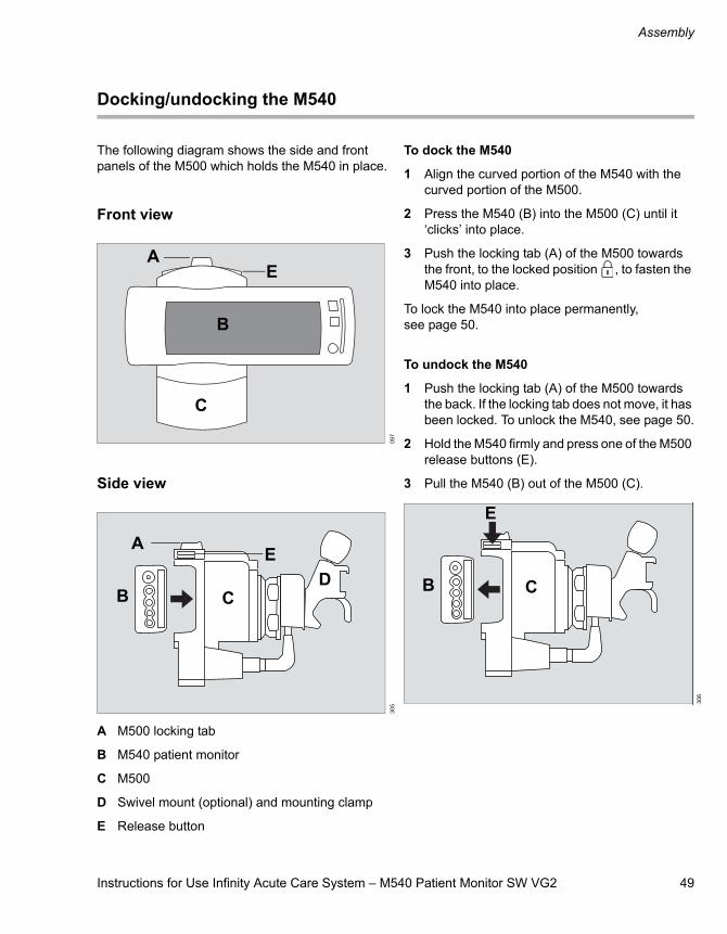
Instructions for Use Infinity Acute Care System – M540 Patient Monitor SW VG2 49
Assembly
Docking/undocking the M540
The following diagram shows the side and front panels of the M500 which holds the M540 in place.
Front view
Side view
A M500 locking tab
B M540 patient monitor
C M500
D Swivel mount (optional) and mounting clamp
E Release button
To dock the M540
1 Align the curved portion of the M540 with the curved portion of the M500.
2 Press the M540 (B) into the M500 (C) until it ‘clicks’ into place.
3 Push the locking tab (A) of the M500 towards the front, to the locked position , to fasten the M540 into place.
To lock the M540 into place permanently, see page 50.
To undock the M540
1 Push the locking tab (A) of the M500 towards the back. If the locking tab does not move, it has been locked. To unlock the M540, see page 50.
2 Hold the M540 firmly and press one of the M500 release buttons (E).
3 Pull the M540 (B) out of the M500 (C).
097
305
B
C
AE
B
A
CD
E
306
B C
E
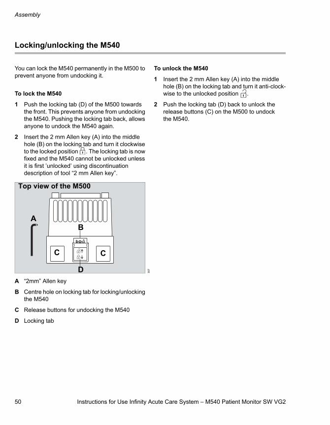
Assembly
50 Instructions for Use Infinity Acute Care System – M540 Patient Monitor SW VG2
Locking/unlocking the M540
You can lock the M540 permanently in the M500 to prevent anyone from undocking it.
To lock the M540
1 Push the locking tab (D) of the M500 towards the front. This prevents anyone from undocking the M540. Pushing the locking tab back, allows anyone to undock the M540 again.
2 Insert the 2 mm Allen key (A) into the middle hole (B) on the locking tab and turn it clockwise to the locked position . The locking tab is now fixed and the M540 cannot be unlocked unless it is first ’unlocked’ using discontinuation description of tool “2 mm Allen key”.
A “2mm” Allen key
B Centre hole on locking tab for locking/unlocking the M540
C Release buttons for undocking the M540
D Locking tab
To unlock the M540
1 Insert the 2 mm Allen key (A) into the middle hole (B) on the locking tab and turn it anti-clock-wise to the unlocked position .
2 Push the locking tab (D) back to unlock the release buttons (C) on the M500 to undock the M540.
307
A
CC
D
B
Top view of the M500
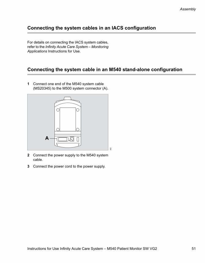
Instructions for Use Infinity Acute Care System – M540 Patient Monitor SW VG2 51
Assembly
Connecting the system cables in an IACS configuration
For details on connecting the IACS system cables, refer to the Infinity Acute Care System – Monitoring Applications Instructions for Use.
Connecting the system cable in an M540 stand-alone configuration
1 Connect one end of the M540 system cable (MS20345) to the M500 system connector (A).
2 Connect the power supply to the M540 system cable.
3 Connect the power cord to the power supply.
302
A
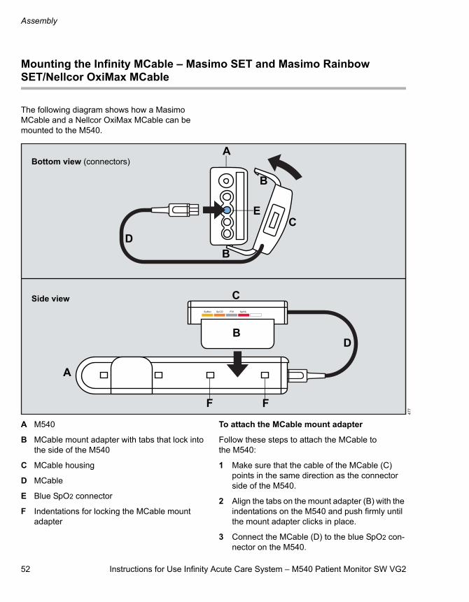
Assembly
52 Instructions for Use Infinity Acute Care System – M540 Patient Monitor SW VG2
Mounting the Infinity MCable – Masimo SET and Masimo Rainbow SET/Nellcor OxiMax MCable
The following diagram shows how a Masimo MCable and a Nellcor OxiMax MCable can be mounted to the M540.
A M540
B MCable mount adapter with tabs that lock into the side of the M540
C MCable housing
D MCable
E Blue SpO2 connector
F Indentations for locking the MCable mount adapter
To attach the MCable mount adapter
Follow these steps to attach the MCable to the M540:
1 Make sure that the cable of the MCable (C) points in the same direction as the connector side of the M540.
2 Align the tabs on the mount adapter (B) with the indentations on the M540 and push firmly until the mount adapter clicks in place.
3 Connect the MCable (D) to the blue SpO2 con-nector on the M540.
477
A
DB
C
B
B
C
A
D
E
Bottom view (connectors)
Side view
F F

Instructions for Use Infinity Acute Care System – M540 Patient Monitor SW VG2 53
Assembly
To remove the MCable mount adapter
1 Insert a flat head screwdriver (or equivalent tool) between the indentations for locking the MCable mount adapter (F).
2 Gently lift to unhinge the adapter.

54 Instructions for Use Infinity Acute Care System – M540 Patient Monitor SW VG2
This page is intentionally left blank
Instructions for Use Infinity Acute Care System – M540 Patient Monitor SW VG2 55
Getting started
Getting started
Overview of monitoring a patient . . . . . . . . . 56
Turning the M540 on/off . . . . . . . . . . . . . . . . . 56
Admitting a Patient. . . . . . . . . . . . . . . . . . . . . 57
Discharging a Patient. . . . . . . . . . . . . . . . . . . 58
Patient categories. . . . . . . . . . . . . . . . . . . . . . 58
Selecting a new patient category . . . . . . . . . . . 59
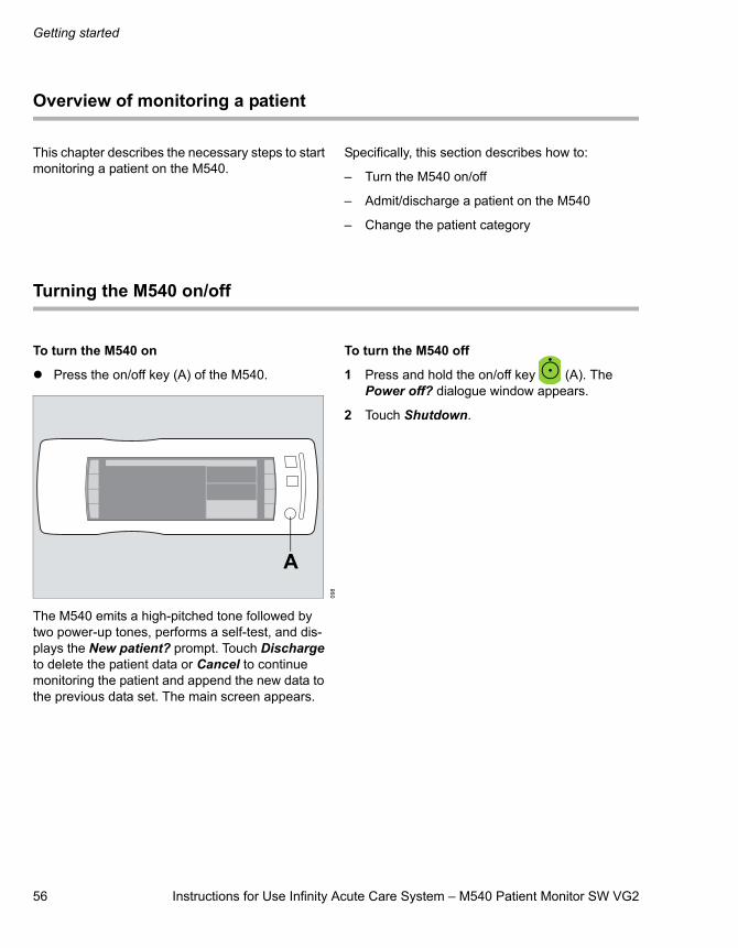
56 Instructions for Use Infinity Acute Care System – M540 Patient Monitor SW VG2
Getting started
Overview of monitoring a patient
This chapter describes the necessary steps to start monitoring a patient on the M540.
Specifically, this section describes how to:
– Turn the M540 on/off
– Admit/discharge a patient on the M540
– Change the patient category
Turning the M540 on/off
To turn the M540 on
Press the on/off key (A) of the M540.
The M540 emits a high-pitched tone followed by two power-up tones, performs a self-test, and dis-plays the New patient? prompt. Touch Discharge to delete the patient data or Cancel to continue monitoring the patient and append the new data to the previous data set. The main screen appears.
To turn the M540 off
1 Press and hold the on/off key (A). The Power off? dialogue window appears.
2 Touch Shutdown.
098
A
Instructions for Use Infinity Acute Care System – M540 Patient Monitor SW VG2 57
Getting started
Admitting a patient
If the M540 is part of an IACS that is connected to the Infinity network, the patient data can be retrieved over the network and transferred to the M540 (for details, refer to Infinity Acute Care Sys-tem – Monitoring Applications Instructions for Use). A patient can also be admitted manually on the M540.
To admit a patient manually
1 Press the Menu function key.
2 Touch the Patient setup tab.
3 Touch Patient category and then touch the appropriate category (Adult, Pediatric, Neonate). The message Changing category will change alarm settings and algorithmic processing appears. For more details on the categories, see page 58.
4 Touch OK. The Patient setup dialogue window closes.
5 Press the Menu function key.
6 Touch the Patient setup tab.
7 Touch Name and use the on-screen keyboard to enter the name (up to 25 characters) and then touch Confirm.
8 Touch ID and use the on-screen keyboard to enter the ID number (up to 12 characters) and then touch Confirm.
9 Touch Admit date, then touch each of the fol-lowing: Day, Month, and Year to enter the appropriate date.
10 Touch OK to confirm the data entry.
Use the arrows to scroll up or down to change the date. To scroll faster through the date (for example, the year), touch and hold the arrow.
11 Touch Birth date, then touch each of the follow-ing: Day, Month, and Year to enter the appro-priate date.
Use the arrows to scroll up or down to change the date. To scroll faster through the date (for example, the year), touch and hold the arrow.
12 Touch OK to confirm the data entry.
13 Touch Physician and use the on-screen key-board for entering the name of the physician (up to 12 characters).
14 Touch Confirm to confirm the data entry.
WARNINGMonitors in a Carearea™ may seem identical but may use different default alarm settings because of different profile assignments. After admitting a patient, always verify that the set alarm limits are appropriate for the patient.
NOTEThe height and weight of the patient must be entered at the Cockpit when the M540 is docked in an IACS configuration. When the M540 is on wire-less transport, the height and weight can be entered at the ICS.
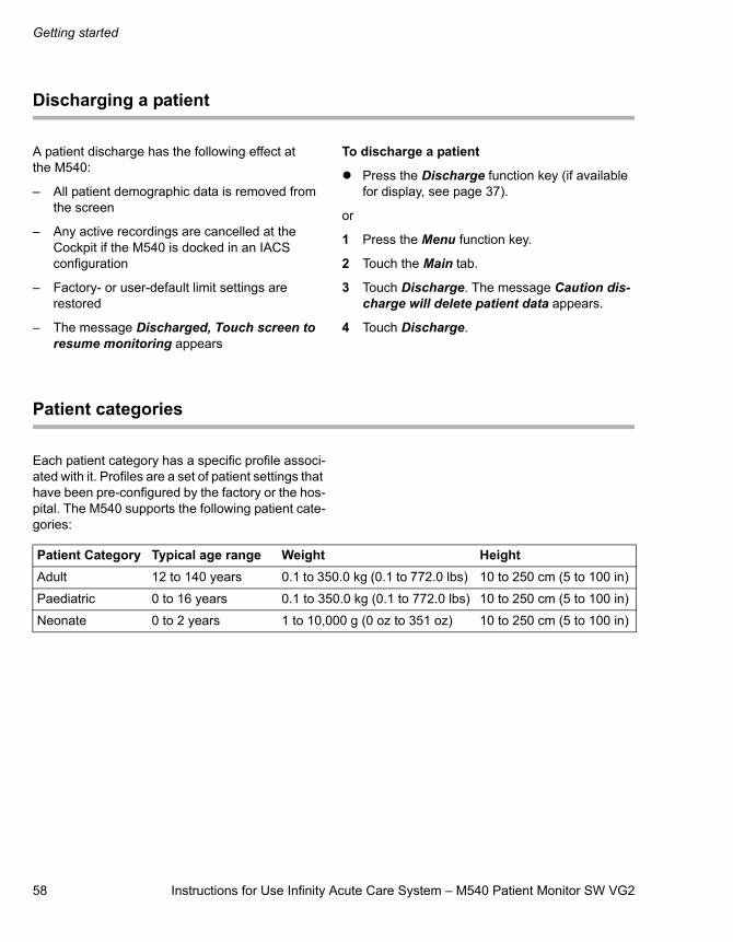
58 Instructions for Use Infinity Acute Care System – M540 Patient Monitor SW VG2
Getting started
Discharging a patient
A patient discharge has the following effect at the M540:
– All patient demographic data is removed from the screen
– Any active recordings are cancelled at the Cockpit if the M540 is docked in an IACS configuration
– Factory- or user-default limit settings are restored
– The message Discharged, Touch screen to resume monitoring appears
To discharge a patient
Press the Discharge function key (if available for display, see page 37).
or
1 Press the Menu function key.
2 Touch the Main tab.
3 Touch Discharge. The message Caution dis-charge will delete patient data appears.
4 Touch Discharge.
Patient categories
Each patient category has a specific profile associ-ated with it. Profiles are a set of patient settings that have been pre-configured by the factory or the hos-pital. The M540 supports the following patient cate-gories:
Patient Category Typical age range Weight HeightAdult 12 to 140 years 0.1 to 350.0 kg (0.1 to 772.0 lbs) 10 to 250 cm (5 to 100 in)
Paediatric 0 to 16 years 0.1 to 350.0 kg (0.1 to 772.0 lbs) 10 to 250 cm (5 to 100 in)
Neonate 0 to 2 years 1 to 10,000 g (0 oz to 351 oz) 10 to 250 cm (5 to 100 in)
Instructions for Use Infinity Acute Care System – M540 Patient Monitor SW VG2 59
Getting started
Selecting a new patient category
After selecting the patient category, the new patient category label appears in the header bar (see page 38).
A patient category change does not affect the following settings: the patient and physician names, patient ID, birth date, admit date, height, and weight.
To select a new patient category
1 Press the Menu function key.
2 Touch the Patient setup tab.
3 Touch Patient category and then select the appropriate category (Adult, Pediatric, Neonate). The message Changing category will change alarm settings and algorithmic processing appears.
4 Touch OK.

60 Instructions for Use Infinity Acute Care System – M540 Patient Monitor SW VG2
This page is intentionally left blank
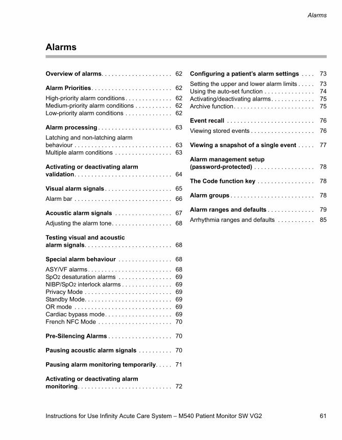
Instructions for Use Infinity Acute Care System – M540 Patient Monitor SW VG2 61
Alarms
Alarms
Overview of alarms. . . . . . . . . . . . . . . . . . . . . 62
Alarm Priorities. . . . . . . . . . . . . . . . . . . . . . . . 62
High-priority alarm conditions. . . . . . . . . . . . . . 62Medium-priority alarm conditions . . . . . . . . . . . 62Low-priority alarm conditions . . . . . . . . . . . . . . 62
Alarm processing . . . . . . . . . . . . . . . . . . . . . . 63
Latching and non-latching alarm behaviour . . . . . . . . . . . . . . . . . . . . . . . . . . . . . 63Multiple alarm conditions . . . . . . . . . . . . . . . . . 63
Activating or deactivating alarm validation. . . . . . . . . . . . . . . . . . . . . . . . . . . . . 64
Visual alarm signals . . . . . . . . . . . . . . . . . . . . 65
Alarm bar . . . . . . . . . . . . . . . . . . . . . . . . . . . . . 66
Acoustic alarm signals . . . . . . . . . . . . . . . . . 67
Adjusting the alarm tone. . . . . . . . . . . . . . . . . . 68
Testing visual and acoustic alarm signals. . . . . . . . . . . . . . . . . . . . . . . . . . 68
Special alarm behaviour . . . . . . . . . . . . . . . . 68
ASY/VF alarms. . . . . . . . . . . . . . . . . . . . . . . . . 68SpO2 desaturation alarms . . . . . . . . . . . . . . . . 69NIBP/SpO2 interlock alarms . . . . . . . . . . . . . . . 69Privacy Mode . . . . . . . . . . . . . . . . . . . . . . . . . . 69Standby Mode. . . . . . . . . . . . . . . . . . . . . . . . . . 69OR mode . . . . . . . . . . . . . . . . . . . . . . . . . . . . . 69Cardiac bypass mode. . . . . . . . . . . . . . . . . . . . 69French NFC Mode . . . . . . . . . . . . . . . . . . . . . . 70
Pre-Silencing Alarms . . . . . . . . . . . . . . . . . . . 70
Pausing acoustic alarm signals . . . . . . . . . . 70
Pausing alarm monitoring temporarily. . . . . 71
Activating or deactivating alarm monitoring. . . . . . . . . . . . . . . . . . . . . . . . . . . . 72
Configuring a patient’s alarm settings . . . . 73
Setting the upper and lower alarm limits . . . . . 73Using the auto-set function . . . . . . . . . . . . . . . 74Activating/deactivating alarms. . . . . . . . . . . . . 75Archive function. . . . . . . . . . . . . . . . . . . . . . . . 75
Event recall . . . . . . . . . . . . . . . . . . . . . . . . . . 76
Viewing stored events . . . . . . . . . . . . . . . . . . . 76
Viewing a snapshot of a single event . . . . . 77
Alarm management setup (password-protected) . . . . . . . . . . . . . . . . . . 78
The Code function key . . . . . . . . . . . . . . . . . 78
Alarm groups . . . . . . . . . . . . . . . . . . . . . . . . . 78
Alarm ranges and defaults . . . . . . . . . . . . . . 79
Arrhythmia ranges and defaults . . . . . . . . . . . 85
Alarms
62 Instructions for Use Infinity Acute Care System – M540 Patient Monitor SW VG2
Overview of alarms
The M540 produces acoustic and visual alarm sig-nals to alert you to alarm conditions ranging from alarm limits violations, arrhythmia calls, and battery issues.
Each alarm condition is assigned one of three alarm priorities:
– high (life-threatening),
– medium (serious)
– low (advisory).
Each alarm priority has unique acoustic and visual alarm signals.
In addition to the visual and acoustic alarm signals, alarm messages appear in the alarm message field of the M540. All alarm conditions and associated alarm messages are described in detail in the chap-ter, Problem solving on page 211.
The colour of an alarm message corresponds to the priority of the associated alarm condition (see Alarm priorities on page 62).
The alarm settings for a patient can be set up to store alarms for later event review in the event recall dialogue window. A physiological alarm can also activate an external alarm device, such as a nurse call system.
When the M540 is docked in an IACS configuration, special monitoring modes (see page 68), such as cardiac bypass mode, affect the regular alarming behaviour.
Alarm priorities
Each alarm condition is assigned to one of three priorities: high (life-threatening), medium (serious) or low (advisory). Visual and acoustic alarm signals indicate the level of the alarm priority. For more information on how alarm priorities affect alarm reporting, see Visual alarm signals on page 65 and Acoustic alarm signals on page 67.
High-priority alarm conditions
All high-priority alarms are physiological alarm con-ditions that can be life-threatening and require immediate intervention.
An example of a high-priority alarm condition is asystole.
Medium-priority alarm conditions
Most medium-priority alarms report physiological alarm conditions, that require prompt attention but may not be life-threatening.
An example of a medium-priority alarm condition is a respiratory-rate limit violation.
Low-priority alarm conditions
All low-priority alarms alert you to technical issues that may compromise the ability of the system to monitor the patient.
An example of a low-priority alarm condition is an artefact on the ECG waveform.
Instructions for Use Infinity Acute Care System – M540 Patient Monitor SW VG2 63
Alarms
Alarm processing
The M540 provides acoustic and visual alarm sig-nals for all parameters except for the following ones:
– Cardiac output (C.O.)
– Injectate temperature (Tinj)
– Pulmonary wedge pressure (PWP)
– Paced beats (%paced)
– Perfusion index (PI) for Masimo SET MCable and Masimo Rainbow SET MCable
– Total oxygen content (SpOC) for the Masimo Rainbow SET MCable
Latching and non-latching alarm behaviour
When an alarm condition no longer exists, the associated acoustic and visual alarm signals behave in one of two ways:
– The alarm signals automatically stop when the alarm condition ceases to exist. This type of alarm is called a non-latching alarm condition.
– The alarm signals continue until you acknowl-edge the alarm even though the alarm condition has ceased to exist. This type of alarm is called a latching alarm condition.
In general, high-priority alarms are latching alarm conditions while low-priority alarm conditions are non-latching. Exceptions to this alarm behaviour are listed on page 68.
The alarm priority of a latching alarm condition determines how the alarm signals behave after the alarm condition ceases to exist:
– A latched alarm condition of high-priority is identified by the standard acoustic and visual alarm signals (see Visual alarm signals on page 65).
– A latched alarm condition of medium priority is downgraded to a status message which appears in the header bar. The alarm header does not flash, and there are no acoustic alarm signals.
To acknowledge a latched alarm condition
– Press the key on the M540.
or
1 Select All alarms off/All alarms pause (the name and function of the button depends on the M540 configuration – see page 210). To access the button, press the Alarms function key.
2 Change the alarm limits.
The latched alarm signals are cleared and all acoustic and visual latched alarm signals disappear.
Multiple alarm conditions
During multiple alarm conditions, the M540 reports the most recently detected alarm condition of high-est priority. When several alarm conditions occur simultaneously, the parameter boxes flash for all alarming parameters. The alarm condition with the highest priority determines which acoustic alarm signal is generated, how the alarm bar and the parameter box appear, and what alarm message appears in the header bar. Messages for active alarms rotate in the header bar.
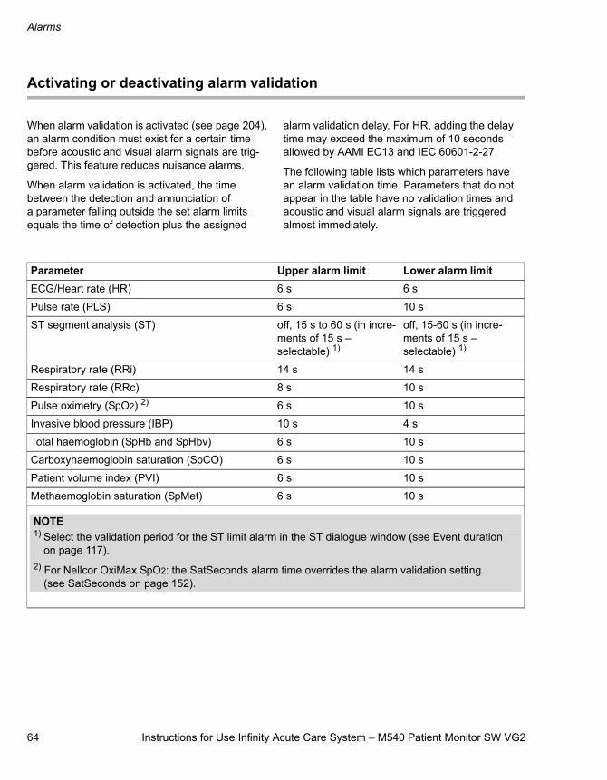
Alarms
64 Instructions for Use Infinity Acute Care System – M540 Patient Monitor SW VG2
Activating or deactivating alarm validation
When alarm validation is activated (see page 204), an alarm condition must exist for a certain time before acoustic and visual alarm signals are trig-gered. This feature reduces nuisance alarms.
When alarm validation is activated, the time between the detection and annunciation of a parameter falling outside the set alarm limits equals the time of detection plus the assigned
alarm validation delay. For HR, adding the delay time may exceed the maximum of 10 seconds allowed by AAMI EC13 and IEC 60601-2-27.
The following table lists which parameters have an alarm validation time. Parameters that do not appear in the table have no validation times and acoustic and visual alarm signals are triggered almost immediately.
Parameter Upper alarm limit Lower alarm limitECG/Heart rate (HR) 6 s 6 s
Pulse rate (PLS) 6 s 10 s
ST segment analysis (ST) off, 15 s to 60 s (in incre-ments of 15 s – selectable) 1)
off, 15-60 s (in incre-ments of 15 s – selectable) 1)
Respiratory rate (RRi) 14 s 14 s
Respiratory rate (RRc) 8 s 10 s
Pulse oximetry (SpO2) 2) 6 s 10 s
Invasive blood pressure (IBP) 10 s 4 s
Total haemoglobin (SpHb and SpHbv) 6 s 10 s
Carboxyhaemoglobin saturation (SpCO) 6 s 10 s
Patient volume index (PVI) 6 s 10 s
Methaemoglobin saturation (SpMet) 6 s 10 s
NOTE1) Select the validation period for the ST limit alarm in the ST dialogue window (see Event duration
on page 117).2) For Nellcor OxiMax SpO2: the SatSeconds alarm time overrides the alarm validation setting
(see SatSeconds on page 152).
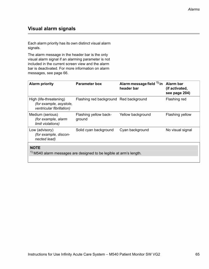
Instructions for Use Infinity Acute Care System – M540 Patient Monitor SW VG2 65
Alarms
Visual alarm signals
Each alarm priority has its own distinct visual alarm signals.
The alarm message in the header bar is the only visual alarm signal if an alarming parameter is not included in the current screen view and the alarm bar is deactivated. For more information on alarm messages, see page 66.
Alarm priority Parameter box Alarm message field 1) in header bar
Alarm bar (if activated, see page 204)
High (life-threatening)(for example, asystole, ventricular fibrillation)
Flashing red background Red background Flashing red
Medium (serious)(for example, alarm limit violations)
Flashing yellow back-ground
Yellow background Flashing yellow
Low (advisory)(for example, discon-nected lead)
Solid cyan background Cyan background No visual signal
NOTE1) M540 alarm messages are designed to be legible at arm’s length.
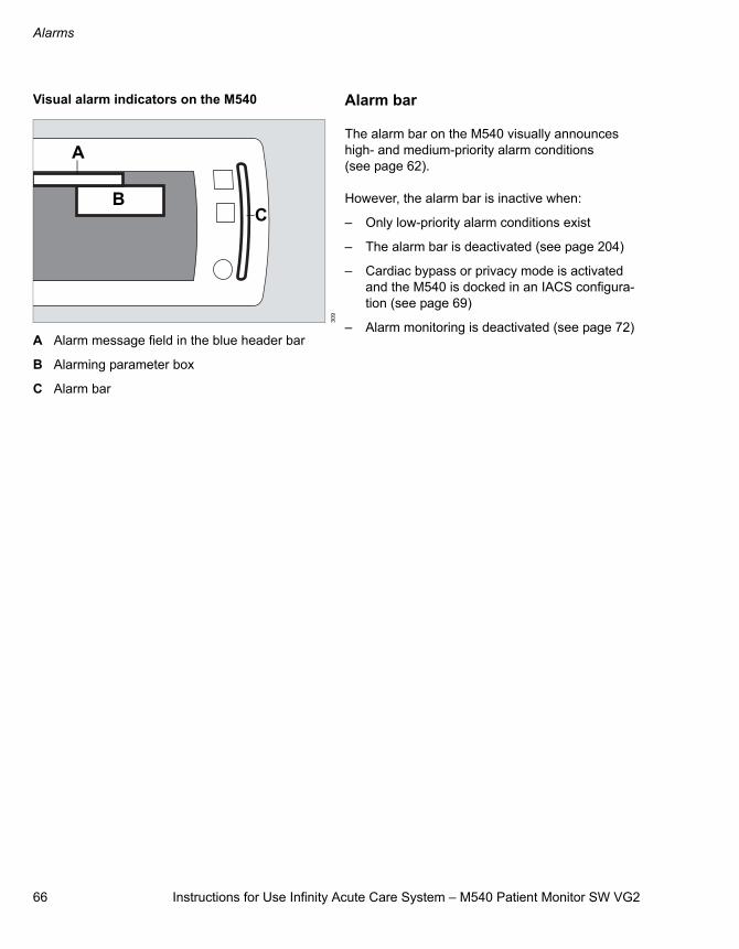
Alarms
66 Instructions for Use Infinity Acute Care System – M540 Patient Monitor SW VG2
Visual alarm indicators on the M540
A Alarm message field in the blue header bar
B Alarming parameter box
C Alarm bar
Alarm bar
The alarm bar on the M540 visually announces high- and medium-priority alarm conditions (see page 62).
However, the alarm bar is inactive when:
– Only low-priority alarm conditions exist
– The alarm bar is deactivated (see page 204)
– Cardiac bypass or privacy mode is activated and the M540 is docked in an IACS configura-tion (see page 69)
– Alarm monitoring is deactivated (see page 72)30
9
A
BC
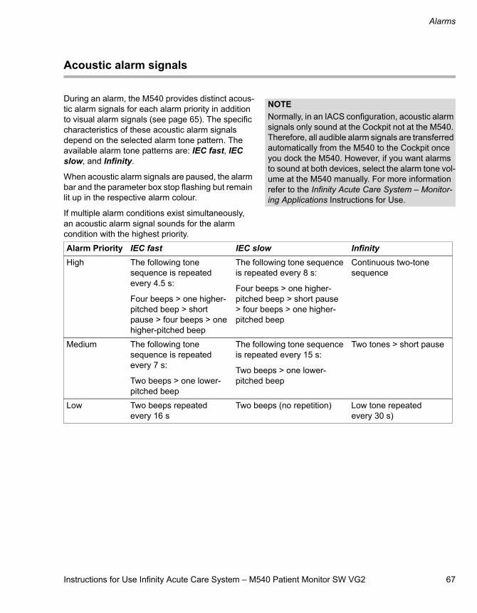
Instructions for Use Infinity Acute Care System – M540 Patient Monitor SW VG2 67
Alarms
Acoustic alarm signals
During an alarm, the M540 provides distinct acous-tic alarm signals for each alarm priority in addition to visual alarm signals (see page 65). The specific characteristics of these acoustic alarm signals depend on the selected alarm tone pattern. The available alarm tone patterns are: IEC fast, IEC slow, and Infinity.
When acoustic alarm signals are paused, the alarm bar and the parameter box stop flashing but remain lit up in the respective alarm colour.
If multiple alarm conditions exist simultaneously, an acoustic alarm signal sounds for the alarm condition with the highest priority.
NOTENormally, in an IACS configuration, acoustic alarm signals only sound at the Cockpit not at the M540. Therefore, all audible alarm signals are transferred automatically from the M540 to the Cockpit once you dock the M540. However, if you want alarms to sound at both devices, select the alarm tone vol-ume at the M540 manually. For more information refer to the Infinity Acute Care System – Monitor-ing Applications Instructions for Use.
Alarm Priority IEC fast IEC slow InfinityHigh The following tone
sequence is repeated every 4.5 s:
Four beeps > one higher-pitched beep > short pause > four beeps > one higher-pitched beep
The following tone sequence is repeated every 8 s:
Four beeps > one higher-pitched beep > short pause > four beeps > one higher-pitched beep
Continuous two-tone sequence
Medium The following tone sequence is repeated every 7 s:
Two beeps > one lower-pitched beep
The following tone sequence is repeated every 15 s:
Two beeps > one lower-pitched beep
Two tones > short pause
Low Two beeps repeated every 16 s
Two beeps (no repetition) Low tone repeated every 30 s)
Alarms
68 Instructions for Use Infinity Acute Care System – M540 Patient Monitor SW VG2
Adjusting the alarm tone
The volume of the alarm tone is adjustable. Set the volume of the alarm tone so it can be heard during the noisiest times.
To adjust the alarm tone volume
1 Press the Alarms function key.
2 Touch the Speaker volume button and select the desired volume level (Off, 10 to 100 % in increments of 10 %).
When the M540 is on wireless transport and it loses its connection to the ICS, the alarm tone volume setting is automatically set to 100 %. The setting Off is no longer available until the connection to the ICS is restored.
Testing visual and acoustic alarm signals
The alarm bar and the speakers of the M540 are automatically tested during startup. You can also test the visual and acoustic alarm signals by creat-
ing an alarm condition (for example, by lowering the HR upper alarm limits). To end the test, restore the alarm limits to the previous setting (see page 73).
Special alarm behaviour
Activating any of the following features alters the normal alarm annunciation behaviour:
– ASY/VF alarm feature
– SpO2 desaturation alarm
– NIBP/SpO2 interlock function
– Privacy, cardiac bypass, and OR modes (only available when the M540 is docked in an IACS configuration)
– Standby Mode
– French NFC Mode
ASY/VF alarms
You can control the alarming behaviour for ventricu-lar fibrillation (VF) and asystole (ASY) alarms. To make sure that VF and ASY alarms are always reported, even when HR alarms and ARR monitor-ing are deactivated, set the ASY/VF alarms selec-tion in the Alarms mgmt. dialogue window to Always on. If you select Follow HR, asystole and ventricular fibrillation alarm conditions are only enunciated when either HR alarms or ARR monitor-ing is also activated. To configure this feature, see page 204.
The HR, ASY, VF off banner appears when arrhythmia monitoring is deactivated, the ASY/VF alarms selection is set to Follow HR, and HR alarms are deactivated.
NOTEThe M540 speaker volume can only be turned off when the M540 is docked in an IACS configura-tion.
The symbol appears in the M540 header bar when the alarm volume is deactivated and the M540 is connected to the ICS.
Instructions for Use Infinity Acute Care System – M540 Patient Monitor SW VG2 69
Alarms
SpO2 desaturation alarms
In neonatal mode, the alarm priority is upgraded to high-priority if the SpO2 value falls more than 10 % below the lower SpO2 alarm limit. This feature is automatically activated whenever neonatal mode is activated. This function can be activated or deacti-vated (see page 152). When using the Infinity MCable – Nellcor OxiMax this feature is only avail-able if the SatSeconds function is set to Off (see page 152).
NIBP/SpO2 interlock alarms
To avoid SpO2 nuisance alarms during an active NIBP measurement, select NIBP/SpO2 interlock On in the Alarms mgmt. dialogue window. When the feature is activated, all SpO2 alarms are deacti-vated during an active NIBP measurement. To acti-vate or deactivate this feature, see page 204.
Privacy mode
Privacy mode is only available when the M540 is docked in an IACS configuration or on wireless transport, and the patient is admitted at the ICS. When privacy mode is activated, the following hap-pens at the M540:
– All patient data is removed from the M540, but continues to be displayed at the ICS
– The alarm bar is deactivated
– Acoustic alarm signals are only provided at the ICS
– The M540 displays Privacy, Touch screen to resume monitoring
You can activate privacy mode only if the patient is also admitted at the ICS. To activate or deactivate this feature, see page 46.
Standby mode
When standby mode is activated, the following hap-pens at the M540:
– All patient data is removed from the screen
– All monitoring (including acoustic and visual alarm signals) is suppressed
– Active alarms are considered acknowledged by the user
– All recordings are cancelled at the Cockpit (provided the M540 is docked in an IACS con-figuration)
– The M540 displays Standby, Touch screen to resume monitoring
OR mode
OR mode is only available on the M540 when it is docked in an IACS configuration. When OR mode is activated at the Cockpit, alarm messages for medium- and high-priority alarms clear when the alarm condition no longer exists.
Cardiac bypass mode
Cardiac bypass mode is only available when the M540 is docked in an IACS configuration, and the Cockpit is in OR mode. When cardiac bypass mode is activated, the following happens at the M540:
– All alarm monitoring (including arrhythmia alarms), and the alarm bar are deactivated
– The message All alarms off: Bypass appears in the upper right corner of the screen
Cardiac bypass mode is not available if French NFC mode is activated.
Alarms
70 Instructions for Use Infinity Acute Care System – M540 Patient Monitor SW VG2
French NFC Mode
When French NFC mode is activated, the following happens at the M540:
– HR alarms cannot be deactivated
– The alarm pause period cannot last longer than 3 minutes
– You cannot activate cardiac bypass mode when French NFC mode is activated. If cardiac bypass mode was activated before French NFC mode was turned on, cardiac bypass mode is deactivated.
To activate or deactivate this feature, see page 206.
Pre-silencing alarms
This function allows you to concentrate on a proce-dure without being interrupted by continuous acoustic alarm signals arising from potential alarm conditions. When you pre-silence alarms, the fol-lowing happens at the M540:
– Visual alarms are reported as usual.
– The alarm message Audio paused appears in the far-right field of the header bar along with a countdown timer and the following symbol:
To pre-silence alarms
Press the yellow key on the M540. Press-ing the key again cancels the pre-silence state.
Pausing acoustic alarm signals
You can pause acoustic alarm signals for two min-utes. The following happens when you pause acoustic alarm signals:
– All acoustic alarm signals are paused for a max-imum of two minutes. If the same alarm condi-tion occurs again after the alarm has been paused, no acoustic or visual alarm signals are generated.
– The parameter box and the alarm bar stop blinking but appear solid in the alarm colour cor-responding to the alarm grade (see page 65).
– The alarm message continues to be displayed in the header bar.
– The Audio paused banner appears in the far-right field of the header bar along with a count-down timer and the following symbol:
If the condition of the patient is still unchanged after the alarm pause period, the acoustic alarm signal is reactivated.
Instructions for Use Infinity Acute Care System – M540 Patient Monitor SW VG2 71
Alarms
If new alarm condition occurs during an active audio pause period, the following happens at the M540:
– A single alarm tone sequence consisting of sev-eral distinct tones sounds in addition to the visual alarm signals for any new alarm condition of a higher priority than the previous alarm con-dition. Any alarm condition of equal or lower alarm priority than the paused alarm, does not generate any visual or acoustic alarm signal.
– The parameter box of the new alarming param-eter flashes while the parameter box of the pre-viously paused alarm remains highlighted.
– All alarm messages for paused and active alarm conditions rotate in the header of the M540.
To pause acoustic alarm signals
Press the yellow key on the M540. Press-ing the key again, reactivates the acoustic alarm signals.
Pausing alarm monitoring temporarily
If the password-protected alarm pause feature is activated (see page 203), you can pause alarm monitoring temporarily. The alarm pause duration is adjustable from 1 minute to 5 minutes.
The following happens when you pause alarm monitoring:
– Acoustic and visual alarm signals for new alarm conditions are suppressed for all parameters until alarm monitoring begins again
– Alarm signals for any active alarm condition stop immediately
– The alarming parameter box and alarm bar return to the pre-alarm state
– Alarm messages are removed from the alarm message field in the header bar
– The far-right field of the header bar turns yellow and displays the alarm message All alarms pause, a countdown timer, and the following symbol:
To pause alarm monitoring temporarily
1 Press the Alarms function key.
2 Touch All alarms pause.
As soon as the alarm pause period ends, the M540 generates acoustic and visual alarm signals as needed.
To activate alarm monitoring after pausing
1 Press the Alarms function key.
2 Touch All alarms pause before the alarm pause period ends to cancel the alarm pause.
NOTEIf the French NFC mode is enabled (see page 206), you cannot pause alarm monitoring for more than 3 minutes.
Alarms
72 Instructions for Use Infinity Acute Care System – M540 Patient Monitor SW VG2
Activating or deactivating alarm monitoring
If the password-protected alarm pause feature is set to No timeout (see page 203), the following happens when you deactivated alarm monitoring:
– All acoustic and visual alarm signals for new alarm conditions are suppressed for all param-eters until alarm monitoring is manually acti-vated again
– Acoustic alarm signals for any active alarm con-dition stop immediately
– The alarming parameter box and alarm bar return to the pre-alarm state
– Alarm messages are removed from the “Alarm message” field in the header bar
– The far-right field of the header bar turns yellow displays the message All alarms off and the following symbol:
To deactivate alarm monitoring
1 Press the Alarms function key.
2 Touch All alarms off.
To activate alarm monitoring after deactivating
1 Press the Alarms function key.
2 Touch All alarms off.
The M540 provides acoustic and visual alarm signals again when it detects a new alarm con-dition.
WARNINGIf No timeout is assigned to the alarm off period, no counter appears and alarms remain deactivated until you enable them again.
WARNINGNever leave a patient unattended when alarm monitoring is permanently deactivated. Always activate alarm monitoring again as soon as possible.
Instructions for Use Infinity Acute Care System – M540 Patient Monitor SW VG2 73
Alarms
Configuring a patient’s alarm settings
The following section describes the alarm features and settings available for each patient. When set-ting alarm limits, make sure they are appropriate for the patient’s condition.
Each parameter has its own dialogue window for configuring parameter-specific alarm functions. For composite parameters such as NIBP, there are alarm settings for each parameter (systolic, diasto-lic, and mean).
Setting the upper and lower alarm limits
You can configure the upper and lower alarm limits of a parameter manually to trigger acoustic and visual alarm signals if a parameter goes above or below the set limits.
To set an individual parameter’s alarm settings
1 Touch the parameter box (for example, HR) to access that parameter’s dialogue window.
2 Touch the tab for configuring the parameter limits (for example, HR limits).
3 Touch the upper or lower alarm limit value.
4 Touch the up or down arrow to change the alarm limit setting.
5 Touch OK.
WARNINGSetting alarm limits to extreme values may prevent certain alarm conditions from being detected and from being enunciated with audible and visual alarm signals.
Alarms
74 Instructions for Use Infinity Acute Care System – M540 Patient Monitor SW VG2
Using the auto-set function
The auto-set function allows you to adjust alarm limits quickly based on preset percentages listed in the following table.
To use the auto-set function
1 Touch the parameter box of the parameter whose alarm limits you wish to set (for example, HR).
2 Touch the tab for configuring the parameter limits (for example, HR limits).
3 Touch Auto set.
Parameter Upper Limit Lower limitTa, Tb, T1a, T1b, Tblood
≤107 % of current value ≤93 % of current value
ΔT, ΔT1, PVC/min/min, etCO2
Unaffected Unaffected
SpO2 Adult/paediatric: 100 % saturation
Neonate: 98 % saturation
Current value –((value)*(5 %))
ST Current value +2.0 mm Current value –2.0 mm
etCO2 Current value +25 % Current value –20 %
All others Alarm limit that is closest to but not greater than 25 % above the current value of the parameter
Alarm limit that is closest to but not greater than 20 % below the current value of the parameter
NOTEIf the Auto-set function forces the alarm limits of a parameter outside the allowable limit range of the monitor, the alarm limits remain unchanged.
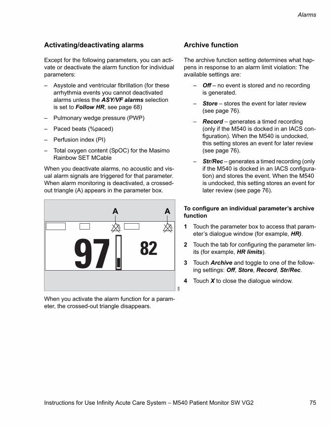
Instructions for Use Infinity Acute Care System – M540 Patient Monitor SW VG2 75
Alarms
Activating/deactivating alarms
Except for the following parameters, you can acti-vate or deactivate the alarm function for individual parameters:
– Asystole and ventricular fibrillation (for these arrhythmia events you cannot deactivated alarms unless the ASY/VF alarms selection is set to Follow HR, see page 68)
– Pulmonary wedge pressure (PWP)
– Paced beats (%paced)
– Perfusion index (PI)
– Total oxygen content (SpOC) for the Masimo Rainbow SET MCable
When you deactivate alarms, no acoustic and vis-ual alarm signals are triggered for that parameter. When alarm monitoring is deactivated, a crossed-out triangle (A) appears in the parameter box.
When you activate the alarm function for a param-eter, the crossed-out triangle disappears.
Archive function
The archive function setting determines what hap-pens in response to an alarm limit violation: The available settings are:
– Off – no event is stored and no recording is generated.
– Store – stores the event for later review (see page 76).
– Record – generates a timed recording (only if the M540 is docked in an IACS con-figuration). When the M540 is undocked, this setting stores an event for later review (see page 76).
– Str/Rec – generates a timed recording (only if the M540 is docked in an IACS configura-tion) and stores the event. When the M540 is undocked, this setting stores an event for later review (see page 76).
To configure an individual parameter’s archive function
1 Touch the parameter box to access that param-eter’s dialogue window (for example, HR).
2 Touch the tab for configuring the parameter lim-its (for example, HR limits).
3 Touch Archive and toggle to one of the follow-ing settings: Off, Store, Record, Str/Rec.
4 Touch X to close the dialogue window.
096
A A
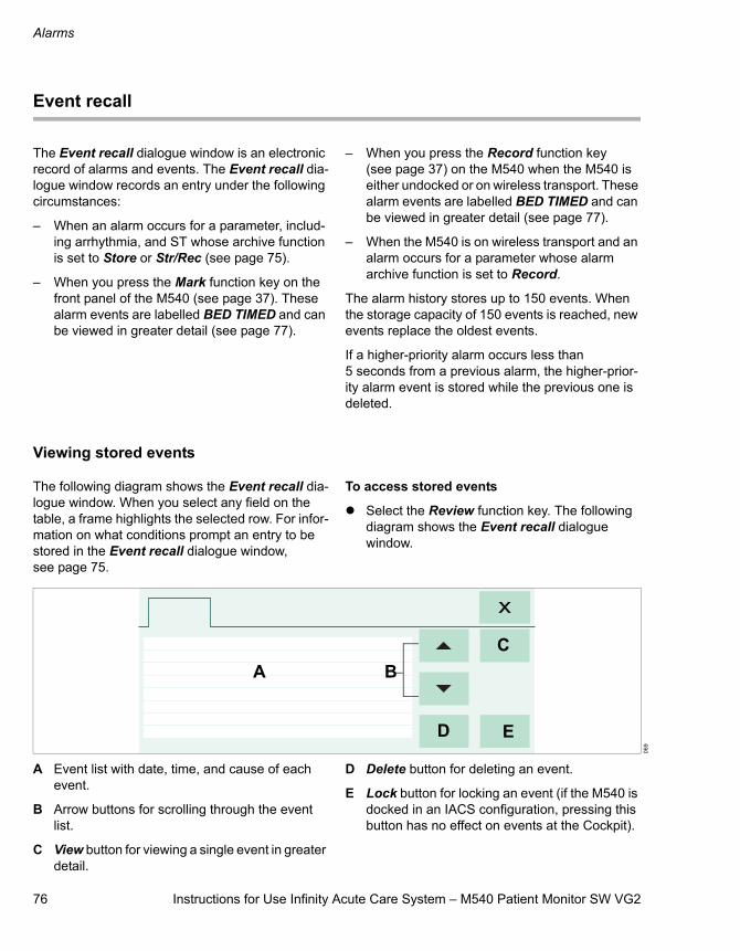
Alarms
76 Instructions for Use Infinity Acute Care System – M540 Patient Monitor SW VG2
Event recall
The Event recall dialogue window is an electronic record of alarms and events. The Event recall dia-logue window records an entry under the following circumstances:
– When an alarm occurs for a parameter, includ-ing arrhythmia, and ST whose archive function is set to Store or Str/Rec (see page 75).
– When you press the Mark function key on the front panel of the M540 (see page 37). These alarm events are labelled BED TIMED and can be viewed in greater detail (see page 77).
– When you press the Record function key (see page 37) on the M540 when the M540 is either undocked or on wireless transport. These alarm events are labelled BED TIMED and can be viewed in greater detail (see page 77).
– When the M540 is on wireless transport and an alarm occurs for a parameter whose alarm archive function is set to Record.
The alarm history stores up to 150 events. When the storage capacity of 150 events is reached, new events replace the oldest events.
If a higher-priority alarm occurs less than 5 seconds from a previous alarm, the higher-prior-ity alarm event is stored while the previous one is deleted.
Viewing stored events
The following diagram shows the Event recall dia-logue window. When you select any field on the table, a frame highlights the selected row. For infor-mation on what conditions prompt an entry to be stored in the Event recall dialogue window, see page 75.
To access stored events
Select the Review function key. The following diagram shows the Event recall dialogue window.
A Event list with date, time, and cause of each event.
B Arrow buttons for scrolling through the event list.
C View button for viewing a single event in greater detail.
D Delete button for deleting an event.
E Lock button for locking an event (if the M540 is docked in an IACS configuration, pressing this button has no effect on events at the Cockpit).
069
A BC
D E
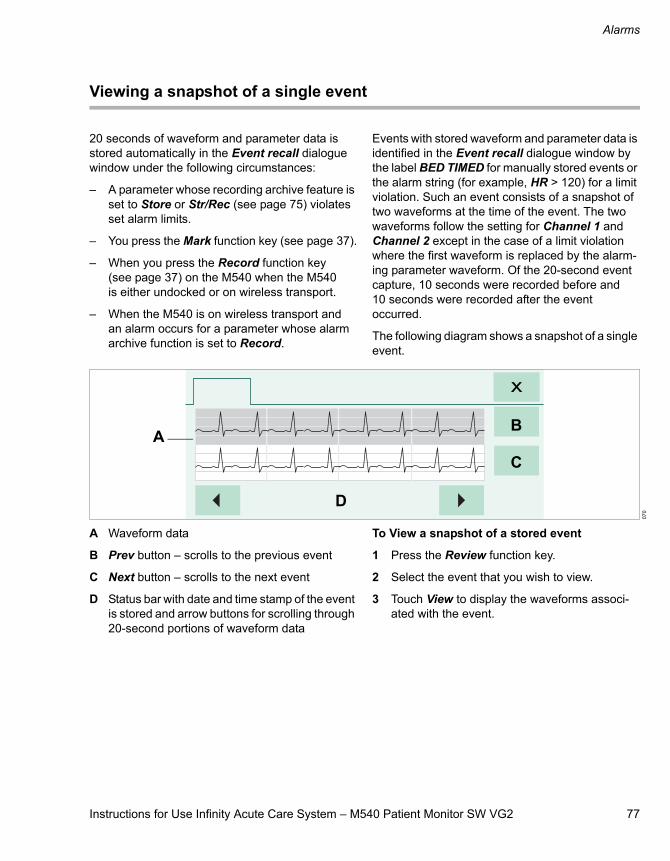
Instructions for Use Infinity Acute Care System – M540 Patient Monitor SW VG2 77
Alarms
Viewing a snapshot of a single event
20 seconds of waveform and parameter data is stored automatically in the Event recall dialogue window under the following circumstances:
– A parameter whose recording archive feature is set to Store or Str/Rec (see page 75) violates set alarm limits.
– You press the Mark function key (see page 37).
– When you press the Record function key (see page 37) on the M540 when the M540 is either undocked or on wireless transport.
– When the M540 is on wireless transport and an alarm occurs for a parameter whose alarm archive function is set to Record.
Events with stored waveform and parameter data is identified in the Event recall dialogue window by the label BED TIMED for manually stored events or the alarm string (for example, HR > 120) for a limit violation. Such an event consists of a snapshot of two waveforms at the time of the event. The two waveforms follow the setting for Channel 1 and Channel 2 except in the case of a limit violation where the first waveform is replaced by the alarm-ing parameter waveform. Of the 20-second event capture, 10 seconds were recorded before and 10 seconds were recorded after the event occurred.
The following diagram shows a snapshot of a single event.
A Waveform data
B Prev button – scrolls to the previous event
C Next button – scrolls to the next event
D Status bar with date and time stamp of the event is stored and arrow buttons for scrolling through 20-second portions of waveform data
To View a snapshot of a stored event
1 Press the Review function key.
2 Select the event that you wish to view.
3 Touch View to display the waveforms associ-ated with the event.
070
AB
C
D
Alarms
78 Instructions for Use Infinity Acute Care System – M540 Patient Monitor SW VG2
Alarm management setup (password-protected)
The password-protected alarm setup is only acces-sible to authorised personnel. For details on availa-ble setup functions, see page 203.
The Code function key
If the M540 is connected to the IACS you can acti-vate a set of monitoring functions at the IACS dur-ing emergency care by selecting the Code function
key on the M540. For specific information, refer to Infinity Acute Care System – Monitoring Applica-tions Instructions for Use.
Alarm groups
You can configure the M540 and other monitors as members of an alarm group. This feature makes sure that any alarms that occur at any of the moni-htors within the alarm group are broadcast to all other members in the alarm group (see page 204) for remote viewing of alarm conditions.
When the M540 is docked in a IACS configuration, the alarm group of the M540 is adjusted to the alarm group ID set on the Cockpit device.
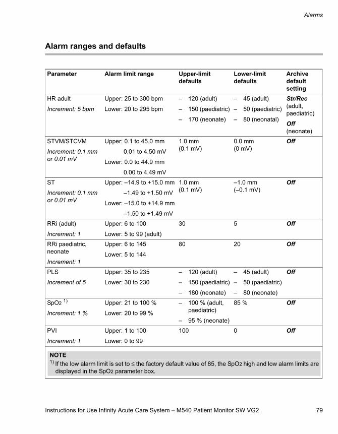
Instructions for Use Infinity Acute Care System – M540 Patient Monitor SW VG2 79
Alarms
Alarm ranges and defaults
Parameter Alarm limit range Upper-limit defaults
Lower-limit defaults
Archive default setting
HR adult
Increment: 5 bpm
Upper: 25 to 300 bpm
Lower: 20 to 295 bpm
– 120 (adult)
– 150 (paediatric)
– 170 (neonate)
– 45 (adult)
– 50 (paediatric)
– 80 (neonatal)
Str/Rec (adult, paediatric)
Off (neonate)
STVM/STCVM
Increment: 0.1 mm or 0.01 mV
Upper: 0.1 to 45.0 mm
0.01 to 4.50 mV
Lower: 0.0 to 44.9 mm
0.00 to 4.49 mV
1.0 mm (0.1 mV)
0.0 mm (0 mV)
Off
ST
Increment: 0.1 mm or 0.01 mV
Upper: –14.9 to +15.0 mm
–1.49 to +1.50 mV
Lower: –15.0 to +14.9 mm
–1.50 to +1.49 mV
1.0 mm(0.1 mV)
–1.0 mm (–0.1 mV)
Off
RRi (adult)
Increment: 1
Upper: 6 to 100
Lower: 5 to 99 (adult)
30 5 Off
RRi paediatric, neonate
Increment: 1
Upper: 6 to 145
Lower: 5 to 144
80 20 Off
PLS
Increment of 5
Upper: 35 to 235
Lower: 30 to 230
– 120 (adult)
– 150 (paediatric)
– 180 (neonate)
– 45 (adult)
– 50 (paediatric)
– 80 (neonate)
Off
SpO2 1)
Increment: 1 %
Upper: 21 to 100 %
Lower: 20 to 99 %
– 100 % (adult, paediatric)
– 95 % (neonate)
85 % Off
PVI
Increment: 1
Upper: 1 to 100
Lower: 0 to 99
100 0 Off
NOTE1) If the low alarm limit is set to ≤ the factory default value of 85, the SpO2 high and low alarm limits are
displayed in the SpO2 parameter box.
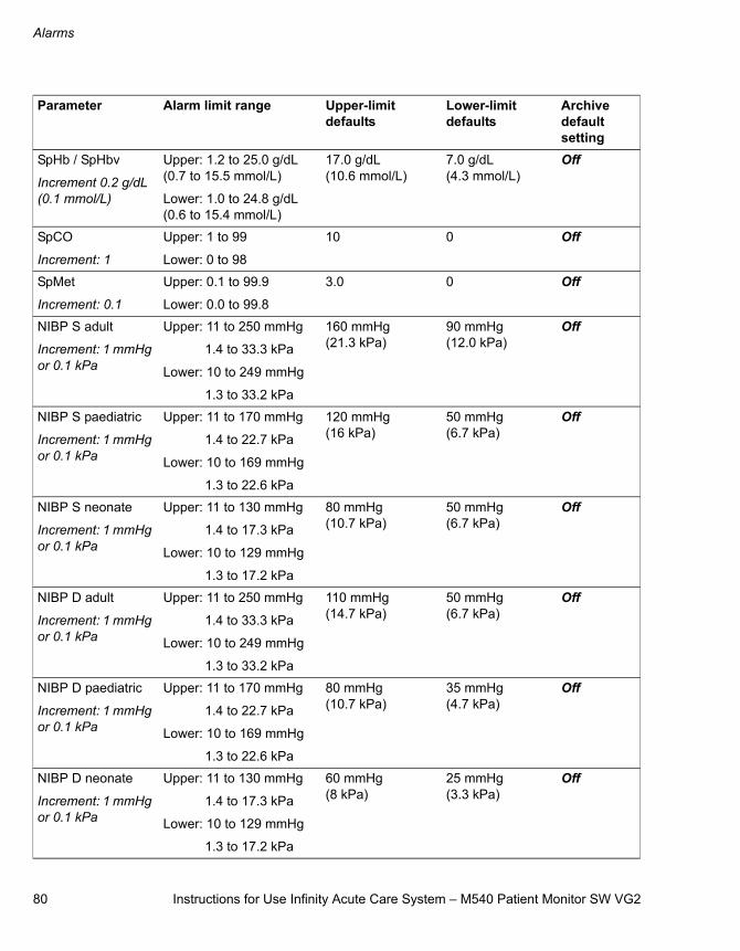
Alarms
80 Instructions for Use Infinity Acute Care System – M540 Patient Monitor SW VG2
SpHb / SpHbv
Increment 0.2 g/dL (0.1 mmol/L)
Upper: 1.2 to 25.0 g/dL (0.7 to 15.5 mmol/L)
Lower: 1.0 to 24.8 g/dL (0.6 to 15.4 mmol/L)
17.0 g/dL (10.6 mmol/L)
7.0 g/dL (4.3 mmol/L)
Off
SpCO
Increment: 1
Upper: 1 to 99
Lower: 0 to 98
10 0 Off
SpMet
Increment: 0.1
Upper: 0.1 to 99.9
Lower: 0.0 to 99.8
3.0 0 Off
NIBP S adult
Increment: 1 mmHg or 0.1 kPa
Upper: 11 to 250 mmHg
1.4 to 33.3 kPa
Lower: 10 to 249 mmHg
1.3 to 33.2 kPa
160 mmHg (21.3 kPa)
90 mmHg (12.0 kPa)
Off
NIBP S paediatric
Increment: 1 mmHg or 0.1 kPa
Upper: 11 to 170 mmHg
1.4 to 22.7 kPa
Lower: 10 to 169 mmHg
1.3 to 22.6 kPa
120 mmHg (16 kPa)
50 mmHg (6.7 kPa)
Off
NIBP S neonate
Increment: 1 mmHg or 0.1 kPa
Upper: 11 to 130 mmHg
1.4 to 17.3 kPa
Lower: 10 to 129 mmHg
1.3 to 17.2 kPa
80 mmHg (10.7 kPa)
50 mmHg (6.7 kPa)
Off
NIBP D adult
Increment: 1 mmHg or 0.1 kPa
Upper: 11 to 250 mmHg
1.4 to 33.3 kPa
Lower: 10 to 249 mmHg
1.3 to 33.2 kPa
110 mmHg (14.7 kPa)
50 mmHg (6.7 kPa)
Off
NIBP D paediatric
Increment: 1 mmHg or 0.1 kPa
Upper: 11 to 170 mmHg
1.4 to 22.7 kPa
Lower: 10 to 169 mmHg
1.3 to 22.6 kPa
80 mmHg (10.7 kPa)
35 mmHg (4.7 kPa)
Off
NIBP D neonate
Increment: 1 mmHg or 0.1 kPa
Upper: 11 to 130 mmHg
1.4 to 17.3 kPa
Lower: 10 to 129 mmHg
1.3 to 17.2 kPa
60 mmHg (8 kPa)
25 mmHg (3.3 kPa)
Off
Parameter Alarm limit range Upper-limit defaults
Lower-limit defaults
Archive default setting
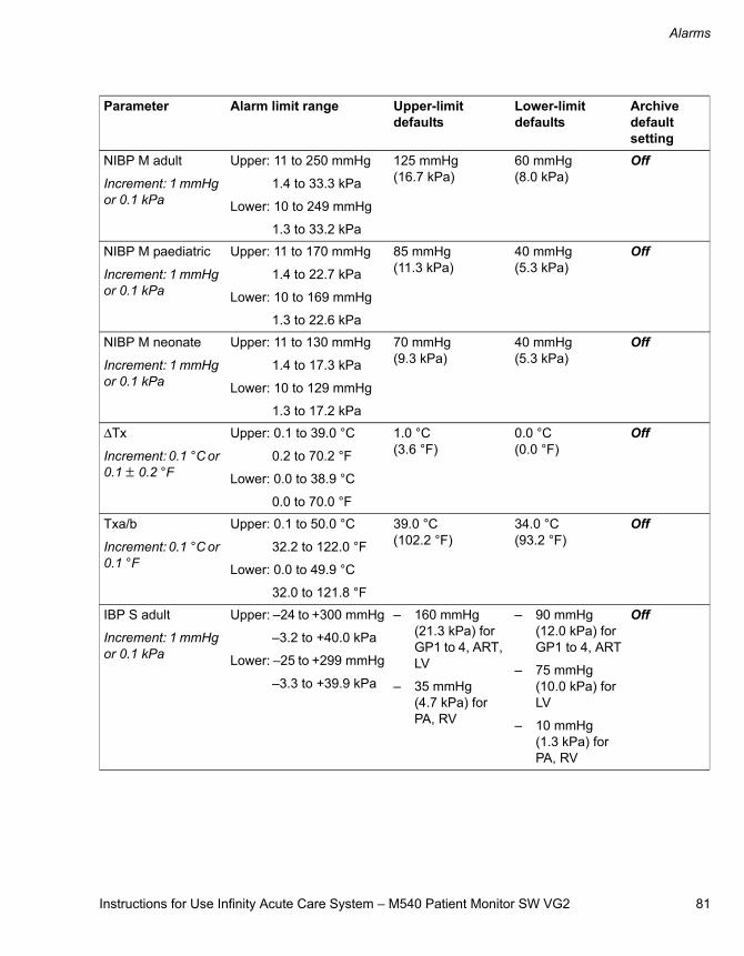
Instructions for Use Infinity Acute Care System – M540 Patient Monitor SW VG2 81
Alarms
NIBP M adult
Increment: 1 mmHg or 0.1 kPa
Upper: 11 to 250 mmHg
1.4 to 33.3 kPa
Lower: 10 to 249 mmHg
1.3 to 33.2 kPa
125 mmHg (16.7 kPa)
60 mmHg (8.0 kPa)
Off
NIBP M paediatric
Increment: 1 mmHg or 0.1 kPa
Upper: 11 to 170 mmHg
1.4 to 22.7 kPa
Lower: 10 to 169 mmHg
1.3 to 22.6 kPa
85 mmHg (11.3 kPa)
40 mmHg (5.3 kPa)
Off
NIBP M neonate
Increment: 1 mmHg or 0.1 kPa
Upper: 11 to 130 mmHg
1.4 to 17.3 kPa
Lower: 10 to 129 mmHg
1.3 to 17.2 kPa
70 mmHg (9.3 kPa)
40 mmHg (5.3 kPa)
Off
ΔTx
Increment: 0.1 °C or 0.1 ± 0.2 °F
Upper: 0.1 to 39.0 °C
0.2 to 70.2 °F
Lower: 0.0 to 38.9 °C
0.0 to 70.0 °F
1.0 °C (3.6 °F)
0.0 °C (0.0 °F)
Off
Txa/b
Increment: 0.1 °C or 0.1 °F
Upper: 0.1 to 50.0 °C
32.2 to 122.0 °F
Lower: 0.0 to 49.9 °C
32.0 to 121.8 °F
39.0 °C (102.2 °F)
34.0 °C (93.2 °F)
Off
IBP S adult
Increment: 1 mmHg or 0.1 kPa
Upper: –24 to +300 mmHg
–3.2 to +40.0 kPa
Lower: –25 to +299 mmHg
–3.3 to +39.9 kPa
– 160 mmHg (21.3 kPa) for GP1 to 4, ART, LV
– 35 mmHg (4.7 kPa) for PA, RV
– 90 mmHg (12.0 kPa) for GP1 to 4, ART
– 75 mmHg (10.0 kPa) for LV
– 10 mmHg (1.3 kPa) for PA, RV
Off
Parameter Alarm limit range Upper-limit defaults
Lower-limit defaults
Archive default setting
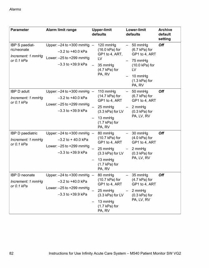
Alarms
82 Instructions for Use Infinity Acute Care System – M540 Patient Monitor SW VG2
IBP S paediat-ric/neonate
Increment: 1 mmHg or 0.1 kPa
Upper: –24 to +300 mmHg
–3.2 to +40.0 kPa
Lower: –25 to +299 mmHg
–3.3 to +39.9 kPa
– 120 mmHg (16.0 kPa) for GP1 to 4, ART, LV
– 35 mmHg (4.7 kPa) for PA, RV
– 50 mmHg (6.7 kPa) for GP1 to 4, ART
– 75 mmHg (10.0 kPa) for LV
– 10 mmHg (1.3 kPa) for PA, RV
Off
IBP D adult
Increment: 1 mmHg or 0.1 kPa
Upper: –24 to +300 mmHg
–3.2 to +40.0 kPa
Lower: –25 to +299 mmHg
–3.3 to +39.9 kPa
– 110 mmHg (14.7 kPa) for GP1 to 4, ART
– 25 mmHg (3.3 kPa) for LV
– 13 mmHg (1.7 kPa) for PA, RV
– 50 mmHg (6.7 kPa) for GP1 to 4, ART
– 2 mmHg (0.3 kPa) for PA, LV, RV
Off
IBP D paediatric
Increment: 1 mmHg or 0.1 kPa
Upper: –24 to +300 mmHg
–3.2 to + 40.0 kPa
Lower: –25 to +299 mmHg
–3.3 to +39.9 kPa
– 80 mmHg (10.7 kPa) for GP1 to 4, ART
– 25 mmHg (3.3 kPa) for LV
– 13 mmHg (1.7 kPa) for PA, RV
– 30 mmHg (4.0 kPa) for GP1 to 4, ART
– 2 mmHg (0.3 kPa) for PA, LV, RV
Off
IBP D neonate
Increment: 1 mmHg or 0.1 kPa
Upper: –24 to +300 mmHg
–3.2 to +40.0 kPa
Lower: –25 to +299 mmHg
–3.3 to +39.9 kPa
– 80 mmHg (10.7 kPa) for GP1 to 4, ART
– 25 mmHg (3.3 kPa) for LV
– 13 mmHg (1.7 kPa) for PA, RV
– 35 mmHg (4.7 kPa) for GP1 to 4, ART
– 2 mmHg (0.3 kPa) for PA, LV, RV
Off
Parameter Alarm limit range Upper-limit defaults
Lower-limit defaults
Archive default setting
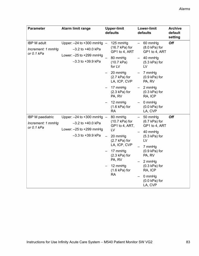
Instructions for Use Infinity Acute Care System – M540 Patient Monitor SW VG2 83
Alarms
IBP M adult
Increment: 1 mmHg or 0.1 kPa
Upper: –24 to +300 mmHg
–3.2 to +40.0 kPa
Lower: –25 to +299 mmHg
–3.3 to +39.9 kPa
– 125 mmHg (16.7 kPa) for GP1 to 4, ART
– 80 mmHg (10.7 kPa) for LV
– 20 mmHg (2.7 kPa) for LA, ICP, CVP
– 17 mmHg (2.3 kPa) for PA, RV
– 12 mmHg (1.6 kPa) for RA
– 60 mmHg (8.0 kPa) for GP1 to 4, ART
– 40 mmHg (5.3 kPa) for LV
– 7 mmHg (0.9 kPa) for PA, RV
– 2 mmHg (0.3 kPa) for RA, ICP
– 0 mmHg (0.0 kPa) for LA, CVP
Off
IBP M paediatric
Increment: 1 mmHg or 0.1 kPa
Upper: –24 to +300 mmHg
–3.2 to +40.0 kPa
Lower: –25 to +299 mmHg
–3.3 to +39.9 kPa
– 80 mmHg (10.7 kPa) for GP1 to 4, ART, LV
– 20 mmHg (2.7 kPa) for LA, ICP, CVP
– 17 mmHg (2.3 kPa) for PA, RV
– 12 mmHg (1.6 kPa) for RA
– 50 mmHg (6.7 kPa) for GP1 to 4, ART
– 40 mmHg (5.3 kPa) for LV
– 7 mmHg (0.9 kPa) for PA, RV
– 2 mmHg (0.3 kPa) for RA, ICP
– 0 mmHg (0.0 kPa) for LA, CVP
Off
Parameter Alarm limit range Upper-limit defaults
Lower-limit defaults
Archive default setting
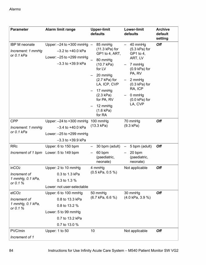
Alarms
84 Instructions for Use Infinity Acute Care System – M540 Patient Monitor SW VG2
IBP M neonate
Increment: 1 mmHg or 0.1 kPa
Upper: –24 to +300 mmHg
–3.2 to +40.0 kPa
Lower: –25 to +299 mmHg
–3.3 to +39.9 kPa
– 85 mmHg (11.3 kPa) for GP1 to 4, ART,
– 80 mmHg (10.7 kPa) for LV
– 20 mmHg (2.7 kPa) for LA, ICP, CVP
– 17 mmHg (2.3 kPa) for PA, RV
– 12 mmHg (1.6 kPa) for RA
– 40 mmHg (5.3 kPa) for GP1 to 4, ART, LV
– 7 mmHg (0.9 kPa) for PA, RV
– 2 mmHg (0.3 kPa) for RA, ICP
– 0 mmHg (0.0 kPa) for LA, CVP
Off
CPP
Increment: 1 mmHg or 0.1 kPa
Upper: –24 to +300 mmHg
–3.4 to +40.0 kPa
Lower: –25 to +299 mmHg
–3.3 to +39.9 kPa
100 mmHg (13.3 kPa)
70 mmHg (9.3 kPa)
Off
RRc
Increment of 1 bpm
Upper: 6 to 150 bpm
Lower: 5 to 149 bpm
– 30 bpm (adult)
– 60 bpm (paediatric, neonate)
– 5 bpm (adult)
– 20 bpm (paediatric, neonate)
Off
inCO2
Increment of 1 mmHg, 0.1 kPa, or 0.1 %
Upper: 2 to 10 mmHg
0.3 to 1.3 kPa
0.3 to 1.3 %
Lower: not user-selectable
4 mmHg (0.5 kPa, 0.5 %)
Not applicable Off
etCO2
Increment of 1 mmHg, 0.1 kPa, or 0.1 %
Upper: 6 to 100 mmHg
0.8 to 13.3 kPa
0.8 to 13.2 %
Lower: 5 to 99 mmHg
0.7 to 13.2 kPa
0.7 to 13.0 %
50 mmHg (6.7 kPa, 6.6 %)
30 mmHg (4.0 kPa, 3.9 %)
Off
PVC/min
Increment of 1
Upper: 1 to 50 10 Not applicable Off
Parameter Alarm limit range Upper-limit defaults
Lower-limit defaults
Archive default setting
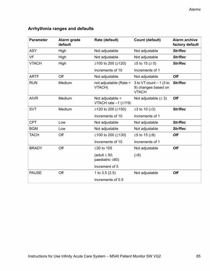
Instructions for Use Infinity Acute Care System – M540 Patient Monitor SW VG2 85
Alarms
Arrhythmia ranges and defaults
Parameter Alarm grade default
Rate (default) Count (default) Alarm archive factory default
ASY High Not adjustable Not adjustable Str/RecVF High Not adjustable Not adjustable Str/RecVTACH High ≥100 to 200 (≥120)
Increments of 10
≥5 to 15 (≥ 0)
Increments of 1
Str/Rec
ARTF Off Not adjustable Not adjustable OffRUN Medium not adjustable (Rate =
VTACH)3 to VT count – 1 (3 to 9) changes based on VTACH
Str/Rec
AIVR Medium Not adjustable = VTACH rate –1 (≤119)
Not adjustable (≥ 3) Off
SVT Medium ≥120 to 200 (≥150)
Increments of 10
≥3 to 10 (≥3)
Increments of 1
Str/Rec
CPT Low Not adjustable Not adjustable Str/RecBGM Low Not adjustable Not adjustable Str/RecTACH Off ≥100 to 200 (≥130)
Increments of 10
≥5 to 15 (≥8)
Increments of 1
Off
BRADY Off ≤30 to 105
(adult ≤ 50; paediatric ≤60)
Increment of 5
Not adjustable
(≥8)
Off
PAUSE Off 1 to 3.5 (2.5)
Increments of 0.5
Not adjustable Off

86 Instructions for Use Infinity Acute Care System – M540 Patient Monitor SW VG2
This page is intentionally left blank
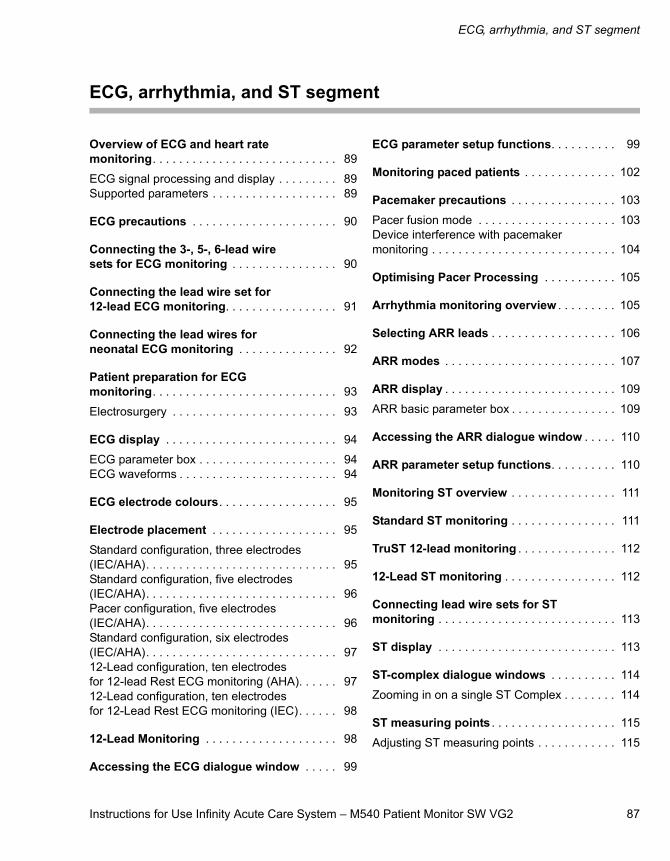
Instructions for Use Infinity Acute Care System – M540 Patient Monitor SW VG2 87
ECG, arrhythmia, and ST segment
ECG, arrhythmia, and ST segment
Overview of ECG and heart rate monitoring. . . . . . . . . . . . . . . . . . . . . . . . . . . . 89
ECG signal processing and display . . . . . . . . . 89Supported parameters . . . . . . . . . . . . . . . . . . . 89
ECG precautions . . . . . . . . . . . . . . . . . . . . . . 90
Connecting the 3-, 5-, 6-lead wire sets for ECG monitoring . . . . . . . . . . . . . . . . 90
Connecting the lead wire set for 12-lead ECG monitoring. . . . . . . . . . . . . . . . . 91
Connecting the lead wires for neonatal ECG monitoring . . . . . . . . . . . . . . . 92
Patient preparation for ECG monitoring. . . . . . . . . . . . . . . . . . . . . . . . . . . . 93
Electrosurgery . . . . . . . . . . . . . . . . . . . . . . . . . 93
ECG display . . . . . . . . . . . . . . . . . . . . . . . . . . 94
ECG parameter box . . . . . . . . . . . . . . . . . . . . . 94ECG waveforms . . . . . . . . . . . . . . . . . . . . . . . . 94
ECG electrode colours. . . . . . . . . . . . . . . . . . 95
Electrode placement . . . . . . . . . . . . . . . . . . . 95
Standard configuration, three electrodes (IEC/AHA). . . . . . . . . . . . . . . . . . . . . . . . . . . . . 95Standard configuration, five electrodes (IEC/AHA). . . . . . . . . . . . . . . . . . . . . . . . . . . . . 96Pacer configuration, five electrodes (IEC/AHA). . . . . . . . . . . . . . . . . . . . . . . . . . . . . 96Standard configuration, six electrodes (IEC/AHA). . . . . . . . . . . . . . . . . . . . . . . . . . . . . 9712-Lead configuration, ten electrodes for 12-lead Rest ECG monitoring (AHA). . . . . . 9712-Lead configuration, ten electrodesfor 12-Lead Rest ECG monitoring (IEC). . . . . . 98
12-Lead Monitoring . . . . . . . . . . . . . . . . . . . . 98
Accessing the ECG dialogue window . . . . . 99
ECG parameter setup functions. . . . . . . . . . 99
Monitoring paced patients . . . . . . . . . . . . . . 102
Pacemaker precautions . . . . . . . . . . . . . . . . 103
Pacer fusion mode . . . . . . . . . . . . . . . . . . . . . 103Device interference with pacemaker monitoring . . . . . . . . . . . . . . . . . . . . . . . . . . . . 104
Optimising Pacer Processing . . . . . . . . . . . 105
Arrhythmia monitoring overview . . . . . . . . . 105
Selecting ARR leads . . . . . . . . . . . . . . . . . . . 106
ARR modes . . . . . . . . . . . . . . . . . . . . . . . . . . 107
ARR display . . . . . . . . . . . . . . . . . . . . . . . . . . 109
ARR basic parameter box . . . . . . . . . . . . . . . . 109
Accessing the ARR dialogue window . . . . . 110
ARR parameter setup functions. . . . . . . . . . 110
Monitoring ST overview . . . . . . . . . . . . . . . . 111
Standard ST monitoring . . . . . . . . . . . . . . . . 111
TruST 12-lead monitoring . . . . . . . . . . . . . . . 112
12-Lead ST monitoring . . . . . . . . . . . . . . . . . 112
Connecting lead wire sets for ST monitoring . . . . . . . . . . . . . . . . . . . . . . . . . . . 113
ST display . . . . . . . . . . . . . . . . . . . . . . . . . . . 113
ST-complex dialogue windows . . . . . . . . . . 114
Zooming in on a single ST Complex . . . . . . . . 114
ST measuring points . . . . . . . . . . . . . . . . . . . 115
Adjusting ST measuring points . . . . . . . . . . . . 115

88 Instructions for Use Infinity Acute Care System – M540 Patient Monitor SW VG2
ECG, arrhythmia, and ST segment
ST reference . . . . . . . . . . . . . . . . . . . . . . . . . . 115
Saving ST reference. . . . . . . . . . . . . . . . . . . . . 115
Accessing the ST dialogue window . . . . . . . 116
ST setup functions . . . . . . . . . . . . . . . . . . . . . 116
Learning/relearning QRS pattern . . . . . . . . . 118
Manual relearning. . . . . . . . . . . . . . . . . . . . . . . 118
Instructions for Use Infinity Acute Care System – M540 Patient Monitor SW VG2 89
ECG, arrhythmia, and ST segment
Overview of ECG and heart rate monitoring
The M540 calculates and displays the heart rate, identifies paced beats, reports arrhythmia condi-tions, and measures ST deviations. ECG and heart rate monitoring is for adult, paediatric, and neonatal patients.
3-, 5-, 6-, and 10-lead wire sets are available for adult and paediatric ECG monitoring (including TruST). A neonatal ECG adapter cable is available for connecting individual ECG leads for neonatal monitoring.
12-lead monitoring is of diagnostic quality and can be used with our optional Rest ECG analysis.
The ECG monitoring functions are configurable in the ECG dialogue window (see page 99).
Before performing any monitoring functions, refer to the section “For your safety and that of your patients” on page 9.
ECG signal processing and display
The M540 identifies QRS complexes of certain amplitudes and QRS widths for adult, paediatric, and neonatal patients (see page 266 of the “Tech-nical data” chapter for detailed parameter specifica-tions). It calculates heart rates within a range of 15 beats to 300 beats per minute, using the R-R intervals of the last 10 seconds. This calculation excludes the two longest and two shortest R-R intervals. The M540 averages the remaining inter-vals and displays the result as the current heart rate in the HR parameter box.
During dual-channel processing, a weight is assigned to each channel depending on its level of artefact. The cleaner channel always receives a greater weight. When a channel exceeds a cer-tain level of artefact, it is excluded from the com-posite signal, and the M540 shifts to single-channel processing. If both channels experience excessive artefact, the message ECG artifact appears until at least one channel is sufficiently free of artefact.
During an artifact, asterisks (* * *) replace the heart rate value. When the artefact clears, QRS process-ing resumes without initiating a relearning phase.
Arrhythmia monitoring and the selected arrhythmia mode affect the display of the HR parameter box. For detailed information, see “ARR display” on page 109.
Parameter-specific error messages are listed on page 214.
Supported parameters
– ECG: HR (heart rate)
– ST: STI, STII, STIII, STaVR, STaVL, STaVF, STV, STV+, STV1 to TruSTV6, STVM, STCVM, STdV1, STdV3, STdV4, STdV6
– Arrhythmia: ARR (ASY, VF, ARTF, VTACH, RUN, AIVR, SVT, CPT, BGM, TACH, BRADY, PAUSE; see page 107 for a description of these ARR modes) and PVC/min
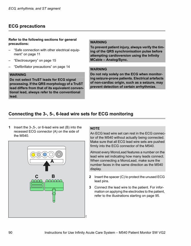
ECG, arrhythmia, and ST segment
90 Instructions for Use Infinity Acute Care System – M540 Patient Monitor SW VG2
ECG precautions
Refer to the following sections for general precautions:
– “Safe connection with other electrical equip-ment” on page 11
– “Electrosurgery” on page 15
– “Defibrillator precautions” on page 14
Connecting the 3-, 5-, 6-lead wire sets for ECG monitoring
1 Insert the 3-,5-, or 6-lead wire set (B) into the recessed ECG connector (A) on the side of the M540.
2 Insert the spacer (C) to protect the unused ECG lead pins.
3 Connect the lead wire to the patient. For infor-mation on applying the electrodes to the patient, refer to the illustrations starting on page 95.
WARNINGDo not select TruST leads for ECG signal processing. If the QRS morphology of a TruST lead differs from that of its equivalent conven-tional lead, always refer to the conventional lead.
WARNINGTo prevent patient injury, always verify the tim-ing of the QRS synchronisation pulse before attempting cardioversion using the Infinity MCable – Analog/Sync.
WARNINGDo not rely solely on the ECG when monitor-ing seizure-prone patients. Electrical artefacts of non-cardiac origin, such as a seizure, may prevent detection of certain arrhythmias.
312
A
BC
NOTEAn ECG lead wire set can rest in the ECG connec-tor of the M540 without actually being connected. Make sure that all ECG lead wire sets are pushed firmly into the ECG connector of the M540.
Almost every MonoLead features a number on the lead wire set indicating how many leads connect. When connecting a MonoLead, make sure the number faces in the same direction as the M540 display.
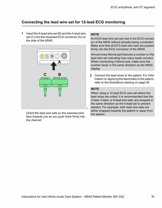
Instructions for Use Infinity Acute Care System – M540 Patient Monitor SW VG2 91
ECG, arrhythmia, and ST segment
Connecting the lead wire set for 12-lead ECG monitoring
1 Insert the 6-lead wire set (B) and the 4-lead wire set (C) into the recessed ECG connector (A) on the side of the M540.
Orient the lead wire sets so the exposed pins face towards you as you push them firmly into the channel.
2 Connect the lead wires to the patient. For infor-mation on applying the electrodes to the patient, refer to the illustrations starting on page 95.
311
A
BC
NOTEAn ECG lead wire set can rest in the ECG connec-tor of the M540 without actually being connected. Make sure that all ECG lead wire sets are pushed firmly into the ECG connector of the M540.
Almost every MonoLead features a number on the lead wire set indicating how many leads connect. When connecting a MonoLead, make sure the number faces in the same direction as the M540 display.
NOTEWhen using a 12-lead ECG wire set where the lead wires are coiled, it is recommended that the 3-lead, 5-lead, or 6-lead wire sets, are wrapped in the same direction as the 4-lead set to prevent artefact. For example, both lead wire sets are either wrapped towards the patient or away from the patient.
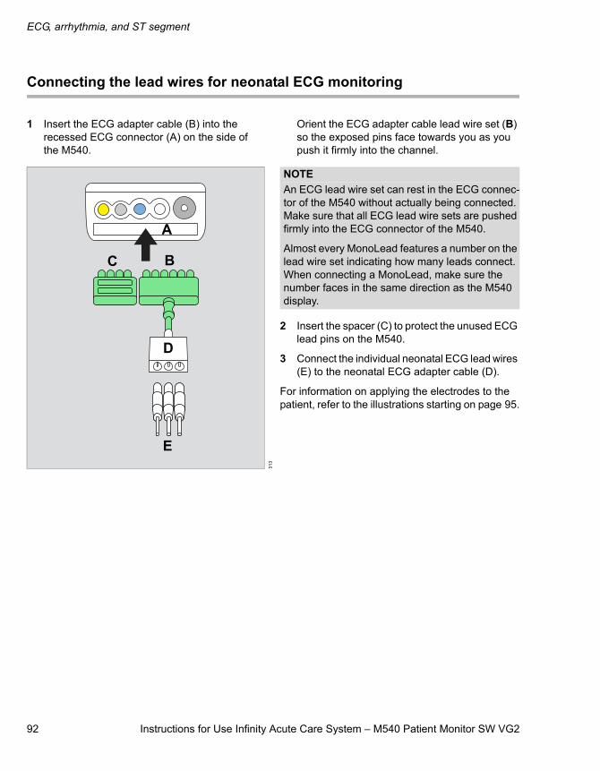
ECG, arrhythmia, and ST segment
92 Instructions for Use Infinity Acute Care System – M540 Patient Monitor SW VG2
Connecting the lead wires for neonatal ECG monitoring
1 Insert the ECG adapter cable (B) into the recessed ECG connector (A) on the side of the M540.
Orient the ECG adapter cable lead wire set (B) so the exposed pins face towards you as you push it firmly into the channel.
2 Insert the spacer (C) to protect the unused ECG lead pins on the M540.
3 Connect the individual neonatal ECG lead wires (E) to the neonatal ECG adapter cable (D).
For information on applying the electrodes to the patient, refer to the illustrations starting on page 95.
313
A
BC
E
D
NOTEAn ECG lead wire set can rest in the ECG connec-tor of the M540 without actually being connected. Make sure that all ECG lead wire sets are pushed firmly into the ECG connector of the M540.
Almost every MonoLead features a number on the lead wire set indicating how many leads connect. When connecting a MonoLead, make sure the number faces in the same direction as the M540 display.
Instructions for Use Infinity Acute Care System – M540 Patient Monitor SW VG2 93
ECG, arrhythmia, and ST segment
Patient preparation for ECG monitoring
The following tips provide optimal ECG monitoring results, but must never replace hospital-approved practices or manufacturer’s recommendations.
Follow hospital procedures for proper skin prepara-tion. Dräger recommends Ag/AgCl disposable elec-trodes. Never use disposable electrodes after their expiration date and make sure that there is enough gel and that the gel has not dried out.
P- and T-waves with amplitudes exceeding 0.2 mV can be interpreted as QRS complexes. To allow detection of low heart rate conditions under these circumstances, place the lead with the highest R-wave in channel ECG1. If P- and T-waves continue to be misinterpreted, reposition the electrodes or use a pulse oximeter to monitor the pulse rate.
To maintain a clear signal, change electrodes every 24 to 48 hours or more often when the following occurs:
– ECG signal degradation
– Excessive patient perspiration
– Skin irritation
Consider the following when selecting the electrode sites:
– Surgery – keep electrodes as far from the surgi-cal site as possible, while maintaining a clini-cally useful lead configuration. Place the cable and lead wires as far from the ESU as possible and perpendicular to the ESU cables.
– Burn Patients – use sterile electrodes. Clean the equipment thoroughly and follow hospital infection control procedures.
Electrosurgery
Integrated ESU suppression improves the perform-ance of the monitor during electrosurgery, reduces noise on ECG waveforms, and protects the patient from burns.
To minimise interference from the electrosurgical unit
1 Touch the HR parameter box to select the ECG dialogue window directly.
2 Touch the Settings tab > ECG 1 tab.
3 Touch ECG filter until it toggles to ESU.
4 Touch X to close the dialogue window.
NOTE12-lead monitoring is not available when the ESU filter is activated. Likewise, the ESU filter selec-tion is not available when you are using 12-lead monitoring.
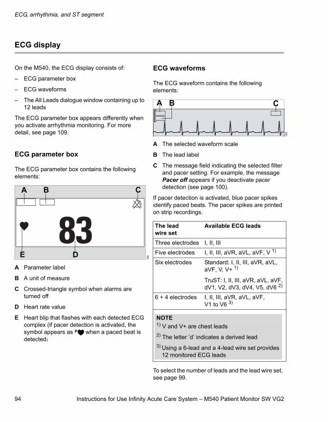
ECG, arrhythmia, and ST segment
94 Instructions for Use Infinity Acute Care System – M540 Patient Monitor SW VG2
ECG display
On the M540, the ECG display consists of:
– ECG parameter box
– ECG waveforms
– The All Leads dialogue window containing up to 12 leads
The ECG parameter box appears differently when you activate arrhythmia monitoring. For more detail, see page 109.
ECG parameter box
The ECG parameter box contains the following elements:
A Parameter label
B A unit of measure
C Crossed-triangle symbol when alarms are turned off
D Heart rate value
E Heart blip that flashes with each detected ECG complex (if pacer detection is activated, the symbol appears as when a paced beat is detected)
ECG waveforms
The ECG waveform contains the following elements:
A The selected waveform scale
B The lead label
C The message field indicating the selected filter and pacer setting. For example, the message Pacer off appears if you deactivate pacer detection (see page 100).
If pacer detection is activated, blue pacer spikes identify paced beats. The pacer spikes are printed on strip recordings.
To select the number of leads and the lead wire set, see page 99.
100
A B C
DE
042
The lead wire set
Available ECG leads
Three electrodes I, II, III
Five electrodes I, II, III, aVR, aVL, aVF, V 1)
Six electrodes Standard: I, II, III, aVR, aVL, aVF, V, V+ 1)
TruST: I, II, III, aVR, aVL, aVF, dV1, V2, dV3, dV4, V5, dV6 2)
6 + 4 electrodes I, II, III, aVR, aVL, aVF, V1 to V6 3)
A B C
NOTE1) V and V+ are chest leads2) The letter ’d’ indicates a derived lead3) Using a 6-lead and a 4-lead wire set provides
12 monitored ECG leads
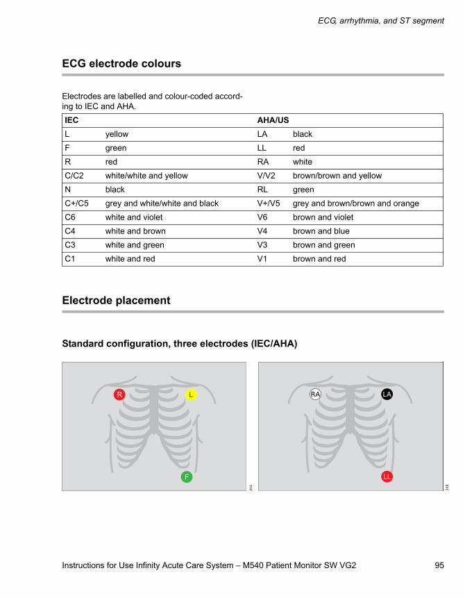
Instructions for Use Infinity Acute Care System – M540 Patient Monitor SW VG2 95
ECG, arrhythmia, and ST segment
ECG electrode colours
Electrodes are labelled and colour-coded accord-ing to IEC and AHA.
Electrode placement
Standard configuration, three electrodes (IEC/AHA)
IEC AHA/USL yellow LA black
F green LL red
R red RA white
C/C2 white/white and yellow V/V2 brown/brown and yellow
N black RL green
C+/C5 grey and white/white and black V+/V5 grey and brown/brown and orange
C6 white and violet V6 brown and violet
C4 white and brown V4 brown and blue
C3 white and green V3 brown and green
C1 white and red V1 brown and red31
4
315
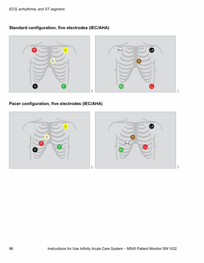
ECG, arrhythmia, and ST segment
96 Instructions for Use Infinity Acute Care System – M540 Patient Monitor SW VG2
Standard configuration, five electrodes (IEC/AHA)
Pacer configuration, five electrodes (IEC/AHA)
316
317
318
319
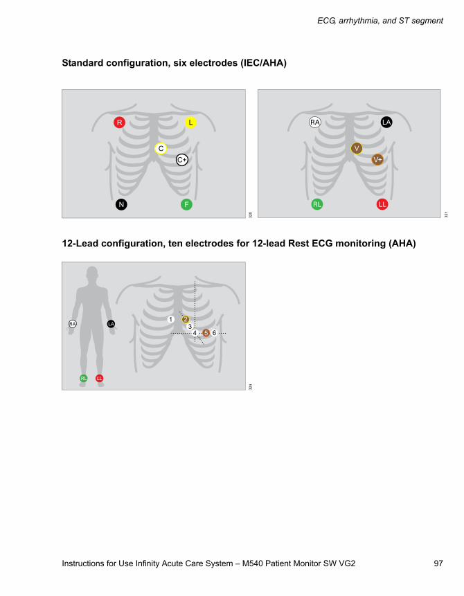
Instructions for Use Infinity Acute Care System – M540 Patient Monitor SW VG2 97
ECG, arrhythmia, and ST segment
Standard configuration, six electrodes (IEC/AHA)
12-Lead configuration, ten electrodes for 12-lead Rest ECG monitoring (AHA) 32
0
321
324
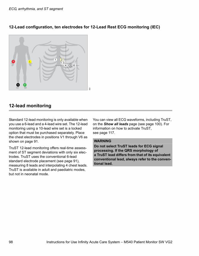
ECG, arrhythmia, and ST segment
98 Instructions for Use Infinity Acute Care System – M540 Patient Monitor SW VG2
12-Lead configuration, ten electrodes for 12-Lead Rest ECG monitoring (IEC)
12-lead monitoring
Standard 12-lead monitoring is only available when you use a 6-lead and a 4-lead wire set. The 12-lead monitoring using a 10-lead wire set is a locked option that must be purchased separately. Place the chest electrodes in positions V1 through V6 as shown on page 91.
TruST 12-lead monitoring offers real-time assess-ment of ST segment deviations with only six elec-trodes. TruST uses the conventional 6-lead standard electrode placement (see page 91), measuring 8 leads and interpolating 4 chest leads. TruST is available in adult and paediatric modes, but not in neonatal mode.
You can view all ECG waveforms, including TruST, on the Show all leads page (see page 100). For information on how to activate TruST, see page 117.
322
WARNINGDo not select TruST leads for ECG signal processing. If the QRS morphology of a TruST lead differs from that of its equivalent conventional lead, always refer to the conven-tional lead.
Instructions for Use Infinity Acute Care System – M540 Patient Monitor SW VG2 99
ECG, arrhythmia, and ST segment
Accessing the ECG dialogue window
1 Touch the HR parameter box.
2 Touch the Settings tab.
or, if the parameter is not displayed
1 Touch any parameter box > Settings tab > Change parameter.
2 Touch the desired parameter label to display it on the main screen.
3 Touch the parameter box > Settings tab.
ECG parameter setup functions
All ECG-parameter setup functions take place in the HR dialogue window (see “Accessing the ECG dialogue window”).
The limits dialogue window contains the Auto set and Alarm buttons for configuring the alarm func-tions. For detailed alarm setup information, see “Configuring a patient’s alarm settings” on page 73.
Selection Available settings DescriptionSettings - ECG 1 page
Tone volume Off, 5, 10 (default) to 100 % in increments of 10 %
Sets the volume of the pulse tone.
Tone source ECG (default), SpO2 Sets the source of the pulse tone.
ECG filter – Off – provides the greatest sensitivity to noise or artefact (the message Filter off appears in the waveform channel).
– Monitor (default) – recommended for stand-ard monitoring; reduces baseline drift, muscle artefact, and power-line interference. No message appears in the waveform channel.
– ESU– reduces signal distortion during elec-trosurgery (the message Filter ESU appears in the waveform channel).
Controls the sensitivity to vari-ous artefact sources.
When the M540 is in OR mode and the filter selection is set to Monitoring, the hardware low-pass ESU filter is activated.
NOTE12-lead monitoring is not available when the ESU filter is enabled. Likewise, the ESU filter selection is not available when you are using 12-lead monitoring.
ECG, arrhythmia, and ST segment
100 Instructions for Use Infinity Acute Care System – M540 Patient Monitor SW VG2
HR source – ECG (default) – derives the heart rate from the ECG signal.
– ART – derives the heart rate from the arterial pressure signal. The HR parameter box label changes to APR and appears in the colour of ART.
– SpO2 – derives the heart rate from the pulse oximetry signal. The HR parameter box label changes to PLS and appears in the colour of SpO2.
– Auto – derives the heart rate either from the ECG signal or other available sources. If an ECG signal is not available, the M540 switches to ART, and then to SpO2.
Selects a different source for the heart rate when the ECG channel is unavailable due to artefact resulting from surgical procedures.
Show all leads Not applicable Shows all ECG waveforms. Press anywhere in the wave-form area to access additional ECG waveforms. Press Menu to close all the ECG wave-forms.
Size all ECG 0.25, 0.5, 1 (default), 2, 4, 8 mV/cm Sets the amplitude of ALL dis-played ECG leads.
Color Red, White, Yellow, Green (default), Light blue, Blue, Purple, Orange
Determines the colour of the waveforms, the parameter labels and values.
Change parameter A list of currently available parameters. Changes the parameter box to a different parameter.
Settings - ECG 2 page
Pacer detection
(Not available in the neonatal mode)
– On (default)
– Off – the message Pacer off appears in the waveform channel
– Fusion – the message Pacer fusion appears in the waveform channel
Determines whether pacer impulses are detected. See “Pacer fusion mode” on page 103 for precautions before you start this mode.
QRS sync marker – On – displays QRS synchronisation markers
– Off (default)
Determines whether vertical white markers appear on the waveform to identify QRS com-plexes which helps in deter-mining when it is safe to perform synchronised cardio-version.
Selection Available settings Description
Instructions for Use Infinity Acute Care System – M540 Patient Monitor SW VG2 101
ECG, arrhythmia, and ST segment
Cable type
(TruST is only avail-able with a 6-lead wire set)
– Auto (default)
– 3, 5, 6, and 12 leads (if activated)
When set to Auto, it detects the number of connected lead wires automatically. If the auto-detect mode does not detect the connected lead wire set, it allows you to select the cable type manually. “12” denotes a combination of a 6-lead and 4-lead wire set for 12-lead monitoring.
ARR lead 1 ECGI, ECGII (ARR lead 1 default), ECGIII, ECGaVR, ECGaVL, ECGaVF, ECGV (ARR lead 2 default), ECGV+, ECGV1 to ECGV6
Assigns the lead for QRS processing.ARR lead 2
ARR processing ECG1, ECG1&2 (default) ECG1 setting – arrhythmia processing occurs only on the lead selected as ARR lead 1.
ECG1&2 setting – arrhythmia processing occurs on the leads selected as ARR lead 1 and ARR lead 2.
Selection Available settings Description
NOTEWhen using the ECG extension cable, the system always assumes the cable is a 6-lead wire set.
NOTEThe ECG1&2 selection is not available if the neo-natal patient category is selected.
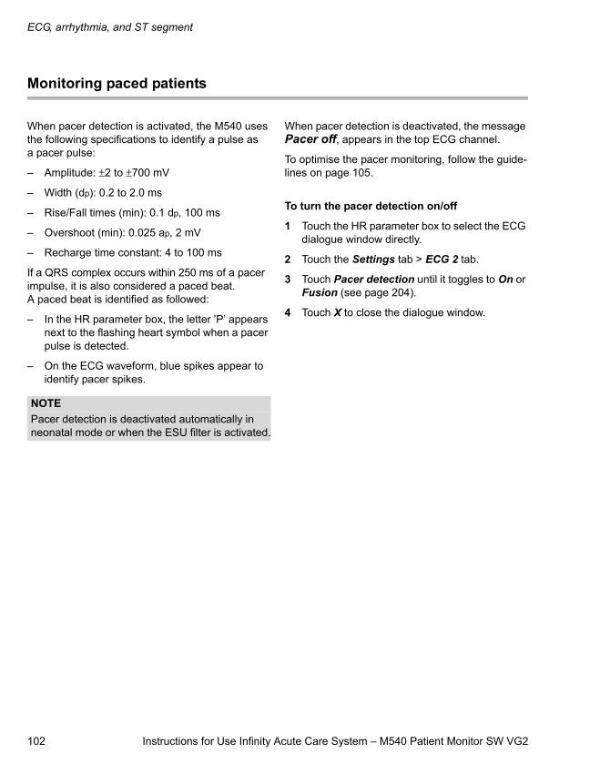
ECG, arrhythmia, and ST segment
102 Instructions for Use Infinity Acute Care System – M540 Patient Monitor SW VG2
Monitoring paced patients
When pacer detection is activated, the M540 uses the following specifications to identify a pulse as a pacer pulse:
– Amplitude: ±2 to ±700 mV
– Width (dp): 0.2 to 2.0 ms
– Rise/Fall times (min): 0.1 dp, 100 ms
– Overshoot (min): 0.025 ap, 2 mV
– Recharge time constant: 4 to 100 ms
If a QRS complex occurs within 250 ms of a pacer impulse, it is also considered a paced beat. A paced beat is identified as followed:
– In the HR parameter box, the letter ’P’ appears next to the flashing heart symbol when a pacer pulse is detected.
– On the ECG waveform, blue spikes appear to identify pacer spikes.
When pacer detection is deactivated, the message Pacer off, appears in the top ECG channel.
To optimise the pacer monitoring, follow the guide-lines on page 105.
To turn the pacer detection on/off
1 Touch the HR parameter box to select the ECG dialogue window directly.
2 Touch the Settings tab > ECG 2 tab.
3 Touch Pacer detection until it toggles to On or Fusion (see page 204).
4 Touch X to close the dialogue window.
NOTEPacer detection is deactivated automatically in neonatal mode or when the ESU filter is activated.
Instructions for Use Infinity Acute Care System – M540 Patient Monitor SW VG2 103
ECG, arrhythmia, and ST segment
Pacemaker precautions
The M540 has been tested for the pacer pulse rejection. However, it is impossible to anticipate every clinically possible waveform characteristic. For the paced patient, the M540 could, therefore, miscount heart rates and misinterpret rate-depend-ent arrhythmias. False low-rate alarms can result under the following conditions:
– Fused beats and asynchronous pacemakers, when coupling intervals are in the range of +1s to –90 ms
– 70 mV pacemaker pulses followed by QRS complexes smaller than 0.5 mV
– Asynchronous pacemaker pulses with overshoot
Pacer fusion mode
Pacer Fusion mode offers increased detection sen-sitivity to fused paced beats, thereby reducing false asystole and low heart rate alarms.Pacer Fusion mode offers increased detection sensitivity to fused paced beats, thereby reducing false asystole and low heart rate alarms.
WARNINGMake sure pacer detection is deactivated for patients without pacemakers. Make sure it is activated for patients with pacemakers. Deac-tivating pacemaker detection for paced patients may result in pacemaker pulses being counted as regular QRS complexes, which could prevent an asystole alarm from being detected. Always verify that the pacer detec-tion status is correct for the patient. Be aware that setting the ECG filter option to ESU deac-tivates pacemaker detection automatically.
WARNINGInterference from a monitor may cause some rate-adaptive implantable pacemakers to pace at unnecessarily high rates. Be extra-vigilant with patients when using these types of pace-makers.
WARNINGAlways keep pacemaker patients under close surveillance and monitor their vital signs care-fully. – Do not assess the patient’s condition
exclusively from the heart and respiratory rate values the monitor displays and the rate alarms that are generated. Heart rate meters may continue to count the pace-maker rate during cardiac arrest or some arrhythmias.
– Some pacemakers (especially external pacemakers with body surface electrodes) emit pulses with amplitudes far exceeding the 700 mV maximum amplitude specified for the M540. The M540 may incorrectly detect these large pacemaker pulses as valid QRS complexes and may fail to detect cardiac arrest.
WARNINGImpedance respiration and pacemaker detec-tion are inoperative when the ESU filter is selected. Refer to “Electrosurgery” on page 15 for general safety precautions.
WARNINGPay close attention to pacemaker patients being monitored in Fusion mode because this mode may increase the risk of falsely count-ing pacemaker spikes as QRS complexes, thus failing to detect cardiac arrest.
ECG, arrhythmia, and ST segment
104 Instructions for Use Infinity Acute Care System – M540 Patient Monitor SW VG2
Device interference with pacemaker monitoring
The following devices can interfere with pacemaker monitoring.
Impedance-derived rate response pacemakers
These pacemakers emit pulses that adjust the pacemaker rate to the respiratory rate. These pulses could be falsely interpreted as pacer pulses. For impedance-derived rate response pacemakers, modify the electrode placement until the blue spikes on the waveform disappear since they are not related to real pacer impulses.
Infusion or roller bypass pumps
Interference from these devices can cause pacer spikes to appear on the waveform although the ECG appears normal. To determine if the pump is the cause of the artefact, turn it off, if possible. To minimise the artefact, choose the lead with the best signal or replace the electrodes. Rerouting invasive pressure tubing away from the infusion tubing can also improve the ECG signals.
Line isolation devices
To minimise the effect of line isolation devices, which can cause temporary disturbances in the ECG signal, follow these precautions:
– Choose the lead with the best signal for ECG monitoring.
– Check the ECG electrodes; replace them, if necessary.
Transcutaneous Electrical Nerve Stimulators (TENS)
Signals from the transcutaneous electrical nerve stimulators (TENS) often resemble the pacer signals and can be labelled as such. The M540 can reject valid QRS complexes, which follow misinter-preted TENS signals. If TENS signals continue to register as pacer spikes, turn off pacer detection (see page 100).
CAUTIONThe fusion mode pacer detection is not intended for use with large-signal, unipolar pacemakers. It is intended for use only with biphasic pacemakers. Observe the following:– Select Fusion mode only in situations where
it becomes necessary to suppress repeated false asystole and/or false low heart rate alarms.
– Before selecting Fusion mode, be certain that the patient has a biphasic pacemaker (exter-nal or implanted) and that it is accurately pro-grammed as appropriate for that patient.
– Do not use Fusion mode if you are uncertain as to what type of pacemaker is being used.
NOTEThe displayed heart rate may be incorrect if the pacemaker pulse wanders through the ECG wave-form (ineffective pacing). During the wandering pacemaker test required by IEC 60601-2-27 and ANSI/AAMI EC13, the displayed heart rate varied between 15 and 30 bpm (rather than consistently being 30 bpm). The displayed heart rate was not affected by the presence of pacemaker pulses dur-ing any of those standard’s other pacemaker tests.
Instructions for Use Infinity Acute Care System – M540 Patient Monitor SW VG2 105
ECG, arrhythmia, and ST segment
Optimising pacer processing
You can minimise interference and optimise ECG signal acquisition and processing for paced patients.
To optimise the pacer processing
1 Touch the HR parameter box to select the ECG dialogue window directly.
2 Touch the Settings tab > ECG 1 tab.
3 Touch ECG filter until it toggles to Monitor or Off and determine which setting provides the clearest signal.
4 Touch X to close the dialogue window.
Arrhythmia monitoring overview
The M540 performs arrhythmia (ARR) monitoring on adult and paediatric patients. Arrhythmia moni-toring is not available for neonates. To make sure that asystole and ventricular fibrillation alarms are reported even when the HR alarm monitoring and arrhythmia monitoring functions are deactivated, set the ASY/VF alarms selection in the Alarms mgmt. dialogue window to Always on (see page 204).
The selected arrhythmia mode (see page 107) con-trols which arrhythmia parameters are monitored and how they are displayed.
The ARR monitoring functions have configurable parameter-specific setup pages (see page 110).
Before performing any monitoring functions, refer to the section “For Your Safety and that of Your Patients” starting on page 9.
WARNINGWhen HR alarm and ARR monitoring are deac-tivated and the ASY/VF alarms setting is set to Follow HR, the monitor does not generate ASY/VF alarms. To make sure that ASY/VF alarms are always generated, set the ASY/VF alarms setting to Always on.
NOTEThe banner HR Alarms Off appears in the right most field in the header bar whenever you turn HR alarms off.
The HR, ASY, VF off banner appears when arrhythmia monitoring is deactivated, the ASY/VF alarms feature is set to Follow HR, and HR alarms are deactivated.
NOTEIf French NFC mode is activated (see page 206), you cannot deactivate HR alarms.
ECG, arrhythmia, and ST segment
106 Instructions for Use Infinity Acute Care System – M540 Patient Monitor SW VG2
Selecting ARR leads
Appropriate lead selection is essential for accurate ARR monitoring. It is ideal to assign the two best ECG leads as the ARR monitoring leads. The fol-lowing two options are available:
– ECG1 (single-channel selection) – dedicates processing to the lead selected as ARR lead 1.
– ECG1&2 (Dual-channel selection) – deter-mines the heart rate and ARR based on the leads selected as ARR lead1 and ARR lead 2.
To select ARR Leads
1 Touch the HR parameter box to select the ECG dialogue window directly.
2 Touch the Settings tab > ECG 2 tab.
3 Touch the ARR lead 1 or ARR lead 2 tab.
4 Touch the appropriate lead and then touch X to close the dialogue window.
NOTEWhen the M540 is docked in an IACS configura-tion, the top two ECG waveform channels on the Cockpit are ARR lead 1 and ARR lead 2.
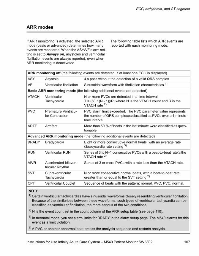
Instructions for Use Infinity Acute Care System – M540 Patient Monitor SW VG2 107
ECG, arrhythmia, and ST segment
ARR modes
If ARR monitoring is activated, the selected ARR mode (basic or advanced) determines how many events are monitored. When the ASY/VF alarm set-ting is set to Always on, asystoles and ventricular fibrillation events are always reported, even when ARR monitoring is deactivated.
The following table lists which ARR events are reported with each monitoring mode.
ARR monitoring off (the following events are detected, if at least one ECG is displayed)
ASY Asystole 4 s pass without the detection of a valid QRS complex
VF Ventricular fibrillation Sinusoidal waveform with fibrillation characteristics 1)
Basic ARR monitoring mode (the following additional events are detected)
VTACH Ventricular Tachycardia
N or more PVCs are detected in a time interval T = (60 * (N - 1))/R, where N is the VTACH count and R is the VTACH rate 2)
PVC Premature Ventricu-lar Contraction
PVC alarm limit exceeded. The PVC parameter value represents the number of QRS complexes classified as PVCs over a 1-minute time interval.
ARTF Artefact More than 50 % of beats in the last minute were classified as ques-tionable
Advanced ARR monitoring mode (the following additional events are detected)
BRADY Bradycardia Eight or more consecutive normal beats, with an average rate ≤bradycardia rate setting 3)
RUN Ventricular RUN Series of 3 to N–1 consecutive PVCs with a beat-to-beat rate ≥ the VTACH rate 2)
AIVR Accelerated Idioven-tricular Rhythm
Series of 3 or more PVCs with a rate less than the VTACH rate.
SVT Supraventricular Tachycardia
N or more consecutive normal beats, with a beat-to-beat rate greater than or equal to the SVT setting 2)
CPT Ventricular Couplet Sequence of beats with the pattern: normal, PVC, PVC, normal.
NOTE1) Certain ventricular tachycardias have sinusoidal waveforms closely resembling ventricular fibrillation.
Because of the similarities between these waveforms, such types of ventricular tachycardia can be classified as ventricular fibrillation, the more serious of the two conditions.
2) N is the event count set in the count column of the ARR setup table (see page 110).3) In neonatal mode, you set alarm limits for BRADY in the alarm setup page. The M540 alarms for this
event as a limit violation.4) A PVC or another abnormal beat breaks the analysis sequence and restarts analysis.
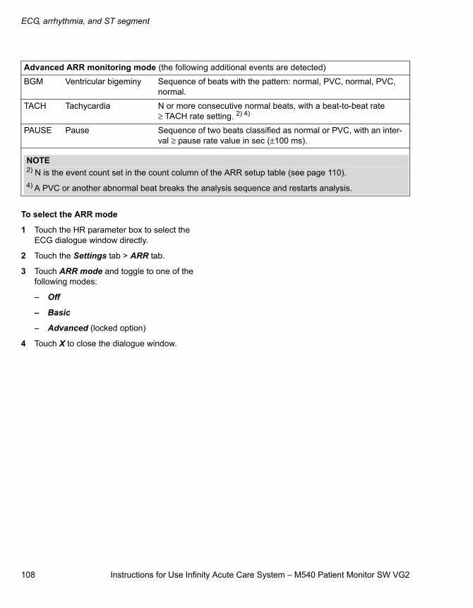
ECG, arrhythmia, and ST segment
108 Instructions for Use Infinity Acute Care System – M540 Patient Monitor SW VG2
To select the ARR mode
1 Touch the HR parameter box to select the ECG dialogue window directly.
2 Touch the Settings tab > ARR tab.
3 Touch ARR mode and toggle to one of the following modes:
– Off
– Basic
– Advanced (locked option)
4 Touch X to close the dialogue window.
Advanced ARR monitoring mode (the following additional events are detected)
BGM Ventricular bigeminy Sequence of beats with the pattern: normal, PVC, normal, PVC, normal.
TACH Tachycardia N or more consecutive normal beats, with a beat-to-beat rate ≥ TACH rate setting. 2) 4)
PAUSE Pause Sequence of two beats classified as normal or PVC, with an inter-val ≥ pause rate value in sec (±100 ms).
NOTE2) N is the event count set in the count column of the ARR setup table (see page 110).4) A PVC or another abnormal beat breaks the analysis sequence and restarts analysis.
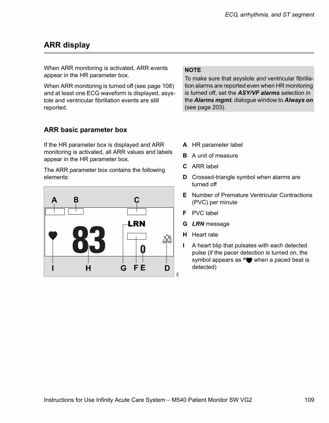
Instructions for Use Infinity Acute Care System – M540 Patient Monitor SW VG2 109
ECG, arrhythmia, and ST segment
ARR display
When ARR monitoring is activated, ARR events appear in the HR parameter box.
When ARR monitoring is turned off (see page 108) and at least one ECG waveform is displayed, asys-tole and ventricular fibrillation events are still reported.
L
ARR basic parameter box
If the HR parameter box is displayed and ARR monitoring is activated, all ARR values and labels appear in the HR parameter box.
The ARR parameter box contains the following elements:
A HR parameter label
B A unit of measure
C ARR label
D Crossed-triangle symbol when alarms are turned off
E Number of Premature Ventricular Contractions (PVC) per minute
F PVC label
G LRN message
H Heart rate
I A heart blip that pulsates with each detected pulse (if the pacer detection is turned on, the symbol appears as when a paced beat is detected)
NOTETo make sure that asystole and ventricular fibrilla-tion alarms are reported even when HR monitoring is turned off, set the ASY/VF alarms selection in the Alarms mgmt. dialogue window to Always on (see page 203).
089
LRN
A B C
DEFGHI
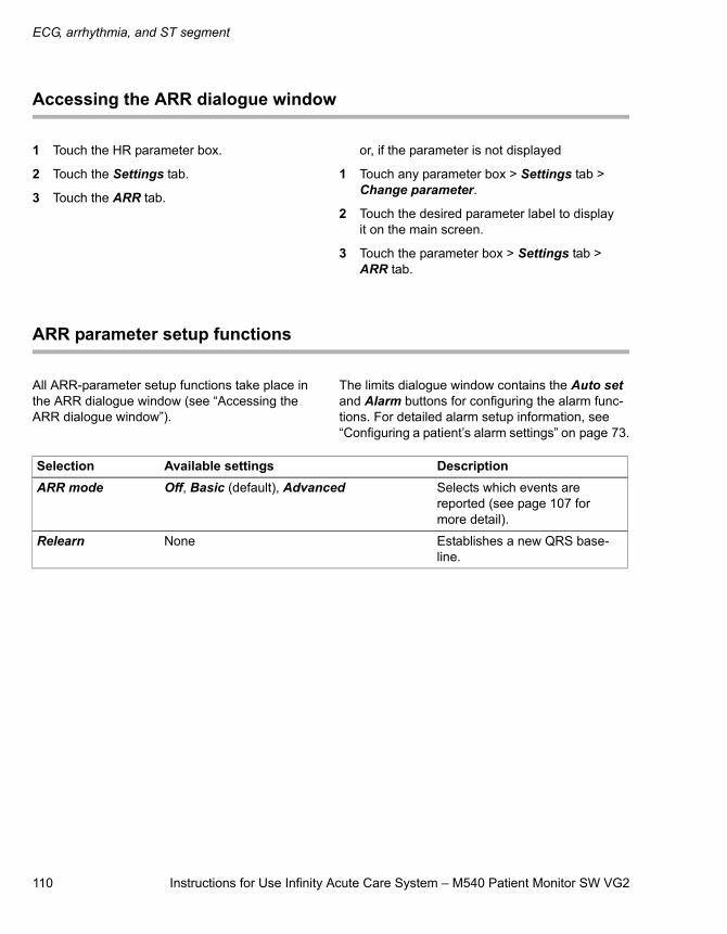
ECG, arrhythmia, and ST segment
110 Instructions for Use Infinity Acute Care System – M540 Patient Monitor SW VG2
Accessing the ARR dialogue window
1 Touch the HR parameter box.
2 Touch the Settings tab.
3 Touch the ARR tab.
or, if the parameter is not displayed
1 Touch any parameter box > Settings tab > Change parameter.
2 Touch the desired parameter label to display it on the main screen.
3 Touch the parameter box > Settings tab > ARR tab.
ARR parameter setup functions
All ARR-parameter setup functions take place in the ARR dialogue window (see “Accessing the ARR dialogue window”).
The limits dialogue window contains the Auto set and Alarm buttons for configuring the alarm func-tions. For detailed alarm setup information, see “Configuring a patient’s alarm settings” on page 73.
Selection Available settings DescriptionARR mode Off, Basic (default), Advanced Selects which events are
reported (see page 107 for more detail).
Relearn None Establishes a new QRS base-line.
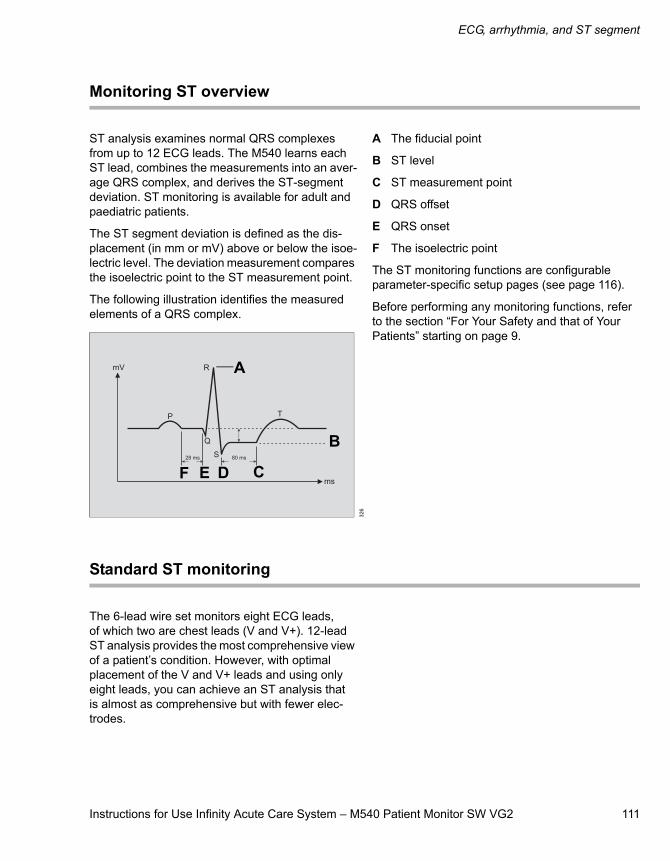
Instructions for Use Infinity Acute Care System – M540 Patient Monitor SW VG2 111
ECG, arrhythmia, and ST segment
Monitoring ST overview
ST analysis examines normal QRS complexes from up to 12 ECG leads. The M540 learns each ST lead, combines the measurements into an aver-age QRS complex, and derives the ST-segment deviation. ST monitoring is available for adult and paediatric patients.
The ST segment deviation is defined as the dis-placement (in mm or mV) above or below the isoe-lectric level. The deviation measurement compares the isoelectric point to the ST measurement point.
The following illustration identifies the measured elements of a QRS complex.
A The fiducial point
B ST level
C ST measurement point
D QRS offset
E QRS onset
F The isoelectric point
The ST monitoring functions are configurable parameter-specific setup pages (see page 116).
Before performing any monitoring functions, refer to the section “For Your Safety and that of Your Patients” starting on page 9.
Standard ST monitoring
The 6-lead wire set monitors eight ECG leads, of which two are chest leads (V and V+). 12-lead ST analysis provides the most comprehensive view of a patient’s condition. However, with optimal placement of the V and V+ leads and using only eight leads, you can achieve an ST analysis that is almost as comprehensive but with fewer elec-trodes.
326
A
B
CDE F
ECG, arrhythmia, and ST segment
112 Instructions for Use Infinity Acute Care System – M540 Patient Monitor SW VG2
TruST 12-lead monitoring
This feature offers real-time assessment of 12 ST segment deviations, with only six electrodes, which provide eight measured ECG leads and four derived chest leads. The derived leads are identi-fied by adding the letter ‘d’ before the lead label.
When TruST monitoring is activated, the V-lead defaults to V2 and the V+ lead defaults to V5. Although you can select derived leads for display, they are excluded from ARR and QRS processing.
12-lead ST monitoring
During 12-lead ST monitoring, the M540 acquires 12 ST leads in addition to the following:
– ST Vector Magnitude (STVM) – the magnitude (mm or mV) of the ST vector. It is a summary vector, combining the ST values from all 12 leads. STVM is trended and has its own alarm limits.
– ST Change in Vector Magnitude (STCVM) – the change of magnitude (mm or mV) between the current ST vector and the ST vector at the time of the last reference. STCVM values also show a change in the location of the ST vector over time.
To activate or deactivate ST monitoring
You can turn ST monitoring on or off at any time.
1 Touch the ST parameter box.
2 Touch the Settings tab.
3 Touch ST monitoring until it toggles to On or Off.
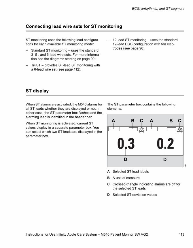
Instructions for Use Infinity Acute Care System – M540 Patient Monitor SW VG2 113
ECG, arrhythmia, and ST segment
Connecting lead wire sets for ST monitoring
ST monitoring uses the following lead configura-tions for each available ST monitoring mode:
– Standard ST monitoring – uses the standard 3- 5-, and 6-lead wire sets. For more informa-tion see the diagrams starting on page 90.
– TruST – provides ST-lead ST monitoring with a 6-lead wire set (see page 112).
– 12-lead ST monitoring – uses the standard 12-lead ECG configuration with ten elec-trodes (see page 90).
ST display
When ST alarms are activated, the M540 alarms for all ST leads whether they are displayed or not. In either case, the ST parameter box flashes and the alarming lead is identified in the header bar.
When ST monitoring is activated, current ST values display in a separate parameter box. You can select which two ST leads are displayed in the parameter box.
The ST parameter box contains the following elements:
A Selected ST lead labels
B A unit of measure
C Crossed-triangle indicating alarms are off for the selected ST leads
D Selected ST deviation values
090
A AB B C
D D
C
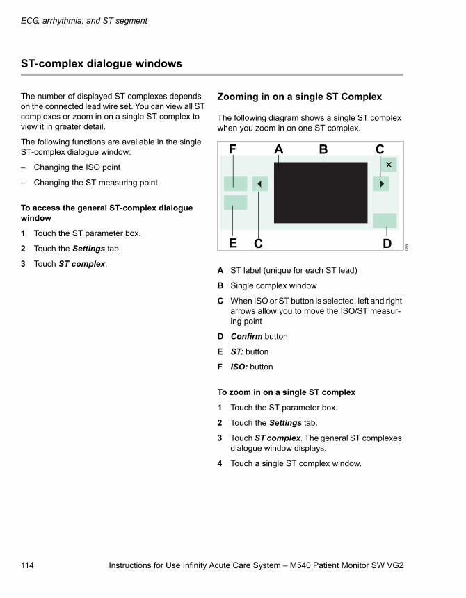
ECG, arrhythmia, and ST segment
114 Instructions for Use Infinity Acute Care System – M540 Patient Monitor SW VG2
ST-complex dialogue windows
The number of displayed ST complexes depends on the connected lead wire set. You can view all ST complexes or zoom in on a single ST complex to view it in greater detail.
The following functions are available in the single ST-complex dialogue window:
– Changing the ISO point
– Changing the ST measuring point
To access the general ST-complex dialogue window
1 Touch the ST parameter box.
2 Touch the Settings tab.
3 Touch ST complex.
Zooming in on a single ST Complex
The following diagram shows a single ST complex when you zoom in on one ST complex.
A ST label (unique for each ST lead)
B Single complex window
C When ISO or ST button is selected, left and right arrows allow you to move the ISO/ST measur-ing point
D Confirm button
E ST: button
F ISO: button
To zoom in on a single ST complex
1 Touch the ST parameter box.
2 Touch the Settings tab.
3 Touch ST complex. The general ST complexes dialogue window displays.
4 Touch a single ST complex window.
085
A B
E D
CF
C
Instructions for Use Infinity Acute Care System – M540 Patient Monitor SW VG2 115
ECG, arrhythmia, and ST segment
ST measuring points
You can change the ST measuring points and isoelectric point from the single ST-complex dia-logue window. The setup buttons for changing the measuring points are located on the left side of the screen. Changing the measuring point for one complex adjusts the measuring points for all ST complexes.
Adjusting ST measuring points
Whenever you adjust the isoelectric and ST meas-uring points, the ST deviation is recomputed.
To change ST measuring points
1 Touch the ST parameter box to access the ST dialogue window directly.
2 Touch the Settings tab.
3 Touch ST complex to display the general ST complexes dialogue window.
4 Touch an individual ST panel to zoom in on a single ST complex.
5 Touch ISO: and use the arrows to move cursor and adjust ISO point.
6 Touch ST: and use the arrows to move cursor and adjust ST point.
7 Touch Confirm to accept the settings and to close the ST-complex panel or touch X to close the ST-complex panel without saving changes.
ST reference
You can save ST reference complexes as a refer-ence point for future ST deviation measurement comparisons. The first time you relearn QRS com-plexes, the current ST data is saved as a reference data. This original ST reference data is updated each time you save ST references.
Saving ST reference
You can save the ST reference from the Settings tab. Saving the ST reference saves all current ST complexes as the new reference.
To save ST reference complexes
1 Touch the ST parameter box.
2 Touch the Settings tab.
3 Touch Save:
ECG, arrhythmia, and ST segment
116 Instructions for Use Infinity Acute Care System – M540 Patient Monitor SW VG2
Accessing the ST dialogue window
1 Touch the ST parameter box.
2 Touch the Settings tab.
or, if the parameter is not displayed
1 Touch any parameter box > Settings tab > Change parameter.
2 Touch the desired parameter label to display it on the main screen.
3 Touch the parameter box > Settings tab.
ST setup functions
All ST-parameter setup functions take place in the ST dialogue window (see “Accessing the ST dia-logue window”).
The limits dialogue window contains the Auto set and Alarm buttons for configuring the alarm func-tions. For detailed alarm setup information, see “Configuring a patient’s alarm settings” on page 73.
Selection Available settings DescriptionSettings
Relearn
(Not available if ECG is not connected, in neonatal mode, or ST monitoring is turned off)
Not applicable Purges stored average ST com-plexes, blanks displayed aver-age ST complexes, and learns the arrhythmia and dominant QRS pattern.
Instructions for Use Infinity Acute Care System – M540 Patient Monitor SW VG2 117
ECG, arrhythmia, and ST segment
ST lead 1 – Three electrodes: STI, STII, STIII
– Five electrodes: STI, STII, STIII, STaVR, STaVL, STaVF, STV
– Six electrodes: STI, STII, STIII, STaVR, STaVL, STaVF, STV, STV+
– Six electrodes (with TruST activated): STI, STII, STIII, STaVR, STaVL, STaVF, STdV1, STdV2, STdV3, STdV4, STdV5, STdV6
– Ten electrodes: STI, STII, STIII, STaVR, STaVL, STaVF, STV1, STV2, STV3, STV4, STV5, STV6, STCVM, and STVM
– Default for ST lead1: STII
– Default for ST lead2: STV for 5-/6-lead cable, STV2 for TruST or 12-lead cable
Selects an ST lead for analysis and display.ST lead 2
ST monitoring Off, On (default) Turns ST monitoring on/off.
ST complex Not applicable Views ST complexes.
Event duration Off, 15, 30, 45, 60 (default) sec Defines a period during which an alarm condition must persist before alarm signals are generated.
TruST
(TruST is only avail-able with a 6-lead wire set.)
On, Off (default) Turns TruST monitoring on or off.
Save: Not applicable Saves the current ST complexes as references (see page 115).
Change parameter A list of currently available parameters Changes the parameter box to a different parameter.
Selection Available settings Description
ECG, arrhythmia, and ST segment
118 Instructions for Use Infinity Acute Care System – M540 Patient Monitor SW VG2
Learning/relearning QRS pattern
The M540 creates a reference template by learning the dominant QRS pattern of a patient. The refer-ence template is stored for reference and all subse-quent beats and rhythms are compared against it and classified either as normal or irregular.
The M540 can only learn the QRS pattern of the leads that are selected for ARR processing. If only one lead is available, the M540 only learns on one lead. If no lead wire set is connected, the M540 cannot perform a learning phase. In this case, an error message is displayed.
The M540 starts a learning phase automatically when:
– ARR monitoring is turned on
– A different ARR mode is selected
– Different ECG leads are selected for ARR processing
– The cable type is changed
During the learning phase, which lasts approxi-mately 30 to 40 seconds, the message ARR relearning appears in the message field. In addi-tion, and message LRN appears in the ECG parameter box.
If ST monitoring is turned on, ST deviations are also recomputed during the learning phase.
Manual relearning
Relearn the QRS pattern of a patient when:
– Leads are reconnected or electrodes are repo-sitioned.
– Eight hours have passed since the last learning phase.
– Questionable ARR calls appear on the ECG.
– Other significant changes appear on the ECG.
You can initiate a relearning phase from the arrhythmia and the ST dialogue windows.
To relearn from the ARR dialogue window
1 Touch the HR parameter box to select the ECG dialogue window.
2 Touch the Settings tab > ARR tab > Relearn.
To relearn from the ST dialogue window
1 Touch the ST parameter box to select the ST dialogue window.
2 Touch the Settings tab > Relearn.
Instructions for Use Infinity Acute Care System – M540 Patient Monitor SW VG2 119
Impedance respiration (RRi)
Impedance respiration (RRi)
Overview of RRi monitoring . . . . . . . . . . . . . 120
Supported parameters . . . . . . . . . . . . . . . . . . . 120
RRi precautions . . . . . . . . . . . . . . . . . . . . . . . 120
Connecting the 3-, 5-, 6-lead wire sets for RRi monitoring . . . . . . . . . . . . . . . . . 121
Connecting the lead wire set for 12-lead RRi monitoring . . . . . . . . . . . . . . 122
Connecting the lead wires forneonatal RRi monitoring . . . . . . . . . . . . . . . . 123
Patient preparation for respiration monitoring. . . . . . . . . . . . . . . . . . . . . . . . . . . . 123
RRi display . . . . . . . . . . . . . . . . . . . . . . . . . . . 125
Respiration parameter box . . . . . . . . . . . . . . . . 125Respiration markers . . . . . . . . . . . . . . . . . . . . . 125
RRi measuring modes . . . . . . . . . . . . . . . . . . 126
Accessing the RRi dialogue window . . . . . . 126
RRi parameter setup functions . . . . . . . . . . . 127
Impedance respiration (RRi)
120 Instructions for Use Infinity Acute Care System – M540 Patient Monitor SW VG2
Overview of RRi monitoring
The M540 measures impedance respiration by passing a harmless high-frequency current between two ECG electrodes on the patient's chest. The electrical resistance (impedance) between the electrodes varies with the expansion and contraction of the chest during inspiration and expiration. The M540 displays a respiration wave-form and respiratory rate value from these imped-ance changes.
The M540 uses ECG leads I or II for breath detec-tion regardless of the lead selected for QRS processing.
The respiration monitoring is for adult, paediatric and neonatal patients. The M540 can use the respiration signal for central apnoea monitoring.
The RRi monitoring functions are configurable in the parameter-specific dialogue window (see page 126).
Before performing any monitoring functions, refer to the section “For Your Safety and That of Your Patients” starting on page 9.
Parameter-specific error messages are listed on page 218.
Supported parameters
RRi – respiration rate measured by impedance (RRi values are not displayed when the ESU filter is activated – see page 99).
RRi precautions
WARNINGThe safety and effectiveness of the respiration measurement method in the detection of apnoea, particularly the apnoea of prematurity and apnoea of infancy, have not been estab-lished.
WARNINGThis device does not monitor obstructive apnoea. Patients at risk for respiratory crises should be observed closely.
WARNINGThe large amplitude pacemaker pulses (100 mV or greater) may interfere with the monitor ability to measure or detectrespiration.
WARNINGThe monitor reports an apnoeic event when no breaths are reported within the established apnoea period. Therefore, do not rely on impedance respiration monitoring as the sole method for detecting cessation of breathing. Dräger recommends the monitoring of addi-tional parameters that indicate the patient’s oxygenation status, such as etCO2 and SpO2. Heart rate limit alarms should also be enabled and set appropriately.
WARNINGImpedance respiration and pacemaker detec-tion are inoperative when the ESU filter is selected. Refer to “Electrosurgery” on page 15 for general safety precautions.
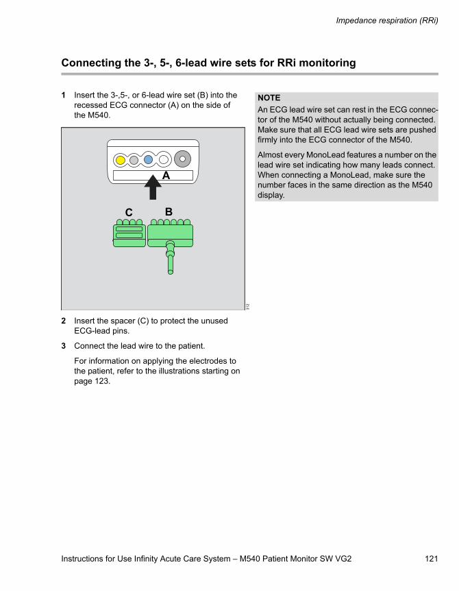
Instructions for Use Infinity Acute Care System – M540 Patient Monitor SW VG2 121
Impedance respiration (RRi)
Connecting the 3-, 5-, 6-lead wire sets for RRi monitoring
1 Insert the 3-,5-, or 6-lead wire set (B) into the recessed ECG connector (A) on the side of the M540.
2 Insert the spacer (C) to protect the unused ECG-lead pins.
3 Connect the lead wire to the patient.
For information on applying the electrodes to the patient, refer to the illustrations starting on page 123.
312
A
BC
NOTEAn ECG lead wire set can rest in the ECG connec-tor of the M540 without actually being connected. Make sure that all ECG lead wire sets are pushed firmly into the ECG connector of the M540.
Almost every MonoLead features a number on the lead wire set indicating how many leads connect. When connecting a MonoLead, make sure the number faces in the same direction as the M540 display.
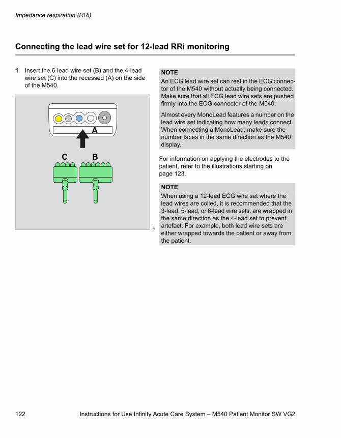
Impedance respiration (RRi)
122 Instructions for Use Infinity Acute Care System – M540 Patient Monitor SW VG2
Connecting the lead wire set for 12-lead RRi monitoring
1 Insert the 6-lead wire set (B) and the 4-lead wire set (C) into the recessed (A) on the side of the M540.
For information on applying the electrodes to the patient, refer to the illustrations starting on page 123.
311
A
BC
NOTEAn ECG lead wire set can rest in the ECG connec-tor of the M540 without actually being connected. Make sure that all ECG lead wire sets are pushed firmly into the ECG connector of the M540.
Almost every MonoLead features a number on the lead wire set indicating how many leads connect. When connecting a MonoLead, make sure the number faces in the same direction as the M540 display.
NOTEWhen using a 12-lead ECG wire set where the lead wires are coiled, it is recommended that the 3-lead, 5-lead, or 6-lead wire sets, are wrapped in the same direction as the 4-lead set to prevent artefact. For example, both lead wire sets are either wrapped towards the patient or away from the patient.
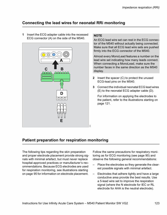
Instructions for Use Infinity Acute Care System – M540 Patient Monitor SW VG2 123
Impedance respiration (RRi)
Connecting the lead wires for neonatal RRi monitoring
1 Insert the ECG adapter cable into the recessed ECG connector (A) on the side of the M540.
2 Insert the spacer (C) to protect the unused ECG-lead pins on the M540.
3 Connect the individual neonatal ECG lead wires (E) to the neonatal ECG adapter cable (D).
For information on applying the electrodes to the patient, refer to the illustrations starting on page 121.
Patient preparation for respiration monitoring
The following tips regarding the skin preparation and proper electrode placement provide strong sig-nals with minimal artefact, but must never replace hospital-approved practices or manufacturer’s rec-ommendations. Because ECG electrodes are used for respiration monitoring, see illustrations starting on page 95 for information on electrode placement.
Follow the same precautions for respiratory moni-toring as for ECG monitoring (see page 90) and observe the following general recommendations:
– Place the electrodes so they generate the clear-est possible signals with minimal artefact.
– Electrodes that adhere tightly and have a large conductive area provide the best results. Use a 5-lead wire set to improve the respiration signal (where the N electrode for IEC or RL electrode for AHA is the neutral electrode).
313
A
BC
E
D
NOTEAn ECG lead wire set can rest in the ECG connec-tor of the M540 without actually being connected. Make sure that all ECG lead wire sets are pushed firmly into the ECG connector of the M540.
Almost every MonoLead features a number on the lead wire set indicating how many leads connect. When connecting a MonoLead, make sure the number faces in the same direction as the M540 display.
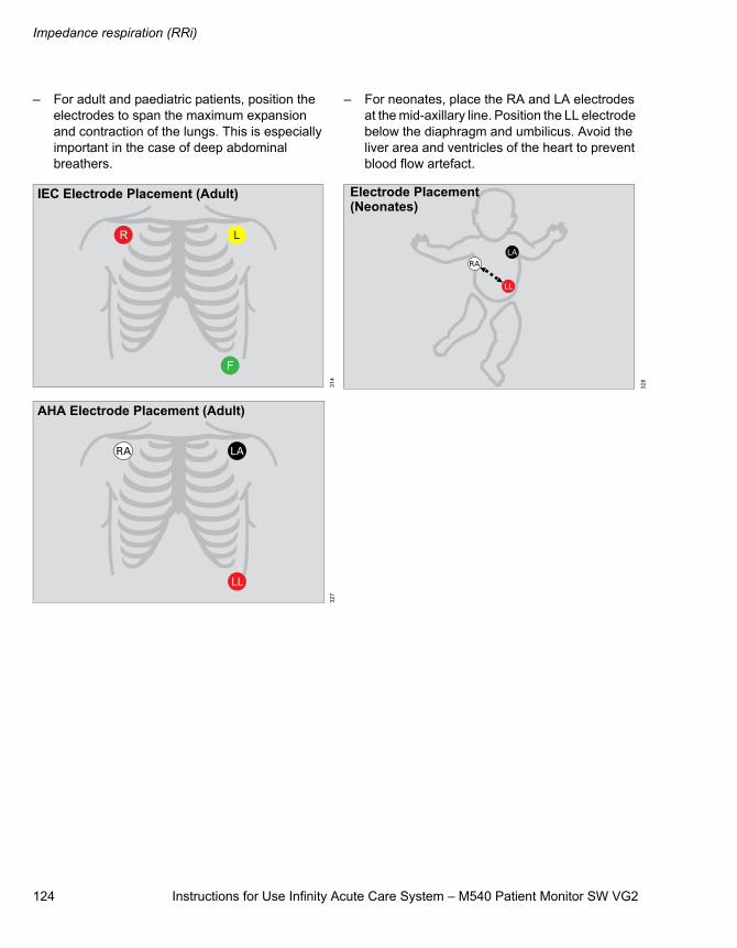
Impedance respiration (RRi)
124 Instructions for Use Infinity Acute Care System – M540 Patient Monitor SW VG2
– For adult and paediatric patients, position the electrodes to span the maximum expansion and contraction of the lungs. This is especially important in the case of deep abdominal breathers.
– For neonates, place the RA and LA electrodes at the mid-axillary line. Position the LL electrode below the diaphragm and umbilicus. Avoid the liver area and ventricles of the heart to prevent blood flow artefact.
314
327
IEC Electrode Placement (Adult)
AHA Electrode Placement (Adult)
328
Electrode Placement(Neonates)
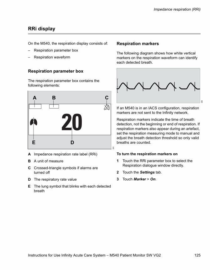
Instructions for Use Infinity Acute Care System – M540 Patient Monitor SW VG2 125
Impedance respiration (RRi)
RRi display
On the M540, the respiration display consists of:
– Respiration parameter box
– Respiration waveform
Respiration parameter box
The respiration parameter box contains the following elements:
A Impedance respiration rate label (RRi)
B A unit of measure
C Crossed-triangle symbols if alarms are turned off
D The respiratory rate value
E The lung symbol that blinks with each detected breath
Respiration markers
The following diagram shows how white vertical markers on the respiration waveform can identify each detected breath.
If an M540 is in an IACS configuration, respiration markers are not sent to the Infinity network.
Respiration markers indicate the time of breath detection, not the beginning or end of respiration. If respiration markers also appear during an artefact, set the respiration measuring mode to manual and adjust the breath detection threshold so only valid breaths are counted.
To turn the respiration markers on
1 Touch the RRi parameter box to select the Respiration dialogue window directly.
2 Touch the Settings tab.
3 Touch Marker > On.
091
A B C
DE
356
Impedance respiration (RRi)
126 Instructions for Use Infinity Acute Care System – M540 Patient Monitor SW VG2
RRi measuring modes
The following respiration measuring modes are available:
– Auto (default) – appropriate for patients with regular breathing patterns. It uses the optimal breath-detection threshold calculated at the beginning of respiration monitoring.
– Manual – appropriate for adult or paediatric patients whose breathing patterns show exces-sive variation, or for neonates with irregular breathing rhythms, whose respiration signals may otherwise not be reliably evaluated. The M540 does not set a breath-detection threshold at the beginning of respiration monitoring. Instead, the adjustments you make to the wave-form size (see page 39) alter the breath detec-tion sensitivity of the monitor.
To select the desired respiration mode, see page 127.
Accessing the RRi dialogue window
1 Touch the RRi parameter box.
2 Touch the Settings tab.
or, if the parameter is not displayed
1 Touch any parameter box > Settings tab > Change parameter.
2 Touch the desired parameter label to display it on the main screen.
3 Touch the parameter box > Settings tab.
WARNINGIf the respiration waveform size is set too low in the Manual mode, shallow breaths may not be counted. If it is set too high, cardiac arte-facts will be counted as breaths. Therefore, always use the respiration marker to verify the breath detection at the desired amplitude.
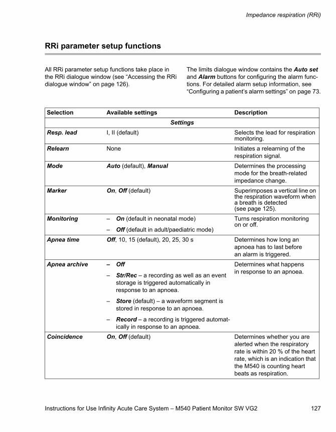
Instructions for Use Infinity Acute Care System – M540 Patient Monitor SW VG2 127
Impedance respiration (RRi)
RRi parameter setup functions
All RRi parameter setup functions take place in the RRi dialogue window (see “Accessing the RRi dialogue window” on page 126).
The limits dialogue window contains the Auto set and Alarm buttons for configuring the alarm func-tions. For detailed alarm setup information, see “Configuring a patient’s alarm settings” on page 73.
Selection Available settings DescriptionSettings
Resp. lead I, II (default) Selects the lead for respiration monitoring.
Relearn None Initiates a relearning of the respiration signal.
Mode Auto (default), Manual Determines the processing mode for the breath-related impedance change.
Marker On, Off (default) Superimposes a vertical line on the respiration waveform when a breath is detected (see page 125).
Monitoring – On (default in neonatal mode)
– Off (default in adult/paediatric mode)
Turns respiration monitoring on or off.
Apnea time Off, 10, 15 (default), 20, 25, 30 s Determines how long an apnoea has to last before an alarm is triggered.
Apnea archive – Off
– Str/Rec – a recording as well as an event storage is triggered automatically in response to an apnoea.
– Store (default) – a waveform segment is stored in response to an apnoea.
– Record – a recording is triggered automat-ically in response to an apnoea.
Determines what happens in response to an apnoea.
Coincidence On, Off (default) Determines whether you are alerted when the respiratory rate is within 20 % of the heart rate, which is an indication that the M540 is counting heart beats as respiration.

Impedance respiration (RRi)
128 Instructions for Use Infinity Acute Care System – M540 Patient Monitor SW VG2
Color Red, White, Yellow, Green, Light blue (default), Blue, Purple, Orange
Determines the colour of the waveforms, the parameter labels and values.
Change parameter A list of currently available parameters Changes the parameter box to a different parameter.
Selection Available settings Description
Instructions for Use Infinity Acute Care System – M540 Patient Monitor SW VG2 129
SpO2 and Pulse CO-Ox monitoring with Masimo SET MCables
SpO2 and Pulse CO-Ox monitoring with Masimo SET MCables
Overview of SpO2 monitoring . . . . . . . . . . . . 130
Supported parameters . . . . . . . . . . . . . . . . . . . 130
SpO2 and Pulse CO-Ox precautions. . . . . . . 132
Connecting the Masimo SET MCable . . . . . . 134
Connecting the Masimo Rainbow SET MCable. . . . . . . . . . . . . . . . . . . . . . . . . . . . . . . 135
Patient preparation. . . . . . . . . . . . . . . . . . . . . 136
Applying the sensor . . . . . . . . . . . . . . . . . . . . . 136
SpO2 and Pulse CO-Ox display. . . . . . . . . . . 137
Accessing the SpO2 dialogue window . . . . . 139
SpO2-parameter setup functions . . . . . . . . . 139
Accessing the Pulse CO-Ox dialogue window . . . . . . . . . . . . . . . . . . . . . . . . . . . . . . 141
Pulse CO-Ox parameter setup functions . . . . . . . . . . . . . . . . . . . . . . . . . . . . . 141
Password-protected Masimo Rainbow SET setup functions. . . . . . . . . . . . 144
SpO2 and Pulse CO-Ox monitoring with Masimo SET MCables
130 Instructions for Use Infinity Acute Care System – M540 Patient Monitor SW VG2
Overview of SpO2 monitoring
SpO2 and Pulse CO-Ox monitoring is only possible with the corresponding SpO2 MCable. The follow-ing two MCable are available from Masimo for mon-itoring SpO2 and Pulse CO-Ox parameters:
– Infinity MCable – Masimo SET
– Infinity MCable – Masimo SET Rainbow
The values and the waveform of both MCables are displayed on the M540 and on the Cockpit if the M540 is docked in an IACS configuration.
Both MCables support motion-tolerant pulse oxi-metry using Signal Extraction Technology (SET). This technology enhances the quality of SpO2 mon-itoring and also measures the percentage of func-tional haemoglobin saturated with oxygen (%SpO2) in the arterial blood of the patient accurately and effectively.
A sensor applied to the patient measures the absorption levels of red and infrared light. The Masimo SET MCable or Masimo Rainbow SET MCable uses the difference between the two meas-urements to calculate the percentage of saturated haemoglobin (SpO2). Because light absorption var-ies with blood volume and blood volume varies with pulse rate, the Masimo SET MCable can also derive a pulse rate (PLS).
In addition, the Masimo SET MCables also provide a perfusion index (PI) value. PI is the ratio of the pulsatile blood flow to the non-pulsatile blood flow in peripheral tissue. The PI value provides informa-tion regarding the perfusion status of the selected application site. This provides a means to select the most optimal site.
The Infinity MCable – Masimo Rainbow SET meas-ures additional parameters that continuously and non-invasively measure blood constituents.
SpO2 and Pulse CO-Ox measurements are for adult, paediatric, and neonatal patients (with the following exceptions).
The SpO2 monitoring functions are configurable in the parameter-specific dialogue window (see page 139).
Before performing any monitoring functions, refer to the section “For your safety and that of your patients” on page 9.
Parameter-specific error messages are listed on page 220.
Supported parameters
The parameters SpO2, PLS, and PI are available and displayed regardless of which Masimo sensor and which Masimo SET MCable is being used.
The availability of additional Masimo Rainbow SET parameters depends on the sensor type that is being used and which parameters are activated on the Masimo Rainbow SET MCable.
NOTEThe Masimo Rainbow SET MCable parameters SpHb and SpOC are not approved for neonatal monitoring.
NOTEInformation about the wavelength range may be useful during photodynamic therapy. For details, see the “Technical Data” chapter.
NOTEThis device is covered under one or more of the following USA patents: 5,758,644, 6,011,986, 6,699,194, 7,214,986, 7,254,433, 7,530,955 and other applicable patents listed at: www.masimo.com/patents.htm
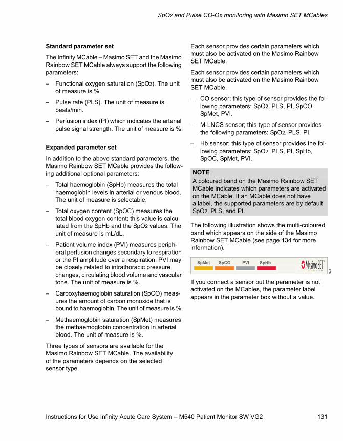
Instructions for Use Infinity Acute Care System – M540 Patient Monitor SW VG2 131
SpO2 and Pulse CO-Ox monitoring with Masimo SET MCables
Standard parameter set
The Infinity MCable – Masimo SET and the Masimo Rainbow SET MCable always support the following parameters:
– Functional oxygen saturation (SpO2). The unit of measure is %.
– Pulse rate (PLS). The unit of measure is beats/min.
– Perfusion index (PI) which indicates the arterial pulse signal strength. The unit of measure is %.
Expanded parameter set
In addition to the above standard parameters, the Masimo Rainbow SET MCable provides the follow-ing additional optional parameters:
– Total haemoglobin (SpHb) measures the total haemoglobin levels in arterial or venous blood. The unit of measure is selectable.
– Total oxygen content (SpOC) measures the total blood oxygen content; this value is calcu-lated from the SpHb and the SpO2 values. The unit of measure is mL/dL.
– Patient volume index (PVI) measures periph-eral perfusion changes secondary to respiration or the PI amplitude over a respiration. PVI may be closely related to intrathoracic pressure changes, circulating blood volume and vascular tone. The unit of measure is %.
– Carboxyhaemoglobin saturation (SpCO) meas-ures the amount of carbon monoxide that is bound to haemoglobin. The unit of measure is %.
– Methaemoglobin saturation (SpMet) measures the methaemoglobin concentration in arterial blood. The unit of measure is %.
Three types of sensors are available for the Masimo Rainbow SET MCable. The availability of the parameters depends on the selected sensor type.
Each sensor provides certain parameters which must also be activated on the Masimo Rainbow SET MCable.
Each sensor provides certain parameters which must also be activated on the Masimo Rainbow SET MCable.
– CO sensor; this type of sensor provides the fol-lowing parameters: SpO2, PLS, PI, SpCO, SpMet, PVI.
– M-LNCS sensor; this type of sensor provides the following parameters: SpO2, PLS, PI.
– Hb sensor; this type of sensor provides the fol-lowing parameters: SpO2, PLS, PI, SpHb, SpOC, SpMet, PVI.
The following illustration shows the multi-coloured band which appears on the side of the Masimo Rainbow SET MCable (see page 134 for more information).
If you connect a sensor but the parameter is not activated on the MCables, the parameter label appears in the parameter box without a value.
NOTEA coloured band on the Masimo Rainbow SET MCable indicates which parameters are activated on the MCable. If an MCable does not have a label, the supported parameters are by default SpO2, PLS, and PI.
478
SpO2 and Pulse CO-Ox monitoring with Masimo SET MCables
132 Instructions for Use Infinity Acute Care System – M540 Patient Monitor SW VG2
SpO2 and Pulse CO-Ox precautions
Interfering substances: Carboxyhaemoglobin may erroneously increase the measurement values. The level of increase is approximately equal to the amount of carboxyhaemoglobin present. Dyes, or any substance containing dyes that change arterial pigmentation, may cause erroneous measurement values.
-------------------------------------------------------------------
WARNINGHigh oxygen levels may predispose a prema-ture infant to retrolental fibroplasia. If this is a consideration do NOT set the high alarm limit to 100 %, which is equivalent to switch-ing the alarm off. Transcutaneous pO2 moni-toring is recommended for premature infants receiving supplemental oxygen.
WARNINGA pulse oximeter should not be used as an apnoea monitor.
WARNINGUse only Masimo-specified sensors. Other sensors may not provide adequate protection against defibrillation and may put the patient at risk.
WARNINGA Pulse CO-Oximeter should be considered an early warning device. If a trend towards patient hypoxemia is observed, blood sam-ples should be analysed by laboratory instru-ments to completely understand the condition of the patient.
WARNINGThe pulsations from an intra-aortic balloon support can elevate the pulse rate. Verify the pulse rate of the patient against the heart rate.
WARNINGElevated levels of methaemoglobin (MetHb) may lead to inaccurate SpO2 and SpCO meas-urements.
Elevated levels of total bilirubin may lead to inaccurate SpO2, SpMet, SpCO, SpHb, and SpOC measurements.
Motion artefact may lead to inaccurate SpMet, SpCO, SpHb, and SpOC measurements.
Very low arterial oxygen saturation (SaO2) lev-els may cause inaccurate SpCO and SpMet measurements.
Haemoglobin synthesis disorders may cause erroneous SpHb readings.
WARNINGTo reduce the hazard of burns during surgery, keep the sensor or transducer and their asso-ciated cables away from the surgical site, the electro-surgical unit return electrode, and earth ground.
WARNINGInspect the application site every two to three hours to ensure skin quality and correct opti-cal alignment. If the skin quality changes, move the sensor to another site. Change the application site at least every four hours.
CAUTIONDo not immerse the sensor or patient cable in any liquid. Moisture may present a safety risk.
NOTEA pulse oximeter can be used during defibrillation, but the readings may be inaccurate for up to 20 seconds.
Instructions for Use Infinity Acute Care System – M540 Patient Monitor SW VG2 133
SpO2 and Pulse CO-Ox monitoring with Masimo SET MCables
NOTEPossession or purchase of the Masimo SET MCable or the Masimo Rainbow SET MCable does not convey any expressed or implied license to use the device with unauthorised sen-sors or cables which would, alone, or in combina-tion with this device, fall within the scope of one or more of the patents relating to this device.
NOTEPurchase of this device confers no express or implied license under any Masimo patent to use this instrument with any oximetry sensor that is not manufactured or licensed by Masimo. For a list of approved sensors, refer to the Instructions for Use entitled ’Infinity Acute Care System – Accessories’.
NOTEDo not use a functional tester to assess the accu-racy of a pulse oximeter probe or a pulse oximeter monitor. Since pulse oximeter measurements are statistically distributed, only about two-thirds of those measurements can be expected to fall within ±A rms of a CO-oximeter's measured value.
NOTEA functional tester can be used to measure the total error of a pulse oximeter monitor-probe sys-tem if a particular calibration curve has been inde-pendently demonstrated to be accurate for that system. The functional tester can then measure how accurate a particular pulse oximeter is in reproducing the calibration curve.
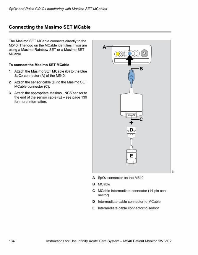
SpO2 and Pulse CO-Ox monitoring with Masimo SET MCables
134 Instructions for Use Infinity Acute Care System – M540 Patient Monitor SW VG2
Connecting the Masimo SET MCable
The Masimo SET MCable connects directly to the M540. The logo on the MCable identifies if you are using a Masimo Rainbow SET or a Masimo SET MCable.
To connect the Masimo SET MCable
1 Attach the Masimo SET MCable (B) to the blue SpO2 connector (A) of the M540.
2 Attach the sensor cable (D) to the Masimo SET MCable connector (C).
3 Attach the appropriate Masimo LNCS sensor to the end of the sensor cable (E) – see page 139 for more information.
A SpO2 connector on the M540
B MCable
C MCable intermediate connector (14-pin con-nector)
D Intermediate cable connector to MCable
E Intermediate cable connector to sensor
329
A
B
C
E
D
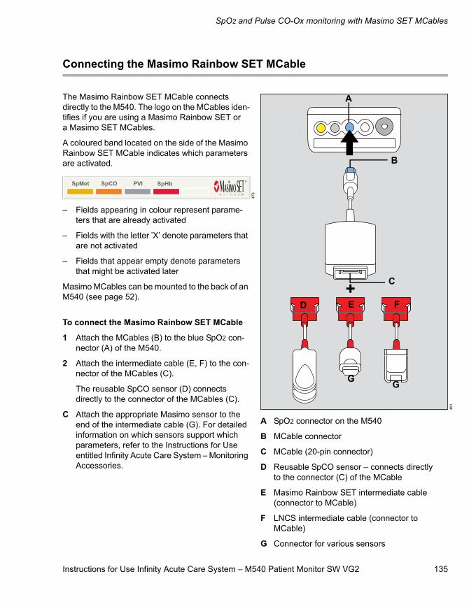
Instructions for Use Infinity Acute Care System – M540 Patient Monitor SW VG2 135
SpO2 and Pulse CO-Ox monitoring with Masimo SET MCables
Connecting the Masimo Rainbow SET MCable
The Masimo Rainbow SET MCable connects directly to the M540. The logo on the MCables iden-tifies if you are using a Masimo Rainbow SET or a Masimo SET MCables.
A coloured band located on the side of the Masimo Rainbow SET MCable indicates which parameters are activated.
– Fields appearing in colour represent parame-ters that are already activated
– Fields with the letter ’X’ denote parameters that are not activated
– Fields that appear empty denote parameters that might be activated later
Masimo MCables can be mounted to the back of an M540 (see page 52).
To connect the Masimo Rainbow SET MCable
1 Attach the MCables (B) to the blue SpO2 con-nector (A) of the M540.
2 Attach the intermediate cable (E, F) to the con-nector of the MCables (C).
The reusable SpCO sensor (D) connects directly to the connector of the MCables (C).
C Attach the appropriate Masimo sensor to the end of the intermediate cable (G). For detailed information on which sensors support which parameters, refer to the Instructions for Use entitled Infinity Acute Care System – Monitoring Accessories.
A SpO2 connector on the M540
B MCable connector
C MCable (20-pin connector)
D Reusable SpCO sensor – connects directly to the connector (C) of the MCable
E Masimo Rainbow SET intermediate cable (connector to MCable)
F LNCS intermediate cable (connector to MCable)
G Connector for various sensors
478
481
B
A
C
D E F
G G
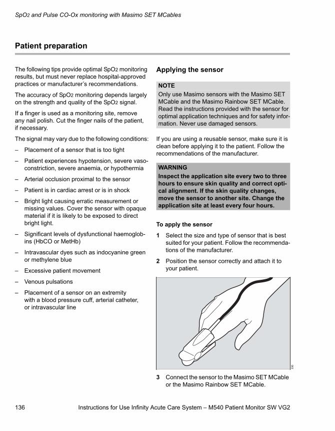
SpO2 and Pulse CO-Ox monitoring with Masimo SET MCables
136 Instructions for Use Infinity Acute Care System – M540 Patient Monitor SW VG2
Patient preparation
The following tips provide optimal SpO2 monitoring results, but must never replace hospital-approved practices or manufacturer’s recommendations.
The accuracy of SpO2 monitoring depends largely on the strength and quality of the SpO2 signal.
If a finger is used as a monitoring site, remove any nail polish. Cut the finger nails of the patient, if necessary.
The signal may vary due to the following conditions:
– Placement of a sensor that is too tight
– Patient experiences hypotension, severe vaso-constriction, severe anaemia, or hypothermia
– Arterial occlusion proximal to the sensor
– Patient is in cardiac arrest or is in shock
– Bright light causing erratic measurement or missing values. Cover the sensor with opaque material if it is likely to be exposed to direct bright light.
– Significant levels of dysfunctional haemoglob-ins (HbCO or MetHb)
– Intravascular dyes such as indocyanine green or methylene blue
– Excessive patient movement
– Venous pulsations
– Placement of a sensor on an extremity with a blood pressure cuff, arterial catheter, or intravascular line
Applying the sensor
If you are using a reusable sensor, make sure it is clean before applying it to the patient. Follow the recommendations of the manufacturer.
To apply the sensor
1 Select the size and type of sensor that is best suited for your patient. Follow the recommenda-tions of the manufacturer.
2 Position the sensor correctly and attach it to your patient.
3 Connect the sensor to the Masimo SET MCable or the Masimo Rainbow SET MCable.
NOTEOnly use Masimo sensors with the Masimo SET MCable and the Masimo Rainbow SET MCable. Read the instructions provided with the sensor for optimal application techniques and for safety infor-mation. Never use damaged sensors.
WARNINGInspect the application site every two to three hours to ensure skin quality and correct opti-cal alignment. If the skin quality changes, move the sensor to another site. Change the application site at least every four hours.
330
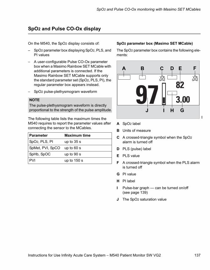
Instructions for Use Infinity Acute Care System – M540 Patient Monitor SW VG2 137
SpO2 and Pulse CO-Ox monitoring with Masimo SET MCables
SpO2 and Pulse CO-Ox display
On the M540, the SpO2 display consists of:
– SpO2 parameter box displaying SpO2, PLS, and PI values
– A user-configurable Pulse CO-Ox parameter box when a Masimo Rainbow SET MCable with additional parameters is connected. If the Masimo Rainbow SET MCable supports only the standard parameter set (SpO2, PLS, PI), the regular parameter box appears instead.
– SpO2 pulse-plethysmogram waveform
The following table lists the maximum times the M540 requires to report the parameter values after connecting the sensor to the MCables.
SpO2 parameter box (Masimo SET MCable)
The SpO2 parameter box contains the following ele-ments:
A SpO2 label
B Units of measure
C A crossed-triangle symbol when the SpO2 alarm is turned off
D PLS (pulse) label
E PLS value
F A crossed-triangle symbol when the PLS alarm is turned off
G PI value
H PI label
I Pulse-bar graph — can be turned on/off (see page 139)
J The SpO2 saturation value
NOTEThe pulse-plethysmogram waveform is directly proportional to the strength of the pulse amplitude.
Parameter Maximum time SpO2, PLS, PI up to 35 s
SpMet, PVI, SpCO up to 60 s
SpHb, SpOC up to 90 s
PVI up to 150 s
095
EA B C D F
GHIJ
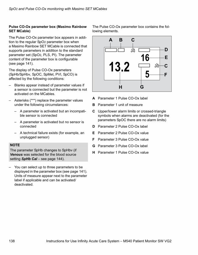
SpO2 and Pulse CO-Ox monitoring with Masimo SET MCables
138 Instructions for Use Infinity Acute Care System – M540 Patient Monitor SW VG2
Pulse CO-Ox parameter box (Masimo Rainbow SET MCable)
The Pulse CO-Ox parameter box appears in addi-tion to the regular SpO2 parameter box when a Masimo Rainbow SET MCable is connected that supports parameters in addition to the standard parameter set (SpO2, PLS, PI). The parameter content of the parameter box is configurable (see page 141).
The display of Pulse CO-Ox parameters (SpHb/SpHbv, SpOC, SpMet, PVI, SpCO) is affected by the following conditions:
– Blanks appear instead of parameter values if a sensor is connected but the parameter is not activated on the MCables.
– Asterisks (***) replace the parameter values under the following circumstances:
– A parameter is activated but an incompati-ble sensor is connected
– A parameter is activated but no sensor is connected
– A technical failure exists (for example, an unplugged sensor)
– You can select up to three parameters to be displayed in the parameter box (see page 141). Units of measure appear next to the parameter label if applicable and can be activated/deactivated.
The Pulse CO-Ox parameter box contains the fol-lowing elements.
A Parameter 1 Pulse CO-Ox label
B Parameter 1 unit of measure
C Upper/lower alarm limits or crossed-triangle symbols when alarms are deactivated (for the parameters SpOC there are no alarm limits)
D Parameter 2 Pulse CO-Ox label
E Parameter 2 Pulse CO-Ox value
F Parameter 3 Pulse CO-Ox value
G Parameter 3 Pulse CO-Ox label
H Parameter 1 Pulse CO-Ox value
NOTEThe parameter SpHb changes to SpHbv (if Venous was selected for the blood source setting SpHb Cal – see page 144).
A B C
C
DE
F
GH
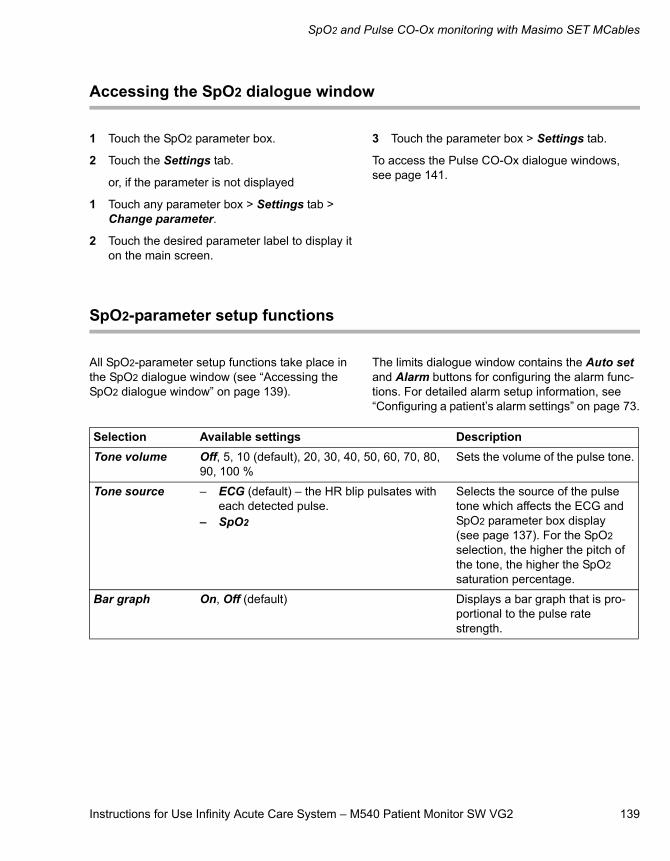
Instructions for Use Infinity Acute Care System – M540 Patient Monitor SW VG2 139
SpO2 and Pulse CO-Ox monitoring with Masimo SET MCables
Accessing the SpO2 dialogue window
1 Touch the SpO2 parameter box.
2 Touch the Settings tab.
or, if the parameter is not displayed
1 Touch any parameter box > Settings tab > Change parameter.
2 Touch the desired parameter label to display it on the main screen.
3 Touch the parameter box > Settings tab.
To access the Pulse CO-Ox dialogue windows, see page 141.
SpO2-parameter setup functions
All SpO2-parameter setup functions take place in the SpO2 dialogue window (see “Accessing the SpO2 dialogue window” on page 139).
The limits dialogue window contains the Auto set and Alarm buttons for configuring the alarm func-tions. For detailed alarm setup information, see “Configuring a patient’s alarm settings” on page 73.
Selection Available settings DescriptionTone volume Off, 5, 10 (default), 20, 30, 40, 50, 60, 70, 80,
90, 100 %Sets the volume of the pulse tone.
Tone source – ECG (default) – the HR blip pulsates with each detected pulse.
– SpO2
Selects the source of the pulse tone which affects the ECG and SpO2 parameter box display (see page 137). For the SpO2 selection, the higher the pitch of the tone, the higher the SpO2 saturation percentage.
Bar graph On, Off (default) Displays a bar graph that is pro-portional to the pulse rate strength.
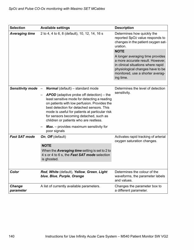
SpO2 and Pulse CO-Ox monitoring with Masimo SET MCables
140 Instructions for Use Infinity Acute Care System – M540 Patient Monitor SW VG2
Averaging time 2 to 4, 4 to 6, 8 (default), 10, 12, 14, 16 s Determines how quickly the reported SpO2 value responds to changes in the patient oxygen sat-uration.
Sensitivity mode – Normal (default) – standard mode
– APOD (adaptive probe off detection) – the least sensitive mode for detecting a reading on patients with low perfusion. Provides the best detection for detached sensors. This mode is useful for patients at particular risk for sensors becoming detached, such as children or patients who are restless.
– Max. – provides maximum sensitivity for poor signals
Determines the level of detection sensitivity.
Fast SAT mode On, Off (default) Activates rapid tracking of arterial oxygen saturation changes.
Color Red, White (default), Yellow, Green, Light blue, Blue, Purple, Orange
Determines the colour of the waveforms, the parameter labels and values.
Change parameter
A list of currently available parameters. Changes the parameter box to a different parameter.
Selection Available settings Description
NOTEA longer averaging time provides a more accurate result. However, in clinical situations where rapid physiological changes have to be monitored, use a shorter averag-ing time.
NOTEWhen the Averaging time setting is set to 2 to 4 s or 4 to 6 s, the Fast SAT mode selection is ghosted.
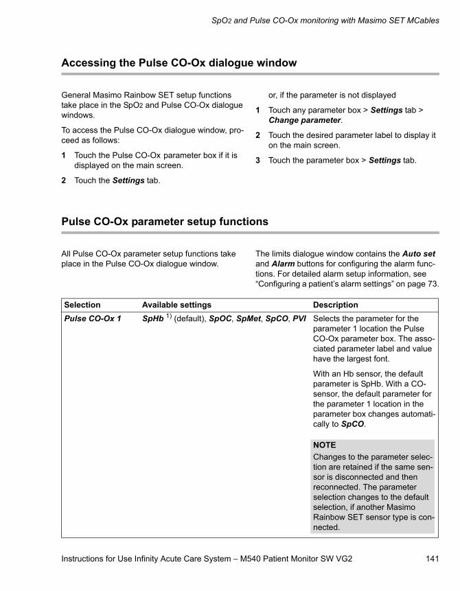
Instructions for Use Infinity Acute Care System – M540 Patient Monitor SW VG2 141
SpO2 and Pulse CO-Ox monitoring with Masimo SET MCables
Accessing the Pulse CO-Ox dialogue window
General Masimo Rainbow SET setup functions take place in the SpO2 and Pulse CO-Ox dialogue windows.
To access the Pulse CO-Ox dialogue window, pro-ceed as follows:
1 Touch the Pulse CO-Ox parameter box if it is displayed on the main screen.
2 Touch the Settings tab.
or, if the parameter is not displayed
1 Touch any parameter box > Settings tab > Change parameter.
2 Touch the desired parameter label to display it on the main screen.
3 Touch the parameter box > Settings tab.
Pulse CO-Ox parameter setup functions
All Pulse CO-Ox parameter setup functions take place in the Pulse CO-Ox dialogue window.
The limits dialogue window contains the Auto set and Alarm buttons for configuring the alarm func-tions. For detailed alarm setup information, see “Configuring a patient’s alarm settings” on page 73.
Selection Available settings DescriptionPulse CO-Ox 1 SpHb 1) (default), SpOC, SpMet, SpCO, PVI Selects the parameter for the
parameter 1 location the Pulse CO-Ox parameter box. The asso-ciated parameter label and value have the largest font.
With an Hb sensor, the default parameter is SpHb. With a CO-sensor, the default parameter for the parameter 1 location in the parameter box changes automati-cally to SpCO.
NOTEChanges to the parameter selec-tion are retained if the same sen-sor is disconnected and then reconnected. The parameter selection changes to the default selection, if another Masimo Rainbow SET sensor type is con-nected.
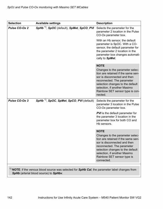
SpO2 and Pulse CO-Ox monitoring with Masimo SET MCables
142 Instructions for Use Infinity Acute Care System – M540 Patient Monitor SW VG2
Pulse CO-Ox 2 SpHb 1), SpOC (default), SpMet, SpCO, PVI Selects the parameter for the parameter 2 location in the Pulse CO-Ox parameter box.
With an Hb sensor, the default parameter is SpOC. With a CO-sensor, the default parameter for the parameter 2 location in the parameter box changes automati-cally to SpMet.
Pulse CO-Ox 3 SpHb 1), SpOC, SpMet, SpCO, PVI (default) Selects the parameter for the parameter 3 location in the Pulse CO-Ox parameter box.
PVI is the default parameter for the parameter 3 location in the parameter box for both CO and Hb sensors.
Selection Available settings Description
NOTEChanges to the parameter selec-tion are retained if the same sen-sor is disconnected and then reconnected. The parameter selection changes to the default selection, if another Masimo Rainbow SET sensor type is con-nected.
NOTEChanges to the parameter selec-tion are retained if the same sen-sor is disconnected and then reconnected. The parameter selection changes to the default selection, if another Masimo Rainbow SET sensor type is connected.
1) NOTE: if the venous blood source was selected for SpHb Cal, the parameter label changes from SpHb (arterial blood source) to SpHbv.
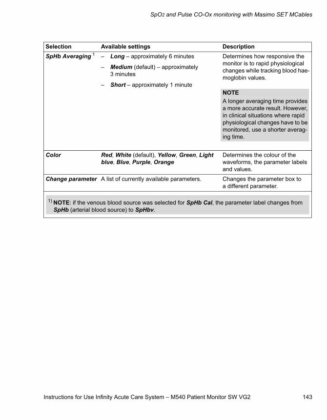
Instructions for Use Infinity Acute Care System – M540 Patient Monitor SW VG2 143
SpO2 and Pulse CO-Ox monitoring with Masimo SET MCables
SpHb Averaging 1 – Long – approximately 6 minutes
– Medium (default) – approximately 3 minutes
– Short – approximately 1 minute
Determines how responsive the monitor is to rapid physiological changes while tracking blood hae-moglobin values.
Color Red, White (default), Yellow, Green, Light blue, Blue, Purple, Orange
Determines the colour of the waveforms, the parameter labels and values.
Change parameter A list of currently available parameters. Changes the parameter box to a different parameter.
Selection Available settings Description
NOTEA longer averaging time provides a more accurate result. However, in clinical situations where rapid physiological changes have to be monitored, use a shorter averag-ing time.
1) NOTE: if the venous blood source was selected for SpHb Cal, the parameter label changes from SpHb (arterial blood source) to SpHbv.

SpO2 and Pulse CO-Ox monitoring with Masimo SET MCables
144 Instructions for Use Infinity Acute Care System – M540 Patient Monitor SW VG2
Password-protected Masimo Rainbow SET setup functions
Additional Masimo Rainbow SET setup functions take place in the Settings 2 page which is pro-tected by a clinical password.
Selection Available settings DescriptionSpHb Cal Arterial (default), Venous Selects the blood sampling
source which is used to calcu-late the SpHb value.
The SpHb value changes to SpHbv when the SpHb Cal set-ting Venous is selected.
PVI Averaging Short, Long (default) Determines how responsive the monitor is to rapid physiological changes while tracking patient volume index. NOTEA longer averaging time provides a more accurate result. However, in clinical situations where rapid physiological changes have to be monitored, use a shorter averag-ing time.
Instructions for Use Infinity Acute Care System – M540 Patient Monitor SW VG2 145
SpO2 and pulse rate with Nellcor OxiMax MCable
SpO2 and pulse rate with Nellcor OxiMax MCable
Overview of SpO2 monitoring . . . . . . . . . . . . 146
Supported parameters . . . . . . . . . . . . . . . . . . . 146
SpO2 precautions . . . . . . . . . . . . . . . . . . . . . . 147
Connecting the Nellcor OxiMax MCable . . . . . . . . . . . . . . . . . . . . . . . . 148
Patient preparation for SpO2 monitoring. . . . . . . . . . . . . . . . . . . . . . . 149
Applying the sensor . . . . . . . . . . . . . . . . . . . . . 149
SpO2 display . . . . . . . . . . . . . . . . . . . . . . . . . . 150
Accessing the SpO2 dialogue window . . . . . 151
SpO2 parameter setup functions . . . . . . . . . 151
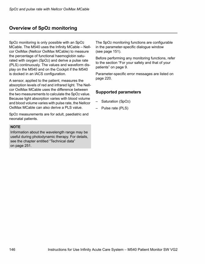
SpO2 and pulse rate with Nellcor OxiMax MCable
146 Instructions for Use Infinity Acute Care System – M540 Patient Monitor SW VG2
Overview of SpO2 monitoring
SpO2 monitoring is only possible with an SpO2 MCable. The M540 uses the Infinity MCable – Nell-cor OxiMax (Nellcor OxiMax MCable) to measure the percentage of functional haemoglobin satu-rated with oxygen (SpO2) and derive a pulse rate (PLS) continuously. The values and waveform dis-play on the M540 and on the Cockpit if the M540 is docked in an IACS configuration.
A sensor, applied to the patient, measures the absorption levels of red and infrared light. The Nell-cor OxiMax MCable uses the difference between the two measurements to calculate the SpO2 value. Because light absorption varies with blood volume and blood volume varies with pulse rate, the Nellcor OxiMax MCable can also derive a PLS value.
SpO2 measurements are for adult, paediatric and neonatal patients.
The SpO2 monitoring functions are configurable in the parameter-specific dialogue window (see page 151).
Before performing any monitoring functions, refer to the section “For your safety and that of your patients” on page 9.
Parameter-specific error messages are listed on page 220.
Supported parameters
– Saturation (SpO2)
– Pulse rate (PLS)
NOTEInformation about the wavelength range may be useful during photodynamic therapy. For details, see the chapter entitled “Technical data” on page 251.
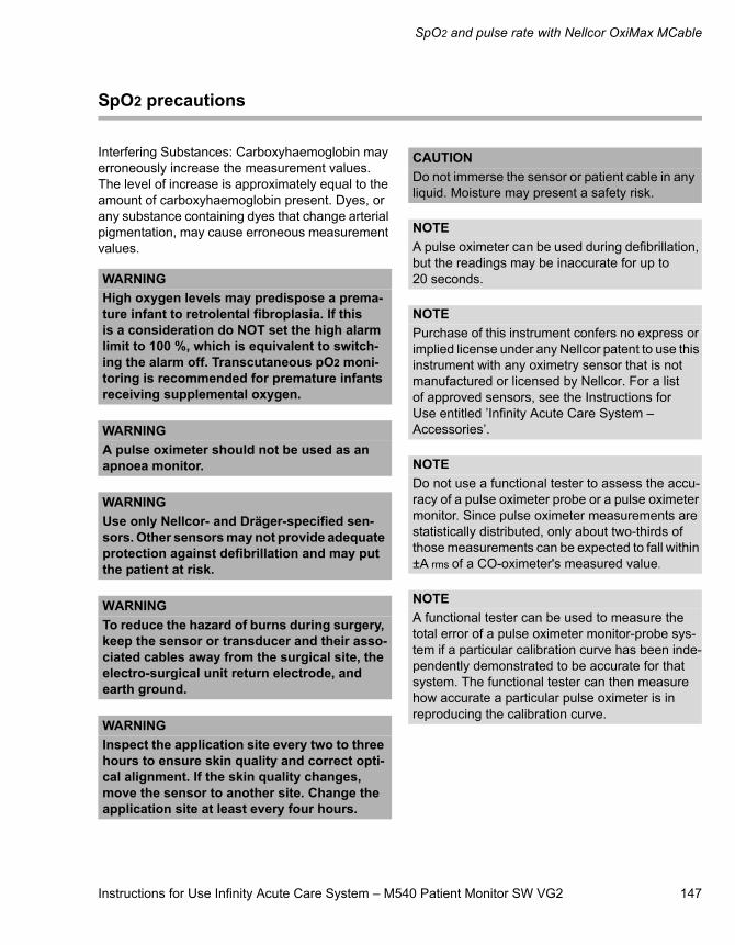
Instructions for Use Infinity Acute Care System – M540 Patient Monitor SW VG2 147
SpO2 and pulse rate with Nellcor OxiMax MCable
SpO2 precautions
Interfering Substances: Carboxyhaemoglobin may erroneously increase the measurement values. The level of increase is approximately equal to the amount of carboxyhaemoglobin present. Dyes, or any substance containing dyes that change arterial pigmentation, may cause erroneous measurement values.
-------------------------------------------------------------------
WARNINGHigh oxygen levels may predispose a prema-ture infant to retrolental fibroplasia. If this is a consideration do NOT set the high alarm limit to 100 %, which is equivalent to switch-ing the alarm off. Transcutaneous pO2 moni-toring is recommended for premature infants receiving supplemental oxygen.
WARNINGA pulse oximeter should not be used as an apnoea monitor.
WARNINGUse only Nellcor- and Dräger-specified sen-sors. Other sensors may not provide adequate protection against defibrillation and may put the patient at risk.
WARNINGTo reduce the hazard of burns during surgery, keep the sensor or transducer and their asso-ciated cables away from the surgical site, the electro-surgical unit return electrode, and earth ground.
WARNINGInspect the application site every two to three hours to ensure skin quality and correct opti-cal alignment. If the skin quality changes, move the sensor to another site. Change the application site at least every four hours.
CAUTIONDo not immerse the sensor or patient cable in any liquid. Moisture may present a safety risk.
NOTEA pulse oximeter can be used during defibrillation, but the readings may be inaccurate for up to 20 seconds.
NOTEPurchase of this instrument confers no express or implied license under any Nellcor patent to use this instrument with any oximetry sensor that is not manufactured or licensed by Nellcor. For a list of approved sensors, see the Instructions for Use entitled ’Infinity Acute Care System – Accessories’.
NOTEDo not use a functional tester to assess the accu-racy of a pulse oximeter probe or a pulse oximeter monitor. Since pulse oximeter measurements are statistically distributed, only about two-thirds of those measurements can be expected to fall within ±A rms of a CO-oximeter's measured value.
NOTEA functional tester can be used to measure the total error of a pulse oximeter monitor-probe sys-tem if a particular calibration curve has been inde-pendently demonstrated to be accurate for that system. The functional tester can then measure how accurate a particular pulse oximeter is in reproducing the calibration curve.
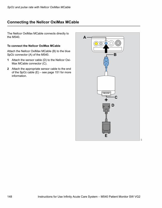
SpO2 and pulse rate with Nellcor OxiMax MCable
148 Instructions for Use Infinity Acute Care System – M540 Patient Monitor SW VG2
Connecting the Nellcor OxiMax MCable
The Nellcor OxiMax MCable connects directly to the M540.
To connect the Nellcor OxiMax MCable
Attach the Nellcor OxiMax MCable (B) to the blue SpO2 connector (A) of the M540.
1 Attach the sensor cable (D) to the Nellcor Oxi-Max MCable connector (C).
2 Attach the appropriate sensor cable to the end of the SpO2 cable (E) – see page 151 for more information.
331
A
B
C
D
E
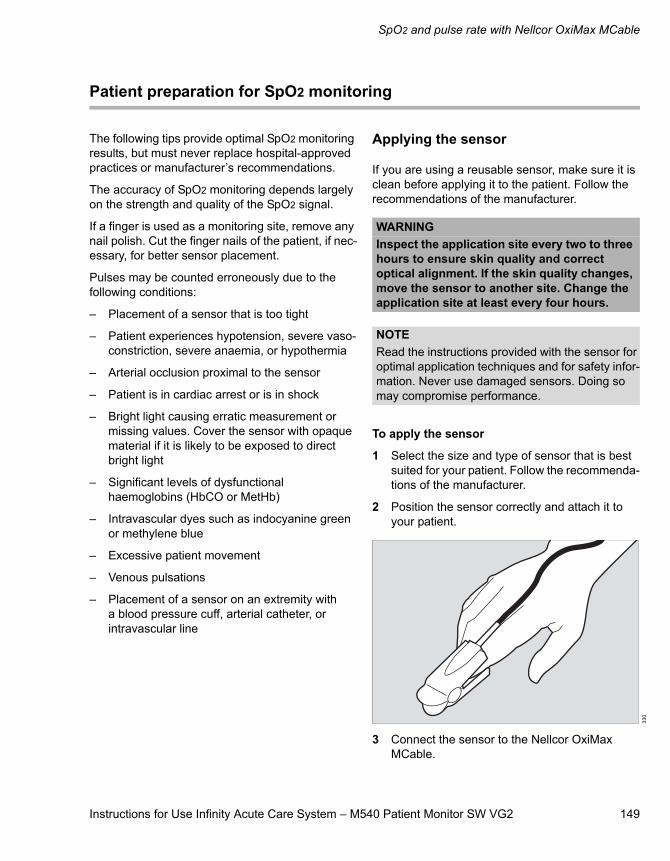
Instructions for Use Infinity Acute Care System – M540 Patient Monitor SW VG2 149
SpO2 and pulse rate with Nellcor OxiMax MCable
Patient preparation for SpO2 monitoring
The following tips provide optimal SpO2 monitoring results, but must never replace hospital-approved practices or manufacturer’s recommendations.
The accuracy of SpO2 monitoring depends largely on the strength and quality of the SpO2 signal.
If a finger is used as a monitoring site, remove any nail polish. Cut the finger nails of the patient, if nec-essary, for better sensor placement.
Pulses may be counted erroneously due to the following conditions:
– Placement of a sensor that is too tight
– Patient experiences hypotension, severe vaso-constriction, severe anaemia, or hypothermia
– Arterial occlusion proximal to the sensor
– Patient is in cardiac arrest or is in shock
– Bright light causing erratic measurement or missing values. Cover the sensor with opaque material if it is likely to be exposed to direct bright light
– Significant levels of dysfunctional haemoglobins (HbCO or MetHb)
– Intravascular dyes such as indocyanine green or methylene blue
– Excessive patient movement
– Venous pulsations
– Placement of a sensor on an extremity with a blood pressure cuff, arterial catheter, or intravascular line
Applying the sensor
If you are using a reusable sensor, make sure it is clean before applying it to the patient. Follow the recommendations of the manufacturer.
To apply the sensor
1 Select the size and type of sensor that is best suited for your patient. Follow the recommenda-tions of the manufacturer.
2 Position the sensor correctly and attach it to your patient.
3 Connect the sensor to the Nellcor OxiMax MCable.
WARNINGInspect the application site every two to three hours to ensure skin quality and correct optical alignment. If the skin quality changes, move the sensor to another site. Change the application site at least every four hours.
NOTERead the instructions provided with the sensor for optimal application techniques and for safety infor-mation. Never use damaged sensors. Doing so may compromise performance.
330
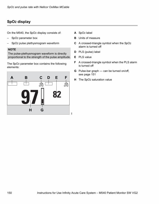
SpO2 and pulse rate with Nellcor OxiMax MCable
150 Instructions for Use Infinity Acute Care System – M540 Patient Monitor SW VG2
SpO2 display
On the M540, the SpO2 display consists of:
– SpO2 parameter box
– SpO2 pulse plethysmogram waveform
The SpO2 parameter box contains the following elements:
A SpO2 label
B Units of measure
C A crossed-triangle symbol when the SpO2 alarm is turned off
D PLS (pulse) label
E PLS value
F A crossed-triangle symbol when the PLS alarm is turned off
G Pulse-bar graph — can be turned on/off, see page 151
H The SpO2 saturation value
NOTEThe pulse-plethysmogram waveform is directly proportional to the strength of the pulse amplitude.
096
EA B C D F
GH
Instructions for Use Infinity Acute Care System – M540 Patient Monitor SW VG2 151
SpO2 and pulse rate with Nellcor OxiMax MCable
Accessing the SpO2 dialogue window
1 Touch the SpO2 parameter box.
2 Touch the Settings tab.
or, if the parameter is not displayed
1 Touch any parameter box > Settings tab > Change parameter.
2 Touch the desired parameter label to display it on the main screen.
3 Touch the parameter box > Settings tab.
SpO2 parameter setup functions
All SpO2 parameter setup functions take place in the SpO2 dialogue window (see “Accessing the SpO2 dialogue window” on page 151).
The limits dialogue window contains the Auto set and Alarm buttons for configuring the alarm func-tions. For detailed alarm setup information, see “Configuring a patient’s alarm settings” on page 73.
Selection Available settings DescriptionTone volume Off, 5, 10 (default), 20, 30, 40, 50, 60, 70, 80,
90, 100 %Sets the volume of the pulse tone.
Tone source – ECG (default) – the HR blip pulsates with each detected pulse.
– SpO2
Selects the source of the pulse tone which affects the ECG and SpO2 parameter box display (see page 150). For the SpO2 selection, the higher the pitch of the tone, the higher the SpO2 saturation percentage.
Bar graph On, Off (default) Displays a bar graph that is proportional to the pulse rate strength.
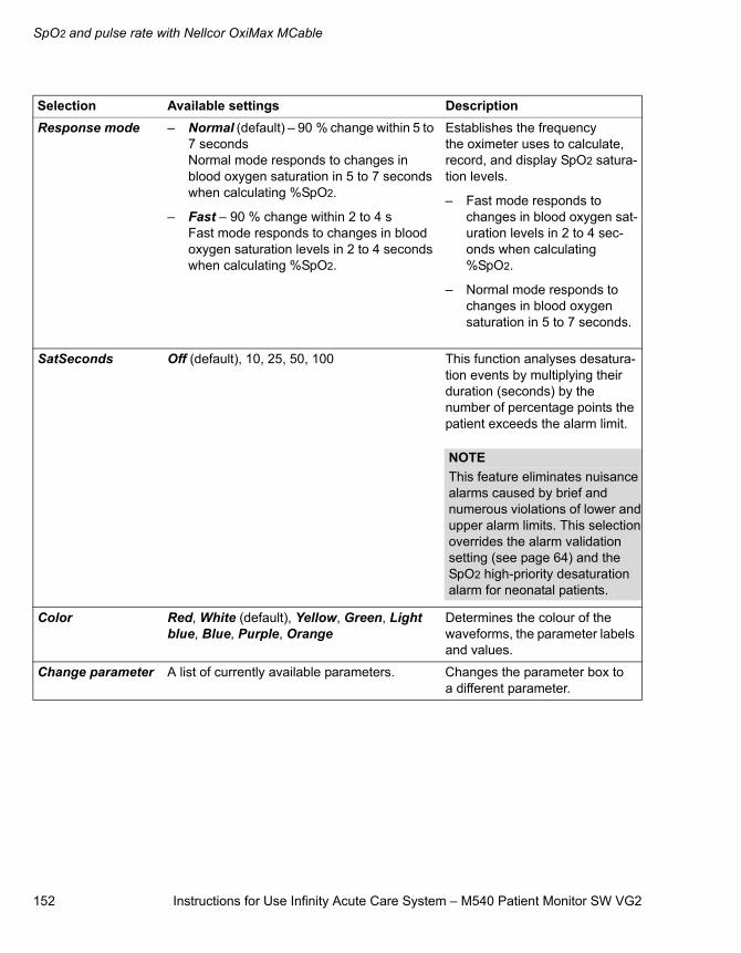
SpO2 and pulse rate with Nellcor OxiMax MCable
152 Instructions for Use Infinity Acute Care System – M540 Patient Monitor SW VG2
Response mode – Normal (default) – 90 % change within 5 to 7 secondsNormal mode responds to changes in blood oxygen saturation in 5 to 7 seconds when calculating %SpO2.
– Fast – 90 % change within 2 to 4 sFast mode responds to changes in blood oxygen saturation levels in 2 to 4 seconds when calculating %SpO2.
Establishes the frequency the oximeter uses to calculate, record, and display SpO2 satura-tion levels.
– Fast mode responds to changes in blood oxygen sat-uration levels in 2 to 4 sec-onds when calculating %SpO2.
– Normal mode responds to changes in blood oxygen saturation in 5 to 7 seconds.
SatSeconds Off (default), 10, 25, 50, 100 This function analyses desatura-tion events by multiplying their duration (seconds) by the number of percentage points the patient exceeds the alarm limit.
Color Red, White (default), Yellow, Green, Light blue, Blue, Purple, Orange
Determines the colour of the waveforms, the parameter labels and values.
Change parameter A list of currently available parameters. Changes the parameter box to a different parameter.
Selection Available settings Description
NOTEThis feature eliminates nuisance alarms caused by brief and numerous violations of lower and upper alarm limits. This selection overrides the alarm validation setting (see page 64) and the SpO2 high-priority desaturation alarm for neonatal patients.

Instructions for Use Infinity Acute Care System – M540 Patient Monitor SW VG2 153
Temperature
Temperature
Overview of temperature monitoring . . . . . . 154
Supported parameters . . . . . . . . . . . . . . . . . . . 154
Connecting the temperature sensors. . . . . . 154
Connecting the temperature sensors to the M540. . . . . . . . . . . . . . . . . . . . . 155connecting the temperature sensorsto the hemodynamic pods . . . . . . . . . . . . . . . . 156
Temperature display. . . . . . . . . . . . . . . . . . . . 157
Temperature parameter box . . . . . . . . . . . . . . . 157
Accessing the temperature dialogue window . . . . . . . . . . . . . . . . . . . . . . . . . . . . . . 158
Temperature parameter setup functions . . . . . . . . . . . . . . . . . . . . . . . . . . . . . 158

Temperature
154 Instructions for Use Infinity Acute Care System – M540 Patient Monitor SW VG2
Overview of temperature monitoring
The M540 measures and displays the following temperature values:
– Surface body temperature
– Core temperature
Temperature monitoring is intended for adult, paediatric and neonatal patients.
The temperature monitoring functions are config-urable in the parameter-specific dialogue window (see page 158).
Before performing any monitoring functions, refer to the section “For your safety and that of your patients” on page 9.
Parameter-specific error messages are listed on page 228.
Supported parameters
– Ta/T1a: absolute temperature values
– Tb/T1b: absolute temperature values
– ΔT/ΔT1: delta temperature values
Connecting the temperature sensors
You can connect temperature sensors directly to the M540 or to one of the following haemody-namic pods:
– MPod – QuadHemo
– Hemo4 pod
– Hemo2 pod
NOTEThe temperature functions and associated probes should be calibrated every two years by qualified personnel to maintain an accuracy of ±0.1 °C (±0.2 °F).
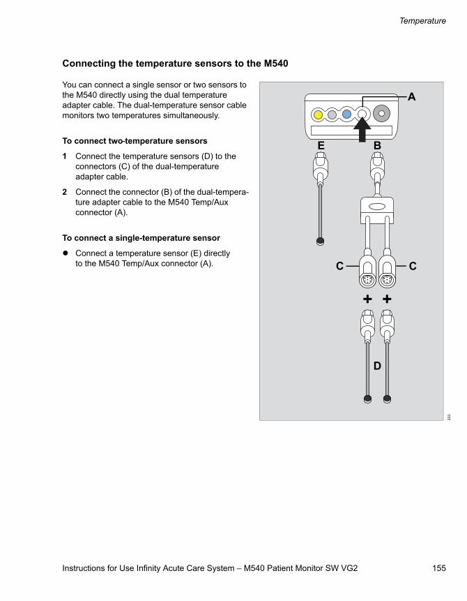
Instructions for Use Infinity Acute Care System – M540 Patient Monitor SW VG2 155
Temperature
Connecting the temperature sensors to the M540
You can connect a single sensor or two sensors to the M540 directly using the dual temperature adapter cable. The dual-temperature sensor cable monitors two temperatures simultaneously.
To connect two temperature sensors
1 Connect the temperature sensors (D) to the connectors (C) of the dual-temperature adapter cable.
2 Connect the connector (B) of the dual-tempera-ture adapter cable to the M540 Temp/Aux connector (A).
To connect a single-temperature sensor
Connect a temperature sensor (E) directly to the M540 Temp/Aux connector (A).
333
A
B
C C
D
E
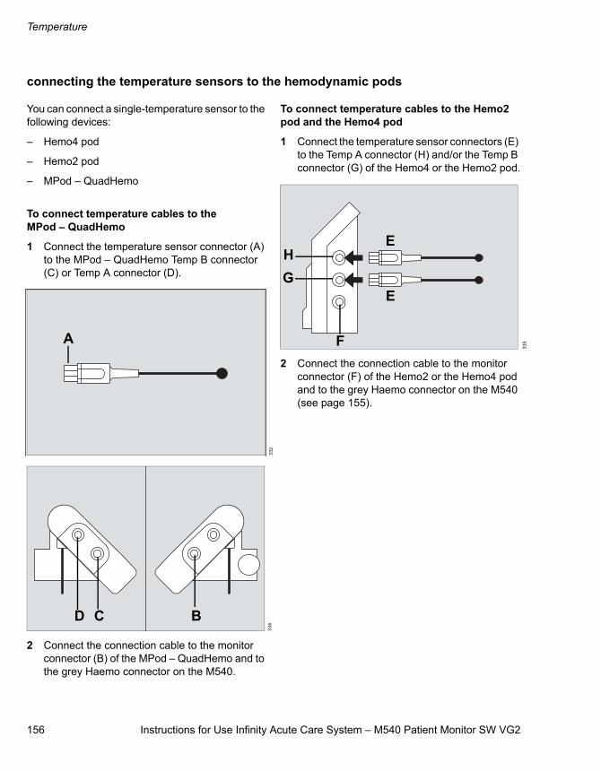
Temperature
156 Instructions for Use Infinity Acute Care System – M540 Patient Monitor SW VG2
connecting the temperature sensors to the hemodynamic pods
You can connect a single-temperature sensor to the following devices:
– Hemo4 pod
– Hemo2 pod
– MPod – QuadHemo
To connect temperature cables to the MPod – QuadHemo
1 Connect the temperature sensor connector (A) to the MPod – QuadHemo Temp B connector (C) or Temp A connector (D).
2 Connect the connection cable to the monitor connector (B) of the MPod – QuadHemo and to the grey Haemo connector on the M540.
To connect temperature cables to the Hemo2 pod and the Hemo4 pod
1 Connect the temperature sensor connectors (E) to the Temp A connector (H) and/or the Temp B connector (G) of the Hemo4 or the Hemo2 pod.
2 Connect the connection cable to the monitor connector (F) of the Hemo2 or the Hemo4 pod and to the grey Haemo connector on the M540 (see page 155).
332
334
A
D C B
335
E
E
F
GH
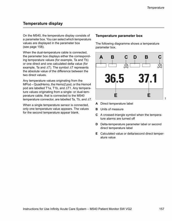
Instructions for Use Infinity Acute Care System – M540 Patient Monitor SW VG2 157
Temperature
Temperature display
On the M540, the temperature display consists of a parameter box. You can select which temperature values are displayed in the parameter box (see page 158).
When the dual-temperature cable is connected, the parameter box displays either the correspond-ing temperature values (for example, Ta and Tb) or one direct and one calculated delta value (for example, Ta and ΔT). The symbol ΔT represents the absolute value of the difference between the two direct values.
Any temperature values originating from theMPod – QuadHemo, the Hemo2 pod, or the Hemo4 pod are labelled T1a, T1b, and ΔT1. Any tempera-ture values originating from a single- or dual-tem-perature cable, that is connected to the M540 temperature connector, are labelled Ta, Tb, and ΔT.
When a single temperature sensor is connected, only one temperature value appears. The values for the second temperature appear blank.
Temperature parameter box
The following diagramme shows a temperature parameter box.
A Direct temperature label
B Units of measure
C A crossed-triangle symbol when the tempera-ture alarms are turned off
D Delta-temperature parameter label or second direct temperature label
E Calculated value or delta/second direct temper-ature value
092
A B
E
C D B
E
C
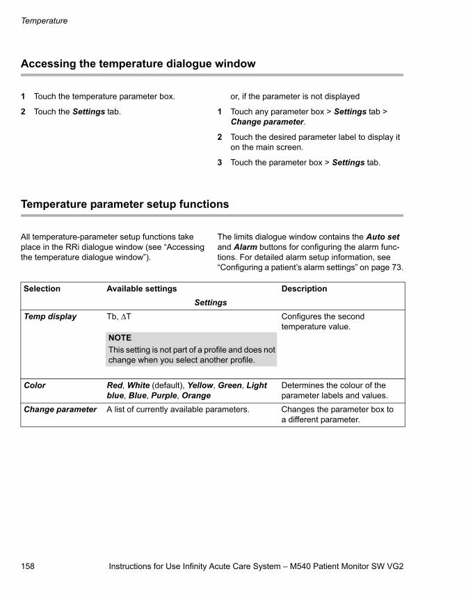
Temperature
158 Instructions for Use Infinity Acute Care System – M540 Patient Monitor SW VG2
Accessing the temperature dialogue window
1 Touch the temperature parameter box.
2 Touch the Settings tab.
or, if the parameter is not displayed
1 Touch any parameter box > Settings tab > Change parameter.
2 Touch the desired parameter label to display it on the main screen.
3 Touch the parameter box > Settings tab.
Temperature parameter setup functions
All temperature-parameter setup functions take place in the RRi dialogue window (see “Accessing the temperature dialogue window”).
The limits dialogue window contains the Auto set and Alarm buttons for configuring the alarm func-tions. For detailed alarm setup information, see “Configuring a patient’s alarm settings” on page 73.
Selection Available settings DescriptionSettings
Temp display Tb, ΔT Configures the second temperature value.
Color Red, White (default), Yellow, Green, Light blue, Blue, Purple, Orange
Determines the colour of the parameter labels and values.
Change parameter A list of currently available parameters. Changes the parameter box to a different parameter.
NOTEThis setting is not part of a profile and does not change when you select another profile.
Instructions for Use Infinity Acute Care System – M540 Patient Monitor SW VG2 159
Non-invasive blood pressure (NIBP)
Non-invasive blood pressure (NIBP)
Overview of NIBP monitoring . . . . . . . . . . . . 160
Supported parameters . . . . . . . . . . . . . . . . . . . 160
NIBP precautions . . . . . . . . . . . . . . . . . . . . . . 161
Connecting the NIBP hose and cuff . . . . . . . 162
Patient preparation for NIBP monitoring. . . . . . . . . . . . . . . . . . . . . . . . . . . . 163
Applying the NIBP cuff . . . . . . . . . . . . . . . . . . . 163
NIBP display . . . . . . . . . . . . . . . . . . . . . . . . . . 164
NIBP measurement modes . . . . . . . . . . . . . . 165
Single measurement mode. . . . . . . . . . . . . . . . 165Interval measurements mode. . . . . . . . . . . . . . 165Continuous measurements. . . . . . . . . . . . . . . . 166
Venous Stasis . . . . . . . . . . . . . . . . . . . . . . . . . 167
Activating or deactivating venous stasis. . . . . . 167
Accessing the NIBP dialogue window . . . . . 168
NIBP parameter setup functions . . . . . . . . . . 168
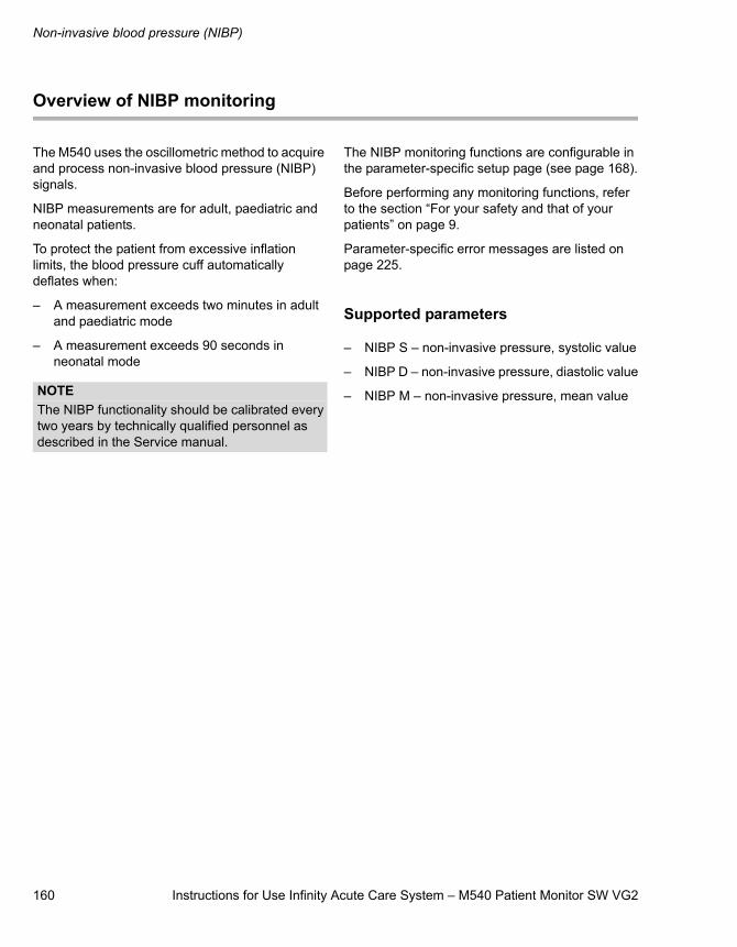
Non-invasive blood pressure (NIBP)
160 Instructions for Use Infinity Acute Care System – M540 Patient Monitor SW VG2
Overview of NIBP monitoring
The M540 uses the oscillometric method to acquire and process non-invasive blood pressure (NIBP) signals.
NIBP measurements are for adult, paediatric and neonatal patients.
To protect the patient from excessive inflation limits, the blood pressure cuff automatically deflates when:
– A measurement exceeds two minutes in adult and paediatric mode
– A measurement exceeds 90 seconds in neonatal mode
The NIBP monitoring functions are configurable in the parameter-specific setup page (see page 168).
Before performing any monitoring functions, refer to the section “For your safety and that of your patients” on page 9.
Parameter-specific error messages are listed on page 225.
Supported parameters
– NIBP S – non-invasive pressure, systolic value
– NIBP D – non-invasive pressure, diastolic value
– NIBP M – non-invasive pressure, mean valueNOTEThe NIBP functionality should be calibrated every two years by technically qualified personnel as described in the Service manual.
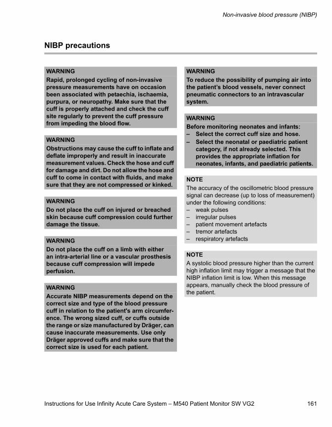
Instructions for Use Infinity Acute Care System – M540 Patient Monitor SW VG2 161
Non-invasive blood pressure (NIBP)
NIBP precautions
WARNINGRapid, prolonged cycling of non-invasive pressure measurements have on occasion been associated with petaechia, ischaemia, purpura, or neuropathy. Make sure that the cuff is properly attached and check the cuff site regularly to prevent the cuff pressure from impeding the blood flow.
WARNINGObstructions may cause the cuff to inflate and deflate improperly and result in inaccurate measurement values. Check the hose and cuff for damage and dirt. Do not allow the hose and cuff to come in contact with fluids, and make sure that they are not compressed or kinked.
WARNINGDo not place the cuff on injured or breached skin because cuff compression could further damage the tissue.
WARNINGDo not place the cuff on a limb with either an intra-arterial line or a vascular prosthesis because cuff compression will impede perfusion.
WARNINGAccurate NIBP measurements depend on the correct size and type of the blood pressure cuff in relation to the patient's arm circumfer-ence. The wrong sized cuff, or cuffs outside the range or size manufactured by Dräger, can cause inaccurate measurements. Use only Dräger approved cuffs and make sure that the correct size is used for each patient.
WARNINGTo reduce the possibility of pumping air into the patient’s blood vessels, never connect pneumatic connectors to an intravascular system.
WARNINGBefore monitoring neonates and infants:– Select the correct cuff size and hose.– Select the neonatal or paediatric patient
category, if not already selected. This provides the appropriate inflation for neonates, infants, and paediatric patients.
NOTEThe accuracy of the oscillometric blood pressure signal can decrease (up to loss of measurement) under the following conditions:– weak pulses– irregular pulses– patient movement artefacts– tremor artefacts– respiratory artefacts
NOTEA systolic blood pressure higher than the current high inflation limit may trigger a message that the NIBP inflation limit is low. When this message appears, manually check the blood pressure of the patient.
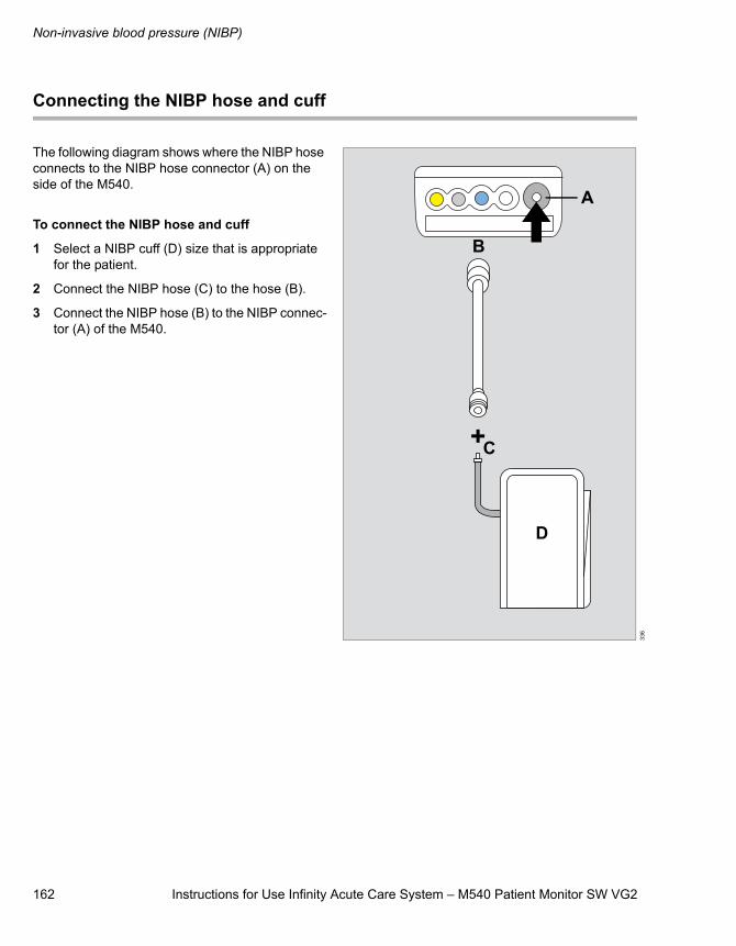
Non-invasive blood pressure (NIBP)
162 Instructions for Use Infinity Acute Care System – M540 Patient Monitor SW VG2
Connecting the NIBP hose and cuff
The following diagram shows where the NIBP hose connects to the NIBP hose connector (A) on the side of the M540.
To connect the NIBP hose and cuff
1 Select a NIBP cuff (D) size that is appropriate for the patient.
2 Connect the NIBP hose (C) to the hose (B).
3 Connect the NIBP hose (B) to the NIBP connec-tor (A) of the M540.
336
+
B
C
A
D
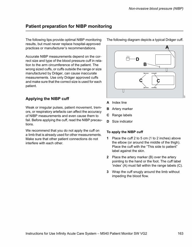
Instructions for Use Infinity Acute Care System – M540 Patient Monitor SW VG2 163
Non-invasive blood pressure (NIBP)
Patient preparation for NIBP monitoring
The following tips provide optimal NIBP monitoring results, but must never replace hospital-approved practices or manufacturer’s recommendations.
Accurate NIBP measurements depend on the cor-rect size and type of the blood pressure cuff in rela-tion to the arm circumference of the patient. The wrong sized cuffs, or cuffs outside the range or size manufactured by Dräger, can cause inaccurate measurements. Use only Dräger approved cuffs and make sure that the correct size is used for each patient.
Applying the NIBP cuff
Weak or irregular pulses, patient movement, trem-ors, or respiratory artefacts can affect the accuracy of NIBP measurements and even cause them to fail. Before applying the cuff, read the NIBP precau-tions.
We recommend that you do not apply the cuff on a limb that is already used for other measurements. Make sure that other patient connections do not interfere with each other.
The following diagram depicts a typical Dräger cuff.
A Index line
B Artery marker
C Range labels
D Size indicator
To apply the NIBP cuff
1 Place the cuff 2 to 5 cm (1 to 2 inches) above the elbow (or around the middle of the thigh). Place the cuff with the “This side to patient” label against the skin.
2 Place the artery marker (B) over the artery pointing to the hand or the foot. The cuff label ’index’ (A) must fall within the range labels (C).
3 Wrap the cuff snugly around the limb without impeding the blood flow.
337
BD
A
C C
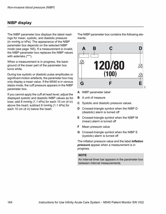
Non-invasive blood pressure (NIBP)
164 Instructions for Use Infinity Acute Care System – M540 Patient Monitor SW VG2
NIBP display
The NIBP parameter box displays the latest read-ings for mean, systolic, and diastolic pressure (in mmHg or kPa). The appearance of the NIBP parameter box depends on the selected NIBP mode (see page 165). If a measurement is invalid, the NIBP parameter box replaces the NIBP values with asterisks (***).
When a measurement is in progress, the back-ground of the lower part of the parameter box turns white.
During low systolic or diastolic pulse amplitudes or significant motion artefacts, the parameter box may only display a mean value. If the M540 is in venous stasis mode, the cuff pressure appears in the NIBP parameter box.
If you cannot apply the cuff at heart level, adjust the displayed systolic and diastolic NIBP values as fol-lows: add 8 mmHg (1.1 kPa) for each 10 cm (4 in) above the heart; subtract 8 mmHg (1.1 kPa) for each 10 cm (4 in) below the heart.
The NIBP parameter box contains the following ele-ments:
A NIBP parameter label
B A unit of measure
C Systolic and diastolic pressure values
D Crossed-triangle symbol when the NIBP D (diastolic) alarm is turned off
E Crossed-triangle symbol when the NIBP M (mean) alarm is turned off
F Mean pressure value
G Crossed-triangle symbol when the NIBP S (systolic) alarm is turned off
The inflation pressure value and the label Inflation pressure appear when a measurement is in progress.
093
NOTEAn interval timer bar appears in the parameter box between interval measurements.
A B C D
F EG
Instructions for Use Infinity Acute Care System – M540 Patient Monitor SW VG2 165
Non-invasive blood pressure (NIBP)
NIBP measurement modes
The following NIBP measurement modes are available:
– Single
– Interval
– Continuous
The selected mode affects the appearance of the NIBP parameter box (see page 164).
Before taking any NIBP measurements, read the precautions on page 161.
At the beginning of a measurement, the M540 inflates the cuff to a pressure that is 25 mmHg (3.3 kPa) for the adult/paediatric mode and 30 mmHg (4 kPa) for the neonate mode above the previously detected systolic value. If the M540 cannot obtain a valid measurement, it reinflates the cuff to the maximum inflation pressure provided the measurement cycle has not timed-out. If the M540 cannot obtain a measurement within the measure-ment cycle, no further attempts are made until the next scheduled interval or until you initiate a single measurement.
The last NIBP measurement value is displayed in the parameter box until the new measurement is completed. New values appear at the end of a measurement at which point a chime sounds if the corresponding function was activated (see page 168).
Single measurement mode
Single measurement mode allows you to start measurements when needed. You can start and stop a single measurement any time.
To start a single measurement
Press the NIBP key on M540. Press the key again to stop the measurement.
Interval measurements mode
In the interval mode, the M540 initiates measure-ments at set intervals. Changing the interval setting during a measurement resets the interval timer. If you select another interval setting after interval mode was deactivated, you must press the NIBP key on the front of the M540 for interval measure-ments to start.
You can still take single measurements during an interval cycle.
Interval measurements are not possible during:
– The venous stasis mode – the measurements resume immediately after the cuff deflates.
– Cardiac bypass mode – press the NIBP key to resume interval measurement after exiting car-diac bypass mode.
– Standby mode – press the NIBP key to resume interval measurement after exiting standby mode.
– When continuous mode is activated.
WARNINGPress the NIBP start/stop fixed key to deflate the cuff rapidly if an adverse effect occurs on the patient.
WARNINGBecause NIBP measurements occur intermit-tently, a patient’s condition may change between measurements. Therefore, do not rely on NIBP alarms alone to notify you of a patient’s changing condition.
Non-invasive blood pressure (NIBP)
166 Instructions for Use Infinity Acute Care System – M540 Patient Monitor SW VG2
To activate or deactivate interval mode
1 Touch the NIBP parameter box.
2 Touch the Settings tab.
3 Touch the Interval time button and select the desired time (Off, 1, 2, 2.5, 3, 5, 10, 15, 20, 25, 30, 45, 60, 120, or 240 min).
4 Touch X to close the dialogue window
To start the interval measurements
Press the NIBP key on the M540.
To stop the interval measurements
Press the NIBP key on the M540.
Continuous measurements
In continuous mode, the M540 continuously initi-ates NIBP measurements over a 5-minute period.
A 10 second (±1 second) minimum interval between the end of one measurement and the start of another provides minimal perfusion of the limb.
To activate or deactivate continuous mode
1 Touch the NIBP parameter box.
2 Touch the Settings tab.
3 Make sure NIBP venous stasis not activated (see page 168).
4 Touch the Continuous mode button until it tog-gles to On or Off.
5 Touch X to close the dialogue window.
To stop the continuous measurements
Do one of the following:
Press the NIBP key on the M540.
or
Touch the NIBP parameter box > Settings > Continuous mode button until it toggles to Off.
WARNINGWhen using the continuous mode, observe the patient closely and verify the limb per-fusion clinically. Be extra-vigilant when using the continuous mode on neonates or haemo-dynamically compromised patients.
NOTEContinuous NIBP mode prevents you from ena-bling venous stasis.
Instructions for Use Infinity Acute Care System – M540 Patient Monitor SW VG2 167
Non-invasive blood pressure (NIBP)
Venous Stasis
By maintaining a constant cuff pressure, the M540 stops the blood flow to the lower extremity of the cuffed limb long enough to cannulate a patient. In this mode, the cuff occludes the limb for about as long as a NIBP measurement takes (approximately two minutes for adults and approximately one minute for neonates).
Activating or deactivating venous stasis
To activate or deactivate venous stasis
1 Touch the NIBP parameter box.
2 Touch the Settings tab.
3 Make sure NIBP continuous mode is not acti-vated (see page 168).
4 Touch the Venous stasis button until it toggles to On or Off.
5 Touch X to close the dialogue window.
The interval measurements are suspended during venous stasis but resume immediately after the cuff deflates.
WARNINGDo not use venous stasis on a limb that is unsuitable for NIBP measurements (for exam-ple, an arm with a catheter). If the patient expe-riences adverse reactions, immediately press the NIBP Start/Stop menu button to deflate the cuff.
NOTEMake sure continuous NIBP mode is not enabled (see page 168) because it prevents you from using venous stasis mode.
NOTEWhen the venous stasis mode begins, an attention tone sounds.
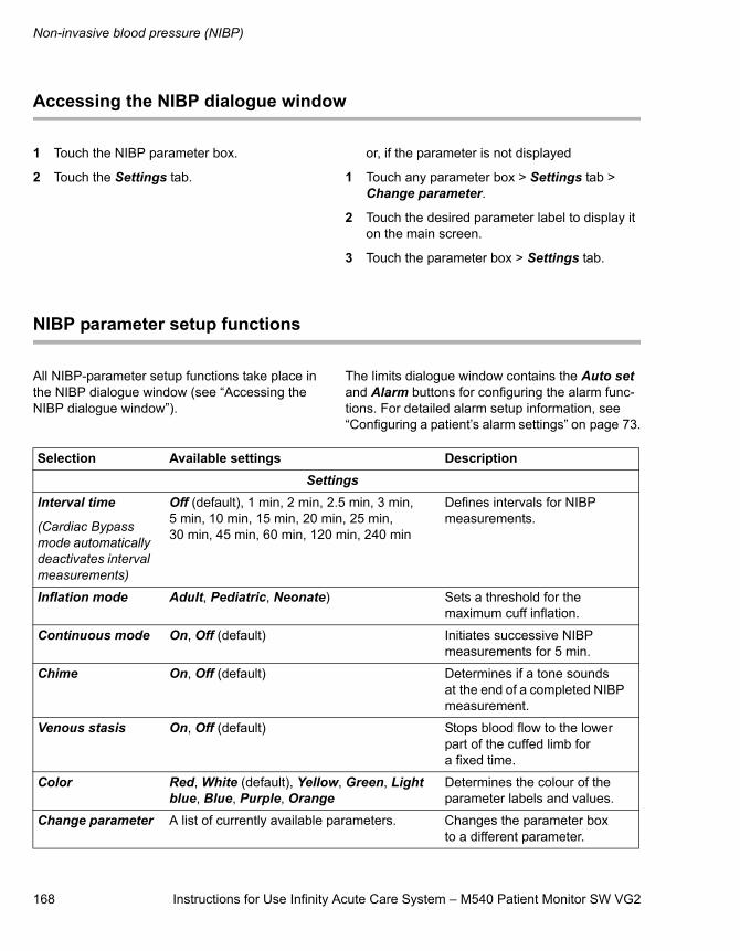
Non-invasive blood pressure (NIBP)
168 Instructions for Use Infinity Acute Care System – M540 Patient Monitor SW VG2
Accessing the NIBP dialogue window
1 Touch the NIBP parameter box.
2 Touch the Settings tab.
or, if the parameter is not displayed
1 Touch any parameter box > Settings tab > Change parameter.
2 Touch the desired parameter label to display it on the main screen.
3 Touch the parameter box > Settings tab.
NIBP parameter setup functions
All NIBP-parameter setup functions take place in the NIBP dialogue window (see “Accessing the NIBP dialogue window”).
The limits dialogue window contains the Auto set and Alarm buttons for configuring the alarm func-tions. For detailed alarm setup information, see “Configuring a patient’s alarm settings” on page 73.
Selection Available settings DescriptionSettings
Interval time
(Cardiac Bypass mode automatically deactivates interval measurements)
Off (default), 1 min, 2 min, 2.5 min, 3 min, 5 min, 10 min, 15 min, 20 min, 25 min, 30 min, 45 min, 60 min, 120 min, 240 min
Defines intervals for NIBP measurements.
Inflation mode Adult, Pediatric, Neonate) Sets a threshold for the maximum cuff inflation.
Continuous mode On, Off (default) Initiates successive NIBP measurements for 5 min.
Chime On, Off (default) Determines if a tone sounds at the end of a completed NIBP measurement.
Venous stasis On, Off (default) Stops blood flow to the lower part of the cuffed limb for a fixed time.
Color Red, White (default), Yellow, Green, Light blue, Blue, Purple, Orange
Determines the colour of the parameter labels and values.
Change parameter A list of currently available parameters. Changes the parameter box to a different parameter.
Instructions for Use Infinity Acute Care System – M540 Patient Monitor SW VG2 169
Invasive blood pressure (IBP)
Invasive blood pressure (IBP)
Overview of IBP monitoring . . . . . . . . . . . . . 170
Supported parameters . . . . . . . . . . . . . . . . . . . 170IBP pods. . . . . . . . . . . . . . . . . . . . . . . . . . . . . . 170
IBP precautions . . . . . . . . . . . . . . . . . . . . . . . 172
Connecting the Hemo4 and Hemo2 pods . . . . . . . . . . . . . . . . . . . . . . . . . . 173
Connecting the MPod – QuadHemo . . . . . . . 174
Connecting the Dual Hemo MCable . . . . . . . 175
Patient preparation for IBP monitoring . . . . 176
IBP display . . . . . . . . . . . . . . . . . . . . . . . . . . . 176
IBP parameter box . . . . . . . . . . . . . . . . . . . . . . 176
Labelling IBP pressure channels . . . . . . . . . 177
Standard pressure labels. . . . . . . . . . . . . . . . 178
Pressure label conflicts . . . . . . . . . . . . . . . . . 179
Pod-M540 label conflicts . . . . . . . . . . . . . . . . . 179
Zeroing an IBP transducer. . . . . . . . . . . . . . . 179
Zeroing a specific transducer . . . . . . . . . . . . . . 179Zeroing all pressure transducers (SmartZero) . . . . . . . . . . . . . . . . . . . . . . . . . . . 180
Pulmonary wedge pressure. . . . . . . . . . . . . . 181
Accessing the IBP dialogue window . . . . . . 181
IBP parameter setup functions . . . . . . . . . . . 181
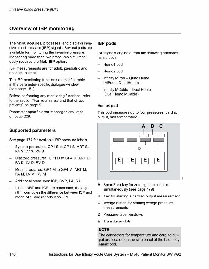
Invasive blood pressure (IBP)
170 Instructions for Use Infinity Acute Care System – M540 Patient Monitor SW VG2
Overview of IBP monitoring
The M540 acquires, processes, and displays inva-sive blood pressure (IBP) signals. Several pods are available for monitoring the invasive pressure. Monitoring more than two pressures simultane-ously requires the Multi-IBP option.
IBP measurements are for adult, paediatric and neonatal patients.
The IBP monitoring functions are configurable in the parameter-specific dialogue window (see page 181).
Before performing any monitoring functions, refer to the section “For your safety and that of your patients” on page 9.
Parameter-specific error messages are listed on page 229.
Supported parameters
See page 177 for available IBP pressure labels.
– Systolic pressures: GP1 S to GP4 S, ART S, PA S, LV S, RV S
– Diastolic pressures: GP1 D to GP4 D, ART D, PA D, LV D, RV D
– Mean pressures: GP1 M to GP4 M, ART M, PA M, LV M, RV M
– Additional pressures: ICP, CVP, LA, RA
– If both ART and ICP are connected, the algo-rithm computes the difference between ICP and mean ART and reports it as CPP.
IBP pods
IBP signals originate from the following haemody-namic pods:
– Hemo4 pod
– Hemo2 pod
– Infinity MPod – Quad Hemo (MPod – QuadHemo)
– Infinity MCable – Dual Hemo (Dual Hemo MCable)
Hemo4 pod
This pod measures up to four pressures, cardiac output, and temperature.
A SmartZero key for zeroing all pressures simultaneously (see page 179)
B Key for starting a cardiac output measurement
C Wedge button for starting wedge pressure measurements
D Pressure-label windows
E Transducer slots
338
NOTEThe connectors for temperature and cardiac out-put are located on the side panel of the haemody-namic pod.
A B C
D
E E E E
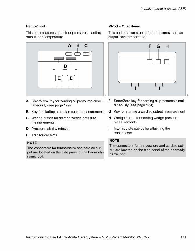
Instructions for Use Infinity Acute Care System – M540 Patient Monitor SW VG2 171
Invasive blood pressure (IBP)
Hemo2 pod
This pod measures up to four pressures, cardiac output, and temperature.
A SmartZero key for zeroing all pressures simul-taneously (see page 179)
B Key for starting a cardiac output measurement
C Wedge button for starting wedge pressure measurements
D Pressure-label windows
E Transducer slots
MPod – QuadHemo
This pod measures up to four pressures, cardiac output, and temperature.
F SmartZero key for zeroing all pressures simul-taneously (see page 179)
G Key for starting a cardiac output measurement
H Wedge button for starting wedge pressure measurements
I Intermediate cables for attaching the transducers
339
NOTEThe connectors for temperature and cardiac out-put are located on the side panel of the haemody-namic pod.
A B C
D
E E
340
NOTEThe connectors for temperature and cardiac out-put are located on the side panel of the haemody-namic pod.
F G H
I I
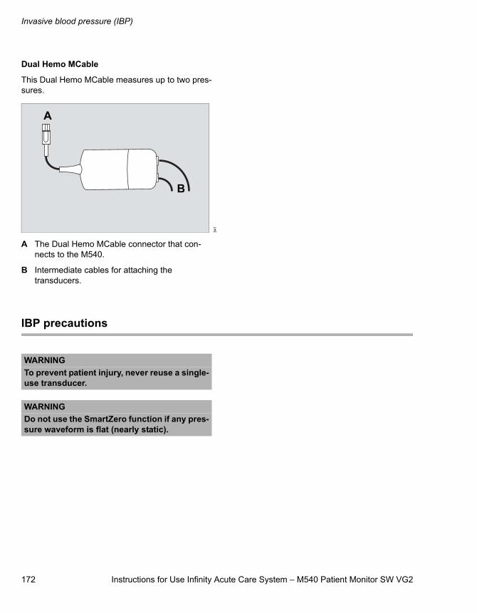
Invasive blood pressure (IBP)
172 Instructions for Use Infinity Acute Care System – M540 Patient Monitor SW VG2
Dual Hemo MCable
This Dual Hemo MCable measures up to two pres-sures.
A The Dual Hemo MCable connector that con-nects to the M540.
B Intermediate cables for attaching the transducers.
IBP precautions
341
A
B
WARNINGTo prevent patient injury, never reuse a single-use transducer.
WARNINGDo not use the SmartZero function if any pres-sure waveform is flat (nearly static).
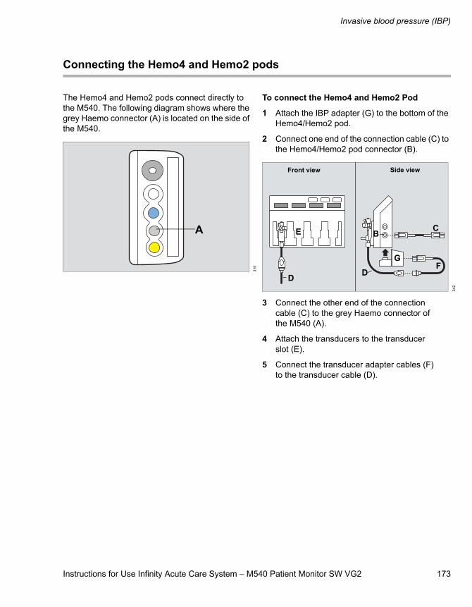
Instructions for Use Infinity Acute Care System – M540 Patient Monitor SW VG2 173
Invasive blood pressure (IBP)
Connecting the Hemo4 and Hemo2 pods
The Hemo4 and Hemo2 pods connect directly to the M540. The following diagram shows where the grey Haemo connector (A) is located on the side of the M540.
To connect the Hemo4 and Hemo2 Pod
1 Attach the IBP adapter (G) to the bottom of the Hemo4/Hemo2 pod.
2 Connect one end of the connection cable (C) to the Hemo4/Hemo2 pod connector (B).
3 Connect the other end of the connection cable (C) to the grey Haemo connector of the M540 (A).
4 Attach the transducers to the transducer slot (E).
5 Connect the transducer adapter cables (F) to the transducer cable (D).
310
A
342
B C
DF
Front view Side view
E
DG
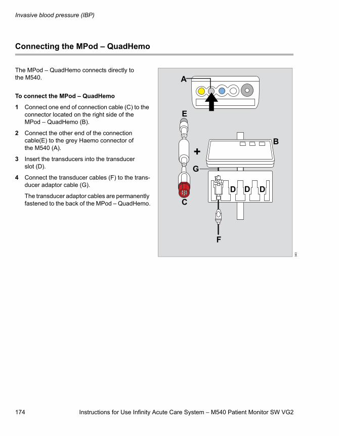
Invasive blood pressure (IBP)
174 Instructions for Use Infinity Acute Care System – M540 Patient Monitor SW VG2
Connecting the MPod – QuadHemo
The MPod – QuadHemo connects directly to the M540.
To connect the MPod – QuadHemo
1 Connect one end of connection cable (C) to the connector located on the right side of the MPod – QuadHemo (B).
2 Connect the other end of the connection cable(E) to the grey Haemo connector of the M540 (A).
3 Insert the transducers into the transducer slot (D).
4 Connect the transducer cables (F) to the trans-ducer adaptor cable (G).
The transducer adaptor cables are permanently fastened to the back of the MPod – QuadHemo.
343
C
A
E
G
D D D
B
F
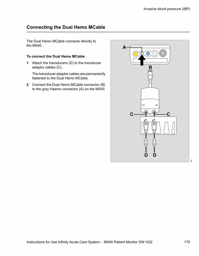
Instructions for Use Infinity Acute Care System – M540 Patient Monitor SW VG2 175
Invasive blood pressure (IBP)
Connecting the Dual Hemo MCable
The Dual Hemo MCable connects directly to the M540.
To connect the Dual Hemo MCable
1 Attach the transducers (D) to the transducer adaptor cables (C).
The transducer adaptor cables are permanently fastened to the Dual Hemo MCable.
2 Connect the Dual Hemo MCable connector (B) to the grey Haemo connector (A) on the M540.
344
A
B
CC
D D
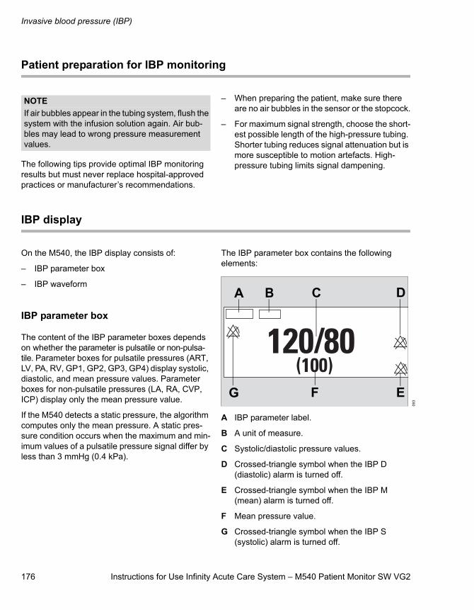
Invasive blood pressure (IBP)
176 Instructions for Use Infinity Acute Care System – M540 Patient Monitor SW VG2
Patient preparation for IBP monitoring
The following tips provide optimal IBP monitoring results but must never replace hospital-approved practices or manufacturer’s recommendations.
– When preparing the patient, make sure there are no air bubbles in the sensor or the stopcock.
– For maximum signal strength, choose the short-est possible length of the high-pressure tubing. Shorter tubing reduces signal attenuation but is more susceptible to motion artefacts. High-pressure tubing limits signal dampening.
IBP display
On the M540, the IBP display consists of:
– IBP parameter box
– IBP waveform
IBP parameter box
The content of the IBP parameter boxes depends on whether the parameter is pulsatile or non-pulsa-tile. Parameter boxes for pulsatile pressures (ART, LV, PA, RV, GP1, GP2, GP3, GP4) display systolic, diastolic, and mean pressure values. Parameter boxes for non-pulsatile pressures (LA, RA, CVP, ICP) display only the mean pressure value.
If the M540 detects a static pressure, the algorithm computes only the mean pressure. A static pres-sure condition occurs when the maximum and min-imum values of a pulsatile pressure signal differ by less than 3 mmHg (0.4 kPa).
The IBP parameter box contains the following elements:
A IBP parameter label.
B A unit of measure.
C Systolic/diastolic pressure values.
D Crossed-triangle symbol when the IBP D (diastolic) alarm is turned off.
E Crossed-triangle symbol when the IBP M (mean) alarm is turned off.
F Mean pressure value.
G Crossed-triangle symbol when the IBP S (systolic) alarm is turned off.
NOTEIf air bubbles appear in the tubing system, flush the system with the infusion solution again. Air bub-bles may lead to wrong pressure measurement values.
093
A B C D
F EG
Instructions for Use Infinity Acute Care System – M540 Patient Monitor SW VG2 177
Invasive blood pressure (IBP)
Labelling IBP pressure channels
The IBP pressure label determines how a signal is analyzed and reported. The M540 takes the pres-sure labels from the connected pod or MCable pro-vided the transducers are connected. When a new label is assigned to a pressure channel, the M540 clears the parameters and conditions set for the previous label (including alarms and waveform scales) and replaces them with the settings of the new label.
The following rules apply to labelling pressure channels:
– If no pressure labels are assigned, the labels GP1 to GP4 are automatically assigned depending on how many pressures are connected
– The zero value, the date and time associated with the pressure channel remain unchanged even if a new label is assigned
To assign a pressure label manually
1 Touch the IBP parameter box.
2 Touch the Settings tab.
3 Touch Edit label.
4 Touch the appropriate pod label (Pod 1A label, Pod 1B label, and so on).
5 Touch the new pressure name (GP1, ART, PA, CVP, ICP, LV, LA, RA, RV).
6 Touch X to close the dialogue window.
or
1 Touch the Menu function key.
2 Touch Label IBP.NOTEIf the M540 displays the generic pressure labels (GP1, GP2, GP3, GP4), the displays on the Hemo2 and Hemo4 pods are labelled P1a, P1b, P1c, P1d.
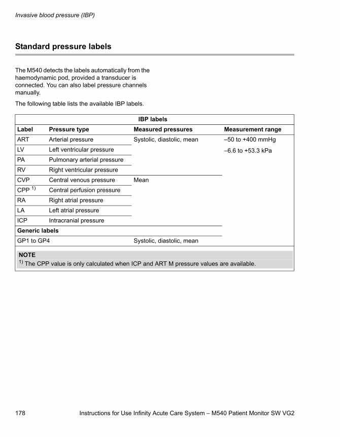
Invasive blood pressure (IBP)
178 Instructions for Use Infinity Acute Care System – M540 Patient Monitor SW VG2
Standard pressure labels
The M540 detects the labels automatically from the haemodynamic pod, provided a transducer is connected. You can also label pressure channels manually.
The following table lists the available IBP labels.
IBP labelsLabel Pressure type Measured pressures Measurement rangeART Arterial pressure Systolic, diastolic, mean –50 to +400 mmHg
–6.6 to +53.3 kPaLV Left ventricular pressure
PA Pulmonary arterial pressure
RV Right ventricular pressure
CVP Central venous pressure Mean
CPP 1) Central perfusion pressure
RA Right atrial pressure
LA Left atrial pressure
ICP Intracranial pressure
Generic labelsGP1 to GP4 Systolic, diastolic, mean
NOTE1) The CPP value is only calculated when ICP and ART M pressure values are available.
Instructions for Use Infinity Acute Care System – M540 Patient Monitor SW VG2 179
Invasive blood pressure (IBP)
Pressure label conflicts
Each pressure label is assigned to one location. If you try to reuse a label, you must confirm it. The M540 assigns the label to the currently selected parameter box and places an automatic pressure label (GP1 to GP4) in the previous location. When the M540 is docked in an IACS configuration, the pressure labels are saved as part of the M540 profile.
Pod-M540 label conflicts
The haemodynamic pods store pressure labels like the M540. When a pod with previously stored labels is connected, different pressure labels may exist for the same channel, thus causing a conflict.
If a transducer is connected to the pod, the label stored in the pod prevails. The M540 assigns that parameter label to the pressure-label list box. If no transducer is connected to the pod, the label stored in the M540 has priority.
Zeroing an IBP transducer
To establish accurate IBP values, zero the trans-ducer according to the hospital’s protocol at least once a day. Perform additional zeroing under the following circumstances:
– After introducing a catheter into the vascular system of the patient
– Before each monitoring session
– Each time you use a new transducer or tubing
– Whenever you connect the transducer cable to the monitor
– If the reported pressure values seem incorrect
– When the message IBP check zero appears
For zeroing to be successful, a pressure must be stable for at least 3 seconds. Messages report the status of the zeroing process. The time and date of the last successful zero is recorded on the IBP page. Check the IBP waveform and repeat the zeroing procedure if the zeroing fails because the pressures are not static. If the procedure fails after two attempts, replace the transducer or consult your technical personnel.
Zeroing a specific transducer
This procedure allows you to select a specific trans-ducer for zeroing.
To zero a specific sensor
1 Touch the appropriate IBP parameter box.
2 Touch the Settings tab.
3 Align the transducer to the level of the heart (phlebostatic access point, fifth intercostal space and mid-axillary line).
4 Close the transducer stopcock to the patient and open it to air.
5 Touch Zero on the M540.
If the zeroing of the transducer is successful, the message Zero accepted appears. If zero-ing fails, the message did not zero appears. In that case, repeat steps three to five.
6 Touch X to close the dialogue window.
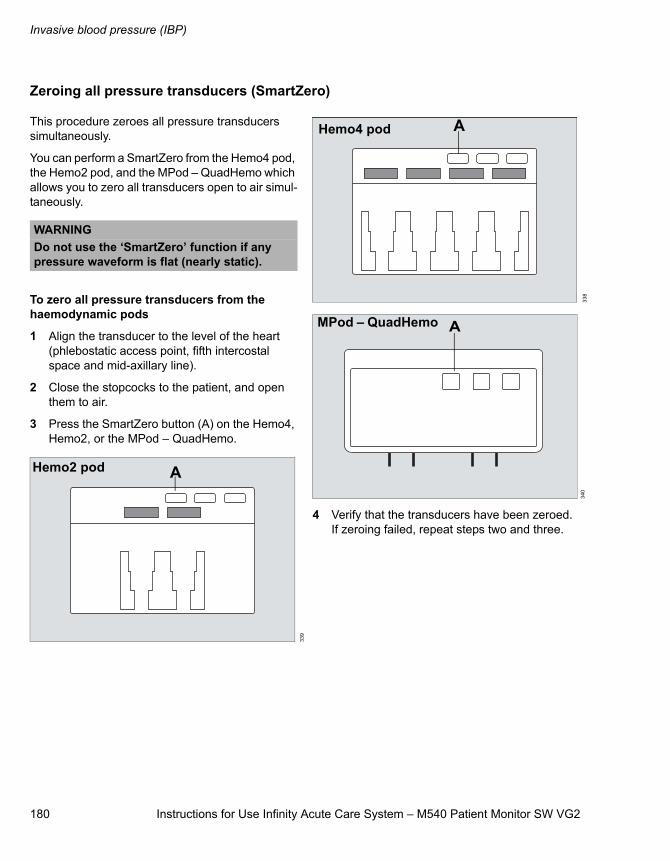
Invasive blood pressure (IBP)
180 Instructions for Use Infinity Acute Care System – M540 Patient Monitor SW VG2
Zeroing all pressure transducers (SmartZero)
This procedure zeroes all pressure transducers simultaneously.
You can perform a SmartZero from the Hemo4 pod, the Hemo2 pod, and the MPod – QuadHemo which allows you to zero all transducers open to air simul-taneously.
To zero all pressure transducers from the haemodynamic pods
1 Align the transducer to the level of the heart (phlebostatic access point, fifth intercostal space and mid-axillary line).
2 Close the stopcocks to the patient, and open them to air.
3 Press the SmartZero button (A) on the Hemo4, Hemo2, or the MPod – QuadHemo.
4 Verify that the transducers have been zeroed. If zeroing failed, repeat steps two and three.
WARNINGDo not use the ‘SmartZero’ function if any pressure waveform is flat (nearly static).
339
AHemo2 pod
338
340
AHemo4 pod
AMPod – QuadHemo
Instructions for Use Infinity Acute Care System – M540 Patient Monitor SW VG2 181
Invasive blood pressure (IBP)
Pulmonary wedge pressure
You cannot request pulmonary wedge pressures directly from the M540. For more information on requesting pulmonary wedge pressures when the
M540 is part of IACS, refer to the Infinity Acute Care System – M540 Patient Monitor Instructions for Use.
Accessing the IBP dialogue window
1 Touch the IBP parameter box.
2 Touch the Settings tab.
or, if the parameter is not displayed
1 Touch any parameter box > Settings tab > Change parameter.
2 Touch the desired parameter label to display it on the main screen.
3 Touch the parameter box > Settings tab.
IBP parameter setup functions
All IBP setup functions take place in the IBP dia-logue window (see “Accessing the IBP dialogue window”).
The limits dialogue window contains the Auto set and Alarm buttons for configuring the alarm func-tions. For detailed alarm setup information, see “Configuring a patient’s alarm settings” on page 73.
Selection Available settings Description Settings
Zero Not applicable Zeroes only the pressure indicated on the IBP page and displays the time and date of the last zeroing (see page 179).
Edit label ART, PA, CVP, LA, LV, RV, RA, ICP, GP1 to GP4
The defaults are as follows:
– Channel 1: GP1
– Channel 2: GP2
– Channel 3: GP3
– Channel 4: GP4
Allows you to assign a label to each pressure channel.
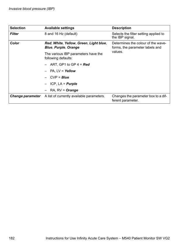
Invasive blood pressure (IBP)
182 Instructions for Use Infinity Acute Care System – M540 Patient Monitor SW VG2
Filter 8 and 16 Hz (default) Selects the filter setting applied to the IBP signal.
Color Red, White, Yellow, Green, Light blue, Blue, Purple, Orange
The various IBP parameters have the following defaults:
– ART, GP1 to GP 4 = Red
– PA, LV = Yellow
– CVP = Blue
– ICP, LA = Purple
– RA, RV = Orange
Determines the colour of the wave-forms, the parameter labels and values.
Change parameter A list of currently available parameters. Changes the parameter box to a dif-ferent parameter.
Selection Available settings Description
Instructions for Use Infinity Acute Care System – M540 Patient Monitor SW VG2 183
Cardiac Output (C.O.)
Cardiac Output (C.O.)
Overview of Cardiac Output (C.O.) monitoring. . . . . . . . . . . . . . . . . . . . . . . . . . . . 184
C.O. measurement method . . . . . . . . . . . . . . . 184Supported parameters . . . . . . . . . . . . . . . . . . . 184
C.O. precautions. . . . . . . . . . . . . . . . . . . . . . . 184
Connecting the C.O. hardware . . . . . . . . . . . 185
Patient preparation for C.O. monitoring . . . . . . . . . . . . . . . . . . . . . . . 187
Cardiac Output (C.O.)
184 Instructions for Use Infinity Acute Care System – M540 Patient Monitor SW VG2
Overview of Cardiac Output (C.O.) monitoring
The M540 uses the thermodilution method to com-pute cardiac output (C.O.) for adult and paediatric patients. C.O. monitoring is not intended for neona-tal patients.
The MPod – QuadHemo, the Hemo4 and Hemo2 pods connect to the M540 and acquire the blood, and the injectate temperatures which are used to compute the C.O. value.
Although the M540 processes the C.O. algorithms, you can only view the data and execute C.O. func-tions on the Cockpit when the M540 is docked in an IACS configuration. For more information, refer to Infinity Acute Care System - M540 Patient Monitor Instructions for Use.
C.O. measurement method
A solution of known temperature and volume is injected into the bloodstream in the right atrium. A thermistor in the catheter tip continuously meas-ures the temperature of the blood as it leaves the heart. The injectate mixes with and cools the sur-rounding blood. The blood reaches its minimum temperature relatively quickly and then warms up slowly until it returns to the baseline blood temper-ature. The total drop in blood temperature is
inversely related to the C.O. of the patient. The lower the C.O. value, the more the injectate cools the blood.
When computing C.O., the M540 takes the follow-ing factors into account:
– Injectate volume, temperature, density, and specific heat of the fluid that is being injected
– Baseline blood temperature, density, and spe-cific heat
– Temperature changes of the blood injectate mixture
– Area under the temperature curve
Before performing any monitoring functions, refer to the section “For your safety and that of your patients” on page 9.
Parameter-specific error messages are listed on page 231.
Supported parameters
– C.O. – Cardiac output
– Tblood – blood temperature
– Tinj – injectate temperature
C.O. precautions
WARNINGAn incorrect computation constant may yield incorrect C.O. measurements and put the patient at risk. Confirm that the manually entered computation constant is correct for the catheter you are using.
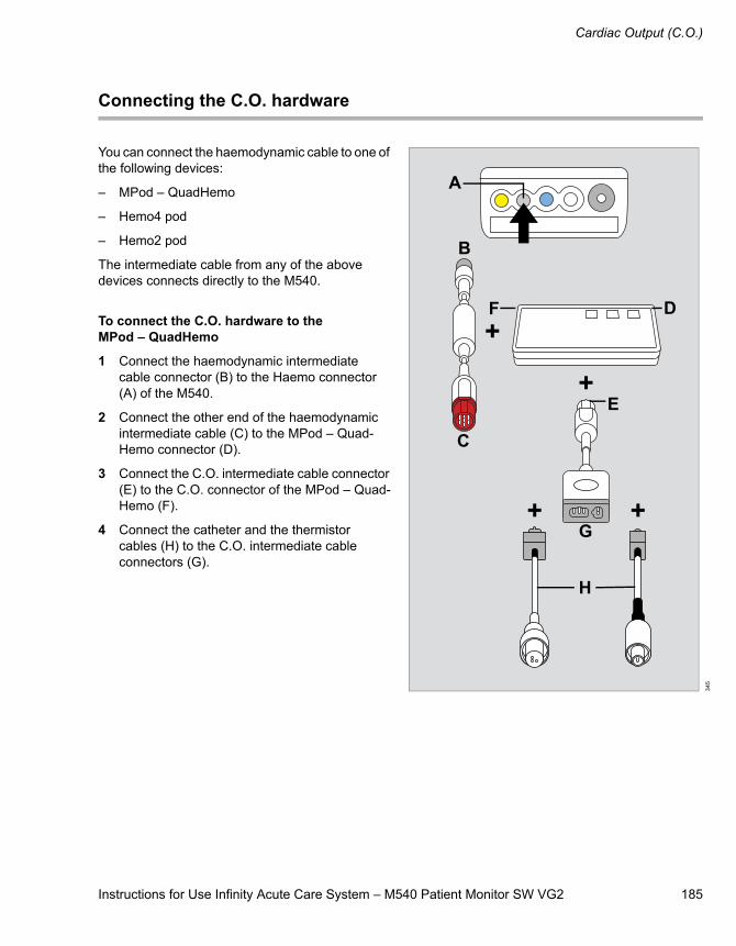
Instructions for Use Infinity Acute Care System – M540 Patient Monitor SW VG2 185
Cardiac Output (C.O.)
Connecting the C.O. hardware
You can connect the haemodynamic cable to one of the following devices:
– MPod – QuadHemo
– Hemo4 pod
– Hemo2 pod
The intermediate cable from any of the above devices connects directly to the M540.
To connect the C.O. hardware to the MPod – QuadHemo
1 Connect the haemodynamic intermediate cable connector (B) to the Haemo connector (A) of the M540.
2 Connect the other end of the haemodynamic intermediate cable (C) to the MPod – Quad-Hemo connector (D).
3 Connect the C.O. intermediate cable connector (E) to the C.O. connector of the MPod – Quad-Hemo (F).
4 Connect the catheter and the thermistor cables (H) to the C.O. intermediate cable connectors (G).
345
B
C
D
A
E
F
G
H
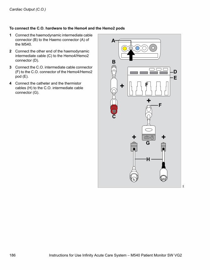
Cardiac Output (C.O.)
186 Instructions for Use Infinity Acute Care System – M540 Patient Monitor SW VG2
To connect the C.O. hardware to the Hemo4 and the Hemo2 pods
1 Connect the haemodynamic intermediate cable connector (B) to the Haemo connector (A) of the M540.
2 Connect the other end of the haemodynamic intermediate cable (C) to the Hemo4/Hemo2 connector (D).
3 Connect the C.O. intermediate cable connector (F) to the C.O. connector of the Hemo4/Hemo2 pod (E).
4 Connect the catheter and the thermistor cables (H) to the C.O. intermediate cable connector (G).
346
B
C
DE
F
A
F
G
H
Instructions for Use Infinity Acute Care System – M540 Patient Monitor SW VG2 187
Cardiac Output (C.O.)
Patient preparation for C.O. monitoring
The following tips provide optimal C.O. monitoring results, but must never replace hospital-approved practices or manufacturer’s recommendations.
– Follow the recommendations of the manufac-turer. Dräger recommends that you place pre-filled syringes or the closed injectate delivery system into an ice bath.
– Check the ice bath regularly and add ice to maintain a temperature between 0 °C (32 °F) and 5 °C (41 °F). The accuracy of measure-ments done with the thermodilution method increases as the temperature of the injectate approaches 0 °C (32 °F).
– Verify the injectate volume.
– Verify the proper selection of catheter type and size or computation constant if Other is chosen for the catheter type.
– Use an in-line injectate system. Systems that measure the injectate temperature in the ice bath can introduce errors. These errors happen because the injectate temperature changes between its removal from the ice bath and the injection.
– If you fill your syringes manually, fill them with the same volume each time. The recommended amount is 10 cc for adults and 5 cc for paediat-ric patients. Do not touch the body of the syringe to avoid warming the injectate.
– Inject the entire volume in one swift, continuous motion.
– Perform the injection at the end of expiration. Taking successive C.O. measurements at dif-ferent points in the respiratory cycle provides different measurements, especially for patients on mechanical ventilators.
– Discard results that are widely different from the general trend, and results associated with irreg-ularly shaped waveforms.
NOTEFor the most accurate results when using an injec-tate at room temperature, use a 10 cc injectate volume unless clinically contraindicated, to get the best results.

188 Instructions for Use Infinity Acute Care System – M540 Patient Monitor SW VG2
This page is intentionally left blank

Instructions for Use Infinity Acute Care System – M540 Patient Monitor SW VG2 189
Carbon Dioxide Concentrations (CO2)
Carbon Dioxide Concentrations (CO2)
Overview of CO2 monitoring . . . . . . . . . . . . . 190
Supported parameters . . . . . . . . . . . . . . . . . . . 190
CO2 precautions . . . . . . . . . . . . . . . . . . . . . . . 190
Connecting the CO2 sensor. . . . . . . . . . . . . . 192
Patient preparation for CO2 monitoring . . . . 193
CO2 display . . . . . . . . . . . . . . . . . . . . . . . . . . . 194
CO2 parameter box . . . . . . . . . . . . . . . . . . . . . 194CO2 waveform (capnogramme) . . . . . . . . . . . . 194Troubleshooting . . . . . . . . . . . . . . . . . . . . . . . . 195
Accessing the CO2 dialogue window . . . . . . 196
CO2 parameter setup functions . . . . . . . . . . 196
Carbon Dioxide Concentrations (CO2)
190 Instructions for Use Infinity Acute Care System – M540 Patient Monitor SW VG2
Overview of CO2 monitoring
The M540 provides fast and continuous main-stream measurements of carbon dioxide concen-trations (CO2) in the airway of intubated patients. The M540 acquires signals from a CO2 sensor (Infinity MCable – Mainstream CO2) which fits over a mainstream airway adapter. The lightweight, reusable CO2 mainstream sensor provides sensi-tive and accurate measurements. It uses non-dis-persive infrared technology to measure CO2 in respiratory gases.
CO2 monitoring is available for adult and paediatric patients.
As respiratory gases flow through the airway adap-tor, the sensor analyses the expired and inspired air of the patient by sending a beam of infrared light through transparent ports in the airway adaptor while detecting changes in CO2 absorption levels.
Before performing any monitoring functions, refer to the section “For your safety and that of your patients” on page 9.
Parameter-specific error messages are listed on page 231.
Supported parameters
– etCO2 – end-tidal CO2
– inCO2 – inspired CO2
– RRc – respiration rate as calculated from capnogramme
CO2 precautions
WARNINGRRc apnoea alarms are NOT reported if the setting RRc apnea time is set to Off in the CO2 setup page and the RRc alarm feature is deac-tivated. To generate RRc apnoea alarms, activate the RRc alarms and select a RRc apnoea time.
WARNINGThe safety and effectiveness of the respiration measurement method in the detection of apnoea, particularly the apnoea of prematurity and apnoea of infancy, have not been estab-lished.
WARNINGPatient monitors that measure CO2, anaes-thetic agents, and/or respiratory mechanics are not intended to be used as an apnoea monitor and/or recording device. While these products provide an apnoea alarm, that alarm condition is initiated based on the elapsed time since the last breath was detected. The clinical diagnosis of a true apnoeic event, however, requires multiple physiological signals.
WARNINGCO2 alarms do not activate until the first breath is detected after turning on the monitor or discharging a patient.
Instructions for Use Infinity Acute Care System – M540 Patient Monitor SW VG2 191
Carbon Dioxide Concentrations (CO2)
WARNINGThe surface temperature of the sensor may rise to 43 °C (109 °F). Prolonged exposure to the patient's skin may result in a burn.
CAUTIONLeaks in the breathing circuit (for example, an uncuffed endotracheal tube or a damaged airway adaptor) may significantly affect CO2 the meas-urement values.
CAUTIONTo avoid accidental disconnections, do not apply excessive tension to any sensor cable.
CAUTIONTo prevent leakage, make sure the airway adaptor is firmly connected to the breathing circuit.
CAUTIONCheck the CO2 mainstream sensor for damage before use. A damaged CO2 sensor may impair electrical isolation or may introduce debris into the breathing circuit.
NOTEDräger CO2 accessories that come in contact with the patient do not contain latex.
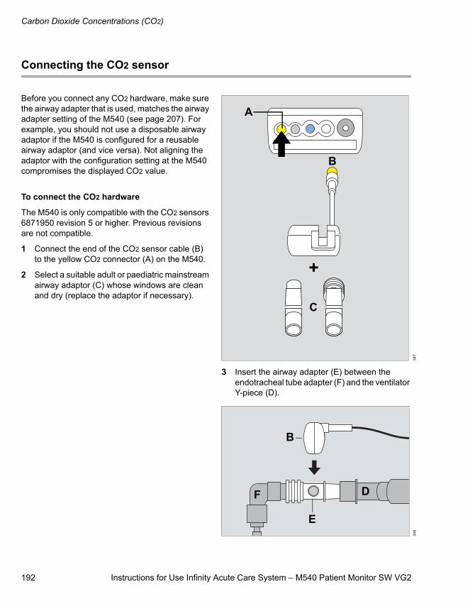
Carbon Dioxide Concentrations (CO2)
192 Instructions for Use Infinity Acute Care System – M540 Patient Monitor SW VG2
Connecting the CO2 sensor
Before you connect any CO2 hardware, make sure the airway adapter that is used, matches the airway adapter setting of the M540 (see page 207). For example, you should not use a disposable airway adaptor if the M540 is configured for a reusable airway adaptor (and vice versa). Not aligning the adaptor with the configuration setting at the M540 compromises the displayed CO2 value.
To connect the CO2 hardware
The M540 is only compatible with the CO2 sensors 6871950 revision 5 or higher. Previous revisions are not compatible.
1 Connect the end of the CO2 sensor cable (B) to the yellow CO2 connector (A) on the M540.
2 Select a suitable adult or paediatric mainstream airway adaptor (C) whose windows are clean and dry (replace the adaptor if necessary).
3 Insert the airway adapter (E) between the endotracheal tube adapter (F) and the ventilator Y-piece (D).
347
348
A
B
C
B
E
DF
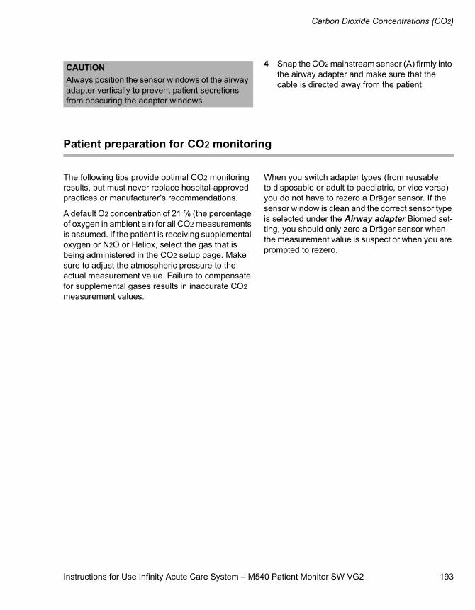
Instructions for Use Infinity Acute Care System – M540 Patient Monitor SW VG2 193
Carbon Dioxide Concentrations (CO2)
4 Snap the CO2 mainstream sensor (A) firmly into the airway adapter and make sure that the cable is directed away from the patient.
Patient preparation for CO2 monitoring
The following tips provide optimal CO2 monitoring results, but must never replace hospital-approved practices or manufacturer’s recommendations.
A default O2 concentration of 21 % (the percentage of oxygen in ambient air) for all CO2 measurements is assumed. If the patient is receiving supplemental oxygen or N2O or Heliox, select the gas that is being administered in the CO2 setup page. Make sure to adjust the atmospheric pressure to the actual measurement value. Failure to compensate for supplemental gases results in inaccurate CO2 measurement values.
When you switch adapter types (from reusable to disposable or adult to paediatric, or vice versa) you do not have to rezero a Dräger sensor. If the sensor window is clean and the correct sensor type is selected under the Airway adapter Biomed set-ting, you should only zero a Dräger sensor when the measurement value is suspect or when you are prompted to rezero.
CAUTIONAlways position the sensor windows of the airway adapter vertically to prevent patient secretions from obscuring the adapter windows.
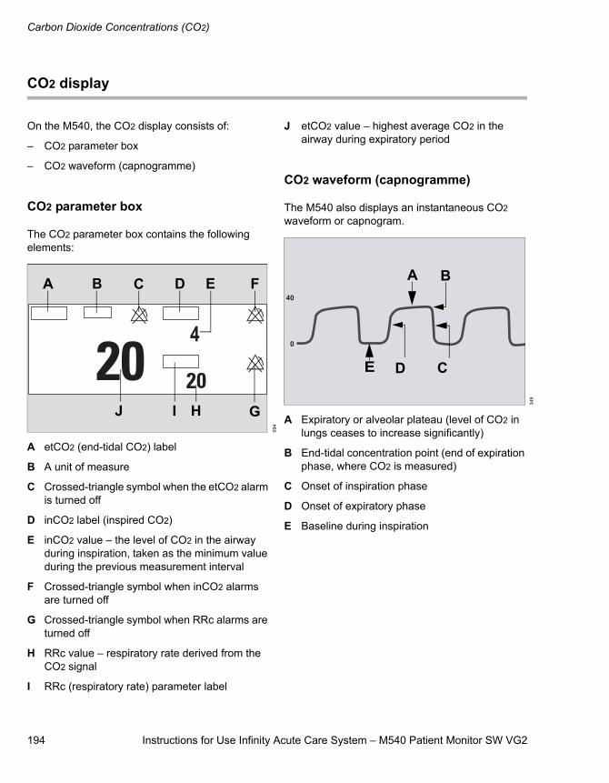
Carbon Dioxide Concentrations (CO2)
194 Instructions for Use Infinity Acute Care System – M540 Patient Monitor SW VG2
CO2 display
On the M540, the CO2 display consists of:
– CO2 parameter box
– CO2 waveform (capnogramme)
CO2 parameter box
The CO2 parameter box contains the following elements:
A etCO2 (end-tidal CO2) label
B A unit of measure
C Crossed-triangle symbol when the etCO2 alarm is turned off
D inCO2 label (inspired CO2)
E inCO2 value – the level of CO2 in the airway during inspiration, taken as the minimum value during the previous measurement interval
F Crossed-triangle symbol when inCO2 alarms are turned off
G Crossed-triangle symbol when RRc alarms are turned off
H RRc value – respiratory rate derived from the CO2 signal
I RRc (respiratory rate) parameter label
J etCO2 value – highest average CO2 in the airway during expiratory period
CO2 waveform (capnogramme)
The M540 also displays an instantaneous CO2 waveform or capnogram.
A Expiratory or alveolar plateau (level of CO2 in lungs ceases to increase significantly)
B End-tidal concentration point (end of expiration phase, where CO2 is measured)
C Onset of inspiration phase
D Onset of expiratory phase
E Baseline during inspiration
094
A B C D
H G
FE
IJ
349
A B
CDE
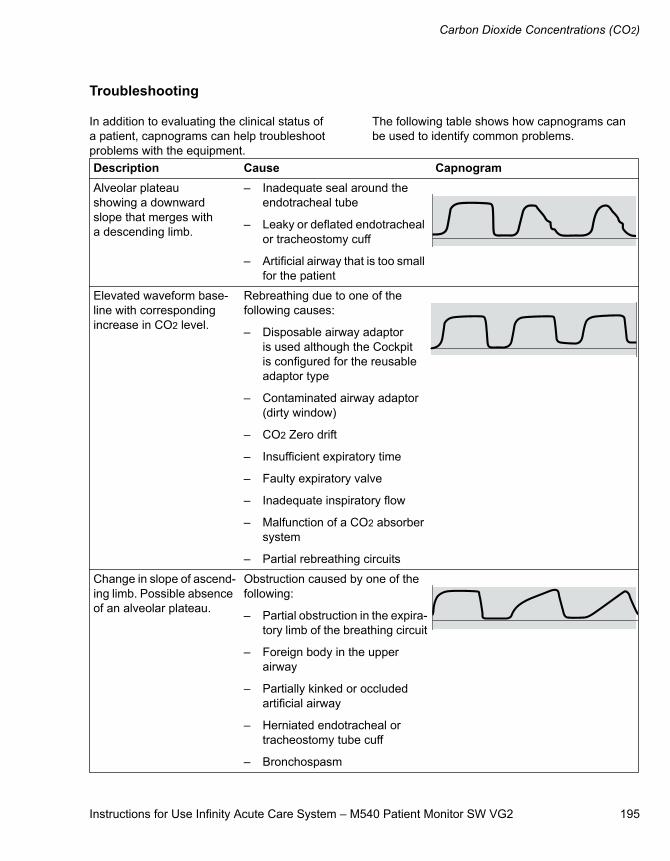
Instructions for Use Infinity Acute Care System – M540 Patient Monitor SW VG2 195
Carbon Dioxide Concentrations (CO2)
Troubleshooting
In addition to evaluating the clinical status of a patient, capnograms can help troubleshoot problems with the equipment.
The following table shows how capnograms can be used to identify common problems.
Description Cause CapnogramAlveolar plateau showing a downward slope that merges with a descending limb.
– Inadequate seal around the endotracheal tube
– Leaky or deflated endotracheal or tracheostomy cuff
– Artificial airway that is too small for the patient
Elevated waveform base-line with corresponding increase in CO2 level.
Rebreathing due to one of the following causes:
– Disposable airway adaptor is used although the Cockpit is configured for the reusable adaptor type
– Contaminated airway adaptor (dirty window)
– CO2 Zero drift
– Insufficient expiratory time
– Faulty expiratory valve
– Inadequate inspiratory flow
– Malfunction of a CO2 absorber system
– Partial rebreathing circuits
Change in slope of ascend-ing limb. Possible absence of an alveolar plateau.
Obstruction caused by one of the following:
– Partial obstruction in the expira-tory limb of the breathing circuit
– Foreign body in the upper airway
– Partially kinked or occluded artificial airway
– Herniated endotracheal or tracheostomy tube cuff
– Bronchospasm
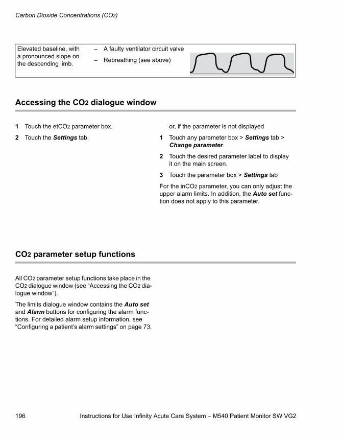
Carbon Dioxide Concentrations (CO2)
196 Instructions for Use Infinity Acute Care System – M540 Patient Monitor SW VG2
Accessing the CO2 dialogue window
1 Touch the etCO2 parameter box.
2 Touch the Settings tab.
or, if the parameter is not displayed
1 Touch any parameter box > Settings tab > Change parameter.
2 Touch the desired parameter label to display it on the main screen.
3 Touch the parameter box > Settings tab
For the inCO2 parameter, you can only adjust the upper alarm limits. In addition, the Auto set func-tion does not apply to this parameter.
CO2 parameter setup functions
All CO2 parameter setup functions take place in the CO2 dialogue window (see “Accessing the CO2 dia-logue window”).
The limits dialogue window contains the Auto set and Alarm buttons for configuring the alarm func-tions. For detailed alarm setup information, see “Configuring a patient’s alarm settings” on page 73.
Elevated baseline, with a pronounced slope on the descending limb.
– A faulty ventilator circuit valve
– Rebreathing (see above)
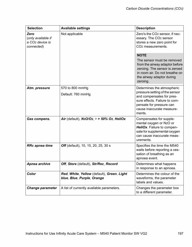
Instructions for Use Infinity Acute Care System – M540 Patient Monitor SW VG2 197
Carbon Dioxide Concentrations (CO2)
Selection Available settings DescriptionZero(only available if a CO2 device is connected)
Not applicable Zero's the CO2 sensor, if nec-essary. The CO2 sensor stores a new zero point for CO2 measurements.
Atm. pressure 570 to 800 mmHg
Default: 760 mmHg
Determines the atmospheric pressure setting of the sensor and compensates for pres-sure effects. Failure to com-pensate for pressure can cause inaccurate measure-ments.
Gas compens. Air (default), N2O/O2, > > 50% O2, HeliOx Compensates for supple-mental oxygen or N2O or HeliOx. Failure to compen-sate for supplemental oxygen can cause inaccurate meas-urements.
RRc apnea time Off (default), 10, 15, 20, 25, 30 s Specifies the time the M540 waits before reporting a ces-sation of breathing as an apnoea event.
Apnea archive Off, Store (default), Str/Rec, Record Determines what happens in response to an apnoea.
Color Red, White, Yellow (default), Green, Light blue, Blue, Purple, Orange
Determines the colour of the waveforms, the parameter labels and values.
Change parameter A list of currently available parameters. Changes the parameter box to a different parameter.
NOTEThe sensor must be removed from the airway adaptor before zeroing. The sensor is zeroed in room air. Do not breathe on the airway adaptor during zeroing.

198 Instructions for Use Infinity Acute Care System – M540 Patient Monitor SW VG2
This page is intentionally left blank
Instructions for Use Infinity Acute Care System – M540 Patient Monitor SW VG2 199
System configuration
System configuration
System configuration overview . . . . . . . . . . 200
Configuring general settings. . . . . . . . . . . . . 201
Configuring the patient settings . . . . . . . . . . 202
Configuring the system settings. . . . . . . . . . 203
Viewing the system information . . . . . . . . . . 205
Configuring the biomed settings . . . . . . . . . 206
Configuring units of measure . . . . . . . . . . . . . . 207Configuring the network setup . . . . . . . . . . . . . 208
Configuring the screen setup . . . . . . . . . . . . 208
Configuring alarm settings . . . . . . . . . . . . . . 210
System configuration
200 Instructions for Use Infinity Acute Care System – M540 Patient Monitor SW VG2
System configuration overview
This chapter describes the Menu and Alarm set-tings dialogue windows. The Menu dialogue win-dow consists of several dialogue windows for configuring the M540. Some of these dialogue win-dows are password-protected and are only acces-sible to authorised personnel.
The Menu dialogue window consists of the follow-ing dialogue windows:
– Main (see page 201)
– Patient setup (see page 202)
– System setup (see page 203)
– Biomed button (see page 206)
– General tab (see page 203)
– Alarms mgmt. tab (see page 203)
– Service tab (see Service Instructions)
– System information tab (see page 205)
– Screen setup (see page 208)
– Settings tab (see page 208)
– Screen views tab (see page 209)
– Function keys tab (see page 209)
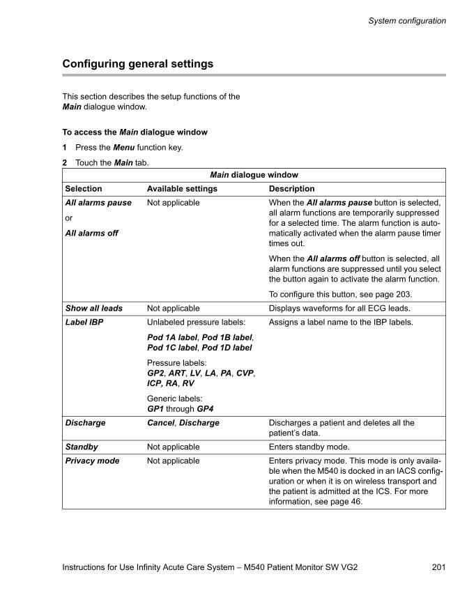
Instructions for Use Infinity Acute Care System – M540 Patient Monitor SW VG2 201
System configuration
Configuring general settings
This section describes the setup functions of the Main dialogue window.
To access the Main dialogue window
1 Press the Menu function key.
2 Touch the Main tab.Main dialogue window
Selection Available settings DescriptionAll alarms pause
or
All alarms off
Not applicable When the All alarms pause button is selected, all alarm functions are temporarily suppressed for a selected time. The alarm function is auto-matically activated when the alarm pause timer times out.
When the All alarms off button is selected, all alarm functions are suppressed until you select the button again to activate the alarm function.
To configure this button, see page 203.
Show all leads Not applicable Displays waveforms for all ECG leads.
Label IBP Unlabeled pressure labels:
Pod 1A label, Pod 1B label, Pod 1C label, Pod 1D label
Pressure labels: GP2, ART, LV, LA, PA, CVP, ICP, RA, RV
Generic labels:GP1 through GP4
Assigns a label name to the IBP labels.
Discharge Cancel, Discharge Discharges a patient and deletes all the patient’s data.
Standby Not applicable Enters standby mode.
Privacy mode Not applicable Enters privacy mode. This mode is only availa-ble when the M540 is docked in an IACS config-uration or when it is on wireless transport and the patient is admitted at the ICS. For more information, see page 46.
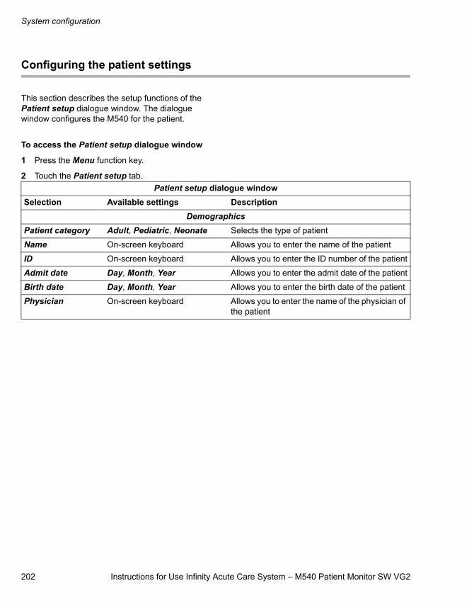
System configuration
202 Instructions for Use Infinity Acute Care System – M540 Patient Monitor SW VG2
Configuring the patient settings
This section describes the setup functions of the Patient setup dialogue window. The dialogue window configures the M540 for the patient.
To access the Patient setup dialogue window
1 Press the Menu function key.
2 Touch the Patient setup tab.Patient setup dialogue window
Selection Available settings DescriptionDemographics
Patient category Adult, Pediatric, Neonate Selects the type of patient
Name On-screen keyboard Allows you to enter the name of the patient
ID On-screen keyboard Allows you to enter the ID number of the patient
Admit date Day, Month, Year Allows you to enter the admit date of the patient
Birth date Day, Month, Year Allows you to enter the birth date of the patient
Physician On-screen keyboard Allows you to enter the name of the physician of the patient
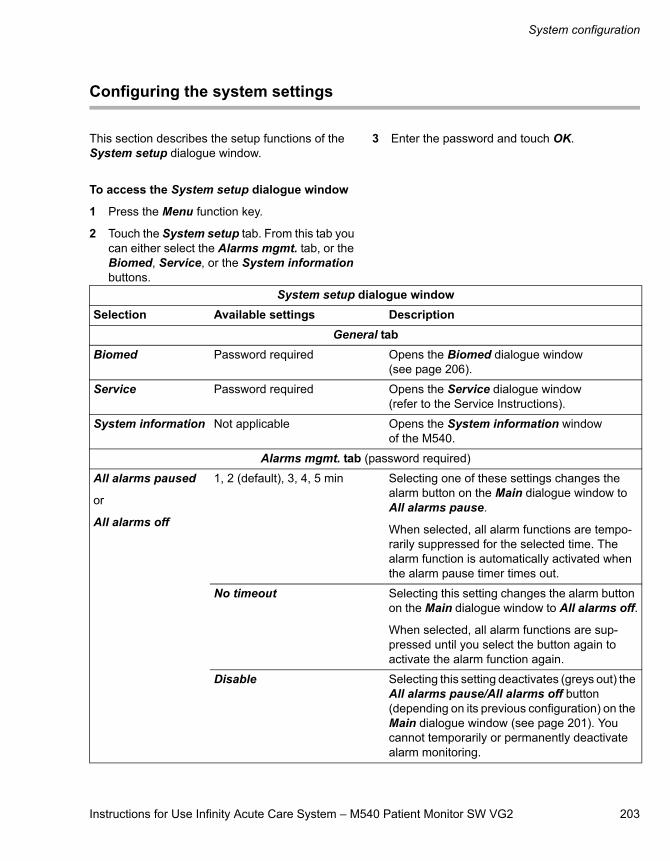
Instructions for Use Infinity Acute Care System – M540 Patient Monitor SW VG2 203
System configuration
Configuring the system settings
This section describes the setup functions of the System setup dialogue window.
To access the System setup dialogue window
1 Press the Menu function key.
2 Touch the System setup tab. From this tab you can either select the Alarms mgmt. tab, or the Biomed, Service, or the System information buttons.
3 Enter the password and touch OK.
System setup dialogue windowSelection Available settings Description
General tabBiomed Password required Opens the Biomed dialogue window
(see page 206).
Service Password required Opens the Service dialogue window (refer to the Service Instructions).
System information Not applicable Opens the System information window of the M540.
Alarms mgmt. tab (password required)
All alarms paused
or
All alarms off
1, 2 (default), 3, 4, 5 min Selecting one of these settings changes the alarm button on the Main dialogue window to All alarms pause.
When selected, all alarm functions are tempo-rarily suppressed for the selected time. The alarm function is automatically activated when the alarm pause timer times out.
No timeout Selecting this setting changes the alarm button on the Main dialogue window to All alarms off.
When selected, all alarm functions are sup-pressed until you select the button again to activate the alarm function again.
Disable Selecting this setting deactivates (greys out) the All alarms pause/All alarms off button (depending on its previous configuration) on the Main dialogue window (see page 201). You cannot temporarily or permanently deactivate alarm monitoring.
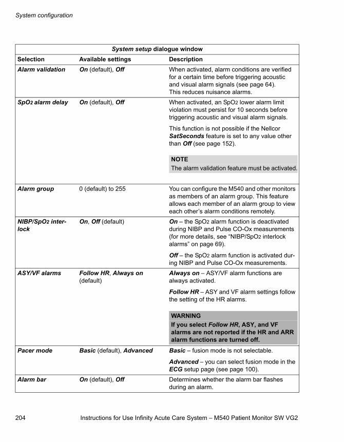
System configuration
204 Instructions for Use Infinity Acute Care System – M540 Patient Monitor SW VG2
Alarm validation On (default), Off When activated, alarm conditions are verified for a certain time before triggering acoustic and visual alarm signals (see page 64). This reduces nuisance alarms.
SpO2 alarm delay On (default), Off When activated, an SpO2 lower alarm limit violation must persist for 10 seconds before triggering acoustic and visual alarm signals.
This function is not possible if the Nellcor SatSeconds feature is set to any value other than Off (see page 152).
Alarm group 0 (default) to 255 You can configure the M540 and other monitors as members of an alarm group. This feature allows each member of an alarm group to view each other’s alarm conditions remotely.
NIBP/SpO2 inter-lock
On, Off (default) On – the SpO2 alarm function is deactivated during NIBP and Pulse CO-Ox measurements (for more details, see “NIBP/SpO2 interlock alarms” on page 69).
Off – the SpO2 alarm function is activated dur-ing NIBP and Pulse CO-Ox measurements.
ASY/VF alarms Follow HR, Always on (default)
Always on – ASY/VF alarm functions are always activated.
Follow HR – ASY and VF alarm settings follow the setting of the HR alarms.
Pacer mode Basic (default), Advanced Basic – fusion mode is not selectable.
Advanced – you can select fusion mode in the ECG setup page (see page 100).
Alarm bar On (default), Off Determines whether the alarm bar flashes during an alarm.
System setup dialogue windowSelection Available settings Description
NOTEThe alarm validation feature must be activated.
WARNINGIf you select Follow HR, ASY, and VF alarms are not reported if the HR and ARR alarm functions are turned off.
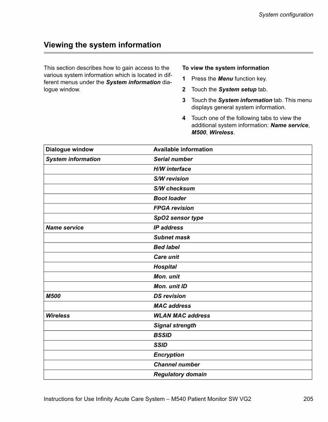
Instructions for Use Infinity Acute Care System – M540 Patient Monitor SW VG2 205
System configuration
Viewing the system information
This section describes how to gain access to the various system information which is located in dif-ferent menus under the System information dia-logue window.
To view the system information
1 Press the Menu function key.
2 Touch the System setup tab.
3 Touch the System information tab. This menu displays general system information.
4 Touch one of the following tabs to view the additional system information: Name service, M500, Wireless.
Dialogue window Available informationSystem information Serial number
H/W interfaceS/W revisionS/W checksumBoot loaderFPGA revisionSpO2 sensor type
Name service IP addressSubnet maskBed labelCare unitHospitalMon. unitMon. unit ID
M500 DS revisionMAC address
Wireless WLAN MAC addressSignal strengthBSSIDSSIDEncryptionChannel numberRegulatory domain

System configuration
206 Instructions for Use Infinity Acute Care System – M540 Patient Monitor SW VG2
Configuring the biomed settings
This section describes the setup functions of the Biomed dialogue windows.
To access the Biomed dialogue window
1 Press the Menu function key.
2 Touch the System setup tab.
3 Touch the Biomed button.
4 Enter the password and touch OK.
5 Touch the Settings 1 or the Settings 2 buttons.
Biomed dialogue windowsSelection Available settings DescriptionLanguage English, German, Spanish,
French, Italian, Portugese, Port.(Br), Russian, Japanese, Swedish, Norweg., Danish, Dutch, Turkish, Polish, Finnish, Greek, Chinese, Hungarian, English (UK), Czech
Selects the language of the M540 screen text.
Date Day, Month, Year Allows you to enter the date.
Time Hour, Minute Allows you to enter the time.
Simulation Cancel, OK Activates simulation mode. Select the “Discharge” function key to exit.
Save profile Cancel, OK Saves and replaces the profile for the current patient category.
Restore views Cancel, OK After a software upgrade, this feature restores the up to five available views.
Alarm pattern IEC slow, IEC fast, Infinity (default)
Determines the type of alarm tone pattern in use (for more information, see “Acoustic alarm sig-nals” on page 67).
Line frequency 50, 60 Hz (default) Selects the line frequency.
Biomed > Settings 2French NFC Off (default), On When activated, HR alarms cannot be turned
off, and the All alarms pause period cannot exceed 3 minutes.
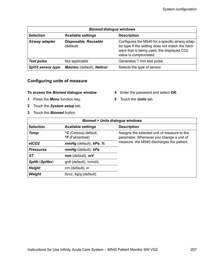
Instructions for Use Infinity Acute Care System – M540 Patient Monitor SW VG2 207
System configuration
Configuring units of measure
To access the Biomed dialogue window
1 Press the Menu function key.
2 Touch the System setup tab.
3 Touch the Biomed button.
4 Enter the password and select OK.
5 Touch the Units tab.
Airway adapter Disposable, Reusable (default)
Configures the M540 for a specific airway adap-tor type If the setting does not match the hard-ware that is being used, the displayed CO2 value is compromised.
Test pulse Not applicable Generates 1 mm test pulse.
SpO2 sensor type Masimo (default), Nellcor Selects the type of sensor.
Biomed dialogue windowsSelection Available settings Description
Biomed > Units dialogue windowsSelection Available settings DescriptionTemp °C (Celsius) default,
°F (Fahrenheit)Assigns the selected unit of measure to the parameter. Whenever you change a unit of measure, the M540 discharges the patient.etCO2 mmHg (default), kPa, %
Pressures mmHg (default), kPaST mm (default), mVSpHb (SpHbv) g/dl (default), mmol/L
Height cm (default), in
Weight lb/oz, kg/g (default)
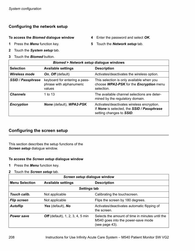
System configuration
208 Instructions for Use Infinity Acute Care System – M540 Patient Monitor SW VG2
Configuring the network setup
To access the Biomed dialogue window
1 Press the Menu function key.
2 Touch the System setup tab.
3 Touch the Biomed button.
4 Enter the password and select OK.
5 Touch the Network setup tab.
Configuring the screen setup
This section describes the setup functions of the Screen setup dialogue window.
To access the Screen setup dialogue window
1 Press the Menu function key.
2 Touch the Screen setup tab.
Biomed > Network setup dialogue windowsSelection Available settings DescriptionWireless mode On, Off (default) Activates/deactivates the wireless option.
SSID / Passphrase keyboard for entering a pass-phrase with alphanumeric values
This selection is only available when you choose WPA2-PSK for the Encryption menu selection.
Channels 1 to 13 The available channel selections are deter-mined by the regulatory domain.
Encryption None (default), WPA2-PSK Activates/deactivates wireless encryption. If None is selected, the SSID / Passphrase setting changes to SSID.
Screen setup dialogue windowMenu Selection Available settings Description
Settings tabTouch calib. Not applicable Calibrating the touchscreen.
Flip screen Not applicable Flips the screen by 180 degrees.
Autoflip Yes (default), No Activates/deactivates automatic flipping of the screen.
Power save Off (default), 1, 2, 3, 4, 5 min Selects the amount of time in minutes until the M540 goes into the power-save mode (see page 43).
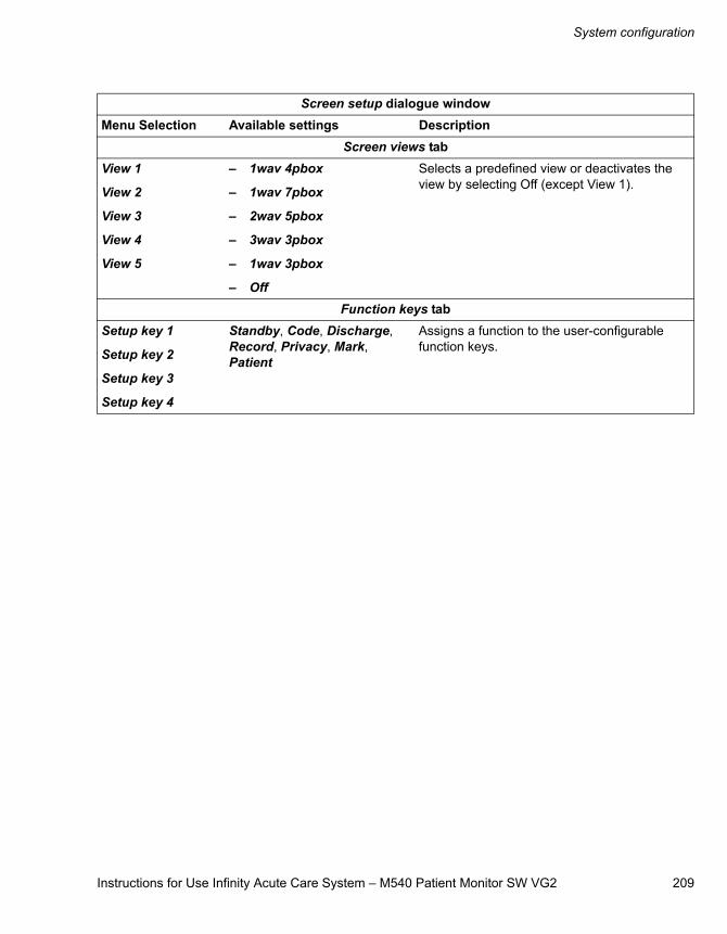
Instructions for Use Infinity Acute Care System – M540 Patient Monitor SW VG2 209
System configuration
Screen views tabView 1
View 2
View 3
View 4
View 5
– 1wav 4pbox
– 1wav 7pbox
– 2wav 5pbox
– 3wav 3pbox
– 1wav 3pbox
– Off
Selects a predefined view or deactivates the view by selecting Off (except View 1).
Function keys tabSetup key 1
Setup key 2
Setup key 3
Setup key 4
Standby, Code, Discharge, Record, Privacy, Mark, Patient
Assigns a function to the user-configurable function keys.
Screen setup dialogue windowMenu Selection Available settings Description
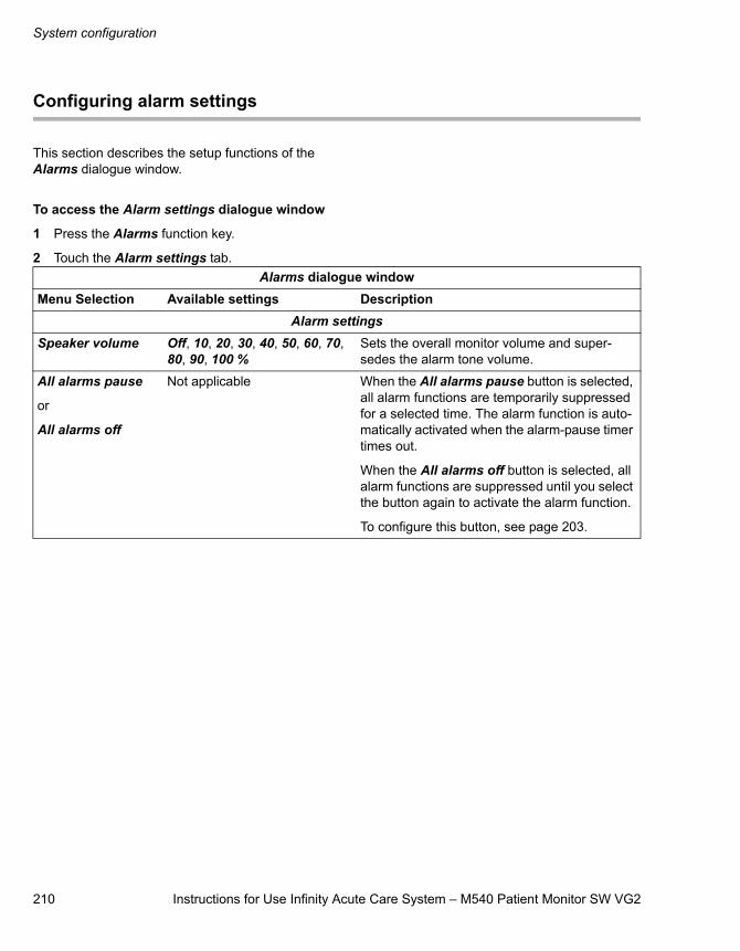
System configuration
210 Instructions for Use Infinity Acute Care System – M540 Patient Monitor SW VG2
Configuring alarm settings
This section describes the setup functions of the Alarms dialogue window.
To access the Alarm settings dialogue window
1 Press the Alarms function key.
2 Touch the Alarm settings tab.Alarms dialogue window
Menu Selection Available settings DescriptionAlarm settings
Speaker volume Off, 10, 20, 30, 40, 50, 60, 70, 80, 90, 100 %
Sets the overall monitor volume and super-sedes the alarm tone volume.
All alarms pause
or
All alarms off
Not applicable When the All alarms pause button is selected, all alarm functions are temporarily suppressed for a selected time. The alarm function is auto-matically activated when the alarm-pause timer times out.
When the All alarms off button is selected, all alarm functions are suppressed until you select the button again to activate the alarm function.
To configure this button, see page 203.
Instructions for Use Infinity Acute Care System – M540 Patient Monitor SW VG2 211
Problem solving
Problem solving
Overview . . . . . . . . . . . . . . . . . . . . . . . . . . . . . 212
Device communication messages . . . . . . . . 212
M540 battery messages . . . . . . . . . . . . . . . . . 213
ECG . . . . . . . . . . . . . . . . . . . . . . . . . . . . . . . . . 214
ST . . . . . . . . . . . . . . . . . . . . . . . . . . . . . . . . . . . 215
ARR . . . . . . . . . . . . . . . . . . . . . . . . . . . . . . . . . 217
Respiration (RRi) . . . . . . . . . . . . . . . . . . . . . . 218
SpO2. . . . . . . . . . . . . . . . . . . . . . . . . . . . . . . . . 220
NIBP . . . . . . . . . . . . . . . . . . . . . . . . . . . . . . . . . 225
Temperature . . . . . . . . . . . . . . . . . . . . . . . . . . 228
IBP . . . . . . . . . . . . . . . . . . . . . . . . . . . . . . . . . . 229
CO2. . . . . . . . . . . . . . . . . . . . . . . . . . . . . . . . . . 231
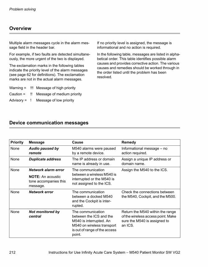
Problem solving
212 Instructions for Use Infinity Acute Care System – M540 Patient Monitor SW VG2
Overview
Multiple alarm messages cycle in the alarm mes-sage field in the header bar.
For example, if two faults are detected simultane-ously, the more urgent of the two is displayed.
The exclamation marks in the following tables indicate the priority level of the alarm messages (see page 62 for definitions). The exclamation marks are not in the actual alarm messages.
If no priority level is assigned, the message is informational and no action is required.
In the following table, messages are listed in alpha-betical order. This table identifies possible alarm causes and provides corrective action. The various causes and remedies should be worked through in the order listed until the problem has been resolved.
Device communication messages
Warning = !!! Message of high priority
Caution = !! Message of medium priority
Advisory = ! Message of low priority
Priority Message Cause RemedyNone Audio paused by
remoteM540 alarms were paused by a remote device.
Informational message – no action required.
None Duplicate address The IP address or domain name is already in use.
Assign a unique IP address or domain name.
None Network alarm error
NOTE: An acoustic tone accompanies this message.
The communication between a wireless M540 is interrupted or the M540 is not assigned to the ICS.
Assign the M540 to the ICS.
None Network error The communication between a docked M540 and the Cockpit is inter-rupted.
Check the connections between the M540, Cockpit, and the M500.
None Not monitored by central
The communication between the ICS and the M540 is interrupted. An M540 on wireless transport is out of range of the access point.
Return the M540 within the range of the wireless access point. Make sure the M540 is assigned to an ICS.
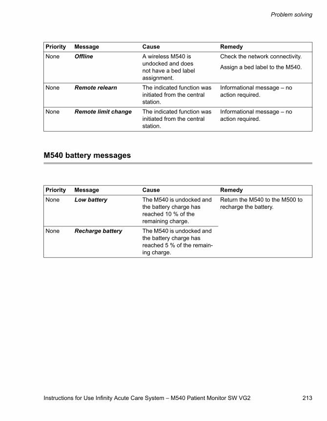
Instructions for Use Infinity Acute Care System – M540 Patient Monitor SW VG2 213
Problem solving
M540 battery messages
None Offline A wireless M540 is undocked and does not have a bed label assignment.
Check the network connectivity.
Assign a bed label to the M540.
None Remote relearn The indicated function was initiated from the central station.
Informational message – no action required.
None Remote limit change The indicated function was initiated from the central station.
Informational message – no action required.
Priority Message Cause Remedy
Priority Message Cause RemedyNone Low battery The M540 is undocked and
the battery charge has reached 10 % of the remaining charge.
Return the M540 to the M500 to recharge the battery.
None Recharge battery The M540 is undocked and the battery charge has reached 5 % of the remain-ing charge.
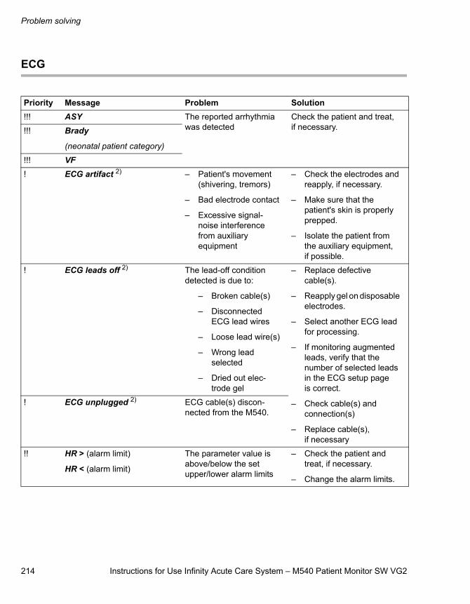
Problem solving
214 Instructions for Use Infinity Acute Care System – M540 Patient Monitor SW VG2
ECG
Priority Message Problem Solution!!! ASY The reported arrhythmia
was detectedCheck the patient and treat, if necessary.!!! Brady
(neonatal patient category)
!!! VF! ECG artifact 2) – Patient's movement
(shivering, tremors)
– Bad electrode contact
– Excessive signal-noise interference from auxiliary equipment
– Check the electrodes and reapply, if necessary.
– Make sure that the patient's skin is properly prepped.
– Isolate the patient from the auxiliary equipment, if possible.
! ECG leads off 2) The lead-off condition detected is due to:
– Broken cable(s)
– Disconnected ECG lead wires
– Loose lead wire(s)
– Wrong lead selected
– Dried out elec-trode gel
– Replace defective cable(s).
– Reapply gel on disposable electrodes.
– Select another ECG lead for processing.
– If monitoring augmented leads, verify that the number of selected leads in the ECG setup page is correct.
– Check cable(s) and connection(s)
– Replace cable(s), if necessary
! ECG unplugged 2) ECG cable(s) discon-nected from the M540.
!! HR > (alarm limit)
HR < (alarm limit)
The parameter value is above/below the set upper/lower alarm limits
– Check the patient and treat, if necessary.
– Change the alarm limits.
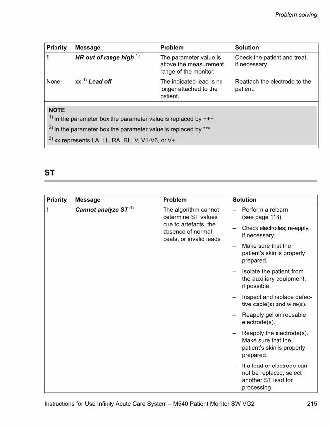
Instructions for Use Infinity Acute Care System – M540 Patient Monitor SW VG2 215
Problem solving
ST
!! HR out of range high 1) The parameter value is above the measurement range of the monitor.
Check the patient and treat, if necessary.
None xx 3) Lead off The indicated lead is no longer attached to the patient.
Reattach the electrode to the patient.
Priority Message Problem Solution
NOTE1) In the parameter box the parameter value is replaced by +++2) In the parameter box the parameter value is replaced by ***3) xx represents LA, LL, RA, RL, V, V1-V6, or V+
Priority Message Problem Solution! Cannot analyze ST 3) The algorithm cannot
determine ST values due to artefacts, the absence of normal beats, or invalid leads.
– Perform a relearn (see page 118).
– Check electrodes; re-apply, if necessary.
– Make sure that the patient's skin is properly prepared.
– Isolate the patient from the auxiliary equipment, if possible.
– Inspect and replace defec-tive cable(s) and wire(s).
– Reapply gel on reusable electrode(s).
– Reapply the electrode(s). Make sure that the patient’s skin is properly prepared.
– If a lead or electrode can-not be replaced, select another ST lead for processing
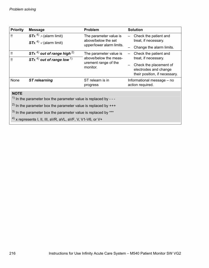
Problem solving
216 Instructions for Use Infinity Acute Care System – M540 Patient Monitor SW VG2
!! STx 4) > (alarm limit)
STx 4) < (alarm limit)
The parameter value is above/below the set upper/lower alarm limits.
– Check the patient and treat, if necessary.
– Change the alarm limits.
!! STx 4) out of range high 2) The parameter value is above/below the meas-urement range of the monitor.
– Check the patient and treat, if necessary.
– Check the placement of electrodes and change their position, if necessary.
!! STx 4) out of range low 1)
None ST relearning ST relearn is in progress
Informational message – no action required.
Priority Message Problem Solution
NOTE1) In the parameter box the parameter value is replaced by - - -2) In the parameter box the parameter value is replaced by +++3) In the parameter box the parameter value is replaced by ***4) x represents I, II, III, aVR, aVL, aVF, V, V1-V6, or V+
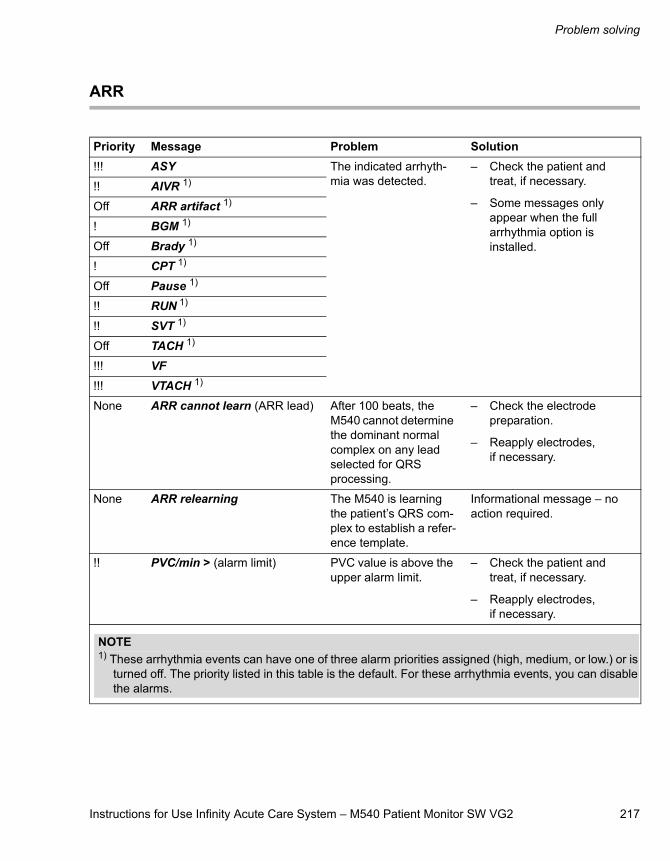
Instructions for Use Infinity Acute Care System – M540 Patient Monitor SW VG2 217
Problem solving
ARR
Priority Message Problem Solution!!! ASY The indicated arrhyth-
mia was detected. – Check the patient and
treat, if necessary.
– Some messages only appear when the full arrhythmia option is installed.
!! AIVR 1)
Off ARR artifact 1)
! BGM 1)
Off Brady 1)
! CPT 1)
Off Pause 1)
!! RUN 1)
!! SVT 1)
Off TACH 1)
!!! VF!!! VTACH 1)
None ARR cannot learn (ARR lead) After 100 beats, the M540 cannot determine the dominant normal complex on any lead selected for QRS processing.
– Check the electrode preparation.
– Reapply electrodes, if necessary.
None ARR relearning The M540 is learning the patient’s QRS com-plex to establish a refer-ence template.
Informational message – no action required.
!! PVC/min > (alarm limit) PVC value is above the upper alarm limit.
– Check the patient and treat, if necessary.
– Reapply electrodes, if necessary.
NOTE1) These arrhythmia events can have one of three alarm priorities assigned (high, medium, or low.) or is
turned off. The priority listed in this table is the default. For these arrhythmia events, you can disable the alarms.
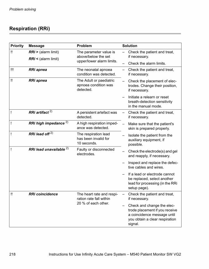
Problem solving
218 Instructions for Use Infinity Acute Care System – M540 Patient Monitor SW VG2
Respiration (RRi)
Priority Message Problem Solution!! RRi > (alarm limit)
RRi < (alarm limit)
The parameter value is above/below the set upper/lower alarm limits.
– Check the patient and treat, if necessary.
– Check the alarm limits.
!!! RRi apnea The neonatal apnoea condition was detected.
– Check the patient and treat, if necessary.
– Check the placement of elec-trodes. Change their position, if necessary.
– Initiate a relearn or reset breath-detection sensitivity in the manual mode.
!! RRi apnea The Adult or paediatric apnoea condition was detected.
! RRi artifact 2) A persistent artefact was detected.
– Check the patient and treat, if necessary.
– Make sure that the patient's skin is prepared properly.
– Isolate the patient from the auxiliary equipment, if possible.
– Check the electrode(s) and gel and reapply, if necessary.
– Inspect and replace the defec-tive cables and wires.
– If a lead or electrode cannot be replaced, select another lead for processing (in the RRi setup page).
! RRi high impedance 2) A high respiration imped-ance was detected.
! RRi lead off 2) The respiration lead has been invalid for 10 seconds.
! RRi lead unavailable 2) Faulty or disconnected electrodes.
!! RRi coincidence The heart rate and respi-ration rate fall within 20 % of each other.
– Check the patient and treat, if necessary.
– Check and change the elec-trode placement if you receive a coincidence message until you obtain a clear respiration signal.
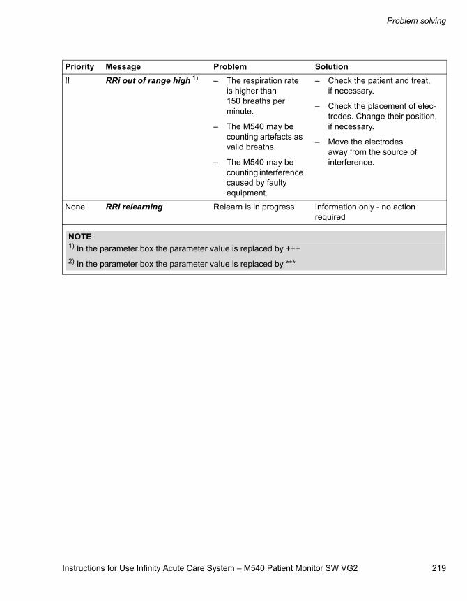
Instructions for Use Infinity Acute Care System – M540 Patient Monitor SW VG2 219
Problem solving
!! RRi out of range high 1) – The respiration rate is higher than 150 breaths per minute.
– The M540 may be counting artefacts as valid breaths.
– The M540 may be counting interference caused by faulty equipment.
– Check the patient and treat, if necessary.
– Check the placement of elec-trodes. Change their position, if necessary.
– Move the electrodes away from the source of interference.
None RRi relearning Relearn is in progress Information only - no action required
Priority Message Problem Solution
NOTE1) In the parameter box the parameter value is replaced by +++2) In the parameter box the parameter value is replaced by ***
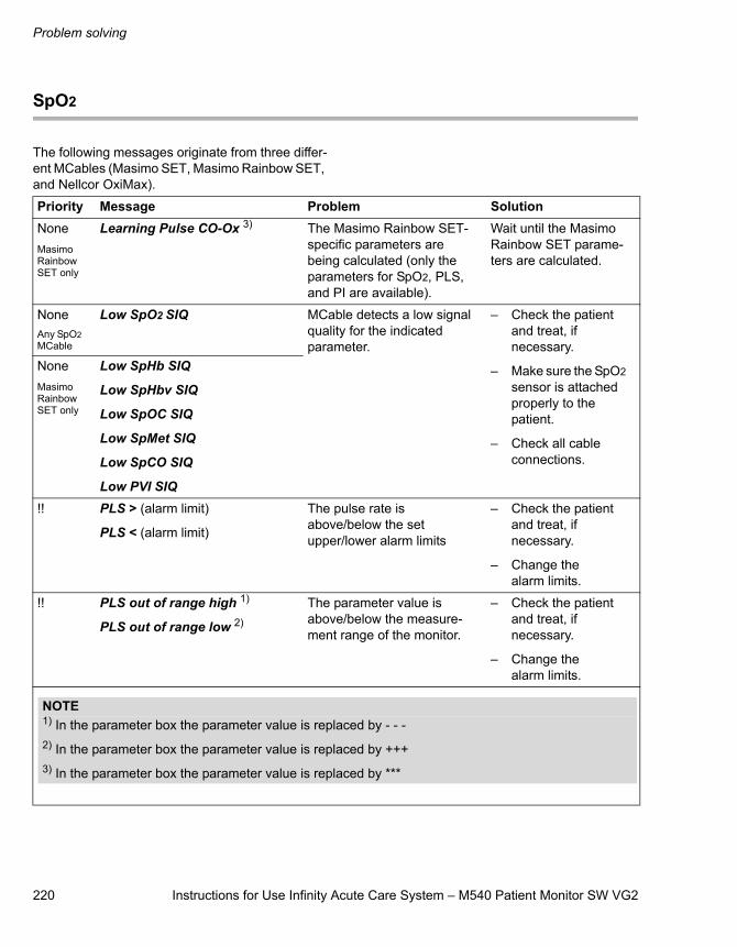
Problem solving
220 Instructions for Use Infinity Acute Care System – M540 Patient Monitor SW VG2
SpO2
The following messages originate from three differ-ent MCables (Masimo SET, Masimo Rainbow SET, and Nellcor OxiMax).
Priority Message Problem SolutionNoneMasimo Rainbow SET only
Learning Pulse CO-Ox 3) The Masimo Rainbow SET-specific parameters are being calculated (only the parameters for SpO2, PLS, and PI are available).
Wait until the Masimo Rainbow SET parame-ters are calculated.
NoneAny SpO2 MCable
Low SpO2 SIQ MCable detects a low signal quality for the indicated parameter.
– Check the patient and treat, if necessary.
– Make sure the SpO2 sensor is attached properly to the patient.
– Check all cable connections.
NoneMasimo Rainbow SET only
Low SpHb SIQ
Low SpHbv SIQ
Low SpOC SIQ
Low SpMet SIQ
Low SpCO SIQ
Low PVI SIQ!! PLS > (alarm limit)
PLS < (alarm limit)
The pulse rate is above/below the set upper/lower alarm limits
– Check the patient and treat, if necessary.
– Change the alarm limits.
!! PLS out of range high 1)
PLS out of range low 2)
The parameter value is above/below the measure-ment range of the monitor.
– Check the patient and treat, if necessary.
– Change the alarm limits.
NOTE1) In the parameter box the parameter value is replaced by - - -2) In the parameter box the parameter value is replaced by +++3) In the parameter box the parameter value is replaced by ***
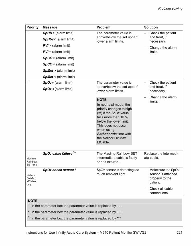
Instructions for Use Infinity Acute Care System – M540 Patient Monitor SW VG2 221
Problem solving
!! SpHb > (alarm limit)
SpHbv< (alarm limit)
PVI > (alarm limit)
PVI < (alarm limit)
SpCO > (alarm limit)
SpCO < (alarm limit)
SpMet > (alarm limit)
SpMet < (alarm limit)
The parameter value is above/below the set upper/ lower alarm limits.
– Check the patient and treat, if necessary.
– Change the alarm limits.
!! SpO2 > (alarm limit)
SpO2 < (alarm limit)
The parameter value is above/below the set upper/ lower alarm limits.
– Check the patient and treat, if necessary.
– Change the alarm limits.
!Masimo Rainbow SET only
SpO2 cable failure 3) The Masimo Rainbow SET intermediate cable is faulty or has expired.
Replace the intermedi-ate cable.
!Nellcor OxiMax MCable only
SpO2 check sensor 3) SpO2 sensor is detecting too much ambient light.
– Make sure the SpO2 sensor is attached properly to the patient.
– Check all cable connections.
Priority Message Problem Solution
NOTEIn neonatal mode, the priority changes to high (!!!) if the SpO2 value falls more than 10 % below the lower limit. This does not occur when using SatSeconds time with the Nellcor OxiMax MCable.
NOTE1) In the parameter box the parameter value is replaced by - - -2) In the parameter box the parameter value is replaced by +++3) In the parameter box the parameter value is replaced by ***
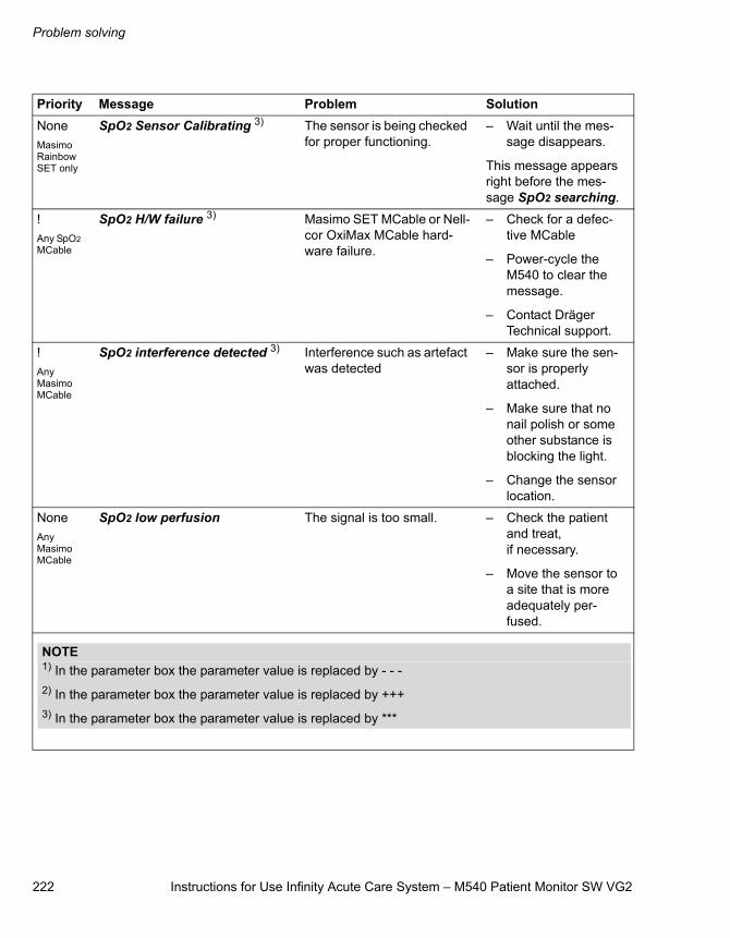
Problem solving
222 Instructions for Use Infinity Acute Care System – M540 Patient Monitor SW VG2
NoneMasimo Rainbow SET only
SpO2 Sensor Calibrating 3) The sensor is being checked for proper functioning.
– Wait until the mes-sage disappears.
This message appears right before the mes-sage SpO2 searching.
!Any SpO2 MCable
SpO2 H/W failure 3) Masimo SET MCable or Nell-cor OxiMax MCable hard-ware failure.
– Check for a defec-tive MCable
– Power-cycle the M540 to clear the message.
– Contact Dräger Technical support.
!Any Masimo MCable
SpO2 interference detected 3) Interference such as artefact was detected
– Make sure the sen-sor is properly attached.
– Make sure that no nail polish or some other substance is blocking the light.
– Change the sensor location.
NoneAny Masimo MCable
SpO2 low perfusion The signal is too small. – Check the patient and treat, if necessary.
– Move the sensor to a site that is more adequately per-fused.
Priority Message Problem Solution
NOTE1) In the parameter box the parameter value is replaced by - - -2) In the parameter box the parameter value is replaced by +++3) In the parameter box the parameter value is replaced by ***
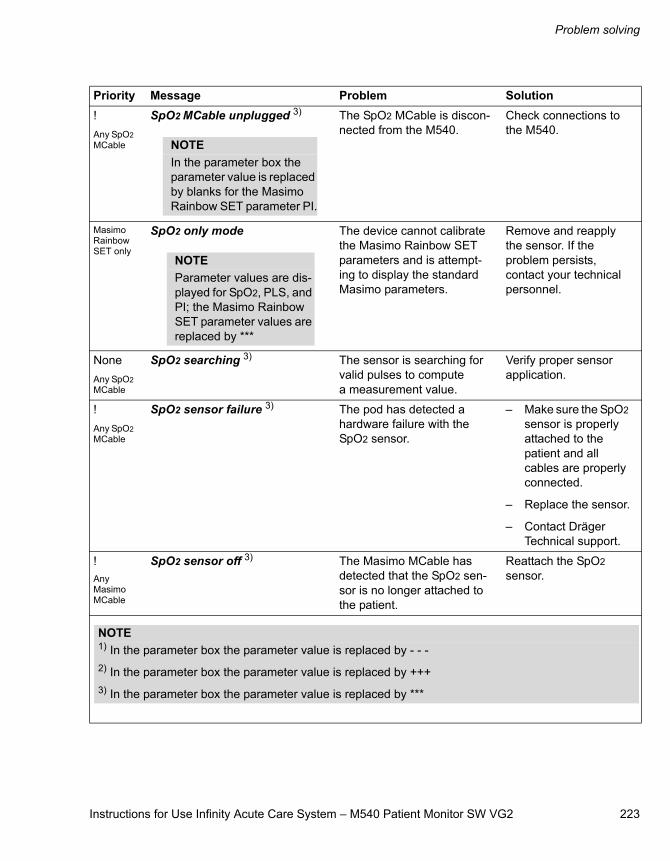
Instructions for Use Infinity Acute Care System – M540 Patient Monitor SW VG2 223
Problem solving
!Any SpO2 MCable
SpO2 MCable unplugged 3) The SpO2 MCable is discon-nected from the M540.
Check connections to the M540.
Masimo Rainbow SET only
SpO2 only mode The device cannot calibrate the Masimo Rainbow SET parameters and is attempt-ing to display the standard Masimo parameters.
Remove and reapply the sensor. If the problem persists, contact your technical personnel.
NoneAny SpO2 MCable
SpO2 searching 3) The sensor is searching for valid pulses to compute a measurement value.
Verify proper sensor application.
!Any SpO2 MCable
SpO2 sensor failure 3) The pod has detected a hardware failure with the SpO2 sensor.
– Make sure the SpO2 sensor is properly attached to the patient and all cables are properly connected.
– Replace the sensor.
– Contact Dräger Technical support.
!Any Masimo MCable
SpO2 sensor off 3) The Masimo MCable has detected that the SpO2 sen-sor is no longer attached to the patient.
Reattach the SpO2 sensor.
Priority Message Problem Solution
NOTEIn the parameter box the parameter value is replaced by blanks for the Masimo Rainbow SET parameter PI.
NOTEParameter values are dis-played for SpO2, PLS, and PI; the Masimo Rainbow SET parameter values are replaced by ***
NOTE1) In the parameter box the parameter value is replaced by - - -2) In the parameter box the parameter value is replaced by +++3) In the parameter box the parameter value is replaced by ***
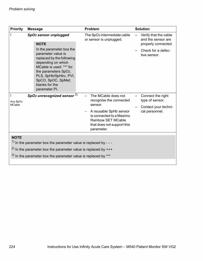
Problem solving
224 Instructions for Use Infinity Acute Care System – M540 Patient Monitor SW VG2
! SpO2 sensor unplugged The SpO2 intermediate cable or sensor is unplugged.
– Verify that the cable and the sensor are properly connected.
– Check for a defec-tive sensor.
!Any SpO2 MCable
SpO2 unrecognized sensor 3) – The MCable does not recognise the connected sensor.
– A reusable SpHb sensor is connected to a Masimo Rainbow SET MCable that does not support this parameter.
– Connect the right type of sensor.
– Contact your techni-cal personnel.
Priority Message Problem Solution
NOTEIn the parameter box the parameter value is replaced by the following depending on which MCable is used: *** for the parameters SpO2, PLS, SpHb/SpHbv, PVI, SpCO, SpOC, SpMet; blanks for the parameter PI.
NOTE1) In the parameter box the parameter value is replaced by - - -2) In the parameter box the parameter value is replaced by +++3) In the parameter box the parameter value is replaced by ***
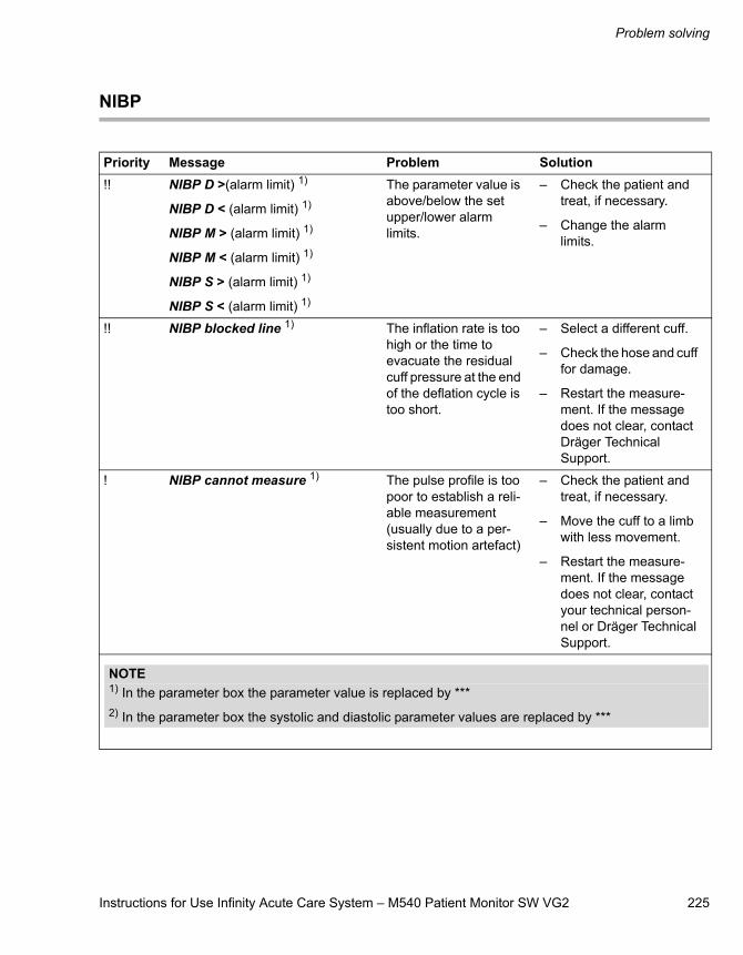
Instructions for Use Infinity Acute Care System – M540 Patient Monitor SW VG2 225
Problem solving
NIBP
Priority Message Problem Solution!! NIBP D >(alarm limit) 1)
NIBP D < (alarm limit) 1)
NIBP M > (alarm limit) 1)
NIBP M < (alarm limit) 1)
NIBP S > (alarm limit) 1)
NIBP S < (alarm limit) 1)
The parameter value is above/below the set upper/lower alarm limits.
– Check the patient and treat, if necessary.
– Change the alarm limits.
!! NIBP blocked line 1) The inflation rate is too high or the time to evacuate the residual cuff pressure at the end of the deflation cycle is too short.
– Select a different cuff.
– Check the hose and cuff for damage.
– Restart the measure-ment. If the message does not clear, contact Dräger Technical Support.
! NIBP cannot measure 1) The pulse profile is too poor to establish a reli-able measurement (usually due to a per-sistent motion artefact)
– Check the patient and treat, if necessary.
– Move the cuff to a limb with less movement.
– Restart the measure-ment. If the message does not clear, contact your technical person-nel or Dräger Technical Support.
NOTE1) In the parameter box the parameter value is replaced by ***2) In the parameter box the systolic and diastolic parameter values are replaced by ***
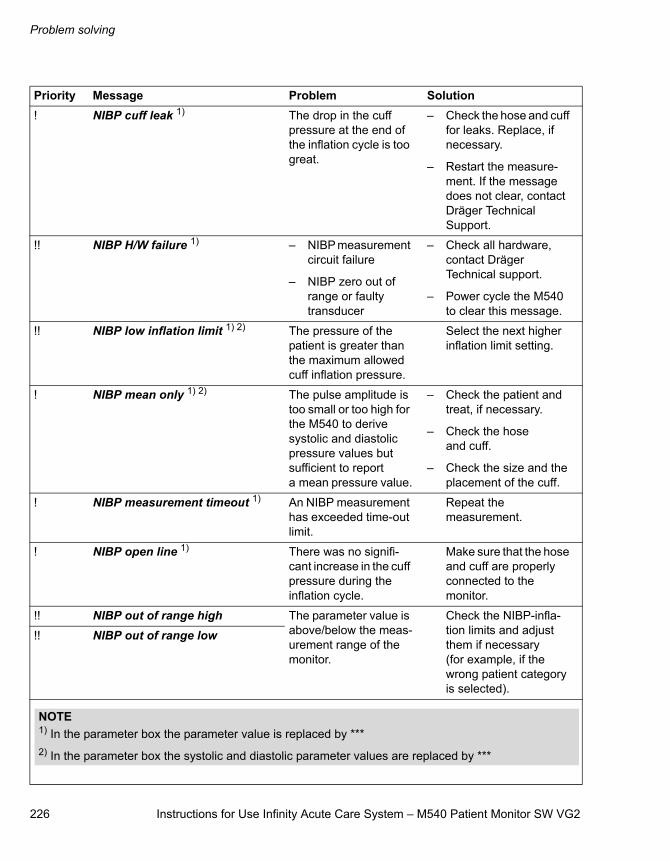
Problem solving
226 Instructions for Use Infinity Acute Care System – M540 Patient Monitor SW VG2
! NIBP cuff leak 1) The drop in the cuff pressure at the end of the inflation cycle is too great.
– Check the hose and cuff for leaks. Replace, if necessary.
– Restart the measure-ment. If the message does not clear, contact Dräger Technical Support.
!! NIBP H/W failure 1) – NIBP measurement circuit failure
– NIBP zero out of range or faulty transducer
– Check all hardware, contact Dräger Technical support.
– Power cycle the M540 to clear this message.
!! NIBP low inflation limit 1) 2) The pressure of the patient is greater than the maximum allowed cuff inflation pressure.
Select the next higher inflation limit setting.
! NIBP mean only 1) 2) The pulse amplitude is too small or too high for the M540 to derive systolic and diastolic pressure values but sufficient to report a mean pressure value.
– Check the patient and treat, if necessary.
– Check the hose and cuff.
– Check the size and the placement of the cuff.
! NIBP measurement timeout 1) An NIBP measurement has exceeded time-out limit.
Repeat the measurement.
! NIBP open line 1) There was no signifi-cant increase in the cuff pressure during the inflation cycle.
Make sure that the hose and cuff are properly connected to the monitor.
!! NIBP out of range high The parameter value is above/below the meas-urement range of the monitor.
Check the NIBP-infla-tion limits and adjust them if necessary (for example, if the wrong patient category is selected).
!! NIBP out of range low
Priority Message Problem Solution
NOTE1) In the parameter box the parameter value is replaced by ***2) In the parameter box the systolic and diastolic parameter values are replaced by ***
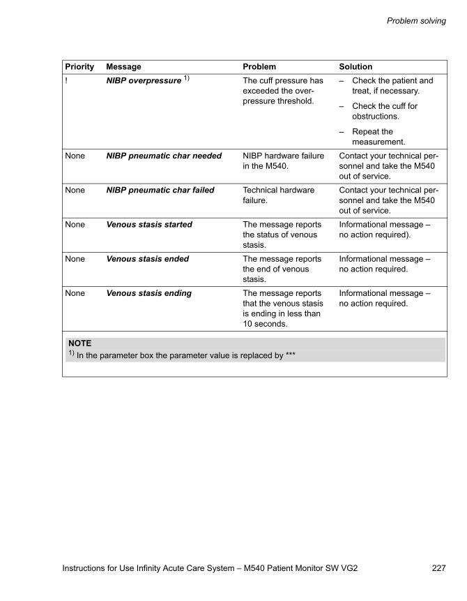
Instructions for Use Infinity Acute Care System – M540 Patient Monitor SW VG2 227
Problem solving
! NIBP overpressure 1) The cuff pressure has exceeded the over-pressure threshold.
– Check the patient and treat, if necessary.
– Check the cuff for obstructions.
– Repeat the measurement.
None NIBP pneumatic char needed NIBP hardware failure in the M540.
Contact your technical per-sonnel and take the M540 out of service.
None NIBP pneumatic char failed Technical hardware failure.
Contact your technical per-sonnel and take the M540 out of service.
None Venous stasis started The message reports the status of venous stasis.
Informational message – no action required).
None Venous stasis ended The message reports the end of venous stasis.
Informational message – no action required.
None Venous stasis ending The message reports that the venous stasis is ending in less than 10 seconds.
Informational message – no action required.
Priority Message Problem Solution
NOTE1) In the parameter box the parameter value is replaced by ***
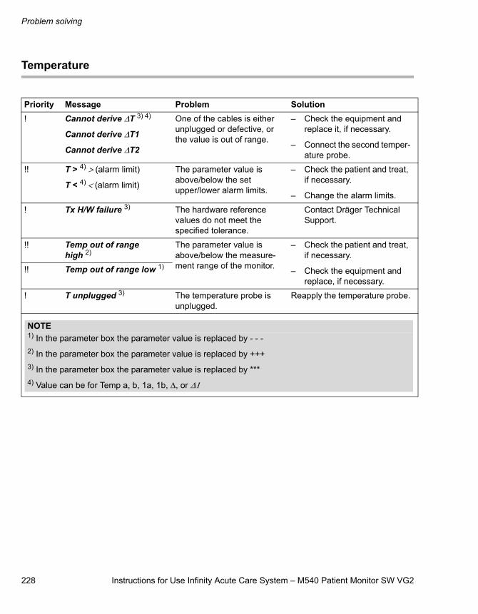
Problem solving
228 Instructions for Use Infinity Acute Care System – M540 Patient Monitor SW VG2
Temperature
Priority Message Problem Solution! Cannot derive ΔT 3) 4)
Cannot derive ΔT1
Cannot derive ΔT2
One of the cables is either unplugged or defective, or the value is out of range.
– Check the equipment and replace it, if necessary.
– Connect the second temper-ature probe.
!! T > 4) > (alarm limit)
T < 4) < (alarm limit)
The parameter value is above/below the set upper/lower alarm limits.
– Check the patient and treat, if necessary.
– Change the alarm limits.
! Tx H/W failure 3) The hardware reference values do not meet the specified tolerance.
Contact Dräger Technical Support.
!! Temp out of range high 2)
The parameter value is above/below the measure-ment range of the monitor.
– Check the patient and treat, if necessary.
– Check the equipment and replace, if necessary.
!! Temp out of range low 1)
! T unplugged 3) The temperature probe is unplugged.
Reapply the temperature probe.
NOTE1) In the parameter box the parameter value is replaced by - - -2) In the parameter box the parameter value is replaced by +++3) In the parameter box the parameter value is replaced by ***4) Value can be for Temp a, b, 1a, 1b, Δ, or Δ1
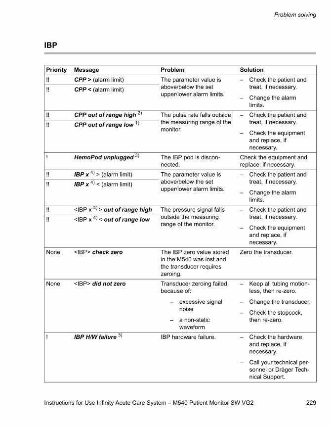
Instructions for Use Infinity Acute Care System – M540 Patient Monitor SW VG2 229
Problem solving
IBP
Priority Message Problem Solution!! CPP > (alarm limit) The parameter value is
above/below the set upper/lower alarm limits.
– Check the patient and treat, if necessary.
– Change the alarm limits.
!! CPP < (alarm limit)
!! CPP out of range high 2) The pulse rate falls outside the measuring range of the monitor.
– Check the patient and treat, if necessary.
– Check the equipment and replace, if necessary.
!! CPP out of range low 1)
! HemoPod unplugged 3) The IBP pod is discon-nected.
Check the equipment and replace, if necessary.
!! IBP x 4) > (alarm limit) The parameter value is above/below the set upper/lower alarm limits.
– Check the patient and treat, if necessary.
– Change the alarm limits.
!! IBP x 4) < (alarm limit)
!! <IBP x 4) > out of range high The pressure signal falls outside the measuring range of the monitor.
– Check the patient and treat, if necessary.
– Check the equipment and replace, if necessary.
!! <IBP x 4) < out of range low
None <IBP> check zero The IBP zero value stored in the M540 was lost and the transducer requires zeroing.
Zero the transducer.
None <IBP> did not zero Transducer zeroing failed because of:
– excessive signal noise
– a non-static waveform
– Keep all tubing motion-less, then re-zero.
– Change the transducer.
– Check the stopcock, then re-zero.
! IBP H/W failure 3) IBP hardware failure. – Check the hardware and replace, if necessary.
– Call your technical per-sonnel or Dräger Tech-nical Support.
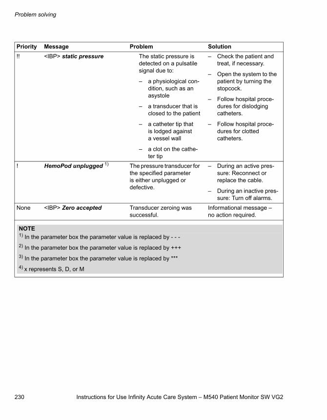
Problem solving
230 Instructions for Use Infinity Acute Care System – M540 Patient Monitor SW VG2
!! <IBP> static pressure The static pressure is detected on a pulsatile signal due to:
– a physiological con-dition, such as an asystole
– a transducer that is closed to the patient
– a catheter tip that is lodged against a vessel wall
– a clot on the cathe-ter tip
– Check the patient and treat, if necessary.
– Open the system to the patient by turning the stopcock.
– Follow hospital proce-dures for dislodging catheters.
– Follow hospital proce-dures for clotted catheters.
! HemoPod unplugged 1) The pressure transducer for the specified parameter is either unplugged or defective.
– During an active pres-sure: Reconnect or replace the cable.
– During an inactive pres-sure: Turn off alarms.
None <IBP> Zero accepted Transducer zeroing was successful.
Informational message – no action required.
Priority Message Problem Solution
NOTE1) In the parameter box the parameter value is replaced by - - -2) In the parameter box the parameter value is replaced by +++3) In the parameter box the parameter value is replaced by ***4) x represents S, D, or M
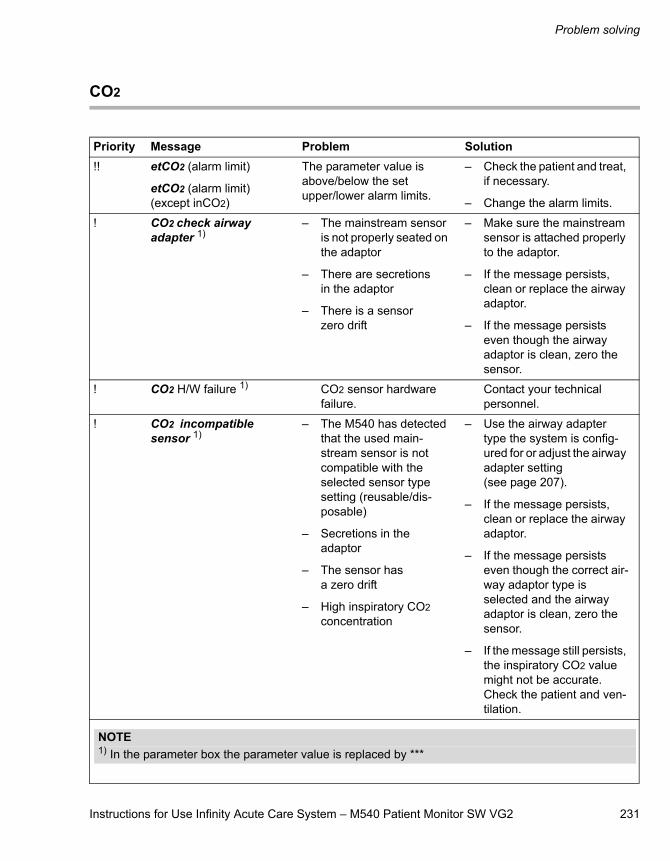
Instructions for Use Infinity Acute Care System – M540 Patient Monitor SW VG2 231
Problem solving
CO2
Priority Message Problem Solution!! etCO2 (alarm limit)
etCO2 (alarm limit)(except inCO2)
The parameter value is above/below the set upper/lower alarm limits.
– Check the patient and treat, if necessary.
– Change the alarm limits.
! CO2 check airway adapter 1)
– The mainstream sensor is not properly seated on the adaptor
– There are secretions in the adaptor
– There is a sensor zero drift
– Make sure the mainstream sensor is attached properly to the adaptor.
– If the message persists, clean or replace the airway adaptor.
– If the message persists even though the airway adaptor is clean, zero the sensor.
! CO2 H/W failure 1) CO2 sensor hardware failure.
Contact your technical personnel.
! CO2 incompatible sensor 1)
– The M540 has detected that the used main-stream sensor is not compatible with the selected sensor type setting (reusable/dis-posable)
– Secretions in the adaptor
– The sensor has a zero drift
– High inspiratory CO2 concentration
– Use the airway adapter type the system is config-ured for or adjust the airway adapter setting (see page 207).
– If the message persists, clean or replace the airway adaptor.
– If the message persists even though the correct air-way adaptor type is selected and the airway adaptor is clean, zero the sensor.
– If the message still persists, the inspiratory CO2 value might not be accurate. Check the patient and ven-tilation.
NOTE1) In the parameter box the parameter value is replaced by ***
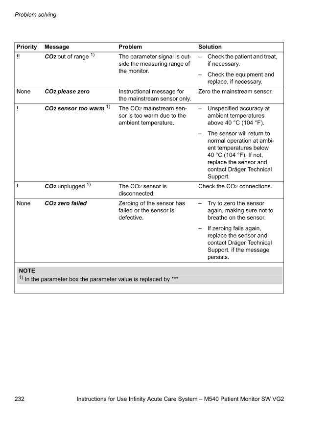
Problem solving
232 Instructions for Use Infinity Acute Care System – M540 Patient Monitor SW VG2
!! CO2 out of range 1) The parameter signal is out-side the measuring range of the monitor.
– Check the patient and treat, if necessary.
– Check the equipment and replace, if necessary.
None CO2 please zero Instructional message for the mainstream sensor only.
Zero the mainstream sensor.
! CO2 sensor too warm 1) The CO2 mainstream sen-sor is too warm due to the ambient temperature.
– Unspecified accuracy at ambient temperatures above 40 °C (104 °F).
– The sensor will return to normal operation at ambi-ent temperatures below 40 °C (104 °F). If not, replace the sensor and contact Dräger Technical Support.
! CO2 unplugged 1) The CO2 sensor is disconnected.
Check the CO2 connections.
None CO2 zero failed Zeroing of the sensor has failed or the sensor is defective.
– Try to zero the sensor again, making sure not to breathe on the sensor.
– If zeroing fails again, replace the sensor and contact Dräger Technical Support, if the message persists.
Priority Message Problem Solution
NOTE1) In the parameter box the parameter value is replaced by ***
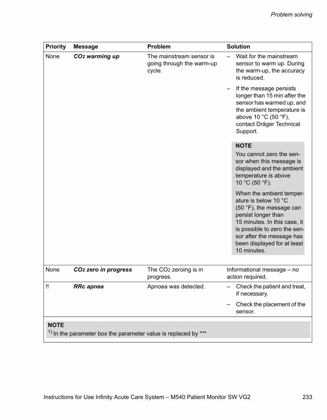
Instructions for Use Infinity Acute Care System – M540 Patient Monitor SW VG2 233
Problem solving
None CO2 warming up The mainstream sensor is going through the warm-up cycle.
– Wait for the mainstream sensor to warm up. During the warm-up, the accuracy is reduced.
– If the message persists longer than 15 min after the sensor has warmed up, and the ambient temperature is above 10 °C (50 °F), contact Dräger Technical Support.
None CO2 zero in progress The CO2 zeroing is in progress.
Informational message – no action required.
!! RRc apnea Apnoea was detected. – Check the patient and treat, if necessary.
– Check the placement of the sensor.
Priority Message Problem Solution
NOTEYou cannot zero the sen-sor when this message is displayed and the ambient temperature is above 10 °C (50 °F).
When the ambient temper-ature is below 10 °C (50 °F), the message can persist longer than 15 minutes. In this case, it is possible to zero the sen-sor after the message has been displayed for at least 10 minutes.
NOTE1) In the parameter box the parameter value is replaced by ***

234 Instructions for Use Infinity Acute Care System – M540 Patient Monitor SW VG2
This page is intentionally left blank

Instructions for Use Infinity Acute Care System – M540 Patient Monitor SW VG2 235
Maintenance
Maintenance
Overview . . . . . . . . . . . . . . . . . . . . . . . . . . . . . 236
Maintenance of the IACS components . . . . . 237
Safety inspections . . . . . . . . . . . . . . . . . . . . . 238
Scope of safety inspection for the M540 . . . . . 238

Maintenance
236 Instructions for Use Infinity Acute Care System – M540 Patient Monitor SW VG2
Overview
This chapter describes the necessary maintenance steps to be performed by your technical personnel for the proper functioning of the equipment. For complete instructions on how to perform the required maintenance, refer to the Technical Serv-ice Document which can be obtained from Dräger.
WARNINGIf the device is mechanically damaged, or if it is not working properly, do not use it. Contact your hospital’s technical personnel.
CAUTIONThis device must be inspected and serviced at regular intervals. A record must be kept on this preventive maintenance. We recommend obtain-ing a service contract with DrägerService through your vendor. For repairs, we recommend that you contact DrägerService.
CAUTIONWhen servicing devices from Dräger, always use replacement parts that are qualified to Dräger standards. Dräger cannot warrant or endorse the safe performance of third-party replacement parts for use with the devices.
CAUTIONIf you spill liquid on the equipment, battery or accessories or immerse these components in liquid, allow them to dry completely for at least 24 hours to 48 hours. Contact your hospital technical personnel to test any such component is fully operational before putting it back in clinical use.
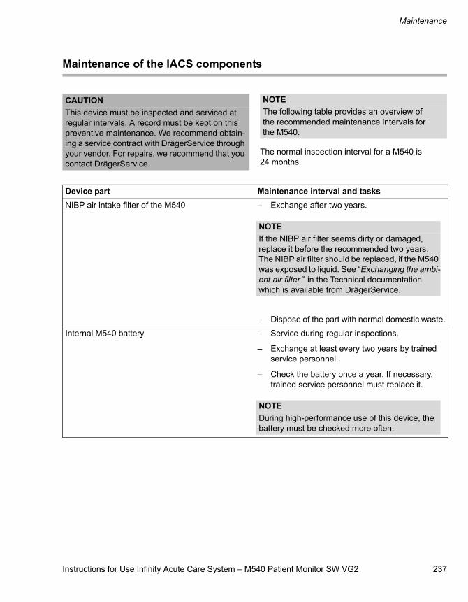
Instructions for Use Infinity Acute Care System – M540 Patient Monitor SW VG2 237
Maintenance
Maintenance of the IACS components
The normal inspection interval for a M540 is 24 months.
CAUTIONThis device must be inspected and serviced at regular intervals. A record must be kept on this preventive maintenance. We recommend obtain-ing a service contract with DrägerService through your vendor. For repairs, we recommend that you contact DrägerService.
NOTEThe following table provides an overview of the recommended maintenance intervals for the M540.
Device part Maintenance interval and tasksNIBP air intake filter of the M540 – Exchange after two years.
– Dispose of the part with normal domestic waste.
Internal M540 battery – Service during regular inspections.
– Exchange at least every two years by trained service personnel.
– Check the battery once a year. If necessary, trained service personnel must replace it.
NOTEIf the NIBP air filter seems dirty or damaged, replace it before the recommended two years. The NIBP air filter should be replaced, if the M540 was exposed to liquid. See “Exchanging the ambi-ent air filter ” in the Technical documentation which is available from DrägerService.
NOTEDuring high-performance use of this device, the battery must be checked more often.
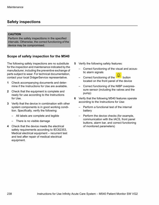
Maintenance
238 Instructions for Use Infinity Acute Care System – M540 Patient Monitor SW VG2
Safety inspections
Scope of safety inspection for the M540
The following safety inspections are no substitute for the inspection and maintenance indicated by the manufacturer, including the preventive exchange of parts subject to wear. For technical documentation, contact your local DrägerService representative.
1 Check accompanying documents and deter-mine if the Instructions for Use are available.
2 Check that the equipment is complete and ready for use according to the Instructions for Use.
3 Verify that the device in combination with other system components is in good working condi-tion. Specifically, verify the following:
– All labels are complete and legible
– There is no visible damage
4 Check that the device meets the electrical safety requirements according to IEC62353, Medical electrical equipment – recurrent test and test after repair of medical electrical equipment.
5 Verify the following safety features:
– Correct functioning of the visual and acous-tic alarm signals
– Correct functioning of the button located on the front panel of the device
– Correct functioning of the NIBP overpres-sure sensor (including the valves and the pump)
6 Verify that the following M540 features operate according to the Instructions for Use:
– Perform a functional test of the internal battery
– Perform the device checks (for example, communication with the IACS, front panel buttons, alarm bar, and correct functioning of monitored parameters)
CAUTIONPerform the safety inspecitions in the specified intervals. Otherwise, the correct functioning of the device may be compromised.
Instructions for Use Infinity Acute Care System – M540 Patient Monitor SW VG2 239
Cleaning and disinfection
Cleaning and disinfection
Overview of cleaning and disinfecting the M540 and its accessories . . . . . . . . . . . . 240
Cleaning and disinfecting precautions . . . . . . . 240
Approved cleaning agents. . . . . . . . . . . . . . . 241
Cleaning and disinfecting the M540, M500, and PS50 . . . . . . . . . . . . . . . . . . . . . . . 242
M540, M500, and PS50 precaution . . . . . . . . . 242
Cleaning and disinfecting MCables and MPods . . . . . . . . . . . . . . . . . . . . . . . . . . . 243
MCable precautions . . . . . . . . . . . . . . . . . . . . . 243
Cleaning and disinfecting patient cables . . . . . . . . . . . . . . . . . . . . . . . . . . . . . . . 244
Patient cable precautions . . . . . . . . . . . . . . . . . 244
Cleaning and disinfecting reusable ECG lead wires . . . . . . . . . . . . . . . . . . . . . . . . 244
Cleaning and disinfecting temperature sensors and cables . . . . . . . . . 245
Temperature probe and cable precautions. . . . 245
Cleaning NIBP cuffs . . . . . . . . . . . . . . . . . . . . 246
NIBP Precaution . . . . . . . . . . . . . . . . . . . . . . . . 246
Cleaning and disinfecting IBP transducers and hemodynamic pods. . . . . . 246
Transducers . . . . . . . . . . . . . . . . . . . . . . . . . . . 246
Cleaning and disinfecting mainstream CO2 sensors and airway adapters . . . . . . . . 247
Mainstream CO2 sensors and airway adapters precaution . . . . . . . . . . . . . . . . . . . . . 247
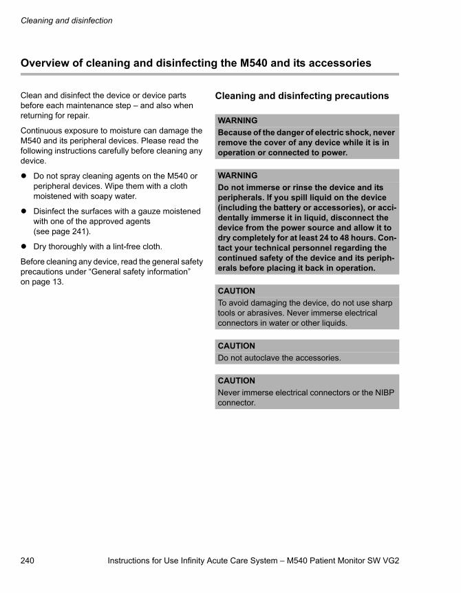
Cleaning and disinfection
240 Instructions for Use Infinity Acute Care System – M540 Patient Monitor SW VG2
Overview of cleaning and disinfecting the M540 and its accessories
Clean and disinfect the device or device parts before each maintenance step – and also when returning for repair.
Continuous exposure to moisture can damage the M540 and its peripheral devices. Please read the following instructions carefully before cleaning any device.
Do not spray cleaning agents on the M540 or peripheral devices. Wipe them with a cloth moistened with soapy water.
Disinfect the surfaces with a gauze moistened with one of the approved agents (see page 241).
Dry thoroughly with a lint-free cloth.
Before cleaning any device, read the general safety precautions under “General safety information” on page 13.
Cleaning and disinfecting precautions
WARNINGBecause of the danger of electric shock, never remove the cover of any device while it is in operation or connected to power.
WARNINGDo not immerse or rinse the device and its peripherals. If you spill liquid on the device (including the battery or accessories), or acci-dentally immerse it in liquid, disconnect the device from the power source and allow it to dry completely for at least 24 to 48 hours. Con-tact your technical personnel regarding the continued safety of the device and its periph-erals before placing it back in operation.
CAUTIONTo avoid damaging the device, do not use sharp tools or abrasives. Never immerse electrical connectors in water or other liquids.
CAUTIONDo not autoclave the accessories.
CAUTIONNever immerse electrical connectors or the NIBP connector.
Instructions for Use Infinity Acute Care System – M540 Patient Monitor SW VG2 241
Cleaning and disinfection
Approved cleaning agents
Clean and disinfect the device or device parts as per the hospital-approved protocol. Agents tested by Dräger and shown to have no harmful effect at the time of testing on the materials utilised in the device include:
– Isopropyl alcohol 40 %
– Compliance (not for use on touch screen); this cleaning agent may discolour soft plastic material
– Sporox II (not for use on touch screen)
– Dismozun pur
– Ammonia-based glass cleaner (M540 touch screen only)
– Isopropyl alcohol (40 % solution)
Dräger makes no claims regarding the efficacy of the listed chemicals, their methods as a means for disinfecting, the ability of the agents to control infec-tion, their environmental impact, safe handling, or any related precautions in their use. Refer to the information provided by the manufacturer of the cleaning solution for more information in these areas.CAUTION
If using alcohol, it should only be a 40 % diluted solution. Higher concentrations could damage the device.
Cleaning and disinfection
242 Instructions for Use Infinity Acute Care System – M540 Patient Monitor SW VG2
Cleaning and disinfecting the M540, M500, and PS50
Use only the approved cleaning agents listed on page 241, unless otherwise specified.
M540, M500, and PS50 precaution
To clean the M540 and M500
1 Clean the M540/M500 with a gauze pad mois-tened with soapy water or with an approved cleaning agent.
2 Dry thoroughly with a lint-free cloth.
To disinfect the M540 and M500
1 Disinfect the M540/M500 with a gauze pad moistened with diluted alcohol.
2 Dry thoroughly with a lint-free cloth.
To clean the PS50
Clean the outside enclosure of the PS50 with a cloth dampened with diluted alcohol.
WARNINGDo not immerse or rinse the device and its peripherals. If you spill liquid on the device (including the battery or accessories), or acci-dentally immerse it in liquid, disconnect the device from the power source and allow it to dry completely for at least 24 to 48 hours. Con-tact your technical personnel regarding the continued safety of the device and its periph-erals before placing it back in operation.
CAUTIONDo not steam autoclave, gas sterilise, or immerse the M540 in liquid or cleaning solutions. Do not subject the M540 to intense vacuum.
Instructions for Use Infinity Acute Care System – M540 Patient Monitor SW VG2 243
Cleaning and disinfection
Cleaning and disinfecting MCables and MPods
Use only the approved cleaning agents listed on page 241, unless otherwise specified.
MCable precautions
To clean MCables and MPods
1 Disconnect the MCable from the M540.
2 Clean the MCable with a gauze pad moistened with soapy water or with an approved cleaning agent.
3 Dry thoroughly with a lint-free cloth.
To disinfect MCables and MPods
1 Disconnect the MCable from the M540.
2 Disinfect the MCable with a gauze pad mois-tened with diluted alcohol.
3 Dry thoroughly with a lint-free cloth.
To clean and disinfect a reusable SpO2 sensor
Refer to the cleaning instructions and recom-mendations provided with the sensor.
CAUTIONDo not sterilise by irradiation, steam, heat, or ethylene oxide.
CAUTIONDo not use sharp tools or abrasives to clean the MCables.
CAUTIONDo not immerse the SpO2 sensors or MCables in water, organic solvents, or cleaning solutions. Make sure that NO liquid enters the MCables.
Cleaning and disinfection
244 Instructions for Use Infinity Acute Care System – M540 Patient Monitor SW VG2
Cleaning and disinfecting patient cables
Use only the approved cleaning agents listed on page 241, unless otherwise specified. The follow-ing procedures apply to all patient cable except temperature cables (see page 245).
Patient cable precautions
To clean patient cables
1 Disconnect the patient cable from the M540.
2 Clean the patient cables with a gauze pad mois-tened with soapy water or with an approved cleaning agent.
3 Dry thoroughly with a lint-free cloth.
To disinfect patient cables
1 Disconnect the patient cable from the M540.
2 Disinfect the patient cables with a gauze pad moistened with diluted alcohol.
3 Dry thoroughly with a lint-free cloth.
Cleaning and disinfecting reusable ECG lead wires
Use only the approved cleaning agents listed on page 241, unless otherwise specified.
To clean ECG lead wire
1 Disconnect the lead wires from the M540.
2 Clean the ECG lead wires regularly with a tooth-brush and water to remove any gel residue.
3 Wipe the ECG lead wires with a gauze pad moistened with soapy water or with an approved cleaning agent.
4 Dry thoroughly with a lint-free cloth.
To disinfect ECG lead wire
1 Disconnect the ECG lead wires from the M540.
2 Disinfect the ECG lead wires with a gauze pad moistened with diluted alcohol.
3 Dry thoroughly with a lint-free cloth.
CAUTIONDo not immerse the patient cables in any liquid.
CAUTIONDo not use excessive pressure or flex cables unnecessarily when cleaning. Excessive pres-sure can damage the cables.
Instructions for Use Infinity Acute Care System – M540 Patient Monitor SW VG2 245
Cleaning and disinfection
Cleaning and disinfecting temperature sensors and cables
Use only the approved cleaning agents listed on page 241, unless otherwise specified.
Temperature probe and cable precautions
To clean temperature cables
1 Disconnect the temperature cable from the M540.
2 Clean the temperature cables with a gauze pad moistened with soapy water or with an approved cleaning agent.
3 Dry thoroughly with a lint-free cloth.
To clean temperature sensors
1 Clean the temperature sensors with a gauze pad moistened with a 30 % hydrogen peroxide or 40 % alcohol solution.
2 Dry thoroughly with a lint-free cloth.
To disinfect temperature cables
1 Disconnect the temperature cable from the M540.
2 Disinfect the temperature cables with a gauze pad moistened with diluted alcohol.
3 Dry thoroughly with a lint-free cloth.
To disinfect temperature probes
Refer to the recommendations provided with the probes.
CAUTIONDo not immerse the patient cables in any liquid.
CAUTIONDo not use excessive pressure or flex cables unnecessarily when cleaning. Excessive pres-sure can damage the cables.
CAUTIONNever boil or autoclave the cable. Vinyl can with-stand temperatures up to 100 °C (212 °F), but begins to soften around 90 °C (194 °F). Handle gently when hot and wipe away from the tip toward the cables.
Cleaning and disinfection
246 Instructions for Use Infinity Acute Care System – M540 Patient Monitor SW VG2
Cleaning NIBP cuffs
NIBP Precaution To clean NIBP cuffs
1 Disconnect the NIBP hose from the M540.
2 Wipe the NIBP cuff with a cloth moistened with soapy water or a sodium hypochlorite solution (1:10), alcohol, or phenol.
3 Dry thoroughly with a lint-free cloth.
Cleaning and disinfecting IBP transducers and hemodynamic pods
Transducers
Always handle transducers and other pressure accessories with great care. Do not apply exces-sive pressure to a transducer diaphragm.
To clean and sterilise transducers
Refer to the cleaning instructions and recommen-dations provided with the transducer.
To clean transducer plates
1 Remove the transducer mounting plate from the front of the haemodynamic pod.
2 Wash the plate with hot soapy water.
To clean haemodynamic pods
1 Disconnect the haemodynamic pod from the M540.
2 Wipe the haemodynamic pod with a gauze pad moistened with an enzymatic detergent or a solution of green-tinctured soapy water.
3 Dry thoroughly with a lint-free cloth.
To disinfect haemodynamic pods
1 Disinfect the surfaces with a gauze pad moistened with diluted alcohol.
2 Dry thoroughly with a lint-free cloth.
CAUTIONThe NIBP cuff can be immersed in cleaning solu-tion, but do not allow the solution to enter the NIBP hose. The guarantee is void if the cleaning solution is allowed to enter the hose or the cuff.
CAUTIONDo not allow liquids to enter the connector.
NOTEDo not spray cleaning agents on the haemody-namic pod.
Instructions for Use Infinity Acute Care System – M540 Patient Monitor SW VG2 247
Cleaning and disinfection
Cleaning and disinfecting mainstream CO2 sensors and airway adapters
Use only the approved cleaning agents listed on page 241, unless otherwise specified.
Mainstream CO2 sensors and airway adapters precaution
To clean mainstream CO2 sensors
1 Disconnect the sensor cable from the M540 and then disconnect the airway adapter from the sensor cable.
2 Wipe the sensor, particularly the sensor win-dows, with a cotton swab to remove dirt.
3 Dry thoroughly with a lint-free cloth.
To disinfect mainstream CO2 sensors
1 Disconnect the airway adapter cable from the M540 and then disconnect the sensor from the sensor cable.
2 Wipe the sensor with a cotton swab moistened with diluted alcohol.
3 Dry thoroughly with a lint-free cloth.
To clean re-usable airway adaptors
1 Disconnect the sensor from the airway adaptor.
2 Wipe the airway adaptor with a cotton swab to remove dirt.
3 Rinse the airway adaptor in warm soapy water, then soak it in an approved cleaning agent.
4 Dry thoroughly with a lint-free cloth, making sure that the adaptor windows are dry and free of any residue before they are used.
To disinfect re-usable airway adaptors
Refer to the recommendations provided with the airway adaptors.
WARNINGTo reduce the risk of infection, remember that the disposable airway adaptors are for single-patient use only and cannot be sterilised.

248 Instructions for Use Infinity Acute Care System – M540 Patient Monitor SW VG2
This page is intentionally left blank

Instructions for Use Infinity Acute Care System – M540 Patient Monitor SW VG2 249
Disposal
Disposal
EU Directive 2002/96/EC (WEEE) . . . . . . . . . . 250M540, M500 and Instructions for Use. . . . . . . . 250

Disposal
250 Instructions for Use Infinity Acute Care System – M540 Patient Monitor SW VG2
EU Directive 2002/96/EC (WEEE)
This device is subject to EU Directive 2002/96/EC (WEEE). It is not registered for use in private households, and may not be disposed of at munic-ipal collection points for waste of electrical and electronic equipment. Dräger has authorised a firm to dispose of this device in the proper manner. For more detailed information, please contact your local Dräger organisation.
M540, M500 and Instructions for Use
All materials must be disposed of or recycled properly and in accordance with local regulations. There are no known special disposal requirements for any accessories.
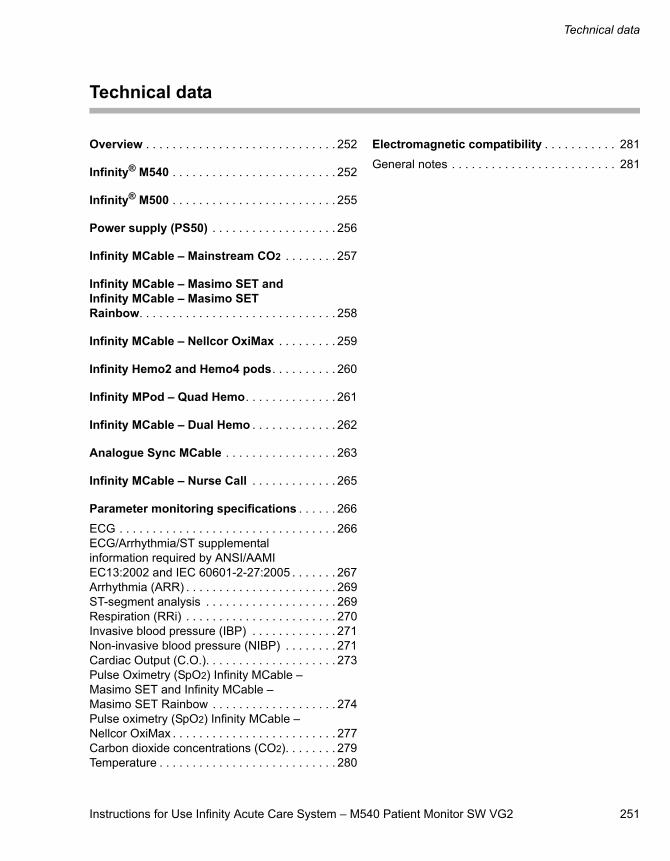
Instructions for Use Infinity Acute Care System – M540 Patient Monitor SW VG2 251
Technical data
Technical data
Overview . . . . . . . . . . . . . . . . . . . . . . . . . . . . . 252
Infinity® M540 . . . . . . . . . . . . . . . . . . . . . . . . . 252
Infinity® M500 . . . . . . . . . . . . . . . . . . . . . . . . . 255
Power supply (PS50) . . . . . . . . . . . . . . . . . . . 256
Infinity MCable – Mainstream CO2 . . . . . . . . 257
Infinity MCable – Masimo SET and Infinity MCable – Masimo SET Rainbow. . . . . . . . . . . . . . . . . . . . . . . . . . . . . . 258
Infinity MCable – Nellcor OxiMax . . . . . . . . . 259
Infinity Hemo2 and Hemo4 pods. . . . . . . . . . 260
Infinity MPod – Quad Hemo. . . . . . . . . . . . . . 261
Infinity MCable – Dual Hemo . . . . . . . . . . . . . 262
Analogue Sync MCable . . . . . . . . . . . . . . . . . 263
Infinity MCable – Nurse Call . . . . . . . . . . . . . 265
Parameter monitoring specifications . . . . . . 266
ECG . . . . . . . . . . . . . . . . . . . . . . . . . . . . . . . . . 266ECG/Arrhythmia/ST supplemental information required by ANSI/AAMI EC13:2002 and IEC 60601-2-27:2005 . . . . . . . 267Arrhythmia (ARR) . . . . . . . . . . . . . . . . . . . . . . . 269ST-segment analysis . . . . . . . . . . . . . . . . . . . . 269Respiration (RRi) . . . . . . . . . . . . . . . . . . . . . . . 270Invasive blood pressure (IBP) . . . . . . . . . . . . . 271Non-invasive blood pressure (NIBP) . . . . . . . . 271Cardiac Output (C.O.). . . . . . . . . . . . . . . . . . . . 273Pulse Oximetry (SpO2) Infinity MCable – Masimo SET and Infinity MCable – Masimo SET Rainbow . . . . . . . . . . . . . . . . . . . 274Pulse oximetry (SpO2) Infinity MCable – Nellcor OxiMax . . . . . . . . . . . . . . . . . . . . . . . . . 277Carbon dioxide concentrations (CO2). . . . . . . . 279Temperature . . . . . . . . . . . . . . . . . . . . . . . . . . . 280
Electromagnetic compatibility . . . . . . . . . . . 281
General notes . . . . . . . . . . . . . . . . . . . . . . . . . 281
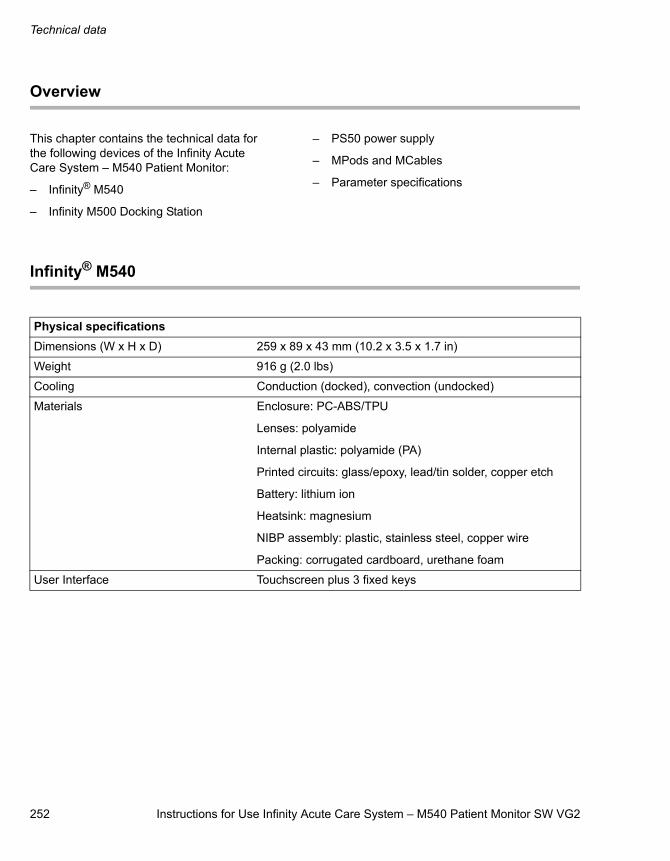
Technical data
252 Instructions for Use Infinity Acute Care System – M540 Patient Monitor SW VG2
Overview
This chapter contains the technical data for the following devices of the Infinity Acute Care System – M540 Patient Monitor:
– Infinity® M540
– Infinity M500 Docking Station
– PS50 power supply
– MPods and MCables
– Parameter specifications
Infinity® M540
Physical specificationsDimensions (W x H x D) 259 x 89 x 43 mm (10.2 x 3.5 x 1.7 in)
Weight 916 g (2.0 lbs)
Cooling Conduction (docked), convection (undocked)
Materials Enclosure: PC-ABS/TPU
Lenses: polyamide
Internal plastic: polyamide (PA)
Printed circuits: glass/epoxy, lead/tin solder, copper etch
Battery: lithium ion
Heatsink: magnesium
NIBP assembly: plastic, stainless steel, copper wire
Packing: corrugated cardboard, urethane foam
User Interface Touchscreen plus 3 fixed keys
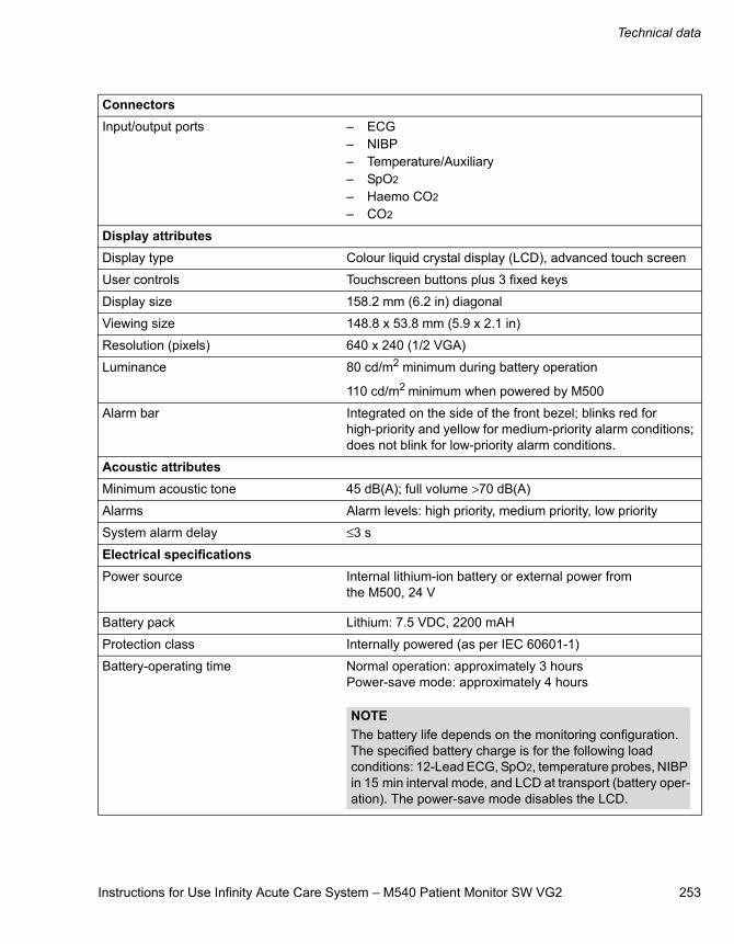
Instructions for Use Infinity Acute Care System – M540 Patient Monitor SW VG2 253
Technical data
ConnectorsInput/output ports – ECG
– NIBP– Temperature/Auxiliary– SpO2
– Haemo CO2
– CO2
Display attributesDisplay type Colour liquid crystal display (LCD), advanced touch screen
User controls Touchscreen buttons plus 3 fixed keys
Display size 158.2 mm (6.2 in) diagonal
Viewing size 148.8 x 53.8 mm (5.9 x 2.1 in)
Resolution (pixels) 640 x 240 (1/2 VGA)
Luminance 80 cd/m2 minimum during battery operation
110 cd/m2 minimum when powered by M500
Alarm bar Integrated on the side of the front bezel; blinks red for high-priority and yellow for medium-priority alarm conditions; does not blink for low-priority alarm conditions.
Acoustic attributesMinimum acoustic tone 45 dB(A); full volume >70 dB(A)
Alarms Alarm levels: high priority, medium priority, low priority
System alarm delay ≤3 s
Electrical specificationsPower source Internal lithium-ion battery or external power from
the M500, 24 V
Battery pack Lithium: 7.5 VDC, 2200 mAH
Protection class Internally powered (as per IEC 60601-1)
Battery-operating time Normal operation: approximately 3 hoursPower-save mode: approximately 4 hours
NOTEThe battery life depends on the monitoring configuration. The specified battery charge is for the following load conditions: 12-Lead ECG, SpO2, temperature probes, NIBP in 15 min interval mode, and LCD at transport (battery oper-ation). The power-save mode disables the LCD.
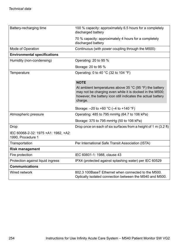
Technical data
254 Instructions for Use Infinity Acute Care System – M540 Patient Monitor SW VG2
Battery-recharging time 100 % capacity: approximately 6.5 hours for a completely discharged battery
70 % capacity: approximately 4 hours for a completely discharged battery
Mode of Operation Continuous (with power coupling through the M500)
Environmental specificationsHumidity (non-condensing) Operating: 20 to 95 %
Storage: 20 to 95 %
Temperature Operating: 0 to 40 °C (32 to 104 °F)
Storage: –20 to +60 °C (–4 to +140 °F)
Atmospheric pressure Operating: 485 to 795 mmHg (64.7 to 106 kPa)
Storage: 375 to 795 mmHg (50 to 106 kPa)
Drop
IEC 60068-2-32: 1975 +A1: 1982, +A2: 1990, Procedure 1
Drop once on each of six surfaces from a height of 1 m (3.2 ft)
Transportation Per International Safe Transit Association (ISTA)
Risk managementFire protection IEC 60601-1: 1988, clause 43
Protection against liquid ingress IPX4 (protected against splashing water) per IEC 60529
CommunicationsWired network 802.3 100BaseT Ethernet when connected to the M500.
Optically isolated connection between the M540 and M500.
NOTEAt ambient temperatures above 35 °C (95 °F) the battery may not be charging even while it is docked in the M500; however, the battery icon still indicates the actual battery charge.
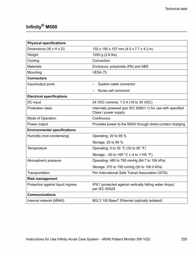
Instructions for Use Infinity Acute Care System – M540 Patient Monitor SW VG2 255
Technical data
Infinity® M500
Physical specificationsDimensions (W x H x D) 102 x 195 x 107 mm (4.0 x 7.7 x 4.2 in)
Weight 1200 g (2.6 lbs)
Cooling Convection
Materials Enclosure: polyamide (PA) and ABS
Mounting VESA 75
ConnectorsInput/output ports – System cable connector
– Nurse call connector
Electrical specificationsDC input 24 VDC nominal, 1.5 A (18 to 30 VDC)
Protection class Internally powered (per IEC 60601-1) for use with specified Class I power supply
Mode of Operation Continuous
Power output Provides power to the M540 through direct-contact charging
Environmental specificationsHumidity (non-condensing) Operating: 20 to 95 %
Storage: 20 to 95 %
Temperature Operating: 0 to 35 °C (32 to 95 °F)
Storage: –20 to +60 °C (–4 to +140 °F)
Atmospheric pressure Operating: 485 to 795 mmHg (64.7 to 106 kPa)
Storage: 375 to 795 mmHg (50 to 106.0 kPa)
Transportation Per International Safe Transit Association (ISTA)
Risk managementProtection against liquid ingress IPX1 (protected against vertically falling water drops)
per IEC 60529
CommunicationsInternal network (M540) 802.3 100 BaseT Ethernet (optically isolated)
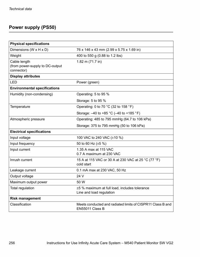
Technical data
256 Instructions for Use Infinity Acute Care System – M540 Patient Monitor SW VG2
Power supply (PS50)
Physical specificationsDimensions (W x H x D) 76 x 146 x 43 mm (2.99 x 5.75 x 1.69 in)
Weight 400 to 550 g (0.88 to 1.2 lbs)
Cable length(from power-supply to DC-output connector)
1.82 m (71.7 in)
Display attributesLED Power (green)
Environmental specificationsHumidity (non-condensing) Operating: 5 to 95 %
Storage: 5 to 95 %
Temperature Operating: 0 to 70 °C (32 to 158 °F)
Storage: –40 to +85 °C (–40 to +185 °F)
Atmospheric pressure Operating: 485 to 795 mmHg (64.7 to 106 kPa)
Storage: 375 to 795 mmHg (50 to 106 kPa)
Electrical specificationsInput voltage 100 VAC to 240 VAC (±10 %)
Input frequency 50 to 60 Hz (±5 %)
Input current 1.35 A max at 115 VAC0.7 A maximum at 230 VAC
Inrush current 15 A at 115 VAC or 30 A at 230 VAC at 25 °C (77 °F) cold start
Leakage current 0.1 mA max at 230 VAC, 50 Hz
Output voltage 24 V
Maximum output power 50 W
Total regulation ±5 % maximum at full load, includes toleranceLine and load regulation
Risk managementClassification Meets conducted and radiated limits of CISPR11 Class B and
EN55011 Class B
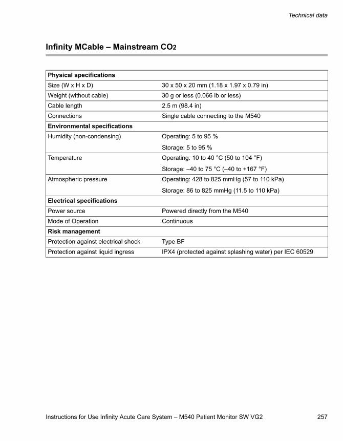
Instructions for Use Infinity Acute Care System – M540 Patient Monitor SW VG2 257
Technical data
Infinity MCable – Mainstream CO2
Physical specificationsSize (W x H x D) 30 x 50 x 20 mm (1.18 x 1.97 x 0.79 in)
Weight (without cable) 30 g or less (0.066 lb or less)
Cable length 2.5 m (98.4 in)
Connections Single cable connecting to the M540
Environmental specifications Humidity (non-condensing) Operating: 5 to 95 %
Storage: 5 to 95 %
Temperature Operating: 10 to 40 °C (50 to 104 °F)
Storage: –40 to 75 °C (–40 to +167 °F)
Atmospheric pressure Operating: 428 to 825 mmHg (57 to 110 kPa)
Storage: 86 to 825 mmHg (11.5 to 110 kPa)
Electrical specificationsPower source Powered directly from the M540
Mode of Operation Continuous
Risk managementProtection against electrical shock Type BF
Protection against liquid ingress IPX4 (protected against splashing water) per IEC 60529

Technical data
258 Instructions for Use Infinity Acute Care System – M540 Patient Monitor SW VG2
Infinity MCable – Masimo SET and Infinity MCable – Masimo SET Rainbow
Physical specificationsSize (W x H x D) 61 x 20 x 130 mm (2.4 x 0.8 x 5.1 in)
Weight 0.12 kg (0.26 lb)
Cable length 300 mm (11.8 in)
Connections Single cable connecting to the M540
Masimo cable connector for sensor cable
Environmental specifications Humidity (non-condensing) Operating: 10 to 95 %
Storage: 10 to 95 %
Temperature Operating: 0 to 45 °C (32 to 113 °F)
Storage: –40 to +70 °C (–40 to +158 °F)
Atmospheric pressure Operating: 480 to 795 mmHg (64 to 106 kPa)
Storage: 375 to 795 mmHg (50 to 106 kPa)
Electrical specificationsPower source Powered directly from the M540
Input voltage 5 V nominal
Maximum power consumption 500 mW
Mode of Operation Continuous
Risk managementProtection against electrical shock Type CF
Protection against liquid ingress Masimo SET: IPX1 (protected against vertically falling water drops) per IEC 60529
Masimo Rainbow SET: IPX2 (protected against vertically falling water drops with enclosure tilted up to 15°) per IEC 60529
Defibrillator protection As per ISO 9919
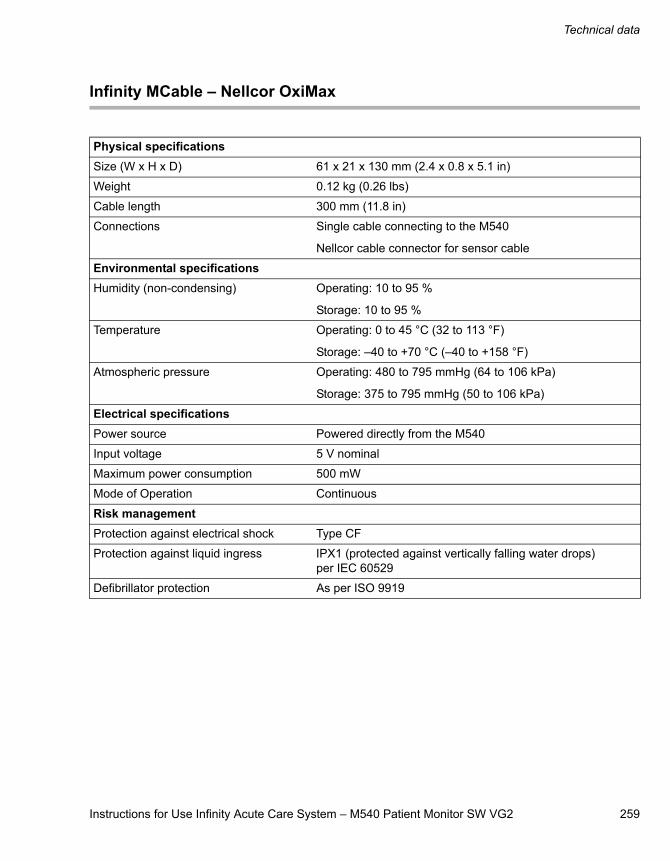
Instructions for Use Infinity Acute Care System – M540 Patient Monitor SW VG2 259
Technical data
Infinity MCable – Nellcor OxiMax
Physical specificationsSize (W x H x D) 61 x 21 x 130 mm (2.4 x 0.8 x 5.1 in)
Weight 0.12 kg (0.26 lbs)
Cable length 300 mm (11.8 in)
Connections Single cable connecting to the M540
Nellcor cable connector for sensor cable
Environmental specifications Humidity (non-condensing) Operating: 10 to 95 %
Storage: 10 to 95 %
Temperature Operating: 0 to 45 °C (32 to 113 °F)
Storage: –40 to +70 °C (–40 to +158 °F)
Atmospheric pressure Operating: 480 to 795 mmHg (64 to 106 kPa)
Storage: 375 to 795 mmHg (50 to 106 kPa)
Electrical specificationsPower source Powered directly from the M540
Input voltage 5 V nominal
Maximum power consumption 500 mW
Mode of Operation Continuous
Risk managementProtection against electrical shock Type CF
Protection against liquid ingress IPX1 (protected against vertically falling water drops) per IEC 60529
Defibrillator protection As per ISO 9919
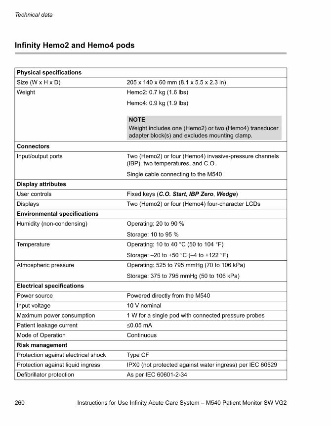
Technical data
260 Instructions for Use Infinity Acute Care System – M540 Patient Monitor SW VG2
Infinity Hemo2 and Hemo4 pods
Physical specificationsSize (W x H x D) 205 x 140 x 60 mm (8.1 x 5.5 x 2.3 in)
Weight Hemo2: 0.7 kg (1.6 lbs)
Hemo4: 0.9 kg (1.9 lbs)
ConnectorsInput/output ports Two (Hemo2) or four (Hemo4) invasive-pressure channels
(IBP), two temperatures, and C.O.
Single cable connecting to the M540
Display attributesUser controls Fixed keys (C.O. Start, IBP Zero, Wedge)
Displays Two (Hemo2) or four (Hemo4) four-character LCDs
Environmental specificationsHumidity (non-condensing) Operating: 20 to 90 %
Storage: 10 to 95 %
Temperature Operating: 10 to 40 °C (50 to 104 °F)
Storage: –20 to +50 °C (–4 to +122 °F)
Atmospheric pressure Operating: 525 to 795 mmHg (70 to 106 kPa)
Storage: 375 to 795 mmHg (50 to 106 kPa)
Electrical specificationsPower source Powered directly from the M540
Input voltage 10 V nominal
Maximum power consumption 1 W for a single pod with connected pressure probes
Patient leakage current ≤0.05 mA
Mode of Operation Continuous
Risk managementProtection against electrical shock Type CF
Protection against liquid ingress IPX0 (not protected against water ingress) per IEC 60529
Defibrillator protection As per IEC 60601-2-34
NOTEWeight includes one (Hemo2) or two (Hemo4) transducer adapter block(s) and excludes mounting clamp.
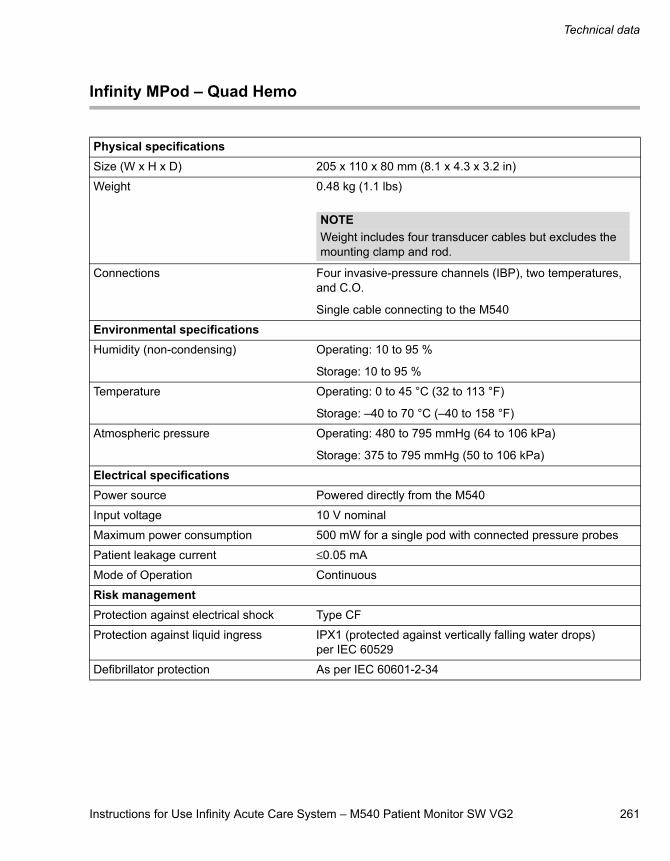
Instructions for Use Infinity Acute Care System – M540 Patient Monitor SW VG2 261
Technical data
Infinity MPod – Quad Hemo
Physical specificationsSize (W x H x D) 205 x 110 x 80 mm (8.1 x 4.3 x 3.2 in)
Weight 0.48 kg (1.1 lbs)
Connections Four invasive-pressure channels (IBP), two temperatures, and C.O.
Single cable connecting to the M540
Environmental specificationsHumidity (non-condensing) Operating: 10 to 95 %
Storage: 10 to 95 %
Temperature Operating: 0 to 45 °C (32 to 113 °F)
Storage: –40 to 70 °C (–40 to 158 °F)
Atmospheric pressure Operating: 480 to 795 mmHg (64 to 106 kPa)
Storage: 375 to 795 mmHg (50 to 106 kPa)
Electrical specificationsPower source Powered directly from the M540
Input voltage 10 V nominal
Maximum power consumption 500 mW for a single pod with connected pressure probes
Patient leakage current ≤0.05 mA
Mode of Operation Continuous
Risk managementProtection against electrical shock Type CF
Protection against liquid ingress IPX1 (protected against vertically falling water drops) per IEC 60529
Defibrillator protection As per IEC 60601-2-34
NOTEWeight includes four transducer cables but excludes the mounting clamp and rod.
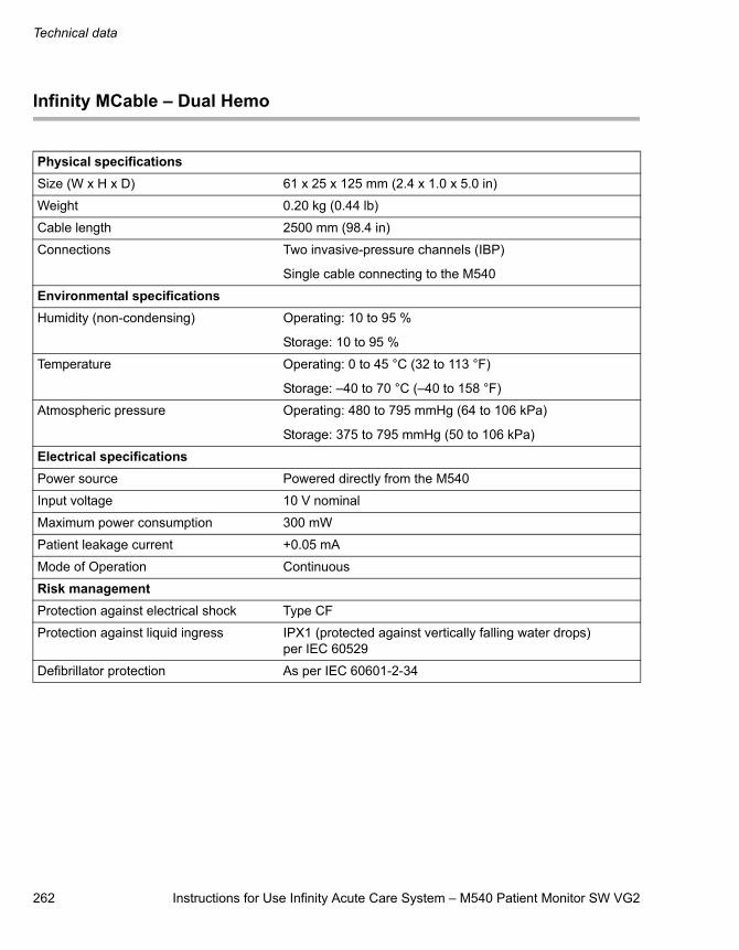
Technical data
262 Instructions for Use Infinity Acute Care System – M540 Patient Monitor SW VG2
Infinity MCable – Dual Hemo
Physical specificationsSize (W x H x D) 61 x 25 x 125 mm (2.4 x 1.0 x 5.0 in)
Weight 0.20 kg (0.44 lb)
Cable length 2500 mm (98.4 in)
Connections Two invasive-pressure channels (IBP)
Single cable connecting to the M540
Environmental specificationsHumidity (non-condensing) Operating: 10 to 95 %
Storage: 10 to 95 %
Temperature Operating: 0 to 45 °C (32 to 113 °F)
Storage: –40 to 70 °C (–40 to 158 °F)
Atmospheric pressure Operating: 480 to 795 mmHg (64 to 106 kPa)
Storage: 375 to 795 mmHg (50 to 106 kPa)
Electrical specificationsPower source Powered directly from the M540
Input voltage 10 V nominal
Maximum power consumption 300 mW
Patient leakage current +0.05 mA
Mode of Operation Continuous
Risk managementProtection against electrical shock Type CF
Protection against liquid ingress IPX1 (protected against vertically falling water drops) per IEC 60529
Defibrillator protection As per IEC 60601-2-34
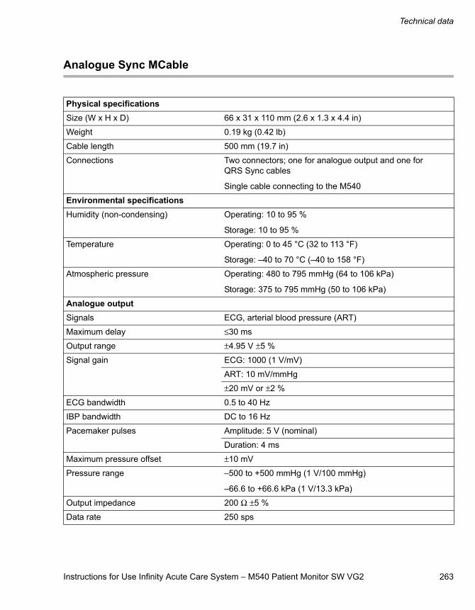
Instructions for Use Infinity Acute Care System – M540 Patient Monitor SW VG2 263
Technical data
Analogue Sync MCable
Physical specificationsSize (W x H x D) 66 x 31 x 110 mm (2.6 x 1.3 x 4.4 in)
Weight 0.19 kg (0.42 lb)
Cable length 500 mm (19.7 in)
Connections Two connectors; one for analogue output and one for QRS Sync cables
Single cable connecting to the M540
Environmental specificationsHumidity (non-condensing) Operating: 10 to 95 %
Storage: 10 to 95 %
Temperature Operating: 0 to 45 °C (32 to 113 °F)
Storage: –40 to 70 °C (–40 to 158 °F)
Atmospheric pressure Operating: 480 to 795 mmHg (64 to 106 kPa)
Storage: 375 to 795 mmHg (50 to 106 kPa)
Analogue outputSignals ECG, arterial blood pressure (ART)
Maximum delay ≤30 ms
Output range ±4.95 V ±5 %
Signal gain ECG: 1000 (1 V/mV)
ART: 10 mV/mmHg
±20 mV or ±2 %
ECG bandwidth 0.5 to 40 Hz
IBP bandwidth DC to 16 Hz
Pacemaker pulses Amplitude: 5 V (nominal)
Duration: 4 ms
Maximum pressure offset ±10 mV
Pressure range –500 to +500 mmHg (1 V/100 mmHg)
–66.6 to +66.6 kPa (1 V/13.3 kPa)
Output impedance 200 Ω ±5 %
Data rate 250 sps
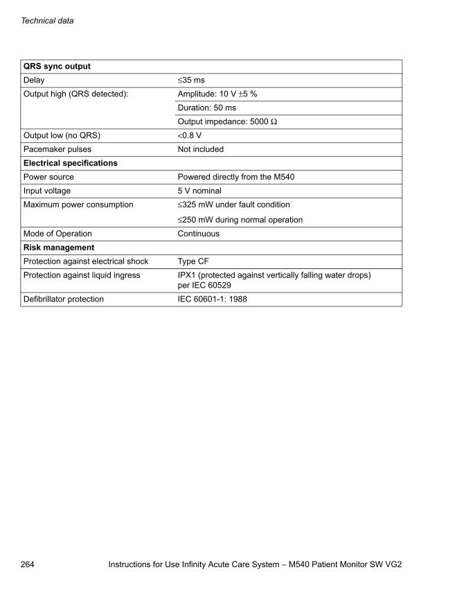
Technical data
264 Instructions for Use Infinity Acute Care System – M540 Patient Monitor SW VG2
QRS sync outputDelay ≤35 ms
Output high (QRS detected): Amplitude: 10 V ±5 %
Duration: 50 ms
Output impedance: 5000 Ω
Output low (no QRS) <0.8 V
Pacemaker pulses Not included
Electrical specificationsPower source Powered directly from the M540
Input voltage 5 V nominal
Maximum power consumption ≤325 mW under fault condition
≤250 mW during normal operation
Mode of Operation Continuous
Risk managementProtection against electrical shock Type CF
Protection against liquid ingress IPX1 (protected against vertically falling water drops) per IEC 60529
Defibrillator protection IEC 60601-1: 1988
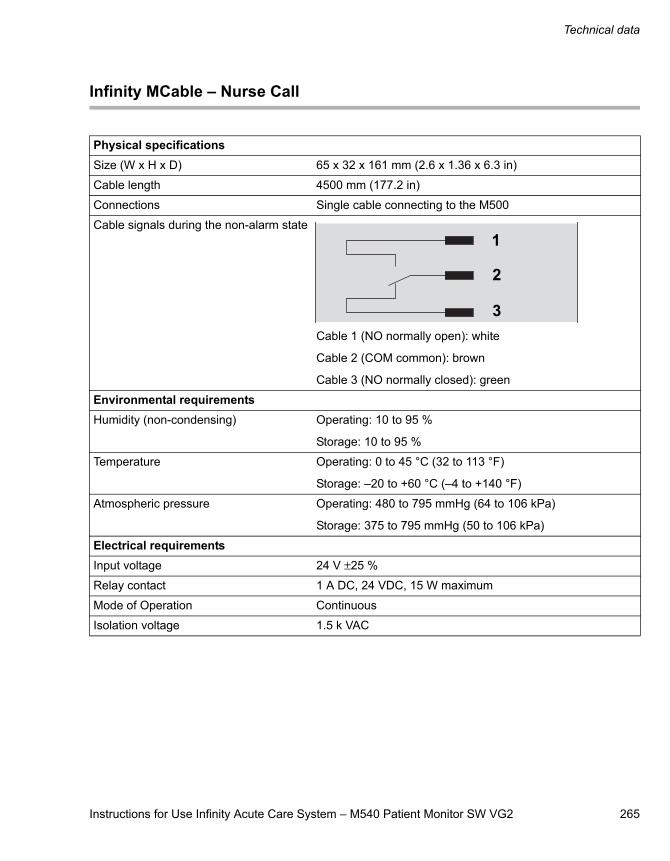
Instructions for Use Infinity Acute Care System – M540 Patient Monitor SW VG2 265
Technical data
Infinity MCable – Nurse Call
Physical specificationsSize (W x H x D) 65 x 32 x 161 mm (2.6 x 1.36 x 6.3 in)
Cable length 4500 mm (177.2 in)
Connections Single cable connecting to the M500
Cable signals during the non-alarm state
Cable 1 (NO normally open): white
Cable 2 (COM common): brown
Cable 3 (NO normally closed): green
Environmental requirementsHumidity (non-condensing) Operating: 10 to 95 %
Storage: 10 to 95 %
Temperature Operating: 0 to 45 °C (32 to 113 °F)
Storage: –20 to +60 °C (–4 to +140 °F)
Atmospheric pressure Operating: 480 to 795 mmHg (64 to 106 kPa)
Storage: 375 to 795 mmHg (50 to 106 kPa)
Electrical requirementsInput voltage 24 V ±25 %
Relay contact 1 A DC, 24 VDC, 15 W maximum
Mode of Operation Continuous
Isolation voltage 1.5 k VAC
1
2
3
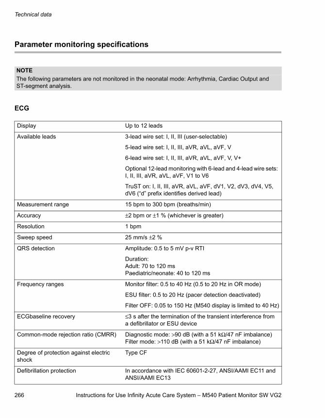
Technical data
266 Instructions for Use Infinity Acute Care System – M540 Patient Monitor SW VG2
Parameter monitoring specifications
ECG
NOTEThe following parameters are not monitored in the neonatal mode: Arrhythmia, Cardiac Output and ST-segment analysis.
Display Up to 12 leads
Available leads 3-lead wire set: I, II, III (user-selectable)
5-lead wire set: I, II, III, aVR, aVL, aVF, V
6-lead wire set: I, II, III, aVR, aVL, aVF, V, V+
Optional 12-lead monitoring with 6-lead and 4-lead wire sets: I, II, III, aVR, aVL, aVF, V1 to V6
TruST on: I, II, III, aVR, aVL, aVF, dV1, V2, dV3, dV4, V5, dV6 (“d” prefix identifies derived lead)
Measurement range 15 bpm to 300 bpm (breaths/min)
Accuracy ±2 bpm or ±1 % (whichever is greater)
Resolution 1 bpm
Sweep speed 25 mm/s ±2 %
QRS detection Amplitude: 0.5 to 5 mV p-v RTI
Duration: Adult: 70 to 120 msPaediatric/neonate: 40 to 120 ms
Frequency ranges Monitor filter: 0.5 to 40 Hz (0.5 to 20 Hz in OR mode)
ESU filter: 0.5 to 20 Hz (pacer detection deactivated)
Filter OFF: 0.05 to 150 Hz (M540 display is limited to 40 Hz)
ECGbaseline recovery ≤3 s after the termination of the transient interference from a defibrillator or ESU device
Common-mode rejection ratio (CMRR) Diagnostic mode: >90 dB (with a 51 kΩ/47 nF imbalance)Filter mode: >110 dB (with a 51 kΩ/47 nF imbalance)
Degree of protection against electric shock
Type CF
Defibrillation protection In accordance with IEC 60601-2-27, ANSI/AAMI EC11 and ANSI/AAMI EC13
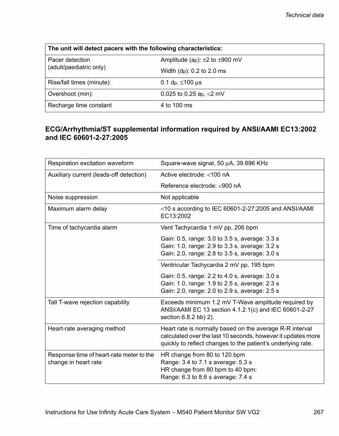
Instructions for Use Infinity Acute Care System – M540 Patient Monitor SW VG2 267
Technical data
ECG/Arrhythmia/ST supplemental information required by ANSI/AAMI EC13:2002 and IEC 60601-2-27:2005
The unit will detect pacers with the following characteristics:
Pacer detection(adult/paediatric only)
Amplitude (ap): ±2 to ±900 mV
Width (dp): 0.2 to 2.0 ms
Rise/fall times (minute): 0.1 dp, ≤100 μs
Overshoot (min): 0.025 to 0.25 ap, <2 mV
Recharge time constant 4 to 100 ms
Respiration excitation waveform Square-wave signal, 50 μA, 39.896 KHz
Auxiliary current (leads-off detection) Active electrode: <100 nA
Reference electrode: <900 nA
Noise suppression Not applicable
Maximum alarm delay <10 s according to IEC 60601-2-27:2005 and ANSI/AAMI EC13:2002
Time of tachycardia alarm Vent Tachycardia 1 mV pp, 206 bpm
Gain: 0.5, range: 3.0 to 3.5 s, average: 3.3 sGain: 1.0, range: 2.9 to 3.3 s, average: 3.2 sGain: 2.0, range: 2.8 to 3.5 s, average: 3.0 s
Ventricular Tachycardia 2 mV pp, 195 bpm
Gain: 0.5, range: 2.2 to 4.0 s, average: 3.0 sGain: 1.0, range: 1.9 to 2.5 s, average: 2.3 sGain: 2.0, range: 2.0 to 2.9 s, average: 2.5 s
Tall T-wave rejection capability Exceeds minimum 1.2 mV T-Wave amplitude required by ANSI/AAMI EC 13 section 4.1.2.1(c) and IEC 60601-2-27 section 6.8.2 bb) 2).
Heart-rate averaging method Heart rate is normally based on the average R-R interval calculated over the last 10 seconds, however it updates more quickly to reflect changes to the patient’s underlying rate.
Response time of heart-rate meter to the change in heart rate
HR change from 80 to 120 bpmRange: 3.4 to 7.1 s average: 5.3 sHR change from 80 bpm to 40 bpm:Range: 6.3 to 8.6 s average: 7.4 s
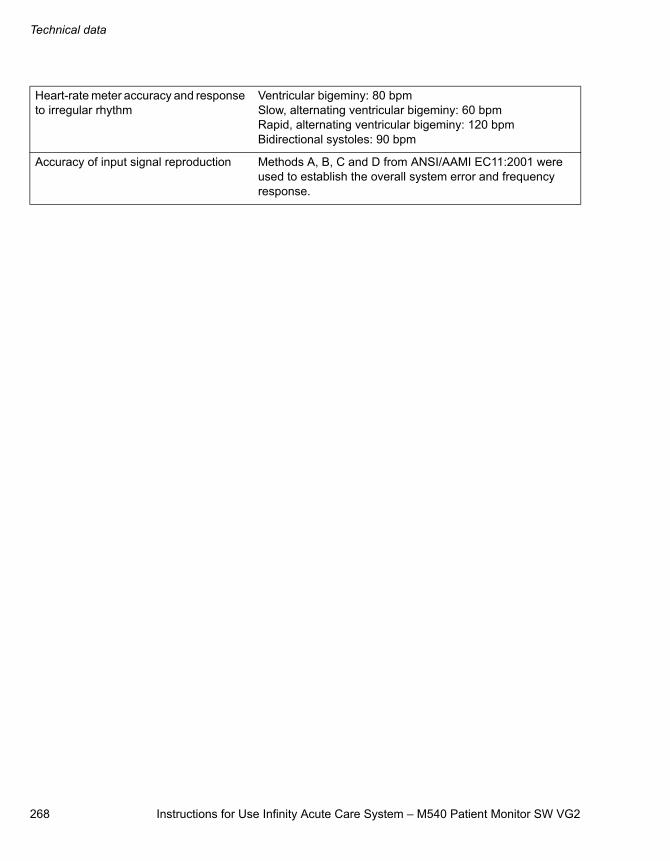
Technical data
268 Instructions for Use Infinity Acute Care System – M540 Patient Monitor SW VG2
Heart-rate meter accuracy and response to irregular rhythm
Ventricular bigeminy: 80 bpmSlow, alternating ventricular bigeminy: 60 bpmRapid, alternating ventricular bigeminy: 120 bpmBidirectional systoles: 90 bpm
Accuracy of input signal reproduction Methods A, B, C and D from ANSI/AAMI EC11:2001 were used to establish the overall system error and frequency response.
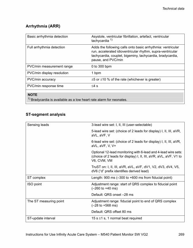
Instructions for Use Infinity Acute Care System – M540 Patient Monitor SW VG2 269
Technical data
Arrhythmia (ARR)
ST-segment analysis
Basic arrhythmia detection Asystole, ventricular fibrillation, artefact, ventricular tachycardia 1)
Full arrhythmia detection Adds the following calls onto basic arrhythmia: ventricular run, accelerated idioventricular rhythm, supra-ventricular tachycardia, couplet, bigeminy, tachycardia, bradycardia, pause, and PVC/min
PVC/min measurement range 0 to 300 bpm
PVC/min display resolution 1 bpm
PVC/min accuracy ±5 or ±10 % of the rate (whichever is greater)
PVC/min response time ≤4 s
NOTE1) Bradycardia is available as a low heart rate alarm for neonates.
Sensing leads 3-lead wire set: I, II, III (user-selectable)
5-lead wire set: (choice of 2 leads for display) I, II, III, aVR, aVL, aVF, V
6-lead wire set: (choice of 2 leads for display) I, II, III, aVR, aVL, aVF, V, V+
Optional 12-lead monitoring with 6-lead and 4-lead wire sets: (choice of 2 leads for display) I, II, III, aVR, aVL, aVF, V1 to V6, CVM, VM
TruST on: I, II, III, aVR, aVL, aVF, dV1, V2, dV3, dV4, V5, dV6 (“d” prefix identifies derived lead)
ST complex Length: 900 ms (–300 to +600 ms from fiducial point)
ISO point Adjustment range: start of QRS complex to fiducial point (–260 to +40 ms)
Default: QRS onset –28 ms
The ST measuring point Adjustment range: fiducial point to end of QRS complex (–28 to +568 ms)
Default: QRS offset 80 ms
ST-update interval 15 s ±1 s, 1 normal beat required
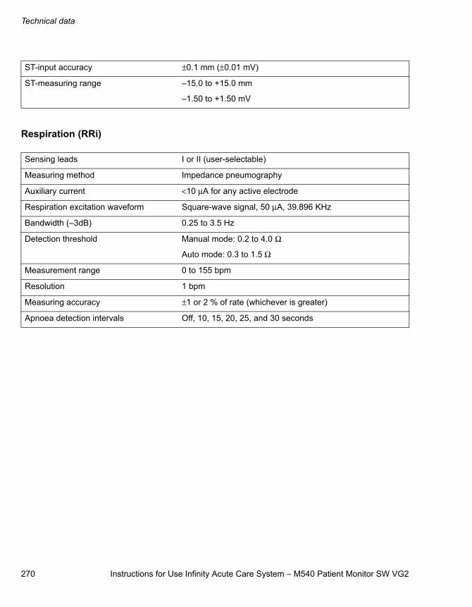
Technical data
270 Instructions for Use Infinity Acute Care System – M540 Patient Monitor SW VG2
Respiration (RRi)
ST-input accuracy ±0.1 mm (±0.01 mV)
ST-measuring range –15.0 to +15.0 mm
–1.50 to +1.50 mV
Sensing leads I or II (user-selectable)
Measuring method Impedance pneumography
Auxiliary current <10 μA for any active electrode
Respiration excitation waveform Square-wave signal, 50 μA, 39.896 KHz
Bandwidth (–3dB) 0.25 to 3.5 Hz
Detection threshold Manual mode: 0.2 to 4.0 Ω
Auto mode: 0.3 to 1.5 Ω
Measurement range 0 to 155 bpm
Resolution 1 bpm
Measuring accuracy ±1 or 2 % of rate (whichever is greater)
Apnoea detection intervals Off, 10, 15, 20, 25, and 30 seconds
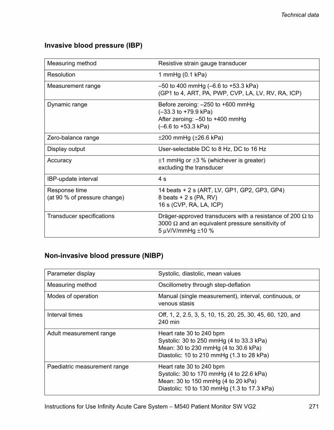
Instructions for Use Infinity Acute Care System – M540 Patient Monitor SW VG2 271
Technical data
Invasive blood pressure (IBP)
Non-invasive blood pressure (NIBP)
Measuring method Resistive strain gauge transducer
Resolution 1 mmHg (0.1 kPa)
Measurement range –50 to 400 mmHg (–6.6 to +53.3 kPa)(GP1 to 4, ART, PA, PWP, CVP, LA, LV, RV, RA, ICP)
Dynamic range Before zeroing: –250 to +600 mmHg(–33.3 to +79.9 kPa)After zeroing: –50 to +400 mmHg(–6.6 to +53.3 kPa)
Zero-balance range ±200 mmHg (±26.6 kPa)
Display output User-selectable DC to 8 Hz, DC to 16 Hz
Accuracy ±1 mmHg or ±3 % (whichever is greater) excluding the transducer
IBP-update interval 4 s
Response time(at 90 % of pressure change)
14 beats + 2 s (ART, LV, GP1, GP2, GP3, GP4)8 beats + 2 s (PA, RV)16 s (CVP, RA, LA, ICP)
Transducer specifications Dräger-approved transducers with a resistance of 200 Ω to 3000 Ω and an equivalent pressure sensitivity of 5 μV/V/mmHg ±10 %
Parameter display Systolic, diastolic, mean values
Measuring method Oscillometry through step-deflation
Modes of operation Manual (single measurement), interval, continuous, or venous stasis
Interval times Off, 1, 2, 2.5, 3, 5, 10, 15, 20, 25, 30, 45, 60, 120, and 240 min
Adult measurement range Heart rate 30 to 240 bpmSystolic: 30 to 250 mmHg (4 to 33.3 kPa)Mean: 30 to 230 mmHg (4 to 30.6 kPa)Diastolic: 10 to 210 mmHg (1.3 to 28 kPa)
Paediatric measurement range Heart rate 30 to 240 bpmSystolic: 30 to 170 mmHg (4 to 22.6 kPa)Mean: 30 to 150 mmHg (4 to 20 kPa)Diastolic: 10 to 130 mmHg (1.3 to 17.3 kPa)
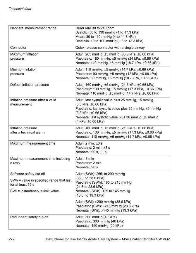
Technical data
272 Instructions for Use Infinity Acute Care System – M540 Patient Monitor SW VG2
Neonatal measurement range Heart rate 30 to 240 bpmSystolic: 30 to 130 mmHg (4 to 17.3 kPa)Mean: 30 to 110 mmHg (4 to 14.7 kPa)Diastolic: 10 to 100 mmHg (1.3 to 13.3 kPa)
Connector Quick-release connector with a single airway
Maximum inflationpressure
Adult: 265 mmHg, ±5 mmHg (35.3 kPa, ±0.66 kPa)Paediatric: 180 mmHg, ±5 mmHg (24 kPa, ±0.66 kPa)Neonate: 140 mmHg, ±5 mmHg (18.7 kPa, ±0.66 kPa)
Minimum inlationpressure
Adult: 110 mmHg, ±5 mmHg (14.7 kPa, ±0.66 kPa)Paediatric: 90 mmHg, ±5 mmHg (12 kPa, ±0.66 kPa)Neonate: 80 mmHg, ±5 mmHg (10.7 kPa, ±0.66 kPa)
Default inflation pressure Adult: 160 mmHg, ±5 mmHg (21.3 kPa, ±0.66 kPa)Paediatric: 130 mmHg, ±5 mmHg (17.3 kPa, ±0.66 kPa)Neonate: 110 mmHg, ±5 mmHg (14.7 kPa, ±0.66 kPa)
Inflation pressure after a valid measurement
Adult: last systolic value plus 25 mmHg, ±5 mmHg (3.3 kPa, ±0.66 kPa)Paediatric: last systolic value plus 25 mmHg, ±5 mmHg (3.3 kPa, ±0.66 kPa)Neonate: last systolic value plus 30 mmHg, ±5 mmHg (4 kPa, ±0.66 kPa)
Inflation pressureafter a technical alarm
Adult: 160 mmHg, ±5 mmHg (21.3 kPa, ±0.66 kPa)Paediatric: 130 mmHg, ±5 mmHg (17.3 kPa, ±0.66 kPa)Neonatal: 110 mmHg, ±5 mmHg (14.7 kPa, ±0.66 kPa)
Maximum measurement time Adult: 2 min, ±3 sPaediatric: 2 min, ±3 sNeonatal: 90 s, ±1 s
Maximum measurement time including a retry
Adult: 3 minPaediatric: 2 minNeonatal: 90 s
Software safety cut-off
SWh = value in specified range that last for at least 15 s
SWi = instantaneous limit value
Adult (SWh): 265, to 290 mmHg (35.3, to 38.6 kPa)Paediatric (SWh): 185 to 215 mmHg (24.6 to 28.6 kPa)Neonatal (SWh): 125 to 145 mmHg (16.6 to 19.3 kPa)
Adult (SWi): >290 mmHg (38.6 kPa)Paediatric (SWi): >215 mmHg (28.6 kPa)Neonatal (SWi): >145 mmHg (19.3 kPa)
Redundant safety cut-off Adult: 300 mmHg (40 kPa)Paediatric: 300 mmHg (40 kPa)Neonatal: 150 mmHg (20 kPa)
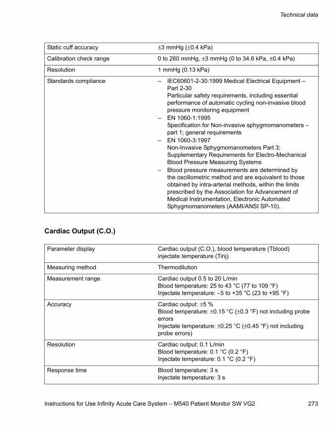
Instructions for Use Infinity Acute Care System – M540 Patient Monitor SW VG2 273
Technical data
Cardiac Output (C.O.)
Static cuff accuracy ±3 mmHg (±0.4 kPa)
Calibration check range 0 to 260 mmHg, ±3 mmHg (0 to 34.6 kPa, ±0.4 kPa)
Resolution 1 mmHg (0.13 kPa)
Standards compliance – IEC60601-2-30:1999 Medical Electrical Equipment – Part 2-30 Particular safety requirements, including essential performance of automatic cycling non-invasive blood pressure monitoring equipment
– EN 1060-1:1995 Specification for Non-invasive sphygmomanometers – part 1; general requirements
– EN 1060-3:1997 Non-Invasive Sphygmomanometers Part 3; Supplementary Requirements for Electro-Mechanical Blood Pressure Measuring Systems
– Blood pressure measurements are determined by the oscillometric method and are equivalent to those obtained by intra-arterial methods, within the limits prescribed by the Association for Advancement of Medical Instrumentation, Electronic Automated Sphygmomanometers (AAMI/ANSI SP-10).
Parameter display Cardiac output (C.O.), blood temperature (Tblood)injectate temperature (Tinj)
Measuring method Thermodilution
Measurement range Cardiac output 0.5 to 20 L/min Blood temperature: 25 to 43 °C (77 to 109 °F)Injectate temperature: –5 to +35 °C (23 to +95 °F)
Accuracy Cardiac output: ±5 %Blood temperature: ±0.15 °C (±0.3 °F) not including probe errorsInjectate temperature: ±0.25 °C (±0.45 °F) not including probe errors)
Resolution Cardiac output: 0.1 L/minBlood temperature: 0.1 °C (0.2 °F) Injectate temperature: 0.1 °C (0.2 °F)
Response time Blood temperature: 3 sInjectate temperature: 3 s
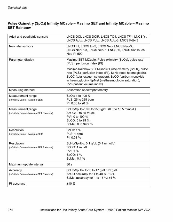
Technical data
274 Instructions for Use Infinity Acute Care System – M540 Patient Monitor SW VG2
Pulse Oximetry (SpO2) Infinity MCable – Masimo SET and Infinity MCable – Masimo SET Rainbow
Adult and paediatric sensors LNCS DCI, LNCS DCIP, LNCS TC-I, LNCS TF-I, LNCS YI, LNCS Adtx, LNCS Pdtx, LNCS Adtx-3, LNCS Pdtx-3
Neonatal sensors LNCS Inf, LNCS Inf-3, LNCS Neo, LNCS Neo-3, LNCS NeoPt-3, LNCS NeoPt, LNCS YI, LNCS SoftTouch, Neo-Pt-500
Parameter display Masimo SET MCable: Pulse oximetry (SpO2), pulse rate (PLS), perfusion index (PI)
Masimo Rainbow SET MCable: Pulse oximetry (SpO2), pulse rate (PLS), perfusion index (PI), SpHb (total haemoglobin), SpOC (total oxygen saturation), SpCO (carbon monoxide in haemoglobin), SpMet (methaemoglobin saturation), PVI (patient volume index)
Measuring method Absorption spectrophotometry
Measurement range(Infinity MCable – Masimo SET)
SpO2: 1 to 100 %PLS: 26 to 239 bpmPI: 0.00 to 20 %
Measurement range(Infinity MCable – Masimo SET Rainbow)
SpHb/SpHbv: 0.0 to 25.0 g/dL (0.0 to 15.5 mmol/L)SpOC: 0 to 35 mL/dLPVI: 0 to 100 %SpCO: 0 to 99 %SpMet: 0 to 99.9 %
Resolution(Infinity MCable – Masimo SET)
SpO2: 1 %PLS: 1 bpmPI: 0.01 %
Resolution(Infinity MCable – Masimo SET Rainbow)
SpHb/SpHbv: 0.1 g/dL (0.1 mmol/L)SpOC: 1 mL/dLPVI: 1 %SpCO: 1 %SpMet: 0.1 %
Maximum update interval 30 s
Accuracy(Infinity MCable – Masimo SET Rainbow)
SpHb/SpHbv for 8 to 17 g/dL: ±1 g/dLSpCO accuracy for 1 to 40 %: ±3 %SpMet accuracy for 1 to 15 %: ±1 %
PI accuracy ±10 %
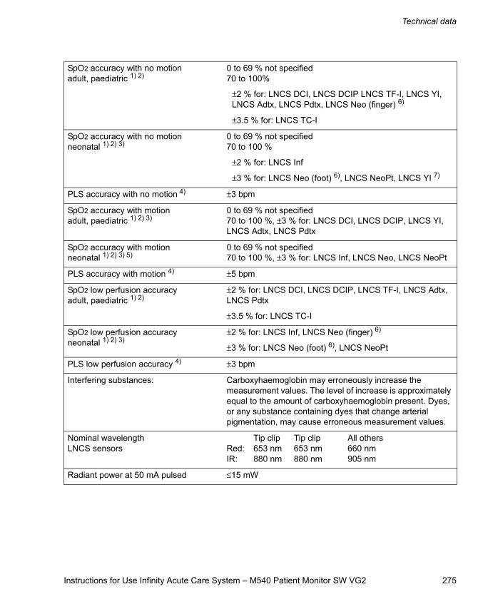
Instructions for Use Infinity Acute Care System – M540 Patient Monitor SW VG2 275
Technical data
SpO2 accuracy with no motionadult, paediatric 1) 2)
0 to 69 % not specified70 to 100%
±2 % for: LNCS DCI, LNCS DCIP LNCS TF-I, LNCS YI, LNCS Adtx, LNCS Pdtx, LNCS Neo (finger) 6)
±3.5 % for: LNCS TC-I
SpO2 accuracy with no motionneonatal 1) 2) 3)
0 to 69 % not specified70 to 100 %
±2 % for: LNCS Inf
±3 % for: LNCS Neo (foot) 6), LNCS NeoPt, LNCS YI 7)
PLS accuracy with no motion 4) ±3 bpm
SpO2 accuracy with motionadult, paediatric 1) 2) 3)
0 to 69 % not specified70 to 100 %, ±3 % for: LNCS DCI, LNCS DCIP, LNCS YI, LNCS Adtx, LNCS Pdtx
SpO2 accuracy with motionneonatal 1) 2) 3) 5)
0 to 69 % not specified70 to 100 %, ±3 % for: LNCS Inf, LNCS Neo, LNCS NeoPt
PLS accuracy with motion 4) ±5 bpm
SpO2 low perfusion accuracyadult, paediatric 1) 2)
±2 % for: LNCS DCI, LNCS DCIP, LNCS TF-I, LNCS Adtx, LNCS Pdtx
±3.5 % for: LNCS TC-I
SpO2 low perfusion accuracyneonatal 1) 2) 3)
±2 % for: LNCS Inf, LNCS Neo (finger) 6)
±3 % for: LNCS Neo (foot) 6), LNCS NeoPt
PLS low perfusion accuracy 4) ±3 bpm
Interfering substances: Carboxyhaemoglobin may erroneously increase the measurement values. The level of increase is approximately equal to the amount of carboxyhaemoglobin present. Dyes, or any substance containing dyes that change arterial pigmentation, may cause erroneous measurement values.
Nominal wavelengthLNCS sensors
Tip clip Tip clip All othersRed: 653 nm 653 nm 660 nmIR: 880 nm 880 nm 905 nm
Radiant power at 50 mA pulsed ≤15 mW
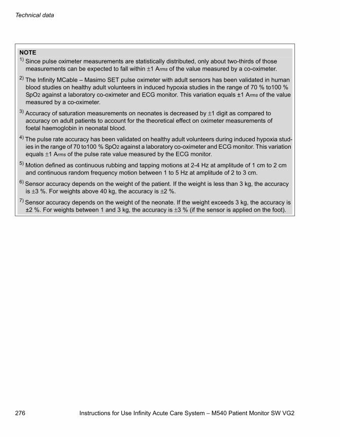
Technical data
276 Instructions for Use Infinity Acute Care System – M540 Patient Monitor SW VG2
NOTE1) Since pulse oximeter measurements are statistically distributed, only about two-thirds of those
measurements can be expected to fall within ±1 Arms of the value measured by a co-oximeter.2) The Infinity MCable – Masimo SET pulse oximeter with adult sensors has been validated in human
blood studies on healthy adult volunteers in induced hypoxia studies in the range of 70 % to100 % SpO2 against a laboratory co-oximeter and ECG monitor. This variation equals ±1 Arms of the value measured by a co-oximeter.
3) Accuracy of saturation measurements on neonates is decreased by ±1 digit as compared to accuracy on adult patients to account for the theoretical effect on oximeter measurements of foetal haemoglobin in neonatal blood.
4) The pulse rate accuracy has been validated on healthy adult volunteers during induced hypoxia stud-ies in the range of 70 to100 % SpO2 against a laboratory co-oximeter and ECG monitor. This variation equals ±1 Arms of the pulse rate value measured by the ECG monitor.
5) Motion defined as continuous rubbing and tapping motions at 2-4 Hz at amplitude of 1 cm to 2 cm and continuous random frequency motion between 1 to 5 Hz at amplitude of 2 to 3 cm.
6) Sensor accuracy depends on the weight of the patient. If the weight is less than 3 kg, the accuracy is ±3 %. For weights above 40 kg, the accuracy is ±2 %.
7) Sensor accuracy depends on the weight of the neonate. If the weight exceeds 3 kg, the accuracy is ±2 %. For weights between 1 and 3 kg, the accuracy is ±3 % (if the sensor is applied on the foot).
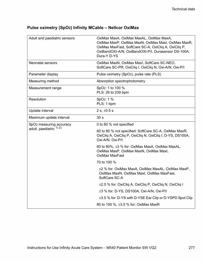
Instructions for Use Infinity Acute Care System – M540 Patient Monitor SW VG2 277
Technical data
Pulse oximetry (SpO2) Infinity MCable – Nellcor OxiMax
Adult and paediatric sensors OxiMax MaxA, OxiMax MaxAL, OxiMax MaxA, OxiMax MaxP, OxiMax MaxN, OxiMax MaxI, OxiMax MaxR, OxiMax MaxFast, SoftCare SC-A, OxiCliq A, OxiCliq P, OxiBandOXI-A/N, OxiBandOXI-P/I, Durasensor DS-100A, Dura-Y D-YS
Neonatal sensors OxiMax MaxN, OxiMax MaxI, SoftCare SC-NEO, SoftCare SC-PR, OxiCliq I, OxiCliq N, Oxi-A/N, Oxi-P/I
Parameter display Pulse oximetry (SpO2), pulse rate (PLS)
Measuring method Absorption spectrophotometry
Measurement range SpO2: 1 to 100 %PLS: 26 to 239 bpm
Resolution SpO2: 1 %PLS: 1 bpm
Update interval 2 s, ±0.5 s
Maximum update interval 30 s
SpO2 measuring accuracyadult, paediatric 1) 2)
0 to 60 % not specified
60 to 80 % not specified: SoftCare SC-A, OxiMax MaxR, OxiCliq A, OxiCliq P, OxiCliq N, OxiCliq I, D-YS, DS100A, Oxi-A/N, Oxi-P/I
60 to 80%, ±3 % for: OxiMax MaxA, OxiMax MaxAL, OxiMax MaxP, OxiMax MaxN, OxiMax MaxI, OxiMax MaxFast
70 to 100 %
±2 % for: OxiMax MaxA, OxiMax MaxAL, OxiMax MaxP, OxiMax MaxN, OxiMax MaxI, OxiMax MaxFast, SoftCare SC-A
±2.5 % for: OxiCliq A, OxiCliq P, OxiCliq N, OxiCliq I
±3 % for: D-YS, DS100A, Oxi-A/N, Oxi-P/I
±3.5 % for: D-YS with D-YSE Ear Clip or D-YSPD Spot Clip
80 to 100 %, ±3.5 % for: OxiMax MaxR
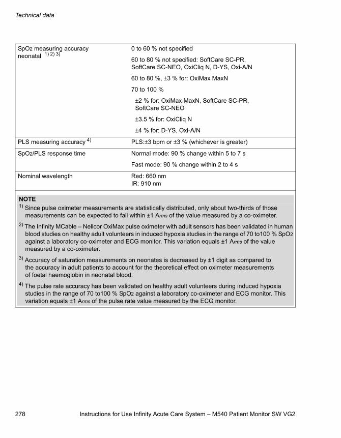
Technical data
278 Instructions for Use Infinity Acute Care System – M540 Patient Monitor SW VG2
SpO2 measuring accuracyneonatal 1) 2) 3)
0 to 60 % not specified
60 to 80 % not specified: SoftCare SC-PR, SoftCare SC-NEO, OxiCliq N, D-YS, Oxi-A/N
60 to 80 %, ±3 % for: OxiMax MaxN
70 to 100 %
±2 % for: OxiMax MaxN, SoftCare SC-PR, SoftCare SC-NEO
±3.5 % for: OxiCliq N
±4 % for: D-YS, Oxi-A/N
PLS measuring accuracy 4) PLS:±3 bpm or ±3 % (whichever is greater)
SpO2/PLS response time Normal mode: 90 % change within 5 to 7 s
Fast mode: 90 % change within 2 to 4 s
Nominal wavelength Red: 660 nmIR: 910 nm
NOTE1) Since pulse oximeter measurements are statistically distributed, only about two-thirds of those
measurements can be expected to fall within ±1 Arms of the value measured by a co-oximeter.2) The Infinity MCable – Nellcor OxiMax pulse oximeter with adult sensors has been validated in human
blood studies on healthy adult volunteers in induced hypoxia studies in the range of 70 to100 % SpO2 against a laboratory co-oximeter and ECG monitor. This variation equals ±1 Arms of the value measured by a co-oximeter.
3) Accuracy of saturation measurements on neonates is decreased by ±1 digit as compared to the accuracy in adult patients to account for the theoretical effect on oximeter measurements of foetal haemoglobin in neonatal blood.
4) The pulse rate accuracy has been validated on healthy adult volunteers during induced hypoxia studies in the range of 70 to100 % SpO2 against a laboratory co-oximeter and ECG monitor. This variation equals ±1 Arms of the pulse rate value measured by the ECG monitor.
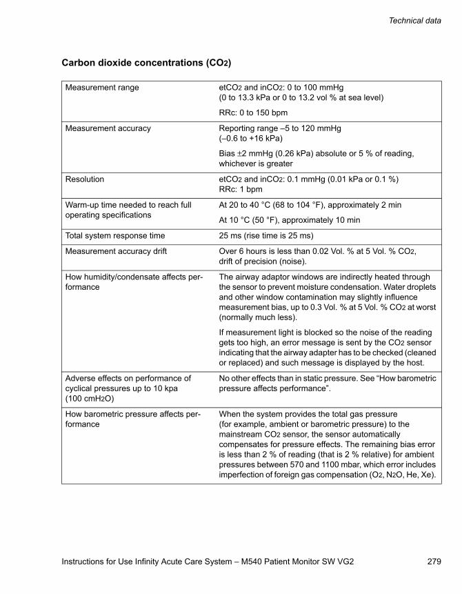
Instructions for Use Infinity Acute Care System – M540 Patient Monitor SW VG2 279
Technical data
Carbon dioxide concentrations (CO2)
Measurement range etCO2 and inCO2: 0 to 100 mmHg(0 to 13.3 kPa or 0 to 13.2 vol % at sea level)
RRc: 0 to 150 bpm
Measurement accuracy Reporting range –5 to 120 mmHg (–0.6 to +16 kPa)
Bias ±2 mmHg (0.26 kPa) absolute or 5 % of reading, whichever is greater
Resolution etCO2 and inCO2: 0.1 mmHg (0.01 kPa or 0.1 %)RRc: 1 bpm
Warm-up time needed to reach full operating specifications
At 20 to 40 °C (68 to 104 °F), approximately 2 min
At 10 °C (50 °F), approximately 10 min
Total system response time 25 ms (rise time is 25 ms)
Measurement accuracy drift Over 6 hours is less than 0.02 Vol. % at 5 Vol. % CO2, drift of precision (noise).
How humidity/condensate affects per-formance
The airway adaptor windows are indirectly heated through the sensor to prevent moisture condensation. Water droplets and other window contamination may slightly influence measurement bias, up to 0.3 Vol. % at 5 Vol. % CO2 at worst (normally much less).
If measurement light is blocked so the noise of the reading gets too high, an error message is sent by the CO2 sensor indicating that the airway adapter has to be checked (cleaned or replaced) and such message is displayed by the host.
Adverse effects on performance of cyclical pressures up to 10 kpa (100 cmH2O)
No other effects than in static pressure. See “How barometric pressure affects performance”.
How barometric pressure affects per-formance
When the system provides the total gas pressure (for example, ambient or barometric pressure) to the mainstream CO2 sensor, the sensor automatically compensates for pressure effects. The remaining bias error is less than 2 % of reading (that is 2 % relative) for ambient pressures between 570 and 1100 mbar, which error includes imperfection of foreign gas compensation (O2, N2O, He, Xe).
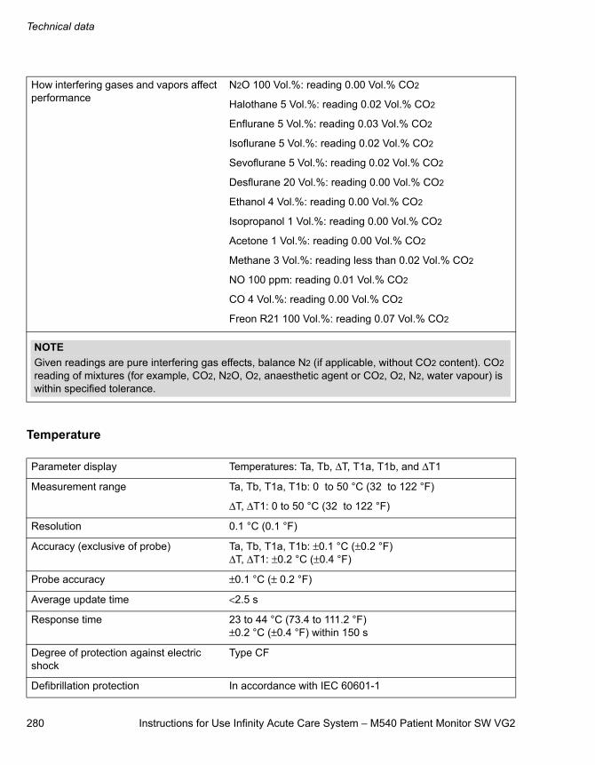
Technical data
280 Instructions for Use Infinity Acute Care System – M540 Patient Monitor SW VG2
Temperature
How interfering gases and vapors affect performance
N2O 100 Vol.%: reading 0.00 Vol.% CO2
Halothane 5 Vol.%: reading 0.02 Vol.% CO2
Enflurane 5 Vol.%: reading 0.03 Vol.% CO2
Isoflurane 5 Vol.%: reading 0.02 Vol.% CO2
Sevoflurane 5 Vol.%: reading 0.02 Vol.% CO2
Desflurane 20 Vol.%: reading 0.00 Vol.% CO2
Ethanol 4 Vol.%: reading 0.00 Vol.% CO2
Isopropanol 1 Vol.%: reading 0.00 Vol.% CO2
Acetone 1 Vol.%: reading 0.00 Vol.% CO2
Methane 3 Vol.%: reading less than 0.02 Vol.% CO2
NO 100 ppm: reading 0.01 Vol.% CO2
CO 4 Vol.%: reading 0.00 Vol.% CO2
Freon R21 100 Vol.%: reading 0.07 Vol.% CO2
NOTEGiven readings are pure interfering gas effects, balance N2 (if applicable, without CO2 content). CO2 reading of mixtures (for example, CO2, N2O, O2, anaesthetic agent or CO2, O2, N2, water vapour) is within specified tolerance.
Parameter display Temperatures: Ta, Tb, ΔT, T1a, T1b, and ΔT1
Measurement range Ta, Tb, T1a, T1b: 0 to 50 °C (32 to 122 °F)
ΔT, ΔT1: 0 to 50 °C (32 to 122 °F)
Resolution 0.1 °C (0.1 °F)
Accuracy (exclusive of probe) Ta, Tb, T1a, T1b: ±0.1 °C (±0.2 °F)ΔT, ΔT1: ±0.2 °C (±0.4 °F)
Probe accuracy ±0.1 °C (± 0.2 °F)
Average update time <2.5 s
Response time 23 to 44 °C (73.4 to 111.2 °F) ±0.2 °C (±0.4 °F) within 150 s
Degree of protection against electric shock
Type CF
Defibrillation protection In accordance with IEC 60601-1
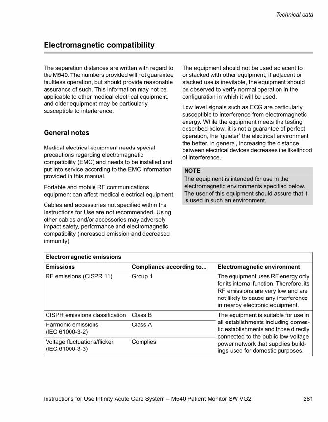
Instructions for Use Infinity Acute Care System – M540 Patient Monitor SW VG2 281
Technical data
Electromagnetic compatibility
The separation distances are written with regard to the M540. The numbers provided will not guarantee faultless operation, but should provide reasonable assurance of such. This information may not be applicable to other medical electrical equipment, and older equipment may be particularly susceptible to interference.
General notes
Medical electrical equipment needs special precautions regarding electromagnetic compatibility (EMC) and needs to be installed and put into service according to the EMC information provided in this manual.
Portable and mobile RF communications equipment can affect medical electrical equipment.
Cables and accessories not specified within the Instructions for Use are not recommended. Using other cables and/or accessories may adversely impact safety, performance and electromagnetic compatibility (increased emission and decreased immunity).
The equipment should not be used adjacent to or stacked with other equipment; if adjacent or stacked use is inevitable, the equipment should be observed to verify normal operation in the configuration in which it will be used.
Low level signals such as ECG are particularly susceptible to interference from electromagnetic energy. While the equipment meets the testing described below, it is not a guarantee of perfect operation, the ‘quieter’ the electrical environment the better. In general, increasing the distance between electrical devices decreases the likelihood of interference.
NOTEThe equipment is intended for use in the electromagnetic environments specified below. The user of this equipment should assure that it is used in such an environment.
Electromagnetic emissionsEmissions Compliance according to... Electromagnetic environmentRF emissions (CISPR 11) Group 1 The equipment uses RF energy only
for its internal function. Therefore, its RF emissions are very low and are not likely to cause any interference in nearby electronic equipment.
CISPR emissions classification Class B The equipment is suitable for use in all establishments including domes-tic establishments and those directly connected to the public low-voltage power network that supplies build-ings used for domestic purposes.
Harmonic emissions (IEC 61000-3-2)
Class A
Voltage fluctuations/flicker (IEC 61000-3-3)
Complies
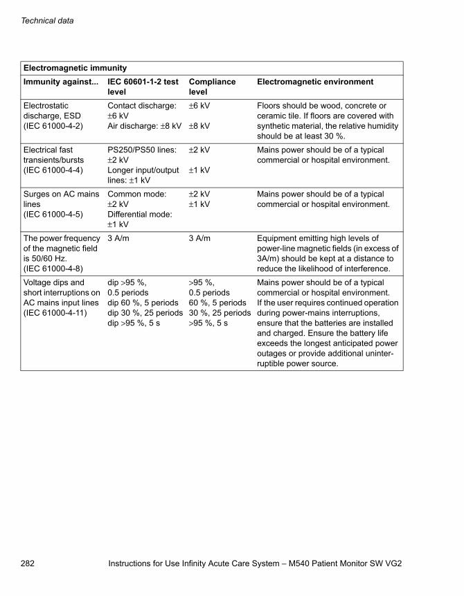
Technical data
282 Instructions for Use Infinity Acute Care System – M540 Patient Monitor SW VG2
Electromagnetic immunityImmunity against... IEC 60601-1-2 test
levelCompliance level
Electromagnetic environment
Electrostatic discharge, ESD (IEC 61000-4-2)
Contact discharge: ±6 kVAir discharge: ±8 kV
±6 kV
±8 kV
Floors should be wood, concrete or ceramic tile. If floors are covered with synthetic material, the relative humidity should be at least 30 %.
Electrical fast transients/bursts(IEC 61000-4-4)
PS250/PS50 lines: ±2 kVLonger input/output lines: ±1 kV
±2 kV
±1 kV
Mains power should be of a typical commercial or hospital environment.
Surges on AC mains lines(IEC 61000-4-5)
Common mode: ±2 kVDifferential mode: ±1 kV
±2 kV±1 kV
Mains power should be of a typical commercial or hospital environment.
The power frequency of the magnetic field is 50/60 Hz. (IEC 61000-4-8)
3 A/m 3 A/m Equipment emitting high levels of power-line magnetic fields (in excess of 3A/m) should be kept at a distance to reduce the likelihood of interference.
Voltage dips and short interruptions on AC mains input lines(IEC 61000-4-11)
dip >95 %, 0.5 periodsdip 60 %, 5 periodsdip 30 %, 25 periodsdip >95 %, 5 s
>95 %, 0.5 periods60 %, 5 periods30 %, 25 periods>95 %, 5 s
Mains power should be of a typical commercial or hospital environment. If the user requires continued operation during power-mains interruptions, ensure that the batteries are installed and charged. Ensure the battery life exceeds the longest anticipated power outages or provide additional uninter-ruptible power source.
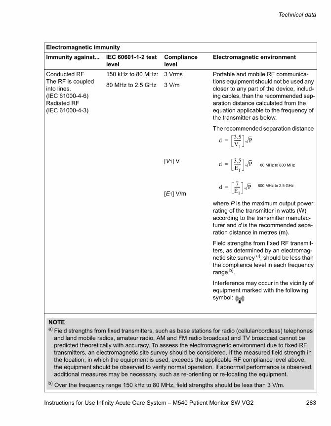
Instructions for Use Infinity Acute Care System – M540 Patient Monitor SW VG2 283
Technical data
Conducted RFThe RF is coupled into lines.(IEC 61000-4-6)Radiated RF(IEC 61000-4-3)
150 kHz to 80 MHz:
80 MHz to 2.5 GHz
3 Vrms
3 V/m
[V1] V
[E1] V/m
Portable and mobile RF communica-tions equipment should not be used any closer to any part of the device, includ-ing cables, than the recommended sep-aration distance calculated from the equation applicable to the frequency of the transmitter as below.
The recommended separation distance
where P is the maximum output power rating of the transmitter in watts (W) according to the transmitter manufac-turer and d is the recommended sepa-ration distance in metres (m).
Field strengths from fixed RF transmit-ters, as determined by an electromag-netic site survey a), should be less than the compliance level in each frequency range b).
Interference may occur in the vicinity of equipment marked with the following symbol:
Electromagnetic immunityImmunity against... IEC 60601-1-2 test
levelCompliance level
Electromagnetic environment
d 3.5V1------- P=
d 3.5E1------- P= 80 MHz to 800 MHz
d 7E1------ P= 800 MHz to 2.5 GHz
NOTEa) Field strengths from fixed transmitters, such as base stations for radio (cellular/cordless) telephones
and land mobile radios, amateur radio, AM and FM radio broadcast and TV broadcast cannot be predicted theoretically with accuracy. To assess the electromagnetic environment due to fixed RF transmitters, an electromagnetic site survey should be considered. If the measured field strength in the location, in which the equipment is used, exceeds the applicable RF compliance level above, the equipment should be observed to verify normal operation. If abnormal performance is observed, additional measures may be necessary, such as re-orienting or re-locating the equipment.
b) Over the frequency range 150 kHz to 80 MHz, field strengths should be less than 3 V/m.

284 Instructions for Use Infinity Acute Care System – M540 Patient Monitor SW VG2
This page is intentionally left blank
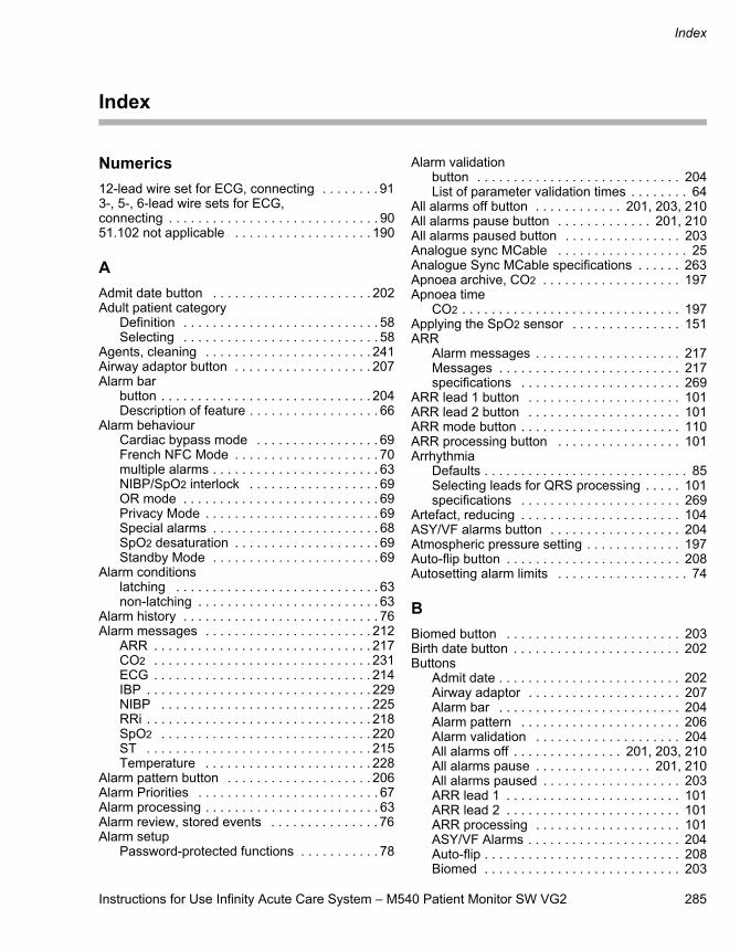
Instructions for Use Infinity Acute Care System – M540 Patient Monitor SW VG2 285
Index
Index
Numerics12-lead wire set for ECG, connecting . . . . . . . . 913-, 5-, 6-lead wire sets for ECG, connecting . . . . . . . . . . . . . . . . . . . . . . . . . . . . . 9051.102 not applicable . . . . . . . . . . . . . . . . . . . 190
AAdmit date button . . . . . . . . . . . . . . . . . . . . . . 202Adult patient category
Definition . . . . . . . . . . . . . . . . . . . . . . . . . . . 58Selecting . . . . . . . . . . . . . . . . . . . . . . . . . . . 58
Agents, cleaning . . . . . . . . . . . . . . . . . . . . . . . 241Airway adaptor button . . . . . . . . . . . . . . . . . . . 207Alarm bar
button . . . . . . . . . . . . . . . . . . . . . . . . . . . . . 204Description of feature . . . . . . . . . . . . . . . . . . 66
Alarm behaviourCardiac bypass mode . . . . . . . . . . . . . . . . . 69French NFC Mode . . . . . . . . . . . . . . . . . . . . 70multiple alarms . . . . . . . . . . . . . . . . . . . . . . . 63NIBP/SpO2 interlock . . . . . . . . . . . . . . . . . . 69OR mode . . . . . . . . . . . . . . . . . . . . . . . . . . . 69Privacy Mode . . . . . . . . . . . . . . . . . . . . . . . . 69Special alarms . . . . . . . . . . . . . . . . . . . . . . . 68SpO2 desaturation . . . . . . . . . . . . . . . . . . . . 69Standby Mode . . . . . . . . . . . . . . . . . . . . . . . 69
Alarm conditionslatching . . . . . . . . . . . . . . . . . . . . . . . . . . . . 63non-latching . . . . . . . . . . . . . . . . . . . . . . . . . 63
Alarm history . . . . . . . . . . . . . . . . . . . . . . . . . . . 76Alarm messages . . . . . . . . . . . . . . . . . . . . . . . 212
ARR . . . . . . . . . . . . . . . . . . . . . . . . . . . . . . 217CO2 . . . . . . . . . . . . . . . . . . . . . . . . . . . . . . 231ECG . . . . . . . . . . . . . . . . . . . . . . . . . . . . . . 214IBP . . . . . . . . . . . . . . . . . . . . . . . . . . . . . . . 229NIBP . . . . . . . . . . . . . . . . . . . . . . . . . . . . . 225RRi . . . . . . . . . . . . . . . . . . . . . . . . . . . . . . . 218SpO2 . . . . . . . . . . . . . . . . . . . . . . . . . . . . . 220ST . . . . . . . . . . . . . . . . . . . . . . . . . . . . . . . 215Temperature . . . . . . . . . . . . . . . . . . . . . . . 228
Alarm pattern button . . . . . . . . . . . . . . . . . . . . 206Alarm Priorities . . . . . . . . . . . . . . . . . . . . . . . . . 67Alarm processing . . . . . . . . . . . . . . . . . . . . . . . . 63Alarm review, stored events . . . . . . . . . . . . . . . 76Alarm setup
Password-protected functions . . . . . . . . . . . 78
Alarm validationbutton . . . . . . . . . . . . . . . . . . . . . . . . . . . . 204List of parameter validation times . . . . . . . . 64
All alarms off button . . . . . . . . . . . . 201, 203, 210All alarms pause button . . . . . . . . . . . . . 201, 210All alarms paused button . . . . . . . . . . . . . . . . 203Analogue sync MCable . . . . . . . . . . . . . . . . . . 25Analogue Sync MCable specifications . . . . . . 263Apnoea archive, CO2 . . . . . . . . . . . . . . . . . . . 197Apnoea time
CO2 . . . . . . . . . . . . . . . . . . . . . . . . . . . . . . 197Applying the SpO2 sensor . . . . . . . . . . . . . . . 151ARR
Alarm messages . . . . . . . . . . . . . . . . . . . . 217Messages . . . . . . . . . . . . . . . . . . . . . . . . . 217specifications . . . . . . . . . . . . . . . . . . . . . . 269
ARR lead 1 button . . . . . . . . . . . . . . . . . . . . . 101ARR lead 2 button . . . . . . . . . . . . . . . . . . . . . 101ARR mode button . . . . . . . . . . . . . . . . . . . . . . 110ARR processing button . . . . . . . . . . . . . . . . . 101Arrhythmia
Defaults . . . . . . . . . . . . . . . . . . . . . . . . . . . . 85Selecting leads for QRS processing . . . . . 101specifications . . . . . . . . . . . . . . . . . . . . . . 269
Artefact, reducing . . . . . . . . . . . . . . . . . . . . . . 104ASY/VF alarms button . . . . . . . . . . . . . . . . . . 204Atmospheric pressure setting . . . . . . . . . . . . . 197Auto-flip button . . . . . . . . . . . . . . . . . . . . . . . . 208Autosetting alarm limits . . . . . . . . . . . . . . . . . . 74
BBiomed button . . . . . . . . . . . . . . . . . . . . . . . . 203Birth date button . . . . . . . . . . . . . . . . . . . . . . . 202Buttons
Admit date . . . . . . . . . . . . . . . . . . . . . . . . . 202Airway adaptor . . . . . . . . . . . . . . . . . . . . . 207Alarm bar . . . . . . . . . . . . . . . . . . . . . . . . . 204Alarm pattern . . . . . . . . . . . . . . . . . . . . . . 206Alarm validation . . . . . . . . . . . . . . . . . . . . 204All alarms off . . . . . . . . . . . . . . . 201, 203, 210All alarms pause . . . . . . . . . . . . . . . . 201, 210All alarms paused . . . . . . . . . . . . . . . . . . . 203ARR lead 1 . . . . . . . . . . . . . . . . . . . . . . . . 101ARR lead 2 . . . . . . . . . . . . . . . . . . . . . . . . 101ARR processing . . . . . . . . . . . . . . . . . . . . 101ASY/VF Alarms . . . . . . . . . . . . . . . . . . . . . 204Auto-flip . . . . . . . . . . . . . . . . . . . . . . . . . . . 208Biomed . . . . . . . . . . . . . . . . . . . . . . . . . . . 203
Index
286 Instructions for Use Infinity Acute Care System – M540 Patient Monitor SW VG2
Birth date . . . . . . . . . . . . . . . . . . . . . . . . . . 202Cable type . . . . . . . . . . . . . . . . . . . . . . . . . 101Change parameter . . . . . . . . . . . . . . . 100, 117Date . . . . . . . . . . . . . . . . . . . . . . . . . . . . . . 206Discharge . . . . . . . . . . . . . . . . . . . . . . . . . . 201ECG filter . . . . . . . . . . . . . . . . . . . . . . . . . . . 99Event duration . . . . . . . . . . . . . . . . . . . . . . 117Flip screen . . . . . . . . . . . . . . . . . . . . . . . . . 208French NFC . . . . . . . . . . . . . . . . . . . . . . . . 206HR source . . . . . . . . . . . . . . . . . . . . . . . . . 100ID . . . . . . . . . . . . . . . . . . . . . . . . . . . . . . . . 202Label IBP . . . . . . . . . . . . . . . . . . . . . . . . . . 201Language . . . . . . . . . . . . . . . . . . . . . . . . . . 206Line frequency . . . . . . . . . . . . . . . . . . . . . . 206Name . . . . . . . . . . . . . . . . . . . . . . . . . . . . . 202NIBP/SpO2 interlock . . . . . . . . . . . . . . . . . 204Pacer detection . . . . . . . . . . . . . . . . . . . . . 100Pacer mode . . . . . . . . . . . . . . . . . . . . . . . . 204Patient Category . . . . . . . . . . . . . . . . . . . . 202Physician . . . . . . . . . . . . . . . . . . . . . . . . . . 202Power save . . . . . . . . . . . . . . . . . . . . . . . . 208Privacy Mode . . . . . . . . . . . . . . . . . . . . . . . 201QRS sync marker . . . . . . . . . . . . . . . . . . . 100Relearn . . . . . . . . . . . . . . . . . . . . . . . 110, 116RRi colour . . . . . . . . . . . . . . . . . . . . . . . . . 100Save (ST-complex) . . . . . . . . . . . . . . . . . . 117Save profile . . . . . . . . . . . . . . . . . . . . . . . . 206Service . . . . . . . . . . . . . . . . . . . . . . . . . . . . 203Setup key . . . . . . . . . . . . . . . . . . . . . . . . . . 209Show all leads . . . . . . . . . . . . . . . . . . 100, 201Simulation . . . . . . . . . . . . . . . . . . . . . . . . . 206Size all ECG . . . . . . . . . . . . . . . . . . . . . . . 100Speaker volume . . . . . . . . . . . . . . . . . . . . . 210SpO2 alarm delay . . . . . . . . . . . . . . . . . . . 204ST complex . . . . . . . . . . . . . . . . . . . . . . . . 117ST lead 1 . . . . . . . . . . . . . . . . . . . . . . . . . . 117ST lead 2 . . . . . . . . . . . . . . . . . . . . . . . . . . 117ST monitoring . . . . . . . . . . . . . . . . . . . . . . 117Standby . . . . . . . . . . . . . . . . . . . . . . . . . . . 201Test pulse . . . . . . . . . . . . . . . . . . . . . . . . . 207The ARR Mode . . . . . . . . . . . . . . . . . . . . . 110Time . . . . . . . . . . . . . . . . . . . . . . . . . . . . . . 206Tone source . . . . . . . . . . . . . . . . . . . . . . . . . 99Tone volume . . . . . . . . . . . . . . . . . . . . . . . . 99Touch calib. . . . . . . . . . . . . . . . . . . . . . . . . 208TruST . . . . . . . . . . . . . . . . . . . . . . . . . . . . . 117View . . . . . . . . . . . . . . . . . . . . . . . . . . . . . . 209
CC.O.
Connections . . . . . . . . . . . . . . . . . . . . . . . 185Messages . . . . . . . . . . . . . . . . . . . . . . . . . 231Monitoring Principles . . . . . . . . . . . . . . . . 184Patient preparation . . . . . . . . . . . . . . . . . . 187Precautions . . . . . . . . . . . . . . . . . . . . . . . . 184
C.O. specifications . . . . . . . . . . . . . . . . . . . . . 273Cable type for ECG, selecting . . . . . . . . . . . . 101Cable-type button . . . . . . . . . . . . . . . . . . . . . . 101Cables
Cleaning . . . . . . . . . . . . . . . . . . . . . . . . . . 244Disinfecting . . . . . . . . . . . . . . . . . . . . . . . . 244
Calibrating the touchscreen . . . . . . . . . . . . . . . 41Carbon dioxide concentrations specifications . . . . . . . . . . . . . . . . . . . . . . . . . 279Cardiac bypass mode
Alarms . . . . . . . . . . . . . . . . . . . . . . . . . . . . 69Message . . . . . . . . . . . . . . . . . . . . . . . . . . . 69
Cardiac output specifications . . . . . . . . . . . . . 273Cardioversion . . . . . . . . . . . . . . . . . . . . . . . . . . 25Cause/remedy messages . . . . . . . . . . . . . . . . 212Changing a parameter box . . . . . . . . . . . 100, 197Changing a parameter button . . . . . . . . . 100, 117Changing unit of measurement . . . . . . . 207, 208Cleaning . . . . . . . . . . . . . . . . . . . . . . . . . . . . . 240
agents . . . . . . . . . . . . . . . . . . . . . . . . . . . . 241Grabber-wire clips . . . . . . . . . . . . . . . . . . 244M500 power supply . . . . . . . . . . . . . . . . . 242Mainstream CO2 sensor . . . . . . . . . . . . . . 247MCables . . . . . . . . . . . . . . . . . . . . . . . . . . 243monitor . . . . . . . . . . . . . . . . . . . . . . . . . . . 242NIBP cuffs . . . . . . . . . . . . . . . . . . . . . . . . . 246Patient cables . . . . . . . . . . . . . . . . . . . . . . 244Temperature Cables . . . . . . . . . . . . . . . . . 245Temperature probes . . . . . . . . . . . . . 245, 246
CO2Alarm messages . . . . . . . . . . . . . . . . . . . . 231Apnoea archive, selecting . . . . . . . . . . . . 197Apnoea time selection . . . . . . . . . . . . . . . 197Gas compensation selection . . . . . . . . . . 197Messages . . . . . . . . . . . . . . . . . . . . . . . . . 231Patient preparation . . . . . . . . . . . . . . . . . . 193Precautions . . . . . . . . . . . . . . . . . . . . . . . . 190specifications . . . . . . . . . . . . . . . . . . . . . . 279Zeroing . . . . . . . . . . . . . . . . . . . . . . . . . . . 197
Code button . . . . . . . . . . . . . . . . . . . . . . . . . . . 78Colour
CO2 . . . . . . . . . . . . . . . . . . . . . . . . . . . . . . 197
Instructions for Use Infinity Acute Care System – M540 Patient Monitor SW VG2 287
Index
Configuring waveform size . . . . . . . . . . . . . . . . 39Conflicts between pressure labels . . . . . . . . . . 179Connections
12-Lead Wire Set . . . . . . . . . . . . . . . . . . . . . 913-, 5-, 6-lead wire sets . . . . . . . . . . . . . . . . . 90cardiac output . . . . . . . . . . . . . . . . . . . . . . 185Dual Hemo MCable . . . . . . . . . . . . . . . . . . 175ECG lead wire sets . . . . . . . . . . . . . . . . . . . 90Neonatal ECG monitoring . . . . . . . . . . . . . . 92SpO2 (Masimo) . . . . . . . . . . . . . . . . . 134, 135SpO2 (Nellcor) . . . . . . . . . . . . . . . . . . . . . . 148Temperature probes . . . . . . . . . . . . . . . . . 154
DDate button . . . . . . . . . . . . . . . . . . . . . . . . . . . 206Defaults, arrhythmia . . . . . . . . . . . . . . . . . . . . . 85Discharge button . . . . . . . . . . . . . . . . . . . . . . . 201Disinfecting . . . . . . . . . . . . . . . . . . . . . . . . . . . 240
Cables . . . . . . . . . . . . . . . . . . . . . . . . 244, 245Electrodes . . . . . . . . . . . . . . . . . . . . . . . . . 244Patient cables . . . . . . . . . . . . . . . . . . . . . . 244
Docking the M540 . . . . . . . . . . . . . . . . . . . . . . . 49Dual Hemo MCable . . . . . . . . . . . . . . . . . . . . . 172Dual Hemo MCable specifications . . . . . . . . . . 262
EECG
Alarm messages . . . . . . . . . . . . . . . . . . . . 214Cable type, selecting . . . . . . . . . . . . . . . . . 101Connecting 12-lead wire set . . . . . . . . . . . . 91Connecting lead wire sets . . . . . . . . . . . . . . 90Display . . . . . . . . . . . . . . . . . . . . . . . . . . . . . 94Frank lead, selecting format . . . . . . . . . . . . 99HR source . . . . . . . . . . . . . . . . . . . . . . . . . 100Infusion pumps . . . . . . . . . . . . . . . . . . . . . 104Line isolation devices . . . . . . . . . . . . . . . . . 104Pacer detection, on/off . . . . . . . . . . . . . . . . 100pacer mode, selecting . . . . . . . . . . . . . . . . 204Patient preparation . . . . . . . . . . . . . . . . . . . 99Precautions . . . . . . . . . . . . . . . . . . . . . . . . . 90Pulse tone source . . . . . . . . . . . . . . . . . . . . 99QRS sync marker . . . . . . . . . . . . . . . . . . . 100Roller bypass pumps . . . . . . . . . . . . . . . . . 104Signal quality . . . . . . . . . . . . . . . . . . . . . . . 104specifications . . . . . . . . . . . . . . . . . . . . . . . 266Standard lead format, selecting . . . . . . . . . . 99TENS signals . . . . . . . . . . . . . . . . . . . . . . . 104Tone source . . . . . . . . . . . . . . . . . . . . . . . . . 99Tone volume . . . . . . . . . . . . . . . . . . . . . . . . 99Transient signals . . . . . . . . . . . . . . . . . . . . 104
ECG filter button . . . . . . . . . . . . . . . . . . . . . . . . 99ESU interference, pacemakers . . . . . . . . . . . . 93Event duration button . . . . . . . . . . . . . . . . . . . 117Events
Marking . . . . . . . . . . . . . . . . . . . . . . . . . . . . 76Storing manually . . . . . . . . . . . . . . . . . . . . . 76
FFastSat mode, SpO2 . . . . . . . . . . . . . . . . . . . 140Filtering IBP signal . . . . . . . . . . . . . . . . . . . . . 182Flip screen button . . . . . . . . . . . . . . . . . . . . . . 208French NFC button . . . . . . . . . . . . . . . . . . . . . 206French NFC Mode
Alarms . . . . . . . . . . . . . . . . . . . . . . . . . . . . . 70Fusion mode . . . . . . . . . . . . . . . . . . . . . . . . . . 103
GGrabber-wire
Clips, cleaning . . . . . . . . . . . . . . . . . . . . . 244Snaps, cleaning . . . . . . . . . . . . . . . . . . . . 244
HHardware
additional hardware . . . . . . . . . . . . . . . . . . 24Hemo2 pod . . . . . . . . . . . . . . . . . . . . . . . . . . . 171Hemo2 pod specifications . . . . . . . . . . . . . . . 260Hemo4 pod . . . . . . . . . . . . . . . . . . . . . . . . . . . 170Hemo4 pod specifications . . . . . . . . . . . . . . . 260HR source button . . . . . . . . . . . . . . . . . . . . . . 100HR source, selecting . . . . . . . . . . . . . . . . . . . 100
IIBP
Alarm messages . . . . . . . . . . . . . . . . . . . . 229Available pressure labels . . . . . . . . . . . . . 181Filter selection . . . . . . . . . . . . . . . . . . . . . . 182Labelling pressure channels . . . . . . . . . . . 177Messages . . . . . . . . . . . . . . . . . . . . . . . . . 229Precautions . . . . . . . . . . . . . . . . . . . . . . . . 172Pressure Label Conflicts . . . . . . . . . . . . . . 179Standard labels . . . . . . . . . . . . . . . . . . . . . 178Wedge pressure . . . . . . . . . . . . . . . . . . . . 181Zeroing a Specific Sensor . . . . . . . . . . . . . 179Zeroing all sensors . . . . . . . . . . . . . . . . . . 180Zeroing pressures . . . . . . . . . . . . . . . . . . . 181
IBP specifications . . . . . . . . . . . . . . . . . . . . . . 271ID button . . . . . . . . . . . . . . . . . . . . . . . . . . . . . 202Infusion pumps, artefact . . . . . . . . . . . . . . . . . 104
Index
288 Instructions for Use Infinity Acute Care System – M540 Patient Monitor SW VG2
Invasive blood pressure specifications . . . . . . 271ISO 2005, 2005
clause 101 . . . . . . . . . . . . . . . . . . . . . 137, 150ISO 21647, 2004 + C1
clause 6.8.2 cc) 3) items v), x) . . . . . . . . . . 196ISO 21647, 2004 + C1, 2005
clause 44.7 . . . . . . . . . . . . . . . . . . . . . . . . 247clause 6.8.2 cc) 2) for items iii) - ix . . . . . . 196clause 6.8.2 cc) 3) iii) . . . . . . . . . . . . . . . . . 236clause 6.8.2 cc) 3) viii) . . . . . . . . . . . . . . . . 253clause cc) 1), iii), vi), viii) . . . . . . . . . . . . . . 190
ISO 9919, 2005clause 6.8.2 aa) 8) . . . . . . . . . . . . . . . 137, 150
LLabel IBP button . . . . . . . . . . . . . . . . . . . . . . . 201Language button . . . . . . . . . . . . . . . . . . . . . . . 206Latching alarms . . . . . . . . . . . . . . . . . . . . . . . . . 63Lead-wire sets, connecting . . . . . . . . . . . . . . . . 90Line frequency button . . . . . . . . . . . . . . . . . . . 206
MM540 specifications . . . . . . . . . . . . . . . . . 252, 255Mainstream CO2 MCable specifications . . . . . 257Maintenance . . . . . . . . . . . . . . . . . . . . . . . . . . 237Marking events . . . . . . . . . . . . . . . . . . . . . . . . . 76Masimo SET MCable specifications . . . . . . . . 258Masimo SET MCable, connecting . . . . . . . . . . 134Messages
arrhythmia . . . . . . . . . . . . . . . . . . . . . . . . . 217C.O. . . . . . . . . . . . . . . . . . . . . . . . . . . . . . . 231CO2 . . . . . . . . . . . . . . . . . . . . . . . . . . . . . . 231IBP . . . . . . . . . . . . . . . . . . . . . . . . . . . . . . . 229Printing . . . . . . . . . . . . . . . . . . . . . . . . . . . . 231Resp . . . . . . . . . . . . . . . . . . . . . . . . . . . . . 218SpO2 . . . . . . . . . . . . . . . . . . . . . . . . . . . . . 220ST . . . . . . . . . . . . . . . . . . . . . . . . . . . . . . . 215Temperature . . . . . . . . . . . . . . . . . . . . . . . 228
Messages, alarm . . . . . . . . . . . . . . . . . . . . . . . 212Monitor
Cleaning . . . . . . . . . . . . . . . . . . . . . . . . . . . 242Multiple alarm conditions . . . . . . . . . . . . . . . . . . 63
NName button . . . . . . . . . . . . . . . . . . . . . . . . . . 202Nellcor Oximax MCable . . . . . . . . . . . . . . . . . . 145Nellcor OxiMax MCable specifications . . . . . . 259Neonatal ECG monitoring, connections . . . . . . 92Neonatal patient category
Definition . . . . . . . . . . . . . . . . . . . . . . . . . . . 58
Neonatal patient category, selecting . . . . . . . . 58NIBP
Alarm messages . . . . . . . . . . . . . . . . . . . . 225Interval time . . . . . . . . . . . . . . . . . . . . . . . 168Precautions . . . . . . . . . . . . . . . . . . . . . . . . 161
NIBP specifications . . . . . . . . . . . . . . . . . . . . 271NIBP/SpO2
Interlock alarms . . . . . . . . . . . . . . . . . . . . . 69NIBP/SpO2 interlock button . . . . . . . . . . . . . . 204Non-invasive blood pressure specifications . . . . . . . . . . . . . . . . . . . . . . . . . 271Non-latching alarms . . . . . . . . . . . . . . . . . . . . . 63Nurse Call MCable specifications . . . . . . . . . . 265
OOptimising Pacer Processing . . . . . . . . . . . . . . 93OR mode
Alarms . . . . . . . . . . . . . . . . . . . . . . . . . . . . 69Oximax MCable, connecting . . . . . . . . . . . . . 148
PPacemaker
Detection, on/off . . . . . . . . . . . . . . . . . . . . 100Fusion mode . . . . . . . . . . . . . . . . . . . . . . . 103Infusion pumps . . . . . . . . . . . . . . . . . . . . . 104Minimising ESU interference . . . . . . . . . . . 93mode selection . . . . . . . . . . . . . . . . . . . . . 204Roller bypass pumps . . . . . . . . . . . . . . . . 104TENS . . . . . . . . . . . . . . . . . . . . . . . . . . . . 104
Pacer detection button . . . . . . . . . . . . . . . . . . 100Pacer mode button . . . . . . . . . . . . . . . . . . . . . 204Paediatric patient category
Definition . . . . . . . . . . . . . . . . . . . . . . . . . . . 58Paediatric patient category, selecting . . . . . . . . 58Parameters
Changing . . . . . . . . . . . . . . . . . . . . . 100, 197Patient cables
Disinfecting . . . . . . . . . . . . . . . . . . . . . . . . 244Patient Category
Selecting . . . . . . . . . . . . . . . . . . . . . . . . . . . 58Patient category button . . . . . . . . . . . . . . . . . 202Patient preparation
cardiac output . . . . . . . . . . . . . . . . . . . . . . 187CO2 . . . . . . . . . . . . . . . . . . . . . . . . . . . . . . 193ECG . . . . . . . . . . . . . . . . . . . . . . . . . . . . . . 99RESP . . . . . . . . . . . . . . . . . . . . . . . . . . . . 123SpO2 . . . . . . . . . . . . . . . . . . . . . . . . . . . . . 136
Patient Safety . . . . . . . . . . . . . . . . . . . . . . . . 9, 12operator’s responsibility for . . . . . . . . . . . . . . 9
Pausing alarm monitoring . . . . . . . . . . . . . . . . . 71Pausing alarm tones . . . . . . . . . . . . . . . . . . . . . 70
Instructions for Use Infinity Acute Care System – M540 Patient Monitor SW VG2 289
Index
Physician button . . . . . . . . . . . . . . . . . . . . . . . 202Power-save button . . . . . . . . . . . . . . . . . . . . . . 208Pre-configured Code Settings . . . . . . . . . . . . . . 78Pre-Silencing Alarms . . . . . . . . . . . . . . . . . . . . . 70Precautions
C.O. . . . . . . . . . . . . . . . . . . . . . . . . . . . . . . 184CO2 . . . . . . . . . . . . . . . . . . . . . . . . . . . . . . 190ECG . . . . . . . . . . . . . . . . . . . . . . . . . . . . . . . 90IBP . . . . . . . . . . . . . . . . . . . . . . . . . . . . . . . 172NIBP . . . . . . . . . . . . . . . . . . . . . . . . . . . . . 161Resp . . . . . . . . . . . . . . . . . . . . . . . . . . . . . 121SpO2 . . . . . . . . . . . . . . . . . . . . . . . . . . . . . 132
Pressure channels, labelling . . . . . . . . . . . . . . 177Pressure Label Conflicts . . . . . . . . . . . . . . . . . 179Priority level, of alarm messages . . . . . . . . . . . 212Privacy Mode
Alarm behaviour . . . . . . . . . . . . . . . . . . . . . . 69Alarms . . . . . . . . . . . . . . . . . . . . . . . . . . . . . 69Placing M540 in . . . . . . . . . . . . . . . . . . . . . . 46Placing M540 out of . . . . . . . . . . . . . . . . . . . 46
Privacy modeabout . . . . . . . . . . . . . . . . . . . . . . . . . . . . . . 46
Privacy mode button . . . . . . . . . . . . . . . . . . . . 201Probes, cleaning . . . . . . . . . . . . . . . . . . . . . . . 246Problem Solving . . . . . . . . . . . . . . . . . . . . . . . 212PS50 specifications . . . . . . . . . . . . . . . . . . . . . 256Pulse oximetry, Masimo SET MCable specifications . . . . . . . . . . . . . . . . . . . . . . . . . . 274Pulse oximetry, Nellcor OxiMax MCablespecifications . . . . . . . . . . . . . . . . . . . . . . . . . . 277Pulse tone
Source, selecting . . . . . . . . . . . . . . . . . . . . . 99
QQRS leads, selecting . . . . . . . . . . . . . . . . . . . . 101QRS sync marker button . . . . . . . . . . . . . . . . . 100QRS sync marker, selecting . . . . . . . . . . . . . . 100Quad Hemo MPod specifications . . . . . . . . . . 261Quad Hemo pod . . . . . . . . . . . . . . . . . . . . . . . 171
RRecordings
Messages . . . . . . . . . . . . . . . . . . . . . . . . . 231Relearn button . . . . . . . . . . . . . . . . . . . . . 110, 116Repairs . . . . . . . . . . . . . . . . . . . . . . . . . . . . . . . 10Resp
measuring modes . . . . . . . . . . . . . . . . . . . 126Precautions . . . . . . . . . . . . . . . . . . . . . . . . 121
RespirationApnoea archive selection . . . . . . . . . . . . . . 127Colour . . . . . . . . . . . . . . . . . . . . . . . . 100, 128
Messages . . . . . . . . . . . . . . . . . . . . . . . . . 218Patient preparation . . . . . . . . . . . . . . . . . . 123specifications . . . . . . . . . . . . . . . . . . . . . . 270
Reviewing events . . . . . . . . . . . . . . . . . . . . . . . 76Roller bypass pumps . . . . . . . . . . . . . . . . . . . 104RRi
Alarm messages . . . . . . . . . . . . . . . . . . . . 218specifications . . . . . . . . . . . . . . . . . . . . . . 270
RRi colour button . . . . . . . . . . . . . . . . . . . . . . 100
SSafety
Accessories . . . . . . . . . . . . . . . . . . . . . . . . 11Maintenance . . . . . . . . . . . . . . . . . . . . . . . . 10Patient Safety . . . . . . . . . . . . . . . . . . . . . . . 12
Save (ST-complex) button . . . . . . . . . . . . . . . 117Save profile button . . . . . . . . . . . . . . . . . . . . . 206Sensitivity mode . . . . . . . . . . . . . . . . . . . . . . . 140Service button . . . . . . . . . . . . . . . . . . . . . . . . 203Setup key button . . . . . . . . . . . . . . . . . . . . . . 209Show all leads button . . . . . . . . . . . . . . . 100, 201Sicherheitstechnische Kontrollen . . . . . . . . . . . 10Silencing alarm tones . . . . . . . . . . . . . . . . . . . . 70Simulation button . . . . . . . . . . . . . . . . . . . . . . 206Six-Lead ST Monitoring . . . . . . . . . . . . . . . . . 111Size all ECG button. . . . . . . . . . . . . . . . . . . . . 100Sizing waveforms . . . . . . . . . . . . . . . . . . . . . . . 39SmartZero . . . . . . . . . . . . . . . . . . . . . . . . . . . 180Speaker volume button . . . . . . . . . . . . . . . . . 210Special alarm conditions . . . . . . . . . . . . . . . . . 68Specifications
Analogue Sync MCable . . . . . . . . . . . . . . 263ARR . . . . . . . . . . . . . . . . . . . . . . . . . . . . . 269arrhythmia . . . . . . . . . . . . . . . . . . . . . . . . . 269C.O. . . . . . . . . . . . . . . . . . . . . . . . . . . . . . 273Carbon dioxide concentration . . . . . . . . . . 279cardiac output . . . . . . . . . . . . . . . . . . . . . . 273CO2 . . . . . . . . . . . . . . . . . . . . . . . . . . . . . . 279Dual Hemo MCable . . . . . . . . . . . . . . . . . 262ECG . . . . . . . . . . . . . . . . . . . . . . . . . . . . . 266Hemo2 pod . . . . . . . . . . . . . . . . . . . . . . . . 260Hemo4 pod . . . . . . . . . . . . . . . . . . . . . . . . 260IBP . . . . . . . . . . . . . . . . . . . . . . . . . . . . . . 271invasive blood pressure . . . . . . . . . . . . . . 271M500 . . . . . . . . . . . . . . . . . . . . . . . . . . . . . 255M540 . . . . . . . . . . . . . . . . . . . . . . . . . . . . . 252Mainstream CO2 MCable . . . . . . . . . . . . . 257Masimo SET MCable . . . . . . . . . . . . . . . . 258Nellcor OxiMax MCable . . . . . . . . . . . . . . 259NIBP . . . . . . . . . . . . . . . . . . . . . . . . . . . . . 271non-invasive blood pressure . . . . . . . . . . . 271Nurse Call MCable . . . . . . . . . . . . . . . . . . 265
Index
290 Instructions for Use Infinity Acute Care System – M540 Patient Monitor SW VG2
PS50 . . . . . . . . . . . . . . . . . . . . . . . . . . . . . 256Pulse oximetry, Masimo SET MCable . . . . 274Pulse oximetry, Nellcor OxiMax MCable . . 277Quad Hemo MPod . . . . . . . . . . . . . . . . . . . 261respiration . . . . . . . . . . . . . . . . . . . . . . . . . 270RRi . . . . . . . . . . . . . . . . . . . . . . . . . . . . . . . 270SpO2, Masimo SET MCable . . . . . . . . . . . 274SpO2, Nellcor OxiMax MCable . . . . . . . . . 277ST . . . . . . . . . . . . . . . . . . . . . . . . . . . . . . . 269Temperature . . . . . . . . . . . . . . . . . . . . . . . 280
SpO2Alarm delay on/off . . . . . . . . . . . . . . . . . . . 204Alarm messages . . . . . . . . . . . . . . . . . . . . 220applying sensor . . . . . . . . . . . . . . . . . 149, 151Bar graph . . . . . . . . . . . . . . . . . . . . . . 139, 151Colour . . . . . . . . . . . . 140, 143, 152, 158, 168Desaturation, alarm behaviour . . . . . . . . . . . 69FastSat mode . . . . . . . . . . . . . . . . . . . . . . 140Masimo SET MCable specifications . . . . . 274measurement method . . . . . . . . . . . . 130, 146Messages . . . . . . . . . . . . . . . . . . . . . . . . . 220Nellcor OxiMax MCable specifications . . . 277Patient preparation . . . . . . . . . . . . . . . . . . 136Precautions . . . . . . . . . . . . . . . . . . . . . . . . 132Sensitivity mode . . . . . . . . . . . . . . . . . . . . . 140Tone source . . . . . . . . . . . . . . . . . . . . 139, 151Tone volume . . . . . . . . . . . . . . . . . . . 139, 151
SpO2 alarm delay button . . . . . . . . . . . . . . . . . 204ST
12-Lead ST Monitoring . . . . . . . . . . . . . . . 1116-Lead ST Monitoring . . . . . . . . . . . . . . . . 111Alarm messages . . . . . . . . . . . . . . . . . . . . 215Complex . . . . . . . . . . . . . . . . . . . . . . . . . . . 117Lead 1 . . . . . . . . . . . . . . . . . . . . . . . . . . . . 117Messages . . . . . . . . . . . . . . . . . . . . . . . . . 215specifications . . . . . . . . . . . . . . . . . . . . . . . 269
ST-complex button . . . . . . . . . . . . . . . . . . . . . 117ST-lead 1 button . . . . . . . . . . . . . . . . . . . . . . . 117ST-lead 2 button . . . . . . . . . . . . . . . . . . . . . . . 117ST-monitoring button . . . . . . . . . . . . . . . . . . . . 117Standard labels, IBP . . . . . . . . . . . . . . . . . . . . 178Standby button . . . . . . . . . . . . . . . . . . . . . . . . 201Standby Mode
about . . . . . . . . . . . . . . . . . . . . . . . . . . . . . . 45Alarm behaviour . . . . . . . . . . . . . . . . . . . . . . 69Placing M540 in . . . . . . . . . . . . . . . . . . . . . . 45Placing M540 out of . . . . . . . . . . . . . . . . . . . 45
Sterilising . . . . . . . . . . . . . . . . . . . . . . . . . . . . . 240System compatibility . . . . . . . . . . . . . . . . . . . . . 33
TTemperature
Alarm messages . . . . . . . . . . . . . . . . . . . . 228Connecting probes . . . . . . . . . . . . . . . . . . 154Dual-temperature cable . . . . . . . . . . . . . . 156Messages . . . . . . . . . . . . . . . . . . . . . . . . . 228Monitoring Principles . . . . . . . . . . . . . . . . 154Parameter selection . . . . . . . . . . . . . . . . . 158
Temperature specifications . . . . . . . . . . . . . . 280Temporarily pausing alarm monitoring . . . . . . . 71TENS signals . . . . . . . . . . . . . . . . . . . . . . . . . 104Test pulse button . . . . . . . . . . . . . . . . . . . . . . 207Time button . . . . . . . . . . . . . . . . . . . . . . . . . . 206Tone source button . . . . . . . . . . . . . . . . . . . . . 99Tone source, selecting . . . . . . . . . . . 99, 139, 151Tone volume
Selecting . . . . . . . . . . . . . . . . . . . 99, 139, 151Tone volume button . . . . . . . . . . . . . . . . . . . . . 99Touch calib. button . . . . . . . . . . . . . . . . . . . . . 208Touchscreen calibration . . . . . . . . . . . . . . . . . . 41Troubleshooting . . . . . . . . . . . . . . . . . . . . . . . 212TruST button . . . . . . . . . . . . . . . . . . . . . . . . . 117Twelve-Lead ST Monitoring . . . . . . . . . . . . . . 111
UUndocking the M540 . . . . . . . . . . . . . . . . . . . . 49Unit of measurement, changing . . . . . . . 207, 208
VValidating alarm conditions . . . . . . . . . . . . . . . 64View button . . . . . . . . . . . . . . . . . . . . . . . . . . . 209
WWaveform sizing . . . . . . . . . . . . . . . . . . . . . . . . 39Wedge pressure . . . . . . . . . . . . . . . . . . . . . . . 181Wireless communication with network . . . . . . . 33Wireless mode . . . . . . . . . . . . . . . . . . . . . . . . . 32Wireless symbols . . . . . . . . . . . . . . . . . . . . . . . 32Wireless, network interruptions . . . . . . . . . . . . 34Wireless, remote control . . . . . . . . . . . . . . . . . . 35
ZZeroing
A specific sensor, IBP . . . . . . . . . . . . . . . . 179All sensors, IBP . . . . . . . . . . . . . . . . . . . . 180

Instructions for Use Infinity Acute Care System – M540 Patient Monitor SW VG2 291
This page is intentionally left blank
These Instructions for Use only apply to Infinity Acute Care System SW VG2 with the Serial No.:If no Serial No. has been filled in by Dräger Med-ical, these Instructions for Use are provided for general information only and are not intended for use with any specific machine or device.This document is provided for customer informa-tion only and will not be updated or exchanged without customer request.
Directive 93/42/EECconcerning Medical Devices
Manufacturer
Dräger Medical GmbHMoislinger Allee 53 – 55D-23542 LübeckGermany+49 451 8 82-0
FAX +49 451 8 82-20 80http://www.draeger.com
Distributed in the USA by
Draeger Medical, Inc.3135 Quarry RoadTelford, PA 18969-1042U.S.A.(215) 721-5400(800) 4DRAGER(800 437-2437)
FAX (215) 723-5935http://www.draeger.com
MS28383 – RI02 enUK© Dräger Medical GmbHEdition: 1 – 2011-07Dräger reserves the right to make modifications to the equipment without prior notice.
The Infinity Acute Care System – M540 patient monitor complies with the Radio Equipment and Telecommunications Terminal Equipment Direc-tive (99/5/EC). For a copy of the Declaration of Conformity please contact the local sales repre-sentative.


