Embed Size (px)
Citation preview

II
I ELECTRONICS • TECHNOLOGY
INNOVATION
The Ideas Olympics Toyota's boffins get creative
Special Feature: The March of the Compacts
Solar-powered to Venus Magellan launches at last
Modern modem technology Part 2
ETl-1623 Input/output card
ETl-1432 Audio toolkit
Feedforward
Schmidt Modem 1234 A look at this new tool
New and home-grown JED's processor
Company profile: TMR MacRent
Parameters LR 8100 We review this recorder
Frequency
News digest
Comment
Politics
Tucker's terminal
Roger's column
Kilohertz comment
Semiconductor watch
New products
Dregs
JUNE 1989
INNOVATION 32
TECHNOLOGY
18
36
40
ELECTRONICS 48
60
100
INSTRUMENTATION 66
68
70
72
DEPARTMENTS 5
6
14
16
78
80
85
86
88
104
Page 32
Page 18
Page 60
COVER: Artist's impression of the highest point yet found on Venus, tentatively named Maxwell Montes.

No matter how or where you go Tek's new 222 is the perfect traveller
Introducing Tek's new 222 Digital Oscilloscope. Weighing in at only 2 kgs, the new Tek 222 is an ultra-portable, 10-MHz digital storage scope that's perfect for service applications. So tough, rugged, and totally self-contained, it can go just about anywhere. And it's incredibly easy to use - even in extreme conditions.
Extraordinary capability and reliability at a great price. The 222 is a dual-channel scope that can measure a wide variety of electronic instrumentation and circuitry. It has rechargeable on-board batteries with a floating ground to 400 volts, and meets tough environmental standards.
Plus, the 222 lets you pre-define front-panel setups, and call them up with a single button in the field. You can also save waveforms in the scope's memory, then transfer them to a PC for analysis and hard-copy output when you get back to the shop.
The 222 is great value especially as it includes Tek's remarkable three-year warranty on parts, labour and CRT.
Get one to go! Pack a handful of power with you wherever you go. To order your 222, or for a free brochure, contact your local Tek
representative. In a hurry? Call ..
Sydney (02) 888 7066 Melbourne (03) 836 3355 Brisbane (07) 394 1155 Adelaide (08) 223 2811 Canberra (062) 51 6111 Perth (09) 325 8433 Toll free (008) 023342
COMMITTED TO EXCELLENCE
READER INFO NO. 2
I I

I ROS BROMWICH
Nice weather. for ~e time of year? ()l'Mthlng which used.to~ the preserve Of the trodltlonally lnhlblt9dtrltlsh, that is. an~ with theWeatl'ler. ls fast becoming a prime candidate tor c:tnner party CQnVersotion olong with the shocking or fantostlc rise In the price. of real estate,
depending on which side of the conveyance yoo happen to be. As I write. Sydll$y1s being subjeded to some qUte overwhelming deluges lasting for days
at a ttrre, supplies are being alrllfted to stranded people and llvestook. water-weary households are being swartped for .the third time In os many weekS and Queensland Is picking up the pieces left by that unwelcome tourist. Cy¢1one Alvu It seems that autumn started.In January and winter has been with us since mid-March. so what's octuolly happening?
People the world over"de¢1qre that Ifs always hotter/colder/wetter/drier/more humid than It was In their <:hlldhood. Clod of course they're right. to on extent. There's no reason whY the cBmote should be an ui'deroble entity In our lifetime. when the evidence of numerous cllmotlc shifts 1$ ctearly there In hlstorlcal records orld from the growing amount of geologlcal lnformalon to hand·
lhese apparently uncontrollclble changes In weather patterns wouk:I be easter to bear. however, If we didn't hove to live with the nagging suspicion that we ore Somehow responsil::llefornotullfsdlsostfolJ$$$.lreler,OfCQt.nEJ,tothedreadedG•---h-•--ettect (surely to be k~n eventuQlly as the G word?) Which. as everyone knows, wlU cause Irreversible Qlobol warming, melt the polar Icecaps, make the sea levels rise and hl.lmanklnq. ~.chclnge ltt~s. Coinbfnedwlth that otherbumlng Issue, the holeln the 0----1 ..... -- whlchla golng.tc:>lncrease f!'l&sun's strength and damage our sensltlVe coverings with less exp0aure, It~ os though the temperature trend is up, up, up. But, Just when we thought It was SOfe to ossune that we could give that nearly new wool coot to st Vinnie's the coming of a. new Ice Age hos chucked a hefty spanner Into the works of ecodlsostermongers everywhere.
The down of o new Ice Agtijt does not actually hold great terrors for me, Actually. I could be said to be blose oboUt It. The reason for this Is that It was the great eco-score of my . childhood. alongw#Jl i'adloflon ~ss caused by nuclear fallout when the Cold War was roglng. so I can dlanilss It fairly eQslly as unimaginable. and not reaDy going to hoppen. a bit .like Dr Who, tf tenifled me at the age of seven or thereabouts. but no more.
I feet howe\ler,t'd t ITllAtreportthefact that. aooorClng to an account In o recent Bulletin. ·we should be exp8cflngfl:e new IC& Age 'about now. It hos been unprecedently cold In ·some northern ~:winters 1900/9, with snow In Son Francisco and Los Angeles; lecdlng to rots of speculaffOn thc1t this wlD be the norm In future. But along comes global warming. for once WElal1ng the good guy's gear, to perhaps stop the cooUng down and Ptevent the WOF$f COl'JS9quences. Sounds hopeful? Maybe not, though. when evidence of a slmllat bUllqup C)f ~dioxide before the lost Ice Age hos been uncovered.
Jn Aus1rolfo. If the lee ~(R:>ear and sea levels fall. Tasmania will be joined to Victoria bY a~ bt'ldge, ~ VIiii submerge high country such as the Snowy Mountains and what are now seoslc:le~ wlU be quite a way Inland. It will be predlctobly cooler and ~tiUt. q llffle ~,drier and. again, occasion moJor Hfestyle chonges for us au. Well. our~. anvwov.
Thls!SsueOf eTI contains an exhaustive review of new oamero techno!Ogy from Barrie Smith, fncludlng ·something for .everv tevel of photographer, plus o feature on loudspeakers. one of the areas df ht'-fl equlpl'n8nt Which Is currently showing the most Innovation In terms of moterlols and development.
We also have two new regular columns, one trom Roger Harrison on matters electronic and o computer column by Jim Tucker. Both are intended to provide o place for reader feedboci<. so we are looking torward to hearing your thoughts. Ideas, questions and .comments.
ETI JUNE '89
5
EDITOR RosaNnd Bromwich
PRODUCTION EDITOR Anne Lawton
DESIGNER Clive Davis
.ART STAFF Ron Farrell
PRODUCTION Mal Burgen
ADVERTISING PRODUCTION Brett Baker
SECRETARY Nino Stevens
ACOUSTICAL CONSULTANTS ChalUs and Associates
ELECTRONICS EDITOR Roger Harrison VK2ZTB
ELECTRONICS SECTION Complied by The Apogee Group
EDITORIAL ASSISTANTS Adam Searle Jamye Harrison
DRAFTING Graeme Knight Jamye Harrison
Enquiries to The Apogee Group on (02) 5551646: fax (02) 818 2949.
MANAGING EDITOR Brad Boxell
PUBLISHER Michael Hannon
HEAD OFl'ICE 180 Bourke Road, Alexandria, NSW 2015. PO Box Z27, Waterloo, NSW 2017. Ph; (02) 693 6666. Federal Facsimile; (02) 693 9935.
ADVERTISING New South Wales: Kim Bucknole, Jonathan Poynter, The Federal Publishing Company, 180 Boirke Road. Alexandria. NSW 2015. Ph: (02) 693 6666. Facsimile: (02) 693 9997. Victoria and Tasmania: Valerie Newton. The Federal PubNshlng Company. 221a Bay Street, Part Melbourne, Vic 3207. Ph: (03) 646 3lll. Facsimile; (03) 646 5494. Queensland: Graeme Smith. The Federal Publishing Company, 26 Chermslde Street. Newstead, Qld. Ph; (07) 854 1119. Facsimile: (07) 252 3692. South AU$1ralla and Northern Territory; Michael MuHlns, Cl- Federal Publishing. 98 Jervols Street. Torrensvllle. SA 5031. Ph: (08) 352 8666. Facsimile: (08) 352 6033. Western Australia: Des McDonald. 48 Clleveden Street, North Perth 6006 WA Ph; (09) 444 4426. New Zealand: Rugby Presa, 3rd Floor, Communications House. 12 Heather street. Parnell. Auckland. Ph: 796 648. Telex: NZ63112, "Sportby". Britain: Peter Holloway, Cl- John Fairfax&. Sons. 12 Norwich Street, London EC4A lBH. Ph: 353 9321.
ELECTRONICS TODAY INTERNATIONAL Is published and distributed monthly by
. The Federal PubNshlng Company Ply Limited, Inc. In NSW. 180 Bourke Road, Alexandria. NSW 2015 (02) 693 6666. Printed by Hannonprlnt, Sydney. Distributed by Newsagents Direct Distribution. Alexandria. NSW 2015. •Maximum and recommended Australian retail price only. Registered by Australia Post. Publication No. NBP0407. ISSN No. 0013-5216. COPYRIGHT© 1989.

Industry News . . ' .
Kam Vong has been ·QpJ!>slnf«I engineering manager, ele.ctriebl for MM Oobles - Pyrotenox In Melbourne. ··
He will be respor)sFore to~. tfM!t design ·and monufqeture .ot Pyrotenqx Ellecfrieol . prod\lcls and systems .. ond· will ptovic;js 'IO)u~t;ichr11¢a1 JU~ ln th& .
· customer serVlce .area. · · .· .. Vdng.·hc:is hdd morefhan·20
· years e~rlence as 0,quol{fiec;j .. elecfrlebl engineer iii Australia and'stluth Eci$t Asio. He Worked fQr·eteeftfdfy li~·ciuthoritles IQ Malaysia.· tor 16 years betOre mc>Vlng to Australia In 1982 an<d · hol.dlng positions ·in ·• projl:t~t management and J;1mPertY . devel¢pment · ·
la\n . D,o:-ie, former" .. !Dr~~Qn manager, BIS 80.nkirlQ System pty Umlfed, Sohr<:1it'< .·has a;ie~~h· Q~ted Qi:>eratlons manag~, BIS Banking Systems, 1'ustraWct responsible for. all Including· Poltfbllo In MQnagement .. System. (PlfAS). M!dQs Qnd other BIS supPQrte9 products.
Alan Prior, formerly senior consultant BIS BQnklng Systems Ply Limited, Sydney. has been appointed branch manaQe!', .BIS BOnking Systems~ BQhraln.
Alan Middleton has.. been. oJJpolnted accounts manager for existing Midas ·clients, BIS BQnking Systems, Sydney. He "':'Q5 previously a senior consultant In the company's londOn Office.
Of Noodle Doodles and dancing oats
Noodles, doodles and dancing oats; all done by Australiandeveloped software.
New laser from Siemens, THE LGK 7804 has been added to Siemens' range of argon-ion laser tubes with outputs of 2 to 5 mW. It mainly emits in the 488 nm (blue) and 514 nm (green) wavelengths. This kind of "two colour" laser is said to be particularly suitable for ophthalmic diagnosis, scanning microscopy, materials inspection and wafer inspection in semiconductor production.
It has an output of up to 65 mW. Roughly 75% of total emitted output is in the blue and green spectral lines. The first application is in an optical scanning microscope (laser
A new application for 3D computer-generated animation has been made by the Video Paint Brush Co. of Sydney and Melbourne in the Maggi 'Noodle Doodle' and Sunicrust Golden Oat bread adverts. Made for the agencies of Mccann/Erickson and Luscombe & Partners respectively, the adverts are said to have required highly complex production techniques, including specially written software programs.
The advertisements consisted of a noodle leaping from its packet. and delivering a spiel while forming itself into appropriate shapes as it speaks, and oot grains dancing to a beat. According to VPB's managing director, Alan Lewins, these television commercials represent a radical new direction for computer animation technology.
scan) developed by Carl Zeiss in New blue-green laser from Siemens. Oberkochen, Germany. Objects will be scanned point-by-point THIS Multlline laser is said to be while stationary. A screen able to enhance the reproducsynchronised with the scanning tion of preparations treated with motion is driven by re-emitted or different contrasting agents
....._ __________ .._. absorbed light which is detected. exhibiting divergent re-emission
or fluorescent effects at a number of wavelengths. Argonion lasers are increasingly being used in medicine to diagnose eye injuries and disorders.
ETI JUNE '89
6

Ozone, progress? Industry News
AUSTRALIA'S Science Minister, Barry Jones, was one of 600 delegates to the international conference on the ozone layer. held in Britain in March. One hundred and twenty-three countries were represented. It was co-hosted by the UN Environment Program.
Few who attended doubted the role in world ozone depletion played by chlorofluorocarbons (CFCs). Widely used in refrigeration, air conditioning systems, as cleaning agents in the computer and electronics industries and aerosol propellants, the chemicals trap heat. warming global temperatures. This process, known as the Greenhouse Effect. is held responsible for significant changes In climate which have occurred across Earth.
At the conference, many governments and companies pledged to reduce or abolish usage of CFCs in Industry. But few Third World countries did so. They warned that unless the developed world provided assistance to allow them to bypass CFC technology and share in environmentally benign technology, they could not financially afford to do so.
Plans by China to supply 24 million fridges for its domestic market caused serious alarm. Many feared this alone would jeopardise the beneficial effects of cutting down the rest of the world's use of CFCs, It highlights this most important problem.
Delegates said it was up to companies, like the world's largest CFC producer, US company DuPont. and the UK's ICI, to find safer, cheaper alternatives before developing countries begin large-scale CFC use and the fragile environment is damaged further.
Mr Denys Henderson, chairman
of ICI. called for a complete elimination of CFCs. He said ICI is investing $2.12m in research and development of alternatives. Two plants for the manufacture of HFC 134a, costing 30 million pounds each, are being built. The UK plant will commence. production in 1991 with the US starting a year later. It is the first commercial production of a CFC alternative.
the new chemicals. In the past. .. DuPont has claimed banning ~·j,
Companies developing refrigeration alternatives are being supplied with small amounts of the substance to study.
The vice-president of DuPont. Mr Archie Dunham, told the conference that industrialists had already spent around US$7.5lb on R&D into flurocarbons to replace CFCs. Apparently they offer similar advantages but do not contain chlorine or damage the ozone layer.
However, alternatives are likely to be more expensive because of the expense involved in converting production techniques to
CFCs by the year 2000 would cost at least US$100b.
Another difficulty is that Western companies earn over US$lb per year from CFCs.
And the head of ozone research at NASA. Dr Robert Watson, said that even with a total rapid halt to CFC production and consumption, the ozone layer would take "several decades, maybe even one century" to repair itself.
A number of bizarre solutions have been suggested by researchers. Included are lasers to blast apart harmful chemicals, chemical-replacing airships to cruise the ozone layer replacing depleted chemicals, and micro organisms to absorb pollutants. A group of Soviet scientists even proposed a giant man-made ring spraying water and oxygen into the stratosphere above industrialised countries.
ETI JUNE '89 7
~enc& in ero1fessllet J:iay!ng mi:>st recently bffl'l
•·· ~pt<:>yed, .t;,y · Anife~h:. .qnif ,p;&¥JQ:Y~ly .Wifh .. Rb~f.Qn EleQtronlcs. · • . ·· , · . ···. M~t. r~r:tHy, Phll hd$ ~
.·~wtth~·cmfr«• onc;t s.wttchgear •tirtlent, 't:>!I · .o l:)ievlou$ lnvo~nt fn F!CB · productfon has parttc:;:utt:i r~riceto tne AUQOt~t Tangei ... ·. •' ...... .

IF YOUR NEEDS ARE
QUALITY ELECTRONIC ASSEMBLY
Satellite disaster for Australia
TRY US Intertronics assembly offers very COMPETITIVE pricing on assembly and manufacture due to our LOW OVERHEAD costs, labor saving semi-automated equipment, and COMPUTERIS~D management information systems. lntertromcs also provides 100% QUALITY INSPECTI<?N, thus assuring customers of perfect assemblies,
everytime. INTEllTR.ONICS
Provides customers with: * circuit board assembly * wire harness assembly * flow and hand soldering * mechanical assembly * automatic wire cutting and stripping * wire termination and related services ·---INTERTRONICS ___ _ Unit Cl, 23-25 Windsor Road, Northmead, NSW 2152
Ph (02) 683-5959 or (02) 683-5700 Fax (02) 683-6405 READER INFO NO. 3
ACCORDING to Dr Ken McCracken, Director of the CSIRO Office of Space Science and Applications, Australia could face disaster regarding the supply of its vital satellite data.
This was illustrated, he said. by the decision of the US Congress to close down LANDSAT for budgetary reasons after 17 years' continuous use - with only two weeks' notice. Only a last minute Congress decision averted the calamity showing that Australia was at the mercy of overseas satellite operators.
Sales of data from LANDSAT and the French/Belgian/Swedish SPOT satellite is a multi-million dollar business In Australia. The economic benefits which flow from more efficient use of our resources and the husbandry of our environment. enabled by access to this data, are worth $40m per year. The world-wide
STC-CANNON
READER INFO NO. 4
248 Wickham Road, Moorabbin. Vic. 3189 Phone (03) 5551566 Fax: (613) 553 3801 Telex: 30877
Sydney (02) 663 2283 Adelaide (08} 363 0055 Brisbane (07) 832 5511
8
benefit by the year 2000 will be According to Dr McCracken we
risk all this being lost unless we invest more strongly in our own space program. The $6m set aside for it each year · Is not enough, he says. Countries which fly the satellites will use the information first. We will get the information too late, too degraded, and at too high q price.
To overcome this, "We must join with other nations to build the observation satellites we need for the next decade. Then we will be able to exercise control," said Dr McCracken. "By acting now and establishing a realistic space research and development program, the Australian Government will secure its own source of management information, and guarantee an Important brainbased export Industry for the future."

Detecting space junk
ONE of the main topics at a recent international conference on light pollution, radio interference and space debris held in Washington D.C. was the risk to safe space operations by the amount of space-junk left in orbit
around Earth by man. Dr Duncan Olsson-Steel of the
Department of Physics in the University of Adelaide presented a joint paper with Dr W.G. Elford, also of Adelaide University, on ways of detecting the smaller
pieces of space junk, hence characterising their number, mass distribution and trajectories.
There are roughly 7300 objects larger than 10 cm across In low orbit, and over 70,000 In the 1-10 cm" range. To detect these smaller, and arguably more dangerous bodies, radiophyslcists have looked at detecting thes~ items as artificial meteors as they re-enter the atmosphere. Observations using suitable radars could enable general characteristics of the debris cloud around the Earth to be delineated.
The Adelaide group Is said to be a world leader in radar meteor work, and has over 30 years experience In the area. As a result of the WashJngton meeting, Dr Olsson-Steel was Invited to NASA's Space Debris Research Group at the Johnson Space Centre (JSC) in Houston to discuss the program being run there and possibilities for collaboration between Houston and Adelaide.
The JSC group is building a VHF radar almost exactly like the 54 MHz one already operating In Adelaide. Also, the Jindalee overthe-horizon radar near Alice Springs has an excellent capacity for this kind of work. Discussions between Adelaide and the DSTO personnel have taken place concerning collaboration in such a program.
Industry News
Amtex Electronics 1'108 announced th& appc>lntmert of Michael Folettl to th& posftlon of national product manager.
Michael. who will be responsible for the compqnyt Increasing Involvement In the supply of video prlnters,.hos hod extensive experience In that fleld with a video auPJo computer company. There he was responsible .for the ov•rall running. profit and mangement of the video dMslon, .which. <;11$0 lnvOlved clll'ect HOim with R~ 0 and manufactutlnQ. ·
At Amtex, hi$ extensive 8(llJes and technical sldll&. wlH •Pia~• an Important role In meeflhgr an : Increasing dernand .. for ~ printers from the CAD/CAM•Ond medical fields. The compapy recently won a substantt(::JI contract for video printers from the Bureau.of M$feorolcgy.
• Multi Electronic Services Provides a multitude of services to the Electronics Industry
Manufacturers of: Security Control Equipment,
Difti:rcntial Control Products, Power Supplies,
Temperature.and Humidity Controllers.
Products; Custom Built Direct Line or Dialler,
Security Panels, Interfiices and Peripherals. "Monil2ir" Temperature
& Humidity Controller, "Sola S" Swimming Pool Difti:rcntial ·
Controller, "Mandata" Small Business Production System, High Reliability
UV Power Supplies & Battery Chargm.
Dittdbutor for: "LANt:astic" Local Alu Network,
Hasco l'\clays, Meisei l'\clays,Handok LCD
dot matrix displays.
We Provide Quality Manufacturing & Service At Affordable Prices. HEAD OFFICE 12/112 TALAVERA RD, NORTH RYDE 2113 PH (02) 805 1055, FAX (02) 805 1583 MELB. OFFICE 24 ]ESMOND Rl), CROYDON 3136 PH (03) 723 6282, FAX (03) 725 5035
ETI JUNE '89 9
READER INFO No. 5

r----------, I I I I
.__.I I --•I I
I POSTCARD DIAGNOSTIC MODULE I I Pinpointing component Simplified debugging for: I
problems in IBM' compatible • Field service- for on-site •--.-.a I motherboards can take hours. repairs or maintenance I Usually the whole system has depot work
I to be working to isolate the •Manufacturing test- for burn
1 troubled area. But not so with in. test flaws and to do the new Postcard Diagnostic quality control
I Module. So no other cards • Inspection- Postcard slmp- I ~-.... - are necessary to test a bare lilies incoming and outgoing
• motherboard. test processes on stand •
L"lt now only takes seconds."' X18048 .................. $849 I ...... __________ ... 10 MHz XT* TURBO
MOTHERBOARD Increase the performance of you sluggish XT' approximately four times with this super fast motherboard. • 8088·2 running at 10 MHz, no wait state
• Turbo/ Normal selectable • 640K fitted • 8 Expansion slots • 4 Channel OMA • Keyboard port Excluding RAM X18032 ..................... $199 Including RAM X18033 ..................... $749
BABY AT* MOTHERBOARD
(WITHOUT MEMORY) • 6/1 O MHz system clock with zero wait state. 12 MHz, 1 wait state
• 80286-10 Microprocessor • Hardware and software
----· switchable • Socket for 80287 numeric data
co-processor •64K ROM • Phoenix BIOS ••••I • 8 Expansion slots Excluding Ram X18200 ..................... $689 Including 2M/Byte Ram X18201 .................. $1,649
386 CACHE 25MHz MOTHERBOARD ••••I • Processor 80386-25
• Cache controller 82385-20 •Speed: 25 MHz or 20 MHz • Memory: 32KB Cache memory (35ns)
• 2 M/Byte RAM fitted (70ns) • 2/8 MB plus 32 bit memory card • Expansion slots: 1 x 32 bit, 5 x 6 bit, 2 x 8 bit
• Intel' Combo Chip set: 82230, 82231
·BIOS: AMI • Landmark Test: Up to 43.5 MHz • LED display for speed indication
• Ability to run OS/2, MS/DOS, XENIX
• Real time clock/calendar with battery back up •1.i11•• • Baby AT' size board
X18105 .................. $4,395
EXTENDED 3.5 M/BYTE CARD
• AT' compatible only Without RAM X18056 ..................... $299
FLOPPY DISK DRIVE CONTROLLER CARD
These cards will control up to 2 or 4 double sided 360K IBM' compatible disk drives.
With 2 Drives X18005 ....................... $52
FLOPPY DISK DRIVE CONTROLLER CARD
• Supports 1.44MB, 1.2MB, 720K, 360K
·PC'/ XT'/ AT' compatible • 5 1 /4" and 3 1 /2" drives X18009 ..................... $139
4WAY DISK CONTROLLER
• PC'/ XT'i AT' compatible • 1.44 MiB, 1.2 M/B, 720K, 360K Drives
X18006 ..................... $159
HARD DISK CONTROLLER CARDS
X18060 (XT*) ............ $190 X18140 (AT*) ............ $290
EPROM PROGRAMMER CARD
• Programs 2716, 2732, 2732A, 2764, 2764A, 27128, 27128A, 27256, 27256A, 27512, 27512A, 27C64, 27C128, 27C256, 27C512
• Software set program voltage: 12.5, 21, 25
·Software: Write, read, verily, blank, check, copy, Illes, process
• Intelligent programming method: 2716-6 sec/ 2732-12 sec I 2764·24 sec/ 27128-48 sec/ 27256-96 sec/ 27512-300
X18022 ..................... $245
E-NET INTERFACE NETWORK CARD
• Fully compatible withNoveli NE-1000 Ethernet card
• Built-in 15 pin D type connector
• 1 O Mbps transmission rate • Meets the IEEE 802.3 standard X18160 ..................... $489
R-NET/S INTERFACE NETWORK CARD
• Fully compatible with SMC, Novell Arenel card
• Star-burst topology through RG-62 AIU coaxial cable
·Zero wait at 20MHz or higher 80386 machl ne
• 2.5 Mbps transmission rate X18162 ..................... $312
386 MAIN BOARD ·Intel 80386 CPU (20 MHz) • Socket for 80387 Math coprocessor
• 32 bit BUS system, 1 M/Byte or 640K on board memory ·
• Built-in speaker attachment • Battery backup for CMOS configuration table and real time clock
• Keyboard controller and attachment
• 7 Channel OMA • 16 Level interrupts • 3 Programmable timers • 8 System expansion 1/0 slots: 5 with a 36 pin and a 62 pin expansion slots I 2 with only the 62 pin expansion slot I 1 with two 62 pin expansion slots (32 bit BUS)
Without RAM X18103 .................. $2,390 Including 2 M/Byte RAM X18107 .................. $3,500
GRAPHICS CARD • Hercules compatible ·Interlace to TTL monochrome monitor
• One Centronics parellel printer port
• 2K·Static RAM, 64K Dynamic RAM
•Display Mode: 720 dots x 348 lines
X18003 ..................... $139
ENHANCED GRAPHICS ADAPTOR CARD
•Auto switch: CGA, EGA & Hercules•
• Full 256K Video RAM • Flicker free scrolling •Standards: 320 x 200, 640 x 200, 640 x 348, and 720 x 348.
•Short slot • XT' & AT' compatible X18070 ..................... $330
COLOUR GRAPHICS CARD
This card plugs straight into 1/0 slot and gives RGB or composite video In monochrome to a monitor.
COLOUR GRAPHICS: 320 dots x 200 lines MONO GRAPHICS: 640 dots x 200 lines X18002 ....................... $99
INTELLIGENT 6 PORT l/OCARD
An intelligent front end communication adaptor featuring 6 asynchronous RS232C ports and communic- ation co· processor. With many driver routines support- ed for various operating systems, this card lets your AT' (and compatibles ) be connected with ASCII terminals, modems or other serial devices operating UNIX-V like systems (eg: M/S XENIX, SCO XENIX, Microport Unix) or DOS environment. With either Xenix/ Unix or DOS configur· ations, your AT' can be turn- ed into a full scale super microcomputers that rivals or exceeds the performance of systems costing much more. X18152 .................. $995
GAMES 1/0 CARD Features tw9 joystick ports (DB15) X18019 ....................... $29
1/0 PLUS CARD Provides a serial port, a parallel port and a joystick port, and even a clock/calendar with battery backup! X18045 ..................... $119
SERIAL/ PARALLEL/ GAMES CARD
• PC'/ XT'/ AT' compatible • 1 parallel port three port addresses selectable (378, 278, 3BC) and disable
·Serial port: 2 serial ports available, both can be set to address comm 1, 2, 3 or 4
• Game adaptor: 2 joysticks can be connected. Paddles must be 0-100K range
X18151 ..................... $115
RS232 (SERIAL) CARD {WITHOUT CABLE)
This RS232 card supports 2 asynchronous communication ports. Programmable baud rate generator allows operation from 50 baud to 9600 baud. Fully buffered. First serial port is configured as Comm. 1 Second serial port is optional and configured as Comm.2. X18026 ....................... $49
MULTI 1/0 & DISK CONTROLLER CARD
This card will control 2 x double sided, double density drives, and features a serial port, a parallel port, and a joystick port or games port. It also has a clock/calendar generator with battery backup.
X18040 ..................... $145
RS232 & CLOCK CARD (WITHOUT CABLE)
This RS232 card supports 1 asynchronous communication ports. Programmable baud rate generator allows operation from 50 baud to 9600 baud. Fully buttered. Clock Includes battery back-up and software. X18028 ....................... $49
VGA CARD • PC'/ XT'/ AT' compatible • 245K RAM • Excellent Value
X18071 ..................... $655
VGA CARD ·PC'/ XT'/ AT' compatible • 512K RAM • Hardware zoom, pan, window X18072 ..................... $825
PRINTER CARD This card features a parallel interlace for Centronics printers. Included is printer data port, printer control port, and printer status port. X18017 ....................... $29
IBM* PC*/AT* DECODED l/OCARD
This card is designed for the IBM' PC'/AT' expansion slot and includes data buffering and address selection. The wire wrap area features plated through holes. Extremely useful for R&D, it's address range is 0280H to 72F7H. + ·5V, + -12V fuse protection and has location for D type 37 pin or D type 25 pin connector. H19125 ....................... $99
IBM* PC*/XT* EXTENSION CARD
This card will dit in the standard IBM' PC'/XT' expansion slot and allows you to repair and test IBM' PC'/XT' add on cards. It extends the add-on cards above the motherboard for easy access. Standard IBM' PC'/XT' bus edge connector. H19115 ....................... $69
'

150W SWITCH MODE POWER SUPPLY FOR
IBM* PC/ XT* & COMPATIBLES
DC OUTPUT: • +5/ 13A, -5V/ 0.5A • +12V/ 4.5·12V/0.5A X11096 ..................... $129
180W SWITCH MODE POWER SUPPLY FOR
BABY AT*. COMPATIBLES
X11098 ..................... $169
200W SWITCH MODE POWER SUPPLY FOR
IBM* AT* & COMPATIBLE
DC OUTPUT: +5/ 16A, -5V/ 0.5A +12V/5A • 12V/ 0.5A X11097 ..................... $199
QUALITY JAPANESE DRIVES
51/4" 360K DRIVE • SOOK unformatted • IBM' XT' compatible C11901 ..................... $239
5 1/4" 720K DRIVE • 1 M/Byte unformatted • IBM' AT' compatible C11906' ..... : ............... $269
RODIRVING ELEaRONICS All sales tax exempt orders and wholesale Inquiries to: AITRONICS WHOLESALE, 56 Renver Road, Clayton. Phone: (03) 543 2166 (3 lines) Fax: (03) 543 2648 SYDNEY: 74 Parramatta Ad. Stanmore. 2048. Phone (02) 519 3134 Fax (02) 519 3868 MELBOURNE: 48 A'Beckett St. Phone (03) 663 6151 NORTHCOTE:425 High St. Phone (03) 489 8866 CLAYTON: 56 Renver Ad. Phone (03) 543 7877 MAIL ORDER& CORRESPONDENCE: P.O. Box 620, CLAYTON 3168 Order Hotline: 008 33 5757 (Toll free, strictly orders only) Inquiries: (03) 543 7877 Telex: AA 151938 Fax: (03) 543 2648
For postage rates refer to other R.l.E advertisement
Errors and omissions excepted. Prices and specifications subject to change. BM", PC', XT', AT', are regtsl~red trademarks of ntemationaJ Business Machines. 'Apple is a eg1stered trademark 'Denotes registered radmar11:s of their respective owners
[ffi] VISA
RITRON CGA COLOUR MONITORS
Quatity monitors without the exprborant price tag! Display Tube: 14 inch 90° deflection 0.39mm Dots trio pitch. Dark face screen.
DUSTCOVER Keep your computer and .accessories free of dust and grime while not in use XT* Cover Set
Phosphor: P22 Resolution:640 dots (horizontal)
240 line (vertical)
C21066 .................. $14.95 AT* Cover Set
X14526 ............. only $445 C21068 .................. $16.95
RITRON EGA COLOUR MONITORS
Display Tube: 14 inch 90' deflection dot type black matrix. Standard persistence phosphor.
Active Display Area: 240mm x 18omm RIPPER STRIPPER
Resolution: Remove ugly paper feed edges 64 Colour:720dots(H) x 350 lines quickly and cleanly with this 16 Colour:640dols(H) x 200 lines simple little gadget X14527 ............. only $645 C21085 .................... $9.95
******************* * ~ * * 8 CEEEI EEE8 EEEEl m:JI * : ff1(:im:1'.~:~·111{Qffiv: :
.:..::: . .!'. I' _J I' I' I" I" 1 I _J __.. _:__ _fl_ • · · * * ~" "~rn:J~o ,,· * * * * ..&. KEYBOARD WITH * * -. SOLAR CALCULATOR * * EXTERNAL PS/2* • Enhanced RT layout plus *
calculator function keys * COMPATIBLE 5 1 /4" • size: 495 x 195mm (W x DJ * * DISK DRIVES ·custom mold logo tab * *
Capacity: 360K formatted • FK-3002, 112 keys European * Track/Disk: 801160 version * Number of Cylinders: 80 • Big-caps calculator function *
* Average Access Time: Japan Alps Mechanical *
91 (94) msec tactlle"Click" keys * MTBF: Greater 10,000 hours X12024 ............. $189.95 * * MTTR: 30 min. or less * • External 37 pin connector * cable * * • Internal 40 pin adaptor cable * for PS/2 models • 40 pin card edge * · Installation Guide * C11907 .................. $495
* * * * .... 111111u1u111nn1ru11 * * * * *******************
20 M/BVTE HARD DISK • Drive with controller card, IBM' compatible, 12 month warranty
X2001 O .•••.•..•••.. only $449
40 M/BYTE VOICE COIL HARD DISK
• IBM' compatible, 28 msec access, 12 month warranty
Without controller ... $895
80 M/BYTE VOICE COIL HARD DISK
• IBM' compatible, 25 msec access, 12 month warranty
Without controller.$1,595
330 M/BYTE VOICE COIL HARD DISK
·IBM' compatible, 18 msec access, ESDI, 12 month warranty Without controller.$3,200
31/2" 1.44 M/BVTE DRIVE
• Switchable 1.44 M/Byte formatted or 720K formatted
• Double sided, Double density • 5 1 /4" mounted C11911 ..................... $225
CONTROLLER CARD TO SUIT X18009 .................................. $139
IBM* XT* 640K RAM TURBO COMPATIBLE COMPUTER
Check these features and our prices. We're sure you'll agree they're exceptional value for money! • Final assembling and testing in
Australia! • Fast TURBO Motherboard • AT' style keyboard • Tested by us for 24 hours prior to delivery!
• 8 Slot motherboard • 12 months warranty! • 150W power supply
640K RAM TURBO COMPATIBLE COMPUTER
2 x 360K Disk Drives, Multifunction Card, Colour Graphics, Disk Controller, f Serial, Parallel Port (Clock) ..•••.......•.......• $1, 195
*$995 WORKSTATION COMPATIBLE COMPUTER
256K RAM, Single Drive, Graphics and Disk Controller Card ....................................•.. $995
WITH 20 M/BYTE HARD DISK: & single 360K Disk Drive ..• $1,495 & dual 360K Disk Drives ... $1,695
WITH 40 M/BYTE HARD DISK: & single 360K V.C. H.D ...... $2,095 & dual 360K V.C. H.D ......•.. $2,295
~.il=~JW
BABY AT* COMPATIBLE COMPUTER!
2M/B RAM $2,695 • Final assembling and testing in Australia!
• 4 M/Byte Main Board, 2 M/Byle fitted
• Switchable 8/10/12 MHz • 1.2 M/Byte Floppy Disk Drive • 80286 CPU • Colour Graphics Display Card • 8 Slots • Floppy & Hard Disk Controller • Printer Card and RS232 •Keyboard • 200W Power Supply ·Manual • 6 Months Warranty ·Size:
360(W) x 175(H) x 405(D)mm
With 20 M/Byte Hard Disk.$2,695 With 40 M/Byte V.C. H.D .... $3,295 With 80 M/Byte Hard Disk .. CALL
386 TOWER PC The 386 Tower PC is a high performance system that's IBM' AT' compatible. However, the 386 Tower PC gives you 2·5 times the performance. FEATURES: • Intel 80386-16MHz microprocessor
• Switchable 16/20 MHz • 2 M/Byte fitted. Total memory expandable up to 16 M/Byte
• Up to 2 M/Byle or 8 M/Byte RAM modules on system board or on RAM card
• Option for 80287 & 80387 coprocessor socket
• Operates In page mode with Interleave memory subsystem
• Shadow RAM supported to a!low system BIOS to be executed on system memory instead of slower EPROM
•Four 16-bit 110 slot. Three 8-blt 110 slot, and one 32-bit memory slot
• 8042 keyboard controller interlace for AT' compatible keyboard
• Seven direct memory access (OMA) chan.nels
• Chips and Technology chip set • AMI 386 BIOS/ Phoenix 386 BIOS/ AWARD 386 BIOS (AMI fitted)
• 50 M/Byte hard disk. 42 M/Byle formatted. Fast access
•EGA card • 3 1/2" drive 1.44 M/Byte X20070 .................. $5,995
TOWER COMPUTER CASING
Remount your computer to give ii that professional look. • Accepts XT, AT, Baby AT and 386 boards
• Horizontal full height hard disk drive mounting
• Room for 2 x3 1 /2'" and 2 x 5 1 /4" floppy drives
• Full height HOD plus fan mount
•Size: 165(W) x 600(H) x 500(0) X11105 ..................... $295
·•· :r··:1~e··.· .. '• . ,, . . . . . .

Designed by the professionals who know best. Our experience with oscilloscopes
goes back 25 years. We've put this experience to good
use, specifying our own range of oscilloscopes - so you can be sure you're getting the specifications you need at a down-to-earth price.
As you can see from our specification chart, we've concentrated on meaningful performance benefits. And we've skipped the gimmicks that do little more than push the price up.
You'll also be glad to see that everything is included in the price - and
that means the often elusive probes as well!
As with all Parameters products, these top-grade oscilloscopes are backed by our famous, non-nonsense 12-month warranty.
5502 - Unbeatable value in a 20MHzCRO
• 20MHz dual trace • lmV to 5 V div • Signal delay line • Channel 1 signal output • Variable hold-off • Sweep magnification • Trigger preset • Single sweep • 150mm rectangular CRT • Illuminated inner-face graticule • $795 including probes tax exempt
5504-401\tHz for a 20MHz price
All the features of the 5502 with 40MHz bandwidth and delayed sweep. $1258 including probes, tax exempt.
5506-601\tHz, 3 channel
All the features of the 5502 with 60MHz bandwidth and delayed sweep. $1675 including probes, tax exempt. Prices are recommended only and don't include sales tax.
Call us now.
SYDNEY Centrecourt 25-27 Paul Street Nth, North Ryde 2113
MELBOURNE: 1064 Centre Road, Oakleigh South 3167 Tel: (03) 575 0222 Fax: (03) 579 0622
PERTH: 106 Howe Street, Osborne Park 6017 Tel: (09) 242 2000 Fax: ( 09) 242 2150
QUEENSLAND: (07) 369 1277 SOUTH AUST: (08) 212 6235 TASMANIA: (002) 34 9899 PARAMET&RSr:l _, Tel: (02) 888 8777
Fax: (02) 887 1283
---------------------------------------PERFECTION IN MEASUREMENT READER INFO NO. 6

Marconi Instruments' French takeover Industry News
THE acquisition of Adret a French electronic Instrumentation company. from Schlumberger Technologies. hos been announced by Marconi Instruments UK Ltd. The agreement. establishing Morconl-Adret, was
signed in November 1988. Adret Is located in Troppes near
Paris. employs over 120 people and hos a turnover in excess of A$15m. It hos distributors throughout the world and is apparently one of Europe's foremost
designers and suppliers of test equipment which complement Marconi's current range.
For more information contact Marconi Instruments, 2 Giffnock Ave, PO Box 143, Nth Ryde NSW 2113. w (02) 887 6117.
Oatacroft Australia .. has appointed DoWd. Tulloh to the;. position ot NSW sales mar1aQer. Previously, he was NSW sol$$· manager for JM Almgren and hos experience with AWA Doto Group and Tele¢0m;. ··
The Hanover Fair Wyse Techrlc;I announced
AT the Hanover Fair, the first of two industry events, CeBlt '89 was where world suppliers touted their latest wares. Australian companies were also well represented. We ore the only notion Invited to establish a permanent pavilion at the Fair, due to the fact that an Australian designed the hall the first Fair was held In. This Is something Austrade Is keen on.
The second event was the Hanover Fair lndustry-T echnology at which we were also represented.
At CeBlt there was on emphasis on ISDN and the CCITT standard XAOO for electronic moll. The German Federal Post Office unveiled Its first ISDN network which hod been tested since January.
Mobile communications were also among this year's drowcords. Japanese and US suppliers were In force, appearing at CeBit for the first time, eyeing the European telecoms market.
Peripherals and ortwore, data acquisition, security, CIM and CAD-CAM, software databases and training were all exhibited In the various halls of the Fair.
Ausdoto demonstrated Its PDT model 2000 hand-held micro with the Portabli 2000 which can be mounted In vehicles. It Is designed to shorten the time between delivery of goods and money In the bank. Ausdoto Is looking for European distributors.
Protel, the Tasmanian-based company known for Its pc board design software, hod three packages for the Fair. The most Important from Its perspective was Autotrax. a smart outoroutlng printed circuit design
two oppoio .. to~ bOor<.lot directors. ·Joining the. bac:trd are Robert c' wn~ choltmdn of Wilson &Chaml!>ef.s.. and: Crofg w · J()hnson, an qttomey wHt1 Wllsr>n. .
· Sonslni, GOodrlch & RosOtl. Wiison, 69, hos had C:Mtrong
history of successful turnoroond management throughout his. career. After starting his career' with Generql Electric;· where• he was q corpor:ate vice ~sldent for consumer electronics ond industrial drJves, hEI lolned Rockwell lnternotlonOI in 1969 as preslde·nt of .Its . CQmfne:rclal Products Group and was responsible for bringing aerospace technology to Rodwell's commercial businesses. expanding . its lnternatlcinaf cictlvJtle$ and· imProvlnQ .•. the i;iertormance. of .. several dM$ians. · ·
Johnson; 42. ···nos served• as cOl'POff3te secr~Qr'Y for Wise
Protel pushed Its Innovative pc board and circuit design software at the huge Hanover Fair In Europe. Picture shows display from Its Easytrax package.
. ·since~ He ls <:1 ~berotthEI executive and' t&ehflology commlftees · cit Wiison; SOnslhl, · GooQrlch &. Rosati, His elltnts Include. · many c()mr>onles
program. The others were Schematic 3, on update of the Protel-Schematic analogue and digital circuit design software with a mouse and menu driven command structure similar to Autotrax: and the Protel-Easytrox, a new generation of pc board CAD software for the IBM-PC and compatibles. They hove 13 European sole distributors.
Anvil released ONboord 2 at CeBlt - an Intelligent serial 1/0 communications board, mainly designed for OEMs. T allgross Technology hos agreed to distribute it In Norway and Denmark, according to Anvil.
• 1nvotv~d In supplying t!Qrd\vore Launching its A2600 to and software f<lt pets<>nal
streamline access to different computet"'bosed .Qfflce, Mtems,. items of office equipment. Before' jolnirlg t,t\e PolO AltoMelbourne company Alfotron bdsed low. flrmln 1974.he seived was also looking for distributors. .o~ a avsterns pr~ wfftr Up to 24 Items con apparently be · ~rroug.h&. .. . · · · · hung off this machine without WY•TfllCnnology ls o ~ throughput dropping, according tl'ldepend$nt .~epff"r ·· 91 · to the manufacturer. They ore ffllCrQPr~. also pushing their TIMS PC used WhlCti lncfOde with a PABX to provide cost ,eon:i>Ot~e ·C:qi'nM!f~ ~· accounting for telecom use. Both montt•J Tft9•~0:v•~•· the Australian and New Zealand ... PrPCl.uetUhrOl.IQh.~-· · Telecoms ore customers, and :add VQlue.~ · · · s,. ·
:EE~~5:=: F-,~:~ with. ·•
ETI JUNE '89 13

PAUL BUDDE
PAY TV FOR AUSTRALIA through hybrid techniques whereby the decoder is connected to the telephone network for remote controlling. This opens up interactive applications such as home shopping.
Australia is one of the few western countries which does not yet enjoy the benefits of Pay TV. Lack of foresight on the part of the Government is just one of the reasons we are lagging behind with this technology. Paul Budde writes on this sorry state of affairs.
While most of the western world is now enjoying the
benefits of Pay TV through cable TV, Australia is not yet using this technology.
Australia never started to build its own cable TV network - lack of innovative thinking in the sixties and seventies, the vastness of the country and certain political
attitudes prevented an Australian approach to this technology.
Some people now believe that a satellite-based network would fill the gap, but high user costs and existing regulations are not helping to expand the market. It will not be until the early rineties that a Pay TV satellite system will be In place, one which allows low-cost receiving
equipment for the users.
What is Pay TV? Pay TV, simply, is the distribution of TV and video programs to domestic TV sets. The Pay TV signal is encoded and can only be transformed to a TV program if the user has a decoder connected to the TV set. This decoder can be programmed in such a way that only those programs to which he subscribes can be decoded.
The concept works most effectively within cable TV networks and/or satellite TV networks. Those networks allow for advanced digitised techniques for billing, distribution and security. Pay TV services can also be offered
In 1984, the Government invited expressions of interest for Pay TV licences. Over 90 submissions were received. In 1986, however, the Government put a four year moratorium on Pay TV.
Pressure from the coalition and private companies such as Bond Media brought Pay TV back onto the agenda and last month an extensive report was published.
The key issues are:-• Regulation by Government,
necessary legislation, licences, etc~
• Who is allowed to own Pay TV markets?
• Impact on existing broadcasting;
Great opportunities for satellite TY THE majority of organisations involved in satellite communication are hardware suppliers, or engineers Involved in the technology. But service providers, including State Governments (Western Austrolia. Northern Territory and Queensland) and non-technical people (nurses. teachers, etc.), are becoming Increasingly involved In this field.
The major issues in the development of satellite communication In Australia are:-• applications: videoconferencing, data transmission. teletext
broadcasting, videotex; • Government regulations, especially in broadcasting; • the need for a national overall communications plan; • Input from the users.
Commercial applications such as the Golden West Network (commercial TV in Western Australia), Sky Channel (broadcasting to hotels)from the Bond Corporation, and the former Oub Superstationfrom the Bell Corporation were, and stut ore, breakthroughs in broadcasting in Australia. They will definitely play a leading role in Pay-TV developments in Australia In the 90s.
What is still hampering the services to the end-user (in the outback) is the expensive decoder/dish equipment at $2,400 per TV set (the
. decoder can only serve one TV set), At this stage, it would be be'fter for even the small communities (less
than 200 people)to retransmit the signal to ordinary TV sets. At the same time, data communication facilities could be shared e.g. receive electronic news, print it locally and make it available to the community.
Hundreds of thousdnds of Australians still do not have a doily news service on paper. rooio or TV! The new generation of satellltes hos to be more powerful to allow for cheaper end-user equipment for Direct Broadcasting Satellite (DBS) Radio ond TV services. This will be included in the next Aussat generqtlon, due In the early 1990s,
People who are only now becoming involved In satellite communication are starting to appreciate theenormouscommunication problems of the roughly 600,000 Australians in the outback. Newspapers, mail, radio and television ore a luxury for them.
Some four million Austroilans can receive only one (ABC) radio station. The impact of the satellite is therefore hard to describe -it is turning the outback upside down
The "OUtback Service Providers" - Television Austrollo. School of the Air, and the Flying Doctor Service- have Indicated to hi-tech sateHite wizards the enormous impact of the new applications available through the satellite.
It is impressive and touching to see how these people embrace the satellite technology. Their appeal for more assistance for their opplicotlons in the form of cross-subsidies and more flexible regulations ls quite understandable ..
The services available through Aussot are so obvious for a coul"ltry lll<e Austra!la, that the technology hos received a very w9rm welcome.
The woy Australians are now accepting Aussot means that within a few years. Australia could become a world leader in the usage of this technology.
ETI JUNE '89
14
• Distribution channels (Aussat -fibre optics - microwave - cable networks). At the moment. a limited form of
Pay TV is allowed as Video and Audio Entertainment and Information Services (VAEIS). These are services delivered by satellite to non-domestic users. The best known VAEIS Service is Sky Channel from Bond Media delivering TV programs to pubs, clubs and TABS.
Another VAEIS delivery system is known as Multi Distribution System (MDS), using microwave frequencies to distribute information to TV sets with special decoders. AAP uses this technology for Its Corporate Report Service to business users. The government has Indicated that more MDS- VAEIS Services will be licensed with a maximum of 19 per state.
Pay TV another Telecom monopoly? In Europe and the USA, cable TV networks are used for Pay TV. These markets are worth billions of dollars with enormous employment and export benefits for the countries involved.
Under the present Pay TV discussions, and with these networks again under consideration, hopefully the Australian Government will give the industry a fair go this time. Let the market sort out what kind of networks are most applicable to Australia. The new regulatory authority, Austei, should set the rules and standards so that different developments will be compatible and in line with Australia's overall policy.
Telecom Australia should definitely not get the monopoly on Pay TV.
Telecom does not have the right incentives to establish networks for Pay TV and it will be afraid of competition to its own terrestrial networks. Its optical fibre networks for domestic use will not be ready before the end of the century. A Telecom monopoly would, therefore, severely hamper the growth of Pay TV In Australia and would not generate the necessary private funding to set up such networks within the next five years.
In Europe and the USA cable
networks are outside the Telecom monopolies. Public telecommunication authorities in Europe do have the monopoly on interconnections, but even these facilities are negotiable nowadays. In the United states, this market is, of course, completely deregulated.
If New Zealand also starts with Pay TV, it will not face the same political barriers as Australia. New Zealand has deregulated its telecommunication market so another monopoly would not fit in with its policies.
At present. Telecom does not have a monopoly and happily it is not necessary for the Government to negotiate with Telecom on the same level as with the telecommunication policy.
Telecom can, of course, be one of the market partners in establishing Pay TV networks, but on an equal basis with private network operators.
A regulated but competitive market would be of more benefit to our society as a whole than a monopolistic market and with Aussat in place, we do not have to be afraid that the outback will suffer from such an open strategy. On the contrary, the outback has an advantage. The satellite technology used by these Aussies makes cable TV networks unnecessary. They can have access to virtually all Pay TV services around the country!
Microwave the Aussie way New developments in microwave distribution also make it possible to distribute Pay TV to Australian viewers. Central dishes would pick up the satellite-delivered programs and distribute them through inexpensive aerials to the users. As stated before, the Australian Government allowed some experiments with this technology for non-domestic services. The UK has also decided to use the "wave" for non-cable TV areas.
Two years ago, the Australian Government put a moratorium on domestic service for five years. While other countries were swiftly adopting new techniques, Australia stopped. With a very
expensive and highly sophisticated satellite system in place we should quickly be able to change this situation. This would make all the difference to Aussat's operation, changing a predicted loss of $12m for this year into a profit.
But there are fresh hopes that the present Minister for Transport and Communications will lift the moratorium so Australian entrepreneurs can experiment with the technology. If we fail to do so, European and US companies will have become so well established they wil be ready to export their goods by the time we lift the bans, thus preventing the Australian industry from taking a share of its own market.
More public discussion needed THE right to have freedom of speech is one of the most fundamental principles of our democratic system. But it is a right that is dependent on social conditions.
While it was possible to use the market place to spread ideas during the Middle Ages, the situation today has changed dramatically. Freedom of speech requires access to the vehicles of expression needed to practice it. Technological progress in the last few decades has made the media increasingly remote from the man in the street. The industrial structure of our society has caused tremendous alienation. The centralisation of all manner of activities has created a society with too much welfare and large bureaucratic structures.
Fortunately, today's society has become increasingy aware of this alteration, especially in the last few years. In addition, newly developed technology is starting to move closer to ordinary people. We can now talk about the information society as opposed to the industrial society, which is drawing to a close. However, it is far preferable to talk about a more human, aware society or structure or a step forward in the evolutionary process. Things are no longer accepted without protest
ETI JUNE '89 15
·····---"- -----------
because politicians or governments say it is in our own interest. People now want to take part in the discussion and regain some of the creativity they sacrificed in the years following the Second World War in return for improved welfare facilities.
Both politically and socially, space will have to be made for creativity, because technology has long since reached the point at which it can offer a positive contribution to this primeval human need. There is no reason why a requirement to retain positive features of a previous age should stand in the way of new developments.
Modern technology is moving closer and closer to mankind, and this is in fact what all our political, social, business and private activities revolve around - our humanity. As a result of various developments, ordinary people are now in a position to utilise a wide variety of new services without extensive technological know-how.
Some of the new possibilities are:-• local television: • professional and hobby
broadcasting; •information storage using
computers (videotex); •minority television (using
satellites); • armchair shopping (for the
elderly, disabled and overworked);
• telebanking (for business and the self-employed);
• alarm systems for the elderly (calamities), using cable TV systems;
• television selection (Pay TV); • electronic mail.
Hundreds of possibilities will become available to us during the next ten years. In the residential markets, television (not PCs) is becoming the screen for individuals to use to make contact. From now on television can offer us much more than just entertainment, information and news. -S.ti
Paul Budde specialises in the marketing and management of electronic services and communications networks.

THE LESSONS OF WESLEY VALE After intense debate and the spending of often large- sums of money, many development proposals are, ultimately, thrown out the window. John Coulter looks at ways to avoid this waste.
In recent years, Australia has seen a number of industrial and
other proposals withdrawn after a period of intense and often rancorous debate and after considerable sums of money have been spent by both proponents and opponents.
JOHN COULTER
Wesley Vale in Tasmania Is but the most recent. Several petrochemical plant proposals in South Australia and a plan for a high class suburb to be built on an artificial peninsula at Glenelg, SA have followed a similar poth to ultimate withdrawal.
cost /benefit analysis. Economists, using traditional economic tools, are most often employed by the proposer. In a growth oriented society It Is Instructive to remember that growth, to economists and most politicians, refers to growth of gross national product (GNP) or gross domestic product (GDP). These are measures of the dollar value of goods and services made, and largely consumed, in one year. If, after allowing for inflation, this year's GDP Is more than last year's, then the economy is said to have grown. This Is regarded as good and desirable and attempts are made to ensure that this growth is maintained year on year. Growth is measured as a percentage. Therefore what Is being attempted Is exponential growth. This should give thoughtful people cause for concern. Are we living In an Infinite world? Economists would argue this Is the case - or is the world finite?
Government calls the tearing down of rainforests' development ' but, to many, It Is sheer prostitution of the environment.
The entrepreneur feels aggrieved that quite large sums of money have been spent on environmental assessment. Residents and public interest groups are annoyed that governments seem Intent on prostituting the environment to commercial exploitation, that each bss is permanent and each win temporary, until the next "development" proposal is launched. (To many in the environment movement "development" Is a euphemism for destruction). There are two major areas in which improvements need to be made so that these wasteful and mutually frustrating exercises are not endlessly repeated. They are in economic indices and preliminary community assessment of government policies in relation to resource development.
Economic Indices Assessments of the value of a proposal usually depend upon
Growth is a measure of throughput, It measures what Is spent or used up. It does not measure stock. The National Accounts are like one half only of a company's account; they record the cash flow but not the capttal assets. No value Is placed
taking money out of it?" remarked Amory Lovins, several years ago. Nothing which nature provides free is given value In economic analysis, be it clean air or water or mineral deposits or forests. But note that as these things are used up and dollars must be spent on salvage then those dollars add to GDP. The principal index used to measure national prosperity then indicates that we have become better off. Thus, a forest In Its natural state does not enter the National Accounts. Tear it down and what Is spent on repairing the problems of soil erosion, silting of rivers and dams and replanting trees is entered In the national accounts as a benefit.
on Tasmanian forests In situ; value Costs, not benefits accrues as they are used up, turned from capital to cash flow. But, you say, many of these things The core of much development are costs, not benefits! And you is of this nature. Its essence Is the would be quite right. The conliquldatlon of assets. It's strange ventlonal measures count many that we should call this develop- of the costs of growth as benefits. ment. "Who ever heard of Should Wesley Vale be built then developing a bank account by all. the costs of monitoring and
ETI JUNE 'B9 16
cleaning up pollution will appear as additions to GDP. This gives the
Moreover, the GDP Index makes no distinction between the social and environmental non-dollar costs and benefits of achieving the same final benefit. We all need paper but paper can be made from virgin forests or from recycled pulp. Both processes making the same dollar value of paper would contribute equally to GDP but would have a markedly different environmental Impact. If a capital account was kept beside the cash flow account (GDP) value would be placed on virgin forests. In this more comprehensive system, clear economic differences between these two processes would emerge and steer a decision toward recycling.
Senator John Coulter Is the spokesman for the Australian Democrats on Science and Technology.

±0.8% Basic Accurary
Fused Current Ranges
High Contrast LCD
I ----------
Buy this oscilloscope before June 30th 1989 and we will give you this
Beckman Multimeter free. Phone us on 647 8651 now! That's right-we're so sure you'll
find this oscilloscope unbeatable value for money ... and just about the easiest to use in the world, that we are giving you an added incentive to find out. Just order before 30.6.89 and you will receive this Circuitmate Series Beckman Multimeter (normally $78) entirely free.
There's never been a better time to make sure you have the up-to-date oscilloscope you need. The specifications are truly impressive as you'll see.
Should you need a larger model, our range goes all the way to 150 MHz.
Calf us now to order - and remember: our free multimeter offer expires on 30.6.89 or until all scope
• High quality • Lowprice • Anitech guarantee - 1 year • Service centres in all States
Also available
• 40MHz 3 channel $1600 • 60MHz 3 channel $1990 • 70MHz 4 channel $2950 • 100MHz 2 channel $2800 • 100MHz 4 channel $3650 • 150MHz 4 channel $3700
stocks are sold. . . . •otter apphes only m States where this does not contravene local regulations.
READER INFO No. 7
T~chnical Specifications o Sensitivity 5mV/DIV-5V/DIV +/-3% 10 calibrated
steps x 5 Mag. o Bandwidth 20MHz(-3dB) o Display Mode CH1, CH2, CH2 INV., ADD BOTH o Impedance 1 M!1/25pF o Time Base 0.2uS/DIV-0.5S/DIV +l-3%, 20
calibrated steps x 10 Mag. o Trigger Mode AUTO, NORM, TV o X-Y Mode CH 1-X Axis, CH2-Y Axis o CRT 6 inch Rectangular, internal graticle with %
scale
aniteeh ADELAIDE: (08) 356 7333 MELBOURNE: (03) 795 9011 SYDNEY: (02) 648 1711 PERTH: (09) 277 7000 BRISBANE: (07) 844 7211
JBA265

TECHNOLOGY
fJ s we observe the Japanese camera Industry continuing to battle with market problems caused by the rising
yen and domestic labour costs, Ifs easy to be waylaid by the 'Phewl Wowl' factor of photography - and forget the basic aim of the whole business: people Just want to take pictures.
My article Pressing the Button (Ell-FEB, 1989) - covered the 'Phew!' or how today's crop of SLRs Is continuing the fight against the evil devils of focusing and exposure that militate against catching the perfect picture.
The 'Wowl' revealed how camera designers have used computer sciences, electronics and advanced mechanical techniques to accomplish just this. But technology has little assistance to offer when currency markets and rising Japanese living
RCH OF THE
COMPACTS Jlllfl oll1ar tales
The hot news from the photographic front in Australia, by Barrie Smith.

standards push the cost of these wonderful treasure troves of goodies past the resources of the average purse/wallet/credit card.
Paying too much for your camera, you feel? Spare a thought for the Japanese Camera and Optical Instruments Testing Institute. The JCll, which puts those fiddly little quality approval stickers on your camera's lens, found recently there was an Increase In faulty cameras leaving the country's factories - a 13 to 14% Increase. The blame for this somewhat alarming statistic rests with critical shortages of CCD chips needed for AF cameras, plus lower quality control and shorter R&D times, both a result of lifting output to cope with a yen that seems to have developed a hunger for helium.
The JCll normally batch tests cameras by firing the shutter 1.000 times, applying shock and vibration, and temperat1.te trials In -5° to +40°C conditions. Faults found were light leaks, film not advancing, and built-In flash units falling at low temperatures. Vibration tests also caused some lenses to fall offl
But despite the apparent woes of the Japanese Industry, photography In Australia is worth $750 million a year. Within this figure we see a clear trend as to how tomorrow's camera will be:
Compact Cameras ....................................... 62.0% SLRs .................................................................................. 11.5% Instant (which means Polaroid)
cameras ............................................................. 5.0% Cartridge (110 & 126) cameras:
a surprising ...................................................... 20.0% It's easy to see the dilemma facing
manufacturers: with falling demand for the expensive-to-produce SLR, we'll see more compacts, more complex compacts, more expensive compacts.
We'll see more, simpler. cheaper video camcorders and. in some form not yet clear. we'll have the opportunity to enter the world of still video.
The game and the players are changing: old faces doing unfamiliar things, newer ones delving Into the unexpected and sometimes arcane.
One case. Electronics giant Panasonic has found It pays to be In the compact camera field. Their range Includes quite nice and holdable 35 mm IR autofocus and 'focus-free' models. 'Focus-free' may actually be more In the manner of 'focus-absent', le, fixed focus! - but these cameras give you Just about all you need to freeze that moment, and hold that smile: film speeds up to ISO 1600, flash range up to an Impressive 11 metres (with fast film) and autofocus - If not autoparallax - down to 1 metre. For around $200 you get a simple-to-use camera with a programmed exposure F3.5 lens that will pull In most of the subjects for which the snapshooter craves.
And also worth reporting, Polaroid announced In mld-1988 that It was going straight engaging In the marketing of conventional. silver-based film.
Believed to be sourced from the phials and
ETI JUNE '89 19
~-------------------
pipettes of the Agta people, the film has so far been seen In Spain and Portugal. And, a shocking admission for a company that revelled In producing Its Instant film In sizes uniquely Its own. the new films come In 110, 35 mm and 120.
Why? In recent years, co-Incident with -but not directly due to - the departure of Dr · Edwin Land, ttie company has experienced ::i little Internal turmoil. flagging performance, and the loss of ground to Its closest competitors. Fuji and Kodak. Time to get Into the ocean with the rest of the sharks.
Known for abrasives, adhesives and magnetic tapes 3M Is among the companies Intruding Into areas mostly the domain of tradltlonal photographic manufacturers and has developed a new dry photographic emulsion. It produces a full colour Image without the need for messy chemicals or copious quantities of water.
The paper base Is coated with three primary colour layers, believed to have small quantities of sliver bromide. Exposure to light _ converts this to latent crystals of silver. Heated to 135°C the small crystals catalyse the colour layers to form cyan, magenta and yellow.
Currently the process Is Intended only for the commercial market with hardware to produce It costing around US$10,000. But the company Is working on a domestic version, allowing you to 'peel off' a picture from your home TV set. Market time: 18 months.
The Dry Sliver process, as It Is called, would also obviously have great use as a means of making hard copies from computer Images and stlll video originals.
An instant 5 per cent Five per cent of any market Is not to be scoffed at and Polaroid shows no signs of tiring In Its efforts to convince photographers there Is still a place for a 'picture in a moment'.
Since the Introduction of the SX-70 In 1972 a steady flow of models based on Its revolutionary film and SLR camera Internals have, If nothing else, demonstrated that the company Is no slouch In terms of R&D.
The most recent product was the Spectra and, even In terms of Japanese 'Phew! Wowt' Is stlll ahead In design features.
Its Quintic lens system Is novel. -Unlike the spiral to-and-fro focussing path taken by normal lens systems, Polaroids three element lens Incorporates a kidney-shaped component which pivots laterally across the optical path. This gives a wide focussing range with only a few millimetres of movement.
Driven by the unique sonar autofocus module, the lens locks Into 10 focus positions, getting In as close as 60 cm. The camera emits ultrasonic signals of one millisecond duration. timing the echo's return to arrive at subject distance; a sensible override allows you to shoot through glass.

HOW INTERESTED ARE YOU
IN TAKING GREAT PHOTOGRAPHS?
VERY INTERESTED.
EXTREMELY INTERESTED.
SERIOUSLY INTERESTED.
READER INFO NO. 8
No matter how serious you are about
photography, there's a Chinon camera
to suit everyone. From simple to
sophisticated, Chinon's wide range
represents the very latest in Japanese
innovation and technology. On the left,
the Auto 3001. A 35mm compact with
built-in triple beam auto focusing, auto
load, auto wind and rewind, electronic
sensor flash, and DX automatic film
speed setting. Next, the brilliant Chinon
Genesis. The one-hand operation, full
frame 35mm camera with built-in
35-80mm macro zoom lens, TTL viewing
and metering, stepless autofocus, auto
load, auto wind and rewind, electronic
sensor flash, and continuous and single-
shot AF modes. And for true buffs, the
CP-9AE Chinon's four-mode focusing
and fully motorized SLR, with three
automatic programme modes. Aperture
priority AE, auto exposure bracketing
and bulb and manual exposure mC)des,
LCD panel and TTL strobe capability.
'fry these or any cameras from our
range, and recommend them. Anyone
interested in taking great photographs
will be interested in Chinon cameras.
CHI NON
Now distributed in Australia by Kodak. For best
results only use Kodacolor •..
Gold film. KCH 125 Y&R ·MELB

March of the compacts
Polaroid - still has a place In the market.
The lens Is an FlO /125 mm. Remember this Is a 9.lx7.3cm Image. The original SX-70 could happily bustle in to 40 cm, but the SLR format is no longer. Spectra is, in theory, a direct viewfinder camera: with a little help from six lenses, two prisms and four mirrors the scene eventually gets home to your eyeball virtually parallax free.
The camera's flash system allows correct daylight 'fill-flash' determination, or the flash can be terminated. 'Fill-flash' comes in at light levels above 10 foot-candles, Its strobe rating is 600 beam candle power seconds.
Colour and definition have never been strong points of the Polaroid process. The new film pack introduced for the Spectra sought to address this, with Improved rendering of pastels and a thinner base - the latter helping the apparent sharpness of the Image.
The size of the prints has also been found to be a turn-off. Now the company offers laser print enlargements, via Its lab in El Segundo, California. Laser-scanned and computer-enchanced, the quality is of a very high standard; unfortunately, prices also get up there too - how about $18.50 for a 8 x 10 (20x25cm)?
It may have escaped your notice, but large laser prints are now freely to hand from Canon and its laser print copier. Bureaux can be found In most of the major cities and a number of photographic retailers have installed them. Blow-ups to A3 size ( 42 x 29.7 cm) can be made from almost any original slide, neg or happy snap print for around $6. But It's only paper, not a photographic surface, and you'll have to laminate your hard copy (another few dollars at most). And, be aware, the colours can be a little vibrant.
March of the compacts The Japanese seem to have a penchant for - to us - novel nomenclature. Who could forget the charm of the Datsun Cherry, the Nissan Cedric or the Dalhatsu Charade?
Canon has announced proudly that the
The Canon Sure Shot Joy.
Sure Shot line of AF compacts Is now the world's best seller. Fine. LIKe the name. Gets a little more turgid, however, as we scan the shelves for the Sure Shot Multi Tele, and the Sure Shot Multi Tele Date, the Sure Shot Joy, and Sure Shot Joy Date, Sure Shot Ace, Sure Shot Ace Date. A relief to encounter the Sure Shot Supreme - I don't remember, Is that with or without anchovy?
Moving away from Canon, the situation improves little: take Genesis, Samurai, Mira!. and the Z-up 80 and Pop from Konica.
Why all the odd names? My guess Is It goes like this: manufacturers are pumping out new . models almost every six months. The buying public's eyes must glaze over when the shelves of the local camera store - or Duty Free kiosk - are graced with an alphanumeric display of model numbers that would happily grace a sophisticated computer language. Names - even if they jangle - at least access a little adhesive In the memory chamber. So, expect to see more.
The names also tend to take away much of the fear of unforgiving, demanding precision that cameras engender amongst those of us who are photographically Illiterate. But don't be misled, Joy and Genesis and their like pack a host of internals of amazing complexity.
Canon One model - Sure Shot Ace - approaches the old problem of 'point and shoot' by supplying an infrared remote control. Point the tiny capsule at the camera and two seconds later you're In the picture. The tiny unit normally lives in a socket In the left side of the camera, and allows a Sm remote range.
Two viewfinders - eye-level and waist level - show that designers have realised some of the market have less than perfect eyesight and access to a viewfinder Image 40 or 60 cm away from the bifocals is really good.
Talking to one Importer's rep I learned that camera makers-haven't overcome the main
ETI JUNE '89 21
stumbling block to full and total acceptance of the brilliance of their advanced technology: operator stupidity.
No matter how complex and comprehensive, or on the other hand, basic and skeletal. the operating instructions are - dumbness will prevail. And no matter how initially happy and proud Is the owner of the 1atest' the boys in Nippon can create, human Ingenuity will still find a way around the correct operating procedure.
Autofocus Is a mixed blessing. Unless you realise the marked central zone should be placed fairly and squarely over the subject the lens will never deliver a sharp result. Shooting the dogs at Harold Park? - your inboard flash will never cover the arena so delightfully framed In your finder. And so on.
But consumers are not entirely to blame. We are told our compacts are automatic -focus, exposure, flash. Why not expect fussfree results? SLR design has, In the main, attacked the problem of operator ignorance with gusto, especially with such sophisticated focussing systems as Nlkon/Canon/Mlnoltds. But at a price ... In dollars and kilograms.
The problem lies in determining your level of skill when acquiring a compact. And the problem will get worse as compacts adopt more highly sophisticated design directions.
But the answer is already here. Most manufacturers present a product line or range to encompass market whims. You have to choose: will you go for operational features that will enhance the quality of your pictures, like a faster lens, zoom, close focusing, exposure override, or pricey 'nice bits' like remote control and a quartz data back that add nothing to composition, the sharpness, or colour saturation of the photographic image?
Canon's top-of-the-range AF snapper bounces off your credit card for around four hundred, plus another seventy for a quartz data back. See what I mean about making a choice? But the base camera Is worth gaping to know.
New in compacts - or cameras in general,
INTRODUCING THE ULTIMATE MULTI MODE COMMUNICATIONS CARD Featured In Electronic Australia May '88
EC-452 2xRS2321/F,
16MHz CENTRONICS PORT(BlDIRECTIONAL) ADDRESS PAL (Allows
$85 use config.) Manual 2nd Port &
ass. & tested inc. tax. Cable inc. SPEClllS
EC-CGMA CGA + 640x400, CCA, HGA $159 EC-SLOTLESS Clock for PCXT, no slot needed
$49.95 AT SYSTEM 12 MHz Sockets 4Mb Fit 512k 2S+1P,
640x400 CGA+, 360/1.2Mb FOO 200W, 101 Deluxe kbd. ETI Aug. Sep. Oct 89 $1499
AT-4000 Motherboard: VLSI chip set (used by IBM in PS2-30/286) Sockets 4Mb OK fit $519
DISKETTES 51/• OS DD Pk 10 $5.99 31h OS HD $49.90 51/• OS HD Pk 10 $17.88 plus p&p incl. tax. 31/2 OS DD Pk 10 $19.50
26 Boron St, Sumner Park Brisbane, Old 4074 KEN CURRY Phone: (07) 376 2955 Managing
:£L.~~:,8~z: Director (04) 85 8742 Fax: (04) 828 850
Go RS485 The OCT ART ... Intelligent octal PC
plug-in card. Eight async. RS485 channels each up to 31 peripherals at up
to 19.2 Kbs. 1 slot on any IBM. The CIC ... The intelligent corns interface card. Interfaces RS485
(optically isolated) to any of eight RS232 channels in half duplex mode.
Protocol conversions and special applications to order.
VANDA IA Suite 8, Midway Arcade 145 Maroondah Highway
Ringwood 3134 (03) 870 6078 b2 AME
READER INFO NO. 10
March of the compacts
for that matter - is the use of userreplaceable lithium batteries. These are estimated to last five years. that is, if you take an annual 240 shots a year. flashing on about 80 of them, and the figures are based on normal 20°C conditions applying. Now. where does that leave Darwin?
Autofocus can work down to a surprising 55 cm. and a finder light gives you the 'go' for correct focus. A focus lock copes with offcentre subjects - a problem with a surprising number of AF users, my 1-hour lab friends tell me.
Flash? Fill-In flash is a useful feature. and really, If you keep within the specified range, the camera's systems turn in very acceptable results. If exposure drops in low light levels. flash is on; if the subject moves into a backlit position - flash again, for fill purposes. In exterior use the flash lets loose when the light level gets to F3.5 at l/30. Early AF cameras carried an exposure override for non-flash use. which could kick up the lens aperture to cover these very same backlit situations; Canon has decided to eliminate this option - a pity.
Which brings up the question of how accurate is the exposure determination in compact cameras. I own one of the early Nikon AF models. Fine camera - on neg. But a few years ago I experienced the theft of an entire 35 SLR kit during an overseas posting and was forced to fall back on the AF to cover some important shots of city landmarks on Kodachrome. I didn't bracket my shots and was depressed to find how flat and washy the results were.
Since that sad day I have learnt that, since neg-replaced reversal colour is the most common 35 mm material. most manufacturers build their automatic exposure systems to bias a third stop up on the correct exposure. Why? A colour print is always more satisfactory from a thick neg. Ask any lab.
The message is, if you want to shoot correctly exposed reversal with an AF -bracket. or at least raise the ISO speed a third. For example take ISOlOO to IS0125.
Now, the bad news. Compacts. and even the state-of-the-art compact SLRs (Genesis. Samurai. etc) incorporate DX exposure determination. The cassette carries a bar code which informs the camera's metering system of the ISO rating; most cameras run in X2 increments - 50. 100. 200. etc. If the film is IS064 the system defaults to the next lowest - to 50. giving you a third of a stop over-exposure. Catch the drift?
And there's worse: if your film carries no DX pattern. the camera silently, in the depths of its depressingly dark film chamber - defaults to ISOlOO.
The Sure Shot Supreme's lens equipment is attractive: F2.8/38mm. four elements. with one of them an aspheric. The aperture blades serve double duty as shutter sectors.
ETI JUNE '89 22
If you're prepared to up your investment by $150 - you start to get features. not gadgets. The Canon Sure Shot with, wait for it. Retractable Bifocal Lens. gets you an F3.5/35mm wide and an F5.6/60mm tele. And, by clipping on a Xl.5 tele converter. 75 mm can be installed. Closest focussing distance: 63 cm.
And that's not all. Sometimes I think Japanese labs must be an adventurous lot compared to ours. How else would you explain the continual resurrections of halfframe by Japanese camera makers? Currently we're seeing another flurry of these little budgeteers.
I've never heard anything but moans and groans from any 1-hour lab when I've hurled a 72. 18 x 24 mm roll of colour across their counter. Cries of 'When do you want it?' 'I'll have to send it out' usually gargle from their C-41-infested larynxes. And, I suppose. you really could question the value of getting 72 shots on a 36 roll. With an exposure costing less than 20 cents a pop, and most rolls staying In the camera way past their bed time. where's the real economy?
The Canon offers not only the normal 24 x 36 mm Leica frame, but the scourge of the min-labs - 18 x 24 as well. But only at the start of a new roll do you have the option to change format. With modern colour emulsions grain Is not really a penalty. and you do get a bonus of a Xl.43 Increase in focal length.
Optically this camera is a cut above the rest: the wide is a three-element lens, tale affords us a six-element made up In six groups.
Integral flash is reasonably powerful. too: a guide number of 10.5 (metres at ISO 100) gets you coverage as wide as 4.2 metres (with ISO 100 film). And manual flash Is accessible too.
A strange function called Bulb is a new feature for a compact. Bulb normally means the shutter stays open as long as your little pink digit is applied to the button; not this one: Canon's Bulb allows you up to four seconds extended time exposure.
If you've just had a good financial year and are feeling a little loose with the readies, another 70 notes fits you out with the quartz data back.
Normally, I feel. these are not worth it if you're any grade above a humble snapper but in this case I make an exception because of a very attractive feature in Canon's version. This feature, an interval timer. allows you to make preset exposures from one minute to 24 hours and 59 minute intervals; one use: time lapse shots of flowers growing.
All a bit too much? Frankly. unless you're prepared to understand the precise functions and limitations of these higher tech AF cameras - better stay away. Most manufacturers offer a basic. no frill. no focus model. Which means all is sharp from about

1.3 metres to infinity - that's with ISO 100 film; fall into a roll of ISO 1600 and your sharpness zone slams in to a very close 70 cm. After all, what's a little bit of grain between friends?
Canon's EOS range of SLRs demonstrates the company's strong holding position in this type of camera. The technology would be hard to fault, and there's a model for almost every level of skill.
For prices approaching $1000 you can get into SLR technology with autofocus, an intelligent exposure program system and pop-up flash (in some) and built-in motor drive. Sure, It's a big investment, but joining the SLR club - whatever make - is the only way you can enjoy the benefits of some fine lens designs, Canon's in particular.
Canon has approached SLR autofocus lens design In a very original manner. Other makers install the drive motor within the camera body, with one motor handling the differing torque requlrments of the entire lens range from, say, a 24 mm wide angle to a 300mm tele.
But Canon has placed two high-precision motors within the lens Itself, allowing a precisely powered and geared unit to cope with the short travel of a wide, or long stretch of a long focus optic.
The majority of EOS lenses utilise the "arc form" drive motor, a modified, brushless, hall effect unit, arranged In a partial arc around the lens mount. Extremely complex circuitry inside the lens barrel minimises mechanical linkages, and permits future expansion of electronic interfaces.
Fuji Amid the throngs of Joys, Geneses et al the Fuji company approaches the whole business with a strong show of conservatism, unusual in a Japanese company. But, make no mistake, the company is in there with the rest when technical know how is on the agenda.
Seriously, the Canon EOS 630 THE new Canon EOS 630, a 35 mm autofocus single lens reflex camera puts automation to work for serious photographers, says the company. The camera has seven built-in automatic program modes and autofacusing twice as fast as in previous EOS cameras.
Other EOS 630 features include a built-in five frames per second motor drive, automatic exposure bracketing with manual cancellation, multiple exposure capability, depth of field auto exposure, illuminated LCD information panel and an improved version of Canon's evaluative metering system.
Their compacts don't go in for a lot of bells and whistles, but do offer sensible specs and features. The FZ-500 uses a F3.5-6.7 /35-70 mm zoom made up of seven elements in six groups. Autofocus is available from l metre to infinity, with a Macro mode that gets to 60 cm. It does offer one feature that I think is essential for an AF compact: a + 1.5 stop backlight exposure compensation. Aside from this the DX film setting copes with ISO 50-1600 films, and the camera keeps its single LCD panel's display down to simple levels (frame count, film motion, battery check) unlike those of other makers, who seem to think an LCD panel is an excuse for opening an art gallery!
Konica As producers of the very first 35 mm autofocus camera, the company should have a little to say in these competitive days - and it does. Also one of the first manufacturers to put cameras into colour, their Tomato looks as though it would be
Konica Z-up 80.
range of 40-80mm. Keeping this zoom range in a compact bottle of glass has forced the designers to limit the aperture at the tale end: from F3.8 at 40 mm it rapidly descends to F7.3 at the 80 mm end.
-.._.~ quite happy in a plastic bag for $1.50 a kilo: Minolta
"~ c:: ____ ·'-..... ~-Fuji patent for a telephoto lens for compact cameras in which the long optical path is folded by a series of mirrors making space saving.
bright red, basic and attractively useful. Fixed focus (l.5 metres to infinity), F4.2/36 mm with auto-exposure, it is a good example of the few frills models filling a gap in the market.
Two other cameras, AF in nature, give a choice of focal lengths: the oddly named Mr 640 can flip in a 60 mm or a 40 mm choice of view - and the camera is weather proof. The Z-up 80 goes further. and allows a zoom
ETI JUNE '89 23
It often becomes a matter of me too - and more - when major SLR makers push up their heads into the compact market. Minolta's weatherproof camera, the 35DL is waterproof but pushes ahead of the Konica in the water stakes by giving you a choice of 35 and 60 mm focal lengths. Another model, for use on dry land. gives a useful pair of 38 and 80 mm lenses.

March of the compacts
Minolta's Dynax 7000i.
Minolta surprised the world with its interchangeable lens Maxxum 7000 in 1984, thereby opening the whole SLR autofocus industry. Their SLR models now run 3000, 5000, 7000 and 9000. suffixed with an 'i' - for intelligent. .
The range of cameras boasts an autofocus system with three CCD sensors, arranged vertically and laterally to cope with a wider range of subject matter. The total area of CCDs is said to be 12 times larger than that of compact AF cameras, and being larger can cope more efficiently with moving subjects.
It remains to be seen what the company will do about staying in the compact market · - keeping its basic direct finder models, updating them, or going into the SLR compact bridge area.
I think it was Chevrolet which used the line "Ask the man who owns one" when searching for comparative superlatives. You might well place the same slogan in the world of cameras by asking most owners of a top of the range Japanese 35 mm SLR (Nikon/Canon/Minolta, etc) what camera he or she would buy if money was no object. Majority answer would be Leica.
A new Leitz factory was opened late 1988 at Solms, a few km from their well established home in Wetzler. The tradition of hand assembly continues. which naturally limits production and places no restrictions on the cost of the Instruments produced by the company. At around $4000 for an R6 or M6 body, quality comes in as the utmost
The new Leica R6.
consideration of the company. The Range Finder models continue to
present the utmost in this style of camera: the M6's wide base ( 49.9 mm) viewfinder allows framing In the lowest light, and access to six frames (28/35/50/75/90/135 mm) for lens switches.
Exposure <3Ssessment Is mdde by matching a pair of LEDs. A silicon photo diode measures light bounced from a white circular dot on the shutter blind. About 13% of the frame area is measured. Sensitivity of the meter ranges from 1 second at Fl to 1/1000 sec at F32 with ISO 100 film.
Fastest M6 lens: the Fl/50 mm Noctilux. Longest: Fl.4/1355 Tele-Elmor.
The reflex R6 allows two exposure modes: centre-weighted averaging and selective spot with a 7 mm diameter central field, visible in the finder. Sensitivity: 4 seconds at Fl.4 to 1/1000 sec at F22. Enough for most problem scenes. one would think.
The camera is claimed to work in conditions of - 20° to + 60°C. Both models are popular in arctic and tropical zones because of their lack of unnecessary electronics. and refined mechanicals.
Fastest R6 lens: Fl.4/35 and 50 mm optics. Longest: F6.3/800mm Telyt. Still In prototype is a lens that will raise a few eyebrows: an F2.8/400mm Apo-Telyt.
The genesis of photography . .. again? Chinen got there first - with the name. The concept of a "bridge" camera arose, though, in the back rooms of a number of manufacturers roughly around the same time. What does it mean?
For a start, we're now In reflex territory, in compact form. The Olympus is not strictly reflex, but desperately tries to look like It! And while the cameras are all quite different In detail, they have an uneasy family resemblance. a little like stepchildren, but all ve-ry unlike any camera we've seen-before.
The four models currently breaking the
Yashica Samurai X40.
ETI JUNE '89 24
conventional codes of visual conformity are Chinen Genesis, Olympus AZ.-300, Ricoh Mlrai and Yashlca Samurai.
All have Integral zoom lenses - a 2.3x1. 2.8x1 . 3.9x1 and 4x1. All have autowlnd (load. advance rewind), varying degrees of sophisticated exposure manipulation, and flash: three can shoot multiple exposures. two can shoot multiple flash shots, and all can cope with the exposure balances necessary for fill-in flash - two with a particularly nice trick on night shoots. One is a half-frame model.
Years ago, Olympus kicked the chair from beneath the concept of the well proportioned SLR that had looked like a reflex camera since the 1930s, along with the bulk and weight that had tradltlonally accompanied that ponderous status symbol. Their OM series just about put SLRs back into pockets, with everything, from controls to lenses, designed as a small, easy-to-carry package.
Chinen and friends have set up the noose again. The cameras are far from tiny little, unobtrusive picture makers. Fat has been added to body design, but for two reasons.
First reason: to flt the hand better. All these compact SLRs can be held and operated with one gently relaxed bunch of fives. Admittedly, If a touch of zoom Is needed. or a dash of multi-exposure, the other mitt may have to be brought Into play, but basically they're one handers - presuming all lefthanders use their right forefinger to fire the shutter button.
Second? Even the smallest zoom will take up more room than a fixed focal length. That's the price you pay.
The other price Is maximum aperture. Chinen has opted for a 35-80 mm zoom that changes aperture from F4.l to F6.4 as the tele approaches. The Olympus does a 38 to 105 mm swing, but the aperture at the wlde1
end Is F4.5 moving down to F6. Ricoh Mlral gives a long 35-135 mm range, aperture changing from F4.2 to F5.6. Samurai? Its advantage of 25 to lOOmm (4xl) and aperture range F3.8 to F4.8 is solely due to the half-frame format making less demands for hectares of glass In the optics department - even so, the designers still thought flt to throw In 14 lens elements for good measure.
There's one big hope with these very fresh examples of the camera designer's art: they may turn on hesitant snapshooters and enthuse them to explore the business of making Images with more serious intent. With reflex viewing, macro capability, thoroughly useful exposure modes and workable methods of securing correct foreground to background exposure. the newcomer has most of the doors open to pictorial improvement that current compacts can never grasp.
(Continued on page 28)


""'<
You automatlCG'lly.~r the dt(JVI by. ·. . .. subscrlb#ng. 9r .. ~M9'yaur·sflbJOrlpfl011'fo·.···
AustralltJ'S.PtemlW<allJCllOIJlo• anc:f tee~ monthtv· 111. f2,·lffnth · subsorlptlOll ontv··S41. ·


March of the compacts (Continued from page 24) ·
Olympus tries a different tack with the AZ·300.
I find the varying approaches to automatic focus fascinating.
The Chinen permits the lens to change focus on a moving subject. fire when you like. Button pressed right down, and the Genesis will squirt three frames in a quick row. More film consumed, sure. But, with kids, animals and fast cars one shot is never enough.
Olympus tried once before with the OM20 to achieve follow-focus and shooting with a preset focus point. but the camera never gained the popularity It deserved. .
N-300 tries a different tack. The camera's AF IC accepts the incoming scene from the autofocus window via a photo diode array of 350 eleetronics signals. Because of this, the manufacturer claims high focus precision even in.low light. The AF system uses 64 CCD sensors to set the lens at 208 focus points from the close spot (l.3 metres) to infinity.
Orwellian I call It: methinks the AZ-300 should have been called the Retriever or the US Mail - now you merely punch In Subject Mode, choose the icon display for the shot you want and the Olympus will zoom and focus to go get It for you, no matter how you move and sway, enduring hail, rain and snow. The shot will still get through.
By integrating the functions of exposure programming, film advance, zoom and focus in the four major LSls - the 8-bit 8Kb CPU, E2PROM, Interface IC and the AF IC - the body dimensions were kept to a minimum while the complex Interaction of lens controls and drive motors achieved the Intended framing, focusing and firing. Quite an achievement.
The finder Is pseudoreflex, and further illustrates how the bridge concept Is followed. What we have Is a coupled direct vision viewfinder, linked to the zooming action of the taking lens. The latter, being no mean piece of glass, Is composed of 12 elements In four groups; the finder has nine elements, also In four groups. As the taking zoom moves from wide to tele, so too do the finder components. Result: linked interaction.
Plus, the good news from the design department. Because there is no flipping mirror in the lens-to-film path ( d la reflex), nor intrusion of a pentaprism into lens-to-finder
route, the entire lens dimension factor fell away to acceptable compact levels, and the finder image is a bright one unaffected by aperture.
Ricoh uses a phase detection system with two sets of CCDs carrying 128 pixels.
All SLR compacts have remarkedly close focus figures, considering we're talking zoom. The Chinen moves Into 85 cm - plus another step to half a metre in macro mode; Olympus takes us to 1.3 metres, and further to 80 cm in macro; Ricoh does a neat 1.2 metre close spot, and 49 cm in macro; the Samurai stops at 80 cm - sorry, no macro - but remember. If you're sitting in at the 100 mm end that's the equivalent of 143 mm. Field area: 153x215mm.
The AZ-300 proves itself to be more the camera for the dedicated photographer. Why? For one it allows the use of DX-coded films rated from ISO 25 to 3200 ... and in between; by utilising the exposure compensation switch (plus or minus W2 stops in V2 stop increments) you can slot In such esoteric ratings as 64, 125 and 160.
A dual-segmented, one-piece silicon photo diode reads the exposure in either centre-weighted average or spot pattern.
The Ricoh is a technically interesting camera. The AF system is abetted by a low light Illumination beam, allowing autofocus up to 5.5 metres away. Focus is further modified by calculations In three modes: wide (35-44 mm), standard (45-70 mm) and tele (71-135mm) programs.
As your zoom range moves to the tele end, so does the exposure program and, thus, the shutter speed selection. And quite a range: 32 secs to 1/2000. The shutter Is a vertical travel focal plane, allowing a higher than normal 1/100 sync speed. But. if you wish, you can kick into another program range at will. A bonus for the photographer who owns an automatic, but likes to change the gears manually now and then.
Hold that hearse! We've not seen the end of the SLR as we've come to know it. A number of manufacturers are still in the game. Some half-way into bridge cameras, some stubbornly supplying a market that still refuses to lie down and swallow total automation. Among them, Pentax, Nikon, Minolta and others.
One tends to forget that a great number of people own more than just a camera, they often own quite a handsome stable of lenses. The choice of a new camera is frequently governed by that fact.
Of course, these people are fortunate enough to be able to focus with the fingers - instead of with assistance from a barrel of CCDs, measure light with a meter, or read the Info inside the film packing and load the film, wind it forward each frame and rewind - all without need for batteries, motors or micro computers.
ETI JUNE '89 28
So, Pen tax happily feeds a market owning K and Ka mount lenses. Their P30 and P50 cameras oblige you to focus manually, but take care of exposure with a range of programs - or manual metering, where the familiar match-needle of yore has given way to matching a group of LCDs.
Two cameras go a little further into automation without completely scaring away the fishes. The very conventional looking SF? and SFXn use a new range of F series autofocus lenses, but you can still slip in the K and Ka mount optics and focus via a Focus Indicator semi-autofocus method. And both cameras include pop-up flash.
By going this route you can wrap your tlnies around some pretty useful pieces of glass: like a 16 mm fish-eye, an Fl.2/ 50 mm and a
Pentax - happily feeding the K and Ka mount lens market.
powerful F4.5/300 mm (the latter is an F series).
An each-way bet is secured by entering two zoom compacts in the event: a 35-70 mm and 38-60 mm. The cameras use albada type finders, with former model giving parallax correction as the zoom is operated. Interestingly, in both models macro mode brings in a prism device to further correct finder information.
Nikon has been playing the game In a similar fashion. by keeping a foot in the decidely compact camp, but running a very fast race in the SLR stakes. One will never know how financially profitable pro cameras are to a manufacturer, but what is patently obvious Is the importance of stdying In there. Obvious to Minolta, Canon, Nikon and Leica.
Nikon's Giugiaro-bodied F4 is an example of how advanced electronics and computer assistance have finally become accepted on a professional camera. Accepted, that Is, by Nikon: only time will tell whether the pro market itself sees things the same way.
Three metering systems in five modes, manual and autofocussing, multiple exposure capability, exposure bracketing, quadruple mode film advance, 1/8000 sec top shutter speed, 1/250 flash sync, interactive flash system.
As a rival distributor phrased the other day: Who needs 1/8000?' Who indeed? To use ISO 100 Ektachrome outdoors you need Fl.71
Lower-priced, the company's F-401s

The Nikon TW20.
embodies much of the F4's advanced technology, with only a few feature deletions.
And AF compacts? The TW20 is Nikon's current answer, with an inbuilt F3.8/35 and F5.7 /55 mm for company. Close focus on the wide lens Is 45 cm.
Worth mentioning is the thoughtful flash feature on this model: few of us have ever completely escaped the dreaded red eye, Jn which the on-camera flash illuminates the retina of the eye, doing horrific things to even the most handsome of sitters. Rescue is at hand: Advanced Smart Flash fires two bursts of electronic light - one to close down the subject's puplls, the second (approximately 0.75 sec later) for the actual exposure.
Still video - still moving The main players In stlll video are Canon, Olympus, Fuji, Konica, Sony, Pentax, Polaroid and Nikon. ·
Most are aimed at the amateur market, but few are anywhere near being offered for sale. Prototypes aplenty seem to populate every major photo show in Europe and the USA and, so far, two things militate against these exploratory fingers of technology being able to actually reach out and grab the marketplace by storm: price (hitting over $US1000 on average) and the system's lnablllty to devise a convenient method of seeing your shots: home to the TV, or rush to the nearest photocopy shop?
A few stlll video units are on the run, however, and already in use. I lunched with some Sydney press men who covered the Seoul Olympics and they cackled about how their stuff was landing on Sydney news desks only minutes after exposure. Their system was made by Nikon.
QV-lOOOC Is Nikon Corporation's model designation for their monochrome unit. To work In the field, you need only the camera, a lens and the transmitter. Reception back at base Is on the standard picturegram equipment.
Here we see the same approach as Canon's In image storage - the still video standard floppy disk. The camera looks very much like a Nikon SLR, with contoured grip and pentaprlsm.
Whereas Canon has aimed Its SV at the business market. Nikon has obvious sights on
---------------
news and sports coverage in particular. Three modes of picture making are possible: single frame. 4 frames per second and a startling 20 images in every second via "field" mode (half interlace); for the latter, 1/1000 sec is obligatory and the shutter is Jocked up.
Shutter? It's electronically controlled and uses two rotary blades at the focal plane. One second is the low and 1 /2000 the high in the range. Flash sync at 1/250.
Imaging is on to a %rd-inch, 380.000 pixel CCD. And now the interesting part: reminding us that the maker is a concerned photographic innovator of some standing, the designers have thought to open the video side to three sensitivity (gain) ranges; the wily photographer can select gain settings equivalent to IS0400, 800 and 1600. Hopefully, the production editor at the receiving end will be able to process the noisier (grainier) images enough to get at least a semblance of an image on to newsprint.
The camera uses a rechargeable Nicad battery, weighs 980g (ex battery) has a standard ISO type hot shoe for flash and is said to capture at least 450 lines or more in horizontal resolution. The lenses are an Fl.4/10-40 mm and F2/ll-120 mm, bayonet mount.
The transmitter playback sector is driven by a flat. brushless, coreless spindle motor, the head feed is automatic via a step motor which autotracks.
Display is on a lOcm high mono CRT. As an image is transmitted it is accompanied by basic data such as date, etc . .Both frame and field images can be sent out. The unit weighs around 3 kg, and is smaller than your average phone book.
Major newspapers in Australia have already ordered units, and great interest is being shown by some forward-thinking provincial newspapers. Albury's Border
Nikon's still video camera system.
ETI JUNE '89 29
Morning Mail can see benefits in, surprisingly, servicing its retail advertising clients.
When you can get a photograph into the news room actually minutes after it was taken, quality tends to take a later booking. We now see a tool equally attractive to both TV and news media.
"Imagine how it will change your business" is the cry on Canon's brochure for its still video system. To many It may come as a surprise to find such revolutionary technology already niched into a sector of the market.
But "niched" it is. And the company adopts a surprisingly low profile on the novelty of its electronics.
Image capture is on the new, standard VF-50 floppy disk. The format is capable of recording not only pictures but audio and identification data (date, time, etc) as well. The disk measures 54 x 60 x 3.6 mm, and weighs just under 9 g.
Canon's SV is a well thought out, and reasonably comprehensive system. One shoots with a not too Martian-looking camera, views one's images via a record/replay unit and walks away with a paper print made with an ink-jet printer.
The camera has a CCD sensor claimed to deliver 380,000 pixels. Lenses are, currently, a Fl2/ll-66 mm zoom, F2.8/50-150 mm zoom (both with macro mode), an Fl.8/6 mm, and access to Canon's FD lenses via an adaptor. It should be mentioned that 11 mm is roughly equivalent to a 50 mm, so the 6 mm gets you to around 28 mm.
Viewing is through the familiar pentaprism, on the familiar optical focussing system, but the finder mirror spins rapidly. Shutter speeds are 1/8 to 1/2000 sec and the shutter is another spinner - two rotary blades whizzing away at the focal plane. Shooting modes are single frame or 1.5 and 10 frames per second.
In many respects the camera Is a familiar beast: LED function display Jn the viewfinder, centre-weighted metering, shutter-priority

March of the compacts
auto-exposure. and flash sync at 1/80 of a second. Not too heavy, either - under a kilo.
Only when you've finished your session. and leave these comfortable surroundings do things get a touch strange. To view the results you can drop the disk into the player and view on a home TV set. A little in the mode of a CD. you can program a single frame. dial in a random access sequence. or let the whole 50 images hurtle along at 2, 5 or lOfps.
The disk's capacity is 25 full frame mode. or 50 lower quality images using only a single scanning field.
Paper copies pop out of the ink-jet printer in about four minutes and in two sizes: 69 x 92 mm and 92 x 122 mm. Not exactly poster size. you may be thinking. And you're right. But this one's not for Ansel Adams!
Should the whim take you. the STY Transceiver will fling your newly made images across the world (or town) at a rate of 64K bps via a phone modem. Six minutes for a colour picture.
To extend its business appeal a neat little unit called a Visualiser takes care of the graphics. Easily mistaken for a copy stand. the device has a fixed camera on an elevated column able to cover an A4 page. Hidden away at its foot is an insignificant little knob that takes care of the sound level. Are we seeing Canon's entry into conference video - or could a later. amateur version of the SY SLR be capable of sound on its video stills?
Polaroid's approach is to develop a system offering 600.000 pixels in their new Model 8801 high resolution CCD still video camera system.
Currently, video camcorders and other still video units are boasting specs of anything from 290.000 to 440.000 pixels but not all of this gets on to the screen or the paper print - control tracks and other formatting information eat up a large part of this.
The Polaroid unit comprises the CCDbased camera, a control unit and a desk-top printer. The company's approach is, as
Polaroid's still video system.
Konica still video camera KC-300.
always, unusual. The digital information from the CCD chip
is converted to analogue form, and then recorded on to S-VHS video tape using a standard domestic recorder.
This avoids the bandwidth compression and storage problems of floppy disk media in other still video formats. To demonstrate this. 14.000 high res images can be laid down on to a 2-hour tape.
Images can be retrieved for preview via a monitor, exposed on to Polaroid 4 x 5 material in the system printer. fed directly into a computer for digital enhancement or sent via modem to a distant computer point.
The camera can be fired in single shot mode, or about two frames per second in continuous. ISO speed equivalent of the CCD is 600; the camera's shutter ranges 1/60 to 1/500 sec.
This gear was used to cover the 1988 US Democrat Convention. Images were fed into the electronic darkroom, cropped and enhanced then disseminated via traditional wirephoto to 1200 newspapers worldwide. No chemicals, no silver, no Polaroid - but fast it was.
Photokina 88 saw Fuji's approach to electronic photography. The system bypasses the usual media - tape, floppy disk and film - and goes straight to the heart of digital storage, direct to a solid state memory chip.
The l Mbyte SRAM (static RAM) chip, in the
ETI JUNE '89 30
shape of a small card, is slipped into the side of the camera. Present experiments allow 10 pictures, 40 is the aim, using signal compression techniques.
The camera has a 16 mm/F4-5.6 lens; the CCD is a 2/3rd inch 400,000 pixel sensor placed behind an electronic shutter speeded l I 60 to l /2000 sec.
Replay is arranged by slipping the card into a player feeding to a monitor. Market appearance: about four years.
Konica showed its still video entry at the 1988 Chicago Photo Show. The KC-100 looks a little like a hand-held white radar detector and takes 50 pictures on a floppy disk. The lens is an F2.8/ll mm. shutter speeded 1/15 to 1/3000 sec: Replay via a cradle into your home TV set. Market date: surprisingly soon. but probably not in Australia just yet.
In 1987 Minolta threw its weight in early and announced a still video back for its pioneering range of 7000 and 9000 autofocus cameras. This approach was integral to the original concept of its well designed AF SLR series, and was the main reason for the changes to the new equipment's lens mount - the still video "clipon" demanded more information transfer.
Next stop? Still video is in a hurry. Some would say it needs to be. to catch up with conventional photography's 160-year head start. Not to be out-run. there are patents aplenty in the narrow field of silver-based imaging technology; seems you just can't keep a good thing down. Many innovative advances will never see the shelves of the local camera store, but some will - although most likely not in the form you might expect.
Can we look forward to one camera being all things to all people? Possibly, if one US patent gets up.
The idea is for a basic 35 mm SLR to open out concertina fashion and, by means of extensible viewfinders and replaceable backs. allow you to switch from 35 to 120 or 220 roll-film at will. There's provision for a Polaroid back as well. Which means you then have the prospect of the cost and weight of all your lens purchases increasing by a factor of five or six.
Polaroid has come up with a method of changing focus rapidly in conventional lenses. This scheme places a pair of aspheric plastic wedges which contra-rotate about an arc; the swinging elements are within the lens assembly itself and affect the imageforming light rays somewhat in the manner of two constantly variable prisms. Not only focussing could be controlled by this method. but also zooming action. The benefits are fewer moving parts and rapidity of operation. This or:ie I would tend to put some money on. When? Well, that's another question.
One idea with great promise is a liquid

MANUAL THUMB WHEEL FILM WINDER
SHUTTER RELEASE
VEWFINDER Manual thumb wheel film winder
Chamber holding exposed roll of film
The Fujicolor Quick Snap - it incorporates shutter and lens in a lightweight film package. ·
crystal lens. A fresnel lens element is faced with another of plane glass - separated only by a layer of nematic liquid crystal material. The liquid crystal is in gel form; applying an AC current causes the crystals to change polarity - and so the refractive index of the material is also changed causing the compound lens block's focal length to alter. Thank Olympus for this clever approach.
Polaroid continued its research into photographic emulsions and came up with one idea that could have long-reaching effects. Basically they have created an emulsion that is "built" with the light sensitive grains of silver halide arranged across the film's surface in an organised pattern, something like a resau or grid. Using a pressure lamination process and solvent treatment the grains are positioned and dimensioned 2.5 microns apart and 1.5 deep. It would appear this would give each grain of silver a location within the image-making frame. Digital silver imaging do I hear you say?
Recent years have seen lens manufacturers attack the problem of bulk in SLR lenses - especially telephotos. Fuji came up with one answer to the problem: fold the light path. By placing the front lens assembly at · some convenient point on the camera body - say, on top - the long throw necessary for long focal length optics could be consumed by ricocheting the image off a series of deftly placed mirrors - a little in the manner of a fractured periscope.
But for the far out, courageously imaginative guess at what our cameras will look like by the year 2000 - or maybe as soon as 1990 - Britain's Photographic Journal carried a prophecy by one John Henshall:
"The camera will be capable of capturing still and moving pictures, hand-held and shaped like a garden hose. The lens will be of fixed focal length but capable of covering an angle of view between 1 and 120°. The imaging technology will not be photographic as we know it today, nor digital, nor w/11 it resemble the current video line raster. The viewfinder will be non-optical, flat and electronic in nature. Stereo imaging, of course, and the camera will incorporate a
gyro-type device to prevent off-level pictures. Storage capacity: an hour of live action - or 90,000 separate frames." Release date: Mr Henshall is, oddly, a little reluctant to specify when his camera will take its first photograph.
With a garden hose for a camera, will that mean BTR Ny/ex could enter the wonderful world of photography, too?
F-stop press Minox of Germany is still turning out its excellent, miniaturised 35 mm cameras. Pushing on with an F3.5/32 mm lens, manual advance and rewind, they've now added auto focus to the programmed exposure mode. Still delightfully small and simple to use.
The Contax line presses on; currently the 167MT model presents a 16-speed shutter -tops at 1/4000. It was the first camera to introduce autobracketting, now becoming popular with other top-of-the-line SLRs. Still with the unique ability (in 35 mm) to use Carl Zeiss T* lenses. Eight exposure programs. • Stable mate Yashica has two autofocus SLRs. Unique in that. by adding a xl.6 converter, one can slip into one of the 32 lenses in the Zeiss range. Model 230-AF has unusual Trap Focus Mode: a focus point can be preselected and as the subject enters the zone, the shutter will fire. Great for sports or wild animals - including kids.
After many patent tussles independent lens maker, Sigma, now offers AF-compatible lenses for Minolta. Nikon, Olympus. Pentax, Yashica, Canon. Great pieces of glass in the AF range which, apart from a healthy assortment of fixed focal lengths, include: a F4-5.6/55-200 mm zoom, F4.5-5.6/75-300 mm zoom, and a range of APO lenses that should satisty the most demanding purist: APO zooms start at 70 mm and wind up to 1200 mm!
Pelicu/a con lente Or, if you're not in Rome: film plus lens. Kodak and Fuji continue to battle it out in the disposable camera engagement. Neither
ET/ JUNE '89 31
Film countdown indicator
Pre-wound unexposed film capsule (fully loaded at start)
would appear to be very eager to pour bags of money into promotion of this interesting path of photographic science. Users are surprised to find the pictures produced by these little disposables are more than satisfactory with no focussing, a simple viewfinder, and subject sharpness from 1 metre to infinity, how could you go wrong? But the utter simplicity may change as manufacturers add features.
This month (June) the Fujicolor Quicksnap Flash shows its head. Great idea: a 24 exposure roll of /SC 400 film and a tiny inbuilt flashgun. To shoot. one merely hits the flash button which charges the capacitor, then an LED lights up - and you fire the shutter release. Flash range: 1 metre.
Kodak's first entry into this field was with a 110 Fling - but fling was not flung! - and the company, in its wisdom. has now gone to 35mm.
No other entrants in this field appear to have emerged, which means there's not a lot of dollars in it for more than a couple of players. -iiti
Footnote: Having been an avid reader of photographic advertising matter for nigh on 40 years, I could claim to be something of an expert on the subject - the literature, that is.
Preparing this review I've had my head low beneath not only mountains of cameras, but also Everests of lavish literature and it's become painfully obvious that very few of the photographs within them were actually taken with the same camera. Hasselblad, RB67, Ro/lei or 5x4 cameras most likely would seem to have supplied the original trannies.
I think it's time for the sumptuous photography that decorates even the most timid of pamphlets to be true unto the subject?
If it's a brochure Illustrating the Nipponatar 35 mm SLR Model JFK, shouldn't the brochure proudly state that the photographs within the glossy pages were actually taken with said Nipponotar JFK?

There is a gulf, indeed a chasm, between the cars we can buy and the cars engineers are still thinking about. Toyota holds an Ideas Olympics each year where engineers can flex their imaginations, and entertain too. By Brian Woodward.
oving about on this planet has been a human obsession since the first hunters and gatherers followed
herds of grazing animals. fYVhere the food went. so did they.)
Since the three major socioscientific discoveries (fire. the wheel and having something or somebody do your hard work for you) the obsession has become more sophisticated - carts led to carts drawn by passive animals, followed by enginepowered carts. Just as needs are fulfilled. new needs arise. Just as technology is refined. new technology emerges.
Looking back through science and motoring journals there Is a wealth of designs which then. appeared to make sense, but today are faintly ridiculous. Yet from these have come the essence of Ideas which have revolutionised motoring. Before the turn of the century automatic transmission. disc brakes and even front wheel drive had all been Invented, made and used, though Invariably such visionary engineering actually applied to vehicles failed. As the first world war ended, the concept of a powered horse-drawn carriage was being threatened; cars with wings. which could fly, were developed cars made Inside a boat hull to cross rivers were tried. The first car radios, which weighed almost as much as the cars themselves, were thought to have no practical application. apart from use by police. (But then. Morse Code was the only form of transmission at the time - hardly the right method for broadcasting a Beethoven Symphony!)
As the end of this century approaches (don't be depressed to discover that the year 2000 is as close - or far away - as 1978) designing cars has become less innovative, more evolutionary. Engineers are, by their very nature, poor at repetitive clerical work and for this reason Toyota's Engineering division has encouraged company engineers to take part in the Toyota Engineering
ETI JUNE '89 32
BRIAN WOODWARD
Society Festival - ·its culmination being the Ideas Olympics. Here, engineers actually get the chance to make and display their particular flights of fancy.
Toyota's encouragement of this event isn't entirely altruistic. Apart from the fact that it offers excellent emotional release to people who may otherwise stagnate in the tedium of modern CAD testing, there is always the possibility that one of the ideas will be a winner. Out of a staggering 4936 entries in the last Ideas Olympics. three were chosen for top awards. One. given the President's Award, is so clever that it may well have practical application even though its appearance is decidedly quirky. But more of that in a moment.
Some of the ideas are as entertaining as they are Interesting. One four-wheeled
'On the highway, Mt 2-Type is a sports.cat
c:apable oJ .high spea:l c.tdisblg'
bicycle, for example, is powered by a cylinder of compressed carbon dioxide. It looks like an ordinary kid's bllly cart apart from the C02 tank alongside the rider.
The chassis for this little vehicle slides like a trombone. When the accelerator Is pressed the front wheels move forwards about half a metre and then back again. How does this make It move? Simply that the wheels on the front and rear have opposing one-way clutches. When the front wheels move forwards. they free wheel while the back wheels lock. When the chassis contracts, the rear wheels freewheel and the front wheels lock. Ingenious. but few people would want to ride a vehicle which changed Its length constantly.
Another Idea solves the steering problems

ETI JUNE '89 33
Winner of the President's Award - the Next Wheel car. The "wheels" are actually wok-Ilk• discs. When parked, the discs rest on the ground. As the car moves forward the discs spin and tilt. The faster the car goes the more severe Is the tilt until, eventually, each wok Is riding along on Its rim.
Intellectual • • 1ogg1ng forroyota

Ideas Olympics
of a small commuter car by placing a pivot immediately above each wheel. This makes it possible for each wheel to pivot 360 degrees. Tight turns are a breeze and for parking, the wheels are turned at right angles to the body and the car driven sideways into a restricted parking spot. (How other, conventionally steered cars then escape Is an unanswered question!)
One vehicle. called the A21. solves the steering problem In an even more astonishing manner - the car has no steered wheels. Instead. its two wheels are independently driven and placed either side of the vehicle. What stops It dropping its nose or tail on the ground you ask? inside the car is a balance weight that is free to silde back and forth so that the vehicle Is always balanced on its either-side wheels. Naturally, It is controlled by sensitive sensors and an onboard computer.
The reason for the odd design is this: when both wheels are driven at the same speed, the vehicle moves forwards (or backwards). But when wheel speed differs. the car turns. When wheels are turned In opposite directions, the car pivots about Its centre point. The idea of several hundred kilograms accelerating from the front to the back of the car in stop-start motoring is too weird to contemplate.
Perhaps one of the more clever Ideas (and one which could easily see a market) is one of the three prize winners. With the very Japanese name of "Lers Go To A Forest. Young Lady" the car appears perfectly normal until either side door opens.
At this point. wheels are lowered from the floor section Immediately beneath the driver and front passenger's seat. This mobile seat Is self-powered by a battery and small electric motor. Either seat can then be driven away from the car for short distances - when the battery loses Its charge, for shopping or, as the name implies, for a battery-powered stroll through a forest - young lady.
Let's go for a stroll In the forest, young lady. Amazingly, the front passenger and driver seats of this Innovative car, complete with their own wheels, can be driven away from the main vehicle.
Ken'lchl Suzuki and 11 other members of the Engine Engineering Department have developed a car they've called "Mr 2-Type". This is because it constitutes two types of car. each fulfilling a different need. Based on a Toyota MR2 mid-engined sports car, on the highway, Mr 2-Type is a sports car capable of high speed cruising. As the city limits are reached the car Is stopped (perhaps what follows next could cause people to quit drink forever If they saw it happening while the car was moving) and the centre section Is raised. The front and rear sections move together and the result is a tall, short-wheelbase car offering excellent vision and. because of the truncated wheelbase. greatly Increased manoeuvrability. The biggest problem would seem to be remembering how high up you are before stepping from the Mr 2-Type.
But, without doubt, the Next Wheel car is truly Innovative. At each of Its four corners an arm supports a wok-like disc. At the centre of the disc Is an articulated arm and a motor. When parked, the wok-discs rest on the ground In their centres. To move forward. the woks are spun and slightly tilted. The faster you want to go, the more severe the angle of the tilt until eventually each wok Is riding along on Its rim in much the same way as a conventional wheel.
Steering is achieved by twisting the wokdiscs In their vertical axis to the extent that the Next Wheel car can turn In its own length.
While few of the exhibits at the Ideas Olympics are developed far enough to take to the streets and startle the horses. all are operational In that area which displays their lnventlveness.Jhe Mr 2-Type does actually lift from being a sports car to being a twoseater double decker car. The seats do remove and roll about from the 'Lady In the Forest' car and the trombone billy cart does move back and forth, to the consternation of brass band players In the audience.
The Ideas Olympics has been a well kept secret for many years. not open to the public or the media. Now, Toyota has decided that the world should see just how innovative its engineers can be In their spare time.
Perhaps Toyota has become less coy since discovering that many of the Ideas are very clever and not so eccentric that Toyota would be accused of harbouring a colony of nutty professors. Whatever the reason, from 1989 onwards you will be bombarded by television reports showing the dreaming genius of Toyota's engineers. Other Japanese car companies have similar events - perhaps. now that Toyota has broken down the barrier they. too. will make their ideas olymplcs public.
The Next Wheel car Is the winner of the President's Award and It Is easy to see why. Mr Yoshlkatsu Ikeda and his team of 12 from the Engine Engineering Division have - to put it simply - re-invented the wheel. A hard act to follow. eti
ETI JUNE '89 34
. ,,llf:.tflp. ~,.,'~f-(all occn/dM. . '.Otf,tfW'lt1jlfJlt.aY •. orul•a..you vMft
!If • "-:kf ~ fHl~,,.,.. A•~BP.u · •~It .,.,....,_. /llWIO'"""'
~f. to • tlll(:, ..,,on- .· '·;·'.r. ,'.,.·~ .,,.. car tor -.ypar1c1ng aNJ
·· ~Vision. ~,\:!.'.):!<;:),)


TECHNOLOGY
After many delays over the last few years, Magellan is due to launch. If all goes well, the spacecraft will cruise for several months and reach its destination in August, 1990. Data obtained will, hopefully, give scientists enough information to construct a thorough global view of Venus' geologic history. Kathryn Doolan reports.
m ne frequently criticised aspect of the current United States space program is the lack of an active space
science policy. After the Apollo program in the early 70s, NASA placed a lot of emphasis on the Space Shuttle and because of the enormous cost overruns that the Shuttle produced, nearly all ambitious space science plans were shelved. Now, in 1989, it can be said that space science Is a low priority at NASA.
NASA, by the beginning of the Reagan administration, was under heavy siege from space scientists, active space groups and politicians for this lack of planetary and scientific projects, and decided to revive the flagging space science program with a series of high profile missions to various planets and the Sun. Among the projects considered were the Galileo probe to Jupiter, the Ulysses mission to the Sun and the Magellan mission to Venus.
Unlike in the 1960s, the process of starting new programs involved political and bureaucratic battles. A no longer lenient Congress was unwilling to grant NASA large sums of money and government agencies such as the General Accounting Office and the Office of Management and Budget had recommended that space science be scaled down considerably. Only after large battles by NASA In Congress and the White House, was funding given to several of the planned scientific missions.
Due to the problems of getting the Space Shuttle operational, the Galileo, Ulysses and Hubble Space Telescope flights were all delayed till 1986 and Magellan deferred to 1987. These tour ambitious missions were expected to be the first in an Increasingly complex series. Plans came to a halt, however, after the Challenger tragedy in early 1986.
Originally, NASA had planned to have a Voyager-style mission to Venus, In order to study the planet in detail, as had been done
with Jupiter and Saturn. Budgetary problems put an end to that idea, but scientists came up with the idea of an orbiting mapping probe, which would launch from the Shuttle in the middle '80s.
During the design stage, however, a new problem arose: David Stockman, then director of the Office of Management and Budget, in the first budget under Reagan, slashed US$488m from NASA's budget, with US$196m taken from space science programs.
The Venus project was then deferred by NASA, and actually struck from the US 1982 and 1983 budgets. After this, scientists and engineers at the Jet Propulsion Laboratory (JPL) redesigned a scaled-down and cheaper mission named the Venus Radar Mapper. This was anticipated to get a start In the 1984 (election year) budget.
Again, the threat of severe budget cuts put
the space lobby Into high gear. An Intensive lobbying effort was started, with Congress and the White House being targeted. Hundreds of thousands of letters were written and, for the first ttme, the mainstream media entered into the fight with all the major newspapers and magazines bombarding the general public with stories of how the United States was in danger of becoming a second rate space power. Consequently, the media said, the USA was losing prestige abroad - especially In Europe where the European Space Agency was fuming over NASA's lack of commitment to the Ulysses probe and the planned Halleys Comet flyby.
SOLAR-POWERED CRAFT TO ORBIT VENUS Magellan to launclt at last
ETI JUNE '89 37

Magellan
After the fighting ceased, it was announced that the Venus Radar Mapper would be started in late 1984, launched In 1987 and would arrive at Venus in 1988. This was at the cost of having no United States representation when Halleys Comet flew by in 1985/6. The only American planned activity was a space shuttle flight (which was never launched).
Venus Venus is the second planet from the Sun and the Ea~th's nearest planetary neighbour. Named after the Roman goddess of love and beauty, Venus is a mysterious planet covered by swirling clouds. It has huge continent-sized plateaus, deep canyons, high mountains and there is evidence of active volcanoes and impact craters. The clouds which hide the surface from the view of orbiting spacecraft consist of sulphuric acid droplets. The atmosphere is composed mainly of carbon dioxide with traces of water vapour. The surface temperature is an uncomfortable 470° celsius which is sufficient to melt lead and any reckless, exploring humans! A magnetic field has not been detected, and an unusual phenomenon is that a day on Venus (243.0 Earth days) is longer than the planet's year (224.7 Earth days).
Long considered by astronomers to be the Earth's twin, there are indeed some similarities between the two planets. Mass and volume are alike, making density and gravity remarkably similar.
Venus has long been known as the morning and evening star due to its appearance at those times. It is 107.4 million miles· from the Sun and has no moons. Astronomers have summed up the planet as the place closest to hell within the solar system.
Probes Because of Venus' proximity to Earth, both the United States and the Soviet Union have been sending probes there since the early 1960s. In February 1961, the Soviet Union launched Venera l, which was the first probe ever launched to another planet. Unfortunately, communication was lost with the spacecraft two weeks after launch and the probe missed Venus by 60,000 miles and went into permanent orbit around the Sun. The United States launched Mariner 2 in August 1962 and after a non-eventful journey of three and a half months, the probe flew by Venus at a distance of 21.594 miles, returning photographs and data to Earth.
During the next 25 years, many more unmanned probes were sent to Venus. It was never considered a serious possibility that either the Soviets or the USA would send a manned mission because of the planet's adverse surface conditions. One journalist
wrote in jest that the first words from Venus' surface would be "That's one hot foot for man ... " The unmanned craft had, by 1986, studied the planet in some detail but scientists were waiting for the Venus Radar Mapper to give them more intricate detail.
The Magellan probe, nomed after the Portuguese explorer Ferdinand Magellan, was constructed from spoce "qualified" parts from the Voyager, Galileo, Ulysses and Viking spacecraft. The spare parts were built along with the other spacecraft and when they weren't used, put into long term storage. Engineers at JPL decided to use the parts to save money and put into use ideas learned from other planetary missions.
Magellan Magellan is a solar-powered craft weighing almost 4000 kilograms. It has two types of moving parts - the solar panels and three gyroscopic momentum wheels. The solar panels, which are 12.6 square metres in diameter, will provide most of the power for Magellan. The panels will always be pointed towards the Sun. Two cadmium-nickel batteries will provide power when the Sun is In a solar occultation phase and this will allow normal spacecraft operations at all times.
The orientation of Magellan will be controlled by three small momentum wheels and, when necessary, will be assisted by 12 small gas thrusting motors. The momentum wheels will act as gyroscopes which will maintain the spacecraft relative to Venus for operations. The small gas thrusters will be used to turn the craft and will also release the excess speed built up by the momentum wheels.
Because of Venus' thick cloud cover, which obscures the surface, JPL engineers had to design an innovative radar which will produce high resolution images. If a conventional radar was used, problems would arise with the size of antennas required. The bigger the antenna, the better the resolution. Putting a large antenna on a spacecraft would be expensive, difficult to manipulate and would present problems with space considerations in the shuttle's payload bay. To solve the problem the engineers designed the Synthetic Aperture Radar (SAR), which will create high resolution radar Images by using Earth-based computers to simulate a large antenna on Magellan. Therefore, the onboard radar system will operate as though a huge antenna, hundreds of metres in diameter is onboard. Actually, the antenna on Magellan is 3.7 metres in diameter.
The spacecraft has a circular antenna at the top of the craft which will be used for telecommunications, radiometry and radar imaging. There is also a low gain antenna which will serve as a secondary backup in the case of equipment failure. The Forward
ETI JUNE '89 38
Equipment Module houses the Synthetic Aperture Radar electronics, the momentum wheels and other subsystem components. Remaining subsystem components are housed in the ten-sided main body of the spacecraft known as the "bus".
Magellan is currently due to launch in late April or early May. There is a time-critical launch "window" of approximately 25 days and if Magellan misses that, it will have to wait two years for another launch opportunity.
Once the shuttle Atlantis gets into low Earth orbit, Magellan will be launched from the payload bay and be propelled into a Venus trajectory by the Inertial Upper Stage (IUS), a two-stage booster rocket. (Originally,

Magellan was to be launched by the liquidfuelled Centaur Upper Stage, a powerful rocket which would have ensured that Magellan would have arrived early at Venus. However, the Centaur was seen as too unpredictable and was cancelled in May 1986 for safety reasons.) The IUS is a twostage vehicle weighing approximately 15,000 kilograms. Each of its stages has a solid rocket motor, selected for simplicity, reliability and safety.
Once the spacecraft is outside Earth's gravitational influence, it will cruise for several months and reach its destination in August. 1990. Magellan will then be inserted into a 189-mile hlgh elliptical orbit, split up into two major sections - radar mapping of the
surface and sending the data back to Earth. A large part of Magellan's effectiveness will
be the ability to send data at a very high rate. 268 800 bits per second will be returned to Earth via the Tracking Data and Relay Satellite (TDRS) network as well as NASA's Deep Space Network which is located in Australia (Tidbinbilla), California and Spain. Commands will be sent to Magellan by ground controllers at the rate of 62.5 bits per second.
Altitude and speed The altitude of the spacecraft will vary between 250 kilometres and 3000 kilometres. When the craft is in the 250 kilometre altitude, it will be travelling at a speed of 81h kilometres per second and when it is at the 3000 kilometre altitude it will be travelling at 61h kilometres per second.
Orbiting Venus every three hours and nine minutes Magellan will complete one mapping cycle every 243 days. During that cycle, it will acquire radiometry, altimetry, imaging and gravity data from between 70 and 90 percent of Venus' surface.
The image data created after each orbit of Venus will be a long, narrow band measuring 25 kilometres wide by 16,000 kilometres long. This swath wiU be the basis for all the other image and data products that project scientists will study. Because these bands will be so large and numerous (1852 per 243 day mapping cycle), there will be three data compression steps undertaken, which will present the Venusian surface in increasingly greater detail with each step taken. The resulting mosaics will then show views 15 by 15 degrees, 45 by 45 degrees and 90 by 120 degrees, in latitude and longitude respectively. Even though these mosaics will cover only 15 percent of the surface, they will produce photographs of great clarity to complement the larger set of mosaics.
The large antenna on Magellan will also be employed as a radiometer which will be used to measure surface heat properties. Instead of sending out radar pulses, the radiometry experiment will instead passively sense heat emissions from the Venusian surface which will then give information on surface temperature. Together with the radar images, the radiometer data will provide information on the surface roughness.
Adjacent to the main radar antenna is a rectangular, horn-shaped antenna which will measure altimetry data. The altimeter will be used to measure the height of the surface features and it will be accurate to a distance of 30 metres. When paired with the radar images, it will supply data on volcanic, tectonic, erosional processes and cratering.
To measure gravity data, Magellan will be measured after each orbit to obtain
ETI JUNE '89 39
information on whether there have been any small deviations to orbital altitude. Small variations in the density of the planet under Magellan would be enough to determine details about subsurface composition and the construction of the planet at that location. A series of subtle changes would have implications on the dynamics of the planet's core and interior and the effects on surface features.
Data obtained from the surface by the radar, radiometry and altimetry experiments, combined with subsurface information from the gravity experiments, would give scientists enough information to construct a thorough global view of Venus' geologic history.
Increased cost The delay experienced by Magellan because of the Challenger accident has been reflected in its financial details. Before 1986, NASA estimated that the project.in its entirety, would cost approximately US$294.6m. Recent figures have now put the cost at US$513.5m, an increase of just under' US$220m.
More money to the cost of the project was added when Magellan was damaged in a freak accident last October. A technician in the Spacecraft Assembly Facility incorrectly connected a test battery which caused an electrical fire and US$87,000 damage. Initial reports stated that human error was the cause of the fire; however, this theory was discounted when the official report was issued. The investigation board stated the official cause of the accident was an incorrect connection which short-circuited the battery. The launch date was said not to be affected as the damage was minimal.
Scientific investigators for Magellan come from all over the world, selected by NASA from academic, business and government organisations from within the United States, France, Britain, Canada and Australia. Kurt Lambeck, from the Australian National University, is a member of the Radar Investigation Group which will be analysing the main body of data returned by Magellan.
The Magellan probe is managed by the Jet Propulsion Laboratory. The main contractor for the spacecraft was the Martin Marietta Corporation and the Synthetic Aperture Radar was built by the Hughes Aircraft Company. Shuttle management for the mission is provided by the Johnson Space Centre and the Goddard Space Flight Centre is responsible for the management of the Tracking and Data Relay Satellite systems.
Magellan will be the first planetary mission launched by the United States in over twelve years. If it can follow in the footsteps of the Voyager spacecraft, NASA's space science programs will be looking at a very bright future, with unlimited possibilities and greater projects to follow. iEti

TECHNOLOGY
Part 2 concludes with a discussion of the 'critical technologies" that have brought the breakthroughs in speed and functionality to modem technology over the past few years. By Roger Harrison, Jamye Harrison and Adam Searle.
regress In any technological field depends on the development and application of certain key ideas,
processes or devices, and sometimes the convergence of two or more of these. These "critical technologies" give rise to an everIncreasing rush of development and application. Sometimes the delay between the origination of the idea, process or device and its application can be quite considerable; at other times it can be quite short. The steam engine gave rise to the industrial revolution; Heinrich Hertz's investigation of James Clerk Maxwell's electromagnetic theory inspired a number of experimenters, Guglielmo Marconi being the most famous, spawning the development of radio and later electronics.
The development of the integrated circuit was a critical technology that led to the later development of the microprocessor. The microprocessor was the key device that "created" the personal computer and the burgeoning industry that's grown up around it. Communications between computers arose with the development of mainframes and minis. When the personal computer hit the scene in the 1970s, inter-computer communications was investigated, at first by enthusiasts, commercial interest following
The first modems employed discrete devices. But. as the microprocessor ushered in large-scale integration (LSI), it wasn't long before chip manufacturers embarked on the development of modem !Cs, combining digital and analogue circuitry on the one chip. The Advanced Micro Devices AM 7910 "World-Chip" modem was the key device that spawned rapid development and application of low-cost direct-connect modems with multi-mode and multi communications standard capabilities. It was second-sourced by the French electronics giant Thomson-CSF.
The 7910, still a widely used device, provides CCITI V.21 (300 bps full duplex) and V.23 (1200/75 bps half duplex) signalling
Speed 2-WlreMode Modulation
0-300bps Full Duplex FSK, Asynchronous
0-1200bps Hatt Duplex
FSK, Asynchronous (with Back Channel)
1200bps Full Duplex DPSK, Synchronous
2400bps Hatt Duplex
DPSK, Synchronous (with Back Channel)
2400bps Full Duplex QAM, Synchronous
4800bps · HattDuplex DPSK, Synchronous
9600bps Hatt Duplex QAM, Synchronous
modes, in addition to Bell 103 and 202 modes. All these modes employ FSK signalling. It was designed so that it was easy to implement a computer-modem interface and a modem-line interface. Function control may be by manual switches or it can be interfaced direct to a microprocessor. AMD developed a "family" of devices around the 7910, including an auto-dial version, the AM79101. A block diagram of the basic structure of these devices is shown in Figure 11.
The next big step came with the introduction of 2400 bps full-duplex (V.22bis) modem !Cs, a number of manufacturers racing to get products into the market place a few short years ago. Chip sets of two or
Specs
Bell 103/113 CCITTV.21
Bell202 CCITTV.23
Bell212A CCITTV.22 Vadic3400
Bell201 CCITTV.26
CCITTV.22 bis
Bell208 CCITTV.':/;7
Bell 209A CCITTV.29
quickly behind. Figure 11: basic block diagram of the AM7910 FSK modem family.
MODERN MODEM TECHNOLOGY
ETI JUNE '89 40

---------~,-----------~~ t""'~ ..... · llll,2AQI •
t . . L. ~' ....:--~~~.....,,...~~~~~~~~;?• t I
• t r I . .r
- _!._ __ - ____ ;;.....:"-,;_._.:_;... --- - --_,· .... ,.:.._...:'_.:.;. ____ _._t g:'\
Figure 12: block diagram of the XR2400 V.22bls modem chip set.
three devices were introduced, splitting the necessary functions, although at least one firm released single-chip designs. Prominent amongst the players were Rockwell, Sierra. Silicon Systems and Exar. The 1200 bps mode was leap-frogged in the rush. A winner in this market is yet to emerge.
The Exar "XR2400" chip set Is representative of this class of modem technology, comprising two chips - the XR2401DSP· and the XR2402. The firstmentioned is a digital signal processor chip which facilitates baud rates, equalisation, carrier detect and DTMF (tone dialling) tone generator. It provides 300 bps full-duplex (FSK), 1200 bps full duplex (DPSK) and 2400 bps full duplex QAM communications modes. The XR2402 provides the Interfacing; Including the digital-to-analogue and analogue-to-digital conversions, a programmable gain amplifier to provide signal level control. frequency band splitting filters. guard tone generation for CCITTstandard signalllng and synchronous to asynchronous data conversion.
This chip set is designed to interface directly to a microprocessor and features the ability to "re-train". That is, if the received signal is degraded by noise or interference on the line. the XR2400 adjusts the
operating parameters to improve the slgnalto-noise ratio. A block diagram of the XR2400 system Is shown in Figure 12.
Silicon Systems integrated a 2400 bps V.22bis modem bnto a single chip. the K224. It features 300 bps FSK, 600 and 1200 bps DPSK and 2400 bps QAM signalling and interfaces directly with several microprocessor types. In addition. it includes synchronous-asynchronous conversion, carrier detect. DTMF and guard tone generators.
Silicon Systems has developed a family of single-chip modem devices for 1200 and 2400 bps communications. and one Incorporating V.21. V.23. V.22 and V.22bls, the K324.
On to 9600 bps, and beyond Modems operating beyond 2400 bps full
ETI JUNE '89 41
duplex rely on digital signal processing technology to generate the necessary
·quadrature amplitude modulation (QAM) signal constellations (see Figure 9, In Part 1 last month). The pressure for Increasingly higher data rates and true full duplex operation has seen the introduction of coded mudulatlon systems. the latest generation of high speed modems employing a system called Trellis Coded Modulation, (TCM). Modems featuring TCM are capable of full duplex data rates up to 14AOO bps (14.4 Kbps). or higher. The ETl-1622 Turbo Modem published in the May issue features TCM to achieve Its top signalling speed of 14.4 Kbps.
Two modems employing TCM can tolerate more than double the noise on the line than conventional QAM modems can tolerate. with the same error rates. Looked at another way, for the same signal-to-noise ratio, a

JOIN THE WIRELESS
INSTITUTE OF AUSTRALIA
The Wireless Institute of Australia (W.l.A.) represents radio amateurs in local and international matters
and provides assistance, education and many other services. As a
member you will receive:
AMATEUR RADIO the monthly magazine of the WIA.
OTHER SERVICES INCLUDE: • Sole representation for amateurs at
government level. • Classes for students for the Novice,
Limited and Full Call Certificates. • Lessons by correspondence. • A world-wide QSL service. • Books and publications sales. • Participation in contests, seminars
and field days. • Weekly news and information
broadcasts.
Learn more about the W.l.A. and AMATEUR RADIO
Forward this coupon, or write to:
Helen W&genlngen MEMBERSHIP & CIRCULATION
MANAGER
W.l.A., PO.BOX300
CAULFIELD SOUTH VICTORIA 3162
Please send a WIA membership form to:
NAME ............................ .
Address .......................... .
. . . . . . . . . . . . . Postcode ............ .
~g~~=~~':OS~d, Caulfield North.
READER INFO NO. 12
Modern modems
FSK ---------------1 MOcu.ATOR
a-BIT 11.P
BUS
SERIAL llF
DEBUFFER
Figure 13: the K224 single-chip V.22bls modem block diagram.
DESCRAMBLER
Figure 14: the effect of typical phone line disturbances on signal points.
ETI JUNE '89 42
PISITI OUAOBIT ENCODER
OBIT/ OUADB!T
DE COO ER

TONE GENERATOR
OTMI' ANSWER GUAAO
Fl.TEA FIR PULSE
SHAPER
OAMI OPSK
MODULATOR EOUAl...IZER FL TER
OIGITAL SIGNAL OCESSOR
OOE OETECTIOO
FLTER
FIXED DEM OD
EQUALIZER FLTER FLTER
AGC
CAUTION: Use handling procedures necessary for a static sensitive OOl'Tl>OOent.
TCM modem will reduce the error rate by up to three orders of magnitude and achieve much greater throughput (effective data rate). That's 1000-1 ratio! Two QAM modems operating on a noisy line may require one retransmission for every ten blocks of data
sent. Two TCM modems, under the same conditions, may only need a retransmission every 10,000 blocks. Pretty stunning!
To see how TCM works, let's first go over some details of QAM. Two carriers (tones) of the same frequency but at 90 degrees (in
INPUT DATA SERIAL/PARALLEL - CONVERTER
TWO-BIT -• •
ENCODER
quadrature) to each other are amplitudemodulated and combined to produce the· transmitter output. The receiver separates the quadrature carriers and demodulates them to recover the transmitted data. The modulation for each symbol interval involves a pair of amplitudes, creating a signal point. A 9600 bps QAM modem transmitter sends four bits per symbol interval at 2400 symbols per second (hence, 4 x 2400 = 9600 bps). Each of the possible 4-bit combinations is mapped into one of 16 signal points (pairs of rectangular coordinates), which are used to modulate the carriers. The signal point constellation of Figure 9 (Part 1) illustrates what's happening here.
Now, noise and distortion on the phone line will cause the received signal points to be displaced from the transmitted signal point. In other words, the received signals points in the constellation will suffer from jitter. The effect of noise, phase litter and harmonic distortion on signal points is illustrated in Figure 14. Only four points are shown here, for the sake of clarity.
At the receiving end, the modem will select the signal point closest to received point as the one transmitted. When the line degradation gets bad enough, the received signal point may be well away from the transmitted point; when it's closer to a point that is not the one transmitted, a symbol error occurs.
The higher the data rate, the more constellation points there are and thus the greater the chance for errors as the points are closer together which significantly reduces the modem's noise immunity.
A modem's efficiency is characterised by its throughput, that is the effective speed at which it can transfer data, and this is related to the number of transmissions necessary. As
SINE CARRIER
i I FILTER I ;-X SIGNAL I I • I SUMMER:
OVTPUI' SPACE
MAPPING 1FILTER 1 I . I
Figure 15: block diagram of the Trell/s Code Modulation Scheme.
ET/ JUNE '89 43
90•
~Ix I.
t COSINE CARRIEll

Buying a modem made simple.
:f¥~i:mlor the latest modems and i:: communications software. r::
:~~~®ml interface standards to adopt. r::
5 Research the compatibility 1111111
between your modem and \\I those which you want to l\\ interwork with. !\\!j
6 Ensure a high level of service lllllll and support by allowing for 1\I the cost of qualified m maintenance technicians. m::
7 Consider finance options. 1111
8 Purchase and test a variety ·\!]1\1\
. :§fJfl READER INFO No. 23
ETI JUNE '89 44
1 Simply call Telecom Datel on ::::::: 008 077 222 (for the price Im of a local call), during :t: business hours. ·111111
~=l=~:;:~=~l~:~=l=~=~=l=l=~:~:~:~=~:~=~=~=~=~=i:;:~:;:;:;:;l;l;l;lmm;l;~;l;l;;;~;l;~~:;;;;l~~:;:;:;:;:;:~:;:;:;:;:l:;:;:l:~:;:;:;~~ll~~
Telecom Datel. For modems and a
whole lot more . = Telecom Australia
DDBTAT4260

Modern modems
CURRENT STATE
NEXT STATE
0 0
1
2 2
3 3
4 4
5 5
6 6
7 7
Figure 16: here's how Trellis Code Modulation got Its name. This Is a statetransmission, or trellis, diagram. The states are the circles and the transitions are the lines.
high speed modems process the data In blocks, the efficiency is related to the block error rate, or BLER.
To get higher transmission rates than 9600 bps over the PSTN, more bits per symbol must be transmitted. With each bit per symbol the number of signal points doubles, rapidly decreasing noise Immunity, as we just explained. How to get over this limitation?
Trellis coded modulation adds-In redundancy, putting In an extra code bit to the data transmitted as It enters the QAM encoder. Figure 15 shows the block diagram of a TCM system. For 14.4 Kbps transmission, for example, the transmitter organises the Incoming serial data Into 6-blt symbols 2400 times a second. then encodes two of the six bits using a special binary encoding scheme. This encoder adds an extra bit to the two
incoming bits in each symbol interval. resulting In seven bits in all. The four untouched bits of the original code and the three encoded bits result in a seven bit code that Is mapped into a 128-polnt signal constellation. Imagine Figure 9 covered in fly spots!
This scheme introduces a redundancy that ensures only certain sequences of signal points are valid. At the receiver. line degradation will cause the signal points to differ from the transmitted ones. as we saw before. The TCM decoder compares the incoming sequences of signal points of all valid sequences, selecting the valid sequence that Is closest. The binary encoder at the transmitter transmits only certain sequences, remember, and the rules used to map the signal points ensure they are all distinct from each other.
Figure 16 shows how TCM got its name. This Is a state-transition, or trellis, diagram (yes, it looks like a garden trellis!). The signal states are represented by points and the lines connecting them are the possible state transitions. The decoder doesn't know the
state of the transmitter at any moment because errors may have occurred. An algorithm must be used in the decoder to search through all possible valid transmitted sequences, .compare each sequence received and select the closest. This is simplified by a procedure known as the Viterbi algorithm. This stores a history of the path of the most likely state trar.sltions; as each symbol ls received, it considers all the possible extensions of the path.
The Viterbi algorithm "prunes'' the trellis by choosing the path closest to that received out of the four possible paths leading into each of the next states, "weeding our' those paths which are unlikely. Figure 17 shows a pruned trellis. Discarded states are not connected, you'll notice. The Viterbi algorithm can search back through the path histories to make a final decision. although for practical purposes the histories are cut off at typically 12 to 16 symbols with little material loss in performance.
The encoder and the signal point constellation are the key differences between QAM and TCM modulators. In TCM
PREVIOUS STATE
CURRENT STATE
NEXT STATE
0
2
3
4
5
6
7
Figure 17: the Viterbi algorithm makes an educated guess at the most likely path, "pruning" the tre/lls, as explained In the text.
ETI JUNE '89 45
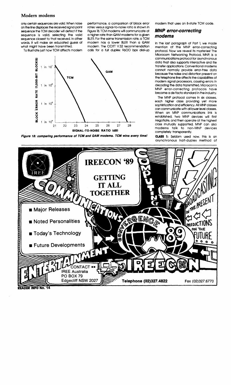
Modern modems
only certain sequences are valid. When noise on the line displaces the received signal point sequence the TCM decoder will detect if the sequence is valid, selecting the valid sequence closest to that received. In other words, it will make an educated guess of what might have been transmitted.
To Illustrate just how TCM affects modem
a; li' 0 g in 10' 1111
I-
ii? g 0 in 10
2
~ w Ice a: a: i 1 in 10
3
a: ,w li' 0 0
performance, a comparison of block error rates versus signal-to-noise ratio is shown in Figure 18. TCM modems will communicate at a higher rate than QAM modems for a given BLER. For the same transmission rate, a TCM modem has a lower BLER than a QAM modem. The CCITT V.32 recommendation calls for a full duplex 9600 bps dial-up
~ 1 in 104 L---+---+--.o-+---+----+---+--.......,r-
21 22 23 24 25 26 27 28
SIGNAL-TO-NOISE RATIO (dB)
Figure 18: comparing performance of TCM and QAM modems. TCM wins every time!
• Major Releases
• Noted Personalities
• Today's Technology
• Future Developments
IREECON '89
GETfING IT ALL
TOGETHER
CONTACT .. IREE Australia
modem that uses an 8-state TCM code.
MNP error-correcting modems In the last paragraph of Part 1, we made mention of the MNP error-correcting protocol. Now we reveal Its mysteries! The Microcom Networking Protocol, MNP, is a communications protocol for asynchronous data that also supports interactive and file transfer applications. Conventional modems cannot normally provide error-free data because the noise and distortion present on the telephone line affects the capabilities of modem signal processors, causing errors in decoding the data transmitted. Microcom's MNP error-correcting protocols have become a de facto standard In the industry.
The MNP protocol comes In six classes, each higher class providing yet more sophistication and efficiency. All MNP classes can communicate with all lower level classes. When an MNP communications link is established, two MNP devices will first negotiate, and then operate at the highest class mutually supported. MNP can also modems talk to non-MNP devices completely transparently.
CLASS 1: Seldom used now, this is an asynchronous half-duplex method of
PO BOX 79 Edgecliff NSW 2027 Telephone (02)327.4822 Fax (02)327.6770

exchanging data In blocks. The protocol efficiency of a Closs l terminal or modem Is about 70%.
CLASS 2: This class odds full-duplex capability to Closs 1. The protocol efficiency Is quoted as around 84%. A device using MNP Closs 2 with a full duplex 2400 bps. Because asynchronous transmission is relatively Inefficient. modems implementing M~P Closs 2 ore not so popular.
CLASS 3: This uses a synchronous bitorlentoted full duplex data pocket format which eliminates the necessity to transmit start and stop bits. The protocol efficiency of a Closs 3 Is approximately 108%. Thus a Closs 3 2400 bps modem con achieve 2600 bps throughout.
CLASS 4: Closs 4 odds both adoptive size pocket assembly and data phase pocket format optimisation to further improve efficiency. During data transfer. the reliability of the transmission is monitored. If the data channel is relatively error-free, MNP Increases the size of the data field in each pocket to increase the throughput. If the line shows degradation. MNP shifts to smaller transmit data pockets.
The result of smaller data pockets Is that more data Is successfully transmitted on the first try. MNP Closs 4 protocol also recognises that during data transfer. much of the
------··----- ----·------"'~--------------
overhead (framing bytes) in the data pocket never change. Doto phase format optimisation eliminates this redundant information.
The protocol efficiency of a Closs 4 unit is about 120%. Thus on MNP Closs 4 2400 bps modem con achieve a throughput around 2900 bps. Competing techniques such as selective ARQ where only the block received In error is retransmitted rather than all blocks since the error may prevail. may be equally efficient.
Class !5: Closs 5 odds data compression to C[oss 4. This uses a real-time adoptive algorithm to compress data. The real-time minimum delay of the Closs 5 algorithm allows data compression of Interactive terminal data as well as file transfer data.
This means data compression is always optimised for the user's data. The compression algorithm continuously analyses the user data and adjusts the compression parameters to maximise data throughput. Typical compression performance varies between l.3 to l and 2 to l (some files may be compressed at even higher ratios). A realistic estimate of overall compression factor Is l.6 to l or 63%. equivalent to a net efficiency of 200%.
MNP Closs 5 with a 2400 bps modem will raise throughput to 4800 bps. The computer
Dual Trace
or terminal Interface needs to operate at 9600 baud or at least 4800 baud to toke full advantage of this technique. Other proprietary data compression techniques ore used by various manufacturers. CLASS 8: This odds universal link negotiation (ULN) and statistical duplexing to Closs 5. Many Bell 212 and V.22bls modems ore designed to automatically adopt to coils from lower speed modems. However, _high speed V.27. V.29 and V.32 modems ore not compatible with each other or with the lower speed modulation techniqu.,s found in 212A and V.22bis modems. ULN In Closs 6 makes it possible for a single modem to operate at the full range of signalling speeds between 50 and 9600 bps.
A Closs 6 modem based on V.29 technology delivers maximum performance in file transfer applications; up to 19.200 bps throughput is possible on dial-up lines.
The data compression algorithm of Closs 5 ls fully incorporated in MNP Closs 6. Screen updates will toke less than a second. depending on the error rote of the channel and the compressibility of the data. -eti
We gratefully acknowledge the assistance of the following companies in providing material used to compile this two-part feature: Energy Control. Netcomm. R&D Electronics and VS/.
Oscilloscope FEATURING:- • Component Tester •Wide bandwidth and high sensitivity • Very low power consumption • High sensitivity XV mode • Z axis (intensity modulation) • Front panel electrical trace Rotator • Regulated power supply circuit for Accuracy.
Universi/Y Piiliili INSTRUMENTS
FOR ACCESS TO THE BEST
106 Belmore Rd., Nth. Riverwood, N.S.W. Telex: AA 121398. Fax_: (02) 534 4002. Ph.: (02) 53 0644 • Victoria: (03) 370 5994 • Qld: (07) 52 9611 • S.A.: (08) 212 6235 • W.A.: (09) 244 2777 ((09) 381 6422 • Tas.: (002) 34 2811 (002) 34 5978 • A.C.T.:
(062) 80 6576 • Hunter: (049) 69 5177 (049) 69 3122 • lllawarra Dist: (042) 71 3844 • NL (09) 46 3048 (09) 59 4481
47 READER INFO NO. 15

GETTING IN TOUCH A 24-line input/output carcl for your PC . With this low-cost, simple-to-build project, you can put your PC "in toqch with the real world." With 24 lines, all individually programmable as inputs or outputs, you can operate relays, lights or other electronic devices, detect the status of switches or "read" digital or analogue voltages (with additional electronics). Applications are only limited by your imagination! Graham Dicker writes.
fJ dd-on projects for computers are very popular with enthusiasts. This project. for owners of the ubiquitous
PC/compatible (XT or AT) Is a versatile Input/output (1/0) card providing 24 Individually programmable lines. The project has been designed to plug in to a standard 64-pln (XT-type) slot present on the motherboard of both XT and AT type PCs. This provides access to the computer's address and data busses, input I output read and write lines, reset. 5 V supply and ground.
A double-sided printed circuit board is required because of the slot arrangement and I designed a plated-through hole board to keep board area to a minimum (and thus save space requirements in the computer), to simplify construction and save on cost. A 26-pin IDC unprotected header provides connection off-board for the 24 output lines, the two extra pins providing access to the computer's + 5V supply and ground (0 V).
The card can be controlled quite simply using INP and OUT statements from BASIC; no special software is required. There are only five components on the board, three ICs, a capacitor and the IDC header, so It can be readily built by relative beginners.
Design details The project is based on the 8255A Programmable Peripheral Interface (PPI) IC. made by Intel. NEC and other chip
ELECTRONICS ETl-1623
manufacturers. The accompanying abbreviated data sheet gives a comprehensive rundown on Its features and functions. Its 241/0 lines are completely TTL compatible so It Is easily Interfaced directly with other logic circuitry, including CMOS. Suggested other Interfacing techniques are discussed at the end of the article.
8255A
ETI JUNE '89 48
30
29
28
25
24
23
22
21
PA4
PAS
PA6
PA7
WR
RESET
DO
04
05
06
The circuit features a full 1/0 address decoder. employing two 74LS138 l-of-8 decoders (ICs land 2). The projects address Is nominally set at $279, the games port address In 8088, 80286 and 80386 based PCs. This address can be set anywhere In the range of $201 to $280 in increments of $04 by cutting tracks on the pc board. marked J3 and J9. and then. by linking the appropriate address decoder pins Jl-Jl6. as required.
The 8255 PPI (IC3) has four addressable ports. as follows:
1) port A: data register at address $00 2) port B: dot.a register at address $01 3) port C: data register at address $02 4) the control register. at address $03. While a thorough read of the
accompanying data sheet fully describes the functions and operational details of the 8255, I've summarised the details pertinent to this project.
Operating Modes: The 8255 features three basic operating modes:
AO 16 Vee
A1 2 15 '00
A2 3 14 m
n 4 74LS138 13 "Q2
'E2 5 12 '03
E3 6 11 'Q+·
'Q7 7 10 ~
GND 8 9 'OS
PINOUTS FOR THE 8255 AND 74LS138
PIN NAMES D7-DO DATA BUS (bl-directional) AO, A 1 PORT ADDRESS
. PA7-PAO PORT A PB7-PBO PORT B PC7-PCO PORT C CS CHIP SELECT (active low) RD READ INPUT (active low) WR WRITE INPUT (active low) RESET RESETINPUT Vee +5 VOLTS GND ZERO VOL TS

1-------------------~--------t I 1 3 OUTPUTS 1 I I ETl-1623 i:; • · .,, ' ? Jn~&,r .:>J I I COMPONENT SIDE ~~no .. :'" . ·:,··
0:" ,· ';'1 I
tC1 ICZ I
·o.: ... ~ ... ~:~. i.,:0 .. ~.} .. ~!~il'·.···; ."; I •. : . . J~ "' ··. .. J13l . ''" •'J4 .... •. J1~t.
·' ,. J3 . ii : • J1 ii • 'J2, :.; J1ctl
'•J1 •. :·:" ···:.ig ~· • . ' 1 >,. ' ·,' '.f (
·.·~ o/ £ ~ M u
T----------------------------r
Component overlay for the project. Note the orientation of the /Cs. We have not reproduced the pc board artwork here as it is Impracticable to make a plated-through hole board with the facl/ltles generally available to the enthusiast. The author has also retained copyright on the pc board artwork, but has made arrangements to have ready-made pc boards available at low cost. Contact Graham Dicker at PC Computers, 36 Regent St, Kensington S.A. 5068, phone (OB) 332 6513. Boards may be purchased singly or In small quantities; wholesale prices are available for larger quantities.
MODE 0. This is the basic l/O mode where each group of 12 l/O lines may be programmed to be used in subgroups of four lines as inputs or outputs. MODE 1. The "handshake" mode. Here the 24 I!O lines are divided up into two groups of 12 lines with eight lines (A-B) used for bi-directional I!O and port C as the handshake and interrupt control lines.
In Mode 1 the data word can be latched in full into the input port by an external latch strobe to be later read by software. MODE 2. The bus mode. In this mode, port A emulates a bi-directional processor bus port, controlled by five 110 lines.
In Mode 2, the l/O channel or port A can be used as an extension of the CPU data bus under program control via the control lines of port C.
Each of the 8255's three ports have individual characteristics, permitting wide flexibility: PORT A has an output and input latch/buffer and as such can be configured by the control register to operate in any of the three different modes. PORT B has an l/O latch/buffer and an input buffer and operates in similar fashion to port A with the exception that, while port A is in Mode 3, port B can only be used in Modes 0 or 1. l:'lo mode 3 operation is available for this port. PORT C comprises an output latch/buffer and an input buffer and can be logically split into two 4-bit registers as control ports for Ports A and B.
Software interfacing As the 1/0 card is located within the normal 1/0 bus range of addresses, programming languages do not normally require a machine code interface or driver as each of
the ports is readily available with standard OUT and INP statement usage and, In the case of interpretive BASIC, use of these statements can also be made in direct
ETI JUNE '89 49
Parts list - ETl-1623 SEMICONDUCTORS ICl. IC2 ..................................................................... 7 4LS138 IC3 .................................................................................. 8255A CAPACITORS Cl ............................................................... lOOn ceramic MISCELLANEOUS ETl-1623 pc board (see text); 1 x 40-pin IC socket; 2 x 16-pin IC sockets (optional); 26-way IDC unprotected header; 26-way IDC plug; length of 26-way ribbon cable to suit. Approx. Cost: $28-$33.
(command) mode to effect control and debugging of Interfaces. A test program, which Illustrates the simplicity of the techniques, Is reproduced here.
~ i:r:c:;~~lar.gort (1) port debug 121 toggle all ports (3)"••
3 IF A=3 'IHEN 200 5 ClS:WCATE 1,1 10 FOR A=632 'IO 638 20 PRINI' INP(A); 30 NEXI' A 40 CDl'O 5 100 INPtrr "port,data" ;A,B 110 Ol1l' A,B 120 CD'IO 100 199 REM p:>rt toggle test 200 our 635 ,12s 210 our 634,o:our 633,0:our 632,0 220 FCR A=l 10 500 :NEXI' A 230 our 634,255:our 633,25S:our 632,255 240 FCR A=l 'ID 500 :NEXI' A 250 00'10 210
My advice on programming, if you're Inexperienced yourself. Is to make friends with a fellow enthusiast who has the sklllsl Your local computer club is a good place to start. Contributions on programming the project are welcomed by the Electronics Editor!
Building it Assembling the project Is a straightforward operation. It's always good practice to first give your pc board a thorough look over, ensuring there are no small "bridges" between closely-spaced pads or where tracks pass between IC pin pads. The pc board was designed using SmartWork. a computer program written specially for pc board design. and artwork produced with a precision plotter, which gives much more accurate results than laying a board like this by hand. While professionally produced, ready-made boards have been made available for this project. it is always wise to check even though blemishes are rare.
Sockets may be used for the three ICs If ¥OU so wish, but a socket at least for the 8255 is recommended. As the pc board Is doublesided, first determine the side on which the components are to be mounted. Then solder the IC socket or sockets, In place taking care to get the right orientation, then the capacitor and 26-pin header. The capacitor need only have short leads, 2-3mm long.
Note that you only need to solder component leads on the non-component side of the board. If you're soldering the 74LS138s to the board, check that you get them the right way round first. The component overlay diagram shows which

1/0 card TABLE 2. OUTPUT PIN DESIGNATIONS Port A Output Pin Port B
PAO 8 PBO
PAI 10 PB1
PA2 12 PB2
PA3 13 PB3
PA4 6 PB4
PAS 11 PBS
PA6 9 PB6
PA7 7 PB7
+S v 17 ov
way all the ICs go. After completing the assembly. carefully
check your work. See that there are no small solder dogs or whiskers shorting to adjacent tracks or pads. Use a multimeter to check for a possible short circuit between + 5 V and 0 V pins B3 and BlO on the non-component side of the board. If there's a short, you'll have to search for it; it's most likely to be a soldering fault.
If, or when. all's well, you're ready to try it out.
Connections The 26-pin unprotected header provides easy external connection via a 26-way insulation displacement connector (IDC) plug and 26-way ribbon cable. The free end of the ribbon can be terminated in whatever way is appropriate to your application. Alternatively, a 26-way ribbon cable may be
Output Pin Port C Output Pin
16 PCO 21
1S PC1 20
14 PC2 19
PC3 18
2 PC4 22
3 PC4 23
4 PC6 24
s PC7 2S
26
stripped and the ends soldered directly to the pads on the board. This is not as robust, however, as using the IDC header and plug.
For testing purposes, terminate the 26-way cable to pads on a prototype board or to a terminal block.
Try out With your PC turned off, plug the card into a suitable free slot. Power-up and check that you get + 5 Von the Vee pins (with respect to GND or 0 V) of the ICs and between pins 17 and 26 of the output. If not, immediately power down and check that. firstly, the board is seated properly in the slot socket and then for any construction faults.
If the project runs OK, run BASIC and enter the program reproduced here. When the screen displays the line l message, hit the 3 keys and the program will toggle the output lines; a logic probe or oscilloscope hooked
+12 v IN4002:
RL1 ..,---0 N/O
.c::::: ~/C f!L1/1
Figure 1: driving a relay from a port line configured as an output.
to an output line will show it going high, then low, then high, and so on.
Your 1/0 card is ready to work!
Interfacing suggestions The 8255A's TTL-compatible 1/0 lines make interfacing a snack! You can connect directly to TTL circuitry. To drive a relay from a port output line, use the circuit in Figure l. Any suitable relay with a 12 V coil and whatever contact arrangement you want may be
+5 v
INPUT
TO 8255 INPUT
Figure 2: non-inverting opto-coupler circuit for a port line configured as an Input. When the input LED is turned on, the collector of the transistor goes high, taking the port input high.
SLOT PIN SIGNAL SLOT PIN SIGNAL COMPONENT SIDE (SIDE A)
A1 - 81 A2 D7 82 A3 DS 83 A4 D5 B4-B9 A5 D4 810 AS D3 811 A7 D2 812 A8 D1 813 A9 DO 814
A10 - B15-B28 A11 AEN 829
A12-A21 - 830 A22 A9 831 A23 A8 A24 A7 A25 AS A2.S A5 A27 A4 A28 A3 A29 A2 A30 A1 A31 AO
-RESET +5 v -0 v --l/C!R I/OR -+5 v -0 v
EDGE CONNECTOR
A31 831
_J
I
NON-COMPONENT SIDE (SIDE B)
TABLE 3. SLOT PIN DESIGNATIONS
ETI JUNE '89 50
L A1 B1
REAR OF IBM PC CABINET

IEC
2
3
IBM SLOT PINS
AO
A2
A3
A4
AS
A6
A7
AB +5 v
A9
AEN
00
01
02
03
04 . 05
DG
07
v'Oll
l1SW
RESET
•SV~ av~
+5 v -. +5 v
INPUT
74LS138 LOGIC SYMBOL
: ~ G¥
TO 8255 INPUT
2 Al
3 A2
1 AO
2 Al
3 A2
DX
+5 v
1S
Vee QO
Ql
Q2
Q3
04
QS
QS
GND 07
B
-. +5 v
1S
Vee QO
Q1
Q2
Q3
04
05
Q6
GNO 07
-.
0
2
3
4
5
7
JB
J7
JS
JS
J4
J3
J3
J2
J1
J16
J15
J14
J13
J12
J11
J10
J9
OATA BUS
+5 v
Cl
I
* 2S 100n
Vee 9 AO PB3 21
Al PB4 22
PBS 23
PBS 24 'CS
PB7 25
PA4 40
IC3 PA7 37
8255 PAO 4
IC1 74LS138 PA6 38
PA1 3
I PAS 39
PA2 2
PA3 1
PB2 20 JUMPER TO SELECT ADDRESS PB1 19
) PBO 18
34 DO
33 D1 PC3 17
D2 PC2 16
03 PC1 15
IC2 74LS13B PCO 14
04 PC4 13
05 PCS 12
06 PCS 11
07 PC7 10
'RD WR GNO RESET
5 3S 35
-.
Figure 3: Inverting opto-coupler for a port line configured as an input. When the input LED Is off, the collector resistor of the BC547 pulls the 8255 Input high; when the input LED Is on, the BC547 Is driven on and the collector voltage drops, pulling the 8255 input low. There's not much to the project, but Its slmpllclty belles Its versatlllty.
ETI JUNE '89 51
ETl-1623.
OUTPUTS
3
10
11
12
13
14
1S
1S
17 +5 v
1B
19
20
21
22
23
24
25
.r26 0 v
+s v

PC2
1/0 ,card PC3
PBO
PB1
PB2
PB3
PB4
PB5
PB6
PB7
PCO
PC1
PNJ
PA1
P"2
P"3
PM
P"5
P"6
PA7
PC4
PC5
PC6
PC7
19
18
16
15
14
2
3
" 5
i OUTPUT
CONNECTOR
21
20 =
8
10 -12
13
6
11 -9
7
22
23
24
25
5.'IMPLE ENABLE -STROBE
LSB
8-BIT A-D
CONVERTER -
-MSB
STROBE CATA
OUTPUT ENABLE
LSB
12-BIT D-A
CONVERTER
MSB
' ANALOGUE INPUT
ANALOGUE OUTPUT
The project occupies very little spece Inside a PC, here shown Installed In an XT clone. Figure 4: suggested Interfacing for an B-blt ADC and a 12-blt DAC.
used. Any suitable, small NPN general purpose transistor with a current gain of 10 or better may be used In lieu of the BC547; such as the 2N2222, PNlOO. 2N3641/2/3, BC639 etc.
Inputs may be connecteq directly to switches or relay contact which switch the port line from 0 V to + 5 V. Relays provide good electrical Isolation, but opto-couplers are cheaper and feature a lesser power requirement. Figures 2 and 3 show how. Figure 2 shows a non-Inverting opto-coupled Input. Figure 3 an Inverting Input. The 4N35 specified provides 3500 volt Isolation. A 4N28 may be used, but has a lesser Isolation of 500 volts. The Input LED of the optocoupler may be driven from any suitable circuitry, which might be a current loop or logic device output. for example. The 5 V supply for the transistor driving the port Input line may be derived from the project (pins 17 and 26 of the output connector).
Figure 4 shows a suggested configuration for Interfacing the project to an 8-bit analogue-to-digital converter (ADC) input on Port B and a 12-blt digital-to-analogue converter output using Port A and part of Port C. An 8-blt DAC could be Interfaced In a similar manner, lines PC4 to PC7 not being needed.
Go to ltl eti
Topside view of the board. This prototype had one track In the wrong place, which was corrected In later prototypes. The printed circuit board Is a double-sided design with through-hole plating. The edge connector was gold-flashed and the tracks solder-tinned. A socket for the 8255 Is recommended.
ETI JUNE '89 52

ABBREVIATED DATA SHEET 8255A/8255A·5
Programmable Peripheral Interface hatures: • 24 Programmable 1/0 Pins • Completely TTL Compatible • Fully Compatible with Intel
Microprocessor Families • Direct Bit Set /Reset Capability Easing
Control Application Interface
The Intel 8255A is a general purpose programmable 1/0 device. It has 24 1/0
pins which may be individually programmed in 2 groups of 12 and used in 3 major modes of operation. In the first mode (MODE 0), each group of 23 1/0 pins may be programmed in sets of 4 to be input or output. In MODE l. the second mode, each group may be programmed to have 8 lines of input or output. Of the remaining 4 pins, 3 are used for handshaking and interrupt control signals. The third mode of operation (MODE 2) is a bidirectional bus mode which uses 8 lines for a bidirectional bus, and 5 lines, borrowing one from the other group, for handshaking.
Of necessity, the information presented here has been abbreviated. We are grateful to Intel for permission to reproduce the data presented here. Complete data on the 8255 is published in Intel's "Microcomputer Components Handbook, Microprocessors and Peripherals. Volume II".
POWER SUPPLIES l
-+5Y
----+- GNO
im----OI
Wl!----.l'JI
., ____ .., AO----"'
RESE.T
DATA BUS
BUFFER
READ/ WRITE
COf.ITROl LOGIC
Functional description General The 8255A is a general purpose 1/0 component to interface peripheral equipment to the microcomputer system bus. The functional configuration of the 8255A is programmed by the system software so that normally no external logic is necessary to interface peripheral devices or structures.
Data bus buffer This 3-state bidirectional 8-bit buffer is used to interface the 8255A to the system data bus. Data is transmitted or received by the buffer upon execution of Input or output instructions by the CPU. Control words and status information are also transferred through the data bus buffer.
Read/write and control logic The function of this block is to manage all of the internal and external transfers of both data and control or status words. It accepts inputs from the CPU address and control busses and in turn. issues commands to both of the control groups.
(CS)Chlp seled A "low" on this input pin enables the communication between the 8255A and the CPU.
(RD) Read A "low" on this input pin enables the 8255A to send the data or status information to the CPU on the data bus. in essence. It allows the
1/0 PA7-PAO
1/0 PC7-PC4
1/0 PCJ-PCO
1/0 PB7-PBO
Figure 1: 8255A block diagram showing Group A and Group B control functions.
The MAESTRO 2400XR Here's a fully-featured, Hayes compatible 1200 & 2400 bps full duplex modem for just
$369 (incl. tax). This modem uses the LA TEST in DSP chip Set Technology and microprocessor control, bringing you the future Today.
-------~-~
Moestro-2400--XR-
""" - ~ ... u.. - a;. --- ~.t;-"'"" , - . . . . . . Super price on a super V.22/V.22 bis Modem!
ETI JUNE '89 53
ETl-1623
CPU to "read from" the 8255A
(WR) Write A "low" on this input pin enables the CPU to write data or control words into the 8255A
(Ao and A 1) Port Select 0 and Port Select I • These input signals. in conjunction with the RD and WR Inputs, control the selection of one of the three ports or the control word registers. They are normally connected to the least significant bits of the address bus (A0 and A1).
8255A BASIC OPERATION
A1 A11 RD WR cs INPUT OPERATION !READ) 0 0 0 l 0 PORT A ~ DATA BUS 0 1 0 1 0 PORT B ~ DATA BUS 1 0 0 1 0 PORT C ~ DATA BUS
OUTPUT OPERATION (WRITE)
0 0 1 0 0 DATA BUS ~PORT A 0 1 1 0 0 DATA BUS ~PORT B 1 0 1 0 0 DATA BUS ~PORT C 1 1 1 0 0 DAT A BUS ~CONTROL
DISABLE FUNCTION x x x x 1 DATA BUS~ 3-STATE 1 1 0 1 0 ILLEGAL CONDITION x x 1 1 0 DATA BUS~ 3-STATE
(RESET) ReHt A "high" on this input clears the control register and ail ports (A. B. C) are set to the input mode.
Group A and Group B cantrols The functional configuration of each port Is programmed by the systems software. In essence. the CPU "outputs" a control word to the 8255A The control word contains information such as "mode", "bit set", "bit rest", etc.. that Initialises the functional configuration of the 8255A
Each of the Control blocks (Group A and Group B) accepts "commands" from the Read/Write Control Logic, receives "control words" from the internal data bus and issues the proper commands to its associated ports.
Control Group A - Port A and Port C upper (C7-C4)
Control Group B - Port B and Port C lower (C3-CO)
The Control Word Register can only be written into. No Read operation of the Control Word Register is allowed.
Ports A, B, and C The 8255A contains three 8-bit ports (A. B. and C). All can be configured in a wide variety of functional characteristics by the system software but each has its own special features or "personality" to further enhance the power and flexibility of the 8255A
Port A One 8-bit data output latch/buffer and one 8-bit data Input latch.
Port B. One 8-bit data input/output latch/buffer and one 8-blt data input buffer. ·Port C. One 8-bit data output latch/buffer
The MAESTRO 2400 ZXR 4 Speed Version $399 (incl. tax).
Don't Wait! RING NOW (043) 68 2277 or 68 2278
Maestro Distributors Calool St. South Kincumber, NSW 2256
READER INFO N0.16

Belt kits to suit all popular VCRs.
Square section belts for tape recorders. Flat section belts to suit most audio applications including turntables. READER INFO No. 65
Video Heads
For National, Akai, Sharp, Sanyo etc.
We stock over 50 types to suit all popular VCRs.
READER INFO NO. 66
Integrated Circuits
Including AN, BA, HA, LA, LM,MB,STK, TA, TDAand UPC.
Other popular European and Japanese ICs and a wide variety of transistors are also available. READER INFO NO. 67
Wagner Electronics 305 Liverpool Rd Ashfield, NSW 2131 Ph (02) 798 9233 Fax (02) 799 7051 " WAGNER
v•' WJl.J.. TRADE ENQUIRIES WELCOME
MooE1--{~o '11 ! I l 111 A T
~o PB7-PB0 CONTROL CONTROL
OR l/O OR 1/0 PA7·PAo
MODE2 --f B
s~ ·1111 111r Pe, PBo 110 CONTROL
Figure 3: basic mode definitions and bus interlace.
and one 8-bit data input buffer (no latch for input), This port can be divided Into two 4-bit ports under the mode control. Each 4-blt port contains a 4-bit latch and it can be used for the control signal outputs and status signal Inputs in conjunction with ports A and B.
Operational description Mode selection There are three basic modes of operation that can be selected by the system software:
Mode 0 - Basic Input/Output Mode 1 - Strobed Input/Output Mode 2 - Bi-Directional Bus When the reset input goes "high" all ports
will be set to the input mode (Le,, all 24 lines will be in the high Impedance state), After the reset is removed the 8255A can remain in the input- mode with no additional Initialisation required During the execution of the system program any -of the other modes may be selected using a single output inst~uction. This allows a single 8255A to service a' variety of peripheral devices with a simple software maintenance routine.
The modes for Port A and Port B can be separately defined, while Port C is divided into two portions as required by the Port A and Port B definitions. Ali of the output registers, including the status flip-flops, will be reset whenever the mode is changed. Modes may be combined so that their functional definition can be "tailored" to almost any 1/0 structure. For instance; Group B can be programmed In Mode 0 to monitor simple switch closings or display computational
Jsults. Group A could be programmed in Mode 1 to monitor a keyboard or tape reader on an interrupt-driven basis.
The mode definitions and possible mode combinations may seem confusing at first but after a cursory review of the complete device operation a simple, logical 1/0 approach will surface. The design of the 8255A has taken into account things such as efficient PC board layout, control signal definition vs PC layout and complete functional flexibility to support almost any peripheral device with no external logic. Such design represents the maximum use of the available pins.
Single bit set/reset feature Any of the eight bits of Port C can be Set or Reset using a single OUTput Instruction. This feature reduces software requirements in Control-based applications. When Port C is
ETI JUNE '89
54
ETl-1623 CONTROL WORD
I o, l o, °' l 0 • l o,· I 0 • I 0 • I 0• I L_J
I GROUP 8 \ POAT C (LOWER)
'---- 1 •INPUT O•OUTPUT
PORTB ~ 1 •INPUT
0 .. OUTPUT
MOOE SELECTION O•MOOEO 1~MODE1
;· GROUP A
PORT C !UPPER) l"' INPUT 0: OUTPUT
PORTA 1 "INPUT 0 •OUTPUT
MOOE SELECl ION 00 •MOOE 0 01•MOOE1 1X •MODE 2
MODE SET FLAG 1 z ACTIVE
Figure 4: mode definition format.
being used as status/control for Port A or B, these bits can be set or reset by using the Bit Set /Reset operation just as If they were data output ports.
Interrupt colllnll fulldlons When the 8255A Is programmed to operate in Mode 1 or Mode 2, control signals are provided that can be used as Interrupt request Inputs to the CPU. The interrupt request signals, generated from port C, can be Inhibited or enabled by setting or resetting the associated INTE flip-flop, using the bit set /reset function of port C.
This function allows the Programmer to disallow or allow a specific 1/0 device to Interrupt the CPU without affecting any other device In the interrupt structure.
INTE flip-flop definition: (BIT-SET) - INTE Is SET - Interrupt enable (BIT-RESET)- INTE is RESET - Interrupt disable
CONTROL WORD
BfTUT/RIUT 1 •IET O• RESIT
L-----------1 :~:g.:::-T FLAG
Figure 5: bit set/reset format.
Note: All Mask flip-flops are automatically reset during mode selection and device Reset.
Operating modes MODE 0 (Basic Input /Output). This functional configuration provides simple Input and
\

output operations for each of the three ports. No "handshaking" Is required, data Is simply written to or read from a specified port.
Mode O Basic Functional Definitions: • Two 8-bit ports and two 4-blt ports. • Any port can be input or output. • Outputs are latched. • Inputs are not latched. • 16 different Input/Output configurations are
possible in this Mode.
• • OROl.WA GROUP I
PORT A POlllT C . PORT B
PORTC D4 o, D1 Do IUl'HRI (LOWER)
0 0 0 0 OUTPUT OUTPUT 0 OUTPUT OUTPUT
0 0 0 1 OUTPUT OUTPUT 1 OUTPUT INPUT
0 0 1 0 OUTPUT OUTPUT ' INPUT OUTPUT
0 0 1 , OUTPUT OUTPUT 3 INPUT INPUT
0 , 0 0 OUTPUT INPUT • OUTPUT OUTPUT
0 , 0 , OUTPUT INPUT • OUTPUT INPUT
0 , , 0 OUTPUT INPUT • INPUT OUTPUT
0 , 1 , OUTPUT INPUT 7 INPUT INPUT , 0 0 0 INPUT OUTPUT 8 OUTPUT OUTPUT
1 0 0 , JNPUT OUTPUT • OUTPUT INPUT , 0 , 0 INPUT OUTPUT 10 INPUT OUTPUT
1 0 , , INPUT OUTPUT ,, INPUT INPUT , , 0 0 INPUT INPUT " OUTPUT OUTPUT , , 0 , INPUT INPUT " OUTPUT INPUT , , , 0 INPUT INPUT " INPUT OUTPUT , , , , INPUT INPUT " INPUT INPUT
CONTROL WORD #0
0, o1 °' o, D:s D2 01 Do
I I I I I I I · I 0 I A • ''!>"""'
IZSSA
o,-o. c{ ,. •
PC7-PC4
I • ....... CONTROL WORD #1
0, o1 0. 0 4 o1 D2 0 1 0 0
l·l·l·l·l·l·l·l·I •f---+!-- .........
. '211"-• c{ •
I ' ....... CONTROL WORD #2
A • IZSSA
• c { •
• • ... ... CONTROL WORD #3
0, °' °' D, D, D, D, Do
l·l·l·l·l·l·l·l·I ,. .. l' ... Ae A
I
IZSSA
• c{ •
I • ...... Figure 6: MOOE 0 configurations.
CONTROL WORD _. CONTROL WORD #10
o7 o, o. o4 o3 Dz o, o0 D7 D1 o5 D4 o3 Dz D1 D0
l·l·l·l·l ·l·I ·l·I l·l·l·l·l·l·l·l·I A • ......... A •
usu. 1255A
• - c{ , . D7·Do
, . c{ •
• • • 8 .., .. .,, CX>NTROL WOAD #I CONTROL WORD #11
Or 01 Os 0 4 o3 Dz o, 0 0
l·l·l·l·l·l·l·l·I 07 D1 Os 04 0 3 Oz 0 1 00
I I I I I I I· I· I A
,, A
I ......... 1255.l 1255.l ,,
c{ ,, • c{ •
• ,. ... .... I
I
CONTROL WOAD #6 CONTROL WORD #12
0 7 0 11 Os o, D3 b2 o, o0 D7 o, Ds D4 OJ Dz 01 Do
l·l·l·l·l·l·I· l·I I· ID, .• I· I· I 0 I 0 I 0 I A
8 A • . ........
IZSSA 825SA
• 4
c{ 4 '-
c{ •
B 8
8 8 ..... .,,
a:JNTAOL WORD #7 CONTROL WORD •13
0, 0. 0. D, D, D2 D1 D0 o7 0 6 Os o4 DJ Dz o1 o0
I · I • I D I 0 I , I 0 I · I , I I I I I I I I I I A
8 .. • . ........ ~ 825SA
4
c{ • ' c{ ,.
PCJ-PCO
8 8
I I
CONTROL WOAD #I CONTROL WORD •14
0 7 o1 o5 0 4 o3 D2 o, o0 D7 011 05 o,. OJ Dz o, Do
l•l•l•l•f•l•l•l 0 I I , I D I 0 I · I , I 0 I , I 0 I A • PA7·P°'o
8 A
1255.l 12SSA
• 4
c{ •
c{ 4
• • .., . .,, • B
CONTROL WOAD #I CONTROL WORD #15
0., D, °' D, D, D, o, Do o, o, o, D, o, D, o, D,
I , I 0 I D I , I 0 I D I • I · I I · I • I • I · I · I • I · I· I A
8 A
8
1255A 82SS'\,
• 4
c{ I 4
c{ 4
....... B 8 • 8

1/0 card
MODf 1 !PORT Al
CONTROL WORD
01 D1 0s 0 4 0 3 0 2 0 1 0 0
I • I 0 I• I • l""IXlXIXl L~·.~PUT
0• OUTPUT
•• MODE 1 (fl'ORT 8)
CONTROL WORD
1 ~,Mo,1 1 ~,M
Figure 7: MODE 1 Input.
MOOE 1 lPORT A)
MOOE 1 !PORT 8)
Figure 8: MODE 1 output.
MODE 1 (Strobed input /Output). This functional configuration provides a means for transferring 1/0 data to or from a specified port in conjunction with strobes or "handshaking" signals. In mode 1, Port A and Port B use the lines on Port C to generate or accept these "handshaking" signals. Mode l Basic Functional Definitions: • Two groups (Group A and Group B) • Each group contains one 8-bit data port
and one 4-bit control/data port. • The.8-bit data port can be either Input or
output. Both inputs and outputs are latched. • The 4-bit port is used for control and status
of the 8-bit data port.
Input Control Signal Definition STB (Strobe Input)
A "low" on this input loads data into the input latch.
IBF (Input Buffer Full F/F) A "high" on this output Indicates that the
data has been loaded into the input latch; in' essence. an acknowledgement. IBF is set by STB input being low and is reset by the rising edge of the RD input.
INTI (Interrupt Request) A "high" on this output can be used to
interrupt the CPU when an input device is requesting service. INTR is set when STB is a
"one", IBF is a "one" and INTE is a "one". It is reset by the failing edge of RD. This procedure allows an Input device to request service from the CPU by simply strobing its data into the port.
INTE A Controlled by bit set/reset of PC4. JNTE B Controlled by bit set/reset of PC2 .
Output Control Signal Definition OBF (Output Buffer Full F/F)
The OBF output will go "low" to indicate that the CPU has written data out to the specified port. The OBF F/F will be set by the rising.edge of the WR input and reset by ACK Input being low.
ACK (Acknawlotlgo Input) A "low" on this input informs the 8255A that
the data from port A . or port B has been accepted. In essence. a response from the peripheral device indicating that it has received the dcita output by the CPU.
INTI (Interrupt Request) A "high" on this output can be used to
interrupt the CPU when an output device has accepted data transmitted by the CPU. INTR · is set when ACK is a "one". OBF Is a "one", and INTE is a "one". It is reset by the falling edge of WR.
INTE A Controlled by bit set/reset of PC6. INTE B Controlled by bit set/reset of PC2.
Camblnatlans af MODE I Port A and Port B can be individually
defined as input or output in Mode 1 to support a wide variety of strobed 1/0 applications.
MODE 2 (Strobed Bldlrodlonal Bus 1/0) This functional configuration provides a
means for communicating with a peripheral
CONTROL WORD
CONTROL WORD
~ 18F..,
INTRA
2
PCe 1 --f- 110
PORT A~ (STROBED INPUT) PORT B - !STROBED OUTPUT!
PC1 --Aa..,
PC, - INTR"
PC.,
P'B,PBo ~8=";
iW- PC, -- sre,
"• - 18F1
PCo INTR 8
PORT A /STROBED OUTPUT) PORT B !STROBED INPUT)
Figure 9: combinations of MODE 1.
CONTROLWOR,D
,,, 0,
ETl-1623
"'•• 1 •INl"UT O•OUTPUT
PORTS 1 •INPUT O• OUTPUT
~--- GROl.PIMOOf O• MOOE 0
Figure 10: MODE control word. 1•MODE1
..,. __ ""-- PC>< 110
Figure 11: MODE 2.
device or structure on a single 8-blt bus for both transmitting and receiving data (bidirectional bus 1/0). "Handshaking" signals are provided to maintain proper bus flow discipline in a similar manner to MODE 1. Interrupt generation and enable/disable functions are also available.
MOOE 2 Basic Functional Definitions: • Used in Group A only. • One 8-bit, bi-directional bus port (Port A)
and a 5-blt control port (Port C). • Both inputs and outputs are latched. • The 5-bit control port (Port C) is us~d for
control and status for the 8-bit. bidirectional bus port (Port A).
BldlrodlHal Bus 1/0 Co11trol SlgHI hffnltlo11 INTI (lntonupt Request). A high on this output can be used to Interrupt the CPU for both input or output operations.
Output Operations OBF (Output Buffer Full). The OBF output will go "low" to indicate that the CPU has written data out to port A
ACK (Acknowledge). • A "low" on this input enables the tri-state output buffer of port A to send out the data. Otherwise, the output buffer will be In the high impedance state.
INTI I (Tho INTI Fllp-Flop Associated with OBF). Controlled by bit set/reset of PC6.
Input Operations STB (Strobe l11put). A "low" on this input loads data into the input latch.
IBF (Input Buffer Full F/F). A "high" on this output Indicates that data has been loaded into the input latch.
INTI 2 (Tho INTI Alp-Flop Auodatod with IBF). Controlled by bit set/reset of PC4
Spoclal moclo combhtatlon considerations There are several combinations of modes when not all of the bits In Port C are used for control or status. The remaining bits can be used as follows: '

If Programmed as Inputs -All Input lines can be accessed during a normal Port C read. If Programmed as Outputs -Bits In C upper (PCrPC4) must be Individually accessed during the bit set /reset function. Bits In C lower (PC3-PC0 ) can be accessed using the bit set /reset function or accessed as a threesome by writing Into Port c. __ __,
... .. , ,., ... ... ... ... ... ... .. , ... ... ... ... ... .., ... ''" ... ... ... ... ... ..,
-· -· -· our our _.,.AOMLY OUT OUT our our OUT OUT -our OUT -OUT OUT OUT OUT -OUT OUT ---OUT OUT
OUT OUT
OUT OUT OUT OUT
our OUT
OUT
OUT }-· our ...... , .... OUT ..... ..... OUT .... ... ,,. OUT ""' a. ,, . OUT ..... ..... . .... OUT .... ,,. .... OUT ... .,. . ... OUT ,,. m. a • OUT ,,. •• ....
.._ atn .. t .,.WRty H Pert I 111111 Pert C Any set of eight output buffers, selected randomly from Ports Band C can source lmA at l.5 volts. This feature allows the 8255 to directly drive Darlington type drivers and high-voltage displays that require such source current.
_..,,. CDfllPKIUllATION
D, 0.' 0. D, 0, ... D, 0.
I .., I .., l·-.1 ..... l-w.j ..... l · ... l"""'I ..UA ...a\.a ----... ... ... ... ... ... Do ...
1-.1-.1 .., I ·~ l·--+ .... 1-.l-w.! .Ua ~.
Flgu,. 12: MODE 1 •flltw word format.
D, 0. 0. 0. 0, ... D, 0.
1-.1 .... 1 ... 1 ..... 1 ..... t><MXJ -· ------· CDIPtNm IY la>l O °" MODI , •ucrou
Figure 13: MODE 2 status word format.
11111111., Pert c Shltu In Mode 0, Port C tronsfers data to or from the peripheral device. When the 8255 Is programmed to function In Modes l or 2, Port C generates or accepts "hand-shaking" signals with the peripheral device. Reading the contents of Port C allows the programmer to test or verify the "status" of each peripheral device and change the program flow accordingly.
There Is no special Instruction to read the status Information from Port C. A normal read operation of Port C Is executed to perform this function. eti
ABSOLUTE MAXIMUM RATINGS•
Ambient Temperature Under Bias ......... 0°C to 70°C Storage Temperature .............. -65°C to +150°C Voltage on Any Pin
With Respect to Ground ............ -0.5V to +7V Power Dissipation ....................... 1 Watt
•NOTICE: StlUlff abQve those listed under "Absolute Maximum Ratln11•" may caun ,,.rmanent damage to th• device. Thia la • •trns ratln11 only and function•/ operation of the device at thne or any other condition• above thon Indicated In the o,,.ratlonel net/one of thl• specif/. cation la not Implied. Expoaura to abaolute maximum ratin11 condition• for Htended periods may effect device rallebl//ty.
D.C. CHARACTERISTICS (TA= O'C to 70'C, Vee= +sv ± 10%, GND - OV) •
Symbol Par•-* Min. Max. Unit Teet Condlllon•
V1L Input Low Voltage -0.5 0.8 v VoH Input High Voltage 2.0 Vee v Vol (DBI Output Low Voltage (Dita Bus) 0.45. v loL • 2.5mA
VoL!PERI Output Low Voltage (Peripheral Portl 0.45• v loL • 1.7mA
VoH(DBI Output High Voltage (Dita Busl 2.4 v loH = -40<ljtA
VoHIPERI Output High Voltage (Peripheral Port I 2.4 v loH • -200jtA
IOARlfl Darlington Drive Current -1.0 -4.0 mA RexT = 750fl; VeXT" 1.5V
Ice Power Supply Current 120 mA
l1L In put Load Current ±10 µA VoN •Vee to ov lo FL Output Float Leakage ±10 µA VouT •Vee to .45V
NOTI: t. Available on any 8 pl no from Port B 1nd C.
CAPACITANCE (TA = 2s·c. Vee = GND = OV)
S,.mllol. P.,am•ter Min. Typ. Max. Unit ..... ~ C1N Input Capacitance 10 pF le= 1MHz
C110 1/0 Capacitance 20 pF Unmeasured pins returned to GND
A.C. CHARACTERISTICS (TA= O'Cto 70'C, Vee= +sv ±10%, GND = OV) •
Bu• P•r1matel'I
READ
8255A 8266A-6
Symbol Par•m- Min. Max. Min. Max.
IAR Address Stable Before READ 0 0
IRA Address Stable After READ 0 0
IRR READ Pulse Width 300 300
IRO Data Valid From REAOl11 250 200
toF Dita Float After READ 10 150 10 100
IRV Time Between READs and/or WRITEs 850 B50
WlllTE
8256A 8255A·5
Symbol Paraln ... r Min. M•x. Min. M•x.
IAW Address Stable Before WRITE 0 0
twA Address Stable After WRITE 20 20
tww WRITE Pulse Width 400 300
tow Data Valid to WRITE (T.E.I 100 100
two Data Valid After WRITE 30 30
OTHER TIMINGS
8255A 8255A·5
Symbol P•r•meter Min. M•x. Min. Mex.
twe WR= 1 to Outputl11 350 350
l1R Peripheral Data Before RO 0 0
IHR Peripheral Data After RD 0 0
IAK ACK Pulse Width 300 300
tsT STB Pulse Width 500 500
IPS Per. Data Before T.E. of STB 0 0
tpH Per. Data After T.E. of STB 180 180
IAO ACK = 0 to Output I 11 300 JOO
IKO ACK= 1 to Output Float 20 250 20 250
twee WR = 1 to OBF = 011 I 650 650
tAOB ACK= OtoOBF = 1111 350 350
ts1e STB = 0 to IBF = 111 I 300 300
tRIB RO= 1 to IBF =CJl'I 300 300
tRIT RO' 0 to INTR = ()111 400 400
,, ts1T STB = 1 to INTR = 1111 300 300
tAIT ACK= 1 to INTR = 1111 350 350
tw1T WR= 0 to INTR = oP.31 450 450
NOTIS: 1. Test Conditions: Ct. = 150 pf. 2. Period of Anet pulse muat be at lent 50µ.a during or after power on. Subsequent Raaet pulae can be 500 nl min. 3. INTRf may occur as early u WFU. • For Extended Temperature EXPRESS, use M8255A electrical parameters.
Unit
ns
ns
ns
ns
ns
ns
Unit
ns
ns
ns
ns
ns
Unit
ns
ns
ns
ns
ns
ns
ns
ns
ns
ns
ns
ns
ns
'" ns
ns
ns

On Heard Island, Antarctica, the
Australian Antarctic Division lost one of their
IC-M12 portable two-way radios.
Then, with the onset of winter, the
base had to be abandoned. And so was all
hope of finding the radio.
But the following year, it was found.
And though it had seen 12 months of exposure
to rain, snow, sleet and seaspray, the scientist
who found it decided to put in a fresh battery
and see what happened.
Amazingly, it worked like new. And so
did another unfortunate IC-M12 that a member
of the Division dropped from a tower to the
ground 70 feet below.
In fact, it was experiences like those
that led to the replacement of more expensive
'military standard' radios with the more reliable
ICOM range.
So Australian Antarctic bases and
exploration parties use IC-M700 HF transceivers
to communicate to and from remote destinations
up to 1,000 kilometres inland.
Helicopters as well as search and rescue
boats use IC-M80s, often via a pilot's headset.
And ground parties and other personnel
carry the IC-M12s because they combine
practical, easy to use functions with proven
toughness and reliability.
Of course, ICOM's wide range of
radio equipment is designed for thousands of
commercial and marine applications.
And if they can survive the Antarctic,
they can handle what you have in mind.
Because at ICOM, we know we can't
design our radios specifically for each and
every potential use. That's why we build them
to take anything.
For more information call ICOM today
on Melbourne (03) 529 7582. Or you can call toll
free on (008) 338 915 from
anywhere else within Australia.
0 ICOM
READER INFO No. 24

• Mlcropower Supply Current (160µ.A) - Ideal for battery appllcatlons • Adjustable Reset Vo.ltage - down to 3.0V for CMOS µP's
• 200ms Reset Pulse - for Motorola µP compatlblllty
Power-On/Low Line Reset
Maxim's supervisory ICs each have a precise factory trimmed or user
adjustable threshold detector and timer that generates an accurate, reliable
Reset signal for any power-on, brownout or low battery condition.
Power-Fall Detection An uncommitted 1.3V threshold
comparator is built into each device for use as a power fail indicator or for
monitoring the back-up battery voltage.
-GND
II() • NMI p.
RESET
watchdog Timer A watchdog circuit built into every MAX690-697 constantly monitors all µP activity. It detects both hardware and software malfunctions and automatically issues a Reset command to the µP -effectively eliminating 'lock up' conditions.
Memory Protect - Chip Enable Gating MAX690-697s prevent µPs from writing erroneous data into RAM during powerup, power-down, brown-outs, and momentary power interruptions.
Automatic Battery Switchover The MAX690-696 monitor incoming power and automatically switch to battery back-up
when the power supply drops below the battery voltage. Quiescent current drops to less than 1 µA and ensures that the data in CMOS RAM or EE PROM remains intact until power is restored .
Reset lsupli'' Reset Batttrr ...=, LowUne Part# Pins (Votts) (m ) (ms) Swltcltov• In out
MAX690 8 4.o5 4 50 Yes No No No MAX691 16 4.65 4 50* Yes Yes No Yes MAX692 8 4.40 4 50 Yes No No No MAX693 16 4.40 4 50* Yes Yes No Yes MAX694 8 4.65 4 200 Yes No No No MAX695 16 4.65 4 200* Yes Yes No Yes MAX696 16 Adj 4 50* Yes No Yes Yes MAX697 16 Adj 160µA 50* No Yes Yes Yes ·internally preset value, also adjustable
The MAX690-MAX697 are available in DIP or SO packages and - like every other Maxim part - each is tested to rigorous reliability standards absolutely free. They offer you a price-performance value unmatched in the marketplace.
lie! ... ~., ----- ------- ----- --- ---HEAD OFFICE
22 HARKER STREET, BURWOOD, VIC, 3125
PHONE: (03). 808-7511/808-5473 FAX: (03) 288-5473
/N.S.W. OFFICE SUITE 4, 5 KING STREET, ROCKDALE, N.S. W. 2216
PHONE: (02) 599-1900 FAX: (02) 597-7826
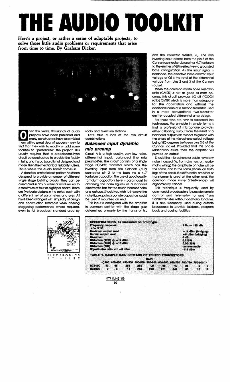
THE AUDIO mOLKIT Here's a project, or rather a series of adaptable projects, to solve those little audio problems or requirements that arise from time to time. By Graham Dicker.
m ver the years, thousands of audio projects have been published and many constructors have assembled
them with a great deal of success - only to find that they wish to modify or add some facilities to "personalise" the project. This usually requires that a breadboard-type circuit be constructed to provide the facility missing and If a pc board Is not designed and made, then the mechanical reliability suffers. This Is where the Audio Toolkit comes In.
A standard printed circuit pattern has been designed to provide a number of different single stage building blocks. They can be assembled In any number of modules up to a maximum of four or eight per board. There are five basic designs in the series, each with a different set of parameters and uses. All have been arranged with simplicity of design and construction foremost while offering staggering performance where required. even to full broadcast standard used by
ELECTRONICS ETl-1432
radio and television stations. Let's take a look at the five circuit
combinations.
Balanced input dynamic mic preamp Circuit A is a high quality, very low noise, differential input, balanced line mic preamplifier. The circuit consists of a single stage BC549C transistor which has the inverting Input from the Cannon (XLR) connector pin 2 to the base via a 4u7 tantalum capacitor. The use of good quality tantalum capacitors here is paramount to obtaining the noise figures as a standard electrolytic has far too much inherent noise and leakage. Should you wish to Improve the noise figure, polycarbonate capacitors could be used If mounted on end.
This input is configured with the amplifier in common emitter with the stage gain determined primarily by the transistor hre
and the collector resistor, Re. The non inverting input comes from the pin 3 of the Cannon connector via another 4u7 tantalum to the emitter of Ql In effectively a grounded base configuration. As the input signal is balanced, the effective base-emitter Input voltage of Ql is the total of the differential voltage from pins 2 and 3 of the Cannon socket.
While the common mode noise rejection ratio (CMRR) is not as good as most opamps, this clruclt provides 60 dB (1000:1 ratio) CMRR which Is more than adequate for the application and without the additional noise of a second transistor used in a more conventional two-transistor emitter-coupled differential amp design.
For those who are new to balanced line techniques, the principle In simple terms is that a professional microphone provides either a floating output from the insert or a balanced output with respect to ground with the phase of the microphone output voltage being 180 degrees between pins 2-3 of the Cannon socket. Provided that this phase relationship exists, then the amplifier will provide an output.
Should the microphone or cable have any noise Induced (le, from dimmers or nearby mains wiring) the amplitude of noise will be the same, and in the same. phase, on both legs of the cable. If a differential amplifier or transformer Is used at the other end, the common mode noise (interference) will algebraically cancel.
This technique is frequently used by commercial broadcasters to provide remote control and telemetry to and from transmitter sites without additional landlines. it Is also frequently used during outside broadcasts to provide talkback, program back and cueing facilities.
SNCIPJCATtONS, ~ MQWNd Olf...-~P.. ·~~~. · · 1Hl-121kHz
llfaxfmUm OUtpUt llY91 + ,. dBm (bl'ldal"fl) Normat OUtpUt kMl1 +8 dBm. {Drfd(lf"fl} Httaclrooril . . . . . I d8 Dlstonlol'l .CfflPJ .- +1it Cf8l'A o.ots% Dlltorllott ('fflP) 0 "'HJ dBm . 0,8012$% DlttortJon (TIM) Wllll .. rabf41 Sflntl/no!M ratto wrt +Ulm ·t't8 d8m
TAB'-' f,,$AMPLE GAIN SPREAOS OP T,UTS :ntAIGfSTORS. ...... · .·. •' .~· ......•.. · .. (;400 .. ·40M50 · 4SO.:SOO SGa-$50 ··sso.eat ........... ·-· · 100-.159 71HOO '> ·.cs. SS-. IS 283.. .280'. 100 '.>U .. to 25 $ 'O
BC109C 0 3 11 Ill J20 { 2'1 1U · IS 18 17
ETI JUNE '89 60

What happens is this: a common mode signal is transmitted down the line between the single pair cable and the return signal formed by the ground return at both ends. This is commonly called a Hybrid or Kylo circuit as depicted in Figure 1. It is also possible to send de levels down the line as well as the ac Kylo signals or to split the audio spectrum up for different purposes. One AM broadcast station used this technique for some months in place of two landlines when it first converted to stereo.
An interesting hint for those in the PA business: a number of my colleagues have in the past used figure eight (8) lighting flex with balancing transformers at both ends of the line in place of very long screened microphone leads, with considerable success.
The de bias for the preamplifier is provided by a self-biasing 2M2 resistor between base and collector. This was selected to set the transistor's operating point to centre the collector voltage at approximately 12 V.
The BC459 transistors were chosen because of three main factors: 1) high gain, typically greater than 500, 2) low noise, 3) their hre provides pretty well an optimal Input terminating impedance for a wide range of microphones, giving optimum power transfer.
Phantom-fed balanced mic preamp This circuit, Circuit B, Is identical in operation to Circuit A, with the exception of the addition of two 22k resistors going to the + 24 V rail, and the reversal of the tantalum input capacitors.
Modern condenser (capacitor) microphones and some broadcast quality electret microphones are all externally powered by a nominal 24V supply; some early microphones require + 48 V. In this case de Is fed to the microphone via both leads, bypassed internally within the microphone to provide Its operating voltage. This is called phantom powering.
Audio output is sent 180 degrees out of phase on the two leads from the microphone. The de is blocked by the tantalum capacitors and the audio coupled in the same way as in Circuit A
Unbalanced mic or GP amp A general purpose gain stage which can be used for a myriad of uses Is shown in Circuit C. Applications include Baxendall-type bass and treble controls, compressors, expanders, limiters, etc. The voltage gain is set by the ratio of Re to RE. In the example given, the voltage gain will be approximately 100 (being lOk/100). Should you, for example, wish to have a voltage gain of 80 times, the required emitter resistor would be given by the collector resistor Re divided by the voltage gain (Av):
TRANSt.llT ENO :~-· RECEJVE ENO 600R C.T. 600R C.T.
"\..; PROGRAt.4t.4E TO Tx :J11 TELECOt.4 115: OVTPllT TO Tx, FROt.4 t.4ASTER PROGRAt.4 LINE CONTROL (1WO CONDUCTORS) AUDIO ONLY
"\..; TO :J11 :~~ 11E TO TELEt.tETRY TELEMETRY
ONLY
Figure 1: hybrid or Kyla circuit.
Re/Av or 10,000/80 = 125 ohms.
Depending on the peak-to-peak output voltage required, the base bias resistor (Rs) may need some adjustment.
The input impedance of this stage is equal to approximately
hFE x RE or in the case of the example
500 x 100 = 50k ohms. It is worth noting that under most
circumstances the value of the base bias resistor is usually larger than the transistor input impedance and as such may be ignored for the calculation.
Emitter follower The emitter follower, shown in Circuit D, has many applications. This circuit has the same input impedance as Circuit C (calculated in the same way), and provides slightly less than unity voltage gain but substantial current gain as the output impedance is approximately RE/2
The collector is bypassed to audio frequencies and the retention of the collector resistor limits the maximum peakto-peak output voltage. For most applications in low level audio where the peak-to-peak voltages rarely exceed 2 Vpp, the circuit will be quite useful. Should you wish to construct a conventional emitter follower the additional base resistor required between base and ground can be placed on the bottom of the pc board (the collector resistor can be bridged out with a link).
Simple headphone amplifier This circuit operates in the same manner as Circuit C with the exception of a change of transistor type, no emitter resistor and a lower value of collector r~slstor. This stage has an output impedance of approximately 150 ohms and will produce a peak-to-peak voltage across a single 8 hm headphone of 1.2 V. This corresponds to a power level of 2 mW which will provide a 3 dB headroom above the maximum power rating of most headphones.
As the stage runs in pure class "A" it represents a good quality headphone amplifier for the digital era and is suitable for use with CD players, DAT recorders and as
ETI JUNE '89 61
a studio or recording headphone monitor amp.
For home recording with the new generation of multitrack recorders available, a simple multiple output mixdown/foldback system could be constructed to enable each artist to receive a separate mix in their headphones.
Assembly hints Before any modules are built, it is worth taking special note of the power supply. I have specified that this be derived from an external 24 V regulated source. This is necessary for noise-free operation of all low level stages as any ripple or noise on the supply would be readily amplified.
Two bypass capacitors are installed across the supply on the pc board, CBl and CB2. CBl, a metallised polyester type, is used to effectively bypass any high frequency noise while CB2, an electrolytic, bypasses low frequency noise and prevents mutual coupling between stages which is the cause of motorboating. If the length of the leads from the power supply of the pc board exceeds 200 mm, the inductance of the cable becomes a factor to be considered, and the use of both capacitors Is strongly recommended.
Because the basic board design is open, with well spaced component layout, construction is quite straightforward. Whether you make your own printed circuit board or purchase one ready-made, it is always good practice to check it thoroughly first. All the holes should be drilled out and of the right diameter to accept the component leads. See that no tracks are over-etched and possibly broken.
When mounting components, you can solder them in place in any order; just take care with the orientation of polarised components, such as the tantalum and electrolytic capacitors.
Orientation of the transistors should be quite clear. However you should check their pinout to see that the emitter base and collector leads coincide with the board layout. A quick foray with your multimeter in the ohms range or "diode check" will confirm which are the emitter and base leads, the remaining lead being the collector, of course.

---------------------------------------
Audio toolkit
CB1
T10on
CANNON XLR3F
FROM REAR ~ Of SOCKET"
CB2
+ 100u I35 v
-.. 4u7
TANT.
(A) DYNAMIC
BALANCED INPUT MIC PREAMP
Circuit A. Balanced Input dynamic mlc preamp.
-..
<l:i "'
"" !:l
+
(Bl CONDENSER
PHANTOM FEED BALANCED INPUT MIC PREAMP
Circuit B. Phantom feed balanced Input condenser mlc preamp. Circuit C. Unbalanced mlc or general purpose preamp.
-..
+
'~T IN
+24 V REG.
-.. • 1 OOR (SEE TEXT)
(Cl UNBALANCE:b MIC OR
GP PREAMP
In general. components should be equipment. These are headroom and signal-to-noise mounted flush to the surface of the printed Low noise mic preamps have long been ratio. If you have good noise figures, circuit board to minimise lead length. This an area for manufacturers of mixing desks invariably the headroom is poor and vice provides mechanical stability and reduces to invest huge amounts of R&D. While the versa. stray coupling between circuits and possible performance of a single channel may not Pa11lv1 components. All passive components, pickup of RF or extraneous hum or noise. pose a problem, as In the case of a simple particularly resistors, will generate noise so to Where an emitter resistor is not called for, as hi-fl preamp, by the time you add the optimise for minimum noise the highest in Circuit E, simply bridge the two pc board combined output of 16-32 channels the quality resistors must be used, not necessarily holes with a short link of tinned copper wire. resultant noise figures can bring tears to an for tolerance but for minimum generation of Just as you checked your pc board before engineer's eyes. thermal noise. It has been found that assembly, it is always wise to check it It is because of this this that, generally, two Beyschlag 0.5% tolerance metal film resistors, afterwards, too. Check that components are areas are used as a compromise in designs. or similar, offer advantages over cracked in the right place and that polarised I 1 components are correctly orientated. - -- - -- -- -- -- -- -- -- -- -- -- -- -- -1- .
When you're satisfied that all is hunky-dory, I you can connect a power supply and try out your circuit or circuits with real signals! I Design of a low noise preamp I Before this project was taken on, years of m I experience were taken into account for the .......J optimisation of the design of the balanced --, I line mic preamp. It may make interesting -reading for those who build the projects to 1 I have a little more insight Into the design ~ stages that were undertaken and some of ~ I the unique methods that can be applied. to (.,.) design broadcast standard audio I\)
1
-• hFE TEST CIRCUIT
~ I +10 v I I
I I ·-1 --------------1-
Figure 2: circuit to check hFE of transistors. Four-circuit printed circuit board (ETl-143214), full size.
ET! JUNE '89 62

carbon or composition resistors, with wire wound devices being a definite no-no because of their inductance and construction.
Capocitors are, again, another story, with electrolytics to be avoided because of their inherently high leakage and increasing Impedance at higher audio frequencies. It Is commonplace to find where electrolytlcs have been used In broadcast applications they are used with polycarbonate and/or disk ceramics connected in parallel to ensure a good Impedance vs frequency performance.
Where large capacitances are required, for example Interstage coupling, tantalum capacitors may be used, but these devices tend to break down and become noisy if for any reason they are reverse polarised. If the input impedance of the amplifier can be raised, then the use of high quality polycarbonate capacitors may be used as the capacitance values required are lower. This has been the choice of many designers today with the availability of BiFET low noise op-amps allowing the use of very high impedance circuits.
This may be very well, but the designer then must be careful of stray capacitances causing unwanted stability or bandwidth problems.
IC sockets should not be used as the least amount of contact resistance or dissimilar metals can cause rectification or noisy joints. The best solution Is to directly solder devices to a good quality epoxy glass printed cirucit board, preferably double sided with the topside acting as a ground plane, and being constructed from 2 oz. or 4 oz. copper laminate, gold plated. (You also need an understanding bank manager!)
The use of laminated pc board with more copper can affect the noise performance of the design, especially at elevated temperature, and the thicker copper tracking will result In a lower resistance per square centimetre of track. Connectors of any sort are to be avoided, regardless of construction, for the same reasons listed above; the best solution Is to solder everything. Input transformers. Most high quality preamps use an input transformer to match the impedance of the microphone to that of the amplifier to ensure correct termination of an inductive source, for a flat frequency response, to provide a balanced Input to the amplifier for good common mode noise rejection, and to provide an amount of voltage gain to improve the signal-to-noise ratio of the device.
This is a good design practice; however a good transformer will cost between $18 and $200 depending on the quality, and regardless of the expensive mu-metal shield incorporated, it will still have stray magnetic and electrostatic fields induced into its
output. This is apart from the mounting and weight problems. It is also worth noting that all low noise preamps of any note have been frequently enclosed within mu-metal cases. Earthing. The simplest and best designs can .often be degraded by lack of care in design of the grounding systems employed for both modules and ancillary hardware.
Single point earthing is recommended for constructors with the common point being taken to ground separately with a short length of wire. In many systems, Isolating the ground point then experimenting with a short jumper lead to find the best ground point can make a difference of up to 12 dB In noise figures. Also make sure that all input and output sockets are Insulated from ground, and beware of one of my pet hates -chassis-mount RCA sockets! (If you must use them, put a grommet in the chassis hole to insulate them by other means.) Potentiometers. It has amazed me how reputable designers' of hi-fi equipment still continue to use lousy quality carbon track pots in their designs when the broadcast Industry has for years been using quality conductive plastic faders, or even the antiquated but functional stud-type stepped faders.
Apart from the noise generated by the carbon pots, the mistracking between pots on a concentric shaft (stereo controls) is completely unacceptable for today's digital standards of 100 dB average head room. Surely the costs in quantity would be minimum.
On testing a batch of pots on my personal computer (I have written a simple program to display graphically the tracking of a pot's rotational position against resistance using the games port), of 100 pots only seven were to be found to be within 2% of each other, with the remainder all over the place.
IN -.. IN
ETl-1432
The only consolation was that the resistance from end to end was within 5%.
One could argue that, as our ears are logarithmic, who cares about trackabJllty better than 10% as the difference is less than 1 dB In audio terms (1.41:1 ratio = 3 dB).
The problem is that, with the advent of digital equipment, the music headroom of 100 dB, plus the ambient noise level of 45 dBa, results In 145 dB range plus the scaling factor determined by the amplifier gain, all in 270 degrees of rotation of a gain control. While this may have been entirely suitable back in the days when vinyl disks reigned supreme, with CD and DAT now present this requires some rethinking. Power supplies.The power supply rail (or rails) must be well regulated and filtered and If three-terminal regulators are used, they must be free from HF noise. The use of split supplies offers an additional advantage In that If any mains spikes do get their way through, then generally the spikes are equal and opposite in amplitude thus resulting in little or no change to the biasing of active devices and hence fewer clicks and plops in the output.
It is also vital that the mains transformers be well shielded to prevent stray electromagnetic radiation, toroids and "C" cores with copper shorting straps are recommended. If possible, mount the power supply in a different case away from the preamplifier stages. One of the best designs I ever tested used NiCads, which were charged when the unit was switched off. Active devices. Op-amps are commonly used In preamp designs but suffer from two problems noise and transient intermodulation distortion (TIM). With these designs It can be argued that you can't have both. Owing to the number of devices in the op-amp the rise time and transition time (propagation delay) through the devices
+24 v
100u
~ . ~ IT -FROM -
-.. OTHER • CHANNEL
(D) (E) EMITTER FOLLOWER SIMPLE HOOPHONE
(HIGH IN Z LOW OUT Z) AMPLIFIER/LINE DRIVER
Circuit D. Emitter follower (high input Impedance, low output Impedance). Circuit E. Simple headphone amplifier or line driver.
ETI JUNE '89
63

Audio toolkit causes a delay before any feedback can be made effective. This results in the now well known TIM distortion.
For this same reason, the more devices in a circuit under feedback, the greater the noise introduced by each device and the greater the TIM. Among other factors, valve amplifiers usually have less than 12 dB negative feedback (due to limited open loop gain) and invariably had good TIM distortion figures. One point to remember -the noise figures will be degraded by every additional device put in circuit so the old rule of "keep it simple" applies.
Transistors have been around for years, and good ones are readily available at reasonable prices. The device selected for this series Is the BC549, which offers good noise figures with high gain and excellent gain-bandwidth product figures. The noise figures do not vary greatly from device to device but the hFE of the individual devices does.
In the units built for prototyping, 2000 transistors were purchased at an average cost of 6 cents each, then their gains tested with 1 mA of collector current. A typical breakdown of gains is listed in Table l.
The first row shows BC549C devices (plastic pack), the second row BC109C (Philips metal can package). Of the 100 BC109s tested one had a gain of 1350 and, yes, it was functional.
To test devices a simple test circuit, as in Figure 2, can be constructed. The 9M4 base resistor can be made by connecting an 8M2 and a 1M2 resistor in series. The theory Is that if a constant base current of l uA is supplied, a 0-1 mA meter in the collector circuit will directly read hFE times 1000. If the hFE is 1000, then exactly l mA of collector current will flow. If the hFE is 500, then 500 uA (half a milliamp) will flow.
As mentioned earlier, the noise figures remain substantially the same between transistors, but the hFE varies within a batch and in our prototypes we used the devices with gains of 750 or more.
To design the preamp, the collector current must be noise optimised and from Figures 3 and 4 it can be seen that the noise figure changes with the collector current and source impedance. Here we are attempting to directly match a 500 ohm source impedance microphone with hie, the input admittance of the transistor (effectively the
102
Ic lmAl
10
,
10-'
\
\
\
' \
base-emitter input impedance), to get the maximum power transfer and to ensure correct termination of the microphone source impedance.
It will be seen that the noise performance is best In Figure 4(at10 kHz) and the Q point (quiescent, or de, operating point) chosen is with a 600 ohm source. The collector current noise Is optimised at 1 mA.
Figure 5 shows that at 1 mA collector current. the h (cutoff frequency of the device) is 125 MHz; in this case at least 1000 times the highest frequency requir.ed (100 kHi). Figure 6 shows that the hFE at l mA should be typically 500 for an untested device.
The devices selected had an actual hFE of nearly double this. It can also be shown from Figure 4 that the noise figure for these operations should be about 1.75 dB, which translates to approximately -120 dBm with an input voltage of 10 mV.
When you consider that an $18,000 NEVE mixing desk only quotes figures In the mid 90s, the performance obtained sets new levels and Is suitable as a reference preamplifier. Once the collector current has been selected the rest is Ohm's low. £ti
JH&4n
BC549
typical values ~to10V
H B=ZOOHz T;=zs•c
'
' ~ r'\. "'
. "" ' ''-o
~ I\"' 'di 'oT
?_, .f \
I\ View of the printed circuit board of one prototype. This Is a four channel headphone preamp.
10-1 1 10 10' 103 104 Rs Ck!l.l 10s
Figure 3: curves of constant noise figure for the BC549 at 1 kHz.
400 UH047
7ZH'-H
BC549
Ic lmAl
typical values
1¥cj~ 0 5 rov --
Vee =5V T;:25°C f=35MHz /' ""'-z
; I'\.
"' B=ZOOHz TJ=ZS°C 10
,, ty}
v
/
" ~ ,-~
' \
'\ \ 200
" ./ ,,....
.,,. "" ' ''.,,o
r\. I!' ~ --?1' __.,,-
" \ !'\
2 \. \ \ 0 10-1 1 10 IclmAJ Figure 5: how fr (cutoff frequency) of the BC549
10-10-1 1 10 102 103 104 Rs lk!l.l 105
Figure 4: curves of constant noise figure for the BC549 st 10 kHz. varies with collector current.
ETI JUNE '89 64
\

600
••• 400
-200
0 0,01
~
i..--
0,1
7z.11ar '
~- --i- ......
""
10 'cfmAt 100
Figure 6: spread of hFE versus collector current for the BC549C.
_, _, _, _, ~
~
~
~
~
~
~
~
~
~
~
~
~
~
~
~
~
ETl-1432/8 I I I
-----------1 Eight-circuit printed circuit board (ETl-143218), full size.
ETl-1432
_I------------
GND ... !iml .. lill~illO PIN 3 ---····~
XLR PIN 2 --'11:.--f""'I.,.. ....... ------. OUT .. llllrliii-~ ..... ~,.._'-=:J.l•
-1-----------1
PART8 LISTS - ETl-1432 CIRCUIT A l x BC549C or BC109C 1 x 2M2. 112. w. 5" (see text) l x lOk. 112 w. 5" (see text) 1 x .220R. 112 w. 5" (see text) l x 4u7116 V tantalums 1 x lOu/25 V tantalum CIRCUITB 1 x BC549C or BC109C 2 x 221<. 112 w, 5" (see text) 1 x 2M2. 1/2 W, 5'l (see text) 1 x 10k. 112 W. 5" (see text) 1 )( 220R. 112 w. sex. (see text) 2 x 4u7116 V tantalums 1 x lOu/25 V tantalum CIRCUIT C 1 x BC549C or BC109C 1 x 2M2. 112 W, 5% (see text) 1 x 10k. 112 w. 511. (see text) 1 x 4Ul 116 V tantalum 1 x lOu/25 V tantalum 1 x lOOR selected for gain required
(see text) CIRCUIT 0 1 x BC549C or BC109C l x 2M2. 112 w, 5" (see text) . 1 x 470R. 1/2 w. ft (see text) 1 x lOOR. 112 W.5'l (see text) 1 )( lOOn/100 v polyester 2 x lOOu/25 V electrolyflcs CIRCUIT E 1 )( BC547 1 x lM, 112 w, ft (see text) l x 10k. 112 W, ft (tee text) 1 )( 150R. 112 w. 5" l x 4u7 /16 V tantalum 1 )( lOOu/25 v electralytlc MISCELLANEOU$ l )( 100n/10Q v ~, ... l )( lOOu/35 v etectralytlc 1 )( 150R. 112. w, ft . .,· En-1432/4or~·/81)Cbpqrd<J$~ Input conneotors as r.ciutn.¢ . 01.rtput connectors as required; tlnn$d cop#)er wire as re®lrea.
ETI JUNE '89
65

INSTRUMENTATION
Jon Fairall gives this small, high-performance modem a good workout and reports that it's almost fault-free.
[i he past year has been one of doom and gloom for the electronics industry. In spite of a booming economy, local
manufacturers have been falling left, right and centre. There is thus something to cheer about in reporting on d competent new product from a nascent electronics giant In Melbourne, Schmidt Electronic Laboratories (SEL).
The device in question Is the Schmidt 1234 AT modem. one of a new generation of small, cheap, high performance modems Intended for domestic and business use. It will talk at 1200/75, 300, 1200 and 2400 bits a second with auto answer, auto dial. and a fully Hayes-compatible AT command set.
It will do a host of clever things! It can choose between pulse or tone dialling; convert baud rates; it has a built-in speaker, and a transformer (Look Ma - no plugpakl); seven Leds on the front to monitor performance, and a switch to select between automatic or manual control.
I pulled the top off the box to see what construction was like. Most notlcable were two small kludges on the back of the board and at least one link on the front. Evidence, perhaps, of a post-midnight head crash when the designer suddenly realised that
THE SCHMIDT Indeed, all was not quite right. even if the board Is at revision Cl Otherwise, construction looks first class. I Judge It could withstand a bench level drop test with ease.
The low end chip, used for the 75. 300 and 1200 boud rates, Is the ubiquitous 791G world modem chip. More interestingly, to Implement Its high speed (2400) design, SEL has used the Silicon Systems 1<224, which was only released In August, barely a month before the 1234AT itself. According to SEL's Tad Young. the reason SEL was so quick off the mark Is that the K224 is virtually plncompatlbie with an earlier Silicon Systems product that features In the three speed SEL 123 modem. To get more speed. the EPROM needed to be reblown. the 224 replaced and a few resistors changed.
So, what can I say about the 1234? It works. If you know the standard Hayes commands and have used a modem before you can throw the manual away, plug It In (no cable supplied) and hack yourself silly. No problem. As far as I could see during a fairly extensive workout that involved calling most of the bulletin boards and data boses I know in the Sydney area, no significant bugs occurred.
According to the manufacturer, the 1234 will deliver one error in a hundred thousand
ETI JUNE '89 66
in the presence of a 6 dB signal-to-error ratio. The figure rises to 17 dB for V22bis (2400). Since V22bis uses Quadrature Amplitude Modulation, a complex operation at the best of times, this seems a respectable figure. I would like to have been able to do some quantitative tests on noise performance to see how good the 1234 AT really is, but time and a lack of equipment precluded that. At the very least. however. I can report that in the noisy environment where I live. it didn't drop out. It didn't misread lines. It didn't print a single error character all night. and the only time I didn't connect first go. it was my fault.
A fault-free modem? Not quite. If you haven't used a modem before then you will need to learn how. In fact, you will need the manual, and it will be difficult.
Althought the manual is logically laid out. and seems to contain most of the information required to deal with difficult Interfacing problems. (and is better than many others I have seen) it does not seem to me to be a book designed to help the first time user. For instance. I wonder how confused the neophyte will be when confronted with instructions on how to run the modem using the Crosstalk software package, when in fact, SEL has bundled the

1234AT product with Telix, a public domain communications drive. It's a pity, because the quality of the manual is what makes all the difference to a beginner.
It's perhaps too trite to say that SEL like much of the rest of the electronics industry, is guilty of getting its product right and its marketing wrong. The 1234AT is nicely packaged in a small, bone-coloured box measuring 190 x 170 x 50 mm with a pretty front panel. and comes wrapped in an attractive white and green box. Someone has spent a bit of time considering the aesthetics of the situation. Also. some respected communications companies, Rosser, Shuttle and PC Plus, for instance, are doing the selling. Time, of course. will tell if they are selling enough. I hope so, because we need all the manufacturing we can get.
Should you buy one? Well, it depends. Considering the price: $699rrp inc sales tax, there Is undoubtably a premium on the high speed facility. On the other hand, V22bis is getting to be the minimum configuration for a respectable modem these days, and the premium Is not very much. Schmidt should. therefore. be a serious contender for your dollar. eti
0,.. ................... ... 0 ~ en p:!
!il
ETI JUNE '89 67
-< -< 0 "'
~~ ~ g -~ o_ DO ~~ w"' ww
"' -0"' "'0 "' -
READER INFO NO. 21

NEWAND HOME-GROWN 'ID SJD-80 I CMOS data acquisition and control _computer Story by Ed Schoell.
ETI JUNE '89 68
[ioday, with the proliferation of IMB-PCs and their clones (most of which originate well to the north of this
country), It Is unusual for a new computer to be designed and built In Australia.
The JED STD-801 single board computer Is designed and built In Boronia, on the edge of the Dandenongs to the east of Melbourne.
This small system Is Intended to provide system developers with a CPU card usable either as a single card computer or as the main computing element In a multlcard system made up of a number of STD bus cards in a rack. It Is especially useful In data acquisition applications where the built-in analogue-to-digital converter and the battery-backed RAM allow data to be gathered and stored.
The STD bus The STD bus was developed about 10 years ago for Industrial and scientific applications by a number of companies, Prolog's name being the most well known from the USA. In Australia, Pulsar's Little Big Board Introduced the STD bus to many users. At JED, we have been using the STD bus since 1981. and currently have 15 different cards In production on the bus. as well as 2-slot. 3-slot. 5-slot and 10-slot racks and powered motherboards.
The STD-801 card Is Intended for a range of applications. Its low power consumption (approximately 90 mA. le, 0.45 watt. from a single 5-volt S!JPPIY) makes it Ideal In field data logging applications. It is equally usable In Industrial, commercial and educational applications where the reliability of CMOS and the standard Z80 Instruction set. combined with both an operating system emulation (for high level compiled languages) and a powerful control BASIC Interpreter and monitor make It easy to use.
The card Includes parallel 1/0. dual serial (RS232) 1/0, an optional RS485 Interface, 8 analogue Inputs (8 or 10 bits), a real-timeclock, EEPROM. RAM. PROM. three 16-bit counters, a watchdog timer and full STD bus Interfacing.
STD-801 JED has been manufacturing single board computers In Australia since 1978, and this new board upgrades the facilities provided In the STD bus format.
The STD-800. and now the STD-801, Is used for tasks as widespread as furnace and medical monitoring, Ice cream and paint manufacture. laser controllers. goat dewormers. sheep welghers, pea freezers. time clocks, mushroom compost processors. barley test molters, well water depth loggers. tide monitors around New Guinea and frozen lamb processors.
Program development Program development Is easy: simply connect a terminal, a PC running a

communications program like PROCOMM or CROSSTALK. or the JED STD-850 video board, and type in a BASIC program. When the program is functioning correctly, plug the JED PROM programmer into the top end of the board, transfer the program into PROM, and plug the PROM(s) into the USER sockets.
Machine code debugging is easy with breakpoints and the single step monitor command, and cross-complied programs in a variety of languages are easily downloaded from a development system (le, a PC or CP/M system).
The card uses the National Semiconductor CMOS NSC800 CPU, running at a 4.0 mHz clock rate, along with a number of other CMOS LSI peripheral chips, memory devices and STD bus interfacing.
This CMOS CPU emulates the ZILOG Z80 CPU instruction set completely and exactly. Thus all Z80 software, operating systems, compilers, etc, work In exactly the same way, and Instruction timing (for an equivalent internal clock frequency) is identical. Including the automatic insertion of a wait state Into INPUT and OUTPUT instructions).
The card uses HC CMOS devices throughout. and on the bus pins, the HC driver devices are rated at 6 mA source and sink. All bus lines are pulled up with 4K7 resistors. so the card Is compatible with all other STD bus peripheral cards, both LS-TTL and CMOS.
On-card memory On the CPU board are four 28-pin memory device sockets. It is possible to flt up to 120 kB of RAM/PROM into these, using selective bank switching.
In the top 8 kB (address EOOO-FFFF) is the Executive EPROM. a 27Cl28, 16 kB device, providing JMON, a powerful monitor, and the BDOS-BIOS system. Transparent bank switching accesses built-in PROM programming software and an INTEGER BASIC Interpreter, called XTBASIC.
The next socket is supplied with an 8 kB CMOS battery backed RAM which occupies address range COOO to DFFF.
There are two more User 28-pin sockets which each can hold CMOS or NMOS PROMS or RAMS. During development. users can have 32 kB battery-backed RAMs in these two sockets, giving plenty of space for downloaded compiled programs. When the code is correct. a 32 kB PROM can be plugged into either (or both) sockets, with the code safely In place In an autostartlng system. The second user socket can have a 32 kB RAM (In two 16 kB pages), offering 32 kB of space for data-logged data.
An on-card l kBlt EEPROM holds startup status, (baud rates, 1/0 channels, etc) or userset calibration data for systems.
On-card dual serial 110 Two UART-driven serial communication channels are provided on the board,
implemented by a CMOS dual UART chip, the XR-88C681.
This device has its own baud rate generators, and both transmitters and receivers, as well as a 16-blt counter-timer. can generate interrupts, which can be masked and controlled internally and used to generate communications related interrupts to a vectored CPU interrupt Input. Usual baud rates up to 19200 are supported, with support software in the executive PROM.
Although the board only needs a single + 5 volt supply, level translation to ± 10 volt RS232 levels for the two transmit and RTS lines is provided by a MAX238 device which has two built-in inverters. This device also includes the four receivers which handle the two serial inputs and the two CTS inputs.
Channel B can be alternatively connected as an RS485 1/0 port, allowing for four-wire (full duplex differential pairs In each direction) or two-wire party-line, with RTS control of the connect-to-line function.
JED manufactures separate boxes for opto-isolated communications, intended for industrial communications interfaces, both for 20 mA current loop and RS485.
On-card real time clock A battery backed MM58167 AN real time clock chip provides time registers from hundredths of seconds to months of the year, so that time can always be read and known by a program.
As well, this chip allows alarms to control system power-up at regular time intervals.
On-card analogue input A popular feature of the JED CPU boards over the years Is the inclusion of analogue inputs on the card. For analogue input. a 10-bit ADC is included. This allows the CPU card to do data gathering or monitoring on eight input channels without needing (the usually expensive) additional A/D cards.
The normal Input range Is 0-S volts, but JED makes a variety of front-end boards for thermocouple and other low-level signal inputs which can be added in front of the STD-801.
NSC810 parallel 110 and timers This LSI chip adds two programmable 16-bit counter timers to the system. They work In six modes, have a pre-sealer, and can generate Interrupts If required. They can be linked to external Inputs or the CLK signal, so they can be used to monitor and count signals like tachometer pulses, outputs of metering devices like gas. water or electric flow transducers, or to generate pulses, tones or time delays before interrupt.
The device also provides two 8-blt and a 6-bit 1/0 port with direction control registers and easy bit-control. These Ones. and an
ETI JUNE '89 69
additional 8-bit input buffer provide 30 bits of 110 to the basic card. Eight or twelve power FETs can drive relays from these outputs.
These are at the top end of the card with a 26-pin and a 10-pin ribbon cable connector, allowing the card direct control of the outside world. (This port can also drive a parallel printer).
PROM programming The 26-way connector used for parallel 1/0 provides connection to the JED PROM programmer box, and allows programming for a wide range of PROMs.
Microwire 110 to DataSafe and displays A separate 10-pin connector on the board connects the board to external bit-serial 1/0 devices with clock and data In and out lines. The board can thus communicate with a range of LED and LCD numeric and multi-line displays and keyboards, useful as system control panels on instruments. This also couples to the JED DataSafe device for offcard bulk storage in CMOS RAM in a sealed, removable box for field data. which can then be read by a PC.
XTBASIC interpreter The top half of the executive PROM contains a specially adapted INTEGER BASIC. This has functions for time and alarm setting and reading, direct analogue input and BIT and BYTE manipulation.
MTBAS/C multitasking BASIC compiler This software package is designed specifically for scientific and industrial applications, where fast. compiled BASIC code Is needed, where a mixture of integer and floating point maths is needled, or for any appllcatlon where a number of things have to happen "at once".
The compiler can be run on board for interactive development. or code compiled In an external PC or development system can be down-loaded Into RAM, and then PROM-ed.
Modu/a-2 and Hltech-C support These Australian compilers, which both produce very efficlent Z80 PROM-able code. are effective ways to gain the features of a structured language for the STD-801 programmer. Both support a wide range of data types, and allow programs for the board to be built up In a controlled way, with good control of communication between sections (or modules) In the program. Eli
Ed Schoell Is managing director of JED Microprocessors. PO Box 30. Boron/a, Vic 3155, (03) 762 3588.

Company profile
T est & Measurement Equipment Rentals is a division of MacRent, the well known computer rental company,
and has commenced operation from the company's Brookvale head office in Sydney. It is expanding Into the Melbourne market, too. with the opening of TMR and Mac-Rent offices.
Keith Leech, general manager of TMR explained to ET/ why MacRent has entered the test equipment rental market.
"Until now there has been only one electronic equipment rental company operating in Australia. In the USA and in Europe. customers are able to hire equipment from many different rental companies. ensuring a wide range of alternative equipment at competitive prices.
"Companies or individuals needing to rent test and measurement equipment will now have a choice of suppliers, and we welcome comparison with our competitors. Our rates include free delivery and collection within the metropolltian areas of Sydney and Melbourne. Our rates are very competitive. and we do not require our customers to pay any additional charges or taxes.
"Because we are starting off without any pre-existing stock of test equipment. we are
able to select equipment according to the needs of our customers. We will be carrying brand new equipment from all the major manufacturers. and also stock equipment from smaller manufacturers who are able to demonstrate quality. value-for money and performance.
"TMR has already built up a stock of test equipment, including oscilloscopes. logic analysers. chart recorders. power supplies. EPROM programmers, etc. but we are always willing to buy in equipment to suit the needs of our customers. Our policy Is simply to give our customers the equipment they want -at the best possible price."
"We welcome requests for any kind of electronic equipment; if we don't already have it in stock we will check with the supplier and call back the customer with full details of our rental offer within an hour.
An example of the fast response which TMR can provide occurred recently when a client called who was having problems with interruptions to the mains power supply. The client had previously used a mains disturbance analyser which recorded the amplitude and duration of disturbances, but this had been insufficient to trace the cause of the problem.
• Multi Electronic Services Provides a multitude of services to the Electronics Industry
Manufactw:crs of: Security Control ~uipment,
Dift'erential Conrrol .Products, Power Supplies,
Tempemrure and Humidity Controllers.
Products: Custom Built Direct Line or Dialler,
Security Panels, Interf.ices and Peripherals. "Monitair" Tumperawre
& HumidityControllet, "Sola 5" Swimming Pool Dift'erential
Controller, "Mandata" Small Business Production System, High Reliability
l2V Power Supplies & Battery Chargas.
Distributor for: "LANtastk" Lcx:a!Area Network,
Rasco Rdays, Meisci Rdays,Handok LCD
dot matrix displays.
Services: Research and Development Assistance,
CAD Layouts, Prototyping (Including Sheetmetal Fabrication), Contract AS$embly of
PCB.
We Provide Quality Manufacturing & Service At Affordable Prices. HEAD OFFICE 12/lll TALAVERA RD, NORTH RYDE 2113 PH (02) 805 1055, FAX (02) 805 1583 MELB. OFFICE 24 ]ESMOND RD, CROYDON 3136 PH (03) 723 6282, FAX (03) 725 5035
READER INFO NO. 20
ETI JUNE '89
70

TMR contacted Anitech, which had just received the first delivery of the new BMI 4800 Analyser. This revolutionary new machine produces a detailed graphical record of any variation in mains voltage or waveshape. With the aid of the supplied Handbook of Power Signatures the client was able to identify the exact cause of the power disturbance and to eliminate the problem.
The BMI 4800 has become the standard choice of US computer companies but has been unavailable for hire for periods of one week or more.
Another client of TMR had to do a complete survey of underground cables and pipework on a construction site. We were able to source a complete location system - the Radiodetection RD 400 precision locator - which is able to perform a sweep
Keith Leech, general manager of TMR.
of an area for unknown cables to identify individual cables, detect insulation damage, and by means of a radio sounder, to trace the route of plastic drainage piping. When the client's job was completed, the equipment became part of TMR's stock equipment and is now available for hire with or without operator.
"Because our stock of equipment is growing so rapidly, we have no plans at this stage to print a catalogue. We will be mailing a monthly update of new equipment to our customers, but the best way for our customers is simple. All they have to do is phone us, tell us what they'd like to have and let us do the running around! We are confident that we can provide the best service, best prices and best equipment in Australia," says Keith Leech. i:ti
ETI JUNE '89 71
UV PROCESSING EQUIPMENT
KALEX LIGHT BOX • Autoreset Timer • 2 Level Exposure • Timrng Light • Instant Light Up • Safety Micro Switch • Exposure to 22in x 11 in
$650.00 PCB PROCESSING KALEX ETCH TANK
• Two Compartment •Heater • Recirculation
(by Magnetic Pump) • Two Level Rack • Lid
$650.00 3M Scotchal Photosensitive Riston 3400 PCB Material
All prices plus sales tax ii applicable •
40 Wallis Ave ' East Ivanhoe 3079 (03) 497 3422
497 3034 Fax (03) 314 7400
ELECTRONIC COMPONENTS & ACCESSORIES • SPECIALIST SCHOOL SUPPLIERS
READER INFO NO. 22
™*' 1989 148-PAGE ENGINEERING CATALOGUE OUT NOW
Get your copy from: • Any Jaycar store for $1 • Free with Electronics
Australia and Silicon Chip -March issue
• Send $2 to P.O. Box 185, Concord 2137, and we'll post you one.
THOUSANDS OF PRODUCTS
~*' Ph: (02) 747-2022

INSTRUMENTATION
hart recorders have been used In electronics, science and engineering - and other fields - since, well, the
year dotl If you've been Involved In any of these fields for some time, no doubt you're able to recall the clockwork chart drive and electromagnetic pen movements of the chart recorders of yesteryear - by makers -such as Esterline Angus or Evershead &. Vlgnoles. When I began a serious personal Interest In radio astronomy and radio propagation some. er, twenty-odd years ago. as a student. I found and purchased a pair of second hand E &. V chart recorders. Objects of beauty and a joy to behold they were, tool But like respectable young ladles of the era (we're talking about the '60s), they proved frustrating O lived In Melbourne then)
The cabinets were beautifully crafted. dovetall-Jolnted, varnished and polished maple. with a small glass viewing window and a little key lock to secure the swingaway front.
The clockwork chart drive had two speeds - slower than a snail, and stop. The pen movement was a triumph of engineering and craftsmanship, like a gigantic version of a moving coll panel meter's movement about the size of your fist. but with a pen Instead of a pointer.
Despite the size, they were not robust. A 150 mm chart width called for a long lever action In order that the pen be able to trace the width of the paper. For sensitivity, the pen arm had to be very light. The pen Itself was a small reservoir "cup" suspended on the end of the arm with a capillary point that rested
on the paper. You filled the ink reservoir with an eyedropper every now and then (every couple of hours. depending on "activity").
Chart paper came In rolls of 10 metres length and was a scarce, expensive commodity. You couldn't use ink from the local newsagent or Coles store. Setting up such a recorder required plenty of preparation time. patience, a steady hand and a calm attitude, with perhaps a few magic Incantations.
If the eyedropper dripped at the wrong moment or a muscle twitched, or you sneezed, coughed or broke wind - all manner of things would go wrongl The zero set would shift. the Ink would blotch on the chart, the capillary point would block - or worse. gushl Then. the Incantations would be forced out between clenched teeth and quivering lips - and they're not found even In the Macquarie Dictionary to this dayl
And multichannel recordings? Oh, Just line up more E &. Vs In a rowl For long recording sessions. attendance was mandatory. The Ink reservoir had to be kept topped-up and the motor spring wound; the latter required a few foot-pounds (now there's a real forcel) torque making It quite a task not to disturb the pen movement. Seductions In those days were fraught with similar problems. so you see the reason for my earlier caustic observation.
In their day, such recorders were expensive, precision Instruments. But. despite all the trials and tribulations. I was able to coax one Into service, and I learned the joys of recording hard data.
Later, I became acquainted with various models In professional applications during a stint in Antarctica, and later while employed by the Ionospheric Prediction Service. The frustrations I had experienced earlier were in evidence here, too, sometimes!
Some of the more modern instruments reduced or eliminated a few, but other frustrations remained. However. as time went on and I came Into contact with more evolved instruments, design and manufacturing advances gave rise to better instruments.
The Anglo-Saxon brand names common In earlier eras, gave way to Japanese names In the 70s. Clockwork chart drives gave way
to servo-controlled precision electric/ electronic motors. Moving coil pen movements gave way to linear pen drives with high input impedance op-amps sporting input attenuators. filters and special "noise guard' connections. Multi-pen/multi-channel recorders became de rigeur for many applications.
So. it was with some interest I took on reviewing this Yokogawa recorder, supplied by the local distributor, Parameters.
General description The LR8100 Model 3701 Is described as an "Intelligent" recorder with 250 mm wide chart and four. six or eight channels and powered from 100. 115. 200 or 230 volt 50 or 60 Hertz ac mains. It provides a wide range of Inputs: de volts, 12 types of thermocouples (TCs) and four types of RTD resistance bulbs (the TCs and RTDs for temperature measurement). The type of Input Is lndivtdually selectable for each channel.
The recording system uses disposable felttip pen cartridges for analogue trace recording. Each pen. or channel, can be arranged to record over the whole width of the chart or over a specified zone so that the traces can be recorded side by side. So that the pens don't physically clash with one another, each Is offset from Its neighbour by a distance of 4 mm along the chart. To provide properly time-aligned traces, Pen Offset Compensation Is incorporated. hence you can record phase-coincident overlapping waveforms across the chart and be sure that the zero crossings are all exactly aligned.
A dot-matrix printing faclllty is Included so that you can print on the chart a variety of parameters and "messages" of up to 70 characters. You can print up to four messages.
The chart. Instead of the roll of yesteryear, Is a "Z-fold" type, more reminiscent of computer fan-fold paper. It Is marked 0-100 In 2.5 mm Intervals with major marks at each decade (i.e .. 10. 20. 30 ... etc). It comes In 30m lengths and is 270 mm wide.
Chart speed can be set between 10 to 1200 mm/minute or mm/hour In l mm steps, or 0.5 to 45.0 Inches/min. and Inches/hour
YOKOGAWA LRl I 00 CHART RECORDER Now here's a chart recorder featuring "smart" operation and showing evidence of some smart design work behind it. Roger Harrison reports.
ETI JUNE '89 72

In 0.1 Inch steps. Yokagawa quotes the maximum pen speed as 1600 mm/second and says that the LR8100 will give a signal of 4Hz at full chart width, or approximately 8 Hz with small ampltude. This compares very favourably with many similar competitive models which roll off at around one or two Hertz, even at small amplitude.
The LR8100 has a basic measuring accuracy of +I - 0.2% of effective recording span. Chart speed accuracy Is quoted as +I - 1% on recordings of more than one metre length.
It Incorporates a vacuum fluorescent display to show data for each channel on a 20-character, 5 x 7 dot matrix display. There are three display modes: (1) a measured data display of up to seven digits, plus date/time and /or chart speed; (II) a bar graph display of the Input quantity (which has a 2.5% resolution), and (Ill) a range data display.
An Interesting, and very useful, feature Is the Inclusion of a "memory card" for storing· Instrument setting so that you can store particular setups and recall them In a wink using the memory card. This card Is about the size of a credit card and about five or six times as thick. It has a capacity of 8 Kybtes and Is powered by a lithium battery with a quoted life of about 5 years.
There Is a battery-backed memory In the LR8100 that stores all the last-used settings when mains power Is switched off. Yokogowa claims this memory has a life of about 10 years, which Is certalriy longer than most people would be Interested. I'd venture.
Options available Include a GP-IB Interface (IEEE488), an RS232C serial Interface, remote controls, alarm outputs, a Fahrenheit degrees display and mathematical functions. With a personal computer linked to the LR8100 via the GP-IB Interface you can "Interrogate"
and control the Instrument's setting and output data being recorded as well as data held In memory. The RS232C Interface provides similar facilities.
The remote control option permits control of chart speed, message printout, Individual pen lift/lower and record on/off functions. Fall and chart end alarm outputs are also available on the remote control connector.
The alarm output option offers up to eight relay outputs triggered by conditions configured by the user.
A Setting & Measured Data Memory card Is also an optional extra. This Is more versatlle than the standard memory card, having a capacity of 256 Kbytes and Is able to record measured data, Interface Input data and computed data. It Is powered by a lithium battery with a life of about 3 years.
A "Mathematical Functions" option permits mathematical operations In addition to the standard difference calculation (between channels) and scaling functions provided as standard. This option permits the execution of the following calculators on data: addition, subtraction, multiplication, division, square root, absolute value, log. (base 10) and exponents. You can record the calculated data or output It via the computer Interface.
There Just Isn't room to go Into all the "standard" features and functions here. The unit supplied was the eight channel unit, Model 370181 fitted with Maths Function, Setting & Measured Data Memory Card and RS232C Interface options fitted. In this configuration, It Is priced at $13,714. The 4-pen model, sans any options, Is priced at $7A76. The basic 8-pen model costs $12,149, or fullyoptioned $14.392.
The "user Interface" By that, I mean the front panel, Its knobs, dials and buttons and the rear panel connections,
ETI JUNE '89 73
etc. The recording mechanism Is housed behind a drop-down transparent plastic door which dominates the instrument's front panel. In fact, the recording mechanism dominates the Inside volume of the 266 mm high by 438 mm wide by 310 mm deep case.
On the left of the door Is a narrow panel, at the bottom of which is located the power switch. Above this Is a vertical slot for the memory card. The top half of this narrow panel contains eight plastic bubble-type push-switches, or keys. These control the basic operational functions of the Instrument providing chart control, pen control, print operations and display modes.
To the right of the door is the large display panel, and beneath this a keypad and a rotary knob. There are eight displays, one per channel, to the right of which is an array of eight keys, one per channel, for setting each channel record-on or record-off. Above each of these keys is a LED which lights when the channel may be set to record-off. Below the display panel are five keys, labelled NEXT, Fl-2-3-4. The NEXT key selects the next required display menu.
The keypad below the display Is used to set up the Instrument configuration. Five function keys are arranged along the top of this panel. These are used in conjunction with the 18-key alpha-numeric keypad, the rotary knob and the ENTER key. Two small arrow keys below the knob are cursor keys which operate on the display.
Behind the door, located at the top right, is a small panel with LED Indicators and two key buttons. The LEDs are the alarm and remote indicators, the LOCAL key works with the GP-IB Interface to set local or remote operation; the KEY LOCK is used for locking the menu setting keys below the display, the configuration keypad and rotary knob. Activating this key prevents accidental operation of the Instrument's configuration keys. No-one can Idly push buttons and stuff up a recording!
Despite the apparent complexity and proliferation of buttons, setting up the Instrument is remarkably easy, and easy to learn! The Instrument's handbook Is ve,ry helpful here, giving well-Illustrated step-bystep examples (as In "monkey see, monkey do"!) In two hours sitting down in front of the Instrument with the handbook open I had mastered all the basic configuration and recording functions. Another hour and I had learned how to set it up for zone recording, zero and record span settings, etc. The sales literature emphasises ease of operation, and I can agree with thatl
The rotary knob Is a real boon! It Is actually a 60-posltlon detent switch. You use It In setting chart speed, measuring range, scale, zero adjustment and In recording area (zone recording). It has a circular depression for rotating It with one finger and a knurled edge for thumb-and-fingers operation.
An OPERATION GUIDE chart encapsulated In a sturdy plastic sheet slides In under the

MICROTEX 666 SUBSCRIPTION FOR 1 YEAR
$500.66 $175.00
•Please Note: VIATEL annual subscription does not include local call fees to connect to VIATEL (21' from anywhere in Australia), connect time charges or any frame charges you may incur.

ORDER NOW PteasenoteyourAVTEKEXPLORERpackagewill include modem, connecting cables, software, Microtex 666 membership card, VIATEL membership. Sates tax and postage and handling is included in price.
TO ORDER: Call credit card details through to AVTEK Data Communications on 008 252 754 for same-day dispatch.
OR
Simply fill out the coupon below and send it to: AVTEK Data Communications Freepost 16 POBox651 Lane Cove, NSW 2066
My choice of modem is: (please tick)
D Modem 3 + 12 for IBM PCs & Compatibles D Auto Dial Modem for Commodore 64 & 128 PCs
I currently have a: (please tick)
0 IBM PC/XT/Compatible D IBM/AT/Compatible & require a 9 pin connector (25 pin D25 female connector)
D Commodore 64/128 (Commodore interface)
PLEASE PRINT CLEARLY IN BLOCK LETIERS DELIVER TO: (No P.O. Box numbers, please)
NAME
ADDRESS
REGISTERED TELEPHONE NUMBER
POSTCODE
CHARGE MY CREDIT CARD ACCOUNT OR PHONE THROUGH TO (008) 252 754
0 BANKCARD 0 VISA 0 MASTERCARD
ACCOUNT NAME
CARD NUMBER EXPIRY DATE I SIGNATURE___________________ I
----,-,--_J

Y okogawa chart recorder
base of the cabinet. You just pull on the protruding tab which Is beneath the main keypad on the bottom right of the front panel. and key functions and standard operation adjustments and settings are all laid out for you.
If you do something "illegal" in the configuration procedure, the display gives you an error message. If you get one of these, the display shows "Error 13", for example. You look this up in the handbook's error message table and It tells you where you went wrong. From experience, I learned that Error 13 means "the set value Is out of the settable range or is Incorrect." From the message given, you should be able to find out where you went wrong. All very well in theory, but I'd hate to confront Error 31- "Memory card related error." Nine possible causes are listed. Well, at least you're not entirely In the dark. There are only 20 error messages In all; l to 13, 26, 27 and 31, then 61, 62, 64 and 66. No, I can't figure it out either, but I guess it doesn't matter much.
The recording mechanism Is quite ingenious in Its design. Many other chart recorder designs drive the paper horizontally across a flat bed atop the instrument, leaving the paper and pen mechanism largely exposed. The LR8100's design keeps the whole thing· well out of harm's way and entirely shielded from dust, accidental knocks, etc. The Z-fold chart, while not revolutionary, is a practical asset, particularly when It comes to chart examination and storage.
The felt-tip pens don't smudge. are claimed to have a life twice as long as conventional types and the cartridges are very easily replaced. The specially-shaped disposable pen cartridge snaplocks Into a "dolly" on the channel pen drive mechanism. Access is good and the cartridge change operation Is very easy indeed.
Chart loading and replacement looks complicated at first. but is, In reality, quite straightforward; there's nothing awkward about it at all. The whole chart drive mechanism is a large quarter-cylindrical shaped "tray'' which lifts out. The paper sits in the top rear behind the roller platen which the paper passes over, beneath the pens. Likewise, replacing the dot-matrix ribbon cartridge is a simple operation. The handbook describes each operation In 11 steps, which makes it sound complicated when it isn't. Try describing how to tie a shoelace step by step; thafs a simple operation but it looks more complicated than It is when you write it out!
The display is. in effect. eight digital voltmeters with full four-digit readout - and then somel As mentioned earlier, there are three display modes: (i) measured data (which also includes date & time and chart speed, (Ii) bar graph, and (iii) range data
display which shows the current reading, the range and quantity (volts, temperature, etc). Each has its applications, of course. The bar graph display Is good for "at-a-glance" viewing during recording. The range data display Is very useful when setting up the Instrument. and In some applications while it's recording I'd Imagine. The measured data display Is useful during setup and while recording.
The rear panel has the eight Input channel connections, an IEC mains input socket and chassis earth terminal, and a DB25 socket for
, the RS232C Interface.
The electronics The electronics assembly uses a motherboard/daughterboard scheme. The eight input channel cards are all daughterboards and there are slots for up to six other cards; five were Installed: a "main processor" card (the "smart" bltsl), two four-channel display driver cards, a printer driver card and the RS232C Interface card. All are doublesided, through-hole plated, solder-masked and gold-flashed professional quality printed circuit boards. Interestingly, a DIN 41612 indirect edge connector system Is used, most often seen on "Eurocard" based equipment.
ETI JUNE '89 76
Ifs the first time I've seen It on Japanese . equipment.
The main processor card employs a NEC V40 processor. A mixture of surface-mount and standard leaded devices are employed. Various cards have Yokogawa proprietary ASIC devices on-board, plus a mixture of other unknown large-scale ICs from Fujitsu and Hitachi et al. The manufacturers have made copious use of standard EPROMs; clearly, upgrading Is not a hassle.
The Input cards have shields both sides of the board protecting the Input circuitry, a necessity when input levels down to the 100 microvolt region are encountered. Each input has a positive and a negative terminal, plus a "guard" terminal for use where external shielding of Input leads or circuitry Is required. The guard terminal also serves for the third, or B, terminal with RTD input sensors. A small slide switch located between the guard and positive terminals provides the following selections: (i) selects the guard terminal for voltage and thermocouple input. (ii) selects the guard terminal as the B terminal for RTD input, and (iii) shorts the guard and negative ("low") terminals.
At the bottom of each Input panel is a small circular protrusion with slots in it. This

houses the reference junction compensation sensor necessary when a thermocouple input is used. It uses a transistor to "track" the ambient temperature.
Each input channel has a low pass filter featuring a presettable cutoff that can be selected from the front panel configuration keypad. You get three settings: 0.1 Hz, l Hz and OFF. Very useful.
In use Well. as I remarked earlier. the LR8100 is delightfully easy to set up and use. I did not have a memory card to try with it. but I can see how useful it would be when using the instrument in automated or semi-automated test and measurement applications where it was necessary to change configurations on a regular basis. It would certainly save setup time and obviate mistakes in such operations.
Incidentally, the Setting & Measured Data Memory card can be used as a digital data logger. Apart from the chart recording, which provides hard copy in useful graphical form, stored data can be retrieved from this card direct into a computer via either the GP-IB or RS232C interfaces.
I was unable to confirm the absolute accuracy of the Instrument as I did not have a DVM of like or better accuracy for comparison. I was. however. able to check and confirm the chart accuracy, which is quoted as +I - 0.2% of effective recording span, including non-linearity, deadband and error between ranges.
As an exercise, I recorded the discharge characteristics of a number of AA cells. each discharged into loads of the same value (2.750hms). For the exercise. I set up channels 3. 4. 7 and 8 for zone recording, each with a range and span of 2 V and a zone of 20% of chart width. channel 3 covering 0-20%, channel 4 20-40% and so on. Chart speed was initially set at 10 mm /hr but I changed It to 100 mm/hr shortly after I started recording.
Channel 3 recorded a heavy duty dry cell. channel 4 a super heavy duty dry cell, channel 7 one brand of alkaline cell and channel 8 a rival brand alkaline cell. The pen offset compensation was off and the traces not time aligned. Around three hours from the start, all batteries and loads were disconnected for half an hour. Channel 3 had a zero offset which I could not adjust using the zero adjustment function. It seemed to be a mechanical problem. It was the only channel affected. As the machine reviewed was a demonstrator unit that had seen considerable service all round the country, this minor problem is understandable.
I noted a curiosity with the two alkaline cells. Once the terminal voltage approaches 0.6-0.7 V, it takes a rapid dive of around half
a volt. The alkaline cells showed. as expected. a much longer discharge time than the dry cells. with a much "flatter" discharge characteristic before diving at the end. The dry cells' terminal voltage falls rapidly at first. then just steadily declines.
Each hour. the channel readings and chart speed are printed out; as well as date and time. I printed out all the initial configuration values and functions using the "LIST" key on the panel at the left of the recorder access door.
It took me one hour to set up the entire recording session from "scratch", including wiring the four batteries and loads. configuring the LR8100 for zone recording. making all the channel settings. etc.
The handbook is generally well set out and easily followed. although I found the format and expression rather stilted. A very big plus in its favour though Is the inclusion of examples of settings and readings. No information was supplied on the operation and use of the options fitted to the review unit. A pity.
In conclusion I was disappointed that I did not have enough time or equipment to carry out a full technical evaluation of the LR8100. but I have no doubts that it would have come up trumps if I had.
A little hands-on experience shows it Is a delight to use, suffers none of the gross drawbacks of Its forebears (and I should think sol) and sports features and functions not
even dreamed of less than a decade ago. And I must not let this opportunity pass to mention a few of those: partially expanded scale recording. for example. which allows any portion within full scale to be expanded or reduced for each channel. Or Its auto span shift mode that automatically shifts the span 50% (plus or minus, as required) and
_ continues recording If the input exceeds the measuring span. Very tricky!
The ability to mix Inputs on the channels is a good Idea, as is the built-in pen offset compensation (not an option!)
The LR8100 Is sturdily built. Functionally, the instrument is very well thought out; I was quite impressed. I really expected to have to spend some days painstakingly going through all the setup and operational procedures before even attempting a recording with any half-way chance of success. Thankfully, and to my delight, I was wrong.
The LR8100 Is a very fine instrument Indeed, combining the features and functions most desired In a modern chart recorder and the versatility so necessary where such an instrument may be used In very diverse applications. A review such as this is really too short to do It full justice. It's worth your own hands-on demonstration If you're In the market for such a chart recorder. eti Review Instrument kindly provided by Parameters. Centrecourt, 25-27 Paul St North. North Ryde NSW 2113. Telephone (02) 888-8777.
At last, a real alternative for instrument rentals • Latest technology, market
leaders in instruments. • Our expert "NO HASSLE"
service includes; • FREE delivery and collection
(within Metro. area). • FREE advice and full support
from our expert staff.
For all of your requirements in electronic test and measurement equipment, whatever you require ...
Oscilloscopes, Chart Recorders, Logic analysers, Data analysers, Power supplies (including U.P.S.), Cable Locators, Mains analysers, Temperature Recorders, Transient recorders ... and much more.
Call us nowl (SYD)PH:(02)905-5999 Unit 6/9 Old Pittwater Rd Brookvale NSW 2100
ETI JUNE '89 77
READER INFO NO. 44

JIM TUCKER
IN THE BEGINNING This column is for electronics enthusiasts who take an interest in computers and computing, and, from our reader surveys, that's a significant percentage of you. Now, there's a huge variety of computers available and, understandably, we can't have "something for everyone" every month. From month to month we'll touch on aspects of various popular computers, depending on contributions - and this depends on you, dear reader. The column is intended to be practical in content, to help you ·get the best from your machine, plus perhaps a smattering of new developments. This month, and continuing each month, we introduce correspondent Jim Tucker, from Adelaide, an IBM enthusiast and user, who will give practical advice, hints and tips on making the most of your PC/compatible.
If you buy an IBM or compatible PC you'll need more than the
book that comes with it. Usually all you get is a copy of the DOS manual. It's okay for reference, but don't expect it to teach you how to use a computer.
The DOS manual is like the book that comes with a new car - it tells you where the knobs are, when to change the oil and other technical stuff, but nothing about traffic lights or how to get from home to the city during rush hour. To get the best from your computer you need driving lessons.
Where to begin Start with the salesman. What sort of driving lessons can fle give? Can he or his company teach you how to use this darn device? If you already know about computers this might not be important. If you're a beginner then some sort of help is vital.
PCs are often sold supermarket-style with nothing but DOS and a few bits of public domain software. Buying a supermarket computer is okay as long as you realise all you are really buying is a bunch of sand (the smart people call it silicon) In a box. Don't expect the Acme Widget El-cheapo Mail Order Computer Company to give you personal instructions.
You might get more support from those who sell brand name computers - delivery, installation and an hour or two of instruction. But you will have to pay for this. And sometimes the service is not much better than buying a cheap box. You phone and the so-called expert is busy or you wait for days for a reply to a simple question.
One company I know will lend you a 90-miriute video which explains lots.of things to get your PC up and running. The video is called The IBM PC Tutorial, and I bought a copy from Australis Software, PO Box 472, Turramurra, NSW 2074, for $59. The quality is a bit rough (it's obviously a copy of a copy of a copy) but the content is surprisingly good.
The smooth talking instructor assumes you have never used a computer in your life. He tells you what to plug in where, how the keyboard works, lots of things about the screen, how to format and copy floppy disks, and how not to accidentally format a hard disk. If there's nothing on the box one night and you want to learn about PCs it's worth watching. I prefer it to Neighbours.
Computer clubs Once you have your computer plugged in and a bit of software running you'll probably want to
learn more. The best idea is to join a computer club. (Join fellow travellers on the blue brick road.)
Computer clubs have access to cheap (public domain) software, and most publish a list of members that you can call at home outside regular working hours. Jim's Law says the biggest problems always happen when the computer shop is closed or the guy who can solve your problem is having a good time in Hong Kong.
Most computer clubs publish regular newsletters with hints and tips written by members and aimed mostly at beginners.
The largest PC computer club in the land, with more than 3000 members, is the Melbourne PC User Group, GPO Box 1728P, Melbourne Vic 3001. Phone (03) 699-1943 between 9am and noon. If you don't want to join the Melbourne group it can certainly put you in touch with the club nearest you.
Membership is $30 a year, trivial compared with the cost of a computer. And what do you get for your thirty bucks? Heaps. For starters, you get a 50-page glossy monthly magazine called PC Update every month. There's access to a public domain library of more than 800 floppy disks, and most of all, for beginners, you get help. Included in PC Update
ETI JUNE '89 78
is a list of more than 100 members with their home and/or work phone numbers who offer their advice and solutions absolutely free.
The list. called Dial Help, is in alphabetical order of special knowledge. Here we have Lotus experts who can count from one to three, Wordstar wizards who know what all those magic control keys do, and even experts on Pick and SPF/PC (whatever that is). A quick phone
·call to somebody who has been there and done that can save you hours.
Most computer clubs hold regular meetings. The Melbourne group holds several meetings each month in what are called "special interest groups", devoted to particular PC topics. Computer clubs in other towns and cities do a similar sort of thing.
Back to school If you want to learn more about your computer's operating system or special programs in a helluva hurry you could take a commercial training course. But expect to pay big bickies. Learning Lotus, for example, can cost $500, fine if your employer is paying - it's tax deductible and increases productivity - but if you have to pay for a course yourself

it may be beyond your budget.
It's cheaper to go to night school. Phone around. Advanced education colleges, universities and even schools have computer courses. Colleges of advanced education have different names in each state but a quick call to the state education department or a flick through the phone directory should put you on the right track.
A warning. Many computer courses will assume you are familiar with the IBM PC operating system. Which means you must know how to load DOS, access files and so on. If you are a real novice then make sure you find a class for beginners before you attempt the heavy stuff.
Also, it pays to brush up your typing skills. When the instructor tells you to type Control-E he expects you to do that and not waste time showing you how the control key works and where to find the little button that displays the letter E (which I have discovered is above the letter D).
I learned about computers from books. Just about every program ever written has a book telling you how to use it. Computer books are expensive so my first suggestion is to plunder the public llbraries. Try the local library first, then the main city library, and finally, if you live in a university city, try them. You usually don't have to be a graduate or student to read their books.
Start with a book on the PC's operating system which will help explain the magic words in your DOS manual. I use a paperback called Your IBM PC Made Easy published by Osborne/McGrawHill. The fact is that as soon as somebody reckons the world needs a computer book called "Something Made Easy" you know it is not. This book assumes you know nothing. It tells you
what a floppy disk is and which way is up.
But, as the pages go by (more than 400 of them) things get a bit more complicated. How to use DOS commands, how to evaluate software, and even an explanation of the difference between relational and hierarchial data bases. Arrrgggh!
If you are a beginner, take it a few pages at a time. Here we have a university course explained in 100,000 words! Curiously, my copy of Your IBM PC Made Easy says it's printed in Taiwan and "For sale in Taiwan only: Not for export." It came with an IBM clone made in youknow-where.
Nuts 'n' bolts If you want to write programs then one book is essential - The Peter Norton Guide to the IBM PC - published by Microsoft (the people who wrote DOS) and distributed by Penguin.
Peter Norton is a PC guru and well known. He has a software company which writes excellent utility programs and excels in explaining complicated technology using words most of us can understand. Norton's book is both readable (take it to bed) and a reference book.
There's another book by Peter Norton, Inside the IBM PC. This is less useful but worth adding to your library. It's a book-to read, not for reference. Another of my favourite books is The IBM Personal Computer from the Inside Out by Sargent and Shoemaker. This is for the curious and experts. It explains just about everything, from assembly language (the best explanation of assembler code I have read) to complete circuit diagrams for printer ports, stepping motors, how the video works. You name it, it's in there somewhere. It's also very readable.
Inside Out really gets down to the nitty gritty with circuit diagrams and pin positions of some of the vital chips. Fortunately the authors do not take life too seriously. Consider the caption for a powerline modulation circuit (with full diagram): "Touching the point marked • in the circuit is even more dangerous than reading this book/ We cannot assume any liability for doing either."
There are dozens of books which tell you in simple language how to use popular programs. If you are running Word Perfect, Wordstar, Lotus or whatever, you should buy one. A book is often easier to understand than the manual that comes with the program. .
Newsy bits Once you start using your PC more regularly, you accumulate lots of files and programs, which naturally you save on disk. Keeping track of all those files gets to be a big headache after a while and finding a particular file can be very time-consuming. What you need is some sort of file
· indexing system that enables you to find files easily once you've committed them to disk.
Mike Pratt, of SME Systems, who's been around this industry since the mircoprocessor first saw the light of day, has released a very useful, low cost program for IBM compatibles called "D-label". This can read a disk directory and print a list of selected file names to make future identification simple. It can itemise any number of files or programs contained on a floppy disk. You can also print file sizes and the date, giving you specific details about each disk's contents.
D-label is "driven" from a menu and almost every feature of the operation can be reconfigured to suit individual needs. A full
ETI JUNE '89 79
manual and the program's source code are provided on disk. It costs $20, from SME Systems, 22 Queen St, Mitcham, Vic 3132. Phone (03) 874-3666.
Read magazines You can learn a lot about computers, electronics or even the anatomy of lovely ladies from magazines. The fact that you are reading ET/ proves a point, although centrefolds are sadly lacking.
My favourite PC magazines are: PC Magazine (US), BYTE (US), Your Computer and Australlan Personal Computer. There are dozens of others. If you are a PC user who likes to read about the latest and greatest buy a surface mail subscription to a US magazine. This will generally be two-thirds the Australian newsstand price and you will most likely get the magazine at least a month before it hits the local newsagent's shelves. Reading this column every month isn't a bad idea, either.
Program du jour Wordstar and other programs allow you to redirect printer output to disk. For programs that do not, load FLASHDSK into memory before you print. Everything output to the printer (via INT 17H) will be written to a disk file. You can even save the contents of the screen on disk using the PrtSc key. To use it the command line is:
FLASHDSK D: PATH FILENAME D: can be any valid drive and the path is optional. If the file exists data will be appended else the file will be created.
FLASHDSK is available free to ETI readers. Simply send a DOS 5.25-inch 360K formatted disk to: Jim Tucker, PO Box 582, Blackwood, SA 5051 In a suitable mailer (available from Australia Post) with return postage.

ROGER HARRISON
ANSWERS & ARGUMENTS This column, to be a monthly feature as from this issue, is intended as a forum for exchange between you, the readers and the magazine. As such, it's more your forum, rather than my forum - our forum, if you like. Via this column I'll answer queries on projects, general questions on electronics and related subjects that may puzzle or concern you, engage in a little argument on topics of interest, or discuss subjects you might like raised. It's up to you! Short letters will be appreciated, long ones may be edited; if asking questions, confine your letter to one or two topics please. Send letters to: Locked Bag 888, Rozelle NSW 2039.
Amateur TV info Dear Sir.
I am seeking some information regarding amateur television transmission.
I am a keen video enthusiast and I am hoping to establish a community television station in Esperance. It has been suggested to me that I will require a license to transmit and that It may be necessary to obtain "add-on" equipment to standard television sets to be able to receive A TV.
Could you tell me where or who I can contact for Information dealing with all aspects of A TV? Are there existing bodies or organisations operating A TV stations and If so. could you provide me with their addres(s)? I would like to know everything there is about establishing and operating an amateur television station.
I would be Interested In obtaining ready-made equipment as opposed to building It as I lack the necessary knowledge and skill In electronics to do so.
T.S., Esperance, WA.
If you are Interested Jn ATV, contact the South Australian Division of the Wireless Institute of Australia, PO Box 72341<, Adela/de SA. 5000. There Is a small, but active, group of amateurs In South Australia experimenting with A T\I. Most are active at the
weekends. The 50cm amateur band,
576-585(T) MHz, has been used for amateur television but was recently withdrawn by the Department of Transport and Communications. The lO(T)cm amateur band is the most popular band used for amateur TV. The frequencies used are 426.25(T)MHz and 44425(T)MHz. Some TV receiver tuners (particularly the modern electronic tuners) can tune down that far, but many will not.
However, if your interest really lies with commurJty television. then I suggest you contact the Public Broadcasting Association of Australia, 645 Harris St. Ultimo NSW 2007. A licence Is necessary and licensing details may be obtained from the Department of Communications. Regulatory and Licensing Branch in Adelaide.
XLR puzzle Dear Sir,
I do occasional audio work on both the technical and performance side with two local bands and am attending a tertiary Institute doing a course in electronics. Three-pin XLR (Cannon) connectors are widely used In the audio gear I come across. They're great connectors, except for one thing - different manufacturers have different ways of connecting them!
What I mean is, while pin 1 of
the XLRs is always grounded. pins 2 and 3. which carry the "hof' and "cold" audio signals, may be connected as pin 2 hot on one piece of gear and pin 3 hot on another. Grrr. I keep hearing that there's a "standard". If there is. just what is it?
L.C., Melbourne, Vic.
I think a special case of Sod's law says that If there are two or more ways of connecting something, then all possibilities will be found in practice. The short answer to your question is - yes. there are two "standard" ways of wiring a three-pin XLR connector.
As XLRs are widely used in balanced line applications, two pins carry the 'Yn-phase" and "out-of-phase" signal lines. the "hot" and "cold" pins respectively.
The connection standard set down by the International Electrotechnical Committee (/EC), a European standards body, specifies the following connection scheme:
• Pin 1 I• 01ound, 01 eal'th • Pin 2 I• hot, ca1rylno the tn
pha•• •tonal. • Pin 3 I• cold, ca1rytno th• out
ol-phan •Iona/. You'll find this connection
scheme widely used on equipment of European origin and some locally-manufactured equipment. It is the standard used In the broadcast Industry.
The American standard
ETI JUNE '89 80
connects the XLR this way: • Pin 1 01ound, 01 eal'th. • Pin 2 I• cold. • Pin 3 I• hot. As you'd expect, this is found
on equipment of US manufacture, but It is also found on much Australian-made equipment.
In some applications where equipment of various origins Is used, "mixed" standards are encountered. Problems can arise, but the solution is to make up a cable with a male XLR at one end and a female at the other, having the connections to pins 2 and 3 swapped.
Alternatively make up a "switch box", connected In the line between a male and female connector, with a double-pole. double-t/']row switch in the lines between pins 2 and 3, wired so that It connects pins 2 and 3 "straight through" In one position and "hot-cold reversed" In the other. Such a gadget is sometimes used to cure miking problems.
VHF power amp Dear Sir,
I am interested in building a VHF power amplifier and In doing a bit of reading, I came across the ETl-n6 (January 78) giving 45(r)W output from lO(T)W input on two metres using a CTC 840-12 transistor.
Could you give me some information on the availability of

parts such as the CTC 640-12 transistor, the capacitors and a pc board if available?
Secondly, one of my other interests is flying, and I have on the odd occasion, due to radio problems, been forced to use an air band handheld transcelver. At the moment, communication to the nearest Flight Service Unit from the ground is possible on VHF. but in the event that the aircraft's main VHF falls the handheld Is not quite up to the task. Are any circuits available to boost the handheld's power . levels up to a more useful level?
S.L, Walcha, NSW.
With regard to the ETl-716 VHF power amplifier, unfortunately CTC devices are longer oval/able, so far as I can determine. You are probably better off investigating the range of Mitsubishi RF power devices, and your best source there would be: Steward Electronic Components, 44 Stafford St, Hunt/ngda/e Vic 3166, a" (03) 543-3733. They can also supply the type of speclal/sed capacitors, etc, needed for VHF RF power amplifiers.
Various semiconductor manufacturers have a line of RF power devices, e.g: Motorola and Philips, and I suggest you seek out data l;>ooks and applications from suppliers. Try Geoff Wood Electron/cs In Sydney.
As for having a "booster" amplifier for your air band handheld transceiver, I'm not certain. but I think that would require approval from the Department of Transport and Communications, at least.
UHF TV Dear Sir,
I live near Canberra and want to receive the new UHF TV service here. My question Is this, how do I know I will be able to receive the UHF stations without having to go to the trouble and expense of an antenna Installation with the possibility that I might not be able to receive the stations anyway?
N.D., Canberra.ACT.
to TV.
@ Transmitter site - Coverage area
0 10 20 30 .OKm
•VHF channels ABC 9, CTC 10 and UHF SBS 58. from Mt Taytor will continua untll 1993
UHF transmitter locations and coverage areas In the Canberra region. The Department of Transport and Communications can supply maps for your local area and can also tell you lf"you wlll need a horizontally or vertically polarised antenna.
The Deparment of Transport and Communications should be able to provide you with a copy of a local area map showing the location of the UHF seN/ces and the coverage area. They can also tell you whether you w/11 need a horlzontal/y or vertlcally polarised antenna.
I obtained one of these maps from DOTC and It Is reproduced here. Note the translator located at Tuggeranong Hill. If you live
within either of the coverage areas shown. you should be able to receive the stations with only a modest antenna designed for primary area use. It should be mounted so as to get a clear "view" of the transmitter site and aimed directly at It. Make sure you Install a good quality, /ow-loss coaxial cable, otherwise you'll be wasting your effort and your money.
If you Uve outside the coverage
ETI JUNE '89 81
area, all may not be lost. If you can find a point on your roof where you can get a relatively unobstructed view of the Black Mountain transmitter site, then an antenna lnstallatlon designed for "fringe" area reception should do the job.
Find a local TV antenna installer and have a chat with him· he may have done an Installation near you and know the success or problems first hand. eti

MARINE RADIO
arine Radio has come a long way since the days when Crippen was apprehended as he reached New
York because of a transatlantic radio message using the new Invention.
Today two-way radio is a legal requirement on most vessels and advisable on even a small private boat. The equipment used falls Into two broad categories: HF equipment used for long distance and worldwide communications, and VHF equipment. which because of the "line-of-sight" nature of the signal path is for relatively local use. Aw~inYestment
in safety In the HF category different bands are used to maximise the effects of signal path changes caused by seasonal and day /night
ETI JUNE '89 82
The IC.M700 gives lull coverage ol all msrlne bands, Instant access to emergency channel 2182 kHz, new. broadcasts, weather reports and time signal& INSET: the A T120 HF antenna tuner which will interlace directly with the IC-M700.

INSTRUMENTATION
differences; the ICOM IC-M700 is a good example of this.
Involved in the marine transceiver industry for many years. ICOM uses the most modern techniques of design and manufacture to produce what has been called the Rolls Royce of marine radio.
The IC-M700 provides full coverage of all marine bands. instant access to the 2182 kHz emergency channel. together with reception of news broadcasts. weather reports, time signals and facsimile weather chart frequencies.
The operation is further enhanced by the provision of all radio-telephone channels and the option of a choice of high seas transmission modes.
Technically the unit is based on a quartziocked rock solid synthesised tuning system which provides stability to within 20Hz. Fortyeight memory channels are provided which may be operated in either simplex or split frequency. These memories are fully programmable from the front panel by the operator. The use of an audio-activated squelch allows the radio to remain silent until a voice is heard thus eliminating the continual background noise when on standby. Frequency confirmation is provided by digital read-out.
Since the range of frequencies covered varies from 1.6 MHz to 23.999 MHz aerial tuning is imperative for optimum performance. ICOM provides the AT120 HF automatic antenna tuner which will directly interface to the M700 and tune the antenna within three seconds to the operating frequency chosen on the M700. This is achieved by employing a microprocessor inside the weatherproof housing and mounting the tuner close to the preferred Marconi-type aerial. The tuner will provide a matching accuracy of less than 2:1. will handle 150 watts PEP and 100 watts continuous. This allows the IC-M700 to perform Its 100% duty cycle.
All Australian base stations of the Antarctic Division of the Department of Foreign Affairs are now equipped with the IC-M700 and ATI20 set-up. This is also used by the traverse trains. groups of sleds pulled by a tractor. which travel up to 1000 km away from base in appalling conditions. The equipment is subjected to severe vibration. temperatures as low as -50°C and it stands up to the test.
The bases and traverse trains also use
ICOM VHF equipment for base-to-vehicle and intervehicle communications. The ICMBO is used both as base and vehicle mobile equipment while the handheld IC-Ml2 is used by personnel. One of these was lost for 12 months on Heard island. exposed to snow. rain and sea spray and when found needed . only a new battery to be operational once again. Another was dropped 20 metres from a tower and when picked up it worked!
The IC-MBO provides 70 marine channels. four weather channels and 10 memories for the most often used channels. Memories are owner programmable from the front panel. Three scanning systems allow complete flexibility. The choice is to scan all channels, scan the memory channels or scan the weather chamels. ICOM's sea watch system allows the monitoring of the emergency channel, channel 16, while operating or listening on another channel. Power output
is switchable between 25 watts for distances and l watt for local contact.
The unit is supplied with a stainless steel mounting bracket which allows a choice of mounting positions. the enclosure is waterresistant to allow for fitting in an exposed position. A built in loud-hailer system offers onboard communications.
The IC-Ml2 is a compact handheid l watt marine transceiver with 12 channels. It weighs only 510 g. With optional antenna and power adaptors it can be plugged into the boat's VHF antenna and 12 V system.
ICOM also has a 55-channel handheld known as the IC-MS. This is water-resistant with 10 owner-programmable memories, scanning and the sea watch emergency channel monitoring system. Channel display is provided digitally and a keyboard controls the programming and channel change functions. eti
Buy direct from Australia's leading manufacturer and save on quality AVTEK Modems. .
A range of 16 internal & external modems from low priced manual to fully automatic 2400 bps
models complete with power supply, instructions and telephone connections. Designed and built in Australia, all Avtek Modems are guaranteed, with service and technical support available direct from Avtelc.
CALL TODAY ON 008 25 2754 or (02) 888 5333
TOLL FREE SYDNEY RESIDENTS For further information and to see how much
you can save on the best modem for your needs.
-~ (A Member of the NetComm Group of Companies)
READER INFO NO. 26
ET/ JUNE '89 ------83

UESTIONS There are still many questions about the causes of Multiple Sclerosis. More funds means
more research and more answers. A cure could be only dollars away.
MS Multiple Sclerosis.
ROCKBY ELECTRONICS 224A HUNTINGDALE RD HUNTINGDALE 3166
TRANSISTORS PRICE BC107B .15¢ BF259 .15 AD161 .40 TIP125 .29 2N3789 .40 BC550 .65 2N5195 .30 2SC1061 .40
POWER MOSFETS 2SK400 4.00 2SK414 3.20 2SJ114 2.90 2SJ119 4.10 1RF630 1.90
P.O. BOX 189 HUNTINGDALE 3166
STOCK TAKING SPECIALS
REGULATORS PRICE 7915KC 1.00 7815KC 1.00
BRIDGE RECT. WOl .10¢ CM2504 1.40
CRYSTALS lMHz 2.00 lOMHz 1.00 11.340MHz 1.20
DIODES 1N4148 .02¢ 1N4004 .04
I C's
PHONE:(03) 562 8559 FAX: (03) 562 8772
PRICE LM348P .40¢ 74LS126 .15 74LS244 .20 74LS166 .15 4572 .40 4556 .20 68B09 3.00 WD8275 5.00 4014 .30
FOR A FREE CATALOGUE JUST SEND YOUR BUSINESS CARD TO THE ABOVE ADDRESS
READER INFO NO. 27 ETI JUNE '89
84

SOVIET RADIO OPENS UP The lifting of almost all restrictions on shortwave radio listening and amateur operation in the USSR will bring dramatically better reception to listeners long plagued by jamming. By Arthur Cushen.
The lifting of almost all restrictions on radio listening and the
work of radio amateurs in the USSR. and the transfer of new services from the former Jamming stations, are proof indeed that the Soviet policy of Glasnost is working.
Now that the barrage of jamming signals being hurled into Western Europe has ceased, one wonders what has happened to all the equipment - and the technical staff - employed over the past 40 years to make listening within the Soviet Union to stations in Western Europe an Impossibility. Stories are now circulating that the Russian jamming was not successful in many areas, and in one of the Soviet republics the magnitude of the operation has been revealed.
In Belorussia some 89 transmitters located at five points have ceased operation. Most of these locations were in the centre of, or close to, major cities and these stations employed
100 technicians. Up to 90% of the transmitters will be used for relaying republican and central programs within the shortwave range. Seemingly, the employees of the jamming stations have been taken on by communications organisations. Listeners will enjoy a change for the better with the quality of reception much improved. Antennas will be used more effectively, as the Soviet Union switches its emphasis from preventing listeners from hearing programs, to encouraging a competitive · nature in international broadcasting.
Now, with the lifting of restrictions, an operator can give his home address to all correspondence; stations of all categories are allowed to operate with all countries, including Israel; verification cards can be received at one's home address, or through the Bureau of the USSR Central Radio Club.
It is reported that there are approximately 51,000 amateur
Yury Zolotov, UA3HR, well known radio amateur and member of the USSR Federation of Radio Sport in Moscow.
radic call signs In the USSR. omong them about 4000 groups. For a country with such a large population as the Soviet Union, this is a small number, the reason being the lack of equipment in stores. Most radio amateurs have to make their own, as imported equipment is very expensive.
Nevertheless, radio plays an important part in the Soviet Union, with 'Radio Day' being celebrated each year in May.
Spying bv numbent SHORTWAVE listeners will be aware of stations broadcasting series of numbers either in English, German or Spanish. Now the mystery surrounding these 'numbers' stations has been somewhat solved with the arrest in London of a Czech spy.
The report, from London, indicated that the spy was writing down numbers originating in Czechoslovakia and decoding them with a pad concealed In a cake of soap. Neighbours in adjacent flats reported that they had had severe interference to their television reception, and it was discovered that. as well as receiving the coded numbers, the spy was also transmitting material back to Prague.
It is a little disturbing to hear numbers stations broadcasting to the Pacific area, at times when only propagation from this area is possible. These numbers stations are in English and often broadcast the same sequence; presumably a coded message intended for someone in the South Pacific.
Around the world AUSTRIA: Vienna broadcasts to Australia in English 0830-900UTC on 15450, 21490kHz. On Monday the English transmission
ARTHUR CUSHEN
commences at 0815 with Austrian Shortwave Panorama. CANADA: Radio Canada has retimed many of Its transmissions and English can be heard 2100-2159UTC on 11945 and 15325. A new transmission 1300-1329 is carried through the Yamato transmitter In Japan on 15270 and 17810 and from Xian transmitters in China on 11955 and 15435kHz. A transmission which is relayed through the Austrian Radio 0300-0329 (Mon-Fri) and 0300-0359 (Sat-Sun) is on ll730kHz; 0400-0429 on 15275kHz. HOLLAND: Radio Nederland, In its English transmission to Australia 1030-1125, Is now using 9675 In place of 9505kHz while the alternative frequency Is 6020kHz. The earlier transmission 0730-0825UTC remains on 9630 and 9715kHz. JORDAN: Radio Jordan has moved Its English transmission from 11955 to 13655kHz and Is heard from 0700 with news summary at 0800. The former frequency of 11955 Is now used in the Arabic service heard from 0500UTC. TONGA: Tonga Is now broadcasting on shortwave and heard on 5030kHz with local news at 0700 and a relay of news from Radio Australia at 0713UTC. Most of the programs are In a local language and otter 0915 the transmission suffers interference from Radio lmpacto in Costa Rica. The broadcast, from Nuku'alofa on shortwave, was first noted on 6010kHz and the power is listed as 200 watts. et;
This item was contributed by Arthur Cushen, 272 Earn Street, lnvercargill, New Zealand. He would be pleased to supply additional information on medium and shortwave l/stenlng. All times are quoted In UTC (GMT) which is 70 hours behind Australian Eastern Standard Time.
ETI JUNE '89 85

SEMICONDUCTOR WATCH ETl's Roger Harrison looks at the latest available in semiconductors.
World's fastest memory chip from IBM IBM scientists and engineers have made a practical prototype 128 K-bit SRAM (Static Random Access Memory) with the fastest data rate of any memory chip yet reported, more than six billior bits of data per second.
This has been achieved, IBM says, by innovative circuit design using CMOS with half micron devices.
The device features "pipelinlng" which treats data like a stream of ·marbles rolling through a tube. The chip's cycle time, the time it takes to "read" from or "write" into the pipe, Is five billionths of a second. Its access time, the time It takes to go through the pipe, Is 6.5 billionths of a second.
These high-speed memory chips enhance the processing power of large mainframes, high performance workstations and supercomputers. More data might be gleaned from IBM, 168 Kent St Sydney NSW 2000. 111' (02) 234 5678.
Better graphics on the way TRENDSETTER In graphics chips, Texas Instruments, has released a
considerably upgraded version of its TMS34010 Graphics System Processor, to be known by the handle TMS34010FNL-60.
With a 60 MHz clock, half as fast again as the earlier version, It boasts a 132 nS instruction cycle time and a 7.5 million instructions per second "burst" rate for Instructions to be executed from the on-chip cache memory.
Translated, that means It will refresh the screen faster than the blinking of a gnafs eye, providing very smooth flow for moving Images on screen. Your local Texas Instruments office can supply more details ..
PIN switches THE ASM218-0l Is an Alpha Advanced Technology Division MMIC switch providing a minimum of 50 dB isolation and a maximum insertion loss of 1.5 dB across a frequency range of 2-18 GHz. It is a fast switching speed device (2 nS), with 1/0 DC blocking.
It incorporates one series and two shunt PINs, in a 1.5 3.4 mm size, and is said to offer systems designers a real alternative to hybrid switches. Custom packaging Is available on request.
Other specifications include a switching current while on of 24 mA, 28 mA when off, and -5 V when V off. VSWR Is 2:1.
For more information contact Benmar International Pty Ltd, Level 67, MLC Centre, Sydney NSW 2001. 111' (02) 233 7566.
FACT designer kits • GEORGE Brown Electronics has FACT Designer Kits available, containing the latest data information and sample FACT components. According to the company, designing the latest components Into new designs will give them maximum lifetime and give you a competitive edge over the competition.
For further information, contact The George Brown Group, Marketing Division, 456 Spencer St, West Melbourne Vic 3003. 111' (03) 329 7500.
The next 80X86 INTEL has announced the 80486 processor. Said to contain over a million transistors on the chip, it has been designed to be object code compatible with the earlier 80386. A bonus is that it will carry out its simplest instructions in a
ETI JUNE '89 86
TECHNOLOGY
RISCy manner - that Is, like a reduced instruction set chip; but Intel says it will work as if it were a complex instruction set chip (a CISC?).
Mains earth leakage chip DESIGNED to amplify small earth leakage currents In mains circuits and to trigger an external circuit breaker, the BA6527 A from Rohm Electronics is a monolithic device consisting of a comparator, monostable multivibrator, Schmitt circuit and power supply.
The comparator inputs (pins 6 and 7) accept a zero-phase current transformer (ZCT). If a leak is detected by the ZCT, the comparator output charges the capacitor for the monostable multivibrator (pin 4). An output trigger signal is delivered by the device when the potential of the capacitor reaches the Schmitt circuit's high level threshold.

For further details, contact Fairmont Marketing, Suite 3, 208 Whitehorse Rd, Blackburn Vic 3130 .• (03) 877 5444.
PEELs appeal PROGRAMMABLE Electrically Erasable Logic (PEEL) devices offer low power, consumption and highly competitive bipolar performance, according to their manufacturer.
The result of EECMOS technology linked with the architecture of PLDs, they use about 1/8 to l/10 the power of standard bipolar PLDs. EECMOS permits devices to work at under five volts for most analogue operations.
They can be erased and reprogrammed electrically, so a PEEL can be fully tested in the factory, and their cells are smaller than bipolar fuses. This means device density and function on a die can be Increased.
The testability of EEPROM cells has enabled Gould Inc. to improve the PLD architecture, they say. And EECMOS ensures' security by using a floating gate to l:iold a charge, making the fuse map invisible.
For further information contact Ericsson Components Pty Ltd, PO Box 95, Preston Vic 3072. s (03) 480 1211.
Reversible motor driver APPARENTLY capable of directly driving a reversible motor, like a VCR loading motor, capstan motor or reel motor, the BA6209, from Rohm Electronics, has an internal surge suppressor enabling it to tolerate a rush current of up to l.6 A.
It also has an internal forced brake feature. This brakes the motor when the control inputs are both set high or low. The motor voltage can be controlled with a control pin, which Is said to
make the BA6209 suitable for driving reversible motors with a wide speed variation range.
For further information contact Fairmont Marketing, Suite 3, 208 Whitehorse Rd, Blackburn Vic 3130 .• (03) 877 5444.
New ECL RAM and PLO devices NEW ECL RAM and PLD devices from Aspen, a Cyprus Semiconductor Corporation Company, are being sampled by selected customers, we are told. The CY100E474-5DC (an ECL 4K RAM), and CY100E301-4DC (an ECL 16P8 PLD) will soon be followed by lOK/lOKH and low power versions.
These devices can be programmed using the ECL 16P8 algorithm on a Quickpro CY3000 Programmer, the SMS Spring Plus System, Data 1/0 and others, the makers say.
Options such as the 302 versions of both RAM and PLDs in 2.5 nS and 3 nS will be available roughly one to three months after these Items.
For further information contact Dynamic Component Sales Pty Ltd, PO Box 476, Ringwood Vic 3134 .• (03) 873 4755.
New VGA chip from Trident Microsystems TRIDENT Microsystems Pty Ltd has released the Trident VGA (TVGA), a video graphics chip for IBM PS/2 and IBM PC/XT I AT and compatible systems. It provides QEMs and add-In board manufacturers the following features: 50 MHz video dot clock; a turbo design which increases Its bandwidth 50% and apparently enhances drawing speed by 4-5
times; 16 Kb software loadable RAM fonts for scientific and foreign language applications; supports 8- or 16-bit bus for IBM PC/XT I AT and supports 8- or 16-bit wide VGA-compatible BIOS.
It also supports Micro-channel protocol, has on-chip BIOS and colour palette chip select line (no external decoder needed) and automatic monitor-type detection.
The VLSI chip uses l.5 micron CMOS technology, Is delivered In a 100-pin flat pack and requires only six support chips for a minimum half-card Implementation. High resolution drivers are available for popular software such as Lotus 1-2-3, Microsoft Windows and Word Perfect, among others.
Trident Microsystems also has an evaluation kit consisting of either an 8- or 16-blt board, a users' manual, schematic diagram, bill of materials and a technical data sheet.
For further Information, contact Gordon Spremlc at Veltek Pty Ltd, 22 Harker St, Burwood Vic 3125. s ~03) 288 7511 or 808 7511.
New National Semiconductor Linear Databook Set
THE latest Linear Databooks from National Semiconductor are available as a set from The George Brown Group. The set comprises:
Linear 1 Databook, containing information on voltage
ETI JUNE '89 87
regulators; operational amplifiers; voltage comparators; instrumentation amplifiers and surface mount devices.
Linear 2 Databook, with data on active filters; analogue switches/multiplexes; analogueto-digital and dlgital-toanalogue; sample-and-hold ICs and voltage references.
Linear 3 Databook. This comprises audio circuits; radio circuits; video circuits; special functions and motion control.
Full details from The George Brown Group, Marketing Division, 456 Spencer St, West Melbourne Vic 3003. S (03) 329 7500.
Transistor array CERTAIN interface applications require a mass of transistor drivers, eg. displays. Transistor arrays In a standard IC package provide a simple solution to the manufacturing Inefficiencies of multiple discrete transistors.
The BA6250, recently released by Rohm Electronics, Is a monolithic 7-channel Darlington array said to be specifically suitable for Interfacing between a microprocessor and Its peripheral devices, or between logic devices used in VCRs.
For further information contact Fairmont Marketing, Suite 3, 208 Whitehorse Rd, Blackburn Vic 3130 .• (03) 877 5444.
Tone/pulse dialers COMBINING tone and pulse dialer functions on a single chip, the BU8304 from Rohm Electronics Is a monolithic telephone dialer featuring low standby current, lasf number radial and no external power supply.
For further Information contact Fairmont Marketing, Suite ~. 208 Whitehorse Rd, Blackburn Vic 3130 .• (03) 877 5444.

ACME connector catalogue • ACME Electronics. a division of Hardie Technologies. has released a connector and accessories catalogue detailing over 300 products supplied by the company. It Is free. and available from any branch in Victoria. NSW. Queensland. SA. WA and the Northern Territory and Tasmania.
Sections on BNC. BNC high voltage, TNC. N. Twin. UHF, SMA.
Between series adapters. resistor loads. C27 Push-on. RF Patching system, 19" Patch panels and faceplates. D Submlnlature. plus Tool and Die Sets are included.
More Information can be obtained from Ted Harnett. product marketing manager. ACME Electronics. 205 Middlesborough Rd. Box Hill Vic 3128 •• (03) 890-0900.
READER INFO No. 220
Peripheral surge protector THIS product Is designed for Installation In peripheral equipment attached to computers and apparently dissipates unwanted transient energy. such as that induced from lightning strikes or static discharge, while allowing the
RS232C signals to pass unimpeded.
Nine of the 25 pins on the EIA standard RS232C are connected; eight of these nine pins have a clamp voltage of· 33 V; peak pulse energy rating Is given as 18.2 kW. Capacitance of 100 pF is said to be typical.
Pin 7 Is clamped to Pin 1 via a low capacitance device to stop noise being Induced onto the common return line; it has a de breakdown voltage of 90; surge discharge current of 5000 A. with capacitance of 5 pF. also said to be typical.
For more Information. contact Component Resources pty Ltd. Technopark. Dowslngs Point 7010. Hobart. Tas. Australia.
READER INFO No. 221
Surface mount capacitors from Evox THE recently developed MMC family of capacitors for use in surface mount applications. is a further development of the leaded MMK polyester capacitor. and is said to offer improved performance over X7R ceramics or tantalum chip capacitors.
Available with capacitances ranging from 1 nF to 1 uF and dimensions (L. W. H) from 4.9 x 2.5 x 4.5 mm to 9.8 x 5.5 x 7.7 mm. their high insulation resistance (10.000M) and low loss (0.5%) apparently make them a good choice for bypass and coupling work.
The SMC is based on a poly-
phenylene sulphide (PPS) dielectric material. which has electrical properties suited for precision applications and a wide temperature range from -55C to 125C. and said to be able to replace NPO (COG. COH) ceramics in many applications.
Suitable for operation in high ambient temperatures. the SMH comes in capacitances from 1 nF to 470 nF and sizes from 7.3 x 3.0 x 5.0 mm. Both are available in bulk packs or tape and reel. More information from Ericsson Components pty Ltd. S (03) 4801211.
READER INFO No. 222
Pin grid array sockets NOW available In Australia. the PKC Serles of pin grid array sockets. mounted on a Kapton (R) carrier. come in three styles: low profile PC tail (J); standard PC tail (H); and no tall (K). The system has a high temperature, polymide film carrier arrangement.
Socket terminals ore placed into the pin grid hold patterns on the printed circuit board and wave soldered in the traditional way. The carrier can be removed after cleaning.
Removing the carrier exposes the solder joints around the pins for visual Inspection and allows more efficient cooling of the device. It is claimed. The low profile version of the series allows the boards to be stacked more closely together and the carrier system enables Individual sockets to be removed rather than the whole plastic mould package.
For more information contact Augat pty Ltd. Unit 21126 Wattle St, Brookvale NSW 2100. S (02) 905 0533. '
ETI JUNE '89 88
READER INFO No. 223

Bubble aids A PROMOTIONAL aid to create more awareness for Rheem's Air Cap bubble cushioning material consists of a comprehensive sample kit showing the different grades and recommended uses.
It aims to help users in choosing the bubble packaging material
to meet individual requirements. The product has nylon barrier bubbles, which are claimed to retain the air cushion more effectively over an extended period.
Contact Rheem on W (02) 5194211.
READER INFO No. 224
New SSB rig from Uniden THE new Uniden model PRO 640e transceiver has been released by Captain Communications. it is a 40 channel AM/SSB transceiver which operates on the 27 MHz CB band.
Facilities include selectable AM/USB/LSB control; illuminated controls for night driving; mic gain contra~ ANL/NB key limiting most background noise; dim key which
NEC Nefax 63 RELEASED In February. the NEC Nefax 63 can telephone you to let you know your fax got through! Another feature is its ability to send confidential faxes (in electronic brown paper!) It transmits to another compatible NEC transceiver with memory capacity. The machine then stores the information away until a four-digit private password and three-digit mailbox number is keyed in. · An optional extra allows various sections of the same company sharing the fax to have their own password. This not only keeps
reduces front panel lights for optimum night viewing; instant channel 9 and 19; TX and RX indicators; an easy to read digital channel indicator and an S/RF/SWR metre.
Further information can be gleaned from Captain Communications, 26-28 Parkes St. Parramatta 2150. S (02) 633 4333.
READER INFO No. 225
track of the volume of faxes, we are told, but also alleviates the accounts division ·of a major problem when working out costings. An error correction mode is also another standard feature.
SM DIP sockets A surface mountable version of its standard 200 Series and 800 Series DIP socket lines, the 200SM and 800SM Series has been introduced by Augat Inc.
The 200SM stamped series has an "L" bend formed lead to provide a compliant lead to pc boards. This eases stress generated by thermal shock and mechanical forces during the surface mounting process.
Apparently providing the highest pull strength available in surface mount termination, the 800SM precision machined series features a "butt" joint termination. Allowing the contact assembly to float ( + /l 0.015") in
the insulator body is said to provide lead compliancy, and configuration of the lead includes relief to control wicking.
The high temperature polyester insulator is apparently a benefit to OEMs and pc board sub-assembly suppliers as it allows the insulator body to withstand the high temperdture of vapour phase processing, claims Augat.
Both new series sockets are available in Australia. Further information can be obtained from Augat Ply Ltd, Unit 21/26 Wattle Rd. Brookvale NSW 2100. s (02) 905 0533.
READER INFO No. 228
High power speaker connections FOR high power audio systems frequently connected and disconnected, Neutrik has developed the Speakon ampliflerloudspeaker connection system.
The system has features such as solderless. easily assembled
terminations, airtight chassis · connectors and robust, durable
cable connectors to claim failsafe, long-life audio and electrical connection integrity. Call Amber Technology, 'Z (02) 19751211.
READER INFO No. 227
The Nefax 63 includes a fine and extra-fine printing mode for superb reproductions of characters and illustrations and a special high speed mode for transmission, has 200 one-touch and abbreviated dialling numbers and doubles as a professional copier. For more details, contact NEC Australia. READER INFO No. 226
ETI JUNE '89 89

New HP scalar network analysers FORMING the heart of production-oriented test systems used to measure microwave components, the HP 8757E and the HP 8757C, high-performance analysers with colour display, have been released by HewlettPackard. According to HP, when combined with a sweptfrequency signal source, directional bridge and detectors, these scalar-measurement systems can be configured to measure transmission and return loss from 10 MHz to 40 or 50 GHz in coax, and to 100 GHz in waveguide.
data without using a computer; adaptive normalisation for calibrated measurements on narrowed sweep ranges after a wide-band calibration; and up to 1,601 measurement points each sweep.
Both models can operate in the ac and de detection modes, with ac detection offering the widest dynamic range, up to 76dB (-16 to-60dBm). According to HP, in the ac mode, the RF is square wave modulated, meaning only the signals in the modulation envelope are detected, thus improving accuracy. For the HP 8757C/E also offers de detection of unmodulated signals for test devices that are modulation sensitive.
Densepak adaptor
Features of the HP 8757E are three detector Inputs with a choice of ac or de detection; -76-dB dynamic range with ac detection; two display channels with both traces updated each sweep, and sweep time for a two-trace plotter/printer buffer which speeds production test by simultaneously allowing hardcopy output while testing.
HP also offers 40 compatible microwave and millimetre sources. The HP 83508 sweeposcillator family includes a 10 MHz to 40 GHz source with coaxial output featuring 4-dBm output power to 18.6 GHz and 0 dBm to 40GHz.
CLAIMED by its manufacturers to bridge the gap between surface mounting and board mounting technology, the VLSI surface mount and pin grid adaptor from the Interconnection Components Division of Augat, Densepak, is for mounting on universal and universal hl-pak wire-wrap panels.
It is said to overcome problems encountered with prototyping circuits for surface mount and pin grid devices and using them with
traditional wire-wrap panel technology.
Designed to . promote development of prototype circuits using standard wire-wrap or dual in-line sockets, It may be positioned anywhere on the circuit. This encourages the shortest Interconnect wiring path.
For more information, contact Augat pty Ltd, Unit 21126 Wattle St, Brookvale, NSW 2100, S (02) 905 0533.
READER INFO No. 229
The HP 8757C has this plus a number of features which HP claims will improve productiontest throughput versatility. They include colour display with four display channels; optional fourth detector input for testing multiport devices; limit line test capability with immediate onscreen pass/fail indication of test-device performance; disc interface able to externally store and recall test setups or store test
Harmonic I subharmonic suppression is -50 dBc from l.5 to 20 GHz and -40 dBc from 20 to 40 GHz. For testing narrowband, frequency-selective devices, the HP 833408 or HP 83418 synthesised sweepers provide frequency resolution as low as l Hz. Full details from Hewlett Packard S (03) 895 2644.
READER INFO No. 230
• Multi Electronic Services Provides a multitude of services to the Electronics Industry
Manufacturers of: Security Control Equipment,
Diffi!rential Control Products, Power . Supplies,
Temperature and Humidity Controllers.
Products: Custom Built D~ Line or Dialler,
Serurity Panels, Interf.ices and Peripherals. "Monitair" Temperature
& Humidity Controller, "Sola 5" Swimming Pool Differential
Controller, "Mindata" Small Business Production System, High Reliability
l2V ~Supplies & Batteiy Chaigcrs.
Distributor for: "LANtastic" Local Area Network,
Hasco Relays, Mcl$ci Relays,Handok LCD
dot matrix displays.
Services: Bacarch and Development Assislance,
CAD Layouts, Pro~ing (IndudingSheermetal Fabricanon), Contract Assembly of
PCB.
We Provide Quality Manufacturing & Service At Affordable Prices. HEAD OFFICE 121~TALAVERA RD, NORTH RYDE 2113 PH (02) 805 1055, FAX (02) 805 1583 MELB. OFFICE 24 ]ESMOND RD, CROYDON 3136 PH (03) 723 6282, FAX (03) 725 5035
ETI JUNE '89 90
READER INFO NO. 28

DIGITAL METER • Autoranging operation • Data-hold for easy readout • Full range protection • Service temperature and humidity =0-40°C and below 80%RH
• Dimension & weight =133 x 29 x 17mm and 60g approx
011270 ....................... $69
9 PIN TO 25 PIN CONNECTOR ADAPTOR The perfect solution! Features gold plated pins. DB9 Socket to DB25 Plug X15669 .................. $10.95
I ......... .
~r:1.e-· ··. . , . . . . . RODIRVING
ELEaRONICS All sales tax exempt orders and wholesale Inquiries to: RITRONICS WHOLESALE, 56 Renver Road, Clayton./ Phone: (03) 543 2166 (3 lines) Fax: (03) 543 2648 SYDNEY: 74 Parramatta Rd. Stanmore. 2048. Phone (02) 519 3134 Fax (02) 519 3868 MELBOURNE: 48 A'Beckett St. Phone (03) 6636151 NORTHCOTE: 425 High St. Phone (03) 489 8866 CLAYTON: 56 Renver Rd. Phone (03) 543 7877 MAIL ORDER& CORRESPONDENCE: P.O. Box 620, CLAYTON 3168 Order Hotline: 008 33 5757 (Toll free, strictly orders only) Inquiries: (03) 543 7877 Telex: AA 151938 Fax: (03) 543 2648
ORDER HOTLINE -JJ5757 (TOUFREEJ
STRICTLY ORDERS ONLY
LOCAL ORDERS & INQUIRIES (03) 543 7877
POSTAGE RATES: $1 - $9.99 ....................... $2.00 $10 - $24.99 ................... $3.00 $25 - $49.99 ................... $4.00 $50 - $99.99 ................... $5.00 $100 plus ........................ $7.50 The above postage rates are for basic postage only. Road Freight, bulky and fragile items will be charged at different rales. Errors and omissions excepted. Prices and specifications subject to change. IBM•, PC", XT', AT'. are r~steredtrademarksof 1ntematlonal Business Machines 'Appl~ 1s a registered trademark. 'Denotes registered tradmartl:s ol lhelr respective owners m VISA
"NO BRAND" DISKS Now you can buy absolute top quality disks that are also the cheapest in Australia! They even come with a lifetime warranty, which indicates the quality o: these disks. So why pay 2-3 times the price for the same quality? Packs of 10, DIS DID without boxes, or brand name, just their whltepaper jacket, and Index label. (5 114" disks includes write protects)
5 1/4" 2S/2D "NO BRAND" DISKS 10+ DISKS
$6.SOea 100+ DISKS
$6.25ea 1,000+ DISKS
$6.00ea
51/4" HIGH DENSITY DISKS 10+ DISKS
$21ea
(DOUBLE SIDED) 100+ DISKS
$20ea 1.,000+ DISKS
$19ea
3 1 /2" 2S/2D "NO BRAND" DISKS Suitable for IBM, PS/2, Macintosh, Atari, etc.
$21 (ALL PRICES PER 10 DISKS)
MICRODOT DISKS DESCRIPTION 1-9 BOXES
3 1 /2" 25/20 ................ $23.95 5 1/4" 25/20 ................ $11.95 5 1/4" 25/20 ................ $21.00
(All PRICES PER BOX OF 10 DISKS) DESCRIPTION 1·9 BOXES
3 1/2" 15/20 ............... $39.95 3 1/2" 25/20 ............... $46.95 3 1/2" 25/H0 .............. $99.00 5 1/4" 15/20 ............... $22.00 5 1 /4" 25/20 ............... $26.00 5 1/4" 25/40 ............... $75.00 5 1/4" 25/H0 .............. $41.00
10+ BOXES
$22.95 $10.95 $20.00
10+ BOXES
$37.95 $43.95 $89.00 $21.00 $24.00 $70.00 $39.00
100 x 5 1/4" DISK STORAGE UNIT
• 100 x 51/4" disk capacity • Smoked plastic hinged lid • Lockable (2 keys supplied) C16020 ......... only $15.95
50 x 5 1/4" DISK STORAGE UNITS
• 50 x 5 1/4" Disk capacity • Smoked plastic hinged lid • Lockable (2 keys supplied) C16025 ......... only $14.95
120 x 3 1/2" DISK STORAGE UNIT
•Holds up to 120 x 3112" diskettes
• Smoked plastic hinged lid • Lockable (2 keys supplied) C16039 .•....... only $21.95
80 x 3 1/2" DISK STORAGE UNIT
•Holds up to 80 x 3 1/2" diskettes.
• Smoked plastic hinged lid • Lockable (2 keys supplied) C16038 ......... only $19.95
40 x 3 1/2" DISK STORAGE UNITS
•Holds up to 40 x 31/2" diskettes
• Lockable (2 keys supplied) • High Impact plastic lid and base
C16035 ......... only $14.95
DD 120 x 51/4" DISK STORAGE UNITS
•Holds up to 120 x 51/4" diskettes
• Lockable (2 keys supplied) • High impact plastic lid and base
C16028 ......... only $19.95
MINI VACUUM CLEANER
Use It to clean: • Computer keyboards •Printers • Video recorders • Computer circuit boards C21087 ................. $14.95
MAGIC STAGE A working bench for your Mouse. • High quality ABS plastic and anti-static rubberised top • Stationary holder • Includes pull-out shell for Mouse
• Dimensions: 280 x 260 x :<!5mm • Fits over keyboard C21080 .................. $24.95
CJj-QUICK MOUSE
MICROSOFT* COMPATIBLE • Auto-selection and autotransfer between mouse system PC mouse mode and Microsoft serial mouse mode
• Microsoft Serial Mouse and Mouse System compatible
• Super high tracking speed: 600mm/sec
• Super high resolution: 200 DPI (0.12mm/dol)
• Silicon rubber coated ball • Optical rotary encoder • Includes mouse mat and mouse pocket
X19955 .................. $94.95
******************* * GRIP CLIP COPY * * HOLDER * * • Attaches to the top of your * * monitor
• Put your copy, right where ye ~ * * ~dm * * • spring clip to hold paper * • Velcro at mount for er1sy
* ....ill removal . * * ""'1111111 C21065 .................. $14.95 * * ARGUS726 * * ADJUSTABLE * * MAGNIFIER WITH LAMP * * Perfect for close up work! *
*
Intricate PCB's, projects, etc., * will be a breeze under this
* superb, adjustable magnifying * lamp.
*•Magnifies 1.75 times * * • 40 watt Incandescent lamp *
* • 2 spring-balanced arms, * extendable to 800mm ......
* • Adjustable head for optimum * viewing
* • Variety of mounts available, * * but not Included * * T10015 ....................... $99 * * ARGUS CLAMP BASE
T10016 ....•............... $9.50 * * ARGUS T·BASE ~ * * T10017 .................. $17.50 * *******************

FLUKE AND PHILIPS - THE GLOBAL ALLIANCE IN TEST & MEASUREMENT
FLUKE PHILIPS
Available from the following stocking distributors: ACT: John Pope Electrical, (062) 80-6576. Aeromotive Maintenance Services, (062) 85-2377. NSW: Ames Agency, 699-4524. J. Blackwood & Son, 609-0111. George Brown & Co, 519-5855. OGE Systems, (049) 69-1625. Ebson, 707-2111. Macelec, (042) 29-1455. Obiat, 698-4776. Petro-Ject, 569-9655. David Reid, 267-1385. NT: J. Blackwood & Son, (089) 84-4255. Haymans, (089) 84-3422. QLD: Auslec, (07) 854-1661. Petro-Ject, (07) 252-2777 St Lucia Electronics, 52-7466. L. E. Boughen, 369-1277. Haytech, 844-9396. Thompson Instruments (Cairns), (070) 51-2200 Nortek (Townsville), (077) 79-8600. SA: Electech (08) 277-1533. Petro-Ject, 363-1353. TAS: George Harvey Electric, (003) 31-6533. Petro-Ject, 44-8400. VIC: Radio Parts Group, 329-7888. George Brown & Co, 878-8111. Electech, 482-1577. Petro-Ject, 877-4122. J. Blackwood & Son, 542-4321. Factory Controls, (052) 78-8222. Mektronics, 587-3888. WA: Atkins Carlyle, 481-1233. Dobbie Instruments, 478-1366

'
CONTROL FROM YOUR PC! FEATURES
* IBM-PC SOFTWARE INCLUDED * B Isolated 24V AC or DC inputs * B SPOT long-life relay outputs * 1.000 Volt rms isolation * Screw terminals accept 1.5mm wire * LED's indfcate input/output state * Powered from 5VDC or 9V AC source * Relays remain off when powering up
* 0 perated through any IBM-PC Printer Adapter Externally mounted, expands to 240 110
·other input/output options available.
r-:r==-:=-==-=F:. 1technology --- . ·- - -·-· - -.. -- - -· -· - -···- --·-· - --· .. - .... ---------
ELECTRONICS TODAY
• I
ELECTRONICS· TECHNOLOGY .__ _ _,INNOVATION~-~
Reader Information Card On the reverse of this page you
will find the Reader Information Cord. This is o
service ETI provides free to readers who wont more
information about products advertised or otherwise
mentioned in the magazine. At the bottom of the article or
advert you will find o RI number. Just circle that number
on the cord and send the cord to us. We will poss on your
address to our contacts, either the advertiser or our source for
the story, who will then inundate you with literature
on the product of your choice. Another feature: to the right,
there is o blank space. Why not use it to drop us o line,
and let us know what you think of the magazine. We ore
particularly interested in ideas from readers on how we con
improve things.
APPLICATIONS
* Home/Business security systems * Process monitoring and control * Laboratory automation * Quality Control testing * Environmental switching * Energy management
A AUSTJl:ALIAN MADf
110 Board shown •
PC-IO-NR-24VAC
BOX 43, ESSENDON 3040, VIC.
AUSTRALIA. TEL. (03) 336 4956
READERINFON0.4!
Note to the Editor:
Name: .................................................................. .
Address: .............................................................. .
Postcode: .......................... .
ETI JUNE '89 93

, Hand held multiscope Portable transceiver from
Sawtron .~ THE Multiscope 100 and 120 are designed for service technicians In field work. These unique instruments use flat panel LCD and digital technology to perform as a full-sized digital storage oscilloscope and multimeter.
Features claimed include: dual channel storage CRO; 10 MHz analogue bandwidth with a maximum sampling rate at 20 MHz; extensive measurement capabilities normally restricted to complex computer controlled equipment; multimeter functions which calculate the true RMS or average values, frequency and period measurements; storage capability and auto calibrate and automatic analysis of signal and optimises the time base, trigger and trace cursor positions.
It is also claimed the multiscopes can arithmetically correlate two signal channels, or one channel with respect to buffered signals. Size: 260 by 105 by39mm.
Further details are available from University Paton Instruments pty Ltd, 106 Belmore Rd Nth, Riverwood NSW 2210. s (02) 530644.
READER INFO No. 234
!MARK Communications pty Ltd has released the Sawtron KG 109-4000SKW Scanning Portable Transceiver for use in the 450-486 MHz commercial band.
It is a UHF FM, 99 channel, frequency synthesised portable transceiver. It has dual RF power outputs able to be preset from l watt to 5 watts and is compact in size and water-resistant, according to the manufacturer.
It incorporates features such as channel scanning, LCD function display and transmit time limiter and has a microprocessor and EPROM for frequency and function control, a battery saver circuit and squelch tail eliminator.
A waterproof diecast aluminium chassis and modular construction with surface mount components are employed to provide better shock resistance and reliability, according to lmark.
The KG109 is approved to operate on the business and CB bands. Both 600 mAH or 1000 mAH twist-on NiCad battery packs, multi-tone CTCSS, 5-tone Selecall, ANI Encoder, belt holster, vinyl case, speaker /microphone and KC1109 fast chargers are all available options.
Further details can be supplied by !mark Communications pty Ltd, 167 Roden St, West Melbourne 3003, Vic. W (03) 329 5433.
READER INFO No. 235
To find out more about the products and services in this issue, note the Reader Service Number from the advertisement or article,
I For a I
l~~~l~l~l~l~§~§~§~ "ir.i and circle the corresponding number in this coupon. Enclose it in an envelope and send to:
FREE POST No 4 The Federal Publishing Company
P.O. Box 227, Waterloo. N.S.W 2017 No stamp required if posted rn Australia
A. Engineer/Designer D B. Technical Officer D c. Technician D Please y the box D. Programmer/Analyst D that best fits you. E.Manager D F. Teacher/Lecturer D G.Student D H. Interested Consumer D I. Other (please state) .................................................... .
7 32 57 82 107 132 157 182 207 232 257 282 307 332 8 33 58 83 108 133 158 183 208 233 258 283 308 333 liiil 9 34 59 84 109 134 159 184 209 234 259 284 309 334 0
10 35 so 85 110 135 160 185 210 235 260 285 310 '335 11 36 61 86 111 136 161 186 211 236 261 286 311 336 12 37 62 87 112 137 162 187 212 237 262 287 312 337 13 38 63 8e 113 138 153 188 213 238 m 288 313 338 I
~i~5EU:l~~5:E~!iE~5~ms -17 42 67 92 117 142 167 192 217 242 267 292 317 342 18 43 68 93 118 143 HIS 193 218 243 268 293 318 343
w~ro~m*~•-~m~m• 0 21 46 71 96 121 146 171 196 221 ~- 171 296 321 346 22 47 72 97 122 147 172 197 222 247 172 297 322 347 23 48 73 98 123 148 173 198 223 248 273 298 323 348
19 44 69 94 119 144 169 194 219 244 269 294 319 344 -
Name.............................................................. ~ ~ ~; ,: ~~; ~~ g; ~ ;~; ~~ ~= ~: ~; ;: -Address ......................................................... . .................................................... P/C.............. ETI JUNE '89 •
L--------------------------------------------------------1 ETI JUNE '89 94

IPL launches big disk drives WITH the introduction of two new 765 megabyte 5.25" Winchester models. IPL Datron has expanded its family of disk drives.
Both the new Priam 676 and 776 drives have an unformatted capacity of 765 Mbtyes. boast high data transfer rates and the industry's fastest access time of 14 milliseconds. The 676 supports the Enhanced Small Disc Interface (ESDI). while the 776 model supports the industry standard Small Computer Systems Interface (SCSI).
The drives are designed for use
in multi-user systems and supermicro-workstations for applications such as database management and on-line transaction processing.
IPL claims both units are among the most reliable available with a Mean-Time-Between-Failure of 40.000 hours. This is supported by a three-year warranty for customers - a first in the industry, the company says.
For more information contact Ranbir Nanra. marketing manager. IPL Datron Pty Ltd. W (02) 698-8211.
READER INFO No. 236
Keyboard with in-built mouse • THE Kambrook KeyCat. released in Australia by the Kambrook Group, features a 102-key enhanced keyboard incorporating a tracker ball mouse system. Three extra function keys are used for 'clicking' keys for the mouse.
A main feature. according to John Reardon. national manager for Kambrook's Office Automation Division. is the optional pre-written pop-up menus which can be used with programs like Microsoft Windows, dBasell or Ill, Lotus 1-2-3 and Wordstar that do not normally support a mouse.
KeyCat works with most mouse supporting applications. like AutoCAD. Microsoft Word, Windows, GEM. Flight Simulator, QuickBasic. PC Paintbrush. Dr Halo Ill. EGA Paint. Codevlew. and Norton Commander. It is fully compatible with mice from other
brands like Microsoft and Logitech.
It will support a number of MSDOS systems. including IBM PC. XT. AT. IBM Portable machines. Sanyo 775, Zenith models 150 and 2100 and compatibles. Deskpro 286/386, Eagle and Epson among others, Kambrook claims.
This first release is a serial model that works directly off the system serial port. It is combined with the keyboard cable for simple installation and is designed with all displays and display adaptors supported by IBM PC and compatibles.
An Apple KeyCat version was released earlier this year. For more information, contact Mr John Reardon, national manager. Office Automation Division, The Kambrook Group. 44-60 Fenton St. Huntingdale. Vic 3166. 11' (03) 5432200.
READER INFO No. 237
New chip carrier range THE Precicontact range of chip carrier sockets has been introduced into the Australian market by Utilux. They are said to have a compact. low-profile design and perforated construction for easy cleaning, and are a PLCC series leaded chip carrier. JEDECqualified for standard leaded chip carrier type A.
Test probing after mounting is permitted by the socket design. Mountable anti-shock/antivibration retention clips are fitted. and the body is manufactured from UL 94V-O glass-filled polyphenylene sulphide.
Contact material is copper alloy. Plating is tin lead. Models are available with either 68 or 84 pins.
The LCC series consists of ceramic leadless chip carrier sockets conforming to JEDEC standard A. B. C and D. Also in this range are single and doublesided spring latches and heat-sink.
They are designed for use in telecommunication, industrial and military appilcatlons with the body consisting of glass-filled thermoplastic with contacts of copper alloy with gold on the contact area.
Dip solder or surface mount terminations are available. Two polarisations are available, too. Further details can be obtained from Utilux's Electronic Division at 14 Commercial Rd, Kingsgrove. 11' (02) 50 0155.
READER INFO, No. 238
New data transmission analyse~ THE Anritsu Data Transmission Analyser MD6401A has been released by Alcatel-STC. It can be used to test a wide range of communications devices. including networked digital PABX systems.
Plug-in cards support most currently-used interfaces. A total of five cards may be used simultaneously, and different interfaces can be used for sending and receiving.
The unit is light, compact with an easy to read centralised liquid crystal display and inbuilt thermal printer. IEEE 488 general purpose interface bus and RS232C inter-
faces are provided for. remote controlling.
The MD6401A can generate a wide variety of test patterns. and error rates. Performance can be measured and displayed simultaneously. The data transmission standards supported already include V.24/V.28. V.35, G.703 64 kilobit /sec and TTL 50 bits/sec to 10 megabits/sec, among others.
Further information can be obtained by contacting AlcatelSTC. Measuring Instruments. 58 Queensbridge St. Sth Melbourne, Vic 3205. s (02) 6156666.
READER INFO No. 239
ETI JUNE '89 95

INTERFACE YOUR ENTIRE STAFF
ACROSS A CITVJ A COUNTRY, ORAN OCEAN
Settle engineering. manufacturing. marketing. sales. and financial problems as they occur- · instantly! Permits unlimited numbers of indMduals or groups to conduct meaningful and productive dialogues at a moments notice. without the complicated logistics of assembling a group at some central point.
WE'U. BRING IT TO YOU FORA DEMONSTRATION.
Totally Portable Ats In sturdy. protective canylng case (optional) no larger than an attache' case. Sets up in seconds.
Truly Intelligent Electronics Audio module with "smart" microphones and Ingenious sophisticated microprocessor circuitry prevents audio chaos. No need for special acoustic room treatments. Interconnects through YOJf telephone systembut far more intelligible. versatile, and simpler than traditional conference calls. Requires no camplex training of personnel.
AUDIO ENGINEERS PTY. LTD. 342 Kent St., Sydney, NSW 2000
Ph: (02) 29 6731
MARKETEC PTY. LTD. 146a Canning Hwy, Sth. Perth, WA 6151
Ph: (09) 474 2323
AUDIO ENGINEERS VIC. 18 Enfield Ave., Park Orchards, VIC 3114
Ph: (03) 879 0320 AE15
New miniaturised de/de converters WITH the advent of its new series of 0.3-6 watt hybridised converters by Power Industries, Ericsson Components now claims to offer a complete range of de I de converters from 0.3 up to 40W.
The new converters have single or dual 5, 9, 12 and 15 V outputs from 5, 12, 24 and 48 V Inputs. A high switching frequency (80-120 kHz), an efficient thermal management and high efficiency apparently result In higher power densities than conventional converters using the same footprints.
The units have high voltage isolation between Input and output (500-2500 Vdc). are protected against short-circuit. come in DIL 16, DIL 24 and standard packages like 31 x 31 x lOmm and 51 x 51 x lOmm.
Case material is selfextinguishing, and the potting is approved for aeronautical purposes. According to Ericsson. the technical specifications make these converters Ideal for professional, Industrial. computer and Telecom applications. ·Contact Ericsson Components. • (03) 4801211. '
READER INFO No. 240
Panasonic electronic cameras • THE C-340EF and C-520EF, both automatic 35 mm cameras. have been added to the Panasonic range. They are lightweight, pocket-sized, and feature automatic switchover flash with an Instant pre-charge system which activates the built-In flash unit automatically In dim light.
They have programmed automatic exposure control. Both aperture and shutter speeds are automatically set. Fully automatic loading and winding self-timer feature on each model. Automatic DX film speed settings are ISO 100 or 400 for the C-340EF and ISO 50. 100, 200, 400, 1000 or 1600 for the C-520EF.
The C-340EF Is focus-free with a range of l.5m to Infinity In daylight and a flash range of up to 6.9m depending on the film used. The C-520EF has an Infrared auto focus system. This measures the distance between camera and subject and adjusts the focus accordingly, giving a focus range of up to 11.0m, also depending on the film used.
The ,C-340EF Is priced at $179.00 RRP, and $239.00 for the C-520EF. For further Information contact Diana Radovich, Panasonic Australia Ply Ltd, 96-99 Epping Rd. Nth Ryde 2113, S (02) 886 0423.
READER INFO No. 241
ETI JUNE '89
96

Really big hard disks IPL DA TRON has added 160 and 250 Mbyte disk drives to the Priam family of internal disk (ID) add-in kits IPL markets in Australia. Each kit contains the disk drive. mounting hardware, cables, installation manual and partitioning software on floppy disk.
The expanded range of Priam Storage Space external add-on kits, including 160. 250 and 330 mbyte disk drives. is also being marketed.
Additional storage options
offering external and internal 160. . 250 mbyte disk drives as well as an external ·330 mbyte are available to IBM PS/2 models 60 and 80. Nine capacity levels between 45 and 330 mbytes of magnetic disk space in both internal and external configurations are being offered. All drives are Novell-Ready.
Contact Ranbir Nanra, marketing manager. IPL Datron Pty Ltd. S (02) 689 8211.
READER INFO No. 242
Tektronix opto-scope THE 2815 OPTO-Scope from T ektronlx claims to Integrate an 850 nm optical input channel and optical power metre into a portable. dual-channel. 50 MHz oscilloscope.
It can apparently be used to view electrical signals in dualchannel mode. with the second channel able to be switched to optical mode at the push of a button. allowing both electrical and optical system waveforms to be viewed and measured with a single. portable Instrument. or so we are told.
This ability is useful in verifying or troubleshooting optical data communication links. such as LANs. and associated electronics. Similar applications for the OPTOScope include optical system design. installation. servicing, laser monitoring and optical video.
Its 850 nm optical input channel includes an inbuilt optical/electrical converter. Optical channel bandwidth is DC to 35 MHz. It is applicable to systems operating at wave-
lengths from 450 nm to 1050 nm. Oscilloscope display sensitivity
is 200 nW /div for optical signals and 500 uV I div for electrical signals. Both signals can be displayed with horizontal sweep rates to 5 ns/div.
There Is a fully-integrated optical power metre for precise measurement of optical signal levels. Its sensitivity Is -60 dBm. Measurements are displayed on a backlit LCD display.
Measurement dynamic range is -60dBmto +3dBm orO.lnW to 1.999 mW. Metre operating modes include dBm. dB. dB REF. and autoranging and manual watts.
The 2815 OPTO-Scope also includes a built-in lOwatt mean. 850 nm LED optical source. It comes with a three-year warranty covering parts and labour. including CRT. and is UL listed and CSA certified.
For more information contact Krysia Taggart, 80 Waterloo Rd, Nth Ryde NSW 2113. 'Ir (02) 8887066.
Micro-channel features RAM IPL-DATRON clalms the Tecmar 16-bit memory board. ClassicRAM. available since February this year. provides more expansion pawer for the IBM PC/AT and compatibles using Micro-channel features.
They say the single-slot board provides up to 8 Mbytes of memory using one megabit SIMMs and Is user field upgraded In 512 K byte or two mbyte increments, using 256 Kb or 1 Mb SIMMs. The ClasslcRAM Is compatible with LIM EMS 4.0. LIM EMS 3.2 EEMS. OS/2. Xenix and Novell's NetWare.
Other features include bus speeds up to 12.5 MHz. with selectable wait-state operation; the memory can be configured between extended and expanded memory through software at any 64K byte partition. and AT memory can be
backbilled. For more Information contact
Mr Ranblr Nanra. marketing manager. IPL-Datron, 19-25 Wyndham Rd. Alexandria NSW. .. (02) 698 8211.
READER INFO No. 244
BWD Powerscope to rent DESIGNED for use in the power industry, the Powerscope 881A from Tech Rentals is also said to be suitable for any environment requiring a multi-channel display with high voltage capability.
It has four differential input channels which can measure 1600 volts peak to peak with the standard probes provided. and an optional single ended input fifth channel.
Channel output Is available singly and as a composite signal via BNC connectors on the rear panel. The 881A can measure phase angles between any two signals being displayed by utilising
intensified markers and a 3-digit LED display.
Measurements range from 1 to 359 degrees of signals in the band 15 to 2000 Hz. The phase marker pulse can also be used to trigger the time base. it is claimed.
An upgraded version of the 881 oscilloscope. the Powerscope will operate from a variety of AC and DC voltages, weighs 10 kg and can accept a range of optional current and high voltage probes.
For more information. contact Tech-Rentals. 12 Maroondah Highway. PO Box 621. Ringwood. Vic 3134. 'Ir (03) 879 2266.
READER INFO No. 243 ETI JUNE '89 READER INFO No. 245
97

ARQ benefits THE ARQ Radio Telex. made and distributed by Australia's only manufacturer of automatic request systems. the Perth company Barrett Communications. can be used to send error corrected messages over high frequency radio circuits up to half way around the world.
Using a wordprocessor you create the flies. then you transmit them from disk to air using an ARQ terminal modem.
The system Includes a selective calling system with 456. 976 codes. Mining companies, government agencies and
Interpol are among those who use this system. It comprises a mini-computer with split-screen display, a smart modem and an HF radio transceiver.
Messages are sent In groups of three characters. They are analysed by a modem at the receiving end. A signal Is sent automatically from the receiver to the sender enquiring whether the characters have been correctly received. The sending system then either sends the next burst of characters. or repeats the previous ones until they are correctly received.
The split display allows you to see how much of any message has been received, and displays both Incoming and outgoing calls simultaneously. ARQ Is apporentty secure from casual listeners, and higher levels of security can be Implemented to prevent even
· the most determined eavesdroppers, say the manufacturers. The system can be left to receive messages automatically.
For further Information. contact Barrett Communications. 10 Port Kemble Drive. Blbra Lake WA 6163 .• (09) 418 4141.
READER INFO No. 246
100 MHz, 4-ch portable scope COUNTER/timer. automatic rise/fall time measurements and extended measurement capabilities are among the features of the 2247A portable 100 MHz. four channel oscilloscope which also has auto setup, on screen cursors and up to 20 programmed measurements.
The oscilloscope has gated measurements so the user can choose ports of the waveform for clqser analysis. You can measure on'the delayed sweep using the unit's cursors. To help the operator the Instrument puts up prompt and error messages on the screen.
Make your Inquiries to Tektronix, • (02) 888-7066.
READER INFO No. 247 ETI JUNE '89 98
SMD diodes from ITT THROUGH Crusader Electronic Components Pty Ltd, ITT lntermetall has made available zener diodes for surface mounting In the rectangular JEDEC T0-236 plastic package.
This follows the Introduction of mlnlMELF diodes. The BZX84 series with a rating of 360 mW Is supplied on 178 mm diameter. reels of 3000 pieces and will complement those already available from ITT lntermetall.
For more Information contact Crusader Electronlcs. S (02) 516-3855. Fax (02) 517-1189.
READER INFO No. 248
PCB connector a HIT THE Hierarchical Interconnection Technology (HIT) boards from the McMurdo Instrument Company are said to be partition complex. high-density circuits into separable. easy-to-mount modules. and offer significant economies and posslbllltles to designers of electronic equipment and subsystems.
lnvoMng developments In child and mother board substrates. subcircult designs. connector systems. thermal management, and ATE methods, they comprise a series of up to eight child boards parallel-mounted on one side of a double Eurocard. or a daughter board. Connections are routed via all four edges of one face In a north-south data and east-west control direction.
The development has been complemented by standard, compatible plug-in child-module packages. and McMurdo claims the HITs reduce design time and testing problems. For more details contact Swann Electronics Group. S (03) 560-7555. Fax (03) 560-0373.
READER INFO No. 249

Versatile monitor /controller THE PM-5070 Is an Intelligent panel mounting Instrument designed specifically for strain gauge and other bridge type measurements.
It has all the electronics needed to measure precision force, strain, and pressure, Including a high accuracy 10 V excitation and two input channels: one +I- 50 mV Input for connecting to the bridge output and one + /-10 V Input for excitation sense measurement.
A ratlometrlc measurement mode automatically
compensates for excitation drift and lead wire resistance, while Input gain and offset errors are corrected automatically every minute.
Variable values are on a sixcharacter, five-digit fluorescent display. It can alternately display at two second intervals up to eight different "system variables", including the two input signals. maths function values and input peaks and valleys. For more. contact Elmeasco on S (03) 879-2322.
READER INFO No. 250
New PC from AST ENTRY-priced at SA 1995, the new AST Bravo/286 from AST Research Inc. features 8 MHz zero-wait-state processing In a small-footprint package.
Utilising ASIC. surface-mount and VLSI technologies this machine Is said to offer a highly Integrated design. Two models are available, the Model 5 and Model45.
Features Include 512 Kb of RAM four expansion slots (AT-height. one 8-blt and three 16-blt), a floppy controller, a floppy drive, a 101-key enhanced keyboard, asynchronous serial port, bidirectional parallel port and support for an 80287 co-processor. The Model 45 also has a hard drive.
This machine accommodates memory configuration of 640 Kb to 4 Mb on the system board as well as up to 16 Mb total memory system with optional memory cards. The floppy drive controller and hard drive interface are integrated Into the system board.
The 5.25", 1.2 Mb floppy drive is standard with a 3.5". 1.44 Mb drive being another option. A 40 Mb hard drive with 28 ms access time Is offered for mass storage, says AST.
Fixed disk data access is reduced by the ASTCache disk caching program. AST's Common User Interface is said to be an easy-to-use menu-driven interface for establishing and testing the system. As well, It can install and run utlllty programs. ASTute diagnostics also come with the system.
A variety of displays and graphics adapters are offered. The Bravo/286 is small enough to flt on a desk while powerful enough to suppcirt applications written for XENIX, OS/2 and DOS operating environments, and Is aimed at the education, home and small business market. The Model 45 with 40 Mb hard drive Is priced at A$2995.
READER INFO No. 251
Universal signal source A UNIVERSAL source offers an attractive feature set, Including de. ac and arbitrary waveform generation: a performance mix that makes the HP 3245A useful for R&D and computer-aided test applications.
Voltage and current have 6 Y2-diglts of resolution. The highest current is ± 100 mA. and the highest voltage is ± 10.25 with a 90 day accuracy of better than 0.006 per. cent.
System configurations that Include this unit and the 8Y2-dlglt HP 3458A digital multimeter can improve accuracy to within 5 ppm. The highest ac frequency is l MHz. All ac waveforms, Including arbitrary, are synthesised, giving 0.001 Hz resolution and 50 ppm frequency accuracy. Contact Hewlett Packard via S (03) 8952895.
READER INFO No. 252
6.5 GHz spectrum analyser • BY using solid state switching, the HP 8561A spectrum analyser is said to be the first RF analyser to give continuous sweep capability from l kHz to 6.5 GHz.
Tracking preselectlon extends from 2.75 to 6.5 GHz, eliminating concerns about multiple images when high frequency signals are analysed.
The unit Is lightweight. easy to use and meets MIL-T-28800C requirements for temperature, pulse shock, and transit drop.
Based on 2000 hours use a year, the series has a meon-timebetween-failures of 10 years, HP
claims. The analyser simplifies mobile and cellular radio system analysis by measuring fundamental signals and their higher harmonics In a single sweep.
Several high level functions are Included, one measuring power bandwidth of a signal. A fas.t Fourier transform function measures amplitude modulation· and distortion, as well as amplitude modulation in the presence of Incidental phaseangle modulation. Contact Hewlett Packard, · S (03) 8952895.
READER INFO No. 253
ETI JUNE '89 99

Circuits
ELECTRONICS
Stereo-LED vu-meter This circuit provides a cheap alternative to the LM3915-series LED displays, with only a small reduction in resolution for those managing on a budget.
The meter relies on a squarewave oscillator built around two CMOS analogue switches, which alternatively selects the right and left channels for monitoring and display. The selected signal Is amplified by the common-emitter stage Tl, and the output Is fed into the string of comparators which control the display.
These eight comparators crA from two LM324 quad op-amps; each is connected to a resistor network which has a 3dB step between each comparator.
Each comparator has a positive feedback resistor to increase the hysteresis to provide a longer display, which · is switched alternatively at about lOkHz. At this speed, the eye cannot detect the change but only the average light produced.
The two CMOS switches in line are biased at half the supply voltage by lM resistors from a lOOk divider, which allows them to handle analogue signals up to 9 volts peak to peak.
As the voltage increases above the set point of each comparator, the output goes low and the corresponding LED lights up, producing a bar of light in response to the lntput voltage.
For a linear response the resistor-network can be replaced by nine lOk resistors, giving an equal voltage ·9ap before each LED comes on,

~v -· 14 4 4
470u c!o,+
IC1 IC2 IC3 16 v I 1111 ~ 71
~ - ~
IC1 - 40668 IC2, IC3 - LM324 TI, T2, T3 - BC548
~
4
--
.. R .. T, u 4u7
"' 0 ;:>
--.... T' [)--4u7
i'5 0
--
IC1b
I I
3
l s I
11 I
IN
+c!o, 470u
I25·V
~
--+9 v
/o L t 1C1c
12 I I
110
IC1d
+9 v
T3 +12 v
T3
+9 v
100u c!o,+
16VJ
-8
°' ~ UJ
14 510 ...., j:::
+9 v UJ
. ..L ~~
I ..... +9_ v
~
I • I • I+ ::-....._ Is
I I 4u7 • I • I+::----...._ I 14
-- '=' -- --- -

I HYSTERESIS
I O/P 1. ..1
I I
ENVELOPE INPUT (FROM ENVELOPE o---t----f
FOLLOWER)
l/P
+15 v
~ 0
"'
N > "'
RESET LEVEL °':'
-.
INPUT ~ ENVEL~EJ ""--
.......... LED
-15 v
Gates from envelopes Analogue synths often allow (or can easily be modified to allow) the input of an external signal from perhaps a guitar or microphone. One of the hardest parts of such a conversion is to control the envelope generators from the envelope of the original signal.
/fl RV2/
WITH VALUES SHOWN,
The best way of achieving this is the use of an envelope follower (full wave rectifier with output smoothing) followed by a comparator with hysteresis, to generate a gate voltage with which to control the ADSRs. The circuit shown is such a comparator and possesses the advantage that set and reset levels can be adjusted independently of each other.
SET BY SET THRESHOLD IS OV33 TO 4'17 RESET THRESHOLD IS OV TO OV94
SET BY RV1
Feed Forward needs your minds. If you have ideas for circuits that you would like to enter in our idea of the month contest, programs for the computing columns or just want a word with the editor, send your thoughts to:
Feed Forward ETI, Federal Publishing, PO Box 227, Waterloo, NSW 2017
Contributors can look forward to $20 for each published idea/program which should be submitted with the declaration coupon below.
Programs MUST be in the form of a listing from a printer. You should indicate which computer the program is for. Letters should be typewritten or from a printer, preferably with lines double spaced. Circuits can be drawn roughly, because we have a draughtsman who redraws them anyway, but make sure they are clear enough for us to understand.
'Idea of the month' contest Scope Laboratories, which manufactures and distributes soldering irons and accessory tools, is sponsoring this contest with a prize given away every month for the best item submitted for publication in the 'Ideas for Experimenters' column - one of the most consistently popular features in ETI Magazine. Each month, we will be giving away a Scope Soldering Station (model ETC60L) worth approximately $191.
Selections will be made at the sole discretion of the editorial staff of ETI Magazine.
RULES
The winning entry will be judged by the Editor of ETI Magazine, whose decision will be final. No correspondence can be entered into regarding the decision.
The winner will be advised by telegram. The name of the winner, together with the winning idea, will be published in the next possible issue of ETI Magazine.
Contestants must enter their names and addresses where indicated on each coupon. Photostats or clearly written copies will be accepted. You may send as many entries as your wish.
This contest is invalid in states where local laws prohibit entries. Entrants must sign the declaration on the coupon that they have read the above rules and agree to abide by their conditions.
-----------------------------COUPON
Cut and serid to: Scope-ET! 'Idea of the Month' Contest/ Computing Column, ETI Magazine, PO Box 227, Waterloo NSW 2017.
"I a9ree to the above terms and grant Electronics Today International all rights to publish my idea/program m ETI Magazine or other publications produced by it. I declare that the attached idea/program is my own original material, that it has not previously been published and that its publication does not violate any othe' copyright.•" •Breach of copyright is now a criminal offence.
Title of idea/program
Signature .......................................................... Date .............................. .. I I
Name.......................................................................................................... I Address .................................................................................................... ..
I I I
L~::::·~·=::::·~-~~·=~-=~·=::::·~·~::'~~·::::·~·=·~==·-j
ETI JUNE '89 102

VL
~~ PAN
(a) HOW NOT TO DO IT
High frequency current-controlled oscillator This ICO achieves linearity of 0.1% over the frequency range 0.7KHz-l.5MHz (a span of 10 octaves). VCOs and ICOs usually rely on some form of currentswitching arrangement around a capacitor with the charge/ discharge cycle sensed and controlled by a Schmitt trigger. A switching delay of only lOns causes an error of 1% at lMHz in the case of a sawtooth oscillator, 2% in the triangle case since two transitions are required per cycle.
This effect can in principle be compensated by the judicious use of a resistor in series with that timing capacitor but the snag is that switching delay is generally not constant, tending to increase at the higher current levels that correspond to higher frequencies.
The ICO shown here cheats its way round the problem by employing a highly linear frequency to voltage converter (IC3,IC2b) and feedback loop (IC2a) controlling a cheap and fairly dodgy VCO (IC4).
The FV converter exploits the dependence of CMOS supply current on clock frequency which for the 4013 dual flip flop (connected as shown) is a consistent l.5uA/kHz up to at
LEFT Constant power pan pot The apparently common sense, VR will both be 0.5 V and the simple stereo pan control shown amplifier outputs will be delivering is not suited to audio use since 2.5 W each, a total of only 5 w. -CdR
the combined power output of This is easily understood by the left and right amplification remembering that if the voltage
-3d8 channels suffers a drop of 3dB across a speaker coil drops by a
RIGHT when the pot is central. This is due factor or two, the current flowing COMt31NED POWER
VR to the fact that here we are through it will consequently halve considering power, not voltage also, causing a net four-fold drop as we usually do. in power.
Say a stereo amplifier gives an The improved scheme shown is output power of lOW for an input not new (it was originally voltage of 1 V. At the end-stop proposed by R. Orban in 1971) but
OdB settings of the pan pot the . handy to be reminded of. When -0.13d8
output from one channel will be R = Rvll.414 the deviation from 10 W and from the other 0 W, constant power is less than 1.6% making a total of 10 W. However. or 0.14db (occurring close to the if the pot is at midpoint, VL and scale ends).
+15 v
10 kHz/uA
PIN 7 nPIN B
CONTROL
cu~~~~~ o---•11N-----1--E~}--.
IC1 IC2
. PIN 4 YPIN 4
NOTEo
C1 47p
IC1 = TL071 IC2 ~ TL072
16
\C3 = MOTOROLA 401 3 IC4 = MOTOROLA 4046
Four<' Hz) ~ 0.67 R2/R1 I 1N(uA)
O/P
1.5 uA/kHz ~
+15 v
~ ~
-15 v
least l.5MHz. RVl corrects for the 4046, the mark/space ratio op-amp offsets and 4013 varies with frequency so if a true quiescent current (nominally luA. squarewave is required then a maximum but nearer to lOnA in divide-by-two flip flop or counter practice). stage should be added to the
Scaling is controlled by the ratio output. of R2 to Rl. provided that Vl and High frequency ICO/VCOs are V2 do not exceed - 12V. If the ·useful for controlling the clock frequency range is to be rate in samplers, switched extended up or down, Cl and/or capacity filters and waveform R3 should be changed accord- generators based on EPROM ingly. Regarding the output of the look-up tables.
ETI JUNE '89 103
-15 v
100n
22n
PAN
CL'-lt:ilNEO PCWEt<
PAN

WHAT'S IN A NAME? Wizzywigs and syzygys, sometimes
Since the "Crash of '87" a certain ripple effect has been felt across the business
world and in the economies of countries the world over. No news in that. O~ concomitant has been a series of company mergers, actual and mooted.
One of the most spectacular, and ironical, mergers in the world of electronics was the swallowing-up of Fairchild by long-term rival National Semiconductor. Fairchild, long time an innvoative leader in certain semiconductor fields, got into a position· where it was asset-rich, but cash poor, so we're told, and thus ripe for a takeover.
chips has introduced a new acronym for a certain breed of superfast, supposedly simple to program processors known as "reduced instruction set computer" chips, reduced to RISC. I can handle that - WYSIWYG you can keep.
But now, renowned microprocessor chip manufacturer and market leader, Intel, has coined a new one - a complex instruction set computer chip - a CISC. Reputedly developed in its New Mexico (USA) plant, I suspect that, this time, someone's pulled a smart one on us and there's some Mexican immigrant having a huge laugh at the
BUFFOONERY
industry's expense! Equip an office with an array of computers
using CISC chips and you've got a CISCO -a Complex Instruction Set Computer Office!
I can just see a scene from a Mel Brooks movie: "Hey, Cisco", says the factory manager to the Mexican factory hand, "you've got sand in your hair!"
"No senor", he ~eplles, "it's rejects from the chip foundry!"
Enough! - when it comes to acronyms I have reached a non-conjunctive syzygy (and that's no acronym - look it up In your Funk & Wagnelll). i!li
Several suitors appeared on the scene, one early contender being the giant computer and electronic systems manufacturer, Honeywell. It was speculated at the time, according to Inside industry sources, that maybe the combined Honeywell-Fairchild company would be called Fairwell Honeychlld!
Advertiser Index
A more recent story, closer to home, also linked Honeywell, or rather, a Honeywell subsidiary, with another company in a speculated merger. Rumour had it that Honeywell Bull and German electronics manufacturer/distributor Siemens were talking of a joint venture. We shall draw a veil over the joint venture name possibilities ...
Mexican chips? Acronyms are, perhaps, a necessary invention - or maybe they're the lexicon of the high priests of high tech, I don't know. But they seem to be with us to stay. The computer industry is particularly enamoured of them, from the chip level right through to the software; SRAM, DRAM, ROM, EPROM, EPLD, BIOS, DOS - AARGHI (That last stands for Actual Autonomic Reaction of Great Horror!) It's getting harder to react sanely to the ever-increasing plethora of alllterative acronyms, let alone the ones you can't pronounce. Wlzzywig, Indeed!
The furious, fast-paced research in recent times into powerful, high speed processor
Alcatel-STC-Cannon Audio Engineers Audio2000 Avtek Electronics Anitech Bose Australia Canon Energy Control R. Gunz Photographic ICOM lntertronics IREE Jaycar Jansson Ka lex C.R. Kennedy Kodak Maestro Marconi Multl Electronics Services
ETI JUNE '89 104
8 96 110 83 17
IBC OBC
22 25 76
8 46 71
111 71
126 20 53
IFC 9,70,90
Odyl Communications 108, 120 Parameters 12 Philips Scientific and Industrial 92 Procom 93 Prometheus 84 Rltronics 10/11, 91 Rockby Electronics 84 Scan Audio 116, 119 Schmidt Electronic Laboratories 67 Synfonia Hi-Fi 117 Syntec· 121 Technics 114 Tektronix 4 TMR 77 Telecom 44, 74175 University Paton 47 Vandata 22 WES Components 54 WIA 42


THE SHOW'S THE THING The largest of its kind in the southern hemisphere, the Perth International Electronics Show in 1989 promises to be a not-to-be-missed affair.
Starting ten years ago as a hifi show, prior to the consumer
video and office automation boom, the Perth International Electronics Show developed quickly into a true electronics show. Since then it has been used by the industry to launch new products and test market prototypes on the Australian market.
While mainly a consumer show, last year's PIES saw business and office automation equipment introduced on exhibitors' stands.
Faxes, photocopiers, phone equipment, business computers, printers and mobile cellular phone proliferated. However. consumer goods still dominated. with N, video and hl-fi remaining the "hot Items".
A downside to the show was the failure of major consumer electronics marketers such as JVC, Panasonic. Akal, Sharp, Pioneer and Philips to put on a display in 1988. A number of the well-known smaller companies
like Falk Electrosound and Scan Audio, which in the past provided a great deal of special interest, also did not exhibit.
But a number of new faces appeared. Where In the past the Japanese majors dominated the show, last year the Koreans arrived in force and established a foothold. Companies like Goldstar and Samsung displayed a range of their current products, plus others to be released over the following 12 months. Many have predicted that such companies would go through the markets held by the Japanese like a proverbial dose of salts.
With lower prices, less frllls and longer warranties to counter fears of unreliability, Korean brand names are appearing In major retallers In ever-larger numbers. And Australia is the only country In the world where Kambrook has authorised the use of its name. In the USA and Europe it "brand names" products for other companies.
The 1989 Perth International Electronics Show will be held at the Claremont Showgrounds from August 24 to 27, coinciding with new industry product releases. Companies like Panasonic, Technlcs, Asher & Paykel, Kambrook, JVC and Pioneer among others, have confirmed their participation. Hitachi, which has not been there for a couple of years, has also confirmed and will release an entire range of new products at the show. And, as if to make up for last year's dearth, a contingent of Japanese executives will be In attendance.
Chriss Gulland, the show manager, said that Samsung, Sanyo and Orion would be there
ETI JUNE '89 108
as well. "We are confident we will also secure the support of Toshiba. NEC. Mitsubishi. Email and Philips," he added. Major trade press Counterpoint, Mingays, Australian Hi-Fi and the Melbourne Age have verified that they will be there and trade buyers will also be in attendance. Invitations have been sent to Billy Guyatts, Brashs. Betta Stores and Myer.
An expansion ·of last year's successful concept, the business and technology centre, is planned; and a separate musical section. industry seminars and an investor's scholarship are to be established.
Meanwhile, in Europe ••• SAID to be the only event covering the entire spectrum of consumer electronic products, the International Audio and Video Fair (IA VF). "the world market for consumer electronics", will be held in Berlin from August 25th through September 3rd this year.
There is a universal offering of equipment from the top European. American and far eastern manufacturers. Over 50.000 trade visitors attended the 1987 IA VF. It is the forum for the initiation of business contacts, orders. and the exchange of experience and information. More than 400,000 visitors from the world over learned about the products and experienced this event first hand.
In addition to this Is a multifaceted technical-scientific program for exchanging Information between research and development, industry as well as specialised dealers. skilled craftsmen and their industry partners. Radio. TV and print media attend in force, covering the products. trends and developments throughout Europe and the world. i:ti

New two-ways from GNP ., THE new Model 90 loudspeaker from GNP Acoustics is a floor standing two-way system measuring 985 mm high by 260 mm wide and 290 mm deep. Hand constructed enclosures are made from braced medium density crattwood with an integrated crossover sub-enclosure.
The Model 90s use a 200 mm diameter twin voice-coiled Neoflex bass-midrange driver and a 25 mm diameter fibreglass Inverted dome tweeter.
The crossover network is hardwired. uses air-cored inducto~s and polypropylene· capacitors matched to 1% tolerance. Thermal circuit breakers are fitted
to both drivers to eliminate voice coil burnout.
GNP Acoustics says these speakers are fully tested before leaving the factory and is so confident In Its work that it guarantees the speakers for five years.
Other specifications include: • frequency response: 39 Hz to 20 kHz. + 3dB, •sensitivity: 91 dB/l W /1 m. •power handling: 20-80 WRMS. • impedance: Nominal 4 ohms, • weight: 22.5 kg.
They are priced at $1300 per pair, recommended retail. Further details can be obtained from GNP Acoustics. s (03) 470 3ln.
Furniture-look audio range T
ETI JUNE '89 109
DESIGNED to blend Into a family living environment. the Sanyo GXT 848S and the GXT 828S have been released In Australia. Both feature a cordless remote control and 15 watt per channel sound system. The GXT 848S has a 5-band graphic equaliser and 18 pre-set channel selectors as well as a dual cassette deck synchronised for high-speed dubbing. 1t also features two-way full
range speakers and auto touch tuning with LCD read-out and a semi auto belt drive turntable.
The GXT 828S is a 10 watt per channel system with a threeband graphic equaliser. It also features touch tuning with LCD readout in addition to aspects similar to the larger GXT 848S. Both have separate timber style front doors, the GXT 848S having the addition of glass front doors and a timber lid.
For further information contact Wally Fabiszewski, sales and promotions manager, Sanyo Australia. s (02) 428 0822.

New Marantz amplifier
MARANTZ has announced the release of its 110 watts-perchannel (DIN) digital amplifier. Model PM75. It has many of the features of the PM95. but sells for $1499 as opposed to the PM95's $5999.
The PM75 has the same digital input circuitry featuring jitter elimination, which banishes distortion across the entire audio bandwidth. we are told.
It can be connected to a CD player or other digital source by electronic digital cables or by optical fibre cables. which are
said to prevent interference and electronic distortion of musical signals conducted via this means.
The PM75 has one optical and three digital inputs and one electronic digital output. It also features a phono input with moving coil option for playing analogue LPs. The PM75 comes with a remote control. and a twoyear warranty.
For more information contact Kym Biddell, national manager. Marantz Australia. Australia Centre. Figtree Drive. Homebush NSW 2140. s (02) 742 8440.
~ MONITOR AUDIO
Listen to a complete range of internationally awarded, handcrafted loudspeakers.
For the name of your nearest selected Monitor Audio dealer, please contact
AUDIO 2000 P.O. Box 94, Drummoyne 2047
Ph: (02) 819 6533 Fax (02) 819 6312
;:s. ":>' ... ;· ,;'~,,~ ':,~ii'. •<:r, ',.;: ~{~ ~:;: ;5.~ :.!1: ·~ \1' l ~",i;: i\:,
Audio Active lands Klyne AUDIO Active has just secured the sole rights to distribute and service the renowned range of Klyne Audio Art's preamplifiers. head amplifiers. and shortly to be released power amps.
KAA's range consists of the SK-6 and SK-SA stereophonic preamps and the SK-2A moving coil preamp. The SK-6 can be bought with low level inputs for moving coil and moving magnet cartridges or high level inputs for CD. tuner and auxiliary. The upgrade to phone level inputs can be retro-fitted to the SK-6.
According to KAA. it blends well with either vacuum tube or solid state amps. The optional RIAA phono preamplifier for the SK-6 has three gain settings to accommodate all types of phono cartridges available (37. 50 or 63 dB at l kHz). Each setting has its own RIAA network with each network individually calibrated at the factory to ensure RIAA accuracy at each gain level.
Audio Active claims the extensive and unusual combination of switchable features should satisfy the most demanding phono user for optimum matching to his or her cartridge. There are special receptacles for customised resistors and I or capacitors without the need for soldering. Small DIP switches inside the SK-6 select the gain settings, input impedance and high frequency
contour. Also included is an auto-mute
circuit providing a 30-second turn-on delay. eliminating loud transients when the preamp is switched on or off. The main outputs are buffered and direct coupled to eliminate the need for large coupling capacitors.
The SK-2A. a dedicated moving coil preamp, uses the Klyne Audio Art's proprietary "music module" which it claims provides unprecedented clarity and natural tonal balance. It is also suitable for use in conjunction with either vacuum tube and solid state amps.
Frequency is quoted from 0.8 Hz to 350 kHz ( - 3 dB points) and noise -90 dB below SmV input from 20 Hz to 20 kHz. Input characteristics are direct coupled with switch selectable impedance loads from 100 ohms to 47 ohms. and O to 47 ohms input impedance with user-supplied resistors.
Both the SK-2A and the SK-6 use only selected components which include Tiffany connectors. 1% metal film resistors. selected polypropylene. polystyrene capacitors and double-sided anti-resonant glass epoxy motherboards with environmental coatings on both sides.
All units have a three-year transferrable warranty. Audio Active can be contacted on s (02) 4871142.
Video projector for the home THE Barcovision 600 series video projectors. aimed at the home entertainment market. have been selling well in Japan and Europe. according to their Australian distributors. Trace Technology.
The 600c uses hybrid lenses developed for high resolution data projection. They carry an optical resolution specification of 1600 lines - said to be double that offered by other projectors.
These projectors can function on any television standard including the "S" outputs of the
new video recorders. They can source from VCR. video disc players. off air tuners. satellite receivers or video cameras.
They can be used for front and rear screen projection. on flat or curved screens. and can be mounted on the ceiling or on the coffee table. And there is an RGB input for use with computers and decoders with RGB outputs.
For more information contact Peter Della Tolla. Trace Technology pty Ltd. 200 Rouse St. Port Melbourne. Vic 3207. s (03) 646 5833.
ETI JUNE '89 110

Speakon connectors from Neutrik THE Speakon amplifier /loudspeaker connection system is said to have been developed by Neutrlk for high power audio systems which require frequent connection and/or disconnection. It is made to an Interconnection standard Neutrik claims ensures failsafe conditions for both equipment and operators.
Solderless, easy-assembly terminations, airtight chassis connectors, and durable cable
CD update TWO outboard digltal-toanalogue converters designed to update outmoded CD players have been released by Cambridge Audio. The only requirement Is that the players in question have a digital output socket to allow connection to these devices.
The DAC 3 features 16-bit eight times oversampling, while the
connectors apparently give the Speakon long-life audio/ electrical connection integrity. A good cost /performance ratio Is said to be another feature.
The Speakon is distributed, along with other Neutrik products, by Amber Technology. For further information contact. David Hudson at Amber Technology, PO Box 942, Brookvale NSW 2100. 2 (02) 4982799.
DAC 2 has 16-bit, 16 times oversampling. Previously, this rate of oversampling was available only on Cambridge's own CD 2 player.
Cost is estimated to start at under $1000. Further information can be obtained by contacting Vincent Testa, Audio Q Imports, 649 Burwood Rd, Hawthorn, Vic 3122. s (03) 813 3691.
A new Castle speaker A NEW addition to the family of dB/w /mtr and an impedance of Castle Acoustics loudspeakers is 7 ohms, according to specithe Warwick. It is a ported (bass fications. To prevent overdriving, reflex) two-way design with power-sensitive Castek proCastle's ferro-fluid cooled tection devices are fitted. tweeter and 8" mid-bass driver. For more information contact
The crossover specifies second Vincent Testa, Audio Q Imports, order filter slopes and utilises six 649 Burwood Rd, Hawthorn, Vic elements. It has a sensitivity of 89 3122. s (03) 813 3691.
EUROPEAN TECHNOLOGY ADVANCED AUSTRALIAN DESIGN
Many people are surprised to hear, that Australia today has a thriving loudspeaker industry, exporting all over the world. In fact, some of the world's finest speakers sold in Europe, America and Asia, are manufactured right here in Australia.
JANllON CONCERTO SERIES
The new line-up of JANSSON speakers consist of 4
models, from the small audiophile JS-5, to the
impressive 3-foot tall floorstanding
JS-30, which in blind test comparison
was voted the best sounding
speaker over JBL TANNOYand
other leading brands.
So why look elsewhere, when
the best is right here in our own backyard. JANSSON - the best
.money can buy.
Available from 90 independent Electronic Entreprises Stores throughout Australia. For more information and your nearest stockist contact:
JANSSEN SPEAKER CORP .. 10 Pope Street. Ryde 2112. Phone (02) 807 4099.
ETI JUNE '89 111
READER INFO No. 35

LOUDSPEAKERS DESIGNING FOR THE FUTURE There has been tremendous development and marketing activity in the loudspeaker field these past few years. Performance improvements have been significant and the variety of styles and models shows some interesting evolutionary trends. In this article, we look at the emerging variations in speaker styles permitted by recent advances in engineering and design and the use of new materials. By Roger Harrison.
(Jsk any hi-fi dealer or distributor these days about fashion trends , in loudspeakers and you'll get an
answer that depends on their range of products and the market they address. Ask them about sales, though, and you'll get much the same story across the board. Suppliers generally agree speaker sales lately have been good, with prospects continuing to look bright. Top end speakers particularly are selling well, and the Australian market seems to stay attached to the Briti.sh or European sound.
At the lower-priced end of the market around $500-$1000, the smaller, two-way systems hold sway in the popularity stakes, but the advent of CD has driven manufacturers to improve performance of small speakers, as well as keep costs low. Many quality manufacturers have addressed this market and its needs in recent years. Designs tend to be innovative adaptations and conventional sealed box and vented (bass reflex) enclosures, with specially designed drivers and, in some, cases, quite a bit of attention paid to the box design and manufacture.
In the $1500-$3000 price range, the choice in styles. models and acoustic techniques increases dramatically. While conventional "boxes" (sealed and vented) still dominate, a trend towards flat panel designs is clearly emerging, while satellite/subwoofer speaker systems are beginning to establish themselves.
Small size, big sound There is clearly a trend towards smaller-sized loudspeakers, and I'm not talking about the popularity of so-called "bookshelf' speakers.
The trend is towards making the loudspeakers, of whatever physical volume, less obtrusive. The towers of yesteryear that stood in the lounge/listening room like the monolith In Stanley Kubrick's 2007. A Space Odyssey are approaching extinction.
Jn years past, loudspeakers were required to be of such a size if one wanted reasonable bass performance, let alone extreme bass response, as demanded by fans of orchestral timpani (viz: Gustav Holst's The Planets) or organ recitals (viz: Bach's Toccata and Fugue). To some extent size is still a factor In obtaining bass response, but advances in design have substantially reduced the necessity for sheer bulk.
For some time now, loudspeakers have been required to be seen as part of the furnished environment of a room, rather than the dominating element. Attempts to miniaturise loudspeakers have been made over the years, for the most part unsuccessfully. Only in recent years have manufacturers been able to design and make bookshelf loudspeakers with acceptable performance.
In part, this has resulted from the advance In understanding of bass reflex design, developed from the theories of Australian engineers Neville Thiele and Richard Small. The same work by these two gentlemen provided the kernel for many radical new designs that have appeared recently. Advances in driver design helped here and also enabled improved acoustic suspension (sealed box) loudspeaker designs to be successfully realised.
Renowned British manufacturers KEF and B&W have been leaders in the design and manufacture of successful bookshelf
ETI JUNE '89 112
The KEF C10 Is a tiny acoustic suspension two-way bookshelf loudspeaker measuring 300 x 205 x 172 mm (Falk Electrosound).
loudspeakers. KEF's model ClO, released in 1985, would
epitomise the advances here. This two-way acoustic suspension speaker measures just 300 x 205 x 172 mm - tiny! Yet It achieves a credible performance with the bass response rolling off around 80 Hz and distortion at 100 Hz - always a critical parameter with bookshelf loudspeakers -being only -26 dB at 10 watts, -32 dB at 1 watt. (See our review in ETJ, February 1986.)
Designed to achieve its performance potential when mounted next to a wall, KEF put a deliberate "step" in the low frequency response to account for the boost gained by reflection from the wall. The ClO really depends on the bass-mid driver for its performance, as in any smalll acoustic suspension system.
Mission, another British manufacturer, followed a similar pattern in size reduction, but in a bass reflex design with a rearwardfacing port, necessitating some clearance be left behind the speaker. Others followed suit.
Eschewing the bookshelf philosophy, but believing in the move towards the reduction in bulk, B&W's Matrix 1. released in 1986, took a similar course to the KEF ClO. being a small two-way acoustic suspension design measuring 410 x 230 x 322 mm. But the Matrix 1 was part of a trilogy that introduced
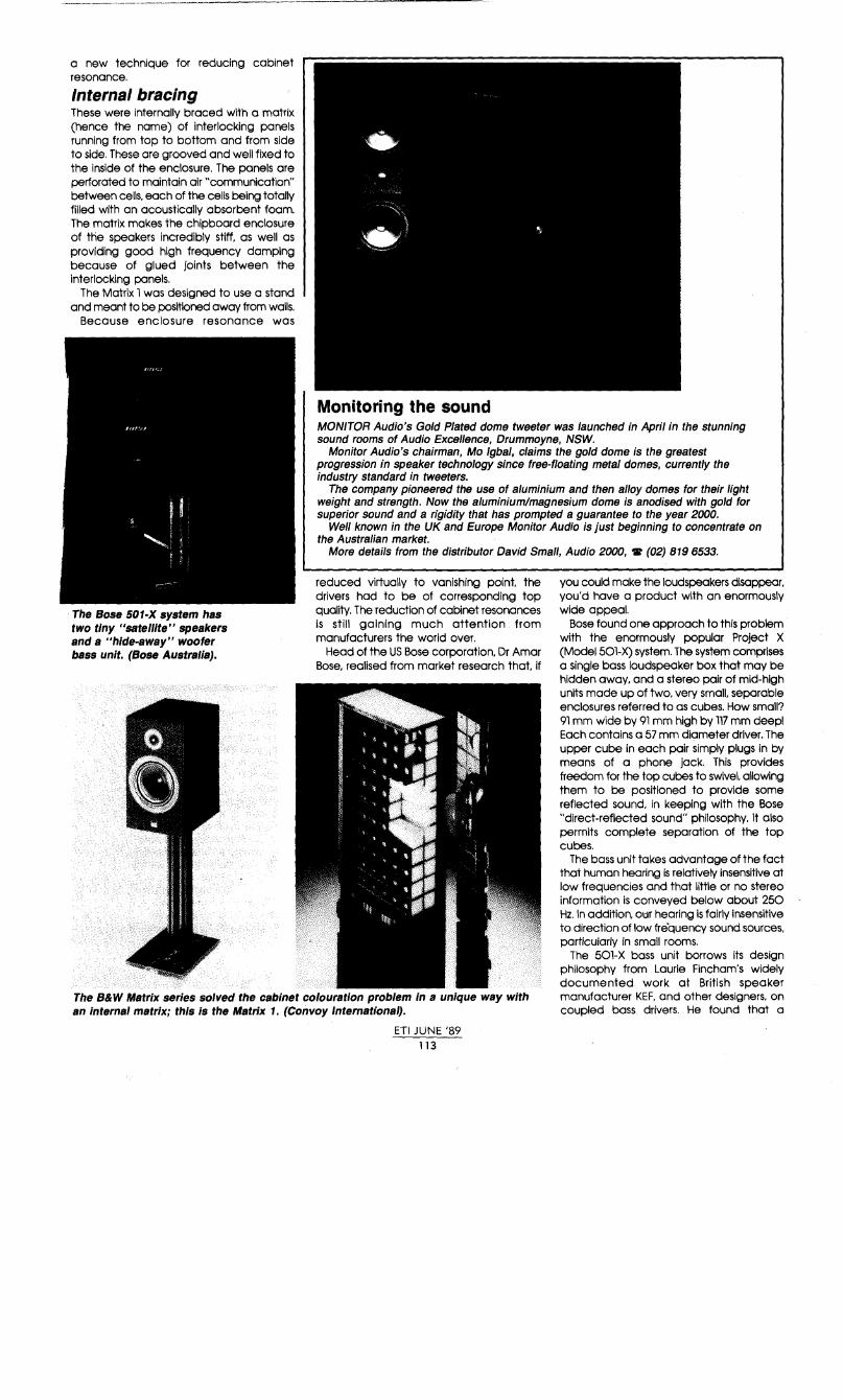
a new technique for reducing cabinet resonance.
Internal bracing These were internally braced with a matrix (hence the name) of interlocking panels running from top to bottom and from side to side. These are grooved and well fixed to the inside of the enclosure. The panels are perforated to maintain air "communication" between cells. each of the cells being totally filled with an acoustically absorbent foam. The matrix makes the chipboard enclosure of the speakers incredibly stiff, as well as providing good high frequency damping because of glued Joints between the interlocking panels.
The Matrix 1 was designed to use a stand and meant to be positioned away from walls.
Because enclosure resonance was
The Bose 501-X system has two tiny "satell/te" speakers and a "hide-away" woofer bass unit. (Bose Australia).
MONITOR Audio's Gold Plated dome tweeter was launched in April in the stunning sound rooms of Audio Excellence, Drummoyne, NSW.
Monitor Audio's chairman, Mo Igbal, claims the gold dome is the greatest progression in speaker technology since free-floating metal domes, currently the industry standard in tweeters.
The company pioneered the use of aluminium and then alloy domes for their light weight and strength. Now the aluminium/magnesium dome is anodised with gold for superior sound and a rigidity that has prompted a guarantee to the year 2000.
Well known in the UK and Europe Monitor Audio is just beginning to concentrate on the Australian market.
More details from the distributor David Small, Audio 2000, 'Ir (02) 819 6533.
reduced virtually to vanishing paint the drivers had to be of corresponding top quality. The reduction of cabinet resonances is still gaining much attention from manufacturers the world over.
Head of the US Bose corporation, Dr Amar Bose, realised from market research that if
you could make the loudspeakers disappear, you'd have a product with an enormously wide appeal.
Bose found one approach to this problem with the enormously popular Project X (Model 501-X) system. The system comprises a single bass loudspeaker box that may be hidden away, and a stereo pair of mid-high units made up of two. very small, separable enclosures referred to as cubes. How small? 91 mm wide by 91 mm high by 117 mm deep! Each contains a 57 mm diameter driver. The upper cube in each pair simply plugs in by means of a phone jack. This provides freedom for the top cubes to swivel. allowing them to be positioned to provide some reflected sound, in keeping with the Bose "direct-reflected sound" philosophy. It also permits complete separation of the top cubes.
The bass unit takes advantage of the fact that human hearing is relatively insensitive at low frequencies and that little or no stereo information is conveyed below about 250 Hz. In addition, otir hearing is fairly insensitive to direction of low frequency sound sources. particularly in small rooms.
The B& W Matrix series solved the cabinet colouration problem in a unique way with an internal matrix; this is the Matrix 1. (Convoy International).
The 501-X bass unit borrows its design philosophy from Laurie Fincham's widely documented work at British speaker manufacturer KEF, and other designers. on coupled bass drivers. He found that a
ETI JUNE '89 113

THE TECHNICS Hl·FI CHALLENGE:
comes remote y close.
National. Panasonic. lt'(hnicsart' from Nati1ina! Panasonic ~Au;tra!ia) Pry Limited
READER INFO NO. 52
When you're in the market for a Hi-Fi system, it's easy to become confused by the myriad of brands and styles available. It's often difficult to choose between systems - what features are really important? And which are merely for show?
At Technics we make this choice easy. We use the latest technology and fine craftsmanship to create features that expand your musical experience. Such as Major Function infra-red remote control, which allows you to operate your unit from anywhere in the room.
Normally, this function is only available on expensive top-of-the-range models. But at Technics we thoughtfully provide you with full remote control on every one of our Midi Hi-Fi systems.
We also give you other important features. Like Class AA amplifier circuitry, which reduces noise while purifying and concentrating your sound power; double, auto reverse tape decks; fully programmable *CD players; Digital Response speakers, and sophisticated Quartz Digital tuners.
It all adds up to superior sound quality at an affordable price.
So don't waste your hardearned dollars on another
possibly obsolete sound system.
Take up the Technics Challenge - on features,
quality, service and reliability. We know you'll be glad you did.
Technics HI-Fl

Loudspeakers
This tiny! Wharfedale's Diamond bookshelf loudspeaker. (NZ Marketing).
bandpass response could be obtained by coupling two drivers. mounting them faceto-face Inside the one enclosure. loading one with a sealed enclosure to the rear and the other with a ported. bass reflex enclosure. Sound radiation was entirely from the port. This technique combines the characteristics of a bass reflex and a sealed enclosure. providing good bass in a relatively small enclosure with the added advantages of good transient response and low distortion.
What Bose did was to take two rear-ported bass reflex enclosures and mount them with the drivers face to face; then he did away with one driver. The ports are used to separately tune each enclosure. front and rear. which then effectively act as two coupled tuned circuits exhibiting the familiar flat-topped bandpass response. All radiation is from the ports. Bose designed the enclosure so that both ports exited from one end of the cabinet. passing one port entirely through one enclosure.
Bose claims that a frequency range of typically two octaves can be obtained from this arrangement. through careful choice of driver characteristics together with port and box design. Apparently, up to three octaves bandwidth can be achieved.
The 501-X bass unit achieves a low frequency response that extends to a remarkable 50 Hz in such a small unit.
More and more European manufacturers are Introducing very compact bookshelf designs Into their product ranges. and there seems to be a relatively equal spread In design philosophies used - acoustic suspension and bass reflex; Whartedale. Tanney, Rogers and Vita are prominent in the brigade. The prominent Japanese manufacturers have tackled the same design problem, but have preferred to largely market bookshelf loudspeakers as part of Integrated midi systems.
Off the shelf Reducing size and extending the
Epicure loudspeakers AUDIO Q Imports, of Melbourne is to act as the official distributor for the new range of Epicure loudspeakers from the USA.
Epicure Products has a 23-year history of producing innovative, high quality, high accuracy loudspeakers built with the philosophy that "loudspeakers should sound like the musical instrument they are reproducing."
Enter new products: Model 1, which was selected for the prestigious Innovation '88 Design and Engineering Exhibit at the International Consumer Electronic Show. New cone materials - MFP (mineral fl/led polypropylene) for bass and midrange drive units are used. The cone material is formed in a vacuum with unique non-concentric corrugation rings, giving a structure that prevents mechanical resonances or ringing associated with conventional cones.
The tweeter diaphragm cone material is very light and rigid polycarbonate to help resist deformation at high temperature.
New crossover, speaker components and cabinet design have resulted in life-like reproduction.
There are five models in the new Epicure lineup, each with special features. Further information on Epicure Loudspeakers can be obtained from Vincent Testa, Audio Q Imports, C(03) 813-3691, fax (03) 813 3763.
ETI JUNE '89 115

Information from DALI in Denmark about New Products soon to be released in Australia.
DaCapo by DALI A ground-breaking hybrid loudspeaker
with ribbon midrange/tweeter and dynamic bass
In addition to ongoing development and research into all areas of dynamic Joudspeak
ers, DALI have made a major commitment to ambitious research programmes in the field of ribbon and electrostatic driver configurations.
The DALI DaCapo is the first in our innovative line of panel loudspeakers which we call the Dipole Dispersion Series.
OBIECTIVES The design brief for the DALI DaCapo was to create a loudspeaker capable of producing an unrivalled level of musical performance at a reasonable price when driven by real-world electronics. In other words, a loudspeaker which would not present the power amplifier with a vicious reactive load or an unquenchable appetite for current. The DALI DaCapo is not designed to produce extreme sound pressure levels or for use in overly large rooms. Audiophiles who require high volume settings in addition to natural musical performance should consider the DALI 40.
The DALI DaCapo is a fundamentally purist loudspeaker for the discerning individual who seeks to achieve new levels of musical realism at realistic volume levels in rooms up to 100 m3 On these terms, a pair of DALI DaCapo possess all the subtlety, power and transparency necessary to mercilessly reveal all the technical manipulations carried out by studio engineers in their efforts to make the end product sound "good." Right down tu the clumsy edits and heavy-handed mixing that are part and parcel of modern studio techniques.
But far more important than their peerless potential as an analytical tool is the ability of the DALI DaCapo to "disappear" on those precious occasions when the artist's performance and the labours of the studio engineers place you in the palpable presence of living music.
DESIGN PRINCIPLES The DALI DaCapo is a hybrid design incorporating an 8" bass driver and an ultra-thin 40" ribbon element a mere 3/4" wide. The system crossover frequency is 450Hz. To the best of our knowledge, this represents the first successful integration of these divergent driver principles in a single, musically coherent loudspeaker. To achieve this goal, DALI developed several original solutions to the problems of "marrying" a ribbon element to a dynamic woofer. Several of these ideas are the subject of patent aplications.
Numerous problems arise in an attempt to utilize dynamic drivers for the low end in conjunction with ribbon or electrostatic drivers for the upper frequency range. For one thing, the sheer mass of a dynamic woofer means that it will respond more slowly than a nearly weightless dipole driver. Secondly, and even more important, is the fact that the dynamic element radiates sound in only one direction with very wide dispersion. The much faster ribbon or electrostatic element is generally a dipole with a figure-eight radiation pattern which severely restricts dispersion 90 degrees off-axis.
. i ' ' I ' I
r~-h'Tl -~---- '~~
logfrequent:yHz
PHASE
' '
L:
' ' ' j
'
SPECTRAL DECAY PLOT
/~
We solved this seemingly irreconcilable problem by employing a dynamic woofer to "drive" a large membrane via a small captive volume of air. This is possible because the compressed air acts as a piston when the signal wavelength is greater than the dimensions of the volume of air. Thus, the size of the membrane operating below 450Hz becomes less critical and the dispersion characteristics of the woofer match those of the rihbon driver.
THE BASS SYSTEM The woofer and its three square foot membrane are placed in a sea.led enclosure, giving a system resonance of 50Hz and a Q of approximately 0.8. Thus, the system is down 3dB at 50Hz, below which frequency response rolls off at a rate of 12dB/octave. Consequently, the DALI DaCapo is capable of excellent impulse response and therefore, "fast" bass reproduction to match the quickness and transparency of the ribbon driver. Total structural integrity in the bass enclosure is achieved through extensive use of modal analysis.
THE RIBBON DRIVER After extensive examination of various materials and technologies, DALI selected a strong, thermostable polyester foil with three separate current paths, in order to increase the ribbon impedance, provide more "wire" in the magnetic gap and in order to generate a more linear magnetic field. The magnetic field is generated by powerful strontium-ferrite magnets in a rigid yoke construction designed to optimize the magnetic field. Unlike certain other ribbon designs the DALI yoke is constructed so as not to deform the magnetic field.
The 4 Ohm ribbon itself weighs 0. 7 gram and is 36 micrometers thin. The carefully d•• signed magnet system ensures reasonable efhciency.
The frame hoJ1sing the ribbon weighs 16 kg and contributes significantly to overall system stability and rigidity.
THE CROSSOVER NETWORK The linear phase third-order crossover incorporates hand-picked components, selected on the basis of extensive listening sessions and strict measurement tolerances. The combination of measurements and listening tests extends to the internal wiring of the DALI DaCapo for which we selected the finest Linear Crystal Oxygen-Free Copper (LC-OFC).
DISTINCTIVE DANISH DESIGN The slimline sculptural elegance of the DALI DaCapo lives up to the highest contemporary standards of Scandinavian design, making them a distinctive addition to any interior and bringing new levels of musical realism to the home at an affordable price.
SPECIFICATIONS Bass driver ... air-driven membrane, 35xl00cm Midrange/treble driver ..... 40"x3/4" metalised
polyester ribbon Crossover . . three-pole linear phase network Frequency response ..... 50-20,000Hz ±3dB Sensitivity .. .. .. .. .. .. .. 87 dB/lm/2. 83V (1 W) Power rating . . . .. .. . .. . . . .. . . . .. .. . . . . .. . .. . SOW Dimensions .. . .. .. . . 120x50xl5cm (HxWxD),
base 40cm deep Nominal impedance ...................... 4 Qhm
FOR FULL INFORMATION CONTACT YOUR NEAREST 'DALI' DEALER OR SCAN-AUDIO Pty Ltd ON (03) 429 2199 READER INFO NO. 33

Loudspeakers
performance of floor-standing models has long been a goal of the industry, tor there's still a healthy demand for floor-standing loudspeakers from those who have the room - and the money.
European manufacturers have been prominent here. but so too have some Japanese companies. The Americans have only been thinly represented. KEF and B&W led the way early in the piece. latterly followed by such notables as Celestion and Dali. Jamo dropped out of the race a few years ago, to concentrate on the pro-sound market. but mode a comeback in a new field recently, which will be discussed shortly. Technics. the hi-fi division of Japan's electronics manufacturing giant Matsushita, is one notable among the Japanese companies successfully addressing this area stretching back a decade, while Yamaha, Sony and Marantz have followed similar paths.
KEF's Model 104 was one of the first steps in size reduction while maintaining or extending performance. This ushered in Laurie Fincham's dual bass driver technique. successfully exploited in the later Model 107. At the same time. KEF introduced its active bass equalisation concept. with the KUBE (KEF Universal Bass Equalisation). This is an active equaliser that connects between the preand power amps, or in the tape or processor loop of the preamp.
The KUBE provides fixed and variable equalisation: low frequency cutoff can be set at 50, 35, 25 and 18 Hz, while Q (which controls the damping and hence the response 'shape') can be varied from 0.3 (over-damped, for live room acoustics) to 0.7 (maximally flat).
Active equalisation has been part of Bose pro-sound systems for years. Certainly the technique has gained more success than the once-promising "motional feedback" technique pioneered by Phillps a decade ago. This involved mounting a sensor on the bass driver and using Its output to provide feedback in an amplifier system to compensate for bass rolloff in a small enclosure. While Phillps has quietly walked away from motional feedback designs, Yamaha has recently activated the technique in a new design to be released here mid-year. Details on it are scant. as yet. Something to look forward to, perhaps?
other loudspeaker manufacturers have come to exploit the bandpass bass technique in a variety of innovative designs, particularly the Scandinavian manufacturers Vifa and Dali, now gaining considerable prominence In the European market and making their presence felt here.
Dali wished to further Fincham's work in order to improve the upper frequency limit. among other goals, and launched a research program in 1983, culminating in the Dali-40, released in 1987. This design put the
two bass drivers back to back - one driver mounted internally and loaded by an Internal sealed enclosure at the front with a bass reflex enclosure loading its rear, the driver on the rear of this being mounted on the front face of the box, rear-loaded by the bass reftex enclosure. The back-to-back mounting of the drivers is said to eliminate bass driver vibration being coupled to the cabinet and phase modulating the tweeter. The opposing cone motions tend to cancel (even though they are not equivalent). significantly reducing energy coupled to the cabinet via the drivers' frames as a result of Newton's reactionary law- "To every action there's an equal and opposite reaction".
Dali's technique extended the bass response at the top end to around 800 Hz, where Fincham's original bandpass system has a natural rolloff around 150 Hz. Again, the whole success of the Dali-40 hinged on using quality drivers having appropriate characteristics.
While these represent innovative. but "conventional" approaches, US manufacturer Magneplanar has tackled things another way. Its speakers have no enclosure, but feature a large ftat diaphragm with the "voice coil" attached, running up and down the diaphragm. The diaphragm is suspended over the strips of magnets and sound radiation exits from the front and rear of the vertical rectangular panel (ie: It's a dipole radiator). The magnets are comparatively small and lightweight. yet
The Dali-40 employs an innovative adaptation of Flncham's bandpass bass system In a conventional "tower" less than 1.25 metres high. (Scan Audio).
ETI JUNE '89 117
The perfect contact with lockable plugs.
WBT Factory Standards They are produced as turned parts with a dimensional tolerance of less than 2/100mm.
Corrosion-Resistant Hard Gold Pla\lng The 24 carat hard gold plated three-layer surface gives the plug long-time corrosion resistance.
Send SAE for a catalgue and Dealer list.
AUDIO Q IMPORT 649 Burwood Road PH: (03)813 1292 Hawthorn East 3123 FAX (03) 813 3763
READER INFO NO. 36

Loudspeakers quite powerful, a product of research into rare-earth magnets. The arrangement provides a wide, flat frequency response from deep bass through the mid-range, the high end being handled by a ribbon tweeter. They're only a few hundred millimetres wide and about 60 mm deep. Being a dipole radiator. they're not constrained to being mounted near a wall. either.
The Magneplanars, while sharing some physical characteristics of electrostatics, do not share their most notable limitations. While they appear to be growing in acceptance in the top end market, it's not their pricing which is holding them back for they compete successfully here with mid-priced conventional loudspeakers.
The trend to flat panel designs has not been left up to the Americans, however. The
At an advantage
Danes are at it, too. Dali recently released its DaCapo through Scan Audio here. The DaCapo is an unusual wedge shape and an unusual acoustic design. It stands 1.2 metres high, and is 500 mm wide by 150 mm deep at the top, 400 mm deep at the bottom.
The DaCapo is a hybrid, a two-way system employing a 200 mm diameter bass driver and a ribbon tweeter just over one metre tall. Now, normally, cone drivers and ribbons don't mix. A cone driver has wide dispersion and is unidirectional (being mounted in a box). A tweeter is a dipole radiator; sound exits from the front and rear - very little from the sides. The mass of cone drivers is also very much greater than a ribbon, so has much slower attack.
In the DaCapo, Dali employs the 200 mm woofer to drive a plastic membrane about
MELBOURNE-based speaker system and cabinet manufacturer Advantage Speaker Works has announced the introduction of the new Advantage speaker range. The new range is designed to span standing monitor models.
Although the Advantage brand is new the company is known and respected as a leading OEM producer. For many years the Advantage plant has designed and manufactured quality systems badged with major local and overseas brands. According to John Woodhead, the company founder, " The fact that so many major brands are actually Advantage under a different badge confirms our quality. Our strength in OEM production gives us massive buying power and we think it's time to give Advantage a chance on the open market."
Woodhead continued, "Our new range won't be static, Our research has revealed a growing demand for speakers with a more personalised appeal. More emphasis on power, more attention to cabinets as furniture, something a little bit different. We plan production runs of some very special configurations we feel could become classics."
The reference to buying power and special models begs a question about selling prices. John Woodhead is quick to point out that the cutthroat business of OEM production is so competitive that fractions of cents are the difference between sink and swim. The new range will be very competitive indeed.
ETI JUNE '89 118
Boston Acoustics has released a range of speakers for mounting in walls, to blend with room decor, rather than be part of the furniture. (Falk Electrosound).
a metre square, all in a sealed enclosure. The air trapped between the woofer and the membrane acts as a piston, and the membrane has dispersion characteristics closely matching that of the ribbon tweeter. The tweeter's magnet has been specially designed and constructed to generate a very linear magnetic field. It's made of strontium-ferrite and weighs some 16 kg, which Dali claims contributes to the speaker's stability. The success of this approach will become apparent in time; certainly the speakers acquitted themselves well during a recent launch in Sydney.
While the Magneplanars and the Dali DaCapo are meant for floor-standing, other designers are looking at "sinking" the loudspeaker into the decor of your dwelllng's walls, either cosmetically or actually.
On the wall Another approach to making the loudspeaker in an audio system less obtrusive has been to "flatten" them. so that they may be mounted on or in a wall. The idea is certainly not new, but it seems success, or acceptance, has not been forthcoming; but it's time, perhaps, for the philosophy to catch on.
Again, recent research into driver and enclosure design has paved the way to change the box-like dimensions of conventional loudspeakers.
A number of manufacturers in recent years have moved into the area of "flattening"; Duntech in Australia, Boston Acoustics of the US, Jamo and KEF in Europe, and Technics in Japan.
Adaptations of conventional systems and unconventional driver I cabinet approaches have been explored by the various manufacturers. Duntech tried the former, with a system designed to be hung like a painting, but was perhaps ahead of its time.
Last year, Boston Acoustics launched a range of three systems designed to be mounted in a wall and to blend, or at least not to clash, with one's decor. All are relatively small in frontal area and depth. The

Model 705 is about 150 mm square and only 45 mm deep, using a single, wide-range driver. It's a basic system suited to small rooms or use as auxiliary speakers. The model 350 is a better two-way system using a 130 mm long-throw bass-mid driver and a 25 mm tweeter. It measures 170 mm wide by 240 mm high and requires a mounting depth of only 67 mm. Boston claims to achieve a frequency response of 58 Hz to 20 kHz with the 350. Top of the line is the model 360, also a two-way system, employing a 160 mm long-throw bass-mid driver with 25 mm tweeter and boasting a response from 48 Hz to 20 Hz. They don't cost a lot either, at $199, $499 and $599 a pair respectively.
KEF also offers a similar style in-wall twoway system.
Jamo returned to the quality hi-fi loudspeaker scene with new releases
l~ r-->-----
L..---v
Figure 1. Laurie Fincham 's basic sealedboxlbass-reflex subwoofer scheme. The front radiation of the single driver is controlled by the sealed box, while the rear radiation is controlled by the ported box, all sound radiation coming from the port. It provides a bandpass response, with excellent base extension In a comparatively small enclosure.
Figure 2. The twin-driver, passive subwoofer system employed by Vila. Two drivers are mounted In the box face-to-face, with a volume of air trapped between them. This acts as a "piston" between the cones. One driver Is controlled by the sealed enclosure, the other by the ported enclosure, with sound radiation only from the port, as in Fincham 's system. It Is easily driven from a stereo system, whereas the arrangement In Figure 1 requires a stereo low-pass filter, mono combiner and amplifier.
The Jama Art, released recently, is a two-way ported system designed for wall mounting. (Scan Audio).
recently, its most interesting system being the Jamo Art system. Designed to mount on a wall, this comprises a two-way bass reflex system, rear-ported to take advantage of the boost gained from wall-reflected radiation. Front-on they're the size of a 20-inch TV screen (350 mm high by 400 mm wide), and just 90 mm deep.
Jamo says it's almost impossible to make a flat loudspeaker using conventional chipboard construction techniques so the front panel is an injection moulded ABS material reinforced with a computer optimised pattern of ribs to provide stiffness. The rear panel is a heavy steel plate, covered on the inside with synthetic polymer foam material for damping. Screwing the front and rear plates together locks the drivers in place, eliminating resonances, Jamo claims.
The Jamo Art uses a 125 mm long-throw bass-mid driver and a 25 mm wide dispersion dome tweeter and is claimed to achieve a frequency response extending from 40 Hz to 20 kHz. You can have them in either white or black.
These examples reflect the conventional approach. The unconventional approach would be represented by Technics' Audio Flat Panel (AFP) speaker system, three models announced late in 1987. The largest, the SB-AFPlOOO, is a 2 m x 2 m panel just 64 mm deep. The AFP speakers may be mounted either in a wall or on floor-mounting stands. Two large, rectangular flat bass units are mounted either side of a central panel
ET\ JUNE '89 119
RECORD SAVING
THE WORLDS FINEST CARTRIDGE
ortofon MC 3000
SAVING*
LIMITED STOCK AVAILABLE at the special price of $1200 from these MC-3000 specialists
only: VIC: (03) 836 0522 (03) 813 3533 (052) 216 011
NSW: (02) 708 4388 (047) 513 091
SA: (08) 272 0341 WA: (09) 384 1362 QLD: (07) 229 0611
*Normal Rec. Retail Price: A$ 1990.00 (Australia) US$ 1500.000 (America) £ 800.00 (England)
ortofon accuracy in sound
For more information call (03) 429 2199
READER INFO NO. 14

Loudspeakers
containing a smaller flat panel. lower-mid driver and two circular planar disc drivers for the top end, a four-way system. The AFPlOO Is similar, but is only about 11/.i m square.
Technics says there are inherent limitations in thin speakers systems, imposed by the physics of the situation. Neither a thin closed enclosure, nor a thin open-backed enclosure can provide satisfactory extended bass performance, Technics says. However, Technics engineers found that by incorporating aspects of both the closed and open designs in a single cabinet 'hybrid', it was possible for each to compensate for the deficiencies of the other. Dubbed the Twin Cabinet, it is the cornerstone of the T echnics AFP system.
It provides open and closed areas loading the rear of a flat diaphragm, with a central duct behind the open area. The open area serves to raise compliance, preventing unwanted boost In the low range resonant frequency. The rear duct minimises the effects of phase cancellation.
A large dlaphraQm Is more desirable for bass reproduction since it requires much smaller displacement than a smaller diaphragm because the suspension system on smaller diaphragms has to cope with the large excursions and this makes it difficult to achieve linearity and thus low distortion. The flat panel diaphragm is driven at a number
of points by four voice coil and magnet assemblies, which Technics engineers found extended the frequency response and suppressed resonances in the flat panels. The diaphragm is made from a laminate compromising chitlnised pulp mica sheet and mica foam, providing rigidity and high damping.
The plane wave produced by the large, flat diaphragms of the AFP is said to not suffer the attenuation and response irregularities suffered by conventional drivers because of the spherical wavefront they produce and how this is affected by reflections from floor and walls.
Technics sees its AFP as pointing the way to the future, where loudspeakers will become an architectural component, creating a sound field In the listening environment that will put listeners "in" the performance being reproduced.
Digital speakers That may be what Technics views the future to be, but Philips sees it differently. Apparently Philips R&D is working on a digital loudspeaker that extends the digital chain from the compact disc, or other digital source, right through to the loudspeaker, eliminating all analogue components - the CD player's digital-to-analogue converter, preamp, power amp and analogue loudspeaker -
11> large volume ID ~o:ode closed ~ enclosure
20 50 100 500
(2) Thin closed enclosure
(3) Thin openback enclosure
ill E. _, g;
Frequency (Hz)
20 50 100 500
10 E. _, Q. (/)
Frequency (HZ)
20 5 100 500 Frequency (Hz)
Figure 3. Typical frequency response curves for conventional enclosure configurations, according to Technlcs.
along the way. Details at this stage are very sketchy, but preliminary patent information talks about a 16-bit speaker system with multiple radiators and binary voice-coil drivers attached to a system of radiators that "reconstructs" the digital Input Into an analogue wavefront. Further news could prove interesting indeed! Eli
ODVL SUPER WOOFER
~BES speakers. Only B.E.S. gives you stereo everywhere - from speakers you can place anywhere. The total moving surface - front and back - of B.E.S. speakers gives
Unique cube design for easy decor placement. 100 watt active powered super woofer system. Selectable crossover points, sensitivity control with sophisticated amplifier protection circuits. Available with and without satellite speaker driving facility.
you dramatically greater efficiency. Hear music like you've never heard before, from these absolutely unique absolutely elegant B.E.S.
Recommended Retail AW100 $1,450 SBS 200 $1,750 Recommended Retail $995 to $3,500
SOLE AUSTRALIAN DISTRIBUTORS: e Odyl Group Limited Unit 4, 11 Molan Street, Ringwood Vic. 3134 PH: (03) 879-5111 FAX: (03) 879-6014
READER INFO No. :s9 ETI JUNE '89
120
e SOLE AUSTRALIAN DISTIBUTORS: Odyl Group Limited Unit 4, 11 Molan Street Ringwood Vic. 3134
PH: (03) 879-5111 FAX:(03) 879-6014
READER INFO NO. 40
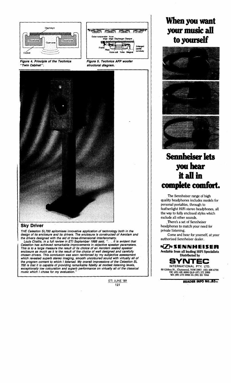
Figure 4. Principle of the Technics "Twin Cabinet".
Sky Driver
Outer suspension Inner
-:;j;J] F~ij En•~ rame Plate pal1ial
Voice col Yoke Magnet cut-away
Figure 5. Technics AFP woofer structural diagram.
THE Celestion SL700 epitomises innovative application of technology both in the design of its enclosure and Its drivers. The enclosure is constructed of Aero/am and the drivers designed with the aid of three-dimensional interferometry.
Louis Challis, in a full review in ET/ September 1988 said, " ... it is evident that Celestion has achieved remarkable improvements in objective speaker parameters. This is to a large measure the result of its choice of an Aero/am sealed speaker enclosure as much as it is the result of the choice of well designed and carefully chosen drivers. This conclusion was soon reinforced by my subjective assessment which revealed superb stereo imaging, smooth uncoloured sound with virtually all of the program contEmt to which I listened. My overall impressions of the Celestion SL 700 is that it is capable of providing remarkable fidelity at modest listening levels, exceptionally low colouration and superb performance on virtually all of the classical music which I chose for my evaluation."
ETI JUNE '89 121
When you want your music all
to yourself
Sennheiser lets you hear it all in
complete comfort. The Sennheiser range of high
quality headphones includes models for personal portables, through to featherlight HiFi stereo headphones, all the way to fully enclosed styles which exclude all other sounds .
. There's a set of Sennheiser headphones to match your need for private listening.
Come and hear for yourself, at your authorised Sennheiser dealer.
~SENNHEISER Available from all leading HiFi Specialists
Distributed by
SVNTEC INTERNATIONAL PTY. LTD.
60 Gibbes St., Chatswood, NSW2067. (02) 406 4700 VIC ( 03) 481 6000 QLD ( 07) 371 3999 WA (09) 275 5066 SA (08) 211 7044
READER INFO NO.Jlii66

ELECTRO-VOICE 7300 POWER AMP Electro-Voice has broadened its range with the release of the EV 7300 stereo power amplifier. Louis Challis was pleasantly surprised to find it as 'at home', in his home, as his own monitor amplifier.

D n the competitive market in which they find themselves. many august manufacturers - and Electro-Voice is but one
- have been forced to broaden their range to compete with others who are selling the 'one-shop-stop' concept to their wholesalers and retailers.
Now I must admit I had always considered Electro-Voice to be a microphone and loudspeaker manufacturer, and consequently, as the amplifier normally sits neatly in the middle of the chain which interconnects the microphone and the speaker, it really is logical for it to offer a matching amplifier. Just about everybody I know manufactures amplifiers, and even I stopped counting how many I'd tested or reviewed more than a decade ago. The EV 7300 stereo amplifier does,
however, offer some rather neat attributes which many professional and quite a few dedicated audiophiles will find as attractive as I did when I put this amplifier through all its paces.
The frontal appearance of the 7300 is very neat. and quite attractive. The grey /black cabinet is designed for rack mounting with two prominent rectangular handles on either side to provide protection for the cabinet. although alas, the sharp corners at each end
of those handles may not provide quite as much protection for the user. The middle of the front panel has three contiguous columns of horizontal slots. behind which the multifinned output stage heat sinks are located, and behind them, the cooling fan.
On the right-hand side of the panel is a power switch with a 'O' 'l' labelling on the switch and an exposed red LED below. to indicate that the power is on.
On either side of the slotted section of the panel are two sensibly indented attenuators with mechanical steps, which provide gain settings from zero output (minus infinity) to O dB. Below each of these indented attenuators are supplementary red LEDs labelled CLIP and PROTECT, which are activated when the output signal reaches the clipping point on the supply rails and when the protection circuit has been activated by excessive current in the output. as relevant. The front of the amplifier is also emblazoned with a series of seven red lines right across the centre of the panel and the EV logo and model number printed in white, silkscreened lettering.
The rear of the amplifier hos been subdivided into three major sections. On the lefthand side of the panel is the Input signal area where there are pairs of balanced inputs using Canon female sockets and matching 6.5 mm tip/ring and sleeve phone-sockets. lmmedlotely above these there are 2 conventional Octal accessory sockets. To the right of these is a MODE switch which allows the user to select normal dual channel (stereo) outputs, with 200 watts per channel into 8 ohms or, at the flick of the switch, to convert the amplifier to the bridged mode where the two active terminals become a veritable power house, providing 600 watts into 8 ohms (but not much more if the impedance is lower).
Immediately behind the slotted section of the front panel is the cooling fan, and on the right-hand side of the panel, protected by a pair of supplementary curved stand-off brackets. are two pairs of colour-coded universal terminals, which the manufacturer describes as 'five-way binding posts'.
The inside of the amplifier is neatly and solidly constructed with the two separate power output stages, each with Its eight complementary symmetry Mosfet transistors aerodynamically aligned between the cooling fan and the slotted front panel of the amplifier.
These are flanked on one side by the associated printed circuit board with predriver stages and protection circuits integrated onto the board.
On the right-hand side of the amplifier is
Dimensions: Height • 1.$3tt\m Wldtb - 483mm
Weight: Price:
Depth.• 324mm .17.71(9 · ... R.R.P. $2,39$
·.

EV 7300
a large power transformer, power supply filtering circuitry, and, lmmedlately behind the rear panel. the Input circuitry and wiring Interconnects to facilitate connection, servicing and. I suspect, automated testing during production.
One of the more Interesting. and Innovative features of this ampllfler Is the provision of the auxiliary facilities that are readily available (at extra cost) through the accessory sockets on the rear panel. First and foremost
amongst these Is the provision of an APX crossover which provides a user-selectable set of crossover filter frequencies. These ore selectable at any one of 24, one-third octave band centre frequencies extending from 50 Hz through to 10 kHz. Each of these filter frequencies hos a fourth order Llnkwitz-Riley 24 dB per octave skirt selectivity, which maintains smooth phase responses between the high pass and low poss selectable outputs. By using one of these crossovers. the
Specifications
Measured performance of Electro-Voice 7300 ampllfler Serial No: 088 8532
Frequency response (-3 cJB re 1 watt) Input to Aux = 0.5V Left
Right
SenaHlvlty (for 1 watt In 8 ohms):
Auxmarr Input Impedance(@ 1 kHz):
5.tffz to S.7Hz to
Left 7-0mV
Left (bal) Auxiliary 43. 7 kohms
Output Impedance(@ 1 kHz): 26m11Uohme
Noise Ii hum levels (re 1 watt In 8 ohms): (See graph) Input 0.5 V (9*1n. set for· 1 W) . 56 dB(Un)
Harmonic distortion: At a power of 1 watts Into a ohms
2nd 3rd 4th 5th
T.H.O.
Harmonic dlatortton
100Hz -90.9 -88.2 -91.8
-104.2
0.013
71 dS(A)
1 kHz -97.4
-105.3 -108.2
0.0042
At rated power of 200 watts Into 8.0 ohms 2nd -97.0 -95.8 3rd -89.1 -84.7 4th -110.7 -105.6 5th -111.5 ;.. 109;4 T.H.D. 0.008 0.012
tEC high frequency total difference frequency dl•tortton 8 kHz and 11.95 kHz mixed 1.1 At rated power (8 ohms) 0.0066 it\ At 1 watt (8 ohms} o.0042 %
Maximum output power at cUpplng point (IHF·A-202): (20 ms burst repeated at 500 ms Intervals)
4.0 125
= 488 O,namlc Headroom • 2.1 (re 200/SOO watt•,
a.o . 14& SOI 1.8
ETI JUNE '89 124
179kHz 174 kHz
Right 70tnV
Right 44kohm8·
6.3 kHz -91.5
0.0078
-89.7 -93.8 -85.1
0.018
Load Ohms v p-p watts dB
amplifier becomes truly 'bl-ampable' (which Is the way Electro-Voice describes its capability) and provides an extremely convenient way of powering both a subwoofer or tweeter - and. as I subsequently discovered with the optional power limlter circuit type 14712A of protecting those speakers as well. With the optional power limiter you can select the maximum power level which will be fed to your speakers, select three attack and decay times. as well as selectable response times to add, and protect low frequency drivers (or compression drivers) with a module that avoids oscillation through progressive use of 'feed forward' design philosophy.
In measuring the performance of this amplifier. I had to drag out our balanced input drive components yet once more to ensure that the amplifier was correctly evaluated. although I would point out that the amplifier was quite happy to be driven by unbalanced inputs. when these were all that were available in a restdentlal situation.
The frequency response was a trifle different from what I would hove expected In that. although the frequency response is ruler flat from 50 Hz to 7 kHz (and is only 1 dB down at 11 Hz. and 3 dB down at 5.6 Hz), between 7 kHz and 90 kHz the amplifier's output produces a 1 dB rise in its response
.7lte :rollover 'at the bottom end ls smooth
and very stable'
with the peak occurring between 35 kHz and 60 kHz. Now a rise of l dB In a response curve Is totally Inaudible to most people, but does provide the wherewithal to extend the upper frequency response out by a trifle more than might otherwise have been the case. With this amplifier, the upper -3 dB point was 174 kHz. and the -1 dB point was still at a relatively high 120 kHz.
The rollover at the bottom end is smooth and very stable, and the amplifier provides excellent phase linearity all the way through Its frequency range. The harmonic distortion characteristics of the amplifier are excellent with total harmonic distortion levels which ore above average at 1 watt and stlll very good at the rated output level of 200 watts Into 8 ohms (being better than 0.018% at 6.3 kHz and even lower at 100 Hz and 1 kHz.) The IEC high frequency total difference frequency distortion characteristics are also excellent being .0066% at rated power and .0042% at the 1 watt level. As the curve shows, the distortion characteristics do not start to rise significantly until the amplifier is approaching the 300 watt output level. The crosstalk between the channels is also excellent being better than -75 dB at any one-third octave band centre frequency,

which confirms the adequacy of the power supply filtering and Inter-channel decoupling. The measured signal-to-noise characteristics of the amplifier (S/N) reveal a slightly lower performance than claimed In the manufacturer's literature with -69 dB(A) re 1 watt and ~5 dB(A) re 200 watts (cf the manufacturer's :laim of 100 dB). The measured noise :omponents are harmonically related to the ::>ower supply and the dominant :omponents are at 150 Hz and 250 Hz respectively.
The transient overload recovery test (In accordance with IHF-A-202) confirms that this amplifier Is absolutely stable under overload conditions. with instantaneous recovery without any sign of Jitter or offset bias being manifest. In like manner, the application of short circuits and other adverse operating conditions. leading to excessive current or peak clipping, do not result in failure of the amplifier which accepted these attacks with the aplomb of a professional. gently shutting down the unit until the short circuit was removed.
The last objective test was to assess the audible noise of the cooling fan which was a modest 43 dB( A) at l metre. This increased by approximately 12 dB(A) when the amplifier was subjected to very__ demanding high level signals. which of course would generally be expected to result In audible signals of at least 50 dB In excess of that fan noise figure (based on the presumption that you were sitting or standing only l metre from the amplifier).
I carried the EV 7300 home. and connected up a Sony CDP 555 CD player to the inputs and a pair of B & W 801F speakers to the output, to evaluate the sonic clarity and power handling capabilities of the amplifier.
I selected some newly-released discs for my evaluation. The first of these was a CBS
. Masterworks rendition of Shostakovich's Trio Op. 67 (MK 44664-DDD) with Isaac Stern. Yo Yo Mar and Emanual Ax Who. who although internationally acclaimed. are not particularly well-known on the Australian symphonic or Music Aviva concert scenes. Shostakovich was very much a 'poliflcal football' In Russia during his lifetime and this particular trio was
Electro-Voice Model 7300 power amplifier
dB Potentiometer Range· __5_Q_ dB Rectifier. /2 M S Lower Lim Freq.: _£Q_ Hz Wr Speed: ~mm/ .. c. Pap11r Spe•d: ...3_mm!aec. ~
5
.,.,.--,,r 50 ~ 1 00 200 500 , 000 2000 5000 10000 2~ D A B C Lir
Crosstalk: one-third octave band analysis, aux/l/ary Input. Other channel Input 0.5 V RMS; sine wave output 1 W Into 8 ohms.
-2
-4
7~ ~- 10 20 ~. 100 200 1161'2.':
Frequency response 2 Hz to 200 kHz; Input 0.5 V RMS, output 1 W Into 8 ohms, 10 dB pot.
-50
-60
-70
-80
-90
. 6
•·
2•
-110 20""""-m 50 """"' 100 200 500 1 000 0000
0 ~v .... OABCLin'="'
Hum and noise: one-third octave band analysis (re 1 W In 8 ohms), Input 0.5 V.
ETI JUNE '89 125

If you sa-w- it on Beyond 2000
you 01ay -w-ish to 01ove directly . tO the - Noknobs,
buttons,
coupon You're looking at the future of home video.
If you saw it on Beyond 2000, you'll probably
be posting the coupon already.
· The extraordinary new Videonics system lets
you edit your own home videos and much more.
Add professional titles in up to 64 different col
ours. Skip the boring sections. Add special effects
-wipes, fades and cuts.
Combine scenes in any order. Produce high
quality videos in your own home. You can even use the system as a video
librarian to keep track of every scene and movie in
your library. A powerful video computer remem
bers the precise location of every scene.
Move to the right spot immediately without
reeling through hours of tapes. The system works with VHS, BETA, 8mm,
and 3/4" formats. Use it to get the most from your
video or camcorder.
or switches. Do it all by infra red remote control.
The uses of the Videonics system are endless.
You can even use it to cut out the ads from your
favourite tapes!
r -------, Cut out this coupon now for free colour brochure.
I I I I L
NAME
ADDRESS
·POSTCODE
Complete and post to: C.R. Kennedy & Co. Pty Ltd P. 0. Box 276 Brunswick. Victoria 3056
I I I
..,, VIDEO~~~~cm"..11 -------READER INFO NO. :SS ETI JUNE '89
126

EV 7300
Transient overload recovery: 1 mS/dlv.
written in 1944 and deals with a song cycle from Jewish folk poetry. What is not clear to me, and to many others, was whether or to what degree Shostakovich had some revelation of the extent of the holocaust when he wrote this particular piece. Isaac Stern, Yo Yo Mar and Emanuel Ax have produced a brilliantly recorded rendition of this outstanding piece of music. and the EV 7300 produced a flawless output signal at concert hall levels with a brilliance and clarity which I believe was superior to my normal monitoring amplifier which I used as a yardstick.
The second piece which I chose was a disc by Joe Satriani, "Dreaming II" (CBS 65453 5 2) which features Joe Satriani on guitar. Jeff Campitelli on drums and 'Bongo' Bob Smith on percussion. This music provided superb transient signals. and the EV 7300 handled rock concert listening levels with the true aplomb of a real professional. The music was exciting. and the transients provided by a real 'gutsy' test signal equal to the most demanding live or recorded signals I could generate. I would have liked to have tried the EV crossovers in a two-way drive connection with this particular disc. but realised only too late that I had forgotten to organise picking up the crossover.
The third disc was one that will only interest those of you who have as wide an interest in modern films as my family seems to have developed. I chose the theme song from "Bagdad Cafe. the original motion picture soundtrack" (Festival D 30054). which has a haunting quality which buzzed through my mind tor more than a week until we purchased this disc. Jevetta Steele, who recorded this number in London especially for the film. has a clear winner in this particular track and I believe the film owes much of its audible imagery to this particular
50mSldiv.
piece. The EV 7300 stereo power amplifier
proved to be Just as much 'at home' in my. home, as is my existing and nominally more powerful monitor amplifier. Although the rating of the EV7300 is supposedly less. I was never at any stage aware of that difference, although I was aware of nuances between
.1
.OS
.02 z 0 j:: .01 0::: 0 I-Vl Cl .005
the two amplifiers. The EV 7300 is the better of the two and that difference would obviously become more apparent in a commercial or professional situation. where the APX electronic crossover module. or the selectable power limiter module, would provide some functional advantages that relatively few other amplifiers currently offer.
eti
~ L/
~
~ --1'..._ ~ 0
.002
.001 1 2 10 20 50 100 200
IEC high frequency total difference frequency distortion.
PEAK-PEAK VOLTS I I I
1 2 5 10 20 50 100 400 Ea.UIVALENT SINE WAVE POWER. 8-Q LOAD, WATTS
ETI JUNE '89 127

ETI JUNE '89 128

ED-IT YOURSELF rite Vicleonics DirectlD ltoine vicleo eclitor Reviewed for ETI by Patrick Hayes.
Cl ome movie enthusiasts are justly overjoyed at the facllltles the video camcorder can offer them. Back In
. the bad old (pre-transistor) days, when home movies were usually made with a Super-8 film camera, the backyard producers had to put up with their system's many basic shortcomings before their masterpieces flickered Into life on the wall of a darkened living room before suitably Impressed family and friends.
The beauty of the Super-8 genre was that even If the colours were all washed out the camera-work shaky and the subject matter a tour of next-door's backyard, the audience always called for more.
One of the main reasons for the popularity was the brevity of the program; It seemed that no sooner had the Images of the local stars started to make their selfconsclous way about the wall than the show ended with a clatter of freewheeling reels.
The Super-8 film cassettes produced only three minutes of action and cost an arm and a leg to buy and to process. Few people could afford to make amateur productions
ETI JUNE '89 129
any longer than the attention span of the least fascinated audience.
But now we have home video and the game has changed. The amateur movie maker can record sound as well as picture, the colour Is superb and the equipment can usually zoom from a telephoto shot of the famlly cat In a tree to a macro view of an ant having breakfast.
The sensitivity of the circuitry Is such that Indoor or outdoor shots require no adjustment and automatic focussing systems keep the blurry bits to a minimum.
Even better for producing the local blockbuster, vldeo-8 and VHS C-cassette camcorders will hold 90 minutes on a tape (and twice that In LP mode) and those using full-size video cassettes wlll, of course, run for up to four hours at normal speed. Better again, the cassettes are cheap and plentiful and require no processing before screening on the living room television set.
The audience, however, does not take such a rosy view of the new developments. A mere 15 minutes of watching botched

Ed-it yourself
attempts to capture baby's tottering gait. most of it featuring baby sitting down and being prodded by arms and soft toys that emerge surreptitiously from the side of the screen. can reduce the most placid of neighbours to a twitching, yawning, wriggling wreck.
All of this is leading up to a shining truth: home videos are excruciatingly boring unless they are edited tightly.
Achieving that is not as simple as It sounds, however. An editing suite that will run a video cassette on a monitor and enable it to be dubbed on to another cassette in shortened, revised form can cost $10.000 or more. That's a high price to pay in order to spare people from watching father's numerous attempts to sling a steak on the barbecue without an air of smirking selfconsciousness.
Home editing using just a camcorder and a video recorder can be more trouble than it is worth. The cuts from one take to another can produce jarring. jagged breaks In the sound and picture that give the impression they were made by chewing through the tape and stlcklng it back together with gaffer tape.
Attempts to tidy up the production by making several "generations" of copies. doing further editing on each one. results in the final copy being a blurred and blemished example of the degradation that occurs when copies are made ·using domestic equipment. The degradation seems to Increase proportionally with the number of times a tape is dubbed.
Then along came the Vldeonic DirectED, a machine that uses computer technology
Get editing/ Follow the step-by-step
instructions on the screen or, If necessary,
press the Help button on the remote control.
and some delightful lateral thinking to produce a home editing suite for under $1000.
The brochure claims that it "allows you to combine your favourite scenes. in any order. with special effects. graphics, titles and backgrounds to make a production you'll be proud to show." That brochure is correct.
The system has no knobs, buttons or switches. Everything is done with its "smart" infrared remote control. including the operation of your own video recorder which teaches the DirectED unit the infrared commands It needs.
The unit has no moving parts. It Is only the command part of the editing suite. A video recorder (with remote control. ordinary playsearch capabilities and video and audio connectors) and a camcorder with playback ability (or a video recorder) make up the running gear.
Both units can be from any manufacturer and use any format. You can mix and match formats; a VHS video recorder, for Instance, can be teamed with a Video-8 camcorder. The second unit (camcorder /VCR) does not require record ability, remote control or search.
The television set used in the process does have to be a bit special. If the set does not have. as well as its antenna socket. jacks for audio and video input On other words. monitor capability) a video modulator will be
eeded (Tandy has one for $69.95). Once you've got the DirectED, the
camcorder and VCR, television set and modulator (if needed) together, the rest is easy. Step-by-step Instructions on how to carry out the editing of a tape appear on the screen. Further advice is available by touching the Help button on the remote control.
The DlrectED system contains an NEC V40 processor running at 8 mHz with no wait states. The software has been developed using Turbo PASCAL. It has 256K of RAM and BK of non-volatile RAM with fail-safe power back-up provided by dual redundant lithium cells with a minimum life of eight years. The •ame lithium cells also keep watch on the
ETI JUNE '89 130
system clock and calendar. So, you might be asking. how do yoL load
the 256K up with the program. the database \ which keeps track of scenes, the graphics and storyboards? This is where the first bit of lateral thinking comes In.
The DlrectED black box comes with a videotape. When It Is played, the first five seconds displays a black and white pattern which is the entire program being loaded. After that. the tape goes on to give a tutorial on the operation of the system.
The editing process starts when you copy a tape (or tapes) from the camcorder to the VCR. Each scene has to be given a name I and Its beginning and end marked.
From this point on, all editing is done on the dubbed copy. The original Is kept aside to be used for the final, high quality copy.
After this. the list of scenes appears on the television screen and the editor selects thE1 scenes required and adds titles, graphics an2\ special effects. Text and graphics In a range of styles and sizes are available in a range of 64 colours and backgrounds. You can use single colour graphics on a solid colour or mix the graphics with a scene using fades and wipes.
At this stage the order of scenes can be changed and scenes can be deleted. There is no need to keep a list of what's to happen, DirectED remembers all, including just where I each scene can be found on the original tape or tapes.
The on-screen menu tells you what scenes you have and the duration (in minutes and seconds) of each one.
The third stage of the task is previewing the edited tape and making any adjustments. For the final production, the original tapes are reloaded into the camcorder /VCR and an infrared wand Is placed near the remote control receptor on the main video cassette recorder.
The DlrectED rolls the tape through the camcorder. turning the VCR on and off as it selects the scenes to be dubbed in the correct order. It generates the required graphics and special effects as required.
It must be remembered, of course, that the tape Is rolling through the camcorder /VCR at playing speed. To locate and position each scene, DirectED has to take the camcorder back to the start of the tape and play It through. This means that it could take 10 hours to complete the final dub but. short of getting access to a professional editing suite. there Is no faster way of doing the job. 1
Anyway, the time invested Is worthwhile If the end result is a professionally edited movie that might once again have family members and neighbours calling for more and heaping praise on the producer.
The DlrectED system has a recommended retail price of $999. More details from the distributor. CR Kennedy & Co, 7 Union Street. Brunswick, Vic, 11' (03) 387 4611. eti


