Embed Size (px)
Citation preview
InnovationsSolutions for safe automation, electrical safety and power electronics
Our experience. Your safety.

Innovations
DOLD offers an integrated program for safe automation, electrical safety and power electronics, which have already been in use successfully worldwide for many decades.
In addition to mono-functional standard devices up to multi-functional solutions, DOLD develops tailor-made products for your machines and plant protection.
You can find further information on our homepage under www.dold.com.
Safety technique
■ Safety switch and key transfer system SAFEMASTER STS
■ Emergency stop module SAFEMASTER
■ Standstill and speed monitoring SAFEMASTER S
■ Multifunctional safety modules SAFEMASTER C
■ Software free safety system SAFEMASTER M
■ Configurable safety system SAFEMASTER PRO
■ Wireless Safety System SAFEMASTER W
Measuring and monitoring technique
■ Insulation fault location system VARIMETER EDS
■ Residual current monitoring VARIMETER RCM
Contents
■ Insulation monitoring VARIMETER IMD
■ Multifunction measuring relay VARIMETER PRO
■ Measuring and monitoring relays VARIMETER
Power electronics
■ Smart motorstarter, Softstarters MINISTART
■ Solid state relays / contactors POWERSWITCH
PCB relays
■ Safety relays with forcibly guided contacts
■ Bistable relay with forcibly guided contacts
PRODUCTFINDERStart now!
Find the right product for your application!
With our Product Finder you have direct and quick access to our product range of relay modules.
www.dold.com/productfinder

SAFEMASTER STS
Don‘t you wish you had a simple safety switch and trapped key interlock system to protect your dangerous working areas. If you are looking for a reliable, expandable, flexible and cost saving solution, then you have found the perfect product with our TÜV-approved system SAFEMASTER STS.
The SAFEMASTER STS Program consists of modules that can be individually combined and adapted to your application. They combine the advantages of safety switches, interlocks and key transfer in one system. The modular design allows systems to be assembled out of several units, or to modify and expand existing systems as required. All mechanical interlocks can be utilised in machine and plant concepts without wiring. They provide an economic and reliable proctection in wide applica-tions.
With only a few single components, a number of individual interlock units can be assem-bled. The stainless steel units guarantee good stability. Extensive equipment allows a simple mounting.
Advantages and customer benefit
Combines advantages of safety switch, solenoid lock, trapped key interlock and command function in one System
EC type approval certificate in accordance with the statutory requirements For safety applications up to Cat. 4 / PL e according to EN ISO 13849-1
as individual system Modular and expandable system Version available in plastic as well as a in rugged stainless steel Wireless safeguarding Easy installation through comprehensive accessories Protection against lock-in Fault exclusion is not required
The key to more safety
Our experience. Your safety.
www.dold.com
SAFEMASTER STS E. Dold & Söhne GmbH & Co. KG
Safety switch and trapped key interlock system
System
Industries
Application example
Further information
Automation technology Stone and cement processing Recycling Steel, wood and foodstuff industry Conveyor technology and logistics Railway and automotive industries
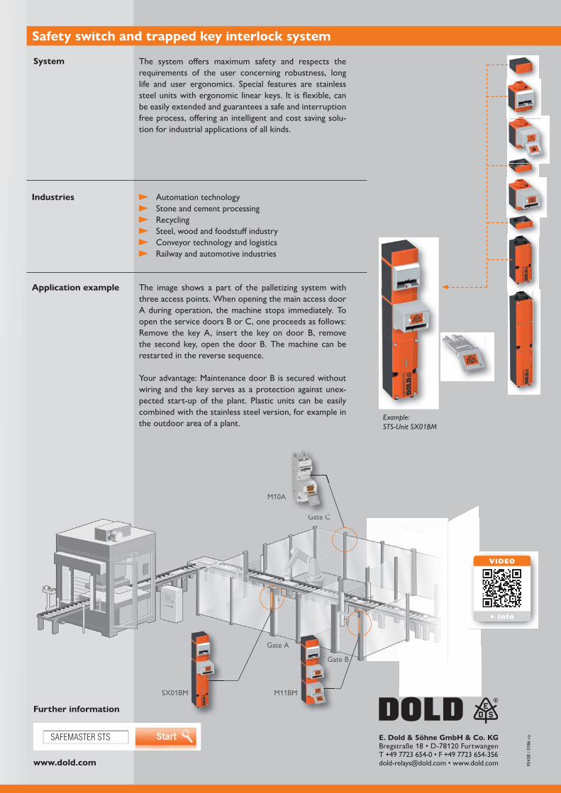
The image shows a part of the palletizing system with three access points. When opening the main access door A during operation, the machine stops immediately. To open the service doors B or C, one proceeds as follows: Remove the key A, insert the key on door B, remove the second key, open the door B. The machine can be restarted in the reverse sequence.
Your advantage: Maintenance door B is secured without wiring and the key serves as a protection against unex-pected start-up of the plant. Plastic units can be easily combined with the stainless steel version, for example in the outdoor area of a plant.
The system offers maximum safety and respects the requirements of the user concerning robustness, long life and user ergonomics. Special features are stainless steel units with ergonomic linear keys. It is flexible, can be easily extended and guarantees a safe and interruption free process, offering an intelligent and cost saving solu-tion for industrial applications of all kinds.
Example:STS-Unit SX01BM
Gate A
Gate B
Gate C
M11BM
G C
VIDEO
+ Info

SAFEMASTER STS
Power Interlocking - Safely switched off!
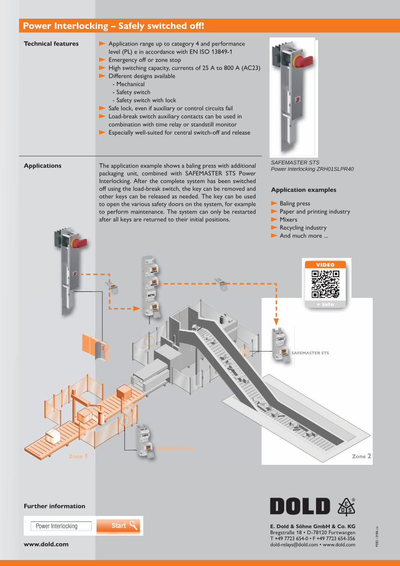
Power Interlocking from the SAFEMASTER STS family by DOLD allows you to easily integrate a load-break switch into your safety switch and key transfer system. This lets you to directly deactivate and safely lock the energy supply to a machine or system. The safety system can then reliably protect personnel from entering the hazardous area. At the same time, Power Interlocking can easily be combined with other SAFEMASTER STS modules to wirelessly and mechanically safeguard safety doors. The system offers the best possible safety up to category 4 / PL e with EC type examination certificate.
The most important components of Power Interlocking are a load-break switch and a mechanical or electromechanical locking unit. When switched off, these release a key which opens a safety door to a hazardous area. The locking mechanism prevents the operating lever from being activated, thereby stopping the system from turning back on.
Power Interlocking forces the energy supply to the machine to be switched off and locked directly using a load-break switch, without the use of an electrical or electronic control level. For simple or machines or retrofitting machines, power interlocking offers the advantage that no controller is required. The system can, however, also be a good addition to more complex systems as a restart prevention.
Your advantages
For safety applications up to cat. 4 / PL e Reduced installation and assembly work due to simple construction Load-break switch integrated into SAFEMASTER STS Electrical control level not required Safe restart protection by locking off energy supply
EC type examination certificate
Our experience. Your safety.
www.dold.com
Zone 2Zone 1
SAFEMASTER STS
SAFEMASTER STS
Power Interlocking E. Dold & Söhne GmbH & Co. KG
Application range up to category 4 and performance level (PL) e in accordance with EN ISO 13849-1
Emergency off or zone stop
Different designs available - Mechanical - Safety switch - Safety switch with lock
Safe lock, even if auxiliary or control circuits fail Load-break switch auxiliary contacts can be used in combination with time relay or standstill monitor
Especially well-suited for central switch-off and release
Power Interlocking – Safely switched off!
Technical features
Applications
Further information
Application examples
Baling press Paper and printing industry Mixers Recycling industry And much more ...
SAFEMASTER STSPower Interlocking ZRH01SLPR40The application example shows a baling press with additional
packaging unit, combined with SAFEMASTER STS Power Interlocking. After the complete system has been switched off using the load-break switch, the key can be removed and other keys can be released as needed. The key can be used to open the various safety doors on the system, for example to perform maintenance. The system can only be restarted after all keys are returned to their initial positions.
VIDEO
+ Info

SAFEMASTER STS
Option module – Decentralized Control Center
The robust stainless steel option module expands the modular SAFEMASTER STS safety switch and key transfer system by adding variable command, indication, selec-tion and emergency stop functions. This makes the system a true “control center” which can be used to control command functions, additional displays, releases, and main and maintenance access points. The option module can be installed interlocking directly below the safety switch or locking units, facilitating direct command execution at machine and system access points. It is also possible to install it as a stand-alone control device. Benefit from the high flexibility of the system.
With just a few components from the SAFEMASTER STS system, you can assemble a large number of different locking units and combine these with various option modules. This results in a large number of possible units with command functions.
The specialized ribbon cable with plug connectors ensures individual components can be connected easily and quickly internally. The standard design is made of stain-less steel, ensuring the best possible stability and safety, even in rugged or extreme environmental conditions. Comprehensive accessories allow for simple, fast assembly directly at the access point.
Your advantages and customer benefits at a glance
Simple integration of command and indication functions in SAFEMASTER STS
Highly robust stainless steel design makes the unit suited for rugged and extreme environmental conditions
Large selection of different operating elements such as emergency stop buttons, illuminated buttons, push buttons and selector switches
Protect personnel and systems up to the highest safety category 4 / PL e Reduced assembly and wiring work through integrated
operating elements and wireless safeguard for safety doors
Our experience. Your safety.
www.dold.com
E. Dold & Söhne GmbH & Co. KG
Control function through illuminated buttons or emergency stop buttons
Pluggable connection technology with double spring-
Robust stainless steel housing Can also be installed as stand-alone unit
gland Optional connection set for plug connection between
switch / locking module and option module Plug connection between control station in cover and
option module Colored panels and icon signs selectable
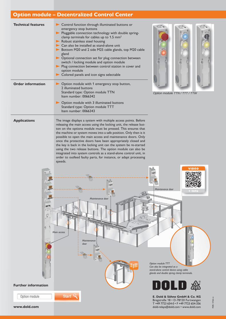
Option module – Decentralized Control Center
Option module with 1 emergency stop button,
Standard type: Option module TTN
Option module with 3 illuminated buttons Standard type: Option module TTT
Technical features
Order information
Applications
Further information
Option module TTN / TTT / TTW
The image displays a system with multiple access points. Before releasing the main access using the locking unit, the release but-ton on the optiona module must be pressed. This ensures that the machine or system moves into a safe position. Only then is it possible to open the main access and maintenance doors. Only once the protective doors have been appropriately closed and the key is back in the locking unit can the system be re-started using the two release buttons. The option module can also be integrated into system controls as a stand-alone control unit, in order to outfeed faulty parts, for instance, or adapt processing speeds.
Option module TTT Can also be integrated as a stand-alone control device using cable glands and double spring clamp terminals.
Maintenance door
Maintenance door
Maintenance door
Main access
VIDEO
+ Info
Option module

SAFEMASTER
Our experience. Your safety.
emergency stop module UF 6925 of the SAFEMASTER series monitors safety functions such as emergency stop or safety door safely and simply in nearly every application and is characterised by maximum safety for man and machine with minimum space requirement. The
terminals and also makes rapid assembly possible by simple snapping on to the DIN rail.
structure the device is designed for highest safety requirements up to cat. 4 / PL e or SIL 3 and is also suitable for use in furnace installations according to EN
the back of the device and allows the selection of type of start and cross fault detection.
for a great variety of applications in machine and plant engineering and in mobile applications.
Advantages and customer benefit
For safety applications up to cat. 4 / PL e or SIL 3, UL-listed
Rapid wiring via integrated push-in connection technology
Rapid diagnosis using LED display
Suitable for safety functions such as safety door and emergency stop
Adjustable type of start with line fault detection on On-button
Front side device connection
www.dold.com
UF 6925 E. Dold & Söhne GmbH & Co. KG
Further information
Emergency stop module UF 6925
Technical features
Order information
Applications
Application example
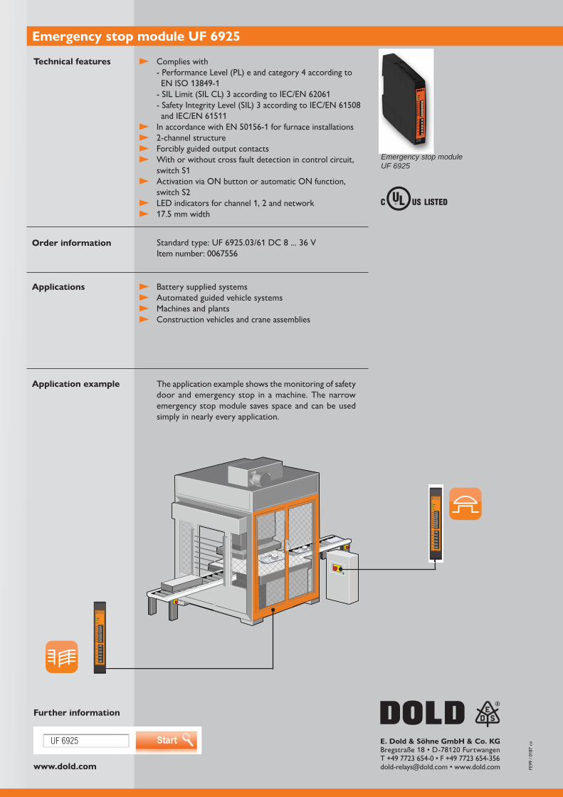
Emergency stop module UF 6925
Complies with - Performance Level (PL) e and category 4 according to EN ISO 13849-1
Forcibly guided output contacts With or without cross fault detection in control circuit,
switch S1 Activation via ON button or automatic ON function,
Battery supplied systems Automated guided vehicle systems Machines and plants Construction vehicles and crane assemblies
The application example shows the monitoring of safety door and emergency stop in a machine. The narrow emergency stop module saves space and can be used simply in nearly every application.

SAFEMASTER S
Safe sensorless standstill monitoring
The safe sensorless standstill monitor UG 6946 from the SAFEMASTER S series detects the standstill of 3-phase and 1-phase motors independent of the direction of rotation. This means sensors such as encoders or proximity switches are not required. Access to the danger zone of a system is only possible by the enabling signal of the standstill monitor after the drive has been switched off and run down. In order to detect a standstill, the remanence voltage induced by the motor windings is evaluated and provides safe standstill monitoring up to Cat. 4 / PL e or SIL 3, even if the motor has already been switched off. Using a conventional release via a time control, dangerous movement could not necessarily be excluded. For the
offers the possibility of bridging the standstill monitoring (muting).
The simple integration into the machine and drive concept reduces the commissioning effort and costs and is particularly suitable for use in machine tools and woodworking
can be accommodated in the control panel even under tight space conditions allowing easy retrofitting. The device also offers two redundant safety contact paths and a forcibly guided signal contact.
Your advantages
Possibility of bridging the standstill monitoring (muting function)
Standstill detection without additional sensors
For safety applications up to Cat. 4 / PL e or SIL 3
Rotary switches protected by sealable transparent cover
Can be combined with safety interlock SAFEMASTER STS
Our experience. Your safety.
www.dold.com
UG 6946
UH 6932
14
2
44
3
E. Dold & Söhne GmbH & Co. KG
Standstill monitor UG 6946
Further information
Technical features
Fields of applicationOrder information
Are you looking for further solutions for speed monitoring?
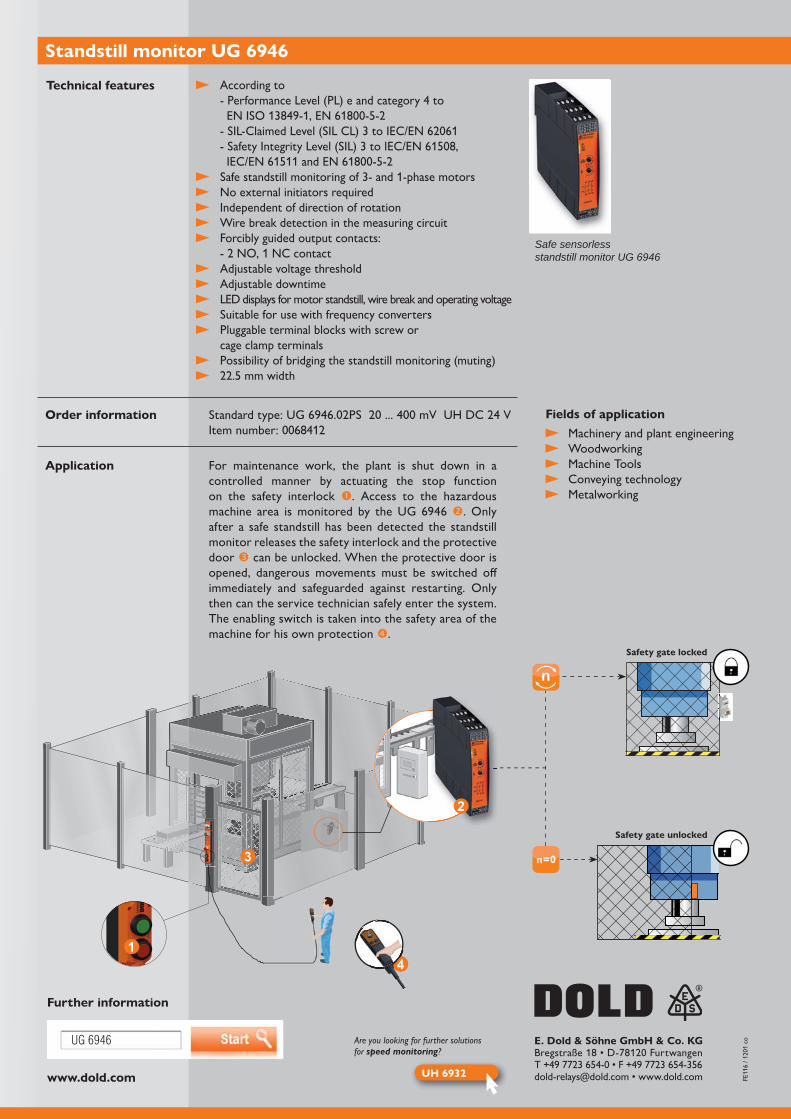
Safe sensorless standstill monitor UG 6946
Safety gate locked
Safety gate unlocked
For maintenance work, the plant is shut down in a controlled manner by actuating the stop function on the safety interlock . Access to the hazardous
. Only after a safe standstill has been detected the standstill monitor releases the safety interlock and the protective door can be unlocked. When the protective door is opened, dangerous movements must be switched off immediately and safeguarded against restarting. Only then can the service technician safely enter the system. The enabling switch is taken into the safety area of the machine for his own protection .
Application
Machinery and plant engineering Woodworking Machine Tools Conveying technology Metalworking
According to - Performance Level (PL) e and category 4 to
Safe standstill monitoring of 3- and 1-phase motors No external initiators required Independent of direction of rotation Wire break detection in the measuring circuit Forcibly guided output contacts:
Adjustable voltage threshold Adjustable downtime LED displays for motor standstill, wire break and operating voltage Suitable for use with frequency converters Pluggable terminal blocks with screw or
cage clamp terminals Possibility of bridging the standstill monitoring (muting)

SAFEMASTER S
Comfortable speed monitoring
With the safe speed monitor UH 6932 from the SAFEMASTER S series, DOLD offers a comfortable solution for safety-oriented speed monitoring for use in wind turbines, centrifuges, or stage engineering. The device safely monitors machine stand-still and both excessive and low speeds, in automatic and setup operating modes.
The speed monitor finds use in machines and apparatus which can pose a threat to people whilst running through mobile machinery or movable parts. Therefore, through the safe monitoring of reduced operating speed during usage, for example, the safety of operating personnel will be increased. The device also increases productivity, since there is no need to unnecessarily shut down equipment.
operation and quick configuration of the device without a PC. The surveillance function can be deactivated via a digital input or activated during operation, with up to four pre-configured velocity modes with varying response thresholds. Besides the safety-oriented contact paths, the device also offers an analog output to display the current frequency.
Your advantages
For safety applications up to cat. 4 / PL e or SIL 3, UL-listed
Simple, time-saving start-up without a PC
Suitable for commonly available proximity switches
Reduced system downtime through comprehensive diagnostic functions
Speed monitoring offers a bypass option (Muting)
Up to 4 operating modes can be activated (e.g. automatic, set-up, or service mode)
Overspeed, underspeed or window monitoring
Our experience. Your safety.
www.dold.com
UH 6932
LH 5946
E. Dold & Söhne GmbH & Co. KG
Overspeed, underspeed or window monitoring User-friendly front display:
- For convenient, menu-based parameter adjustment of parameters - for target and actual value displays in Hz
Quick response time using cycle duration measurements of input frequency
For PNP or NPN initiators Adjustable hysteresis
Save alarm or auto-reset
Positively driven output contacts
Safety technology characteristicsCat. 4 / PL e according to DIN EN ISO 13849-1
Speed Monitor UH 6932
Technical features
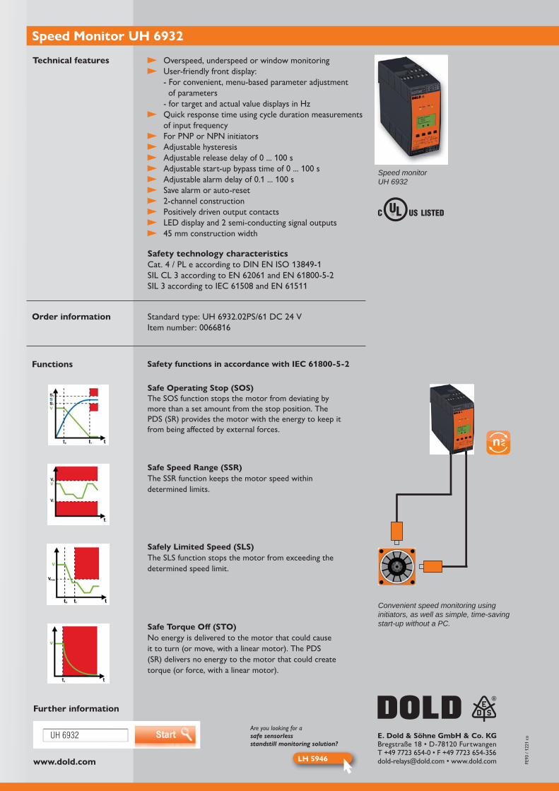
Speed monitor UH 6932
Order information
Functions Safety functions in accordance with IEC 61800-5-2
Safe Operating Stop (SOS) The SOS function stops the motor from deviating by more than a set amount from the stop position. The PDS (SR) provides the motor with the energy to keep it from being affected by external forces.
Safely Limited Speed (SLS) The SLS function stops the motor from exceeding the determined speed limit.
Safe Torque Off (STO)No energy is delivered to the motor that could cause it to turn (or move, with a linear motor). The PDS (SR) delivers no energy to the motor that could create torque (or force, with a linear motor).
Safe Speed Range (SSR) The SSR function keeps the motor speed within determined limits.
Further information
Are you looking for asafe sensorlessstandstill monitoring solution?
Convenient speed monitoring using initiators, as well as simple, time-saving start-up without a PC.

SAFEMASTER S
Safe, sensorless drive monitoring
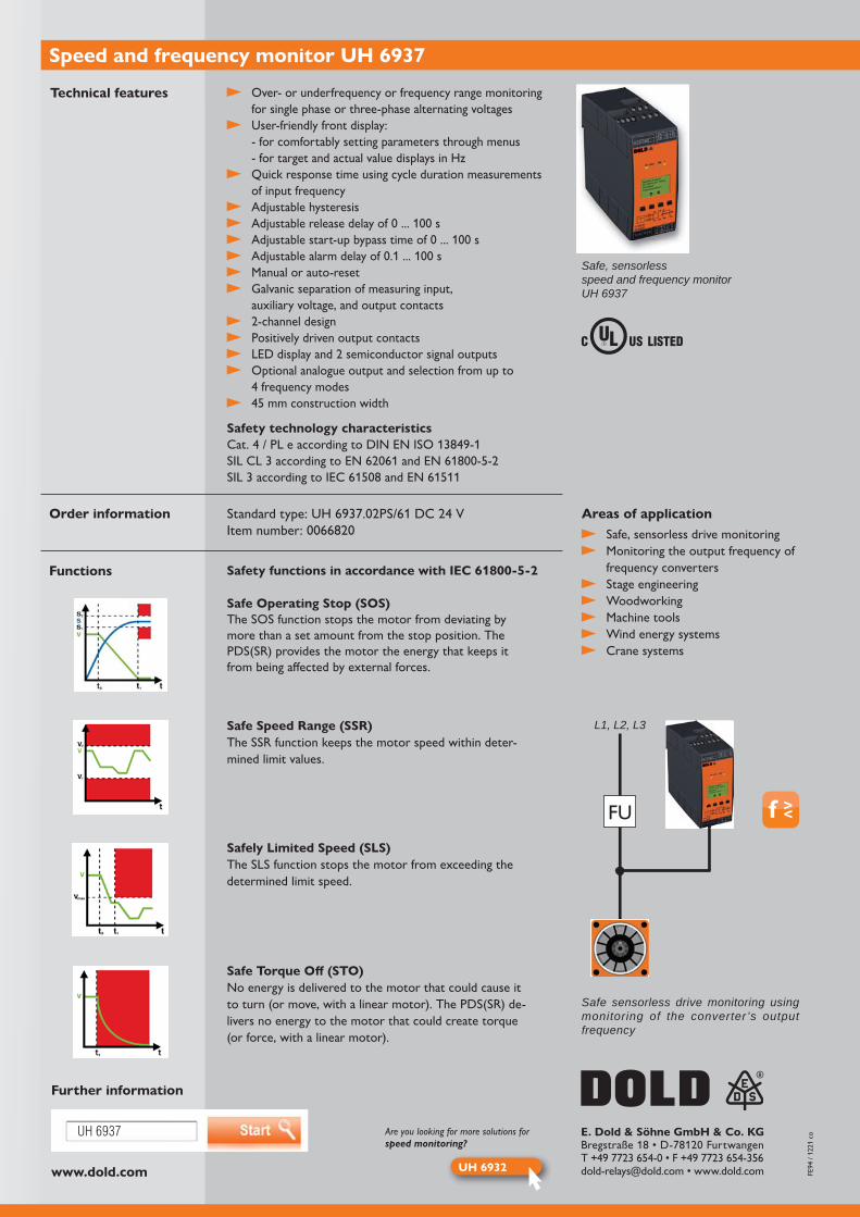
With the speed and frequency monitor UH 6937 from the SAFEMASTER S Series, DOLD offers an efficient, economic solution for safe, sensorless drive moni-toring. Monitoring the output frequency of traction converters is just one of the many different ways to use this component. In case of over- or under-frequency, or if the frequency is outside the set window, the frequency monitor shuts off safely, proving its benefit over frequency converters with integrated safety functions in any application where simplicity, flexibility, and safety are required.
As an additional protective measure, the device can be adapted to an application by pressing just a few buttons. With the appropriate wiring, the device can offer the safety functions STO (safe torque off), SOS (safe operation stop), SLS (safely limited speed), SSM (safe speed monitoring) and SSR (safe speed range) in accordance with
Level (SIL) 3.
With the help of ergonomically shaped buttons on the front, and a lit LCD display, you can quickly and easily access parameters relevant for the application, such as monitoring functions, delay times, and frequency ranges for up to four operating modes – all without a PC.
Your advantages
For safety applications up to cat. 4 / PL e or SIL 3, UL-listed
Simple, time-saving start-up without a PC
Sensorless and easy to upgrade
Comprehensive diagnostic function
Bypass option for frequency monitoring (Muting)
Up to 4 operating modes can be activated (e.g. automatic, set-up, or service mode)
Over- or under-frequency or frequency range monitoring
Our experience. Your safety.
www.dold.com
UH 6937
UH 6932
FU
L1, L2, L3
E. Dold & Söhne GmbH & Co. KG
Over- or underfrequency or frequency range monitoring for single phase or three-phase alternating voltages
User-friendly front display: - for comfortably setting parameters through menus - for target and actual value displays in Hz
Quick response time using cycle duration measurements of input frequency
Adjustable hysteresis
Manual or auto-reset Galvanic separation of measuring input,
auxiliary voltage, and output contacts
Positively driven output contacts
Optional analogue output and selection from up to 4 frequency modes
Safety technology characteristicsCat. 4 / PL e according to DIN EN ISO 13849-1
Speed and frequency monitor UH 6937
Technical features
Safe, sensorlessspeed and frequency monitorUH 6937
Safe, sensorless drive monitoring Monitoring the output frequency of
frequency converters Stage engineering Woodworking Machine tools Wind energy systems Crane systems
Areas of applicationOrder information
Further information
Functions Safety functions in accordance with IEC 61800-5-2
Safe Operating Stop (SOS)The SOS function stops the motor from deviating by more than a set amount from the stop position. The PDS(SR) provides the motor the energy that keeps it from being affected by external forces.
Safely Limited Speed (SLS)The SLS function stops the motor from exceeding the determined limit speed.
Safe Torque Off (STO)No energy is delivered to the motor that could cause it to turn (or move, with a linear motor). The PDS(SR) de-livers no energy to the motor that could create torque (or force, with a linear motor).
Safe Speed Range (SSR)The SSR function keeps the motor speed within deter-mined limit values.
Are you looking for more solutions forspeed monitoring?
Safe sensorless drive monitoring using monitoring of the converter ’s output frequency

SAFEMASTER S
More than just drive monitoring
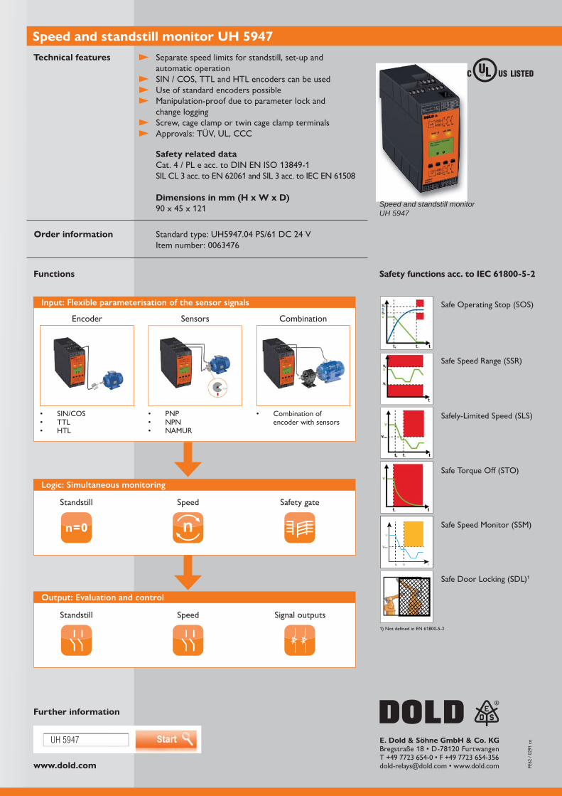
Regardless of whether the set-up operation must be monitored safely, protection via speed limitation is needed or a safety gate is released after detection of standstill - the speed and standstill monitor UH 5947 of the SAFEMASTER S series is the right choice for your application.
The device can be operated via the 4 buttons on the front and the LCD display, thus enabling simple parameterisation. For example, the encoder type, speed limits per operating mode and delay times can be flexibly adapted to your application. During operation, the current speed values can be read directly at any time, which in particular makes commissioning easier. To prevent manipulation, the configuration can be protected against unintentional changes by means of a parameter lock after commissioning. For multiple use, the configuration can easily be transferred from unit to unit via interface. The device status or the current speed can further be processed by a control system via a semiconductor signal output.
of encoder signals and PNP or NPN sensors. Alternatively, NAMUR sensor technology can be used as a device variant. The device can be used in tempe-
Advantages and customer benefits
Controllable operating mode selection via input terminals Safety gate monitoring and solenoid control possible Feedback from drives through encoders and/or sensors Simple retrofitting into existing drive concepts by switching to encoders Monitoring of slip and shaft breakage through configurable speed ratio
of the channelsOur experience. Your safety.
www.dold.com
UH 5947 E. Dold & Söhne GmbH & Co. KG
V
Vmax.
t0 t1 t
Separate speed limits for standstill, set-up and automatic operation
SIN / COS, TTL and HTL encoders can be used Use of standard encoders possible Manipulation-proof due to parameter lock and
change logging Screw, cage clamp or twin cage clamp terminals Approvals: TÜV, UL, CCC
Speed and standstill monitor UH 5947Technical features
Functions
Safety related dataCat. 4 / PL e acc. to DIN EN ISO 13849-1
Dimensions in mm (H x W x D)
Order information
Safety functions acc. to IEC 61800-5-2
Encoder
Standstill
Standstill
SIN/COSTTLHTL
PNPNPNNAMUR
Combination of encoder with sensors
Sensors
Speed
Speed
Input: Flexible parameterisation of the sensor signals
Logic: Simultaneous monitoring
Output: Evaluation and control
Combination
Safety gate
Signal outputs
Speed and standstill monitor UH 5947
Further information
Safe Operating Stop (SOS)
Safely-Limited Speed (SLS)
Safe Torque Off (STO)
Safe Speed Monitor (SSM)
Safe Door Locking (SDL)1
Safe Speed Range (SSR)

SAFEMASTER S
Sensorless safety standstill detection
The sensorless safety related standstill monitor LH 5946 of the SAFEMASTER S family recognizes direction-independent the standstill of motors without making use of additional external sensors like encoder or proximity switch. The Standstill Detec-tion is directly achieved by monitoring the voltage at the motor connection terminals.
Particularly when it comes to access protection, where regular intervention during
use of its strengths. When there is no dangerous movement from the motor anymore the safety gate can be released within a very short time at detected standstill. Due to a variable adjustment of the response value and reaction time on the device, an individual adaption is possible.
Compared to solutions with time-controlled unlocking of safety gates, maintenance
and thus productivity can be improved.
Your advantages
For safety applications up to cat. 4 / PL e / SIL 3
Fast reaction time
Easy commissioning by means of screwdriver
Easy retrofitting, as there is no connection of sensors
Reductions of down time of machines and installations
Combinations with safety lock SAFEMASTER STS available Our experience. Your safety.
www.dold.com
LH 5946
UH 5947
E. Dold & Söhne GmbH & Co. KG
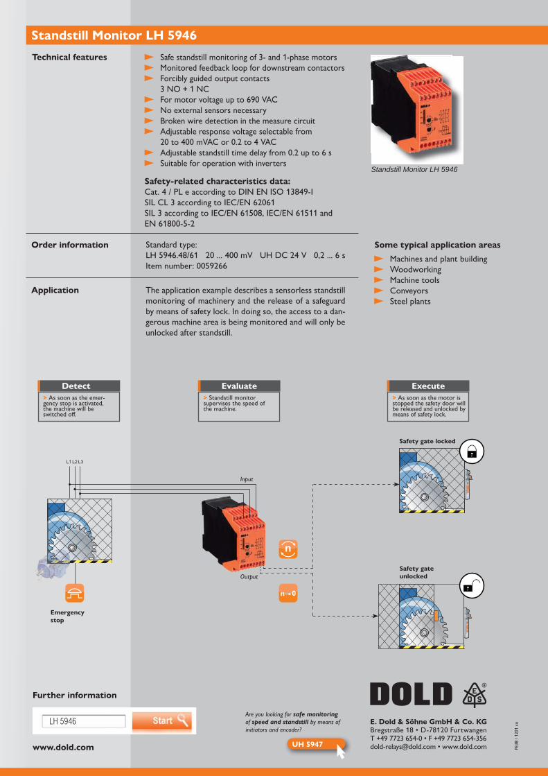
Safe standstill monitoring of 3- and 1-phase motors Monitored feedback loop for downstream contactors Forcibly guided output contacts
3 NO + 1 NC
No external sensors necessary Broken wire detection in the measure circuit Adjustable response voltage selectable from
Suitable for operation with inverters
Safety-related characteristics data:Cat. 4 / PL e according to DIN EN ISO 13849-I
Standstill Monitor LH 5946
Further information
Machines and plant building Woodworking Machine tools Conveyors Steel plants
The application example describes a sensorless standstill monitoring of machinery and the release of a safeguard by means of safety lock. In doing so, the access to a dan-gerous machine area is being monitored and will only be unlocked after standstill.
Technical features
Some typical application areasOrder information
Application
Standard type:
Are you looking for safe monitoringof speed and standstill by means ofinitiators and encoder?
Output
Input
L1L2L3
Standstill Monitor LH 5946
Safety gate locked
Emergency stop
Safety gate unlocked
Detect Evaluate Execute> As soon as the emer-gency stop is activated, the machine will be switched off.
> Standstill monitor supervises the speed of the machine.
> As soon as the motor is stopped the safety door will be released and unlocked by means of safety lock.

SAFEMASTER C
Safety technology has never been this simple.
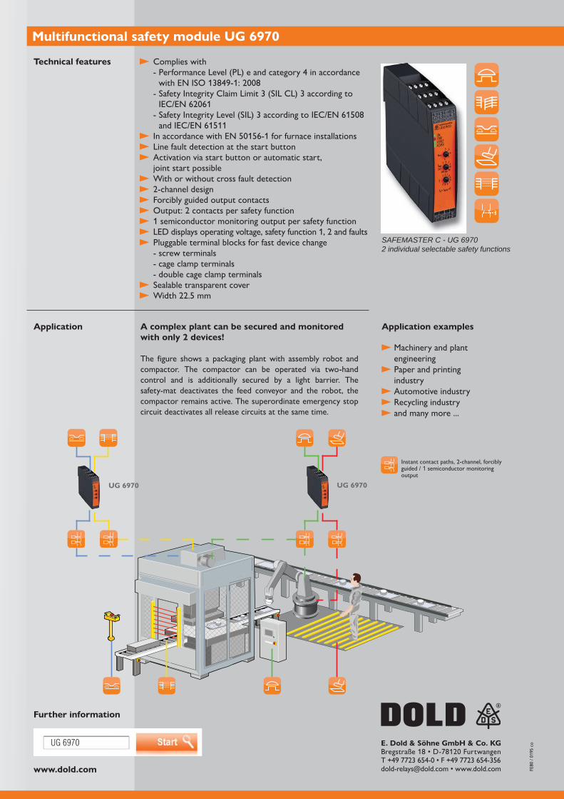
The multifunctional safety module UG 6970 from the SAFEMASTER C family serves the protection of staff and machinery by releasing and interrupting safety circuits. Up to two independent safety functions which are selected in a simple way and without programming via latching rotary switches can be implemented in a single device. The flexible adjustment of the safety functions lead to a sustainable reduction in storage costs.
Besides safety functions such as emergency stop, protective door, non-equivalent safety sensor, two-hand or light barrier, it also allows you to connect your safety-related mats and safety edges. The variable start configuration which can also be adjusted via rotary switches, allow for an optimal adjustment in accordance with the application. Besides the manual and automated start, the mutual manual start can also be selected for both safety functions.
N/O contacts and one semiconductor monitoring output for each safety function. In accordance with the requirements, the number of safety contacts can be multiplied via
Your advantages
Two safety functions independent from each other selectable Emergency stop Safety gate Two-hand control Safety-mat / safety edge Light barrier Antivalent safety sensor
Manual or automated start, individually or jointlyOur experience. Your safety.
UG 6970 UG 6970
UG 6970
www.dold.com
E. Dold & Söhne GmbH & Co. KG
Complies with - Performance Level (PL) e and category 4 in accordance
- Safety Integrity Claim Limit 3 (SIL CL) 3 according to
Line fault detection at the start button Activation via start button or automatic start,
joint start possible With or without cross fault detection
Forcibly guided output contacts
1 semiconductor monitoring output per safety function
Pluggable terminal blocks for fast device change - screw terminals - cage clamp terminals - double cage clamp terminals
Sealable transparent cover
Multifunctional safety module UG 6970
Technical features
Application A complex plant can be secured and monitored with only 2 devices!
The figure shows a packaging plant with assembly robot and compactor. The compactor can be operated via two-hand control and is additionally secured by a light barrier. The safety-mat deactivates the feed conveyor and the robot, the compactor remains active. The superordinate emergency stop circuit deactivates all release circuits at the same time.
Further information
Application examples
Machinery and plant engineering
Paper and printing industry
Automotive industry Recycling industry and many more ...
SAFEMASTER C - UG 69702 individual selectable safety functions
guided / 1 semiconductor monitoring output

SAFEMASTER C
Flexible in function, variable in time
The multifunctional safety timer UG 6960 from the SAFEMASTER C family serves the protection of staff and machinery by releasing and interrupting safety circuits. The
flexibly and without programming via latching rotary switches. Besides safety functions such as emergency stop, protective door, non-equivalent safety sensor, two-hand or light barrier, it also allows you to connect your safety-related safety-mats and safety edges. The fine adjustment of time which is also done gradually via latching rotary switches is particularly advantageous for an optimal adjustment of the device in accordance with your application.
two N/O contacts and one semiconductor monitoring output each, delayed and undelayed. In accordance with the requirements, the number of safety contacts can be multiplied via
Your advantages
Fast and exact adjustment of different time functions Release delay Release delay can be retriggered Response delay Fleeting on make/fleeting on break Detent adjustment of delay time
Suitable for several safety functions Emergency stop Safety gate Two-hand control Safety-mat / safety edge Light barrier Antivalent safety sensor
Our experience. Your safety.
UG 6960
UG 6960
www.dold.com
E. Dold & Söhne GmbH & Co. KG
Complies with - Performance Level (PL) e and category 4 in accordance
- Safety Integrity Claim Limit 3 (SIL CL) 3 according to
Line-fault detection at the start button Activation via start button or automatic start With or without cross fault detection
Forcibly guided output contacts
1 semiconductor monitoring output for instant contacts 1 semiconductor monitoring output for delayed contacts
LED displays operating voltage, safety function, time delay and faults
Pluggable terminal blocks for fast device change - screw terminals - cage clamp terminals - double cage clamp terminals
Sealable transparent cover
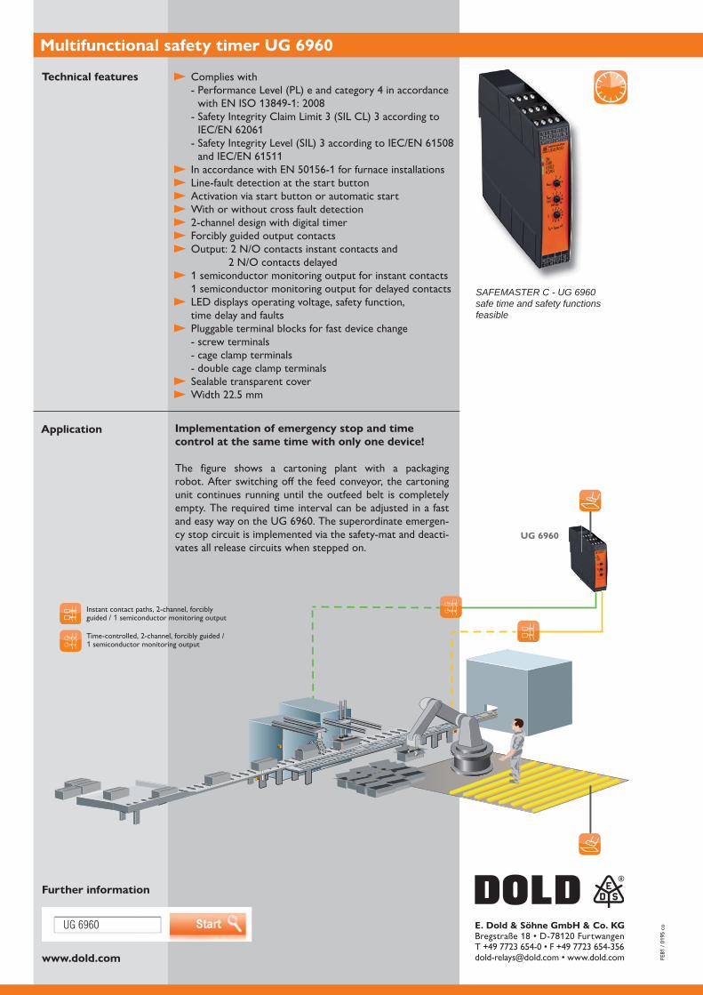
Multifunctional safety timer UG 6960
Technical features
Implementation of emergency stop and time control at the same time with only one device!
The figure shows a cartoning plant with a packaging robot. After switching off the feed conveyor, the cartoning unit continues running until the outfeed belt is completely empty. The required time interval can be adjusted in a fast
-cy stop circuit is implemented via the safety-mat and deacti-vates all release circuits when stepped on.
Application
Further information
SAFEMASTER C - UG 6960safe time and safety functions feasible
1 semiconductor monitoring output
guided / 1 semiconductor monitoring output

SAFEMASTER M
The modular, software-freesafety system
Safety-oriented control systems to evaluate safety switches and sensors as well as for the activation of actors have long been on the market. As a machine and equipment manufacturer, you are spoiled for choice. Hard wire, configure or program? The use of programmable safety controls is not always worth it. The requirements and expenses for software specification, programming, validation and documentation cannot be overlooked.
DOLD offers an interesting alternative with the multifunctional safety system SAFEMASTER M, just for smaller to medium sized facilities. Safety requirements are implemented quickly and easily through the software-free configuration.
To configure your safety applications, SAFEMASTER M requires nothing more than a simple screwdriver: Connect safety modules together with ease using a ribbon cable, define the safety function using a rotary switch, and use a DIP switch to assign the safety-related inputs to the outputs and thereby to different safety zones – that‘s all.
Advantages and customer benefit
Multifunctional, modular, freely configurable
Free assignment of input and output functions
Easy software-free configuration
Modular expandability with input and output modules
Diagnosis using LEDs and semiconductor outputs
Easy function selection with rotary switch
Optional fieldbus connection Our experience. Your safety.
www.dold.com
SAFEMASTER M
Zone 2
Zone 1
SAFEMASTER STS
SAFEMASTER STS
1 2 3 4
E. Dold & Söhne GmbH & Co. KG
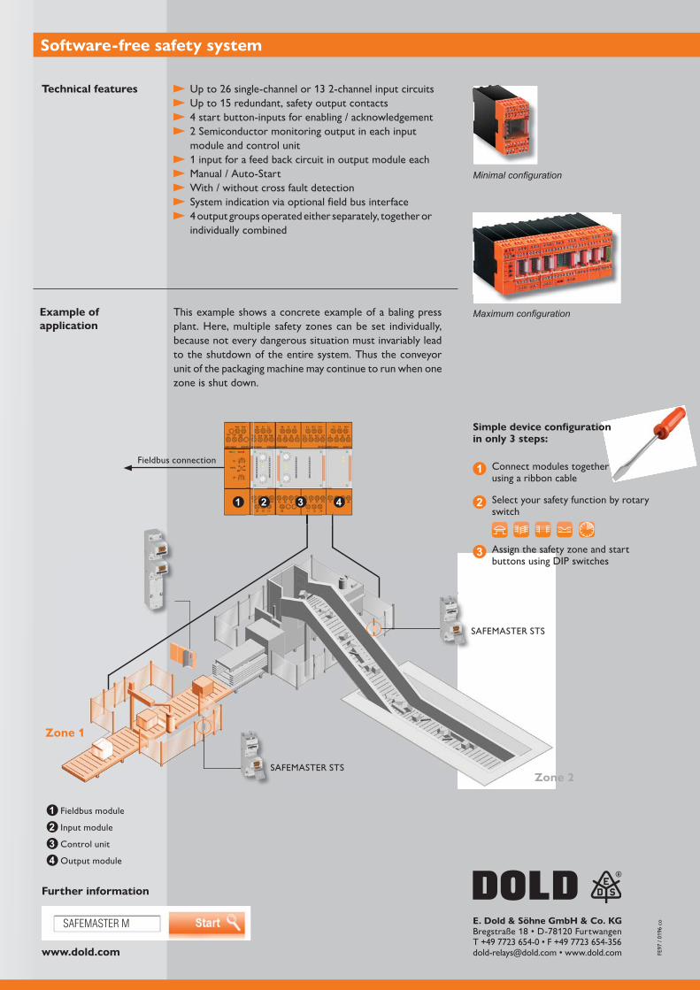
Software-free safety system
Technical features
4 start button-inputs for enabling / acknowledgement
module and control unit 1 input for a feed back circuit in output module each Manual / Auto-Start With / without cross fault detection System indication via optional field bus interface 4 output groups operated either separately, together or
individually combined
Example of application
This example shows a concrete example of a baling press plant. Here, multiple safety zones can be set individually, because not every dangerous situation must invariably lead to the shutdown of the entire system. Thus the conveyor unit of the packaging machine may continue to run when one zone is shut down.
Further information
1
2
3
Connect modules together using a ribbon cable
Simple device configuration in only 3 steps:
Select your safety function by rotary switch
Assign the safety zone and start buttons using DIP switches
Fieldbus module
Input module
Control unit
Output module
1234
Fieldbus connection

SAFEMASTER PRO
Configurable safety system -Modular and multifunctional
With the size of the plants and complexity of the safety requirements the number of safety devices increases in many applications. In addition logical functions need to be implemented when e.g. only parts of the whole system needed to be disconnected. The modular and configurable safety system SAFEMASTER PRO of DOLD monitors the safety circuits of your machines and plants simple, flexible and safe. The number of inputs and outputs of the central control unit can be amended by extension modules. In this way SAFEMASTER PRO can be configured very flexible to the actual application.
The configuration of the TUEV approved system is done very simple on a PC with the free configuration software SAFEMASTER PRO Designer: Select safety functions, assign in and outputs and connect them comfortably by PC. Finally transfer the tested logic via USB cable to the safety controller. Ready!
For safety applications up to Cat 4 / PL e and SIL 3
TÜV certified hardware and software
Configuration instead of wiring with SAFEMASTER PRO Designer
Simple handling by Drag & Drop in the graphic programming tool
Time and cost saving set-up
Reduces wiring and saves space in the cabinet
Flexible extension with safe I/O modules
Safe remote I/Os with bus extender modules for longer distances
Extensive failure localisation and diagnostics
Memory card as option for simple maintenance
Your advantages
Our experience. Your safety.
www.dold.com
1
2
3
.
SAFEMASTER PRO E. Dold & Söhne GmbH & Co. KG
Further information
Compact design: Control Unit and Extension modules
In addition to the Controller unit max. 14 extension modules can be connected
Flexible safety logic to create and amend the safety functions
Safe integrated logic testing Monitoring outputs, status LEDs and field bus connection
to provide best diagnostic functions TÜV and UL approval
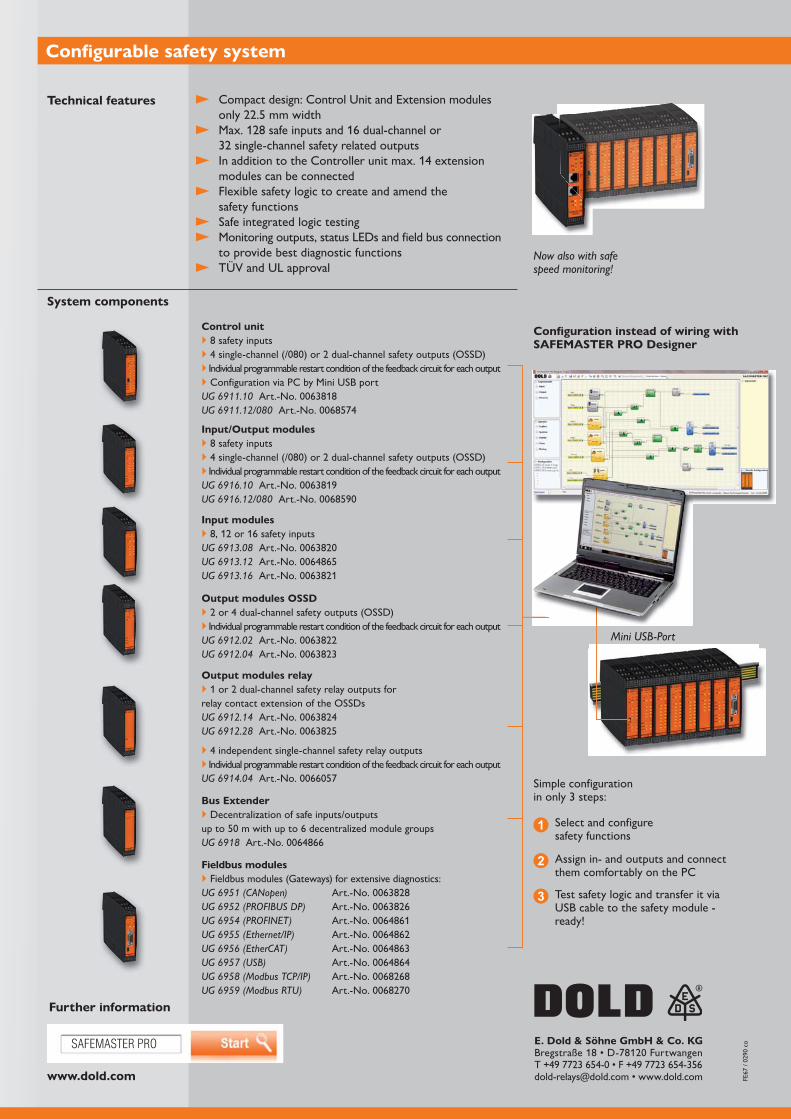
Configurable safety system
Technical features
System components
Configuration instead of wiring with SAFEMASTER PRO Designer
Select and configure safety functions
Simple configuration in only 3 steps:
Assign in- and outputs and connect them comfortably on the PC
Test safety logic and transfer it via USB cable to the safety module - ready!
Mini USB-Port
Now also with safe speed monitoring!
Control unit 8 safety inputs Individual programmable restart condition of the feedback circuit for each output Configuration via PC by Mini USB port
UG 6911.10 UG 6911.12/080
Input/Output modules 8 safety inputs Individual programmable restart condition of the feedback circuit for each output
UG 6916.10 UG 6916.12/080
Input modules
UG 6913.08 UG 6913.12 UG 6913.16
Output modules OSSD Individual programmable restart condition of the feedback circuit for each output
UG 6912.02 UG 6912.04
Output modules relay
relay contact extension of the OSSDsUG 6912.14 UG 6912.28
4 independent single-channel safety relay outputs Individual programmable restart condition of the feedback circuit for each output
UG 6914.04
Bus Extender Decentralization of safe inputs/outputs
UG 6918
Fieldbus modules Fieldbus modules (Gateways) for extensive diagnostics:
UG 6951 (CANopen) UG 6952 (PROFIBUS DP) UG 6954 (PROFINET) UG 6955 (Ethernet/IP) UG 6956 (EtherCAT) UG 6957 (USB) UG 6958 (Modbus TCP/IP) UG 6959 (Modbus RTU)

SAFEMASTER W
Wireless emergency stop system -Work wirelessly
In automated manufacturing systems, safety devices ensure that the operator does not come too close to the hazardous area during automatic operation, Frequently, however, operators must work in hazardous areas in special machine operating modes during reviews, programming, or maintenance. In such situations, the wireless emergency stop system from the SAFEMASTER W family by DOLD offers the safety you need. It is the wireless solution for mobile applications in extended or complex facilities with hazardous zones.
With the wireless emergency stop system, you can safely be closer to what’s happening. Besides the safety function, the handheld transmitter has a button and switch which can be freely configured for user-specific control tasks for convenient operation. Inde-pendent of the user’s location, it facilitates secure operation and makes it possible to switch off facilities in dangerous situations. It can be used universally, providing maximum mobility and safety.
An electronic key allows rights to be allocated to individuals. The optional design of the system with infrared transmitter and infrared receiver serves to securely (re)start machines from pre-defined start zones in the field of view.
Advantages and customer benefit
Maximum mobility and flexibility with the highest level of security
For security applications up to cat. 4 / PL e or SIL CL 3, TÜV certified
Ergonomic handheld transmitter for fatigue-free work
Comfortable one-handed operation
Maximum freedom of movement due to the cordless design
Clearly arranged control panel, can be configured individually
Protection from accidentally pressing the button
Quick charging and high capacity transmitter battery Our experience. Your safety.
www.dold.com
SAFEMASTER W
1
23
E. Dold & Söhne GmbH & Co. KG
Safe transmission path User-friendly, compact handheld transmitter
Comfortable, one-handed operation Available if desired with 4 freely configurable buttons
or knobs for control functions
With label fields beside the buttons Protection from accidentally operating the buttons Quick charging and high capacity transmitter battery Possible to quickly adjust frequency Optional belt or chest bag for the handheld transmitter
Safety technology characteristicsPerformance Level (PL) e and category 4 in accordance with
Safety Integrity Level (SIL 3) in accordance with IEC/EN
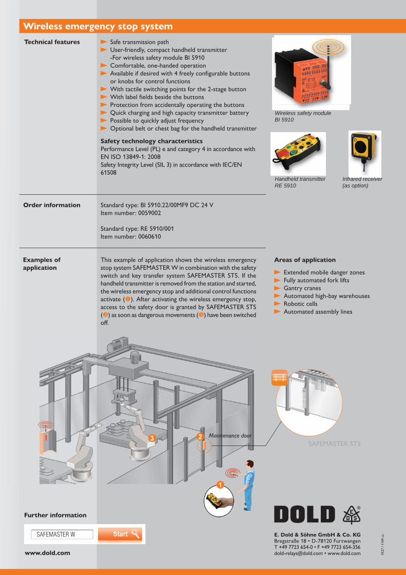
Wireless emergency stop system
Further information
Extended mobile danger zones Fully automated fork lifts Gantry cranes Automated high-bay warehouses Robotic cells Automated assembly lines
Technical features
Areas of application
Order information
Wireless safety moduleBI 5910
Handheld transmitterRE 5910
This example of application shows the wireless emergency stop system SAFEMASTER W in combination with the safety switch and key transfer system SAFEMASTER STS. If the handheld transmitter is removed from the station and started, the wireless emergency stop and additional control functions activate ( ). After activating the wireless emergency stop, access to the safety door is granted by SAFEMASTER STS ( ) as soon as dangerous movements ( ) have been switched off.
Examples of application
Maintenance doorSAFEMASTER STS
Infrared receiver(as option)

SAFEMASTER W
Wireless enabling switch - Have a good grip on safety
In automised processes safety systems block the access to dangerous areas. Often people have to work inside a dangerous area while the machine is in a special operation mode e.g. during test, programming and maintenance.
Especially for these situations the TUEV approved 3-step radiocontrolled enabling switch SAFEMASTER W provides the necessary safety functions. It allows a safe operation and safe disconnection in a dangerous situation. It is designed for universal usage and allows maximum mobility and flexibility. In the case of danger the operator presses the button fully or releases it from middle position. The machine goes into safe state. In addition the unit has a display and 4 programmable push buttons to actuate
The ergonomic designed enabling switch with large display provides a comfortable one hand operation.
Maximum mobility and flexibility at highest safety
For safety applications up to Cat 4 / PL e or SIL CL 3, TUEV approved
Ergonomic transmitter for non-tiring operation
Comfortable one-hand operation
Clear operating panel with easy to read display
Fast frequency adoption to environment on the enabling switch
Maximum freedom of movement due to wireless design
High operating safety by dynamic and redundant data transmission protocol
Your advantages
Our experience. Your safety.
www.dold.com
RE 6910 E. Dold & Söhne GmbH & Co. KG
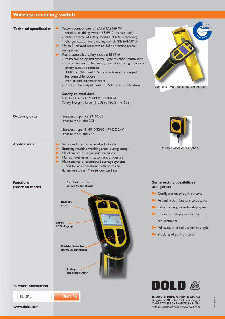
System components of SAFEMASTER W
Up to 3 infrared receivers to define starting areas (as option)
- to receive e-stop and control signals via radio transmission- to connect e-stop buttons, gate contacts or light curtains- safety output contacts:
for control functions- manual and automatic start- 3 transistor outputs and LEDS for status indication
Safety related dataCat 4 / PL e to DIN EN ISO 13849-1
Wireless enabling switch
Further information
Setup and maintenance of robot cellsEntering machine working areas during setupMaintenance of dangerous machinesManual interfering in automatic processesMaintenance of automated storage systems…and for all applications with access to dangerous areas. Please contact us
Technical specification
Applications
Functions(Function mode)
Pushbuttons to select 10 functions
3-step enabling switch
Pushbuttons for up to 20 functions
Large LCD display
Battery status
Some setting possibilities at a glance:
Configuration of push buttons
Assigning push buttons to outputs
Individual programmable display text
Frequency adoption to ambient
requirements
Adjustment of radio signal strength
Blocking of push buttons
Ordering data
Enabling switch RE 6910 and charger
Infrared receiver (as option)
SAFEMASTER W
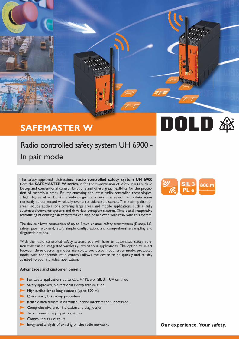
SIL 3PL e
800 m
Our experience. Your safety.
In pair mode
The safety approved, bidirectional radio controlled safety system UH 6900 from the SAFEMASTER W series, is for the transmission of safety inputs such as E-stop and conventional control functions and offers great flexibility for the protec-tion of hazardous areas. By implementing the latest radio controlled technologies, a high degree of availability, a wide range, and safety is achieved. Two safety zones can easily be connected wirelessly over a considerable distance. The main application areas include applications covering large areas and mobile applications such as fully automated conveyor systems and driverless transport systems. Simple and inexpensive retrofitting of existing safety systems can also be achieved wirelessly with this system.
The device allows connection of up to 3 two-channel safety transmitters (E-stop, LC, safety gate, two-hand, etc.), simple configuration, and comprehensive sampling and diagnostic options.
With the radio controlled safety system, you will have an automated safety solu-tion that can be integrated wirelessly into various applications. The option to select between three operating modes (complete protected mode, cross mode, protected mode with connectable ratio control) allows the device to be quickly and reliably adapted to your individual application.
Advantages and customer benefit
For safety applications up to Cat. 4 / PL e or SIL 3, TÜV certified Safety approved, bidirectional E-stop transmission
Quick start, fast set-up procedure Reliable data transmission with superior interference suppression Comprehensive error indication and diagnostics Two channel safety inputs / outputs Control inputs / outputs Integrated analysis of existing on site radio networks
www.dold.com
UH 6900
I / O I / O
I / OI / O USB
E. Dold & Söhne GmbH & Co. KG
Further information
Radio controlled safety system UH 6900 - Pair mode
Technical features
Order information
Overview
ApplicationApplication example
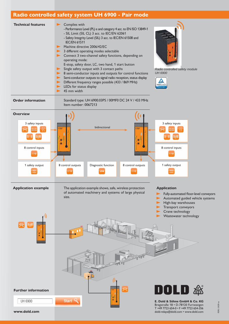
Radio controlled safety module UH 6900
Complies with - Performance Level (PL) e and category 4 acc. to EN ISO 13849-1
3 different operating modes selectable Connect 3 two-channel safety functions, depending on
operating mode: E-stop, safety door, LC, two hand, 1 start button
Single safety output with 3 contact paths 8 semi-conductor inputs and outputs for control functions Semi-conductor outputs to signal radio reception, status display
LEDs for status display
Fully-automated floor-level conveyors Automated guided vehicle systems High-bay warehouses Transport conveyors Crane technology Wastewater technology
The application example shows, safe, wireless protection of automated machinery and systems of large physical size.
3 safety inputs 3 safety inputs
8 control inputs 8 control inputs
8 control outputs8 control outputs 1 safety output1 safety output Diagnostic function
bidirectional

SAFEMASTER W
SIL 3PL e
800 m
In group mode
The radio controlled safety system UH 6900 of the SAFEMASTER W
safety-related, wireless transmission of emergency stop and control functions, offers more flexibility in safeguarding hazardous areas. High availability, long range and safety are achieved by implementing the latest radio technologies. With the group controller, several receivers can be safely switched off via a unidirectional, safety-related radio link. Furthermore, the controller can exchange message, control and status information with a receiving device.
The devices enable the connection of up to 3 two-channel safety sensors (emer-gency stop, LC, safety door, two-hand etc.) and offer simple configuration as well as extensive evaluation and diagnostic options.
The main areas of application include mobile applications such as fully automated floor conveyors and driverless transport systems. A simple and cost-effective retro-fitting of existing safety systems can also be realized without wiring.
Advantages and customer benefits
For safety applications up to Cat. 4 / PL e or SIL 3, TÜV certified Safety-related, unidirectional emergency-stop transmission in group mode
Quick start, fast set-up procedure Reliable data transmission and low susceptibility to interference Comprehensive fault localization and diagnosis Two-channel safety inputs / outputs Control inputs / outputs Integrated analysis of the existing radio network
Our experience. Your safety.
www.dold.com
UH 6900
I / O
I / O
. . .USB
E. Dold & Söhne GmbH & Co. KG
Radio controlled safety system UH 6900 - Group mode
Further information
Technical features
Order information
Overview
Applications
Application example
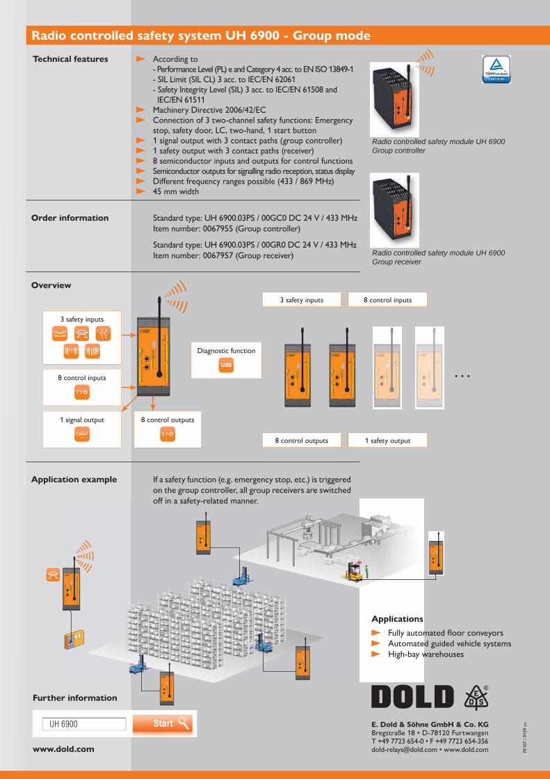
Radio controlled safety module UH 6900Group controller
Radio controlled safety module UH 6900Group receiver
According to - Performance Level (PL) e and Category 4 acc. to EN ISO 13849-1
Connection of 3 two-channel safety functions: Emergency stop, safety door, LC, two-hand, 1 start button
1 signal output with 3 contact paths (group controller) 1 safety output with 3 contact paths (receiver) 8 semiconductor inputs and outputs for control functions Semiconductor outputs for signalling radio reception, status display
Fully automated floor conveyors Automated guided vehicle systems High-bay warehouses
If a safety function (e.g. emergency stop, etc.) is triggered on the group controller, all group receivers are switched off in a safety-related manner.
3 safety inputs
8 control inputs
8 control outputs1 signal output
Diagnostic function
3 safety inputs 8 control inputs
8 control outputs 1 safety output

VARIMETER EDS
Insulation fault location system with Modbus RTU -
Precise localisation of faults during operation
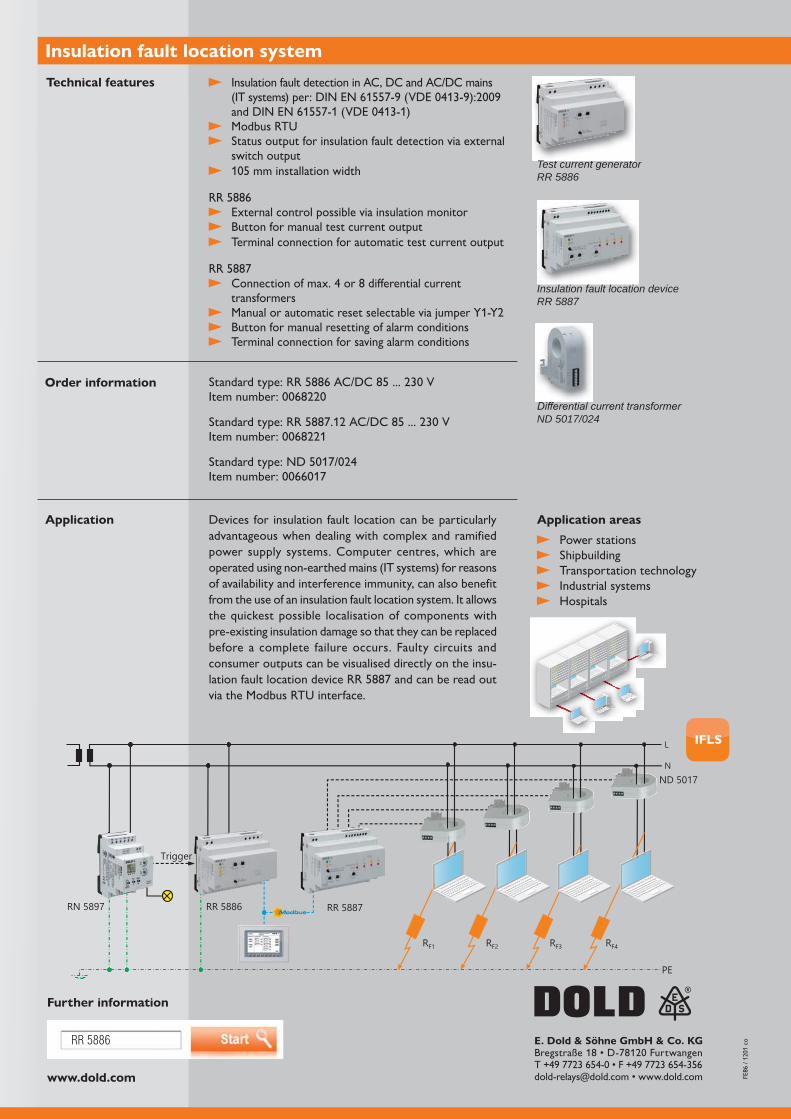
In extensive industrial systems, the localisation of insulation faults can be a cost-intensive and time-consuming process. The insulation fault location systems from the VARIMETER EDS family of DOLD, comprising the RR 5886 test current generator and the RR 5887 insulation fault location device, localise insulation faults quickly and reliably in complex insulated AC/DC mains (IT systems).
A device for insulation fault detection, also known as IFLS (Insulation Fault Location System), enables the rapid localisation of insulation faults in non-earthed power supply systems. It is employed along with an insulation monitor and in the event of a fault it injects a test current between the current-carrying conductors and the earth. It allows the quickest possible localisation of components with pre-existing insulation damage so that they can be replaced before a complete failure occurs, i.e. there is no need to shut down the plant. Protective devices such as circuit breakers or fuses only trip after a second fault. Immediate fault rectification is therefore required.
During operation you receive all necessary information regarding faulty circuits and
detection device. Via the Modbus RTU interface, insulation fault current values can be read out from the connected devices. This allows the optimum planning of the maintenance and repair of your plant. VARIMETER EDS is suitable for use in a great variety of sectors.
Automatic and rapid localisation of faulty circuits
Increase in reliability and system availability
Optimum planning of the maintenance and repair
No manual and time-consuming fault detection
Simple operation
Monitoring of complex systems
With Modbus RTU interface
Advantages and customer benefits
Our experience. Your safety.
www.dold.com
RR 5886
L
NND 5017
RN 5897 RR 5886 RR 5887
PE
RF1 RF2 RF3 RF4
Trigger
IFLS
E. Dold & Söhne GmbH & Co. KG
Insulation fault detection in AC, DC and AC/DC mains
Modbus RTU Status output for insulation fault detection via external
switch output
External control possible via insulation monitor Button for manual test current output Terminal connection for automatic test current output
Connection of max. 4 or 8 differential current transformers
Button for manual resetting of alarm conditions Terminal connection for saving alarm conditions
Insulation fault location system
Further information
Power stations Shipbuilding Transportation technology Industrial systems Hospitals
Devices for insulation fault location can be particularly advantageous when dealing with complex and ramified power supply systems. Computer centres, which are operated using non-earthed mains (IT systems) for reasons of availability and interference immunity, can also benefit from the use of an insulation fault location system. It allows the quickest possible localisation of components with pre-existing insulation damage so that they can be replaced before a complete failure occurs. Faulty circuits and consumer outputs can be visualised directly on the insu-
via the Modbus RTU interface.
Technical features
Application areasApplication
Insulation fault location deviceRR 5887
Test current generatorRR 5886
Order information
ND 5017/024

VARIMETER RCM
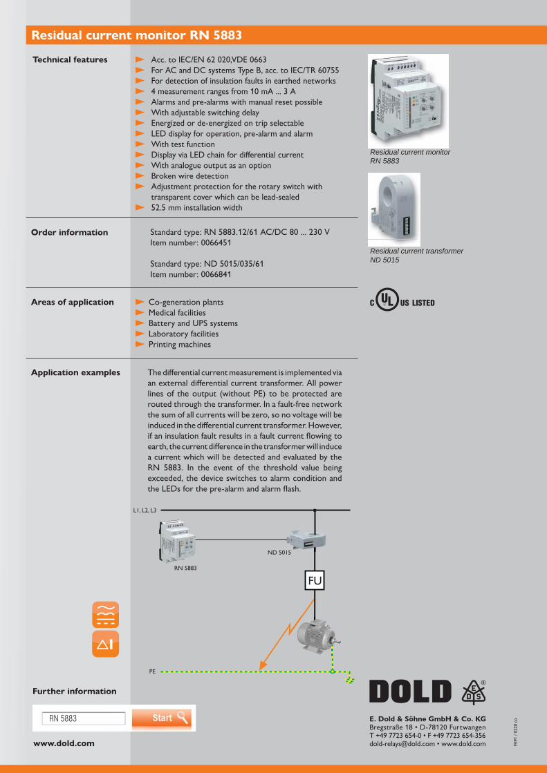
The residual current monitor RN 5883 (type B) from the VARIMETER RCM family by DOLD detects fault currents with DC or AC components in earthed networks. Here, the differential current measurement is implemented via the ND 5015 external differential current transformer. With an installation depth of 71 mm, the RN 5883 is also suitable for use in installation consumer units and industrial cabinets.
Residual current monitors (RCMs) measure and monitor differential currents or fault currents in earthed power supply systems. They are installed in systems in which a message rather than a shut-down is to be initiated in the event of a fault. In comparison to residual current breakers (or residual current devices - RCDs), which trip in the event of a defined fault current being measured and cause an immediate shut-down, residual current monitors indicate a fault current early and report a degradation of insulation via an output contact for example.
The early detection of insulation faults along with preventative maintenance and repair outside operating hours allows unexpected downtimes for machines and systems to be avoided and this in turn avoids undesirable operational interruptions, property damage and high costs.
Advantages and customer benefits
Space-saving switch cabinet installation with a width of just 52.5 mm Time and cost optimised maintenance / repair High system availability through early fault reporting Simple adjustment via stepped rotary switches Broken wire detection in the measurement circuit 4 measurement ranges from 10 mA to 3 A Adjustable pre-alarm
Residual current monitor RN 5883 - Reliably detect fault currents
Our experience. Your safety.
www.dold.com
RN 5883
PE
RN 5883
ND 5015
L1, L2, L3
15
FU
E. Dold & Söhne GmbH & Co. KG
Residual current monitor RN 5883
Technical features
Residual current monitorRN 5883
Residual current transformer ND 5015
Acc. to IEC/EN 62 020,VDE 0663
4 measurement ranges from 10 mA ... 3 A Alarms and pre-alarms with manual reset possible With adjustable switching delay Energized or de-energized on trip selectable LED display for operation, pre-alarm and alarm With test function Display via LED chain for differential current With analogue output as an option Broken wire detection Adjustment protection for the rotary switch with
transparent cover which can be lead-sealed 52.5 mm installation width
Order information
The differential current measurement is implemented via an external differential current transformer. All power lines of the output (without PE) to be protected are routed through the transformer. In a fault-free network the sum of all currents will be zero, so no voltage will be induced in the differential current transformer. However, if an insulation fault results in a fault current flowing to earth, the current difference in the transformer will induce a current which will be detected and evaluated by the RN 5883. In the event of the threshold value being exceeded, the device switches to alarm condition and the LEDs for the pre-alarm and alarm flash.
Application examples
Areas of application Co-generation plants Medical facilities Battery and UPS systems Laboratory facilities Printing machines
Standard type: RN 5883.12/61 AC/DC 80 ... 230 VItem number: 0066451
Standard type: ND 5015/035/61Item number: 0066841
Further information
VARIMETER RCM
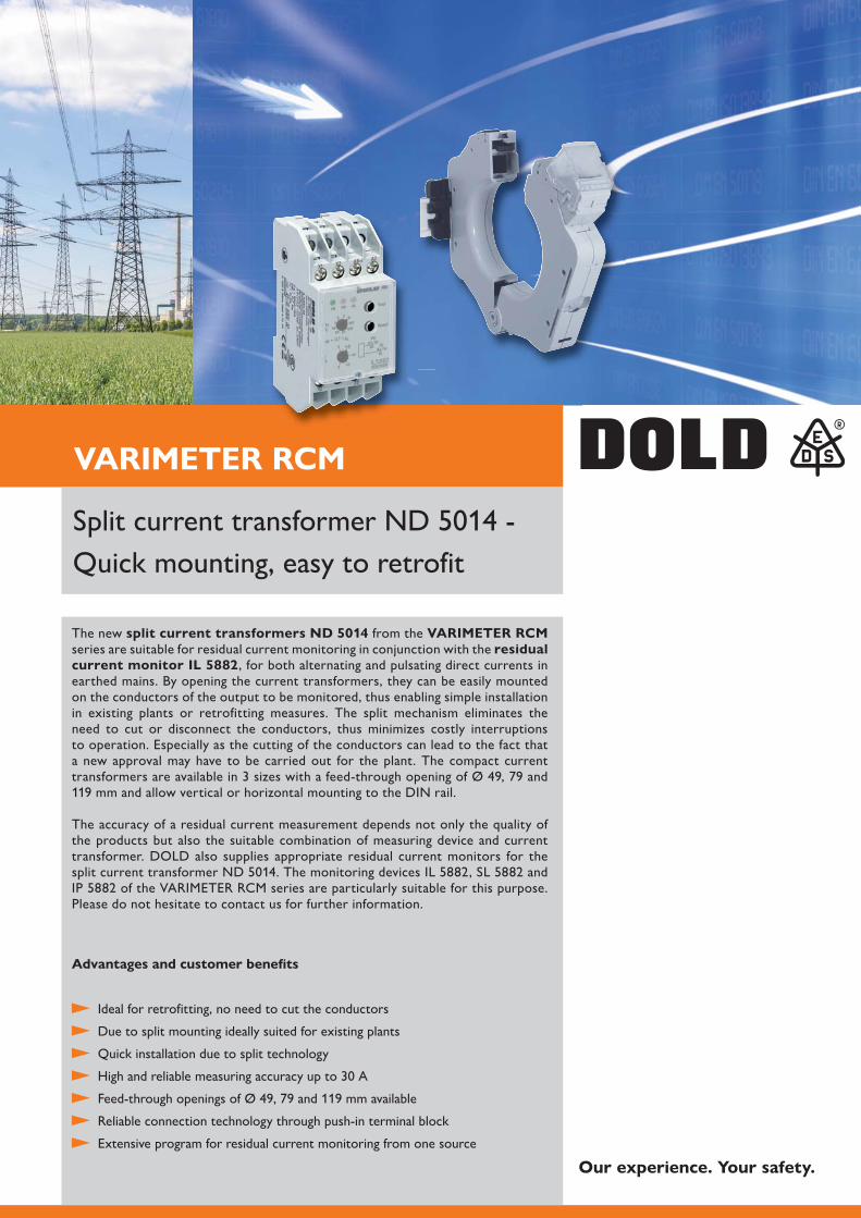
The new split current transformers ND 5014 from the VARIMETER RCM series are suitable for residual current monitoring in conjunction with the residual current monitor IL 5882, for both alternating and pulsating direct currents in earthed mains. By opening the current transformers, they can be easily mounted on the conductors of the output to be monitored, thus enabling simple installation in existing plants or retrofitting measures. The split mechanism eliminates the need to cut or disconnect the conductors, thus minimizes costly interruptions to operation. Especially as the cutting of the conductors can lead to the fact that a new approval may have to be carried out for the plant. The compact current
119 mm and allow vertical or horizontal mounting to the DIN rail.
The accuracy of a residual current measurement depends not only the quality of the products but also the suitable combination of measuring device and current transformer. DOLD also supplies appropriate residual current monitors for the
Please do not hesitate to contact us for further information.
Advantages and customer benefits
Ideal for retrofitting, no need to cut the conductors
Due to split mounting ideally suited for existing plants
Quick installation due to split technology
Reliable connection technology through push-in terminal block
Extensive program for residual current monitoring from one source
Quick mounting, easy to retrofit
Our experience. Your safety.
www.dold.com
ND 5014
ND 5016
123
E. Dold & Söhne GmbH & Co. KG
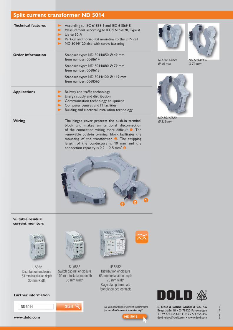
Split current transformer ND 5014
Technical features
Applications
Wiring
Suitable residual current monitors
Further information
ND 5014/050Ø 49 mm
ND 5014/080Ø 79 mm
ND 5014/120Ø 119 mm
Vertical and horizontal mounting to the DIN rail
Railway and traffic technology Energy supply and distribution Communication technology equipment Computer centres and IT facilities Building and electrical installation technology
IL 5882Distribution enclosure63 mm installation depth
35 mm width
IP 5882Distribution enclosure
63 mm installation depth70 mm width
Cage clamp terminalsforcibly guided contacts
SL 5882Switch cabinet enclosure
100 mm installation depth35 mm width
The hinged cover protects the push-in terminal block and makes unintentional disconnection of the connection wiring more difficult . The removable push-in terminal block facilitates the mounting of the transformer . The stripping
.
Do you need further current transformers for residual current monitoring?
Order information

VARIMETER IMD
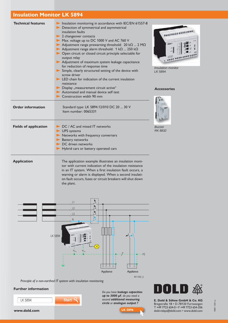
With the new Insulation Monitor LK 5894 from the VARIMETER IMD family, DOLD offers a convincing solution for insulation monitoring of non-earthed AC, AC/DC,
is used for preventive maintenance and repair. Faults are detected even during operation and costly plant standstills are prevented. The insulation monitor was specially designed for use in modern power supplies that often include rectifiers, converters, thyristor cont-rollers or directly connected DC components. EMC interference suppression measures with its leakage capacitances against earth play an important role in this matter. DOLD's insulation monitor meets the criteria.
Besides a faster fault localisation by selective earth fault detection and optimised measuring
additional adaption device.
The device can be adjusted quickly and easily with its latching rotary switches. The measu-ring circuit monitoring for broken wire detection and the LED chain for indication of the
Advantages and customer benefit
Preventive fire and plant protection Early insulation fault detection during operation No additional adaption device needed Fast error localisation via selective earth fault detection to L+ and L- Suitable for universal application in non-earthed DC/AC and mixed networks
Simple adjustment via latching rotary switches Reliable monitoring, also in voltage-free network Measuring circuit monitoring of wire breakage Our experience. Your safety.
www.dold.com
LK 5894
LK 5896
LK5894
M11202_b
L3
N
PE
Verbraucher Verbraucher
L2
L1
LK 5894
E. Dold & Söhne GmbH & Co. KG
Insulation Monitor LK 5894Technical features
Order information
The application example illustrates an insulation moni-tor with current indication of the insulation resistance in an IT system. When a first insulation fault occurs, a warning or alarm is displayed. When a second insulati-on fault occurs, fuses or circuit breakers will shut down the plant.
Application
Fields of application
Further information
Insulation monitorLK 5894
Detection of symmetrical and asymmetrical insulation faults
Open circuit or closed circuit principle selectable for output relay
Adjustment of maximum system leakage capacitance for reduction of response time
Simple, clearly structured setting of the device with screw driver
LED chain for indication of the current insulation resistance
Display „measurement circuit active“ Automated and manual device self test
DC / AC and mixed IT networks UPS systems Networks with frequency converters Battery networks DC driven networks Hybrid cars or battery operated cars
Principle of a non-earthed IT system with insulation monitoring
Verbraucher VerbraucherAppliance Appliance
Do you have leakage capacitiesup to 3000 μF, do you need asecond additional measuringcircle or analogue output ?
Accessories
BuzzerRK 8832

VARIMETER IMD
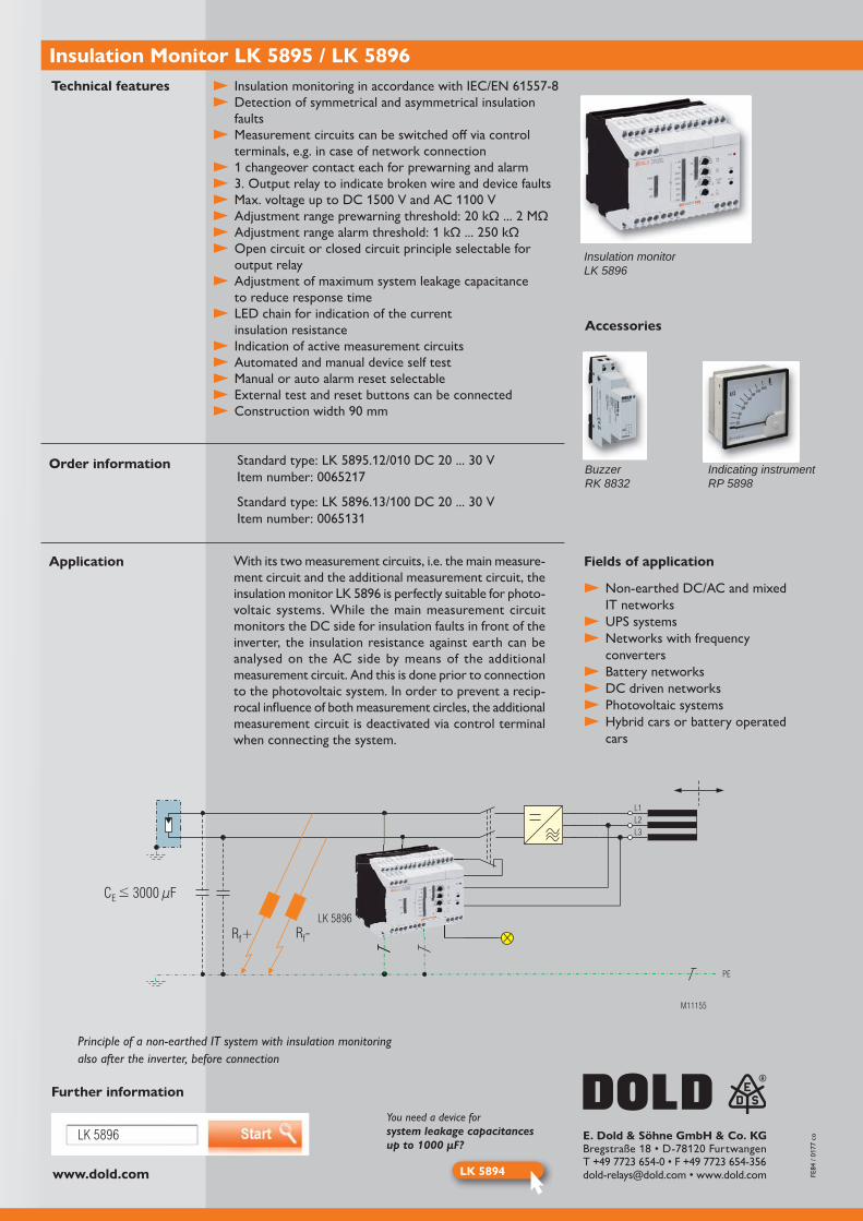
With the new Insulation Monitors LK 5895 and LK 5896 from the VARIMETER IMD family, DOLD offers a convincing solution for insulation monitoring of non-earthed AC, AC/DC, and DC power supplies (IT systems). The devices increase the availability of plants and are used for preventive maintenance and repair. Faults are detected even during opera-tion and costly plant standstills are prevented. The insulation monitors were specially desi-gned for use in modern power supplies that often include rectifiers, converters, thyristor controllers or directly connected DC components. EMC interference suppression with its leakage capacitances against earth plays an important role in this matter. The two insula-tion monitors meet these requirements.
Besides a faster fault localisation by selective earth fault detection and optimised measu-ring times, the insulation monitors can deal with system leakage capacitances of up to
simultaneous monitoring of an AC network which is galvanically isolated from the main measurement circuit. Universal analogue outputs for the insulation resistance output complete the device's functionality.
Advantages and customer benefit
Preventive fire and plant protection Early insulation fault detection during operation No additional adaption device needed Fast error localisation via selective earth fault detection to L+ and L- Suitable for universal application in non-earthed DC/AC and mixed networks
Simple adjustment via latching rotary switches Reliable monitoring, also in voltage-free network
Our experience. Your safety.
www.dold.com
LK 5896
LK 5894
M11155
C 3000 μFE<
R -fR +f
PE
L3
L2
L1
LK 5896
E. Dold & Söhne GmbH & Co. KG
Insulation Monitor LK 5895 / LK 5896Technical features
Order information
With its two measurement circuits, i.e. the main measure-ment circuit and the additional measurement circuit, the
-voltaic systems. While the main measurement circuit monitors the DC side for insulation faults in front of the inverter, the insulation resistance against earth can be analysed on the AC side by means of the additional measurement circuit. And this is done prior to connection to the photovoltaic system. In order to prevent a recip-rocal influence of both measurement circles, the additional measurement circuit is deactivated via control terminal when connecting the system.
Application
Further information
Insulation monitorLK 5896
Detection of symmetrical and asymmetrical insulation faults
Measurement circuits can be switched off via control terminals, e.g. in case of network connection
1 changeover contact each for prewarning and alarm 3. Output relay to indicate broken wire and device faults
Open circuit or closed circuit principle selectable for output relay
Adjustment of maximum system leakage capacitance to reduce response time
LED chain for indication of the current insulation resistance
Indication of active measurement circuits Automated and manual device self test Manual or auto alarm reset selectable External test and reset buttons can be connected
Non-earthed DC/AC and mixed IT networks
UPS systems Networks with frequency
converters Battery networks DC driven networks Photovoltaic systems Hybrid cars or battery operated
cars
Fields of application
Principle of a non-earthed IT system with insulation monitoringalso after the inverter, before connection
You need a device forsystem leakage capacitancesup to 1000 μF?
Accessories
BuzzerRK 8832
Indicating instrumentRP 5898

VARIMETER IMD
The number of electric vehicles is constantly increasing and will grow even faster in the future. This will also drive forward the expansion of the charging station infra-structure, as DC charging stations are the first choice when electric vehicles need to be charged in the shortest possible time. Electrical safety must be guaranteed during the charging process. For this purpose, an unearthed DC power supply system (IT grid) with insulation monitoring is set up and monitored by means of an insulation monitoring device (IMD). The user must never be exposed to high voltages (up to 1
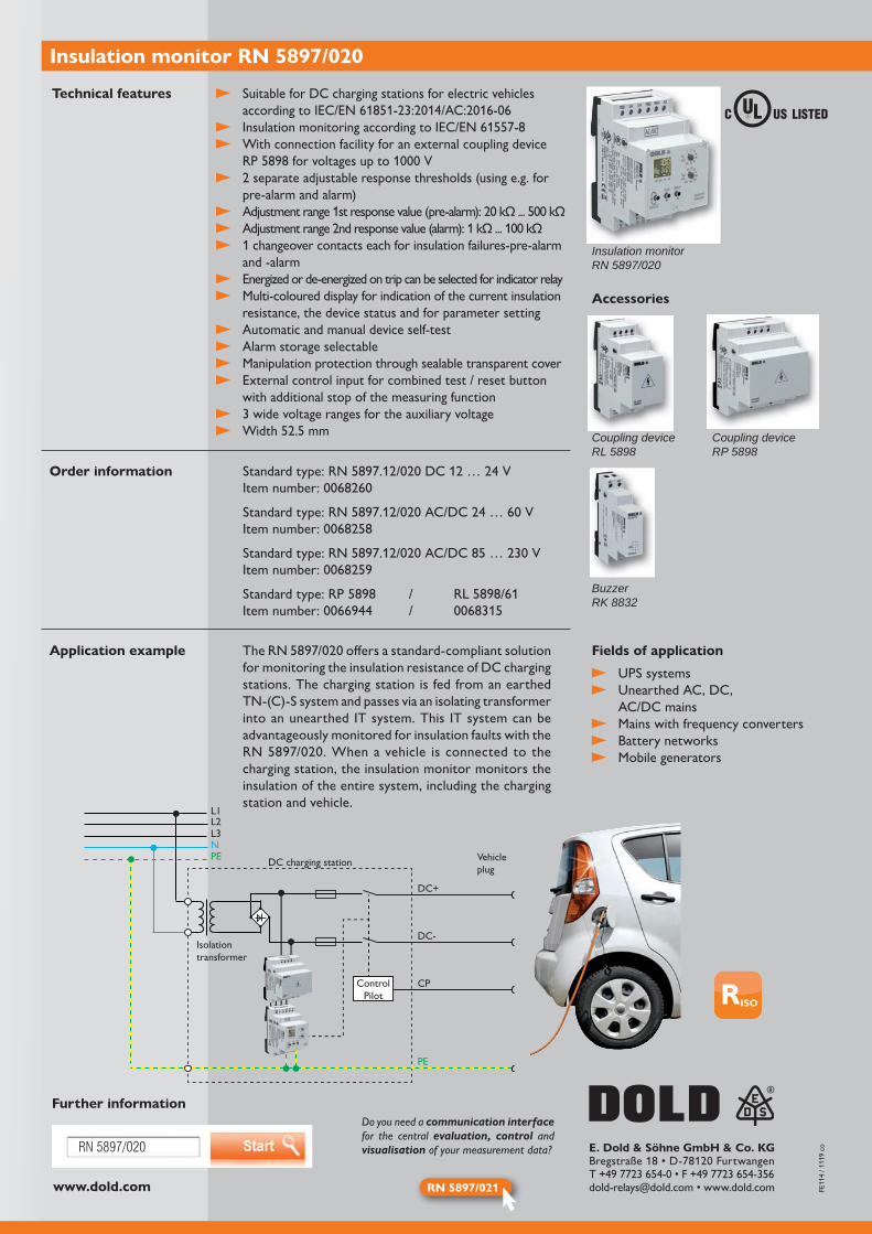
The insulation monitor RN 5897/020 of the VARIMETER IMD family is used
standard and monitors the charging process from the charging station into the vehicle. The device is characterised by the short response delay of ≤ 1s, a rated voltage up to DC 1 -rical insulation faults. The integrated voltage measurement ensures reliable detection of the insulation resistance in the IT grid. The insulation monitor also features a self-test. This takes place automatically after power-on and after every full operating hour.
Advantages and customer benefits
Response delay of ≤ 1s
Nominal voltage up to DC 1 Integrated voltage metering
Self-test function after every full operating hour
Detection of symmetrical and asymmetrical insulation faults
Fast fault localization through selective earth fault detection according to L+ and L-
Multicolour display for indication of insulation value
Universally applicable in unearthed AC, DC and AC/DC grids
Simple setting of parameters via rotary switch and menu navigation
Insulation monitoring for DC charging stations
Our experience. Your safety.
www.dold.com
RN 5897/020 E. Dold & Söhne GmbH & Co. KG
RN 5897/021
Insulation monitor RN 5897/020
Technical features
Order information
Application example
Further information
FE11
4 / 1
119
co
Insulation monitorRN 5897/020
UPS systems Unearthed AC, DC,
AC/DC mains Mains with frequency converters Battery networks Mobile generators
Standard type:
Standard type:
Standard type:
Standard type:
Suitable for DC charging stations for electric vehicles
With connection facility for an external coupling device
pre-alarm and alarm)
1 changeover contacts each for insulation failures-pre-alarm and -alarm
Energized or de-energized on trip can be selected for indicator relay Multi-coloured display for indication of the current insulation
resistance, the device status and for parameter setting Automatic and manual device self-test Alarm storage selectable Manipulation protection through sealable transparent cover External control input for combined test / reset button
with additional stop of the measuring function 3 wide voltage ranges for the auxiliary voltage
Fields of applicationfor monitoring the insulation resistance of DC charging stations. The charging station is fed from an earthed TN-(C)-S system and passes via an isolating transformer into an unearthed IT system. This IT system can be advantageously monitored for insulation faults with the
charging station, the insulation monitor monitors the insulation of the entire system, including the charging station and vehicle.
Accessories
BuzzerRK 8832
Coupling deviceRP 5898
Coupling deviceRL 5898
L1L2L3NPE
ControlPilot
DC+
DC-
CP
PE
Vehicleplug
Isolationtransformer
DC charging station
Do you need a communication interface for the central evaluation, control and visualisation of your measurement data?
VARIMETER IMD
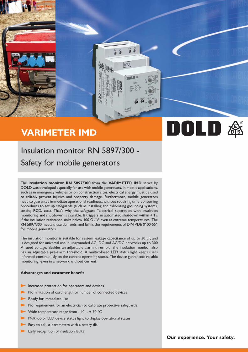
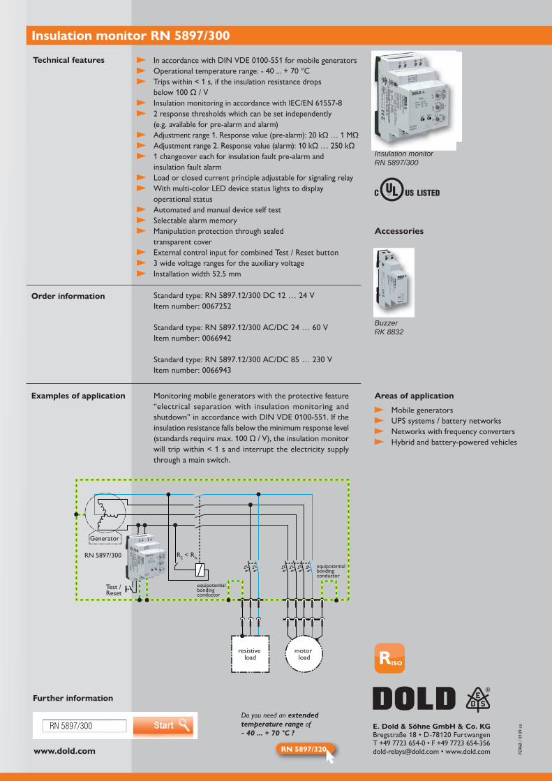
The insulation monitor RN 5897/300 from the VARIMETER IMD series by DOLD was developed especially for use with mobile generators. In mobile applications, such as in emergency vehicles or on construction sites, electrical energy must be used to reliably prevent injuries and property damage. Furthermore, mobile generators need to guarantee immediate operational readiness, without requiring time-consuming procedures to set up safeguards (such as installing and calibrating grounding systems, testing RCD, etc.). That’s why the safeguard “electrical separation with insulation monitoring and shutdown” is available. It triggers an automated shutdown within < 1 s
for mobile generators.
V rated voltage. Besides an adjustable alarm threshold, the insulation monitor also has an adjustable pre-alarm threshold. A multicolored LED status light keeps users informed continuously on the current operating status. The device guarantees reliable monitoring, even in a network without current.
Advantages and customer benefit
Increased protection for operators and devices
No limitation of cord length or number of connected devices
Ready for immediate use
No requirement for an electrician to calibrate protective safeguards
Multi-color LED device status light to display operational status
Easy to adjust parameters with a rotary dial
Early recognition of insulation faults
Our experience. Your safety.
Safety for mobile generators
www.dold.com
RN 5897/300
RN 5897/320
E. Dold & Söhne GmbH & Co. KG
Insulation monitor RN 5897/300
Technical features
Order information
Examples of application
Insulation monitorRN 5897/300
Mobile generators UPS systems / battery networks Networks with frequency converters Hybrid and battery-powered vehicles
Trips within < 1 s, if the insulation resistance drops
/ V
(e.g. available for pre-alarm and alarm)
1 changeover each for insulation fault pre-alarm and insulation fault alarm
Load or closed current principle adjustable for signaling relay With multi-color LED device status lights to display
operational status Automated and manual device self test Selectable alarm memory Manipulation protection through sealed
transparent cover External control input for combined Test / Reset button 3 wide voltage ranges for the auxiliary voltage
Areas of applicationMonitoring mobile generators with the protective feature “electrical separation with insulation monitoring and
insulation resistance falls below the minimum response level / V), the insulation monitor
will trip within < 1 s and interrupt the electricity supply through a main switch.
Further information
equipotential bonding conductor
RE < RARN 5897/300
Test /Reset
Generator
equipotential bonding conductor
resistive load
motor load
Accessories
BuzzerRK 8832
Do you need an extended temperature range of - 40 ... + 70 °C ?
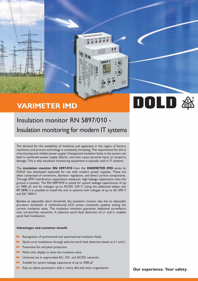
VARIMETER IMD
The demand for the availability of machines and apparatus in the region of factory machinery and process technology is constantly increasing. The requirement for this is a functioning and reliable power supply. Unexpected insulation faults in the system can lead to unwanted power supply failures, and even cause personal injury or property damage. This is why insulation monitoring equipment is typically used in IT systems.
The insulation monitor RN 5897/010 from the VARIMETER IMD series by DOLD was developed especially for use with modern power supplies. These are often comprised of converters, thyristor regulators, and direct current components. Through EMV interference suppression measures, high leakage capacitance onto the
Besides an adjustable alarm threshold, the insulation monitor also has an adjustable pre-alarm threshold. A multicoloured LCD screen constantly updates stating the current insulation value. The insulation monitors guarantee additional surveillance over current-free networks. A selective earth fault detection of L+ and L- enables quick fault localisation.
Advantages and customer benefit
Recognition of symmetrical and asymmetrical insulation faults
Quick error localization through selective earth fault detection based on L+ und L-
Preventive fire and plant protection
Multi-color display to show the insulation value
Universal use in ungrounded AC-, DC- and AC/DC networks
Easy to adjust parameters with a rotary dial and menu organization Our experience. Your safety.
Insulation monitoring for modern IT systems
www.dold.com
RN 5897/010
PE
RN 5897/010
L1L2
SPSPLC
L+
L-
LK 5896
E. Dold & Söhne GmbH & Co. KG
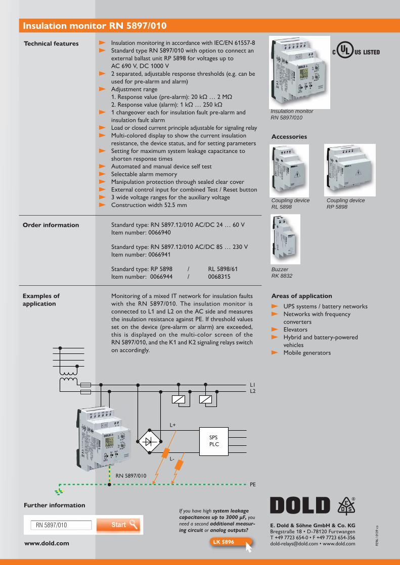
Insulation monitor RN 5897/010
Technical features
Order information
Examples of application
Insulation monitorRN 5897/010
UPS systems / battery networks Networks with frequency
converters Elevators Hybrid and battery-powered
vehicles Mobile generators
Standard type:
Standard type:
Standard type:
used for pre-alarm and alarm)
Adjustment range
1 changeover each for insulation fault pre-alarm and insulation fault alarm
Load or closed current principle adjustable for signaling relay Multi-colored display to show the current insulation
resistance, the device status, and for setting parameters Setting for maximum system leakage capacitance to
shorten response times Automated and manual device self test Selectable alarm memory Manipulation protection through sealed clear cover External control input for combined Test / Reset button 3 wide voltage ranges for the auxiliary voltage
Areas of applicationMonitoring of a mixed IT network for insulation faults
the insulation resistance against PE. If threshold values set on the device (pre-alarm or alarm) are exceeded, this is displayed on the multi-color screen of the
on accordingly.
Further informationIf you have high system leakage capacitances up to 3000 μF, you need a second additional measur-ing circuit or analog outputs?
Accessories
BuzzerRK 8832
Coupling deviceRP 5898
Coupling deviceRL 5898
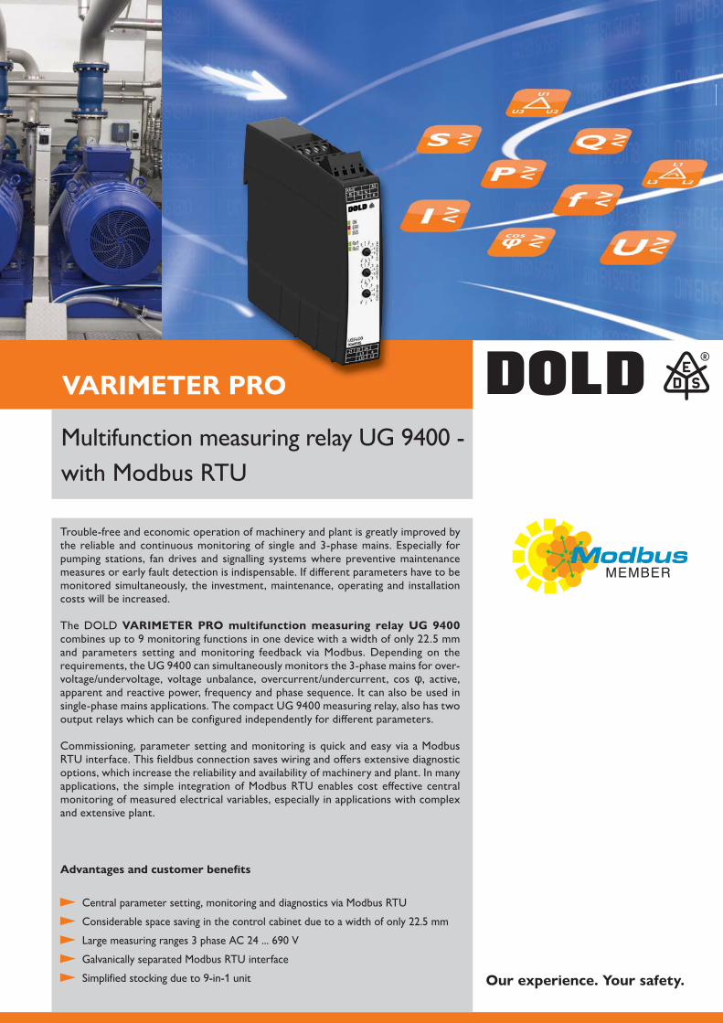
VARIMETER PROPRO
Trouble-free and economic operation of machinery and plant is greatly improved by the reliable and continuous monitoring of single and 3-phase mains. Especially for pumping stations, fan drives and signalling systems where preventive maintenance measures or early fault detection is indispensable. If different parameters have to be monitored simultaneously, the investment, maintenance, operating and installation costs will be increased.
The DOLD VARIMETER PRO multifunction measuring relay UG 9400
and parameters setting and monitoring feedback via Modbus. Depending on the -
voltage/undervoltage, voltage unbalance, overcurrent/undercurrent, cos , active, apparent and reactive power, frequency and phase sequence. It can also be used in
output relays which can be configured independently for different parameters.
Commissioning, parameter setting and monitoring is quick and easy via a Modbus RTU interface. This fieldbus connection saves wiring and offers extensive diagnostic options, which increase the reliability and availability of machinery and plant. In many applications, the simple integration of Modbus RTU enables cost effective central monitoring of measured electrical variables, especially in applications with complex and extensive plant.
Advantages and customer benefits
Central parameter setting, monitoring and diagnostics via Modbus RTU
Galvanically separated Modbus RTU interface
Simplified stocking due to 9-in-1 unit
with Modbus RTU
Our experience. Your safety.
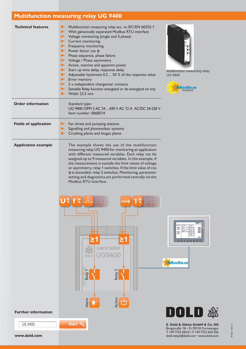
www.dold.com
UG 9400
≥1 ≥1
>>>>><<>><>>>><<>>L2<<<<LSSSSSSSSSLSSSS11>>SSSSS>>>>SSSSSS1
SS<<<<SSSSSSSSSSSS<SSSSSSSSSSSSSSSSSSSSSSSSSSSSSSS>SSLL
SSSSSSSSSSSSSSSSSSSSSSSSSSSSSSSSSSSSSSSQSSSLL
SSSS>SSLL
SS>>>>SSS>>>SSL
<<SS<<SS<<SSS<QQQ>Q>>QQQ<<<QQQQQ>QQQQQQQQQQQQQQQQQQQQQQQQQQQQQQQ33333333QQQQQQQQ>>>>QQQQQQQQQQQQQQQQQQQQLLLLLLLL3333QQQQQQQQQQQQQQQQQQQQQQQQQQQQQQQQQQQQQQQQQQQQQQ333333333333333333333QQQQQQQQQQQQQQQQQQQLLLLQQQQQQQ >>>><<>><>>>><<>>>>>>>>>>><<<<<<>>>><<<<<><<<>fffffff>><<<<<<ff>>U2ffff<<<<ffffUfffffffffffffffffffffffffUUUfffUUffffffUUUffffffffffffUUfff
111
UUffUUUUUffffffffU>>>ffUUUUUffffffff11
UUUUUUUffffffffUUUUffffffffffffffUUUffUUUUffffffffUUUUUUUUUUUUUUUU>UUUUUUUUUUUUUUUUUUUUUUUUUUUUUUUUUUUUUUUUUUUUUUUUUUUUUUUUUUUUUUUUUUUUUUUUUUUUUUUUUUUUUUUUUUUUUU
UU>>UUUUUUUUUU
UUUUUUUULUUUUUUUUUUUUUULUUUUUUUUUUUUUUUUUUUUUUULLcosQQQQQQQQQQQQQQQQQQQQQQQQQQQQQQQQQQQQQQQQQQQQQQQQQQQQQQQQQQQQQQQQQQQQQQQQQQQQQQQQQQQQQQQQQQQQQQQQQQQQQQQQQQQQQQQQQQQQQQQQLLLLLLLQQQQQQQQQQQQQQQQQQQQQQQQQQQQQQQQQQQQQQQQQQQQQQQQQQQQQQQQQQQQQQQQQQQQQQQQQQQQQQQQQQQQQQQQQQQQQQQQQQQQQQQQQQQQQQQQQQQQQQQQQQQQQQQQQQQQ>>>>>>>QQQQQQQQQQQQQQQQQQQQQQQQQQQQQQQQQQQQQQQQQQQQQQQQQQQQQQQQQQQQQQQQQQQQQQQQQQQQQQQQQQQQQQQQQQQQQQU1
U2U3U >< UUf >< 3SSSSSSSSSSSSSSSSSL33LSS111>>>SSSSSSS>>>>>>SSSSSSSSSSSSSS>>>>>>>>SSSSSSSSSSSSSSSSS11
SS<<<<3333<<SSSSSSSSSSSSUUUUUUUU33333333SSSSUUUUUUUU<SSSSSSSSSUUUUUUUU33333333UUUUUUUUUUSSSSSSSSSSSSSSSSSSSUUUUSSUUUUUUUUUUUUU>SSL
SSSSSSSSSSSSSSSSSSSSSSSSSSSSUUUUSSSSSSSSSSSSSSUUUUSSSSSSSSSSSSUUUUSSSSSSSSSSSSSSSSSSSSSSSSSSSSSSSSSSSSSSSSSSSSSSSSSUUUUUUUUSSSSSUUUUUUUUUUUUUQQQQQQQLL33QQQQQQSSSSSSSSSLLLLLLLL
SSSSSSSSSSSSSSS>>SSSSLLLL
SSSSSSSSQQQQQQQQQ>>>>>SSSSSSSSSSQQ>>>>>>>>>>>>SSSSSSSL
QQQQQQQQQQQQQ<<<<<SSSSSSSSSSS<<<SSSSSSS<<<SSSSSSSSSSSSSSSS<QQQQQQQQ33333333QQQQQQQPPPQQQQQQPPPPQQQQQQQQQQQQQQ><I
E. Dold & Söhne GmbH & Co. KG
Multifunction measuring relay UG 9400
Technical features
Order information
Fields of application
Application example
Further information
Multifunction measuring relayUG 9400
Fan drives and pumping stations Signalling and photovoltaic systems Crushing plants and biogas plants
With galvanically separated Modbus RTU interface Voltage monitoring (single and 3-phase) Current monitoring Frequency monitoring Power factor cos Phase sequence, phase failure Voltage / Phase asymmetry Active, reactive and apparent power Start up time delay, response delay Error memory Settable Relay function energized or de-energized on trip
Standard type:
The example shows the use of the multifunction
with different measured variables. Each relay can be assigned up to 9 measured variables. In this example, if the measurement is outside the limit values of voltage or asymmetry, relay 1 switches. If the limit value of cos
setting and diagnostics are performed centrally via the Modbus RTU interface.
Rela
y 1
Ala
rm
Act
ion

VARIMETER PROPRO
With the universal measuring relay MK 9300N of the VARIMETER PRO
wide. This universal measuring and monitoring relay thus offers a functional diversity unparalleled so far at this minimal unit width.
Troublefree and economic operation of machines and systems is guaranteed only by the reliable and continuous monitoring of three-phase systems. Depending on the need, the VARIMETER PRO therefore monitors the three-phase system simultane-ously for overvoltage/ undervoltage, voltage asymmetry, overcurrent/undercurrent, cos phi, active power, apparent power and reactive power, frequency and phase sequence. Employment in single-phase systems is also possible.
To facilitate simple fault diagnostics, this all-rounder features a display and a multic-oloured LED. The user-friendly device configuration permits optimal adjustment to the application. For example, the response values for all monitoring functions can be easily set. The space-saving multifunctional measuring relay is optionally equipped with one or two output relays, independently configurable.
Advantages and customer benefit
Min-, Max. value or window monitoring
Simultaneous monitoring of up to 9 different parameters
Simple configuration and fault diagnostic
Different fault indications
Early detection of irregular states
Space and cost saving
Reduced wiring
One device, many functions
Our experience. Your safety.
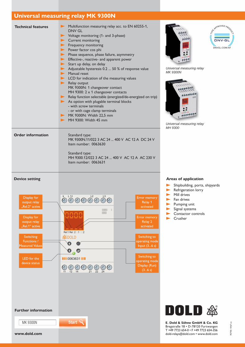
www.dold.com
MK 9300N E. Dold & Söhne GmbH & Co. KG
Universal measuring relay MK 9300N
Technical features
Order information
Device setting
Further information
Universal measuring relayMK 9300N
Universal measuring relayMH 9300
Shipbuilding, ports, shipyards Refrigeration lorry Mill drives Fan drives Pumping unit Signal systems Contactor controls Crusher
DNV GL
Voltage monitoring (1- and 3-phase) Current monitoring Frequency monitoring Power factor cos phi Phase sequence, phase failure, asymmetry Effective-, reactive- and apparent power Start up delay, on delay Manual reset LCD for indication of the measuring values Relay output
Relay function selectable (energized/de-energized on trip) As option with plugable terminal blocks
- with screw terminals - or with cage clamp terminals
Areas of application
k L 1/i
11 12 14 21 22 24
0063631
L3L2
Rel�1 Rel�2
DOLD
�������������� �
��1 ��2
���
Display for output relay
Error memory Relay 1
activated
Error memory
activated
Switching to operating mode
LED for the device status
Switching to operating mode Display (Run)
Display for output relay „Rel.1“ active
Switching Functions /
Measured Values
Standard type:
Standard type:
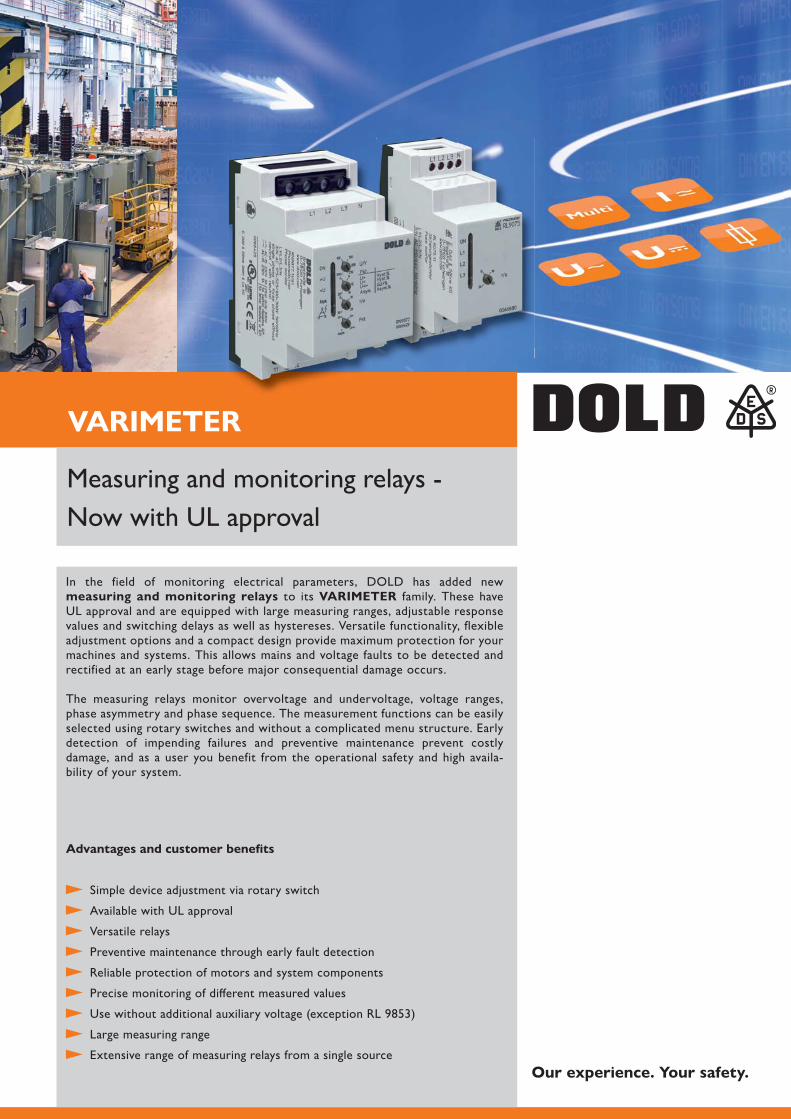
VARIMETER
In the field of monitoring electrical parameters, DOLD has added new measuring and monitoring relays to its VARIMETER family. These have UL approval and are equipped with large measuring ranges, adjustable response values and switching delays as well as hystereses. Versatile functionality, flexible adjustment options and a compact design provide maximum protection for your machines and systems. This allows mains and voltage faults to be detected and rectified at an early stage before major consequential damage occurs.
The measuring relays monitor overvoltage and undervoltage, voltage ranges, phase asymmetry and phase sequence. The measurement functions can be easily selected using rotary switches and without a complicated menu structure. Early detection of impending failures and preventive maintenance prevent costly damage, and as a user you benefit from the operational safety and high availa-bility of your system.
Advantages and customer benefits
Simple device adjustment via rotary switch
Available with UL approval
Versatile relays
Preventive maintenance through early fault detection
Reliable protection of motors and system components
Precise monitoring of different measured values
Large measuring range
Extensive range of measuring relays from a single source
Measuring and monitoring relays - Now with UL approval
Our experience. Your safety.
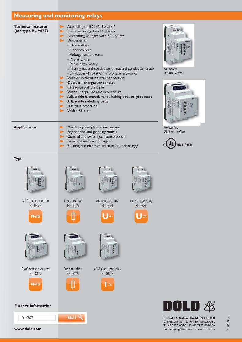
www.dold.com
RL 9877 E. Dold & Söhne GmbH & Co. KG
Measuring and monitoring relays
Technical features (for type RL 9877)
Applications
Type
Further information
RL series 35 mm width
RN series 52.5 mm width
For monitoring 3 and 1 phases
Detection of - Overvoltage - Undervoltage - Voltage range excess - Phase failure - Phase asymmetry - Missing neutral conductor or neutral conductor break - Direction of rotation in 3-phase networks
With or without neutral connection Output: 1 changeover contact Closed-circuit principle Without separate auxiliary voltage Adjustable hysteresis for switching back to good state Adjustable switching delay Fast fault detection
Machinery and plant construction Engineering and planning offices Control and switchgear construction Industrial service and repair Building and electrical installation technology
3 AC phase monitor RL 9877
AC voltage relayRL 9854
Fuse monitorRL 9075
DC voltage relayRL 9836
3 AC phase monitors RN 9877
Fuse monitorRN 9075
AC/DC current relayRL 9853

MINISTART
The smart motorstarter UG 9410 of the MINISTART series from DOLD
motorstarter ensures reliable soft starting, soft stopping, reversing and protection of 3-phase asynchronous motors. Whether for retrofitting or original equipment, the device can be used in a space-saving manner and, in addition to phase sequence moni-toring, also offers an integrated motor protection function and phase failure detection.
Commissioning, parameterisation and control are carried out quickly and easily via the Modbus RTU interface. The fieldbus connection saves wiring and offers extensive diagnostic options that improve reliability and increase system availability.
and is suitable for demanding drive tasks. The areas of application include in particular reversing drives such as door and gate controls, conveyor systems as well as bridge and actuator drives.
Advantages and customer benefits
stop, phase failure monitoring, motor protection and phase sequence monitoring Simple commissioning, control and parameterisation via Modbus RTU
Extensive diagnostic options through fieldbus connection
High device availability due to - Semiconductor temperature monitoring
- Load free relay reversing function and device overload protection
With Modbus RTU - IE3 ready
Our experience. Your safety.
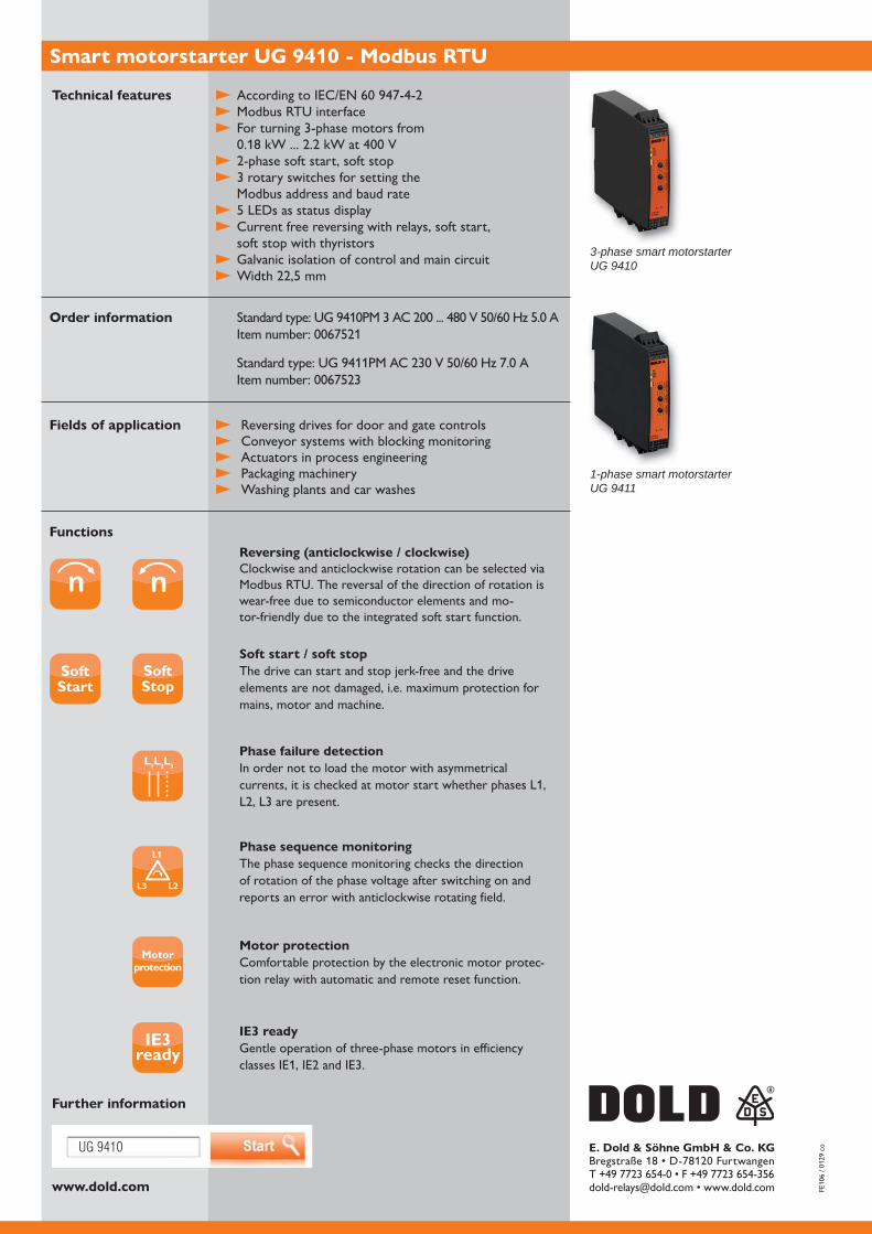
www.dold.com
UG 9410 E. Dold & Söhne GmbH & Co. KG
Smart motorstarter UG 9410 - Modbus RTU
Technical features
Order information
Functions
Fields of application
Further information
3-phase smart motorstarterUG 9410
1-phase smart motorstarterUG 9411
Modbus RTU interface For turning 3-phase motors from
3 rotary switches for setting the Modbus address and baud rate
Current free reversing with relays, soft start, soft stop with thyristors
Galvanic isolation of control and main circuit
Reversing drives for door and gate controls Conveyor systems with blocking monitoring Actuators in process engineering Packaging machinery Washing plants and car washes
Reversing (anticlockwise / clockwise)Clockwise and anticlockwise rotation can be selected via Modbus RTU. The reversal of the direction of rotation is wear-free due to semiconductor elements and mo-tor-friendly due to the integrated soft start function.
Soft start / soft stopThe drive can start and stop jerk-free and the drive elements are not damaged, i.e. maximum protection for mains, motor and machine.
L1L2L3
Phase failure detectionIn order not to load the motor with asymmetrical currents, it is checked at motor start whether phases L1,
Phase sequence monitoringThe phase sequence monitoring checks the direction of rotation of the phase voltage after switching on and reports an error with anticlockwise rotating field.
Motorprotection
Motor protectionComfortable protection by the electronic motor protec-tion relay with automatic and remote reset function.
IE3ready
IE3 readyGentle operation of three-phase motors in efficiency

MINISTART
The smart motorstarter UG 9256/804 of the MINISTART series is designed for reliable starting of asynchronous motors and ensures that a clockwise rotating field is always applied to the motor when connected to the mains and that the motor runs correctly right away. The device automatically corrects the rotating field if the mains connection is incorrect, thereby preventing the motor from running backwards and being damaged.
correction, an integrated motor protection function and phase failure detection to protect the motor - optionally also with galvanic mains isolation via forcibly guided contacts.
at different locations, in particular for mobile machines such as pumps, blowers, grinding machines and compressors as well as for use by the fire brigade or the Federal Agency for Technical Relief. Whether retrofitting or original equipment, the phase inverter can be used in a space-saving manner and always ensures the correct direction of rotation. Troubleshooting or rewiring is therefore no longer necessary.
Advantages and customer benefits
Up to four functions in one UL-approved device: Ensures clockwise rotating field, phase failure detection, motor protection and galvanic mains isolation through forcibly guided contacts
Automatic correction of the rotary field in case of incorrect connection No troubleshooting in the wiring No phase inverter plug required Damage prevention through correct direction of rotation
Simple device adjustment via rotary switch
Increased service life due to hybrid design Integrated protection against overtemperature of the motor
Automatic correction of the direction of rotation
Our experience. Your safety.
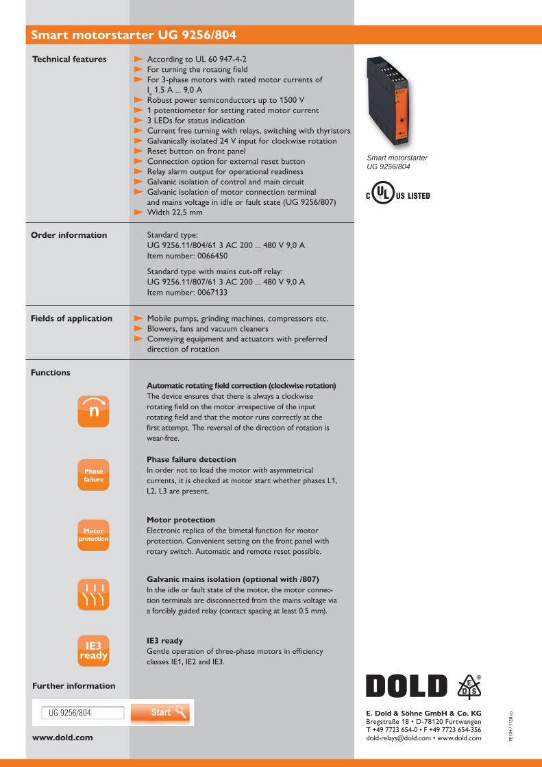
www.dold.com
UG 9256/804 E. Dold & Söhne GmbH & Co. KG
Smart motorstarter UG 9256/804
Standard type:
Standard type with mains cut-off relay:
Technical features
Order information
Functions
Fields of application
Further information
Smart motorstarterUG 9256/804
For turning the rotating field For 3-phase motors with rated motor currents of
Ie
1 potentiometer for setting rated motor current 3 LEDs for status indication Current free turning with relays, switching with thyristors
Reset button on front panel Connection option for external reset button Relay alarm output for operational readiness Galvanic isolation of control and main circuit Galvanic isolation of motor connection terminal
Mobile pumps, grinding machines, compressors etc. Blowers, fans and vacuum cleaners Conveying equipment and actuators with preferred
direction of rotation
Automatic rotating field correction (clockwise rotation)The device ensures that there is always a clockwise rotating field on the motor irrespective of the input rotating field and that the motor runs correctly at the first attempt. The reversal of the direction of rotation is wear-free.
Phasefailure
Phase failure detectionIn order not to load the motor with asymmetrical currents, it is checked at motor start whether phases L1,
Motorprotection
Motor protectionElectronic replica of the bimetal function for motor protection. Convenient setting on the front panel with rotary switch. Automatic and remote reset possible.
Galvanic mains isolation (optional with /807)In the idle or fault state of the motor, the motor connec-tion terminals are disconnected from the mains voltage via
IE3ready
IE3 readyGentle operation of three-phase motors in efficiency
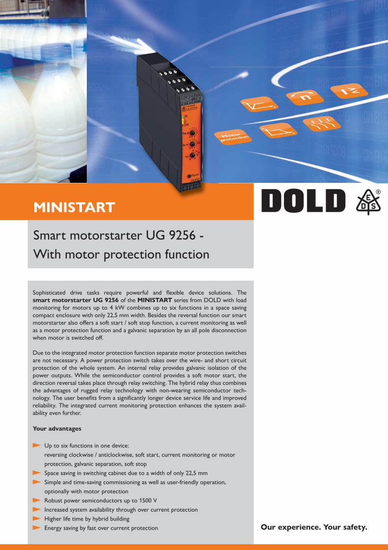
MINISTART
With motor protection function
Sophisticated drive tasks require powerful and flexible device solutions. The smart motorstarter UG 9256 of the MINISTART series from DOLD with load monitoring for motors up to 4 kW combines up to six functions in a space saving
motorstarter also offers a soft start / soft stop function, a current monitoring as well as a motor protection function and a galvanic separation by an all pole disconnection when motor is switched off.
Due to the integrated motor protection function separate motor protection switches are not necessary. A power protection switch takes over the wire- and short circuit protection of the whole system. An internal relay provides galvanic isolation of the power outputs. While the semiconductor control provides a soft motor start, the direction reversal takes place through relay switching. The hybrid relay thus combines the advantages of rugged relay technology with non-wearing semiconductor tech-nology. The user benefits from a significantly longer device service life and improved reliability. The integrated current monitoring protection enhances the system avail-ability even further.
Your advantages
Up to six functions in one device: reversing clockwise / anticlockwise, soft start, current monitoring or motor protection, galvanic separation, soft stop
Simple and time-saving commissioning as well as user-friendly operation,
optionally with motor protection Increased system availability through over current protection Higher life time by hybrid building Energy saving by fast over current protection Our experience. Your safety.
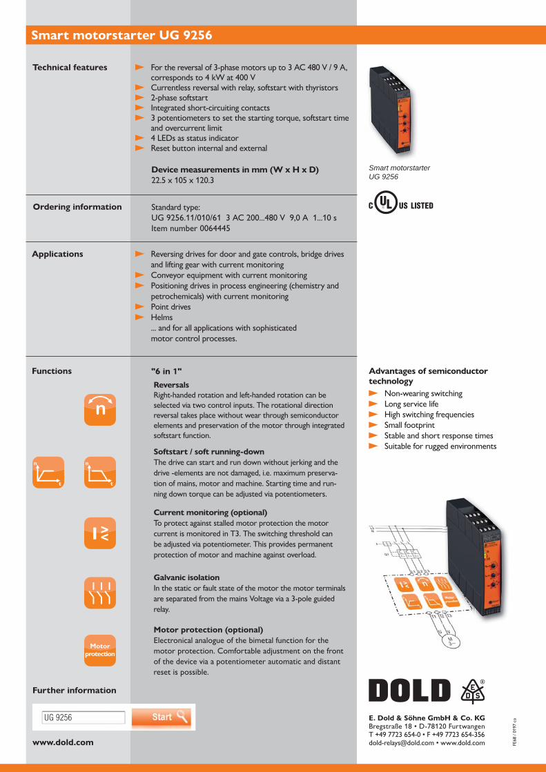
UG 9256
www.dold.com
E. Dold & Söhne GmbH & Co. KG
Smart motorstarter UG 9256
Functions
Currentless reversal with relay, softstart with thyristors
Integrated short-circuiting contacts 3 potentiometers to set the starting torque, softstart time
and overcurrent limit 4 LEDs as status indicator Reset button internal and external
Technical features
Device measurements in mm (W x H x D)
Ordering information Standard type:
Applications Reversing drives for door and gate controls, bridge drives and lifting gear with current monitoring
Conveyor equipment with current monitoring Positioning drives in process engineering (chemistry and
petrochemicals) with current monitoring Point drives Helms
... and for all applications with sophisticated motor control processes.
Advantages of semiconductor technology
Non-wearing switching Long service life High switching frequencies Small footprint Stable and short response times Suitable for rugged environments
"6 in 1"
Smart motorstarterUG 9256
ReversalsRight-handed rotation and left-handed rotation can be selected via two control inputs. The rotational direction reversal takes place without wear through semiconductor elements and preservation of the motor through integrated softstart function.
n
t
n
t
Softstart / soft running-downThe drive can start and run down without jerking and the drive -elements are not damaged, i.e. maximum preserva-tion of mains, motor and machine. Starting time and run-ning down torque can be adjusted via potentiometers.
Current monitoring (optional)To protect against stalled motor protection the motor current is monitored in T3. The switching threshold can be adjusted via potentiometer. This provides permanent protection of motor and machine against overload.
Galvanic isolationIn the static or fault state of the motor the motor terminals are separated from the mains Voltage via a 3-pole guided relay.
Motorprotection
Motor protection (optional)Electronical analogue of the bimetal function for the motor protection. Comfortable adjustment on the front of the device via a potentiometer automatic and distant reset is possible.
Further information

MINISTART
With the softstarter UG 9019 from the MINISTART series, DOLD offers a
phase controlled softstarter for the power range of up to 4 kW combines perfect starting and stopping characteristics with intelligent monitoring functions. In doing so, it allows both smooth control and simplified drive monitoring in a wide variety of application fields. Optional function possibilities offer additional advantages even for challenging applications.
easy even in existing units by simply clipping on to the DIN rail. The device is also suitable for retrofitting due to its narrow construction type. Starting and decelera-tion time can be selected conveniently and continuously variable via rotary switches as a standard feature. The starting voltage can be individually adjusted and a relay output shows that the device is ready for operation.
failure, phase sequence or overtemperature are recognised instantly and displayed by luminous diodes and indicator contacts. Versatile functionality, flexible adjusting possibilities and a compact construction type: Soft starting has never been this simple.
Advantages and customer benefit
Soft starting and deceleration Continuously variable starting and minimised starting current Simple device setting via rotary switches Reduction of current peaks Wear free switching Increase of service life of motors Decrease of mechanical stress in the drive Considerable saving of space compared with conventional starters
Smooth control of motors
Our experience. Your safety.
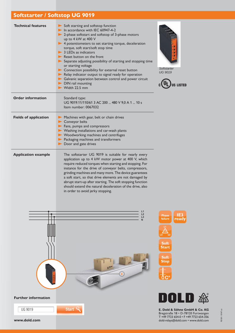
www.dold.com
UG 9019
L1L2L3N
IE3ready
E. Dold & Söhne GmbH & Co. KG
Softstarter / Softstop UG 9019
Standard type:
Technical features
Order information
require reduced torques when starting and stopping. For instance for the drive of conveyor belts, compressors, grinding machines and many more. The device guarantees a soft start, so that drive elements are not damaged by abrupt start-up after starting. The soft stopping function should extend the natural deceleration of the drive, also in order to avoid jerky stopping.
Application example
Fields of application
SoftstarterUG 9019
Soft starting and softstop function
4 potentiometers to set starting torque, deceleration torque, soft start/soft stop time
3 LEDs as indicators Reset button on the front Separate adjusting possibility of starting and stopping time
or starting voltage Connection possibility for external reset button Relay indicator output to signal ready for operation Galvanic separation between control and power circuit DIN rail mounting
Machines with gear, belt or chain drives Conveyor belts Fans, pumps and compressors Washing installations and car-wash plants Woodworking machines and centrifuges Packaging machines and transformers Door and gate drives
Further information
Phasefailure

MINISTART
With the softstarter UH 9018 from the MINISTART series, DOLD offers a reliable softstarter available in four performance levels. The compact, two-phase
start-up and run-down characteristics with intelligent monitoring functions. Optional functions offer additional advantages, even for challenging applications. These allow the soft starter to offer both gentle control and simplified drive monitoring in a wide variety of applications.
a substitute for a star-delta starter. Its slim construction and the ability to snap the
start-up and run-down time can be continuously controlled using potentiometers as a standard feature. The starting voltage can be individually adjusted. The boost function also allows operators to start drives with high holding torque at a standstill.
Low voltage, phase / ignition failures or high temperatures are detected instantly and displayed using LEDs and signaling contacts. Diverse functions, flexible setting options,
so simple.
Advantages and customer benefit
To limit start-up current and for stable network conditions Jolt-free start and minimized start-up current Increases the life span of motors and mechanical drive components Protects the drive unit Integrated bypass conductor Simple operation Comprehensive diagnosis through LED flash code
Our experience. Your safety.
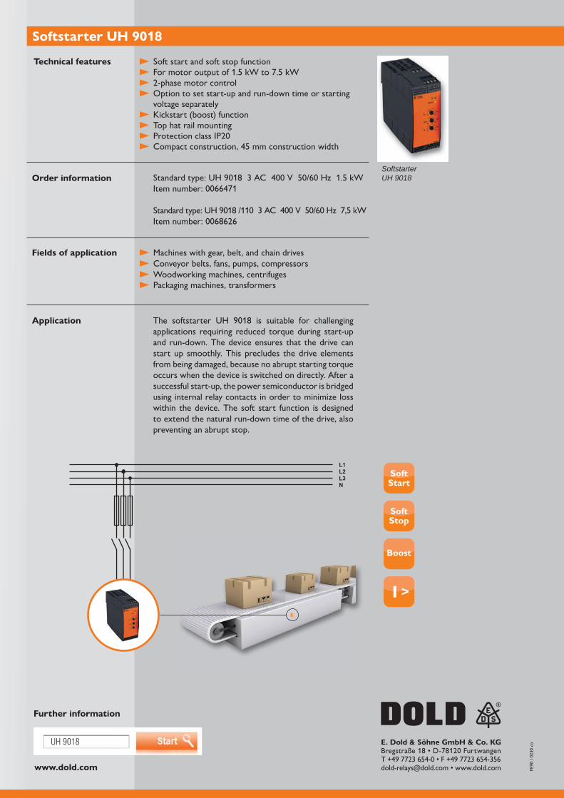
www.dold.com
UH 9018
L1L2L3N
Boost
E. Dold & Söhne GmbH & Co. KG
Softstarter UH 9018
Technical features
Order information
applications requiring reduced torque during start-up and run-down. The device ensures that the drive can start up smoothly. This precludes the drive elements from being damaged, because no abrupt starting torque occurs when the device is switched on directly. After a successful start-up, the power semiconductor is bridged using internal relay contacts in order to minimize loss within the device. The soft start function is designed to extend the natural run-down time of the drive, also preventing an abrupt stop.
Application
Fields of application
Further information
SoftstarterUH 9018
Soft start and soft stop function
Option to set start-up and run-down time or starting voltage separately
Kickstart (boost) function Top hat rail mounting
Machines with gear, belt, and chain drives Conveyor belts, fans, pumps, compressors Woodworking machines, centrifuges Packaging machines, transformers

MINISTART
The new softstarter PF 9015 of the MINISTART family from DOLD is a robust
in just one device.
The compact 3-phase controlled softstarter enables a smooth and gentle start
torque shocks that interfere with switching are reduced. This increases the service life of the motors and mechanical drive components.
Monitoring the rotating field (clockwise) prevents motors from starting up in the wrong direction of rotation. The integrated undervoltage and overvoltage monitoring
against overload. The most important functions of the device include blockage protection in bypass mode, detection of missing load and integrated temperature
has a smart, user-friendly softstarter with extensive monitoring and protection functions.
Advantages and customer benefits
Improved starting current reduction Less self-heating Only 1 device for soft start, motor protection, voltage and phase sequence monitoring Gentle starting and reduced starting current Increases the service life of the drives No mains filter required due to low interference radiation
Low installation costs Our experience. Your safety.
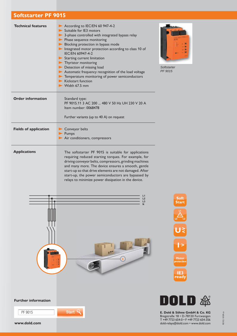
www.dold.com
PF 9015
L1L2L3N
IE3ready
E. Dold & Söhne GmbH & Co. KG
Softstarter PF 9015
Standard type:
Technical features
Order information
Applications
Fields of application
Further information
SoftstarterPF 9015
Suitable for IE3 motors 3-phase controlled with integrated bypass relay Phase sequence monitoring Blocking protection in bypass mode
Starting current limitation Thyristor monitoring Detection of missing load Automatic frequency recognition of the load voltage Temperature monitoring of power semiconductors Kickstart function
Conveyor belts Pumps Air conditioners, compressors
requiring reduced starting torques. For example, for driving conveyor belts, compressors, grinding machines and many more. The device ensures a smooth, gentle start-up so that drive elements are not damaged. After start-up, the power semiconductors are bypassed by relays to minimize power dissipation in the device.
Motorprotection

POWERSWITCH
DCBTechnologie
Reliable and noiseless switching
With the new solid-state relay PI 9260, the POWERSWITCH family from DOLD has been supplemented by a further attractive electronic switching device. The solid-state contactor has been specially developed for switching resistive and induc-tive three-phase loads and therefore serves as an electronic contactor replacement.
Copper-Bonding) ensures optimum heat transfer, which allows switching of large load currents and at the same time ensures high reliability and robustness.
The long service life saves you costly and time-consuming replacement of the device. The device can be mounted on existing cooling surfaces. Optionally, the solid-state
which enables quick and easy commissioning.
Due to the short reaction time, high peak current compatibility and high EMC resist-ance, this shock- and vibration-resistant solid-state relay is predestined for many appli-cations. These include, for example, heating and cooling systems, process controls, plastic injection machines, motor valves and many other applications.
Advantages and customer benefits
Immediately ready for use - thanks to optimally adapted heat sinks Long service life ensures high system availability Low interference emission, immune to interference radiation Noiseless and wear-free switching - even at high switching frequencies Shock and vibration resistant Easy integration into existing automation systems Wide voltage range for control and load voltage
Our experience. Your safety.
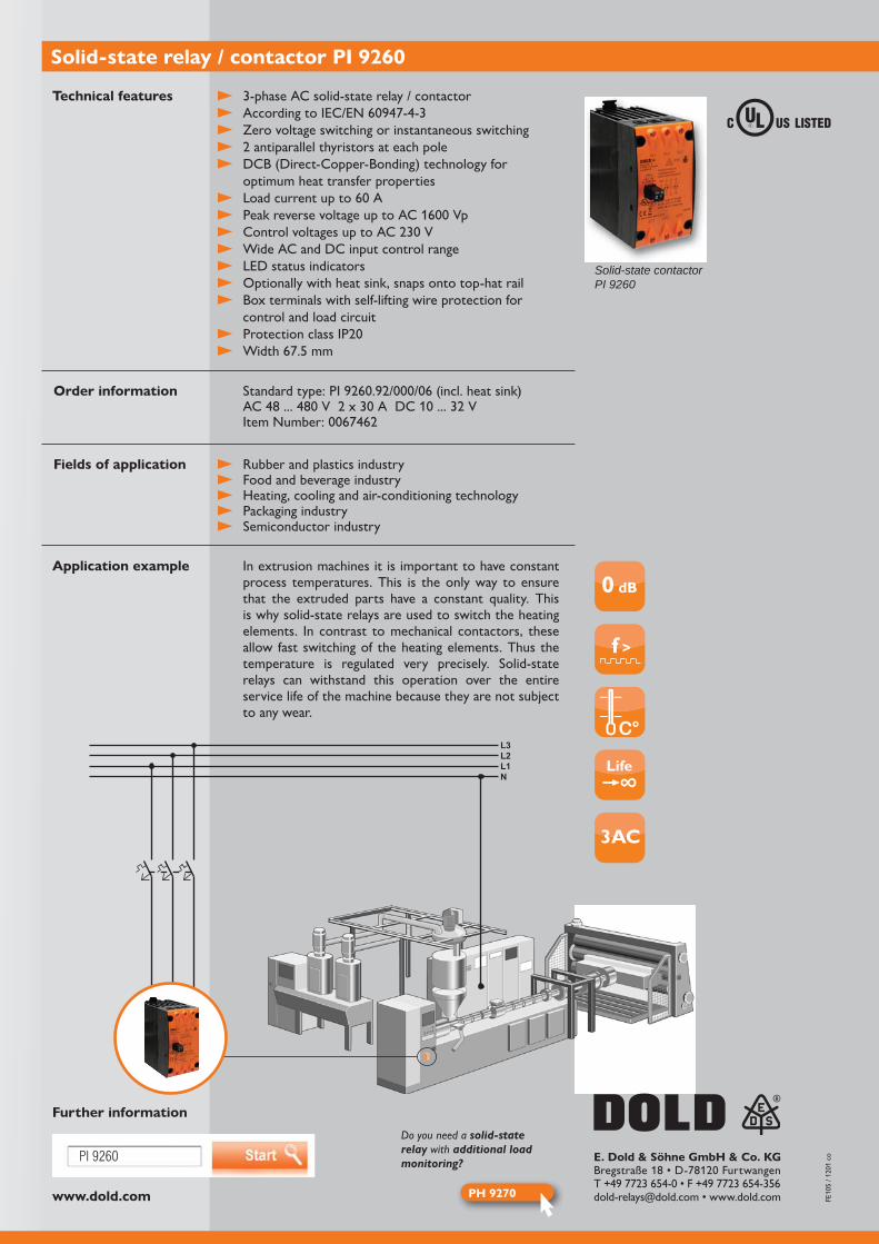
www.dold.com
PI 9260
0 dB
f >
3AC
PH 9270
L1N
L2L3
E. Dold & Söhne GmbH & Co. KG
3-phase AC solid-state relay / contactor
Zero voltage switching or instantaneous switching
DCB (Direct-Copper-Bonding) technology for optimum heat transfer properties
Wide AC and DC input control range LED status indicators Optionally with heat sink, snaps onto top-hat rail Box terminals with self-lifting wire protection for
control and load circuit
Solid-state relay / contactor PI 9260
Technical features
Order information
Application example
Further information
In extrusion machines it is important to have constant process temperatures. This is the only way to ensure that the extruded parts have a constant quality. This is why solid-state relays are used to switch the heating elements. In contrast to mechanical contactors, these allow fast switching of the heating elements. Thus the temperature is regulated very precisely. Solid-state relays can withstand this operation over the entire service life of the machine because they are not subject to any wear.
Rubber and plastics industry Food and beverage industry Heating, cooling and air-conditioning technology Packaging industry Semiconductor industry
Fields of application
Solid-state contactorPI 9260
Do you need a solid-state relay with additional load monitoring?
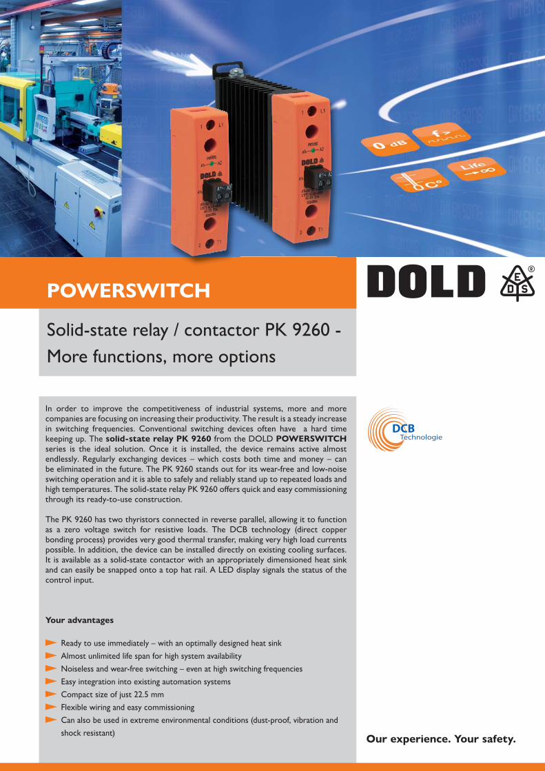
POWERSWITCH
DCBTechnologie
More functions, more options
In order to improve the competitiveness of industrial systems, more and more companies are focusing on increasing their productivity. The result is a steady increase in switching frequencies. Conventional switching devices often have a hard time keeping up. The solid-state relay PK 9260 from the DOLD POWERSWITCH series is the ideal solution. Once it is installed, the device remains active almost endlessly. Regularly exchanging devices – which costs both time and money – can
switching operation and it is able to safely and reliably stand up to repeated loads and
through its ready-to-use construction.
as a zero voltage switch for resistive loads. The DCB technology (direct copper bonding process) provides very good thermal transfer, making very high load currents possible. In addition, the device can be installed directly on existing cooling surfaces. It is available as a solid-state contactor with an appropriately dimensioned heat sink and can easily be snapped onto a top hat rail. A LED display signals the status of the control input.
Your advantages
Ready to use immediately – with an optimally designed heat sink Almost unlimited life span for high system availability Noiseless and wear-free switching – even at high switching frequencies Easy integration into existing automation systems
Flexible wiring and easy commissioning Can also be used in extreme environmental conditions (dust-proof, vibration and shock resistant) Our experience. Your safety.
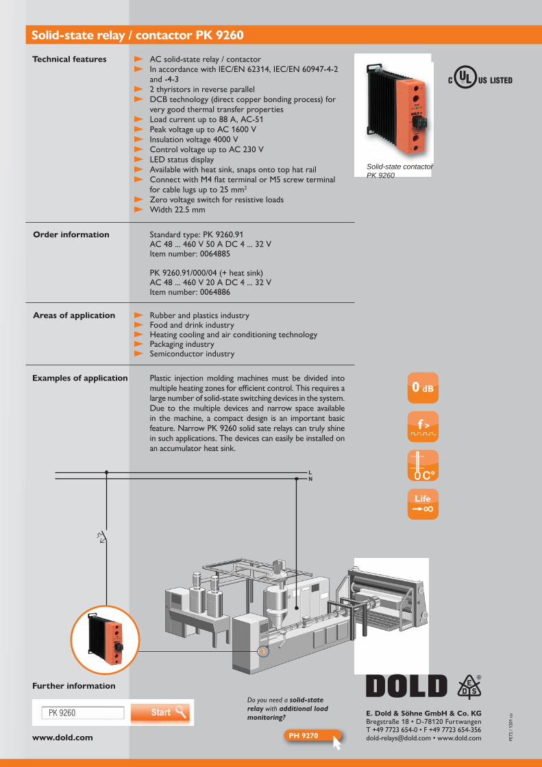
www.dold.com
PK 9260
0 dB
f >
PH 9270
LN
E. Dold & Söhne GmbH & Co. KG
AC solid-state relay / contactor
and -4-3
DCB technology (direct copper bonding process) for very good thermal transfer properties
LED status display Available with heat sink, snaps onto top hat rail
Zero voltage switch for resistive loads
Solid-state relay / contactor PK 9260
Technical features
Order information
Examples of application
Further information
Plastic injection molding machines must be divided into multiple heating zones for efficient control. This requires a large number of solid-state switching devices in the system. Due to the multiple devices and narrow space available in the machine, a compact design is an important basic
in such applications. The devices can easily be installed on an accumulator heat sink.
Rubber and plastics industry Food and drink industry Heating cooling and air conditioning technology Packaging industry Semiconductor industry
Areas of application
Solid-state contactorPK 9260
Do you need a solid-state relay with additional load monitoring?
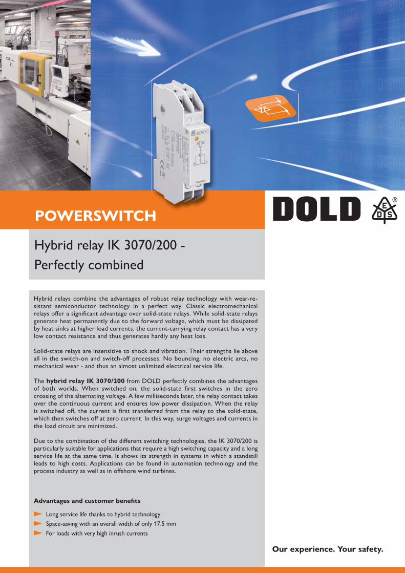
POWERSWITCHH
Hybrid relays combine the advantages of robust relay technology with wear-re-sistant semiconductor technology in a perfect way. Classic electromechanical relays offer a significant advantage over solid-state relays. While solid-state relays generate heat permanently due to the forward voltage, which must be dissipated by heat sinks at higher load currents, the current-carrying relay contact has a very low contact resistance and thus generates hardly any heat loss.
Solid-state relays are insensitive to shock and vibration. Their strengths lie above all in the switch-on and switch-off processes. No bouncing, no electric arcs, no mechanical wear - and thus an almost unlimited electrical service life.
The hybrid relay IK 3070/200 from DOLD perfectly combines the advantages of both worlds. When switched on, the solid-state first switches in the zero crossing of the alternating voltage. A few milliseconds later, the relay contact takes over the continuous current and ensures low power dissipation. When the relay is switched off, the current is first transferred from the relay to the solid-state, which then switches off at zero current. In this way, surge voltages and currents in the load circuit are minimized.
particularly suitable for applications that require a high switching capacity and a long service life at the same time. It shows its strength in systems in which a standstill leads to high costs. Applications can be found in automation technology and the process industry as well as in offshore wind turbines.
Advantages and customer benefits
Long service life thanks to hybrid technology
For loads with very high inrush currents
Perfectly combined
Our experience. Your safety.
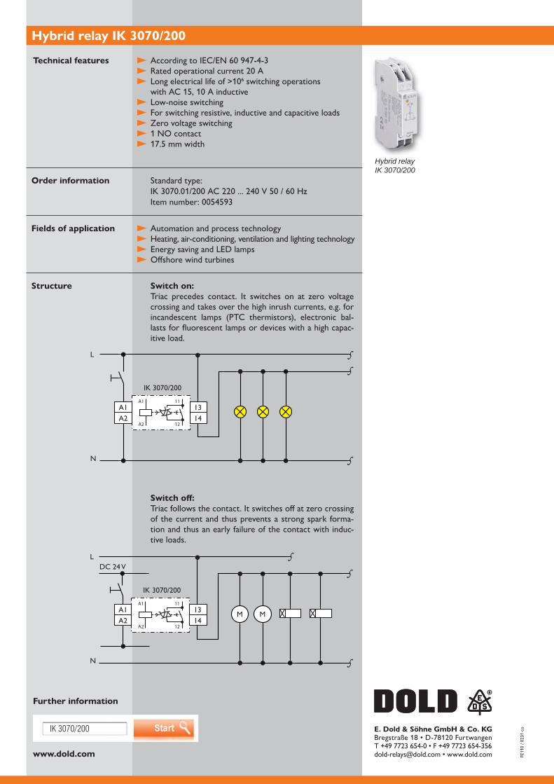
www.dold.com
IK 3070/200 E. Dold & Söhne GmbH & Co. KG
Hybrid relay IK 3070/200
Standard type:
Switch on:Triac precedes contact. It switches on at zero voltage crossing and takes over the high inrush currents, e.g. for incandescent lamps (PTC thermistors), electronic bal-lasts for fluorescent lamps or devices with a high capac-itive load.
Switch off:Triac follows the contact. It switches off at zero crossing of the current and thus prevents a strong spark forma-tion and thus an early failure of the contact with induc-tive loads.
Technical features
Order information
Fields of application
Structure
Further information
Hybrid relayIK 3070/200
switching operations
Low-noise switching For switching resistive, inductive and capacitive loads Zero voltage switching 1 NO contact
Automation and process technology Heating, air-conditioning, ventilation and lighting technology Energy saving and LED lamps Offshore wind turbines
L
1314
A1
A2
11
12
A1A2
N
IK 3070/200
M M
DC 24 VS
S
S
L
1314
A1
A2
11
12
A1A2
SS
SN
IK 3070/200
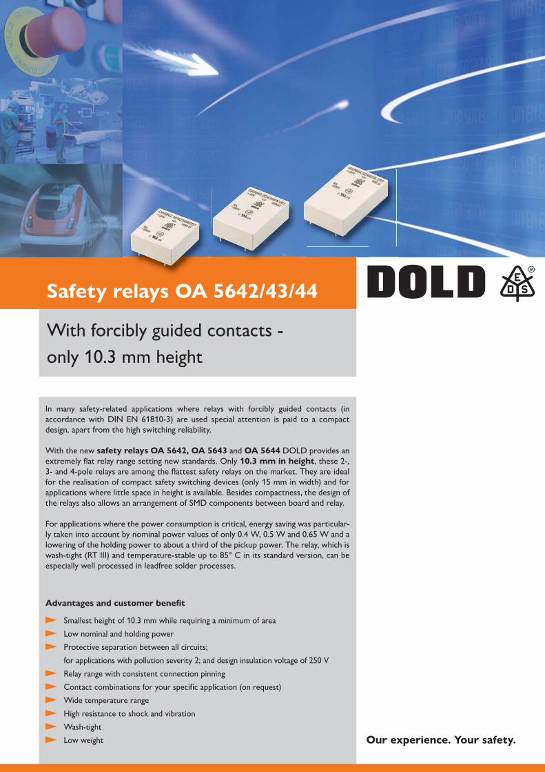
With forcibly guided contacts -
In many safety-related applications where relays with forcibly guided contacts (in accordance with DIN EN ) are used special attention is paid to a compact design, apart from the high switching reliability.
With the new safety relays OA 5642, OA 5643 and OA 5644 DOLD provides an extremely flat relay range setting new standards. Only 10.3 mm in height3- and 4-pole relays are among the flattest safety relays on the market. They are ideal
applications where little space in height is available. Besides compactness, the design of the relays also allows an arrangement of SMD components between board and relay.
For applications where the power consumption is critical, energy saving was particular-
lowering of the holding power to about a third of the pickup power. The relay, which is
especially well processed in leadfree solder processes.
Low nominal and holding power
Protective separation between all circuits;
Relay range with consistent connection pinning
Contact combinations for your specific application (on request)
Wide temperature range
High resistance to shock and vibration
Wash-tight
Low weight
Advantages and customer benefit
Safety relays OA 5642/43/44
Our experience. Your safety.
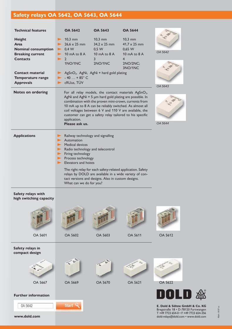
OA 5644
OA 5643
OA 5642
www.dold.com
OA 5642 E. Dold & Söhne GmbH & Co. KG
Further information
For all relay models, the contact materials AgSnO ,
combination with the proven mini-crown, currents from
customer can get a safety relay tailored to his specific application. Please ask us.
Notes on ordering
Technical features OA 5642 OA 5643 OA 5644
HeightAreaNominal consumptionBreaking currentContacts
1NO/1NC3 4
3NO/1NCContact material AgSnO , AgNi, AgNi + hard gold platingTemperature rangeApprovals cRUus, TÜV
Safety relays with high switching capacity
Safety relays in compact design
Safety relays OA 5642, OA 5643, OA 5644
Railway technology and signalling Automation Medical devices Radio technology and telecontrol Firing technology Process technology Elevators and hoists
The right relay for each safety-related application. Safety relays by DOLD are available in a wide variety of con-tact versions and designs. Also in custom designs. What can we do for you?
Applications

Up to 8 forcibly guided contacts -monostable
In safety-critical applications in which relays with forcibly guided contacts (in accordance
as is a high level of switching reliability. In addition, this relay stands out for its good vibration and shock resistance.
The safety relays OA 5621 and OA 5622 have enjoyed great success on the market
designs. The 8-pole safety relay OA 5623 responds to the need for more contacts
width.
Reducing the coil voltage makes it possible to lower the holding power to a quarter of
and are available with contact materials of silver tin oxide (AgSnO ) and silver-nickel (AgNi), as well as hard gold plating.
Compact size, short overall height
Low rated and holding power
Safe separation between all circuits;
Common pin arrangement of relays family
Wide temperature range
Optionally available with offset pins for optimized spacing and a simpler layout design
Wash-proof design
Advantages and customer benefit
Safety relays OA 5621/22/23
Our experience. Your safety.
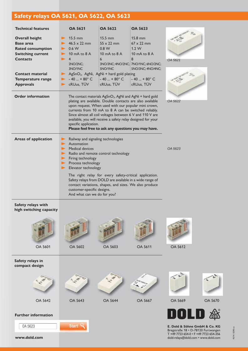
www.dold.com
OA 5623
OA 5622
OA 5621
OA 5623
E. Dold & Söhne GmbH & Co. KG
Further information
Railway and signaling technologies Automation Medical devices Radio and remote control technology Firing technology Process technology Elevator technology
The right relay for every safety-critical application. Safety relays from DOLD are available in a wide range of contact variations, shapes, and sizes. We also produce customer-specific designs. And what can we do for you?
The contact materials AgSnO , AgNi and AgNi + hard gold plating are available. Double contacts are also available upon request. When used with our popular mini crown,
available, you will receive a safety relay designed for your specific application.Please feel free to ask any questions you may have.
Order information
Areas of application
Technical features OA 5621 OA 5622 OA 5623
Overall heightBase areaRated consumptionSwitching currentContacts 4
3NO/1NC
8
Contact material AgSnO , AgNi, AgNi + hard gold platingTemperature rangeApprovals cRUus, TÜV cRUus, TÜV cRUus, TÜV
Safety relays withhigh switching capacity
Safety relays incompact design
Safety relays OA 5621, OA 5622, OA 5623

With 8 forcibly guided contacts for energy-efficient design
Specialized applications need relays that maintain their switching position if supply voltage fails, thereby preventing a loss of information on the current switched state. The bistable relay OB 5623, with its unique construction, was developed for these applications. In addition, this relay stands out for its good vibration and shock resistance.
Short switching pulses of just a few milliseconds bring the relay into a defined switched
holding power is ! This saves a large amount of energy and reduces self-heating. Designing today, for tommorrow. Let the energy revolution come.
The special feature of forcibly guided contacts ( ) enables reliable detection of the contact position. These features make the destined for use in challenging applications. If desired, you can purchase the relay as a manually-operated
silver-nickel + hard gold plating.
Energy efficient
Low rated power to change the switching position, no holding power
Safe separation between all circuits;
Wide temperature range
Optionally available with manual activation (switched position display)
Wash-proof design (not with manually operated design)
Advantages and customer benefit
Bistable relay OB 5623
Our experience. Your safety.
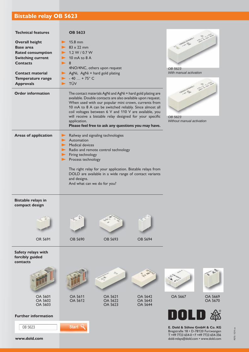
www.dold.com
OB 5623 E. Dold & Söhne GmbH & Co. KG
Further information
Technical features OB 5623
Overall heightBase areaRated consumptionSwitching currentContacts 8
4NO/4NC, others upon requestContact material AgNi, AgNi + hard gold platingTemperature rangeApprovals TÜV
Bistable relays incompact design
Safety relays with forcibly guided contacts
Bistable relay OB 5623
Railway and signaling technologies Automation Medical devices Radio and remote control technology Firing technology Process technology
The right relay for your application. Bistable relays from DOLD are available in a wide range of contact variants and designs.And what can we do for you?
The contact materials AgNi and AgNi + hard gold plating are available. Double contacts are also available upon request. When used with our popular mini crown, currents from
will receive a bistable relay designed for your specific application.Please feel free to ask any questions you may have.
Order information
Areas of application
OB 5623 With manual activation
OB 5623 Without manual activation
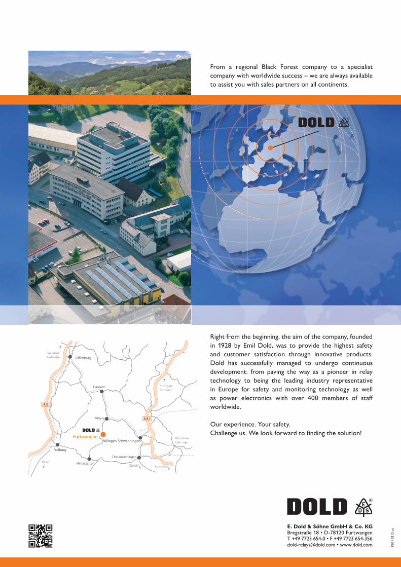
Offenburg
Freiburg
Furtwangen
Triberg
Hausach
Villingen-Schwenningen
Donaueschingen
Hinterzarten
A 5
BaselZürich Konstanz
MünchenUlm
StuttgartRottweil
FrankfurtKarlsruhe
A 81
E. Dold & Söhne GmbH & Co. KG
FE0
/ 021
2 co
Right from the beginning, the aim of the company, founded
and customer satisfaction through innovative products. Dold has successfully managed to undergo continuous development: from paving the way as a pioneer in relay technology to being the leading industry representative in Europe for safety and monitoring technology as well
worldwide.
Our experience. Your safety. Challenge us. We look forward to finding the solution!
From a regional Black Forest company to a specialist company with worldwide success – we are always available to assist you with sales partners on all continents.


