Embed Size (px)
Citation preview

Nat. Hazards Earth Syst. Sci., 12, 1883–1903, 2012www.nat-hazards-earth-syst-sci.net/12/1883/2012/doi:10.5194/nhess-12-1883-2012© Author(s) 2012. CC Attribution 3.0 License.
Natural Hazardsand Earth
System Sciences
Instability mechanisms affecting cultural heritage sites in theMaltese Archipelago
G. Gigli1, W. Frodella1, F. Mugnai1, D. Tapete1, F. Cigna1,*, R. Fanti1, E. Intrieri 1, and L. Lombardi 1
1Department of Earth Sciences, University of Firenze, Firenze, Italy* Present address: British Geological Survey, Nicker Hill, Keyworth, Nottingham, UK
Correspondence to:G. Gigli ([email protected])
Received: 11 October 2011 – Revised: 9 January 2012 – Accepted: 22 January 2012 – Published: 14 June 2012
Abstract. The superimposition of geological formationswith marked contrast in geotechnical properties presents oneof the most critical environments for slope instability due tothe different response of the materials to the applied distur-bances. Moreover, the above-mentioned geological settingis often associated with high risk conditions, since many iso-lated rock slabs located at a higher altitude than the surround-ing countryside have been sites of historical towns or build-ings.
The purpose of the present paper is to investigate themechanisms determining instability in rock slabs overlyinga soft substratum, with reference to two cultural heritagesites in Malta. Accurate investigations have been carried outto evaluate the geological, geotechnical and geomechanicalproperties together with the main geomorphological featuresof the soft clayey substratum and the overlying limestonerock mass.
The main instability processes have thus been identifiedand investigated through kinematic analyses and numericalmodeling, combined with a 1992–2001 Persistent Scatterersmonitoring of ground displacements. The study constitutesthe basis for the subsequent restoration works.
1 Introduction
The overlapping of hard rock masses, potentially subjected toelastic deformations and brittle collapse, on a plastic substra-tum is a common geological feature, especially in culturalheritage sites (Cancelli and Pellegrini, 1987; Canuti et al.,1990, 2004; Bertocci et al., 1991; Casagli et al., 1993; Katzand Crouvi, 2007).
This superimposition frequently leads to mechanical insta-bility due to the diverse response of the materials to the ap-plied perturbations, such as man-made excavations, weather-ing or erosion. The latter acts selectively, with major impactson the more erodible substratum, thereby forming buttes or
plateaus above the surrounding countryside, bordered by un-stable steep cliffs. Such a type of configuration evidentlygenerates conditions of high hazard associated with a rele-vant vulnerability and related risk for built heritage of sig-nificant cultural value; threats to people’s safety can deriveas well (Cestelli et al., 1984; Cotecchia, 1997; Canuti et al.,1999; Luzi et al., 2004; Egglezos et al., 2008).
We should carefully distinguish in detail the overall mech-anism which governs the behavior of a rock slab over a softsubstratum from the failures that take place at its boundaries.Only the latter can be classified according to the traditionallandslide classification schemes. The former can be definedas a complex mass movement, according to Varnes (1978)and Hutchinson (1988), since it involves a combination ofseveral different basic failure mechanisms
Therefore, the problem requires a multi-disciplinary ap-proach involving the application of principles from differentfields, such as rock and soil mechanics, geology, geomor-phology, engineering geology, and conservation sciences.
According to Casagli (1992), the instability mechanismsaffecting this geological environment can be classified intothree different but strictly interconnected types:
– overall mechanism of instability;
– soil slope instability;
– rock slope instability.
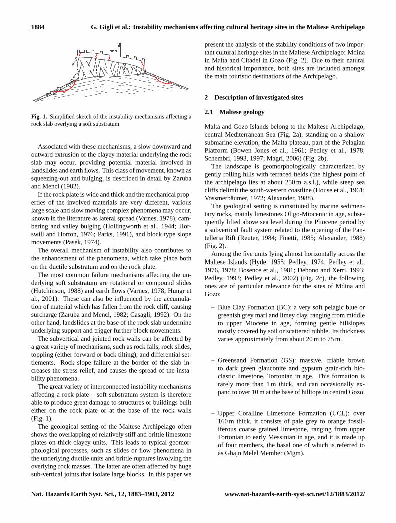
As regards the overall mechanism, the contrast in stiffnessof the outcropping materials causes the opening of joints andnew tensile failures (Casagli, 1992); both isolate large blocksthat can be involved in marginal mass movements (Fig. 1).The fracturing and opening of joints produce stress redistri-bution at the boundary between the rock plate and the sub-stratum. Thus, vertical relative displacements of rock blocksmay also take place due to local elastic-viscous settlementsand yielding.
Published by Copernicus Publications on behalf of the European Geosciences Union.
1884 G. Gigli et al.: Instability mechanisms affecting cultural heritage sites in the Maltese Archipelago
Fig. 1. Simplified sketch of the instability mechanisms affecting arock slab overlying a soft substratum.
Associated with these mechanisms, a slow downward andoutward extrusion of the clayey material underlying the rockslab may occur, providing potential material involved inlandslides and earth flows. This class of movement, known assqueezing-out and bulging, is described in detail by Zarubaand Mencl (1982).
If the rock plate is wide and thick and the mechanical prop-erties of the involved materials are very different, variouslarge scale and slow moving complex phenomena may occur,known in the literature as lateral spread (Varnes, 1978), cam-bering and valley bulging (Hollingworth et al., 1944; Hor-swill and Horton, 1976; Parks, 1991), and block type slopemovements (Pasek, 1974).
The overall mechanism of instability also contributes tothe enhancement of the phenomena, which take place bothon the ductile substratum and on the rock plate.
The most common failure mechanisms affecting the un-derlying soft substratum are rotational or compound slides(Hutchinson, 1988) and earth flows (Varnes, 1978; Hungr etal., 2001). These can also be influenced by the accumula-tion of material which has fallen from the rock cliff, causingsurcharge (Zaruba and Mencl, 1982; Casagli, 1992). On theother hand, landslides at the base of the rock slab undermineunderlying support and trigger further block movements.
The subvertical and jointed rock walls can be affected bya great variety of mechanisms, such as rock falls, rock slides,toppling (either forward or back tilting), and differential set-tlements. Rock slope failure at the border of the slab in-creases the stress relief, and causes the spread of the insta-bility phenomena.
The great variety of interconnected instability mechanismsaffecting a rock plate – soft substratum system is thereforeable to produce great damage to structures or buildings builteither on the rock plate or at the base of the rock walls(Fig. 1).
The geological setting of the Maltese Archipelago oftenshows the overlapping of relatively stiff and brittle limestoneplates on thick clayey units. This leads to typical geomor-phological processes, such as slides or flow phenomena inthe underlying ductile units and brittle ruptures involving theoverlying rock masses. The latter are often affected by hugesub-vertical joints that isolate large blocks. In this paper we
present the analysis of the stability conditions of two impor-tant cultural heritage sites in the Maltese Archipelago: Mdinain Malta and Citadel in Gozo (Fig. 2). Due to their naturaland historical importance, both sites are included amongstthe main touristic destinations of the Archipelago.
2 Description of investigated sites
2.1 Maltese geology
Malta and Gozo Islands belong to the Maltese Archipelago,central Mediterranean Sea (Fig. 2a), standing on a shallowsubmarine elevation, the Malta plateau, part of the PelagianPlatform (Bowen Jones et al., 1961; Pedley et al., 1978;Schembri, 1993, 1997; Magri, 2006) (Fig. 2b).
The landscape is geomorphologically characterized bygently rolling hills with terraced fields (the highest point ofthe archipelago lies at about 250 m a.s.l.), while steep seacliffs delimit the south-western coastline (House et al., 1961;Vossmerbaumer, 1972; Alexander, 1988).
The geological setting is constituted by marine sedimen-tary rocks, mainly limestones Oligo-Miocenic in age, subse-quently lifted above sea level during the Pliocene period bya subvertical fault system related to the opening of the Pan-telleria Rift (Reuter, 1984; Finetti, 1985; Alexander, 1988)(Fig. 2).
Among the five units lying almost horizontally across theMaltese Islands (Hyde, 1955; Pedley, 1974; Pedley et al.,1976, 1978; Bosence et al., 1981; Debono and Xerri, 1993;Pedley, 1993; Pedley et al., 2002) (Fig. 2c), the followingones are of particular relevance for the sites of Mdina andGozo:
– Blue Clay Formation (BC): a very soft pelagic blue orgreenish grey marl and limey clay, ranging from middleto upper Miocene in age, forming gentle hillslopesmostly covered by soil or scattered rubble. Its thicknessvaries approximately from about 20 m to 75 m.
– Greensand Formation (GS): massive, friable brownto dark green glauconite and gypsum grain-rich bio-clastic limestone, Tortonian in age. This formation israrely more than 1 m thick, and can occasionally ex-pand to over 10 m at the base of hilltops in central Gozo.
– Upper Coralline Limestone Formation (UCL): over160 m thick, it consists of pale grey to orange fossil-iferous coarse grained limestone, ranging from upperTortonian to early Messinian in age, and it is made upof four members, the basal one of which is referred toas Ghajn Melel Member (Mgm).
Nat. Hazards Earth Syst. Sci., 12, 1883–1903, 2012 www.nat-hazards-earth-syst-sci.net/12/1883/2012/

G. Gigli et al.: Instability mechanisms affecting cultural heritage sites in the Maltese Archipelago 1885
28
1 Figure 2 2
3
4
Fig. 2. Geographic setting(A), simplified geological map(B) and stratigraphic column(C) of the Maltese Archipelago (modified afterPedley et al., 2002).
UCL hillcaps and plateaus overtopping BC gentle slopesare the dominant feature in the landscape of north-westernMalta and north-eastern Gozo (Fig. 3a, b). Therefore, the ge-ological and geomorphological features of the latter areas aredeeply influenced by the geological characteristics and mu-tual interaction of the above-mentioned formations (Magri etal., 2008; Devoto et al., 2011), while GS, due to its limitedthickness, can only affect the form of the land surface locally.
2.2 Geological setting of the investigated sites
Mdina and Citadel (Fig. 3c, d) are built on two hills belong-ing to the many that characterize the Maltese and Gozitanlandscapes. These reliefs owe their existence to the deeper
erosion of the land that surrounds them (Scerri, 2003). All ofthem are characterized by sub-horizontal or gently inclinedUCL cap protecting the underlying soft BC slopes. Althoughthe geological materials and the stratigraphic sequences aresimilar, the investigated sites show quite diverse instabilityproblems, due mainly to the different thickness of the out-cropping formations and to specific geological features.
UCL, being at the top of the Maltese Islands stratigraphicsequence, is particularly subjected to the action of erodingfactors: percolating rainwater dissolves the limestone, form-ing fissures and caves, stopping when it reaches the imper-meable barrier of the underlying BC. When the contact ofthese two units meets the land surface, spring lines may de-velop, contributing to undermining the limestone hillcaps’
www.nat-hazards-earth-syst-sci.net/12/1883/2012/ Nat. Hazards Earth Syst. Sci., 12, 1883–1903, 2012

1886 G. Gigli et al.: Instability mechanisms affecting cultural heritage sites in the Maltese Archipelago
A B
C D
Fig. 3. Panoramic views of UCL slabs overlying BC exposed in Gozo(A) and Malta(B), and of the investigated sites of Mdina(C) andCitadel(D).
stability. Furthermore rainfall washes away the easily erodi-ble BC causing the overtopping limestone caps to break awayand collapse into blocks of various sizes (Fig. 3d) (Pedley etal., 2002).
2.3 Mdina
Mdina, the former capital of Malta, is a fortified town lo-cated in the central – western sector of the Island on a riseconstituted by the UCL (Fig. 3c). Thanks to its strategic po-sition, over the past centuries the city has been influenced bymany cultures. In 1693 it was extensively damaged by theVal di Noto (Sicily) earthquake (Galea, 2007), and most ofthe buildings and bastions were constructed afterwards (DeLucca, 1993). The city is built on a thin UCL plate (max-imum thickness: 6 m) with a rhomboidal shape and a totalsurface area of about 55 000 m2.
From a geomorphological point of view, the main land-forms associated with the geological system described aboveare always hidden by anthropic structures, and can only beobserved on the nearby hills, where the landscape is muchless modified by human activities. Due to the thinness of the
rock plate, the structures are often built over the contact be-tween the UCL/GS and the underlying BC, thus increasingthe instability problems due to differential settlements of thestructures.
For this reason, most of the damage to buildings and bas-tion walls is located in the perimetral sectors of the city(Baratin et al., 2001; Bonnici et al., 2008) (Fig. 4), and isconcentrated in three specific areas, namely Vilhena Palace,Cathedral and Curtain Magazines.
2.4 Citadel
Citadel is a small fortified town (Fig. 3d) located in the cen-tral part of Gozo, on a hilltop located above the town of Vic-toria (also known as Rabat). Given its central and panoramiclocation within the island of Gozo, this vantage point hashosted urban settlements since the Bronze Age.
The hill consists of more or less circular UCL rock plate,which is 20 m to 25 m thick and about 150 m wide, overlyingfirst a layer of GS and then gentle BC slopes.
The rock plate slopes are sub-vertical, sometimesoverhanging, while the underlying slopes are mostly
Nat. Hazards Earth Syst. Sci., 12, 1883–1903, 2012 www.nat-hazards-earth-syst-sci.net/12/1883/2012/

G. Gigli et al.: Instability mechanisms affecting cultural heritage sites in the Maltese Archipelago 1887
Fig. 4. Structural damages affecting Mdina bastions, walls and buidings.(A): St. Paul’s Bastion;(B) and(C) : Vilhena Palace;(D): DespuigBastion.
Fig. 5. Instability mechanisms affecting the UCL rock plate underlying Citadel (A: rock mass and underpinning masonry;B: rock fall debris).
www.nat-hazards-earth-syst-sci.net/12/1883/2012/ Nat. Hazards Earth Syst. Sci., 12, 1883–1903, 2012

1888 G. Gigli et al.: Instability mechanisms affecting cultural heritage sites in the Maltese Archipelago
Blue Clay
Globigerina Limestone
Upper Coralline Limestone
0 20 40 60 8010 (m)
Landslide
Scarp
!
!
!
!
!
!
! !
!
!
!
!
!
! !
!
!
!
!
!
!
!
!!
!
!
!
!
!
!
!
!
!
!
!
!
B1C1
C2C7 !
!B3
!
!
C0
C1
C4
C5C8C11
C9
C6C9C4
C2
C3
B2
B4
B2
B6
B3B4
B5
B6
A1
A3
A2A3
A4
A5A6
A8
A9
A2
A1
A12
A7
A10
SL 1A11
SL 2Vertical boreholes
Inclined boreholes
Geomechanical scanlines (SL)
Geological cross-section
!
!
Horizontal strata
±
B’
BAREA C
AREA A
AREA B
240
230
220
210
200
190
180
170
160
150
240
230
220
210
200
190
180
170
160
150
Curtain MagazineTriq San Pietru
Triq IL-Villegianon
Cathedral
Despuig Bastion
B B’(m) (m)
E/NE W/SW
0 10 20 30 40 (m)5
C1
C7 C5B5 B4
B3
Fig. 6. Geological map and cross-section of Mdina. Area A: Vilhena Palace; Area B: Cathedral and Despuig Bastion; Area C: CurtainMagazines.
characterized by very gentle to gentle steepness (from 10 %to 20 %).
The rock mass shows a high degree of fracturing, and isconstituted by layers having different resistance to erosion,leading to the formation of ledges and niches (Fig. 5a); thesefactors cause the detachment and falling of rock blocks ofvarious sizes. On the northern sector of the cliff, a large rock-fall event took place in December 2001, and the resulting de-bris is still evident (Fig. 5b).
Evidence of previous rockfalls is also visible slightly eastto the event which occurred in 2001. In order to inhibit theserockfalls several underpinning masonry structures were builtin the past, with the purpose of protecting the niches whichare the most eroded portions of the outcropping cap rock,and to improve its global stability. These structures, widelypresent on the northern and eastern side of the cliff face, werebuilt in different periods, and many of them are now in a poorstate of repair (Fig. 5a).
From a structural point of view, although extensive ev-idence around the fortification walls shows rebuilding ofstructures due to cliff face retreat, the only signs of defor-mation are related to differential displacements of the fewstructures built on the contact between different materials.
3 Data collection
3.1 Geological survey
Accurate geological, geomorphological and geomechanicalsurveys of the selected sites were carried out with the aim ofinvestigating the causes of the main instability processes anddetermining the material properties to be subsequently usedduring the analysis phase.
In particular, high resolution geological maps and relatedcross-sections were drawn utilizing the detailed geologicalsurvey, carried out by means of a differential GPS survey, in
Nat. Hazards Earth Syst. Sci., 12, 1883–1903, 2012 www.nat-hazards-earth-syst-sci.net/12/1883/2012/

G. Gigli et al.: Instability mechanisms affecting cultural heritage sites in the Maltese Archipelago 1889
TextTextTextTextText
TextTextText
A’
A
BC
D
E
c aA!
!
!!
!
g!f!
e!
b
d!
!
!
!
j
jj
j
jj
j
j
j
j
jj
j
j
j
jj
SL 1
SL 5
SL 3
SL 4
20
20
15
16
20
16
18
15
30
17
12
18
28
SL 2
SL 620
17
20
20
Greensand
Blue Clay
Upper Coralline Limestone
Vertical boreholes
Inclined boreholes
Geomechanical scanlines (SL)
Geological cross-section
20 Strata dip direction
!
!
Interpreted fault ±
j
A A’
B
E
140
150
130
120
110
100
(m)
150
140
130
120
110
(m)
Triq San Guzepp Cathedral
Triq Bieb l’Imbina
Ditch
NW SE
100
0 10 20 30 40 (m)5
0 20 40 60 80 (m)10
Fig. 7. Geological map and cross-section of Citadel.
order to reconstruct, with centimeter accuracy, the 3-D ge-ological model and its geometric correlation with the man-made structures.
The traditional geological surveys have been integratedwith a number of ground (deep vertical boreholes; Figs. 6and 7) and structural investigations (horizontal and inclinedboreholes), carried out by Ballut Blocks Services Ltd. (Md-ina) and Solidbase Ltd. (Citadel).
Furthermore, a geotechnical characterization has also beencarried out by means of laboratory tests on undisturbed rockand soil samples retrieved from the deep and inclined bore-holes (Tapete et al., 2012).
As regards Mdina the stratigraphic contact between theUCL and the underlying GS and BC is not regular, and somegroundwater emerges on the clayey slopes in the form of mi-nor springs along the scarps. The location of these minor
www.nat-hazards-earth-syst-sci.net/12/1883/2012/ Nat. Hazards Earth Syst. Sci., 12, 1883–1903, 2012
1890 G. Gigli et al.: Instability mechanisms affecting cultural heritage sites in the Maltese Archipelago
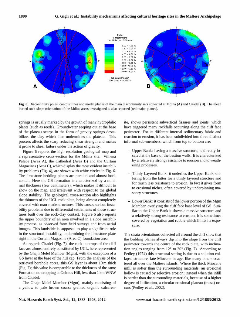
Fig. 8. Discontinuity poles, contour lines and modal planes of the main discontinuity sets collected at Mdina(A) and Citadel(B). The meanburied rock-slope orientation of the Mdina areas investigated is also reported (red major planes).
springs is usually marked by the growth of many hydrophilicplants (such as reeds). Groundwater seeping out at the baseof the plateau scarps in the form of gravity springs desta-bilizes the clay which then undermines the plateau. Thisprocess affects the scarp reducing shear strength and makesit prone to shear failure under the action of gravity.
Figure 6 reports the high resolution geological map anda representative cross-section for the Mdina site. VilhenaPalace (Area A), the Cathedral (Area B) and the CurtainMagazines (Area C), which display the most evident instabil-ity problems (Fig. 4), are shown with white circles in Fig. 6.The limestone bedding planes are parallel and almost hori-zontal. Here the GS formation is characterized by a mini-mal thickness (few centimeters), which makes it difficult toshow on the map, and irrelevant with respect to the globalslope stability. The geological cross-section also highlightsthe thinness of the UCL rock plate, being almost completelycovered with man-made structures. This causes serious insta-bility problems due to differential settlements of those struc-tures built over the rock-clay contact. Figure 6 also reportsthe upper boundary of an area involved in a slope instabil-ity process, as observed from field surveys and from aerialimages. This landslide is supposed to play a significant rolein the structural instability, undermining the limestone plateright in the Curtain Magazine (Area C) foundation area.
As regards Citadel (Fig. 7), the rock outcrops of the cliffface are almost entirely constituted by UCL, here representedby the Ghajn Melel Member (Mgm), with the exception of aGS layer at the base of the hill cap. From the analysis of theretrieved borehole cores, this GS layer is about 10 m thick(Fig. 7); this value is comparable to the thickness of the sameFormation outcropping at Gelmus Hill, less than 1 km WNWfrom Citadel.
The Ghajn Melel Member (Mgm), mainly consisting ofa yellow to pale brown coarse grained organic calcaren-
ite, shows persistent subvertical fissures and joints, whichhave triggered many rockfalls occurring along the cliff faceperimeter. For its different internal sedimentary fabric andreaction to erosion, it has been subdivided into three distinctinformal sub-members, which from top to bottom are:
– Upper Bank: having a massive structure, is directly lo-cated at the base of the bastion walls. It is characterizedby a relatively strong resistance to erosion and to weath-ering processes.
– Thinly Layered Bank: it underlies the Upper Bank, dif-fering from the latter for a thinly layered structure andfor much less resistance to erosion. In fact it gives formto erosional niches, often covered by underpinning ma-sonry structures.
– Lower Bank: it consists of the lower portion of the MgmMember, overlying the cliff face base level of GS. Sim-ilar to the Upper Bank it shows a massive structure anda relatively strong resistance to erosion. It is sometimescovered by vegetation and rubble which limits its expo-sure.
The strata orientations collected all around the cliff show thatthe bedding planes always dip into the slope from the cliffperimeter towards the centre of the rock plate, with inclina-tion angles ranging from 12◦ to 30◦ (Fig. 7). According toPedley (1974) this structural setting is due to a solution col-lapse structure, late Miocene in age, like many others scat-tered all over the Maltese islands. Where the thick Mioceneinfill is softer than the surrounding materials, an erosionalhollow is caused by selective erosion; instead when the infillis harder than the surrounding materials, because of a higherdegree of litification, a circular erosional plateau (mesa) oc-curs (Pedley et al., 2002).
Nat. Hazards Earth Syst. Sci., 12, 1883–1903, 2012 www.nat-hazards-earth-syst-sci.net/12/1883/2012/

G. Gigli et al.: Instability mechanisms affecting cultural heritage sites in the Maltese Archipelago 1891
Table 1. Geomechanical properties of the rock mass discontinuities. Setid: joint set identification code;α: dip direction;β: dip; X:true spacing; L: persistence; e: aperture; JRC: Joint Roughness Coefficient; JCS: Joint Compressive Strength; r: Schmidt hammer reboundnumber on wet and weathered fracture surfaces; R: Schmidt hammer rebound number on dry unweathered surfaces;φb: basic friction angle.
Set id α (◦) β (◦) X (m) L (m) e (mm) JRC JCS r/R φb(◦)
UCL Mdina
JN1 272 75 3.5 1.3 9.8 11.1 18.3 0.4 32.3JN2 104 76 7.0 1.6 15.3 12.8 17.4 0.5 32.3JN3 314 81 5.4 1.6 15.6 14.6 21.7 0.7 32.3JN4 075 76 7.8 1.5 21.4 13 20.1 0.5 32.3
UCL Citadel
JN1 030 89 1.4 2.5 13.3 12.1 15.6 0.4 35.9JN2 274 84 1.3 2.9 12.9 11.7 17.5 0.8 35.9JN3 329 73 5.1 2.6 17 13.7 16.9 0.6 35.9BG 0–360 12–17 1.4 Inf. 11 12 15.7 0.7 35.9
3.2 Geomechanical survey
The rock mass characterization and the quantitative descrip-tion of discontinuities were obtained by means of traditionalgeomechanical surveys (scanline method), according to themethods suggested by the International Society for Rock Me-chanics (ISRM, 1978, 1985).
Due to the limited rock mass outcropping at Mdina, only2 scanline surveys (25 m and 30 m in length) were performedon the rockwall next to the ditch within the Vilhena Palacearea (Area A) (Fig. 6). In order to extend the rock massmechanical properties to the other investigated areas, somerandom discontinuity orientation measurements were taken,confirming the spatial distribution of the identified disconti-nuity sets.
As regards Citadel, a total of 6 scanline surveys (varyingfrom 15 m to 33 m in length) were performed according tothe methods suggested by ISRM (1978, 1985). These scan-lines were performed all around the cliff face, to cover boththe massive Upper and Lower Bank and the Thinly LayeredBank of the Ghajn Melel Member within the UCL Formation(Fig. 7).
For each scanline a sheet was filled by measuring the ori-entation, persistence, aperture, roughness, rock wall strength,filling, seepage of the discontinuities crossing the survey line.
In order to determine the UCL intact rock tensile and com-pressive strength for both investigated sites, a number ofpoint load tests were performed, following the methods sug-gested by ISRM (1985). The resultingσc values for UCLintact rock are: 22.3 MPa (Mdina) and 6.7 MPa (Citadel).
With the aim of identifying the major discontinuity sets,orientation data were plotted on a stereographic projection(lower hemisphere).
Figure 8a reports the stereographic projection of the col-lected data: discontinuity poles concentration, main setmodal planes and mean buried rock-slope orientation in theinvestigated areas are shown. Excluding the sub-horizontal
stratification, four main sets can be identified on the rockmass underlying Mdina.
Four discontinuity sets have also been identified within therock slab underlying Citadel (Fig. 8b).
Both sites show medium pole dispersion, with a preva-lence of high dipping discontinuity planes (excluding thebedding planes).
These structural data were employed in the kinematic anal-yses and numerical modelling, described in Sect. 4.
The shear strength of discontinuities was calculated usingBarton’s failure criterion (Barton and Choubey, 1977). Fi-nally, for a complete characterization of the material proper-ties to be used in the numerical model, the Mohr Coulombequivalent strength parameters of the rock mass were calcu-lated through the Hoek and Brown failure criterion (Hoekand Brown, 1980; Hoek et al., 2002). These properties wereused as input parameters for the kinematic analyses and nu-merical modelling (Table 1).
3.3 Laser scanning survey
Nowadays, advanced techniques are available for obtaininghigh resolution 3-D representations of land surface, such asdigital photogrammetry (Chandler, 1999; Lane et al., 2000)and laser scanning (both terrestrial and aerial) (Kraus andPfeiffer, 1998; Frohlich and Mettenleiter, 2004).
The main product of a long range laser scanning survey is ahigh resolution point cloud, obtained by measuring with highaccuracy (millimeter or centimeter) the distance of a mesh ofpoints on the object, following a regular pattern with polarcoordinates. The high acquisition rate (up to hundreds ofthousands points per second) makes the detailed 3-D shapeof the object immediately available.
The advantage of employing remote and high resolutionsurveying techniques is that it allows us to perform detailedanalyses and to rapidly obtain information on inaccessiblerock exposures. This is very important in the field of en-gineering geology and emergency management, when it is
www.nat-hazards-earth-syst-sci.net/12/1883/2012/ Nat. Hazards Earth Syst. Sci., 12, 1883–1903, 2012

1892 G. Gigli et al.: Instability mechanisms affecting cultural heritage sites in the Maltese Archipelago
A B
Fig. 9. Laser scanner in action at Vilhena Palace, Mdina(A); True coloured 3-D point cloud of Vilhena Palace, Mdina(B).
A
N
B
Mtarfa
Mdina
Fig. 10. (A): Example of ERS2 image acquired along descending orbit on the Maltese Archipelago (displayed in terms of amplitude).Footprint of the whole scene is shown within the inset as a dashed black polygon.(B): Subset of(A) displayed in SAR coordinates andincluding the urban area of Mtarfa and Mdina.
often advisable to minimize survey time in dangerous envi-ronments and at the same time gather all the required infor-mation as fast as possible.
The Laser Scanning technique is being more frequentlyused for instability analyses in cultural heritage sites(Boehler et al., 2001; Arayici, 2007; Lambers et al., 2007;Yastikli, 2007; Yilmaz et al., 2007; Al-kheder et al., 2009;Fanti et al., 2011, 2012), as it allows detailed and high ac-curacy 3-D representation of both the underlying ground andthe overlying structures in a short time.
A detailed 3-D model of the investigated sites is usefulfor building a complete digital model including the struc-
tures and the slopes, making it possible to reconstruct theplano-altimetric relationship between the local geology andthe man-made structures (Figs. 6 and 7). Thanks to the highresolution of the laser scanning survey we can also extracteven the smallest features, such as the structural crack pat-tern, the crack opening direction (Gigli et al., 2009), andthe orientation of critical discontinuities within the rock mass(Gigli and Casagli, 2011).
A laser scanning survey of the investigated Mdina areaswas carried out, by employing a long range 3-D laser scan-ner (RIEGL LMSZ410-i) (Fig. 9a). This device can deter-mine the position of up to 12 000 points s−1 with a maximum
Nat. Hazards Earth Syst. Sci., 12, 1883–1903, 2012 www.nat-hazards-earth-syst-sci.net/12/1883/2012/

G. Gigli et al.: Instability mechanisms affecting cultural heritage sites in the Maltese Archipelago 1893
P1
P2
23.2 cm
North North
A
B
Fig. 11. (A): 3-D polylines of the main cracks affecting the Curtain Magazines.(B): True coloured point cloud and displacement vector of acrack affecting the Despuig Bastion (modified from Gigli et al., 2009).
angular resolution of 0.008◦ and an accuracy of±10 mmfrom a maximum distance of 800 m. In order to completelycover the intervention areas, several surveys from differentscan positions were performed. The different point cloudswere subsequently linked to a projection reference systemwith the aid of reference points, whose coordinates were de-fined by using a differential GPS. Three different projectswere constructed, corresponding to the number of the studyareas.
Area A was covered by 26 different scan positions, andareas B and C by 12 and 18 scan positions respectively. A
total of more than 200 million points and 250 high resolutiondigital images were taken.
All the acquired point clouds were cleared of vegetationand encumbering objects, and were given their true coloursacquired by a high resolution digital camera mounted overthe instrument (Fig. 9b). For each study area all point cloudswere linked, based on a global reference system, and a con-tinuous surface was created by triangulation points from dis-crete point clouds.
As regards Citadel, the 3-D model employed for the kine-matic analysis and the numerical modelling, produced by
www.nat-hazards-earth-syst-sci.net/12/1883/2012/ Nat. Hazards Earth Syst. Sci., 12, 1883–1903, 2012

1894 G. Gigli et al.: Instability mechanisms affecting cultural heritage sites in the Maltese Archipelago
Fig. 12. 3-D maps of slope steepness(A) and aspect(B) of theCitadel rock mass.
the “Consorzio Ferrara Ricerche of the University of Fer-rara”, under the Service Tender for the documentation of theCitadel Fortifications, was provided by the Restoration Unit,Works Division, Floriana (Malta) within the Ministry for Re-sources and Rural Affairs.
3.4 Satellite radar data (1992–2001)
In situ investigations carried out at Mdina were completedwith satellite radar monitoring by means of Persistent Scat-terers Interferometry (PSI). Developed in the late ’90s, thisremote sensing technique uses long temporal series of Syn-thetic Aperture Radar (SAR) imagery allowing for the recog-nition of reflective targets on the ground, which makes pos-sible the detection and monitoring of the displacements oc-curring between the analysed satellite acquisitions (Ferrettiet al., 2001; Crosetto et al., 2010). Thanks to wide area cov-erage, millimeter precision and cost-effectiveness, PSI tech-nologies can successfully integrate conventional field inves-tigations in the reconstruction of the past deformation history
of the observed areas, and improve the understanding of thedeformation mechanisms threatening unstable structures andinfrastructures (Casagli et al., 2009; Cigna et al., 2010, 2011;Righini et al., 2011).
The multi-temporal PSI analysis in Mdina was used totest the feasibility of radar remote sensing for the analysisof the instability mechanisms affecting the rock plate-softsubstratum system. The measurement of land displacementsinduced by hydrogeological and structural instability oftenrepresents the most effective method for the definition of thehazard and risk scenarios, the choice of corrective actionsaimed at risk reduction and/or the evaluation of their effec-tiveness.
The availability of historical datasets of ERS1/2 radar im-ages made possible the retrospective analysis of past move-ments occurring in Mdina since the early ’90s. Launched andoperated by the European Space Agency (ESA), the ERS1/2satellites were the first radar missions acquiring commer-cially available microwave data since July 1991 (ERS1) andMay 1995 (ERS2). To perform the PSI analysis, a data stackof 63 ERS1/2 scenes acquired along descending orbits in theperiod 5 June 1992 – 8 January 2001, with nominal revisitingtime of 35 days, was selected.
These images were acquired in C band (wavelength of5.66 cm) and VV polarization, and are characterized by aresolution of about 20 m on the ground and a spatial cover-age of 100 km by 100 km, consequently covering the wholearchipelago (Fig. 10). At the analysed latitudes, the Line OfSight of the ERS1/2 satellites in the descending mode has anazimuth of about 257◦ and a look angle of 23◦ (measuredfrom the vertical direction).
4 Data analysis
4.1 Quantitative deformation analysis affecting Mdinastructures
The high detail of the laser scanning point clouds, integratedwith the high resolution digital images acquired by the cam-era mounted over the device, allowed for the construction ofa 3-D map of the main fractures affecting Mdina structures,by digitizing 3-D polylines over the crack traces (Fig. 11a).Displacement vectors were calculated for the main cracks ordeformed structures, with the aim of identifying the struc-tural deformation patterns. Each vector was drawn by joiningtwo corresponding points selected from the 3-D point cloud.These were chosen because they occupied the same locationbefore displacement had occurred (Fig. 11b).
4.2 Kinematic analysis
The term kinematic refers to the study of movement, withoutreference to the forces that produce it. This kind of analysisis able to establish when a particular instability mechanism
Nat. Hazards Earth Syst. Sci., 12, 1883–1903, 2012 www.nat-hazards-earth-syst-sci.net/12/1883/2012/

G. Gigli et al.: Instability mechanisms affecting cultural heritage sites in the Maltese Archipelago 1895
is kinematically feasible, given the geometry of the slope anddiscontinuities.
The main instability mechanisms investigated with this ap-proach are:
– plane failure (PF) (Hoek and Bray, 1981);
– wedge failure (WF) (Hoek and Bray, 1981);
– block toppling (BT) (Goodman and Bray, 1976; Mathe-son, 1983);
– flexural toppling (FT) (Goodman and Bray, 1976; Hud-son and Harrison, 1997).
Casagli and Pini (1993) introduced a “kinematic hazardindex” for each instability mechanism. These values arecalculated by counting poles and discontinuities falling incritical areas:
Npf = number of poles satisfying planefailure conditions;
Iwf = number of intersections satisfyingwedge failure conditions;
Nbt = number of poles satisfying blocktoppling conditions;
Ibt = number of intersections satisfyingblock toppling conditions;
Nft = number of poles satisfyingflexural toppling conditions.
The kinematical hazard index is calculated as follows:
Cpf = 100× (Npf/N) for plane failure;Cwf = 100× (Iwf /I ) for wedge failure;Cbt = 100× (Nbt/N)× (Ibt/I ) for block toppling;Cft = 100× (Nft /N) for flexural toppling.
WhereN andI are the total number of poles and intersec-tions respectively.
By using specific software, such as KARS (Casagli andPini, 1993), or Rock Slope Stability (Lombardi, 2007) it ispossible to load a great number of discontinuities with dif-ferent friction angles.
Intersection lines are calculated automatically, togetherwith the equivalent friction angle, based on the friction an-gles of the intersecting planes and the shape of the wedge(Casagli and Pini, 1993).
The analysis can be performed for specific slope orienta-tions, or for each cell of a 3-D surface (true 3-D kinematicanalysis).
4.2.1 3-D kinematic analysis – Citadel
The Citadel rock mass is characterized by different joint sets(Fig. 8b; Table 1).
As the orientation of these fractures does not seem to berandom, but related to the tectonic processes that have beenacting in the investigated area, a kinematic analysis can be
useful to highlight the rock wall sectors which are moreprone to instability processes. These are identified by com-bining fracture dip and dip directions with local slope orien-tations.
The rock plate is, in fact, characterised by very steepslopes, sometimes overhanging, and, due to its circularshape, by the whole range of possible slope aspects.
Local slope orientation data were evaluated by analysingthe 3-D model produced by the “Consorzio Ferrara Ricercheof the University of Ferrara”, under the “Service Tenderfor the documentation of the Citadel Fortifications, Gozo,Malta”.
It is important to point out that this analysis only takes intoaccount those discontinuities intersected by the scanline ge-omechanical surveys carried out at the base of the cliff, anddoes not consider minor and irregular fractures originating inlocal stress concentrations, thus underestimating the proba-bility of occurrence of instability phenomena in those areas.
The analysis input parameters are the slope dip (Fig. 12a),the dip direction (Fig. 12b), and the discontinuity surface ori-entations.
The analyses were performed by applying the method pro-posed by Lombardi (2007), which employs the principles ofkinematic analysis to overhanging slopes.
The discontinuity shear strength was considered purelyfrictional, and the mean peak friction angle resulting fromthe analysis of geomechanical data was set toφ = 48◦.
The results of the analysis for each mechanism investi-gated are presented in Fig. 13.
The kinematic indices were plotted with a common leg-end, scaled according to the maximum values (30 %).
4.2.2 Constant dip kinematic analysis – Mdina
By observing the fracture distribution on the structures in theMdina area, we can say that these are mainly caused by dif-ferential movements, due to different mechanical character-istics of the underlying materials.
In addition, rigid block displacements along pre-existingrock mass discontinuity planes can occur. In fact, the shearresistance of discontinuities is much lower than the intactrock strength.
Thus, the presence of unfavourably oriented discontinuitysets would enhance deformational mechanisms on the rockslab, leading to major fractures in the overlying buildings andbastions.
To quantify this behaviour of the UCL rock mass, we canmake use of kinematic analysis principles. Although kine-matic analysis applies to sub-aerial slopes, we can employthis concept to a buried rock plate, such as the rock massunderlying the town of Mdina.
The aim of this study is to demonstrate that damage tobuildings and ground displacements observed in the studyareas are amplified by the presence of unfavourably orienteddiscontinuity sets, dissecting the UCL plate.
www.nat-hazards-earth-syst-sci.net/12/1883/2012/ Nat. Hazards Earth Syst. Sci., 12, 1883–1903, 2012

1896 G. Gigli et al.: Instability mechanisms affecting cultural heritage sites in the Maltese Archipelago
Fig. 13. 3-D maps derived from the results of the kinematic analysis for the northern sector of Citadel rock mass.(A): Plane failure (PF);(B): wedge failure (WF);(C): block toppling (BT);(D): flexural toppling (FT).
0
5
10
15
20
25
30
35
40
0 50 100 150 200 250 300 350
Kin
em
ati
c in
dex (
%)
Dip direction (°)
%PF
%WF
%BT
%FT
Area A Area CArea B
Fig. 14. Constant dip quantitative kinematic analysis for Mdina.Yellow rectangles indicate the dip direction range for each investi-gated area. (PF: plane failure; WF: wedge failure; BT: block top-pling; FT: flexural toppling).
The employed quantitative approach considers a fixedslope dip (80◦); the kinematic hazard index for each insta-bility mechanism is then calculated by varying the slope dipdirection from 0◦ to 360◦. Given a certain slope dip, it istherefore possible to identify the most unfavourable slopeorientations for the main instability mechanisms.
The results of the analysis are presented in Fig. 14, wherethe kinematic indices are plotted for each slope dip direction;yellow rectangles indicate the dip direction range for eachstudy area.
4.3 Numerical modelling
The identified instability processes were also investigated bymeans of numerical modelling.
This analysis was performed for the Citadel slopes by em-ploying the Universal Distinct Element Code (UDEC, Itasca,2004). This is a two-dimensional numerical program basedon the Distinct Element method for discontinuum modelling,which simulates the response of discontinuous media (suchas a jointed rock mass) subjected to either static or dynamicloading. The discontinuous medium is represented as an as-semblage of discrete blocks, and discontinuities are treatedas boundary conditions between blocks; large displacementsalong discontinuities and rotation of blocks are allowed. In-dividual blocks behave as either rigid or deformable material.
Deformable blocks are subdivided into a mesh of finite-difference elements, and each element responds accordingto a prescribed linear or non-linear stress-strain law. UDEC
Nat. Hazards Earth Syst. Sci., 12, 1883–1903, 2012 www.nat-hazards-earth-syst-sci.net/12/1883/2012/

G. Gigli et al.: Instability mechanisms affecting cultural heritage sites in the Maltese Archipelago 1897
Fig. 15.Numerical modelling results.(A): Initial model;(B): Block displacements (third step);(C): Displacement vectors (fourth step);(D):Zone state (fourth step).
is based on a “Lagrangian” calculation scheme that is well-suited to model the large movements and deformations of ablocky system, such as the one investigated.
The analysis was performed along the profile shown inFig. 7. This section was chosen due to the local steepness ofthe rock wall, which is affected by several instability mecha-nisms.
Fractures were generated within the UCL layer, accord-ing to the apparent orientation of the discontinuities surveyed(Fig. 15a). Each block was subdivided into a mesh of finite-difference elements, and each element was assigned a MohrCoulomb constitutive model.
Joints were assigned the Coulomb slip criterion, whichgives elastic stiffness, frictional, cohesive and tensilestrengths, and dilation characteristics to each joint. Both thematerial and the joint properties were selected based on theresults of the geomechanical survey (Table 1).
The first step of the analysis consists in the setting up of thestress state. This was performed by assigning high strength tomaterials and discontinuities together with real elastic prop-erties, thus allowing the model to converge to equilibrium un-der its own weight. After assigning real peak strength prop-erties to zones and joints (second step), the model still con-verged to a stable state, but with some plastic deformations
below the rock plate, probably because in situ BC strengthparameters are higher than the simulated ones.
The third step of the numerical modelling consists in as-signing joint residual properties, in order to simulate shal-low instability phenomena induced by weathering processes.With these perturbations the model did not reach equilibrium,and blocks delimited by steep joints that dip out of the cliffface moved downward, especially in sections correspondingto overhanging parts (Fig. 15b).
For the last stage (fourth step), falling blocks were re-moved, to restore the model to a stable state, and residualstrength properties were assigned to the shallow part of theBC region, in order to simulate the eventual processes of de-cay of these materials, favoured by the poor conditions ofthe Citadel retaining terrace walls. Due to this modifica-tion, a shallow landslide is triggered in the numerical model(Fig. 15c), and mixed shear-traction sub-vertical fractures areinduced throughout the whole upper rock plate by the result-ing undermining action (Fig. 15d).
4.4 Persistent Scatterers analysis
The PSI processing approach implemented in Mdina is theInterferometric Point Target Analysis (IPTA), developed by
www.nat-hazards-earth-syst-sci.net/12/1883/2012/ Nat. Hazards Earth Syst. Sci., 12, 1883–1903, 2012

1898 G. Gigli et al.: Instability mechanisms affecting cultural heritage sites in the Maltese Archipelago
-90
-75
-60
-45
-30
-15
0
15
Jun-'92
Dec-'92
Jun-'93
Dec-'93
Jun-'94
Dec-'94
Jun-'95
Dec-'95
Jun-'96
Dec-'96
Jun-'97
Dec-'97
Jun-'98
Dec-'98
Jun-'99
Dec-'99
Jun-'00
Dec-'00
LO
S d
isp
lac
em
en
t [m
m]
Time
PS12529
PS12470
PS12649
A B
PS12529
PS12649
PS12470
C
-90
-75
-60
-45
-30
-15
0
15
Jun-'92
Dec-'92
Jun-'93
Dec-'93
Jun-'94
Dec-'94
Jun-'95
Dec-'95
Jun-'96
Dec-'96
Jun-'97
Dec-'97
Jun-'98
Dec-'98
Jun-'99
Dec-'99
Jun-'00
Dec-'00
LO
S d
isp
lac
em
en
t [m
m]
Time
PS12529
PS12470
PS12649
A B
PS12529
PS12649
PS12470
C
Fig. 16. (A): LOS displacement velocities measured between 1992–2001 for the ERS1/2 Persistent Scatterers identified in the area of Mdina.Negative velocities indicate movements away from the sensors, while positive values indicate movements toward the sensor.(B) Standarddeviations of LOS velocity of the identified PS.(C): Deformation time series of selected PS. For graphical purposes, the temporal referencefor the time series was shifted from the master images (30 March 1998) to the first SAR acquisition (5 June 1992).
Gamma Remote Sensing and Consulting AG, Switzerland.The interferometric phase model used by IPTA is the sameas that used in conventional interferometry, and can be ex-pressed as the sum of topographic, deformational, differen-tial path delay (i.e. atmospheric), and noise phase compo-nents (Werner et al., 2003). Through the use of point tar-gets (the so called PS, Persistent Scatterers), interferometricpairs with longer baselines can also be used (even above thecritical baseline), increasing the number of scenes processed,allowing a reliable removal of the atmospheric components,and leading to both a better temporal coverage and a moreprecise estimation of ground displacements.
Within each ERS1/2 scene, a 9 km by 9 km workingarea including the towns of Mdina, Mtarfa, Mosta and Sig-giewi was selected, and the processing started with the co-registration of the full stack of images to a single master(i.e. the 30 March 1998 scene). A 90 m resolution DigitalElevation Model (DEM) obtained through the SRTM (Shut-tle Radar Topography Mission) mission was used to simulatethe topographic phase component (Werner, 2001). Criteriafor the selection of PS candidates included low temporal vari-ability of the backscattering coefficient and also low spectralphase diversity, to maximize the density of the PS candidatenetwork. The presence of point targets depended strongly onthe scene and many points were identified in built-up areas
(e.g. man-made structures, buildings, antennas), while veryfew points were detected in vegetated and agricultural areas.
A simple linear model of phase variation through timewas chosen to extract the components related to ground dis-placements; linear variability of the topographic phase on theperpendicular baseline was also taken into account. EachPS phase model was improved through a step-wise itera-tive processing, using height corrections (added to DEMheights), linear deformation rates, standard deviations fromregression, and residual phases (including atmospheric, non-linear deformation and error terms), to progressively updatethe different phase components. Final results of the IPTAprocessing include a set of 10 941 point targets (averagedensity of 140 PS km−2), characterized by information onheight, yearly deformation velocity measured along the satel-lite LOS (Line Of Sight), quality information (standard de-viation of LOS velocity), and non-linear deformation historywith millimeter precision (Fig. 16).
5 Discussion
On the basis of the undertaken surveys and analyses, spe-cific instability processes can be inferred for the two inves-tigated sites. Some differences however arise, mainly due
Nat. Hazards Earth Syst. Sci., 12, 1883–1903, 2012 www.nat-hazards-earth-syst-sci.net/12/1883/2012/

G. Gigli et al.: Instability mechanisms affecting cultural heritage sites in the Maltese Archipelago 1899
Fig. 17. Field validation of the numerical modelling results.(A):General view of the Gelmus Hill, close to Citadel;(B): Detail of theouter portion of the rock mass.
to the major thickness and different structural setting of therock plate underlying Citadel.
For this reason, and given the intense urbanization of theMdina site, the effects of these mechanisms of instability, aremore evident in the rock mass outcropping at Citadel and theanthropic structures built on the margin of the Mdina cliffface.
The sub-vertical rock wall of Citadel is, in fact, heavilyprone to rockfall, as results from both the 3-D kinematicanalysis and the numerical modelling. This is a very im-portant point, as the touristic appeal of the site can result inhigh risk levels, especially in case of exploitation of the areaunder the cliff for the construction of a pedestrian path.
Figure 13 shows that the mechanism associated to thehighest index is wedge failure (WF max = 30 %), followed byflexural toppling (FT max = 17 %). All the other mechanismsseem to be irrelevant, due to the fact that the bedding planesalways dip gently into the slope. All the northern sector iscurrently deeply affected by wedge failure, especially wherethe formation of wedges is favoured by the cliff overhangingparts, as confirmed from field evidence, which shows signsof a number of niches and potential wedge detachments.
The numerical modeling, besides confirming these super-ficial instability mechanisms, also displays the possibilityof a deeper involvement of the rock mass, in case of shal-low landslide or undercutting within the underlying clayeyunit (Fig. 15d). Such phenomena are clearly visible on theboundary of the UCL rock plate at Gelmus Hill, near Citadel(Fig. 17), where the clay slopes are not terraced, and shallowlandslides can take place. The distance from the cliff face ofthe observed fractures seems however slightly lower than thatof the numerical modelling, probably due to a low spatial res-olution of the model caused by a coarse meshing. These kindof processes, however, do not seem to be presently affectingthe Citadel rock plate, where the instability phenomena aremainly constituted by rockfalls along pre-existing structuraldiscontinuities; the latter are enhanced by the intense weath-ering conditions of the rock walls. Probably this is due tothe concave setting of the hill (Fig. 7), caused by the solutioncollapse structure, which prevents the concentration of highstress at the base of the cliff, thus limiting plastic deforma-tions.
As regards Mdina, the integration of geological, geomor-phological and geomechanical surveys with the 3-D distribu-tion of fractures, the quantitative displacement analysis of thestructures, and the Persistent Scatterers study allowed us tounderstand the basic kinematic behaviour in the study area.
The bastion and buildings in the investigated areas werebuilt in different periods and are founded both on the cap rockand on the clayey unit. The damage to the bastions and build-ings is, therefore, mainly associated to differential move-ments produced by the contrasting mechanical behaviour ofthe underlying materials or by rock block displacements. Infact the UCL rock mass is here quite thin; this leads to rockfragmentation, located mainly along the rock plate borders.
The Vilhena Palace area (Area A) shows the most com-plex fracture pattern, probably due to the thin and heav-ily fractured underlying rock mass, and the intrinsic struc-tural problems linked to the different construction phases(Fig. 6). In the Cathedral area (Area B), a predominanttranslational displacement with an E-SE direction is associ-ated with considerable vertical component. This behaviouris in accordance with the geological setting, as the Despuigbastion was constructed directly on the stratigraphic contactbetween the UCL and the BC (Fig. 6). The Curtain Maga-zine area (Area C) is characterized by an intense concentra-tion of fractures, most of which show displacement vectorswith a sub-horizontal direction and apertures of up to 20 cm(Fig. 11a). These displacements are compatible with the dif-ferential behaviour of the materials underlying the structure,and can be emphasized by the presence of a relevant an-cient landslide, which is probably responsible for the localrock plate indentation (Fig. 6). All the instability processeswithin the investigated areas are also magnified by the pres-ence of unfavourably orientated discontinuity sets with re-spect to the main instability mechanisms affecting the rockmass (Fig. 8A). The constant dip kinematic analysis (Fig. 14)
www.nat-hazards-earth-syst-sci.net/12/1883/2012/ Nat. Hazards Earth Syst. Sci., 12, 1883–1903, 2012

1900 G. Gigli et al.: Instability mechanisms affecting cultural heritage sites in the Maltese Archipelago
confirms that all the study areas are oriented unfavourablywith respect to all the mechanisms analysed (with the excep-tion of block toppling), with high kinematic hazard indices(ranging from 12 % to 35 %).
It is important to stress that, for the investigated sites, theinstability of both the cliff and the overlying structures isalso greatly affected by presence of the BC Formation un-derlying the limestone cap rock, which can be subjected toflow phenomena or volume variations caused by the seasonalchanges of water content. Clayey hillslopes have long beenused intensively for agricultural purposes; at present, theseslopes (especially at Citadel) are only marginally used foragriculture, while most of the area is uncultivated. Terracesare still evident, but the retaining walls show the traces oflong-standing neglect (Scerri, 2003).
The buildings and bastion walls, being made of local stone(UCL or GL), are also affected by weathering and alterationpatterns that can be observed on single stones, mainly due tothermal expansion, haloclasty and wind action.
PSI processing of the available SAR images covering thearea of Mdina allowed us to improve the knowledge aboutthe instability affecting the different sectors of the walledcity and to detect its spatial distribution and temporal evo-lution. The results of the IPTA processing indicate a gen-eral stability over the whole area between 1992 and 2001.In the inner sectors of Mdina, only 38 PS are identifiedand most of them show null to very low annual deforma-tion velocities (i.e. lower than±1.5 mm yr), as well as aquite stable displacement history over the whole time inter-val (Fig. 16). The identified targets are not homogeneouslydistributed over the city. They lack especially in the areasof Vilhena Palace, Cathedral and Despuig Bastion, and Cur-tain Magazine, where the severest damage occurred. Someunstable targets are detected in the eastern and north-easternsectors of the walled city. In particular, a target located on theDespuig Bastion (PS12529) shows a significant rate of defor-mation of about−8.6 mm yr−1, measured in the LOS direc-tion (Fig. 16a). However, values of standard deviation of themeasured velocity of this specific target and many other iden-tified targets are quite high (up to 1.7 mm yr−1), due to thepresence of noise and significant phase components deviat-ing from the assumed linear model of deformation (Fig. 16b).
6 Conclusions
This paper deals with the geological and geomechanicalstudy of the rock plate – soft substratum system on whichMdina (island of Malta) and Citadel (island of Gozo) arebuilt.
The geological setting of the investigated sites is domi-nated by the superimposition of a stiff and brittle limestoneplate, belonging to the Upper Limestone Formation, on aclayey unit (Blue Clay Formation). The selective action oferosion affects mainly the more erodible substratum; there-
fore the rock masses investigated constitute buttes higherthan the surrounding countryside, bordered by steep cliffs.
Several field activities were carried out, together with lab-oratory tests, kinematic analyses, numerical modelling, anda Persistent Scatterers study over the period 1992-2001, withthe aim of characterising the material properties and the maininstability processes acting on the cliff face and the underly-ing hillslopes.
Based on these studies, the following conclusions can bedrawn. The sites investigated show instability processes thatare peculiar to rock masses overlying soft-substratum sys-tems. The geomorphological differences are mainly relatedto the rock plate thickness and structural setting, giving riseto different instability mechanisms for the two sites inves-tigated. The maximum probable scenario at Citadel is re-lated to the detachment of rock wedges along pre-existingjoints, which, due to the sub-vertical cliff, are able to reachlong run-out distances by bouncing and rolling along the hill-slopes. The process is ongoing, since once a block has beendetached, the relaxation of pressure on the newly exposedcliff face results in the gradual development of a new jointsystem (Scerri, 2003).
Three areas located in Mdina are more affected by insta-bility processes. These are mainly concentrated in locationswhere the intense urbanization has led to structures beingbuilt over the contact between the limestone rock mass andthe underlying clayey unit. The geomechanical and kine-matic analyses also showed that in these areas the discon-tinuity sets are unfavourably orientated with respect to themain instability mechanisms. The hypothesis that this set-ting could enhance deformational mechanisms on the UCLslab, leading to major cracks in the overlying buildings andbastions, is thus suggested.
All the identified processes are favoured by possible in-stability processes affecting the underlying clayey slopes,which are able to influence the rock plate shape and trig-ger large sub-vertical fractures in the overlying UCL Forma-tion. On the basis of this evidence, a specific monitoringsystem has been installed and appropriate consolidation in-terventions are being designed.
Acknowledgements.This study was carried out under the follow-ing contracts: “Contract for the provision of geotechnical engi-neering consultancy and project management services with specificexperience in ground consolidation in historically sensitive areasin relation with the consolidation of the fragile terrain underlyingthe bastion walls and historic places of the walled city of Mdina,Malta”, and “Contract for the provision of geotechnical engineer-ing consultancy with specific experience in ground consolidation inhistorically sensitive areas and project management services in re-lation to the unstable, fragile terrain underlying the bastion wallsof the Citadel fortifications, Gozo, Malta”, partly-financed by theEuropean Regional Development Fund (ERDF) for Malta (2007–2013). The consultancy is being led by Politecnica Ingegneria eArchitettura for Restoration Unit, Works Division, Floriana (Malta)under the Ministry for Resources and Rural Affairs.
Nat. Hazards Earth Syst. Sci., 12, 1883–1903, 2012 www.nat-hazards-earth-syst-sci.net/12/1883/2012/
G. Gigli et al.: Instability mechanisms affecting cultural heritage sites in the Maltese Archipelago 1901
ERS1/2 SAR scenes were acquired under the ESA CAT-1 projectC1P5778. SRTM DEM was made available by the NASA – JPL(Jet Propulsion Laboratory) athttp://www2.jpl.nasa.gov/srtm/.
Edited by: O. KatzReviewed by: two anonymous referees
References
Alexander, D.: A review of the physical geography of Malta and itssignificance for tectonic geomorphology, Quatern. Sci. Rev., 7,41–53, 1988.
Al-kheder, S., Al-shawabkeh, Y., and Haala, N.: Developing a doc-umentation system for desert palaces in Jordan using 3-D laserscanning and digital photogrammetry, J. Archaeol. Sci., 36, 537–546, 2009.
Arayici, Y.: An approach for real world data modelling with the 3-Dterrestrial laser scanner for built environment, Automat. Constr.,16, 816–829, 2007.
Baratin, L., Bitelli, G., Bonnici, H., Unguendoli, M., and Zanutta,A.: Traditional and modern methods of surveying architecturalheritage: a few examples in the fortified island of Malta, in: Pro-ceedings of the 18th International Symposium of CIPA, 18–21,Potsdam, Germany, September 2001.
Barton, N. and Choubey, V.: The shear strength of rock joints intheory and practice, Rock Mechanics, 10, 1–54, 1977.
Bertocci, R., Canuti, P., Casagli, N., and Garzonio, C. A.: Deepseated gravitational slope deformations and landslides in North-Central Italy: geotechnical analyses, mechanisms and evolutivemodels of the phenomena, Proc. Of the International Symposiumon Landslide and Geotechnics (ISLG), 13–20, Wuhan, China,May 1991.
Boehler, W., Heinz, G., and Marbs, A.: The potential of non-contactclose range laser scanners for cultural heritage recording, in: Pro-ceedings of the 18th International Symposium of CIPA, Potsdam,Germany, 18–21, 2001.
Bonnici, H., Gatt, N., Spiteri, S. C., and Valentino J.: VilhenaPalace and underlying bastions (Mdina, Malta) – A multidisci-plinary approach in defining a consolidation intervention, Geogr.Fis. Din. Quat., 31, 99–105, 2008.
Bosence, D. W. J., Pedley, H. M., and Rose, E. P. F.: Field giude tothe mid-Tertiary carbonate facies of Malta, The PalaeontologicalAssociation, London, 1981.
Bowen Jones, H., Dewdney, J. C., and Fisher, W. B.: Malta, a back-ground for development, Durham University Press, Durham,1961.
Cancelli, A. and Pellegrini, M.: Deep seated gravitational deforma-tions in the northern Apennines, Italy. Proc. 5th ICFL, Australiaand New England, 1–8, August 1987.
Canuti, P., Casagli, N., Garzonio, C. A., and Vannocci, P.: Lat-eral spreads and landslide hazards in the Northern Apennine:the example of M. Fumaiolo (Emilia Romagna) and Chiusi dellaVerna (Tuscany), Proc. 6th International Congress of the Inter-national Association of Engeneering Geology, Amsterdam, 3,1525–1533, August 1990.
Canuti, P., Casagli, N., and Garzonio, C. A.: Slope instability at ahistorical site, La Verna Monastery, Italy, edited by: Sassa, K.,
Landslides of the World, Kyoto, Japan Landslide Society, KyotoUniversity Press, 348–352, 1999.
Canuti, P., Casagli, N., Fanti, R., Iotti, A., Pecchioni, E., and Santo,A. P.: Rock weathering and failure of the ”Tomba della Sirena”in the Etruscan necropolis of Sovana (Italy), J. Cult. Herit., 5,323–330, 2004.
Casagli, N.: Slope instability in rock masses overlying a soft sub-stratum: some analyses in the Italian Northern Apennine, un-published Master thesis, Master of Science in Engennering RockMechanics, Imperial College, London, 1992.
Casagli, N. and Pini, G.: Analisi cinematica della stabilita inversanti naturali e fronti di scavo in roccia,. Atti 3◦ Con-vegno Nazionale dei Giovani Ricercatori in Geologia Applicata,Potenza, 1993.
Casagli, N., Garduno, V. H., Garzonio, C. A., Tarchiani, U., andVannocci, P.: Large-scale complex slope movements at the Sassodi Simone - M. Simoncello. Mem. Soc. Geol. It. XLVIII, 873–880, 1993.
Casagli, N., Cigna, F., Del Conte, S. and Liguori, V.: Nuove tec-nologie radar per il monitoraggio delle deformazioni superficialidel terreno: casi di studio in Sicilia, Geologi di Sicilia, 3, 1–27,2009.
Cestelli-Guidi, C., Croci, G., and Ventura, P.: Stability of the Orvi-eto rock. In: Proc 5th Congress of the International Society forRock Mechanics, Melbourne, 10–15 April 1983, V1, PC31–C38.Publ Rotterdam: A. A. Balkema, 1983, Int. J. Rock Mech. Min.Abstr., 21, 152 pp., August 1984.
Chandler, J.: Effective application of automated digital photogram-metry for geomorphological research, Earth Surf. Proc. Land.,24, 51–63, 1999.
Cigna, F., Del Ventisette, C., Liguori, V., and Casagli, N.: InSARtime-series analysis for management and mitigation of geologi-cal risk in urban area, in: Proc. of the 2010 IEEE Int. Geosci.Remote Sens. Symposium, IGARSS 2010, 25–30 July 2010,Hawaii, USA, 1924–1927, 2010.
Cigna, F., Del Ventisette, C., Liguori, V., and Casagli, N.: Advancedradar-interpretation of InSAR time series for mapping and char-acterization of geological processes, Nat. Hazards Earth Syst.Sci., 11, 865–881,doi:10.5194/nhess-11-865-2011, 2011.
Cotecchia, V.: Geotechnical degradation of the archaeological siteof Agrigento, in: Proc. Symp. Geotech. Eng. for the Preservationof Monuments and Historic Sites, edited by: C. Viggiani, 101–107, 1997.
Crosetto, M., Monserrat, O., Iglesias, R., and Crippa, B.: PersistentScatterer Interferometry: potential, limits and initial C- and X-band comparison, Photogramm. Eng. Remote. Sens., 76, 1061–1069, 2010.
Debono, G. and Xerri, S.: Geological map of the Maltese islands,Sheet 2, Gozo and Comino, 1:25 000, 1993.
De Lucca, D.: Architectural interventions in Mdina following theearthquake of 1693, in: Mdina and the Earthquake of 1693,edited by: Azzopardi, C. J., Heritage Books, Malta, 49 pp., 1993.
Devoto, S., Biolchi, S., Bruschi, V. M., Gonzalez Dıez, A., Manto-vani, M., Pasuto, A., Piacentini, D., Schembri, J. A., and Soldati,M.: Landslides along the north-west coast of Island of Malta,Proceedings of the Second World Landslide Forum, 3–7, Rome,October 2011.
Egglezos, D., Moullou, D., and Mavromati, D.: Geostructural anal-ysis of the Athenian Acropolis wall based on terrestrial laser
www.nat-hazards-earth-syst-sci.net/12/1883/2012/ Nat. Hazards Earth Syst. Sci., 12, 1883–1903, 2012

1902 G. Gigli et al.: Instability mechanisms affecting cultural heritage sites in the Maltese Archipelago
scanning data. The International Archives of the Photogramme-try, Remote Sensing and Spatial Information Sciences, 37, B5,Beijing, 2008.
Fanti, R., Gigli, G., Tapete, D., Mugnai, F., and Casagli, N.: ac-cepted/in press Monitoring and modelling slope instability in cul-tural heritage sites, Proc. of the Second World Landslide Forum,Rome, Italy 2011.
Fanti, R., Gigli, G., Lombardi, L., Tapete, D., and Canuti, P.: In-tegrated geomechanical analyses for evaluating the instabilitymechanisms affecting cultural heritage in the historic site of Pit-igliano (Central Italy), Landslides, in review, 2012.
Ferretti, A., Prati, C., and Rocca, F.: Permanent Scatterers in SARinterferometry, IEEE T. Geosci. Remote Sens., 39, 8–20, 2001.
Finetti, I.: Structure and evolution of the Central Mediterranean(Pelagian and Ionian seas), 215–230, edited by: Stanley, D. J. andWezel, F. C., Geological evolution of the mediterranean basins,Springer Verlag, 1985.
Frohlich, C. and Mettenleiter, M.: Terrestrial laser scanning: newperspectives in 3-D surveying, edited by: Thies, M., Koch,B., Spiecker, H., and Weinacker H., Laser scanners for forestand landscape assessment, 36, International Archives of Pho-togrammetry, Remote Sensing and Spatial Information Sciences,p. 8/W2, 2004.
Galea, P.: Seismic history of the Maltese islands and considerationson seismic risk, Ann. Geophys., 50, 725–740, 2007,http://www.ann-geophys.net/50/725/2007/.
Gigli, G., Mugnai, F., Leoni, L., and Casagli, N.: Brief communica-tion “Analysis of deformations in historic urban areas using ter-restrial laser scanning”, Nat. Hazards Earth Syst. Sci., 9, 1759–1761,doi:10.5194/nhess-9-1759-2009, 2009.
Gigli, G. and Casagli, N.: Semi-automatic extraction of rock massstructural data from high resolution LIDAR point clouds, Int. J.Rock. Mech. Min., 48, 187–198, 2011.
Goodman, R. E. and Bray, J. W.: Toppling of rock slopes. Proc.Special Conf. on Rock Engineering for Foundations and Slopes,ASCE, Boulder (Colorado), 2, 201–234, 1976.
Hoek, E. and Bray, J. W.: Rock Slope Engineering. Revised ThirdEdition. Istitution of Mining and Metallurgy, London, 1981.
Hoek, E. and Brown, E. T.: Empirical strength criterion for rockmasses, J. Geotech. Eng. Div., ASCE, 106, 1013–1035, 1980.
Hoek, E., Carranza-Torres, C. T., and Corkum, B.: Hoek-Brownfailure criterion – 2002 edition, Proc. North American Rock Me-chanics Society Meeting, Toronto, July 2002.
Hollingworth, S. E., Taylor, J. H., and Kellaway, G. A.: Large-scalesuperficial structures in the Narthampton Ironstone Field, Q. J.Geol. Soc. Lond., 100, 1–44, 1944.
Horswill, P. and Horton, A.: Cambering & valley bulging in theGwash valley at Eppingham, Rutland, Phil. Trans. Royal. Soc.London, Ser. A, 283, 427–462, 1976.
House, M. R., Dunham, K. C., and Wigglesworth, J. C.: Geologyand structure of the Maltese Islands, in: Malta: A backgroundfor development, edited by: Bowen Jones, H., Dewdney, J., andFisher, W. B., 25–47, Durham: Durham University Press, 1961.
Hudson, J. A. and Harrison, J. P.: Engineering rock mechanics,Pergamon ed., 1997.
Hungr, O., Evans S. G, Bovis, M., and Hutchinson, J. N.: Reviewof the classification of landslides of the flow type, Environ. Eng.Geosci., 7, 221–238, 2001.
Hutchinson, J. N.: General Report: Morphological and geotechni-
cal parameters of landslides in relation to geology and hydrogeol-ogy, Proceedings, Fifth International Symposium on Landslides,edited by: Bonnard, C., 1, 3–35, Rotterdam, Balkema, 1988.
Hyde, H. P. T.: Geology of the Maltese Islands, Malta, 1955.Katz, O. and Crouvi, O: The geotechnical effects of long human
habitation (2000byears): Earthquake induced landslide hazard inthe city of Zefat, northern Israel, Eng. Geol., 95, 57–78, 2007.
ISRM: Commission on The Standardization of Laboratory andField Test, Suggested methods for the quantitative description ofdiscontinuities in rock masses, Int. Jour. Rock Mech. Min. Sci.Geomech. Abs., 15, 319–368, 1978.
ISRM: Suggested methods for determining point load strength, Int.Jour. Rock Mech. Min. Sci. Geomech. Abs., 22, 51–62, 1985.
UDEC, Itasca Inc.: Universal Distinct Element Code – version 4.0.User’s Manual, Itasca Consulting Group Inc. Minneapolis, 2004.
Kraus, K and Pfeifer, N.: Determination of terrain models inwooded areas with airborne laser scanner data, ISPRS J. Photogr.Remote Sens., 53, 193–203, 1998.
Lambers, K., Eisenbeiss, H., Sauerbier, M., Kupferschmidt, D.,Gaisecker, T., Sotoodeh, S., and Hanusch, T.: Combining pho-togrammetry and laser scanning for the recording and modelingof the Late Intermediate Period site of Pinchango Alto, Palpa,Peru, J. Archaeol. Sci., 34, 1702–1712, 2007.
Lane, S., N., James, T., D. and Crowell, M., D.,: Application ofdigital photogrammetry to complex topography for geomorpho-logical research, Photogrammetric Record, 16, 793–821, 2000.
Lombardi, L.: Nuove tecnologie di rilevamento e di analisi di datigoemeccanici per la valutazione della sicurezza. Universita deglistudi di Firenze, Unedited PhD Thesis, 2007.
Luzi, G., Pieraccini, M., Mecatti, D., Noferini, L., Guidi, G., Moia,F., and Atzeni, C.: Ground-based radar interferometry for land-slides monitoring: atmospheric and instrumental decorrelationsources on experimental data, IEEE T. Geosci. Remote Sens.,42, 2454–2466, 2004.
Magri, O.: A geological and geomorphological review of the Mal-tese Islands with special reference to the coastal zone, Territoris,6, 7–26, 2006.
Magri, O., Mantovani, M., Pasuto, A., and Soldati, M.: Geomor-phological investigation and monitoring of lateral spreading phe-nomena along the north-west coast of Malta, Geogr. Fis. Din.Quat., 31, 171–180, 2008.
Matheson, G. D.: Rock stability assessment in preliminary site in-vestigations – Graphical Methods, Transport and Road ResearchLaboratory Report, 1039, 1983.
Parks, C. D.: A review of the mechanisms of cambering and valleybulging. Geological Society, London, Eng. Geol. Special Publi-cations, 7, 373–380, 1991.
Pasek, J.: Gravitational block-type slope movements, Proc. 2nd Int.Cong. iaeg, Sao Paulo (Brazil), 2, Th. V.PC.1.9, 1974.
Pedley, H. M.: Miocene seafloor subsidence and later subaerialsolution subsidence structures in the Maltese Islands, PROC.GEOL. ASSOC., 85, 533–547, 1974.
Pedley, H. M.: Geological maps of the Maltese islands,. Scale1:25.000, 2 sheets, in: OIL Exploration Dictorate, Sheet 2 (Gozoand Comino), British Geological Survey, Keyworth, 1993.
Pedley, H. M., House, M. R., and Waugh, B.: The geology of Maltaand Gozo, Proc. Geol. Assoc., 87, 325–341, 1976.
Pedley, H. M., House M. R., and Waugh., B.: The Geology of thePelagian Block: the Maltese Islands, in: The Ocean Basins and
Nat. Hazards Earth Syst. Sci., 12, 1883–1903, 2012 www.nat-hazards-earth-syst-sci.net/12/1883/2012/

G. Gigli et al.: Instability mechanisms affecting cultural heritage sites in the Maltese Archipelago 1903
Margins, edited by: Nairn, A. E. M., Kanes, W. H. and Stehli,F. G., The Western Mediterranean, London, Plenum Press, 4B,417–433, 1978.
Pedley, M., Hughes Clarke, M., and Galea, P.: Limestone isles in acrystal sea. The geology of the Maltese islands, Publisher Enter-prises Group Ltd. 109 pp., 2002.
Reuther, C. D.: Tectonics of the Maltese Islands. Centro 1, 1–20,1984.
Righini, G., Raspini, F., Moretti, S., and Cigna, F.: Unsustainableuse of groundwater resources in agricultural and urban areas: in:a Persistent Scatterer study of land subsidence at the basin scale,edited by: Villacampa, Y. and Brebbia, C. A., Ecosytems andSustainable Development VIII. WIT Transactions on Ecologyand the Environment, 144, 544 pp., WIT Press, Southampton,UK, 81–92, 2011.
Scerri, S.: IC – Citadel, Victoria, Gozo, Structural stability of thecliff margin, Geological report, 2003.
Schembri, P. J.: Physical geography and ecology of the Mal-tese Islands: A brief overview, in Options Mediterraneennes,Malta: Food, agriculture, fisheries and the environment, CI-HEAM, Montpellier, 7, 27–39, 1993.
Schembri, P. J.: The Maltese Islands: climate, vegetation and land-scape, GeoJournal, 41, 115–125, 1997.
Tapete, D., Gigli, G., Mugnai, F., Vannocci, P., Pecchioni, E.,Fanti, R., Morelli, S., and Casagli, N.: Geotechnical and minero-petrographic characterisation of weathering and instability mech-anisms threatening the Citadel fortifications, Gozo (Malta), in re-view, J. Cult. Herit., 2012.
Varnes, D. J.: Slope movement types and processes, in: Special Re-port 176: Landslides: Analysis and Control, edited by: Schuster,R. L. and Krizek, R. J., Transportation and Road Research Board,National Academy of Science, Washington D. C., 11–33, 1978.
Vossmerbaumer, H.: Malta, ein Beitrag zur geologie und geomor-phologie des Zentralmediterranen Raumes, Wurzburger Geogr.Arb. 38, 1–213, 1972.
Werner, M.: Shuttle Radar Topography Mission (SRTM), Missionoverview, J. Telecom. (Frequenz), 55, 75–79, 2001.
Werner, C., Wegmuller, U., Strozzi, T., and Wiesmann, A.: Interfer-ometric Point Target Analysis for deformation mapping, in: Proc.of the 2003 IEEE International Geoscience and Remote SensingSymposium, Toulouse, France, 4362–4364, July 2003.
Yastikli, N.: Documentation of cultural heritage using digital pho-togrammetry and laser scanning, J. Cult. Herit., 8, 423–427,2007.
Yilmaz, H. M., Yakar, M., Gulec, S. A., and Dulgerler, O. N.: Im-portance of digital close-range photogrammetry in documenta-tion, J. Cult. Herit., 8, 428–433, 2007.
Zaruba, Q. and Mencl, V.: Landslides and their control, 2nd com-pletely rev. edition, Elsevier Scientific Pub. Co., 324 pp., Ams-terdam, 1982.
www.nat-hazards-earth-syst-sci.net/12/1883/2012/ Nat. Hazards Earth Syst. Sci., 12, 1883–1903, 2012


