Embed Size (px)
Citation preview

INSTALL ATION INSTRUCTIONS
RESIDENTIAL SECTIONAL INSULATED STEEL DOORS
CLOPAY CONSUMER SERVICES • 1-800-225-6729
FR La version française de ce supplément peut être accédée en ligne à l'adresse suivante: http://www.clopaydoor.com/owners-manuals
Français
ES Se puede acceder a la versión en español del presente suplemento en la siguiente dirección: http://www.clopaydoor.com/owners-manuals
Español
STEP 2 Read Safety Information . . . . . . . . . . . . . . . . . . . . . . . 2
STEP 3 Check Headroom, Backroom, Sideroom . . . . . . . . . . . . 3
STEP 4 Review Complete Door Assembly and Verify Hardware . 4–6
STEP 5 Remove the Existing Door . . . . . . . . . . . . . . . . . . . . . . 7
STEP 6 Prepare the Opening . . . . . . . . . . . . . . . . . . . . . . . . . . 8
STEP 7 Prepare the First (Bottom) Section . . . . . . . . . . . . . 9–10
STEP 8 Install Lift Handles . . . . . . . . . . . . . . . . . . . . . . . . 11–13
STEP 9 Install Door Sections . . . . . . . . . . . . . . . . . . . . . . 14–16
STEP 10 Reinforce the Top Section for Garage Door Opener . . . . . . . . . . . . . . . . . . . . . . . . . . . . . . . . . . . . . . 17–18
STEP 11 Assemble and Install the Track . . . . . . . . . . . . . . . 19–21
STEP 12 Install Lock (If Included) . . . . . . . . . . . . . . . . . . . . . . . 22
STEP 13 Install Pull Rope (Manually Opened Doors Only) . . . . . 22
STEP 14 Install Springs . . . . . . . . . . . . . . . . . . . . . . . . . . . . . . 22
STEP 15 Attach Automatic Garage Door Opener . . . . . . . . . . . 23
GENERAL MAINTENANCE & CARE . . . . . . . . . . . . . . . . . . . . . 25–31
WARRANTY . . . . . . . . . . . . . . . . . . . . . . . . . . . . . . . . . . . . . . . . 32
■ Verify you have all parts and materials required for installation .
• Door Components (See Page 5) .
If missing parts or damaged sections, call Clopay Consumer Services Hotline 1-800-225-6729.
■ Read instructions completely and/or watch installation video .
■ HEADROOM: Verify appropriate amount of headroom to install door (STEP 3) .
■ LOW HEADROOM: Special instructions and additional hardware may be required (STEP 3, Table 3-B) .
■ INSTALLATION TIME: Allow enough time to complete installation . Garage will be open and unsecured during installation and will not be able to be used until tracks are installed .
• Removing existing door will take approximately 1–3 hours .
• Typical installation time is 9–12 hours .
■ TRACK AND HARDWARE: Express warranties apply only to doors installed using original, factory-supplied sections, parts and hardware and in strict adherence with these instructions .
! WARNINGNever reuse old track or hardware when installing a new door as it may cause installation problems or door to fall which could result in serious personal injury or property damage.
■ AUTOMATIC DOOR OPENER: Installation of a reinforced mounting point is required to avoid damage (STEP 10) . Sold separately .
■ DRILLING: Take care not to drill through outside steel skin unless otherwise instructed .
■ HIGH WIND AREAS: Doors installed in high windload regions (Florida and other high wind-prone areas) may require additional reinforcement . Refer to Supplemental Instructions for details if applicable .
■ PAINTING DOOR: If planning to paint door, follow directions in Care & Maintenance section . Clopay recommends painting door and allowing it to dry completely before beginning install .
STEP 1 - BEFORE YOU BEGIN TABLE OF CONTENTS
INSTALLATION VIDEO:http://www .clopaydoor .com/residential/buyingguide/ residential-installation-videos
or scan the QR code on the right .
INSTRUCTIONS COMPATIBLE WITH THE FOLLOWING MODELSComposite Overlay Faux Wood Doors CAN, CRM, GLN, GLM // Composite Overlay Doors CXU, CS, CFF, CGU, CG, CD, SXU, SC, SF // Carriage House Steel Doors GR2SU, GR2LU, GR1SU, GR1LU, GR2SP, GR2LP, GR1SP, GR1LP, GD2SU, GD2LU, GD1SU, GD1LU, GD2SP, GD2LP, GD1SP, GD1LP, AR2SU, AR2LU, AR1SU, AR1LU, AR2SP, AR2LP, AR1SP, AR1LP // Insulated Steel Doors 4050, 4051, 4053, 4132, 4138, 4300, 4301, 4302, 4305, 4308, 4309, 4310, HDG, HDGL, HDGF, HDGC, HDGCC, HDGR, HDGRC, 2050, 2053, 2051, 2132, 2138, 6200, 6203, 6130, 6133, 6202, 6132, 6201, 6131, 6208, 6138, 6205, 6209, 9130, 9131, 9132, 9133, 9134, 9135, 9138, 9139, 9200, 9201, 9202, 9203, 9204, 9205, 9208, 9209, HDPCC1, HDPRC1, HDPCC2, HDPRC2, HDP20, HDPL20, HDPF20, HDPC20, HDPR20, HDP13, HDPL13, HDPF13, HDPC13, HDPR13, 7200, 7203, 7130, 7133, 7202, 7132, 7201, 7131, 7208, 7138, 7205, 7209, 7139, BD1EU, BD1NU, BD2EU, BD2NU, BR1EU, BR1NU, BR2EU, BR2NU, AR1EU, AR1NU, AR2EU, AR2NU
2
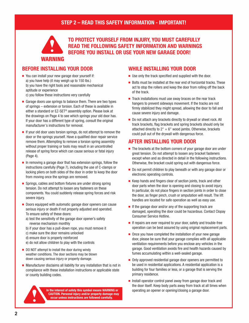
TO PROTECT YOURSELF FROM INJURY, YOU MUST CAREFULLY READ THE FOLLOWING SAFETY INFORMATION AND WARNINGS BEFORE YOU INSTALL OR USE YOUR NEW GARAGE DOOR!
In the interest of safety this symbol means WARNING or CAUTION. Personal injury and/or property damage may
occur unless instructions are followed carefully.!
WARNING!
STEP 2 – READ THIS SAFETY INFORMATION - IMPORTANT!
BEFORE INSTALLING YOUR DOOR■ You can install your new garage door yourself if:
a) you have help (it may weigh up to 150 lbs .) b) you have the right tools and reasonable mechanical aptitude or experience c) you follow these instructions very carefully
■ Garage doors use springs to balance them . There are two types of springs – extension or torsion . Each of these is available in either a standard or EZ-SET® assembly option . Please look at the drawings on Page 4 to see which springs your old door has . If your door has a different type of spring, consult the original manufacturer’s instructions for removal .
■ If your old door uses torsion springs, do not attempt to remove the door or the springs yourself . Have a qualified door repair service remove them . Attempting to remove a torsion spring assembly without proper training or tools may result in an uncontrolled release of spring force which can cause serious or fatal injury (Page 4) .
■ In removing a garage door that has extension springs, follow the instructions carefully (Page 7), including the use of C-clamps or locking pliers on both sides of the door in order to keep the door from moving once the springs are removed .
■ Springs, cables and bottom fixtures are under strong spring tension . Do not attempt to loosen any fasteners on these components . You could suddenly release spring forces and risk severe injury .
■ Doors equipped with automatic garage door openers can cause serious injury or death if not properly adjusted and operated . To ensure safety of these doors: a) test the sensitivity of the garage door opener’s safety reverse mechanism monthly b) if your door has a pull-down rope, you must remove it c) make sure the door remains unlocked d) ensure door is properly reinforced e) do not allow children to play with the controls
■ DO NOT attempt to install the door during windy weather conditions . The door sections may be blown down causing serious injury or property damage .
■ Manufacturer disclaims all liability for any installation that is not in compliance with these installation instructions or applicable state or county building codes .
WHILE INSTALLING YOUR DOOR■ Use only the track specified and supplied with the door .
■ Bolts must be installed at the rear end of horizontal tracks . These act to stop the rollers and keep the door from rolling off the back of the track .
■ Track installations must use sway braces on the rear track hangers to prevent sideways movement . If the tracks are not firmly stabilized they might spread, allowing the door to fall and cause severe injury and damage .
■ Do not attach any brackets directly to drywall or sheet rock . All track brackets, flag brackets and spring brackets should only be attached directly to 2" × 6" wood jambs . Otherwise, brackets could pull out of the drywall with dangerous force .
AFTER INSTALLING YOUR DOOR■ The brackets at the bottom corners of your garage door are under
great tension . Do not attempt to loosen any bracket fasteners except when and as directed in detail in the following instructions . Otherwise, the bracket could spring out with dangerous force .
■ Do not permit children to play beneath or with any garage door or electronic operating controls .
■ Keep hands and fingers clear of section joints, track and other door parts when the door is opening and closing to avoid injury . In particular, do not place fingers in section joints in order to close the door, as finger pinch, crush or amputation will result . The lift handles are located for safe operation as well as easy use .
■ If the garage door and/or any of the supporting track are damaged, operating the door could be hazardous . Contact Clopay Consumer Service Hotline .
■ If repairs are ever required to your door, safety and trouble-free operation can be best assured by using original replacement parts .
■ Once you have completed the installation of your new garage door, please be sure that your garage complies with all applicable ventilation requirements before you enclose any vehicles in the garage . Good ventilation avoids fire and health hazards caused by fumes accumulating within a well-sealed garage .
■ Only approved residential garage door openers are permitted to be used in residential applications . A residential application is a building for four families or less, or a garage that is serving the primary residence .
■ Install operator control panel away from garage door track and the door itself . Keep body parts away from track at all times when operating an opener or opening/closing a garage door .
3
Headroom Requirement:
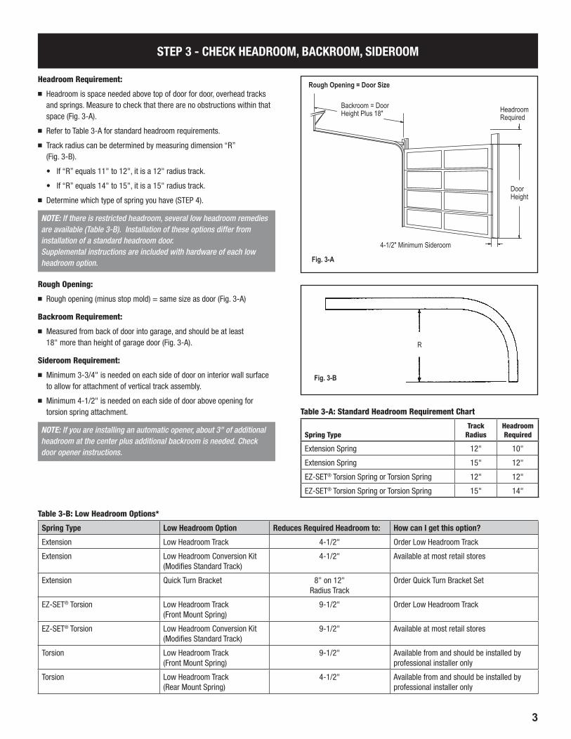
■ Headroom is space needed above top of door for door, overhead tracks and springs . Measure to check that there are no obstructions within that space (Fig . 3-A) .
■ Refer to Table 3-A for standard headroom requirements .
■ Track radius can be determined by measuring dimension “R” (Fig . 3-B) .
• If “R” equals 11" to 12", it is a 12" radius track .
• If “R” equals 14" to 15", it is a 15" radius track .
■ Determine which type of spring you have (STEP 4) .
NOTE: If there is restricted headroom, several low headroom remedies are available (Table 3-B). Installation of these options differ from installation of a standard headroom door. Supplemental instructions are included with hardware of each low headroom option.
Rough Opening:
■ Rough opening (minus stop mold) = same size as door (Fig . 3-A)
Backroom Requirement:
■ Measured from back of door into garage, and should be at least 18" more than height of garage door (Fig . 3-A) .
Sideroom Requirement:
■ Minimum 3-3/4" is needed on each side of door on interior wall surface to allow for attachment of vertical track assembly .
■ Minimum 4-1/2" is needed on each side of door above opening for torsion spring attachment .
NOTE: If you are installing an automatic opener, about 3" of additional headroom at the center plus additional backroom is needed. Check door opener instructions.
Fig. 3-A
Rough Opening = Door Size
Backroom = DoorHeight Plus 18" Headroom
Required
DoorHeight
4-1/2" Minimum Sideroom
Fig. 3-B
R
Table 3-A: Standard Headroom Requirement Chart
Spring TypeTrack
RadiusHeadroom Required
Extension Spring 12" 10"
Extension Spring 15" 12"
EZ-SET® Torsion Spring or Torsion Spring 12" 12"
EZ-SET® Torsion Spring or Torsion Spring 15" 14"
Table 3-B: Low Headroom Options*
Spring Type Low Headroom Option Reduces Required Headroom to: How can I get this option?
Extension Low Headroom Track 4-1/2" Order Low Headroom Track
Extension Low Headroom Conversion Kit(Modifies Standard Track)
4-1/2" Available at most retail stores
Extension Quick Turn Bracket 8" on 12"Radius Track
Order Quick Turn Bracket Set
EZ-SET® Torsion Low Headroom Track(Front Mount Spring)
9-1/2" Order Low Headroom Track
EZ-SET® Torsion Low Headroom Conversion Kit(Modifies Standard Track)
9-1/2" Available at most retail stores
Torsion Low Headroom Track(Front Mount Spring)
9-1/2" Available from and should be installed by professional installer only
Torsion Low Headroom Track(Rear Mount Spring)
4-1/2" Available from and should be installed by professional installer only
STEP 3 - CHECK HEADROOM, BACKROOM, SIDEROOM
Fig. 3-A
4
STEP 4 - REVIEW COMPLETE DOOR ASSEMBLY AND VERIFY ALL HARDWARE IS PRESENT
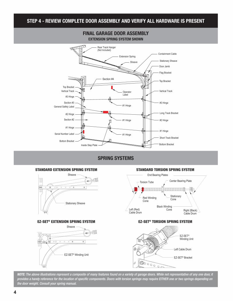
FINAL GARAGE DOOR ASSEMBLYEXTENSION SPRING SYSTEM SHOWN
Right (Black)Cable Drum
Black Winding Cone
Center Bearing Plate
StationaryCone
Left (Red)Cable Drum
End Bearing Plates
Red WindingCone
EZ-SET® Extension Spring System
EZ-SET® Winding Unit
Sheave
Standard Extension Spring System
Stationary Sheave
Sheave
EZ-SET® Torsion Spring System
EZ-SET®
Winding Unit
Left Cable Drum
EZ-SET® Bracket
Typical Garage Door Installation IllustrationExtension Spring System Shown on Complete Door
Rear Track Hanger(Not Included)
Extension Spring
Sheave Stationary Sheave
OperatorLabel
Inside Step Plate
Section #4
#3 Hinge
Section #3General Safety Label
#2 Hinge
Section #2
#1 Hinge
Serial Number Label
Bottom Bracket
Containment Cable
Torsion Tube
Standard Torsion Spring System
Vertical Track
Top Bracket
Flag Bracket
Door Jamb
#3 Hinge
Long Track Bracket
#2 Hinge
#1 Hinge
Short Track Bracket
Bottom Bracket
#1 Hinge
#1 Hinge
#1 Hinge
Top BracketVertical Track
NOTE: The above illustrations represent a composite of many features found on a variety of garage doors. While not representative of any one door, it provides a handy reference for the location of specific components. Doors with torsion springs may require EITHER one or two springs depending on the door weight. Consult your spring manual.
Right (Black)Cable Drum
Black Winding Cone
Center Bearing Plate
StationaryCone
Left (Red)Cable Drum
End Bearing Plates
Red WindingCone
EZ-SET® Extension Spring System
EZ-SET® Winding Unit
Sheave
Standard Extension Spring System
Stationary Sheave
Sheave
EZ-SET® Torsion Spring System
EZ-SET®
Winding Unit
Left Cable Drum
EZ-SET® Bracket
Typical Garage Door Installation IllustrationExtension Spring System Shown on Complete Door
Rear Track Hanger(Not Included)
Extension Spring
Sheave Stationary Sheave
OperatorLabel
Inside Step Plate
Section #4
#3 Hinge
Section #3General Safety Label
#2 Hinge
Section #2
#1 Hinge
Serial Number Label
Bottom Bracket
Containment Cable
Torsion Tube
Standard Torsion Spring System
Vertical Track
Top Bracket
Flag Bracket
Door Jamb
#3 Hinge
Long Track Bracket
#2 Hinge
#1 Hinge
Short Track Bracket
Bottom Bracket
#1 Hinge
#1 Hinge
#1 Hinge
Top BracketVertical Track
STANDARD EXTENSION SPRING SYSTEM
EZ-SET® EXTENSION SPRING SYSTEM
STANDARD TORSION SPRING SYSTEM
EZ-SET® TORSION SPRING SYSTEM
EZ-SET® Winding Unit
SPRING SYSTEMS
5
HARDWARE COMPONENTS INCLUDED
ADDITIONAL HARDWARE COMPONENTS INCLUDEDONLY WITH COMPOSITE OVERLAY FAUX WOOD DOORS & STEEL CARRIAGE HOUSE DOORS
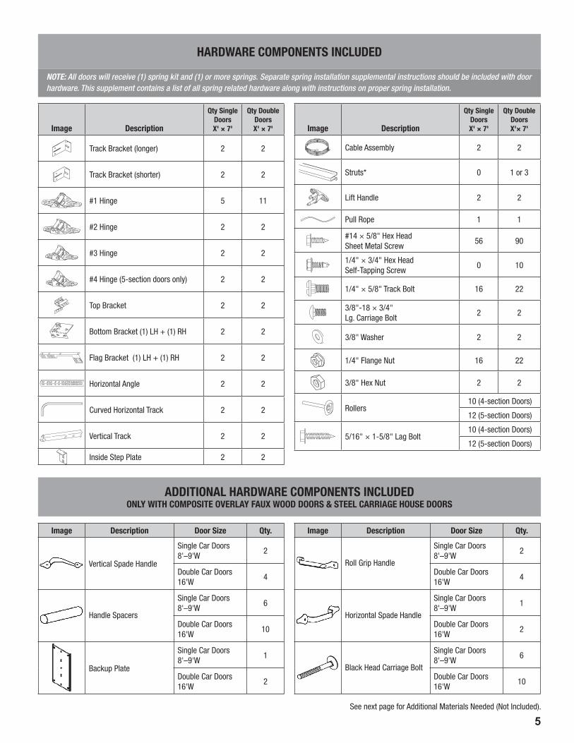
NOTE: All doors will receive (1) spring kit and (1) or more springs. Separate spring installation supplemental instructions should be included with door hardware. This supplement contains a list of all spring related hardware along with instructions on proper spring installation.
Image Description
Qty Single Doors X' × 7'
Qty Double Doors X' × 7'
Track Bracket (longer) 2 2
Track Bracket (shorter) 2 2
#1 Hinge 5 11
#2 Hinge 2 2
#3 Hinge 2 2
#4 Hinge (5-section doors only) 2 2
Top Bracket 2 2
Bottom Bracket (1) LH + (1) RH 2 2
Flag Bracket (1) LH + (1) RH 2 2
Horizontal Angle 2 2
Curved Horizontal Track 2 2
Vertical Track 2 2
Inside Step Plate 2 2
Image Description
Qty Single Doors X' × 7'
Qty Double Doors X'× 7'
Cable Assembly 2 2
Struts* 0 1 or 3
Lift Handle 2 2
Pull Rope 1 1
#14 × 5/8" Hex Head Sheet Metal Screw
56 90
1/4" × 3/4" Hex HeadSelf-Tapping Screw
0 10
1/4" × 5/8" Track Bolt 16 22
3/8"-18 × 3/4"Lg . Carriage Bolt
2 2
3/8" Washer 2 2
1/4" Flange Nut 16 22
3/8" Hex Nut 2 2
Rollers10 (4-section Doors)
12 (5-section Doors)
5/16" × 1-5/8" Lag Bolt10 (4-section Doors)
12 (5-section Doors)
Image Description Door Size Qty.
Vertical Spade Handle
Single Car Doors 8'–9'W
2
Double Car Doors 16'W
4
Handle Spacers
Single Car Doors 8'–9'W
6
Double Car Doors 16'W
10
Backup Plate
Single Car Doors 8'–9'W
1
Double Car Doors 16'W
2
Image Description Door Size Qty.
Roll Grip Handle
Single Car Doors 8'–9'W
2
Double Car Doors 16'W
4
Horizontal Spade Handle
Single Car Doors 8'–9'W
1
Double Car Doors 16'W
2
Black Head Carriage Bolt
Single Car Doors 8'–9'W
6
Double Car Doors 16'W
10
See next page for Additional Materials Needed (Not Included) .
6
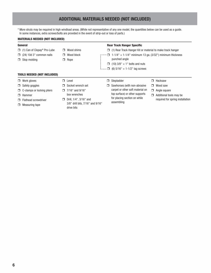
* More struts may be required in high windload areas . (While not representative of any one model, the quantities below can be used as a guide . In some instances, extra screws/bolts are provided in the event of strip-out or loss of parts .)
MATERIALS NEEDED (NOT INCLUDED)
General
� (1) Can of Clopay® Pro-Lube
� (24) 10d 3" common nails
� Stop molding
� Wood shims
� Wood block
� Rope
Rear Track Hanger Specific
� (1) Rear Track Hanger Kit or material to make track hanger
� 1-1/4" × 1-1/4" minimum 13 ga . (3/32") minimum thickness punched angle
� (10) 3/8" × 1" bolts and nuts
� (6) 5/16" × 1-1/2" lag screws
TOOLS NEEDED (NOT INCLUDED)
� Work gloves
� Safety goggles
� C-clamps or locking pliers
� Hammer
� Flathead screwdriver
� Measuring tape
� Level
� Socket wrench set
� 7/16" and 9/16" box wrenches
� Drill, 1/4", 3/16" and 3/8" drill bits, 7/16" and 9/16" drive bits
� Stepladder
� Sawhorses (with non-abrasive carpet or other soft material on top surface) or other supports for placing section on while assembling
� Hacksaw
� Wood saw
� Angle square
� Additional tools may be required for spring installation
ADDITIONAL MATERIALS NEEDED (NOT INCLUDED)
7
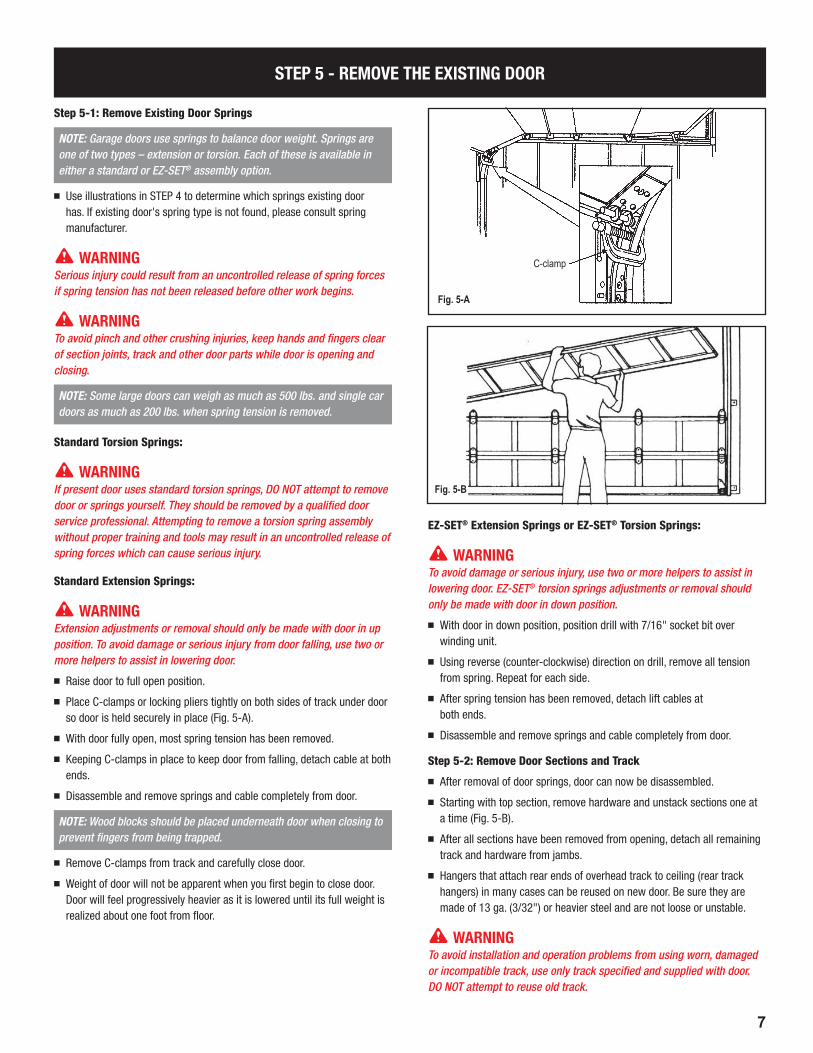
Fig. 5-A
C-clamp
Step 5-1: Remove Existing Door Springs
NOTE: Garage doors use springs to balance door weight. Springs are one of two types – extension or torsion. Each of these is available in either a standard or EZ-SET® assembly option.
■ Use illustrations in STEP 4 to determine which springs existing door has . If existing door's spring type is not found, please consult spring manufacturer .
! WARNINGSerious injury could result from an uncontrolled release of spring forces if spring tension has not been released before other work begins.
! WARNINGTo avoid pinch and other crushing injuries, keep hands and fingers clear of section joints, track and other door parts while door is opening and closing.
NOTE: Some large doors can weigh as much as 500 lbs. and single car doors as much as 200 lbs. when spring tension is removed.
Standard Torsion Springs:
! WARNINGIf present door uses standard torsion springs, DO NOT attempt to remove door or springs yourself. They should be removed by a qualified door service professional. Attempting to remove a torsion spring assembly without proper training and tools may result in an uncontrolled release of spring forces which can cause serious injury.
Standard Extension Springs:
! WARNINGExtension adjustments or removal should only be made with door in up position. To avoid damage or serious injury from door falling, use two or more helpers to assist in lowering door.
■ Raise door to full open position .
■ Place C-clamps or locking pliers tightly on both sides of track under door so door is held securely in place (Fig . 5-A) .
■ With door fully open, most spring tension has been removed .
■ Keeping C-clamps in place to keep door from falling, detach cable at both ends .
■ Disassemble and remove springs and cable completely from door .
NOTE: Wood blocks should be placed underneath door when closing to prevent fingers from being trapped.
■ Remove C-clamps from track and carefully close door .
■ Weight of door will not be apparent when you first begin to close door . Door will feel progressively heavier as it is lowered until its full weight is realized about one foot from floor .
EZ-SET® Extension Springs or EZ-SET® Torsion Springs:
! WARNINGTo avoid damage or serious injury, use two or more helpers to assist in lowering door. EZ-SET® torsion springs adjustments or removal should only be made with door in down position.
■ With door in down position, position drill with 7/16" socket bit over winding unit .
■ Using reverse (counter-clockwise) direction on drill, remove all tension from spring . Repeat for each side .
■ After spring tension has been removed, detach lift cables at both ends .
■ Disassemble and remove springs and cable completely from door .
Step 5-2: Remove Door Sections and Track
■ After removal of door springs, door can now be disassembled .
■ Starting with top section, remove hardware and unstack sections one at a time (Fig . 5-B) .
■ After all sections have been removed from opening, detach all remaining track and hardware from jambs .
■ Hangers that attach rear ends of overhead track to ceiling (rear track hangers) in many cases can be reused on new door . Be sure they are made of 13 ga . (3/32") or heavier steel and are not loose or unstable .
! WARNINGTo avoid installation and operation problems from using worn, damaged or incompatible track, use only track specified and supplied with door. DO NOT attempt to reuse old track.
Fig. 5-B
STEP 5 - REMOVE THE EXISTING DOOR
Fig. 5-B
8
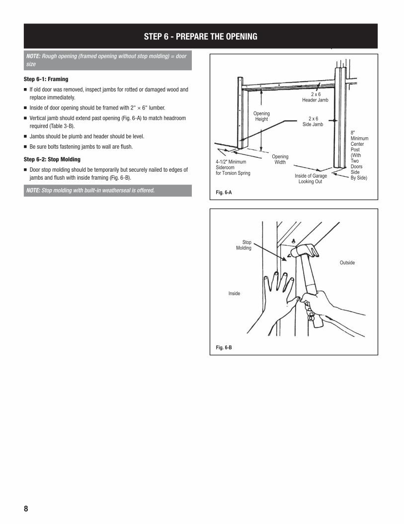
Fig. 6-B
Outside
Inside
StopMolding
Fig. 6-A
8"MinimumCenterPost(WithTwoDoorsSideBy Side)
2 x 6Header Jamb
OpeningHeight
Inside of GarageLooking Out
2 x 6Side Jamb
OpeningWidth4-1/2" Minimum
Sideroomfor Torsion Spring
NOTE: Rough opening (framed opening without stop molding) = door size
Step 6-1: Framing
■ If old door was removed, inspect jambs for rotted or damaged wood and replace immediately .
■ Inside of door opening should be framed with 2" × 6" lumber .
■ Vertical jamb should extend past opening (Fig . 6-A) to match headroom required (Table 3-B) .
■ Jambs should be plumb and header should be level .
■ Be sure bolts fastening jambs to wall are flush .
Step 6-2: Stop Molding
■ Door stop molding should be temporarily but securely nailed to edges of jambs and flush with inside framing (Fig . 6-B) .
NOTE: Stop molding with built-in weatherseal is offered.
Required HeadroomSTEP 6 - PREPARE THE OPENING
9
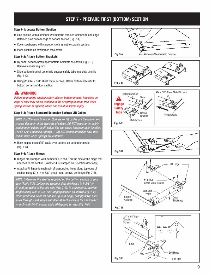
Step 7-1: Locate Bottom Section
■ Find section with aluminum weatherstrip retainer fastened to one edge . Retainer is on bottom edge of bottom section (Fig . 7-A) .
■ Cover sawhorses with carpet or cloth as not to scratch section .
■ Place section on sawhorses face down .
Step 7-2: Attach Bottom Brackets
■ By hand, bend to break apart bottom brackets as shown (Fig . 7-B) . Remove connecting tabs .
■ Slide bottom bracket up to fully engage safety tabs into slots on stile (Fig . 7-C) .
■ Using (2) #14 × 5/8" sheet metal screws, attach bottom brackets to bottom corners of door section .
! WARNINGFailure to properly engage safety tabs on bottom bracket into slots on edge of door may cause sections to fall or spring to break free when spring tension is applied, which can result in severe injury.
Step 7-3: Attach Standard Extension Springs Lift Cables
NOTE: For Standard Extension Springs — lift cables are the longer and smaller diameter of the two sets of cables. DO NOT use shorter safety containment cables as lift cable, this can cause improper door function. For EZ-Set® Extension Springs — DO NOT attach lift cables now, this will be done when springs are installed.
■ Hook looped ends of lift cable over buttons on bottom brackets (Fig . 7-D) .
Step 7-4: Attach Hinges
■ Hinges are stamped with numbers 1, 2 and 3 on the side of the hinge that attaches to the section . (Number 4 is stamped on 5-section door only .)
■ Attach a #1 hinge to each pair of prepunched holes along top edge of section using (2) #14 × 5/8" sheet metal screws per hinge (Fig . 7-E) .
NOTE: Determine if a strut is required on the bottom section of your door (Table 7-A). Determine whether door thickness is 1-3/8" or 2" and the width of the end stile (Fig. 7-E). To attach strut, overlap hinges using 1/4" × 3/4" self-tapping screws as shown (Fig. 7-F). When predrilled holes do not line up with hinge, drill (2) 3/16" pilot holes through strut, hinge and door at each location (or use impact wrench with 7/16" socket and self-tapping screws (Fig. 7-F).
Fig. 7-A Aluminum Weatherstrip Retainer
Fig. 7-B
Fig. 7-D
End StileWidth
DoorThickness
BottomAstragal
#1 Hinge
#14 x 5/8"Sheet Metal Screws
Fig. 7-E
End Hinge
1/4" x 3/4" Self-TappingScrews
End Stile
Strut
Fig. 7-F
Fig. 7-C
#14 x 5/8" Sheet Metal Screws
Weatherstrip
Safety Tabs
BottomBracket
Bottom SectionSlots
! Engage Safety Tabs
STEP 7 - PREPARE FIRST (BOTTOM) SECTION
Fig. 7-B
10
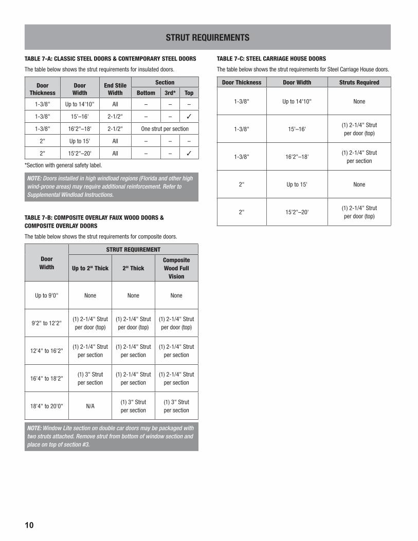
STRUT REQUIREMENTS
TABLE 7-A: CLASSIC STEEL DOORS & CONTEMPORARY STEEL DOORS
The table below shows the strut requirements for insulated doors .
DoorThickness
DoorWidth
End StileWidth
Section
Bottom 3rd* Top
1-3/8" Up to 14'10" All – – –
1-3/8" 15'–16' 2-1/2" – – ✓
1-3/8" 16'2"–18' 2-1/2" One strut per section
2" Up to 15' All – – –
2" 15'2"–20' All – – ✓
*Section with general safety label .
NOTE: Doors installed in high windload regions (Florida and other high wind-prone areas) may require additional reinforcement. Refer to Supplemental Windload Instructions.
TABLE 7-B: COMPOSITE OVERLAY FAUX WOOD DOORS & COMPOSITE OVERLAY DOORS
The table below shows the strut requirements for composite doors .
DoorWidth
STRUT REQUIREMENT
Up to 2" Thick 2" ThickComposite Wood Full
Vision
Up to 9'0" None None None
9'2" to 12'2"(1) 2-1/4" Strut per door (top)
(1) 2-1/4" Strut per door (top)
(1) 2-1/4" Strut per door (top)
12'4" to 16'2"(1) 2-1/4" Strut
per section(1) 2-1/4" Strut
per section(1) 2-1/4" Strut
per section
16'4" to 18'2"(1) 3" Strut per section
(1) 2-1/4" Strut per section
(1) 2-1/4" Strut per section
18'4" to 20'0" N/A(1) 3" Strut per section
(1) 3" Strut per section
NOTE: Window Lite section on double car doors may be packaged with two struts attached. Remove strut from bottom of window section and place on top of section #3.
TABLE 7-C: STEEL CARRIAGE HOUSE DOORS
The table below shows the strut requirements for Steel Carriage House doors .
Door Thickness Door Width Struts Required
1-3/8" Up to 14'10" None
1-3/8" 15'–16'(1) 2-1/4" Strut per door (top)
1-3/8" 16'2"–18'(1) 2-1/4" Strut
per section
2" Up to 15' None
2" 15'2"–20'(1) 2-1/4" Strut per door (top)
11
Lift Handle Hole Drilling PatternOutside View
2nd Section
Bottom Section
Measure to Hinge Holeson Opposite Side
Measure to Hinge Holeson Opposite Side
3/4"
3/4"Center Line of2nd Section
OR2-3/4" Offset ofBottom Edge
of Door
1/2" Dia.
Fig. 8-C
DO NOT USE THE PRESTAMPED HINGE HOLESFOR LIFT HANDLE PLACEMENT – MEASUREPER THE DRILLING PATTERN BELOW.
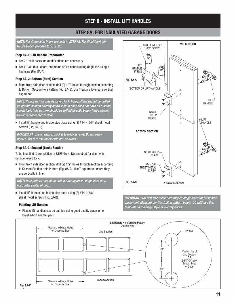
NOTE: For Composite Doors proceed to STEP 8B. For Steel Carriage House Doors, proceed to STEP 8C.
Step 8A-1: Lift Handle Preparation
■ For 2" thick doors, no modifications are necessary .
■ For 1-3/8" thick doors, cut stems on lift handle along ridge line using a hacksaw (Fig . 8A-A) .
Step 8A-2: Bottom (First) Section
■ From front side door section, drill (2) 1/2" holes through section according to Bottom Section Hole Pattern (Fig . 8A-B) . Use T-square to ensure vertical alignment .
NOTE: If door has an outside keyed lock, hole pattern should be drilled on bottom section directly below lock. If door does not have an outside keyed lock, hole pattern should be drilled directly below hinge closest to horizontal center of door.
■ Install lift handle and inside step plate using (2) #14 × 5/8" sheet metal screws (Fig . 8A-B) .
IMPORTANT: Use wrench or socket to drive screws. Do not over-tighten. DO NOT use an electric drill or driver.
Step 8A-3: Second (Lock) Section
To be installed at completion of STEP 9A-4 . Not required for door with outside keyed lock .
■ From front side door section, drill (2) 1/2" holes through section according to Second Section Hole Pattern (Fig . 8A-C) . Use T-square to ensure they are vertically in line .
NOTE: Hole pattern should be drilled directly above hinge closest to horizontal center of door.
■ Install lift handle and inside step plate using (2) #14 × 5/8" sheet metal screws (Fig . 8A-B) .
Painting Lift Handles
• Plastic lift handles can be painted using good quality spray-on or brushed-on enamel paint .
INSIDESTEP
PLATE
#14 x 5/8"SHEET METAL
SCREW
INSIDE STEPPLATE
LIFTHANDLE
STEMS
CUT HERE FOR1-3/8" DOORS
2ND SECTION
LIFTHANDLE
Fig. 8-B
FIG 8-A
BOTTOM SECTION
(BOTTOM OF LIFT HANDLE)
LIFTHANDLE
2" DOOR SHOWN
Fig. 8A-A
Fig. 8A-B
IMPORTANT: DO NOT use these prestamped hinge holes for lift handle placement. Measure per the drilling pattern below. DO NOT use this template for carriage style or overlay doors.
Fig. 8A-C
STEP 8 - INSTALL LIFT HANDLES
STEP 8A: FOR INSULATED GARAGE DOORS
12
5-1/2" (Composite Overlay Doors)5-1/4" (Composite Overlay Faux Wood Doors)
5-1/2"
Inside Handle
1/4" Hex Flange Nut
Outside Handle
Spacer
1/4" - 20 x 2-1/4"Hex Head Bolt
Spacer
Outside Handle
1/4" Hex Flange Nut1/4"- 20 x 2 -1/4"Hex Head Bolt
InsideHandle
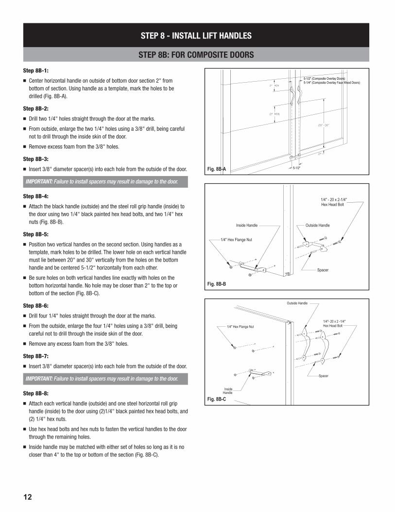
Step 8B-1:
■ Center horizontal handle on outside of bottom door section 2" from bottom of section . Using handle as a template, mark the holes to be drilled (Fig . 8B-A) .
Step 8B-2:
■ Drill two 1/4" holes straight through the door at the marks .
■ From outside, enlarge the two 1/4" holes using a 3/8" drill, being careful not to drill through the inside skin of the door .
■ Remove excess foam from the 3/8" holes .
Step 8B-3:
■ Insert 3/8" diameter spacer(s) into each hole from the outside of the door .
IMPORTANT: Failure to install spacers may result in damage to the door.
Step 8B-4:
■ Attach the black handle (outside) and the steel roll grip handle (inside) to the door using two 1/4" black painted hex head bolts, and two 1/4" hex nuts (Fig . 8B-B) .
Step 8B-5:
■ Position two vertical handles on the second section . Using handles as a template, mark holes to be drilled . The lower hole on each vertical handle must lie between 20" and 30" vertically from the holes on the bottom handle and be centered 5-1/2" horizontally from each other .
■ Be sure holes on both vertical handles line exactly with holes on the bottom horizontal handle . No hole may be closer than 2" to the top or bottom of the section (Fig . 8B-C) .
Step 8B-6:
■ Drill four 1/4" holes straight through the door at the marks .
■ From the outside, enlarge the four 1/4" holes using a 3/8" drill, being careful not to drill through the inside skin of the door .
■ Remove any excess foam from the 3/8" holes .
Step 8B-7:
■ Insert 3/8" diameter spacer(s) into each hole from the outside of the door .
IMPORTANT: Failure to install spacers may result in damage to the door.
Step 8B-8:
■ Attach each vertical handle (outside) and one steel horizontal roll grip handle (inside) to the door using (2)1/4" black painted hex head bolts, and (2) 1/4" hex nuts .
■ Use hex head bolts and hex nuts to fasten the vertical handles to the door through the remaining holes .
■ Inside handle may be matched with either set of holes so long as it is no closer than 4" to the top or bottom of the section (Fig . 8B-C) .
Fig. 8B-A
Fig. 8B-B
Fig. 8B-C
STEP 8 - INSTALL LIFT HANDLES
STEP 8B: FOR COMPOSITE DOORS
13
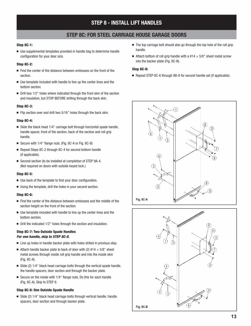
Step 8C-1:
■ Use supplemental templates provided in handle bag to determine handle configuration for your door size .
Step 8C-2:
■ Find the center of the distance between embosses on the front of the section .
■ Use template included with handle to line up the center lines and the bottom section .
■ Drill two 1/2" holes where indicated through the front skin of the section and insulation, but STOP BEFORE drilling through the back skin .
Step 8C-3:
■ Flip section over and drill two 5/16" holes through the back skin .
Step 8C-4:
■ Slide the black head 1/4" carriage bolt through horizontal spade handle, handle spacer, front of the section, back of the section and roll grip handle .
■ Secure with 1/4" flange nuts . (Fig . 8C-A or Fig . 8C-B)
■ Repeat Steps 8C-2 through 8C-4 for second bottom handle (if applicable) .
■ Second section (to be installed at completion of STEP 9A-4 . (Not required on doors with outside keyed lock .)
Step 8C-5:
■ Use back of the template to find your door configuration .
■ Using the template, drill the holes in your second section .
Step 8C-6:
■ Find the center of the distance between embosses and the middle of the section height on the front of the section .
■ Use template included with handle to line up the center lines and the bottom section .
■ Drill the indicated 1/2" holes through the section and insulation .
Step 8C-7: Two Outside Spade Handles For one handle, skip to STEP 8C-8.
■ Line up holes in handle backer plate with holes drilled in previous step .
■ Attach handle backer plate to back of door with (2) #14 × 5/8" sheet metal screws through inside roll grip handle and into the inside skin (Fig . 8C-A) .
■ Slide (2) 1/4" black head carriage bolts through the vertical spade handle, the handle spacers, door section and through the backer plate .
■ Secure on the inside with 1/4" flange nuts . Do this for each handle (Fig . 8C-A) . Skip to STEP 9 .
Step 8C-8: One Outside Spade Handle
■ Slide (2) 1/4" black head carriage bolts through vertical handle, handle spacers, door section and through backer plate .
■ The top carriage bolt should also go through the top hole of the roll grip handle .
■ Attach bottom of roll grip handle with a #14 × 5/8" sheet metal screw into the backer plate (Fig . 8C-B) .
Step 8C-9:
■ Repeat STEP 8C-6 through 8B-8 for second handle set (if applicable) .
6
53
2
4 6
7
58
1
1 3
4
6
5
5
7
5
6
8
41 3
4
2 3
Fig. 8C-A
Fig. 8C-B
STEP 8 - INSTALL LIFT HANDLES
STEP 8C: FOR STEEL CARRIAGE HOUSE GARAGE DOORS
14
NOTE: For Composite Doors proceed to STEP 9B.
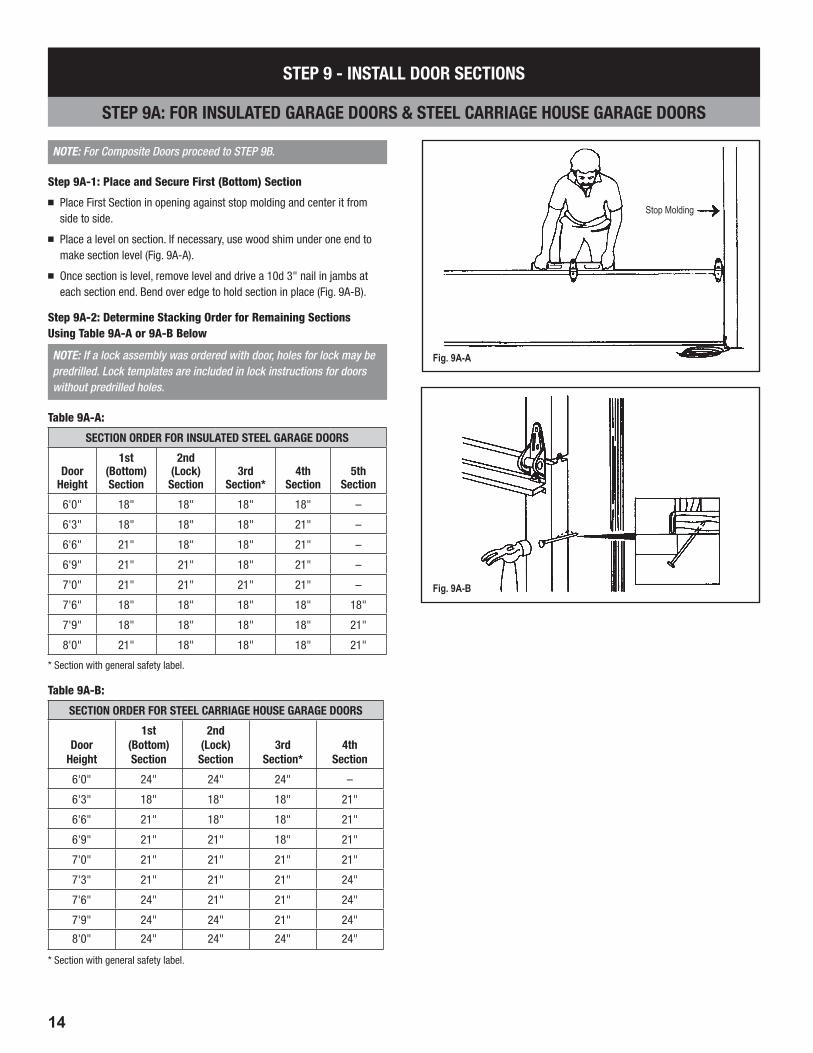
Step 9A-1: Place and Secure First (Bottom) Section
■ Place First Section in opening against stop molding and center it from side to side .
■ Place a level on section . If necessary, use wood shim under one end to make section level (Fig . 9A-A) .
■ Once section is level, remove level and drive a 10d 3" nail in jambs at each section end . Bend over edge to hold section in place (Fig . 9A-B) .
Step 9A-2: Determine Stacking Order for Remaining Sections Using Table 9A-A or 9A-B Below
NOTE: If a lock assembly was ordered with door, holes for lock may be predrilled. Lock templates are included in lock instructions for doors without predrilled holes.
Table 9A-A:
SECTION ORDER FOR INSULATED STEEL GARAGE DOORS
DoorHeight
1st(Bottom)Section
2nd(Lock)Section
3rdSection*
4thSection
5thSection
6'0" 18" 18" 18" 18" –
6'3" 18" 18" 18" 21" –
6'6" 21" 18" 18" 21" –
6'9" 21" 21" 18" 21" –
7'0" 21" 21" 21" 21" –
7'6" 18" 18" 18" 18" 18"
7'9" 18" 18" 18" 18" 21"
8'0" 21" 18" 18" 18" 21"
* Section with general safety label .
Table 9A-B:
SECTION ORDER FOR STEEL CARRIAGE HOUSE GARAGE DOORS
DoorHeight
1st(Bottom)Section
2nd(Lock)Section
3rdSection*
4thSection
6'0" 24" 24" 24" –
6'3" 18" 18" 18" 21"
6'6" 21" 18" 18" 21"
6'9" 21" 21" 18" 21"
7'0" 21" 21" 21" 21"
7'3" 21" 21" 21" 24"
7'6" 24" 21" 21" 24"
7'9" 24" 24" 21" 24"
8'0" 24" 24" 24" 24"
* Section with general safety label .
Fig. 9-B
Fig. 9-A
Stop Molding
Fig. 9A-A
Fig. 9A-B
STEP 9 - INSTALL DOOR SECTIONS
STEP 9A: FOR INSULATED GARAGE DOORS & STEEL CARRIAGE HOUSE GARAGE DOORS
15
#2 Hinge
#1 Hinge
Bottom EdgeEnd Stile
#14 x 5/8" SheetMetal Screws
Fig. 9-C
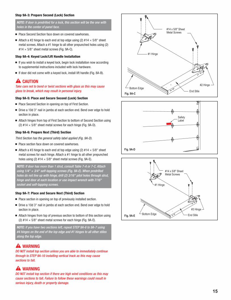
Step 9A-3: Prepare Second (Lock) Section
NOTE: If door is predrilled for a lock, this section will be the one with holes in the center of panel face.
■ Place Second Section face down on covered sawhorses .
■ Attach a #2 hinge to each end at top edge using (2) #14 × 5/8" sheet metal screws . Attach a #1 hinge to all other prepunched holes using (2) #14 × 5/8" sheet metal screws (Fig . 9A-C) .
Step 9A-4: Keyed Lock/Lift Handle Installation
■ If you wish to install a keyed lock, begin lock installation now according to supplemental instructions included with lock hardware .
■ If door did not come with a keyed lock, install lift handle (Fig . 8A-B) .
! CAUTIONTake care not to bend or twist sections with glass as this may cause glass to break, which may result in personal injury.
Step 9A-5: Place and Secure Second (Lock) Section
■ Place Second Section in opening on top of First Section .
■ Drive a 10d 3" nail in jambs at each section end . Bend over edge to hold section in place .
■ Attach hinges from top of First Section to bottom of Second Section using (2) #14 × 5/8" sheet metal screws for each hinge (Fig . 9A-D) .
Step 9A-6: Prepare Next (Third) Section
Third Section has the general safety label applied (Fig. 9A-D).
■ Place section face down on covered sawhorses .
■ Attach a #3 hinge to each end at top edge using (2) #14 × 5/8" sheet metal screws for each hinge . Attach a #1 hinge to all other prepunched holes using (2) #14 × 5/8" sheet metal screws (Fig . 9A-E) .
NOTE: If door has more than 1 strut, consult Table 7-A or 7-C. Attach using 1/4" × 3/4" self-tapping screws (Fig. 9A-E). When predrilled holes do not line up with hinge, drill (2) 3/16" pilot holes through strut, hinge and door at each location or use impact wrench with 7/16" socket and self-tapping screws.
Step 9A-7: Place and Secure Next (Third) Section
■ Place section in opening on top of previously installed section .
■ Drive a 10d 3" nail in jambs at each section end . Bend over edge to hold section in place .
■ Attach hinges from top of previous section to bottom of this section using (2) #14 × 5/8" sheet metal screws for each hinge (Fig . 9A-E) .
NOTE: If you have two sections left, repeat STEP 9A-6 to 9A-7 using #4 hinges on the end of the top edge and #1 hinges to all other stiles along the top edge.
! WARNINGDO NOT install top section unless you are able to immediately continue through to STEP 9A-10 installing vertical track as this may cause sections to fall.
! WARNINGDO NOT install top section if there are high wind conditions as this may cause sections to fall. Failure to follow these warnings could result in serious injury, death or property damage.
#3 Hinge
End StileBottom Edge
#1 Hinge
#14 x 5/8" SheetMetal Screws
Fig. 9-E
SafetyLabel
Fig. 9-DFig. 9A-D
Fig. 9A-E
Fig. 9A-C
16
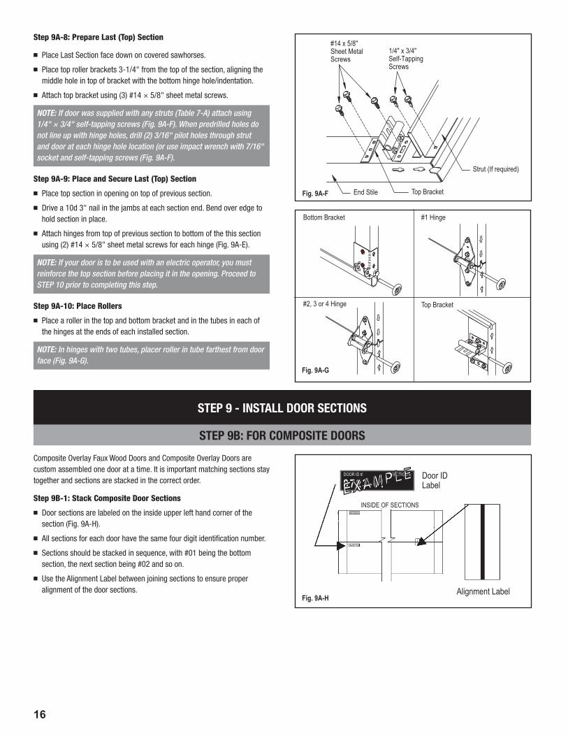
Step 9A-8: Prepare Last (Top) Section
■ Place Last Section face down on covered sawhorses .
■ Place top roller brackets 3-1/4" from the top of the section, aligning the middle hole in top of bracket with the bottom hinge hole/indentation .
■ Attach top bracket using (3) #14 × 5/8" sheet metal screws .
NOTE: If door was supplied with any struts (Table 7-A) attach using 1/4" × 3/4" self-tapping screws (Fig. 9A-F). When predrilled holes do not line up with hinge holes, drill (2) 3/16" pilot holes through strut and door at each hinge hole location (or use impact wrench with 7/16" socket and self-tapping screws (Fig. 9A-F).
Step 9A-9: Place and Secure Last (Top) Section
■ Place top section in opening on top of previous section .
■ Drive a 10d 3" nail in the jambs at each section end . Bend over edge to hold section in place .
■ Attach hinges from top of previous section to bottom of the this section using (2) #14 × 5/8" sheet metal screws for each hinge (Fig . 9A-E) .
NOTE: If your door is to be used with an electric operator, you must reinforce the top section before placing it in the opening. Proceed to STEP 10 prior to completing this step.
Step 9A-10: Place Rollers
■ Place a roller in the top and bottom bracket and in the tubes in each of the hinges at the ends of each installed section .
NOTE: In hinges with two tubes, placer roller in tube farthest from door face (Fig. 9A-G).
INSIDE OF SECTIONS
Door IDLabel
DOOR ID #: SECTION #:
9723-01EXAMPLE
Alignment LabelFig. 9A-H
STEP 9 - INSTALL DOOR SECTIONS
STEP 9B: FOR COMPOSITE DOORS
Composite Overlay Faux Wood Doors and Composite Overlay Doors are custom assembled one door at a time . It is important matching sections stay together and sections are stacked in the correct order .
Step 9B-1: Stack Composite Door Sections
■ Door sections are labeled on the inside upper left hand corner of the section (Fig . 9A-H) .
■ All sections for each door have the same four digit identification number .
■ Sections should be stacked in sequence, with #01 being the bottom section, the next section being #02 and so on .
■ Use the Alignment Label between joining sections to ensure proper alignment of the door sections .
#14 x 5/8"Sheet MetalScrews
1/4" x 3/4"Self-TappingScrews
End Stile Top Bracket
Strut (If required)
Fig. 9-FFig. 9A-F
Top Bracket
#1 HingeBottom Bracket
#2, 3 or 4 Hinge
Fig. 9-GFig. 9A-G
17
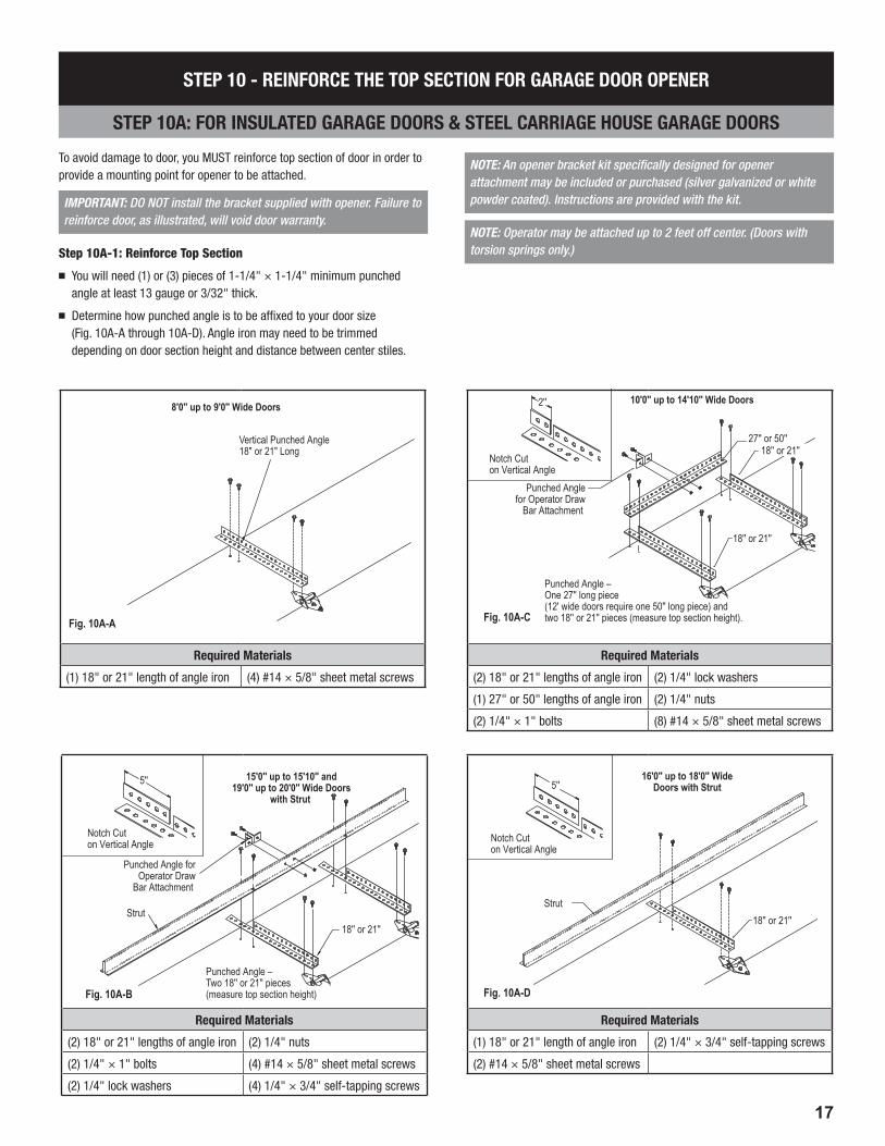
To avoid damage to door, you MUST reinforce top section of door in order to provide a mounting point for opener to be attached .
IMPORTANT: DO NOT install the bracket supplied with opener. Failure to reinforce door, as illustrated, will void door warranty.
Step 10A-1: Reinforce Top Section
■ You will need (1) or (3) pieces of 1-1/4" × 1-1/4" minimum punched angle at least 13 gauge or 3/32" thick .
■ Determine how punched angle is to be affixed to your door size (Fig . 10A-A through 10A-D) . Angle iron may need to be trimmed depending on door section height and distance between center stiles .
NOTE: An opener bracket kit specifically designed for opener attachment may be included or purchased (silver galvanized or white powder coated). Instructions are provided with the kit.
NOTE: Operator may be attached up to 2 feet off center. (Doors with torsion springs only.)
8'0'' up to 9'0'' Wide Doors
Fig. 10-A
Vertical Punched Angle18" or 21" Long
Required Materials
(1) 18" or 21" length of angle iron (4) #14 × 5/8" sheet metal screws
18'' or 21''
Punched Angle –Two 18'' or 21'' pieces(measure top section height)
Strut
Notch Cuton Vertical Angle
5'' 15'0'' up to 15'10'' and19'0'' up to 20'0'' Wide Doors
with Strut
Punched Angle forOperator Draw
Bar Attachment
Fig. 10-B
Required Materials
(2) 18" or 21" lengths of angle iron (2) 1/4" nuts
(2) 1/4" × 1" bolts (4) #14 × 5/8" sheet metal screws
(2) 1/4" lock washers (4) 1/4" × 3/4" self-tapping screws
18'' or 21''
Strut
Notch Cuton Vertical Angle
5''16'0'' up to 18'0'' Wide
Doors with Strut
Fig. 10-D
Required Materials
(1) 18" or 21" length of angle iron (2) 1/4" × 3/4" self-tapping screws
(2) #14 × 5/8" sheet metal screws
Punched Angle –One 27'' long piece(12' wide doors require one 50'' long piece) andtwo 18'' or 21'' pieces (measure top section height).
18'' or 21''
Notch Cuton Vertical Angle
2''
Punched Anglefor Operator Draw
Bar Attachment
18'' or 21''27'' or 50''
10'0'' up to 14'10'' Wide Doors
Fig. 10-C
Required Materials
(2) 18" or 21" lengths of angle iron (2) 1/4" lock washers
(1) 27" or 50" lengths of angle iron (2) 1/4" nuts
(2) 1/4" × 1" bolts (8) #14 × 5/8" sheet metal screws
STEP 10 - REINFORCE THE TOP SECTION FOR GARAGE DOOR OPENER
STEP 10A: FOR INSULATED GARAGE DOORS & STEEL CARRIAGE HOUSE GARAGE DOORS
Fig. 10A-A
Fig. 10A-B Fig. 10A-D
Fig. 10A-C
18
Required Materials
(1) operator reinforcement bracket (2) 1/4" × 3/4" self-tapping screws
Required Materials
(1) operator reinforcement bracket (2) 1/4" × 3/4" self-tapping screws
Required Materials
(2) operator reinforcement bracket (2) 1/4" lock washers
(2) 2" pieces of 1-1/4" × 1-1/4" punched angle
(2) 1/4" nuts
(2) 1/4" × 1" bolts (4) 1/4" × 3/4" self-tapping screws
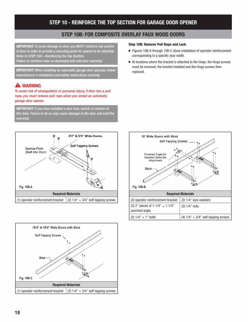
IMPORTANT: To avoid damage to door, you MUST reinforce top section of door in order to provide a mounting point for opener to be attached. Refer to STEP 10A – Reinforcing the Top Section. Failure to reinforce door as illustrated will void door warranty.
IMPORTANT: When installing an automatic garage door operator, follow manufacturer’s installation and safety instructions carefully.
! WARNINGTo avoid risk of strangulation or personal injury, if door has a pull rope, you must remove pull rope when you install an automatic garage door opener.
IMPORTANT: If you have installed a door lock, unlock or remove at this time. Failure to do so may cause damage to the door and void the warranty.
Step 10B: Remove Pull Rope and Lock
■ Figures 10B-A through 10B-C show installation of operator reinforcement corresponding to a specific door width .
■ At locations where the bracket is attached to the hinge, the hinge screws must be removed, the bracket installed and the hinge screws then replaced .
Fig. 10B-A Fig. 10B-B
Fig. 10B-C
STEP 10 - REINFORCE THE TOP SECTION FOR GARAGE DOOR OPENER
STEP 10B: FOR COMPOSITE OVERLAY FAUX WOOD DOORS
19
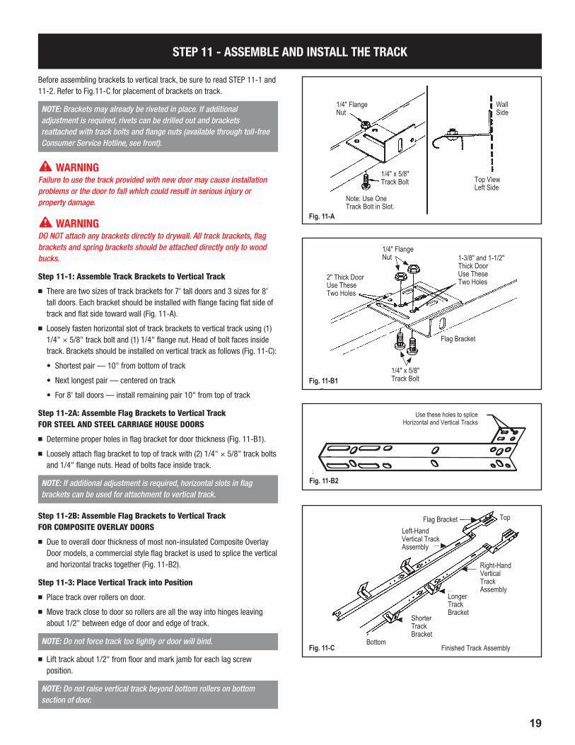
Before assembling brackets to vertical track, be sure to read STEP 11-1 and 11-2 . Refer to Fig .11-C for placement of brackets on track .
NOTE: Brackets may already be riveted in place. If additional adjustment is required, rivets can be drilled out and brackets reattached with track bolts and flange nuts (available through toll-free Consumer Service Hotline, see front).
! WARNINGFailure to use the track provided with new door may cause installation problems or the door to fall which could result in serious injury or property damage.
! WARNINGDO NOT attach any brackets directly to drywall. All track brackets, flag brackets and spring brackets should be attached directly only to wood bucks.
Step 11-1: Assemble Track Brackets to Vertical Track
■ There are two sizes of track brackets for 7' tall doors and 3 sizes for 8' tall doors . Each bracket should be installed with flange facing flat side of track and flat side toward wall (Fig . 11-A) .
■ Loosely fasten horizontal slot of track brackets to vertical track using (1) 1/4" × 5/8" track bolt and (1) 1/4" flange nut . Head of bolt faces inside track . Brackets should be installed on vertical track as follows (Fig . 11-C):
• Shortest pair — 10" from bottom of track
• Next longest pair — centered on track
• For 8' tall doors — install remaining pair 10" from top of track
Step 11-2A: Assemble Flag Brackets to Vertical Track FOR STEEL AND STEEL CARRIAGE HOUSE DOORS
■ Determine proper holes in flag bracket for door thickness (Fig . 11-B1) .
■ Loosely attach flag bracket to top of track with (2) 1/4" × 5/8" track bolts and 1/4" flange nuts . Head of bolts face inside track .
NOTE: If additional adjustment is required, horizontal slots in flag brackets can be used for attachment to vertical track.
Step 11-2B: Assemble Flag Brackets to Vertical Track FOR COMPOSITE OVERLAY DOORS
■ Due to overall door thickness of most non-insulated Composite Overlay Door models, a commercial style flag bracket is used to splice the vertical and horizontal tracks together (Fig . 11-B2) .
Step 11-3: Place Vertical Track into Position
■ Place track over rollers on door .
■ Move track close to door so rollers are all the way into hinges leaving about 1/2" between edge of door and edge of track .
NOTE: Do not force track too tightly or door will bind.
■ Lift track about 1/2" from floor and mark jamb for each lag screw position .
NOTE: Do not raise vertical track beyond bottom rollers on bottom section of door.
STEP 11 - ASSEMBLE AND INSTALL THE TRACK
Fig. 11-B
2" Thick DoorUse TheseTwo Holes
1-3/8" and 1-1/2"Thick DoorUse TheseTwo Holes
Flag Bracket
1/4" x 5/8"Track Bolt
1/4" FlangeNut
Fig. 11-C
Right-HandVerticalTrackAssembly
LongerTrackBracket
ShorterTrackBracket
BottomFinished Track Assembly
TopFlag Bracket
Left-HandVertical TrackAssembly
Fig. 11-A
1/4" FlangeNut
1/4" x 5/8"Track Bolt
Note: Use OneTrack Bolt in Slot.
Top ViewLeft Side
WallSide
Fig. 11-A
Fig. 11-B1
Fig. 11-C
Use these holes to spliceHorizontal and Vertical Tracks
Fig. 11-B2
20
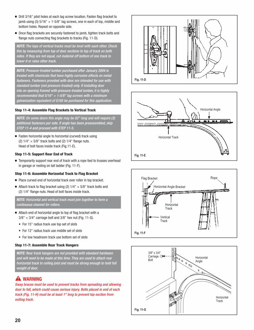
■ Drill 3/16" pilot holes at each lag screw location . Fasten flag bracket to jamb using (3) 5/16" × 1-5/8" lag screws, one in each of top, middle and bottom holes . Repeat on opposite side .
■ Once flag brackets are securely fastened to jamb, tighten track bolts and flange nuts connecting flag brackets to tracks (Fig . 11-D) .
NOTE: The tops of vertical tracks must be level with each other. Check this by measuring from top of door sections to top of track on both sides. If they are not equal, cut material off bottom of one track to lower it or raise other track.
NOTE: Pressure-treated lumber purchased after January 2004 is treated with chemicals that have highly corrosive effects on metal fasteners. Fasteners provided with door are intended for use with standard lumber (not pressure-treated) only. If installing door into an opening framed with pressure-treated lumber, it is highly recommended that 5/16" × 1-5/8" lag screws with a minimum galvanization equivalent of G185 be purchased for this application.
Step 11-4: Assemble Flag Brackets to Vertical Track
NOTE: On some doors this angle may be 82" long and will require (3) additional fasteners per side. If angle has been preassembled, skip STEP 11-4 and proceed with STEP 11-5.
■ Fasten horizontal angle to horizontal (curved) track using (2) 1/4" × 5/8" track bolts and (2) 1/4" flange nuts . Head of bolt faces inside track (Fig .11-E) .
Step 11-5: Support Rear End of Track
■ Temporarily support rear end of track with a rope tied to trusses overhead in garage or resting on tall ladder (Fig . 11-F) .
Step 11-6: Assemble Horizontal Track to Flag Bracket
■ Place curved end of horizontal track over roller in top bracket .
■ Attach track to flag bracket using (2) 1/4" × 5/8" track bolts and (2) 1/4" flange nuts . Head of bolt faces inside track .
NOTE: Horizontal and vertical track must join together to form a continuous channel for rollers.
■ Attach end of horizontal angle to top of flag bracket with a 3/8" × 3/4" carriage bolt and 3/8" hex nut (Fig . 11-G) .
• For 15" radius track use top set of slots
• For 12" radius track use middle set of slots
• For low headroom track use bottom set of slots
Step 11-7: Assemble Rear Track Hangers
NOTE: Rear track hangers are not provided with standard hardware and will need to be made at this time. They are used to attach rear horizontal track to ceiling joist and must be strong enough to hold full weight of door.
! WARNINGSway braces must be used to prevent tracks from spreading and allowing door to fall, which could cause serious injury. Bolts placed in end of each track (Fig. 11-H) must be at least 1" long to prevent top section from exiting track.
Fig. 11-DFig. 11-D
Fig. 11-F
HorizontalTrack
VerticalTrack
Horizontal Angle Bracket
Flag Bracket Rope
Fig. 11-G
HorizontalTrack
HorizontalAngle
3/8" x 3/4"CarriageBolt
Fig. 11-E
Horizontal Angle
Horizontal Track
Fig. 11-E
Fig. 11-F
Fig. 11-G
21
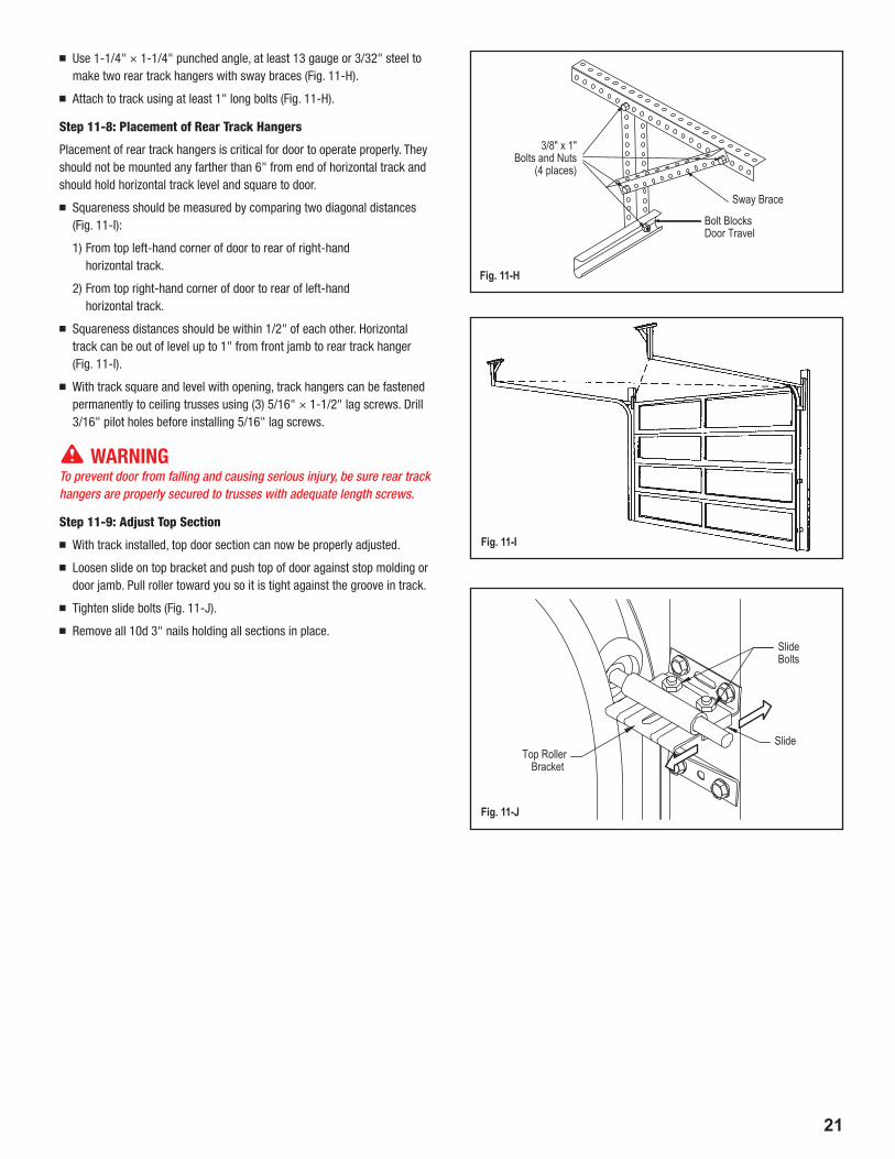
■ Use 1-1/4" × 1-1/4" punched angle, at least 13 gauge or 3/32" steel to make two rear track hangers with sway braces (Fig . 11-H) .
■ Attach to track using at least 1" long bolts (Fig . 11-H) .
Step 11-8: Placement of Rear Track Hangers
Placement of rear track hangers is critical for door to operate properly . They should not be mounted any farther than 6" from end of horizontal track and should hold horizontal track level and square to door .
■ Squareness should be measured by comparing two diagonal distances (Fig . 11-I):
1) From top left-hand corner of door to rear of right-hand horizontal track .
2) From top right-hand corner of door to rear of left-hand horizontal track .
■ Squareness distances should be within 1/2" of each other . Horizontal track can be out of level up to 1" from front jamb to rear track hanger (Fig . 11-I) .
■ With track square and level with opening, track hangers can be fastened permanently to ceiling trusses using (3) 5/16" × 1-1/2" lag screws . Drill 3/16" pilot holes before installing 5/16" lag screws .
! WARNINGTo prevent door from falling and causing serious injury, be sure rear track hangers are properly secured to trusses with adequate length screws.
Step 11-9: Adjust Top Section
■ With track installed, top door section can now be properly adjusted .
■ Loosen slide on top bracket and push top of door against stop molding or door jamb . Pull roller toward you so it is tight against the groove in track .
■ Tighten slide bolts (Fig . 11-J) .
■ Remove all 10d 3" nails holding all sections in place .
SlideTop Roller
Bracket
SlideBolts
Fig. 11-J
Fig. 11-IFig. 11-I
Fig. 11-J
Fig. 11-H
Sway Brace
Bolt BlocksDoor Travel
3/8" x 1"Bolts and Nuts
(4 places)
Fig. 11-H
22
Pull Rope
Fig. 13-A
Fig. 12-A
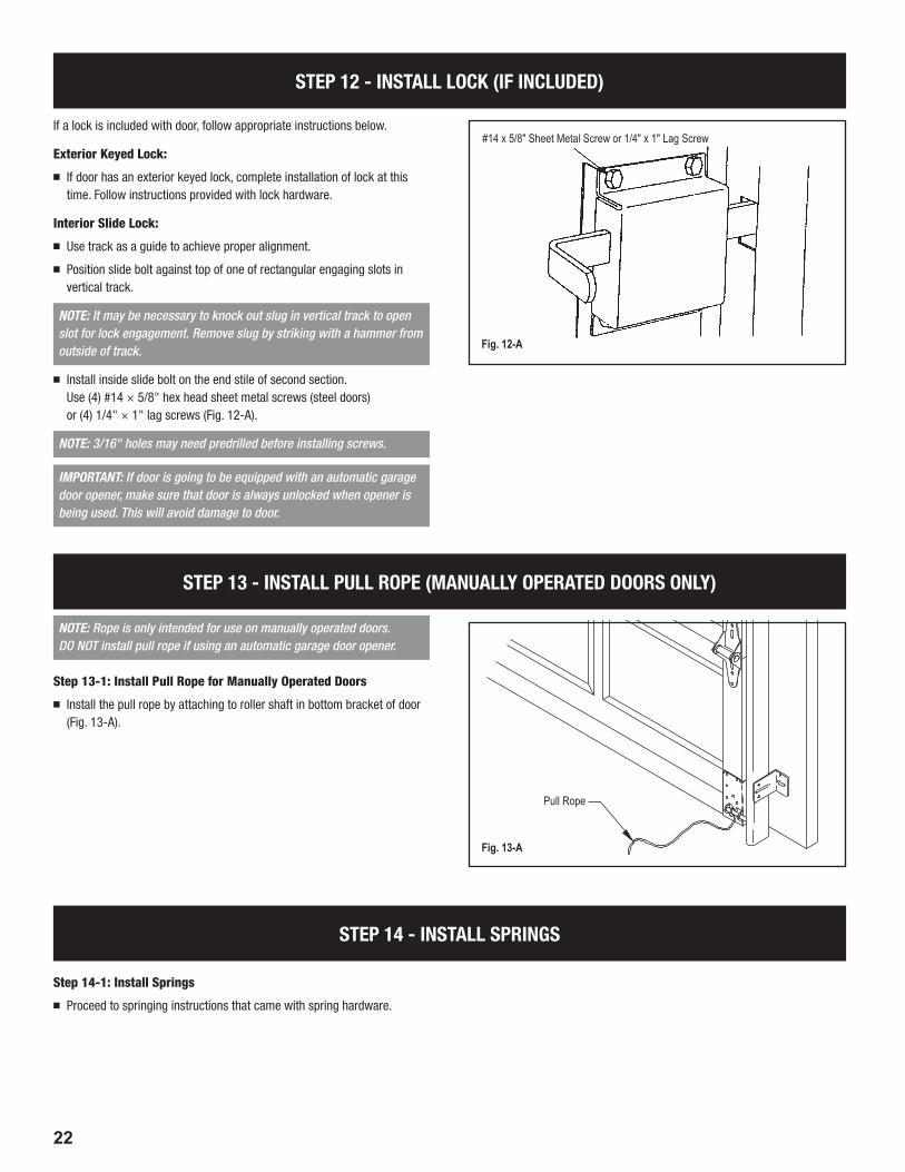
#14 x 5/8" Sheet Metal Screw or 1/4" x 1" Lag ScrewIf a lock is included with door, follow appropriate instructions below .
Exterior Keyed Lock:
■ If door has an exterior keyed lock, complete installation of lock at this time . Follow instructions provided with lock hardware .
Interior Slide Lock:
■ Use track as a guide to achieve proper alignment .
■ Position slide bolt against top of one of rectangular engaging slots in vertical track .
NOTE: It may be necessary to knock out slug in vertical track to open slot for lock engagement. Remove slug by striking with a hammer from outside of track.
■ Install inside slide bolt on the end stile of second section . Use (4) #14 × 5/8" hex head sheet metal screws (steel doors) or (4) 1/4" × 1" lag screws (Fig . 12-A) .
NOTE: 3/16" holes may need predrilled before installing screws.
IMPORTANT: If door is going to be equipped with an automatic garage door opener, make sure that door is always unlocked when opener is being used. This will avoid damage to door.
Fig. 13-A
Fig. 12-A
STEP 12 - INSTALL LOCK (IF INCLUDED)
STEP 13 - INSTALL PULL ROPE (MANUALLY OPERATED DOORS ONLY)
STEP 14 - INSTALL SPRINGS
NOTE: Rope is only intended for use on manually operated doors. DO NOT install pull rope if using an automatic garage door opener.
Step 13-1: Install Pull Rope for Manually Operated Doors
■ Install the pull rope by attaching to roller shaft in bottom bracket of door (Fig . 13-A) .
Step 14-1: Install Springs
■ Proceed to springing instructions that came with spring hardware .
23
Fig. 15-B (Doors with supplied reinforcement bracket and stile in center of door)
60°
ClevisPin
Opener Rail Mounting Distance
Ceiling
Opener Rail
Horizontal Track
Keep Clearance at 2"–5"Fig. 15-A
Top View(assembled)
OpenerArm
Lock TheseNuts TogetherSecurely
LeaveClearance
MountingSurface of Door
Vertical PunchedAngle
Opener Arm
3/8" x1-1/2"Hex Bolt
3/8"Hex Nut
VerticalPunchedAngle
HorizontalPunchedAngle
Fig. 15-D (Doors with angle iron reinforcement bracket and stile in center of door)
Opener Arm Attachment to Vertical Angle
Fig. 15-C (Doors with odd number of panels)
Punched Angle
Opener Arm Attachment to Horizontal Angle or Strut
Horizontal Angleor Strut
Opener Arm
Lock These NutsTogether Securely
Punched Angle
HorizontalAngle
or Strut
Front View (assembled)
Opener Arm
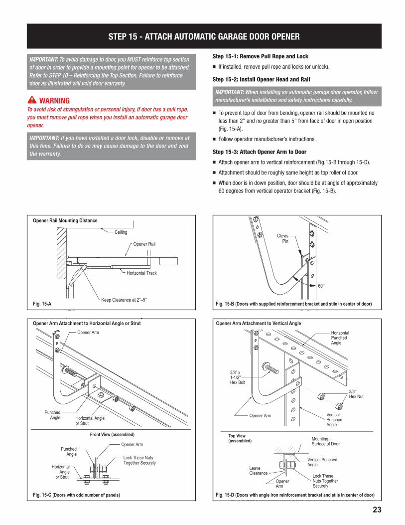
IMPORTANT: To avoid damage to door, you MUST reinforce top section of door in order to provide a mounting point for opener to be attached. Refer to STEP 10 – Reinforcing the Top Section. Failure to reinforce door as illustrated will void door warranty.
! WARNINGTo avoid risk of strangulation or personal injury, if door has a pull rope, you must remove pull rope when you install an automatic garage door opener.
IMPORTANT: If you have installed a door lock, disable or remove at this time. Failure to do so may cause damage to the door and void the warranty.
Step 15-1: Remove Pull Rope and Lock
■ If installed, remove pull rope and locks (or unlock) .
Step 15-2: Install Opener Head and Rail
IMPORTANT: When installing an automatic garage door operator, follow manufacturer’s installation and safety instructions carefully.
■ To prevent top of door from bending, opener rail should be mounted no less than 2" and no greater than 5" from face of door in open position (Fig . 15-A) .
■ Follow operator manufacturer’s instructions .
Step 15-3: Attach Opener Arm to Door
■ Attach opener arm to vertical reinforcement (Fig .15-B through 15-D) .
■ Attachment should be roughly same height as top roller of door .
■ When door is in down position, door should be at angle of approximately 60 degrees from vertical operator bracket (Fig . 15-B) .
Fig. 15-C (Doors with odd number of panels) Fig. 15-D (Doors with angle iron reinforcement bracket and stile in center of door)
Fig. 15-A
Opener Rail Mounting Distance
Opener Arm Attachment to Horizontal Angle or Strut Opener Arm Attachment to Vertical Angle
Fig. 15-B (Doors with supplied reinforcement bracket and stile in center of door)
STEP 15 - ATTACH AUTOMATIC GARAGE DOOR OPENER

THIS PAGE INTENTIONALLY
LEFT BLANK
25
GENERAL MAINTENANCE
Your door will need regular inspection, lubrication and cleaning . The following checklists will help keep your door and its parts in good working order and help protect it from the elements
! WARNINGA sectional garage door is a large, heavy object that moves with the help of springs under high tension. Springs, bottom brackets, cables and associated hardware are under high tension and can cause death, serious injuries, or damage to the door if not properly handled. For your safety and the safety of others, follow these instructions:
■ DO NOT loosen or remove bottom bracket with the spring tension engaged.
■ DO NOT operate door with a broken spring.
■ DO NOT manually operate door if handles are not installed or functioning properly.
■ DO NOT operate door if it is too difficult to move, opens too quickly, or the rollers come out of the track.
■ DO NOT operate the door if glass or interior window retainer appears to be loose, cracked, or warped. DO NOT remove screws on inside retainer.
■ For assistance with these maintenance steps, repair or replacement of any parts, please contact your professional installing Clopay Dealer: https://www.clopaydoor.com/where-to-buy
VISUAL INSPECTION CHECKLIST
Monthly inspection of the door and all of its components is recommended . If something seems out of balance or adjustment, or you note any of the following, please contact your Clopay Dealer or Clopay Customer Service at 800-225-6729 .
Visually inspect the door when in the down position for:
� Loose or bent hinges .
� Broken wheels, bent shafts or worn out bearings on rollers .
� Loose or missing bolts, screws, or other fasteners on the door or track .
� Creases or bends in the track .
� Cracking or fatigue of the door panels .
� Damaged or broken springs or spring components . If the spring looks broken it will need replaced .
� Standard extension springs that run alongside the door should include a safety containment cable . To see a visual of the safety containment cable scan the QR code to the right or visit: http://clopaypdfs.com/pdf_files/SUP-0137180_EN.pdf
� Worn or frayed cables .
� Loose, cracked, or warped glass panels or inside glass retainers . Inside the door, the plastic retainer and holding the glass and its fasteners should appear secure .
� Tears or gaps in the bottom weather seal or perimeter seal .
� Any covered, ripped, damaged, or missing warning labels .
� Any missing, broken, loose, or malfunctioning door handles . There should be two lifting points on the outside and two on the inside of the garage door .
DOOR OPERATION CHECKLIST
We recommend that at least twice per year after you have visually inspected the door and all of its components . Scan the QR code to the right or visit: https://vimeo.com/106430735
� Check the balance of the door .
1 . With the door in the down position, detach the opener (if applicable) by pulling down on the red manual release handle .
2 . Next lift the door manually up to the halfway point and gently release the door . A balanced door should hang in place and not raise or lower . If the door does not stay in place contact your Clopay Dealer for adjustment .
� Check the door operation .
■ Once you have determined your door is in balance, lift the door up and down to ensure smooth operation . The door should be easily controlled when lifting and lowering .
■ Note: Be sure to reattach the opener once you confirm the door is operating properly .
� Safety feature for doors with automatic operators:
■ Make sure any door locks are disabled or removed if an automatic operator is installed .
■ Retest following opener manufacturer's instructions .
LUBRICATE THE DOOR
At least twice per year lubricate all moving parts of the door with Clopay Garage Door Pro Lube or a synthetic lubricant:
� Lift cables at bottom bracket button .
� Lock hardware where surfaces turn or slide .
� Full length of torsion spring to reduce friction between coils .
� Rollers at the bearing (but not the tire)
� Hinges
FOR ALL NON-INSULATED GARAGE DOORS
26
CARE & MAINTENANCE
APPLIES TO THE FOLLOWING MODELSCarriage House Steel Doors GR2SU, GR2LU, GR1SU, GR1LU, GR2SP, GR2LP, GR1SP, GR1LP, GD2SU, GD2LU, GD1SU, GD1LU, GD2SP, GD2LP, GD1SP, GD1LP, AR2SU, AR2LU, AR1SU, AR1LU, AR2SP, AR2LP, AR1SP, AR1LP // Classic Steel Doors HDP20, HDPL20, HDP13, HDPL13, 9200, 9203, 9130, 9133, 7200, 7203, 7130, 7133, HDG, HDGL, 2050, 2053, 4300, 4310, 4050, 4053, 6200, 6203, 6130, 6133 // Contemporary Steel Doors HDPC20, HDPC13, HDPF20, HDPF13, HDPCC2, HDPCC1, HDPR20, HDPRC2, HDPRC1, 9202, 9132, 9201, 9131, 9208, 9138, 9205, 9209, 9139, 7202, 7132, 7201, 7131, 7208, 7138, 7205, 7209, 7139, HDGC, 2132, HDGF, 2051, HDGCC, 2138, HDGR, HDGRC, 4302, 4132, 4301, 4051, 4308, 4138, 4305, 4309, 6202, 6132, 6201, 6131, 6208, 6138, 6205, 6209, BD1EU, BD1NU, BD2EU, BD2NU, BR1EU, BR1NU, BR2EU, BR2NU, AR1EU, AR1NU, AR2EU, AR2NU
FOR STEEL GARAGE DOORS
CLEANING & PRESERVING THE DOORDoors must be cleaned and waxed at least twice a year or four times a year for harsh environments (such as coastal regions, areas with high road salt, etc .) . Failure to do so may result in loss of warranty coverage. For further questions about the requirements, refer to the warranty page at the end of this manual or contact Clopay Consumer Services.
Cleaning & Waxing
■ Help prevent damage (rusting) caused by foreign matter or salt adhering to the door .
■ Assist to restore the look of factory-applied finish by removing dirt and chalking .
■ For how-to video scan the QR code to the right or visit: https://vimeo.com/106434183
Cleaning the Door
Working from top to bottom of the door sections, use a well soaked cloth, sponge or soft bristle brush with either of the following solutions:
■ One cup of Simple Green® or other non-toxic biodegradable cleaner (less than 0 .5% phosphate) into two gallons of warm water -OR-
■ Household liquid dishwashing detergent such as Dawn® .
■ DO NOT use scouring powders or solvents when cleaning the door. If preparing to paint, see cleaning instructions under "Painting" in this manual.
■ Rinse door with clean water to complete cleaning and allow to dry .
NOTE: Be sure to clean behind stop molding on the sides and top of the door. Refer to "Window Care" for detail on window cleaning on the next page. DO NOT use a pressure washer on the door.
Waxing the Door
After cleaning, use liquid car wax (not paste) to preserve the door’s finish . This is especially important in coastal and harsh environments . Be sure to wax any surface that may be exposed to elements such as salt, including the interior of the bottom section of the door .
■ To apply the wax, follow the manufacturer’s instructions .
NOTE: Be careful not to get wax on decorative hardware as this may cause discoloration.
WINDOW CARE
Snap-In Decorative Inserts
■ Decorative inserts are designed to snap in and out of the window frame and may be installed on the inside or outside of the window .
NOTE: DO NOT REMOVE SCREWS from the window frame.
Removing Decorative Inserts for Cleaning & Painting Purposes
■ The insert has tabs on each end of each leg .
■ To remove pull the center of the insert firmly out of the window .
■ Replacing the insert is the reversal of the process described for removal . The four tabs must be pressed under the lip in the window frame .
Window Cleaning
■ Clean glass with a mild solution of a dishwashing detergent and a soft cloth .
• For acrylic impact or decorative windows: These windows CAN ONLY be washed using a clean, soft sponge or cloth with a mild dish soap and lukewarm water . Dry with soft cloth or chamois to prevent spotting .
• DO NOT use any ammoniated, abrasive or solvent-based cleaners of any kind . DO NOT brush, scrub or scrape these windows .
■ After cleaning, rinse thoroughly .
! NOTICEUse care when handling decorative windows to avoid scraping or scratching the surface.
Glass Replacement
! WARNINGTo avoid injury, use extreme caution in handling glass window pane. When frame is removed, exposed steel edge of door may be sharp. Avoid contact with steel edges. Always wear safety glasses and gloves.
■ If the door is equipped with windows, and glass should need replacement, follow the steps below:
1) With someone holding the outside frame, remove screws from the inside frame retainer .
2) Pull inside frame out of door . Carefully remove broken or old glass .
3) Insert new glass .
4) With someone holding outside frame, reinsert screws into inside frame, securing glass .
27
Gallery® Collection Window Frame and Retainer Retightening
■ Using drill loosen screw by turning it counter-clockwise one to two turns - do not unscrew any farther .
■ Retighten screw turning it clockwise the total turns unscrewed plus another turn or two . Do not over tighten the screw .
■ Tighten one screw location at a time . Repeat steps for remaining screws .
PAINTING THE DOORRead these instructions completely prior to painting your door .
IMPORTANT: Failure to follow these instructions may cause damage to your door, which will result in loss of warranty.
Required Paint
■ Your garage door can be painted with high quality 100% acrylic latex (flat, satin or semi-gloss) exterior grade paint .
■ DO NOT use any type of oil-based paint or alkyd modified paint. These paints will void the warranty of your door.
■ We strongly recommend all doors are painted with solar reflective paint when available, especially when using darker colors and when the door is in direct sunlight or a high heat/high UV environment . These paints help reflect more sunlight keeping the surface of the door cooler .
■ For more information and a list of pre-approved paints, call the consumer hotline at 800-225-6729, scan the QR code to the right or visit info.garagedoors.com/lrv
Preparing the Surface
Before painting, the door, window frames and inserts must be free of dirt, oil, caulk, waxes and mildew . To prepare window grilles and window frames:
■ Lightly scuff the entire exposed surface of window grilles and window frames with medium sandpaper (grit 60-100) .
NOTE: Sanding could remove rust-inhibiting compounds from the steel portion of the door, therefore, sanding should be done only to damaged areas where bare metal has been exposed. Refer to “Paint Repair” for details on repair on the next page.
Cleaning the Door for Painting Only
■ Make a solution of trisodium phosphate, also known as TSP, using 1/3 cup of powder to 1-1/2 to 2 gallons of water . NEVER BLEND CLEANERS OR AMMONIA WITH BLEACH.
NOTE: DO NOT use this if you are not planning to paint the door.
■ Saturate cleaning pad (3M synthetic steel wool–gray not green) and rub with even pressure to lightly scuff surface while applying the cleaning solution over all surfaces to be painted .
■ Rinse with clean water and sponge, changing water often .
■ A final wipe and rinse with clean water and sponge should be done to remove any loose material .
NOTE: You must remove any wax applied to the door before cleaning (doors are not waxed in the manufacturing process). Using moderate pressure, wipe the door surface with a rag saturated with xylene (xylol). Xylene is a flammable substance, be sure to follow instructions when using. DO NOT allow it to sit on door for extended time. Damage to your door’s paint system can occur if overexposed to this or other solvents.
Pretesting Paint
All paints are not created equal . The following test must be performed prior to application on the entire door:
■ Apply paint on a small area of door (following instructions on paint container) .
■ Allow paint to dry and evaluate for any blistering or peeling .
■ Perform adherence test by applying strip of masking tape over painted area and peel back tape . Check to see that paint adheres to door and not to tape .
NOTE: If paint shows signs of poor adherence (blistering or peeling) there may be a problem with the paint or surface preparation. DO NOT PROCEED! A new paint or further preparation of surface is called for.
Applying Paint
Follow directions on paint container and apply to door . Be sure to allow adequate drying time should you wish to apply a second coat .
NOTE: DO NOT apply paint when door surface temperature is different from manufacturer’s suggested temperature range for application.
Paint Repair
Should door’s paint finish become damaged, exposing bare metal, it will become necessary to repair this area to prevent rust from forming .
■ Damaged area should be lightly sanded with medium to fine sandpaper, making sure to remove all visible red and white rust .
■ Wipe this area with dry, clean rag .
■ Coat sanded area with high quality, rust inhibiting, zinc enriched primer . This can be found at most paint or hardware stores and should be labeled for covering bare and galvanized steel .
■ Wait time specified on the primer’s instructions before proceeding with painting door .
28
CLEANING & PRESERVING THE DOORThese garage door models contain both Limited Edition Series doors that consist of composite cladding and overlays and Ultra-Grain® Series doors which consist of composite overlays and Ultra-Grain® steel .
Both the Ultra-Grain® steel portion of the door and the inside steel surface of the door should be periodically cleaned and waxed at least twice a year or four times a year for harsh environments (such as coastal regions, high road salts, etc .) . Failure to do so may result in loss of warranty coverage . For further questions about the requirements, refer to the warranty page at the end of this manual or contact Clopay Consumer Services.
Cleaning the Door
Working from top to bottom of the door sections, use a well soaked cloth, sponge or soft bristle brush with either of the following solutions:
■ One cup of Simple Green® or other non-toxic biodegradable cleaner (less than 0 .5% phosphate) into two gallons of warm water -OR-
■ Household liquid dishwashing detergent such as Dawn® .
■ DO NOT use scouring powders or solvents when cleaning the door. If preparing to paint, see cleaning instructions under "Painting" in this manual.
■ Rinse door with clean water to complete cleaning and allow to dry .
NOTE: Be sure to clean behind stop molding on the sides and top of the door.
Waxing the Door
After cleaning, use liquid car wax (not paste) to preserve the Ultra-Grain® finish and the interior steel surface between cleanings . This is especially important in coastal and harsh environments .
WINDOW CARE
Window Grille Removal
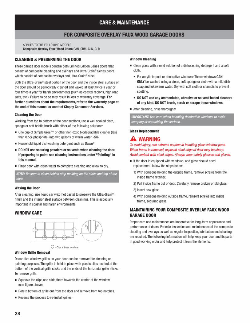
Decorative window grilles on your door can be removed for cleaning or painting purposes . The grille is held in place with plastic clips located at the bottom of the vertical grille sticks and the ends of the horizontal grille sticks . To remove grille:
■ Squeeze the clips and slide them towards the center of the window (see figure above) .
■ Rotate bottom of grille out from the door and remove from top notches .
■ Reverse the process to re-install grilles .
Window Cleaning
■ Clean glass with a mild solution of a dishwashing detergent and a soft cloth .
• For acrylic impact or decorative windows: These windows CAN ONLY be washed using a clean, soft sponge or cloth with a mild dish soap and lukewarm water . Dry with soft cloth or chamois to prevent spotting .
• DO NOT use any ammoniated, abrasive or solvent-based cleaners of any kind. DO NOT brush, scrub or scrape these windows.
■ After cleaning, rinse thoroughly .
IMPORTANT: Use care when handling decorative windows to avoid scraping or scratching the surface.
Glass Replacement
! WARNINGTo avoid injury, use extreme caution in handling glass window pane. When frame is removed, exposed steel edge of door may be sharp. Avoid contact with steel edges. Always wear safety glasses and gloves.
■ If the door is equipped with windows, and glass should need replacement, follow the steps below:
1) With someone holding the outside frame, remove screws from the inside frame retainer .
2) Pull inside frame out of door . Carefully remove broken or old glass .
3) Insert new glass .
4) With someone holding outside frame, reinsert screws into inside frame, securing glass .
MAINTAINING YOUR COMPOSITE OVERLAY FAUX WOOD GARAGE DOOR Proper care and maintenance are imperative for long-term appearance and performance of doors . Periodic inspection and maintenance of the composite cladding and overlays as well as regular inspection, lubrication and cleaning are required . The following information will help keep your door and its parts in good working order and help protect it from the elements .
CARE & MAINTENANCE
APPLIES TO THE FOLLOWING MODELSComposite Overlay Faux Wood Doors CAN, CRM, GLN, GLM
FOR COMPOSITE OVERLAY FAUX WOOD GARAGE DOORS
= Clips in these locations
29
FINISHING INFORMATIONComposite Overlay Faux Wood Garage Doors come pre-finished from the factory unless “No-Finish” has been specified .
No-Finish Limited Edition Doors
If you have ordered your door without factory pre-finish, it is necessary to finish the door prior to installation .
■ Recommended finish: Minwax® gel stain or high quality exterior grade latex paint .
■ Surface preparation: Before finishing your door, the overlay and cladding surfaces must be prepared and cleaned .
• Clean with a mild store-bought paint surface preparation cleaner .
• Rinse with clean water and sponge, changing water often .
• A final wipe and rinse with clean water and sponge should be done to remove any loose material .
• Allow to dry .
■ Pre-test paint: All paints are not created equal, the following test needs to be performed:
• Apply paint on small area of door (following instructions on paint container) .
• Allow paint to dry and evaluate for any blistering or peeling .
• Perform adherence test by applying strip of masking tape over painted area and peel back tape . Check to see that paint adheres to door and not to tape .
NOTE: If paint shows signs of poor adherence there may be a problem with the paint or surface preparation. DO NOT PROCEED! A new paint or further preparation of surface is needed.
NOTE: DO NOT apply paint when door surface temperature is different from manufacturer’s suggested temperature range.
IMPORTANT: Do not use any type of oil-based paint or alkyd modified paint. These paints will void the warranty of your door.
■ Finishing: Follow directions on the paint or stain container and apply to the door . Be sure to allow adequate drying time between coats and prior to installation .
Factory Pre-Finish Limited Edition and Ultra Grain® Doors
Unless you purchased the door with “No-Finish”, your door has been factory pre-finished . Limited Edition Series doors consist of composite cladding and overlays that must have periodic maintenance performed to the finish . Ultra-Grain® Series doors consist of composite overlays that must have periodic maintenance performed to the finish and Ultra-Grain® steel that does not require this finish maintenance other than periodic cleaning (see CLEANING AND PRESERVING THE DOOR) .
■ Annual inspection: Inspect the finish for discoloration and coating delamination every 12 months and more frequently if exposed to direct sunlight or harsh environmental conditions .
■ Maintenance coat: The composite portions must be recoated at least every two years for maximum longevity with an exterior grade, UV resistant, clear protective top coat . In locations of severe weather exposure, more frequent maintenance may be required .
• Recommended finish: Minwax® Helmsman® Spar Urethane or Minwax® Clear Shield™ . (Use painter’s tape to mask off the Ultra-Grain® steel from the overlays .)
REPAIR AND RE-FINISHShould your door’s composite wood overlay or cladding become damaged or discolored, they can be repaired using the following instructions .
NOTE: DO NOT apply recoat or re-finish when door surface temperature is different from manufacturer’s suggested temperature range.
■ First, fill any gaps or voids in the composite surface with a paintable wood putty or urethane caulk and let dry completely .
■ For a how-to video scan the QR Code to the right or visit https://vimeo.com/216025923
NOTE: For Ultra-Grain® Series doors, mask off the steel surface using painter's tape.
■ To bring out light and dark highlights of the composite texture, two coats are needed (a lighter base coat and a darker top coat) . This can be accomplished one of two ways, a combination of paint and gel stain, or two coats of paint .
■ For a how-to video scan the QR Code to the right or visit https://vimeo.com/216026336
NOTE: Be sure to follow the Pre-test Paint instructions to ensure proper adhesion, then follow the directions on the container to apply to the door.
■ Exterior grade 100% acrylic latex paint bottom coat with darker gel stain top coat .
• Brush lighter base coat of paint completely into composite texture for full coverage . Allow to dry overnight .
• Brush darker top coat gel stain onto the door thoroughly; BEFORE THE GEL STAIN DRIES, use a cloth rag to wipe off a little or a lot of the stain (depending on your preference) to reveal areas of base coat . Use paint brush to even out coat . Allow to dry overnight .
■ Exterior grade 100% acrylic latex paint base coat and top coat .
• Brush lighter base coat paint completely into the composite texture for full coverage . Allow to dry overnight .
• Brush darker top coat paint onto the door; BEFORE THE TOP COAT DRIES, use a cloth rag to wipe off a little or a lot of top coat (depending on your preference) to reveal areas of base coat .
• Once finish coats are dried, apply layer of exterior grade, UV resistant, clear protective top coat (such as Minwax® Clear Shield™ or Minwax® Helmsman® Spar Urethane) . Allow to dry . (Required for gel stain top coat, optional for paint top coat) . Use brush to even coat out . Allow to dry overnight .
NOTE: Remove painters tape AFTER clear coat.
30
CLEANING & PRESERVING THE DOORBoth the exterior steel of the door and the inside steel surface of the door should be periodically cleaned and waxed at least twice a year or four times a year for harsh environments (such as coastal regions and areas with high road salt, etc .) . Failure to do so may result in loss of warranty coverage . For further questions about the requirements, refer to the warranty page at the end of this manual or contact Clopay Consumer Services.
Cleaning & Waxing
■ Help prevent damage (rusting) caused by foreign matter or salt adhering to the door .
■ Assist to restore the look of factory-applied finish by removing dirt and chalking .
■ For how-to video scan the QR code to the right or visit: https://vimeo.com/106434183
Cleaning the Door
Working from top to bottom of the door sections, use a well soaked cloth, sponge or soft bristle brush with either of the following solutions:
■ One cup of Simple Green® or other non-toxic biodegradable cleaner (less than 0 .5% phosphate) into two gallons of warm water -OR-
■ Household liquid dishwashing detergent such as Dawn® .
■ DO NOT use scouring powders or solvents when cleaning the door. If preparing to paint, see cleaning instructions under "Painting" in this manual.
■ Rinse door with clean water to complete cleaning and allow to dry .
NOTE: Be sure to clean behind stop molding on the sides and top of the door.
Waxing the Door
After cleaning, use liquid car wax (not paste) to preserve the door’s finish . This is especially important in coastal and harsh environments . Be sure to wax any surface that may be exposed to elements such as salt, including the interior of the bottom section of the door .
■ To apply the wax, follow the manufacturer’s instructions .
NOTE: Be careful not to get wax on decorative hardware as this may cause discoloration.
PAINTING THE DOORRead these instructions completely prior to painting your door .
IMPORTANT: Failure to follow these instructions may cause damage to your door, which will result in loss of warranty.
Required Paint
■ Your garage door can be painted with high quality 100% acrylic latex (flat, satin or semi-gloss) exterior grade paint .
■ DO NOT use any type of oil-based paint or alkyd modified paint. These paints will void the warranty of your door.
■ We strongly recommend all doors are painted with solar reflective paint when available, especially when using darker colors and when the door is in direct sunlight or a high heat/high UV environment . These paints help reflect more sunlight keeping the surface of the door cooler .
IMPORTANTFor your Coachman® Collection product, you must check the Light Reflectance Value (LRV) of the paint color. We strongly recommend all doors are painted with solar reflective paint when available. These paints help reflect more sunlight keeping the surface of the door cooler. Tested and approved solar reflective paint is required for darker colors (when the LRV of the color is between 13–38). Black and very dark colors (when the LRV is 12 or less) are NOT permitted.
■ For more information and a list of pre-approved paints, call the consumer hotline at 800-225-6729, scan the QR code to the right or visit info.garagedoors.com/lrv
Preparing the Surface for Painting
Before painting, the door, window frames and inserts must be free of dirt, oil, caulk, waxes and mildew . To prepare window grilles and window frames:
■ Lightly scuff the entire exposed surface of window grilles and window frames with medium sandpaper (grit 60-100) .
NOTE: Sanding could remove rust-inhibiting compounds from the steel portion of the door, therefore, sanding should be done only to damaged areas where bare metal has been exposed. Refer to “Paint Repair” for details on repair.
Cleaning the Door for Painting Only
■ Make a solution of trisodium phosphate, also known as TSP, using 1/3 cup of powder to 1-1/2 to 2 gallons of water . NEVER BLEND CLEANERS OR AMMONIA WITH BLEACH.
CARE & MAINTENANCE
APPLIES TO THE FOLLOWING MODELSComposite Overlay Doors CXU, CX, CF, CGU, CG, CD, SXU, SX, SF
FOR COMPOSITE OVERLAY GARAGE DOORS
31
NOTE: DO NOT use this if you are not planning to paint the door.
■ Saturate cleaning pad (3M synthetic steel wool–gray not green) and rub with even pressure to lightly scuff surface while applying the cleaning solution over all surfaces to be painted .
■ Rinse with clean water and sponge, changing water often .
■ A final wipe and rinse with clean water and sponge should be done to remove any loose material .
NOTE: You must remove any wax applied to the door before cleaning (doors are not waxed in the manufacturing process). Using moderate pressure, wipe the door surface with a rag saturated with xylene (xylol). Xylene is a flammable substance, be sure to follow instructions when using. DO NOT allow it to sit on door for extended time. Damage to your door’s paint system can occur if overexposed to this or other solvents.
Pretesting Paint
All paints are not created equal . The following test must be performed prior to application on the entire door:
■ Apply paint on a small area of door (following instructions on paint container) .
■ Allow paint to dry and evaluate for any blistering or peeling .
■ Perform adherence test by applying strip of masking tape over painted area and peel back tape . Check to see that paint adheres to door and not to tape .
NOTE: If paint shows signs of poor adherence (blistering or peeling) there may be a problem with the paint or surface preparation. DO NOT PROCEED! A new paint or further preparation of surface is
called for.
Applying Paint
Follow directions on paint container and apply to door . Be sure to allow adequate drying time should you wish to apply a second coat .
NOTE: DO NOT apply paint when door surface temperature is different from manufacturer’s suggested temperature range for application.
PAINT REPAIRShould the door’s paint finish become damaged, exposing bare metal, it will become necessary to repair this area to prevent rust from forming .
■ Damaged area should be lightly sanded with medium to fine sandpaper, making sure to remove all visible red and white rust .
■ Wipe this area with dry, clean rag .
■ Coat sanded area with high quality, rust inhibiting, zinc enriched primer . This can be found at most paint or hardware stores and should be labeled for covering bare and galvanized steel .
■ Wait time specified on the primer’s instructions before proceeding with painting door .
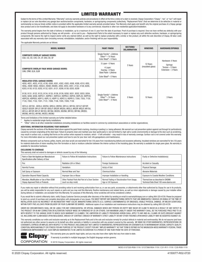
4150077-R02-0720© 2020 Clopay Corporation. All rights reserved.
MOD 0137320-R08-1119 / 0137398-R04-1119 / C31-R11-1119 / C35-R08-1119
LIMITED WARRANTYSubject to the terms of this Limited Warranty (“Warranty”) and any warranty policies and procedures in effect at the time a notice of a claim is received, Clopay Corporation (“Clopay”, “we”, or “our”) will repair or replace (at our sole discretion) any garage door sections/section components, hardware, or springs/spring components (collectively, “Replacement Parts”) that we determine to be defective in material or workmanship so long as timely written notice is provided within the applicable limited warranty periods provided below . This Warranty shall apply and benefit only the original purchase of a Clopay garage door product and is non-transferable, and does not apply to decorative hardware or to any commercial, industrial or other non-residential application/installation .
The warranty period begins from the date of delivery or installation, up to a maximum of one (1) year from the date of purchase . Proof of purchase is required . Once we have verified any defect(s) with your product through persons authorized by Clopay, we will provide – at no cost to you – Replacement Parts to the extent necessary to repair or replace any such defective sections, hardware, or springs/spring components . We reserve the right to inspect and/or verify any claimed defect, as well as the right to replace product(s) with a similar or like product, all within the sole discretion of Clopay . All labor costs associated with any warranty claim (including removal, reinstallation, installation, and/or finishing) will be your responsibility .
The applicable Warranty periods are as follows:
MODEL NUMBER PAINT FINISHSECTIONS/
DELAMINATIONWINDOWS HARDWARE/SPRINGS
COMPOSITE OVERLAY GARAGE DOORS: CGU, CG, CD, CXU, CX, CF, SXU, SX, SF
Single Family* – LifetimeOther** – 10 Years
Color Blast® – 5 Years
5 Years 10 Years (insulated glass)
Hardware: 5 Years
Springs: Torsion – 5 Years
Extension – 3 YearsCOMPOSITE OVERLAY FAUX WOOD GARAGE DOORS:CAN, CRM, GLN, GLM
5 Layer – 5 Years
4 Layer: Overlay – 5 Years
Steel Paint – Lifetime
Color Blast® – 5 Years
INSULATED STEEL GARAGE DOORS:4050, 4051, 4053, 4132, 4138, 4300, 4301, 4302, 4305, 4308, 4309, 4310, HDG, HDGL, HDGF, HDGC, HDGCC, HDGR, HDGRC, 2050, 2053, 2051, 2132, 2138, 6200, 6203, 6130, 6133, 6202, 6132, 6201, 6131, 6208, 6138, 6205, 6209
9130, 9131, 9132, 9133, 9134, 9135, 9138, 9139, 9200, 9201, 9202, 9203, 9204, 9205, 9208, 9209, HDPCC1, HDPRC1, HDPCC2, HDPRC2, HDP20, HDPL20, HDPF20, HDPC20, HDPR20, HDP13, HDPL13, HDPF13, HDPC13, HDPR13, 7200, 7203, 7130, 7133, 7202, 7132, 7201, 7131, 7208, 7138, 7205, 7209, 7139
GD1LU, GD1SU , GD2LU, GD2SU, GR2LU, GR2SU, GR1LU, GR1SU, GD1LP, GD1SP, GD2LP, GD2SP, GR1LP, GR1SP, GR2LP, GR2SP, AR2SU, AR2LU, AR2SP, AR2LP, AR1SU, AR1LU, AR1SP, AR1LP, BD1EU, BD1NU, BD2EU, BD2NU, BR1EU, BR1NU, BR2EU, BR2NU, AR1EU, AR1NU, AR2EU, AR2NU
Single Family* – LifetimeOther** – 10 Years
Color Blast® – 5 Years5 Years 10 Years 3 Years
Terms and limitations of the limited warranty are further detailed below:* Applies to residential single family installations .** “Other” refers to all other residential installations (including installations on facilities owned in common by condominium associations or similar organizations) .
ADDITIONAL INFORMATION REGARDING YOUR WARRANTYClopay warrants the sections of the Models listed above against the paint finish cracking, checking or peeling (i .e . losing adhesion) . We warrant our rust prevention system against rust through for perforation(s) caused by corrosion originating at the steel layer . Failure to properly clean and maintain your door (particularly in, but not limited to, high-salt or acidic environments) or damage to the door such as scratching, may result in surface rust, a coating that forms on the surface when exposed to moisture, which – if left untreated – may result in loss of warranty coverage . Surface rust is not covered under this warranty . For more information about our rust prevention system and how to care for your door visit: info .garagedoors .com/maintenance .
Window components such as frames, grilles, inserts, and clear acrylic are warranted for ten (10) years from manufacturing defects and excessive yellowing . Insulated windows are warranted for ten (10) years for material obstruction of vision resulting from film formation or dust or moisture collection between the interior surface of the insulating glass . No warranty is available for single pane glass . No warranty is available for decorative hardware .
EXCLUSIONS TO COVERAGEThis warranty shall not extend to damages or defects caused by any of the following:
Paint or Stain Not Applied per Manufacturer Specifications after Delivery of Door
Failure to Follow All Installation Instructions Failure to Follow Maintenance Instructions Faulty or Defective Installation(s)
Fire Radiation (UV or Other) Foreign Substances Accident or Casualty
Harmful Fumes Vandalism Act(s) of God Physical Damage
Salt Spray or Exposure Normal Wear and Tear Chemical Action Abrasive Materials
Operation Beyond Rated Capacity Improper Use or Abuse Improper Installation or Handling Exposure to Coastal Weather Conditions
Alteration, Modification or Use of Non-OEM/Clopay-Approved Parts or Products
Other Painted Parts Not Part of a Door Section (such as stop mold)
Normal Fading or Discoloration from Usage, Age or UV Exposure
Thermal bow as described in DASMA Technical Data Sheet 185 www .dasma .com
If you make any repair or alteration without first providing notice to and receiving authorization from us, or use any parts, accessories, or attachments other than authorized by Clopay for use in its products, you will be solely responsible for any such repairs or parts and you may void this Warranty . Routine maintenance and related items, as well as minor adjustments or damage caused by your installer either during delivery or installation, are excluded from this Warranty . For purposes of this Warranty, minor scratches will not be considered a defect .
If you would like to submit a Warranty claim, notify Clopay Customer Service promptly after discovery of the defect by sending an email to warranty@clopay .com or calling 800-225-6729 . Please be prepared to send us a proof of purchase and complete description with photographs of any issues . YOU MUST REPORT ANY MANUFACTURING DEFECTS THAT ARE IMMEDIATELY OBVIOUS OR VISIBLE AT THE TIME OF INSTALLATION (SUCH AS INCORRECT OR INCONSISTENT PAINT COLOR, MANUFACTURING DEFECTS (E .G . SURFACE CONTAMINANT(S) OR SMUDGES), VISIBLE PHYSICAL DAMAGE, OR MAJOR SCRATCHES) WITHIN FORTY FIVE (45) DAYS FROM DELIVERY OR YOUR CLAIM MAY BE BARRED . Additional copies of our installation and maintenance instructions may be obtained by calling 800-225-6729 .
UNDER NO CIRCUMSTANCES SHALL WE BE LIABLE FOR ANY CONSEQUENTIAL OR SPECIAL DAMAGES WHICH ANY PERSON OR ENTITY MAY INCUR OR CLAIM TO INCUR AS A RESULT OF ANY DEFECT IN THE PRODUCT OR IN ANY CORRECTION OR ALTERATION THEREOF MADE OR FURNISHED BY US OR OTHERS . OUR MAXIMUM LIABILITY UNDER THIS WARRANTY SHALL BE THE PURCHASE PRICE PAID TO US WITH RESPECT TO THE GARAGE DOOR TO WHICH SUCH WARRANTY IS CLAIMED . THE LIMITATION OF LIABILITY PROVISIONS HEREIN SHALL APPLY TO ANY AND ALL CLAIMS OR SUITS BROUGHT AGAINST US, INCLUDING ANY CLAIM BASED UPON NEGLIGENCE, BREACH OF CONTRACT, BREACH OF WARRANTY, STRICT LIABILITY OR ANY OTHER THEORIES UPON WHICH LIABILITY MAY BE ASSERTED AGAINST US .
This warranty constitutes our entire and exclusive warranty as to the Replacement Parts and is the sole and exclusive remedy for product defects in material and workmanship . We do not assume (and have not authorized any other person to assume on its behalf) any other warranty or liability in connection with any product covered by this warranty . WE MAKE NO OTHER WARRANTIES, REPRESENTATIONS OR COVENANTS, EXPRESS OR IMPLIED, WITH RESPECT TO THIS PRODUCT, INCLUDING BUT NOT LIMITED TO WARRANTIES, REPRESENTATIONS OR COVENANTS AS TO WORKMANSHIP, DESIGN, CAPACITY, QUALITY, CONDITION, MERCHANTABILITY OR FITNESS FOR ANY PURPOSE OF THE PRODUCT, EXCEPT FOR ANY “IMPLIED WARRANTY” AS THAT TERM IS DEFINED IN THE MAGNUSON-MOSS WARRANTY-FEDERAL TRADE COMMISSION IMPROVEMENT ACT, SUCH IMPLIED WARRANTIES TO BE LIMITED IN DURATION TO A PERIOD OF ONE YEAR FROM THE DATE OF PURCHASE .
This warranty gives you specific legal rights, and you may also have other rights that vary from state to state .
If warranty is provided in multiple languages, the English language version governs .
© 2019 Clopay Corporation. All rights reserved.


