Embed Size (px)
Citation preview

Installation, Operation and Maintenance Manual 1-20 Hp “Oil-Less” Medical Air Systems (Covers both V-series and G-series Compressors) This unit purchased from: Date purchased: Model number: Serial number: Option(s) included: Any information, service or spare parts requests should include the machine serial number and be directed to: BeaconMedæs 1800 Overview Drive Rock Hill, SC 29730 Tech. Services 1-888-4MEDGAS (1-888-463-3427) Fax: (803) 817-5750 BeaconMedæs reserves the right to make changes and improvements to update products sold previously and support materials without notice or obligation. Issue Date: March 19, 2010 MAN 01- 001

"Oil-Less” Medical Air
Medical Systems
ii
Table of Contents Safety Precautions 1.0 General Information 1.1 Modular Base Mount Standard Components
1.2 SPC (Single Point Connection) Base Mount Standard Components 1.3 Tank Mount Standard Components
2.0 Installation 2.1 Inspection Upon Receiving 2.2 Handling 2.3 Location 2.4 Space Requirements 2.5 Piping 2.6 Wiring 3.0 System Operation 3.1 Prestart-up 3.2 Initial Start-up 3.3 Normal Start-up 3.4 Normal Operation 3.5 Normal Shutdown 3.6 Emergency Shutdown/Alarms 4.0 Trouble Shooting 5.0 Maintenance 5.1 Maintenance Schedule 5.2 Replacement Filter Elements 5.3 Maintenance Kits 6.0 Inspection/Replacement Procedures 6.1 V-belts 6.2 Air Intake Filter 6.3 Readjustment of Cut-out and Cut-in Pressure 6.4 Replacing the Air Valve Assembly 6.5 Checking/Replacing Piston Rings, Rider Rings & Gaskets 6.6 Replacing the Piston Pin 6.7 Recommended Fastener Torques 7.0 Parts Lists 8.0 Specifications 9.0 Maintenance Record

"Oil-Less” Medical Air
Medical Systems
iii
Table of Contents (continued) Appendix A - Desiccant Dryer A.1 General Information 1.1 Drying Cycles 1.2 Prefilter 1.3 Automatic Drain Valves A.2 Operation
2.1 Start-Up 2.2 Procedure to Switch Off Dryer 2.3 Normal Start-Up 2.4 Maintenance Shut Down
A.3 Troubleshooting A.4 Maintenance 4.1 Maintenance Shut Down A.5 Replace/Repair
5.1 Desiccant Replacement Procedure (1-5 hp) 5.2 Desiccant Replacement Procedure (7.5-20 hp)
A.6 Dryer Specifications Appendix B - CO Monitor B.1 Introduction B.2 Specifications
2.1 Monitor 2.2 Sensor 2.3 Display 2.4 Annunciator Lights
B.3 Operation 3.1 Alarms B.4 Maintenance
4.1 Repair Policy 4.2 Maintenance Schedule 4.3 Calibration 4.4 Sensor check out and changing
B.5 Troubleshooting B.6 Accessories and Replacement Parts
Appendix C - Ceramic Dew Point Monitor C.1 Introduction C.2 Specifications
2.5 Monitor 2.6 Sensor
C.3 Operation 3.1 Alarms C.4 Maintenance
4.5 Repair Policy 4.6 Maintenance Schedule
C.5 Troubleshooting

"Oil-Less” Medical Air
Medical Systems
iv
Safety Precautions
Pressurized air from the system may cause personnel injury or property damage if the unit is improperly operated or maintained. Operator should have carefully read and become familiar with the contents of this manual before installing, wiring, starting, operating, adjusting and maintaining the system. Operator is expected to use common sense safety precautions, good workmanship practices and follow any related local safety precautions. In addition: • Before starting any installation or maintenance procedures, disconnect all power to the package. • All electrical procedures must be in compliance with all national, state and local codes and requirements. • A certified electrician should connect all wiring. • Refer to the electrical wiring diagram provided with the unit before starting any installation or
maintenance work. • Release all pressure from the package before removing, loosening, or servicing any covers, guards,
fittings, connections, or other devices. • Notify appropriate hospital personnel if repairs or maintenance will affect available compressed air levels. • Air inlet must be placed in an area free of toxic or hazardous contaminants. It must be kept away from
ETO exhaust vents, vacuum exhaust vents, areas close to automotive exhausts, etc., in accordance with NFPA 99.
• Prior to using the LifeLine® Medical Air System, the medical facility must have a Certifier perform all
installation tests as specified in NFPA 99. The medical facility is also responsible for ensuring that the Medical Air meets the minimum requirements as specified in NFPA 99.
• This is a high speed rotating piece of machinery. Do not attempt to service any part while machine is in
operation. • To prevent automatic starting, disconnect all electrical power before performing any maintenance. • Do not operate unit without belt guards, shields or screens in place. • Make sure that all loose articles, packing material, and tools are clear of the package. • Check all safety devices periodically for proper operation. • Never operate a compressor with its isolation (shutoff) valve closed or without its relief valve in place.
Damage to the compressor may occur. • Do not add lubricating oil of any kind to the compressor. Absolutely no oil is required for proper
operation. • Do not allow the compressor to run unattended in the “Hand” mode. Damage may occur. • Electrical service must be the same as specified on the control panel nameplate or damage to the
equipment may occur. • Vibration during shipment can loosen electrical terminals, fuse inserts, and mechanical connections.
Tighten as necessary.

"Oil-Less” Medical Air
Medical Systems
1-1
1.0 General Information 1.1 Modular Basemount Standard Components System Design The modular LifeLine® Medical Air system consists of compressor modules (duplexed or multiplexed), a dryer/control module, and an air receiver module. Each module has a maximum base width of 34" (86 cm) or less, and is fully compliant with NFPA 99. Compressor Module The compressor is a continuous duty rated "oil-less" type with permanently lubricated, sealed bearings. The design is single stage, air-cooled, reciprocating type with corrosion resistant reed type valves with stainless steel reeds. Both the compression rings and rider rings are made from a long life, fluororesin material designed for continuous duty operation. The crankshaft is constructed of a durable nodular graphite cast iron and is fully supported on both ends by heavy duty ball bearings permanently lubricated and sealed. The crankcase is constructed of gray cast iron, not aluminum. Maximum heat dissipation is achieved through cast aluminum alloy cylinders treated for optimum corrosion and wear resistance. Cylinder sleeves are not required. Additionally, an insulated "heat cut" piston pin minimizes heat transmission from the piston wall to the piston pin needle bearing. The connecting rod is of a one-piece design for maximum reliability. Compressor Drive and Motor The compressor is v-belt driven through a combination flywheel/sheave and steel motor sheave with tapered bushing and protected by an OSHA approved, totally enclosed beltguard. A pivoting motor mounting base that is fully adjustable through twin adjusting screws achieves belt tensioning. Once adjusted the tension can be maintained by means of twin motor mounting base locking nuts. The motor is a NEMA high efficiency type, open dripproof, 1800 RPM, with 1.15 service factor suitable for 208 or 230/460V electrical service. Intake Piping The compressor has a factory piped intake manifold with one "hospital type" inlet air filter with threaded opening for remote intake connection. The inlet filter housing is isolated from the intake manifold by a braided 304 stainless steel flex connector. The inlet filter removes dust from the incoming air through cyclonic action and through an element. Discharge Piping Each compressor module is equipped with an integral air-cooled aftercooler, designed for a maximum approach temperature of 15oF, complete with moisture separator and timed automatic solenoid drain valve. A manual drain valve bypass is included. Each cylinder head is equipped with a factory wired high discharge air temperature shutdown switch. The compressor discharge line includes a flex connector, safety relief valve, and check valve. The discharge air piping is made of ASTM B-819 copper tubing, brass, and stainless steel. The discharge flex connector is braided 304 stainless steel. Isolation System The compressor and motor are fully isolated from the main compressor module base by means of a four point, heavy duty, spring isolation system for a minimum of 95% isolation efficiency. The main module base frame does not exceed 34" in width and includes standard pallet jack slots for ease of mobility.
"Oil-Less” Medical Air
Medical Systems
1-2
1.0 General Information (continued) 1.1 Modular Basemount Standard Components Noise Attenuating Enclosure (optional) A two piece, molded fiberglass noise attenuating enclosure is available. Noise levels of a single compressor module do not exceed 78 dB(A) when measured in accordance with Cagi-Pneurop. Enclosure panels are capable of being removed during operation without exposing rotating v-belts. Dryer/Control Module The dryer/control module includes a NEMA 12, U.L. Labeled control system, duplexed desiccant drying system, duplexed final line filters, duplexed final line regulators, and dew point/CO monitor. All of the above are factory piped and wired in accordance with NFPA 99 and include valving to allow complete air receiver bypass, as well as air sampling port. Dryer Each desiccant dryer is individually sized for peak calculated demand and capable of producing a 10oF (-12oC) pressure dew point. Dryer purge flow is minimized through a demand-based purge saving control system. The inlet to each dryer includes a mounted prefilter with automatic drain and element change indicator. Control System The multiplex, factory mounted and wired, control system is NEMA 12 and U. L. labeled. This control system provides automatic lead/lag sequencing with circuit breaker disconnects for each compressor. Duplex systems have two external operators; triplex and larger systems have one external operator. The control panel also includes full voltage motor starters with overload protection, redundant 120V control circuit transformers, visual and audible reserve unit alarm with isolated contacts for remote alarm, hand-off-auto lighted selector switches, automatic alternation of all compressors with provisions for simultaneous operation if required, automatic activation of reserve unit if required, visual alarm indication for high discharge air temperature shutdown with isolated contacts for remote alarm, and runtime hourmeters. Final Line Filters and Regulators Fully duplexed final line filters rated for 0.01 micron with element change indicators, along with duplexed final line regulators, are factory mounted and piped. Dew Point Hygrometer/CO Monitor The factory mounted, piped and wired, dew point hygrometer and CO monitor include remote alarm contacts. The dew point sensor is a ceramic type with system accuracy of ± 2° F. The CO sensor is a chemical type with system accuracy of ± 2 PPM (at 10 PPM) for carbon monoxide. The dew point alarm is factory set at 36° F (2° C) per NFPA 99, and the CO alarm is factory set at 10 PPM. Both set points are field adjustable. High CO and high dew point conditions are indicated with visual and audible alarms. Air Receiver Module The vertical air receiver is ASME coded, National Board certified, rated for a minimum 150 PSIG design pressure, and includes a liquid level gauge glass as well as a timed automatic solenoid drain valve.

"Oil-Less” Medical Air
Medical Systems
1-3
1.0 General Information (continued) 1.2 SPC (Single Point Connection) Basemount Standard Components System Design The SPC (Single Point Connection) LifeLine® Medical Air system consists of compressor modules (duplexed or multiplexed), and a dryer/control module with an air receiver. Each module has a maximum base width of 34.5" (88 cm), and is fully compliant with NFPA 99. The modules are attached as one unit with single point connections for the intake, discharge, and electrical. Compressor Module The compressor is a continuous duty rated "oil-less" type with permanently lubricated, sealed bearings. The design is single stage, air-cooled, reciprocating type with corrosion resistant reed type valves with stainless steel reeds. Both the compression rings and rider rings are made from a long life, fluororesin material designed for continuous duty operation. The crankshaft is constructed of a durable nodular graphite cast iron and is fully supported on both ends by heavy duty ball bearings permanently lubricated and sealed. The crankcase is constructed of gray cast iron, not aluminum. Maximum heat dissipation is achieved through cast aluminum alloy cylinders treated for optimum corrosion and wear resistance. Cylinder sleeves are not required. Additionally, an insulated "heat cut" piston pin minimizes heat transmission from the piston wall to the piston pin needle bearing. The connecting rod is of a one-piece design for maximum reliability. Compressor Drive and Motor The compressor is v-belt driven through a combination flywheel/sheave and steel motor sheave with tapered bushing and protected by an OSHA approved, totally enclosed beltguard. A sliding motor mounting base that is fully adjustable through twin adjusting screws achieves belt tensioning. The motor is a NEMA high efficiency type, open dripproof, 1800 RPM, with 1.15 service factor suitable for 208 or 230/460V electrical service. Intake Piping Each compressor has a piped intake manifold with one "hospital type" inlet air filter with threaded opening for remote intake connection. The inlet filter housing is isolated from the intake manifold by a braided 304 stainless steel flex connector. The inlet filter removes dust from the incoming air through cyclonic action and through an element. Discharge Piping Each compressor module is equipped with an integral air-cooled aftercooler, designed for a maximum approach temperature of 15oF, complete with moisture separator and timed automatic solenoid drain valve. A manual drain valve bypass is included. Each cylinder head is equipped with a wired high discharge air temperature shutdown switch. The compressor discharge line includes a flex connector, safety relief valve, and check valve. The discharge air piping is made of ASTM B-819 copper tubing, brass, and stainless steel. The discharge flex connector is braided 304 stainless steel. Isolation System The compressor and motor are fully isolated from the main compressor module base by means of a four point, heavy duty, spring isolation system for a minimum of 95% isolation efficiency.

"Oil-Less” Medical Air
Medical Systems
1-4
1.0 General Information (continued) 1.2 SPC (Single Point Connection) Basemount Standard Components Dryer/Control Module with Air Receiver The dryer/control module includes a NEMA 12, U.L. Labeled control system, duplexed desiccant drying system, duplexed final line filters, duplexed final line regulators, and dew point/CO monitor. All of the above are factory piped and wired in accordance with NFPA 99 and include valving to allow complete air receiver bypass, as well as air sampling port. Dryer Each desiccant dryer is individually sized for peak calculated demand and capable of producing a 10oF (-12oC) pressure dew point. Dryer purge flow is minimized through a demand-based purge saving control system. The inlet to each dryer includes a mounted prefilter with automatic drain and element change indicator. Control System The multiplex, factory mounted and wired, control system is NEMA 12 and U. L. labeled. This control system provides automatic lead/lag sequencing with circuit breaker disconnects for each compressor. Duplex systems have two external operators; triplex and larger systems have one external operator. The control panel also includes full voltage motor starters with overload protection, redundant 120V control circuit transformers, visual and audible reserve unit alarm with isolated contacts for remote alarm, hand-off-auto lighted selector switches, automatic alternation of all compressors with provisions for simultaneous operation if required, automatic activation of reserve unit if required, visual alarm indication for high discharge air temperature shutdown with isolated contacts for remote alarm, and runtime hourmeters. Final Line Filters and Regulators Fully duplexed final line filters rated for 0.01 micron with element change indicators, along with duplexed final line regulators, are factory mounted and piped. Dew Point Hygrometer/CO Monitor The factory mounted, piped and wired, dew point hygrometer and CO monitor include remote alarm contacts. The dew point sensor is a ceramic type with system accuracy of ± 2° F. The CO sensor is a chemical type with system accuracy of ± 2 PPM (at 10 PPM) for carbon monoxide. The dew point alarm is factory set at 36° F (2° C) per NFPA 99, and the CO alarm is factory set at 10 PPM. Both set points are field adjustable. Air Receiver The vertical air receiver is ASME coded, National Board certified, rated for a minimum 150 PSIG design pressure and includes a liquid level gauge glass as well as a timed automatic solenoid drain valve.

"Oil-Less” Medical Air
Medical Systems
1-5
1.0 General Information (continued) 1.3 Tankmount Standard Components Compressor Package The LifeLine® Medical Air system is fully compliant with NFPA 99. The "oil-less" duplexed compressors are continuous duty rated with permanently lubricated, sealed bearings. The design is single stage, air-cooled, reciprocating type with corrosion resistant reed type valves with stainless steel reeds. Both the compression rings and rider rings are made from a long life, fluororesin material designed for continuous duty operation. The crankshaft is constructed of a durable nodular graphite cast iron and is fully supported on both ends by heavy duty ball bearings permanently lubricated and sealed. The crankcase is constructed of gray cast iron, not aluminum. Maximum heat dissipation is achieved through cast aluminum alloy cylinders treated for optimum corrosion and wear resistance. Cylinder sleeves are not required. Additionally, an insulated "heat cut" piston pin minimizes heat transmission from the piston wall to the piston pin needle bearing. The connecting rod is of a one-piece design for maximum reliability. Compressor Drive The compressors are v-belt driven through a combination compressor flywheel/sheave and steel motor sheave with tapered bushing protected by an OSHA approved, totally enclosed belt guard. The maximum compressor rotating speed does not exceed 1150 RPM. Provisions for v-belt adjustment are provided. Motor The motor is a NEMA high efficiency type, open dripproof, 1800 RPM, with 1.15 service factor suitable for 208/230/460V electrical service. Control System The duplex control system is NEMA 12 and U.L. Labeled. This control system provides automatic lead/lag sequencing with circuit breaker disconnects for each compressor with external operators, full voltage motor starters with overload protection, redundant 120V control circuit transformers, visual and audible reserve unit alarm with isolated contacts for remote alarm, hand-off-auto lighted selector switches, automatic alternation of both compressors with provisions for simultaneous operation if required, automatic activation of reserve if required, visual alarm indication for high discharge air temperature shutdown with isolated contacts for remote alarm, and duplexed runtime hourmeters. Air Receiver The air receiver is integrally mounted horizontally, ASME code stamped, National Board certified, and rated for a minimum 150 PSIG design pressure. The air receiver is equipped with a liquid level gauge glass, safety valve, pressure gauge, and automatic timed solenoid drain valve. The duplexed compressor/motor subbases are fully isolated from the air receiver and from the steel support structure by means of a four-point heavy-duty spring isolation system for a minimum of 95% isolation efficiency. Intake Piping Each compressor has a piped intake with one "hospital type" inlet air filter with threaded opening for remote intake connection.

"Oil-Less” Medical Air
Medical Systems
1-6
1.0 General Information (continued) 1.3 Tankmount Standard Components Discharge Piping Each compressor (5-20 HP only) is equipped with an integral air-cooled aftercooler, designed for a maximum 15oF approach temperature, complete with moisture separator with timed automatic solenoid drain valve. Each cylinder head is equipped with a high discharge air temperature shutdown switch wired to the compressor control system. Each compressor discharge line includes a flex connector, safety relief valve, and check valve. Discharge air piping and fittings are of ASTM B-819 copper tubing, brass and stainless steel. All brazed joints are per NFPA 99. All discharge flex connectors are braided 304 stainless steel. The package includes an integral three valve by-pass that allows individual compressor isolation as well as complete air receiver by-pass. Dryer/Filter/Regulator Package The air drying system consists of fully duplexed desiccant types with integral demand based purge saving control. Each dryer is individually sized for peak calculated demand and capable of producing a 10oF (-12oC) pressure dewpoint. A prefilter rated for 0.01 micron is included with each dryer and includes an automatic drain. Duplexed final line filters rated for 0.01 micron, along with duplexed final line regulators, are factory mounted and piped. The dryers, filters, and regulators include isolation valves to permit servicing without shutting down the Medical Air system. All filters have element change indicators. Dew Point Hygrometer/CO Monitor The factory mounted, piped and wired, dew point hygrometer and CO monitor include remote alarm contacts. The dew point sensor is a ceramic type with system accuracy of ± 2° F. The CO sensor is a chemical type with system accuracy of ± 2 PPM (at 10 PPM) for carbon monoxide. The dew point alarm is factory set at 36° F (2° C) per NFPA 99, and the CO alarm is factory set at 10 PPM. Both set points are field adjustable.

"Oil-Less” Medical Air
Medical Systems
2-1
2.0 Installation 2.1 Inspection Upon Receiving The condition of the LifeLine® Medical Air system should be carefully inspected upon delivery. Any indication of damage by the carrier should be noted on the delivery receipt, especially if the system will not be immediately uncrated and installed. LifeLine® modules may remain in their shipping containers until ready to be installed. If any of the modules are to be stored prior to installation, they must be protected from the elements to prevent rust and deterioration. DO NOT REMOVE the protective covers from the inlet and discharge connection ports of the modules until they are ready for connecting to the hospital’s pipeline distribution system. 2.2 Handling
!!WARNING!! USE APPROPRIATE LOAD RATED LIFTING EQUIPMENT AND OBSERVE SAFE LIFTING
PROCEDURES DURING ALL MOVES. The compressor and control modules can be moved with either a forklift or a standard pallet jack (modular systems). Be sure that the orange spacers used to prevent the compressor and motor assembly from floating are in place. These spacers will prevent unnecessary movement of the compressor and motor while moving and mounting the compressor modules. Keep all packing in place around the dew point/CO monitor, humidifier, and CO sensor reservoir during installation to minimize damage. Walk along the route the unit must travel and note dimensions of doorways and low ceilings. Unenclosed LifeLine® modules are designed to go through 36” doorways. Units should be placed to ensure easy access to perform maintenance and high visibility of indicators and gauges. When installing a modular system, there is no preferred arrangement of modules. The modular design of the components allows for the system to be custom fit to the facility to optimize accessibility and operation. 2.3 Location The LifeLine® Medical Air system should be installed indoors in a clean, well-ventilated environment. Areas of excessive dust, dirt or other air-borne particulate should be avoided. Secure the package to a flat, level surface capable of supporting the weight and forces of the unit. Make sure that the main bases are not bowed, twisted, or uneven. Because of the internal flexible hose connections and spring isolators, no special foundation is required. However, all main bases must be securely bolted using all mounting holes provided in the bases. If a raised concrete pad is used, the bases must not overhang the concrete pad. A method to drain away moisture is necessary. If a gravity drain is not available, a connection to a drain is necessary. After securing the units to the floor, remove the orange spacers from under the compressor bases. For the modular basemount compressor units, it will be necessary to remove the lower beltguard screens.

"Oil-Less” Medical Air
Medical Systems
2-2
2.0 Installation (continued) 2.3 Location (continued) The area should have an average ambient temperature of 70oF (21oC) with a minimum ambient temperature of 40oF (4.4oC) and a maximum ambient temperature of 105oF (40.5oC) (Note: At temperatures below 32oF the bare compressor will not be adversely affected, but freezing of the condensate can occur which could affect operation.) Sound levels of 76 to 85 dbA are to be anticipated. These sound levels can be reduced on the modular basemount compressor system with the optional sound attenuating covers. Sound attenuating covers are not available for the SPC systems. Though the sound levels are not excessive, they should be considered when locating the system. 2.4 Space Requirements Modules should be placed to ensure easy access to perform maintenance and high visibility of indicators and gauges. When installing a modular system, there is no preferred arrangement of modules. The modular design of the components allows for the system to be custom fit to the facility to optimize accessibility and operation. It is recommended that a minimum space of 24” be allowed on all sides of the compressor system for ventilation and maintenance. A vertical distance of 36” is required above the compressors for ventilation and maintenance. 2.5 Piping 2.5.1 Intake Piping
The air intake line must be piped to the outside in accordance with NFPA 99. To ensure that no restriction of air flow will occur, size the piping according to the following chart. All pipe must be pre-cleaned for medical gas in accordance with NFPA 99. The outside pipe must be turned down and screened to prevent contamination. The source of air is typically from outside the building. In hot humid areas, using the building’s air-conditioned supply (per NFPA 99) may improve operating conditions of the system.
In the case of the modular and SPC systems, all necessary flex connectors (both intake and discharge) are already piped, and no further flex connectors are needed. In the case of tank mount systems, only the discharge flex connector is factory piped, and the customer must install the intake flex connector. For 1-5 hp tank mount systems, there is only one intake connection for the system at the common intake filter. At this connection, an elbow should be installed to orient the intake flex connector in the horizontal plane, then brace the end of the flex connector opposite the compressor air filter. For 7.5-20 hp tank mount systems, there are two intake connections; one at each compressor. At these connections, an elbow should be installed to orient the intake flex connector in the horizontal plane, then brace the end of the flex connector opposite the compressor air filter. After this point, the two inlet pipes should be connected and piped outside the building per NFPA 99 code.
WARNING: The air intake must be placed in an area free of toxic or hazardous contaminates; it must be
kept away from ETO gas exhaust vents, vacuum exhaust vents, areas close to automotive exhausts, etc., in accordance with NFPA 99.

"Oil-Less” Medical Air
Medical Systems
2-3
2.0 Installation (continued) 2.5 Piping (continued) 2.5.1 Intake Piping (continued)
LifeLine System Pipe Length (ft) - See Notes
Units 25 50 75 100 150 200 250 300 350 400 450 500 Duplex 1 HP 1.25 1.25 1.25 1.25 1.25 1.25 1.25 1.25 1.25 1.50 1.50 1.50 Duplex 2 HP 1.25 1.25 1.25 1.25 1.50 1.50 1.50 2.00 2.00 2.00 2.00 2.00 Duplex 3 HP 1.25 1.25 1.50 1.50 2.00 2.00 2.00 2.00 2.00 2.00 2.00 2.50 Duplex 5 HP 1.50 2.00 2.00 2.00 2.00 2.50 2.50 2.50 2.50 2.50 2.50 3.00
Duplex 7.5 HP 2.00 2.00 2.00 2.50 2.50 2.50 3.00 3.00 3.00 3.00 3.00 3.00 Duplex 10 HP 2.00 2.50 2.50 2.50 2.50 3.00 3.00 3.00 3.00 3.50 3.50 3.50 Duplex 15 HP 2.50 2.50 2.50 3.00 3.00 3.50 3.50 3.50 3.50 4.00 4.00 4.00 Duplex 20 HP 2.50 3.00 3.50 3.50 3.50 4.00 4.00 4.00 5.00 5.00 5.00 5.00 Triplex 7.5 HP 3.00 3.00 3.00 3.00 3.00 3.00 3.50 3.50 3.50 3.50 3.50 3.50 Triplex 10 HP 3.00 3.00 3.00 3.00 3.00 3.00 3.50 3.50 3.50 3.50 4.00 4.00 Triplex 15 HP 3.00 3.00 3.00 3.00 3.50 3.50 4.00 4.00 4.00 4.00 5.00 5.00 Triplex 20 HP 3.00 3.50 3.50 4.00 4.00 5.00 5.00 5.00 5.00 5.00 6.00 6.00 Quad 7.5 HP 3.00 3.00 3.00 3.00 3.00 3.50 3.50 3.50 4.00 4.00 4.00 4.00 Quad 10 HP 3.00 3.00 3.00 3.00 3.50 3.50 3.50 4.00 4.00 4.00 4.00 5.00 Quad 15 HP 3.00 3.00 3.50 3.50 4.00 4.00 5.00 5.00 5.00 5.00 5.00 5.00 Quad 20 HP 3.50 4.00 4.00 5.00 5.00 5.00 5.00 6.00 6.00 6.00 6.00 6.00
Notes: 1) All pipe sizes are based on the following: copper pipe (Type L), 14.7 psia, 70 deg F. 2) The minimum pipe size must be maintained for the total length of the inlet pipe. Use next larger size pipe in the event the minimum size is not available. 3) When determining the total pipe length, add all the straight lengths of pipe together
in addition to the number of elbows times the effective pipe length for that pipe size. (See the table and example below.)
Effective Pipe Length Equivalent to each 90 deg Elbow Pipe Size (in.) 1.25 1.50 2.00 2.50 3.00 3.50 4.00 5.00 6.00 Eff. Pipe Length (ft) 3.4 4.0 4.9 6.4 7.9 9.4 10.0 11.9 13.2
Example: Select the pipe size for a Duplex 10 HP with 20 feet of straight pipe and six elbows:
A) Select the pipe size of 2" diameter for 20 feet of straight pipe. B) Determine the eff. Pipe length for an elbow of 2" dia. (EPL = 4.9 ft / elbow). C) Calculate the SYSTEM PIPE LENGTH {SPL (2.0" D) = 20 + (6 x 4.9) = 49.4 ft} D)
Check this SYSTEM PIPE LENGTH to see if it exceeds the minimum pipe size. In this case it does, select the next larger pipe size from the table (D = 2.5").
E)
To double check the pipe size, recalculate the SPL with the new diameter. SPL (D = 2.5") = 20 + (6 x 6.4) = 58.4 ft, which is okay.

"Oil-Less” Medical Air
Medical Systems
2-4
2.0 Installation (continued) 2.5 Piping (continued) 2.5.1 Intake Piping (continued) After determining the total system inlet air pipe size, the next step is to calculate the individual lines to each compressor (for modular and larger tank mount systems only.) Use the table below to determine the inlet pipe size. LifeLine Intake Module Pipe Length (ft) - See Notes
Modules Size 10 20 30 40 50 60 80 100 120 140 160
7.5 HP 1.25 1.50 1.50 1.50 2.00 2.00 2.00 2.00 2.00 2.50 2.50 2.50
10 HP 1.25 1.50 1.50 2.00 2.00 2.00 2.00 2.00 2.50 2.50 2.50 2.50
15 HP 1.50 1.50 2.00 2.00 2.00 2.50 2.50 2.50 2.50 3.00 3.00 3.00
20 HP 1.50 2.00 2.00 2.50 2.50 2.50 3.00 3.00 3.00 3.00 3.50 3.50 1) All pipe sizes are based on the following: copper pipe (Type L), 14.7 psia, 70 deg F. 2) The minimum pipe size must be maintained for the total length of the inlet pipe. Use next larger size pipe in the event the minimum size is not available. 3) When determining the total pipe length, add all the straight lengths of pipe together in addition to the number of elbows times the effective pipe length for that pipe size. (See the table and example below).
Effective Pipe Length Equivalent to each 90 deg Elbow
Pipe Size (in.) 1.50 2.00 2.50 3.00 3.50 Effective Pipe Length (ft) 3.7 5.1 5.4 5.9 6.6 Example: Select the pipe size for a 10 HP Module with 20 feet of straight pipe and two elbows:
A) Select the pipe size of 1.5" diameter for 20 feet of straight pipe. B) Determine the eff. pipe length for an elbow of 1.5" dia. (EPL = 3.7 ft / elbow). C) Calculate the MODULE PIPE LENGTH {MPL (1.5" D) = 20 + (2 x 3.7) = 27.4 ft} D) Check this MODULE PIPE LENGTH to see if it exceeds the minimum pipe size. In this case it
does, select the next larger pipe size from the table (D = 2.0"). E) To double check the pipe size, recalculate the MPL with the new diameter. MPL (D = 2.0") =
20 + (2 x 5.1) = 30.2 ft, which is okay. 2.5.2 Discharge Piping For tankmount models, the discharge piping should be a minimum of ½” for 1-5 hp and 1” for 7.5-20 hp. For compressor modules, the discharge piping to the control/dryer module should be a minimum of ¾” for 7.5-10 hp and 1” for 15-20 hp. For modular systems, the receiver bypass piping should be ¾” for Duplex 7.5/10 hp, 1” for Duplex 15/20 hp, 1” for Triplex 7.5/10 hp, 1” for Quadruplex 7.5 hp, 1-1/4” for Triplex 15/20 hp, 1-1/4” for Quadruplex 15/20 hp, 1-1/2” for Quadruplex 20 hp. In all modular and SPC systems, the discharge piping out to the hospital should correspond to a minimum of the sizes listed above for the system receiver bypass.

"Oil-Less” Medical Air
Medical Systems
2-5
2.0 Installation (continued) 2.6 Wiring
Refer to the electrical diagram provided with the unit before starting any installation or
maintenance work.
Do not operate compressor on a voltage other than the voltage specified on the compressor nameplate.
All customer wiring should be in compliance with the National Electrical Code and any other applicable state or local codes. CAUTION: An important difference between the Duplex, Triplex, and Quadraplex systems is the way control power is distributed to the compressor modules. In the Duplex configuration, all voltages will be disconnected from the compressor modules using the circuit breaker. In the Triplex and Quadraplex configurations, control voltages for the compressor modules must be disconnected separately from the motor voltages. Opening the appropriate fused knife-switch disconnects disconnects control power. Turning off the appropriate motor circuit breaker disconnects motor power. Refer to the wiring diagram(s) that came with the compressor system for pertinent wiring connections. Electrical power for the medical air system must be supplied from the emergency life support circuit. Check the control voltage, phase, and amp ratings before starting the electrical installation, and make sure the voltage supplied by the hospital is the same. The wire size should be able to handle peak motor amp load of all operating units, refer to the full load and compressor system amperes on the wiring diagram. Check all electrical connections within the air system that may have loosened during shipment. Qualified electricians only should make power connections to the control panel and any interconnecting wiring. Ensure that the emergency generation system electrical supply is consistent with the air system’s requirements. Three-phase power supplied from emergency generator(s) must match that of the normal supply to allow for correct direction of the motor rotation at all times.
WARNING! BE SURE TO DISCONNECT ALL ELECTRICAL POWER FROM THE COMPRESSOR
BEFORE PERFORMING ANY ELECTRICAL PROCEDURES.

"Oil-Less” Medical Air
Medical Systems
3-1
3.0 System Operation 3.1 Prestart-up The contractor should notify BeaconMedæs two weeks prior to start-up date to schedule an appointment for an authorized technician to review the installation prior to start-up. CAUTION: Failure to install the unit properly and have a BeaconMedæs authorized technician start-up the system can void the manufacturer’s warranties.
Prestart-up and start-up procedures should be performed for a new installation or when major maintenance has been performed.
The main power source to the control panel should be OFF for the duration of the visual inspection. Ensure that the equipment is installed on a solid level surface. Walk around the system to ensure that there is enough clearance on all sides to perform operational checks/actions and maintenance. The temperature of the area containing the modules should be approximately 70°F (21.1°C) with a minimum ambient temperature of 40°F (4.4°C) and a maximum ambient temperature of 100°F (37.7°C). Check the inlet piping for proper size and connection to the compressor modules. Refer to section 2.5 in this manual. Check all piping system joints that might have come loose during shipment and installation to ensure they are tight. Check the air receiver, control module, and compressors for damage. Check the drain valves on the air receiver and compressor modules. Check all valves for full open and full close travel. Ensure that the systems valves are positioned for proper operation. (Refer to labeling on valve handles.) Remove the orange shipping blocks from each compressor module if base mounted and from the compressor/motor base if tank mounted. Check the electrical cabinet on the control module.
WARNING: Prior to putting the LifeLine® Medical Air system into use, the medical facility must have a Certifier
perform all installation tests as specified in NFPA 99. The medical facility is also responsible for ensuring that the medical air meets the minimum requirements for medical air as specified in NFPA 99.
WARNING: Have more than one person on hand during prestart-up and start-up procedures to ensure safety and to
facilitate certain checks.

"Oil-Less” Medical Air
Medical Systems
3-2
3.0 System Operation (continued) 3.1 Prestart-up (continued) Verify electrical service. Before starting the LifeLine® Medical Air system, check to see that voltage, amperage, and wire size are appropriate. CAUTION: Electrical service must be as specified or damage to equipment may occur.
Open the electrical cabinet by loosening the fasteners on the front. CAUTION: Vibration during shipment and installation can loosen electrical terminals, fuse inserts, and mechanical connections. Tighten as necessary. Check the electrical cabinet for any broken switches, lights, etc. Check that all motor starter connections are tight and that there are no loose objects such as terminal lugs, screws, nuts, etc., in the cabinet.
WARNING: To prevent electrical shock, ensure that ALL electrical power to the system is OFF, including the
disconnect switches and H-O-A switches on the control panel. The facility’s supply circuit breaker should also be locked out.

"Oil-Less” Medical Air
Medical Systems
3-3
3.0 System Operation (continued) 3.2 Initial Start-up CAUTION: Complete the prestart-up procedure before continuing with the initial start-up procedure.
NOTE: Do not add oil to the compressor modules. The design of the LifeLine® compressor is totally oil-less. It is not necessary to fill the crankcases with oil.
Set the H-O-A switches are to O (OFF). Check all voltages supplied to the LifeLine® system to ensure they are the required value and phases needed by the control panel. Open the outlet isolation valve on each compressor module. Open the control line isolation valve on each compressor module. Close the manual drain valve on each compressor module. Open the receiver isolation valves on the control/dryer module. Close the receiver bypass valve on the control/dryer module. Open the control air isolation valve on the control/dryer module. Close the control air bypass valve on the control/dryer module. Close the inlet and outlet valves on both dryer/filter/regulator assemblies on the control/dryer module. Close the outlet isolation valve on the control/dryer module. Apply power to the system and turn on the disconnect switches.
WARNING: To prevent electrical shock, ensure that ALL electrical power to the system is OFF, including the
disconnect switches and H-O-A switches on the control panel. The facility’s supply circuit breaker should also be locked out.
WARNING: Ensure that all loose articles, packing material, and tools are clear of the system.
"Oil-Less” Medical Air
Medical Systems
3-4
3.0 System Operation (continued) 3.2 Initial Start-up (continued) Check for correct direction of rotation of each compressor by momentarily turning the H-O-A switch to the “Hand” position and observing rotation. Rotation direction indicators are located on the beltguard and the compressor sheave. Correct the rotation, if required, by switching the motor leads at the starter. Remove power before working on any electrical connections. Start each compressor by turning the H-O-A switch to the “Auto” position. Allow each compressor module to operate for a short time (15 to 30 seconds) and check for any unusual noises or vibrations. If everything appears normal, allow each compressor to run in the “Auto” mode until pressure builds in the air receiver. The lag compressor should stop when the panel gauge pressure reaches 95 psig on Duplex systems, 90 psig on a Triplex, and 85 psig on a Quadruplex. Pushing the reset button on the control panel can now silence the lag alarm. The lead compressor should stop when the panel gauge pressure reaches 105 psig. Check for any leaks in the piping up to the inlet isolation valves of the dryers. Repair leaks, if needed. Open the inlet isolation valve on one of the dryers. The pressure reading on one of the gauges should be the same as the panel pressure gauge. The other gauge will normally read 0 psig, and airflow will be coming from the dryer purge exhaust muffler. It is possible, but unlikely, that the outlet dew point may be low enough to activate the purge saving feature at start-up. If the purge saving feature is activated, then both dryer pressure gauges will be at the same pressure as the control panel gauge and there will be no flow from the dryer purge exhaust muffler. Check for air leaks. Adjust the pressure regulator to the desired pressure setting. Open the outlet isolation valve of the dryer/filter/regulator group. Check for air leaks. Open the dew point sensor isolation valve. Slowly open the outlet isolation valve to allow air to flow out to the hospital. Adjust the pressure regulator setting if necessary. If everything appears normal, open the inlet isolation valve of the other dryer/filter/regulator assembly. If the dryer pressures appear as expected, open the dryer/filter/regulator outlet isolation valve. Close the other dryer/filter/regulator inlet and outlet isolation valves. CAUTION: Only one dryer/filter/regulator group should be on line at a time. Adjust the pressure regulator to the desired pressure. Open the outlet isolation valve on this same dryer/filter/regulator group. Close the inlet and outlet isolation valves on the other dryer/filter/regulator group. Adjust the pressure regulator setting, if necessary.

"Oil-Less” Medical Air
Medical Systems
3-5
3.0 System Operation (continued) 3.2 Initial Start-up (continued) CAUTION: Only one dryer/filter/regulator group should be on line at a time. The dryer should purge until the dew point monitor reading is below minus 12°C. When dew point is below minus 12°C, both pressure gauges of the on-line dryer will read the same as the panel pressure gauge. Observe the system for normal operation. 3.3 Normal Start-up Hospital shutoff valve - CLOSED. Isolation (shutoff) valves - OPEN. Receiver bypass valve - CLOSED. One air dryer off line with valves CLOSED; the other air dryer on-line with the valves OPEN. Main electrical power - ON. Disconnect switches - ON. H-O-A switches - AUTO (starting all compressor units). Pressure gauge increasing to 100 psi (689 kPa). Check that each compressor shuts down as it reaches its off-limit pressure. Check that the mainline regulator is set for the desired output pressure and adjust if necessary. Slowly OPEN the hospital shutoff valve. Note: Opening the hospital valve may cause a pressure demand that brings the lag compressors back on-line. This is a normal sequence. Note: The medical air system is now on-line and in the Normal Operating Mode (lead/lag operation). To verify dryer operation, refer to Appendix A for desiccant dryers.

"Oil-Less” Medical Air
Medical Systems
3-6
3.0 System Operation (continued) 3.4 Normal Operation 3.4.1 Controls During normal operation, all H-O-A switches should be turned to the “Auto” position so that the PLC (Programmable Logic Controller) can effectively control the system. The PLC monitors the system pressure switch condition, starts and stops the compressors depending on changing pressure switch conditions, and automatically alternates the lead position between compressor units. In a typical duplex system, one compressor will be able to handle the system load. The PLC will signal the lead compressor to start when the lead pressure switch (PS-1) closes at 90 psig with falling system pressure. If the one compressor can carry the load, then the system pressure will rise to 100 psig and PS-1 will open. At this point, the PLC will turn off the lead compressor. When the system pressure drops again and PS-1 re-closes, the PLC will automatically sequence the lead role to the other compressor and will start it. This is also known as “first on/first off” instead of the more traditional “last on/first off”. With the “first on/first off” sequencing technique, starts and stops on the compressor are minimized. If the lead compressor runs continuously in lead for more than 17 minutes, the PLC will automatically sequence the compressor attempting to evenly distribute the run time among all available compressors. If during operation, the second compressor is required to come on in addition to the lead compressor, the PLC will turn on the “Lag Alarm” (see Section 3.6). In a triplex or quadruplex system, the operation is very similar to the duplex operation described above with the following differences. For each additional compressor, there is an additional pressure switch (see electrical diagram for pressure switch settings). With a triplex or a quadruplex system, the lag unit running alarm may not necessarily correspond to the third or fourth compressor coming on. To determine when the PLC turns on the lag alarm, it counts the number of units in the “Auto” position and makes a decision based on the pressure switch conditions. For example, in a quadruplex system with only 2 H-O-A switches in the “Auto” position, the lag alarm will turn on when the second unit is turned on (or the lag pressure switch PS-2 closes at 85 psig). To adjust any of the pressure switch settings, refer to section 6.4.
Note: For a compressor to be considered available to the system (PLC), its H-O-A switch must be in the “Auto” position.
For maintenance, or other reasons, the compressors can operate in the “Hand” position. In this condition, the compressor in the “Hand” position will start and stop depending on the lead (PS-1) pressure switch condition.

"Oil-Less” Medical Air
Medical Systems
3-7
3.0 System Operation (continued) 3.4 Normal Operation (continued) 3.4.2 Dryers This fully automatic, heat-less type dryer alternately cycles the compressed process gas flow through two desiccant charged vessels where the gas’ vaporous moisture content is adsorbed. One desiccant vessel is always on-line in a drying cycle throughout normal dryer operation. The opposite, off-line vessel is in a regeneration cycle for removal of the previously adsorbed moisture content, or in a purge saving cycle at line pressure. When the dryer selector switch is in the “continuous purge” position, the dryer will shift towers every 30 seconds. At normal operating conditions, one tower is approximately 100 psig and the other tower is at 0 psig. Any condition other than this is not normal and will cause a high dew point condition. During tower changeover, the online chamber will exhaust, and the chamber that is regenerating (purging) will come to line pressure. There is no repressurization cycle. If the selector switch is on the continuous purge cycle, the dryer will use 15% of the system capacity to purge the dryer. When the dryer selector switch is in the “controlled purge” position, the dew point monitor controls the dryer purge and purging depends on the dew point condition. When the dew point reading is above the setpoint of -10°C, the dryer will function normally (one tower at 100 psig, one tower at 0 psig). When the dew point is below the setpoint of -10° C on the dew point monitor, closing the exhaust valve turns off purge. In this condition, both towers will be approximately 100 psig and the dryer will continue to shift towers. However, the off line chamber will remain at 100 psig until the dew point is above -10°C. 3.5 Normal Shutdown H-O-A switches-OFF. Disconnect switches-OFF. Main power source-OFF. Hospital shutoff valve-CLOSED. Air receiver manual tank drain-OPEN. Pressure gauge decreasing to 0 psi (0 kPa). Close air receiver manual tank drain when pressure decreases to 0 psi (0 kPa).

"Oil-Less” Medical Air
Medical Systems
3-8
3.0 System Operation (continued) 3.6 Emergency Shutdown / Alarms The following conditions may arise during operation. High Air Temperature Shutdown - This will shut down the compressor in question and will not re-start until the appropriate red push button is pressed on the main control panel. Before allowing the unit to re-start, the condition should be checked (see “Compressor runs hot” in the Troubleshooting Section 4.0). Even after pushing the button, the unit may not re-start, depending on system sequencing and system pressure. Motor Overload Shutdown - This will shut down the compressor in question and will not re-start until the reset button on the starter inside the main control cabinet is reset. See “Motor overheating” in the Troubleshooting Section 4.0. Lag Unit Running Alarm - This alarm will activate if the last available compressor unit comes on. In the case of a duplex system, it will activate when the second compressor turns on or the lag pressure switch (PS-2) opens. In the case of a multiplex system, the lag alarm will activate when the last available unit is required to come on. For example, in a quadruplex system, if all four (4) H-O-A switches are set to “Auto”, then the lag alarm will trigger when the fourth unit comes on. If on the same system, three (3) of the four (4) H-O-A switches are set to “Auto” and the other to “Off” or “Hand”, then the lag alarm will activate when the third unit comes on. To silence the alarm, press the amber push button. In the event the lag alarm is persistent, check to see if any leaks or valves are open downstream or reduce the system load. Maintenance Alarm (Optional) - For units with maintenance timers, the PLC program monitors the run time hours. When the unit reaches the predetermined set point (8000 hours for 1-7.5 HP, 6000 hours for 10-20 HP), the PLC will turn on a blue light to indicate that maintenance is now due on that unit. At that same time, a remote set of contacts associated with that unit will change condition (refer to the wiring diagram that came with the unit for terminal numbers). To acknowledge/cancel the maintenance alarm, press the lighted pushbutton. Once the alarm is canceled, the remote contacts will return to their original condition. The PLC program will automatically reset the “clock” for the next maintenance alarm, as soon as the previous alarm times out. This way the maintenance intervals should correspond to predictable readings on the hourmeter. For example, on a 7.5 HP unit, the maintenance alarm light should occur approximately at 8000-hour increments (i.e., the first alarm at 8000 hours, the second at 16,000 hours, etc.) Dryer Tower Switching Failure Alarm (Optional) - For units with this feature, there is one pressure switch that senses pressure inside each dryer tower for a total of four pressure switches. If the pressure in both towers of the same dryer fall below 50 psig, the “dryer fault” light will come on and the remote dryer switching failure contacts will change condition (refer to the wiring diagram that came with the unit for terminal numbers). A short time delay (1.5 seconds) is started when both pressure switches fall below 50 psig to eliminate false alarms during normal tower switching. To eliminate alarms during periods when the dryer is turned “off” for maintenance or other reasons, the dryer tower switching failure alarm is bypassed for that dryer. Please note there is only one set of remote alarm contacts that will be activated in the event that either dryer has an alarm condition. Pushing the illuminated pushbutton can reset the dryer fault alarm.

"Oil-Less” Medical Air
Medical Systems
3-9
3.0 System Operation (continued) 3.6 Emergency Shutdown / Alarms (continued) Low Dryer Outlet Pressure Alarm (Optional) - For units with this feature, there is an adjustable pressure switch located upstream of the dryer check valve that will alarm if the pressure in that line drops below the 75 psig factory setpoint. In the event of an alarm, the “dryer fault” light will come on and a remote set of contacts will change condition (refer to the wiring diagram that came with the unit for terminal numbers). Pushing the illuminated pushbutton can reset the dryer fault alarm.
"Oil-Less” Medical Air
Medical Systems
4-1
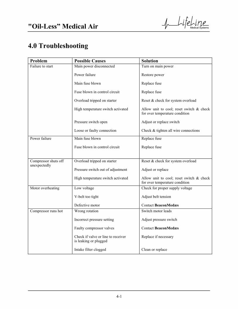
4.0 Troubleshooting Problem Possible Causes Solution Failure to start Main power disconnected
Power failure Main fuse blown Fuse blown in control circuit Overload tripped on starter High temperature switch activated Pressure switch open Loose or faulty connection
Turn on main power Restore power Replace fuse Replace fuse Reset & check for system overload Allow unit to cool; reset switch & check for over temperature condition Adjust or replace switch Check & tighten all wire connections
Power failure Main fuse blown Fuse blown in control circuit
Replace fuse Replace fuse
Compressor shuts off unexpectedly
Overload tripped on starter Pressure switch out of adjustment High temperature switch activated
Reset & check for system overload Adjust or replace Allow unit to cool; reset switch & check for over temperature condition
Motor overheating Low voltage V-belt too tight Defective motor
Check for proper supply voltage Adjust belt tension Contact BeaconMedæs
Compressor runs hot Wrong rotation Incorrect pressure setting Faulty compressor valves Check if valve or line to receiver is leaking or plugged Intake filter clogged
Switch motor leads Adjust pressure switch Contact BeaconMedæs Replace if necessary Clean or replace

"Oil-Less” Medical Air
Medical Systems
4-2
4.0 Troubleshooting
Problem Possible Cause Solution Wrong direction of rotation Motor wired incorrectly
Switch motor leads
Low discharge pressure System piping leaks Defective pressure gauge Pressure switch open No power to solenoid Belts slipping Intake filter clogged Gasket leaks; piston ring wear
Repair leaks Replace gauge Adjust or replace Check electrical connections Adjust tension Clean or replace Replace gaskets and rings
Compressor cycles too often System undersized Incorrect pressure setting Faulty pressure switch System piping leaks Check valve or line to receiver is leaking or plugged Both dryers on line Water in air receiver
Contact BeaconMedæs Adjust pressure switch Replace switch Repair leaks Replace if necessary Valve off one dryer Drain air receiver
Compressor won’t shut off Pressure switch out of adjustment or faulty
Adjust or replace
Excessive belt wear Belt tension Belt alignment
Adjust tension Realign compressor & motor sheaves
Abnormal noise Mounting bolts loose Belt tension Worn piston or rider ring; broken valve parts
Tighten bolts Adjust tension Replace
Note: For air dryer troubleshooting, see Appendix A.

"Oil-Less” Medical Air
Medical Systems
5-1
5.0 Maintenance 5.1 Maintenance Schedule
Release all pressure from the package before removing, loosening, or servicing any covers, guards, fittings, connections, or other devices. Never perform any maintenance functions while the unit is in operation.
Item Frequency Action Check condensate in tank Daily Open manual drain valve: check
auto drain Check operation of safety valve
Weekly
Manually release pressure
Check inlet air filter(s)
Weekly
Inspect and clean or replace
Check nuts, bolts, fittings, etc.
Monthly
Inspect and tighten
Crankcase filter(s)
Monthly
Inspect and clean or replace
Check belt tension
Monthly
Inspect and tighten or replace
Check compressor piston rings & rider rings Every 3,000 hours Inspect
Check compressor valve plates and valve parts 1 - 20 HP Every 12,000 hours Inspect and repair or replace
Piston rings and rider rings 1 - 7.5 HP 10 - 20 HP
Every 10,000 hours Every 8,000 hours
Replace
Ball and needle bearings 1 - 7.5 HP 10 - 20 HP
Every 10,000 hours Every 8,000 hours
Replace
Check flow through orifice of dew point sensor Every 6 months Check for flow blockage
Check dew point sensor accuracy Every 12 months Verify dew point sensor accuracy
(contact BeaconMedæs) Calibrate CO monitor Every 6 months See Appendix B
Replace pre-filters & afterfilters Yearly Replace filter elements
Replace Dryer Desiccant 5 years See Appendix A
WARNING: BEFORE STARTING ANY MAINTENANCE PROCEDURES, DISCONNECT ALL POWER
TO THE PACKAGE.

"Oil-Less” Medical Air
Medical Systems
5-2
5.0 Maintenance
Warning: Verify compressor series type prior to servicing or ordering replacement parts or kits. The
model number of the compressor is located on the back of the compressor crankcase. Compare the number to the chart below to determine compressor series type ("V" or "G").
HP V-Series Model No’s G-Series Model No’s
1 .75OU-8.5CH .75OU-9.5CGH 2 1.5OU-8.5CH 1.5OU-9.5CGH 3 2.2OU-8.5CH 2.2OU-9.5CGH 5 3.7OU-8.5CH 3.7OU-9.5CGH
7.5 5.5OU-8.5CH 5.5OU-9.5CGH 10 7.5OU-7CVH 7.5OU-8.5CG2H 15 11OU-7CVH 11OU-8.5CG2H 20 15OU-7CVH 15OU-7CVH
5.2.1 Replacement Filter Elements (Individual) (V-Series)
(For S/N 6718112 to 6801406 or 20,000 to 156300.) Duplex HP Type Inlet Qty. Crankcase Qty. Prefilter Qty. Afterfilter Qty. 1-5 Tankmount 1
Tankmount 7.5 Modular
SPC ELM 01 005 2 ELM 22 001 2 ELM 22 001 2 Tankmount 609658600 2
10 Modular SPC Tankmount
15 Modular ELM 22 002 2 ELM 22 002 2 SPC Tankmount ELM 01 006 2
20 Modular 609823000 4 ELM 22 003 2 ELM 22 003 2 SPC

"Oil-Less” Medical Air
Medical Systems
5-3
5.0 Maintenance
5.2.2 Replacement Filter Elements (Individual) (V-Series) (For S/N 6718112 to 6801406 or 20,000 to 156300.)
Triplex
Quadruplex HP Type Inlet Qty. Crankcase Qty. Prefilter Qty. Afterfilter Qty. 7.5 Modular
SPC ELM 01 005 4 ELM 22 003 2 ELM 22 003 2 10 Modular 609658600 4
SPC 15 Modular ELM 22 005 2 ELM 22 005 2
SPC ELM 01 006 4 20 Modular 609823000 8 ELM 22 006 2 ELM 22 006 2
SPC Complete sets of replacement filter element kits are available that include all required filter elements for a given system. See page 5-5.
HP Type Inlet Qty. Crankcase Qty. Prefilter Qty. Afterfilter Qty. 7.5 Modular ELM 22 002 2 ELM 22 002 2
SPC ELM 01 005 3 10 Modular 609658600 3
SPC ELM 22 003 2 ELM 22 003 2 15 Modular
SPC ELM 01 006 3 20 Modular 609823000 6 ELM 22 005 2 ELM 22 005 2
SPC

"Oil-Less” Medical Air
Medical Systems
5-4
5.0 Maintenance 5.2.3 Replacement Filter Elements (Individual) (G-Series) (For S/N Prior to 156300.) Duplex HP Type Inlet Qty. Crankcase Qty. Prefilter Qty. Afterfilter Qty. 1 Tankmount 609750901 2
2-5 Tankmount Tankmount
Modular 7.5 SPC
Tankmount Modular 10
SPC
ELM 01 005 2 ELM 22 001 2 ELM 22 001 2
Tankmount Modular 15
SPC
609752288 2
ELM 22 002 2 ELM 22 002 2
Tankmount Modular 20
SPC
ELM 01 006 2
609823000 4 ELM 22 003 2 ELM 22 003 2
Triplex
Quadruplex HP Type Inlet Qty. Crankcase Qty. Prefilter Qty. Afterfilter Qty.
Modular 7.5 SPC
Modular 10 SPC
ELM 01 005 4 ELM 22 003 2 ELM 22 003 2
Modular 15 SPC
609752288 4
ELM 22 005 2 ELM 22 005 2
Modular 20 SPC
ELM 01 006 4 609823000 8 ELM 22 006 2 ELM 22 006 2
Complete sets of replacement filter element kits are available that include all required filter elements for a given system. See page 5-6.
HP Type Inlet Qty. Crankcase Qty. Prefilter Qty. Afterfilter Qty. Modular 7.5
SPC ELM 22 002 2 ELM 22 002 2
Modular 10 SPC
ELM 01 005 3
Modular 15 SPC
609752288 3 ELM 22 003 2 ELM 22 003 2
Modular 20 SPC
ELM 01 006 3 609823000 6 ELM 22 005 2 ELM 22 005 2

"Oil-Less” Medical Air
Medical Systems
5-5
5.0 Maintenance 5.2.4 Replacement Filter Elements (Individual) (G-Series) (For S/N After 156300.) Duplex HP Type Inlet Qty. Crankcase Qty. Prefilter Qty. Afterfilter Qty. 1 Tankmount 609750901 2
2-5 Tankmount Tankmount
Modular 7.5 SPC
Tankmount Modular 10
SPC
ELM 01 005 2 2901 0524 00 2 2901 0524 00 2
Tankmount Modular 15
SPC
609752288 2
2901 0527 00 2 2901 0527 00 2
Tankmount Modular 20
SPC
ELM 01 006 2
609823000 4 2901 0530 00 2 2901 0530 00 2
Triplex
Quadruplex HP Type Inlet Qty. Crankcase Qty. Prefilter Qty. Afterfilter Qty.
Modular 7.5 SPC
2901 0530 00 2 2901 0530 00 2
Modular 10 SPC
ELM 01 005 4 2901 0533 00 2 2901 0533 00 2
Modular 15 SPC
609752288 4
2901 0536 00 2 2901 0536 00 2
Modular 20 SPC
ELM 01 006 4 609823000 8 2901 0536 00 2 2901 0536 00 2
Complete sets of replacement filter element kits are available that include all required filter elements for a given system. See page 5-7.
HP Type Inlet Qty. Crankcase Qty. Prefilter Qty. Afterfilter Qty. Modular 7.5
SPC 2901 0527 00 2 2901 0527 00 2
Modular 10 SPC
ELM 01 005 3 2901 0530 00 2 2901 0530 00 2
Modular 15 SPC
609752288 3
2901 0533 00 2 2901 0533 00 2
Modular 20 SPC
ELM 01 006 3 609823000 6 2901 0536 00 2 2901 0536 00 2

"Oil-Less” Medical Air
Medical Systems
5-6
5.0 Maintenance 5.2.5 Replacement Filter Elements (Complete Filter Kit) (V-Series)
(For S/N 6718112 to 6801406 or 20,000 to 156300.)
Kit Description HP Configuration Kit Part No. Kit Consists of: 1-5 KIT 22 001
7.5-10 KIT 22 002 15 KIT 22 003 20
Duplex
KIT 22 004 7.5 KIT 22 005 10 KIT 22 006 15 KIT 22 007 20
Triplex
KIT 22 008 7.5-10 KIT 22 009
15 KIT 22 010
Complete Set of System Filters
20
Quadruplex
KIT 22 011
Inlet filter(s) Crankcase filter(s) Prefilter(s) Afterfilter(s)
Complete sets of replacement filter element kits include required quantities of filter elements for a given system. 5.2.6 Replacement Filter Elements (Complete Filter Kit) (G-Series) (For S/N Prior to 156300-0.)
Kit Description HP Configuration Kit Part No. Kit Consists of: 1 KIT 22 001G-001
2-5 KIT 22 001G 7.5-10 KIT 22 002G
15 KIT 22 003G 20
Duplex
KIT 22 004 7.5 KIT 22 005G 10 KIT 22 006G 15 KIT 22 007G 20
Triplex
KIT 22 008 7.5-10 KIT 22 009G
15 KIT 22 010G
Complete Set of System Filters
20
Quadruplex
KIT 22 011
Inlet filter(s) Crankcase filter(s) Prefilter(s) Afterfilter(s)
Complete sets of replacement filter element kits include required quantities of filter elements for a given system.

"Oil-Less” Medical Air
Medical Systems
5-7
5.0 Maintenance 5.2.7 Replacement Filter Elements (Complete Filter Kit) (G-Series) (For S/N After 156300-0.)
Kit Description HP Configuration Kit Part No. Kit Consists of: 1 4107 7826 92
2-5 4107 7826 93 7.5-10 4107 7826 94
15 4107 7826 95 20
Duplex
4107 7826 96 7.5 4107 7826 97 10 4107 7826 98 15 4107 7826 99 20
Triplex
4107 7827 00 7.5 4107 7827 01 10 4107 7827 02 15 4107 7827 03
Complete Set of System Filters
20
Quadruplex
4107 7827 04
Inlet filter(s) Crankcase filter(s) Prefilter(s) Afterfilter(s)
Complete sets of replacement filter element kits include required quantities of filter elements for a given system.

"Oil-Less” Medical Air
Medical Systems
5-8
5.0 Maintenance 5.3 Maintenance Kits (V-Series) Kit Description HP Kit Part No. Kit Consists of:
1 KIT 03 001 2 KIT 03 002 3 KIT 03 003 5 KIT 03 004
7.5 KIT 03 005 10 KIT 03 020 15 KIT 03 021
Complete Overhaul
20 KIT 03 022
Crankshaft main bearings Connecting rod assembly Ring overhaul kit Bearing box gasket Valve kit(s)
1 KIT 03 012 2 KIT 03 013 3 KIT 03 014 5 KIT 03 015
7.5 KIT 03 016 10 KIT 03 017 15 KIT 03 018
Ring Overhaul
20 KIT 03 023
Rider rings(s) Piston ring(s)
1 KIT 04 001 2 KIT 04 002 3 KIT 04 003 5 KIT 04 004
7.5 KIT 04 005 10 KIT 04 008 15 KIT 04 009
Valve
20 KIT 04 010
Air valve assembly Air valve packing(s) Cylinder head packing(s) Unloader spring(s) Unloader o-ring(s) Unloader packing(s)
1 KIT 05 001 2 KIT 05 002 3 KIT 05 003 5 KIT 05 004
7.5 KIT 05 005 10 KIT 05 006 15 KIT 05 007
Gasket
20 KIT 05 008
Bearing box gasket Air valve packing(s) Cylinder head packing(s) Unloader packing(s)

"Oil-Less” Medical Air
Medical Systems
5-9
5.0 Maintenance 5.3 Maintenance Kits (G-Series) Kit Description HP Kit Part No. Kit Consists of:
1 KIT 03 001G 2 KIT 03 002G 3 KIT 03 003G 5 KIT 03 004G
7.5 KIT 03 005G 10 KIT 03 020G 15 KIT 03 021G
Complete Overhaul
20 KIT 03 022
Crankshaft main bearings Connecting rod assembly(s) Ring overhaul kit Bearing seal Valve kit(s)
1 KIT 03 012G 2 KIT 03 013G 3 KIT 03 014G 5 KIT 03 015G
7.5 KIT 03 016G 10 KIT 03 017G 15 KIT 03 018G
Ring Overhaul
20 KIT 03 023
Rider rings(s) Piston ring(s)
1 KIT 04 001G 2 KIT 04 002G 3 KIT 04 003G 5 KIT 04 004G
7.5 KIT 04 005G 10 KIT 04 008G 15 KIT 04 009G
Valve
20 KIT 04-010
Air valve assembly Air valve packing(s) Cylinder head packing(s) Unloader piston set
1 KIT 05 001G 2 KIT 05 002G 3 KIT 05 003G 5 KIT 05 004G
7.5 KIT 05 005G 10 KIT 05 006G 15 KIT 05 007G
Gasket
20 KIT 05 008
Bearing seal Air valve packing(s) Cylinder head packing(s)

"Oil-Less” Medical Air
Medical Systems
6-1
6.0 Inspection/Replacement Procedures 6.1 V-Belts Narrow type V-belts are used for this unit. Refer to Table 6-1 for the correct size. 6.1.1 Tension Check Table 6-1 Belt size and Tension (for new belts)
LifeLine Modular Units (V-Series) Center TENSIONING No. of
Hp Freq (Hz) Distance (IN.)
Belt Size Defl. Force Belts
7 1/2 50 18.91 5V900 0.29 7.5 1 60 17.94 5V850 0.27 7.7 1
10 50 17.55 5V900 0.27 8.9 1 60 19.34 5V900 0.30 9.0 1
15 50 20.26 5V1000 0.31 11.4 1 60 21.69 5V1000 0.33 11.5 1
20 50 19.69 5V950 0.30 9.1 2 60 21.27 5V950 0.32 9.2 2
LifeLine Tankmount & SPC Units (V-Series) Center TENSIONING No. of
Hp Freq (Hz) Distance (in.)
Belt Size Defl. Force Belts
1 50 12.53 A-56 0.19 1.8 1 60 12.81 A-54 0.20 1.9 1
2 50 11.92 B-60 0.18 3.1 1 60 11.46 B-58 0.18 3.2 1
3 50 16.67 B-71 0.26 4.1 1 60 16.47 B-69 0.25 4.1 1
5 50 18.34 3V900 0.28 3.8 1 60 18.15 3V850 0.27 4.1 1
7 ½* 50 26.99 5V1060 0.42 7.4 1 60 25.56 5V1000 0.39 7.5 1
10* 50 25.61 5V1060 0.40 8.8 1 60 24.42 5V1000 0.38 8.9 1
15* 50 26.30 5V1120 0.41 11.3 1 60 27.76 5V1120 0.43 11.4 1
20* 50 28.34 5V1120 0.44 8.9 2 60 26.93 5V1060 0.41 9.1 2
* Denotes units available as tankmount or SPC units

"Oil-Less” Medical Air
Medical Systems
6-2
Table 6-1 Belt size and Tension (for new belts)
LifeLine Modular Units (G-Series) Center TENSIONING No. of
Hp Freq (Hz) Distance (IN.)
Belt Size Defl. Force Belts
7.5 50 19.25 5V900 0.30 7.5 1 60 18.28 5V850 0.28 7.7 1
10 50 18.26 5V900 0.28 8.8 1 60 19.14 5VX880 0.39 8.5 1
15 50 21.36 5V950 0.32 11.3 1 60 20.44 5V900 0.31 11.6 1
20 50 19.70 5V950 0.30 9.0 2 60 21.21 5V950 0.32 9.1 2
LifeLine Tankmount & SPC Units (G-Series) Center TENSIONING No. of
Hp Freq (Hz) Distance (in.)
Belt Size Defl. Force Belts
1 50 12.84 A-54 0.20 1.9 1 60 13.45 A-53 0.20 1.9 1
2 50 13.74 B-58 0.21 3.2 1 60 13.18 B-55 0.20 3.2 1
3 50 18.57 B-65 0.29 4.5 1 60 18.39 B-63 0.28 4.6 1
5 50 17.02 3VX750 0.26 4.3 1 60 18.47 3VX750 0.28 4.4 1
7.5* 50 25.84 5VX1030 0.40 7.0 1 60 25.96 5V1000 0.40 7.5 1
10* 50 26.33 5VX1060 0.41 8.2 1 60 25.25 5V1000 0.38 8.9 1
15* 50 26.91 5VX1060 0.41 8.9 1 60 28.58 5VX1060 0.44 10.9 1
20* 50 28.34 5V1120 0.44 8.8 2 60 26.85 5VX1060 0.41 8.5 2
* Denotes units available as tankmount or SPC units

"Oil-Less” Medical Air
Medical Systems
6-3
6.0 Inspection/Replacement Procedures 6.1 V-Belts (continued) 6.1.1 Tension Check (continued)
Release all pressure from the package before removing, loosening, or servicing any covers, guards, fittings, connections, or other devices. Never perform any maintenance functions while the unit is in operation. Check the belt tension monthly. Disconnect the main power and remove the beltguard. As shown in Fig. 6-1 and 6-2, deflect each V-belt at the center of the drive span with a spring balance or tension meter at the tension force of Table 6-1. Then check that the average deflections at the proper tension force are approximately the same values as shown in Table 6-1.
Fig. 6-1 Tension Check (modular) Fig. 6-2 Tension Check (tank mount or SPC)
WARNING: BEFORE STARTING ANY MAINTENANCE PROCEDURES, DISCONNECT ALL POWER
TO THE PACKAGE.

"Oil-Less” Medical Air
Medical Systems
6-4
6.0 Inspection/Replacement Procedures 6.1 V-Belts (continued) 6.1.2 V-Belt Tension Adjustment If necessary, adjust the V-belts until the average deflections are within the values shown in Table 6-1. On the modular basemount units, the motor is mounted on a pivoting platform with two bolts for adjustment. On the tankmount and SPC units, the motor slides horizontally after loosening the mounting bolts. To tighten the V-belts on a modular basemount unit (Ref. Fig. 6-3):
1. Remove the beltguard screens. 2. Loosen the two locking bolts (A) securing the motor base. 3. Turn the two belt tensioning adjustment rods (B) on the motor base and rotate the motor downward
until the proper tension and alignment is obtained (see Fig. 6-1). To check for correct alignment, place a straight edge on the faces of the two sheaves. Proper alignment is obtained when all the gaps between the straight edge and the sheaves are minimized and less than 1/8”.
4. Check the belt tension again and make sure the tension is similar to the values listed in Table 6-1. 5. Replace the beltguard screens before operating the machine.
Fig. 6-3 Tension and Alignment Adjustment
CAUTION: IF THE COMPRESSOR IS OPERATED WITH LOOSE V-BELTS OR IMPROPER SHEAVE ALIGNMENT, THE LIFE OF THE V-BELTS IS SHORTENED. EXCESSIVE TENSION CAN BREAK THE SHAFT OR REDUCE BEARING LIFE. BE SURE TO MAINTAIN PROPER V-BELT TENSION AND ALIGNMENT.

"Oil-Less” Medical Air
Medical Systems
6-5
6.0 Inspection/Replacement Procedures 6.1 V-Belts (continued) 6.1.3 Changing the V-Belts V-belts should be changed every 8,000 hours under normal operating conditions. If any damage is found, they should be replaced at once. To change the v-belts call the nearest Lifeline distributor or follow the procedures described below: To change the belts on a modular basemount unit: Remove the old belts:
1. Remove the beltguard screens. 2. Loosen the two locking bolts (A) securing the motor base. 3. Turn the two belt tensioning adjustment rods (B) on the motor base and rotate the motor upward 4. Remove the old belt(s)
Check and Clean: 1. Check and clean all of the grooves of both the motor and compressor sheaves. 2. Check the tightness of bolts on the sheave bushings.
Installation of New Belts: 1. Confirm the belt type and length. 2. Place the belt(s) into the grooves of both sheaves. 5. Turn the two belt tensioning adjusting rods (B) on the motor base and rotate the motor downward
until the proper tension and alignment is obtained (see Figs. 6-3). To check for correct alignment, place a straight edge on the faces of the two sheaves. Proper alignment is obtained when all the gaps between the straight edge and the sheaves are minimized and less than 1/8”.
6. Check the belt tension again and make sure the tension is similar to the values listed in Table 6-1. 7. Replace the beltguard screens before operating the machine.

"Oil-Less” Medical Air
Medical Systems
6-6
6.0 Inspection/Replacement Procedures 6.2 Air Intake Filter
Release all pressure from the package before removing, loosening, or servicing any covers, guards, fittings, connections, or other devices. Never perform any maintenance functions while the unit is in operation. The air intake filter element should be changed every 4,000 hours of operation under normal operating conditions. To change the filter (Ref. Fig 6-4): 1. Turn off the compressor being serviced and lock open the appropriate disconnect switches. 2. Close intake isolation valve 3. Remove the protective cover by loosening the wing nut (if applicable) and latches. 4. Remove the element. 5. Clean inside of housing. 6. Insert a new element (note orientation of the element). 7. Replace protective cover and tighten wing nut (if applicable) and latches. 8. Open intake isolation valve 9. Turn on the compressor
Canister Housing
Element
Protective Cover
Fig. 6-4 Air Intake Filter
WARNING: BEFORE STARTING ANY MAINTENANCE PROCEDURES, DISCONNECT ALL POWER
TO THE PACKAGE.

"Oil-Less” Medical Air
Medical Systems
6-7
6.0 Inspection/Replacement Procedures 6.3 Readjustment of Cut-Out and Cut-In Pressure The cut-out pressure refers to the discharge air pressure at which the unit will stop and is indicated by the gauge near the electrical cabinet.
!!WARNING!! IT IS STRICTLY PROHIBITED TO READJUST DISCHARGE AIR PRESSURE TO
MORE THAN THE SPECIFIED MAXIMUM PRESSURE (105 PSIG); NEGLECTING IT MAY CAUSE HIGH DISCHARGE TEMPERATURE SHUTDOWN, MAIN
MOTOR OVERLOAD SHUTDOWN, OR SERIOUS COMPRESSOR BREAKDOWN. The cut-in pressure refers to the discharge air pressure at which the compressor will start and is dictated by the pressure and differential setting of the pressure switch. The standard factory pressure switch settings for the lead pressure switch (PS-1) is 100 psig for cut-out (open) pressure and 90 psig for cut-in (close) pressure.
CAUTION Generally, a narrower differential requires a larger volume of receiver, and vice versa. The recommended receiver volume in the instruction manual is based on the standard factory setting of 10 psig differential. If a narrower differential is desired, install a larger volume receiver; otherwise the cycle of start/stop may be shorter which could generate an undesirable effect on the unit.
Adjusting Instructions (See electrical diagram for factory pressure switch settings) FIRST - Adjust the range (screw “A”) to the required cut-out pressure setting. Turning the screw clockwise raises the cut-in and cut-out pressure settings equally. SECOND - Adjust the differential (screw “B”) to the required cut-in pressure setting. Turning the screw clockwise will raise the cut-in pressure setting only. Differential is the difference between cut-in and cut-out settings.
Fig. 6-5 Pressure Switch
"Oil-Less” Medical Air
Medical Systems
6-8
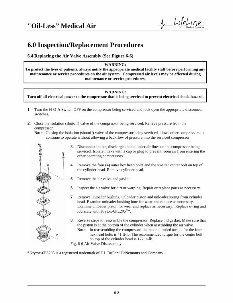
6.0 Inspection/Replacement Procedures 6.4 Replacing the Air Valve Assembly (See Figure 6-6)
1. Turn the H-O-A Switch OFF on the compressor being serviced and lock open the appropriate disconnect
switches. 2. Close the isolation (shutoff) valve of the compressor being serviced. Relieve pressure from the
compressor. Note: Closing the isolation (shutoff) valve of the compressor being serviced allows other compressors to
continue to operate without allowing a backflow of pressure into the serviced compressor. 3. Disconnect intake, discharge and unloader air lines on the compressor being
serviced. Isolate intake with a cap or plug to prevent room air from entering the other operating compressors.
4. Remove the four (4) outer hex head bolts and the smaller center bolt on top of
the cylinder head. Remove cylinder head. 5. Remove the air valve and gasket. 6. Inspect the air valve for dirt or warping. Repair or replace parts as necessary. 7. Remove unloader bushing, unloader piston and unloader spring from cylinder
head. Examine unloader bushing bore for wear and replace as necessary. Examine unloader piston for wear and replace as necessary. Replace o-ring and lubricate with Krytox-6PL205*.
8. Reverse steps to reassemble the compressor. Replace old gasket. Make sure that
the piston is at the bottom of the cylinder when assembling the air valve. Note: In reassembling the compressor, the recommended torque for the four
hex head bolts is 41 ft-lb. The recommended torque for the center bolt on top of the cylinder head is 177 in-lb.
Fig. 6-6 Air Valve Disassembly
*Krytox-6PS205 is a registered trademark of E.I. DuPont DeNemours and Company
WARNING: To protect the lives of patients, always notify the appropriate medical facility staff before performing any
maintenance or service procedures on the air system. Compressed air levels may be affected during maintenance or service procedures.
WARNING: Turn off all electrical power to the compressor that is being serviced to prevent electrical shock hazard.
"Oil-Less” Medical Air
Medical Systems
6-9
6.0 Inspection/Replacement Procedures 6.5 Checking/Replacing Piston Ring, Rider Ring and Gaskets
Piston and rider rings must be checked periodically (refer to Section 5.1 Preventive Maintenance Schedule) for wear and/or damage. The following procedure details how to check the piston and rider rings and replace them if necessary. 1. Lock out power and turn the H-O-A Switch OFF on the compressor being serviced. 2. Close the isolation (shutoff) valve of the compressor being serviced. Relieve pressure from the
compressor. Note: Closing the isolation (shutoff) valve of the compressor being serviced allows other compressors to continue to operate without allowing a backflow of pressure into the serviced compressor.
3. Disconnect intake, discharge and unloader air lines on the compressor being serviced. Isolate intake with a cap or plug to prevent room air from entering other operating compressors.
4. Remove the four (4) nuts that
secure the cylinder to the crankcase and lift the cylinder off, exposing the piston.
5. Remove piston and rider rings from the piston, taking care to note their position in order to ensure that if
they are to be reinstalled, they are reinstalled on the same piston and in the same position as they were originally.
WARNING: To protect the lives of patients, always notify the appropriate medical facility staff before performing any
maintenance or service procedures on the air system. Compressed air levels may be affected during maintenance or service procedures.
WARNING: Turn off all electrical power to the compressor that is being serviced to prevent electrical shock hazard.

"Oil-Less” Medical Air
Medical Systems
6-10
6.0 Inspection/Replacement Procedures 6.5 Checking/Replacing Piston Ring, Rider Ring and Gaskets (continued) 6. Measure the thickness of the piston and rider rings and compare it to the values shown in Table 6-3. 7. Divide the measured difference from the thickness when the rings are new by the hours in service since
the rings were last replaced (or since startup for new installations). This is the approximate wear rate. 8. Multiply the approximate wear rate by the average hours that are expected until the next maintenance
inspection. 9. Subtract that number from the measured ring dimension. If the resulting number is near or below the
minimum value found in Table 6-3, the rings should be replaced. Otherwise, if they are not damaged, they may be reinstalled (taking care that they are returned to their original position, on their original piston). Wrap rider rings so that the oval mark (0) is facing in against the piston.
10. If the rings are below tolerance, or otherwise damaged, they must be replaced with new ones. Install the
piston ring with its diagonally cut mating surfaces facing downward. Wrap the rider rings with inside oval marking (0) facing in against the piston.
11. Reverse above steps to reassemble the compressor. Replace air valve gasket with a new one. Note: When reassembling the compressor, the recommended torque for the four hex head bolts and the four
cylinder nuts is 41 ft-lb.
Table 6-3 Piston Ring and Rider Ring Dimensions
LifeLine Modular Units (G-Series)
Piston Rings Rider Rings
Model Hp
Radial Thickness (Inches)
New
Radial Thickness
(in.) Minimum
Radial Thickness
(in.) New
Radial Thickness
(in.) Minimum
1 .177 .142 .055 .047 2 .256 .193 .079 .063 3 .256 .193 .079 .063 5 .256 .193 .079 .063
7.5 .256 .193 .079 .063 10 .354 .291 .106 .079 15 .354 .291 .106 .079 20 .410 .330 .132 .097
LifeLine Modular Units (V-Series)
Piston Rings Rider Rings
Model Hp
Radial Thickness (Inches)
New
Radial Thickness
(in.) Minimum
Radial Thickness
(in.) New
Radial Thickness
(in.) Minimum
1 .177 .142 .055 .047 2 .256 .193 .079 .063 3 .256 .193 .079 .063 5 .295 .232 .094 .067
7.5 .295 .232 .094 .067 10 .354 .291 .106 .079 15 .354 .291 .106 .079 20 .410 .330 .132 .097

"Oil-Less” Medical Air
Medical Systems
6-11
6.0 Inspection/Replacement Procedures 6.6 Replacing the Piston Pin
1. Turn the H-O-A Switch OFF on the compressor being serviced. 2. Close the isolation (shutoff) valve of the compressor being serviced. Relieve pressure from the
compressor. Closing the isolation (shutoff) valve of the compressor being serviced allows other compressors to continue to operate without allowing a backflow of pressure into the serviced compressor.
3. Disconnect intake, discharge and unloader air lines on the compressor being serviced. Isolate intake with a
cap or plug to prevent room air from entering other operating compressors. 4. Remove the four (4) nuts that secure the cylinder to the crankcase and lift the cylinder off, exposing the
piston. 5. Remove the two (2) set screws on the underside of the piston with an allen wrench. 1. Slide the piston pin out
and replace with the new piston pin. Replace the air valve gasket. Use a wire brush to remove residual thread seal from the set screw threads. Apply permanent thread seal to threads and reassemble compressor.
2. When reassembling the
compressor, the recommended torque for the four hex head bolts and the four cylinder nuts is 41 ft-lb; the recommended torque for the piston set screws is 35 in-lb (1-3 HP) or 62 in-lb (5-15 HP).
WARNING: To protect the lives of patients, always notify the appropriate medical facility staff before performing any
maintenance or service procedures on the air system. Compressed air levels may be affected during maintenance or service procedures.
WARNING: Turn off all electrical power to the compressor that is being serviced to prevent electrical shock hazard.
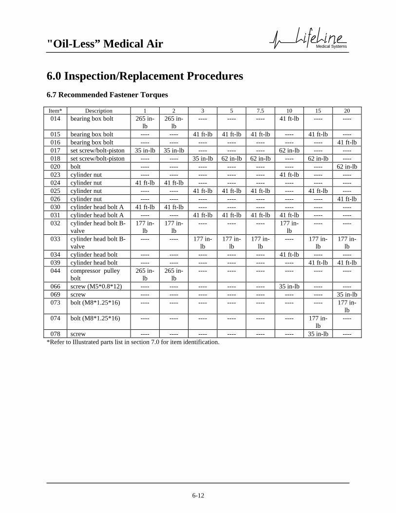
"Oil-Less” Medical Air
Medical Systems
6-12
6.0 Inspection/Replacement Procedures 6.7 Recommended Fastener Torques Item* Description 1 2 3 5 7.5 10 15 20 014 bearing box bolt 265 in-
lb 265 in-
lb ---- ---- ---- 41 ft-lb ---- ----
015 bearing box bolt ---- ---- 41 ft-lb 41 ft-lb 41 ft-lb ---- 41 ft-lb ---- 016 bearing box bolt ---- ---- ---- ---- ---- ---- ---- 41 ft-lb 017 set screw/bolt-piston 35 in-lb 35 in-lb ---- ---- ---- 62 in-lb ---- ---- 018 set screw/bolt-piston ---- ---- 35 in-lb 62 in-lb 62 in-lb ---- 62 in-lb ---- 020 bolt ---- ---- ---- ---- ---- ---- ---- 62 in-lb 023 cylinder nut ---- ---- ---- ---- ---- 41 ft-lb ---- ---- 024 cylinder nut 41 ft-lb 41 ft-lb ---- ---- ---- ---- ---- ---- 025 cylinder nut ---- ---- 41 ft-lb 41 ft-lb 41 ft-lb ---- 41 ft-lb ---- 026 cylinder nut ---- ---- ---- ---- ---- ---- ---- 41 ft-lb 030 cylinder head bolt A 41 ft-lb 41 ft-lb ---- ---- ---- ---- ---- ---- 031 cylinder head bolt A ---- ---- 41 ft-lb 41 ft-lb 41 ft-lb 41 ft-lb ---- ---- 032 cylinder head bolt B-
valve 177 in-
lb 177 in-
lb ---- ---- ---- 177 in-
lb ---- ----
033 cylinder head bolt B-valve
---- ---- 177 in-lb
177 in-lb
177 in-lb
---- 177 in-lb
177 in-lb
034 cylinder head bolt ---- ---- ---- ---- ---- 41 ft-lb ---- ---- 039 cylinder head bolt ---- ---- ---- ---- ---- ---- 41 ft-lb 41 ft-lb 044 compressor pulley
bolt 265 in-
lb 265 in-
lb ---- ---- ---- ---- ---- ----
066 screw (M5*0.8*12) ---- ---- ---- ---- ---- 35 in-lb ---- ---- 069 screw ---- ---- ---- ---- ---- ---- ---- 35 in-lb 073 bolt (M8*1.25*16) ---- ---- ---- ---- ---- ---- ---- 177 in-
lb 074 bolt (M8*1.25*16) ---- ---- ---- ---- ---- ---- 177 in-
lb ----
078 screw ---- ---- ---- ---- ---- ---- 35 in-lb ---- *Refer to Illustrated parts list in section 7.0 for item identification.

"Oil-Less” Medical Air
Medical Systems
7-1
7.0 Replacement Parts Any information, service or spare parts requests should include the machine serial number and be directed to: BeaconMedæs 1800 Overview Drive Rock Hill, SC 29730 Telephone: (888) 4-MEDGAS Fax: (803) 817-5750
Warning: Verify compressor series type prior to servicing or ordering replacement parts or kits. The
model number of the compressor is located on the back of the compressor crankcase. Compare the number to the chart below to determine compressor series type ("V" or "G").
HP V-Series Model No’s G-Series Model No’s
1 .75OU-8.5CH .75OU-9.5CGH 2 1.5OU-8.5CH 1.5OU-9.5CGH 3 2.2OU-8.5CH 2.2OU-9.5CGH 5 3.7OU-8.5CH 3.7OU-9.5CGH
7.5 5.5OU-8.5CH 5.5OU-9.5CGH 10 7.5OU-7CVH 7.5OU-8.5CG2H 15 11OU-7CVH 11OU-8.5CG2H 20 15OU-7CVH 15OU-7CVH

"Oil-Less” Medical Air
Medical Systems
7-2
7.0 Replacement Parts 7.1 Compressor 1hp (V-Series)

"Oil-Less” Medical Air
Medical Systems
7-3
7.0 Replacement Parts 7.1 Compressor 1hp (V-Series)
Ref. Part No. Description Qty/Unit Ref. Part No. Description Qty/Unit001 609714999 crankcase 1 150 609718000 suction filter assembly 1 003 609716000 crankshaft 1 151 NOT AVAIL suction filter body 1 004 609715000 connecting rod assembly 1 152 609658500 suction filter support 2 005 NOT AVAIL connecting rod 1 153 609669000 suction filter element 1 006 609691000 crank pin ball bearing 1 154 NOT AVAIL suction filter bracket 1 007 609692000 piston pin needle bearing 1 155 609658510 suction filter washer 1 008 609693000 oil seal 2 156 609658511 suction filter wing nut 1 009 NOT AVAIL snap ring 1 157 609658512 suction filter packing 1 010 609664000 crankshaft ball bearing 1 170 609658598 breathing filter assembly 1 011 609691000 crankshaft ball bearing 1 171 609658599 breathing filter body 1 012 609683000 bearing box packing 1 172 609658600 breathing filter element 1 013 609684000 bearing box 1 173 609658601 breathing filter cover 1 014 NOT AVAIL bearing box bolt 3 174 609658512 breathing filter packing 1 015 609696000 piston 1 016 609697000 piston pin 1 017 NOT AVAIL set screw 2 018 609717000 ring set 1 019 NOT AVAIL rider ring 1 020 NOT AVAIL piston ring 2 021 NOT AVAIL cylinder stud bolt 4 023 609695000 cylinder 1 024 NOT AVAIL cylinder nut 4 025 609698000 air valve packing 1 026 609720000 air valve assembly 1 027 609699000 cylinder head packing 1 028 NOT AVAIL cylinder head (P-type) 1 029 609700000 cylinder head (U-type) 1 030 609668000 cylinder head bolt A 4 031 609665000 cylinder head packing 1 032 NOT AVAIL cylinder head bolt 1 033 609685000 unloader spring 1 034 609686000 unloader piston 1 035 609687000 o-ring 1 036 609661000 unloader bush packing 1 037 609688000 unloader bush 1 038 271571000 unloader joint 1 040 609654000 compressor pulley key 1 041 609719000 compressor pulley 1 042 609659000 compressor pulley washer 1 043 NOT AVAIL pulley clamp ring washer 1 044 NOT AVAIL compressor pulley bolt 1

"Oil-Less” Medical Air
Medical Systems
7-4
7.0 Replacement Parts 7.2 Compressor 2hp (V-Series)

"Oil-Less” Medical Air
Medical Systems
7-5
7.0 Replacement Parts 7.2 Compressor 2hp (V-Series) Ref. Part No. Description Qty/Unit Ref. Part No. Description Qty/Unit001 609720500 crankcase 1 150 609718000 suction filter assembly 1 003 609722000 crankshaft 1 151 NOT AVAIL suction filter body 1 004 609721000 connecting rod assembly 1 152 609658500 suction filter support 2 005 NOT AVAIL connecting rod 1 153 609669000 suction filter element 1 006 609711000 crank pin ball bearing 1 154 NOT AVAIL suction filter bracket 1 007 609656000 piston pin needle bearing 1 155 609658510 suction filter washer 1 008 609704000 oil seal 2 156 609658511 suction filter wing nut 1 009 NOT AVAIL snap ring 1 157 609658512 suction filter packing 1 010 609664000 crankshaft ball bearing 1 170 609658598 breathing filter assembly 1 011 609691000 crankshaft ball bearing 1 171 609658599 breathing filter body 1 012 609683000 bearing box packing 1 172 609658600 breathing filter element 1 013 609684000 bearing box 1 173 609658601 breathing filter cover 1 014 NOT AVAIL bearing box bolt 3 174 609658512 breathing filter packing 1 015 609723000 piston 1 016 609724000 piston pin 1 017 NOT AVAIL set screw 2 018 609725000 ring set 1 019 NOT AVAIL rider ring 2 020 NOT AVAIL piston ring 2 021 NOT AVAIL cylinder stud bolt 4 023 609726000 cylinder 1 024 NOT AVAIL cylinder nut 4 025 609727000 air valve packing 1 026 609731000 air valve assembly 1 027 609730000 cylinder head packing 1 028 609707500 cylinder head (P-type) 1 029 609729000 cylinder head (U-type) 1 030 609668000 cylinder head bolt A 4 031 609665000 cylinder head packing 1 032 NOT AVAIL cylinder head bolt 1 033 609685000 unloader spring 1 034 609686000 unloader piston 1 035 609687000 o-ring 1 036 609661000 unloader bush packing 1 037 609688000 unloader bush 1 038 271571000 unloader joint 1 040 609654000 compressor pulley key 1 041 609728000 compressor pulley 1 042 609659000 compressor pulley washer 1 043 NOT AVAIL pulley clamp ring washer 1 044 NOT AVAIL compressor pulley bolt 1

"Oil-Less” Medical Air
Medical Systems
7-6
7.0 Replacement Parts 7.3 Compressor 3hp (V-Series)

"Oil-Less” Medical Air
Medical Systems
7-7
7.0 Replacement Parts 7.3 Compressor 3hp (V-Series)
Ref. Part No. Description Qty/Unit Ref. Part No. Description Qty/Unit001 609731500 crankcase 1 150 609718000 suction filter assembly 2 003 609733000 crankshaft 1 151 NOT AVAIL suction filter body 2 004 609721000 connecting rod assembly 2 152 609658500 suction filter support 4 005 NOT AVAIL connecting rod 2 153 609669000 suction filter element 2 006 609711000 crank pin ball bearing 2 154 NOT AVAIL suction filter bracket 2 007 609656000 piston pin needle bearing 2 155 609658510 suction filter washer 2 008 609704000 oil seal 4 156 609658511 suction filter wing nut 2 009 609732000 thrust ring 1 157 609658512 suction filter packing 2 010 NOT AVAIL snap ring 1 170 609658598 breathing filter assembly 1 011 609664000 crankshaft ball bearing 1 171 609658599 breathing filter body 1 012 609691000 crankshaft ball bearing 1 172 609658600 breathing filter element 1 013 609670000 bearing box packing 1 173 609658601 breathing filter cover 1 014 609680000 bearing box 1 174 609658512 breathing filter packing 1 015 NOT AVAIL bearing box bolt 5 016 609723000 piston 2 017 609724000 piston pin 2 018 NOT AVAIL set screw 4 019 609725000 ring set 2 020 NOT AVAIL rider ring 4 021 NOT AVAIL piston ring 4 023 NOT AVAIL cylinder stud bolt 8 024 609726000 cylinder 2 025 NOT AVAIL cylinder nut 8 026 609727000 air valve packing 2 027 609731000 air valve assembly 2 028 609730000 cylinder head packing 2 029 609707500 cylinder head (P-type) 2 030 609729000 cylinder head (U-type) 2 031 609668000 cylinder head bolt A 8 032 609665000 cylinder head packing 2 033 NOT AVAIL cylinder head bolt 2 034 609685000 unloader spring 2 035 609686000 unloader piston 2 036 609687000 o-ring 2 037 609661000 unloader bush packing 2 038 609688000 unloader bush 2 039 271571000 unloader joint A 1 040 271483000 unloader joint B 1 045 609654000 compressor pulley key 1 046 609734000 compressor pulley 1 047 609659000 compressor pulley washer 1 048 NOT AVAIL pulley spring washer 1 049 NOT AVAIL suction joint 2

"Oil-Less” Medical Air
Medical Systems
7-8
7.0 Replacement Parts 7.4 Compressor 5hp (V-Series)
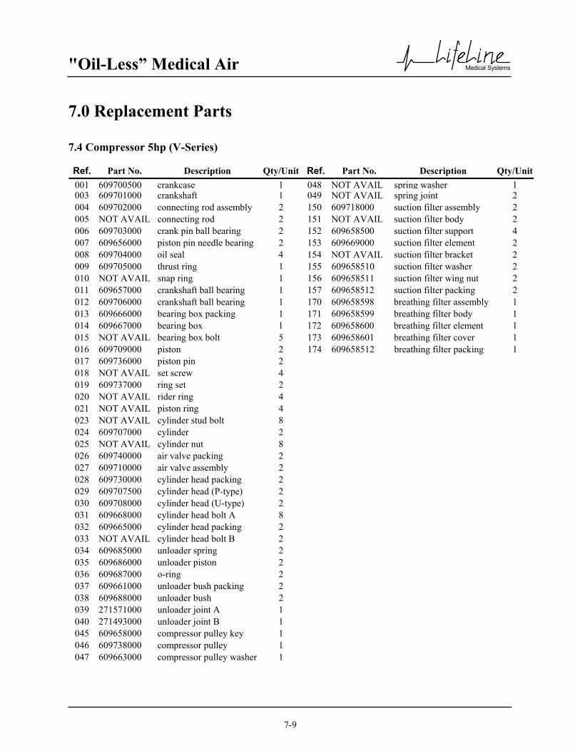
"Oil-Less” Medical Air
Medical Systems
7-9
7.0 Replacement Parts 7.4 Compressor 5hp (V-Series)
Ref. Part No. Description Qty/Unit Ref. Part No. Description Qty/Unit001 609700500 crankcase 1 048 NOT AVAIL spring washer 1 003 609701000 crankshaft 1 049 NOT AVAIL spring joint 2 004 609702000 connecting rod assembly 2 150 609718000 suction filter assembly 2 005 NOT AVAIL connecting rod 2 151 NOT AVAIL suction filter body 2 006 609703000 crank pin ball bearing 2 152 609658500 suction filter support 4 007 609656000 piston pin needle bearing 2 153 609669000 suction filter element 2 008 609704000 oil seal 4 154 NOT AVAIL suction filter bracket 2 009 609705000 thrust ring 1 155 609658510 suction filter washer 2 010 NOT AVAIL snap ring 1 156 609658511 suction filter wing nut 2 011 609657000 crankshaft ball bearing 1 157 609658512 suction filter packing 2 012 609706000 crankshaft ball bearing 1 170 609658598 breathing filter assembly 1 013 609666000 bearing box packing 1 171 609658599 breathing filter body 1 014 609667000 bearing box 1 172 609658600 breathing filter element 1 015 NOT AVAIL bearing box bolt 5 173 609658601 breathing filter cover 1 016 609709000 piston 2 174 609658512 breathing filter packing 1 017 609736000 piston pin 2 018 NOT AVAIL set screw 4 019 609737000 ring set 2 020 NOT AVAIL rider ring 4 021 NOT AVAIL piston ring 4 023 NOT AVAIL cylinder stud bolt 8 024 609707000 cylinder 2 025 NOT AVAIL cylinder nut 8 026 609740000 air valve packing 2 027 609710000 air valve assembly 2 028 609730000 cylinder head packing 2 029 609707500 cylinder head (P-type) 2 030 609708000 cylinder head (U-type) 2 031 609668000 cylinder head bolt A 8 032 609665000 cylinder head packing 2 033 NOT AVAIL cylinder head bolt B 2 034 609685000 unloader spring 2 035 609686000 unloader piston 2 036 609687000 o-ring 2 037 609661000 unloader bush packing 2 038 609688000 unloader bush 2 039 271571000 unloader joint A 1 040 271493000 unloader joint B 1 045 609658000 compressor pulley key 1 046 609738000 compressor pulley 1 047 609663000 compressor pulley washer 1

"Oil-Less” Medical Air
Medical Systems
7-10
7.0 Replacement Parts 7.5 Compressor 7.5hp (V-Series)

"Oil-Less” Medical Air
Medical Systems
7-11
7.0 Replacement Parts 7.5 Compressor 7.5hp (V-Series)
Ref. Part No. Description Qty/Unit Ref. Part No. Description Qty/Unit001 609740500 crankcase 1 055 NOT AVAIL pulley clamping washer 1 003 609741000 crankshaft 1 056 NOT AVAIL suction joint 2 004 609702000 connecting rod assembly 3 150 609718000 suction filter assembly 3 005 NOT AVAIL connecting rod 3 151 NOT AVAIL suction filter body 3 006 NOT AVAIL crank pin ball bearing 3 152 609658500 suction filter support 6 007 609656000 piston pin needle bearing 3 153 609669000 suction filter element 3 008 609704000 oil seal 6 154 NOT AVAIL suction filter bracket 3 009 609705000 thrust ring 2 155 609658510 suction filter washer 3 010 NOT AVAIL snap ring 1 156 609658511 suction filter wing nut 3 011 609711000 crankshaft ball bearing 1 157 609658512 suction filter packing 3 012 609711000 crankshaft ball bearing 1 170 609658598 breathing filter assembly 1 013 609712000 bearing box bearing 1 171 609658599 breathing filter body 1 014 609713000 bearing box 1 172 609658600 breathing filter element 1 015 NOT AVAIL bearing box bolt 5 173 609658601 breathing filter cover 1 016 609709000 piston 3 174 609658512 breathing filter packing 1 017 609736000 piston pin 3 018 NOT AVAIL set screw 6 019 609737000 ring set 3 020 NOT AVAIL rider ring 6 021 NOT AVAIL piston ring 6 022 NOT AVAIL cylinder stud bolt 12 024 609707000 cylinder 3 025 NOT AVAIL cylinder nut 16 026 609740000 air valve packing 3 027 609710000 air valve assembly 3 028 609730000 cylinder head packing 3 029 609707500 cylinder head (P-type) 3 030 609708000 cylinder head (U-type) 3 031 609668000 cylinder head bolt A 12 032 609665000 cylinder head packing 3 033 NOT AVAIL cylinder head bolt B 3 034 609685000 unloader spring 3 035 609686000 unloader piston 3 036 609687000 o-ring 3 037 609661000 unloader bush packing 3 038 609688000 unloader bush 3 039 271571000 unloader joint A 2 040 271493000 unloader joint B 2 052 609658000 compressor pulley key 1 053 609742000 compressor pulley 1 054 609662000 compressor pulley washer 1

"Oil-Less” Medical Air
Medical Systems
7-12
7.0 Replacement Parts 7.6 Compressor 10hp (V-Series)
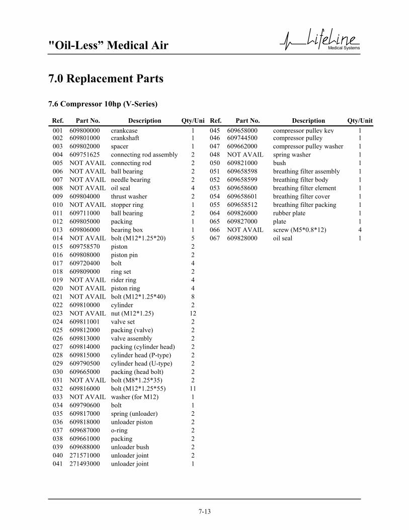
"Oil-Less” Medical Air
Medical Systems
7-13
7.0 Replacement Parts 7.6 Compressor 10hp (V-Series)
Ref. Part No. Description Qty/Uni Ref. Part No. Description Qty/Unit001 609800000 crankcase 1 045 609658000 compressor pulley key 1 002 609801000 crankshaft 1 046 609744500 compressor pulley 1 003 609802000 spacer 1 047 609662000 compressor pulley washer 1 004 609751625 connecting rod assembly 2 048 NOT AVAIL spring washer 1 005 NOT AVAIL connecting rod 2 050 609821000 bush 1 006 NOT AVAIL ball bearing 2 051 609658598 breathing filter assembly 1 007 NOT AVAIL needle bearing 2 052 609658599 breathing filter body 1 008 NOT AVAIL oil seal 4 053 609658600 breathing filter element 1 009 609804000 thrust washer 2 054 609658601 breathing filter cover 1 010 NOT AVAIL stopper ring 1 055 609658512 breathing filter packing 1 011 609711000 ball bearing 2 064 609826000 rubber plate 1 012 609805000 packing 1 065 609827000 plate 1 013 609806000 bearing box 1 066 NOT AVAIL screw (M5*0.8*12) 4 014 NOT AVAIL bolt (M12*1.25*20) 5 067 609828000 oil seal 1 015 609758570 piston 2 016 609808000 piston pin 2 017 609720400 bolt 4 018 609809000 ring set 2 019 NOT AVAIL rider ring 4 020 NOT AVAIL piston ring 4 021 NOT AVAIL bolt (M12*1.25*40) 8 022 609810000 cylinder 2 023 NOT AVAIL nut (M12*1.25) 12 024 609811001 valve set 2 025 609812000 packing (valve) 2 026 609813000 valve assembly 2 027 609814000 packing (cylinder head) 2 028 609815000 cylinder head (P-type) 2 029 609790500 cylinder head (U-type) 2 030 609665000 packing (head bolt) 2 031 NOT AVAIL bolt (M8*1.25*35) 2 032 609816000 bolt (M12*1.25*55) 11 033 NOT AVAIL washer (for M12) 1 034 609790600 bolt 1 035 609817000 spring (unloader) 2 036 609818000 unloader piston 2 037 609687000 o-ring 2 038 609661000 packing 2 039 609688000 unloader bush 2 040 271571000 unloader joint 2 041 271493000 unloader joint 1

"Oil-Less” Medical Air
Medical Systems
7-14
7.0 Replacement Parts 7.7 Compressor 15hp (V-Series)

"Oil-Less” Medical Air
Medical Systems
7-15
7.0 Replacement Parts 7.7 Compressor 15hp (V-Series) Ref. Part No. Description Qty/Uni Ref. Part No. Description Qty/Unit001 609888000 crankcase 1 052 609658000 compressor pulley key 1 002 609889000 crankshaft 1 053 609892500 compressed pulley 1 003 609802000 spacer 1 054 609662000 compressor pulley washer 5 004 609751625 connecting rod assembly 3 055 NOT AVAIL spring washer (M12) 1 005 NOT AVAIL connecting rod 3 064 609821000 bush 1 006 NOT AVAIL ball bearing 3 065 609658598 breathing filter assembly 1 007 NOT AVAIL needle bearing 3 066 609658599 breathing filter body 1 008 NOT AVAIL oil seal 6 067 609658600 breathing filter element 1 009 609804000 thrust washer 2 068 609658601 breathing filter cover 1 010 NOT AVAIL stopper washer 1 069 609658512 filter packing 1 011 609890000 ball bearing 1 070 609895000 oil seal 1 012 609655900 ball bearing 1 071 609894000 guide plate 1 013 609790000 packing 1 072 609896000 guide 1 014 609891000 bearing box 1 073 NOT AVAIL washer 2 015 NOT AVAIL bolt (bolt (M12*1.25*20) 7 074 NOT AVAIL bolt (M8*1.25*16) 2 016 609758571 piston (center) 1 075 609897000 rubber plug 1 017 609808000 piston pin 3 076 609826000 rubber plate 1 018 609720400 bolt 6 077 609827000 plate 1 019 609758570 piston (outboard) 2 078 NOT AVAIL screw 4 020 609809000 ring set 3 021 NOT AVAIL piston ring 6 022 NOT AVAIL rider ring 6 023 NOT AVAIL bolt (M12*1.25*40) 12 024 609810000 cylinder 3 025 NOT AVAIL nut (M12*1.25) 20 026 609811001 valve set 3 027 609812000 packing (valve) 3 028 609813000 valve assembly 3 029 609814000 packing (cylinder head) 3 030 609815000 cylinder head (P-type) 3 031 609790500 cylinder head (U-type) 3 032 609665000 packing (head bolt) 3 033 NOT AVAIL bolt (M8*1.25*35) 3 034 609817000 spring (unloader) 3 035 609818000 unloader piston 3 036 609687000 o-ring 3 037 609661000 unloader packing 3 038 609688000 unloader bush 3 039 609816000 bolt (M12*1.25*35) 18 040 271571000 unloader joint 2 041 271493000 unloader joint 2

"Oil-Less” Medical Air
Medical Systems
7-16
7.0 Replacement Parts 7.8 Compressor 20hp (V-Series)

"Oil-Less” Medical Air
Medical Systems
7-17
7.0 Replacement Parts 7.8 Compressor 20hp (V-Series) Ref. Part No. Description Qty/Unit Ref. Part No. Description Qty/Unit001 609757291 crankcase 1 054 609742004 compressor pulley key 1 002 609757292 crankshaft 1 055 609757325 compressor pulley 1 003 609802000 crank pin spacer 1 056 609662000 compressor pulley washer 1 004 609757293 connecting rod assembly 3 057 NOT AVAIL spring washer (M12) 1 005 NOT AVAIL connecting rod 3 058 NOT AVAIL street elbow (1B) 2 006 NOT AVAIL ball bearing 3 059 609757326 guide plate 2 007 NOT AVAIL needle bearing 3 060 609757327 guide plate 1 008 NOT AVAIL oil seal 6 067 609755426 rubber plug 1 009 609757295 ring (grease) 6 068 609755427 plate 1 010 609751006 washer (thrust) 2 069 NOT AVAIL screw 4 011 NOT AVAIL stopper ring (for Ø 55) 1 070 609757328 guide 1 012 609890000 crankshaft ball bearing 2 071 609757329 guide 1 013 609757296 bearing spacing 1 072 NOT AVAIL washer (for M8) 6 014 609790000 packing 1 073 NOT AVAIL bolt (M8*1.25*16) 6 015 609757297 bearing box 1 074 609757330 guide 1 016 NOT AVAIL bolt (M12 *1.25*20) 7 017 609755511 oil seal 1 018 609757298 piston 3 019 609757299 piston pin 3 020 609720400 bolt 6 021 609757300 ring set 3 022 NOT AVAIL piston ring 6 023 NOT AVAIL rider ring 6 024 NOT AVAIL bolt (M12*1.25*49) 12 025 609757304 cylinder 3 026 NOT AVAIL nut (M12*1.25) 12 027 609757305 valve set 3 028 609757306 packing valve 3 029 NOT AVAIL air valve 3 030 609757308 packing cylinder head 3 031 609757309 cylinder head 3 032 609748657 packing (head bolt) 3 033 NOT AVAIL bolt (M10*1.25*43) 3 034 609757311 spring unloader 3 035 609757312 unloader piston 3 036 609757313 o-ring 3 037 609757314 packing unloader bush 3 038 609757315 unloader bush 3 039 609757316 bolt (M12*1.25*55) 18 040 271571000 unloader joint 1 041 271493000 unloader joint 2

"Oil-Less” Medical Air
Medical Systems
7-18
7.0 Replacement Parts 7.9 Compressor 1hp (G-Series)
7.0 Replacement Parts 7.9 Compressor 1hp (G-Series)
Ref. Part No. Description Qty/Unit001 609752601 Crankcase 1 002 NOT AVAIL Bolt 4 003 609750901 Filter 1 004 609716000 Crank shaft 1 005 609715000 Connecting rod assembly 1 006 NOT AVAIL Stopper ring 1 007 609664000 Crank shaft ball bearing 1 008 609691000 Crank shaft ball bearing 1 009 609683000 Bearing box packing 1 010 609684000 Bearing box 1 011 NOT AVAIL Bolt 4 012 609752069 Piston 1 013 609697000 Piston pin 1 014 NOT AVAIL Bolt 2 015 609752070 Ring set 1 016 NOT AVAIL Rider ring 1 017 NOT AVAIL Piston ring 1 018 609752071 Cylinder 1 019 NOT AVAIL Nut 4 020 609752073 Air valve set 1 021 609750181 Air valve packing 1 022 NOT AVAIL Air valve 1 023 609754632 Cylinder head packing 1 024 609753607 Cylinder head 1 025 609816000 Cylinder head bolt 4 026 609665000 Packing 1 027 NOT AVAIL Bolt (M8 x 1.25 x 35) 1 029 609654000 Compressor pulley key 1 030 6910-9018-059 Compressor pulley 1 031 609659000 Compressor pulley washer 1 032 NOT AVAIL Spring washer 1 033 609750526 Unloader piston set 1 034 NOT AVAIL o-ring 1

"Oil-Less” Medical Air
Medical Systems
7-19
7.0 Replacement Parts 7.10 Compressor 2hp (G-Series)

"Oil-Less” Medical Air
Medical Systems
7-20
7.0 Replacement Parts
7.10 Compressor 2hp (G-Series) Ref. Part No. Description Qty/Unit001 609752081 Crankcase 1 002 NOT AVAIL Bolt 4 003 609755492 Rubber plug 1 004 609752082 Crank shaft 1 005 609752277 Connecting rod assembly 1 006 NOT AVAIL Stopper ring 1 007 609664000 Crank shaft ball bearing 1 008 609691000 Crank shaft ball bearing 1 009 609752278 Bearing box 1 010 609752283 Oil seal 1 011 NOT AVAIL Bolt 3 012 609752083 Piston 1 013 609724000 Piston pin 1 014 NOT AVAIL Bolt 2 015 609752280 Ring set 1 016 NOT AVAIL Rider ring 2 017 NOT AVAIL Piston ring 1 018 609752281 Cylinder 1 019 NOT AVAIL Nut 4 020 609752290 Air valve set 1 021 609751061 Air valve packing 1 022 NOT AVAIL Air valve 1 023 609751063 Cylinder head packing 1 025 609752262 Cylinder head (U-type) 1 026 609816000 Cylinder head bolt 4 027 609665000 Packing 1 028 NOT AVAIL Bolt (M8 x 1.25 x 35) 1 029 609750526 Unloader piston set 4 030 NOT AVAIL O-ring 1 033 609654000 Compressor pulley key 1 034 609752084 Compressor pulley 1 035 609659000 Compressor pulley washer 1 036 NOT AVAIL Spring washer 1 037 NOT AVAIL Bolt 1 190 609752287 Filter assembly 1 191 609752288 Filter element 1 192 NOT AVAIL Bolt 2 193 NOT AVAIL Lug nut 1 194 NOT AVAIL Washer 1

"Oil-Less” Medical Air
Medical Systems
7-21
7.0 Replacement Parts
7.11 Compressor 3hp (G-Series)

"Oil-Less” Medical Air
Medical Systems
7-22
7.0 Replacement Parts 7.11 Compressor 3hp (G-Series)
Ref. Part No. Description Qty/Unit001 609752180 Crankcase 1 002 NOT AVAIL Bolt 8 003 609755492 Rubber plug 2 004 609752181 Crank shaft 1 005 609752277 Connecting rod assembly 2 006 609732000 Thrust ring 1 007 NOT AVAIL Stopper ring 1 008 609664000 Crank shaft ball bearing 1 009 609691000 Crank shaft ball bearing 1 010 609752278 Bearing box 1 011 609752283 Oil seal 1 012 NOT AVAIL bolt 3 013 609752279 piston 2 014 609724000 Piston pin 2 015 NOT AVAIL bolt 4 016 609752280 Ring set 2 017 NOT AVAIL Rider ring 4 018 NOT AVAIL Piston ring 2 019 609752281 Cylinder 2 020 NOT AVAIL Nut 8 021 609752290 Air valve set 2 022 609751061 Air valve packing 2 023 NOT AVAIL Air valve 2 024 609751063 Cylinder head packing 2 026 609752262 Cylinder head 2 027 609816000 Cylinder head bolt 8 028 609665000 Packing 2 029 NOT AVAIL Bolt (M8 x 1.25 x 35) 2 030 609750526 Unloader piston set 2 031 NOT AVAIL O-ring 2 036 609654000 Compressor pulley key 1 037 609752183 Compressor pulley 1 038 609659000 Compressor pulley washer 1 039 NOT AVAIL Spring washer 1 040 NOT AVAIL Bolt 1 190 609752287 Filter assembly 1 191 609752288 Filter element 1 192 NOT AVAIL Bolt 2 193 NOT AVAIL Lug nut 1 194 NOT AVAIL washer 1

"Oil-Less” Medical Air
Medical Systems
7-23
7.0 Replacement Parts
7.12 Compressor 5hp (G-Series)

"Oil-Less” Medical Air
Medical Systems
7-24
7.0 Replacement Parts
7.12 Compressor 5hp (G-Series)
Ref. Part No. Description Qty/Unit001 609752222 Crank case 1 002 NOT AVAIL bolt 8 003 609755492 Rubber plug 2 004 609752223 Crank shaft 1 005 609702000 crank pin ball bearing 2 006 609705000 Thrust ring 1 007 NOT AVAIL Stopper ring 1 008 609751979 Crank shaft ball bearing 1 009 609706000 Crank shaft ball bearing 1 010 609752224 Bearing box 1 011 609828000 Oil seal 1 012 NOT AVAIL bolt 5 013 609752279 Piston 2 014 609724000 Piston pin 2 015 NOT AVAIL Bolt 4 016 609752280 Ring set 2 017 NOT AVAIL Rider ring 4 018 NOT AVAIL Piston ring 2 019 609752281 Cylinder 2 020 NOT AVAIL Nut 8 021 609752290 Air valve set 2 022 609751061 Air valve packing 2 023 NOT AVAIL Air valve 2 024 609751063 Cylinder head packing 2 026 609752262 Cylinder head 2 027 609816000 Cylinder head bolt 8 028 609665000 Packing 2 029 NOT AVAIL Bolt (M8 x 1.25 x 35) 2 030 609750526 Unloader piston set 2 031 NOT AVAIL O-ring 2 038 609742004 Compressor pulley key 1 039 609738000 Compressor pulley 1 040 609662000 Compressor pulley washer 1 041 NOT AVAIL Spring washer 1 190 609752287 Filter assembly 1 191 609752288 Filter element 1 192 NOT AVAIL Bolt 2 193 NOT AVAIL Lug nut 1 194 NOT AVAIL Washer 1

"Oil-Less” Medical Air
Medical Systems
7-25
7.0 Replacement Parts
7.13 Compressor 7.5hp (G-Series)

"Oil-Less” Medical Air
Medical Systems
7-26
7.0 Replacement Parts 7.13 Compressor 7.5hp (G-Series)
Ref. Part No. Description Qty/Unit001 609752246 Crank case 1 002 NOT AVAIL Bolt 12 003 609755492 Rubber plug 2 004 609752247 Crank shaft 1 005 609702000 Connecting rod assembly 3 006 609705000 Thrust ring 2 007 NOT AVAIL Stopper ring 1 008 609711000 Crank shaft ball bearing 2 009 609752248 Bearing box 1 010 609828000 Oil seal 1 011 NOT AVAIL Bolt 5 012 609752279 Piston 3 013 609724000 Piston pin 3 014 NOT AVAIL Bolt 6 015 609752280 Ring set 3 016 NOT AVAIL Rider ring 6 017 NOT AVAIL Piston ring 3 018 609752281 Cylinder 3 019 NOT AVAIL Nut 12 020 609752290 Air valve assembly 3 021 609751061 Air valve packing 3 022 NOT AVAIL Air valve 3 023 609751063 Cylinder head packing 3 024 609752262 Cylinder head 3 025 609816000 Cylinder head bolt 12 026 609665000 Packing 3 027 NOT AVAIL Bolt (M8 x 1.25 x 35) 3 028 609750526 Unloader piston set 3 029 NOT AVAIL O-ring 3 036 609742004 Compressor pulley key 1 037 609754629 Compressor pulley 1 038 609662000 Compressor pulley washer 1 039 NOT AVAIL Spring washer 1 190 609752287 Filter assembly 1 191 609752288 Filter element 1 192 NOT AVAIL Bolt 2 193 NOT AVAIL Lug nut 1 194 NOT AVAIL Washer 1

"Oil-Less” Medical Air
Medical Systems
7-27
7.0 Replacement Parts 7.14 Compressor 10hp (G-Series)

"Oil-Less” Medical Air
Medical Systems
7-28
7.0 Replacement Parts 7.14 Compressor 10hp (G-Series)
Ref. Part No. Description Qty/Unit001 609741130 Crank case 1 003 609755492 Rubber plug 2 004 609741132 Crank shaft 1 005 609741143 Connecting rod assembly 2 006 609751006 Thrust ring 1 009 609711000 Ball bearing 2 010 609806000 Bearing box 1 011 609828000 Oil seal 1 012 NOT AVAIL Bolt 5 013 609741381 Piston 2 014 609808000 Piston pin 2 015 609720400 Bolt 4 016 609741141 Ring set 2 017 NOT AVAIL Rider ring 4 018 NOT AVAIL Piston ring 2 019 609810000 Cylinder 2 020 NOT AVAIL Nut 8 021 609811001 Air valve set 2 022 609812000 Air valve packing 2 023 NOT AVAIL Air valve assembly 2 024 609814000 Cylinder head packing 2 026 609790500 Cylinder head 2 027 609816000 Cylinder head bolt 12 028 609665000 Packing 2 029 NOT AVAIL Bolt 2 030 609750526 Unloader piston set 2 031 609687000 O-ring 2 038 609742004 Compressor pulley key 1 039 609741135 Compressor pulley 1 040 609662000 Compressor pulley washer 1 041 NOT AVAIL Spring washer 1 043 NOT AVAIL Suction joint 2 190 609752287 Filter assembly 1 191 609752288 Filter element 1 192 NOT AVAIL Bolt 2 193 NOT AVAIL Nut 1 194 NOT AVAIL Washer 1

"Oil-Less” Medical Air
Medical Systems
7-29
7.0 Replacement Parts 7.15 Compressor 15hp (G-Series)

"Oil-Less” Medical Air
Medical Systems
7-30
7.0 Replacement Parts 7.15 Compressor 15hp (G-Series)
Ref. Part No. Description Qty/Unit001 609741131 Crank case 1 003 609755492 Rubber plug 2 004 609741133 Crank shaft 1 005 609741143 Connecting rod assembly 3 006 609751006 Thrust ring 2 008 609655900 Ball bearing 1 009 609890000 Ball bearing 1 010 609741134 Bearing box 1 011 609895000 Oil seal 1 012 NOT AVAIL Bolt 7 013 609741142 Piston 1 014 609808000 Piston pin 3 015 609720400 Bolt 6 016 609741141 Ring set 3 017 NOT AVAIL Rider ring 6 018 NOT AVAIL Piston ring 3 019 609810000 Cylinder 3 020 NOT AVAIL Nut 12 021 609811001 Air valve set 3 022 609812000 Air valve packing 3 023 NOT AVAIL Air valve assembly 3 024 609814000 Cylinder head packing 3 025 609741381 Piston 2 026 609790500 Cylinder head 3 027 609816000 Cylinder head bolt 18 028 609665000 Packing 3 029 NOT AVAIL Bolt 3 030 609750526 Unloader piston set 3 031 609687000 O-ring 3 038 609742004 Compressor pulley key 1 039 609741136 Compressor pulley 1 040 609662000 Compressor pulley washer 1 041 NOT AVAIL Spring washer 1 190 609752287 Filter assembly 1 191 609752288 Filter element 1 192 NOT AVAIL Bolt 2 193 NOT AVAIL Nut 1 194 NOT AVAIL Washer 1

"Oil-Less” Medical Air
Medical Systems
8-1
8.0 Specifications (V-Series & G-Series) Table 8-1 System Specifications for 1-20 HP Duplex with Mounted Tank Duplex with Mounted Tank HP Capacity1 Receiver HP Capacity1 Receiver
50 psig 100 psig (Gallons) 50 psig 100 psig (Gallons) 1 4.1 3.3 80 7½ 29.0 26.3 120 2 7.8 6.6 80 10 38.7 34.2 120 3 12.3 10.3 80 15 58.5 51.3 200 5 19.6 17.3 80 20 78.4 66.3 200
Table 8-2 System Specifications for 7.5-20 HP Base Mounted Modular and SPC Systems Base Mounted Systems
DUPLEX TRIPLEX QUADRUPLEX HP Capacity1 Receiver2 Capacity1 Receiver2 Capacity1 Receiver2
50 psig 100 psig (Gallons) 50 psig 100 psig (Gallons) 50 psig 100 psig (Gallons) 7½ 29.0 26.3 120 58.0 52.6 200 87.0 78.9 200 10 38.7 34.2 120 77.4 68.4 200 116.1 102.6 200 15 58.5 51.3 120 117.0 102.6 200 175.5 153.9 200 20 78.4 66.3 200 156.8 132.6 200 235.2 198.9 200
Notes: 1 All capacities are shown as NFPA system capacities (reserve compressor on standby) and are shown in Inlet Cubic Feet per Minute (ICFM). 2 All receivers are supplied separately with base mounted modular systems.
Warning: Verify compressor series type prior to servicing or ordering replacement parts or kits. The
model number of the compressor is located on the back of the compressor crankcase. Compare the number to the chart below to determine compressor series type ("V" or "G").
HP V-Series Model No’s G-Series Model No’s
1 .75OU-8.5CH .75OU-9.5CGH 2 1.5OU-8.5CH 1.5OU-9.5CGH 3 2.2OU-8.5CH 2.2OU-9.5CGH 5 3.7OU-8.5CH 3.7OU-9.5CGH
7.5 5.5OU-8.5CH 5.5OU-9.5CGH 10 7.5OU-7CVH 7.5OU-8.5CG2H 15 11OU-7CVH 11OU-8.5CG2H 20 15OU-7CVH 15OU-7CVH
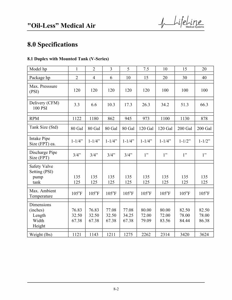
"Oil-Less” Medical Air
Medical Systems
8-2
8.0 Specifications 8.1 Duplex with Mounted Tank (V-Series) Model hp 1 2 3 5 7.5 10 15 20
Package hp 2 4 6 10 15 20 30 40
Max. Presssure (PSI) 120 120 120 120 120 100 100 100
Delivery (CFM) 100 PSI
3.3 6.6 10.3 17.3 26.3 34.2 51.3 66.3
RPM 1122 1180 862 945 973 1100 1130 878
Tank Size (Std) 80 Gal 80 Gal 80 Gal 80 Gal 120 Gal 120 Gal 200 Gal 200 Gal
Intake Pipe Size (FPT) ea. 1-1/4” 1-1/4” 1-1/4” 1-1/4” 1-1/4” 1-1/4” 1-1/2” 1-1/2”
Discharge Pipe Size (FPT) 3/4” 3/4” 3/4” 3/4” 1” 1” 1” 1”
Safety Valve Setting (PSI) pump tank
135 125
135 125
135 125
135 125
135 125
135 125
135 125
135 125
Max. Ambient Temperature 105oF 105oF 105oF 105oF 105oF 105oF 105oF 105oF
Dimensions (inches) Length Width Height
76.83 32.50 67.38
76.83 32.50 67.38
77.08 32.50 67.38
77.08 34.25 67.38
80.00 72.00 79.09
80.00 72.00 83.56
82.50 78.00 84.44
82.50 78.00 86.38
Weight (lbs) 1121 1143 1211 1275 2262 2314 3420 3624

"Oil-Less” Medical Air
Medical Systems
8-3
8.0 Specifications 8.1 Duplex with Mounted Tank (G-Series) Model hp 1 2 3 5 7.5 10 15 20
Package hp 2 4 6 10 15 20 30 40
Max. Presssure (PSI) 120 120 120 120 120 100 100 100
Delivery (CFM) 100 PSI
3.3 6.6 10.3 17.3 26.3 34.2 51.3 66.3
RPM 1063 889 670 894 917 1056 1012 888
Tank Size (Std) 80 Gal 80 Gal 80 Gal 80 Gal 120 Gal 120 Gal 200 Gal 200 Gal
Intake Pipe Size (FPT) ea. 1-1/4” 1-1/4” 1-1/4” 1-1/4” 1-1/4” 1-1/4” 1-1/2” 1-1/2”
Discharge Pipe Size (FPT) 3/4” 3/4” 3/4” 3/4” 3/4” 3/4” 1” 1”
Safety Valve Setting (PSI) pump tank
135 125
135 125
135 125
135 125
135 125
135 125
135 125
135 125
Max. Ambient Temperature 105oF 105oF 105oF 105oF 105oF 105oF 105oF 105oF
Dimensions (inches) Length Width Height
76.84 32.00 71.00
76.84 32.00 71.00
76.88 31.87 71.00
78.00 34.50 71.00
79.44 69.95 77.50
79.44 69.95 79.52
86.72 74.95 79.83
86.72 74.95 84.44
Weight (lbs) 1121 1143 1211 1275 2262 2314 3420 3624

"Oil-Less” Medical Air
Medical Systems
8-4
8.0 Specifications 8.2 Basemount Modular Unenclosed Compressor (V-Series) Model hp 7.5 10 15 20
Package hp 7.5 10 15 20
Max. Presssure (PSI) 120 100 100 100
Delivery (CFM) 100 PSI
26.3 34.2 51.3 66.3
RPM 973 1100 1130 878
Tank Size (min) 120 Gal 120 Gal 120 Gal 200 Gal
Intake Pipe Size (FPT) 1-1/4” 1-1/4” 1-1/2” 1-1/2”
Discharge Pipe Size (FPT) 3/4” 3/4” 1” 1”
Safety Valve Setting (PSI) pump 135 135 135 135
Max. Ambient Temperature 105oF 105oF 105oF 105oF
Dimensions (inches) Length Width Height
49.75 30.00 52.81
49.75 30.00 52.81
54.75 33.00 58.63
54.75 33.00 58.63
Weight (lbs) 891 905 1189 1296
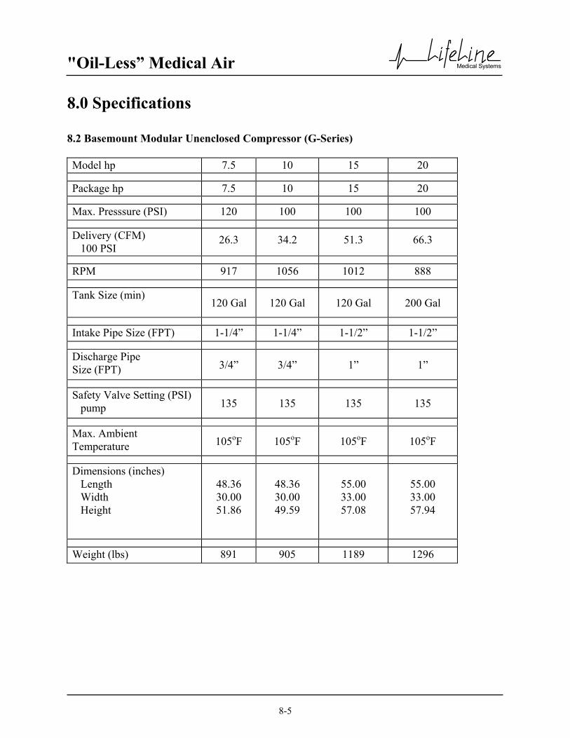
"Oil-Less” Medical Air
Medical Systems
8-5
8.0 Specifications 8.2 Basemount Modular Unenclosed Compressor (G-Series) Model hp 7.5 10 15 20
Package hp 7.5 10 15 20
Max. Presssure (PSI) 120 100 100 100
Delivery (CFM) 100 PSI
26.3 34.2 51.3 66.3
RPM 917 1056 1012 888
Tank Size (min) 120 Gal 120 Gal 120 Gal 200 Gal
Intake Pipe Size (FPT) 1-1/4” 1-1/4” 1-1/2” 1-1/2”
Discharge Pipe Size (FPT) 3/4” 3/4” 1” 1”
Safety Valve Setting (PSI) pump 135 135 135 135
Max. Ambient Temperature 105oF 105oF 105oF 105oF
Dimensions (inches) Length Width Height
48.36 30.00 51.86
48.36 30.00 49.59
55.00 33.00 57.08
55.00 33.00 57.94
Weight (lbs) 891 905 1189 1296

"Oil-Less” Medical Air
Medical Systems
8-6
8.0 Specifications 8.3 Basemount Modular Enclosed Compressor (V-Series) Model hp 7.5 10 15 20
Package hp 7.5 10 15 20
Max. Presssure (PSI) 120 100 100 100
Delivery (CFM) 100 PSI
26.3 34.2 51.3 66.3
RPM 973 1100 1130 878
Tank Size (min) 120 Gal 120 Gal 120 Gal 200 Gal
Intake Pipe Size(FPT) 1-1/4” 1-1/4” 1-1/2” 1-1/2”
Discharge Pipe Size (FPT) 3/4” 3/4” 1” 1”
Safety Valve Setting (PSI) pump
135 135 135 135
Max. Ambient Temperature 105oF 105oF 105oF 105oF
Dimensions (inches) Length Width Height
49.75 39.50 58.00
49.75 39.50 58.00
54.75 43.00 62.25
54.75 43.00 62.25
Weight (lbs) 1183 1206 1339 1446

"Oil-Less” Medical Air
Medical Systems
8-7
8.0 Specifications 8.3 Basemount Modular Enclosed Compressor (G-Series) Model hp 7.5 10 15 20
Package hp 7.5 10 15 20
Max. Presssure (PSI) 120 100 100 100
Delivery (CFM) 100 PSI
26.3 34.2 51.3 66.3
RPM 917 1056 1012 888
Tank Size (min) 120 Gal 120 Gal 120 Gal 200 Gal
Intake Pipe Size(FPT) 1-1/4” 1-1/4” 1-1/2” 1-1/2”
Discharge Pipe Size (FPT) 3/4” 3/4” 1” 1”
Safety Valve Setting (PSI) pump
135 135 135 135
Max. Ambient Temperature 105oF 105oF 105oF 105oF
Dimensions (inches) Length Width Height
49.75 39.50 58.00
49.75 39.50 58.00
54.75 43.00 62.25
54.75 43.00 62.25
Weight (lbs) 1183 1206 1339 1446

"Oil-Less” Medical Air
Medical Systems
8-8
8.0 Specifications 8.4 Basemount Duplex SPC (Single Point Connection) Compressor (V-Series) Model hp 7.5 10 15 20
Package hp 15 20 30 40
Max. Presssure (PSI) 120 100 100 100
Delivery (CFM) 100 PSI
26.3 34.2 51.3 66.3
RPM 973 1100 1130 878
Tank Size (min) 120 Gal 120 Gal 120 Gal 200 Gal
Intake Pipe Size(FPT) 2” 2” 2” 2”
Discharge Pipe Size (FPT)
3/4”
1”
1”
1”
Safety Valve Setting (PSI) pump
135
135
135
135
Max. Ambient Temperature 105oF 105oF 105oF 105oF
Dimensions (inches) Length Width Height
94.50 80.00 81.00
94.50 80.00 81.00
103.50 80.00 81.00
103.50 80.00 84.00
Weight (lbs) 2340 2420 3024 3474
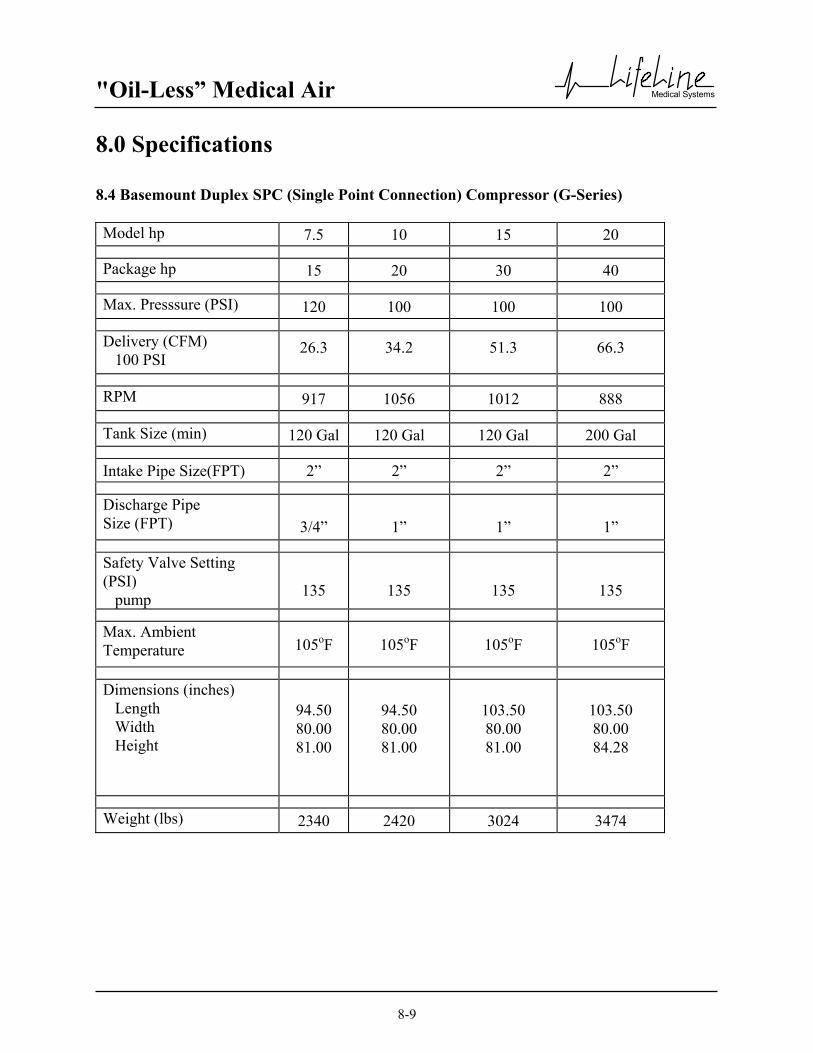
"Oil-Less” Medical Air
Medical Systems
8-9
8.0 Specifications 8.4 Basemount Duplex SPC (Single Point Connection) Compressor (G-Series) Model hp 7.5 10 15 20
Package hp 15 20 30 40
Max. Presssure (PSI) 120 100 100 100
Delivery (CFM) 100 PSI
26.3 34.2 51.3 66.3
RPM 917 1056 1012 888
Tank Size (min) 120 Gal 120 Gal 120 Gal 200 Gal
Intake Pipe Size(FPT) 2” 2” 2” 2”
Discharge Pipe Size (FPT)
3/4”
1”
1”
1”
Safety Valve Setting (PSI) pump
135
135
135
135
Max. Ambient Temperature 105oF 105oF 105oF 105oF
Dimensions (inches) Length Width Height
94.50 80.00 81.00
94.50 80.00 81.00
103.50 80.00 81.00
103.50 80.00 84.28
Weight (lbs) 2340 2420 3024 3474

"Oil-Less” Medical Air
Medical Systems
8-10
8.0 Specifications 8.5 Basemount Triplex SPC (Single Point Connection) Compressor (V-Series) Model hp 7.5 10 15 20
Package hp 22.5 30 45 60
Max. Presssure (PSI) 120 100 100 100
Delivery (CFM) 100 PSI
52.6 68.4 102.6 132.6
RPM 973 1100 1130 878
Tank Size (min) 200 Gal 200 Gal 200 Gal 200 Gal
Intake Pipe Size(FPT) 2” 2” 3” 3”
Discharge Pipe Size (FPT) 1” 1” 1.25” 1.25”
Safety Valve Setting (PSI) pump 135 135 135 135
Max. Ambient Temperature 105oF 105oF 105oF 105oF
Dimensions (inches) Length Width Height
124.50 80.00 84.00
124.50 80.00 84.00
138.00 80.00 84.00
138.00 84.00 84.00
Weight (lbs) 3267 3413 4348 4703

"Oil-Less” Medical Air
Medical Systems
8-11
8.0 Specifications 8.5 Basemount Triplex SPC (Single Point Connection) Compressor (G-Series) Model hp 7.5 10 15 20
Package hp 22.5 30 45 60
Max. Presssure (PSI) 120 100 100 100
Delivery (CFM) 100 PSI
52.6 68.4 102.6 132.6
RPM 917 1056 1012 888
Tank Size (min) 200 Gal 200 Gal 200 Gal 200 Gal
Intake Pipe Size(FPT) 2” 2” 3” 3”
Discharge Pipe Size (FPT) 1” 1” 1.25” 1.25”
Safety Valve Setting (PSI) pump 135 135 135 135
Max. Ambient Temperature 105oF 105oF 105oF 105oF
Dimensions (inches) Length Width Height
124.50 80.00 84.28
124.50 80.00 84.28
138.00 80.00 84.28
138.00 84.00 84.28
Weight (lbs) 3267 3413 4348 4703

"Oil-Less” Medical Air
Medical Systems
8-12
8.0 Specifications 8.6 Basemount Quadruplex SPC (Single Point Connection) Compressor (V-Series) Model hp 7.5 10 15 20
Package hp 30 40 60 80
Max. Presssure (PSI) 120 100 100 100
Delivery (CFM) 100 PSI
78.9 102.6 153.9 198.9
RPM 973 1100 1130 878
Tank Size (min) 200 Gal 200 Gal 200 Gal 200 Gal
Intake Pipe Size (FPT) 2” 2” 3” 3”
Discharge Pipe Size (FPT) 1” 1” 1.25” 1.50”
Safety Valve Setting (PSI) pump
135 135 135 135
Max. Ambient Temperature 105oF 105oF 105oF 105oF
Dimensions (inches) Length Width Height
154.50 80.00 84.00
154.50 80.00 84.00
172.50 84.00 84.00
172.50 84.00 84.00
Weight (lbs) 3976 4165 5458 5853

"Oil-Less” Medical Air
Medical Systems
8-13
8.0 Specifications 8.6 Basemount Quadruplex SPC (Single Point Connection) Compressor (G-Series) Model hp 7.5 10 15 20
Package hp 30 40 60 80
Max. Presssure (PSI) 120 100 100 100
Delivery (CFM) 100 PSI
78.9 102.6 153.9 198.9
RPM 917 1056 1012 878
Tank Size (min) 200 Gal 200 Gal 200 Gal 200 Gal
Intake Pipe Size (FPT) 2” 2” 3” 3”
Discharge Pipe Size (FPT) 1” 1” 1.25” 1.50”
Safety Valve Setting (PSI) pump
135 135 135 135
Max. Ambient Temperature 105oF 105oF 105oF 105oF
Dimensions (inches) Length Width Height
154.50 80.00 84.28
154.50 80.00 84.28
172.50 84.00 84.28
172.50 84.00 84.28
Weight (lbs) 3976 4165 5458 5853

"Oil-Less” Medical Air
Medical Systems
9-1
9.0 Maintenance Record Model Number
Serial Number
Installation Date
Date of Service
Hours
Load
Ambient Temp.
Inlet Filter
Crankcase Filter
Belt Tension
Piston
Rings
Valve Plate
Ball Bearings
Connecting Rods
Misc.
Serviced By

"Oil-Less” Medical Air
Medical Systems
9-2
9.0 Maintenance Record Model Number
Serial Number
Installation Date
Date of Service
Hours
Load
Ambient Temp.
Inlet Filter
Crankcase Filter
Belt Tension
Piston
Rings
Valve Plate
Ball Bearings
Connecting Rods
Misc.
Serviced By

"Oil-Less” Medical Air
Medical Systems
A-1
Appendix A - Desiccant Dryer A.1 General Information CAUTION: This manual is designed to serve as the operation and maintenance guide for your dryer. The contents of this manual should be read carefully BEFORE attempting any phase of operation or maintenance. Failure to follow the operating and maintenance procedures of the instruction manual could result in personal injury or property damage. All information, specifications and illustrations within this manual are those in effect at the time of printing. The manufacturer reserves the right to change or make improvements without notice and without incurring any obligation to make changes or add improvements to products previously sold. When requesting information, service, ordering of spare parts, etc., please reference all information supplied on the serial number plate located inside the dryer control panel or on the side of the dryer enclosure. To facilitate maintenance, recommended spare parts for your specific dryer model are available. Failure to maintain recommended spare parts and filter cartridges might result in expensive and unnecessary downtime for which the manufacturer cannot be responsible. To request a quotation of, or place an order for, recommended or emergency spare parts, please contact your local distributor. A.1.1 Drying Cycles This fully automatic, heatless type dryer alternately cycles the compressed, process gas flow through two desiccant charged towers where the entrained, vaporous moisture content of the gas is adsorbed. One desiccant tower is always on-line in a drying cycle throughout normal dryer operation. The opposite, off-line tower is in a regeneration cycle for removal of the previously adsorbed moisture content or in a purge saving cycle at line pressure. A.1.1.1 Continuous Purge When the dryer selector switch is in the “continuous purge” position, the dryer will shift towers every 30 seconds. At normal operating conditions, one tower is at 100 p.s.i and the other tower is at 0 p.s.i. Any condition other than this is not normal and will cause a high dew point condition. During tower changeover, the online chamber will exhaust, and the chamber that is regenerating (purging) will come to line pressure. There is no re-pressurization cycle. If the selector switch is on the continuous purge cycle, the dryer will use 15% of the NFPA system capacity to purge the dryer. A.1.1.2 Controlled Purge When the dryer selector switch is in the “controlled purge” position, the dew point monitor controls the dryer purge, and purging depends on the dew point condition. When the dew point reading is above the setpoint of -10ºC (14ºF), the dryer will function normally (one tower at 100 p.s.i, one tower at 0 p.s.i.). When the dew point is below the setpoint of -10ºC (14ºF) on the dew point monitor, the purge valve will close. In this condition both towers will be approximately 100 p.s.i. and the dryer will continue to shift towers but the off line chamber will remain at 100 p.s.i. until the dew point is above -10ºC (14ºF).

"Oil-Less” Medical Air
Medical Systems
A-2
Appendix A - Desiccant Dryer A.1 General Information (continued) A.1.2 Pre-filter As the first line of defense against water contaminants, a coalescing pre-filter with an automatic drain is installed. The LifeLine coalescing pre-filter removes water aerosols from the gas stream before the gas enters the dryer. Liquids collected by the assembly's filter cartridge(s) fall to the housing sump and are drained by a float drain. A.1.3 Automatic Drain Valves As previously stated, the accumulated water collected by a pre-filter must be periodically drained from the pre-filter housing sump. An automatic drain valve is a recommended and reliable means of removing collected moisture from coalescing pre-filter housings and other components requiring periodic draining.

"Oil-Less” Medical Air
Medical Systems
A-3
Appendix A - Desiccant Dryer A.2 Operation A.2.1. Initial Start-Up 1. Switch on the electrical supply to the dryer. 2. CLOSE the dryer isolation valves. 3. Check that the compressed air supply is on. Let the system come up to pressure 4. Slowly OPEN the dryer inlet isolation valve. 5. Rotate the dryer selector switch to the “continuous purge” position. The dryer will now begin to cycle. 6. Check that purge air is flowing from the purge muffler. 7. Slowly OPEN the dryer outlet isolation valve. 8. Open the dew point and CO sensor (if supplied) isolation valves. 9. Check for airflow at the dew point sensor orifice. 10. Adjust CO regulator (if supplied) to obtain a flow rate of .5-.9 SCFM. 11. Operate the dryer for five to ten minutes with the source isolation valve closed. 12. During the conditioning run (see 11 above) test all joints to locate any leaks using leak detector spray or a
suitable alternative. Tighten or repair any leaks and retest.
NOTE: Any small leaks on the dryer outlet side will cause a deterioration of the dew point. 13. Rotate the dryer selector switch to the “controlled purge” position. Verify proper operation as described in
A.1.1.2. 14. On the completion of the conditioning run, slowly open the source isolation valve. The dryer will now be fully
operational. A.2.2 Procedure to Switch Off the Dryer 1. Put second dryer on line by repeating steps 4 thru 7 above. 2. CLOSE the dryer outlet isolation valve. 3. SWITCH OFF the electrical supply to the dryer. 4. CLOSE the dryer inlet isolation valve. Dryer should de-pressurize
WARNING: Wait at least 2 minutes for pressure in the dryer to decay before performing any service to the dryer.

"Oil-Less” Medical Air
Medical Systems
A-4
Appendix A - Desiccant Dryer A.2 Operation (continued) A.2.3 Normal Start-up This procedure is to be followed when the dryer has been shut down for a short period during which time the desiccant has not been exposed to wet gas. 1. Start up the compressor if shut down. 2. Set the appropriate dryer selector switch to controlled purge. 3. Slowly OPEN the dryer inlet isolation valve. 4. Slowly OPEN the dryer outlet isolation valve. 5. Check operation of the dryer. A.2.4 Maintenance Shut Down 1. CLOSE the dryer outlet isolation valve. 2. CLOSE the dryer inlet isolation valve. 3. Allow the dryer to continue to cycle until the purge exhaust fully depressurizes both chambers. 4. Switch off electrical power to the dryer by removing the fuse.
WARNING: Display prominent notices indicating that maintenance is being carried out.
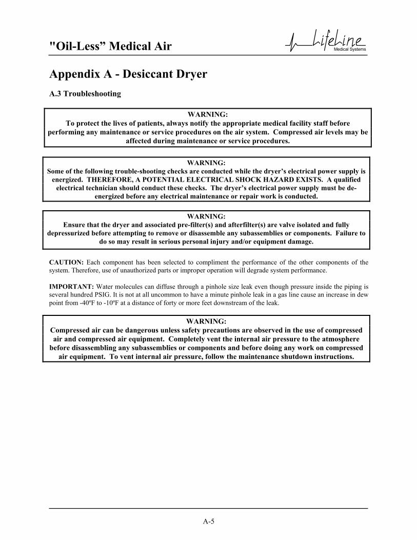
"Oil-Less” Medical Air
Medical Systems
A-5
Appendix A - Desiccant Dryer A.3 Troubleshooting
CAUTION: Each component has been selected to compliment the performance of the other components of the system. Therefore, use of unauthorized parts or improper operation will degrade system performance. IMPORTANT: Water molecules can diffuse through a pinhole size leak even though pressure inside the piping is several hundred PSIG. It is not at all uncommon to have a minute pinhole leak in a gas line cause an increase in dew point from -40ºF to -10ºF at a distance of forty or more feet downstream of the leak.
WARNING: To protect the lives of patients, always notify the appropriate medical facility staff before
performing any maintenance or service procedures on the air system. Compressed air levels may be affected during maintenance or service procedures.
WARNING: Some of the following trouble-shooting checks are conducted while the dryer’s electrical power supply is
energized. THEREFORE, A POTENTIAL ELECTRICAL SHOCK HAZARD EXISTS. A qualified electrical technician should conduct these checks. The dryer’s electrical power supply must be de-
energized before any electrical maintenance or repair work is conducted.
WARNING: Ensure that the dryer and associated pre-filter(s) and afterfilter(s) are valve isolated and fully
depressurized before attempting to remove or disassemble any subassemblies or components. Failure to do so may result in serious personal injury and/or equipment damage.
WARNING: Compressed air can be dangerous unless safety precautions are observed in the use of compressed air and compressed air equipment. Completely vent the internal air pressure to the atmosphere
before disassembling any subassemblies or components and before doing any work on compressed air equipment. To vent internal air pressure, follow the maintenance shutdown instructions.

"Oil-Less” Medical Air
Medical Systems
A-6
Appendix A - Desiccant Dryer A.3 Troubleshooting Problem Possible Causes Solution Dryer not cycling Main power disconnected
Power failure Main fuse blown Fuse blown in control circuit Timer failure Dryer selector switch in off position Loose or faulty connection Switching valve failure
Turn on main power Restore power Replace fuse Replace fuse Check and replace if defective Rotate switch to controlled purge position Check & tighten all wire connections Replace switching valve
Dew point degradation
Incorrect purge air flow Excessive system flow rate Inlet air temperature is above the dryer’s design inlet working temperature. Liquids entering the dryer inlet Purge muffler restricted
Check purge orifice for blockage. Clean or replace as required. Reduce inlet flow rate and/or increase operating pressure. Check the compressor aftercooler and cooling system. Adjust as necessary to bring the dryer inlet temperature to less than the maximum design working temperature of 43°C (110°F). Isolate and depressurize the pre-filter assembly. Inspect pre-filter cartridges and end seals for loosening and/or damage. Tighten or replace as necessary. Inspect the pre-filter automatic drain valve. Ensure that it is not clogged, and is draining properly. Repair or replace as necessary, if a problem is noted. Replace muffler

"Oil-Less” Medical Air
Medical Systems
A-7
Appendix A - Desiccant Dryer A.3 Troubleshooting (continued) Problem Possible Causes Solution Dew point degradation
Desiccant is contaminated. The “white” desiccant beads may appear discolored and dirty if contamination has occurred. Union or other piping/component leaks at dryer outlet manifold or downstream of dryer outlet
Shutdown and depressurize the dryer. Inspect the desiccant and replace if fouled. Inspect any existing pre-filter if fouling is noted. Soap test the dryer outlet manifold and piping downstream of dryer. Repair all leaks noted.
Back pressure on a desiccant chamber during the regeneration cycle.
Dirty or fouled purge muffler Outlet check valve leaking
Switch off power and remove purge muffler and clean using an air nozzle, or replace. Replace check valve
NOTE: The presence of backpressure will result in insufficient regeneration followed by dew point degradation. An off-line chamber’s pressure MUST be less than 3 psig throughout all regeneration cycles.

"Oil-Less” Medical Air
Medical Systems
A-8
Appendix A - Desiccant Dryer A.4 Maintenance
A compressed air dryer should give long and trouble free operation if the recommended preventative maintenance program is carried out. The following is a recommended schedule: 1. Quarterly procedure - Clean the auto drain in the coalescing filter. Monitor the backpressure on the purging
tower. If the gauge reads more than 0 psig (when purging), check the purge muffler for blockage and replace if necessary.
2. Annual procedure - Replace all filter cartridges and purge muffler(s). Check the automatic drain function in
the coalescing filter. Refer to chart located in Section A.4.1 for correct system size and part numbers. Contact your local distributor for parts.
3. Five-year procedure - Change all annual parts. Change desiccant, check valves, and purge valve(s) See chart
in Section A.4.1 for correct system size and part numbers.
WARNING: To protect the lives of patients, always notify the appropriate medical facility staff before performing any
maintenance or service procedures on the air system. Compressed air levels may be affected during maintenance or service procedures.
WARNING: Compressed air can be dangerous unless safety precautions are observed in the use of compressed air and compressed air equipment. Completely vent the internal air pressure to the atmosphere before
disassembling any subassemblies or components and before doing any work on compressed air equipment. To vent internal air pressure, follow the maintenance shutdown instructions.

"Oil-Less” Medical Air
Medical Systems
A-9
Appendix A - Desiccant Dryer A.4 Maintenance A.4.1 Maintenance Schedule
1-5 hp Duplex (Type 1 Dryer) 10-25 cfm
Service Interval Part number Description Quantity Every year ELM 22 001 Pre-filter 2 Every year ELM 22 001 After-filter 2 Every year MUF 01 006 Purge muffler 2
Every 5 years DES 02 001 Desiccant Kit 2 Every 5 years ORG 01 007 Poppet o-ring 4 Every 5 years GKT 10 005 Tower gasket 4 Every 5 years GKT 10 004 Canister gasket 4 Every 5 years GKT 10 003 Manifold o-ring 4 Every 5 years GKT 10 002 Orifice plate gasket 4
As needed VAL 11 001 Switching valve 2 As needed GAG 01 032 Tower pressure gauge 2
Purge valve (Refer to diagram for correct valve) Every 5 years VAL 04 018 Diaphragm 2 Every 5 years VAL 04 029 Poppet 2

"Oil-Less” Medical Air
Medical Systems
A-10
Appendix A - Desiccant Dryer A.4.1 Maintenance Schedule
7-1/2 hp Duplex, 10 hp Duplex (Type 2 Dryer) 35 cfm Service Interval Part number Description Quantity
Every year ELM 22 001 Pre-filter 2 Every year ELM 22 001 After-filter 2 Every year MUF 01 006 Purge muffler 2
Every 5 years DES 01 001 Desiccant 4 bags Every 5 years VAL 01 014 Check valve 4 Every 5 years ORG 01 009 Tower o-ring 4 Every 5 years ORG 01 010 Canister o-ring 4
As needed VAL 11 001 Switching valve 2 As needed GAG 01 032 Tower pressure gauge 2
Purge valve (Refer to diagram for correct valve) Every 5 years VAL 04 018 Diaphragm 2 Every 5 years VAL 04 029 Poppet 2

"Oil-Less” Medical Air
Medical Systems
A-11
Appendix A - Desiccant Dryer
A.4.1 Maintenance Schedule
15 hp Duplex, 7-1/2 hp Triplex (Type 2 Dryer) 55 cfm Service Interval Part number Description Quantity
Every year ELM 22 002 Pre-filter 2 Every year ELM 22 002 After-filter 2 Every year MUF 01 006 Purge muffler 2
Every 5 years DES 01 001 Desiccant 4 bags Every 5 years VAL 01 014 Check valve 4 Every 5 years ORG 01 009 Tower o-ring 4 Every 5 years ORG 01 010 Canister o-ring 4
As needed VAL 11 001 Switching valve 2 As needed GAG 01 032 Tower pressure gauge 2
Purge valve (Refer to diagram for correct valve) Every 5 years VAL 04 018 Diaphragm 2 Every 5 years VAL 04 029 Poppet 2
20 hp Duplex, 10 hp Triplex, 7-1/2 hp Quad (Type 2 Dryer) 75 cfm
Service Interval Part number Description Quantity Every year ELM 22 003 Pre-filter 2 Every year ELM 22 003 After-filter 2 Every year MUF 01 007 Purge muffler 2
Every 5 years DES 01 001 Desiccant 4 bags Every 5 years VAL 01 014 Check valve 4 Every 5 years ORG 01 009 Tower o-ring 4 Every 5 years ORG 01 010 Canister o-ring 4
As needed VAL 11 002 Switching valve 2 As needed GAG 01 032 Tower pressure gauge 2
Purge valve (Refer to diagram for correct valve) Every 5 years VAL 04 018 Diaphragm 2 Every 5 years VAL 04 030 Poppet 2
15 hp Triplex, 10 hp Quad (Type 2 Dryer) 105 cfm
Service Interval Part number Description Quantity Every year ELM 22 003 Pre-filter 2 Every year ELM 22 003 After-filter 2 Every year MUF 01 007 Purge muffler 2
Every 5 years DES 01 001 Desiccant 6 bags Every 5 years VAL 01 014 Check valve 4 Every 5 years ORG 01 009 Tower o-ring 4 Every 5 years ORG 01 010 Canister o-ring 4
As needed VAL 11 002 Switching valve 2 As needed GAG 01 032 Tower pressure gauge 2
Purge valve (Refer to diagram for correct valve) Every 5 years VAL 04 018 Diaphragm 2 Every 5 years VAL 04 030 Poppet 2
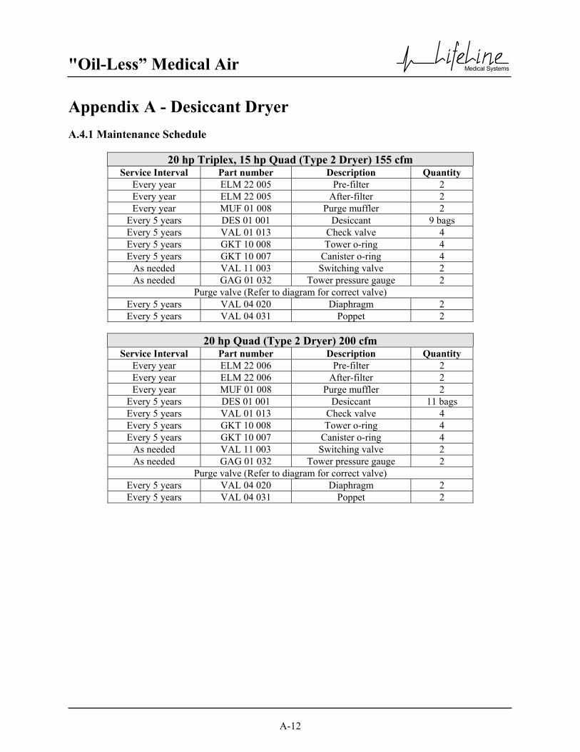
"Oil-Less” Medical Air
Medical Systems
A-12
Appendix A - Desiccant Dryer A.4.1 Maintenance Schedule
20 hp Triplex, 15 hp Quad (Type 2 Dryer) 155 cfm Service Interval Part number Description Quantity
Every year ELM 22 005 Pre-filter 2 Every year ELM 22 005 After-filter 2 Every year MUF 01 008 Purge muffler 2
Every 5 years DES 01 001 Desiccant 9 bags Every 5 years VAL 01 013 Check valve 4 Every 5 years GKT 10 008 Tower o-ring 4 Every 5 years GKT 10 007 Canister o-ring 4
As needed VAL 11 003 Switching valve 2 As needed GAG 01 032 Tower pressure gauge 2
Purge valve (Refer to diagram for correct valve) Every 5 years VAL 04 020 Diaphragm 2 Every 5 years VAL 04 031 Poppet 2
20 hp Quad (Type 2 Dryer) 200 cfm
Service Interval Part number Description Quantity Every year ELM 22 006 Pre-filter 2 Every year ELM 22 006 After-filter 2 Every year MUF 01 008 Purge muffler 2
Every 5 years DES 01 001 Desiccant 11 bags Every 5 years VAL 01 013 Check valve 4 Every 5 years GKT 10 008 Tower o-ring 4 Every 5 years GKT 10 007 Canister o-ring 4
As needed VAL 11 003 Switching valve 2 As needed GAG 01 032 Tower pressure gauge 2
Purge valve (Refer to diagram for correct valve) Every 5 years VAL 04 020 Diaphragm 2 Every 5 years VAL 04 031 Poppet 2

"Oil-Less” Medical Air
Medical Systems
A-13
Appendix A - Desiccant Dryer A.5 Replace/Repair A.5.1 Desiccant Replacement Procedure (1 - 5 hp) (Type 1 Dryer)
1. Shut down dryer. Close inlet and outlet isolation valves and turn off electrical power to the dryer. 2. Remove hex nuts, washers and cast tower assembly from manifold assembly. 3. Remove spring and perforated screen from top of canister 4. Unscrew desiccant canisters from manifold. 5. Dispose of used desiccant into suitable containers. 6. Replace desiccant and canister o-rings.
NOTE: DO NOT REMOVE DESICCANT FROM NYLON BAGS. Insert bag of desiccant into canister. 7. Replace tower O-rings. Set cast tower assembly onto manifold assembly. 8. Install plain washers and hex nuts. Tighten nuts in an X-pattern until towers are snug against the manifold.
Torque to 15 ft-lbs.
WARNING: Ensure that the dryer and associated pre-filter(s) and afterfilter(s) are valve isolated and fully depressurized before attempting to remove or disassemble any subassemblies or components.
Failure to do so may result in serious personal injury and/or equipment damage.
WARNING: Used desiccant material must be handled with special care. Desiccant is an adsorbent material. Used
desiccant may contain chemicals and/or gases that are hazardous, toxic and/or flammable. It is recommended that all used desiccants be analyzed to determine content before disposal. Exercise
proper care and procedures during handling and storage of used materials. All containers must be properly labeled and disposed of in accordance with local, state and federal regulations.

"Oil-Less” Medical Air
Medical Systems
A-14
Appendix A - Desiccant Dryer A.5 Replace/Repair (continued) A.5.2 Desiccant Replacement Procedure (7.5 - 20 hp) (Type 2 Dryer)
1. Shut down dryer – close the inlet and outlet isolation valves and turn off electrical power to the dryer. 2. Remove hex nuts, washers and towers from manifold assembly. 3. Remove spring and perforated screen from top of canister. 4. Remove canister from manifold assembly, being careful not to spill any desiccant. 5. Dispose of used desiccant into suitable containers. 6. Remove any blockage that may have lodged in the perforated screens. 7. Replace canister O-rings. Set canister onto manifold assembly. 8. Install the perforated screen into the bottom of the canister. 9. Fill canisters with desiccant to one inch (1”) from the top of canister. Install perforated screen. CAUTION: DO NOT OVERFILL. 10. Set spring retainer on top of perforated screen. Install tower over the canister. Install plain washers and hex
nuts. Tighten nuts in an X-pattern until chambers are snug against the manifold. Torque to 35 ft-lbs.
WARNING: Ensure that the dryer and associated pre-filter(s) and afterfilter(s) are valve isolated and fully depressurized before attempting to remove or disassemble any subassemblies or components.
Failure to do so may result in serious personal injury and/or equipment damage.
WARNING: Used desiccant material must be handled with special care. Desiccant is an adsorbent material. Used
desiccant may contain chemicals and/or gases that are hazardous, toxic and/or flammable. It is recommended that all used desiccants be analyzed to determine content before disposal. Exercise proper care and procedures during handling and storage of used materials. All containers must be
properly labeled and disposed of in accordance with local, state and federal regulations.

"Oil-Less” Medical Air
Medical Systems
A-15
Appendix A - Desiccant Dryer A.6 Dryer Specifications Type: Desiccant Heatless Design pressure: 105 PSIG Operating pressure: 60 PSIG minimum, 125 PSIG maximum Maximum inlet air temperature: 43ºC (110ºF) Ambient temperature: 4.4ºC (40ºF) minimum, 40.5ºC (105ºF) maximum Pressure dew point capability @100 PSIG: -12ºC (10ºF) Normal DP operating range: -8ºC (17.6ºF) to -12ºC (10ºF) Differential Pressure @ 100 PSIG and 37.8ºC (100ºF): 2 to 8 PSIG Desiccant: Activated alumina Control: Fully automatic solid-state electric fixed cycle (1 minute) Power: 120 volt 50/60 Hz 1 ph power (100 Watts)
"Oil-Less” Medical Air
Medical Systems
B-1
Appendix B - CO Monitor B.1 Introduction
B.2 Specifications B.2.1 Monitor The instrument's electronics are enclosed in a NEMA-4A polycarbonate case. The case is corrosion resistant, positively pressurized by the compressor supply line, and sealed except for a bleed hole to exhaust the compressor's air. The unit operates on 110 VAC power supplied from the system control panel. Alarm contact terminals are in the system control panel. Refer to the control panel wiring diagram. Adjustment controls are not necessary since they are automatically performed by the microprocessor. The unit has two internal push buttons to set alarm levels and other set-up functions. B.2.2 Sensor The instrument uses a state-of-the-art electrochemical cell for detecting carbon monoxide. The sensor has a life expectancy of approximately two years. It is easily replaced and should be periodically calibrated as its output diminishes during its life especially during the final months. B.2.3 Display The readout is a one line eight character backlighted LCD display located on the front panel. The display shows the level of gas in PPM (parts per million) and flashes when in red alarm. It also displays prompt messages during calibration or warnings such as low flow.
WARNING:
Before starting any installation, maintenance or service procedures, disconnect ALL power to the system to prevent electrical shock hazard .
Before making or breaking any medical gas line connections, make sure the system is
depressurized in order to avoid personal injury.
An alarm condition on the CO monitor display indicates a CO level exceeding the maximum set point, or a faulty CO sensor. Immediate action should be taken to reduce
the possibility of CO in the Medical Air line.

"Oil-Less” Medical Air
Medical Systems
B-2
Appendix B - CO Monitor B.2 Specifications (continued) B.2.4 Annunciator Lights at Monitor Display Red Alarm Indicates a level of gas above the red alarm point. Yellow Caution One of the following conditions: 1. Indicates a gas reading above the caution alarm point. 2. Indicates a low flow. 3. Indicates that the instrument is in the calibration mode or not calibrated and requires attention. Green Safe operational condition

"Oil-Less” Medical Air
Medical Systems
B-3
Appendix B - CO Monitor B.3 Operation When power is turned on at the system control panel, the display will show introductory messages and a warm-up countdown. If the unit does not power up, check the electrical connections. If the start up does not occur, call the factory. After the warm-up countdown, the instrument will display the gas level. The air regulator may be adjusted at any time to set the flow level from 0.5 to 0.9 CFH (14 to 25 lph). If the low flow indication shows on the display, increase the flow; and then drop the flow to operational range to activate the low flow switch. Caution: If the unit is reading a gas level, do not make any adjustments for a few hours until the unit has settled in. If calibration is attempted within the first fifteen minutes a TOO SOON message will occur on the display. If gas readings remain high or below zero (-0), re-calibration may be needed. We also recommend checking the compressor's air intake. If not outside quality air, this may be the cause for high readings since inside air normally contains a few parts of carbon monoxide. B.3.1 Alarms
Red Relay If switched on, Red Relay activates when Red Alarm light is illuminated - Gas level above 10 ppm. Yellow Relay If switched on, Yellow Relay activates: 1. Gas level above 8 ppm. 2. In low flow after a two minute delay (delay required during calibration to avoid activating Yellow
Relay). During calibration the alarm relays are deactivated to eliminate any external alarms and remain shut off for one minute after calibration to clear test gas from the sensor. The alarm circuits are reactivated when the yellow light is off and the green light appears or after two minutes in low flow. Audible Horn and Light To avoid false alarms caused by communications equipment a time delay of 20 seconds has been included in the alarm circuit. A red alarm light may be present for a short time on the monitor display but will not trigger the system alarm light or horn until the alarm is present for 20 seconds. Pushing the "Horn Silence" button on the front of the control panel may silence the audible horn.
WARNING: Respond to alarm conditions immediately. An alarm condition on the CO display indicates a CO
level exceeding the maximum set point. Immediate action should be taken to reduce the possibility of high CO in the Medical Air line.

"Oil-Less” Medical Air
Medical Systems
B-4
Appendix B - CO Monitor B.4 Maintenance B.4.1 Repair Policy Do not use a unit which is not functioning properly until all necessary repairs have been made and the unit has been tested to determine that it is functioning in accordance with the manufacturer's published specifications. Contact BeaconMedæs at 1-800-756-2590 for service assistance. Note: To ensure full reliability, have all maintenance and testing done by a qualified technician. If this cannot be done, maintenance and testing of those parts discussed in this manual may be undertaken by a competent, trained individual having experience in the repair of devices of this nature.
CAUTION: No maintenance and testing should ever be undertaken or attempted by anyone not having general experience in the repair of devices of this nature. Also, to avoid damaging the unit or any of its components, no maintenance and testing should be undertaken by qualified individuals who are not completely familiar with the procedures in this manual. Replace damaged parts with components from BeaconMedæs. Test the unit after installation of replacement parts to make certain that it complies with the published specifications.
B.4.2 Maintenance Schedule
Maintenance Frequency Action Re-calibration
Every 6 months See section B.4.3
Replace Sensor
Every 2 years See section B.4.4
WARNING: Electrical Shock Hazard. No repair should ever be attempted by anyone not having experience in the
repair of devices of this nature. Failure to follow proper repair procedures can result in serious injury.

"Oil-Less” Medical Air
Medical Systems
B-5
Appendix B - CO Monitor B.4 Maintenance (continued) B.4.3 Calibration Although the unit was calibrated at the factory, it may require re-calibration due to handling. The only way to assure a gas sensor is properly operating is to place gas on it. To calibrate the unit with gas, shut off the air from the compressor supply line with the regulator and a low flow message will appear with the supply line shut off. Connect the tank of test gas to the cal port connector on the instrument. Open the gas valve until the meter displays "CAL GAS" and a 60-second count down begins. Set the flow in the operating range of 0.5 to 0.9 CFH (14 to 25 lph). If the compressor air supply line was not shut off, a message will appear SUPPLY OFF. If such a message occurs, shut off the supply air; and then reinitiate the cal process to activate the cal port switch. After 60 seconds a gas reading will appear along with a COUNT NUMBER. With 20 PPM test gas applied the gas reading should be 20 and the count 70. At 70 counts with 20 PPM CO the unit will automatically set. The count number is used for trouble shooting (see trouble shooting section). After the unit auto-calibrates, a message will appear CO G SET indicating that the CO gain adjustment has been set for 20 PPM. Next an informational message on the automatic control pot value is displayed which also can be used for trouble shooting after the G (gain) SET message. If an incorrect gas concentration is used or the sensor and instrument is not properly functioning, a message will appear CO G FAILED, PREV CAL, END CAL. This affords improper calibration protection and an effort should be made to understand why it did not calibrate (See trouble shooting section for assistance). After proper calibration the next messages will be REMOVE CAL GAS, END CAL, SUPPLY ON. This prompts the calibrator to remove test gas and turn the supply on at the regulator. In cases where zero gas calibration is needed, the unit can be automatically zeroed by inserting a small diameter wire in the zero cal opening near the cal port and pushing on a button switch. The hole is made inconveniently small so that an unbent paper clip may activate the switch but larger wire or devices will not. It also doubles as the supply line outlet of the compressor. There are two conditions where pushing the zero button will activate zeroing: 1. Holding the button for three seconds while air is coming from the supply line. In this case the zero button
needs to be depressed until the zeroing message stops flashing and a solid zeroing message appears. The auto-zero process will begin without a countdown as it is assumed that air has been flowing from the supply line for more than a few minutes. If the supply line has more than one or two PPM of carbon monoxide, messages will appear BAD 0 AIR, PREV CAL, END CAL. The instrument is informing the user that it will not calibrate because of bad zero air; and it will use its previously zeroed cal setting. If the supply air is about 0 PPM concentration, the messages displayed will be CO 0 SET, END CAL which indicates that a new zero setting has been accepted and is now in use.
2. A second method for zeroing is to place zero test gas in the cal port similarly as described above with calibration gas, and the unit will initiate its calibration gas routine. However, the unit expects that 20
"Oil-Less” Medical Air
Medical Systems
B-6
Appendix B - CO Monitor B.4 Maintenance (continued) B.4.3 Calibration (continued) PPM CO or another cal gas concentration that was inserted in the setup mode is being applied in the cal
port unless the zero button is pushed. Check to see that the message now says zero gas instead of cal gas as the 60-second countdown proceeds. Any time during the countdown the zero may be pushed to have the unit know that zero gas is being applied. If the button is not pushed, a bad air message will appear resulting in returning to the previous calibration. This is the error protection.
After the zero button is depressed, a ZEROING message appears and then RELEASE UNLESS ZERO INT message. Holding the zero button for 15 seconds will reinitialize a unit, which is used when replacing a sensor or as discussed in the trouble shooting section. B.4.4 Sensor Checkout and Changing To check a sensor's response, test gas has to be placed on the sensor. When it fails to show a gas response during calibration, a new sensor is required. Most sensors will last from one and one-half years to two and one-half years. To replace the sensor, disconnect the power to the unit and remove the four corner screws and the electronics front cover as described in the mounting section. Next remove the three screws which hold the sensor block and unplug the sensor from its socket. Replace with a new sensor after being sure that the shorting-wire is removed from the new sensor. Re-assemble the unit and reconnect to power. Let the new sensor settle in for an hour prior to calibrating. When calibrating with a new sensor, an initializing step is added to the calibration procedure that eliminates the error protection that is afforded after a sensor has once been calibrated. In effect this permits the sensor to be zeroed on any background air and caution needs to be taken that the air is free of carbon monoxide. If the supply line is not CO free, then obtain a tank of impurity free air test gas from BeaconMedæs. To initialize the unit hold the zero button depressed for 15 seconds without the supply line air on or with impurity free air on the cal port. During the fifteen seconds the messages will read: ZERO CAL, RELEASE UNLESS ZERO INT, INTIT-ING. Release the zero button when INIT-ING appears and the display will read: ZERO GAS REQUIRED. Flow zero gas from either the supply line or cal port and the unit will set its zero after 60 seconds. The instrument message will then read CAL GAS REQUIRED. When placing 20 PPM cal gas or another value selected in the set-up mode on the unit, it will calibrate after a minute and the next message will read END CAL, REMOVE GAS, SUPPLY ON. After turning the supply gas on, the unit will have the error protection and will be reading the carbon monoxide level of the compressor supply line.

"Oil-Less” Medical Air
Medical Systems
B-7
Appendix B - CO Monitor B.5 Troubleshooting
Before servicing the CO sensor, do the following: 1. Unplug sensor(s) or turn off monitor. 2. Depressurize the CO sensor. Note: Remote alarms will be activated. Problem Possible Causes Solution CO Alarm - 10 ppm or above Inlet air to the medical air system
is contaminated Move air inlet location or remove source of CO contamination
CO Alarm (Red light on monitor) but not on control panel
Communications equipment interference
Observe monitor alarm light. Monitor alarm light should go off after communications interference is removed.
Monitor will not calibrate Sensor depleted Replace sensor
Count Numbers Another set of numbers are displayed during calibration other than the gas concentration. These numbers are there to assist in trouble shooting in case zero or cal fails or other malfunctions occur. These other numbers are called counts. The zero cal will not set if the counts are less than 46 or greater than 53 and when the unit sets at zero the number will read 50 ↑ 1 count. With 20 PPM cal gas the count number will be 70 ↑ 1 to set. If the computer cannot auto-adjust the readout to these values of 50 and 70, the zero or calibration will fail. Zero Fail During Calibration If a failure occurs during zero cal, it means the counts are not between 46 and 53. If the counts are above 53, a BAD AIR message occurs and the zero air should be questioned for CO content. When the count level is below 46, it may be a malfunctioning unit or during initial zero calibration (without the error protection) it was zeroed with a concentration of gas on it. Another initialization will remove the 46 to 53 count restraints, and with known zero air the unit may be re-zeroed. If the counts never reach 50, the unit is malfunctioning, call the factory for further instructions.
WARNING: Before removing the CO sensor, verify that line pressure has been valved off or reduced to
atmospheric pressure.

"Oil-Less” Medical Air
Medical Systems
B-8
Appendix B - CO Monitor B.5 Troubleshooting (continued) Calibration Gas Fail During Calibration With 20 PPM gas on the unit the gas reading should reach 20 PPM and 70 counts. If the reading does not reach 70 counts, use the appropriate following procedure. 1. If the counts or gas reading do not show any increase when the gas is applied, probably the sensor is
expired or the test gas is zero concentration. Check hose connections to assure gas is flowing into sensor chamber.
2. If the counts are close to 70, a zero reinitializing with known zero gas will probably correct the problem.
If the unit was initialized with more than couple PPM of CO, the cal will fail when 20 PPM test gas is applied.
CAUTION: Be sure that the air is zero CO concentration when zero initializing. B.6 Accessories and Replacement Parts KIT 06 003 Calibration Kit. Includes calibration connector and 20 ppm test gas (#7800-001) in carrying case. Replacement Parts SSR 01 005 CO Sensor - Chemical Cell REG 01 014 Regulator Test Gas GAS 01 001 20 ppm Carbon Monoxide GAS 01 002 Impurity Free Air

"Oil-Less” Medical Air
Medical Systems
C-1
Appendix C - Ceramic Dew Point Monitor C.1 Introduction
The ceramic dew point hydrometer is a continuous, on-line instrument for the measurement of absolute moisture content in gas. The instrument consists of two component parts: monitor and sensor, each of which is calibrated to a single standard allowing combinations of sensor and monitor units to be totally interchangeable. The ceramic sensor is manufactured from metalized ceramics using thin and thick film technologies to produce a sensor that is virtually chemically inert with inherently fast response, high calibration stability and high resilience to corrosive environments. The ceramic hygrometer measures moisture by monitoring the electrical response exhibited by the sensor to variations in the partial pressure of water vapor of the monitored gas.
WARNING:
Before starting any installation, maintenance or service procedures, disconnect ALL power to the system to prevent electrical shock hazard.
Before making or breaking any medical gas line connections, make sure the system is
depressurized in order to avoid personal injury.
Before removing the dew point sensor, verify that the source of line pressure has been valved off or reduced to atmospheric pressure.
An alarm condition on the dew point display indicates a dew point level exceeding the maximum set point, or a faulty dewpoint sensor. Immediate action should be taken to
reduce the possibility of high dew point in the Medical Air line.
If the dew point sensor orifice becomes clogged, dew point readings may be inaccurate, allowing moisture to accumulate undetected.

"Oil-Less” Medical Air
Medical Systems
C-2
Appendix C - Ceramic Dew Point Monitor C.2 Specifications C.2.1 Monitor System Power Requirements: 10 Watts, 110 VAC (90-126 VAC), 50/60 Hz System Operational Ambient Conditions: -20° to 50°C continuous, 0 to 90% RH Electronic Accuracy (Repeatability, Hysteresis, Linearity): Dew point ± 0.5°C (± 1°F) Resolution of Display: Dew point: 0.1° Dew point Measurement Range: -80° to 20°C (-112° to 68°F) C.2.2 Sensor Sensor Accuracy (Repeatability, Hysteresis, Linearity): ± 2°C (± 4°F) BeaconMedæs recommends annual verification of air quality. Operating Pressure Range: 0 to 150 psig (0 to 1,034 kPa) Air Consumption: 0.2 - 0.5 LPM (0.42 - 1.0 SCFH) with 50 psi line pressure

"Oil-Less” Medical Air
Medical Systems
C-3
Appendix C - Ceramic Dew Point Monitor C.3 Operation Although the correct operation of the sensor is not sample flow rate dependent, it is important to ensure that flow velocity through the sample source to the sampling block is high enough to avoid long time lags in response to changes in moisture at the sample source. BeaconMedæs has already installed an orifice to ensure the proper flow velocity. However, this orifice should be checked occasionally to see if it has any blockage. C.3.1 Alarms The dew point monitor is provided with separate sets of alarm contacts (they share a "common" contact). Alarm relays are normally energized. Dew points that exceed setpoints shall cause an alarm condition. Loss of power will also cause an alarm condition. Alarm relays are rated for 5A @ 120V. When the dew point exceeds the alarm set point, the relay contacts are de-energized. Alarm relays remain de-energized until alarm condition is cleared.
WARNING: Respond to alarm conditions immediately. An alarm condition on the dew point display indicates a dew point level exceeding the maximum set point. Immediate action should be taken to reduce
the possibility of high dew point in the Medical Air line. Prolonged exposure to condensing moisture can damage medical equipment.
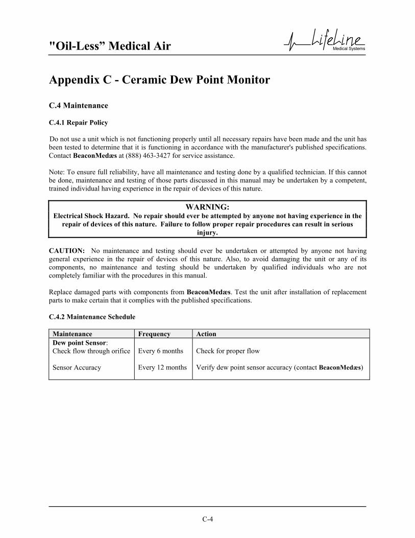
"Oil-Less” Medical Air
Medical Systems
C-4
Appendix C - Ceramic Dew Point Monitor C.4 Maintenance C.4.1 Repair Policy Do not use a unit which is not functioning properly until all necessary repairs have been made and the unit has been tested to determine that it is functioning in accordance with the manufacturer's published specifications. Contact BeaconMedæs at (888) 463-3427 for service assistance. Note: To ensure full reliability, have all maintenance and testing done by a qualified technician. If this cannot be done, maintenance and testing of those parts discussed in this manual may be undertaken by a competent, trained individual having experience in the repair of devices of this nature.
CAUTION: No maintenance and testing should ever be undertaken or attempted by anyone not having general experience in the repair of devices of this nature. Also, to avoid damaging the unit or any of its components, no maintenance and testing should be undertaken by qualified individuals who are not completely familiar with the procedures in this manual. Replace damaged parts with components from BeaconMedæs. Test the unit after installation of replacement parts to make certain that it complies with the published specifications.
C.4.2 Maintenance Schedule
Maintenance Frequency Action Dew point Sensor: Check flow through orifice Sensor Accuracy
Every 6 months Every 12 months
Check for proper flow Verify dew point sensor accuracy (contact BeaconMedæs)
WARNING: Electrical Shock Hazard. No repair should ever be attempted by anyone not having experience in the
repair of devices of this nature. Failure to follow proper repair procedures can result in serious injury.

"Oil-Less” Medical Air
Medical Systems
C-5
Appendix C - Ceramic Dew Point Monitor C.5 Troubleshooting
Before servicing the dew point sensor, do the following: 1. Unplug sensor(s) or turn off monitor. 2. Depressurize the dewpoint sensor. Note: Remote alarms will be activated.
Problem Possible Causes Solution Slow system response
Insufficient flow through dew point sensor.
Check flow
No power
No incoming power.
Verify line power is being supplied.
Erratic display
Unit defect.
Contact BeaconMedæs.
LED display does not work or has missing segments
Display board defect Loose connections
Contact BeaconMedæs. Check connections
High Dew point
Air is not being dried. Faulty monitor or sensor.
Verify that dryer is not being bypassed. Replace monitor or sensor
WARNING: Before removing the dew point sensor, verify that line pressure has been valved off or reduced to
atmospheric pressure.


