Embed Size (px)
Citation preview
INSTRUCTION MANUAL
FOR
GSS/GSSW SETUP SOFTWARE
Mar, 2020
GIKEN INDUSTRIAL CO., LTD.
- 1 -
1
Before beginning operation:
Caution
Note
1. Please read this instruction manual carefully in order to ensure that you use this product correctly.
2. A part or no part of this instruction manual may be used or reproduced without the permission of Giken
Industrial Co.,Ltd.
3. Regarding the handling process and operation that are not listed in this instruction manual, please think
that they cannot be operated, and do not attempt to operate them. Any defect that would occur when the
handling process or the operation that is not listed in this instruction manual is executed should be
excluded in the scope of the warranty.
4. Matters listed in this instruction manual are subject to change for the improvement without notice.
Caution
Measures in case of an emergency
If this product is in a dangerous condition, immediately turn OFF all power switches of the main unit or
the connected equipment, or pull out all power cords from the plug outlets. (“Dangerous condition” means
the condition when the fire break out or the danger to personal injury can be expected due to the excessive
heat generation, smoking or ignition.)
- 2 -
2
Outline
This product is the setup software for the GSS/GSSW controller. Setup input can be entered from the front panel
of the controller manually for the GSS/GSSW controller, but this software is used to facilitate the setup input in
a way easy to understand. When the personal computer with this software installed is used, it is possible to
simplify the initial setup input and improve the maintainability due to its batch transmission function while
monitoring the display screen. As the other feature, the tightening history can be read and the torque waveform
display can be checked by sampling the tightening torque value.
Hardware requirements
OS: WINDOWS’95
WINDOWS’98
WINDOWS NT
WINDOWS ME
WINDOWS 2000
WINDOWS XP
RAM: 64MB or more
Installation destination: C:¥Program Files¥GSS Setup
Activation method: Execute GSS_IF.exe
Password to write to the controller is 2003.
- 3 -
3
Contents
1. MAIN MENU .................................................................................................................................................... 4
1-1. Organizations of Screens ............................................................................................................................. 5
1-2. Automatic Communication Check ............................................................................................................... 6
1-3. Automatic Communication Check Function ................................................................................................ 6
2. SETTING READ ................................................................................................................................................ 7
2-1. FD/HD ......................................................................................................................................................... 7
2-2. Using the CONTROLLER Key ................................................................................................................... 8
3. SETTING WRITE ............................................................................................................................................... 8
3-1. Using the FD/HD Key ................................................................................................................................. 8
3-2. Using the CONTROLLER Key ................................................................................................................... 9
4. SETTING ......................................................................................................................................................... 10
4-1. SAMPLING SET ....................................................................................................................................... 10
4-2. RATE. SET ................................................................................................................................................ 12
4-3. MOM.T SET .............................................................................................................................................. 13
4-4. PRE.T SET ................................................................................................................................................. 14
4-5. REV.T SET................................................................................................................................................. 15
4-6. REA.T SET ................................................................................................................................................ 16
4-7. Changing the setting from the torque waveform ........................................................................................ 20
4-8. Changing the setting from the speed waveform ......................................................................................... 20
4-9. AXIS.ARRANGE SET .............................................................................................................................. 21
4-10. PROGRAM SET ...................................................................................................................................... 22
4-10-1. OPERATION SELECT screen .................................................................................................................. 23
4-11. CALENDAR AND BASIC UNIT SETTING .......................................................................................... 24
4-12. TIGHTENING DATA OUTPUT SETTING ............................................................................................ 25
4-13. OPTION SETTING ................................................................................................................................. 26
4-14. SETTING READ AND WRITE ON SETTING SCREENS ................................................................... 27
4-14-1. Reading the rating,/rotation/pretightening/reverse rotation/final tightening/axial arrangement/program setting ....... 27
4-14-2. Writing the rating/rotation/pretightening/reverse rotation/final tightening/axial arrangement/program setting ......... 30
4-14-3. Reading the unit/tightening data output/option setting ................................................................................... 33
4-14-4. Writing of the unit/tightening data output setting .......................................................................................... 35
4-14-5. Writing the option setting ......................................................................................................................... 38
5. AUTO MEASUREMENT .............................................................................................................................. 41
5-1. Using the ONLINE key ............................................................................................................................. 42
5-2. Using the TIGHTENING WAVE key ........................................................................................................ 43
5-3. Using the TIGHTENING RECORD button .............................................................................................. 47
5-4. Using the ALARM HISTORY button ........................................................................................................ 48
6. QUALITY CONTROL ..................................................................................................................................... 49
6-1. Zero magnification, TQ1 result .................................................................................................................. 50
6-2. Torque sensor zero point adjustment .......................................................................................................... 51
6-3. Self diagnosis ............................................................................................................................................. 52
7. PRINT .............................................................................................................................................................. 53
8. I/O MONITOR................................................................................................................................................. 55
8-1. Using the MONITOR button ..................................................................................................................... 56
8-2. Using the DUMMY INPUT button ............................................................................................................ 57
8-3. Using the DUMMY OUTPUT button ........................................................................................................ 58
Glossary................................................................................................................................................................. 59
- 4 -
4
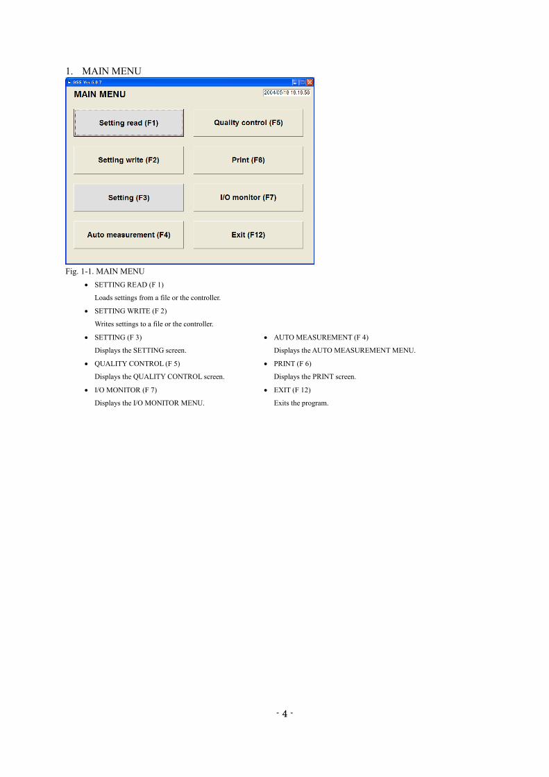
1. MAIN MENU
Fig. 1-1. MAIN MENU
SETTING READ (F 1)
Loads settings from a file or the controller.
SETTING WRITE (F 2)
Writes settings to a file or the controller.
SETTING (F 3) AUTO MEASUREMENT (F 4)
Displays the SETTING screen. Displays the AUTO MEASUREMENT MENU.
QUALITY CONTROL (F 5) PRINT (F 6)
Displays the QUALITY CONTROL screen. Displays the PRINT screen.
I/O MONITOR (F 7) EXIT (F 12)
Displays the I/O MONITOR MENU. Exits the program.
- 5 -
5
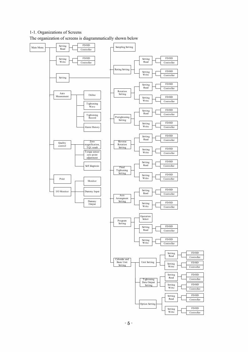
1-1. Organizations of Screens
The organization of screens is diagrammatically shown below
Main MenuSetting
Read
FD/HD
Controller
Setting
Write
FD/HD
Controller
Setting
Sampling Setting
Rating Setting
Setting
Read
FD/HD
Controller
SettingWrite
FD/HD
Controller
RotationSetting
Setting
Read
FD/HD
Controller
Setting
Write
FD/HD
Controller
Pretightening
Setting
SettingRead
FD/HD
Controller
Setting
Write
FD/HD
Controller
Reverse
Rotation
Setting
Setting
Read
FD/HD
Controller
Setting
Write
FD/HD
Controller
Final
T ightening
Setting
Setting
Read
FD/HD
Controller
Setting
Write
FD/HD
Controller
Axis
Arrangment
Setting
Setting
Read
FD/HD
Controller
Setting
Write
FD/HD
Controller
ProgramSetting
Setting
Read
FD/HD
Controller
SettingWrite
FD/HD
Controller
Calendar and
Basic Unit
Setting
SettingRead
FD/HD
Controller
SettingWrite
FD/HD
Controller
OperationSelect
Unit Setting
Quality
control
Zero
magnification,
TQ1 result
Torque sensor
zero point
adjustment
Self diagnosis
I/O Monitor
Monitor
Dummy Input
DummyOutput
Setting
Read
Setting
Write
FD/HD
Controller
T ightening
Data Output
Setting
Setting
Read
FD/HD
Controller
Setting
Write
FD/HD
Controller
Option Setting
FD/HD
Controller
Auto
MeasrementOnline
Tightening
Wave
TighteningRecord
Alarm History
- 6 -
6
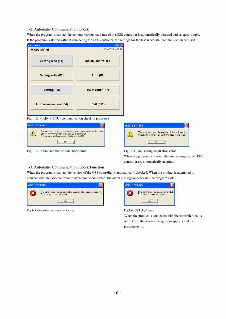
1-2. Automatic Communication Check
When the program is started, the communication baud rate of the GSS controller is automatically detected and set accordingly.
If the program is started without connecting the GSS controller, the settings for the last successful communication are used.
Fig. 1-2. MAIN MENU (communication check in progress)
Fig. 1-3. Initial communication check error Fig. 1-4. Unit setting acquisition error
When the program is started, the unit settings of the GSS
controller are automatically acquired.
1-3. Automatic Communication Check Function
When the program is started, the version of the GSS controller is automatically checked. When the product is attempted to
connect with the GSS controller that cannot be connected, the alarm message appears and the program exits.
Fig.1-5. Controller version check error Fig.1-6. GSS check error
When the product is connected with the controller that is
set to GSS, the alarm message also appears and the
program exits.
- 7 -
7
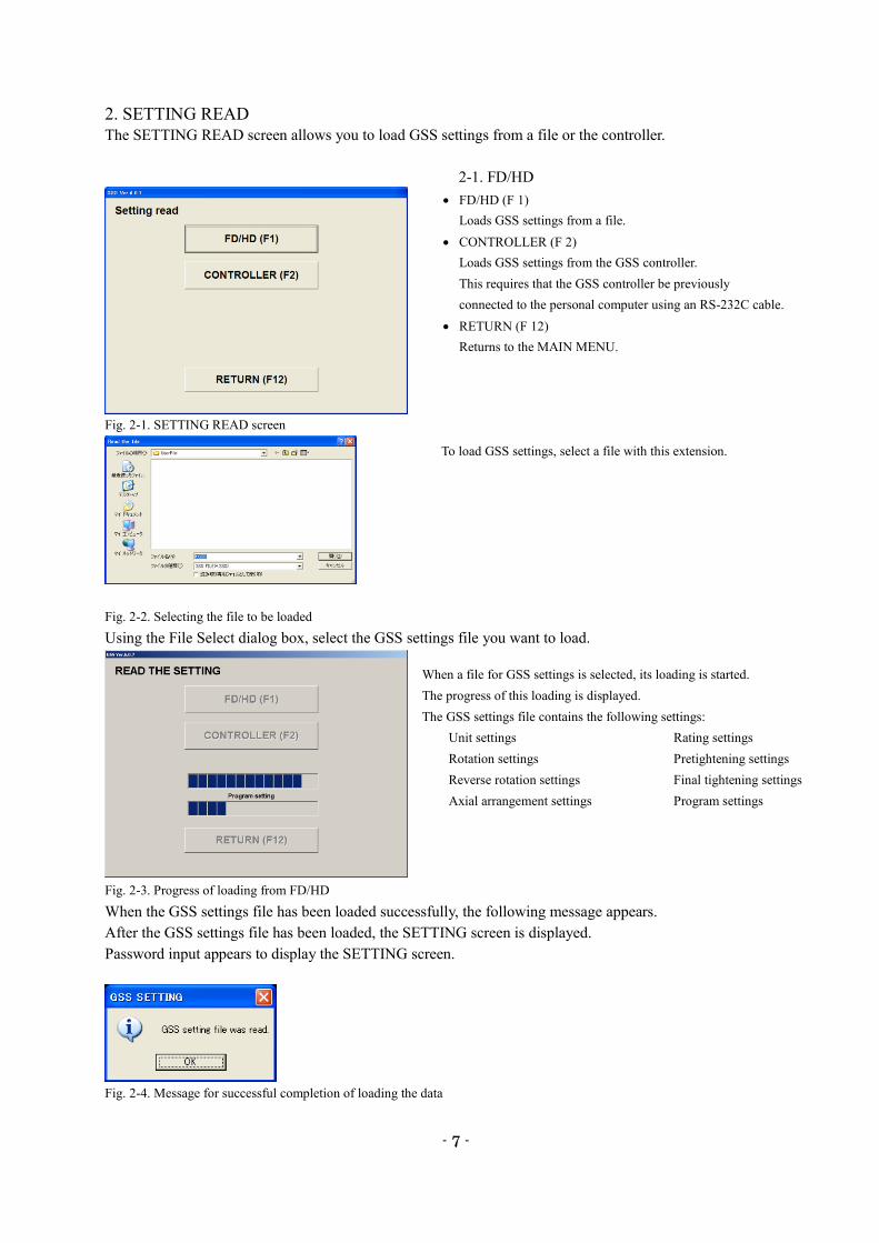
2. SETTING READ
The SETTING READ screen allows you to load GSS settings from a file or the controller.
2-1. FD/HD
Fig. 2-1. SETTING READ screen
Fig. 2-2. Selecting the file to be loaded
Using the File Select dialog box, select the GSS settings file you want to load.
Fig. 2-3. Progress of loading from FD/HD
When the GSS settings file has been loaded successfully, the following message appears.
After the GSS settings file has been loaded, the SETTING screen is displayed.
Password input appears to display the SETTING screen.
Fig. 2-4. Message for successful completion of loading the data
To load GSS settings, select a file with this extension.
FD/HD (F 1)
Loads GSS settings from a file.
CONTROLLER (F 2)
Loads GSS settings from the GSS controller.
This requires that the GSS controller be previously
connected to the personal computer using an RS-232C cable.
RETURN (F 12)
Returns to the MAIN MENU.
When a file for GSS settings is selected, its loading is started.
The progress of this loading is displayed.
The GSS settings file contains the following settings:
Unit settings Rating settings
Rotation settings Pretightening settings
Reverse rotation settings Final tightening settings
Axial arrangement settings Program settings
- 8 -
8
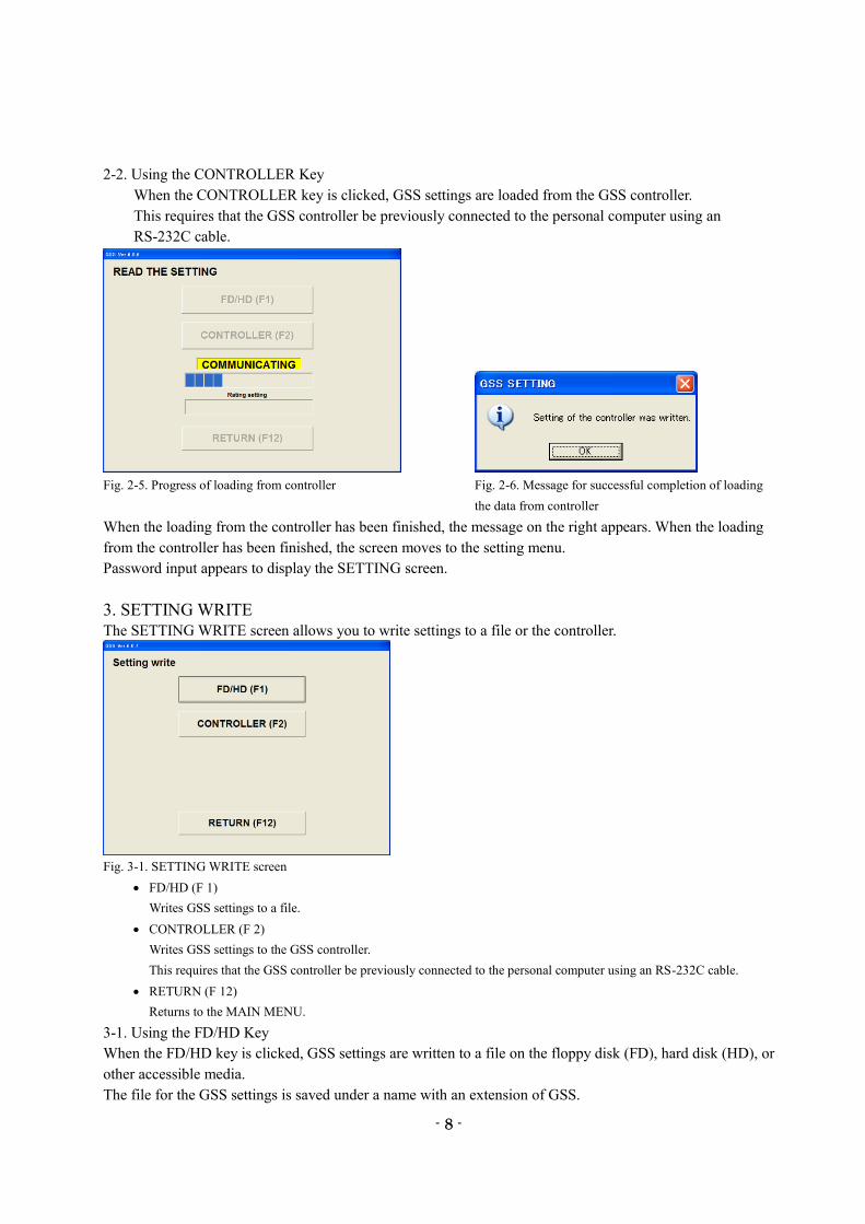
2-2. Using the CONTROLLER Key
When the CONTROLLER key is clicked, GSS settings are loaded from the GSS controller.
This requires that the GSS controller be previously connected to the personal computer using an
RS-232C cable.
Fig. 2-5. Progress of loading from controller Fig. 2-6. Message for successful completion of loading
the data from controller
When the loading from the controller has been finished, the message on the right appears. When the loading
from the controller has been finished, the screen moves to the setting menu.
Password input appears to display the SETTING screen.
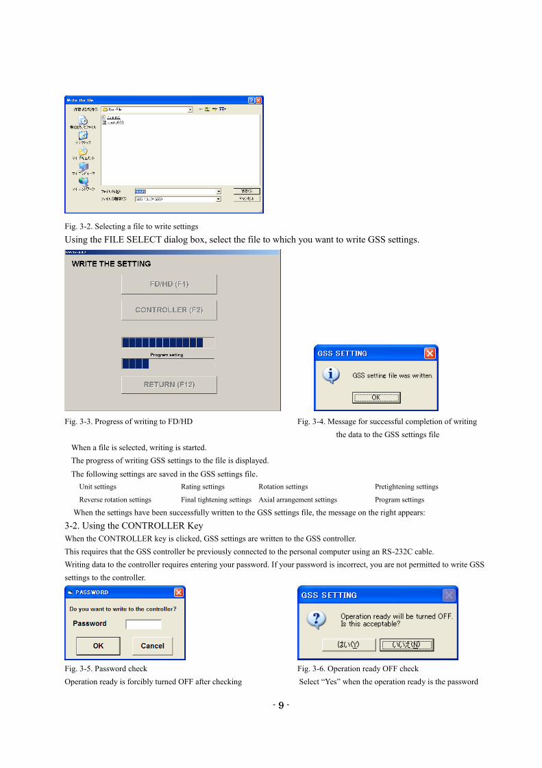
3. SETTING WRITE
The SETTING WRITE screen allows you to write settings to a file or the controller.
Fig. 3-1. SETTING WRITE screen
FD/HD (F 1)
Writes GSS settings to a file.
CONTROLLER (F 2)
Writes GSS settings to the GSS controller.
This requires that the GSS controller be previously connected to the personal computer using an RS-232C cable.
RETURN (F 12)
Returns to the MAIN MENU.
3-1. Using the FD/HD Key
When the FD/HD key is clicked, GSS settings are written to a file on the floppy disk (FD), hard disk (HD), or
other accessible media.
The file for the GSS settings is saved under a name with an extension of GSS.
- 9 -
9
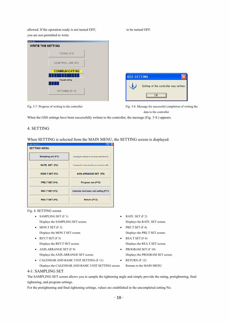
Fig. 3-2. Selecting a file to write settings
Using the FILE SELECT dialog box, select the file to which you want to write GSS settings.
Fig. 3-3. Progress of writing to FD/HD Fig. 3-4. Message for successful completion of writing
the data to the GSS settings file
When a file is selected, writing is started.
The progress of writing GSS settings to the file is displayed.
The following settings are saved in the GSS settings file.
Unit settings Rating settings Rotation settings Pretightening settings
Reverse rotation settings Final tightening settings Axial arrangement settings Program settings
When the settings have been successfully written to the GSS settings file, the message on the right appears:
3-2. Using the CONTROLLER Key
When the CONTROLLER key is clicked, GSS settings are written to the GSS controller.
This requires that the GSS controller be previously connected to the personal computer using an RS-232C cable.
Writing data to the controller requires entering your password. If your password is incorrect, you are not permitted to write GSS
settings to the controller.
Fig. 3-5. Password check Fig. 3-6. Operation ready OFF check
Operation ready is forcibly turned OFF after checking Select “Yes” when the operation ready is the password
- 10 -
10
allowed. If the operation ready is not turned OFF, to be turned OFF.
you are not permitted to write.
Fig. 3-7. Progress of writing to the controller Fig. 3-8. Message for successful completion of writing the
data to the controller
When the GSS settings have been successfully written to the controller, the message (Fig. 3-8.) appears.
4. SETTING
When SETTING is selected from the MAIN MENU, the SETTING screen is displayed.
Fig. 4. SETTING screen
SAMPLING SET (F 1) RATE. SET (F 2)
Displays the SAMPLING SET screen. Displays the RATE. SET screen.
MON.T SET (F 3) PRE.T SET (F 4)
Displays the MON.T SET screen. Displays the PRE.T SET screen.
REV.T SET (F 5) REA.T SET (F 6)
Displays the REV.T SET screen. Displays the REA.T SET screen.
AXIS.ARRANGE SET (F 9) PROGRAM SET (F 10)
Displays the AXIS.ARRANGE SET screen. Displays the PROGRAM SET screen.
CALENDAR AND BASIC UNIT SETTING (F 11) RETURN (F 12)
Displays the CALENDAR AND BASIC UNIT SETTING screen Returns to the MAIN MENU
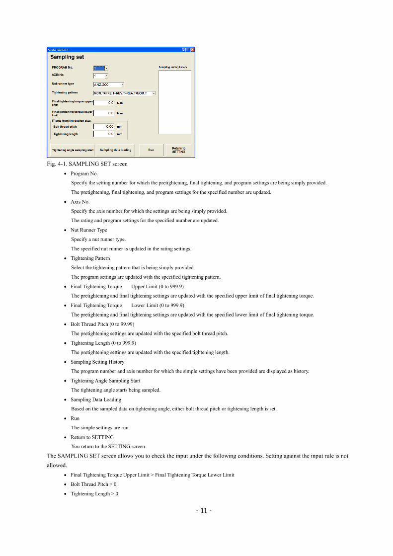
4-1. SAMPLING SET
The SAMPLING SET screen allows you to sample the tightening angle and simply provide the rating, pretightening, final
tightening, and program settings.
For the pretightening and final tightening settings, values are established in the uncompleted setting No.
- 11 -
11
Fig. 4-1. SAMPLING SET screen
Program No.
Specify the setting number for which the pretightening, final tightening, and program settings are being simply provided.
The pretightening, final tightening, and program settings for the specified number are updated.
Axis No.
Specify the axis number for which the settings are being simply provided.
The rating and program settings for the specified number are updated.
Nut Runner Type
Specify a nut runner type.
The specified nut runner is updated in the rating settings.
Tightening Pattern
Select the tightening pattern that is being simply provided.
The program settings are updated with the specified tightening pattern.
Final Tightening Torque Upper Limit (0 to 999.9)
The pretightening and final tightening settings are updated with the specified upper limit of final tightening torque.
Final Tightening Torque Lower Limit (0 to 999.9)
The pretightening and final tightening settings are updated with the specified lower limit of final tightening torque.
Bolt Thread Pitch (0 to 99.99)
The pretightening settings are updated with the specified bolt thread pitch.
Tightening Length (0 to 999.9)
The pretightening settings are updated with the specified tightening length.
Sampling Setting History
The program number and axis number for which the simple settings have been provided are displayed as history.
Tightening Angle Sampling Start
The tightening angle starts being sampled.
Sampling Data Loading
Based on the sampled data on tightening angle, either bolt thread pitch or tightening length is set.
Run
The simple settings are run.
Return to SETTING
You return to the SETTING screen.
The SAMPLING SET screen allows you to check the input under the following conditions. Setting against the input rule is not
allowed.
Final Tightening Torque Upper Limit > Final Tightening Torque Lower Limit
Bolt Thread Pitch > 0
Tightening Length > 0
- 12 -
12
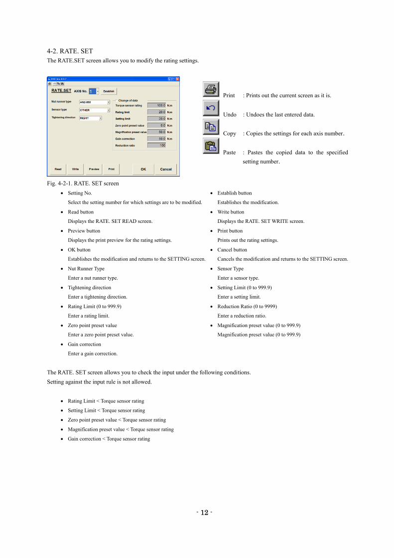
4-2. RATE. SET
The RATE.SET screen allows you to modify the rating settings.
Fig. 4-2-1. RATE. SET screen
Setting No. Establish button
Select the setting number for which settings are to be modified. Establishes the modification.
Read button Write button
Displays the RATE. SET READ screen. Displays the RATE. SET WRITE screen.
Preview button Print button
Displays the print preview for the rating settings. Prints out the rating settings.
OK button Cancel button
Establishes the modification and returns to the SETTING screen. Cancels the modification and returns to the SETTING screen.
Nut Runner Type Sensor Type
Enter a nut runner type. Enter a sensor type.
Tightening direction Setting Limit (0 to 999.9)
Enter a tightening direction. Enter a setting limit.
Rating Limit (0 to 999.9) Reduction Ratio (0 to 9999)
Enter a rating limit. Enter a reduction ratio.
Zero point preset value Magnification preset value (0 to 999.9)
Enter a zero point preset value. Magnification preset value (0 to 999.9)
Gain correction
Enter a gain correction.
The RATE. SET screen allows you to check the input under the following conditions.
Setting against the input rule is not allowed.
Rating Limit < Torque sensor rating
Setting Limit < Torque sensor rating
Zero point preset value < Torque sensor rating
Magnification preset value < Torque sensor rating
Gain correction < Torque sensor rating
Print : Prints out the current screen as it is.
Undo : Undoes the last entered data.
Copy : Copies the settings for each axis number.
Paste : Pastes the copied data to the specified
setting number.
- 13 -
13
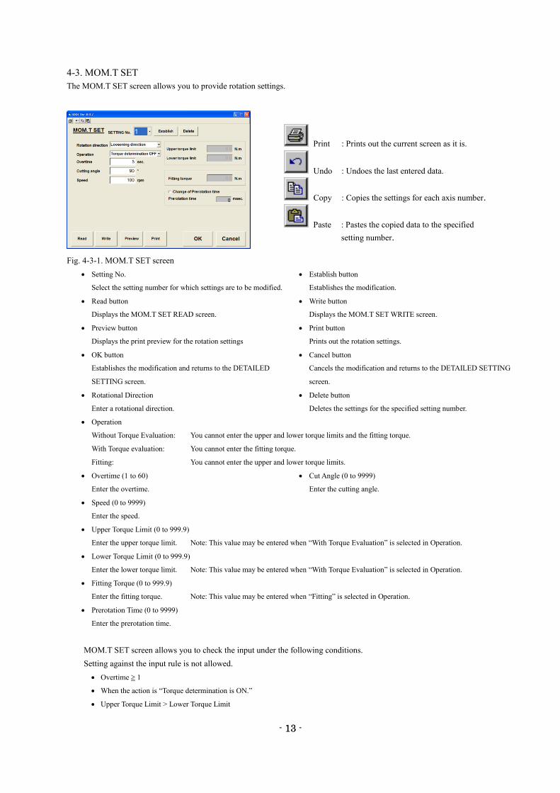
4-3. MOM.T SET
The MOM.T SET screen allows you to provide rotation settings.
Fig. 4-3-1. MOM.T SET screen
Setting No. Establish button
Select the setting number for which settings are to be modified. Establishes the modification.
Read button Write button
Displays the MOM.T SET READ screen. Displays the MOM.T SET WRITE screen.
Preview button Print button
Displays the print preview for the rotation settings Prints out the rotation settings.
OK button Cancel button
Establishes the modification and returns to the DETAILED Cancels the modification and returns to the DETAILED SETTING
SETTING screen. screen.
Rotational Direction Delete button
Enter a rotational direction. Deletes the settings for the specified setting number.
Operation
Without Torque Evaluation: You cannot enter the upper and lower torque limits and the fitting torque.
With Torque evaluation: You cannot enter the fitting torque.
Fitting: You cannot enter the upper and lower torque limits.
Overtime (1 to 60) Cut Angle (0 to 9999)
Enter the overtime. Enter the cutting angle.
Speed (0 to 9999)
Enter the speed.
Upper Torque Limit (0 to 999.9)
Enter the upper torque limit. Note: This value may be entered when “With Torque Evaluation” is selected in Operation.
Lower Torque Limit (0 to 999.9)
Enter the lower torque limit. Note: This value may be entered when “With Torque Evaluation” is selected in Operation.
Fitting Torque (0 to 999.9)
Enter the fitting torque. Note: This value may be entered when “Fitting” is selected in Operation.
Prerotation Time (0 to 9999)
Enter the prerotation time.
MOM.T SET screen allows you to check the input under the following conditions.
Setting against the input rule is not allowed.
Overtime 1
When the action is “Torque determination is ON.”
Upper Torque Limit > Lower Torque Limit
Print : Prints out the current screen as it is.
Undo : Undoes the last entered data.
Copy : Copies the settings for each axis number.
Paste : Pastes the copied data to the specified
setting number.
- 14 -
14
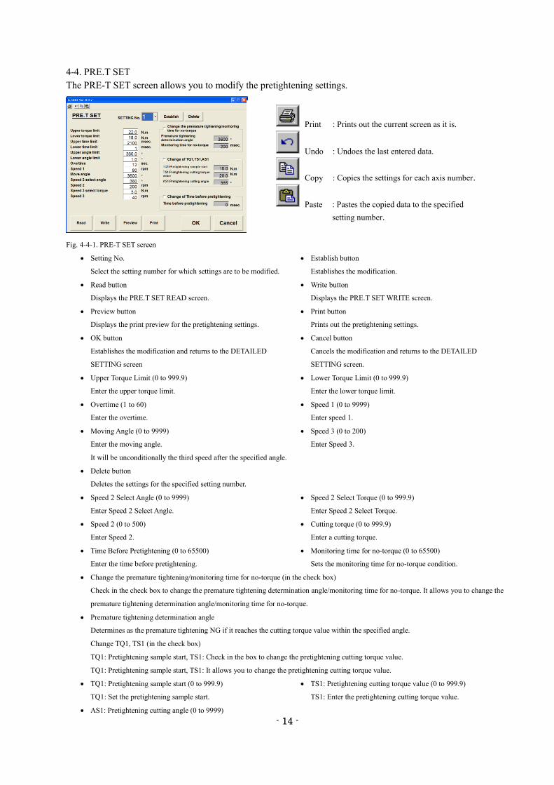
4-4. PRE.T SET
The PRE-T SET screen allows you to modify the pretightening settings.
Fig. 4-4-1. PRE-T SET screen
Setting No. Establish button
Select the setting number for which settings are to be modified. Establishes the modification.
Read button Write button
Displays the PRE.T SET READ screen. Displays the PRE.T SET WRITE screen.
Preview button Print button
Displays the print preview for the pretightening settings. Prints out the pretightening settings.
OK button Cancel button
Establishes the modification and returns to the DETAILED Cancels the modification and returns to the DETAILED
SETTING screen SETTING screen.
Upper Torque Limit (0 to 999.9) Lower Torque Limit (0 to 999.9)
Enter the upper torque limit. Enter the lower torque limit.
Overtime (1 to 60) Speed 1 (0 to 9999)
Enter the overtime. Enter speed 1.
Moving Angle (0 to 9999) Speed 3 (0 to 200)
Enter the moving angle. Enter Speed 3.
It will be unconditionally the third speed after the specified angle.
Delete button
Deletes the settings for the specified setting number.
Speed 2 Select Angle (0 to 9999) Speed 2 Select Torque (0 to 999.9)
Enter Speed 2 Select Angle. Enter Speed 2 Select Torque.
Speed 2 (0 to 500) Cutting torque (0 to 999.9)
Enter Speed 2. Enter a cutting torque.
Time Before Pretightening (0 to 65500) Monitoring time for no-torque (0 to 65500)
Enter the time before pretightening. Sets the monitoring time for no-torque condition.
Change the premature tightening/monitoring time for no-torque (in the check box)
Check in the check box to change the premature tightening determination angle/monitoring time for no-torque. It allows you to change the
premature tightening determination angle/monitoring time for no-torque.
Premature tightening determination angle
Determines as the premature tightening NG if it reaches the cutting torque value within the specified angle.
Change TQ1, TS1 (in the check box)
TQ1: Pretightening sample start, TS1: Check in the box to change the pretightening cutting torque value.
TQ1: Pretightening sample start, TS1: It allows you to change the pretightening cutting torque value.
TQ1: Pretightening sample start (0 to 999.9) TS1: Pretightening cutting torque value (0 to 999.9)
TQ1: Set the pretightening sample start. TS1: Enter the pretightening cutting torque value.
AS1: Pretightening cutting angle (0 to 9999)
Print : Prints out the current screen as it is.
Undo : Undoes the last entered data.
Copy : Copies the settings for each axis number.
Paste : Pastes the copied data to the specified
setting number.
- 15 -
15
AS1: Set the pretightening cut angle.
Change the previous time before pretightening (in the check box)
Check to change the previous time. It allows you to change the previous time.
PRE-T SET screen allows you to check the input under the following conditions.
Setting against the input rule is not allowed.
Overtime 1
Upper torque limit Lower Torque Limit
Upper time limit Lower time limit
Moving Angle Speed 2 Select Angle
TS1: Pretightening cut torque value > TQ1: Pretightening sample start
Upper torque limit TS1: Pretightening Cutting Torque Lower Torque Limit
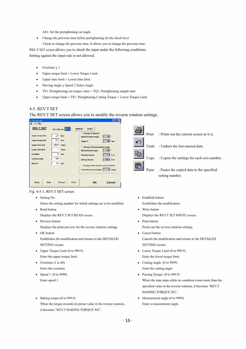
4-5. REV.T SET
The REV.T SET screen allows you to modify the reverse rotation settings.
Fig. 4-5-1. REV.T SET screen
Setting No. Establish button
Select the setting number for which settings are to be modified. Establishes the modification.
Read button Write button
Displays the REV.T SET READ screen. Displays the REV.T SET WRITE screen.
Preview button Print button
Displays the print preview for the reverse rotation settings. Prints out the reverse rotation settings.
OK button Cancel button
Establishes the modification and returns to the DETAILED Cancels the modification and returns to the DETAILED
SETTING screen. SETTING screen.
Upper Torque Limit (0 to 999.9) Lower Torque Limit (0 to 999.9)
Enter the upper torque limit. Enter the lower torque limit.
Overtime (1 to 60) Cutting Angle. (0 to 9999)
Enter the overtime. Enter the cutting angle
Speed 1. (0 to 9999) Passing Torque. (0 to 999.9)
Enter speed 1 When the step stops while no condition exists more than the
specified value in the reverse rotation, it becomes “REV.T
PASSING TORQUE NG”.
Baking torque (0 to 999.9) Measurement angle (0 to 9999)
When the torque exceeds its preset value in the reverse rotation, Enter a measurement angle.
it becomes “REV.T BAKING TORQUE NG”.
Print : Prints out the current screen as it is.
Undo : Undoes the last entered data.
Copy : Copies the settings for each axis number.
Paste : Pastes the copied data to the specified
setting number.
- 16 -
16
Change Speed 2 (in the check box) Delete button
Check in the check box to change Speed 2 Select Angle Deletes the settings for the specified setting number.
and Speed 2. It allows you to change Speed 2 Select Angle and Speed 2.
Speed 2 Select Angle. (0 to 9999) Speed 2. (0 to 9999)
Enter Speed 2 Select Angle. Enter speed 2
Change the measurement angle (in the check box).
Check in the box to change the measurement angle, passing torque and baking torque.
It allows you to change the measurement angle, passing torque and baking torque.
Change the time before reverse rotation (in the check box).
Check in the check box to change the time before reverse rotation. It allows you to change the time bore reverse rotation.
Time Before Reverse Rotation (0 to 65500)
Enter the time before reverse rotation
REV.T SET screen allows you to check the input under the following conditions.
Setting against the input rule is not allowed.
Overtime 1
Upper Torque Limit Lower Torque Limit
Upper Time Limit Lower Time Limit
Measurement Angle Cutting Angle
Select Angle Cutting Angle
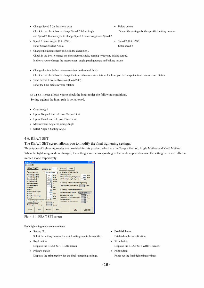
4-6. REA.T SET
The REA.T SET screen allows you to modify the final tightening settings.
Three types of tightening modes are provided for this product, which are the Torque Method, Angle Method and Yield Method.
When the tightening mode is changed, the setting screen corresponding to the mode appears because the setting items are different
in each mode respectively.
Fig. 4-6-1. REA.T SET screen
Each tightening mode common items
Setting No. Establish button
Select the setting number for which settings are to be modified. Establishes the modification.
Read button Write button
Displays the REA.T SET READ screen. Displays the REA.T SET WRITE screen.
Preview button Print button
Displays the print preview for the final tightening settings. Prints out the final tightening settings.
- 17 -
17
OK button Cancel button
Establishes the modification and returns to the DETAILED Cancels the modification and returns to the DETAILED
SETTING screen. SETTING screen.
Upper Torque Limit (0 to 999.9) Lower Torque Limit (0 to 999.9)
Enter the upper torque limit. Enter the lower torque limit.
Overtime (1 to 60) Speed 1 (0 to 9999)
Enter the overtime. Enter speed 1.
Speed 2 Select Angle (0 to 9999) Speed 2 (0 to 999)
Enter Speed 2 Select Angle. Enter speed 2.
Speed 3 Select Torque (0 to 999.9) Speed 3 (0 to 999)
Enter the speed 3 select torque. Enter speed 3
Change The Premature Tightening Angle/Monitoring Time for No-Torque (in the check box)
Check in the check box to change the premature tightening angle/monitoring time for no-torque. It allows you to change the premature
tightening angle/ monitoring time for no-torque.
Premature tightening determination angle (0 to 9999) Monitoring time for no-torque (0 to 65500)
Enter the premature tightening angle. Enter the monitoring time for no-torque.
Change TQ2, TS2, AS2 (in the check box)
Check to change TQ2: Snag torque, TS2: Final tightening cutting torque, AS2: Final tightening cutting angle.
It allows you to change TQ2: Snag torque, TS2: Final tightening cutting torque, AS2: Final tightening cutting angle.
TQ2: Snag torque (0 to 999.9) TS2: Final tightening cutting torque (0 to 999.9)
TQ2: Enter the snag torque. TS2: Enter the final tightening cutting torque.
AS2: Final tightening cutting angle (0 to 9999) Delete button
AS2: Enter the final tightening cutting angle. Deletes the settings for the specified setting number.
Change the time before final tightening (in the check box)
Check to change the time before final tightening. It allows you to change the time before final tightening.
Time Before Final Tightening (0 to 65500)
Enter the time before final tightening.
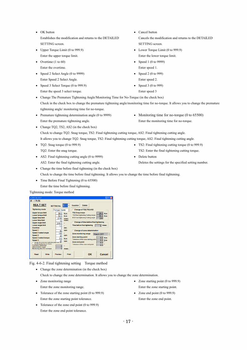
Tightening mode: Torque method
Fig. 4-6-2. Final tightening setting Torque method
Change the zone determination (in the check box)
Check to change the zone determination. It allows you to change the zone determination.
Zone monitoring range Zone starting point (0 to 999.9)
Enter the zone monitoring range. Enter the zone starting point.
Tolerance of the zone starting point (0 to 999.9) Zone end point (0 to 999.9)
Enter the zone starting point tolerance. Enter the zone end point.
Tolerance of the zone end point (0 to 999.9)
Enter the zone end point tolerance.
- 18 -
18
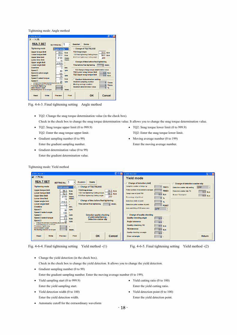
Tightening mode: Angle method
Fig. 4-6-3. Final tightening setting Angle method
TQ2: Change the snag torque determination value (in the check box).
Check in the check box to change the snag torque determination value. It allows you to change the snag torque determination value.
TQ2: Snag torque upper limit (0 to 999.9) TQ2: Snag torque lower limit (0 to 999.9)
TQ2: Enter the snag torque upper limit. TQ2: Enter the snag torque lower limit.
Gradient sampling number (0 to 99) Moving average number (0 to 199)
Enter the gradient sampling number. Enter the moving average number.
Gradient determination value (0 to 99)
Enter the gradient determination value.
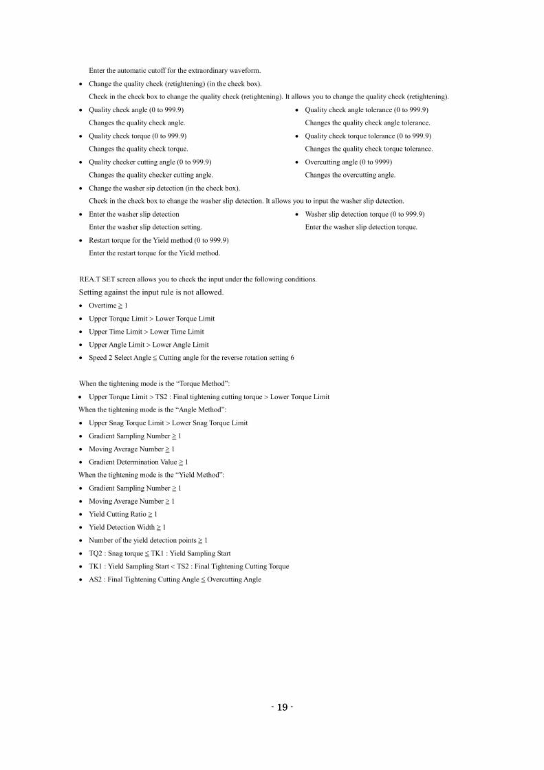
Tightening mode: Yield method
Fig. 4-6-4. Final tightening setting Yield method -(1) Fig. 4-6-5. Final tightening setting Yield method -(2)
Change the yield detection (in the check box).
Check in the check box to change the yield detection. It allows you to change the yield detection.
Gradient sampling number (0 to 99)
Enter the gradient sampling number. Enter the moving average number (0 to 199).
Yield sampling start (0 to 999.9) Yield cutting ratio (0 to 100)
Enter the yield sampling start. Enter the yield cutting ratio.
Yield detection width (0 to 100) Yield detection point (0 to 100)
Enter the yield detection width. Enter the yield detection point.
Automatic cutoff for the extraordinary waveform
- 19 -
19
Enter the automatic cutoff for the extraordinary waveform.
Change the quality check (retightening) (in the check box).
Check in the check box to change the quality check (retightening). It allows you to change the quality check (retightening).
Quality check angle (0 to 999.9) Quality check angle tolerance (0 to 999.9)
Changes the quality check angle. Changes the quality check angle tolerance.
Quality check torque (0 to 999.9) Quality check torque tolerance (0 to 999.9)
Changes the quality check torque. Changes the quality check torque tolerance.
Quality checker cutting angle (0 to 999.9) Overcutting angle (0 to 9999)
Changes the quality checker cutting angle. Changes the overcutting angle.
Change the washer sip detection (in the check box).
Check in the check box to change the washer slip detection. It allows you to input the washer slip detection.
Enter the washer slip detection Washer slip detection torque (0 to 999.9)
Enter the washer slip detection setting. Enter the washer slip detection torque.
Restart torque for the Yield method (0 to 999.9)
Enter the restart torque for the Yield method.
REA.T SET screen allows you to check the input under the following conditions.
Setting against the input rule is not allowed.
Overtime 1
Upper Torque Limit Lower Torque Limit
Upper Time Limit Lower Time Limit
Upper Angle Limit Lower Angle Limit
Speed 2 Select Angle Cutting angle for the reverse rotation setting 6
When the tightening mode is the “Torque Method”:
Upper Torque Limit TS2 : Final tightening cutting torque Lower Torque Limit
When the tightening mode is the “Angle Method”:
Upper Snag Torque Limit Lower Snag Torque Limit
Gradient Sampling Number 1
Moving Average Number 1
Gradient Determination Value 1
When the tightening mode is the “Yield Method”:
Gradient Sampling Number 1
Moving Average Number 1
Yield Cutting Ratio 1
Yield Detection Width 1
Number of the yield detection points 1
TQ2 : Snag torque TK1 : Yield Sampling Start
TK1 : Yield Sampling Start TS2 : Final Tightening Cutting Torque
AS2 : Final Tightening Cutting Angle Overcutting Angle
- 20 -
20
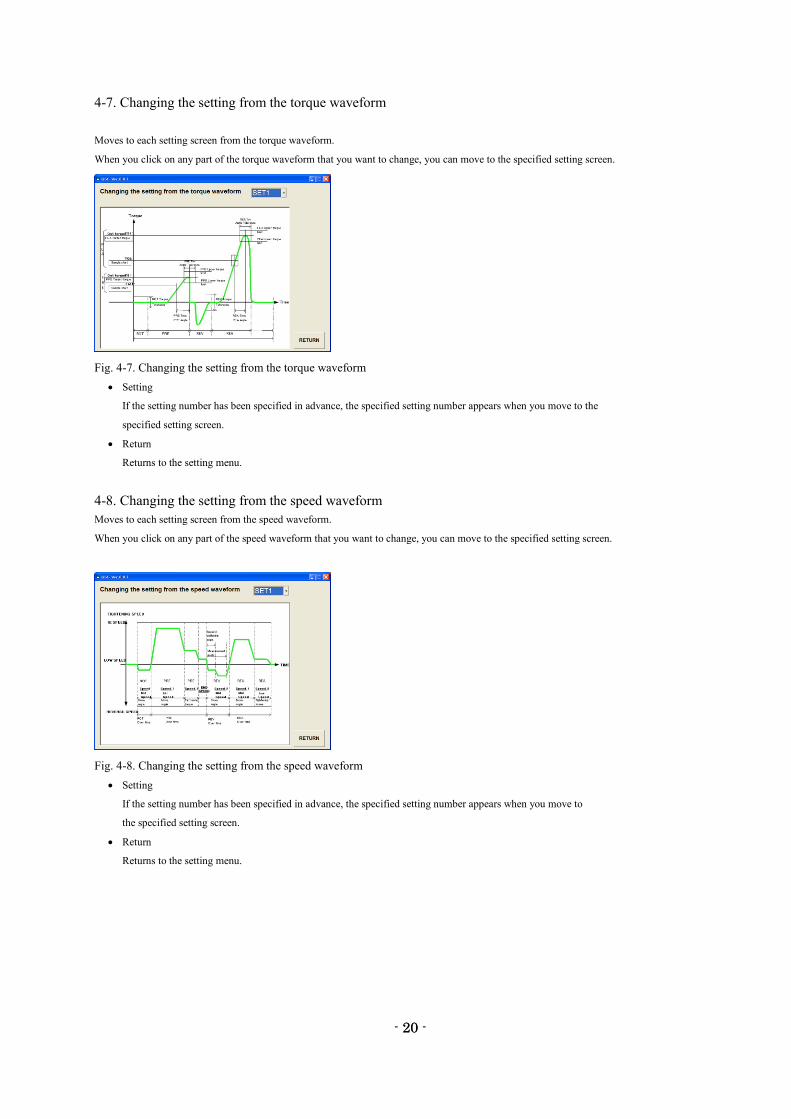
4-7. Changing the setting from the torque waveform
Moves to each setting screen from the torque waveform.
When you click on any part of the torque waveform that you want to change, you can move to the specified setting screen.
Fig. 4-7. Changing the setting from the torque waveform
Setting
If the setting number has been specified in advance, the specified setting number appears when you move to the
specified setting screen.
Return
Returns to the setting menu.
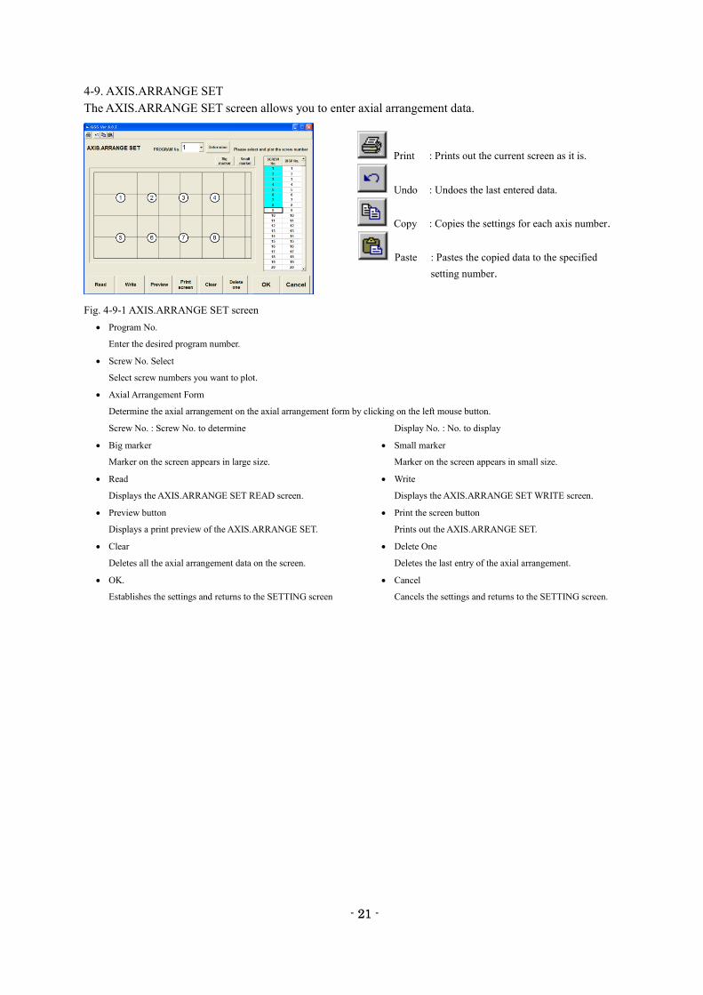
4-8. Changing the setting from the speed waveform
Moves to each setting screen from the speed waveform.
When you click on any part of the speed waveform that you want to change, you can move to the specified setting screen.
Fig. 4-8. Changing the setting from the speed waveform
Setting
If the setting number has been specified in advance, the specified setting number appears when you move to
the specified setting screen.
Return
Returns to the setting menu.
- 21 -
21
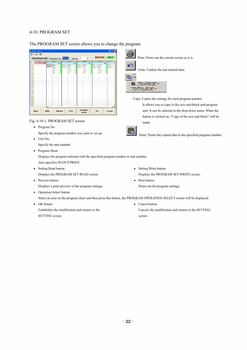
4-9. AXIS.ARRANGE SET
The AXIS.ARRANGE SET screen allows you to enter axial arrangement data.
Fig. 4-9-1 AXIS.ARRANGE SET screen
Program No.
Enter the desired program number.
Screw No. Select
Select screw numbers you want to plot.
Axial Arrangement Form
Determine the axial arrangement on the axial arrangement form by clicking on the left mouse button.
Screw No. : Screw No. to determine Display No. : No. to display
Big marker Small marker
Marker on the screen appears in large size. Marker on the screen appears in small size.
Read Write
Displays the AXIS.ARRANGE SET READ screen. Displays the AXIS.ARRANGE SET WRITE screen.
Preview button Print the screen button
Displays a print preview of the AXIS.ARRANGE SET. Prints out the AXIS.ARRANGE SET.
Clear Delete One
Deletes all the axial arrangement data on the screen. Deletes the last entry of the axial arrangement.
OK. Cancel
Establishes the settings and returns to the SETTING screen Cancels the settings and returns to the SETTING screen.
Print : Prints out the current screen as it is.
Undo : Undoes the last entered data.
Copy : Copies the settings for each axis number.
Paste : Pastes the copied data to the specified
setting number.
- 22 -
22
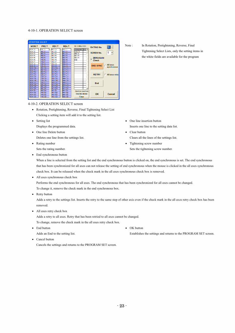
4-10. PROGRAM SET
The PROGRAM SET screen allows you to change the program.
Fig. 4-10-1. PROGRAM SET screen
Program No.
Specify the program number you want to set up.
Unit No.
Specify the unit number.
Program Sheet
Displays the program selected with the specified program number or unit number.
Also specifies IN/OUT/PRINT.
Setting Read button Setting Write button
Displays the PROGRAM SET READ screen. Displays the PROGRAM SET WRITE screen.
Preview button Print button
Displays a print preview of the program settings. Prints out the program settings.
Operation Select button
Select an area on the program sheet and then press this button, the PROGRAM OPERATION SELECT screen will be displayed.
OK button Cancel button
Establishes the modification and returns to the Cancels the modification and returns to the SETTING
SETTING screen. screen.
Print: Prints out the current screen as it is.
Undo: Undoes the last entered data.
Copy: Copies the settings for each program number.
It allows you to copy in the axis unit/block unit/program
unit. It can be selected in the drop down menu. When the
button is clicked on, “Copy of the axis and block” will be
made.
Paste: Pastes the copied data to the specified program number.
- 23 -
23
4-10-1. OPERATION SELECT screen
4-10-2. OPERATION SELECT screen
Rotation, Pretightening, Reverse, Final Tightening Select List
Clicking a setting item will add it to the setting list.
Setting list One line insertion button
Displays the programmed data. Inserts one line to the setting data list.
One line Delete button Clear button
Deletes one line from the settings list. Clears all the lines of the settings list.
Rating number Tightening screw number
Sets the rating number. Sets the tightening screw number.
End synchronous button
When a line is selected from the setting list and the end synchronous button is clicked on, the end synchronous is set. The end synchronous
that has been synchronized for all axes can not release the setting of end synchronous when the mouse is clicked in the all axes synchronous
check box. It can be released when the check mark in the all axes synchronous check box is removed.
All axes synchronous check box
Performs the end synchronous for all axes. The end synchronous that has been synchronized for all axes cannot be changed.
To change it, remove the check mark in the end synchronous box.
Retry button
Adds a retry to the settings list. Inserts the retry to the same step of other axis even if the check mark in the all axes retry check box has been
removed.
All axes retry check box
Adds a retry to all axes. Retry that has been retried to all axes cannot be changed.
To change, remove the check mark in the all axes retry check box.
End button OK button
Adds an End to the setting list. Establishes the settings and returns to the PROGRAM SET screen.
Cancel button
Cancels the settings and returns to the PROGRAM SET screen.
Note : In Rotation, Pretightening, Reverse, Final
Tightening Select Lists, only the setting items in
the white fields are available for the program
- 24 -
24
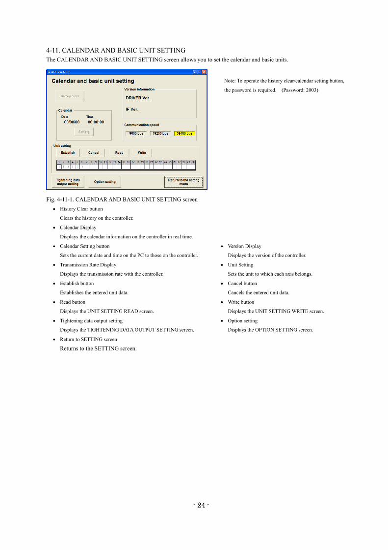
4-11. CALENDAR AND BASIC UNIT SETTING
The CALENDAR AND BASIC UNIT SETTING screen allows you to set the calendar and basic units.
Fig. 4-11-1. CALENDAR AND BASIC UNIT SETTING screen
History Clear button
Clears the history on the controller.
Calendar Display
Displays the calendar information on the controller in real time.
Calendar Setting button Version Display
Sets the current date and time on the PC to those on the controller. Displays the version of the controller.
Transmission Rate Display Unit Setting
Displays the transmission rate with the controller. Sets the unit to which each axis belongs.
Establish button Cancel button
Establishes the entered unit data. Cancels the entered unit data.
Read button Write button
Displays the UNIT SETTING READ screen. Displays the UNIT SETTING WRITE screen.
Tightening data output setting Option setting
Displays the TIGHTENING DATA OUTPUT SETTING screen. Displays the OPTION SETTING screen.
Return to SETTING screen
Returns to the SETTING screen.
Note: To operate the history clear/calendar setting button,
the password is required. (Password: 2003)
- 25 -
25
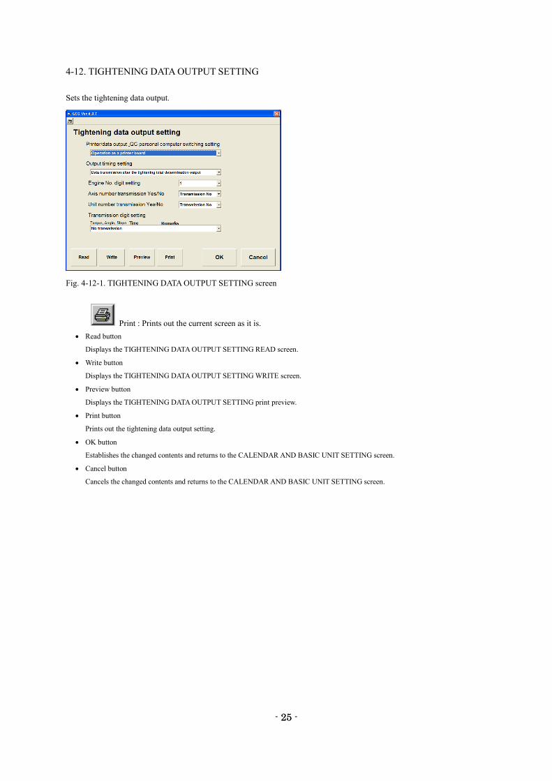
4-12. TIGHTENING DATA OUTPUT SETTING
Sets the tightening data output.
Fig. 4-12-1. TIGHTENING DATA OUTPUT SETTING screen
Print : Prints out the current screen as it is.
Read button
Displays the TIGHTENING DATA OUTPUT SETTING READ screen.
Write button
Displays the TIGHTENING DATA OUTPUT SETTING WRITE screen.
Preview button
Displays the TIGHTENING DATA OUTPUT SETTING print preview.
Print button
Prints out the tightening data output setting.
OK button
Establishes the changed contents and returns to the CALENDAR AND BASIC UNIT SETTING screen.
Cancel button
Cancels the changed contents and returns to the CALENDAR AND BASIC UNIT SETTING screen.
- 26 -
26
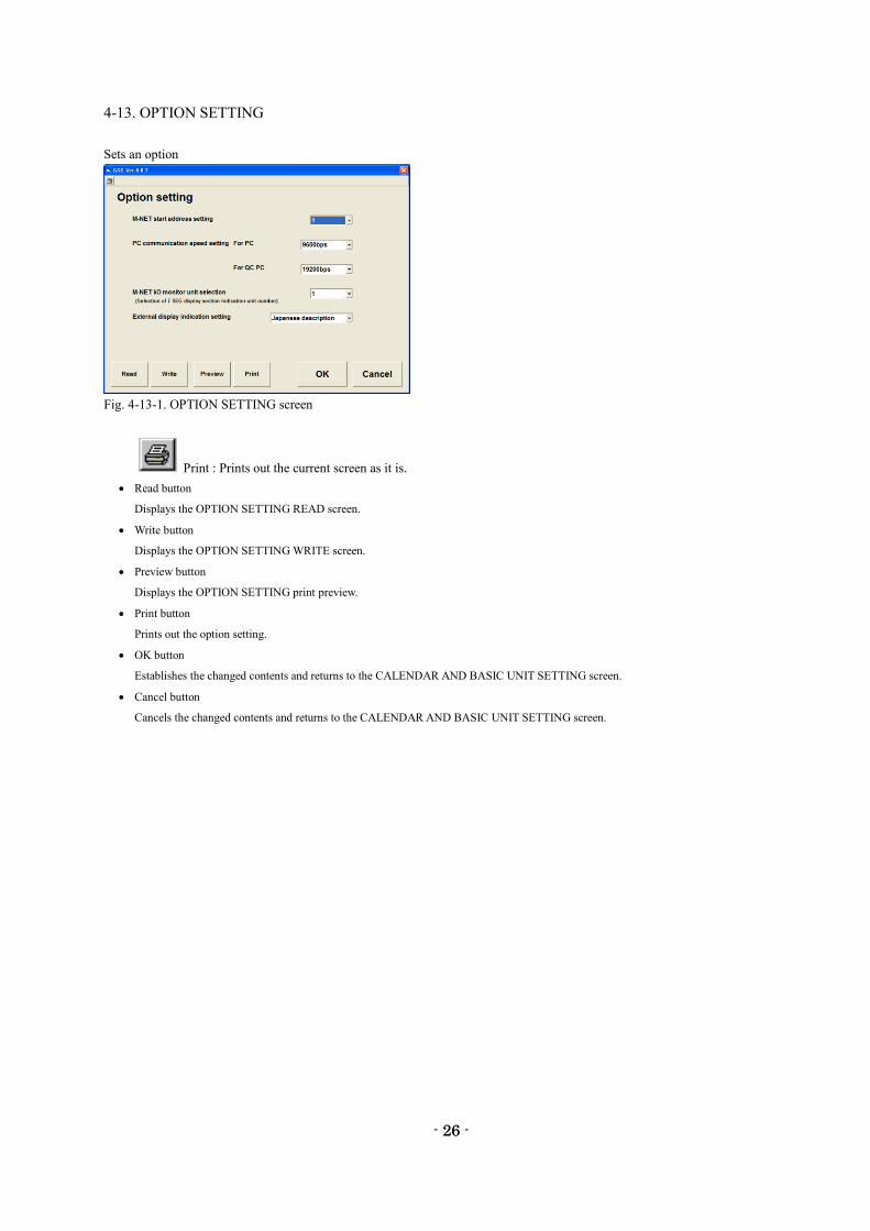
4-13. OPTION SETTING
Sets an option
Fig. 4-13-1. OPTION SETTING screen
Print : Prints out the current screen as it is.
Read button
Displays the OPTION SETTING READ screen.
Write button
Displays the OPTION SETTING WRITE screen.
Preview button
Displays the OPTION SETTING print preview.
Print button
Prints out the option setting.
OK button
Establishes the changed contents and returns to the CALENDAR AND BASIC UNIT SETTING screen.
Cancel button
Cancels the changed contents and returns to the CALENDAR AND BASIC UNIT SETTING screen.
- 27 -
27
4-14. SETTING READ AND WRITE ON SETTING SCREENS
Reads and writes the setting of setting screens about the rating, rotation, pretightening, reverse rotation, final tightening, axial
arrangement, program, tightening data output and option. Similar setting screens are described in a lot.
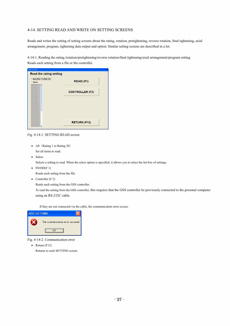
4-14-1. Reading the rating,/rotation/pretightening/reverse rotation/final tightening/axial arrangement/program setting
Reads each setting from a file or the controller.
Fig. 4-14-1. SETTING READ screen
All(Rating 1 to Rating 30)
Set all items to read.
Select
Selects a setting to read. When the select option is specified, it allows you to select the list box of settings.
FD/HD(F 1)
Reads each setting from the file.
Controller (F 2)
Reads each setting from the GSS controller.
To read the setting from the GSS controller, this requires that the GSS controller be previously connected to the personal computer
using an RS-232C cable.
If they are not connected via the cable, the communication error occurs.
Fig. 4-14-2. Communication error
Return (F12)
Returns to each SETTING screen.
- 28 -
28
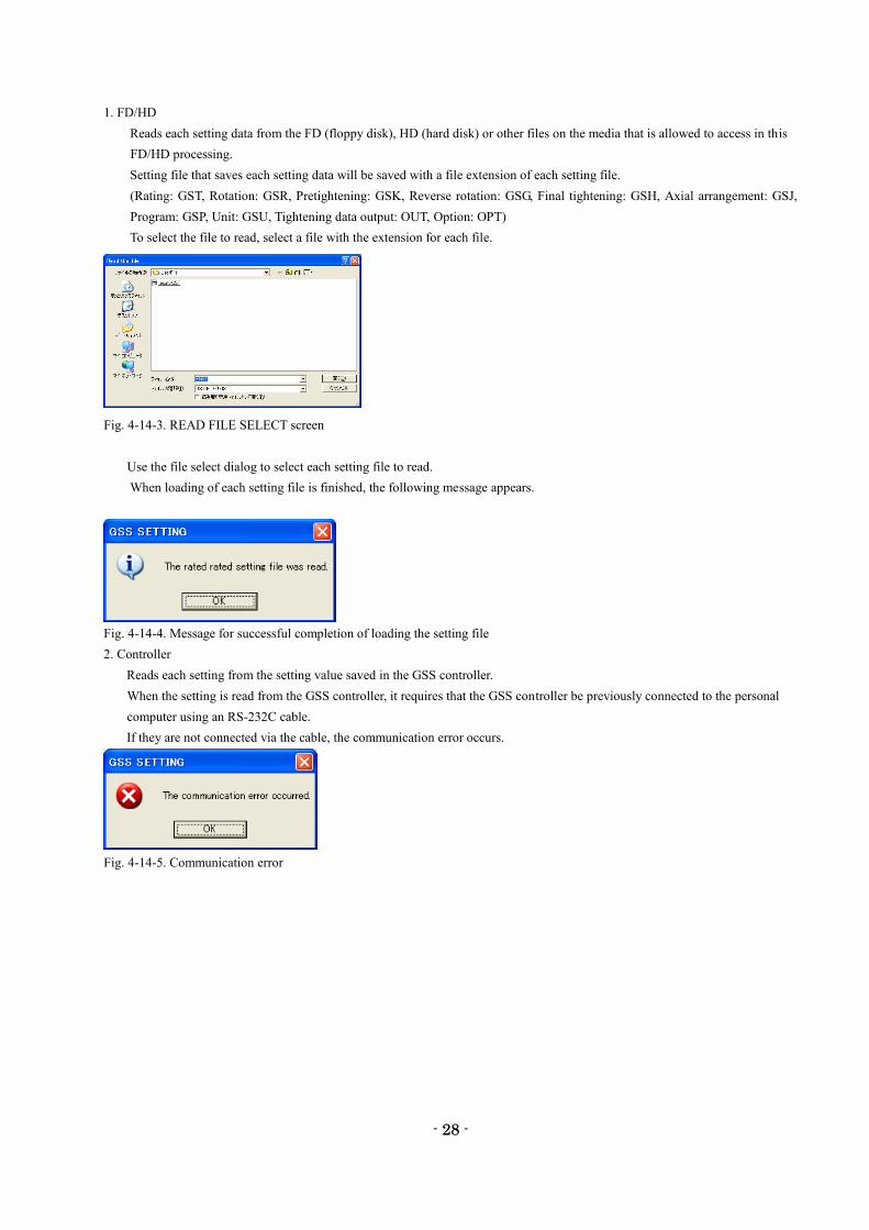
1. FD/HD
Reads each setting data from the FD (floppy disk), HD (hard disk) or other files on the media that is allowed to access in this
FD/HD processing.
Setting file that saves each setting data will be saved with a file extension of each setting file.
(Rating: GST, Rotation: GSR, Pretightening: GSK, Reverse rotation: GSG, Final tightening: GSH, Axial arrangement: GSJ,
Program: GSP, Unit: GSU, Tightening data output: OUT, Option: OPT)
To select the file to read, select a file with the extension for each file.
Fig. 4-14-3. READ FILE SELECT screen
Use the file select dialog to select each setting file to read.
When loading of each setting file is finished, the following message appears.
Fig. 4-14-4. Message for successful completion of loading the setting file
2. Controller
Reads each setting from the setting value saved in the GSS controller.
When the setting is read from the GSS controller, it requires that the GSS controller be previously connected to the personal
computer using an RS-232C cable.
If they are not connected via the cable, the communication error occurs.
Fig. 4-14-5. Communication error
- 29 -
29
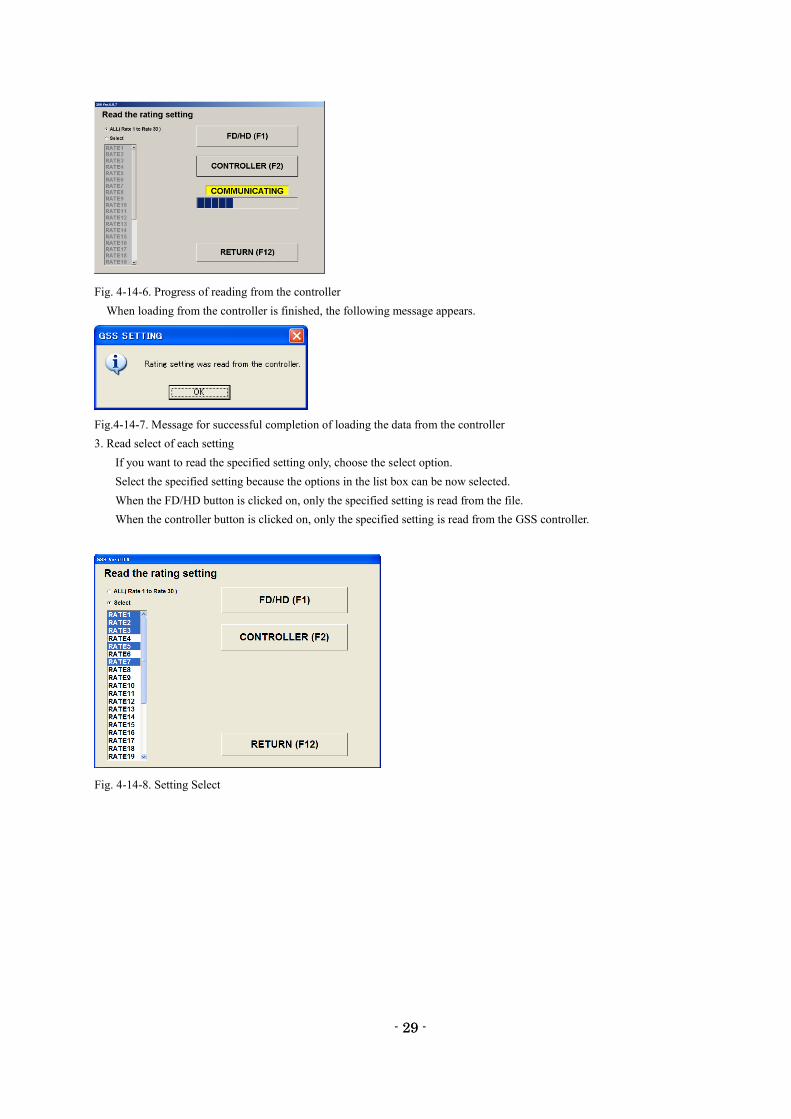
Fig. 4-14-6. Progress of reading from the controller
When loading from the controller is finished, the following message appears.
Fig.4-14-7. Message for successful completion of loading the data from the controller
3. Read select of each setting
If you want to read the specified setting only, choose the select option.
Select the specified setting because the options in the list box can be now selected.
When the FD/HD button is clicked on, only the specified setting is read from the file.
When the controller button is clicked on, only the specified setting is read from the GSS controller.
Fig. 4-14-8. Setting Select
- 30 -
30
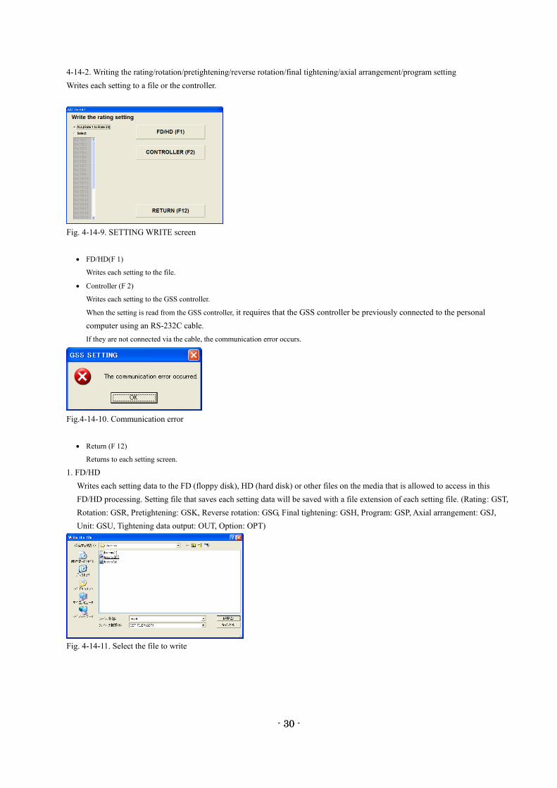
4-14-2. Writing the rating/rotation/pretightening/reverse rotation/final tightening/axial arrangement/program setting
Writes each setting to a file or the controller.
Fig. 4-14-9. SETTING WRITE screen
FD/HD(F 1)
Writes each setting to the file.
Controller (F 2)
Writes each setting to the GSS controller.
When the setting is read from the GSS controller, it requires that the GSS controller be previously connected to the personal
computer using an RS-232C cable.
If they are not connected via the cable, the communication error occurs.
Fig.4-14-10. Communication error
Return (F 12)
Returns to each setting screen.
1. FD/HD
Writes each setting data to the FD (floppy disk), HD (hard disk) or other files on the media that is allowed to access in this
FD/HD processing. Setting file that saves each setting data will be saved with a file extension of each setting file. (Rating: GST,
Rotation: GSR, Pretightening: GSK, Reverse rotation: GSG, Final tightening: GSH, Program: GSP, Axial arrangement: GSJ,
Unit: GSU, Tightening data output: OUT, Option: OPT)
Fig. 4-14-11. Select the file to write
- 31 -
31
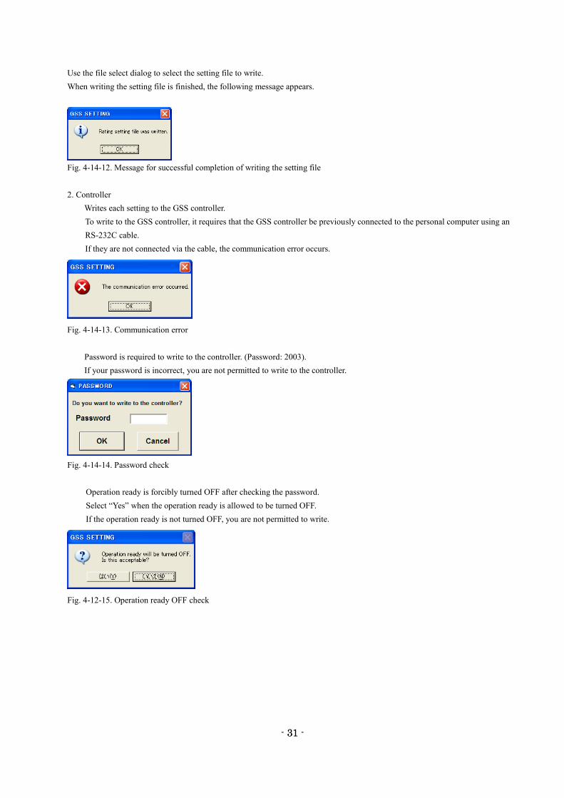
Use the file select dialog to select the setting file to write.
When writing the setting file is finished, the following message appears.
Fig. 4-14-12. Message for successful completion of writing the setting file
2. Controller
Writes each setting to the GSS controller.
To write to the GSS controller, it requires that the GSS controller be previously connected to the personal computer using an
RS-232C cable.
If they are not connected via the cable, the communication error occurs.
Fig. 4-14-13. Communication error
Password is required to write to the controller. (Password: 2003).
If your password is incorrect, you are not permitted to write to the controller.
Fig. 4-14-14. Password check
Operation ready is forcibly turned OFF after checking the password.
Select “Yes” when the operation ready is allowed to be turned OFF.
If the operation ready is not turned OFF, you are not permitted to write.
Fig. 4-12-15. Operation ready OFF check
- 32 -
32
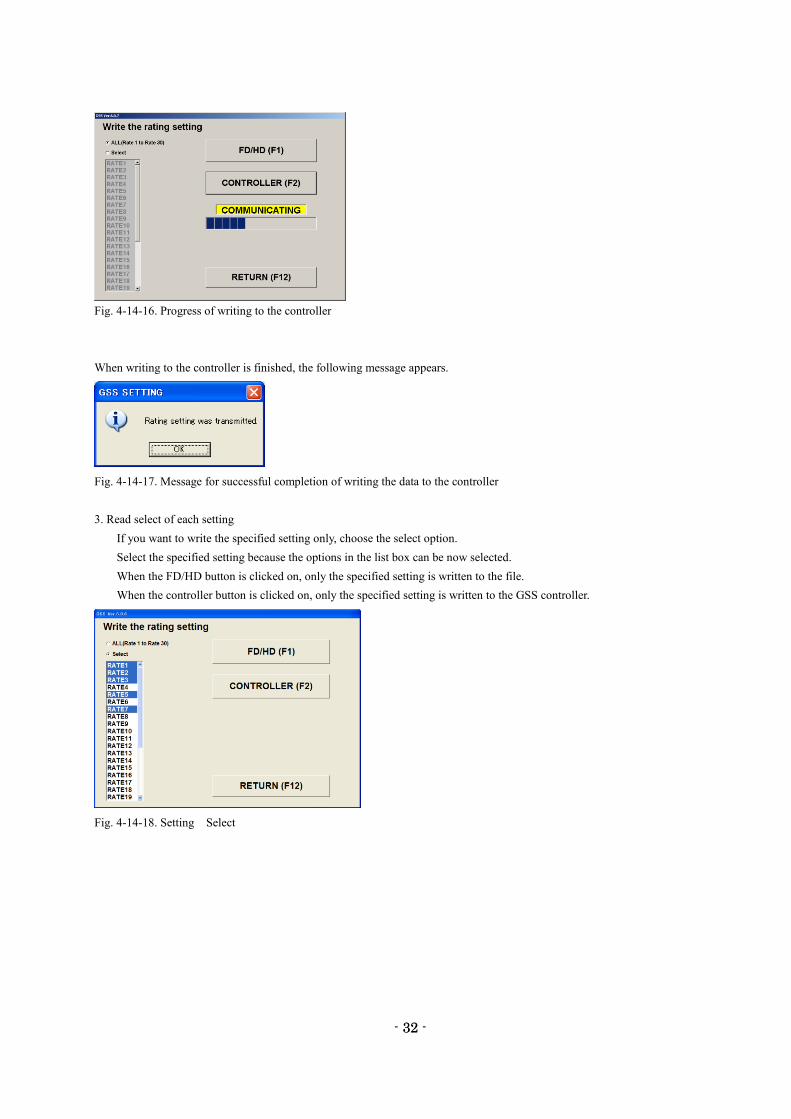
Fig. 4-14-16. Progress of writing to the controller
When writing to the controller is finished, the following message appears.
Fig. 4-14-17. Message for successful completion of writing the data to the controller
3. Read select of each setting
If you want to write the specified setting only, choose the select option.
Select the specified setting because the options in the list box can be now selected.
When the FD/HD button is clicked on, only the specified setting is written to the file.
When the controller button is clicked on, only the specified setting is written to the GSS controller.
Fig. 4-14-18. Setting Select
- 33 -
33
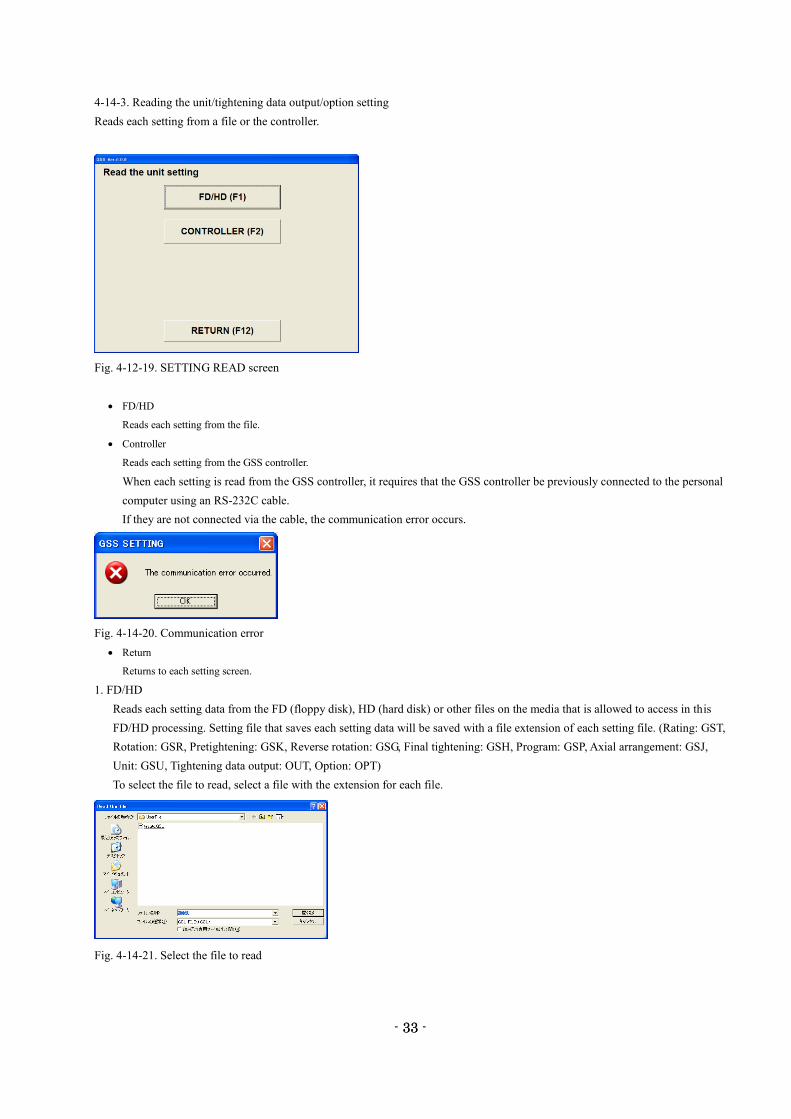
4-14-3. Reading the unit/tightening data output/option setting
Reads each setting from a file or the controller.
Fig. 4-12-19. SETTING READ screen
FD/HD
Reads each setting from the file.
Controller
Reads each setting from the GSS controller.
When each setting is read from the GSS controller, it requires that the GSS controller be previously connected to the personal
computer using an RS-232C cable.
If they are not connected via the cable, the communication error occurs.
Fig. 4-14-20. Communication error
Return
Returns to each setting screen.
1. FD/HD
Reads each setting data from the FD (floppy disk), HD (hard disk) or other files on the media that is allowed to access in this
FD/HD processing. Setting file that saves each setting data will be saved with a file extension of each setting file. (Rating: GST,
Rotation: GSR, Pretightening: GSK, Reverse rotation: GSG, Final tightening: GSH, Program: GSP, Axial arrangement: GSJ,
Unit: GSU, Tightening data output: OUT, Option: OPT)
To select the file to read, select a file with the extension for each file.
Fig. 4-14-21. Select the file to read
- 34 -
34
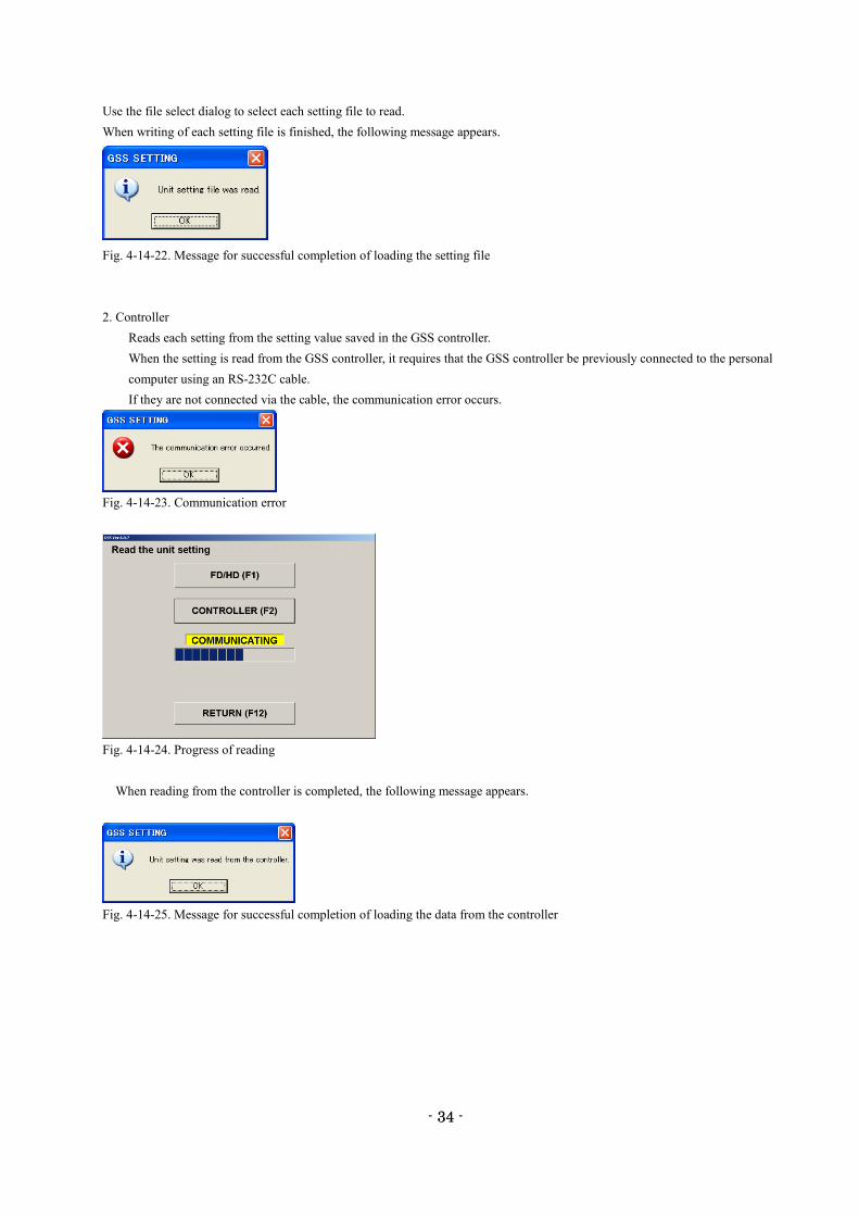
Use the file select dialog to select each setting file to read.
When writing of each setting file is finished, the following message appears.
Fig. 4-14-22. Message for successful completion of loading the setting file
2. Controller
Reads each setting from the setting value saved in the GSS controller.
When the setting is read from the GSS controller, it requires that the GSS controller be previously connected to the personal
computer using an RS-232C cable.
If they are not connected via the cable, the communication error occurs.
Fig. 4-14-23. Communication error
Fig. 4-14-24. Progress of reading
When reading from the controller is completed, the following message appears.
Fig. 4-14-25. Message for successful completion of loading the data from the controller
- 35 -
35
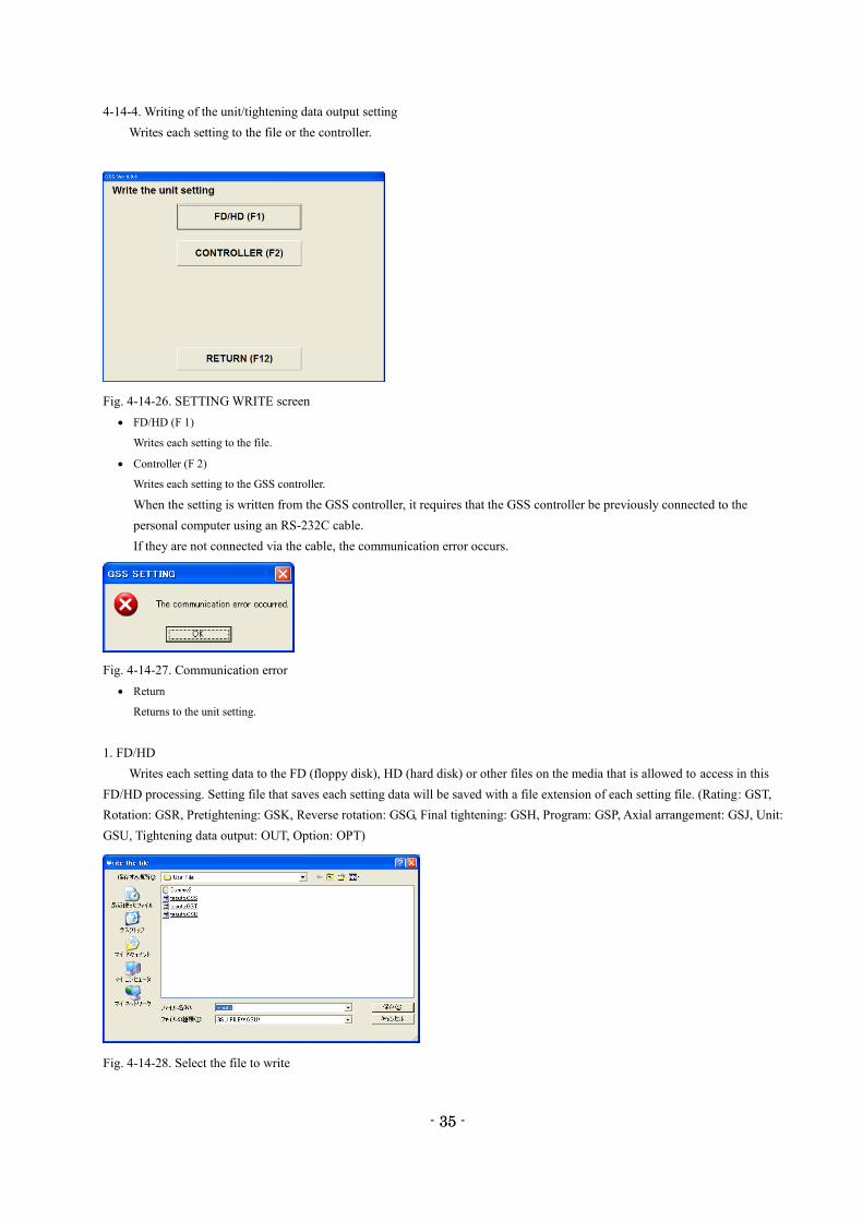
4-14-4. Writing of the unit/tightening data output setting
Writes each setting to the file or the controller.
Fig. 4-14-26. SETTING WRITE screen
FD/HD (F 1)
Writes each setting to the file.
Controller (F 2)
Writes each setting to the GSS controller.
When the setting is written from the GSS controller, it requires that the GSS controller be previously connected to the
personal computer using an RS-232C cable.
If they are not connected via the cable, the communication error occurs.
Fig. 4-14-27. Communication error
Return
Returns to the unit setting.
1. FD/HD
Writes each setting data to the FD (floppy disk), HD (hard disk) or other files on the media that is allowed to access in this
FD/HD processing. Setting file that saves each setting data will be saved with a file extension of each setting file. (Rating: GST,
Rotation: GSR, Pretightening: GSK, Reverse rotation: GSG, Final tightening: GSH, Program: GSP, Axial arrangement: GSJ, Unit:
GSU, Tightening data output: OUT, Option: OPT)
Fig. 4-14-28. Select the file to write
- 36 -
36
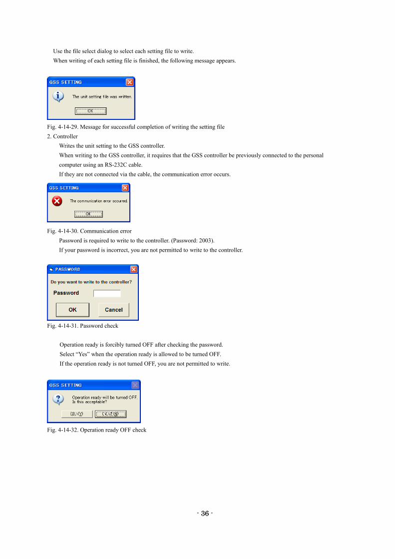
Use the file select dialog to select each setting file to write.
When writing of each setting file is finished, the following message appears.
Fig. 4-14-29. Message for successful completion of writing the setting file
2. Controller
Writes the unit setting to the GSS controller.
When writing to the GSS controller, it requires that the GSS controller be previously connected to the personal
computer using an RS-232C cable.
If they are not connected via the cable, the communication error occurs.
Fig. 4-14-30. Communication error
Password is required to write to the controller. (Password: 2003).
If your password is incorrect, you are not permitted to write to the controller.
Fig. 4-14-31. Password check
Operation ready is forcibly turned OFF after checking the password.
Select “Yes” when the operation ready is allowed to be turned OFF.
If the operation ready is not turned OFF, you are not permitted to write.
Fig. 4-14-32. Operation ready OFF check
- 37 -
37
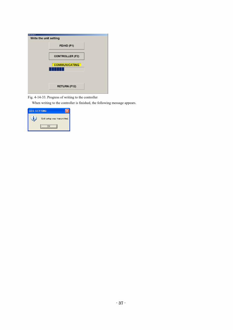
Fig. 4-14-33. Progress of writing to the controller
When writing to the controller is finished, the following message appears.
- 38 -
38
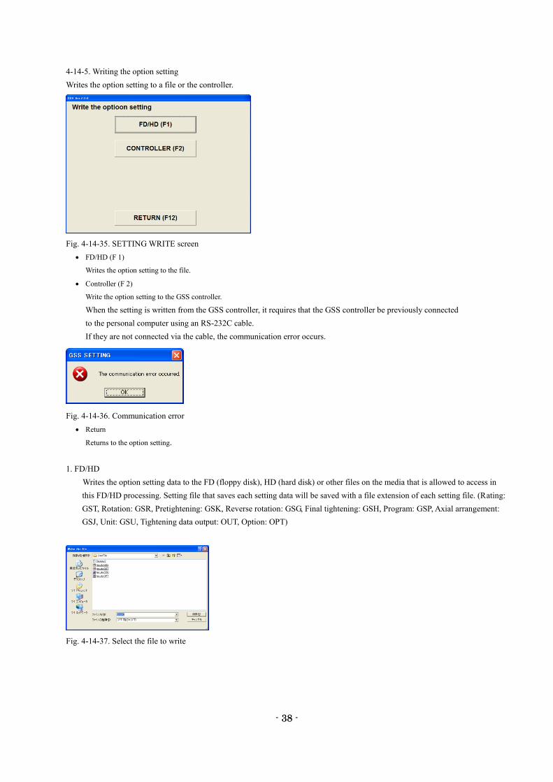
4-14-5. Writing the option setting
Writes the option setting to a file or the controller.
Fig. 4-14-35. SETTING WRITE screen
FD/HD (F 1)
Writes the option setting to the file.
Controller (F 2)
Write the option setting to the GSS controller.
When the setting is written from the GSS controller, it requires that the GSS controller be previously connected
to the personal computer using an RS-232C cable.
If they are not connected via the cable, the communication error occurs.
Fig. 4-14-36. Communication error
Return
Returns to the option setting.
1. FD/HD
Writes the option setting data to the FD (floppy disk), HD (hard disk) or other files on the media that is allowed to access in
this FD/HD processing. Setting file that saves each setting data will be saved with a file extension of each setting file. (Rating:
GST, Rotation: GSR, Pretightening: GSK, Reverse rotation: GSG, Final tightening: GSH, Program: GSP, Axial arrangement:
GSJ, Unit: GSU, Tightening data output: OUT, Option: OPT)
Fig. 4-14-37. Select the file to write
- 39 -
39
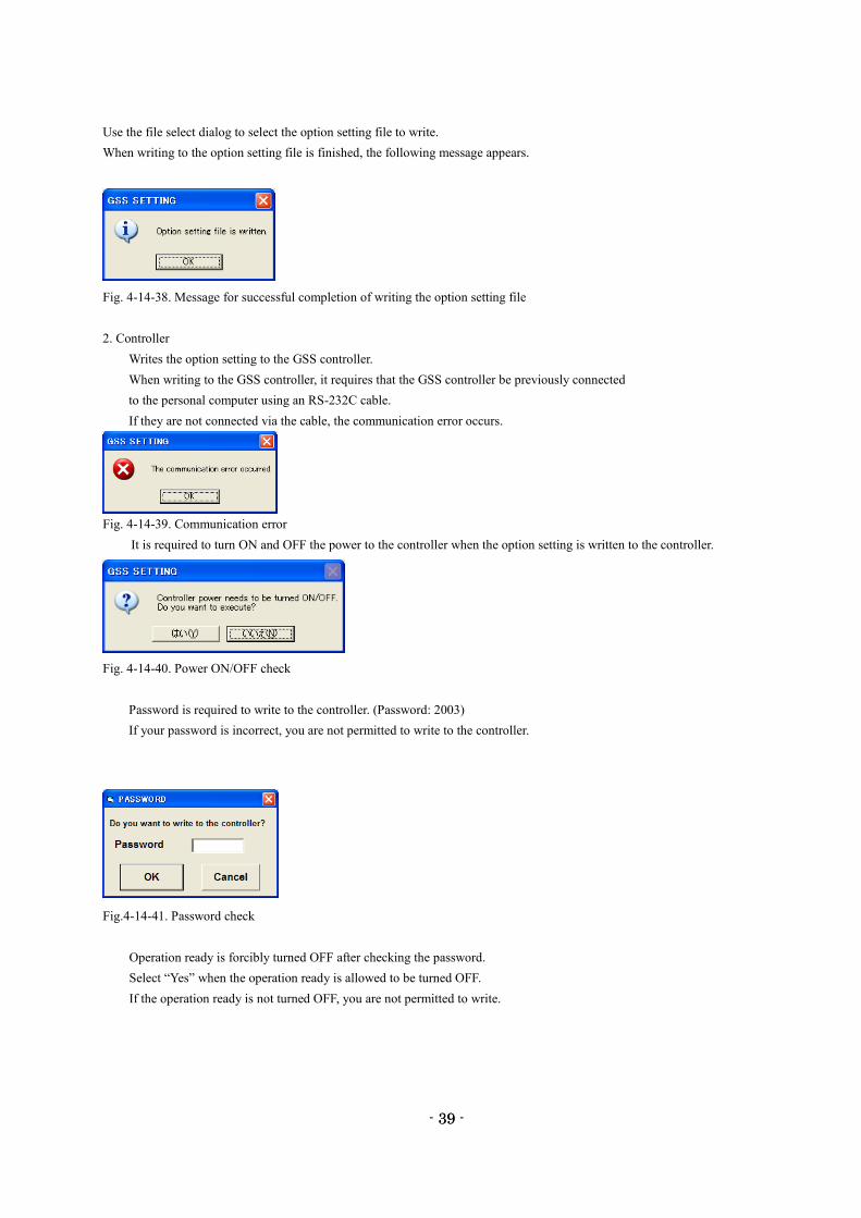
Use the file select dialog to select the option setting file to write.
When writing to the option setting file is finished, the following message appears.
Fig. 4-14-38. Message for successful completion of writing the option setting file
2. Controller
Writes the option setting to the GSS controller.
When writing to the GSS controller, it requires that the GSS controller be previously connected
to the personal computer using an RS-232C cable.
If they are not connected via the cable, the communication error occurs.
Fig. 4-14-39. Communication error
It is required to turn ON and OFF the power to the controller when the option setting is written to the controller.
Fig. 4-14-40. Power ON/OFF check
Password is required to write to the controller. (Password: 2003)
If your password is incorrect, you are not permitted to write to the controller.
Fig.4-14-41. Password check
Operation ready is forcibly turned OFF after checking the password.
Select “Yes” when the operation ready is allowed to be turned OFF.
If the operation ready is not turned OFF, you are not permitted to write.
- 40 -
40
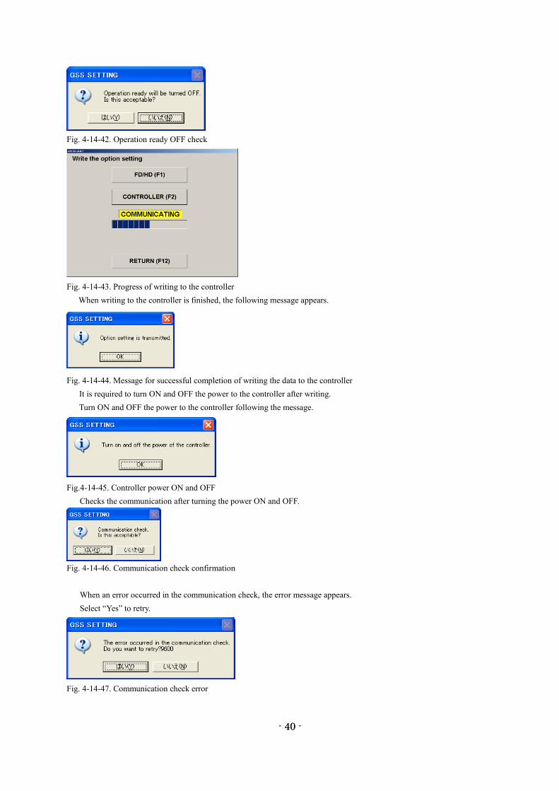
Fig. 4-14-42. Operation ready OFF check
Fig. 4-14-43. Progress of writing to the controller
When writing to the controller is finished, the following message appears.
Fig. 4-14-44. Message for successful completion of writing the data to the controller
It is required to turn ON and OFF the power to the controller after writing.
Turn ON and OFF the power to the controller following the message.
Fig.4-14-45. Controller power ON and OFF
Checks the communication after turning the power ON and OFF.
Fig. 4-14-46. Communication check confirmation
When an error occurred in the communication check, the error message appears.
Select “Yes” to retry.
Fig. 4-14-47. Communication check error
- 41 -
41
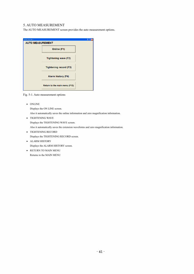
5. AUTO MEASUREMENT
The AUTO MEASUREMENT screen provides the auto measurement options.
Fig. 5-1. Auto measurement options
ONLINE
Displays the ON LINE screen.
Also it automatically saves the online information and zero magnification information.
TIGHTENING WAVE
Displays the TIGHTENING WAVE screen.
Also it automatically saves the extension waveforms and zero magnification information.
TIGHTENING RECORD
Displays the TIGHTENING RECORD screen.
ALARM HISTORY
Displays the ALARM HISTORY screen.
RETURN TO MAIN MENU
Returns to the MAIN MENU
- 42 -
42
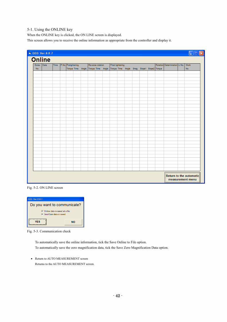
5-1. Using the ONLINE key
When the ONLINE key is clicked, the ON LINE screen is displayed.
This screen allows you to receive the online information as appropriate from the controller and display it.
Fig. 5-2. ON LINE screen
Fig. 5-3. Communication check
To automatically save the online information, tick the Save Online to File option.
To automatically save the zero magnification data, tick the Save Zero Magnification Data option.
Return to AUTO MEASUREMENT screen
Returns to the AUTO MEASUREMENT screen.
- 43 -
43
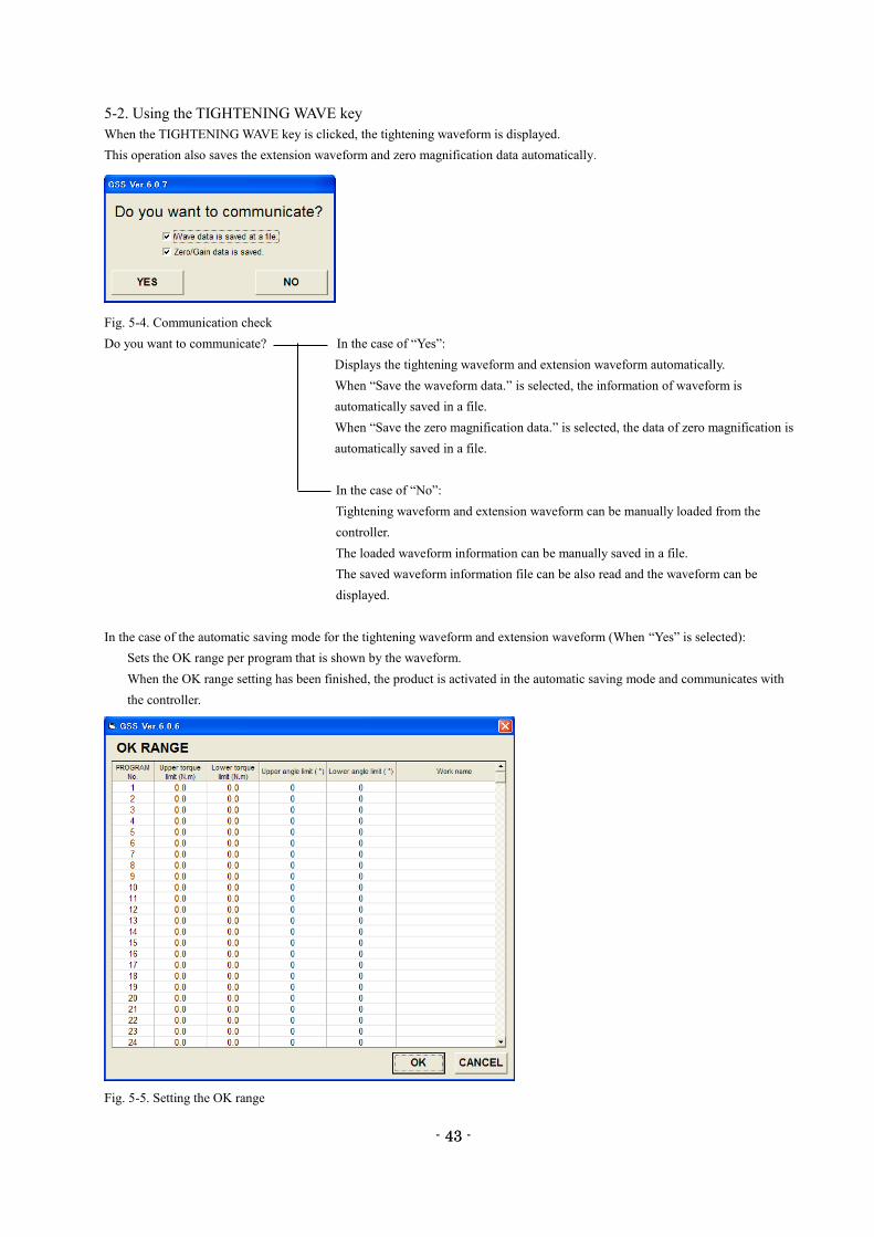
5-2. Using the TIGHTENING WAVE key
When the TIGHTENING WAVE key is clicked, the tightening waveform is displayed.
This operation also saves the extension waveform and zero magnification data automatically.
Fig. 5-4. Communication check
Do you want to communicate? In the case of “Yes”:
Displays the tightening waveform and extension waveform automatically.
When “Save the waveform data.” is selected, the information of waveform is
automatically saved in a file.
When “Save the zero magnification data.” is selected, the data of zero magnification is
automatically saved in a file.
In the case of “No”:
Tightening waveform and extension waveform can be manually loaded from the
controller.
The loaded waveform information can be manually saved in a file.
The saved waveform information file can be also read and the waveform can be
displayed.
In the case of the automatic saving mode for the tightening waveform and extension waveform (When “Yes” is selected):
Sets the OK range per program that is shown by the waveform.
When the OK range setting has been finished, the product is activated in the automatic saving mode and communicates with
the controller.
Fig. 5-5. Setting the OK range
- 44 -
44
Upper torque limit
Enter the upper torque limit in the OK range.
Lower torque limit
Enter the lower torque limit in the OK range.
Upper angle limit
Enter the upper angle limit in the OK range.
Lower angle limit
Enter the lower angle limit in the OK range.
Work name
Enter the work name.
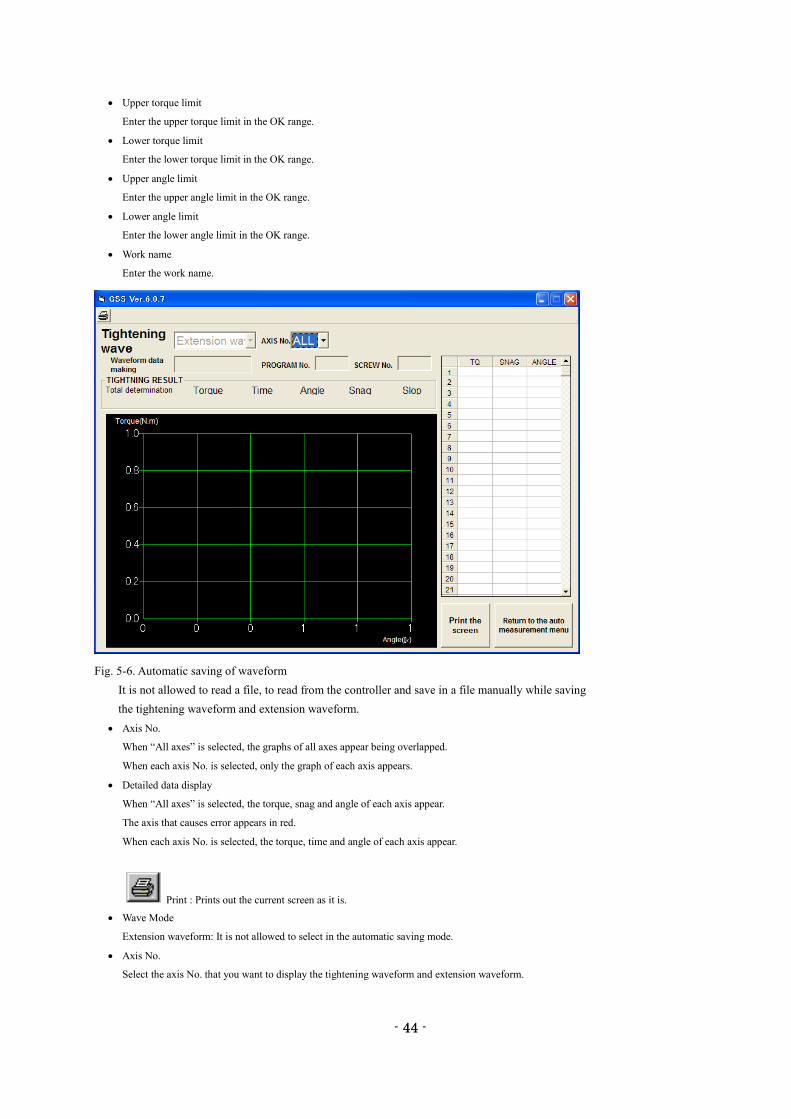
Fig. 5-6. Automatic saving of waveform
It is not allowed to read a file, to read from the controller and save in a file manually while saving
the tightening waveform and extension waveform.
Axis No.
When “All axes” is selected, the graphs of all axes appear being overlapped.
When each axis No. is selected, only the graph of each axis appears.
Detailed data display
When “All axes” is selected, the torque, snag and angle of each axis appear.
The axis that causes error appears in red.
When each axis No. is selected, the torque, time and angle of each axis appear.
Print : Prints out the current screen as it is.
Wave Mode
Extension waveform: It is not allowed to select in the automatic saving mode.
Axis No.
Select the axis No. that you want to display the tightening waveform and extension waveform.
- 45 -
45
Time of Tightening Data
Displays the time and date when the tightening waveform information was obtained.
Program No.
Displays the program number for which the tightening waveform information was obtained.
Screw No.
Displays the screw number for which the tightening waveform information was obtained.
Print button
Prints out the currently displayed screen.
Return to AUTO MEASUREMENT screen
Returns to the AUTO MEASUREMENT screen.
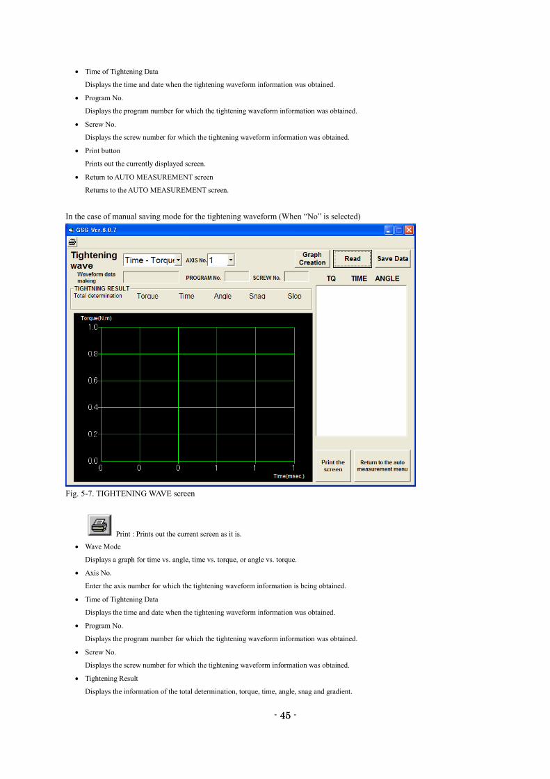
In the case of manual saving mode for the tightening waveform (When “No” is selected)
Fig. 5-7. TIGHTENING WAVE screen
Print : Prints out the current screen as it is.
Wave Mode
Displays a graph for time vs. angle, time vs. torque, or angle vs. torque.
Axis No.
Enter the axis number for which the tightening waveform information is being obtained.
Time of Tightening Data
Displays the time and date when the tightening waveform information was obtained.
Program No.
Displays the program number for which the tightening waveform information was obtained.
Screw No.
Displays the screw number for which the tightening waveform information was obtained.
Tightening Result
Displays the information of the total determination, torque, time, angle, snag and gradient.
- 46 -
46
Graph Creation button
Creates a tightening result graph.
Data Save button
Saves the wave data loaded from the controller to a file.
Read button
Loads the tightening wave data for the specified axis number from the controller. This also allows you to load wave data from the saved file.
Data Display
Numerically displays the tightening result information.
Select the displayed tightening result and then click the Graph Creation button. A graph will be created in an arbitrary data range.
Graph Display
Displays a graph from the tightening result information.
Print button
Prints out the currently displayed screen.
Return to AUTO MEASUREMENT screen
Returns to the AUTO MEASUREMENT screen.
- 47 -
47
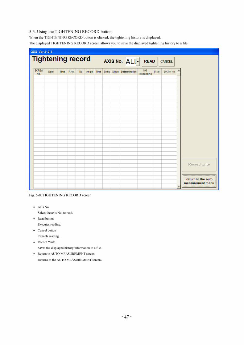
5-3. Using the TIGHTENING RECORD button
When the TIGHTENING RECORD button is clicked, the tightening history is displayed.
The displayed TIGHTENING RECORD screen allows you to save the displayed tightening history to a file.
Fig. 5-8. TIGHTENING RECORD screen
Axis No.
Select the axis No. to read.
Read button
Executes reading.
Cancel button
Cancels reading.
Record Write
Saves the displayed history information to a file.
Return to AUTO MEASUREMENT screen
Returns to the AUTO MEASUREMENT screen.
- 48 -
48
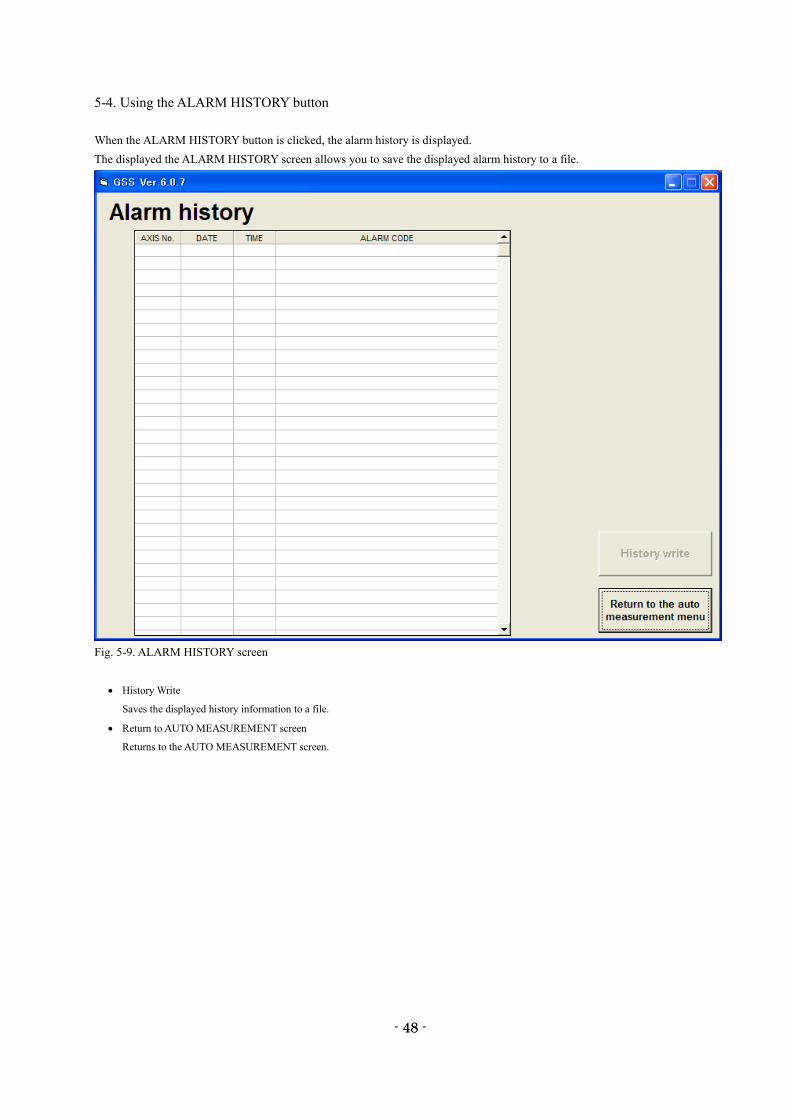
5-4. Using the ALARM HISTORY button
When the ALARM HISTORY button is clicked, the alarm history is displayed.
The displayed the ALARM HISTORY screen allows you to save the displayed alarm history to a file.
Fig. 5-9. ALARM HISTORY screen
History Write
Saves the displayed history information to a file.
Return to AUTO MEASUREMENT screen
Returns to the AUTO MEASUREMENT screen.
- 49 -
49
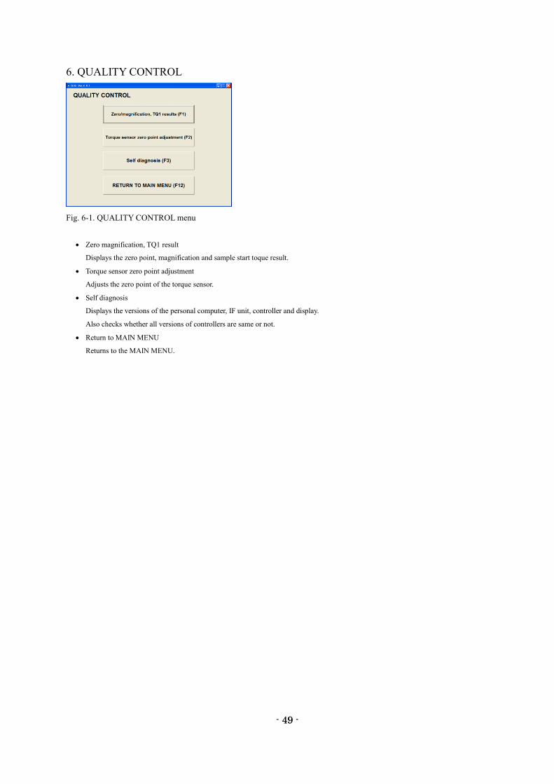
6. QUALITY CONTROL
Fig. 6-1. QUALITY CONTROL menu
Zero magnification, TQ1 result
Displays the zero point, magnification and sample start toque result.
Torque sensor zero point adjustment
Adjusts the zero point of the torque sensor.
Self diagnosis
Displays the versions of the personal computer, IF unit, controller and display.
Also checks whether all versions of controllers are same or not.
Return to MAIN MENU
Returns to the MAIN MENU.
- 50 -
50
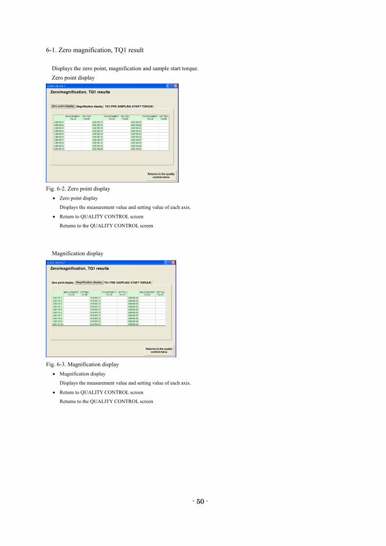
6-1. Zero magnification, TQ1 result
Displays the zero point, magnification and sample start torque.
Zero point display
Fig. 6-2. Zero point display
Zero point display
Displays the measurement value and setting value of each axis.
Return to QUALITY CONTROL screen
Returns to the QUALITY CONTROL screen
Magnification display
Fig. 6-3. Magnification display
Magnification display
Displays the measurement value and setting value of each axis.
Return to QUALITY CONTROL screen
Returns to the QUALITY CONTROL screen
- 51 -
51
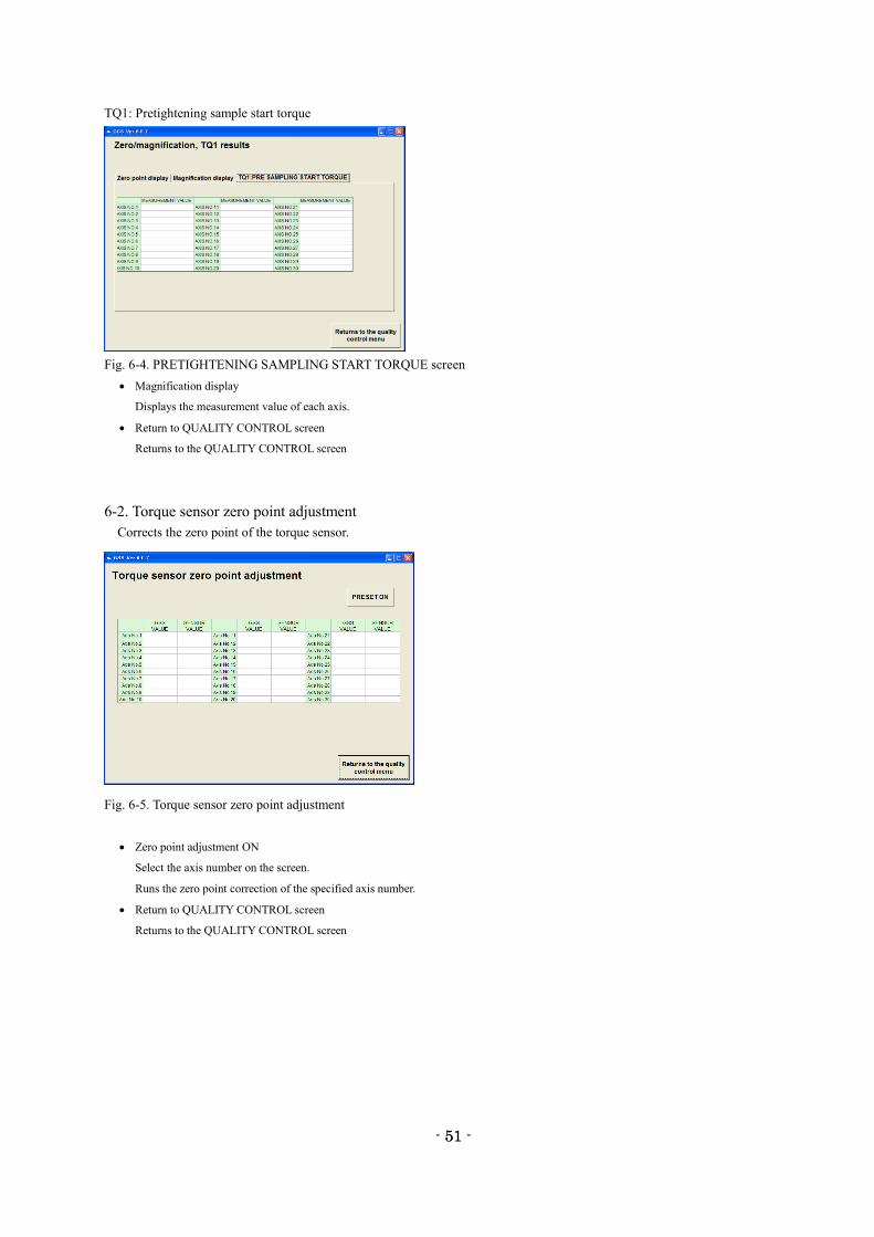
TQ1: Pretightening sample start torque
Fig. 6-4. PRETIGHTENING SAMPLING START TORQUE screen
Magnification display
Displays the measurement value of each axis.
Return to QUALITY CONTROL screen
Returns to the QUALITY CONTROL screen
6-2. Torque sensor zero point adjustment
Corrects the zero point of the torque sensor.
Fig. 6-5. Torque sensor zero point adjustment
Zero point adjustment ON
Select the axis number on the screen.
Runs the zero point correction of the specified axis number.
Return to QUALITY CONTROL screen
Returns to the QUALITY CONTROL screen
- 52 -
52
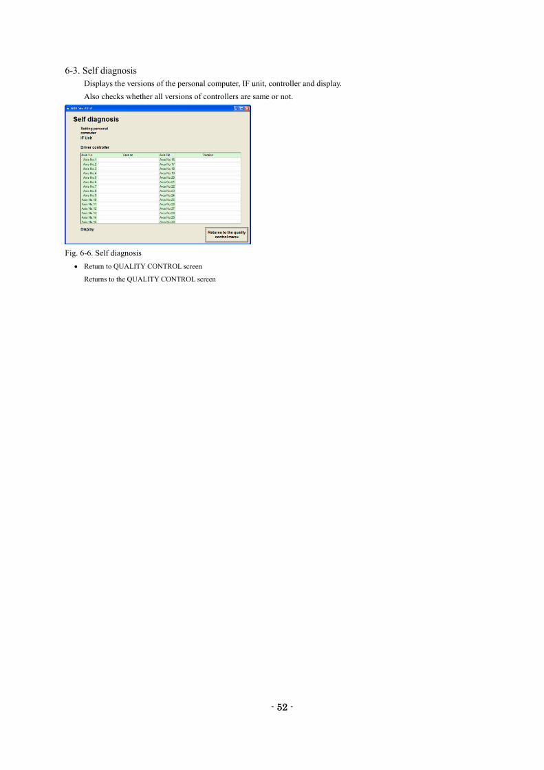
6-3. Self diagnosis
Displays the versions of the personal computer, IF unit, controller and display.
Also checks whether all versions of controllers are same or not.
Fig. 6-6. Self diagnosis
Return to QUALITY CONTROL screen
Returns to the QUALITY CONTROL screen
- 53 -
53
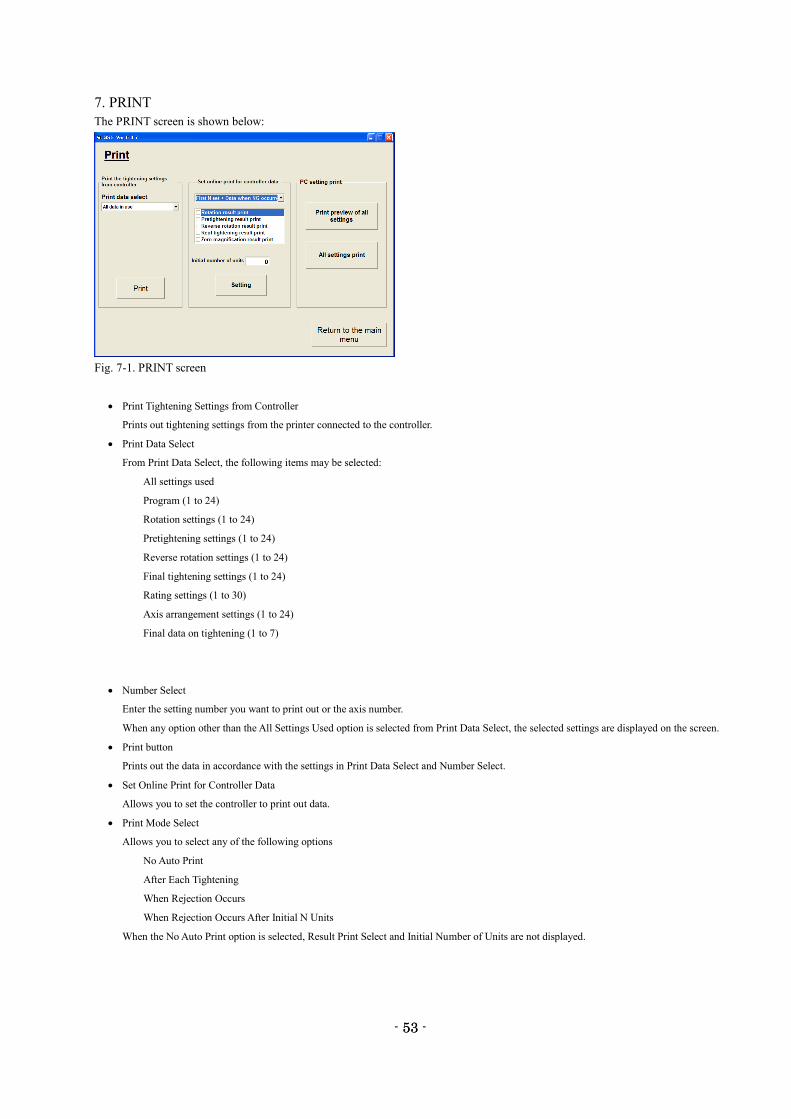
7. PRINT
The PRINT screen is shown below:
Fig. 7-1. PRINT screen
Print Tightening Settings from Controller
Prints out tightening settings from the printer connected to the controller.
Print Data Select
From Print Data Select, the following items may be selected:
All settings used
Program (1 to 24)
Rotation settings (1 to 24)
Pretightening settings (1 to 24)
Reverse rotation settings (1 to 24)
Final tightening settings (1 to 24)
Rating settings (1 to 30)
Axis arrangement settings (1 to 24)
Final data on tightening (1 to 7)
Number Select
Enter the setting number you want to print out or the axis number.
When any option other than the All Settings Used option is selected from Print Data Select, the selected settings are displayed on the screen.
Print button
Prints out the data in accordance with the settings in Print Data Select and Number Select.
Set Online Print for Controller Data
Allows you to set the controller to print out data.
Print Mode Select
Allows you to select any of the following options
No Auto Print
After Each Tightening
When Rejection Occurs
When Rejection Occurs After Initial N Units
When the No Auto Print option is selected, Result Print Select and Initial Number of Units are not displayed.
- 54 -
54
Result Print Select
Allows you to select any of the following options:
Rotation Result Print
Pretightening Result Print
Reverse Rotation Result Print
Final Tightening Result Print
Zero Magnification Result Print
Initial Number of Units
Enter the initial number of units.
Initial Number of Units is only displayed when the print mode is “When Rejection Occurs After Initial N Units”.
PC Setting Print
Prints out settings from the personal computer.
Print Preview of All Settings
Displays a print preview of all the settings.
All Settings Print
Prints out all the settings.
- 55 -
55
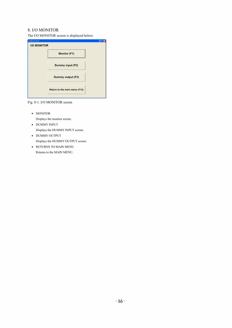
8. I/O MONITOR
The I/O MONITOR screen is displayed below:
Fig. 8-1. I/O MONITOR screen
MONITOR
Displays the monitor screen.
DUMMY INPUT
Displays the DUMMY INPUT screen.
DUMMY OUTPUT
Displays the DUMMY OUTPUT screen.
RETURNS TO MAIN MENU
Returns to the MAIN MENU.
- 56 -
56
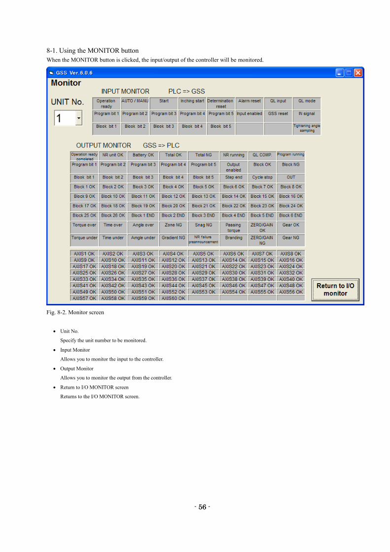
8-1. Using the MONITOR button
When the MONITOR button is clicked, the input/output of the controller will be monitored.
Fig. 8-2. Monitor screen
Unit No.
Specify the unit number to be monitored.
Input Monitor
Allows you to monitor the input to the controller.
Output Monitor
Allows you to monitor the output from the controller.
Return to I/O MONITOR screen
Returns to the I/O MONITOR screen.
- 57 -
57
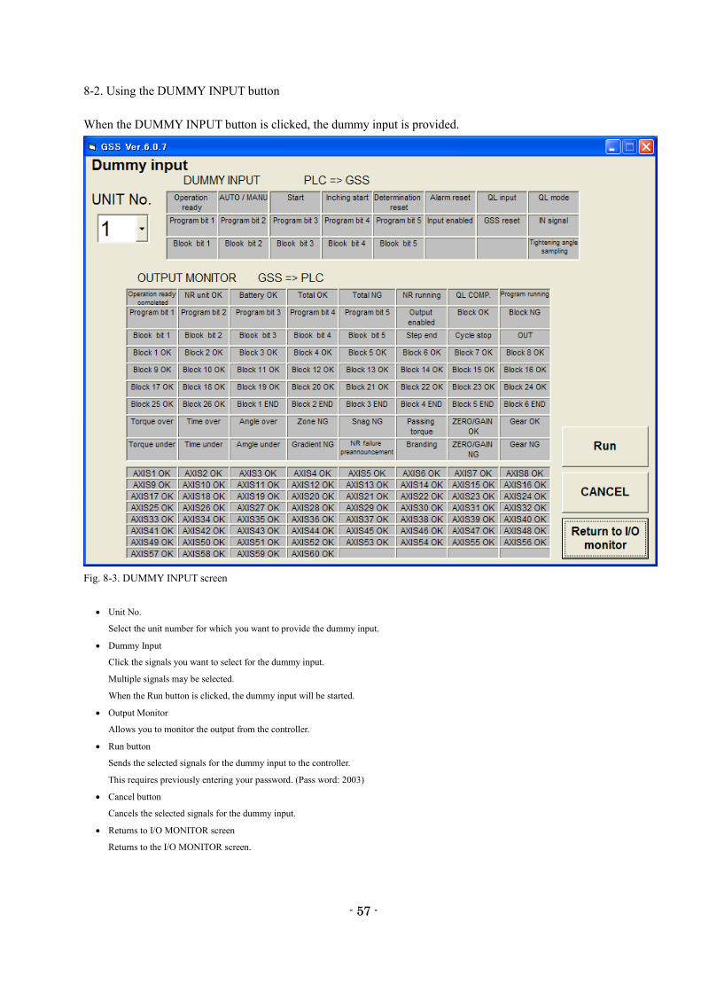
8-2. Using the DUMMY INPUT button
When the DUMMY INPUT button is clicked, the dummy input is provided.
Fig. 8-3. DUMMY INPUT screen
Unit No.
Select the unit number for which you want to provide the dummy input.
Dummy Input
Click the signals you want to select for the dummy input.
Multiple signals may be selected.
When the Run button is clicked, the dummy input will be started.
Output Monitor
Allows you to monitor the output from the controller.
Run button
Sends the selected signals for the dummy input to the controller.
This requires previously entering your password. (Pass word: 2003)
Cancel button
Cancels the selected signals for the dummy input.
Returns to I/O MONITOR screen
Returns to the I/O MONITOR screen.
- 58 -
58
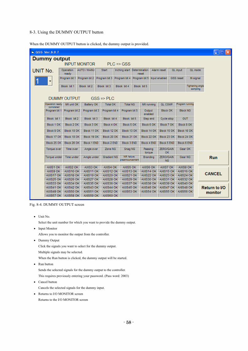
8-3. Using the DUMMY OUTPUT button
When the DUMMY OUTPUT button is clicked, the dummy output is provided.
Fig. 8-4. DUMMY OUTPUT screen
Unit No.
Select the unit number for which you want to provide the dummy output.
Input Monitor
Allows you to monitor the output from the controller.
Dummy Output
Click the signals you want to select for the dummy output.
Multiple signals may be selected.
When the Run button is clicked, the dummy output will be started.
Run button
Sends the selected signals for the dummy output to the controller.
This requires previously entering your password. (Pass word: 2003)
Cancel button
Cancels the selected signals for the dummy input.
Returns to I/O MONITOR screen
Returns to the I/O MONITOR screen
- 59 -
59
Glossary
UNIT:
Multiple axes control up to 30 axes can be treated as each axis to independently operate or as a group of
several axes (a unit) to operate together. One interface unit can control the maximum 7 units. At least one
controller belongs to one unit (maximum 30 axes control to one unit), and one input command is assigned
to one unit and then all belonging axes start operation simultaneously. In SIO, different station numbers
are assigned to each unit.
PROGRAM:
Screw tightening program can form the program from 1 to 24 on each axis. One program begins with the
control flag (Zero magnification check is performed or not, etc.) and rating setting, and it is possible to set
operation to maximum 50 steps. However, the end is treated as one step. At least one block should have
been set in the program.
BLOCK:
A set of operations in tightening program. Block start begins from rating step and shows the set of steps to
the end declaration. In automatic operation, one-time program start executes one block. It is also possible
to start from the block on the way by designating the block number. The determination (Block OK/NG)
against the operated block is output on the step in the block end declaration. If "NG" is determined on
either step in the block, it becomes the "block NG" determination (excluding the case when there is a
retry); the next step will not be executed.
After determination output, the program start initiates the next block.
STEP:
Each operation (Rotation, pretightening, reverse rotation and final tightening), block end declaration, and
retry are called steps respectively. More than one block is needed in a program. Program is executed from
the step 1 and finished by the end declaration at the final block. On the step of the final block end
declaration, the total determination (Total OK/NG) is output.
Each axis in the unit operates by step synchronization and the axis in which step has been complete turns
OFF the servo motor and waits for the step completion of other axes. When steps of all axes are complete,
the next step will be operated.
QL INPUT:
In the block where the tightening operation is in progress, if the tightening operation is not within the OK
range, "NG" determination is output in this block. At this time, it is possible to change the determination
"NG" to "OK" by inputting the tightening output of the manual torque wrench to the controller. This input
is called a QL input.
RETRY:
It is possible to retry (try again) operation if NG occurred in each operation (rotation, pretightening,
reverse rotation or final tightening) in the block. When the retry operation is set on the step, if NG
occurred on the way from the block start declaration till the previous step of retry, the operation following
the retry will be executed. If NG did not occur, the operation following the retry will not be executed.
ROTATION:
Used for screw pick up (a socket picks up a screw head) operation before tightening or preventive
operation against socket-engagement after tightening.
- 60 -
60
PRETIGHTENING:
Operation to perform temporary tightening until a screw seats.
REVERSE ROTATION:
Operation to unfasten the seated screw by several turns. It is possible to determine the screw baking by
monitoring the residual torque during this tightening operation.
FINAL TIGHTENING:
Final tightening operation of screws
APPLICABLE TO ID CONTROLLERS:
It is possible to transfer the engine number, set the calendar and transmit the result data by connecting the
interface unit and ID controller via serial communication. (Exclusive use with a printer.)
APPLICABLE TO PRINTERS:
Connects with a printer through Centronics interface. Setting data and tightening result can be printed.
(Exclusive use with a QC personal computer and ID controller.)
TIGHTENING ANGLE SAMPLING OPERATION:
Operation to rotate the screw in the tightening direction at a constant speed and then stop when it reaches
the preset torque, in order to measure the screw length. This operation allows you to easily set the
tightening program. (Executable only from a personal computer.)

- 61 -
61
Revised Contents
Revised Date Revised Contents
May. 2004(first edition) -
Mar. 2020(second edition) E-mail address change
I add a homepage address

- 62 -
62
GIKEN INDUSTRIAL CO., LTD. ■ Headquarters
97-8, Imago-cho
Yamatokoriyama, Nara, 639-1031
TEL: 0743-59-3730
FAX: 0743-59-3733
E-Mail(Sales engineering department): [email protected]
E-Mail(Control engineering section): [email protected]
HomePage address: http://www.gikenkogyo.com
■ Nagoya Branch Office
1202, Kumada, Nagakute-cho
Aichi Country, Aichi, 480-1144
TEL: 0561-63-5321
FAX: 0561-63-5320
E-Mail: [email protected]
■ Kanto Branch Office
1-2-15, Matoba, Kawagoe-city,
Saitama, 350-1101
TEL: 0429-65-9321
FAX: 0429-65-9322
E-Mail: [email protected]
The second edition in Mar. 2020


