Embed Size (px)
Citation preview

INSTRUCTION MANUAL
EN
INSTRUCTION MANUAL
QPX750SP750W Laboratory Power Supply

CONTENTS
1 Product Description ....................................................................................................................... 2
2 Safety ............................................................................................................................................... 3 2.1 Symbols .................................................................................................................................................. 3 2.2 Safety notices ......................................................................................................................................... 4
3 Installation ...................................................................................................................................... 5 3.1 Mounting ................................................................................................................................................. 5 3.2 Ventilation ............................................................................................................................................... 5 3.3 Electrical Requirements .......................................................................................................................... 5
4 Instrument Overview ...................................................................................................................... 6 4.1 Front Panel ............................................................................................................................................. 6 4.2 Rear Panel .............................................................................................................................................. 8
5 Getting Started .............................................................................................................................10 5.1 Using this manual ................................................................................................................................. 10 5.2 Switching on ......................................................................................................................................... 10 5.3 Home Screen / Settings Menu .............................................................................................................. 11 5.4 Meter status .......................................................................................................................................... 12 5.5 Status bar ............................................................................................................................................. 14 5.6 Navigation controls ............................................................................................................................... 15
6 Menu ..............................................................................................................................................16 6.1 Instrument ............................................................................................................................................. 16 6.2 System .................................................................................................................................................. 20 6.3 Interface ................................................................................................................................................ 21 6.4 Messages ............................................................................................................................................. 22 6.5 Info........................................................................................................................................................ 23 6.6 Help ...................................................................................................................................................... 23 6.7 File Ops ................................................................................................................................................ 23 6.8 Defaults ................................................................................................................................................ 24 6.9 Calibration ............................................................................................................................................ 24
7 Messages. .....................................................................................................................................25 7.1 Error Messages .................................................................................................................................... 25 7.2 Warning messages ............................................................................................................................... 25 7.3 Information messages .......................................................................................................................... 25
8 Maintenance..................................................................................................................................26 8.1 Cleaning ............................................................................................................................................... 26 8.2 Firmware update ................................................................................................................................... 27
9 Remote Operation ........................................................................................................................28 9.1 USB Interface ....................................................................................................................................... 28 9.2 LAN Interface ........................................................................................................................................ 29 9.3 GPIB Interface ...................................................................................................................................... 31 9.4 Status Reporting ................................................................................................................................... 32 9.5 Remote/ local operation ........................................................................................................................ 36 9.6 Parameter Data Format ........................................................................................................................ 37 9.7 Command List ...................................................................................................................................... 37 9.8 SCPI Commands .................................................................................................................................. 38 9.9 SCPI Subsystems ................................................................................................................................. 39
10 Factory default settings ...........................................................................................................43
11 Specification .................................................................................................................................44 11.1 Output Specifications ............................................................................................................................ 44 11.2 Meter Specifications ............................................................................................................................. 45 11.3 Display Features ................................................................................................................................... 46

1 - Product Description
2 QPX750 Instruction Manual
1 PRODUCT DESCRIPTION
The QPX750 is a single output laboratory power supply with a maximum output power of 750 watts.
The PoweFlex+ design provides voltages up to 80V, currents up to 50A and flexible modes of operation (CC, CV, and CP) with automatic crossover, while offering an exceedingly wide range of operation, as detailed in the PowerFlex + curve.
This power supply achieves unusually low noise of <3mV rms at full power and good transient response of <2ms.
This high feature Power Supply displays load power and load impedance in addition to measurements of output voltage and
current. The load impedance calculation enables low resistance measurements to be made at high currents by creating a four-terminal connection, using the remote sense terminals. Also provided is a meter averaging function to dampen the load current - this can be selected in order to achieve more accurate results when measuring rapidly varying loads.
This versatile power supply offers Analog and Digital interface for remote control and Test System integration. Remote Communication is Standard with 2 interfaces: USB and LAN. An optional GPIB interface is also available. Analog inputs provide remote control of the output volts and current while Analog outputs provide monitoring of the output Voltage and current. Digital Opto isolated logic signals provide an input that can control the output state on and off and an output confirms the operating state; current limit, power limit, or any fault trip.
Housed in a ½ rack width, 3U high case with front input ventilation, an intelligent fan is used to minimise cooling noise. It is suited to both bench-top and system applications.
The instrument has two ranges: 50V or 80V. The unit is set on the SELV setting of 50V to reduce the risk of hazardous voltages and simplifying compliance with the safety requirements.
NOTE By default, the range that allows a maximum of 80V is disabled. To enable the 80V range - the user must manually select this range. Before confirming this choice, a warning will appear to inform of the risk.

2 - Safety
3 QPX750 Instruction Manual
2 SAFETY 2.1 Symbols This instruction manual contains information and warnings which must be followed by the user to ensure safe operation and to retain the instrument in a safe condition.
The following symbols are displayed on the instrument and throughout the manual, to ensure the safety of the user and the instrument, all information must be read before proceeding.
WARNING Indicates a hazard that, if not avoided, could result in injury or death.
CAUTION Indicates a hazard that could damage the product and may result in loss of important data or invalidation of the warranty.
NOTE Indicates a helpful tip.
EXAMPLE Indicates an example to show further details.
Terminal connected to chassis ground.
Instrument in STANDBY.
l Mains supply ON.
Alternating current.

2 - Safety
4 QPX750 Instruction Manual
2.2 Safety notices This instrument is:
· A safety Class I instrument according to IEC classification and has been designed to meet the requirements of EN61010-1 (Safety Requirements for Electrical Equipment for Measurement, Control and Laboratory Use). It is an Installation Category II instrument intended for operation from a normal single-phase supply.
· Designed for indoor use in a Pollution Degree 2 environment in the temperature range 5°C to 40°C, 20% - 80% RH (non-condensing).
· Tested in accordance with EN61010-1 and has been supplied in a safe condition. This instruction manual contains some information and warnings which have to be followed by the user to ensure safe operation and to retain the instrument in a safe condition.
WARNING Do not operate while condensation is present.
Do not operate outside its rated supply voltages or environmental range.
THIS INSTRUMENT MUST BE EARTHED. Ensure that only fuses with the required rated current and of the specified type are used for replacement.
The use of makeshift fuses and the short-circuiting of fuse holders is prohibited.
Use of this instrument in a manner not specified by these instructions may impair the safety protection provided.
Any interruption of the mains earth connector, inside or outside, will make the instrument dangerous. Intentional interruption is prohibited.
Any adjustment, maintenance, and repair of the opened instrument under voltage must be avoided. When connected, terminals may be live and opening the covers or removal of parts (except those that can be accessed by hand) may expose live parts.
Voltages above 60VDC are hazardous live according to EN 61010-1 and great care must be taken when using the power supply at voltages above this level. Capacitors inside the power supply may still be charged even if the power supply has been disconnected from all voltage sources but will be safely discharged about 10 minutes after switching off.
To avoid electric shock, or damage to the instrument, never allow water to get inside the case. If the instrument is clearly defective, or has been subject to mechanical damage, excessive moisture, or chemical corrosion, the safety protection may be impaired, and it must be withdrawn from use and returned for repair.
CAUTION Do not wet when cleaning, use only a soft dry cloth to clean the screen.
Do not use a sharp or pointed objects to operate the touch screen. Take care not to restrict the inlet vents at the front, rear, sides or underneath the instrument. In rack-mounted situations, allow adequate space around the instrument.
This instrument is protected by an internal fuse which is user serviceable (refer to Service Manual).
3 - Installation
5 QPX750 Instruction Manual
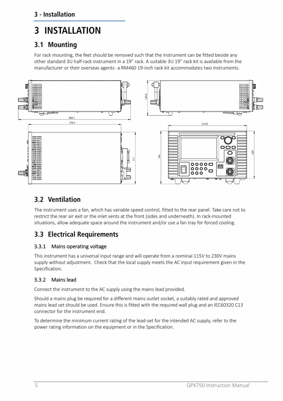
3 INSTALLATION 3.1 Mounting For rack mounting, the feet should be removed such that the instrument can be fitted beside any other standard 3U half-rack instrument in a 19” rack. A suitable 3U 19” rack kit is available from the manufacturer or their overseas agents - a RM460 19-inch rack kit accommodates two instruments.
3.2 Ventilation The instrument uses a fan, which has variable speed control, fitted to the rear panel. Take care not to restrict the rear air exit or the inlet vents at the front (sides and underneath). In rack-mounted situations, allow adequate space around the instrument and/or use a fan tray for forced cooling.
3.3 Electrical Requirements
3.3.1 Mains operating voltage
This instrument has a universal input range and will operate from a nominal 115V to 230V mains supply without adjustment. Check that the local supply meets the AC input requirement given in the Specification.
3.3.2 Mains lead
Connect the instrument to the AC supply using the mains lead provided.
Should a mains plug be required for a different mains outlet socket, a suitably rated and approved mains lead set should be used. Ensure this is fitted with the required wall plug and an IEC60320 C13 connector for the instrument end.
To determine the minimum current rating of the lead-set for the intended AC supply, refer to the power rating information on the equipment or in the Specification.

4 - Instrument Overview
6 QPX750 Instruction Manual
4 INSTRUMENT OVERVIEW
4.1 Front Panel
4.1.1 Overview
4.1.2 ① Colour Touch Screen Display
CAUTION Do not use sharp objects or pointed objects to operate the touch screen.
② Power Switch Power Switch is located in the bottom left-hand corner. Press to start the unit.
CAUTION When instrument is in Standby mode, Mains is still present.
③ Numeric Keypad Numeric keys permit direct entry of a value for the parameter currently selected.
④ Escape Key/Local/OK Entry can be abandoned at any point by pressing the ESCAPE key. It will also exit the selection or screen currently selected. This key is also used to clear output trip conditions, together with their pop-ups. Additionally, when in remote mode, this key is used to return the instrument to local operation. The OK key is used to confirm a selection.
⑤ Remote Sense Terminals Allows the user to adjust the voltage at the point of the load. The instrument has a very low output impedance, but this is inevitably increased by the resistance of the connecting leads and the contact resistance between terminals and leads. At high currents, this can result in significant differences between the indicated source voltage and the actual load voltage (even two 2mΩ connecting leads will drop 0·2V at 50 Amps, for instance). This problem can be minimised by using short, thick, connecting leads, but where necessary it can be completely overcome by using the remote sense capability.

4 - Instrument Overview
7 QPX750 Instruction Manual
CAUTION Voltage drop on sense leads should not exceed 2V.
NOTE To avoid instability and transient response problems, care must be taken to ensure good coupling between each output and sense lead; this can best be done by twisting the leads together. An electrolytic capacitor directly across the load connection point may also be beneficial. The voltage drop in each output lead must not exceed 1V.
⑥ Output Terminals The load should be connected to the positive (red) and negative (black) terminals marked OUTPUT. The terminals accept 4mm plugs into the end (but note that 4mm plugs will only support 30 Amps). For currents greater than 30A, 6mm diameter wires, plugs or 8mm spade connections (with a maximum blade width of 16mm) can be accepted into the cross-hole.
WARNING The wiring and connectors must be capable of supporting the current required; for 50 Amps, 6mm2 cable is needed.
WARNING Voltages above 60VDC are hazardous live according to EN 61010-1 and great care must be taken when using the power supply at voltages above this level.
Always make connections to the instrument with the OUTPUT off.
CAUTION Exceeding the maximum reverse voltage (90V) and current (3A) will damage the unit.
⑦ Volts/Amps/Lock Pressing either V or I to adjust the Voltage or Current, respectively. The LOCK key will light when active, indicating that the entire front panel is locked. In this mode, only navigation between menus is permitted. Long press for 3 seconds to deactivate the lock.
⑧ Rotary knob and Directional Keys The rotary knob is used to navigate the user interface - it features a ‘press’ function to select an option. See ‘Rotary knob’ for more details.
The direction keys are used for navigating parameter windows and scrolling numeric parameter values. In addition, the left directional key can be used as a backspace during editing. See ‘Front Panel Keys’ for more details.

4 - Instrument Overview
8 QPX750 Instruction Manual
4.2 Rear Panel
① AC power inlet ② GPIB (optional)
Requires GPIB 1A user retrofittable option. The default GPIB address is 11.
③ LAN The LAN interface is designed to meet 1.5 LXI (LAN extensions for Instrumentation) Core 2016. Remote control using the LAN interface is possible using a TCP/IP Socket protocol.
④ USB
The USB port accepts a standard USB cable. The Windows plug-and-play functions should automatically recognise that the instrument has been connected.
⑤ Terminal Block
Press the orange actuators of the screwless terminals, insert the connecting wire and release the actuator to secure the connection.
NOTE Minimum recommended cable 0.4mm, maximum. 0.8mm diameter cable. Always use shrouded ferrules to prevent the risk of shock.
Logic Control: LOGIC COMMON, LOGIC IN, LOGIC OUT, NC (no connection) see ‘Logic Control’ for setup and configuration details. LOGIC IN is connected to the input of an isolating opto-coupler via an 820Ω resistor in series. The input is activated by an input voltage greater than approximately 3.3V between LOGIC IN and LOGIC COMMON
LOGIC OUT is an isolated rear-panel open-collector output that will sink up to 2mA when active
CAUTION Do not apply an input voltage greater than 20V.
Do not apply volts greater than 30Vdc to LOGIC OUT
Analog Control / Monitor: I CONTROL, V CONTROL, COM, COM, I MONITOR, V MONITOR See ‘Analog Control’ for setup and configuration details.
4 - Instrument Overview
9 QPX750 Instruction Manual
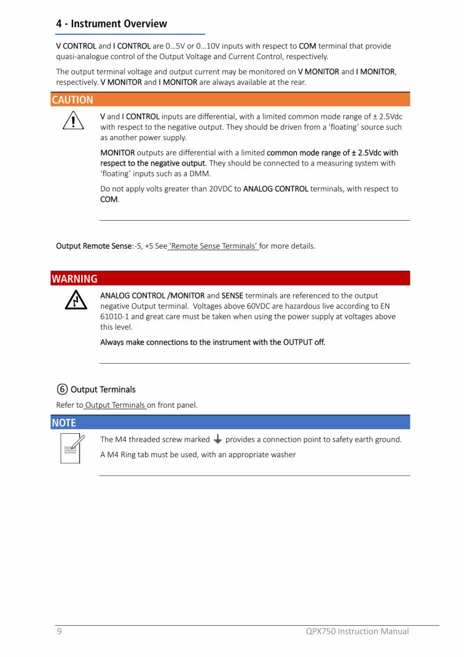
V CONTROL and I CONTROL are 0…5V or 0…10V inputs with respect to COM terminal that provide quasi-analogue control of the Output Voltage and Current Control, respectively.
The output terminal voltage and output current may be monitored on V MONITOR and I MONITOR, respectively. V MONITOR and I MONITOR are always available at the rear.
CAUTION V and I CONTROL inputs are differential, with a limited common mode range of ± 2.5Vdc with respect to the negative output. They should be driven from a ‘floating’ source such as another power supply.
MONITOR outputs are differential with a limited common mode range of ± 2.5Vdc with respect to the negative output. They should be connected to a measuring system with ‘floating’ inputs such as a DMM.
Do not apply volts greater than 20VDC to ANALOG CONTROL terminals, with respect to COM.
Output Remote Sense: -S, +S See 'Remote Sense Terminals’ for more details.
WARNING ANALOG CONTROL /MONITOR and SENSE terminals are referenced to the output negative Output terminal. Voltages above 60VDC are hazardous live according to EN 61010-1 and great care must be taken when using the power supply at voltages above this level.
Always make connections to the instrument with the OUTPUT off.
⑥ Output Terminals
Refer to Output Terminals on front panel.
NOTE The M4 threaded screw marked provides a connection point to safety earth ground.
A M4 Ring tab must be used, with an appropriate washer

5 - Getting Started
10 QPX750 Instruction Manual
5 GETTING STARTED 5.1 Using this manual This section is a general introduction to the operation of the instrument and is intended to be read before using the Power Supply for the first time.
In this manual front panel keys and sockets are shown in capitals, e.g. ON, OFF. Text, entry fields and messages displayed on the LCD are shown in a different font, e.g. V Set, I Set.
The descriptions in this manual relate to using the instrument via the touch screen, alternatively, the hard keys and rotary knob can be used. See ‘Navigation Controls’ for details on how to use the instrument in this way.
Throughout this manual, the navigation through menus will be shown at the top of a section using the following format:
Menu>Sub Menu>Option
NOTE The pop-up screens for parameters will only occur when using the touch screen.
Trip/System Failure, Error, and Warning pop-up screens will appear when using any form of navigation.
5.2 Switching on Connect the instrument to the AC supply using the mains lead provided.
Press the POWER switch. At power up, the instrument displays a start-up message whilst initialising the application.
Loading takes a few seconds, after which the home screen is displayed.
WARNING To fully disconnect from the AC supply, unplug the mains cord from the back of the instrument or switch off at the AC supply outlet; make sure that the means of disconnection are readily accessible. Disconnect from the AC supply when not in use.

5 - Getting Started
11 QPX750 Instruction Manual
5.3 Home Screen / Settings Menu The Home Screen will be shown when the instrument is powered on. It will include the default parameters.
To set volts or amps, select the parameter window and enter the value required. See ‘Navigation controls' for more details.
Use the ON/OFF key on the front panel to turn the output on.
The home screen and settings menus are designed to be used in conjunction with one another using the Settings and buttons.
① STATUS BAR Shows current status of the instrument. See ‘Status Bar' for more details. ② METER Displays the live volts/amps present at the output terminals. See ‘Meter Status’ ③ INFORMATION Lists the set information from the settings menu. ④ EDITABLE PARAMETERS
V set Set DC output voltage. Values are dependent on selected range.
I Set Set DC output current limit. Values are dependent on selected range.
Range Select operating range - 50V or 80V. 50V in steps of 1mV, 80V in steps of 2mV. As the resolution of the 80V range is 2mV, when switching from 50V to 80V range the set-point will be rounded down to the nearest 2mV figure (e.g., if output is set to 49.997 it will be changed to 49.996).
Plim
Set the power limit, this can also be used to regulate the power being delivered by the unit: 100W to 750W in 10W increments
OVP Set the Over Voltage Protection limit. Protects against dangerously high voltages: 2V to 90V
OCP Set the Over Current Protection limit. Protects against excessive current: 2A to 55A
Sense Select how the voltage is regulated. Local: Instrument will regulate set voltage Remote: Instrument will regulate set voltage at the point the remote sensing wires are connected.
Iavg
Select Current Averaging: The AMPS reading is still updated at the same rate (4 times per second), but the value displayed is a filtered rolling average of the last 4 current measurements made. On: The measured current value at the output terminals is filtered and displayed. Off: A sample of the measured output current value is shown on the display.
⑤ Navigation BUTTONS
Settings: Allows editing of the set parameters in the information box, shown in ③ Menu: Contains all system and instrument setups, see ‘Menu’ for more details. Back: Return to the previous screen.
①
③ ②
④ ⑤
②
④

5 - Getting Started
12 QPX750 Instruction Manual
5.4 Meter status The following symbols may appear in the meter display:
Mode With the output on, the mode shown will be: CV (Constant Voltage), CC (Constant Current) or CP (Constant Power), depending on the set limits and load conditions. The display will show the actual output voltage and current at the terminals.
CV Constant Voltage: Power supply will regulate at set voltage, provided the current and power are less than Iset and Plim, respectively.
CC Constant Current: Power supply will regulate at set current, provided the voltage and power are less than Vset and Plim, respectively.
CP Constant Power: Power supply will regulate at the set power, provided the voltage and current are less than Vset and Iset respectively. PowerFlex+ allows you to set voltage and currents that result in power greater than the power curve - in this case the active mode will depend on the load.
EXAMPLE Setting the instrument to:
Vset 36V, Iset 36A & Plim 750W.
Note: 36Vx36A = 1296W this is greater than max
2Ω load: display; 36V, 18A and 648W: CV mode
0.5Ω load: display; 18V, 36A and 648W: CC mode
1Ω load: display; ≈27V, ≈26A and 720W: CP mode
Protection
The OVP or OCP circuits will trip if an excessive voltage or current is accidentally set from the front panel (via a remote-control interface) or is the result of a failure in the control circuitry of the instrument itself. OVP will also trip if an excessive voltage is impressed across the terminals from an external source; however, when the output is tripped off, the external voltage will still be present, and it is up to the user to remove the source to avoid possible damage.
OVP Over Voltage Protection trip – If the output voltage exceeds the set OVP the output will immediately turn off (typically within 100µs), thus avoiding damage to the circuit under test.
OCP Over Current Protection trip - If the output current exceeds the set OCP the output is shut down (typically within 100ms), thus avoiding damage to the circuit under test.
High Voltage Mode active- The instrument is set to the 80V range and could provide potentially hazardous voltages.
NOTE It is possible to set OVP or OCP below Vset or Iset. This often results in the power supply unexpectedly turning the output off and can be used to turn the output off if the load changes and you do not want the voltage or current to fold back.

5 - Getting Started
13 QPX750 Instruction Manual
5.4.1 Meter colours If the output is switched off, the meter volts and current will be displayed in
Grey.
If the output is turned on the active volts will be shown in Yellow.
If the output is turned off but there are still volts present from an external source, that voltage measurement is shown in Red. Measured volts will show in Red until the output caps are discharged. The pre-set values will then be shown in Grey.
5.4.2 Load Impedance and power calculations
When the output is on, calculated load impedance (Ω) and output power (W) can be viewed on the meter underneath the voltage and current readings (Power only on Home Screen). The calculated load impedance function enables low resistance measurements to be made at high currents, e.g., RDS(on) of power MOSFETs., by creating a four-terminal connection, using the remote sense terminals.
NOTE Always use the Remote Sensing function to eliminate the effects of connecting lead and contact resistance when making low value V/A measurements. See 'Remote Sense Terminals’ for more information.

5 - Getting Started
14 QPX750 Instruction Manual
5.5 Status bar
① Analog Control
When choosing an active option on ‘Analog Control’, the choice of: V Only, I Only, V&I will appear in the status bar.
② Sense Trip
If SNS Trip appears, a sense error has occurred and caused a trip. The output is tripped off if the voltage between an output terminal and its corresponding sense terminal exceeds approximately 2V; this will happen if the sense wires are wired at the load to the wrong output or if an attempt is made to draw power from the sense wires. If the sense terminals are mis wired in this way the output is turned off and a pop-up will appear notifying of the trip; pressing ESCAPE at this point removes the message, pressing OK will remove the pop-up but SNS Trip will remain in the status bar. The display will now show the pre-set voltage and current limit. When the cause of the trip has been corrected, the output can be turned on again.
③ Remote status
· REM : This symbol will appear once the instrument starts to receive communications from any of the remote interfaces.
· : This symbol will appear if an error has occurred while using a remote interface, it can be viewed in ‘Remote Error Messages’.
· GPIB (optional): When a GPIB connection is detected, the GPIB icon will become activated.
· USB: When a USB connection is detected, the USB icon will become activated.
· LAN: The LAN field in the Status Line can show multiple status indications:
There is no LAN connection, for example no cable connected.
· Successfully connected.
· (Flashing icon) Configuring LAN connection.
· Unsuccessful attempt to connect.

5 - Getting Started
15 QPX750 Instruction Manual
5.6 Navigation controls The versatile user interface can be navigated using the touch screen, rotary knob, front panel keys or a combination of all three options.
Many settings can be made quickly and easily using the touch screen alone; the rotary knob is most useful when, for example, a parameter is being frequently increased or decreased during manual testing. Using the front panel keys is a quick way to directly edit when frequently changing a value.
There are two types of field; both of which are explained in this manual. A ‘button’ - ① - will apply an action. A ‘parameter’ - ② - will provide a list of options for the user to choose.
5.6.1 Touch screen
Touch to select an editable field, touch again to adjust the field. An editing screen will appear - enter the required values and touch OK. Editing screens will vary depending on field type, this could be a numeric keypad, QWERTY keypad or unique options related to that field. See appropriate menus for more details.
5.6.2 Front Panel Keys
Use the < > keys to highlight the actionable field and press OK. When editing a numeric field, pressing a number key will begin editing, other field type options can be viewed using the rotary encoder - press the OK key to action the change.
To directly edit set volts or amps, press the V or I key followed by number keys, press OK to action.
Editing state on a numeric field using the front panel numeric keys:
5.6.3 Rotary knob
The rotary knob offers two different states of editing – 2 State (default setting – detailed below) and 3 State. For further information, see ‘Encoder State Adjust’.
Press to initiate the rotary knob and turn to highlight the actionable fields from top to bottom, left to right. To select a field, press the knob. When an editable field is selected, adjustments can be made by turning the knob until the required value is selected. Press the knob to action the change.
Editing state on a numeric field with rotary knob:
① ②

6 - Menu
16 QPX750 Instruction Manual
6 MENUThis gives access to the menus used to:
· Set up operational parameters for the instrument, system, and remote interface.
· View messages, instrument information, and Help menus.
· Save and recall instrument setup. · Calibrate the instrument.
6.1 Instrument Menu> Instrument
This menu allows the user to set or recall the operational parameters that affect instrument use.
6.1.1 Power-on State
Menu>System>Power-ON State
These editable parameters determine what setting the power supply switches on with.
NOTE Always Off and Default Params. if a safe power up is required.
As Power Down and Latest Params. If a long-term test is running and the user wishes to restart automatically.
Output State: · Always Off: Output will remain off until manually set.
· As Power Down: Output will reset at the previously set state when the instrument was switched off.
Parameters: · Latest Params: Instrument will automatically load
parameters the unit was powered down with.
· Default Params: Unit will power up with the default values - see ‘Factory default settings’ for more information.

6 - Menu
17 QPX750 Instruction Manual
6.1.2 Analog Control
Menu>Instrument>Analog Control
Analog signal connections V CONTROL and I CONTROL are available from the terminal block on the ‘Rear Panel’. These can provide quasi-analog control of Output Voltage and Current Limit, respectively.
Control Type: · None: deselects the analog input, output voltage is
controlled by Vset and Iset
· V only: Enables analog control of the output voltageand disables Vset from front panel and remote.
· I Only: Enables analog control of the output anddisables Iset from front panel and remote.
· V&I: Enables analog control of both output voltageand output current.
Range Selected:
Sets the control voltage full scale range. Used to control Vset, Iset or V&I
· 0…10V
· 0…5V
EXAMPLE Setting: Range to 50V, Control type to V&I and Range selected to 0…10V.
Supply 0-5 volts into VCONTROL with respect to COMMON from a floating source i.e., PSU.
Applying 0V will result in 0V appearing on the Output Terminals
Applying 1V will result in 5V appearing on the Output Terminals
NOTE The inputs are read 4 times per second by the A-to-D converter and the output is set according to the selected input scaling range. See 'Terminal Block’ for hardware configuration details. When Analog Control is active, the parameter fields are no longer editable for the activated control type as the output is now controlled by the input on the rear terminal block.

6 - Menu
18 QPX750 Instruction Manual
6.1.3 Logic Control
Menu>Instrument>Logic Control
Digital signal connections LOGIC IN and LOGIC OUT are available from the terminal block on the ‘Rear Panel’.
Logic Out LOGIC OUT is an isolated rear-panel, open-collector output that will sink up to 2mA when active (‘switch closure’); the LOGIC OUT can be set to be ‘closed on’ or ‘closed off’ for instrument operating states: current limit (CC mode), power limit (CP mode), or for any fault trip. The default condition is for LOGIC OUT to be ‘closed’ for the output on. Loss of AC power, which would deactivate the opto, is also reliably detected with this setting.
Logic Out has the following states: -
· O/P On – Main output is turned on.
· Trip - Any fault trip condition OVP, OCP etc.
· CP- PSU operates in Constant Power regulation mode.
· CC- PSU operates in Constant Current regulation mode.
Logic In
LOGIC IN is connected to the input of an isolating opto-coupler via an 820Ω resistor in series. The input is activated by an input voltage greater than approximately 3.3V between LOGIC IN and LOGIC COMMON.
Logic In has the following states: -
· Ignored: Will not affect output.
· Enable O/P: Instrument will enable the output.
· Disable O/P: Instrument will disable the output.
NOTE • LOGIC IN can only be used to enable/disable the output if the output has already been turned
on with the front panel key or by remote interface command; this permits the front panel key to be used to turn the output off in an emergency, i.e., to override LOGIC IN. Having turned the output on with the key, the ON/OFF key remains illuminated even when the output is disabled by the LOGIC IN signal.

6 - Menu
19 QPX750 Instruction Manual
6.1.4 Save
Menu>Instrument>Save Instrument setups can be saved as a file to the internal storage, these settings include: · Set volts, current and power limit · Selected Range · Over voltage and Over current protection · Sense terminal setup · Current averaging settings · Power on state · Logic control settings · Analog control settings
The file name can be up to 8 characters and a combination of uppercase letters, numbers, and “- _” symbols.
6.1.5 Recall
Menu>Instrument>Recall
Recall a previously saved instrument setup file from the Internal Storage.
Use the keys to choose.
The files can be sorted into alphabetical order using the ^ file name(s) button. The selected file to be recalled is highlighted in white. Press Recall applying saved setup.

6 - Menu
20 QPX750 Instruction Manual
6.2 System Menu>System
This menu controls the look and feel of the instrument, it allows the user to set the operational parameters that affect the system use.
Brightness
Increase/decrease screen brightness by using the rotary knob to scroll through the options, or the touch screen to manually enter a value.
Colour Theme
Choose from 8 colour themes.
Encoder State Adjust · 2 State (default): The rotary knob is used together with
the < and > keys to select the parameter window and press the knob to confirm. The selection will flow from top to bottom, left to right when turned clockwise. When selected, the parameter will turn blue with yellow text; when confirmed the parameter will turn black with white text.
· 3 State: For selecting and editing parameters, 3 State works in the same way as 2 State. However, the resolution digit can be selected with the knob opposed to the < and > keys. Press the knob a second time to edit the number.
6.2.1 Buzzer
Menu>System>Buzzer
This menu is a series of toggle buttons, allowing activation and deactivation of the buzzer from a list of operations by pressing the On and Off buttons.
① ② ③ ④ ⑤ ⑥ ⑦ ⑧

6 - Menu
21 QPX750 Instruction Manual
6.3 Interface Menu>Interface
This menu allows the user to set the operational parameters that affect remote interface use.
6.3.1 LAN Reset
Menu>Interface>LAN Reset
Resets LAN configuration to default setting, removing any changes made in ‘LAN Settings’.
6.3.2 LAN Settings
Menu>Interface>LAN Settings
IP Configuration Method: · Manual: Use Static-IP settings
· Automatic: Obtain the IP settings using DHCP or AutoIP.
To save these changes to the instrument, press Apply.
To edit the Static-IP settings, select IPv4 Manual.
See Remote Operation for more details on LAN settings.
6.3.3 USB Reset
Menu>Interface>USB Reset Resets USB configuration to default setting.
6.3.4 GPIB Reset
Menu>Interface>GPIB Reset
Resets GPIB configuration to default settings.

6 - Menu
22 QPX750 Instruction Manual
6.4 Messages Menu>Messages
· Last Displayed Message: A pop-up will appear with the last opened message. By pressing OK, the user will be returned to the messages screen.
· Remote Error Message Queue: Displays any error message that occurred while using Remote Command.
6.4.1 Remote Error Messages
Menu>Messages>Remote Error Message Queue All error messages sent whilst using Remote Command over LAN, GPIB or USB can be opened here; select the message by using the keys and press View to open. The two errors shown here will be:
· Execution Errors: These occur when the
command has been accepted but the values provided are invalid. The message will include details of the error and the command it is related to.
· Command Errors: These occur when the command is incorrect and has not been accepted, this could include incorrect formatting, see Command List for more details.
If a critical system error occurs, a pop-up will appear and advise the unit to be switched off immediately and to contact the manufacturer.
6 - Menu
23 QPX750 Instruction Manual
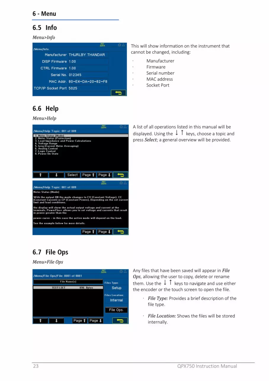
6.5 Info Menu>Info
This will show information on the instrument that cannot be changed, including:
· Manufacturer · Firmware · Serial number · MAC address · Socket Port
6.6 Help Menu>Help
A list of all operations listed in this manual will be displayed. Using the keys, choose a topic and press Select; a general overview will be provided.
6.7 File Ops Menu>File Ops
Any files that have been saved will appear in File Ops, allowing the user to copy, delete or rename them. Use the keys to navigate and use either the encoder or the touch screen to open the file.
· File Type: Provides a brief description of the file type.
· File Location: Shows the files will be stored internally.

6 - Menu
24 QPX750 Instruction Manual
6.8 Defaults Menu> Defaults
Some, or all, of the instruments original factory default settings can be restored in this menu. When activated, a pop-up with the following choices will be shown:
· Instrument: Will reset the settings that have been changed in Menu>Instrument, in addition to the PSU parameters, to default.
· System: Will reset only the settings that have been changed in Menu>System to default.
· Interface: Will reset only the settings changed in Menu>Interface to default.
· All: All of the above settings will be reset to factory defaults.
6.9 Calibration Menu>Calibration
The calibration menu is password protected to prevent unintentional adjustments.
For further information on Calibration and password protection, please refer to the Service Guide.

7 - Messages.
25 QPX750 Instruction Manual
7 MESSAGES. 7.1 Error Messages
Error messages are shown on the display until the ESC key is pressed. This will immediately remove the pop-up box and execute the function of the key which is pressed.
REM LOCK will appear when they keypad is locked while in remote mode. This can happen either by a lock key or a lock command, while this is active, the front keyboard is disabled.
If there is a Critical System Failure, they keys will lock, and it is recommended to turn the instrument off immediately.
7.2 Warning messages Warning messages will appear when a state or operation is activated that alters the way the instrument is used, for example: change to high voltage range.
7.3 Information messages Information messages are shown to inform the user of actions that are being taken, for example:
Please wait... the current settings are being saved.

8 - Maintenance
26 QPX750 Instruction Manual
8 MAINTENANCE The manufacturers or their agents overseas will provide a repair service for any unit developing a fault. Where owners wish to undertake their own maintenance work, this should only be done by skilled personnel in conjunction with the Service Manual which may be obtained directly from the manufacturer or their agents overseas.
8.1 Cleaning If the instrument requires cleaning, use a cloth that is only lightly dampened with water or a mild detergent.
WARNING To avoid electric shock, or damage to the instrument, never allow water to get inside the case. To avoid damage to the case, never clean with solvents.

8 - Maintenance
27 QPX750 Instruction Manual
8.2 Firmware update 1. Instrument firmware can be updated via a USB or LAN connection. Connect the instrument before
starting the process. 2. The latest Firmware update, together with file transfer utility can be downloaded from
https://www.aimtti.com/ 3. Once downloaded, unzip the file, and run the File Transfer Utility application.
4. Within the File Transfer Utility application, select File and Open.
5. Open the QPX750.ttiupd file.
6. Select Start Update. Once all the files have transferred successfully, a pop up will appear asking for an instrument power cycle.
7. Manually power cycle the instrument and the instrument firmware will update.
NOTE After a Firmware update, the settings will automatically be reset to default.

9 - Remote Operation
28 QPX750 Instruction Manual
9 REMOTE OPERATION The instrument can be remotely controlled via its USB, LAN or (optional) GPIB interfaces.
9.1 USB Interface Using the USB interface for remote control requires a Communications Device Class driver on the PC to provide a virtual COM port instance.
Windows 10 will automatically install a suitable driver. In earlier versions of Windows, a suitable driver is provided by Microsoft, but it is not installed by default. The data (.INF) file to control the installation is provided on the website: www.aimtti.com
If required, unzip the contents of the downloaded USB driver.
NOTE The same driver is also used by many other instruments from this manufacturer and may already be known to the PC.
9.1.1 Installing USB driver for the first time
To install the driver for the first time:
• First switch the unit On.
• Then connect the USB port to PC.
NOTE In Windows 10, the driver is automatically installed by the operating system.
The Windows plug and play functions should automatically recognise the attachment of new hardware to the USB interface and (possibly after searching the internet for some time) prompt for the location of a suitable driver. Follow the Windows prompts and point to the downloaded driver file named USB_ARM_VCP_xxx.INF, where xxx is a version number.
In some cases, Windows will not complete this procedure (especially recent versions which search the internet first, looking for the unique Vendor ID and Product ID), in which case the instrument will show in Device Manager as “not working properly”. If this happens, select this device, right click, and choose “update driver software...”, followed by: “browse this computer for driver software...”; then locate the downloaded .INF file.
Once Windows has installed the device driver it will assign a COM port number to this particular unit. This number will depend on previous COM port assignments on this PC, and it may be necessary to use Device Manager to discover it. Each instrument has a unique USB identifier which is remembered by the system, so it will receive the same COM port number whenever it is attached to the same PC (regardless of the physical interface socket used), even though the COM port will disappear while the instrument is disconnected or switched off. Other instruments will receive different COM port numbers.
NOTE A different PC will not necessarily assign the same COM port number to a particular instrument (it depends on the history of installations). Device Manager can be used to change the assignments given.

9 - Remote Operation
29 QPX750 Instruction Manual
9.2 LAN Interface The LAN interface is designed to meet 1.5 LXI Device Specification 2016. Remote control using the LAN Interface is possible using the TCP/IP Sockets protocol. The instrument also contains a basic web server which provides information on the instrument and allows it to be configured from a web browser. Simple command line control from the browser is also possible.
Since it is possible to misconfigure the LAN interface, making it impossible to communicate with the instrument over LAN, a LAN Configuration Initialise (LCI) mechanism is provided via the menus from the front panel to reset the instrument's interfaces to the factory default.
The default setting is for the instrument to attempt to obtain settings via DHCP if available or, if DHCP times out (30 seconds), via Auto-IP.
In the very unlikely event that an Auto-IP address cannot be found, a static IP address of 192.168.1.100 is assigned. Resetting the LAN removes any password protection which has been set on the web page.
To reset the LAN interface, touch the LAN Reset button on the ‘Interface’ menu.
For more information on LXI standards refer to www.lxistandard.org
9.2.1 LAN Connection
To use the LAN Interface, the IP address or the host name of the instrument must be known.
The assigned IP address of the instrument may be determined from the front panel controls by pressing the Interface button. Then select LAN Status and the assigned IP settings will be shown on the second page of the displayed menu.
Alternatively, Windows PC software tools such as the LXI Discovery Tool may be used find all LXI compliant devices on the network. The latest version of the LXI Discovery Tool can be downloaded from www.lxistandard.org.
Note that older versions of the LXI Discovery Tool may not find this instrument as they only support the legacy VXI-11 protocol which is not implemented in this instrument.
Connecting via a router is recommended as this is significantly quicker to assign an IP address; connecting directly to the PC will begin to assign an IP address only after a 30 second DHCP time-out. Double clicking on any entry in the list of devices discovered will open the PC's web browser and display the Home page of that device.
There are also tools for LAN discovery included as part of the National Instruments Measurement and Automation Explorer package and the Keysight (formerly Agilent) Vee application.
The unit will, when first powered up, attempt to obtain settings via DHCP if available or, if DHCP times out (30 seconds), via Auto-IP. In the very unlikely event that an Auto-IP address cannot be found a static IP address of 192.168.1.100 is assigned. During this time, the LAN indicator will keep flashing and change to if a LAN connection is successfully made. However, if a connection is still not made by the end of the above process, or if the LAN connector is physically removed at any
time, the LAN field in the status line will change to ;see ‘LAN error’ section for details.
9 - Remote Operation
30 QPX750 Instruction Manual
9.2.2 Web server; configuration password protection
The unit contains a basic web server. This provides information on the instrument and allows it to be configured. The Settings page can be password protected to deter unauthorised changes to the remote operation configuration.
The Settings page itself explains how to set the password. The password can be up to 15 characters long; the username should be left blank. The password will, however, be reset to the default (no password) if the front panel is used to reset all the LAN parameters to their factory default.
The web pages also have an ‘Identify’ function which allows the user to send an identifying command to the instrument which causes its display to flash until the command is cancelled.
9.2.3 ICMP ping server
The unit contains an ICMP server allowing the instrument to be ‘pinged’ via either its host name or IP address.
9.2.4 mDNS and DNS-SD support
Multicast DNS provides DNS services even on networks without a central DNS server (or DHCP server). This simplifies the setting up of a simple LAN using meaningful hostnames instead of a raw IP address. With service discovery it becomes straightforward for the device to be discovered and the services it provides.
The services provided by the instrument are http (_http._tcp) , lxi (_lxi._tcp) and scpi-raw (_scpi-raw._tcp).
9.2.5 VISA resource name
The instrument must be referred to by its raw socket information when used in software packages which communicate via a VISA resource name. For example, an instrument at IP address 192.168.1.100 would normally have a VISA resource name of "TCPIP0::192.168.1.100::inst0::INSTR" but for this instrument the name must be modified to read "TCPIP0::192.168.1.100::5025::SOCKET" where 5025 is the scpi-raw TCP port used by this instrument for control and monitoring.
9.2.6 XML identification document URL
As required by the LXI Standard, the instrument provides an XML identification document that can be queried via a GET at “http:<hostname>:80/lxi/identification” that conforms to the LXI XSD Schema (available at http:www.lxistandard.org/InstrumentIdentification/1.0) and the W3C XML Schema Standards ( http:www.w3.org/XML/Schema ). This document describes the instrument.
9.2.7 TCP sockets
The instrument uses 1 socket on TCP port 5025 for instrument control and monitoring. Text commands are sent to this port as defined in the ‘Remote/ local operation’ section and any replies are returned via the same port. Commands may be separated with either semicolons “;” or line feeds.
9.2.8 LAN error
If a LAN connection is made but an error is detected (e.g., the IP address is the same as another device on the network), then the LAN field in the status line will show until the error is corrected. If a LAN error occurs; check and correct the configuration of the instrument; To reset the LAN interface touch the LAN Reset button in the ‘Interface Menu’. The default setting is for the instrument to attempt to obtain settings via DHCP if available or, if DHCP times out (30 seconds), via Auto-IP. In the very unlikely event that an Auto-IP address cannot be found a static IP address of 192.168.1.100 is assigned. If no physical LAN connection is found at any time the LAN field in the status line will show

9 - Remote Operation
31 QPX750 Instruction Manual
9.3 GPIB Interface The GPIB interface 24-way connector is located on the instrument rear panel (requires GPIB option 1A fitted). The pin connections are as specified in IEEE Std. 488.1-1987 and the instruments in the range complies with IEEE Std. 488.1-1987 and IEEE Std. 488.2-1987 and contain the following IEEE 488.1 subsets.
9.3.1 GPIB subsets
This instrument contains the following IEEE 488.1 subsets:
Source Handshake SH1
Acceptor Handshake
AH1
Talker T6
Listener L4
Service Request SR1
Remote Local RL2
Parallel Poll PP1
Device Clear DC1
Device Trigger DT0
Controller C0
Electrical Interface E2
9.3.2 GPIB IEEE Std. 488.2 error handling – Query error register
The IEEE 488.2 UNTERMINATED error (addressed to talk with nothing to say) is handled as follows. If the instrument is addressed to talk and the response formatter is inactive, and the input queue is empty then the UNTERMINATED error is generated. This will cause the Query Error bit to be set in the Standard Event Status Register, a value of 3 to be placed in the Query Error Register and the parser to be reset. See ‘Status reporting’ section for further information.
The IEEE 488.2 INTERRUPTED error is handled as follows. If the response formatter is waiting to send a response message and a <PROGRAM MESSAGE TERMINTOR> has been read by the parser or the input queue contains more than one END message, then the instrument has been INTERRUPTED and an error is generated. This will cause the Query Error bit to be set in the Standard Event Status Register, a value of 1 to be placed in the Query Error Register and the response formatter to be reset thus clearing the output queue. The parser will then start parsing the next <PROGRAM MESSAGE UNIT> from the input queue. See ‘Status Reporting’ section for further information.
The IEEE 488.2 DEADLOCK error is handled as follows. If the response formatter is waiting to send a response message and the input queue becomes full then the instrument enters the DEADLOCK state, and an error is generated. This will cause the Query Error bit to be set in the Standard Event Status Register, a value of 2 to be placed in the Query Error Register and the response formatter to be reset thus clearing the output queue. The parser will then start parsing the next<PROGRAM MESSAGE UNIT> from the input queue. See ‘Status Reporting’ section for further information.

9 - Remote Operation
32 QPX750 Instruction Manual
9.3.3 GPIB Parallel Poll
Complete parallel poll capabilities are offered on this instrument. The Parallel Poll Enable Register is set to specify which bits in the Status Byte Register are to be used to form the ist local message. The Parallel Poll Enable Register is set by the *PRE<NRF> command and read by the *PRE? command. The value in the Parallel Poll Enable Register is ANDed with the Status Byte Register; if the result is zero then the value of ist is 0 otherwise the value of ist is 1.
The instrument must also be configured so that the value of ist can be returned to the controller during a parallel poll operation. The instrument is configured by the controller sending a Parallel Poll Configure command (PPC) followed by a Parallel Poll Enable command (PPE). The bits in the PPE command are shown in the following table:
Bit 7= X don’t care
Bit 6= 1
Parallel Poll Enable Bit 5= 1
Bit 4= 0
Bit 3= Sense Sense of the response bit; 0=low, 1= high
Bit 2= ?
bit position of the response Bit 1= ?
Bit 0= ?
EXAMPLE To return the RQS bit (bit 6 of the Status Byte Register) as a 1 when true and a 0 when false in bit position 1 in response to a parallel poll operation send the following commands:
*PRE 64<pmt>, then PPC followed by 69H (PPE)
The parallel poll response from the instrument will then be 00H if RQS is 0 and 01H if RQS is 1.
9.4 Status Reporting A separate error and status model is maintained for each interface instance; an interface instance is defined as a potential connection. USB and GPIB are inherently single connections so represent one interface instance each. LAN, however, allows for multiple simultaneous connections and therefore represents multiple interface instances. Two interface instances are allocated to the two TCP socket interfaces and one more is allocated to the Web page interface. Having a separate model for each interface instance ensures that data does not get lost as many commands e.g., ‘*ESR?’ clear the contents on read.
Error status is maintained using a set of registers; these are described in the following paragraphs and shown on the Status Model at the end of this section.

9 - Remote Operation
33 QPX750 Instruction Manual
9.4.1 Standard Event Status and Standard Event Status Enable Registers
These two registers are implemented as required by the IEEE Std. 488.2.
Any bits set in the Standard Event Status Register which correspond to bits set in the Standard Event Status Enable Register will cause the ESB bit to be set in the Status Byte Register.
The Standard Event Status Register is read and cleared by the *ESR? command. The Standard Event Status Enable register is set by the *ESE<NRF> command and read by the *ESE? command.
It is a bit field where each bit has the following significance.
Bit 7 Power On. Set when power is first applied to the instrument.
Bit 6 Not used.
Bit 5 Command Error. Set when a syntax type error is detected in a command from the bus. The parser is reset, and parsing continues at the next byte in the input stream.
Bit 4 Execution Error. Set when an error is encountered while attempting to execute a completely parsed command. The appropriate error number will be reported in the Execution Error Register.
Bit 3 Verify Timeout Error. Set when a parameter is set with 'verify' specified and the value is not reached within 5 secs, e.g., output voltage is slowed by a large capacitor on the output.
Bit 2 Query Error. Set when a query error occurs. The appropriate error number will be reported in the Query Error Register.
Bit 1 Not used.
Bit 0 Operation Complete: Set in response to the ‘*OPC’ command.

9 - Remote Operation
34 QPX750 Instruction Manual
9.4.2 Execution Error Register
This register contains a number representing the last error encountered over the current interface. The Execution Error Register is read and cleared using the ‘EER?’ command. On power up this register is set to 0 for all interface instances.
Error messages have the following meaning:
0 No error encountered
1 Indicates a hardware error has been encountered
100 The numerical value sent with the command was too big or too small. Includes negative numbers, illegal store numbers, numbers >1 where only 0 and 1 are allowed, etc.
101 A recall of set up data has been requested but the store specified contains corrupted data. This indicates either a hardware fault or a temporary data corruption which can be corrected by writing data to the store again.
102 A recall of set up data has been requested but the store specified does not contain any data.
103 Command Invalid:
The command is recognised but is not valid in the current circumstances.
9.4.3 Limit Event Status and Limit Event Status Enable Registers
This pair of registers are implemented for each output as an addition to the IEEE Std.488.2. Their purpose is to inform the controller of entry to and/or exit from current or voltage limit conditions and the history of protection trip conditions since the last read.
Any bits set in the Limit Event Status Register (LSR<N>) which correspond to bits set in the Limit Event Status Enable Register (LSE<N>) will cause the LIM<N> bit to be set in the Status Byte Register, where <N>is 1 for output1.
The Limit Event Status Register is read and cleared by the LSR<N>? command. The Limit Event Status Enable Register is set by the LSE<N><NRF> command and read by the LSE<N>? command.
Bit 7 Reserved for future use
Bit 6 Set when a fault trip has occurred which requires AC power OFF/ON to reset.
Bit 5 Set when an output sense trip has occurred
Bit 4 Set when an output over current trip has occurred
Bit 3 Set when an output over voltage trip has occurred
Bit 2 Set when output enters power limit (unregulated mode)
Bit 1 Set when output enters current limit (constant current mode)
Bit 0 Set when output enters voltage limit (constant voltage mode)

9 - Remote Operation
35 QPX750 Instruction Manual
9.4.4 Status Byte Register and Service Request Enable Register
These two registers are implemented as required by the IEEE Std. 488.2.
Any bits set in the Status Byte Register which correspond to bits set in the Service Request Enable Register will cause the RQS/MSS bit to be set in the Status Byte Register, thus generating a Service Request on the bus.
The Status Byte Register is read either by the *STB? command, which will return MSS in bit 6, or by a Serial Poll which will return RQS in bit 6. The Service Request Enable register is set by the *SRE<NRF> command and read by the *SRE? command.
Bit 7 STATus:OPERation summary bit. This bit is set if any bits in the STATus:OPERation register correspond to bits set in the STATus:OPERation:ENABle register
Bit 6 RQS/MSS. This bit, as defined by IEEE Std. 488.2, contains both the Requesting Service message and the Master Status Summary message. RQS is returned in response to a Serial Poll and MSS is returned in response to the *STB? command.
Bit 5 ESB. The Event Status Bit. This bit is set if any bits set in the Standard Event Status Register correspond to bits set in the Standard Event Status Enable Register.
Bit 4 MAV. The Message Available Bit. This will be set when the instrument has a response message formatted and ready to send to the controller. The bit will be cleared after the Response Message Terminator has been sent.
Bit 3 Not used.
Bit 2 Error Queue is not empty. This will be set when there is one or more entries in the error queue.
Bit 1 Not used.
Bit 0 LIM1. This will be set if any bits in the Limit Event Status register for output1 are set and corresponding bits are set in the Limit Event Status Enable register LSE1.

9 - Remote Operation
36 QPX750 Instruction Manual
9.4.5 Status Model
9.5 Remote/ local operation At power-on, the instrument will be in the local state and the REM indicator is not displayed on the Status Line. In this state, all front panel operations are possible.
When the instrument receives a command from an interface the remote state will be entered, and the REM indicator will be displayed on the Status Line. In this state the front panel user interface can still be navigated but no changes to parameters are possible.
The instrument may be returned to the local state by pressing the LOCAL key; however, the effect of this action will only remain until the instrument receives another character from the interface, when the remote state will once again be entered. Returning to Local by this action will keep the settings at their last remotely set values.
NOTE This instrument is backwards compatible with the QPX600DP remote command set. These can be found in the QPX600DP instruction manual, see aimtti.com/support.

9 - Remote Operation
37 QPX750 Instruction Manual
9.6 Parameter Data Format <NR1> Digits with no fractional part, i.e., an integer Example: 451 <NR2> Digits with an explicit decimal point. Example: 0.451 <NR3> Digits with an explicit decimal point and an exponent. Example: 45.1e+01 <NRF> A number in any format. Example: 12, 12·00, 1·2 e1 and 120 e-1 are all accepted as the
number 12 <CPD> <CHARACTER PROGRAM DATA>, i.e., a short mnemonic or string such as ON or OFF.
Multiple CPDs in a command are shown as <CPD1>, <CPD2>, <CPD3>, etc. <CRD> <CHARACTER RESPONSE DATA> Returns a short mnemonic or string. Only the short
form of the parameter is returned. <Bool> Boolean data. Example: 0 | 1 or ON | OFF <Quad> A number in dotted quad notation. <Unquoted String> String data without any quotation.
9.7 Command List *IDN? Returns the instrument identification. The exact response is determined by the instrument
configuration and is of the form <MANUFACTURER>,<model>,0,<serial no XX-xx>>, where XX-xx is the instrument firmware version number.
*CLS Clear Status. Clears the Status structure; this indirectly clears the Status Byte register.
*RST Resets the instrument to the factory default settings − with the exception of all remote interface settings. These can be viewed in Factory Default Settings.
RCL <N> <unquoted string>
Recall a set up for the output <N> specified by <unquoted string> from the internal storage. File name could be mixture of letters and numbers but up to 8 characters long only.
SAV <N> <unquoted string>
Save the instrument set-up for the output <N> to a file < unquoted string> on the internal storage. File name could be mixture of letters or numbers but up to 8 characters long only.
*SRE<NRF> Sets the Service Request Enable Register to <NRF>
*SRE? Return the value of Service Request Enable Register in <NR1> numeric format. The syntax of the response is <NR1>
*ESE <NRF> Set the Standard Event Status Enable Register to the value of <NRF>.
*ESE? Return the value in the Standard Event Status Enable Register in < NR1>numeric format. The syntax of the response is <NR1>
*PRE <NRF> Set the Parallel Poll Enable Register to the value <NRF>
*PRE? Return the value in the Parallel Poll Enable Register in <NR1>numeric format. The syntax of the response is <NR1>
*OPC Sets the Operation Complete bit (bit 0) in the Standard Event Status Register. This will happen immediately the command is executed because of the sequential nature of all operations.
*OPC? Query Operation Complete status. The response is always 1 and is available immediately, the command is executed because all commands are sequential.
*ESR? Query and clear the Event Status Register. The response format is <NR1>. See Status Reporting section for details of the response.
EER? Query and clear the Execution Error Register. The response format is <NR1>. See Error Reporting section for details of the response
QER? Query and clear Query Error Register. The response format is <NR1>.
*STB? Report the value of the Status Byte. Response is <NR1>
LSE<N><NRF> Set the Limit Status Enable Register<N> to <NRF>
LSE<N>? Returns the value in the Limit Status Enable Register. The response format is<NR1>.
LSR<N>? Query and clear the Limit Status Register<N>. The response format is <NR1><RMT>. See Status Reporting section for details of the response.
*IST? Returns ist local message as defined by IEEE Std. 488.2. The response is 0<RMT> if the local message is false, or 1<RMT> if the local message is true.

9 - Remote Operation
38 QPX750 Instruction Manual
9.8 SCPI Commands
9.8.1 SCPI Overview
This instrument uses SCPI (Standard Commands for Programmable Instruments) commands for remote control. The commands are based on SCPI Version 1999 and follow the syntax and rules including commands that are not taken from the SCPI standard. These commands are separated into two groups: common and subsystem.
Common commands are defined by the IEEE 488.2 standard to perform common instrument functions such as querying the status or resetting to default parameters.
Subsystem commands perform instrument specific functions and allow all operating parameters to be configured and queried. They are arranged in groups which correspond to particular functionality of the instrument. A tree structure is used extending to one or more levels below the root.
Square brackets ([ ]) are used to represent a keyword that is optional for the command. Uppercase letters are used to differentiate between the short and long form version of keywords.
EXAMPLE The following command is used to set the Voltage of DC Output to 10V:
[:SOURce]:VOLTage[:LEVel][:IMMediate][AMPLitude] 10
The above command can also be executed in below listed formats and they all will set the volts to 10 in this case.
[:SOUR]:VOLT[:LEV][:IMM][:AMPL] 10
[:SOUR]:VOLT[:LEV][:IMM] 10
[:SOUR]:VOLT[:LEV] 10
[:SOUR]:VOLT 10
:VOLT 10
Multiple SCPI commands can be combined into a single message using a semicolon as separator.
EXAMPLE The combined message below will set the volts to 10 and will also switch DC output ON.
[:SOURce]:VOLTage[:LEVel][:IMMediate][:AMPLitude] 10;:OUTPut[:STATe] 1
The colon : character after ; in the above example is used to reset the SCPI parser to the root level. If the multiple commands in a single message are from the same SCPI subsystem then the colon may be omitted.
A message terminator (typically a ‘new line’ character) completes the message and resets the current path to the root.
9.8.2 Query commands
All commands (with the exception of any set in Orange) can be presented as a query command by adding ‘?’ at the end, this will return the current set value or parameter as <…>
Commands set in Blue are query only.

9 - Remote Operation
39 QPX750 Instruction Manual
9.9 SCPI Subsystems :SOURce The SOURce subsystem contains the commands for configuring the output signal. :OUTPut The OUTPut subsystem configures the output signal state. :MMEMory The MMEMory subsystem is used to manage instrument setups. :STATus The STATus subsystem is used to query the Operation Condition Register :SYSTem The SYSTem subsystem is used for a number of functions not associated with the
output signal, such as configuring the LAN.
9.9.1 SYSTem Subsystem · :SYSTem:COMMunicate:GPIB:ADDRess <NRF> Set the GPIB address to <NRF> · :SYSTem:COMMunicate:USB:VID? Query the instrument USB Vendor ID. The response is “0x103E” · :SYSTem:COMMunicate:USB:PID? Query the instrument USB Product ID. The response is “0x04EC” · :SYSTem:COMMunicate:LAN:MAC? Query the media access control address (MAC)
of the instrument. The response is a 12 digit hexadecimal number of 6 bytes separated with a hyphen.
· :SYSTem:COMMunicate:LAN:TCPPort? Query the TCP port used for instrument control
and monitoring. This instrument used the standard scpi-raw port 5025.
· :SYSTem:COMMunicate:LAN:IDENtify[:STATE] <Bool> Enable and disable the LAN Identify feature. Setting
this to true will cause the connected instrument display to flash until reset to false. OFF|ON|0|1
· :SYSTem:COMMunicate:LAN:RESet Return all LAN settings to the default values and
restart the network connection. · :SYSTem:COMMunicate:LAN:HOSTname:DESired<Unquoted String>
Set the desired mDNS hostname · :SYSTem:COMMunicate:LAN:HOSTname[:RESolved]? Query the unique resolved mDNS hostname · :SYSTem:COMMunicate:LAN:MDNS:SNAMe:DESired <Unquoted String>
Set the desired mDNS service name · :SYSTem:COMMunicate:LAN:MDNS:SNAMe[:RESolved]? Query the resolved mDNS service name · :SYSTem:COMMunicate:LAN:IPCONFig <CPD> Set automatic or manual setting of the IP address
AUTOmatic|MANual · :SYSTem:COMMunicate:LAN:IPADdress:DESired <Quad> Set the desired IP address when MANual
configuration is used
· :SYSTem:COMMunicate:LAN:SMASk:DESired <Quad> Set the desired subnet mask when MANual configuration is used.
· :SYSTem:COMMunicate:LAN:GATeway:DESired <Quad> Set the IP address of the default gateway when
MANual configuration is used

9 - Remote Operation
40 QPX750 Instruction Manual
· :SYSTem:COMMunicate:LAN:PRIDNS:DESired <Quad> Set the IP address of the primary DNS server on the
network when MANual configuration is used
· :SYSTem:COMMunicate:LAN:SECDNS:DESired <Quad> Set the IP address of the secondary DNS server on the network
· :SYSTem:COMMunicate:LAN:IPADdress[:RESolved]? Query the resolved IP address in use on the
network.
· :SYSTem:COMMunicate:LAN:SMASk[:RESolved]? Query the subnet mask in use on the network.
· :SYSTem:COMMunicate:LAN:GATeway[:RESolved]? Query the default gateway in use on the network.
· :SYSTem:COMMunicate:LAN:PRIDNS[:RESolved]? Query the primary DNS server in use on the
network.
· :SYSTem:COMMunicate:LAN:SECDNS[:RESolved]? Query the secondary DNS server in use on the network.
· :SYSTem:COMMunicate:LAN:IPUPDate Apply any pending changes made by other
commands in the SYSTem:COMMunicate:LAN subsystem and restart the network connection.
· :SYSTem:BEEPer <Bool> Set all system buzzer settings to OFF|ON |0|1
(The query response is a comma separated list of the states of the error, warning, info, key, touch, and remote buzzers.)
· :SYSTem:BACKLight <NR1> Set the LCD backlight brightness to %
· :SYSTem:THEMe <CPD> Set the system display colour theme to THEMe1| THEMe2| THEMe3| THEMe4|THEMe5|
THEMe6| THEMe7| THEMe8
· :SYSTem:POWeron <CPD> Set the instrument power on state to DEFualt|LATest
· :SYSTem:ERRor[:NEXT]? Query the error/event queue for the oldest entry
and remove it from the queue. The response is an error number followed by a description of the error. If the queue is empty the response will be 0, “No error”
· :SYSTem:VERSion? Query the instrument firmware version number. · :SYSTem:KLOCk <Bool > Enable or disable the remote-control keyboard
lock out. This disables the front panel LOCAL key when set to true. OFF|ON|0|1
· :SYSTem:LOCal Go to local operation. Any subsequent command will restore the remote state.
9 - Remote Operation
41 QPX750 Instruction Manual
9.9.2 STATus Subsystem
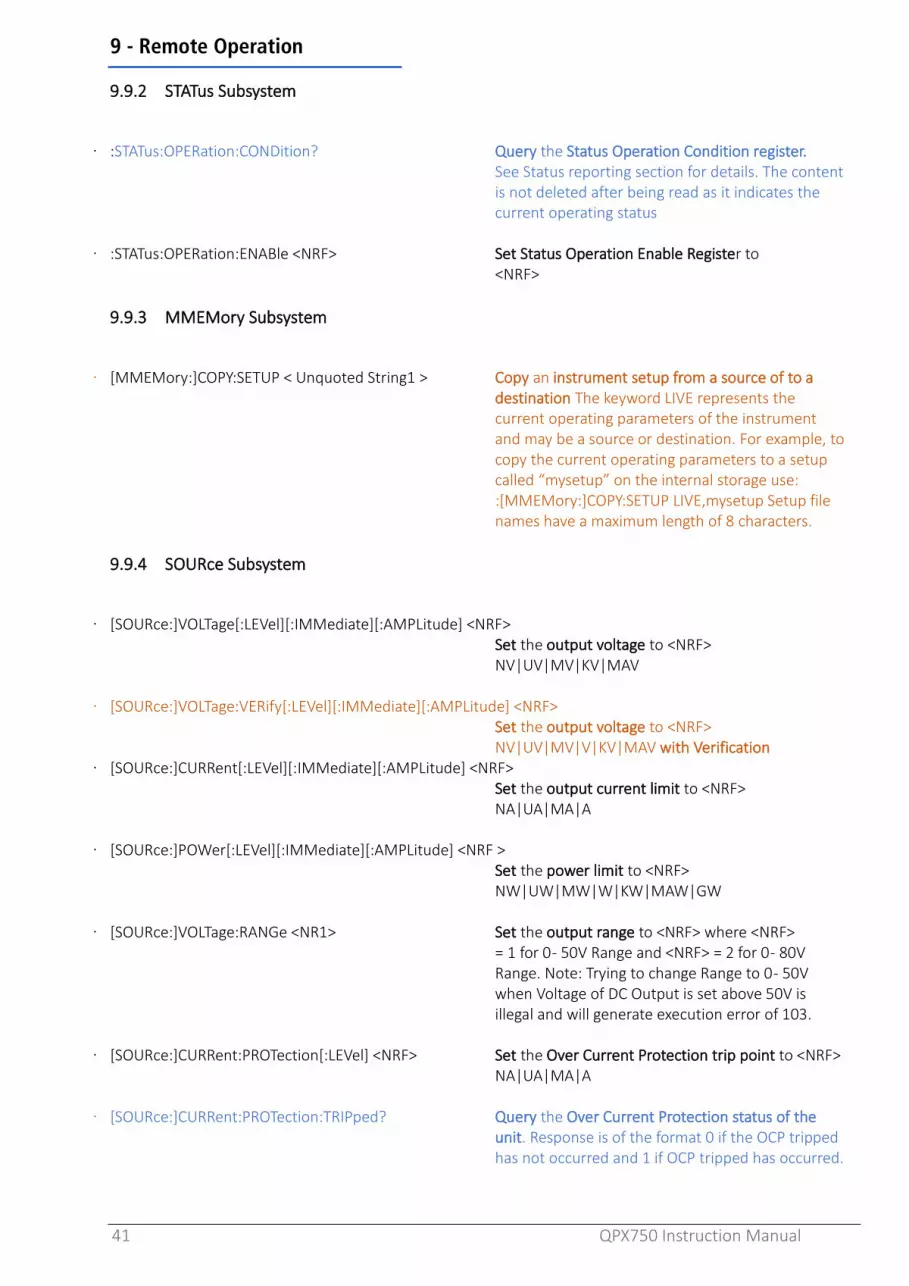
· :STATus:OPERation:CONDition? Query the Status Operation Condition register. See Status reporting section for details. The content is not deleted after being read as it indicates the current operating status
· :STATus:OPERation:ENABle <NRF> Set Status Operation Enable Register to <NRF>
9.9.3 MMEMory Subsystem
· [MMEMory:]COPY:SETUP < Unquoted String1 > Copy an instrument setup from a source of to a destination The keyword LIVE represents the current operating parameters of the instrument and may be a source or destination. For example, to copy the current operating parameters to a setup called “mysetup” on the internal storage use: :[MMEMory:]COPY:SETUP LIVE,mysetup Setup file names have a maximum length of 8 characters.
9.9.4 SOURce Subsystem
· [SOURce:]VOLTage[:LEVel][:IMMediate][:AMPLitude] <NRF> Set the output voltage to <NRF>
NV|UV|MV|KV|MAV
· [SOURce:]VOLTage:VERify[:LEVel][:IMMediate][:AMPLitude] <NRF> Set the output voltage to <NRF>
NV|UV|MV|V|KV|MAV with Verification · [SOURce:]CURRent[:LEVel][:IMMediate][:AMPLitude] <NRF>
Set the output current limit to <NRF> NA|UA|MA|A
· [SOURce:]POWer[:LEVel][:IMMediate][:AMPLitude] <NRF > Set the power limit to <NRF> NW|UW|MW|W|KW|MAW|GW
· [SOURce:]VOLTage:RANGe <NR1> Set the output range to <NRF> where <NRF>
= 1 for 0 - 50V Range and <NRF> = 2 for 0 - 80V Range. Note: Trying to change Range to 0 - 50V when Voltage of DC Output is set above 50V is illegal and will generate execution error of 103.
· [SOURce:]CURRent:PROTection[:LEVel] <NRF> Set the Over Current Protection trip point to <NRF>
NA|UA|MA|A
· [SOURce:]CURRent:PROTection:TRIPped? Query the Over Current Protection status of the unit. Response is of the format 0 if the OCP tripped has not occurred and 1 if OCP tripped has occurred.

9 - Remote Operation
42 QPX750 Instruction Manual
· [SOURce:]CURRent:PROTection:CLEar Attempt to clear the OCP trip. · [SOURce:]VOLTage:PROTection[:LEVel] <NRF> Set the Over Voltage Protection trip point to <NRF>
NV|UV|MV|V|KV|MAV
· [SOURce:]VOLTage:PROTection:TRIPped? Query the Over Voltage Protection status of the unit. Response is of the format 0 if the OVP tripped has not occurred and 1 if OVP tripped has occurred.
· [SOURce:]VOLTage:PROTection:CLEar Attempt to clear the OVP trip.
· [SOURce:]VOLTage[:LEVel][:IMMediate]:DELTa <NRF> Set the voltage step size to <NRF> NV|UV|MV|V|KV|MAV
· [SOURce:]CURRent[:LEVel][:IMMediate]:DELTa <NRF > Set the current step size to <NRF> NA|UA|MA|A
· [SOURce:]VOLTage[:LEVel][:IMMediate]:INCrement Increment the voltage by step size.
· [SOURce:]VOLTage[:LEVel][:IMMediate]:DECrement Decrement the voltage by step size.
· [SOURce:]CURRent[:LEVel][:IMMediate]:INCrement Increment the current by step size.
· [SOURce:]CURRent[:LEVel][:IMMediate]:DECrement Decrement the current by step size.
· [SOURce:]VOLTage:VERify[:LEVel][:IMMediate]:INCrement
Increment the voltage by step size with verification
· [SOURce:]VOLTage:VERify[:LEVel][:IMMediate]:DECrement Decrement the voltage by step size with verification
OUTPut Subsystem
· :OUTPut:[:STATe] <bool> Set the output state to OFF|ON|0|1 · :OUTPut:SENSe[:STATe] <bool> Set the Sense mode output state to OFF|ON|0|1
Where OFF means Local mode and ON means Remote mode
MEASure Subsystem · :MEASure:VOLTage? Query the DC Voltage present on the output.
Response is of the format <NR3>
· :MEASure:CURRent? Query the DC current present on the output. Response is of the format <NR3>
· :MEASure:POWer? Query the total power delivered by the instrument. Response is of the format <NR3>
· :MEASure:CURRent:DAMPing[:STATe] <bool> Set the current meter measurement averaging to OFF|ON|0|1

10 - Factory default settings
43 QPX750 Instruction Manual
10 FACTORY DEFAULT SETTINGS Output Configuration Factory Setting
Settings
Voltage 0V
Amps 1.00A
Range 50V
Sense Local
Iavg Off
Plim 750W
OVP 90V
OCP 55A
Power on State
Output State Always Off
Power on State Latest Params
Analog Control
Control Type None
Range Selected 0-10V
Logic Control
Logic In Ignored
Logic Out Closed for Output ON
System
Brightness 40%
Colour Theme Theme 1
Encoder State Adjust 2-State
Buzzer On
LAN Config Method Automatic
LAN/IPv4 Manual
IP Address 192.168.1.100
Subnet Mask 255.255.255.0
Gateway 0.0.0.0
Pri. DNS Server 0.0.0.0
Sec. DNS Server 0.0.0.0
GPIB address 11

11 - Specification
44 QPX750 Instruction Manual
11 SPECIFICATION 11.1 Output Specifications
Voltage Range: Two ranges: 0V to 50V or 0V to 80V
Current Range: 0.01A to 50A
Power Range: Up to 750W: within envelope shown (12V/50A, 36V/20A, 60V/12A & 80V/9.4A guaranteed). Or programmable power limit 100W to 600W in 10W increments.
Voltage Setting: Resolution: 1mV (50V Range), 2mV (80V Range) Accuracy: 0.1% of setting ± 2mV, (± 4mV on 80V range)
Current Setting: Resolution 10mA Accuracy: 0.3% of setting ± 20mA
Operating Mode: Constant voltage, constant current or constant power with automatic cross-over dependant on output setting parameters. CV, CI, or CP mode indication in display.
Output Switch: Independent electronic switching, with ON indication. Pre-set voltage and current displayed when off.
Output Terminals: Front & rear panel safety terminals accepting 6mm wire diameter, 6mm plugs or 8mm spades at 50 Amps max, or 4mm plugs at 30 Amps max.
Sensing: Switchable between local and remote. Screwless remote sense terminals on both front & rear panels. Sense miswiring trip and indication.
Ripple & Noise (20MHz bandwidth):
Typically, <3mVrms, <20mV pk-pk at maximum load, CV mode
Load Regulation: Change in output for any load change within PowerFlex envelope, using remote sense: Constant voltage: <0.01% ± 5mV
Line Regulation: Change in output for a 10% line change: Constant voltage: <0.01% ± 5mV
Transient Response: To within 100mV of set level for a 5% to 95% load change. Rear Terminals: <2ms Front Terminals: <2.5ms
Output Protection: Output will withstand an applied forward voltage of up to 90V. Reverse protection by diode clamp for reverse currents up to 3A.
Over-voltage Protection (OVP):
Range 2V to 90V. Resolution 0.1V; accuracy: 0.2% ± 0.2V. Response time typically 100µs.
Over-current Protection (OCP):
Range 2A to 55A. Resolution 0.1A; accuracy: 0.5% ± 0.2A. Response time typically 100ms.
Over-temperature Protection:
The output will be tripped off if a fault causes the internal temperature to rise excessively.
Temperature Coefficient: Typically, <100ppm/°C
9.4, 80
20, 36
50, 10
20
40
60
80
100
0 20 40 60
Volts
(V)
Amps (A)
QPX750 Power Envelope

11 - Specification
45 QPX750 Instruction Manual
11.2 Meter Specifications Display Type: 5-digit (Volts), 4-digit (Amps), 4.3” TFT colour. Voltage
Resolution 1mV Accuracy: 0.1% of reading ± 2 digits
Current
Resolution 10mA Accuracy: 0.3% of reading ± 2 digits
V x A: Resolution 0·1W Accuracy: 0·5% ± 0·1W
V/A: Meter shows calculated nominal V/A value; 5-digit resolution.
11.2.1 LOGIC CONTROL INPUT and OUTPUT
LOGIC IN is a rear-panel opto-isolated input that is activated at an input current greater than approximately 1mA. User can set LOGIC IN (via the keyboard) to enable the output, disable the output, or be ignored when it is activated.
LOGIC OUT is an isolated rear-panel open-collector output that will sink up to 2mA when activated (‘switch closure’); the maximum voltage that can be applied to LOGIC OUT is 30VDC. User can set LOGIC OUT to be ‘closed’ or ‘open’ for output enabled or disabled, current limit (CC mode), power limit (CP mode), or for any fault trip.
11.2.2 ANALOG REMOTE CONTROL and MONITORING
Quasi-analog inputs and outputs to set voltage and current limit and to monitor actual output voltage and current. The control inputs are read four times per second by the A-D converter and the output is set according to the selected input scaling; similarly, the monitor outputs are updated four times per second with values representing the actual output voltage and current. These signals each have a range of 0 to 10V or 0 to 5V with respect to the shared COM return signal; the set range applies to all inputs and outputs.
Analog Control Voltage Range: Keyboard selectable to be 0 to 10Vdc or 0 to 5Vdc for range maximum output. Absolute maximum input 20Vdc.
Analog Control Accuracy: Voltage: 0.3% ± 4mV; Current: 0.5% ± 40mA. Analog Control Common Mode Range: ± 2.5Vdc max to negative output. Analog Control Input Impedance: Nominally 40kΩ. Analog Monitor Voltage Range: Same as set for Analog Control Voltage Range.
Analog Monitor Accuracy: Voltage: 0.3% ± 4mV; Current: 0.5% ± 40mA. Analog Monitor Output: Connect to isolated measuring system with >10kΩ input
impedance. Will withstand a short-circuit.
11.2.3 KEYBOARD & ROTARY CONTROL
All functions, including the selection and set-up of the remote-control interfaces, can be set from the keyboard. The rotary Jog control can be used to adjust output voltage and current settings in a quasi-analog mode.
Voltage Programming Speed (Typical figures)
Maximum time required for output to settle within 1% of its total excursion (for resistive load). Excludes command processing time:
90% Load No Load 90% Load No Load
80V 9.4A Up 200ms 200ms Down 60ms 190ms
12V 50A Up 190ms 190ms Down 10ms 160ms

11 - Specification
46 QPX750 Instruction Manual
11.3 Display Features The display is a graphic LCD, 4.3” TFT colour display; contrast is software-controlled and can be adjusted from the keyboard.
The displays show live VOLTS (5 digits) and AMPS (4 digits) when output is on, plus output range, status and other key PSU setting parameters. It also shows pre-set values in GREY when output is OFF unless voltage is present on output terminals in which case the voltage present on the terminals is shown in RED.
11.3.1 INTERFACES (QPX750SP only)
Fully digital remote-control facilities are available through the LAN, USB and GPIB interfaces. Setting and readback resolutions are the same as for the Output and Meter specifications, respectively.
USB: Standard USB 2.0 hardware connection.
LAN: Auto speed detect(10/100MHz), Auto MDIX. LXI V1.2, Class C compliant.
GPIB: Conforms with IEEE488.1 and IEEE488.2.
Remote Command Processing Time:
Typically, <100ms between receiving the command terminator for a step voltage change at the instrument and the output voltage beginning to change.
11.3.2 GENERAL
AC Input: 115V – 240V AC ± 10%, 50/60Hz. Installation Category II.
Power Consumption:
1000VA max.
Operating Range: +5ºC to +40ºC, 20% to 80% RH.
Storage Range: −40ºC to + 70ºC.
Environmental: Indoor use at altitudes up to 2000m, Pollution Degree 2.
Store/Recall: Set-ups can be saved and recalled via the keyboard or remote interfaces.
Safety: Complies with EN61010-1.
EMC: Complies with EN61326.
Size: 130mm H (3U) x 215mm W x 460mm D (including terminals)
Weight: <6.4kg
Options: RM460 19-inch rack kit accommodates two instruments.
For details, request the EU Declaration of Conformity for this instrument via http://www.aimtti.com/support (serial no. needed). General specifications apply for the temperature range 5°C to 40°C. Accuracy specifications apply for the temperature range 18°C to 28°C after 30 minutes warm-up, at maximum output into 50Ω. Typical specifications are determined by design and are not guaranteed.

EXCELLENCE THROUGH EXPERIENCEAim-TTi is the trading name of Thurlby Thandar Instruments Ltd. (TTi), one of Europe’s leading manufacturers of test and measurement instruments.
The company has wide experience in the design and manufacture of advanced test instruments and power supplies built up over more than thirty years.
The company is based in the United Kingdom, and all products are built at the main facility in Huntingdon, close to the famous university city of Cambridge.
TRACEABLE QUALITY SYSTEMSTTi is an ISO9001 registered company operating fully traceable quality systems for all processes from design through to final calibration.
ISO9001:2015
Certificate number FM 20695
WHERE TO BUY AIM-TTI PRODUCTSAim-TTi products are widely available from a network of distributors and agents in more than sixty countries across the world.
To find your local distributor, please visit our website which provides full contact details.
Designed and built in Europe by:
Thurlby Thandar Instruments Ltd.Glebe Road, Huntingdon, Cambridgeshire.PE29 7DR United KingdomTel: +44 (0)1480 412451 Fax: +44 (0)1480 450409 Email: [email protected] Web: www.aimtti.com
Book Part No. 48511-1600 Issue 1


