Embed Size (px)
Citation preview

Rhein-Nadel Automation GmbH 1 14.04.2014 VT-BA ESG2000 -GB
Instructions for the Control Units
for Vibratory Drives
ESG 2000
BA
Rhein-Nadel Automation GmbH

Rhein-Nadel Automation GmbH 2 14.04.2014 VT-BA ESG2000 -GB
Table of contents Chapt........................................................................................................................ Page
1 Technical data 3
2 Safety notes.................................................................................................. 4
3 Commissioning instructions ............................................................................... 4
4 Operation 6
5 Dimensional drawing..................................................................................... 10
6 Connection diagram....................................................................................... 11
Declaration of conformity
as defined by Low voltage directive 2014/35/EU
and EMC directive 2014/30/EU
Herewith we declare that the product complies with the following provisions:
Low voltage directive 2014/35/EU EMC directive 2014/30/EU
applied harmonized standards: DIN EN 60204 T1 EN 61439-1
remarks: Rhein-Nadel-Automation -------------------------------- Managing Director Jack Grevenstein

Rhein-Nadel Automation GmbH 3 14.04.2014 VT-BA ESG2000 -GB
1.1 Performance Characteristics This compact control unit has been designed to operate a bowl or linear feeder. The unit has the following performance characteristics: - one power outputs: - channel 1 bowl feeder < 10 A - 24V DC remote control input. - two optocouplers for status messages and further links. - a membrane keyboard for setting and editing the operating values (parameters) in the setting menus. - plug connections for
- bowl or linear feeder - communication
- double-pole mains power switch
1.2 EC Conformity / CSA Conformity
The control device corresponds to the following regulations:
Low voltage directive 2014/35/EU
EMC directive 2014/30/EU
Applied harmonized standards:
DIN EN 60204 T1
EN 61439-1 The control device corresponds also to the UL/CSA regulations.
1.3 Technical Data
Mains voltage: 230 Volt AC, 50/60 Hz, +20/ -15% 110 Volt AC, 50/60 Hz, +10 / -10%
Output voltage: 0 ... 208 Veff /230 VAC ; 0 ... 98 Veff /110 VAC
Load current channel 1: 10 Aeff
Total load current: 10 Aeff Minimum load current: 80 mA
Internal fuse: F1 = 10A Soft start time, soft stop time: 0 ... 5 sec.
Remote control input: 24V DC (10-24 VDC) Outputs: 2 optocouplers
Status output (optocoupler): max. 30V DC 10mA Operating temperature: 0 ... 50° C
Type of protection: IP 54
1.4 Accessoires
Label Denomination Type Manufacteur Supplier RNA-Mat-code XS1 Connector Harting XS1 Mains plug C16-1 Amphenol 35051469 XS4 Coupler connector, 7-poles, straight 09 0126 70 07 Binder EVG 35051153 XS4 Coupler connector, 7-poles, angular 99 0126 75 07 Binder EVG 35002545

Rhein-Nadel Automation GmbH 4 14.04.2014 VT-BA ESG2000 -GB
2 Safety Instructions It is always necessary to read and understand the safety instructions. This ensures that valuable material is not dam-aged and injuries are avoided. Steps must be taken to ensure that all persons working with this control unit are familiar with the safety regulations and observe them. The device described in this manual is a control unit for operating RNA bowl feeders and linear feeders. The limit val-ues specified in the technical data must be observed.
Note! This hand indicates tips on operation of the control unit.
Attention! This warning triangle indicates safety instructions. Failure to heed this warning can lead to severe injuries or death!
Work on electrical equipment of the machine/plant may be carried out only by a trained electrician or by untrained persons under the leadership and supervision of a trained electrician in accordance with the regulations for electrical engineering! All safety and danger signs on the machine/plant must be observed! The electrical equipment of a machine/plant must be inspected and checked regularly. Defects such as loose connections or damaged cables must be remedied immediately!
Before commencing operation, make sure that the earthing line (power earth, PE) is intact and installed at the connecting point. Only test instruments approved for this purpose may be used for checking the safety grounding conductor.
3 Commissioning Instructions
Before connecting up to the mains and switching on the control unit, it is essential to check the following points:
Is the control unit in proper working condition and closed with all screws?
Are the connector locks clicked in/screwed secure?
Are all cables and glands intact?
Is PROPER INTENDED USAGE ensured?
Does the mains voltage specification on the control unit agree with the local mains voltage?
Does the mains frequency specification on the vibratory drive agree with the local mains?
Is the correct operating mode set on the control unit? (See "Operating Mode" section)
Operation of the control unit may be commenced only when all questions asked above can be answered unambiguous-ly with YES.
Before you start operation after repair work has been carried out or control units/vibrating drives have been exchanged, set the output on the control unit to minimum before switching on. Check that the system is working properly when you increase the output.

Rhein-Nadel Automation GmbH 5 14.04.2014 VT-BA ESG2000 -GB
3.1 OPERATING MODE Bowl feeder frequency coding in connector.
Operating mode 2
With bridge: 100 / 120Hz
With bridge: 6000 / 7200 oscillations/min
Operating mode 1 Without bridge: 50 / 60Hz
Without bridge: 3000 / 3600 oscillations/min
3.2 Status Outputs The status outputs are used for remote diagnostics of the control unit operating mode or for linking several control units together. They are unassigned NPN-doped transistor routes and are potential-free.
The transistor route is always connected at the STANDBY status output when the control unit is connected to the mains and switched on with the mains power switch.
The ON ACTION status output requires the same conditions as STANDBY. Channel 1 must also be active and the transistor will block if it is set to OFF or STOP. The status outlet and the remote control should be wired via the XS4 plug connection. The connections and the cable inlets are on the right-hand side of the control unit. The terminal strip is behind the con-trol unit panel.
Rhein-Nadel Automation GmbH 6 14.04.2014 VT-BA ESG2000 -GB
4. Operation
4.1 General
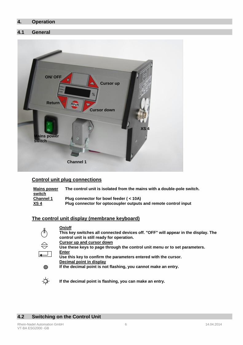
Control unit plug connections
Mains power
switch
The control unit is isolated from the mains with a double-pole switch.
Channel 1 Plug connector for bowl feeder ( < 10A)
XS 4 Plug connector for optocoupler outputs and remote control input
The control unit display (membrane keyboard)
On/off
This key switches all connected devices off. "OFF" will appear in the display. The
control unit is still ready for operation. Cursor up and cursor down
Use these keys to page through the control unit menu or to set parameters. Enter
Use this key to confirm the parameters entered with the cursor. Decimal point in display
If the decimal point is not flashing, you cannot make an entry.
If the decimal point is flashing, you can make an entry.
4.2 Switching on the Control Unit
Channel 1
Mains power
switch
Return
Cursor up
ON/ OFF
Cursor down
XS 4

Rhein-Nadel Automation GmbH 7 14.04.2014 VT-BA ESG2000 -GB
Switch on the control unit with the mains power switch. The main menu will appear in the display showing the last set-point set in channel 1 (bowl feeder or linear feeder feed rate).
KANAL l
KANAL 2
CODE The following displays may also appear depending on the circuit state of the unit.
KANAL l
KANAL 2
CODE
The remote control has been activated but is currently not available on the unit. (low priority)
KANAL l
KANAL 2
CODE
The unit has been switched off with the upper left-hand key on the membrane keyboard, all functions are blocked. (high priority)
4.3 Main Menu/Setting and Displaying Setpoints for Channel 1
Display of setpoint or the channel 1
output (bowl feeder)
Alternatively: STOP, OFF
(see above)
KANAL l
KANAL 2
CODE
No entries possible
Enter code to change or make re-
quired settings. KANAL l
KANAL 2
CODE
Enter code. See section 4.4 for de-scription of code.
Setpoint preset for channel 1
(bowl feeder) KANAL l
KANAL 2
CODE
Entry in %; return to
display mode to store
From these three basic displays you can page through the main menu using the cursor keys (UP/DOWN). Press the ENTER key in the main menu to activate a menu item for setting or adjustment. The decimal point will flash once you have pressed the ENTER key. Changes can now be made using the cursor keys (UP/DOWN). Confirm the entries by pressing the ENTER key again. The decimal point will no longer flash. You can scroll further through the menu using the cursor keys. This procedure is also used in the code menus described below. All displays shown in the following section represent the factory settings. If the actual display on the control unit differs, the factory setting has been changed in the individual codes for a specific application.
4.4 Description of the Individual Codes for Programming the Control Unit

Rhein-Nadel Automation GmbH 8 14.04.2014 VT-BA ESG2000 -GB
KANAL l
KANAL 2
CODE
Settings for channel 1 The following functions can be set or limited for channel 1 in this submenu: - vibration amplitude - signal direction of the remote control - remote control - soft start time and soft stop time
KANAL l
KANAL 2
CODE
Lock setpoint This submenu allows the setpoints (vibration amplitude) to be blocked in the main menu. The setpoints for channel 1 and channel 2 can no longer be changed in the main menu. This pre-vents the output values being accidentally changed. Changes can only be made using code C001.
KANAL l
KANAL 2
CODE
Display status This submenu is used to check the set vibration frequency.
KANAL l
KANAL 2
CODE
To call software version Determinat. 411. 59. 10. 23.11.99
date version -no. type internal no.
type: 59 = ESK 2001 58 = ESG 2001 57 = ESK 2000 56 = ESG 2000
KANAL l
KANAL 2
CODE
Store parameters If the values (user parameters) previously set in the different submenus are to be stored, call this submenu.
KANAL l
KANAL 2
CODE
Block all setting functions This code blocks all entry options on the control unit. The values can no longer be changed. The menu can now only be enabled using this code.
KANAL l
KANAL 2
CODE
Reset parameters This submenu allows the user to reset the control unit to the factory settings. If user parameters have been stored, the control unit can also be set to these settings.
4.5 Application-specific Changes to the Factory Settings
4.5.1 Code C001 for Channel 1 and Code C002 for Channel 2
Aim: Setting and limiting the oscillation amplitude, the remote control, the soft start time and the soft stop time.
Select code KANAL l
KANAL 2
CODE
Set code
Code C001 KANAL l
KANAL 2
CODE
Set vibration amplitude KANAL l
KANAL 2
CODE
0 - 100 %
Limit vibration amplitude KANAL l
KANAL 2
CODE
50 - 100 % (*)
Remote control KANAL l
KANAL 2
CODE
I = active
0 = inactive
Remote control signal direction KANAL l
KANAL 2
CODE
I = start = 24V DC
0 = stop = 24V DC
Soft start time KANAL l
KANAL 2
CODE
0 - 5 sec.
Soft stop time KANAL l
KANAL 2
CODE
0 - 5 sec.
Return KANAL l
KANAL 2
CODE
Store and return to
main menu
* For RNA-Feeder with 200 V = 90 %

Rhein-Nadel Automation GmbH 9 14.04.2014 VT-BA ESG2000 -GB
4.5.2 Code C003 Lock Setpoint
Aim: Blocking the setpoints in the main menu. The values can no longer be changed directly. Changes can only be made using code C001.
Select code KANAL l
KANAL 2
CODE
Set code
Code C003 KANAL l
KANAL 2
CODE
Setpoint (vibration amplitude) KANAL l
KANAL 2
CODE
1 = can be set
0 = entry blocked
Return KANAL l
KANAL 2
CODE
Store and return to
main menu
4.5.3 Code C009 Display Status
Aim: Checking the set oscillation frequency.
Select code KANAL l
KANAL 2
CODE
Set code
Code C009 KANAL l
KANAL 2
CODE
Remote control signal
Channel 1 KANAL l
KANAL 2
CODE
I = active
0 = inactive
Vibration frequency channel 1 KANAL l
KANAL 2
CODE
I = 50 Hz
0 = 100 Hz
Return KANAL l
KANAL 2
CODE
Store and return to
main menu
With the menu item HA = half-wave you can check whether the operating mode (100–50Hz) has been
correctly selected.
4.5.4 Code C200 Blocking all Setting Functions
Aim: The user can no longer (accidentally) change the set values.
Select code KANAL l
KANAL 2
CODE
Set code
Code C200 KANAL l
KANAL 2
CODE
Block the setting functions KANAL l
KANAL 2
CODE
I = enabled
0 = block
Return KANAL l
KANAL 2
CODE
Store and return to
main menu
Now only code C200 will be accepted!!!
4.5.5 Code C143 Store Parameters
Aim: Storing user parameters.
Select code KANAL l
KANAL 2
CODE
Select code
Code C143 KANAL l
KANAL 2
CODE
Store KANAL l
KANAL 2
CODE
KANAL l
KANAL 2
CODE
Return KANAL l
KANAL 2
CODE
Store and return to
main menu
Once PUSH has been confirmed with ENTER, the selected parameters will be stored separately
by pressing a cursor key.

Rhein-Nadel Automation GmbH 10 14.04.2014 VT-BA ESG2000 -GB
4.5.6 Code C210 Reset Parameters
Aim: Resetting to factory settings or restoring the stored user parameters.
Select code KANAL l
KANAL 2
CODE
Set code
Code C210 KANAL l
KANAL 2
CODE
Factory setting KANAL l
KANAL 2
CODE
KANAL l
KANAL 2
CODE
User parameters KANAL l
KANAL 2
CODE
KANAL l
KANAL 2
CODE
Return KANAL l
KANAL 2
CODE
Store and return to
main menu
FAC Selection and confirmation of FAC. applies the factory settings.
US.PA. Selection and confirmation of US.PA restores the user parameters previously stored
under C143.
5 Scale Drawing

Rhein-Nadel Automation GmbH 11 14.04.2014 VT-BA ESG2000 -GB
6 Connecting Diagram

Rhein-Nadel Automation GmbH 12 14.04.2014 VT-BA ESG2000 -GB
Rhein-Nadel Automation GmbH
Reichsweg 19/23 D - 52068 Aachen Tel (+49) 0241/5109-159 Fax +(49) 0241/5109-219
Internet www.rna.de Email [email protected]
Rhein-Nadel Automation GmbH
Zweigbetrieb Lüdenscheid Nottebohmstraße 57 D - 58511 Lüdenscheid
Tel (+49) 02351/41744 Fax (+49) 02351/45582
Email [email protected]
Rhein-Nadel Automation GmbH
Zweigbetrieb Ergolding Ahornstraße 122 D - 84030 Ergolding
Tel (+49) 0871/72812 Fax (+49) 0871/77131
Email [email protected]
PSA Zuführtechnik GmbH
Dr. Jakob-Berlinger-Weg 1 D – 74523 Schwäbisch Hall Tel +49 (0)791/9460098-0 Fax +49 (0)791/9460098-29
Email [email protected]
HSH Handling Systems AG
Wangenstr. 96 CH - 3360 Herzogenbuchsee Tel +(41) 062/95610-00 Fax (+41) 062/95610-10
Internet www.rna.de Email [email protected]
RNA AUTOMATION LTD
Hayward Industrial Park Tameside Drive, Castle Bromwich
GB - Birmingham, B 35 7 AG Tel (+44) 0121/749-2566 Fax (+44) 0121/749-6217
Internet www.rna-uk.com Email [email protected]
Vibrant S.A.
Pol. Ind. Famades C/Energía Parc 27 E - 08940 Cornellà Llobregat (Barcelona)
Tel (+34) 093/377-7300 Fax (+34) 093/377-6752 Internet www.vibrant-rna.com Email [email protected]


