Embed Size (px)
Citation preview
INTEGRATED SOLAR POWERED ORGANIC RANKINECYCLE
PROJECT REPORT
Submitted by
NAME ROLL NO
PRANAB NAIDU.K 1102030
RAMANATHAN.M 1102039
RANJITH.S 1102040
SANTHAMOORTHY.M 1102041
VIJAYAKUMAR.R 1102055
Under the guidance of
Mr P.RAMAKRISHNAN M.E.,
in partial fulfillment for the award of the degree of
BACHELOR OF ENGINEERING
in
MECHANICAL ENGINEERING
COIMBATORE INSTITUTE OF TECHNOLOGY
1
COIMBATORE-641 014
MAY 2014
BONAFIDE CERTIFICATE
Certified that this project report “INTEGRATEDSOLAR POWERED ORGANIC RANKINE CYCLE” is a bonafidework of Pranab Naidu K (1102030), Ramanathan M(1102039), Ranjith S (1102040), Santhamoorthy M(1102041), and Vijayakumar R (1102055), who carriedout the project work under my supervision.
SIGNATURE SIGNATURE
Mr.P.RAMAKRISHNAN,M.Tech., Dr. V.SELLADURAI M.E., Ph. D.,
ASSISTANT PROFESSOR, PRINCIPAL AND PROFESSOR, HEAD,
DEPARTMENT OF MECHANICAL DEPARTMENT OF MECHANICAL
ENGINEERING, ENGINEERING,
COIMBATORE INSTITUTE OF COIMBATORE INSTITUTE OF
TECHNOLOGY, TECHNOLOGY,
COIMBATORE -641 014. COIMBATORE-641 014.
2
PLACE: Coimbatore
DATE:
CERTIFICATE EVALUATIONNAME OF THE COLLEGE : COIMBATORE INSTITUTE OF TECHNOLOGY
BRANCH AND SEMESTER : MECHANICAL ENGINEERING, VI SEMESTER
NAME OF THE STUDENTS TITLE OF THEPROJECT
NAME OF THESUPERVISOR WITHDESIGNATION
PRANAB NAIDU K
RAMATHAN M
RANJITH S
SANTHAMOORTHY M
VIJAYAKUMAR R
INTEGRATED SOLAR POWERED ORGANIC RANKINE CYCLE
Mr. P.RAMAKRISHNANM.Tech.,
ASSISTANT PROFESSOR,DEPARTMENT OF
MECHANICAL ENGINEERING
The report of the project work submitted by theabove students in partial fulfillment for the awardof the degree of Bachelor of Engineering inMechanical Engineering of Anna University wasevaluated and confirmed to be the report of theproject work done by the students.
3
Certified that the candidates were examined by usin the project work viva-voce examination held on
PROJECT CO –ORDINATOR PROJECT CO-ORDINATOR
INTERNAL EXAMINER EXTERNAL EXAMINER
ACKNOWLEDGEMENT
“Gratitude is the memory of the heart”
We are happy to express our profound sense ofgratitude and indebtedness to Mr. P. RamakrishnanM.Tech., for his adequate guidance, valuablesuggestions and constant encouragement throughout ourwork, without which it would have been aninsurmountable task for us.
4
With a great sense of pleasure and privilege, weextend our gratitude to Dr. V. Selladurai M.E.,Ph.D., Principal and Professor, Head, Department ofMechanical Engineering for his support and guidance.
We extend our gratitude to our project co-coordinators Mr. S. Selvam M.E., Assistant professorand Dr. G. SureshKannan M.E., Ph.D., Associateprofessor, Department of Mechanical Engineering fortheir valuable suggestions and guidelines during theperiodical project reviews which were helpful tocomplete this project successfully.
We thank our correspondent Dr. S.R.K. PrasadD.Sc., (USA) for providing us with excellent labfacilities to complete this project
We also thank all the good hearts who eitherdirectly or indirectly contributed their best to thisproject.
We are grateful to our parents, faculty andfriends for their constant encouragement.
Above all, we thank the Almighty for giving usthe strength and resources to complete the projectsuccessfully.
5
ABSTRACT
In the ever growing world markets withdepleting fossil fuels, the world envisagesrenewable energy sources as an alternative.Renewable energy resources are sunlight, wind,rain, tides, waves and geothermal heat.
The amount of solar energy reaching thesurface of the planet is so vast that in oneyear it is about twice as much as will ever beobtained from all of the Earth's non-renewableresources of coal, oil, natural gas, and mineduranium combined.
This project is based on solar poweredconventional steam Rankine cycle. A parabolictrough type collector is used to trap solarheat. We employ two Rankine cycle namelyprimary and secondary cycles, in whichsecondary cycle is an organic Rankine cycle(ORC) performing waste heat recovery functionfrom the condensing steam of the primary cycle.
We have chosen R245fa as the working fluidin ORC. Based on the experimental results, it
6
suits well for the waste heat recovery systemunder normal operating conditions.
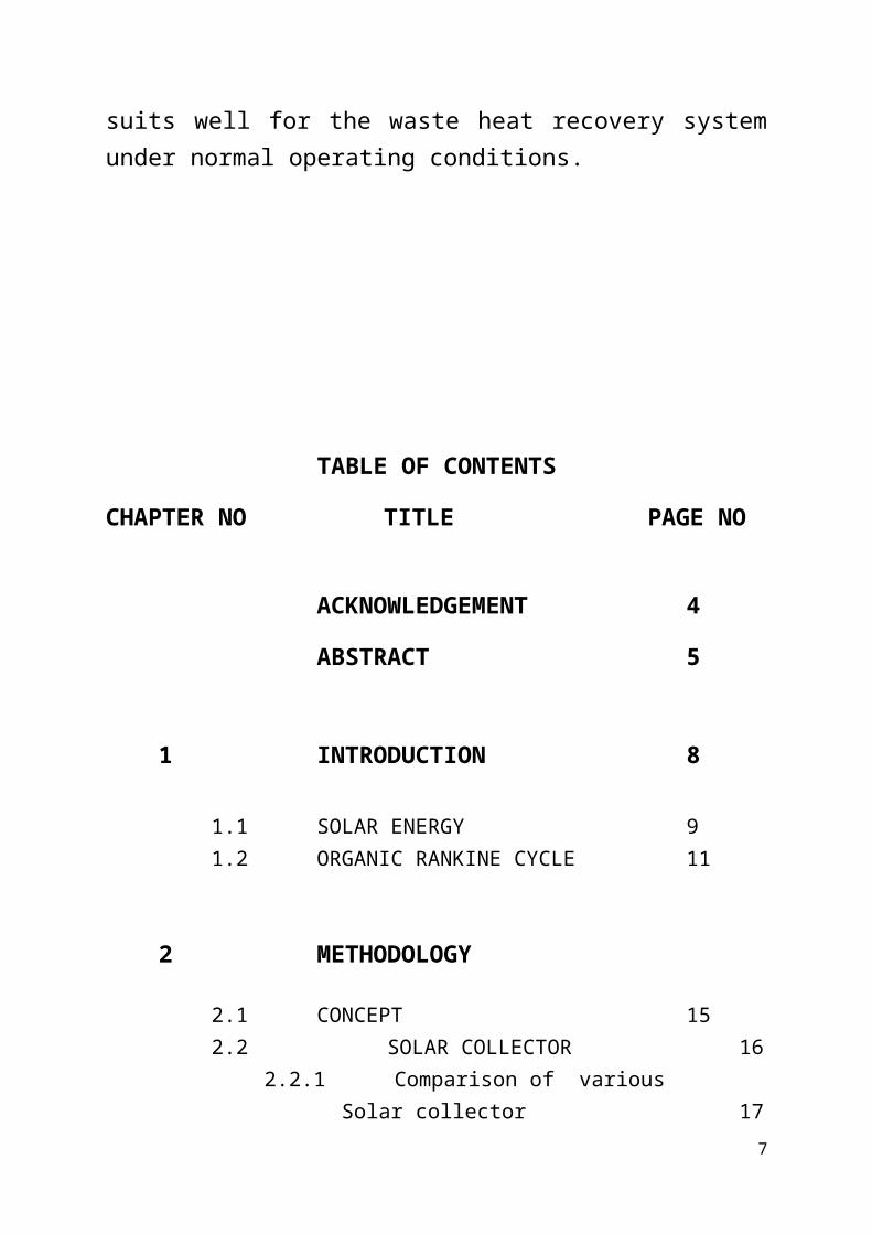
TABLE OF CONTENTS
CHAPTER NO TITLE PAGE NO
ACKNOWLEDGEMENT 4
ABSTRACT 5
1 INTRODUCTION 8
1.1 SOLAR ENERGY 91.2 ORGANIC RANKINE CYCLE 11
2 METHODOLOGY
2.1 CONCEPT 152.2 SOLAR COLLECTOR 16
2.2.1 Comparison of various Solar collector 17
7
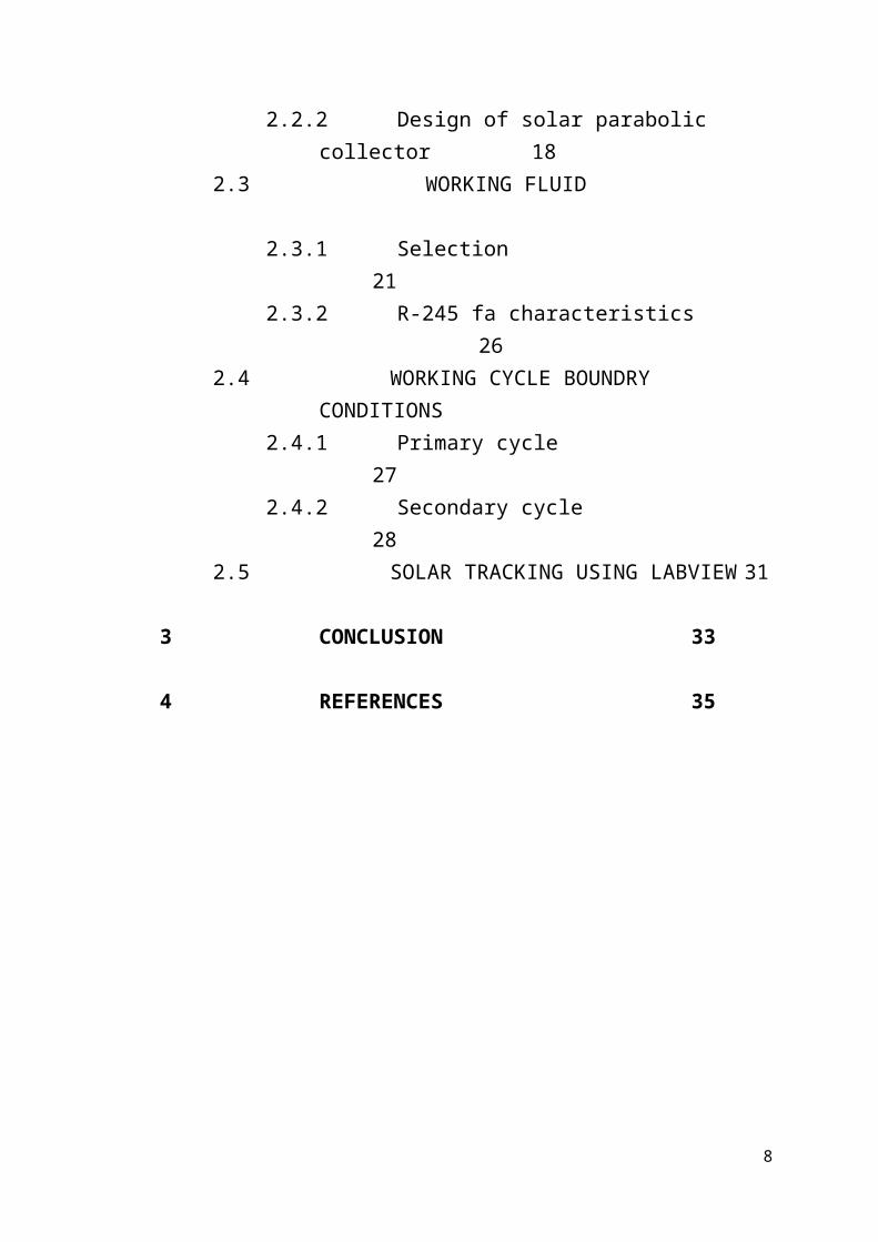
2.2.2 Design of solar parabolic collector 18
2.3 WORKING FLUID
2.3.1 Selection 21
2.3.2 R-245 fa characteristics26
2.4 WORKING CYCLE BOUNDRY CONDITIONS
2.4.1 Primary cycle27
2.4.2 Secondary cycle28
2.5 SOLAR TRACKING USING LABVIEW 31
3 CONCLUSION 33
4 REFERENCES 35
8
LIST OF SYMBOLS:
P –Pressure
V –Volume
H –Enthalpy
S –Entropy
T –Temperature
v –Specific Volume
h –Specific Enthalpy
s –Specific Entropy
x –Dryness Fraction
R -Refrigerant
M –Molar Mass
ODP –Ozone Depleting Potential
GWP –Global Warming Potential
9

10
INTRODUCTION
CHAPTER 1
INTRODUCTION
WHY SOLAR ENERGY?
While a majority of the world's currentelectricity supply is generated from fossilfuels such as coal, oil and natural gas, thesetraditional energy sources face a number ofchallenges including rising prices, securityconcerns over dependence on imports from alimited number of countries which havesignificant fossil fuel supplies, and growingenvironmental concerns over the climate changerisks associated with power generation usingfossil fuels. As a result of these and otherchallenges facing traditional energy sources,governments, businesses and consumers areincreasingly supporting the development ofalternative energy sources and new technologiesfor electricity generation. Renewable energysources such as solar, biomass, geothermal,hydroelectric and wind power generation haveemerged as potential alternatives which address
11
some of these concerns. As opposed to fossilfuels, which draw on finite resources that mayeventually become too expensive to retrieve,renewable energy sources are generallyunlimited in availability.
Solar power generation has emerged as one ofthe most rapidly growing renewable sources ofelectricity. Solar power generation has severaladvantages over other forms of electricitygeneration:
Reduced Dependence on Fossil Fuels. Environmental Advantages. Modularity and Scalability. Flexible Locations.
Solar energy, radiant light and heat from thesun, is harnessed using a range of ever-evolving technologies such as solar heating,solar photovoltaic, solar thermal electricity,solar architecture and artificialphotosynthesis
CONCENTRATED SOLAR POWER
Concentrating Solar Power (CSP) systems uselenses or mirrors and tracking systems to focusa large area of sunlight into a small beam. Theconcentrated heat is then used as a heat source
12
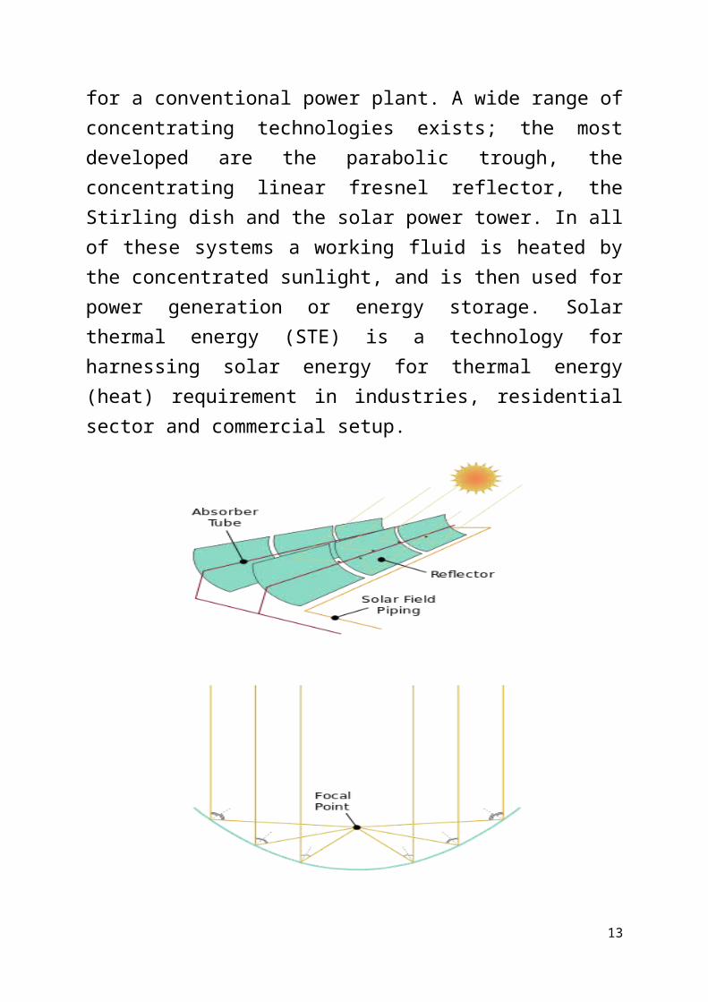
for a conventional power plant. A wide range ofconcentrating technologies exists; the mostdeveloped are the parabolic trough, theconcentrating linear fresnel reflector, theStirling dish and the solar power tower. In allof these systems a working fluid is heated bythe concentrated sunlight, and is then used forpower generation or energy storage. Solarthermal energy (STE) is a technology forharnessing solar energy for thermal energy(heat) requirement in industries, residentialsector and commercial setup.
13
ORGANIC RANKINE CYCLE:The Organic Rankine cycle (ORC) is named
for its use of an organic, high molecular massfluid with a liquid-vapour phase change,or boiling point, occurring at a lowertemperature than the water-steam phase change.The fluid allows Rankine cycle heat recoveryfrom lower temperature sources such as biomasscombustion, industrial waste heat, geothermalheat, solar ponds etc. The low-temperature heatis converted into useful work that can itselfbe converted into electricity.
WORKING PRINCIPLE OF ORC:The working principle of the organic
Rankine cycle is the same as that ofthe Rankine cycle: the working fluid is pumpedto a boiler where it is evaporated, passedthrough an expansion device (turbine or otherexpander), and then through a condenser heatexchanger where it is finally re-condensed.
14
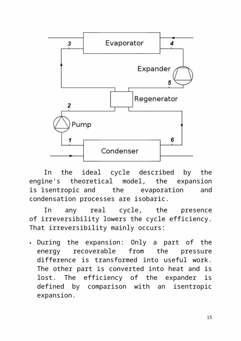
In the ideal cycle described by theengine's theoretical model, the expansionis isentropic and the evaporation andcondensation processes are isobaric.
In any real cycle, the presenceof irreversibility lowers the cycle efficiency.That irreversibility mainly occurs:
During the expansion: Only a part of theenergy recoverable from the pressuredifference is transformed into useful work.The other part is converted into heat and islost. The efficiency of the expander isdefined by comparison with an isentropicexpansion.
15
In the heat exchangers: The working fluidtakes a long and sinuous path which ensuresgood heat exchange but causes pressuredrops that lower the amount of powerrecoverable from the cycle. Likewise, thetemperature difference between the heatsource/sink and the working fluidgenerates exergy destruction and reduces thecycle performance.
IMPROVEMENT OF ORGANIC RANKINE CYCLE :In the case of a "dry fluid", the cycle can
be improved by the use of a regenerator: sincethe fluid has not reached the two-phase stateat the end of the expansion, its temperature atthis point is higher than the condensingtemperature. This higher temperature fluid canbe used to preheat the liquid before it entersthe evaporator.
A counter-current heat exchanger is thusinstalled between the expander outlet and theevaporator inlet. The power required from theheat source is therefore reduced and theefficiency is increased.
APPLICATIONS OF ORC:The organic Rankine cycle technology has
many possible applications, and counts more
16
than 250 identified power plants worldwide onesuch field is
WASTE HEAT RECOVERY:
Waste heat recovery is one of the mostimportant development fields for the organicRankine cycle (ORC). It can be applied to heatand power plants (for example a small scalecogeneration plant on a domestic water heater),or to industrial and farming processes such asorganic products fermentation, hot exhaustsfrom ovens or furnaces (e.g. lime and cementkilns), flue-gas condensation, exhaust gasesfrom vehicles, intercooling of a compressor,condenser of a power cycle, etc.
SOLAR THERMAL POWER:The organic Rankine cycle can be used in
the solar parabolic trough technology in placeof the usual steam Rankine cycle. The ORCallows power generation at lower capacities andwith a lower collector temperature, and hencethe possibility for low-cost, small scaledecentralized CSP units.
17

18
METHODOLOGYCHAPTER 2
BLOCK DIAGRAM OF INTEGRATED SOLAR POWEREDORGANIC RANKINE CYCLE
19
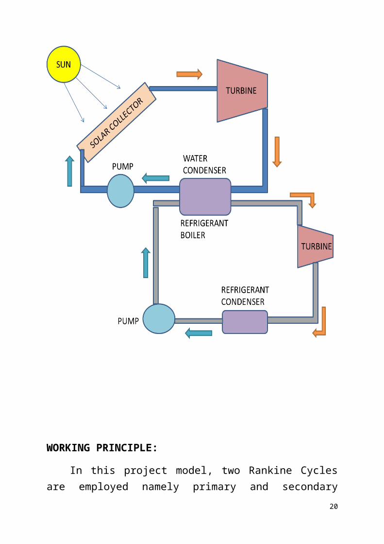
WORKING PRINCIPLE:
In this project model, two Rankine Cyclesare employed namely primary and secondary
20
cycle. In primary cycle, water is used as theworking fluid. The water gets transformed intosuperheated vapour by absorbing the solarradiation heat focussed on the absorber tube bya parabolic reflector. After doing the shaftwork in turbine, the steam condenses in thecondenser.
In secondary cycle, the refrigerant R245-fais used as the working fluid. The refrigerantacts as coolant in the condenser of the primarycycle and working fluid in the secondary cyclethereby, performing waste heat recoveryfunction.
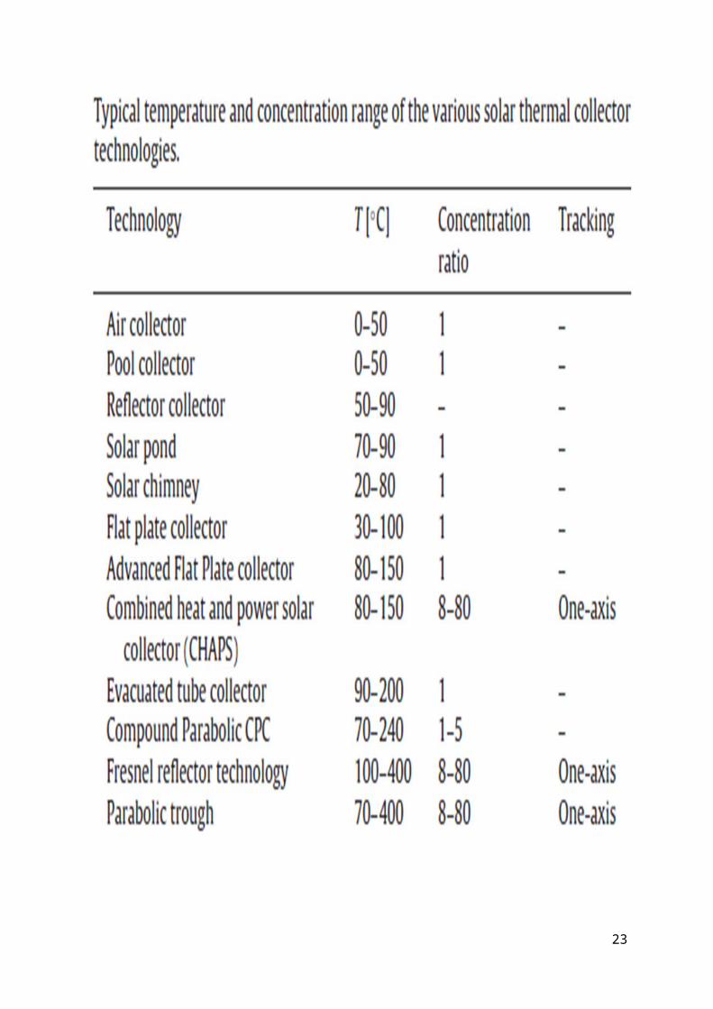
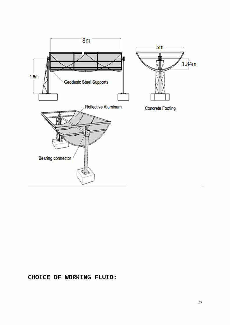
SOLAR COLLECTOR:
• Here the parabolic trough with reflectivealuminium coating is used as solarcollector.
• Heat transfer fluid runs through the tubeto absorb the concentrated sunlight.
• This increases the temperature of the fluidto required temperature (up to 450℃).
21

22
23
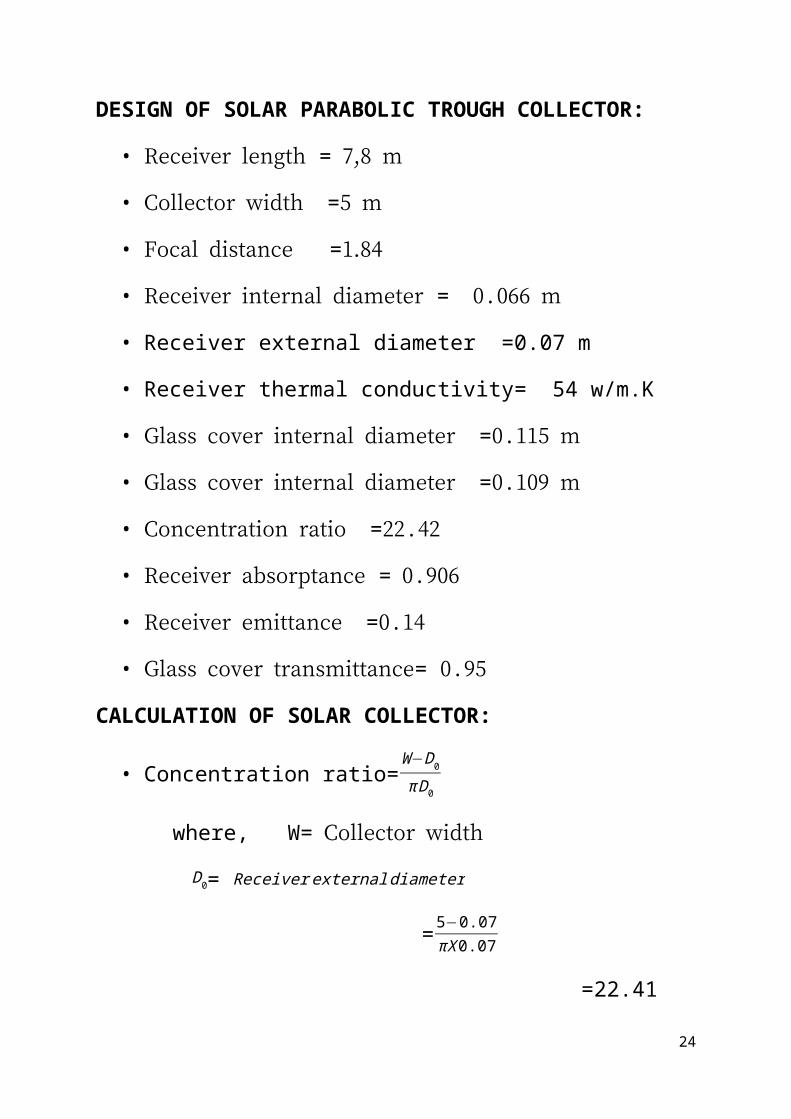
DESIGN OF SOLAR PARABOLIC TROUGH COLLECTOR:
• Receiver length = 7,8 m
• Collector width =5 m
• Focal distance =1.84
• Receiver internal diameter = 0.066 m
• Receiver external diameter =0.07 m
• Receiver thermal conductivity= 54 w/m.K
• Glass cover internal diameter =0.115 m
• Glass cover internal diameter =0.109 m
• Concentration ratio =22.42
• Receiver absorptance = 0.906
• Receiver emittance =0.14
• Glass cover transmittance= 0.95
CALCULATION OF SOLAR COLLECTOR:
• Concentration ratio=W−D0
πD0
where, W= Collector width
D0= Receiverexternaldiameter
=5−0.07πX0.07
=22.41
24

LAW GOVERNING RADIATION:
According to law of conservation of energy,α+ρ+τ=1
Where, α=absorptivity=IαI
ρ=reflectivity=IρI ,
τ=transmissivity=IτI .
I=Incident radiation.
25
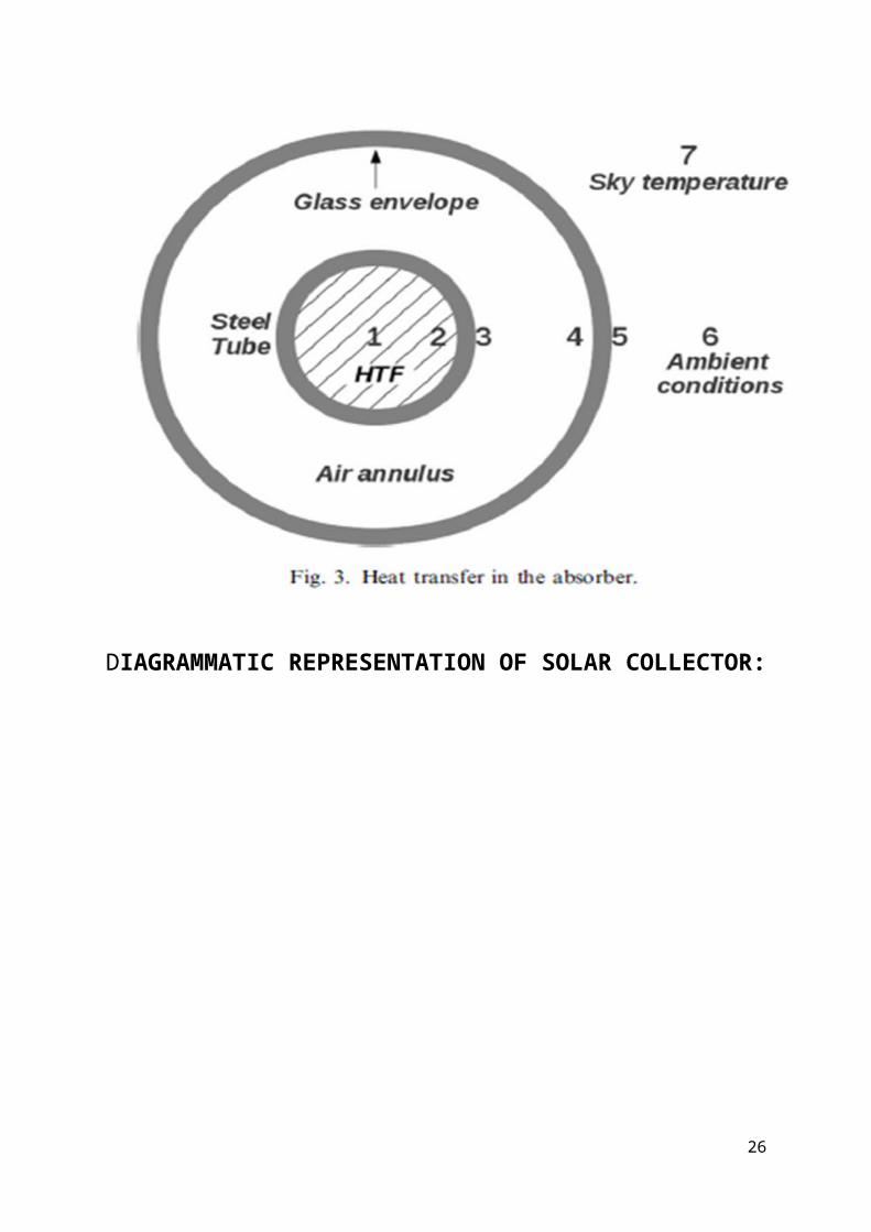
DIAGRAMMATIC REPRESENTATION OF SOLAR COLLECTOR:
26
CHOICE OF WORKING FLUID:
27
The selection of the working fluid is of key importance in low temperature Rankine Cycles. Because of the low temperature, heat transfer inefficiencies are highly prejudicial.These inefficiencies depend very strongly on the thermodynamic characteristics of the fluid and on the operating conditions.
In order to recover low-grade heat, the fluid generally has a lower boiling temperaturethan water. Refrigerants and hydrocarbons are two commonly used components.OPTIMAL CHARECTERISTIC OF WORKING FLUID:
Isentropic saturation vapour curve :Since the purpose of the ORC focuses on the recovery of low grade heat power, a superheatedapproach like the traditional Rankine cycle is not appropriate. Therefore, a small superheating at the exhaust of the evaporator will always be preferred, which disadvantages "wet" fluids (that are in two-phase state at the end of the expansion). In the case of dry fluids, a regenerator should be used.
Low freezing point, high stability temperature :
Unlike water, organic fluids usually suffer chemical deteriorations and decomposition at high temperatures. The maximum hot source temperature is thus limited by the chemical stability of the working fluid. The freezing
28
point should be lower than the lowest temperature in the cycle.
High heat of vaporisation and density :A fluid with a high latent heat and density will absorb more energy from the source in the evaporator and thus reduce the required flow rate, the size of the facility, and the pump consumption.
Low environmental impactThe main parameters taken into account are the Ozone depletion potential (ODP) and the global warming potential (GWP).
SafetyThe fluid should be non-corrosive, non-flammable, and non-toxic. The ASHRAE safety classification of refrigerants can be used as an indicator of the fluid dangerousness level.
29
Good availability and low cost Acceptable pressures
WORKING FLUID SELECTION:
Refrigerants are good candidates for ORCapplications because of their low-toxicitycharacteristics.
The working fluids under investigation areR134a, R113, R245ca, R245fa, R123,isobutene and propane
30
Some of the results demonstrate that ORCusing
R113 shows the maximum efficiency among theevaluated organic fluids for temperatures>157 ℃;
R123, R245ca, and R245fa show the bestefficiencies for temperatures between 95and 157 ℃;
For temperatures <95℃, isobutene shows thebest efficiency.
Also, it is shown that the organic-fluidboiling point has a strong influence on thesystem thermal efficiency.
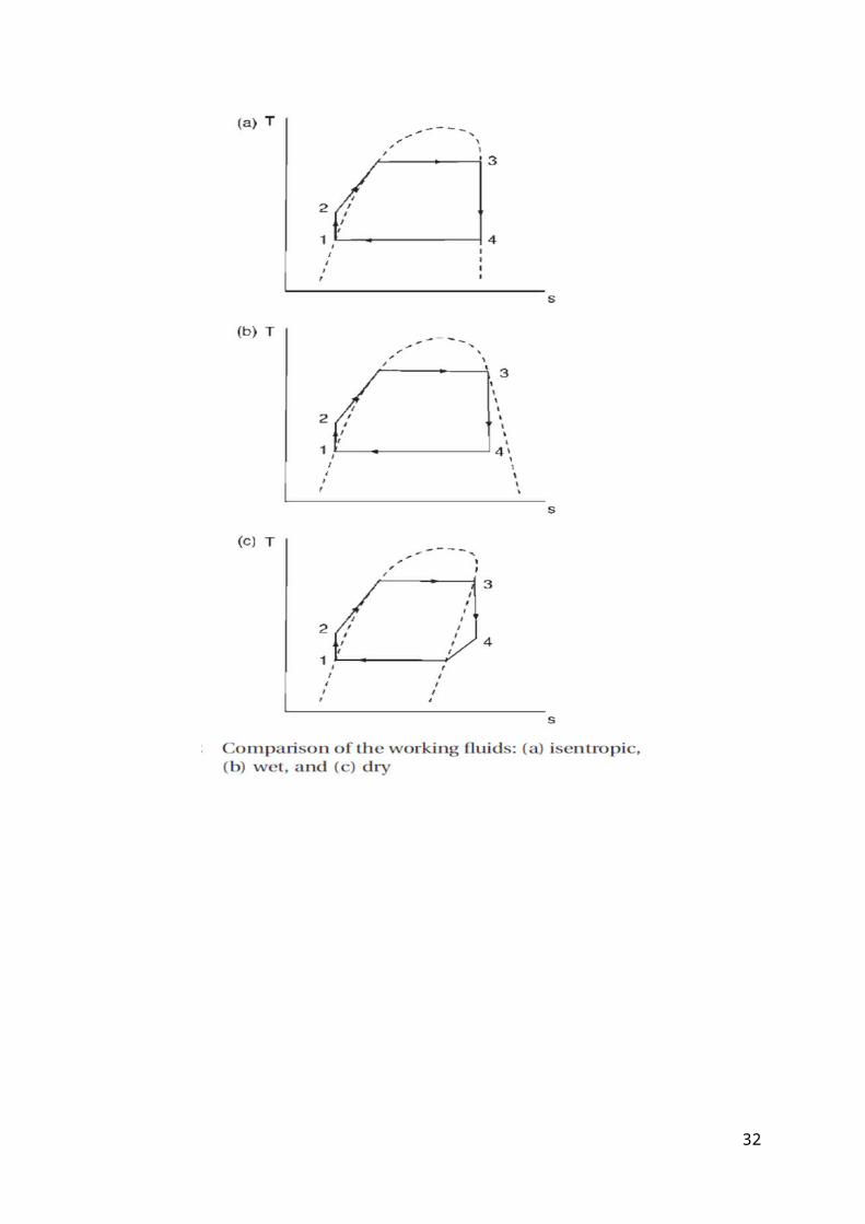
Another characteristic that must beconsidered during the selection of organicfluid is its saturation vapour curve. Thischaracteristic affects cycle efficiency.
A dry fluid has a positive slope; a wetfluid has a negative slope; and anisentropic fluid has infinite large slopes.
Generally, dry and isentropic fluids arebetter working fluids for an ORC becausethey do not condensate after the fluid goesthrough the turbine.
31
32
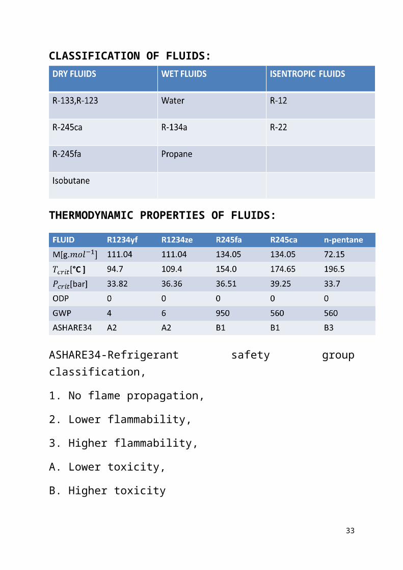
CLASSIFICATION OF FLUIDS:
THERMODYNAMIC PROPERTIES OF FLUIDS:
ASHARE34-Refrigerant safety groupclassification,
1. No flame propagation,
2. Lower flammability,
3. Higher flammability,
A. Lower toxicity,
B. Higher toxicity
33
R245fa (1,1,1,3,3-Pentafluoropropane):
• R245fa is selected which is appropriate forlow and ultra-low temperatures.
• Compared with pentane, R245fa’s advantageis the non-flammability, thus the safety ofthe system is certifiable
• The use of R245fa would provide favourableheat transfer and transport properties(high heat exchanger efficiency and lowpump power requirements).
• The ratio of heat transfer coefficient tofriction factor signifies the heat transferperformance efficiency (one wants tomaximize heat transfer and minimize fluidfriction or pumping power).
34
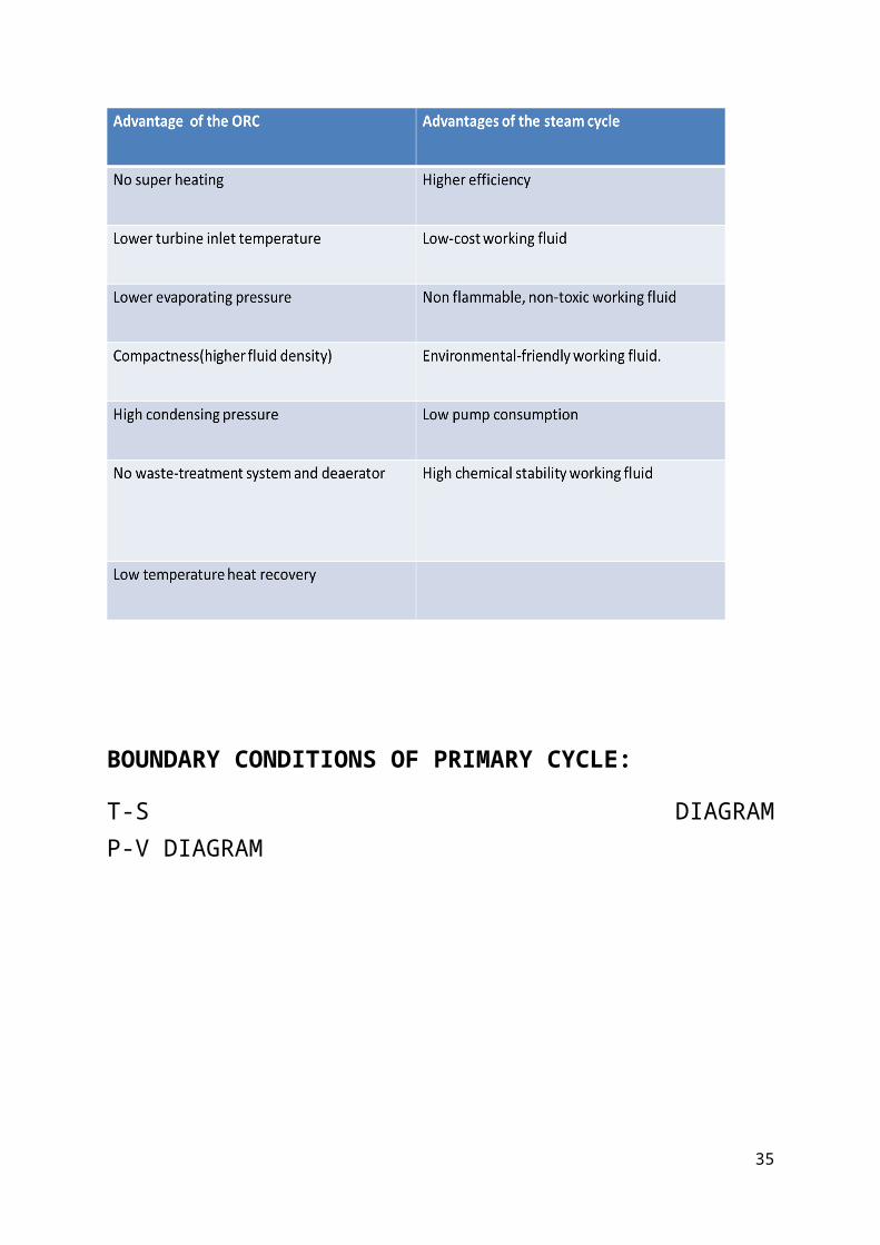
BOUNDARY CONDITIONS OF PRIMARY CYCLE:
T-S DIAGRAMP-V DIAGRAM
35
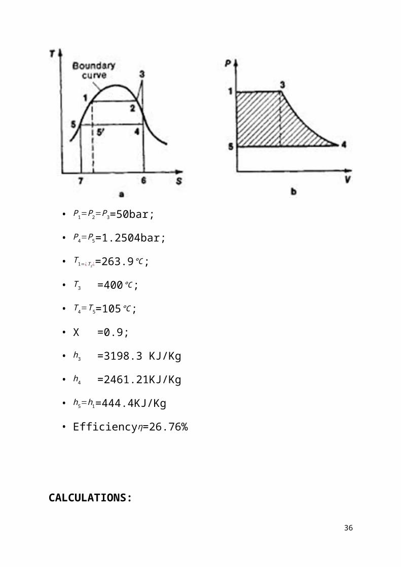
• P1=P2=P3=50bar;
• P4=P5=1.2504bar;
• T1=¿T2¿=263.9℃;
• T3 =400℃;
• T4=T5=105℃;
• X =0.9;
• h3 =3198.3 KJ/Kg
• h4 =2461.21KJ/Kg
• h5=h1=444.4KJ/Kg
• Efficiencyη=26.76%
CALCULATIONS:
36
• Shaft work =h3-h4
=3198.3-2461.21
=737.09kJ/kg.
• Heat supplied =h3-h1
=3198.3-444.4
=2753.9KJ/Kg.
• Condenser work =h4−h5
=2461.21-444.4
=2016.81KJ/Kg.
• % Efficiency = ShaftworkHeatsupplied
X100
=737.092753.9X100
=26.76%
BOUNDARY CONDITIONS OF SECONDARY CYCLE:T-S DIAGRAM
37
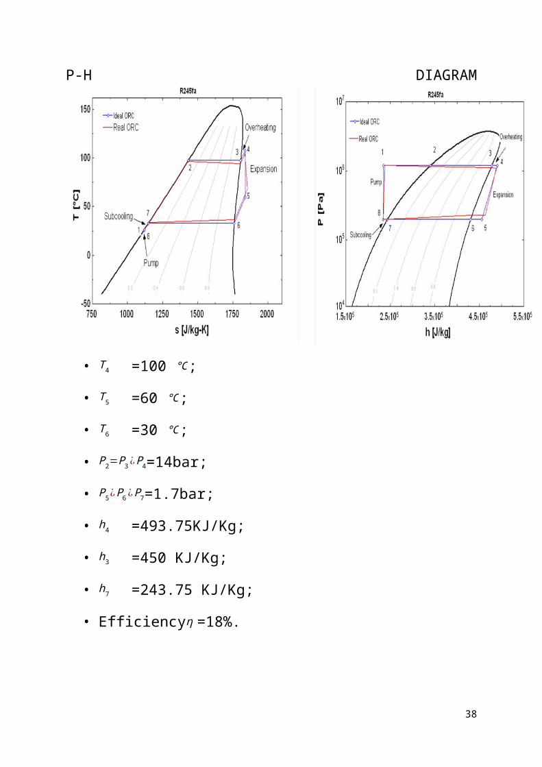
P-H DIAGRAM
• T4 =100 ℃;
• T5 =60 ℃;
• T6 =30 ℃;
• P2=P3 ¿P4=14bar;
• P5¿P6 ¿P7=1.7bar;
• h4 =493.75KJ/Kg;
• h3 =450 KJ/Kg;
• h7 =243.75 KJ/Kg;
• Efficiencyη =18%.
38
CALCULATIONS:
• Shaft work =h4-h5
=493.75-450
=43.75kJ/kg.
• Heat supplied =h4-h7
=493.75-243.75
=250kJ/kg.
• % Efficiency = ShaftworkHeatsupplied
X100
=43.75250 X100
=18%
39
NECESSARY FOR TRACKING:
If the solar collector is fixed in anorientation, it will not able to track thesolar rays effectively throughout the day. So,it is necessary to change the collectororientation according to the solar rays whichshows the tracking is necessary.
40
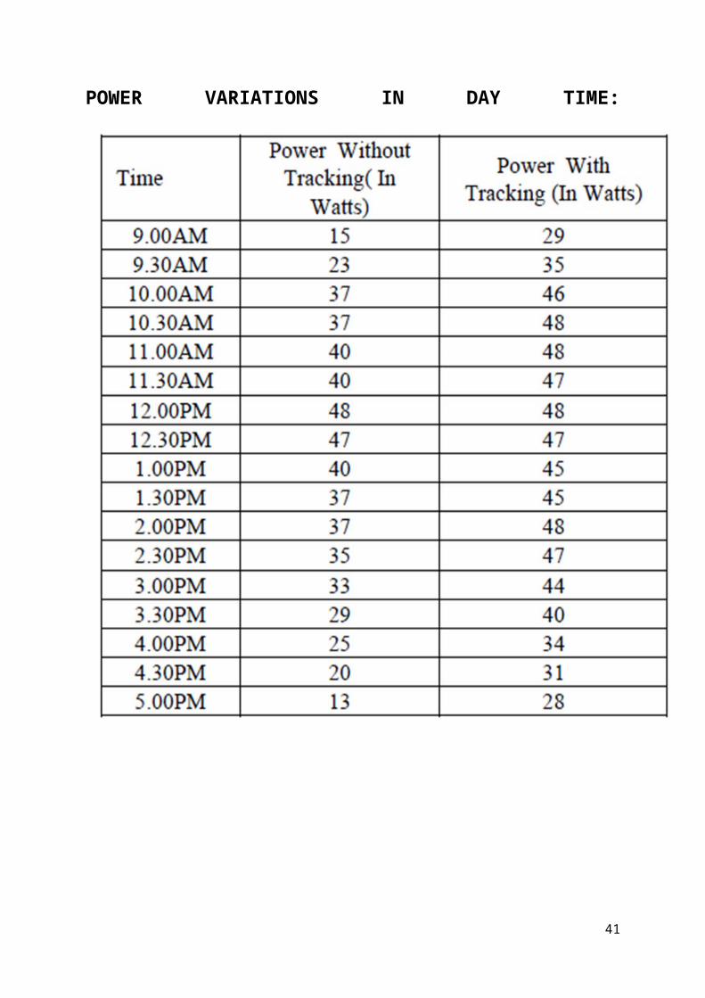
POWER VARIATIONS IN DAY TIME:
41
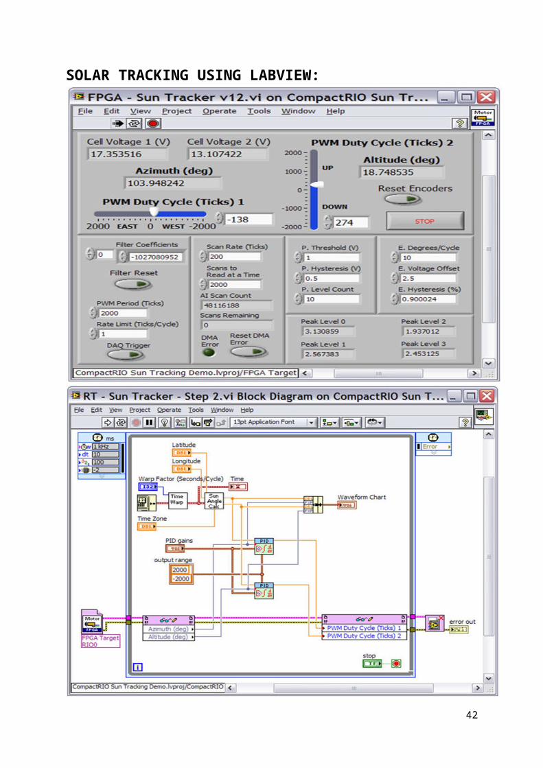
SOLAR TRACKING USING LABVIEW:
42

Try to add thermal efficiency comparisionof Rankine ane ORC cycle efficience in t
abular form.
43
CONCLUSIONCHAPTER 3
CONCLUSION
This project provides a method forproducing solar thermal renewable electricitywith waste heat recovery system.
The additional power output from ORCsystems appended to power generation systemscan help meet growing demand for power whileoffering a more attractive emissions profilesince there is a gain in output withoutadditional fuel consumption.
The high heat capacity of HFC-245fa resultsin improved theoretical cycle efficiency andheat exchanger performance that translates intoimproved overall efficiency.
Hence, this method can be employed foreconomic power generation or Captive powergeneration.
44

45
REFERENCESCHAPTER 4
REFRENCES
• Renewable Energy Sources and Emerging Technologies
by D.P. Kothari ,K.C. Singal, RakeshRanjan.
• A review of thermodynamic cycles and working fluidsfor the conversion of low-grade heat
46
by Huijuan Chen, D. Yogi Goswami *, EliasK. Stefanakos
• Experimental Study and Modeling of a LowTemperature Rankine Cycle for Small ScaleCogeneration.
by Sylvain Quoilin
• Performance evaluation of a low-temperature solarRankine cycle system utilizing R245fa
X.D. Wang, L. Zhao *, J.L. Wang, W.Z.Zhang, X.Z. Zhao
• Dynamic modeling and simulation of an OrganicRankine Cycle (ORC) system for waste heat recovery
Donghong Wei *, Xuesheng Lu, Zhen Lu,Jianming Gu
• Performance analysis of different working fluids foruse in organic Rankine cycles
P J Mago, L M Chamra, and C Somayaji
• Simulation of the Temperature and Heat Gain by SolarParabolic Trough Collector in Algeria
M. Ouagued, A. Khellaf
47