Embed Size (px)
Citation preview
Network Code
“Requirements for Generators”
(RfG)
A Public Consultation Document for the integration of the
Regulation (EU) 631/2016 in the Hellenic Grid Code
INDEPENDENT POWER TRANSMISSION OPERATOR
February 2019

IPTO Regulation (EU) 631/2016 - Network Code “Requirements for Generators” page 2
IPTO Regulation (EU) 631/2016 - Network Code “Requirements for Generators” page 3
INTRODUCTION TO COMMISSION REGULATION (EU) 2016/631of 14 April 2016 8
TITLE I INTRODUCTION AND GENERAL PROVISIONS 13
Article 1. 13
Subject matter 13
Article 2. 13
Definitions 13
Article 3. 18
Scope of application 18
Article 4. 19
Application to existing power-generating modules 19
Article 5. 20
Determination of significance 20
Article 6. 22
Application to power-generating modules, pump-storage power-generating modules, combined heat and
power facilities, and industrial sites 22
Article 7. 22
Regulatory aspects 22
Article 8. 23
Multiple TSOs 23
Article 9. 23
Recovery of costs 23
Article 10. 24
Public consultation 24
Article 11. 24
Stakeholder involvement 24
Article 12. 24
Confidentiality obligations 24
TITLE II REQUIREMENTS 25
CHAPTER 1 -General requirements 25
Article 13. 25
General requirements for type A power-generating modules 25
Article 14. 29
General requirements for type B power-generating modules 29
Article 15. 34
General requirements for type C power-generating modules 34
Article 16. 42
General requirements for type D power-generating modules 42
CHAPTER 2 - Requirements for synchronous power-generating modules 46
Article 17. 46
Requirements for type B synchronous power-generating modules 46
Article 18. 46
Requirements for type C synchronous power-generating modules 46
Article 19. 47
Requirements for type D synchronous power-generating modules 47
IPTO Regulation (EU) 631/2016 - Network Code “Requirements for Generators” page 4
CHAPTER 3 - Requirements for power park modules 49
Article 20. 49
Requirements for type B power park modules 49
Article 21. 51
Requirements for type C power park modules 51
Article 22. 54
Requirements for type D power park modules 54
CHAPTER 4 - Requirements for offshore power park modules 57
Article 23. 57
General provisions 57
Article 24. 57
Frequency stability requirements applicable to AC-connected offshore power park modules 57
Article 25. 57
Voltage stability requirements applicable to AC-connected offshore power park modules 57
Article 26. 57
Robustness requirements applicable to AC-connected offshore power park modules 57
Article 27. 58
System restoration requirements applicable to AC-connected offshore power park modules 58
Article 28. 58
General system management requirements applicable to AC-connected offshore power park modules 58
TITLE III OPERATIONAL NOTIFICATION PROCEDURE FOR CONNECTION 59
CHAPTER 1 - Connection of new power-generating modules 59
Article 29. 59
General provisions 59
Article 30. 59
Operational notification of type A power-generating modules 59
Article 31. 60
Operational notification of type B, C and D power-generating modules 60
Article 32. 60
Procedure for type B and C power-generating modules 60
Article 33. 60
Procedure for type D power-generating modules 60
Article 34. 61
Energisation operational notification for type D power-generating modules 61
Article 35. 61
Interim operational notification for type D power-generating modules 61
Article 36. 62
Final operational notification for type D power-generating modules 62
Article 37. 62
Limited operational notification for type D power-generating modules 62
CHAPTER 2 -Cost-benefit analysis 64
Article 38. 64
Identification of costs and benefits of application of requirements to existing power-generating
modules 64
IPTO Regulation (EU) 631/2016 - Network Code “Requirements for Generators” page 5
Article 39. 64
Principles of cost-benefit analysis 64
TITLE IV -COMPLIANCE 66
CHAPTER 1 -Compliance monitoring 66
Article 40. 66
Responsibility of the power-generating facility owner 66
Article 41. 66
Tasks of the relevant system operator 66
Article 42. 67
Common provisions for compliance testing 67
Article 43. 68
Common provisions on compliance simulation 68
CHAPTER 2 -Compliance testing for synchronous power-generating modules 69
Article 44. 69
Compliance tests for type B synchronous power-generating modules 69
Article 45. 69
Compliance tests for type C synchronous power-generating modules 69
Article 46. 71
Compliance tests for type D synchronous power-generating modules 71
CHAPTER 3 -Compliance testing for power park modules 72
Article 47. 72
Compliance tests for type B power park modules 72
Article 48. 72
Compliance tests for type C power park modules 72
Article 49. 75
Compliance tests for type D power park modules 75
CHAPTER 4 -Compliance testing for offshore power park modules 76
Article 50. 76
Compliance tests for offshore power park modules 76
CHAPTER 5 Compliance simulations for synchronous power-generating modules 77
Article 51. 77
Compliance simulations for type B synchronous power-generating modules 77
Article 52. 77
Compliance simulations for type C synchronous power-generating modules 77
Article 53. 78
Compliance simulations for type D synchronous power-generating modules 78
CHAPTER 6 -Compliance simulations for power park modules 80
Article 54. 80
Compliance simulations for type B power park modules 80
Article 55. 80
Compliance simulations for type C power park modules 80
Article 56. 82
Compliance simulations for type D power park modules 82
CHAPTER 7 -Compliance simulations for offshore power park modules 83
IPTO Regulation (EU) 631/2016 - Network Code “Requirements for Generators” page 6
Article 57. 83
Compliance simulations applicable to offshore power park modules 83
CHAPTER 8 -Non-binding guidance and monitoring of implementation 84
Article 58. 84
Non-binding guidance on implementation 84
Article 59. 84
Monitoring 84
TITLE V DEROGATIONS 85
Article 60. 85
Power to grant derogations 85
Article 61. 85
General provisions 85
Article 62. 85
Request for a derogation by a power-generating facility owner 85
Article 63. 87
Request for a derogation by a relevant system operator or relevant TSO 87
Article 64. 88
Register of derogations from the requirements of this Regulation 88
Article 65. 88
Monitoring of derogations 88
TITLE VI TRANSITIONAL ARRANGEMENTS FOR EMERGING TECHNOLOGIES 89
Article 66. 89
Emerging technologies 89
Article 67. 89
Establishment of thresholds for classification as emerging technologies 89
Article 68. 89
Application for classification as an emerging technology 89
Article 69. 90
Assessment and approval of requests for classification as an emerging technology 90
Article 70. 90
Withdrawal of classification as an emerging technology 90
TITLE VII FINAL PROVISIONS 91
Article 71. 91
Amendment of contracts and general terms and conditions 91
IPTO Regulation (EU) 631/2016 - Network Code “Requirements for Generators” page 7
List of Annexes
Annex 1: ENTSO-E parameters of non-exhaustive requirements for RfG
Annex 2: Information exchange between IPTO and Power Generating Facilities
Annex 3: Data required from Users for connection to Transmission or Distribution network
Annex 4: Operational Notification Procedure for connection of type A, B, and C PGMs
Annex 5: Operational Notification Procedure for connection of type D PGMs
Annex 6: Compliance Testing
Annex 7: Compliance simulation models and studies
Annex 8: Summary of RAE’s derogation criteria
IPTO Regulation (EU) 631/2016 - Network Code “Requirements for Generators” page 8
INTRODUCTION TO COMMISSION REGULATION (EU) 2016/631of 14 April 2016
establishing a network code on requirements for grid connection of generators
THE EUROPEAN COMMISSION,
Having regard to the Treaty on the Functioning of the European Union,
Having regard to Regulation (EC) No 714/2009 of the European Parliament and of the Council of 13
July 2009 on conditions for access to the network for cross-border exchanges in electricity and
repealing Regulation (EC) No 1228/20031, and in particular Article 6(11) thereof,
Whereas:
(1) The swift completion of a fully functioning and interconnected internal energy market is
crucial to maintaining security of energy supply, increasing competitiveness and ensuring
that all consumers can purchase energy at affordable prices.
(2) Regulation (EC) No 714/2009 sets out non-discriminatory rules governing access to the
network for cross-border exchanges in electricity with a view to ensuring the proper
functioning of the internal market in electricity. In addition, Article 5 of Directive
2009/72/EC of the European Parliament and of the Council2 requires that Member States
(MS) or, where Member States have so provided, regulatory authorities ensure, inter alia,
that objective and non-discriminatory technical rules are developed which establish
minimum technical design and operational requirements for the connection to the
system. Where requirements constitute terms and conditions for connection to national
networks, Article 37(6) of the same Directive requires regulatory authorities to be
responsible for fixing or approving at least the methodologies used to calculate or
establish them. In order to provide system security within the interconnected
transmission system, it is essential to establish a common understanding of the
requirements applicable to power-generating modules. Those requirements that
contribute to maintaining, preserving and restoring system security in order to facilitate
proper functioning of the internal electricity market within and between synchronous
areas, and to achieve cost efficiencies, should be regarded as cross-border network issues
and market integration issues.
(3) Harmonised rules for grid connection for power-generating modules should be set out in
order to provide a clear legal framework for grid connections, facilitate Union-wide trade
in electricity, ensure system security, facilitate the integration of renewable electricity
sources, increase competition and allow more efficient use of the network and resources,
for the benefit of consumers.
(4) System security depends partly on the technical capabilities of power-generating
modules. Therefore, regular coordination at the level of the transmission and distribution
networks and adequate performance of the equipment connected to the transmission and
distribution networks with sufficient robustness to cope with disturbances and to help to
prevent any major disruption or to facilitate restoration of the system after a collapse are
fundamental prerequisites.
1 OJ L 211, 14.8.2009, p. 15 2 Directive 2009/72/EC of the European Parliament and of the Council of 13 July 2009 concerning common rules for the internal market in
electricity and repealing Directive 2003/54/EC (OJ L 211, 14.8.2009, p. 55).
IPTO Regulation (EU) 631/2016 - Network Code “Requirements for Generators” page 9
(5) Secure system operation is only possible if there is close cooperation between power-
generating facility owners and system operators. In particular, the functioning of the
system under abnormal operating conditions depends on the response of power-
generating modules to deviations from the reference 1 per unit (pu) values of voltage and
nominal frequency. In the context of system security, the networks and the power-
generating modules should be considered as one entity from a system engineering point
of view, given that those parts are interdependent. Therefore, as a prerequisite for grid
connection, relevant technical requirements should be set for power- generating modules.
(6) Regulatory authorities should consider the reasonable costs effectively incurred by
system operators in the implementation of this Regulation when fixing or approving
transmission or distribution tariffs or their methodologies or when approving the terms
and conditions for connection and access to national networks in accordance with Article
37(1) and (6) of Directive 2009/72/EC and with Article 14 of Regulation (EC) No
714/2009.
(7) Different synchronous electricity systems in the Union have different characteristics
which need to be taken into account when setting the requirements for generators. It is
therefore appropriate to consider regional specificities when establishing network
connection rules as required by Article 8(6) of Regulation (EC) No 714/2009.
(8) In view of the need to provide regulatory certainty, the requirements of this Regulation
should apply to new generating facilities but should not apply to existing generating
modules and generating modules already at an advanced stage of planning but not yet
completed unless the relevant regulatory authority or Member State decides otherwise
based on evolution of system requirements and a full cost-benefit analysis, or where there
has been substantial modernisation of those generating facilities.
(9) The significance of power-generating modules should be based on their size and their
effect on the overall system. Synchronous machines should be classed on the machine size
and include all the components of a generating facility that normally run indivisibly, such
as separate alternators driven by the separate gas and steam turbines of a single
combined-cycle gas turbine installation. For a facility including several such combined-
cycle gas turbine installations, each should be assessed on its size, and not on the whole
capacity of the facility. Non- synchronously connected power-generating units, where
they are collected together to form an economic unit and where they have a single
connection point should be assessed on their aggregated capacity.
(10) In view of the different voltage level at which generators are connected and their
maximum generating capacity, this Regulation should make a distinction between
different types of generators by establishing different levels of requirements. This
Regulation does not set the rules to determine the voltage level of the connection point to
which the power-generating module shall be connected.
(11) The requirements applicable to type A power-generating modules should be set at the
basic level necessary to ensure capabilities of generation with limited automated
response and minimal system operator control. They should ensure that there is no large-
scale loss of generation over system operational ranges, thereby minimising critical
events and include requirements necessary for widespread intervention during system-
critical events.
IPTO Regulation (EU) 631/2016 - Network Code “Requirements for Generators” page 10
(12) The requirements applicable to type B power-generating modules should provide for a
wider range of automated dynamic response with greater resilience to operational
events, in order to ensure the use of this dynamic response, and a higher level of system
operator control and information to utilise those capabilities. They ensure an automated
response to mitigate the impact of, and maximise dynamic generation response to, system
events.
(13) The requirements applicable to type C power-generating modules should provide for a
refined, stable and highly controllable real-time dynamic response aiming to provide
principle ancillary services to ensure security of supply. Those requirements should cover
all system states with consequential detailed specification of interactions of
requirements, functions, control and information to utilise those capabilities and ensure
the real-time system response necessary to avoid, manage and respond to system events.
Those requirements should also provide for sufficient capability of generating modules to
respond to both intact and system disturbed situations and should provide the
information and control necessary to utilise generation in different situations.
(14) The requirements applicable to type D power-generating modules should be specific to
higher voltage connected generation with an impact on control and operation of the
entire system. They should ensure stable operation of the interconnected system,
allowing the use of ancillary services from generation Europe-wide.
(15) The requirements should be based on the principles of non-discrimination and
transparency as well as on the principle of optimisation between the highest overall
efficiency and lowest total cost for all involved parties. Therefore, those requirements
should reflect the differences in the treatment of generation technologies with different
inherent characteristics and avoid unnecessary investments in some geographical areas
in order to take into account their respective regional specificities. Transmission system
operators (‘TSOs’) and distribution system operators (‘DSOs’) including closed
distribution system operators (‘CDSOs’) can take those differences into account when
defining the requirements in accordance with the provisions of this Regulation, whilst
recognising that the thresholds which determine whether a system is a transmission
system or a distribution system are established at the national level.
(16) Due to its cross-border impact, this Regulation should aim at the same frequency-related
requirements for all voltage levels, at least within a synchronous area. That is necessary
because, within a synchronous area, a change in frequency in one Member State would
immediately impact frequency and could damage equipment in all other Member States.
(17) To ensure system security, it should be possible for power-generating modules in each
synchronous area of the interconnected system to remain connected to the system for
specified frequency and voltage ranges.
(18) This Regulation should provide for ranges of parameters for national choices for fault-
ride-through capability to maintain a proportionate approach reflecting varying system
needs such as the level of renewable energy sources (‘RES’) and existing network
protection schemes, both transmission and distribution. In view of the configuration of
some networks, the upper limit for fault-ride-through requirements should be 250
milliseconds. However, given that the most common fault clearing time in Europe is
currently 150 milliseconds it leaves scope for the entity, as designated by the Member
State to approve the requirements of this Regulation, to verify that a longer requirement
is necessary before approving it.
IPTO Regulation (EU) 631/2016 - Network Code “Requirements for Generators” page 11
(19) When defining the pre-fault and post-fault conditions for the fault-ride-through
capability, taking into account system characteristics such as network topology and
generation mix, the relevant TSO should decide whether priority is given to pre-fault
operating conditions of power-generating modules or to longer fault clearance times.
(20) Ensuring appropriate reconnection after an incidental disconnection due to a network
disturbance is important to the functioning of the interconnected system. Proper network
protection is essential for maintaining system stability and security, particularly in case of
disturbances to the system. Protection schemes can prevent aggravation of disturbances
and limit their consequences.
(21) Adequate information exchange between system operators and power-generating facility
owners is a prerequisite for enabling system operators to maintain system stability and
security. System operators need to have a continuous overview of the state of the system,
which includes information on the operating conditions of power-generating modules, as
well as the possibility to communicate with them in order to direct operational
instructions.
(22) In emergency situations which could endanger system stability and security, system
operators should have the possibility to instruct that the output of power-generating
modules be adjusted in a way which allows system operators to meet their
responsibilities for system security.
(23) Voltage ranges should be coordinated between interconnected systems because they are
crucial to secure planning and operation of a power system within a synchronous area.
Disconnections because of voltage disturbances have an impact on neighbouring systems.
Failure to specify voltage ranges could lead to widespread uncertainty in planning and
operation of the system with respect to operation beyond normal operating conditions.
(24) The reactive power capability needs depend on several factors including the degree of
network meshing and the ratio of in-feed and consumption, which should be taken into
account when establishing reactive power requirements. When regional system
characteristics vary within a systems operator's area of responsibility, more than one
profile could be appropriate. Reactive power production, known as lagging, at high
voltages and reactive power consumption, known as leading, at low voltages might not be
necessary. Reactive power requirements could put constraints on the design and
operation of power-generating facilities. Therefore, it is important that the capabilities
actually required for efficient system operation be thoroughly assessed.
(25) Synchronous power-generating modules have an inherent capability to resist or slow
down frequency deviations, a characteristic which many RES technologies do not have.
Therefore, countermeasures should be adopted, to avoid a larger rate of change of
frequency during high RES production. Synthetic inertia could facilitate further expansion
of RES, which do not naturally contribute to inertia.
(26) Appropriate and proportionate compliance testing should be introduced so that system
operators can ensure operational security.
(27) The regulatory authorities, Member States and system operators should ensure that, in
the process of developing and approving the requirements for network connection, they
are harmonised to the extent possible, in order to ensure full market integration.
Established technical standards should be taken into particular consideration in the
development of connection requirements.
IPTO Regulation (EU) 631/2016 - Network Code “Requirements for Generators” page 12
(28) A process for derogating from the rules should be set out in this Regulation to take into
account local circumstances where exceptionally, for example, compliance with those
rules could jeopardise the stability of the local network or where the safe operation of a
power-generating module might require operating conditions that are not in line with the
Regulation. In the case of particular combined heat and power plants, which bring wider
efficiency benefits, applying the rules set out in this Regulation could result in
disproportionate costs and lead to the loss of those efficiency benefits.
(29) Subject to approval by the relevant regulatory authority, or other authority where
applicable in a Member State, system operators should be allowed to propose derogations
for certain classes of power-generating modules.
(30) This Regulation has been adopted on the basis of Regulation (EC) No 714/2009 which it
supplements and of which it forms an integral part. References to Regulation (EC) No
714/2009 in other legal acts should be understood as also referring to this Regulation.
(31) The measures provided for in this Regulation are in accordance with the opinion of the
Committee referred to in Article 23(1) of Regulation (EC) No 714/2009
(32) For Power Generating Modules and Power Park Modules, where energy primary offer
cannot be influenced (e.g. wind, solar), all requirements related to active current and
active power are considered with reservation to a sufficient available primary energy
offer."
IPTO Regulation (EU) 631/2016 - Network Code “Requirements for Generators” page 13
TITLE I INTRODUCTION AND GENERAL PROVISIONS
Article 1. Subject matter
This Regulation establishes a network code which lays down the requirements for grid connection of
power-generating facilities, namely synchronous power-generating modules, power park modules and
offshore power park modules, to the interconnected system. It, therefore, helps to ensure fair conditions of
competition in the internal electricity market, to ensure system security and the integration of
renewable electricity sources, and to facilitate Union-wide trade in electricity.
This regulation also lays down the obligations for ensuring that system operators make appropriate use of
the power- generating facilities' capabilities in a transparent and non-discriminatory manner to
provide a level playing field throughout the Union.
Article 2. Definitions
For the purposes of this Regulation, the definitions in Article 2 of Directive 2012/27/EU of the
European Parliament and of the Council 3, Article 2 of Regulation (EC) No 714/2009, Article 2 of
Commission Regulation (EU) 2015/1222 4 Article 2 of Commission Regulation (EU) No 543/2013 5
and Article 2 of Directive 2009/72/EC shall apply.
In addition, the following definitions shall apply:
(1) ‘entity’ means a regulatory authority, other national authority, system operator or other public
or private body appointed under national law.
(2) ‘synchronous area’ means an area covered by synchronously interconnected TSOs, such as the
synchronous areas of Continental Europe, Great Britain, Ireland-Northern Ireland and Nordic
and the power systems of Lithuania, Latvia and Estonia, together referred to as ‘Baltic’ which
are part of a wider synchronous area;
`
(3) ‘voltage’ means the difference in electrical potential between two points measured as the root-
mean-square value of the positive sequence phase-to-phase voltages at fundamental
frequency;
(4) ‘apparent power’ means the product of voltage and current at fundamental frequency, and the
square root of three in the case of three-phase systems, usually expressed in kilovolt-amperes
(‘kVA’) or megavolt-amperes (‘MVA’);
(5) ‘power-generating module’, (PGM), means either a synchronous power-generating module or a
power park module;
(6) ‘power-generating facility’, (PGF), means a facility that converts primary energy into electrical
3 Directive 2012/27/EU of the European Parliament and of the Council of 25 October 2012 on energy efficiency, amending Directives 2009/125/EC and 2010/30/EU and repealing Directives 2004/8/EC and 2006/32/EC (OJ L 315, 14.11.2012, p. 1). 4 Commission Regulation (EU) 2015/1222 of 24 July 2015 establishing a guideline on capacity allocation and congestion management (OJ L 197, 25.7.2015, p. 24). 5Commission Regulation (EU) No 543/2013 of 14 June 2013 on submission and publication of data in electricity markets and amending Annex I to Regulation (EC) No 714/2009 of the European Parliament and of the Council (OJ L 163, 15.6.2013, p. 1)
IPTO Regulation (EU) 631/2016 - Network Code “Requirements for Generators” page 14
energy and which consists of one or more power-generating modules connected to a network at
one or more connection points;
(7) ‘power-generating facility owner’, (PGFO), means a natural or legal entity owning a power-
generating facility;
(8) ‘main generating plant’ means one or more of the principal items of equipment required to
convert the primary source of energy into electricity;
(9) ‘synchronous power-generating module’ means an indivisible set of installations which can
generate electrical energy such that the frequency of the generated voltage, the generator speed
and the frequency of network voltage are in a constant ratio and thus in synchronism;
(10) ‘power-generating module document’ or ‘PGMD’ means a document provided by the power-
generating facility owner to the relevant system operator for a type B or C power-generating
module which confirms that the power- generating module's compliance with the technical
criteria set out in this Regulation has been demonstrated and provides the necessary data and
statements, including a statement of compliance;
(11) ‘relevant TSO’ means the TSO in whose control area a power-generating module, a demand
facility, a distribution system or a HVDC system is or will be connected to the network at any
voltage level;
(12) ‘network’ means a plant and apparatus connected together in order to transmit or distribute
electricity;
(13) ‘relevant system operator’ means the transmission system operator or distribution system
operator to whose system a power-generating module, demand facility, distribution system or
HVDC system is or will be connected;
(14) ‘connection agreement’ means a contract between the relevant system operator and either the
power-generating facility owner, demand facility owner, distribution system operator or HVDC
system owner, which includes the relevant site and specific technical requirements for the
power-generating facility, demand facility, distribution system, distribution system connection
or HVDC system;
(15) ‘connection point’ means the interface at which the power-generating module, demand facility,
distribution system or HVDC system is connected to a transmission system, offshore network,
distribution system, including closed distribution systems, or HVDC system, as identified in the
connection agreement;
(16) ‘maximum capacity’ or ‘Pmax’ means the maximum continuous active power which a power-
generating module can produce, less any demand associated solely with facilitating the
operation of that power-generating module and not fed into the network as specified in the
connection agreement or as agreed between the relevant system operator and the power-
generating facility owner;
(17) ‘power park module’ or ‘PPM’ means a unit or ensemble of units generating electricity, which is
either non-synchronously connected to the network or connected through power electronics,
and that also has a single connection point to a transmission system, distribution system
including closed distribution system or HVDC system;
(18) ‘offshore power park module’ means a power park module located offshore with an offshore
connection point;
IPTO Regulation (EU) 631/2016 - Network Code “Requirements for Generators” page 15
(19) ‘synchronous compensation operation’ means the operation of an alternator without prime
mover to regulate voltage dynamically by production or absorption of reactive power;
(20) ‘active power’ means the real component of the apparent power at fundamental frequency,
expressed in watts or multiples thereof such as kilowatts (‘kW’) or megawatts (‘MW’);
(21) ‘pump-storage’ means a hydro unit in which water can be raised by means of pumps and stored
to be used for the generation of electrical energy;
(22) ‘frequency’ means the electric frequency of the system expressed in hertz that can be measured
in all parts of the synchronous area under the assumption of a consistent value for the system in
the time frame of seconds, with only minor differences between different measurement
locations. Its nominal value is 50Hz;
(23) ‘droop’ means the ratio of a steady-state change of frequency to the resulting steady-state
change in active power output, expressed in percentage terms. The change in frequency is
expressed as a ratio to nominal frequency and the change in active power expressed as a ratio to
maximum capacity or actual active power at the moment the relevant threshold is reached;
(24) ‘minimum regulating level’ means the minimum active power, as specified in the connection
agreement or as agreed between the relevant system operator and the power-generating facility
owner, down to which the power- generating module can control active power;
(25) ‘setpoint’ means the target value for any parameter typically used in control schemes;
(26) ‘instruction’ means any command, within its authority, given by a system operator to a power-
generating facility owner, demand facility owner, distribution system operator or HVDC system
owner in order to perform an action;
(27) ‘secured fault’ means a fault which is successfully cleared according to the system operator's
planning criteria;
(28) ‘reactive power’ means the imaginary component of the apparent power at fundamental
frequency, usually expressed in kilovar (‘kVAr’) or megavar (‘MVAr’);
(29) ‘fault-ride-through’ means the capability of electrical devices to be able to remain connected to
the network and operate through periods of low voltage at the connection point caused by
secured faults;
(30) ‘alternator’ means a device that converts mechanical energy into electrical energy by means of a
rotating magnetic field;
(31) ‘current’ means the rate at which electric charge flows which is measured by the root-mean-
square value of the positive sequence of the phase current at fundamental frequency;
(32) ‘stator’ means the portion of a rotating machine which includes the stationary magnetic parts
with their associated windings;
(33) ‘inertia’ means the property of a rotating rigid body, such as the rotor of an alternator, such that
it maintains its state of uniform rotational motion and angular momentum unless an external
torque is applied;
(34) ‘synthetic inertia’ means the facility provided by a power park module or HVDC system to
replace the effect of inertia of a synchronous power-generating module to a prescribed level of
performance;
IPTO Regulation (EU) 631/2016 - Network Code “Requirements for Generators” page 16
(35) ‘frequency control’ means the capability of a power-generating module or HVDC system to
adjust its active power output in response to a measured deviation of system frequency from a
setpoint, in order to maintain stable system frequency;
(36) ‘frequency sensitive mode’ or ‘FSM’ means the operating mode of a power-generating module or
HVDC system in which the active power output changes in response to a change in system
frequency, in such a way that it assists with the recovery to target frequency;
(37) ‘limited frequency sensitive mode — overfrequency’ or ‘LFSM-O’ means a power-generating
module or HVDC system operating mode which will result in active power output reduction in
response to a change in system frequency above a certain value;
(38) ‘limited frequency sensitive mode — underfrequency’ ‘LFSM-U’ means a power-generating
module or HVDC system operating mode which will result in active power output increase in
response to a change in system frequency below a certain value;
(39) ‘frequency response deadband’ means an interval used intentionally to make the frequency
control unresponsive;
(40) ‘frequency response insensitivity’ means the inherent feature of the control system specified as
the minimum magnitude of change in the frequency or input signal that results in a change of
output power or output signal;
(41) ‘P-Q-capability diagram’ means a diagram describing the reactive power capability of a power-
generating module in the context of varying active power at the connection point;
(42) ‘steady-state stability’ means the ability of a network or a synchronous power-generating
module to revert and maintain stable operation following a minor disturbance;
(43) ‘island operation’ means the independent operation of a whole network or part of a network
that is isolated after being disconnected from the interconnected system, having at least one
power-generating module or HVDC system supplying power to this network and controlling the
frequency and voltage;
(44) ‘houseload operation’ means the operation which ensures that power-generating facilities are
able to continue to supply their in-house loads in the event of network failures resulting in
power-generating modules being disconnected from the network and tripped onto their
auxiliary supplies;
(45) ‘black start capability’ means the capability of recovery of a power-generating module from a
total shutdown through a dedicated auxiliary power source without any electrical energy supply
external to the power-generating facility;
(46) ‘authorised certifier’ means an entity that issues equipment certificates and power-generating
module documents and whose accreditation is given by the national affiliate of the European
cooperation for Accreditation (‘EA’), established in accordance with Regulation (EC) No
765/2008 of the European Parliament and of the Council6 ;
6 Regulation (EC) No 765/2008 of the European Parliament and of the Council of 9 July 2008 setting out the requirements for
accreditation and market surveillance relating to the marketing of products and repealing Regulation (EEC) No 339/93 (OJ L 218,
13.8.2008, p. 30).
IPTO Regulation (EU) 631/2016 - Network Code “Requirements for Generators” page 17
(47) ‘equipment certificate’ means a document issued by an authorised certifier for equipment used
by a power- generating module, demand unit, distribution system, demand facility or HVDC
system. The equipment certificate defines the scope of its validity at a national or other level at
which a specific value is selected from the range allowed at a European level. For the purpose of
replacing specific parts of the compliance process, the equipment certificate may include
models that have been verified against actual test results;
(48) ‘excitation control system’ means a feedback control system that includes the synchronous
machine and its excitation system;
(49) ‘U-Q/Pmax-profile’ means a profile representing the reactive power capability of a power-
generating module or HVDC converter station in the context of varying voltage at the connection
point;
(50) ‘minimum stable operating level’ means the minimum active power, as specified in the
connection agreement or as agreed between the relevant system operator and the power-
generating facility owner, at which the power- generating module can be operated stably for an
unlimited time;
(51) ‘overexcitation limiter’ means a control device within the AVR which prevents the rotor of an
alternator from overloading by limiting the excitation current;
(52) ‘underexcitation limiter’ means a control device within the AVR, the purpose of which is to
prevent the alternator from losing synchronism due to lack of excitation;
(53) ‘automatic voltage regulator’ or ‘AVR’ means the continuously acting automatic equipment
controlling the terminal voltage of a synchronous power-generating module by comparing the
actual terminal voltage with a reference value and controlling the output of an excitation control
system;
(54) ‘power system stabiliser’ or ‘PSS’ means an additional functionality of the AVR of a synchronous
power-generating module whose purpose is to damp power oscillations;
(55) ‘fast fault current’ means a current injected by a power park module or HVDC system during and
after a voltage deviation caused by an electrical fault with the aim of identifying a fault by
network protection systems at the initial stage of the fault, supporting system voltage retention
at a later stage of the fault and system voltage restoration after fault clearance;
(56) ‘power factor’ means the ratio of the absolute value of active power to apparent power;
(57) ‘slope’ means the ratio of the change in voltage, based on reference 1 pu voltage, to a change in
reactive power in- feed from zero to maximum reactive power, based on maximum reactive
power;
(58) ‘offshore grid connection system’ means the complete interconnection between an offshore
connection point and the onshore system at the onshore grid interconnection point;
(59) ‘onshore grid interconnection point’ means the point at which the offshore grid connection
system is connected to the onshore network of the relevant system operator;
(60) ‘installation document’ means a simple structured document containing information about a
type A power- generating module or a demand unit, with demand response connected below 1
000 V, and confirming its compliance with the relevant requirements;
IPTO Regulation (EU) 631/2016 - Network Code “Requirements for Generators” page 18
(61) ‘statement of compliance’ means a document provided by the power-generating facility owner,
demand facility owner, distribution system operator or HVDC system owner to the system
operator stating the current status of compliance with the relevant specifications and
requirements;
(62) ‘final operational notification’ or ‘FON’ means a notification issued by the relevant system
operator to a power- generating facility owner, demand facility owner, distribution system
operator or HVDC system owner who complies with the relevant specifications and
requirements, allowing them to operate respectively a power- generating module, demand
facility, distribution system or HVDC system by using the grid connection;
(63) ‘energisation operational notification’ or ‘EON’ means a notification issued by the relevant
system operator to a power-generating facility owner, demand facility owner, distribution
system operator or HVDC system owner prior to energisation of its internal network;
(64) ‘interim operational notification’ or ‘ION’ means a notification issued by the relevant system
operator to a power- generating facility owner, demand facility owner, distribution system
operator or HVDC system owner which allows them to operate respectively a power-generating
module, demand facility, distribution system or HVDC system by using the grid connection for a
limited period of time and to initiate compliance tests to ensure compliance with the relevant
specifications and requirements;
(65) ‘limited operational notification’ or ‘LON’ means a notification issued by the relevant system
operator to a power- generating facility owner, demand facility owner, distribution system
operator or HVDC system owner who had previously attained FON status but is temporarily
subject to either a significant modification or loss of capability resulting in non-compliance with
the relevant specifications and requirements.
Article 3.
Scope of application
1. The connection requirements set out in this Regulation shall apply to new power-generating
modules which are considered significant in accordance with Article 5, unless otherwise
provided.
The relevant system operator shall refuse to allow the connection of a power-generating module
which does not comply with the requirements set out in this Regulation and which is not
covered by a derogation granted by the regulatory authority, or other authority where
applicable in a Member State pursuant to Article 60. The relevant system operator shall
communicate such refusal, by means of a reasoned statement in writing, to the power-
generating facility owner and, unless specified otherwise by the regulatory authority, to the
regulatory authority.
2. This Regulation shall not apply to:
(a) power-generating modules connected to the transmission system and distribution systems, or to parts
of the transmission system or distribution systems, of islands of Member States of which the systems
are not operated synchronously with either the Continental Europe, Great Britain, Nordic, Ireland and
Northern Ireland or Baltic synchronous area;
(b) power-generating modules that were installed to provide back-up power and operate in parallel with
the system for less than five minutes per calendar month while the system is in normal system state.
Parallel operation during maintenance or commissioning tests of that power-generating module shall
not count towards the five-minute limit;
IPTO Regulation (EU) 631/2016 - Network Code “Requirements for Generators” page 19
(c) power-generating modules that do not have a permanent connection point and are used by the system
operators to temporarily provide power when normal system capacity is partly or completely
unavailable;
(d) storage devices except for pump-storage power-generating modules in accordance with Article 6(2).
Article 4.
Application to existing power-generating modules
1. Existing power-generating modules are not subject to the requirements of this Regulation, except
where:
(a) a type C or type D power-generating module has been modified to such an extent that its connection
agreement must be substantially revised in accordance with the following procedure:
(i) power-generating facility owners who intend to undertake the modernisation of a plant or
replacement of equipment impacting the technical capabilities of the power-generating module
shall notify their plans to the relevant system operator in advance;
(ii) if the relevant system operator considers that the extent of the modernisation or replacement of
equipment is such that a new connection agreement is required, the system operator shall notify
the relevant regulatory authority or, where applicable, the Member State; and
(iii) the relevant regulatory authority or, where applicable, the Member State shall decide if the
existing connection agreement needs to be revised or a new connection agreement is required
and which requirements of this Regulation shall apply; or
(b) a regulatory authority or, where applicable, a Member State decides to make an existing power-
generating module subject to all or some of the requirements of this Regulation, following a proposal
from the relevant TSO in accordance with paragraphs 3, 4 and 5.
2. For the purposes of this Regulation, a power-generating module shall be considered existing if:
(a) it is already connected to the network on the date of entry into force of this Regulation; or
(b) the power-generating facility owner has concluded a final and binding contract for the purchase of the
main generating plant by two years after the entry into force of the Regulation. The power-generating
facility owner must notify the relevant system operator and relevant TSO of conclusion of the contract
within 30 months after the entry into force of the Regulation.
The notification submitted by the power-generating facility owner to the relevant system operator and to
the relevant TSO shall at least indicate the contract title, its date of signature and date of entry into force
and the specifications of the main generating plant to be constructed, assembled or purchased.
A Member State may provide that in specified circumstances the regulatory authority may determine
whether the power-generating module is to be considered an existing power-generating module or a new
power-generating module.
3. Following a public consultation in accordance with Article 10 and in order to address significant
factual changes in circumstances, such as the evolution of system requirements including
penetration of renewable energy sources, smart grids, distributed generation or demand
response, the relevant TSO may propose to the regulatory authority concerned, or where
applicable, to the Member State to extend the application of this Regulation to existing power-
generating modules.
For that purpose, a sound and transparent quantitative cost-benefit analysis shall be carried out, in
accordance with Articles 38 and 39. The analysis shall indicate:
(a) the costs, in regard to existing power-generating modules, of requiring compliance with this
Regulation;
(b) the socioeconomic benefit resulting from applying the requirements set out in this Regulation; and
IPTO Regulation (EU) 631/2016 - Network Code “Requirements for Generators” page 20
(c) the potential of alternative measures to achieve the required performance.
4. Before carrying out the quantitative cost-benefit analysis referred to in paragraph 3, the relevant TSO
shall:
(a) carry out a preliminary qualitative comparison of costs and benefits;
(b) obtain approval from the relevant regulatory authority or, where applicable, the Member State.
5. The relevant regulatory authority or, where applicable, the Member State shall decide on the
extension of the applicability of this Regulation to existing power-generating modules within six
months of receipt of the report and the recommendation of the relevant TSO in accordance with
Article 38.4 of NC-RfG. The decision of the regulatory authority or, where applicable, the Member
State shall be published.
6. The relevant TSO shall take account of the legitimate expectations of power-generating facility
owners as part of the assessment of the application of this Regulation to existing power-generating
modules.
7. The relevant TSO may assess the application of some or all of the provisions of this Regulation to
existing power- generating modules every three years in accordance with the criteria and process set
out in paragraphs 3 to 5.
Article 5.
Determination of significance
1. The power-generating modules shall comply with the requirements on the basis of the voltage
level of their connection point and their maximum capacity according to the categories set out in
paragraph 2.
2. Power-generating modules within the following categories shall be considered as significant:
(a) connection point below 110 kV and maximum capacity of 0,8 kW or more (type A);
(b) connection point below 110 kV and maximum capacity at or above a threshold proposed by each
relevant TSO in accordance with the procedure laid out in paragraph 3 (type B). This threshold shall
not be above the limits for type B power-generating modules contained in Table 1;
(c) connection point below 110 kV and maximum capacity at or above a threshold specified by each
relevant TSO in accordance with paragraph 3 (type C). This threshold shall not be above the limits for
type C power-generating modules contained in Table 1; or
(d) connection point at 110 kV or above (type D). A power-generating module is also of type D if its
connection point is below 110 kV and its maximum capacity is at or above a threshold specified in
accordance with paragraph 3. This threshold shall not be above the limit for type D power-generating
modules contained in Table 1.
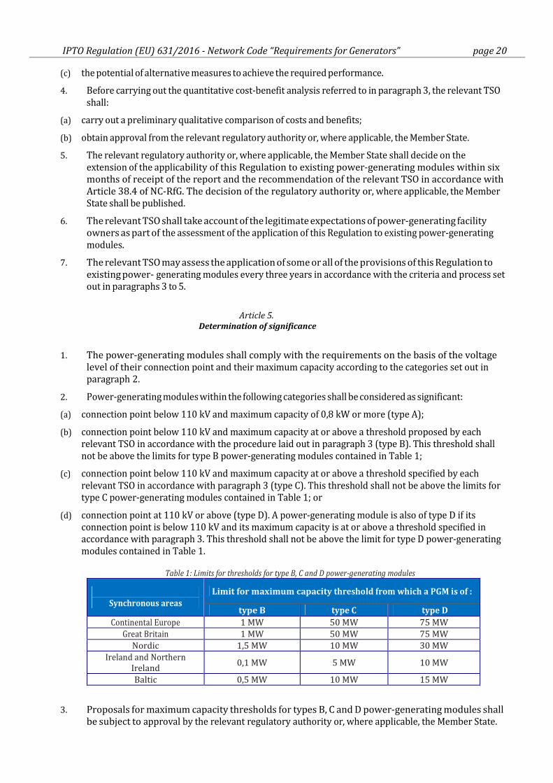
Table 1: Limits for thresholds for type B, C and D power-generating modules
Synchronous areas
Limit for maximum capacity threshold from which a PGM is of :
type B type C type D
Continental Europe 1 MW 50 MW 75 MW
Great Britain 1 MW 50 MW 75 MW
Nordic 1,5 MW 10 MW 30 MW
Ireland and Northern
Ireland 0,1 MW 5 MW 10 MW
Baltic 0,5 MW 10 MW 15 MW
3. Proposals for maximum capacity thresholds for types B, C and D power-generating modules shall
be subject to approval by the relevant regulatory authority or, where applicable, the Member State.
IPTO Regulation (EU) 631/2016 - Network Code “Requirements for Generators” page 21
In forming proposals, the relevant TSO shall coordinate with adjacent TSOs and DSOs and shall
conduct a public consultation in accordance with Article 10. A proposal by the relevant TSO to
change the thresholds shall not be made sooner than three years after the previous proposal.
4. Power-generating facility owners (PGFO) shall assist this process and provide data as requested by the
relevant TSO.
5. If, as a result of modification of the thresholds, a power-generating module qualifies under a
different type, the procedure laid down in Article 4.2(a) concerning existing power-generating
modules shall apply before compliance with the requirements for the new type is required.
[Note]
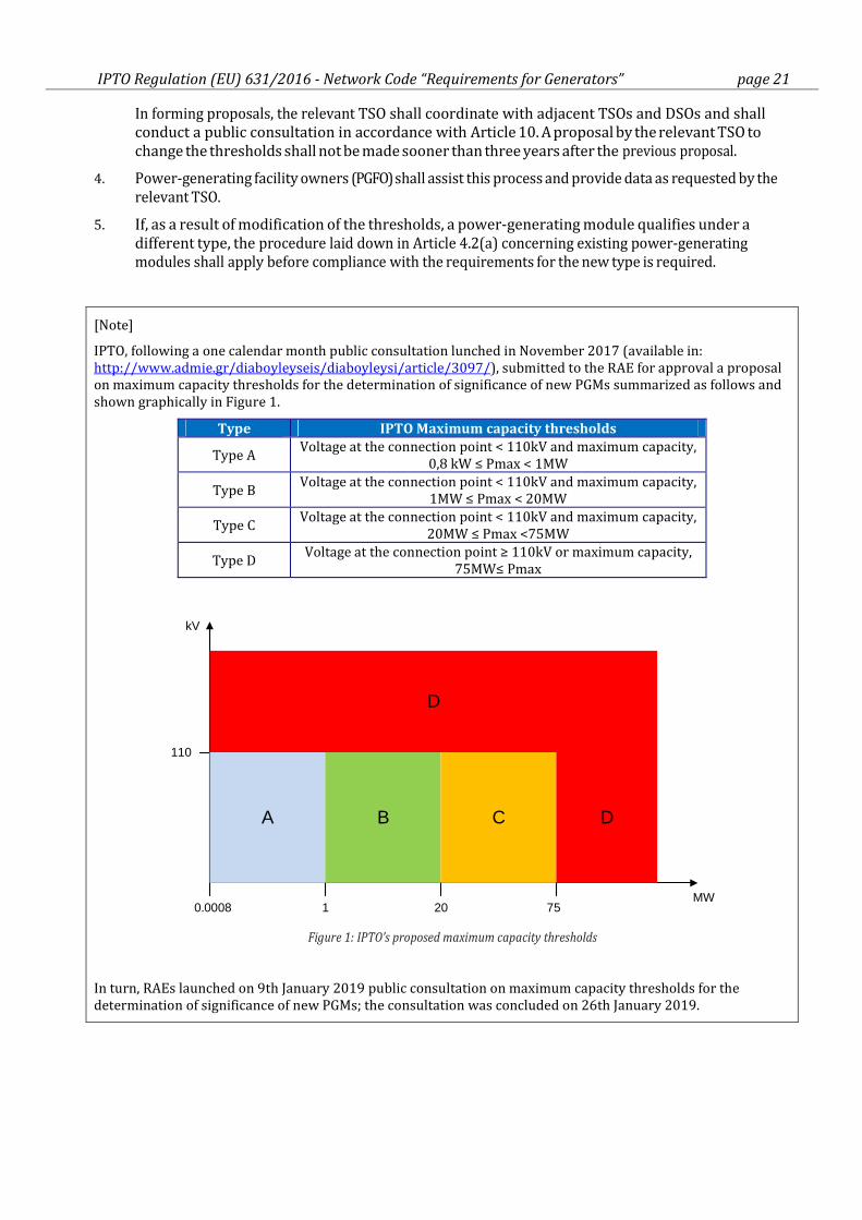
IPTO, following a one calendar month public consultation lunched in November 2017 (available in:
http://www.admie.gr/diaboyleyseis/diaboyleysi/article/3097/), submitted to the RAE for approval a proposal
on maximum capacity thresholds for the determination of significance of new PGMs summarized as follows and
shown graphically in Figure 1.
Type IPTO Maximum capacity thresholds
Type A Voltage at the connection point < 110kV and maximum capacity,
0,8 kW ≤ Pmax < 1MW
Type B Voltage at the connection point < 110kV and maximum capacity,
1MW ≤ Pmax < 20MW
Type C Voltage at the connection point < 110kV and maximum capacity,
20MW ≤ Pmax <75MW
Type D Voltage at the connection point ≥ 110kV or maximum capacity,
75MW≤ Pmax
110
kV
MW1 20 750.0008
A B C D
D
Figure 1: IPTO’s proposed maximum capacity thresholds
In turn, RAEs launched on 9th January 2019 public consultation on maximum capacity thresholds for the
determination of significance of new PGMs; the consultation was concluded on 26th January 2019.
IPTO Regulation (EU) 631/2016 - Network Code “Requirements for Generators” page 22
Article 6.
Application to power-generating modules, pump-storage power-generating modules, combined heat
and power facilities, and industrial sites
1. Offshore power-generating modules connected to the interconnected system shall meet the
requirements for onshore power-generating modules, unless the requirements are modified for
this purpose by the relevant system operator or unless the connection of power park modules is
via a high voltage direct current connection or via a network whose frequency is not
synchronously coupled to that of the main interconnected system (such as via a back- to-back
convertor scheme).
2. Pump-storage power-generating modules shall fulfil all the relevant requirements in both generating
and pumping operation mode. Synchronous compensation operation of pump-storage power-
generating modules shall not be limited in time by the technical design of power-generating modules.
Pump-storage variable speed power-generating modules shall fulfil the requirements applicable to
synchronous power-generating modules as well as those set out in point (b) of Article 20.2, if they
qualify as type B, C or D.
3. With respect to power-generating modules embedded in the networks of industrial sites, power-generating facility owners, system operators of industrial sites and relevant system operators whose network is connected to the network of an industrial site shall have the right to agree on conditions for disconnection of such power-generating modules together with critical loads, which secure production processes, from the relevant system operator's network. The exercise of this right shall be coordinated with the relevant TSO.
4. Except for requirements under paragraphs 2 and 4 of Article 13 or where otherwise stated in
the national framework, requirements of this Regulation relating to the capability to maintain
constant active power output or to modulate active power output shall not apply to power-
generating modules of facilities for combined heat and power production embedded in the
networks of industrial sites, where all of the following criteria are met:
(a) the primary purpose of those facilities is to produce heat for production processes of the industrial site
concerned;
(b) heat and power-generating is inextricably interlinked, that is to say any change of heat generation
results inadvertently in a change of active power-generating and vice versa;
(c) the power-generating modules are of type A, B, C or, in the case of the Nordic synchronous area, type D
in accordance with points (a) to (c) of Article 5.2.
5. Combined heat and power-generating facilities shall be assessed on the basis of their electrical
maximum capacity.
Article 7.
Regulatory aspects
1. Requirements of general application to be established by relevant system operators (IPTO or
HEDNO) under this Regulation shall be subject to approval by the entity designated by the Member
State (Greece) and be published. The designated entity shall be the regulatory authority (RAE) unless
otherwise provided by the Member State.
2. For site specific requirements to be established by relevant system operators under this
Regulation, approval may be required by the designated entity.
3. When applying this Regulation, Member States, competent entities and system operators shall:
(a) apply the principles of proportionality and non-discrimination;
IPTO Regulation (EU) 631/2016 - Network Code “Requirements for Generators” page 23
(b) ensure transparency;
(c) apply the principle of optimisation between the highest overall efficiency and lowest total costs for all
parties involved;
(d) respect the responsibility assigned to the relevant TSO in order to ensure system security, including as
required by national legislation;
(e) consult with relevant DSOs and take account of potential impacts on their system;
(f) take into consideration agreed European standards and technical specifications.
4. The relevant system operator shall submit a proposal for requirements of general application,
or the methodology used to calculate or establish them, for approval by the competent entity
within two years of entry into force of this Regulation.
5. Where this Regulation requires the relevant system operator, power-generating facility owner and/or
the distribution system operator to seek agreement, they shall endeavour to do so within six
months after a first proposal has been submitted by one party to the other parties. If no agreement
has been found within this time frame, each party may request the relevant regulatory authority to
issue a decision within six months.
6. Competent entities shall take decisions on proposals for requirements or methodologies within
six months following the receipt of such proposals.
7. If the relevant system operator deems an amendment to requirements or methodologies as provided for and approved under paragraph 1 and 2 to be necessary, the requirements provided for in paragraphs 3 to 8 shall apply to the proposed amendment. System operators proposing an amendment shall take into account the legitimate expectations, if any, of power-generating facility owners, equipment manufacturers and other stakeholders based on the initially specified or agreed requirements or methodologies.
8. Any party having a complaint against a relevant system operator in relation to that relevant
system operator's obligations under this Regulation may refer the complaint to the regulatory
authority which, acting as dispute settlement authority, shall issue a decision within two months
after receipt of the complaint. That period may be extended by two months where additional
information is sought by the regulatory authority. That extended period may be further extended
with the agreement of the complainant. The regulatory authority's decision shall have binding effect
unless and until overruled on appeal.
9. Where the requirements under this Regulation are to be established by a relevant system
operator that is not a TSO, Member States may provide that, instead the TSO be responsible for
establishing the relevant requirements.
Article 8.
Multiple TSOs
1. Where more than one TSO exists in a Member State, this Regulation shall apply to all those TSOs.
2. Member States may, under the national regulatory regime, provide that the responsibility of a TSO to
comply with one or some or all obligations under this Regulation is assigned to one or more specific
TSOs.
Article 9.
Recovery of costs
1. The costs borne by system operators subject to network tariff regulation and stemming from the
obligations laid down in this Regulation shall be assessed by the relevant regulatory authorities.
Costs assessed as reasonable, efficient and proportionate shall be recovered through network tariffs
or other appropriate mechanisms.

IPTO Regulation (EU) 631/2016 - Network Code “Requirements for Generators” page 24
2. If requested by the relevant regulatory authorities, system operators referred to in paragraph 1 shall,
within three months of the request, provide the information necessary to facilitate assessment of the
costs incurred.
Article 10.
Public consultation
1. Relevant system operators and relevant TSOs shall carry out consultation with stakeholders,
including the competent authorities of each Member State, on proposals to extend the
applicability of this Regulation to existing power-generating modules in accordance with Article
4.2(a), for the proposal for thresholds in accordance with NC-RfG Article 5.3, and on the report
prepared in accordance with NC-RfG Article 38.3 and the cost-benefit analysis undertaken in
accordance with NC-RfG Article 63.2. The consultation shall last at least for a period of one month.
2. The relevant system operators or relevant TSOs shall duly take into account the views of the
stakeholders resulting from the consultations prior to the submission of the draft proposal for
thresholds, the report or cost benefit analysis for approval by the regulatory authority or, if
applicable, the Member State. In all cases, a sound justification for including or not the views of
the stakeholders shall be provided and published in a timely manner before, or simultaneously
with, the publication of the proposal.
Article 11.
Stakeholder involvement
The Regulatory Authority for Electricity (RAE), in close cooperation with the relevant System Operators
(IPTO and HEDNO), shall organise stakeholder involvement regarding the requirements for grid
connection of power-generating facilities, and other aspects of the implementation of this Regulation.
This shall include regular meetings with stakeholders to identify problems and propose improvements
notably related to the requirements for grid connection of power-generating facilities.
Article 12.
Confidentiality obligations
1. Any confidential information received, exchanged or transmitted pursuant to this Regulation shall be
subject to the conditions of professional secrecy laid down in paragraphs 2, 3 and 4.
2. The obligation of professional secrecy shall apply to any persons, regulatory authorities or entities
subject to the provisions of this Regulation.
3. Confidential information received by the persons, regulatory authorities or entities referred to in
paragraph 2 in the course of their duties may not be divulged to any other person or authority,
without prejudice to cases covered by national law, the other provisions of this Regulation or other
relevant Union law.
4. Without prejudice to cases covered by national or Union law, regulatory authorities, entities or
persons who receive confidential information pursuant to this Regulation may use it only for the
purpose of carrying out their duties under this Regulation.
IPTO Regulation (EU) 631/2016 - Network Code “Requirements for Generators” page 25
TITLE II REQUIREMENTS
CHAPTER 1 -General requirements
Article 13.
General requirements for type A power-generating modules
1. Type A power-generating modules shall fulfil the following requirements relating to frequency
stability:
(a) With regard to frequency ranges:
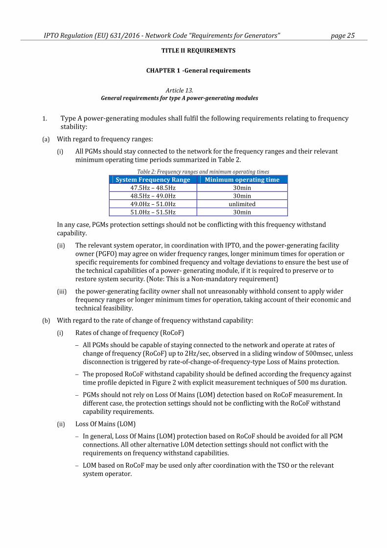
(i) All PGMs should stay connected to the network for the frequency ranges and their relevant
minimum operating time periods summarized in Table 2.
Table 2: Frequency ranges and minimum operating times
System Frequency Range Minimum operating time
47.5Hz – 48.5Hz 30min
48.5Hz – 49.0Hz 30min
49.0Hz – 51.0Hz unlimited
51.0Hz – 51.5Hz 30min
In any case, PGMs protection settings should not be conflicting with this frequency withstand
capability.
(ii) The relevant system operator, in coordination with IPTO, and the power-generating facility
owner (PGFO) may agree on wider frequency ranges, longer minimum times for operation or
specific requirements for combined frequency and voltage deviations to ensure the best use of
the technical capabilities of a power- generating module, if it is required to preserve or to
restore system security. (Note: This is a Non-mandatory requirement)
(iii) the power-generating facility owner shall not unreasonably withhold consent to apply wider
frequency ranges or longer minimum times for operation, taking account of their economic and
technical feasibility.
(b) With regard to the rate of change of frequency withstand capability:
(i) Rates of change of frequency (RoCoF)
− All PGMs should be capable of staying connected to the network and operate at rates of
change of frequency (RoCoF) up to 2Hz/sec, observed in a sliding window of 500msec, unless
disconnection is triggered by rate-of-change-of-frequency-type Loss of Mains protection.
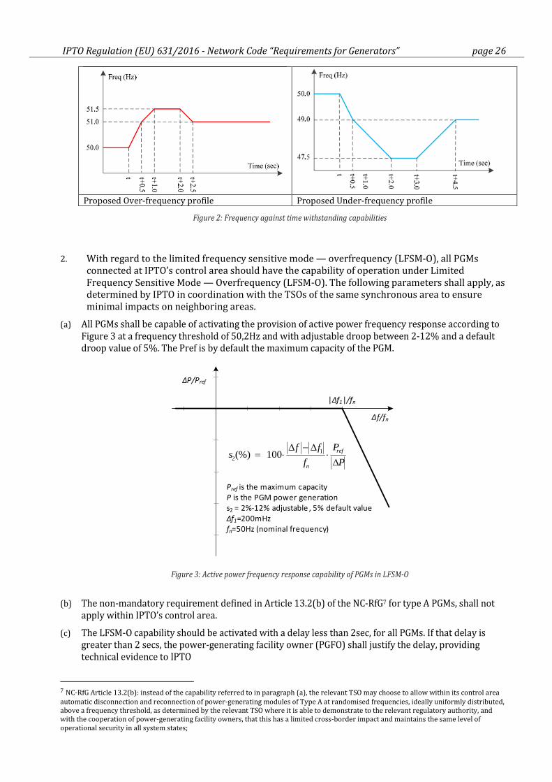
− The proposed RoCoF withstand capability should be defined according the frequency against
time profile depicted in Figure 2 with explicit measurement techniques of 500 ms duration.
− PGMs should not rely on Loss Of Mains (LOM) detection based on RoCoF measurement. In
different case, the protection settings should not be conflicting with the RoCoF withstand
capability requirements.
(ii) Loss Of Mains (LOM)
− In general, Loss Of Mains (LOM) protection based on RoCoF should be avoided for all PGM
connections. All other alternative LOM detection settings should not conflict with the
requirements on frequency withstand capabilities.
− LOM based on RoCoF may be used only after coordination with the TSO or the relevant
system operator.
IPTO Regulation (EU) 631/2016 - Network Code “Requirements for Generators” page 26
Proposed Over-frequency profile Proposed Under-frequency profile
Figure 2: Frequency against time withstanding capabilities
2. With regard to the limited frequency sensitive mode — overfrequency (LFSM-O), all PGMs
connected at IPTO’s control area should have the capability of operation under Limited
Frequency Sensitive Mode — Overfrequency (LFSM-O). The following parameters shall apply, as
determined by IPTO in coordination with the TSOs of the same synchronous area to ensure
minimal impacts on neighboring areas.
(a) All PGMs shall be capable of activating the provision of active power frequency response according to
Figure 3 at a frequency threshold of 50,2Hz and with adjustable droop between 2-12% and a default
droop value of 5%. The Pref is by default the maximum capacity of the PGM.
Pref is the maximum capacity
P is the PGM power generation
s2 = 2%-12% adjustable , 5% default value
Δf1=200mHz
fn=50Hz (nominal frequency)
P
P
f
ffs ref
n ∆⋅
∆−∆⋅=
12 100(%)
|Δf1|/fn
Δf/fn
ΔP/Pref
Figure 3: Active power frequency response capability of PGMs in LFSM-O
(b) The non-mandatory requirement defined in Article 13.2(b) of the NC-RfG7 for type A PGMs, shall not
apply within IPTO’s control area.
(c) The LFSM-O capability should be activated with a delay less than 2sec, for all PGMs. If that delay is
greater than 2 secs, the power-generating facility owner (PGFO) shall justify the delay, providing
technical evidence to IPTO
7 NC-RfG Article 13.2(b): instead of the capability referred to in paragraph (a), the relevant TSO may choose to allow within its control area
automatic disconnection and reconnection of power-generating modules of Type A at randomised frequencies, ideally uniformly distributed,
above a frequency threshold, as determined by the relevant TSO where it is able to demonstrate to the relevant regulatory authority, and
with the cooperation of power-generating facility owners, that this has a limited cross-border impact and maintains the same level of
operational security in all system states;
IPTO Regulation (EU) 631/2016 - Network Code “Requirements for Generators” page 27
(d) Upon reaching minimum regulating level, the PGM shall be capable of continuing operation at constant
power control mode (no further decrease for further frequency increase)
(e) The PGM shall be capable of operating stably during LFSM-O operation. When LFSM-O is active, the
LFSM-O setpoint will prevail over any other active power setpoints
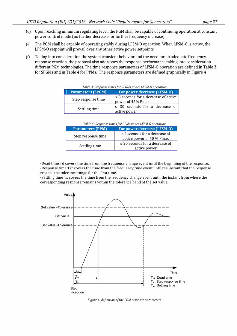
(f) Taking into consideration the system transient behavior and the need for an adequate frequency
response reaction, the proposal also addresses the response performance taking into consideration
different PGM technologies. The time response parameters of LFSM-O operation are defined in Table 3
for SPGMs and in Table 4 for PPMs. The response parameters are defined graphically in Figure 4
Table 3: Response times for SPGMs under LFSM-O operation
Parameters (SPGM) For power decrease (LFSM-O)
Step response time ≤ 8 seconds for a decrease of active
power of 45% Pmax
Settling time ≤ 30 seconds for a decrease of
active power
Table 4: Response times for PPMs under LFSM-O operation
Parameters (PPM) For power decrease (LFSM-O)
Step response time ≤ 2 seconds for a decrease of
active power of 50 % Pmax
Settling time ≤ 20 seconds for a decrease of
active power
-Dead time Td covers the time from the frequency change event until the beginning of the response.
-Response time Tsr covers the time from the frequency time event until the instant that the response
reaches the tolerance range for the first time.
-Settling time Ts covers the time from the frequency change event until the instant from where the
corresponding response remains within the tolerance band of the set value.
Figure 4: definition of the PGM response parameters
IPTO Regulation (EU) 631/2016 - Network Code “Requirements for Generators” page 28
3. The power-generating module shall be capable of maintaining constant output at its target
active power value regardless of changes in frequency, except where output follows the changes
specified in the context of paragraphs 2 and 4 of this Article or points (c) and (d) of Article 15.2
as applicable.
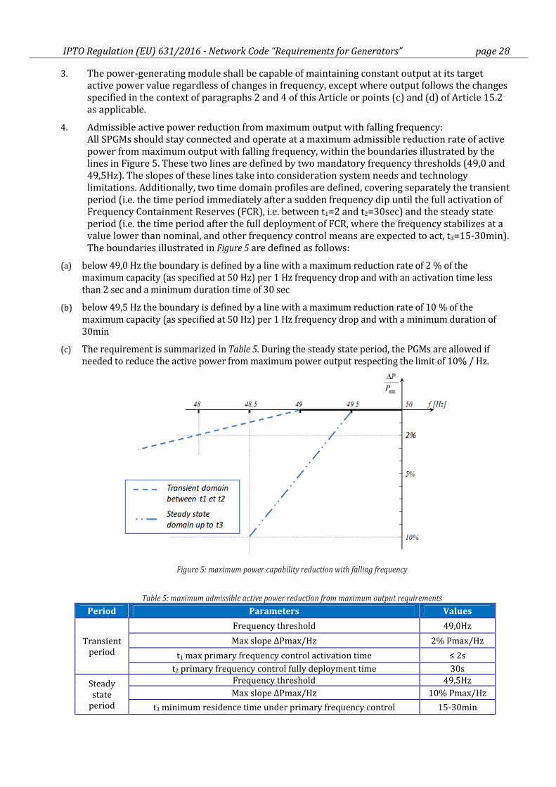
4. Admissible active power reduction from maximum output with falling frequency:
All SPGMs should stay connected and operate at a maximum admissible reduction rate of active
power from maximum output with falling frequency, within the boundaries illustrated by the
lines in Figure 5. These two lines are defined by two mandatory frequency thresholds (49,0 and
49,5Hz). The slopes of these lines take into consideration system needs and technology
limitations. Additionally, two time domain profiles are defined, covering separately the transient
period (i.e. the time period immediately after a sudden frequency dip until the full activation of
Frequency Containment Reserves (FCR), i.e. between t1=2 and t2=30sec) and the steady state
period (i.e. the time period after the full deployment of FCR, where the frequency stabilizes at a
value lower than nominal, and other frequency control means are expected to act, t3=15-30min).
The boundaries illustrated in Figure 5 are defined as follows:
(a) below 49,0 Hz the boundary is defined by a line with a maximum reduction rate of 2 % of the
maximum capacity (as specified at 50 Hz) per 1 Hz frequency drop and with an activation time less
than 2 sec and a minimum duration time of 30 sec
(b) below 49,5 Hz the boundary is defined by a line with a maximum reduction rate of 10 % of the
maximum capacity (as specified at 50 Hz) per 1 Hz frequency drop and with a minimum duration of
30min
(c) The requirement is summarized in Table 5. During the steady state period, the PGMs are allowed if
needed to reduce the active power from maximum power output respecting the limit of 10% / Hz.
Figure 5: maximum power capability reduction with falling frequency
Table 5: maximum admissible active power reduction from maximum output requirements
Period Parameters Values
Transient
period
Frequency threshold 49,0Hz
Max slope ΔPmax/Hz 2% Pmax/Hz
t1 max primary frequency control activation time ≤ 2s
t2 primary frequency control fully deployment time 30s
Steady
state
period
Frequency threshold 49,5Hz
Max slope ΔPmax/Hz 10% Pmax/Hz
t3 minimum residence time under primary frequency control 15-30min
IPTO Regulation (EU) 631/2016 - Network Code “Requirements for Generators” page 29
5. The admissible active power reduction from maximum output shall apply at the following
standard ambient conditions:
(a) temperature 25 οC, altitude 400 - 500m, humidity 15 - 20 g H2O/Kg
(b) if the requirements are covered under other ambient conditions, specified by the manufacturers
taking account of the technical capabilities of their PGMs, these conditions should be included in the
connection agreement
For PPMs, where no technical limitation to maintain active power are existing, active power
reduction under falling system frequency is not acceptable.
6. The PGM shall be equipped with a logic interface (input port) in order to cease active power
output within five seconds following an instruction being received at the input port. The
relevant system operator shall have the right to specify requirements for equipment to make
this facility operable remotely.
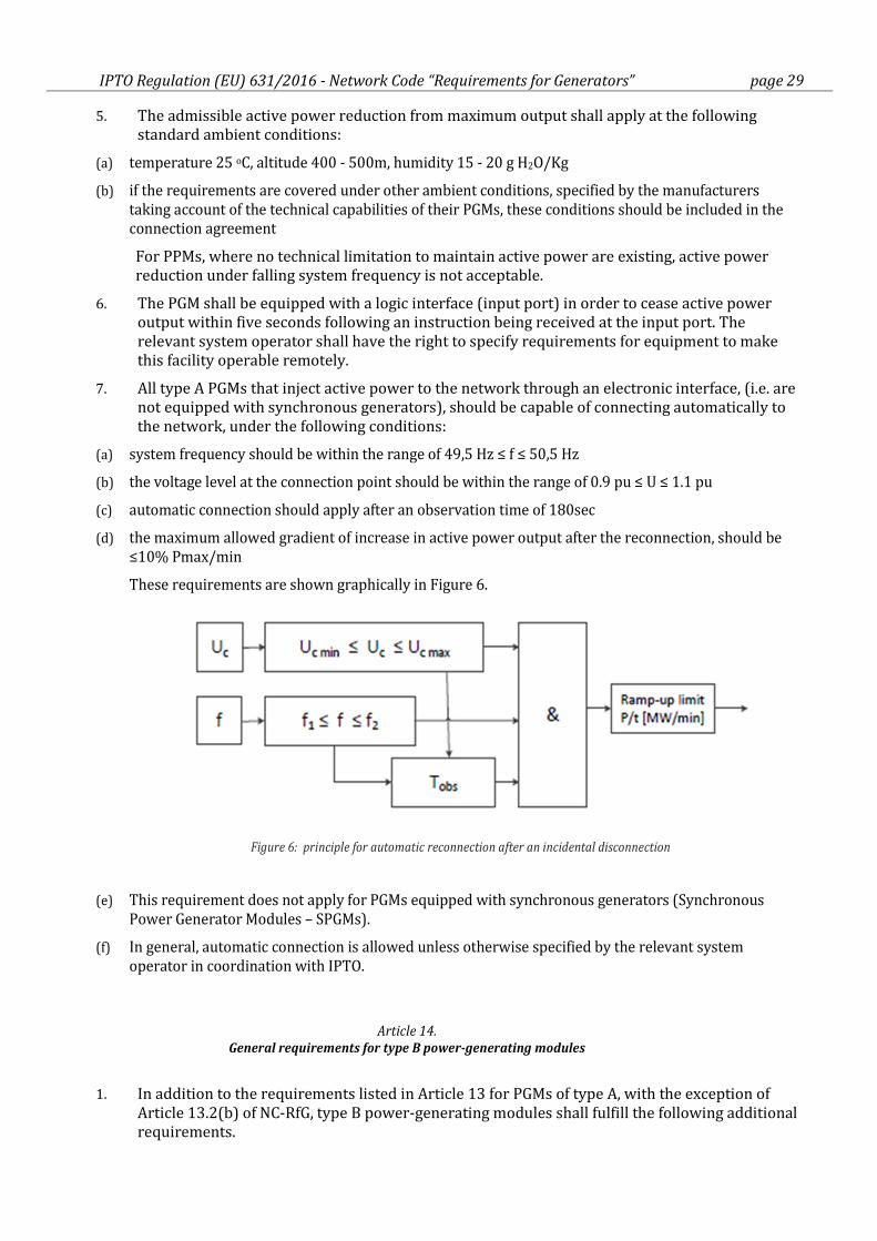
7. All type A PGMs that inject active power to the network through an electronic interface, (i.e. are
not equipped with synchronous generators), should be capable of connecting automatically to
the network, under the following conditions:
(a) system frequency should be within the range of 49,5 Hz ≤ f ≤ 50,5 Hz
(b) the voltage level at the connection point should be within the range of 0.9 pu ≤ U ≤ 1.1 pu
(c) automatic connection should apply after an observation time of 180sec
(d) the maximum allowed gradient of increase in active power output after the reconnection, should be
≤10% Pmax/min
These requirements are shown graphically in Figure 6.
Figure 6: principle for automatic reconnection after an incidental disconnection
(e) This requirement does not apply for PGMs equipped with synchronous generators (Synchronous
Power Generator Modules – SPGMs).
(f) In general, automatic connection is allowed unless otherwise specified by the relevant system
operator in coordination with IPTO.
Article 14.
General requirements for type B power-generating modules
1. In addition to the requirements listed in Article 13 for PGMs of type A, with the exception of
Article 13.2(b) of NC-RfG, type B power-generating modules shall fulfill the following additional
requirements.
IPTO Regulation (EU) 631/2016 - Network Code “Requirements for Generators” page 30
2. Type B power-generating modules shall fulfill the following requirements in relation to
frequency stability:
(a) to control active power output, all PGMs shall be equipped with an interface (input port) in order to be
able to reduce active power output following an instruction at the input port; and
(b) the relevant system operator shall have the right to specify the requirements for further equipment to
allow active power output to be remotely operated (Non-mandatory requirement).
3. Type B power-generating modules shall fulfil the following requirements in relation to robustness:
(a) Type B SPGMs shall fulfill the following requirements with regard to fault-ride-through (FRT)
capability:
(i) the SPGM shall be capable of staying connected to the network and continuing to operate stably
after the power system has been disturbed by secured symmetrical faults (i.e. faults successfully
cleared according to the IPTO's planning criteria;) on the transmission system according the
voltage-against-time-profile for fault conditions at the connection point specified in line with
Figure 7 (denoted as GR curve, which is located between the lower and upper limit that is
imposed by the Regulation 2016/631) and Table 6;
(ii) this voltage-against-time-profile expresses a lower limit of the actual course of the phase-to-
phase voltages on the network voltage level at the connection point during a symmetrical fault,
as a function of time before, during and after the fault;
(iii) the relevant system operator shall specify and make publicly available the pre-fault and post-
fault conditions for the FRT capability in terms of: the calculation of the pre-fault minimum
short circuit capacity at the connection point, pre-fault active and reactive power operating
point of the power-generating module at the connection point, and calculation of the post-fault
minimum short circuit capacity at the connection point; the pre-fault voltage at the connection
point for the FRT capability should not diverge from the nominal more than ±10%; the post-
fault voltage should be restored within the same limits;
(iv) at the request of a PGFO, the relevant system operator shall provide the pre-fault and post-fault
conditions to be considered for FRT capability as an outcome of the calculations at the
connection point as specified in point (iii) regarding: pre-fault minimum short circuit capacity at
each connection point expressed in MVA, pre-fault operating point of the power-generating
module expressed in active power output and reactive power output at the connection point
and voltage at the connection point, and post-fault minimum short circuit capacity at each
connection point expressed in MVA. Alternatively, the relevant system operator may provide
generic values derived from typical cases;
(v) the SPGM shall be capable of remaining connected to the network and continuing to operate
stably when the actual course of the phase-to-phase voltages on the network voltage level at the
connection point during a symmetrical fault, given the pre-fault and post-fault conditions in
points (iii) and (iv), remain above the lower limit specified in point (i), unless the protection
scheme for internal electrical faults requires the disconnection of the power-generating module
from the network. The protection schemes and settings for internal electrical faults must not
jeopardize fault-ride- through performance;
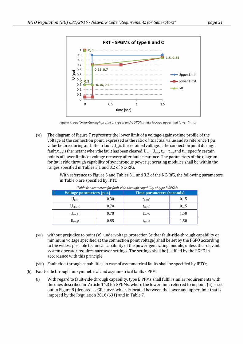
IPTO Regulation (EU) 631/2016 - Network Code “Requirements for Generators” page 31
Figure 7: Fault-ride-through profile of type B and C SPGMs with NC-RfG upper and lower limits
(vi) The diagram of Figure 7 represents the lower limit of a voltage-against-time profile of the
voltage at the connection point, expressed as the ratio of its actual value and its reference 1 pu value before, during and after a fault. Uret is the retained voltage at the connection point during a
fault, tclear is the instant when the fault has been cleared. Urec1, Urec2, trec1, trec2 and trec3 specify certain
points of lower limits of voltage recovery after fault clearance. The parameters of the diagram
for fault ride through capability of synchronous power generating modules shall be within the
ranges specified in Tables 3.1 and 3.2 of NC-RfG.
With reference to Figure 3 and Tables 3.1 and 3.2 of the NC-RfG, the following parameters
in Table 6 are specified by IPTO:
Table 6: parameters for fault-ride-through capability of type B SPGMs
Voltage parameters (p.u.) Time parameters (seconds)
Uret: 0,30 tclear: 0,15
Uclear: 0,70 trec1: 0,15
Urec1: 0,70 trec2: 1,50
Urec2: 0,85 trec3: 1,50
(vii) without prejudice to point (v), undervoltage protection (either fault-ride-through capability or
minimum voltage specified at the connection point voltage) shall be set by the PGFO according
to the widest possible technical capability of the power-generating module, unless the relevant
system operator requires narrower settings. The settings shall be justified by the PGFO in
accordance with this principle;
(viii) Fault-ride-through capabilities in case of asymmetrical faults shall be specified by IPTO;
(b) Fault-ride through for symmetrical and asymmetrical faults - PPM.
(i) With regard to fault-ride-through capability, type B PPMs shall fulfill similar requirements with
the ones described in Article 14.3 for SPGMs, where the lower limit referred to in point (ii) is set
out in Figure 8 (denoted as GR curve, which is located between the lower and upper limit that is
imposed by the Regulation 2016/631) and in Table 7.
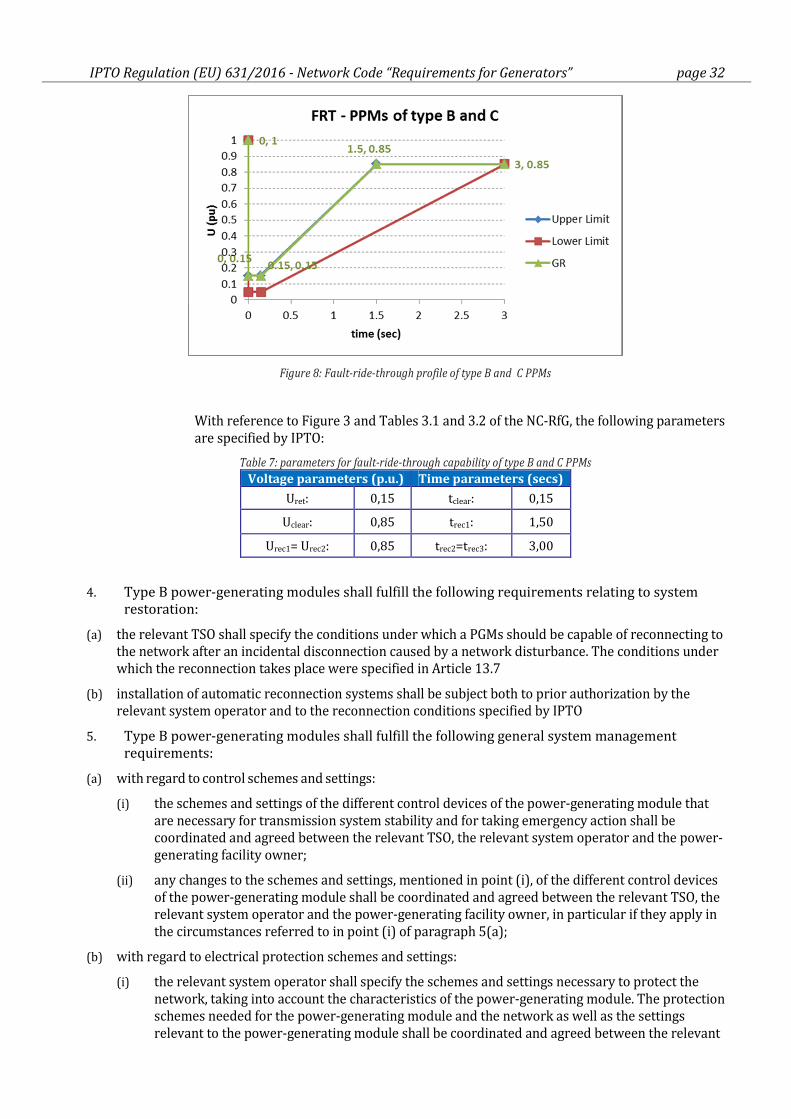
IPTO Regulation (EU) 631/2016 - Network Code “Requirements for Generators” page 32
Figure 8: Fault-ride-through profile of type B and C PPMs
With reference to Figure 3 and Tables 3.1 and 3.2 of the NC-RfG, the following parameters
are specified by IPTO:
Table 7: parameters for fault-ride-through capability of type B and C PPMs
Voltage parameters (p.u.) Time parameters (secs)
Uret: 0,15 tclear: 0,15
Uclear: 0,85 trec1: 1,50
Urec1= Urec2: 0,85 trec2=trec3: 3,00
4. Type B power-generating modules shall fulfill the following requirements relating to system
restoration:
(a) the relevant TSO shall specify the conditions under which a PGMs should be capable of reconnecting to
the network after an incidental disconnection caused by a network disturbance. The conditions under
which the reconnection takes place were specified in Article 13.7
(b) installation of automatic reconnection systems shall be subject both to prior authorization by the
relevant system operator and to the reconnection conditions specified by IPTO
5. Type B power-generating modules shall fulfill the following general system management
requirements:
(a) with regard to control schemes and settings:
(i) the schemes and settings of the different control devices of the power-generating module that
are necessary for transmission system stability and for taking emergency action shall be
coordinated and agreed between the relevant TSO, the relevant system operator and the power-
generating facility owner;
(ii) any changes to the schemes and settings, mentioned in point (i), of the different control devices
of the power-generating module shall be coordinated and agreed between the relevant TSO, the
relevant system operator and the power-generating facility owner, in particular if they apply in
the circumstances referred to in point (i) of paragraph 5(a);
(b) with regard to electrical protection schemes and settings:
(i) the relevant system operator shall specify the schemes and settings necessary to protect the
network, taking into account the characteristics of the power-generating module. The protection
schemes needed for the power-generating module and the network as well as the settings
relevant to the power-generating module shall be coordinated and agreed between the relevant
IPTO Regulation (EU) 631/2016 - Network Code “Requirements for Generators” page 33
system operator and the power-generating facility owner.
The protection schemes and settings for internal electrical faults must not jeopardise the
performance of a power-generating module, in line with the requirements set out in this
Regulation;
(ii) electrical protection of the power-generating module shall take precedence over operational
controls, taking into account the security of the system and the health and safety of staff and of
the public, as well as mitigating any damage to the power-generating module;
(iii) protection schemes may cover the following aspects:
− external and internal short circuit,
− asymmetric load (negative phase sequence),
− stator and rotor overload,
− over-/underexcitation,
− over-/undervoltage at the connection point,
− over-/undervoltage at the alternator terminals,
− inter-area oscillations, inrush current,
− asynchronous operation (pole slip),
− protection against inadmissible shaft torsions (for example, sub-synchronous resonance),
− power-generating module line protection,
− unit transformer protection,
− back-up against protection and switchgear malfunction,
− overfluxing (U/f),
− inverse power,
− rate of change of frequency, and
− neutral voltage displacement
(iv) changes to the protection schemes needed for the power-generating module and the network
and to the settings relevant to the power-generating module shall be agreed between the system
operator and the power-generating facility owner, and agreement shall be reached before any
changes are made;
[Note]:
Requirements set out in Article 14.5(a) oben are a site specific; they are to be agreed during the connection
process with the relevant system operator on a case by case level and fixed in the individual connection contract.
(c) the power-generating facility owner shall organise its protection and control devices in accordance
with the following priority ranking (from highest to lowest):
(i) network and power-generating module protection;
(ii) synthetic inertia, if applicable;
(iii) frequency control (active power adjustment);
(iv) power restriction; and
(v) power gradient constraint;
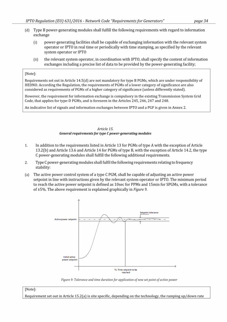
IPTO Regulation (EU) 631/2016 - Network Code “Requirements for Generators” page 34
(d) Type B power-generating modules shall fulfill the following requirements with regard to information
exchange
(i) power-generating facilities shall be capable of exchanging information with the relevant system
operator or IPTO in real time or periodically with time stamping, as specified by the relevant
system operator or IPTO
(ii) the relevant system operator, in coordination with IPTO, shall specify the content of information
exchanges including a precise list of data to be provided by the power-generating facility;
[Note]:
Requirements set out in Article 14.5(d) are not mandatory for type B PGMs, which are under responsibility of
HEDNO. According the Regulation, the requirements of PGMs of a lower category of significance are also
considered as requirements of PGMs of a higher category of significance (unless differently stated).
However, the requirement for information exchange is compulsory in the existing Transmission System Grid
Code, that applies for type-D PGMs, and is foreseen in the Articles 245, 246, 247 and 248.
An indicative list of signals and information exchanges between IPTO and a PGF is given in Annex 2.
Article 15.
General requirements for type C power-generating modules
1. In addition to the requirements listed in Article 13 for PGMs of type A with the exception of Article
13.2(b) and Article 13.6 and Article 14 for PGMs of type B, with the exception of Article 14.2, the type
C power-generating modules shall fulfill the following additional requirements.
2. Type C power-generating modules shall fulfil the following requirements relating to frequency
stability:
(a) The active power control system of a type C PGM, shall be capable of adjusting an active power
setpoint in line with instructions given by the relevant system operator or IPTO. The minimum period
to reach the active power setpoint is defined as 10sec for PPMs and 15min for SPGMs, with a tolerance
of ±5%. The above requirement is explained graphically in Figure 9.
Figure 9: Tolerance and time duration for application of new set point of active power
[Note]:
Requirement set out in Article 15.2(a) is site specific, depending on the technology, the ramping up/down rate
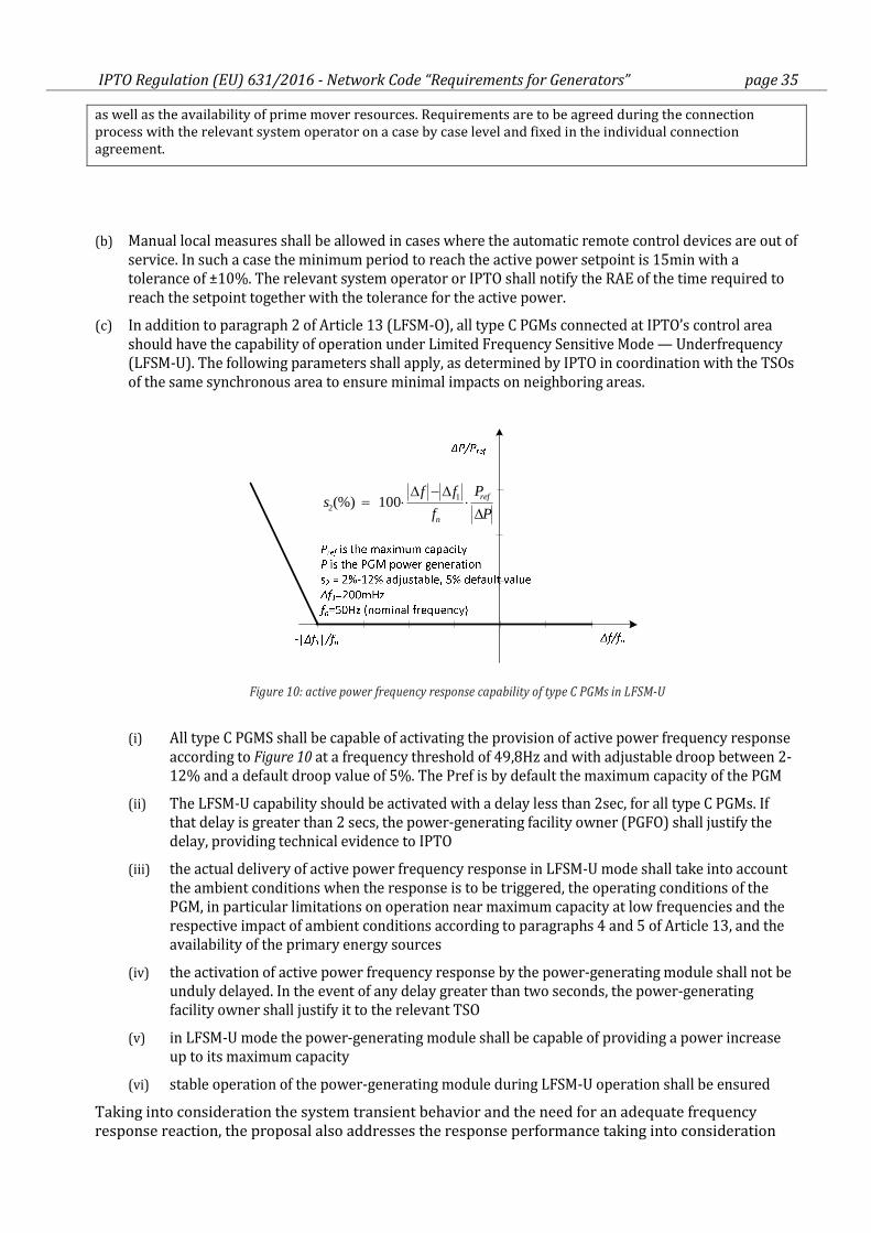
IPTO Regulation (EU) 631/2016 - Network Code “Requirements for Generators” page 35
as well as the availability of prime mover resources. Requirements are to be agreed during the connection
process with the relevant system operator on a case by case level and fixed in the individual connection
agreement.
(b) Manual local measures shall be allowed in cases where the automatic remote control devices are out of
service. In such a case the minimum period to reach the active power setpoint is 15min with a
tolerance of ±10%. The relevant system operator or IPTO shall notify the RAE of the time required to
reach the setpoint together with the tolerance for the active power.
(c) In addition to paragraph 2 of Article 13 (LFSM-O), all type C PGMs connected at IPTO’s control area
should have the capability of operation under Limited Frequency Sensitive Mode — Underfrequency
(LFSM-U). The following parameters shall apply, as determined by IPTO in coordination with the TSOs
of the same synchronous area to ensure minimal impacts on neighboring areas.
P
P
f
ffs ref
n ∆⋅
∆−∆⋅=
12 100(%)
Figure 10: active power frequency response capability of type C PGMs in LFSM-U
(i) All type C PGMS shall be capable of activating the provision of active power frequency response
according to Figure 10 at a frequency threshold of 49,8Hz and with adjustable droop between 2-
12% and a default droop value of 5%. The Pref is by default the maximum capacity of the PGM
(ii) The LFSM-U capability should be activated with a delay less than 2sec, for all type C PGMs. If
that delay is greater than 2 secs, the power-generating facility owner (PGFO) shall justify the
delay, providing technical evidence to IPTO
(iii) the actual delivery of active power frequency response in LFSM-U mode shall take into account
the ambient conditions when the response is to be triggered, the operating conditions of the
PGM, in particular limitations on operation near maximum capacity at low frequencies and the
respective impact of ambient conditions according to paragraphs 4 and 5 of Article 13, and the
availability of the primary energy sources
(iv) the activation of active power frequency response by the power-generating module shall not be
unduly delayed. In the event of any delay greater than two seconds, the power-generating
facility owner shall justify it to the relevant TSO
(v) in LFSM-U mode the power-generating module shall be capable of providing a power increase
up to its maximum capacity
(vi) stable operation of the power-generating module during LFSM-U operation shall be ensured
Taking into consideration the system transient behavior and the need for an adequate frequency
response reaction, the proposal also addresses the response performance taking into consideration
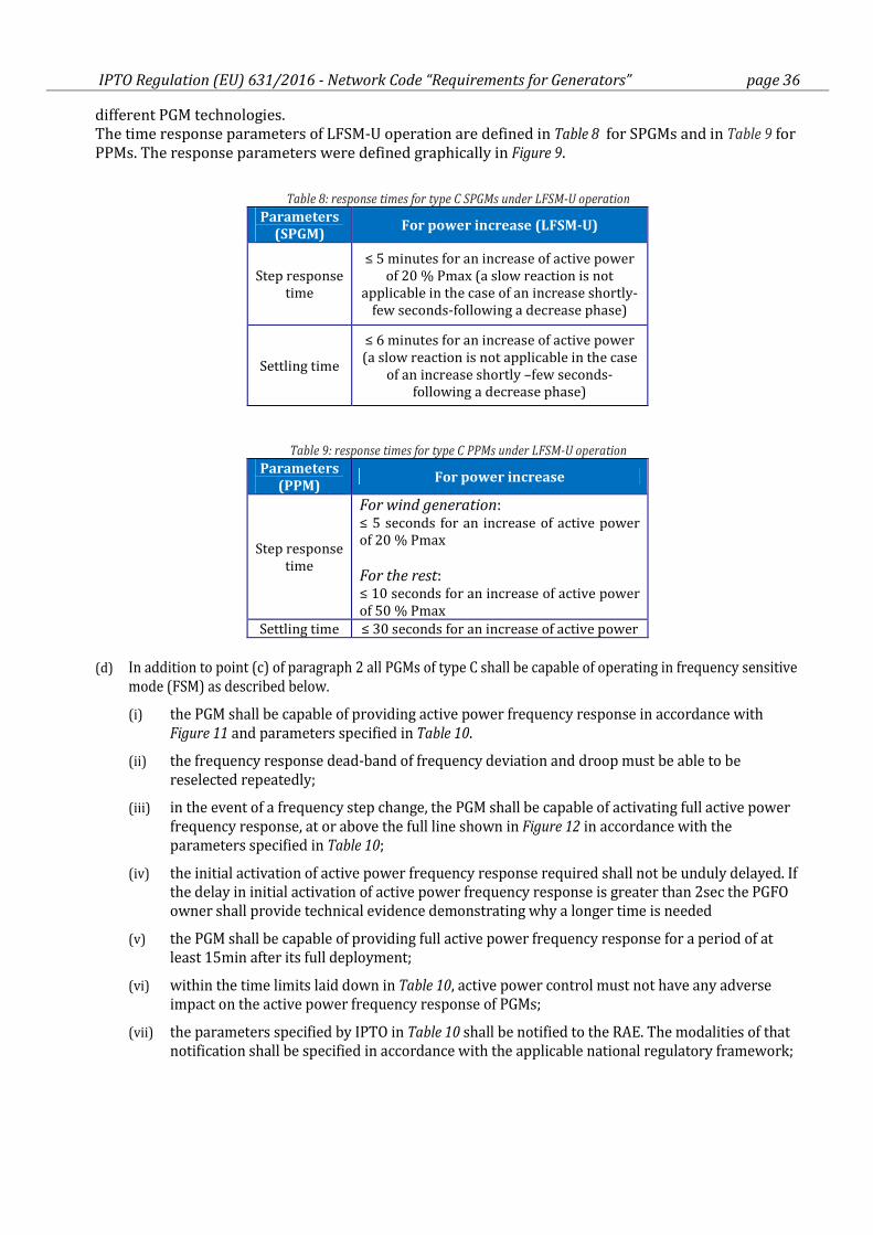
IPTO Regulation (EU) 631/2016 - Network Code “Requirements for Generators” page 36
different PGM technologies.
The time response parameters of LFSM-U operation are defined in Table 8 for SPGMs and in Table 9 for
PPMs. The response parameters were defined graphically in Figure 9.
Table 8: response times for type C SPGMs under LFSM-U operation
Parameters
(SPGM) For power increase (LFSM-U)
Step response
time
≤ 5 minutes for an increase of active power
of 20 % Pmax (a slow reaction is not
applicable in the case of an increase shortly-
few seconds-following a decrease phase)
Settling time
≤ 6 minutes for an increase of active power
(a slow reaction is not applicable in the case
of an increase shortly –few seconds-
following a decrease phase)
Table 9: response times for type C PPMs under LFSM-U operation
Parameters
(PPM) For power increase
Step response
time
For wind generation: ≤ 5 seconds for an increase of active power
of 20 % Pmax
For the rest: ≤ 10 seconds for an increase of active power
of 50 % Pmax
Settling time ≤ 30 seconds for an increase of active power
(d) In addition to point (c) of paragraph 2 all PGMs of type C shall be capable of operating in frequency sensitive
mode (FSM) as described below.
(i) the PGM shall be capable of providing active power frequency response in accordance with
Figure 11 and parameters specified in Table 10.
(ii) the frequency response dead-band of frequency deviation and droop must be able to be
reselected repeatedly;
(iii) in the event of a frequency step change, the PGM shall be capable of activating full active power
frequency response, at or above the full line shown in Figure 12 in accordance with the
parameters specified in Table 10;
(iv) the initial activation of active power frequency response required shall not be unduly delayed. If
the delay in initial activation of active power frequency response is greater than 2sec the PGFO
owner shall provide technical evidence demonstrating why a longer time is needed
(v) the PGM shall be capable of providing full active power frequency response for a period of at
least 15min after its full deployment;
(vi) within the time limits laid down in Table 10, active power control must not have any adverse
impact on the active power frequency response of PGMs;
(vii) the parameters specified by IPTO in Table 10 shall be notified to the RAE. The modalities of that
notification shall be specified in accordance with the applicable national regulatory framework;
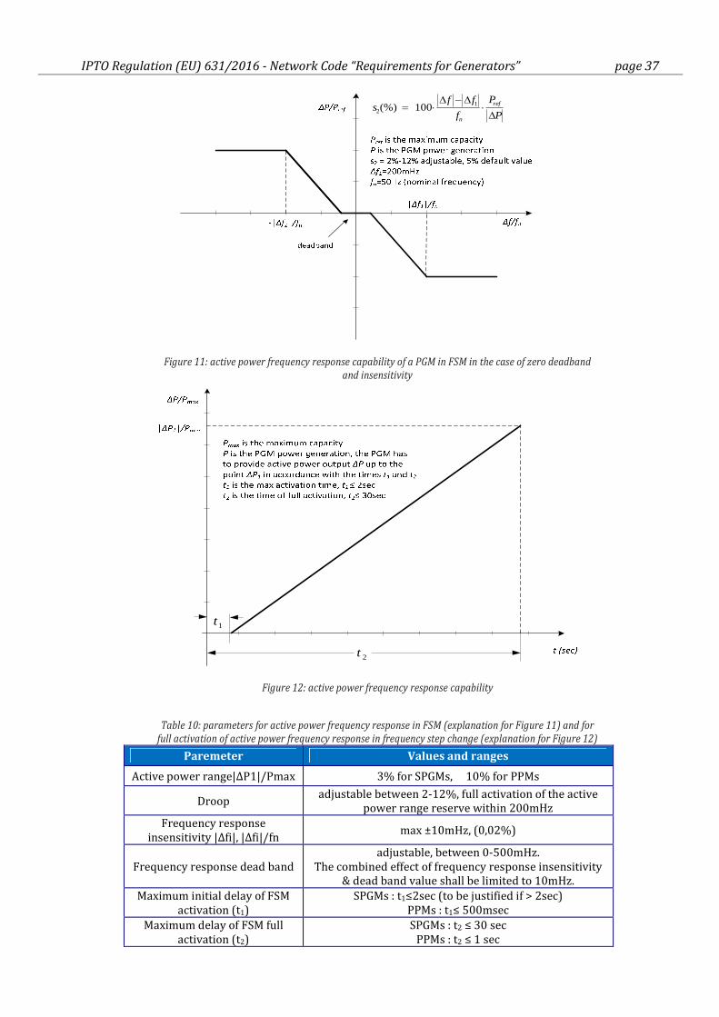
IPTO Regulation (EU) 631/2016 - Network Code “Requirements for Generators” page 37
P
P
f
ffs ref
n ∆⋅
∆−∆⋅=
12 100(%)
Figure 11: active power frequency response capability of a PGM in FSM in the case of zero deadband
and insensitivity
1t
2t
Figure 12: active power frequency response capability
Table 10: parameters for active power frequency response in FSM (explanation for Figure 11) and for
full activation of active power frequency response in frequency step change (explanation for Figure 12)
Paremeter Values and ranges
Active power range|ΔP1|/Pmax 3% for SPGMs, 10% for PPMs
Droop adjustable between 2-12%, full activation of the active
power range reserve within 200mHz
Frequency response
insensitivity |Δfi|, |Δfi|/fn max ±10mHz, (0,02%)
Frequency response dead band
adjustable, between 0-500mHz.
The combined effect of frequency response insensitivity
& dead band value shall be limited to 10mHz.
Maximum initial delay of FSM
activation (t1)
SPGMs : t1≤2sec (to be justified if > 2sec)
PPMs : t1≤ 500msec
Maximum delay of FSM full
activation (t2)
SPGMs : t2 ≤ 30 sec
PPMs : t2 ≤ 1 sec
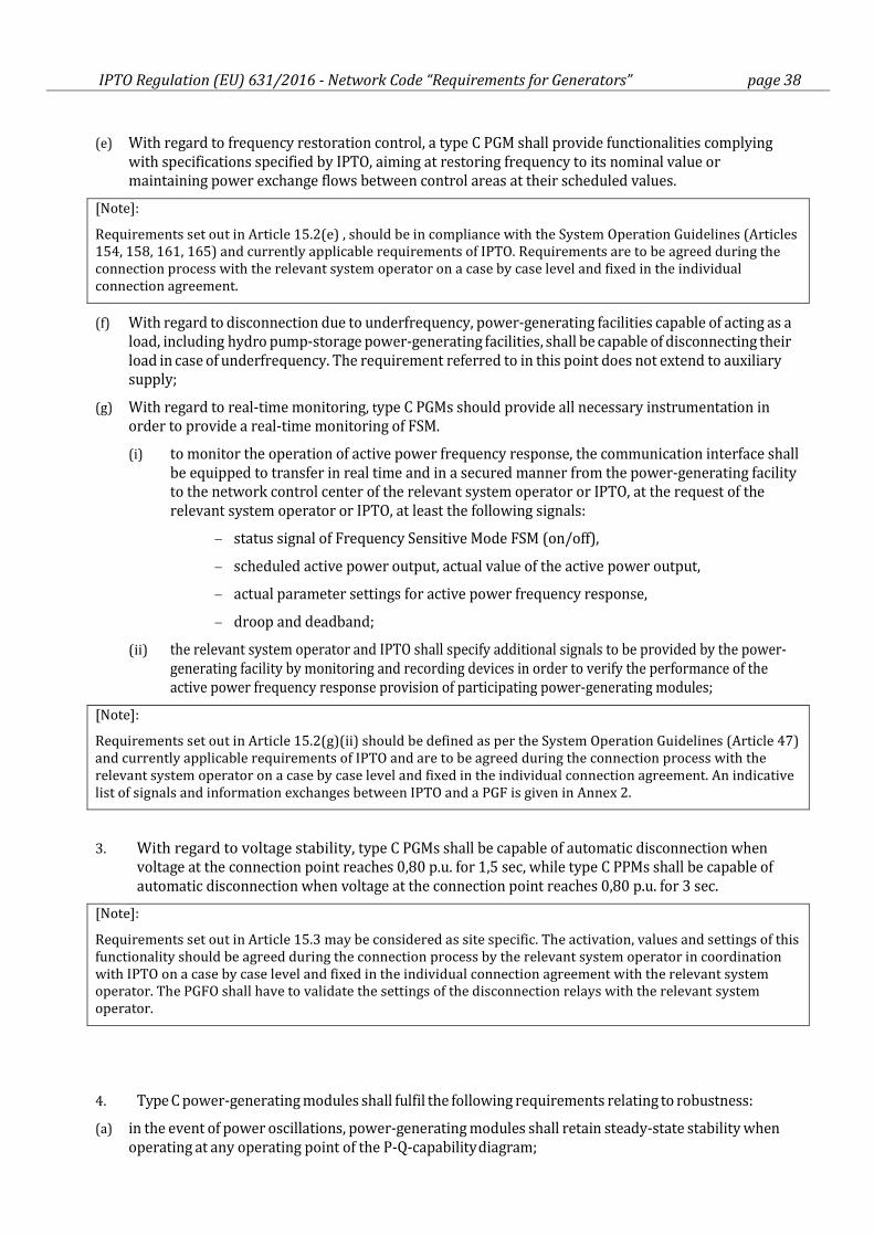
IPTO Regulation (EU) 631/2016 - Network Code “Requirements for Generators” page 38
(e) With regard to frequency restoration control, a type C PGM shall provide functionalities complying
with specifications specified by IPTO, aiming at restoring frequency to its nominal value or
maintaining power exchange flows between control areas at their scheduled values.
[Note]:
Requirements set out in Article 15.2(e) , should be in compliance with the System Operation Guidelines (Articles
154, 158, 161, 165) and currently applicable requirements of IPTO. Requirements are to be agreed during the
connection process with the relevant system operator on a case by case level and fixed in the individual
connection agreement.
(f) With regard to disconnection due to underfrequency, power-generating facilities capable of acting as a
load, including hydro pump-storage power-generating facilities, shall be capable of disconnecting their
load in case of underfrequency. The requirement referred to in this point does not extend to auxiliary
supply;
(g) With regard to real-time monitoring, type C PGMs should provide all necessary instrumentation in
order to provide a real-time monitoring of FSM.
(i) to monitor the operation of active power frequency response, the communication interface shall
be equipped to transfer in real time and in a secured manner from the power-generating facility
to the network control center of the relevant system operator or IPTO, at the request of the
relevant system operator or IPTO, at least the following signals:
− status signal of Frequency Sensitive Mode FSM (on/off),
− scheduled active power output, actual value of the active power output,
− actual parameter settings for active power frequency response,
− droop and deadband;
(ii) the relevant system operator and IPTO shall specify additional signals to be provided by the power-
generating facility by monitoring and recording devices in order to verify the performance of the
active power frequency response provision of participating power-generating modules;
[Note]:
Requirements set out in Article 15.2(g)(ii) should be defined as per the System Operation Guidelines (Article 47)
and currently applicable requirements of IPTO and are to be agreed during the connection process with the
relevant system operator on a case by case level and fixed in the individual connection agreement. An indicative
list of signals and information exchanges between IPTO and a PGF is given in Annex 2.
3. With regard to voltage stability, type C PGMs shall be capable of automatic disconnection when
voltage at the connection point reaches 0,80 p.u. for 1,5 sec, while type C PPMs shall be capable of
automatic disconnection when voltage at the connection point reaches 0,80 p.u. for 3 sec.
[Note]:
Requirements set out in Article 15.3 may be considered as site specific. The activation, values and settings of this
functionality should be agreed during the connection process by the relevant system operator in coordination
with IPTO on a case by case level and fixed in the individual connection agreement with the relevant system
operator. The PGFO shall have to validate the settings of the disconnection relays with the relevant system
operator.
4. Type C power-generating modules shall fulfil the following requirements relating to robustness:
(a) in the event of power oscillations, power-generating modules shall retain steady-state stability when
operating at any operating point of the P-Q-capability diagram;
IPTO Regulation (EU) 631/2016 - Network Code “Requirements for Generators” page 39
(b) without prejudice to paragraph 4 and 5 of Article 13, power-generating modules shall be capable of
remaining connected to the network and operating without power reduction, as long as voltage and
frequency remain within the specified limits pursuant to this Regulation;
(c) power-generating modules shall be capable of remaining connected to the network during single-
phase or three- phase auto-reclosures on meshed network lines, if applicable to the network to which
they are connected. The details of that capability shall be subject to coordination and agreements on
protection schemes and settings as referred to in point (b) of Article 14.5.
5. Type C power-generating modules shall fulfil the following requirements relating to system
restoration:
(a) with regard to black start capability:
(i) black start capability is not mandatory without prejudice to the Member State's rights to
introduce obligatory rules in order to ensure system security;
(ii) power-generating facility owners shall, at the request of the relevant TSO, provide a quotation for
providing black start capability. The relevant TSO may make such a request if it considers
system security to be at risk due to a lack of black start capability in its control area;
(iii) a power-generating module with black start capability shall be capable of starting from
shutdown without any external electrical energy supply within a time frame specified by the
relevant system operator in coordination with the relevant TSO;
(iv) a power-generating module with black start capability shall be able to synchronise within the
frequency limits laid down in point (a) of Article 13.1 and, where applicable, voltage limits
specified by the relevant system operator or in Article 16.2;
(v) a power-generating module with black start capability shall be capable of automatically
regulating dips in voltage caused by connection of demand;
(vi) a power-generating module with black start capability shall:
− be capable of regulating load connections in block load,
− be capable of operating in LFSM-O and LFSM-U, as specified in point (c) of paragraph 2 and
Article 13.2,
− control frequency in case of overfrequency and underfrequency within the whole active
power output range between minimum regulating level and maximum capacity as well as at
houseload level,
− be capable of parallel operation of a few power-generating modules within one island, and
− control voltage automatically during the system restoration phase;
(b) with regard to the capability to take part in island operation:
(i) Type C PGMs may be required to have the capability to take part in island operation. In such a
case:
− Type C PGMs shall be capable of taking part in island operation if required by the relevant
system operator in coordination with IPTO and: the frequency limits for island operation
shall be those established in accordance with Article 13.1(a), the voltage limits for island
operation shall be those established in accordance with Article 15.3 or Article 16.2, where
applicable;
− Type C PGMs shall be able to operate in FSM during island operation, as specified in Article
15(2)(d). In the event of a power surplus, power-generating modules shall be capable of
reducing the active power output from a previous operating point to any new operating point
within the P-Q-capability diagram. In that regard, the power-generating module shall be
capable of reducing active power output as much as inherently technically feasible, but to at
least 55 % of its maximum capacity;
IPTO Regulation (EU) 631/2016 - Network Code “Requirements for Generators” page 40
− the method for detecting a change from interconnected system operation to island operation
shall be agreed between the power-generating facility owner and the relevant system
operator in coordination with IPTO. The agreed method of detection must not rely solely on
the system operator’s switchgear position signals;
− power-generating modules shall be able to operate in LFSM-O and LFSM-U during island
operation, as specified in Article 15.2(c) and Article 13.2;
[Note]:
Even though the requirement of taking part in island operation set out in Article 15.5(b) is not mandatory, IPTO
considers it as mandatory because it is already foreseen as compulsory in the existing Grid Code (Article
241.13), for synchronous generation with a start-up time exceeding 30min.
(c) Type C PGMs should have a quick re-synchronisation capability:
(i) in case of disconnection of the PGM from the network, the PGM shall be capable of quick re-
synchronisation in line with the protection strategy agreed between the relevant system
operator in coordination with IPTO and the PGFO;
(ii) a type C PGM with a minimum re-synchronisation time greater than 15 minutes after its
disconnection from any external power supply must be designed to trip to houseload from any
operating point in its P-Q-capability diagram. In this case, the identification of houseload operation
must not be based solely on the system operator’s switchgear position signals;
(iii) a type C PGM shall be capable of continuing operation following tripping to houseload,
irrespective of any auxiliary connection to the external network. The minimum operation time is
2 hours for steam turbines and 4 hours for hydro and gas turbines; the PGF must have its own
means for identifying tripping to houseload operation.
6. Type C power-generating modules shall fulfil the following general system management requirements:
(a) With regard to loss of angular stability or loss of control, the power generating facility owner and the
relevant system operator in coordination with IPTO shall agree during the connection process about
the criteria to detect loss of angular stability or loss of control and consequent disconnection of the
unit. These parameters will be taken in the appendices of the individual connection agreement.
(b) With regard to instrumentation:
(i) Type C power-generating facilities shall comply with the following requirements with regard to
instrumentation:
− The power-generating facilities shall be equipped with a facility to provide fault recording
and monitoring of dynamic system behavior. This facility shall record the following
parameters: voltage, active power, reactive power, and frequency. The relevant system
operator shall have the right to specify quality of supply parameters to be complied with on
condition that reasonable prior notice is given;
− the settings of the fault recording equipment, including triggering criteria and the sampling
rates shall be agreed between the power-generating facility owner and the relevant system
operator in coordination with IPTO;
− the dynamic system behavior monitoring shall include an oscillation trigger specified by the
relevant system operator in coordination with IPTO, with the purpose of detecting poorly
damped power oscillations;
− the facilities for quality of supply and dynamic system behavior monitoring shall include
arrangements for the power-generating facility owner, and the relevant system operator and
IPTO to access the information. The communications protocols for recorded data shall be
agreed between the power-generating facility owner, the relevant system operator and IPTO;
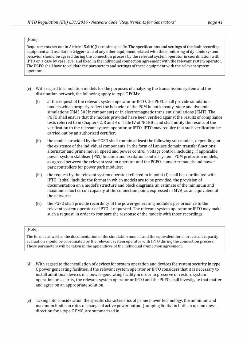
IPTO Regulation (EU) 631/2016 - Network Code “Requirements for Generators” page 41
[Note]:
Requirements set out in Article 15.6(b)(i) are site specific. The specifications and settings of the fault recording
equipment and oscillation triggers and of any other equipment related with the monitoring of dynamic system
behavior should be agreed during the connection process by the relevant system operator in coordination with
IPTO on a case by case level and fixed in the individual connection agreement with the relevant system operator.
The PGFO shall have to validate the parameters and settings of these equipment with the relevant system
operator.
(c) With regard to simulation models for the purposes of analyzing the transmission system and the
distribution network, the following apply to type C PGMs:
(i) at the request of the relevant system operator or IPTO, the PGFO shall provide simulation
models which properly reflect the behavior of the PGM in both steady- state and dynamic
simulations (RMS 50 Hz component) or in electromagnetic transient simulations (EMT). The
PGFO shall ensure that the models provided have been verified against the results of compliance
tests referred to in Chapters 2, 3 and 4 of Title IV of NC-RfG, and shall notify the results of the
verification to the relevant system operator or IPTO. IPTO may require that such verification be
carried out by an authorized certifier;
(ii) the models provided by the PGFO shall contain at least the following sub-models, depending on
the existence of the individual components, in the form of Laplace domain transfer functions:
alternator and prime mover, speed and power control, voltage control, including, if applicable,
power system stabiliser (PSS) function and excitation control system, PGM protection models,
as agreed between the relevant system operator and the PGFO, converter models and power
park controllers for power park modules;
(iii) the request by the relevant system operator referred to in point (i) shall be coordinated with
IPTO. It shall include: the format in which models are to be provided, the provision of
documentation on a model’s structure and block diagrams, an estimate of the minimum and
maximum short circuit capacity at the connection point, expressed in MVA, as an equivalent of
the network;
(iv) the PGFO shall provide recordings of the power-generating module’s performance to the
relevant system operator or IPTO if requested. The relevant system operator or IPTO may make
such a request, in order to compare the response of the models with those recordings;
[Note]:
The format as well as the documentation of the simulation models and the equivalent for short circuit capacity
evaluation should be coordinated by the relevant system operator with IPTO during the connection process.
These parameters will be taken in the appendices of the individual connection agreement.
(d) With regard to the installation of devices for system operation and devices for system security in type
C power generating facilities, if the relevant system operator or IPTO considers that it is necessary to
install additional devices in a power-generating facility in order to preserve or restore system
operation or security, the relevant system operator or IPTO and the PGFO shall investigate that matter
and agree on an appropriate solution.
(e) Taking into consideration the specific characteristics of prime mover technology, the minimum and
maximum limits on rates of change of active power output (ramping limits) in both an up and down
direction for a type C PMG, are summarized in
IPTO Regulation (EU) 631/2016 - Network Code “Requirements for Generators” page 42
(f) Table 11.
Table 11: max ramp up/down limits for type C PGMs
Prime mover
Technology Ramp-up capability Ramp-down capability
Lignite or Coal
fed Steam
Turbines
not less than 1,0% Pmax/min when in
normal dispatch conditions
not less than 1,0% Pmax/min when in
normal dispatch conditions
Oil or Natural
Gas fed Steam
Turbines
not less than 1,5% Pmax/min when in
normal dispatch conditions
not less than 1,5% Pmax/min when in
normal dispatch conditions
Oil or Natural
Gas fed Gas
Turbines
within 20 minutes from unit
synchronization it must provide Pmax
when in normal dispatch conditions
within 10 minutes generation should
drop from Pmax to Pmin when in
normal dispatch conditions
Natural Gas fed
single shaft
Turbines
not less than 2,0% Pmax/min when in
normal dispatch conditions
not less than 2,0% Pmax/min when in
normal dispatch conditions
Hydro Turbines not less than 50,0% Pmax/min when in
normal dispatch conditions
not less than 50,0% Pmax/min when in
normal dispatch conditions
PPMs with a
power electronic
interface
not less than 10,0% Pmax/sec when in
normal conditions
not less than 10,0% Pmax/sec when in
normal conditions
(g) With regard to earthing arrangements of the neutral-point at the network side of step up
transformers, the following specifications apply to transformers installed at connection points:
(i) generator transformer windings shall be connected in star (with the neutral brought out) on the
System side (high voltage side) and in delta on the generator side (low voltage)
(ii) generating units general ancillary transformers are connected in star on the high voltage side
with the neutral node brought out to a terminal for direct earthing and in delta on the medium/
low voltage side
[Note]:
The relevant system operator shall specify the earthing arrangement of the neutral-point at the network side of
step-up transformers during connection process. These parameters will be included in the appendices of the
individual connection agreement.
Article 16.
General requirements for type D power-generating modules
1. In addition to the requirements listed in Articles 13, 14 and 15, with the exception of Article
13.2(b), Article 13.6, Article 13.7 and Article 15.3, type D power-generating modules shall fulfill
the following additional requirements.
2. Type D power-generating modules shall fulfil the following requirements relating to voltage stability:
(a) with regard to voltage ranges:
(i) without prejudice to Article 14.3(a) and to Article 16.3(a), a PGM shall be capable of staying
connected to the network and operating within the ranges of the network voltage at the
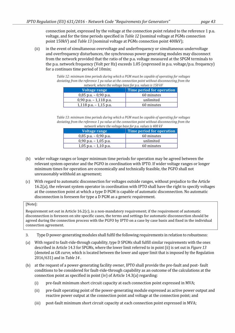
IPTO Regulation (EU) 631/2016 - Network Code “Requirements for Generators” page 43
connection point, expressed by the voltage at the connection point related to the reference 1 p.u.
voltage, and for the time periods specified in Table 12 (nominal voltage at PGMs connection
point 150kV) and Table 13 (nominal voltage at PGMs connection point 400kV);
(ii) in the event of simultaneous overvoltage and underfrequency or simultaneous undervoltage
and overfrequency disturbances, the synchronous power generating modules may disconnect
from the network provided that the ratio of the p.u. voltage measured at the SPGM terminals to
the p.u. network frequency (Volt per Hz) exceeds 1.05 (expressed in p.u. voltage/p.u. frequency)
for a continues time period of 10min;
Table 12: minimum time periods during which a PGM must be capable of operating for voltages
deviating from the reference 1 pu value at the connection point without disconnecting from the
network, where the voltage base for p.u. values is 150 kV
Voltage range Time period for operation
0,85 p.u. – 0,90 p.u. 60 minutes
0,90 p.u. – 1,118 p.u. unlimited
1,118 p.u. – 1,15 p.u. 60 minutes
Table 13: minimum time periods during which a PGM must be capable of operating for voltages
deviating from the reference 1 pu value at the connection point without disconnecting from the
network where the voltage base for p.u. values is 400 kV
Voltage range Time period for operation
0,85 p.u. – 0,90 p.u. 60 minutes
0,90 p.u. – 1,05 p.u. unlimited
1,05 p.u. – 1,10 p.u. 60 minutes
(b) wider voltage ranges or longer minimum time periods for operation may be agreed between the
relevant system operator and the PGFO in coordination with IPTO. If wider voltage ranges or longer
minimum times for operation are economically and technically feasible, the PGFO shall not
unreasonably withhold an agreement;
(c) With regard to automatic disconnection for voltages outside ranges, without prejudice to the Article
16.2(a), the relevant system operator in coordination with IPTO shall have the right to specify voltages
at the connection point at which a type D PGM is capable of automatic disconnection. No automatic
disconnection is foreseen for type a D PGM as a generic requirement.
[Note]:
Requirement set out in Article 16.2(c), is a non-mandatory requirement; if the requirement of automatic
disconnection is foreseen on site specific cases, the terms and settings for automatic disconnection should be
agreed during the connection process with the PGFO by IPTO on a case by case basis and fixed in the individual
connection agreement.
3. Type D power-generating modules shall fulfil the following requirements in relation to robustness:
(a) With regard to fault-ride-through capability, type D SPGMs shall fulfill similar requirements with the ones
described in Article 14.3 for SPGMs, where the lower limit referred to in point (ii) is set out in Figure 13
(denoted as GR curve, which is located between the lower and upper limit that is imposed by the Regulation
2016/631) and in Table 14 .
(b) at the request of a power-generating facility owner, IPTO shall provide the pre-fault and post- fault
conditions to be considered for fault-ride-through capability as an outcome of the calculations at the
connection point as specified in point (iv) of Article 14.3(a) regarding:
(i) pre-fault minimum short circuit capacity at each connection point expressed in MVA;
(ii) pre-fault operating point of the power-generating module expressed as active power output and
reactive power output at the connection point and voltage at the connection point; and
(iii) post-fault minimum short circuit capacity at each connection point expressed in MVA;
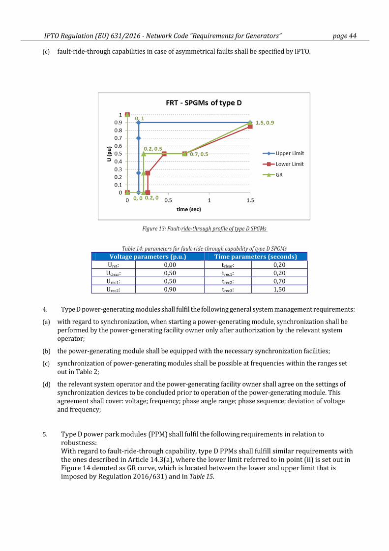
IPTO Regulation (EU) 631/2016 - Network Code “Requirements for Generators” page 44
(c) fault-ride-through capabilities in case of asymmetrical faults shall be specified by IPTO.
Figure 13: Fault-ride-through profile of type D SPGMs
Table 14: parameters for fault-ride-through capability of type D SPGMs
Voltage parameters (p.u.) Time parameters (seconds)
Uret: 0,00 tclear: 0,20
Uclear: 0,50 trec1: 0,20
Urec1: 0,50 trec2: 0,70
Urec2: 0,90 trec3: 1,50
4. Type D power-generating modules shall fulfil the following general system management requirements:
(a) with regard to synchronization, when starting a power-generating module, synchronization shall be
performed by the power-generating facility owner only after authorization by the relevant system
operator;
(b) the power-generating module shall be equipped with the necessary synchronization facilities;
(c) synchronization of power-generating modules shall be possible at frequencies within the ranges set
out in Table 2;
(d) the relevant system operator and the power-generating facility owner shall agree on the settings of
synchronization devices to be concluded prior to operation of the power-generating module. This
agreement shall cover: voltage; frequency; phase angle range; phase sequence; deviation of voltage
and frequency;
5. Type D power park modules (PPM) shall fulfil the following requirements in relation to
robustness:
With regard to fault-ride-through capability, type D PPMs shall fulfill similar requirements with
the ones described in Article 14.3(a), where the lower limit referred to in point (ii) is set out in
Figure 14 denoted as GR curve, which is located between the lower and upper limit that is
imposed by Regulation 2016/631) and in Table 15.
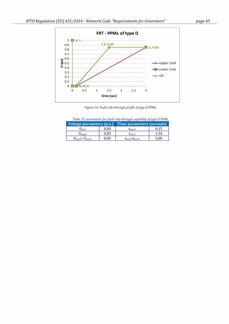
IPTO Regulation (EU) 631/2016 - Network Code “Requirements for Generators” page 45
Figure 14: Fault-ride-through profile of type D PPMs
Table 15: parameters for fault-ride-through capability of type D PPMs
Voltage parameters (p.u.) Time parameters (seconds)
Uret: 0,00 tclear: 0,15
Uclear: 0,85 trec1: 1,50
Urec1= Urec2: 0,85 trec2=trec3: 3,00
IPTO Regulation (EU) 631/2016 - Network Code “Requirements for Generators” page 46
CHAPTER 2 - Requirements for synchronous power-generating modules
Article 17.
Requirements for type B synchronous power-generating modules
1. Type B synchronous power-generating modules shall fulfil the requirements listed in Articles
13, except for the Article 13.2(b), and 14.
2. Type B synchronous power-generating modules shall fulfil the following additional requirements
relating to voltage stability:
(a) With regard to reactive power capability of type B SPGMs, the relevant system operator shall have the
right to specify the capability of a synchronous power-generating module to provide reactive power.
[Note]:
Requirement set out in Article 17.2(a) is a non-mandatory requirement. Type B SPGMs shall provide reactive
power according to HEDNO's requirements, on a case by case basis.
(b) With regard to the voltage control system, a type B SPGM shall be equipped with a permanent
automatic excitation control system that can provide constant alternator terminal voltage at a
selectable setpoint without instability over the entire operating range of the synchronous power-
generating module.
3. With regard to robustness, type B SPGMs that are not disconnected during a fault, shall be capable of
providing post-fault active power recovery to recover 90% of the pre-fault active power in less than
5sec after fault clearance, provided that the voltage at the connection point (U) is greater than
0,90p.u., U > 0,90 p.u
Article 18.
Requirements for type C synchronous power-generating modules
1. Type C synchronous power-generating modules shall fulfil the requirements laid down in
Articles 13, 14, 15 and 17, except for Article 13.2(b) and Article 13.6, Article 14.2 and Article 17.2(a) .
2. Type C synchronous power-generating modules shall fulfill the following additional
requirements in relation to voltage stability:
(a) with regard to reactive power capability, IPTO may specify supplementary reactive power to be
provided if the connection point of a synchronous power-generating module is neither located at the
high-voltage terminals of the step-up transformer to the voltage level of the connection point nor at the
alternator terminals, if no step-up transformer exists. This supplementary reactive power shall
compensate the reactive power demand of the high-voltage line or cable between the high-voltage
terminals of the step-up transformer of the synchronous power-generating module or its alternator
terminals, if no step-up transformer exists, and the connection point and shall be provided by the
responsible owner of that line or cable;
(b) with regard to reactive power capability at maximum capacity:
(i) the SPGM shall be capable of providing reactive power at maximum capacity at varying voltage
at the connection point according the U-Q/Pmax-profile specified in Figure 15 (denoted as GR
curve, which is located inside the outer boundary that is imposed by the Regulation 2016/631);
(ii) the synchronous power-generating module shall be capable of moving to any operating point
within its U-Q/Pmax profile in appropriate timescales to target values requested by the relevant
system operator;
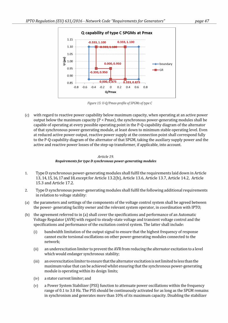
IPTO Regulation (EU) 631/2016 - Network Code “Requirements for Generators” page 47
Figure 15: U-Q/Pmax-profile of SPGMs of type C
(c) with regard to reactive power capability below maximum capacity, when operating at an active power
output below the maximum capacity (P < Pmax), the synchronous power-generating modules shall be
capable of operating at every possible operating point in the P-Q-capability diagram of the alternator
of that synchronous power-generating module, at least down to minimum stable operating level. Even
at reduced active power output, reactive power supply at the connection point shall correspond fully
to the P-Q-capability diagram of the alternator of that SPGM, taking the auxiliary supply power and the
active and reactive power losses of the step-up transformer, if applicable, into account.
Article 19.
Requirements for type D synchronous power-generating modules
1. Type D synchronous power-generating modules shall fulfil the requirements laid down in Article
13, 14, 15, 16, 17 and 18, except for Article 13.2(b), Article 13.6, Article 13.7, Article 14.2, Article
15.3 and Article 17.2.
2. Type D synchronous power-generating modules shall fulfil the following additional requirements
in relation to voltage stability:
(a) the parameters and settings of the components of the voltage control system shall be agreed between
the power- generating facility owner and the relevant system operator, in coordination with IPTO;
(b) the agreement referred to in (a) shall cover the specifications and performance of an Automatic
Voltage Regulator (AVR) with regard to steady-state voltage and transient voltage control and the
specifications and performance of the excitation control system. The latter shall include:
(i) bandwidth limitation of the output signal to ensure that the highest frequency of response
cannot excite torsional oscillations on other power-generating modules connected to the
network;
(ii) an underexcitation limiter to prevent the AVR from reducing the alternator excitation to a level
which would endanger synchronous stability;
(iii) an overexcitation limiter to ensure that the alternator excitation is not limited to less than the
maximum value that can be achieved whilst ensuring that the synchronous power-generating
module is operating within its design limits;
(iv) a stator current limiter; and
(v) a Power System Stabilizer (PSS) function to attenuate power oscillations within the frequency
range of 0.1 to 3.0 Hz. The PSS should be continuously activated for as long as the SPGM remains
in synchronism and generates more than 10% of its maximum capacity. Disabling the stabilizer
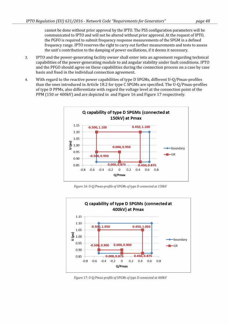
IPTO Regulation (EU) 631/2016 - Network Code “Requirements for Generators” page 48
cannot be done without prior approval by the IPTO. The PSS configuration parameters will be
communicated to IPTO and will not be altered without prior approval. At the request of IPTO,
the PGFO is required to submit frequency response measurements of the SPGM in a defined
frequency range. IPTO reserves the right to carry out further measurements and tests to assess
the unit's contribution to the damping of power oscillations, if it deems it necessary.
3. IPTO and the power-generating facility owner shall enter into an agreement regarding technical
capabilities of the power-generating module to aid angular stability under fault conditions. IPTO
and the PFGO should agree on these capabilities during the connection process on a case by case
basis and fixed in the individual connection agreement.
4. With regard to the reactive power capabilities of type D SPGMs, different U-Q/Pmax-profiles
than the ones introduced in Article 18.2 for type C SPGMs are specified. The U-Q/Pmax-profiles
of type D PPMs, also differentiate with regard the voltage level at the connection point of the
PPM (150 or 400kV) and are depicted in and Figure 16 and Figure 17 respectively.
Figure 16: U-Q/Pmax-profile of SPGMs of type D connected at 150kV
Figure 17: U-Q/Pmax-profile of SPGMs of type D connected at 400kV
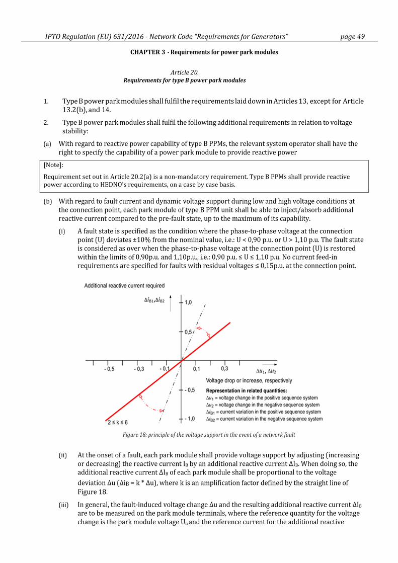
IPTO Regulation (EU) 631/2016 - Network Code “Requirements for Generators” page 49
CHAPTER 3 - Requirements for power park modules
Article 20.
Requirements for type B power park modules
1. Type B power park modules shall fulfil the requirements laid down in Articles 13, except for Article
13.2(b), and 14.
2. Type B power park modules shall fulfil the following additional requirements in relation to voltage
stability:
(a) With regard to reactive power capability of type B PPMs, the relevant system operator shall have the
right to specify the capability of a power park module to provide reactive power
[Note]:
Requirement set out in Article 20.2(a) is a non-mandatory requirement. Type B PPMs shall provide reactive
power according to HEDNO's requirements, on a case by case basis.
(b) With regard to fault current and dynamic voltage support during low and high voltage conditions at
the connection point, each park module of type B PPM unit shall be able to inject/absorb additional
reactive current compared to the pre-fault state, up to the maximum of its capability.
(i) A fault state is specified as the condition where the phase-to-phase voltage at the connection
point (U) deviates ±10% from the nominal value, i.e.: U < 0,90 p.u. or U > 1,10 p.u. The fault state
is considered as over when the phase-to-phase voltage at the connection point (U) is restored
within the limits of 0,90p.u. and 1,10p.u., i.e.: 0,90 p.u. ≤ U ≤ 1,10 p.u. No current feed-in
requirements are specified for faults with residual voltages ≤ 0,15p.u. at the connection point.
Figure 18: principle of the voltage support in the event of a network fault
(ii) At the onset of a fault, each park module shall provide voltage support by adjusting (increasing
or decreasing) the reactive current IB by an additional reactive current ΔIB. When doing so, the
additional reactive current ΔIB of each park module shall be proportional to the voltage
deviation Δu (ΔiB = k * Δu), where k is an amplification factor defined by the straight line of
Figure 18.
(iii) In general, the fault-induced voltage change Δu and the resulting additional reactive current ΔIB
are to be measured on the park module terminals, where the reference quantity for the voltage
change is the park module voltage Un and the reference current for the additional reactive
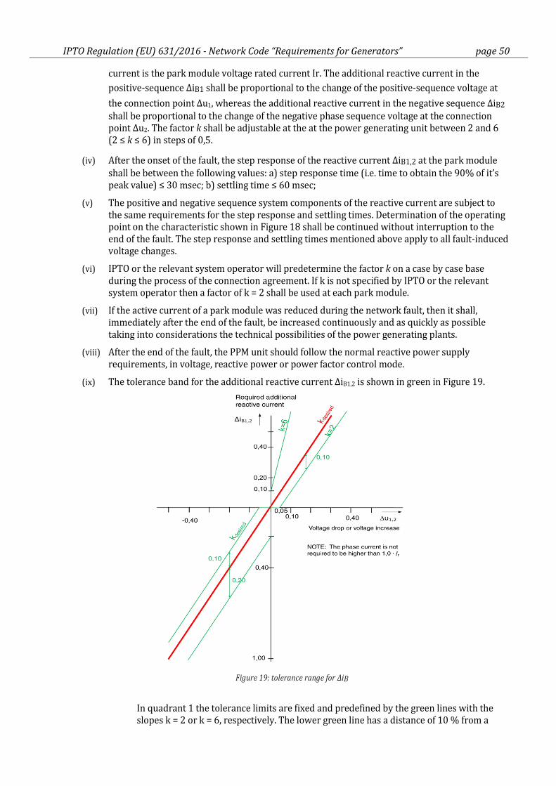
IPTO Regulation (EU) 631/2016 - Network Code “Requirements for Generators” page 50
current is the park module voltage rated current Ir. The additional reactive current in the
positive-sequence ΔiB1 shall be proportional to the change of the positive-sequence voltage at
the connection point Δu1, whereas the additional reactive current in the negative sequence ΔiB2
shall be proportional to the change of the negative phase sequence voltage at the connection
point Δu2. The factor k shall be adjustable at the at the power generating unit between 2 and 6
(2 ≤ k ≤ 6) in steps of 0,5.
(iv) After the onset of the fault, the step response of the reactive current ΔiB1,2 at the park module
shall be between the following values: a) step response time (i.e. time to obtain the 90% of it’s
peak value) ≤ 30 msec; b) settling time ≤ 60 msec;
(v) The positive and negative sequence system components of the reactive current are subject to
the same requirements for the step response and settling times. Determination of the operating
point on the characteristic shown in Figure 18 shall be continued without interruption to the
end of the fault. The step response and settling times mentioned above apply to all fault-induced
voltage changes.
(vi) IPTO or the relevant system operator will predetermine the factor k on a case by case base
during the process of the connection agreement. If k is not specified by IPTO or the relevant
system operator then a factor of k = 2 shall be used at each park module.
(vii) If the active current of a park module was reduced during the network fault, then it shall,
immediately after the end of the fault, be increased continuously and as quickly as possible
taking into considerations the technical possibilities of the power generating plants.
(viii) After the end of the fault, the PPM unit should follow the normal reactive power supply
requirements, in voltage, reactive power or power factor control mode.
(ix) The tolerance band for the additional reactive current ΔiB1,2 is shown in green in Figure 19.
Figure 19: tolerance range for ΔiB
In quadrant 1 the tolerance limits are fixed and predefined by the green lines with the
slopes k = 2 or k = 6, respectively. The lower green line has a distance of 10 % from a
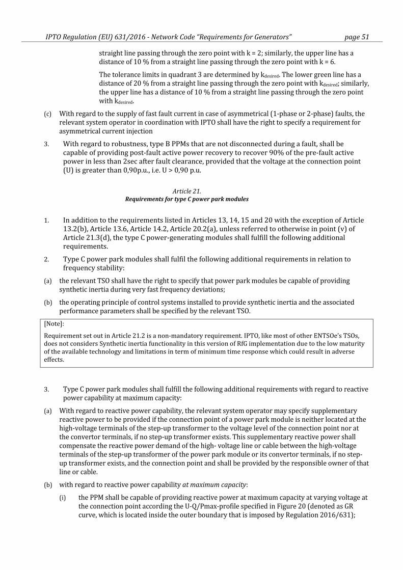
IPTO Regulation (EU) 631/2016 - Network Code “Requirements for Generators” page 51
straight line passing through the zero point with k = 2; similarly, the upper line has a
distance of 10 % from a straight line passing through the zero point with k = 6.
The tolerance limits in quadrant 3 are determined by kdesired. The lower green line has a
distance of 20 % from a straight line passing through the zero point with kdesired; similarly,
the upper line has a distance of 10 % from a straight line passing through the zero point
with kdesired.
(c) With regard to the supply of fast fault current in case of asymmetrical (1-phase or 2-phase) faults, the
relevant system operator in coordination with IPTO shall have the right to specify a requirement for
asymmetrical current injection
3. With regard to robustness, type B PPMs that are not disconnected during a fault, shall be
capable of providing post-fault active power recovery to recover 90% of the pre-fault active
power in less than 2sec after fault clearance, provided that the voltage at the connection point
(U) is greater than 0,90p.u., i.e. U > 0,90 p.u.
Article 21.
Requirements for type C power park modules
1. In addition to the requirements listed in Articles 13, 14, 15 and 20 with the exception of Article
13.2(b), Article 13.6, Article 14.2, Article 20.2(a), unless referred to otherwise in point (v) of
Article 21.3(d), the type C power-generating modules shall fulfill the following additional
requirements.
2. Type C power park modules shall fulfil the following additional requirements in relation to
frequency stability:
(a) the relevant TSO shall have the right to specify that power park modules be capable of providing
synthetic inertia during very fast frequency deviations;
(b) the operating principle of control systems installed to provide synthetic inertia and the associated
performance parameters shall be specified by the relevant TSO.
[Note]:
Requirement set out in Article 21.2 is a non-mandatory requirement. IPTO, like most of other ENTSOe’s TSOs,
does not considers Synthetic inertia functionality in this version of RfG implementation due to the low maturity
of the available technology and limitations in term of minimum time response which could result in adverse
effects.
3. Type C power park modules shall fulfill the following additional requirements with regard to reactive
power capability at maximum capacity:
(a) With regard to reactive power capability, the relevant system operator may specify supplementary
reactive power to be provided if the connection point of a power park module is neither located at the
high-voltage terminals of the step-up transformer to the voltage level of the connection point nor at
the convertor terminals, if no step-up transformer exists. This supplementary reactive power shall
compensate the reactive power demand of the high- voltage line or cable between the high-voltage
terminals of the step-up transformer of the power park module or its convertor terminals, if no step-
up transformer exists, and the connection point and shall be provided by the responsible owner of that
line or cable.
(b) with regard to reactive power capability at maximum capacity:
(i) the PPM shall be capable of providing reactive power at maximum capacity at varying voltage at
the connection point according the U-Q/Pmax-profile specified in Figure 20 (denoted as GR
curve, which is located inside the outer boundary that is imposed by Regulation 2016/631);
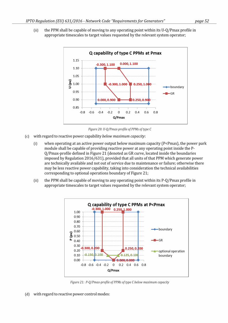
IPTO Regulation (EU) 631/2016 - Network Code “Requirements for Generators” page 52
(ii) the PPM shall be capable of moving to any operating point within its U-Q/Pmax profile in
appropriate timescales to target values requested by the relevant system operator;
Figure 20: U-Q/Pmax-profile of PPMs of type C
(c) with regard to reactive power capability below maximum capacity:
(i) when operating at an active power output below maximum capacity (P<Pmax), the power park
module shall be capable of providing reactive power at any operating point inside the P-
Q/Pmax-profile defined in Figure 21 (denoted as GR curve, located inside the boundaries
imposed by Regulation 2016/631), provided that all units of that PPM which generate power
are technically available and not out of service due to maintenance or failure; otherwise there
may be less reactive power capability, taking into consideration the technical availabilities
corresponding to optional operations boundary of Figure 21;
(ii) the PPM shall be capable of moving to any operating point within its P-Q/Pmax profile in
appropriate timescales to target values requested by the relevant system operator;
Figure 21: P-Q/Pmax-profile of PPMs of type C below maximum capacity
(d) with regard to reactive power control modes:
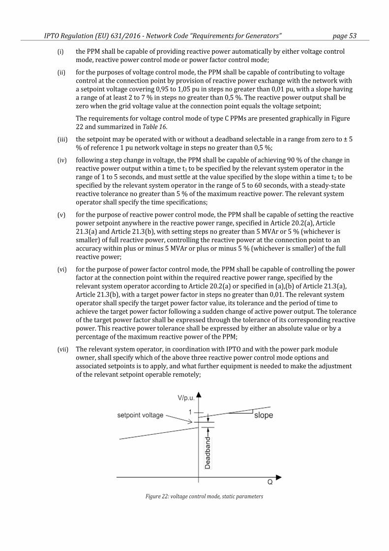
IPTO Regulation (EU) 631/2016 - Network Code “Requirements for Generators” page 53
(i) the PPM shall be capable of providing reactive power automatically by either voltage control
mode, reactive power control mode or power factor control mode;
(ii) for the purposes of voltage control mode, the PPM shall be capable of contributing to voltage
control at the connection point by provision of reactive power exchange with the network with
a setpoint voltage covering 0,95 to 1,05 pu in steps no greater than 0,01 pu, with a slope having
a range of at least 2 to 7 % in steps no greater than 0,5 %. The reactive power output shall be
zero when the grid voltage value at the connection point equals the voltage setpoint;
The requirements for voltage control mode of type C PPMs are presented graphically in Figure
22 and summarized in Table 16.
(iii) the setpoint may be operated with or without a deadband selectable in a range from zero to ± 5
% of reference 1 pu network voltage in steps no greater than 0,5 %;
(iv) following a step change in voltage, the PPM shall be capable of achieving 90 % of the change in
reactive power output within a time t1 to be specified by the relevant system operator in the
range of 1 to 5 seconds, and must settle at the value specified by the slope within a time t2 to be
specified by the relevant system operator in the range of 5 to 60 seconds, with a steady-state
reactive tolerance no greater than 5 % of the maximum reactive power. The relevant system
operator shall specify the time specifications;
(v) for the purpose of reactive power control mode, the PPM shall be capable of setting the reactive
power setpoint anywhere in the reactive power range, specified in Article 20.2(a), Article
21.3(a) and Article 21.3(b), with setting steps no greater than 5 MVAr or 5 % (whichever is
smaller) of full reactive power, controlling the reactive power at the connection point to an
accuracy within plus or minus 5 MVAr or plus or minus 5 % (whichever is smaller) of the full
reactive power;
(vi) for the purpose of power factor control mode, the PPM shall be capable of controlling the power
factor at the connection point within the required reactive power range, specified by the
relevant system operator according to Article 20.2(a) or specified in (a),(b) of Article 21.3(a),
Article 21.3(b), with a target power factor in steps no greater than 0,01. The relevant system
operator shall specify the target power factor value, its tolerance and the period of time to
achieve the target power factor following a sudden change of active power output. The tolerance
of the target power factor shall be expressed through the tolerance of its corresponding reactive
power. This reactive power tolerance shall be expressed by either an absolute value or by a
percentage of the maximum reactive power of the PPM;
(vii) The relevant system operator, in coordination with IPTO and with the power park module
owner, shall specify which of the above three reactive power control mode options and
associated setpoints is to apply, and what further equipment is needed to make the adjustment
of the relevant setpoint operable remotely;
Figure 22: voltage control mode, static parameters
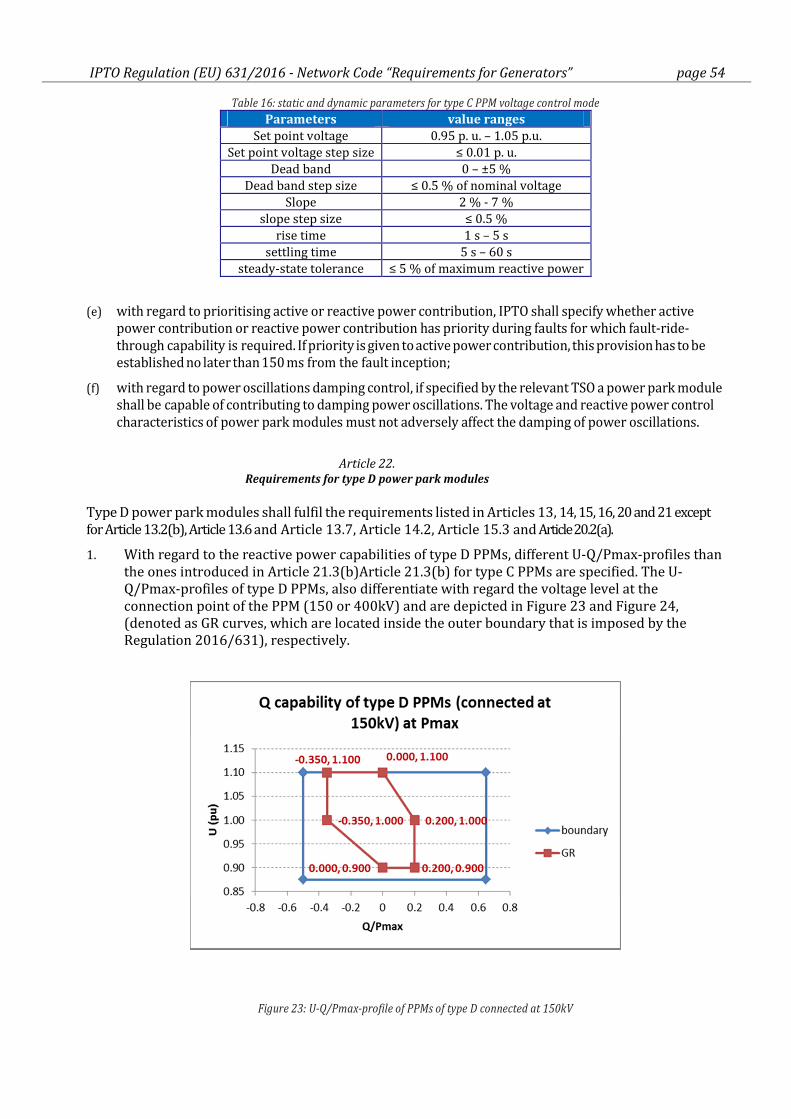
IPTO Regulation (EU) 631/2016 - Network Code “Requirements for Generators” page 54
Table 16: static and dynamic parameters for type C PPM voltage control mode
Parameters value ranges
Set point voltage 0.95 p. u. – 1.05 p.u.
Set point voltage step size ≤ 0.01 p. u.
Dead band 0 – ±5 %
Dead band step size ≤ 0.5 % of nominal voltage
Slope 2 % - 7 %
slope step size ≤ 0.5 %
rise time 1 s – 5 s
settling time 5 s – 60 s
steady-state tolerance ≤ 5 % of maximum reactive power
(e) with regard to prioritising active or reactive power contribution, IPTO shall specify whether active
power contribution or reactive power contribution has priority during faults for which fault-ride-
through capability is required. If priority is given to active power contribution, this provision has to be
established no later than 150 ms from the fault inception;
(f) with regard to power oscillations damping control, if specified by the relevant TSO a power park module
shall be capable of contributing to damping power oscillations. The voltage and reactive power control
characteristics of power park modules must not adversely affect the damping of power oscillations.
Article 22.
Requirements for type D power park modules
Type D power park modules shall fulfil the requirements listed in Articles 13, 14, 15, 16, 20 and 21 except
for Article 13.2(b), Article 13.6 and Article 13.7, Article 14.2, Article 15.3 and Article 20.2(a).
1. With regard to the reactive power capabilities of type D PPMs, different U-Q/Pmax-profiles than
the ones introduced in Article 21.3(b)Article 21.3(b) for type C PPMs are specified. The U-
Q/Pmax-profiles of type D PPMs, also differentiate with regard the voltage level at the
connection point of the PPM (150 or 400kV) and are depicted in Figure 23 and Figure 24,
(denoted as GR curves, which are located inside the outer boundary that is imposed by the
Regulation 2016/631), respectively.
Figure 23: U-Q/Pmax-profile of PPMs of type D connected at 150kV
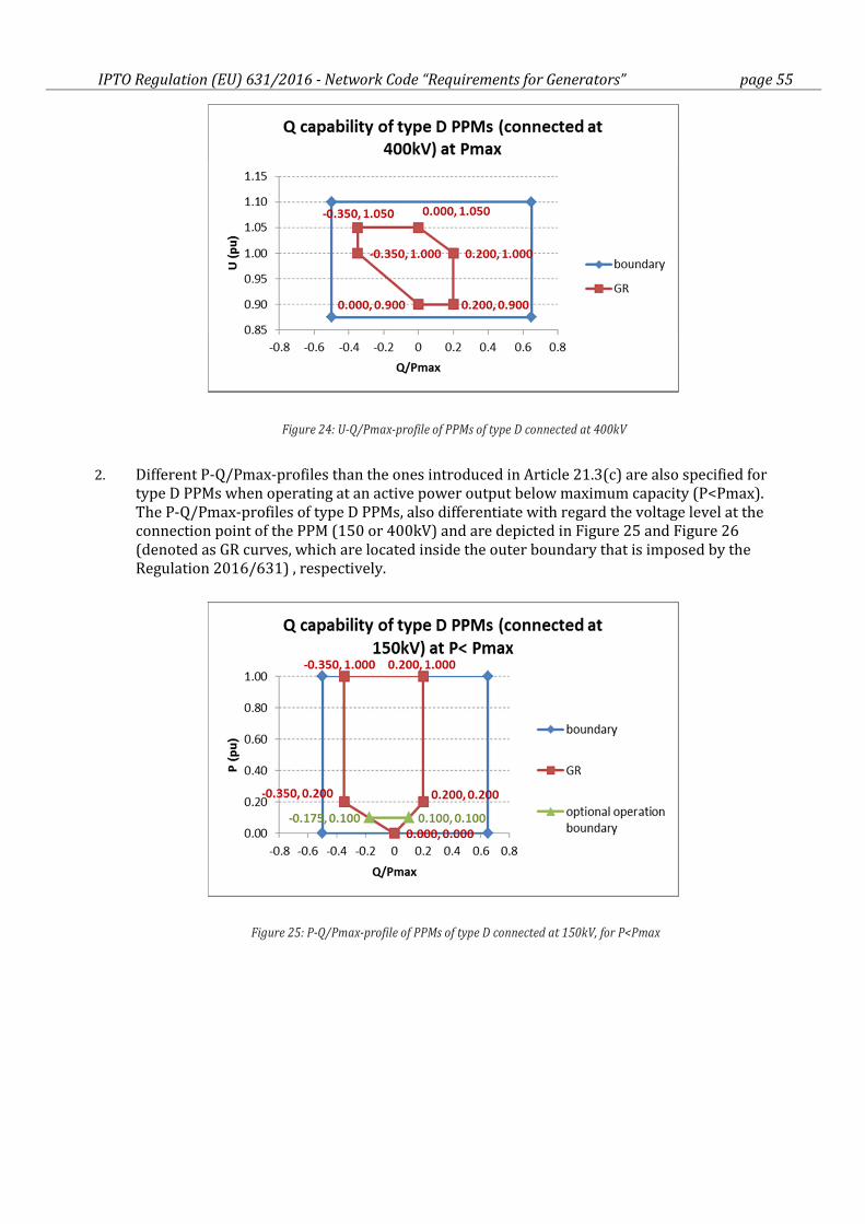
IPTO Regulation (EU) 631/2016 - Network Code “Requirements for Generators” page 55
Figure 24: U-Q/Pmax-profile of PPMs of type D connected at 400kV
2. Different P-Q/Pmax-profiles than the ones introduced in Article 21.3(c) are also specified for
type D PPMs when operating at an active power output below maximum capacity (P<Pmax).
The P-Q/Pmax-profiles of type D PPMs, also differentiate with regard the voltage level at the
connection point of the PPM (150 or 400kV) and are depicted in Figure 25 and Figure 26
(denoted as GR curves, which are located inside the outer boundary that is imposed by the
Regulation 2016/631) , respectively.
Figure 25: P-Q/Pmax-profile of PPMs of type D connected at 150kV, for P<Pmax
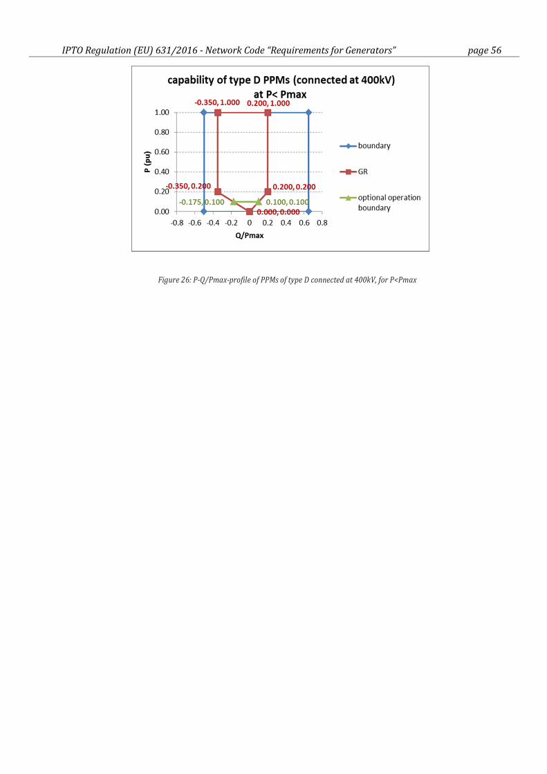
IPTO Regulation (EU) 631/2016 - Network Code “Requirements for Generators” page 56
Figure 26: P-Q/Pmax-profile of PPMs of type D connected at 400kV, for P<Pmax
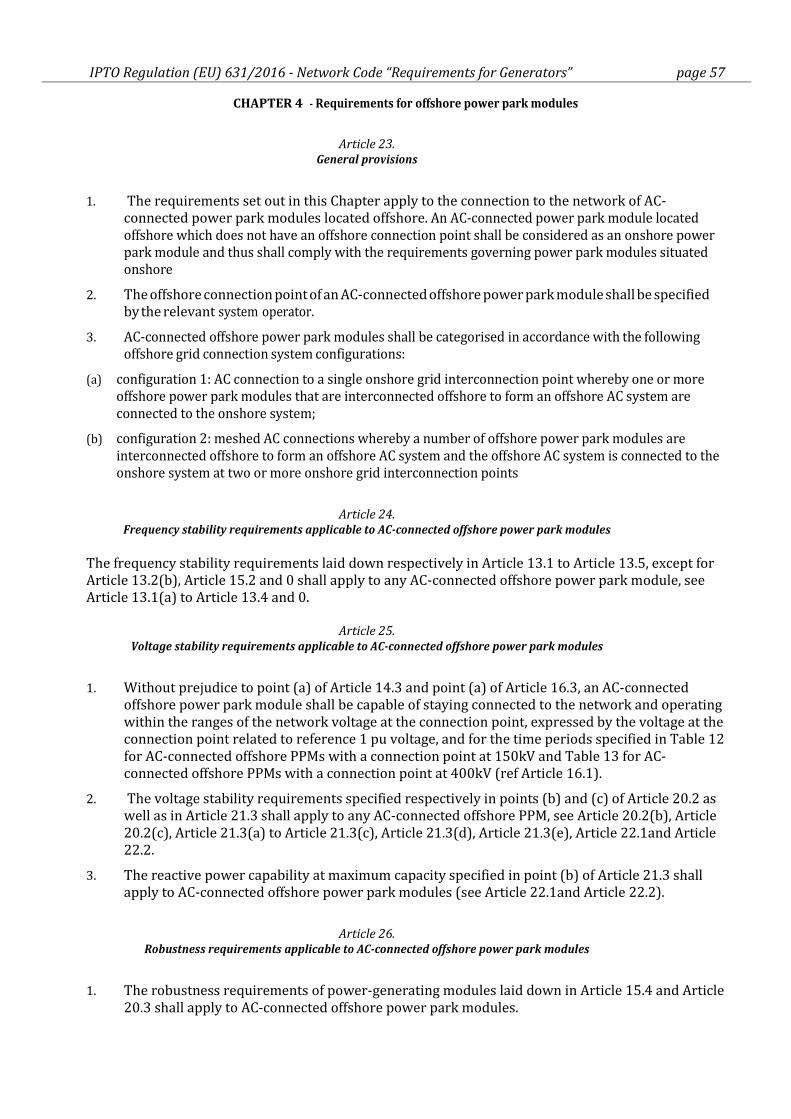
IPTO Regulation (EU) 631/2016 - Network Code “Requirements for Generators” page 57
CHAPTER 4 - Requirements for offshore power park modules
Article 23.
General provisions
1. The requirements set out in this Chapter apply to the connection to the network of AC-
connected power park modules located offshore. An AC-connected power park module located
offshore which does not have an offshore connection point shall be considered as an onshore power
park module and thus shall comply with the requirements governing power park modules situated
onshore
2. The offshore connection point of an AC-connected offshore power park module shall be specified
by the relevant system operator.
3. AC-connected offshore power park modules shall be categorised in accordance with the following
offshore grid connection system configurations:
(a) configuration 1: AC connection to a single onshore grid interconnection point whereby one or more
offshore power park modules that are interconnected offshore to form an offshore AC system are
connected to the onshore system;
(b) configuration 2: meshed AC connections whereby a number of offshore power park modules are
interconnected offshore to form an offshore AC system and the offshore AC system is connected to the
onshore system at two or more onshore grid interconnection points
Article 24.
Frequency stability requirements applicable to AC-connected offshore power park modules
The frequency stability requirements laid down respectively in Article 13.1 to Article 13.5, except for
Article 13.2(b), Article 15.2 and 0 shall apply to any AC-connected offshore power park module, see
Article 13.1(a) to Article 13.4 and 0.
Article 25.
Voltage stability requirements applicable to AC-connected offshore power park modules
1. Without prejudice to point (a) of Article 14.3 and point (a) of Article 16.3, an AC-connected
offshore power park module shall be capable of staying connected to the network and operating
within the ranges of the network voltage at the connection point, expressed by the voltage at the
connection point related to reference 1 pu voltage, and for the time periods specified in Table 12
for AC-connected offshore PPMs with a connection point at 150kV and Table 13 for AC-
connected offshore PPMs with a connection point at 400kV (ref Article 16.1).
2. The voltage stability requirements specified respectively in points (b) and (c) of Article 20.2 as
well as in Article 21.3 shall apply to any AC-connected offshore PPM, see Article 20.2(b), Article
20.2(c), Article 21.3(a) to Article 21.3(c), Article 21.3(d), Article 21.3(e), Article 22.1and Article
22.2.
3. The reactive power capability at maximum capacity specified in point (b) of Article 21.3 shall
apply to AC-connected offshore power park modules (see Article 22.1and Article 22.2).
Article 26.
Robustness requirements applicable to AC-connected offshore power park modules
1. The robustness requirements of power-generating modules laid down in Article 15.4 and Article
20.3 shall apply to AC-connected offshore power park modules.
IPTO Regulation (EU) 631/2016 - Network Code “Requirements for Generators” page 58
2. The fault-ride-through capability requirements laid down in point (a) of Article 14.3 and point
(a) of Article 16.3 shall apply to AC-connected offshore power park modules (ref Article 16.5).
Article 27.
System restoration requirements applicable to AC-connected offshore power park modules
The system restoration requirements laid down respectively in Article 14.4 and Article 15.5 shall
apply to AC-connected offshore power park modules, ref Article 14.4(a), Article 14.4(b) and Article
15.6(c).
Article 28.
General system management requirements applicable to AC-connected offshore power park modules
The general system management requirements laid down in Article 14.5, Article 15.6 and Article 16.4 shall
apply to AC-connected offshore power park modules, ref Article 14.5(a), Article 14.5(b) and Article 16.4.
IPTO Regulation (EU) 631/2016 - Network Code “Requirements for Generators” page 59
TITLE III OPERATIONAL NOTIFICATION PROCEDURE FOR CONNECTION
CHAPTER 1 - Connection of new power-generating modules
Article 29. General provisions
1. The power-generating facility owner shall demonstrate to the relevant system operator that it
has complied with the requirements set out in Title II of this Regulation by completing
successfully the operational notification procedure for connection of each power-generating
module described in Articles 30 to 37.
2. The relevant system operator shall clarify and make publicly available the details of the
operational notification procedure.
Article 30.
Operational notification of type A power-generating modules
1. The operational notification procedure for connection of each new type A power-generating
module shall consist of submitting an installation document. The power-generating facility
owner shall ensure that the required information is filled in on an installation document
obtained from the relevant system operator and is submitted to the system operator. Separate
installation documents shall be provided for each power-generating module within the power-
generating facility.
The relevant system operator shall ensure that the required information can be submitted by
third parties on behalf of the power-generating facility owner.
2. The relevant system operator shall specify the content of the installation document, which shall
have at least the following information:
(a) the location at which the connection is made;
(b) the date of the connection;
(c) the maximum capacity of the installation in kW;
(d) the type of primary energy source;
(e) (the classification of the power-generating module as an emerging technology according to Title VI of
this Regulation;
(f) reference to equipment certificates issued by an authorised certifier used for equipment that is in the
site installation;
(g) as regards equipment used, for which an equipment certificate has not been received, information
shall be provided as directed by the relevant system operator; and
(h) the contact details of the power-generating facility owner and the installer and their signatures.
3. The power-generating facility owner shall ensure that the relevant system operator or the
competent authority of the Member State is notified about the permanent decommissioning of a
power-generating module in accordance with national legislation.
The relevant system operator shall ensure that such notification can be made by third parties,
including aggregators.
4. Further explanations are detailed in Annex 4.
IPTO Regulation (EU) 631/2016 - Network Code “Requirements for Generators” page 60
Article 31.
Operational notification of type B, C and D power-generating modules
The operational notification procedure for connection of each new type B, C and D power-generating
module shall allow the use of equipment certificates issued by an authorised certifier.
Article 32.
Procedure for type B and C power-generating modules
1. For the purpose of operational notification for connection of each new type B and C power-
generating module, a power-generating module document (‘PGMD’) shall be provided by the
power-generating facility owner to the relevant system operator and shall include a statement
of compliance.
For each power-generating module within the power-generating facility, separate independent
PGMDs shall be provided.
2. The format of the PGMD and the information to be given therein shall be specified by the
relevant system operator. The relevant system operator shall have the right to request that the
power-generating facility owner include the following in the PGMD:
(a) evidence of an agreement on the protection and control settings relevant to the connection point
between the relevant system operator and the power-generating facility owner;
(b) itemised statement of compliance;
(c) detailed technical data of the power-generating module with relevance to the grid connection as
specified by the relevant system operator;
(d) equipment certificates issued by an authorised certifier in respect of power-generating modules,
where these are relied upon as part of the evidence of compliance;
(e) for Type C power-generating modules, simulation models pursuant to point (c) of Article 15(6);
(f) compliance test reports demonstrating steady-state and dynamic performance as required by
Chapters 2, 3 and 4 of Title IV, including use of actual measured values during testing, to the level of
detail required by the relevant system operator; and
(g) studies demonstrating steady-state and dynamic performance as required by Chapters 5, 6 or 7 of
Title IV, to the level of detail required by the relevant system operator.
3. The relevant system operator, on acceptance of a complete and adequate PGMD, shall issue a
final operational notification to the power-generating facility owner.
4. The power-generating facility owner shall notify the relevant system operator or the competent
authority of the Member State about the permanent decommissioning of a power-generating
module in accordance with national legislation.
5. Where applicable, the relevant system operator shall ensure that the commissioning and
decommissioning of Type B and Type C power-generating modules can be notified
electronically.
6. Member States may provide that the PGMD shall be issued by an authorised certifier.
7. Further explanations and requirements are detailed in Annex 4.
Article 33.
Procedure for type D power-generating modules
The operational notification procedure for connection of each new type D power-generating module
IPTO Regulation (EU) 631/2016 - Network Code “Requirements for Generators” page 61
shall comprise:
(a) energisation operational notification (‘EON’);
(b) interim operational notification (‘ION’); and
(c) final operational notification (‘FON’).
In addition to Article 34, Article 35, Article 36 and Article 37, further explanations and requirements
are detailed in Annex 5.
Article 34.
Energisation operational notification for type D power-generating modules
1. An EON shall entitle the power-generating facility owner to energise its internal network and
auxiliaries for the power-generating modules by using the grid connection that is specified for
the connection point.
2. An EON shall be issued by the relevant system operator, subject to completion of preparations
including agreement on the protection and control settings relevant to the connection point
between the relevant system operator and the power-generating facility owner.
Article 35.
Interim operational notification for type D power-generating modules
1. An ION shall entitle the power-generating facility owner to operate the power-generating
module and generate power by using the grid connection for a limited period of time.
2. An ION shall be issued by the relevant system operator, subject to completion of the data and
study review process as required by this Article.
3. With regard to the data and study review, the relevant system operator shall have the right to
request that the power-generating facility owner provide the following:
(a) itemised statement of compliance;
(b) detailed technical data on the power-generating module of relevance to the grid connection as
specified by the relevant system operator;
(c) equipment certificates issued by an authorised certifier in respect of power-generating modules,
where they are relied upon as part of the evidence of compliance;
(d) simulation models, as specified by point (c) of Article 15(6) and required by the relevant system
operator;
(e) studies demonstrating the expected steady-state and dynamic performance as required by Chapter 5,
6 or 7 of Title IV; and
(f) details of intended compliance tests in accordance with Chapters 2, 3 and 4 of Title IV.
4. The maximum period during which the power-generating facility owner may maintain ION
status shall be 24 months. The relevant system operator is entitled to specify a shorter ION
validity period. An extension of the ION shall be granted only if the power-generating facility
owner has made substantial progress towards full compliance. Outstanding issues shall be
clearly identified at the time of requesting extension.
5. An extension of the period during which the power-generating facility owner may maintain ION
status, beyond the period established in paragraph 4, may be granted if a request for a
derogation is made to the relevant system operator before the expiry of that period in
accordance with the derogation procedure laid down in Article 60.
IPTO Regulation (EU) 631/2016 - Network Code “Requirements for Generators” page 62
Article 36.
Final operational notification for type D power-generating modules
1. A FON shall entitle the power-generating facility owner to operate a power-generating module
by using the grid connection.
2. A FON shall be issued by the relevant system operator, upon prior removal of all
incompatibilities identified for the purpose of ION status and subject to completion of the data
and study review process as required by this Article.
3. For the purposes of the data and study review, the power-generating facility owner must submit
the following to the relevant system operator:
(a) an itemised statement of compliance; and
(b) an update of applicable technical data, simulation models and studies as referred to in points (b), (d)
and (e) of Article 35(3), including the use of actual measured values during testing.
4. If incompatibility is identified in connection with the issuing of the FON, a derogation may be
granted upon a request made to the relevant system operator, in accordance with the
derogation procedure described in Title V. A FON shall be issued by the relevant system
operator if the power-generating module complies with the provisions of the derogation.
Where a request for a derogation is rejected, the relevant system operator shall have the right to
refuse to allow the operation of the power-generating module until the power-generating facility
owner and the relevant system operator resolve the incompatibility and the relevant system
operator considers that the power-generating module complies with the provisions of this
Regulation.
If the relevant system operator and the power-generating facility owner do not resolve the
incompatibility within a reasonable time frame, but in any case, not later than six months after
the notification of the rejection of the request for a derogation, each party may refer the issue for
decision to the regulatory authority.
Article 37.
Limited operational notification for type D power-generating modules
1. Power-generating facility owners to whom a FON has been granted shall inform the relevant
system operator immediately in the following circumstances:
(a) the facility is temporarily subject to either significant modification or loss of capability affecting its
performance; or
(b) equipment failure leading to non-compliance with some relevant requirements.
2. The power-generating facility owner shall apply to the relevant system operator for a LON, if the
power-generating facility owner reasonably expects the circumstances described in paragraph 1
to persist for more than three months.
3. A LON shall be issued by the relevant system operator and shall contain the following
information which shall be clearly identifiable:
(a) the unresolved issues justifying the granting of the LON;
(b) the responsibilities and timescales for the expected solution; and
(c) a maximum period of validity which shall not exceed 12 months. The initial period granted may be
shorter with the possibility of an extension if evidence is submitted to the satisfaction of the relevant
system operator demonstrating that substantial progress has been made towards achieving full
compliance.
IPTO Regulation (EU) 631/2016 - Network Code “Requirements for Generators” page 63
4. The FON shall be suspended during the period of validity of the LON with regard to the items for
which the LON has been issued.
5. A further extension of the period of validity of the LON may be granted upon a request for a
derogation made to the relevant system operator before the expiry of that period, in accordance
with the derogation procedure described in Title V.
6. The relevant system operator shall have the right to refuse to allow the operation of the power-
generating module, once the LON is no longer valid. In such cases, the FON shall automatically
become invalid.
7. If the relevant system operator does not grant an extension of the period of validity of the LON
in accordance with paragraph 5 or if it refuses to allow the operation of the power-generating
module once the LON is no longer valid in accordance with paragraph 6, the power-generating
facility owner may refer the issue for decision to the regulatory authority within six months
after the notification of the decision of the relevant system operator.
IPTO Regulation (EU) 631/2016 - Network Code “Requirements for Generators” page 64
CHAPTER 2 -Cost-benefit analysis
Article 38.
Identification of costs and benefits of application of requirements to existing power-generating
modules
1. Prior to the application of any requirement set out in this Regulation to existing power-
generating modules in accordance with Article 4(3), the relevant TSO shall undertake a
qualitative comparison of costs and benefits related to the requirement under consideration.
This comparison shall take into account available network-based or market-based alternatives.
The relevant TSO may only proceed to undertake a quantitative cost-benefit analysis in
accordance with paragraphs 2 to 5, if the qualitative comparison indicates that the likely
benefits exceed the likely costs. If, however, the cost is deemed high or the benefit is deemed
low, then the relevant TSO shall not proceed further.
2. Following a preparatory stage undertaken in accordance with paragraph 1, the relevant TSO
shall carry out a quantitative cost-benefit analysis of any requirement under consideration for
application to existing power-generating modules that have demonstrated potential benefits as
a result of the preparatory stage according to paragraph 1.
3. Within three months of concluding the cost-benefit analysis, the relevant TSO shall summarise
the findings in a report which shall:
(a) include the cost-benefit analysis and a recommendation on how to proceed;
(b) include a proposal for a transitional period for applying the requirement to existing power-generating
modules. That transitional period shall not be more than two years from the date of the decision of the
regulatory authority or where applicable the Member State on the requirement's applicability;
(c) be subject to public consultation in accordance with Article 10.
4. No later than six months after the end of the public consultation, the relevant TSO shall prepare
a report explaining the outcome of the consultation and making a proposal on the applicability
of the requirement under con sideration to existing power-generating modules. The report and
proposal shall be notified to the regulatory authority or, where applicable, the Member State,
and the power-generating facility owner or, where applicable, third party shall be informed on
its content.
5. The proposal made by the relevant TSO to the regulatory authority or, where applicable, the
Member State pursuant to paragraph 4 shall include the following:
(a) an operational notification procedure for demonstrating the implementation of the requirements by
the existing power-generating facility owner;
(b) a transitional period for implementing the requirements which shall take into account the category of
the power- generating module as specified in Article 5(2) and Article 23(3) and any underlying
obstacles to the efficient implementation of the equipment modification/refitting.
Article 39.
Principles of cost-benefit analysis
1. Power-generating facility owners and DSOs including CDSOs shall assist and contribute to the
cost-benefit analysis undertaken according to Articles 38 and 63 and provide the necessary data
as requested by the relevant system operator or relevant TSO within three months of receiving a
request, unless agreed otherwise by the relevant TSO. For the preparation of a cost-benefit-
analysis by a power-generating facility owner, or prospective owner, assessing a potential
derogation pursuant to Article 62, the relevant TSO and DSO, including CDSO, shall assist and
contribute to the cost- benefit analysis and provide the necessary data as requested by the
IPTO Regulation (EU) 631/2016 - Network Code “Requirements for Generators” page 65
power-generating facility owner, or the prospective owner, within three months of receiving a
request, unless agreed otherwise by the power-generating facility owner or the prospective
owner.
2. A cost-benefit analysis shall be in line with the following principles:
(a) the relevant TSO, relevant system operator, power-generating facility owner or prospective owner
shall base its cost- benefit analysis on one or more of the following calculating principles:
(i) the net present value;
(ii) the return on investment;
(iii) the rate of return;
(iv) the time needed to break even;
(b) the relevant TSO, relevant system operator, power-generating facility owner or prospective owner
shall also quantify socioeconomic benefits in terms of improvement in security of supply and shall
include at least:
(i) the associated reduction in probability of loss of supply over the lifetime of the modification;
(ii) the probable extent and duration of such loss of supply;
(iii) the societal cost per hour of such loss of supply;
(c) the relevant TSO, relevant system operator, power-generating facility owner or prospective owner
shall quantify the benefits to the internal market in electricity, cross-border trade and integration of
renewable energies, including at least:
(i) the active power frequency response;
(ii) the balancing reserves;
(iii) the reactive power provision;
(iv) congestion management;
(v) defence measures;
(d) the relevant TSO shall quantify the costs of applying the necessary rules to existing power-generating
modules, including at least:
(i) the direct costs incurred in implementing a requirement;
(ii) the costs associated with attributable loss of opportunity;
(iii) the costs associated with resulting changes in maintenance and operation.
IPTO Regulation (EU) 631/2016 - Network Code “Requirements for Generators” page 66
TITLE IV -COMPLIANCE
CHAPTER 1 -Compliance monitoring
Article 40.
Responsibility of the power-generating facility owner
1. The power-generating facility owner shall ensure that each power-generating module complies
with the requirements applicable under this Regulation throughout the lifetime of the facility.
For type A power-generating modules, the power-generating facility owner may rely upon
equipment certificates, issued as per Regulation (EC) No 765/2008.
2. The power-generating facility owner shall notify to the relevant system operator any planned
modification of the technical capabilities of a power-generating module which may affect its
compliance with the requirements applicable under this Regulation, before initiating that
modification.
3. The power-generating facility owner shall notify the relevant system operator of any
operational incidents or failures of a power-generating module that affect its compliance with
the requirements of this Regulation, without undue delay, after the occurrence of those
incidents.
4. The power-generating facility owner shall notify the relevant system operator of the planned
test schedules and procedures to be followed for verifying the compliance of a power-
generating module with the requirements of this Regulation, in due time and prior to their
launch. The relevant system operator shall approve in advance the planned test schedules and
procedures. Such approval by the relevant system operator shall be provided in a timely manner
and shall not be unreasonably withheld.
5. The relevant system operator may participate in such tests and record the performance of the
power-generating modules.
[Note]:
In addition to the requirements of this chapter, for Compliance monitoring, testing and simulations, the
requirements of the Greek Transmission Grid Code (6/2018) will also apply, particularly Chapter 48
(Monitoring, Testing and Investigation of System and User Installation Operation), Chapter 52 (Registered
Characteristics and Operation Specifications for User Installations) and Chapter 54 (Monitoring, testing and
investigation).
Article 41.
Tasks of the relevant system operator
1. The relevant system operator shall assess the compliance of a power-generating module with
the requirements applicable under this Regulation, throughout the lifetime of the power-
generating facility. The power-generating facility owner shall be informed of the outcome of this
assessment.
For type A power-generating modules, the relevant system operator may rely upon equipment
certificates issued by an authorised certifier for this assessment.
2. The relevant system operator shall have the right to request that the power-generating facility
owner carry out compliance tests and simulations according to a repeat plan or general scheme
or after any failure, modification or replacement of any equipment that may have an impact on
the power-generating module's compliance with the requirements of this Regulation.
The power-generating facility owner shall be informed of the outcome of those compliance tests
and simulations.
IPTO Regulation (EU) 631/2016 - Network Code “Requirements for Generators” page 67
3. The relevant system operator shall make publicly available a list of information and documents
to be provided as well as the requirements to be fulfilled by the power-generating facility owner
within the framework of the compliance process. The list shall cover at least the following
information, documents and requirements:
(a) all the documentation and certificates to be provided by the power-generating facility owner;
(b) details of the technical data on the power-generating module of relevance to the grid connection;
(c) requirements for models for steady-state and dynamic system studies;
(d) timeline for the provision of system data required to perform the studies;
(e) studies by the power-generating facility owner to demonstrate the expected steady-state and dynamic
performance in accordance with the requirements set out in Chapters 5 and 6 of Title IV;
(f) conditions and procedures, including the scope, for registering equipment certificates; and
(g) conditions and procedures for the use of relevant equipment certificates issued by an authorised
certifier by the power-generating facility owner.
4. The relevant system operator shall make public the allocation of responsibilities between the
power-generating facility owner and the system operator for compliance testing, simulation and
monitoring.
5. The relevant system operator may totally or partially delegate the performance of its
compliance monitoring to third parties. In such cases, the relevant system operator shall
continue ensuring compliance with Article 12, including entering into confidentiality
commitments with the assignee.
6. If compliance tests or simulations cannot be carried out as agreed between the relevant system
operator and the power-generating facility owner due to reasons attributable to the relevant
system operator, then the relevant system operator shall not unreasonably withhold the
operational notification referred to in Title III.
Article 42.
Common provisions for compliance testing
1. Testing of the performance of individual power-generating modules within a power-generating
facility shall aim at demonstrating that the requirements of this Regulation have been complied
with.
2. Notwithstanding the minimum requirements for compliance testing set out in this Regulation,
the relevant system operator is entitled to:
(a) allow the power-generating facility owner to carry out an alternative set of tests, provided that those
tests are efficient and suffice to demonstrate that a power-generating module complies with the
requirements of this Regulation;
(b) require the power-generating facility owner to carry out additional or alternative sets of tests in those
cases where the information supplied to the relevant system operator in relation to compliance testing
under the provisions of Chapter 2, 3 or 4 of Title IV, is not sufficient to demonstrate compliance with
the requirements of this Regulation; and
(c) require the power-generating facility owner to carry out appropriate tests in order to demonstrate a
power- generating module's performance when operating on alternative fuels or fuel mixes. The
relevant system operator and the power-generating facility owner shall agree on which types of fuel
are to be tested.
IPTO Regulation (EU) 631/2016 - Network Code “Requirements for Generators” page 68
3. The power-generating facility owner is responsible for carrying out the tests in accordance with
the conditions laid down in Chapters 2, 3 and 4 of Title IV. The relevant system operator shall
cooperate and not unduly delay the performance of the tests.
4. The relevant system operator may participate in the compliance testing either on site or
remotely from the system operator's control centre. For that purpose, the power-generating
facility owner shall provide the monitoring equipment necessary to record all relevant test
signals and measurements as well as ensure that the necessary representatives of the power-
generating facility owner are available on site for the entire testing period. Signals specified by
the relevant system operator shall be provided if, for selected tests, the system operator wishes
to use its own equipment to record performance. The relevant system operator has sole
discretion to decide about its participation.
5. Additional details and requirements for compliance testing are detailed in Annex 6.
Article 43.
Common provisions on compliance simulation
1. Simulation of the performance of individual power-generating modules within a power-
generating facility shall aim at demonstrating that the requirements of this Regulation have
been fulfilled.
2. Notwithstanding the minimum requirements set out in this Regulation for compliance
simulation, the relevant system operator may:
(a) allow the power-generating facility owner to carry out an alternative set of simulations, provided that
those simulations are efficient and suffice to demonstrate that a power-generating module complies
with the requirements of this Regulation or with national legislation; and
(b) require the power-generating facility owner to carry out additional or alternative sets of simulations
in those cases where the information supplied to the relevant system operator in relation to
compliance simulation under the provisions of Chapter 5, 6 or 7 of Title IV, is not sufficient to
demonstrate compliance with the requirements of this Regulation.
3. To demonstrate compliance with the requirements of this Regulation, the power-generating
facility owner shall provide a report with the simulation results for each individual power-
generating module within the power-generating facility. The power-generating facility owner
shall produce and provide a validated simulation model for a given power- generating module.
The scope of the simulation models is set out in point (c) of Article 15(6).
4. The relevant system operator shall have the right to check that a power-generating module
complies with the requirements of this Regulation by carrying out its own compliance
simulations based on the provided simulation reports, simulation models and compliance test
measurements.
5. The relevant system operator shall provide the power-generating facility owner with technical
data and a simulation model of the network, to the extent necessary to carry out the requested
simulations in accordance with Chapter 5, 6 or 7 of Title IV.
6. Additional details and requirements for compliance simulations are detailed in Annex 7.
IPTO Regulation (EU) 631/2016 - Network Code “Requirements for Generators” page 69
CHAPTER 2 -Compliance testing for synchronous power-generating modules
Article 44.
Compliance tests for type B synchronous power-generating modules
1. Power-generating facility owners shall undertake LFSM-O response compliance tests in relation
to type B synchronous power-generating modules.
Instead of carrying out the relevant test, power-generating facility owners may rely upon
equipment certificates issued by an authorised certifier to demonstrate compliance with the
relevant requirement. In such a case, the equipment certificates shall be provided to the
relevant system operator.
2. The following requirements with regard to the LFSM-O response test shall apply:
(a) the power-generating module's technical capability to continuously modulate active power to
contribute to frequency control in case of any large increase of frequency in the system shall be
demonstrated. The steady-state parameters of regulations, such as droop and deadband, and dynamic
parameters, including frequency step change response shall be verified;
(b) the test shall be carried out by simulating frequency steps and ramps big enough to trigger at least 10
% of maximum capacity change in active power, taking into account the droop settings and the
deadband. If required, simulated frequency deviation signals shall be injected simultaneously at both
the speed governor and load controller of the control systems, taking into account the scheme of those
control systems;
(c) the test shall be deemed successful if the following conditions are fulfilled:
(i) the test results, for both dynamic and static parameters, meet the requirements set out in Article
13(2); and
(ii) undamped oscillations do not occur after the step change response.
Article 45.
Compliance tests for type C synchronous power-generating modules
1. In addition to the compliance tests for type B synchronous power-generating modules described
in Article 44, power-generating facility owners shall undertake the compliance tests set out in
paragraphs 2, 3, 4 and 6 of this Article in relation to type C synchronous power-generating
modules. Where a power-generating module provides black start capability, power-generating
facility owners shall also undertake the tests referred to in paragraph 5. Instead of the relevant
test, the power-generating facility owner may use equipment certificates issued by an
authorised certifier to demonstrate compliance with the relevant requirement. In that case, the
equipment certificates shall be provided to the relevant system operator.
2. The following requirements with regard to the LFSM-U response test shall apply:
(a) it shall demonstrate that the power-generating module is technically capable of continuously
modulating active power at operating points below maximum capacity to contribute to frequency
control in case of a large frequency drop in the system;
(b) the test shall be carried out by simulating appropriate active power load points, with low frequency
steps and ramps big enough to trigger active power change of at least 10 % of maximum capacity,
taking into account the droop settings and the deadband. If required, simulated frequency deviation
signals shall be injected simultaneously into both the speed governor and the load controller
references;
(c) the test shall be deemed successful if the following conditions are fulfilled:
IPTO Regulation (EU) 631/2016 - Network Code “Requirements for Generators” page 70
(i) the test results, for both dynamic and static parameters, comply with point (c) of Article 15(2);
and
(ii) undamped oscillations do not occur after the step change response.
3. The following requirements with regard to the FSM response test shall apply:
(a) it shall demonstrate that the power-generating module is technically capable of continuously
modulating active power over the full operating range between maximum capacity and minimum
regulating level to contribute to frequency control. The steady-state parameters of regulations, such as
droop and deadband and dynamic parameters, including robustness through frequency step change
response and large, fast frequency deviations shall be verified;
(b) the test shall be carried out by simulating frequency steps and ramps big enough to trigger the whole
active power frequency response range, taking into account the settings of droop and deadband, as
well as the capability to actually increase or decrease active power output from the respective
operating point. If required, simulated frequency deviation signals shall be injected simultaneously
into the references of both the speed governor and the load controller of the unit or plant control
system;
(c) the test shall be deemed successful if the following conditions are fulfilled:
(i) the activation time of full active power frequency response range as a result of a frequency step
change is no longer than required by point (d) of Article 15(2);
(ii) undamped oscillations do not occur after the step change response;
(iii) the initial delay time complies with point (d) of Article 15(2);
(iv) the droop settings are available within the range specified in point (d) of Article 15(2) and the
deadband (threshold) is not higher than the value specified in that Article; and
(v) the insensitivity of active power frequency response at any relevant operating point does not
exceed the requirements set out in point (d) of Article 15(2).
4. With regard to the frequency restoration control test the following requirements shall apply:
(a) the power-generating module's technical capability to participate in frequency restoration control
shall be demonstrated and the cooperation of FSM and frequency restoration control shall be checked;
(b) the test shall be deemed successful if the results, for both dynamic and static parameters, comply with
the requirements of point (e) of Article 15(2).
5. With regard to the black start capability test the following requirements shall apply:
(a) for power-generating modules with black start capability, this technical capability to start from shut
down without any external electrical energy supply shall be demonstrated;
(b) the test shall be deemed successful if the start-up time is kept within the time frame set out in point
(iii) of Article 15(5)(a).
6. With regard to the tripping to houseload test the following requirements shall apply:
(a) the power-generating modules' technical capability to trip to and stably operate on house load shall be
demonstrated;
(b) the test shall be carried out at the maximum capacity and nominal reactive power of the power-
generating module before load shedding;
(c) the relevant system operator shall have the right to set additional conditions, taking into account point
(c) of Article 15(5);
(d) the test shall be deemed successful if tripping to house load is successful, stable houseload operation
has been demonstrated in the time period set out in point (c) of Article 15(5) and re-synchronisation
to the network has been performed successfully.
7. With regard to the reactive power capability test the following requirements shall apply:
IPTO Regulation (EU) 631/2016 - Network Code “Requirements for Generators” page 71
(a) the power-generating module's technical capability to provide leading and lagging reactive power
capability in accordance with points (b) and (c) of Article 18(2) shall be demonstrated;
(b) the test shall be deemed successful if the following conditions are fulfilled:
(i) the power-generating module operates at maximum reactive power for at least one hour, both
leading and lagging, at:
− minimum stable operating level,
− maximum capacity, and
− an active power operating point between those maximum and minimum levels;
(ii) the power-generating module's capability to change to any reactive power target value within
the agreed or decided reactive power range shall be demonstrated.
Article 46.
Compliance tests for type D synchronous power-generating modules
1. Type D synchronous power-generating modules are subject to the compliance tests for type B
and C synchronous power-generating modules described in Articles 44 and 45.
2. Instead of the relevant test, the power-generating facility owner may use equipment certificates
issued by an authorised certifier to demonstrate compliance with the relevant requirement. In
such a case, the equipment certificates shall be provided to the relevant system operator.
IPTO Regulation (EU) 631/2016 - Network Code “Requirements for Generators” page 72
CHAPTER 3 -Compliance testing for power park modules
Article 47.
Compliance tests for type B power park modules
1. Power-generating facility owners shall undertake LFSM-O response compliance tests in relation
to type B power park modules.
Instead of the relevant test, the power-generating facility owner may use equipment certificates
issued by an authorised certifier to demonstrate compliance with the relevant requirement. In
that case, the equipment certificates shall be provided to the relevant system operator.
2. With regard to type B power park modules, the LFSM-O response tests shall reflect the choice of
control scheme selected by the relevant system operator.
3. With regard to the LFSM-O response tests the following requirements shall apply:
(a) the power park module's technical capability to continuously modulate active power to contribute to
frequency control in case of increase of frequency in the system shall be demonstrated. The steady-
state parameters of regulations, such as droop and deadband, and dynamic parameters shall be
verified;
(b) the test shall be carried out by simulating frequency steps and ramps big enough to trigger at least 10
% of maximum capacity change in active power, taking into account the droop settings and the
deadband. To perform this test simulated frequency deviation signals shall be injected simultaneously
into the control system references;
(c) the test shall be deemed successful in the event that the test results, for both dynamic and static
parameters, comply with the requirements set out in Article 13(2).
Article 48.
Compliance tests for type C power park modules
1. In addition to the compliance tests for type B power park modules described in Article 47,
power-generating facility owners shall undertake the compliance tests set out in paragraphs 2
to 9 in relation to type C power park modules. Instead of the relevant test, the power-generating
facility owner may use equipment certificates issued by an authorised certifier to demonstrate
compliance with the relevant requirement. In such a case, the equipment certificate shall be
provided to the relevant system operator.
2. With regard to the active power controllability and control range test the following
requirements shall apply:
(a) the power park module's technical capability to operate at a load level below the setpoint set by the
relevant system operator or the relevant TSO shall be demonstrated;
(b) the test shall be deemed successful if the following conditions are fulfilled:
(i) the load level of the power park module is kept below the setpoint;
(ii) the setpoint is implemented according to the requirements laid down in Article 15(2)(a); and
(iii) the accuracy of the regulation complies with the value specified in point (a) of Article 15(2).
3. With regard to the LFSM-U response test the following requirements shall apply:
(a) the power park module's technical capability to continuously modulate active power to contribute to
frequency control in case of a large frequency drop in the system shall be demonstrated;
IPTO Regulation (EU) 631/2016 - Network Code “Requirements for Generators” page 73
(b) the test shall be carried out by simulating the frequency steps and ramps big enough to trigger at least
10 % of maximum capacity active power change with a starting point of no more than 80 % of
maximum capacity, taking into account the droop settings and the deadband;
(i) the test shall be deemed successful if the following conditions are fulfilled:
(ii) the test results, for both dynamic and static parameters, comply with the requirements laid
down in Article 15(2)(c); and
(iii) undamped oscillations do not occur after the step change response.
4. With regard to the FSM response test the following requirements shall apply:
(a) the power park module's technical capability to continuously modulate active power over the full
operating range between maximum capacity and minimum regulating level to contribute to frequency
control shall be demonstrated. The steady-state parameters of regulations, such as insensitivity,
droop, deadband and range of regulation, as well as dynamic parameters, including frequency step
change response shall be verified;
(b) the test shall be carried out by simulating frequency steps and ramps big enough to trigger the whole
active power frequency response range, taking into account the droop settings and the deadband.
Simulated frequency deviation signals shall be injected to perform the test;
(c) the test shall be deemed successful if the following conditions are fulfilled:
(i) the activation time of the full active power frequency response range as a result of a frequency
step change is no longer than that required by point (d) of Article 15(2);
(ii) undamped oscillations do not occur after the step change response;
(iii) the initial delay is in line with point (d) of Article 15(2);
(iv) the droop settings are available within the ranges specified in point (d) of Article 15(2) and the
deadband (threshold) is not higher than the value chosen by the relevant TSO; and
(v) the insensitivity of active power frequency response does not exceed the requirement set out in
point (d) of Article 15(2).
5. With regard to the frequency restoration control test the following requirements shall apply:
(a) the power park module's technical capability to participate in frequency restoration control shall be
demonstrated. The cooperation of both FSM and frequency restoration control shall be checked;
(b) the test shall be deemed successful if the results for both dynamic and static parameters comply with
the requirements of point (e) of Article 15(2).
6. With regard to the reactive power capability test the following requirements shall apply:
(a) the power park module's technical capability to provide leading and lagging reactive power capability
in accordance with points (b) and (c) of Article 21(3) shall be demonstrated;
(b) it shall be carried out at maximum reactive power, both leading and lagging, and shall verify the
following parameters:
(i) operation in excess of 60 % of maximum capacity for 30 min;
(ii) operation within the range of 30-50 % of maximum capacity for 30 min; and
(iii) operation within the range of 10-20 % of maximum capacity for 60 min;
(c) the test shall be deemed successful if the following criteria are fulfilled:
(i) the power park module operates for a duration no shorter than the requested duration at
maximum reactive power, both leading and lagging, in each parameter specified in paragraph
6(b);
(ii) the power park module's capability to change to any reactive power target value within the
agreed or decided reactive power range is demonstrated; and
IPTO Regulation (EU) 631/2016 - Network Code “Requirements for Generators” page 74
(iii) no protection action takes place within the operation limits specified by the reactive power
capacity diagram.
7. With regard to the voltage control mode test the following requirements shall apply:
(a) the power park module's capability to operate in voltage control mode referred to in the conditions set
out in points (ii) to (iv) of Article 21(3)(d) shall be demonstrated;
(b) The voltage control mode test shall verify the following parameters:
(i) the implemented slope and deadband according to Article 21(3)(d)(iii);
(ii) the accuracy of the regulation;
(iii) the insensitivity of the regulation; and
(iv) the time of reactive power activation;
(c) The test shall be deemed successful if the following conditions are fulfilled:
(i) the range of regulation and adjustable droop and deadband complies with the agreed or decided
characteristic parameters set out in point (d) of Article 21(3);
(ii) the insensitivity of voltage control is not higher than 0,01 pu, in accordance with point (d) of
Article 21(3); and
(iii) following a step change in voltage, 90 % of the change in reactive power output has been
achieved within the times and tolerances specified in point (d) of Article 21(3).
8. With regard to the reactive power control mode test the following requirements shall apply:
(a) the power park module's capability to operate in reactive power control mode, in accordance with
point (v) of Article 21(3)(d), shall be demonstrated;
(b) the reactive power control mode test shall be complementary to the reactive power capability test;
(c) the reactive power control mode test shall verify the following parameters:
(i) the reactive power setpoint range and increment;
(ii) the accuracy of the regulation; and
(iii) the time of reactive power activation.
(d) the test shall be deemed successful if the following conditions are fulfilled:
(i) the reactive power setpoint range and increment are ensured in accordance with point (d)
of Article 21(3); and
(ii) the accuracy of the regulation complies with the conditions set out in point (d) of Article
21(3).
9. With regard to the power factor control mode test the following requirements shall apply:
(a) the power park module's capability to operate in power factor control mode in accordance with point
(vi) of Article 21(3)(d) shall be demonstrated;
(b) the power factor control mode test shall verify the following parameters:
(i) the power factor setpoint range;
(ii) the accuracy of the regulation; and
(iii) the response of reactive power due to step change of active power;
(c) the test shall be deemed successful if the following conditions are cumulatively fulfilled:
(i) the power factor setpoint range and increment are ensured in accordance with point (d) of
Article 21(3);
(ii) the time of reactive power activation as a result of step active power change does not exceed the
requirement laid down in point (d) of Article 21(3); and
IPTO Regulation (EU) 631/2016 - Network Code “Requirements for Generators” page 75
(iii) the accuracy of the regulation complies with the value specified in point (d) of Article 21(3).
10. With regard to the tests referred to in paragraphs 7, 8 and 9, the relevant system operator may
select only one of the three control options for testing.
Article 49.
Compliance tests for type D power park modules
1. Type D power park modules are subject to the compliance tests for type B and C power park
modules in accordance with the conditions set out in Articles 47 and 48.
2. Instead of the relevant test, the power-generating facility owner may use equipment certificates
issued by an authorised certifier to demonstrate compliance with the relevant requirement. In
that case, the equipment certificates shall be provided to the relevant system operator.

IPTO Regulation (EU) 631/2016 - Network Code “Requirements for Generators” page 76
CHAPTER 4 -Compliance testing for offshore power park modules
Article 50.
Compliance tests for offshore power park modules
The compliance tests established in Article 44(2), as well as in paragraphs 2, 3, 4, 5, 7, 8 and 9
of Article 48 shall apply to offshore power park modules.
IPTO Regulation (EU) 631/2016 - Network Code “Requirements for Generators” page 77
CHAPTER 5 Compliance simulations for synchronous power-generating modules
Article 51.
Compliance simulations for type B synchronous power-generating modules
1. Power-generating facility owners shall undertake LFSM-O response simulations in relation to
type B synchronous power-generating modules. Instead of the relevant simulations, the power-
generating facility owner may use equipment certificates issued by an authorised certifier to
demonstrate compliance with the relevant requirement. In that case, the equipment certificates
shall be provided to the relevant system operator.
2. With regard to the LFSM-O response simulation the following requirements shall apply:
(a) the power-generating module's capability to modulate active power at high frequency in accordance
with Article 13(2) shall be demonstrated by simulation;
(b) the simulation shall be carried out by means of high frequency steps and ramps reaching minimum
regulating level, taking into account the droop settings and the deadband;
(c) the simulation shall be deemed successful in the event that:
(i) the simulation model of the power-generating module is validated against the compliance test
for LFSM-O response described in Article 44(2); and
(ii) compliance with the requirement set out in Article 13(2) is demonstrated.
3. With regard to the simulation of fault-ride-through capability of type B synchronous power-
generating modules, the following requirements shall apply:
(a) the power-generating module's capability to ride through faults in accordance with the conditions set
out in subparagraph (a) of Article 14(3) shall be demonstrated by simulation;
(b) the simulation shall be deemed successful if compliance with the requirement set out in point (a) of
Article 14(3) is demonstrated.
4. With regard to the post fault active power recovery simulation the following requirements shall
apply:
(a) the power-generating module's capability to provide post fault active power recovery referred to in
the conditions set out in Article 17(3) shall be demonstrated;
(b) the simulation shall be deemed successful if compliance with the requirement set out in Article 17(3)
is demonstrated.
Article 52.
Compliance simulations for type C synchronous power-generating modules
1. In addition to the compliance simulations for type B synchronous power-generating modules set
out in Article 51, type C synchronous power-generating modules shall be subject to the
compliance simulations detailed in paragraphs 2 to 5. Instead of all or part of those simulations,
the power-generating facility owner may use equipment certificates issued by an authorised
certifier, which must be provided to the relevant system operator.
2. With regard to the LFSM-U response simulation the following requirements shall apply:
(a) the power-generating module's capability to modulate active power at low frequencies in accordance
with point (c) of Article 15(2) shall be demonstrated;
(b) the simulation shall be carried out by means of low frequency steps and ramps reaching maximum
capacity, taking into account the droop settings and the deadband;
IPTO Regulation (EU) 631/2016 - Network Code “Requirements for Generators” page 78
(c) the simulation shall be deemed successful in the event that:
(i) the simulation model of the power-generating module is validated against the compliance test
for LFSM-U response described in of Article 45(2); and
(ii) compliance with the requirement of point (c) of Article 15(2) is demonstrated.
3. With regard to the FSM response simulation the following requirements shall apply:
(a) the power-generating module's capability to modulate active power over the full frequency range in
accordance with point (d) of Article 15(2) shall be demonstrated;
(b) the simulation shall be carried out by simulating frequency steps and ramps big enough to trigger the
whole active power frequency response range, taking into account the droop settings and the
deadband;
(c) the simulation shall be deemed successful in the event that:
(i) the simulation model of the power-generating module is validated against the compliance test
for FSM response described in Article 45(3); and
(ii) compliance with the requirement of point (d) of Article 15(2) is demonstrated.
4. With regard to the island operation simulation the following requirements shall apply:
(a) the power-generating module's performance during island operation referred to in the conditions set
out in point (b) of Article 15(5) shall be demonstrated;
(b) the simulation shall be deemed successful if the power-generating module reduces or increases the
active power output from its previous operating point to any new operating point within the P-Q-
capability diagram within the limits of point (b) of Article 15(5), without disconnection of the power-
generating module from the island due to over- or underfrequency.
5. With regard to the reactive power capability simulation the following requirements shall apply:
(a) the power-generating module's capability to provide leading and lagging reactive power capability in
accordance with the conditions set out in points (b) and (c) of Article 18(2) shall be demonstrated;
(b) the simulation shall be deemed successful if the following conditions are fulfilled:
(i) the simulation model of the power-generating module is validated against the compliance tests
for reactive power capability described in Article 45(7); and
(ii) compliance with the requirements of points (b) and (c) of Article 18(2) is demonstrated.
Article 53.
Compliance simulations for type D synchronous power-generating modules
1. In addition to the compliance simulations for type B and C synchronous power-generating
modules set out in Articles 51 and 52, except for the simulation of fault-ride-through capability
of type B synchronous power-generating modules referred to in Article 51(3), type D
synchronous power-generating modules are subject to the compliance simulations set out in
paragraphs 2 and 3. Instead of all or part of those simulations, the power-generating facility
owner may use equipment certificates issued by an authorised certifier, which must be provided
to the relevant system operator.
2. With regard to the power oscillations damping control simulation the following requirements
shall apply:
(a) it shall be demonstrated that the power-generating module's performance in terms of its control
system (‘PSS function’) is capable of damping active power oscillations in accordance with the
conditions set out in paragraph 2 of Article 19;
IPTO Regulation (EU) 631/2016 - Network Code “Requirements for Generators” page 79
(b) the tuning must result in improved damping of corresponding active power response of the AVR in
combination with the PSS function, compared to the active power response of the AVR alone;
(c) the simulation shall be deemed successful if the following conditions are cumulatively fulfilled:
(i) the PSS function damps the existing active power oscillations of the power-generating module
within a frequency range specified by the relevant TSO. That frequency range shall include the
local mode frequencies of the power-generating module and the expected network oscillations;
and
(ii) a sudden load reduction of the power-generating module from 1 pu to 0,6 pu of the maximum
capacity does not lead to undamped oscillations in active or reactive power of the power-
generating module.
3. With regard to the simulation of fault-ride-through capability of type D synchronous power-
generating modules, the following requirements shall apply:
(a) the power-generating module's capability to provide fault-ride-through in accordance with the
conditions set out in point (a) of Article 16(3) shall be demonstrated;
(b) the simulation shall be deemed successful if compliance with the requirement laid down in point (a) of
Article 16(3) is demonstrated.
IPTO Regulation (EU) 631/2016 - Network Code “Requirements for Generators” page 80
CHAPTER 6 -Compliance simulations for power park modules
Article 54.
Compliance simulations for type B power park modules
1. Type B power park modules are subject to the compliance simulations in paragraphs 2 to 5.
Instead of all or part of those simulations, the power-generating facility owner may use
equipment certificates issued by an authorised certifier, which must be provided to the relevant
system operator.
2. With regard to the LFSM-O response simulation the following requirements shall apply:
(a) the power park module's capability to modulate active power at high frequency in accordance with
Article 13(2) shall be demonstrated;
(b) the simulation shall be carried out by means of high frequency steps and ramps reaching minimum
regulating level, taking into account the droop settings and the deadband;
(c) the simulation shall be deemed successful in the event that:
(i) the simulation model of the power park module is validated against the compliance test for
LFSM-O response set out in Article 47(3); and
(ii) compliance with the requirement laid down in Article 13(2) is demonstrated.
3. With regard to the fast fault current injection simulation the following requirements shall apply:
(a) the power park module's capability to provide fast fault current injection in accordance with the
conditions set out in point (b) of Article 20(2) shall be demonstrated;
(b) the simulation shall be deemed successful if compliance with the requirement laid down in point (b) of
Article 20(2) is demonstrated.
4. With regard to the fault-ride-through simulation capability of type B power park modules, the
following requirements shall apply:
(a) the power park module's capability to ride through faults in accordance with the conditions set out in
point (a) of Article 14(3) shall be demonstrated by simulation;
(b) the simulation shall be deemed successful if compliance with the requirement laid down in point (a) of
Article 14(3) is demonstrated.
5. The following requirements with regard to the post fault active power recovery simulation shall
apply:
(a) the power park module's capability to provide post fault active power recovery in accordance with the
conditions set out in Article 20(3) shall be demonstrated;
(b) the simulation shall be deemed successful if compliance with the requirement laid down in Article
20(3) is demonstrated.
Article 55.
Compliance simulations for type C power park modules
1. In addition to the compliance simulations for type B power park modules set out in Article 54,
type C power park modules are subject to the compliance simulations set out in paragraphs 2 to
7. Instead of all or part of those simulations, the power-generating facility owner may use
equipment certificates issued by an authorised certifier, which must be provided to the relevant
system operator.
2. With regard to the LFSM-U response simulation the following requirements shall apply:
IPTO Regulation (EU) 631/2016 - Network Code “Requirements for Generators” page 81
(a) the power park module's capability to modulate active power at low frequencies in accordance with
point (c) of Article 15(2) shall be demonstrated;
(b) the simulation shall be carried out by simulating low frequency steps and ramps reaching maximum
capacity, taking into account the droop settings and the deadband;
(c) the simulation shall be deemed successful in the event that:
(i) the simulation model of the power park module is validated against the compliance test for
LFSM-U response set out in Article 48(3); and
(ii) compliance with the requirement laid down in point (c) of Article 15(2) is demonstrated.
3. With regard to the FSM response simulation the following requirements shall apply:
(a) the power park module's capability to modulate active power over the full frequency range as referred
to in point (d) of Article 15(2) shall be demonstrated;
(b) the simulation shall be carried out by simulating frequency steps and ramps big enough to trigger the
whole active power frequency response range, taking into account the droop settings and the
deadband;
(c) the simulation shall be deemed successful in the event that:
(i) the simulation model of the power park module is validated against the compliance test for FSM
response set out in Article 48(4); and
(ii) compliance with the requirement laid down in point (d) of Article 15(2) is demonstrated.
4. With regard to the island operation simulation, the following requirements shall apply:
(a) the power park module's performance during island operation in accordance with the conditions set
out in point (b) of Article 15(5) shall be demonstrated;
(b) the simulation shall be deemed successful in the event that the power park module reduces or
increases the active power output from its previous operating point to any new operating point, within
the P-Q-capability diagram and within the limits set out in point (b) of Article 15(5), without
disconnection of the power park module from the island due to over- or underfrequency.
5. With regard to the simulation of the capability of providing synthetic inertia, the following
requirements shall apply:
(a) the model of the power park module's capability of providing synthetic inertia to a low frequency
event as set out in point (a) of Article 21(2) shall be demonstrated;
(b) the simulation shall be deemed successful if the model demonstrates that it complies with the
conditions set out in Article 21(2).
6. With regard to the reactive power capability simulation, the following requirements shall apply:
(a) the power park module shall demonstrate that it can provide leading and lagging reactive power
capability as set out in points (b) and (c) of Article 21(3);
(b) the simulation shall be deemed successful if the following conditions are cumulatively fulfilled:
(i) the simulation model of the power park module is validated against the compliance tests for
reactive power capability set out in paragraph 6 of Article 48; and
(ii) compliance with the requirements laid down in points (b) and (c) of Article 21(3) is
demonstrated.
7. With regard to the power oscillations damping control simulation, the following requirements
shall apply:
(a) the model of the power park module shall demonstrate that it can provide active power oscillations
damping capability accordance with point (f) of Article 21(3);
IPTO Regulation (EU) 631/2016 - Network Code “Requirements for Generators” page 82
(b) the simulation shall be deemed successful in the event that the model demonstrates compliance with
the conditions described in point (f) of Article 21(3).
Article 56.
Compliance simulations for type D power park modules
1. In addition to the compliance simulations for type B and C power park modules set out in
Articles 54 and 55, except for the fault-ride-through capability of type B power park modules
referred to in Article 54(4), type D power park modules are subject to the fault-ride-through
capability of power park modules compliance simulation.
2. Instead of all or part of the simulations mentioned in paragraph 1, the power-generating facility
owner may use equipment certificates issued by an authorised certifier, which must be provided
to the relevant system operator.
3. The model of the power park module shall demonstrate that it is suitable for simulating the
fault-ride-through capability in accordance with point (a) of Article 16(3).
4. The simulation shall be deemed successful if the model demonstrates compliance with the
conditions set out in point (a) of Article 16(3).

IPTO Regulation (EU) 631/2016 - Network Code “Requirements for Generators” page 83
CHAPTER 7 -Compliance simulations for offshore power park modules
Article 57.
Compliance simulations applicable to offshore power park modules
The compliance simulations specified in paragraphs 3 and 5 of Article 54 as well as in
paragraphs 4, 5 and 7 of Article 55 shall apply to any offshore power park module.
IPTO Regulation (EU) 631/2016 - Network Code “Requirements for Generators” page 84
CHAPTER 8 -Non-binding guidance and monitoring of implementation
Article 58.
Non-binding guidance on implementation
1. No later than six months after the entry into force of this Regulation, the ENTSO for Electricity
shall prepare and thereafter every two years provide non-binding written guidance to its
members and other system operators concerning the elements of this Regulation requiring
national decisions. The ENTSO for Electricity shall publish this guidance on its website.
2. ENTSO for Electricity shall consult stakeholders when providing non-binding guidance.
3. The non-binding guidance shall explain the technical issues, conditions and interdependencies
which need to be considered when complying with the requirements of this Regulation at
national level.
Article 59.
Monitoring
1. ENTSO for Electricity shall monitor the implementation of this Regulation in accordance with
Article 8(8) of Regulation (EC) No 714/2009. Monitoring shall cover in particular the following
matters:
(a) identification of any divergences in the national implementation of this Regulation;
(b) assessment of whether the choice of values and ranges in the requirements applicable to power-
generating modules under this Regulation continues to be valid.
2. The Agency, in cooperation with ENTSO for Electricity, shall produce by 12 months after the
entry into force of this Regulation a list of the relevant information to be communicated by
ENTSO for Electricity to the Agency in accordance with Article 8(9) and Article 9(1) of
Regulation (EC) No 714/2009. The list of relevant information may be subject to updates.
ENTSO for Electricity shall maintain a comprehensive, standardised format, digital data archive
of the information required by the Agency.
3. Relevant TSOs shall submit to ENTSO for Electricity the information required to perform the
tasks referred to in paragraphs 1 and 2.
Based on a request of the regulatory authority, DSOs shall provide TSOs with information under
paragraph 2 unless the information is already obtained by regulatory authorities, the Agency or
ENTSO-E in relation to their respective implementation monitoring tasks, with the objective of
avoiding duplication of information.
4. Where ENTSO for Electricity or the Agency establish areas subject to this Regulation where,
based on market developments or experience gathered in the application of this Regulation,
further harmonisation of the requirements under this Regulation is advisable to promote
market integration, they shall propose draft amendments to this Regulation pursuant to Article
7(1) of Regulation (EC) No 714/2009.
IPTO Regulation (EU) 631/2016 - Network Code “Requirements for Generators” page 85
TITLE V DEROGATIONS
Article 60.
Power to grant derogations
1. Regulatory authorities may, at the request of a power-generating facility owner or prospective
owner, relevant system operator or relevant TSO, grant power-generating facility owners or
prospective owners, relevant system operators or relevant TSOs derogations from one or more
provisions of this Regulation for new and existing power- generating modules in accordance
with Articles 61 to 63.
2. Where applicable in a Member State, derogations may be granted and revoked in accordance
with Articles 61 to 63 by other authorities than the regulatory authority.
Article 61.
General provisions
1. Each regulatory authority shall specify, after consulting relevant system operators and power-
generating facility owners and other stakeholders whom it deems affected by this Regulation,
the criteria for granting derogations pursuant to Articles 62 and 63. It shall publish those
criteria on its website and notify them to the Commission within nine months of the entry into
force of this Regulation. The Commission may require a regulatory authority to amend the
criteria if it considers that they are not in line with this Regulation. This possibility to review
and amend the criteria for granting derogations shall not affect the derogations already granted
which shall continue to apply until the scheduled expiry date as detailed in the decision granting
the exemption.
2. If the regulatory authority deems that it is necessary due to a change in circumstances relating
to the evolution of system requirements, it may review and amend at most once every year the
criteria for granting derogations in accordance with paragraph 1. Any changes to the criteria
shall not apply to derogations for which a request has already been made.
3. The regulatory authority may decide that power-generating modules for which a request for a
derogation has been filed pursuant to Articles 62 or 63 do not need to comply with the
requirements of this Regulation from which a derogation has been sought from the day of filing
the request until the regulatory authority's decision is issued.
4. RAE’s decision no 778/2018 on the criteria to be used for the Derogations has been issued in
the Government Gazette (ΦΕΚ 4643/18.10.2018).
Article 62.
Request for a derogation by a power-generating facility owner
1. Power-generating facility owners, or prospective owners, may request a derogation to one or
several requirements of this Regulation for power-generating modules within their facilities.
2. A request for a derogation shall be filed with the relevant system operator and include:
(a) an identification of the power-generating facility owner, or prospective owner, and a contact person
for any communications;
(b) a description of the power-generating module or modules for which a derogation is requested;
(c) a reference to the provisions of this Regulation from which a derogation is requested and a detailed
description of the requested derogation;
IPTO Regulation (EU) 631/2016 - Network Code “Requirements for Generators” page 86
(d) detailed reasoning, with relevant supporting documents and cost-benefit analysis pursuant to the
requirements of Article 39;
(e) demonstration that the requested derogation would have no adverse effect on cross-border trade.
3. Within two weeks of receipt of a request for a derogation, the relevant system operator shall
confirm to the power-generating facility owner, or prospective owner, whether the request is
complete. If the relevant system operator considers that the request is incomplete, the power-
generating facility owner, or prospective owner, shall submit the additional required
information within one month from the receipt of the request for additional information. If the
power-generating facility owner, or prospective owner, does not supply the requested
information within that time limit, the request for a derogation shall be deemed withdrawn.
4. The relevant system operator shall, in coordination with the relevant TSO and any affected
adjacent DSO or DSOs, assess the request for a derogation and the provided cost-benefit
analysis, taking into account the criteria determined by the regulatory authority pursuant to
Article 61.
5. If a request for a derogation concerns a type C or D power-generating module connected to a
distribution system, including a closed distribution system, the relevant system operator's
assessment must be accompanied by an assessment of the request for a derogation by the
relevant TSO. The relevant TSO shall provide its assessment within two months of being
requested to do so by the relevant system operator.
6. Within six months of receipt of a request for a derogation, the relevant system operator shall
forward the request to the regulatory authority and submit the assessment(s) prepared in
accordance with paragraphs 4 and 5. That period may be extended by one month where the
relevant system operator seeks further information from the power- generating facility owner,
or prospective owner and by two months where the relevant system operator requests the
relevant TSO to submit an assessment of the request for a derogation.
7. The regulatory authority shall adopt a decision concerning any request for a derogation within
six months from the day after it receives the request. That time limit may be extended by three
months before its expiry where the regulatory authority requires further information from the
power-generating facility owner, or prospective owner, or from any other interested parties.
The additional period shall begin when the complete information has been received.
8. The power-generating facility owner, or prospective owner, shall submit any additional
information requested by the regulatory authority within two months of such request. If the
power-generating facility owner, or prospective owner, does not supply the requested
information within that time limit, the request for a derogation shall be deemed withdrawn
unless, before its expiry:
(a) the regulatory authority decides to provide an extension; or
(b) the power-generating facility owner, or prospective owner, informs the regulatory authority by means
of a reasoned submission that the request for a derogation is complete.
9. The regulatory authority shall issue a reasoned decision concerning a request for a derogation.
Where the regulatory authority grants a derogation, it shall specify its duration.
10. The regulatory authority shall notify its decision to the relevant power-generating facility
owner, or prospective owner, the relevant system operator and the relevant TSO.
11. A regulatory authority may revoke a decision granting a derogation if the circumstances and
underlying reasons no longer apply or upon a reasoned recommendation of the Commission or
reasoned recommendation by the Agency pursuant to Article 65(2).
12. For Type A power-generating modules, a request for a derogation under this Article may be
made by a third party on behalf of the power-generating facility owner, or prospective owner.
Such a request may be for a single power- generating module or multiple, identical power-
generating modules. In the case of the latter, and provided the cumulative maximum capacity is
IPTO Regulation (EU) 631/2016 - Network Code “Requirements for Generators” page 87
specified, the third party may substitute the details required by point (a) of paragraph 2 with
their details.
Article 63.
Request for a derogation by a relevant system operator or relevant TSO
1. Relevant system operators or relevant TSOs may request derogations for classes of power-
generating modules connected or to be connected to their network.
2. Relevant system operators or relevant TSOs shall submit their requests for derogations to the
regulatory authority. Each request for a derogation shall include:
(a) identification of the relevant system operator or relevant TSO, and a contact person for any
communications;
(b) a description of the power-generating modules for which a derogation is requested and the total
installed capacity and number of power-generating modules;
(c) the requirement or requirements of this Regulation for which a derogation is requested, with a
detailed description of the requested derogation;
(d) detailed reasoning, with all relevant supporting documents;
(e) demonstration that the requested derogation would have no adverse effect on cross-border trade;
(f) a cost-benefit analysis pursuant to the requirements of Article 39. If applicable, the cost-benefit
analysis shall be carried out in coordination with the relevant TSO and any adjacent DSO or DSOs.
3. Where the request for a derogation is submitted by a relevant DSO or CDSO, the regulatory
authority shall, within two weeks from the day after receipt of that request, ask the relevant TSO
to assess the request for a derogation in the light of the criteria determined by the regulatory
authority pursuant to Article 61.
4. Within two weeks from the day after the receipt of such request for assessment, the relevant
TSO shall confirm to the relevant DSO or CDSO whether the request for a derogation is complete.
If the relevant TSO considers that it is incomplete, the relevant DSO or CDSO shall submit the
required additional information within one month from the receipt of the request for additional
information.
5. Within six months of receipt of a request for a derogation, the relevant TSO shall submit to the
regulatory authority its assessment, including any relevant documentation. The six-month time
limit may be extended by one month where the relevant TSO seeks further information from the
relevant DSO or from the relevant CDSO.
6. The regulatory authority shall adopt a decision concerning a request for a derogation within six
months from the day after it receives the request. Where the request for a derogation is
submitted by the relevant DSO or CDSO, the six- month time limit runs from the day following
receipt of the relevant TSO's assessment pursuant to paragraph 5.
7. The six-month time limit referred to in paragraph 6 may, before its expiry, be extended by an
additional three months where the regulatory authority requests further information from the
relevant system operator requesting the derogation or from any other interested parties. That
additional period shall run from the day following the date of receipt of the complete
information.
The relevant system operator shall provide any additional information requested by the
regulatory authority within two months from the date of the request. If the relevant system
operator does not provide the requested additional information within that time limit, the
request for a derogation shall be deemed withdrawn unless, before expiry of the time limit:
IPTO Regulation (EU) 631/2016 - Network Code “Requirements for Generators” page 88
(a) the regulatory authority decides to provide an extension; or
(b) the relevant system operator informs the regulatory authority by means of a reasoned submission that
the request for a derogation is complete.
8. The regulatory authority shall issue a reasoned decision concerning a request for a derogation.
Where the regulatory authority grants derogation, it shall specify its duration.
9. The regulatory authority shall notify its decision to the relevant system operator requesting the
derogation, the relevant TSO and the Agency.
10. Regulatory authorities may lay down further requirements concerning the preparation of
requests for derogation by relevant system operators. In doing so, regulatory authorities shall
take into account the delineation between the transmission system and the distribution system
at the national level and shall consult with system operators, power- generating facility owners
and stakeholders, including manufacturers.
11. A regulatory authority may revoke a decision granting a derogation if the circumstances and
underlying reasons no longer apply or upon a reasoned recommendation of the Commission or
reasoned recommendation by the Agency pursuant to Article 65(2).
Article 64.
Register of derogations from the requirements of this Regulation
1. Regulatory authorities shall maintain a register of all derogations they have granted or refused
and shall provide the Agency with an updated and consolidated register at least once every six
months, a copy of which shall be given to ENTSO for Electricity.
2. The register shall contain, in particular:
(a) the requirement or requirements for which the derogation is granted or refused;
(b) the content of the derogation;
(c) the reasons for granting or refusing the derogation;
(d) the consequences resulting from granting the derogation.
Article 65.
Monitoring of derogations
1. The Agency shall monitor the procedure of granting derogations with the cooperation of the
regulatory authorities or relevant authorities of the Member State. Those authorities or relevant
authorities of the Member State shall provide the Agency with all the information necessary for
that purpose.
2. The Agency may issue a reasoned recommendation to a regulatory authority to revoke a
derogation due to a lack of justification. The Commission may issue a reasoned recommendation
to a regulatory authority or relevant authority of the Member State to revoke derogation due to
a lack of justification.
3. The Commission may request the Agency to report on the application of paragraphs 1 and 2 and
to provide reasons for requesting or not requesting derogations to be revoked.
IPTO Regulation (EU) 631/2016 - Network Code “Requirements for Generators” page 89
TITLE VI TRANSITIONAL ARRANGEMENTS FOR EMERGING TECHNOLOGIES
Article 66.
Emerging technologies
1. With the exception of Article 30, the requirements of this Regulation shall not apply to power-
generating modules classified as an emerging technology, in accordance with the procedures set
out in this Title.
2. A power-generating module shall be eligible to be classified as an emerging technology pursuant
to Article 69, provided that:
(a) it is of type A;
(b) it is a commercially available power-generating module technology; and
(c) the accumulated sales of the power-generating module technology within a synchronous area at the
time of application for classification as an emerging technology do not exceed 25 % of the maximum
level of cumulative maximum capacity established pursuant to Article 67(1).
Article 67.
Establishment of thresholds for classification as emerging technologies
1. The maximum level of cumulative maximum capacity of power-generating modules classified as
emerging technologies in a synchronous area shall be 0,1 % of the annual maximum load in
2014 in that synchronous area.
2. Member States shall ensure that their maximum level of cumulative maximum capacity of
power-generating modules classified as emerging technologies is calculated by multiplying the
maximum level of cumulative maximum capacity of power-generating modules classified as
emerging technologies of a synchronous area with the ratio of annual electrical energy
generated in 2014 in the Member State to the total annual electrical energy generated in 2014 in
the respective synchronous area to which the Member State belongs.
For Member States belonging to parts of different synchronous areas, the calculation shall be
carried out on a pro rata basis for each of those parts and combined to give the total allocation
to that Member State.
3. The source of the data for applying this Article shall be the ENTSO for Electricity's Statistical
factsheet published in 2015.
Article 68.
Application for classification as an emerging technology
1. Within six months of the entry into force of this Regulation manufacturers of Type A power-
generating modules may submit to the relevant regulatory authority a request for classification
of their power-generating module technology as an emerging technology.
2. In connection with a request pursuant to paragraph 1, the manufacturer shall inform the
relevant regulatory authority of the accumulated sales of the respective power-generating
module technology within each synchronous area at the time of application for classification as
an emerging technology.
3. Proof that a request submitted pursuant to paragraph 1 complies with the eligibility criteria laid
down in Articles 66 and 67 shall be provided by the manufacturer.
IPTO Regulation (EU) 631/2016 - Network Code “Requirements for Generators” page 90
4. Where applicable in a Member State, assessment of requests and approval and withdrawal of
classification as an emerging technology may be undertaken by authorities other than the
regulatory authority.
Article 69.
Assessment and approval of requests for classification as an emerging technology
1. By 12 months of the entry into force of this Regulation, the relevant regulatory authority shall
decide, in coordination with all the other regulatory authorities of a synchronous area, which
power-generating modules, if any, should be classified as an emerging technology. Any
regulatory authority of the relevant synchronous area may request a prior opinion from the
Agency, which shall be issued within three months of receipt of the request. The decision of the
relevant regulatory authority shall take into account the opinion of the Agency.
2. A list of power-generating modules approved as emerging technologies shall be published by
each regulatory authority of a synchronous area.
Article 70.
Withdrawal of classification as an emerging technology
1. From the date of the decision of the regulatory authorities pursuant to Article 69(1), the
manufacturer of any power-generating module classified as an emerging technology shall
submit to the regulatory authority every two months an update of the sales of the module per
Member State for the past two months. The regulatory authority shall make publicly available
the cumulative maximum capacity of power-generating modules classified as emerging
technologies.
2. In the event that the cumulative maximum capacity of all power-generating modules classified
as emerging technologies connected to networks exceeds the threshold established in Article 67,
the classification as an emerging technology shall be withdrawn by the relevant regulatory
authority. The withdrawal decision shall be published.
3. Without prejudice to the provisions of paragraphs 1 and 2, all regulatory authorities of a
synchronous area may decide in a coordinated manner to withdraw a classification as an
emerging technology. The regulatory authorities of the synchronous area concerned may
request a prior opinion from the Agency, which shall be issued within three months of receipt of
the request. Where applicable, the coordinated decision of the regulatory authorities shall take
into account the opinion of the Agency. The withdrawal decision shall be published by each
regulatory authority of a synchronous area.
Power-generating modules classified as emerging technologies and connected to the network
prior to the date of withdrawal of that classification as an emerging technology shall be
considered as existing power-generating modules and shall therefore only be subject to the
requirements of this Regulation pursuant to the provisions of Article 4(2) and Articles 38 and
39.
IPTO Regulation (EU) 631/2016 - Network Code “Requirements for Generators” page 91
TITLE VII FINAL PROVISIONS
Article 71.
Amendment of contracts and general terms and conditions
1. Regulatory authorities shall ensure that all relevant clauses in contracts and general terms and
conditions relating to the grid connection of new power-generating modules are brought into
compliance with the requirements of this Regulation.
2. All relevant clauses in contracts and relevant clauses of general terms and conditions relating to
the grid connection of existing power-generating modules subject to all or some of the
requirements of this Regulation in accordance with Article 4(1) shall be amended in order to
comply with the requirements of this Regulation. The relevant clauses shall be amended within
three years following the decision of the regulatory authority or Member State as referred to in
Article 4(1).
3. Regulatory authorities shall ensure that national agreements between system operators and
owners of new or existing power-generating facilities subject to this Regulation and relating to
grid connection requirements for power- generating facilities, in particular in national network
codes, reflect the requirements set out in this Regulation.


![ΓΛΟΣΣΑΡΙΟ Greek [ 2015 ]](https://img.pdfslide.net/doc/110x75/634626d4f474639c9b052c39/glossrio-greek-2015-.jpg)


![AutoWikiBrowser [2015, Greek]](https://img.pdfslide.net/doc/110x75/63494f787442d262850f78b3/autowikibrowser-2015-greek.jpg)