Embed Size (px)
Citation preview
International Journal of Research Publication and Reviews Vol (2) Issue (4) (2021) Page 321-330
International Journal of Research Publication and Reviews
Journal homepage: www.ijrpr.com ISSN 2582-7421
Intelligent Bidirectional Semiconductor Transformer for Smart
Power Distribution System
P.Anil kumar1, G.Seshadri2
1Assistant Professor,PVKK Instite of Technology,Ananthapur,AP,India
2Professor,Holy Mary Institute of Technology and cience,Hyderabad,India
A B S T R A C T
In general, conventional transformer composed of coil and iron core can change only the magnitude of the ac voltage and the quality of supplying power is
totally dependent on that of the input power. So, it cannot be applicable for the smart grid, in which the magnitude and frequency of the operation voltage are
various and high-quality power is required. Intelligent semiconductor transformer or solid-state transformer was proposed by EPRI to replace the
conventional transformer in railway systems and substations, in which light weight is mandatorily required.This paper proposes a new bidirectional
intelligent semiconductor transformer (BIST) for the smart distribution system and smart grid. The proposed BIST consists of high-voltage high-frequency
ac/dc converter, bidirectional low-voltage dc/dc converter, and hybrid-switching dc/ac inverter.
Keywords:
Transformer, EPRI, Bidirectional intelligent semiconductor transformer
1. Introduction
Power generation, transmission, and distribution are the three main parts of the modern power system, in which the power transformers play a critical
role. The power transformers enable the high efficiency and long distance power transmission by boosting the voltage to a higher one in the generation
side. In the distribution system side, this high voltage is stepped down for industrial, commercial, and residential use.The development trends of the
traditional power transformers are mainly focused on the new magnetic materials, insulation mediums, manufacturing processes, and etc. Conventional
transformers which consist of copper winding and iron core can change only the magnitude of the ac voltage and its power quality is totally dependent on
that of the input power. So, it’s not flexible for the smart grid applications, in which the magnitude and frequency of the operation voltage are various and
high-quality power is required. Modern life needs electrical energy: at any place, any time requiring high quality. Increasing demand for electricity –
especially in developing countries – and the concerns about global warming are the reasons to push renewable energy sources in many countries. In
addition, high efforts are made to reduce power losses wherever possible. The power transformer plays a transformational role to become the interface
technology for full integration of critical distributed resource technologies and independent operation of local energy networks. This ability will be an
important development in the overall Smart Grid development strategy. The Electric Power Research Institute (EPRI) has developed the concept for a
Smart Grid power interface (SPI), which is the result of several years of research to develop a power electronics-based transformer, the Intelligent
universal transformer (IUT) or solid state transformer. EPRI had worked towards construction of a laboratory-scale (2.4 kV, class 5 kVA) prototype. EPRI
had developed this new interface to the Smart Grid which includes power electronics. Activity in 2010 focused on the development, testing, and
demonstration of a utility-class (4 kV, class 25 kVA) field prototype of the IUT system. Major design changes were made from the first-generation,
laboratory-scale IUT. The first prototype is now being developed to integrate the energy storage systems and electric vehicle fast charging. It will support
industry-grade communication protocols that will enable the IUT to act as a smart node. The IUT system is being designed to also serve as a voltage
regulator to facilitate voltage optimization controls. This EPRI’s report is the constant inspiration behind the development of the solid state transformer
The Intelligent Solid State Transformer (ISST), or an Intelligent semiconductor transformer, also named Power Electronic Transformer
10 International Journal of Research Publication and Reviews Vol (2) Issue (4) (2021) Page 321-330
(PET), Electronic Power Transformer (EPT), or Intelligent Universal Transformer (IUT), is a new type of transformer based on high power electronic
conversion, introduced by EPRI to replace the conventional transformer in railway systems and substations, in which light weight is mandatorily required.
This solid state transformer not only matches the functions of a conventional power transformer, but also provides additional capabilities to mitigate
dynamic power quality problems. ISST aims at voltage regulation, power transmission, isolation, and power quality improvement of power grid. It will
become an important smart device for the development of intelligent power grid.
Compared with conventional transformer, ISST has no 50Hz line frequency transformer which remains bulky physical size and weight. Instead, ISST will
consists of smart control feature by power electronic converters, high frequency transformer and comprehensive controlling technology. It overcomes the
problems such as environmental concerns regarding mineral oil, sensitive to harmonics, protection of the system from problems arising at or beyond the
transformer, voltage drop on load, etc. In addition, it is convenient to communicate with power grid. IST also can improve power quality and integrate
kinds of AC and DC distribution power source with the flexibility of power electronics switching. Consequently, it has better application prospect not
only in intelligent power grid but also in the field of telecom and aerospace.
2. Solid state transformer
The transformer has been used throughout the twentieth century. Until now, it has consisted of a configuration of iron or steel cores and copper/aluminium
coils, with mineral oil serving as both coolant and dielectric medium. Inherent in this type of construction are regulation, significant weight, losses,
environmental concerns, and power quality issues. For the 21st century, a new kind of power electronics transformer is developed one that can be made
self-regulating, coil free, and able to correct power quality problems. The solid-state transformer allows add-on intelligence to enhance power quality
compatibility between source and load. It is desired to demonstrate the benefits gained by the use of such a device. Recent advancement in semiconductor
devices and converter topologies facilitated a newly proposed Solid state intelligent transformer (SSIT), which can isolate a disturbance from either source
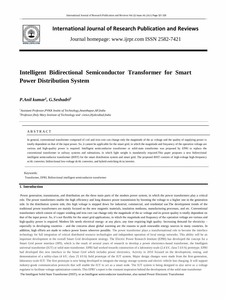
or load.The solid state transformer is a power electronic device that replaces the traditional 50Hz power transformer by means of high frequency
transformer isolated AC-AC conversion technique, which is represented in Fig .1.
Fig.1 Solid state transformer configuration
The basic operation of the SST is firstly to change the 50 Hz AC voltage to a high frequency one (normally in the range of several kHz to tens of kH z),
then this high frequency voltage is stepped up/down by a high frequency transformer with dramatically decreased volume and weight, and finally shaped
back into the desired 50 Hz one to feed the load. In this sense, the first advantage that SST may offer is the reduced volume and weight compared with
traditional transformers. To reduce the input voltage to a lower one. This was followed in 1995 by a similar EPRI sponsored effort. Both of these efforts
yielded working prototypes, but they operated at power and primary voltage levels that were orders of magnitude below utility distribution levels. The
ac/ac buck converter is perhaps the most direct approach to single phase ac power conversion. In this arrangement, switches and are bidirectional. Turning
a switch on permits it to conduct current in either direction. Conversely, turning it off can block voltage of either polarity. Two devices tied in series
indicate an arrangement of some number of semiconductors that would be needed to achieve the desired voltage ratings. (The nu mber of devices required
would be a function of voltage level and the type of semiconductor). The bidirectional switches and are alternately turned on at a high frequency relative
to the fundamental component of the voltage and current waveforms. Under these conditions, it can be shown that where is the duty cycle (the time the
upper switch is on relative to the switching period) and “~” designates the phasor representation of the fundamental component. Although this is the most
straightforward approach to ac–ac power conversion, it is problematic in several respects. First, each switch must be able to block full primary voltage and
also be capable of conducting full secondary current.
2.1 Necessity of Solid State Intelligent Transformer
With the advancement of power electronics circuits and devices, the all solid-state transformer becomes a viable option to replace the conventional
copper-and-iron based transformer for a better power quality. The solid-state switching technologies allow power conversion between different formats
such as dc/dc, dc/ac, ac/dc, and ac/ac with any desired frequencies. The term “solid-state transformer” has been defined long back and the main purpose of
solid-state power conversion is to convert ac to ac for step-up or step-down with a function same as that of a conventional transformer but with much
3
2
3
International Journal of Research Publication and Reviews Vol (2) Issue (4) (2021) Page 321-330
reduced size and weight. The key elements of the solid-state transformer are an ac/dc converter and a dc/ac inverter. In recent literature the solid-state
transformers were proposed to replace the conventional transformer in the distribution voltage level. Some of them are still relying on low-frequency
transformers, but adding electronics to enhance power quality.
A conventional transformer lacks of energy storage capability, and thus the output load can be easily interrupted due to disturbance at the input source.
Similarly, when the output load current generates disturbances such as load transients, harmonics and reactive power, the conventional transformer also
reflects them back to the input side. To overcome these problems, the modern power electronics technology can be used to serve as the energy buffer in
between the source and load to avoid direct impact from either side. In addition, with the flexibility of power electronics switching, it is also possible to
provide universal voltage output such as dc voltage or variable frequency ac voltage output to the load
2.2 Various Solid State Transformer Configurations
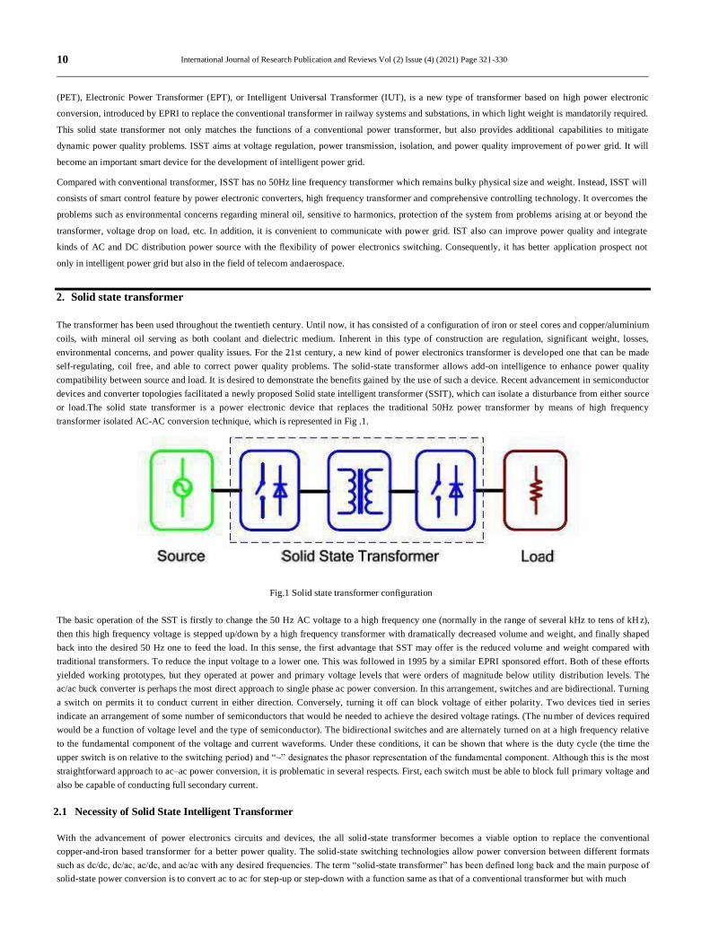
Fig.2: Various configurations of solid state transformer
The selection of the appropriate topology for the SST implementation is a key aspect. In order to select these potential topologies for comparison, a
number of topologies proposed for SST as well as for general AC-AC power conversion have been surveyed. An approach to classify the SST topologies
and select the appropriate configuration according to the specific needs was presented here. In this classification, as seen in Figure.2, four SST
configurations that cover all the possible SST topologies are identified: a) single-stage with no DC link, b) two-stage with low voltage DC (LVDC) link,
c) two stage with high voltage DC (HVDC) link, and d) three-stage with both HVDC and LVDC links. The DC link of the third configuration is not
appropriate for DES and DER integration since it is high voltage and has no isolation from the grid; therefore, topologies under that classification are not
practical for SST implementation.
2.3 Basic Solid State Transformer topology
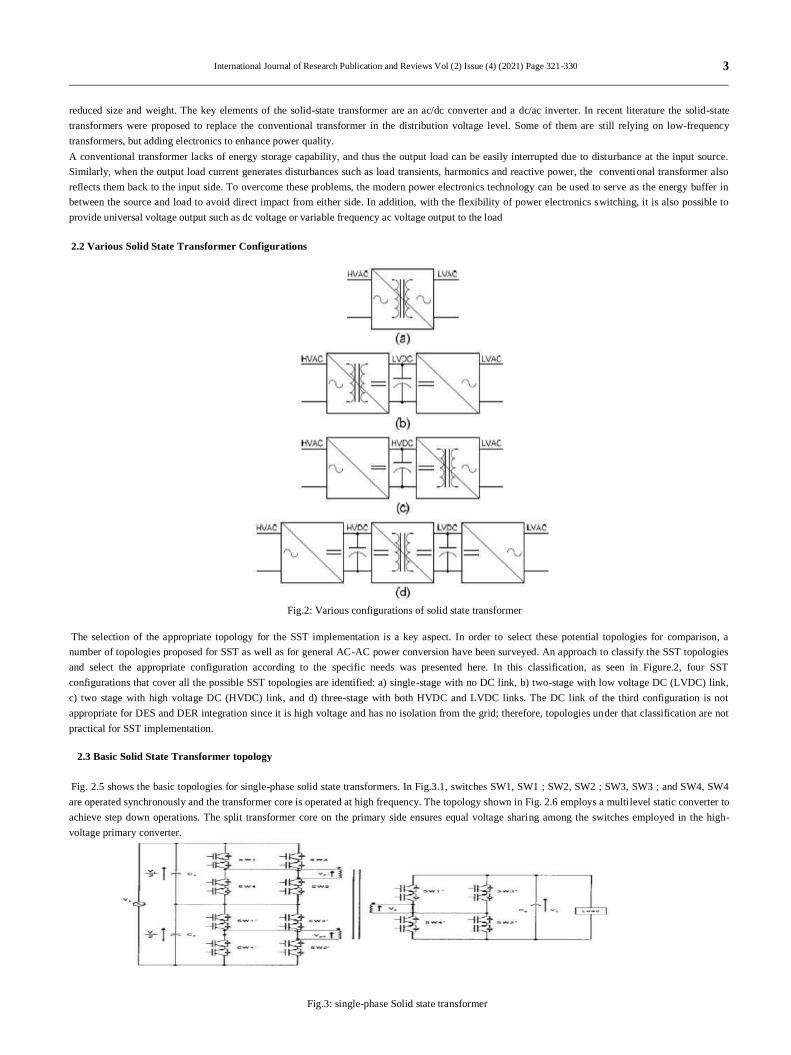
Fig. 2.5 shows the basic topologies for single-phase solid state transformers. In Fig.3.1, switches SW1, SW1 ; SW2, SW2 ; SW3, SW3 ; and SW4, SW4
are operated synchronously and the transformer core is operated at high frequency. The topology shown in Fig. 2.6 employs a multilevel static converter to
achieve step down operations. The split transformer core on the primary side ensures equal voltage sharing among the switches employed in the high-
voltage primary converter.
Fig.3: single-phase Solid state transformer
3
2
4
International Journal of Research Publication and Reviews Vol (2) Issue (4) (2021) Page 321-330
3. AC TO DC CONVERTER TOPOLOGY
One of the first and most widely used application of power electronic devices have been in rectification. Rectification refers to the process of converting
an ac voltage or current source to dc voltage and current. Rectifiers specially refer to power electronic converters where the electrical power flows from
the ac side to the dc side. In many situations the same converter circuit may carry electrical power from the dc side to the ac side where upon they are
referred to as inverters.
The three phase fully controlled bridge converter has been probably the most widely used power electronic converter in the medium to high power
applications. Three phase circuits are preferable when large power is involved. The controlled rectifier can provide controllable output dc voltage in a
single unit instead of a three phase autotransformer and a diode bridge rectifier. The controlled rectifier is obtained by replacing the diodes of the
uncontrolled rectifier with thyristors. Control over the output dc voltage is obtained by controlling the conduction interval of each thyristor. This method is
known as phase angle control and converters are also called “phase controlled converters”. Since thyristors can block voltage in both directions it is
possible to reverse the polarity of the output dc voltage and hence feed power back to the ac supply from the dc side. Under such condition the converter is
said to be operating in the “inverting mode”. The thyristors in the converter circuit are commutated with the help of the supply voltage in the rectifying
mode of operation and are known as “Line commutated converter”. The same circuit while operating in the inverter mode requires load side counter emf.
for commutation and are referred to as the “Load commutated inverter”. In phase controlled rectifiers though the output voltage can be varied
continuously the load harmonic voltage increases considerably as the average value goes down. Of course the magnitude of harmonic voltage is lower in
three phase converter compared to the single phase circuit. Since the frequency of the harmonic voltage is higher smaller load inductance leads to
continuous conduction. Input current wave shape become rectangular and contain 5th and higher order odd harmonics. The displacement angle of the
input current increases with firing angle. The frequency of the harmonic voltage and current can be increased by increasing the pulse number of the
converter which can be achieved by series and parallel connection of basic 6 pulse converters. The control circuit become considerably complicated and
the use of coupling transformer and / or interphase reactors become mandatory.
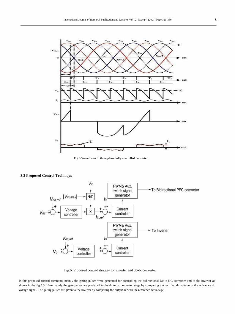
3.1. Three Phase Fully Controlled Converter
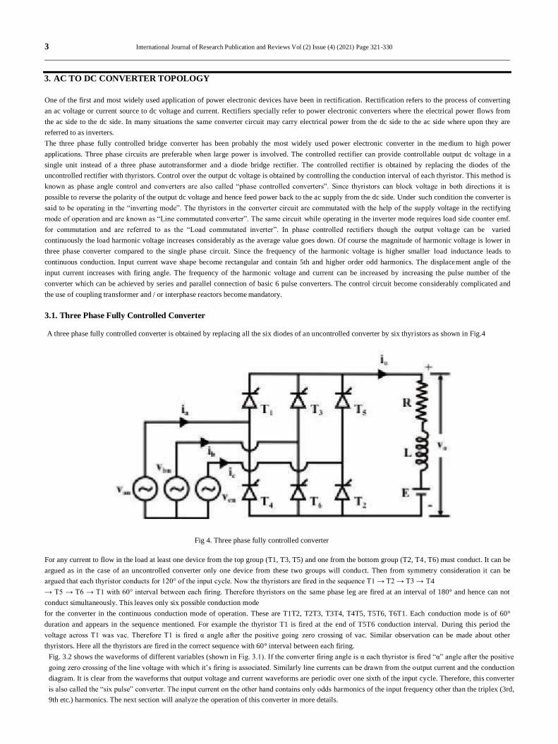
A three phase fully controlled converter is obtained by replacing all the six diodes of an uncontrolled converter by six thyristors as shown in Fig.4
Fig 4. Three phase fully controlled converter
For any current to flow in the load at least one device from the top group (T1, T3, T5) and one from the bottom group (T2, T4, T6) must conduct. It can be
argued as in the case of an uncontrolled converter only one device from these two groups will conduct. Then from symmetry consideration it can be
argued that each thyristor conducts for 120° of the input cycle. Now the thyristors are fired in the sequence T1 → T2 → T3 → T4
→ T5 → T6 → T1 with 60° interval between each firing. Therefore thyristors on the same phase leg are fired at an interval of 180° and hence can not
conduct simultaneously. This leaves only six possible conduction mode
for the converter in the continuous conduction mode of operation. These are T1T2, T2T3, T3T4, T4T5, T5T6, T6T1. Each conduction mode is of 60°
duration and appears in the sequence mentioned. For example the thyristor T1 is fired at the end of T5T6 conduction interval. During this period the
voltage across T1 was vac. Therefore T1 is fired α angle after the positive going zero crossing of vac. Similar observation can be made about other
thyristors. Here all the thyristors are fired in the correct sequence with 60° interval between each firing.
Fig. 3.2 shows the waveforms of different variables (shown in Fig. 3.1). If the converter firing angle is α each thyristor is fired “α” angle after the positive
going zero crossing of the line voltage with which it’s firing is associated. Similarly line currents can be drawn from the output current and the conduction
diagram. It is clear from the waveforms that output voltage and current waveforms are periodic over one sixth of the input cycle. Therefore, this converter
is also called the “six pulse” converter. The input current on the other hand contains only odds harmonics of the input frequency other than the triplex (3rd,
9th etc.) harmonics. The next section will analyze the operation of this converter in more details.
3
2
5
International Journal of Research Publication and Reviews Vol (2) Issue (4) (2021) Page 321-330
Fig 5 Waveforms of three phase fully controlled converter
3.2 Proposed Control Technique
Fig.6: Proposed control strategy for inverter and dc-dc converter
In this proposed control technique mainly the gating pulses were generated for controlling the bidirectional Dc to DC converter and to the inverter as
shown in the fig:5.3. Here mainly the gate pulses are produced to the dc to dc converter stage by comparing the rectified dc voltage to the reference dc
voltage signal. The gating pulses are given to the inverter by comparing the output ac with the reference ac voltage.
3
2
6
International Journal of Research Publication and Reviews Vol (2) Issue (4) (2021) Page 321-330
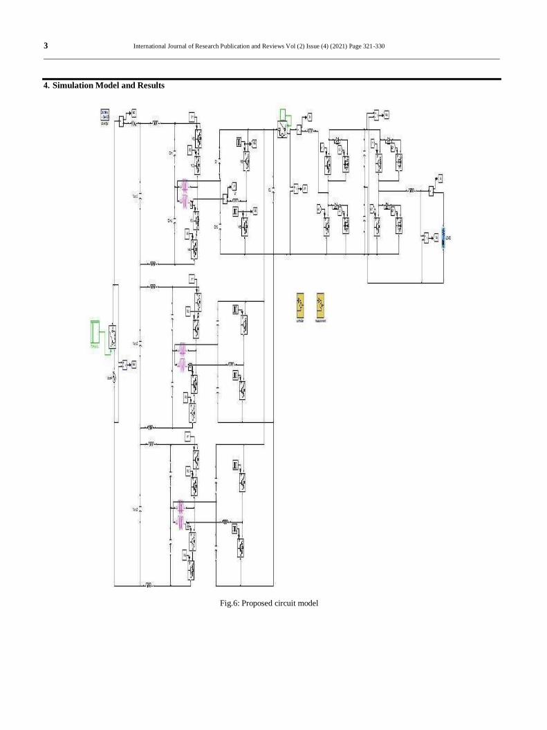
4. Simulation Model and Results
Fig.6: Proposed circuit model
3
2
7
International Journal of Research Publication and Reviews Vol (2) Issue (4) (2021) Page 321-330
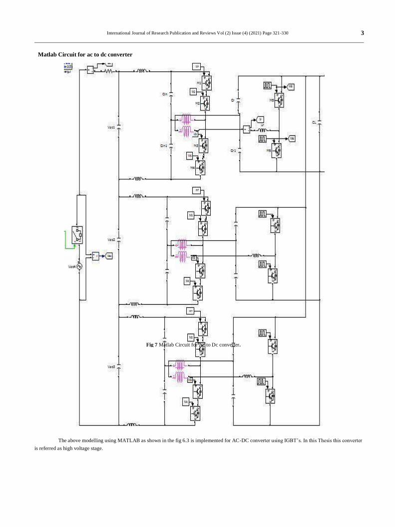
Fig 7 Matlab Circuit for Ac to Dc converter.
Matlab Circuit for ac to dc converter
The above modelling using MATLAB as shown in the fig 6.3 is implemented for AC-DC converter using IGBT’s. In this Thesis this converter
is referred as high voltage stage.
3
2
8
International Journal of Research Publication and Reviews Vol (2) Issue (4) (2021) Page 321-330
DC LINK VOLTAGE
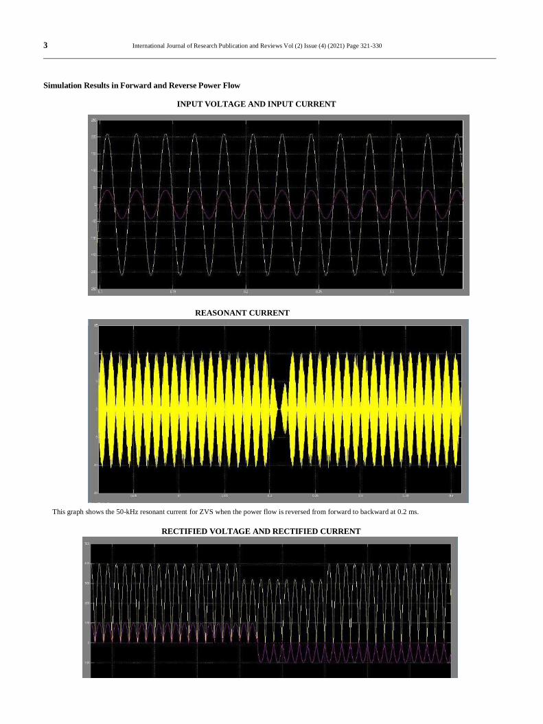
Simulation Results in Forward and Reverse Power Flow
INPUT VOLTAGE AND INPUT CURRENT
REASONANT CURRENT
This graph shows the 50-kHz resonant current for ZVS when the power flow is reversed from forward to backward at 0.2 ms.
RECTIFIED VOLTAGE AND RECTIFIED CURRENT
3
2
9
International Journal of Research Publication and Reviews Vol (2) Issue (4) (2021) Page 321-330
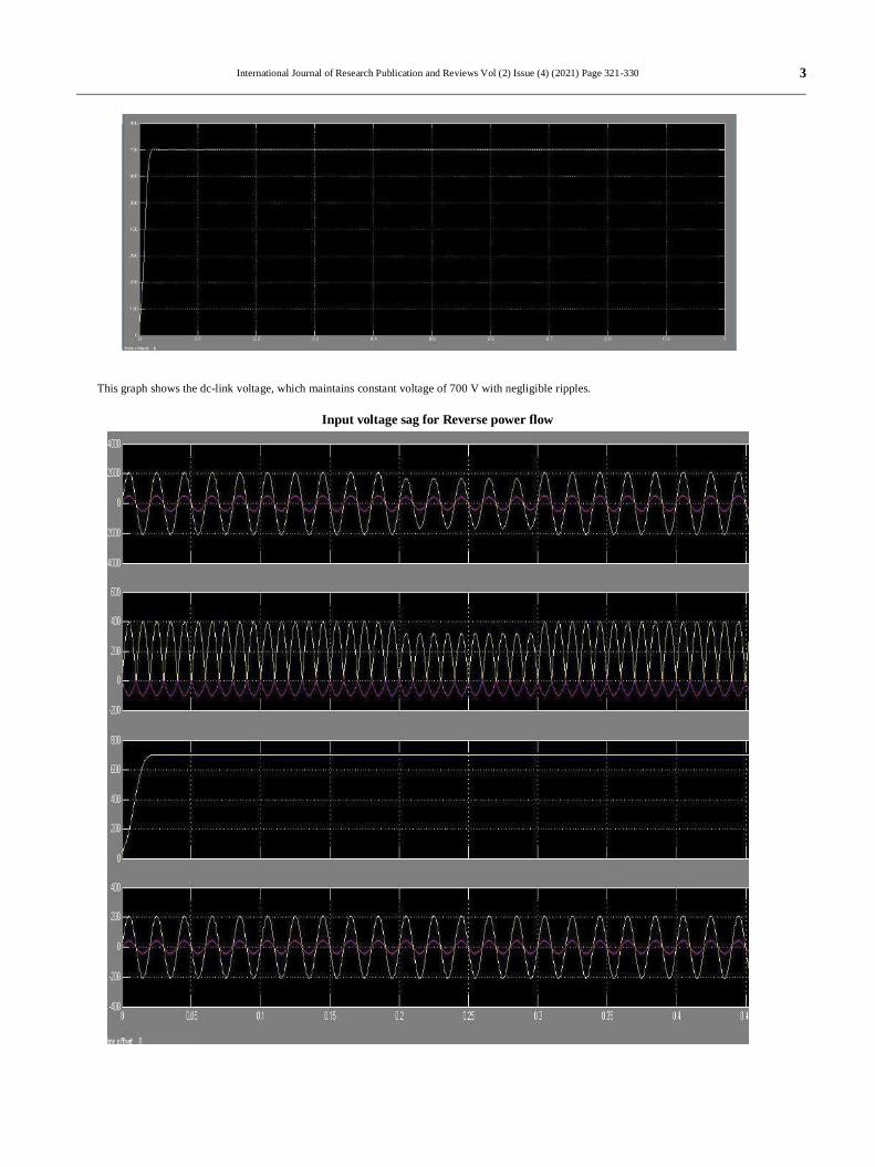
This graph shows the dc-link voltage, which maintains constant voltage of 700 V with negligible ripples.
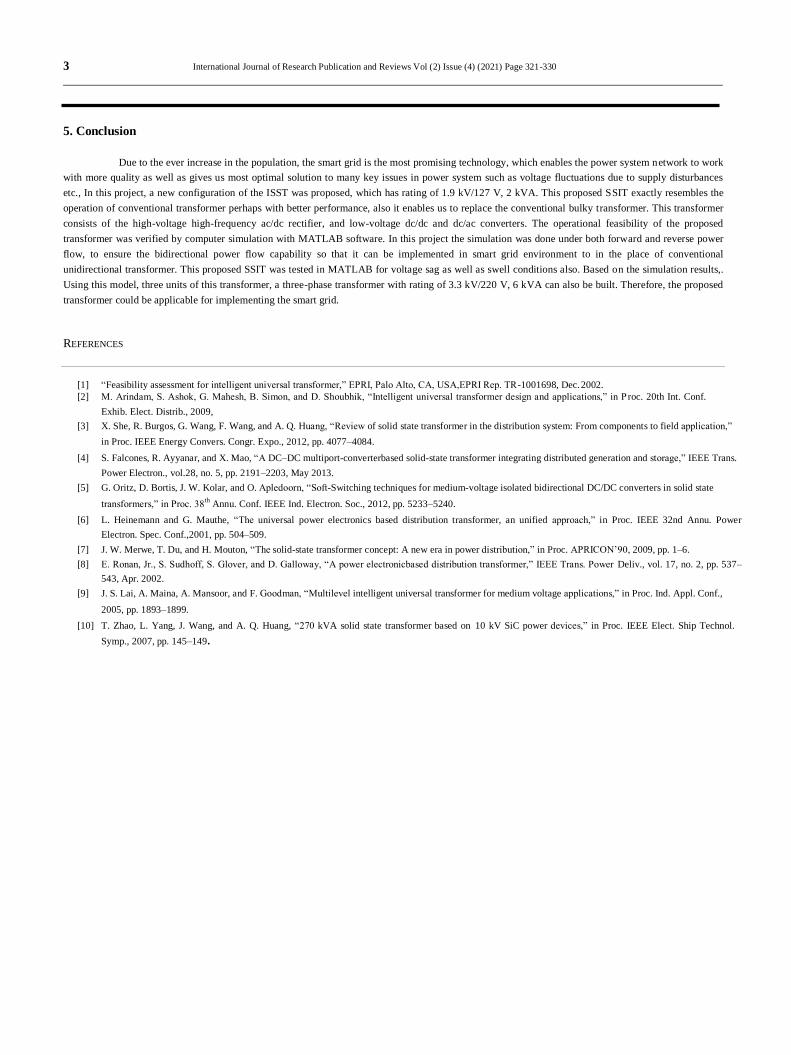
Input voltage sag for Reverse power flow
3
3
0
International Journal of Research Publication and Reviews Vol (2) Issue (4) (2021) Page 321-330
5. Conclusion
Due to the ever increase in the population, the smart grid is the most promising technology, which enables the power system network to work
with more quality as well as gives us most optimal solution to many key issues in power system such as voltage fluctuations due to supply disturbances
etc., In this project, a new configuration of the ISST was proposed, which has rating of 1.9 kV/127 V, 2 kVA. This proposed SSIT exactly resembles the
operation of conventional transformer perhaps with better performance, also it enables us to replace the conventional bulky transformer. This transformer
consists of the high-voltage high-frequency ac/dc rectifier, and low-voltage dc/dc and dc/ac converters. The operational feasibility of the proposed
transformer was verified by computer simulation with MATLAB software. In this project the simulation was done under both forward and reverse power
flow, to ensure the bidirectional power flow capability so that it can be implemented in smart grid environment to in the place of conventional
unidirectional transformer. This proposed SSIT was tested in MATLAB for voltage sag as well as swell conditions also. Based on the simulation results,.
Using this model, three units of this transformer, a three-phase transformer with rating of 3.3 kV/220 V, 6 kVA can also be built. Therefore, the proposed
transformer could be applicable for implementing the smart grid.
REFERENCES
[1] “Feasibility assessment for intelligent universal transformer,” EPRI, Palo Alto, CA, USA,EPRI Rep. TR-1001698, Dec. 2002.
[2] M. Arindam, S. Ashok, G. Mahesh, B. Simon, and D. Shoubhik, “Intelligent universal transformer design and applications,” in P roc. 20th Int. Conf.
Exhib. Elect. Distrib., 2009,
[3] X. She, R. Burgos, G. Wang, F. Wang, and A. Q. Huang, “Review of solid state transformer in the distribution system: From components to field application,”
in Proc. IEEE Energy Convers. Congr. Expo., 2012, pp. 4077–4084.
[4] S. Falcones, R. Ayyanar, and X. Mao, “A DC–DC multiport-converterbased solid-state transformer integrating distributed generation and storage,” IEEE Trans.
Power Electron., vol.28, no. 5, pp. 2191–2203, May 2013.
[5] G. Oritz, D. Bortis, J. W. Kolar, and O. Apledoorn, “Soft-Switching techniques for medium-voltage isolated bidirectional DC/DC converters in solid state
transformers,” in Proc. 38th
Annu. Conf. IEEE Ind. Electron. Soc., 2012, pp. 5233–5240.
[6] L. Heinemann and G. Mauthe, “The universal power electronics based distribution transformer, an unified approach,” in Proc. IEEE 32nd Annu. Power
Electron. Spec. Conf.,2001, pp. 504–509.
[7] J. W. Merwe, T. Du, and H. Mouton, “The solid-state transformer concept: A new era in power distribution,” in Proc. APRICON’90, 2009, pp. 1–6.
[8] E. Ronan, Jr., S. Sudhoff, S. Glover, and D. Galloway, “A power electronicbased distribution transformer,” IEEE Trans. Power Deliv., vol. 17, no. 2, pp. 537–
543, Apr. 2002.
[9] J. S. Lai, A. Maina, A. Mansoor, and F. Goodman, “Multilevel intelligent universal transformer for medium voltage applications,” in Proc. Ind. Appl. Conf.,
2005, pp. 1893–1899.
[10] T. Zhao, L. Yang, J. Wang, and A. Q. Huang, “270 kVA solid state transformer based on 10 kV SiC power devices,” in Proc. IEEE Elect. Ship Technol.
Symp., 2007, pp. 145–149.


