Embed Size (px)
Citation preview

Intelligent Power Supply Design Solutions
Intelligent Power
www.microchip.com/power

www.microchip.com/power2
Today, power supply designers must create power conversion products that off er greater effi ciency, higher power density, higher reliability, advanced communications and sophisticated control features. And, as always, these products need to be developed and marketed quickly and at lower costs. Microchip off ers a comprehensive set of Intelligent Power Supply solutions enabling you to meet these challenges.
What is an Intelligent Power Supply?Traditional power supply designs use analog ICs with fi xedfunctionality to provide regulated power. The intelligent power supply integrates a microcontroller (MCU) or Digital Signal Controller (DSC) for a fully programmable and fl exible solution. Below are some examples of intelligent power supply functions:• Digital on/off control for low standby power• Power supply sequencing and hot-swap control• Programmable soft-start profi le• Power supply history logging and fault management• Output voltage margining• Current fold back control• Load sharing and balancing• Regulation reference adjustment• Compensation network control and adjustment• Full digital control of power control loop• Communications• AC RMS voltage measurement• Power factor correctionExample intelligent power supply applications include the following:• AC-to-DC converters• DC-to-DC converters• DC-to-AC inverters• Wireless power transmitters/receivers• Uninterruptible Power Supply (UPS)• Renewable power/pure sine wave inverters• Battery chargers• HID, LED and fl uorescent light ballasts
Why Intelligent Power Conversion?The use of digital control to implement power conversionfunctions off ers many benefi ts to your designs and
applications. These functions are enabled by performing power conversion control via reprogrammable software in conjunction with the performance and features off ered by Microchip’s Digitally Enhanced Power Analog technology plus our PIC® MCU and dsPIC® DSC solutions.
Intelligent Power Conversion Lowers theSystem Component CountValuable board space can be made available for magneticsand power components. Power supply control, regulationand protection functions can be incorporated into the same device. Auxiliary functions, such as fan control and data logging, are easily integrated.
Intelligent Power Conversion Allows Confi guration for Diff erent ApplicationsWith intelligent power conversion, the power supply becomes a platform solution for many diff erent applications. The power supply can easily be reprogrammed to support diff erent output voltage levels, operating limits and control inputs. This reduces inventory overhead and the support required for multiple platforms.
Intelligent Power Conversion Increases System Effi ciencyA power supply without intelligence is typically optimized for one operating point. A change in the operating load usually means a drop in system effi ciency. An intelligent power supply design can adapt to load changes using many methods. These include a change of the power supply switching frequency and changes in the control loop confi guration. Intelligent power supplies can monitor internal temperatures and supply power to cooling fans only when needed. They can also dynamically change the control loop behavior to provide the optimal system response for the load conditions.
Intelligent Power Conversion Lowers Standby Power ConsumptionIntelligence can be added to a power supply design thatconsumes only milliwatts or microwatts from the AC inputwhen in standby. Electronic control inputs can be monitoredwhile the bias supplies for the application are turned off .
How Can Microchip Help?In addition to its local and global non-commissioned salesforce, Microchip provides these products and resources forpower conversion applications:• 8-, 16- and 32-bit microcontrollers and 16-bit digital
signal controllers• High-side, low-side and synchronous MOSFET gate drivers• Temperature sensors, fan controllers, digital potentiometers
and op amps• Analog PWM controllers including external control inputs• High-voltage linear regulators and high-voltage
interface products• Serial EEPROM memory products• Power conversion development tools, reference designs,
algorithms and software• Power conversion training and technical support
Intelligent Power Supply Solutions
Description Technical Functions Recommended Devices Applications
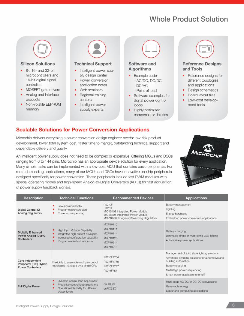
Digital Control Of Analog Regulators
• Low-power standby• Programmable soft start• Power up sequencing
PIC10FPIC12FMIC45408 Integrated Power ModuleMIC28304 Integrated Power ModuleMCP16XXX Integrated Switching Regulators
Battery managementLightingEnergy harvesting Embedded power conversion applications
Digitally Enhanced Power Analog (DEPA) Controllers
• High Input Voltage Capability• Integrated high current drive pins• Increased confi guration capability• Programmable fault response
MCP19110 MCP19111 MCP19114 MCP19125 MCP19214 MCP19215
Battery chargingDimmable single or multi-string LED lighting Automotive power applications
Core Independent Peripheral (CIP) Hybrid Power Controllers
Flexibility to assemble multiple control topologies managed by a single CPU
PIC16F1764 PIC16F1769 PIC16F1777 PIC16F753
Management of solid state lighting solutionsAdvanced dimming solutions for automotive and building automationBattery chargingMultistage power sequencingSmart power applications for IoT
Full Digital Power
• Dynamic control loop adjustment• Predictive control loop algorithms• Operational fl exibility for diff erent
power levels
dsPIC33EdsPIC33C
Multi-stage AC-DC or DC-DC conversionsRenewable energyServer and computing applications
Intelligent Power Supply Design Solutions 3
Scalable Solutions for Power Conversion ApplicationsMicrochip delivers everything a power conversion design engineer needs: low-risk product development, lower total system cost, faster time to market, outstanding technical support and dependable delivery and quality.
An intelligent power supply does not need to be complex or expensive. Off ering MCUs and DSCs ranging from 6 to 144 pins, Microchip has an appropriate device solution for every application. Many simple tasks can be implemented with a low-cost MCU that contains basic peripherals. For more demanding applications, many of our MCUs and DSCs have innovative on-chip peripherals designed specifi cally for power conversion. These peripherals include fast PWM modules with special operating modes and high-speed Analog-to-Digital Converters (ADCs) for fast acquisition of power supply feedback signals.
Whole Product Solution
Silicon Solutions• 8-, 16- and 32-bit
microcontrollers and 16-bit digital signal controllers
• MOSFET gate drivers• Analog and interface
products• Non-volatile EEPROM
memory
Technical Support• Intelligent power sup-
ply design center• Power conversion
application notes• Web seminars• Regional training
centers• Intelligent power
supply experts
Software and Algorithms• Example code
• AC/DC, DC/DC, DC/AC
• Point of load• Software examples for
digital power control loops
• Highly optimized compensator libraries
Reference Designs and Tools• Reference designs for
diff erent topologies and applications
• Design schematics• Board layout fi les• Low-cost develop-
ment tools
www.microchip.com/power4
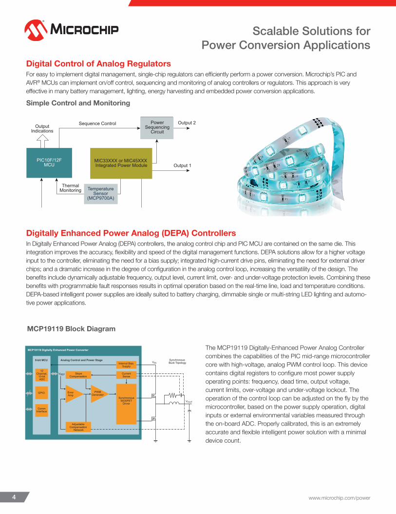
Digital Control of Analog RegulatorsFor easy to implement digital management, single-chip regulators can efficiently perform a power conversion. Microchip’s PIC and AVR® MCUs can implement on/off control, sequencing and monitoring of analog controllers or regulators. This approach is very effective in many battery management, lighting, energy harvesting and embedded power conversion applications.
Digitally Enhanced Power Analog (DEPA) ControllersIn Digitally Enhanced Power Analog (DEPA) controllers, the analog control chip and PIC MCU are contained on the same die. This integration improves the accuracy, flexibility and speed of the digital management functions. DEPA solutions allow for a higher voltage input to the controller, eliminating the need for a bias supply; integrated high-current drive pins, eliminating the need for external driver chips; and a dramatic increase in the degree of configuration in the analog control loop, increasing the versatility of the design. The benefits include dynamically adjustable frequency, output level, current limit, over- and under-voltage protection levels. Combining these benefits with programmable fault responses results in optimal operation based on the real-time line, load and temperature conditions. DEPA-based intelligent power supplies are ideally suited to battery charging, dimmable single or multi-string LED lighting and automo-tive power applications.
The MCP19119 Digitally-Enhanced Power Analog Controller combines the capabilities of the PIC mid-range microcontroller core with high-voltage, analog PWM control loop. This device contains digital registers to configure most power supply operating points: frequency, dead time, output voltage, current limits, over-voltage and under-voltage lockout. The operation of the control loop can be adjusted on the fly by the microcontroller, based on the power supply operation, digital inputs or external environmental variables measured through the on-board ADC. Properly calibrated, this is an extremely accurate and flexible intelligent power solution with a minimal device count.
MCP19119 Block Diagram
Scalable Solutions for Power Conversion Applications
VOUT
MCP19119 Digitally Enhanced Power Converter
Adjustable Compensation
Network
SynchronousMOSFET
Driver
SlopeCompensation
Internal Bias Supply
CurrentSense
ErrorAmp
PWMGenerator
VREF
Analog Control and Power Stage8-bit MCU
12 Channel,
10-bit ADC
Synchronous Buck Topology
GPIO
CommInterface
VIN
Simple Control and Monitoring
Output 2Output
Indications
ThermalMonitoring
Output 1
O/P Feedback
Sequence Control PowerSequencing
Circuit
MIC33XXX or MIC45XXX Integrated Power Module
PIC10F/12FMCU
TemperatureSensor
(MCP9700A)
Intelligent Power Supply Design Solutions 5
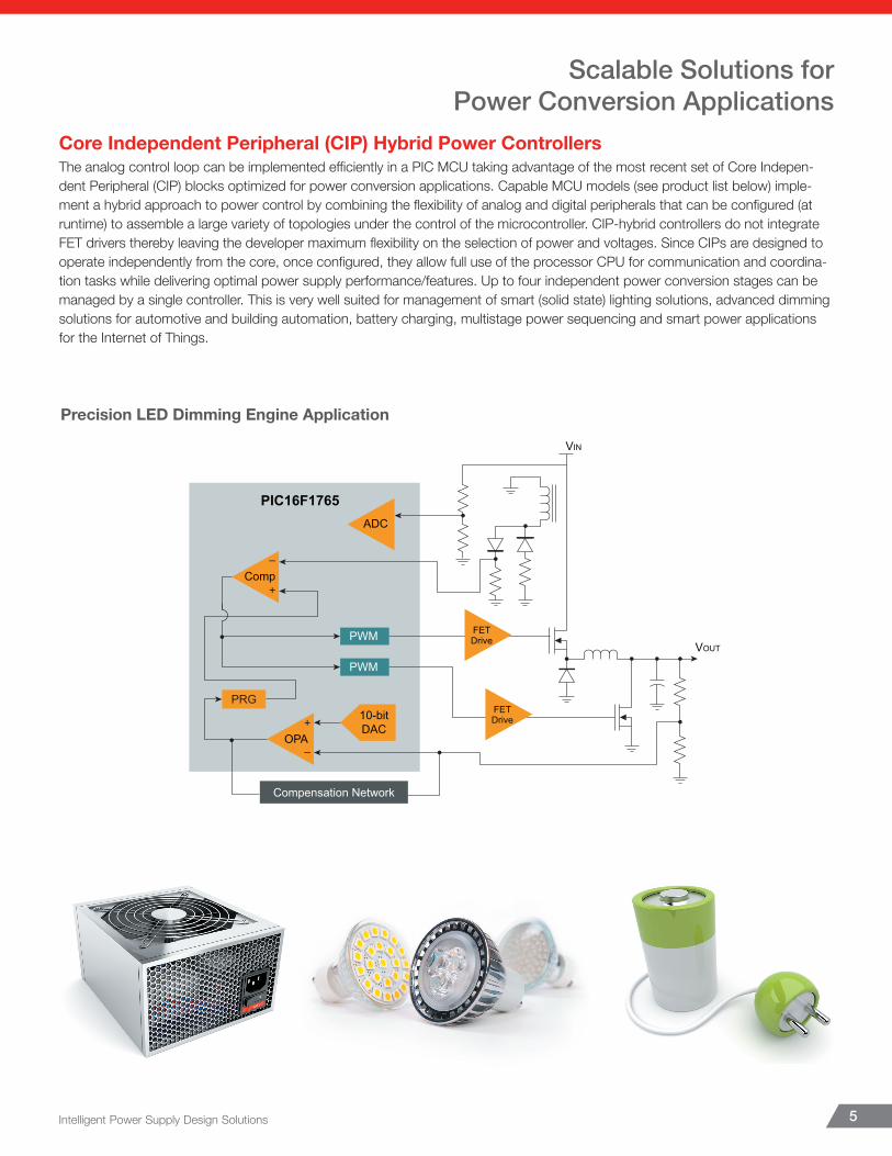
Core Independent Peripheral (CIP) Hybrid Power ControllersThe analog control loop can be implemented effi ciently in a PIC MCU taking advantage of the most recent set of Core Indepen-dent Peripheral (CIP) blocks optimized for power conversion applications. Capable MCU models (see product list below) imple-ment a hybrid approach to power control by combining the fl exibility of analog and digital peripherals that can be confi gured (at runtime) to assemble a large variety of topologies under the control of the microcontroller. CIP-hybrid controllers do not integrate FET drivers thereby leaving the developer maximum fl exibility on the selection of power and voltages. Since CIPs are designed to operate independently from the core, once confi gured, they allow full use of the processor CPU for communication and coordina-tion tasks while delivering optimal power supply performance/features. Up to four independent power conversion stages can be managed by a single controller. This is very well suited for management of smart (solid state) lighting solutions, advanced dimming solutions for automotive and building automation, battery charging, multistage power sequencing and smart power applications for the Internet of Things.
Precision LED Dimming Engine Application
Scalable Solutions for Power Conversion Applications
PIC16F1765
–
+Comp
PRG
–
+ 10-bitDAC
ADC
PWM
PWM
VIN
VOUT
Compensation Network
OPA
FETDrive
FETDrive
www.microchip.com/power6
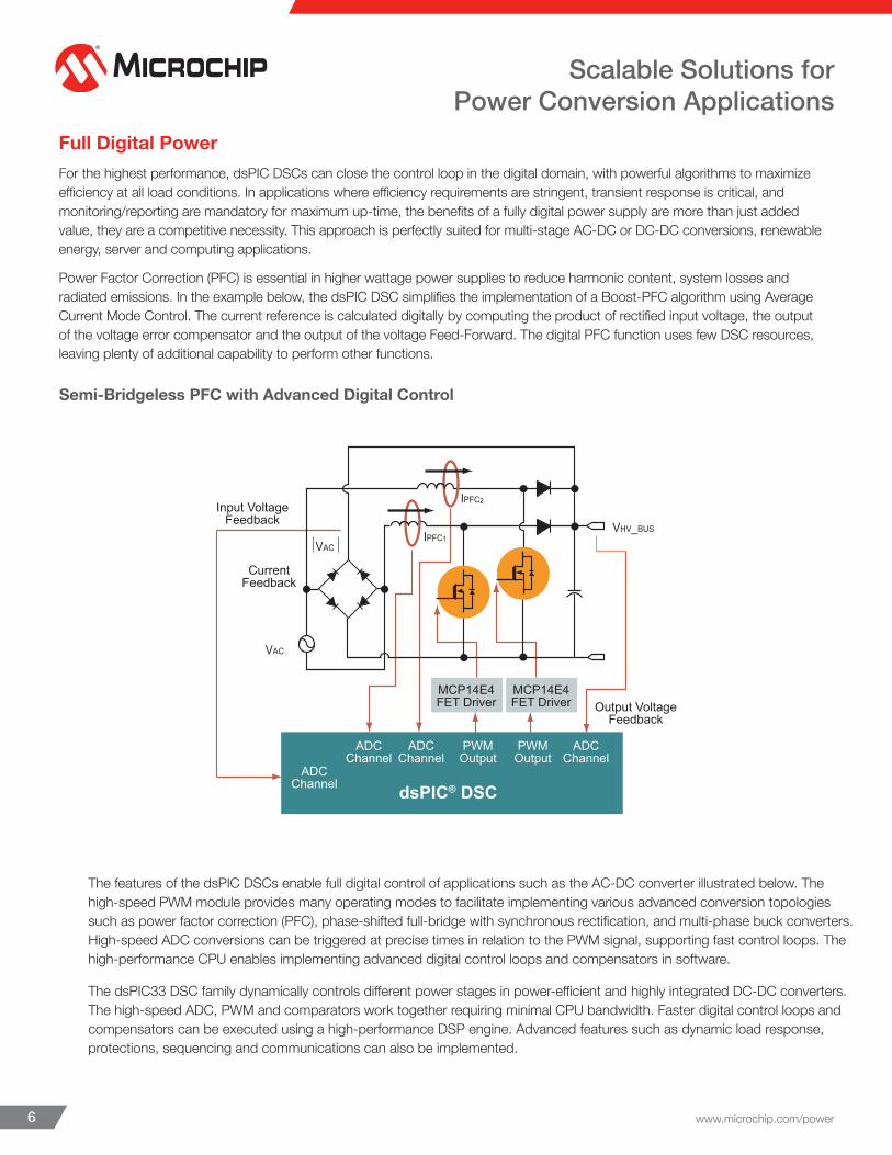
Full Digital PowerFor the highest performance, dsPIC DSCs can close the control loop in the digital domain, with powerful algorithms to maximize efficiency at all load conditions. In applications where efficiency requirements are stringent, transient response is critical, and monitoring/reporting are mandatory for maximum up-time, the benefits of a fully digital power supply are more than just added value, they are a competitive necessity. This approach is perfectly suited for multi-stage AC-DC or DC-DC conversions, renewable energy, server and computing applications.
Power Factor Correction (PFC) is essential in higher wattage power supplies to reduce harmonic content, system losses and radiated emissions. In the example below, the dsPIC DSC simplifies the implementation of a Boost-PFC algorithm using Average Current Mode Control. The current reference is calculated digitally by computing the product of rectified input voltage, the output of the voltage error compensator and the output of the voltage Feed-Forward. The digital PFC function uses few DSC resources, leaving plenty of additional capability to perform other functions.
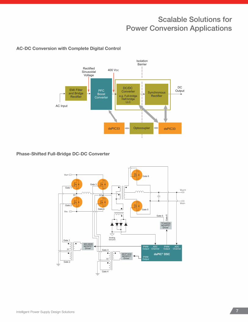
The features of the dsPIC DSCs enable full digital control of applications such as the AC-DC converter illustrated below. The high-speed PWM module provides many operating modes to facilitate implementing various advanced conversion topologies such as power factor correction (PFC), phase-shifted full-bridge with synchronous rectification, and multi-phase buck converters. High-speed ADC conversions can be triggered at precise times in relation to the PWM signal, supporting fast control loops. The high-performance CPU enables implementing advanced digital control loops and compensators in software.
The dsPIC33 DSC family dynamically controls different power stages in power-efficient and highly integrated DC-DC converters. The high-speed ADC, PWM and comparators work together requiring minimal CPU bandwidth. Faster digital control loops and compensators can be executed using a high-performance DSP engine. Advanced features such as dynamic load response, protections, sequencing and communications can also be implemented.
Scalable Solutions for Power Conversion Applications
Semi-Bridgeless PFC with Advanced Digital Control
dsPIC® DSC
MCP14E4FET Driver
MCP14E4FET Driver
ADCChannel
ADCChannel
ADCChannel
ADCChannel
PWMOutput
PWMOutput
VAC
VAC
VHV_BUSIPFC1
Input VoltageFeedback
CurrentFeedback
Output VoltageFeedback
IPFC2
Intelligent Power Supply Design Solutions 7
Scalable Solutions for Power Conversion Applications
AC-DC Conversion with Complete Digital Control
AC Input
RectifiedSinusoidal
Voltage
400 VDC
IsolationBarrier
SynchronousRectifier
DCOutput
DC/DC Converter
e.g. Full-bridgeHalf-bridge
LLC
Optocoupler dsPIC33dsPIC33
EMI Filterand Bridge
Rectifier
PFCBoost
Converter
Gate 2
Gate 1
S1
Gate 4
Gate 3
S1
AnalogGround
Gate 5
Gate 5
Gat
e 6
Gate 6
Gate 3
Gate 4
Gate 2
Gate 1
VIN+
VIN-
VOUT+
VOUT-
S1 S3
dsPIC® DSC
PWMOutput
ADCChannel
PWMOutput
ADCChannel
PWMOutput
TC4422AMOSFET
Driver
MCP1404MOSFET
Driver
MIC4608MOSFET
Driver
Phase-Shifted Full-Bridge DC-DC Converter

Select 8-bit PIC10F, PIC12F and PIC16F Microcontrollers
Product
Pins
Flas
h M
emor
y (B
)
Self
Rea
d/W
rite
RAM
(B)
EE B
ytes
Tim
er 8
-/16
-bit
PRG
/SC
Op
Amp
ZCD
Com
para
tor
PWM
ADC
DAC
DSM
EUSA
RT
SPI/I
2 CPIC16F18313 10 3.5 K ü 256 256 3/1 – – – 1 1 × Half
Bridge 5 × 10-bit 1 × 5-bit 1 1 1
PIC16F(HV)753 14 3.5 K ü 128 HEF* 3/1 0/1 – – 2 1 × Half Bridge 8 × 10-bit 1 × 9-bit – – –
PIC16F1765 14 14 K ü 1 K HEF* 4/3 1/0 1 12 × High
Speed1 × Full Bridge 8 × 10-bit 1 × 5-bit
1 × 9-bit 1 1 1
PIC16F1769 20 14 K ü 1 K HEF* 4/3 1/0 2 14 × High
Speed2 × Full Bridge
12 × 10-bit
2 × 5-bit2 × 9-bit 2 1 1
PIC16F1778 28 28 K ü 2 K HEF* 4/3 1/0 3 16 × High
Speed3 × Full Bridge
17 × 10-bit
3 × 5-bit3 × 9-bit 3 1 1
PIC16F1779 40 28 K ü 2 K HEF* 4/3 1/0 4 18 × High
Speed4 × Full Bridge
28 × 10-bit
4 × 5-bit4 × 9-bit 4 1 1
*High-Endurance Flash: 128B non-volatile data storage with high-endurance 100k E/W cycles
www.microchip.com/power8
Digital Control of Analog RegulatorsThe 6-pin PIC10F family of devices and the 8-pin PIC12F devices allows digital features to be integrated into any power supply design with minimal BOM impact. These devices provide signal generation, custom logic and signal condition-ing to augment analog power supply designs, providing on/off control, soft start, power sequencing or monitoring features to your application.
These devices include:• Comparator• Internal 8-bit ADC• 10-bit PWMs• Confi gurable Logic Cell (CLC)• Complementary Waveform Generator (CWG)• Numerically Controlled Oscillator (NCO)
Core Independent Peripheral (CIP) Hybrid Power Controllers The 8-bit PIC16F devices are off ered in 14-pin through 64-pin packages. These device families are suitable for proportion and confi guration or topology control. Variants have multiple PWMs with peripherals that create complementary output waveforms, which can be used to drive analog control loops. Built-in op amps, ADCs and high-speed comparators can be used to create feedback loops for Peak Current Mode Control (PCMC) and temperature monitoring. The Programmable Ramp Generator and Slope Compensation peripherals auto-mate and simplify output stabilization of Switch Mode Power Supplies. Highly integrated products feature peripheral sup-port for up to four independent Switch Mode Power Supplies, with built-in LED dimming engine functionality. Specialized timers can be employed to monitor for fault conditions. The Confi gurable Logic Cell peripheral can be used to reconfi gure feedback loops on the fl y, as needed within the application.
The Core Independent Peripherals operate autonomously and can alter system performance, with little or no core interven-tion. This allows users to put the core to sleep, reducing power consumption. Communication peripherals can be used for remote monitoring and control. Key features of these microcontroller families are:• 8-/10-/16-bit PWMs• Complementary Output Generator (COG)/Complementary
Waveform Generator (CWG)• Op amps, high-speed comparators, 10-/12-bit ADCs,
5-/8-/9-bit DACs• Slope Compensation (SC), Programmable Ramp
Generator (PRG)• Hardware Limit Timer (HLT), 24-bit Signal Measurement
Timer (SMT), Zero Cross Detect (ZCD)• Communication interfaces: EUSART, SPI, I2C
Which MCU or DSC Should You Choose?
MCP19111 PMBus Enabled Point of Load (POL)Demonstration Board (ARD00609)
This board demonstrates how the MCP19111 device operates as a PMBus-enabled POL converter over a wide input voltage and load range. The fi rmware is preloaded in the MCP19111, so no software development is needed. A USB-to-PMBus bridge is included, allowing direct communi-
cation with a PC using a PICkit In-Circuit Debugger/
Programmer. Nearly all operational and control system param-eters are programmable and readable via the PMBus. A full-featured and easy-to-use GUI can be downloaded from the Microchip website or you can program the MCP19111 using your own fi rmware, tailoring it to you application. This board contains headers for In-Circuit Serial Programming™ (ICSP™), I2C/PMBus communication and a mini USB connector.
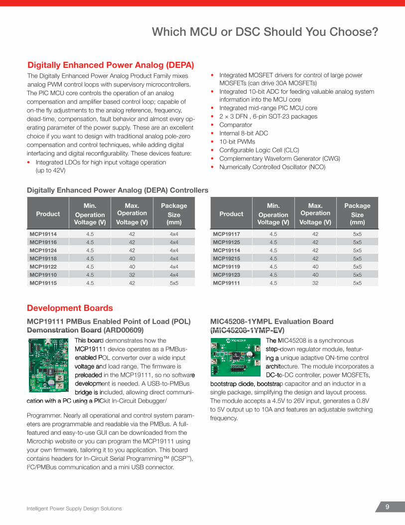
Digitally Enhanced Power Analog (DEPA) Controllers
ProductMin.
OperationVoltage (V)
Max.OperationVoltage (V)
PackageSize(mm)
MCP19114 4.5 42 4x4MCP19116 4.5 42 4x4MCP19124 4.5 42 4x4MCP19118 4.5 40 4x4MCP19122 4.5 40 4x4MCP19110 4.5 32 4x4MCP19115 4.5 42 5x5
ProductMin.
OperationVoltage (V)
Max.OperationVoltage (V)
PackageSize(mm)
MCP19117 4.5 42 5x5MCP19125 4.5 42 5x5MCP19114 4.5 42 5x5MCP19215 4.5 42 5x5MCP19119 4.5 40 5x5MCP19123 4.5 40 5x5MCP19111 4.5 32 5x5
Intelligent Power Supply Design Solutions 9
Digitally Enhanced Power Analog (DEPA)The Digitally Enhanced Power Analog Product Family mixes analog PWM control loops with supervisory microcontrollers. The PIC MCU core controls the operation of an analog compensation and amplifi er based control loop; capable of on-the fl y adjustments to the analog reference, frequency, dead-time, compensation, fault behavior and almost every op-erating parameter of the power supply. These are an excellent choice if you want to design with traditional analog pole-zero compensation and control techniques, while adding digital interfacing and digital reconfi gurability. These devices feature:• Integrated LDOs for high input voltage operation
(up to 42V)
• Integrated MOSFET drivers for control of large power MOSFETs (can drive 30A MOSFETs)
• Integrated 10-bit ADC for feeding valuable analog system information into the MCU core
• Integrated mid-range PIC MCU core• 2 × 3 DFN , 6-pin SOT-23 packages• Comparator• Internal 8-bit ADC• 10-bit PWMs• Confi gurable Logic Cell (CLC)• Complementary Waveform Generator (CWG)• Numerically Controlled Oscillator (NCO)
Which MCU or DSC Should You Choose?
Development BoardsMCP19111 PMBus Enabled Point of Load (POL)Demonstration Board (ARD00609)
This board demonstrates how the MCP19111 device operates as a PMBus-enabled POL converter over a wide input voltage and load range. The fi rmware is preloaded in the MCP19111, so no software development is needed. A USB-to-PMBus bridge is included, allowing direct communi-
cation with a PC using a PICkit In-Circuit Debugger/
Programmer. Nearly all operational and control system param-eters are programmable and readable via the PMBus. A full-featured and easy-to-use GUI can be downloaded from the Microchip website or you can program the MCP19111 using your own fi rmware, tailoring it to you application. This board contains headers for In-Circuit Serial Programming™ (ICSP™), I2C/PMBus communication and a mini USB connector.
MIC45208-1YMPL Evaluation Board (MIC45208-1YMP-EV)
The MIC45208 is a synchronous step-down regulator module, featur-ing a unique adaptive ON-time control architecture. The module incorporates a DC-to-DC controller, power MOSFETs,
bootstrap diode, bootstrap capacitor and an inductor in a single package, simplifying the design and layout process. The module accepts a 4.5V to 26V input, generates a 0.8V to 5V output up to 10A and features an adjustable switching frequency.
Demonstration Board (ARD00609)This board demonstrates how the MCP19111 device operates as a PMBus-enabled POL converter over a wide input voltage and load range. The fi rmware is preloaded in the MCP19111, so no software development is needed. A USB-to-PMBus bridge is included, allowing direct communi-
cation with a PC using a PICkit In-Circuit Debugger/
preloaded in the MCP19111, so no software
(MIC45208-1YMP-EV)The MIC45208 is a synchronous step-down regulator module, featur-ing a unique adaptive ON-time control architecture. The module incorporates a DC-to-DC controller, power MOSFETs,
bootstrap diode, bootstrap capacitor and an inductor in a
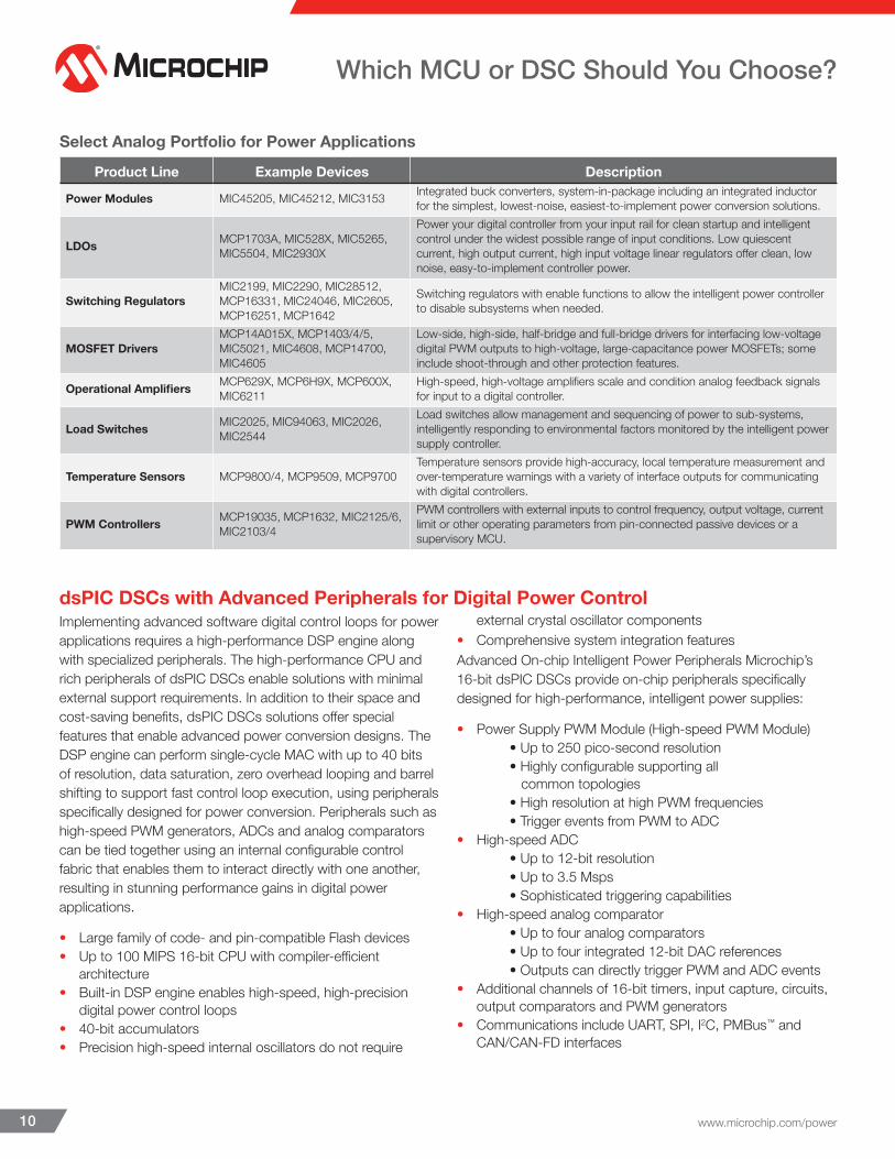
Select Analog Portfolio for Power Applications
Product Line Example Devices Description
Power Modules MIC45205, MIC45212, MIC3153 Integrated buck converters, system-in-package including an integrated inductor for the simplest, lowest-noise, easiest-to-implement power conversion solutions.
LDOs MCP1703A, MIC528X, MIC5265, MIC5504, MIC2930X
Power your digital controller from your input rail for clean startup and intelligent control under the widest possible range of input conditions. Low quiescent current, high output current, high input voltage linear regulators offer clean, low noise, easy-to-implement controller power.
Switching RegulatorsMIC2199, MIC2290, MIC28512, MCP16331, MIC24046, MIC2605, MCP16251, MCP1642
Switching regulators with enable functions to allow the intelligent power controller to disable subsystems when needed.
MOSFET DriversMCP14A015X, MCP1403/4/5, MIC5021, MIC4608, MCP14700, MIC4605
Low-side, high-side, half-bridge and full-bridge drivers for interfacing low-voltage digital PWM outputs to high-voltage, large-capacitance power MOSFETs; some include shoot-through and other protection features.
Operational Amplifiers MCP629X, MCP6H9X, MCP600X, MIC6211
High-speed, high-voltage amplifiers scale and condition analog feedback signals for input to a digital controller.
Load Switches MIC2025, MIC94063, MIC2026, MIC2544
Load switches allow management and sequencing of power to sub-systems, intelligently responding to environmental factors monitored by the intelligent power supply controller.
Temperature Sensors MCP9800/4, MCP9509, MCP9700Temperature sensors provide high-accuracy, local temperature measurement and over-temperature warnings with a variety of interface outputs for communicating with digital controllers.
PWM Controllers MCP19035, MCP1632, MIC2125/6, MIC2103/4
PWM controllers with external inputs to control frequency, output voltage, current limit or other operating parameters from pin-connected passive devices or a supervisory MCU.
www.microchip.com/power10
Which MCU or DSC Should You Choose?
dsPIC DSCs with Advanced Peripherals for Digital Power ControlImplementing advanced software digital control loops for power applications requires a high-performance DSP engine along with specialized peripherals. The high-performance CPU and rich peripherals of dsPIC DSCs enable solutions with minimal external support requirements. In addition to their space and cost-saving benefits, dsPIC DSCs solutions offer special features that enable advanced power conversion designs. The DSP engine can perform single-cycle MAC with up to 40 bits of resolution, data saturation, zero overhead looping and barrel shifting to support fast control loop execution, using peripherals specifically designed for power conversion. Peripherals such as high-speed PWM generators, ADCs and analog comparators can be tied together using an internal configurable control fabric that enables them to interact directly with one another, resulting in stunning performance gains in digital power applications.
• Large family of code- and pin-compatible Flash devices• Up to 100 MIPS 16-bit CPU with compiler-efficient
architecture• Built-in DSP engine enables high-speed, high-precision
digital power control loops• 40-bit accumulators• Precision high-speed internal oscillators do not require
external crystal oscillator components• Comprehensive system integration featuresAdvanced On-chip Intelligent Power Peripherals Microchip’s 16-bit dsPIC DSCs provide on-chip peripherals specifically designed for high-performance, intelligent power supplies:
• Power Supply PWM Module (High-speed PWM Module) • Up to 250 pico-second resolution • Highly configurable supporting all common topologies • High resolution at high PWM frequencies • Trigger events from PWM to ADC• High-speed ADC • Up to 12-bit resolution • Up to 3.5 Msps • Sophisticated triggering capabilities• High-speed analog comparator • Up to four analog comparators • Up to four integrated 12-bit DAC references • Outputs can directly trigger PWM and ADC events• Additional channels of 16-bit timers, input capture, circuits,
output comparators and PWM generators• Communications include UART, SPI, I2C, PMBus™ and
CAN/CAN-FD interfaces
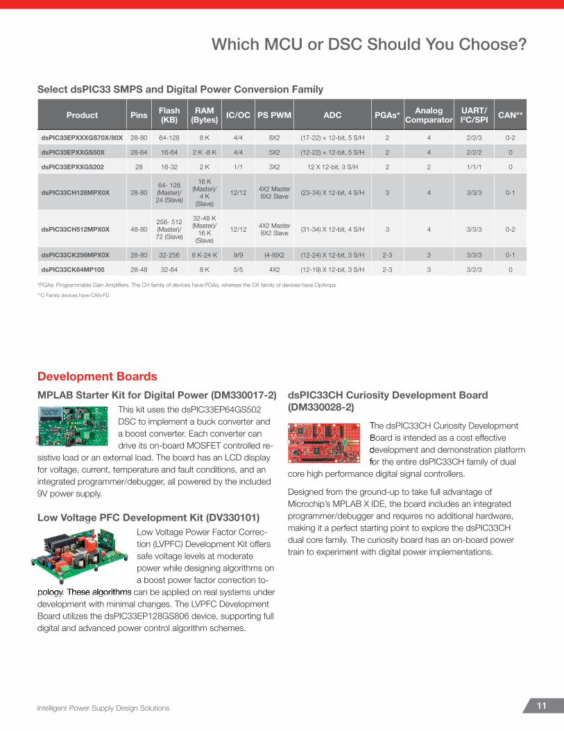
Select dsPIC33 SMPS and Digital Power Conversion Family
Product Pins Flash (KB)
RAM (Bytes) IC/OC PS PWM ADC PGAs* Analog
ComparatorUART/I2C/SPI CAN**
dsPIC33EPXXXGS70X/80X 28-80 64-128 8 K 4/4 8X2 (17-22) × 12-bit, 5 S/H 2 4 2/2/3 0-2
dsPIC33EPXXGS50X 28-64 16-64 2 K -8 K 4/4 5X2 (12-22) × 12-bit, 5 S/H 2 4 2/2/2 0
dsPIC33EPXXGS202 28 16-32 2 K 1/1 3X2 12 X 12-bit, 3 S/H 2 2 1/1/1 0
dsPIC33CH128MPX0X 28-8064- 128 (Master)/ 24 (Slave)
16 K (Master)/
4 K (Slave)
12/12 4X2 Master 8X2 Slave (23-34) X 12-bit, 4 S/H 3 4 3/3/3 0-1
dsPIC33CH512MPX0X 48-80256- 512 (Master)/ 72 (Slave)
32-48 K (Master)/
16 K (Slave)
12/12 4X2 Master 8X2 Slave (31-34) X 12-bit, 4 S/H 3 4 3/3/3 0-2
dsPIC33CK256MPX0X 28-80 32-256 8 K-24 K 9/9 (4-8)X2 (12-24) X 12-bit, 3 S/H 2-3 3 3/3/3 0-1
dsPIC33CK64MP105 28-48 32-64 8 K 5/5 4X2 (12-19) X 12-bit, 3 S/H 2-3 3 3/2/3 0
*PGAs: Programmable Gain Amplifi ers. The CH family of devices have PGAs, whereas the CK family of devices have OpAmps
**C Family devices have CAN-FD
Intelligent Power Supply Design Solutions 11
Which MCU or DSC Should You Choose?
Development BoardsMPLAB Starter Kit for Digital Power (DM330017-2)
This kit uses the dsPIC33EP64GS502 DSC to implement a buck converter and a boost converter. Each converter can drive its on-board MOSFET controlled re-
sistive load or an external load. The board has an LCD display for voltage, current, temperature and fault conditions, and an integrated programmer/debugger, all powered by the included 9V power supply.
Low Voltage PFC Development Kit (DV330101)Low Voltage Power Factor Correc-tion (LVPFC) Development Kit off ers safe voltage levels at moderate power while designing algorithms on a boost power factor correction to-
pology. These algorithms can be applied on real systems under development with minimal changes. The LVPFC Development Board utilizes the dsPIC33EP128GS806 device, supporting full digital and advanced power control algorithm schemes.
dsPIC33CH Curiosity Development Board (DM330028-2)
The dsPIC33CH Curiosity Development Board is intended as a cost eff ective development and demonstration platform for the entire dsPIC33CH family of dual
core high performance digital signal controllers.
Designed from the ground-up to take full advantage of Microchip’s MPLAB X IDE, the board includes an integrated programmer/debugger and requires no additional hardware, making it a perfect starting point to explore the dsPIC33CH dual core family. The curiosity board has an on-board power train to experiment with digital power implementations.
Low Voltage PFC Development Kit (DV330101)
pology. These algorithms can be applied on real systems under
(DM330028-2)
The dsPIC33CH Curiosity Development Board is intended as a cost eff ective development and demonstration platform for the entire dsPIC33CH family of dual
www.microchip.com/power12
Microchip’s Intelligent power reference designs enable optimized system development and faster time to market. To request an evaluation kit for any of these reference designs, please contact your local Microchip FSE/FAE.
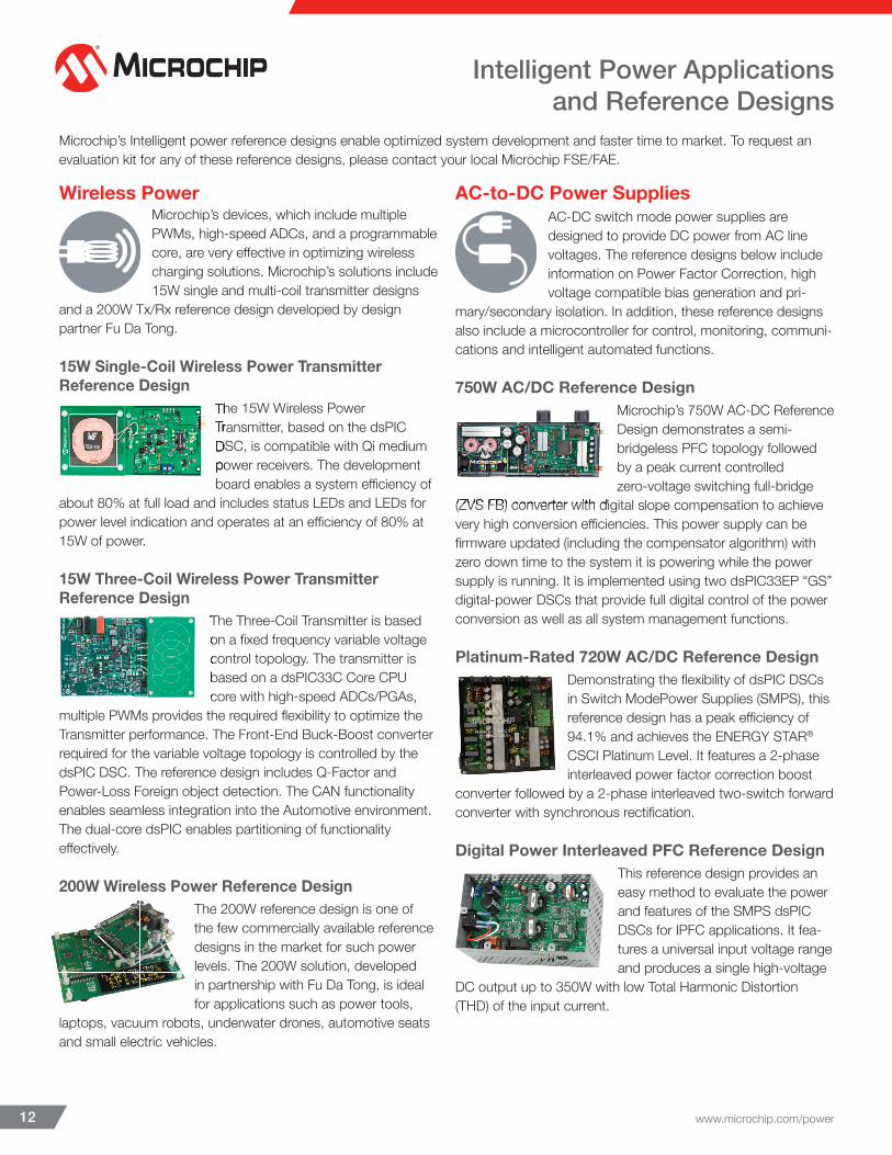
Wireless Power Microchip’s devices, which include multiple PWMs, high-speed ADCs, and a programmable core, are very eff ective in optimizing wireless charging solutions. Microchip’s solutions include 15W single and multi-coil transmitter designs
and a 200W Tx/Rx reference design developed by design partner Fu Da Tong.
15W Single-Coil Wireless Power Transmitter Reference Design
The 15W Wireless Power Transmitter, based on the dsPIC DSC, is compatible with Qi medium power receivers. The development board enables a system effi ciency of
about 80% at full load and includes status LEDs and LEDs for power level indication and operates at an effi ciency of 80% at 15W of power.
15W Three-Coil Wireless Power Transmitter Reference Design
The Three-Coil Transmitter is based on a fi xed frequency variable voltage control topology. The transmitter is based on a dsPIC33C Core CPU core with high-speed ADCs/PGAs,
multiple PWMs provides the required fl exibility to optimize the Transmitter performance. The Front-End Buck-Boost converter required for the variable voltage topology is controlled by the dsPIC DSC. The reference design includes Q-Factor and Power-Loss Foreign object detection. The CAN functionality enables seamless integration into the Automotive environment. The dual-core dsPIC enables partitioning of functionality eff ectively.
200W Wireless Power Reference DesignThe 200W reference design is one of the few commercially available reference designs in the market for such power levels. The 200W solution, developed in partnership with Fu Da Tong, is ideal for applications such as power tools,
laptops, vacuum robots, underwater drones, automotive seats and small electric vehicles.
AC-to-DC Power SuppliesAC-DC switch mode power supplies are designed to provide DC power from AC line voltages. The reference designs below include information on Power Factor Correction, high voltage compatible bias generation and pri-
mary/secondary isolation. In addition, these reference designs also include a microcontroller for control, monitoring, communi-cations and intelligent automated functions.
750W AC/DC Reference DesignMicrochip’s 750W AC-DC Reference Design demonstrates a semi-bridgeless PFC topology followed by a peak current controlled zero-voltage switching full-bridge
(ZVS FB) converter with digital slope compensation to achieve very high conversion effi ciencies. This power supply can be fi rmware updated (including the compensator algorithm) with zero down time to the system it is powering while the power supply is running. It is implemented using two dsPIC33EP “GS” digital-power DSCs that provide full digital control of the power conversion as well as all system management functions.
Platinum-Rated 720W AC/DC Reference DesignDemonstrating the fl exibility of dsPIC DSCs in Switch ModePower Supplies (SMPS), this reference design has a peak effi ciency of 94.1% and achieves the ENERGY STAR® CSCI Platinum Level. It features a 2-phase interleaved power factor correction boost
converter followed by a 2-phase interleaved two-switch forward converter with synchronous rectifi cation.
Digital Power Interleaved PFC Reference DesignThis reference design provides an easy method to evaluate the power and features of the SMPS dsPIC DSCs for IPFC applications. It fea-tures a universal input voltage range and produces a single high-voltage
DC output up to 350W with low Total Harmonic Distortion (THD) of the input current.
The 15W Wireless Power Transmitter, based on the dsPIC DSC, is compatible with Qi medium power receivers. The development board enables a system effi ciency of
The Three-Coil Transmitter is based on a fi xed frequency variable voltage control topology. The transmitter is based on a dsPIC33C Core CPU core with high-speed ADCs/PGAs,
(ZVS FB) converter with digital slope compensation to achieve
Intelligent Power Applicationsand Reference Designs
Intelligent Power Supply Design Solutions 13
Intelligent Power Applicationsand Reference Designs
DC-to-DC Power SuppliesPower Conversion using switch mode power supply design is typically more effi cient than linear regulation. These reference designs provide examples of switching converters with built in microcontrollers. The microcontrollers
provide management functions as well as the controller func-tions required for the switch mode power conversion.
200W DC/DC LLC Resonant Converter Reference Design
A single dsPIC33EP “GS” digital power DSC provide full digital control of the power conversion and system manage-ment functions in this reference design. It operates over a wide input voltage range (350–420V DC) with a nominal
input of 400V, providing a 12V DC output while maintaining high-voltage isolation between the primary and secondary.
Quarter Brick DC/DC Converter Reference Design
This reference design provides an easy method to evaluate the performance and features of SMPS DSCs in high-density quarter brick DC-DC converters.
Battery ManagementEvery battery type has its own unique charging requirements. Managing these diverse requirements, while cell-balancing, fuel-gauging and managing power paths, becomes very complex. Flyback, buck, and boost
topology design examples using PIC MCUs and dsPIC DSCs can handle these functions in compact, easy to implement circuits. The designs include temperature, voltage, current, and time monitoring. In addition, the charge profi les can be customized in fi rmware to match the exact requirements of a battery manufacturer, and to allow any desired customization to improve battery capacity, charge time, or system lifetime.
MCP19111 Battery Charger Evaluation Board (ADM00513)
The MCP19111 Battery Charger Evaluation Board demonstrates the features of a programmable and confi gurable multi-chemistry battery charger.The MCP19111 can be programmed to make a very fl exible battery charger by controlling a high effi ciency synchronous buck circuit. The controller dynamically moves from
voltage to current controlled charging, following the charge characteristics of the target battery chemistry, and the operation can be adjusted or monitored using the available software GUI, a PICkit™ Debugger and a USB connection.
(ADM00513)The MCP19111 Battery Charger Evaluation Board demonstrates the features of a programmable and confi gurable multi-chemistry battery charger.The MCP19111 can be programmed to make a very fl exible battery charger by controlling a high effi ciency synchronous buck circuit. The controller dynamically moves from
www.microchip.com/power14
Intelligent Power Applicationsand Reference Designs
Digital Lighting ControlBinning, temperature, component aging, dimming and constant current-drive needs infl uence light quality – aff ecting the customer experience. In addition to effi ciency benefi ts or lifetime monetary savings, consumers are
looking for better interior designs, brighter headlights, more beautiful colors and fi ner dimming control. To make better LED and traditional lighting circuits, for proper color, temperature and chromaticity, start with a Microchip evaluation board or reference design. These designs can be implemented as stand-alone systems using a traditional dimmer and AC input; or as connected systems supporting standard or custom communi-cation protocols to open new control possibilities.
MCP19215 Dual Boost/SEPIC Evaluation Board (ADM00799)
This board demonstrates how the MCP19215 device operates in Boost and SEPIC topologies over a wide input voltage and load range. Nearly all operational and control system parameters are
programmable by utilizing the integrated PIC microcontroller.
MCP19114 Flyback Standalone Evaluation Board (ADM00578)
The MCP19114-Flyback Standalone Evaluation Board and Graphical User Interface (GUI) demonstrate the MCP19114 performance in a synchronous Flyback topology. It is confi gured to regulate load current, and is well suited to drive LED loads. Nearly all operational and control system
parameters are programmable through the integrated PIC MCU core. The MCP19114 evaluation board comes preprogrammed with fi rmware designed to operate with the GUI interface.
SMPS Solar PowerSolar related power conversion is becoming more important with increase in solar power adoption and stringent effi ciency requirements. Microchip’s grid-connected solar micro inverter reference design, with the dsPIC DSC, has a
maximum power output of 215W and provides a high effi ciency of ~94% at nominal conditions (230V AC). Microchip also has a portable solar charging reference design based on a PIC16F MCU that can charge a 24V battery system from a 130W/12V solar panel. This design can provide 1.3 kWh of energy in 10 hours of charging time.
Grid-Connected Solar Microinverter Reference Design
Demonstrating the fl exibility and power of SMPS dsPIC DSCs in grid-connected solar microinverter systems, this reference design has a maximum output power of 215W and
ensures maximum power point tracking for PV panel volt-ages between 20V to 45V DC. High effi ciency is achieved by implementing a novel interleaved active-clamp fl yback topology with Zero Voltage Switching (ZVS).
(ADM00578)
The MCP19114-Flyback Standalone Evaluation Board and Graphical User Interface (GUI) demonstrate the MCP19114 performance in a synchronous Flyback topology. It is confi gured to regulate load current, and is well suited to drive LED loads. Nearly all operational and control system
parameters are programmable through the integrated PIC MCU
Intelligent Power Supply Design Solutions 15
Intelligent Power Applicationsand Reference Designs
DC-to-AC Power InverterMicrochip’s UPS reference design includes a battery charger and a dsPIC based inverter which converts a 380V D.C battery voltage into a 220V A.C supply. Multiple PWMs, multiple ADC channels and a programmable
core in the dsPIC33FJ16GS504 device enable the optimiza-tion of the inverter design.
Digital Pure Sine Wave Uniterruptile Power Supply (UPS) Reference Design
Implemented using a single dsPIC33F “GS” digital-power DSC, this reference design demonstrates how digital power techniques can be applied to UPS applications
to reduce audible and electrical noise via a purer sine-wave output. It also shows how these techniques enable easy modifi cation through software, the use of smaller magnetics, the creation of higher-effi ciency and compact designs, and a low bill-of-materials cost.
www.microchip.com/power16
Tools and Libraries
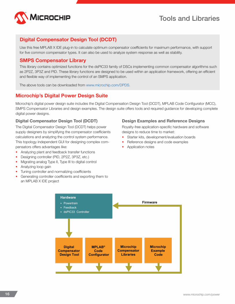
Digital Compensator Design Tool (DCDT) Use this free MPLAB X IDE plug-in to calculate optimum compensator coeffi cients for maximum performance, with support for fi ve common compensator types. It can also be used to analyze system response as well as stability.
SMPS Compensator Library This library contains optimized functions for the dsPIC33 family of DSCs implementing common compensator algorithms such as 2P2Z, 3P3Z and PID. These library functions are designed to be used within an application framework, off ering an effi cient and fl exible way of implementing the control of an SMPS application.
The above tools can be downloaded from www.microchip.com/DPDS.
Microchip’s Digital Power Design SuiteMicrochip’s digital power design suite includes the Digital Compensation Design Tool (DCDT), MPLAB Code Confi gurator (MCC), SMPS Compensator Libraries and design examples. The design suite off ers tools and required guidance for developing complete digital power designs.
Digital Compensator Design Tool (DCDT)The Digital Compensator Design Tool (DCDT) helps power supply designers by simplifying the compensator coeffi cients calculations and analyzing the control system performance. This topology independent GUI for designing complex com-pensators off ers advantages like:• Analyzing plant and feedback transfer functions• Designing controller (PID, 2P2Z, 3P3Z, etc.) • Migrating analog Type II, Type III to digital control• Analyzing loop gain• Tuning controller and normalizing coeffi cients• Generating controller coeffi cients and exporting them to
an MPLAB X IDE project
Design Examples and Reference DesignsRoyalty-free application-specifi c hardware and software designs to reduce time to market:• Starter kits, development/evaluation boards• Reference designs and code examples• Application notes
Hardware• Powertrain• Feedback• dsPIC33 Controller
Digital Compensator Design Tool
MPLAB® Code
Configurator
Microchip Compensator
Libraries
Microchip Example
Code
Firmware
Intelligent Power Supply Design Solutions 17
Tools and Libraries
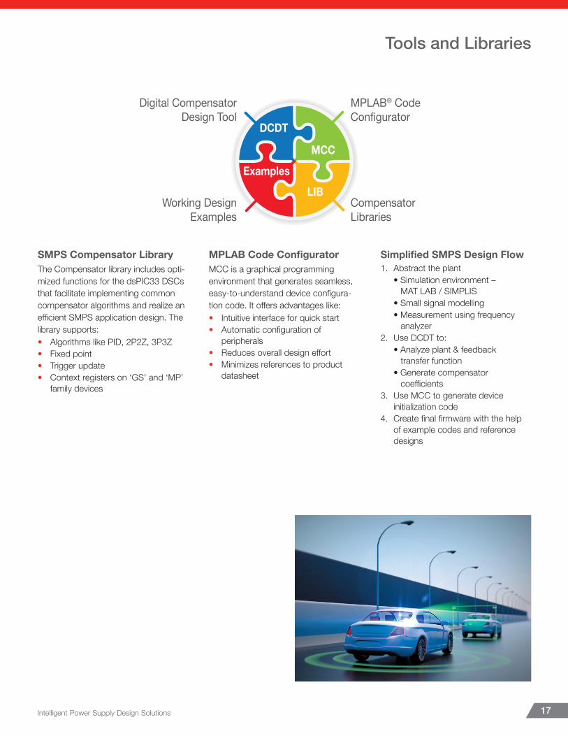
SMPS Compensator LibraryThe Compensator library includes opti-mized functions for the dsPIC33 DSCs that facilitate implementing common compensator algorithms and realize an effi cient SMPS application design. The library supports:• Algorithms like PID, 2P2Z, 3P3Z• Fixed point• Trigger update• Context registers on ‘GS’ and ‘MP’
family devices
MPLAB Code Confi guratorMCC is a graphical programming environment that generates seamless, easy-to-understand device confi gura-tion code. It off ers advantages like:• Intuitive interface for quick start• Automatic confi guration of
peripherals• Reduces overall design eff ort• Minimizes references to product
datasheet
Simplifi ed SMPS Design Flow1. Abstract the plant • Simulation environment – MAT LAB / SIMPLIS • Small signal modelling • Measurement using frequency analyzer2. Use DCDT to: • Analyze plant & feedback transfer function • Generate compensator coeffi cients3. Use MCC to generate device initialization code4. Create fi nal fi rmware with the help of example codes and reference designs
DCDT
Digital CompensatorDesign Tool
Working DesignExamples
MPLAB® CodeConfigurator
CompensatorLibraries
ExamplesLIB
MCC
Making Your Power Applications Intelligent The Easy Way!• Log on to www.microchip.com/design-centers/intelligent-power and navigate to the “Webinars” tab at the bottom of the page
to find intelligent power training.• Register for Design Workshops at www.microchip.com/Biricha.
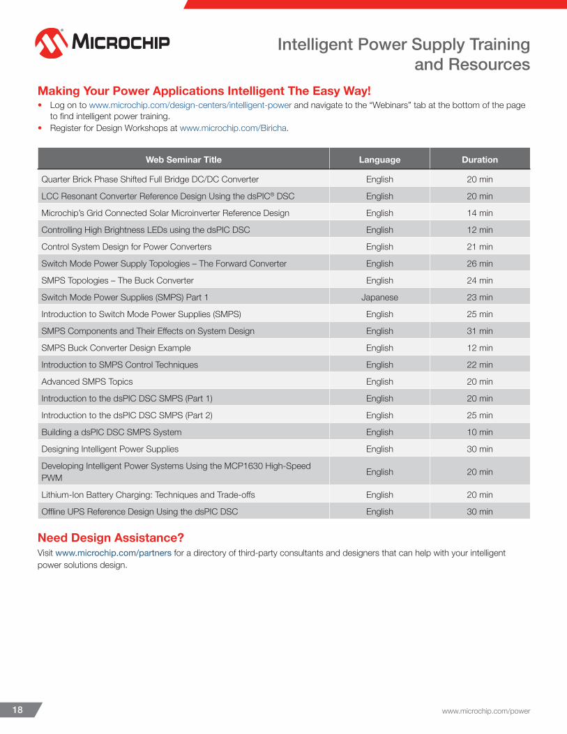
Web Seminar Title Language Duration
Quarter Brick Phase Shifted Full Bridge DC/DC Converter English 20 min
LCC Resonant Converter Reference Design Using the dsPIC® DSC English 20 min
Microchip’s Grid Connected Solar Microinverter Reference Design English 14 min
Controlling High Brightness LEDs using the dsPIC DSC English 12 min
Control System Design for Power Converters English 21 min
Switch Mode Power Supply Topologies – The Forward Converter English 26 min
SMPS Topologies – The Buck Converter English 24 min
Switch Mode Power Supplies (SMPS) Part 1 Japanese 23 min
Introduction to Switch Mode Power Supplies (SMPS) English 25 min
SMPS Components and Their Effects on System Design English 31 min
SMPS Buck Converter Design Example English 12 min
Introduction to SMPS Control Techniques English 22 min
Advanced SMPS Topics English 20 min
Introduction to the dsPIC DSC SMPS (Part 1) English 20 min
Introduction to the dsPIC DSC SMPS (Part 2) English 25 min
Building a dsPIC DSC SMPS System English 10 min
Designing Intelligent Power Supplies English 30 min
Developing Intelligent Power Systems Using the MCP1630 High-Speed PWM English 20 min
Lithium-Ion Battery Charging: Techniques and Trade-offs English 20 min
Offline UPS Reference Design Using the dsPIC DSC English 30 min
Need Design Assistance?Visit www.microchip.com/partners for a directory of third-party consultants and designers that can help with your intelligent power solutions design.
www.microchip.com/power18
Intelligent Power Supply Trainingand Resources
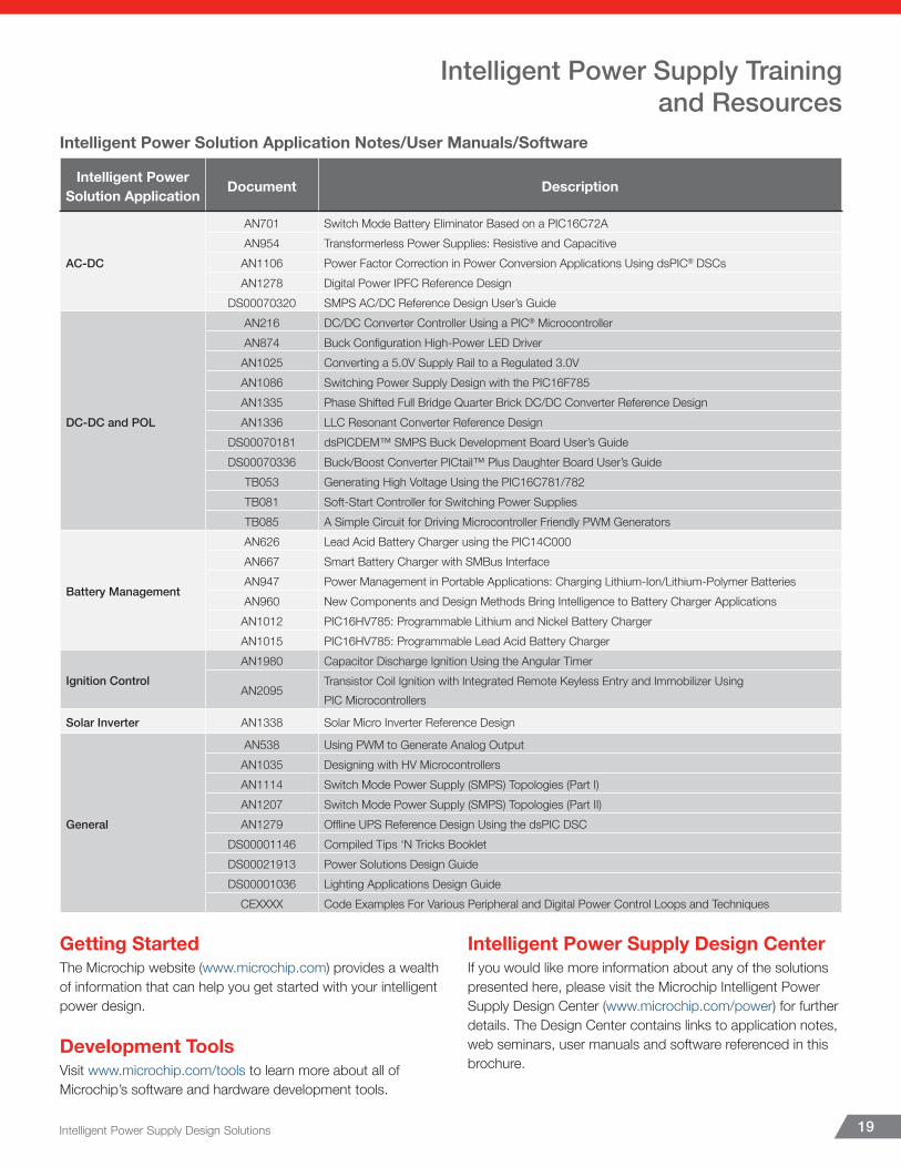
Intelligent Power Solution Application Notes/User Manuals/Software
Intelligent Power Solution Application Document Description
AC-DC
AN701 Switch Mode Battery Eliminator Based on a PIC16C72AAN954 Transformerless Power Supplies: Resistive and CapacitiveAN1106 Power Factor Correction in Power Conversion Applications Using dsPIC® DSCsAN1278 Digital Power IPFC Reference Design
DS00070320 SMPS AC/DC Reference Design User’s Guide
DC-DC and POL
AN216 DC/DC Converter Controller Using a PIC® MicrocontrollerAN874 Buck Configuration High-Power LED DriverAN1025 Converting a 5.0V Supply Rail to a Regulated 3.0VAN1086 Switching Power Supply Design with the PIC16F785AN1335 Phase Shifted Full Bridge Quarter Brick DC/DC Converter Reference DesignAN1336 LLC Resonant Converter Reference Design
DS00070181 dsPICDEM™ SMPS Buck Development Board User’s GuideDS00070336 Buck/Boost Converter PICtail™ Plus Daughter Board User’s Guide
TB053 Generating High Voltage Using the PIC16C781/782TB081 Soft-Start Controller for Switching Power SuppliesTB085 A Simple Circuit for Driving Microcontroller Friendly PWM Generators
Battery Management
AN626 Lead Acid Battery Charger using the PIC14C000AN667 Smart Battery Charger with SMBus InterfaceAN947 Power Management in Portable Applications: Charging Lithium-Ion/Lithium-Polymer BatteriesAN960 New Components and Design Methods Bring Intelligence to Battery Charger ApplicationsAN1012 PIC16HV785: Programmable Lithium and Nickel Battery ChargerAN1015 PIC16HV785: Programmable Lead Acid Battery Charger
Ignition ControlAN1980 Capacitor Discharge Ignition Using the Angular Timer
AN2095Transistor Coil Ignition with Integrated Remote Keyless Entry and Immobilizer Using PIC Microcontrollers
Solar Inverter AN1338 Solar Micro Inverter Reference Design
General
AN538 Using PWM to Generate Analog OutputAN1035 Designing with HV MicrocontrollersAN1114 Switch Mode Power Supply (SMPS) Topologies (Part I)AN1207 Switch Mode Power Supply (SMPS) Topologies (Part II)AN1279 Offline UPS Reference Design Using the dsPIC DSC
DS00001146 Compiled Tips ‘N Tricks BookletDS00021913 Power Solutions Design GuideDS00001036 Lighting Applications Design Guide
CEXXXX Code Examples For Various Peripheral and Digital Power Control Loops and Techniques
Getting StartedThe Microchip website (www.microchip.com) provides a wealth of information that can help you get started with your intelligent power design.
Development ToolsVisit www.microchip.com/tools to learn more about all of Microchip’s software and hardware development tools.
Intelligent Power Supply Design CenterIf you would like more information about any of the solutions presented here, please visit the Microchip Intelligent Power Supply Design Center (www.microchip.com/power) for further details. The Design Center contains links to application notes, web seminars, user manuals and software referenced in this brochure.
Intelligent Power Supply Design Solutions 19
Intelligent Power Supply Trainingand Resources

www.microchip.com/power
SupportMicrochip is committed to supporting its customers in de-veloping products faster and more effi ciently. We maintain a worldwide network of fi eld applications engineers and technical support ready to provide product and system assistance. For more information, please visit www.microchip.com:• Technical Support: www.microchip.com/support• Evaluation samples of any Microchip device:
www.microchip.com/sample• Knowledge base and peer help:
www.microchip.com/forums• Sales and Global Distribution: www.microchip.com/sales
TrainingIf additional training interests you, Microchip off ers several resources including in-depth technical training and reference material, self-paced tutorials and signifi cant online resources.• Overview of Technical Training Resources:
www.microchip.com/training• MASTERs Conferences:
www.microchip.com/masters• Developer Help Website:
www.microchip.com/developerhelp• Technical Training Centers:
www.microchip.com/seminars
Microchip Technology Inc. | 2355 W. Chandler Blvd. | Chandler AZ, 85224-6199
Sales Offi ce ListingAMERICASAtlanta, GATel: 678-957-9614Austin, TXTel: 512-257-3370Boston, MATel: 774-760-0087Chandler, AZ (HQ)Tel: 480-792-7200Chicago, ILTel: 630-285-0071Dallas, TXTel: 972-818-7423Detroit, MITel: 248-848-4000Houston, TXTel: 281-894-5983Indianapolis, INTel: 317-773-8323Tel: 317-536-2380Los Angeles, CATel: 949-462-9523Tel: 951-273-7800Raleigh, NCTel: 919-844-7510New York, NYTel: 631-435-6000San Jose, CATel: 408-735-9110Tel: 408-436-4270Canada - TorontoTel: 905-695-1980
EUROPEAustria - WelsTel: 43-7242-2244-39Denmark - CopenhagenTel: 45-4450-2828Finland - EspooTel: 358-9-4520-820France - ParisTel: 33-1-69-53-63-20Germany - GarchingTel: 49-8931-9700Germany - HaanTel: 49-2129-3766-400Germany - HeilbronnTel: 49-7131-67-3636Germany - KarlsruheTel: 49-721-62537-0Germany - MunichTel: 49-89-627-144-0Germany - RosenheimTel: 49-8031-354-560
EUROPEIsrael - Ra’ananaTel: 972-9-744-7705Italy - MilanTel: 39-0331-742611Italy - PadovaTel: 39-049-7625286Netherlands - DrunenTel: 31-416-690399Norway - TrondheimTel: 47-7289-7561Poland - WarsawTel: 48-22-3325737Romania - BucharestTel: 40-21-407-87-50Spain - MadridTel: 34-91-708-08-90Sweden - GothenbergTel: 46-31-704-60-40Sweden - StockholmTel: 46-8-5090-4654UK - WokinghamTel: 44-118-921-5800
ASIA/PACIFICAustralia - SydneyTel: 61-2-9868-6733China - BeijingTel: 86-10-8569-7000China - ChengduTel: 86-28-8665-5511China - ChongqingTel: 86-23-8980-9588China - DongguanTel: 86-769-8702-9880China - GuangzhouTel: 86-20-8755-8029China - HangzhouTel: 86-571-8792-8115China - Hong Kong SARTel: 852-2943-5100China - NanjingTel: 86-25-8473-2460China - QingdaoTel: 86-532-8502-7355China - ShanghaiTel: 86-21-3326-8000China - ShenyangTel: 86-24-2334-2829China - ShenzhenTel: 86-755-8864-2200China - SuzhouTel: 86-186-6233-1526China - WuhanTel: 86-27-5980-5300China - XiamenTel: 86-592-2388138China - XianTel: 86-29-8833-7252
ASIA/PACIFICChina - ZhuhaiTel: 86-756-321-0040India - BangaloreTel: 91-80-3090-4444India - New DelhiTel: 91-11-4160-8631India - PuneTel: 91-20-4121-0141Japan - OsakaTel: 81-6-6152-7160Japan - TokyoTel: 81-3-6880-3770Korea - DaeguTel: 82-53-744-4301Korea - SeoulTel: 82-2-554-7200Malaysia - Kuala LumpurTel: 60-3-7651-7906Malaysia - PenangTel: 60-4-227-8870Philippines - ManilaTel: 63-2-634-9065SingaporeTel: 65-6334-8870Taiwan - Hsin ChuTel: 886-3-577-8366Taiwan - KaohsiungTel: 886-7-213-7830Taiwan - TaipeiTel: 886-2-2508-8600Thailand - BangkokTel: 66-2-694-1351Vietnam - Ho Chi MinhTel: 84-28-5448-2100
8/15/18
The Microchip name and logo, the Microchip logo, AVR, dsPIC, MPLAB and PIC are registered trademarks and ICSP, In-Circuit Serial Programming, PICkit, PICtail and REAL ICE are trademarks of Microchip Technology Incorporated in the U.S.A. and other countries. All other trademarks mentioned herein are property of their respective companies. © 2019, Microchip Technology Incorporated. All Rights Reserved. 3/19 00001240G


