Embed Size (px)
Citation preview

SSAAFFEETTYY WWAARRNNIINNGGOnly qualified personnel should install and service the equipment. The installation, starting up, and servicing of heating, ventilating, and air-conditioningequipment can be hazardous and requires specific knowledge and training. Improperly installed, adjusted or altered equipment by an unqualified personcould result in death or serious injury. When working on the equipment, observe all precautions in the literature and on the tags, stickers, and labels thatare attached to the equipment.
June 2020 RRTT--SSVVXX2244QQ--EENN
Installation, Operation, and Maintenance
IntelliPak™ 2Commercial Rooftop Air Conditioners with CV,VAV, or SZVAV Controls
““FF00”” aanndd llaatteerr ddeessiiggnn sseeqquueenncceeSEHJ090-162SFHJ090-162SLHJ090-162SSHJ090-162SXHJ090-162

©2020 Trane RT-SVX24Q-EN
IntroductionRead this manual thoroughly before operating orservicing this unit.
Warnings, Cautions, and NoticesSafety advisories appear throughout this manual asrequired. Your personal safety and the properoperation of this machine depend upon the strictobservance of these precautions.
The three types of advisories are defined as follows:
WARNINGIndicates a potentially hazardous situationwhich, if not avoided, could result in death orserious injury.
CAUTIONIndicates a potentially hazardous situationwhich, if not avoided, could result in minor ormoderate injury. It could also be used to alertagainst unsafe practices.
NOTICEIndicates a situation that could result inequipment or property-damage onlyaccidents.
Important Environmental ConcernsScientific research has shown that certain man-madechemicals can affect the earth’s naturally occurringstratospheric ozone layer when released to theatmosphere. In particular, several of the identifiedchemicals that may affect the ozone layer arerefrigerants that contain Chlorine, Fluorine and Carbon(CFCs) and those containing Hydrogen, Chlorine,Fluorine and Carbon (HCFCs). Not all refrigerantscontaining these compounds have the same potentialimpact to the environment. Trane advocates theresponsible handling of all refrigerants-includingindustry replacements for CFCs and HCFCs such assaturated or unsaturated HFCs and HCFCs.
Important Responsible RefrigerantPracticesTrane believes that responsible refrigerant practicesare important to the environment, our customers, andthe air conditioning industry. All technicians whohandle refrigerants must be certified according to localrules. For the USA, the Federal Clean Air Act (Section608) sets forth the requirements for handling,reclaiming, recovering and recycling of certainrefrigerants and the equipment that is used in theseservice procedures. In addition, some states ormunicipalities may have additional requirements thatmust also be adhered to for responsible managementof refrigerants. Know the applicable laws and followthem.
WWAARRNNIINNGGPPrrooppeerr FFiieelldd WWiirriinngg aanndd GGrroouunnddiinnggRReeqquuiirreedd!!FFaaiilluurree ttoo ffoollllooww ccooddee ccoouulldd rreessuulltt iinn ddeeaatthh oorrsseerriioouuss iinnjjuurryy..AAllll ffiieelldd wwiirriinngg MMUUSSTT bbee ppeerrffoorrmmeedd bbyy qquuaalliiffiieeddppeerrssoonnnneell.. IImmpprrooppeerrllyy iinnssttaalllleedd aanndd ggrroouunnddeeddffiieelldd wwiirriinngg ppoosseess FFIIRREE aanndd EELLEECCTTRROOCCUUTTIIOONNhhaazzaarrddss.. TToo aavvooiidd tthheessee hhaazzaarrddss,, yyoouu MMUUSSTT ffoolllloowwrreeqquuiirreemmeennttss ffoorr ffiieelldd wwiirriinngg iinnssttaallllaattiioonn aannddggrroouunnddiinngg aass ddeessccrriibbeedd iinn NNEECC aanndd yyoouurr llooccaall//ssttaattee//nnaattiioonnaall eelleeccttrriiccaall ccooddeess..
WWAARRNNIINNGGPPeerrssoonnaall PPrrootteeccttiivvee EEqquuiippmmeenntt ((PPPPEE))RReeqquuiirreedd!!FFaaiilluurree ttoo wweeaarr pprrooppeerr PPPPEE ffoorr tthhee jjoobb bbeeiinngguunnddeerrttaakkeenn ccoouulldd rreessuulltt iinn ddeeaatthh oorr sseerriioouuss iinnjjuurryy..TTeecchhnniicciiaannss,, iinn oorrddeerr ttoo pprrootteecctt tthheemmsseellvveess ffrroommppootteennttiiaall eelleeccttrriiccaall,, mmeecchhaanniiccaall,, aanndd cchheemmiiccaallhhaazzaarrddss,, MMUUSSTT ffoollllooww pprreeccaauuttiioonnss iinn tthhiiss mmaannuuaallaanndd oonn tthhee ttaaggss,, ssttiicckkeerrss,, aanndd llaabbeellss,, aass wweellll aass tthheeiinnssttrruuccttiioonnss bbeellooww::
•• BBeeffoorree iinnssttaalllliinngg//sseerrvviicciinngg tthhiiss uunniitt,,tteecchhnniicciiaannss MMUUSSTT ppuutt oonn aallll PPPPEE rreeqquuiirreedd ffoorrtthhee wwoorrkk bbeeiinngg uunnddeerrttaakkeenn ((EExxaammpplleess;; ccuuttrreessiissttaanntt gglloovveess//sslleeeevveess,, bbuuttyyll gglloovveess,, ssaaffeettyyggllaasssseess,, hhaarrdd hhaatt//bbuummpp ccaapp,, ffaallll pprrootteeccttiioonn,,eelleeccttrriiccaall PPPPEE aanndd aarrcc ffllaasshh ccllootthhiinngg))..AALLWWAAYYSS rreeffeerr ttoo aapppprroopprriiaattee SSaaffeettyy DDaattaaSShheeeettss ((SSDDSS)) aanndd OOSSHHAA gguuiiddeelliinneess ffoorrpprrooppeerr PPPPEE..
•• WWhheenn wwoorrkkiinngg wwiitthh oorr aarroouunndd hhaazzaarrddoouusscchheemmiiccaallss,, AALLWWAAYYSS rreeffeerr ttoo tthhee aapppprroopprriiaatteeSSDDSS aanndd OOSSHHAA//GGHHSS ((GGlloobbaall HHaarrmmoonniizzeeddSSyysstteemm ooff CCllaassssiiffiiccaattiioonn aanndd LLaabbeelllliinngg ooffCChheemmiiccaallss)) gguuiiddeelliinneess ffoorr iinnffoorrmmaattiioonn oonnaalllloowwaabbllee ppeerrssoonnaall eexxppoossuurree lleevveellss,, pprrooppeerrrreessppiirraattoorryy pprrootteeccttiioonn aanndd hhaannddlliinnggiinnssttrruuccttiioonnss..
•• IIff tthheerree iiss aa rriisskk ooff eenneerrggiizzeedd eelleeccttrriiccaallccoonnttaacctt,, aarrcc,, oorr ffllaasshh,, tteecchhnniicciiaannss MMUUSSTT ppuuttoonn aallll PPPPEE iinn aaccccoorrddaannccee wwiitthh OOSSHHAA,, NNFFPPAA7700EE,, oorr ootthheerr ccoouunnttrryy--ssppeecciiffiicc rreeqquuiirreemmeennttssffoorr aarrcc ffllaasshh pprrootteeccttiioonn,, PPRRIIOORR ttoo sseerrvviicciinnggtthhee uunniitt.. NNEEVVEERR PPEERRFFOORRMM AANNYY SSWWIITTCCHHIINNGG,,DDIISSCCOONNNNEECCTTIINNGG,, OORR VVOOLLTTAAGGEE TTEESSTTIINNGGWWIITTHHOOUUTT PPRROOPPEERR EELLEECCTTRRIICCAALL PPPPEE AANNDDAARRCC FFLLAASSHH CCLLOOTTHHIINNGG.. EENNSSUURREEEELLEECCTTRRIICCAALL MMEETTEERRSS AANNDD EEQQUUIIPPMMEENNTT AARREEPPRROOPPEERRLLYY RRAATTEEDD FFOORR IINNTTEENNDDEEDDVVOOLLTTAAGGEE..

RT-SVX24Q-EN 3
WWAARRNNIINNGGFFoollllooww EEHHSS PPoolliicciieess!!FFaaiilluurree ttoo ffoollllooww iinnssttrruuccttiioonnss bbeellooww ccoouulldd rreessuulltt iinnddeeaatthh oorr sseerriioouuss iinnjjuurryy..
•• AAllll TTrraannee ppeerrssoonnnneell mmuusstt ffoollllooww tthheeccoommppaannyy’’ss EEnnvviirroonnmmeennttaall,, HHeeaalltthh aanndd SSaaffeettyy((EEHHSS)) ppoolliicciieess wwhheenn ppeerrffoorrmmiinngg wwoorrkk ssuucchh aasshhoott wwoorrkk,, eelleeccttrriiccaall,, ffaallll pprrootteeccttiioonn,, lloocckkoouutt//ttaaggoouutt,, rreeffrriiggeerraanntt hhaannddlliinngg,, eettcc.. WWhheerree llooccaallrreegguullaattiioonnss aarree mmoorree ssttrriinnggeenntt tthhaann tthheesseeppoolliicciieess,, tthhoossee rreegguullaattiioonnss ssuuppeerrsseeddee tthheesseeppoolliicciieess..
•• NNoonn--TTrraannee ppeerrssoonnnneell sshhoouulldd aallwwaayyss ffoolllloowwllooccaall rreegguullaattiioonnss..
Overview of ManualNNoottee:: This document is customer property and must be
retained by the unit owner for use bymaintenance personnel.
These units are equipped with electronic Unit ControlModules (UCM). Refer to the “Start-Up” and “TestMode” procedures within this Installation, Operation,and Maintenance manual and the latest edition of theappropriate programming manual for Constant Volume(CV), Rapid Restart (RR), Variable Air Volume (VAV), orSingle Zone Variable Air Volume (SZVAV) applicationsbefore attempting to operate or service this equipment.
IImmppoorrttaanntt:: The procedures discussed in this manualshould only be performed by qualified andexperienced HVAC technicians.
This booklet describes proper installation, start-up,operation, and maintenance procedures for 90 to 162ton rooftop air conditioners designed for CV, RR, VAV,or SZ VAV applications. By carefully reviewing theinformation within this manual and following theinstructions, the risk of improper operation and/orcomponent damage will be minimized.
NNoottee:: One copy of the appropriate service literatureships inside the control panel of each unit.
It is important that periodic maintenance be performedto help assure trouble-free operation. Should
equipment failure occur, contact a qualified serviceorganization with qualified, experienced HVACtechnicians to properly diagnose and repair thisequipment.
IImmppoorrttaanntt:: DO NOT release refrigerant to theatmosphere!
If adding or removing refrigerant is required, theservice technician must comply with all federal, state,and local laws.
CopyrightThis document and the information in it are theproperty of Trane, and may not be used or reproducedin whole or in part without written permission. Tranereserves the right to revise this publication at any time,and to make changes to its content without obligationto notify any person of such revision or change.
TrademarksAll trademarks referenced in this document are thetrademarks of their respective owners.
Factory TrainingFactory training is available through Trane University™to help you learn more about the operation andmaintenance of your equipment. To learn aboutavailable training opportunities contact TraneUniversity™.
Online: www.trane.com/traneuniversity
Phone: 855-803-3563
Email: [email protected]
Revision History• Updated Manual Limit — Open Temp. values. See
Table 68, p. 190.
• Updated Air Cooled Electric document numbers.See .
• Removed Dolphin WaterCare™ as it is no longeroffered.
IInnttrroodduuccttiioonn

4 RT-SVX24Q-EN
Model Number Description. . . . . . . . . . . . . . . . . 7
General Information . . . . . . . . . . . . . . . . . . . . . . . 10Unit Nameplate . . . . . . . . . . . . . . . . . . . . . . . . . 10
Compressor Nameplate . . . . . . . . . . . . . . . . . . 10
Unit Description . . . . . . . . . . . . . . . . . . . . . . . . . 10Rooftop Module . . . . . . . . . . . . . . . . . . . . . 10Compressor Module . . . . . . . . . . . . . . . . . 11Human Interface Module . . . . . . . . . . . . . 11Heat Module . . . . . . . . . . . . . . . . . . . . . . . . 11Ventilation Override Module . . . . . . . . . . 11Variable Speed Module . . . . . . . . . . . . . . 11Interprocessor CommunicationsBoard . . . . . . . . . . . . . . . . . . . . . . . . . . . . . . . 11Lontalk®/BACnet® CommunicationInterface Module . . . . . . . . . . . . . . . . . . . . 11Exhaust/Comparative EnthalpyModule . . . . . . . . . . . . . . . . . . . . . . . . . . . . . 11Multi Purpose Module . . . . . . . . . . . . . . . 12Variable Speed Module . . . . . . . . . . . . . . 12Modulating Hot Gas ReheatModule . . . . . . . . . . . . . . . . . . . . . . . . . . . . . 12Ventilation Control Module . . . . . . . . . . . 12Generic Building AutomationSystem Module . . . . . . . . . . . . . . . . . . . . . 13Input Devices and SystemFunctions . . . . . . . . . . . . . . . . . . . . . . . . . . . 13Constant Volume (CV) and VariableAir Volume (VAV) Units. . . . . . . . . . . . . . . 13Constant Volume (CV) Units . . . . . . . . . . 17Variable Air Volume (VAV)Units. . . . . . . . . . . . . . . . . . . . . . . . . . . . . . . . 17Single Zone Variable Air Volume(SZVAV) Only . . . . . . . . . . . . . . . . . . . . . . . . 21
Pre-Installation . . . . . . . . . . . . . . . . . . . . . . . . . . . . 24Unit Inspection . . . . . . . . . . . . . . . . . . . . . . . . . . 24
Exterior Inspection . . . . . . . . . . . . . . . . . . . 24Inspection for ConcealedDamage . . . . . . . . . . . . . . . . . . . . . . . . . . . . . 24Repair. . . . . . . . . . . . . . . . . . . . . . . . . . . . . . . 24
Storage . . . . . . . . . . . . . . . . . . . . . . . . . . . . . . . . . 24
Unit Clearances . . . . . . . . . . . . . . . . . . . . . . . . . 24
Unit Dimensions and WeightInformation . . . . . . . . . . . . . . . . . . . . . . . . . . . . . 25
Installation Checklist . . . . . . . . . . . . . . . . . . . . . 25
General Checklist (Applies to allunits) . . . . . . . . . . . . . . . . . . . . . . . . . . . . . . . 25Unit Rigging and Placement (Two-piece—addition to GeneralChecklist). . . . . . . . . . . . . . . . . . . . . . . . . . . . 25Unit Rigging and Placement (Three-piece unit) (in addition to two-pieceunit rigging and placement). . . . . . . . . . . 26Main Electrical PowerRequirements . . . . . . . . . . . . . . . . . . . . . . . 26Electric Heat Units . . . . . . . . . . . . . . . . . . . 26Gas Heat Units. . . . . . . . . . . . . . . . . . . . . . . 26Hot Water Heat . . . . . . . . . . . . . . . . . . . . . . 26Steam Heat . . . . . . . . . . . . . . . . . . . . . . . . . . 26O/A Pressure Sensor and TubingInstallation (All VAV units and CVunits with return fan orStatiTrac). . . . . . . . . . . . . . . . . . . . . . . . . . . . 27Evaporative Condenser . . . . . . . . . . . . . . . 27Energy Recovery Wheel . . . . . . . . . . . . . . 27
Dimensional Data . . . . . . . . . . . . . . . . . . . . . . . . . 28Water Connection Locations . . . . . . . . . . . . . . 37
Electrical Entry Details . . . . . . . . . . . . . . . . . . . 38
Minimum Required Clearance . . . . . . . . . . . . 39
Weights . . . . . . . . . . . . . . . . . . . . . . . . . . . . . . . . . . . 40
Installation . . . . . . . . . . . . . . . . . . . . . . . . . . . . . . . . 43Roof Curb and Ductwork . . . . . . . . . . . . . . . . . 43
Pitch Pocket Location. . . . . . . . . . . . . . . . . 43Field Converting HorizontalDuctwork (Supply or Return) fromRight to the Left Side . . . . . . . . . . . . . . . . . 45
Unit Rigging and Placement . . . . . . . . . . . . . . 47Air-Cooled and EvaporativeCondensers—Three-Piece Unit FitUp . . . . . . . . . . . . . . . . . . . . . . . . . . . . . . . . . . 52Air-Cooled and EvaporativeCondensers—Two-Piece Unit FitUp . . . . . . . . . . . . . . . . . . . . . . . . . . . . . . . . . . 54Tubing and Wiring Connections . . . . . . . 57
General Installation Requirements . . . . . . . . 60Rigging the Unit . . . . . . . . . . . . . . . . . . . . . 60Main Electrical Power . . . . . . . . . . . . . . . . 60Field Installed Control Wiring . . . . . . . . . 60Electric Heat Units . . . . . . . . . . . . . . . . . . . 60
Table of Contents

RT-SVX24Q-EN 5
Gas Heat . . . . . . . . . . . . . . . . . . . . . . . . . . . . 60Hot Water Heat . . . . . . . . . . . . . . . . . . . . . . 61Steam Heat . . . . . . . . . . . . . . . . . . . . . . . . . 61O/A Pressure Sensor and TubingInstallation . . . . . . . . . . . . . . . . . . . . . . . . . . 61Condensate Drain Connections. . . . . . . . 61Units with Gas Furnace . . . . . . . . . . . . . . . 61Removing Compressor AssemblyShipping Hardware . . . . . . . . . . . . . . . . . . 61Removing Supply and Exhaust FanShipping Channels . . . . . . . . . . . . . . . . . . 61Remove Evaporative Condenser FanShipping Brackets. . . . . . . . . . . . . . . . . . . . 62O/A Sensor and TubingInstallation . . . . . . . . . . . . . . . . . . . . . . . . . . 63Evaporative-Cooled CondenserMake-up Water and Drain LineInstallation . . . . . . . . . . . . . . . . . . . . . . . . . . 64Gas Heat Units. . . . . . . . . . . . . . . . . . . . . . . 65General Coil Piping and ConnectionRecommendations . . . . . . . . . . . . . . . . . . . 69Disconnect Switch with ExternalHandle . . . . . . . . . . . . . . . . . . . . . . . . . . . . . . 72Electric Heat Units . . . . . . . . . . . . . . . . . . . 73Main Unit Power Wiring . . . . . . . . . . . . . . 73Electrical Service Sizing . . . . . . . . . . . . . . 76Field Installed Control Wiring . . . . . . . . . 80Controls using 24 VAC. . . . . . . . . . . . . . . . 80Controls using DC Analog Input/Outputs . . . . . . . . . . . . . . . . . . . . . . . . . . . . . 80Constant Volume SystemControls. . . . . . . . . . . . . . . . . . . . . . . . . . . . . 81Variable Air Volume SystemControls. . . . . . . . . . . . . . . . . . . . . . . . . . . . . 81Constant Volume or Variable AirVolume System Controls . . . . . . . . . . . . . 81Single Zone Variable Air Volume &Rapid Restart System Control . . . . . . . . . 82Emergency Override . . . . . . . . . . . . . . . . . 82Ventilation Override Module(VOM). . . . . . . . . . . . . . . . . . . . . . . . . . . . . . . 83Temperature vs. ResistanceCoefficient. . . . . . . . . . . . . . . . . . . . . . . . . . . 84Emergency Stop Input. . . . . . . . . . . . . . . . 84External Stop Input. . . . . . . . . . . . . . . . . . . 85Occupied/Unoccupied Contacts . . . . . . . 85Demand Limit Relay. . . . . . . . . . . . . . . . . . 85
Outside Air Sensor(BAYSENS016*) . . . . . . . . . . . . . . . . . . . . . 85Generic Building AutomationSystem. . . . . . . . . . . . . . . . . . . . . . . . . . . . . . 85
Unit Startup . . . . . . . . . . . . . . . . . . . . . . . . . . . . . . . 92Sequence of Operation. . . . . . . . . . . . . . . . . . . 92
Cooling Sequence of Operation . . . . . . . 92Compressor Sequence ofOperation . . . . . . . . . . . . . . . . . . . . . . . . . . . 92Units with Evaporative CondenserSequence of Operation . . . . . . . . . . . . . . . 93Low Charge Protection . . . . . . . . . . . . . . . 97Frostat™ Control. . . . . . . . . . . . . . . . . . . . . 97Lead/Lag Operation . . . . . . . . . . . . . . . . . . 97Units Equipped with 100%Modulating Exhaust . . . . . . . . . . . . . . . . . . 98Modulating Hot Gas ReheatSequence of Operation . . . . . . . . . . . . . . . 98Energy Recovery Sequence ofOperation . . . . . . . . . . . . . . . . . . . . . . . . . . . 99Gas Heating Sequence of OperationStandard . . . . . . . . . . . . . . . . . . . . . . . . . . . 101Modulating Gas Sequence ofOperation . . . . . . . . . . . . . . . . . . . . . . . . . . 102Electric Heat Sequence ofOperation . . . . . . . . . . . . . . . . . . . . . . . . . . 103Demand Control VentilationSequence of Operation . . . . . . . . . . . . . . 103Return Fan Sequence ofOperation . . . . . . . . . . . . . . . . . . . . . . . . . . 103Hydronic Heat Sequence ofOperation . . . . . . . . . . . . . . . . . . . . . . . . . . 104Startup the Unit. . . . . . . . . . . . . . . . . . . . . 104
Performance Data . . . . . . . . . . . . . . . . . . . . . . 115Supply Fan (with or without VariableFrequency Drive). . . . . . . . . . . . . . . . . . . . 115Airside Pressure Drop — StandardEvaporator Coil . . . . . . . . . . . . . . . . . . . . . 117Exhaust Fan (with or without EnergyRecovery Wheel) . . . . . . . . . . . . . . . . . . . . 119Return Fan (with or without EnergyRecovery Wheel) . . . . . . . . . . . . . . . . . . . . 120Component Static PressureDrops . . . . . . . . . . . . . . . . . . . . . . . . . . . . . . 122
Pressure Curves . . . . . . . . . . . . . . . . . . . . . . . . 128(60 Hz) Air-Cooled Condensers . . . . . . . 128
TTaabbllee ooff CCoonntteennttss

6 RT-SVX24Q-EN
(50 Hz) Air-Cooled Condensers . . . . . . . 142
Components . . . . . . . . . . . . . . . . . . . . . . . . . . . 155Economizer and Exhaust Air DamperAdjustment. . . . . . . . . . . . . . . . . . . . . . . . . 155Standard Unit with Energy RecoveryWheel. . . . . . . . . . . . . . . . . . . . . . . . . . . . . . 159Energy Recovery Wheel (ERW) . . . . . . . 164
Compressor Startup . . . . . . . . . . . . . . . . . . . . 171Refrigerant Charging . . . . . . . . . . . . . . . . 172Compressor CrankcaseHeaters . . . . . . . . . . . . . . . . . . . . . . . . . . . . 173
Compressor Operational Sounds . . . . . . . . 173At Shutdown . . . . . . . . . . . . . . . . . . . . . . . 173At Low Ambient Start-Up . . . . . . . . . . . . 173Variable Speed Compressors . . . . . . . . 173
Electronic Compressor ProtectionModule (CPM) . . . . . . . . . . . . . . . . . . . . . . . . . . 173
Evaporative Condenser Startup . . . . . . . . . . 176Thermostatic ExpansionValves . . . . . . . . . . . . . . . . . . . . . . . . . . . . . 177Measuring Superheat . . . . . . . . . . . . . . . 177Charging by Subcooling . . . . . . . . . . . . 178Electric, Steam and Hot Water Start-Up . . . . . . . . . . . . . . . . . . . . . . . . . . . . . . . . . 178Gas Furnace Start-Up . . . . . . . . . . . . . . . 179Final Unit Checkout . . . . . . . . . . . . . . . . . 184
Trane Startup Checklist . . . . . . . . . . . . . . . . . . . 186Critical Control Parameters and Dry BulbChangeover Map . . . . . . . . . . . . . . . . . . . . . . . 187
Service and Maintenance. . . . . . . . . . . . . . . . . 189Fan Belt Adjustment . . . . . . . . . . . . . . . . . . . . 195
Scroll Compressor Replacement . . . . . . . . . 196
Refrigeration System. . . . . . . . . . . . . . . . 197CSHN Compressors . . . . . . . . . . . . . . . . . 198VZH Variable SpeedCompressors . . . . . . . . . . . . . . . . . . . . . . . 198VFD Programming Parameters(Supply/Return/ExhaustInverters). . . . . . . . . . . . . . . . . . . . . . . . . . . 199eFlex™ Compressor VFDProgramming Parameters . . . . . . . . . . . 202
Monthly Maintenance. . . . . . . . . . . . . . . . . . . 203
Filters. . . . . . . . . . . . . . . . . . . . . . . . . . . . . . . . . . 203
Cooling Season . . . . . . . . . . . . . . . . . . . . . . . . 203
Heating Season . . . . . . . . . . . . . . . . . . . . . . . . 204
Coil Cleaning . . . . . . . . . . . . . . . . . . . . . . . . . . . 205Refrigerant Coils . . . . . . . . . . . . . . . . . . . . 205Steam or Hot Water Coils . . . . . . . . . . . . 205
Evaporative Condenser Coil Cleaning —Sump Water Management . . . . . . . . . . . . . . 206
Water Supply . . . . . . . . . . . . . . . . . . . . . . . 206Water Drain . . . . . . . . . . . . . . . . . . . . . . . . 206Traditional Bleed Method . . . . . . . . . . . 206Operation and Care . . . . . . . . . . . . . . . . . 206
Microchannel Condenser Coil Repair andReplacement . . . . . . . . . . . . . . . . . . . . . . . . . . . 207
Final Process . . . . . . . . . . . . . . . . . . . . . . . . . . . 207
Unit Wiring Diagram Numbers . . . . . . . . . . . 210
Warranty and Liability Clause . . . . . . . . . . . . 216COMMERCIAL EQUIPMENT - 20 TONSAND LARGER AND RELATEDACCESSORIES . . . . . . . . . . . . . . . . . . . . . . . . . 216
TTaabbllee ooff CCoonntteennttss

RT-SVX24Q-EN 7
Model Number Description
DIGIT 1: Unit Type
S = Self-Contained (Packaged Rooftop)
Digit 2 — Unit Function
E = DX Cooling, Electric HeatF = DX Cooling, Natural Gas HeatL = DX Cooling, Hot Water HeatS = DX Cooling, Steam HeatX = DX Cooling, No Heat, Extended Casing
Digit 3 — System Type
H = Single Zone
Digit 4 — Development Sequence
J = Ninth
Digit 5, 6, 7 — Nominal Capacity
090 = 90 Ton Air-Cooled105 = 105 Ton Air-Cooled120 = 120 Ton Air-Cooled130 = 130 Ton Air-Cooled150 = 150 Ton Air-Cooled100 = 100 Ton Evap Condenser118 = 118 Ton Evap Condenser128 = 128 Ton Evap Condenser140 = 140 Ton Evap Condenser162 = 162 Ton Evap Condenser
Digit 8 — Voltage Selection
4 = 460/60/3 XL5 = 575/60/3 XLC = 380/50/3 XL
Digit 9 —Heating Capacity Selection
0 = No Heat1 = Electric heat 90/56 kW 60/50 Hz2 = Electric heat 140/88 kW 60/50 Hz3 = Electric heat 265/166 kW 60/50 Hz4 = Electric Heat 300/188 kW 60/50 HzA = Low Gas Heat — 2-stageB =Medium Gas Heat — 2-stageC = High Gas Heat — 2-stageD = Low Gas Heat — ModulatingE = Medium Gas Heat — ModulatingF = High Gas Heat — Modulating
Digit 10 —Heating (continued)
Steam or HotWater Heat:
G = Low Heat - 1.0" (25mm) ValveH= Low Heat - 1.25" (32mm) ValveJ = Low Heat - 1.5" (38mm) ValveK= Low Heat - 2.0" (50mm) ValveL = Low Heat - 2.50" (64mm) ValveM = Low Heat - 3.0" (76mm) ValveN = High Heat - 1.0" (25mm) ValveP = High Heat - 1.25" (32mm) ValveQ = High Heat - 1.5" (38mm) ValveR = High Heat - 2.0" (50mm) ValveT= High Heat - 2.50" (64mm) ValveU= High Heat - 3.0" (76mm) Valve
DIGIT 10, 11— Design Sequence
A-ZZ = (Factory Assigned) Sequence may beany letter A to Z, or any digit 1 to 9.
DIGIT 12— Unit ConfigurationSelection1 = One-Piece Unit w/o Blank Section2 = One-Piece Unit w/4' Blank Section3 = One-Piece Unit w/8' Blank Section4 = Two-Piece Unit w/o Blank Section5 = Two-Piece Unit w/4' Blank Section6 = Two-Piece Unit w/8' Blank Section7 = Three-Piece unit w/o Blank Section8 = Three-Piece Unit w/4' Blank Section9 = Three-Piece Unit w/8' Blank Section
DIGIT 13— Airflow Direction
1 = Downflow Supply/Upflow Return2 = Downflow Supply/Horiz End Return3 = Downflow Supply/Horiz Right Return4 = Right Side Horiz Supply/Upflow Return5 = Right Side Horiz Supply/Horizontal EndReturn6 = Right Side Horiz Supply/Horizontal RightReturn
DIGIT 14— Supply Fan Options
1 = Standard CFM3 = Standard CFM -TEFC Motor(s)4 = Low CFM6 = Low CFM -TEFC Motor(s)7 = Standard CFM - w/ Motor ShaftGrounding9 = Standard CFM -TEFC Motor(s) w/ ShaftGroundingA = Low CFM - w/ Motor Shaft GroundingC= Low CFM -TEFC Motor(s) w/ ShaftGrounding
DIGIT 15— Supply Fan MotorSelectionF = 15 hpG = 20 HpH = 25 HpJ = 30 HpK = 40 HpL = 50 HpM = 60 HpN = 75 HpP = 100 Hp
DIGIT 16— Supply Fan RPM Selection
7 = 7008 = 8009 = 900A = 1000B = 1100C = 1200D = 1300E = 1400F = 1500G = 1600H = 1700J = 1800K = 1900L = 2000
DIGIT 17— Exhaust/Return FanOptions0 = None1 = Std CFM Exhaust Fan w/o Statitrac CVOnly2 = Low CFM Exhaust Fan w/o Statitrac CVOnly3 = Std CFM Exhaust w/o VFD w/ Statitrac4 = Low CFM Exhaust w/o VFD w/ Statitrac5 = Std CFM Exhaust w/ VFD w/ Bypass w/Statitrac6 = Low CFM Exhaust w/ VFD w/ Bypass w/Statitrac7 = Std CFM Exhaust w/ VFD w/o Bypass w/Statitrac8 = Low CFM Exhaust w/ VFD w/o Bypass w/StatitracA = Std CFM Return w/o Statitrac CV OnlyB = Low CFM Return w/o Statitrac CV OnlyC = Std CFM Return w/ VFD w/ Bypass w/StatitracD = Low CFM Return w/ VFD w/ Bypass w/StatitracE = Std CFM Return w/ VFD w/o Bypass w/StatitracF = Low CFM Return w/ VFD w/o Bypass w/Statitrac

8 RT-SVX24Q-EN
DIGIT 18— Exhaust/Return FanMotor Selection0 = NoneD = 7.5 HpE = 10 HpF = 15 HpG = 20 HpH = 25 HpJ = 30 HpK = 40 HpL = 50 HpM = 60 Hp
DIGIT 19— Exhaust/Return RPMSelection0 = None3 = 3004 = 4005 = 5006 = 6007 = 7008 = 8009 = 900A = 1000B = 1100C = 1200D = 1300E = 1400
DIGIT 20— System Control Selection
1 = Constant Volume (CV) (ZoneTemperature Control)2 = CV w/ Discharge Temp Control4 = VAV w/ VFD Supply w/o Bypass(Discharge Temp Control)5 = VAV w/ VFD Supply w/ Bypass (DischargeTemp Control)6 = VAV – Single Zone VAV w/VFD w/oBypass (ZoneTemperature Control)7 = VAV – Single Zone VAV w/VFD w/ Bypass(Zone Temperature Control)
DIGIT 21—Outside Air andEconomizer Option/ControlsA = 0-25%Motorized DamperB = Economizer w/Dry BulbC = Economizer w/Reference EnthalpyD = Economizer w/Comparative EnthalpyE = Econ w/Outside Air Measure/Dry BulbF = Econ w/Outside Air Measure/Ref EnthalpyG = Econ w/Outside Air Measure/CompEnthalpyH = Econ w/DCV/Dry Bulb(a)J = Econ w/DCV/Ref Enthalpy(a)K = Econ w/DCV/Comp Enthalpy(a)(a) Requires CO2 Zone Sensor(s)
DIGIT 22—Damper Option
0 = Standard1 = Low Leak2 = Ultra Low LeakU= Ultra Low Leak, AMCA 1A, w/ FDD(Design Special)
DIGIT 23— Pre-Evaporator Coil FilterSelection0 = Two Inch High Efficiency Throwaway1 = Two Inch Throwaway Rack/Less Filters2 = 90-95% Bag Filters w/ Prefilters3 = Bag Filter Rack/Less Filters4 = 90-95% Cartridge Filters w/ Prefilters5 = Cartridge Rack/Less Filters6 = 90-95% Low Pressure Drop CartridgeFilters w/ Prefilters7 = Low Pressure Drop Cartridge Rack/LessFilters
DIGIT 24— Blank Section ApplicationOptions0 = NoneA = 90-95% Bag w/ PrefiltersB = 90-95% Low Pressure Drop Cartridge w/PrefiltersC= 90-95%, Cartridge Filters w/ PrefiltersD = 90-95% High Temp Cartridge w/PrefiltersE= HEPA w/ PrefiltersF= High Temp HEPA w/ Prefilters
DIGIT 25— Energy RecoveryWheel
0 = None1 = Low CFM ERW w/ Bypass Defrost2 = Standard CFM ERW w/ Bypass Defrost
DIGIT 26— Unit Mounted PowerConnection SelectionA = Terminal BlockB = Non-Fused DisconnectC= Non-Fused Disconnect w/ PoweredConvenience OutletD = Unit Disconnect Switch w/ high faultSCCRE= Unit Disconnect Switch w/ high faultSCCR/ Powered Convenience Outlet
DIGIT 27— Condenser Coil Selection
0 = Air-Cooled AluminumA = Evap CondenserB = Evap Condenser w/ Sump HeaterE= Evap Condenser w/ ConductivityControllerF= Evap Condenser w/ ConductivityController and Sump HeaterJ = Corrosion Protected Condenser Coil
DIGIT 28— Capacity/Efficiency &Drain Pan Option0 = Standard Evap Coil w/ Galvanized DrainPanA = Standard Evap Coil w/ Stainless SteelDrain PanB = High Cap Evap Coil w/ Galvanized DrainPanC = High Cap Evap Coil w/ Stainless SteelDrain PanV = eFlex™ w/ Std evap coil w/ Galv drain panW = eFlex™ w/ Std evap coil w/ SS drain panY = eFlex™ w/ Hi cap evap coil w/ Galv drainpanZ = eFlex™ w/ Hi cap evap coil w/ SS drainpan
DIGIT 29— Refrigeration SystemSelection A0 = StandardA = Suction Service ValvesB = Replaceable Core Liquid Filter DriersC = Suction Service Valves & ReplaceableCore Liquid Filter Driers
DIGIT 30— Refrigeration SystemSelection B0 = Standard1 = Hot Gas Reheat(a)2 = Hot Gas By-Pass3 = Hot Gas Reheat(a)/Hot Gas By-Pass(a) Humidity sensor required
DIGIT 31— Ambient Control Option
0 = Standard Ambient1 = Low Ambient
DIGIT 32—High Duct TempThermostat0 = None1 = High Duct Temp Thermostat
DIGIT 33— Controls Option
0 = None1 = Remote Human Interface (RHI) & Inter-Processor Communication Bridge (IPCB)2 = IPCB3 = Rapid Restart
(a) Requires CO2 Zone Sensor(s)(b) Humidity sensor required
MMooddeell NNuummbbeerr DDeessccrriippttiioonn

RT-SVX24Q-EN 9
DIGIT 34—Module Options
0 = NoneA = 0-5 volt Generic Building AutomationSystem (GBAS)B = 0-10 volt GBASC = 0-5 volt GBAS and 0-10 volt GBASD = Ventilation OverrideF = LonTalk® Communication Interface (LCI)G = 0-5 volt GBAS volt & Ventilation OverrideH = 0-10 volt GBAS & Ventilation OverrideJ = 0-5 volt GBAS and 0-10 volt GBAS &Ventilation OverrideL = LCI & Ventilation OverrideM = BACnet Communication Interface (BCI)N = BCI & Ventilation Override
DIGIT 35— Zone Sensor Option
0 = NoneA = Dual Setpoint w/Man/Auto Changeover— BAYSENS108B = Dual Setpoint w/Man/Auto Chgovr & SysLights — BAYSENS110C = Room Sensor w/timed Override & Cancel— BAYSENS073D = Room Sensor w/TO (Timed Override) &Cancel & Local Stpt Adj — BAYSENS074G = VAV w/System Lights — BAYSENS021L = Programmable Night Setback—BAYSENS119
DIGIT 36— Agency Approval Option
0 = None1 = cULus
DIGIT 37— Service Enhancements
0 = Single Side Access DoorA = Dual Side Access DoorB = Single Side Access Doors/ Marine LightsC = Dual Side Access Doors/ Marine Lights
DIGIT 38—Miscellaneous Options
0 = None1 = Belt Guards2 = Burglar Bars3 = Belt Guards/Burglar Bars
EXAMPLEModel numberSXHJ10540AA715MFDE81D1100A1-BA1000AA1A1 describes a unit with thefollowing characteristics: DX Cooling, NoHeat, Extended Casing, 105 Ton nominalcapacity, with 460/3/60 power supply, 3piece construction with downflow supply andupflow return, low CFM fans, a 60 hp supplyfan w/ a 1500 rpm drive, a 10 Hp return fanwith VFD, bypass and statitrac, with CVcontrol, and economizer w/ comparativeenthalpy, low leak dampers, 2” throwawayrack less filters, terminal blank connection,Air Cooled Copper Condenser coil, high capevap with galvanized drain pan, suctionservice valves, hot gas reheat, 0-5V GBAS,dual setpoint with Manual/Auto Changeover,cULus approval, Dual side access, and beltguards.The service digit for each model numbercontains 38 digits; all 38 digits must bereferenced.
MMooddeell NNuummbbeerr DDeessccrriippttiioonn

10 RT-SVX24Q-EN
General InformationUnit NameplateOne Mylar unit nameplate is located on the outsideupper left corner of the control panel door. It includesthe unit model number, serial number, electricalcharacteristics, weight, refrigerant charge, unit wiringdiagram numbers, as well as other pertinent unit data.A small metal nameplate with the Model Number,Serial Number, and Unit Weight is located just abovethe Mylar nameplate, and a third nameplate is locatedon the inside of the control panel door.
Compressor NameplateThe Nameplate for the Scroll Compressor is located onthe compressor lower housing. Max amps is listed onthe nameplate and is the absolute highest amp load onthe compressor at any operating condition (does notinclude locked rotor amps or inrush). This value shouldnever be exceeded.
Unit DescriptionTable 1. Available tonnages
Air-Cooled TonnagesEvaporative Condenser
Tonnages
90 100
105 118
120 128
130 140
150 162
Each single-zone rooftop air conditioner ships fullyassembled from the factory. An optional roof curb,specifically designed for the S_HJ units is availablefrom Trane. The roof curb kit must be field assembledand installed according to the latest edition of the roofcurb installation manual.
Trane Commercial Rooftop Units are controlled by amicroelectronic control system that consists of anetwork of modules and are referred to as Unit ControlModules (UCM). The acronym (UCM) is usedextensively throughout this document when referringto the control system network. These modules throughProportional/Integral control algorithms performspecific unit functions which provide the best possiblecomfort level for the customer.
They are mounted in the control panel and are factorywired to their respective internal components. Theyreceive and interpret information from other unitmodules, sensors, remote panels, and customer binarycontacts to satisfy the applicable request foreconomizing, mechanical cooling, heating, and
ventilation. Refer to the following discussion for anexplanation of each module function.
Table 2. Resistance input vs. setpoint temperature
RTM cooling orheating
setpoint inputused as thesource for aZONE tempsetpoint (°F)
RTM coolingsetpoint inputused as thesource forSUPPLY AIRtemp setpointcooling (°F)
Resistance(Ohms) Max.Tolerance 5%
40 40 1084
45 45 992
50 50 899
55 55 796
60 60 695
65 65 597
70 70 500
75 75 403
80 80 305
n/a 85 208
n/a 90 111
Table 3. RTM resistance value vs. system operatingmode
Resistance appliedto RTMMODE inputTerminals (Ohms)Max. Tolerance 5%
Constant Volume Units
Fan Mode SystemMode
2320 Auto Off
4870 Auto Cool
7680 Auto Auto
10770 On Off
13320 On Cool
16130 On Auto
19480 Auto Heat
27930 On Heat
Rooftop Module(RTM - Standard on all units)
The rooftop Module (RTM) responds to cooling,heating, and ventilation requests by energizing theproper unit components based on information receivedfrom other unit modules, sensors, remote panels, andcustomer supplied binary inputs. It initiates supply fan,exhaust fan, exhaust damper, positioning or variablefrequency drive output, and economizer operationbased on that information.

RT-SVX24Q-EN 11
Compressor Module(MCM - Standard on all units)
The Compressor module, upon receiving a request formechanical cooling, energizes the appropriatecompressors and condenser fans. It monitors thecompressor operation through feedback information itreceives from various protection devices.
Human Interface Module(HI - 1U65 Standard on all units)
The Human Interface module enables the operator toadjust the operating parameters for the unit using a 16key keypad. The 2 line, 40 character LCD screenprovides status information for the various unitfunctions as well as menus for the operator to set ormodify the operating parameters.
Heat Module(Used on heating units)
The Heat module, upon receiving a request for Heating,energizes the appropriate heating stages or strokes theModulating Heating valve as required.
Ventilation Override Module(VOM - 1U51 Optional)
The Ventilation Override module initiates specifiedfunctions such as; space pressurization, exhaust,purge, purge with duct pressure control, and unit offwhen any one of the five (5) binary inputs to themodule are activated. The compressors and condenserfans are disabled during the ventilation operation. Ifmore than one ventilation sequence is activated, theone with the highest priority is initiated.
Variable Speed Module(VSM — Optional 1U123)
The Variable Speed module used in eFlex™ variablespeed units provides a 0-10 VDC output analog speedsignal to control the compressor VFD. “Table 4,” p. 11lists VSM output signal (VDC) and correspondingcompressor speed (RPM) at 0%, 50% and 100%Intellipak command speeds (Spd %).
Table 4. VSM output signal (VDC)
Varia-blespeedunit
Spd 0% Spd 50% Spd 100%
VDC RPM VDC RPM VDC RPM
90-150T 0 1500 5.0 3750 10.0 6000
Note: Voltages and speed +/- 1%
During Auto Run mode, the Intellipak command speed(Spd %) can be monitored at the HI. The 0-10VDC signaland compressor RPM is displayed on the TRV200inverter keypad (1U128).
Figure 1. Display—TRV200 inverter keypad (1U128)
0-10VDC signal
The VSM output signal can also be checked in ServiceTest mode. Compressor relays should be commandedoff as shown in “Figure 2,” p. 11, and the Spd%command can be changed at the HI. Then check theVSM output signal against “Table 4,” p. 11. VSMoutput signal voltage is measured between terminals53 and 55 at the VFD (3U119) input.
Figure 2. VSM output signal
Interprocessor Communications Board(IPCB - Optional used with the Optional Remote HumanInterface)
The Interprocessor Communication Board expandscommunications from the rooftop unit UCM network toa Remote Human Interface Panel. DIP switch settingson the IPCB module for this application should be;Switches 1 and 2 “Off”, Switch 3 “On”.
Lontalk®/BACnet® CommunicationInterface Module(LCI/BCI - Optional - used on units with Trane ICS™ or3rd party Building Automation Systems)
The LonTalk/BACnet Communication Interfacemodules expand communications from the unit UCMnetwork to a Trane Tracer Summit™ or a 3rd partybuilding automation system and allow externalsetpoint and configuration adjustment and monitoringof status and diagnostics.
Exhaust/Comparative Enthalpy Module(ECEM - Optional used on units with Statitrac and/orcomparative enthalpy options)
The Exhaust/Comparative Enthalpy module receivesinformation from the return air humidity sensor, theoutside air humidity sensor, and the return airtemperature sensor to utilize the lowest possiblehumidity level when considering economizeroperation. In addition, it receives space pressure
GGeenneerraall IInnffoorrmmaattiioonn

12 RT-SVX24Q-EN
information which is used to maintain the spacepressure to within the setpoint control band. Refer to“Figure 3,” p. 12 for the Humidity vs. Current inputvalues.
Figure 3. Humidity vs. current
Multi Purpose Module(MPM - Optional 1U105 - Used with Return Fan Control,Energy Recovery, and Evaporative Condensers)
The MPM supports three optional features. The first ofwhich is return plenum pressure control by receivinganalog voltage information for measuring returnplenum pressure, calibrating that reading, andproviding an output to control the return fan speed (ifvariable speed configured) in response to controlalgorithm requests.
This module also provides inputs and outputs forcontrol of all Energy Recovery feature devicesincluding the energy wheel, exhaust and outdoor airbypass dampers, and recovery preheat.
The liquid line pressure sensor inputs for bothrefrigeration circuits are received through the MPM insupport of head pressure control on water-cooledcondenser units.
Variable Speed Module(VSM - Optional - Used with Fault Detection andDiagnostics FDD)
The VSM is also used with FDD. The VSM will accept a0-10 VDC actuator feedback position signal which willthen be used to determine the state of Outside AirDamper system.
Modulating Hot Gas Reheat Module(MDM - Optional - Used with Hot Gas Reheat Control)
The MDM supports specific control inputs and outputsfor Modulating Hot Gas Reheat control including
modulating Reheat and Cooling valve control as well asthe Reheat Pumpout Coil Relay output. The ModulatingHot Gas Reheat control algorithm provides controlrequests to the MDM to accomplish proper control.
Ventilation Control Module(VCM)
The Ventilation Control Module is located in the filtersection of the unit and is linked to the unit’s UCMnetwork. Using a “velocity pressure” sensing ringlocated in the outside air section allows the VCM tomonitor and control the quantity of outside air enteringthe unit to a minimum airflow setpoint.
An optional temperature sensor can be connected tothe VCM which enables it to control a field installedoutside air preheater. An optional CO2 sensor can beconnected to the VCM to control CO2 reset.
The reset function adjusts the minimum CFM upwardas the CO2 concentrations increase. The maximumeffective (reset) setpoint value for outside air enteringthe unit is limited to the systems operating CFM. Thefollowing table lists the velocity pressure vs. InputVoltage (see also Figure 7, p. 16).
Table 5. Minimum outside air setpoint w/VCM andTraq™ sensing
Unit Input Volts CFM
90-162 Tons 0.5 - 4.5 VDC 0 - 46000
The velocity pressure transducer/solenoid assembly isillustrated below. Refer to the “Units with Traq™Sensor,” p. 97 for VCM operation.
Figure 4. Velocity pressure transducer/solenoidassembly
VentilationControlModule
Transducers
Tee
Assembly is locatedinside the filtercomponent
Tee
Tube from highside of velocityflow ring
Tube from low side of velocity flow ring
Tube from Tee to low side of transducer
Tube from solenoid to high side of transducer
GGeenneerraall IInnffoorrmmaattiioonn

RT-SVX24Q-EN 13
Figure 5. Outside air tubing schematic
UpperFlowRing
Low
Lo
NC
C
NO
Fresh AirTransducerLeft side
High
Hi
UpperFlowRing
Low
High
UpperFlowRing
Low
High
UpperFlowRing
Low
High
Lo
Fresh AirTransducerLeft side
Hi
NC
C
NO
Figure 6. Return air pressure tubing schematic
Lo
Outside Air
Return Plenum Pressure
Fresh AirTransducerLeft side
Hi
NC
C
NO
Generic Building Automation SystemModule(GBAS - Optional used with non-Trane building controlsystems)
The Generic Building Automation System (GBAS)module allows a non-Trane building control system tocommunicate with the rooftop unit and acceptsexternal setpoints in the form of analog inputs forcooling, heating, supply air pressure, and a binaryInput for demand limit. Refer to the “Field InstalledControl Wiring” section for the input wiring to theGBAS module and the various desired setpoints withthe corresponding DC voltage inputs for VAV, SZVAV,RR and CV applications.
Input Devices and System FunctionsThe descriptions of the following basic Input Devicesused within the UCM network are to acquaint theoperator with their function as they interface with thevarious modules. Refer to the unit’s electricalschematic for the specific module connections.
Constant Volume (CV) and Variable AirVolume (VAV) Units
Supply Air Temperature SensorAn analog input device used with CV and VAVapplications that monitors the supply air temperaturefor:
• supply air temperature control (VAV)
• supply air temperature reset (VAV)
• supply air temperature low limiting (CV)
• supply air tempering (CV/VAV)It is mounted in the supply air discharge section of theunit and is connected to the RTM.
Return Air Temperature SensorAn analog input device used with a return humiditysensor on CV and VAV applications when thecomparative enthalpy option is ordered. It monitors thereturn air temperature and compares it to the outdoortemperature to establish which temperature is bestsuited to maintain the cooling requirements. It ismounted in the return air section and is connected tothe ECEM.
Leaving Evaporator Temperature SensorAn analog input device used with CV and VAVapplications that monitors the refrigerant temperatureinside the evaporator coil to prevent coil freezing. It isattached to the suction line near the evaporator coiland is connected to the MCM. It is factory set for 30°Fand has an adjustable range of 25°F to 35°F. Thecompressors are staged “Off” as necessary to preventicing. After the last compressor stage has been turned“Off”, the compressors will be allowed to restart oncethe evaporator temperature rises 10°F above the “coilfrost cutout temperature” and the minimum threeminute “Off” time has elapsed.
Entering Evaporator Temperature SensorsAnalog input devices used with CV and VAVapplications. This device is used in conjunction withthe Leaving Evaporator Temperature Sensor to preventthe unit from running compressors with insufficientcharge.
GGeenneerraall IInnffoorrmmaattiioonn

14 RT-SVX24Q-EN
Filter SwitchA binary input device used on CV and VAV applicationsthat measures the pressure differential across the unitfilters. It is mounted in the filter section and isconnected to the RTM. A diagnostic SERVICE signal issent to the remote panel if the pressure differentialacross the filters is at least 0.5" w.c. The contacts willautomatically open when the pressure differentialacross the filters decrease to 0.4" w.c. The switchdifferential can be field adjusted between 0.17" w.c. to5.0" w.c. ± 0.05" w.c.
Leaving Recovery Exhaust Temp SensorAnalog input device used on CV and VAV applicationswith Energy Recovery option installed. It is used tomonitor the temperature of the leaving air on theExhaust Fan side of the energy recovery wheel. Thistemperature is used to determine if the temperature ofthe wheel is too cold as compared to the RecoveryFrost Avoidance Setpoint. The result is used todetermine when to enable energy wheel frostavoidance functions.
Supply, Exhaust and Return Fan and ExhaustAirflow Proving SwitchesSupply Airflow Proving Switch is a binary input deviceused on CV and VAV applications to signal the RTMwhen the supply fan is operating. It is located in thesupply fan section of the unit and is connected to theRTM. During a request for fan operation, if thedifferential switch is detected to be open for 40consecutive seconds, the following occurs:
• compressor operation is turned “Off”
• heat operation is turned “Off”
• the request for supply fan operation is turned “Off”and locked out
• exhaust dampers (if equipped) are “closed”
• economizer dampers (if equipped) are “closed”
• manual reset diagnostic is initiated
Exhaust/Return Airflow Proving Switch is a binary inputdevice used on all rooftop units equipped with anexhaust fan. It is located in the exhaust/return fansection of the unit and is connected to the RTM. Duringa request for fan operation, if the differential switch isdetected to be open for 40 consecutive seconds, theeconomizer is closed to the minimum position setpoint,the request for exhaust fan operation is turned “Off”and locked out, and a manual reset diagnostic isinitiated. The fan failure lockout can be reset at theHuman Interface located in the unit control panel, byTracer™, or by cycling the control power to the RTMOff/On.
Lead-LagA selectable mode of operation through the HumanInterface. It alternates the starting between the firstcompressor of each refrigeration circuit. Only the
compressor banks will switch, not the order of thecompressors within a bank, providing the firstcompressor in each circuit had been activated duringthe same request for cooling.
Charge IsolationDuring the OFF cycle, most of the charge is isolatedbetween the compressor (internal) discharge checkvalves and liquid line solenoid valve. This reduces theOFF cycle charge migration, and liquid feedback duringsubsequent start-up. The liquid line solenoid isenergized (opened) with the start of the circuitcompressor.
Supply, Exhaust and Return Fan CircuitBreakersThe supply fan and exhaust fan motors are protectedby circuit breakers or fuses. They will trip and interruptthe power supply to the motors if the current exceedsthe breaker's “must trip” value. The rooftop module(RTM) will shut all system functions “Off” when anopen fan proving switch is detected.
Low Pressure ControlLow Pressure Control is accomplished using a binaryinput device on CV and VAV applications. LP cutoutsare located on the suction lines near the scrollcompressors. The LPC contacts are designed to closewhen the suction pressure exceeds 41 ± 4 psig. If the LPcontrol is open when a compressor is requested tostart, none of the compressors on that circuit will beallowed to operate. They are locked out and a manualreset diagnostic is initiated.
The LP cutouts are designed to open if the suctionpressure approaches 22 ± 4 psig. If the LP cutout opensafter a compressor has started, all compressorsoperating on that circuit will be turned off immediatelyand will remain off for a minimum of three minutes. Ifthe LP cutout trips four consecutive times during thefirst three minutes of operation, the compressors onthat circuit will be locked out and a manual resetdiagnostic is initiated.
Saturated Condenser Temperature SensorsAnalog input devices used on CV and VAV applicationsare mounted inside a temperature well located on acondenser tube bend. They monitor the saturatedrefrigerant temperature inside the condenser coil andare connected to the MCM. As the saturated refrigeranttemperature varies due to operating conditions, thecondenser fans are cycled “On” or “Off” as required tomaintain acceptable operating pressures.
Head Pressure ControlAccomplished using two saturated refrigeranttemperature sensors on CV and VAV applications.During a request for compressor operation, when thecondensing temperature rises above the “lower limit”of the controlband, the Compressor Module (MCM)
GGeenneerraall IInnffoorrmmaattiioonn
RT-SVX24Q-EN 15
starts sequencing condenser fans “On”. If theoperating fans cannot bring the condensingtemperature to within the controlband, more fans areturned on. As the saturated condensing temperatureapproaches the lower limit of the controlband, fans aresequenced “Off”.
The minimum “On/Off” time for condenser fan stagingis 5.2 seconds. If the system is operating at a given fanstage below 100% for 30 minutes and the saturatedcondensing temperature is above the “efficiency checkpoint” setting, a fan stage will be added. If thesaturated condensing temperature falls below the“efficiency check point” setting, the fan control willremain at the present operating stage. If a fan stagecycles four times within a 10 minute period, the controlswitches from controlling to the “lower limit” to atemperature equal to the “lower limit” minus the“temporary low limit suppression” setting. It will utilizethis new “low limit” temperature for one hour toreduce condenser fan short cycling.
For evaporative condensing units, head pressure ismonitored with pressure transducers attached to thesaturated condensing line and converted to atemperature by the MPM. This temperature is used tocontrol the variable speed fan and sump pump. Whenthe temperature rises above the upper limit (120°F) thesump pump is energized. If the condensingtemperature drops below the lower limit (70°F) thesump pump is de-energized.
High Pressure Limit ControlsHigh Pressure controls are located on the dischargelines near the scroll compressors. They are designed toopen when the discharge pressure approaches 650 ± 10psig. The controls reset automatically when thedischarge pressure decreases to approximately 550 ±10 psig. However, the compressors on that circuit arelocked out and a manual reset diagnostic is initiatedafter the fourth occurrence of a high pressurecondition.
High Compressor Pressure DifferentialProtection(eFlex™ variable speed compressor units)
The eFlex variable speed compressor units provideHigh Compressor Pressure Differential protection forthe equipment, also referred to as Low VI compressorprotection. This protection is active on a per circuitbasis and prevents scroll involute stresses fromexceeding levels that could cause compressor damage.
Two levels of control are implemented to support theHigh Compressor Pressure Differential protection: Limitand Diagnostic trips.
During a Limit trip, the controller will determine whenthe pressure differential has exceeded predeterminedlimits and will then take action by either limiting thecompressor capacity or by unloading/reducing thecompressor capacity on that circuit. Once the pressure
differential returns to an acceptable level, the circuitwill become unlimited if still needed for temperaturecontrol.
During a Diagnostic trip, the controller will determinewhen the pressure differential has exceeded acceptablelevels for the equipment and will then de-energize thecircuit completely. Once the pressure differentialreturns to an acceptable level, the circuit will beallowed to re-energize if still needed for temperaturecontrol. If four Diagnostic trips occur within the samerequest for compressor operation, the circuit will belocked out on a manual reset diagnostic.
If actively limiting or controlling compressor outputsOFF due to a High Compressor Pressure Differentialevent, the Limit/Diagnostic event will be found underStatus/ Compressor Status Submenu at the humaninterface . During a diagnostic trip a diagnostic will beindicated at the human interface .
Outdoor Air Humidity SensorAn analog input device used on CV and VAVapplications with 100% economizer. It monitors theoutdoor humidity levels for economizer operation. It ismounted in the outside air intake section and isconnected to the RTM.
Return Air Humidity SensorAn analog input device used on CV and VAVapplications with the comparative enthalpy option. Itmonitors the return air humidity level and compares itto the outdoor humidity level to establish whichconditions are best suited to maintain the coolingrequirements. It is mounted in the return air sectionand is connected to the ECEM.
Space Humidity SensorAnalog input device used on CV and VAV applicationswith modulating dehumidification option and/orhumidification field installed option. It is used tomonitor the humidity level in the space and forcomparison with the dehumidification andhumidification setpoints to maintain space humidityrequirements. It is field mounted in the space andconnected to the RTM.
Status/Annunciator OutputAn internal function within the RTM module on CV andVAV applications that provides:
• diagnostic and mode status signals to the remotepanel (LEDs) and to the Human Interface
• control of the binary Alarm output on the RTM
• control of the binary outputs on the GBAS moduleto inform the customer of the operational statusand/or diagnostic conditions
Low Ambient Compressor LockoutUtilizes an analog input device on CV and VAVapplications. When the system is configured for low
GGeenneerraall IInnffoorrmmaattiioonn

16 RT-SVX24Q-EN
ambient compressor lockout, the compressors are notallowed to operate if the temperature of the outside airfalls below the lockout setpoint. When the temperaturerises 5°F above the lockout setpoint, the compressorsare allowed to operate. The factory preset is 50°F.
These compressors come equipped with a protectionmodule that monitors phase loss, phase sequencingand motor temperature.
Space Pressure TransducerAn analog input device used on CV and VAVapplications with the Statitrac option. This analog inputdeviceIt modulates the exhaust dampers to keep thespace pressure within the building to a customer-designated controlband. It is mounted on the bottomsupport below the return damper blade assembly andis connected to the ECEM. Field-supplied pneumatictubing must be connected between the space beingcontrolled and the transducer assembly. See Figure 7,p. 16.
Morning Warm-Up—Zone HeatWhen a system changes from an unoccupied to anoccupied mode, or switches from STOPPED to AUTO,or power is applied to a unit with the MWU option, theheater in the unit or external heat will be brought on ifthe space temperature is below the MWU setpoint. Theheat will remain on until the temperature reaches theMWU setpoint.
If the unit is VAV, then the VAV box/unocc relay willcontinue to stay in the unoccupied position and theVFD output will stay at 100% during the MWU mode.
When the MWU setpoint is reached and the heat modeis terminated, then the VAV box/unocc relay will switchto the occupied mode and the VFD output will becontrolled by the duct static pressure. During FullCapacity MWU the economizer damper is held closedfor as long as it takes to reach setpoint. During CyclingCapacity MWU the economizer damper is allowed togo to minimum position after one hour of operation ifsetpoint has not been reached.
Compressor Motor Winding ThermostatsA thermostat is embedded in the motor windings ofeach Scroll compressor. Each thermostat is designed toopen if the motor windings exceed approximately 221°F. The thermostat will reset automatically when thewinding temperature decreases to approximately 181°F. Rapid cycling, loss of charge, abnormally highsuction temperatures, or the compressor runningbackwards could cause the thermostat to open. Duringa request for compressor operation, if the CompressorModule detects a problem outside of normalparameters, it turns any operating compressor(s) onthat circuit “Off”, locks out all compressor operationfor that circuit, and initiates a manual reset diagnostic(compressor trip). These compressors come equippedwith a protection module that monitors phase loss,phase sequencing and motor temperature.
VZH Variable Speed CompressorsOver current and over torque protection for VZHcompressors are provided by the TRV200 inverter. VZHover temperature protection is not required.
Figure 7. Transducer voltage output vs. pressure input for supply, return and building pressure
-0.75 to 9.0 Iwc Pressure Transducer Voltage Output vs. Pressure Input
0.00
0.50
1.00
1.50
2.00
2.50
3.00
3.50
4.00
4.50
-0.75
-0.25 0.2
50.7
51.2
51.7
52.2
52.7
53.2
53.7
54.2
54.7
55.2
55.7
56.2
56.7
57.2
57.7
58.2
58.7
5
Pressure (inches w.c.)
Vo
lts
GGeenneerraall IInnffoorrmmaattiioonn

RT-SVX24Q-EN 17
Supply Air Temperature Low LimitUses the supply air temperature sensor input tomodulate the economizer damper to minimum positionin the event the supply air temperature falls below theoccupied heating setpoint temperature.
Discharge Line Thermostat for EvaporativeCondensersThe first compressor on each circuit is equipped with aDischarge Line Thermostat. If the temperature of theline exceeds 210°F the thermostat interrupts the 115Vcircuit for the compressors and both of thecompressors on that circuit will be de-energized. Oncethe temperature drops below 170°F the thermostat willclose and allow the compressor to be energized.
FreezestatA binary input device used on CV and VAV units withHydronic Heat. It is mounted in the heat section andconnected to the Heat Module . If the temperature ofthe air leaving the heating coil falls to 40°F, thenormally open contacts on the freezestat closessignalling the Heat Module and the Rooftop Module(RTM) to:
• drive the Hydronic Heat Actuator to the full openposition
• turn the supply fan “Off”
• close the outside air damper
• turn “On” the SERVICE light at the Remote Panel
• initiate a “Low Temp Limit” diagnostic to theHuman Interface
Compressor Circuit BreakersThe Scroll Compressors are protected by circuitbreakers which interrupt the power supply to thecompressors if the current exceeds the breakers “musttrip” value. During a request for compressor operation,if the Compressor Module detects a problem outsidenormal parameters, it turns any operating compressor(s) on that circuit “Off”, locks out all compressoroperation for that circuit, and initiates a manual resetdiagnostic (compressor trip).
Constant Volume (CV) Units
Zone Temperature — CoolingRelies on input from a sensor located directly in thespace, while a system is in the occupied “Cooling”mode. It modulates the economizer (if equipped) and/or stages the mechanical cooling “On and Off” asrequired to maintain the zone temperature to within thecooling setpoint deadband.
Zone Temperature — HeatingRelies on input from a sensor located directly in thespace, while a system is in the occupied “Heating”mode or an unoccupied period, to stage the heat “on
and off” or to modulate the heating valve (hydronicheat only) as required to maintain the zonetemperature to within the heating setpoint deadband.The supply fan will be requested to operate any timethere is a request for heat. On gas heat units, the fanwill continue to run for 60 seconds after the furnace isturned off.
Supply Air TemperingOn CV units equipped with staged gas heat, if thesupply air temperature falls 10°F below the occupiedheating setpoint temperature while the heater is “Off”,the first stage of heat will be turned “On”. The heater isturned “Off” when the supply air temperature reaches10°F above the occupied heating setpoint temperature.
Variable Air Volume (VAV) Units
Occupied Heating — Supply Air TemperatureWhen a VAV unit is equipped with “Modulating Heat”,and the system is in an occupied mode, and the fieldsupplied changeover relay contacts have closed or pera BAS command, the supply air temperature will becontrolled to the customer specified supply air heatingsetpoint. It will remain in the heating status until thechangeover relay contacts are opened or BAS hasreleased the heat command.
Occupied Cooling — Supply Air TemperatureWhen a VAV unit is in the occupied mode, the supplyair temperature will be controlled to the customerspecified supply air cooling setpoint by modulating theeconomizer and/or staging the mechanical cooling “Onand Off” as required. The changeover relay contactsmust be open, or BAS command set to auto or cool, forthe cooling to operate.
Daytime Warm-upOn VAV units equipped with heat, if the zonetemperature falls below the daytime warm-up initiatetemperature during the occupied mode, the system willswitch to full airflow. During this mode, the VAV box/unocc relay will be energized (this is to signal the VAVboxes to go to 100%). After the VAV box max stroketime has elapsed (factory set at 6 minutes), the VFDoutput will be set to 100%. The airflow will be at 100%and the heat will be turned on to control to theoccupied heating setpoint.
When the zone temperature reaches the daytimewarm-up termination setpoint, the heat will be turnedoff, the relay will be de-energized, releasing the VAVboxes, the VFD output will go back to duct staticpressure control and the unit will return to dischargeair control. If the occ zone heating setpoint is less thanthe DWU terminate setpoint, the heat will turn off whenthe occ zone heat setpoint is reached, but it will stay inDWU mode and cycle the heat to maintain setpoint.
GGeenneerraall IInnffoorrmmaattiioonn

18 RT-SVX24Q-EN
Unoccupied Heating — Zone TemperatureWhen a VAV unit is equipped with gas, electric, orhydronic heat and is in the unoccupied mode, the zonetemperature will be controlled to within the customerspecified setpoint deadband. During an unoccupiedmode for a VAV unit, the VAV box/unocc relay will be inthe unoccupied position and the VFD output will be at100%. This means that if there is a call for heat (or cool)and the supply fan comes on, it will be at full airflowand the VAV boxes in the space will need to be 100%open as signaled by the VAV box/unocc relay.
Supply Air TemperingOn VAV units equipped with “Modulating Heat”, if thesupply air temperature falls 10°F below the supply airtemperature setpoint, the heat will modulate tomaintain the supply air temperature to within the lowend of the setpoint deadband.
Supply Duct Static Pressure Control(Occupied)The RTM relies on input from the duct pressuretransducer when a unit is equipped with a VariableFrequency Drive to set the supply fan speed tomaintain the supply duct static pressure to within thestatic pressure setpoint deadband. The transducercompares supply duct pressure to ambient pressure.
Figure 8. Transducer voltage output vs. pressureinput with VCM and Traq™ sensing
0.0
0.5
1.0
1.5
2.0
2.5
3.0
3.5
4.0Transducer Voltage Output vs. Pressure Input
Pressure (inches w.c.)
Vo
lts
-0.5 0.0 0.5 1.0 1.5 2.0 2.5 3.0 3.5 4.0 4.5 5.0
Space Temperature AveragingSpace temperature averaging for Constant Volumeapplications is accomplished by wiring a number ofremote sensors in a series/parallel circuit.
The fewest number of sensors required to accomplishspace temperature averaging is four. The SpaceTemperature Averaging with Multiple Sensors figureillustrates a single sensor circuit (Single Zone), foursensors wired in a series/parallel circuit (Four Zone),nine sensors wired in a series/parallel circuit (NineZone). Any number squared, is the number of remotesensors required.
Wiring termination will depend on the type of remotepanel or control configuration for the system. Refer tothe wiring diagrams that shipped with the unit.
GGeenneerraall IInnffoorrmmaattiioonn

RT-SVX24Q-EN 19
Figure 9. Unit component layout and “ship with” locations
Re turn/
Exhaus t
Fan
Outside Air
Dampe rs
Supply Fan
Condens er
Fans
Compress or
Sect ion
Hea ting
Section
Exh
aust
Dam
per
Hoo
d
Ev
ap C
oil
Ev
ap C
oil
Con
trols
Variab le
F rquency
Drive (VF D)
Filt
er S
ection
Reh
eat Coil
Opti
on
Outside Air
Dampe rs
Re
turn
Air D
ampe
rs
Flue Vent
Ac cess
Variab le
F rquency
Drive (VF D)
Ho t Water/Steam
Hydronic Conne ction
Outside Air
Static Kit and
sen sors
Figure 10. Space temperature averaging withmultiple sensors
Single Zone Averaging Circuit
Four Zone Averaging Circuit
Nine Zone Averaging Circuit
Remote Sensor #1
Remote Sensor #1
Remote Sensor #1
Remote Sensor #4
Remote Sensor #4
Remote Sensor #5 Remote Sensor #6
Remote Sensor #7 Remote Sensor #8 Remote Sensor #9
Remote Sensor #2
Remote Sensor #2
To Terminalson the Zone SensorModule or to 1TB4
To Terminalson the Zone SensorModule or to 1TB4
To Terminalson the Zone SensorModule or to 1TB4
Remote Sensor #3
Unit Control ModulesUnit control modules are microelectronic circuit boardsdesigned to perform specific unit functions. The controlmodules, through proportional/integral controlalgorithms, provide the best possible comfort level forthe customer. They are mounted in the control paneland are factory wired to their respective internalcomponents.
The control modules receive and interpret informationfrom other unit modules, sensors, remote panels, andcustomer binary contacts to satisfy the applicablerequest for economizing, mechanical cooling, heating,and ventilation. The figure below illustrates the typicallocation of each designated module.
GGeenneerraall IInnffoorrmmaattiioonn
20 RT-SVX24Q-EN
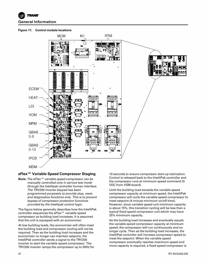
Figure 11. Control module locations
BCI
eFlex™ Variable Speed Compressor StagingNNoottee:: The eFlex™ variable speed compressor can be
manually controlled only in service test modethrough the Intellipak controller human interface.The TRV200 inverter keypad has beenprogrammed purposely to provide stop, reset,and diagnostics functions only. This is to preventbypass of compressor protection functionsprovided by the Intellipak control logic.
The figure below generally describes how the IntelliPakcontroller sequences the eFlex™ variable speedcompressor as building load increases. It is assumedthat the unit is equipped with an economizer.
At low building loads, the economizer will often meetthe building load and compressor cooling will not berequired. Then as the building load increases and theeconomizer no longer can maintain setpoint, theIntelliPak controller sends a signal to the TRV200inverter to start the variable speed compressor. TheTRV200 inverter ramps the compressor up to 50Hz for
10 seconds to ensure compressor start-up lubrication.Control is released back to the IntelliPak controller andthe compressor runs at minimum speed command (0VDC from VSM board).
Until the building load exceeds the variable speedcompressor capacity at minimum speed, the IntelliPakcompressor will cycle the variable speed compressor tomeet setpoint (4 minute minimum on/off time).However, since variable speed unit minimum capacityis about 15%, this transition cycling will be less than atypical fixed speed compressor unit which may have25% minimum capacity.
As the building load increases and eventually equalsthe variable speed compressor capacity at minimumspeed, the compressor will run continuously and nolonger cycle. Then as the building load increases, theIntelliPak controller will increase compressor speed tomeet the setpoint. When the variable speedcompressor eventually reaches maximum speed andmore capacity is required, a fixed speed compressor is
GGeenneerraall IInnffoorrmmaattiioonn

RT-SVX24Q-EN 21
started while the variable speed compressor speed issimultaneously ramped back down to minimum. Notethat capacity overlap is typically provided between
each stage of operation to provide continuous capacitymodulation and minimize compressor cycling betweenstages.
Figure 12. eFlex™ variable speed compressor, IntelliPak controller sequences
NNoottee:: The number of compressor stages varies from 3to 7 depending on eFlex™ unit size.
Single Zone Variable Air Volume(SZVAV) OnlyThe IntelliPak controls platform will support SingleZone VAV as an optional unit control type in order tomeet ASHRAE 90.1. The basic control will be a hybridVAV/CV configured unit that provides dischargetemperature control to a varying discharge airtemperature target setpoint based on the spacetemperature and/or humidity conditions. Concurrently,the unit will control and optimize the supply fan speedto maintain the zone temperature to a zonetemperature setpoint.
Supply Fan Output ControlUnits configured for Single Zone VAV control willutilize the same supply fan output control scheme ason traditional VAV units except the VFD signal will bebased on zone heating and cooling demand instead ofthe supply air pressure.
VFD ControlSingle Zone VAV units will be equipped with a VFD-controlled supply fan which is controlled via a 0-10VDCsignal from the Rooftop Module (RTM). The VFD willmodulate the supply fan motor speed, accelerating ordecelerating as required to maintain the zonetemperature to the zone temperature setpoint. Whensubjected to high ambient return conditions the VFDwill reduce its output frequency to maintain operation.Bypass control is offered to provide full nominalairflow in the event of drive failure.
Ventilation ControlUnits configured for Single Zone VAV control willrequire special handling of the OA Damper MinimumPosition control in order to compensate for the non-linearity of airflow associated with the variable supplyfan speed and damper combinations. Units configuredfor Traq™ with or without DCV will operate identicallyto traditional units with no control changes.
Space Pressure ControlFor units configured with Space Pressure Control withor without Statitrac, the new schemes implemented foreconomizer minimum position handling requirechanges to the existing Space Pressure Control schemein order to prevent over/under pressurization. Theoverall scheme will remain very similar to VAV unitswith Space Pressure Control with the exception of thedynamic Exhaust Enable Setpoint.
For SZVAV an Exhaust Enable Setpoint must beselected during the 100% Fan Speed Command. Onceselected, the difference between the Exhaust EnableSetpoint and Design OA Damper Minimum Position at100% Fan Speed Command will be calculated. Thedifference calculated will be used as an offset andadded to the Active Building Design OA MinimumPosition Target in order to calculate the dynamicExhaust Enable Target, which will be used throughoutthe Supply Fan Speed/OA Damper Position range.
The Exhaust Enable Target could be above or belowthe Active Building Design OA Minimum PositionTarget Setpoint, based on the Active Exhaust EnableSetpoint being set above or below the Building DesignMinimum Position at 100% Fan Speed Command. Notethat an Exhaust Enable Setpoint of 0% will result in the
GGeenneerraall IInnffoorrmmaattiioonn

22 RT-SVX24Q-EN
same effect on Exhaust Fan control as on VAVapplications with and without Statitrac.
Occupied Cooling OperationFor normal cooling operation, cooling capacity will bestaged or modulated in order to meet the calculateddischarge air target setpoint. If the current activecooling capacity is controlling the discharge air withinthe deadband, no additional cooling capacity changewill be requested. As the Discharge Air Temperaturerises above the deadband, the algorithm will requestadditional capacity as required (additional compressorsor economizer). As the Discharge Air Temperature fallsbelow the deadband, the algorithm will request areduction in active capacity.
Default Economizer OperationBy default, the unit will be setup to optimize theminimum supply fan speed capability duringEconomizer Only operation. If the economizer is able tomeet the demand alone, due to desirable ambientconditions, the supply fan speed will be allowed toincrease above the minimum prior to utilizingmechanical cooling if discharge air setpoint falls belowthe discharge air Lower Limit (Cooling) setpoint.
Unoccupied ModeIn Unoccupied mode the unit will utilize setbacksetpoints, 0% Minimum OA Damper position, and AutoFan Mode operation as on normal CV units. The SupplyFan speed, and cooling and modulating types of heat,will be controlled to the discharge air target setpoint asis done during occupied periods. The Supply fan speedduring staged heat control will be forced to 100% as onnormal CV units.
Occupied Heating OperationOccupied heating operation has two separate controlsequences; staged and modulated. All staged heatingtypes will drive the supply fan to maximum flow andstage heating to control to the Zone Heating Setpoint.For units with Hydronic and Gas heat, modulatedSZVAV Heating. On an initial call for heating, thesupply fan will drive to the minimum heating airflow.
On an additional call for heating, the heat will control inorder to meet the calculated discharge air targetsetpoint. As the load in the zone continues to requestheat operation, the supply fan will ramp-up while thecontrol maintains the heating discharge airtemperature. Heating can be configured for either theenergy saving SZVAV Heating solution as describedabove, or the traditional, less efficient CV Heatingsolution.
Compressor (DX) CoolingCompressor control and protection schemes willfunction identical to that of a traditional unit. Normalcompressor proving and disable input monitoring willremain in effect as well as normal 3-minute minimum
on, off, and inter-stage timers. Also, all existing headpressure control schemes will be in effect.
Cooling SequenceIf the control determines that there is a need for activecooling capacity in order to meet the calculateddischarge air target setpoint, once supply fan provinghas been made, the unit will begin to stagecompressors accordingly. Note that the compressorstaging order will be based on unit configuration andcompressor lead/lag status.
Once the discharge air target setpoint calculation hasreached the Minimum Setpoint and compressors arebeing utilized to meet the demand, as the discharge airtarget setpoint value continues to calculate lower thealgorithm will begin to ramp the supply fan speed uptoward 100%. Note that the supply fan speed willremain at the compressor stage’s associated minimumvalue (as described below) until the discharge air targetsetpoint value is calculated below the discharge airtemperature Minimum Setpoint (limited discharge airtarget setpoint).
As the cooling load in the zone decreases the zonecooling algorithm will reduce the speed of the fandown to minimum per compressor stage and controlthe compressors accordingly. As the compressorsbegin to de-energize, the supply fan speed will fall backto the Cooling Stage’s associated minimum fan speed,but not below. As the load in the zone continues todrop, cooling capacity will be reduced in order tomaintain the discharge air within the ± ½ discharge airtarget deadband.
Fault Detection and DiagnosticsFault Detection of the Outdoor Air Damper will beevaluated based on the commanded position of thedamper compared to the feedback position of thedamper.
The damper is commanded to a position based on a 2-10 VDC signal. If the Damper position is outside of±10% of the commanded position, a diagnostic isgenerated.
UUnniitt NNoott EEccoonnoommiizziinngg wwhheenn iitt sshhoouulldd bbee::
The Unit is operating in Cooling Mode, Economizing isenabled and/or Mechanical Cooling is enabled. If theCommanded Economizer Position is greater thanCurrent Economizer Feedback Position + 10% for 5continuous minutes, Unit Not Economizing when itshould be diagnostic is generated.
UUnniitt EEccoonnoommiizziinngg wwhheenn iitt sshhoouulldd nnoott bbee::
The unit is operating in Cooling Mode, Economizing isenabled and or Mechanical Cooling is enabled. If thecommanded Economizer Position is less than thecurrent Economizer Feedback Position - 10% for 5continuous minutes, Unit Economizing When it shouldnot be diagnostic is generated.
OOuuttddoooorr AAiirr DDaammppeerr NNoott MMoodduullaattiinngg
GGeenneerraall IInnffoorrmmaattiioonn

RT-SVX24Q-EN 23
The unit is operating in Ventilation Only Mode - notattempting to Economize and the Commanded DamperPosition is greater than the Current Damper FeedbackPosition + 10% for 5 continuous minutes, Outdoor AirDamper Not Modulating diagnostic is generated.
EExxcceessssiivvee OOuuttddoooorr AAiirr
The unit is operating in Ventilation Only Mode - notattempting to Economize and the Commanded DamperPosition is less than the Current Damper Feedback
Position - 10% for 5 continuous minutes. ExcessiveOutdoor Air diagnostic is generated.
To change the Economizer Control Function to drybulb, go to the Configuration Menu on the HumanInterface Module and set Comparative Enthalpy to "NotInstalled".This allows the user to select dry bulb underthe Economizer Control Function which is a Submenuof the Setup Menu. For additional instructions pleasesee the Programming and Troubleshooting Guide.
GGeenneerraall IInnffoorrmmaattiioonn
24 RT-SVX24Q-EN
Pre-InstallationUnit InspectionTo protect against loss due to damage incurred intransit, perform inspection immediately upon receipt ofthe unit.
Exterior InspectionIf the job site inspection reveals damage or materialshortages, file a claim with the carrier immediately.Specify the type and extent of the damage on the bill oflading before signing. Notify the appropriate salesrepresentative.
IImmppoorrttaanntt:: Do not proceed with installation of adamaged unit without salesrepresentative’s approval.
• Visually inspect the complete exterior for signs ofshipping damages to unit or packing material.
• Verify that the nameplate data matches the salesorder and bill of lading.
• Verify that the unit is properly equipped and thereare no material shortages.
• Verify that the power supply complies with the unitnameplate and electric heater specifications.
Inspection for Concealed DamageVisually inspect the components for concealed damageas soon as possible after delivery and before it isstored.
Do NOT walk on the sheet metal base pans. Bridgingbetween the unit’s main supports may consist ofmultiple 2 by 12 boards or sheet metal grating.
WWAARRNNIINNGGNNoo SStteepp SSuurrffaaccee!!FFaaiilluurree ttoo ffoollllooww iinnssttrruuccttiioonn bbeellooww ccoouulldd rreessuulltt iinnddeeaatthh oorr sseerriioouuss iinnjjuurryy..DDoo nnoott wwaallkk oonn tthhee sshheeeett mmeettaall ddrraaiinn ppaann.. WWaallkkiinnggoonn tthhee ddrraaiinn ppaann ccoouulldd ccaauussee tthhee ssuuppppoorrttiinngg mmeettaallttoo ccoollllaappssee aanndd rreessuulltt iinn tthhee ooppeerraattoorr//tteecchhnniicciiaannffaalllliinngg..
If concealed damage is discovered:
• Notify the carrier’s terminal of the damageimmediately by phone and by mail.
• Concealed damage must be reported within 15days.
• Request an immediate, joint inspection of thedamage with the carrier and consignee.
• Stop unpacking the unit.
• Do not remove damaged material from receivinglocation.
• Take photos of the damage, if possible.
• The owner must provide reasonable evidence thatthe damage did not occur after delivery.
RepairNotify the appropriate sales representative beforearranging unit installation or repair.
IImmppoorrttaanntt:: Do not repair unit until the damage hasbeen inspected by the carrier’srepresentative.
StorageStore unit in a level and dry location. Use adequateblocking under the base rail. If unit is not level andsupported adequately, damage may occur whenremoving screws and opening doors.
Take precautions to prevent condensate formationinside the unit electrical components and motors when:
• The unit is stored before it is installed; or,
• The unit is set on the roof curb and temporaryauxiliary heat is provided in the building.
Isolate all side panel service entrances and base panopenings (e.g., conduit holes, S/A and R/A openings,and flue openings) to minimize ambient air fromentering the unit until it is ready for startup.
NNoottee:: Do not use the unit heater as temporary heatwithout completing the startup proceduresdetailed under Startup information.
The manufacturer will not assume responsibility forequipment damage resulting from accumulation ofcondensate on the unit electrical and/or mechanicalcomponents.
Unit ClearancesMinimum Required Clearance (see Dimensional Datachapter) illustrates the minimum operating and serviceclearances for either a single or multiple unitinstallation.
These clearances are the minimum distancesnecessary for adequate service, cataloged unitcapacity, and peak operating efficiency. Providing lessthan the recommended clearances may result incondenser coil starvation, “short-circulating” ofexhaust and economizer airflows, or recirculation ofhot condenser air.

RT-SVX24Q-EN 25
Unit Dimensions and WeightInformation
Description Reference
Air-Cooled Condenser
One-piece unit dimensions See “Dimensional Data,” p. 28
Two-piece unit dimensions See “Dimensional Data,” p. 28
Three-piece unit dimensions See “Dimensional Data,” p. 28
Roof curb weights See “Weights,” p. 40
Evaporative Condenser
Two-piece unit dimensions See “Dimensional Data,” p. 28
Three-piece unit dimensions See “Dimensional Data,” p. 28
Roof curb weights See “Weights,” p. 40
Installation ChecklistGeneral Checklist (Applies to all units)The checklist listed below is a summary of the stepsrequired to successfully install a Commercial rooftopunit. This checklist is intended to acquaint the installingpersonnel with what is required in the installationprocess. It does not replace the detailed instructionscalled out in the applicable sections of this manual.
IImmppoorrttaanntt:: This checklist does not replace the detailedinstructions called out in the applicablesections of this manual.
☐ Unit checked for shipping damage and materialshortage.
☐ Verify that the installation location of the unit willprovide the required clearance for properoperation.
☐ Roof curb assembled and installed.
☐ Roof curb level and square.
☐ Ductwork secured to curb, or unit.
☐ Corners of duct adapters sealed on units withhorizontal supply or return.
☐ Horizontal supply or return ductwork is selfsupporting.
☐ Pitch pocket installed for units with power supplythrough building roof.
☐ Unit set on curb and checked level.
☐ Unit-to-curb seal checked to ensure it is tight andwithout buckles or cracks.
☐ Condensate drain lines installed to each evaporatordrain connection.
☐ Verify that all access doors open 100% and are notobstructed by drain lines etc.
☐ Shipping hardware removed from each compressorassembly.
☐ Shipping hold-down bolts and shipping channelsremoved from the supply and exhaust/return fanswith spring isolators.
☐ Supply and exhaust/return fans spring isolatorschecked for proper adjustment.
☐ Plastic coverings (paint shields) removed from allcompressors (if present).
☐ Verify all discharge and suction line service valvesare back seated.
☐ Compressor crankcase heaters energized for aminimum of 12 hours prior to unit refrigerationsystem start-up.
☐ Verify that unit literature (IOM, PTG) are left insidecontrol box for start-up.
Unit Rigging and Placement (Two-piece—addition to General Checklist)☐ First, rig and set the low side unit on the roof curb
(aligned with return end).
☐ Remove the rail connector splice brackets andinstall the brackets on the low side unit base rails.
☐ Take off the side panels (these are labeled) and thetop cover of the high side unit and set aside to beassembled later.
☐ Rig and set the high side unit on roof curb pedestal.
☐ Lift the unit and position it over the pedestal.
☐ Use the rail splice bracket as an alignment aid toconnect the Low and high side units. The Low andhigh side unit rails should be butted together with amaximum 2" (preferably 1") separation.
☐ Remove the left upper and lower louvered panels ofthe high side unit as well as the corner panels oneach side to aid in tubing and wiring connections.
☐ Close refrigeration shut off valves as indicated inthis manual—Liquid, discharge, hot gas bypass (ifpresent), and hot gas reheat (if present).
☐ For Evaporative Condensers: Recover/transfercharge from tubing between shut valves and stubpoint.
☐ For 2 and 3 piece Air-Cooled condensers add fieldcharge per nameplate.
☐ Braze refrigerant piping connections and leak test.
☐ Low side and high side evacuated to 500 microns.
☐ Standing vacuum does not rise over 200 microns in15 minutes.
☐ Open service valves to allow refrigerant flow.
☐ Refrigerant released from discharge to suction untilsuction pressure is approximately 60 PSIG.
☐ Power wires connected in connection box.
☐ Control wires connected in connection box.
PPrree--IInnssttaallllaattiioonn

26 RT-SVX24Q-EN
☐ Seal air gaps around wiring and refrigerant tubingthrough bulkhead.
☐ Side panels and top cover assembled between highand low side.
☐ Verify line dampening weights are installed on eachdischarge line.
Unit Rigging and Placement (Three-pieceunit) (in addition to two-piece unitrigging and placement)☐ Rail guide attached to evaporator section base rails.
☐ Evaporator section rigged and set onto roof curb,aligned with supply end.
☐ Removed and discarded shipping protection panelsand top blockoffs from evaporator section.
☐ Removed side panels and roof cap from evaporatorsection.
☐ Applied gasket and butyl tape as indicated in theIOM.
☐ Removed and discarded shipping protection panelsand top block off from outside air section.
☐ Rigged and set outside air section onto roof curb towithin 2" of evaporator section.
☐ Using 0.75" x 24" threaded rod pull and secureevaporator section and outside air section together.
☐ Using .375" bolts, nuts and washers pull and securethe roof rails together.
☐ Installed roof splice plate.
☐ Added bullwrap to electrical wiring betweenevaporator and outside air section.
☐ Connected power and control wiring betweenevaporator and outside air section.
☐ Gasket applied and side panels installed on unitsplit.
☐ Butyl tape applied on top of unit split along roofseam and roof cap installed.
☐ Field Installed Control Wiring—Complete the fieldwiring connections for constant volume or variableair volume controls as applicable. Refer to “FieldInstalled Control Wiring” for guidelines.
Main Electrical Power Requirements☐ Verify that the power supply to the unit complies
with the unit nameplate specification. Refer to MainUnit Power Wiring in the Installation chapter.
☐ Properly ground the unit.
☐ Inspect all control panel components and tightenany loose connections.
☐ Connect properly sized and protected power supplywiring to a field supplied/installed disconnect andthe unit (copper wiring only to the unit).
☐ Verify that phasing to the unit is correct (ABC).
☐ Turn the 1S2 toggle switch off to prevent accidentalunit operation.
☐ Turn on power to the unit.
☐ Press the STOP button on the Human Interface(1U2).
☐ Verify that all compressor crankcase heaters areenergized for at least 8 hours prior to unit start-up.
IImmppoorrttaanntt:: Note: All field-installed wiring must complywith NEC and applicable local codes.
Electric Heat Units☐ Inspect the heater junction box and control panel;
tighten any loose connections.
☐ Check electric heat circuits for continuity.
☐ Two and Three piece units only) Route powerwiring to high side junction box.
Gas Heat Units☐ Gas supply line properly sized and connected to the
unit gas train.
☐ All gas piping joints properly sealed.
☐ Drip leg installed in the gas piping near the unit.
☐ Gas piping leak checked with a soap solution. Ifpiping connections to the unit are complete, do notpressurize piping in excess of 0.50 psig or 14" W.C.to prevent component failure.
☐ Main supply gas pressure between 7" and 14" W.C.
☐ Flue Tubes clear of any obstructions.
☐ Factory-supplied flue assembly installed on theunit.
☐ Connect the 3/4" CPVC furnace drain stub-out to aproper condensate drain.
☐ Install field provided heat tape to furnace drain line.
Hot Water Heat☐ Route properly sized water piping through the base
of the unit into the heating section.
☐ Install the factory-supplied, 3-way modulatingvalve.
☐ Complete the valve actuator wiring.
Steam Heat☐ Route properly sized steam piping through the base
of the unit into the heating section.
☐ Install the factory-supplied, 2-way modulatingvalve.
☐ Complete the valve actuator wiring.
☐ Install 1/2", 15-degree swing check vacuum breaker(s) at the top of each coil section. Vent breaker(s) to
PPrree--IInnssttaallllaattiioonn

RT-SVX24Q-EN 27
the atmosphere or merge with return main atdischarge side of steam trap.
☐ Position the steam trap discharge at least 12" belowthe outlet connection on the coil.
☐ Use float and thermostatic traps in the system, asrequired by the application.
O/A Pressure Sensor and TubingInstallation (All VAV units and CV unitswith return fan or StatiTrac)☐ O/A pressure sensor mounted to the roof bracket.
☐ Factory supplied pneumatic tubing installedbetween the O/A pressure sensor and the connectoron the vertical support.
☐ (Units with StatiTrac) Field supplied pneumatictubing connected to the proper fitting on the spacepressure transducer located in the filter section, andthe other end routed to a suitable sensing locationwithin the controlled space.
Evaporative Condenser☐ Remove fan bracket.
☐ Hookup inlet and drain piping.
☐ Install heat tape if needed.
☐ Setup drain hold or drain on power loss.
☐ Setup Mechanical Float.
☐ Setup drain time.
☐ Setup water quality management (3rd partysystem).
☐ Options setup.
☐ Calibrate Conductivity Controller.
☐ Setup blowdown setpoints on the conductivitysensor.
Energy Recovery Wheel☐ Verify that the wheel turns freely though a full
rotation.
☐ Confirm that all wheel segments are fully engagedin the wheel frame and that the segment retainersare completely fastened.
☐ Confirm the seal adjustment and proper belttracking on the wheel rim.
PPrree--IInnssttaallllaattiioonn

28 RT-SVX24Q-EN
Dimensional DataFigure 13. Unit top/left view
1-1/4 NPT. DRAIN2X TYP. LEFT & RIGHT SIDES OF UNIT
Detail A
Table 6. Unit dimensions (in.)—ONE-PIECE unit air-cooled—WITHOUT energy recovery wheel
TonsBlankSec-tion
Lifting Lug Locations Unit Width Unit Height ReturnFan
ExhaustFan
Unit Dimensions Air Handler Side Condens-er Side M N O P R J K
A B C1 C2 C3 D1
90
None 437 3/16 159 15/16 66 252 14/16 N/A 27 11/16 139 13/16 143 8/16
103 12/16 97 9/16 103 7/16 29 3/16 174 ft 485 6/16 159 15/16 66 252 14/16 N/A 54 2/16 139 13/16 143 8/16
8 ft 533 9/16 159 15/16 66 252 14/16 N/A 54 2/16 139 13/16 143 8/16
105
None 455 3/16 159 15/16 66 252 14/16 N/A 27 11/16 139 13/16 143 8/16
103 12/16 97 9/16 103 7/16 29 3/16 174 ft 503 6/16 159 15/16 66 252 14/16 N/A 54 2/16 139 13/16 143 8/16
8 ft 551 9/16 159 15/16 66 252 14/16 N/A 54 2/16 139 13/16 143 8/16
120-150(a) None 528 15/16 197 1/16 66 269 6/16 N/A 63 2/16 139 13/16 143 8/16 — — — — —

RT-SVX24Q-EN 29
Table 6. Unit dimensions (in.)—ONE-PIECE unit air-cooled—WITHOUT energy recovery wheel (continued)
TonsBlankSec-tion
Lifting Lug Locations Unit Width Unit Height ReturnFan
ExhaustFan
Unit Dimensions Air Handler Side Condens-er Side M N O P R J K
A B C1 C2 C3 D1
120-150(a)
4 ft 577 2/16 197 1/16 66 269 6/16 N/A 63 2/16 139 13/16 143 8/16 — — — — —
120-150(b) None 540 15/16 197 1/16 66 269 6/16 N/A 63 2/16 139 13/16 143 8/16 — — — — —
(a) All units except high heat gas models(b) High heat gas models only
Table 7. Unit dimensions (in.)—ONE-PIECE unit air-cooled—WITH energy recovery wheel
Tons BlankSection
Unit Dimensions Lifting Lug Locations Unit Width Unit Height
A BAir Handler Side Condenser
Side M N O P RC1 C2 C3 D1
90 None 533 9/16 256 5/16 66 201 1/16 349 4/16 27 11/16 139 13/16 143 8/16 103 12/16 97 9/16 103 7/16
90 4 ft 581 13/16 256 5/16 66 201 1/16 349 4/16 54 2/16 139 13/16 143 8/16 103 12/16 97 9/16 103 7/16
105 None 551 9/16 256 5/16 66 201 1/16 349 4/16 27 11/16 139 13/16 143 8/16 103 12/16 97 9/16 103 7/16
105 4 ft 599 13/16 256 5/16 66 201 1/16 349 4/16 54 2/16 139 13/16 143 8/16 103 12/16 97 9/16 103 7/16
Tons BlankSection
ReturnFan
ExhaustFan
J K
90 None N/A 17
90 4 ft N/A 17
105 None N/A 17
105 4 ft N/A 17
Table 8. Unit dimensions (in.)—TWO-PIECE unit air-cooled—WITHOUT energy recovery wheel
TonsBlankSec-tion
Unit Dimensions Lifting Lug Locations Lug Locations
A B E FAir Handler Side Condenser
SideC1 C2 C3 C4 D1 D2
90
None 454 4/16 159 15/16 330 14/16 121 6/16 66 252 14/16 N/A N/A 16 112 7/16
4 ft 502 7/16 159 15/16 379 1/16 121 6/16 66 252 14/16 368 6/16 N/A 16 112 7/16
8 ft 550 11/16 159 15/16 427 4/16 121 6/16 66 252 14/16 416 10/16 N/A 16 112 7/16
105
None 472 4/16 159 15/16 330 14/16 139 6/16 66 252 14/16 N/A N/A 16 130 7/16
4 ft 520 7/16 159 15/16 379 1/16 139 6/16 66 252 14/16 368 6/16 N/A 16 130 7/16
8 ft 568 11/16 159 15/16 427 4/16 139 6/16 66 252 14/16 416 10/16 N/A 16 130 7/16120-150(a) None 546 197 1/16 395 10/16 148 6/16 66 269 6/16 384 15/16 N/A 16 139 7/16120-150(a) 4 ft 594 4/16 197 1/16 443 13/16 148 6/16 66 269 6/16 433 2/16 N/A 16 139 7/16120-150(a) 8 ft 642 7/16 197 1/16 492 1/16 148 6/16 66 269 6/16 481 6/16 N/A 16 139 7/16120-150(a) None 558 197 1/16 407 10/16 148 6/16 66 269 6/16 396 15/16 N/A 16 139 7/16
DDiimmeennssiioonnaall DDaattaa

30 RT-SVX24Q-EN
Table 8. Unit dimensions (in.)—TWO-PIECE unit air-cooled—WITHOUT energy recovery wheel (continued)
TonsBlankSec-tion
Unit Width Unit Height ReturnFan
ExhaustFan
M N O P R J K
90
None 139 13/16 143 8/16 103 12/16 97 9/16 103 7/16 29 3/16 17
4 ft 139 13/16 143 8/16 103 12/16 97 9/16 103 7/16 29 3/16 17
8 ft 139 13/16 143 8/16 103 12/16 97 9/16 103 7/16 29 3/16 17
105
None 139 13/16 143 8/16 103 12/16 97 9/16 103 7/16 29 3/16 17
4 ft 139 13/16 143 8/16 103 12/16 97 9/16 103 7/16 29 3/16 17
8 ft 139 13/16 143 8/16 103 12/16 97 9/16 103 7/16 29 3/16 17120-150(a) None 139 13/16 143 8/16 103 12/16 97 9/16 103 7/16 29 3/16 17120-150(a) 4 ft 139 13/16 143 8/16 103 12/16 97 9/16 103 7/16 29 3/16 17120-150(a) 8 ft 139 13/16 143 8/16 103 12/16 97 9/16 103 7/16 29 3/16 17120-150(b) None 139 13/16 143 8/16 103 12/16 97 9/16 103 7/16 29 3/16 17
(a) High Heat Gas Models Only(b) High Heat Gas Models Only
Table 9. Unit dimensions (in.)—TWO-PIECE unit air-cooled—WITH energy recovery wheel
Tons BlankSection
Unit Dimensions Lifting Lug Locations Lug Locations
A B E FAir Handler Side Condenser
SideC1 C2 C3 C4 D1 D2
90
None 550 11/16 256 5/16 427 5/16 121 6/16 66 201 1/16 349 4/16 N/A 16 112 7/16
4 ft 598 14/16 256 5/16 475 8/16 121 6/16 66 201 1/16 349 4/16 464 13/16 16 112 7/16
8 ft 647 2/16 256 5/16 523 12/16 121 6/16 66 201 1/16 349 4/16 513 16 112 7/16
105
None 568 11/16 256 5/16 427 5/16 139 6/16 66 201 1/16 349 4/16 N/A 16 130 7/16
4 ft 616 14/16 256 5/16 475 8/16 139 6/16 66 201 1/16 349 4/16 464 13/16 16 130 7/16
8 ft 665 2/16 256 5/16 523 12/16 139 6/16 66 201 1/16 349 4/16 513 16 130 7/16120-150(a) None 642 7/16 293 8/16 492 1/16 148 6/16 66 238 5/16 365 5/16 480 14/16 16 139 7/16
120-150(a) 4 ft 690 10/16 293 8/16 540 4/16 148 6/16 66 238 5/16 365 5/16 529 2/16 16 139 7/16
120-150(a) 8 ft 738 14/16 293 8/16 588 8/16 148 6/16 66 238 5/16 365 5/16 577 5/16 16 139 7/16
120-150(a) None 654 7/16 293 8/16 504 1/16 148 6/16 66 238 5/16 365 5/16 492 14/16 16 139 7/16
Tons BlankSection
Unit Width Unit Height ReturnFan
ExhaustFan
M N O P R J K
90
None 139 13/16 143 8/16 103 12/16 97 9/16 103 7/16 N/A 17
4 ft 139 13/16 143 8/16 103 12/16 97 9/16 103 7/16 N/A 17
8 ft 139 13/16 143 8/16 103 12/16 97 9/16 103 7/16 N/A 17
105
None 139 13/16 143 8/16 103 12/16 97 9/16 103 7/16 N/A 17
4 ft 139 13/16 143 8/16 103 12/16 97 9/16 103 7/16 N/A 17
8 ft 139 13/16 143 8/16 103 12/16 97 9/16 103 7/16 N/A 17120-150(a) None 139 13/16 143 8/16 103 12/16 97 9/16 103 7/16 N/A 17120-150(a) 4 ft 139 13/16 143 8/16 103 12/16 97 9/16 103 7/16 N/A 17120-150(a) 8 ft 139 13/16 143 8/16 103 12/16 97 9/16 103 7/16 N/A 17
120-150(b) None 139 13/16 143 8/16 103 12/16 97 9/16 103 7/16 N/A 17
(a) High Heat Gas Models Only(b) High Heat Gas Models Only
DDiimmeennssiioonnaall DDaattaa

RT-SVX24Q-EN 31
Table 10. Unit dimensions (in.)—TWO-PIECE unit evaporative condensing—WITHOUT energy recovery wheel
Tonnage BlankSection
Unit Dimensions Lifting Lug Locations Lug Locations
A B E FAir Handler Side Condenser
SideC1 C2 C3 C4 D1 D2
100-118
None 475 8/16 159 15/16 330 14/16 142 10/16 66 252 14/16 N/A N/A 16 133 11/16
4 ft 523 12/16 159 15/16 379 1/16 142 10/16 66 252 14/16 368 6/16 N/A 16 133 11/16
8 ft 571 15/16 159 15/16 427 5/16 142 10/16 66 252 14/16
416 10/16 N/A 16 133 11/16
128-162(a)None 540 5/16 197 1/16 395 10/16 142 10/16 66 269 6/16 384 15/
16 N/A 16 133 11/16
4 ft 588 8/16 197 1/16 443 14/16 142 10/16 66 269 6/16 433 2/16 N/A 16 133 11/16
8 ft 636 11/16 197 1/16 492 1/16 142 10/16 66 269 6/16 481 6/16 N/A 16 133 11/16
128-162(b) None 552 5/16 197 1/16 407 10/16 142 10/16 66 269 6/16 396 15/16 N/A ― ―
Tonnage BlankSection
Unit Width Unit Height ReturnFan
ExhaustFan
M N O P R J K
100-118
None 139 13/16 143 8/16 103 12/16 97 9/16 102 6/16 29 3/16 17
4 ft 139 13/16 143 8/16 103 12/16 97 9/16 102 6/16 29 3/16 17
8 ft 139 13/16 143 8/16 103 12/16 97 9/16 102 6/16 29 3/16 17
128-162(a)None 139 13/16 143 8/16 103 12/16 97 9/16 102 6/16 29 3/16 17
4 ft 139 13/16 143 8/16 103 12/16 97 9/16 102 6/16 29 3/16 17
8 ft 139 13/16 143 8/16 103 12/16 97 9/16 102 6/16 29 3/16 17
128-162(b) None ― ― ― ― ― 29 3/16 17
Table 11. Unit dimensions (in.)—TWO-PIECE unit evaporative condensing—WITH energy recovery wheel
Tons BlankSection
Unit Dimensions Lifting Lug Locations Lug Locations
A B E FAir Handler Side Condenser
SideC1 C2 C3 C4 D1 D2
100-118
None 571 15/16 256 5/16 427 5/16 142 10/16 66 201 1/16 349 4/16 N/A 16 133 11/16
4 ft 620 3/16 256 5/16 475 8/16 142 10/16 66 201 1/16 349 4/16 464 13/16 16 133 11/16
8 ft 668 6/16 256 5/16 523 12/16 142 10/16 66 201 1/16 349 4/16 513 16 133 11/16
128-162(a)
None 636 11/16 293 8/16 492 1/16 142 10/16 66 238 5/16 365 5/16 480 14/16 16 133 11/16
4 ft 684 15/16 293 8/16 540 4/16 142 10/16 66 238 5/16 365 5/16 529 2/16 16 133 11/16
8 ft 733 2/16 293 8/16 588 8/16 142 10/16 66 238 5/16 365 5/16 577 5/16 16 133 11/16128-162
(a) None 648 11/16 293 8/16 504 1/16 142 10/16 66 238 5/16 365 5/16 492 14/16 16 133 11/16
TonsUnit Width Unit Height Return
FanExhaustFan
M N O P R J K
100-118
139 13/16 143 8/16 103 12/16 97 9/16 102 6/16 N/A 17139 13/16 143 8/16 103 12/16 97 9/16 102 6/16 N/A 17139 13/16 143 8/16 103 12/16 97 9/16 102 6/16 N/A 17
128-162(a)
139 13/16 143 8/16 103 12/16 97 9/16 102 6/16 N/A 17139 13/16 143 8/16 103 12/16 97 9/16 102 6/16 N/A 17139 13/16 143 8/16 103 12/16 97 9/16 102 6/16 N/A 17
128-162(b) 139 13/16 143 8/16 103 12/16 97 9/16 102 6/16 N/A 17
(a) High Heat Gas Models Only(b) High Heat Gas Models Only
DDiimmeennssiioonnaall DDaattaa
32 RT-SVX24Q-EN
Table 12. Unit dimensions (in.)—THREE-PIECE unit air-cooled—WITHOUT energy recovery wheel
TonsBlankSec-tion
Unit Dimensions Lifting Lug Locations
A B E E1 E2 FAir Handler Side
C1 C2 C3 C4 C5 C6
90
None 473 9/16 179 3/16 350 3/16 144 15/16 205 3/16 121 6/16 11 14/16 N/A 138 9/16 151 6/16 272 339 11/16
4 ft 521 12/16 179 3/16 398 6/16 144 15/16 253 7/16 121 6/16 11 14/16 N/A 138 9/16 151 6/16 272 387 14/16
8 ft 569 15/16 179 3/16 446 9/16 144 15/16 301 10/16 121 6/16 11 14/16 N/A 138 9/16 151 6/16 272 436 1/16
105
None 491 9/16 179 3/16 350 3/16 144 15/16 205 3/16 139 6/16 11 14/16 N/A 138 9/16 151 6/16 272 339 11/16
4 ft 539 12/16 179 3/16 398 6/16 144 15/16 253 7/16 139 6/16 11 14/16 N/A 138 9/16 151 6/16 272 387 14/16
8 ft 587 15/16 179 3/16 446 9/16 144 15/16 301 10/16 139 6/16 11 14/16 N/A 138 9/16 151 6/16 272 436 1/16
120-150(a)
None 571 8/16 222 9/16 421 2/16 161 2/16 260 148 6/16 11 14/16 N/A 155 2/16 167 5/16 294 14/16 410 10/16
4 ft 619 11/16 222 9/16 469 5/16 161 2/16 308 4/16 148 6/16 11 14/16 N/A 155 2/16 167 5/16 294 14/16 458 13/16
8 ft 667 15/16 222 9/16 517 9/16 161 2/16 356 7/16 148 6/16 11 14/16 N/A 155 2/16 167 5/16 294 14/16 507 1/16120-150(a) None 583 8/16 222 9/16 433 2/16 161 2/16 272 148 6/16 11 14/16 N/A 155 2/16 167 5/16 294 14/16 422 10/16
TonsBlankSec-tion
Lug Locations Unit Width Unit Height ReturnFan
ExhaustFan
CondenserSide M N O P R J K
D1 D2
90
None 16 112 7/16 139 13/16 143 8/16 103 12/16 97 9/16 103 7/16 29 3/16 17
4 ft 16 112 7/16 139 13/16 143 8/16 103 12/16 97 9/16 103 7/16 29 3/16 17
8 ft 16 112 7/16 139 13/16 143 8/16 103 12/16 97 9/16 103 7/16 29 3/16 17
105
None 16 130 7/16 139 13/16 143 8/16 103 12/16 97 9/16 103 7/16 29 3/16 17
4 ft 16 130 7/16 139 13/16 143 8/16 103 12/16 97 9/16 103 7/16 29 3/16 17
8 ft 16 130 7/16 139 13/16 143 8/16 103 12/16 97 9/16 103 7/16 29 3/16 17
120-150(a)
None 16 139 7/16 139 13/16 143 8/16 103 12/16 97 9/16 103 7/16 29 3/16 17
4 ft 16 139 7/16 139 13/16 143 8/16 103 12/16 97 9/16 103 7/16 29 3/16 17
8 ft 16 139 7/16 139 13/16 143 8/16 103 12/16 97 9/16 103 7/16 29 3/16 17120-150(b) None 16 139 7/16 139 13/16 143 8/16 103 12/16 97 9/16 103 7/16 29 3/16 17
(a) High Heat Gas Models Only(b) High Heat Gas Models Only
Table 13. Unit dimensions (in.)—THREE-PIECE unit air-cooled—WITH energy recovery wheel
Tons BlankSection
Unit Dimensions Lifting Lug Locations
A B E E1 E2 FAir Handler Side
C1 C2 C3 C4 C5 C6
90
None 569 15/16
275 10/16 446 9/16 241 6/16 205 3/16 121 6/16 17 12/16 201 1/16 234 13/
16247 13/16 368 7/16 436 2/16
4 ft 618 3/16 275 10/16
494 13/16 241 6/16 253 7/16 121 6/16 17 12/16 201 1/16 234 13/
16247 13/16 368 7/16 484 5/16
8 ft 666 6/16 275 10/16 543 241 6/16 301 10/
16 121 6/16 17 12/16 201 1/16 234 13/16
247 13/16 368 7/16 532 8/16
105
None 587 15/16
275 10/16 446 9/16 241 6/16 205 3/16 139 6/16 17 12/16 201 1/16 234 13/
16247 13/16 368 7/16 436 2/16
4 ft 636 3/16 275 10/16
494 13/16 241 6/16 253 7/16 139 6/16 17 12/16 201 1/16 234 13/
16247 13/16 368 7/16 484 5/16
8 ft 684 6/16 275 10/16 543 241 6/16 301 10/
16 139 6/16 17 12/16 201 1/16 234 13/16
247 13/16 368 7/16 532 8/16
120-150(a)
None 667 15/16
318 15/16 517 9/16 257 8/16 260 148 6/16 17 12/16 204 7/16 252 12/
16263 12/16 391 5/16 507 1/16
4 ft 716 2/16 318 15/16
565 12/16 257 8/16 308 4/16 148 6/16 17 12/16 204 7/16 252 12/
16263 12/16 391 5/16 555 4/16
8 ft 764 5/16 318 15/16
613 15/16 257 8/16 356 7/16 148 6/16 17 12/16 204 7/16 252 12/
16263 12/16 391 5/16 603 7/16
120-150(a) None 679 15/
16318 15/16 529 9/16 257 8/16 272 148 6/16 17 12/16 204 7/16 252 12/
16263 12/16 391 5/16 519 1/16
DDiimmeennssiioonnaall DDaattaa

RT-SVX24Q-EN 33
Table 13. Unit dimensions (in.)—THREE-PIECE unit air-cooled—WITH energy recovery wheel (continued)
Tons BlankSection
Lug Locations Unit Width Unit Height ReturnFan
ExhaustFan
CondenserSide M N O P R J K
D1 D2
90
None 16 112 7/16 139 13/16 143 8/16 103 12/
16 97 9/16 103 7/16 N/A 17
4 ft 16 112 7/16 139 13/16 143 8/16 103 12/
16 97 9/16 103 7/16 N/A 17
8 ft 16 112 7/16 139 13/16 143 8/16 103 12/
16 97 9/16 103 7/16 N/A 17
105
None 16 130 7/16 139 13/16 143 8/16 103 12/
16 97 9/16 103 7/16 N/A 17
4 ft 16 130 7/16 139 13/16 143 8/16 103 12/
16 97 9/16 103 7/16 N/A 17
8 ft 16 130 7/16 139 13/16 143 8/16 103 12/
16 97 9/16 103 7/16 N/A 17
120-150(a)
None 16 139 7/16 139 13/16 143 8/16 103 12/
16 97 9/16 103 7/16 N/A 17
4 ft 16 139 7/16 139 13/16 143 8/16 103 12/
16 97 9/16 103 7/16 N/A 17
8 ft 16 139 7/16 139 13/16 143 8/16 103 12/
16 97 9/16 103 7/16 N/A 17120-150(b) None 16 139 7/16 139 13/
16 143 8/16 103 12/16 97 9/16 103 7/16 N/A 17
(a) High Heat Gas Models Only(b) High Heat Gas Models Only
Table 14. Unit dimensions (in.)—THREE-PIECE unit evaporative condensing—WITHOUT energy recovery wheel
Tons BlankSection
Unit Dimensions Lifting Lug Locations
A B E E1 E2 FAir Handler Side
C1 C2 C3 C4 C5 C6
100/118
None 494 13/16 179 3/16 350 3/16 144 15/16 205 3/16 142 10/16 11 14/16 N/A 138 9/16 151 6/16 272 339 11/16
4 ft 543 179 3/16 398 6/16 144 15/16 253 7/16 142 10/16 11 14/16 N/A 138 9/16 151 6/16 272 387 14/16
8 ft 591 4/16 179 3/16 446 9/16 144 15/16 301 10/16 142 10/16 11 14/16 N/A 138 9/16 151 6/16 272 436 1/16
128-162(a)
None 565 12/16 222 9/16 421 2/16 161 2/16 260 142 10/16 11 14/16 N/A 155 2/16 167 5/16 294 14/16 410 10/16
4 ft 613 15/16 222 9/16 469 5/16 161 2/16 308 4/16 142 10/16 11 14/16 N/A 155 2/16 167 5/16 294 14/16 458 13/16
8 ft 662 3/16 222 9/16 517 9/16 161 2/16 356 7/16 142 10/16 11 14/16 N/A 155 2/16 167 5/16 294 14/16 507 1/16
128-162(a) None 577 12/16 222 9/16 433 2/16 161 2/16 272 142 10/16 11 14/16 N/A 155 2/16 167 5/16 294 14/16 422 10/16
Tons BlankSection
Lug Locations Unit Width Unit Height ReturnFan
ExhaustFan
Condenser SideM N O P R J K
D1 D2
100/118
None 16 133 11/16 139 13/16 143 8/16 103 12/16 97 9/16 102 12/16 29 3/16 17
4 ft 16 133 11/16 139 13/16 143 8/16 103 12/16 97 9/16 102 12/16 29 3/16 17
8 ft 16 133 11/16 139 13/16 143 8/16 103 12/16 97 9/16 102 12/16 29 3/16 17
128-162(a)
None 16 133 11/16 139 13/16 143 8/16 103 12/16 97 9/16 102 6/16 29 3/16 17
4 ft 16 133 11/16 139 13/16 143 8/16 103 12/16 97 9/16 102 6/16 29 3/16 17
8 ft 16 133 11/16 139 13/16 143 8/16 103 12/16 97 9/16 102 6/16 29 3/16 17
128-162(b) None 16 133 11/16 139 13/16 143 8/16 103 12/16 97 9/16 102 6/16 29 3/16 17
(a) High Heat Gas Models Only(b) High Heat Gas Models Only
DDiimmeennssiioonnaall DDaattaa

34 RT-SVX24Q-EN
Table 15. Unit dimensions (in.)—THREE-PIECE unit evaporative condensing—WITH energy recovery wheel
Tons BlankSection
Unit Dimensions Lifting Lug Locations
A B E E1 E2 FAir Handler Side
C1 C2 C3 C4 C5 C6
100/118
None 591 4/16 275 10/16 446 9/16 241 6/16 205 3/16 142 10/16 17 12/16 201 1/16 234 13/16
247 13/16 368 7/16 436 2/16
4 ft 639 7/16 275 10/16 494 13/16 241 6/16 253 7/16 142 10/16 17 12/16 201 1/16 234 13/
16247 13/16 368 7/16 484 5/16
8 ft 687 10/16 275 10/16 543 241 6/16 301 10/
16 142 10/16 17 12/16 201 1/16 234 13/16
247 13/16 368 7/16 532 8/16
128-162(a)
None 662 3/16 318 15/16 517 9/16 257 8/16 260 142 10/16 17 12/16 204 7/16 252 12/16
263 12/16 391 5/16 519 1/16
4 ft 710 6/16 318 15/16 565 12/16 257 8/16 308 4/16 142 10/16 17 12/16 204 7/16 252 12/
16263 12/16 391 5/16 507 1/16
8 ft 758 10/16 318 15/16 613 15/
16 257 8/16 356 7/16 142 10/16 17 12/16 204 7/16 252 12/16
263 12/16 391 5/16 555 4/16
128-162 (a) None 674 3/16 318 15/16 529 9/16 257 8/16 272 142 10/16 17 12/16 204 7/16 252 12/
16263 12/16 391 5/16 603 7/16
Tons BlankSection
Lug Locations Unit Width Unit Height Return Fan ExhaustFan
Condenser SideM N O P R J K
D1 D2
100/118
None 16 133 11/16 139 13/16 143 8/16 103 12/16 97 9/16 102 6/16 N/A 17
4 ft 16 133 11/16 139 13/16 143 8/16 103 12/16 97 9/16 102 6/16 N/A 17
8 ft 16 133 11/16 139 13/16 143 8/16 103 12/16 97 9/16 102 6/16 N/A 17
128-162(a)
None 16 133 11/16 139 13/16 143 8/16 — — — — —
4 ft 16 133 11/16 139 13/16 143 8/16 — — — — —
8 ft 16 133 11/16 139 13/16 143 8/16 — — — — —
128-162 (b) None 16 133 11/16 139 13/16 143 8/16 — — — — —
(a) High Heat Gas Models Only(b) High Heat Gas Models Only
Table 16. Downflow/horizontal airflow configuration dimensions (in.) air-cooled (AC) and evaporative condensing(EC) without energy recovery wheel (ERW)
TonnageAC/EC
BlankSection
GasHeat
DOWNFLOWOpening DimensionsReturn Opening-with or without
Exhaust FanReturn Opening-with Return Fan
X1 Y1 W1 L1 X1 Y1 W1 L1
90-105/100-118
None None 14 13/16 8 14/16 48 3/16 121 15/16 14 13/16 42 14/16 48 3/16 53 14/16
4 ft None 14 13/16 8 14/16 48 3/16 121 15/16 14 13/16 42 14/16 48 3/16 53 14/16
8 ft None 14 13/16 8 14/16 48 3/16 121 15/16 14 13/16 42 14/16 48 3/16 53 14/16
120-150/128-162
None None 14 13/16 8 14/16 48 3/16 121 15/16 14 13/16 42 14/16 48 3/16 53 14/16
4 ft None 14 13/16 8 14/16 48 3/16 121 15/16 14 13/16 42 14/16 48 3/16 53 14/16
8 ft None 14 13/16 8 14/16 48 3/16 121 15/16 14 13/16 42 14/16 48 3/16 53 14/16
90-105/100-118
None Low/Med 14 13/16 8 14/16 48 3/16 121 15/16 14 13/16 42 14/16 48 3/16 53 14/16
8 ft Low/Med 14 13/16 8 14/16 48 3/16 121 15/16 14 13/16 42 14/16 48 3/16 53 14/16
120-150/128-162
None Low/Med 14 13/16 8 14/16 48 3/16 121 15/16 14 13/16 42 14/16 48 3/16 53 14/16
8 ft Low/Med 14 13/16 8 14/16 48 3/16 121 15/16 14 13/16 42 14/16 48 3/16 53 14/16
None High 14 13/16 8 14/16 48 3/16 121 15/16 14 13/16 42 14/16 48 3/16 53 14/16
DDiimmeennssiioonnaall DDaattaa

RT-SVX24Q-EN 35
Table 16. Downflow/horizontal airflow configuration dimensions (in.) air-cooled (AC) and evaporative condensing(EC) without energy recovery wheel (ERW) (continued)
TonnageAC/EC
BlankSection
GasHeat
DOWNFLOWOpening Dimensions HORIZONTAL Opening Dimensions
Supply Opening Return Side OpeningX2 (Oneor Two-PieceModels)
X2(Three-PieceModels)
Y2 W2 L2 X3 Y3 W3 H1
90-105/100-118
None None 256 1/16 275 6/16 13 47 14/16 102 8/16 9 5/16 10 10/16 54 12/16 84 15/16
4 ft None 304 4/16 323 9/16 13 47 14/16 102 8/16 9 5/16 10 10/16 54 12/16 84 15/16
8 ft None 352 8/16 371 12/16 13 47 14/16 102 8/16 9 5/16 10 10/16 54 12/16 84 15/16
120-150/128-162
None None 320 13/16 346 4/16 13 47 14/16 102 8/16 — — — —
4 ft None 369 394 8/16 13 47 14/16 102 8/16 — — — —
8 ft None 417 3/16 442 11/16 13 47 14/16 102 8/16 9 5/16 10 10/16 54 12/16 84 15/16
90-105/100-118
None Low/Med 256 1/16 275 6/16 13 47 14/16 102 8/16 9 5/16 10 10/16 54 12/16 84 15/16
8 ft Low/Med 352 8/16 371 12/16 13 47 14/16 102 8/16 9 5/16 10 10/16 54 12/16 84 15/16
120-150/128-162
None Low/Med 320 13/16 346 4/16 13 47 14/16 102 8/16 9 5/16 10 10/16 54 12/16 84 15/16
8 ft Low/Med 417 3/16 442 11/16 13 47 14/16 102 8/16 9 5/16 10 10/16 54 12/16 84 15/16
None High 320 13/16 346 4/16 13 59 14/16 102 8/16 9 5/16 10 10/16 54 12/16 84 15/16
TonnageAC/EC
BlankSection
GasHeat
HORIZONTAL Opening Dimensions
Return End Opening Supply Opening
Y1 Y3 H3 L1
X4 (Oneor Two-PieceModels)
X4 (ThreePieceModels)
Y4 W4 H2
90-105/100-118
None None 6 5/16 8 3/16 35 3/16 127 2/16 254 12/16 274 10 10/16 54 12/16 84 15/16
4 ft None 6 5/16 8 3/16 35 3/16 127 2/16 302 15/16 322 4/16 10 10/16 54 12/16 84 15/16
8 ft None 6 5/16 8 3/16 35 3/16 127 2/16 351 2/16 370 7/16 10 10/16 54 12/16 84 15/16
120-150/128-162
None None — — — — 319 8/16 345 10 10/16 54 12/16 84 15/16
4 ft None — — — — 367 11/16 393 3/16 10 10/16 54 12/16 84 15/16
8 ft None 6 5/16 8 3/16 35 3/16 127 2/16 415 15/16 441 6/16 10 10/16 54 12/16 84 15/16
90-105/100-118
None Low/Med 6 5/16 8 3/16 35 3/16 127 2/16 254 12/16 274 10 10/16 54 12/16 66 11/16
8 ft Low/Med 6 5/16 8 3/16 35 3/16 127 2/16 351 2/16 370 7/16 10 10/16 54 12/16 84 15/16
120-150/128-162
None Low/Med 6 5/16 8 3/16 35 3/16 127 2/16 319 8/16 345 10 10/16 54 12/16 66 11/16
8 ft Low/Med 6 5/16 8 3/16 35 3/16 127 2/16 415 15/16 441 6/16 10 10/16 54 12/16 84 15/16
None High 6 5/16 8 3/16 35 3/16 127 2/16 319 8/16 345 10 10/16 66 12/16 66 11/16
DDiimmeennssiioonnaall DDaattaa
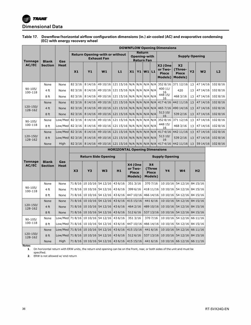
36 RT-SVX24Q-EN
Table 17. Downflow/horizontal airflow configuration dimensions (in.) air-cooled (AC) and evaporative condensing(EC) with energy recovery wheel
TonnageAC/EC
BlankSection
GasHeat
DOWNFLOWOpening Dimensions
Return Opening-with or withoutExhaust Fan
ReturnOpening-withReturn Fan
Supply Opening
X1 Y1 W1 L1 X1 Y1 W1 L1
X2 (Oneor Two-PieceModels)
X2(Three-PieceModels)
Y2 W2 L2
90-105/100-118
None None 82 3/16 8 14/16 49 10/16 121 15/16 N/A N/A N/A N/A 352 8/16 371 12/16 13 47 14/16 102 8/16
4 ft None 82 3/16 8 14/16 49 10/16 121 15/16 N/A N/A N/A N/A 400 11/16 420 13 47 14/16 102 8/16
8 ft None 82 3/16 8 14/16 49 10/16 121 15/16 N/A N/A N/A N/A 448 15/16 468 3/16 13 47 14/16 102 8/16
120-150/128-162
None None 82 3/16 8 14/16 49 10/16 121 15/16 N/A N/A N/A N/A 417 4/16 442 11/16 13 47 14/16 102 8/16
4 ft None 82 3/16 8 14/16 49 10/16 121 15/16 N/A N/A N/A N/A 465 7/16 490 14/16 13 47 14/16 102 8/16
8 ft None 82 3/16 8 14/16 49 10/16 121 15/16 N/A N/A N/A N/A 513 10/16 539 2/16 13 47 14/16 102 8/16
90-105/100-118
None Low/Med 82 3/16 8 14/16 49 10/16 121 15/16 N/A N/A N/A N/A 352 8/16 371 12/16 13 47 14/16 102 8/16
8 ft Low/Med 82 3/16 8 14/16 49 10/16 121 15/16 N/A N/A N/A N/A 448 15/16 468 3/16 13 47 14/16 102 8/16
120-150/128-162
None Low/Med 82 3/16 8 14/16 49 10/16 121 15/16 N/A N/A N/A N/A 417 4/16 442 11/16 13 47 14/16 102 8/16
8 ft Low/Med 82 3/16 8 14/16 49 10/16 121 15/16 N/A N/A N/A N/A 513 10/16 539 2/16 13 47 14/16 102 8/16
None High 82 3/16 8 14/16 49 10/16 121 15/16 N/A N/A N/A N/A 417 4/16 442 11/16 13 59 14/16 102 8/16
TonnageAC/EC
BlankSection
GasHeat
HORIZONTAL Opening Dimensions
Return Side Opening Supply Opening
X3 Y3 W3 H1
X4 (Oneor Two-PieceModels)
X4(ThreePieceModels)
Y4 W4 H2
90-105/100-118
None None 71 8/16 10 10/16 54 12/16 43 6/16 351 3/16 370 7/16 10 10/16 54 12/16 84 15/16
4 ft None 71 8/16 10 10/16 54 12/16 43 6/16 399 6/16 418 11/16 10 10/16 54 12/16 84 15/16
8 ft None 71 8/16 10 10/16 54 12/16 43 6/16 447 10/16 466 14/16 10 10/16 54 12/16 84 15/16
120-150/128-162
None None 71 8/16 10 10/16 54 12/16 43 6/16 415 15/16 441 6/16 10 10/16 54 12/16 84 15/16
4 ft None 71 8/16 10 10/16 54 12/16 43 6/16 464 2/16 489 10/16 10 10/16 54 12/16 84 15/16
8 ft None 71 8/16 10 10/16 54 12/16 43 6/16 512 6/16 537 13/16 10 10/16 54 12/16 84 15/16
90-105/100-118
None Low/Med 71 8/16 10 10/16 54 12/16 43 6/16 351 3/16 370 7/16 10 10/16 54 12/16 66 11/16
8 ft Low/Med 71 8/16 10 10/16 54 12/16 43 6/16 447 10/16 466 14/16 10 10/16 54 12/16 84 15/16
120-150/128-162
None Low/Med 71 8/16 10 10/16 54 12/16 43 6/16 415 15/16 441 6/16 10 10/16 54 12/16 66 11/16
8 ft Low/Med 71 8/16 10 10/16 54 12/16 43 6/16 512 6/16 537 13/16 10 10/16 54 12/16 84 15/16
None High 71 8/16 10 10/16 54 12/16 43 6/16 415 15/16 441 6/16 10 10/16 66 12/16 66 11/16Notes:
1. On horizontal return with ERW units, the return end opening can be on the front, rear, or both sides of the unit and must bespecified.
2. ERW is not allowed w/ end return
DDiimmeennssiioonnaall DDaattaa

RT-SVX24Q-EN 37
Water Connection LocationsFigure 14. Evaporative condenser water connection locations
RIGHT SIDE VIEW
DDiimmeennssiioonnaall DDaattaa

38 RT-SVX24Q-EN
Electrical Entry DetailsFigure 15. Electrical entry details/bottom view
16
6034
7114
7614
8114
46 116
48 116
6134 44
Ø358
Ø1 116
Ø78
6 5165 5
16
Marine lightscustomer supplied power service entrance
Unit power
External customer connection points
Outside edge of base rail
5158
531116
311116
Ø112
Bottom View
DDiimmeennssiioonnaall DDaattaa

RT-SVX24Q-EN 39
Minimum Required ClearanceFigure 16. Minimum required clearance
Filters
VFDVFD Heat
Rtn/ExhMtr
Rtn/ExhVFD
Evp(F)
Fltr(F)
SupMtr
SupVFD
Fltr(R)
Evp(R)
Heat(L&R
OptionOption
As Req. As Req. As Req.StdStd StdStd
Blank Section
Final Filter
FnlFltr
As Req.
FnlFltr
As Req.
Ctrl Box(L&R)
Std
OutsideAir
OutsideAir
Exhaust
Condenser
Condenser
Exh
AH R
CBox
AH L Cond L
Cond R
NNoottee:: Unit drawing is representative only and may not accurately depict all models.
Table 18. Minimum required clearance
Door Location Availability
Unit Option Selection (Door Swing Ft. and In.)
Standard VFD Heat Two-sideAccess
FinalFilter
EnergyRecovery90-
118120-162
Return/Exhaust
Supply
Electric/Hot
Water/Steam
Reheat 90-118
120-162
Exhaust/Ret Motor Std 2' 2" 2' 2" * * * * * * *Exhaust/Ret VFD As Req. * * 2' 2" * * * * * *ERW Fltr (L & R) (F) Option * * * * * * * * * 2' 2"ERW Fltr(a) (L & R) (R) Option * * * * * * * * * 2' 2"Filter (Front) Std 2' 8" 2' 8" * * * * * * *Filter (Rear) Option * * * * * * 2' 2" 2' 8" *Evap (Front) Std 2' 2" 2' 2" * * * * * * *Evap (Rear) Std 2' 8" * * * * * * * *or Evap (Rear) Option * * * * * 2' 2 * 2' 2" *Supply Motor Std 2' 8" 2' 8" * * * * * * *Supply VFD As Req. * * * 2' 2" * * * * *Heat (Left & Right) As Req. * * * * 2' 2" * * * *Final Filter (Front) As Req. * * * * * * * * 2' 2"Final Filter (Rear) As Req. * * * * * * * * 2' 2"Control Box (L & R) Std 3' 2" 3' 2" * * * * * * *
MinimumRequired Clearance (Ft.) AH_L AH_R Exh Cond_L Cond_RControlBox
8' 8' 8' 8' 8' 6'
Note: See Unit Dimensions for Energy Recovery Wheel location.
DDiimmeennssiioonnaall DDaattaa

40 RT-SVX24Q-EN
Weights
Table 19. Approximate operating weights (lbs.)
Air-Cooled Units Evaporative Condensing UnitsNominalTons
Unit(Minimum)
Roof Curb(Minimum)
NominalTons
Unit(Minimum)
Roof Curb(Minimum)
90 13731 907 100 18430 1055
105 14792 907 118 18941 1055
120 16939 1040 128 21362 1194
130 17241 1040 140 21348 1194
150 17923 1040 162 21470 1194Notes:
1. Weights shown for air-cooled units include the following features: standard coils, 0-25%Outside Air, throwaway filters, low CFM supply fan, minimummotor sizes, constantvolume, 460 XL, No heat. Weights shown for Evaporative-condensing units include high-capacity evaporator coil and the weight of the extra structure associated with a twopiece unit. Add 1300 lbs for installed sump base water weight for evaporative condensertotal operating weight.
2. Weights shown represent approximate minimum operating weights. To calculate weightfor a specific unit configuration, utilize TOPSS or contact the local Trane salesrepresentative. Weight outputs have a + 10% accuracy. ACTUALWEIGHTS ARESTAMPED ON THE UNIT NAMEPLATE.
Table 20. Component weights
90/100 105/118 120/128 130/140 150/162
Size Weight Size Weight Size Weight Size Weight Size Weight
RefrigerationCompressor Assy. - Fixed capacitycompressors - 1126 - 1344 - 1562 - 1616 - 1670Compressor Assy. - eFlexTM Variable speed(air cooled only) - 1479 1503 1626 1754 1786
Air-Cooled Condensing Coil (Al) - 623 - 722 - 1049 - 1224 - 924Evaporative Condensing Coil 4566 4329 4129 4109 4029Evap Coil - Std. Cap - 1034 - 1300 - 1664 - 1892 - 2564Evap Coil - Hi. Cap. - 1382 - 1462 - 2564 - 2496 - N/AReheat Coil & Tubing - 292 - 294 - 367 - 367 - 367Replaceable Core Filter Driers - 26 - 25 - 35 - 35 - 35HGBP - 46 - 49 - 53 - 53 - 53
Supply Fan AssemblySupply Fan & Fan Board Assy. - Low CFM 25" 1159 32" 1361 32" 1361 32" 1361 32" 1361Supply Fan & Fan Board Assy. - Std. CFM 36" 1490 36" 1490 40" 1653 40" 1653 40" 1653Belt Guard - 116 - 116 - 116 - 116 - 116Supply VFD (50 hp and below) - 233 - 233 - 233 - 233 - 233Supply VFD (60-100 hp) - 284 - 284 - 284 - 284 - 284Supply-Exh Fan Motor - 15 hp - 181 - 181 - 181 - 181 - 181Supply-Exh Fan Motor - 20 hp - 206 - 206 - 206 - 206 - 206Supply-Exh Fan Motor - 25 hp - 358 - 358 - 358 - 358 - 358Supply-Exh Fan Motor - 30 hp - 413 - 413 - 413 - 413 - 413Supply-Exh Fan Motor - 40 hp - 495 - 495 - 495 - 495 - 495Supply-Exh Fan Motor - 50 hp - 604 - 604 - 604 - 604 - 604Supply-Exh Fan Motor - 60 hp - 776 - 776 - 776 - 776 - 776Supply-Exh Fan Motor - 75 hp - 879 - 879 - 879 - 879 - 879Supply-Exh Fan Motor - 100 hp - 1102 - 1102 - 1102 - 1102 - 1102
Return/Exhaust Fan AssemblyReturn Fan & Dampers - Low CFM 36" 2294 36" 2294 36" 2294 36" 2294 36" 2294Return Fan & Dampers - Std. CFM 40" 2343 40" 2343 44" 2445 44" 2445 44" 2445Exhaust Fan & Dampers - Low CFM 25" 889 28" 979 28" 979 28" 979 28" 979Exhaust Fan & Dampers - Std. CFM 28" 979 32" 1429 32" 1429 32" 1429 32" 1429Belt Guard - 119 - 119 - 119 - 119 - 119

RT-SVX24Q-EN 41
Table 20. Component weights (continued)
90/100 105/118 120/128 130/140 150/162
Size Weight Size Weight Size Weight Size Weight Size Weight
Exhaust VFD (50 hp and below) - 244 - 244 - 244 - 244 - 244Exhaust VFD (60-100 hp) - 295 - 295 - 295 - 295 - 295Exh Fan Motor - 7.5 hp - 160 160 - 160 - 160 - 160Exh Fan Motor - 10 hp - 181 - 181 - 181 - 181 - 181Exh Fan Motor - 15 hp - 206 - 206 - 206 - 206 - 206Exh Fan Motor - 20 hp - 206 - 206 - 206 - 206 - 206Exh Fan Motor - 25 hp - 358 - 358 - 358 - 358 - 358Exh Fan Motor - 30 hp - 413 - 413 - 413 - 413 - 413Exh Fan Motor - 40 hp - 495 - 495 - 495 - 495 - 495Exh Fan Motor - 50 hp - 604 - 604 - 604 - 604 - 604Exh Fan Motor - 60 hp - 776 - 776 - 776 - 776 - 776
HeatGas Heat Low 0.85 M 690 0.85M 690 1.1M 840 1.1M 840 1.1M 840Gas Heat Med 1.1 M 840 1.1M 840 1.8M 1150 1.8M 1150 1.8M 1150Gas Heat High 1.8 M 1150 1.8M 1150 2.5M 1398(a) 2.5M 1398(a) 2.5M 1398(a)
Electric Heat - 485 - 485 - 485 - 485 - 485Steam Heat Low - 753 - 753 - 802 - 802 - 802Steam Heat High - 821 - 821 - 886 - 886 - 886Hot Water Heat Low - 773 - 773 - 841 - 841 - 841Hot Water Heat High - 818 - 818 - 897 - 897 - 897
FiltersFilter Rack - Throwaway Filters - 181 - 181 - 191 - 191 - 191Filter Rack - Bag Filters - 395 - 395 - 395 - 395 - 395Filter Rack - Cartridge Filters - 662 - 662 - 662 - 662 - 662Final Filters - Bag Filters - 392 - 392 - 392 - 392 - 392Final Filters - Cartridge Filters w/ 2" pre-filter - 607 - 607 - 607 - 607 - 607Final Filters - Cartridge Filters w/ 4" pre-filter - 638 - 638 - 638 - 638 - 638Final Filters - High Temp. Cartridge - 669 - 669 - 669 - 669 - 669Final Filters - HEPA - 1777 - 1777 - 1777 - 1777 - 1777Final Filters - HEPA High Temp. - 1839 - 1839 - 1839 - 1839 - 1839
Outside Air0-25% Damper - 637 - 637 - 699 - 699 - 699Econ - 760 - 760 - 865 - 865 - 865Econ w/ Air Measure - 724 - 724 - 807 - 807 - 807ERW, Low CFM w/ Econ(b) - 3307 - 3307 - 3518 - 3681 - 3681ERW, High CFM w/ Econ(b) - 3545 - 3514 - 3756 - 3756 - 3756ERW, Low CFM w/ Econ & Air Measure(b) - 3487 - 3487 - 3727 - 3890 - 3890ERW, High CFM w/ Econ & Air Measure(b) - 3725 - 3694 - 3965 - 3965 - 3965
CabinetCabinet - 8097 - 8315 - 9473 - 9473 - 9473Cabinet - 4' Blank Section - 935 - 935 - 901 - 901 - 901Cabinet - 8' Blank Section - 1709 - 1709 - 1682 - 1682 - 1682
Control Box - MainControl Box - Main - 519 - 519 - 519 - 519 - 519Convenience Outlet - 36 - 36 - 36 - 36 - 36Low Ambient VFD - 57 - 57 - 57 - 57 - 57
2/3 Piece Unit Adder2 Piece Adder - 406 - 406 - 406 - 406 - 4063 Piece Adder - 1157 - 1157 - 1236 - 1236 - 1236
Air-Cooled CondenserTotal Weight of Condenser Section - 4637 - 5201 - 6015 - 6075 - 6092(a) Evaporative Condenser weight includes the additional weight in the cabinet structure. coil weight and additional refrigerant charge. Add 1300 lbs for
operating sump base water weight.(b) Energy Recovery includes weight associated w/ 96" of cabinet length.
WWeeiigghhttss

42 RT-SVX24Q-EN
Table 21. Roof curb weights — air-cooled (AC) and evaporative condensing (EC)
Tonnage AC/ECEnergyRecoveryWheel
BlankSection
One-PieceUnit
Two/Three-Piece Unit
90-105/100-118 No None 907 1055
90-105/100-118 No 4 ft 988 1136
90-105/100-118 No 8 ft 1069 1217
90-105/100-118 Yes None 1093 1240
90-105/100-118 Yes 4 ft 1174 1321
90-105/100-118 Yes 8 ft N/A 1401
120-150/128-162 (All Units Except High Heat Gas models) No None 1040 1194
120-150/128-162 (All Units Except High Heat Gas models) No 4 ft 1122 1275
120-150/128-162 (All Units Except High Heat Gas models) No 8 ft N/A 1357
120-150/128-162 (High Heat Gas Models Only) No None 1055 1209
120-150/128-162 (All Units Except High Heat Gas models) Yes None N/A 1378
120-150/128-162 (All Units Except High Heat Gas models) Yes 4 ft N/A 1459
120-150/128-162 (All Units Except High Heat Gas models) Yes 8 ft N/A 1540
120-150/128-162 (High Heat Gas Models Only) Yes None N/A 1393
Note: One-piece available with air-cooled condenser only.
WWeeiigghhttss

RT-SVX24Q-EN 43
InstallationRoof Curb and DuctworkThe roof curbs consist of two main components: apedestal to support the unit condenser section and a“full perimeter” enclosure to support the unit’s airhandler section.
Before installing any roof curb, verify the following:
• It is the correct curb for the unit.
• It includes the necessary gaskets and hardware.
• The purposed installation location provides therequired clearance for proper operation.
• The curb is level and square — the top surface ofthe curb must be true to assure an adequate curb-to-unit seal.
Step-by-step curb assembly and installationinstructions ship with each Trane accessory roof curbkit. Follow the instructions carefully to assure properfit-up when the unit is set into place.
NNoottee:: To assure proper condensate flow duringoperation, the unit (and curb) must be as level aspossible. The maximum slope allowable forrooftop unit applicationsexcluding Steam HeatUnits, is 4" end-to-end and 2" side-to-side. Unitswith steam coils must be set level!
If the unit is elevated, a field constructed catwalkaround the unit is strongly recommended to provideeasy access for unit maintenance and service.Recommendations for installing the Supply Air andReturn Air ductwork joining the roof curb are includedin the curb instruction booklet. Curb ductwork must befabricated and installed by the installing contractorbefore the unit is set into place.
NNoottee:: For sound consideration, cut only the holes in theroof deck for the ductwork penetrations. Do notcut out the entire roof deck within the curbperimeter.
Pitch Pocket LocationThe location of the main supply power entry is locatedat the bottom right-hand corner of the control panel.illustrates the location for the electrical entrancethrough the base in order to enter the control panel. Ifthe power supply conduit penetrates the building roofbeneath this opening, it is recommended that a pitchpocket be installed before the unit is placed onto theroof curb.
The center line dimensions shown in the illustrationbelow indicates the center line of the electrical accesshole in the unit base when it is positioned on the curb,±3/8 inch. The actual diameter of the hole in the roofshould be at least 1/2 inch larger than the diameter ofthe conduit penetrating the roof. This will allow for theclearance variable between the roof curb rail and theunit base rail illustrated in Figure 18, p. 44.
The pitch pocket dimensions listed are recommendedto enhance the application of roofing pitch after theunit is set into place. The pitch pocket may need to beshifted as illustrated to prevent interference with thecurb pedestal.
Figure 17. Solid flow baffle wall installation for non-Trane roof curbs
Return Fan
Roof Curb
Return AirflowFlow Baffle
Return Airflow Duct
If a Trane Curb Accessory Kit is not used:
• The ductwork can be attached directly to the unitbottom, around the unit supply and return airopenings. Be sure to use flexible duct connectionsat the unit.
• For “built-up” curbs supplied by others, gasketsmust be installed around the curb and the supplyand return air opening perimeters.
• If a “built-up” curb is provided by others, it shouldNOT be made of wood.
• If a “built-up” curb is provided by others, keep inmind that these commercial rooftop units do nothave base pans in the condenser section.
• If this is a REPLACEMENT UNIT keep in mind thatthe CURRENT DESIGN commercial rooftop units donot have base pans in the condenser section.

44 RT-SVX24Q-EN
Figure 18. Pitch pocket location
B1
B2
B3
A2
B1
B2
B3
A1
Pitch Pocket
Pitch Pocket
Roof Curb1Pc
Roof Curb2Pc
Table 22. Pitch pocket dimensions (in.)
One-PieceTwo/Three-
Piece One, Two, or Three-Piece
Tonnages A1 A2 B1 B2 B3
90 113.8 129.9±1 68.875 73.875 78.875
105 131.8 147.9±1 68.875 73.875 78.875
120,130,150 140.8 156.9±1 68.875 73.875 78.875
100,118,128,140,162 N/A 135.0±1 68.875 73.875 78.875
IInnssttaallllaattiioonn

RT-SVX24Q-EN 45
Field Converting Horizontal Ductwork(Supply or Return) from Right to the LeftSideFigure 19. Ductwork conversion
Door
Header
Header
Panel 2
Header
Post
DoorPanel 1
Footer
LeftSide
RightSide
As Shipped(Right Side Hz)
LeftSide
RightSide
Field Converted(Left Side Hz)
Panel 2Panel 1
To field convert horizontal ductwork from right side tothe left, follow this procedure:
1. Remove Panel 2 from end of unit
2. Remove the Door and Door header from the leftside.
3. Assemble Door header and Door removed from theleft side in the empty location on the end wall.
4. Remove Panel 1 and Post from the left side.Remove gaskets from the base rail flange at thebottom.
5. Remove the top duct adapter, side duct adapters,
header, and footer in this order from the right side.Remove gaskets from post side flanges and thebase rail flange at the bottom.
6. Assemble gaskets, header, footer, side ductadapters, and top duct adapter in this order to theleft side. SeeFigure 19, p. 45 for gasket applicationdetails.
7. Finally assemble Post, gaskets, Panel 1, and Panel 2in this order to the right side to complete the fieldconversion. See Figure 20, p. 46 and Figure 21, p.47 for gasket application details.
IInnssttaallllaattiioonn

46 RT-SVX24Q-EN
Figure 20. Ductwork conversion
Hz Return & Supply Gasketing Application Details
Hz Supply or Return HeaderNo Gasket Required
Vertical DuctAdapter Channel
Bottom Horizontal Duct Adapter Channel
See Detail A
Detail A
See Detail B
Base Rail
Vertical Support
Vertical Support
Align Gasket WithBase Rail Surface
Align Gasket With Vertical SupportVertical SupportSkin Edge
Detail BTypical Both Vertical Duct Adapters
Base Rail
Vertical AdapterGasket
Vertical Adapter Gasket1/8” Thick x 3/4” Wide
Vertical Adapter Gasket1/8” Thick x 3/4” Wide
IInnssttaallllaattiioonn

RT-SVX24Q-EN 47
Figure 21. Ductwork conversion
See Detail A
Detail A
Vertical Support
Align GasketTo Base RailSurface
Gasket1/4” Thick x 1” Wide
Gasket to Butt Up toVertical Support SurfaceTypical Both Sides
Vertical Support/Base Rail BottomGasket Application Details
Base Rail
Unit Rigging and Placement
WWAARRNNIINNGGHHeeaavvyy OObbjjeecctt!!FFaaiilluurree ttoo ffoollllooww iinnssttrruuccttiioonnss bbeellooww ccoouulldd rreessuulltt iinnuunniitt ddrrooppppiinngg wwhhiicchh ccoouulldd rreessuulltt iinn ddeeaatthh oorrsseerriioouuss iinnjjuurryy,, aanndd eeqquuiippmmeenntt oorr pprrooppeerrttyy--oonnllyyddaammaaggee..EEnnssuurree tthhaatt aallll tthhee lliiffttiinngg eeqquuiippmmeenntt uusseedd iisspprrooppeerrllyy rraatteedd ffoorr tthhee wweeiigghhtt ooff tthhee uunniitt bbeeiinngglliifftteedd.. EEaacchh ooff tthhee ccaabblleess ((cchhaaiinnss oorr sslliinnggss)),, hhooookkss,,aanndd sshhaacckklleess uusseedd ttoo lliifftt tthhee uunniitt mmuusstt bbee ccaappaabblleeooff ssuuppppoorrttiinngg tthhee eennttiirree wweeiigghhtt ooff tthhee uunniitt.. LLiiffttiinnggccaabblleess ((cchhaaiinnss oorr sslliinnggss)) mmaayy nnoott bbee ooff tthhee ssaammeelleennggtthh.. AAddjjuusstt aass nneecceessssaarryy ffoorr eevveenn uunniitt lliifftt..
1. To configure the unit Center-of-Gravity, utilizeTOPSS or contact the local Trane sales office.
2. Attach adequate strength lifting slings to all liftinglugs. The figures beginning with Figure 23, p. 48show the minimum distance between the liftinghook and the top of the unit and illustrate theinstallation of spreader bars to protect the unit andto facilitate a uniform lift. lists typical approximateminimal unit operating weights. To determineadditional component weight, see .
3. Test lift the unit to ensure it is properly rigged andbalanced, make any necessary rigging adjustments.
4. Lift the unit and position it over the curb andpedestal. These units have a continuous base railaround the air handler section which matches thecurb.
IImmppoorrttaanntt:: For replacements, remove old gasketfrom the roof curb and place newgasket material on curb. See “,” todetermine gasket material length usingroof curb dimensions.
5. Align the base rail of the unit air handler sectionwith the curb rail while lowering the unit onto thecurb. Make sure that the gasket on the curb is notdamaged while positioning the unit. (The pedestalsimply supports the unit condenser section)
A cross section of the juncture between the unit andthe roof curb is shown below.
Figure 22. Curb cross section
Gasket
Base PanLiftingLug
14 1/16
1 13/16
2
1/2
2”x4”
IInnssttaallllaattiioonn

48 RT-SVX24Q-EN
Figure 23. Typical unit rigging—one-piece unit with three lifting lugs per side
One piece unit with three
lifting lugs per side
Turnbuckle or
Chain Adjustment
for each lug
Note: Turnbuckle or chain adjustment required for each lifting point.
24 ft min
IInnssttaallllaattiioonn

RT-SVX24Q-EN 49
Figure 24. Typical unit rigging—one piece unit with four lifting lugs per side
15 ft min
20 ft min
Turnbuckler orChain Adjustmentfor each lug
One piece unit with fourlifting lugs per side
Note: Turnbuckle or chain adjustment required for each lifting point.
IInnssttaallllaattiioonn

50 RT-SVX24Q-EN
Figure 25. Typical unit rigging—two-piece unit with two lifting lugs per side
12 ft min
12 ft min
Condenser with twolifting lugs per side
Air handler with twolifting lugs per side
Turnbuckle orChain Adjustmentfor each lug
Note: Turnbuckle or chain adjustment required for each lifting point.
IInnssttaallllaattiioonn

RT-SVX24Q-EN 51
Figure 26. Typical unit rigging—two-piece unit with three lifting lugs per air handler side
Turnbuckle orChain Adjustmentfor each lug
Air handler with threelifting lugs per side
Condenser with twolifting lugs per side
12 ft min
24 ft min
Note: Turnbuckle or chain adjustment required for each lifting point.
IInnssttaallllaattiioonn
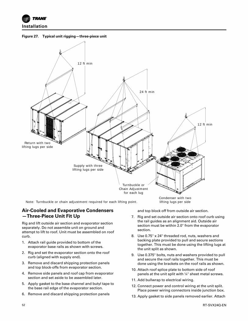
52 RT-SVX24Q-EN
Figure 27. Typical unit rigging—three-piece unit
12 ft min
12 ft min
Return with twolifting lugs per side
Supply with threelifting lugs per side
Condenser with twolifting lugs per side
Turnbuckle orChain Adjustment
for each lug
24 ft min
Note: Turnbuckle or chain adjustment required for each lifting point.
Air-Cooled and Evaporative Condensers—Three-Piece Unit Fit UpRig and lift outside air section and evaporator sectionseparately. Do not assemble unit on ground andattempt to lift to roof. Unit must be assembled on roofcurb.
1. Attach rail guide provided to bottom of theevaporator base rails as shown with screws.
2. Rig and set the evaporator section onto the roofcurb (aligned with supply end).
3. Remove and discard shipping protection panelsand top block-offs from evaporator section.
4. Remove side panels and roof cap from evaporatorsection and set aside to be assembled later.
5. Apply gasket to the base channel and butyl tape tothe base rail edge of the evaporator section.
6. Remove and discard shipping protection panels
and top block off from outside air section.
7. Rig and set outside air section onto roof curb usingthe rail guides as an alignment aid. Outside airsection must be within 2.0" from the evaporatorsection.
8. Use 0.75" x 24" threaded rod, nuts, washers andbacking plate provided to pull and secure sectionstogether. This must be done using the lifting lugs atthe unit split as shown.
9. Use 0.375" bolts, nuts and washers provided to pulland secure the roof rails together. This must bedone using the brackets on the roof rails as shown.
10. Attach roof splice plate to bottom side of roofpanels at the unit split with ¼" sheet metal screws.
11. Add bullwrap to electrical wiring.
12. Connect power and control wiring at the unit split.Place power wiring connectors inside junction box.
13. Apply gasket to side panels removed earlier. Attach
IInnssttaallllaattiioonn

RT-SVX24Q-EN 53
side panel to unit split.
14. Apply 1.25" butyl tape on top of unit split along theroof seam. Attach roof cap over roof seam andbutyl tape with screws.
15. Attach roof cap over roof seam and butyl tape withscrews
Figure 28. Rail guide locations
Attach rail guides as shown
Figure 29. Evaporator section shipping protectionremoval
Discard shippingprotection
Figure 30. Evaporator section side panel and roof capremoval
Save side panelsand roof cap forreassembly
Discard shippingprotection
Figure 31. Evaporator section gasket locations
Rail guides
Gasket
Butyl Tape
Figure 32. Outside air section shipping protectionremoval
Discard shippingprotection
Figure 33. Base rail connection
Lifting lug
Backing Plate
Threaded rod
IInnssttaallllaattiioonn

54 RT-SVX24Q-EN
Figure 34. Roof rail connection
Brackets
Figure 35. Roof panel splice plate connection
Apply splice plate tobottom of roof panelsat unit split
Figure 36. Side panel and roofcap reinstallation
Reinstall sidepanels removedearlier
Reinstall roof capremoved earlier
Apply butyl tape onunit split in roof
Air-Cooled and Evaporative Condensers—Two-Piece Unit Fit Up1. Rig the low side unit (Air handler) and the high side
unit (Condenser) separately.
2. First, rig and set the low side unit on the roof curb(aligned with return end).
3. Take off and discard the protection boxes. (Do notremove wire shields).
4. Remove the rail connector splice brackets andinstall the brackets on the low side unit base rails.
5. Take off the side panels (these are labeled) and thetop cover of the high side unit and set aside to beassembled later.
6. Rig and set the high side unit on roof curb pedestal,using the rail splice bracket as an alignment aid toconnect the Low and high side units. The Low andhigh side unit rails should be butted together with amaximum 2" separation.
7. Remove the left upper and lower louvered panelsand the corner panels on each side to aid in tubingand wiring connections.
IInnssttaallllaattiioonn

RT-SVX24Q-EN 55
Figure 37. (1) Protection box removal/(2) railconnector installation position
(1)
(a) (b)
(2)
Note: Unscrew the rail connectoras show in fig 1(b) and screwback to these locations
Note: Do not removethe wiring shields
Rail connectorshipping position
Figure 38. (3) Side and top filler panel removal/(4)high side installation preparation
Filler panelshipping position
Filler panelshipping position
Top covershipping position
(3)
Note: Remove the filler panels and top cover before putting the Indoor and Outdoor sections together and screw to both Indoorand Outdoor panels on each side as shown in fig (6). Finally the top cover is assembled in space.
Unconnected tubes
(4)
IInnssttaallllaattiioonn

56 RT-SVX24Q-EN
Figure 39. (5) Connected tubes/(6) install panels
Connected tubes
(5)
(6)
IInnssttaallllaattiioonn

RT-SVX24Q-EN 57
Figure 40. Charge evacuation diagram - evaporative condensers
Liquid Line
Schrader Port
Manual Shut-off Valve
Hot Gas Reheat Valve
Hot Gas Bypass Valve
Thermal Expansion Valve
Copper Cap w/Schrader Port
Solenoid Valve
Refrigerant Shipping Location
Liquid Line
Hot Gas Reheat Line (Option)
Hot Gas Reheat Line (Option)
Suction Line
Suction Line
Condenser Coil Circuit 1
Condenser Coil Circuit 2
LEGEND:
Tubing and Wiring Connections
Air-Cooled Tubing ConnectionOne piece Air Cooled units are shipped with refrigerantthroughout the entire tubing assemblies.
Two and three piece Air-Cooled low side andcondenser sections are shipped with a Nitrogenholding charge. All service valves are shipped in anopen position. Additional interconnecting tubes(approx. 15-20” in length) will be supplied with the unit.
NNoottee:: Field charging of 2 and 3 piece air-cooled units isREQUIRED.
To prepare the two or three piece sections for joininginstall pressure gauges to the appropriate access valve(s) to verify nitrogen charge is present.
1. Relieve the pressure before attempting to unsweatthe “seal” caps.
2. Remove the brackets which support the suctiontubes (retain for possible use later for unitreassembly) after the tubing connections arecomplete.
3. Place wet rags on the flow/ ball valve on the highside when suction tubes are being brazed.
NNoottee:: Additional care should be taken whenbrazing near the wire bundle.
4. Sweat the copper caps off both the high and lowside of the suction and liquid lines of both circuits. Ifpresent also sweat off the copper caps from hot gasbypass or hot gas reheat lines.
5. Clean the joints of weld puddles to avoid insertion
problems.
6. Cut the appropriate interconnecting tube to a lengthapproximately 0.75"- 1" more than the distancebetween the two tubes.
7. Insert the appropriate tube to the complete depth ofthe bell on one side of the joint and align the otherside(prying the high side may be needed). Makesure the insertion depth is met.
8. Complete the connections by brazing the tubes inplace.
NNoottee:: Refrigeration ball valves are intended forgeneral service and are not a positive shutoffdevice.
9. Once all connections have been brazed, evacuatethe entire system. The recommended method forevacuation and dehydration is to evacuate thesystem to 500 microns or less. To establish that theunit is leak-free, use a standing vacuum test. Themaximum allowable rise over a 15 minute period is200 microns. If the rise exceeds this, there is eitherstill moisture in the system or a leak is present.
10. Charge the system per the unit nameplate fieldcharge. Do not add refrigerant in the suction line atthis time to prevent excessive refrigerant in the lowside prior to compressor start-up.
11. At the liquid line angle valve add as much R-410ALIQUID as possible. Depending on conditions, itcould not be possible to add more than 60% of thefield charge. This will be adequate for compressorstart-up. More charge will be added aftercompressors are started. Use an accurate scale to
IInnssttaallllaattiioonn

58 RT-SVX24Q-EN
measure and record the preliminary amount of R-410A added to each circuit.
12. With all the circuit compressors operating, SLOWLYmeter R410-A into the suction line from the LIQUIDcharging connection.
Evaporative Condenser Tubing ConnectionIImmppoorrttaanntt::
• For units with electric heat, completetubing connections AFTER completingwiring connections. See “Electric HeatWiring Connection,” p. 59.
• Complete tubing connections BEFOREPower and Control wiring connections.See “Power and Control WiringConnections,” p. 59.
There will be a N2 nitrogen charge in the air handlersection. This holding charge should be relieved prior toremoving the caps.
The condenser section will ship with R-410Athroughout the entire tubing assemblies. The servicevalves will be shipped in an open position. Additionalinterconnecting tubes (approx. 15-20" in length) will besupplied with the unit.
1. To prepare the condensing section for the joining ofthe two sections, the discharge line service valvesshould be shut and the refrigerant remainingbetween the valves and the end caps should betransferred/recovered.
2. If the unit has been purchased with hot gas bypassor hot gas reheat options, those valves should beshut as well and the refrigerant transferred/recovered from the sections between the valvesand the end caps.
3. Remove the brackets which support the suctiontubes (retain for possible use later for unitreassembly) after the tubing connections arecomplete.
4. Relieve the pressure (charge) for the section of thetubing being worked on.
5. Place wet rags on the flow/ ball valve on the highside when suction tubes are being brazed.
NNoottee:: Additional care should be taken whenbrazing near the wire bundle.
WWAARRNNIINNGGEExxpplloossiioonn HHaazzaarrdd aanndd DDeeaaddllyy GGaasseess!!FFaaiilluurree ttoo ffoollllooww aallll pprrooppeerr ssaaffee rreeffrriiggeerraanntthhaannddlliinngg pprraaccttiicceess ccoouulldd rreessuulltt iinn ddeeaatthh oorr sseerriioouussiinnjjuurryy..NNeevveerr ssoollddeerr,, bbrraazzee oorr wweelldd oonn rreeffrriiggeerraanntt lliinneess oorraannyy uunniitt ccoommppoonneennttss tthhaatt aarree aabboovvee aattmmoosspphheerriiccpprreessssuurree oorr wwhheerree rreeffrriiggeerraanntt mmaayy bbee pprreesseenntt..AAllwwaayyss rreemmoovvee rreeffrriiggeerraanntt bbyy ffoolllloowwiinngg tthheegguuiiddeelliinneess eessttaabblliisshheedd bbyy tthhee EEPPAA FFeeddeerraall CClleeaannAAiirr AAcctt oorr ootthheerr ssttaattee oorr llooccaall ccooddeess aass aapppprroopprriiaattee..AAfftteerr rreeffrriiggeerraanntt rreemmoovvaall,, uussee ddrryy nniittrrooggeenn ttoobbrriinngg ssyysstteemm bbaacckk ttoo aattmmoosspphheerriicc pprreessssuurree bbeeffoorreeooppeenniinngg ssyysstteemm ffoorr rreeppaaiirrss.. MMiixxttuurreess ooffrreeffrriiggeerraannttss aanndd aaiirr uunnddeerr pprreessssuurree mmaayy bbeeccoommeeccoommbbuussttiibbllee iinn tthhee pprreesseennccee ooff aann iiggnniittiioonn ssoouurrcceelleeaaddiinngg ttoo aann eexxpplloossiioonn.. EExxcceessssiivvee hheeaatt ffrroommssoollddeerriinngg,, bbrraazziinngg oorr wweellddiinngg wwiitthh rreeffrriiggeerraannttvvaappoorrss pprreesseenntt ccaann ffoorrmm hhiigghhllyy ttooxxiicc ggaasseess aannddeexxttrreemmeellyy ccoorrrroossiivvee aacciiddss..
6. Sweat the copper caps off both the high and lowside of the suction and liquid lines of both circuits.
7. Clean the joints of weld puddles to avoid insertionproblems.
8. Cut the appropriate interconnecting tube to a lengthapproximately 0.75"- 1" more than the distancebetween the two tubes.
9. Insert the appropriate tube to the complete depth ofthe bell on one side of the joint and align the otherside (prying the high side may be needed). Makesure the insertion depth is met.
10. Complete the connections by brazing the tubes inplace.
NNoottee:: Refrigeration ball valves are intended forgeneral service and are not a positive shutoffdevice.
11. Once all connections have been brazed, evacuatethe low side. The low side may be evacuated by theschrader ports on the discharge line just past thecompressor and the liquid line below the sightglass. See Figure 40, p. 57.
The recommended method for evacuation anddehydration is to evacuate the low side to 500microns or less. To establish that the unit is leak-free, use a standing vacuum test. The maximumallowable rise over a 15 minute period is 200microns. If the rise exceeds this, there is either stillmoisture in the system or a leak is present.
NNoottee:: Only after evacuation should the taggedvalves be opened.
IInnssttaallllaattiioonn

RT-SVX24Q-EN 59
WWAARRNNIINNGGPPrrooppeerr FFiieelldd WWiirriinngg aanndd GGrroouunnddiinnggRReeqquuiirreedd!!FFaaiilluurree ttoo ffoollllooww ccooddee ccoouulldd rreessuulltt iinn ddeeaatthh oorrsseerriioouuss iinnjjuurryy..AAllll ffiieelldd wwiirriinngg MMUUSSTT bbee ppeerrffoorrmmeedd bbyy qquuaalliiffiieeddppeerrssoonnnneell.. IImmpprrooppeerrllyy iinnssttaalllleedd aanndd ggrroouunnddeeddffiieelldd wwiirriinngg ppoosseess FFIIRREE aanndd EELLEECCTTRROOCCUUTTIIOONNhhaazzaarrddss.. TToo aavvooiidd tthheessee hhaazzaarrddss,, yyoouu MMUUSSTT ffoolllloowwrreeqquuiirreemmeennttss ffoorr ffiieelldd wwiirriinngg iinnssttaallllaattiioonn aannddggrroouunnddiinngg aass ddeessccrriibbeedd iinn NNEECC aanndd yyoouurr llooccaall//ssttaattee//nnaattiioonnaall eelleeccttrriiccaall ccooddeess..
Electric Heat Wiring ConnectionIImmppoorrttaanntt:: For units with electric heat, complete
tubing connections AFTER completingwiring connections. See “TubingConnections” section.
1. Cut and remove wire ties which hold the electriccontrol wires together, remove the shield bracket.Leave the armaflex on the hole with the controlwires.
2. Cut the lowest wire tie which holds the electric heatpower wires to the vertical post on the high side.
3. Route the power wires one by one in to the hole onthe low side end panel and connect them to theterminal block inside the electric Junction Box orinside the extended casing section.
NNoottee:: For 8' extended casing units, remove thepanel (this panel weighs approximately 60pounds) next to the corner post in the lowside to locate the terminal block.
4. Bundle the electric heat power and control wireswith armaflex wrap on the low side end of the unit.Screw the shield bracket to compress the wire
bundle and create a good seal, see Figure 42, p. 59.
5. Route the electric heat control wires to the Junctionbox located on the high side, see Figure 42, p. 59.
Power and Control Wiring ConnectionsNNoottee:: Complete Power and Control Wiring Connections
after the tubing connections are complete.
1. Discard the clamps and the wire shield which holdthe power and control wires.
2. Make the power and the control wire connectionsand route the wires such that they route straightfrom the hole at the bottom of the air handler, turnat right angles and straight up through the bottomof the high voltage junction box on the condenserside, see Figure 42, p. 59.
3. Assemble the louvered panels and the cornerpanels in the condenser side back in place.
4. Screw the side panels to both the air handler andcondenser side panels to act as filler panels.
5. Finally, assemble the top cover back in place.
Figure 41. Wire routing at low side end wall
Rain Shield Bracket
Armaflex with Wire Ties
Electric Heat Powerand Control Wires
Figure 42. Wire routing and connections
Electric Heat Power Wires - Routed through the hole at the air handler side end wall. Route wires one by oneand connect to the electric heat terminal block.
Electric Heat Control Wires - Routed through the hole at the air handler side end wall. Removewire ties at hole area to improve power wire routing. Terminate at high voltage junction box.
High Voltage Junction Box
Motor Power Wires are routed through the bottom opening and terminated at high voltage junction box. Control wires on the rightside of unit have similar routing.
Motor Power Wires and Heater Control Wires from the maincontrol box will be terminated atthe high voltage junction box bythe factory.
Electric HeatTerminal Block
IInnssttaallllaattiioonn

60 RT-SVX24Q-EN
General InstallationRequirementsThe checklist below is a summary of the steps requiredto successfully install a Commercial rooftop unit. Thischecklist is intended to acquaint the installingpersonnel with what is required in the installationprocess. It does not replace the detailed instructionscalled out in the applicable sections of this manual.
☐ Complete “Unit Inspection,” p. 24 checklist.
☐ Verify that the installation location of the unit willprovide the required clearance for properoperation.
☐ Assemble and install the roof curb. Refer to thecurrent edition of the roof curb installer’s guide.
☐ Fabricate and install ductwork; secure ductwork tocurb. Seal the corners of duct adapters as shownbelow. Ducting attached to the unit should be selfsupporting. Do not use the unit to support theweight of the ducting.
☐ Install pitch pocket for power supply throughbuilding roof. (If applicable).
Figure 43. Sealed ductwork
Note: Customer to seal ductadapter corners as shown
Rigging the Unit☐ Set the unit onto the curb; check for levelness.
☐ Ensure unit-to-curb seal is tight and without bucklesor cracks.
☐ Install and connect condensate drain lines to eachevaporator drain connection.
☐ Remove the shipping hardware from eachcompressor assembly.
☐ Remove the shipping hold-down bolts and shippingchannels from the supply and exhaust fans withspring isolators.
☐ Check all supply and exhaust fan spring isolatorsfor proper adjustment.
☐ Verify all discharge line service valves (one percircuit) are back seated.
Main Electrical Power☐ Verify that the power supply complies with the unit
nameplate specifications. Refer to Main Unit PowerWiring in the Installation chapter.
☐ Inspect all control panel components; tighten anyloose connections.
☐ Connect properly sized and protected power supplywiring to a field-supplied/installed disconnect andunit
☐ Properly ground the unit.
☐ All field-installed wiring must comply with NEC andapplicable local codes.
Field Installed Control Wiring☐ Complete the field wiring connections for the
constant volume controls as applicable.
☐ Complete the field wiring connections for thevariable air volume controls as applicable.
NNoottee:: All field-installed wiring must comply with NECand applicable local codes.
Electric Heat Units☐ Verify that the power supply complies with the
electric heater specifications on the unit and heaternameplate.
☐ Inspect the heater junction box and control panel;tighten any loose connections.
☐ Check electric heat circuits for continuity.
Gas Heat☐ Gas supply line properly sized and connected to the
unit gas train.
☐ All gas piping joints properly sealed.
☐ Drip leg installed in the gas piping near the unit.
☐ Gas piping leak checked with a soap solution. Ifpiping connections to the unit are complete, do notpressurize piping in excess of 0.50 psig or 14 inchesw.c. to prevent component failure.
☐ Main supply gas pressure adequate.
☐ Flue Tubes clear of any obstructions.
☐ Factory-supplied flue assembly installed on theunit.
IInnssttaallllaattiioonn
RT-SVX24Q-EN 61
☐ Connect the 3/4" CPVC furnace drain stubout to aproper condensate drain. Provide heat tape orinsulation for condensate drain as needed.
Hot Water Heat☐ Route properly sized water piping through the base
of the unit into the heating section.
☐ Install the factory-supplied, 3-way modulatingvalve.
☐ Complete the valve actuator wiring.
Steam Heat☐ Route properly sized steam piping through the base
of the unit into the heating section.
☐ Install the factory-supplied, 2-way modulating valve
☐ Complete the valve actuator wiring.
☐ Install 1/2", 15-degree swing-check vacuum breaker(s) at the top of each coil section. Vent breaker(s) tothe atmosphere or merge with return main atdischarge side of steam trap.
☐ Position the steam trap discharge at least 12" belowthe outlet connection on the coil.
☐ Use float and thermostatic traps in the system, asrequired by the application.
O/A Pressure Sensor and TubingInstallation(All VAV units and all units with Statitrac, see Figure47, p. 63)
☐ O/A pressure sensor mounted to the roof bracket.
☐ Factory supplied pneumatic tubing installedbetween the O/A pressure sensor and the connectoron the vertical support.
☐ Field supplied pneumatic tubing connected to theproper fitting on the space pressure transducerlocated in the filter section, and the other endrouted to a suitable sensing location within thecontrolled space.
Condensate Drain ConnectionsEach unit provides one 1-1/4" evaporator drainconnections on each side of the unit.
Due to the size of these units, all condensate drainconnections must be connected to the evaporator drainconnections.
Refer to Detail A in Figure 13, p. 28 for the location ofthese drain connections.
A condensate trap must be installed due to the drainconnection being on the “negative pressure” side ofthe fan. Install the P-Traps at the unit using theguidelines in Figure 13, p. 28.
Figure 44. Condensate trap installation1-1/4” NPTfemale connection
Field supplied condensate piping
Cleanout plug
Base rail
Note: Negative static pressure in coil section.
Pitch the drain lines at least 1/2 inch for every 10 feet ofhorizontal run to assure proper condensate flow. Donot allow the horizontal run to sag causing a possibledouble-trap condition which could result in condensatebackup due to “air lock”.
Units with Gas FurnaceUnits equipped with a gas furnace have a 3/4" CPVCdrain connection stubbed out through the verticalsupport in the gas heat section. It is extremelyimportant that the condensate be piped to a properdrain. Refer to the appropriate illustration in Figure 52,p. 68 for the location of the drain connection.
NNoottee:: Units equipped with an optional modulating gasfurnace will likely operate in a condensing modepart of the time.
Ensure that all condensate drain line installationscomply with applicable building and waste disposalcodes.
NNoottee:: Installation on gas heat units will requireaddition of heat tape to the condensate drain.
Removing Compressor AssemblyShipping HardwareEach manifolded compressor assembly is rigidly boltedto a mounting rail assembly. The rail assembly is set onsix (6) rubber isolators. The assembly is held in placeby six (6) shipping “Tiedown” bolts. To remove theshipping hardware, follow the procedures below:
1. Remove the bolt in each rubber isolator and theslotted shipping spacer located between thecompressor rails and the unit base rail illustrated inFigure 46, p. 63. Reinstall the bolts at the samelocation by screwing them into the base rail two tothree turns only.
2. Ensure that the compressor rail assembly is free tomove on the rubber isolator.
Removing Supply and Exhaust FanShipping ChannelsEach supply fan assembly and exhaust fan assembly isequipped with spring isolators. Shipping channels areinstalled beneath each fan assembly and must be
IInnssttaallllaattiioonn

62 RT-SVX24Q-EN
removed. To locate and remove these channels, referto Figure 45, p. 62 and use the following procedures.
Spring IsolatorsSpring isolators for the supply and/or exhaust fan areshipped with the isolator adjusting bolt backed out.Field adjustment is required for proper operation.Figure 45, p. 62 shows isolator locations. To adjust thespring isolators use the following procedure.
1. Remove and discard the shipping tie down boltsbut leave the shipping channels in place during theadjustment procedure. See Figure 45, p. 62.
2. Tighten the leveling bolt on each isolator until thefan assembly is approximately 1/4" above eachshipping channel.
3. Secure the lock nut on each isolator.
4. Remove the shipping channels and discard.
Remove Evaporative Condenser FanShipping BracketsIImmppoorrttaanntt:: Remove fan shipping brackets before start-
up. Failure to remove brackets could resultin fan damage.
Evaporative condensers are shipped with fan shippingbrackets to reduce damage caused by vibration duringshipment. The fan shipping brackets must be removedprior to unit start-up. To remove the shipping bracketsstart from the side opposite to the drain actuator (seeFigure 135, p. 177):
1. Loosen the screw for the bracket that holds the
inlet louvers below the door side.
2. Remove inlet louvers and set to the side.
NNoottee:: Service technician may need to step on thehorizontal surface of FRP coated base.Step with care.
3. Unscrew the bolt in the middle of the door. Keepthe bolt in a safe place.
4. Lift one door with handle until it touches the top.Swivel bottom of door to remove it from the dooropening and set it to the side.
5. Slide and remove the middle mist eliminatorsection so that the shipping bracket is visible.
6. Use screw gun to unscrew the two screws that holdthe fan shipping bracket. The bracket should dropdown but still remain engaged with a hook on thebracket.
7. Go to the other side of the unit and follow theprocedure for inlet louver and door removal (seesteps 1 - 6).
8. Hold the bracket with one hand and removeremaining two screws.
9. Remove the bracket and all the removed screwsfrom the unit.
IImmppoorrttaanntt:: Make sure there are no screwsremaining in the coil area.
10. Reinstall inlet louvers, mist eliminators and louvers.
11. Check that the direction of arrow on the inlet louveris correct.
Figure 45. Removing fan assembly shipping hardware
Loc3
Loc4
Loc1
Loc2
ShippingChannels
Fan Assembly Rail
Detail “A”4 Locations
Top View
Front View
IInnssttaallllaattiioonn

RT-SVX24Q-EN 63
Figure 46. Removing compressor shipping hardware
Note:Shims are located in the center, and on the four corners, of each set of compressors.
shims
O/A Sensor and Tubing InstallationAn Outside Air Pressure Sensor is shipped with allunits designed to operate on variable air volumeapplications or constant volume units with 100%modulating exhaust with Statitrac.
On VAV systems, a duct pressure transducer and theoutside air sensor is used to control the discharge ductstatic pressure to within a customer-specifiedparameter. On CV and VAV units equipped with 100%modulating exhaust with Statitrac, a space pressuretransducer and the outside air sensor is used to controlthe exhaust fan and dampers to relieve static pressureto within a customer-specified parameter, within thecontrolled space.
Use the following steps and image to install the sensorand the pneumatic tubing.
1. Remove the O/A pressure sensor kit located insidethe “ship with” item container. The kit contains thefollowing items:
a. O/A static pressure sensor with slottedmounting bracket
b. 50 ft. 0.188 in tubing
c. Mounting hardware
2. Remove the two roof cap screws and install theprovided L mounting bracket as shown in thefigure.
3. Place the sensor mounting slotted bracket to the Lmounting bracket with the slot located to the top.
4. Install the sensor vertically to the slotted bracketand secure it with provided bolt and nut.
5. Connect one end of factory provided tubing to thetop port of sensor and pass it through the two slotsin the mount and the other end to the port in thebase.
6. Secure the tubing with the mounting hardwarelocated in the ship with item container.
Figure 47. Outside air sensing kit
Sensor
Sensor mounting slotted bracket
0.188in OD tubing
L bracket
Sensor mounting screws
Units with Statitrac1. Open the filter access door and locate the Space
Pressure and Duct Supply Pressure control devices,see the following image for specific location. Thereare three tube connectors mounted on the left ofthe solenoid and transducers.
2. Connect one end of the field provided 1/4" (length50-100 ft.) or 3/8" (length greater than 100 ft.) O.D.pneumatic tubing for the space pressurizationcontrol to the bottom fitting.
3. Route the opposite end of the tubing to a suitablelocation inside the building. This location should bethe largest open area that will not be affected bysudden static pressure changes.
IInnssttaallllaattiioonn

64 RT-SVX24Q-EN
Figure 48. Space pressure and duct supply pressure tubing schematic
Evaporative-Cooled Condenser Make-upWater and Drain Line Installation
Water Supply SourceThe supply line should be designed to provide aminimum supply of water within customary domesticsupply pressures – 35 to 60 psig dynamic pressure(measured with the valve open). This will allowapproximately 30 GPM to enter the sump through themakeup water valve when the sump is empty. The unituses about 2-4 GPM. Attach a hand valve at the inlet foruse during inspection and maintenance. An inletstrainer is also recommended. Make-up water inletconnection is a ¾" PVC slip connector. Care must betaken to ensure the water line upstream of the watersolenoid valve will not freeze. Insulating the line andutilizing heat tape is recommended if ambienttemperatures below 32° F are expected.
Water QualityOverall performance of any water-cooled device can beaffected by suspended particulates, mineralconcentration, trash and debris resulting in cloggingand heat transfer loss. The evaporative-cooledcondenser is designed to greatly minimize problemswith these impurities.
However, float valves and solenoid valves are used tocontrol the incoming water. If the incoming watercontains contaminants, sand or other objects, anincoming line strainer with a 80 to 100 mesh screen isrequired. The inlet line should be flushed prior toconnection to the unit, whether or not there is astrainer.
NNoottee:: Backflow preventer is field installed and shouldonly be installed by qualified personnel.
Water Drain Schedule 80 PVC pipe of 1¼" is normallyadequate for sump water drain. Periodically, the sumpis emptied and flushed to eliminate accumulated dirt,debris, and minerals. Concentration of these foreignsubstances will increase as the system operates.
The evaporative process releases essentially purewater vapor into the atmosphere, leaving theimpurities behind that accumulate in the sump.Although these impurities are present in the originalmake-up water, their concentration will be higher in thesump discharge. Care and judgment should beexercised when selecting a discharge site.
Local Site DischargeRooftop or simple storm sewer discharge is generallyacceptable. Do not routinely direct the sump dischargeonto an area where these higher concentrations will
IInnssttaallllaattiioonn

RT-SVX24Q-EN 65
adversely affect that area, i.e. continued sumpdischarge into a flower bed for example, where theinput water contains CaCO3 (lime) will eventuallydecrease the pH of the soil.
Sewer DischargeThe quantities of mineral and debris flushed areactually very small, and do not cause problems whendiluted in normal sewer flow. However, local, state orfederal standards and restrictions must be followed inany given locality.
Make Up Water Solenoid ValveThis valve is controlled by the UCM based on waterlevel in the sump, as well as whether a call formechanical cooling exists. During low ambienttemperatures, the solenoid valve will be de-energizedpreventing water from further filling sump. The sumpdrain valve opens to empty sump of water. Operationcan be extended to 10 deg by providing an optionalsump heater.
Drain ValveThe drain valve is shipped to “drain during power lossconditions”. If “hold during power loss conditions” isdesired, refer to “Evaporative Condenser Drain ValveSetup,” p. 94
Gas Heat UnitsAll internal gas piping is factory-installed and pressureleak-tested before shipment. Once the unit is set intoplace, the gas supply line must be field-connected tothe elbow located inside the gas heat controlcompartments.
WWAARRNNIINNGGHHaazzaarrddoouuss GGaasseess aanndd FFllaammmmaabblleeVVaappoorrss!!FFaaiilluurree ttoo oobbsseerrvvee tthhee ffoolllloowwiinngg iinnssttrruuccttiioonnss ccoouullddrreessuulltt iinn eexxppoossuurree ttoo hhaazzaarrddoouuss ggaasseess,, ffuueellssuubbssttaanncceess,, oorr ssuubbssttaanncceess ffrroomm iinnccoommpplleetteeccoommbbuussttiioonn,, wwhhiicchh ccoouulldd rreessuulltt iinn ddeeaatthh oorr sseerriioouussiinnjjuurryy.. TThhee ssttaattee ooff CCaalliiffoorrnniiaa hhaass ddeetteerrmmiinneedd tthhaatttthheessee ssuubbssttaanncceess mmaayy ccaauussee ccaanncceerr,, bbiirrtthh ddeeffeeccttss,,oorr ootthheerr rreepprroodduuccttiivvee hhaarrmm..IImmpprrooppeerr iinnssttaallllaattiioonn,, aaddjjuussttmmeenntt,, aalltteerraattiioonn,,sseerrvviiccee oorr uussee ooff tthhiiss pprroodduucctt ccoouulldd ccaauusseeffllaammmmaabbllee mmiixxttuurreess oorr lleeaadd ttoo eexxcceessssiivvee ccaarrbboonnmmoonnooxxiiddee.. TToo aavvooiidd hhaazzaarrddoouuss ggaasseess aannddffllaammmmaabbllee vvaappoorrss ffoollllooww pprrooppeerr iinnssttaallllaattiioonn aannddsseettuupp ooff tthhiiss pprroodduucctt aanndd aallll wwaarrnniinnggss aass pprroovviiddeeddiinn tthhiiss mmaannuuaall..
WWAARRNNIINNGGEExxpplloossiioonn HHaazzaarrdd!!FFaaiilluurree ttoo pprrooppeerrllyy rreegguullaattee pprreessssuurree ccoouulldd rreessuullttiinn aa vviioolleenntt eexxpplloossiioonn,, wwhhiicchh ccoouulldd rreessuulltt iinn ddeeaatthh,,sseerriioouuss iinnjjuurryy,, oorr eeqquuiippmmeenntt oorr pprrooppeerrttyy--oonnllyy--ddaammaaggee..WWhheenn uussiinngg ddrryy nniittrrooggeenn ccyylliinnddeerrss ffoorrpprreessssuurriizziinngg uunniittss ffoorr lleeaakk tteessttiinngg,, aallwwaayyss pprroovviiddeeaa pprreessssuurree rreegguullaattoorr oonn tthhee ccyylliinnddeerr ttoo pprreevveenntteexxcceessssiivveellyy hhiigghh uunniitt pprreessssuurreess.. NNeevveerr pprreessssuurriizzeeuunniitt aabboovvee tthhee mmaaxxiimmuumm rreeccoommmmeennddeedd uunniitt tteessttpprreessssuurree aass ssppeecciiffiieedd iinn aapppplliiccaabbllee uunniitt lliitteerraattuurree..
Access holes are provided on the unit as illustrated inFigure 52, p. 68 to accommodate a side or bottom pipeentry.
Following the guidelines listed below will enhance boththe installation and operation of the furnace.
NNoottee:: In the absence of local codes, the installationmust conform with the American NationalStandard Z223-1a of the National Fuel Gas Code,(latest edition).
1. To assure sufficient gas pressure at the unit, useTable 23, p. 66 as a guide to determine theappropriate gas pipe size for the unit heatingcapacity listed on the unit nameplate.
2. If a gas line already exists, verify that it is sizedlarge enough to handle the additional furnacecapacity before connecting to it.
3. Take all branch piping from any main gas line fromthe top at 90 degrees or at 45 degrees to preventmoisture from being drawn in with the gas.
4. Ensure that all piping connections are adequatelycoated with joint sealant and properly tightened.Use a piping compound that is resistant to liquidpetroleum gases.
5. Provide a drip leg near the unit.
6. Install a pressure regulator at the unit that isadequate to maintain 7" w.c. for natural gas whilethe furnace is operating at full capacity.
IImmppoorrttaanntt:: Gas pressure in excess of 14" w.c. or 0.5psig will damage the gas train.
NNOOTTIICCEEGGaass VVaallvvee DDaammaaggee!!FFaaiilluurree ttoo ffoollllooww iinnssttrruuccttiioonnss bbeellooww ccoouulldd rreessuulltt iinnggaass vvaallvvee ddaammaaggee ffrroomm iinnccoorrrreecctt ggaass pprreessssuurreess,,iirrrreegguullaarr ppuullssaattiinngg ffllaammee ppaatttteerrnnss,, bbuurrnneerr rruummbbllee,,aanndd ppootteennttiiaall ffllaammee oouuttaaggeess..UUssee aa pprreessssuurree rreegguullaattoorr ttoo pprrooppeerrllyy rreegguullaattee ggaasspprreessssuurree.. DDOO NNOOTT oovveerrssiizzee tthhee rreegguullaattoorr..
Failure to use a pressure regulating device willresult in incorrect gas pressure, which can causeerratic operation due to gas pressure fluctuations as
IInnssttaallllaattiioonn

66 RT-SVX24Q-EN
well as damage the gas valve. Oversizing theregulator will cause irregular pulsating flamepatterns, burner rumble, potential flame outages,and possible gas valve damage.
If a single pressure regulator serves more than onerooftop unit, it must be sized to ensure that the inletgas pressure does not fall below 7" w.c. with all thefurnaces operating at full capacity. The gaspressure must not exceed 14" w.c. when thefurnaces are off.
7. Provide adequate support for all field installed gaspiping to avoid stressing the gas train and controls.
WWAARRNNIINNGGEExxpplloossiioonn HHaazzaarrdd!!FFaaiilluurree ttoo ffoollllooww ssaaffee lleeaakk tteesstt pprroocceedduurreess bbeelloowwccoouulldd rreessuulltt iinn ddeeaatthh oorr sseerriioouuss iinnjjuurryy oorreeqquuiippmmeenntt oorr pprrooppeerrttyy--oonnllyy--ddaammaaggee..NNeevveerr uussee aann ooppeenn ffllaammee ttoo ddeetteecctt ggaass lleeaakkss.. UUssee aalleeaakk tteesstt ssoolluuttiioonn ffoorr lleeaakk tteessttiinngg..
8. Leak test the gas supply line using a soap-and-water solution or equivalent before connecting it tothe gas train.
9. Check the supply pressure before connecting it tothe unit to prevent possible gas valve damage andthe unsafe operating conditions that will result.
NNoottee:: Do not rely on the gas train shutoff valves toisolate the unit while conducting gaspressure/leak test. These valves are notdesigned to withstand pressures in excess of14" w.c. or 0.5 psig.
Connecting the Gas Supply Line to theFurnace Gas TrainFollow the steps below to complete the installationbetween the supply gas line and the furnace. Refer toFigure 49, p. 67 and Figure 50, p. 67, for theappropriate gas train configuration.
1. Connect the supply gas piping using a “ground-joint” type union to the furnace gas train and checkfor leaks.
2. Adjust the inlet supply pressure to therecommended 7" to 14" w.c. parameter for naturalgas.
3. Ensure that the piping is adequately supported toavoid gas train stress.
4. If the through the base gas opening is used, seal offaround the pipe and the 3" water dam. If thethrough the base gas opening is not used, the 3"opening should be sealed shut to prevent indoor airleakage.
Table 23. Sizing natural gas pipe mains and branches
Gas SupplyPipe Run(ft)
Gas Input (Cubic Feet/Hour)
1¼" Pipe 1½" Pipe 2" Pipe 2½" Pipe 3" Pipe 4" Pipe
10 1,060 1,580 3,050 4,860 8,580 17,500
20 726 1,090 2,090 3,340 5,900 12,000
30 583 873 1,680 2,680 4,740 9,660
40 499 747 1,440 2,290 4,050 8,270
50 442 662 1,280 2,030 3,590 7,330
60 400 600 1,160 1,840 3,260 6,640
70 368 552 1,060 1,690 3,000 6,110
80 343 514 989 1,580 2,790 5,680
90 322 482 928 1,480 2,610 5,330
100 304 455 877 1,400 2,470 5,040
125 269 403 777 1,240 2,190 4,460
150 244 366 704 1,120 1,980 4,050
175 224 336 648 1,030 1,820 3,720
IInnssttaallllaattiioonn

RT-SVX24Q-EN 67
Table 23. Sizing natural gas pipe mains and branches (continued)
Gas SupplyPipe Run(ft)
Gas Input (Cubic Feet/Hour)
1¼" Pipe 1½" Pipe 2" Pipe 2½" Pipe 3" Pipe 4" Pipe
200 209 313 602 960 1,700 3,460
Notes:1. Table is based upon specific gravity of 0.60. Refer to the latest edition of the National Fuel Gas Code, Z223.1, unless superseded by local gas codes.2. If more than one unit is served by the same main gas supply, consider the total gas input (cubic feet/hr.) and the total length when determining
the appropriate gas pipe size.3. Obtain the Specific Gravity and BTU/Cu.Ft. from the gas company.4. The following example demonstrates the considerations necessary when determining the actual pipe size:
Example: A 40' pipe run is needed to connect a unit with a 850 MBH furnace to a natural gas supply having a rating of 1,000 BTU/Cu.Ft. and aspecific gravity of 0.60Cu.Ft/Hour = Furnace MBH InputGas BTU/Cu.Ft. X Multiplier Table 24, p. 67Cu.Ft/Hour = 850The above table indicates that a 2" pipe is required.
Table 24. Specific gravity multipliers
SpecificGravity Multiplier
0.50 1.10
0.55 1.04
0.60 1.00
0.65 0.96
Table 25. Gas heating capacity altitude correction factors
Altitude (Ft.)
Sea Level To2000
2001 to2500
2501 to3500
3501 to4500
4501 to5500
5501 to6500
6501 to7500
Capacity Multiplier 1.00 .92 .88 .84 .80 .76 .72
Note: Correction factors are per AGA Std. 221.30 - 1964, Part VI, 6.12. Local codes may supersede.
Figure 49. Two-stage natural gas train for 850, 1100Mbh heaters
Pilot Line
Gas Orifice
2-StageRegulatingValve
Pilot Gas Valve
Safety Valve
Pilot Regulation
Figure 50. Modulating (850-2500 Mbh heaters) andtwo-stage (1800-2500 Mbh heaters) natural gas train
Ignition control board
Ignition transformer
Safety valve
Single stage regulating valve
Combustion blower
Combustion blowerpressure switch
Butterfly gascontrol valve
Actuator
Table 26. Gas heat inlet sizes
Standard Gas Heat Input(MBh) Gas Heat Inlet Sizes (in.)
850 1
1100 1 1/4
IInnssttaallllaattiioonn

68 RT-SVX24Q-EN
Table 26. Gas heat inlet sizes (continued)
Standard Gas Heat Input(MBh) Gas Heat Inlet Sizes (in.)
1800 1 1/2
2500 1 1/2
Flue Assembly Installation1. Locate the collapsed flue assembly in the
compartment above the gas heat controls byremoving the panel screws. The assembly issecured by screws up through the roof of the gascontrols compartment roof.
2. Separate the pieces of the collapsed assembly andthen assemble the stack as shown in Figure 51, p.68.
3. Insert the tube on the flue assembly into the holelocated in the vertical support for the heat section.
4. Butt both tube sections together and center the pipeclamp over joint.
5. Using the pre-punch hole in the flue assembly,extension, and the vertical support, install theappropriate number of mounting brackets (Refer tothe installation instructions that ship with the flue
assembly.)
Figure 51. Flue assembly
FlueExtension
MountingBracket
Flue TubeVent CapAssembly
Heat SectionVertical Support
Figure 52. Gas heat piping penetration locations
K
178
1158
W
D
2.5M & 1.8M (W=16 1/8in, D=14 11/16in)
1.1M, 0.8M (W=9 15/16in, D=9 12/16in)
H
C
2119
207
16
B
Horizontal gas pipe inletPipe type: Black pipe, sch 40
Condensate drain outletPipe type: cpvc
Hole at the base
Ø3
Unit end plane
Edge of mist eliminator
Top View
Side View
IInnssttaallllaattiioonn

RT-SVX24Q-EN 69
Table 27. Gas heat piping penetration measurements
Tons
EnergyRecoveryWheel(ERW) Pieces
Heat(MBH)
Gas FlueCondensateDrain Outlet
Gas Connection,Horizontal
Gas Connection,Base
Horizontal Distance
Mist Elim to FlueC/L
Unit End to HoleC/L
Unit End to HoleC/L
K C H B
90-118 No ERW 1 & 2 Pc 1800 160 1/16 254 14/16 266 4/16 274 11/16
90-118 No ERW 1 & 2 Pc 1100 159 15/16 263 15/16 265 5/16 274 11/16
90-118 No ERW 1 & 2 Pc 850 159 15/16 263 15/16 265 5/16 274 11/16
120-162 No ERW 1 & 2 Pc 2500 214 11/16 321 337 7/16 339 7/16
120-162 No ERW 1 & 2 Pc 1800 214 13/16 319 11/16 331 339 7/16
120-162 No ERW 1 & 2 Pc 1100 214 11/16 327 14/16 330 1/16 339 7/16
90-118 ERW 1 & 2 Pc 1800 164 11/16 351 5/16 362 10/16 371 1/16
90-118 ERW 1 & 2 Pc 1100 164 8/16 360 6/16 361 12/16 371 1/16
90-118 ERW 1 & 2 Pc 850 164 8/16 360 6/16 361 12/16 371 1/16
120-162 ERW 1 & 2 Pc 2500 219 13/16 417 7/16 433 14/16 435 14/16
120-162 ERW 1 & 2 Pc 1800 220 416 2/16 427 7/16 435 14/16
120-162 ERW 1 & 2 Pc 1100 219 13/16 424 5/16 426 8/16 435 14/16
90-118 No ERW 3 Pc 1800 179 6/16 274 3/16 285 8/16 293 15/16
90-118 No ERW 3 Pc 1100 179 3/16 283 3/16 284 9/16 293 15/16
90-118 No ERW 3 Pc 850 179 3/16 283 3/16 284 9/16 293 15/16
120-162 No ERW 3 Pc 2500 240 2/16 346 8/16 362 15/16 364 15/16
120-162 No ERW 3 Pc 1800 240 5/16 345 3/16 356 8/16 364 15/16
120-162 No ERW 3 Pc 1100 240 2/16 353 6/16 355 9/16 364 15/16
90-118 ERW 3 Pc 1800 183 15/16 376 13/16 388 2/16 390 6/16
90-118 ERW 3 Pc 1100 183 13/16 385 13/16 387 3/16 390 6/16
90-118 ERW 3 Pc 850 183 13/16 385 13/16 387 3/16 390 6/16
120-162 ERW 3 Pc 2500 245 5/16 442 15/16 459 6/16 461 6/16
120-162 ERW 3 Pc 1800 245 8/16 441 9/16 452 15/16 461 6/16
120-162 ERW 3 Pc 1100 245 5/16 449 12/16 452 461 6/16
General Coil Piping and ConnectionRecommendationsProper installation, piping, and trapping is necessary toensure satisfactory coil operation and to preventoperational damage:
NNoottee:: The contractor is responsible for supplying theinstallation hardware.
☐ Support all piping independently of the coils.
☐ Provide swing joints or flexible fittings on allconnections that are adjacent to heating coils toabsorb thermal expansion and contraction strains.
☐ Install factory supplied control valves (valves shipseparately).
NNOOTTIICCEECCoonnnneeccttiioonn LLeeaakkss!!FFaaiilluurree ttoo ffoollllooww iinnssttrruuccttiioonnss bbeellooww ccoouullddrreessuulltt iinn ddaammaaggee ttoo tthhee ccooiill hheeaaddeerr aanndd ccaauusseeccoonnnneeccttiioonn lleeaakkss..UUssee aa bbaacckkuupp wwrreenncchh wwhheenn aattttaacchhiinngg ppiippiinngg ttooccooiillss wwiitthh ccooppppeerr hheeaaddeerrss.. DDoo nnoott uussee bbrraassssccoonnnneeccttoorrss bbeeccaauussee tthheeyy ddiissttoorrtt eeaassiillyy..
IInnssttaallllaattiioonn
70 RT-SVX24Q-EN
☐ When attaching the piping to the coil header, makethe connection only tight enough to prevent leaks.Maximum recommended torque is 200 foot-pounds.
NNOOTTIICCEEOOvveerr TTiigghhtteenniinngg!!FFaaiilluurree ttoo ffoollllooww iinnssttrruuccttiioonnss bbeellooww ccoouullddrreessuulltt iinn ddaammaaggee ttoo tthhee ccooiill hheeaaddeerr..DDoo nnoott uussee tteefflloonn--bbaasseedd pprroodduuccttss ffoorr aannyy ffiieellddccoonnnneeccttiioonnss bbeeccaauussee tthheeiirr hhiigghh lluubbrriicciittyy ccoouullddaallllooww ccoonnnneeccttiioonnss ttoo bbee oovveerr ttiigghhtteenneedd..
☐ Use pipe sealer on all thread connections.
NNOOTTIICCEELLeeaakkaaggee!!FFaaiilluurree ttoo ffoollllooww iinnssttrruuccttiioonnss bbeellooww ccoouullddrreessuulltt iinn eeqquuiippmmeenntt ddaammaaggee..PPrrooppeerrllyy sseeaall aallll ppeenneettrraattiioonnss iinn uunniitt ccaassiinnggffrroomm iinnnneerr ttoo oouutteerr ppaanneell iinn oorrddeerr ttoo pprreevveennttuunnccoonnddiittiioonneedd aaiirr ffrroomm eenntteerriinngg tthhee mmoodduullee,, aasswweellll aass pprreevveenntt wwaatteerr ffrroomm iinnffiillttrraattiinngg tthheeiinnssuullaattiioonn..
☐ After completing the piping connections, sealaround pipe from inner panel to outer panel.
Hot Water Heat Units (SLH_)Hot water heating coils are factory installed inside theheater section of the unit. Once the unit is set intoplace, the hot water piping and the factory provided 3–way modulating valve must be installed. The valve canbe installed inside the heat section or near the unit. Ifthe valve is installed in a remote location, use fieldsupplied wiring to extend the control wires from theheater section to the valve. Two access holes areprovided in the unit base as illustrated in Figure 53, p.71.
Use the following guidelines to enhance both theinstallation and operation of the “wet heat” system.
Figure 54, p. 72 illustrates the recommended pipingconfiguration for the hot water coil. Table 28, p. 71 liststhe coil connection sizes.
NNoottee:: The valve actuators are not waterproof. Failure toprotect the valve frommoisture may result in theloss of heating control.
1. Support all field-installed piping independentlyfrom the heating coil.
2. Use swing joints or flexible connectors adjacent tothe heating coil. (These devices will absorb thestrains of expansion and contraction).
3. All return lines and fittings must be equal to thediameter of the “outlet” connection on the hotwater coil.
4. Install a “Gate” type valve in the supply branch lineas close as possible to the hot water main and
upstream of any other device or takeoff.
5. Install a “Gate” type valve in the return branch lineas close as possible to the return main and downstream of any other device.
6. Install a strainer in the hot water supply branch asshown in Figure 54, p. 72.
7. Install the 3-way valve in an upright position, pipedfor valve seating against the flow. Ensure that thevalve location lends itself to serviceability.
8. The Type “W” hot water coil is self-venting onlywhen the tube water velocity exceeds 1.5 feet persecond (fps). If the tube velocity is less than 1.5 feetper second, either:
a. install an automatic air vent at the top of thereturn header, using the tapped pipe connection
or,
b. vent the coil from the top of the return headerdown to the return piping. At the ventconnection, size the return piping to providesufficient water velocity.
9. Install a “Globe” type valve in the Bypass line asshown in Figure 54, p. 72.
Steam Heat UnitsSteam heating coils are factory installed inside theheater section of the unit. The coils are pitched withinthe units to provide the proper condensate flow fromthe coil. To maintain the designed degree of pitch forthe coil, the unit must be level.
Once the unit is set into place, the steam piping and thefactory provided 2–way modulating valve must beinstalled. The valve can be installed inside the heatersection or near the unit. If the valve is installed in aremote location, use field supplied wiring to extend thecontrol wires from the heater section to the valve. Twoaccess holes are provided in the unit base as illustratedin Figure 53, p. 71.
Use the following guidelines to enhance both theinstallation and operation of the “wet heat” system.Figure 55, p. 72 illustrates the recommended pipingconfigurations for the steam coil.Table 28, p. 71 liststhe coil connection sizes.
NNoottee:: The valve actuators are not waterproof. Failure toprotect the valve from moisture may result in theloss of heating control.
1. Support all field-installed piping independentlyfrom the heating coil.
2. Use swing joints or flexible connectors adjacent tothe heating coil. (These devices will absorb thestrains of expansion and contraction.)
3. Install the 2-way valve in an upright position.Ensure that the valve's location lends itself toserviceability.
4. Pitch the supply and return steam piping downward1" per 10' of run in the direction of flow.
IInnssttaallllaattiioonn

RT-SVX24Q-EN 71
5. All return lines and fittings must be equal to thediameter of the “outlet” connection on the steamcoil(s). If the steam trap connection is smaller thatthe coil “outlet” diameter, reduce the pipe sizebetween the strainer and the steam trapconnections only.
6. Install a 1/2" 15 degree swing-check vacuumbreaker at the top of the return coil header using thetapped pipe connection. Position the vacuumbreaker as close to the coil as possible.
NNoottee:: Vacuum breakers should have extended linesfrom the vent ports to the atmosphere orconnect each vent line to the return pipe onthe discharge side of the steam traps.
7. Install a “Gate” type valve in the supply branch lineas close as possible to the steam main andupstream of any other device.
8. Install a “Gate” type valve in the return branch lineas close as possible to the condensate return mainand downstream of any other device.
9. Install a strainer as close as possible to the inlet ofthe control valve and steam trap(s). Steam trapselection should be based on the maximumpossible condensate flow and the recommendedload factors.
10. Install a Float-and-Thermostatic (FT) type trap tomaintain proper flow. It provides gravity drains andcontinuous discharge operation. FT type traps arerequired if the system includes either of thefollowing:
a. an atmospheric pressure/gravity condensatereturn
or
b. a potentially low pressure steam supply.
11. Position the outlet or discharge port of the steamtrap at least 12" below the outlet connection on thecoil(s). This will provide adequate hydrostatic headpressure to overcome the trap losses and assure
complete condensate removal.
If two steam coils are stacked together, they mustbe piped in a parallel arrangement. The steps listedbelow should be used in addition to the previoussteps.Figure 55, p. 72 illustrates the recommendedpiping configuration for the steam coils.
a. Install a strainer in each return line before thesteam trap.
b. Trap each steam coil separately as described inStep 10Installation_Steam Heat Units and Step11Installation_Steam Heat Units to preventcondensate backup in one or both coils.
c. In order to prevent condensate backup in thepiping header supplying both coil sections, adrain must be installed utilizing a strainer and asteam trap as illustrated in Figure 55, p. 72.
Table 28. Hot water and steam coil connection sizes
HotWater Coil Steam Coil
UnitSize
Sup-ply
Re-turn
Drai-n/Vent
Sup-ply
Re-turn Vent
90-162Ton
2 ½ 2½ ½ 3.0 1 ¼ 1¼
Notes:1. Type W coils, with center offset headers, are used in Hot
Water units; Type NS coils are used in Steam units.2. Hot water and Steam units have multiple headers.3. All sizes are in inches.4. All connection threads are internal.
Table 29. Hot water and steam heat connectiondimensions
Tons A B Y Diameter
90-118 276 9/16 290 5/16 18 5
120-162 341 5/16 355 1/16 18 5
Figure 53. Hot water and steam heat connection location
A
B
Y
Supply
Air O
pen
ing
Ret
urn
Air O
pen
ing
Unit bottom view
Inlet
Contr
ols
Outlet
Recommended
IInnssttaallllaattiioonn

72 RT-SVX24Q-EN
Figure 54. Hot water coil piping
Figure 55. Steam coil piping
2-WayModulatingValveVacuum
Breaker(2 locations)
SteamMain
IN(2 locations)OUT(2 locations)
ReturnMain
Type NSSteam Coils
(ARI Listed)
Use same size pipeas Trap Connections(3 locations)
Steam Trap(Float & Thermostatic Type)(3 locations)
Gate Valve(3 locations)
Use same size pipeas Steam Main
Use same size pipeas Coil Connection(2 locations)
Strainer(3 locations)
12” Minimum(both outlets)
Disconnect Switch with External HandleUnits come equipped with a factory mounteddisconnect switch with an externally mounted handle.This allows the operator to disconnect power from the
unit without having to open the control panel door. Thehandle has three positions:
• “ON” - Indicates that the disconnect switch isclosed, allowing the main power supply to beapplied at the unit.
IInnssttaallllaattiioonn

RT-SVX24Q-EN 73
• “OFF” - Indicates that the disconnect switch isopen, interrupting the main power supply to theunit controls.
• “RESET/LOCK” - Turning the handle to this positionresets or disconnects the device. To disconnect, thehandle must be turned to the Reset/Lock position.Pulling the spring-loaded thumb key out, so the lockshackle can be placed between the handle and thethumb key, locks the handle so the unit cannot beenergized.
WWAARRNNIINNGGHHaazzaarrddoouuss VVoollttaaggee ww//CCaappaacciittoorrss!!FFaaiilluurree ttoo ddiissccoonnnneecctt ppoowweerr aanndd ddiisscchhaarrggeeccaappaacciittoorrss bbeeffoorree sseerrvviicciinngg ccoouulldd rreessuulltt iinn ddeeaatthh oorrsseerriioouuss iinnjjuurryy..DDiissccoonnnneecctt aallll eelleeccttrriicc ppoowweerr,, iinncclluuddiinngg rreemmootteeddiissccoonnnneeccttss aanndd ddiisscchhaarrggee aallll mmoottoorr ssttaarrtt//rruunnccaappaacciittoorrss bbeeffoorree sseerrvviicciinngg.. FFoollllooww pprrooppeerrlloocckkoouutt//ttaaggoouutt pprroocceedduurreess ttoo eennssuurree tthhee ppoowweerrccaannnnoott bbee iinnaaddvveerrtteennttllyy eenneerrggiizzeedd.. FFoorr vvaarriiaabblleeffrreeqquueennccyy ddrriivveess oorr ootthheerr eenneerrggyy ssttoorriinnggccoommppoonneennttss pprroovviiddeedd bbyy TTrraannee oorr ootthheerrss,, rreeffeerr ttootthhee aapppprroopprriiaattee mmaannuuffaaccttuurreerr’’ss lliitteerraattuurree ffoorraalllloowwaabbllee wwaaiittiinngg ppeerriiooddss ffoorr ddiisscchhaarrggee ooffccaappaacciittoorrss.. VVeerriiffyy wwiitthh aa CCAATT IIIIII oorr IIVV vvoollttmmeetteerrrraatteedd ppeerr NNFFPPAA 7700EE tthhaatt aallll ccaappaacciittoorrss hhaavveeddiisscchhaarrggeedd..FFoorr aaddddiittiioonnaall iinnffoorrmmaattiioonn rreeggaarrddiinngg tthhee ssaaffeeddiisscchhaarrggee ooff ccaappaacciittoorrss,, sseeee PPRROODD--SSVVBB0066**--EENN..
The handle can be locked in the “OFF” position bycompleting the following steps (see Figure 56, p. 73):
1. While holding the handle in the “OFF” position,push the spring loaded thumb key, attached to thehandle, into the base slot.
2. Place the lock shackle between the handle and thethumb key. This will prevent it from springing out ofposition.
Figure 56. Disconnect switch external handle
LockingSlot
Locking ThumbKey UnderHandle
NNoottee:: All field installed wiring must conform to NECguidelines as well as State and Local codes.
An overall layout of the field required power wiring isillustrated in Figure 57, p. 74. To ensure that the unitsupply power wiring is properly sized and installed,follow these guidelines:
WWAARRNNIINNGGLLiivvee EElleeccttrriiccaall CCoommppoonneennttss!!FFaaiilluurree ttoo ffoollllooww aallll eelleeccttrriiccaall ssaaffeettyy pprreeccaauuttiioonnsswwhheenn eexxppoosseedd ttoo lliivvee eelleeccttrriiccaall ccoommppoonneennttss ccoouullddrreessuulltt iinn ddeeaatthh oorr sseerriioouuss iinnjjuurryy..WWhheenn iitt iiss nneecceessssaarryy ttoo wwoorrkk wwiitthh lliivvee eelleeccttrriiccaallccoommppoonneennttss,, hhaavvee aa qquuaalliiffiieedd lliicceennsseedd eelleeccttrriicciiaannoorr ootthheerr iinnddiivviidduuaall wwhhoo hhaass bbeeeenn pprrooppeerrllyy ttrraaiinneeddiinn hhaannddlliinngg lliivvee eelleeccttrriiccaall ccoommppoonneennttss ppeerrffoorrmmtthheessee ttaasskkss..
NNOOTTIICCEEUUssee CCooppppeerr CCoonndduuccttoorrss OOnnllyy!!FFaaiilluurree ttoo uussee ccooppppeerr ccoonndduuccttoorrss ccoouulldd rreessuulltt iinneeqquuiippmmeenntt ddaammaaggee aass tthhee eeqquuiippmmeenntt wwaass nnoottddeessiiggnneedd oorr qquuaalliiffiieedd ttoo aacccceepptt ootthheerr ttyyppeess ooffccoonndduuccttoorrss..
• Verify that the power supply available is compatiblewith the unit nameplate rating for all components.The available power supply must be within 10% ofthe rated voltage stamped on the nameplate.
• Use only copper conductors to connect the 3-phasepower supply to the unit.
Electric Heat UnitsElectric Heat Units require one power entry asillustrated in .
Use the information provided in Service Sizing dataand the “Power Wire Sizing & Protection DeviceEquations,” to determine the appropriate wire size andMaximum Over current Protection for the heaters/unit.
NNoottee:: Each power supply must be protected from shortcircuit and ground fault conditions. To complywith NEC, protection devices must be sizedaccording to the “Maximum Over currentProtection” (MOP) or “Recommended DualElement” (RDE) fuse size data on the unitnameplate.
Provide grounding for the supply power circuit in theelectric heat control box.
Main Unit Power WiringFigure 58, p. 75 and Table 30, p. 75 lists the fieldconnection wire ranges for both the main powerterminal block and the optional main power disconnectswitch. The electrical tables beginning withTable 31, p.76 list the component electrical data.
The electrical service must be protected from overcurrent and short circuit conditions in accordance withNEC requirements. Protection devices must be sized
IInnssttaallllaattiioonn

74 RT-SVX24Q-EN
according to the electrical data on the nameplate. Referto the equations listed in the product catalog todetermine the following:
• the appropriate electrical service wire size based on“Minimum Circuit Ampacity” (MCA)
• the “Maximum Over Current Protection” (MOP)device
• the “Recommended Dual Element fuse size” (RDE)
WWAARRNNIINNGGPPrrooppeerr FFiieelldd WWiirriinngg aanndd GGrroouunnddiinnggRReeqquuiirreedd!!FFaaiilluurree ttoo ffoollllooww ccooddee ccoouulldd rreessuulltt iinn ddeeaatthh oorrsseerriioouuss iinnjjuurryy..AAllll ffiieelldd wwiirriinngg MMUUSSTT bbee ppeerrffoorrmmeedd bbyy qquuaalliiffiieeddppeerrssoonnnneell.. IImmpprrooppeerrllyy iinnssttaalllleedd aanndd ggrroouunnddeeddffiieelldd wwiirriinngg ppoosseess FFIIRREE aanndd EELLEECCTTRROOCCUUTTIIOONNhhaazzaarrddss.. TToo aavvooiidd tthheessee hhaazzaarrddss,, yyoouu MMUUSSTT ffoolllloowwrreeqquuiirreemmeennttss ffoorr ffiieelldd wwiirriinngg iinnssttaallllaattiioonn aannddggrroouunnddiinngg aass ddeessccrriibbeedd iinn NNEECC aanndd yyoouurr llooccaall//ssttaattee//nnaattiioonnaall eelleeccttrriiccaall ccooddeess..
The location of the electrical service entrance isillustrated in Figure 58, p. 75. It’s important to completethe unit power wiring connections onto either the mainterminal block or the factory mounted, non-fuseddisconnect switch. The disconnect switch is inside theunit control panel. Refer to the component locationdiagrams that shipped with the unit for specifictermination points.
Provide proper grounding for the unit in accordancewith local and national codes.
Figure 57. Typical field power wiring (front view)
Field Supplied SurviceOver Current Protection
Pitch Pocket
Pitch Pocket3-Wire Power Supply+Ground
Front View Control Box
1TB1or
1S1
Electric Heat Control PanelGas Heat Control PanelSteam or Hot Water Control Panel
Heat Control Box
CondenserSection
IInnssttaallllaattiioonn

RT-SVX24Q-EN 75
Figure 58. Typical field power wiring
Table 30. Customer connection wire range
Units with Main Power Terminal Block (All Voltages)
Block Size Wire QtyConnector Wire
Range
760 Amp 2 500 MCM(a)
Units with Main Power Disconnect Switch (All Voltages)
Switch Size Wire QtyConnector Wire
Range
250 Amp 1 500 MCM(a)Installation_Main Unit Power Wiring
400 Amp 1 600 MCM(b)
OR 2 250 MCM(b)Installation_Main Unit Power Wiring
600 Amp 2 250-500 MCM
Table 30. Customer connection wire range(continued)
OR 3 3/0 - 500 MCM
800 Amp 2 250-500 MCM
OR 3 3/0 - 500 MCM
Note: Non-fused disconnect switch size is calculated by selectingthe size greater than or equal to 1.15 X (sum of unitloads). See unit literature for unit load values. Seefollowing page for circuit breaker sizing.
(a) Wires to the optional steam and/or hot water heat valve are suppliedwith the unit. Wire connections to the valve to be made by thecustomer.
(b) Wires connecting to the optional steam and/or hot water heatactuator at nodes 100, 102, 545 and 554 will be numbered 100AD,102V, 545E and 554E on 1-piece units and will be numbered 100AA,102AL, 545G and 554G on multi-piece units.
IInnssttaallllaattiioonn

76 RT-SVX24Q-EN
Electrical Service SizingTo correctly size electrical service wiring for a unit, findthe appropriate calculations listed below. Each type ofunit has its own set of calculations for MCA (MinimumCircuit Ampacity), MOP (Maximum OvercurrentProtection), and RDE (Recommended Dual Elementfuse size). Read the load definitions that follow andthen find the appropriate set of calculations based onunit type.
NNoottee:: Set 1 is for cooling only and cooling with gasheat units, and set 2 is for cooling with electricheat units.
Load Definitions: (To determine load values, see theElectrical Service Sizing Data Tables on the followingpage.)
LOAD1 = Current of the largest motor (compressor orfan motor)
LOAD2 = Sum of the currents of all remaining motors
LOAD3 = Current of electric heaters
LOAD4 = Any other load rated at 1 AMP or more
Set 1: Cooling Only Rooftop Units andCooling with Gas Heat Rooftop UnitsMCA = (1.25 x LOAD1) + LOAD2 + LOAD4
MOP = (2.25 x LOAD1) + LOAD2 + LOAD4
Select a fuse rating equal to the MOP value. If the MOPvalue does not equal a standard fuse size as listed inNEC 240-6, select the next lower standard fuse rating.
NNoottee:: If selected MOP is less than the MCA, then selectthe lowest standard maximum fuse size which isequal to or larger than the MCA, provided theselected fuse size does not exceed 800 amps.
RDE = (1.5 x LOAD1) + LOAD2 + LOAD4
Select a fuse rating equal to the RDE value. If the RDEvalue does not equal a standard fuse size as listed inNEC 240-6, select the next higher standard fuse rating.
NNoottee:: If the selected RDE is greater than the selectedMOP value, then select the RDE value to equalthe MOP value.
Set 2: Rooftop units with Electric HeatTo arrive at the correct MCA, MOP, and RDE values forthese units, two sets of calculations must beperformed. First calculate the MCA, MOP, and RDEvalues as if the unit was in cooling mode (use theequations given in Set 1). Then calculate the MCA,MOP, and RDE values as if the unit were in heatingmode as follows. (Keep in mind when determiningLOADS that the compressors don't run while the unit isin heating mode).
MCA = 1.25 x (LOAD1 + LOAD2 + LOAD4) + LOAD3
The nameplate MCA value will be the larger of thecooling mode MCA value or the heating mode MCAvalue calculated above.
MOP = (2.25 x LOAD1) + LOAD2 + LOAD3 + LOAD4
The selection MOP value will be the larger of thecooling mode MOP value or the heating mode MOPvalue calculated above.
Select a fuse rating equal to the MOP value. If the MOPvalue does not equal a standard fuse size as listed inNEC 240-6, select the next lower standard fuse rating.
NNoottee:: If selected MOP is less than the MCA, then selectthe lowest standard maximum fuse size which isequal to or larger than the MCA, provided theselected fuse size does not exceed 800 amps.
RDE = (1.5 x LOAD1) + LOAD2 + LOAD3 + LOAD4
The selection RDE value will be the larger of thecooling mode RDE value or the heating mode RDEvalue calculated above.
Select a fuse rating equal to the RDE value. If the RDEvalue does not equal a standard fuse size as listed inNEC 240-6, select the next higher standard fuse rating.
NNootteess::
• If the selected RDE is greater than theselected MOP value, then select the RDEvalue to equal the MOP value.
• On 90 to 162 ton rooftops, the selected MOPvalue is stamped in the MOP field on theunit nameplate.
Service Sizing Data
Table 31. Electrical service sizing data — air-cooled and evaporative condensing
Fixed Capacity Compressors
NomTonsAC/EC
Compressor Nominal Voltage
Size No perUnit
460 V 575 V 380 V
RLA (ea.) LRA (ea.) RLA (ea.) LRA (ea.) RLA (ea.) LRA (ea.)
90/100 250 4 34.1 215 27.3 175 34 215
105/118250 2 34.1 215 27.3 175 34 215
315 2 44.7 260 35.8 210 44.6 260
120/128 315 4 44.7 260 35.8 210 44.6 260
IInnssttaallllaattiioonn

RT-SVX24Q-EN 77
Table 31. Electrical service sizing data — air-cooled and evaporative condensing (continued)
Fixed Capacity Compressors
NomTonsAC/EC
Compressor Nominal Voltage
Size No perUnit
460 V 575 V 380 V
RLA (ea.) LRA (ea.) RLA (ea.) LRA (ea.) RLA (ea.) LRA (ea.)
130/140315 2 44.7 260 35.8 210 44.6 260
374 2 52.1 320 41.1 235 52 320
150/162 374 4 52.1 320 41.1 235 52 320
Table 32. Electrical service sizing data — eFlex™
Nom TonsAC
Compressor Nominal Voltage
Size No perUnit
460 V 575 V 380 V
RLA (ea.) LRA (ea.) RLA (ea.) LRA (ea.) RLA (ea.) LRA (ea.)
90170(a) 1 42.9 N/A 35.6 N/A 53.5 N/A
184 4 28 160 21.7 135 34.3 160
105
170 1 42.9 N/A 35.6 N/A 53.5 N/A
184 3 28 160 21.7 135 34.3 160
250 1 34.1 215 27.3 175 34 215
120
170 1 42.9 N/A 35.6 N/A 53.5 N/A
184 2 28 160 21.7 135 34.3 160
250 1 34.1 215 27.3 175 34 215
315 1 44.7 260 35.8 210 44.6 260
130
170 1 42.9 N/A 35.6 N/A 53.5 N/A
184 2 28 160 21.7 135 34.3 160
315 1 44.7 260 35.8 210 44.6 260
374 1 52.1 320 41.1 235 52 320
150
170 1 42.9 N/A 35.6 N/A 53.5 N/A
184 1 28 160 21.7 135 34.3 160
250 1 34.1 215 27.3 175 34 215
374 2 52.1 320 41.1 235 52 320
(a) Variable Speed Compressor
IInnssttaallllaattiioonn

78 RT-SVX24Q-EN
Table 33. Electrical service sizing data—motors — air-cooled and evaporative condensing
Nom Tons No of Fans460V 575V 380V
FLA FLA FLA
90-105 (AC) 6 16.2 13.2 15
120, 130, 150 (AC) 8 21.6 17.6 20
100 (EC) 2 11.8 N/A N/A
118, 128, 140, 162 (EC) 2 11.8 N/A N/A
Table 34. Electrical service sizing data—supply,exhaust/return fan motors — air-cooled andevaporative condensing
Motor HP460 V 575 V 380 V
FLA FLA FLA
Supply Fan Motors
15 18.0 15.0 22.0
20 24.7 19.5 28.0
25 30.5 24.8 34.0
30 36.6 29.0 41.0
40 49.0 39.0 54.0
50 59.0 47.2 68.0
60 71.0 57.0 81.0
75 88.0 70.0 103.0
100 115.0 92.0 N/A
Exhaust/Return Fan Motors
7.5 9.8 7.8 12.1
10 12.6 10.1 15.2
15 18.0 15.0 22.0
20 24.7 19.5 28.0
25 30.5 24.8 35.0
30 36.6 29.0 41.0
40 49.0 39.0 54.0
50 59.0 47.2 68.0
60 71.0 57.0 81.0
Table 35. Electrical service sizing data—electric heatmodule (electric heat units only)
Module kW
Voltage
460 575 380
FLA FLA FLA90 / 56 108.3 86.6 85.1140 / 88 168.4 134.7 133.7265 / 166 318.8 255 252.2300 / 188 360.8 288.7 285.6Note: Electric heat FLA are determined at 480, 600,
380 volts.
Table 36. Electrical service sizing data—controlpower transformer (heating mode only) —air-cooled and evaporative condensing
Nom Tons AC/EC Digit 2 UnitFunction
Voltage
460 575 380
FLA FLA FLA
90-150/100-162 E, L, S, X 3 3 4
90, 105/100, 118
F (850 mbh) 4 4 5
F (1100 mbh) 4 4 5
F (1800 mbh) 4 4 5
120-150/128-162F (1100 mbh) 4 4 5
F (1800 mbh) 4 4 5
F (2500 mbh) 4 4 5
Table 37. Electrical service sizing data—crankcaseheater — air-cooled and evaporativecondensing
Nom TonsAC/EC
Voltage
460 575 380
FLA (add) FLA(add) FLA(add)
All 1 1 1
Table 38. Voltage utilization range
Unit Voltage Range
460/60/3 414-506
575/60/3(a) 517-633
380/50/3(a) 342-418
(a) Units with air-cooled condensers only.
IInnssttaallllaattiioonn

RT-SVX24Q-EN 79
Table 39. Electrical service sizing data—energyrecovery wheel motor — air-cooled andevaporative condensing
Nom Tons AC/EC Unit Function
Voltage
460 575
FLA FLA
90-120/100-128 1 (Low CFM ERW) 1.2 0.95
130-150/140-162 1 (Low CFM ERW) 1.7 1.4
All 2 (Std. CFM ERW) 1.7 1.4
Table 40. Electrical service sizing data—evaporativecondenser
Unit Part kW hp
Voltage
460
FLA
Pump 1.5 2.7
Sump Heater 3 3.8
IInnssttaallllaattiioonn

80 RT-SVX24Q-EN
Field Installed Control WiringThe Rooftop Module (RTM) must have a mode input inorder to operate the rooftop unit. The flexibility ofhaving several system modes depends upon the typeof sensor and/or remote panel selected to interfacewith the RTM. An overall layout of the various controloptions available, with the required number ofconductors for each device, is illustrated beginningwith Figure 59, p. 86.
NNoottee:: All field wiring must conform to NEC guidelinesas well as state and local codes.
WWAARRNNIINNGGHHaazzaarrddoouuss VVoollttaaggee!!FFaaiilluurree ttoo ddiissccoonnnneecctt ppoowweerr bbeeffoorree sseerrvviicciinngg ccoouullddrreessuulltt iinn ddeeaatthh oorr sseerriioouuss iinnjjuurryy..DDiissccoonnnneecctt aallll eelleeccttrriicc ppoowweerr,, iinncclluuddiinngg rreemmootteeddiissccoonnnneeccttss bbeeffoorree sseerrvviicciinngg.. FFoollllooww pprrooppeerrlloocckkoouutt//ttaaggoouutt pprroocceedduurreess ttoo eennssuurree tthhee ppoowweerrccaann nnoott bbee iinnaaddvveerrtteennttllyy eenneerrggiizzeedd.. VVeerriiffyy tthhaatt nnooppoowweerr iiss pprreesseenntt wwiitthh aa vvoollttmmeetteerr..
WWAARRNNIINNGGPPrrooppeerr FFiieelldd WWiirriinngg aanndd GGrroouunnddiinnggRReeqquuiirreedd!!FFaaiilluurree ttoo ffoollllooww ccooddee ccoouulldd rreessuulltt iinn ddeeaatthh oorrsseerriioouuss iinnjjuurryy..AAllll ffiieelldd wwiirriinngg MMUUSSTT bbee ppeerrffoorrmmeedd bbyy qquuaalliiffiieeddppeerrssoonnnneell.. IImmpprrooppeerrllyy iinnssttaalllleedd aanndd ggrroouunnddeeddffiieelldd wwiirriinngg ppoosseess FFIIRREE aanndd EELLEECCTTRROOCCUUTTIIOONNhhaazzaarrddss.. TToo aavvooiidd tthheessee hhaazzaarrddss,, yyoouu MMUUSSTT ffoolllloowwrreeqquuiirreemmeennttss ffoorr ffiieelldd wwiirriinngg iinnssttaallllaattiioonn aannddggrroouunnddiinngg aass ddeessccrriibbeedd iinn NNEECC aanndd yyoouurr llooccaall//ssttaattee//nnaattiioonnaall eelleeccttrriiccaall ccooddeess..
The various field installed control panels, sensors,switches, and contacts discussed in this section requireboth AC and DC consideration. These diagrams arerepresentative of standard applications and areprovided for general reference only. Always refer to thewiring diagram that shipped with the unit for specificelectrical schematic and connection information.
Controls using 24 VACBefore installing any connecting wiring, refer to Figure16, p. 39 for the electrical access locations provided onthe unit, and Table 41, p. 80 for AC conductor sizingguidelines. Then check the following:
NNOOTTIICCEEUUssee CCooppppeerr CCoonndduuccttoorrss OOnnllyy!!FFaaiilluurree ttoo uussee ccooppppeerr ccoonndduuccttoorrss ccoouulldd rreessuulltt iinneeqquuiippmmeenntt ddaammaaggee aass tthhee eeqquuiippmmeenntt wwaass nnoottddeessiiggnneedd oorr qquuaalliiffiieedd ttoo aacccceepptt ootthheerr ttyyppeess ooffccoonndduuccttoorrss..
1. Use copper conductors unless otherwise specified.
2. Ensure that the AC control wiring between thecontrols and the unit's termination point does notexceed three (3) ohms/conductor for the length ofthe run.
NNoottee:: Resistance in excess of 3 ohms per conductormay cause component failure due to insufficientAC voltage supply.
3. Make sure to check all loads and conductors forgrounds, shorts, and mis-wiring.
Table 41. AC conductors
Distance from Unit toControl
RecommendedWireSize
000-460 feet 18 gauge
461-732 feet 16 gauge
733-1000 feet 14 gauge
4. Do not run the AC low voltage wiring in the sameconduit with the high voltage power wiring.
Controls using DC Analog Input/OutputsBefore installing any connecting wiring between theunit and components utilizing a DC analog input\outputsignal, refer to the appropriate illustration in Figure 16,p. 39 for the electrical access locations provided on theunit and Table 42, p. 80 for conductor sizing guidelines.Then check the following:
NNOOTTIICCEEUUssee CCooppppeerr CCoonndduuccttoorrss OOnnllyy!!FFaaiilluurree ttoo uussee ccooppppeerr ccoonndduuccttoorrss ccoouulldd rreessuulltt iinneeqquuiippmmeenntt ddaammaaggee aass tthhee eeqquuiippmmeenntt wwaass nnoottddeessiiggnneedd oorr qquuaalliiffiieedd ttoo aacccceepptt ootthheerr ttyyppeess ooffccoonndduuccttoorrss..
1. Use standard copper conductor thermostat wireunless otherwise specified.
2. Ensure that the wiring between the controls and theunit termination point does not exceed two and ahalf (2.5) ohms/conductor for the length of the run.
NNoottee:: Resistance in excess of 2.5 ohms per conductorcan cause deviations in the accuracy of thecontrols.
Table 42. DC conductors
Distance from Unit toControl
RecommendedWireSize
000-150 feet 22 gauge
151- 240 feet 20 gauge
241- 385 feet 18 gauge
IInnssttaallllaattiioonn

RT-SVX24Q-EN 81
Table 42. DC conductors (continued)
Distance from Unit toControl
RecommendedWireSize
386- 610 feet 16 gauge
611- 970 feet 14 gauge
3. Do not run the electrical wires transporting DCsignals in or around conduit housing high voltagewires. Units equipped with a BACnet®Communication Interface (BCI) or LonTalk®communication Interface (LCI) option which utilizesa serial communication link must:
• be 18 AWG shielded twisted pair cable (Belden 8760or equivalent).
• not exceed 5,000 feet maximum for each link.
• not pass between buildings.
Constant Volume System Controls
Remote Panel w/o NSB (BAYSENS110*)This electronic sensor features four system switchsettings (Heat, Cool, Auto, and Off) and two fan settings(On and Auto) with four system status LED's. It is amanual or automatic changeover control with dualsetpoint capability. It can be used with a remote zonesensor BAYSENS077*. Refer to Table 43, p. 84 for theTemperature vs. Resistance coefficient.
Constant Volume Zone Panel(BAYSENS108*)This electronic sensor features four system switchsettings (Heat, Cool, Auto, and Off) and two fan settings(On and Auto). It is a manual or automatic changeovercontrol with dual setpoint capability.
Variable Air Volume System Controls
VAV Changeover ContactsThe changeover input is used with modulating gasheat, electric heat, or hydronic heat. When the contactsare closed, the unit will control to the discharge heatingsetpoint. Refer to the unit wiring diagram for the fieldconnection terminals in the unit control panel. Theswitch must be rated at 12 ma @ 24 VDC minimum.
Constant Volume or Variable Air VolumeSystem Controls
Remote Human Interface ModuleThe remote Human Interface module enables theoperator to set or modify the operating parameters ofthe unit using a 16 key keypad and to view theoperating status of the unit on the 2 line, 40 characterLCD screen without leaving the building. However, theRemote Human Interface module cannot be used toperform any service functions.
One remote panel is designed to monitor and controlup to four units providing each of the units areequipped with an IPCB module. Use the installationinstructions that shipped with the module to install it,and the appropriate illustrations beginning with Figure59, p. 86 to connect it to the unit.
Remote Panel w/ NSB (BAYSENS119*)This 7 day programmable sensor features four periodsfor Occupied\Unoccupied programming per day. Eitherone or all four periods can be programmed. If thepower is interrupted, the program is retained inpermanent memory. If power is off longer than 2 hours,only the clock and day may have to be reset.
The front panel allows selection of Occupied/Unoccupied periods with two temperature inputs(Cooling Supply Air Temperature and Heating Warm-up temperature) per occupied period. The occupiedcooling setpoint ranges between 40 and 80°F. Thewarm-up setpoint ranges between 50 and 90°F with a 2degree deadband. The Unoccupied cooling setpointranges between 45 and 98°F. The heating setpointranges between 43 and 96°F.
The liquid crystal display (LCD) displays zonetemperature, temperature setpoints, week day, time,and operational mode symbols. The DIP switches onthe subbase are used to enable or disable applicablefunctions, i.e.; Morning warm-up, economizerminimum position override during unoccupied status,heat installed, remote zone temperature sensor, 12/24hour time display, and daytime warm-up.
Refer to Table 43, p. 84 for the Temperature vs.Resistance coefficient. During an occupied period, anauxiliary relay rated for 1.25 amps @ 30 volts AC withone set of single pole double throw contacts isactivated.
Remote Zone Sensor (BAYSENS073*)This electronic analog sensor features remote zonesensing and timed override with override cancellation.It is used when the RTM has been programmed as thesource for zone temperature control. Refer to Table 43,p. 84 for the Temperature vs. Resistance coefficient.
Remote Zone Sensor (BAYSENS074*)This electronic analog sensor features single setpointcapability and timed override with overridecancellation. It is used with a Trane IntegratedComfort™ system. Refer to Table 43, p. 84 for theTemperature vs. Resistance coefficient.
Remote Zone Sensor (BAYSENS016*)This bullet type analog Temperature sensor can beused for outside air (ambient) sensing, return airtemperature sensing, supply air temperature sensing,remote temperature sensing (uncovered), morningwarm-up temperature sensing, and for VAV zone reset.Wiring procedures vary according to the particularapplication and equipment involved. When this sensor
IInnssttaallllaattiioonn

82 RT-SVX24Q-EN
is wired to a BAYSENS119* Remote Panel, wiring mustbe 18 AWG Shielded Twisted Pair (Belden 8760 orequivalent). Refer to Table 43, p. 84 for theTemperature vs. Resistance coefficient.
Remote Zone Sensor (BAYSENS077*)This electronic analog sensor can be used withBAYSENS119* or 021* Remote Panels. When thissensor is wired to a BAYSENS119* Remote Panel,wiring must be 18 AWG Shielded Twisted Pair (Belden8760 or equivalent). Refer to the specific Remote Panelfor wiring details.
CO2 Sensing—Space or DuctThe CO2 sensor shall have the ability to monitor spaceoccupancy levels within the building by measuring theparts per million of CO2 in the air. As the CO2 levelsincrease, the outside air damper modulates to meet theCO2 space ventilation requirements.
Remote Minimum Position Potentiometer(BAYSTAT023*)The remote minimum position potentiometer is usedon units with an economizer. It allows the operator toremotely set the economizer minimum position (whichcontrols the amount of outside air entering the unit).Use the installation instructions that shipped with thepotentiometer to install it, and the appropriateillustrations beginning with Figure 60, p. 87 to connectit to the unit.
Single Zone Variable Air Volume & RapidRestart System Control
Remote Zone Sensor (BAYSENS016*)This bullet-type, analog temperature sensor can beused for supply air and return air temperature sensing.Wiring procedures vary according to application andequipment. When this sensor is wired to aBAYSENS119* Remote Panel, wiring must be 18 AWGShielded Twisted Pair (Belden 8760 or equivalent).Refer to “Table 36, p. 91,” p. 84 for the Temperature vs.Resistance coefficient.
External Auto/Stop SwitchA field supplied single pole single throw switch may beused to shut down the unit operation. This switch is abinary input wired to the RTM. When opened, the unitshuts down immediately and can be cancelled byclosing the switch. Refer to the appropriate illustrationsbeginning with “Figure 61, p. 93,” p. 86 for the properconnection terminals in the unit control panel. Theswitch must be rated for 12 ma @ 24 VDC minimum.
Emergency OverrideWhen a Lontalk®/BACnet® communication module isinstalled, the user can initiate from the Trane Tracer®Summit or 3rd party BAS one of five (5) predefined, notavailable to configure, Emergency Override sequences.
All compressors, condenser fans and theHumidification output are deenergized for anyEmergency Override sequence. Each EmergencyOverride sequence commands the unit operation asfollows:
• PPRREESSSSUURRIIZZEE__EEMMEERRGG
– Supply Fan - On– Supply Fan VFD Open/Max (if so equipped)– Exhaust Fan - Off; Exhaust Dampers Closed (if
so equipped)– OA Dampers - Open; Return Damper - Closed– Heat - All heat stages off; Mod Heat output at 0
VDC– Occupied/Unoccupied/VAV box output -
Energized– VOM Relay - Energized (if so equipped)– Preheat Output - Off– Return Fan - Off; Exhaust Dampers - Closed (if
so equipped)– Return VFD - Min (if so equipped)
• EEMMEERRGG__DDEEPPRREESSSSUURRIIZZEE
– Supply Fan - Off– Supply Fan VFD - Closed/Min (if so equipped)– Exhaust Fan - On; Exhaust Dampers Open/Max
(if so equipped)– OA Dampers - Closed; Return Damper - Open– Heat - All heat stages off; Mod Heat output at 0
VDC– Occupied/Unoccupied/VAV box output -
Energized– VOM Relay - Energized (if so equipped)– Preheat Output - Off– Return Fan - On; Exhaust Dampers - Open (if so
equipped)– Return VFD - Max (if so equipped)
• EEMMEERRGG__PPUURRGGEE
– Supply Fan - On– Supply Fan VFD - Open/Max (if so equipped)– Exhaust Fan - On; Exhaust Dampers Open (if so
equipped)– OA Dampers - Open; Return Damper - Closed– Heat - All heat stages off; Mod Heat output at 0
VDC– Occupied/Unoccupied/VAV box output -
Energized– VOM Relay - Energized (if so equipped)– Preheat Output - Off– Return Fan - On; Exhaust Dampers - Open (if so
equipped)– Return VFD - Max (if so equipped)
• EEMMEERRGG__SSHHUUTTDDOOWWNN
– Supply Fan - Off– Supply Fan VFD - Closed/Min (if so equipped)– Exhaust Fan - Off; Exhaust Dampers Closed (if
so equipped)
IInnssttaallllaattiioonn

RT-SVX24Q-EN 83
– OA Dampers - Closed; Return Damper - Open– Heat - All heat stages off; Mod Heat output at 0
VDC– Occupied/Unoccupied/VAV box output -
Energized– VOM Relay - Energized (if so equipped)– Preheat Output - Off– Return Fan - Off; Exhaust Dampers - Closed (if
so equipped)– Return VFD - Min (if so equipped)
• EEMMEERRGG__FFIIRREE -- IInnppuutt ffrroomm ffiirree ppuullll bbooxx//ssyysstteemm
– Supply Fan - Off– Supply Fan VFD - Closed/Min (if so equipped)– Exhaust Fan - Off; Exhaust Dampers Closed (if
so equipped)– OA Dampers - Closed; Return Damper - Open– Heat - All heat stages off; Mod Heat output at 0
VDC– Occupied/Unoccupied/VAV box output -
Energized– VOM Relay - Energized (if so equipped)– Preheat Output - Off– Return Fan - Off; Exhaust Dampers - Closed (if
so equipped)– Return VFD - Min (if so equipped)
Ventilation Override Module (VOM)IImmppoorrttaanntt:: The ventilation override system should not
be used to signal the presence of smokecaused by a fire, as it is not intended nordesigned to do so.
The user can customize up to five (5) different overridesequences for purposes of ventilation override control.If more than one VOM sequence is being requested, thesequence with the highest priority is initiated first.Sequence hierarchy is the sequence “A” (UNIT OFF) isfirst, with sequence “E” (PURGE with Duct PressureControl) last. A ventilation override mode can beinitiated by closing any of the five (5) correspondingbinary inputs on the VOM module. A binary output isprovided on the VOM module to provide remoteindication of an active VOM mode. All compressors,condenser fans and the Humidification output aredeenergized for any VOM sequence. The factory defaultdefinitions for each mode are as follows:
• UUNNIITT OOFFFF sseeqquueennccee ““AA””
When complete system shutdown is requiredthe following sequence can be used.
– Supply Fan - Off
– Supply Fan VFD - Closed/Min (if so equipped)
– Exhaust Fan - Off; Exhaust Dampers Closed (ifso equipped)
– OA Dampers - Closed; Return Damper - Open
– Heat - All heat stages off; Mod Heat output at 0VDC
– Occupied/Unoccupied/VAV box output -Deenergized
– VOM Relay - Energized
– Preheat Output - Off
– Return Fan - Off; Exhaust Dampers - Closed (ifso equipped)
– Return VFD - Min (if so equipped)
– OA Bypass Dampers - Open (if so equipped)
– Exhaust Bypass Dampers - Open (if soequipped)
• PPRREESSSSUURRIIZZEE sseeqquueennccee ““BB””
Perhaps a positively pressurized space isdesired instead of a negatively pressurizedspace. In this case, the supply fan should beturned on with VFD at 100% speed and exhaustfan should be turned off.
– Supply Fan - On– Supply Fan VFD - Max (if so equipped)– Exhaust Fan - Off; Exhaust Dampers Closed (if
so equipped)– OA Dampers - Open; Return Damper - Closed– Heat - All heat stages off; Mod Heat output at 0
VDC– Occupied/Unoccupied/VAV box output -
Energized– VOM Relay - Energized– Preheat Output - Off– Return Fan - Off; Exhaust Dampers - Closed (if
so equipped)– Return VFD - Min (if so equipped)– OA Bypass Dampers - Open (if so equipped)– Exhaust Bypass Dampers - Open (if so
equipped)
• EEXXHHAAUUSSTT sseeqquueennccee ““CC””
With only the exhaust fans running (supply fanoff), the space that is conditioned by the rooftopwould become negatively pressurized. This isdesirable for clearing the area of smoke fromthe now-extinguished fire, possibly keepingsmoke out of areas that were not damaged.
– Supply Fan - Off– Supply Fan VFD - Closed/Min (if so equipped)– Exhaust Fan - On; Exhaust Dampers - Open (if so
equipped)– OA Dampers - Closed; Return Damper - Open– Heat - All heat stages off; Mod Heat output at 0
VDC– Occupied/Unoccupied/VAV box output -
Deenergized– VOM Relay - Energized– Preheat Output - Off– Return Fan - On; Exhaust Dampers - Open (if so
equipped)– Return VFD - Max (if so equipped)
IInnssttaallllaattiioonn

84 RT-SVX24Q-EN
– OA Bypass Dampers - Open (if so equipped)– Exhaust Bypass Dampers - Open (if so
equipped)
• PPUURRGGEE sseeqquueennccee ““DD””
Possibly this sequence could be used forpurging the air out of a building before comingout of Unoccupied mode of operation on VAVunits or for the purging of smoke or stale air ifrequired after a fire.
– Supply Fan - On
– Supply Fan VFD - Max (if so equipped)
– Exhaust Fan - On; Exhaust Dampers - Open (if soequipped)
– OA Dampers - Open; Return Damper - Closed
– Heat - All heat stages off; Mod Heat output at 0VDC
– Occupied/Unoccupied/VAV box output -Energized
– VOM Relay - Energized
– Preheat Output - Off
– Return Fan - On; Exhaust Dampers - Open (if soequipped)
– Return VFD - Max (if so equipped)
– OA Bypass Dampers - Open (if so equipped)
– Exhaust Bypass Dampers - Open (if soequipped)
• PPUURRGGEE wwiitthh dduucctt pprreessssuurree ccoonnttrrooll sseeqquueennccee ““EE””
This sequence can be used when supply aircontrol is required for smoke control.
– Supply Fan - On
– Supply Fan VFD - (If so equipped) Controlled bySupply Air Pressure Control function; Supply AirPressure High Limit disabled
– Exhaust Fan - On; Exhaust Dampers Open (if soequipped)
– OA Dampers - Open; Return Damper - Closed
– Heat - All heat stages off; Mod Heat output at 0VDC
– Occupied/Unoccupied/VAV box output -Energized
– VOM Relay - Energized
– Preheat Output - Off
– Return Fan - On; Exhaust Dampers - Open (if soequipped)
– Return VFD - Max (if so equipped)
– OA Bypass Dampers - Open (if so equipped)
– Exhaust Bypass Dampers - Open (if soequipped)
Temperature vs. Resistance CoefficientThe UCM network relies on various sensors locatedthroughout the system to provide temperatureinformation in the form of an analog input. All of thesensors used have the same temperature vs. resistanceco-efficient and are made from Keystone Carbon D97material with a 1 degree Centigrade tolerance.
Table 43. Temp vs. resistance
Temp (°F)
Resistance(in. 1000Ohms)
Temp (°F)
Resistance(in. 1000Ohms)
-40 346.10 71 11.60
-30 241.70 72 11.31
-20 170.10 73 11.03
-10 121.40 74 10.76
-5 103.00 75 10.50
0 87.56 76 10.25
5 74.65 77 10.00
10 63.80 78 9.76
15 54.66 79 9.53
20 46.94 80 9.30
25 40.40 85 8.25
30 34.85 90 7.33
35 30.18 100 5.82
40 26.22 105 5.21
45 22.85 110 4.66
50 19.96 120 3.76
55 17.47 130 3.05
60 15.33 140 2.50
65 13.49 150 2.05
66 13.15 160 1.69
67 12.82 170 1.40
68 12.5 180 1.17
69 12.19 190 0.98
70 11.89 200 0.83
Emergency Stop InputA normally closed (N.C.) switch wired to the RTM maybe used during emergency situations to shut down allunit operations. When opened, an immediateshutdown occurs. An emergency stop diagnostic isentered into the Human Interface and the unit must bemanually reset. Refer to the appropriate illustrations inFigure 63, p. 90 and Figure 62, p. 89 for the properconnection terminals in the unit control panel. Theswitch must be rated for 12 ma @ 24 VDC minimum.
IInnssttaallllaattiioonn

RT-SVX24Q-EN 85
External Stop InputA normally closed (N.C.) switch wired to the RTM maybe used during emergency situations to shut down allunit operations. When opened, an immediateshutdown occurs. When the contacts are closed, theunit will resume normal operation after minimumdelays have occurred. Refer to the appropriateillustrations in Figure 59, p. 86 for the properconnection terminals in the unit control panel.
Occupied/Unoccupied ContactsTo provide Night Setback control if a remote panelwwiitthh NNSSBB was not ordered, a field supplied contactmust be installed. This binary input provides theOccupied/Unoccupied status information of thebuilding to the RTM. It can be initiated by a time clock,or a Building Automation System control output. Therelay’s contacts must be rated for 12 ma @ 24 VDCminimum. Refer to the appropriate illustrations inFigure 63, p. 90 and Figure 62, p. 89 for the properconnection terminals in the unit control panel.
Demand Limit RelayIf the unit is equipped with a Generic BAS Module, anormally open (N.O.) switch may be used to limit theelectrical power usage during peak periods. Whendemand limit is initiated, the mechanical cooling andheating operation is limited to either 50% or 100%.
Demand limit can be initiated by a toggle switchclosure, a time clock, or an ICS™ control output. Thesecontacts must be rated for 12 ma @ 24 VDC minimum.
Outside Air Sensor (BAYSENS016*)This device senses the outdoor air temperature andsends this information in the form of an analog input tothe RTM. It's factory installed on units with aneconomizer, but can be field provided/installed andused for informational purposes on units without aneconomizer. Refer to the appropriate illustrations inFigure 63, p. 90 and Figure 62, p. 89 for the properconnection terminals in the unit control panel. Refer toTable 43, p. 84 for Temperature vs. Resistancecoefficient.
Generic Building Automation SystemThe Generic Building Automation System (GBAS)module allows a non-Trane building control system tocommunicate with the rooftop unit and acceptsexternal setpoints in the form of analog inputs forcooling, heating, demand limiting, and supply airpressure parameters.
Refer to Figure 63, p. 90 and Table 44, p. 90 for theinput wiring to the GBAS module and the variousdesired setpoints with the corresponding DC voltageinputs for VAV, SZVAV and CV applications.
IInnssttaallllaattiioonn

86 RT-SVX24Q-EN
Figure 59. Typical field wiring diagram for 90 to 162 ton CV control options
IInnssttaallllaattiioonn

RT-SVX24Q-EN 87
Figure 60. Typical ventilation override binary output for 90 to 162 ton CV control options
IInnssttaallllaattiioonn
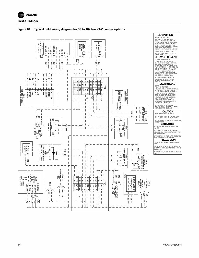
88 RT-SVX24Q-EN
Figure 61. Typical field wiring diagram for 90 to 162 ton VAV control options
IInnssttaallllaattiioonn

RT-SVX24Q-EN 89
Figure 62. Typical field wiring diagram notes for 90 to 162 ton VAV and CV control options
IInnssttaallllaattiioonn

90 RT-SVX24Q-EN
Figure 63. Typical GBAS analog input wiring diagram for 90 to 162 ton CV and VAV control options
Table 44. GBAS voltage vs. setpoint
Setpoint GBAS 0-5 VDC GBAS 0-10 VDC Valid Range
Occ Zone Cooling Setpoint (CV only) 0.5 to 4.5 VDC 0.5 to 9.5 VDC 50 to 90°F
Unocc Zone Cooling Setpoint 0.5 to 4.5 VDC 0.5 to 9.5 VDC 50 to 90°F
Occ Zone Heating Setpoint (CV only) 0.5 to 4.5 VDC 0.5 to 9.5 VDC 50 to 90°F
IInnssttaallllaattiioonn

RT-SVX24Q-EN 91
Table 44. GBAS voltage vs. setpoint (continued)
Setpoint GBAS 0-5 VDC GBAS 0-10 VDC Valid Range
Unocc Zone Heating Setpoint 0.5 to 4.5 VDC 0.5 to 9.5 VDC 50 to 90°F
SA Cooling Setpoint (VAV only) 0.5 to 4.5 VDC 0.5 to 9.5 VDC 40 to 90°F
SA Cooling Setpoint (SZVAV only) 0.5 to 4.5 VDC 0.5 to 9.5 VDC 40 to 70°F
Zone Cooling Setpoint (SZVAV only) 0.5 to 4.5 VDC 0.5 to 9.5 VDC 50 to 80°F
Zone/Return Critical Temperature Setpoint (RR only) 0.5 to 4.5 VDC 0.5 to 9.5 VDC 75 to 95°F
SA Heating Setpoint (VAV only) 0.5 to 4.5 VDC 0.5 to 9.5 VDC 40 to 180°F
SA Heating Setpoint (SZVAV only) 0.5 to 4.5 VDC 0.5 to 9.5 VDC 65 to 95°F
Space Static Pressure Setpoint 0.5 to 4.5 VDC 0.5 to 9.5 VDC -0.20 to 0.30 IWC
SA Static Pressure Setpoint 0.5 to 4.5 VDC 0.5 to 9.5 VDC 0.7 to 5.1 IWC
Min OA Flow Setpoint 1 0.5 to 4.5 VDC 0.5 to 9.5 VDC 0 to Unit Max Flow
MWU Setpoint 0.5 to 4.5 VDC 0.5 to 9.5 VDC 50 to 90°F
Econ Dry Bulb Enable Setpoint 0.5 to 4.5 VDC 0.5 to 9.5 VDC 50 to 140°F
SA_Reheat_Setpoint 0.5 to 4.5 VDC 0.5 to 9.5 VDC 60 to 90°F
Minimum Position Setpoint 3 0.5 to 4.5 VDC 0.5 to 9.5 VDC 0 to 100%
Occ Dehumidification Setpoint 0.5 to 4.5 VDC 0.5 to 9.5 VDC 40 to 65%
Unocc Dehumidification Setpoint 0.5 to 4.5 VDC 0.5 to 9.5 VDC 40 to 65%
Occ Humidification Setpoint 0.5 to 4.5 VDC 0.5 to 9.5 VDC 20 to 50%
Unocc Humidification Setpoint 0.5 to 4.5 VDC 0.5 to 9.5 VDC 20 to 50%
Notes:1. If DCV is enabled this is used for Design Minimum OA Flow Setpoint2. If DCV is enabled, this is used for Design Minimum OA Damper Position Setpoint
Table 45. GBAS 0-10 VDC output range
Setpoint GBAS 0-10 VDC Valid Range
Outdoor Air Temperature 0.5 to 9.5 VDC -40 to 200°F
Zone Temperature 0.5 to 9.5 VDC -40 to 200°F
Supply Air Temperature (VAV only) 0.5 to 9.5 VDC -40 to 200°F
Supply Air Pressure (VAV only) 0.5 to 9.5 VDC 0.0 to 7.91 wc
Space Pressure 0.5 to 9.5 VDC -0.67-0.67 wc
Space RH 0.5 to 9.5 VDC 0-100%
OA RH 0.5 to 9.5 VDC 0-100%
Space CO2 Level 0.5 to 9.5 VDC 50-2000 PPM
Cooling Capacity % 0.5 to 9.5 VDC 0-100%
Heating Capacity % 0.5 to 9.5 VDC 0-100%
Outdoor Air Damper Position 0.5 to 9.5 VDC 0-100%
Outdoor Airflow 0.5 to 9.5 VDC 0 to 65,000 CFM
IInnssttaallllaattiioonn

92 RT-SVX24Q-EN
Unit StartupSequence of Operation
NNOOTTIICCEECCoommpprreessssoorr FFaaiilluurree!!FFaaiilluurree ttoo ffoollllooww iinnssttrruuccttiioonn bbeellooww ccoouulldd rreessuulltt iinnccoommpprreessssoorr ffaaiilluurree..UUnniitt mmuusstt bbee ppoowweerreedd aanndd ccrraannkkccaassee hheeaatteerrsseenneerrggiizzeedd aatt lleeaasstt 88 hhoouurrss BBEEFFOORREE ccoommpprreessssoorrssaarree ssttaarrtteedd..
Cooling Sequence of OperationTime delays are built into the controls to increasereliability and performance by protecting thecompressors and maximizing unit efficiency.
SZVAV Cooling Sequence of OperationSingle Zone VAV units will be equipped with a VFDcontrolled supply fan which will be controlled by the 0-10VDC RTM VFD output and the RTM Supply Fanoutput. With the RTM Supply Fan output energized andthe RTM VFD output at 0VDC the fan speed output is37% (22Hz) from the VFD motor, by default, and at10VDC the Fan Speed output is 100% (60Hz). Thecontrol scales the 0-10VDC VFD output from the RTMlinearly to control between the 37%-100% controllablerange.
If the RTM determines that there is a need for activecooling capacity in order to meet the calculatedTemperature Setpoint (Tset), the unit will begin tostage compressors accordingly once supply fanproving has been made. Note that the compressorstaging order will be based on unit configuration andcompressor lead/lag status.
Once the Tset calculation has reached its bottom limit(Tset Lower Limit Setpoint) and compressors are beingutilized to meet the demand, the Tset value continuesto calculate below the Tset Lower Limit Setpoint andthe algorithm will begin to ramp the Supply Fan Speedup toward 100%. Note that the supply fan speed willremain at the compressor stage’s associated minimumvalue (as described below) until the Tset value iscalculated below the Tset Lower Limit Setpoint.
As the cooling load in the zone decreases the zonecooling algorithm will reduce the speed of the fandown to minimum per compressor stage and controlthe compressor outputs accordingly. As thecompressors begin to de-energize, the Supply Fanspeed will fall back to the Cooling Stage’s associatedminimum fan speed, but not below. As the load in thezone continues to drop, cooling capacity will bereduced in order to maintain the discharge air withinthe ± ½ Tset deadband.
CCoooolliinngg SSttaaggeess MMiinniimmuumm FFaann SSppeeeedd
As the unit begins to stage compressors to meet thecooling demand, the following minimum Supply FanSpeeds will be utilized for each corresponding CoolingStage. Note that the Supply Fan Speed will be allowedto ramp up beyond 37% as determined by the activeTset calculation; the speeds below are only theminimum speeds per cooling stage. Note that whentransitioning between active cooling stages,compressors may energize prior to the supply fanreaching the minimum speed for the associated step.
1. 2-Stage DX Cooling - The minimum fan speed forunits with 2 stages of DX Cooling will be 37% of theunit’s full airflow capacity. At Stage 1 of DX Coolingthe minimum Fan Speed will be 37% and at Stage 2of DX Cooling the Fan Speed will be at a minimumof 67%.
2. 3-Stage DX Cooling - There are no IntelliPakapplications with 3 stages of DX Cooling.
3. 4-Stage DX Cooling - The minimum fan speed forunits with 4 stages of DX Cooling will be 37% of theunit’s total airflow. At Stage 1 the minimum SupplyFan Speed will be 37%, at Stage 2 the minimumSupply Fan Speed will be 58%, and at Stages 3 & 4the minimum Supply Fan Speed will be 67%.
Rapid RestartThis feature will occur after every power cycle. Oncepower is restored (e.g., via a backup generator), theRTM will maximize cooling capacity within 3-5 minutes.Once the space has returned to its Zone TemperatureSetpoint, the RTM controls the load using normalcapacity control algorithms. The supply fan will beturned on immediately after a power cycle, moduleinitialization, or after the Unit Start Delay has timed out.The supply fan proving switch input must be closedprior to continuing with Rapid Restart.
Once the supply fan proving switch input has closed,the unit will consider the outside air temperature todetermine whether economizing or DX mechanicalcooling will be utilized to provide the necessarycooling. If the outside air temperature is less than 50°Fand economizing is enabled, the outside air damperwill be utilized. If the outside air temperature is above50°F, the outside air damper will remain closed and DXmechanical cooling will occur for the duration of RapidRestart.
Compressor Sequence of OperationEach compressor is equipped with a crankcase heaterand is controlled by a 600 volt auxiliary switch on thecompressor contactor. The proper operation of thecrankcase heater is important to maintain an elevatedcompressor oil temperature during the “Off” cycle toreduce oil foaming during compressor starts.

RT-SVX24Q-EN 93
When the compressor starts, the sudden reduction incrankcase pressure causes the liquid refrigerant to boilrapidly causing the oil to foam. This condition coulddamage compressor bearings due to reducedlubrication and could cause compressor mechanicalfailures.
Low Ambient Compressor OperationCertain applications require compressor operation atlower ambient conditions than standard units. Lowambient compressor operation is a factory configuredoption that allows units to operate down to -10°F byextending the low ambient compressor lockoutsetpoint range.
Standard configuration units are limited to a minimumlow ambient compressor lockout setpoint of 40° F. Inconditions below 40°F the low-pressure cutout (LPC)switch can open in the first few minutes of initialcompressor operation due to refrigerant circulationcharacteristics. To prevent nuisance LPC events atstart-up in these conditions the unit controller willbypass LPC processing for a varying period of time asdefined below:
• For ambient temps below 20°F LPC events will bebypassed for the first 170 seconds of compressoroperation.
• For ambient temps between 20° and 40°F thebypass time reduces linearly from 170 seconds at20°F to 0 seconds at 40°F. LPC events are notbypassed at initial compressor start in ambientconditions above 40°F.
00F 20F 40F
170
LPC B
ypas
s Tim
e (s
ec)
Outdoor Air Temp (°F)
• An open LPC switch detected at compressor startwill result in a manual-reset compressor lockoutcondition.
• 4 consecutive LPC trip occurrences after the bypasstime expires without a minimum of 3 minutes ofcompressor operation between trips will result in amanual-reset compressor lockout.
In addition to alternate LPC event processing, thesecond compressor to start on each refrigerant circuitwill be disabled for 40 minutes each time a circuit startsin ambient conditions less than 40°F. To properlymaintain head pressure control in low ambientconditions one condenser fan on each refrigerant
circuit will be controlled by a Variable-frequency motordrive (VFD).
This fan will always be the first fan active. The VFD willcontrol fan speed at all times compressors are active tothe HI-adjustable Low Ambient Control Point. If headpressure control requires additional condenser fanstages to maintain proper Saturated CondenserTemperature within limits they will be activated asnecessary according to the standard head pressurecontrol fan-staging algorithm.
Units with Evaporative CondenserSequence of OperationUpon a power up without water in the sump, thecondenser sump drain will be controlled to allow thesump to hold water. The fill relay will be energized ifthere is a call for mechanical cooling and if the outdoorair temperature is greater than 10°F on units with asump heater installed or greater than 40°F on unitswithout sump heat. Once the fill solenoid is energized,the sump will begin to fill. The minimum water levelswitch will close and the fill relay will be de-energized.The sump water temperature sensor is invalid unlessthe minimum water level switch is closed.
If the sump water temperature is less than the setpoint(default is 38°F), the sump heater will be energized untilthe water temperature reaches the setpoint plus 5degrees (43°F for default). The fill solenoid will remainclosed for 20 minutes or until the water temperature isgreater than 35°F. Once a water temperature of 35°F orgreater is achieved, the fill solenoid is energized, thesump will continue to fill, and a five minute timer isstarted.
When the timer expires, the compressor lockout will bereleased and mechanical cooling will be allowed. Headpressure control will be regulated by a variable speedfan until the liquid line pressure from either circuitreaches the upper limit, which is set on the HumanInterface under the setup menu 120°F default. Theliquid line pressure is converted to a temperature fordisplay at the Human Interface. When the temperatureexceeds the upper limit, the condenser sump pump willbe energized. When the sump pump is energized,water is pumped from the sump and sprayed over thecondenser coil. If the liquid line pressure from eithercircuit falls below the lower limit the sump pump willbe de-energized.
When the sump pump is energized or de-energized achange in state is observed from an auxiliary contactorto ensure proper sump pump operation. A change instates must be observed by the auxiliary contactorwithin 6 seconds of the command to change states ormechanical cooling will be locked out on a sump pumpfailure causing a manual reset diagnostic to be set.
The fill solenoid will remain energized and the waterlevel will be controlled by the mechanical float valve. Ifthe maximum level float ever closes, an information-only diagnostic is set and the fill solenoid is de-
UUnniitt SSttaarrttuupp

94 RT-SVX24Q-EN
energized. This is an indication that the mechanicalfloat is not adjusted properly or a failure of themechanical float valve has occurred. If the maximumlevel input is open for two continuous minutes, thediagnostic will be cleared and the fill solenoid will beenergized.
If the sump water temperature ever drops below 35°F,the drain actuator will be controlled in order to drainthe water from the sump. If there is a call formechanical cooling and the outdoor air temp is greaterthan 10°F on units with sump heat installed or greaterthan 40°F on units without sump heat, the unit will beallowed to refill the sump.
The drain control can be configured via the HumanInterface, and by the drain actuator installation, to holdor drain water on power loss; the default is set to drain.Periodic purge is a cyclic opening of the drain toremove debris and buildup from the sump and addadditional fresh water to the sump. Periodic purge hasan adjustable interval from the setup menu on theHuman Interface with a range of 1-12 hours or can beset to disabled - the default position if periodic purge isnot required. The duration of the blowdown, or thetime that the drain valve is opened, is adjustable to arange of 5 - 255 seconds, with 120 seconds being thedefault.
The optional conductivity controller also uses this timerto open the drain, when required, based on waterquality. During this purge, the fill solenoid will remainenergized to provide fresh water to the sump to replacewater being released during the blowdown. Watertreatment blowdown is provided by shorting thedesignated input on the customer-supplied terminalstrip. This gives the customer more flexibility indetermining water conditions via external controls.Once the input is detected closed, the drain valve willbe opened for a time equal to the Human Interfaceadjustable periodic purge duration.
Once the duration timer expires, or if the minimumlevel switch opens, the drain valve will be closed andthe water treatment blowdown input will be ignored for15 minutes. During this blowdown the fill relay willremain open to provide fresh water to the sump. Theadjustable duration time period should be set so thatduring drain operation 1 inch of water is drained fromthe sump with the fill solenoid valve closed. If theminimum water level switch opens during a blowdowncycle, the unit will de-energize the sump pump in orderto protect the compressors and sump heater frominsufficient water levels. Once the water level reachesthe minimum level input and this input closes for 10seconds, the compressors and sump heater operationswill be allowed to restart.
Evaporative Condenser Drain Valve SetupThe drain valve is shipped to “Drain During Unit PowerLoss Conditions.” This means that when the unitdisconnect is turned off, the 1S2 toggle switch is turnedoff, or the unit loses power, the drain will open. The
valve is spring loaded and will travel from fully closedto fully open in approximately 25 seconds.
This is desirable in cold climates where a risk offreezing exists. In milder climates it may be desirable tokeep the water in the sump when unit power is off toavoid unnecessarily wasting water whenever the unitdisconnect is turned off.
To convert the unit to “Hold During Unit Power LossConditions,” complete the following steps:
1. Remove power from the unit.
2. Remove the weather shield cover (Figure 64, p. 94).
3. Loosen the shaft set screw (Figure 64, p. 94),remove the locking clip and remove the shaftadapter (Figure 65, p. 95).
4. Lift the drain valve actuator and rotate it to the“hold during power loss” position (Figure 66, p.95).
5. Reinstall the shaft adapter and locking clip andreinstall the actuator onto the base. Make sure thearrow on the shaft adapter is set to 0°.
6. Make sure the valve is in the fully closed position,then tighten the shaft set screw.
7. Reinstall the weather shield cover.
8. Restore power to the unit.
9. At the Human Interface, press SSEETTUUPP, NNEEXXTT until'Head Pressure Control Setup Submenu” is seen.Press EENNTTEERR.
10. Change the “Sump Drain Valve Relay Control” fromDrain to Hold.
Figure 64. Drain valve actuator with weather shieldWeather Shield
Shaft Set ScrewDrain Valve Actuator
UUnniitt SSttaarrttuupp

RT-SVX24Q-EN 95
Figure 65. Actuator shaft adapter removal/assembly
Locking clip
Shaft adapter
1
2
Figure 66. Actuator is shipped in “Drain during powerloss” configuration
To drain during power loss,set shaft adapter to 0 degrees
To hold during power loss,set shaft adapter to 90 degrees
Set Drain Duration TimerEnter service test mode from unit Human Interface.Navigate to the compressor condenser fan submenu.Under head pressure control, use manual control.
Close drain valve and energize water inlet solenoidvalve until water reaches nominal level. Once level isachieved, de-energize fill solenoid. Open drain valveand time how long it takes for the water level to dropone inch, make sure to take into account the closingtime of the valve.
Chemical Water Treatment TreeThe Trane evaporative condenser comes with a PVCtree to allow easier inputs for third party watertreatment. The tee labeled A is a 3/4 inch NPT threadedinput, see Figure 67, p. 95. Tees B and C are 1/2 inchNPT threaded inputs. The ball valve can be used to stopthe water flow through the tree to allow the customerto add hookup of water treatment, or to change andupdate water treatment with the unit running.
Units with a conductivity sensor will have theconductivity sensor installed into the 3/4 inch tee withthe other tees plugged. For all other units, A, B and Cwill be plugged, see Figure 67, p. 95. Ensure the ballvalve is in the open position when water treatment isbeing operated in the system to make sure water flowsthrough the tree and transports treatment to the unitsump.
Figure 67. Chemical water treatment treeA
B
C
Conductivity ControllerUpon start-up, the conductivity controller must becalibrated and setup for operation. Below are thenecessary steps to accomplish those tasks. Thecontroller has two setpoints that control two relays.Both of these setpoints will need to be set by a localwater treatment expert.
1. The first setpoint is the standard point blowdownpoint. When the setpoint is exceeded, the relay (K1)will be energized and a blowdown request willclose the Water treatment request binary input onthe MCM.
2. The second setpoint will be the emergency point.The second setpoint will open the normally closedK2 relay, which will interrupt the sump provingcircuit which will generate a manual lockout. Thissecond setpoint will be used to protect the unitfrom extremely high conductivity that wouldindicate a failure in the system.
3. Inside the enclosure for the controller, there will be
UUnniitt SSttaarrttuupp

96 RT-SVX24Q-EN
a thermostat and strip heater that will protect LCDfrom cracking at low ambient conditions. Thethermostat closes at 15°F and opens at 25°F.
Procedure to calibrate conductivity1. Use a calibrated thermometer and a known
conductivity rating. There are two different optionsfor having a liquid with known conductivity:
NNoottee:: Visit the GF Piping Systems site for additionalinformation and resources.
• Purchase a liquid with known conductivityrating
• Purchase a handheld conductivity reader
2. Close the ball valve on the chemical treatment treeand remove the conductivity sensor from the tree.
3. Enter service test mode on the unit and turn thepump on, ensuring the compressors are set to OFF.
4. With the conductivity controller connected to thesensor and power, enter the CALIBRATE menu byholding down the ENTER key for 2 seconds.
5. When asked for the calibration key code, hit the UP,UP, UP, DOWN arrow keys in sequence.
6. Using the UP and DOWN arrows go to Chan 1 Cell:Standard. Ensure this channel is set to standard.
7. If not, press the RIGHT arrow key and set tostandard then press the ENTER key to return to theCALIBRATION menu.
8. Using the UP and DOWN arrows go to Chan 1 Cell.Ensure that the cell constant is set to 1.0.
9. If not, press the RIGHT arrow key and set the cellconstant to 1.0. Then press the ENTER key to returnto the CALIBRATION menu.
10. Using the UP and DOWN arrows go to Chan 1 Set:Temperature and press the RIGHT arrow key toenter the edit mode.
11. Adjust the temperature on the controller to matchthe actual temperature.
12. Press the ENTER key to save the input and return tothe CALIBRATE menu.
13. Using the UP and DOWN arrows, go to the Chan 1Set: Conductivity and press the RIGHT arrow key toenter the edit mode.
14. Adjust the conductivity on the controller to matchthe actual conductivity rating of the liquid.
15. Press the ENTER key to save the conductivity ratingand return to the CALIBRATE menu.
16. When finished calibrating the controller, press theUP and DOWN key simultaneously to return tonormal operating mode.
Procedure to set purge setpoints on theconductivity controllerWork with local water treatment expert to identifynominal purge and emergency purge conductivity
value.
NNoottee:: Visit the GF Piping Systems site for additionalinformation and resources.
1. Close the ball valve on the chemical treatment treeand remove the conductivity sensor from the tree.
2. Enter Service test mode on the unit HI and energizethe sump pump, ensuring the compressors are setto OFF.
3. With the conductivity controller connected to thesensor and power, enter the CALIBRATE menu byholding down the enter key for 2 seconds.
4. When asked for the calibration key code, hit the UP,UP, UP, DOWN arrow keys in sequence.
5. Using the UP and DOWN arrows, go to Relay 1Setpoint: and press the RIGHT arrow key to enteredit mode (K1).
6. Adjust the set point to the nominal blowdownconductivity value.
7. Press the ENTER key to return to the CALIBRATEmenu.
8. Using the UP and DOWN arrows, go to Relay 2Setpoint:and press the RIGHT arrow key to enteredit mode (K2).
9. Adjust the set point to the emergency conductivityvalue.
10. Press the ENTER key to return to the CALIBRATEmenu.
11. When finished setting the values, press the UP andDOWN key simultaneously to return to normaloperating mode.
Units Without an EconomizerUpon entering an “occupied” mode of operation, theRTM receives input from the remote panel to start thesupply fan. For constant volume applications, the RTMsupply fan contacts close, which energizes the supplyfan contactor. When the supply fan starts, the fanproving switch closes, signaling the RTM that airflowhas been established and the VFD will begin to rampthe fan (if equipped).
When a cooling request is sent to the RTM from a zonetemperature sensor, the RTM evaluates the operatingcondition of the system using the supply airtemperature input and the outdoor temperature inputbefore sending the request to the MCM. Once therequest is sent to the MCM, the compressor modulechecks the compressor protection circuit before closing“Stage 1". After the first functional stage has started,the compressor module monitors the saturatedrefrigerant temperature and closes the condenser fanoutput contact, when the saturated refrigeranttemperature rises above the “lower limit” setpoint.
UUnniitt SSttaarrttuupp

RT-SVX24Q-EN 97
Units with an EconomizerUpon entering an “occupied” mode of operation, theRTM receives input from the remote panel to start thesupply fan. For constant volume applications, the RTMsupply fan contacts close, which energizes the supplyfan contactor. When the supply fan starts, the fanproving switch closes, signaling the RTM that airflowhas been established. The RTM opens the economizerdampers to the specified “minimum position”.
When a cooling request is sent to the RTM from thezone temperature sensor, the RTM evaluates theoperating condition of the system using the supply airtemperature input and the outdoor temperature inputbefore sending the request to the MCM for mechanicalcooling. If the outdoor conditions are suitable forcooling (temperature and humidity are within specifiedsetpoints), the RTM will attempt to maintain the zonetemperature without using any compressors. If thezone temperature cannot be maintained within thesetpoint deadband, the RTM sends a cooling request tothe MCM. The compressor module checks thecompressor protection circuit before closing “Stage 1".After the first functional stage has started, thecompressor module monitors the saturated refrigeranttemperature and closes the condenser fan outputcontact, when the saturated refrigerant temperaturerises above the “lower limit” setpoint.
Units with Traq™ SensorThe outside air enters the unit through the Traq™Sensor assemblies and is measured by velocitypressure flow rings. The velocity pressure flow ringsare connected to a pressure transducer/solenoidassemblies. The solenoid is used for calibrationpurposes to compensate for temperature swings thatcould affect the transducer. The Ventilation ControlModule (VCM)Symbio™ 800 utilizes the velocitypressure inputs, the RTM outdoor air temperatureinput, and the minimum outside air CFM setpoint tomodify the volume (CFM) of outside air entering theunit as the measured airflow deviates from setpoint.
When the optional temperature sensor is installed andthe Preheat function is enabled, the sensor will monitorthe combined (averaged) outside air and return airtemperatures. As this mixed air temperature fallsbelow the Preheat Actuate Temperature Setpoint, theVCM will activate the preheat binary output used tocontrol a field installed heater. The output will bedeactivated when the temperature rises 5 above thePreheat Actuate Temperature Setpoint.
When the optional CO2 sensor is installed and DCV isenabled, the OA damper will be modulated to controlCO2 concentrations. If the CO2 concentration is greaterthan the Design Minimum CO2 Setpoint the OAdamper will be opened to the Design Minimum OADamper Setpoint (w/o Traq™) or until the DesignMinimum OA Flow Setpoint is met (w/ Traq™).
If the CO2 concentration is less than the DCV MinimumCO2 Setpoint the OA damper will be closed to the DCVMinimum OA Damper Setpoint (w/o Traq™) or until theDCV Minimum OA Flow Setpoint is met (w/ Traq™).
If the CO2 concentration is between the DesignMinimum CO2 Setpoint and the DCV Minimum CO2Setpoint the OA damper will be modulatedproportionally between the Design Minimum OADamper Setpoint and the DCV Minimum OA DamperSetpoint (w/ Traq™) and between the Design MinimumOA Flow Setpoint and the DCV Minimum OA FlowSetpoint (w/o Traq™).
Low Charge ProtectionFor each refrigeration circuit, the entering and leavingevaporator temperatures are used to calculatesuperheat. When the calculated superheat exceeds theEvaporator Temperature Differential Setpoint minus 5°F but not the Evaporator Temperature DifferentialSetpoint, an information only, auto-reset, HighSuperheat diagnostic is initiated.
If the calculated superheat exceeds the EvaporatorTemperature Differential Setpoint, a manual reset, lowrefrigerant charge diagnostic is initiated and allcompressors on the circuit are locked out.
Note that on circuits with the Variable SpeedCompressor option, the Evaporator TemperatureDifferential Setpoint for that circuit will be reset basedon the active compressor capacity and the userselected Evaporator Temperature Differential Setpoint.
Frostat™ ControlThe compressor module utilizes an evaporatortemperature sensor, mounted on the suction line ofeach circuit, to protect the evaporator from freezing. Ifthe evaporator temperature approaches the specifiedsetpoint, adjustable between 25°F and 35°F, thecompressor(s) will be cycled “off”. The compressorswill not be allowed to restart until the evaporatortemperature has risen 10°F above the specified cutouttemperature and the compressor(s) have been off for aminimum of three minutes.
NNoottee:: On circuits with the Variable Speed Compressoroption, the Active Coil Frost Cutout TemperatureSetpoint for that circuit will be 5°F higher thanthe user selected Coil Frost Cutout TemperatureSetpoint.
Lead/Lag OperationWhen Lead/Lag is enabled, each time the system cyclesafter having stages 1 and 2 “On”, “Stage 2" and thecorresponding condenser fan output will start first. Thecompressor module cycles the compressors “On” and“Off” to keep the zone temperature within the coolingsetpoint deadband. The condenser fans are cycled“On” and “Off” to maintain the saturated refrigeranttemperature within the specified controlband.
UUnniitt SSttaarrttuupp

98 RT-SVX24Q-EN
NNoottee:: Lead-Lag is not available with the variable speedcompressor option.
Units Equipped with 100%ModulatingExhaustThe exhaust dampers are controlled through anExhaust/Comparative Enthalpy Module (ECEM). TheECEM module receives input from a space transducerand modulates the exhaust dampers to maintain thespace pressure to within the specified setpointcontrolband.
Modulating Hot Gas Reheat Sequence ofOperationWhen the relative humidity in the controlled space (asmeasured by the sensor assigned to space humiditysensing) rises above the space humidity setpoint,compressors and the supply fan will energize to reducethe humidity in the space.
All compressors on both refrigerant circuits will bestaged up during active hot gas reheat. Circuit #1 isdesignated the reheat circuit and will feature additionalrefrigerant control devices as well as a split condensercoil with one section in the indoor air stream and theother in the outdoor coil compartment.
While hot gas reheat is active, the discharge air will becontrolled to the Supply Air Reheat Setpoint bymodulating the amount of reheat produced by thereheat coil. The Supply Air Reheat Setpoint, Occupiedand Unoccupied Dehumidification Setpoints areadjustable via the human interfaceBAS/Networkcontrol, or GBAS.
Hot gas reheat will be terminated when the humidity inthe space is reduced to the active space humiditysetpoint - 5% or when an overriding condition such asheating or cooling demand or a failure occurs in acomponent required for dehumidification.
On VAV units, at start-up, satisfying the VAV OccupiedCooling setpoint, MWU setpoint, and DWU setpointwill have priority over dehumidification mode. Onceheating modes are satisfied, and the unit is satisfyingthe SA Cooling Setpoint, dehumidification mode willbe entered if no more than half the unit mechanicalcooling capacity is requested.
On SZVAV units, hot gas reheat will be similar to VAVmodulating hot gas reheat with the exception of adynamic Supply Air Reheat Setpoint. Rather thanutilizing a static Supply Air Reheat Setpoint, once theunit enters dehumidification, the Discharge AirSetpoint will be calculated based on the Zonetemperature vs. Zone Cooling Setpoint error and willbe capped at the user selected Supply Air Reheatsetpoint.
Hot gas reheat is not allowed during VAV HeatingModes (Changeover input closed). Once active, hot gasreheat control will remain active for a minimum of
three minutes unless a priority unit shutdown requestis received or the High Pressure Control input opens oneither circuit.
Hot gas reheat control can be enabled separately foroccupied and unoccupied modes of operation via theHuman Interface and is overridden/disabled whetheractive or inactive by the following methods:
• Priority unit shutdown conditions (Emergency stop,Ventilation Override, Network Stop, etc.)
• Compressor circuit manual reset lockouts on eithercircuit. Low Refrigerant Charge monitoring is activeduring dehumidification mode and will lockoutcompressor circuits based on the same criteria usedfor cooling mode.
• Outdoor Air Temp is less then 40°F or greater the100°F.
• Humidity Sensor Failure• For VAV units, (in occupied) hot gas reheat will be
disabled if space temp is less than the DehumidOverride Low Zone Setpoint or higher than theDehumid Override High Zone Setpoint. If hot gasreheat is inactive it will not be allowed until it spacetemp rises higher than the Dehumid Override LowZone Setpoint + 1.0°F or lower than the DehumidOverride High Zone Setpoint - 2.0°F.
• For SZVAV units, hot gas reheat will be disabled ifspace humidity levels have fallen below the ActiveOcc/Unocc Dehumidification Setpoint -5%Dehumidification Hysteresis Offset, the zonetemperature has dropped too close to the ZoneHeating Setpoint in any unit mode (Zone Temp. isless than ZHSP + 0.5°F), the zone temperature risesabove the Zone Cooling Setpoint +2°F in any unitmode, Entering Evaporator Temperature falls toolow, Froststat input becomes active, or Reheatbecomes disabled.
• For CV and all units in unoccupied, if space temp isless than the Zone Heating Setpoint (ZHSP) + 0.5° Fif hot gas reheat is active, or less than ZHSP + 1.0° Fif not hot gas reheat mode will be disabled. If zoneconditions result in a cooling request for more thanone-half the available cooling capacity of the unithot gas reheat will be disabled and will transition tocooling control. If hot gas reheat is inactive,dehumidification will not be allowed until the activeunit cooling capacity request drops to half theavailable cooling capacity or less, unless the spacetemp is less than the Zone Cooling Setpoint.
• In CV units in occupied mode, if the unit is not in“AUTO” system mode and is set to “HEAT” systemmode via the HI, BAS, or Zone Sensor device,dehumidification control will be disabled at spacetemps above Occupied ZCSP + 1.0° F. Ifdehumidification is inactive it will not be allowed toactivate if space temp is greater than the OZCSP.
All units configured for modulating hot gas reheat willhave a reheat condenser coil purge function to ensureproper refrigerant distribution in the reheat circuit. Thisfeature is always enabled and will monitor the amount
UUnniitt SSttaarrttuupp

RT-SVX24Q-EN 99
of cumulative compressor run time while the reheatcondenser coil pumpout relay is in a certain state. Ifcompressors accrue an amount of run time equal to theHI-adjustable purge interval time without the pumpoutrelay changing states a purge cycle will be initiatedlasting for three minutes.
During this cycle all compressors but the 2ndcompressor on circuit #1 will be energized if notalready, the reheat valve and cooling valves will be setto 50%, and the reheat coil pumpout relay will betoggled to its opposite state. After the three-minutepurge cycle completes the purge interval timer will bereset and all system components will return to the statethey were in prior to entering purge.
During hot gas reheat control an evaporator frostcontrol function designed specifically for reheat modeswill be active. This function will reduce refrigerationcircuit capacity to 50% (1st compressor on each circuitremaining on) when the Entering Evaporator Tempdrops below a non-adjustable limit of 35° F for 10continuous minutes. Once capacity is reduced, it willremain reduced until the current cycle of hot gas reheatis terminated or a purge cycle occurs.
If the Entering Evaporator Temp remains below 35° Ffor an additional 10 minutes both circuits will be de-activated and remain off until the Entering EvaporatorTemp rises above 45°F. Even though all compressorshave been de-activated the unit will remain indehumidification mode and re-enable compressors upto 50% capacity when the Entering Evaporator Temprises to 45°F or greater.
Energy Recovery Sequence of Operation
WWAARRNNIINNGGTTooxxiicc HHaazzaarrddss!!FFaaiilluurree ttoo ffoollllooww iinnssttrruuccttiioonnss bbeellooww ccoouulldd rreessuulltt iinnddeeaatthh oorr sseerriioouuss iinnjjuurryy..DDoo nnoott uussee aann eenneerrggyy wwhheeeell iinn aann aapppplliiccaattiioonnwwhheerree tthhee eexxhhaauusstt aaiirr iiss ccoonnttaammiinnaatteedd wwiitthhhhaarrmmffuull ttooxxiinnss oorr bbiioohhaazzaarrddss..
The primary components of the energy recoverysystem are the energy recovery wheel, exhaust airbypass damper, outdoor air bypass damper, and theenergy recovery preheat output. See Figure 69, p. 100and Figure 70, p. 101. A filter is also placed betweenthe wheel and the outdoor air damper and an indicatorscheme similar to that for final filters is provided tonotify the user when that filter needs to be changed.
The energy recovery wheel will only be energizedwhen both the Supply Fan and Exhaust Fan arerequested on by the various functions that controlthem. Energy recovery is a passive function and cannot request fan operation.
Once the required airflow is present the wheel will becommanded on if the indoor vs. outdoor conditions are
such that energy can be recovered. This is assesseddifferently in cooling and heating modes.
In cooling mode, wheel activation conditions areassessed based on indoor (return air) vs. outdoorenthalpy. Indoor and outdoor enthalpy values arecalculated using the same sensors as used forcomparative enthalpy. If the outdoor enthalpy is 3 BTU/lb. greater than indoor enthalpy the wheel is activatedto remove energy from the incoming outdoor air. Inheating mode the wheel is activated based on indoorvs. outdoor dry bulb temperature. If the outdoortemperature is 5° F less than the indoor temperature.the wheel is activated to recover heat energy from theexhaust air.
In cooling mode the exhaust air bypass damper is heldclosed, providing 100% energy recovery capacityduring cooling modes of operation. In heating modes,including CV heating, VAV Heating, CV Supply AirTempering, VAV Supply Air Tempering, MorningWarm-up, and Daytime Warm-up the exhaust airbypass damper is controlled to discharge airtemperature. The damper is modulated to keep thesupply air temp at the Supply Air Heating setpoint forVAV control, or for CV control, supply air temp will becontrolled to a calculated Supply Air Heat Setpointbased on conditions in the space.
If the wheel is active, supplemental heat (electric,hydronic, gas) control algorithms will be disabled untilthe exhaust air bypass damper is fully closed(maximum heating capacity from the wheel). At thispoint, supplemental heat algorithms are released tocalculate supplemental heat capacity requests usingstandard setpoints until the setpoints are satisfied. InVAV occupied modes the energy recovery wheel willremain active after termination of supplemental heatabove heating setpoint until the exhaust air bypassdamper is opened fully for 3 minutes (indicatingminimal capacity requested from the wheel). In CVoccupied heating mode the wheel will remain activeafter termination of a heating cycle until the zone temprises above the Occupied Zone Heating Setpoint + 1.0°Fand the exhaust air bypass damper is fully open. Thewheel will remain active if these conditions persistcontinuously until the expiration of a HI-adjustabletime-out period or until the zone temp rises above theOccupied Zone Cooling Setpoint - 0.5°F.
During active Economizing control the energy wheelwill be disabled but the outdoor air bypass damper willopen an amount that tracks the opening of the OAdamper proportionally from minimum position to fullyopen.
To protect the wheel from frost build-up in heatingmodes a frost avoidance function is included. Thisfeature will energize the energy recovery preheatoutput (if configured) and modulate the outdoor airbypass damper open (to reduce incident cold outdoorair on the wheel) as necessary when the LeavingRecovery Temp Sensor value is less than the Recovery
UUnniitt SSttaarrttuupp

100 RT-SVX24Q-EN
Frost Avoidance Setpoint. The Leaving Recovery TempSensor is installed in the leaving air stream on theexhaust-fan side of the energy wheel.
Figure 68, p. 100 provides the exhaust air temperaturesetpoint for 70ºF return air at various percents ofrelative humidity.
Where variable effectiveness / outside air bypass is notenough to prevent frosting conditions, the energyrecovery wheel shuts off. Turning the wheel off duringfrost conditions is a reliable method of preventing thewheel from frosting, however, energy is not beingrecovered and the extreme heating load must behandled otherwise. Extreme winter design conditionfor energy recovery units may require return airpreheat.
An energy recovery wheel proving function is alsoprovided to indicate when the wheel is not turning afterit has been commanded on.
Figure 68. Energy recovery wheel exhaust airsetpoint temperatures
Figure 69. Energy recovery wheel operation
Outside Air Intake Damper(Mist Eliminator not shown)
Exhaust Air, Leaving Energy Recovery Wheel, Path to Exhaust Fan
Building Return Air
Outside Air Bypass Damper
Unit ReturnAirflow
Exhaust Air Bypass Damper
Energy Recovery Wheel Conditioned Outside Air
Return Air Damper
Path to Filters & Coil ERW Unit Entering Air (Mixed Return Air & Conditioned Outside Air)
UUnniitt SSttaarrttuupp

RT-SVX24Q-EN 101
Figure 70. Energy recovery wheel economizer operation
Outside Air Intake Damper(Mist Eliminator not shown) Outside Air Bypass Damper
Path toFilters& Coil
Un-ConditionedOutside Air
Path toFilters& Coil
Unit ReturnAirflow
Return Air DamperExhaust Air Bypass Damper
Exhaust Air Path to Exhaust Fan
Building Return Air
Gas Heating Sequence of OperationStandard
Two Stage Gas FurnaceThe control system for the rooftop units are wired toensure that the heating and cooling do not occursimultaneously. Refer to the wiring diagram thatshipped with the unit while reviewing the followingsequence of operation.
Honeywell Ignition System((885500 && 11110000 MMBBHH TTwwoo SSttaaggee NNaattuurraall GGaass))
When a heating requirement exists, the RooftopModule (RTM) starts the supply fan and sends arequest for heat to the Heat Module. The Heat Modulecloses contacts and starts the combustion blowermotor. The combustion blower motor starts on lowspeed through the normally closed combustion blowerrelay contacts.
The supply airflow switch and the combustion airswitch closes. Power is applied through the high limitcutout to the Honeywell ignition control board. The
ignition control board starts a pre-purge timing cycle.At the end of the pre-purge cycle, the ignitiontransformer and the pilot solenoid valve are energized.This starts a 10 second trial for pilot ignition. When thepilot flame is established and sensed by the flamesensing rod, stage 1 of the main gas valve and the 60seconds sequencing time delay relay is energized.
The system will operate in the low heat mode until anadditional call for heat, established by closing thecontacts on the Heat Module. The sequencing timedelay relay will energize the combustion blower motorrelay which switches the combustion blower motor tohigh speed and energizes the 2nd stage solenoid on thegas valve after approximately 60 seconds.
If the flame rod does not detect a pilot flame within the10 second trial for ignition period, the control willlockout. If a flame failure occurs during operation, thegas valve, the sequencing time delay relay, and thecombustion blower relay is de-energized. The systemwill purge and attempt to relight the pilot. If a flame isnot detected after this attempt, the Honeywell ignitioncontrol will lock out. The combustion blower motor will
UUnniitt SSttaarrttuupp

102 RT-SVX24Q-EN
continue to operate as long as a heating demand existsand the system switch is “On”.
Once the heating demand has been satisfied, thecombustion blower and the Honeywell ignition controlboard is de-energized.
NNoottee:: The above sequence is the same for Propane.The orifices are smaller and the manifolds areadjusted to different values
((11880000 && 22550000 MMBBHH TTwwoo SSttaaggee NNaattuurraall GGaass))
When a heating requirement exists, the RooftopModule (RTM) starts the supply fan and sends arequest for heat to the Heat Module. The Heat Modulecloses contacts and starts the combustion blowermotor through the combustion blower relay. Thesupply airflow switch and the combustion air switchcloses. Power is applied through the high limit cutoutto the Honeywell ignition control board. The ignitioncontrol board begins the pre-purge timing cycle withthe damper in the light off position and the low firestart interlock is closed.
At the end of the pre-purge cycle, the ignitiontransformer and the pilot solenoid valve are energized.This starts a 10-second trial for pilot ignition. When thepilot flame is established and sensed by the flamesensing rod, the stage 1 of the main gas valve willbegin. The gas butterfly control valve is in the low firesetting by the linkage arm connection between thecombustion air actuator and the butterfly valve. Thesystem will operate in the low heat mode until there isan additional call for heat established by closing thecontacts on the Heat Module.
If the flame rod does not detect a pilot flame within the10 second trial for ignition period, the ignition controlboard will lockout. The combustion blower motor willcontinue to operate as long as a heating demand existsand the system switch is “On”. Once locked out onflame failure, the IC board will not reactivate theignition/combustion control circuit until it is resetmanually. To do this, press the reset button on thefront of the IC board case. A set of relay contacts isavailable for external use for heat fail (InformationOnly). Once the heating demand has been satisfied, thecombustion blower and the Honeywell ignition controlboard is de-energized.
Modulating Gas Sequence of OperationThe control system for the rooftop units is wired toensure that the heating and cooling do not occursimultaneously. Refer to the modulating heat wiringdiagram that shipped with the unit while reviewing thefollowing sequence of operation. As you review thesequence of operation, keep the following in mind:
• The furnace will not light unless the manual gasvalves are open and the control circuit switch isclosed.
• The control systems are wired to ensure thatheating and cooling cannot occur simultaneously.
• The unit supply fans must run continuously soairflow switch will stay closed.
• Modulating Gas heat is available during bothoccupied and unoccupied operation.
When there is a call for heat, the heat module energizesthe combustion blower, which causes the combustionairflow switch to close. The ignition control board willenergize providing that the indoor air flow switch, highlimit, and low and high pressure gas switches areclosed. The ignition control board then causes thecombustion air actuator to drive the inlet air damper tothe fully open position for a 30 second pre-purge. Thepre-purge time does not begin until the purge interlockswitches are made.
After the pre-purge, the combustion air actuator drivesthe inlet air damper and the gas butterfly control valveto a nearly closed position for light off. When the Lowfire interlock switch is closed the ignition transformer isenergized, the igniter begins to spark and the pilotvalve opens. This begins a 10-second trial for ignitionperiod during which the flame rod must detect theflame. If does not detect a flame at the end of theperiod, it will shut down and lock out the ignition/combustion circuit.
Once the pilot flame has been established, the heatmodule will open the main gas valve and auxiliary gasvalve. After the main flame is established, the pilotvalve closes. The ignition sequence is completed andthe heat module will drive the combustion air actuatorto a firing rate based on a 2-10 VDC signal. The gasbutterfly control valve will respond through theconnecting linkage. The heater will continue to rununtil the call for heat is removed or a limit opens.Following the completion of the call for heat, there is a15-second post-purge.
Flame FailureIn the event that the Ignition Control (IC) board losesthe “proof-of-flame” input signal during furnaceoperation, it will lock out and must be manually reset(Combustion blower motor continues to run as long asa heating requirement exists and control circuit switchis ON.)
Once locked out on flame failure, the IC board will notreactivate the ignition/combustion control circuit until itis reset manually. To do this, press the reset button onthe front of the (IC) board case.
A set of relay contacts is available for external use forheat fail (Information Only).
NNoottee:: The modulating gas heaters are factory adjustedfor safe operation and to reach the nameplaterated firing MBH for most areas of the country.The proper air/gas ratio must be reached by theservice tech during start-up.
UUnniitt SSttaarrttuupp

RT-SVX24Q-EN 103
Electric Heat Sequence of OperationThe control system for the rooftop units are wired toensure that heating and cooling do not occursimultaneously. Refer to electric heat wiring diagramsthat shipped with the unit while reviewing thefollowing sequence of operation. As you review thesequence of operations, remember these points:
• The high limit switch will trip if exposed to atemperature greater than the trip point, and willreset automatically once the temperature fallsbelow the reset point.
• The linear high limit switch is encased in a capillarythat extends across the unit supply air opening. Thelimit will trip if any 6” span of the capillary exceedsthe trip point. Refer toTable 68, p. 190.
• The manual limit switch will trip if exposed to atemperature greater than the trip point, and willneed to be reset manually.
• Electric heat will only energize if all three of thehigh limit safety controls are closed.
Electric Heat—CV, VAV Daytime Warm-upCV electric heat operation is done with discrete stagesof electric heat. Stages 2 and 3 will not energize unlessStage 1 is already operating and unable to satisfy theheating load. The heat will be staged to control to theHeating Setpoint.
VAV Active Occupied Discharge HeatingWhen the changeover input is closed (or whencommanded by BAS) the unit will control discretestages of electric heat to the active supply air heatingsetpoint. VAV occupied electric heating operation isdone with discrete stages (steps) of electric heat. Theheat staging is dependent on unit tonnage and heaterselection. The heat will be staged to control to theSupply Air Heating Setpoint.
SZVAV Occupied HeatingSingle Zone VAV heating will only be available withmodulating types of heat - IPak II units can usehydronic and modulating gas and will include electricheat. During SZVAV heating, the unit will calculate adischarge heating setpoint based on zone heatingdemands, and the unit will modulate heat to maintainthe discharge temperature to this setpoint.
Demand Control Ventilation Sequence ofOperationNNoottee:: CO2 sensor used with Demand Control
Ventilation must be powered from an externalpower source or separate 24 VAC transformer.
Sequence of Operation without Traq™If the space CO2 level is greater than or equal to theDesign Minimum CO2 Setpoint, the outdoor air damperwill open to the Design Minimum Outdoor Air Damper
Setpoint. If there is a call for economizer cooling, thedamper may be opened further to satisfy the coolingrequest.
If the space CO2 level is less than or equal to the DCVMinimum CO2 Setpoint, the outdoor air damper willclose to the DCV Minimum Outdoor Air DamperSetpoint. If there is a call for economizer cooling, thedamper may be opened further to satisfy the coolingrequest.
If the space CO2 level is greater than the DCV MinimumCO2 Setpoint and less than the Design Minimum CO2Setpoint, the outdoor air damper position is modulatedproportionally to the space CO2 level relative to a targetposition between the DCV Minimum CO2 Setpoint andthe Design Minimum CO2 Setpoint. If there is a call foreconomizer cooling, the damper may be openedfurther to satisfy the cooling request.
Sequence of Operation with Traq™If the space CO2 level is greater than or equal to theDesign Minimum CO2 Setpoint, the outdoor air damperwill open to the Design Minimum Outdoor Air FlowSetpoint. If there is a call for economizer cooling, thedamper may be opened further to satisfy the coolingrequest.
If the space CO2 level is less than or equal to the DCVMinimum CO2 Setpoint, the outdoor air damper willclose to the DCV Minimum Outdoor Air Flow Setpoint.If there is a call for economizer cooling, the dampermay be opened further to satisfy the cooling request.
If the space CO2 level is greater than the DCV MinimumCO2 Setpoint and less than the Design Minimum CO2Setpoint, the outdoor air damper position is modulatedproportionally to the space CO2 level relative to a targetposition between the DCV Minimum CO2 Setpoint andthe Design Minimum CO2 Setpoint. If there is a call foreconomizer cooling, the damper may be openedfurther to satisfy the cooling request.
Return Fan Sequence of OperationWhenever the Supply Fan is turned ON, the return fanwill be turned ON. The speed of the return fan willcontrol to the Return Air Plenum Pressure Target. Thetarget is calculated internal to the control and will bebetween the Minimum Return Air Plenum PressureSetpoint and the Maximum Return Air PlenumPressure Setpoint depending on unit operationconditions. A Return Air Pressure High Limit will be setat 3.5 IWC. If the pressure inside the return plenumexceeds the limit the unit will shut down.
Unit ClusteringA cluster is a master unit and one or more similarlyconfigured slave units operative cooperatively, as agroup, to provide higher capacity and/or redundancy atpartial capacity. Clustering is accomplished by bindingvariables between unit LCI-I modules, communicatingcommon setpoints and allowing each unit to run
UUnniitt SSttaarrttuupp

104 RT-SVX24Q-EN
independent algorithms. A cluster will share a commonsupply and return duct network.
Low Charge ProtectionFor each refrigeration circuit, the entering and leavingevaporator temperatures are used to calculatesuperheat. When the calculated superheat exceeds theEvaporator Temperature Differential Setpoint minus 5°F but not the Evaporator Temperature DifferentialSetpoint, an information only, auto-reset, HighSuperheat diagnostic is initiated. If the calculatedsuperheat exceeds the Evaporator TemperatureDifferential Setpoint, a manual reset, low refrigerantcharge diagnostic is initiated and all compressors onthe circuit are locked out.
Hydronic Heat Sequence of OperationElectrical circuitry for units with steam or hot waterheat is limited to the connections associated with themodulating valve actuator and the freezestat.
Like the furnaces described earlier, steam and hotwater heat control systems are wired to ensure thatsimultaneous heating and cooling do not occur. Thesupply fan will cycle “On” and “Off” with each call forheat during both an occupied and unoccupied period.
Whenever there is a call for heat, tthhee rreellaayy oonn tthhee hheeaattmmoodduullee energizes. This allows a modulated voltagesignal to be sent to the “Wet” heat actuator. The valueof this signal regulates the flow of steam or hot waterthrough the coil by positioning the valve stem at somepoint between fully closed (6 VDC) and fully open (8.5VDC).
Freeze ProtectionA freezestat is mounted inside the heat section of hotwater and steam heat units to prevent the “wet” heatcoil from freezing during the “Off” cycle.
If the temperature of the air leaving the heating coilsfalls to 40°F, the freezesta’st normally open contactsclose, completing the heat fail circuit on the UCM.When this occurs:
• The supply fan is turned “Off”.
• “Wet” heat actuator fully opens to allow hot wateror steam to pass through the heating coil andprevent freeze-up.
• A “Low Air Temperature Unit Trip” diagnostic isdisplayed on the Human Interface LCD screen.
For heating control settings and time delayspecifications, refer to and “Trane StartupChecklist,” p. 186.
Startup the UnitUse the following in conjunction with the “TraneStartup Checklist,” p. 186, to ensure that the unit isproperly installed and ready for operation. Be sure to
complete all of the procedures described in this sectionbefore starting the unit for the first time.
WWAARRNNIINNGGHHaazzaarrddoouuss VVoollttaaggee!!FFaaiilluurree ttoo ddiissccoonnnneecctt ppoowweerr bbeeffoorree sseerrvviicciinngg ccoouullddrreessuulltt iinn ddeeaatthh oorr sseerriioouuss iinnjjuurryy..DDiissccoonnnneecctt aallll eelleeccttrriicc ppoowweerr,, iinncclluuddiinngg rreemmootteeddiissccoonnnneeccttss bbeeffoorree sseerrvviicciinngg.. FFoollllooww pprrooppeerrlloocckkoouutt//ttaaggoouutt pprroocceedduurreess ttoo eennssuurree tthhee ppoowweerrccaann nnoott bbee iinnaaddvveerrtteennttllyy eenneerrggiizzeedd.. VVeerriiffyy tthhaatt nnooppoowweerr iiss pprreesseenntt wwiitthh aa vvoollttmmeetteerr..
☐ Turn the field supplied disconnect switch, locatedupstream of the rooftop unit, to the “Off” position.
☐ Turn the 115 volt control circuit switch 1S2 to the“Off” position. .
☐ Turn the 24 volt control circuit switch 1S3 to the“Off” position. It is located in the secondary of the1T2 - 1T5 transformers.
☐ Turn the “System” selection switch (at the RemotePanel) to the “Off” position and the “Fan” selectionswitch (if Applicable) to the “Auto” or “Off”position.
☐ Check all electrical connections for tightness and“point of termination” accuracy.
☐ Verify that the condenser airflow will beunobstructed.
☐ Check the compressor crankcase oil level. Oilshould be visible in the compressor oil sight glass.The oil level should be 1/2 to 3/4 high in the sightglass with the compressor “Off”.
☐ Verify that all refrigerant service valves are backseated on each circuit.
NNOOTTIICCEECCoommpprreessssoorr DDaammaaggee!!EExxcceessssiivvee lliiqquuiidd aaccccuummuullaattiioonn iinn tthhee ssuuccttiioonn lliinneessccoouulldd rreessuulltt iinn ccoommpprreessssoorr ddaammaaggee..DDoo nnoott aallllooww lliiqquuiidd rreeffrriiggeerraanntt ttoo eenntteerr tthhee ssuuccttiioonnlliinnee..
Do not start the unit in the cooling mode if the ambienttemperature is below the following minimumrecommended operating temperature:
Standard unit with or without HGBP — +45°F
NNoottee:: See for minimum outside air temperature.
☐ Check the supply fan belts for proper tension andthe fan bearings for sufficient lubrication. If thebelts require adjustment, or if the bearings needlubricating, refer to the Service/Maintenancesection of this manual for instructions.
☐ Inspect the interior of the unit for tools and debris.Install all panels in preparation for starting the unit.
UUnniitt SSttaarrttuupp

RT-SVX24Q-EN 105
Electrical PhasingScroll compressors are phase sensitive. Proper phasingof the electrical supply to the unit is critical for properoperation and reliability. The compressor motor isinternally connected for clockwise rotation with theincoming power supply phased as A, B, C.
Proper electrical supply phasing can be quicklydetermined and corrected before starting the unit byusing an instrument such as an Associated ResearchModel 45 Phase Sequence Indicator and following thesteps below:
WWAARRNNIINNGGHHaazzaarrddoouuss VVoollttaaggee!!FFaaiilluurree ttoo ddiissccoonnnneecctt ppoowweerr bbeeffoorree sseerrvviicciinngg ccoouullddrreessuulltt iinn ddeeaatthh oorr sseerriioouuss iinnjjuurryy..DDiissccoonnnneecctt aallll eelleeccttrriicc ppoowweerr,, iinncclluuddiinngg rreemmootteeddiissccoonnnneeccttss bbeeffoorree sseerrvviicciinngg.. FFoollllooww pprrooppeerrlloocckkoouutt//ttaaggoouutt pprroocceedduurreess ttoo eennssuurree tthhee ppoowweerrccaann nnoott bbee iinnaaddvveerrtteennttllyy eenneerrggiizzeedd.. VVeerriiffyy tthhaatt nnooppoowweerr iiss pprreesseenntt wwiitthh aa vvoollttmmeetteerr..
IImmppoorrttaanntt:: HIGH VOLTAGE IS PRESENT AT TERMINALBLOCK OR UNIT DISCONNECT SWITCH.
☐ Turn the field supplied disconnect switch thatprovides power to terminal block or to the unit-mounted disconnect switch to the “Off” position.
☐ Connect the phase sequence indicator leads to theterminal block or unit-mounted disconnect switchas follows:
Phase Sequence Leads Unit Power Terminal
Black (phase A) L1
Red (phase B) L2
Yellow (phase C) L3
☐ Close the disconnect switch or circuit protectorswitch that provides the supply power to the unit
terminal block or the unit mounted disconnectswitch.
☐ Observe the ABC and CBA phase indicator lights onthe face of the sequencer. The ABC indicator lightwill glow if the phase is ABC. If the CBA indicatorlight glows, open the disconnect switch or circuitprotection switch and reverse any two power wires.
☐ Restore the main electrical power and recheck thephasing. If the phasing is correct, open thedisconnect switch or circuit protection switch andremove the phase sequence indicator.
Voltage SupplyElectrical power to the unit must meet stringentrequirements for the unit to operate properly. Measureeach leg (phase-to-phase) of the power supply. Eachreading must fall within the utilization range stampedon the unit nameplate. If any of the readings do not fallwithin the proper tolerances, notify the powercompany to correct this situation before operating theunit.
WWAARRNNIINNGGLLiivvee EElleeccttrriiccaall CCoommppoonneennttss!!FFaaiilluurree ttoo ffoollllooww aallll eelleeccttrriiccaall ssaaffeettyy pprreeccaauuttiioonnsswwhheenn eexxppoosseedd ttoo lliivvee eelleeccttrriiccaall ccoommppoonneennttss ccoouullddrreessuulltt iinn ddeeaatthh oorr sseerriioouuss iinnjjuurryy..WWhheenn iitt iiss nneecceessssaarryy ttoo wwoorrkk wwiitthh lliivvee eelleeccttrriiccaallccoommppoonneennttss,, hhaavvee aa qquuaalliiffiieedd lliicceennsseedd eelleeccttrriicciiaannoorr ootthheerr iinnddiivviidduuaall wwhhoo hhaass bbeeeenn pprrooppeerrllyy ttrraaiinneeddiinn hhaannddlliinngg lliivvee eelleeccttrriiccaall ccoommppoonneennttss ppeerrffoorrmmtthheessee ttaasskkss..
Voltage ImbalanceExcessive three phase voltage imbalance betweenphases will cause motors to overheat and eventuallyfail. The maximum allowable voltage imbalance is 2%.Measure and record the voltage between phases 1, 2,and 3 and calculate the amount of imbalance asfollows:
UUnniitt SSttaarrttuupp

106 RT-SVX24Q-EN
% Voltage Imbalance =
where;
AV (Average Voltage) =
V1, V2, V3 = Line Voltage Readings
VD = Line Voltage reading that deviates the farthestfrom the average voltage.
EExxaammppllee:: If the voltage readings of the supply powermeasured 221, 230, and 227, the average volts wouldbe:
VD (reading farthest from average) = 221
The percentage of Imbalance equals:
The 2.2% imbalance in this example exceeds themaximum allowable imbalance of 2.0%. This muchimbalance between phases can equal as much as a20% current imbalance with a resulting increase inmotor winding temperatures that will decrease motorlife. If the voltage imbalance is over 2%, notify theproper agencies to correct the voltage problem beforeoperating this equipment.
UUnniitt SSttaarrttuupp
%

RT-SVX24Q-EN 107
Table 46. Service test guide for component operation — part I of II
ComponentBeing Tested
COMPONENT CONFIGURATIONSupplyFan
ReturnFan
ExhaustFan
CondenserFans
Heat Stages Compressor Stage1 2 3 1 2 3 4 5
COMPRESSOR90 - 105 Ton
1A OFF OFF OFF ALL OFF OFF OFF OFF ON OFF OFF OFF N/A1B OFF OFF OFF ALL OFF OFF OFF OFF ON ON OFF OFF N/A2A OFF OFF OFF ALL OFF OFF OFF OFF OFF OFF ON OFF N/A2B OFF OFF OFF ALL OFF OFF OFF OFF OFF OFF ON ON N/A
120 - 162 Ton
1A OFF OFF OFF
1A-On /1B-Off/1C-Off/1D-Off 2A-Off/2B-Off/2C-Off/2D-
Off
OFF OFF OFF ON OFF OFF OFF N/A
1B OFF OFF OFF ALL OFF OFF OFF OFF ON ON OFF OFF N/A
2A OFF OFF OFF
1A-Off/1B-Off/1C-Off/1D-Off 2A-On/2B-Off/2C-Off/2D-
Off
OFF OFF OFF OFF OFF ON OFF N/A
2B OFF OFF OFF ALL OFF OFF OFF OFF OFF OFF ON ON N/A90 - 150 Ton — Variable Speed
1A OFF OFF OFF ALL OFF OFF OFF OFF ON OFF OFF OFF OFF1B OFF OFF OFF ALL OFF OFF OFF OFF OFF ON OFF OFF OFF1C OFF OFF OFF ALL OFF OFF OFF OFF OFF OFF OFF OFF ON2A OFF OFF OFF ALL OFF OFF OFF OFF OFF OFF ON OFF OFF2B OFF OFF OFF ALL OFF OFF OFF OFF OFF OFF ON ON OFF
CONDENSER FANS90 - 105 Ton — Air Cooled
1A OFF OFF OFF
1A-On /1B-Off/1C-Off2A-Off/2B-Off/2C-Off
OFF OFF OFF OFF OFF OFF OFF N/A
1B & 1C OFF OFF OFF
1A-Off/1B-On /1C-On2A-Off/2B-Off/2C-Off
OFF OFF OFF OFF OFF OFF OFF N/A
2A OFF OFF OFF
1A-Off/1B-Off/1C-Off2A-On /2B-Off/2C-Off
OFF OFF OFF OFF OFF OFF OFF N/A
2B & 2C OFF OFF OFF
1A-On/1B-Off/1C-Off2A-Off /2B-On /2C-On
OFF OFF OFF OFF OFF OFF OFF N/A
120 - 150 Ton — Air Cooled
1A OFF OFF OFF
1A-On /1B-Off/1C-Off/1D-Off 2A-Off/2B-Off/2C-Off/2D-
Off
OFF OFF OFF OFF OFF OFF OFF N/A
1B OFF OFF OFF
1A-Off/1B-On/1C-Off/1D-Off 2A-Off/2B-Off/2C-Off/ 2D-
Off
OFF OFF OFF OFF OFF OFF OFF N/A
1C & 1D OFF OFF OFF
1A-Off/1B-On/1C-On/1D-On 2A-Off/2B-Off/2C-Off/ 2D-
Off
OFF OFF OFF OFF OFF OFF OFF N/A
UUnniitt SSttaarrttuupp

108 RT-SVX24Q-EN
Table 46. Service test guide for component operation — part I of II (continued)
ComponentBeing Tested
COMPONENT CONFIGURATIONSupplyFan
ReturnFan
ExhaustFan
CondenserFans
Heat Stages Compressor Stage1 2 3 1 2 3 4 5
2A OFF OFF OFF
1A-Off/1B-Off/1C-Off/1D-Off 2A-On /2B-Off/2C-Off & 2D-
Off
OFF OFF OFF OFF OFF OFF OFF N/A
2B & 2C OFF OFF OFF
1A-Off/1B-On/1C-Off/1D-Off 2A-Off/2B-On/2C-On/ 2D-
Off
OFF OFF OFF OFF OFF OFF OFF N/A
2D OFF OFF OFF
1A-Off/1B-On/1C-Off1D-Off 2A-Off/2B-Off/2C-Off/ 2D-
On
OFF OFF OFF OFF OFF OFF OFF N/A
100, 118, 128, 140, 162 Ton — Evaporative Condensing
1A OFF OFF OFF 1A 0 -100%2A OFF OFF OFF OFF OFF OFF OFF OFF N/A
2A OFF OFF OFF 1A OFF 2A 0- 100% OFF OFF OFF OFF OFF OFF OFF N/A
SUPPLY FAN ON ON OFF ALL OFF OFF OFF OFF OFF OFF OFF OFF N/ARETURN FAN ON ON N/A ALL OFF OFF OFF OFF OFF OFF OFF OFF N/AEXHAUST FAN OFF N/A ON ALL OFF OFF OFF OFF OFF OFF OFF OFF N/AGAS HEAT
(Full Capacity) ON ON OFF ALL OFF ON ON ON OFF OFF OFF OFF N/ASTAGE 1 ON ON OFF ALL OFF ON OFF ON OFF OFF OFF OFF N/ASTAGE 2 ON ON OFF ALL OFF OFF ON N/A OFF OFF OFF OFF N/A
Full Modulating ON ON OFF ALL OFF 10% - 90% OFF OFF OFF OFF N/AELECTRIC HEAT ON ON OFF ALL OFF ON ON ON OFF OFF OFF OFF N/A
Stage 1 ON ON OFF ALL OFF ON OFF OFF OFF OFF OFF OFF N/AStage 2 ON ON OFF ALL OFF OFF ON OFF OFF OFF OFF OFF N/AStage 3 ON ON OFF ALL OFF OFF OFF ON OFF OFF OFF OFF N/A
HYDRONIC HEAT OFF OFF OFF ALL OFF 100% Select OFF OFF OFF OFF N/AOUTSIDE AIRDAMPERS OFF OFF OFF ALL OFF 100% Select OFF OFF OFF OFF N/AEXHAUSTDAMPERS OFF OFF OFF ALL OFF 100% Select OFF OFF OFF OFF N/A
EVAP COND N/ASump Pump OFF OFF OFF ALL OFF 100% Select OFF OFF OFF OFF N/ASump Heater OFF OFF OFF ALL OFF 100% Select OFF OFF OFF OFF N/A
Table 47. Service test guide for component operation — part II of II
ComponentBeing Tested
Component Configuration OccUnoccRelay
Sump Pump SumpHeaterEcono
DamperExhaustDamper VFD Output
COMPRESSOR90 - 105 Ton
1A Closed Closed 0% Default OFF OFF1B Closed Closed 0% Default OFF OFF2A Closed Closed 0% Default OFF OFF2B Closed Closed 0% Default OFF OFF
120 - 162 Ton1A Closed Closed 0% Default OFF OFF1B Closed Closed 0% Default OFF OFF2A Closed Closed 0% Default OFF OFF2B Closed Closed 0% Default OFF OFF
CONDENSER FANS90 - 105 Ton — Air Cooled
UUnniitt SSttaarrttuupp

RT-SVX24Q-EN 109
Table 47. Service test guide for component operation — part II of II (continued)
ComponentBeing Tested
Component Configuration OccUnoccRelay
Sump Pump SumpHeaterEcono
DamperExhaustDamper VFD Output
1A Closed Closed 0% Default OFF OFF1B & 1C Closed Closed 0% Default OFF OFF2A Closed Closed 0% Default OFF OFF
2B & 2C Closed Closed 0% Default OFF OFF120 - 150 Ton — Air Cooled
1A Closed Closed 0% Default OFF OFF1B Closed Closed 0% Default OFF OFF
1C & 1D Closed Closed 0% Default OFF OFF2A Closed Closed 0% Default OFF OFF
2B & 2C Closed Closed 0% Default OFF OFF2D Closed Closed 0% Default OFF OFF
100, 118, 128, 140, 162 Ton — Evaporative Cooled1A Closed Closed 0% Default OFF OFF2A Closed Closed 0% Default OFF OFF
SUPPLY FAN Closed Closed 100% Unocc OFF OFFRETURN FAN Closed Closed 100% Default OFF OFFEXHAUST FAN Closed Closed 100% Default OFF OFFGAS HEAT
(Full Capacity) Closed Closed 100% Unocc OFF OFFStage 1 Closed Closed 100% Unocc OFF OFFStage 2 Closed Closed 100% Unocc OFF OFF
Full Modulating Closed Closed 100% Unocc OFF OFFELECTRIC HEAT Closed Closed 100% Unocc OFF OFF
Stage 1 Closed Closed 100% Unocc OFF OFFStage 2 Closed Closed 100% Unocc OFF OFFStage 3 Closed Closed 100% Unocc OFF OFF
HYDRONIC HEAT Closed Closed 100% Default OFF OFFOUTSIDE AIRDAMPERS Closed Closed 100% Default OFF OFFEXHAUSTDAMPERS Closed Closed 100% Default OFF OFF
EVAP CONDSump Pump Closed Closed 100% Default ON OFFSump Heater Closed Closed 100% Default OFF ON
Service Testing for Evaporative CondenserComponentsFrom the Compressor and Condenser Service Menuscreens — Head Pressure Control: AUTO or HeadPressure Control: MANUAL.
Select Head Pressure Control: MANUAL
NNoottee:: All outputs, Sump Control, Fan Stage Controland Fan Speed Control (per circuit wherespecified), will be available for ON/OFF, OPEN/CLOSED, 0–100% manual settings consideringthe stipulations in the table below:
Table 48. Service test guide component operation—evaporative condenser
Component Being Tested Requirements (ON) Requirements (OFF)
Compressors Sumpminimum level switch must be closed for a minimum of five minutes No Requirements
Sump Pump Sumpminimum level switch must be closed for a minimum of five minutes No Requirements
Condenser Fans No Requirements No Requirements
Fill Valve Relay No Requirements No Requirements
Drain Valve Actuator No Requirements No Requirements
UUnniitt SSttaarrttuupp

110 RT-SVX24Q-EN
Table 48. Service test guide component operation—evaporative condenser (continued)
Component Being Tested Requirements (ON) Requirements (OFF)
Sump Heater No Requirements No Requirements
Notes:1. Sump freeze protection is active during AUTO but is inactive in service test modes (head pressure control set to MANUAL).2. Water treatment drain request will be ignored in service test.
Verifying Proper Fan Rotation
WWAARRNNIINNGGHHaazzaarrddoouuss SSeerrvviiccee PPrroocceedduurreess!!FFaaiilluurree ttoo ffoollllooww aallll pprreeccaauuttiioonnss iinn tthhiiss mmaannuuaall aannddoonn tthhee ttaaggss,, ssttiicckkeerrss,, aanndd llaabbeellss ccoouulldd rreessuulltt iinnddeeaatthh oorr sseerriioouuss iinnjjuurryy..TTeecchhnniicciiaannss,, iinn oorrddeerr ttoo pprrootteecctt tthheemmsseellvveess ffrroommppootteennttiiaall eelleeccttrriiccaall,, mmeecchhaanniiccaall,, aanndd cchheemmiiccaallhhaazzaarrddss,, MMUUSSTT ffoollllooww pprreeccaauuttiioonnss iinn tthhiiss mmaannuuaallaanndd oonn tthhee ttaaggss,, ssttiicckkeerrss,, aanndd llaabbeellss,, aass wweellll aass tthheeffoolllloowwiinngg iinnssttrruuccttiioonnss:: UUnnlleessss ssppeecciiffiieedd ootthheerrwwiissee,,ddiissccoonnnneecctt aallll eelleeccttrriiccaall ppoowweerr iinncclluuddiinngg rreemmootteeddiissccoonnnneecctt aanndd ddiisscchhaarrggee aallll eenneerrggyy ssttoorriinnggddeevviicceess ssuucchh aass ccaappaacciittoorrss bbeeffoorree sseerrvviicciinngg..FFoollllooww pprrooppeerr lloocckkoouutt//ttaaggoouutt pprroocceedduurreess ttooeennssuurree tthhee ppoowweerr ccaann nnoott bbee iinnaaddvveerrtteennttllyyeenneerrggiizzeedd.. WWhheenn nneecceessssaarryy ttoo wwoorrkk wwiitthh lliivveeeelleeccttrriiccaall ccoommppoonneennttss,, hhaavvee aa qquuaalliiffiieedd lliicceennsseeddeelleeccttrriicciiaann oorr ootthheerr iinnddiivviidduuaall wwhhoo hhaass bbeeeennttrraaiinneedd iinn hhaannddlliinngg lliivvee eelleeccttrriiccaall ccoommppoonneennttssppeerrffoorrmm tthheessee ttaasskkss..
NNoottee:: Fans controlled by VFD will run in the correctdirection even if phasing is incorrect.
1. Ensure that the “System” selection switch at theremote panel is in the Off position and the “Fan”selection switch for constant volume units is in theAuto position. (VAV and SZVAV units do not utilizea “Fan” selection input.)
2. Close the disconnect switch or circuit protectorswitch that provides the supply power to the unitterminal block 1TB1 or the unit mounted disconnectswitch 1S14.
3. Turn the 115 volt control circuit switch 1S2 and the24 volt control circuit switch 1S3 to the On position.
4. Open the Human Interface access door, located inthe unit control panel, and press the SERVICEMODE key to display the first service screen. Referto the latest edition of the appropriateprogramming manual for applications for theSERVICE TEST screens and programminginstructions.
5. Use to program the unit Fans for operation byscrolling through the displays. All of the Fans(Supply, Exhaust, and Condenser) can beprogrammed to be “On”, if desired. Refer to Figure71, p. 111 for the condenser fan locations and theHuman Interface designator.
6. Once the configuration for the Fans is complete,press the NEXT key until the LCD displays the “Starttest in __Sec.” screen. Press the + key to designatethe delay before the test is to start. TThhiiss sseerrvviicceetteesstt wwiillll bbeeggiinn aafftteerr tthhee TTEESSTT SSTTAARRTT kkeeyy iisspprreesssseedd and the delay designated in this step haselapsed. Press the ENTER key to confirm thischoice.
WWAARRNNIINNGGRRoottaattiinngg CCoommppoonneennttss!!FFaaiilluurree ttoo ddiissccoonnnneecctt ppoowweerr bbeeffoorree sseerrvviicciinngg ccoouullddrreessuulltt iinn rroottaattiinngg ccoommppoonneennttss ccuuttttiinngg aanndd ssllaasshhiinnggtteecchhnniicciiaann wwhhiicchh ccoouulldd rreessuulltt iinn ddeeaatthh oorr sseerriioouussiinnjjuurryy..DDuurriinngg iinnssttaallllaattiioonn,, tteessttiinngg,, sseerrvviicciinngg aannddttrroouubblleesshhoooottiinngg ooff tthhiiss pprroodduucctt iitt mmaayy bbeenneecceessssaarryy ttoo wwoorrkk wwiitthh lliivvee aanndd eexxppoosseedd rroottaattiinnggccoommppoonneennttss.. HHaavvee aa qquuaalliiffiieedd oorr lliicceennsseedd sseerrvviicceeiinnddiivviidduuaall wwhhoo hhaass bbeeeenn pprrooppeerrllyy ttrraaiinneedd iinnhhaannddlliinngg eexxppoosseedd rroottaattiinngg ccoommppoonneennttss,, ppeerrffoorrmmtthheessee ttaasskkss..
7. Press the TEST START key to start the test.Remember that the delay designated in step 6 mustelapse before the fans will begin to operate.
8. Check the supply fan and the Exhaust fans (ifequipped) for proper rotation. The direction ofrotation is indicated by an arrow on the fanhousings. Check the condenser fans for clockwiserotation when viewed from the top.
UUnniitt SSttaarrttuupp

RT-SVX24Q-EN 111
Figure 71. Air-cooled (90-150 tons)/evaporative (100-162 tons) condenser fan locations with humaninterface designator
If all of the fans are rotating backwards:1. Press the STOP key at the Human Interface Module
in the unit control panel to stop the fan operation.
2. Open the field-supplied disconnect switch upstreamof the rooftop unit. Lock the disconnect switch inthe open position while working at the unit.
WWAARRNNIINNGGHHaazzaarrddoouuss VVoollttaaggee!!FFaaiilluurree ttoo ddiissccoonnnneecctt ppoowweerr bbeeffoorree sseerrvviicciinngg ccoouullddrreessuulltt iinn ddeeaatthh oorr sseerriioouuss iinnjjuurryy..DDiissccoonnnneecctt aallll eelleeccttrriicc ppoowweerr,, iinncclluuddiinngg rreemmootteeddiissccoonnnneeccttss bbeeffoorree sseerrvviicciinngg.. FFoollllooww pprrooppeerrlloocckkoouutt//ttaaggoouutt pprroocceedduurreess ttoo eennssuurree tthhee ppoowweerrccaann nnoott bbee iinnaaddvveerrtteennttllyy eenneerrggiizzeedd.. VVeerriiffyy tthhaatt nnooppoowweerr iiss pprreesseenntt wwiitthh aa vvoollttmmeetteerr..
3. Interchange any two of the field connected mainpower wires at the unit terminal block or the factorymounted disconnect switch.
NNoottee:: Interchanging “Load” side power wires at thefan contactors will only affect the individualfan rotation. Ensure that the voltage phasesequence at the main terminal block or thefactory mounted disconnect switch is ABC asoutlined in the “Unit Startup_ElectricalPhasing,” p. 105 section.
If some of the fans are rotating backwards:1. Press the STOP key at the Human Interface Module
in the unit control panel to stop the fan operation.
2. Open the field supplied disconnect switch upstreamof the rooftop unit. Lock the disconnect switch inthe open position while working at the unit.
WWAARRNNIINNGGHHaazzaarrddoouuss VVoollttaaggee!!FFaaiilluurree ttoo ddiissccoonnnneecctt ppoowweerr bbeeffoorree sseerrvviicciinngg ccoouullddrreessuulltt iinn ddeeaatthh oorr sseerriioouuss iinnjjuurryy..DDiissccoonnnneecctt aallll eelleeccttrriicc ppoowweerr,, iinncclluuddiinngg rreemmootteeddiissccoonnnneeccttss bbeeffoorree sseerrvviicciinngg.. FFoollllooww pprrooppeerrlloocckkoouutt//ttaaggoouutt pprroocceedduurreess ttoo eennssuurree tthhee ppoowweerrccaann nnoott bbee iinnaaddvveerrtteennttllyy eenneerrggiizzeedd.. VVeerriiffyy tthhaatt nnooppoowweerr iiss pprreesseenntt wwiitthh aa vvoollttmmeetteerr..
3. Interchange any two of the fan motor leads at thecontactor for each fan that is rotating backwards.
System Airflow Measurements
Constant Volume Systems1. Ensure that the “System” selection switch at the
remote panel is in the Off position and the Fanselection switch for constant volume units is in theAuto position.
2. Close the disconnect switch or circuit protectorswitch that provides the supply power to the unitterminal block or the unit mounted disconnectswitch.
WWAARRNNIINNGGHHaazzaarrddoouuss VVoollttaaggee!!FFaaiilluurree ttoo ddiissccoonnnneecctt ppoowweerr bbeeffoorree sseerrvviicciinngg ccoouullddrreessuulltt iinn ddeeaatthh oorr sseerriioouuss iinnjjuurryy..DDiissccoonnnneecctt aallll eelleeccttrriicc ppoowweerr,, iinncclluuddiinngg rreemmootteeddiissccoonnnneeccttss bbeeffoorree sseerrvviicciinngg.. FFoollllooww pprrooppeerrlloocckkoouutt//ttaaggoouutt pprroocceedduurreess ttoo eennssuurree tthhee ppoowweerrccaann nnoott bbee iinnaaddvveerrtteennttllyy eenneerrggiizzeedd.. VVeerriiffyy tthhaatt nnooppoowweerr iiss pprreesseenntt wwiitthh aa vvoollttmmeetteerr..
IImmppoorrttaanntt:: HIGH VOLTAGE IS PRESENT ATTERMINAL BLOCK OR UNITDISCONNECT SWITCH.
3. Turn the 115 volt control circuit switch and the 24volt control circuit switch to the On position.
4. Open the Human Interface access door, located inthe unit control panel, and press the SERVICEMODE key to display the first service screen. Refer
UUnniitt SSttaarrttuupp

112 RT-SVX24Q-EN
to the latest edition of the appropriateprogramming manual for CV applications for theSERVICE TEST screens and programminginstructions.
5. Use the tables in “Voltage Imbalance,” p. 105 toprogram the Supply Fan for operation by scrollingthrough the displays.
6. Once the configuration for the Fan is complete,press the NEXT key until the LCD displays the “Starttest in __Sec.” screen. Press the + key to designatethe delay before the test is to start. This service testwill begin after the TEST START key is pressed andthe delay designated in this step has elapsed. Pressthe ENTER key to confirm this choice.
WWAARRNNIINNGGLLiivvee EElleeccttrriiccaall CCoommppoonneennttss!!FFaaiilluurree ttoo ffoollllooww aallll eelleeccttrriiccaall ssaaffeettyy pprreeccaauuttiioonnsswwhheenn eexxppoosseedd ttoo lliivvee eelleeccttrriiccaall ccoommppoonneennttss ccoouullddrreessuulltt iinn ddeeaatthh oorr sseerriioouuss iinnjjuurryy..WWhheenn iitt iiss nneecceessssaarryy ttoo wwoorrkk wwiitthh lliivvee eelleeccttrriiccaallccoommppoonneennttss,, hhaavvee aa qquuaalliiffiieedd lliicceennsseedd eelleeccttrriicciiaannoorr ootthheerr iinnddiivviidduuaall wwhhoo hhaass bbeeeenn pprrooppeerrllyy ttrraaiinneeddiinn hhaannddlliinngg lliivvee eelleeccttrriiccaall ccoommppoonneennttss ppeerrffoorrmmtthheessee ttaasskkss..
7. Press the TEST START key to start the test.Remember that the delay designated in step 6 mustelapse before the fans will begin to operate.
8. With the system in the SERVICE MODE and thesupply fan rotating in the proper direction, measurethe amperage at the supply fan contactors. If theamperage exceeds the motor nameplate value, thestatic pressure is less than design and the airflow istoo high. If the amperage is below the motornameplate value, static pressure may be too highand CFM may be too low.
To determine the aaccttuuaall CCFFMM (± 5%):
a. Measure the actual fan RPM
b. Calculate the Theoretical BHP:
c. Plot this data onto the appropriate FanPerformance Curve (see Fan Performance Data).Where the two points intersect, read straightdown to the CFM line. Use this data to assist incalculating a new fan drive if the CFM is not atdesign specifications.
d. An alternate method with less accuracy is tomeasure the ssttaattiicc pprreessssuurree ddrroopp aaccrroossss tthheeeevvaappoorraattoorr ccooiill. This can be accomplishedusing the following steps:
• Drill a small hole through the unit casing oneach side of the coil.
IImmppoorrttaanntt:: Coil damage can occur if care isnot taken when drilling holes inthis area.
• Measure the difference between thepressures at both locations.
• Plot this value onto the appropriate pressuredrop curve (see Performance Data). Use thedata in Component Static Pressure Drops toassist in calculating a new fan drive if theCFM is not at design specifications.
• Plug the holes after the proper CFM hasbeen established.
9. Press the STOP key at the Human Interface Modulein the unit control panel to stop the fan operation.
Variable Air Volume Systems1. Ensure that the “System” selection switch at the
remote panel is in the Off position.
2. Close the disconnect switch or circuit protectorswitch that provides the supply power to the unitterminal block or the unit mounted disconnectswitch.
WWAARRNNIINNGGHHaazzaarrddoouuss VVoollttaaggee!!FFaaiilluurree ttoo ddiissccoonnnneecctt ppoowweerr bbeeffoorree sseerrvviicciinngg ccoouullddrreessuulltt iinn ddeeaatthh oorr sseerriioouuss iinnjjuurryy..DDiissccoonnnneecctt aallll eelleeccttrriicc ppoowweerr,, iinncclluuddiinngg rreemmootteeddiissccoonnnneeccttss bbeeffoorree sseerrvviicciinngg.. FFoollllooww pprrooppeerrlloocckkoouutt//ttaaggoouutt pprroocceedduurreess ttoo eennssuurree tthhee ppoowweerrccaann nnoott bbee iinnaaddvveerrtteennttllyy eenneerrggiizzeedd.. VVeerriiffyy tthhaatt nnooppoowweerr iiss pprreesseenntt wwiitthh aa vvoollttmmeetteerr..
IImmppoorrttaanntt:: HIGH VOLTAGE IS PRESENT AT TERMINALBLOCK OR UNIT DISCONNECT SWITCH.
3. Turn the 115 volt control circuit switch and the 24volt control circuit switch to the On position.
4. Open the Human Interface access door, located inthe unit control panel, and press the SERVICEMODE key to display the first service screen. Referto the latest edition of the appropriateProgramming Manual for VAV applications for theSERVICE TEST screens and programminginstructions.
5. Use the tables in “Voltage Imbalance,” p. 105 toprogram the Supply Fan for operation by scrollingthrough the displays:
Supply Fan / Variable Frequency Drive (100%Output, if applicable) / RTM Occ/Unocc Output(Unoccupied)
6. Once the configuration for the components iscomplete, press the NEXT key until the LCDdisplays the “Start test in __Sec.” screen. Press the+ key to designate the delay before the test is tostart. This service test will begin after the TESTSTART key is pressed and the delay designated in
UUnniitt SSttaarrttuupp

RT-SVX24Q-EN 113
this step has elapsed. Press the ENTER key toconfirm this choice.
WWAARRNNIINNGGLLiivvee EElleeccttrriiccaall CCoommppoonneennttss!!FFaaiilluurree ttoo ffoollllooww aallll eelleeccttrriiccaall ssaaffeettyy pprreeccaauuttiioonnsswwhheenn eexxppoosseedd ttoo lliivvee eelleeccttrriiccaall ccoommppoonneennttss ccoouullddrreessuulltt iinn ddeeaatthh oorr sseerriioouuss iinnjjuurryy..WWhheenn iitt iiss nneecceessssaarryy ttoo wwoorrkk wwiitthh lliivvee eelleeccttrriiccaallccoommppoonneennttss,, hhaavvee aa qquuaalliiffiieedd lliicceennsseedd eelleeccttrriicciiaannoorr ootthheerr iinnddiivviidduuaall wwhhoo hhaass bbeeeenn pprrooppeerrllyy ttrraaiinneeddiinn hhaannddlliinngg lliivvee eelleeccttrriiccaall ccoommppoonneennttss ppeerrffoorrmmtthheessee ttaasskkss..
7. Press the TEST START key to start the test.Remember that the delay designated in step 6 mustelapse before the fan will begin to operate.
8. With the VFD at 100% and the supply fan operatingat full airflow capability, measure the amperage atthe supply fan contactors. If the amperage exceedsthe motor nameplate value, the static pressure isless than design and the airflow is too high. If theamperage is below the motor nameplate value,static pressure may be too high and CFM may betoo low. To determine the aaccttuuaall CCFFMM (± 5%):
a. Measure the actual fan RPM
b.
c. Plot this data onto the appropriate FanPerformance Curve (see Performance Data).Where the two points intersect, read straightdown to the CFM line. Use this data to assist incalculating a new fan drive if the CFM is not atdesign specifications.
d. An alternate method with less accuracy is tomeasure the static pressure drop across theevaporator coil. This can be accomplished bycompleting the following steps:
• Drill a small hole through the unit casing oneach side of the coil.
IImmppoorrttaanntt:: Coil damage can occur if care isnot taken when drilling holes inthis area.
• Measure the difference between thepressures at both locations.
• Plot this value onto the appropriate pressuredrop curve (see Fan Performance Data). Usethe data in Component Static PressureDrops to assist in calculating a new fan driveif the CFM is not at design specifications.
• Plug the holes after the proper CFM hasbeen established.
9. Press the STOP key at the Human Interface Modulein the unit control panel to stop the fan operation.
Exhaust Airflow Measurement (Optional)
WWAARRNNIINNGGHHaazzaarrddoouuss VVoollttaaggee!!FFaaiilluurree ttoo ddiissccoonnnneecctt ppoowweerr bbeeffoorree sseerrvviicciinngg ccoouullddrreessuulltt iinn ddeeaatthh oorr sseerriioouuss iinnjjuurryy..DDiissccoonnnneecctt aallll eelleeccttrriicc ppoowweerr,, iinncclluuddiinngg rreemmootteeddiissccoonnnneeccttss bbeeffoorree sseerrvviicciinngg.. FFoollllooww pprrooppeerrlloocckkoouutt//ttaaggoouutt pprroocceedduurreess ttoo eennssuurree tthhee ppoowweerrccaann nnoott bbee iinnaaddvveerrtteennttllyy eenneerrggiizzeedd.. VVeerriiffyy tthhaatt nnooppoowweerr iiss pprreesseenntt wwiitthh aa vvoollttmmeetteerr..
IImmppoorrttaanntt:: HIGH VOLTAGE IS PRESENT AT TERMINALBLOCK OR UNIT DISCONNECT SWITCH.
1. Close the disconnect switch or circuit protectorswitch that provides the supply power to the unit'sterminal block or the unit mounted disconnectswitch.
2. Turn the 115 volt control circuit switch and the 24volt control circuit switch to the “On” position.
3. Open the Human Interface access door, located inthe unit control panel, and press the SERVICEMODE key to display the first service screen. Referto the latest edition of the appropriateprogramming manual for applications for theSERVICE TEST screens and programminginstructions.
4. Use the tables in “Voltage Imbalance,” p. 105 toprogram the following system components foroperation by scrolling through the displays:
• Exhaust Fan• Exhaust Dampers (100% Open, if applicable)• Outside Air dampers (100% Open)• Variable Frequency Drive (100%, if applicable)• RTM Occ/Unocc Output (Default)
5. Once the configuration for the components iscomplete, press the NEXT key until the LCDdisplays the “Start test in __Sec.” screen. Press the+ key to designate the delay before the test is tostart. TThhiiss sseerrvviiccee tteesstt wwiillll bbeeggiinn aafftteerr tthhee TTEESSTTSSTTAARRTT kkeeyy iiss pprreesssseedd and the delay designated inthis step has elapsed. Press the ENTER key toconfirm this choice.
WWAARRNNIINNGGLLiivvee EElleeccttrriiccaall CCoommppoonneennttss!!FFaaiilluurree ttoo ffoollllooww aallll eelleeccttrriiccaall ssaaffeettyy pprreeccaauuttiioonnsswwhheenn eexxppoosseedd ttoo lliivvee eelleeccttrriiccaall ccoommppoonneennttss ccoouullddrreessuulltt iinn ddeeaatthh oorr sseerriioouuss iinnjjuurryy..WWhheenn iitt iiss nneecceessssaarryy ttoo wwoorrkk wwiitthh lliivvee eelleeccttrriiccaallccoommppoonneennttss,, hhaavvee aa qquuaalliiffiieedd lliicceennsseedd eelleeccttrriicciiaannoorr ootthheerr iinnddiivviidduuaall wwhhoo hhaass bbeeeenn pprrooppeerrllyy ttrraaiinneeddiinn hhaannddlliinngg lliivvee eelleeccttrriiccaall ccoommppoonneennttss ppeerrffoorrmmtthheessee ttaasskkss..
6. Press the TEST START key to start the test.Remember that the delay designated in step 5 must
UUnniitt SSttaarrttuupp

114 RT-SVX24Q-EN
elapse before the fans will begin to operate.
7. With the exhaust dampers open and the exhaustfan operating at full airflow capability, measure theamperage at the exhaust fan contactor. If theamperage exceeds the motor nameplate value, thestatic pressure is less than design and airflow is toohigh. If the amperage is below the motor nameplatevalue, static pressure may be too high and CFMmay be too low.
To determine the aaccttuuaall CCFFMM (± 5%):
a. Measure the actual fan RPM
b. Calculate the Theoretical BHP:
c. Use “Exhaust Fan (with or without EnergyRecovery Wheel),” p. 119 to calculate a new fandrive if the CFM is not at design specifications.
8. Press the STOP key at the Human Interface Modulein the unit control panel to stop the fan operation.
Traq™ Sensor Airflow Measurement((OOppttiioonnaall wwiitthh aallll uunniittss eeqquuiippppeedd wwiitthh aanneeccoonnoommiizzeerr))
1. Open the Human Interface access door, located inthe unit control panel, and press the SERVICEMODE key to display the first service screen. Referto the latest edition of the appropriateprogramming manual for applications for theSERVICE TEST screens and programminginstructions.
2. Use the tables in “Voltage Imbalance,” p. 105 toprogram the following system components forEconomizer operation by scrolling through the
displays;
• Supply Fan (On)
• Outside air dampers (Selected % Open)
• Variable Frequency Drive (100% Output, ifapplicable)
• RTM Occ/Unocc Output (Unoccupied)
• Outside Air CFM Setpoint
• Outside Air Pre-Heater Operation (if applicable)
3. Once the configuration for the components iscomplete, press the NEXT key until the LCDdisplays the “Start test in __Sec.” screen. Press the+ key to designate the delay before the test is tostart. TThhiiss sseerrvviiccee tteesstt wwiillll bbeeggiinn aafftteerr tthhee TTEESSTTSSTTAARRTT kkeeyy iiss pprreesssseedd and the delay designated inthis step has elapsed. Press the ENTER key toconfirm this choice.
4. Press the TEST START key to start the test.Remember that the delay designated in step 3 mustelapse before the fans will begin to operate.
5. With the unit operating in the “TEST MODE”, theamount of outside air flowing through the Traq™sensor can be viewed by switching to the “STATUSMENU” screen “OA CFM.
6. Scroll to the “ECONOMIZER ENABLE/ECONOMIZERPOSITION” screen by pressing the NEXT key andread the corresponding damper openingpercentage (%).
7. Press the STOP key at the Human Interface Modulein the unit control panel to stop the unit operation.
UUnniitt SSttaarrttuupp

RT-SVX24Q-EN 115
Performance DataSupply Fan (with or without Variable Frequency Drive)
Figure 72. Supply fan performance LOW CFM— 90 tons air-cooled/100 tons evap-condensing (25")
Figure 73. Supply fan performance STANDARD CFM—90-105 tons air-cool/100-118 tons evap-condensing (36")
UUnniitt SSttaarrttuupp

116 RT-SVX24Q-EN
Figure 74. Supply fan performance LOW CFM—105-150 tons air-cool/118-162 tons evap-condensing (32")
Figure 75. Supply fan performance STANDARD CFM—120-150 tons air-cool/128-162 tons evap-condensing (40")
UUnniitt SSttaarrttuupp

RT-SVX24Q-EN 117
Airside Pressure Drop — Standard Evaporator Coil
Figure 76. Wet airside pressure drop at 0.075 lb./cu. ft.— 90-162 tons standard evaporator coil
Figure 77. Dry airside pressure drop at 0.075 lb./cu. ft.— 90-162 tons standard capacity evaporator coil
UUnniitt SSttaarrttuupp

118 RT-SVX24Q-EN
Figure 78. Wet airside pressure drop at 0.075 lb./cu. ft.— 90-140 tons high capacity evaporator coil
Figure 79. Dry airside pressure drop at 0.075 lb./cu. ft.—90-140 tons high capacityevaporator coil
UUnniitt SSttaarrttuupp

RT-SVX24Q-EN 119
Exhaust Fan (with or without EnergyRecovery Wheel)
Figure 80. Exhaust fan performance LOW CFM—90 tons air-cooled/100 tons evap-condensing (25" Fan)
Figure 81. Exhaust fan performance STANDARD CFM—90 tons air-cooled; LOW CFM—105-150 tons air-cooled;STANDARD CFM—100 tons evap-condenser—LOW CFM—118-162 tons evap-condensing (28")
UUnniitt SSttaarrttuupp

120 RT-SVX24Q-EN
Figure 82. Exhaust fan performance standard CFM—105-150 tons air-cool/118-162 tons evap-condensing (32")
Return Fan (with or without EnergyRecovery Wheel)
Figure 83. Return fan performance LOW CFM— 90-150 tons air-cooled/100-162 tons evap-condensing (36.5")
UUnniitt SSttaarrttuupp

RT-SVX24Q-EN 121
Figure 84. Return fan performance STANDARD CFM— 90-105 tons air-cool/100-118 tons evap-condensing (40")
Figure 85. Return fan performance STANDARD CFM—120-150 tons air-cool/128-162 tons evap-condensing (44”)
UUnniitt SSttaarrttuupp

122 RT-SVX24Q-EN
Component Static Pressure Drops
Table 49. Component static pressure drops (in. H2O) — air-cooled and evaporative condensing
NomTonsAC/EC
CFM
Evaporator Coil (Dampers wide open)
Standard High Capacity ReheatCoil Return
Damper
Outside Air(a)
Dry Wet Dry Wet Dry EconoDamper
TraqDamper
90/100
16000 0.1 0.13 0.17 0.22 0.04 0.06 0.11 0.1920000 0.15 0.19 0.24 0.31 0.06 0.1 0.17 0.2925000 0.21 0.27 0.35 0.45 0.08 0.16 0.27 0.4530000 0.28 0.36 0.47 0.6 0.11 0.23 0.39 0.6533000 0.33 0.42 0.55 0.7 0.13 0.28 0.47 0.7936000 0.38 0.48 0.63 0.8 0.15 0.34 0.57 0.9440000 0.45 0.57 0.75 0.95 0.18 0.42 0.7 1.16
105/118
19000 0.18 0.23 0.27 0.32 0.05 0.09 0.15 0.2623000 0.2 0.31 0.37 0.47 0.07 0.13 0.23 0.3828000 0.34 0.43 0.51 0.64 0.1 0.2 0.34 0.5733000 0.44 0.56 0.66 0.84 0.13 0.28 0.47 0.7938000 0.55 0.7 0.83 1.05 0.16 0.38 0.63 1.0543000 0.67 0.85 1.01 1.28 0.2 0.49 0.81 1.3445000 0.73 0.92 1.09 1.38 0.21 0.53 0.89 1.47
120/128
21000 0.09 0.12 0.18 0.23 0.04 0.05 0.1 0.1726000 0.13 0.16 0.25 0.32 0.06 0.09 0.15 0.2631000 0.17 0.21 0.34 0.43 0.08 0.12 0.22 0.3636000 0.21 0.27 0.43 0.55 0.1 0.17 0.3 0.4941000 0.26 0.34 0.53 0.67 0.12 0.22 0.39 0.6446000 0.32 0.4 0.64 0.81 0.15 0.28 0.49 0.851000 0.38 0.48 0.75 0.95 0.18 0.35 0.61 0.9954000 0.41 0.52 0.83 1.05 0.2 0.39 0.68 1.11
130/140
23000 0.14 0.18 0.21 0.27 0.05 0.07 0.12 0.226000 0.17 0.22 0.25 0.32 0.06 0.09 0.15 0.2630000 0.21 0.27 0.32 0.41 0.07 0.12 0.21 0.3435000 0.27 0.35 0.41 0.52 0.1 0.16 0.28 0.4640000 0.34 0.43 0.51 0.65 0.12 0.21 0.37 0.6145000 0.41 0.52 0.61 0.78 0.15 0.27 0.47 0.7750000 0.49 0.62 0.73 0.93 0.17 0.33 0.59 0.9555000 0.57 0.72 0.85 1.08 0.2 0.4 0.71 1.1558000 0.62 0.78 0.93 1.18 0.22 0.45 0.79 1.28
150/162
23000 0.21 0.27 - - 0.05 0.07 0.12 0.226000 0.25 0.32 - - 0.06 0.09 0.15 0.2630000 0.32 0.41 - - 0.07 0.12 0.21 0.3435000 0.41 0.52 - - 0.1 0.16 0.28 0.4640000 0.51 0.65 - - 0.12 0.21 0.37 0.6145000 0.61 0.78 - - 0.15 0.27 0.47 0.7750000 0.73 0.93 - - 0.17 0.33 0.59 0.9555000 0.85 1.08 - - 0.2 0.4 0.71 1.1558000 0.93 1.18 - - 0.22 0.45 0.79 1.28
Note: Actual Supply Fan CFM Range: 90/100 Ton 16000-40000; 105/118 Ton 19000-45000; 120/128 Ton 21000-54000; 130-150/140-162 Ton 23000-58000
(a) Use only 1 value. Select Traq value if option is selected.
UUnniitt SSttaarrttuupp

RT-SVX24Q-EN 123
Table 50. Component static pressure drops (in. H2O) — air-cooled and evaporative condensing — heating
NomTonsAC/EC
CFM
ElectricHeating(Hz) AllkWs
Gas Heating Hydronic Heating Coil Data
LowHeat MediumHeat High Heat HotWater Coil Steam CoilDF Hz DF Hz DF Hz High Low High Low
90/100
16000 0.01 0.01 0.1 0.01 0.12 0.01 0.14 0.13 0.08 0.12 0.0820000 0.02 0.01 0.16 0.01 0.19 0.01 0.22 0.19 0.12 0.17 0.1225000 0.03 0.01 0.24 0.01 0.3 0.01 0.35 0.27 0.17 0.26 0.1830000 0.05 0.02 0.35 0.02 0.44 0.02 0.5 0.36 0.24 0.35 0.2533000 0.06 0.02 0.42 0.02 0.53 0.02 0.61 0.42 0.28 0.41 0.336000 0.07 0.03 0.51 0.03 0.63 0.03 0.72 0.49 0.33 0.48 0.3540000 0.08 0.03 0.62 0.03 0.77 0.03 0.89 0.58 0.39 0.57 0.43
105/118
19000 0.02 0.01 0.14 0.01 0.17 0.01 0.2 0.17 0.11 0.16 0.1123000 0.03 0.01 0.21 0.01 0.26 0.01 0.3 0.23 0.15 0.22 0.1628000 0.04 0.02 0.31 0.02 0.38 0.02 0.44 0.32 0.21 0.31 0.2233000 0.06 0.02 0.42 0.02 0.53 0.02 0.61 0.42 0.28 0.41 0.338000 0.07 0.03 0.56 0.03 0.7 0.03 0.81 0.53 0.36 0.52 0.3943000 0.1 0.04 0.72 0.04 0.89 0.04 1.03 0.65 0.45 0.65 0.4945000 0.1 0.04 0.79 0.04 0.98 0.04 1.13 0.71 0.49 0.7 0.53
120/128
21000 0.02 0 0.16 0 0.19 0 0.23 0.14 0.09 0.13 0.0926000 0.03 0 0.25 0 0.3 0 0.35 0.2 0.13 0.19 0.1331000 0.05 0 0.35 0 0.42 0 0.49 0.26 0.17 0.25 0.1836000 0.07 0 0.48 0 0.57 0 0.67 0.33 0.22 0.33 0.2441000 0.09 0 0.62 0 0.74 0 0.86 0.42 0.28 0.41 0.346000 0.11 0 0.78 0 0.93 0 1.09 0.5 0.34 0.5 0.3751000 0.13 0 0.96 0 1.15 0 1.34 0.6 0.41 0.59 0.4454000 0.15 0 1.07 0 1.28 0.01 1.5 0.66 0.45 0.65 0.49
130/140
23000 0.03 0 0.2 0 0.23 0.01 0.27 0.16 0.1 0.15 0.126000 0.03 0 0.25 0 0.3 0 0.35 0.2 0.13 0.19 0.1330000 0.05 0 0.33 0 0.4 0 0.46 0.25 0.16 0.24 0.1735000 0.06 0 0.45 0 0.54 0 0.63 0.32 0.21 0.31 0.2240000 0.08 0 0.59 0 0.7 0 0.82 0.4 0.27 0.39 0.2845000 0.1 0 0.75 0 0.89 0 1.04 0.49 0.33 0.48 0.3550000 0.13 0 0.92 0 1.1 0 1.29 0.58 0.39 0.57 0.4355000 0.16 0 1.12 0.01 1.33 0.01 1.56 0.68 0.47 0.67 0.5158000 0.17 0.01 1.24 0.01 1.48 0.01 1.74 0.75 0.51 0.74 0.56
150/162
23000 0.03 0 0.2 0 0.23 0.01 0.27 0.16 0.1 0.15 0.126000 0.03 0 0.25 0 0.3 0 0.35 0.2 0.13 0.19 0.1330000 0.05 0 0.33 0 0.4 0 0.46 0.25 0.16 0.24 0.1735000 0.06 0 0.45 0 0.54 0 0.63 0.32 0.21 0.31 0.2240000 0.08 0 0.59 0 0.7 0 0.82 0.4 0.27 0.39 0.2845000 0.1 0 0.75 0 0.89 0 1.04 0.49 0.33 0.48 0.3550000 0.13 0 0.92 0 1.1 0 1.29 0.58 0.39 0.57 0.4355000 0.16 0 1.12 0.01 1.33 0.01 1.56 0.68 0.47 0.67 0.5158000 0.17 0.01 1.24 0.01 1.48 0.01 1.74 0.75 0.51 0.74 0.56
Note: There is no pressure drop with electric heat DF configuration
UUnniitt SSttaarrttuupp

124 RT-SVX24Q-EN
Table 51. Energy recovery wheel component static pressure drops — air-cooled and evaporative condensing — lowCFM
Nom TonsAC/EC CFM
Outside AirBypass
Damper Open
Outside AirBypass
Damper Closed
Exhaust AirBypass
Damper Open
Exhaust AirBypass
Damper Closed
Low CFM Energy RecoveryWheel
90/100
8000 0.07 0.78 0.09 0.669000 0.09 0.88 0.11 0.7910000 0.12 0.99 0.14 0.9212000 0.16 1.20 0.19 1.1614000 0.21 1.42 0.24 1.4116000 0.27 — 0.29 —20000 0.40 — 0.42 —25000 0.59 — 0.60 —30000 0.80 — 0.80 —33000 0.94 — 0.94 —36000 1.08 — 1.07 —40000 1.30 — 1.27 —
105/118
9000 0.09 0.88 0.11 0.7912000 0.16 1.20 0.19 1.1614000 0.21 1.42 0.24 1.4116000 0.27 — 0.29 —19000 0.36 — 0.39 —23000 0.51 — 0.52 —28000 0.71 — 0.72 —33000 0.94 — 0.94 —38000 1.19 — 1.18 —43000 1.46 — 1.41 —45000 1.58 — 1.52 —
120/128
9000 0.09 0.78 0.11 0.6912000 0.16 1.06 0.18 1.0215000 0.23 1.36 0.26 1.3618000 0.31 — 0.34 —21000 0.41 — 0.44 —26000 0.59 — 0.62 —31000 0.79 — 0.82 —36000 1.01 — 1.04 —41000 1.25 — 1.28 —46000 1.51 — 1.52 —51000 1.79 — 1.79 —54000 1.96 — 1.95 —
130/140
9000 0.09 0.71 0.10 0.6212000 0.15 0.97 0.18 0.9216000 0.25 1.34 0.28 1.3320000 0.36 — 0.40 —23000 0.46 — 0.49 —26000 0.57 — 0.60 —30000 0.72 — 0.75 —35000 0.93 — 0.97 —40000 1.16 — 1.20 —45000 1.40 — 1.43 —50000 1.67 — 1.69 —55000 1.95 — 1.96 —58000 2.12 — 2.12 —
UUnniitt SSttaarrttuupp

RT-SVX24Q-EN 125
Table 51. Energy recovery wheel component static pressure drops — air-cooled and evaporative condensing — lowCFM (continued)
Nom TonsAC/EC CFM
Outside AirBypass
Damper Open
Outside AirBypass
Damper Closed
Exhaust AirBypass
Damper Open
Exhaust AirBypass
Damper Closed
Low CFM Energy RecoveryWheel
150/162
9000 0.09 0.71 0.10 0.6212000 0.15 0.97 0.18 0.9216000 0.25 1.34 0.28 1.3320000 0.36 — 0.40 —23000 0.46 — 0.49 —26000 0.57 — 0.60 —30000 0.72 — 0.75 —35000 0.93 — 0.97 —40000 1.16 — 1.20 —45000 1.40 — 1.43 —50000 1.67 — 1.69 —55000 1.95 — 1.96 —58000 2.12 — 2.12 —
Table 52. Energy recovery wheel component static pressure drops — air-cooled and evaporative condensing —standard CFM
Nom TonsAC/EC CFM
Outside AirBypass
Damper Open
Outside AirBypass
Damper Closed
Exhaust AirBypass
Damper Open
Exhaust AirBypass
Damper Closed
Standard CFM Energy RecoveryWheel
90/100
8000 0.06 0.54 0.07 0.449000 0.08 0.61 0.10 0.5310000 0.10 0.68 0.12 0.6212000 0.15 0.83 0.17 0.7714000 0.19 0.99 0.22 0.9416000 0.24 1.16 0.26 1.1218000 0.30 1.32 0.31 1.2920000 0.35 - 0.37 -25000 0.52 - 0.54 -30000 0.70 - 0.73 -33000 0.82 - 0.84 -36000 0.95 - 0.97 -40000 1.12 - 1.14 -
105/118
9000 0.08 0.57 0.09 0.4712000 0.14 0.77 0.16 0.6514000 0.19 0.93 0.21 0.7816000 0.24 1.08 0.26 0.9119000 0.32 1.33 0.34 1.1121000 0.37 1.49 0.40 1.2523000 0.44 - 0.46 -28000 0.61 - 0.64 -33000 0.80 - 0.82 -38000 1.00 - 1.03 -43000 1.23 - 1.25 -45000 1.33 - 1.34 -
UUnniitt SSttaarrttuupp

126 RT-SVX24Q-EN
Table 52. Energy recovery wheel component static pressure drops — air-cooled and evaporative condensing —standard CFM (continued)
Nom TonsAC/EC CFM
Outside AirBypass
Damper Open
Outside AirBypass
Damper Closed
Exhaust AirBypass
Damper Open
Exhaust AirBypass
Damper Closed
Standard CFM Energy RecoveryWheel
120/128
10000 0.10 0.56 0.11 0.5012000 0.14 0.69 0.16 0.6315000 0.20 0.89 0.23 0.8518000 0.27 1.10 0.29 1.0521000 0.35 1.33 0.38 1.2824000 0.43 1.57 0.47 1.5126000 0.50 - 0.54 -31000 0.66 - 0.72 -36000 0.84 - 0.91 -41000 1.04 - 1.11 -46000 1.26 - 1.34 -51000 1.49 - 1.56 -54000 1.63 - 1.71 -
130-162
13000 0.16 0.59 0.17 0.5315000 0.20 0.69 0.22 0.6318000 0.26 0.86 0.28 0.7921000 0.33 1.04 0.36 0.9623000 0.38 1.16 0.42 1.0626000 0.45 1.36 0.50 1.2429000 0.54 1.57 0.60 1.4230000 0.57 - 0.63 -35000 0.72 - 0.80 -40000 0.89 - 0.98 -45000 1.08 - 1.17 -50000 1.28 - 1.38 -55000 1.50 - 1.60 -58000 1.63 - 1.74 -
Table 53. Energy recovery wheel component static pressure drops — air-cooled and evaporative condensing —dampers
Tons AC/EC CFMReturn Damper,
ERW onlyEcono Damper,ERW only
90/100
16000 0.14 0.1520000 0.2 0.2425000 0.29 0.3930000 0.42 0.5633000 0.51 0.6936000 0.61 0.8240000 0.75 1.01
105/118
19000 0.19 0.2223000 0.25 0.3328000 0.37 0.4933000 0.51 0.6938000 0.68 0.9143000 0.87 1.1745000 0.96 1.29
UUnniitt SSttaarrttuupp
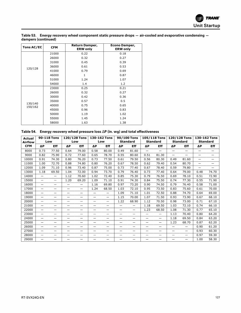
RT-SVX24Q-EN 127
Table 53. Energy recovery wheel component static pressure drops — air-cooled and evaporative condensing —dampers (continued)
Tons AC/EC CFMReturn Damper,
ERW onlyEcono Damper,ERW only
120/128
21000 0.22 0.1826000 0.32 0.2731000 0.45 0.3936000 0.61 0.5341000 0.79 0.6946000 1 0.8751000 1.24 1.0754000 1.4 1.2
130/140150/162
23000 0.25 0.2126000 0.32 0.2730000 0.42 0.3635000 0.57 0.540000 0.75 0.6545000 0.96 0.8350000 1.19 1.0255000 1.45 1.2458000 1.63 1.38
Table 54. Energy recovery wheel pressure loss ΔP (in. wg) and total effectiveness
ActualAirflowCFM
90-118 TonsLow
120/128 TonsLow
130-162 TonsLow
90/100 TonsStandard
105/118 TonsStandard
120/128 TonsStandard
130-162 TonsStandard
ΔP Eff ΔP Eff ΔP Eff ΔP Eff ΔP Eff ΔP Eff ΔP Eff8000 0.73 77.50 0.64 79.00 0.58 80.00 0.49 81.60 — — — — — —9000 0.82 75.90 0.72 77.60 0.65 78.70 0.55 80.60 0.51 81.30 — — — —10000 0.91 74.30 0.80 76.20 0.73 77.50 0.61 79.50 0.56 80.30 0.49 81.60 — —11000 1.00 72.70 0.88 74.80 0.80 76.20 0.67 78.50 0.62 79.40 0.54 80.70 — —12000 1.09 71.10 0.96 73.40 0.87 75.00 0.73 77.40 0.67 78.40 0.59 79.80 — —13000 1.18 69.50 1.04 72.00 0.94 73.70 0.79 76.40 0.73 77.40 0.64 79.00 0.48 74.7014000 — — 1.12 70.60 1.02 72.40 0.85 75.30 0.79 76.50 0.69 78.10 0.51 72.9015000 — — 1.20 69.20 1.09 71.10 0.91 74.30 0.84 75.50 0.74 77.30 0.55 71.9016000 — — — — 1.16 69.80 0.97 73.20 0.90 74.50 0.79 76.40 0.58 71.0017000 — — — — 1.24 68.50 1.03 72.10 0.95 73.50 0.83 75.60 0.61 70.0018000 — — — — — — 1.09 71.10 1.01 72.50 0.88 74.70 0.64 69.0019000 — — — — — — 1.15 70.00 1.07 71.50 0.93 73.90 0.67 68.1020000 — — — — — — 1.22 68.90 1.12 70.50 0.98 73.00 0.71 67.1021000 — — — — — — — — 1.18 69.50 1.03 72.10 0.74 66.1022000 — — — — — — — — 1.23 68.50 1.08 71.30 0.77 65.1023000 — — — — — — — — — — 1.13 70.40 0.80 64.2024000 — — — — — — — — — — 1.18 69.50 0.84 63.2025000 — — — — — — — — — — 1.23 68.70 0.87 62.2026000 — — — — — — — — — — — — 0.90 61.2027000 — — — — — — — — — — — — 0.93 60.3028000 — — — — — — — — — — — — 0.97 59.3029000 — — — — — — — — — — — — 1.00 58.30
UUnniitt SSttaarrttuupp

128 RT-SVX24Q-EN
Pressure Curves(60 Hz) Air-Cooled CondensersFigure 86. Operating pressure curve (all comp. and cond. fans per ckt. on)—90 tons std. capacity
Figure 87. Operating pressure curve (all comp. and cond. fans per ckt. on)—90 tons high capacity
UUnniitt SSttaarrttuupp
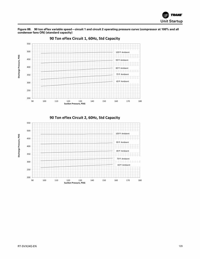
RT-SVX24Q-EN 129
Figure 88. 90 ton eFlex variable speed—circuit 1 and circuit 2 operating pressure curve (compressor at 100% and allcondenser fans ON) (standard capacity)
200
250
300
350
400
450
500
550
90 100 110 120 130 140 150 160 170 180
Dis
char
ge P
ress
ure,
PSI
G
Suc�on Pressure, PSIG
90 Ton eFlex Circuit 1, 60Hz, Std Capacity
105oF Ambient
95oF Ambient
85oF Ambient
75oF Ambient
65oF Ambient
200
250
300
350
400
450
500
550
90 100 110 120 130 140 150 160 170 180
Dis
char
ge P
ress
ure,
PSI
G
Suc�on Pressure, PSIG
90 Ton eFlex Circuit 2, 60Hz, Std Capacity
105oF Ambient
95oF Ambient
85oF Ambient
75oF Ambient
65oF Ambient
UUnniitt SSttaarrttuupp

130 RT-SVX24Q-EN
Figure 89. 90 ton eFlex variable speed—circuit 1 and circuit 2 operating pressure curve (compressor at 100% and allcondenser fans ON) (high capacity)
250
300
350
400
450
500
550
90 100 110 120 130 140 150 160 170 180
Dis
char
ge P
ress
ure,
PSI
G
Suc�on Pressure, PSIG
90 Ton eFlex Circuit 1, 60Hz High Capacity
105oF Ambient
95oF Ambient
85oF Ambient
75oF Ambient
65oF Ambient
200
250
300
350
400
450
500
550
90 100 110 120 130 140 150 160 170 180
Dis
char
ge P
ress
ure,
PSI
G
Suc�on Pressure, PSIG
90 Ton eFlex Circuit 2, 60Hz High Capacity
105oF Ambient
95oF Ambient
85oF Ambient
75oF Ambient
65oF Ambient
UUnniitt SSttaarrttuupp

RT-SVX24Q-EN 131
Figure 90. Operating pressure curve (all comp. and cond. fans per ckt. on)—105 tons std. capacity
Figure 91. Operating pressure curve (all comp. and cond. fans per ckt. on)—105 tons high capacity
UUnniitt SSttaarrttuupp

132 RT-SVX24Q-EN
Figure 92. 105 ton eFlex variable speed—circuit 1 and circuit 2 operating pressure curve (compressor at 100% and allcondenser fans ON) (standard capacity)
250
300
350
400
450
500
550
90 100 110 120 130 140 150 160 170 180
Dis
char
ge P
ress
ure,
PSI
G
Suc�on Pressure, PSIG
105 Ton eFlex Circuit 1, 60Hz, Std Capacity
105 Ton eFlex Circuit 2, 60Hz, Std Capacity
105oF Ambient
95oF Ambient
85oF Ambient
75oF Ambient
65oF Ambient
250
300
350
400
450
500
550
90 100 110 120 130 140 150 160 170 180
Dis
char
ge P
ress
ure,
PSI
G
Suc�on Pressure, PSIG
105oF Ambient
95oF Ambient
85oF Ambient
75oF Ambient
65oF Ambient
UUnniitt SSttaarrttuupp

RT-SVX24Q-EN 133
Figure 93. 105 ton eFlex variable speed—circuit 1 and circuit 2 operating pressure curve (compressor at 100% and allcondenser fans ON) (high capacity)
250
300
350
400
450
500
550
90 100 110 120 130 140 150 160 170 180
Dis
char
ge P
ress
ure,
PSI
G
Suc�on Pressure, PSIG
105 Ton eFlex Circuit 1, 60Hz High Capacity
105 Ton eFlex Circuit 2, 60Hz High Capacity
105oF Ambient
95oF Ambient
85oF Ambient
75oF Ambient
65oF Ambient
250
300
350
400
450
500
550
90 100 110 120 130 140 150 160 170 180
Dis
char
ge P
ress
ure,
PSI
G
Suc�on Pressure, PSIG
105oF Ambient
95oF Ambient
85oF Ambient
75oF Ambient
65oF Ambient
UUnniitt SSttaarrttuupp

134 RT-SVX24Q-EN
Figure 94. Operating pressure curve (all comp. and cond. fans per ckt. on)—120 tons std. capacity
Figure 95. Operating pressure curve (all comp. and cond. fans per ckt. on)—120 tons high capacity
UUnniitt SSttaarrttuupp

RT-SVX24Q-EN 135
Figure 96. 120 ton eFlex variable speed—circuit 1 and circuit 2 operating pressure curve (compressor at 100% and allcondenser fans ON) (standard capacity)
250
300
350
400
450
500
90 100 110 120 130 140 150 160 170 180
Dis
char
ge P
ress
ure,
PSI
G
Suc�on Pressure, PSIG
120 Ton eFlex Circuit 1, 60Hz, Std Capacity
105oF Ambient
95oF Ambient
85oF Ambient
75oF Ambient
65oF Ambient
250
300
350
400
450
500
90 100 110 120 130 140 150 160 170 180
Dis
char
ge P
ress
ure,
PSI
G
Suc�on Pressure, PSIG
120 Ton eFlex Circuit 2, 60Hz, Std Capacity
105oF Ambient
95oF Ambient
85oF Ambient
75oF Ambient
65oF Ambient
UUnniitt SSttaarrttuupp

136 RT-SVX24Q-EN
Figure 97. 120 ton eFlex variable speed—circuit 1 and circuit 2 operating pressure curve (compressor at 100% and allcondenser fans ON) (high capacity)
250
300
350
400
450
500
550
90 100 110 120 130 140 150 160 170 180
Dis
char
ge P
ress
ure,
PSI
G
Suc�on Pressure, PSIG
120 Ton eFlex Circuit 1, 60Hz High Capacity
120 Ton eFlex Circuit 2, 60Hz High Capacity
105oF Ambient
95oF Ambient
85oF Ambient
75oF Ambient
65oF Ambient
250
300
350
400
450
500
550
90 100 110 120 130 140 150 160 170 180
Dis
char
ge P
ress
ure,
PSI
G
Suc�on Pressure, PSIG
105oF Ambient
95oF Ambient
85oF Ambient
75oF Ambient
65oF Ambient
UUnniitt SSttaarrttuupp
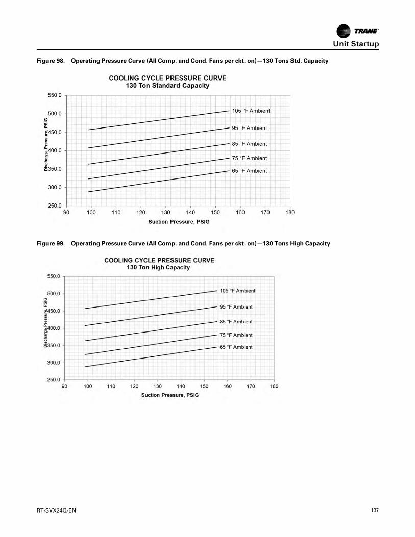
RT-SVX24Q-EN 137
Figure 98. Operating Pressure Curve (All Comp. and Cond. Fans per ckt. on)—130 Tons Std. Capacity
Figure 99. Operating Pressure Curve (All Comp. and Cond. Fans per ckt. on)—130 Tons High Capacity
UUnniitt SSttaarrttuupp
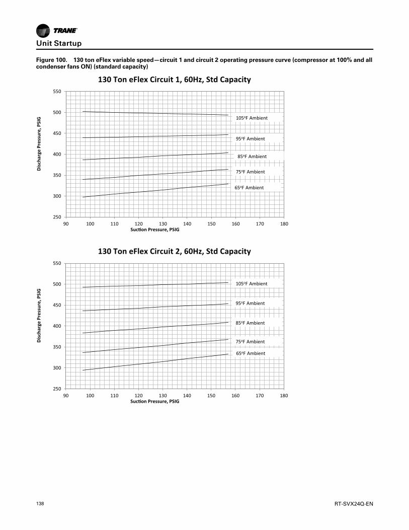
138 RT-SVX24Q-EN
Figure 100. 130 ton eFlex variable speed—circuit 1 and circuit 2 operating pressure curve (compressor at 100% and allcondenser fans ON) (standard capacity)
250
300
350
400
450
500
550
90 100 110 120 130 140 150 160 170 180
Dis
char
ge P
ress
ure,
PSI
G
Suc�on Pressure, PSIG
130 Ton eFlex Circuit 1, 60Hz, Std Capacity
130 Ton eFlex Circuit 2, 60Hz, Std Capacity
105oF Ambient
95oF Ambient
85oF Ambient
75oF Ambient
65oF Ambient
250
300
350
400
450
500
550
90 100 110 120 130 140 150 160 170 180
Dis
char
ge P
ress
ure,
PSI
G
Suc�on Pressure, PSIG
105oF Ambient
95oF Ambient
85oF Ambient
75oF Ambient
65oF Ambient
UUnniitt SSttaarrttuupp

RT-SVX24Q-EN 139
Figure 101. 130 ton eFlex variable speed—circuit 1 and circuit 2 operating pressure curve (compressor at 100% and allcondenser fans ON) (high capacity)
250
300
350
400
450
500
550
90 100 110 120 130 140 150 160 170 180
Dis
char
ge P
ress
ure,
PSI
G
Suc�on Pressure, PSIG
130 Ton eFlex Circuit 1, 60Hz High Capacity
130 Ton eFlex Circuit 2, 60Hz High Capacity
105oF Ambient
95oF Ambient
85oF Ambient
75oF Ambient
65oF Ambient
250
300
350
400
450
500
550
90 100 110 120 130 140 150 160 170 180
Dis
char
ge P
ress
ure,
PSI
G
Suc�on Pressure, PSIG
105oF Ambient
95oF Ambient
85oF Ambient
75oF Ambient
65oF Ambient
UUnniitt SSttaarrttuupp

140 RT-SVX24Q-EN
Figure 102. Operating pressure curve (all comp. and cond. fans per ckt. on)—150 ton std. capacity
NNoottee:: Due to the variable speed fans on Evaporative Condenser units, typical operating pressure curves are not relevant.If operating pressures at certain conditions are needed, contact a local Trane sales representative.
UUnniitt SSttaarrttuupp

RT-SVX24Q-EN 141
Figure 103. 150 ton eFlex variable speed—circuit 1 and circuit 2 operating pressure curve (compressor at 100% and allcondenser fans ON) (standard capacity)
300
350
400
450
500
550
600
90 100 110 120 130 140 150 160 170 180
Dis
char
ge P
ress
ure,
PSI
G
Suc�on Pressure, PSIG
105oF Ambient
95oF Ambient
85oF Ambient
75oF Ambient
65oF Ambient
250
300
350
400
450
500
550
90 100 110 120 130 140 150 160 170 180
Dis
char
ge P
ress
ure,
PSI
G
Suc�on Pressure, PSIG
105oF Ambient
95oF Ambient
85oF Ambient
75oF Ambient
65oF Ambient
150 Ton eFlex Circuit 1, 60Hz
150 Ton eFlex Circuit 2, 60Hz
UUnniitt SSttaarrttuupp

142 RT-SVX24Q-EN
(50 Hz) Air-Cooled CondensersFigure 104. Operating pressure curve (all comp. and cond. fans per ckt. on)—90 tons standard capacity
Figure 105. Operating pressure curve (all comp. and cond. fans per ckt. on)—90 tons high capacity
UUnniitt SSttaarrttuupp

RT-SVX24Q-EN 143
Figure 106. 90 ton eFlex variable speed—circuit 1 and circuit 2 operating pressure curve (compressor at 100% and allcondenser fans ON) (standard capacity)
200
250
300
350
400
450
500
550
90 100 110 120 130 140 150 160 170 180
Dis
char
ge P
ress
ure,
PSI
G
Suc�on Pressure, PSIG
90 Ton eFlex Circuit 1, 50Hz
90 Ton eFlex Circuit 2, 50Hz
105oF Ambient
95oF Ambient
85oF Ambient
75oF Ambient
65oF Ambient
200
250
300
350
400
450
500
550
90 100 110 120 130 140 150 160 170 180
Dis
char
ge P
ress
ure,
PSI
G
Suc�on Pressure, PSIG
105oF Ambient
95oF Ambient
85oF Ambient
75oF Ambient
65oF Ambient
UUnniitt SSttaarrttuupp

144 RT-SVX24Q-EN
Figure 107. 90 ton eFlex variable speed—circuit 1 and circuit 2 operating pressure curve (compressor at 100% and allcondenser fans ON) (high capacity)
200
250
300
350
400
450
500
550
600
90 100 110 120 130 140 150 160 170 180
Dis
char
ge P
ress
ure,
PSI
G
Suc�on Pressure, PSIG
105oF Ambient
95oF Ambient
85oF Ambient
75oF Ambient
65oF Ambient
200
250
300
350
400
450
500
550
600
90 100 110 120 130 140 150 160 170 180
Dis
char
ge P
ress
ure,
PSI
G
Suc�on Pressure, PSIG
105oF Ambient
95oF Ambient
85oF Ambient
75oF Ambient
65oF Ambient
90 Ton eFlex Circuit 1, 50Hz High Capacity
90 Ton eFlex Circuit 2, 50Hz High Capacity
UUnniitt SSttaarrttuupp

RT-SVX24Q-EN 145
Figure 108. Operating pressure curve (all comp. and cond. fans per ckt. on)—105 tons standard capacity
Figure 109. Operating pressure curve (all comp. and cond. fans per ckt. on)—105 tons high capacity
UUnniitt SSttaarrttuupp

146 RT-SVX24Q-EN
Figure 110. 105 ton eFlex variable speed—circuit 1 and circuit 2 operating pressure curve (compressor at 100% and allcondenser fans ON) (standard capacity)
200
250
300
350
400
450
500
550
90 100 110 120 130 140 150 160 170 180
Dis
char
ge P
ress
ure,
PSI
G
Suc�on Pressure, PSIG
105 Ton eFlex Circuit 1, 50Hz
105 Ton eFlex Circuit 2, 50Hz
105oF Ambient
95oF Ambient
85oF Ambient
75oF Ambient
65oF Ambient
200
250
300
350
400
450
500
550
600
90 100 110 120 130 140 150 160 170 180
Dis
char
ge P
ress
ure,
PSI
G
Suc�on Pressure, PSIG
105oF Ambient
95oF Ambient
85oF Ambient
75oF Ambient
65oF Ambient
UUnniitt SSttaarrttuupp

RT-SVX24Q-EN 147
Figure 111. 105 ton eFlex variable speed—circuit 1 and circuit 2 operating pressure curve (compressor at 100% and allcondenser fans ON) (high capacity)
200
250
300
350
400
450
500
550
600
90 100 110 120 130 140 150 160 170 180
Dis
char
ge P
ress
ure,
PSI
G
Suc�on Pressure, PSIG
105oF Ambient
95oF Ambient
85oF Ambient
75oF Ambient
65oF Ambient
200
250
300
350
400
450
500
550
600
90 100 110 120 130 140 150 160 170 180
Dis
char
ge P
ress
ure,
PSI
G
Suc�on Pressure, PSIG
105oF Ambient
95oF Ambient
85oF Ambient
75oF Ambient
65oF Ambient
105 Ton eFlex Circuit 1, 50Hz High Capacity
105 Ton eFlex Circuit 2, 50Hz High Capacity
UUnniitt SSttaarrttuupp

148 RT-SVX24Q-EN
Figure 112. Operating pressure curve (all comp. and cond. fans per ckt. on)—120 tons standard capacity
Figure 113. Operating pressure curve (all comp. and cond. fans per ckt. on)—120 tons high capacity
UUnniitt SSttaarrttuupp

RT-SVX24Q-EN 149
Figure 114. 120 ton eFlex variable speed—circuit 1 and circuit 2 operating pressure curve (compressor at 100% and allcondenser fans ON) (standard capacity)
200
250
300
350
400
450
500
550
90 100 110 120 130 140 150 160 170 180
Dis
char
ge P
ress
ure,
PSI
G
Suc�on Pressure, PSIG
120 Ton eFlex Circuit 1, 50Hz
120 Ton eFlex Circuit 1, 50Hz
105oF Ambient
95oF Ambient
85oF Ambient
75oF Ambient
65oF Ambient
200
250
300
350
400
450
500
550
90 100 110 120 130 140 150 160 170 180
Dis
char
ge P
ress
ure,
PSI
G
Suc�on Pressure, PSIG
105oF Ambient
95oF Ambient
85oF Ambient
75oF Ambient
65oF Ambient
UUnniitt SSttaarrttuupp

150 RT-SVX24Q-EN
Figure 115. 120 ton eFlex variable speed—circuit 1 and circuit 2 operating pressure curve (compressor at 100% and allcondenser fans ON) (high capacity)
200
250
300
350
400
450
500
550
90 100 110 120 130 140 150 160 170 180
Dis
char
ge P
ress
ure,
PSI
G
Suc�on Pressure, PSIG
105oF Ambient
95oF Ambient
85oF Ambient
75oF Ambient
65oF Ambient
250
300
350
400
450
500
550
90 100 110 120 130 140 150 160 170 180
Dis
char
ge P
ress
ure,
PSI
G
Suc�on Pressure, PSIG
105oF Ambient
95oF Ambient
85oF Ambient
75oF Ambient
65oF Ambient
120 Ton eFlex Circuit 1, 50Hz High Capacity
120 Ton eFlex Circuit 2, 50Hz High Capacity
UUnniitt SSttaarrttuupp

RT-SVX24Q-EN 151
Figure 116. Operating pressure curve (all comp. and cond. fans per ckt. on)—130 tons standard capacity
Figure 117. Operating pressure curve (all comp. and cond. fans per ckt. on)—130 tons high capacity
UUnniitt SSttaarrttuupp

152 RT-SVX24Q-EN
Figure 118. 130 ton eFlex variable speed—circuit 1 and circuit 2 operating pressure curve (compressor at 100% and allcondenser fans ON) (standard capacity)
250
300
350
400
450
500
550
90 100 110 120 130 140 150 160 170 180
Dis
char
ge P
ress
ure,
PSI
G
Suc�on Pressure, PSIG
130 Ton eFlex Circuit 1, 50Hz
130 Ton eFlex Circuit 2, 50Hz
105oF Ambient
95oF Ambient
85oF Ambient
75oF Ambient
65oF Ambient
250
300
350
400
450
500
550
90 100 110 120 130 140 150 160 170 180
Dis
char
ge P
ress
ure,
PSI
G
Suc�on Pressure, PSIG
105oF Ambient
95oF Ambient
85oF Ambient
75oF Ambient
65oF Ambient
UUnniitt SSttaarrttuupp

RT-SVX24Q-EN 153
Figure 119. 130 ton eFlex variable speed—circuit 1 and circuit 2 operating pressure curve (compressor at 100% and allcondenser fans ON) (high capacity)
250
300
350
400
450
500
550
90 100 110 120 130 140 150 160 170 180
Dis
char
ge P
ress
ure,
PSI
G
Suc�on Pressure, PSIG
130 Ton eFlex Circuit 1, 50Hz High Capacity
105oF Ambient
95oF Ambient
85oF Ambient
75oF Ambient
65oF Ambient
250
300
350
400
450
500
550
90 100 110 120 130 140 150 160 170 180
Dis
char
ge P
ress
ure,
PSI
G
Suc�on Pressure, PSIG
130 Ton eFlex Circuit 2, 50Hz High Capacity
105oF Ambient
95oF Ambient
85oF Ambient
75oF Ambient
65oF Ambient
UUnniitt SSttaarrttuupp

154 RT-SVX24Q-EN
Figure 120. Operating pressure curve (all comp. and cond. fans per ckt. on)—150 tons standard capacity
NNoottee:: Due to the variable speed fans on evaporative condenser units, typical operating pressure curves are not relevant.If operating pressures at certain conditions are needed, contact a local Trane sales representative.
UUnniitt SSttaarrttuupp
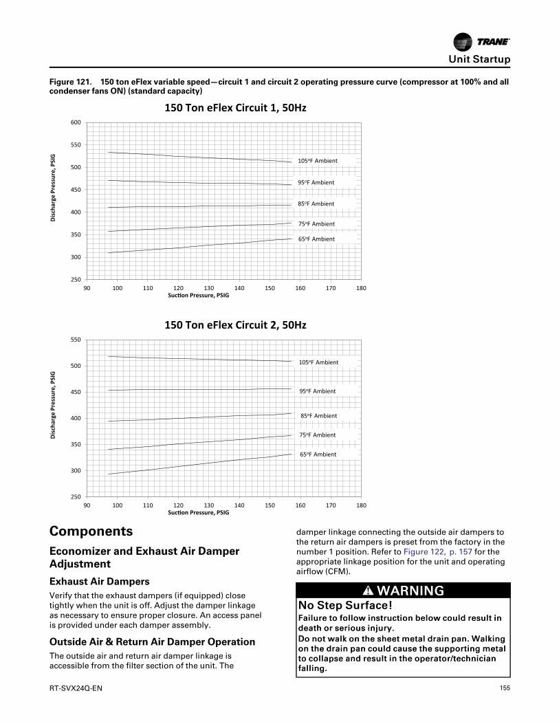
RT-SVX24Q-EN 155
Figure 121. 150 ton eFlex variable speed—circuit 1 and circuit 2 operating pressure curve (compressor at 100% and allcondenser fans ON) (standard capacity)
250
300
350
400
450
500
550
600
90 100 110 120 130 140 150 160 170 180
Dis
char
ge P
ress
ure,
PSI
G
Suc�on Pressure, PSIG
105oF Ambient
95oF Ambient
85oF Ambient
75oF Ambient
65oF Ambient
250
300
350
400
450
500
550
90 100 110 120 130 140 150 160 170 180
Dis
char
ge P
ress
ure,
PSI
G
Suc�on Pressure, PSIG
105oF Ambient
95oF Ambient
85oF Ambient
75oF Ambient
65oF Ambient
150 Ton eFlex Circuit 1, 50Hz
150 Ton eFlex Circuit 2, 50Hz
ComponentsEconomizer and Exhaust Air DamperAdjustment
Exhaust Air DampersVerify that the exhaust dampers (if equipped) closetightly when the unit is off. Adjust the damper linkageas necessary to ensure proper closure. An access panelis provided under each damper assembly.
Outside Air & Return Air Damper OperationThe outside air and return air damper linkage isaccessible from the filter section of the unit. The
damper linkage connecting the outside air dampers tothe return air dampers is preset from the factory in thenumber 1 position. Refer to Figure 122, p. 157 for theappropriate linkage position for the unit and operatingairflow (CFM).
WWAARRNNIINNGGNNoo SStteepp SSuurrffaaccee!!FFaaiilluurree ttoo ffoollllooww iinnssttrruuccttiioonn bbeellooww ccoouulldd rreessuulltt iinnddeeaatthh oorr sseerriioouuss iinnjjuurryy..DDoo nnoott wwaallkk oonn tthhee sshheeeett mmeettaall ddrraaiinn ppaann.. WWaallkkiinnggoonn tthhee ddrraaiinn ppaann ccoouulldd ccaauussee tthhee ssuuppppoorrttiinngg mmeettaallttoo ccoollllaappssee aanndd rreessuulltt iinn tthhee ooppeerraattoorr//tteecchhnniicciiaannffaalllliinngg..
UUnniitt SSttaarrttuupp

156 RT-SVX24Q-EN
NNoottee:: Bridging between the unit main supports mayconsist of multiple 2 x 12 boards or sheet metalgrating.
Arbitrarily adjusting the outside air dampers to openfully when the return air dampers are closed or; failingto maintain the return air pressure drop with theoutside air dampers when the return air dampers areclosed, can overload the supply fan motor and causebuilding pressurization control problems due toimproper CFM being delivered to the space.
The outside air/return air damper linkage is connectedto a crank arm with a series of holes that allows theinstaller or operator to modify the amount of outsideair damper travel in order to match the return staticpressure.
Refer to Table 55, p. 158 for the equivalent return airduct losses that correspond to each of the holesillustrated in Figure 122, p. 157.
To Adjust the Outside Air Damper Travel1. Drill a 1/4" hole through the unit casing up stream
of the return air dampers. Use a location that willproduce an accurate reading with the least amountof turbulence – several locations may be necessary,then average the reading.
WWAARRNNIINNGGHHaazzaarrddoouuss VVoollttaaggee!!FFaaiilluurree ttoo ddiissccoonnnneecctt ppoowweerr bbeeffoorree sseerrvviicciinngg ccoouullddrreessuulltt iinn ddeeaatthh oorr sseerriioouuss iinnjjuurryy..DDiissccoonnnneecctt aallll eelleeccttrriicc ppoowweerr,, iinncclluuddiinngg rreemmootteeddiissccoonnnneeccttss bbeeffoorree sseerrvviicciinngg.. FFoollllooww pprrooppeerrlloocckkoouutt//ttaaggoouutt pprroocceedduurreess ttoo eennssuurree tthhee ppoowweerrccaann nnoott bbee iinnaaddvveerrtteennttllyy eenneerrggiizzeedd.. VVeerriiffyy tthhaatt nnooppoowweerr iiss pprreesseenntt wwiitthh aa vvoollttmmeetteerr..
IImmppoorrttaanntt:: HIGH VOLTAGE IS PRESENT ATTERMINAL BLOCK OR UNITDISCONNECT SWITCH.
2. Close the disconnect switch or circuit protectorswitch that provides the supply power to the unitterminal block or the unit mounted disconnectswitch.
3. Turn the 115 volt control circuit switch and the 24volt control circuit switch to the On position.
4. Open the Human Interface access door located inthe unit control panel, and press the SERVICEMODE key to display the first service screen. Referto the latest edition of the applicable programmingmanual for applications for the SERVICE TESTscreens and programming instructions.
5. Use tables in “Voltage Imbalance,” p. 105 toprogram the following system components foroperation by scrolling through the displays;
• Supply Fan (On)
• Variable Frequency Drive (100% Output, ifapplicable)
• RTM Occ/Unocc Output (Unoccupied)
• Outside Air Dampers (Closed)
6. Once the configuration for the components iscomplete, press the NEXT key until the LCDdisplays the “Start test in __Sec.” screen. Press the+ key to designate the delay before the test is tostart. This service test will begin after the TESTSTART key is pressed and the delay designated inthis step has elapsed. Press the ENTER key toconfirm this choice.
7. Press the TEST START key to start the test.Remember that the delay designated in step 6 mustelapse before the fan will begin to operate.
8. With the outside air dampers fully closed and thesupply fan operating at 100% airflow requirements,measure the return static pressure at the locationdetermined in step 1.
9. Press the STOP key at the Human Interface Modulein the unit control panel to stop the fan operation.
WWAARRNNIINNGGLLiivvee EElleeccttrriiccaall CCoommppoonneennttss!!FFaaiilluurree ttoo ffoollllooww aallll eelleeccttrriiccaall ssaaffeettyy pprreeccaauuttiioonnsswwhheenn eexxppoosseedd ttoo lliivvee eelleeccttrriiccaall ccoommppoonneennttss ccoouullddrreessuulltt iinn ddeeaatthh oorr sseerriioouuss iinnjjuurryy..WWhheenn iitt iiss nneecceessssaarryy ttoo wwoorrkk wwiitthh lliivvee eelleeccttrriiccaallccoommppoonneennttss,, hhaavvee aa qquuaalliiffiieedd lliicceennsseedd eelleeccttrriicciiaannoorr ootthheerr iinnddiivviidduuaall wwhhoo hhaass bbeeeenn pprrooppeerrllyy ttrraaiinneeddiinn hhaannddlliinngg lliivvee eelleeccttrriiccaall ccoommppoonneennttss ppeerrffoorrmmtthheessee ttaasskkss..
WWAARRNNIINNGGRRoottaattiinngg CCoommppoonneennttss!!FFaaiilluurree ttoo ddiissccoonnnneecctt ppoowweerr bbeeffoorree sseerrvviicciinngg ccoouullddrreessuulltt iinn rroottaattiinngg ccoommppoonneennttss ccuuttttiinngg aanndd ssllaasshhiinnggtteecchhnniicciiaann wwhhiicchh ccoouulldd rreessuulltt iinn ddeeaatthh oorr sseerriioouussiinnjjuurryy..DDiissccoonnnneecctt aallll eelleeccttrriicc ppoowweerr,, iinncclluuddiinngg rreemmootteeddiissccoonnnneeccttss bbeeffoorree sseerrvviicciinngg.. FFoollllooww pprrooppeerrlloocckkoouutt//ttaaggoouutt pprroocceedduurreess ttoo eennssuurree tthhee ppoowweerrccaann nnoott bbee iinnaaddvveerrtteennttllyy eenneerrggiizzeedd..
10. Open the field supplied main power disconnectswitch upstream of the rooftop unit. Lock thedisconnect switch in the “Open” position whileworking on the dampers.
NNoottee:: Gravity will cause the damper to close.Support or secure the damper blades whileremoving the actuator to prevent unexpecteddamper rotation.
11. Compare the static pressure reading to the staticpressure ranges and linkage positions in Table 55,p. 158 for the unit size and operating CFM.
Relocate the outside air/return air connecting rod tobalance the outside air damper pressure drop
UUnniitt SSttaarrttuupp

RT-SVX24Q-EN 157
against the return static pressure, using thefollowing steps. If no adjustment is necessary,proceed to step 17.
12. Remove the drive rod and swivel from the crankarm(s). If only one hole requires changing, loosenonly that end.
13. Manually open the return air dampers to the fullopen position.
14. Manually close the outside air dampers.
15. Reattach the drive rod and swivel to the appropriatehole(s). The length of the drive rod may need to beadjusted to align with the new hole(s) location. If so,loosen the lock nut on the drive rod against theswivel. Turn the swivel “in” or “out” to shorten orlengthen the rod as necessary. For some holes,both ends of the rod may need to be adjusted.
16. Tighten the lock nut against the swivel(s).
17. Plug the holes after the proper CFM has beenestablished.
Figure 122. Outside air and return air damperassembly
Outside air damper level
Configuration B
Configuration A
All Top viewJackshaft lever
Economizer Linkage Adjustment
UUnniitt SSttaarrttuupp

158 RT-SVX24Q-EN
Figure 123. Outside air and return air economizerassembly (with Traq™ dampers)
TRAQ Damper Linkage Adjustment
Top view
Jackshaft lever
TRAQ damper Lever
Table 55. Standard unit (no ERW) (economizer)outside air damper travel adjustment/pressure drop (inches w.c.)
Damper Position
EconomizerLinkage Set-up 1 2 3 4 5 6
Jackshaft rodend location 1 1 2 2 2 2
Damper leverconfiguration A B B B B B
Damper leverrod end location 1 2 3 4 5 6
120-162 Ton w/Economizer (includesmist eliminator)
CFM Pressure Drop (inches w.c.)
58,500 0.80 1.64 2.96 - - -
54,000 0.68 1.40 2.52 - - -
Table 55. Standard unit (no ERW) (economizer)outside air damper travel adjustment/pressure drop(inches w.c.) (continued)
45,500 0.48 0.99 1.79 2.22 2.62 -
42,000 0.41 0.85 1.53 1.89 2.23 2.69
38,000 0.34 0.69 1.25 1.55 1.83 2.20
34,000 0.27 0.56 1.00 1.24 1.46 1.76
30,000 0.21 0.43 0.78 0.97 1.14 1.37
90-118 Ton w/Economizer (includesmist eliminator)
CFM Pressure Drop (inches w.c.)
47,250 0.81 1.88 - - - -
40,500 0.60 1.39 2.62 - - -
36,750 0.49 1.14 2.16 2.71 - -
31,500 0.36 0.84 1.59 1.99 2.36 2.87
28,000 0.28 0.66 1.25 1.57 1.87 2.27
25,000 0.22 0.53 1.00 1.25 1.49 1.81
23,000 0.19 0.45 0.85 1.06 1.26 1.53
Damper Position
Jackshaft rodend location 1 1 1 2 1
Damper leverrod end location 1 2 3 5 4
Jackshaft rodend location 1 1 1 2 1
120-162 Ton w/Traq™ Damper (includesmisteliminator)
CFM Pressure Drop (inches w.c.)
58,500 1.10 1.52 2.16 2.73
54,000 0.93 1.28 1.83 2.33
45,500 0.64 0.89 1.28 1.64 2.14
42,000 0.54 0.75 1.09 1.40 1.83
38,000 0.44 0.60 0.88 1.14 1.50
34,000 0.35 0.47 0.69 0.90 1.20
30,000 0.27 0.35 0.53 0.69 0.93
90-118 Tonw/Traq™ Damper (includesmisteliminator)
CFM Pressure Drop (inches w.c.)
47,250 1.37 1.89 2.72
40,500 0.99 1.35 1.97 2.54
36,750 0.80 1.09 1.60 2.08 2.74
31,500 0.58 0.77 1.15 1.51 2.01
28,000 0.46 0.59 0.89 1.17 1.58
UUnniitt SSttaarrttuupp

RT-SVX24Q-EN 159
Table 55. Standard unit (no ERW) (economizer)outside air damper travel adjustment/pressure drop(inches w.c.) (continued)
25,000 0.37 0.45 0.69 0.92 1.24
23,000 0.31 0.37 0.57 0.76 1.04
Standard Unit with Energy RecoveryWheel
Economizer Damper Adjustment - ERW units
Outside & Return Air Damper OperationThe outside air and return air damper actuators areaccessible through from the filter section of the unit.The outside air and return air dampers have individualactuators that are linked electronically. The actuatorsare preset to 0 degrees from the factory. Refer to“Table 46, p. 170,” for the appropriate actuator positionfor the unit and operating airflow (CFM).
To Adjust the Outside Air Damper Travel1. Drill a 1/4" hole through the unit casing up stream
of the return air dampers and below the energyrecovery wheel. Use a location that will produce anaccurate reading with the least amount ofturbulence. Several locations may be necessary,and average the reading.
WWAARRNNIINNGGHHaazzaarrddoouuss VVoollttaaggee!!FFaaiilluurree ttoo ddiissccoonnnneecctt ppoowweerr bbeeffoorree sseerrvviicciinngg ccoouullddrreessuulltt iinn ddeeaatthh oorr sseerriioouuss iinnjjuurryy..DDiissccoonnnneecctt aallll eelleeccttrriicc ppoowweerr,, iinncclluuddiinngg rreemmootteeddiissccoonnnneeccttss bbeeffoorree sseerrvviicciinngg.. FFoollllooww pprrooppeerrlloocckkoouutt//ttaaggoouutt pprroocceedduurreess ttoo eennssuurree tthhee ppoowweerrccaann nnoott bbee iinnaaddvveerrtteennttllyy eenneerrggiizzeedd.. VVeerriiffyy tthhaatt nnooppoowweerr iiss pprreesseenntt wwiitthh aa vvoollttmmeetteerr..
IImmppoorrttaanntt:: HIGH VOLTAGE IS PRESENT ATTERMINAL BLOCK OR UNITDISCONNECT SWITCH.
2. Close the disconnect switch or circuit protectorswitch that provides the supply power to the unitterminal block or the unit mounted disconnectswitch.
3. Turn the 115 volt control circuit switch and the 24volt control circuit switch to the “On” position.
4. Open the Human Interface access door, located inthe unit control panel, and press the SERVICEMODE key to display the first service screen. Referto the latest edition of the applicable programmingmanual for applications for the SERVICE TESTscreens and programming instructions.
5. Use to program the following system componentsfor operation by scrolling through the displays:
Supply Fan (On)
VFD Cmd (100%, if applicable)
RTM Occ/Unocc Output
(Unoccupied)
OA Damper Pos (0%)
Outside Air Bypass Damper Pos (0%)
Exhaust Air Bypass Damper Pos (0%)
6. Once the configuration for the components iscomplete, press the NEXT key until the LCDdisplays the “Start test in __Sec." screen. Press the+ key to designate the delay before the test is tostart. This service test will begin after the TESTSTART key is pressed and the delay designated inthis step has elapsed. Press the ENTER key toconfirm this choice.
WWAARRNNIINNGGRRoottaattiinngg CCoommppoonneennttss!!FFaaiilluurree ttoo ddiissccoonnnneecctt ppoowweerr bbeeffoorree sseerrvviicciinngg ccoouullddrreessuulltt iinn rroottaattiinngg ccoommppoonneennttss ccuuttttiinngg aanndd ssllaasshhiinnggtteecchhnniicciiaann wwhhiicchh ccoouulldd rreessuulltt iinn ddeeaatthh oorr sseerriioouussiinnjjuurryy..DDiissccoonnnneecctt aallll eelleeccttrriicc ppoowweerr,, iinncclluuddiinngg rreemmootteeddiissccoonnnneeccttss bbeeffoorree sseerrvviicciinngg.. FFoollllooww pprrooppeerrlloocckkoouutt//ttaaggoouutt pprroocceedduurreess ttoo eennssuurree tthhee ppoowweerrccaann nnoott bbee iinnaaddvveerrtteennttllyy eenneerrggiizzeedd..
7. Press the TEST START key to start the test.Remember that the delay designated in step 6 mustelapse before the fan will begin to operate.
8. With the outside air dampers fully closed and thesupply fan operating at 100% airflow requirements,measure the return static pressure at the locationdetermined in step 1.
9. Press the STOP key at the Human Interface Modulein the unit control panel to stop the fan operation.
10. Open the field supplied main power disconnectswitch upstream of the rooftop unit. Lock thedisconnect switch in the “Open” position whileworking on the dampers.
11. Locate the static pressure reading in “Table 46,p. 170,” and determine which damper needs to beadjusted and the degree reading. Proceed to theappropriate damper actuator procedure.
To Adjust the Outside Air Damper Actuators1. Remove the shaft coupling from the damper shaft
by loosening the bolt and removing the retainerclip. Be careful not to rotate the shaft.
2. Position the shaft coupling so that the indicatorpoints to the degree value obtained from Step 11.The shaft coupling is adjustable in 5 degreeincrements.
3. Replace the retainer clip and tighten the shaftcoupling on the shaft (120-180 in-lbs).
UUnniitt SSttaarrttuupp

160 RT-SVX24Q-EN
4. Close the disconnect switch or circuit protectorswitch that provides the supply power to the unitterminal block or the unit mounted disconnectswitch.
5. Rotate the actuator control signal dial to Auto-Adapt. The actuator will drive open and then closedto determine the new open and closed positions.
6. Return the actuator control signal dial to 2-10 VDCModulating input signal position.
7. Plug the holes drilled in the cabinet after the properairfow has been established.
To Adjust the Return Damper Actuators1. Support or secure the damper blades in the wide
open position.
NNoottee:: Gravity will cause the damper to close.Support or secure the damper blades whileremoving the actuator to prevent unexpecteddamper rotation.
2. Do not remove the shaft coupling from the shaft.Remove the retainer clip from the shaft coupling.
3. Unscrew the actuator bracket from the damper wall.
4. Slide the actuator down the damper shaft off of theshaft coupling.
5. Rotate the actuator and reinstall the shaft couplingin the actuator so that the indicator points to thedegree value obtained in Step 11. The shaftcoupling is adjustable in 5 degree increments.
6. Replace the retainer clip and remove the bladestops to allow the blades to rotate.
7. Rotate the actuator to the original position andreattach the actuator bracket to the damper wall.
8. Close the disconnect switch or circuit protectorswitch that provides the supply power to the unitterminal block or the unit mounted disconnectswitch.
9. Rotate the actuator control signal dial to Auto-Adapt. The actuator will drive open and then closedto determine the new open and closed positions.
10. Return the actuator control signal dial to the factoryset input signal position.
11. Plug the holes drilled in the cabinet after the properairfow has been established.
Figure 124. IntelliPak 2 energy wheel section
UUnniitt SSttaarrttuupp

RT-SVX24Q-EN 161
Table56.StandardunitswithERW—fieldmeasuredplenumpressure—LowCFMERW—90-162Tons
90/100TonLowCFM
ERW-Fieldmeasuredplenumpressure(incheswc)
CFM
OAActuatorReading[Degrees]
RAActuatorReading[Degrees]
60
50
40
30
20
10
010
20
30
35
40
45
50
Econ
Traq
Econ
Traq
Econ
Traq
Econ
Traq
Econ
Traq
Econ
Traq
E/T
E/T
E/T
E/T
E/T
E/T
E/T
E/T
16000
1.29
—0.87
1.52
0.71
1.05
0.64
0.84
0.6
0.64
0.58
0.63
0.46
0.45
0.43
0.41
0.38
0.35
0.32
0.2
20000
1.99
—1.34
2.34
1.09
1.62
0.98
1.28
0.92
0.97
0.89
0.96
0.69
0.68
0.65
0.62
0.57
0.52
0.48
0.29
25000
——
2.07
—1.68
2.49
1.5
1.97
1.41
1.49
1.36
1.47
1.04
1.02
0.99
0.93
0.86
0.78
0.71
0.42
30000
——
2.94
—2.39
—2.13
2.79
1.99
2.09
1.93
2.08
1.46
1.43
1.37
1.3
1.19
1.08
0.98
0.56
33000
——
——
2.86
—2.54
—2.38
2.5
2.3
2.48
1.73
1.7
1.63
1.54
1.41
1.28
1.15
0.65
36000
——
——
——
3—
2.8
2.94
2.71
2.92
2.02
1.98
1.91
1.79
1.64
1.48
1.34
0.74
40000
——
——
——
——
——
——
2.46
2.41
2.32
2.18
1.98
1.79
1.61
0.87
105/118TonLowCFM
ERW-Fieldmeasuredplenumpressure(incheswc)
CFM
OAActuatorReading[Degrees]
RAActuatorReading[Degrees]
60
50
40
30
20
10
010
20
30
35
40
45
50
Econ
Traq
Econ
Traq
Econ
Traq
Econ
Traq
Econ
Traq
Econ
Traq
E/T
E/T
E/T
E/T
E/T
E/T
E/T
E/T
19000
1.8
—1.22
2.12
0.99
1.46
0.89
1.16
0.83
0.88
0.81
0.88
0.63
0.62
0.59
0.56
0.52
0.48
0.44
0.27
23000
2.63
—1.76
—1.44
2.12
1.29
1.68
1.21
1.27
1.17
1.26
0.9
0.88
0.85
0.8
0.74
0.68
0.62
0.37
28000
——
2.57
—2.09
—1.86
2.45
1.74
1.84
1.69
1.82
1.28
1.25
1.21
1.14
1.05
0.95
0.86
0.5
33000
——
——
2.86
—2.54
2.38
2.5
2.3
2.48
1.73
1.7
1.63
1.54
1.41
1.28
1.15
0.65
38000
——
——
——
——
——
——
2.24
2.2
2.11
1.98
1.81
1.64
1.48
0.81
43000
——
——
——
——
——
——
2.8
2.74
2.64
2.47
2.25
2.03
1.83
0.97
45000
——
——
——
——
——
——
3.04
2.98
2.86
2.68
2.44
2.2
1.97
1.04
120/128TonLowCFM
ERW-Fieldmeasuredplenumpressure(incheswc)
CFM
OAActuatorReading[Degrees]
RAActuatorReading[Degrees]
60
50
40
30
20
10
010
20
30
35
40
45
50
Econ
Traq
Econ
Traq
Econ
Traq
Econ
Traq
Econ
Traq
Econ
Traq
E/T
E/T
E/T
E/T
E/T
E/T
E/T
E/T
21000
1.54
—1.08
1.69
0.9
1.08
0.82
0.89
0.78
0.87
0.76
0.75
0.58
0.56
0.54
0.5
0.44
0.39
0.34
0.14
26000
2.33
—1.62
2.56
1.35
1.62
1.23
1.33
1.16
1.3
1.13
1.11
0.84
0.82
0.78
0.72
0.64
0.56
0.49
—
31000
——
2.26
—1.88
2.25
1.7
1.85
1.61
1.8
1.56
1.53
1.15
1.12
1.07
0.98
0.87
0.75
0.65
—
36000
——
2.99
—2.48
2.98
2.24
2.44
2.11
2.37
2.05
21.5
1.46
1.38
1.27
1.11
0.96
0.81
—
41000
——
——
——
2.85
—2.68
—2.6
2.54
1.89
1.84
1.74
1.59
1.39
1.19
1—
46000
——
——
——
——
——
——
2.31
2.24
2.12
1.93
1.68
1.42
1.19
—
UUnniitt SSttaarrttuupp

162 RT-SVX24Q-EN
Table56.StandardunitswithERW—fieldmeasuredplenumpressure—LowCFMERW—90-162Tons(continued)
51000
——
——
——
——
——
——
2.77
2.69
2.54
2.31
21.69
1.4
—
54000
——
——
——
——
——
——
3.16
3.06
2.89
2.64
2.29
1.94
1.61
—
130-162TonLowCFM
ERW-Fieldmeasuredplenumpressure(incheswc)
CFM
OAActuatorReading[Degrees]
RAActuatorReading[Degrees]
60
50
40
30
20
10
010
20
30
35
40
45
Econ
Traq
Econ
Traq
Econ
Traq
Econ
Traq
Econ
Traq
Econ
Traq
E/T
E/T
E/T
E/T
E/T
E/T
E/T
23000
1.82
—1.27
—1.06
1.27
0.96
1.05
0.91
1.02
0.89
0.87
0.67
0.65
0.62
0.57
0.51
0.44
0.39
26000
2.31
—1.6
—1.33
1.6
1.21
1.32
1.14
1.28
1.11
1.09
0.83
0.81
0.77
0.71
0.63
0.54
0.47
30000
——
2.1
—1.74
2.09
1.57
1.71
1.49
1.67
1.44
1.41
1.06
1.03
0.98
0.9
0.79
0.69
0.59
35000
——
2.8
—2.32
2.79
2.09
2.28
1.97
2.22
1.91
1.87
1.39
1.36
1.29
1.18
1.03
0.88
0.75
40000
——
——
2.97
—2.68
2.92
2.52
2.84
2.45
2.39
1.77
1.72
1.62
1.48
1.29
1.1
0.92
45000
——
——
——
——
——
—2.96
2.17
2.11
1.99
1.81
1.57
1.33
1.1
50000
——
——
——
——
——
——
2.62
2.54
2.39
2.17
1.87
1.57
1.3
55000
——
——
——
——
——
——
3.09
32.82
2.56
2.2
1.83
1.5
58000
——
——
——
——
——
——
3.4
3.29
3.1
2.8
2.4
1.99
1.62
UUnniitt SSttaarrttuupp

RT-SVX24Q-EN 163
Table57.StandardunitswithERW—fieldmeasuredplenumpressure—StandardCFMERW—90-162Tons
90/100TonStandardCFM
ERW-Fieldmeasuredplenumpressure(incheswc)
CFM
OAActuatorReading[Degrees]
RAActuatorReading[Degrees]
60
50
40
30
20
10
010
20
30
35
40
45
50
Econ
Traq
Econ
Traq
Econ
Traq
Econ
Traq
Econ
Traq
Econ
Traq
E/T
E/T
E/T
E/T
E/T
E/T
E/T
E/T
16000
1.26
0.84
1.49
0.68
1.02
0.61
0.81
0.57
0.61
0.55
0.6
0.43
0.42
0.4
0.38
0.35
0.32
0.29
0.17
20000
1.95
1.3
2.3
1.05
1.57
0.93
1.24
0.88
0.93
0.85
0.92
0.64
0.63
0.61
0.57
0.52
0.48
0.43
0.25
25000
21.62
2.42
1.43
1.9
1.34
1.42
1.3
1.41
0.97
0.95
0.92
0.86
0.79
0.71
0.64
0.35
30000
2.84
2.28
2.02
2.69
1.89
1.99
1.82
1.97
1.35
1.32
1.27
1.19
1.08
0.97
0.87
0.46
33000
2.74
2.42
2.26
2.38
2.18
2.36
1.61
1.58
1.51
1.42
1.29
1.16
1.03
0.53
36000
2.86
2.67
2.81
2.57
2.78
1.89
1.85
1.77
1.66
1.5
1.35
1.2
40000
2.28
2.23
2.14
21.81
1.61
1.44
105/118TonStandardCFM
ERW-Fieldmeasuredplenumpressure(incheswc)
CFM
OAActuatorReading[Degrees]
RAActuatorReading[Degrees]
60
50
40
30
20
10
010
20
30
35
40
45
50
Econ
Traq
Econ
Traq
Econ
Traq
Econ
Traq
Econ
Traq
Econ
Traq
E/T
E/T
E/T
E/T
E/T
E/T
E/T
E/T
19000
1.76
1.17
2.07
0.95
1.42
0.84
1.12
0.79
0.84
0.76
0.83
0.58
0.57
0.55
0.52
0.47
0.43
0.39
0.22
23000
2.55
1.69
1.36
2.05
1.21
1.61
1.13
1.2
1.09
1.19
0.82
0.8
0.77
0.73
0.66
0.6
0.54
0.3
28000
2.47
1.99
31.76
2.34
1.64
1.73
1.59
1.72
1.18
1.15
1.11
1.04
0.94
0.85
0.76
0.4
33000
2.72
2.4
2.24
2.36
2.16
2.34
1.59
1.55
1.49
1.39
1.26
1.13
1.01
38000
2.92
2.82
2.05
2.01
1.92
1.8
1.62
1.45
1.29
43000
2.57
2.51
2.41
2.24
2.02
1.8
1.59
45000
2.8
2.73
2.62
2.44
2.19
1.95
1.73
120/128TonStandardCFM
ERW-Fieldmeasuredplenumpressure(incheswc)
CFM
OAActuatorReading[Degrees]
RAActuatorReading[Degrees]
60
50
40
30
20
10
010
20
30
35
40
45
Econ
Traq
Econ
Traq
Econ
Traq
Econ
Traq
Econ
Traq
Econ
Traq
E/T
E/T
E/T
E/T
E/T
E/T
E/T
21000
1.48
1.02
1.63
0.84
1.02
0.76
0.83
0.72
0.81
0.7
0.68
0.51
0.5
0.47
0.44
0.38
0.33
0.28
26000
2.23
1.53
2.47
1.26
1.52
1.13
1.24
1.07
1.21
1.04
1.01
0.75
0.73
0.69
0.63
0.55
0.47
0.4
31000
2.13
1.75
2.12
1.57
1.72
1.48
1.67
1.43
1.4
1.02
0.99
0.94
0.85
0.74
0.62
0.52
36000
2.83
2.31
2.81
2.07
2.27
1.95
2.2
1.89
1.84
1.34
1.29
1.22
1.11
0.95
0.79
0.65
41000
2.95
2.63
2.89
2.47
2.8
2.39
2.33
1.68
1.62
1.53
1.38
1.18
0.98
46000
2.96
2.88
2.06
1.99
1.87
1.68
1.43
1.17
UUnniitt SSttaarrttuupp

164 RT-SVX24Q-EN
Table57.StandardunitswithERW—fieldmeasuredplenumpressure—StandardCFMERW—90-162Tons(continued)
51000
2.47
2.39
2.24
2.01
1.7
1.39
54000
2.74
2.65
2.48
2.22
1.87
1.52
130-162TonStandardCFM
ERW-Fieldmeasuredplenumpressure(incheswc)
CFM
OAActuatorReading[Degrees]
RAActuatorReading[Degrees]
60
50
40
30
20
10
010
20
30
35
40
45
Econ
Traq
Econ
Traq
Econ
Traq
Econ
Traq
Econ
Traq
Econ
Traq
E/T
E/T
E/T
E/T
E/T
E/T
E/T
23000
1.73
1.18
1.92
0.97
1.18
0.87
0.96
0.82
0.93
0.8
0.78
0.58
0.56
0.53
0.48
0.42
0.35
0.3
26000
2.19
1.49
2.43
1.22
1.48
1.09
1.2
1.03
1.16
10.97
0.71
0.69
0.65
0.59
0.51
0.43
0.35
30000
2.89
1.95
1.59
1.94
1.42
1.56
1.34
1.52
1.29
1.26
0.91
0.88
0.83
0.75
0.64
0.54
0.44
35000
2.59
2.11
2.58
1.88
2.07
1.76
2.01
1.71
1.66
1.19
1.15
1.08
0.97
0.82
0.67
40000
2.71
2.41
2.66
2.26
2.57
2.18
2.12
1.5
1.45
1.36
1.22
1.02
0.83
45000
32.8
2.71
2.63
1.84
1.78
1.66
1.49
1.24
1
50000
2.23
2.15
2.01
1.79
1.49
1.19
55000
2.65
2.55
2.38
2.11
1.75
58000
2.91
2.8
2.61
2.31
1.91
Energy Recovery Wheel (ERW)The IntelliPak™ 2 energy wheel section consists of theenergy wheel cassette assembly, return air, outside air,and bypass dampers, and outside air mist eliminators.Double opposing large access doors are provided onboth sides of the section for service access into the
return/exhaust air compartment, see “Figure 125,” p.160.
UUnniitt SSttaarrttuupp

RT-SVX24Q-EN 165
WWAARRNNIINNGGTTooxxiicc HHaazzaarrddss!!FFaaiilluurree ttoo ffoollllooww iinnssttrruuccttiioonnss bbeellooww ccoouulldd rreessuulltt iinnddeeaatthh oorr sseerriioouuss iinnjjuurryy..DDoo nnoott uussee aann eenneerrggyy wwhheeeell iinn aann aapppplliiccaattiioonnwwhheerree tthhee eexxhhaauusstt aaiirr iiss ccoonnttaammiinnaatteedd wwiitthhhhaarrmmffuull ttooxxiinnss oorr bbiioohhaazzaarrddss..
The two access doors are accessible from either side ofthe rooftop. The horizontally oriented energy wheelcassette is permanently installed in the section. Theindividual segments of the energy wheel areremovable for cleaning or replacement. Two additionalaccess doors are provided for service access into thefilter / evaporator section.
Operation
NNOOTTIICCEEEEnneerrggyy WWhheeeell MMoottoorr FFaaiilluurree!!FFaaiilluurree ttoo ffoollllooww iinnssttrruuccttiioonnss bbeellooww ccoouulldd rreessuulltt iinnffaaiilluurree ooff tthhee eenneerrggyy wwhheeeell mmoottoorrDDoo nnoott iinnssttaallll aa vvaarriiaabbllee ffrreeqquueennccyy ddrriivvee ((VVFFDD)) ttooccoonnttrrooll tthhee eenneerrggyy wwhheeeell ssppeeeedd..
WWAARRNNIINNGGCCoonnffiinneedd SSppaaccee HHaazzaarrddss!!FFaaiilluurree ttoo ffoollllooww iinnssttrruuccttiioonnss bbeellooww ccoouulldd rreessuulltt iinnddeeaatthh oorr sseerriioouuss iinnjjuurryy..DDoo nnoott wwoorrkk iinn ccoonnffiinneedd ssppaacceess wwhheerree rreeffrriiggeerraannttoorr ootthheerr hhaazzaarrddoouuss,, ttooxxiicc oorr ffllaammmmaabbllee ggaass mmaayy bbeelleeaakkiinngg.. RReeffrriiggeerraanntt oorr ootthheerr ggaasseess ccoouulldd ddiissppllaacceeaavvaaiillaabbllee ooxxyyggeenn ttoo bbrreeaatthhee,, ccaauussiinngg ppoossssiibblleeaasspphhyyxxiiaattiioonn oorr ootthheerr sseerriioouuss hheeaalltthh rriisskkss.. SSoommeeggaasseess mmaayy bbee ffllaammmmaabbllee aanndd oorr eexxpplloossiivvee.. IIff aa lleeaakkiinn ssuucchh ssppaacceess iiss ddeetteecctteedd,, eevvaaccuuaattee tthhee aarreeaaiimmmmeeddiiaatteellyy aanndd ccoonnttaacctt tthhee pprrooppeerr rreessccuuee oorrrreessppoonnssee aauutthhoorriittyy..
WWAARRNNIINNGGHHaazzaarrddoouuss VVoollttaaggee!!FFaaiilluurree ttoo ddiissccoonnnneecctt ppoowweerr bbeeffoorree sseerrvviicciinngg ccoouullddrreessuulltt iinn ddeeaatthh oorr sseerriioouuss iinnjjuurryy..DDiissccoonnnneecctt aallll eelleeccttrriicc ppoowweerr,, iinncclluuddiinngg rreemmootteeddiissccoonnnneeccttss bbeeffoorree sseerrvviicciinngg.. FFoollllooww pprrooppeerrlloocckkoouutt//ttaaggoouutt pprroocceedduurreess ttoo eennssuurree tthhee ppoowweerrccaann nnoott bbee iinnaaddvveerrtteennttllyy eenneerrggiizzeedd.. VVeerriiffyy tthhaatt nnooppoowweerr iiss pprreesseenntt wwiitthh aa vvoollttmmeetteerr..
WWAARRNNIINNGGRRoottaattiinngg CCoommppoonneennttss!!FFaaiilluurree ttoo ddiissccoonnnneecctt ppoowweerr bbeeffoorree sseerrvviicciinngg ccoouullddrreessuulltt iinn rroottaattiinngg ccoommppoonneennttss ccuuttttiinngg aanndd ssllaasshhiinnggtteecchhnniicciiaann wwhhiicchh ccoouulldd rreessuulltt iinn ddeeaatthh oorr sseerriioouussiinnjjuurryy..DDuurriinngg iinnssttaallllaattiioonn,, tteessttiinngg,, sseerrvviicciinngg aannddttrroouubblleesshhoooottiinngg ooff tthhiiss pprroodduucctt iitt mmaayy bbeenneecceessssaarryy ttoo wwoorrkk wwiitthh lliivvee aanndd eexxppoosseedd rroottaattiinnggccoommppoonneennttss.. HHaavvee aa qquuaalliiffiieedd oorr lliicceennsseedd sseerrvviicceeiinnddiivviidduuaall wwhhoo hhaass bbeeeenn pprrooppeerrllyy ttrraaiinneedd iinnhhaannddlliinngg eexxppoosseedd rroottaattiinngg ccoommppoonneennttss,, ppeerrffoorrmmtthheessee ttaasskkss..
WWAARRNNIINNGGRRoottaattiinngg CCoommppoonneennttss!!FFaaiilluurree ttoo ddiissccoonnnneecctt ppoowweerr bbeeffoorree sseerrvviicciinngg ccoouullddrreessuulltt iinn rroottaattiinngg ccoommppoonneennttss ccuuttttiinngg aanndd ssllaasshhiinnggtteecchhnniicciiaann wwhhiicchh ccoouulldd rreessuulltt iinn ddeeaatthh oorr sseerriioouussiinnjjuurryy..DDiissccoonnnneecctt aallll eelleeccttrriicc ppoowweerr,, iinncclluuddiinngg rreemmootteeddiissccoonnnneeccttss bbeeffoorree sseerrvviicciinngg.. FFoollllooww pprrooppeerrlloocckkoouutt//ttaaggoouutt pprroocceedduurreess ttoo eennssuurree tthhee ppoowweerrccaann nnoott bbee iinnaaddvveerrtteennttllyy eenneerrggiizzeedd..
Figure 125. Segment retainers
ERW Startup1. Turn the energy wheel clockwise (as viewed from
the pulley side) by hand to verify that the wheelturns freely through a full rotation.
2. Confirm that all wheel segments are fully engagedin the wheel frame and that the segment retainersare completely fastened. See Figure 126, p. 167.
3. Manually rotate the energy wheel clockwisethrough several rotations to confirm the sealadjustment and proper belt tracking on the wheelrim. Correct belt tracking is approximately midwaybetween the seal plate and the outer edge of therim.
UUnniitt SSttaarrttuupp

166 RT-SVX24Q-EN
NNoottee:: The drive belt is a urethane stretch beltdesigned to provide constant tensionthroughout the life of the belt. No periodicadjustment is required. Inspect the beltannually for proper tracking and tension. Aproperly tensioned belt will turn the wheelimmediately, with no visible slippage, whenpower is applied.
4. If the wheel has difficulty starting, turn off thepower and inspect the wheel for excessiveinterference between the wheel surface and thefour diameter seals. To correct interference, loosenthe diameter seal adjusting screws and back thediameter seals away from the surface of the wheel.Apply power to confirm free wheel rotation. Re-adjust and tighten the seals according toinstructions in the “Service and Repair” section.
Damper ActuatorsStroke the actuators to observe full open and fullclosure of the dampers.
Routine Maintenance
NNOOTTIICCEEEEnneerrggyy WWhheeeell DDaammaaggee!!FFaaiilluurree ttoo ffoollllooww iinnssttrruuccttiioonnss bbeellooww ccoouulldd rreessuulltt iinnwwhheeeell ddaammaaggee..DDoo nnoott uussee aacciidd bbaasseedd cclleeaanneerrss,, aarroommaattiicc ssoollvveennttss,,sstteeaamm,, oorr tteemmppeerraattuurreess iinn eexxcceessss ooff 117700°°FF ttoo cclleeaanntthhee wwhheeeell..DDoo nnoott uussee aa pprreessssuurree wwaasshheerr ttoo cclleeaann eenneerrggyywwhheeeell sseeggmmeennttss..
Cleaning the Energy WheelDisconnect all electrical power, then use a vacuum orbrush to remove accumulated material from the face ofthe wheel. Examine the energy wheel monthly formaterial build-up on the wheel. If more aggressivecleaning is needed, removed the wheel segments andfollow these steps:
1. Wash the segments or the wheel in a five-percentsolution of non-acid-base coil cleaner (part no.CHM00021 at your local Trane parts center) or in analkaline detergent and warm water.
2. Soak the segments in the solution until grease, oil,and tar deposits are loosened.
3. Before removing the cleaner, rapidly run yourfingers across the surface of segments to separatepolymer strips for better cleaning action.
4. Rinse the dirty solution from the segments andremove the excess water before re-installing thesegments in the wheel.
NNoottee:: Some permanent staining of the desiccantmay remain but is not harmful toperformance.
Cleaning FrequencyIn reasonably clean office or school buildings, cleaningwith a coil cleaner solution may not be required forseveral years. If the energy wheel is exposed to airstreams containing, for example, high levels ofoccupant tobacco smoke, cooking facility exhaust air,or oil-based aerosols found in machine shop areas,annual or more frequent cleaning may be required toremove these contaminants and restore performance.Periodic inspection of the wheel should be done todetermine the cleaning intervals.
WWAARRNNIINNGGHHaazzaarrddoouuss VVoollttaaggee!!FFaaiilluurree ttoo ddiissccoonnnneecctt ppoowweerr bbeeffoorree sseerrvviicciinngg ccoouullddrreessuulltt iinn ddeeaatthh oorr sseerriioouuss iinnjjuurryy..DDiissccoonnnneecctt aallll eelleeccttrriicc ppoowweerr,, iinncclluuddiinngg rreemmootteeddiissccoonnnneeccttss bbeeffoorree sseerrvviicciinngg.. FFoollllooww pprrooppeerrlloocckkoouutt//ttaaggoouutt pprroocceedduurreess ttoo eennssuurree tthhee ppoowweerrccaann nnoott bbee iinnaaddvveerrtteennttllyy eenneerrggiizzeedd.. VVeerriiffyy tthhaatt nnooppoowweerr iiss pprreesseenntt wwiitthh aa vvoollttmmeetteerr..
WWAARRNNIINNGGRRoottaattiinngg CCoommppoonneennttss!!FFaaiilluurree ttoo ddiissccoonnnneecctt ppoowweerr bbeeffoorree sseerrvviicciinngg ccoouullddrreessuulltt iinn rroottaattiinngg ccoommppoonneennttss ccuuttttiinngg aanndd ssllaasshhiinnggtteecchhnniicciiaann wwhhiicchh ccoouulldd rreessuulltt iinn ddeeaatthh oorr sseerriioouussiinnjjuurryy..DDuurriinngg iinnssttaallllaattiioonn,, tteessttiinngg,, sseerrvviicciinngg aannddttrroouubblleesshhoooottiinngg ooff tthhiiss pprroodduucctt iitt mmaayy bbeenneecceessssaarryy ttoo wwoorrkk wwiitthh lliivvee aanndd eexxppoosseedd rroottaattiinnggccoommppoonneennttss.. HHaavvee aa qquuaalliiffiieedd oorr lliicceennsseedd sseerrvviicceeiinnddiivviidduuaall wwhhoo hhaass bbeeeenn pprrooppeerrllyy ttrraaiinneedd iinnhhaannddlliinngg eexxppoosseedd rroottaattiinngg ccoommppoonneennttss,, ppeerrffoorrmmtthheessee ttaasskkss..
High-maintenance applications may benefit fromkeeping a spare set of clean segments on hand. Thisallows for rapid change-out of clean segments withminimal downtime. The dirty segments can then becleaned at a convenient time.
Segment Removal
WWAARRNNIINNGGHHaazzaarrddoouuss VVoollttaaggee!!FFaaiilluurree ttoo ddiissccoonnnneecctt ppoowweerr bbeeffoorree sseerrvviicciinngg ccoouullddrreessuulltt iinn ddeeaatthh oorr sseerriioouuss iinnjjuurryy..DDiissccoonnnneecctt aallll eelleeccttrriicc ppoowweerr,, iinncclluuddiinngg rreemmootteeddiissccoonnnneeccttss bbeeffoorree sseerrvviicciinngg.. FFoollllooww pprrooppeerrlloocckkoouutt//ttaaggoouutt pprroocceedduurreess ttoo eennssuurree tthhee ppoowweerrccaann nnoott bbee iinnaaddvveerrtteennttllyy eenneerrggiizzeedd.. VVeerriiffyy tthhaatt nnooppoowweerr iiss pprreesseenntt wwiitthh aa vvoollttmmeetteerr..
IImmppoorrttaanntt:: Do not open the service access doors whilethe unit is operating.
UUnniitt SSttaarrttuupp
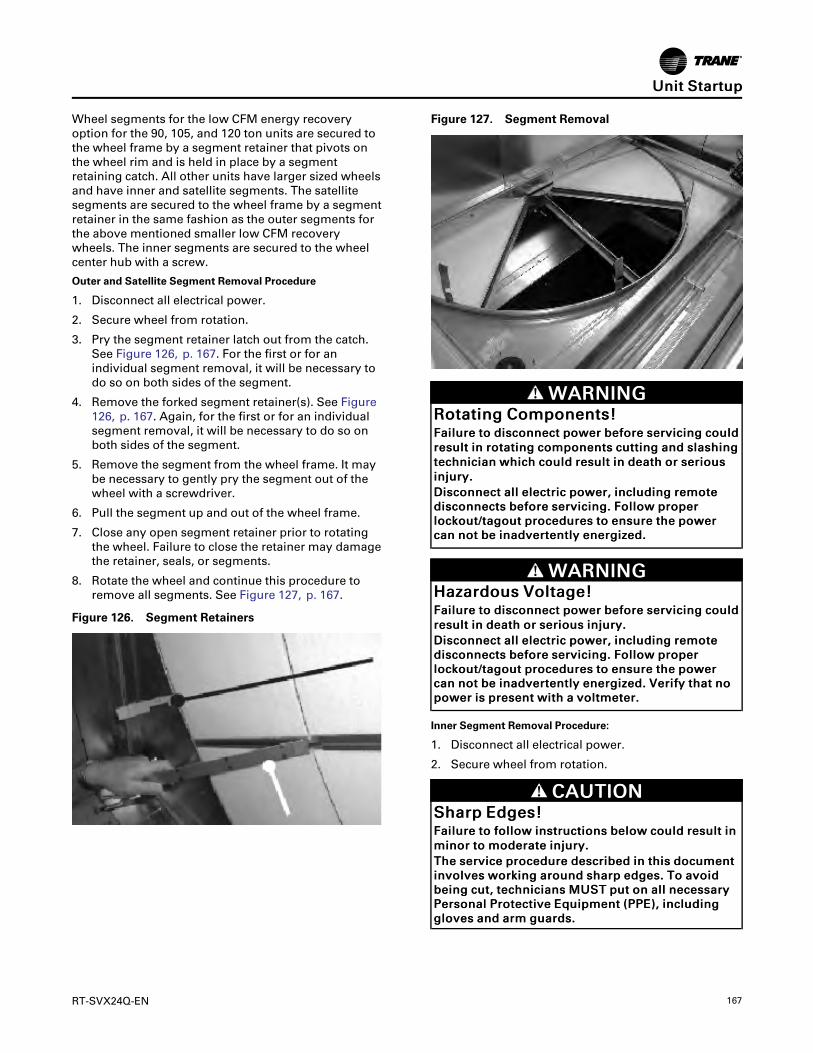
RT-SVX24Q-EN 167
Wheel segments for the low CFM energy recoveryoption for the 90, 105, and 120 ton units are secured tothe wheel frame by a segment retainer that pivots onthe wheel rim and is held in place by a segmentretaining catch. All other units have larger sized wheelsand have inner and satellite segments. The satellitesegments are secured to the wheel frame by a segmentretainer in the same fashion as the outer segments forthe above mentioned smaller low CFM recoverywheels. The inner segments are secured to the wheelcenter hub with a screw.
Outer and Satellite Segment Removal Procedure
1. Disconnect all electrical power.
2. Secure wheel from rotation.
3. Pry the segment retainer latch out from the catch.See Figure 126, p. 167. For the first or for anindividual segment removal, it will be necessary todo so on both sides of the segment.
4. Remove the forked segment retainer(s). See Figure126, p. 167. Again, for the first or for an individualsegment removal, it will be necessary to do so onboth sides of the segment.
5. Remove the segment from the wheel frame. It maybe necessary to gently pry the segment out of thewheel with a screwdriver.
6. Pull the segment up and out of the wheel frame.
7. Close any open segment retainer prior to rotatingthe wheel. Failure to close the retainer may damagethe retainer, seals, or segments.
8. Rotate the wheel and continue this procedure toremove all segments. See Figure 127, p. 167.
Figure 126. Segment Retainers
Figure 127. Segment Removal
WWAARRNNIINNGGRRoottaattiinngg CCoommppoonneennttss!!FFaaiilluurree ttoo ddiissccoonnnneecctt ppoowweerr bbeeffoorree sseerrvviicciinngg ccoouullddrreessuulltt iinn rroottaattiinngg ccoommppoonneennttss ccuuttttiinngg aanndd ssllaasshhiinnggtteecchhnniicciiaann wwhhiicchh ccoouulldd rreessuulltt iinn ddeeaatthh oorr sseerriioouussiinnjjuurryy..DDiissccoonnnneecctt aallll eelleeccttrriicc ppoowweerr,, iinncclluuddiinngg rreemmootteeddiissccoonnnneeccttss bbeeffoorree sseerrvviicciinngg.. FFoollllooww pprrooppeerrlloocckkoouutt//ttaaggoouutt pprroocceedduurreess ttoo eennssuurree tthhee ppoowweerrccaann nnoott bbee iinnaaddvveerrtteennttllyy eenneerrggiizzeedd..
WWAARRNNIINNGGHHaazzaarrddoouuss VVoollttaaggee!!FFaaiilluurree ttoo ddiissccoonnnneecctt ppoowweerr bbeeffoorree sseerrvviicciinngg ccoouullddrreessuulltt iinn ddeeaatthh oorr sseerriioouuss iinnjjuurryy..DDiissccoonnnneecctt aallll eelleeccttrriicc ppoowweerr,, iinncclluuddiinngg rreemmootteeddiissccoonnnneeccttss bbeeffoorree sseerrvviicciinngg.. FFoollllooww pprrooppeerrlloocckkoouutt//ttaaggoouutt pprroocceedduurreess ttoo eennssuurree tthhee ppoowweerrccaann nnoott bbee iinnaaddvveerrtteennttllyy eenneerrggiizzeedd.. VVeerriiffyy tthhaatt nnooppoowweerr iiss pprreesseenntt wwiitthh aa vvoollttmmeetteerr..
Inner Segment Removal Procedure:
1. Disconnect all electrical power.
2. Secure wheel from rotation.
CCAAUUTTIIOONNSShhaarrpp EEddggeess!!FFaaiilluurree ttoo ffoollllooww iinnssttrruuccttiioonnss bbeellooww ccoouulldd rreessuulltt iinnmmiinnoorr ttoo mmooddeerraattee iinnjjuurryy..TThhee sseerrvviiccee pprroocceedduurree ddeessccrriibbeedd iinn tthhiiss ddooccuummeennttiinnvvoollvveess wwoorrkkiinngg aarroouunndd sshhaarrpp eeddggeess.. TToo aavvooiiddbbeeiinngg ccuutt,, tteecchhnniicciiaannss MMUUSSTT ppuutt oonn aallll nneecceessssaarryyPPeerrssoonnaall PPrrootteeccttiivvee EEqquuiippmmeenntt ((PPPPEE)),, iinncclluuddiinngggglloovveess aanndd aarrmm gguuaarrddss..
UUnniitt SSttaarrttuupp

168 RT-SVX24Q-EN
WWAARRNNIINNGGRRiisskk ooff EEnneerrggyy WWhheeeell CCoollllaappssiinngg!!FFaaiilluurree ttoo ffoollllooww iinnssttrruuccttiioonnss bbeellooww ccoouulldd ccaauusseetthhee eenneerrggyy wwhheeeell ttoo ccoollllaappssee uunnddeerr tthheetteecchhnniicciiaann’’ss wweeiigghhtt wwhhiicchh ccoouulldd rreessuulltt iinn sseevveerreeiinnjjuurryy..BBeeffoorree llaayyiinngg aaccrroossss tthhee eenneerrggyy wwhheeeell,, aadddd eexxttrraassuuppppoorrtt bbyy ppllaacciinngg aa rriiggiidd bbooaarrdd aaccrroossss tthhee ssppaann oofftthhee eenneerrggyy wwhheeeell ccaasssseettttee..
3. Support segment with one hand while removing 1/4- 20 flat head retaining screw in the wheel hub with5/32" Allen wrench, see Figure 128, p. 168.
Figure 128. Inner Segment Removal
4. Carefully slide the segment out from between thehub plates, and remove from the wheel.
5. Reinsert the 1/4 - 20 screw in the removed segmentnose to avoid loss.
6. Rotate the wheel and continue this procedure toremove all segments.
Segment Replacement
WWAARRNNIINNGGHHaazzaarrddoouuss VVoollttaaggee!!FFaaiilluurree ttoo ddiissccoonnnneecctt ppoowweerr bbeeffoorree sseerrvviicciinngg ccoouullddrreessuulltt iinn ddeeaatthh oorr sseerriioouuss iinnjjuurryy..DDiissccoonnnneecctt aallll eelleeccttrriicc ppoowweerr,, iinncclluuddiinngg rreemmootteeddiissccoonnnneeccttss bbeeffoorree sseerrvviicciinngg.. FFoollllooww pprrooppeerrlloocckkoouutt//ttaaggoouutt pprroocceedduurreess ttoo eennssuurree tthhee ppoowweerrccaann nnoott bbee iinnaaddvveerrtteennttllyy eenneerrggiizzeedd.. VVeerriiffyy tthhaatt nnooppoowweerr iiss pprreesseenntt wwiitthh aa vvoollttmmeetteerr..
Inner Segment Replacement
1. Disconnect all electrical power.
2. Secure wheel from rotation.
CCAAUUTTIIOONNSShhaarrpp EEddggeess!!FFaaiilluurree ttoo ffoollllooww iinnssttrruuccttiioonnss bbeellooww ccoouulldd rreessuulltt iinnmmiinnoorr ttoo mmooddeerraattee iinnjjuurryy..TThhee sseerrvviiccee pprroocceedduurree ddeessccrriibbeedd iinn tthhiiss ddooccuummeennttiinnvvoollvveess wwoorrkkiinngg aarroouunndd sshhaarrpp eeddggeess.. TToo aavvooiiddbbeeiinngg ccuutt,, tteecchhnniicciiaannss MMUUSSTT ppuutt oonn aallll nneecceessssaarryyPPeerrssoonnaall PPrrootteeccttiivvee EEqquuiippmmeenntt ((PPPPEE)),, iinncclluuddiinngggglloovveess aanndd aarrmm gguuaarrddss..
3. Remove 1/4 - 20 flat head retaining screw from theinner segment nose with 5/32" Allen wrench.
4. Rest the edge of the segment on the support flangeon one wheel spoke and slide it until the segmentnose is fitted firmly in the wheel hub and thesegment screw hole is aligned with the hub slot.
5. Reinsert 1/4 - 20 screw into the hub / inner segmentand tighten until the screw is firmly seated, seeFigure 128, p. 168.
Outer or Satellite Segment Replacement
WWAARRNNIINNGGHHaazzaarrddoouuss VVoollttaaggee!!FFaaiilluurree ttoo ddiissccoonnnneecctt ppoowweerr bbeeffoorree sseerrvviicciinngg ccoouullddrreessuulltt iinn ddeeaatthh oorr sseerriioouuss iinnjjuurryy..DDiissccoonnnneecctt aallll eelleeccttrriicc ppoowweerr,, iinncclluuddiinngg rreemmootteeddiissccoonnnneeccttss bbeeffoorree sseerrvviicciinngg.. FFoollllooww pprrooppeerrlloocckkoouutt//ttaaggoouutt pprroocceedduurreess ttoo eennssuurree tthhee ppoowweerrccaann nnoott bbee iinnaaddvveerrtteennttllyy eenneerrggiizzeedd.. VVeerriiffyy tthhaatt nnooppoowweerr iiss pprreesseenntt wwiitthh aa vvoollttmmeetteerr..
WWAARRNNIINNGGRRoottaattiinngg CCoommppoonneennttss!!FFaaiilluurree ttoo ddiissccoonnnneecctt ppoowweerr bbeeffoorree sseerrvviicciinngg ccoouullddrreessuulltt iinn rroottaattiinngg ccoommppoonneennttss ccuuttttiinngg aanndd ssllaasshhiinnggtteecchhnniicciiaann wwhhiicchh ccoouulldd rreessuulltt iinn ddeeaatthh oorr sseerriioouussiinnjjuurryy..DDiissccoonnnneecctt aallll eelleeccttrriicc ppoowweerr,, iinncclluuddiinngg rreemmootteeddiissccoonnnneeccttss bbeeffoorree sseerrvviicciinngg.. FFoollllooww pprrooppeerrlloocckkoouutt//ttaaggoouutt pprroocceedduurreess ttoo eennssuurree tthhee ppoowweerrccaann nnoott bbee iinnaaddvveerrtteennttllyy eenneerrggiizzeedd..
1. Disconnect all electrical power.
2. Secure wheel from rotation.
3. Rotate out the two segment retainer latches, one foreach side of the selected segment opening, suchthat they are 90° from the wheel rim. See Figure128, p. 168.
4. Set the segment in the gap between the segmentretainer latches, pressing it toward the center of thewheel and inward against the spoke flanges. SeeFigure 131, p. 170. If hand pressure does not fullyseat the segment, insert the flat tip of a screwdriverbetween the wheel rim and the outer corners of thesegment and apply gentle force while guiding the
UUnniitt SSttaarrttuupp

RT-SVX24Q-EN 169
segment into place. Be careful not to bend thewheel frame or the segment frame with thescrewdriver.
5. Reinstall forked segment retainer(s)
NNoottee:: Only applies when there is an adjacentsegment in place.
6. Close each segment retainer latch under thesegment retaining catch.
7. Rotate the wheel and repeat this sequence with theremaining segments.
Removing and replacing the segments with a spareset can be accomplished more quickly. Remove thedirty segment, replace it with a clean segment, thenmove to the next segment.
Filtration
WWAARRNNIINNGGHHaazzaarrddoouuss VVoollttaaggee!!FFaaiilluurree ttoo ddiissccoonnnneecctt ppoowweerr bbeeffoorree sseerrvviicciinngg ccoouullddrreessuulltt iinn ddeeaatthh oorr sseerriioouuss iinnjjuurryy..DDiissccoonnnneecctt aallll eelleeccttrriicc ppoowweerr,, iinncclluuddiinngg rreemmootteeddiissccoonnnneeccttss bbeeffoorree sseerrvviicciinngg.. FFoollllooww pprrooppeerrlloocckkoouutt//ttaaggoouutt pprroocceedduurreess ttoo eennssuurree tthhee ppoowweerrccaann nnoott bbee iinnaaddvveerrtteennttllyy eenneerrggiizzeedd.. VVeerriiffyy tthhaatt nnooppoowweerr iiss pprreesseenntt wwiitthh aa vvoollttmmeetteerr..
Galvanized steel permanent filters are provided toprevent debris from entering the energy wheel section.The return air filters are mounted in a filter rackunderneath the energy recovery wheel, and areaccessible from either side by means of the doubleaccess doors. The outside air filter rack is attached tothe energy recovery cassette. Use the unit filter /evaporator coil access doors to service the energyrecovery outside air filters.
1. Disconnect all electrical power.
2. Remove all filter media from the vertical filter rackproviding air filtration for the unit evaporator coil.
3. Remove the sheet metal screws in the hingedaccess panel beneath the bypass damper assembly.
4. Rotate the access panel downwards.
5. Reach in past the damper wall to access the flexiblefilter puller(s). Pull them towards the evaporatorcoil enough to reach the second filter in each slot ofthe filter rack. Refer to Table 58, p. 169 for filterinformation.
Table 58. ERW Filter Information
GalvanizedSteel Filter
Info
90-118 TonLow CFMERWUnits(in.)
90-162 TonLow CFMERWUnits(in.)
90-162 TonStandardCFM ERWUnits (in.)
RA Filters(size,number)
24x24x1, 10 24x24x1, 10 24x24x1, 10
FA Filters(size, number 224x24x1, 8 24x24x1, 6 24x24x1, 8
12x24x1, 2
NNoottee:: Inspect these filters monthly and clean them asnecessary.
Bearing and Motor LubricationThe wheel drive motor and wheel support shaftbearings are permanently lubricated and no furtherlubrication is necessary.
Service and Repair
Drive Belt ReplacementThe drive belt is a urethane stretch belt designed toprovide constant tension throughout the life of the belt.No periodic adjustment is required. Inspect the beltannually for proper tracking and tension. A properlytensioned belt will turn the wheel immediately, with novisible slippage, when power is applied.
WWAARRNNIINNGGHHaazzaarrddoouuss VVoollttaaggee!!FFaaiilluurree ttoo ddiissccoonnnneecctt ppoowweerr bbeeffoorree sseerrvviicciinngg ccoouullddrreessuulltt iinn ddeeaatthh oorr sseerriioouuss iinnjjuurryy..DDiissccoonnnneecctt aallll eelleeccttrriicc ppoowweerr,, iinncclluuddiinngg rreemmootteeddiissccoonnnneeccttss bbeeffoorree sseerrvviicciinngg.. FFoollllooww pprrooppeerrlloocckkoouutt//ttaaggoouutt pprroocceedduurreess ttoo eennssuurree tthhee ppoowweerrccaann nnoott bbee iinnaaddvveerrtteennttllyy eenneerrggiizzeedd.. VVeerriiffyy tthhaatt nnooppoowweerr iiss pprreesseenntt wwiitthh aa vvoollttmmeetteerr..
WWAARRNNIINNGGRRiisskk ooff EEnneerrggyy WWhheeeell CCoollllaappssiinngg!!FFaaiilluurree ttoo ffoollllooww iinnssttrruuccttiioonnss bbeellooww ccoouulldd ccaauusseetthhee eenneerrggyy wwhheeeell ttoo ccoollllaappssee uunnddeerr tthheetteecchhnniicciiaann’’ss wweeiigghhtt wwhhiicchh ccoouulldd rreessuulltt iinn sseevveerreeiinnjjuurryy..BBeeffoorree llaayyiinngg aaccrroossss tthhee eenneerrggyy wwhheeeell,, aadddd eexxttrraassuuppppoorrtt bbyy ppllaacciinngg aa rriiggiidd bbooaarrdd aaccrroossss tthhee ssppaann oofftthhee eenneerrggyy wwhheeeell ccaasssseettttee..
1. Disconnect all electrical power.
2. Confirm the model number on the belt replacementkit matches the model number on the label by themotor pulley. Remove all remnants of the old belt.
3. Uncoil the belt as necessary. The belt must not twistwhen being feed around the wheel rim.
UUnniitt SSttaarrttuupp
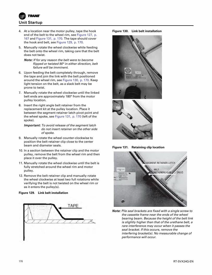
170 RT-SVX24Q-EN
4. At a location near the motor pulley, tape the hookend of the belt to the wheel rim, see Figure 127, p.167 and Figure 131, p. 170. The tape should coverthe hook and belt, see Figure 129, p. 170.
5. Manually rotate the wheel clockwise while feedingthe belt onto the wheel rim, taking care that the beltdoes not twist.
NNoottee:: If for any reason the belt were to becomeflipped or twisted 90° in either direction, beltfailure will be imminent.
6. Upon feeding the belt completely through, removethe tape and join the link with the belt positionedaround the wheel rim, see Figure 130, p. 170. Keeplight tension on the belt, as a slack belt may beprone to twist.
7. Manually rotate the wheel clockwise until the linkedbelt ends are approximately 180° from the motorpulley location.
8. Insert the right angle belt retainer from thereplacement kit at the pulley location. Place itbetween the segment retainer latch pivot point andthe wheel spoke, see Figure 131, p. 170 (left of thespoke).
IImmppoorrttaanntt:: To avoid release of the segment latchdo not insert retainer on the other sideof spoke.
9. Manually rotate the wheel counter-clockwise toposition the belt retainer clip close to the centerbeam and diameter seals.
10. In a section between the retainer clip and the motorpulley, remove the belt from the wheel rim and thenplace it over the pulley.
11. Manually rotate the wheel clockwise until the belt isfully stretched around the wheel rim and motorpulley.
12. Remove the belt retainer clip and manually rotatethe wheel clockwise at least two full rotations whileverifying the belt is not twisted on the wheel rim oras it enters the pulley(s).
Figure 129. Link belt installation
Figure 130. Link belt installation
Figure 131. Retaining clip location
NNoottee:: Pile seal brackets are fixed with a single screw tothe cassette frame near the ends of the wheelbearing beam. Because the height of the belt linkis slightly higher than that of the urethane belt, arare interference may occur when it passes theseal bracket. If this occurs, remove theinterfering bracket(s). No measurable change ofperformance will occur.
UUnniitt SSttaarrttuupp

RT-SVX24Q-EN 171
Seal Adjustment
WWAARRNNIINNGGHHaazzaarrddoouuss VVoollttaaggee!!FFaaiilluurree ttoo ddiissccoonnnneecctt ppoowweerr bbeeffoorree sseerrvviicciinngg ccoouullddrreessuulltt iinn ddeeaatthh oorr sseerriioouuss iinnjjuurryy..DDiissccoonnnneecctt aallll eelleeccttrriicc ppoowweerr,, iinncclluuddiinngg rreemmootteeddiissccoonnnneeccttss bbeeffoorree sseerrvviicciinngg.. FFoollllooww pprrooppeerrlloocckkoouutt//ttaaggoouutt pprroocceedduurreess ttoo eennssuurree tthhee ppoowweerrccaann nnoott bbee iinnaaddvveerrtteennttllyy eenneerrggiizzeedd.. VVeerriiffyy tthhaatt nnooppoowweerr iiss pprreesseenntt wwiitthh aa vvoollttmmeetteerr..
1. Disconnect all electrical power.
2. Loosen the diameter seal adjustment screws andback the seals away from the wheel surface, seeFigure 132, p. 171.
3. Rotate the wheel clockwise until two opposingspokes are hidden behind the bearing supportbeam.
Figure 132. Wheel rotation
4. Using a folded piece of paper as a feeler gauge,position the paper between the wheel surface andthe diameter seals.
5. Adjust the seals toward the wheel surface untilslight friction on the paper feeler gauge is felt whenthe gauge is moved along the length of the spoke.
6. Check the seal adjustment through a full rotation ofthe wheel. Re-tighten the adjusting screws andrecheck the clearance with the paper-feeler gauge.
Drive Motor and Pulley Replacement
WWAARRNNIINNGGHHaazzaarrddoouuss VVoollttaaggee!!FFaaiilluurree ttoo ddiissccoonnnneecctt ppoowweerr bbeeffoorree sseerrvviicciinngg ccoouullddrreessuulltt iinn ddeeaatthh oorr sseerriioouuss iinnjjuurryy..DDiissccoonnnneecctt aallll eelleeccttrriicc ppoowweerr,, iinncclluuddiinngg rreemmootteeddiissccoonnnneeccttss bbeeffoorree sseerrvviicciinngg.. FFoollllooww pprrooppeerrlloocckkoouutt//ttaaggoouutt pprroocceedduurreess ttoo eennssuurree tthhee ppoowweerrccaann nnoott bbee iinnaaddvveerrtteennttllyy eenneerrggiizzeedd.. VVeerriiffyy tthhaatt nnooppoowweerr iiss pprreesseenntt wwiitthh aa vvoollttmmeetteerr..
1. Disconnect all electrical power.
2. Remove the belt from the pulley and position ittemporarily around the wheel rim.
3. Measure and record the distance from the inneredge of the pulley to the mounting wall.
4. Loosen the set screw in the wheel drive pulleyusing an Allen wrench and remove the pulley fromthe motor drive shaft.
5. While supporting the weight of the drive motor inone hand, loosen and remove the four mountingbolts.
6. Install a replacement motor with the hardware kitsupplied.
7. Install the pulley and adjust it to the distancerecorded earlier in this procedure.
8. Tighten the set screw to the drive shaft.
9. Stretch the belt over the pulley and engage it in thegroove.
Compressor StartupNNOOTTIICCEE
CCoommpprreessssoorr FFaaiilluurree!!FFaaiilluurree ttoo ffoollllooww iinnssttrruuccttiioonn bbeellooww ccoouulldd rreessuulltt iinnccoommpprreessssoorr ffaaiilluurree..UUnniitt mmuusstt bbee ppoowweerreedd aanndd ccrraannkkccaassee hheeaatteerrsseenneerrggiizzeedd aatt lleeaasstt 88 hhoouurrss BBEEFFOORREE ccoommpprreessssoorrssaarree ssttaarrtteedd..
1. Ensure that the “System” selection switch at theremote panel is in the “Off” position.
2. Before closing the disconnect switch, ensure thatthe compressor discharge service valve for eachcircuit is back seated.
NNOOTTIICCEECCoommpprreessssoorr DDaammaaggee!!EExxcceessssiivvee lliiqquuiidd aaccccuummuullaattiioonn iinn tthhee ssuuccttiioonn lliinneessccoouulldd rreessuulltt iinn ccoommpprreessssoorr ddaammaaggee..DDoo nnoott aallllooww lliiqquuiidd rreeffrriiggeerraanntt ttoo eenntteerr tthhee ssuuccttiioonnlliinnee..
UUnniitt SSttaarrttuupp

172 RT-SVX24Q-EN
IImmppoorrttaanntt:: COMPRESSOR SERVICE VALVES MUST BEFULLY OPENED BEFORE STARTUP(SUCTION, DISCHARGE, AND OIL LINE).
3. Close the disconnect switch or circuit protectorswitch that provides the supply power to the unitterminal block or the unit mounted disconnectswitch to allow the crankcase heater to operate aminimum of 8 hours before continuing.
IImmppoorrttaanntt:: Compressor Damage could occur if thecrankcase heater is not allowed tooperate the minimum of 8 hours beforestarting the compressor(s).
4. Turn the 115 volt control circuit switch and the 24volt control circuit switch to the “On” position.
5. Open the Human Interface access door located inthe unit control panel, and press the SERVICEMODE key to display the first service screen. Referto the latest edition of the applicationsprogramming guide (RT-SVP07*-EN) forapplications for the SERVICE TEST screens andprogramming instructions.
6. Use tables in “Voltage Imbalance,” p. 105 toprogram the following system components foroperation by scrolling through the displays.
7. Attach a set of service gauges onto the suction anddischarge gauge ports for each circuit. See Figure133, p. 174 for the various compressor locations.
8. Once the configuration for the components iscomplete, press the NEXT key until the LCDdisplays the “Start test in __Sec.” screen. Press the+ key to designate the delay before the test is tostart. This service test will begin after the TESTSTART key is pressed and the delay designated inthis step has elapsed. Press the ENTER key toconfirm this choice.
WWAARRNNIINNGGRRoottaattiinngg CCoommppoonneennttss!!FFaaiilluurree ttoo ddiissccoonnnneecctt ppoowweerr bbeeffoorree sseerrvviicciinngg ccoouullddrreessuulltt iinn rroottaattiinngg ccoommppoonneennttss ccuuttttiinngg aanndd ssllaasshhiinnggtteecchhnniicciiaann wwhhiicchh ccoouulldd rreessuulltt iinn ddeeaatthh oorr sseerriioouussiinnjjuurryy..DDuurriinngg iinnssttaallllaattiioonn,, tteessttiinngg,, sseerrvviicciinngg aannddttrroouubblleesshhoooottiinngg ooff tthhiiss pprroodduucctt iitt mmaayy bbeenneecceessssaarryy ttoo wwoorrkk wwiitthh lliivvee aanndd eexxppoosseedd rroottaattiinnggccoommppoonneennttss.. HHaavvee aa qquuaalliiffiieedd oorr lliicceennsseedd sseerrvviicceeiinnddiivviidduuaall wwhhoo hhaass bbeeeenn pprrooppeerrllyy ttrraaiinneedd iinnhhaannddlliinngg eexxppoosseedd rroottaattiinngg ccoommppoonneennttss,, ppeerrffoorrmmtthheessee ttaasskkss..
9. Press the TEST START key to start the test.Remember that the delay designated in step 8 mustelapse before the system will begin to operate.
10. Once each compressor or compressor pair hasstarted, verify that the rotation is correct. If a scrollcompressor is rotating backwards, it will not pumpand a loud rattling sound can be observed. Check
the electrical phasing at the load side of thecompressor contactor. If the phasing is correct,before condemning the compressor, interchangeany two leads to check the internal motor phasing.If the compressor runs backward for an extendedperiod (15 to 30 minutes), the motor winding canover heat and cause the motor winding thermostatsto open. This will cause a “compressor trip”diagnostic and stop the compressor.
11. Press the STOP key at the Human Interface Modulein the unit control panel to stop the compressoroperation.
12. Repeat steps 5–11 for each compressor stage andthe appropriate condenser fans.
Refrigerant Charging1. Attach a set of service gauges onto the suction and
discharge gauge ports for each circuit. See Figure133, p. 174 for the various compressor locations.
2. Open the Human Interface access door, located inthe unit control panel, and press the SERVICEMODE key to display the first service screen. Referto the latest edition of the applicationsprogramming guide for CV or VAV applications forthe SERVICE TEST screens and programminginstructions.
3. Use tables in “Voltage Imbalance,” p. 105 toprogram the following system components for thenumber 1 refrigeration circuit by scrolling throughthe displays;
Supply Fan (On)
VFD (100%, if applicable)
OCC/UNOCC Relay (Unoccupied for VAV units)
All Compressors for each circuit (On)
Condenser Fans for each circuit (On)
4. Once the configuration for the components iscomplete, press the NEXT key until the LCDdisplays the “Start test in __Sec.” screen. Press the+ key to designate the delay before the test is tostart. This service test will begin after the TESTSTART key is pressed and the delay designated inthis step has elapsed. Press the ENTER key toconfirm this choice.
WWAARRNNIINNGGRRoottaattiinngg CCoommppoonneennttss!!FFaaiilluurree ttoo ddiissccoonnnneecctt ppoowweerr bbeeffoorree sseerrvviicciinngg ccoouullddrreessuulltt iinn rroottaattiinngg ccoommppoonneennttss ccuuttttiinngg aanndd ssllaasshhiinnggtteecchhnniicciiaann wwhhiicchh ccoouulldd rreessuulltt iinn ddeeaatthh oorr sseerriioouussiinnjjuurryy..DDiissccoonnnneecctt aallll eelleeccttrriicc ppoowweerr,, iinncclluuddiinngg rreemmootteeddiissccoonnnneeccttss bbeeffoorree sseerrvviicciinngg.. FFoollllooww pprrooppeerrlloocckkoouutt//ttaaggoouutt pprroocceedduurreess ttoo eennssuurree tthhee ppoowweerrccaann nnoott bbee iinnaaddvveerrtteennttllyy eenneerrggiizzeedd..
UUnniitt SSttaarrttuupp

RT-SVX24Q-EN 173
5. Press the TEST START key to start the test.Remember that the delay designated in step 4 mustelapse before the system will begin to operate.
6. After all of the compressors and condenser fans forthe number 1 circuit have been operating forapproximately 30 minutes, observe the operatingpressures. Use the appropriate pressure curvefound in “(60 Hz) Air-Cooled Condensers,” p. 128 or“(50 Hz) Air-Cooled Condensers,” p. 142 todetermine the proper operating pressures. Forsuperheat and subcooling guidelines, refer to“Thermostatic Expansion Valves,” p. 177.
IImmppoorrttaanntt:: Do Not release refrigerant to theatmosphere! If adding or removingrefrigerant is required, the servicetechnician must comply with allFederal, State and local laws.
7. Verify that the oil level in each compressor iscorrect. The oil level may be down to the bottom ofthe sightglass but should never be above thesightglass.
8. Press the STOP key at the Human Interface Modulein the unit control panel to stop the systemoperation.
9. Repeat steps 1 through 8 for the number 2refrigeration circuit.
10. After shutting the system off, check the compressoroil appearance. Discoloration of the oil indicatesthat an abnormal condition has occurred. If the oil isdark and smells burnt, it has overheated because:the compressor is operating at extremely highcondensing temperatures; high superheat; acompressor mechanical failure; or, occurrence of amotor burnout.
If the oil is black and contains metal flakes, amechanical failure has occurred. This symptom isoften accompanied by a high compressoramperage draw.
If a motor burnout is suspected, use an acid test kitto check the condition of the oil. Test results willindicate an acid level exceeding 0.05 mg KOH/g if aburnout occurred.
The scroll compressor uses Trane OIL00079 (onequart container) or OIL00080 (one gallon container)without substitution. The appropriate oil charge forCSHN250 and CSHN315 scroll compressors is 14.2pints. For CSHN374 scroll compressor, use 15.2pints.
Compressor Crankcase HeatersEach scroll compressor is equipped with a 160-wattcrankcase heater.
Compressor Operational SoundsBecause of the scroll compressor design, it emits ahigher frequency tone (sound) than a reciprocatingcompressor. It is designed to accommodate liquids,both oil and refrigerant, without causing compressordamage. The following sections describe some of theoperational sounds that differentiate it from thosetypically associated with a reciprocating compressor.These sounds do not affect the operation or reliabilityof the compressor.
At ShutdownWhen a Scroll compressor shuts down, the gas withinthe scroll expands and causes momentary reverserotation until the discharge check valve closes. Thisresults in a “flutter” type sound.
At Low Ambient Start-UpWhen the compressor starts up under low ambientconditions, the initial flow rate of the compressor is lowdue to the low condensing pressure. This causes a lowdifferential across the thermal expansion valve thatlimits its capacity. Under these conditions, it is notunusual to hear the compressor rattle until the suctionpressure climbs and the flow rate increases.
NNoottee:: Evaporative Condensers ordered with sumpheaters will have low ambient down to 10 deg asstandard
Variable Speed CompressorsAt all operating speeds, eFlex™ permanent magnetvariable speed compressors sound different than fixedspeed scrolls. At low speed, variable speedcompressors can sputter. At high speed, variable speedcompressor buzz. These are normal operating sounds.To ensure a quiet installation, eFlex variable speedcompressors are installed in a sound enclosure. Makesure and keep the sound enclosure installed at all timesother than servicing.
Listen to recordings of eFlex variable speed scrollsounds at www.trane.com/eFlexSounds.
IImmppoorrttaanntt:: Variable speed scroll compressors sounddifferent than single speed scrollcompressors. Sound changes with speedand condition. To assist troubleshooting,listen to normal operating sounds ofvariable speed scroll compressors at www.trane.com/eFlexSounds
Electronic CompressorProtection Module (CPM)The CSHN*** compressors come equipped with acompressor protection device (CPM) capable ofdetecting phase reversal, phase loss, and motoroverheating. When a fault is identified, the output relay
UUnniitt SSttaarrttuupp

174 RT-SVX24Q-EN
will open. Depending on the fault, the CPM may eitherauto-reset or it may lock-out. The CPM can be manuallyreset by cycling control power.
NNoottee:: If the compressor has tripped due to anoverheated windings condition, the motorwinding temperature sensor resistance (PTC) willbe 4500 ohms or greater; the resistance must beless than 2750 ohms before the 5 minute resettimer becomes enabled.
Figure 133. Compressor locations and stagingsequence (fixed speed compressors)
K4
Table 59. Staging sequence (fixed speedcompressors)
Compressor Staging (Lead)Compressor Staging
(Lag)
1A 1B 2A 2B 1A 1B 2A 2B
Stage 1 X X
Stage 2 X X X X
Stage 3 X X X X X X
Stage 4 X X X X X X X X
Table 60. Compressor data (fixed speed compressors)
Unit Size
Compressors
Num-ber Size
Desig-nator Type
90/100 Ton Std& Hi-Capacity
2 CSH-N250
1A, 2A Scroll
2 CSH-N250
1B, 2B Scroll
105/118 TonStd & Hi-Capacity
2 CSH-N250
1A, 2A Scroll
2 CSH-N315
1B, 2B Scroll
120/128 TonStd & Hi-Capacity
2 CSH-N315
1A, 2A Scroll
2 CSH-N315
1B, 2B Scroll
130/140 TonStd & Hi-Capacity
2 CSH-N315
1A, 2A Scroll
2 CSH-N374
1B, 2B Scroll
150/162 TonStd
2 CSH-N374
1A, 2A Scroll
2 CSH-N374
1B, 2B Scroll
Figure 134. eFlex™ compressor locations and stagingsequence
CO
NTRO
L BO
X
COMPRESSOR 2A HI DESIGNATOR "K3"
COMPRESSOR 2B HI DESIGNATOR "K4"
COMPRESSOR 1C HI DESIGNATOR "K13"
COMPRESSOR 1B HI DESIGNATOR "K12"
COMPRESSOR 1A HI DESIGNATOR "K11"
UUnniitt SSttaarrttuupp

RT-SVX24Q-EN 175
Table 61. eFlex™ staging sequence and compressor data
90 Ton eFlex™ Variable Speed Compressor
Stage 1A CSHN184 1B CSHN184 1C CSHN184 2A VZH170 2B CSHN184VZHminSpeed
VZHmaxSpeed
1 X 2400 5280
2 X X 1500 5460
3 X X X 2040 5100
4 X X X X 1500 6000
5 X X X X X 2040 5000
105 Ton eFlex™ Variable Speed Compressor
Stage 1A CSHN184 1B CSHN184 1C CSHN184 2A VZH170 2B CSHN250VZHminSpeed
VZHmaxSpeed
1 X 2640 5220
2 X X 1500 5460
3 X X X 2040 5600
4 X X X X 1500 6000
5 X X X X X 1500 6000
120 Ton eFlex™ Variable Speed Compressor
Stage 1A CSHN184 1B CSHN184 1C CSHN250 2AVZH170 2B CSHN315VZHminSpeed
VZHmaxSpeed
1 X 3000 5280
2 X X 1500 5520
3 X X X 2100 5000
4 X X X 2700 6000
5 X X X X 1500 6000
6 X X X X X 1500 6000
130 Ton eFlex™ Variable Speed Compressor
Stage 1A CSHN184 1B CSHN184 1C CSHN315 2A VZH170 2B CSHN374VZHminSpeed
VZHmaxSpeed
1 X 3300 5640
2 X X 1740 5340
3 X X X 1860 5000
4 X X X 1500 6000
5 X X X X 1500 5700
6 X X X X 1500 6000
UUnniitt SSttaarrttuupp

176 RT-SVX24Q-EN
Table 61. eFlex™ staging sequence and compressor data (continued)
150 Ton eFlex™ Variable Speed Compressor
Stage 1A CSHN250 1B CSHN184 1C CSHN374 2A VZH170 2B CSHN374VZHminSpeed
VZHmaxSpeed
1 X 3360 5280
2 X X 1500 6000
3 X X X 1620 5000
4 X X X 1800 6000
5 X X X X 1500 5280
6 X X X X 1500 6000
7 X X X X X 1500 6000
Evaporative Condenser StartupIImmppoorrttaanntt:: Water treatment by a qualified water
treatment expert is required to ensureproper equipment life and productperformance. If a water treatment system isnot operating on the unit, do not proceed.
Startup for evaporative and air-cooled condensers isinitially the same. In addition, the following is requiredfor evaporative condensers prior to startup:
• All water and drain connections must be checkedand verified
• Evaporative condensers will ship with a fan supportchannel to reduce damage caused by vibrationduring shipment. The shipping support bracketsmust be removed prior to unit startup. See belowand see Figure 135, p. 177 for removal instructions.
• Verify that inlet water pressure is 35-60 PSIG,dynamic pressure (measured with the valve open)
• Verify that drain valve is set to "drain during powerloss" or "hold during power loss" per jobspecification
• Upon a call for cooling, the sump will fill with water.Verify that the sump fills to a level within the slot onthe max float bracket as shown in Figure 136, p.177.
TToo rreemmoovvee sshhiippppiinngg bbrraacckkeettss::
IImmppoorrttaanntt:: Remove fan shipping brackets beforestartup. Failure to remove brackets couldresult in fan damage.
Evaporative condensers are shipped with fan shippingbrackets to reduce damage caused by vibration duringshipment. The fan shipping brackets must be removed
prior to unit startup. To remove the shipping bracketsstart from the side opposite to the drain actuator:
1. Loosen the screw for the bracket that holds the inletlouvers below the door side.
2. Remove inlet louvers and set to the side.
NNoottee:: Service technician may need to step on thehorizontal surface of FRP coated base. Stepwith care.
3. Unscrew the bolt in the middle of the door. Keepthe bolt in a safe place.
4. Lift one door with handle until it touches the top.Swivel bottom of door to remove it from the dooropening and set it to the side.
5. Slide and remove the middle mist eliminatorsection so that the shipping bracket is visible.
6. Use screw gun to unscrew the two screws that holdthe fan shipping bracket. The bracket should dropdown but still remain engaged with a hook on thebracket.
7. Go to the other side of the unit and follow theprocedure for inlet louver and door removal(see steps 1 - 6).
8. Hold the bracket with one hand and removeremaining two screws.
9. Remove the bracket and all the removed screwsfrom the unit.
IImmppoorrttaanntt:: Make sure there are no screwsremaining in the coil area.
10. Reinstall inlet louvers, mist eliminators and louvers.
11. Check that the direction of arrow on the inlet louveris correct
UUnniitt SSttaarrttuupp

RT-SVX24Q-EN 177
Figure 135. Fan shipping bracket removal
Mist Eliminator
Fan Shipping Bracket Screws
Fan Shipping Bracket
Access Doors
Inlet Louvers
Actuator Side
Figure 136. Float bracket setting
Fill sump so float shuts off when water is within these slots
Thermostatic Expansion ValvesThe reliability and performance of the refrigerationsystem is heavily dependent upon proper expansionvalve adjustment. Therefore, the importance of
maintaining the proper superheat cannot be overemphasized.
On air-cooled units, the expansion valves shippedinstalled arre factory set to control between 14-18°F atthe ARI full load rating conditions (approximately 45°/125°F saturated suction/discharge). On evaporativecondenser units, the expansion valves shippedinstalled are factory set to control between 18-22°F atthe ARI full load rating conditions (approximately 45°/105°F saturated suction/discharge). At part load, expectlower superheat. Systems operating with lowersuperheat could cause serious compressor damagedue to refrigerant floodback.
Pressure curves included in this document are basedon outdoor ambient between 65° & 105°F, relativehumidity above 40 percent. Measuring the operatingpressures can be meaningless outside of these ranges.
Measuring Superheat1. Measure the suction pressure at the suction line
gauge access port located near the compressor.
2. Using a Refrigerant/Temperature chart, convert the
UUnniitt SSttaarrttuupp

178 RT-SVX24Q-EN
pressure reading to a corresponding saturatedvapor temperature.
3. Measure the suction line temperature as close tothe expansion valve bulb, as possible. Use athermocouple type probe for an accurate reading.
4. Subtract the saturated vapor temperature obtainedin step 2 from the actual suction line temperatureobtained in step 3. The difference between the twotemperatures is known as “superheat”.
When adjusting superheat, recheck the systemsubcooling before shutting the system “Off”.
NNoottee:: If unit includes the modulating reheatdehumidification option, adjust superheat onlyin the cooling mode of operation.
Charging by SubcoolingThe outdoor ambient temperature must be between 65and 105°F and the relative humidity of the air enteringthe evaporator must be above 40 percent. When thetemperatures are outside of these ranges, measuringthe operating pressures can be meaningless. Makesure hot gas bypass (if applicable) is not flowing whentaking performance measurements. With the unitoperating at “Full Circuit Capacity”, acceptablesubcooling ranges for air-cooled units is between 10°Fto 18°F. For evaporative condenser units, acceptablesubcooling range is between 8°F to 14°F.
Measuring Subcooling1. At the liquid line service port, measure the liquid
line pressure. Using an R–410A pressure/temperature chart, convert the pressure readinginto the corresponding saturated temperature.
2. Measure the actual liquid line temperature as closeto the liquid line service port as possible. To ensurean accurate reading, clean the line thoroughlywhere the temperature sensor will be attached.After securing the sensor to the line, insulate thesensor and line to isolate it from the ambient air.Use a thermocouple type probe for an accuratereading.
NNoottee:: Glass thermometers do not have sufficientcontact area to give an accurate reading.
3. Determine the system subcooling by subtractingthe actual liquid line temperature (measured in step2) from the saturated liquid temperature (convertedin step 1).
Standard Ambient UnitsThe following Table gives the minimum startingtemperatures for Standard Ambient Units. Do not startthe unit in the cooling mode if the ambient temperatureis below the recommended operating temperatures.
Table 62. Minimum ambient
Minimum Starting Ambient
Unit Size
Standard Ambient
with HGBP without HGBP
90-162 40 55
Note: Minimum starting ambients in degrees F and is based onunit operating at min. step of unloading, and unloading and5 mph wind across condenser
Electric, Steam and Hot Water Start-Up
(Constant Volume & Variable Air VolumeSystems)1. Ensure that the “System” selection switch at the
remote panel is in the Off position.
2. Close the disconnect switch or circuit protectorswitch that provides the supply power to the unitterminal block or the unit-mounted disconnectswitch.
WWAARRNNIINNGGHHaazzaarrddoouuss VVoollttaaggee!!FFaaiilluurree ttoo ddiissccoonnnneecctt ppoowweerr bbeeffoorree sseerrvviicciinngg ccoouullddrreessuulltt iinn ddeeaatthh oorr sseerriioouuss iinnjjuurryy..DDiissccoonnnneecctt aallll eelleeccttrriicc ppoowweerr,, iinncclluuddiinngg rreemmootteeddiissccoonnnneeccttss bbeeffoorree sseerrvviicciinngg.. FFoollllooww pprrooppeerrlloocckkoouutt//ttaaggoouutt pprroocceedduurreess ttoo eennssuurree tthhee ppoowweerrccaann nnoott bbee iinnaaddvveerrtteennttllyy eenneerrggiizzeedd.. VVeerriiffyy tthhaatt nnooppoowweerr iiss pprreesseenntt wwiitthh aa vvoollttmmeetteerr..
IImmppoorrttaanntt:: Do not open the service access doorswhile the unit is operating. HIGHVOLTAGE IS PRESENT AT TERMINALBLOCK OR UNIT DISCONNECTSWITCH.
3. Turn the 115 volt control circuit switch and the 24volt control circuit switch to the On position.
4. Open the Human Interface access door, located inthe unit control panel, and press the SERVICEMODE key to display the first service screen. Referto the latest edition of the appropriateprogramming manual for CV or VAV applicationsfor the SERVICE TEST screens and programminginstructions.
5. Use tables in “Voltage Imbalance,” p. 105 toprogram the following system components foroperation by scrolling through the Human Interfacedisplays:
EElleeccttrriicc HHeeaatt
Supply Fan (On)
Variable Frequency Drive (100% Output, ifapplicable)
RTM Occ/Unocc Output (Unoccupied)
UUnniitt SSttaarrttuupp

RT-SVX24Q-EN 179
Heat Stages 1 & 2 (On)
SStteeaamm oorr HHoott WWaatteerr HHeeaatt
Supply Fan (On)
Variable Frequency Drive (100% Output, ifapplicable)
RTM Occ/Unocc Output (Unoccupied)
Hydronic Heat Actuator (100% Open)
Open the main steam or hot water valve supplyingthe rooftop heater coils.
6. Once the configuration for the appropriate heatingsystem is complete, press the NEXT key until theLCD displays the “Start test in __Sec.” screen. Pressthe + key to designate the delay before the test is tostart. This service test will begin after the TESTSTART key is pressed and the delay designated inthis step has elapsed. Press the ENTER key toconfirm this choice.
WWAARRNNIINNGGRRoottaattiinngg CCoommppoonneennttss!!FFaaiilluurree ttoo ddiissccoonnnneecctt ppoowweerr bbeeffoorree sseerrvviicciinngg ccoouullddrreessuulltt iinn rroottaattiinngg ccoommppoonneennttss ccuuttttiinngg aanndd ssllaasshhiinnggtteecchhnniicciiaann wwhhiicchh ccoouulldd rreessuulltt iinn ddeeaatthh oorr sseerriioouussiinnjjuurryy..DDuurriinngg iinnssttaallllaattiioonn,, tteessttiinngg,, sseerrvviicciinngg aannddttrroouubblleesshhoooottiinngg ooff tthhiiss pprroodduucctt iitt mmaayy bbeenneecceessssaarryy ttoo wwoorrkk wwiitthh lliivvee aanndd eexxppoosseedd rroottaattiinnggccoommppoonneennttss.. HHaavvee aa qquuaalliiffiieedd oorr lliicceennsseedd sseerrvviicceeiinnddiivviidduuaall wwhhoo hhaass bbeeeenn pprrooppeerrllyy ttrraaiinneedd iinnhhaannddlliinngg eexxppoosseedd rroottaattiinngg ccoommppoonneennttss,, ppeerrffoorrmmtthheessee ttaasskkss..
7. Press the TEST START key to start the test.Remember that the delay designated in step 6 mustelapse before the fan will begin to operate.
8. Once the system has started, verify that the electricheat or the hydronic heat system is operatingproperly by using appropriate service technics; i.e.amperage readings, delta tees, etc.
9. Press the STOP key at the Human Interface Modulein the unit control panel to stop the systemoperation.
Gas Furnace Start-Up
(Constant Volume and Variable Air VolumeSystems)It is important to establish and maintain theappropriate air/fuel mixture to assure that the gasfurnace operates safely and efficiently.
Since the proper manifold gas pressure for a particularinstallation will vary due to the specific BTU content ofthe local gas supply, adjust the burner based on carbondioxide and oxygen levels.
The volume of air supplied by the combustion blowerdetermines the amount of oxygen available for
combustion, while the manifold gas pressureestablishes fuel input. By measuring the percentage ofcarbon dioxide produced as a by-product ofcombustion, the operator can estimate the amount ofoxygen used and modify the air volume or the gaspressure to obtain the proper air/fuel ratio.
Confirming the correct air/fuel mixture for a furnaceresults in rated burner output, limited production ofcarbon monoxide, and a steady flame that minimizesnuisance shutdowns.
Two Stage Gas Furnace
High-Fire Adjustment
WWAARRNNIINNGGHHaazzaarrddoouuss GGaasseess aanndd FFllaammmmaabblleeVVaappoorrss!!FFaaiilluurree ttoo oobbsseerrvvee tthhee ffoolllloowwiinngg iinnssttrruuccttiioonnss ccoouullddrreessuulltt iinn eexxppoossuurree ttoo hhaazzaarrddoouuss ggaasseess,, ffuueellssuubbssttaanncceess,, oorr ssuubbssttaanncceess ffrroomm iinnccoommpplleetteeccoommbbuussttiioonn,, wwhhiicchh ccoouulldd rreessuulltt iinn ddeeaatthh oorr sseerriioouussiinnjjuurryy.. TThhee ssttaattee ooff CCaalliiffoorrnniiaa hhaass ddeetteerrmmiinneedd tthhaatttthheessee ssuubbssttaanncceess mmaayy ccaauussee ccaanncceerr,, bbiirrtthh ddeeffeeccttss,,oorr ootthheerr rreepprroodduuccttiivvee hhaarrmm..IImmpprrooppeerr iinnssttaallllaattiioonn,, aaddjjuussttmmeenntt,, aalltteerraattiioonn,,sseerrvviiccee oorr uussee ooff tthhiiss pprroodduucctt ccoouulldd ccaauusseeffllaammmmaabbllee mmiixxttuurreess oorr lleeaadd ttoo eexxcceessssiivvee ccaarrbboonnmmoonnooxxiiddee.. TToo aavvooiidd hhaazzaarrddoouuss ggaasseess aannddffllaammmmaabbllee vvaappoorrss ffoollllooww pprrooppeerr iinnssttaallllaattiioonn aannddsseettuupp ooff tthhiiss pprroodduucctt aanndd aallll wwaarrnniinnggss aass pprroovviiddeeddiinn tthhiiss mmaannuuaall..
WWAARRNNIINNGGEExxpplloossiioonn HHaazzaarrdd!!FFaaiilluurree ttoo pprrooppeerrllyy rreegguullaattee pprreessssuurree ccoouulldd rreessuullttiinn aa vviioolleenntt eexxpplloossiioonn,, wwhhiicchh ccoouulldd rreessuulltt iinn ddeeaatthh,,sseerriioouuss iinnjjuurryy,, oorr eeqquuiippmmeenntt oorr pprrooppeerrttyy--oonnllyy--ddaammaaggee..WWhheenn uussiinngg ddrryy nniittrrooggeenn ccyylliinnddeerrss ffoorrpprreessssuurriizziinngg uunniittss ffoorr lleeaakk tteessttiinngg,, aallwwaayyss pprroovviiddeeaa pprreessssuurree rreegguullaattoorr oonn tthhee ccyylliinnddeerr ttoo pprreevveenntteexxcceessssiivveellyy hhiigghh uunniitt pprreessssuurreess.. NNeevveerr pprreessssuurriizzeeuunniitt aabboovvee tthhee mmaaxxiimmuumm rreeccoommmmeennddeedd uunniitt tteessttpprreessssuurree aass ssppeecciiffiieedd iinn aapppplliiccaabbllee uunniitt lliitteerraattuurree..
1. Use tables in “Voltage Imbalance,” p. 105 toprogram the following system components foroperation by scrolling through the Human Interfacedisplays:
GGaass HHeeaatt
Supply Fan (On)
Return Fan (On, if supplied)
Variable Frequency Drive (100% Output, ifapplicable)
RTM Occ/Unocc Output (Unoccupied)
UUnniitt SSttaarrttuupp

180 RT-SVX24Q-EN
Heat Stages 1 & 2 (On)
Turn the 115 volt control circuit switch 4S24 locatedin the heater control panel to the On position.
Open the manual gas valve, located in the gas heatsection.
2. Once the configuration for the appropriate heatingsystem is complete, press the NEXT key until theLCD displays the “Start test in __Sec.” screen. Pressthe + key to designate the delay before the test is tostart. This service test will begin after the TESTSTART key is pressed and the delay designated inthis step has elapsed. Press the ENTER key toconfirm this choice.
3. Press the TEST START key to start the test.Remember that the delay designated in step 2 mustelapse before the system will begin to operate.
4. Once the system has started, check the appearanceof the flame through the sight glass provided on thefront of the heat exchanger. In appearance, anormal flame has a clearly defined shape, and isprimarily (75%) blue in color with an orange tip.
5. Check the manifold gas pressure by using themanifold pressure port on the gas valve. Refer toTable 63, p. 181 for the required manifold pressurefor high-fire operation. If it needs adjusting, removethe cap covering the high-fire adjustment screw onthe gas valve. Refer to Figure 139, p. 182 for theadjustment screw location. Turn the screwclockwise to increase the gas pressure orcounterclockwise to decrease the gas pressure.
6. Use a carbon dioxide analyzer and measure thepercentage of carbon dioxide in the flue gas. Referto the illustration in Figure 138, p. 182. Take severalsamples to assure that an accurate reading isobtained. Refer to Figure 137, p. 181 for the propercarbon dioxide levels. A carbon dioxide levelexceeding the listed range indicates incompletecombustion due to inadequate air or excessive gas.
Combustion Air Adjustment (O2)
1. Use an oxygen analyzer and measure thepercentage of oxygen in the flue gas. Take severalsamples to assure an accurate reading. Compare
the measured oxygen level to the combustion curvein Figure 137, p. 181. The oxygen content of the fluegas should be 4% to 5%. If the oxygen level isoutside this range, adjust the combustion airdamper to increase or decrease the amount of airentering the combustion chamber. Refer to Figure142, p. 184 for the location of the combustion airdamper.
2. Recheck the oxygen and carbon dioxide levels aftereach adjustment. After completing the high-firecheckout and adjustment procedure, the low-firesetting may require adjusting.
Low-Fire Adjustment (850 & 1100 MBH only)1. Use the TEST initiation procedures outlined in the
previous section to operate the furnace in the low-fire state (1st Stage).
2. Use a carbon dioxide analyzer and measure thepercentage of carbon dioxide in the flue gas. Referto the combustion curve in Figure 137, p. 181, InsetA. Take several samples to assure that an accuratereading is obtained. Refer to Table 63, p. 181 for theproper carbon dioxide levels. If the measuredcarbon dioxide level is within the listed values, noadjustment is necessary. A carbon dioxide levelexceeding the listed range indicates incompletecombustion due to inadequate air or excessive gas.
3. Check the manifold gas pressure by using themanifold pressure port on the gas valve. Refer toTable 63, p. 181 for the required manifold pressureduring low-fire operation. If it needs adjusting,remove the cap covering the low-fire adjustmentscrew on the gas valve. Refer to Figure 139, p. 182for the adjustment screw location. Turn the screwclockwise to increase the gas pressure orcounterclockwise to decrease the gas pressure.
NNoottee:: Do not adjust the combustion air damperwhile the furnace is operating at low-fire.
4. Check the carbon dioxide levels after eachadjustment.
5. Press the STOP key at the Human Interface Modulein the unit control panel to stop the systemoperation.
UUnniitt SSttaarrttuupp

RT-SVX24Q-EN 181
Figure 137. Natural gas combustion curve (ratio of oxygen to carbon dioxide in percent)
0123456789
101112131415161718
0 1 2 3 4 5 6 7 8 9 10 11 12 13 14 15 16 17 18 19 20 21
Perc
en
t C
arb
on
Dio
xid
e
Percent Oxygen
A =
A
Curve Fuel1,000 BTU per cu ft.of Natural Gas
Table 63. Recommended manifold pressures and CO2 levels during furnace operation
2-STAGE MODULATING
MB-H
FIR-INGRAT-ES
%CO2NAT GAS
MANIFPRESS“W.C.
%CO2P-RO-PANE
MANIFPRESS“W.C.
MB-H
FIR-INGRATE
%CO2N-AT GAS
MANIFPRESS“-W.C.
%CO2P-RO-PANE
MANIFPRESS“-W.C.
850 100% 8.0-9.0 3.0-3.5 9.0-10.0 3.0-3.5 850 100% 8.0-9.0 3.0- 3.5 7.8-8.4 1.7-2.2
510 60% 5.0 -7.0 0.8-0.95 5.0-7.0 1.5-3.0 85 10% 5.0 -7.0 0.8- 0.9.5 2.0-3.0 .1-.2
1100 100% 8.0-9.0 3.0-3.3 9.0-10.0 3.0-3.3 1100 100% 7.0-9.0 .8-.9 8.5-9.5 .5-.75
550 50% 5.0 -7.0 0.8-0.95 5.0-7.0 0.8-0.95 55 5% 1.5-3.0 .05-1.0 1.5-2.5 .02-.04
1800 100% 7.0- 8.0 1.5- 1.8 N/A N/A 1800 100% 7.0-9.0 1.5- 1.8 N/A N/A
900 50% 5.0- 7.0 0.5- 0.7 N/A N/A 90 5% 1.5-3.0 .05-1.0 N/A N/A
2500 100% 7.5- 8.5 2.0- 2.5 N/A N/A 2500 100% 7.0-9.0 2.0- 2.5 N/A N/A
1250 50% 5.0- 7.0 0.5- 0.7 N/A N/A 125 5% 1.5-3.0 .05-1.0 N/A N/A
UUnniitt SSttaarrttuupp
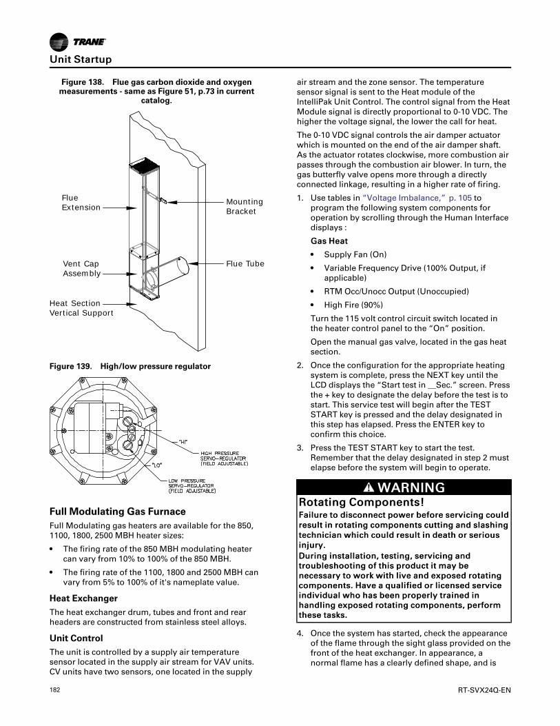
182 RT-SVX24Q-EN
Figure 138. Flue gas carbon dioxide and oxygenmeasurements - same as Figure 51, p.73 in current
catalog.
FlueExtension
MountingBracket
Flue TubeVent CapAssembly
Heat SectionVertical Support
Figure 139. High/low pressure regulator
Full Modulating Gas FurnaceFull Modulating gas heaters are available for the 850,1100, 1800, 2500 MBH heater sizes:
• The firing rate of the 850 MBH modulating heatercan vary from 10% to 100% of the 850 MBH.
• The firing rate of the 1100, 1800 and 2500 MBH canvary from 5% to 100% of it's nameplate value.
Heat ExchangerThe heat exchanger drum, tubes and front and rearheaders are constructed from stainless steel alloys.
Unit ControlThe unit is controlled by a supply air temperaturesensor located in the supply air stream for VAV units.CV units have two sensors, one located in the supply
air stream and the zone sensor. The temperaturesensor signal is sent to the Heat module of theIntelliPak Unit Control. The control signal from the HeatModule signal is directly proportional to 0-10 VDC. Thehigher the voltage signal, the lower the call for heat.
The 0-10 VDC signal controls the air damper actuatorwhich is mounted on the end of the air damper shaft.As the actuator rotates clockwise, more combustion airpasses through the combustion air blower. In turn, thegas butterfly valve opens more through a directlyconnected linkage, resulting in a higher rate of firing.
1. Use tables in “Voltage Imbalance,” p. 105 toprogram the following system components foroperation by scrolling through the Human Interfacedisplays :
GGaass HHeeaatt
• Supply Fan (On)
• Variable Frequency Drive (100% Output, ifapplicable)
• RTM Occ/Unocc Output (Unoccupied)
• High Fire (90%)
Turn the 115 volt control circuit switch located inthe heater control panel to the “On” position.
Open the manual gas valve, located in the gas heatsection.
2. Once the configuration for the appropriate heatingsystem is complete, press the NEXT key until theLCD displays the “Start test in __Sec.” screen. Pressthe + key to designate the delay before the test is tostart. This service test will begin after the TESTSTART key is pressed and the delay designated inthis step has elapsed. Press the ENTER key toconfirm this choice.
3. Press the TEST START key to start the test.Remember that the delay designated in step 2 mustelapse before the system will begin to operate.
WWAARRNNIINNGGRRoottaattiinngg CCoommppoonneennttss!!FFaaiilluurree ttoo ddiissccoonnnneecctt ppoowweerr bbeeffoorree sseerrvviicciinngg ccoouullddrreessuulltt iinn rroottaattiinngg ccoommppoonneennttss ccuuttttiinngg aanndd ssllaasshhiinnggtteecchhnniicciiaann wwhhiicchh ccoouulldd rreessuulltt iinn ddeeaatthh oorr sseerriioouussiinnjjuurryy..DDuurriinngg iinnssttaallllaattiioonn,, tteessttiinngg,, sseerrvviicciinngg aannddttrroouubblleesshhoooottiinngg ooff tthhiiss pprroodduucctt iitt mmaayy bbeenneecceessssaarryy ttoo wwoorrkk wwiitthh lliivvee aanndd eexxppoosseedd rroottaattiinnggccoommppoonneennttss.. HHaavvee aa qquuaalliiffiieedd oorr lliicceennsseedd sseerrvviicceeiinnddiivviidduuaall wwhhoo hhaass bbeeeenn pprrooppeerrllyy ttrraaiinneedd iinnhhaannddlliinngg eexxppoosseedd rroottaattiinngg ccoommppoonneennttss,, ppeerrffoorrmmtthheessee ttaasskkss..
4. Once the system has started, check the appearanceof the flame through the sight glass provided on thefront of the heat exchanger. In appearance, anormal flame has a clearly defined shape, and is
UUnniitt SSttaarrttuupp

RT-SVX24Q-EN 183
primarily (75%) blue in color with an orange tip.
5. Check the inlet gas pressure at the modulating gasvalve. The inlet pressure should be 6" to 8" w.c.
6. Use a carbon dioxide analyzer and measure thepercentage of carbon dioxide in the flue gas. Referto and Figure 137, p. 181 for the proper carbondioxide levels. Take several samples to assure thatan accurate reading is obtained. The C02 levelshould fall in the ranges shown in the guide valuesin Table 63, p. 181.
NNoottee:: The burner capacity is controlled by themovement of the air damper. This has beenpreset at the factory and normally does notneed field adjustment. The combustionquality (air/gas) is controlled by the setup ofthe air damper and butterfly valve linkagerelationship.
7. Use the tables in “Voltage Imbalance,” p. 105 toprogram the minimum (5%) firing rate. Allow thesystem to operate for approximately 10 minutes.
8. Use a carbon dioxide analyzer and measure thepercentage of carbon dioxide in the flue gas. If themeasured carbon dioxide level is in the rangesshown in the Guide Values Table 63, p. 181, noadjustment is necessary.
NNoottee:: It is normal for the low fire CO2 to be lower thanthe high fire.
9. If the measured carbon dioxide level is below therecommended values for low heat, return theburner to 90% fire rate and repeat step 6, to achieveoptimum combustion.
10. Program the burner for 100% operation and recheckthe CO2 or O2 value.
11. Check the flue gas values at several intermediateoutput levels. If corrections are necessary, adjustthe butterfly linkage.
12. Press the STOP key at the Human Interface Modulein the unit control panel to stop the systemoperation.
Figure 140. Modulating gas regulator
Combustion AirPressure SwitchButterfly Valve
Linkage Arm
ModulationMotor
Low Fire Switch (Set to close near low fire)High Fire Switch (Set to close near high fire)
Note: Appx 90 Degree Angle
UUnniitt SSttaarrttuupp

184 RT-SVX24Q-EN
Figure 141. Modulating gas regulator
1
2
3
4
5
6
7
1 Adjustment and indication of the gas to air (Pgas to Pair) ratio.
2 Adjustment and indication of the low fire Bias.
3 Connection for the ambient compensation line.
4 Connection for the gas pressure sensing line.
5 Connection for the air pressure sensing line.
6 Tap location for manifold pressure.
7 Tap location for inlet pressure.
NNoottee:: There are no serviceable parts on the SKP70actuator. Should it become inoperative, replacethe actuator.
Figure 142. 850-1100 MBH
Combustion AirDamper Adjustment
Combustion Fan Proving Switch
Top
Final Unit CheckoutAfter completing all of the checkout and start-upprocedures outlined in the previous sections (i.e.,operating the unit in each of its Modes through allavailable stages of cooling and heating), perform thesefinal checks before leaving the unit:
WWAARRNNIINNGGHHaazzaarrddoouuss VVoollttaaggee!!FFaaiilluurree ttoo ddiissccoonnnneecctt ppoowweerr bbeeffoorree sseerrvviicciinngg ccoouullddrreessuulltt iinn ddeeaatthh oorr sseerriioouuss iinnjjuurryy..DDiissccoonnnneecctt aallll eelleeccttrriicc ppoowweerr,, iinncclluuddiinngg rreemmootteeddiissccoonnnneeccttss bbeeffoorree sseerrvviicciinngg.. FFoollllooww pprrooppeerrlloocckkoouutt//ttaaggoouutt pprroocceedduurreess ttoo eennssuurree tthhee ppoowweerrccaann nnoott bbee iinnaaddvveerrtteennttllyy eenneerrggiizzeedd.. VVeerriiffyy tthhaatt nnooppoowweerr iiss pprreesseenntt wwiitthh aa vvoollttmmeetteerr..
IImmppoorrttaanntt:: HIGH VOLTAGE IS PRESENT AT TERMINALBLOCK OR UNIT DISCONNECT SWITCH.
☐ Close the disconnect switch or circuit protectorswitch that provides the supply power to the unitterminal block or the unit mounted disconnectswitch.
☐ Turn the 115 volt control circuit switch Off.
☐ Turn the 24 volt control circuit switch to the Onposition.
☐ At the Human Interface Module, press the SETUPkey. The LCD screen will display various preset
UUnniitt SSttaarrttuupp

RT-SVX24Q-EN 185
“parameters of operation” based on the unit type,size, and the installed options. Compare the factorypreset information to the specified applicationrequirements. If adjustments are required, followthe step-by-step instructions provided in theappropriate programming manual for CV or VAVapplications.
☐ Program the Night Setback (NSB) panel (ifapplicable) for proper unoccupied operation. Referto the programming instructions for the specificpanel.
☐ Verify that the Remote panel “System” selectionswitch, “Fan” selection switch, and “ZoneTemperature” settings for constant volumesystems are correct.
☐ Verify that the Remote panel “System” selectionswitch and the “Supply Air Temperature” settingsfor variable air volume systems are correct.
☐ Inspect the unit for misplaced tools, hardware, anddebris.
☐ Turn the 115 volt control circuit switch On.
☐ Press the AUTO key at the Human Interface Moduleto begin system operation. The system will startautomatically once the dampers modulate and arequest for either heating or cooling has beengiven.
☐ Verify that all exterior panels including the controlpanel doors and condenser grilles are secured inplace.
Multi-piece Unit – Trane Start-UpWhen the following are complete, Trane will provideunit start-up:
☐ IntelliPak 2 multi-piece unit has been installed.☐ All shipped with items have been installed.☐ All utilities and drain pipes have been connected.☐ All refrigeration piping has been reconnected and
refrigerant charge has been adequately distributedthroughout the system.
☐ All ductwork has been attached to the unit.
Trane start-up of multi-piece units will review theoverall unit for exterior damage (dents, bends, missingpanels, doors work properly), verify that the unitinterior is free from debris/obstructions, ensure that thepanels and doors are secured properly and verify thatall wiring connections are tight. The overall installationwill be reviewed to ensure the unit clearances areadequate to avoid air recirculation and all unit drainlines and traps are properly installed.
The unit main power will be reviewed to ensure theunit is properly grounded, the main power feed wiregauge is adequately sized, the correct voltage issupplied to unit and electric heaters, and the incomingvoltage is phase balanced. Verification will beperformed to ensure that all field installed controlwiring is applied to the correct terminals, all
automation and remote controls installed/wired andcontrol wiring for CV, SZVAV and VAV controls iscompleted.
The refrigeration system will be reviewed to ensure thecoil fins are straightened, the removal of shippinghardware and plastic covers for compressors, properoil level in the compressors, crankcase heaters havebeen operational for at least 12 hours time prior toTrane start-up being performed. The propercompressor voltage and amperage, correct position ofservice valves prior to start-up and proper systemsubcooling and superheat will be verified. The unit fanswill be checked to ensure that the condenser fan bladeset-screws to the motor shaft are tight, that the holddown bolts and channels from fan sections have beenremoved, proper adjustment of fan section springisolators, proper fan belts tension, adequate fanbearings grease, alignment of fan sheaves, adequatetightness of supply and exhaust fan pulley bolts,proper fan rotation, and proper fan motor amperage.
A check will be made to ensure both piping to thecondenser and air handler side of the system havebeen completed and interconnecting refrigerant tubinghas been evacuated by the contractor prior to Traneperforming the start-up. All damper linkages will bechecked for proper adjustment, and proper damperoperation and outside air pressure sensors verified.
Units equipped with electric heaters will be checked toensure that the heating system matches the unitnameplate and for correct voltage supply to theheaters. Units equipped with gas heaters will bechecked to ensure that the flue assembly is secure andproperly installed, sufficient gas pressure existsaccording to pipe size, no leaks exist in gas supply line,the gas heat piping includes a drip leg, condensate lineand the combustion air CO2 and O2 levels are normal.Units equipped with hot water heat will be checked toensure that the hot water pipes are properly routed,sized and leak free; for the presence of swing joints orflexible connectors next to the hot water coil; propergate valve installation in the supply and return branchline; proper three way modulating valve installation,and proper coil venting will be verified.
Units equipped with steam heat will be checked toensure that the hot water pipes are properly routed,sized and leak free; proper swing check vacuumbreaker installation; proper 2-way modulating valveinstallation; proper steam trap installation. Unitsequipped with energy recovery wheels will be checkedto ensure proper rotation and operation of the wheel.The service test guide will be used to check propercomponent operation. Finally, the program set pointsfor proper unit operation will be validated throughhuman interface module. Once the IntelliPak 2 multi-piece unit has been started, a communication will beprovided of start-up activities and the associatedoperating log.
UUnniitt SSttaarrttuupp

186 RT-SVX24Q-EN
Trane Startup ChecklistThis checklist is intended to be a guide for the Tranetechnician just prior to unit 'startup'. Many of therecommended checks and actions could expose thetechnician to electrical and mechanical hazards. Referto the appropriate sections in the this manual forappropriate procedures, component specifications andsafety instructions.
IImmppoorrttaanntt:: This checklist is not intended as asubstitution for the contractor’s installationinstruction.
IImmppoorrttaanntt:: Except where noted, it is implied that theTrane technician is to use this checklist forinspection/verification of prior taskscompleted by the general contractor atinstallation. Use the line item content toalso record the associated values onto theTrane unitary packaged equipment log.
JJoobb NNaammee SSeerriiaall ##
JJoobb LLooccaattiioonn MMooddeell ##
SSaalleess OOrrddeerr ## SShhiipp DDaattee
UUnniitt DDLL ## ((ssppeecciiaall uunniittss)) DDaattee
SSttaarrttiinngg SSaalleess OOffffiiccee TTeecchhnniicciiaann
Table 64. Startup checklist for S*HJ, 90–162 units
Complete
1 Crankcase heaters working for 8 hours prior to arrival of Trane technician performing startup Yes No
2 Correct voltage supplied to unit and electric heaters
3 Unit exterior inspected
4 Disconnect all power, Unit interior free from debris/obstructions etc.
5 Open all access doors to verify all open and close fully without any binding
6 All wiring connections tight
7 Unit properly grounded
8 Copper power wiring meets sizing requirement
9 All field control wiring for CV, SZVAV or VAV controls completed
10 All automation and remote controls installed/wired
11 Unit clearances adequate for service and to avoid air recirculation etc.
12 All unit drain lines and traps proper
13 All coil fins inspected and straightened
14 Shipping hardware for compressors removed
15 Hold down bolts and channels from fan sections removed
16 Fan section spring isolators checked/adjusted
17 Damper linkages tight/adjusted
18 Rail connector splice brackets installed on low side base railWhere applicable: Evaporative condenser
19Verify incoming water pressure is between 35-60psig, dynamic pressure (measured with valve open) for min flowrate of 30 GPM
20Verify fan shipping brackets between fans and mist eliminators above spray distribution system have beenremoved
21Verify water treatment system has been installed and approved - discontinue start-up if proof of active watertreatment does not exist
22 Verify conductivity controller calibration has been documented
23 Verify conductivity controller min and max setpoints have been setup
24 Verify all water and drain connections are complete
25 Verify the sump fills to within 1" of the overflow
26 Verify drain valve is set to "drain during power loss" or "hold during power loss" per job specificationWhere applicable: Electric Heat
27 Electric heat circuits have continuityWhere applicable: Gas Heat
28 Gas heat piping includes drip leg previously installed by controlling contractor
29 Gas heat flue assembly fully installed
30 Gas heat condensate line + heat tape installed where applicable

RT-SVX24Q-EN 187
Table 64. Startup checklist for S*HJ, 90–162 units (continued)
CompleteWhere applicable: HW/Steam Heat
31 Modulating valve and actuator (HW and Steam) installed/wired
32 Steam heat swing check vacuum breakers installed per IOM direction
33 Steam heat condensate trap provided
34 O/A pressure sensor installed and piped
35 High side to low side piping to be completed prior to Trane technician arriving for startup
36 Space sensor and pneumatic tubing installed properly
37 Compressor discharge service valves and oil valves open/back seated (excludes Schrader valves)
38 Compressor oil levels (½ -¾ high in glass) proper
39 Verify power wires are connected in the high voltage power box
40 Verify field installed control wiring landed on correct terminals
41 All fan belts tensioned and bearings greased
42 Heat wheel rotates freely by hand
43 Reenergize power. Phase sequence (A-B-C) proper for compressor rotation
44 Incoming voltage balanced
45 All panels/doors secured prior to startupStart unit
46 Service test guide used to operate unit components
47 Fan amperages within nameplate specs
48 Verify system airflow
49 Dampers open and close properly
50 Adjust outside air damper travel
51On evaporative condenser models: Verify the sump fills to within 1.5” below the overflow, which is within the sloton the max float bracket (see Figure 135, p. 184)
52 Compressor operation normal and within amperage rating
53 Superheat (14-18°F) and subcooling (10-18°F) normal for air-cooled units
54 Electric, hot water and steam heating operation checked
55 Gas heating startup sequence of operation per IOM has been followed
56 Gas heat operation has been verified with combustion analyzer
57 Incoming gas pressure does not drop below 7" water column when burner is on high fire
58 Operating log completed
Critical Control Parameters and Dry Bulb Changeover MapTable 65. Critical control parameters
Description SuggestedParameter
Economizer SettingsRegion1
Region2
Region3
Region4
Region5
Region6
Region7
Supply Air Temperature Control Setpoint 55°FSupply Air Temperature Deadband 8°FSupply Air Pressure Setpoint 1.8" w.c.Supply Air Pressure Deadband 0.1" w.c.Building Static Pressure Setpoint 0.03" w.c.Building Static Pressure Deadband 0.04" w.c.Standby Freeze Avoidance 20%Exhaust Enable Setpoint 10%Economizer Minimum Position Setpoint 10%Fixed Dry Bulb Economizer C/O Type a(Moist)*
TOA >65°F
TOA >65°F
TOA >65°F
TOA >65°F
TOA >70°F
TOA >70°F
TOA >70°F
Fixed Dry Bulb Economizer C/O Type b (Dry)* TOA > 75°FFixed Dry Bulb Economizer C/O Type c(Marine)*
TOA >75°F
TOA >75°F
TOA >75°F
Fixed Reference (Enthalpy Changeover) HOA > 28 Btu
TTrraannee SSttaarrttuupp CChheecckklliisstt

188 RT-SVX24Q-EN
Table 65. Critical control parameters (continued)
Description SuggestedParameter
Economizer SettingsRegion1
Region2
Region3
Region4
Region5
Region6
Region7
Differential Comparative (EnthalpyChangeover) HOA > HRANotes:
1. See map in next figure for dry bulb changeover.Examples:- Minneapolis, Minnesota is in “Region 6" and resides in “Moist” subregion, thus designation is 6b. Economizer changeover setting should be75°F.- Charleston, South Carolina is in “Region 3" and resides in “Moist” subregion, thus the designation is 3c. Economizer changeover settingshould be 65°F.
2. Using the Human Interface (HI), go to SETUP menu and input setting for parameters listed in the table above.3. Use the Dry bulb changeover map to determine region of country based on unit site location.4. Fixed speed compressor units 8°F deadband.5. eFlex™ compressor units 4°F deadband.
Figure 143. Dry bulb changeover map
TTrraannee SSttaarrttuupp CChheecckklliisstt

RT-SVX24Q-EN 189
Service and MaintenanceWWAARRNNIINNGG
HHaazzaarrddoouuss VVoollttaaggee aanndd EExxppoossuurree ttooUUllttrraavviioolleett RRaaddiiaattiioonn!!TThhiiss pprroodduucctt ccoonnttaaiinnss ccoommppoonneennttss tthhaatt eemmiitt hhiigghh--iinntteennssiittyy uullttrraavviioolleett ((UUVV--CC)) rraaddiiaattiioonn wwhhiicchh ccaann bbeehhaarrmmffuull ttoo uunnpprrootteecctteedd eeyyeess aanndd sskkiinn,, aanndd ccaauusseesseerriioouuss ddaammaaggee ttoo tthhee eeqquuiippmmeenntt..FFaaiilluurree ttoo ddiissccoonnnneecctt ppoowweerr bbeeffoorree sseerrvviicciinngg ccoouullddrreessuulltt iinn bbuurrnnss oorr eelleeccttrrooccuuttiioonn wwhhiicchh ccoouulldd rreessuullttiinn ddeeaatthh oorr sseerriioouuss iinnjjuurryy..DDiissccoonnnneecctt aallll eelleeccttrriiccaall ppoowweerr,, iinncclluuddiinngg rreemmootteeddiissccoonnnneeccttss,, aanndd mmaakkee ssuurree tthhee UUVV lliigghhttss aarree ooffffbbeeffoorree sseerrvviicciinngg.. FFoollllooww pprrooppeerr lloocckkoouutt//ttaaggoouuttpprroocceedduurreess ttoo eennssuurree tthhee ppoowweerr ccaannnnoott bbeeiinnaaddvveerrtteennttllyy eenneerrggiizzeedd..TTrraannee ddooeess nnoott rreeccoommmmeenndd ffiieelldd iinnssttaallllaattiioonn ooffuullttrraavviioolleett lliigghhttss iinn iittss eeqquuiippmmeenntt ffoorr tthhee iinntteennddeeddppuurrppoossee ooff iimmpprroovviinngg iinnddoooorr aaiirr qquuaalliittyy.. TTrraanneeaacccceeppttss nnoo rreessppoonnssiibbiilliittyy ffoorr tthhee ppeerrffoorrmmaannccee oorrooppeerraattiioonn ooff oouurr eeqquuiippmmeenntt iinn wwhhiicchh uullttrraavviioolleettddeevviicceess wweerree iinnssttaalllleedd oouuttssiiddee ooff tthhee TTrraannee ffaaccttoorryyoorr iittss aapppprroovveedd ssuupppplliieerrss..
Table 66. Control settings and time delays
ControlDescription
Elec.Designa-tion
ContactsOpen
ContactsClosed
CombustionAirflow Switch(Gas HeatOnly)
4S25 see note 10.1 - 0.25" wcrise in press diff
SupplyAirflow Switch(Gas HeatOnly)
4S38 0.03 - 0.12"wc
0.15 + 0.05" wcrise in press diff
Freezestat(HydronicHeat Only)
4S12 (N.O.) AutoReset 40°F
Pre-purgeTimer:
Honeywell(Gas Heat)
4U18internaltimingfunction
2 Stage 850/1100 MBH 60—seconds/Allother
configurations—30 seconds
SequencingTime DelayRelay (GasHeat)
4DL6 N.C. - timedto close
60 seconds +20%
Note: The combustion airflow switch (4S25) differential is 0.02"- 0.08" wc.
Table 67. Gas heat—high limit
Tons Fan Size (in) Config.Contacts
Open Close
2500MBh High Limit
120-162
40 DF 195 155
40 HZ 240 200
32 DF & HORZ 220 180
1800MBh High Limit
120-16232 &40 DF 240 200
32 &40 HZ 220 180
90-118
32 DF & HZ 240 200
36 DF & HZ 240 200
36 HZ 240 310
25 DF 240 200
25 HZ 220 180
1100MBh High Limit
120-162
32 DF 240 200
32 HZ 200 160
40 DF & HZ 240 200

190 RT-SVX24Q-EN
Table 67. Gas heat—high limit (continued)
Tons Fan Size (in) Config.Contacts
Open Close
90-118
32 DF 240 200
32 HZ 200 160
25 &36 DF & HZ 220 180
850 MBh High Limit
90-118 25 &36 DF & HZ 240 200
Table 68. Electric heat—selection limits
TonsIndoor FanOption
Electric HeatOption
SupplyDischarge
Linear Limit -Open Temp.
Fan Fail Limit- Open Temp.
Manual Limit -Open Temp.
120-162
High (40")
High (300 kW)Downflow 185°F 185°F 225°F
Hz (right) 185°F 185°F 225°F
Low (140 kW)Downflow 150°F 185°F 225°F
Hz (right) 150°F 185°F 225°F
Low (32")
High (300 kW)Downflow 205°F 185°F 225°F
Hz (right) 185°F 185°F 225°F
Low (140 kW)Downflow 150°F 185°F 225°F
Hz (right) 150°F 185°F 225°F
105/118
High (36")
High (262.5 kW)Downflow 195°F 155°F 225°F
Hz (right) 195°F 155°F 225°F
Low (90 kW)Downflow 150°F 175°F 225°F
Hz (right) 150°F 175°F 225°F
Low (32")
High (262.5 kW)Downflow 225°F 185°F 225°F
Hz (right) 205°F 185°F 225°F
Low (90 kW)Downflow 150°F 175°F 225°F
Hz (right) 150°F 175°F 225°F
90/105
High (36")
High (262.5 kW)Downflow 195°F 155°F 225°F
Hz (right) 195°F 155°F 225°F
Low (90 kW)Downflow 150°F 175°F 225°F
Hz (right) 150°F 175°F 225°F
Low (25")
High (262.5 kW)Downflow 215°F 155°F 215°F
Hz (right) 235°F 155°F 215°F
Low (90 kW)Downflow 150°F 175°F 225°F
Hz (right) 150°F 175°F 225°F
SSeerrvviiccee aanndd MMaaiinntteennaannccee

RT-SVX24Q-EN 191
Table 69. Compressor circuit breaker electrical characteristics
Unit SizeCompressorDesignator
CompressorSize
460V 575V 380V
MustHold
MustTrip
MustHold
MustTrip
MustHold
MustTrip
90/1051A, 2A CSHN250 41.5 47.7 33.2 38.2 41.4 47.6
1B, 2B CSHN250 41.5 47.7 33.2 38.2 41.4 47.6
105/1181A, 2A CSHN250 41.5 47.7 33.2 38.2 41.4 47.6
1B, 2B CSHN315 54.4 62.6 43.6 50.1 54.3 62.4
120/1281A, 2A CSHN315 57.7 66.4 46.3 53.2 57.3 66
1B, 2B CSHN315 54.4 62.6 43.6 50.1 54.3 62.4
130/1401A, 2A CSHN315 57.7 66.4 46.3 53.2 57.3 66
1B, 2B CSHN374 63.4 72.9 50.0 57.5 63.3 72.8
150/1621A, 2A CSHN374 66.7 76.7 52.7 60.6 66.4 76.3
1B, 2B CSHN374 63.4 72.9 50.0 57.5 63.3 72.8
SSeerrvviiccee aanndd MMaaiinntteennaannccee

192 RT-SVX24Q-EN
Figure 144. Unit internal fuse replacement data & VFD factory settings
SSeerrvviiccee aanndd MMaaiinntteennaannccee

RT-SVX24Q-EN 193
Table70.Filterdata
Filters
Unit
Model
(AC/
EC)
Standard2"High
EffThrowaways
90-95%BagFilters
withPrefilters
90-95%CartridgeFilters
withPrefilters
90-95%LowPressureDrop
CartridgeFilters
Qty
Sizeof
Each
Face
Area
(ft2)
Pre-filters
BagFilters
Prefilters
CartridgeFilters
Prefilters
LowPDFilters
Qty
Size
Qty
Size
Face
Area
(ft2)Qty
Size
Qty
Size
Face
Area
(ft2)Qty
Size
Qty
Size
Face
Area
(ft2)
90/100
2120x24x2
8021
20x24x2
2120x24x19
8021
20x24x2
2120x24x12
8021
20x24x2
2120x24x12
805
15x24x2
512x24x2
512x24x19
512x24x2
512x24x12
512x24x2
512x24x12
105/118
2120x24x2
8021
20x24x2
2120x24x19
8021
20x24x2
2120x24x12
8021
20x24x2
2120x24x12
805
15x24x2
512x24x2
512x24x19
512x24x2
512x24x12
512x24x2
512x24x12
120/128
2820x24x2
9321
20x24x2
2120x24x19
8021
20x24x2
2120x24x12
8021
20x24x2
2120x24x12
805
12x24x2
512x24x19
512x24x2
512x24x12
512x24x2
512x24x12
130/140
2820x24x2
9321
20x24x2
2120x24x19
8021
20x24x2
2120x24x12
8021
20x24x2
2120x24x12
805
12x24x2
512x24x19
512x24x2
512x24x12
512x24x2
512x24x12
150/162
2820x24x2
9321
20x24x2
2120x24x19
8021
20x24x2
2120x24x12
8021
20x24x2
2120x24x12
805
12x24x2
512x24x19
512x24x2
512x24x12
512x24x2
512x24x12
SSeerrvviiccee aanndd MMaaiinntteennaannccee

194 RT-SVX24Q-EN
Table 71. Final filter dataFinal Filters
UnitModel(AC/EC)
90-95%90-95% Low Pressure DropCartridge Filters 90-95%Bag Filters with Prefilters 90-95%Cartridge Filters with Prefilters
Pre-filters Low PD Cartridge Filters Prefilters Bag Filters Prefilters Cartridge Filters
Qty Size Qty SizeFaceArea(ft2)
Qty Size Qty SizeFaceArea(ft2)
Qty Size Qty SizeFaceArea(ft2)
90/100 15 24x24x4 15 24x24x12 74 15 24x24x2 15 24x24x19 74 15 24x24x2 15 24x24x12 747 12x24x4 7 12x24x12 7 12x24x2 7 12x24x19 7 12x24x2 7 12x24x12
105/118 15 24x24x4 15 24x24x12 74 15 24x24x2 15 24x24x19 74 15 24x24x2 15 24x24x12 747 12x24x4 7 12x24x12 7 12x24x2 7 12x24x19 7 12x24x2 7 12x24x12
120/128 15 24x24x4 15 24x24x12 74 15 24x24x2 15 24x24x19 74 15 24x24x2 15 24x24x12 747 12x24x4 7 12x24x12 7 12x24x2 7 12x24x19 7 12x24x2 7 12x24x12
130/140 15 24x24x4 15 24x24x12 74 15 24x24x2 15 24x24x19 74 15 24x24x2 15 24x24x12 747 12x24x4 7 12x24x12 7 12x24x2 7 12x24x19 7 12x24x2 7 12x24x12
150/162 15 24x24x4 15 24x24x12 74 15 24x24x2 15 24x24x19 74 15 24x24x2 15 24x24x12 747 12x24x4 7 12x24x12 7 12x24x2 7 12x24x19 7 12x24x2 7 12x24x12
UnitModel(AC/EC)
90-95%90-95%High Temp CartridgeFilters
with PrefiltersHEPA Filters with Prefilters High Temp HEPA Filters with Prefilters
Pre-filters High Temp CartridgeFilters Prefilters HEPA Filters Prefilters High HEPA Temp Filters
Qty Size Qty SizeFaceArea(ft2)
Qty Size Qty SizeFaceArea(ft2)
Qty Size Qty SizeFaceArea(ft2)
90/100 15 24x24x2 15 24x24x12 74 15 24x24x2 15 24x24x12 74 15 24x24x2 15 24x24x12 747 12x24x2 7 12x24x12 7 12x24x2 7 12x24x12 7 12x24x2 7 12x24x12
105/118 15 24x24x2 15 24x24x12 74 15 24x24x2 15 24x24x12 74 15 24x24x2 15 24x24x12 747 12x24x2 7 12x24x12 7 12x24x2 7 12x24x12 7 12x24x2 7 12x24x12
120/128 15 24x24x2 15 24x24x12 74 15 24x24x2 15 24x24x12 74 15 24x24x2 15 24x24x12 747 12x24x2 7 12x24x12 7 12x24x2 7 12x24x12 7 12x24x2 7 12x24x12
130/140 15 24x24x2 15 24x24x12 74 15 24x24x2 15 24x24x12 74 15 24x24x2 15 24x24x12 747 12x24x2 7 12x24x12 7 12x24x2 7 12x24x12 7 12x24x2 7 12x24x12
150/162 15 24x24x2 15 24x24x12 74 15 24x24x2 15 24x24x12 74 15 24x24x2 15 24x24x12 747 12x24x2 7 12x24x12 7 12x24x2 7 12x24x12 7 12x24x2 7 12x24x12
Table 72. Grease recommendation
Recommended Grease for FanBearings Recommended Operating Range
Exxon Unirex #2
-20 °F to 250 °FMobil 532
Mobil SHC #220
Texaco Premium RB
Table 73. Air-cooled condenser—refrigerant coil fin data
Tons Coil Type Coil FinConfig. Tube Dia. Coil Rows Fins per foot Coil Face Area
(sq. ft.) Tube Type
90
Evaporator Enhanced 1/2 3 168 73.75 Internally Finned
Hi-Cap Evap Enhanced 1/2 5 168 73.75 Internally Finned
Condenser Enhanced 25 mm 1 240 134 Microchannel
105
Evaporator InternallyFinned 1/2 4 168 73.75 Internally Finned
Hi-Cap Evap InternallyFinned 1/2 6 168 73.75 Internally Finned
Condenser Enhanced 25 mm 1 240 161 Microchannel
SSeerrvviiccee aanndd MMaaiinntteennaannccee

RT-SVX24Q-EN 195
Table 73. Air-cooled condenser—refrigerant coil fin data (continued)
Tons Coil Type Coil FinConfig. Tube Dia. Coil Rows Fins per foot Coil Face Area
(sq. ft.) Tube Type
120
Evaporator InternallyFinned 1/2 3 168 106.25 Internally Finned
Hi-Cap Evap InternallyFinned 1/2 6 168 106.25 Internally Finned
Condenser Enhanced 18 mm 2 276 161 Microchannel
130
Evaporator InternallyFinned 1/2 4 168 106.25 Internally Finned
Hi-Cap Evap InternallyFinned 1/2 6 168 106.25 Internally Finned
Condenser Enhanced 18 mm 2 276 161 Microchannel
150Evaporator Internally
Finned 1/2 6 168 106.25 Internally Finned
Condenser Smooth 18 mm 2 276 161 Microchannel
Fan Belt AdjustmentThe supply fan belts and optional exhaust fan beltsmust be inspected periodically to assure proper unitoperation.
Replacement is necessary if the belts appear frayed orworn. Units with dual belts require a matched set ofbelts to ensure equal belt length. When removing orinstalling new belts, do not stretch them over thesheaves; instead, loosen the adjustable motor-mounting base.
Once the new belts are installed, adjust the belt tensionusing a Browning or Gates tension gauge (orequivalent) illustrated in Figure 145, p. 195.
Figure 145. Typical belt tension gauge
Deflection = Belt Span (in.)64
Deflection = Belt Span (mm)152
Force Scale
Span ScaleLargeO-Ring
SmallO-RingBelt Span
WWAARRNNIINNGGHHaazzaarrddoouuss VVoollttaaggee ww//CCaappaacciittoorrss!!FFaaiilluurree ttoo ddiissccoonnnneecctt ppoowweerr aanndd ddiisscchhaarrggeeccaappaacciittoorrss bbeeffoorree sseerrvviicciinngg ccoouulldd rreessuulltt iinn ddeeaatthh oorrsseerriioouuss iinnjjuurryy..DDiissccoonnnneecctt aallll eelleeccttrriicc ppoowweerr,, iinncclluuddiinngg rreemmootteeddiissccoonnnneeccttss aanndd ddiisscchhaarrggee aallll mmoottoorr ssttaarrtt//rruunnccaappaacciittoorrss bbeeffoorree sseerrvviicciinngg.. FFoollllooww pprrooppeerrlloocckkoouutt//ttaaggoouutt pprroocceedduurreess ttoo eennssuurree tthhee ppoowweerrccaannnnoott bbee iinnaaddvveerrtteennttllyy eenneerrggiizzeedd.. FFoorr vvaarriiaabblleeffrreeqquueennccyy ddrriivveess oorr ootthheerr eenneerrggyy ssttoorriinnggccoommppoonneennttss pprroovviiddeedd bbyy TTrraannee oorr ootthheerrss,, rreeffeerr ttootthhee aapppprroopprriiaattee mmaannuuffaaccttuurreerr’’ss lliitteerraattuurree ffoorraalllloowwaabbllee wwaaiittiinngg ppeerriiooddss ffoorr ddiisscchhaarrggee ooffccaappaacciittoorrss.. VVeerriiffyy wwiitthh aa CCAATT IIIIII oorr IIVV vvoollttmmeetteerrrraatteedd ppeerr NNFFPPAA 7700EE tthhaatt aallll ccaappaacciittoorrss hhaavveeddiisscchhaarrggeedd..FFoorr aaddddiittiioonnaall iinnffoorrmmaattiioonn rreeggaarrddiinngg tthhee ssaaffeeddiisscchhaarrggee ooff ccaappaacciittoorrss,, sseeee PPRROODD--SSVVBB0066**--EENN..
1. To determine the appropriate belt deflection:
a. Measure the center-to-center distance, ininches, between the fan sheave and the motorsheave.
b. Divide the distance measured in Step 1a by 64;the resulting value represents the amount ofbelt deflection for the proper belt tension.
2. Set the large O-ring on the belt tension gauge at thedeflection value determined in Step 1b.
3. Set the small O-ring at zero on the force scale of thegauge.
4. Place the large end of the gauge on the belt at thecenter of the belt span. Depress the gauge plungeruntil the large O-ring is even with the of the secondbelt or even with a straightedge placed across thesheaves.
SSeerrvviiccee aanndd MMaaiinntteennaannccee

196 RT-SVX24Q-EN
5. Remove the tension gauge from the belt. Noticethat the small O-ring now indicates a value otherthan zero on the force scale. This value representsthe force (in pounds) required to deflect the belt(s)the proper distance when properly adjusted.
6. Compare the force scale reading in step 5 with theappropriate “force” value in . If the force reading isoutside of the listed range for the type of belts used,either readjust the belt tension or contact aqualified service representative.
NNoottee:: The actual belt deflection force must notexceed the maximum value shown in Table74, p. 196.
7. Recheck the new belt's tension at least twice duringthe first 2 to 3 days of operation. Readjust the belttension as necessary to correct for any stretchingthat may have occurred. Until the new belts are“run in”, the belt tension will decrease rapidly asthey stretch.
Table 74. Belt tension measurement and deflection ranges
BeltCrossSection
SmallestSheaveDiameterRange(In.)
RPMRange
Belt Deflection Force (Lbs.)
Super Gripbelts andUnnotchedGripbands
Gripnotch Belts andNotched Gripbands
Min. Max. Min. Max.
A, AX
3.0-3.6 1000-2500 3.7 5.5 4.1 6.1
3.8-4.8 1000-2500 4.5 6.8 5 7.4
5.0-7.0 1000-2500 5.4 8 5.7 8.4
B, BX
3.4 – 4.2 860-2500 – – 4.9 7.2
4.4 – 5.6 860-2500 5.3 7.9 7.1 10.5
5.8 – 8.6 860-2500 6.3 9.4 8.5 12.6
3V, 3VX
2.2 - 2.4 1000-2500 – – 3.3 4.9
2.65 - 3.65 1000-2500 3.6 5.1 4.2 6.2
4.12 - 6.90 1000-2500 4.9 7.3 5.3 7.9
5V, 5VX
4.4 – 6.7500-1749
– –10.2 15.2
1750-3000 8.8 13.2
7.1 –10.9 500-1740 12.7 18.9 14.8 22.1
11.8-16.0 500-1740 15.5 23.4 17.1 25.5
Scroll Compressor ReplacementThe compressor manifold system was purposelydesigned to provide proper oil return to eachcompressor. The refrigerant manifold system must notbe modified in any way. See Figure 146, p. 196.
NNoottee:: Altering the compressor manifold piping maycause oil return problems and compressorfailure.
Should a compressor replacement become necessaryand a suction line filter drier is to be installed, install it aminimum of 16 or 25 inches upstream of the oilseparator tee.
IImmppoorrttaanntt:: Do Not release refrigerant to theatmosphere! If adding or removingrefrigerant is required, the servicetechnician must comply with all Federal,State and local laws. Refer to generalservice bulletin MSCU-SB-1 (latest edition).
Figure 146. Suction line filter/drier installation
Sight glass
Suction servicevalve
Replaceable coredrier
Note: These components are also located at circuit #1 side
SSeerrvviiccee aanndd MMaaiinntteennaannccee

RT-SVX24Q-EN 197
Refrigeration System
WWAARRNNIINNGGRR--441100AA RReeffrriiggeerraanntt uunnddeerr HHiigghheerrPPrreessssuurree tthhaann RR--2222!!FFaaiilluurree ttoo uussee pprrooppeerr eeqquuiippmmeenntt oorr ccoommppoonneennttss aassddeessccrriibbeedd bbeellooww,, ccoouulldd rreessuulltt iinn eeqquuiippmmeenntt ffaaiilliinnggaanndd ppoossssiibbllyy eexxppllooddiinngg,, wwhhiicchh ccoouulldd rreessuulltt iinnddeeaatthh,, sseerriioouuss iinnjjuurryy,, oorr eeqquuiippmmeenntt ddaammaaggee..TThhee uunniittss ddeessccrriibbeedd iinn tthhiiss mmaannuuaall uussee RR--441100AArreeffrriiggeerraanntt wwhhiicchh ooppeerraatteess aatt hhiigghheerr pprreessssuurreesstthhaann RR--2222.. UUssee OONNLLYY RR--441100AA rraatteedd sseerrvviicceeeeqquuiippmmeenntt oorr ccoommppoonneennttss wwiitthh tthheessee uunniittss.. FFoorrssppeecciiffiicc hhaannddlliinngg ccoonncceerrnnss wwiitthh RR--441100AA,, pplleeaasseeccoonnttaacctt yyoouurr llooccaall TTrraannee rreepprreesseennttaattiivvee..
WWAARRNNIINNGGRReeffrriiggeerraanntt uunnddeerr HHiigghh PPrreessssuurree!!FFaaiilluurree ttoo ffoollllooww iinnssttrruuccttiioonnss bbeellooww ccoouulldd rreessuulltt iinnaann eexxpplloossiioonn wwhhiicchh ccoouulldd rreessuulltt iinn ddeeaatthh oorrsseerriioouuss iinnjjuurryy oorr eeqquuiippmmeenntt ddaammaaggee..SSyysstteemm ccoonnttaaiinnss rreeffrriiggeerraanntt uunnddeerr hhiigghh pprreessssuurree..RReeccoovveerr rreeffrriiggeerraanntt ttoo rreelliieevvee pprreessssuurree bbeeffoorreeooppeenniinngg tthhee ssyysstteemm.. SSeeee uunniitt nnaammeeppllaattee ffoorrrreeffrriiggeerraanntt ttyyppee.. DDoo nnoott uussee nnoonn--aapppprroovveeddrreeffrriiggeerraannttss,, rreeffrriiggeerraanntt ssuubbssttiittuutteess,, oorr rreeffrriiggeerraannttaaddddiittiivveess..
Refrigerant Evacuation and Charging
NNOOTTIICCEECCoommpprreessssoorr DDaammaaggee!!FFaaiilluurree ttoo ffoollllooww iinnssttrruuccttiioonnss bbeellooww rreessuulltt iinnppeerrmmaanneenntt ddaammaaggee ttoo tthhee ccoommpprreessssoorr..TThhee uunniitt iiss ffuullllyy cchhaarrggeedd wwiitthh RR--441100AA rreeffrriiggeerraannttffrroomm tthhee ffaaccttoorryy.. HHoowweevveerr,, iiff iitt bbeeccoommeess nneecceessssaarryyttoo rreemmoovvee oorr rreecchhaarrggee tthhee ssyysstteemm wwiitthh rreeffrriiggeerraanntt,,iitt iiss iimmppoorrttaanntt tthhaatt tthhee ffoolllloowwiinngg aaccttiioonnss aarree ttaakkeenn..
The recommended method for evacuation anddehydration is to evacuate both the high side and thelow side to 500 microns or less. To establish that theunit is leak-free, use a standing vacuum test. Themaximum allowable rise over a 15 minute period is 200microns. If the rise exceeds this, there is either stillmoisture in the system or a leak is present.
IImmppoorrttaanntt:: Do Not release refrigerant to theatmosphere! If adding or removingrefrigerant is required, the servicetechnician must comply with all federal,state, and local laws.
• To prevent cross contamination ofrefrigerants and oils, use only dedicatedR-410A service equipment.
• Disconnect unit power beforeevacuation and do not apply voltage tocompressor while under vacuum.Failure to follow these instructions willresult in compressor failure.
• Due to the presence of POE oil,minimize system open time. Do notexceed 1 hour.
• When recharging R-410A refrigerant, itshould be charged in the liquid state.
• The compressor should be off when theinitial refrigerant recharge is performed.
• Charging to the liquid line is requiredprior to starting the compressor tominimize the potential damage to thecompressor due to refrigerant in thecompressor oil sump at startup.
• If suction line charging is needed tocomplete the charging process, only doso with the compressor operating. Donot charge liquid refrigerant into thesuction line with the compressor off!This increases both the probability thatthe compressor will start withrefrigerant in the compressor oil sumpand the potential for compressordamage.
• Allow the crankcase heater to operate aminimum of 8 hours before starting theunit.
Charge StorageDue to the reduced capacity of the microchannelcondenser coil compared to the round tube plate finevaporator coil, pumping refrigerant into thecondenser coil to service the refrigerant system is nolonger an option.
Compressor OilRefer to Table 75, p. 199 for the appropriate scrollcompressor oil charge. Remove and measure oil fromany compressor replaced. Adjust oil in replacementcompressor to prevent excessive oil in system.Anytime a compressor is replaced, the oil for eachcompressor within the manifold must be replaced.
The scroll compressor uses Trane OIL00079 (one quartcontainer) or OIL00080 (one gallon container) withoutsubstitution. Discoloration of the oil indicates that anabnormal condition has occurred. If the oil is dark and
SSeerrvviiccee aanndd MMaaiinntteennaannccee

198 RT-SVX24Q-EN
smells burnt, it has overheated because of thefollowing:
• Compressor operating at extremely highcondensing temperatures
• High superheat
• A compressor mechanical failure
• Occurrence of a motor burnout.
If a motor burnout is suspected, use an acid test kit(KIT15496) to check the condition of the oil. Test resultswill indicate an acid level has exceeded the limit if aburnout occurred. Oil test kits must be used for POE oil(OIL00079 for a quart container or OIL00080 for a galloncontainer) to determine whether the oil is acidic. If amotor burnout has occurred, change the oil in bothcompressors in a tandem set.
CSHN CompressorsCSHN compressors have an oil drain valve whichallows the oil to be drained out of the compressor.After the refrigerant has been recovered, pressurize thesystem with nitrogen to help remove the oil from thecompressor.
Figure 147. PTFE gasket
Charge the new oil into the Schrader valve or oil drainvalve on the shell of the compressor. Due to themoisture absorption properties of POE oil, do not usePOE oil from a previously opened container. Alsodiscard any excess oil from the container that is notused.
Figure 148. CSHN
Oil equalizer Rotolock connection fitting
¼ Schrader port
Oil drain valve
VZH Variable Speed CompressorsRefer to “Service and Maintenance_CSHNCompressors,” p. 198 for VZH117 oil removalprocedures.
VZH variable speed compressors include the additionof an oil injection solenoid valve (2L11) to providesupplemental oil flow from an internal gear pump tothe scroll thrust bearing surface. The solenoid is de-energized at low compressor speeds to allowsupplemental oil flow and ensure thrust surfacelubrication. The solenoid is energized at highcompressor speeds to stop supplemental lubrication.This prevents excessive oil circulation to the system.The solenoid is controlled by the inverter and switchesat 3300 RPM for the VZH117, and 2700 RPM for theVZH170.
The 24 VAC solenoid coil operation can be checked onone of the solenoid leads with a clamp on amp meter.Above 3300 RPM (VZH117) /2700 RPM (VZH170), theamp meter should read about 0.5 amps to indicatesupplemental flow has been stopped.
SSeerrvviiccee aanndd MMaaiinntteennaannccee

RT-SVX24Q-EN 199
Figure 149. Oil injection solenoid valve
Oil injection solenoid
Table 75. Oil charge per compressor
Compressor Pints
CSHN374 15.2
CSHN176 thru 315 and VZH170 14.2
Table 76. Torque requirements for rotolock fittings
CSHN* and VZH170 100 +/- 10 ft-lbs
NNoottee:: Always replace gasket when reassembling oilequalizer lines.
VFD Programming Parameters (Supply/Return/Exhaust Inverters)
WWAARRNNIINNGGHHaazzaarrddoouuss VVoollttaaggee ww//CCaappaacciittoorrss!!FFaaiilluurree ttoo ddiissccoonnnneecctt ppoowweerr aanndd ddiisscchhaarrggeeccaappaacciittoorrss bbeeffoorree sseerrvviicciinngg ccoouulldd rreessuulltt iinn ddeeaatthh oorrsseerriioouuss iinnjjuurryy..DDiissccoonnnneecctt aallll eelleeccttrriicc ppoowweerr,, iinncclluuddiinngg rreemmootteeddiissccoonnnneeccttss aanndd ddiisscchhaarrggee aallll mmoottoorr ssttaarrtt//rruunnccaappaacciittoorrss bbeeffoorree sseerrvviicciinngg.. FFoollllooww pprrooppeerrlloocckkoouutt//ttaaggoouutt pprroocceedduurreess ttoo eennssuurree tthhee ppoowweerrccaannnnoott bbee iinnaaddvveerrtteennttllyy eenneerrggiizzeedd.. FFoorr vvaarriiaabblleeffrreeqquueennccyy ddrriivveess oorr ootthheerr eenneerrggyy ssttoorriinnggccoommppoonneennttss pprroovviiddeedd bbyy TTrraannee oorr ootthheerrss,, rreeffeerr ttootthhee aapppprroopprriiaattee mmaannuuffaaccttuurreerr’’ss lliitteerraattuurree ffoorraalllloowwaabbllee wwaaiittiinngg ppeerriiooddss ffoorr ddiisscchhaarrggee ooffccaappaacciittoorrss.. VVeerriiffyy wwiitthh aa CCAATT IIIIII oorr IIVV vvoollttmmeetteerrrraatteedd ppeerr NNFFPPAA 7700EE tthhaatt aallll ccaappaacciittoorrss hhaavveeddiisscchhaarrggeedd..FFoorr aaddddiittiioonnaall iinnffoorrmmaattiioonn rreeggaarrddiinngg tthhee ssaaffeeddiisscchhaarrggee ooff ccaappaacciittoorrss,, sseeee PPRROODD--SSVVBB0066**--EENN..
Units shipped with an optional variable frequency drive(VFD) are preset and run tested at the factory. If aproblem with a VFD occurs, ensure that the
programmed parameters listed in Table 77, p. 201 havebeen set before replacing the drive.
VVeerriiffyy PPaarraammeetteerrss
Verify parameter 1-23 is set to 60 Hz.
1. To check parameter 1-23 press the Main Menubutton twice (if TR150 drive) (press the Back buttonif the main menu does not display)
2. Scroll down to Load & Motor, press OK
3. Select 1-2, press OK
4. Press down until parameter 1-23 is displayed.Parameter 1-23 can then be modified by pressingOK and pressing the Up and Down buttons.
5. When the desired selection has been made, pressOK .
Should replacing the VFD become necessary, thereplacement is not configured with all of Trane'soperating parameters. The VFD must be programmedbefore attempting to operate the unit.
To verify and/or program a VFD, use the followingsteps:
1. At the unit, turn the 115 volt control circuit switch tothe Off position.
2. Turn the 24 volt control circuit switch to the Offposition.
WWAARRNNIINNGGHHaazzaarrddoouuss VVoollttaaggee ww//CCaappaacciittoorrss!!FFaaiilluurree ttoo ddiissccoonnnneecctt ppoowweerr aanndd ddiisscchhaarrggeeccaappaacciittoorrss bbeeffoorree sseerrvviicciinngg ccoouulldd rreessuulltt iinn ddeeaatthh oorrsseerriioouuss iinnjjuurryy..DDiissccoonnnneecctt aallll eelleeccttrriicc ppoowweerr,, iinncclluuddiinngg rreemmootteeddiissccoonnnneeccttss aanndd ddiisscchhaarrggee aallll mmoottoorr ssttaarrtt//rruunnccaappaacciittoorrss bbeeffoorree sseerrvviicciinngg.. FFoollllooww pprrooppeerrlloocckkoouutt//ttaaggoouutt pprroocceedduurreess ttoo eennssuurree tthhee ppoowweerrccaannnnoott bbee iinnaaddvveerrtteennttllyy eenneerrggiizzeedd.. FFoorr vvaarriiaabblleeffrreeqquueennccyy ddrriivveess oorr ootthheerr eenneerrggyy ssttoorriinnggccoommppoonneennttss pprroovviiddeedd bbyy TTrraannee oorr ootthheerrss,, rreeffeerr ttootthhee aapppprroopprriiaattee mmaannuuffaaccttuurreerr’’ss lliitteerraattuurree ffoorraalllloowwaabbllee wwaaiittiinngg ppeerriiooddss ffoorr ddiisscchhaarrggee ooffccaappaacciittoorrss.. VVeerriiffyy wwiitthh aa CCAATT IIIIII oorr IIVV vvoollttmmeetteerrrraatteedd ppeerr NNFFPPAA 7700EE tthhaatt aallll ccaappaacciittoorrss hhaavveeddiisscchhaarrggeedd..FFoorr aaddddiittiioonnaall iinnffoorrmmaattiioonn rreeggaarrddiinngg tthhee ssaaffeeddiisscchhaarrggee ooff ccaappaacciittoorrss,, sseeee PPRROODD--SSVVBB0066**--EENN..
IImmppoorrttaanntt:: HIGH VOLTAGE IS PRESENT AT TERMINALBLOCK OR UNIT DISCONNECT SWITCH.
3. To modify parameters:
a. Press Main Menu twice (if TR150 drive) (pressBack if the main menu does not display)
b. Use the Up and Down buttons to find theparameter menu group (first part of parameternumber)
c. Press OK
SSeerrvviiccee aanndd MMaaiinntteennaannccee

200 RT-SVX24Q-EN
d. Use the Up and Down buttons to select thecorrect parameter sub-group (first digit ofsecond part of parameter number)
e. Press OK
f. Use the Up and Down buttons to select thespecific parameter
g. Press OK
h. To move to a different digit within a parametersetting, use the Left and Right buttons(Highlighted area indicates digit selected forchange)
i. Use the Up and Down buttons to adjust the digit
j. Press Cancel to disregard change, or press OKto accept change and enter the new setting
4. Repeat stepStep 3 for each menu selection settingin Table 77, p. 201.
5. To reset all programming parameters back to thefactory defaults:
a. Go to parameter 14-22 Operation Mode
b. Press OK
c. Select Initialization
d. Press OK
e. Cut off the mains supply and wait until thedisplay turns off.
f. Reconnect the mains supply - the frequencyconverter is now reset.
g. Ensure parameter 14-22 Operation Mode hasreverted back to “Normal Operation”.
NNootteess::
• Item 5 resets the drive to the defaultfactory settings. The programparameters listed in Table 77, p. 201will need to be verified or changed asdescribed in Items 3 and 4.
• Some of the parameters listed in thetable are motor specific. Due tovarious motors and efficienciesavailable, use only the values stampedon the specific motor nameplate. Donot use the Unit nameplate values.
• A backup copy of the current setupmay be saved to the LCP beforechanging parameters or resetting thedrive . See LCP Copy in the VFDOperating Instructions for details.
6. Follow the start-up procedures for supply fan in the“Variable Air Volume System” section or the“Exhaust Airflow Measurement” start-upprocedures for the exhaust fan.
7. After verifying that the VFD(s) are operatingproperly, press the STOP key at the HumanInterface Module to stop the unit operation.
8. Follow the applicable steps in the “Final UnitCheckout” section to return the unit to its normaloperating mode.
If a problem with a VFD occurs, ensure that theprogrammed parameters listed for supply and exhaustVFD have been set before replacing the drive.
SSeerrvviiccee aanndd MMaaiinntteennaannccee

RT-SVX24Q-EN 201
Table 77. Supply and exhaust/return fan VFD programming parameters
Menu ID Name FC DDP Unit
Operation/Display
0-01 Language English US English US
0-03 Regional Settings North America North America
0-06 (TR150 only) Grid Type
Set to applicable unit power supply 200-240V/60Hz for200 & 230V/60Hz units; 440-480V/60Hz for 460V/60Hz units; 525-600V/60Hz for 575V/60Hz units; 380-440V/50Hz for 380 & 415V/50Hz supply.For IT Grid (noground connections) or corner-grounded Delta powersupply systems, select the applicable voltage/Hz andIT-Grid or Delta.
0-20 (TR200 only) Display Line 1.1 Small Analog Input 53 Analog Input 53
0-22 (TR200 only) Display Line 1.3 Small Input Power [hp] Input Power [hp]
0-40 [Hand on] Key on LCP Disabled Disabled
Load and Motor
1-03 Torque Characteristics Variable Torque Variable Torque
1-20 (TR150)1-21(TR200) Motor Power [HP] Per Motor Nameplate HP
Sum of HP Per MotorNameplate HP [dualmotors on 60-75T]
hp
1-22 Motor Voltage Per Motor NameplateVoltage
Per Motor NameplateVoltage V
1-23 Motor Frequency Per Motor Nameplate Per Motor Nameplate Hz
1-24 Motor Current Per Motor Nameplate FLASum of FLA Per MotorNameplate FLA [dualmotors on 60-75T]
A
1-25 Motor Nominal Speed Per Motor NameplateRated Speed
Per Motor NameplateRated Speed RPM
1-39 Motor Poles 4
6 if Motor NameplateRated Speed ~1200 RPM4if Motor Nameplate RatedSpeed > 1200 RPM
1-73 Flying Start Enabled Enabled
1-90 Motor ThermalProtection
ETR Trip1 ETR Trip1
Brakes
2-00 DC Hold/PreheatCurrent 0 0 %
2-01 DC Brake Current 0 0 %
2-04DC Brake Cut In Speed
[Hz] 10 10 Hz
Reference / Ramps
3-03 Maximum Reference 60 83 Hz
3-16 Reference 2 Source No function No function
3-17 Reference 3 Source No function No function
3-41 Ramp 1 Ramp up Time 30 30 s
3-42 Ramp 1 Ramp DownTime 30 30 s
Limits / Warnings
4-12Motor Speed Low Limit
[Hz] 22 15 Hz
4-14Motor Speed High
Limit [Hz] 60 83 Hz
4-18 Current Limit 100 100 %
4-19 Max Output Frequency 60 120 Hz
SSeerrvviiccee aanndd MMaaiinntteennaannccee

202 RT-SVX24Q-EN
Table 77. Supply and exhaust/return fan VFD programming parameters (continued)
Menu ID Name FC DDP Unit
Digital In/Out
5-12Terminal 27 Digital
Input Coast inverse Coast inverse
5-13Terminal 29 Digital
Input No operation No operation
5-40 Function Relay
Relay 1 active No alarm,Relay 2 active Motor
Running (Relay 1 [160],Relay 2 [5])
Relay 1 active No alarm,Relay 2 active Motor
Running (Relay 1 [160],Relay 2 [5])
Analog In/Out6-14 Terminal 53 Low Ref./
Feedb. Value 22 15
6-15 Terminal 53 High Ref./Feedb. Value 60 83
Special Function
14-01 Switching Frequency8.0 kHz (drive dependant,set to 5kHz if 8kHz not
available)
8.0 kHz (drive dependant,set to 5kHz if 8kHz not
available)
14-11 (TR200only)
Mains Voltage at MainsFault
400V for 460V 60Hz unit,leave at default otherwise
400V for 460V 60Hz unit,leave at default otherwise
14-12 Function at MainsImbalance Derate Derate
14-20 Reset Mode Automatic reset x 5 Automatic reset x 5
14-50 RFI Filter Off Off
14-60 (TR200only)
Function at OverTemperature Derate Derate
14-61 (TR200only)
Function at InverterOverload Derate Derate
Note: For 50Hz units parameters 0-06 Grid Type (TR150s only) and 1-23 Motor Freq will need to be set accordingly.
eFlex™ Compressor VFD ProgrammingParameters
WWAARRNNIINNGGHHaazzaarrddoouuss VVoollttaaggee ww//CCaappaacciittoorrss!!FFaaiilluurree ttoo ddiissccoonnnneecctt ppoowweerr aanndd ddiisscchhaarrggeeccaappaacciittoorrss bbeeffoorree sseerrvviicciinngg ccoouulldd rreessuulltt iinn ddeeaatthh oorrsseerriioouuss iinnjjuurryy..DDiissccoonnnneecctt aallll eelleeccttrriicc ppoowweerr,, iinncclluuddiinngg rreemmootteeddiissccoonnnneeccttss aanndd ddiisscchhaarrggee aallll mmoottoorr ssttaarrtt//rruunnccaappaacciittoorrss bbeeffoorree sseerrvviicciinngg.. FFoollllooww pprrooppeerrlloocckkoouutt//ttaaggoouutt pprroocceedduurreess ttoo eennssuurree tthhee ppoowweerrccaannnnoott bbee iinnaaddvveerrtteennttllyy eenneerrggiizzeedd.. FFoorr vvaarriiaabblleeffrreeqquueennccyy ddrriivveess oorr ootthheerr eenneerrggyy ssttoorriinnggccoommppoonneennttss pprroovviiddeedd bbyy TTrraannee oorr ootthheerrss,, rreeffeerr ttootthhee aapppprroopprriiaattee mmaannuuffaaccttuurreerr’’ss lliitteerraattuurree ffoorraalllloowwaabbllee wwaaiittiinngg ppeerriiooddss ffoorr ddiisscchhaarrggee ooffccaappaacciittoorrss.. VVeerriiffyy wwiitthh aa CCAATT IIIIII oorr IIVV vvoollttmmeetteerrrraatteedd ppeerr NNFFPPAA 7700EE tthhaatt aallll ccaappaacciittoorrss hhaavveeddiisscchhaarrggeedd..FFoorr aaddddiittiioonnaall iinnffoorrmmaattiioonn rreeggaarrddiinngg tthhee ssaaffeeddiisscchhaarrggee ooff ccaappaacciittoorrss,, sseeee PPRROODD--SSVVBB0066**--EENN..
A factory-shipped TRV200 should not be modified in
the field. It is specifically matched to the compressor.
Should replacing a VFD become necessary, onlyparameter 4-18 Current Limit requires setting on theVFD, refer to Table 78, p. 203. All other parametersbeside 4-18 Current Limit will be appropriately set infield replacement VFDs. Do not use any other type orbrand of VFD when replacing the VFD.
NNoottee:: Failure to set parameter 4-18 Current Limit on afield replacement VFD will not allow thecompressor to start and result in A18 Start Failedor A49 Speed Limit on the VFD.
To verify and/or set parameter 4-18 in the CompressorVFD:
1. Press QQuuiicckk MMeennuu.
2. Press MMyy PPeerrssoonnaall MMeennuu.
3. Navigate through the options using the UUpp andDDoowwnn arrows to find [4-18 Current Limit].
4. Adjust the current limit percentage value per unittonnage and voltage as shown in Table 78, p. 203.
5. Press [OK].
SSeerrvviiccee aanndd MMaaiinntteennaannccee

RT-SVX24Q-EN 203
Table 78. Compressor VFD programming parameter 4-18
Unit Tonnage 200-240V 380-480V 525-600V
90 105% 105% 105%
105 110% 110% 110%
120 110% 110% 110%
130 110% 110% 110%
150 110% 110% 110%
Monthly Maintenance
WWAARRNNIINNGGHHaazzaarrddoouuss VVoollttaaggee ww//CCaappaacciittoorrss!!FFaaiilluurree ttoo ddiissccoonnnneecctt ppoowweerr aanndd ddiisscchhaarrggeeccaappaacciittoorrss bbeeffoorree sseerrvviicciinngg ccoouulldd rreessuulltt iinn ddeeaatthh oorrsseerriioouuss iinnjjuurryy..DDiissccoonnnneecctt aallll eelleeccttrriicc ppoowweerr,, iinncclluuddiinngg rreemmootteeddiissccoonnnneeccttss aanndd ddiisscchhaarrggee aallll mmoottoorr ssttaarrtt//rruunnccaappaacciittoorrss bbeeffoorree sseerrvviicciinngg.. FFoollllooww pprrooppeerrlloocckkoouutt//ttaaggoouutt pprroocceedduurreess ttoo eennssuurree tthhee ppoowweerrccaannnnoott bbee iinnaaddvveerrtteennttllyy eenneerrggiizzeedd.. FFoorr vvaarriiaabblleeffrreeqquueennccyy ddrriivveess oorr ootthheerr eenneerrggyy ssttoorriinnggccoommppoonneennttss pprroovviiddeedd bbyy TTrraannee oorr ootthheerrss,, rreeffeerr ttootthhee aapppprroopprriiaattee mmaannuuffaaccttuurreerr’’ss lliitteerraattuurree ffoorraalllloowwaabbllee wwaaiittiinngg ppeerriiooddss ffoorr ddiisscchhaarrggee ooffccaappaacciittoorrss.. VVeerriiffyy wwiitthh aa CCAATT IIIIII oorr IIVV vvoollttmmeetteerrrraatteedd ppeerr NNFFPPAA 7700EE tthhaatt aallll ccaappaacciittoorrss hhaavveeddiisscchhaarrggeedd..FFoorr aaddddiittiioonnaall iinnffoorrmmaattiioonn rreeggaarrddiinngg tthhee ssaaffeeddiisscchhaarrggee ooff ccaappaacciittoorrss,, sseeee PPRROODD--SSVVBB0066**--EENN..
Before completing the following checks, turn the unitOOFFFF and lock the main power disconnect switch open.
FiltersInspect the return air and final filters. Clean or replacethem if necessary. Refer to the Service andMaintenance chapter for filter information.
Cooling Season
WWAARRNNIINNGGHHaazzaarrddoouuss VVoollttaaggee!!FFaaiilluurree ttoo ddiissccoonnnneecctt ppoowweerr bbeeffoorree sseerrvviicciinngg ccoouullddrreessuulltt iinn ddeeaatthh oorr sseerriioouuss iinnjjuurryy..DDiissccoonnnneecctt aallll eelleeccttrriicc ppoowweerr,, iinncclluuddiinngg rreemmootteeddiissccoonnnneeccttss bbeeffoorree sseerrvviicciinngg.. FFoollllooww pprrooppeerrlloocckkoouutt//ttaaggoouutt pprroocceedduurreess ttoo eennssuurree tthhee ppoowweerrccaann nnoott bbee iinnaaddvveerrtteennttllyy eenneerrggiizzeedd.. VVeerriiffyy tthhaatt nnooppoowweerr iiss pprreesseenntt wwiitthh aa vvoollttmmeetteerr..
☐ Check the unit’s drain pans and condensate pipingto ensure that there are no blockages.
☐ Inspect the evaporator and condenser coils for dirt,bent fins, etc. If the coils appear dirty, clean themaccording to the instructions described in “CoilCleaning” later in this section.
☐ Inspect the F/A-R/A damper hinges and pins toensure that all moving parts are securely mounted.Keep the blades clean as necessary.
WWAARRNNIINNGGRRoottaattiinngg CCoommppoonneennttss!!FFaaiilluurree ttoo ddiissccoonnnneecctt ppoowweerr bbeeffoorree sseerrvviicciinnggccoouulldd rreessuulltt iinn rroottaattiinngg ccoommppoonneennttss ccuuttttiinnggaanndd ssllaasshhiinngg tteecchhnniicciiaann wwhhiicchh ccoouulldd rreessuulltt iinnddeeaatthh oorr sseerriioouuss iinnjjuurryy..DDuurriinngg iinnssttaallllaattiioonn,, tteessttiinngg,, sseerrvviicciinngg aannddttrroouubblleesshhoooottiinngg ooff tthhiiss pprroodduucctt iitt mmaayy bbeenneecceessssaarryy ttoo wwoorrkk wwiitthh lliivvee aanndd eexxppoosseeddrroottaattiinngg ccoommppoonneennttss.. HHaavvee aa qquuaalliiffiieedd oorrlliicceennsseedd sseerrvviiccee iinnddiivviidduuaall wwhhoo hhaass bbeeeennpprrooppeerrllyy ttrraaiinneedd iinn hhaannddlliinngg eexxppoosseedd rroottaattiinnggccoommppoonneennttss,, ppeerrffoorrmm tthheessee ttaasskkss..
☐ Manually rotate the condenser fans to ensure freemovement and check motor bearings for wear.Verify that all of the fan mounting hardware is tight.
☐ Verify that all damper linkages move freely;lubricate with white grease, if necessary.
☐ Check supply fan motor bearings; repair or replacethe motor as necessary.
☐ Check the fan shaft bearings for wear. Replace thebearings as necessary.
NNoottee:: These bearings are considered permanentlylubricated for normal operation. For severedirty applications, if relubrication becomesnecessary, use a lithium based grease. SeeTable 72, p. 194 for recommended greases.
IImmppoorrttaanntt:: The bearings are manufactured using aspecial synthetic lithium-based greasedesigned for long life and minimumrelube intervals. Over lubrication can bejust as harmful as not enough.
☐ Use a hand grease gun to lubricate these bearings;add grease until a light bead appears all around theseal. Do not over lubricate! After greasing thebearings, check the setscrews to ensure that the
SSeerrvviiccee aanndd MMaaiinntteennaannccee

204 RT-SVX24Q-EN
shaft is held securely to the bearings and fanwheels. Make sure that all bearing braces are tight.
☐ Check the supply fan belt(s). If the belts are frayedor worn, replace them. Refer to the “Fan BeltAdjustment,” p. 195 for belt replacement andadjustments.
☐ Check the condition of the gasket around thecontrol panel doors. These gaskets must fitcorrectly and be in good condition to prevent waterleakage.
☐ Verify that all wire terminal connections are tight.
☐ Remove any corrosion present on the exteriorsurfaces of the unit and repaint these areas.
☐ Generally inspect the unit for unusual conditions (e.g., loose access panels, leaking piping connections,etc.)
☐ Make sure that all retaining screws are reinstalled inthe unit access panels once these checks arecomplete.
☐ With the unit running, check and record thefollowing:
– ambient temperature
– compressor oil level (each circuit)
– compressor suction and discharge pressures(each circuit)
– superheat and subcooling (each circuit)
Record this data on an “operator’s maintenance log”like the one shown in Table 81, p. 209. If the operatingpressures indicate a refrigerant shortage, measure thesystem superheat and system subcooling. Forguidelines, refer to “Charging by Subcooling ,” p. 178.
IImmppoorrttaanntt:: Do not release refrigerant to theatmosphere! If adding or removingrefrigerant is required, the servicetechnician must comply with all federal,state and local laws. Refer to generalservice bulletin MSCU-SB-1 (latest edition).
Heating Season
WWAARRNNIINNGGHHaazzaarrddoouuss VVoollttaaggee!!FFaaiilluurree ttoo ddiissccoonnnneecctt ppoowweerr bbeeffoorree sseerrvviicciinngg ccoouullddrreessuulltt iinn ddeeaatthh oorr sseerriioouuss iinnjjuurryy..DDiissccoonnnneecctt aallll eelleeccttrriicc ppoowweerr,, iinncclluuddiinngg rreemmootteeddiissccoonnnneeccttss bbeeffoorree sseerrvviicciinngg.. FFoollllooww pprrooppeerrlloocckkoouutt//ttaaggoouutt pprroocceedduurreess ttoo eennssuurree tthhee ppoowweerrccaann nnoott bbee iinnaaddvveerrtteennttllyy eenneerrggiizzeedd.. VVeerriiffyy tthhaatt nnooppoowweerr iiss pprreesseenntt wwiitthh aa vvoollttmmeetteerr..
Before completing the following checks, turn the unitOOFFFF and lock the main power disconnect switch open.
☐ Inspect the unit air filters. If necessary, clean orreplace them.
☐ Check supply fan motor bearings; repair or replacethe motor as necessary.
☐ Check the fan shaft bearings for wear. Replace thebearings as necessary.
NNoottee:: These bearing are considered permanentlylubricated for normal operation. For severedirty applications, if relubrication becomesnecessary, use a lithium based grease. SeeTable 72, p. 194 for recommended greases.
IImmppoorrttaanntt:: The bearings are manufactured using aspecial synthetic lithium-based greasedesigned for long life and minimumrelube intervals. Over lubrication can bejust as harmful as not enough.
☐ Use a hand grease gun to lubricate these bearings;add grease until a light bead appears all around theseal. Do not over lubricate!
☐ After greasing the bearings, check the setscrews toensure that the shaft is held securely. Make surethat all bearing braces are tight.
☐ Inspect both the main unit control panel and heatsection control box for loose electrical componentsand terminal connections, as well as damaged wireinsulation. Make any necessary repairs.
☐ Gas units only - Check the heat exchanger(s) for anycorrosion, cracks, or holes.
☐ Check the combustion air blower for dirt orblockage from animals or insects. Clean asnecessary.
NNoottee:: Typically, it is not necessary to clean the gasfurnace. However, if cleaning does becomenecessary, remove the burner inspectionplate from the back of the heat exchanger toaccess the drum. Be sure to replace theexisting gaskets with new ones beforereinstalling the inspection plate.
☐ Open the main gas valve and apply power to theunit heating section; then initiate a “Heat” testusing the startup procedure described in “(ConstantVolume and Variable Air Volume Systems),” p. 179.
SSeerrvviiccee aanndd MMaaiinntteennaannccee

RT-SVX24Q-EN 205
WWAARRNNIINNGGHHaazzaarrddoouuss GGaasseess aanndd FFllaammmmaabblleeVVaappoorrss!!FFaaiilluurree ttoo oobbsseerrvvee tthhee ffoolllloowwiinngg iinnssttrruuccttiioonnssccoouulldd rreessuulltt iinn eexxppoossuurree ttoo hhaazzaarrddoouuss ggaasseess,,ffuueell ssuubbssttaanncceess,, oorr ssuubbssttaanncceess ffrroommiinnccoommpplleettee ccoommbbuussttiioonn,, wwhhiicchh ccoouulldd rreessuulltt iinnddeeaatthh oorr sseerriioouuss iinnjjuurryy.. TThhee ssttaattee ooff CCaalliiffoorrnniiaahhaass ddeetteerrmmiinneedd tthhaatt tthheessee ssuubbssttaanncceess mmaayyccaauussee ccaanncceerr,, bbiirrtthh ddeeffeeccttss,, oorr ootthheerrrreepprroodduuccttiivvee hhaarrmm..IImmpprrooppeerr iinnssttaallllaattiioonn,, aaddjjuussttmmeenntt,, aalltteerraattiioonn,,sseerrvviiccee oorr uussee ooff tthhiiss pprroodduucctt ccoouulldd ccaauusseeffllaammmmaabbllee mmiixxttuurreess oorr lleeaadd ttoo eexxcceessssiivveeccaarrbboonn mmoonnooxxiiddee.. TToo aavvooiidd hhaazzaarrddoouuss ggaasseessaanndd ffllaammmmaabbllee vvaappoorrss ffoollllooww pprrooppeerriinnssttaallllaattiioonn aanndd sseettuupp ooff tthhiiss pprroodduucctt aanndd aallllwwaarrnniinnggss aass pprroovviiddeedd iinn tthhiiss mmaannuuaall..
☐ Verify that the ignition system operates properly.
Coil CleaningRegular coil maintenance, including annual cleaningenhances the unit’s operating efficiency by minimizingthe following:
• Compressor head pressure and amperage draw
• Water carryover
• Fan brake horsepower
• Static pressure losses
At least once each year—or more often if the unit islocated in a “dirty” environment—clean theevaporator, microchannel condenser, and reheat coilsusing the instructions outlined below. Be sure to followthese instructions as closely as possible to avoiddamaging the coils.
WWAARRNNIINNGGHHaazzaarrddoouuss CChheemmiiccaallss!!CCooiill cclleeaanniinngg aaggeennttss ccaann bbee eeiitthheerr aacciiddiicc oorr hhiigghhllyyaallkkaalliinnee aanndd ccaann bbuurrnn sseevveerreellyy iiff ccoonnttaacctt wwiitthh sskkiinnoorr eeyyeess ooccccuurrss..HHaannddllee cchheemmiiccaall ccaarreeffuullllyy aanndd aavvooiidd ccoonnttaacctt wwiitthhsskkiinn.. AALLWWAAYYSS wweeaarr PPeerrssoonnaall PPrrootteeccttiivveeEEqquuiippmmeenntt ((PPPPEE)) iinncclluuddiinngg ggoogggglleess oorr ffaaccee sshhiieelldd,,cchheemmiiccaall rreessiissttaanntt gglloovveess,, bboooottss,, aapprroonn oorr ssuuiitt aassrreeqquuiirreedd.. FFoorr ppeerrssoonnaall ssaaffeettyy rreeffeerr ttoo tthhee cclleeaanniinnggaaggeenntt mmaannuuffaaccttuurreerr’’ss MMaatteerriiaallss SSaaffeettyy DDaattaa SShheeeettaanndd ffoollllooww aallll rreeccoommmmeennddeedd ssaaffee hhaannddlliinnggpprraaccttiicceess..
Refrigerant CoilsTo clean refrigerant coils, use a soft brush and asprayer.
IImmppoorrttaanntt:: DO NOT use any detergents withmicrochannel condenser coils. Pressurizedwater or air ONLY.
For evaporator and reheat coil cleaners, contact thelocal Trane Parts Center for appropriate detergents.
1. Remove enough panels from the unit to gain safeaccess to coils.
2. Straighten any bent coil fins with a fin comb.
3. For accessible areas, remove loose dirt and debrisfrom both sides of the coil. For dual rowmicrochannel condenser coil applications, seekpressure coil wand extension through the localTrane Parts Center.
4. When cleaning evaporator and reheat coils, mix thedetergent with water according to themanufacturer’s instructions. If desired, heat thesolution to 150° F maximum to improve itscleansing capability.
IImmppoorrttaanntt:: DO NOT use any detergents withmicrochannel coils. Pressurized wateror air ONLY.
5. Pour the cleaning solution into the sprayer. If ahigh-pressure sprayer is used:
a. The minimum nozzle spray angle is 15 degrees.
b. Do not allow sprayer pressure to exceed 600 psi.
c. Spray the solution perpendicular (at 90 degrees)to the coil face.
d. For evaporator and reheat coils, maintain aminimum clearance of 6" between the sprayernozzle and the coil. For microchannel condensercoils, optimum clearance between the sprayernozzle and the microchannel coil is 1"-3”.
6. Spray the leaving-airflow side of the coil first; thenspray the opposite side of the coil. For evaporatorand reheat coils, allow the cleaning solution tostand on the coil for five minutes.
7. Rinse both sides of the coil with cool, clean water.
8. Inspect both sides of the coil; if it still appears to bedirty, repeat Steps 6 and 7.
9. Reinstall all of the components and panels removedin Step 1; then restore power to the unit.
10. For evaporator and reheat coils, use a fin comb tostraighten any coil fins which were inadvertentlybent during the cleaning process.
Steam or Hot Water CoilsTo clean a steam or hot water coil, use a soft brush, asteam-cleaning machine, and water.
1. Verify that switches 1S1 and 1S70 are turned“OFF”, and that the main unit disconnect is lockedopen.
SSeerrvviiccee aanndd MMaaiinntteennaannccee

206 RT-SVX24Q-EN
WWAARRNNIINNGGNNoo SStteepp SSuurrffaaccee!!FFaaiilluurree ttoo ffoollllooww iinnssttrruuccttiioonn bbeellooww ccoouulldd rreessuulltt iinnddeeaatthh oorr sseerriioouuss iinnjjuurryy..DDoo nnoott wwaallkk oonn tthhee sshheeeett mmeettaall ddrraaiinn ppaann.. WWaallkkiinnggoonn tthhee ddrraaiinn ppaann ccoouulldd ccaauussee tthhee ssuuppppoorrttiinngg mmeettaallttoo ccoollllaappssee aanndd rreessuulltt iinn tthhee ooppeerraattoorr//tteecchhnniicciiaannffaalllliinngg..
2. Remove enough panels and components from theunit to gain sufficient access to the coil.
3. Straighten any bent coil fins with a fin comb. (Usethe data in Table 73, p. 194 to determine theappropriate fin comb size.)
4. Remove loose dirt and debris from both sides of thecoil with a soft brush.
5. Use the steam-cleaning machine to clean theleaving-air side of the coil first; start at the top of thecoil and work downward; then clean the entering-air side of the coil, starting at the top of the coil andworking downward.
6. Check both sides of the coil; if it still appears dirty,repeat Step 5.
7. Reinstall all of the components and panels removedin Step 2; then restore power to the unit.
Evaporative Condenser CoilCleaning — SumpWaterManagementWater SupplyOverall performance of any water- cooled device canbe affected by suspended particulates, mineralconcentration, trash and debris resulting in cloggingand heat transfer loss. The unit is designed to greatlyminimize problems with these impurities, however,float valves and solenoid valves are used to control theincoming water.
If the incoming water contains contaminants, sand orother objects, it is best to insert an incoming linestrainer having a mesh of 80 to 100. The inlet lineshould be flushed prior to connection to the unit,whether or not there is a strainer.
There is an air gap between the water inlet float valveand sump water level to prevent back flow; however, iflocal code dictates, a backflow prevention valve may berequired (field-provided and installed by a qualifiedtechnician).
Water DrainLocal Site Discharge: Rooftop or simple storm sewerdischarge is generally acceptable. Do not routinelydirect the sump discharge onto an area that will beadversely affected. For example, continued sump
discharge into a flower bed where the input watercontains CaCO3 (lime) will eventually decrease the pHof the soil.
Sewer Discharge: The quantities of mineral and debrisflushed are actually very small and do not causeproblems when diluted in normal sewer flow. However,local, state or federal standards and restrictions mustbe followed in any given locality.
Traditional Bleed MethodASHRAE recommendation for continuous bleed rates:
With good, quality makeup water, the bleed rates (0.8 -2 GPH/ton) may be as low as one-half the evaporationrate (1.6 -2 GPH), and the total water consumptionwould range from 2.4 GPH/ton for air conditioning to 3GPH/ton for refrigeration (Chapter 36.17 of ASHRAE's“Systems and Equipment Handbook”)
Operation and CareThe sump should be inspected at least every 6 monthsfor possible build up of scale pieces that has been shedfrom the coils. The sump flush frequency or bleed rateshould be increased if large amounts of scale arepresent.
If the water has a “milky or cloudy” appearance, thenminerals are concentrating in the sump and thenumber of flushes should be increased.
If the water remains clear between flushes, then thenumber of flushes can be decreased. Through fieldtrials, the optimum flush frequency can be determined.Please note that in some areas, water quality can varyduring different times of the year. The sump waterclarity should be checked periodically.
The evaporative condenser has several design featuresto reduce the possibility of biological growth in thesump. These features include:
• air inlets constructed to eliminate direct sunlight inthe sump
• The sump flush sequence replenishes the sumpwith fresh water 1 to 12 times per day depending onthe flush setting
• The copper tubing in the coils is a natural biocide
IImmppoorrttaanntt:: Do not use chlorine tablets directly onstainless steel surface as it canadversely affect its corrosion resistance.
Always consult local codes for water treatment andwaste water removal requirements. Consult a watertreatment expert for water analysis and chemicaltreatment methods and recommendations for specificapplications.
If deemed necessary after consultation with local waterexperts, there are various means of water treatmentavailable which can be field installed.
SSeerrvviiccee aanndd MMaaiinntteennaannccee

RT-SVX24Q-EN 207
Microchannel Condenser CoilRepair and ReplacementIf microchannel condenser coil repair or replacement isrequired, refer to General Service Bulletin RT-SVB83*-EN for further details.
Table 79. Evaporative condenser models—maintenance and troubleshooting
Maintenance Schedule
Component Action Frequency Comments
Fan Motor None Required Non-grease bearings
Sump Pump Inspect / Clean 1 – 2 times per year Clean inlet openings to pump
Sump Inspect / Clean1 – 2 times per year
depending on water hardnessand unit run time
Sump can be drained and hosed out using hose bibprovided at water fill solenoid valve. Vacuuming scale out is
an alternate method
Sump Float Switch Inspect 1 – 2 times per year Float should be free for full float travel
Sump Float Make UpValve
Inspect for properwater level
1 – 2 times per year
Spray Nozzles Inspect / Clean 1 – 2 times per year Inspection through access panel
Conductivity Sensor Inspect / Clean 1 – 2 times per year Clean sensor to ensure accurate readings
ConductivityController
Inspect / Recalibrate 1 – 2 times per year Recalibrate controller
Troubleshooting
Component Problem Check Fix
Fan Motor Does not run
Condenser Fan Relay closureand control voltage indicatinga call from compressor controlpanel for the condenser fan to
operate. Sump PumpOverload Trip. Fan MotorOverload Trip. Fan fuse trip.
Check each motor overload and reset if necessary. Checkamp draw for each leg.
Sump Pump Does not run
Sump Pump Overload TripLowWater Level or faulty floatswitch. Unit in ‘Dry Mode’
Operation
Reset – check amps on each leg to determine if faultymotor. Check and clean debris around float switch. CheckAmbient thermostat setting and mode of operation (closeon rise). See section 2 for T’stat setup instructions.
Sump Pump Low FlowPumpmay be operatingbackwards or impeller inletmay be slightly blocked.
Change pumping direction by changing any two legs to thepumpmotor. Disconnect Power and remove pump to
inspect for possible impeller obstruction.
Spray Nozzle Dry area on coil Check for proper spraypattern over each quadrant. Remove debris from clogged nozzle.
Final ProcessRecord the unit data in the blanks provided.
Table 80. Unit data log
Complete Unit ModelNumber:
Unit Serial Number:
Unit “DL” Number(“design special” unitsonly):
Wiring DiagramNumbers(from unit control panel):
SSeerrvviiccee aanndd MMaaiinntteennaannccee

208 RT-SVX24Q-EN
Table 80. Unit data log (continued)
-schematic(s)
-connections
Network ID (LCI/BCI):
SSeerrvviiccee aanndd MMaaiinntteennaannccee

RT-SVX24Q-EN 209
Table81.Samplemaintenancelog
Date
Current
Ambient
TempF/
C
RefrigerantCircuit#1
RefrigerantCircuit#2
Com
pr.
OilLevel
Suct.
Press.
Psig/
kPa
Disch.
Press
Psig/
kPa
Liquid
Press
Psig/
kPa
Super-
heatF/C
Sub-
coolF/C
Com
pr.
OilLevel
Suct.
Press.
Psig/
kPa
Disch.
Press
Psig/
kPa
Liquid
Press
Psig/
kPa
Super-
heatF/C
Sub-
coolF/C
-ok-low
-ok-low
-ok-low
-ok-low
-ok-low
-ok-low
-ok-low
-ok-low
-ok-low
-ok-low
-ok-low
-ok-low
-ok-low
-ok-low
-ok-low
-ok-low
-ok-low
-ok-low
-ok-low
-ok-low
-ok-low
-ok-low
-ok-low
-ok-low
-ok-low
-ok-low
-ok-low
-ok-low
SSeerrvviiccee aanndd MMaaiinntteennaannccee

210 RT-SVX24Q-EN
Unit Wiring Diagram Numbers
NNoottee:: Wiring diagrams can be accessed via e-Libraryby entering the diagram number in the literature
order number search field or by calling technicalsupport.
Table 82. Wiring diagrammatrix
Air Cooled Water Cooled Tonnage DescriptionVAV / SZ VAVPower1-Piece 2313-0820 90-150T Schematic, Power - w/Supply VFD
1213-1881 90-150T Power Schematic - w/ VSC and Supply VFD 1-Piece2313-0821 90-150T Schematic, Power - w/Exhaust/Return VFD2313-0822 90-150T Schematic, Power - w/Sup & Exh/Rtn VFD1213-1882 90-150T Power Schematic - w/ VSC and Supply and EXH/RTN VFD 1-Piece2313-0832 90T, 105T Schematic, Power - w/Supply VFD w/Low Ambient1213-1884 90T, 105T Power Schematic - w/ VSC and Low Ambient and Supply VFD 1-Piece2313-0833 90T, 105T Schematic, Power - w/Exhaust/Return VFD w/Low Ambient2313-0834 90T, 105T Schematic, Power - w/Sup & Exh/Rtn VFD w/Low Ambient
1213-1885 90T, 105T Power Schematic - w/ VSC and Low Ambient and Supply and EXH/RTNVFD 1-Piece
2313-0844 120T,130T,150T Schematic, Power - w/Supply VFD w/Low Ambient1213-1887 120-150T Power Schematic -w/ VSC and Low Ambient and Supply VFD 1-Piece2313-0845 120T,130T,150T Schematic, Power - w/Exhaust/Return VFD w/Low Ambient2313-0846 120T,130T,150T Schematic, Power - w/Sup & Exh/Rtn VFD w/Low Ambient
1213-1888 120-150T Power Schematic - w/ VSC and Low Ambient and Supply and EXH/RTNVFD 1-Piece
2313-0848 120T,130T,150T Schematic, Power 2-Pc - w/Supply VFD w/Low Ambient2313-0864 Air Handler Schematic, Power - w/Supply VFD Air Handler2313-0865 Air Handler Schematic, Power - w/Exhaust/Return VFD Air Handler2313-0866 Air Handler Schematic, Power - w/Sup & Exh/Rtn VFD Air Handler
Multi-Piece 2313-0824 90-150T Schematic, Power - w/Supply VFD 2-Pc1213-1890 90-150T Power Schematic - W/ VSC and Supply VFD 2-Piece2313-0825 90-150T Schematic, Power - w/Exhaust/Return VFD 2-Pc2313-0826 90-150T Schematic, Power - w/Sup & Exh/Rtn VFD 2-Pc1213-1891 90-150T Power Schematic - w/ VSC and Supply and EXH/RTN VFD 2-Piece2313-0828 90-150T Schematic, Power 3-Pc - w/Supply VFD1213-1899 90-150T Power Schematic - w/ VSC and Supply VFD 3-Piece1213-1893 90-105T Power Schematic - w/ VSC and Low Ambient and Supply VFD 2-Piece2313-0829 90-150T Schematic, Power 3-Pc - w/Exhaust/Return VFD2313-0830 90-150T Schematic, Power 3-Pc - w/Sup & Exh/Rtn VFD1213-1900 90-150T Power Schematic - w/ VSC and Supply and EXH/RTN VFD 3-Piece2313-0836 90T, 105T Schematic, Power 2-Pc - w/Supply VFD w/Low Ambient2313-0837 90T, 105T Schematic, Power 2-Pc - w/Exhaust/Return VFD w/Low Ambient2313-0838 90T, 105T Schematic, Power 2-Pc - w/Sup & Exh/Rtn VFD w/Low Ambient
1213-1894 90T, 105T Power Schematic - w/ VSC and Low Ambient and Supply and EXH/RTNVFD 2-Piece
2313-0840 90T, 105T Schematic, Power 3-Pc - w/Supply VFD w/Low Ambient1213-1902 90-105T Power Schematic -w/ VSC and Low Ambient and Supply VFD 3-Piece2313-0841 90T, 105T Schematic, Power 3-Pc - w/Exhaust/Return VFD w/Low Ambient2313-0842 90T, 105T Schematic, Power 3-Pc - w/Sup & Exh/Rtn VFD w/Low Ambient1213-1903 90-105T atic - w/ VSC and Low Ambient and Supply and EXH/RTN VFD 3-Piece1213-1896 120-150T Power Schematic - w/ VSC and Low Ambient and Supply VFD 2-Piece2313-0849 120T,130T,150T Schematic, Power 2-Pc - w/Exhaust/Return VFD w/Low Ambient
1213-1897 120-150T Power Schematic - w/ VSC and Low Ambient and Supply and EXH/RTNVFD 2-Piece
2313-0850 120T,130T,150T Schematic, Power 2-Pc - w/Sup & Exh/Rtn VFD w/Low Ambient2313-0852 120T,130T,150T Schematic, Power 3-Pc - w/Supply VFD w/Low Ambient1213-1905 120-150T Power Schematic - w/ VSC and Low Ambient and Supply VFD 3-Piece2313-0853 120T,130T,150T Schematic, Power 3-Pc - w/Exhaust/Return VFD w/Low Ambient2313-0854 120T,130T,150T Schematic, Power 3-Pc - w/Sup & Exh/Rtn VFD w/Low Ambient

RT-SVX24Q-EN 211
Table 82. Wiring diagrammatrix (continued)
Air Cooled Water Cooled Tonnage Description
1213-1906 120-150T Power Schematic - w/ VSC and Low Ambient and Supply and EXH/RTNVFD 3-Piece
2313-0856 100-162T Schematic, Power 2-Pc - w/Supply VFD2313-0857 100-162T Schematic, Power 2-Pc - w/Exhaust/Return VFD2313-0858 100-162T Schematic, Power 2-Pc - w/Sup & Exh/Rtn VFD2313-0860 100-162T Schematic, Power 3-Pc - w/Supply VFD2313-0861 100-162T Schematic, Power 3-Pc - w/Exhaust/Return VFD2313-0862 100-162T Schematic, Power 3-Pc - w/Sup & Exh/Rtn VFD
Controls
1-Piece 2309-3652 All Tonnages +Air Handler
Notes and Specs
2309-3901 All Tonnages +Air Handler
Schematic/Connection Sup VFD w/o Bypass
2309-3902 All Tonnages +Air Handler
Schematic/Connection Sup VFD w/Bypass
2309-3905 All Tonnages +Air Handler
Schematic/Connection Exh/Rtn VFD w/o Bypass
2309-3906 All Tonnages +Air Handler
Schematic/Connection Exh/Rtn VFD w/Bypass
1213-1937 90-150T Schematic and Connection - Compressor VFD 1-Piece
2313-0818 All Tonnages +Air Handler Field Connection VAV
2313-0869 90-150T Connection, Control Box - w/Supply VFD2313-0870 90-150T Connection, Control Box - w/Exh/Rtn VFD2313-0871 90-150T Connection, Control Box - w/Sup & Exh/Rtn VFD2313-0873 90-150T Connection, Control Box - w/Supply VFD 2/3-Pc2313-0874 90-150T Connection, Control Box - w/Exh/Rtn VFD 2/3-Pc2313-0875 90-150T Connection, Control Box - w/Sup & Exh/Rtn VFD 2/3-Pc2313-0877 90-105T Connection, Control Box - w/Supply VFD w/Low Ambient2313-0878 90-105T Connection, Control Box - w/Exh/Rtn VFD w/Low Ambient2313-0879 90-105T Connection, Control Box - w/Sup & Exh/Rtn VFD w/Low Ambient2313-0881 90-105T Connection, Control Box - w/Supply VFD w/Low Ambient 2/3-Pc2313-0882 90-105T Connection, Control Box - w/Exh/Rtn VFD w/Low Ambient 2/3-Pc2313-0883 90-105T Connection, Control Box - w/Sup & Exh/Rtn VFD w/Low Ambient 2/3-Pc2313-0885 120-150T Connection, Control Box - w/Supply VFD w/Low Ambient2313-0886 120-150T Connection, Control Box - w/Exh/Rtn VFD w/Low Ambient2313-0887 120-150T Connection, Control Box - w/Sup & Exh/Rtn VFD w/Low Ambient2313-0897 Air Handler Connection, Control Box - w/Supply VFD Air Handler2313-0898 Air Handler Connection, Control Box - w/Exh/Rtn VFD Air Handler2313-0899 Air Handler Connection, Control Box - w/Sup & Exh/Rtn VFD Air Handler
2313-0902 90-150T & AirHandler Connection, Common Control Modules - w/Return VFD
2313-0903 100-162T Connection, Common Control Modules - w/Return VFD2309-3787 90-150T Connection, Raceway Devices - Condenser Zone (Air Cooled)
2313-0816 100-162T Connection, Raceway Devices - Condenser Zone (Evap Cooled)2309-3789 Air Handler Connection, Raceway Devices - Condenser Zone (Air Handler)2309-3741 Air Handler Connection, Raceway Devices - Air Handler w/Supply VFD2309-3742 Air Handler Connection, Raceway Devices - Air Handler w/Exh/Rtn VFD2309-3743 Air Handler Connection, Raceway Devices - Air Handler w/Sup & Exh/Rtn VFD2309-3757 90-162 Ton Connection, Raceway Devices - Evap Module w/Supply VFD2309-3758 90-162 Ton Connection, Raceway Devices - Evap Module w/Exh/Rtn VFD2309-3759 90-162 Ton Connection, Raceway Devices - Evap Module w/Sup & Exh/Rtn VFD
Multi-Piece 2309-3652 All Tonnages +Air Handler
Notes and Specs
2309-3903 All Tonnages Schematic/Connection Sup VFD w/o Bypass 2/3-Pc2309-3904 All Tonnages Schematic/Connection Sup VFD w/Bypass 2/3-Pc2309-3907 All Tonnages Schematic/Connection Exh/Rtn VFD w/o Bypass 2-Pc2309-3908 All Tonnages Schematic/Connection Exh/Rtn VFD w/Bypass 2-Pc2309-3909 All Tonnages Schematic/Connection Exh/Rtn VFD w/o Bypass 3-Pc2309-3910 All Tonnages Schematic/Connection Exh/Rtn VFD w/Bypass 3-Pc1213-1938 90-150T Schematic and Connection - ompressor VFD 2/3 Piece
2313-0818 All Tonnages +Air Handler Field Connection VAV
UUnniitt WWiirriinngg DDiiaaggrraamm NNuummbbeerrss

212 RT-SVX24Q-EN
Table 82. Wiring diagrammatrix (continued)
Air Cooled Water Cooled Tonnage Description2313-0889 120-150T Connection, Control Box - w/Supply VFD w/Low Ambient 2/3-Pc2313-0890 120-150T Connection, Control Box - w/Exh/Rtn VFD w/Low Ambient 2/3-Pc2313-0891 120-150T Connection, Control Box - w/Sup & Exh/Rtn VFD w/Low Ambient
2/3-Pc2313-0900 90-150T & AH Connection, Common Control Modules - w/o Return VFD
2313-0901 100-162T Connection, Common Control Modules - w/o Return VFD2309-3787 90-150T Connection, Raceway Devices - Condenser Zone (Air Cooled)
2313-0816 100-162T Connection, Raceway Devices - Condenser Zone (Evap Cooled)2309-3789 Air Handler Connection, Raceway Devices - Condenser Zone (Air Handler)
2313-0893 100-162T Connection, Control Box - w/Supply VFD 2/3-Pc2313-0894 100-162T Connection, Control Box - w/Exh/Rtn VFD 2/3-Pc2313-0895 100-162T Connection, Control Box - w/Sup & Exh/Rtn VFD 2/3-Pc
2313-0900 90-150T & AirHandler
Connection, Common Control Modules - w/o Return VFD
2313-0902 90-150T & AirHandler
Connection, Common Control Modules - w/Return VFD
2309-3787 90-150T Connection, Raceway Devices - Condenser Zone (Air Cooled)2313-0816 100-162T Connection, Raceway Devices - Condenser Zone (Evap Cooled)
2309-3789 Air Handler Connection, Raceway Devices - Condenser Zone (Air Handler)2309-3725 90-162 Ton Connection, Raceway Devices - Evap Module w/Supply VFD 3-Pc2309-3726 90-162 Ton Connection, Raceway Devices - Evap Module w/Exh/Rtn VFD 3-Pc2309-3727 90-162 Ton Connection, Raceway Devices - Evap Module w/Sup & Exh/Rtn VFD 3-Pc
2309-3741 Air Handler Connection, Raceway Devices - Air Handler w/Supply VFD2309-3742 Air Handler Connection, Raceway Devices - Air Handler w/Exh/Rtn VFD2309-3743 Air Handler Connection, Raceway Devices - Air Handler w/Sup & Exh/Rtn VFD
2309-3761 90-162 Ton Connection, Raceway Devices - Evap Module w/Supply VFD 2-Pc2309-3762 90-162 Ton Connection, Raceway Devices - Evap Module w/Exh/Rtn VFD 2-Pc2309-3763 90-162 Ton Connection, Raceway Devices - Evap Module w/Sup & Exh/Rtn VFD 2-Pc
Option Modules
1-Piece 2313-0314 All Tonnages +Air Handler
Schematic, Controls - RTM w/Supply VFD
2309-3627 All Tonnages +Air Handler
Schematic, Controls - RTM w/Exh/Rtn VFD
2309-3628 All Tonnages +Air Handler
Schematic, Controls - RTM w/Sup & Exh/Rtn VFD
2309-3633 90-150T Schematic, Controls - MCM
1213-1921 90-150T Control Schematic - Multi-Circuit Compressor Module (MCM) w/ VSC 1-Piece
2313-0102 All Tonnages +Air Handler
Schematic, Controls - HEAT - Elec/ Hydronic Heat
2309-3638 All Tonnages +Air Handler
Schematic, Controls - HEAT - 2-stg / Modulating Gas Heat
2309-3685 All Tonnages +Air Handler
Schematic, Controls - Cooling Only
2309-3645 All Tonnages +Air Handler
Schematic, LHI, ECEM, VCM, MPM w/o Exh or Rtn VFD
2309-3646 All Tonnages +Air Handler
Schematic, LHI, ECEM, VCM, MPM w/Return VFD
2309-3647 All Tonnages +Air Handler
Schematic, LHI, ECEM, VCM, MPM w/Exhaust VFD
2309-3648 All Tonnages Schematic, LHI, ECEM, VCM, MPM 2-Pc, w/o Exh or Rtn VFD
2313-0867 All Tonnages +Air Handler
Schematic, VOM, LCI, IPCB, GBAS 0-5V,GBAS 0-10V, BCI, WCI
Multi-Piece 2313-0316 All Tonnages Schematic, Controls - RTM 2-Pc w/Supply VFD2309-3631 All Tonnages Schematic, Controls - RTM 2-Pc w/Exh/Rtn VFD2309-3632 All Tonnages Schematic, Controls - RTM 2-Pc w/Sup & Exh/Rtn VFD2313-0318 All Tonnages Schematic, Controls - RTM 3-Pc w/Supply VFD2309-3770 All Tonnages Schematic, Controls - RTM 3-Pc w/Exh/Rtn VFD2309-3771 All Tonnages Schematic, Controls - RTM 3-Pc w/Sup & Exh/Rtn VFD
1213-1922 90-150T Control Schematic - Multi-Circuit Compressor Module (MCM) w/ VSC 2/3Piece
2309-3635 90-150T Schematic, Controls - MCM 2/3-Pc2313-0809 100-162T Schematic, Controls - MCM 2/3-Pc
2309-3641 All Tonnages Schematic, Controls - HEAT - Elec/ Hydronic Heat 2/3-Pc2309-3642 All Tonnages Schematic, Controls - HEAT - 2-stg / Modulating Gas Heat 2/3-Pc
UUnniitt WWiirriinngg DDiiaaggrraamm NNuummbbeerrss

RT-SVX24Q-EN 213
Table 82. Wiring diagrammatrix (continued)
Air Cooled Water Cooled Tonnage Description
2309-3645 All Tonnages +Air Handler
Schematic, LHI, ECEM, VCM, MPM w/o Exh or Rtn VFD
2309-3648 All Tonnages Schematic, LHI, ECEM, VCM, MPM 2-Pc, w/o Exh or Rtn VFD2309-3649 All Tonnages Schematic, LHI, ECEM, VCM, MPM 2-Pc w/Return VFD2309-3650 All Tonnages Schematic, LHI, ECEM, VCM, MPM 2-Pc w/Exhaust VFD2309-3772 All Tonnages Schematic, LHI, ECEM, VCM, MPM 3-Pc, w/o Exh or Rtn VFD2309-3773 All Tonnages Schematic, LHI, ECEM, VCM, MPM 3-Pc w/Return VFD2309-3774 All Tonnages Schematic, LHI, ECEM, VCM, MPM 3-Pc w/Exhaust VFD
2313-0867 All Tonnages +Air Handler
Schematic, VOM, LCI, IPCB, GBAS 0-5V,GBAS 0-10V, BCI, WCI
CVPower1-Piece 2313-0819 90-150T Schematic, Power - Standard
2313-0831 90T, 105T Schematic, Power - Standard w/Low Ambient2313-0843 120T,130T,150T Schematic, Power - Standard w/Low Ambient2313-0855 100-162T Evap Cooled Schematic, Power 2-Pc - Standard2313-0863 Air Handler Schematic, Power - Standard Air Handler
Multi-Piece 2313-0823 90-150T Schematic, Power - Standard 2-Pc2313-0827 90-150T Schematic, Power 3-Pc - Standard2313-0835 90T, 105T Schematic, Power 2-Pc - Standard w/Low Ambient2313-0839 90T, 105T Schematic, Power 3-Pc - Standard w/Low Ambient2313-0847 120T,130T,150T Schematic, Power 2-Pc - Standard w/Low Ambient2313-0851 120T,130T,150T Schematic, Power 3-Pc - Standard w/Low Ambient
2313-0859 100-162T Schematic, Power 3-Pc - StandardControls
1-Piece 2309-3652 All Tonnages +Air Handler
Notes and Specs
2313-0817 All Tonnages +Air Handler Field Connection CV
2313-0868 90-150T Connection, Control Box - Standard2313-0876 90-105T Connection, Control Box - Standard w/Low Ambient2313-0884 120-150T Connection, Control Box - Standard w/Low Ambient2313-0896 Air Handler Connection, Control Box - Standard Air Handler
2313-0900 90-150T & AirHandler Connection, Common Control Modules - w/o Return VFD
2313-0901 100-162T Connection, Common Control Modules - w/o Return VFD2309-3787 90-150T Connection, Raceway Devices - Condenser Zone (Air Cooled)
2313-0816 100-162T Connection, Raceway Devices - Condenser Zone (Evap Cooled)2309-3789 Air Handler Connection, Raceway Devices - Condenser Zone (Air Handler)2309-3740 Air Handler Connection, Raceway Devices - Air Handler Standard
Multi-Piece 2309-3756 90-162 Ton Connection, Raceway Devices - Standard Evap Module
2309-3685 All Tonnages +Air Handler
Schematic, Controls - Cooling Only
2309-3652 All Tonnages +Air Handler
Notes and Specs
2313-0900 90-150T & AirHandler
Connection, Common Control Modules - w/o Return VFD
2313-0817 All Tonnages +Air Handler Field Connection CV
2313-0872 90-150T Connection, Control Box - Standard 2/3-Pc2313-0880 90-105T Connection, Control Box - Standard w/Low Ambient 2/3-Pc2313-0888 120-150T Connection, Control Box - Standard w/Low Ambient 2/3-Pc
2313-0892 100-162T Connection, Control Box - Standard 2/3-Pc2313-0900 90-150T & AH Connection, Common Control Modules - w/o Return VFD
2313-0901 100-162T Connection, Common Control Modules - w/o Return VFD2309-3787 90-150T Connection, Raceway Devices - Condenser Zone (Air Cooled)
2313-0816 100-162T Connection, Raceway Devices - Condenser Zone (Evap Cooled)2309-3789 Air Handler Connection, Raceway Devices - Condenser Zone (Air Handler)
2309-3724 90-162 Ton Connection, Raceway Devices - Evap Module Standard 3-Pc2309-3725 90-162 Ton Connection, Raceway Devices - Evap Module w/Supply VFD 3-Pc2309-3726 90-162 Ton Connection, Raceway Devices - Evap Module w/Exh/Rtn VFD 3-Pc2309-3727 90-162 Ton Connection, Raceway Devices - Evap Module w/Sup & Exh/Rtn VFD 3-Pc
UUnniitt WWiirriinngg DDiiaaggrraamm NNuummbbeerrss

214 RT-SVX24Q-EN
Table 82. Wiring diagrammatrix (continued)
Air Cooled Water Cooled Tonnage Description2309-3760 90-162 Ton Connection, Raceway Devices - Evap Module Standard 2-Pc
Option Modules
1-Piece 2313-0313 All Tonnages +Air Handler
Schematic, Controls - RTM Std
2309-3633 90-150T Schematic, Controls - MCM
2313-0102 All Tonnages +Air Handler
Schematic, Controls - HEAT - Elec/ Hydronic Heat
2309-3638 All Tonnages +Air Handler
Schematic, Controls - HEAT - 2-stg / Modulating Gas Heat
2309-3685 All Tonnages +Air Handler
Schematic, Controls - Cooling Only
2309-3645 All Tonnages +Air Handler
Schematic, LHI, ECEM, VCM, MPM w/o Exh or Rtn VFD
2309-3648 All Tonnages Schematic, LHI, ECEM, VCM, MPM 2-Pc, w/o Exh or Rtn VFD2309-3772 All Tonnages Schematic, LHI, ECEM, VCM, MPM 3-Pc, w/o Exh or Rtn VFD
2313-0867 All Tonnages +Air Handler
Schematic, VOM, LCI, IPCB, GBAS 0-5V,GBAS 0-10V, BCI, WCI
Multi-Piece 2313-0315 All Tonnages Schematic, Controls - RTM 2-Pc Std2313-0317 All Tonnages Schematic, Controls - RTM 3-Pc Std2309-3635 90-150T Schematic, Controls - MCM 2/3-Pc
2313-0809 100-162T Schematic, Controls - MCM 2/3-Pc2309-3641 All Tonnages Schematic, Controls - HEAT - Elec/ Hydronic Heat 2/3-Pc2309-3642 All Tonnages Schematic, Controls - HEAT - 2-stg / Modulating Gas Heat 2/3-Pc
2309-3645 All Tonnages +Air Handler
Schematic, LHI, ECEM, VCM, MPM w/o Exh or Rtn VFD
2309-3648 All Tonnages Schematic, LHI, ECEM, VCM, MPM 2-Pc, w/o Exh or Rtn VFD2309-3772 All Tonnages Schematic, LHI, ECEM, VCM, MPM 3-Pc, w/o Exh or Rtn VFD
2313-0867 All Tonnages +Air Handler
Schematic, VOM, LCI, IPCB, GBAS 0-5V,GBAS 0-10V, BCI, WCI
Heat
Electric 1213-3013 All Tonnages +Air Handler
Schematic Electric Heat 90kw (SCCR)
1213-3014 All Tonnages +Air Handler
Schematic Electric Heat 140kw (SCCR)
1213-3015 All Tonnages +Air Handler
Schematic Electric Heat 265kw (SCCR)
1213-3016 All Tonnages +Air Handler
Schematic Electric Heat 300kw (SCCR)
1213-3017 All Tonnages Schematic Electric Heat 90kw 2/3-Pc (SCCR)1213-3018 All Tonnages Schematic Electric Heat 140kw 2/3-Pc (SCCR)1213-3019 All Tonnages Schematic Electric Heat 265kw 2/3-Pc (SCCR)1213-3020 All Tonnages Schematic Electric Heat 300kw 2/3-Pc (SCCR)
1213-3033 All Tonnages +Air Handler
Connection Electric Heat 90kw (SCCR)
1213-3034 All Tonnages +Air Handler
Connection Electric Heat 140kw (SCCR)
1213-3035 All Tonnages +Air Handler
Connection Electric Heat 265kw (SCCR)
1213-3036 All Tonnages +Air Handler
Connection Electric Heat 300kw (SCCR)
1213-3037 All Tonnages Connection Electric Heat 90kw 2/3-Pc (SCCR)1213-3038 All Tonnages Connection Electric Heat 140kw 2/3-Pc (SCCR)1213-3039 All Tonnages Connection Electric Heat 265kw 2/3-Pc (SCCR)1213-3040 All Tonnages Connection Electric Heat 300kw 2/3-Pc (SCCR)
Gas 2309-366990-118T LOW-MED, 120-162T
LOWSchematic/Connection - 2-Stage Natural Gas Heat <1800 mbh
2309-367090-118T HIGH,120-162T MED-
HIGHSchematic/Connection 2-Stage Natural Gas Heat 1800/2500mbh
2309-3671 All Tonnages +Air Handler
Schematic/Connection Modulating Natural Gas Heat 1800/2500 MBH
2309-3672
90-118T LOW-MED, 120-162TLOW Schematic/Connection - 2-Stage NaturalGas Heat <1800mbh 2/3-Pc
2309-367390-118T HIGH,120-162T MED-
HIGHSchematic/Connection 2-Stage Natural Gas Heat 1800/2500mbh 2/3-Pc
UUnniitt WWiirriinngg DDiiaaggrraamm NNuummbbeerrss

RT-SVX24Q-EN 215
Table 82. Wiring diagrammatrix (continued)
Air Cooled Water Cooled Tonnage Description
2309-3674 All Tonnages Schematic/Connection Modulating Natural Gas Heat1800/2500MBH 2/3-Pc
2309-373090-118T LOW-MED, 120-162T
LOWSchematic/Connection Modulating Natural Gas Heat 850/1100 MBH
2309-373190-118T LOW-MED, 120-162T
LOW
Schematic/Connection Modulating Natural Gas Heat 850/1100MBH 2/3-Pc
UUnniitt WWiirriinngg DDiiaaggrraamm NNuummbbeerrss

216 RT-SVX24Q-EN
Warranty and Liability ClauseCOMMERCIAL EQUIPMENT - 20TONS AND LARGER ANDRELATED ACCESSORIESPRODUCTS COVERED - This warranty* is extended byTrane Inc. and applies only to commercial equipmentrated 20 Tons and larger and related accessories.
The Company warrants for a period of 12 months frominitial startup or 18 months from date of shipment,whichever is less, that the Company products coveredby this order (1) are free from defects in material andworkmanship and (2) have the capacities and ratingsset forth in the Company’s catalogs and bulletins,provided that no warranty is made against corrosion,erosion or deterioration. The Company’s obligationsand liabilities under this warranty are limited tofurnishing f.o.b. factory or warehouse at Companydesignated shipping point, freight allowed to Buyer’scity (or port of export for shipment outside theconterminous United States) replacement equipment(or at the option of the Company parts therefore) for allCompany products not conforming to this warrantyand which have been returned to the manufacturer.The Company shall not be obligated to pay for the costof lost refrigerant. No liability whatever shall attach tothe Company until said products have been paid forand then said liability shall be limited to the purchaseprice of the equipment shown to be defective.
The Company makes certain further warrantyprotection available on an optional extra-cost basis.Any further warranty must be in writing, signed by anofficer of the Company.
The warranty and liability set forth herein are in lieu ofall other warranties and liabilities, whether in contractor in negligence, express or implied, in law or in fact,including implied warranties of merchantability andfitness for particular use. In no event shall theCompany be liable for any incidental or consequentialdamages.
THE WARRANTY AND LIABILITY SET FORTH HEREINARE IN LIEU OF ALL OTHER WARRANTIES ANDLIABILITIES, WHETHER IN CONTRACT OR INNEGLIGENCE, EXPRESS OR IMPLIED, IN LAW OR INFACT, INCLUDING IMPLIED WARRANTIES OFMERCHANTABILITY AND FITNESS FOR PARTICULARUSE, IN NO EVENT SHALL WARRANTOR BE LIABLEFOR ANY INCIDENTAL OR CONSEQUENTIALDAMAGES.
Manager - Product Service
Trane
Clarksville, Tn 37040-1008
PW-215-2688
*A 10 year limited warranty is provided on optional FullModulation Gas Heat Exchanger.
*Optional Extended Warranties are available forcompressors and heat exchangers of CombinationGas-Electric Air Conditioning Units.
*A 5 year limited warranty is provided for optional“AMCA 1A Ultra Low Leak” airfoil blade economizerassemblies and the “AMCA 1A Ultra Low Leak”economizer actuator.

RT-SVX24Q-EN 217
NNootteess

218 RT-SVX24Q-EN
NNootteess

RT-SVX24Q-EN 219
NNootteess

Trane - by Trane Technologies (NYSE: TT), a global innovator - creates comfortable, energy efficientindoor environments for commercial and residential applications. For more information, please visittrane.com or tranetechnologies.com.
Trane has a policy of continuous product and product data improvements and reserves the right to change design and specifications withoutnotice. We are committed to using environmentally conscious print practices.
RT-SVX24Q-EN 16 Jun 2020
Supersedes RT-SVX24P-EN (January 2020) ©2020 Trane


