Embed Size (px)
Citation preview
Interactions of semiflexible filaments and molecular motors
Dmitry Karpeev,1 Igor S. Aranson,2 Lev S. Tsimring,3 and Hans G. Kaper4,1
1Mathematics and Computer Science Division, Argonne National Laboratory, 9700 South Cass Avenue, Argonne, Illinois 60439, USA2Materials Science Division, Argonne National Laboratory, 9700 South Cass Avenue, Argonne, Illinois 60439, USA
3Institute for Nonlinear Science, University of California at San Diego, 9500 Gilman Drive, La Jolla, California 92093, USA4Division of Mathematical Sciences, National Science Foundation, 4201 Wilson Blvd., Arlington, Virginia 22230, USA
�Received 13 December 2006; revised manuscript received 25 July 2007; published 6 November 2007�
This paper summarizes the results of numerical simulations of the interaction of a pair of biofilamentsmediated by a molecular motor. The filaments are modeled as flexible rods, and the results are applicable tomicrotubules, which are relatively stiff, as well as to much softer filaments, such as actin. The results provideinsight into the effects of flexibility on cytoskeleton formation and the rheology of semiflexible filamentnetworks. The simulations are based on a nonlinear elasticity equation. The results show that flexibilityenhances the tendency of filaments to align. The enhancement in turn favors the formation of large-scalestructures in multifilament systems. Simulations for soft filaments show that the action of the motor can resultin the formation of multiple loops of the filaments as a result of buckling, which can affect the structure of across-linked network and thereby its rheology. The estimate for the minimal buckling length as a function ofthe motor speed, the viscosity of the solvent, and the bending stiffness of the filament is derived analytically.
DOI: 10.1103/PhysRevE.76.051905 PACS number�s�: 87.16.Ka, 87.16.Nn, 05.65.�b, 47.54.�r
I. INTRODUCTION
One of the primary functions of molecular motors is toform complex networks of long biofilaments �microtubules,actin, and others� and organize the cytoskeleton of thedaughter cells during cell division �1�. In vitro experimentsof the interaction of molecular motors and microtubules�2–7� performed in isolation from other biophysical pro-cesses that normally occur simultaneously in vivo haveshown that, at sufficiently large concentrations of molecularmotors and microtubules, the latter self-organize into starlikeasters and rotating vortices, depending on the type and con-centration of molecular motors.
This phenomenon of pattern formation in mixtures of mi-crotubules and molecular motors can be studied in a multi-scale framework. In Refs. �8,9� we developed a mesoscopictheory to explain the alignment of microtubules �see alsoRef. �10��. The theory is based on a stochastic master equa-tion that governs the evolution of the probability density ofmicrotubules with a given orientation at a given location.The major assumption of the theory is that the complex pro-cess of interaction between microtubules and molecular mo-tors can be approximated by simple binary inelastic colli-sions between rigid polar rods. The molecular motors enterinto the theory in a certain probabilistic way: the probabilityof an interaction between microtubules is proportional to thelocal motor density. The inelasticity of collisions is mani-fested by the alignment of the rods after an interaction. Forsimplicity, binary interactions of microtubules are consideredas instantaneous collisions that are mediated by uniformlydistributed motors. The interaction between the rods on thislevel of description is addressed by a certain interaction ker-nel, localized in space, which depends on the position of thecenters of mass of each rod and their mutual orientation. Thestochastic master equation then gives rise to continuum ormacroscopic coarse-grained equations. The main results ob-tained in Refs. �8,9� can be summarized as follows. �i� Spon-
taneous ordering transition to an oriented state occurs if thedensity of molecular motors exceeds some critical density.This critical density appears to depend on the degree of in-elasticity of interaction between the rods. �ii� Ray-like ob-jects �asters� and circular vortices appear as a result of theprimary orientation instability in large enough systems. �iii�The transition between vortices and asters is controlled bythe dwelling time of molecular motor at the end of microtu-bules, which is in turn represented in our theory by the cor-responding anisotropy of the probabilistic interaction kernel.
In the mesoscopic theory �8,9�, the details of the interac-tion kernel are assumed to be known and derived fromsimple micromechanical calculations with rigid rods. In thepresent paper we focus on such a micromechanical theory indetail. In particular, we are interested in quantifying the ef-fects of flexibility of the filaments on the interaction kernel.Another nontrivial outcome of our studies is that in additionto alignment of stiff filaments, such as microtubules, molecu-lar motors may produce a buckling instability in softer fila-ments such as actin.
Experiments �4–7� suggest the following qualitative pic-ture of motor–filament interactions. If a free molecular motorbinds to a microtubule at a random position, it marches alongthe filament in a fixed direction until it unbinds, perhaps aftera period of dwelling at the end of the filament, as for NCD-type motors �11�. The position and orientation of the filamentare essentially unchanged by the process, since the mass ofthe molecular motor is small in comparison with that of themicrotubule. However, if a molecular motor binds to twomicrotubules �in experiments �4–7� the molecular motorsform multiheaded constructs with more than two bindingsites�, it can change the relative position and orientation ofthe filaments significantly. Moreover, experiments performedwith actin-myosin networks also indicate that myosin motorsinduce parallel alignment of actin filaments �dubbed zipping��12�. Since most of the in vitro experiments with purifiedmicrotubules and motors are quasi-two-dimensional �i.e., thelength of the microtubules typically exceeds the depth of the
PHYSICAL REVIEW E 76, 051905 �2007�
1539-3755/2007/76�5�/051905�12� ©2007 The American Physical Society051905-1

container�, we consider the two-dimensional case only.While our technique can be also applied to the fully three-dimensional case with minor modifications, analysis of thepotentially rich high-dimensional effects goes beyond thescope of this work.
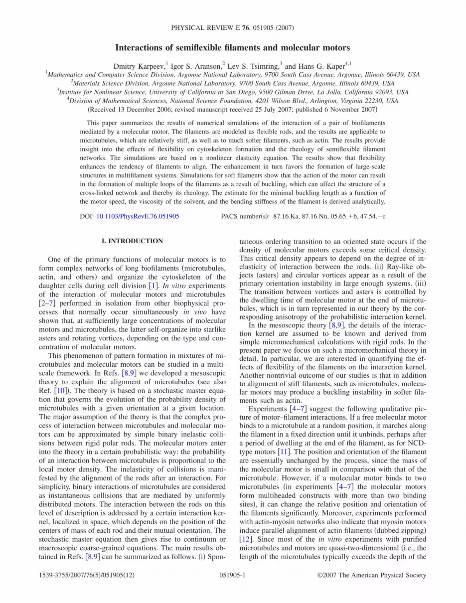
A two-dimensional collision of two microtubules is sche-matically illustrated in Fig. 1�a�. Before the interaction, themicrotubules are oriented at angles �1
b and �2b. The simulta-
neous binding of the molecular motor to the two microtu-bules and the subsequent marching along them results in acomplete alignment of the latter; after the interaction the mi-crotubules are oriented at angles �1
a and �2a, where �1
a=�2a
= 12 ��1
b+�2b�. We refer to this type of interaction as a fully
inelastic collision, by analogy with the physics of inelasti-cally colliding grains �see, for example, Ref. �13��. In Refs.�8,9� we showed that these inelastic collisions can lead to anorientational instability and a subsequent local ordering offilaments. The orientational instability can be compared tothe clustering instability in dissipative granular gases �14�.Moreover, an inelastic collision is a reasonable and efficientcharacterization of the complicated filament zipping processoccurring in the case of interaction between two soft fila-ments and multiple myosin motors �see Ref. �12��.
While a fully inelastic collision �perfect polar alignment�appears to be a simple and useful approximation, the detailsof the interaction of two microtubules mediated by a molecu-lar motor are more complicated. A useful quantitative param-eter that characterizes the inelasticity of the collision is theinelasticity factor
� = � f/�0, �1�
where � f is the angle between the filaments after the inter-action, � f = ��1
a−�2a�, and �0 is the angle before the interac-
tion, �0= ��1b−�2
b�. Thus, �=0 for a fully inelastic collision��1
a=�2a� and �=1 for an elastic collision �� f =�0�. The in-
elasticity factor characterizes the fraction of the initial anglethat the rods recover after an interaction with a motor.
Our early micromechanical calculations �9� show that forpairs of rigid filaments the interaction mediated by a molecu-lar motor is only partially inelastic and, in fact, the finalangle ��s� depends on the position s of the initial attachmentpoint on the tubule. A more meaningful concept is thereforethe mean inelasticity factor
� =�� f��0
. �2�
Here the average is taken over all possible initial attachmentpositions; for filaments of length L, − 1
2L�s�12L
�� f� = L−1�−L/2
L/2
� f�s�ds . �3�
Thus, �=0 for fully inelastic interactions, �=1 for fully elas-tic interactions.
The mean inelasticity factor � is a complicated nonlinearfunction of �0, but a good approximation for rigid filamentsand small �0 is
� 1
2+
arcsinh��/2���1 + �/4�
. �4�
Here � measures the ratio of the translational and rotationalviscous drag coefficients, �= ��� /�r�L2 for tubules of lengthL. Numerically, � is in the range of 12 to 15, so �0.63 forrigid rods at small angles �9�.
The sensitivity of the inelasticity factor to the initial at-tachment point is measured by the asymmetry coefficient �,
� =�s� f�L�� f�
. �5�
For rigid rods, � f�s�=� f�−s�, so �=0. Note that the asym-metry coefficient differs from the collision kernel anisotropyintroduced in Ref. �9�. The latter is related to the motordwelling time at the end of microtubules; however, we an-ticipate that the effect of a strong asymmetry � on patternformation is similar to that of the kernel anisotropy; for ex-ample, it favors the formation of asters over vortices. To-gether, the two parameters � and � quantify the collisionkernel in the mesoscopic theory �9�.
The purpose of this investigation is to study the meaninelasticity factor and asymmetry coefficients of interactingfilaments with various degrees of flexibility. Using the con-tinuum nonlinear elasticity equations, we show through nu-merical simulations that a finite bending flexibility amplifiesthe inelasticity of the collisions. In contrast, for much softerfilaments, such as actin, molecular motors produce bucklinginstead of mutual alignment.
While microtubules are practically unbendable by thermalfluctuations �the thermal persistence length is of the order ofa few mm, thus much larger than their contour length, whichis a few tens of microns�, molecular motors can bend themeasily �see, e.g., Ref. �5��. Bending also increases the prob-ability that two motors attach themselves simultaneously totwo microtubules at different positions. When this situationoccurs, the motors cross-link the microtubules, making themexactly parallel and thus realizing a fully inelastic collision�=0 and the consequent zipping as observed in the experi-ments in Ref. �12�. Further simulations for more flexiblebiofilaments, such as actin, reveal a buckling instability and aformation of multiple loops. We were able to derive an ana-lytic condition for the buckling instability and relate it to themotor speed, bending stiffness, and solvent viscosity. These
FIG. 1. �Color online� �a� A fully inelastic collision of two mi-crotubules mediated by a molecular motor. �b� Schematic represen-tation: The molecular motor is attached symmetrically to two flex-ible microtubules at a distance s along the tubule from the midpoint.
KARPEEV et al. PHYSICAL REVIEW E 76, 051905 �2007�
051905-2

results provide insight into the effects of flexibility on cy-toskeleton formation and the rheology of semiflexible fila-ment networks.
Section II describes the details of the mathematical modelunderlying the numerical simulations. Section III summa-rizes the results of the numerical simulations for both micro-tubules and soft filaments. Section IV deals with the analyti-cal consideration of the buckling condition. Section Vcontains our conclusions. Two Appendixes contain the tech-nical details about the kinematics of filament interactionsmediated by molecular motors �Appendix A� and the dis-cretization of the mathematical model �Appendix B�.
II. MODEL
Consider the interaction of two semiflexible rods �micro-tubules or, more generally, biofilaments� mediated by a mo-lecular motor. We assume that the microtubules are of equallength L, where L is constant in time. That is, we focus onthe case where the endpoints of the microtubules are stabi-lized, for example with taxol, so that the polymerization anddepolymerization processes, which may affect the lengths ofthe microtubules, are insignificant. Furthermore, for simplic-ity we assume that the molecular motor attaches symmetri-cally to the microtubules. Thus, the two attachment pointsare at the same position on each rod with respect to theirrespective midpoints, and the force exerted by the motor isperpendicular to the bisector of the microtubule pair; see Fig.1�b�. The last conclusion follows from the assumption thatthe motor, while moving along the filaments with a constantspeed, acts as a strong spring bringing the two motor headstogether. In Appendix A we show that the motor has a ten-dency to orient perpendicular to the bisector of the microtu-bule pair even if the motor has a nonzero length. Since theinitial attachment may occur at a random position on thetubule, we are interested in the properties of the interaction�in particular, the inelasticity coefficient� averaged with re-spect to the initial attachment position. We make the naturalassumption that the probability of attachment is distributeduniformly along a microtubule. As mentioned above, we ne-glect the effects of thermal fluctuations on the microtubuleshape. However, thermal fluctuations may have some effecton the shape of much softer biofilaments such as actin,whose thermal persistence length is of the order of a fewmicrons. Moreover, we take the longitudinal and the trans-versal drag coefficients to be equal. This assumption is notsignificant and can be relaxed, although it does not affect thequalitative relation between filament flexibility and the in-elasticity factor.
A. Kinematics
To describe the motion of interlinked microtubules, wecombine the theory of Refs. �15,16� for a semiflexible poly-mer with the analysis of the rigid case in Ref. �9�. We adopta two-dimensional setting and model a microtubule as asemiflexible homogeneous inextensible elastic rod of lengthL and bending stiffness . We measure locations along therod relative to the rod’s midpoint, using the arclength s as the
natural parameter, so − 12Ls
12L �see Fig. 1�b��. The inex-
tensibility of the rod implies that its embedding in the Eu-clidean plane preserves the arclength element at all times.Thus, if r�s� is the position in the plane of the point s on thetubule and rs denotes its derivative with respect to s, then wehave the local constraint rs ·rs=1.
A molecular motor attaches initially to the tubule at thepoint si and moves along the tubule with the constant veloc-ity v, exerting a force f on the tubule. As long as the forcedoes not exceed a critical value, we may assume that thevelocity of the motor does not depend on the force f. How-ever, we emphasize that this assumption is not essential;similar calculations can be carried out if the motor velocitydepends on the force. Moreover, it can be rigorously shownthat for rigid rods the particular velocity-force relation doesnot influence the value of inelasticity factor as long as themotors do not stall: the result for rigid filaments Eq. �4� doesnot depend on the motor velocity, the velocity-force relationaffects only the interaction time. Qualitatively similar behav-ior is expected for semiflexible filaments, although the par-ticular force-velocity relation may have some quantitativeeffect since the flexibility of the filaments introduces a newrelaxation time scale. Since the velocity is fixed, the move-ment of the attachment point sa is subject to the kinematicconstraint
sa�t� = si + vt . �6�
In a binary collision, the molecular motor attaches to andmoves along two microtubules simultaneously, and the rela-tive configuration of the tubules changes as a result of themotor force acting on both tubules. As explained above, weconsider only symmetric interactions, where the force is nor-mal to the bisector. Then we can select a Cartesian coordi-nate system where the y-axis is directed along the bisector�see Fig. 1�b��, so f= �±f ,0�, where the magnitude f of f hasto be deduced from the kinematic constraint.
B. Governing equations
The equations governing the motion of the microtubulesare derived from the balance of forces. If the viscosity of themedium containing the mixture is large �Stokes limit�, thenthe viscous drag force is balanced by the force acting on thetubules. The latter is the variational derivative of the energyfunctional E measuring the bending energy of the tubule,together with the energy of the inextensibility and the motorattachment constraints
E =1
2�
−L/2
L/2
�g�rs · rs − 1� + rss · rss + f · r��s − sa��ds .
�7�
Here, g is the line tension, which is determined implicitlyfrom the length conservation constraint �rs�2=1. The singularcomponent of the energy is due to the kinematic constraint�6� and its form depends on the choice of the moving coor-dinate system that places the origin at the motor attachmentpoint r�sa�. The equations of motion are found by takingvariations
INTERACTIONS OF SEMIFLEXIBLE FILAMENTS AND… PHYSICAL REVIEW E 76, 051905 �2007�
051905-3

�r = −�E
�r= �s�grs� − rssss −
f
2��s − sa�t��
0 = −�E
�g= rs · rs − 1, 0 = −
�E
�f= r��s − sa�t�� . �8�
Here, � is the viscous drag coefficient �per unit length�.These equations can be interpreted as defining a gradientflow with respect to the variables r, g, and f, where theconstraints are established instantaneously on the time scaleof the viscous force.
The solution of Eqs. �8� must satisfy the integral relation
�−L/2
L/2
��r · �r + �E�ds = 0, �9�
for all admissible variations �r, �g and �f . The energy varia-tion is
�E = �−L/2
L/2 �grs · �rs + rss · �rss +1
2��s − sa�f · �r ds
+ �−L/2
L/2
�rs · rs − 1��gds + �−L/2
L/2
r��s − sa� · �fds .
Taking Eq. �9� instead of Eq. �8� and demanding that it besatisfied for all admissible variations of r, g, and f, assumedindependent, we obtain a weak form of the governing equa-tions
�−L/2
L/2 ��r · �r + grs · �rs + rss · �rss +f
2��s − sa� · �r�ds
= 0, �10�
�−L/2
L/2
�rs · rs − 1��gds = 0, �−L/2
L/2
��s − sa�r · �fds = 0.
�11�
In this weak formulation there is no need for a priori as-sumptions on the smoothness of the solutions and theirboundary conditions. If the solution is sufficiently smooth,however, we can integrate by parts and obtain the strongform of the governing equations
�−L/2
L/2 ��r − �s�grs� + �s4r +
1
2��s − sa�f� · �rds
+ �grs · �r + rss · �rs − rsss · �r�−L/2L/2 = 0.
The vanishing of the integral is equivalent to the equations ofmotion in the usual differential form �8�, while the vanishingof the boundary term determines the natural boundary con-ditions
�grs − rsss� · �r + rss · �rs +1
2�sa,sb
f · �r = 0 �12�
at each boundary point sb= ±L /2. The Kronecker delta sym-bol �sa,sb
ensures the inclusion of the force in the boundarycondition when the motor is attached at the boundary.
In the absence of smoothness assumptions, Eqs. �10�, �11�implicitly contain the suitable weak version of the boundaryconditions. In particular, the formulation �10�, �11� does notchange when sa= ±L /2, while for the equation above theterm f becomes part of the boundary conditions.
The weak formulation is amenable to discretization in thepresence of singular terms. One such term appears in theequation of motion for r as a result of the movable pointforce exerted by the motor. If an explicit equation of motionfor the tension g is derived from the inextensibility constraintand the equations of motion for r, an even more cumbersomesingular term appears:
gss − rss · rssg − rs�s5r +
1
2rsf���s − sa� = 0. �13�
This equation demands even higher regularity of r than theequation for r itself. We circumvent both problems by solv-ing for the forces of the constraint g and f from the corre-sponding constraint equations, rather than deriving explicitequations for them. The result is a well-posed discrete prob-lem that, however, requires an implicit time discretization�see Appendix B for details�.
III. NUMERICAL EXPERIMENTS
Symmetric interactions of pairs of microtubules are simu-lated numerically by integrating the equations of motion�10�, �11�. In this section we present the results of two typesof such simulations, first for �relatively stiff� microtubulesand then for �fairly soft� actin filaments.
Physical parameters. The viscous drag coefficient per unitlength � is related to the effective dynamic viscosity of thesolvent ; in a thin layer of solvent the approximate relation
is �2� / ln�L /d�, where L is a characteristic cut-off sizeof the problem �for example, the average filament length orthe depth of the container�, typically of the order 5 microns.This models the proximity of the container walls above andbelow the tubules �see also Refs. �5,17,18��. The bulk dy-namic viscosity coefficient for water, the assumed solvent, is =10−3 pN s m−2. Moreover, viscosity can increase sig-nificantly as a result of the presence of organic buffers, suchglycerol etc., which are added to the solution. To account forthese effects, we use the effective drag coefficient �=� =��10−3 pN s/ m2, where the factor � was changed in ourstudies from �=3 to �=15 �for example, in simulations Ref.�5� was used �=200�.
For microtubules we use the bending stiffness strength=2.0�10−23Nm2=20 pN m2, as calculated in Ref. �17�.The motor velocity is set to v=1 m/s �5� and �=3 to ac-count for the confinement in a thin layer. Note that by scalingspace �hence the microtubule length� by a, the effectivebending stiffness is scaled by a−4, while the tension g and theforce f �Lagrange multipliers� remain unchanged. Thus, wenormalize space so that each tubule is of unit length. Time isnormalized by using T, the length of time needed for themotor to traverse 1 m �T=1 s in our case�, resulting in anondimensional motor velocity v=vT /L.
Effective bending stiffness. The introduction of an effec-
KARPEEV et al. PHYSICAL REVIEW E 76, 051905 �2007�
051905-4

tive bending stiffness =L−4�−1T enables us to study theinteractions of a range of tubules of different lengths bymeans of a single tubule of unit length but with differentvalues for the effective bending stiffness and the motor ve-locity. Thus there is no need to change the spatial discretiza-tion of the microtubule to maintain accuracy. Moreover, as itfollows from the expression for the effective bending stiff-
ness , the main factor is the length which enters as L4,whereas viscosity enters in only the first power. Thus, a smallchange in the filament length L can accommodate a consid-
erable change in the solvent viscosity leaving the value of unchanged.
Discretization parameters. In all simulations, we dis-cretized the normalized tubule of length 1 with �s=0.03125 or smaller, and time with �t=0.01. Simulations oftubules of different lengths �L=15,30,45,60 m� were ac-complished by adjusting the effective bending stiffness,
as explained in the previous paragraph: =1.32�10−1 ,8.23�10−3 ,1.63�10−3 ,5.14�10−4; the effective dragcoefficient, �=1.0; the effective motor velocity, v=0.067,0.033,0.022,0.017.
After the interaction, the tubule is allowed to relax untilthe filament assumes an almost straight configuration; that is,the mean relative deviation of the tangent from the mean isless than 10−2. This process was carried out in two differentways, with the motor sliding off the tubule and with themotor dwelling at the end of the tubule, until the relaxation iscomplete. The dwelling was introduced to model differenttypes of motors. It is known that some motors, such as kine-sin, have almost zero dwelling time, whereas the NCD-typemotor complexes used in experimental works �see Refs.�4,5�� appear to have a very large dwelling time at the mi-crotubule ends.
A. Bending of microtubules
Figure 2 shows two typical examples of the time evolu-tion of the interaction of a pair of relatively stiff microtu-bules mediated by a molecular motor. In both cases, the mo-tor induces a significant deformation of the filament shape.The tubules curve in such a way that the segments of micro-tubules behind the moving motor become locally morealigned than if the tubules were straight. This curvature in-creases the probability of attachment of additional motorsand, therefore, the probability of cross-linking of the tubulesin several places. Multiple cross-linking is expected toquickly align the two tubules; however, a consideration ofthe action of multiple motors is beyond the scope of thepresent work.
Figure 3 shows the evolution of the filament tension g�s�in the course of the interaction. The filaments becomestretched �g�0� ahead of the motor attachment point�s�sa� and slightly compressed �g�0� behind the attach-ment point �s�sa�. In the limit of zero motor size, the ten-sion exhibits a discontinuity at the attachment point �s=sa�because of the �-function character of the motor force f. Inour numerical procedure this discontinuity is regularized as aresult of the weak formulation. The negative tension g is a
precursor of the Euler buckling instability for elastic rods�20�. However, buckling of microtubules does not occur be-cause of the large value of the stiffness coefficient �seeSec. IV�.
Figures 4–7 show the results for the inelasticity factor �and asymmetry coefficient �. There is an overall tendencyfor � to decrease with the length L of the tubule �and, there-
FIG. 2. �Color online� Two sequences of images illustrating thebending and alignment of microtubules by molecular motors, withdwelling of the motor at the end of the microtubules. �a�–�c� Initialangle �0=14°, �d�–�f� initial angle �0=90°. The shaded region in-dicates the motor location; the motor moves upward. For compari-son, the image �f� also shows the configuration of the two microtu-bules if the dwelling time is zero �shown by semitransparentcolors�. The sequence shows the configurations at times t=3 �a�,�d�, t=33 �b�, �e�, and t=180 �c�, �f� for =20 pN m2, L=60 m, motor velocity v=1 m/s. The viscosity equals 3 � vis-cosity of water ��=3� with initial attachment offset 6 m from thetubule end. After the interaction with the motor, the initial angle isreduced from 14° to 8.7° with dwelling and from 90° to 58.3° withdwelling and to 62.2° without dwelling �shaded�. More detailedimages can be found in Ref. �19�, movies 1–3.
-0.4 -0.2 0 0.2 0.4s/L
-0.002
0
0.002
0.004
0.006
g
t = 3t = 33t = 3t = 33
FIG. 3. �Color online� Tension in the tubule configurations ofFig. 2 at times t=3 �a�,�d� and t=33 �b�,�e�; =20 pN m2, L=60 m, v=1 m/s, and �=3. At the final stages �e�, �f�, the ten-sion is zero �not shown�. The tension g changes sign and varies veryrapidly near the motor attachment point. A smaller initial angle��0=14° � results in a tension approximately 10 times smaller thanthat of the larger initial angle �90° �.
INTERACTIONS OF SEMIFLEXIBLE FILAMENTS AND… PHYSICAL REVIEW E 76, 051905 �2007�
051905-5

fore, to increase with the bending stiffness , since in therescaled variables is proportional to L−4�. As →�, �approaches the stiff limit value 0.63; see Eq. �4�.
In contrast, the dwelling of the motors at the tubule endshas a relatively small effect on the inelasticity if the tubulesare sufficiently stiff, although it may affect other propertiesof the interaction, such as the anisotropy of the kernel �9�. Asone sees from Figs. 4–6, the inelasticity factor �→1 for �0→�; that is, almost antiparallel filaments do not change theirmutual orientation after an interaction with motors. Thistrend is similar to that of rigid filaments �9�.
A decrease in the stiffness induces a significant asymme-try of the inelasticity with respect to the location of the initialattachment point si, as measured by the asymmetry coeffi-cient �. However, our calculations show that � remains rela-tively small for typical filament lengths used in the majorityof experiments ���0.03�. This result suggests that the ker-nel anisotropy related to dwelling of the motors �9� ratherthan the asymmetry coefficient is the dominant factor affect-ing the large-scale pattern selection, such as transitions be-tween vortices and asters.
The dependence of the mean inelasticity � and its asym-metry � on the tubule length and, hence, the effective stiff-
ness are illustrated in Figs. 8 and 9. For the dwelling case,there is an overall trend of decreasing the inelasticity factor �with the increase of the length. For very large rod lengths, �approaches the value 0.42, which is significantly lower thanthe value for rigid rods 0.63. Thus, our results indicate thatthe interaction becomes more inelastic with the increase ofthe length of filaments �equivalently, with the decrease ofstiffness�. Even for very long filaments, however, the inter-action is not fully inelastic. This is because a single motorcannot align the filaments completely. However, multiplemotors, cross-linking filaments in various locations, will rap-idly make filaments parallel �zipping�. Surprisingly, the de-pendencies are not monotonic for the no-dwelling case. Thisobservation is likely related to the buckling of the rods whenthe filament length exceeds a certain critical value �see be-low�.
B. Bending of actin filaments
The same modeling approach can be applied to muchsofter filaments, such as actin, interacting, for example, withmyosin motors. According to Ref. �6�, as with kinesin and
0 0.2 0.4 0.6 0.8 1ϕ0/π
0.5
0.6
0.7
0.8
0.9
1∈
L = 15L = 30L = 45L = 60
FIG. 4. �Color online� Inelasticity factor � with dwelling, fordifferent lengths of microtubules; =20 pN m2 and �=3.
0 0.2 0.4 0.6 0.8 1ϕ0/π
0
0.01
0.02
0.03
0.04
α
L = 15L = 30L = 45L = 60
FIG. 5. �Color online� Asymmetry coefficient � with dwelling,for different lengths of microtubules; =20 pN m2 and �=3.
0 0.2 0.4 0.6 0.8 1ϕ0/π
0.5
0.6
0.7
0.8
0.9
1
∈
L = 15L = 30L = 45L = 60
FIG. 6. �Color online� Inelasticity factor � without dwelling as afunction of the tubule length; =20 pN m2 and �=3.
0 0.2 0.4 0.6 0.8 1ϕ0/π
0
0.01
0.02
0.03
0.04
α
L = 15L = 30L = 45L = 60
FIG. 7. �Color online� Asymmetry coefficient � without dwell-ing as a function of the tubule length; =20 pN m2 and �=3.
KARPEEV et al. PHYSICAL REVIEW E 76, 051905 �2007�
051905-6

NCD considered in the previous section, myosin motors alsoform multiheaded complexes. The main difference is that thestiffness of actin is about 103 times smaller than that of mi-crotubules �=7.3�10−2 pN m2�. We studied actin fila-ments of length L=50 m in a solvent with �=3 and �=15, the latter being equivalent to a system of filaments oflength L26 in a solvent with �=200.
Our simulations with �=15 produced a surprising result:the interaction of the motor with two actin filaments result inthe creation of complex multilooped structures, as shown inFig. 10. These loops are the result of Euler bending instabil-ity of elastic rods. Experiments with a lower viscosity �=3do not produce buckling, suggesting that there is a criticalvalue of � or, equivalently, of length L, above which buck-ling appears �see the following section�. As loops form, ten-sion g becomes negative and exhibits oscillations �see Fig.11�. After the motor reaches the end of the filaments, buck-ling slowly relaxes because of the finite bending rigidity.
The evolution of the root mean square tension g=L−1�0
Lg�s�2ds as a function of time is shown in Fig. 12 for
both �=3 and 15. As one sees, the asymptotic decay of g isexponential, with the exponent determined mostly by the vis-cosity of the solvent �characterized relative to the viscosityof water by the constant ��. Dwelling also affects the decayrate. For intermediate times, however, the behavior is differ-ent, consistent with some power-law �see the inset to Fig.12�. According to Ref. �21�, for a buckled filament confinedbetween two rigid walls, the tension exhibits a power-law
0 100 200 300 400 500L
0.3
0.4
0.5
0.6
∈dwellingno dwelling
FIG. 8. �Color online� Inelasticity factor for �0=4° as a functionof the tubule length �and, by implication, as a function of the effec-tive bending stiffness of a unit tubule�; =20 pN m2 and �=3.
0 100 200 300 400 500L
0
0.05
0.1
0.15
0.2
α
dwellingno dwelling
FIG. 9. �Color online� Asymmetry coefficient � for �0=4° as afunction of tubule length �and, by implication, as a function of theeffective bending stiffness of a unit tubule�; =20 pN m2 and �=3.
FIG. 10. �Color online� Two sequences of images illustrating thebending and alignment of actin-like filaments by molecular motors:�a�-�d� with motor in motion, �e� with motor dwelling at the end ofthe filaments after interaction, and �f� filaments freely relaxing afterinteraction. The shaded region indicates the motor location; the mo-tor moves upward. Images are shown at times t=1.5 �a�, t=9 �b�,t=12.5 �c� t=13.5 �d�, and t=100.0 �e�,�f�; =7.3�10−2 pN m2,L=50 m, v=1 m/s, and �=15. The images �e� and �f� illustratethe difference between dwelling and nondwelling interactions. Inboth cases, the initial angle is �0=90°, and the initial attachmentoffset is 1 m from the end of the filament. After the interactionwith the motor, the initial angle is reduced to 19.9° with dwellingand to 32.7° without dwelling. More detailed images can be foundin Ref. �19�, movies 3 and 4.
-0.4 -0.2 0 0.2 0.4s/L
-0.002
0
0.002
0.004
0.006
g
t = 1.5t = 9.0t = 12.5t = 13.5
FIG. 11. �Color online� Tension in the actin configurations ofFig. 10 at times �a� t=1.5; �b� t=9; �c� t=12.5; �d� t=13.5; =7.3�10−2 pN m2, L=50 m, v=1 m/s, and �=15. With themotor attached near the very end �t=13.5�, the tension has an os-cillatory profile that decays rapidly to an essentially tension freeprofile �g0, not shown�, regardless of whether the motor is stillattached �dwelling� or not �without dwelling�.
INTERACTIONS OF SEMIFLEXIBLE FILAMENTS AND… PHYSICAL REVIEW E 76, 051905 �2007�
051905-7

relaxation depending on the initial deformation, whereasslightly bent filaments relax as g�1/t. Thus, in our situa-tion, the relaxation dynamics is rather different.
Moreover, dwelling can have a significant effect on theinelasticity factor because of the very slow straightening ofthe filaments �see Fig. 10�. The difference stems from thefact that in contrast to rigid rods, soft filaments possess an
additional time scale �1/ related to the straightening of therod. Since actin-like filaments are strongly bent when themotor reaches the end-point position, further relaxation dy-namics is very sensitive to whether the motor leaves the fila-ments or binds their ends together.
The complex structures shown in Fig. 10 may appear inthe course of cytoskeleton formation and should affect therheological properties of the filament networks. Since actinfilaments take significantly longer to relax back to the unbentconfiguration, the notion of an inelastic collision, which wasintroduced for stiff microtubules, is essentially inapplicableto actin. The formation of loops in actin filaments shouldfacilitate multiple motor bindings and thus the creation ofbundles. The dynamics of actin filaments and active filamentnetworks will be examined in more detail in a forthcomingpublication.
IV. BUCKLING CONDITION
To understand the buckling instability of straight semi-flexible filaments driven by molecular motors, we considerthe situation when the filaments are exactly anti-parallel �i.e.,�0=��. For this configuration the tension g�s , t� and thebuckling threshold can be found analytically. We believe thatthe calculations for the antiparallel configuration capture themost important aspects of the buckling instability, whereasthe derivation of the buckling criterion for arbitrary initialangles � is greatly complicated by the rotation and bendingof the filaments.
We choose filament orientation along the x axis �i.e., r= �s ,0��. The motion of the filament is opposite to the motionof the motor, which moves with the speed v in the positive xdirection �see the left inset in Fig. 13�. Taking this into ac-count, Eq. �8� yields
− v� = �xg0 −f
2��x − sa�t�� , �14�
which is an equation for the tension g0.The tension distribution following from Eq. �14� satisfy-
ing boundary conditions g0=0 at the ends of filament s=x= ±L /2 is of the form
g0�s,t� = �− v��x + L/2� for x � sa�t� ,
− v��x − L/2� for x � sa�t� .�15�
As one sees from Eq. �15� �schematically illustrated in theleft inset to Fig. 13�, behind �or to the left of� the motorattachment point the tension g=g0�x , t� is negative becausethat segment is being compressed �or pushed�; on the seg-ment ahead �to the right� of the motor the tension is positivesince the segment is being stressed �or pulled�. At the motorattachment point x=sa the tension g0 is discontinuous; thevalue of the motor force f can be obtained from the jump ofthe tension. This analytic expression is consistent with ten-sion distributions found numerically �see Fig. 3�.
Negative tension behind the motor is a precursor of buck-ling. However, due to a nonuniform tension distribution thebuckling condition is different from the classical Euler buck-ling and the buckling of semiflexible filaments studied inRefs. �22,23� in the context of microtubules’ buckling, whichwas induced by a compressive force F0 applied at the end
0 250 500 750 1000t/λ
10-10
10-8
10-6
10-4
g
λ=3, no dwellingλ=15,no dwellingλ=3, dwellingλ=15,dwelling
10 100t/λ
10-7
10-6
10-5
10-4
g
FIG. 12. �Color online� Evolution of mean root square tension gfor L=50 with two different values of the solvent viscosity �=3 and�=15. The plots are shown in semilogarithmic scale. Black curvesdepict g for the case of filaments without dwelling, and red lineswith dwelling. The inset shows a blow-up of the region in the boxon the main plot, in log-log scale. The dot-dashed line displays thepower law g�1/t.
5 10 15λ
5
10
15
20
Lm 1 10
λ
10Lm
L
Lm
x
g0(x)
FIG. 13. The dependence of the length behind motor attachmentat the onset of buckling Lm �in microns� on the normalized solventviscosity �=� /�0, where �0 is the viscosity of water. Symbolsshow results of numerical solution of Eq. �8� for �0=� and L=50 m, =7.3�10−2 pN m2 �actin�. The solid line shows solu-tion to Eq. �20�, no fitting parameters. The right inset shows Lm vs� on a log-log scale. The left inset illustrates the tension distributiong0 for a single filament of an antiparallel pair; the motor moves tothe right, pushing the filament to the left; tension g0 is piecewiselinear, vanishes at the ends, with a discontinuity at the motor attach-ment point.
KARPEEV et al. PHYSICAL REVIEW E 76, 051905 �2007�
051905-8

and with lateral confinement. Consequently, our analysis ismore complicated.
To examine the buckling instability we consider a smallperturbation �= ��x ,�y� about a straight horizontal filament:r=x0s+�, where x0 is the unit vector in the x direction. Aftera linearization of Eq. �8�, we derive the following equationfor the transverse perturbation �y �it is easy to see that theparallel perturbation �x plays no role in the linear order�:
��t�y = �x�g0�x,t��x�y� − �x4�y , �16�
with the boundary conditions �x2�y =0 at x= ±L /2.
Equation �16� is still a formidable problem because of theexplicit time dependence of tension g0�t� due to the motormotion, sa�t�=si+vt �see Eq. �6��. Further simplification ispossible by assuming that the buckling instability happensfaster then the time scale associated with motion of the mo-tor L /v, which is true for sufficiently long filaments. In thissituation one can study the linear problem �16� with a “fro-zen” tension �i.e., sa=const�; the time dependence of the per-turbation �y is then described by �y �exp��t�, where � is thegrowth rate.
The instability �and therefore buckling� occurs when themaximum value of the growth-rate � crosses zero. The pro-file of this critical mode can be obtained from the stationaryequation �16�, so that the onset of the instability is signaledby the appearance of a nontrivial solution of the followingequation:
�x�g0�x,t��x�y� − �x4�y = 0. �17�
The existence of nontrivial solutions to this equation, andhence the instability threshold, is determined in terms of themodel parameters: the length of filament L, motor velocity v,viscosity � and bending stiffness . Equation �17� can berewritten as a second-order boundary value problem by sub-stituting W=�x�y, integrating once along the x direction, andusing the boundary condition g0�x�y −�x
3�y =0 at x=s= ±L /2, as implied by Eq. �12�. This kills the constant ofintegration and yields equation
g0�x,t�W − Wxx = 0 �18�
with the boundary conditions Wx=0 at x= ±L /2, and g0given by Eq. �15�. The solution of Eq. �18� depends on themotor attachment position sa; since g0 is discontinuous atthis point, we only demand the continuity of W and Wx atx=sa.
Nontrivial solutions of Eq. �18� with the imposed bound-ary conditions do not exist for arbitrary values of the fila-ment length L. In fact, for fixed v ,� , there is a certaincritical value L* so that no nontrivial solutions exist if L�L* and a solution appears for L=L* and sa=L /2. Further-more, for each filament length L�L* one can find the attach-ment position sa corresponding to the onset of buckling. Cor-respondingly, the length Lm=sa+L /2 is the minimal size ofthe compressed segment of the filament to the left of themotor that can buckle; thus, LmL*, see Fig. 13.
It is useful to consider Lm in the limiting case of a verylong filaments �L→ � �. In this case we can consider Eq. �18�on the left segment of length L with the boundary condition
W=0 at the right end of the segment, i.e., at x=sa. To seethis, note that ahead of the motor attachment point tensiong0=v� �L /2−sa��0 is positive �the filament is beingpulled�, vanishes at the right end, and if L−Lm�1 the cor-responding Airy functions and their derivatives decay veryfast away from the right end of the filament �the correctionsfor the finite size of L−Lm are small�. Therefore, for L→�the continuity condition for functions W ,�xW at x=sa can bereplaced by the asymptotic values to the right of sa: W�x=sa�=0. Making the substitution x→x+L /2, Eq. �18� givesrise to the Airy equation
v�xW + Wxx = 0 �19�
with the boundary conditions Wx=0 at x=0 and W=0 at x=Lm. Applying the solvability criterion to this reduced sys-tem, we find that nontrivial solutions corresponding a buck-ling deformation �i.e., nonmonotone solutions� to Eq. �19�appear when the following condition is satisfied:
Lm 3.82�
v� 1/3
. �20�
Expression �20� for the length Lm is notably different fromthe classical Euler buckling condition due to a compressiveforce F at the boundary, which gives LEuler� /F �24�.
For the parameters of our numerical experiments v=1 m/s and �0.015 pN s/ m2 �about 15 viscosity ofwater�, we obtained that the critical length Lm60−70 mfor microtubules and Lm5−6 m for actin. Thus, it indi-cates that microtubules will not buckle under the action of anindividual motor �a microtubule’s length is typically 10–20micron�, which is fully consistent with our simulations. Incontrast, dilute solution of sufficiently long actin filamentscan buckle easily. However, the buckling can be suppressedin dense networks of interconnected actin filaments �in real-istic actin networks the mesh size could be as small as 1–2microns�.
We have computed Lm numerically for the case of actinparameters with different values of the normalized viscosity�. The resulting Lm as a function of � is shown in Fig. 13.Overall, there is an excellent agreement with the theoreticalprediction of Eq. �20�. Moreover, the dependence of Lm on �exhibits a powerlaw behavior with the exponent −1/3, aspredicted by the theory �see the right inset to Fig. 13�.
V. CONCLUSIONS
In this paper we have investigated the interaction of a pairof biofilaments �microtubules, actin filaments� mediated by amolecular motor. Our main result is that bending effects am-plify the tendency of microtubules to align and, conse-quently, to form structures with large-scale ordering, such asasters and vortices. Our results support the observationsmade in Refs. �4,5� that bending effects are important for theexplanation of self-organization processes in molecularmotor-microtubule mixtures where bent microtubules wereindeed observed. However, our calculations show that theflexibility alone cannot explain complete alignment of fila-ments �zipping� by a single molecular motor. It suggests that
INTERACTIONS OF SEMIFLEXIBLE FILAMENTS AND… PHYSICAL REVIEW E 76, 051905 �2007�
051905-9

action of multiple motors �and possibly static crosslinkers� isimportant to explain pattern formation in Refs. �4,5�. More-over, recent experiments with actin-myosin gels indicate thatindeed static crosslinkers acting along with dynamic motorsgreatly enhance the tendency towards pattern �bundle� for-mation, likely due to stronger alignment interactions �25�.Thus, our studies provide a quantitative characterization ofthe complicated filament-motor interaction processes, possi-bly shedding additional light onto the experimentally ob-served zipping phenomenon in actin-myosin systems �12�.
Our studies indicate that molecular motors have a verystrong and nontrivial effect on the shape of much softer fila-ments such as actin, resulting in Euler-type buckling insta-bilities and the formation of multiloop structures. Our analy-sis indicates that the buckling is strongly enhanced byincreasing the viscosity of the solvent. The minimal length ofthe filament exhibiting buckling under the action of a motoris obtained analytically. While our result is derived for theantiparallel configuration, we anticipate that the estimate forthe minimal buckling length Lm, Eq. �20�, will be applicable,essentially unchanged, even for the initial angles �0��. Asfollows from our simulations of actin-type filaments depictedin Fig. 10, prior to buckling soft filaments become practicallyantiparallel ahead of the motor attachment point, while be-coming nearly straight and parallel behind the motor �zip-ping� �see Figs. 10�a� and 10�b��. Presumably, buckling ef-fects have a strong influence on the rheological properties ofinterconnected �but rather dilute� actin networks interactingwith myosin motors.
ACKNOWLEDGMENTS
The authors thank Jacques Prost, Francois Nédélec, FrankJülicher, Karsten Kruse, and Erwin Frey for useful discus-sions. This work was supported by the U.S. Department ofEnergy, Grants No. DE-AC02-06CH11357 �D.K., H.G.K.,I.A.� and No. DE-FG02-04ER46135 �L.T.�.
APPENDIX A: SYMMETRIC ATTACHMENT LIMIT
In this Appendix we show that the tendency for a pair ofstiff filaments �microtubules� to orient themselves perpen-dicularly to their bisector persists even in the case of nonzerolength motors. The filaments are assumed to be of the samelength, with the motor attached at an equal distance from theminus end of each filament �even attachment� and orientedtransversally to the bisector of the filament pair �symmetricattachment�. The general idea of symmetrization of motorattachment is captured in the case of rigid tubules connectedby a stiff �but flexible� motor of length h, where h�L. Themotion then reduces to a system of ordinary differentialequations governing the overdamped motion of a system oftwo rigid rods �microtubules� connected by flexible inexten-sible link of the length h �motor� as depicted in Fig. 14.
In a fixed coordinate system the centers of mass of thetubules are at c�1� and c�2�, respectively, while the motor at-tachment points are at c�1�+ t�1� and c�2�+ t�2�. In terms of thedistances from the respective centers s1,2 we have t�1,2�
=s1,2t�1,2�. The motor is represented by the vector �; n�1�, n�2�,
and � are normal to t�1�, t�2�, and �, respectively; and hatsdenote unit vectors.
The dynamics of the system are determined as in thesemiflexible case by the balance of forces and the kinematicconstraint d
dt s1,2=v,
d
dtc�1,2� = ± f���
−1�t�1,2�, ��t�1,2� + ��−1�n�1,2�, ��n�1,2�� ,
d
dtt�1,2� = vt�1,2� ± f�r
−1s1,22�t�1,2�, ��n�1,2�, �A1�
where ��−1, ��
−1, and �r−1 denote the inverses of tangential,
transversal, and rotational viscosities; the motor force ofmagnitude f is directed along �, the sign depending on thedirection from the tubule.
To obtain the force f and the motor motion, we observethe geometric constraint �= �c�2�−c�1��+ �t�2�− t�1�� �Fig. 14�.Since the motor is rigid, its velocity must be directed alongthe normal �. Since the motor is rigid, its velocity is directed
along the normal: �=h��. Here � denotes the angular veloc-ity, which is independent of the choice of an orthonormalcoordinate system. We obtain the relations
h�� = − f��−1��t�1�, ��t�1� + �t�2�, ��t�2�� − f��
−1��n�1�, ��n�1�
+ �n�2�, ��n�2�� + v�t�2� − t�1�� − f�r−1�s1
2�t�1�, ��n�1�
+ s22�t�2�, ��n�2�� . �A2�
Denote by vu= �v , u�u the component of a vector v alongthe unit vector u. Projecting the constraint �A2� onto themotor furnishes an equation for f independent of the motorsize �26�,
0 = f���−1���t�1��2 + ��t�2��2� + ��
−1���n�1��2 + ��n�2��2�
+ �r−1�s1
2��n�1��2 + s22��n�2��2�� + v�t�2� − t�1�, �� .
The coefficient of f vanishes only if � is normal to bothtangential and both normal vectors of the tubules, a conditionthat is clearly impossible even in the case of alignment.Hence, the force f is uniquely determined from the aboverelation and is O�1� relative to the motor size.
f
t1
c 1
1n
n2
c 2
t2 τ
rν
n
t
τθ
(a) (b) (c)
FIG. 14. Initial state of a symmetric microtubule pair: force actson the microtubules perpendicular to the bisector; �a� attachmentpoint is equidistant from the centers of mass; �b� inflexible tubulesconnected by a finite-size motor; �c� a vector in an orthonormalframe.
KARPEEV et al. PHYSICAL REVIEW E 76, 051905 �2007�
051905-10

To determine the relative position of the motor and thetubules, we project the constraint �A2� onto t�1�+ t�2�, whichis along the tubule bisector. This eliminates the term with v�a rhombus has orthogonal diagonals�,
f−1h���, t�2� + t�1�� = ��−1�1 + �t�1�, t�2����t�1� + t�2�, �� + ��
−1�tn�1��2�
+ tn�2��1� , �� + �r
−1�s12tn�1�
�2� + s22tn�2�
�1� , �� �A3�
For finite h this relation determines the rotation rate of the
motor � in terms of f . However, in the limit h→0 the motorbecomes slaved to the tubules, with its orientation deter-mined from the above relation with a zero left-hand side andirrespective of the force.
As discussed above, in this paper we consider the case ofeven attachment of the motor, where s1=s2=s= �s1+s2� /2.Simple algebra �27� shows that t
n�1��2�
+ tn�2��1�
= �1− �t�1� , t�2�����t�1�+ t�2��, and in the limit h→0 we obtain the condition
�t�1� + t�2�, �� = 0, �A4�
which means that � is orthogonal to the bisector of thetubules—that is, the attachment becomes symmetric. More-over, for h�0, even if the motor initially was not perpen-dicular the bisector, Eq. �A3� describes the relaxation of themotor orientation toward the angle given by condition �A4�.
APPENDIX B: DISCRETIZATION
We apply the finite element method �FEM� �28� to theweak form of the governing equations �8�. This allows us totreat the singular terms arising from the motor force andautomatically generates appropriate natural boundary condi-tions.
At any time t the components of the radius vector r�t� andits variation �r�t� are written as linear combinations of con-tinuously differentiable functions � j,k , j=0, . . . ,N−1,k=0,1.The basis functions � j,k vanish outside the segments�sj−1 ,sj+1�, j=0, . . . ,N centered at the nodes of a one-dimensional mesh discretizing the normalized tubule�−1/2 ,1 /2� with the mesh size �s=sj+1−sj =1/N. We con-struct the basis from the standard Hermite cubics: � j,k arepiecewise cubic polynomials on each mesh interval and � j,0interpolate function values while � j,1 interpolate derivativevalues. On the interval �−1,1� the standard Hermite func-
tions �k ,k=0,1 have the form �see Ref. �28��
�0�s� = ��s� − 1�2�2�s� + 1�, �1�s� = s��s� − 1�2,
from which the basis functions are obtained by shifting andscaling:
� j,k�s� = �k��s − sj�/�s� .
Similarly, the tension g�t� and its variation �g�t� are ex-panded by using the basis of piecewise linear “hat” functions� j centered at the mesh nodes obtained from the standard hatfunction on �−1,1�:
��s� = 1 − �s�, � j�s� = ���s − sj�/�s� .
For the end nodes j=0,N both � j and � j,k are the suitableone-sided restrictions.
The Galerkin procedure requires that the approximate so-lution
r�s,t� = �j,k
r j,k�t�� j,k�s�, g�s,t� = �j
gj�t�� j�s�
and f�t� satisfy Eqs. �10�, �11� for all piecewise cubics �r, all
piecewise linear functions �g, and all scalars �f. As dis-cussed in Sec. II B, this choice of the discretization spacecontains a suitable weak form of the boundary conditions�12�. The resulting discrete equations can be viewed as theapplication of D’Alembert’s principle to the energy func-tional �7� restricted to this finite-dimensional function spaceof piecewise cubic tubule conformations and piecewise lin-ear tension profiles. The gradient flow and constraints thusgenerated are well-posed ordinary differential equations withdiscrete inextensibility and motor attachment constraints.
To write down these equations explicitly, we introduce thefamiliar mass and bending matrices M and B, as well as anonlinear version of the stiffness matrix K�g�:
Mj,k;j�,k� = �−L/2
L/2
� j,k� j�,k�ds,
Bj,k;j�,k� = �−L/2
L/2
��s2� j,k���s
2� j�,k��ds,
Kj,k;j�,k��g� = �i
giKi;j,k;j�,k� = �−L/2
L/2
� j,k� j�,k�gi�ids .
With these, the implicit Euler’s scheme at a succession oftimes tn produces a system of discrete equations
�j�,k�
2��Mj,k;j�,k��r j�,k�n+1 − r j�,k�
n ��tn+1 − tn� + Kj,k;j�,k��g�r j�,k�n+1
+ Bj,k;j�,k�r j�,k�n+1 � + fn+1� j,k�sa�tn+1�� = 0, �B1�
�j,k;j�,k�
Ki;j,k;j�,k�r j,kr j�,k� = 0, �B2�
�j�,k�
r j�,k�� j�,k��sa�t�� = 0, �B3�
which are solved numerically for all i , j ,k.For our numerical studies we start with the initial state of
a relaxed tubule forming a given angle 12�0 with the vertical
axis. For a given motor attachment point sa0��− 1
2 , 12� the
following discrete conformation determines a normalizedsymmetric tubule pair with the initial angle �0 and the inter-section point at the origin
r j,0 = �cos��0/2�,sin��0/2���j�s − sa0�,
INTERACTIONS OF SEMIFLEXIBLE FILAMENTS AND… PHYSICAL REVIEW E 76, 051905 �2007�
051905-11

r j,1 = �cos��0/2�,sin��0/2�� .
Initially the tension and the motor force are absent gi0=0,
f0=0.The conformation r j,k
n along with the tension gin and the
force fn at a later time tn are determined by solving the non-
linear equations �B1�–�B3� recursively. At each time tn+1these equations are solved by using Newton’s method withthe state at time tn serving as the initial guess. The corre-sponding linearized system is sparse and can be efficientlysolved using any Krylov subspace method. For modest N thestandard LU factorization is also feasible.
�1� J. Howard, Mechanics of Motor Proteins and the Cytoskeleton�Springer, New York, 2000�.
�2� K. Takiguchi, J. Biochem. �Tokyo� 109, 250 �1991�.�3� R. Urrutia, M. A. McNiven, J. P. Albanesi, D. B. Murphy, and
B. Kachar, Proc. Natl. Acad. Sci. U.S.A. 88, 6701 �1991�.�4� F. J. Nédélec, T. Surrey, A. C. Maggs, and S. Leibler, Nature
�London� 389, 305 �1997�.�5� T. Surrey, F. Nédélec, S. Leibler, and E. Karsenti, Science
292, 1167 �2001�.�6� D. Humphrey, C. Duggan, D. Saha, D. Smith, and J. Käs,
Nature �London� 416, 413 �2002�.�7� F. Nédélec, T. Surrey, and A. C. Maggs, Phys. Rev. Lett. 86,
3192 �2001�.�8� I. S. Aranson and L. S. Tsimring, Phys. Rev. E 71, 050901�R�
�2005�.�9� I. S. Aranson and L. S. Tsimring, Phys. Rev. E 74, 031915
�2006�.�10� E. Ben-Naim and P. L. Krapivsky, Phys. Rev. E 73, 031109
�2006�.�11� While it is known that NCD motors have low processivity �or
typical lifetime on the microtubule�, the value of the proces-sivity is not important for the alignment process as long asdensity of motors is high enough: once a motor detaches frommicrotubule, another motor will likely bind to the same siteand continue the walk. However, the important characteristic isthe dwelling time at the end of the microtubule, which is ex-pected to be significant for oligometic motor complexes usedin experiments �4� �also F. Nédélec �private communication��.
�12� J. Uhde, M. Keller, E. Sackmann, A. Parmeggiani, and E.Frey, Phys. Rev. Lett. 93, 268101 �2004�.
�13� I. Goldhirsch and G. Zanetti, Phys. Rev. Lett. 70, 1619 �1993�.�14� I. S. Aranson and L. S. Tsimring, Rev. Mod. Phys. 78, 641
�2006�.�15� P. Ranjith and P. B. Sunil Kumar, Phys. Rev. Lett. 89, 018302
�2002�.�16� T. Munk, O. Hallatschek, Ch. H. Wiggins, and E. Frey, Phys.
Rev. E 74, 041911 �2006�.�17� F. Gittes, B. Mickey, J. Nettleton, and J. Howard, J. Cell Biol.
120, 923 �1993�.�18� C. Brennen and H. Winet, Annu. Rev. Fluid Mech. 9, 339
�1977�.�19� See EPAPS Document No. E-PLEEE8-76-080710 for com-
puter animation of simulations results of filament dynamics.For more information on EPAPS, see http://www.aip.org/pubservs/epaps.html.
�20� L. D. Landau and E. M. Lifshits, Theory of Elasticity �Perga-mon Press, London, 1959�.
�21� O. Hallatschek, E. Frey, and K. Kroy, Phys. Rev. E 70,031802 �2004�.
�22� Y. Guo, Y. Liu, J. X. Tang, and James M. Valles, Jr., Phys. Rev.Lett. 98, 198103 �2007�.
�23� C. P. Brangwynne, F. C. MacKintosh, S. Kumar, N. A. Geisse,J. Talbor, L. Mahadevan, K. K. Parker, D. E. Ingber, and D. A.Weitz, J. Cell Biol. 173, 733 �2006�.
�24� Expression �20� is in fact similar to the critical height hc ofself-buckling condition of vertical column of density � andradius r, hc= �2.5Er2 /�g�1/3, where g is gravity accelerationand E Young’s modulus.
�25� D. M. Smith, F. Ziebert, D. Humphrey, C. Duggan, M. Stein-beck, W. Zimmermann, and J. A. Käs, Biophys. J. �to be pub-lished�.
�26� In two dimensions a vector product of a vector with � is ascalar and can be replaced by a scalar product of the normalwith � �see illustration on the right of Fig. 14�.
�27� We have t�1�+ t�2�= tt�2��1�
+ tn�2��1�
+ tt�1��2�
+ tn�1��2�
= tn�2��1�
+ tn�1��2�
+ �t�1� , t�2����t�1�+ t�2��.
�28� G. Strang and G. Fix, An Analysis of the Finite ElementMethod �Prentice-Hall, New York, 1973�.
KARPEEV et al. PHYSICAL REVIEW E 76, 051905 �2007�
051905-12


