Embed Size (px)
Citation preview
Interconnection Networks
(Introductory Slides)
Appendix FComputer Architecture: A Quantitative Approach
6th Edition
Courtesy of Professor Tim Pinkston
• Interconnection Networks: an Overview• Topology Basics– Characteristics and Properties– Direct vs. Indirect Topologies (examples)– Impact on Performance
• Routing Basics– Routing Algorithm Fundamentals
• Flow Control Basics– Link-level Flow Control and Virtual Channels
• Switching Basics– Cut-through Packet Switching techniques– Impact of Routing, Flow Control, and Switching on Performance
Outline
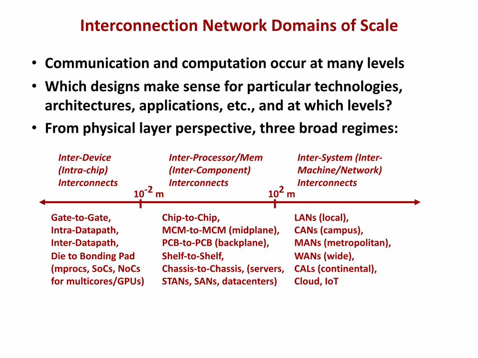
• Communication and computation occur at many levels• Which designs make sense for particular technologies,
architectures, applications, etc., and at which levels?• From physical layer perspective, three broad regimes:
10-2 m 102 m
Inter-Device(Intra-chip) Interconnects
Inter-Processor/Mem(Inter-Component)Interconnects
Inter-System (Inter-Machine/Network) Interconnects
Gate-to-Gate, Intra-Datapath,Inter-Datapath,Die to Bonding Pad(mprocs, SoCs, NoCsfor multicores/GPUs)
Chip-to-Chip,MCM-to-MCM (midplane),PCB-to-PCB (backplane),Shelf-to-Shelf,Chassis-to-Chassis, (servers, STANs, SANs, datacenters)
LANs (local),CANs (campus),MANs (metropolitan),WANs (wide),CALs (continental),Cloud, IoT
Interconnection Network Domains of Scale
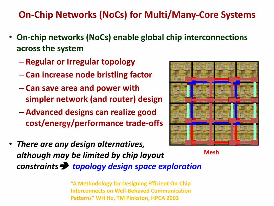
• On-chip networks (NoCs) enable global chip interconnections across the system–Regular or Irregular topology–Can increase node bristling factor–Can save area and power with
simpler network (and router) design–Advanced designs can realize good
cost/energy/performance trade-offs
• There are any design alternatives, although may be limited by chip layout constraintsè topology design space exploration
“A Methodology for Designing Efficient On-Chip Interconnects on Well-Behaved Communication Patterns” WH Ho, TM Pinkston, HPCA 2003
Mesh
On-Chip Networks (NoCs) for Multi/Many-Core Systems
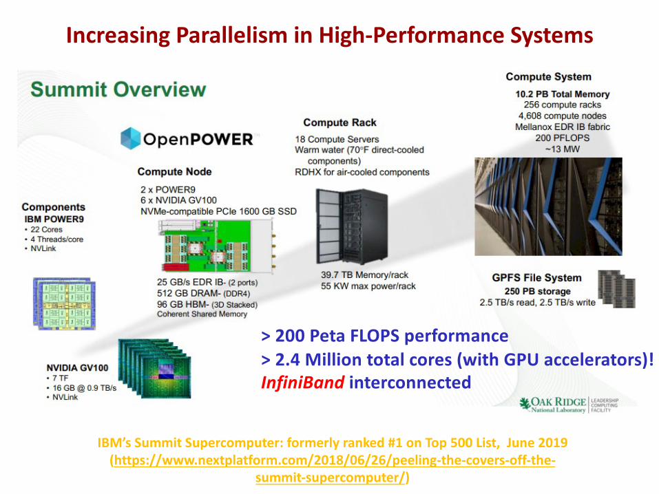
> 200 Peta FLOPS performance> 2.4 Million total cores (with GPU accelerators)!InfiniBand interconnected
IBM’s Summit Supercomputer: formerly ranked #1 on Top 500 List, June 2019 (https://www.nextplatform.com/2018/06/26/peeling-the-covers-off-the-
summit-supercomputer/)
Increasing Parallelism in High-Performance Systems
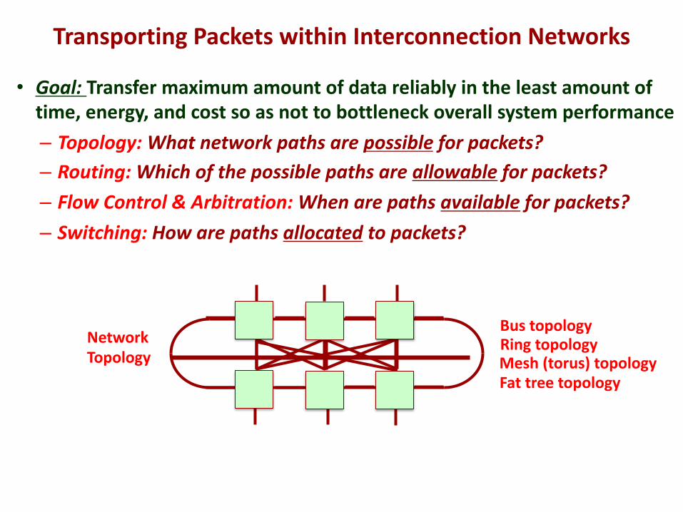
Transporting Packets within Interconnection Networks
• Goal: Transfer maximum amount of data reliably in the least amount of time, energy, and cost so as not to bottleneck overall system performance– Topology: What network paths are possible for packets?– Routing: Which of the possible paths are allowable for packets?– Flow Control & Arbitration: When are paths available for packets?– Switching: How are paths allocated to packets?
Bus topologyRing topologyMesh (torus) topologyFat tree topology
NetworkTopology
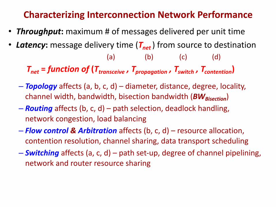
• Throughput: maximum # of messages delivered per unit time• Latency: message delivery time (Tnet ) from source to destination
(a) (b) (c) (d)
Tnet = function of (Ttransceive , Tpropagation , Tswitch , Tcontention)
– Topology affects (a, b, c, d) – diameter, distance, degree, locality, channel width, bandwidth, bisection bandwidth (BWBisection)
– Routing affects (b, c, d) – path selection, deadlock handling, network congestion, load balancing
– Flow control & Arbitration affects (b, c, d) – resource allocation, contention resolution, channel sharing, data transport scheduling
– Switching affects (a, c, d) – path set-up, degree of channel pipelining, network and router resource sharing
Characterizing Interconnection Network Performance
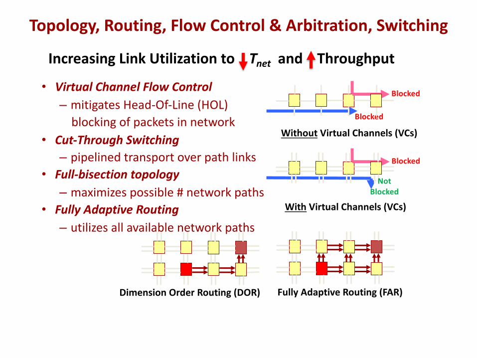
Increasing Link Utilization to Tnet and Throughput
• Virtual Channel Flow Control– mitigates Head-Of-Line (HOL)
blocking of packets in network• Cut-Through Switching– pipelined transport over path links
• Full-bisection topology– maximizes possible # network paths
• Fully Adaptive Routing– utilizes all available network paths
Blocked
Blocked
Without Virtual Channels (VCs)
Blocked
With Virtual Channels (VCs)
Dimension Order Routing (DOR) Fully Adaptive Routing (FAR)
Not Blocked
Topology, Routing, Flow Control & Arbitration, Switching
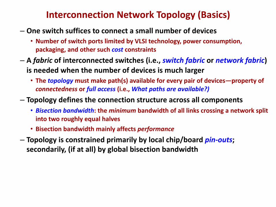
– One switch suffices to connect a small number of devices• Number of switch ports limited by VLSI technology, power consumption,
packaging, and other such cost constraints
– A fabric of interconnected switches (i.e., switch fabric or network fabric) is needed when the number of devices is much larger• The topology must make path(s) available for every pair of devices—property of
connectedness or full access (i.e., What paths are available?)
– Topology defines the connection structure across all components• Bisection bandwidth: the minimum bandwidth of all links crossing a network split
into two roughly equal halves• Bisection bandwidth mainly affects performance
– Topology is constrained primarily by local chip/board pin-outs; secondarily, (if at all) by global bisection bandwidth
Interconnection Network Topology (Basics)
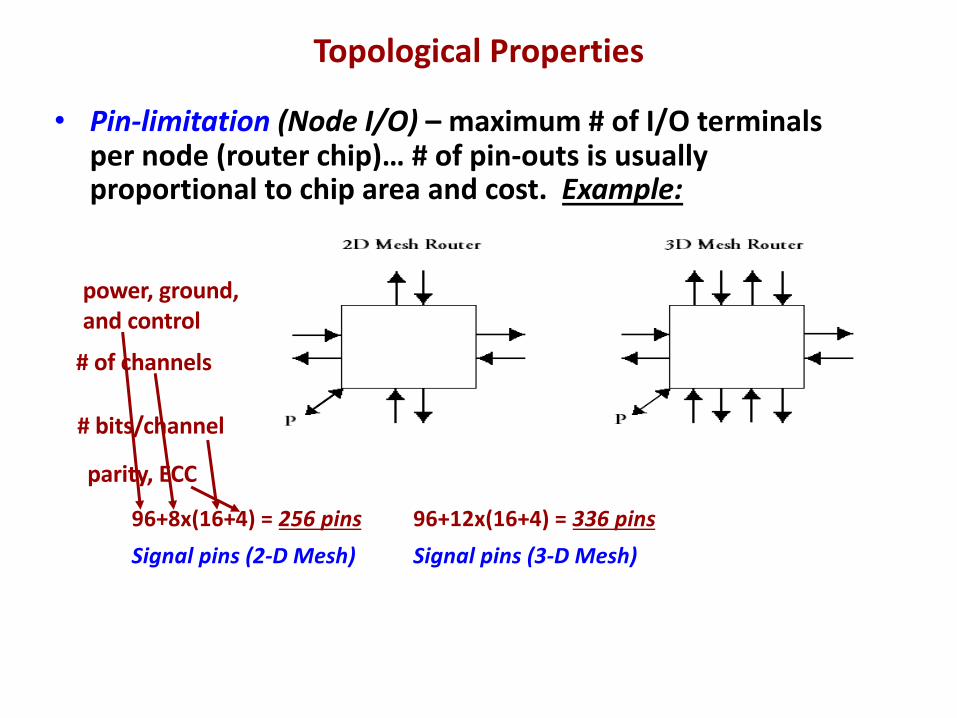
power, ground,and control
• Pin-limitation (Node I/O) – maximum # of I/O terminals per node (router chip)… # of pin-outs is usually proportional to chip area and cost. Example:
96+8x(16+4) = 256 pins 96+12x(16+4) = 336 pinsSignal pins (2-D Mesh) Signal pins (3-D Mesh)
# of channels
# bits/channel
parity, ECC
Topological Properties
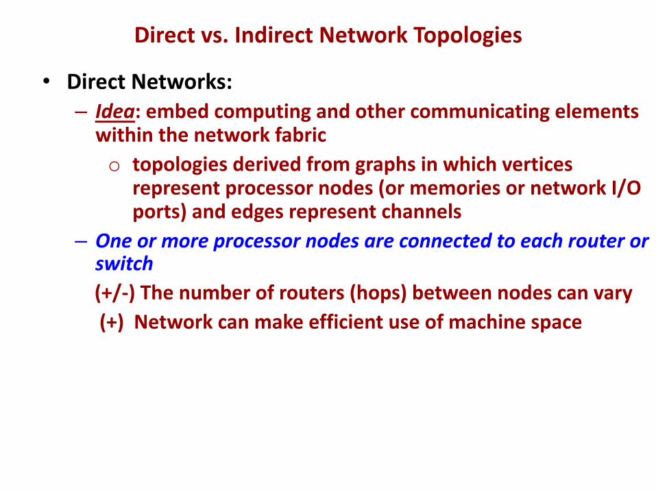
• Direct Networks:– Idea: embed computing and other communicating elements
within the network fabrico topologies derived from graphs in which vertices
represent processor nodes (or memories or network I/O ports) and edges represent channels
– One or more processor nodes are connected to each router or switch(+/-) The number of routers (hops) between nodes can vary(+) Network can make efficient use of machine space
Direct vs. Indirect Network Topologies
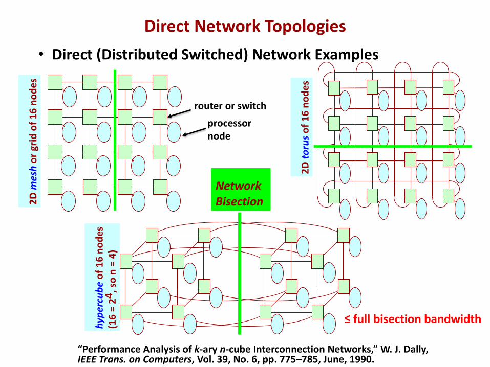
• Direct (Distributed Switched) Network Examples
2D to
ruso
f 16
node
s
hype
rcub
eof
16
node
s(1
6 =
24, s
o n
= 4)
2D m
esh
or g
rid o
f 16
node
s
NetworkBisection
≤ full bisection bandwidth
“Performance Analysis of k-ary n-cube Interconnection Networks,” W. J. Dally,IEEE Trans. on Computers, Vol. 39, No. 6, pp. 775–785, June, 1990.
router or switch
processornode
Direct Network Topologies
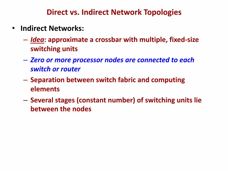
• Indirect Networks:– Idea: approximate a crossbar with multiple, fixed-size
switching units– Zero or more processor nodes are connected to each
switch or router– Separation between switch fabric and computing
elements– Several stages (constant number) of switching units lie
between the nodes
Direct vs. Indirect Network Topologies
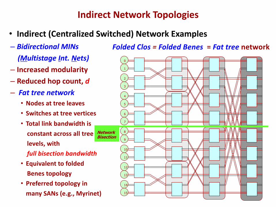
– Bidirectional MINs(Multistage Int. Nets)
– Increased modularity– Reduced hop count, d– Fat tree network• Nodes at tree leaves• Switches at tree vertices• Total link bandwidth is
constant across all treelevels, with full bisection bandwidth
• Equivalent to foldedBenes topology
• Preferred topology inmany SANs (e.g., Myrinet)
Folded Clos = Folded Benes = Fat tree network
7
6
5
4
3
2
1
0
15
14
13
12
11
10
9
8NetworkBisection
Indirect Network Topologies
• Indirect (Centralized Switched) Network Examples
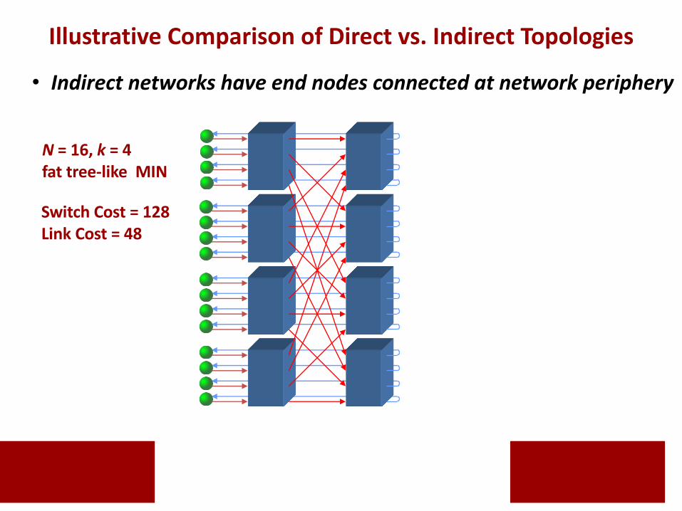
• Indirect networks have end nodes connected at network periphery
Switch Cost = 128Link Cost = 48
N = 16, k = 4fat tree-like MIN
Illustrative Comparison of Direct vs. Indirect Topologies
Switch Cost = 128Link Cost = 48
Switch Cost = 128Link Cost = 48 à 40
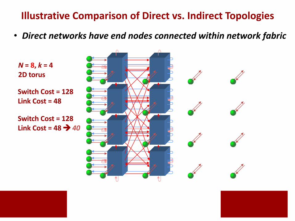
N = 8, k = 42D torus
Illustrative Comparison of Direct vs. Indirect Topologies
• Direct networks have end nodes connected within network fabric
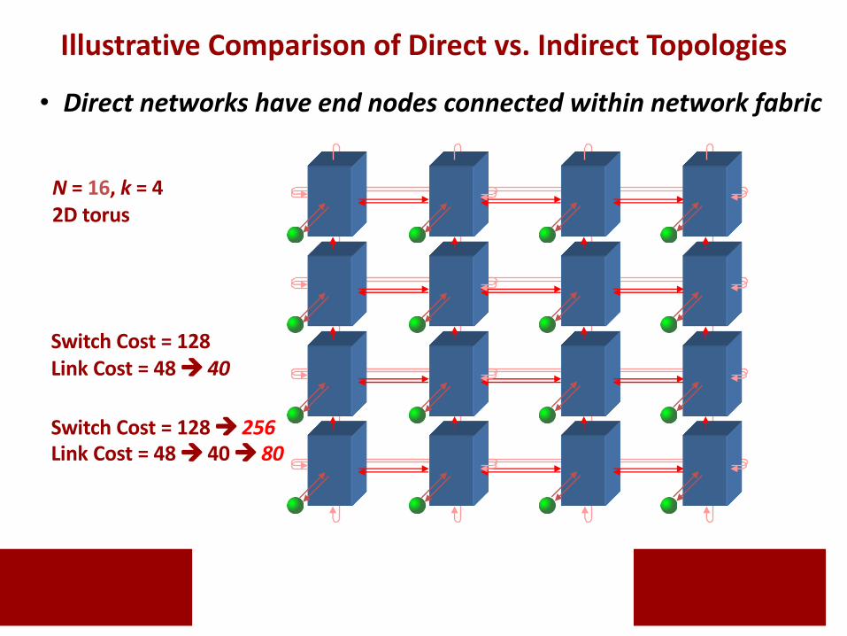
Switch Cost = 128Link Cost = 48 à 40
Switch Cost = 128 à 256Link Cost = 48 à 40 à 80
N = 16, k = 42D torus
Illustrative Comparison of Direct vs. Indirect Topologies
• Direct networks have end nodes connected within network fabric
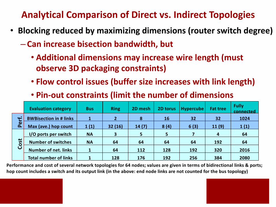
• Blocking reduced by maximizing dimensions (router switch degree)–Can increase bisection bandwidth, but• Additional dimensions may increase wire length (must
observe 3D packaging constraints)• Flow control issues (buffer size increases with link length)• Pin-out constraints (limit the number of dimensions
achievable)Evaluation category Bus
BWBisection in # links
Ring 2D mesh
1
Hypercube Fat tree2D torus Fullyconnected
2 8 16 32 32 1024
Max (ave.) hop count 1 (1) 32 (16) 14 (7) 8 (4) 6 (3) 11 (9) 1 (1)I/O ports per switch NA 3 5 5 7 4 64
Number of switches NA 64 64 64 64 192 64
Number of net. links 1 64 112 128 192 320 2016Total number of links 1 128 176 192 256 384 2080
Performance and cost of several network topologies for 64 nodes; values are given in terms of bidirectional links & ports; hop count includes a switch and its output link (in the above: end node links are not counted for the bus topology)
Perf.
Cost
Analytical Comparison of Direct vs. Indirect Topologies
• Performed at each switch, regardless of topology• Defines the “allowed” path(s) for each packet (Which paths are
safe and allowable?)• Needed to direct packets through network to intended dest’s• Ideally:– Supply as many routing options to packets as there are paths available
by the topology, and evenly distribute network traffic among network links using those paths to minimizing contention, mitigate congestion
• Problems: situations causing packets never to reach destinations– Deadlock• Arises from a set of packets being blocked waiting only for network resources
(i.e., links, buffers) held by other packets in the persistently blocked set• Probability increases with increased traffic and decreased path availability
– Livelock• Arises from an unbounded number of allowed non-minimal hops (misroutes)• Solution: restrict the number of non-minimal (mis)hops allowed
Routing (Basics)
• Routing algorithm selects an output channel for a packet arriving on a given router input channel–Handle deadlock, livelock, and starvation – to allow packets
reach their destinations (avoidance vs. recovery)–Path selection – choose amongst all allowable network paths:
source-based vs. distributed-basedtable-driven vs. algorithmic-driven
• Load balancing? (oblivious vs. adaptive)• Shortest paths? (minimal vs. non-minimal)
• Reduce latency and increase throughput by routing efficiently around congestion and faulty nodes or links(distribute load evenly across all network resources)(+) flexibility can reduce Tcontention
(-) complexity can increase Tprop , Tswitch if not careful
Routing (Basics)
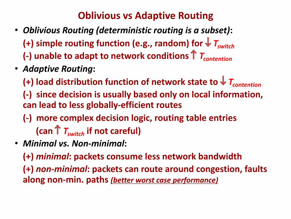
• Oblivious Routing (deterministic routing is a subset):(+) simple routing function (e.g., random) for ¯ Tswitch
(-) unable to adapt to network conditions Tcontention
• Adaptive Routing:(+) load distribution function of network state to ¯ Tcontention
(-) since decision is usually based only on local information, can lead to less globally-efficient routes(-) more complex decision logic, routing table entries
(can Tswitch if not careful)• Minimal vs. Non-minimal:
(+) minimal: packets consume less network bandwidth(+) non-minimal: packets can route around congestion, faults along non-min. paths (better worst case performance)
Oblivious vs Adaptive Routing
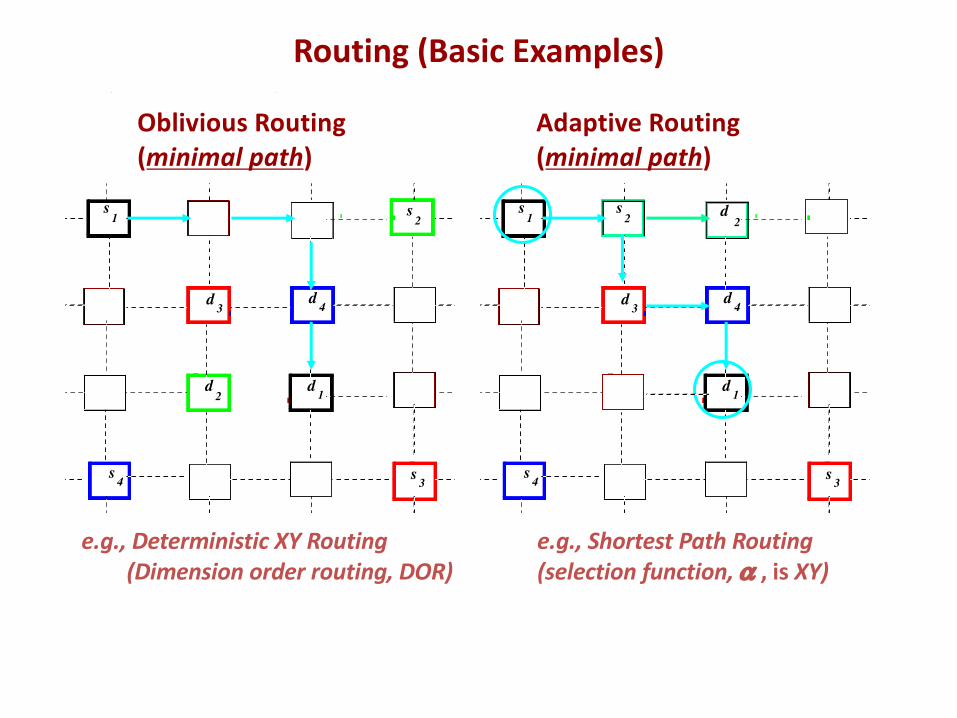
Oblivious Routing(minimal path)
Adaptive Routing(minimal path)
e.g., Deterministic XY Routing(Dimension order routing, DOR)
e.g., Shortest Path Routing (selection function, a , is XY)
s1
d 1
s2
s 3
d 3
d2
s 4
d 4
s1
d 1
s 3
d 3
s 4
d 4
d2
s2
Routing (Basic Examples)
s1
d 1
s2
s 3
d 3
d2
s 4
d 4
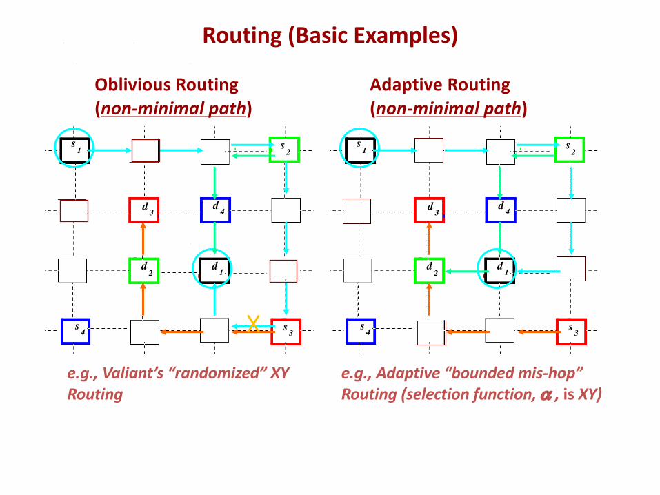
Oblivious Routing(non-minimal path)
Adaptive Routing(non-minimal path)
s1
d 1
s2
s 3
d 3
d2
s 4
d 4
e.g., Valiant’s “randomized” XY Routing
e.g., Adaptive “bounded mis-hop” Routing (selection function, a , is XY)
Routing (Basic Examples)
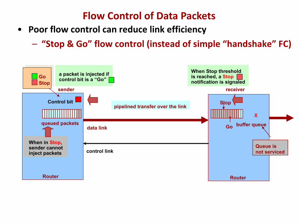
receiversender
GoStop
When Stop threshold is reached, a Stopnotification is signaled
Control bit Stop
Go
When in Stop,sender cannotinject packets
X
Queue isnot serviced
Router Router
data link
control link
pipelined transfer over the link
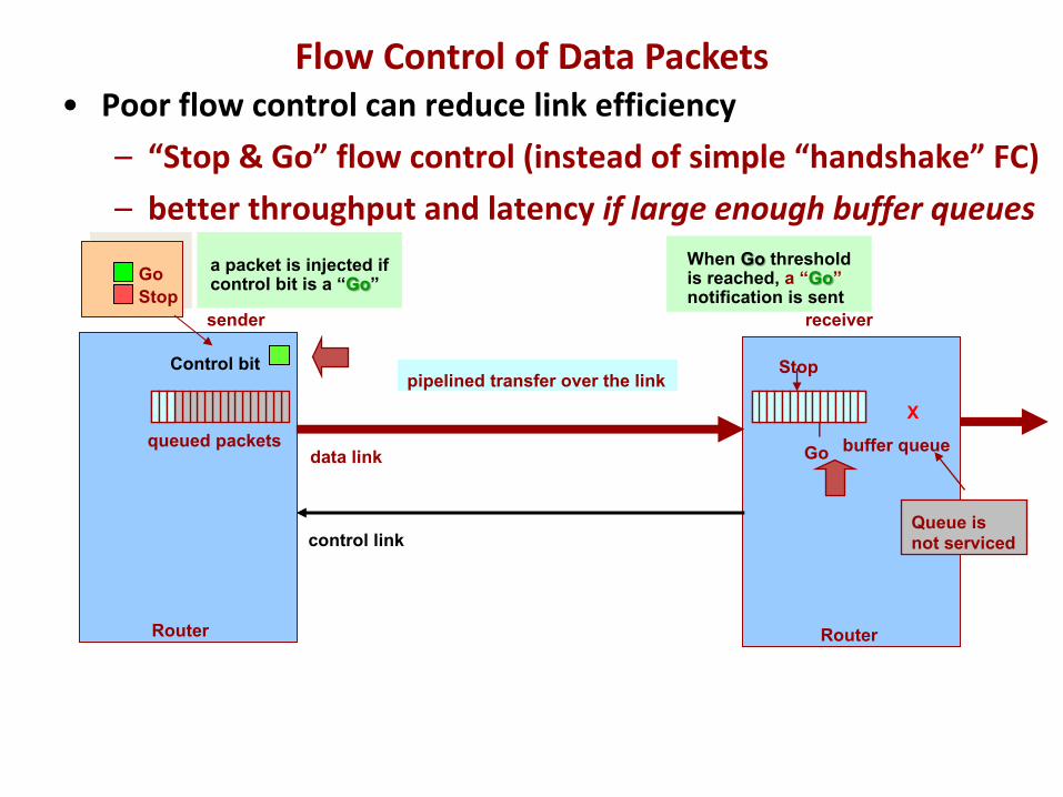
• Poor flow control can reduce link efficiency– “Stop & Go” flow control (instead of simple “handshake” FC)
a packet is injected if control bit is a “Go”
buffer queuequeued packets
Flow Control of Data Packets
receiversender
GoStop
When Go threshold is reached, a “Go” notification is sent
Control bit
Go
Stop
X
Queue isnot serviced
Router Router
data link
control link
pipelined transfer over the link
• Poor flow control can reduce link efficiency– “Stop & Go” flow control (instead of simple “handshake” FC)– better throughput and latency if large enough buffer queues
a packet is injected if control bit is a “Go”
queued packets buffer queue
Flow Control of Data Packets
receiversender
Sender sends packets whenever credit counteris not zero
109876543210
X
Queue isnot serviced
Credit counter
Router Router
data link
control link
pipelined transfer over the link
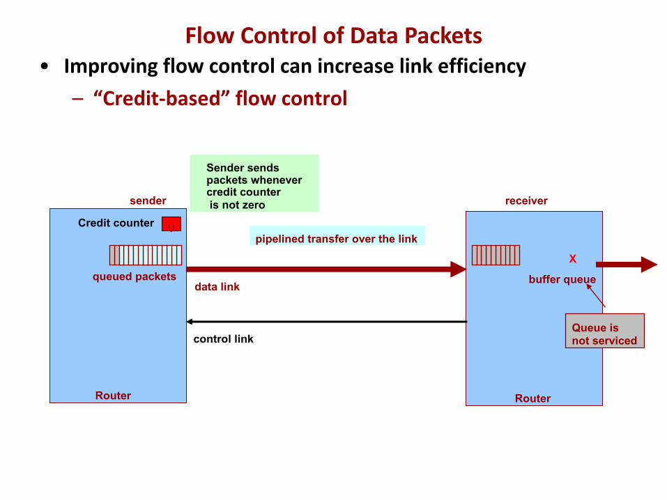
• Improving flow control can increase link efficiency– “Credit-based” flow control
buffer queuequeued packets
Flow Control of Data Packets
receiversender
10Credit counter 9876543210
+5
5432
X
Queue isnot serviced
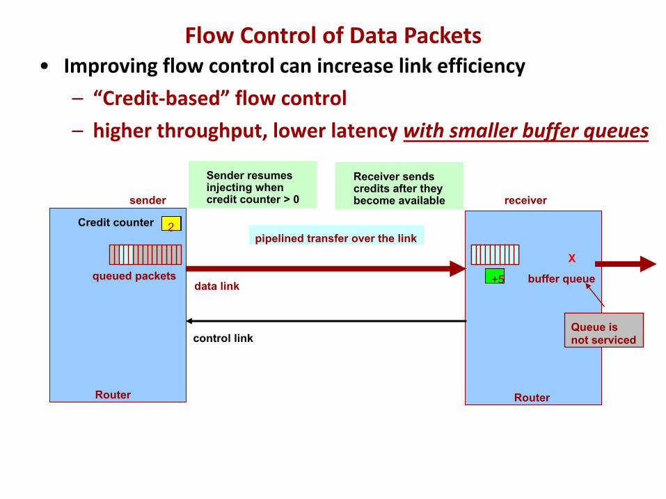
Receiver sends credits after they become available
Sender resumesinjecting when credit counter > 0
Router Router
data link
control link
pipelined transfer over the link
• Improving flow control can increase link efficiency– “Credit-based” flow control– higher throughput, lower latency with smaller buffer queues
buffer queuequeued packets
Flow Control of Data Packets
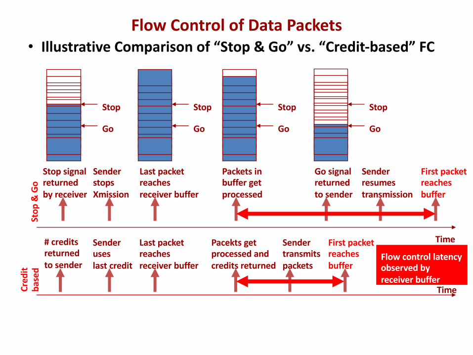
• Illustrative Comparison of “Stop & Go” vs. “Credit-based” FCSt
op &
Go
Time
Cred
itba
sed
Time
Go
Stop
Go
Stop
Go
Stop
Sender stopsXmission
Last packetreachesreceiver buffer
Stop
Go
Packets inbuffer getprocessed
Go signalreturnedto sender
Sender resumestransmission
First packetreachesbuffer
# creditsreturnedto sender
Sender useslast credit
Last packetreachesreceiver buffer
Pacekts getprocessed andcredits returned
Sender transmitspackets
First packetreachesbuffer
Flow control latencyobserved byreceiver buffer
Stop signalreturnedby receiver
Flow Control of Data Packets
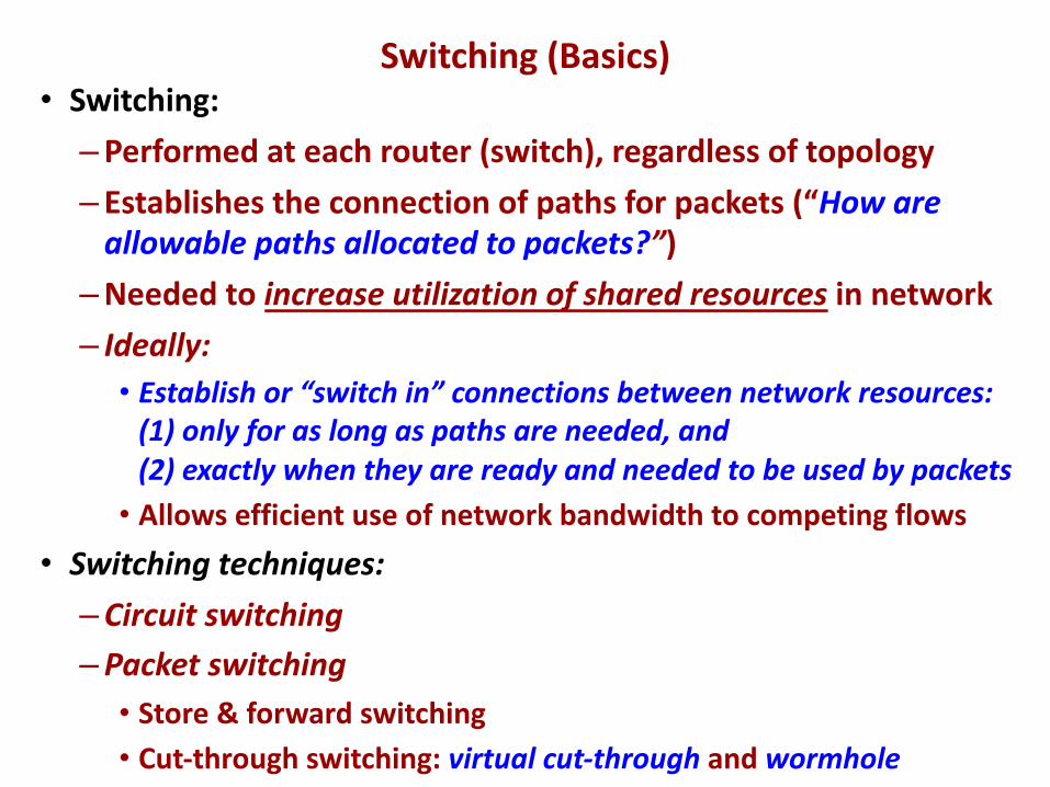
• Switching:–Performed at each router (switch), regardless of topology– Establishes the connection of paths for packets (“How are
allowable paths allocated to packets?”)–Needed to increase utilization of shared resources in network– Ideally:• Establish or “switch in” connections between network resources:
(1) only for as long as paths are needed, and (2) exactly when they are ready and needed to be used by packets• Allows efficient use of network bandwidth to competing flows
• Switching techniques:–Circuit switching–Packet switching• Store & forward switching• Cut-through switching: virtual cut-through and wormhole
Switching (Basics)
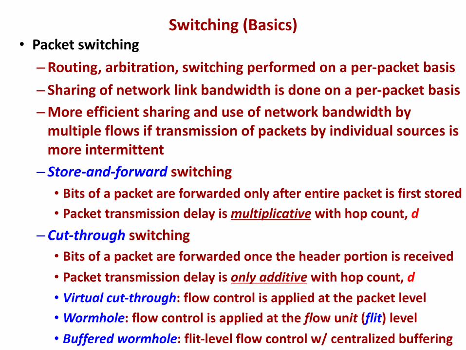
• Packet switching–Routing, arbitration, switching performed on a per-packet basis– Sharing of network link bandwidth is done on a per-packet basis–More efficient sharing and use of network bandwidth by
multiple flows if transmission of packets by individual sources is more intermittent– Store-and-forward switching• Bits of a packet are forwarded only after entire packet is first stored• Packet transmission delay is multiplicative with hop count, d
–Cut-through switching• Bits of a packet are forwarded once the header portion is received• Packet transmission delay is only additive with hop count, d• Virtual cut-through: flow control is applied at the packet level• Wormhole: flow control is applied at the flow unit (flit) level • Buffered wormhole: flit-level flow control w/ centralized buffering
Switching (Basics)
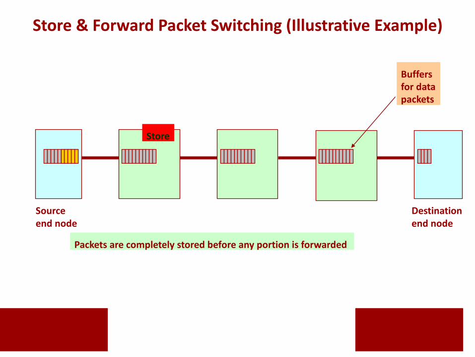
Sourceend node
Destination end node
Packets are completely stored before any portion is forwarded
Store
Buffers for datapackets
Store & Forward Packet Switching (Illustrative Example)
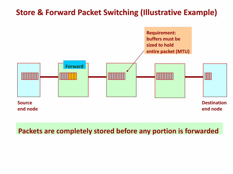
Sourceend node
Destination end node
Packets are completely stored before any portion is forwarded
StoreForward
Requirement:buffers must be sized to holdentire packet (MTU)
Store & Forward Packet Switching (Illustrative Example)
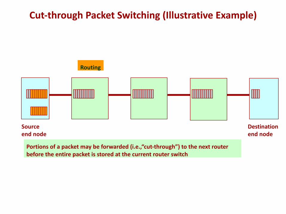
Sourceend node
Destination end node
Routing
Portions of a packet may be forwarded (i.e.,“cut-through”) to the next routerbefore the entire packet is stored at the current router switch
Cut-through Packet Switching (Illustrative Example)
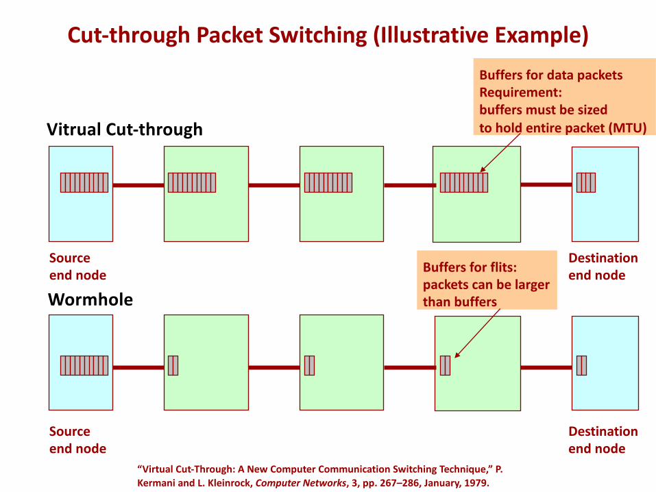
Wormhole
Source end node
Destination end node
Sourceend node
Destination end node
Buffers for data packetsRequirement:buffers must be sizedto hold entire packet (MTU)
Buffers for flits:packets can be largerthan buffers
“Virtual Cut-Through: A New Computer Communication Switching Technique,” P. Kermani and L. Kleinrock, Computer Networks, 3, pp. 267–286, January, 1979.
Cut-through Packet Switching (Illustrative Example)
Vitrual Cut-through
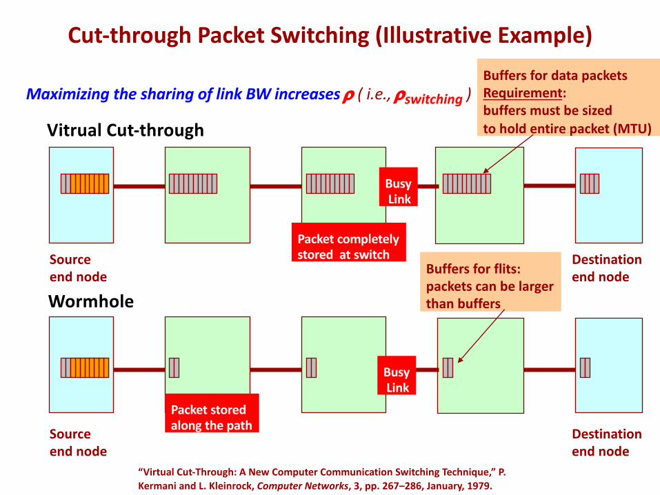
Wormhole
Source end node
Destination end node
Sourceend node
Destination end node
BusyLink
Packet storedalong the path
BusyLink
Packet completelystored at switch
Maximizing the sharing of link BW increases r ( i.e., rswitching )Buffers for data packetsRequirement:buffers must be sizedto hold entire packet (MTU)
Buffers for flits:packets can be largerthan buffers
Cut-through Packet Switching (Illustrative Example)
Vitrual Cut-through
“Virtual Cut-Through: A New Computer Communication Switching Technique,” P. Kermani and L. Kleinrock, Computer Networks, 3, pp. 267–286, January, 1979.
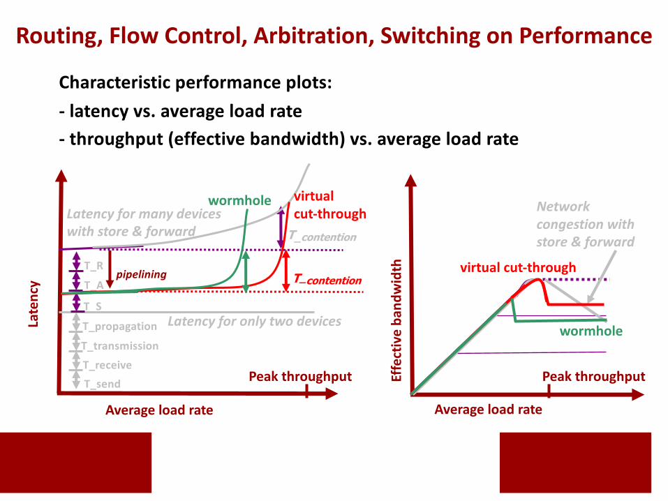
Average load rate
Late
ncy
T_sendT_receive
T_transmission
T_propagation
T_S
T_A
T_R
T_contention
Latency for only two devices
Average load rateEf
fect
ive
band
wid
th
Networkcongestion withstore & forward
Characteristic performance plots:- latency vs. average load rate- throughput (effective bandwidth) vs. average load rate
Latency for many deviceswith store & forward
T_contention
virtual cut-through
pipelining
wormhole
virtual cut-through
wormhole
Peak throughput Peak throughput
Routing, Flow Control, Arbitration, Switching on Performance


