Embed Size (px)
Citation preview
INTERNATIONAL STANDARD
ISO 3161
Second edition 1996-02-0 1
Aerospace - UNJ threads, with controlled root radius, for aerospace - Inch series
Abronautique et espace - Filetage UNJ, avec rayon 3 fond de filet con trol6, pour applica Gons akrospa tiales - Serie en inches
Reference number ISO 3161 :1996(E)
This preview is downloaded from www.sis.se. Buy the entire standard via https://www.sis.se/std-602660
ISO 3161:1996(E)
Foreword
ISO (the International Organization for Standardization) is a worldwide federation of national Standards bodies (ISO member bodies). The work of preparing International Standards is normally carried out through ISO technical committees. Esch member body interested in a subject for which a technical committee has been established has the right to be represented on that committee. International organizations, governmental and non-governmental, in liaison with ISO, also take part in the work. ISO collaborates closely with the International Electrotechnical Commission (IEC) on all matters of electrotechnical standardization.
Draft International Standards adopted by the technical committees are circulated to the member bodies for voting. Publication as an International Standard requires approval by at least 75 % of the member bodies casting a vote.
International Standard ISO 3161 was prepared by Technical Committee ISOnC 20, Aircraft and space vehicles, Subcommittee SC 4, Aerospace fas tener sys tems.
This second edition cancels and replaces the first edition (ISO 3161:1977), of which it constitutes a technical revision.
0 ISO 1996
All rights reserved. Unless otherwise specified, no part of this publication may be reproduced or utilized in any form or by any means, electronie or mechanical, including photocopying and microfilm, without Permission in writing from the publisher.
International Orga nization for Standardization Case Postale 56 l CH-l 21 IG et-kve 20 0 Switzerland
Printed in Switzerland
This preview is downloaded from www.sis.se. Buy the entire standard via https://www.sis.se/std-602660
IN’TERNATIONAL STANDARD @ ISO ISO 3161:1996(E)
Aerospace - UNJ threads, wit controlled root radius, for aerospace - Inch series
1 Scope
This International Standard specifies the character- istics of inch series UNJ threads with controlled root radius.
lt determines the basic triangular Profile for this type of thread and gives a System for designating the di- ameter/pitch combinations. For all diameters 0,060 in to 6,000 in, it offers in the form of tables the basic di- mensions and tolerantes for a selection of diam- eter/pitch combinations. lt also provides the method of calculation for the dimensions and tolerantes for any diameter/pitch combination not given in the tables, including threads with a diameter in excess of 6,000 in.
NOTE 1 Pending publication of the International Standard relating to Iimit gauges referred to in the footnote in clause 7, special care must be taken to ensure that the dimensions and tolerantes specified in this International Standard are confirmed by alternative means.
This International Standard applies primarily to the threads of inch series aerospace fasteners.
2 Definition
For the purposes of this International Standard, the following definition applies.
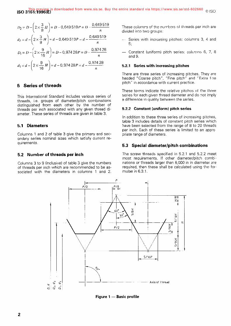
2.1 basic Profile: The theoretical Profile correspond- ing to the basic dimensions, i.e. the major diameter, the pitch diameter and the minor diameter. See figure 1 and clause 3.
The tolerantes are applied to the basic Profile.
3 Symbols
D = basic major diameter of internal thread
D, = basic pitch diameter of internal thread
D, = basic minor diameter of internal thread
d = basic major diameter of external thread
d, = basic pitch diameter of external thread
d, = basic minor diameter of external thread
H= height of fundamental triangle
P= pitch
n = number of threads per inch
4 Basic Profile of thread
4.1 Basic Profile dimensions
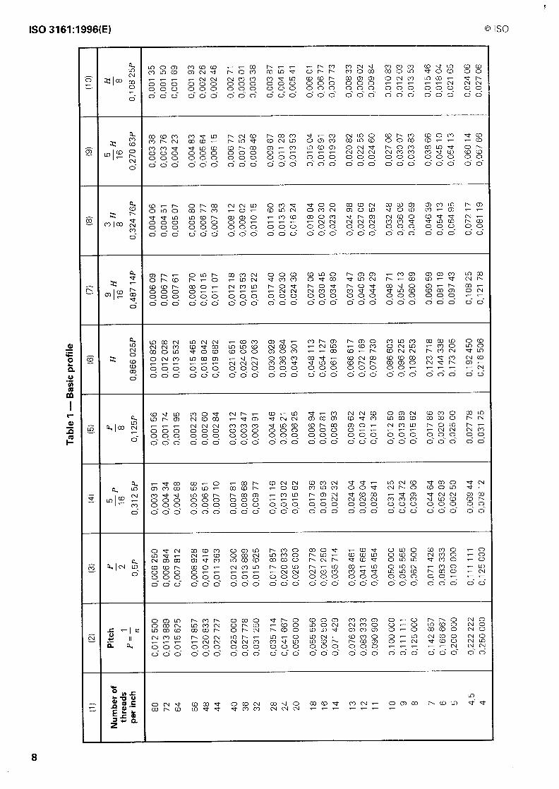
Values given in table 1 have been calculated according to the following formulae:
1 pz- n
1 y1= - P
3r- 3 Hz-- 0,866025 2
xP=O,866025P= n
9 -H=0,48714P= 0,487 14
16 n
3 zH=0,324759P= 0,324 759 8 n
5 -H=O,27063P= 0,27063 16 n
5=0,10825P= 0,10825 8 n
4.2 Basic dimensions of thread
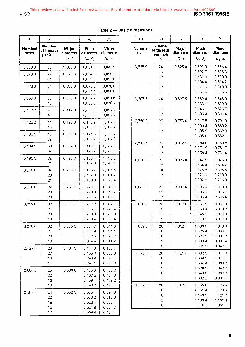
Values given in table 2 have been calculated according to the following formulae:
This preview is downloaded from www.sis.se. Buy the entire standard via https://www.sis.se/std-602660
ISO 3161:1996(E) @ ISO
= D-0,649519P= D- 0,649519
n
=d-0,649519P=d- 0,649519
n
=D-0,97428P=D- 0,974 28
n
=d-0,97428P=d- 0,974 28
n
5 Series of threads
This International Standard includes various series of threads, i.e. groups of diameter/pitch combinations distinguished from each other by the number of threads per inch associated with any given thread di- ameter. These series of threads are given in table 3.
5.1 Diameters
Columns 1 and 2 of table 3 give the primary and sec- ondary series nominal sizes which satisfy current re- quirements.
5.2 Number of threads per inch
Columns 3 to 9 (inclusive) of table 3 give the numbers of threads per inch which are recommended to be as- sociated with the diameters in columns 1 and 2.
These columns of the numbers of threads per inch are divided into two groups:
- Series with increasing pitches: columns 3, 4 and 5;
- Constant (uniform) pitch series: columns 6, 7, 8 and 9.
5.2.1 Series with increasing pitches
There are three series of increasing pitches. They are headed “Coarse pitch”, “Fine pitch” and “Extra fine pitch” in accordance with current practice.
These terms indicate the relative pitches of the three series for each given thread diameter and do not imply a differente in quality between the series.
5.2.2 Constant (uniform) pitch series
In addition to these three series of increasing pitches, table 3 includes details of constant pitch series which have been selected from the range of 8 to 20 threads per inch. Esch of these series is limited to an appro- priate range of diameters.
5.3 Special diameter/pitch combinations
The screw threads specified in 5.2.1 and 5.2.2 meet most requirements. If other diameter/pitch combi- nations or threads larger than 6,000 in in diameter are required, then these shall be calculated using the for- mulae in 6.3.1.
P
\ -(_-_~_--_---~-~ --- I
~- Axis of thread
Figure 1 - Basic Profile
This preview is downloaded from www.sis.se. Buy the entire standard via https://www.sis.se/std-602660
@ ISO ISO 3161:1996(E)
6 Tolerantes
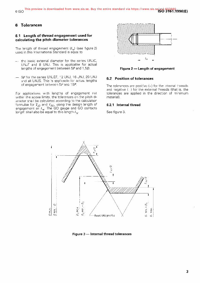
6.1 Length of thread engagement used for calculating the pitch diameter tolerantes
The length of thread engagement (L,) (see figure 2) used in this International Standard is equal to
- the basic extemal diameter for the series UNJC, UNJF and 8 UNJ. This is applicable for actual lengths of engagement between 5P and 1,5D.
- 9P for the series UNJEF, 12 UNJ, 16 UNJ, 20 UNJ and all UNJS. This is applicable for actual lengths of engagement between 5P and 15B.
For applications with lengths of engagement not within the above limits, the tolerantes on the pitch di- ameter shall be calculated according to the calculation formulae for Td2 and TD2, using the design length of engagement as L,. The GO gauge and GO contacts length shall also be equal to this length k,.
_-
Figure 2 - Length of engagement
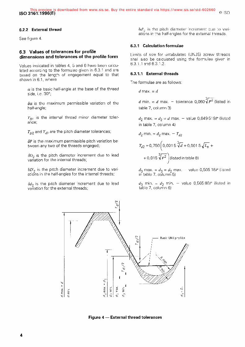
6.2 Position of tolerantes
The tolerantes are positive (+) for the internal threads and negative (-) for the external threads (that is, the tolerantes are applied in the direction of minimum material).
6.21 Internal thread
See figure 3.
Figure 3 - Internal thread tolerantes
This preview is downloaded from www.sis.se. Buy the entire standard via https://www.sis.se/std-602660
ISO 3161:1996(E) @ ISO
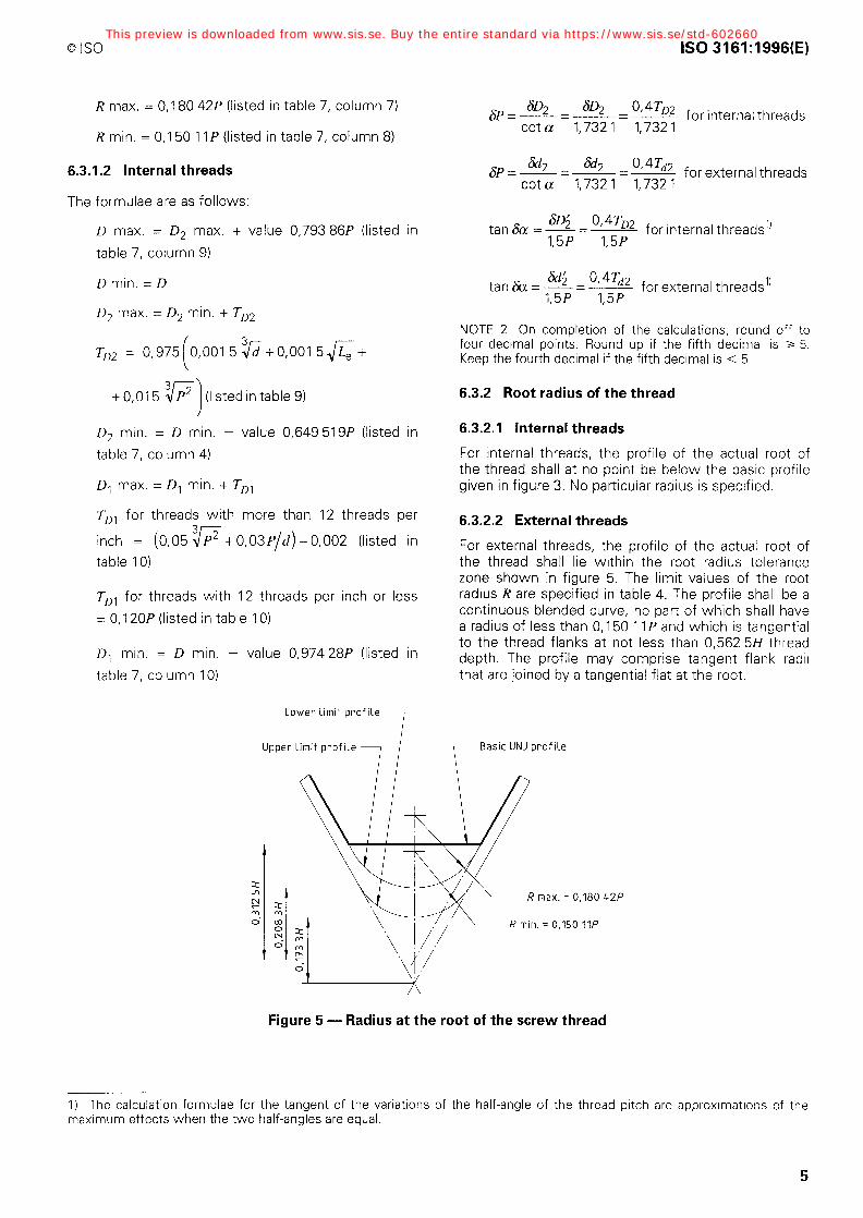
6.22 External thread W, is the pitch diameter increment due to vari- ations in the half-angles for the external threads.
See figure 4.
6.3.1 Calculation formulae 6.3 Values of tolerantes for Profile dimensions and tolerantes of the Profile form
Values indicated in tables 4, 5 and 6 have been calcu- lated according to the formulae given in 6.3.1 and are based on the length of engagement equal to that shown in 6.1, where
a is the basic half-angle at the base of the thread side, i.e. 30”;
6a is the maximum permissible Variation of the half-angle;
TD., is the internal thread minor diameter toler- ante;
TD2 and Td2 are the pitch diameter tolerantes;
6P is the maximum permissible pitch Variation be- tween any two of the threads engaged;
60, is the pitch diameter increment due to lead Variation for the internal threads;
SO; is the pitch diameter increment due to vari- ations in the half-angles for the internal threads;
6d, is the pitch diameter increment due to lead Variation for the external threads;
b II
x
ri
-G
E .- E b”
Limits of size for untabulated (UNJS) screw threads shall also be calculated using the formulae given in 6.3.1.1 and 6.3.1.2.
6.3.1.1 External threads
The formulae are as follows:
d max. = d
d min. = d max. - tolerante 0,060 P (listed in 3c table 7, column 3)
d, max. = d, = d max. - value 0,649 519P (listed in table 7, column 4)
d, min. = d, max. - Td2
Td2 = 0,750 0,001 5 3Jd+ 0,001 5 ,/< +
(listed in table 8)
d3 max. = d, = d, max. - value 0,505 18P (listed in table 7, column 5)
d, min. = d, min. - value 0,565 80P (listed in table 7, column 6)
N \ CY Basic UNJ Profile
Figure 4 - External thread tolerantes
This preview is downloaded from www.sis.se. Buy the entire standard via https://www.sis.se/std-602660
@ ISO
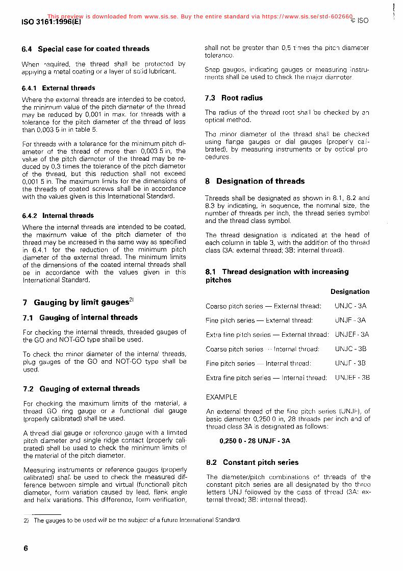
R max. = 0,180 42P (listed in table 7, column 7)
R min. = 0,150 11 P (listed in table 7, column 8)
6.3.1.2 Internal threads
The formulae are as follows:
D max. = D, max. + value 0,793 86P (listed in table 7, column 9)
D min. = D
D, max. = D, min. + To2
TD2 = 0,975 (
0,001 5 3Jzj+o,oo15&-
3 2 + 0,015 P ")
(listed in table 9)
D2 min. = D min. - value 0,649 519P (listed in
table 7, column 4)
D, max. = D, min. + TOI
TDl for threads with more than 12 threads per
inch = (0,05 37 + 0,03P"d) - 0,002 (listed in table IO)
TDl for threads with 12 threads per inch or less = 0, IZOP (listed in table IO)
D, min. = D min. - value 0,974 28P (listed in table 7, column IO)
Lower Limit Profile --/
Upper Limit Profile 7’
ISO 3161:1996(E)
6P 6D 2 SD 2 0, @-DZ =-=-=- for internal threads cot a 1,7321 1,7321
6P =A.k= &2 0,4T,, - = - for external threads cot a 1,7321 1,7321
tan& =i=- SD 0,4T~2 for internal threads’) 1,5P 1,5P
tan&= w 0,4T,, -=- for external threads’) 1,5P 1,5P
NOTE 2 On completion of the calculations, round off to four decimal Points. Round up if the fifth decimal is 2 5. Keep the fourth decimal if the fifth decimal is < 5.
6.32 Root radius of the thread
6.3.2.1 Internal threads
For internal threads, the Profile of the actual root of the thread shall at no Point be below the basic Profile given in figure 3. No particular radius is specified.
6.3.2.2 External threads
For external threads, the Profile of the actual root of the thread shall lie within the root radius tolerante zone shown in figure 5. The limit values of the root radius R are specified in table 4. The Profile shall be a continuous blended curve, no part of which shall have a radius of less than 0,150 1 1 P and which is tangential to the thread flanks at not less than 0,562 5H thread depth. The Profile may comprise tangent flank radii that are joined by a tangential flat at the root.
r Basic UNJ Profite
x. = 0,180 42P
0,150 VP
Figure 5 - Radius at the root of the screw thread
1) The calculation formulae for the tangent of the variations of the half-angle of the thread pitch are approximations of the maximum effects when the two half-angles are equal.
5
This preview is downloaded from www.sis.se. Buy the entire standard via https://www.sis.se/std-602660
ISO 3161:1996(E)
6.4 Special case for coated threads
When required, the thread shall be protected by applying a metal coating or a layer of solid Iubricant.
6.4.1 External threads
Where the extemal threads are intended to be coated, the minimum value of the pitch diameter of the thread may be reduced by 0,001 in max. for threads with a tolerante for the pitch diameter of the thread of less than 0,003 5 in in table 5.
For threads with a tolerante for the minimum pitch di- ameter of the thread of more than 0,003 5 in, the value of the pitch diameter of the thread may be re- duced by 0,3 times the tolerante of the pitch diameter of the thread, but this reduction shall not exceed 0,001 5 in. The maximum limits for the dimensions of the threads of coated screws shall be in accordance with the values given is this International Standard.
6.42 Internal threads
Where the internal threads are intended to be coated, the maximum value of the pitch diameter of the thread may be increased in the same way as specified in 6.4.1 for the reduction of the minimum pitch diameter of the extemal thread. The minimum limits of the dimensions of the coated internal threads shall be in accordance with the values given in this International Standard.
7 Gauging by limit gauges*’
7.1 Gauging of internal threads
For checking the internal threads, threaded gauges of the GO and NOT-G0 type shall be used.
To check the minor diameter of the internal threads, plug gauges of the GO and NOT-G0 type shall be used.
7.2 Gauging of external threads
For checking the maximum limits of the material, a thread GO ring gauge or a functional dial gauge (properly calibrated) shall be used.
A thread dial gauge or reference gauge with a limited pitch diameter and Single ridge contact (properly cali- brated) shall be used to check the minimum limits of the material of the pitch diameter.
Measuring instruments or reference gauges (properly calibrated) shall be used to check the measured dif- ference between simple and virtual (functional) pitch diameter, form Variation caused by lead, flank angle and helix variations. This differente, form verification,
0 ISO
shall not be greater than 0,5 times the pitch diameter tolerante.
Snap gauges, indicating gauges or measuring instru- ments shall be used to check the major diameter.
7.3 Woot radius
The radius of the thread root shall be checked by an Optical method.
The minor diameter of the thread shall be checked using flange gauges or dial gauges (properly cali- brated), by measuring instruments or by Optical pro- cedures.
8 Designation of threads
Threads shall be designated as shown in 8.1, 8.2 and 8.3 by indicating, in sequence, the nominal size, the number of threads per inch, the thread series Symbol and the thread class Symbol.
The thread designation is indicated at the head of each column in table 3, with the addition of the thread class (3A: extemal thread; 3B: internal thread).
8.1 Thread designation with increasing pitches
Designation
Coarse pitch series - External thread: UNJC - 3A
Fine pitch series - External thread: UNJF - 3A
Extra fine pitch series - External thread: UNJEF - 3A
Coarse pitch series - lnternal thread: UNJC - 3B
Fine pitch series - Internal thread: UNJF - 3B
Extra fine pitch series - Internal thread: UNJEF
EXAMPLE
3B
An external thread of the fine pitch series (UNJF) I of basic diameter 0,250 0 in, 28 threads per inch and of thread class 3A is designated as follows:
0,250 0 - 28 UNJF - 3A
8.2 Constant pitch series
The diameter/pitch combinations sf threads of the constant pitch series are all designated by the three letters UNJ followed by the class of thread (3A: ex- ternal thread; 3B: internal thread).
2) The gauges to be used will be the subject of a future International Standard.
6
This preview is downloaded from www.sis.se. Buy the entire standard via https://www.sis.se/std-602660
@ ISO
EXAMPLES
ISO 3161:1996(E)
EXAMPLES
An internal thread of the constant pitch series (UNJ), of basic diameter 3,500 in, 12 threads per inch and of thread class 3B is designated as follows:
3,500 - 12 UN4 - 35
A left-hand thread (LH) of the constant pitch series (UNJ), of basic diameter 3,500 in, 12 threads per inch and of thread class 38 is designated as follows:
3,500 - 12 UNJ - 35 - LH
8.3 Special diametea/pitch combinatiana
Threads derived using the formulae in 6.3.1 are desig- nated UNJS threads, and have the basic form of des- ignation set out in 8.1, but always supplemented by the limits of size.
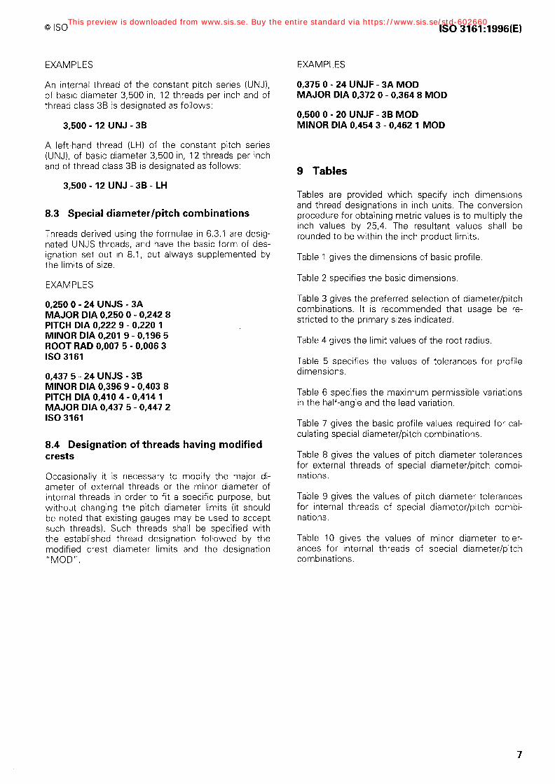
EXAMPLES
0,250 0 - 24 UNJS - 3A MAJOR DIA 0,250 0 - 0,242 8 PITCH DIA 0,222 9 - 0,220 1 MINOR DIA 0,201 9 - 0,196 5 ROOT RAD 0,007 5 - 0,006 3 ISO 3161
0,437 5 - 24 UNJS - 3B MINOR DIA 0,396 9 - 0,403 8 PITCH DIA 0,410 4 - 0,414 1 MAJOR DIA 0,437 5 - 0,447 2 ISO 3161
8.4 Designation sf threads hwing modified crests
Occasionally it is necessary to modify the major di- ameter of extemal threads or the minor diameter of internal threads in Order to fit a specific purpose, but without changing the pitch diameter limits (it should be noted that existing gauges may be used to accept such threads). Such threads shall be specified with the established thread designation followed by the modified crest diameter limits and the designation ” MODI’.
0,375 0 - 24 UNJF - 3A MOD MAJOR DIA 0,372 0 - 0,364 8 MOD
0,500 0 - 20 UNJF - 3B MOD MINOR DIA 0,454 3 - 0,462 1 MOD
9 Tables
Tables are provided which specify inch dimensions and thread designations in inch units. The conversion procedure for obtaining metric values is to multiply the inch values by 25,4. The resultant values shall be rounded to be within the inch product Iimits.
Table 1 gives the dimensions of basic Profile.
Table 2 specifies the basic dimensions.
Table 3 gives the preferred selection of diameter/pitch combinations. lt is recommended that usage be re- stricted to the primary sizes indicated.
Table 4 gives the Iimit values of the root radius.
Table 5 specifies the values of tolerantes for Profile dimensions.
Table 6 specifies the maximum pe rmissible variations in the h alf-angle and the lead variati on.
Table 7 gives the basic Profile values required for cal- culating special diameter/pitch combinations.
Table 8 gives the values of pitch diameter tolerantes for exteanal threads of special diameter/pitch combi- nations.
Table 9 gives the values of pitch diameter tolerantes for internal threads of special diameter/pitch combi- nations.
Table 10 gives the values of minor diameter toler- ances for internal threads of special diameter/pitch combinations.
7
This preview is downloaded from www.sis.se. Buy the entire standard via https://www.sis.se/std-602660
Tabl
e 1
- Ba
sic
Prof
ile
(1)
Num
ber
of
thre
ads
per
inch
80
72
(2)
Pitc
h 1 P
=-- n
0,01
2 50
0 0,
013
889
(3)
(4)
P 5
2 zp
0,
5P
0,31
2 5P
0,00
6 25
0 0,
003
91
0,00
6 94
4 0,
004
34
(5) P 8
0,12
5P
0,00
1 56
0,
001
74
(6)
H
0,86
6 02
5P
0,01
0 82
5 0,
012
028
(7)
9 -H
16
0,48
7 14
P
0,00
6 09
0,
006
77
(8)
3 -H
8
0,32
4 76
P
0,00
4 06
0,
004
51
(9)
5 -H
16
0,27
0 63
P
0,00
3 38
0,
003
76
(10)
H
8 0,
108
25P
0,00
1 35
0,
001
50
m
This
pre
view
is d
ownl
oade
d fr
om w
ww
.sis
.se.
Buy
the
ent
ire
stan
dard
via
htt
ps:/
/ww
w.s
is.s
e/st
d-60
2660
0 ISO ISO 3161:1996(E)
Table 2 - Basic dimensions
(5)
IWlinor diameter
Dl' dl
0,584 4 0,576 3 0,570 9 0,564 2 0,543 9 0,536 5
0,646 9 0,638 8 0,626 7 0,606 4
0,701 3 0,689 2 0,668 9 0,652 6
0,763 8 0,751 7 0,731 4
0,826 3 0,814 2 0,805 5 0,793 9 0,766 8
0,888 8 0,876 7 0,856 4
0,951 3 0,939 2 0,918 9 0,878 3
1,0138 1,008 4 1,001 7 0,981 4 0,940 8
1,076 3 1,070 9 1,064 2 1,043 9 1,003 3 0,985 9
1,1388 1,133 4 1,126 7 1,1064 1,065 8
(2)
Number sf threads
per inch n
24 20 18 16 12 11
24 20 16 12
20 16 12 10
20 16 12
20 16 14 12
9
20 16 12
20 16 12
8
20 18 16 12
8
20 18 16 12
8 7
20 18 16 12
8
Nominal sizes
Major diameter
P, d
Pitch diameter
D2J dz I n l D, d I DZ1 dz I DP dl
0,625 0 0,625 0 0,597 9 0,592 5 0,588 9 0,584 4 0,570 9 0,566 0
0,687 5 0,687 5 0,660 4 0,655 0 0,646 9 0,633 4
0,717 5 0,709 4 0,695 9 0,685 0
0,812 5 0,812 5 0,780 0 0,771 9 0,758 4
0,164 0 / 3;
/ 0,190 0 y;; yiw3; 0,875 0 0,875 0 0,842 5 0,834 4 0,828 6 0,820 9 0,802 8
0,905 0 0,896 9 0,883 4
0,967 5 0,959 4 0,945 9 0,918 8
1,062 5 1,062 5 1,030 0 1:026 4 1,021 9 1,008 4 0,981 3
0,375 0 0,354 7 0,344 6 0,347 9 0,334 4 0,342 5 0,326 3 0,334.4 0,314 2
1,125 0 1,125 0 1,092 5 1,088 9 1,084 4 1,070 9 1,043 8 1,032 2
1,187 5 1,187 5 1,155 0 1,151 4 1,146 9 1,133 4 1,1063
24 20 18 16 12
9
This preview is downloaded from www.sis.se. Buy the entire standard via https://www.sis.se/std-602660


