Embed Size (px)
Citation preview
Introduc on to
Wastewater Treatment
Week # 1
Grades 1 ‐ 4, Course #2201
Fleming Training Center
January 10-14, 2022

2
Grades 1-4
INTRODUCTION TO WASTEWATER TREATMENT WEEK#1
Course #2201
Welcome and class introduction Introduction to Wastewater Treatment Lunch Basic Math Review
Monday 8:30 8:45 11:00 12:00
Preliminary Treatment Flow Measurement Lunch Activated Sludge Part 1
Tuesday 8:30 9:45 11:00 12:30
Wastewater Disinfection Effluent Disposal Lunch Plant Tour (TBD)
Thursday 8:30 10:00 11:00 12:00
Wednesday 8:30 9:45 11:30 12:30
Sedimentation Ponds and Lagoons Lunch Attached Growth Systems
Friday 8:30 9:45 11:00 12:00
Administration and Management Review Lunch Exam
Instructor: Sarah Snyder Phone: 615-898-6506
Fax: 615-898-8064 E-mail: [email protected]
State of Tennessee Dept. of Environment & Conservation
Bureau of Environment Fleming Training Center
2022 Blanton Dr. Murfreesboro, TN 37129
1

4
Sec on 1 Introduc on to Wastewater Treatment 5
Sec on 2 Basic Math Review 19
Sec on 3 Preliminary Treatment 57
Sec on 4 Flow Measurement 83
Sec on 5 Ac vated Sludge Part I 107
Sec on 6 Sedimenta on and Floata on 153
Sec on 7 Ponds and Lagoons 183
Sec on 8 A ached Growth 213
Sec on 9 Disinfec on 249
Sec on 10 Effluent Disposal 287
Sec on 11 Administra on & Management 355
Sec on 12 References & Need to Know 365
Sec on 13 Answers to Review Ques ons 383
Introduc on to Wastewater Treatment
Table of Contents

6

Section 1
Introduction to Wastewater
5

Introduction to Wastewater Treatment
Ancient History• Sewers in Rome
• Water from the baths, latrines, palaces, fountains, etc., as wellas other urban runoff was discharged into collection system.
• Few private connections to thesewers. – Rich paid to use public latrines, poor
used chamberpots
• No significant improvements incollection systems until the 1840's (17 centuries later)
http://www.waterhistory.org/histories/rome/
Ancient History – Roman Baths Ancient History – Roman latrines
• Elevated latrines, suspended over trenches
• Waste was flushed away by used publicbath water
Images from: https://www.nature.com/news/the‐secret‐history‐of‐ancient‐toilets‐1.19960
History ‐ 1800’s Cities
• Night soil men
• 1829‐1849: The SecondCholera Pandemic– reached from India to Asia,
Europe, Great Britain and the Americas
• 1854: London cholera outbreak led to Dr. Snow’sbreakthrough
• 1891: Thomas Crapper
• BOD test created in London– Waste dumped in Thames River
took 5 days to reach ocean
– 1908 test officially adoptedhttps://www.smithsonianmag.com/history/quite‐likely‐the‐worst‐job‐ever‐319843/
History – United States
• 1833: Water piped into White House, a year later“bathing room” installed in East Wing
• 1857: Home connections to Philadelphiasewerage system
• 1850s‐1885: Chicago first American city to havecomprehensive sewer system
• 1885: San Diego installs separate “sanitary”sewers
• 1924: Introduction of the percolation test (septictanks)
Source:http://www.sewerhistory.org/chronos/new_amer_roots.htm
Section 1 TDEC Fleming Training Center
Introduction to Wastewater Treatment8
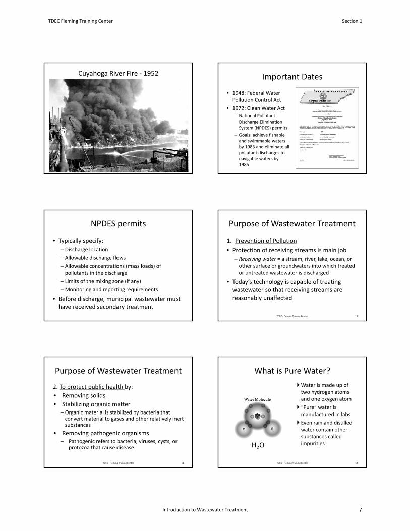
Cuyahoga River Fire ‐ 1952 Important Dates
• 1948: Federal Water Pollution Control Act
• 1972: Clean Water Act
– National Pollutant Discharge Elimination System (NPDES) permits
– Goals: achieve fishable and swimmable waters by 1983 and eliminate all pollutant discharges to navigable waters by 1985
NPDES permits
• Typically specify:
– Discharge location
– Allowable discharge flows
– Allowable concentrations (mass loads) ofpollutants in the discharge
– Limits of the mixing zone (if any)
– Monitoring and reporting requirements
• Before discharge, municipal wastewater musthave received secondary treatment
1. Prevention of Pollution
• Protection of receiving streams is main job
– Receiving water = a stream, river, lake, ocean, or other surface or groundwaters into which treatedor untreated wastewater is discharged
• Today’s technology is capable of treatingwastewater so that receiving streams arereasonably unaffected
Purpose of Wastewater Treatment
10TDEC ‐ Fleming Training Center
2. To protect public health by:
• Removing solids
• Stabilizing organic matter– Organic material is stabilized by bacteria that convert material to gases and other relatively inert substances
• Removing pathogenic organisms– Pathogenic refers to bacteria, viruses, cysts, or
protozoa that cause disease
Purpose of Wastewater Treatment
11TDEC ‐ Fleming Training Center
Water is made up of two hydrogen atoms and one oxygen atom
“Pure” water is manufactured in labs
Even rain and distilledwater contain other substances called impurities
What is Pure Water?
H2O
12TDEC ‐ Fleming Training Center
TDEC Fleming Training Center Section 1
Introduction to Wastewater Treatment 7
What is Wastewater?• The flow of water from a community or city
• Water from showers, sinks, dishwashers, laundries, car washes, hospitals, food processing operations, etc.
• 99.94% water, 0.06% waste– Human waste, food particles, paper, dirt, oil, grease, proteins, organic material, inorganic material, etc.
• Domestic and Industrial– Most plants treat both
• Inflow and Infiltration (I/I)– Collection System
Wastewater Flows
• Sanitary Sewer:– Domestic– Industrial
• Storm water:– Snow melt– Street wash
• Combined sewer:– Sanitary Sewer plus Storm water
• Inflow/Infiltration– Inflow: direct discharge into the sewer from sources other than
regular connections– Infiltration: Seepage of groundwater into the sewer system
through cracks, manholes, pipe connections, etc.
TDEC-Fleming Training Center14
http://www.chesapeakequarterly.net/V15N1/main1/
Image source: https://trekkllc.com
https://www.alsplumbing.com/trenchless‐sewer‐line‐replacement/
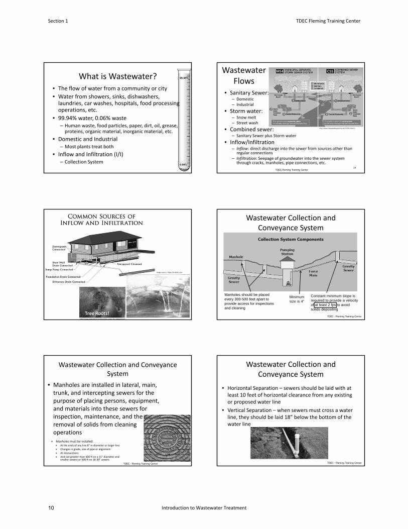
Wastewater Collection and Conveyance System
Constant minimum slope is required to provide a velocity of at least 2 fps to avoid solids depositing
Manholes should be placed every 300-500 feet apart to provide access for inspections and cleaning
Minimum size is 4”
TDEC - Fleming Training Center
Wastewater Collection and Conveyance System
• Manholes are installed in lateral, main, trunk, and intercepting sewers for the purpose of placing persons, equipment, and materials into these sewers for inspection, maintenance, and the removal of solids from cleaning operations
Manholes must be installed: At the ends of any line 8” in diameter or larger line
Changes in grade, size of pipe or alignment
At intersections
And not greater than 400 ft on a 15” diameter and smaller sewers or 500 ft on 18‐30” sewers
TDEC - Fleming Training Center
Wastewater Collection and Conveyance System
• Horizontal Separation – sewers should be laid with at least 10 feet of horizontal clearance from any existing or proposed water line
• Vertical Separation – when sewers must cross a water line, they should be laid 18” below the bottom of the water line
TDEC - Fleming Training Center
Section 1 TDEC Fleming Training Center
Introduction to Wastewater Treatment10
Wastewater Collection and Conveyance System
• Hydrogen sulfide is made in the collection system and can:
– Make waste more difficult to treat
– Damage concrete structures
– Cause odor problems
• Biological activity in long, flat sewer lines will likely cause:– Hydrogen sulfide production
– Oxygen deficiency in sewers, manholes or wet wells
– Metal and concrete corrosion
• Chlorine can be used in the collection system or at the plant headworks to oxidize hydrogen sulfide
TDEC - Fleming Training Center
• Organic waste• Contains carbon
• Inorganic waste• Salts• Metals• Gravel• Sand
• Both may come from domestic or industrial waste
Types of Waste
20
Sucrose
TDEC ‐ Fleming Training Center
• Domestic and industrial wastewater contain both organic and inorganic material
– Domestic wastewater contains a large amount of organic waste
– Industries also contribute some amounts of organic wastes (Ex: vegetable and fruit packing, dairy processing, meat packing, tanning and processing of poultry, oil, paper and fiber.)
• Some inorganic wastes that may come to the plant are salts, metals (chromium or copper), gravel, soil, sand and grit– Indicator that a toxic load has entered an activated sludge plant =
increase in oxygen concentration in the aeration basin
Types of Waste ‐ Organic and Inorganic
21TDEC ‐ Fleming Training Center
Water Pollution• The impairment of water quality by agricultural, domestic, or industrial wastes, rendering it unusable or offensive
• Any condition caused by human activity that adversely affects the quality of stream, lake, ocean, or groundwater.
• Creating or posing a potential threat to human health or the environment
TDEC ‐ Fleming Training Center 22
• Unpolluted water has a wide diversity of aquatic organisms and contains enough dissolved oxygen.
• Polluted water inhibits the growth of aquatic organisms.– Industrial wastes highly acidic or alkaline (basic)
– Toxic substances
• Wastes can affect clarity and color of receiving waters– Unsightly and unpopular for recreation
• Taste and Odor issues in drinking water
• Treated wastewater contains nutrients that can cause excess algae and plant growth
Water Pollution Impacts
23TDEC ‐ Fleming Training Center
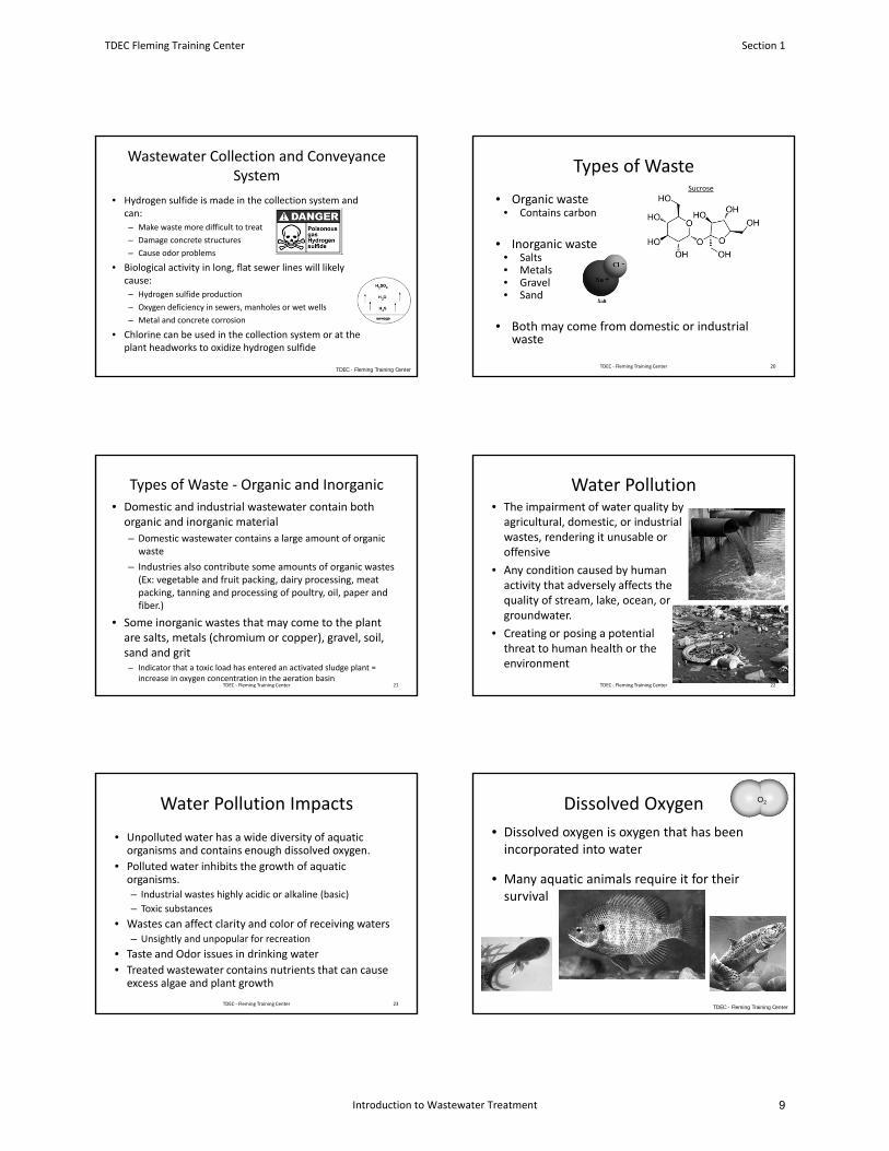
Dissolved Oxygen
• Dissolved oxygen is oxygen that has been incorporated into water
• Many aquatic animals require it for their survival
O2
TDEC - Fleming Training Center
TDEC Fleming Training Center Section 1
Introduction to Wastewater Treatment 9
Dissolved Oxygen• There are two important factors that can influence the amount of dissolved oxygen present:– Water Temperature
• Greater temperature Less DO
• Lower temperature More DO
– Organic matter
• Organic material requires oxygen to decompose
• More organic material requires more DO, and will tend to deplete water of DO
TDEC - Fleming Training Center
• Most living creatures, including fish, need oxygen to survive– Most fish can survive with at least 5 mg/L DO
• When organic wastes are discharged to a receiving stream bacteria begin to feed on it, these bacteria need oxygen for this process– As more organic waste is added to the receiving stream, the bacteria reproduce
– As the bacteria reproduce, they use up more oxygen, faster than it can be replenished by natural diffusion from the atmosphere
– This can potentially cause a fish kill and odors
Oxygen Depletion
26TDEC ‐ Fleming Training Center
• One of the principal objectives of wastewater treatment is to prevent as much of this “oxygen‐demanding” organic material as possible from entering the receiving water.
• The treatment plant actually removes the organic matter the same way a stream would in nature, but it works more efficiently by removing the wastes in secondary treatment
• The treatment plant is designed and operated to use natural organisms such as bacteria to stabilize and remove organic matter
Oxygen Depletion
27TDEC ‐ Fleming Training Center
Importance of Organic Matter• Organic material consumes oxygen in water
– Bacteria will feed on organic matter and most need oxygen to be able to do this
– We want these bacteria to feed on the organic matter and use it up in the plant and not in our receiving water
• High concentrations of organic material can cause taste and odor problems in recreational and drinking water
• Some material may be hazardous
TDEC - Fleming Training Center
• Problems associated with excess nutrients:– Cause an increase in productivity of aquatic plants, leading to depleted DO levels
– May cause odor problems
– Extra vegetation near surface may inhibit light penetration of light into water
• Macronutrients:– Nitrogen (many WWTPs test for ammonia)
– Phosphorus
– Iron
Nutrients
29TDEC ‐ Fleming Training Center
• Initial efforts came from preventing disease outbreaks– Most bacteria in wastewater are not harmful to humans
– Humans who have a disease caused by bacteria or viruses can discharge some of these pathogens
– Many serious outbreaks of communicable diseases have been traced back to contamination of drinking water or food from domestic wastewater
• Good personal hygiene is your best defense against infections and disease
Human Health
30TDEC ‐ Fleming Training Center
Section 1 TDEC Fleming Training Center
Introduction to Wastewater Treatment12
• Bacteria
– Cholera
– Dysentery
– Shigella
– Salmonella
– Typhoid
• Viruses– Polio
– Hepatitis (Jaundice)
• Protozoa– Giardia lamblia
– Cryptosporidium parvum
– Entamoeba hystolitica
Diseases
31
CholeraCryptosporidium
Giardia
Dysentary
Hepatitis
PolioTDEC ‐ Fleming Training Center
• If wastewater does not receive adequate treatment, solids may build up in the receiving stream as sludge in the bottom or scum floating to the surface
• Unsightly, may cause oxygen depletion and be a source of odors.
Sludge and Scum
32TDEC ‐ Fleming Training Center
Solids
• Cause many problems in collection and treatment plant systems– Fill storage areas, clog ditches and channels
– Interfere with mechanical systems
– Associated with taste/color/clarity problems in drinking water
TDEC - Fleming Training Center
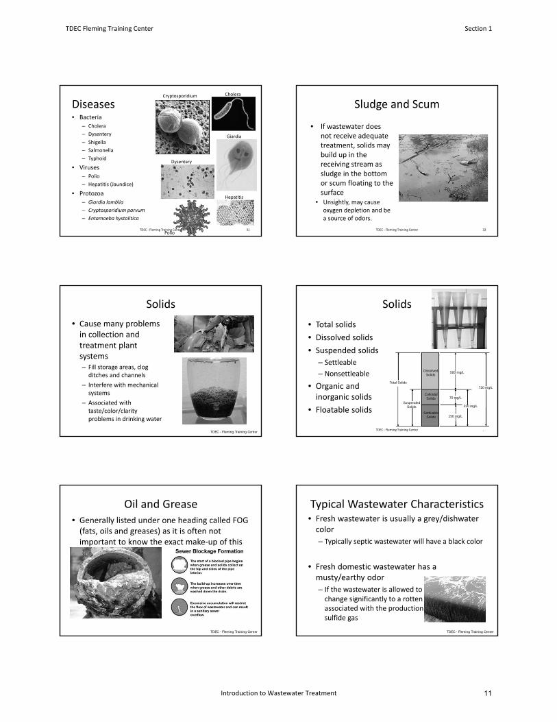
• Total solids
• Dissolved solids
• Suspended solids
– Settleable
– Nonsettleable
• Organic and inorganic solids
• Floatable solids
Solids
34
Dissolved Solids
Colloidal Solids
SettleableSolids
Suspended Solids
Total Solids
150 mg/L
70 mg/L
500 mg/L
220 mg/L
720 mg/L
TDEC ‐ Fleming Training Center
Oil and Grease• Generally listed under one heading called FOG (fats, oils and greases) as it is often not important to know the exact make‐up of this group of components.
TDEC - Fleming Training Center
Typical Wastewater Characteristics• Fresh wastewater is usually a grey/dishwater color
– Typically septic wastewater will have a black color
• Fresh domestic wastewater has a musty/earthy odor
– If the wastewater is allowed to go septic, this will change significantly to a rotten egg odor associated with the production of hydrogen sulfide gas
TDEC - Fleming Training Center
TDEC Fleming Training Center Section 1
Introduction to Wastewater Treatment 11
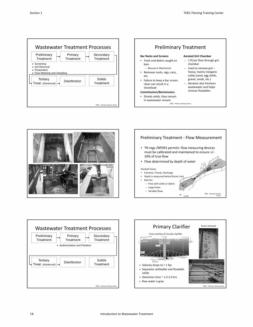
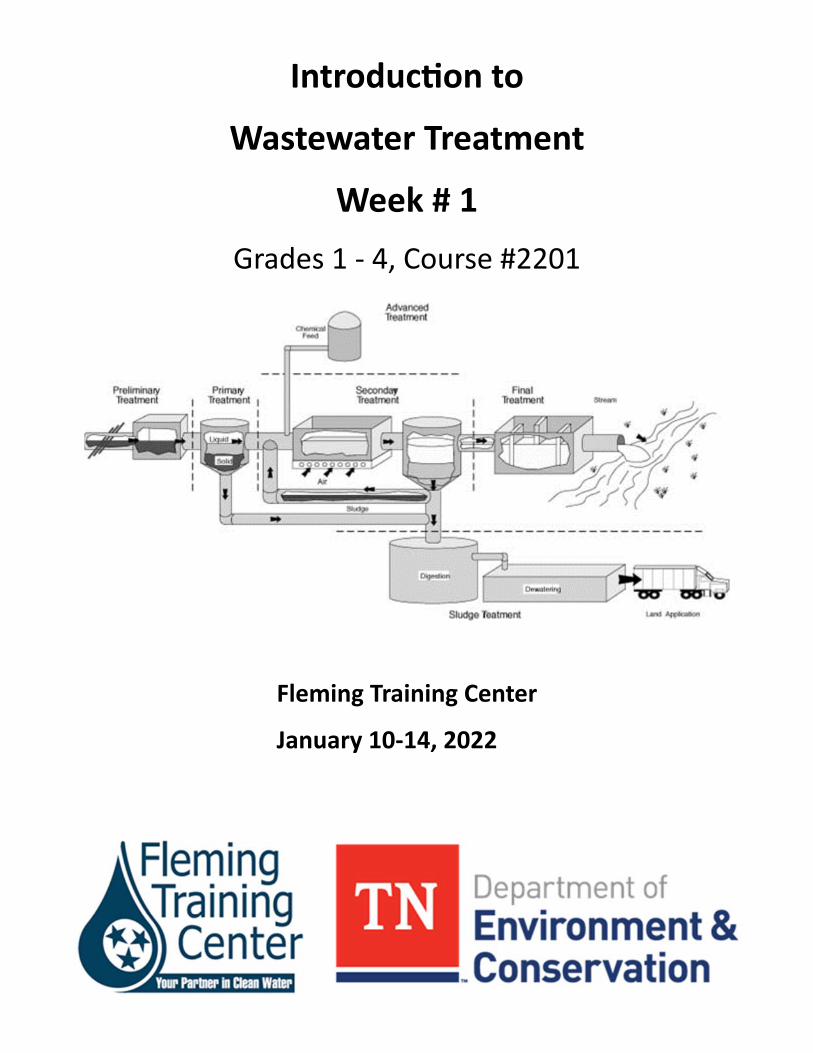
PreliminaryTreatment
PrimaryTreatment
Tertiary Treat. (Advanced)
Disinfection
SecondaryTreatment
Screening Grit Removal Preaeration Flow Metering and Sampling
SolidsTreatment
Wastewater Treatment Processes
TDEC - Fleming Training Center
Preliminary Treatment
Aerated Grit Chamber
• 1 ft/sec flow through grit chamber
• Used to remove grit –heavy, mainly inorganic solids (sand, egg shells, gravel, seeds, etc.)
• Aeration also freshens wastewater and helps remove floatables
Bar Racks and Screens
• Trash and debris caught on bars– Manual or Mechanical
• Removes roots, rags, cans, etc.
• Failure to keep a bar screen clean can result in a shockload
Comminutors/Barminutors
• Shreds solids, they remain in wastewater stream
TDEC - Fleming Training Center
Preliminary Treatment ‐ Flow Measurement
• TN regs /NPDES permits: flow measuring devices must be calibrated and maintained to ensure +/‐10% of true flow
• Flow determined by depth of water
Parshall Flume
• Entrance, Throat, Discharge
• Depth is measured behind flume crest
• Best for:
– Flow with solids or debris
– Large Flows
– Variable flows
40 TDEC - Fleming Training Center
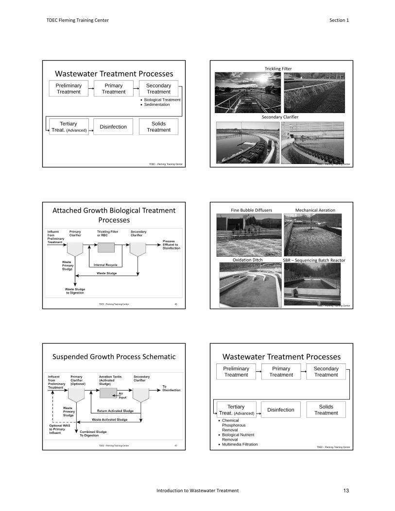
PreliminaryTreatment
PrimaryTreatment
Tertiary Treat. (Advanced)
Disinfection
Sedimentation and Flotation
SecondaryTreatment
SolidsTreatment
Wastewater Treatment Processes
TDEC - Fleming Training Center
Scum removalPrimary Clarifier
Rectangular clarifier
Cross section of circular clarifier
Velocity drops to < 1 fps
Separates settleable and floatable solids
Detention time ~ 1.5‐2.0 hrs
Raw water is gray
TDEC - Fleming Training Center
Section 1 TDEC Fleming Training Center
Introduction to Wastewater Treatment14
PreliminaryTreatment
PrimaryTreatment
Tertiary Treat. (Advanced)
Disinfection
SecondaryTreatment
Biological Treatment Sedimentation
SolidsTreatment
Wastewater Treatment Processes
TDEC - Fleming Training Center
Secondary Clarifier
Trickling Filter
TDEC - Fleming Training Center
Attached Growth Biological Treatment Processes
45TDEC ‐ Fleming Training Center
Oxidation Ditch
Fine Bubble Diffusers Mechanical Aeration
SBR – Sequencing Batch Reactor
TDEC - Fleming Training Center
Suspended Growth Process Schematic
47TDEC ‐ Fleming Training Center
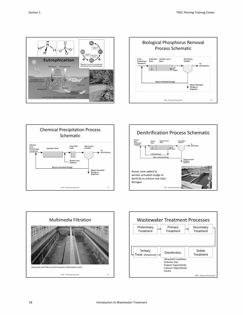
PreliminaryTreatment
PrimaryTreatment
Tertiary Treat. (Advanced)
Disinfection
SecondaryTreatment
Chemical Phosphorous Removal
Biological Nutrient Removal
Multimedia Filtration
SolidsTreatment
Wastewater Treatment Processes
TDEC - Fleming Training Center
TDEC Fleming Training Center Section 1
Introduction to Wastewater Treatment 13
/
Biological Phosphorus Removal Process Schematic
50TDEC ‐ Fleming Training Center
Chemical Precipitation Process Schematic
51TDEC ‐ Fleming Training Center
Anoxic zone added toaerobic activated sludge todenitrify to achieve low total Nitrogen
Denitrification Process Schematic
52
Anoxic Zone
TDEC ‐ Fleming Training Center
Multimedia Filtration
TDEC ‐ Fleming Training Center 53
Deep bed sand filters at Murfreesboro Wastewater plant
PreliminaryTreatment
PrimaryTreatment
Tertiary Treat. (Advanced)
Disinfection
SecondaryTreatment
SolidsTreatment
Ultraviolet IrradiationChlorine GasSodium HypochloriteCalcium HypochloriteOzone
Wastewater Treatment Processes
TDEC - Fleming Training Center
Section 1 TDEC Fleming Training Center
Introduction to Wastewater Treatment16
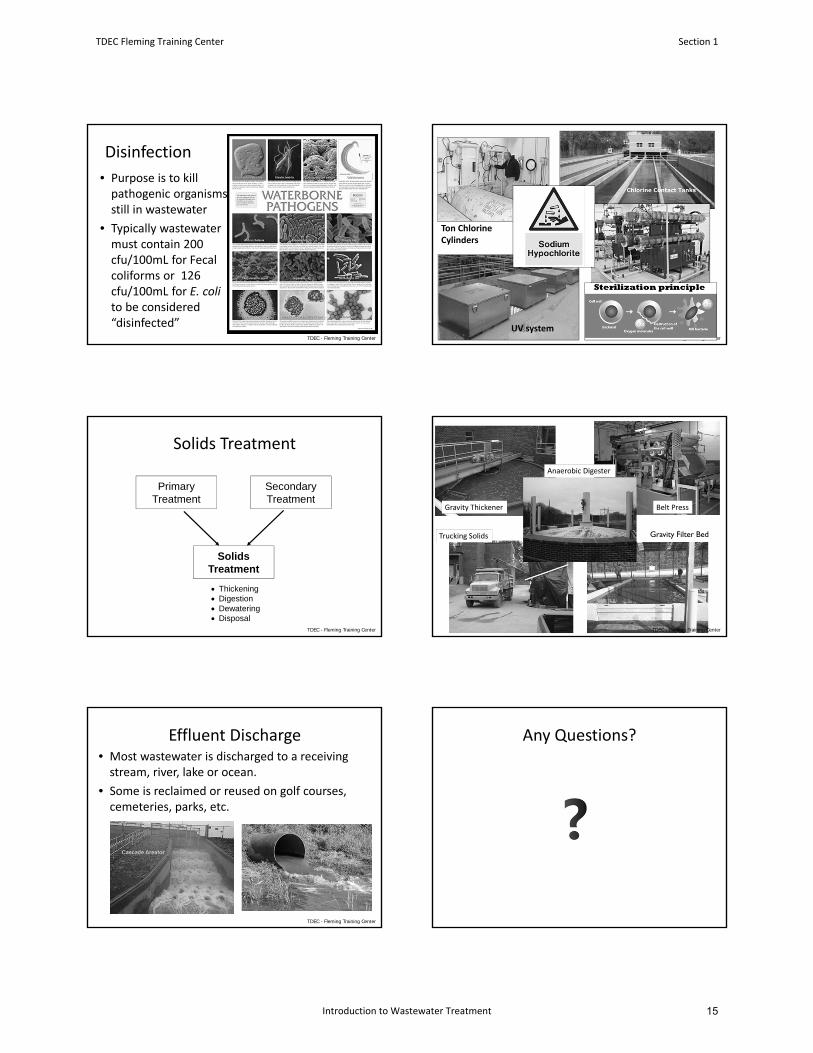
Disinfection
• Purpose is to kill pathogenic organisms still in wastewater
• Typically wastewater must contain 200 cfu/100mL for Fecal coliforms or 126 cfu/100mL for E. coli to be considered “disinfected”
TDEC - Fleming Training Center TDEC - Fleming Training Center
Ton Chlorine Cylinders
UV system
PrimaryTreatment
SecondaryTreatment
SolidsTreatment
Thickening Digestion Dewatering Disposal
Solids Treatment
TDEC - Fleming Training Center
Trucking Solids Gravity Filter Bed
Anaerobic Digester
Gravity Thickener Belt Press
TDEC - Fleming Training Center
Effluent Discharge• Most wastewater is discharged to a receiving stream, river, lake or ocean.
• Some is reclaimed or reused on golf courses, cemeteries, parks, etc.
TDEC - Fleming Training Center
Any Questions?
TDEC Fleming Training Center Section 1
Introduction to Wastewater Treatment 15
Introduction Vocabulary
1. The impairment of water quality by agricultural, domestic, or industrial wastes to the point where
the water is unusable, offensive, or poses a potential threat to human health or the environment is
called __________________________.
2. Water discharged directly into a sewer system from sources other than regular connections is called
_____________________. This includes flow from yard drains, foundations, and around access and
manhole covers.
3. A ____________________________ refers to any substance that is taken in by organisms and
promotes growth. Nitrogen and phosphorus are examples that promote the growth of algae.
4. ___________________________ are a group of bacteria that are used as “indicator organisms,”
which means their presence may indicate that the water is polluted with pathogenic organisms.
5. Organic material undergoes ___________________________ by bacteria, in which the material is
converted to gases and other relatively inert substances. Stabilized organic material generally will
not give off obnoxious odors.
6. The _________________________________test , which lasts for 5 days, is the amount of oxygen
used during the breakdown of organic material. It is considered an indirect measure of the organic
content of a sample.
7. A wastewater treatment process that takes place in a rectangular or circular tank (ex. Primary
clarifier) and allows those substances in wastewater that readily settle or float to be separated from
the wastewater being treated is referred to as ______________________________________.
8. ___________________________ refers to the seepage of groundwater into a sewer system,
including service connections. This seepage frequently occurs through defective or cracked pipes,
pipe joints and connections, interceptor access risers and covers, or manhole walls.
9. ______________________ sewers carry waste (mostly domestic) from homes and commercial
businesses. _______________________ sewers collect runoff from streets, land, and building roofs
and is normally discharged to a waterway without treatment. A __________________________
sewer system combines the two previously listed sewer systems into one, these types of sewers
often become overloaded during heavy storms.
10. Waste material that comes from animal or plant sources is classified as
________________________ waste. These natural wastes generally can be consumed by bacteria
and other small organisms.
11. The __________________________ process is used to convert dissolved or suspended materials
into a form more readily separated from the water, and usually follows primary treatment. It is
Section 1 TDEC Fleming Training Center
Introduction to Wastewater Treatment18
generally a type of biological treatment followed by secondary clarifiers that allow the solids to
settle out.
12. A stream, river, lake, ocean, or other surface or groundwaters into which treated or untreated
wastewater is discharged is called a ________________________________.
13. The water that has been treated and is discharged to a receiving stream, river, lake, or ocean is
called ___________________________. NPDES permit limitations apply to this discharge.
14. Waste material such as sand, salt, iron, calcium, and other mineral materials that are only slightly
affected by the action of organisms is classified as ______________________ waste.
Word Bank
Inflow
Effluent
Combined
Water pollution
Coliforms
Nutrients
Secondary treatment
Primary treatment
Sanitary
Organic
Biochemical oxygen demand (BOD)
Receiving water
Infiltration
Stormwater
Inorganic
Stabilization
TDEC Fleming Training Center Section 1
Introduction to Wastewater Treatment 17

20

Section 2
Basic Math Review
19
For Water and Wastewater Plant Operators
by Joanne Kirkpatrick Price
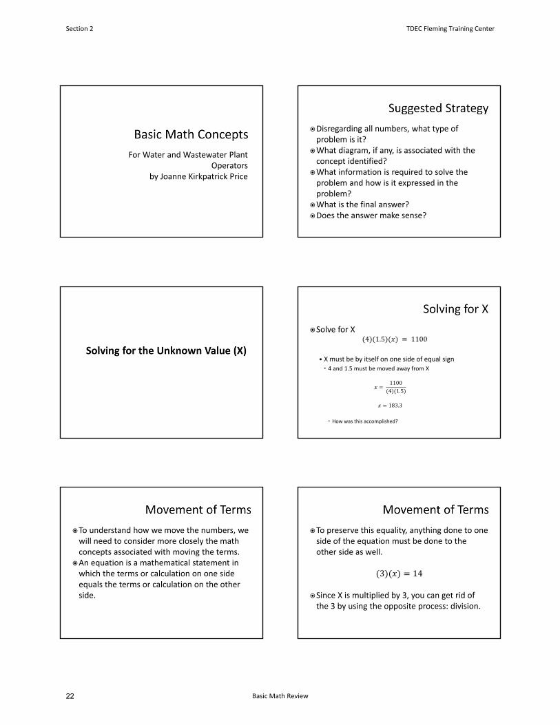
Disregarding all numbers, what type of problem is it?
What diagram, if any, is associated with the concept identified?
What information is required to solve the problem and how is it expressed in the problem?
What is the final answer?Does the answer make sense?
Solve for X4 1.5 1100
• X must be by itself on one side of equal sign 4 and 1.5 must be moved away from X
11004 1.5
183.3
How was this accomplished?
To understand how we move the numbers, we will need to consider more closely the math concepts associated with moving the terms.
An equation is a mathematical statement in which the terms or calculation on one side equals the terms or calculation on the other side.
To preserve this equality, anything done to one side of the equation must be done to the other side as well.
3 14
Since X is multiplied by 3, you can get rid of the 3 by using the opposite process: division.
Section 2 TDEC Fleming Training Center
Basic Math Review22
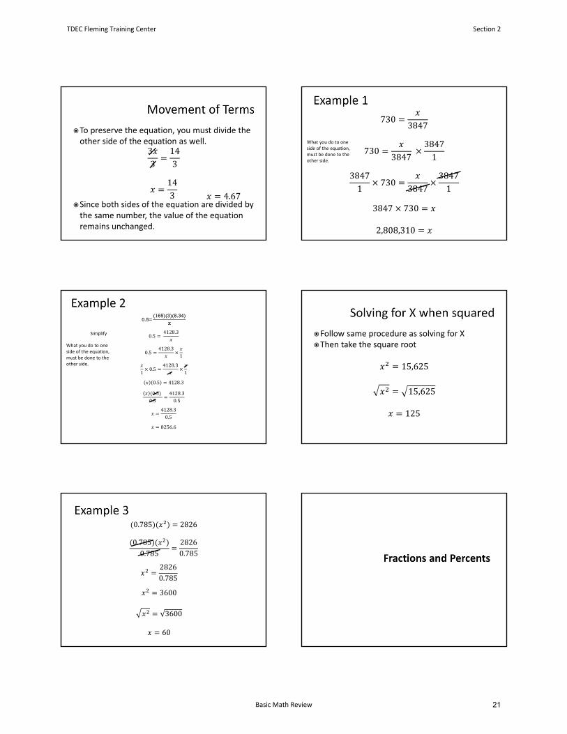
To preserve the equation, you must divide the other side of the equation as well.
33
143
143
Since both sides of the equation are divided by the same number, the value of the equation remains unchanged.
4.67
7303847
7303847
38471
38471
7303847
38471
3847 730
2,808,310
What you do to one side of the equation, must be done to the other side.
0.5=(165)(3)(8.34)
x
0.5 4128.3
0.54128.3
1
10.5
4128.31
0.5 4128.3
0.5
0.54128.30.5
4128.30.5
8256.6
What you do to one side of the equation, must be done to the other side.
Simplify Follow same procedure as solving for XThen take the square root
15,625
15,625
125
0.785 2826
0.7850.785
28260.785
28260.785
3600
3600
60
TDEC Fleming Training Center Section 2
Basic Math Review 21
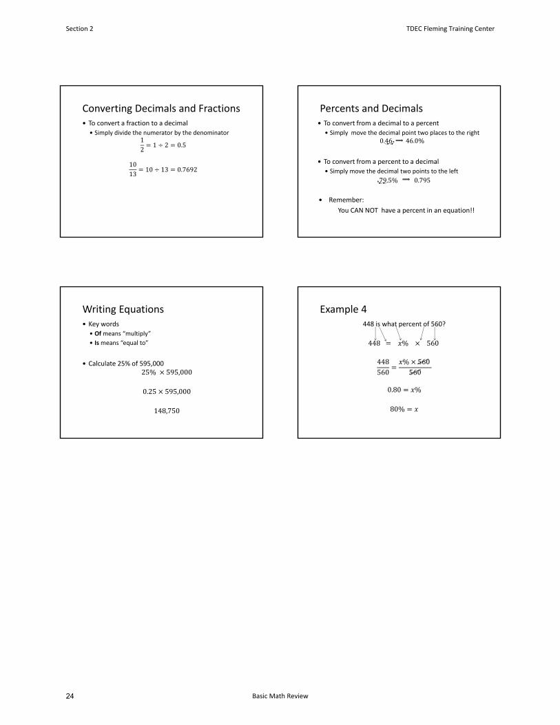
Converting Decimals and Fractions To convert a fraction to a decimal
Simply divide the numerator by the denominator12
1 2 0.5
1013
10 13 0.7692
Percents and Decimals To convert from a decimal to a percent
Simply move the decimal point two places to the right0.4646.0%
To convert from a percent to a decimal
Simply move the decimal two points to the left
79.5%0.795
Remember:
You CAN NOT have a percent in an equation!!
Writing Equations Key words
Ofmeans “multiply”
Ismeans “equal to”
Calculate 25% of 595,000 25% 595,000
0.25 595,000
148,750
Example 4448 is what percent of 560?
448 % 560
448560
% 560 560
0.80 %
80%
Section 2 TDEC Fleming Training Center
Basic Math Review24
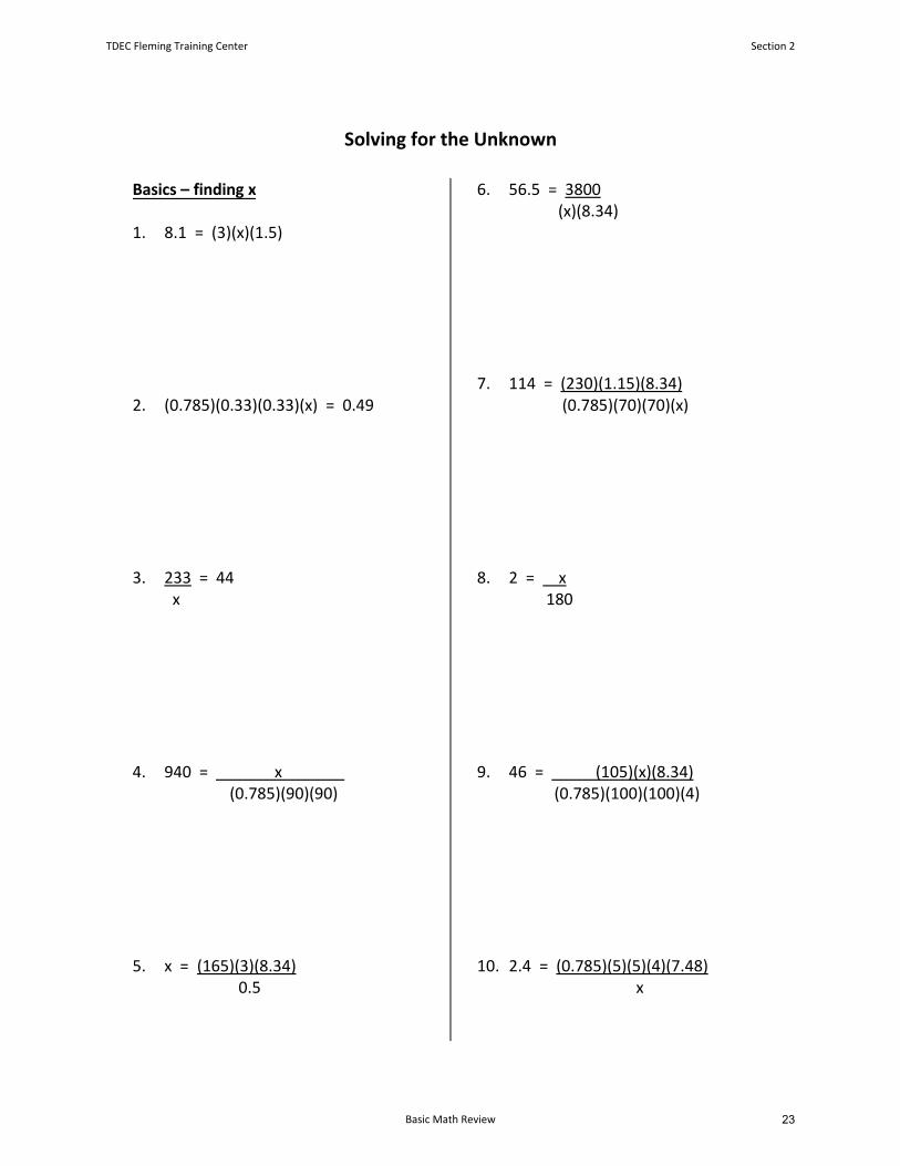
Solving for the Unknown
Basics – finding x
1. 8.1 = (3)(x)(1.5)
2. (0.785)(0.33)(0.33)(x) = 0.49
3. 233 = 44 x
4. 940 = x (0.785)(90)(90)
5. x = (165)(3)(8.34)0.5
6. 56.5 = 3800 (x)(8.34)
7. 114 = (230)(1.15)(8.34) (0.785)(70)(70)(x)
8. 2 = x 180
9. 46 = (105)(x)(8.34) (0.785)(100)(100)(4)
10. 2.4 = (0.785)(5)(5)(4)(7.48)x
TDEC Fleming Training Center Section 2
Basic Math Review 23
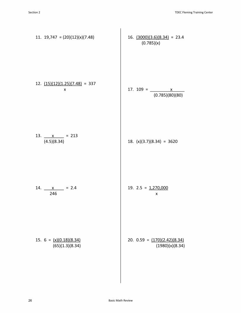
11. 19,747 = (20)(12)(x)(7.48)
12. (15)(12)(1.25)(7.48) = 337x
13. x = 213 (4.5)(8.34)
14. x = 2.4 246
15. 6 = (x)(0.18)(8.34) (65)(1.3)(8.34)
16. (3000)(3.6)(8.34) = 23.4 (0.785)(x)
17. 109 = x (0.785)(80)(80)
18. (x)(3.7)(8.34) = 3620
19. 2.5 = 1,270,000 x
20. 0.59 = (170)(2.42)(8.34)(1980)(x)(8.34)
Section 2 TDEC Fleming Training Center
Basic Math Review26

Finding x2
21. (0.785)(D2) = 5024
22. (x2)(10)(7.48) = 10,771.2
23. 51 = 64,000 (0.785)(D2)
24. (0.785)(D2) = 0.54
25. 2.1 = (0.785)(D2)(15)(7.48)(0.785)(80)(80)
TDEC Fleming Training Center Section 2
Basic Math Review 25
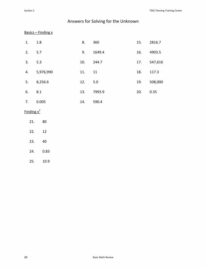
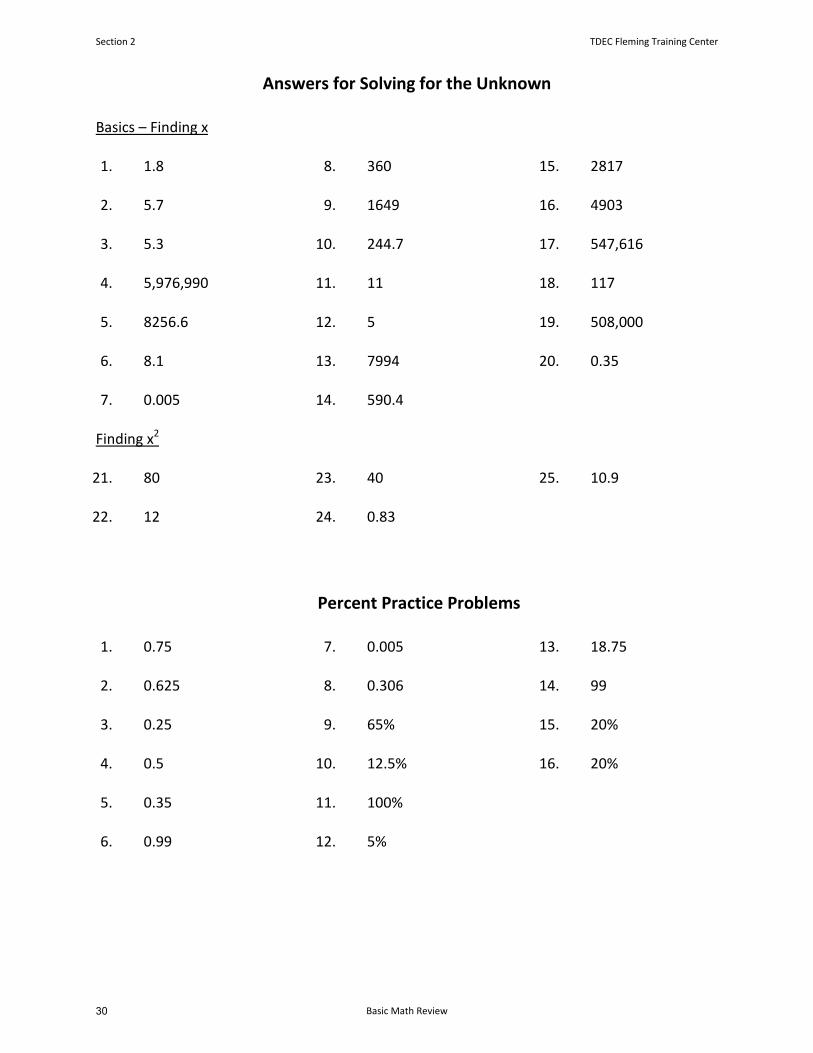
Answers for Solving for the Unknown
Basics – Finding x
1. 1.8
2. 5.7
3. 5.3
4. 5,976,990
5. 8,256.6
6. 8.1
7. 0.005
8. 360
9. 1649.4
10. 244.7
11. 11
12. 5.0
13. 7993.9
14. 590.4
15. 2816.7
16. 4903.5
17. 547,616
18. 117.3
19. 508,000
20. 0.35
Finding x2
21. 80
22. 12
23. 40
24. 0.83
25. 10.9
Section 2 TDEC Fleming Training Center
Basic Math Review28
Percent Practice Problems
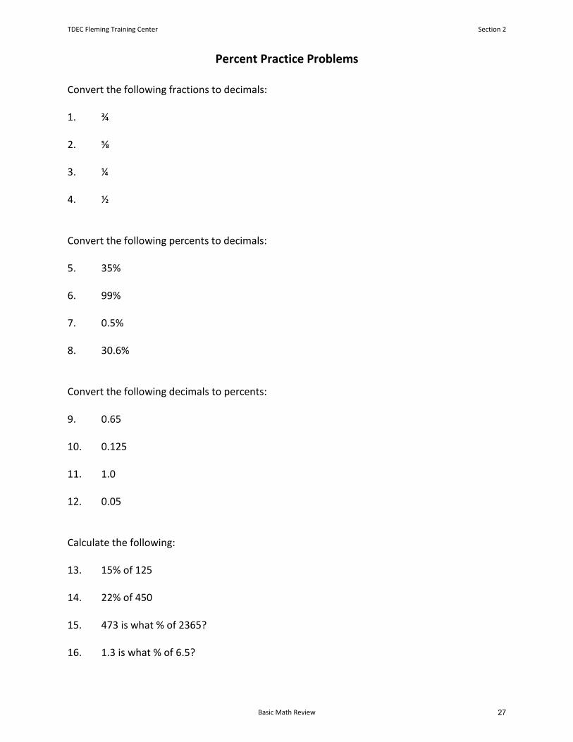
Convert the following fractions to decimals:
1. ¾
2. ⅝
3. ¼
4. ½
Convert the following percents to decimals:
5. 35%
6. 99%
7. 0.5%
8. 30.6%
Convert the following decimals to percents:
9. 0.65
10. 0.125
11. 1.0
12. 0.05
Calculate the following:
13. 15% of 125
14. 22% of 450
15. 473 is what % of 2365?
16. 1.3 is what % of 6.5?
TDEC Fleming Training Center Section 2
Basic Math Review 27
Answers for Solving for the Unknown
Basics – Finding x
1. 1.8
2. 5.7
3. 5.3
4. 5,976,990
5. 8256.6
6. 8.1
7. 0.005
8. 360
9. 1649
10. 244.7
11. 11
12. 5
13. 7994
14. 590.4
15. 2817
16. 4903
17. 547,616
18. 117
19. 508,000
20. 0.35
Finding x2
21. 80
22. 12
23. 40
24. 0.83
25. 10.9
Percent Practice Problems
1. 0.75
2. 0.625
3. 0.25
4. 0.5
5. 0.35
6. 0.99
7. 0.005
8. 0.306
9. 65%
10. 12.5%
11. 100%
12. 5%
13. 18.75
14. 99
15. 20%
16. 20%
Section 2 TDEC Fleming Training Center
Basic Math Review30
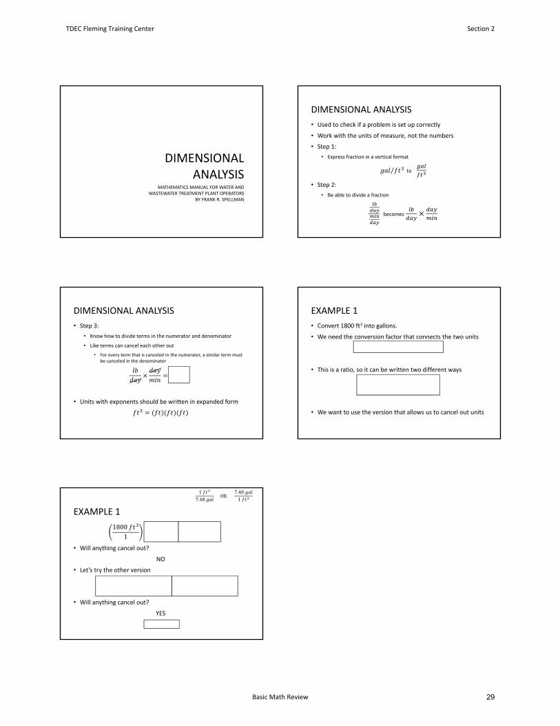
DIMENSIONAL ANALYSIS
MATHEMATICS MANUAL FOR WATER AND WASTEWATER TREATMENT PLANT OPERATORS
BY FRANK R. SPELLMAN
DIMENSIONAL ANALYSIS
• Used to check if a problem is set up correctly
• Work with the units of measure, not the numbers
• Step 1:
• Express fraction in a vertical format
⁄ to
• Step 2:
• Be able to divide a fraction
becomes
DIMENSIONAL ANALYSIS
• Step 3:
• Know how to divide terms in the numerator and denominator
• Like terms can cancel each other out
• For every term that is canceled in the numerator, a similar term mustbe canceled in the denominator
• Units with exponents should be written in expanded form
EXAMPLE 1
• Convert 1800 ft3 into gallons.
• We need the conversion factor that connects the two units
1 cubic foot of water = 7.48 gal
• This is a ratio, so it can be written two different ways
17.48
OR7.481
• We want to use the version that allows us to cancel out units
EXAMPLE 1
18001
17.48
18007.48
• Will anything cancel out?
NO
• Let’s try the other version
18001
7.481
1800 7.481 1
• Will anything cancel out?
YES
13,464
17.48
OR7.481
TDEC Fleming Training Center Section 2
Basic Math Review 29
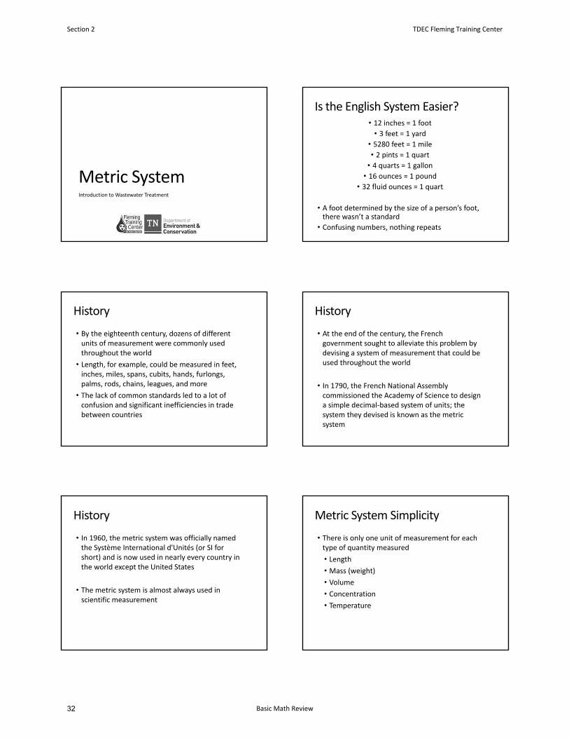
Metric SystemIntroduction to Wastewater Treatment
Is the English System Easier?• 12 inches = 1 foot• 3 feet = 1 yard
• 5280 feet = 1 mile
• 2 pints = 1 quart• 4 quarts = 1 gallon• 16 ounces = 1 pound
• 32 fluid ounces = 1 quart
• A foot determined by the size of a person’s foot, there wasn’t a standard
• Confusing numbers, nothing repeats
History
• By the eighteenth century, dozens of different units of measurement were commonly used throughout the world
• Length, for example, could be measured in feet, inches, miles, spans, cubits, hands, furlongs, palms, rods, chains, leagues, and more
• The lack of common standards led to a lot of confusion and significant inefficiencies in trade between countries
History
• At the end of the century, the French government sought to alleviate this problem by devising a system of measurement that could be used throughout the world
• In 1790, the French National Assembly commissioned the Academy of Science to design a simple decimal‐based system of units; the system they devised is known as the metric system
History
• In 1960, the metric system was officially named the Système International d'Unités (or SI for short) and is now used in nearly every country in the world except the United States
• The metric system is almost always used in scientific measurement
Metric System Simplicity
• There is only one unit of measurement for each type of quantity measured
• Length
• Mass (weight)
• Volume
• Concentration
• Temperature
Section 2 TDEC Fleming Training Center
Basic Math Review32
The Metric System
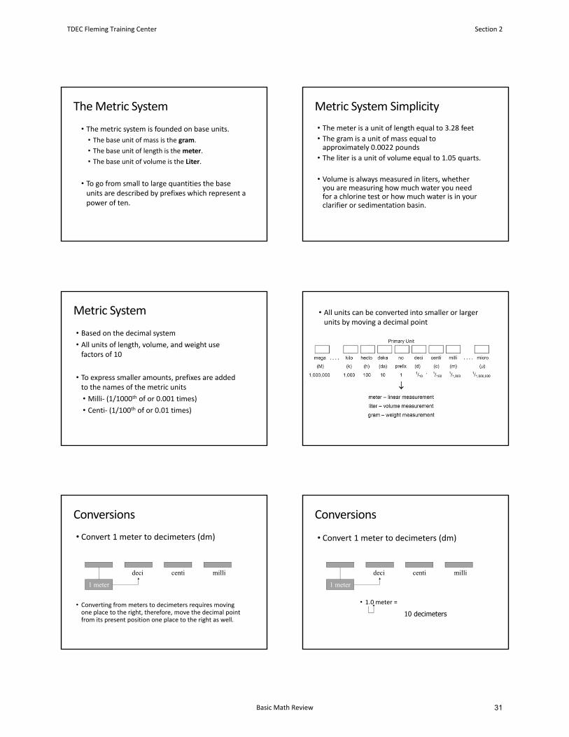
• The metric system is founded on base units.
• The base unit of mass is the gram.
• The base unit of length is the meter.
• The base unit of volume is the Liter.
• To go from small to large quantities the base units are described by prefixes which represent a power of ten.
Metric System Simplicity
• The meter is a unit of length equal to 3.28 feet
• The gram is a unit of mass equal toapproximately 0.0022 pounds
• The liter is a unit of volume equal to 1.05 quarts.
• Volume is always measured in liters, whether you are measuring how much water you need for a chlorine test or how much water is in your clarifier or sedimentation basin.
Metric System
• Based on the decimal system
• All units of length, volume, and weight use factors of 10
• To express smaller amounts, prefixes are added to the names of the metric units
• Milli‐ (1/1000th of or 0.001 times)
• Centi‐ (1/100th of or 0.01 times)
• All units can be converted into smaller or larger units by moving a decimal point
Conversions
• Convert 1 meter to decimeters (dm)
• Converting from meters to decimeters requires moving one place to the right, therefore, move the decimal point from its present position one place to the right as well.
1 meter
deci millicenti
Conversions
• Convert 1 meter to decimeters (dm)
• 1.0 meter =
1 meter
deci millicenti
10 decimeters
TDEC Fleming Training Center Section 2
Basic Math Review 31
Conversions
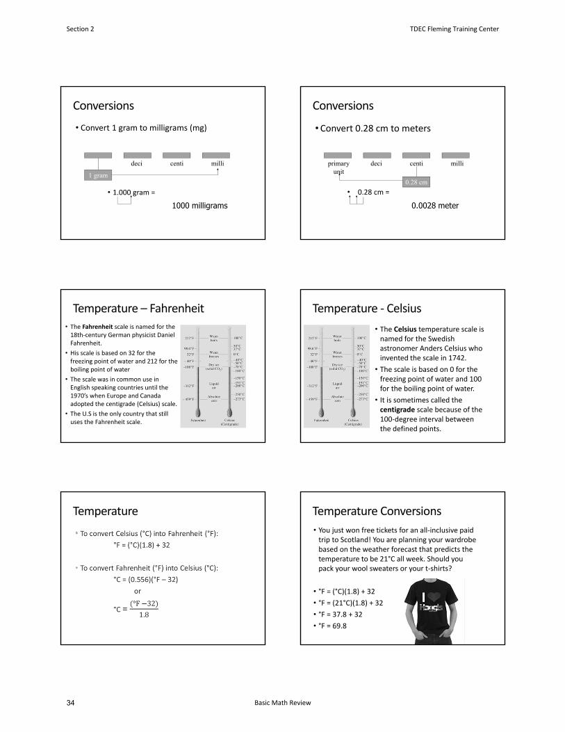
• Convert 1 gram to milligrams (mg)
• 1.000 gram =
1 gram
deci millicenti
1000 milligrams
Conversions
•Convert 0.28 cm to meters
• 0.28 cm =
0.28 cm
deci millicenti
0.0028 meter
primaryunit
Temperature – Fahrenheit
• The Fahrenheit scale is named for the 18th‐century German physicist Daniel Fahrenheit.
• His scale is based on 32 for the freezing point of water and 212 for the boiling point of water
• The scale was in common use in English speaking countries until the 1970’s when Europe and Canada adopted the centigrade (Celsius) scale.
• The U.S is the only country that still uses the Fahrenheit scale.
Temperature ‐ Celsius
• The Celsius temperature scale is named for the Swedish astronomer Anders Celsius who invented the scale in 1742.
• The scale is based on 0 for the freezing point of water and 100 for the boiling point of water.
• It is sometimes called the centigrade scale because of the 100‐degree interval between the defined points.
Temperature
•
Temperature Conversions
• You just won free tickets for an all‐inclusive paid trip to Scotland! You are planning your wardrobe based on the weather forecast that predicts the temperature to be 21°C all week. Should you pack your wool sweaters or your t‐shirts?
• °F = (°C)(1.8) + 32
• °F = (21°C)(1.8) + 32
• °F = 37.8 + 32
• °F = 69.8
Section 2 TDEC Fleming Training Center
Basic Math Review34
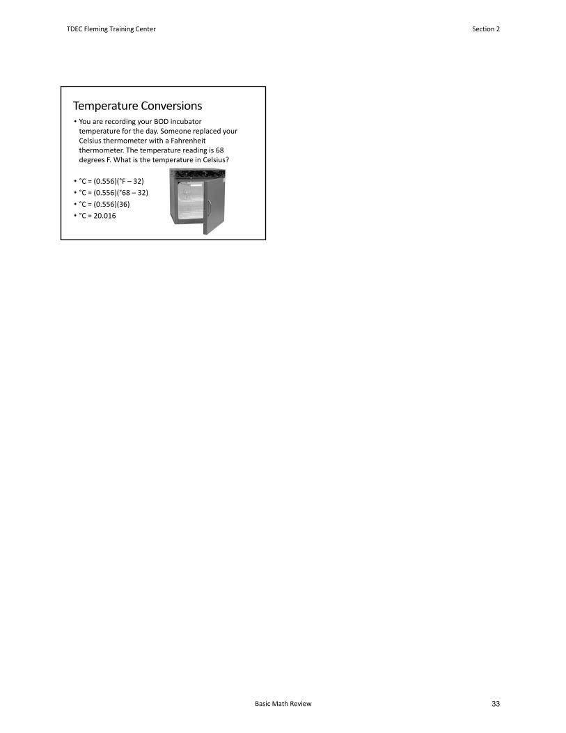
Temperature Conversions• You are recording your BOD incubator temperature for the day. Someone replaced your Celsius thermometer with a Fahrenheit thermometer. The temperature reading is 68 degrees F. What is the temperature in Celsius?
• °C = (0.556)(°F – 32)
• °C = (0.556)(°68 – 32)
• °C = (0.556)(36)
• °C = 20.016
TDEC Fleming Training Center Section 2
Basic Math Review 33
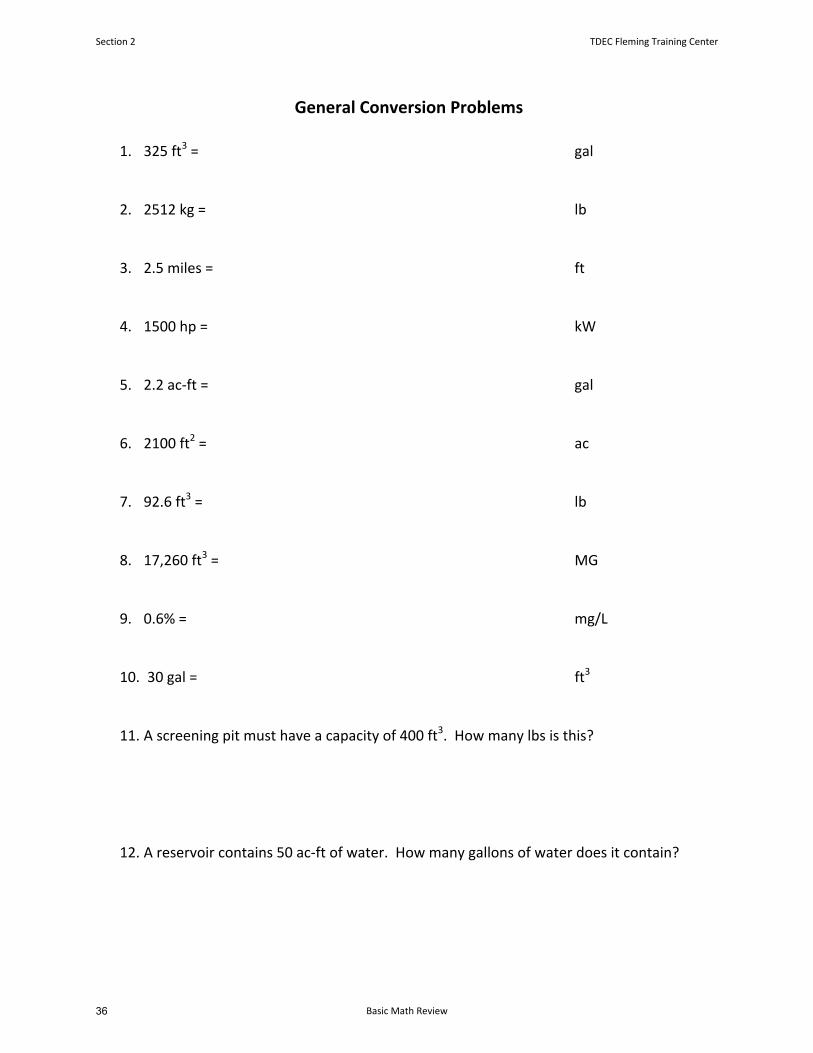
General Conversion Problems
1. 325 ft3 = gal
2. 2512 kg = lb
3. 2.5 miles = ft
4. 1500 hp = kW
5. 2.2 ac‐ft = gal
6. 2100 ft2 = ac
7. 92.6 ft3 = lb
8. 17,260 ft3 = MG
9. 0.6% = mg/L
10. 30 gal = ft3
11. A screening pit must have a capacity of 400 ft3. How many lbs is this?
12. A reservoir contains 50 ac‐ft of water. How many gallons of water does it contain?
Section 2 TDEC Fleming Training Center
Basic Math Review36
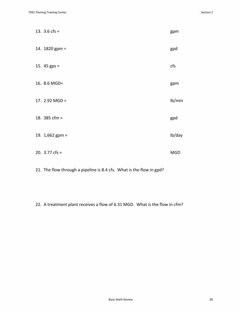
13. 3.6 cfs = gpm
14. 1820 gpm = gpd
15. 45 gps = cfs
16. 8.6 MGD= gpm
17. 2.92 MGD = lb/min
18. 385 cfm = gpd
19. 1,662 gpm = lb/day
20. 3.77 cfs = MGD
21. The flow through a pipeline is 8.4 cfs. What is the flow in gpd?
22. A treatment plant receives a flow of 6.31 MGD. What is the flow in cfm?
TDEC Fleming Training Center Section 2
Basic Math Review 35
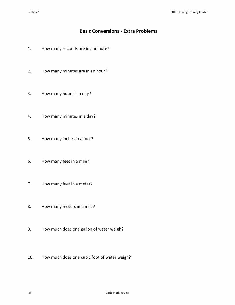
Basic Conversions - Extra Problems
1. How many seconds are in a minute?
2. How many minutes are in an hour?
3. How many hours in a day?
4. How many minutes in a day?
5. How many inches in a foot?
6. How many feet in a mile?
7. How many feet in a meter?
8. How many meters in a mile?
9. How much does one gallon of water weigh?
10. How much does one cubic foot of water weigh?
Section 2 TDEC Fleming Training Center
Basic Math Review38
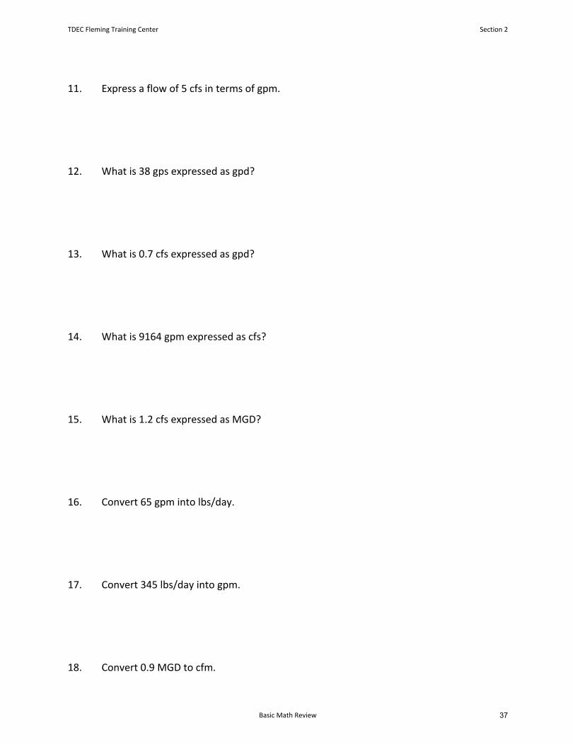
11. Express a flow of 5 cfs in terms of gpm.
12. What is 38 gps expressed as gpd?
13. What is 0.7 cfs expressed as gpd?
14. What is 9164 gpm expressed as cfs?
15. What is 1.2 cfs expressed as MGD?
16. Convert 65 gpm into lbs/day.
17. Convert 345 lbs/day into gpm.
18. Convert 0.9 MGD to cfm.
TDEC Fleming Training Center Section 2
Basic Math Review 37
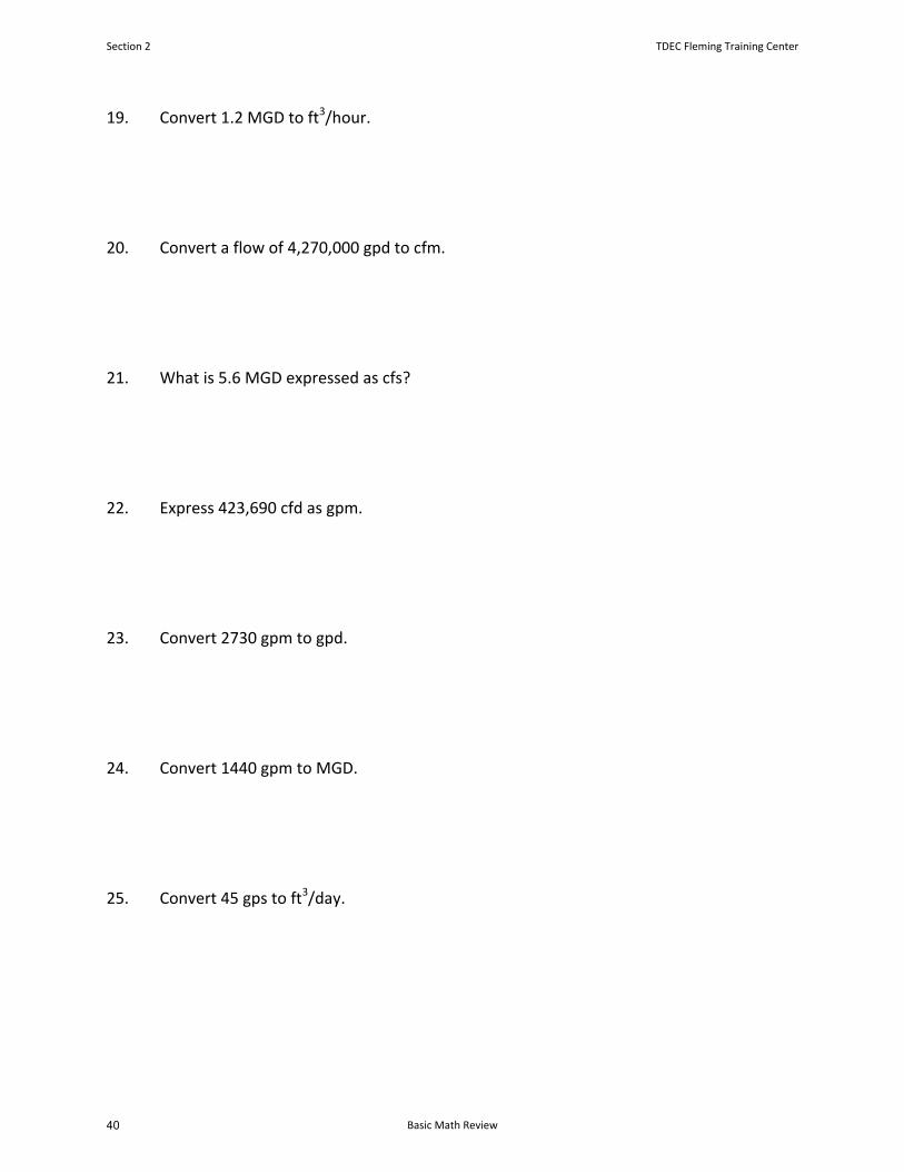
19. Convert 1.2 MGD to ft3/hour.
20. Convert a flow of 4,270,000 gpd to cfm.
21. What is 5.6 MGD expressed as cfs?
22. Express 423,690 cfd as gpm.
23. Convert 2730 gpm to gpd.
24. Convert 1440 gpm to MGD.
25. Convert 45 gps to ft3/day.
Section 2 TDEC Fleming Training Center
Basic Math Review40
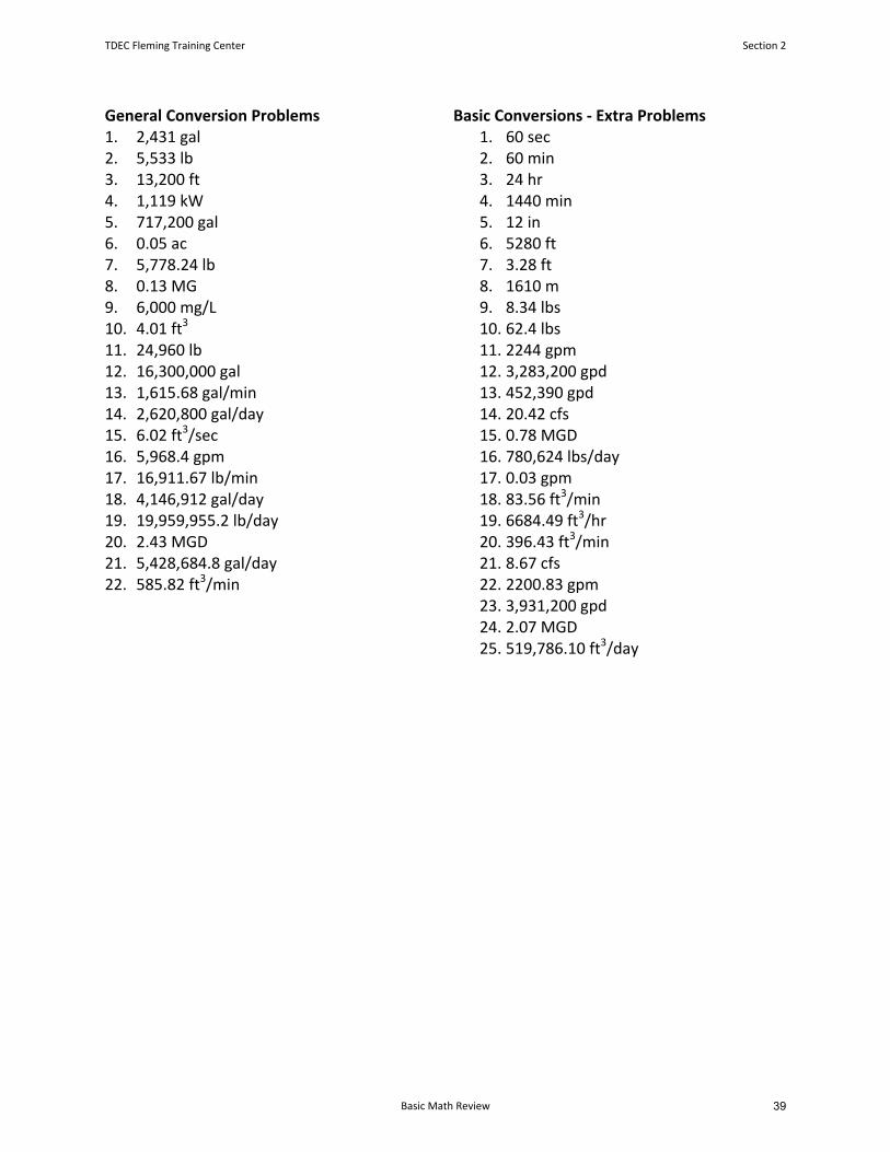
General Conversion Problems 1. 2,431 gal2. 5,533 lb3. 13,200 ft4. 1,119 kW5. 717,200 gal6. 0.05 ac7. 5,778.24 lb8. 0.13 MG9. 6,000 mg/L10. 4.01 ft3
11. 24,960 lb12. 16,300,000 gal13. 1,615.68 gal/min14. 2,620,800 gal/day15. 6.02 ft3/sec16. 5,968.4 gpm17. 16,911.67 lb/min18. 4,146,912 gal/day19. 19,959,955.2 lb/day20. 2.43 MGD21. 5,428,684.8 gal/day22. 585.82 ft3/min
Basic Conversions ‐ Extra Problems 1. 60 sec2. 60 min3. 24 hr4. 1440 min5. 12 in6. 5280 ft7. 3.28 ft8. 1610 m9. 8.34 lbs10. 62.4 lbs11. 2244 gpm12. 3,283,200 gpd13. 452,390 gpd14. 20.42 cfs15. 0.78 MGD16. 780,624 lbs/day17. 0.03 gpm18. 83.56 ft3/min19. 6684.49 ft3/hr20. 396.43 ft3/min21. 8.67 cfs22. 2200.83 gpm23. 3,931,200 gpd24. 2.07 MGD25. 519,786.10 ft3/day
TDEC Fleming Training Center Section 2
Basic Math Review 39
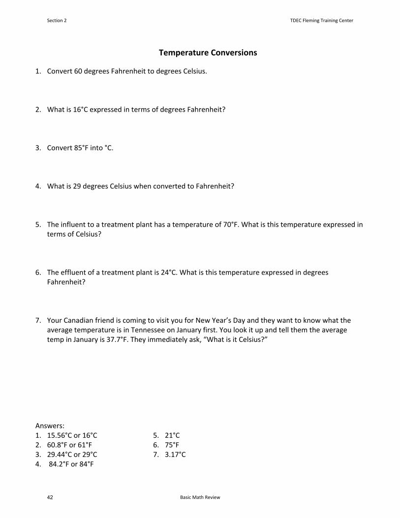
Temperature Conversions
1. Convert 60 degrees Fahrenheit to degrees Celsius.
2. What is 16°C expressed in terms of degrees Fahrenheit?
3. Convert 85°F into °C.
4. What is 29 degrees Celsius when converted to Fahrenheit?
5. The influent to a treatment plant has a temperature of 70°F. What is this temperature expressed interms of Celsius?
6. The effluent of a treatment plant is 24°C. What is this temperature expressed in degreesFahrenheit?
7. Your Canadian friend is coming to visit you for New Year’s Day and they want to know what theaverage temperature is in Tennessee on January first. You look it up and tell them the averagetemp in January is 37.7°F. They immediately ask, “What is it Celsius?”
Answers: 1. 15.56°C or 16°C2. 60.8°F or 61°F3. 29.44°C or 29°C4. 84.2°F or 84°F
5. 21°C6. 75°F7. 3.17°C
Section 2 TDEC Fleming Training Center
Basic Math Review42
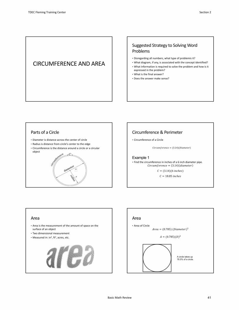
CIRCUMFERENCE AND AREA
Suggested Strategy to Solving Word Problems
• Disregarding all numbers, what type of problemis it?
• What diagram, if any, is associated with the concept identified?
• What information is required to solve the problem and how is itexpressed in the problem?
• What is the final answer?
• Does the answer make sense?
Parts of a Circle
D
• Diameter is distance across the center of circle
• Radius is distance from circle’s center to the edge
• Circumference is the distance around a circle or a circular object
Circumference & Perimeter
• Circumference of a Circle
3.14
• Find the circumference in inches of a 6 inch diameter pipe.3.14
3.14 6
18.85
Example 1
Area
• Area is the measurement of the amount of space on the surface of an object
• Two dimensional measurement
• Measured in: in2, ft2, acres, etc.
Area
• Area of Circle0.785
0.785
A circle takes up 78.5% of a circle.
TDEC Fleming Training Center Section 2
Basic Math Review 41
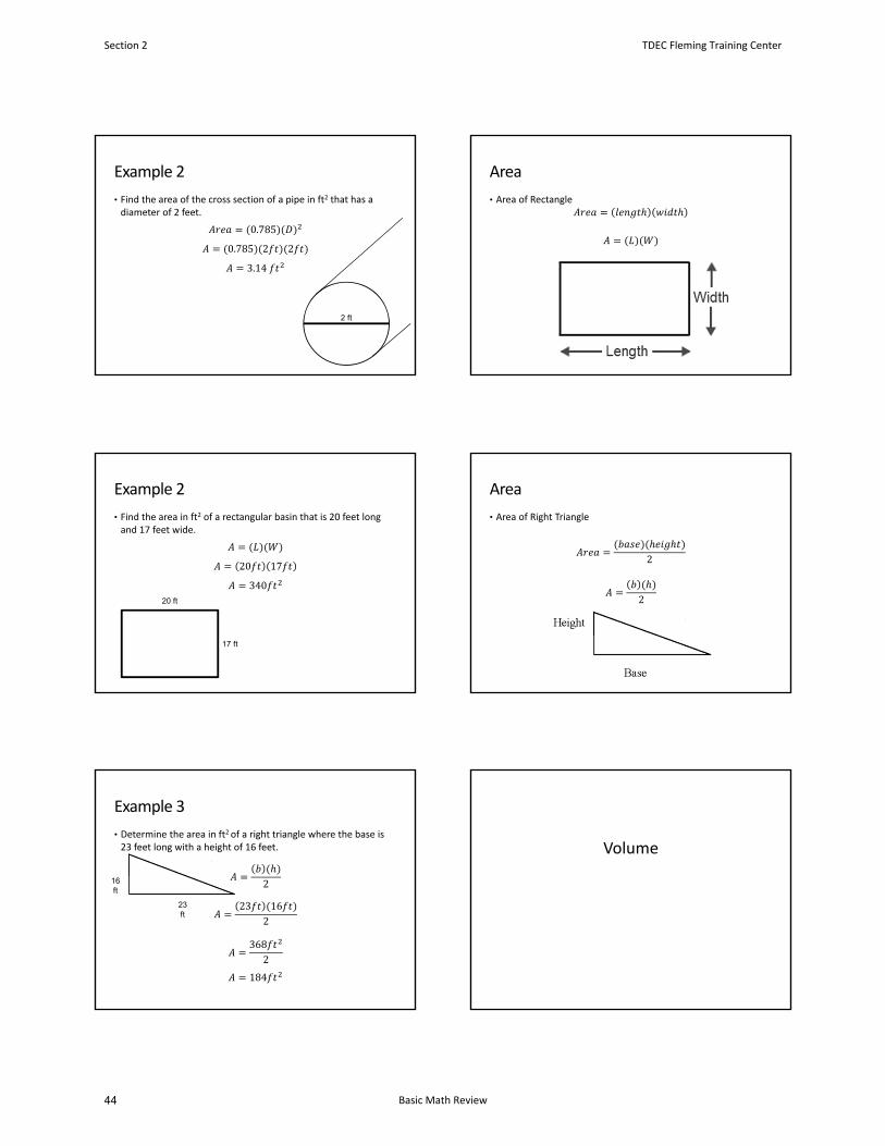
Example 2
• Find the area of the cross section of a pipe in ft2 that has a diameter of 2 feet.
0.785
0.785 2 2
3.14
2 ft
Area
• Area of Rectangle
Example 2
• Find the area in ft2 of a rectangular basin that is 20 feet long and 17 feet wide.
20 17
34020 ft
17 ft
Area
• Area of Right Triangle
2
2
23 ft
16 ft
• Determine the area in ft2 of a right triangle where the base is 23 feet long with a height of 16 feet.
2
23 162
3682
184
Example 3
Volume
Section 2 TDEC Fleming Training Center
Basic Math Review44
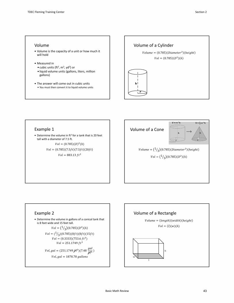
Volume Volume is the capacity of a unit or how much it will hold
Measured in cubic units (ft3, m3, yd3) or liquid volume units (gallons, liters, million gallons)
The answer will come out in cubic units You must then convert it to liquid volume units
Volume of a Cylinder
0.785
0.785
Example 1 Determine the volume in ft3 for a tank that is 20 feet tall with a diameter of 7.5 ft.
0.785
0.785 7.5 7.5 20
883.13
Volume of a Cone
13 0.785
13 0.785
Example 2 Determine the volume in gallons of a conical tank that is 8 feet wide and 15 feet tall.
13 0.785
13 0.785 8 8 15
0.3333 753.6251.1749
, 251.1749 7.48
, 1878.78
Volume of a Rectangle
TDEC Fleming Training Center Section 2
Basic Math Review 43

Example 3 Determine the volume in m3 for a tank that measures 30 meters by 15 meters by 25 meters.
30 15 25
11,250
Section 2 TDEC Fleming Training Center
Basic Math Review46

Circumference, Area, and Volume Problems
Circumference
1.
2.
3.
4.
5. A chemical holding tank has a diameter of 24 feet. What is the circumference of the tank infeet?
6. An influent pipe inlet opening has a diameter of 4 feet. What is the circumference of theinlet opening in inches?
7. What is the length (in feet) around the top of a circular clarifier that has a diameter of 32feet?
3in
5in
2ft
36in
TDEC Fleming Training Center Section 2
Basic Math Review 45

Area
1. A basin has a length of 45 feet and a width of 12 feet. Calculate the area in ft2.
2. If the diameter of a circle is 10 inches, what is the cross‐sectional area in square feet?
3. Calculate the surface area (in ft2) of the top of basin which is 90 feet long, 25 feet wide, and10 feet deep.
4. Calculate the area (in ft2) for a 2 ft diameter main that has just been laid.
5. What is the area of the rectangle that is 3 feet by 9 feet?
6. Calculate the area (in ft2) for an 18” main that has just been laid.
Section 2 TDEC Fleming Training Center
Basic Math Review48

Volume
1. Calculate the volume (in ft3) for a tank that measures 10 feet by 10 feet by 10 feet.
2. Calculate the volume (in gallons) for a basin that measures 22 feet by 11 feet by 5 feet.
3. Calculate the volume of water in a tank (in gallons), which measures 12 feet long, 6 feetwide, 5 feet deep, and contains 8 inches of water.
4. Calculate the volume (in ft3) of a cone shaped chemical hopper with a diameter of 12 feetand a depth of 18 feet.
5. A new water main needs to be disinfected. The main is 30” in diameter and has a length of0.25 miles. How many gallons of water will it hold?
TDEC Fleming Training Center Section 2
Basic Math Review 47
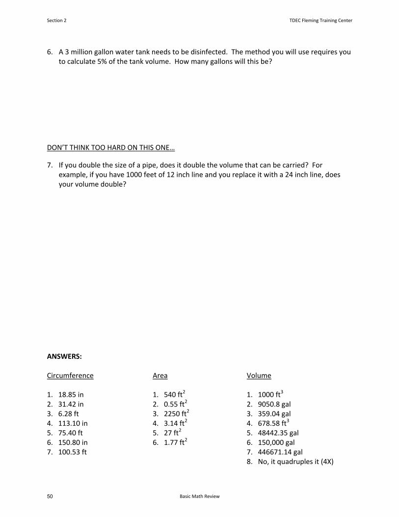
6. A 3 million gallon water tank needs to be disinfected. The method you will use requires youto calculate 5% of the tank volume. How many gallons will this be?
DON’T THINK TOO HARD ON THIS ONE…
7. If you double the size of a pipe, does it double the volume that can be carried? Forexample, if you have 1000 feet of 12 inch line and you replace it with a 24 inch line, doesyour volume double?
ANSWERS:
Circumference Area Volume
1. 18.85 in 1. 540 ft2 1. 1000 ft3
2. 31.42 in 2. 0.55 ft2 2. 9050.8 gal3. 6.28 ft 3. 2250 ft2 3. 359.04 gal4. 113.10 in 4. 3.14 ft2 4. 678.58 ft3
5. 75.40 ft 5. 27 ft2 5. 48442.35 gal6. 150.80 in 6. 1.77 ft2 6. 150,000 gal7. 100.53 ft 7. 446671.14 gal
8. No, it quadruples it (4X)
Section 2 TDEC Fleming Training Center
Basic Math Review50
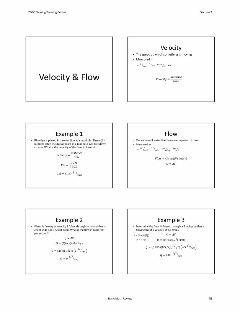
Velocity & Flow
Velocity• The speed at which something is moving
• Measured in
o ⁄ ⁄ etc
Example 1• Bluedyeisplacedinasewerlineatamanhole.Three 3 minuteslater,thedyeappearsinamanhole125feetdownstream.Whatisthevelocityoftheflowinft/min?
1253
41.67
Flow• The volume of water that flows over a period of time
• Measured in
o ⁄
Example 2• Water is flowing at velocity 3 ft/sec through a channel that is
2 feet wide and 1.5 feet deep. What is the flow in cubic feet per second?
2 1.5 3
9
Example 3• Determine the flow in ft3/sec through a 6 inch pipe that is
flowing full at a velocity of 4.5 ft/sec.
0.785
0.785 0.5 0.5 4.5
0.88
6
0.5
TDEC Fleming Training Center Section 2
Basic Math Review 49
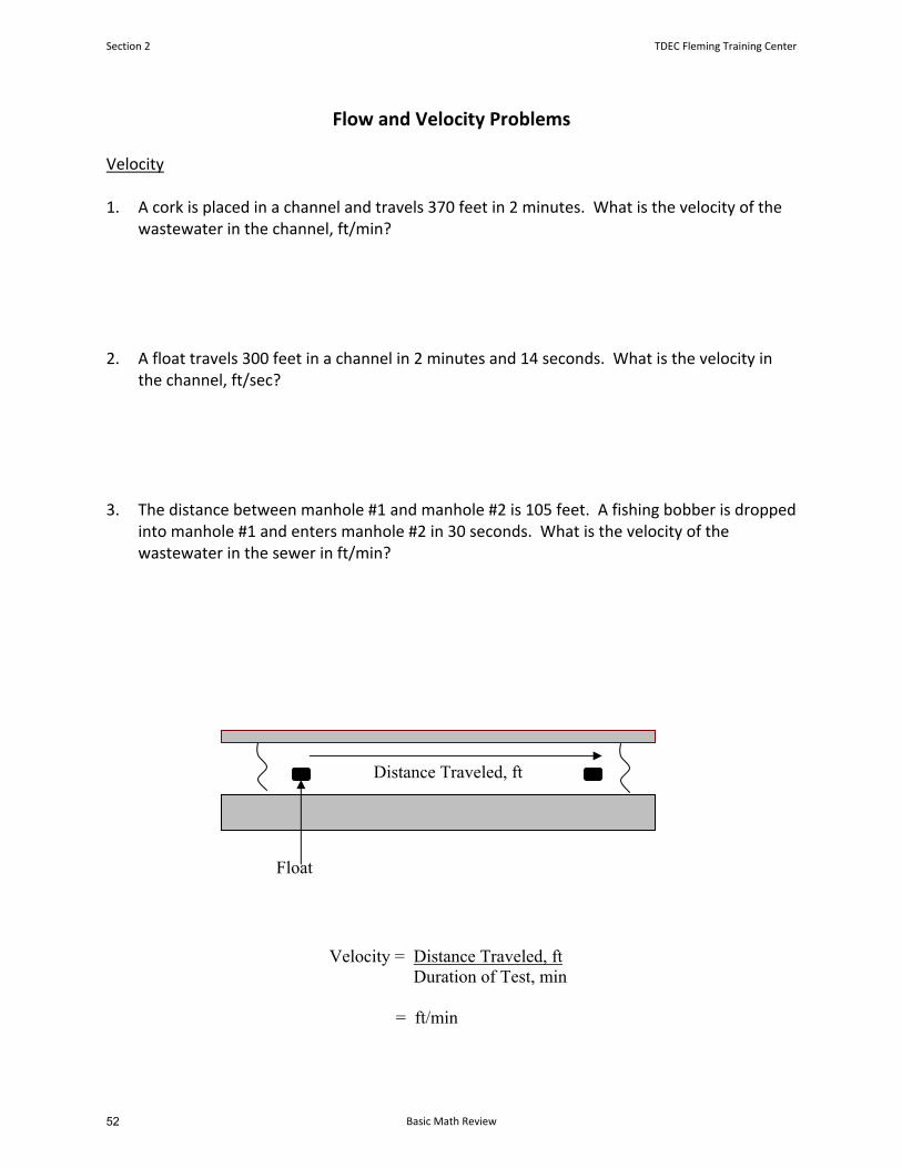
Flow and Velocity Problems
Velocity
1. A cork is placed in a channel and travels 370 feet in 2 minutes. What is the velocity of thewastewater in the channel, ft/min?
2. A float travels 300 feet in a channel in 2 minutes and 14 seconds. What is the velocity inthe channel, ft/sec?
3. The distance between manhole #1 and manhole #2 is 105 feet. A fishing bobber is droppedinto manhole #1 and enters manhole #2 in 30 seconds. What is the velocity of thewastewater in the sewer in ft/min?
Distance Traveled, ft
Float
Velocity = Distance Traveled, ft Duration of Test, min
= ft/min
Section 2 TDEC Fleming Training Center
Basic Math Review52
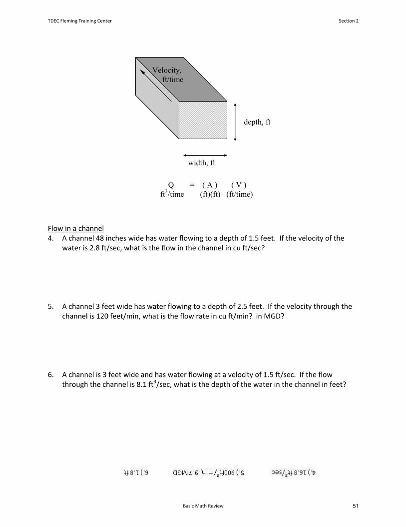
width, ft
Flow in a channel 4. A channel 48 inches wide has water flowing to a depth of 1.5 feet. If the velocity of the
water is 2.8 ft/sec, what is the flow in the channel in cu ft/sec?
5. A channel 3 feet wide has water flowing to a depth of 2.5 feet. If the velocity through thechannel is 120 feet/min, what is the flow rate in cu ft/min? in MGD?
6. A channel is 3 feet wide and has water flowing at a velocity of 1.5 ft/sec. If the flowthrough the channel is 8.1 ft3/sec, what is the depth of the water in the channel in feet?
depth, ft
Velocity, ft/time
Q = ( A ) ( V ) ft3/time (ft)(ft) (ft/time)
TDEC Fleming Training Center Section 2
Basic Math Review 51
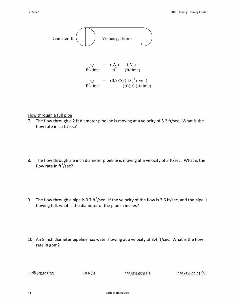
Flow through a full pipe 7. The flow through a 2 ft diameter pipeline is moving at a velocity of 3.2 ft/sec. What is the
flow rate in cu ft/sec?
8. The flow through a 6 inch diameter pipeline is moving at a velocity of 3 ft/sec. What is theflow rate in ft3/sec?
9. The flow through a pipe is 0.7 ft3/sec. If the velocity of the flow is 3.6 ft/sec, and the pipe isflowing full, what is the diameter of the pipe in inches?
10. An 8 inch diameter pipeline has water flowing at a velocity of 3.4 ft/sec. What is the flowrate in gpm?
Velocity, ft/time Diameter, ft
Q = ( A ) ( V ) ft3/time ft2 (ft/time)
Q = (0.785) ( D )2 ( vel ) ft3/time (ft)(ft) (ft/time)
Section 2 TDEC Fleming Training Center
Basic Math Review54

Flow Rate Problems Q = AV
1. A channel is 3 feet wide with water flowing to a depth of 2 feet. If the velocity in the channelis found to be 1.8 fps, what is the cubic feet per second flow rate in the channel?
2. A 12‐inch diameter pipe is flowing full. What is the cubic feet per minute flow rate in the pipeif the velocity is 110 feet/min?
3. A water main with a diameter of 18 inches is determined to have a velocity of 182 feet perminute. What is the flow rate in gpm?
4. A 24‐inch main has a velocity of 212 feet/min. What is the gpd flow rate for the pipe?
5. What would be the gpd flow rate for a 6” line flowing at 2 feet/second?
TDEC Fleming Training Center Section 2
Basic Math Review 53
6. A 36” water main has just been installed. According to the Design Criteria for the State ofTennessee, the minimum flushing velocity is 2 ft/sec. If the main is flushed at 2.5 ft/second,how many gallons/minute should be flushed from the hydrant?
7. A 36” water main has just been installed. If the main is flows at 2 ft/second, how many MGDwill the pipe deliver?
8. A certain pipe has a diameter of 18 inches. If the pipe is flowing full, and the water is knownto flow a distance of 830 yards in 5 minutes, what is the MGD flow rate for the pipe?
9. A float is placed in a channel. It takes 2.5 minutes to travel 300 feet. What is the velocity infeet per minute in the channel? (Assume that float is traveling at the average velocity of thewater.)
Section 2 TDEC Fleming Training Center
Basic Math Review56

10. A cork placed in a channel travels 30 feet in 20 seconds. What is the velocity of the cork infeet per second?
11. A channel is 4 feet wide with water flowing to a depth of 2.3 feet. If a float placed in thechannel takes 3 minutes to travel a distance of 500 feet, what is the cubic‐feet‐per‐minuteflow rate in the channel?
12. The average velocity in a full‐flowing pipe is measured and known to be 2.9 fps. The pipe is a24” main. Assuming that the pipe flows 18 hours per day and that the month in questioncontains 31 days, what is the total flow for the pipe in MG for that month?
13. The flow entering the leg of a tee connection is 9 cfs. If the flow through one branch of thetee is 5 cfs, what is the flow through the other branch?
5 cfs
9 cfs
x cfs
TDEC Fleming Training Center Section 2
Basic Math Review 55

Answers:
1. 10.8 ft3/sec2. 86.35 ft3/min3. 2,404.50 gpm4. 7,170,172.42 gpd5. 253,661.76 gpd6. 7,926.93 gpm7. 9.13 MGD
8. 9.47 MGD9. 120 ft/min10. 1.5 ft/sec11. 1,533.33 ft3/min12. 136.83 MG13. 4 ft3/sec
Section 2 TDEC Fleming Training Center
Basic Math Review58

Section 3
Preliminary
Treatment
57
Preliminary Treatment
TDEC - Fleming Training Center
Preliminary Treatment• Remember, there are 4 types of pollution: organic,
inorganic, thermal, and radioactive• “Pre-treatment” or “Preliminary Treatment” focuses
on the inorganic material
• Preliminary Treatment commonly consists of:1. Screening2. Shredding3. Grit Removal4. Pre-Aeration
TDEC - Fleming Training Center
Preliminary Treatment• The removal of metal, rocks, rags, sand, eggshells,
and similar materials that may hinder the operation of a treatment plant.
• Commonly consists of Screening, Shredding, and Grit Removal to separate coarse materials from the wastewater being treated.
• Located at headworks• Protects downstream treatment processes• Screening, Grit Removal, Odor Control, Septage
Handling, and Flow Equalization
TDEC - Fleming Training Center
Preliminary Treatment• Must be removed to prevent:
• Blockages of pipes• Damage to pumps• Excessive wear on pumps
and chains• Filling of digesters• Plant operating at reduced
efficiency, which increases pollution level of effluent discharged
TDEC - Fleming Training Center
• Cans• Bottles• Sticks• Scrap metal• Rocks• Egg shells• Plastic products• Rags• Sand
Preliminary Treatment• Buried or otherwise inaccessible pipe plugged• Sludge collector mechanism jams• Critical pump put out of commission
These things can all lead to…• Reduced efficiency of plant• Health hazards to downstream water users• Sludge deposits in receiving waters (odors and
unsightliness)• Death of fish and other aquatic life• Costly repairs and large, unbudgeted expenses
TDEC - Fleming Training Center
Screening ProcessCoarse Screens Fine Screens
TDEC - Fleming Training Center
• The plant’s first treatment unit
• Removes large solids and trash, wood, tree limbs, rocks, other large debris
1. Bar Rack 2. Manually Cleaned
Bar Screen3. Mechanically
Cleaned Bar Screen
• Placed after coarse screens for added removal of debris
• May be in the form of belts, discs, or drums set in a channel so the wastewater flows through the submerged portion
1. Wedge-wire2. Rotary drum screens3. Escalating step
screen
Section 3 TDEC Fleming Training Center
Preliminary Treatment60
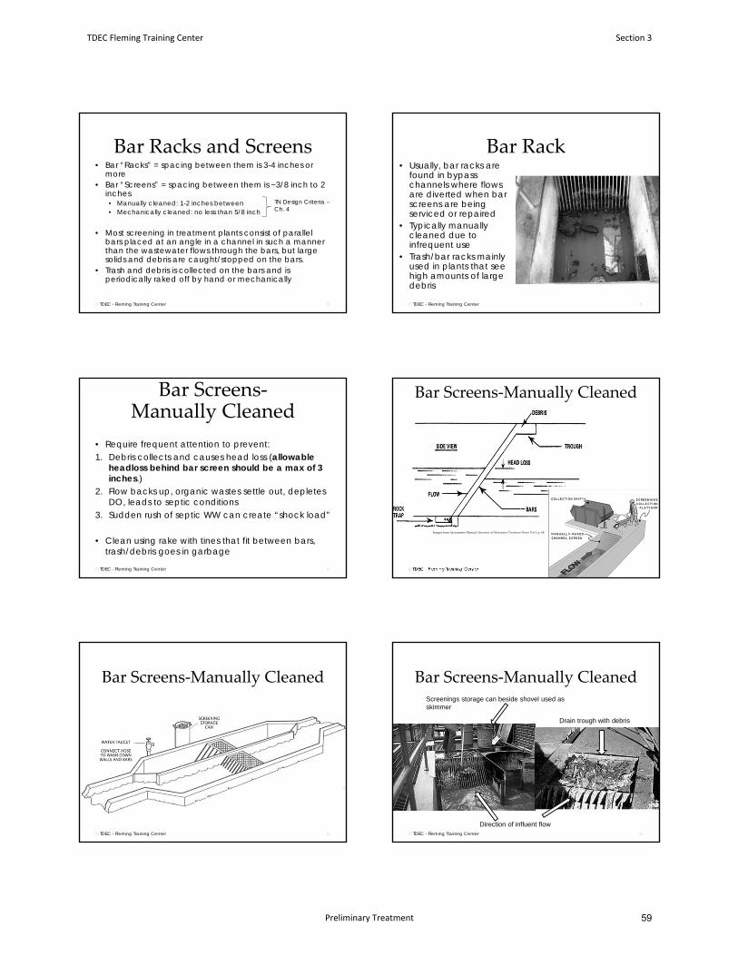
Bar Racks and Screens• Bar “Racks” = spacing between them is 3-4 inches or
more• Bar “Screens” = spacing between them is ~3/8 inch to 2
inches• Manually cleaned: 1-2 inches between• Mechanically cleaned: no less than 5/8 inch
• Most screening in treatment plants consist of parallel bars placed at an angle in a channel in such a manner than the wastewater flows through the bars, but large solids and debris are caught/stopped on the bars.
• Trash and debris is collected on the bars and is periodically raked off by hand or mechanically
TDEC - Fleming Training Center
TN Design Criteria –Ch. 4
Bar Rack
TDEC - Fleming Training Center
• Usually, bar racks are found in bypass channels where flows are diverted when bar screens are being serviced or repaired
• Typically manually cleaned due to infrequent use
• Trash/bar racks mainly used in plants that see high amounts of large debris
Bar Screens‐Manually Cleaned
• Require frequent attention to prevent:1. Debris collects and causes head loss (allowable
headloss behind bar screen should be a max of 3 inches.)
2. Flow backs up, organic wastes settle out, depletes DO, leads to septic conditions
3. Sudden rush of septic WW can create “shock load”
• Clean using rake with tines that fit between bars, trash/debris goes in garbage
TDEC - Fleming Training Center
Bar Screens‐Manually Cleaned
TDEC - Fleming Training Center
Images from Sacramento Manual Operation of Wastewater Treatment Plants Vol I, p. 68
Bar Screens‐Manually Cleaned
TDEC - Fleming Training Center
Bar Screens‐Manually Cleaned
TDEC - Fleming Training Center
Screenings storage can beside shovel used as skimmer
Direction of influent flow
Drain trough with debris
TDEC Fleming Training Center Section 3
Preliminary Treatment 59
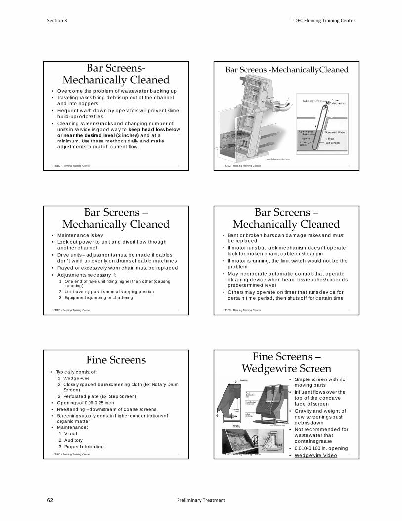
Bar Screens‐Mechanically Cleaned
• Overcome the problem of wastewater backing up• Traveling rakes bring debris up out of the channel
and into hoppers• Frequent wash down by operators will prevent slime
build-up/odors/flies• Cleaning screens/racks and changing number of
units in service is good way to keep head loss below or near the desired level (3 inches) and at a minimum. Use these methods daily and make adjustments to match current flow.
TDEC - Fleming Training Center
Bar Screens ‐MechanicallyCleaned
TDEC - Fleming Training Center
www.huber‐technology.com
Bar Screens –Mechanically Cleaned
• Maintenance is key• Lock out power to unit and divert flow through
another channel• Drive units – adjustments must be made if cables
don’t wind up evenly on drums of cable machines• Frayed or excessively worn chain must be replaced• Adjustments necessary if:
1. One end of rake unit riding higher than other (causing jamming)
2. Unit traveling past its normal stopping position3. Equipment is jumping or chattering
TDEC - Fleming Training Center
Bar Screens –Mechanically Cleaned
• Bent or broken bars can damage rakes and must be replaced
• If motor runs but rack mechanism doesn’t operate, look for broken chain, cable or shear pin
• If motor is running, the limit switch would not be the problem
• May incorporate automatic controls that operate cleaning device when head loss reaches/exceeds predetermined level
• Others may operate on timer that runs device for certain time period, then shuts off for certain time
TDEC - Fleming Training Center
Fine Screens• Typically consist of:
1. Wedge-wire 2. Closely spaced bars/screening cloth (Ex: Rotary Drum
Screen)3. Perforated plate (Ex: Step Screen)
• Openings of 0.06-0.25 inch• Freestanding – downstream of coarse screens• Screenings usually contain higher concentrations of
organic matter• Maintenance:
1. Visual2. Auditory3. Proper Lubrication
TDEC - Fleming Training Center
Fine Screens –Wedgewire Screen
• Simple screen with no moving parts
• Influent flows over the top of the concave face of screen
• Gravity and weight of new screenings push debris down
• Not recommended for wastewater that contains grease
• 0.010-0.100 in. opening• Wedgewire VideoTDEC - Fleming Training Center
www.uboscreen.com
Section 3 TDEC Fleming Training Center
Preliminary Treatment62
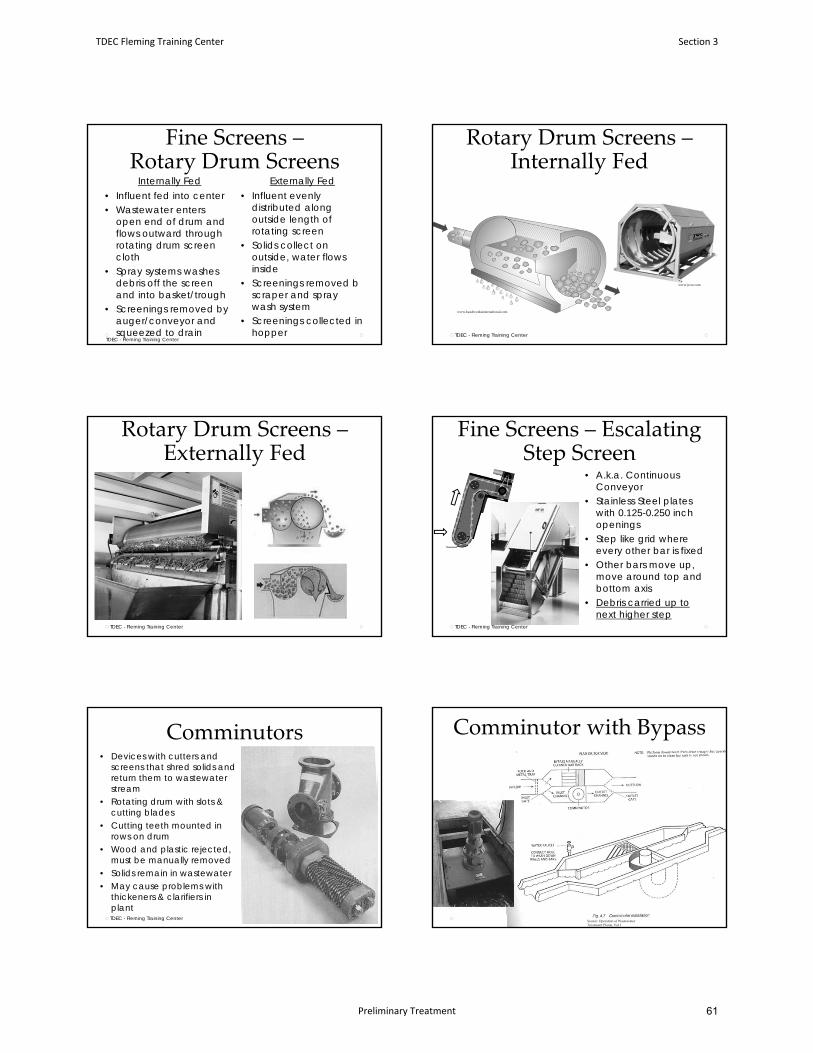
Fine Screens –Rotary Drum Screens
Internally Fed Externally Fed• Influent fed into center• Wastewater enters
open end of drum and flows outward through rotating drum screen cloth
• Spray systems washes debris off the screen and into basket/trough
• Screenings removed by auger/conveyor and squeezed to drain
• Influent evenly distributed along outside length of rotating screen
• Solids collect on outside, water flows inside
• Screenings removed b scraper and spray wash system
• Screenings collected in hopper
TDEC - Fleming Training Center
Rotary Drum Screens –Internally Fed
TDEC - Fleming Training Center
www.jwce.com
www.headworksinternational.com
Rotary Drum Screens –Externally Fed
TDEC - Fleming Training Center
www.parkson.com
Fine Screens – Escalating Step Screen
• A.k.a. Continuous Conveyor
• Stainless Steel plates with 0.125-0.250 inch openings
• Step like grid where every other bar is fixed
• Other bars move up, move around top and bottom axis
• Debris carried up to next higher step
TDEC - Fleming Training Center
Comminutors• Devices with cutters and
screens that shred solids and return them to wastewater stream
• Rotating drum with slots & cutting blades
• Cutting teeth mounted in rows on drum
• Wood and plastic rejected, must be manually removed
• Solids remain in wastewater• May cause problems with
thickeners & clarifiers in plantTDEC - Fleming Training Center
Comminutor with Bypass
Source: Operation of Wastewater Treatment Plants, Vol I
TDEC Fleming Training Center Section 3
Preliminary Treatment 61
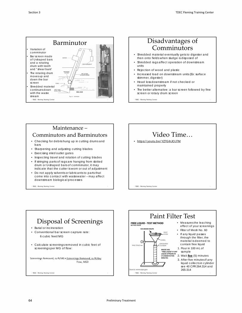
Barminutor• Variation of
comminutor• Bar screen made
of U-shaped bars and a rotating drum with teeth and “shear bars”
• The rotating drum moves up and down the bar screen
• Shredded material continues down with the waste stream
TDEC - Fleming Training Center
Disadvantages of Comminutors
• Shredded material eventually gets to digester and then onto fields when sludge is disposed of
• Shredded rags affect operation of downstream units
• Rejection of wood and plastic• Increased load on downstream units (Ex: surface
skimmer, digester)• Head loss downstream if not checked or
maintained properly• The better alternative: a bar screen followed by fine
screen or rotary drum screen
TDEC - Fleming Training Center
Maintenance –
Comminutors and Barminutors• Checking for debris hung up in cutting drums and
bars• Sharpening and adjusting cutting blades• Exercising inlet/outlet gates• Inspecting travel and rotation of cutting blades• If stringing parts of rags are hanging from slotted
drum or U-shaped bars of comminutor, it may indicate that the cutter is worn or out of adjustment
• Do not apply solvents or lubricants to parts that come into contact with wastewater – may affect downstream biological processes
TDEC - Fleming Training Center
Video Time…• https://youtu.be/YZ7GihJOJ7M
TDEC - Fleming Training Center
Disposal of Screenings• Burial or incineration• Conventional bar screen capture rate:
6 cubic feet/MG
• Calculate screenings removed in cubic feet of screenings per MG of flow:
TDEC - Fleming Training Center
Paint Filter Test• Measures the leaching
effect of your screenings• Filter of Mesh No. 60• If any liquid passes
through the filter, the material is deemed to contain free liquid
1. Pour in 100 mL of sample
2. Wait five (5) minutes3. After five minutes if any
liquid collects in cylinder see 40 CFR 264.314 and 265-314
TDEC - Fleming Training Center
Section 3 TDEC Fleming Training Center
Preliminary Treatment64
Grit Removal• Heavier particulate matter that will not readily
decompose or break down• Fine, non-biodegradable particles• Settling velocity greater than organic solids• Sand, gravel, rocks, seeds, cinders, egg shells,
cigarette filter tips, coffee grounds, etc.• Reduce clogging in pipes and protects moving
mechanical equipment/pumps from abrasion and accompanying wear
• Also prevents accumulation downstream
TDEC - Fleming Training Center
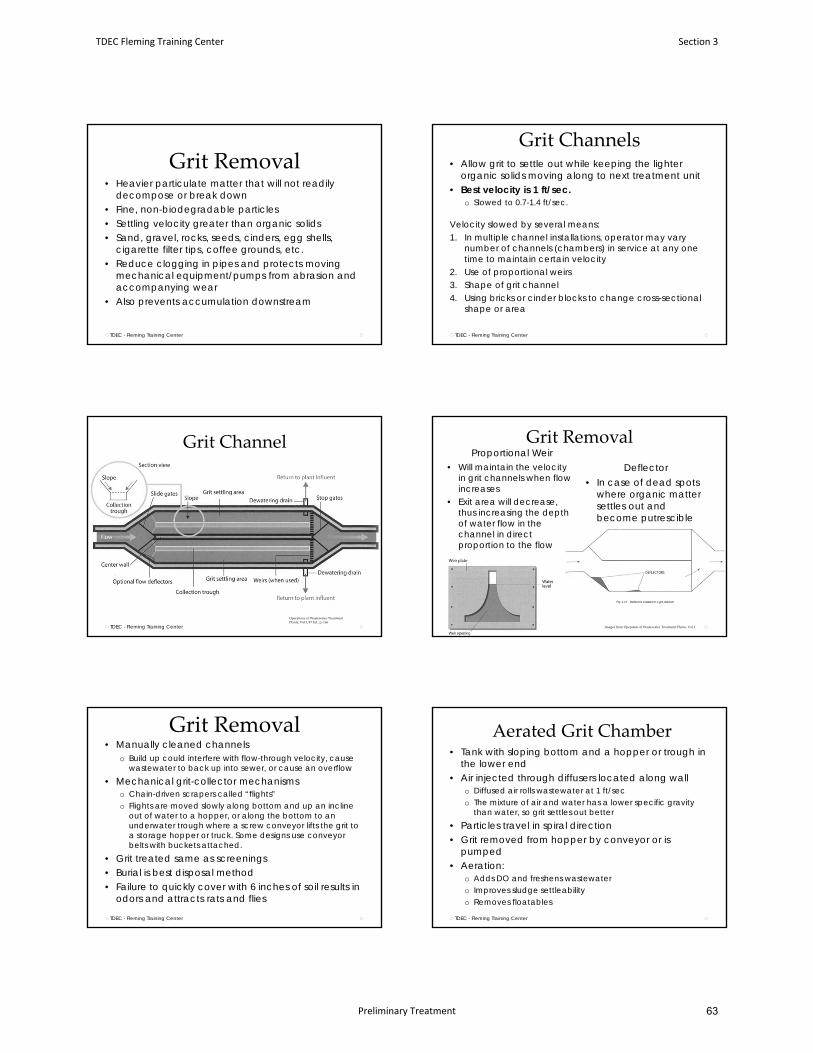
Grit Channels• Allow grit to settle out while keeping the lighter
organic solids moving along to next treatment unit• Best velocity is 1 ft/sec.
o Slowed to 0.7-1.4 ft/sec.
Velocity slowed by several means:1. In multiple channel installations, operator may vary
number of channels (chambers) in service at any one time to maintain certain velocity
2. Use of proportional weirs3. Shape of grit channel4. Using bricks or cinder blocks to change cross-sectional
shape or area
TDEC - Fleming Training Center
Grit Channel
TDEC - Fleming Training Center
Operations of Wastewater Treatment Plants, Vol I, 8th Ed., p. 166
Grit RemovalProportional Weir
Deflector• Will maintain the velocity in grit channels when flow increases
• Exit area will decrease, thus increasing the depth of water flow in the channel in direct proportion to the flow
• In case of dead spots where organic matter settles out and become putrescible
Images from Operation of Wastewater Treatment Plants, Vol I
Grit Removal• Manually cleaned channels
o Build up could interfere with flow-through velocity, cause wastewater to back up into sewer, or cause an overflow
• Mechanical grit-collector mechanismso Chain-driven scrapers called “flights” o Flights are moved slowly along bottom and up an incline
out of water to a hopper, or along the bottom to an underwater trough where a screw conveyor lifts the grit to a storage hopper or truck. Some designs use conveyor belts with buckets attached.
• Grit treated same as screenings• Burial is best disposal method• Failure to quickly cover with 6 inches of soil results in
odors and attracts rats and flies
TDEC - Fleming Training Center
Aerated Grit Chamber• Tank with sloping bottom and a hopper or trough in
the lower end• Air injected through diffusers located along wall
o Diffused air rolls wastewater at 1 ft/seco The mixture of air and water has a lower specific gravity
than water, so grit settles out better• Particles travel in spiral direction• Grit removed from hopper by conveyor or is
pumped• Aeration:
o Adds DO and freshens wastewatero Improves sludge settleabilityo Removes floatables
TDEC - Fleming Training Center
TDEC Fleming Training Center Section 3
Preliminary Treatment 63
Aerated Grit Chamber
TDEC - Fleming Training CenterOperation of Wastewater Treatment Plants, Vol I
Aerated Grit Chamber
• If the velocity of the roll is too great, grit will be carried out of chamber
• If the velocity is too low, organic matter will be removed with grit
• A good way to improve the effectiveness of all type of grit removal systems is to perform a volatile solids test on the collected grito This should help you adjust your air flow and velocity
TDEC - Fleming Training Center
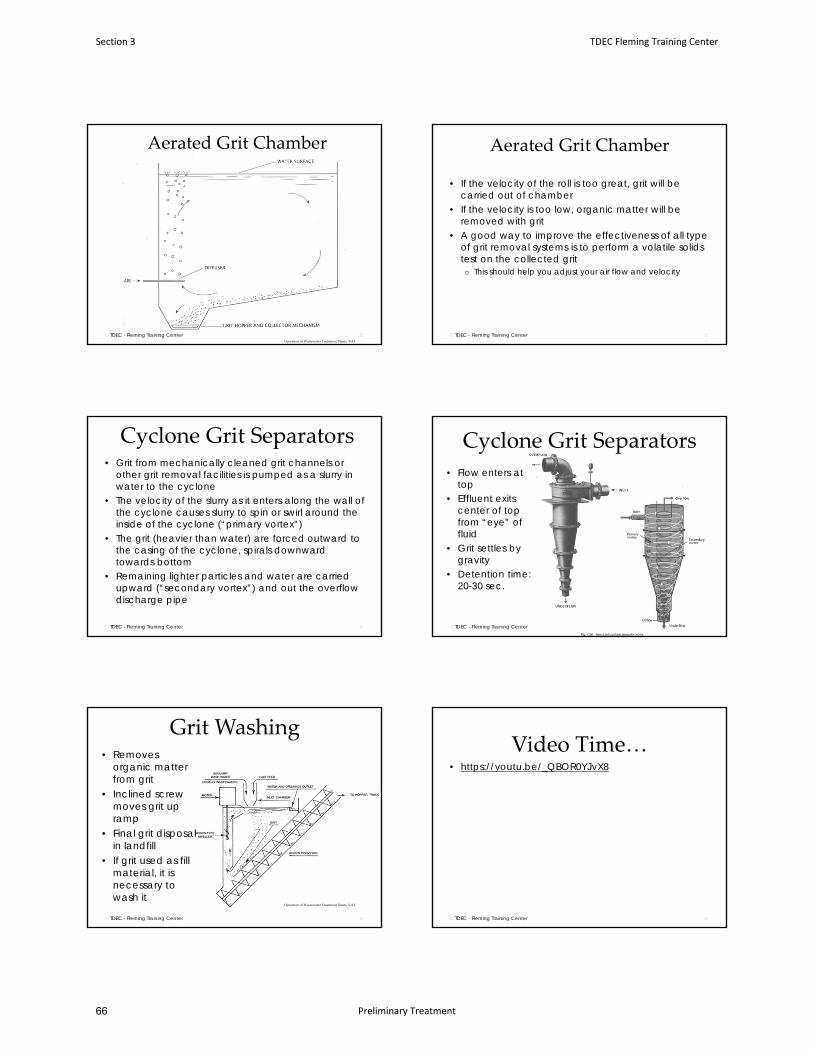
Cyclone Grit Separators• Grit from mechanically cleaned grit channels or
other grit removal facilities is pumped as a slurry in water to the cyclone
• The velocity of the slurry as it enters along the wall of the cyclone causes slurry to spin or swirl around the inside of the cyclone (“primary vortex”)
• The grit (heavier than water) are forced outward to the casing of the cyclone, spirals downward towards bottom
• Remaining lighter particles and water are carried upward (“secondary vortex”) and out the overflow discharge pipe
TDEC - Fleming Training Center
Cyclone Grit Separators
• Flow enters at top
• Effluent exits center of top from “eye” of fluid
• Grit settles by gravity
• Detention time: 20-30 sec.
TDEC - Fleming Training Center
Grit Washing• Removes
organic matter from grit
• Inclined screw moves grit up ramp
• Final grit disposal in landfill
• If grit used as fill material, it is necessary to wash it
TDEC - Fleming Training Center
Operation of Wastewater Treatment Plants, Vol I
Video Time…• https://youtu.be/_QBOR0YJvX8
TDEC - Fleming Training Center
Section 3 TDEC Fleming Training Center
Preliminary Treatment66
Odor Control
TDEC - Fleming Training Center
Odor Problem
On Site Problem
Employee Safety and Health
Working Conditions
Community Problem
Public Relations
Odor Control
• Hydrogen Sulfide (H2S)o Main cause of odors in wastewater systemso Poisonous to respiratory systemo Rotten egg odoro Produced under anaerobic conditionso Explosive, flammable, corrosiveo Dulls sense of smell on exposure
• Ammonia (NH3)• Methane (CH4)
TDEC - Fleming Training Center
TDEC - Fleming Training CenterOperation of Municipal Wastewater Treatment Plants, Vol I, MOP No. 11, p. 13‐9
Odor control methods and technologies
Often requires a combination of treating/removing/and reducing potential causes• Vapor-phase odor control methods
o Atmospheric discharge and dilutiono Masking agents and counteraction chemicalso Chemical wet scrubbingo Activated carbon adsorption
• Liquid-phase odor control methodso Chemical addition
• Operational odor control methodso Source controlo Housekeeping improvementso Process or operational changes
TDEC - Fleming Training Center
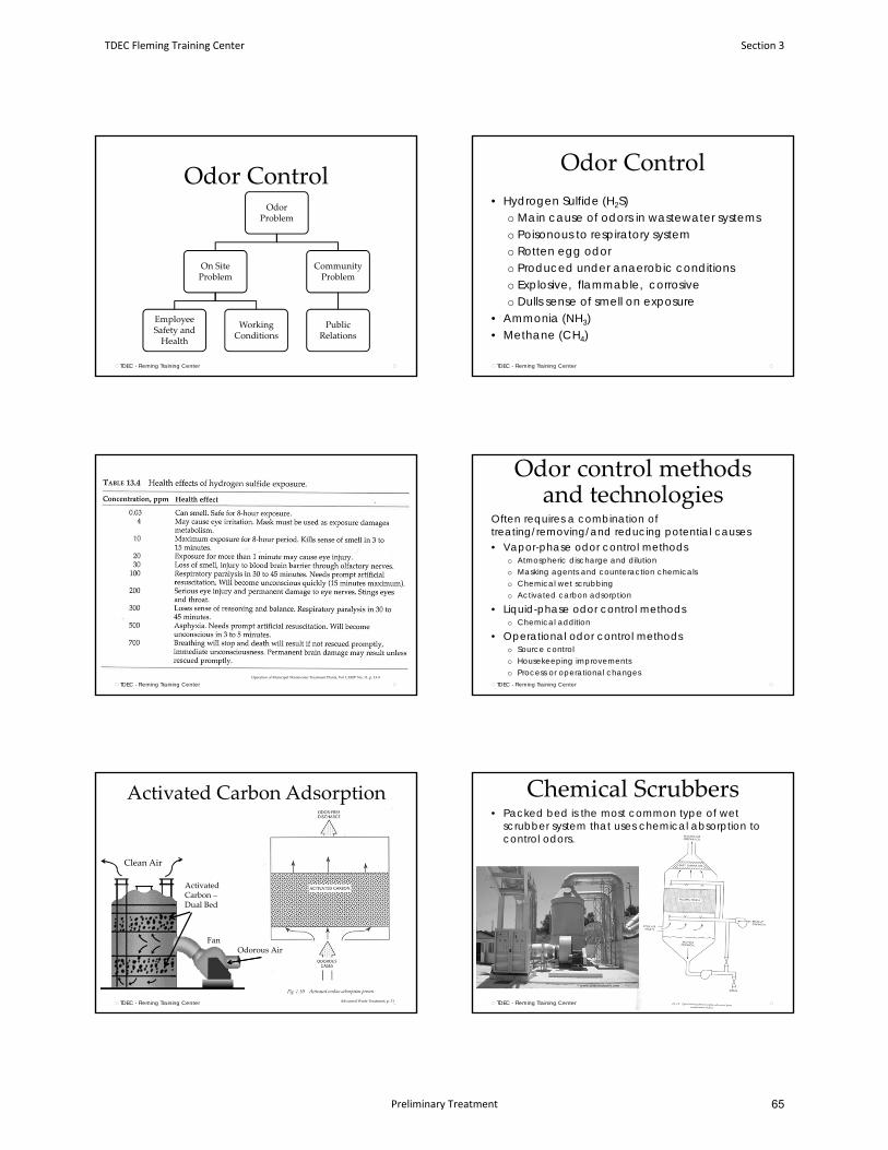
Activated Carbon Adsorption
TDEC - Fleming Training Center
Clean Air
Activated Carbon –Dual Bed
FanOdorous Air
Advanced Waste Treatment, p. 31
Chemical Scrubbers• Packed bed is the most common type of wet
scrubber system that uses chemical absorption to control odors.
TDEC - Fleming Training Center
www.directindustry.com
TDEC Fleming Training Center Section 3
Preliminary Treatment 65
TDEC - Fleming Training Center www.monroeenvironmental.com
Horizontal packed bed scrubber system
Figures from this and previous slide: Advanced Waste Treatment, Fifth edition, p. 30‐31
Chemical Additions• Chlorine and chlorine compounds• Hydrogen peroxide• Metal salts
o Iron o Zinco Copper
• Ozone• Strong Alkalis – H2S is extremely pH dependent
o Sodium hydroxideo Lime
• Nitrates
TDEC - Fleming Training Center
Septage• Septage = wastewater that is pumped out of septic
tanks and other types of holding tanks• Partially digested anaerobic wastewater
o Higher strength (high BOD, COD, TSS, FOG)• Can lead to toxic slug loads
o Sampling can help identify toxic loadso If possible, maintain a way to hold septage and pump it slowly
into your plant• Maintain good records of who dumped, how much,
and wheno Water supply for
washdowno Video monitoring
TDEC - Fleming Training Center
Flow Equalization• A device or tank designed to hold back or store a
portion of peak flows for release during low-flow periodso TN Design Criteria for Sewage Works 4.4.1: required where
peak flows are greater than 2 times the average design flow.
• Equalization systems can be used to dampen peak flows or peak pollutant loadingso In-line sytemso Side-line systems
TDEC - Fleming Training Center
Flow Equalization• High flows can be managed by using:
• Flow-equalization basins• Storage lagoons• Alternate process modes such as contact stabilization or
step feed.• Locations can include:
• Before preliminary treatment• Directly after preliminary treatment• Immediately after primary treatment
• DO must be 1.0 mg/L
53TDEC - Fleming Training Center TDEC - Fleming Training Center
Section 3 TDEC Fleming Training Center
Preliminary Treatment68
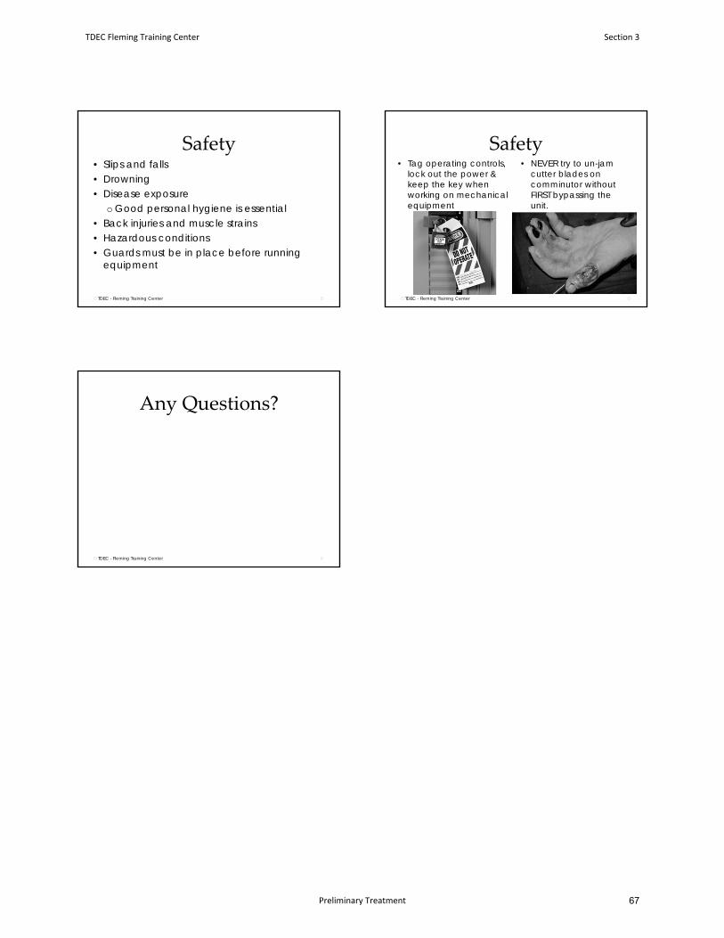
Safety• Slips and falls• Drowning• Disease exposure
o Good personal hygiene is essential• Back injuries and muscle strains• Hazardous conditions• Guards must be in place before running
equipment
TDEC - Fleming Training Center
Safety• NEVER try to un-jam
cutter blades on comminutor without FIRST bypassing the unit.
• Tag operating controls, lock out the power & keep the key when working on mechanical equipment
TDEC - Fleming Training Center
Any Questions?
TDEC - Fleming Training Center
TDEC Fleming Training Center Section 3
Preliminary Treatment 67
January 2016 4-1 Design Criteria Ch. 4
CHAPTER 4
Preliminary and Pretreatment Facilities
4.1 Screening and Grinding
4.1.1 General
4.1.2 Location
4.1.3 Bar Screens
4.1.4 Fine Screens
4.1.5 Communition
4.1.6 Operability
4.1.7 Disposal
4.2 Grit Removal
4.2.1 General
4.2.2 Location
4.2.3 Design
4.2.4 Disposal
4.2.5 Operability
4.3 Pre-aeration
4.4 Flow Equalization
4.4.1 General
4.4.2 Location
4.4.3 Design and Operability
4.5 Swirls and Helical Bends
Section 3 TDEC Fleming Training Center
Preliminary Treatment70
January 2016 4-2 Design Criteria Ch. 4
PRELIMINARY AND PRETREATMENT FACILITIES
4.1 Screening and Grinding
4.1.1 General
Some type of screening and/or grinding device shall be provided at all mechanical
wastewater plants. The effective removal of grit, rocks, debris, excessive oil or grease
and the screening of solids shall be accomplished prior to any activated sludge process.
Any grinding which does not dispose of the shredded material outside of the wastewater
stream must be evaluated with regard to the influent characteristics (rags, combined
sewers) of the waste prior to any activated sludge process.
4.1.2 Location
4.1.2.1 Indoors
Screening devices installed in a building where other equipment or offices are
located shall be accessible only through an outside entrance. Adequate lighting,
ventilation and access for maintenance or removal of equipment and screenings
shall be provided.
4.1.2.2 Outdoors
The removal point for screenings should be as practical as possible for the plant
personnel, preferably at ground level. Ladder access is not acceptable unless
hoisting facilities for screenings are provided. Separate hoisting is not required
for bar screens in manual bypass channels.
4.1.2.3 Deep Pit Installations
Stairway access, adequate lighting and ventilation with a convenient and adequate
means for screenings removal shall be provided.
4.1.3 Bar Screens
4.1.3.1 Manually Cleaned
Clear openings between bars shall be from 1 to 2 inches. Slope of the bars shall be
30 to 60 degrees from the vertical. Bar size shall be from 1/4 to 5/8 inches with 1
to 3 inches of depth, depending on the length and material to maintain integrity.
A perforated drain plate shall be installed at the top of the bar screen for
temporary storage and drainage.
TDEC Fleming Training Center Section 3
Preliminary Treatment 69
January 2016 4-3 Design Criteria Ch. 4
4.1.3.2 Mechanically Cleaned
Mechanically cleaned bar screens are recommended for all plants greater than 1
MGD. Both front cleaned or back cleaned models may be acceptable. Clear
openings no less than 5/8 inch are acceptable. Protection from freezing
conditions should be considered.
Other than the rakes, no moving parts shall be below the water line.
4.1.3.3 Velocities
Approach velocities no less than 1.25 fps nor a velocity greater than 3.0 fps
through the bar screen is desired.
4.1.4 Fine Screens
4.1.4.1 General
Fine screens shall be preceeded by a trash rack or coarse bar screen.
Comminution shall not be used ahead of fine screens. A minimum of two fine
screens shall be provided, each capable of independent operation at peak design
flow. The design engineer must fully evaluate a proposal where fine screens are
to be used in lieu of primary sedimentation. Fine screens shall not be considered
equivalent to primary sedimentation or grit removal, but will be reviewed on a
case-by-case basis. Oil and grease removal must be considered.
4.1.4.2 Design
The operation should be designed to not splash operating personnel with
wastewater or screenings. Fine screens will generally increase the dissolved
oxygen content of the influent which may be beneficial in certain circumstances.
The screens must be enclosed or otherwise protected from cold weather freezing
conditions. Disposal of screenings must be addressed. To be landfilled,
screenings must be dried to approximately 20% solids. Odors may be a problem
in sensitive locations.
4.1.5 Comminution
4.1.5.1 General
In-line comminution may not be acceptable prior to an activated sludge process
for facilities with a history of problems with rags. Out-of-stream comminution or
disintegration is acceptable for activated sludge processes; however, screenings
should not return to the wastewater stream.
Section 3 TDEC Fleming Training Center
Preliminary Treatment72
January 2016 4-4 Design Criteria Ch. 4
4.1.5.2 Design
A coarse bar screen with an automatic bypass shall precede comminution for all
mechanical plants. Gravel traps shall precede comminution which is not preceded
by grit removal. Clear openings of 1/4 inch are prefered in the comminution
device. An automatic unit bypass or other means of protection shall be provided
to protect the comminutor motor from flooding. The design shall incorporate a
method for removing the equipment from service and for repairs or sharpening of
the teeth.
4.1.6 Operability
All screening devices shall have the capability of isolation from the wastewater
stream. Sufficient wash water shall be available for cleanup of the area. All
mechanical screening devices shall be provided with a manually cleaned bar
screen bypass. Multiple bar screens should be considered for plants with rag
problems instead of comminutors.
Adequate space must be provided for access to each screening or comminution
device. This is critical in elevated, indoor or deep pit installations.
4.1.7 Disposal
All screenings shall be disposed of in an approved manner. Suitable containers
shall be provided for holding the screenings. Run-off control must be provided
around the containers, where applicable. If fine screens are proposed,
consideration must be given to the wastewater overflow if the screens clog or
blind. Overflows must be contained and bypassed around the screens by dikes or
other means.
4.2 Grit Removal
4.2.1 General
Grit removal is recommended for all mechanical wastewater plants and is
required in duplicate for plants receiving wastewater from combined sewers.
Systems with a history of substantial grit accumulations may be required to
provide for grit removal. Where a system is designed without grit removal
facilities, the design shall allow for future installation by providing adequate head
and area. Grit washing may be required.
TDEC Fleming Training Center Section 3
Preliminary Treatment 71
January 2016 4-5 Design Criteria Ch. 4
4.2.2 Location
Wherever circumstances permit, grit removal shall be located prior to pumps and
comminution when so equiped. Bar screens shall be prior to grit removal.
Adequate lighting, ventilation and access for maintenance and removal of grit
shall be provided. Stairway access is required if the chamber is above or below
ground level. Adequate and convenient means of grit removal shall be provided.
4.2.3 Design
4.2.3.1 Channel Type
A controlled velocity of one foot per second is recommended. Control by either
sutro or proportional weir should be used. If a Parshall flume is used for control,
the grit chamber must be designed to approach a parabolic cross-section. The
length of the channel depends on the size of grit to be removed. The design
engineer shall provide this information. Inlet and outlet turbulence must be
minimized.
4.2.3.2 Square Type
Square-type basins or similar arrangements should be sized for an overflow rate
of 46,300 (WPCF) gallons per day per square foot at the peak flow based on
65-mesh grit at a specific gravity of 2.65. Other overflow rates may be used when
the design incorporates particle travel distance and detention. Inlet and outlet
turbulence must be minimized.
4.2.3.3 Aerated Type
Aerated grit chambers shall be designed on the basis of detention and/or particle
travel distance. Detention time of 2-5 minutes at peak flow is acceptable. Control
of the air shall be provided for flexibility. Skimming equipment must be provided
in the aerated grit chamber if the outlet is below the water surface.
4.2.3.4 Other Types
Cyclone or swirl-type grit removal processes may be acceptable. The design
engineer will be expected to provide a complete treatment analysis for approval.
4.2.4 Disposal
Temporary storage containers shall be provided to hold the grit. Run-off control
shall be provided. Attention should be given to operations which may splash
waste or grit on operating personnel. Grit washing is required before removal to
drying beds. If not washed, the grit shall be disposed of in an approved landfill.
Section 3 TDEC Fleming Training Center
Preliminary Treatment74
January 2016 4-6 Design Criteria Ch. 4
4.2.5 Operability
Adjustable control valves shall be included in each diffuser air line to control
mixing and particle segregation. Variable speed arrangements should be provided
in cyclone or mechanical type systems. Provisions shall be made for isolation and
dewatering each unit or units.
4.3 Pre-Aeration
Pre-aeration is desirable in certain instances, such as to reduce septicity.
Pre-aeration may be required where pressure or small diameter collection systems
are used. Long detention times in pump stations or collection lines should also be
considered. Units shall be designed so that removal from service will not
interfere with normal plant operations.
4.4 Flow Equalization
4.4.1 General
Equalization may be used to minimize random or cyclic peaking of organic or
hydraulic loadings when the total flow is ultimately processed through the plant.
Either in-line or side-line equalization is acceptable. Equalization may be required
where peak flows are greater than 2 times the average design flow.
4.4.2 Location
Tanks are generally located after screening and grit removal. Care should be
taken in design to minimize solids deposition if located upstream of primary
clarifiers. Equalization downstream of primary clarifiers should be investigated,
as primary clarifier performance is less sensitive to flow peaking when compared
to other processes. Other locations will be evaluated on a case-by-case basis.
4.4.3 Design and Operability
Generally, aeration will be required. Minimum requirements are to maintain 1.0
mg/l of dissolved oxygen. Odor consideration must be addressed when a plant is
located in a sensitive area or large equalization basins are used. Large tanks must
be divided into compartments to allow for operational flexibility, repair and
cleaning. Each compartment shall be capable of dewatering and access. In plant
upgrades, existing units which are otherwise to be abandoned may be used for
equalization, where possible. Sizing the tankage and compartments will depend
on the intended use; i.e., when equalization is for periodic high organic loadings,
peak flow events, toxics, etc. A complete analysis shall accompany all
engineering report (or plan) submission.
TDEC Fleming Training Center Section 3
Preliminary Treatment 73
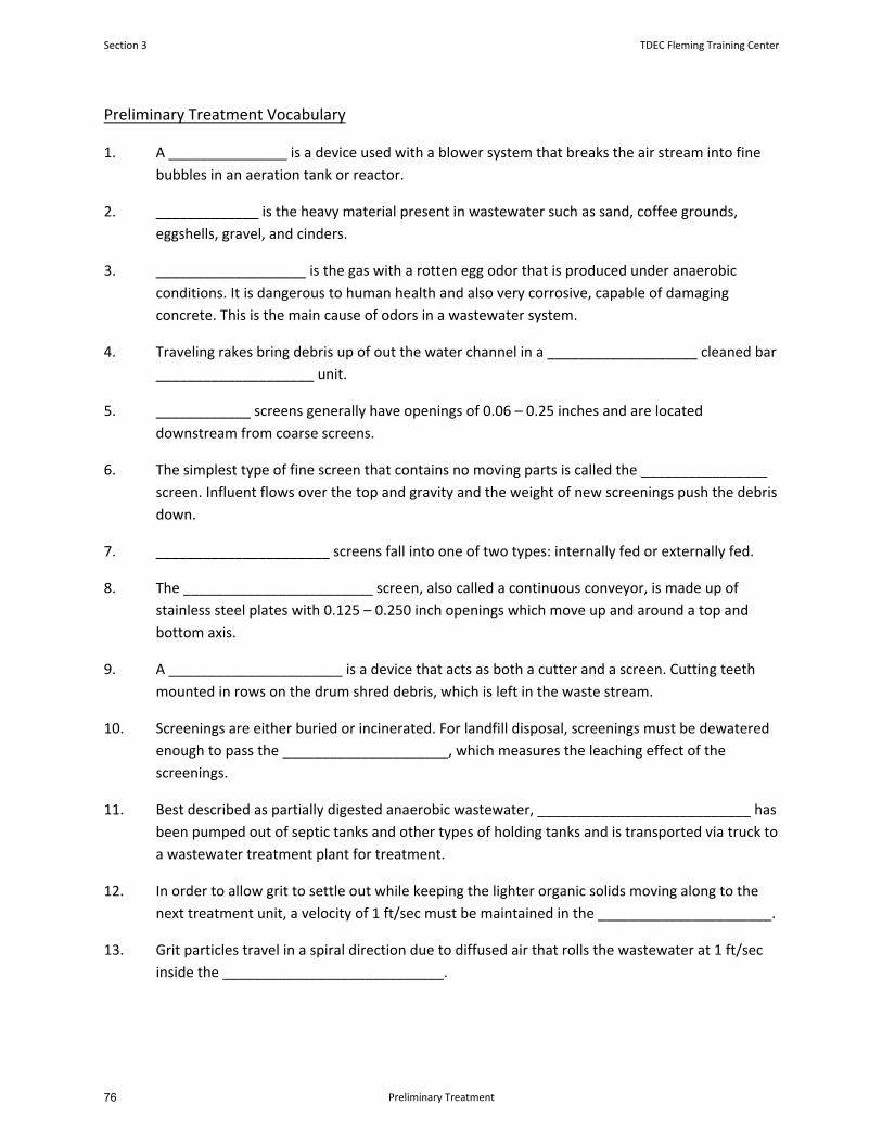
Preliminary Treatment Vocabulary
1. A _______________ is a device used with a blower system that breaks the air stream into fine
bubbles in an aeration tank or reactor.
2. _____________ is the heavy material present in wastewater such as sand, coffee grounds,
eggshells, gravel, and cinders.
3. ___________________ is the gas with a rotten egg odor that is produced under anaerobic
conditions. It is dangerous to human health and also very corrosive, capable of damaging
concrete. This is the main cause of odors in a wastewater system.
4. Traveling rakes bring debris up of out the water channel in a ___________________ cleaned bar
____________________ unit.
5. ____________ screens generally have openings of 0.06 – 0.25 inches and are located
downstream from coarse screens.
6. The simplest type of fine screen that contains no moving parts is called the ________________
screen. Influent flows over the top and gravity and the weight of new screenings push the debris
down.
7. ______________________ screens fall into one of two types: internally fed or externally fed.
8. The ________________________ screen, also called a continuous conveyor, is made up of
stainless steel plates with 0.125 – 0.250 inch openings which move up and around a top and
bottom axis.
9. A ______________________ is a device that acts as both a cutter and a screen. Cutting teeth
mounted in rows on the drum shred debris, which is left in the waste stream.
10. Screenings are either buried or incinerated. For landfill disposal, screenings must be dewatered
enough to pass the _____________________, which measures the leaching effect of the
screenings.
11. Best described as partially digested anaerobic wastewater, ___________________________ has
been pumped out of septic tanks and other types of holding tanks and is transported via truck to
a wastewater treatment plant for treatment.
12. In order to allow grit to settle out while keeping the lighter organic solids moving along to the
next treatment unit, a velocity of 1 ft/sec must be maintained in the ______________________.
13. Grit particles travel in a spiral direction due to diffused air that rolls the wastewater at 1 ft/sec
inside the ____________________________.
Section 3 TDEC Fleming Training Center
Preliminary Treatment76
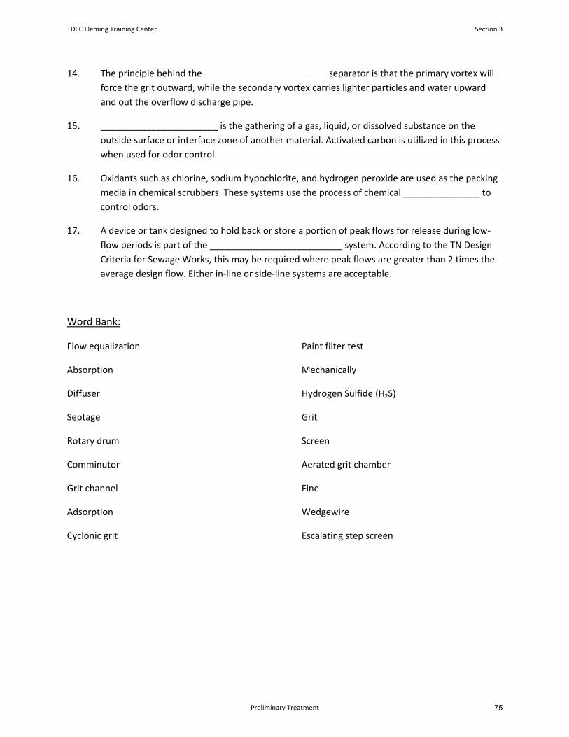
14. The principle behind the ________________________ separator is that the primary vortex will
force the grit outward, while the secondary vortex carries lighter particles and water upward
and out the overflow discharge pipe.
15. _______________________ is the gathering of a gas, liquid, or dissolved substance on the
outside surface or interface zone of another material. Activated carbon is utilized in this process
when used for odor control.
16. Oxidants such as chlorine, sodium hypochlorite, and hydrogen peroxide are used as the packing
media in chemical scrubbers. These systems use the process of chemical _______________ to
control odors.
17. A device or tank designed to hold back or store a portion of peak flows for release during low‐
flow periods is part of the __________________________ system. According to the TN Design
Criteria for Sewage Works, this may be required where peak flows are greater than 2 times the
average design flow. Either in‐line or side‐line systems are acceptable.
Word Bank:
Flow equalization
Absorption
Diffuser
Septage
Rotary drum
Comminutor
Grit channel
Adsorption
Cyclonic grit
Paint filter test
Mechanically
Hydrogen Sulfide (H2S)
Grit
Screen
Aerated grit chamber
Fine
Wedgewire
Escalating step screen
TDEC Fleming Training Center Section 3
Preliminary Treatment 75
Preliminary Treatment Review Questions
1. What problems may occur when it takes a long time for wastewater to flow through the
collection sewers to the treatment plant?
2. Preliminary treatment includes Screening, Grit Removal, and _________________.
a. Clarification
b. UV disinfection
c. Flow measurement/equalization
d. Polymer addition
3. Why is it important to remove grit and coarse debris during preliminary treatment (early on in
the treatment process)?
4. What happens to grit after it is removed from the wastewater?
5. If manually cleaned bar screens are not monitored daily and cleaned frequently, and debris is
allowed to build up, what might happen?
a. The bar screens might break from the weight of build up
b. The water may back up and allow septic conditions to develop upstream
c. A shock load could be released into the plant when the screen is eventually cleaned
d. Hydrogen sulfide can form
e. All of the above
Section 3 TDEC Fleming Training Center
Preliminary Treatment78
6. A plant receives a flow of 8.8 million gallons (MG) on Thursday. The day’s screenings are
calculated to be 12 cubic feet (ft3). How many cubic feet (ft3) of screenings were removed per
MG of flow?
Screenings Removed, ft3/MG = Screenings Removed, ft
3/day
Flow, MGD
7. List the differences between comminution units and bar racks/bar screens.
8. The space between bars is greatest with bar racks, which have a spacing of _____ to ____
inches, whereas bar screens have a spacing of _____ to ______ inches. Spacing is further
reduced with fine screens. What is the main benefit to using a fine screen?
9. During a walk‐through of your plant, you discover rags and large debris accumulating
downstream from your comminutor. Your initial instinct tells you to check the blades to make
sure they are not dull. After locking and tagging out the equipment, you discover the blades are
still sharp. What could the problem be?
TDEC Fleming Training Center Section 3
Preliminary Treatment 77
10. A piece of debris travels 20 feet in 40 seconds through a grit channel. What is the velocity in the
channel? Does this velocity meet the specs recommended in the TN Design Criteria for Sewage
Works? Why is it important to maintain a controlled velocity through a grit channel?
11. What is the point in washing grit?
12. What are the two basic types of rotary drum fine screens?
a. Vertical and horizontal orientation
b. Above and below channel
c. Fully and partially submerged
d. Internally and externally fed
13. Aerated grit chambers are most commonly found at activated sludge plants where there is a
readily available air supply. Why is pre‐aeration useful?
Section 3 TDEC Fleming Training Center
Preliminary Treatment80

14. You begin to notice an increase in septic waste coming into your plant during the warmer
months. What causes septic wastewater conditions in the collection system? What problems
could be occurring to cause this condition?
15. What is the best water velocity to maintain throughout a grit chamber?
TDEC Fleming Training Center Section 3
Preliminary Treatment 79
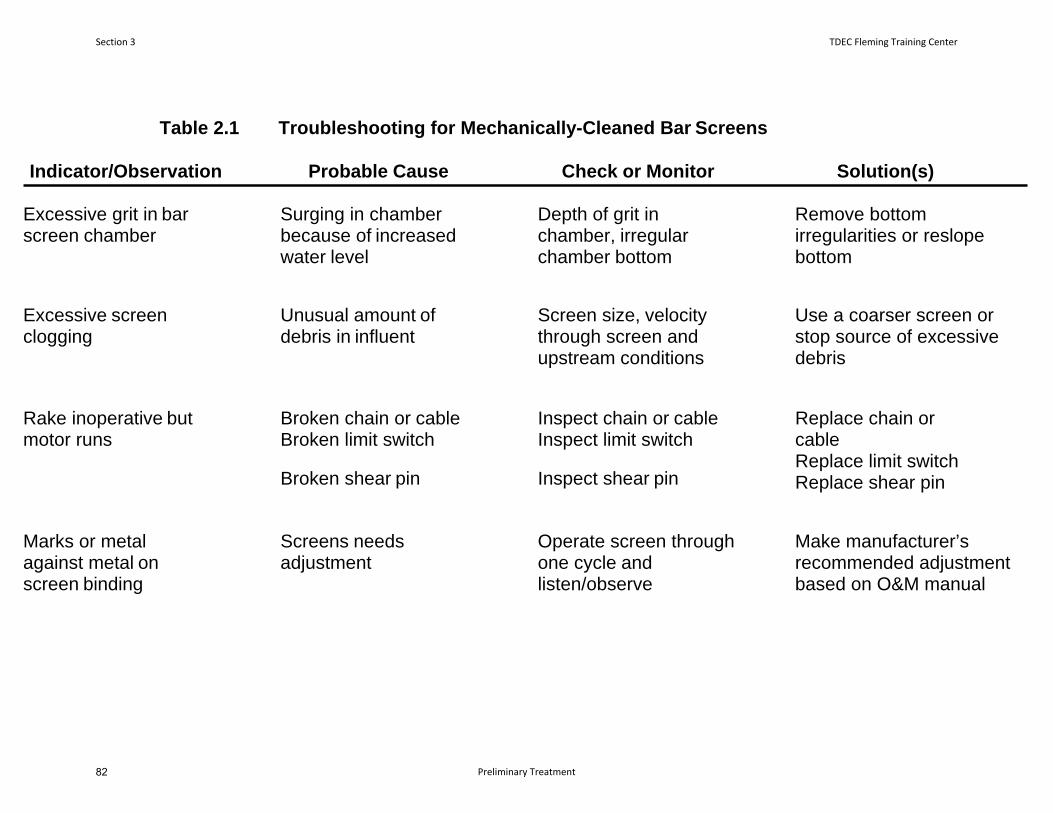
Table 2.1 Troubleshooting for Mechanically-Cleaned Bar Screens
Indicator/Observation Probable Cause Check or Monitor Solution(s) Excessive grit in bar screen chamber
Surging in chamber because of increased water level
Depth of grit in chamber, irregular chamber bottom
Remove bottom irregularities or reslope bottom
Excessive screen clogging
Unusual amount of debris in influent
Screen size, velocity through screen and upstream conditions
Use a coarser screen or stop source of excessive debris
Rake inoperative but motor runs
Broken chain or cable Broken limit switch
Broken shear pin
Inspect chain or cable Inspect limit switch
Inspect shear pin
Replace chain or cable Replace limit switch Replace shear pin
Marks or metal against metal on screen binding
Screens needs adjustment
Operate screen through one cycle and listen/observe
Make manufacturer’s recommended adjustment based on O&M manual
Section 3 TDEC Fleming Training Center
Preliminary Treatment82
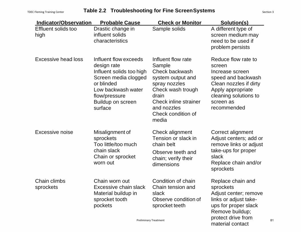
Table 2.2 Troubleshooting for Fine Screen Systems
Indicator/Observation Probable Cause Check or Monitor Solution(s) Effluent solids too high
Drastic change in influent solids characteristics
Sample solids A different type of screen medium may need to be used if problem persists
Excessive head loss Influent flow exceeds design rate Influent solids too high Screen media clogged or blinded Low backwash water flow/pressure Buildup on screen surface
Influent flow rate Sample Check backwash system output and spray nozzles Check wash trough drain Check inline strainer and nozzles Check condition of media
Reduce flow rate to screen Increase screen speed and backwash Clean nozzles if dirty Apply appropriate cleaning solutions to screen as recommended
Excessive noise Misalignment of sprockets Too little/too much chain slack Chain or sprocket worn out
Check alignment Tension or slack in chain belt
Observe teeth and chain; verify their dimensions
Correct alignment Adjust centers; add or remove links or adjust take-ups for proper slack Replace chain and/or sprockets
Chain climbs sprockets
Chain worn out Excessive chain slack Material buildup in sprocket tooth pockets
Condition of chain Chain tension and slack Observe condition of sprocket teeth
Replace chain and sprockets Adjust center; remove links or adjust take- ups for proper slack Remove buildup; protect drive from material contact
TDEC Fleming Training Center Section 3
Preliminary Treatment 81

84
Section 4
Flow
Measurement
83
What are Wastewater Flows?1. Sanitary sewer
Domestic
Industrial waste
2. Storm water Snow melt, street wash, etc.
3. Combined sewer Sanitary sewer + Storm sewer
4. I & I Infiltration = seepage of groundwater into sewer system
Inflow = direct discharge into sewer system
I & IInflow Infiltration
Water discharged into sewer system and service connections from sources other than regular connections.
Inflow differs from infiltration in that it’s a direct discharge into the sewer rather than a leak in the sewer itself.
Ex: yard drains, foundations,manhole covers
The seepage of groundwater into a sewer system, including service connections.
Seepage frequently occurs through defective or crackedpipes, pipe joints and connections, interceptor access risers and covers, or manhole walls
Sewer System Evaluations Flow monitoring is primary tool for identifyinghigh inflow/infiltration (I/I)
System problems:
Back flooding into private property due to surcharging of sewer mains
Bypassing of untreatedwastewater to environment
Reduced system capacity Source: https://www.ocsd.com/Home/ShowDocument?id=16226
Section 4 TDEC Fleming Training Center
Flow Measurement86
Factors Affecting Flow Rates Geographical location & socioeconomic conditions
Type of development
Season
Time of day
Diurnal variations
Weather (Rainy? Dry?)
Wastewater Flow Rates
Source: https://ensia.com/articles/water‐use/
Average American family uses over 300 gallons per day at home
https://www.epa.gov/watersense/how‐we‐use‐water
What is Flow?• Flow = the amount of water passing a reference point over a certain time
• Formula: Q = AV• Q = Flow (volume through a system)
• A = Area (cross‐sectional)
• V = Velocity of flow
• Units: cfs (ft3/sec), gpm, MGD, etc.
Why is flow measurement important?1. Collection system design
Primary tool for identifying high I/I
2. Treatment system design
Hydraulic criteria: must be able to pass peak flows
Treatment criteria: often depends on “hydraulic residence time”
Growth projections
Why is flow measurement important?3. NPDES permits
₋ Flow‐paced composite sampling
4. Process Control
Able to adjust process equipment/pumping capacity
Able to control downstream chemical feed systems
Pumping rates, aeration rates, chemical feed rates,etc. based on current flow
Able to determine when you are reaching the capacity of the system (sewer, pump station, etc.)
Why is flow measurement important?4. Process Control continued…
– Calculation of loadings on treatment processes andtreatment efficiency
– Loading Rate formula: (Concentration, mg/L) (Flow, MGD or gpd)(8.34 lb/gal) = Loading Rate, lb/day
• Accurate flow measurement is key to identify, correct, andprevent operational problems
TDEC Fleming Training Center Section 4
Flow Measurement 85
Wastewater Loads If total suspended solids (TSS) in a wastewater sample at the treatment plant influent = 100 mg/L, and the flow rate of the wastewater is 10 MGD, what is the mass flow rate (load to the treatment plant)?
Concentration = 100 mg/L
Flow = 10 MGD
(100 mg/L)(10 MGD)(8.34 lbs/gal) = 8340 lbs/day influent TSS
Flow Hydraulics – Types of Conditions
1. Open Channels/Pipes Any channel in which the liquid flows with a free/uncovered surface.
May be a visible channel or it may be a closed pipe that is not flowing full
Pipes include gravity sewers or channels
Ex: rivers, irrigation ditches, canals, flumes, etc.
2. Closed Channel/Pipes (flowing full) Flow in completely filled
pressure conduits (a.k.a. pipes)
Pipes include sewer lines running full or force mains
Flow Measurement Open Channel Flow Measurement
Requires a “primary device” and “secondary device”
Staff gauge
Ultrasonic or RADAR
Pressure
Closed Channel Flow Measurement Differential Pressure
Mechanical Devices
Electromagnetic (“mag meters”)
Ultrasonic meters
Flow Equalization
Types of Flow Meters Different types of flow measuring devices include
Constant differential (differential pressure)
Head area
Velocity meter
Differential producers
Differential head and displacement (pressure or distance)
All flow measurement devices should be calibrated andmaintained to ensure the accuracy of the measurement is ± 10% of the true flow.
Flow Metering Devices
Type Common Name Application
Constant differential Rotameters Liquids and gases (Ex: Chlorination)
Head area Weirs
Flumes
Liquids – Partially filled channels, basins, clarifiers
Liquids – Partially filled pipes and channels
Velocity meters Propeller
Magnetic
Liquids – channel flow, clean water piped flow
Liquids and sludge in closed pipes
Differential producers Venturi tubeFlow nozzleOrifice
Gases and liquids in closedpipes
Displacement units Piston Diaphragm Gases and liquids in closed pipes
*See Table 15.10 in Operation of Wastewater Treatment Plants, Vol II for complete table
Flow Metering Equipment Commonly Used in Wastewater Treatment Plants
Type Accuracy Advantages Disadvantages
Open‐Channel Flume
5‐7%Low headloss, self‐cleaning
Requires careful construction, susceptible to flooding
Open‐Channel Weir
5‐7%Low cost, ease of installation
High headloss, requires a well‐developed flow profile, cleaning required
Full‐PipeElectro‐magnetic
1‐3%
No headloss, bi‐directional
Minimum conductivityrequired, expensive, well‐developed velocity profile required
Full‐Pipe Doppler
2‐5%No headloss, low cost, not affected by air bubbles
Not suitable for some pipe material, well‐developed velocity profile required
Full‐Pipe Venturi
1‐3%Low headloss, high accuracy
Expensive, well‐developed velocity profile required
18
Source: MOP No. 11 – Operation of Municipal Wastewater Treatment Plants
Section 4 TDEC Fleming Training Center
Flow Measurement88
Open Channel Flow Primary Elements Creates conditions that produce known relationship between flow and depth
Channel width is known, but velocity is not needed
Primary devices:
Weirs
Flumes
Secondary element senses depth at measurement point, converting this to flow
An open channel flow meter must have 2 components:
1. Primary (1°) Measuring device:
2. Secondary (2°) Measuring device:
– Weirs
– Flumes
– Nozzles
– Open channel flow meters:
• Float
• Ultrasonic
• Bubbler system
• Submerged Pressure Transducer
• Electrical
Open Channel Primary (1°) Measuring Devices
Weir Flume
Open Channel – 1° Measuring Device
Factors to consider when choosing a device
Are suspended solids an issue?
Is head pressure an issue?
Accuracy?
What is the anticipated variability of flow ranges?
Easy to install? Retrofit?
Maintenance requirements/costs?
Open Channel Primary Measuring Device WeirsWeir = An obstruction or dam built across an open channel over which the water flows, often through a specially shaped opening or notch
• Simplest, least expensive, most common type of 1°measuring device
• Measures liquid flow in partially full channels or basins• Blocks flow in channel• Depth of water proportional to amount of flow• Flow determined by depth of water going through opening
• Can provide final aeration/oxygenation (“Free flow”)
Open Channel Primary Measuring DeviceWeirsWeir terminology:
• Crest = the edge or surface over which the water passes
• Nappe = the stream of water leaving the weir crest
• Head = the liquid depth from crest to liquid surface in pool upstream from the crest
Crest
NappeHead Measurement Point
TDEC Fleming Training Center Section 4
Flow Measurement 87
Open Channel Primary Measuring DeviceWeirs
Open Channel Primary Measuring DeviceWeirs• 4 most common types ofWeirs:1. Triangular (V‐notch)
Weirs
2. Rectangular Weir without end constrictions
3. Rectangular Weir with end constrictions
4. Trapezoidal (Cipolletti) Weir
Open Channel Primary Measuring DeviceFlumesFlumes = specially shaped open channel flow section that restricts the channel area and/or changes the slope, resulting in an increased velocity and a change in the level of liquid flowing through the flume.
• Constriction causes a change in head which can be converted to flow rates
• 3 most common types of Flume:
1. Parshall Flume
2. Palmer‐Bowlus Flume
3. Trapezoidal Flume
Open Channel Primary Measuring DeviceFlumes• Flumes consist of 3 sections:
1. Converging section = restricts flow, velocity is increasing in this area
2. Throat = the section that creates a hydraulic jump transition from higher velocity to slower velocity. It produces a head that is related to the discharge.
3. Diverging section = water returns to original shape of channel, it assures the downstream level is less than the level in the converging section
Open Channel Primary Measuring DeviceFlumesParshall Flume
• Best for flows with solids or debris
• Accurate
• Low maintenance
• Self‐cleaning (compared to sharp‐edged weir)
• Ability to function over a wide operating range (low to very high flows ) while requiring only a single headmeasurement
• Relatively low head loss
Parshall Flume
Section 4 TDEC Fleming Training Center
Flow Measurement90
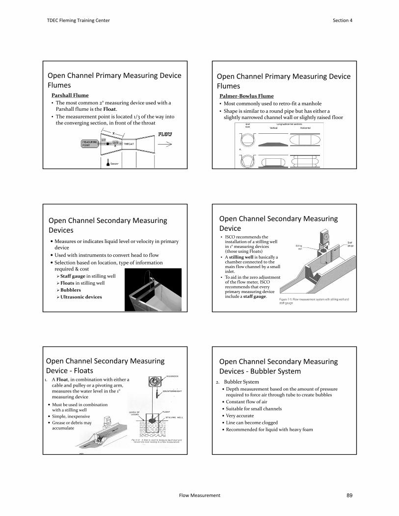
Open Channel Primary Measuring DeviceFlumesParshall Flume
• The most common 2° measuring device used with a Parshall flume is the Float.
• The measurement point is located 1/3 of the way into the converging section, in front of the throat
Open Channel Primary Measuring DeviceFlumesPalmer‐Bowlus Flume
• Most commonly used to retro‐fit a manhole
• Shape is similar to a round pipe but has either a slightly narrowed channel wall or slightly raised floor
Open Channel Secondary Measuring Devices
Measures or indicates liquid level or velocity in primary device
Used with instruments to convert head to flow
Selection based on location, type of information required & cost
Staff gauge in stilling well
Floats in stilling well
Bubblers
Ultrasonic devices
Open Channel Secondary Measuring Device• ISCO recommends the
installation of a stilling wellin 1° measuring devices (those using Floats)
• A stilling well is basically a chamber connected to the main flow channel by a smallinlet.
• To aid in the zero adjustment of the flow meter, ISCO recommends that every primary measuring device include a staff gauge.
Open Channel Secondary Measuring Device ‐ Floats1. A Float, in combination with either a
cable and pulley or a pivoting arm, measures the water level in the 1°measuring device
Must be used in combination with a stilling well
Simple, inexpensive
Grease or debris may accumulate
Open Channel Secondary Measuring Devices ‐ Bubbler System
2. Bubbler System
Depth measurement based on the amount of pressure required to force air through tube to create bubbles
Constant flow of air
Suitable for small channels
Very accurate
Line can become clogged
Recommended for liquid with heavy foam
TDEC Fleming Training Center Section 4
Flow Measurement 89
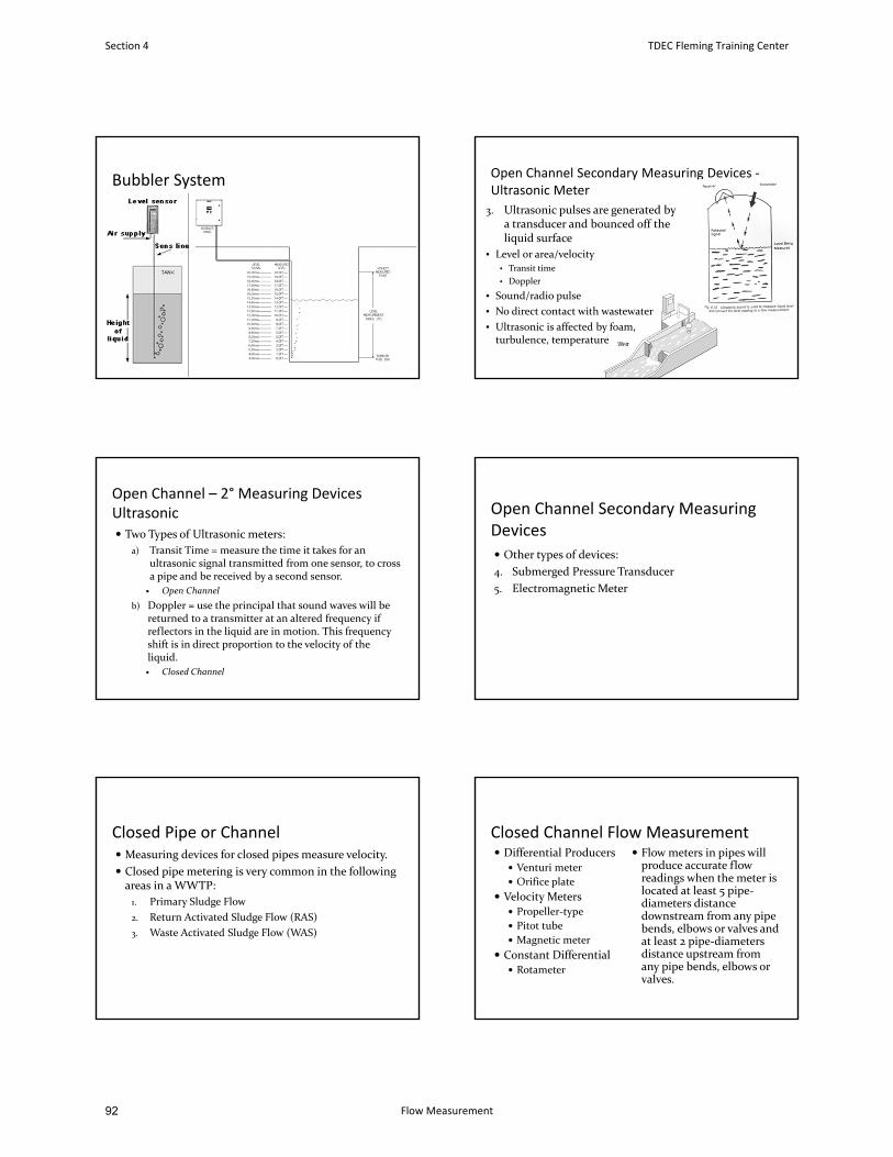
Bubbler System Open Channel Secondary Measuring Devices ‐Ultrasonic Meter
3. Ultrasonic pulses are generated by a transducer and bounced off the liquid surface
• Level or area/velocity• Transit time
• Doppler
• Sound/radio pulse
• No direct contact with wastewater
• Ultrasonic is affected by foam, turbulence, temperature
Open Channel – 2° Measuring DevicesUltrasonic Two Types of Ultrasonic meters:
a) Transit Time = measure the time it takes for an ultrasonic signal transmitted from one sensor, to cross a pipe and be received by a second sensor.
Open Channel
b) Doppler = use the principal that sound waves will be returned to a transmitter at an altered frequency ifreflectors in the liquid are in motion. This frequency shift is in direct proportion to the velocity of the liquid.
Closed Channel
Open Channel Secondary Measuring Devices
Other types of devices:
4. Submerged Pressure Transducer
5. Electromagnetic Meter
Closed Pipe or Channel Measuring devices for closed pipes measure velocity.
Closed pipe metering is very common in the following areas in a WWTP:
1. Primary Sludge Flow
2. Return Activated Sludge Flow (RAS)
3. Waste Activated Sludge Flow (WAS)
Closed Channel Flow Measurement Differential Producers
Venturi meter
Orifice plate
Velocity Meters Propeller‐type
Pitot tube
Magnetic meter
Constant Differential Rotameter
Flow meters in pipes willproduce accurate flow readings when the meter is located at least 5 pipe‐diameters distance downstream from any pipe bends, elbows or valves andat least 2 pipe‐diameters distance upstream from any pipe bends, elbows or valves.
Section 4 TDEC Fleming Training Center
Flow Measurement92
Closed Channel: Differential Pressure
Venturi system
Pipe diameter gradually reduces at the throat andreturns to original diameter
Low pressure is created in throat
Difference in pressure indicates amount of flow
Simple and inexpensive
Need straight runs of pipe before and after
Excellent for gases and liquids (not sludge)
Dall tube
Closed Channel: Differential Pressure Measure velocity directly or convert velocity headto pressure head by restricting flow in pipe
Gases & liquids in closed pipes
Venturi meter: liquid passes through reduced throat section & velocity increases. Pressure differential then measured using manometer.
Orifice plate
Closed Channel: Velocity Meters
Magnetic Flow Meter
Creates magnetic field in water stream
Conductor (water) moving through magnetic field produces electric current
Measure of electricity indicates amount of flow
Very accurate, Low maintenance
Can be expensive (esp. for larger diameters)
Closed Channel: Constant Differential Example: Chemical FeedSystems
Rotameter
Float or ball in verticaltube
Increased flow causes float to ride higher
Simple, accurate, easy
Must keep tube andfloat clean
Maintenance of Flow Measuring Devices Clean devices regularly
Grease build up on floats & magnetic meter coils
Weir plate clogged with debris
Spider webs on the ultrasonic sensor
Periodically inspect devices for damage &deterioration
Recalibrate secondary devices regularly
For open channel, take physical measurement (ruler)
For closed channel, install second flowmeter or return meter to manufacturer for calibration via “drop test”
Maintenance of Flow Measuring DevicesSite conditions that can affect the performance of a flowmeter:
1. Humidity
Critical for bubbler systems
2. Solids deposition
Weirs can become clogged with algae and debris
3. Foaming problems
Can foul sensors
4. Primary measuring device – is it level?
Critical that weir/flume be level andperpendicular to the flow
TDEC Fleming Training Center Section 4
Flow Measurement 91
Flow Equalization Smoothes out fluctuations in flow volume andpollutant concentrations
Provides for constant flow with less variations in loading
Improves performance of downstream processes
TN Design Criteria says you must maintain a 1.0 mg/L DO throughout the EQ tank
Flow Equalization Types:
Surge – prevents flows above max. hydraulic capacity
Diurnal – reduces the magnitude of daily flow variations
Complete – eliminates flow variations
Two Schemes
In‐line equalization
Side‐line equalization
Flow Equalization
Side‐line:• Only flow greater than daily average is diverted to basin• Can occur after screening or grit removal, eliminating major grit and TSS
problems
In‐line:• All flow enters EQ basin before entering the plant• Flow is stored as required and later released as steady flow
Flow Equalization Requires mechanical or diffused air mixing, pumps &flow measurement
Blend entire tank contents
Benefits:
Increased DO
Better grease separation
Better settling in primary
Better settling in final
10% ‐ 20% BOD reduction
Improved response to shock loads
Flow Equalization Can be in collection system or at STP
These basins should normally be located near thehead end of the treatment works, preferably downstream of pretreatment facilities such as bar screens, comminutors, and grit chambers.
After screening and grit removal = eliminating major grit and settleable solids problems
Adequate aeration and mixing must be provided to keep the basins aerobic and prevent solids deposition.
Any Questions?
Flow Equalization Basin
Lewisburg Sewage Treatment Plant
Section 4 TDEC Fleming Training Center
Flow Measurement94
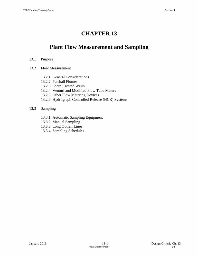
January 2016 13-1 Design Criteria Ch. 13
CHAPTER 13
Plant Flow Measurement and Sampling
13.1 Purpose
13.2 Flow Measurement
13.2.1 General Considerations
13.2.2 Parshall Flumes
13.2.3 Sharp Crested Weirs
13.2.4 Venturi and Modified Flow Tube Meters
13.2.5 Other Flow Metering Devices
13.2.6 Hydrograph Controlled Release (HCR) Systems
13.3 Sampling
13.3.1 Automatic Sampling Equipment
13.3.2 Manual Sampling
13.3.3 Long Outfall Lines
13.3.4 Sampling Schedules
TDEC Fleming Training Center Section 4
Flow Measurement 93
January 2016 13-2 Design Criteria Ch. 13
PLANT FLOW MEASUREMENT AND SAMPLING
13.1 Purpose
Complete and accurate flow measuring and sampling are essential in the proper
treatment of wastewater. Compliance with discharge limits requires proper flow
measurement and sampling. They provide the operator with the information to
optimize process control and operational costs, as well as providing an accurate
data base of flows and process performance which can be used to analyze changes
in operational strategy or assist future plant design.
13.2 Flow Measurement
13.2.1 General Considerations
13.2.1.1 Facilities for measuring the volume of sewage flows should be provided
at all treatment works.
13.2.1.2 Plants with a capacity equal to or less than 100,000 gallons per day
(gpd) shall be equipped, as a minimum, with a primary metering device
such as: a Parshall flume having a separate float well and staff gauge, a
weir box having plate and staff gauge, or other approved devices.
Continuous recording devices may be required where circumstances
warrant.
13.2.1.3 Plants having a capacity of greater than 100,000 gpd shall be provided
with indicating, recording, and totalizing equipment using strip or
circular charts and with flow charts for periods of 1 or 7 days. The chart
size shall be sufficient to accurately record and depict the flow
measured.
13.2.1.4 Flows passed through the plant and flows bypassed shall be measured in
a manner which will allow them to be distinguished and separately
reported.
13.2.1.5 Measuring equipment shall be provided which is accurate under all
expected flow conditions (minimum initial flow and maximum design
peak flow). The accuracy of the total flow monitoring system (primary
device, transmitter, and indicator) must be acceptable. The effect of
such factors as ambient temperature, power source voltage, electronic
interference, and humidity should be considered. Surges must be
eliminated to provide accurate measurement.
Two primary devices and flow charts may be required in some cases.
Section 4 TDEC Fleming Training Center
Flow Measurement96
January 2016 13-3 Design Criteria Ch. 13
13.2.1.6 Metering devices within a sewage works shall be located so that recycle
flow streams do not inadvertently affect the flow measurement. In some
cases, measurement of the total flow (influent plus recycle) may be
desirable.
13.2.1.7 All clarifiers must be provided with a means for accurate flow
measurement of sludge wasting and sludge return lines so that solids
handling can be controlled. Sludge digesters, thickeners, and holding
tanks should be provided with some way to determine the volume of
sludge added or removed. This can be accomplished by a sidewall
depth scale or graduation in batch operations.
13.2.1.8 Flow meter and indicator selection should be justified considering
factors such as probable flow range, acceptable headloss, required
accuracy, and fouling ability of the water to be measured. For more
detailed information the consultant is encouraged to read the EPA
Design Information Report "Flow Measurement Instrumentation";
Journal WPCF, Volume 58, Number 10, pp. 1005-1009. This report
offers many installation details and considerations for different types of
flow monitoring equipment.
13.2.1.9 Flow splitter boxes shall be constructed so that they are reliable, easily
controllable, and accessible for maintenance purposes.
13.2.1.10 Where influent and effluent flow-proportional composite sampling is
required, separate influent and effluent flow measuring equipment is
required.
13.2.1.11 Consideration should be given to providing some types of flow meters
with bypass piping and valving for cleaning and maintenance purposes.
13.2.2 Parshall Flumes
Parshall Flumes are ideal for measuring flows of raw sewage and primary
effluents because clogging problems are usually minimal.
The properly sized flume should be selected for the flow range to be encountered.
All Parshall Flumes must be designed to the specified dimensions of an
acceptable reference.
The following requirements must be met when designing a Parshall Flume.
13.2.2.1 Flow should be evenly distributed across the width of the channel.
13.2.2.2 The crest must have a smooth, definite edge. If a liner is used, all screws
and bolts should be countersunk.
TDEC Fleming Training Center Section 4
Flow Measurement 95
January 2016 13-4 Design Criteria Ch. 13
13.2.2.3 Longitudinal and lateral axes of the crest floor must be level.
13.2.2.4 The location of the head measuring points (stilling well) must be
two-thirds the length of the converging sidewall upstream from the crest.
Sonar-type devices are only acceptable when foaming or turbulance is
not a problem.
13.2.2.5 The pressure tap to the stilling well must be at right angles to the wall of
the converging section.
13.2.2.6 The invert (i.e., inside bottom) of the pressure tap must be at the same
elevation as the crest.
13.2.2.7 The tap should be flush with the flume side wall and have square, sharp
corners free from burrs or other projections.
13.2.2.8 The tap pipe should be 2 inches in size and be horizontal or slope
downward to the stilling well.
13.2.2.9 Free-flow conditions shall be maintained under all flow rates to be
encountered by providing low enough elevations downstream of the
flume. No constrictions (i.e., sharp bends or decrease in pipe size)
should be placed after the flume as this might cause submergence under
high flow conditions.
13.2.2.10 The volume of the stilling well should be determined by the conditions
of flow. For flows that vary rapidly, the volume should be small so that
the instrument float can respond quickly to the changes in rate. For
relatively steady flows, a large-volume stilling well is acceptable.
Consideration should be given to protecting the stilling well from
freezing.
13.2.2.11 Drain and shut-off valves shall be provided to empty and clean the
stilling well.
13.2.2.12 Means shall be provided for accurately maintaining a level in the
stilling well at the same elevation as the crest in the flume, to permit
adjusting the instrument to zero flow conditions.
13.2.2.13 The flume must be located where a uniform channel width is
maintained ahead of the flume for a distance equal to or greater than
fifteen (15) channel widths.
The approach channel must be straight and the approaching flow must
not be turbulent, surging, or unbalanced. Flow -lines should be
essentially parallel to the centerline of the flume.
Section 4 TDEC Fleming Training Center
Flow Measurement98
January 2016 13-5 Design Criteria Ch. 13
13.2.3 Sharp Crested Weirs
The following criteria are for V-notch weirs, rectangular weirs with and without
end contractions, and Cipolletti weirs. The following details must be met when
designing a sharp crested weir:
13.2.3.1 The weir must be installed so that it is perpendicular to the axis of flow.
The upstream face of the bulkhead must be smooth.
13.2.3.2 The thickness of the weir crest should be less than 0.1 inch or the
downstream edge of the crest must be relieved by chamfering at a 45°
angle so that the horizontal (unchamfered) thickness of the weir is less
than 0.1 inch.
13.2.3.3 The sides of rectangular contracted weirs must be truly vertical. Angles
of V-notch weirs must be cut precisely. All corners must be machined or
filed perpendicular to the upstream face so that the weir will be free of
burrs or scratches.
13.2.3.4 The distance from the weir crest to the bottom of the approach channel
must be greater than twice the maximum weir head and is never to be
less than one foot.
13.2.3.5 The distance from the sides of the weir to the side of the approach
channel must be greater than twice the maximum weir head and is never
to be less than one foot (except for rectangular weirs without end
contractions.
13.2.3.6 The nappe (overflow sheet) must touch only the upstream edges of the
weir crest or notch. If properly designed, air should circulate freely
under and on both sides of the nappe. For suppressed rectangular weirs
(i.e., no contractions), the enclosed space under the nappe must be
adequately ventilated to maintain accurate head and discharge
relationships.
13.2.3.7 The measurement of head on the weir must be taken at a point at least
four (4) times the maximum head on the crest upstream from the weir.
13.2.3.8 The cross - sectional area of the approach channel must be at least eight
(8) times that of the nappe at the crest for a distance upstream of 15-20
times the maximum head on the crest in order to minimize the approach
velocity.
The approach channel must be straight and uniform upstream of the weir
for the same distance, with the exception of weirs with end contractions
where a uniform cross section is not needed.
TDEC Fleming Training Center Section 4
Flow Measurement 97
January 2016 13-6 Design Criteria Ch. 13
13.2.3.9 The head on the weir must have at least three (3) inches of free fall at the
maximum downstream water surface to ensure free fall and aeration of
the nappe.
13.2.3.10 All of the flow must pass over the weir and no leakage at the weir plate
edges or bottom is permissable.
13.2.3.11 The weir plate is to be constructed of a material equal to or more
resistant than 304 Stainless Steel.
13.2.4 Venturi and Modified Flow Tube Meters
The following requirements should be observed for application of venturi meters:
13.2.4.1 The range of flows, hydraulic gradient, and space available for
installation must be suitable for a venturi meter and are very important
in selecting the mode of transmission to the indicator, recorder, or
totalizer.
13.2.4.2 Venturi meters shall not be used where the range of flows is too great or
where the liquid may not be under a positive head at all times.
13.2.4.3 Cleanouts or handholes are desirable, particularly on units handling raw
sewage or sludge.
13.2.4.4 Units used to measure air delivered by positive - displacement blowers
should be located as far as possible from the blowers, or means should
be provided to dampen blower pulsations.
13.2.4.5 The velocity and direction of the flow in the pipe ahead of the meter can
have a detrimental effect on accuracy. There should be no bends or other
fittings for 6 pipe diameters upstream of the venturi meter, unless treated
effluent is being measured when straightening vanes are provided.
13.2.4.6 Other design guidelines as provided by manufacturers of venturi meters
should also be considered.
13.2.5 Other Flow Metering Devices
Flow meters, such as propeller meters, magnetic flow meters, orifice meters, pitot
tubes, and other devices, should only be used in applications in accordance with
the manufacturer's recommendations and design guidelines.
Section 4 TDEC Fleming Training Center
Flow Measurement100
January 2016 13-7 Design Criteria Ch. 13
13.2.6 Hydrograph Controlled Release (HCR) Systems
For plants utilizing HCR systems, accurate stream flow measurements are
required. Detailed plans must be submitted outlining the construction of the
primary stream flow measuring device and the associated instrumentation. The
following factors should be emphasized in the design.
13.2.6.1 Accuracy over the flow range required for effluent discharge limiting
purposes.
13.2.6.2 Operational factors such as cleaning and maintenance requirements.
13.2.6.3 Cost
The use of sharp crested weirs as described in Section 13.2.3 will not be
allowed due to the installation requirements such as approach channel
details and upstream pool depth and since entrapment and accumulation
of silt and debris may cause the device to measure inaccurately. Parshall
Flumes may be used due to their self-cleaning ability but field
calibration will be required. Self-cleaning V-notch weirs are
recommended due to their accuracy in low flow ranges. The weir can be
made self-cleaning by sloping both sides of the weir away from the
crest. The top portion of the crest shall be covered with angle-iron to
prevent its breakdown. The angle of the V-notch should be determined
by the stream characteristics; however, a smaller angle will increase
accuracy in the low flow range. The primary device shall be built with
sufficient depth into the stream bed to prevent undercutting and
sufficient height to cover the required flow range.
It is recommended that the wastewater system director, engineer, or
other city official contact the U.S. Geological Survey (USGS), Water
Resources Division, in Nashville, Tennessee, for assistance with the
design and installation of the flow measuring device. They offer a
program which shares much of the costs for designing and maintaining
the device. After visiting the site, they can assist with the design of a
self-cleaning weir for the stream. They provide the consultant with a
field design that shows the proper location and installation of the weir.
From this field design, the consultant must provide detailed plans to the
State.
The wastewater system is responsible for constructing the weir at their
own cost. The flow measuring station is installed, maintained, and
calibrated by USGS personnel so that accurate results are insured.
The primary device will record continuous flow of the stream and can be
designed to send a feedback signal to the WWTP for other purposes
such as controlling plant discharge rates.
TDEC Fleming Training Center Section 4
Flow Measurement 99
January 2016 13-8 Design Criteria Ch. 13
This program benefits both the local wastewater system, the State of
Tennessee, and the USGS, as it adds to stream flow data bases archived
for public use. Cost sharing allows the flow measuring station to be
built and operated at a lower cost for all parties concerned.
13.3 Sampling
13.3.1 Automatic Sampling Equipment
The following general guidelines should be adhered to in the use of automatic
samplers:
13.3.1.1 Automatic samplers shall be used where composite sampling is
necessary.
13.3.1.2 The sampling device shall be located near the source being sampled, to
prevent sample degradation in the line.
13.3.1.3 Long sampling transmission lines should be avoided.
13.3.1.4 If sampling transmission lines are used, they shall be large enough to
prevent plugging, yet have velocities sufficient to prevent
sedimentation. Provisions shall be included to make sample lines
cleanable. Minimum velocities in sample lines shall be 3 feet per
second under all operating conditions.
13.3.1.5 Samples shall be refrigerated unless the samples will not be effected by
biological degradation.
13.3.1.6 Sampler inlet lines shall be located where the flow stream is well mixed
and representative of the total flow.
13.3.1.7 Influent automatic samplers should draw a sample downstream of bar
screens or comminutors. They should be located before any return
sludge lines or scum lines.
13.3.1.8 Effluent sampling should draw a sample immediately upstream of the
chlorination point. This will eliminate the need to dechlorinate and then
re-seed the sample.
13.3.2 Manual Sampling
Because grab samples are manually obtained, safe access to sampling sites should
be considered in the design of treatment facilities.
Section 4 TDEC Fleming Training Center
Flow Measurement102
January 2016 13-9 Design Criteria Ch. 13
13.3.3 Long Outfall Lines
Many wastewater systems are constructing long outfall lines to take advantage of
secondary or equivalent permit limits.
Due to possible changes in effluent quality between the treatment facility and the
outfall, a remote sampling station will be required at or near the confluence of the
outfall line and the receiving stream on all outfall lines greater than one mile in
length.
Dissolved oxygen, fecal coliform, and chlorine residual may have to be measured
at the remote sampling station for permit compliance purposes.
13.3.4 Sampling Schedules
Samples must be taken and analyzed for two purposes: permit compliance and
process control. Any time a new permit is issued, a sampling schedule for permit
compliance will be determined by the Division of Water Pollution Control. An
additional sampling program needs to be set up for process control purposes. This
would include all testing required for completing the monthly operational report,
as well as any other tests that might aid the operation of the plant. This schedule
can be determined by the Division of Water Pollution Control, Wastewater
Treatment Section or the appropriate field office once final plans are approved.
The designer shall provide safe access points to collect representative influent and
effluent samples of all treatment units and to collect samples of all sludge
transmission lines. This makes it possible to determine the efficiency of each
treatment process. Additional information about methods of analyses can be
obtained from the Federal Register 40 CFR Part 136. Information about sampling
locations and techniques can be obtained from the EPA Aerobic Biological
Wastewater Treatment Facilities Process Control Manual and EPA's NPDES
Compliance Inspection Manual.
TDEC Fleming Training Center Section 4
Flow Measurement 101
Flow Vocabulary
1. The amount of water passing a reference point over a certain amount of time is
_________________.
2. An ________________________________ is any channel in which the liquid flows with a free or
uncovered surface.
3. An obstruction or dam built across an open channel over which the water flows, often through a
specially shaped opening or notch is called a ______________________________.
4. A _________________________ is a specially shaped open channel flow section that restricts the
channel area and/or changes the slope, resulting in an increased velocity and a change in the level of
liquid flowing through it.
5. The _______________________________flume is most commonly used to retrofit manholes.
6. The ______________________________of a flume restricts flow. Velocity is increasing in this area.
7. The _______________ is the section of a flume that creates a hydraulic jump transition from higher
velocity to slower velocity. It produces a head that is related to the discharge.
8. A ____________________________________ is any channel in which flow is in a completely filled
pressure conduit (a.k.a. pipes). This includes sewer lines running full or force mains.
9. Weirs, flumes, and nozzles are all examples of ________________________________ measuring
devices.
10. The _____________________________ section of the flume is where water returns to original
shape of channel, it assures the downstream level is less than the level in the converging section.
11. This type of flume is best for wastewater containing solids and debris.
________________________________
12. ____________________________________ is an indirect measure of loss of energy or pressure. Flowing water will lose some of its energy when it passes through a pipe, bar screen, Comminutor, filter or other obstruction. This is measured as the difference in elevation between the upstream water surface and the downstream water surface and may be expressed in feet or meters.
13. Open channel flow meters, such as floats, ultrasonic meters, and bubbler systems, are all examples
of __________________________________ measuring devices.
14. Adequate aeration and mixing must be provided in the _____________________________basin to
keep the basins aerobic and prevent solids deposition. A DO of 1.0 mg/L must be maintained
throughout.
Section 4 TDEC Fleming Training Center
Flow Measurement104

Word Bank
Flow
Diverging
Palmer‐Bowlus
Flume
Headloss
Parshall
Primary (1°)
Weir
Throat
Flow equalization
Open channel
Closed channel
Converging section
Secondary (2°)
TDEC Fleming Training Center Section 4
Flow Measurement 103

Flow Measurement Review Questions
1. What is the difference between open flow and closed flow channel conditions?
2. List three types of flumes and where each is most commonly used.
3. Where are flumes used instead of weirs to measure flows?
4. What are the three different sections of a Parshall flume? Where is flow measured in this flume andwhat type of device would be used?
5. What are the advantages of an electromagnetic/magnetic flow meter?
Section 4 TDEC Fleming Training Center
Flow Measurement106

6. Why measure flows before and after an equalization basin?
7. According to the TN Design Criteria, what DO must be maintained throughout an equalization tank?
TDEC Fleming Training Center Section 4
Flow Measurement 105

108
Section 5
Activated Sludge
Part 1
107
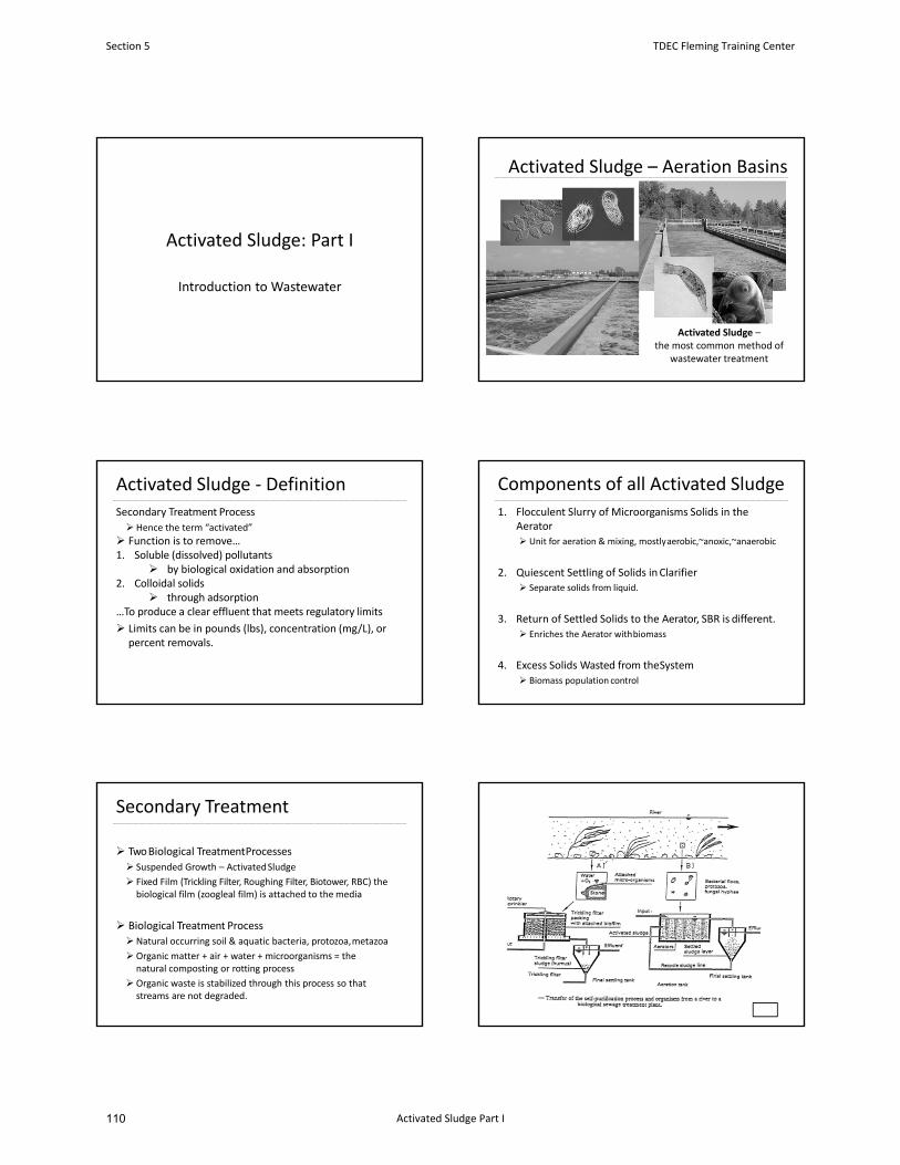
Activated Sludge: Part I
Introduction to Wastewater
Activated Sludge – Aeration Basins
Activated Sludge –the most common method of
wastewater treatment
Activated Sludge ‐ Definition
Secondary Treatment Process
Hence the term “activated”
Function is to remove…1. Soluble (dissolved) pollutants
by biological oxidation and absorption2. Colloidal solids
through adsorption…To produce a clear effluent that meets regulatory limits
Limits can be in pounds (lbs), concentration (mg/L), orpercent removals.
Components of all Activated Sludge
1. Flocculent Slurry of Microorganisms Solids in theAerator Unit for aeration & mixing, mostlyaerobic,~anoxic,~anaerobic
2. Quiescent Settling of Solids in Clarifier Separate solids from liquid.
3. Return of Settled Solids to the Aerator, SBR is different. Enriches the Aerator withbiomass
4. Excess Solids Wasted from theSystem Biomass population control
Secondary Treatment
Two Biological TreatmentProcesses
Suspended Growth – ActivatedSludge
Fixed Film (Trickling Filter, Roughing Filter, Biotower, RBC) thebiological film (zoogleal film) is attached to themedia
Biological Treatment Process
Natural occurring soil & aquatic bacteria, protozoa,metazoa
Organic matter + air + water + microorganisms = thenatural composting or rotting process
Organic waste is stabilized through this process so thatstreams are not degraded.
Section 5 TDEC Fleming Training Center
Activated Sludge Part I110
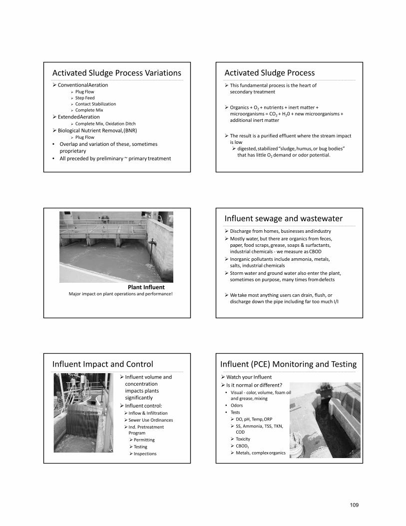
Activated Sludge Process Variations ConventionalAeration
Plug Flow
Step Feed Contact Stabilization Complete Mix
ExtendedAeration Complete Mix, Oxidation Ditch
Biological Nutrient Removal,(BNR) Plug Flow
• Overlap and variation of these, sometimesproprietary
• All preceded by preliminary ~ primary treatment
Activated Sludge Process
This fundamental process is the heart of secondary treatment
Organics + O2 + nutrients + inert matter + microorganisms = CO2 + H20 + new microorganisms + additional inert matter
The result is a purified effluent where the stream impact is low digested,stabilized“sludge,humus,or bug bodies”
that has little O2 demand or odor potential.
Plant InfluentMajor impact on plant operations and performance!
Influent sewage and wastewater
Discharge from homes, businesses andindustry
Mostly water, but there are organics from feces, paper, food scraps,grease, soaps & surfactants, industrial chemicals ‐ we measure asCBOD
Inorganic pollutants include ammonia, metals, salts, industrial chemicals
Storm water and ground water also enter the plant, sometimes on purpose, many times fromdefects
We take most anything users can drain, flush, or discharge down the pipe including far too much I/I
Influent Impact and Control
Influent volume and concentrationimpacts plantssignificantly
Influent control: Inflow & Infiltration
Sewer Use Ordinances
Ind. PretreatmentProgram
Permitting
Testing
Inspections
Influent (PCE) Monitoring and Testing
Watch your Influent
Is it normal ordifferent?• Visual ‐ color, volume, foam oil
and grease,mixing
• Odors
• Tests
DO, pH, Temp,ORP
SS, Ammonia, TSS, TKN,COD
Toxicity
CBOD5
Metals, complexorganics
109
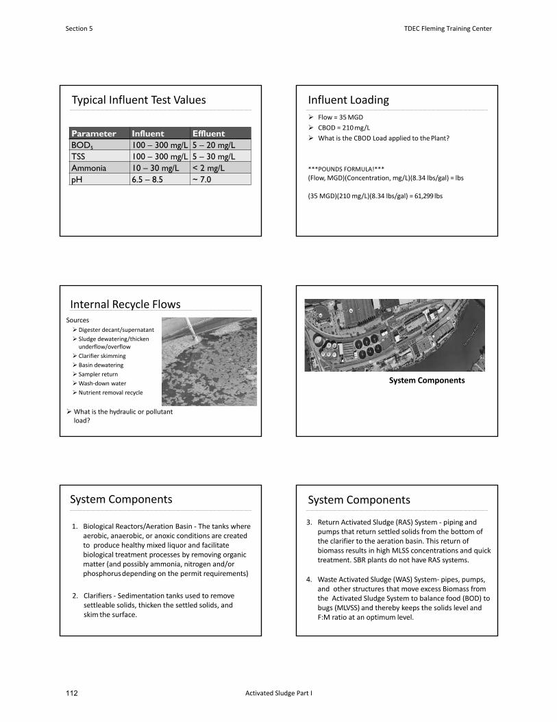
Typical Influent Test Values
Parameter Influent EffluentBOD5 100 – 300 mg/L 5 – 20 mg/LTSS 100 – 300 mg/L 5 – 30 mg/LAmmonia 10 – 30 mg/L < 2 mg/LpH 6.5 – 8.5 ~ 7.0
Influent Loading
Flow = 35MGD
CBOD = 210mg/L
What is the CBOD Load applied to thePlant?
***POUNDS FORMULA!***
(Flow, MGD)(Concentration, mg/L)(8.34 lbs/gal) = lbs
(35 MGD)(210 mg/L)(8.34 lbs/gal) = 61,299 lbs
Internal Recycle FlowsSources
Digester decant/supernatant
Sludge dewatering/thicken underflow/overflow
Clarifier skimming
Basin dewatering
Sampler return
Wash‐down water
Nutrient removal recycle
What is the hydraulic or pollutantload?
System Components
System Components
1. Biological Reactors/Aeration Basin ‐ The tanks where aerobic, anaerobic, or anoxic conditions are created to produce healthy mixed liquor and facilitate biological treatment processes by removing organic matter (and possibly ammonia, nitrogen and/or phosphorusdepending on the permit requirements)
2. Clarifiers ‐ Sedimentation tanks used to remove settleable solids, thicken the settled solids, and skim the surface.
System Components
3. Return Activated Sludge (RAS) System ‐ piping and pumps that return settled solids from the bottom of the clarifier to the aeration basin. This return of biomass results in high MLSS concentrations and quicktreatment. SBR plants do not have RAS systems.
4. Waste Activated Sludge (WAS) System‐ pipes, pumps, and other structures that move excess Biomass from the Activated Sludge System to balance food (BOD) to bugs (MLVSS) and thereby keeps the solids level and F:M ratio at an optimum level.
Section 5 TDEC Fleming Training Center
Activated Sludge Part I112
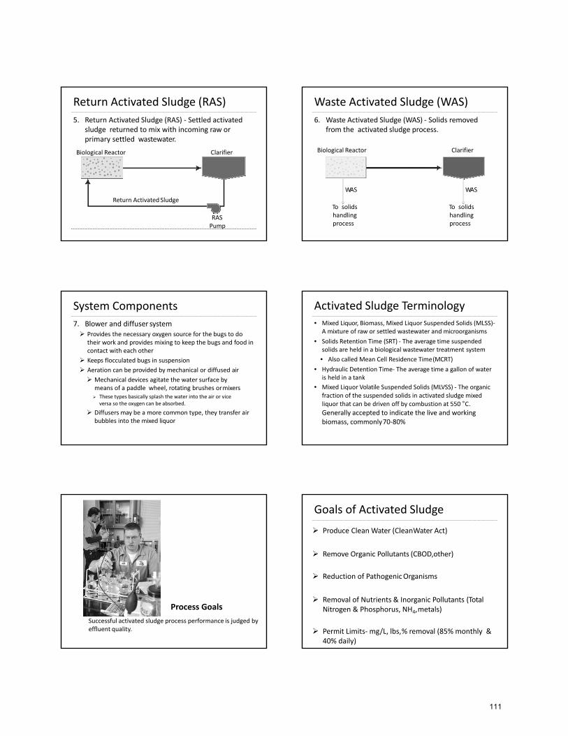
Return Activated Sludge (RAS)
Return ActivatedSludge
RASPump
5. Return Activated Sludge (RAS) ‐ Settled activated sludge returned to mix with incoming raw or primary settled wastewater.
Biological Reactor Clarifier
Waste Activated Sludge (WAS)
6. Waste Activated Sludge (WAS) ‐ Solids removed from the activated sludge process.
WAS
To solidshandlingprocess
WAS
To solidshandlingprocess
ClarifierBiological Reactor
System Components
7. Blower and diffuser system Provides the necessary oxygen source for the bugs to do
their work and provides mixing to keep the bugs and food in contact with each other
Keeps flocculated bugs in suspension
Aeration can be provided by mechanical or diffused air
Mechanical devices agitate the water surface by means of a paddle wheel, rotating brushes ormixers These types basically splash the water into the air or vice
versa so the oxygen can be absorbed.
Diffusers may be a more common type, they transfer air bubbles into the mixed liquor
Activated Sludge Terminology• Mixed Liquor, Biomass, Mixed Liquor Suspended Solids (MLSS)‐
A mixture of raw or settled wastewater and microorganisms
• Solids Retention Time (SRT) ‐ The average time suspended solids are held in a biological wastewater treatment system
• Also called Mean Cell Residence Time(MCRT)
• Hydraulic Detention Time‐ The average time a gallon of water is held in a tank
• Mixed Liquor Volatile Suspended Solids (MLVSS) ‐ The organic fraction of the suspended solids in activated sludge mixed liquor that can be driven off by combustion at 550 °C. Generally accepted to indicate the live and working biomass, commonly70‐80%
Process Goals
Successful activated sludge process performance is judged by effluent quality.
Photo: Treatment Plant Operator
Goals of Activated Sludge
Produce Clean Water (CleanWater Act)
Remove Organic Pollutants (CBOD,other)
Reduction of PathogenicOrganisms
Removal of Nutrients & Inorganic Pollutants (Total Nitrogen & Phosphorus, NH4,metals)
Permit Limits‐mg/L, lbs,% removal (85% monthly & 40% daily)
111
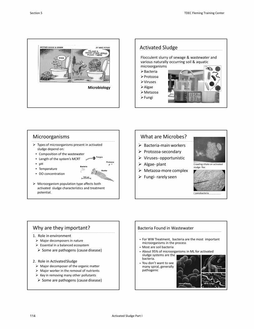
Microbiology
Activated Sludge
Flocculent slurry of sewage & wastewater and various naturally occurring soil & aquatic microorganisms
BacteriaProtozoaVirusesAlgaeMetazoa
Fungi
Microorganisms
Types of microorganisms present in activated sludge depend on:
• Composition of the wastewater
• Length of the system’s MCRT
• pH
• Temperature
• DO concentration
Microorganism population type affects both activated sludge characteristics and treatmentpotential.
What are Microbes?
Bacteria‐mainworkers
Protozoa‐secondary
Viruses‐ opportunistic
Algae‐ plant
Metazoa‐more complex
Fungi‐ rarely seen
Cyanobacteria
Crawling ciliate on activatedsludge floc
Why are they important?
1. Role in environment Major decomposers in nature
Essential in a balanced ecosystem
Some are pathogens (cause disease)
2. Role in ActivatedSludge Major decomposer of the organic matter
Major worker in the removal of nutrients
Key in removing many other pollutants
Some are pathogens (cause disease)
Bacteria Found in Wastewater
• For WW Treatment, bacteria are the most important microorganisms in the process
• Most are soil bacteria• About 95% of microorganisms in ML for activated sludge systems are thebacteria.
• You don’t want to seemany spiral, generallypathogenic
Section 5 TDEC Fleming Training Center
Activated Sludge Part I114
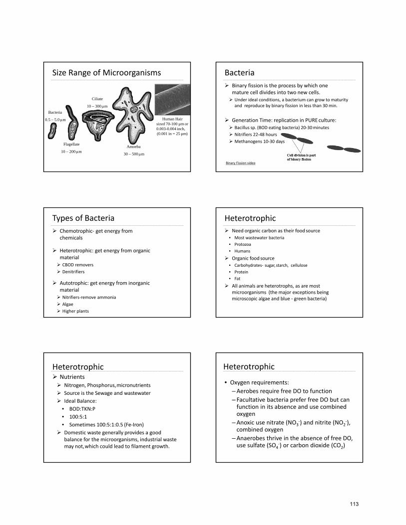
Size Range of Microorganisms
Bacteria
0.5 – 5.0 m
Amoeba
30 – 500 m
Ciliate
10 – 300 m
Flagellate
10 – 200 m
Human Hair sized 70-100 µm or 0.003-0.004 inch,(0.001 in = 25 µm)
Bacteria
Binary fission is the process by which one mature cell divides into two new cells. Under ideal conditions, a bacterium can grow to maturity
and reproduce by binary fission in less than 30 min.
Generation Time: replication in PUREculture: Bacillus sp. (BOD eating bacteria) 20‐30minutes
Nitrifiers 22‐48 hours
Methanogens 10‐30 days
Binary Fission video
Types of Bacteria
Chemotrophic‐ get energy fromchemicals
Heterotrophic: get energy from organicmaterial CBOD removers
Denitrifiers
Autotrophic: get energy from inorganicmaterial Nitrifiers‐remove ammonia
Algae
Higher plants
Heterotrophic
Need organic carbon as their foodsource
• Most wastewater bacteria
• Protozoa
• Humans
Organic food source
• Carbohydrates‐ sugar, starch, cellulose
• Protein
• Fat
All animals are heterotrophs, as are most microorganisms (the major exceptions being microscopic algae and blue ‐ green bacteria)
Heterotrophic Nutrients Nitrogen, Phosphorus,micronutrients
Source is the Sewage and wastewater
Ideal Balance:
• BOD:TKN:P
• 100:5:1
• Sometimes 100:5:1:0.5 (Fe‐Iron)
Domestic waste generally provides a good balance for the microorganisms, industrial waste may not,which could lead to filament growth.
Heterotrophic
• Oxygen requirements:
–Aerobes require free DO to function
– Facultative bacteria prefer free DO but can function in its absence and use combined oxygen
–Anoxic use nitrate (NO3‐) and nitrite (NO2
‐), combined oxygen
–Anaerobes thrive in the absence of free DO, use sulfate (SO4
‐) or carbon dioxide (CO2)
113
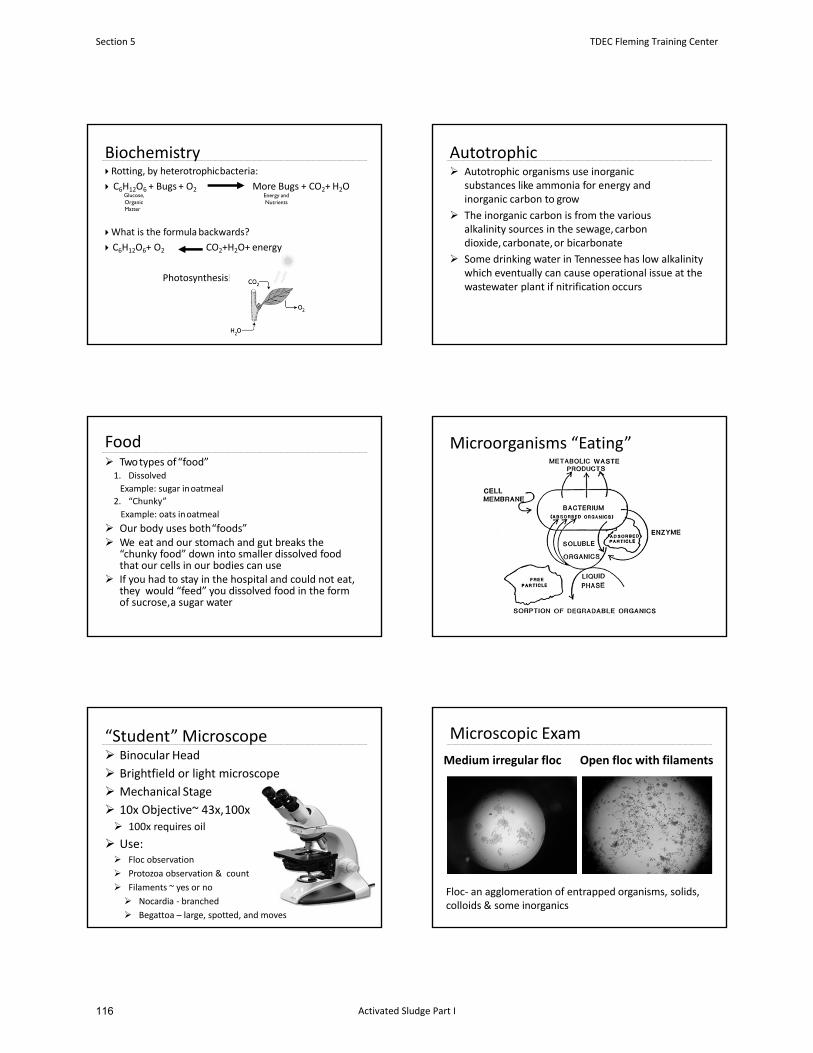
Biochemistry Rotting, by heterotrophicbacteria:
C6H12O6 + Bugs + O2 More Bugs + CO2+ H2O
What is the formula backwards?
C6H12O6+ O2 CO2+H2O+ energy
Photosynthesis!
Glucose,OrganicMatter
Energy and Nutrients
Autotrophic Autotrophic organisms use inorganic
substances like ammonia for energy and inorganic carbon to grow
The inorganic carbon is from the various alkalinity sources in the sewage,carbondioxide, carbonate,or bicarbonate
Some drinking water in Tennessee has low alkalinity which eventually can cause operational issue at the wastewater plant if nitrification occurs
Food Two types of“food”1. Dissolved
Example: sugar inoatmeal
2. “Chunky”
Example: oats inoatmeal
Our body uses both“foods” We eat and our stomach and gut breaks the
“chunky food” down into smaller dissolved food that our cells in our bodies can use
If you had to stay in the hospital and could not eat, they would “feed” you dissolved food in the form of sucrose,a sugar water
Microorganisms “Eating”
“Student” Microscope Binocular Head
Brightfield or light microscope
Mechanical Stage
10x Objective~ 43x,100x 100x requires oil
Use: Floc observation
Protozoa observation & count
Filaments ~ yes or no
Nocardia ‐ branched
Begattoa – large, spotted, and moves
Medium irregular floc Open floc with filaments
Microscopic Exam
Floc‐ an agglomeration of entrapped organisms, solids, colloids & some inorganics
Section 5 TDEC Fleming Training Center
Activated Sludge Part I116
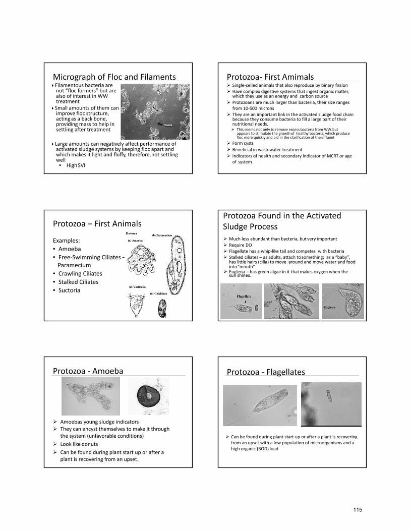
Micrograph of Floc and Filaments Filamentous bacteria are not “floc formers” but are also of interest in WWtreatment
Small amounts of them can improve floc structure, actingas a back bone, providing mass to help in settling after treatment
Large amounts can negatively affect performance of activated sludge systems by keeping floc apart and which makes it light and fluffy, therefore,not settling well • HighSVI
Protozoa‐ First Amimals Single‐celled animals that also reproduce by binary fission Have complex digestive systems that ingest organic matter,
which they use as an energy and carbon source
Protozoans are much larger than bacteria, their size ranges from 10‐500 microns
They are an important link in the activated sludge food chain because they consume bacteria to fill a large part of their nutritional needs. This seems not only to remove excess bacteria from WW, but
appears to stimulate the growthof healthy bacteria, which produce floc more quickly and aid in the clarification of theeffluent
Form cysts
Beneficial in wastewater treatment
Indicators of health and secondary indicator of MCRT or age of system
Protozoa – First Animals
Examples:
• Amoeba
• Free‐Swimming Ciliates –Paramecium
• Crawling Ciliates
• Stalked Ciliates
• Suctoria
Protozoa Found in the Activated Sludge Process Much less abundant than bacteria, butvery important
Require DO Flagellate has a whip‐like tail and competes with bacteria Stalked ciliates – as adults, attach tosomething; as a “baby”,
has little hairs (cilia) to move around and move water and food into“mouth”
Euglena – has green algae in it thatmakes oxygen when the sun shines.
Protozoa ‐ Amoeba
Amoebas young sludge indicators They can encyst themselves to make it through
the system (unfavorable conditions)
Look like donuts
Can be found during plant start up or after a plant is recovering from an upset.
Protozoa ‐ Flagellates
Can be found during plant start up or after a plant is recovering from an upset with a low population of microorganisms and a high organic (BOD) load
115
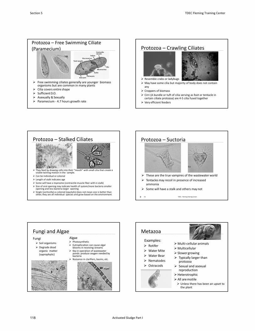
Protozoa – Free Swimming Ciliate (Paramecium)
Free swimming ciliates generally are younger biomass organisms but are common in many plants
Cilia covers entire shape SufficientD.O. Asexually &Sexually Paramecium ‐ 4.7 hours growth rate
Cilia
Protozoa – Crawling Ciliates
Resemble crabs or ladybugs
May have some cilia but majority of body does not containany
Croppers of biomass
Cirri (A bundle or tuft of cilia serving as foot or tentacle in certain ciliate protozoa) are 4‐5 cilia fused together
Very efficient feeders
Protozoa – Stalked Ciliates
They feed by drawing cells into their “mouth” with small cilia that create a visible twirling motion in the sample.
Can be individual or colonial
Length of stalk indicates age
Some will have a myenome (contractile muscle fiber with in stalk)
Size of oral opening may indicate health of system/more bacteria smaller opening and less bacteria larger opening
Single (vorticella) vs colonial (epystylis) does not mean one is better than other, they are all individual species and grow based on the environment
Protozoa – Suctoria
These are the true vampires of the wastewaterworld
Tentacles may recoil in presence of increasedammonia
Some will have a stalk and others maynot
52 TDEC ‐ Fleming Training Center
Fungi and AlgaeFungi Soil organisms
Degrade dead organic matter(saprophytic)
Algae Photosynthetic Eutrophication can cause algal
blooms in receiving streams Key in operation of wastewater
ponds: produce oxygen needed bybacteria
Nuisance in clarifiers, basins, etc.
Metazoa
Multi‐cellular animals
Multicellular
Slowergrowing
Typically larger than protozoa
Sexual and asexual reproduction
Heterotrophic
All aremotile Unless there has been an upset to
the plant
Examples: Rotifer
WaterMite
Water Bear
Nematodes
Ostracods
Section 5 TDEC Fleming Training Center
Activated Sludge Part I118
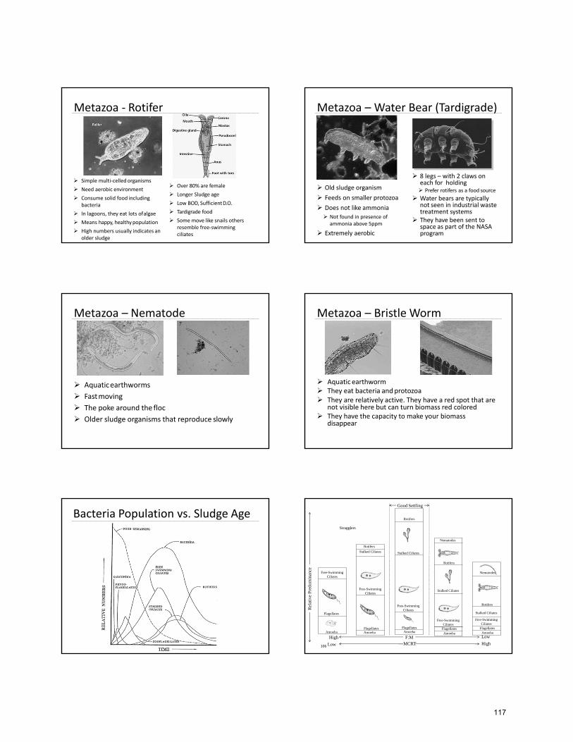
Metazoa ‐ Rotifer
Simple multi‐celledorganisms
Need aerobic environment
Consume solid food including bacteria
In lagoons, they eat lots ofalgae
Means happy, healthypopulation
High numbers usually indicates anolder sludge
Over 80% are female
Longer Sludge age
Low BOD, SufficientD.O.
Tardigrade food
Some move like snails others resemble free‐swimmingciliates
Metazoa – Water Bear (Tardigrade)
Old sludge organism
Feeds on smaller protozoa
Does not like ammonia
Not found in presence ofammonia above 5ppm
Extremely aerobic
8 legs – with 2 claws on each for holding Prefer rotifers as a food source
Water bears are typically not seen in industrial waste treatment systems
They have been sent to space as part of the NASAprogram
Metazoa – Nematode
Aquaticearthworms
Fastmoving
The poke around the floc
Older sludge organisms that reproduce slowly
Metazoa – Bristle Worm
Aquatic earthworm They eat bacteria andprotozoa They are relatively active. They have a red spot that are
not visible here but can turn biomass red colored They have the capacity to make your biomass
disappear
Bacteria Population vs. Sludge Age
Free-Swimming Ciliates
Flagellates
Amoeba
Rotifers
Stalked Ciliates
Free-Swimming Ciliates
FlagellatesAmoeba
Rotifers
Stalked Ciliates
Free-Swimming Ciliates
FlagellatesAmoeba
Nematodes
Rotifers
Stalked Ciliates
Free-Swimming Ciliates
FlagellatesAmoeba
Nematodes
Rotifers
Stalked Ciliates
Free-Swimming Ciliates
FlagellatesAmoeba
Rel
ativ
eP
redo
min
ance
F:MHigh
106 Low
Low
High
Stragglers
Good Settling
MCRT
117
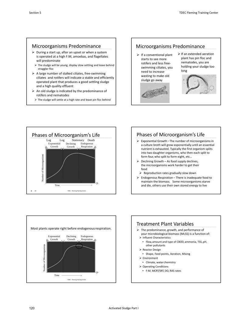
Microorganisms Predominance During a start up, after an upset or when a system
is operated at a high F:M, amoebas, and flagellates will predominate The sludge will be young, display slow settling and leave behind
straggler floc
A large number of stalked ciliates, free‐swimming ciliates and rotifers will indicate a stable and efficiently operated plant that produces a good settling sludge and a high quality effluent
An old sludge is indicated by the predominance of rotifers and nematodes
The sludge will settle at a high rate and leave pin floc behind
Microorganisms Predominance
If a conventional plant starts to see more rotifers and less free‐swimming ciliates, you need to increase wasting to make old sludge go away
If an extended aeration plant has pin floc and nematodes, you are holding your sludge toolong
Phases of Microorganism’s Life
Exponential Growth
Declining Growth
Endogenous Respiration
Time
Num
ber
ofM
icro
orga
nism
s
Lag Log Stationary
63 TDEC ‐ Fleming Training Center
Death
Phases of Microorganism’s Life Exponential Growth –The number of microorganisms in
a culture broth will grow exponentially until an essential nutrient is exhausted. Typically the first organism splits into two daughter organisms, who then each split toform four, who split to form eight, etc…
Declining Growth – As food supply declines, the microorganisms work harder to get theirfood Reproduction rates gradually slow down
Endogenous Respiration – There is inadequate food to maintain the biomass. Some microorganisms starveand die, others use their own stored energy to live
Most plants operate right before endogenousrespiration.
Exponential Growth
Declining Growth
Endogenous Respiration
Time
Num
ber
ofM
icro
orga
nism
s
TDEC ‐ Fleming Training Center
Treatment Plant Variables The predominance, growth, and performance of
your microbiological biomass (MLSS) is a function of: Influent Characteristics
• Flow,amount and type of CBOD,ammonia, TSS, pH,other pollutants
Reactor Design
• Shape, Feed points, Aeration, Mixing
Environment
• Climate, waterchemistry
Operating Conditions
• F:M, MCRT/SRT, DO, RAS rates
Section 5 TDEC Fleming Training Center
Activated Sludge Part I120
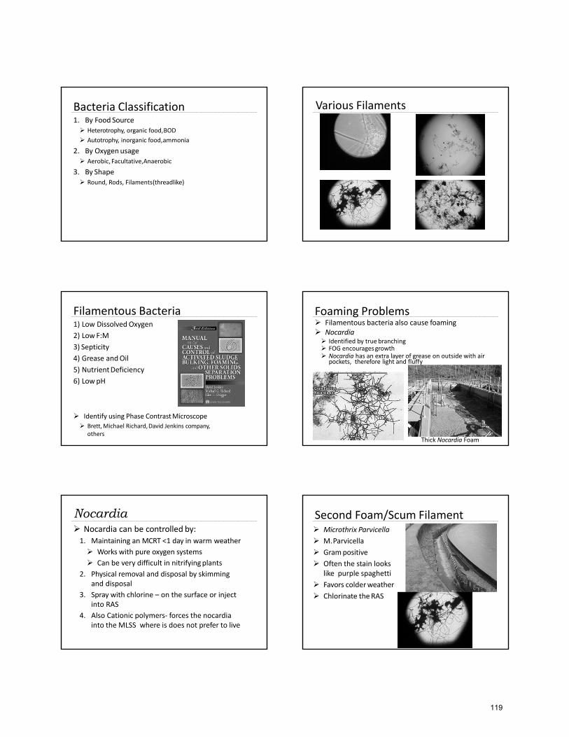
Bacteria Classification1. By Food Source Heterotrophy, organic food,BOD
Autotrophy, inorganic food,ammonia
2. By Oxygenusage Aerobic, Facultative,Anaerobic
3. By Shape Round, Rods, Filaments(threadlike)
Various Filaments
Filamentous Bacteria1) Low Dissolved Oxygen
2) Low F:M
3) Septicity
4) Grease andOil
5) NutrientDeficiency
6) LowpH
Identify using Phase ContrastMicroscope
Brett,Michael Richard,David Jenkins company,others
Foaming Problems Filamentous bacteria also cause foaming Nocardia Identified by true branching FOG encouragesgrowth Nocardia has an extra layer of grease on outside with air
pockets, therefore light and fluffy
Thick Nocardia Foam
Nocardia Nocardia can be controlled by:1. Maintaining an MCRT <1 day in warm weather
Works with pure oxygen systems
Can be very difficult in nitrifyingplants
2. Physical removal and disposal by skimming and disposal
3. Spray with chlorine – on the surface or inject into RAS
4. Also Cationic polymers‐ forces the nocardia into the MLSS where is does not prefer to live
Second Foam/Scum Filament Microthrix Parvicella
M.Parvicella
Grampositive
Often the stain looks like purple spaghetti
Favors colderweather
Chlorinate theRAS
119
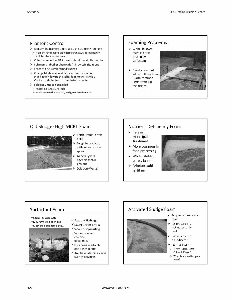
Filament Control Identify the filament and change the plantenvironment
Filament have specific growth preferences, take those away and the filament goes away
Chlorination of the RAS is a old standby and oftenworks
Polymers and other chemicals fit in certain situations
Foam can be skimmed and trapped
Change Mode of operation: step feed or contact stabilization lowers the solids load to the clarifier.Contact stabilization can incubatefilaments.
Selector units can beadded
Anaerobic, Anoxic, Aerobic
These change the F:M, DO, and growthenvironment
Foaming Problems White, billowy
foam is often caused by surfactant
Development of white, billowy foam is also common under start‐up conditions.
Old Sludge‐ High MCRT Foam
Thick, stable, oftendark
Tough to break up with water hose orspray
Generally will have Nocardiapresent
Solution‐Waste!
Nutrient Deficiency Foam Rare in
Municipal Treatment
More common in food processing
White, stable, greasy foam
Solution‐ addfertilizer
Surfactant Foam
Stop the discharge
Divert & treat off line
Slow or stop wasting
Water spray and chemical defoamers
Provide needed air but don’t over aerate
Are there internal sources such as polymers
Looks like soap suds
May have soap odor also
Most are degradable, but…
Activated Sludge Foam All plants have some
foam
It’s presence is not necessarilybad
Foam is merely an indicator
Normal Foam: "Fresh, Crisp, Light
Colored Foam“
What is normal for yourplant?
Section 5 TDEC Fleming Training Center
Activated Sludge Part I122
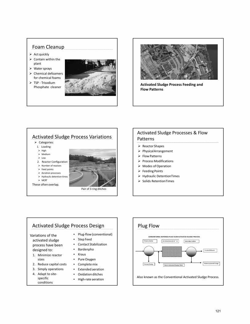
Foam Cleanup Act quickly
Contain within theplant
Water sprays
Chemical defoamersfor chemical foams
TSP ‐ TrisodiumPhosphate cleaner
Activated Sludge Process Feeding and Flow Patterns
Activated Sludge Process Variations Categories:
1. Loading:
High
Medium
Low
2. Reactor Configuration
Number of reactors
Feed points
Aeration processes
Hydraulic detention times
MCRT
These oftenoverlap.
Pair of 3 ring ditches
Activated Sludge Processes & Flow Patterns
Reactor Shapes
PhysicalArrangement
FlowPatterns
ProcessModifications
Modes ofOperation
FeedingPoints
Hydraulic DetentionTimes
Solids RetentionTimes
Activated Sludge Process Design
Variations of the activated sludge process have been designed to:1. Minimize reactor
sizes
2. Reduce capital costs
3. Simply operations
4. Adapt to site‐specific conditions
• Plug‐flow (conventional)
• Step Feed
• Contact Stabilization
• Bardenpho
• Kraus
• PureOxygen
• Completemix
• Extendedaeration
• Oxidation ditches
• High‐rate aeration
Plug Flow
Also known as the Conventional Activated Sludge Process.
121
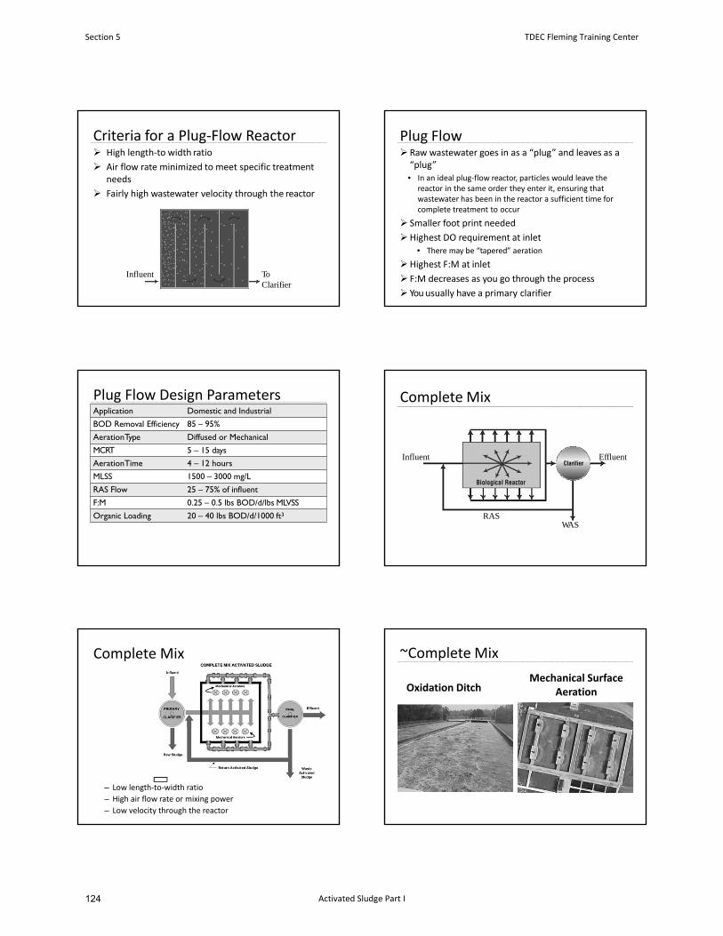
Criteria for a Plug‐Flow Reactor High length‐to width ratio
Air flow rate minimized to meet specific treatment needs
Fairly high wastewater velocity through the reactor
Influent To Clarifier
Plug Flow Raw wastewater goes in as a “plug” and leaves as a“plug”• In an ideal plug‐flow reactor, particles would leave the
reactor in the same order they enter it, ensuring that wastewater has been in the reactor a sufficient time for complete treatment to occur
Smaller foot print needed
Highest DO requirement at inlet• There may be “tapered” aeration
Highest F:M at inlet
F:M decreases as you go through the process
You usually have a primary clarifier
Plug Flow Design ParametersApplication Domestic and Industrial
BOD Removal Efficiency 85 – 95%
AerationType Diffused or Mechanical
MCRT 5 – 15 days
AerationTime 4 – 12 hours
MLSS 1500 – 3000 mg/L
RAS Flow 25 – 75% of influent
F:M 0.25 – 0.5 lbs BOD/d/lbs MLVSS
Organic Loading 20 – 40 lbs BOD/d/1000 ft3
Complete Mix
RAS
Influent
WAS
Effluent
Complete Mix
– Low length‐to‐width ratio
– High air flow rate or mixing power
– Low velocity through the reactor
Oxidation DitchMechanical Surface
Aeration
~Complete Mix
Section 5 TDEC Fleming Training Center
Activated Sludge Part I124
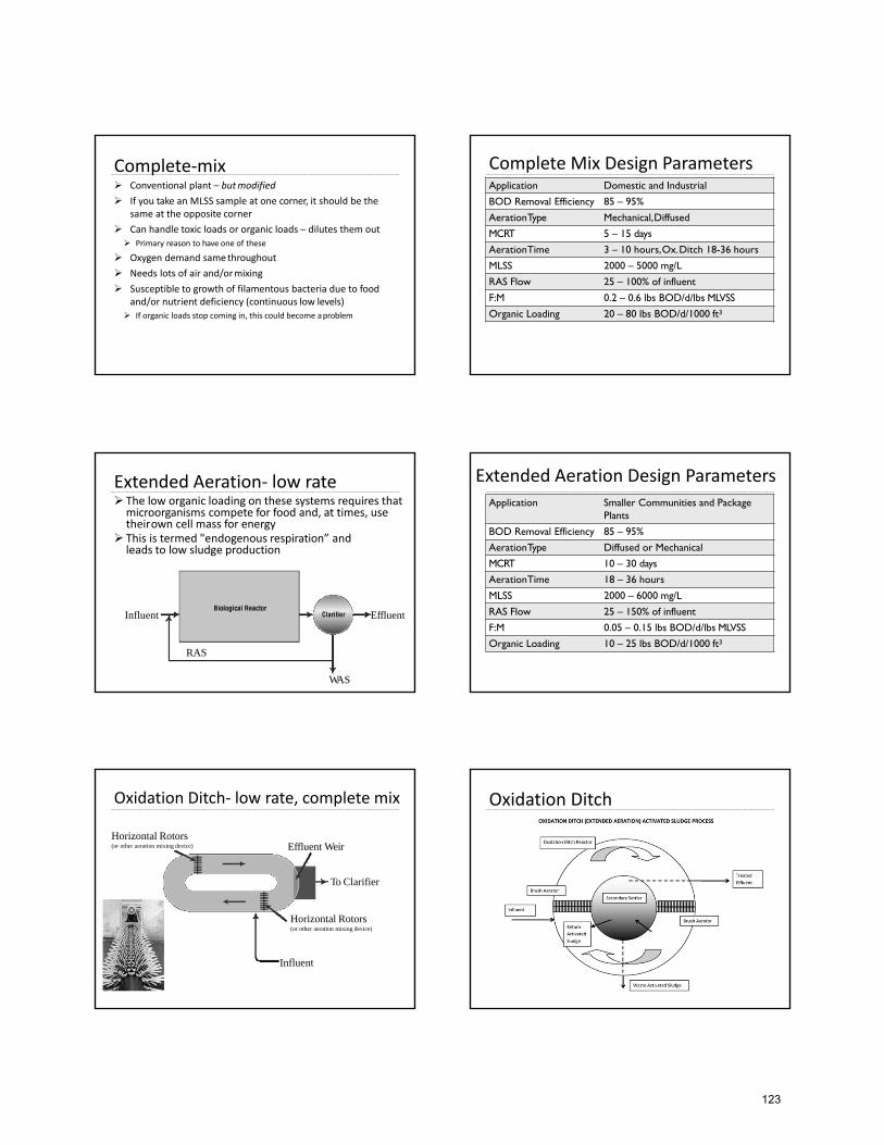
Complete‐mix Conventional plant – butmodified
If you take an MLSS sample at one corner, it should be the same at the opposite corner
Can handle toxic loads or organic loads – dilutes them out
Primary reason to have one of these
Oxygen demand same throughout
Needs lots of air and/ormixing
Susceptible to growth of filamentous bacteria due to food and/or nutrient deficiency (continuous low levels)
If organic loads stop coming in, this could become aproblem
Complete Mix Design ParametersApplication Domestic and Industrial
BOD Removal Efficiency 85 – 95%
AerationType Mechanical,Diffused
MCRT 5 – 15 days
AerationTime 3 – 10 hours,Ox.Ditch 18-36 hours
MLSS 2000 – 5000 mg/L
RAS Flow 25 – 100% of influent
F:M 0.2 – 0.6 lbs BOD/d/lbs MLVSS
Organic Loading 20 – 80 lbs BOD/d/1000 ft3
Extended Aeration‐ low rate The low organic loading on these systems requires that microorganisms compete for food and, at times, use theirown cell mass for energy
This is termed "endogenous respiration” and leads to low sludge production
RAS
Influent
WAS
Effluent
Extended Aeration Design ParametersApplication Smaller Communities and Package
Plants
BOD Removal Efficiency 85 – 95%
AerationType Diffused or Mechanical
MCRT 10 – 30 days
AerationTime 18 – 36 hours
MLSS 2000 – 6000 mg/L
RAS Flow 25 – 150% of influent
F:M 0.05 – 0.15 lbs BOD/d/lbs MLVSS
Organic Loading 10 – 25 lbs BOD/d/1000 ft3
Oxidation Ditch‐ low rate, complete mix
Horizontal Rotors(or other aeration mixing device)
Influent
Effluent Weir
To Clarifier
Horizontal Rotors(or other aeration mixing device)
Oxidation Ditch
123
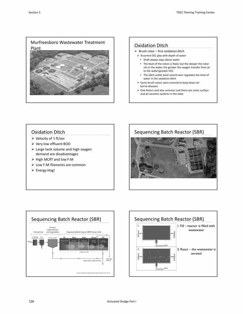
Murfreesboro Wastewater Treatment Plant
Oxidation Ditch Brush rotor – first oxidationditch To control DO, play with depth of water
• Shaft always stays above water
• The level of the rotors is fixed, but the deeper the rotor sits in the water, the greater the oxygen transfer from air to the water(greater DO)
• The ditch outlet level control weir regulates the level of water in the oxidation ditch
Some brush rotors were covered to keep down air‐borne diseases
Disk Rotors and also common and there are some surface and jet aeration systems in the state
Oxidation Ditch Velocity of 1 ft/sec
Very low effluent BOD
Large tank volume and high oxygen demand are disadvantages
High MCRT and low F:M
Low F:M filaments are common
Energy Hog!
Sequencing Batch Reactor (SBR)
Sequencing Batch Reactor (SBR)
Source: Operation of Wastewater Treatment Plants, Vol I, 8th ed.
Sequencing Batch Reactor (SBR)
Infl
uent
Eff
luen
t
WAS
Infl
uent
Eff
luen
t
WAS
1.
2.
1. Fill – reactor is filled with wastewater
2. React – the wastewater is aerated
Section 5 TDEC Fleming Training Center
Activated Sludge Part I126
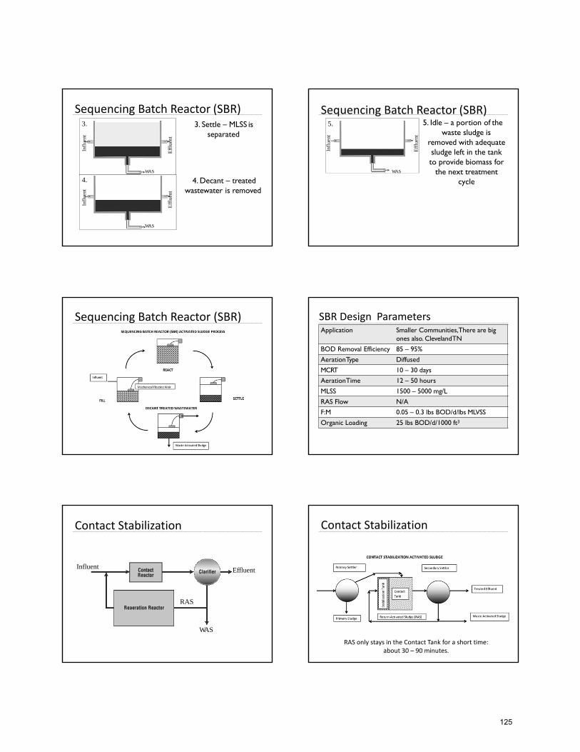
Sequencing Batch Reactor (SBR)
Infl
uent
Eff
luen
tWAS
Infl
uent
Eff
luen
t
WAS
3.
4.
3. Settle – MLSS is separated
4. Decant – treated wastewater is removed
Sequencing Batch Reactor (SBR)
Infl
uent
Eff
luen
t
5.
WAS
5. Idle – a portion of the waste sludge is
removed with adequate sludge left in the tank to provide biomass for
the next treatment cycle
Sequencing Batch Reactor (SBR) SBR Design ParametersApplication Smaller Communities,There are big
ones also. ClevelandTN
BOD Removal Efficiency 85 – 95%
AerationType Diffused
MCRT 10 – 30 days
AerationTime 12 – 50 hours
MLSS 1500 – 5000 mg/L
RAS Flow N/A
F:M 0.05 – 0.3 lbs BOD/d/lbs MLVSS
Organic Loading 25 lbs BOD/d/1000 ft3
Contact Stabilization
RAS
Influent
WAS
Effluent
Contact Stabilization
RAS only stays in the Contact Tank for a short time: about 30 – 90 minutes.
125
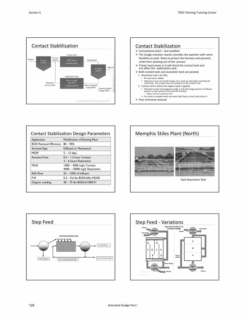
Contact Stablilization Contact Stabilization Conventional plant – butmodified
The sludge rearation reactor provides the operator with some flexibility at peak flows to protect the biomass and prevents solids from washing out of the process
If toxic load comes in,it will shock the contact tank and not affect the stabilization tank
Both contact tank and reaeration tank are aerated1. Reaeration tank is for RAS.
• No new food is added
• Organisms must use stored energy, once used up, they begin searching for more food, this is when they are moved on to the contact tank
2. Contact tank is where the organic load is applied• Attempts to have microorganisms take in and store large portions of influent
waste in a short period of time (30‐90 minutes) Higher F:M than reaeration tank
Can avoid a complete wash‐out when high flows or toxic load comes in
Poor ammonia removal
Contact Stabilization Design ParametersApplication Modification of Existing Plant
BOD Removal Efficiency 80 – 90%
AerationType Diffused or Mechanical
MCRT 5 – 15 days
AerationTime 0.5 – 1.5 hour Contact 3 – 6 hours Reaeration
MLSS 1000 – 3000 mg/L Contact4000 – 10000 mg/L Reaeration
RAS Flow 25 – 100% of influent
F:M 0.2 – 0.6 lbs BOD/d/lbs MLVSS
Organic Loading 30 – 75 lbs BOD/d/1000 ft3
Memphis Stiles Plant (North)
Dark Reaeration Tank
Step Feed Step Feed ‐ Variations
Section 5 TDEC Fleming Training Center
Activated Sludge Part I128
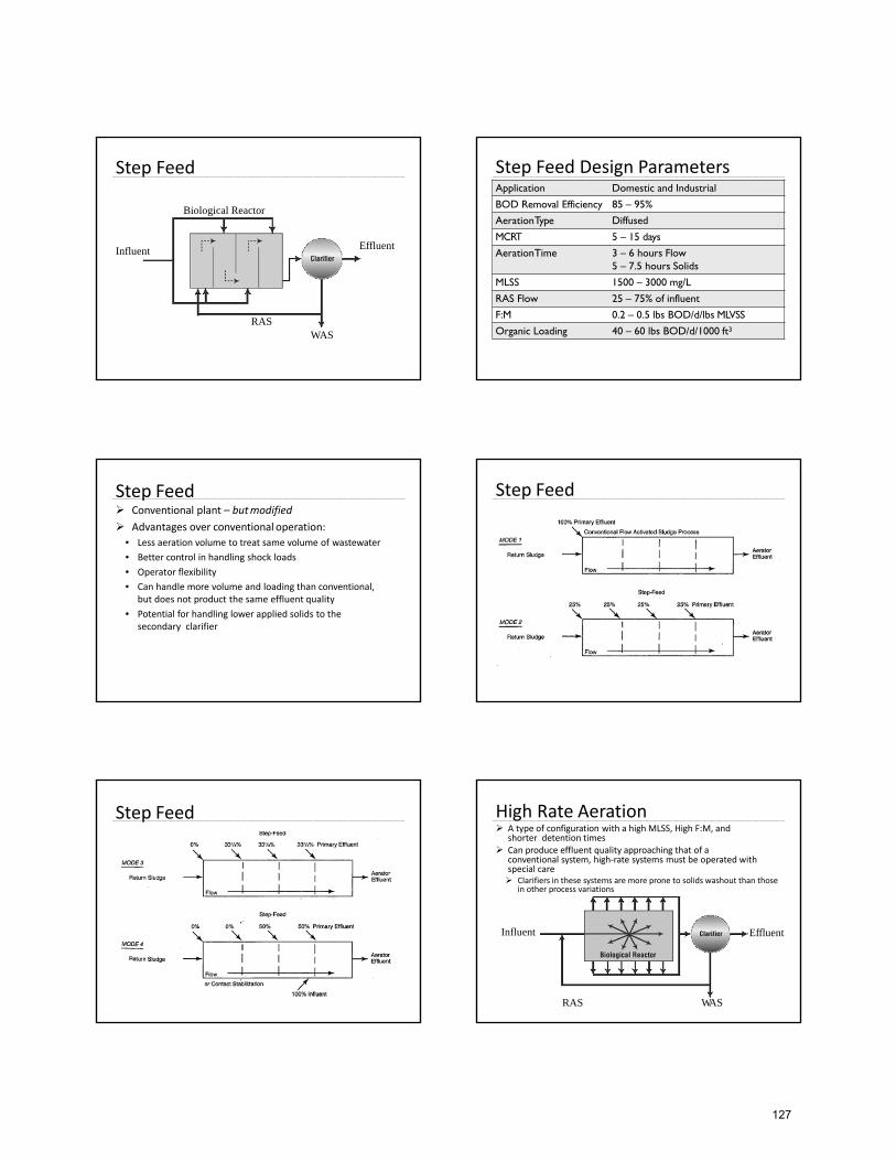
Step Feed
RAS
Influent
WAS
Effluent
Biological Reactor
Step Feed Design ParametersApplication Domestic and Industrial
BOD Removal Efficiency 85 – 95%
AerationType Diffused
MCRT 5 – 15 days
AerationTime 3 – 6 hours Flow5 – 7.5 hours Solids
MLSS 1500 – 3000 mg/L
RAS Flow 25 – 75% of influent
F:M 0.2 – 0.5 lbs BOD/d/lbs MLVSS
Organic Loading 40 – 60 lbs BOD/d/1000 ft3
Step Feed Conventional plant – butmodified
Advantages over conventional operation:
• Less aeration volume to treat same volume of wastewater
• Better control in handling shock loads
• Operator flexibility
• Can handle more volume and loading than conventional, but does not product the same effluent quality
• Potential for handling lower applied solids to the secondary clarifier
Step Feed
Step Feed High Rate Aeration A type of configuration with a high MLSS, High F:M, and
shorter detention times Can produce effluent quality approaching that of a
conventional system, high‐rate systems must be operated with special care Clarifiers in these systems are more prone to solids washout than those
in other process variations
RAS
Influent
WAS
Effluent
127
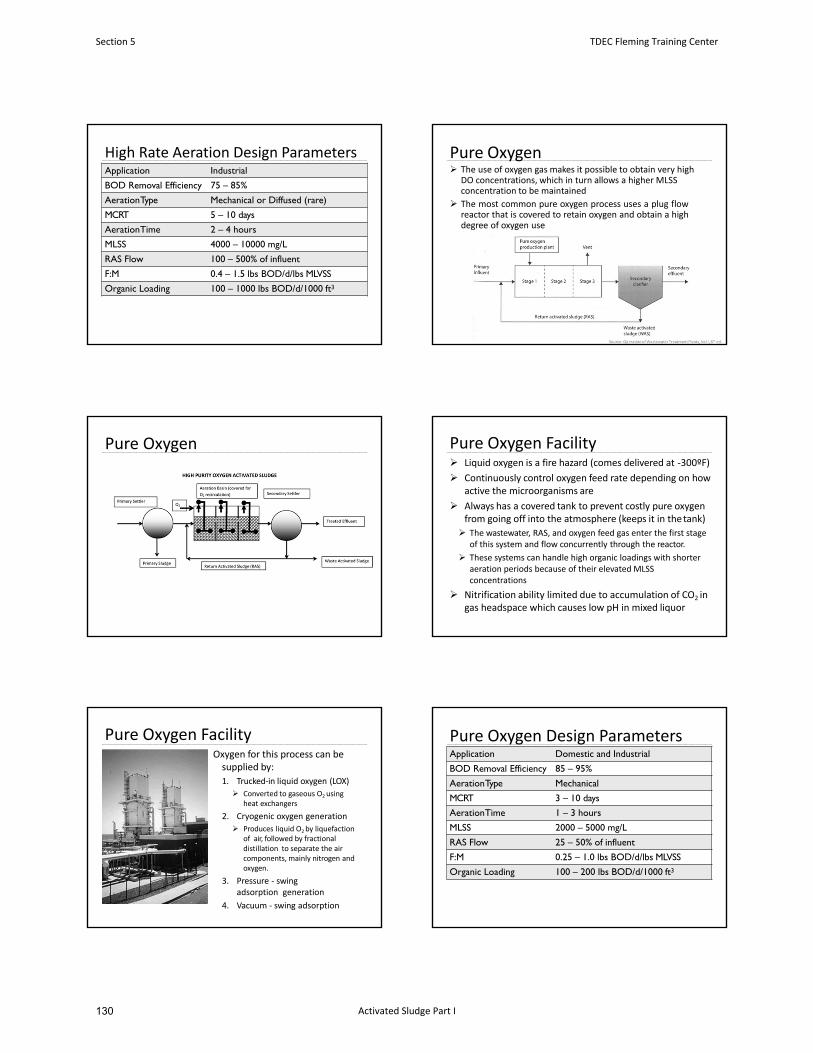
High Rate Aeration Design ParametersApplication Industrial
BOD Removal Efficiency 75 – 85%
AerationType Mechanical or Diffused (rare)
MCRT 5 – 10 days
AerationTime 2 – 4 hours
MLSS 4000 – 10000 mg/L
RAS Flow 100 – 500% of influent
F:M 0.4 – 1.5 lbs BOD/d/lbs MLVSS
Organic Loading 100 – 1000 lbs BOD/d/1000 ft3
Pure Oxygen The use of oxygen gas makes it possible to obtain very high
DO concentrations, which in turn allows a higher MLSS concentration to be maintained
The most common pure oxygen process uses a plug flowreactor that is covered to retain oxygen and obtain a highdegree of oxygen use
Pure Oxygen Pure Oxygen Facility Liquid oxygen is a fire hazard (comes delivered at ‐300ºF)
Continuously control oxygen feed rate depending on how active the microorganisms are
Always has a covered tank to prevent costly pure oxygen from going off into the atmosphere (keeps it in thetank)
The wastewater, RAS, and oxygen feed gas enter the first stage of this system and flow concurrently through the reactor.
These systems can handle high organic loadings with shorter aeration periods because of their elevated MLSS concentrations
Nitrification ability limited due to accumulation of CO2 in gas headspace which causes low pH in mixed liquor
Pure Oxygen FacilityOxygen for this process can be supplied by:
1. Trucked‐in liquid oxygen (LOX)
Converted to gaseous O2 using heat exchangers
2. Cryogenic oxygen generation
Produces liquid O2 by liquefaction of air, followed by fractional distillation to separate the air components, mainly nitrogen andoxygen.
3. Pressure ‐ swing adsorption generation
4. Vacuum ‐ swing adsorption
Pure Oxygen Design ParametersApplication Domestic and Industrial
BOD Removal Efficiency 85 – 95%
AerationType Mechanical
MCRT 3 – 10 days
AerationTime 1 – 3 hours
MLSS 2000 – 5000 mg/L
RAS Flow 25 – 50% of influent
F:M 0.25 – 1.0 lbs BOD/d/lbs MLVSS
Organic Loading 100 – 200 lbs BOD/d/1000 ft3
Section 5 TDEC Fleming Training Center
Activated Sludge Part I130
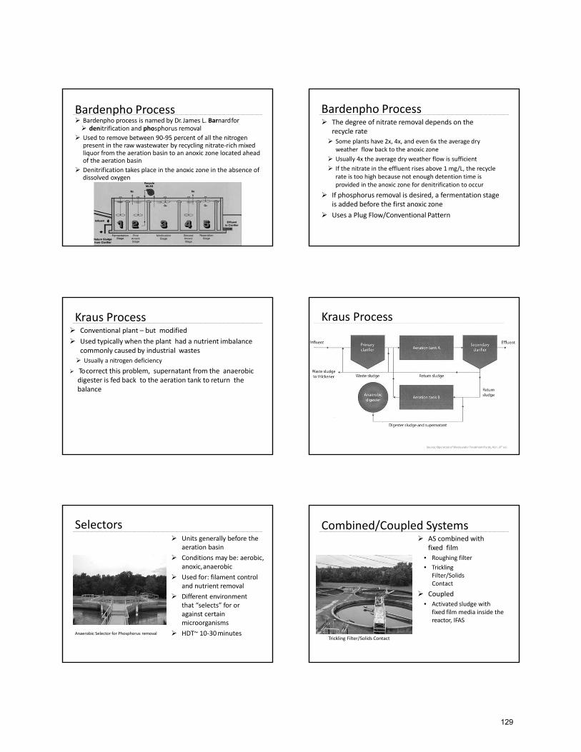
Bardenpho Process Bardenpho process is named by Dr. James L. Barnardfor denitrification and phosphorus removal
Used to remove between 90‐95 percent of all the nitrogen present in the raw wastewater by recycling nitrate‐rich mixed liquor from the aeration basin to an anoxic zone located ahead of the aeration basin
Denitrification takes place in the anoxic zone in the absence of dissolved oxygen
Bardenpho Process The degree of nitrate removal depends on the
recycle rate
Some plants have 2x, 4x, and even 6x the average dry weather flow back to the anoxic zone
Usually 4x the average dry weather flow is sufficient
If the nitrate in the effluent rises above 1 mg/L, the recycle rate is too high because not enough detention time is provided in the anoxic zone for denitrification to occur
If phosphorus removal is desired, a fermentation stage is added before the first anoxic zone
Uses a Plug Flow/Conventional Pattern
Kraus Process Conventional plant – but modified
Used typically when the plant had a nutrient imbalance commonly caused by industrial wastes
Usually a nitrogen deficiency
To correct this problem, supernatant from the anaerobic digester is fed back to the aeration tank to return thebalance
Kraus Process
Selectors Units generally before the
aeration basin
Conditions may be: aerobic, anoxic,anaerobic
Used for: filament control and nutrient removal
Different environment that “selects” for or against certain microorganisms
HDT~ 10‐30minutesAnaerobic Selector for Phosphorus removal
Combined/Coupled Systems AS combined with
fixed film
• Roughing filter
• Trickling Filter/Solids Contact
Coupled
• Activated sludge with fixed film media inside the reactor, IFAS
Trickling Filter/Solids Contact
129
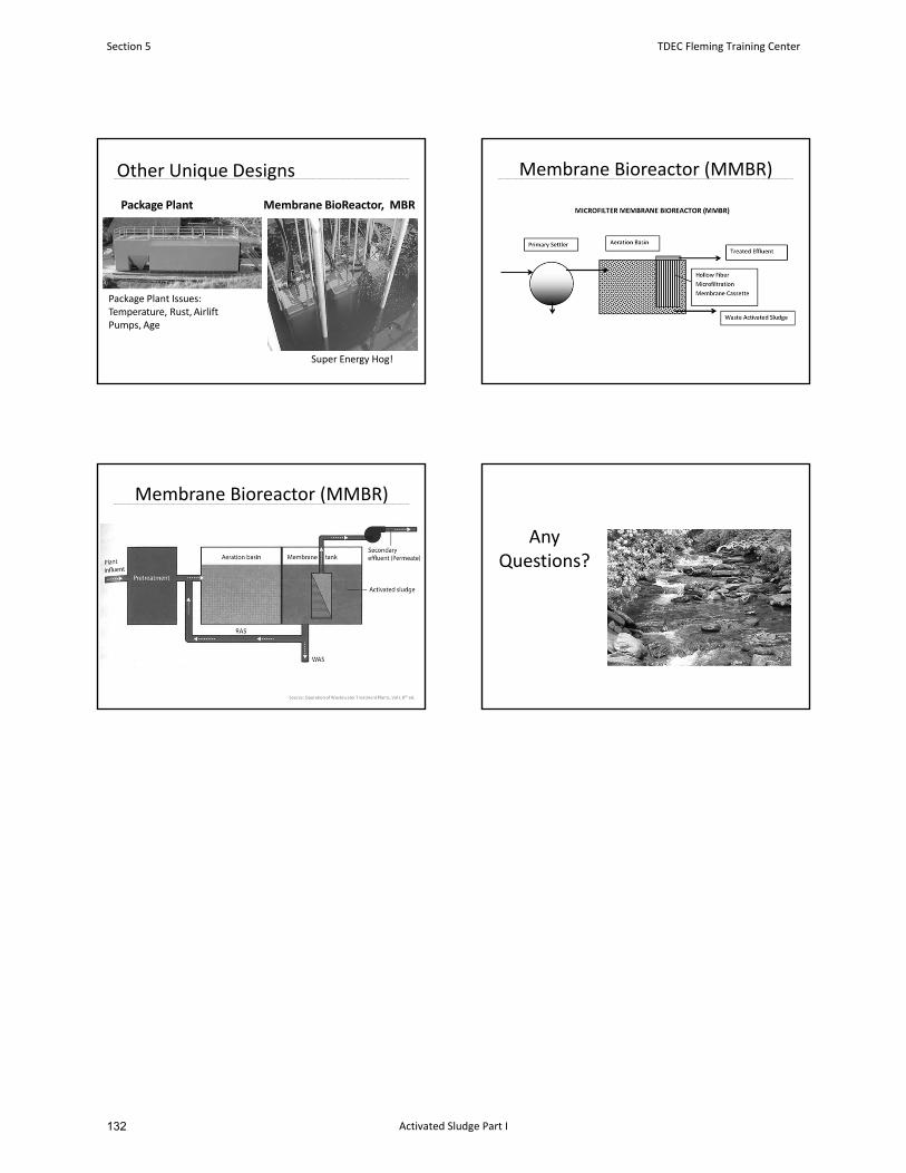
Package Plant Membrane BioReactor, MBR
Other Unique Designs
Super Energy Hog!
Package Plant Issues: Temperature, Rust, Airlift Pumps, Age
Membrane Bioreactor (MMBR)
Membrane Bioreactor (MMBR)
Any Questions?
Section 5 TDEC Fleming Training Center
Activated Sludge Part I132
January 2016 7-1 Design Criteria Ch. 7
CHAPTER 7
Activated Sludge
7.1 General
7.1.1 Applicability
7.1.2 Process Selection
7.1.3 Pretreatment
7.2 Types of Processes
7.2.1 Conventional
7.2.2 Complete Mix
7.2.3 Step Aeration
7.2.4 Tapered Aeration
7.2.5 Contact Stabilization
7.2.6 Extended Aeration
7.2.7 High - Rate Aeration
7.2.8 High - Purity Oxygen
7.2.9 Kraus Process
7.2.10 Sequencing Batch Reactors (SBR)
7.3 Aeration Tanks
7.3.1 Required Volume
7.3.2 Shape and Mixing
7.3.3 Number of Units
7.3.4 Inlets and Outlets
7.3.5 Measuring Devices
7.3.6 Freeboard and Foam Control
7.3.7 Drain and Bypass
7.3.8 Other Considerations
7.4 Aeration Equipment
7.4.1 General
7.4.2 Diffused Air Systems
7.4.3 Mechanical Aeration Equipment
7.4.4 Flexibility and Energy Conservation
131

January 2016 7-2 Design Criteria Ch. 7
7.5 Additional Details
7.5.1 Lifting Equipment and Access
7.5.2 Noise and Safety
7.6 Sequencing Batch Reactors (SBRs)
7.7 Oxidation Ditch
7.7.1 General
7.7.2 Special Details
7.7.3 45 - Degree Sloping Sidewall Tanks
7.7.4 Straight Sidewall Tanks
Section 5 TDEC Fleming Training Center
Activated Sludge Part I134
January 2016 7-3 Design Criteria Ch. 7
ACTIVATED SLUDGE
7.1 General
7.1.1 Applicability
The activated sludge process and its various modifications may be used where sewage is
amenable to biological treatment. This process requires close attention and more
competent operator supervision than some of the other biological processes. A
treatability study may be required to show that the organics are amendable to the
proposed treatment. For example, industrial wastewaters containing high levels of
starches and sugars may cause interferences with the activated sludge process due to
bulking.
Toxic loadings from industries and excessive hydraulic loadings must be avoided to
prevent the loss or destruction of the activated sludge mass. If toxic influents are a
possibility, a properly enforced industrial pretreatment program will prove extremely
beneficial to the WWTP and will be required. It takes days and sometimes weeks for the
plant to recover from a toxic overload and will likely result in permit violations. Flow
equalization, as detailed in Chapter 4, may be required in some instances. These
requirements shall be considered when proposing this type of treatment.
7.1.2 Process Selection
The activated sludge process and its several modifications may be employed to
accomplish varied degrees of removal of suspended solids and reduction of BOD and
ammonia. Choice of the process most applicable will be influenced by the proposed
plant size, type of waste to the treated, and degree and consistency of treatment required.
All designs should provide for flexibility to incorporate as many modes of operation as is
reasonably possible.
Calculations and/or documentation shall be submitted to justify the basis of design for the
following:
a. Process efficiency
b. Aeration tanks
c. Aeration equipment (including oxygen and mixing requirements)
d. Operational rationale (including maintenance)
e. Costs (capital and operating)
In addition, the design must comply with any requirements set forth in other chapters such as
clarifiers, sludge processing, etc.
133
January 2016 7-4 Design Criteria Ch. 7
7.1.3 Pretreatment
Where primary settling tanks are not used, effective removal or exclusion of grit, debris,
excessive oil or grease, and comminution or screening of solids shall be accomplished
prior to the activated sludge process.
Where primary settling is used, provisions should be made for discharging raw sewage
directly to the aeration tanks to facilitate plant start-up and operation during the initial
stages of the plant's design life. Also, primary effluents are often low in D.O. This
should be planned for in the design.
7.2 Types of Processes
Figure 7.1 shows the flow schematics of the major types of activated sludge processes,
excluding pretreatment. The types that are simply modifications of these processes are not
shown.
7.2.1 Conventional
Conventional activated sludge is characterized by introduction of influent wastewater and
return activated sludge at one end of the aeration tank, a plug-flow aeration tank, and
diffused aeration.
7.2.2 Complete Mix
Complete mix activated sludge is characterized by introduction of influent wastewater
and return activated sludge throughout the aeration basin and the use of a completely
mixed aeration tank. Complete mix aeration tanks may be arranged in series to
approximate plug flow and conventional activated sludge.
7.2.3 Step Aeration
Step aeration activated sludge is characterized by introduction of the influent wastewater
at two or more points in the aeration tank, use of a plug-flow aeration tank, and diffused
aeration.
7.2.4 Tapered Aeration
Tapered aeration is similar to conventional activated sludge except that the air supply is
tapered to meet the organic load within the tank. More air is added to the influent end of
the tank where the organic loading and oxygen demand are the greatest.
Section 5 TDEC Fleming Training Center
Activated Sludge Part I136
January 2016 7-5 Design Criteria Ch. 7
7.2.5 Contact Stabilization
Contact stabilization activated sludge is characterized by the use of two aeration tanks for
each process train, one to contact the influent wastewater and return activated sludge
(contact tank) and the other to aerate the return activated sludge (stabilization tank) and
promote the biodegradation of the organics absorbed to the bacterial flocs.
7.2.6 Extended Aeration
Extended aeration activated sludge is characterized by a low F/M ratio, long sludge age,
and long aeration tank detention time (greater than 18 hours). For additional details on
oxidation ditches see Section 7.7).
7.2.7 High-Rate Aeration
High-rate aeration activated sludge is characterized by high F/M ratio, low sludge age,
short aeration tank detention time, and high mixed-liquor suspended solids. High-rate
aeration should be followed by other BOD and suspended solids removal processes to
provide secondary treatment.
7.2.8 High-Purity Oxygen
High-purity oxygen activated sludge is characterized by the use of high-purity oxygen
instead of air for aeration.
7.2.9 Kraus Process
Kraus process activated sludge is characterized by use of an aeration tank to aerate a
portion of the return activated sludge, digester supernatant, and digested sludge in order
to provide nitrogen (ammonia) to a nitrogen-deficient wastewater.
7.2.10 Sequencing Batch Reactors (SBR)
The SBR process is a fill-and-draw, non-steady state activated sludge process in which
one or more reactor basins are filled with wastewater during a discrete time period, and
then operated in a batch treatment mode. SBR's accomplish equalization, aeration, and
clarification in a timed sequence. For additional details see Section 7.6.
135
January 2016 7-6 Design Criteria Ch. 7
7.3 Aeration Tanks
7.3.1 Required Volume
The size of the aeration tank for any particular adaptation of the process shall be based on
the food-to-microorganism (F/M) ratio, using the influent BOD (load per day) divided by
the mixed-liquor volatile suspended solids. Alternatively, aeration tanks may be sized
using sludge age. The calculations using the F/M ratio or sludge age shall be based on
the kinetic relationships.
APPENDIX 7A shows the permissible range of F/M ratio, sludge age, mixed-liquor
suspended solids, aeration tank detention time, aerator loading, and activated sludge
return ratio for design of the various modifications of the activated sludge process. All
design parameters shall be checked to determine if they fall within the permissible range
for the selected F/M ratio or sludge area and the aeration tank size. Diurnal load
variations and peak loadings must be considered when checking critical parameters.
7.3.2 Shape and Mixing
The dimensions of each independent mixed-liquor aeration tank or return sludge
reaeration tank should be such as to maintain effective mixing and utilization of air when
diffused air is used. Liquid depths should not be less than 10 feet or more than 30 feet
except in special design cases. For plug-flow conditions using very small tanks or tanks
with special configuration, the shape of the tank and/or the installation of aeration
equipment should provide for elimination of short-circuiting through the tank.
Aerator loadings should be considered and the horsepower per 1,000 cubic feet of basin
volume required for oxygen transfer should be limited to prevent excessive turbulence in
the aeration basins, which might reduce activated sludge settleability.
7.3.3 Number of Units
Multiple tanks capable of independent operation may be required for operability and
maintenance reasons, depending on the activated sludge process, size of the plant, and the
reliability classification of the sewerage works (refer to Section 1.3.11).
Section 5 TDEC Fleming Training Center
Activated Sludge Part I138
January 2016 7-7 Design Criteria Ch. 7
7.3.4 Inlets and Outlets
7.3.4.1 Controls
Inlets and outlets for each aeration tank unit in multiple tank systems should be
suitably equipped with valves, gates, stop plates, weirs, or other devices to permit
control of the flow and to maintain reasonably constant liquid level. The
hydraulic properties of the system should permit the maximum instantaneous
hydraulic load to be carried with any single aeration tank unit out of service.
7.3.4.2 Conduits
Channels and pipes carrying liquids with solids in suspension should be designed
to maintain self-cleaning velocities or should be agitated to keep such solids in
suspension at all rates of flow within the design limits.
7.3.4.3 Hydraulics
Where multiple aeration tanks and secondary clarifiers are used, provisions
should be made to divide the flow evenly to all aeration tanks in service and then
recombine the flows, and to divide the flow evenly to all secondary clarifiers in
service and then recombine the flows. Treatments plants using more than four
aeration tanks and secondary clarifiers may divide the activated sludge systems
into two or more process trains consisting of not less than two aeration tanks and
secondary clarifiers per process train.
7.3.4.4 Bypass
When a primary settling tank is used, provisions shall also be made for
discharging raw wastewater directly to the aeration tanks following pretreatment
for start-ups.
7.3.5 Measuring Devices
For plants designed for less than 250,000 gallons per day, devices shall be installed for
indicating flow rates of influent sewage, return sludge, and air to each aeration tank. For
plants designed for greater than 250,000 gallons per day, devices shall be installed for
totalizing, indicating, and recording influent sewage and returned sludge to each aeration
tank. Where the design provides for all returned sludge to be mixed with the raw sewage
(or primary effluent) at one location, the mixed-liquor flow rate to each aeration tank
shall be measured, and the flow split in such a manner to provide even loading to each
tank, or as desired by operations.
137
January 2016 7-8 Design Criteria Ch. 7
7.3.6 Freeboard and Foam Control
Aeration tanks shall have a freeboard of at least 18 inches. Freeboards of 24 inches are
desirable with mechanical aerators.
Consideration shall be given for foam control devices on aeration tanks. Suitable spray
systems or other appropriate means will be acceptable. If potable water is used, approved
backflow prevention shall be provided on the water lines. The spray lines shall have
provisions for draining to prevent damage by freezing.
7.3.7 Drain and Bypass
Provisions shall be made for dewatering each aeration tank for cleaning and maintenance.
The dewatering system shall be sized to permit removal of the tank contents within 24
hours. If a drain is used, it shall be valved. The dewatering discharge shall be upstream
of the activated sludge process.
Provisions shall be made to isolate each aeration tank without disrupting flow to other
aeration tanks.
Proper precautions shall be taken to ensure the tank will not "float" when dewatered.
7.3.8 Other Considerations
Other factors that might influence the efficiency of the activated sludge process should be
examined. Septic and/or low pH influent conditions are detrimental, particularly where
primary clarifiers precede the activated sludge process or when the collection system
allows the sewage to go septic. Often, the pH is buffered by the biological mass, but
wide variations in the influent should be avoided and, if present, chemical addition may
be necessary.
Aerobic organisms require minimum quantities of nitrogen and phosphorus. Domestic
wastewater usually has an excess of nitrogen and phosphorus; however, many industrial
wastewaters are deficient in these elements. A mass balance should be performed to see
if the combined industrial and domestic influent contains sufficient nitrogen and
phosphorus or if nutrient levels will have to be supplemented.
Section 5 TDEC Fleming Training Center
Activated Sludge Part I140
January 2016 7-9 Design Criteria Ch. 7
7.4 Aeration Equipment
7.4.1 General
Oxygen requirements generally depend on BOD loading, degree of treatment, and level
of suspended solids concentration to be maintained in the aeration tank mixed liquor.
Aeration equipment shall be designed to supply sufficient oxygen to maintain a minimum
dissolved oxygen concentration of 2 milligrams per liter (mg/l) at average design load
and 1.0 mg/l at peak design loads throughout the mixed liquor. In the absence of
experimentally determined values, the design oxygen requirements for all activated
sludge processes shall be 1.1 lbs oxygen per lb peak BOD5 applied to the aeration tanks,
with the exception of the extended aeration process, for which the value shall be 2.35.
Aeration equipment shall be of sufficient size and arrangement to maintain velocities
greater than 0.5 foot per second at all points in the aeration tank.
The oxygen requirements for an activated sludge system can be estimated using the
following relationship:
O2 = (a) ( BOD) + b (MLVSS)
O2 = pounds of oxygen required per day
BOD = pounds of BOD removed per day (5-day BOD)*
MLVSS = pounds of mixed liquor volatile suspended solids contained in the aeration
basin
a= amount of oxygen required for BOD synthesis. "a" will range from 0.5 to
0.75 pound of oxygen per pound of BOD removed
b= amount of oxygen required for endogenous respiration or decay. "b" will
range from 0.05 to 0.20 pound of oxygen per pound of MLVSS
*BOD removal shall be calculated as influent BOD5 minus soluble effluent BOD5.
For preliminary planning before process design is initiated, a rough estimate can be
obtained by using 1.0 to 1.2 pounds of oxygen per pound of BOD removed (assuming no
nitrification).
139
January 2016 7-10 Design Criteria Ch. 7
7.4.2 Diffused Air Systems
7.4.2.1 Design Air Requirements
The aeration equipment shall be designed to provide the oxygen requirements set
forth above. Minimum requirements for carbonaceous removal are shown below.
(Oxygen requirements for nitrification are in addition to that required for
carbonaceous removal where applicable; i.e., low F/M.)
Cubic Feet of Air
Available per Pound
of BOD Load Applied
Process to Aeration Tank
Conventional 1,500
Step Aeration 1,500
Contact Stabilization 1,500
Modified or "High Rate" 400 to 1,500
(depending upon BOD
removal expected)
Extended Aeration 2,100
Air required for channels, pumps, or other air-use demand shall be added to the air volume
requirements.
Manufacturers' specifications must be corrected to account for actual operation conditions (use a
worst case scenario). Corrections shall be made for temperatures other than 20oC and elevations
greater than 2,000 feet.
7.4.2.2 Special Details
The specified capacity of blowers or air compressors, particularly centrifugal
blowers, shall take into account that the air intake temperature might reach
extremes and that pressure might be less than normal. Motor horsepower shall be
sufficient to handle the minimum and maximum ambient temperatures on record.
The blower filters shall be easily accessible. Spare filters should be provided.
The blowers shall be provided in multiple units, arranged and in capacities to
meet the maximum air demand with the single largest unit out of service. The
design shall also provide for varying the volume of air delivered in proportion to
the load demand of the plant.
The spacing of diffusers shall be in accordance with the oxygen and mixing
requirements in the basin. If only one aeration tank is proposed, arrangement of
Section 5 TDEC Fleming Training Center
Activated Sludge Part I142
January 2016 7-11 Design Criteria Ch. 7
diffusers should permit their removal for inspection, maintenance, and
replacement without de-watering the tank and without shutting off the air supply
to other diffusers in the tank.
Individual units of diffusers shall be equipped with control valves, preferably with
indicator markings, for throttling or for complete shutoff. Diffusers in each
assembly shall have substantially uniform pressure loss. The adjustment of one
diffuser should have minimal influence on the air supply rate to any other
diffusers.
Flow meters and throttling valves shall be placed in each header. Air filters shall
be provided as part of the blower assembly to prevent clogging of the diffuser
system. Means shall be provided to easily check the air filter so that it will be
replaced when needed.
7.4.3 Mechanical Aeration Equipment
Power input from mechanical aerators should range from 0.5 to 1.3 horsepower per 1,000
cubic feet of aeration tank.
The mechanism and drive unit shall be designed for the expected conditions of the
aeration tank in terms of the proven performance of the equipment.
Due to the high heat loss, consideration shall be given to protecting subsequent treatment
units from freezing where it is deemed necessary. Multiple mechanical aeration unit
installations shall be designed to meet the maximum oxygen demand with the largest unit
out of service. The design shall normally also provide for varying the amount of oxygen
transferred in proportion to the load demand on the plant.
A spare aeration mechanism shall be furnished for single-unit installations. Access to the
aerators shall be provided for routine maintenance.
7.4.4 Flexibility and Energy Conservation
The design of aeration systems shall provide adequate flexibility to vary the oxygen
transfer capability and power consumption in relation to oxygen demands. Particular
attention should be given to initial operation when oxygen demands may be significantly
less that the design oxygen demand. The design shall always maintain the minimum
mixing levels; mixing may control power requirements at low oxygen demands.
Dissolved oxygen probes and recording should be considered for all activated sludge
designs. Consideration will be given to automatic control of aeration system oxygen
transfer, based on aeration basin dissolved oxygen concentrations, provided manual
back-up operation is available. A dissolved oxygen field probe and meter is to be
provided for all activated sludge installations.
141
January 2016 7-12 Design Criteria Ch. 7
Watt-hour meters shall be provided for all aeration system drives to record power usage.
Energy conservation measures shall be considered in design of aeration systems. For
diffused aeration systems, the following shall be considered:
a. Use of small compressors and more units
b. Variable-speed drives on positive-displacement compressors
c. Intake throttling on centrifugal compressors
d. Use of timers while maintaining minimum mixing and D.O. levels
(consult with manufacturer's recommendations for proper cycling)
e. Use of high-efficiency diffusers
f. Use of separate and independent mixers and aerators
For mechanical aeration systems, the following shall be considered:
a. Use of smaller aerators
b. Variable aeration tank weirs
c. Multiple-speed motors
d. Use of timers
7.5 Additional Details
7.5.1 Lifting Equipment and Access
Provisions shall be made to lift all mechanical equipment and provide sufficient access to
permit its removal without modifying existing or proposed structures.
7.5.2 Noise and Safety
Special consideration shall be given to the noise produced by air compressors used with
diffused aeration systems and mechanical aerators. Ear protection may be required.
Silencers for blowers may be required in sensitive areas.
Handrails shall be provided on all walkways around aeration tanks and clarifiers.
Section 5 TDEC Fleming Training Center
Activated Sludge Part I144
January 2016 7-13 Design Criteria Ch. 7
The following safety equipment shall be provided near aeration tanks and clarifiers:
Safety vests
Lifelines and rings
Safety poles
Walkways near aeration tanks shall have a roughened surface or grating to provide safe
footing and be built to shed water.
Guards shall be provided on all moving machinery in conformance with OSHA
requirements.
Sufficient lighting shall be provided to permit safe working conditions near aerations
tanks and clarifiers at night.
7.6 Sequencing Batch Reactors (SBRs)
SBRs shall be designed to meet all the requirements set forth in preceding sections on
activated sludge. Special consideration shall be given to the following:
7.6.1 A pre-aeration, flow-equalization basin is to be provided for when the SBR is in the settle
and/or draw phases. If multiple SBR basins are provided, a pre-aeration basin will not be
needed if each SBR basin is capable of handling all the influent peak flow while another
basin is in the settle and/or draw phase.
7.6.2 When discharging from the SBR, means need to be provided to avoid surges to the
succeeding treatment units. The chlorine contact tank shall not be hydraulically
overloaded by the discharge.
7.6.3 The effluent from the SBRs shall be removed from just below the water surface (below
the scum level) or a device which excludes scum shall be used. All decanters shall be
balanced so that the effluent will be withdrawn equally from the effluent end of the
reactor.
7.6.4 Prevailing winds must be considered in scum control.
7.7 Oxidation Ditch
7.7.1 General
The oxidation ditch is a complete-mixed, extended aeration, activated sludge process which is
operated with a long detention time. Brush-rotor (or disk type) aerators are normally used for
mixing and oxygen transfer. All requirements set forth in previous sections and/or chapters must
be met, with the exception of those items addressed below.
143
January 2016 7-14 Design Criteria Ch. 7
7.7.2 Special Details
7.7.2.1 Design Parameters
The design parameters shall be in the permissible range as set forth in Table 7.1
for F/M, sludge age, MLSS, detention time, aerator loading, and activated sludge
return ratio.
7.7.2.2 Aeration Equipment
Aeration equipment shall be designed to transfer 2.35 pounds of oxygen per
pound of BOD at standard conditions. The oxygen requirement takes into
account nitrification in a typical wastewater. Also, a minimum average velocity
of one foot per second shall be maintained, based on the pumping rate of the
aeration equipment and the aeration basin cross-sectional area.
A minimum of two aerators per basin is required.
7.7.2.3 Aeration Tank Details
a. Influent Feed Location
Influent and return activated sludge feed to the aeration tank should be
located just upstream of an aerator to afford immediate mixing with mixed
liquor in the channel.
b. Effluent Removal Location
Effluent from the aeration channel shall be upstream of an aerator and far
enough upstream from the injection of the influent and return activated
sludge to prevent short-circuiting.
c. Effluent Adjustable Weir
Water level in the aeration channel shall be controlled by an adjustable
weir or other means. In calculating weir length, use peak design flow plus
maximum recirculated flow to prevent excessive aerator immersion.
d. Walkways and Splash Control
Walkways must be provided across the aeration channel to provide access
to the aerators for maintenance. The normal location is above the aerator.
Splash guards shall be provided to prevent spray from the aerator on the
walkway. Bridges should not be subject to splash from the rotors.
Section 5 TDEC Fleming Training Center
Activated Sludge Part I146
January 2016 7-15 Design Criteria Ch. 7
e. Baffles
Horizontal baffles, placed across the channel, may be used on all basins
with over 6 feet liquid depth, and may be used where the manufacturer
recommends them to provide proper mixing of the entire depth of the
basin.
Baffles should be provided around corners to ensure uniform velocities.
7.7.3 45-Degree Sloping Sidewall Tanks
7.7.3.1 Liquid Depth
Liquid depth shall be 7 to 10 feet, depending on aerator capability, as stated by
the manufacturer.
7.7.3.2 Channel Width at Water Level
The higher ratios (channel width at water level divided by aerator length) are to be
used with smaller aerator lengths.
3- to 15-foot-long rotors, ratio 3.0 to 1.8.
16- to 30-foot-long rotors, ratio 2.0 to 1.3
Above 30-foot-long rotors, ratio below 1.5
7.7.3.3 Center Island
When used, the minimum width of center island at liquid level, based on aerator
length, should be as follows (with center islands below minimum width, use
return flow baffles at both ends):
3- to 5-foot-long rotor, 14 feet
6- to 15-foot-long rotor, 16 feet
16- to 30-foot-long rotor, 20 feet
Above 30-foot-long rotors, 24 feet
145
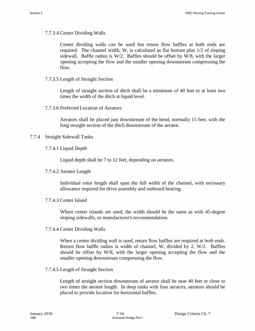
January 2016 7-16 Design Criteria Ch. 7
7.7.3.4 Center Dividing Walls
Center dividing walls can be used but return flow baffles at both ends are
required. The channel width, W, is calculated as flat bottom plus 1/2 of sloping
sidewall. Baffle radius is W/2. Baffles should be offset by W/8, with the larger
opening accepting the flow and the smaller opening downstream compressing the
flow.
7.7.3.5 Length of Straight Section
Length of straight section of ditch shall be a minimum of 40 feet or at least two
times the width of the ditch at liquid level.
7.7.3.6 Preferred Location of Aerators
Aerators shall be placed just downstream of the bend, normally 15 feet, with the
long straight section of the ditch downstream of the aerator.
7.7.4 Straight Sidewall Tanks
7.7.4.1 Liquid Depth
Liquid depth shall be 7 to 12 feet, depending on aerators.
7.7.4.2 Aerator Length
Individual rotor length shall span the full width of the channel, with necessary
allowance required for drive assembly and outboard bearing.
7.7.4.3 Center Island
Where center islands are used, the width should be the same as with 45-degree
sloping sidewalls, or manufacturer's recommendation.
7.7.4.4 Center Dividing Walls
When a center dividing wall is used, return flow baffles are required at both ends.
Return flow baffle radius is width of channel, W, divided by 2, W/2. Baffles
should be offset by W/8, with the larger opening accepting the flow and the
smaller opening downstream compressing the flow.
7.7.4.5 Length of Straight Section
Length of straight section downstream of aerator shall be near 40 feet or close to
two times the aerator length. In deep tanks with four aerators, aerators should be
placed to provide location for horizontal baffles.
Section 5 TDEC Fleming Training Center
Activated Sludge Part I148

January 2016 7-17 Design Criteria Ch. 7
7.7.4.6 Preferred Location of Aerators
Aerators should be placed just downstream of the bend with the long straight
section of the tank downstream of the aerator. Optimal placement of rotors will
consider maintaining ditch center line distance between rotors close to equal.
APPENDIX 7-A
147
Activated Sludge Vocabulary – Part 1
1. ______________________________ describes the taking in or soaking up of a substance into the body of
another by molecular or chemical action.
2. A mass or clump of organic material consisting of living organisms feeding on the wastes in wastewater,
dead organisms, and other debris is called _______________________________.
3. The biological wastewater treatment process that speeds up the decomposition of wastes, involving mixed
liquor that is aerated and agitated before sedimentation, is called the
_______________________________________.
4. The gathering of a gas, liquid, or dissolved substance on the surface or interface zone of another material is
referred to as _____________________________.
5. The _____________________________ is where raw or settled wastewater is mixed with return sludge and
aerated.
6. This type of bacteria can use either dissolved molecular oxygen or oxygen obtained from food materials such
as sulfate or nitrate ions: ____________________________. In other words, these bacteria can live under
aerobic or anaerobic conditions.
7. The suspended solids in the mixed liquor of an aeration tank are called
_____________________________________.
8. ______________________________ bacteria must have molecular (dissolved) oxygen (DO) to survive. These
are also called aerobes. In contrast, ____________________________ bacteria do not need molecular
(dissolved) oxygen to survive. These are also called anaerobes.
9. ____________________________ bacteria grow in a thread‐like or filamentous form and are a common
cause of sludge bulking in the activated sludge process.
10. The organic or volatile suspended solids in the mixed liquor of an aeration tank are called
_____________________________________. This volatile portion is used as a measure or indication of the
microorganisms present.
11. An ____________________________ environment is oxygen deficient or lacking sufficient oxygen.
Generally, it refers to an environment in which chemically bound oxygen, such as nitrate, is present.
12. A bacterial life phase that occurs when living organisms oxidize some of their own cellular mass due to an
inadequate amount of food in their environment is called _____________________________.
13. When the activated sludge in an aeration tank is mixed with primary effluent or the raw wastewater and
return sludge, this mixture is then referred to as ______________________________ as long as it is in the
aeration tank.
Section 5 TDEC Fleming Training Center
Activated Sludge Part I150

14. The jelly‐like masses of bacteria that are found in both the trickling filter and activated sludge process are
called ________________________ masses.
Word Bank:
Absorption
Mixed liquor
Endogenous respiration
Anaerobic
Facultative
Mixed Liquor Volatile Suspended Solids (MLVSS)
Aerobic
Aeration tank
Biomass
Zoogleal
Adsorption
Mixed Liquor Suspended Solids (MLSS)
Filamentous
Activated sludge process
Anoxic
149
Activated Sludge Review Questions – Part 1
1. In the activated sludge process, microorganisms convert organic matter to _______. a. New cells, carbon dioxide and water b. New cells, ammonia and water c. Carbon dioxide, water and nitrate d. Carbon dioxide, water and chlorine
2. The most basic components of the activated sludge process are _______.
a. Thickeners and digesters b. Screens and clarifiers c. Sand filters and chlorine contact chambers d. Biological reactors (aka aeration basins) and clarifiers
3. Solids that settle to the bottom of clarifiers and are pumped back to the head of biological reactors are
referred to as _______. a. RAS b. WAS c. TSS d. Total residual chlorine
4. Which combination of microbes would indicate a good settling sludge?
a. Amoebas and nematodes b. Ciliates and rotifers c. Nematodes and paramecium d. Amoebas and bristle worms
5. The process of reproduction where one mature cell divides into two new cells is known as _______.
a. Cellular deduction b. Binary fission c. Bacterial degradation d. Endogenous respiration
6. Protozoans are _______.
a. Bacteria b. Microscopic plants c. Single‐celled animals d. Worms
7. Potential visual indicators of low DO concentrations include _______.
a. Presence of filamentous bacteria b. Turbid effluent c. Dark gray to black mixed liquor d. All of the above
8. The required ratio of BOD:N:P:Fe in an activated sludge process is 100:10:5:0.5.
a. True b. False
Section 5 TDEC Fleming Training Center
Activated Sludge Part I152
9. Which type of microorganism makes up about 95% of the mixed liquor in an activated sludge system?
a. Protozoans b. Metazoans c. Nematodes d. Bacteria
10. This type of microorganism can encyst itself to move through unfavorable conditions, and is an indication of a young sludge
a. Amoebas b. Water bears c. Rotifers d. Paramecium
11. Because it is photosynthetic, algae is key to the operation of wastewater ponds.
a. True b. False
12. Which of the following conditions are favorable to the growth of filamentous bacteria?
a. Low DO b. Nutrient deficiency c. Septicity d. Grease and oil e. All of the above
13. This type of activated sludge process design has the highest oxygen demand at the influent inlet and will
often utilize tapered aeration in order to supply more oxygen at the beginning of the process. a. Contact stabilization b. Plug Flow (aka “Conventional”) c. Oxidation ditch d. Sequencing Batch Reactor
14. This type of activated sludge process design utilizes 2 tanks in the process train: the contact tank and the
reaeration tank. a. SBR b. Step Feed c. Contact Stabilization d. Pure Oxygen
15. This type of activated sludge process design utilizes a low organic loading, which requires microorganisms to
compete for food, and at times, use their own cell mass for energy (aka “endogenous respiration”). a. Complete mix b. Plug flow c. Extended aeration d. High rate aeration
151

154
Section 6
Sedimentation
153
Sedimentation & Flotation
https://waterpurificationengineering.weebly.com/sedimentation.html
Wastewater Process Overview
Influent
Screen Grit Removal
PrimaryClarifier
Aeration Tank
SecondaryClarifier
Filtration Disinfection
TDEC - Fleming Training Center
Sedimentation & Flotation
• Raw or untreated wastewater containsmaterials (solids) that easily settle to thebottom or float to the surface when thevelocity is slowed
• Collection systems are designed to maintaina certain velocity (2 ft/sec) to keep solidsfrom settling out
• In primary clarifier, velocity slowed to 1 – 2ft/min
TDEC - Fleming Training Center
• Sedimentation = The process of settling anddepositing of suspended matter carried by water orwastewater.• Usually occurs by gravity when the velocity of the liquid is
reduced below the point at which it can transport thesuspended material.
• Flotation = The process of raising suspended matterto the surface of the liquid in a tank where it forms ascum layer that can be removed by skimming.• The suspended matter is raised by aeration, gas,
chemicals, electrolysis, heat, or bacterial decompositionTDEC - Fleming Training Center
Sedimentation & Flotation
Sedimentation
• Settling of solids out of suspension due togravity.• Suspended particles include clay, silt,
particles in natural state or modified bytreatment (biological floc/sloughings)
• Occurs in a rectangular, square or roundbasin.
TDEC - Fleming Training Center
Sedimentation• Other common names:
• Sedimentation and floatation unit
• Settling tank
• Sedimentation tank
• Clarifier• Primary (1°) Clarifier = comes after
preliminary treatment and
• Secondary (2°) Clarifier (can also be calledFinal Clarifier) = follows treatment, usuallyfound after biological process
TDEC - Fleming Training Center
Section 6 TDEC Fleming Training Center
Sedimentation and Flotation156
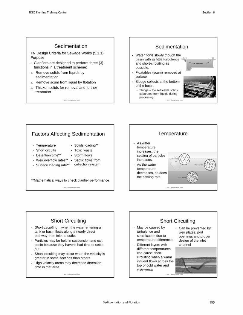
SedimentationTN Design Criteria for Sewage Works (5.1.1) Purpose
• Clarifiers are designed to perform three (3)functions in a treatment scheme:
1. Remove solids from liquids bysedimentation
2. Remove scum from liquid by flotation
3. Thicken solids for removal and furthertreatment
TDEC - Fleming Training Center
Sedimentation
• Water flows slowly though thebasin with as little turbulenceand short-circuiting aspossible.
• Floatables (scum) removed atsurface
• Sludge collects at the bottomof the basin.• Sludge = the settleable solids
separated from liquids duringprocessing.
TDEC - Fleming Training Center
Factors Affecting Sedimentation
• Temperature
• Short circuits
• Detention time**
• Weir overflow rates**
• Surface loading rate**
• Solids loading**
• Toxic waste
• Storm flows
• Septic flows fromcollection system
TDEC - Fleming Training Center
**Mathematical ways to check clarifier performance
Temperature
• As watertemperatureincreases, thesettling of particlesincreases.
• As the watertemperaturedecreases, so doesthe settling rate.
TDEC - Fleming Training Center
Short Circuiting• Short circuiting = when the water entering a
tank or basin flows along a nearly directpathway from inlet to outlet
• Particles may be held in suspension and exitbasin because they haven’t had time to settleout
• Short circuiting may occur when the velocity isgreater in some sections than others
• High velocity areas may decrease detentiontime in that area
TDEC - Fleming Training Center
Short Circuiting• May be caused by
turbulence andstratification due totemperature differences
• Different layers withdifferent temperaturescan cause short-circuiting when a warminfluent flows across thetop of cold water andvise-versa
• Can be prevented byweir plates, portopenings and properdesign of the inletchannel
TDEC - Fleming Training Center
TDEC Fleming Training Center Section 6
Sedimentation and Flotation 155

Short Circuiting
TDEC - Fleming Training Center
Operation of Wastewater Treatment Plants, Vol I, p. 135
Detention Time
• Wastewater should remain in the clarifier long enough to allow sufficient time for solid particles to fall or settle out
• Detention times are usually 2.0 to 3.0 hours
• The efficiency of a clarifier depends on the velocity and the detention time
TDEC - Fleming Training Center
Detention Time
•
TDEC - Fleming Training Center
Weir Overflow Rate
• The number of gallons of wastewater that flow over one lineal foot of weir per day• Lineal = the length in one direction of a line
• The number of lineal feet of weir in relation to flow is important to prevent short circuiting or high velocities (which could pull settled solids into the effluent)
TDEC - Fleming Training Center
Surface Loading Rate
• Also called Surface Overflow Rate
• The number of gallons going through the settling tank each day for each square foot of surface area in the tank
• Also defined as the loading across the surface of your settling tank
• Depends on the nature of the solids and the treatment required
TDEC - Fleming Training Center
Overflow Flow Rate
• Weir Overflow Rate• WOR, gpd/ft = Flow, gpd
Weir Length, ft
• Surface Overflow Rate• SOR, gpd/ft2 = Flow, gpd
Area, ft2
TDEC - Fleming Training Center
Section 6 TDEC Fleming Training Center
Sedimentation and Flotation158
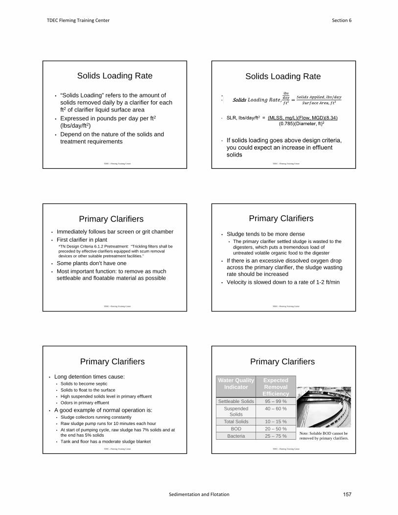
Solids Loading Rate
• “Solids Loading” refers to the amount of solids removed daily by a clarifier for each ft2 of clarifier liquid surface area
• Expressed in pounds per day per ft2
(lbs/day/ft2)
• Depend on the nature of the solids and treatment requirements
TDEC - Fleming Training Center
Solids Loading Rate
•
TDEC - Fleming Training Center
Solids
Primary Clarifiers
• Immediately follows bar screen or grit chamber
• First clarifier in plant *TN Design Criteria 6.1.2 Pretreatment: “Trickling filters shall be preceded by effective clarifiers equipped with scum removal devices or other suitable pretreatment facilities.”
• Some plants don’t have one
• Most important function: to remove as much settleable and floatable material as possible
TDEC - Fleming Training Center
Primary Clarifiers
• Sludge tends to be more dense• The primary clarifier settled sludge is wasted to the
digesters, which puts a tremendous load of untreated volatile organic food to the digester
• If there is an excessive dissolved oxygen drop across the primary clarifier, the sludge wasting rate should be increased
• Velocity is slowed down to a rate of 1-2 ft/min
TDEC - Fleming Training Center
Primary Clarifiers
• Long detention times cause:• Solids to become septic
• Solids to float to the surface
• High suspended solids level in primary effluent
• Odors in primary effluent
• A good example of normal operation is:• Sludge collectors running constantly
• Raw sludge pump runs for 10 minutes each hour
• At start of pumping cycle, raw sludge has 7% solids and at the end has 5% solids
• Tank and floor has a moderate sludge blanket
TDEC - Fleming Training Center
Primary Clarifiers
Water Quality Indicator
Expected Removal
EfficiencySettleable Solids 95 – 99 %
Suspended Solids
40 – 60 %
Total Solids 10 – 15 %
BOD 20 – 50 %
Bacteria 25 – 75 %
TDEC - Fleming Training Center
Note: Soluble BOD cannot be removed by primary clarifiers.
TDEC Fleming Training Center Section 6
Sedimentation and Flotation 157
Primary Clarification
Primary Clarifier
Scum to Solids Handling Process
Influent from screens and/or grit removal
system
Primary sludge to solids handling
process
Effluent to aeration
tank
TDEC - Fleming Training Center
Secondary Clarifiers• Usually located after a biological process
• Activated Sludge, Trickling Filters, Rotating Biological Contactors
• Purpose: to remove the additional solids (and microorganisms) created during the biological treatment
• Cleaner effluent than primary effluent
• Must remove enough solids from bottom before they becomes septic or gasification occurs
TDEC - Fleming Training Center
Trickling Filter Clarifiers
• Settles out “sloughings”• Slime washed off the filter media
• Quite high in BOD and will lower the effluent quality unless it is removed
• Loading rates for secondary clarifiers used after trickling filters:• Detention time – 2.0 to 3.0 hours
• Surface loading – 800 to 1200 gpd/ft2
• Weir overflow – 5,000 to 15,000 gpd/ft
TDEC - Fleming Training Center
Trickling Filter Clarifier
TDEC - Fleming Training Center
https://www.sswm.info/content/trickling-filter
www.igreenion.com
Activated Sludge Clarifiers
• Designed to handle large volumes of sludge
• Loading rates for secondary clarifiers used after activated sludge:• Detention time – 2.0 to 3.0 hours
• Surface loading – 300 to 1200 gpd/ft2
• Weir overflow – 5,000 to 15,000 gpd/ft
• Solids loading – 24 to 30 lbs/day/ft2
TDEC - Fleming Training Center
Activated Sludge Clarifiers• RAS to aeration tank & WAS to solids
handling• The pumps used to remove sludge from
these clarifiers are usually centrifuge type with variable-speed controls or large airlift type.
• RAS rates can range from 15-150% of the plant influent flow
• If return rates are too high, turbulence in the tank can upset the sludge blanket.
TDEC - Fleming Training Center
Section 6 TDEC Fleming Training Center
Sedimentation and Flotation160
Activated Sludge Clarifiers
• During a period of high flow caused by rain fall or periods of hydraulic overloading, operators should decrease WAS• This will retain the microorganisms in the
aeration basins for a quicker recovery if there is a washout.
• Hydraulic flow variations will have the most severe impact upon the activated sludge process.
TDEC - Fleming Training Center
Activated Sludge Clarifiers
• SVI indicates settleability:• SVI>100: light,
fluffy; cone shaped blanket
• SVI<100: more dense; bell shaped blanket
• Desirable: 50-150 mL/g
TDEC - Fleming Training Center Operation of Wastewater Treatment Plants, Vol I, p. 143
Activated Sludge Clarifiers
• Of all the different types of clarifiers, secondary activated sludge clarifiers are the most critical and require the most attention from operators
• The operator should monitor these:• Level of sludge blanket
• Concentration of suspended solids in clarifier
• Control and pacing of RAS flow
• Level of turbidity in clarifier effluent
• DO in clarifier effluent
• pHTDEC - Fleming Training Center
Gasification• Indication of sludge
septicity• Make sure accumulated
settled solids are removed from bottom of clarifier before septicity and gasification take place
• Do not confuse with Denitrification -nitrogen gas bubbles rising to surface
• Secondary Clarifiers TDEC - Fleming Training Center
Rectangular Clarifier
Influent Channel
Sludge Hopper
Sludge Blanket
Flow
Effluent Channel
TDEC - Fleming Training Center
Rectangular Clarifier
Influent
Influent Effluent
Effluent
Flow
Flow
Inlet BaffleFlow Ports
TDEC - Fleming Training Center
TDEC Fleming Training Center Section 6
Sedimentation and Flotation 159
Wooden Baffles
TDEC - Fleming Training Center
Circular Clarifier
TDEC - Fleming Training Center
Circular Clarifier –Side Water Depth
Feedwell Effluent Weir
Influent
Effluent Weir
TDEC - Fleming Training Center
Center-Feed Circular Clarifier
Influent Flow
Effluent WeirFeedwellClarifier Distribution
Structure
TDEC - Fleming Training Center
Peripheral-Feed Circular Clarifier
Grade Grade
BridgeEffluent Weir
Effluent Pipe
Clarifier Distribution
Structure
Influent Pipe
Influent downcomers are located around the entire circumference of clarifier TDEC - Fleming Training Center
Feedwell
TDEC - Fleming Training Center
Section 6 TDEC Fleming Training Center
Sedimentation and Flotation162
Effluent Launder
TDEC - Fleming Training Center
Uneven Split of Flow
• The causes of uneven flow splitting include:• Poor design
• Improper retrofit modifications
TDEC - Fleming Training Center
From aeration
tank
275,000 gpd
400,000 gpd
225,000 gpd
Distribution Box
Influent from aeration tank
Overflow Weir
Stop Gate
To Clarifiers
TDEC - Fleming Training Center
Cross Section of Clarifier Flow
From Aeration
Tank
To Secondary Clarifier
Adjustable Weir
TDEC - Fleming Training Center
Flotation Processes• After 1° clarification, some suspended solids
that neither settle not float always remain
• Colloids and emulsions are two forms of solids that are difficult to remove by sedimentation• Colloids are very small, finely divided solids
that remain dispersed in liquid for a long time
• An emulsion is a liquid mixture of two or more liquid substances not normally dissolved in one another
• Usually grease, oil or fatTDEC - Fleming Training Center
Flotation Processes
• Pumping air into mixture of emulsions and colloids to cause suspended material to float to surface where it can be skimmed off
• Flocculation = gathering together of fine particles after coagulation to form larger particles, clumping makes it easier to separate solids from water
• Particles flocculated with air or coagulants and carried to surface by air bubbles• Coagulant = a chemical that causes very fine particles
to clump (floc) together into larger particlesTDEC - Fleming Training Center
TDEC Fleming Training Center Section 6
Sedimentation and Flotation 161
Dissolved Air Flotation• Vacuum flotation
• Aerated until saturated with dissolved air
• Vacuum chamber then pulls air out and solids travel up with air bubbles
• Pressure flotation• Air is forced into wastewater
• Dissolved air is then released because of change in pressure and solids are carried up with air bubbles
TDEC - Fleming Training Center
Pressure Flotation
TDEC - Fleming Training Center
Dissolved Air Flotation
TDEC - Fleming Training Center
Factors Affecting DAFs
• Type of sludge: heavier primary sludges harder to treat
• Age of feed sludge: older sludges float more readily
• Solids loading: 10-24 lbs/day/ft2
TDEC - Fleming Training Center
Factors Effecting DAFs
• Hydraulic loading: 0.5-1.5 gpm/ft2
• Air to solids ratio: 0.01-0.10 lb/lb
• Recycle rate: 100-200%
• Blanket depth: decreasing scraper speed concentrates sludge
TDEC - Fleming Training Center
Clarifier Solids Removal
• The mechanisms for clarifier solids removal include:• Mechanical transport
• Continuous flight (chain and flight)
• Traveling bridge
• Siphon removal
• Suction removal
TDEC - Fleming Training Center
Section 6 TDEC Fleming Training Center
Sedimentation and Flotation164
Mechanical Solids Removal
TDEC - Fleming Training Center
Chain and Flight
• Rectangular Basins – motor drives chain that pulls flight across basin floor, sweeps sludge to end of basin
TDEC - Fleming Training Center
Traveling Bridge
• Moving bridge scrapes sludge to drain, skims scum Traveling Bridge
Traveling Bridge Effluent StructureInfluent
Structure
RAS
RASTDEC - Fleming Training Center
Floating Bridge Siphon Collector
• Uses suction pipes or submersible pump to withdraw sludge from basin
• Basin does not have to be taken out of service to clean
TDEC - Fleming Training Center
Circular or Square Basins
• Scrapers slant downward to center of basin
• Basin does not have to be taken out of service to clean
TDEC - Fleming Training Center
Solids Removal by Suction
Drive Cage
Bridge
Suction Header
Truss RodSludge
Manifold
Sludge Pipe
Sludge Box
Influent
TDEC - Fleming Training Center
TDEC Fleming Training Center Section 6
Sedimentation and Flotation 163
Scum• Collected scum should be processed with
the waste and primary sludges
TDEC - Fleming Training Center
Scum Skimmer
TDEC - Fleming Training Center
Scum Skimmer
TDEC - Fleming Training Center
Scum Removal for Traveling Bridge
Traveling Bridge
Scum Beach and Trough
Effluent Weir
TDEC - Fleming Training Center
Clarifier Monitoring
• Clarifier monitoring and control systems include sludge blanket monitoring and drive mechanism torque control.
• The continuous data being provided by these systems are very useful for process control.
TDEC - Fleming Training Center
Clarifier Monitoring
• Sludge blanket levels
• Suspended solids concentration in clarifier effluent
• Control of return sludge flows
• Turbidity in clarifier effluent
• DO levels in clarifier effluent
• pH
TDEC - Fleming Training Center
Section 6 TDEC Fleming Training Center
Sedimentation and Flotation166
Monitoring the Process
• Primary clarifier: Imhoff cone• Secondary clarifier:
Settleometer; centrifuge spins• Turbidity test also• Visually checking for floc
carry-over• Visual check of how far floc
particles are visible from inlet
TDEC - Fleming Training Center
Manual Measurement of Sludge Blanket Depth
TDEC - Fleming Training Center
Sonic Measurement of Sludge Blanket Depth
Signal Sender and Receiver
Sludge Blanket
Sound waves are reflected from higher density sludge blanket
TDEC - Fleming Training Center
Flow Management
Flow Management
• Activated sludge system components are sized for a specific design flow.
• Clarifiers can become overloaded
TDEC - Fleming Training Center
Clarifier “Washout”
Normal Clarifier
Clarifier “Washing Out”
TDEC - Fleming Training Center
TDEC Fleming Training Center Section 6
Sedimentation and Flotation 165
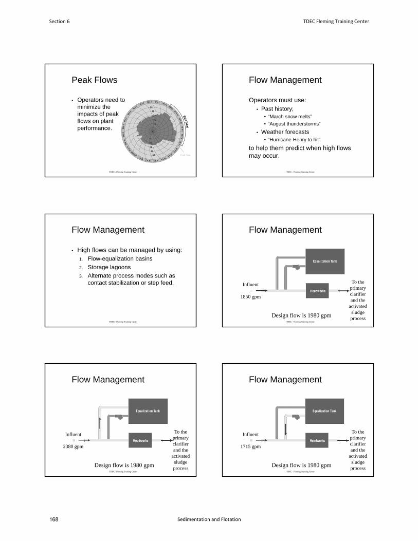
Peak Flows
• Operators need to minimize the impacts of peak flows on plant performance.
TDEC - Fleming Training Center
Flow Management
Operators must use:• Past history;
• “March snow melts”
• “August thunderstorms”
• Weather forecasts• “Hurricane Henry to hit”
to help them predict when high flows may occur.
TDEC - Fleming Training Center
Flow Management
• High flows can be managed by using:1. Flow-equalization basins
2. Storage lagoons
3. Alternate process modes such as contact stabilization or step feed.
TDEC - Fleming Training Center
Flow Management
Influent=
1850 gpm
To the primary clarifier and the
activated sludge processDesign flow is 1980 gpm
TDEC - Fleming Training Center
Flow Management
Influent=
2380 gpm
To the primary clarifier and the
activated sludge processDesign flow is 1980 gpm
TDEC - Fleming Training Center
Flow Management
Influent=
1715 gpm
To the primary clarifier and the
activated sludge processDesign flow is 1980 gpm
TDEC - Fleming Training Center
Section 6 TDEC Fleming Training Center
Sedimentation and Flotation168
Flow Management
• Some plants have storage lagoons for wet weather flows.
• Stored wastewater is pumped to the head of the plant when flow rates decrease.
TDEC - Fleming Training Center
Any Questions?
TDEC - Fleming Training Center
TDEC Fleming Training Center Section 6
Sedimentation and Flotation 167
January 2016 5-1 Design Criteria Ch. 5
CHAPTER 5
Clarifiers
5.1 General Criteria
5.1.1 Purpose
5.1.2 Number of Units
5.1.3 Arrangements
5.1.4 Tank Configurations
5.1.5 Flow Distribution
5.2 Design Loading
5.2.1 Primary Clarifiers
5.2.2 Intermediate Clarifiers
5.2.3 Final Clarifiers
5.2.4 Weir Loading Rates
5.2.5 Depth/Detention Time
5.3 Design Details
5.3.1 Inlets
5.3.2 Submerged Surfaces
5.3.3 Weir Troughs
5.3.4 Freeboard
5.4 Sludge and Scum Removal
5.4.1 Scum Removal
5.4.2 Sludge Removal
5.4.3 Sludge Removal Piping
5.4.4 Sludge Removal Control
5.4.5 Sludge Hopper
5.5 Protective and Service Facilities
5.5.1 Operator Protection
5.5.2 Mechanical Maintenance Access
5.5.3 Electrical Fixtures and Controls
Section 6 TDEC Fleming Training Center
Sedimentation and Flotation170

January 2016 5-2 Design Criteria Ch. 5
5.6 Operability, Flexibility, and Reliability
5.6.1 Scum Removal
5.6.2 Overflow Weirs
5.6.3 Unit Dewatering
5.6.4 Hydraulics
5.6.5 Sludge Removal
5.6.6 Other Design Considerations
TDEC Fleming Training Center Section 6
Sedimentation and Flotation 169
January 2016 5-3 Design Criteria Ch. 5
CLARIFIERS
5.1 General Criteria
5.1.1 Purpose
Clarifiers (sedimentation basins, settling tanks) are designed to perform three (3)
functions in a treatment scheme:
A. Remove solids from liquids by sedimentation
B. Remove scum from liquid by flotation
C. Thicken solids for removal and further treatment
Specific application of clarifier functions will be dependent upon the treatment
process employed. This chapter does not attempt to set criteria for all types of
clarifiers. If a unique clarifier is proposed, the design engineer shall submit
operational and design data justifying its use.
5.1.2 Number of Units
Multiple units capable of independent operation shall be provided in all facilities
where design flows exceed 250,000 gallons per day. Otherwise, the number of
units required shall satisfy reliability requirements (see Section 1.3.11). Facilities
not having multiple units shall include other methods to assure adequate
operability and flexibility of treatment.
5.1.3 Arrangements
Clarifiers shall be arranged for greatest operating and maintenance convenience,
flexibility, economy, continuity of maximum effluent quality, and ease of
installation of future units.
5.1.4 Tank Configurations
Consideration should be given to the probable flow pattern in the selection of tank
size and shape and inlet and outlet type and location.
5.1.5 Flow Distribution
Effective flow measuring devices and control appurtenances (i.e., valves, gates,
splitter boxes, etc.) shall be provided to permit proper proportion of flow to each
unit (see Section 13.2.1).
Section 6 TDEC Fleming Training Center
Sedimentation and Flotation172
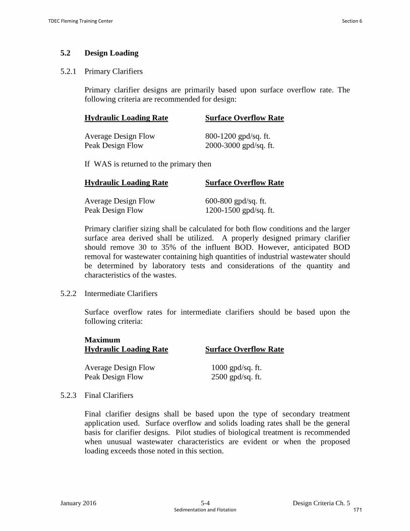
January 2016 5-4 Design Criteria Ch. 5
5.2 Design Loading
5.2.1 Primary Clarifiers
Primary clarifier designs are primarily based upon surface overflow rate. The
following criteria are recommended for design:
Hydraulic Loading Rate Surface Overflow Rate
Average Design Flow 800-1200 gpd/sq. ft.
Peak Design Flow 2000-3000 gpd/sq. ft.
If WAS is returned to the primary then
Hydraulic Loading Rate Surface Overflow Rate
Average Design Flow 600-800 gpd/sq. ft.
Peak Design Flow 1200-1500 gpd/sq. ft.
Primary clarifier sizing shall be calculated for both flow conditions and the larger
surface area derived shall be utilized. A properly designed primary clarifier
should remove 30 to 35% of the influent BOD. However, anticipated BOD
removal for wastewater containing high quantities of industrial wastewater should
be determined by laboratory tests and considerations of the quantity and
characteristics of the wastes.
5.2.2 Intermediate Clarifiers
Surface overflow rates for intermediate clarifiers should be based upon the
following criteria:
Maximum
Hydraulic Loading Rate Surface Overflow Rate
Average Design Flow 1000 gpd/sq. ft.
Peak Design Flow 2500 gpd/sq. ft.
5.2.3 Final Clarifiers
Final clarifier designs shall be based upon the type of secondary treatment
application used. Surface overflow and solids loading rates shall be the general
basis for clarifier designs. Pilot studies of biological treatment is recommended
when unusual wastewater characteristics are evident or when the proposed
loading exceeds those noted in this section.
TDEC Fleming Training Center Section 6
Sedimentation and Flotation 171
January 2016 5-5 Design Criteria Ch. 5
Table 5-1 depicts the criteria established for final clarifier surface overflow and
solids loading rates. In activated sludge systems, the surface overflow rate for
final clarifiers should be based on influent wastewater flows and not include
return activated sludge flows (RAS). Solids loading rate criteria assume sludge
recycle is 100% of the average design flow and the design mixed liquor
suspended solids (MLSS) concentration.
TABLE 5-1
FINAL CLARIFIER DESIGN PARAMETERS
Maximum Surface
Overflow Rate
gpd/sq.ft.
Solids Loading Rate
lbm/day-sq.ft.
Type of
Process
Average
Design Flow
Peak Design
Flow
Average
Design Flow
Peak Design
Flow
Trickling Filter 600 1200 25 40
Activated
Sludge
800
(600 for plants
less than 1
MGD)
1200 30 50
Extended
Aeration
400 1000 25 35
Nitrification 400 800 25 35
Pure Oxygen 700 1200 25 40
5.2.4 Weir Loading Rates
Weir loadings should not exceed 15,000 gallons per day per linear feet (gpd/li ft).
5.2.5 Depth/Detention Time
The sidewater depth (SWD) for clarifier designs associated with design surface
overflow rates should dictate the hydraulic detention time of the clarifier. For
design purposes, the following criteria in Table 5-2 are established specific to
clarifier application:
Section 6 TDEC Fleming Training Center
Sedimentation and Flotation174
January 2016 5-6 Design Criteria Ch. 5
TABLE 5-2
CLARIFIER DEPTH
Type of Process Diameter [ft] Minimum Sidewater Depth [ft]
*Primary - 8
Trickling Filter - 10
**Activated Sludge Less than 40 11
40-70 12
71-100 13
101-140 14
Over 140 15
*The hydraulic detention time in primary clarifiers is not recommended to be greater than
2.5 hours as a function of the surface overflow rate and SWD, since septic conditions
resulting in poor performance and odor conditions can occur.
**For rectangular-shaped clarifiers following activated sludge treatment,
the recommended SWD shall be no less than 12 feet at the shallow end.
TDEC Fleming Training Center Section 6
Sedimentation and Flotation 173
January 2016 5-7 Design Criteria Ch. 5
5.3 Design Details
5.3.1 Inlets
Inlets should be designed to dissipate the influent velocity, to distribute the flow
equally in both the horizontal and vertical vectors, and to prevent short-circuiting.
Channels should be designed to maintain an inlet velocity of at least one (1) foot
per second at one-half the design flow. Corner pockets and dead ends should be
eliminated and corner fillets or channeling used where necessary. Provisions shall
be made for elimination or removal of floating materials in inlet structures having
submerged ports.
5.3.2 Submerged Surfaces
The tops of troughs, beams, and similar submerged construction elements shall
have a minimum slope of 1.75 vertical to 1 horizontal. The underside of such
structures should have a slope of 1 to 1 to prevent accumulation of scum and
solids.
5.3.3 Weir Troughs
Weir troughs shall be designed to prevent submergence at
maximum design flow, and to maintain a velocity of at least one (1) foot per
second at one-half design flow.
5.3.4 Freeboard
Walls of clarifiers shall extend at least six (6) inches above the surrounding
ground surface and shall provide not less than twelve (12) inches of freeboard.
5.4 Sludge and Scum Removal
5.4.1 Scum Removal
Effective scum collection and removal facilities, including baffling ahead of the
outlet weirs, shall be provided for all clarifiers. Provisions may be made for
discharge of scum with sludge; however, other provisions may be necessary to
dispose of floating materials which may adversely affect sludge handling and
disposal. The unusual characteristics of scum which may adversely affect
pumping, piping, sludge handling and disposal, should be recognized in the
design. Scum piping should be glass lined or equivalent. Precautions should be
taken to minimize water content in the scum.
Section 6 TDEC Fleming Training Center
Sedimentation and Flotation176
January 2016 5-8 Design Criteria Ch. 5
5.4.2 Sludge Removal
Sludge collection and withdrawal facilities shall be designed to assure rapid
removal of the sludge. Provisions shall be
made to permit continuous sludge removal from settling tanks. Final clarifiers in
activated sludge plants shall be provided with positive scraping devices. Suction
withdrawal should be provided for activated sludge plants designed for the
reduction of nitrogenous oxygen demand.
5.4.3 Sludge Removal Piping
Each sludge hopper shall have an individually valved sludge withdrawal line at
least six (6) inches in diameter if pumped and at least eight (8) inches in diameter
if gravity flow is used. This does not apply to air lift methods of sludge removal,
as this should be determined by the sludge removal rate. Static head available for
sludge withdrawal shall be at least thirty (30) inches, as necessary, to maintain a
three (3) feet per second velocity in the withdrawal pipe. Clearance between the
end of the withdrawal line and the hopper walls shall be sufficient to prevent
"bridging" of the sludge. Adequate provisions shall be made for rodding or
back-flushing individual pipe runs.
***Air lift type sludge removal will not be approved for removal of primary sludges.
5.4.4 Sludge Removal Control
Sludge wells equipped with telescoping valves or other appropriate equipment
shall be provided for viewing, sampling and controlling the rate of sludge
withdrawal. A means for measuring the sludge removal rate and sludge return
rate shall be provided. Sludge pump motor control systems shall include time
clocks and valve activators for regulating the duration and sequencing of sludge
removal. Gravity flow systems should have back-up pumping capabilities.
5.4.5 Sludge Hopper
The minimum slope of the side walls shall be 1.75 vertical to 1 horizontal.
Hopper wall surfaces should be made smooth with rounded corners to aid in
sludge removal. Hopper bottoms shall have a maximum dimension of two (2)
feet. Extra-depth sludge hoppers for sludge thickening are not acceptable.
5.5 Protective and Service Facilities
5.5.1 Operator Protection
All clarifiers shall be equipped to enhance safety for operators. Such features shall
appropriately include machinery cover lift lines, stairways, walkways, handrails and
slip-resistant surfaces.
TDEC Fleming Training Center Section 6
Sedimentation and Flotation 175
January 2016 5-9 Design Criteria Ch. 5
5.5.2 Mechanical Maintenance Access
The design shall provide for convenient and safe access to routine maintenance items
such as gear boxes, scum removal mechanisms, baffles, weirs, inlet stilling baffle area,
and effluent channels.
5.5.3 Electrical Fixtures and Controls
Electrical fixtures and controls in enclosed settling basins shall meet the requirement of
the National Electrical Code. The fixtures and controls shall be located so as to provide
convenient and safe access for operation and maintenance. Adequate area lighting shall
be provided.
5.6 Operability, Flexibility, and Reliability
5.6.1 Scum Removal
5.6.1.1 A method of conveying scum across the water surface to a point of
removal should be considered, such as water or air spray. Baffles should be
designed to ensure capture of scum at minimum and maximum flow rates.
5.6.1.2 Facilities designed for flows of 0.1 MGD and greater should have
mechanical scum removal equipment.
5.6.1.3.Scum holding tanks may be provided, with a method of removing excess
water.
5.6.1.4 Large scum sumps should have a mixing device (pneumatic, hydraulic, or
mechanical) to keep the scum mixed while being pumped.
5.6.1.5 Manual scum pump start-stop switches should be located adjacent to scum
holding tanks.
5.6.2 Overflow Weirs
5.6.2.1 Since closely spaced multiple overflow weirs tend to increase hydraulic
velocities, their spacing should be conservative.
5.6.2.2 Center-feed, peripheral draw-off clarifiers shall not have the overflow weir
against the clarifier sidewall. Weir placement shall be 1/10 diameter or greater
toward the center.
5.6.2.3 The up-flow rate shall not be greater than the surface overflow rate at any
location within the solids separation zone of a clarifier.
Section 6 TDEC Fleming Training Center
Sedimentation and Flotation178
January 2016 5-10 Design Criteria Ch. 5
5.6.2.4 Overflow weirs should be of the notched type; straight edged weirs will
not be approved.
5.6.2.5 Overflow weirs shall be adjustable for leveling.
5.6.3 Unit Dewatering
5.6.3.1 The capacity of dewatering pumps should be such that the basin can be
dewatered in 24 hours; eight hours is preferable.
5.6.3.2 The contents of the basin should be discharged to the closest process
upstream from the unit being dewatered that can accept the flow.
5.6.3.3 Consideration shall be given to the need for hydrostatic pressure relief
devices to prevent flotation of structures.
5.6.4 Hydraulics
5.6.4.1 Lift/pump stations located immediately upstream of secondary clarifiers
shall have flow-paced controls to reduce shock loadings.
5.6.4.2 Square clarifiers with circular sludge withdrawal mechanisms shall be
designed such that corner hydraulic velocities do not cause sludge carry-over.
5.6.5 Sludge Removal
5.6.5.1 When two or more clarifiers are used, provisions shall be made to control
and measure the rate of sludge withdrawal from each clarifier.
5.6.5.2 Consideration should be given to removing activated sludge from the
effluent end of rectangular clarifiers.
5.6.5.3 Consideration shall be given to chlorination of return activated sludge and
digester supernate. Sufficient mixing and contact time should be provided.
5.6.6 Other Design Considerations
5.6.6.1 Designs should consider the possible need for future modifications to add
chemicals such as flocculants.
5.6.6.2 A method of foam control should be considered for all inlet channels and
feed wells in activated sludge systems.
TDEC Fleming Training Center Section 6
Sedimentation and Flotation 177
Sedimentation and Flotation Vocabulary
1. The particles that settle to the floor of a clarifier are called _________________________.
2. ___________________________ is the term used to describe the clouds of billowing sludge that
occur throughout secondary clarifiers when the sludge does not settle properly.
3. Sludge in primary clarifiers must be removed at regular intervals to prevent the sludge from
turning _________________.
4. _____________________________ is the gathering together of fine particles after coagulation
to form larger particles by a process of gentle mixing. This clumping together makes it easier to
separate the solids from the wastewater by settling, skimming, draining, or filtering.
5. Large clumps of sludge floating to the surface of the water in a primary clarifier would indicate
____________________________________ is occurring due to anaerobic decomposition.
6. A chemical that causes very fine particles to clump or floc together into larger particles is a
________________________. This makes it easier to separate the solids from the liquids by
settling, skimming, draining, or filtering. They can be used as part of the flotation process.
7. The clarifier that follows other types of treatment, usually a biological reactor, is the
________________________________. Its main function is to remove the additional solids that
were converted to settleable form in the treatment processes that followed the primary
clarifier.
8. ____________________________ is a condition that occurs in tanks or basins when the velocity
of water flow is greater in some sections than in others. This is an undesirable situation since it
may result in shorter contact time, detention times, reaction times, or settling rates.
9. Simply put, ________________________________ is defined as the hydraulic loading across the
surface of your settling tank.
10. __________________________are very small, finely divided solids that do not dissolve and
remain dispersed in a liquid for a long time due to their small size and electrical charge. DAF
systems are designed to remove these particulates from wastewater.
11. _________________________________refers to the amount of solids removed daily by a
clarifier for each square foot (ft2) of clarifier liquid surface area.
12. Wastewater must remain in a clarifier long enough to allow sufficient time for particles to settle
out. On average, the __________________________ is 2‐3 hours for a settling tank.
13. Scraper boards made from rot‐resistant wood or plastic that are used to collect and move
settled sludge or floating scum are called _____________________________.
Section 6 TDEC Fleming Training Center
Sedimentation and Flotation180
14. The anoxic process of nitrite or nitrate ions being reduced to nitrogen gas and producing
nitrogen bubbles is called _______________________________. This condition can lead to
rising sludge in secondary clarifiers, due to nitrogen bubbles attaching to the biological floc and
floating the floc to the surface.
15. A ______________________is a wall or obstruction used to control flow from settling tanks and
clarifiers to ensure a uniform flow rate and avoid short‐circuiting.
16. Defined as the number of gallons of wastewater that flow over one lineal foot of weir per day,
the ____________________________________ is generally lower in secondary clarifiers than in
primary clarifiers.
17. The first clarifier in the plant that comes immediately after preliminary treatment (bar screen,
comminutor, or grit channel) is the ___________________________________. Its main function
is to remove settleable and floatable solids.
18. Sedimentation tank effluent troughs consisting of overflow weir plates are called
________________________.
19. The _____________________________ is a calculation that indicates the tendency of activated
sludge solids to thicken or become concentrated during the sedimentation/thickening process.
20. The _____________________________ process involves pumping air into wastewater to cause
the suspended solids to adhere to bubbles and float to the surface, where they can be skimmed
off.
21. The slime that is washed off the filter media in a trickling filter, which is generally quite high in
BOD, is called ___________________________.
Word Bank:
Short circuiting
Bulking
Launders
Coagulant
Flotation
Flocculation
Denitrification
Sludge Volume Index (SVI)
Colloids
Secondary clarifier
Sludge
Weir
Sloughings
Surface loading rate
Flights
Primary clarifier
Septic
Weir overflow rate
Solids loading rate
Sludge gasification
Detention time
TDEC Fleming Training Center Section 6
Sedimentation and Flotation 179

Sedimentation and Flotation Review Questions
1. What is the function of a primary clarifier? What is the function of a secondary clarifier?
2. What is the main difference between sludge from a primary clarifier and a secondary clarifier?
Explain why this difference exists.
3. What is the main difference between effluent from a primary clarifier and a secondary clarifier?
4. What would happen to the flights in a rectangular clarifier if they become misaligned and are
not straight across the tank?
5. List 3 types of abnormal conditions that could affect the clarifier.
6. In order to determine clarifier efficiency, at what two points should you collect samples? Ideally,
what type of samples should you collect?
Section 6 TDEC Fleming Training Center
Sedimentation and Flotation182
7. Calculate the suspended solids removal efficiency of a primary clarifier if the influent
concentration is 400 mg/L and the effluent concentration is 180 mg/L.
8. During your daily walk through, you noticed that your collector mechanism was jerking and
jumping right before it stalled. List some possible causes for these problems.
9. List the factors the will affect clarifier efficiency.
10. What are possible causes of short circuiting?
11. Why is short circuiting a problem? And what can be done to prevent it?
TDEC Fleming Training Center Section 6
Sedimentation and Flotation 181
12. A rectangular clarifier is 50 feet long and 30 feet wide with an average depth of 10 feet. The flow
to the clarifier is 3 MGD. There are 285 feet of weir and the MLSS concentration is 4800 mg/L.
From this information, calculate the following:
13. Why are secondary clarifiers needed?
14. What is usually done with the sludge that collects (or settles out) in secondary clarifiers?
15. What steps would you take if you suspect that your sedimentation basin is short‐circuiting?
16. TN Design Criteria for Sewage Works requires that a Trickling Filter be preceded by a primary
clarifier. The effluent that comes off the Trickling Filter (or from the secondary clarifier, if one is
present) is recirculated back to the primary clarifier. Why is this done?
Section 6 TDEC Fleming Training Center
Sedimentation and Flotation184

Section 7
Ponds and
Lagoons
183
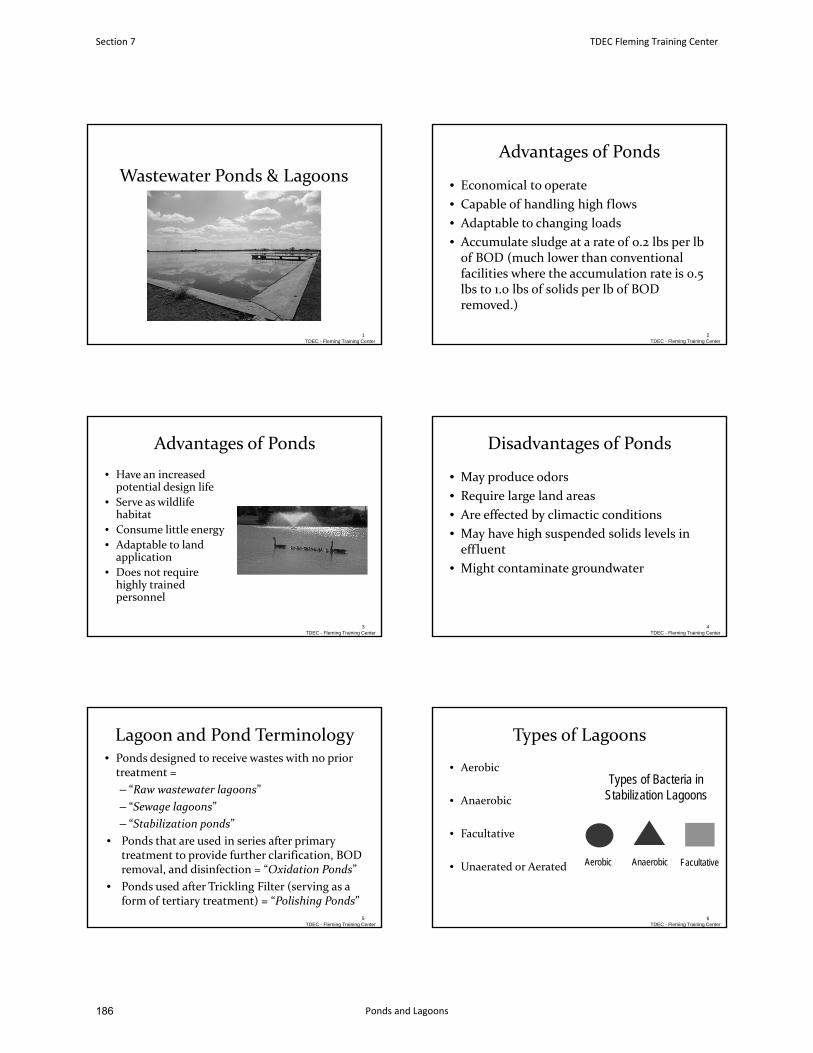
Wastewater Ponds & Lagoons
1TDEC - Fleming Training Center
Advantages of Ponds
• Economical to operate
• Capable of handling high flows
• Adaptable to changing loads
• Accumulate sludge at a rate of 0.2 lbs per lbof BOD (much lower than conventionalfacilities where the accumulation rate is 0.5lbs to 1.0 lbs of solids per lb of BODremoved.)
2TDEC - Fleming Training Center
Advantages of Ponds
• Have an increasedpotential design life
• Serve as wildlife habitat
• Consume little energy
• Adaptable to landapplication
• Does not require highly trainedpersonnel
3TDEC - Fleming Training Center
Disadvantages of Ponds
• May produce odors
• Require large land areas
• Are effected by climactic conditions
• May have high suspended solids levels ineffluent
• Might contaminate groundwater
4TDEC - Fleming Training Center
Lagoon and Pond Terminology• Ponds designed to receive wastes with no prior treatment =
– “Raw wastewater lagoons”
– “Sewage lagoons”
– “Stabilization ponds”
• Ponds that are used in series after primarytreatment to provide further clarification, BODremoval, and disinfection = “Oxidation Ponds”
• Ponds used after Trickling Filter (serving as aform of tertiary treatment) = “Polishing Ponds”
TDEC - Fleming Training Center5
Types of Lagoons
• Aerobic
• Anaerobic
• Facultative
• Unaerated or Aerated
Types of Bacteria in Stabilization Lagoons
Aerobic Anaerobic Facultative
6TDEC - Fleming Training Center
Section 7 TDEC Fleming Training Center
Ponds and Lagoons186
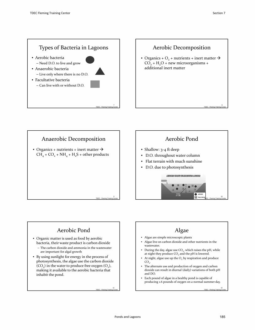
Types of Bacteria in Lagoons
• Aerobic bacteria
– Need D.O. to live and grow
• Anaerobic bacteria
– Live only where there is no D.O.
• Facultative bacteria
– Can live with or without D.O.
7TDEC - Fleming Training Center
Aerobic Decomposition
• Organics + O2 + nutrients + inert matter CO2 + H2O + new microorganisms +additional inert matter
8TDEC - Fleming Training Center
Anaerobic Decomposition
• Organics + nutrients + inert matter CH4 + CO2 + NH4 + H2S + other products
9TDEC - Fleming Training Center
Aerobic Pond
• Shallow: 3‐4 ft deep
• D.O. throughout water column
• Flat terrain with much sunshine
• D.O. due to photosynthesis
10TDEC - Fleming Training Center
Aerobic Pond
• Organic matter is used as food by aerobicbacteria, their waste product is carbon dioxide
– The carbon dioxide and ammonia in the wastewater are important for algal growth
• By using sunlight for energy in the process ofphotosynthesis, the algae use the carbon dioxide (CO2) in the water to produce free oxygen (O2),making it available to the aerobic bacteria thatinhabit the pond.
TDEC - Fleming Training Center11
Algae• Algae are simple microscopic plants
• Algae live on carbon dioxide and other nutrients in the wastewater.
• During the day, algae use CO2, which raises the pH, while at night they produce CO2 and the pH is lowered.
• At night, algae use up the O2 by respiration and produce CO2.
• The alternate use and production of oxygen and carbon dioxide can result in diurnal (daily) variations of both pH and DO.
• Each pound of algae in a healthy pond is capable ofproducing 1.6 pounds of oxygen on a normal summer day.
TDEC - Fleming Training Center12
TDEC Fleming Training Center Section 7
Ponds and Lagoons 185
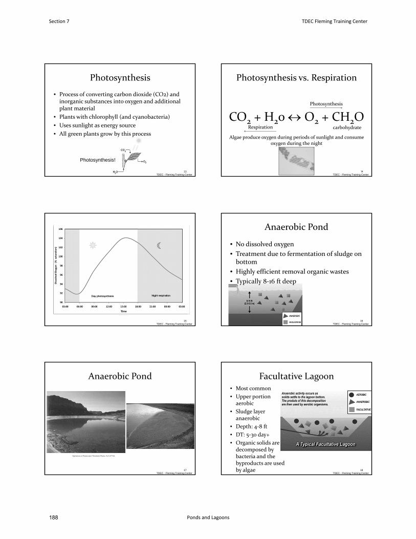
Photosynthesis
• Process of converting carbon dioxide (CO2) and inorganic substances into oxygen and additional plant material
• Plants with chlorophyll (and cyanobacteria)
• Uses sunlight as energy source
• All green plants grow by this process
TDEC - Fleming Training Center13
Photosynthesis!
Photosynthesis vs. Respiration
CO2 + H20 O2 + CH2O carbohydrate
Photosynthesis
Respiration
Algae produce oxygen during periods of sunlight and consume oxygen during the night
TDEC - Fleming Training Center14
TDEC - Fleming Training Center15
Anaerobic Pond
• No dissolved oxygen
• Treatment due to fermentation of sludge on bottom
• Highly efficient removal organic wastes
• Typically 8‐16 ft deep
16TDEC - Fleming Training Center
Anaerobic Pond
TDEC - Fleming Training Center17
Operations of Wastewater Treatment Plants, Vol I, 8th Ed.
Facultative Lagoon• Most common
• Upper portion aerobic
• Sludge layer anaerobic
• Depth: 4‐8 ft
• DT: 5‐30 day+
• Organic solids are decomposed by bacteria and the byproducts are used by algae
TDEC - Fleming Training Center18
Section 7 TDEC Fleming Training Center
Ponds and Lagoons188
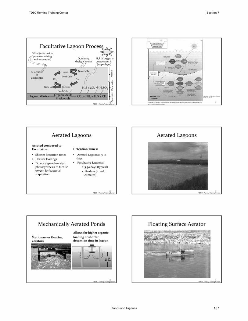
Organic Wastes Organic Acids & Alcohols
CO2 + NH3 + H2S + CH4
O2
Bacteria
CO2
Algae
Facultative Lagoon Process
19 Anaerobic
Facultative
Aerobic
Wind (wind action promotes mixing and re‐aeration)
O2
New Cells
New Cells
O2 (during daylight hours)
Re‐aeration of
wastewaterDead Cells
Dead Cells
H2S + 2O2 H2SO4
H2S (If oxygen is not present in upper layer)
TDEC - Fleming Training Center20
Operations of Wastewater Treatment Plants, Vol I, 8th Ed.
Aerated Lagoons
Aerated compared to Facultative:
• Shorter detention times
• Heavier loadings
• Do not depend on algal photosynthesis to furnish oxygen for bacterial respiration
Detention Times:
• Aerated Lagoons: 3‐10 days
• Facultative Lagoons:
• 5‐30 days (typical)
• 180 days (in cold climates)
21TDEC - Fleming Training Center
Aerated Lagoons
22TDEC - Fleming Training Center
Mechanically Aerated Ponds
Stationary or floating aerators
Allows for higher organic
loading or shorter detention time in lagoon
23TDEC - Fleming Training Center
Floating Surface Aerator
TDEC - Fleming Training Center24
TDEC Fleming Training Center Section 7
Ponds and Lagoons 187
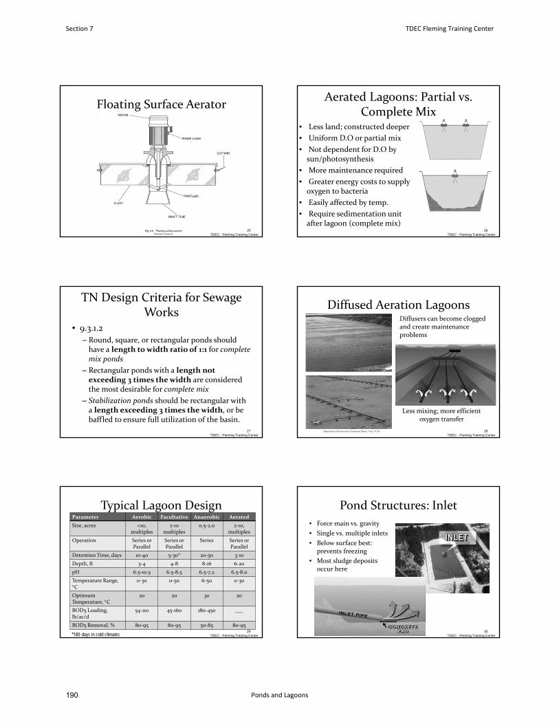
Floating Surface Aerator
TDEC - Fleming Training Center25
Aerated Lagoons: Partial vs. Complete Mix
• Less land; constructed deeper
• Uniform D.O or partial mix
• Not dependent for D.O by sun/photosynthesis
• More maintenance required
• Greater energy costs to supply oxygen to bacteria
• Easily affected by temp.
• Require sedimentation unit after lagoon (complete mix)
26TDEC - Fleming Training Center
TN Design Criteria for Sewage Works
• 9.3.1.2
– Round, square, or rectangular ponds should have a length to width ratio of 1:1 for complete mix ponds
– Rectangular ponds with a length not exceeding 3 times the width are considered the most desirable for complete mix
– Stabilization ponds should be rectangular with a length exceeding 3 times the width, or be baffled to ensure full utilization of the basin.
TDEC - Fleming Training Center27
Diffused Aeration Lagoons
Less mixing; more efficientoxygen transfer
28TDEC - Fleming Training Center
Diffusers can become clogged and create maintenance problems
Operations of Wastewater Treatment Plants, Vol I, 8th Ed
Typical Lagoon DesignParameter Aerobic Facultative Anaerobic Aerated
Size, acres <10, multiples
2‐10 multiples
0.5‐2.0 2‐10, multiples
Operation Series or Parallel
Series or Parallel
Series Series or Parallel
Detention Time, days 10‐40 5‐30* 20‐50 3‐10
Depth, ft 3‐4 4‐8 8‐16 6‐20
pH 6.5‐10.5 6.5‐8.5 6.5‐7.2 6.5‐8.0
Temperature Range, C
0‐30 0‐50 6‐50 0‐30
Optimum Temperature, C
20 20 30 20
BOD5 Loading, lb/ac/d
54‐110 45‐160 180‐450 ___
BOD5 Removal, % 80‐95 80‐95 50‐85 80‐9529
*180 days in cold climates TDEC - Fleming Training Center
Pond Structures: Inlet
• Force main vs. gravity
• Single vs. multiple inlets
• Below surface best: prevents freezing
• Most sludge deposits occur here
30TDEC - Fleming Training Center
Section 7 TDEC Fleming Training Center
Ponds and Lagoons190
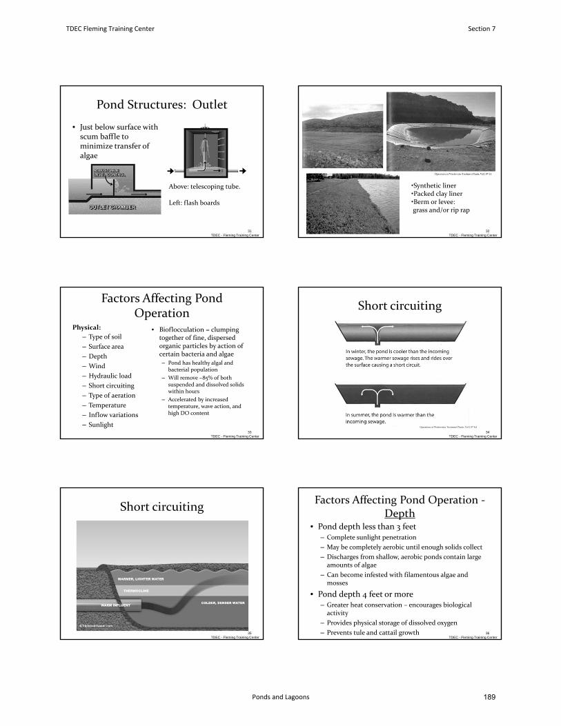
Above: telescoping tube.
Left: flash boards
Pond Structures: Outlet
• Just below surface with scum baffle to minimize transfer of algae
31TDEC - Fleming Training Center
•Synthetic liner•Packed clay liner•Berm or levee:grass and/or rip rap
32TDEC - Fleming Training Center
Factors Affecting Pond Operation
Physical:
– Type of soil
– Surface area
– Depth
– Wind
– Hydraulic load
– Short circuiting
– Type of aeration
– Temperature
– Inflow variations
– Sunlight
• Bioflocculation = clumping together of fine, dispersed organic particles by action of certain bacteria and algae
– Pond has healthy algal and bacterial population
– Will remove ~85% of both suspended and dissolved solids within hours
– Accelerated by increased temperature, wave action, and high DO content
TDEC - Fleming Training Center33
Short circuiting
TDEC - Fleming Training Center34
Operations of Wastewater Treatment Plants, Vol I, 8th Ed
Short circuiting
TDEC - Fleming Training Center35
Factors Affecting Pond Operation ‐Depth
• Pond depth less than 3 feet – Complete sunlight penetration
– May be completely aerobic until enough solids collect
– Discharges from shallow, aerobic ponds contain large amounts of algae
– Can become infested with filamentous algae and mosses
• Pond depth 4 feet or more– Greater heat conservation – encourages biological activity
– Provides physical storage of dissolved oxygen
– Prevents tule and cattail growthTDEC - Fleming Training Center
36
TDEC Fleming Training Center Section 7
Ponds and Lagoons 189
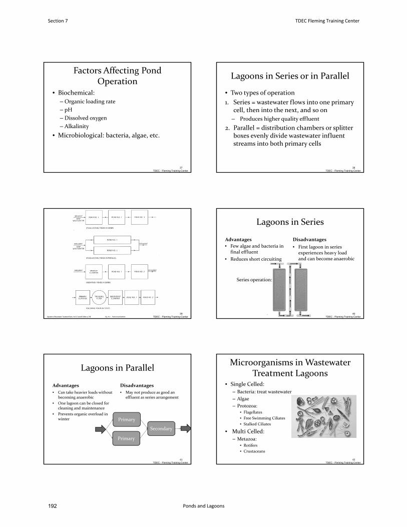
Factors Affecting Pond Operation
• Biochemical:
– Organic loading rate
– pH
– Dissolved oxygen
– Alkalinity
• Microbiological: bacteria, algae, etc.
37TDEC - Fleming Training Center
Lagoons in Series or in Parallel
• Two types of operation
1. Series = wastewater flows into one primary cell, then into the next, and so on
– Produces higher quality effluent
2. Parallel = distribution chambers or splitter boxes evenly divide wastewater influent streams into both primary cells
TDEC - Fleming Training Center38
TDEC - Fleming Training Center39
Operation of Wastewater Treatment Plants, Vol II, Seventh Edition p. 298
Lagoons in Series
Advantages
• Few algae and bacteria in final effluent
• Reduces short circuiting
Disadvantages
• First lagoon in series experiences heavy load and can become anaerobic
40
Series operation:
TDEC - Fleming Training Center
Lagoons in Parallel
Advantages
• Can take heavier loads without becoming anaerobic
• One lagoon can be closed for cleaning and maintenance
• Prevents organic overload in winter
Disadvantages
• May not produce as good an effluent as series arrangement
41
Primary
Primary
Secondary
TDEC - Fleming Training Center
Microorganisms in Wastewater Treatment Lagoons
• Single Celled:
– Bacteria: treat wastewater
– Algae
– Protozoa:• Flagellates
• Free Swimming Ciliates
• Stalked Ciliates
• Multi Celled:
– Metazoa:• Rotifers
• Crustaceans
42TDEC - Fleming Training Center
Section 7 TDEC Fleming Training Center
Ponds and Lagoons192
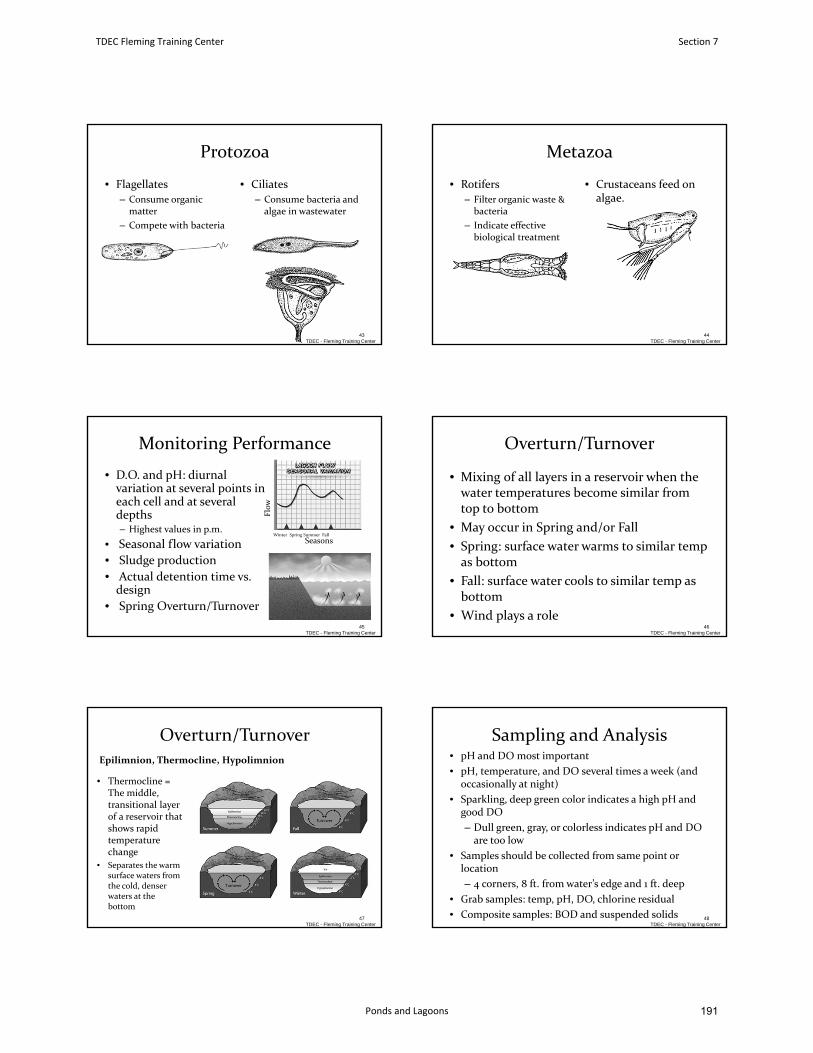
Protozoa
• Flagellates
– Consume organic matter
– Compete with bacteria
• Ciliates
– Consume bacteria and algae in wastewater
43TDEC - Fleming Training Center
Metazoa
• Rotifers
– Filter organic waste & bacteria
– Indicate effective biological treatment
• Crustaceans feed on algae.
44TDEC - Fleming Training Center
Monitoring Performance
• D.O. and pH: diurnal variation at several points in each cell and at several depths – Highest values in p.m.
• Seasonal flow variation
• Sludge production
• Actual detention time vs. design
• Spring Overturn/Turnover
45
Flow
SeasonsWinter Spring Summer Fall
TDEC - Fleming Training Center
Overturn/Turnover
• Mixing of all layers in a reservoir when the water temperatures become similar from top to bottom
• May occur in Spring and/or Fall
• Spring: surface water warms to similar temp as bottom
• Fall: surface water cools to similar temp as bottom
• Wind plays a roleTDEC - Fleming Training Center
46
Overturn/Turnover
• Thermocline = The middle, transitional layer of a reservoir that shows rapid temperature change
• Separates the warm surface waters from the cold, denser waters at the bottom
Epilimnion, Thermocline, Hypolimnion
TDEC - Fleming Training Center47
Sampling and Analysis• pH and DO most important
• pH, temperature, and DO several times a week (and occasionally at night)
• Sparkling, deep green color indicates a high pH and good DO
– Dull green, gray, or colorless indicates pH and DO are too low
• Samples should be collected from same point or location
– 4 corners, 8 ft. from water’s edge and 1 ft. deep
• Grab samples: temp, pH, DO, chlorine residual
• Composite samples: BOD and suspended solidsTDEC - Fleming Training Center
48
TDEC Fleming Training Center Section 7
Ponds and Lagoons 191
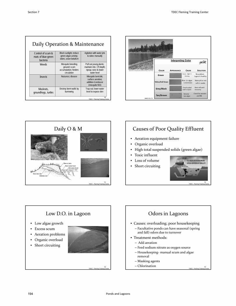
Daily Operation & Maintenance
Control of scum & mats of blue-green
bacteria
Block sunlight; reduce green algae activity;
odors; avian botulism
Agitation with water jets & rakes manually
Weeds Mosquito breeding ground; scum
accumulation; hinders circulation
Pull out young plants; maintain min. 3 ft depth;
riprap; raise & lower water level
Insects Nuisance; disease Mosquito larvicide; surface aeration;
addition Gambusia(mosquito fish)
Muskrats, groundhogs, turtles
Destroy berm walls by burrowing
Trap out; lower water level to expose den
49TDEC - Fleming Training Center
50www.rcap.org
Daily O & M
51TDEC - Fleming Training Center
Causes of Poor Quality Effluent
• Aeration equipment failure
• Organic overload
• High total suspended solids (green algae)
• Toxic influent
• Loss of volume
• Short circuiting
52TDEC - Fleming Training Center
Low D.O. in Lagoon
• Low algae growth
• Excess scum
• Aeration problems
• Organic overload
• Short circuiting
53TDEC - Fleming Training Center
Odors in Lagoons
• Causes: overloading; poor housekeeping
– Facultative ponds can have seasonal (spring and fall) odors due to turnover
• Treatment methods:
– Add aeration
– Feed sodium nitrate as oxygen source
– Housekeeping‐manual scum and algae removal
– Masking agents
– Chlorination 54TDEC - Fleming Training Center
Section 7 TDEC Fleming Training Center
Ponds and Lagoons194
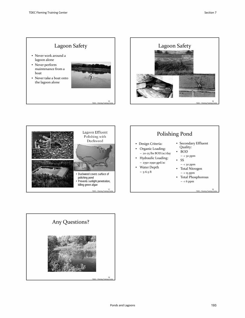
Lagoon Safety
• Never work around a lagoon alone
• Never perform maintenance from a boat
• Never take a boat onto the lagoon alone
55TDEC - Fleming Training Center
Lagoon Safety
56TDEC - Fleming Training Center
Lagoon EffluentPolishing withDuckweed
57
• Duckweed covers surface ofpolishing pond
• Prevents sunlight penetration, killing green algae
TDEC - Fleming Training Center
Polishing Pond
• Design Criteria:
• Organic Loading:
– 20‐25 lbs BOD/ac/day
• Hydraulic Loading:
– 2350‐2990 gpd/ac
• Water Depth
– 5‐6.5 ft
• Secondary Effluent Quality:
• BOD– < 30 ppm
• SS– < 30 ppm
• Total Nitrogen– < 15 ppm
• Total Phosphorous– < 6 ppm
58TDEC - Fleming Training Center
Any Questions?
TDEC - Fleming Training Center59
TDEC Fleming Training Center Section 7
Ponds and Lagoons 193
January 2016 9-1 Design Criteria Ch. 9
CHAPTER 9
Ponds and Aerated Lagoons 9.1 General 9.1.1 Applicability 9.1.2 Supplement to Engineering Report 9.1.3 Effluent Requirements 9.2 Design Loadings 9.2.1 Stabilization Ponds 9.2.2 Aerated Lagoons 9.3 Special Details 9.3.1 General 9.3.2 Stabilization Ponds 9.3.3 Aerated Lagoons 9.4 Pond Construction Details 9.4.1 Liners 9.4.2 Pond Construction 9.4.3 Prefilling 9.4.4 Utilities and Structures Within Dike Sections 9.5 Hydrograph Controlled Release (HCR) Lagoons 9.6 Polishing Lagoons 9.7 Operability 9.8 Upgrading Existing Systems
Section 7 TDEC Fleming Training Center
Ponds and Lagoons196
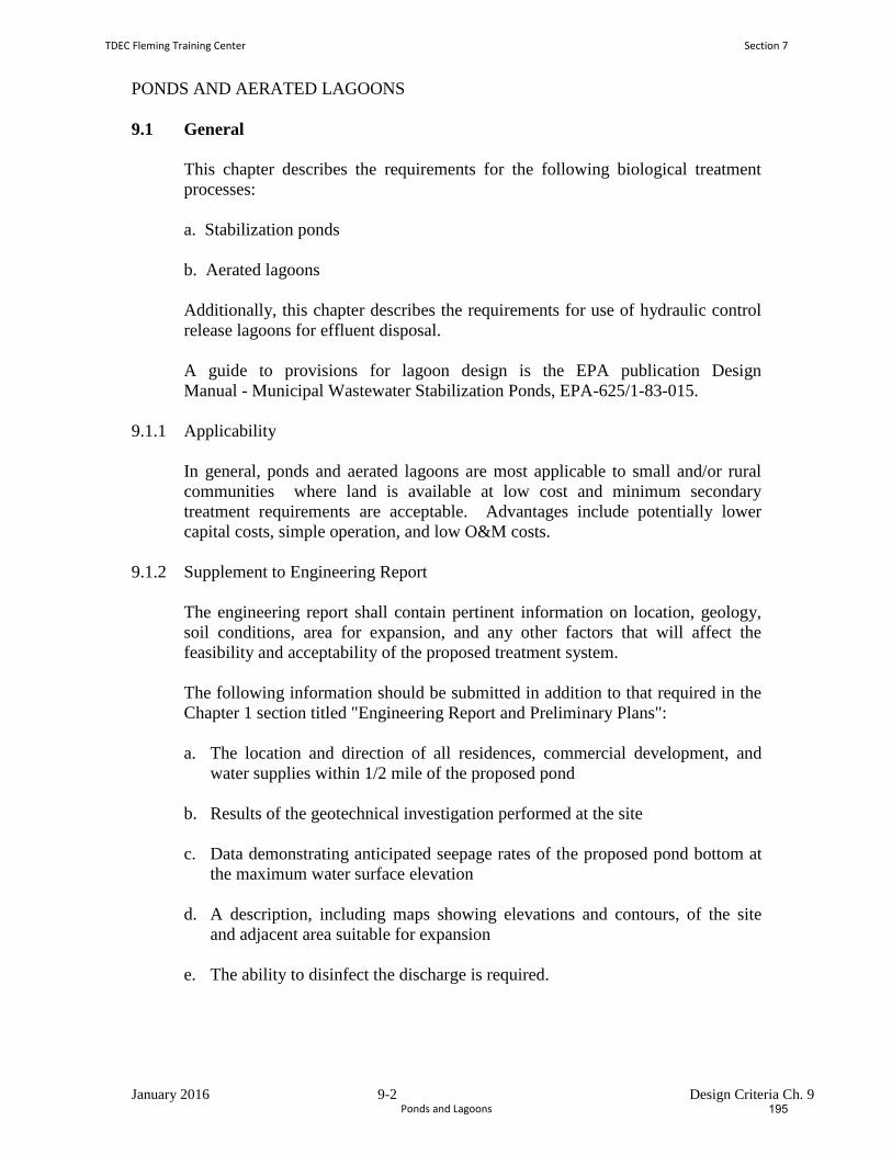
January 2016 9-2 Design Criteria Ch. 9
PONDS AND AERATED LAGOONS
9.1 General
This chapter describes the requirements for the following biological treatment
processes:
a. Stabilization ponds
b. Aerated lagoons
Additionally, this chapter describes the requirements for use of hydraulic control
release lagoons for effluent disposal.
A guide to provisions for lagoon design is the EPA publication Design
Manual - Municipal Wastewater Stabilization Ponds, EPA-625/1-83-015.
9.1.1 Applicability
In general, ponds and aerated lagoons are most applicable to small and/or rural
communities where land is available at low cost and minimum secondary
treatment requirements are acceptable. Advantages include potentially lower
capital costs, simple operation, and low O&M costs.
9.1.2 Supplement to Engineering Report
The engineering report shall contain pertinent information on location, geology,
soil conditions, area for expansion, and any other factors that will affect the
feasibility and acceptability of the proposed treatment system.
The following information should be submitted in addition to that required in the
Chapter 1 section titled "Engineering Report and Preliminary Plans":
a. The location and direction of all residences, commercial development, and
water supplies within 1/2 mile of the proposed pond
b. Results of the geotechnical investigation performed at the site
c. Data demonstrating anticipated seepage rates of the proposed pond bottom at
the maximum water surface elevation
d. A description, including maps showing elevations and contours, of the site
and adjacent area suitable for expansion
e. The ability to disinfect the discharge is required.
TDEC Fleming Training Center Section 7
Ponds and Lagoons 195
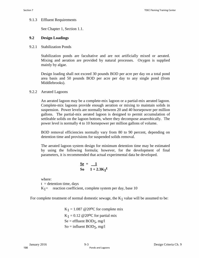
January 2016 9-3 Design Criteria Ch. 9
9.1.3 Effluent Requirements
See Chapter 1, Section 1.1.
9.2 Design Loadings
9.2.1 Stabilization Ponds
Stabilization ponds are facultative and are not artificially mixed or aerated.
Mixing and aeration are provided by natural processes. Oxygen is supplied
mainly by algae.
Design loading shall not exceed 30 pounds BOD per acre per day on a total pond
area basis and 50 pounds BOD per acre per day to any single pond (from
Middlebrooks).
9.2.2 Aerated Lagoons
An aerated lagoon may be a complete-mix lagoon or a partial-mix aerated lagoon.
Complete-mix lagoons provide enough aeration or mixing to maintain solids in
suspension. Power levels are normally between 20 and 40 horsepower per million
gallons. The partial-mix aerated lagoon is designed to permit accumulation of
settleable solids on the lagoon bottom, where they decompose anaerobically. The
power level is normally 4 to 10 horsepower per million gallons of volume.
BOD removal efficiencies normally vary from 80 to 90 percent, depending on
detention time and provisions for suspended solids removal.
The aerated lagoon system design for minimum detention time may be estimated
by using the following formula; however, for the development of final
parameters, it is recommended that actual experimental data be developed.
Se = 1
So 1 + 2.3K1t
where:
t = detention time, days
K1= reaction coefficient, complete system per day, base 10
For complete treatment of normal domestic sewage, the K1 value will be assumed to be:
K1 = 1.087 @20oC for complete mix
K1 = 0.12 @20oC for partial mix
Se = effluent BOD5, mg/l
So = influent BOD5, mg/l
Section 7 TDEC Fleming Training Center
Ponds and Lagoons198
January 2016 9-4 Design Criteria Ch. 9
The reaction rate coefficient for domestic sewage that includes significant
quantities of industrial wastes, other wastes, and partially treated sewage should
be determined experimentally for various conditions that might be encountered in
the aerated ponds. Conversion of the reaction rate coefficient to temperatures
other than 20 degrees C should be according to the following formula:
K1 = K20 1.036(T-20) (T = temperature in degrees C)
The minimum equilibrium temperature of the lagoon should be used for design of
the aerated lagoon. The minimum equilibrium temperature should be estimated
by using heat balance equations, which should include factors for influent
wastewater temperature, ambient air temperature, lagoon surface area, and heat
transfer effects of aeration, wind, and humidity. The minimum 30-day average
ambient air temperature obtained from climatological data should be used for
design.
Additional storage volume shall be considered for sludge storage and partial mix
in aerated lagoons.
Sludge processing and disposal should be considered.
9.3 Special Details
9.3.1 General
9.3.1.1 Location
a. Distance from Habitation
A pond site should be located as far as practicable from habitation or
any area that may be built up within a reasonable future period, taking
into consideration site specifics such as topography, prevailing winds,
and forests. Buffer zones between the lagoon and residences or similar
land use should be at least 300 feet to residential property lines, and
1000 feet to existing residence structures.
b. Prevailing Winds
If practical, ponds should be located so that local prevailing winds will
be in the direction of uninhabited areas. Preference should be given to
sites that will permit an unobstructed wind sweep across the length of
the ponds in the direction of the local prevailing winds.
TDEC Fleming Training Center Section 7
Ponds and Lagoons 197
January 2016 9-5 Design Criteria Ch. 9
c. Surface Runoff
Location of ponds in watersheds receiving significant amounts of
runoff water is discouraged unless adequate provisions are made to
divert storm water around the ponds and protect pond
embankments from erosion.
d. Water Table
The effect of the ground water location on pond performance and
construction must be considered.
e. Ground Water Protection
Ground Water Protection's main emphasis should be on site
selection and liner construction, utilizing mainly compacted clay.
Proximity of ponds to water supplies and other facilities subject to
contamination and location in areas of porous soils and fissured
rock formations should be critically evaluated to avoid creation of
health hazards or other undesirable conditions. The possibility of
chemical pollution may merit appropriate consideration. Test
wells to monitor potential ground water pollution may be required
and should be designed with proper consideration to water
movement through the soil as appropriate.
An approved system of ground water monitoring wells or
lysimeters may be required around the perimeter of the pond site to
facilitate ground water monitoring. The use of wells and/or
lysimeters will be determined on a case-by-case basis depending
on proximity of water supply and maximum ground water levels.
This determination will be at the site approval phase (see Section
1.1).
A routine ground water sampling program shall be initiated prior to
and during the pond operation, if required.
f. Floodwaters
Pond sites shall not be constructed in areas subject to 25-year
flooding, or the ponds and other facilities shall be protected by
dikes from the 25-year flood.
Section 7 TDEC Fleming Training Center
Ponds and Lagoons200
January 2016 9-6 Design Criteria Ch. 9
9.3.1.2 Pond Shape
The shape of all cells should be such that there are no narrow or
elongated portions. Round, square, or rectangular ponds should
have a length to width ratio near 1:1 for complete mix ponds.
Rectangular ponds with a length not exceeding three times the
width are considered most desirable for complete mix aerated
lagoons. However, stabilization ponds should be rectangular with a
length exceeding three times the width, or be baffled to ensure full
utilization of the basin. No islands, peninsulas, or coves are
permitted. Dikes should be rounded at corners to minimize
accumulations of floating materials. Common dike construction
should be considered whenever possible to minimize the length of
exterior dikes.
9.3.1.3 Recirculation
Recirculation of lagoon effluent may be considered. Recirculation
systems should be designed for 0.5 to 2.0 times the average
influent wastewater flow and include flow measurement and
control.
9.3.1.4 Flow Measurement
The design shall include provisions to measure, total, and record
the wastewater flows.
9.3.1.5 Level Gauges
Pond level gauges should be located on outfall structures or be
attached to stationary structures for each pond.
9.3.1.6 Pond Dewatering
All ponds shall have emergency drawdown piping to allow
complete draining for maintenance.
Sufficient pumps and appurtenances should be available to
facilitate draining of individual ponds in cases where multiple
pond systems are constructed at the same elevation or for use if
recirculation is desired.
9.3.1.7 Control Building
A control building for laboratory and maintenance equipment
should be provided.
TDEC Fleming Training Center Section 7
Ponds and Lagoons 199
January 2016 9-7 Design Criteria Ch. 9
9.3.1.8 General Site Requirements
The pond area shall be enclosed with an adequate fence to keep out
livestock and discourage trespassing, and be located so that travel
along the top of the dike by maintenance vehicles is not obstructed.
A vehicle access gate of width sufficient to accommodate mowing
equipment and maintenance vehicles should be provided. All
access gates shall be provided with locks. Cyclone-type fences, 5
to 6 feet high with 3 strands of barbed wire, are desirable, with
appropriate warning signs required.
9.3.1.9 Provision for Sludge Accumulation
Influent solids, bacteria, and algae that settle out in the lagoons
will not completely decompose and a sludge blanket will form.
This can be a problem if the design does not include provisions for
removal and disposal of accumulated sludge, particularly in the
cases of anaerobic stabilization ponds and aerated lagoons. The
design should include an estimate of the rate of sludge
accumulation, frequency of sludge removal, methods of sludge
removal, and ultimate sludge handling and disposal. Abandoning
and capping of the lagoon is an acceptable solution (Re: The
Division of Solid Waste Management guidelines for abandonment
of a lagoon). However, the design life shall be stated in the report.
9.3.2 Stabilization Ponds
9.3.2.1 Depth
The primary (first in a series) pond depth should not exceed 6 feet.
Greater depths will be considered for polishing ponds and the last ponds in
a series of 4 or more.
9.3.2.2 Influent Structures and Pipelines
a. Manholes
A manhole should be installed at the terminus of the interceptor
line or the force main and should be located as close to the dike as
topography permits; its invert should be at least 6 inches above the
maximum operating level of the pond to provide sufficient
hydraulic head without surcharging the manhole.
Section 7 TDEC Fleming Training Center
Ponds and Lagoons202
January 2016 9-8 Design Criteria Ch. 9
b. Influent Pipelines
The influent pipeline can be placed at zero grade. The use of an
exposed dike to carry the influent pipeline to the discharge points
is prohibited, as such a structure will impede circulation.
c. Inlets
Influent and effluent piping should be located to minimize
short-circuiting and stagnation within the pond and maximize use
of the entire pond area.
Multiple inlet discharge points shall be used for primary cells
larger than 10 acres.
All gravity lines should discharge horizontally onto discharge
aprons. Force mains should discharge vertically up and shall be
submerged at least 2 feet when operating at the 3-foot depth.
d. Discharge Apron
Provision should be made to prevent erosion at the point of
discharge to the pond.
9.3.2.3 Interconnecting Piping and Outlet Structures
Interconnecting piping for pond installations shall be valved or provided
with other arrangements to regulate flow between structures and permit
variable depth control.
The outlet structure can be placed on the horizontal pond floor adjacent to
the inner toe of the dike embankment. A permanent walkway from the top
of the dike to the top of the outlet structure is required for access.
The outlet structure should consist of a well or box equipped with
multiple-valved pond drawoff lines. An adjustable drawoff device is also
acceptable. The outlet structure should be designed so that the liquid level
of the pond can be varied from a 3.0- 5.0 foot depth in increments of 0.5
foot or less. Withdrawal points shall be spaced so that effluent can be
withdrawn from depths of 0.75 foot to 2.0 feet below pond water surface,
irrespective of the pond depth.
The lowest drawoff lines should be 12 inches off the bottom to control
eroding velocities and avoid pickup of bottom deposits. The overflow
from the pond shall be taken near but below the water surface. A two-foot
deep baffle may be helpful to keep algae from the effluent. The structure
should also have provisions for draining the pond.
TDEC Fleming Training Center Section 7
Ponds and Lagoons 201
January 2016 9-9 Design Criteria Ch. 9
A locking device should be provided to prevent unauthorized access to
level control facilities. An unvalved overflow placed 6 inches above the
maximum water level shall be provided.
Outlets should be located nearest the prevailing winds to allow floating
solids to be blown away from effluent weirs.
The pond overflow pipes shall be sized for the peak design flow to prevent
overtopping of the dikes.
9.3.2.4 Minimum and Maximum Pond Size
No pond should be constructed with less than 1/2 acre or more than 40
acres of surface area.
9.3.2.5 Number of Ponds
A minimum of three ponds, and preferably four ponds, in series should be
provided (or baffling provided for a single cell lagoon design
configuration) to insure good hydraulic design. The objective in the
design is to eliminate short circuiting.
9.3.2.6 Parallel/Series Operation
Designs, other than single ponds with baffling, should provide for
operation of ponds in parallel or series. Hydraulic design should allow for
equal distribution of flows to all ponds in either mode of operation.
9.3.3 Aerated Lagoons
9.3.3.1 Depth
Depth should be based on the type of aeration equipment used, heat loss
considerations, and cost, but should be no less than 7 feet. In choosing a
depth, aerator erosion protection and allowances for ice cover and solids
accumulation should be considered.
9.3.3.2 Influent Structures and Pipelines
The same requirements apply as described for facultative systems, except
that the discharge locations should be coordinated with the aeration
equipment design.
Section 7 TDEC Fleming Training Center
Ponds and Lagoons204
January 2016 9-10 Design Criteria Ch. 9
9.3.3.3 Interconnecting Piping and Outlet Structures
a. Interconnecting Piping
The same requirements apply as described for facultative systems.
b. Outlet Structure
The same requirements apply as described for facultative systems, except
for variable depth requirements and arrangement of the outlet to withdraw
effluent from a point at or near the surface. The outlet shall be preceded
by an underflow baffle.
9.3.3.4 Number of Ponds
Not less than three basins should be used to provide the detention time and
volume required. The basins should be arranged for both parallel and
series operation. A settling pond with a hydraulic detention time of 2 days
at average design flow must follow the aerated cells, or an equivalent of
the final aerated cell must be free of turbulence to allow settling of
suspended solids.
9.3.3.5 Aeration Equipment
A minimum of two mechanical aerators or blowers shall be used to
provide the horsepower required. At least three anchor points should be
provided for each aerator. Access to aerators should be provided for
routine maintenance which does not affect mixing in the lagoon. Timers
will be required.
9.4 Pond Construction Details
9.4.1 Liners
9.4.1.1 Requirement for Lining
The seepage rate through the lagoon bottom and dikes shall not be greater
than a water surface drop of 1/4 inch per day. (Note: The seepage rate of
1/4 inch per day is 7.3 x 10⁻⁶ cm/sec coefficient of permeability seepage
rate under pond conditions.) If the native soil cannot be compacted or
modified to meet this requirement, a pond liner system will be required.
If a lagoon is proposed to be upgraded, it must be shown that it currently
meets the 1/4-inch per day seepage rate before approval will be given.
TDEC Fleming Training Center Section 7
Ponds and Lagoons 203
January 2016 9-11 Design Criteria Ch. 9
9.4.1.2 General
Pond liner systems that should be evaluated and considered include (1)
earth liners, including native soil or local soils mixed with commercially
prepared bentonite or comparable chemical sealing compound, and (2)
synthetic membrane liners.
The liner should not be subject to deterioration in the presence of the
wastewater. The geotechnical recommendations should be carefully
considered during pond liner design.
Consideration should also be given to construct test wells when required
by the Department in any future regulations, or when industrial waste is
involved.
9.4.1.3 Soil Liners
The thickness and the permeability of the soil liners shall be sufficient to
limit the leakage to the maximum allowable rate of 1/4 inch per day. The
evaluation of earth for use as a soil liner should include laboratory
permeability tests of the material and laboratory compaction tests. The
analysis should take into consideration the expected permeability of the
soil when compacted in the field. All of the soil liner material shall have
essentially the same properties.
The analysis of an earth liner should also include evaluation of the earth
liner material with regard to filter design criteria. This is required so that
the fine-grained liner material does not infiltrate into a coarser subgrade
material and thus reduce the effective thickness of the liner.
If the ponds are going to remain empty for any period of time,
consideration should be given to the possible effects on the soil liners from
freezing and thawing during cold weather or cracking from hot, dry
weather. Freezing and thawing will generally loosen the soil for some
depth. This depth is dependent on the depth of frost penetration.
The compaction requirements for the liner should produce a density equal
to or greater than the density at which the permeability tests were made.
The minimum liner thickness should be 12 inches, to ensure proper mixing
of bentonite with the native soil. The soil should be placed in lifts no
more than 6 inches in compacted thickness. The moisture content at
which the soil is placed should be at or slightly above the optimum
moisture content.
Construction and placement of the soil liner should be inspected by a
qualified inspector. The inspector should keep records on the uniformity
of the earth liner material, moisture contents, and the densities obtained.
Bentonite and other similar liners should be considered as a form of earth
liner. Their seepage characteristics should be analyzed as previously
Section 7 TDEC Fleming Training Center
Ponds and Lagoons206
January 2016 9-12 Design Criteria Ch. 9
mentioned, and laboratory testing should be performed using the mixture
of the native or local soil and bentonite or similar compound.
In general, the requirements for bentonite or similar compounds should
include the following: (1) The bentonite or similar compound should be
high swelling and free flowing and have a particle size distribution
favorable for uniform application and minimizing of wind drift; (2) the
application rate should be least 125 percent of the minimum rate found to
be adequate in laboratory tests; (3) application rates recommended by a
supplier should be confirmed by an independent laboratory; and (4) the
mixtures of soil and bentonite or similar compound should be compacted
at a water content greater than the optimum moisture content.
9.4.1.4 Synthetic Membrane Liners
Requirements for the thickness of synthetic liners may vary due to the
liner material, but it is generally recommended that the liner thickness be
no less than 20 mils; that is, 0.020 inch. There may be special conditions
when reinforced membranes should be considered. These are usually
considered where extra tensile strength is required. The membrane liner
material should be compatible with the wastewater in the ponds such that
no damage results to the liner. PVC liners should not be used where they
will be exposed directly to sunlight. The preparation of the subgrade for a
membrane liner is important. The subgrade should be graded and
compacted so that there are no holes or exposed angular rocks or pieces of
wood or debris. If the subgrade is very gravelly and contains angular rocks
that could possibly damage the liner, a minimum bedding of 3 inches of
sand should be provided directly beneath the liner. The liner should be
covered with 12 inches of soil. This includes the side slope as well. No
equipment should be allowed to operate directly on the liner.
Consideration should be given to specifying that the manufacturer's
representative be on the job supervising the installation during all aspects
of the liner placement. An inspector should be on the job to monitor and
inspect the installation.
Leakage must not exceed 1/4-inch per day.
9.4.1.5 Other Liners
Other liners that have been successfully used are soil cement, gunite, and
asphalt concrete.
The performance of these liners is highly dependent on the experience and
skill of the designer. Close review of the design of these types of liners is
recommended.
TDEC Fleming Training Center Section 7
Ponds and Lagoons 205
January 2016 9-13 Design Criteria Ch. 9
9.4.2 Pond Construction
9.4.2.1 General
Ponds are often constructed of either a built-up dike or embankment
section constructed on the existing grade, or they are constructed using a
cut and fill technique. Dikes and embankments shall be designed using
the generally accepted procedures for the design of small earth dams. The
design should attempt to make use of locally available materials for the
construction of dikes. Consideration should also be given to slope stability
and seepage through and beneath the embankment and along pipes.
9.4.2.2 Top Width
The minimum recommended dike top width should be 12 feet on tangents
and 15 feet on curves to permit access of maintenance vehicles. The
minimum inside radius of curves of the corners of the pond should be 35
feet.
9.4.2.3 Side Slopes
Normally, inside slopes of either dikes or cut sections should not be
steeper than 3 horizontal to 1 vertical. Outer slopes should not be steeper
than 2 horizontal to 1 vertical. However, in many instances, the types of
material used, maintenance considerations, and seepage conditions can
indicate that other slopes should be used.
9.4.2.4 Freeboard
There should be sufficient freeboard to prevent overtopping of the dike
from wave action and strong winds. A minimum of one foot is required.
9.4.2.5 Erosion Control
Erosion control should be considered for the inside slopes of the dike to
prevent the formation of wavecut beaches in the dike slope. In the event
that earth liners or membrane liners with earth cover are used,
consideration should be given to erosion protection directly beneath
aeration units. If the currents are strong enough, considering the type of
material used for the earth cover, erosion pads may be necessary beneath
the aeration units. Erosion control should also be considered wherever
influent pipes empty into the pond.
If a grass cover for the outer slopes is desired, they should be fertilized
and seeded to establish a good growth of vegetative cover. This
vegetative cover will help control erosion from runoff. Consideration
should also be given to protection of the outer slopes in the event that
flooding occurs. The erosion protection should be able to withstand the
currents from a flood.
Section 7 TDEC Fleming Training Center
Ponds and Lagoons208
January 2016 9-14 Design Criteria Ch. 9
9.4.3 Prefilling
The need to prefill ponds in order to determine the leakage rate shall be
determined by the Department and incorporated into the plans and specifications.
The strongest consideration for prefilling ponds will be given to ponds with earth
liners. Ponds in areas where the surrounding homes are on wells will also be
given strong consideration for prefilling.
9.4.4 Utilities and Structures Within Dike Sections
Pipes that extend through an embankment should be bedded up to the springline
with concrete. Backfill should be with relatively impermeable material. No
granular bedding material should be used. Cutoff collars should be used as
required. No gravel or granular base should be used under or around any
structures placed in the embankment within the pond. Embankments should be
constructed at least 2 feet above the top of the pipe before excavating the pipe
trench.
9.5 Hydrograph Controlled Release (HCR) Lagoons
All lagoons requirements apply to HCR lagoons with the following additional
concerns:
HCR lagoons control the discharge of treated wastewater in accordance with the
stream's assimilative capacity. Detention times vary widely and must be
determined on a case-by-case basis.
HCR sites require much receiving stream flow pattern characterization. For this
purpose, EPA Region IV has developed a computer design program. The
Division of Water Pollution Control can assist in sizing the HCR basin using this
program. HCR sites may be more economical if the design is combined with
summertime land application. Their design is more economical if summer/winter
or monthly standards are available.
The design and construction of the in-stream flow measurement equipment are
critical components of an HCR system. The United States Geological Survey
(USGS) should be contacted during the design phase. The USGS also has
considerable construction experience concerning in-stream monitoring stations,
although construction need not necessarily be done or supervised by the USGS.
TDEC Fleming Training Center Section 7
Ponds and Lagoons 207
January 2016 9-15 Design Criteria Ch. 9
9.6 Polishing Lagoons
Polishing lagoons following activated sludge are not permissible in Tennessee due
to the one-cell algae interference.
9.7 Operability
Once a pond is designed, little operation should be required. However, to avoid
NPDES permit violations, pond flexibility is needed. Operation flexibility is best
facilitated by the addition of piping and valves to each pond which allows
isolation of its volume during an algal bloom.
9.8 Upgrading Existing Systems
There are approximately sixty existing lagoons in Tennessee which were built
utilizing standards and criteria from the 1960 period. Most are single- or
double-cell units which need upgrading. Many are required to meet tertiary
standards. The upgrade case should, in general, utilize the guidance in this
chapter or proven configurations. It is noted, however, that there are many lagoon
combinations available, such as complete-mix pond, partial-mix pond,
stabilization pond, HCR pond and marsh-pond (wetlands)concepts. The
combination of these alternatives should be based upon the effluent permit design
standards as well as site economics.
Section 7 TDEC Fleming Training Center
Ponds and Lagoons210
Ponds and Lagoons Vocabulary
1. Raw Wastewater Lagoons, which are also referred to as ___________________________, are ponds
designed to receive wastes with no prior treatment.
2. A __________________________ is used after a trickling filter plant, and it serves as a form of
tertiary treatment.
3. The phenomenon known as ________________________ is the almost spontaneous mixing of all
layers of water in a reservoir due to similar water temperature from top to bottom. This takes place
in the fall/winter when the surface waters cool to the same temperature as the bottom waters; and
also in the spring when the surface waters warm to the same temperature as the insulated bottom
layer.
4. When distribution chambers or splitter boxes evenly divide wastewater influent streams into both
primary cells of a lagoon system, it is said to be in _______________________ operation.
5. Characterized by having dissolved oxygen consistently distributed throughout their water column,
______________________ receive additional DO from algae during the daylight hours when
photosynthesis takes place.
6. In ________________________, where no DO is present, degradation of wastes occurs via
fermentation at the pond bottom. Methane, hydrogen sulfide, and carbon dioxide are byproducts of
this process.
7. In a pond with a healthy algal and bacterial population, a phenomenon known as
_______________________ can occur, in which certain bacteria and algae will cause the clumping
together of fine, dispersed organic particles. This results in faster and more complete settling of the
organic solids in wastewater.
8. When ponds are used in series (after a primary treatment) in order to provide additional
clarification, BOD removal, and disinfection, they are referred to as _________________________.
9. The most common type of pond is the _________________________, which is divided into 2 layers.
10. The process in which organisms (with the aid of chlorophyll) convert carbon dioxide and inorganic
substances into oxygen and additional plant material, using sunlight for energy, is called
__________________________. All green plants grow by this process.
11. ________________________ are microscopic plants containing chlorophyll that produce oxygen
during the sunlight hours and use oxygen during the night hours. Their biological activities affect the
pH, DO, and alkalinity of the pond.
12. The exact opposite equation of photosynthesis, plants use oxygen and produce carbon dioxide
during ______________________. At night in a pond, algae are using up the oxygen (that was
produced by photosynthesis earlier in the day) during this reaction.
TDEC Fleming Training Center Section 7
Ponds and Lagoons 209
13. When wastewater flows into one primary cell, then into the next primary cell, and so on, this set‐up
is called a _______________________ operation. This type of lagoon is used when a higher quality
effluent is required because the quality of the effluent improves as it gets transported through each
lagoon.
14. The transitional middle layer of a pond or reservoir that shows a rapid temperature change is called
the ___________________________. It separates the warm surface waters from the denser cold
waters at the bottom.
Word Bank
Stabilization ponds
Respiration
Oxidation ponds
Polishing pond
Photosynthesis
Thermocline
Parallel
Aerobic ponds
Anaerobic ponds
Facultative pond
Algae
Series
Bioflocculation
Overturn/Turnover
Section 7 TDEC Fleming Training Center
Ponds and Lagoons212
Wastewater Ponds and Lagoons Review Questions
1. If a wastewater pond is emitting offensive odors, does this indicate there is a problem? Are the
wastes being effectively treated? Explain what could be happening and some possible odor control
solutions.
2. Ponds and lagoons can be quite advantageous for smaller treatment operations (less than 1 MGD
generally). Typically speaking, the advantages outweigh the cons, but write a list of potential
limitations.
3. When wastewater flows through different treatment processes in a plant, where are ponds usually
located?
4. Why are most ponds facultative?
TDEC Fleming Training Center Section 7
Ponds and Lagoons 211
5. Why should at least one foot of fresh water be put into a new pond before wastes are introduced?
6. Are ponds more efficient during warm weather or cold weather? Why?
7. What are algae doing in a pond during the day? What are algae doing at night? Explain how these
processes affect the DO and pH of the water.
8. Color can be a useful indicator in aerobic and facultative ponds. What does a definite green color
indicate?
9. Ponds form distinct layers due to temperature variations. Draw a simple diagram that shows these
layers, including the name of each layer. Then briefly describe what happens during a pond
turnover.
Section 7 TDEC Fleming Training Center
Ponds and Lagoons214

Section 8
Attached Growth Systems
213
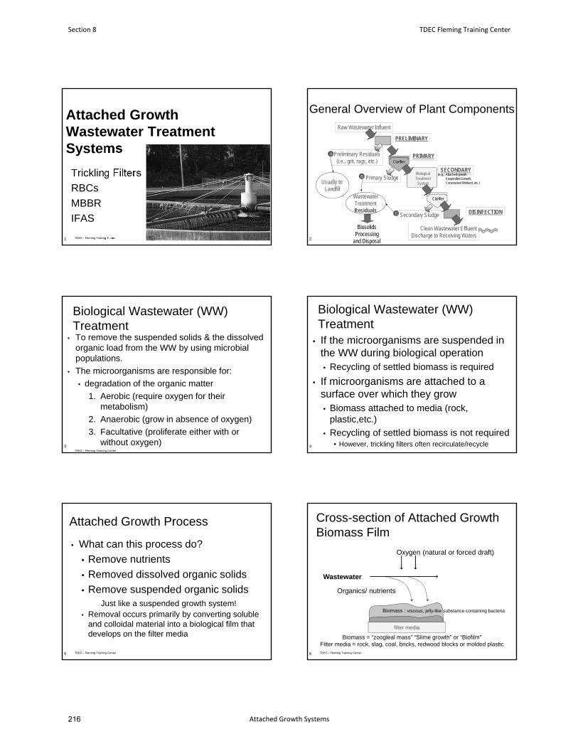
Attached Growth Wastewater Treatment Systems
Trickling Filters
RBCs
MBBR
IFAS
1 TDEC - Fleming Training Center
General Overview of Plant Components
2
Clarifier
Secondary Sludge
Primary Sludge
Clarifier
Raw Wastewater Influent
PRIMARY
DISINFECTION
BiologicalTreatment
System
SECONDARY
Clean Wastewater EffluentDischarge to Receiving Waters
Preliminary Residuals(i.e., grit, rags, etc.)
A
B
C
WastewaterTreatmentResiduals
BiosolidsProcessing
and Disposal
(e.g., Attached-grwothSuspended-Growth,Constructed Wetland, etc.)
Clarifier
PRELIMINARY
Usually to Landfill
Biological Wastewater (WW) Treatment
• To remove the suspended solids & the dissolvedorganic load from the WW by using microbialpopulations.
• The microorganisms are responsible for:
• degradation of the organic matter
1. Aerobic (require oxygen for theirmetabolism)
2. Anaerobic (grow in absence of oxygen)
3. Facultative (proliferate either with orwithout oxygen)
3TDEC - Fleming Training Center
Biological Wastewater (WW) Treatment
• If the microorganisms are suspended inthe WW during biological operation• Recycling of settled biomass is required
• If microorganisms are attached to asurface over which they grow• Biomass attached to media (rock,
plastic,etc.)
• Recycling of settled biomass is not required• However, trickling filters often recirculate/recycle4
Attached Growth Process
• What can this process do?
• Remove nutrients
• Removed dissolved organic solids
• Remove suspended organic solids
• Removal occurs primarily by converting solubleand colloidal material into a biological film that develops on the filter media
5 TDEC - Fleming Training Center
Just like a suspended growth system!
Cross-section of Attached Growth Biomass Film
TDEC - Fleming Training Center6
Wastewater
Oxygen (natural or forced draft)
Organics/ nutrients
filter media
Biomass : viscous, jelly-like substance containing bacteria
Biomass = “zoogleal mass” “Slime growth” or “Biofilm”Filter media = rock, slag, coal, bricks, redwood blocks or molded plastic
Section 8 TDEC Fleming Training Center
Attached Growth Systems216
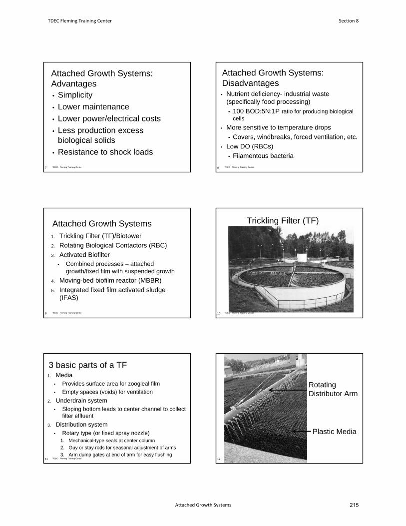
Attached Growth Systems:Advantages• Simplicity
• Lower maintenance
• Lower power/electrical costs
• Less production excessbiological solids
• Resistance to shock loads
7 TDEC - Fleming Training Center
Attached Growth Systems:Disadvantages• Nutrient deficiency- industrial waste
(specifically food processing)
• 100 BOD:5N:1P ratio for producing biologicalcells
• More sensitive to temperature drops
• Covers, windbreaks, forced ventilation, etc.
• Low DO (RBCs)
• Filamentous bacteria
TDEC - Fleming Training Center8
Attached Growth Systems1. Trickling Filter (TF)/Biotower
2. Rotating Biological Contactors (RBC)
3. Activated Biofilter• Combined processes – attached
growth/fixed film with suspended growth
4. Moving-bed biofilm reactor (MBBR)
5. Integrated fixed film activated sludge(IFAS)
TDEC - Fleming Training Center9
Trickling Filter (TF)
10 TDEC - Fleming Training Center
3 basic parts of a TF1. Media
• Provides surface area for zoogleal film
• Empty spaces (voids) for ventilation
2. Underdrain system• Sloping bottom leads to center channel to collect
filter effluent
3. Distribution system• Rotary type (or fixed spray nozzle)
1. Mechanical-type seals at center column
2. Guy or stay rods for seasonal adjustment of arms
3. Arm dump gates at end of arm for easy flushingTDEC - Fleming Training Center11
Rotating Distributor Arm
TDEC - Fleming Training Center12
Plastic Media
TDEC Fleming Training Center Section 8
Attached Growth Systems 215
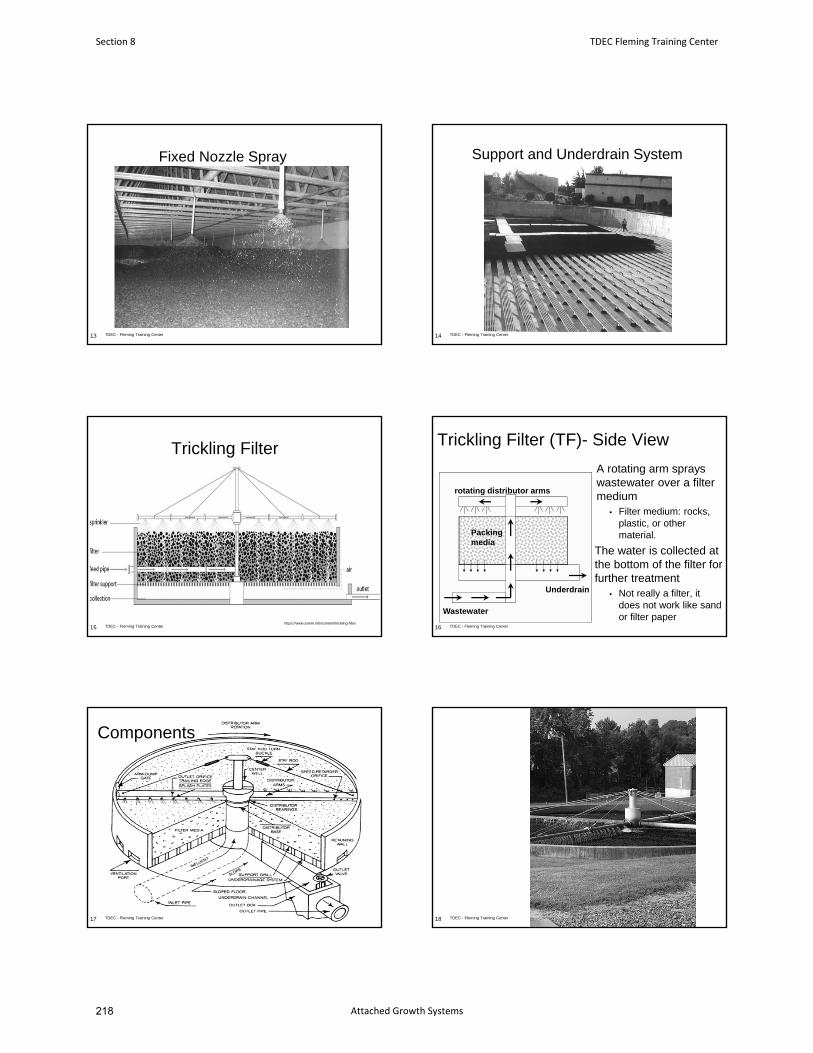
Fixed Nozzle Spray
TDEC - Fleming Training Center13
Support and Underdrain System
TDEC - Fleming Training Center14
Trickling Filter
TDEC - Fleming Training Center15https://www.sswm.info/content/trickling-filter
Trickling Filter (TF)- Side View
A rotating arm sprays wastewater over a filter medium
• Filter medium: rocks, plastic, or other material.
The water is collected at the bottom of the filter for further treatment
• Not really a filter, it does not work like sand or filter paper
16
Wastewater
rotating distributor arms
Packing media
Underdrain
TDEC - Fleming Training Center
Components
17 TDEC - Fleming Training Center TDEC - Fleming Training Center18
Section 8 TDEC Fleming Training Center
Attached Growth Systems218
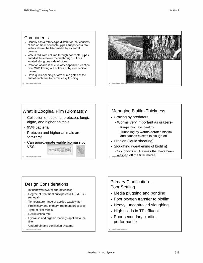
Components• Usually has a rotary-type distributor that consists
of two or more horizontal pipes supported a few inches above the filter media by a central column
• WW is fed from column through horizontal pipes and distributed over media through orifices located along one side of pipes
• Rotation of arm is due to water-sprinkler reaction from WW flowing out orifices or by mechanical means
• Have quick-opening or arm dump gates at the end of each arm to permit easy flushing
19 TDEC - Fleming Training Center
Trickling Filter Process
20 TDEC - Fleming Training Center
What is Zoogleal Film (Biomass)?
• Collection of bacteria, protozoa, fungi, algae, and higher animals
• 95% bacteria
• Protozoa and higher animals are “grazers”
• Can approximate viable biomass by VSS
21 TDEC - Fleming Training Center
Managing Biofilm Thickness• Grazing by predators
• Worms very important as grazers-• Keeps biomass healthy
• Tunneling by worms aerates biofilm and causes excess to slough off
• Erosion (liquid shearing)
• Sloughing (weakening of biofilm)• Sloughings = TF slimes that have been
washed off the filter media22 TDEC - Fleming Training Center
Design Considerations• Influent wastewater characteristics
• Degree of treatment anticipated (BOD & TSS removal)
• Temperature range of applied wastewater
• Preliminary and primary treatment processes
• Type of filter media
• Recirculation rate
• Hydraulic and organic loadings applied to the filter
• Underdrain and ventilation systems 23 TDEC - Fleming Training Center
Primary Clarification –Poor Settling
• Media plugging and ponding
• Poor oxygen transfer to biofilm
• Heavy, uncontrolled sloughing
• High solids in TF effluent
• Poor secondary clarifier performance
24 TDEC - Fleming Training Center
TDEC Fleming Training Center Section 8
Attached Growth Systems 217
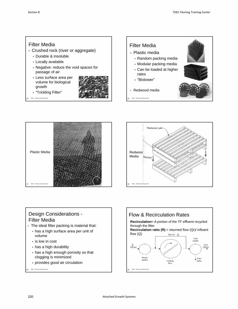
Filter Media• Crushed rock (river or aggregate)
• Durable & insoluble
• Locally available
• Negative: reduce the void spaces for passage of air
• Less surface area per volume for biological growth
• “Trickling Filter”
25 TDEC - Fleming Training Center
Filter Media• Plastic media
• Random packing media
• Modular packing media
• Can be loaded at higher rates
• “Biotower”
• Redwood media
TDEC - Fleming Training Center26
27 TDEC - Fleming Training Center
Plastic Media
28 TDEC - Fleming Training Center
Redwood Media
Design Considerations -Filter Media• The ideal filter packing is material that:
• has a high surface area per unit of volume
• is low in cost
• has a high durability
• has a high enough porosity so that clogging is minimized
• provides good air circulation
29 TDEC - Fleming Training Center
Flow & Recirculation Rates
30
Q
Qr
Recirculation= A portion of the TF effluent recycled through the filterRecirculation ratio (R) = returned flow (Qr)/ influent flow (Q)
TDEC - Fleming Training Center
Section 8 TDEC Fleming Training Center
Attached Growth Systems220
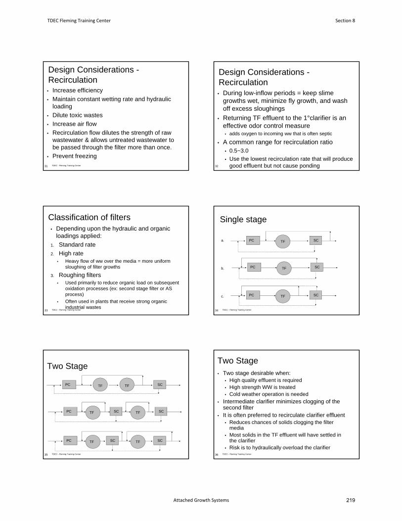
Design Considerations -Recirculation• Increase efficiency
• Maintain constant wetting rate and hydraulic loading
• Dilute toxic wastes
• Increase air flow
• Recirculation flow dilutes the strength of raw wastewater & allows untreated wastewater to be passed through the filter more than once.
• Prevent freezing
31 TDEC - Fleming Training Center
Design Considerations -Recirculation• During low-inflow periods = keep slime
growths wet, minimize fly growth, and wash off excess sloughings
• Returning TF effluent to the 1°clarifier is an effective odor control measure • adds oxygen to incoming ww that is often septic
• A common range for recirculation ratio• 0.5~3.0
• Use the lowest recirculation rate that will produce good effluent but not cause ponding32
Classification of filters• Depending upon the hydraulic and organic
loadings applied:
1. Standard rate
2. High rate• Heavy flow of ww over the media = more uniform
sloughing of filter growths
3. Roughing filters• Used primarily to reduce organic load on subsequent
oxidation processes (ex: second stage filter or AS process)
• Often used in plants that receive strong organic industrial wastes
TDEC - Fleming Training Center33
Single stage
34
PC SCTF
PC SCTF
PC SCTF
a.
b.
c.
TDEC - Fleming Training Center
Two Stage
35
PC SCTF
PC SCTF
TF
TF SC
PC SCTFTF SC
TDEC - Fleming Training Center
Two Stage• Two stage desirable when:
• High quality effluent is required• High strength WW is treated• Cold weather operation is needed
• Intermediate clarifier minimizes clogging of the second filter
• It is often preferred to recirculate clarifier effluent• Reduces chances of solids clogging the filter
media• Most solids in the TF effluent will have settled in
the clarifier• Risk is to hydraulically overload the clarifier
36 TDEC - Fleming Training Center
TDEC Fleming Training Center Section 8
Attached Growth Systems 219
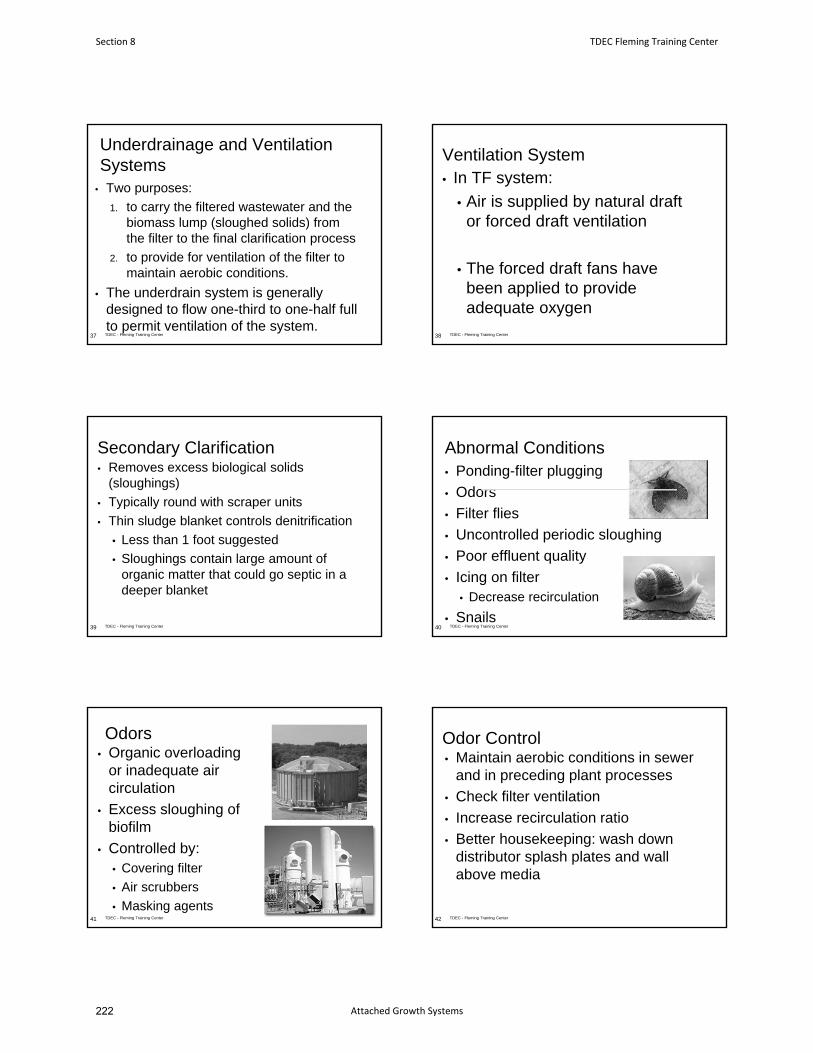
Underdrainage and Ventilation Systems
• Two purposes:
1. to carry the filtered wastewater and the biomass lump (sloughed solids) from the filter to the final clarification process
2. to provide for ventilation of the filter to maintain aerobic conditions.
• The underdrain system is generally designed to flow one-third to one-half full to permit ventilation of the system.
37 TDEC - Fleming Training Center
Ventilation System • In TF system:
• Air is supplied by natural draft or forced draft ventilation
• The forced draft fans have been applied to provide adequate oxygen
38 TDEC - Fleming Training Center
Secondary Clarification• Removes excess biological solids
(sloughings)
• Typically round with scraper units
• Thin sludge blanket controls denitrification
• Less than 1 foot suggested
• Sloughings contain large amount of organic matter that could go septic in a deeper blanket
39 TDEC - Fleming Training Center
Abnormal Conditions• Ponding-filter plugging
• Odors
• Filter flies
• Uncontrolled periodic sloughing
• Poor effluent quality
• Icing on filter• Decrease recirculation
• SnailsTDEC - Fleming Training Center40
Odors• Organic overloading
or inadequate air circulation
• Excess sloughing of biofilm
• Controlled by:• Covering filter
• Air scrubbers
• Masking agents41 TDEC - Fleming Training Center
Odor Control• Maintain aerobic conditions in sewer
and in preceding plant processes
• Check filter ventilation
• Increase recirculation ratio
• Better housekeeping: wash down distributor splash plates and wall above media
42 TDEC - Fleming Training Center
Section 8 TDEC Fleming Training Center
Attached Growth Systems222
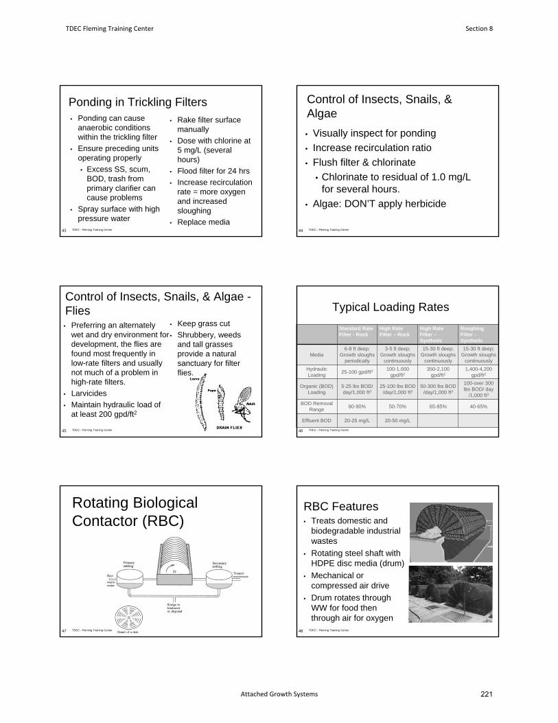
Ponding in Trickling Filters• Ponding can cause
anaerobic conditions within the trickling filter
• Ensure preceding units operating properly
• Excess SS, scum, BOD, trash from primary clarifier can cause problems
• Spray surface with high pressure water
• Rake filter surface manually
• Dose with chlorine at 5 mg/L (several hours)
• Flood filter for 24 hrs
• Increase recirculation rate = more oxygen and increased sloughing
• Replace mediaTDEC - Fleming Training Center43
Control of Insects, Snails, & Algae
• Visually inspect for ponding
• Increase recirculation ratio
• Flush filter & chlorinate
• Chlorinate to residual of 1.0 mg/L for several hours.
• Algae: DON’T apply herbicide
44 TDEC - Fleming Training Center
Control of Insects, Snails, & Algae -Flies
• Preferring an alternately wet and dry environment for development, the flies are found most frequently in low-rate filters and usually not much of a problem in high-rate filters.
• Larvicides
• Maintain hydraulic load of at least 200 gpd/ft2
• Keep grass cut
• Shrubbery, weeds and tall grasses provide a natural sanctuary for filter flies.
TDEC - Fleming Training Center45
Typical Loading Rates
Standard Rate Filter - Rock
High RateFilter – Rock
High RateFilter –Synthetic
Roughing Filter -Synthetic
Media6-8 ft deep;
Growth sloughs periodically
3-5 ft deep; Growth sloughs
continuously
15-30 ft deep;Growth sloughs
continuously
15-30 ft deep;Growth sloughs
continuously
Hydraulic Loading
25-100 gpd/ft2100-1,000
gpd/ft2350-2,100
gpd/ft21,400-4,200
gpd/ft2
Organic (BOD) Loading
5-25 lbs BOD/ day/1,000 ft3
25-100 lbs BOD /day/1,000 ft3
50-300 lbs BOD /day/1,000 ft3
100-over 300lbs BOD/ day
/1,000 ft3
BOD RemovalRange
80-90% 50-70% 65-85% 40-65%
Effluent BOD 20-25 mg/L 20-50 mg/L
46 TDEC - Fleming Training Center
Rotating Biological Contactor (RBC)
47 TDEC - Fleming Training Center
RBC Features• Treats domestic and
biodegradable industrial wastes
• Rotating steel shaft with HDPE disc media (drum)
• Mechanical or compressed air drive
• Drum rotates through WW for food then through air for oxygen
48 TDEC - Fleming Training Center
TDEC Fleming Training Center Section 8
Attached Growth Systems 221
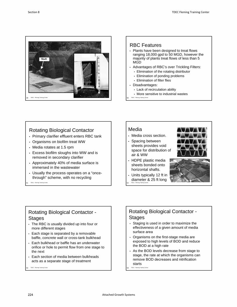
TDEC - Fleming Training Center49
RBC Features• Plants have been designed to treat flows
ranging 18,000 gpd to 50 MGD, however the majority of plants treat flows of less than 5 MGD
• Advantages of RBC’s over Trickling Filters:• Elimination of the rotating distributor• Elimination of ponding problems• Elimination of filter flies
• Disadvantages:• Lack of recirculation ability• More sensitive to industrial wastes
50 TDEC - Fleming Training Center
Rotating Biological Contactor• Primary clarifier effluent enters RBC tank
• Organisms on biofilm treat WW
• Media rotates at 1.5 rpm
• Excess biofilm sloughs into WW and is removed in secondary clarifier
• Approximately 40% of media surface is immersed in the wastewater
• Usually the process operates on a “once-through” scheme, with no recycling
51 TDEC - Fleming Training Center
Media• Media cross section.
• Spacing between sheets provides void space for distribution of air & WW
• HDPE plastic media sheets bonded onto horizontal shafts.
• Units typically 12 ft in diameter & 25 ft long
TDEC - Fleming Training Center52
Rotating Biological Contactor -Stages• The RBC is usually divided up into four or
more different stages
• Each stage is separated by a removable baffle, concrete wall or cross-tank bulkhead
• Each bulkhead or baffle has an underwater orifice or hole to permit flow from one stage to the next
• Each section of media between bulkheads acts as a separate stage of treatment
TDEC - Fleming Training Center53
Rotating Biological Contactor -Stages• Staging is used in order to maximize the
effectiveness of a given amount of media surface area
• Organisms on the first-stage media are exposed to high levels of BOD and reduce the BOD at a high rate
• As the BOD levels decrease from stage to stage, the rate at which the organisms can remove BOD decreases and nitrification starts
TDEC - Fleming Training Center54
Section 8 TDEC Fleming Training Center
Attached Growth Systems224
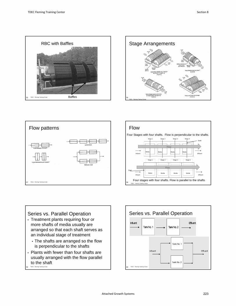
RBC with Baffles
TDEC - Fleming Training Center55 Baffles
Stage Arrangements
TDEC - Fleming Training Center
56
Flow patterns
TDEC - Fleming Training Center57
Flow
58
Stage 1 Stage 2 Stage 3
Influent
Stage 4
Effluent
Shaft
Media Media Media Media
Stage 4
Effluent
Shaft
Stage 1 Stage 2 Stage 3
InfluentMedia Media Media Media
Flow
Flow
Four Stages with four shafts. Flow is perpendicular to the shafts.
Four stages with four shafts. Flow is parallel to the shafts.TDEC - Fleming Training Center
Series vs. Parallel Operation• Treatment plants requiring four or
more shafts of media usually are arranged so that each shaft serves as an individual stage of treatment
• The shafts are arranged so the flow is perpendicular to the shafts
• Plants with fewer than four shafts are usually arranged with the flow parallel to the shaft
TDEC - Fleming Training Center59
Series vs. Parallel Operation
60 TDEC - Fleming Training Center
TDEC Fleming Training Center Section 8
Attached Growth Systems 223
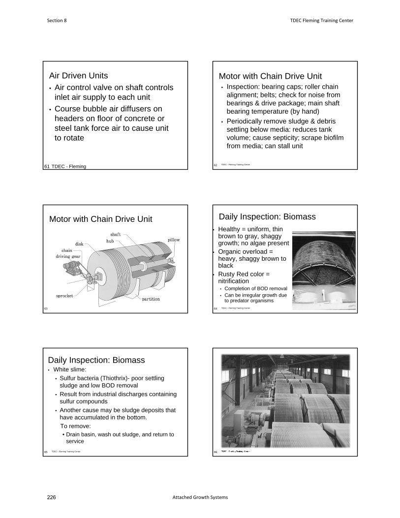
Air Driven Units• Air control valve on shaft controls
inlet air supply to each unit
• Course bubble air diffusers on headers on floor of concrete or steel tank force air to cause unit to rotate
TDEC - Fleming 61
Motor with Chain Drive Unit• Inspection: bearing caps; roller chain
alignment; belts; check for noise from bearings & drive package; main shaft bearing temperature (by hand)
• Periodically remove sludge & debris settling below media: reduces tank volume; cause septicity; scrape biofilm from media; can stall unit
62 TDEC - Fleming Training Center
Motor with Chain Drive Unit
63
Daily Inspection: Biomass
• Healthy = uniform, thin brown to gray, shaggy growth; no algae present
• Organic overload = heavy, shaggy brown to black
• Rusty Red color = nitrification• Completion of BOD removal• Can be irregular growth due
to predator organismsTDEC - Fleming Training Center64
Daily Inspection: Biomass• White slime:
• Sulfur bacteria (Thiothrix)- poor settling sludge and low BOD removal
• Result from industrial discharges containing sulfur compounds
• Another cause may be sludge deposits that have accumulated in the bottom.
To remove:• Drain basin, wash out sludge, and return to
service
TDEC - Fleming Training Center65 TDEC - Fleming Training Center66
Section 8 TDEC Fleming Training Center
Attached Growth Systems226
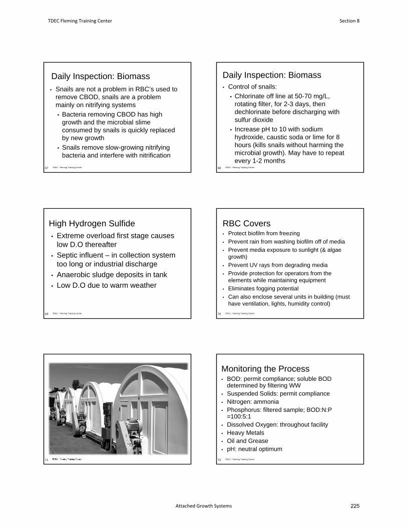
Daily Inspection: Biomass
• Snails are not a problem in RBC’s used to remove CBOD, snails are a problem mainly on nitrifying systems
• Bacteria removing CBOD has high growth and the microbial slime consumed by snails is quickly replaced by new growth
• Snails remove slow-growing nitrifying bacteria and interfere with nitrification
67 TDEC - Fleming Training Center
Daily Inspection: Biomass• Control of snails:
• Chlorinate off line at 50-70 mg/L, rotating filter, for 2-3 days, then dechlorinate before discharging with sulfur dioxide
• Increase pH to 10 with sodium hydroxide, caustic soda or lime for 8 hours (kills snails without harming the microbial growth). May have to repeat every 1-2 months
68 TDEC - Fleming Training Center
High Hydrogen Sulfide• Extreme overload first stage causes
low D.O thereafter
• Septic influent – in collection system too long or industrial discharge
• Anaerobic sludge deposits in tank
• Low D.O due to warm weather
69 TDEC - Fleming Training Center
RBC Covers• Protect biofilm from freezing
• Prevent rain from washing biofilm off of media
• Prevent media exposure to sunlight (& algae growth)
• Prevent UV rays from degrading media
• Provide protection for operators from the elements while maintaining equipment
• Eliminates fogging potential
• Can also enclose several units in building (must have ventilation, lights, humidity control)
TDEC - Fleming Training Center70
TDEC - Fleming Training Center71
Monitoring the Process• BOD: permit compliance; soluble BOD
determined by filtering WW• Suspended Solids: permit compliance• Nitrogen: ammonia• Phosphorus: filtered sample; BOD:N:P
=100:5:1• Dissolved Oxygen: throughout facility• Heavy Metals• Oil and Grease• pH: neutral optimum
72 TDEC - Fleming Training Center
TDEC Fleming Training Center Section 8
Attached Growth Systems 225
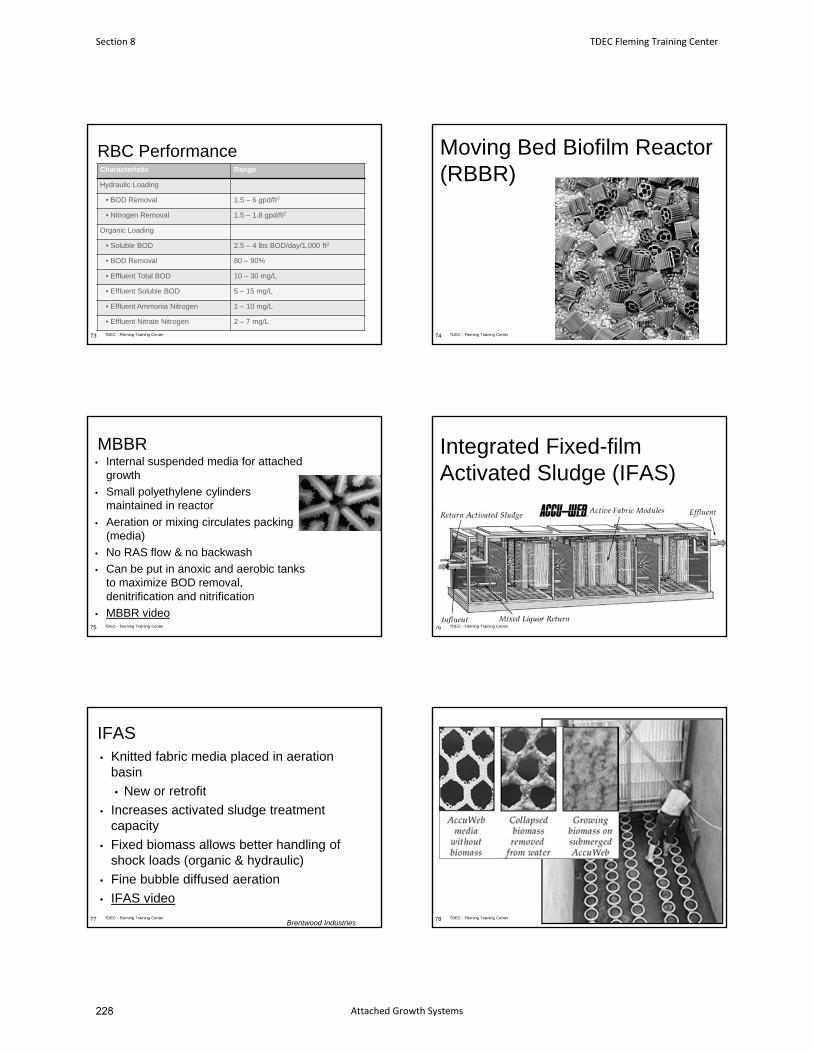
RBC PerformanceCharacteristic Range
Hydraulic Loading
• BOD Removal 1.5 – 6 gpd/ft2
• Nitrogen Removal 1.5 – 1.8 gpd/ft2
Organic Loading
• Soluble BOD 2.5 – 4 lbs BOD/day/1,000 ft2
• BOD Removal 80 – 90%
• Effluent Total BOD 10 – 30 mg/L
• Effluent Soluble BOD 5 – 15 mg/L
• Effluent Ammonia Nitrogen 1 – 10 mg/L
• Effluent Nitrate Nitrogen 2 – 7 mg/L
TDEC - Fleming Training Center73
Moving Bed Biofilm Reactor (RBBR)
74 TDEC - Fleming Training Center
MBBR• Internal suspended media for attached
growth
• Small polyethylene cylinders maintained in reactor
• Aeration or mixing circulates packing (media)
• No RAS flow & no backwash
• Can be put in anoxic and aerobic tanks to maximize BOD removal, denitrification and nitrification
• MBBR video75 TDEC - Fleming Training Center
Integrated Fixed-film Activated Sludge (IFAS)
76 TDEC - Fleming Training Center
IFAS• Knitted fabric media placed in aeration
basin
• New or retrofit
• Increases activated sludge treatment capacity
• Fixed biomass allows better handling of shock loads (organic & hydraulic)
• Fine bubble diffused aeration
• IFAS videoTDEC - Fleming Training Center77
Brentwood IndustriesTDEC - Fleming Training Center78
Section 8 TDEC Fleming Training Center
Attached Growth Systems228
IFAS• Media place along one
wall• Increased treatment
capacity: BOD & nitrification
• Additional tankage not needed
• Improves sludge settling in secondary clarifier
• Reduced waste sludge production
79 TDEC - Fleming Training Center
Any Questions?
TDEC - Fleming Training Center80
Humboldt, TN Trickling Filter
TDEC Fleming Training Center Section 8
Attached Growth Systems 227
January 2016 6-1 Design Criteria Ch. 6
CHAPTER 6
Fixed Film Reactors
6.1 Trickling Filters
6.1.1 General
6.1.2 Pretreatment
6.1.3 Types of Processes
6.1.4 Consideration For Design
6.1.5 Estimation of Performance
6.1.6 Special Details
6.2 Rotating Biological Contactors
6.2.1 General
6.2.2 Media
6.2.3 Design Loadings
6.2.4 Special Details
6.3 Activated Biofilter
6.3.1 General
6.3.2 ABF Media
6.3.3 Design
6.3.4 Special Details
Section 8 TDEC Fleming Training Center
Attached Growth Systems230
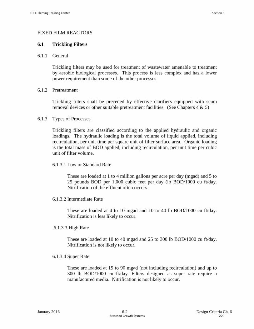
January 2016 6-2 Design Criteria Ch. 6
FIXED FILM REACTORS
6.1 Trickling Filters
6.1.1 General
Trickling filters may be used for treatment of wastewater amenable to treatment
by aerobic biological processes. This process is less complex and has a lower
power requirement than some of the other processes.
6.1.2 Pretreatment
Trickling filters shall be preceded by effective clarifiers equipped with scum
removal devices or other suitable pretreatment facilities. (See Chapters 4 & 5)
6.1.3 Types of Processes
Trickling filters are classified according to the applied hydraulic and organic
loadings. The hydraulic loading is the total volume of liquid applied, including
recirculation, per unit time per square unit of filter surface area. Organic loading
is the total mass of BOD applied, including recirculation, per unit time per cubic
unit of filter volume.
6.1.3.1 Low or Standard Rate
These are loaded at 1 to 4 million gallons per acre per day (mgad) and 5 to
25 pounds BOD per 1,000 cubic feet per day (lb BOD/1000 cu ft/day.
Nitrification of the effluent often occurs.
6.1.3.2 Intermediate Rate
These are loaded at 4 to 10 mgad and 10 to 40 lb BOD/1000 cu ft/day.
Nitrification is less likely to occur.
6.1.3.3 High Rate
These are loaded at 10 to 40 mgad and 25 to 300 lb BOD/1000 cu ft/day.
Nitrification is not likely to occur.
6.1.3.4 Super Rate
These are loaded at 15 to 90 mgad (not including recirculation) and up to
300 lb BOD/1000 cu ft/day. Filters designed as super rate require a
manufactured media. Nitrification is not likely to occur.
TDEC Fleming Training Center Section 8
Attached Growth Systems 229
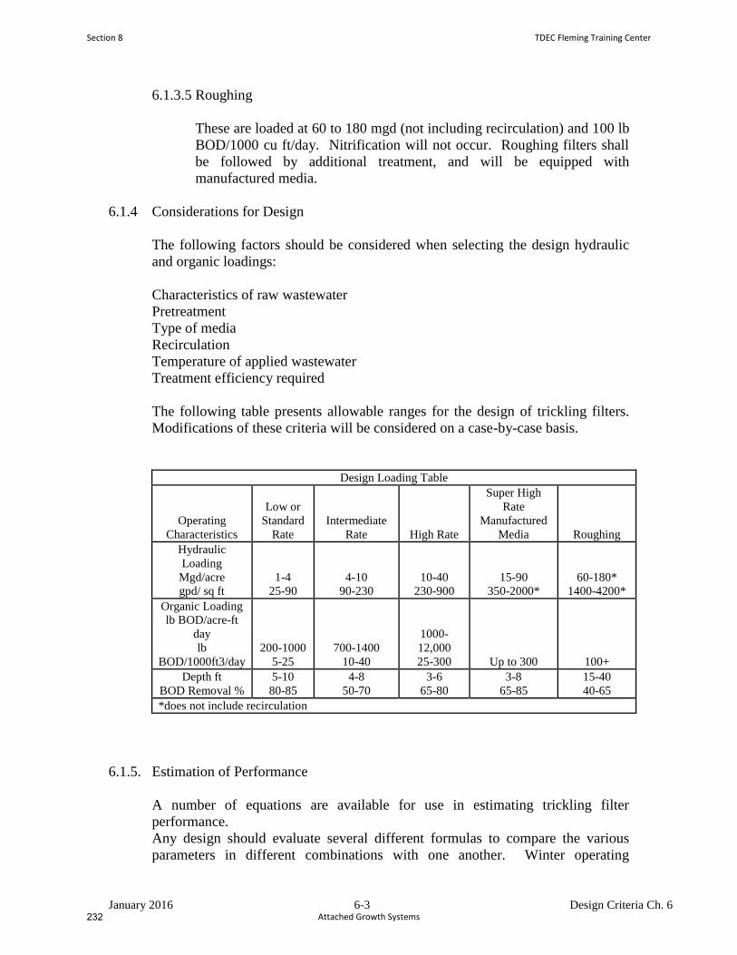
January 2016 6-3 Design Criteria Ch. 6
6.1.3.5 Roughing
These are loaded at 60 to 180 mgd (not including recirculation) and 100 lb
BOD/1000 cu ft/day. Nitrification will not occur. Roughing filters shall
be followed by additional treatment, and will be equipped with
manufactured media.
6.1.4 Considerations for Design
The following factors should be considered when selecting the design hydraulic
and organic loadings:
Characteristics of raw wastewater
Pretreatment
Type of media
Recirculation
Temperature of applied wastewater
Treatment efficiency required
The following table presents allowable ranges for the design of trickling filters.
Modifications of these criteria will be considered on a case-by-case basis.
Design Loading Table
Operating
Characteristics
Low or
Standard
Rate Intermediate
Rate High Rate
Super High
Rate
Manufactured
Media Roughing Hydraulic
Loading Mgd/acre
gpd/ sq ft 1-4
25-90 4-10
90-230 10-40
230-900 15-90
350-2000* 60-180*
1400-4200* Organic Loading lb BOD/acre-ft
day
lb
BOD/1000ft3/day 200-1000
5-25 700-1400
10-40
1000-
12,000 25-300 Up to 300 100+
Depth ft BOD Removal %
5-10 80-85
4-8 50-70
3-6 65-80
3-8 65-85
15-40 40-65
*does not include recirculation
6.1.5. Estimation of Performance
A number of equations are available for use in estimating trickling filter
performance.
Any design should evaluate several different formulas to compare the various
parameters in different combinations with one another. Winter operating
Section 8 TDEC Fleming Training Center
Attached Growth Systems232
January 2016 6-4 Design Criteria Ch. 6
conditions must be analyzed since winter operations normally result in lower
efficiency than summer operations. The trickling filter design must evaluate the
impacts of recirculation, air draft temperatures and medium.
6.1.5.1 Recirculation
Recirculation capability is required for all variations of the trickling filter process
except roughing filters provided that minimum hydraulic loading rates are
maintained at all times. The recirculation ratio should be in the range of 0.5 to
4.0. Recirculation should be provided for manufactured media to maintain 0.5 to
1.0 gallon per minute per square foot (gpm/sq ft) or the manufacturer's
recommended minimum wetting rate at all times. Recirculation ratios greater
than 4.0 should not be used to calculate effluent quality.
6.1.5.2 Staging
Staging of filters can be considered for high-strength wastes or for nitrification.
6.1.6 Special Details
6.1.6.1 Media
a.Rock, Slag, or Similar Media
Rock, slag, and similar media should not contain more than 5 percent by
weight of pieces whose longest dimension is three times the least
dimension. They should be free from thin, elongated and flat pieces, dust,
clay, sand, or fine material and should conform to the following size and
grading when mechanically graded over a vibrating screen with square
openings:
Passing 4-1/2 inch screen: 100 percent by weight
Retained on 3-inch screen: 90-100 percent by weight
Passing 2-inch screen: 0-2 percent by weight
Passing 1-inch screen: 0 percent by weight
Hand-picked field stone should be as follows:
Maximum dimension of stone: 5 inches
Minimum dimension of stone: 3 inches
Material delivered to the filter site should be stored on wood-planked or
TDEC Fleming Training Center Section 8
Attached Growth Systems 231
January 2016 6-5 Design Criteria Ch. 6
other approved clean hard-surfaced areas. All material should be
rehandled at the filter site, and no material should be dumped directly into
the filter. Crushed rock, slag, and similar media should be rescreened or
forked at the filter site to remove all fines. Such material should be
placed by hand to a depth of 12 inches above the tile underdrains, and all
materials should be carefully placed so as not to damage the underdrains.
The remainder of the material may be placed by means of belt conveyors
or equally effective methods approved by the engineer. Trucks, tractors,
or other heavy equipment should not be driven over the filter during or
after construction.
b.Manufactured Media
Application of manufactured media should be evaluated on a case-by-case
basis. Suitability should be evaluated on the basis of experience with
installations handling similar wastes and loadings.
Media manufactured from plastic, wood, or other materials are available
in many different designs. They should be durable, resistant to spalling or
flaking, and relatively insoluble in wastewater. They are generally
applied to super high rate and roughing filter designs.
6.1.6.2 Underdrainage System
a. Arrangement
Underdrains with semicircular inverts or equivalent should be provided
and the underdrainage system should cover the entire floor of the filter.
Inlet openings into the underdrains should have an unsubmerged gross
combined area equal to at least 15 percent of the surface area of the filter.
b.Slope
The underdrains should have a minimum slope of 1 percent. Effluent
channels should be designed to produce a minimum velocity of 2 feet per
second at average daily rate of application to the filter.
c.Flushing
Provision should be made for flushing the underdrains and effluent
channel.
In small filters, use of a peripheral head channel with vertical vents is
acceptable for flushing purposes. Inspection facilities should be provided.
d.Ventilation
Section 8 TDEC Fleming Training Center
Attached Growth Systems234
January 2016 6-6 Design Criteria Ch. 6
The underdrainage system, effluent channels, and effluent pipe shall be
designed to permit free passage of air. The size of drains, channels, and
pipe should be such that not more than 50 percent of their cross-sectional
area will be submerged under the design hydraulic loading. Provision
should be made in the design of the effluent channels to allow for the
possibility of increased hydraulic loading.
6.1.6.3 Dosing Equipment
a.Distribution
The sewage shall be distributed over the filter by rotary distributors or
other suitable devices which will permit reasonably uniform distribution to
the surface area. At design average flow, the deviation from a calculated
uniformly distributed volume per square foot of the filter surface should
not exceed plus or minus 10 percent at any point. Provisions must be
made to spray the side walls to avoid growth of filter flies.
b.Application
Sewage may be applied to the filters by siphons, pumps, or by gravity
discharge from preceding treatment units when suitable flow
characteristics have been developed. Application of sewage should be
practically continuous. Intermittent dosing shall only be considered for
low or standard rate filters. In the case of intermittent dosing, the dosing
cycles should normally vary between 5 and 15 minutes, with distribution
taking place approximately 50 percent of the time. The maximum rest
should not exceed 5 minutes, based on the design average flow.
c. Hydraulics
All hydraulic factors involving proper distribution of sewage on the
filters should be carefully calculated. For reaction-type distributors, a
minimum head of 24 inches between the low-water level in the siphon
chamber and center of the arms should be required. Surge relief to
prevent damage to distributor seals, should be provided where sewage is
pumped directly to the distributors.
d. Clearance
A minimum clearance of 6 inches between medium and distributor arms
should be provided. Greater clearance is essential where icing occurs.
e. Seals
TDEC Fleming Training Center Section 8
Attached Growth Systems 233
January 2016 6-7 Design Criteria Ch. 6
The use of mercury seals is prohibited in the distributors of newly
constructed trickling filters. If an existing treatment facility is to be
modified, any mercury seals in the trickling filters shall be replaced with
oil or mechanical seals.
6.1.6.4 Recirculation Pumping
Low-head, high-capacity pumps are generally used. Submersible pumps
are commonly used. A means to adjust the flow is recommended in
order to maintain constant hydraulic operation.
6.1.6.5 Waste Sludge Equipment
Pumps for trickling filter sludge should be capable of pumping material
up to 6-percent solids (or more if needed) when pumping directly to the
digester. Time clock controlled on-off control is desirable. When
secondary sludge is pumped to the primary clarifier, the sludge pumps
should be designed to pump material with low solid concentrations and
high flow rates.
6.1.6.6 Miscellaneous Features
a. Flooding
Consideration should be given to the design of filter structures so that
they may be flooded.
b. Maintenance
All distribution devices, underdrains, channels, and pipes should be
installed so that they may be properly maintained, flushed, or drained.
c. Flow Measurement
A means shall be provided to measure recirculated flow to the filter.
6.2 Rotating Biological Contactors
6.2.1 General
6.2.1.1 Description
This section presents the requirements for fixed-film reactors using either
partially submerged vertical media rotated on a horizontal shaft or other
designs with similar concepts.
Section 8 TDEC Fleming Training Center
Attached Growth Systems236
January 2016 6-8 Design Criteria Ch. 6
6.2.1.2 Applicability
Rotating biological contactors (RBC) may be used for treatment of
wastewater amenable to treatment by aerobic biological processes. The
process is especially applicable to small communities. These requirements
shall be considered when proposing this type of treatment.
6.2.1.3 Pretreatment
Primary clarifiers or fine screens should be placed ahead of the RBC
process to minimize solids settling in the RBC tanks. (See Chapters 4 & 5)
6.2.2 Media
6.2.2.1 Description
Typical media consists of plastic sheets of various designs with
appropriate spacings to maximize the surface area, allow for entrance of
air and wastewater, the sloughing of excess biological solids and
prevention of plugging. The medium is mounted on a horizontal steel
shaft. Other similar systems will be considered on a case-by-case basis.
6.2.2.2 Types
Two types of medium are currently available.
a. Standard Density
Standard-density medium is available in sizes up to 100,000 square feet
(sq ft) per shaft. It should be used for all secondary treatment
applications.
b. High Density
High-density medium is available in sizes up to 150,000 sq ft per shaft.
It should be used only for nitrification or effluent polishing where the
influent BOD is sufficiently low to ensure that plugging of the medium
will not occur.
TDEC Fleming Training Center Section 8
Attached Growth Systems 235
January 2016 6-9 Design Criteria Ch. 6
6.2.3 Design Loadings
6.2.3.1 RBC Media
Design loadings should be in terms of total organic loading expressed as
pounds BOD5 per day per 1000 square feet of media surface area (lb
BOD5/day/1000 sq. ft.). The development of design loadings should
consider influent BOD, soluble BOD, effluent BOD, flows, temperature,
and the number of treatment stages. The design loading should generally
range between 2.5 and 3.5 lb BOD5/day/1000 sq. ft.
6.2.3.2 Final Clarifiers
The following requirements are in addition to those set forth in Chapter 5,
"Clarifiers."
The overflow rate should be less than or equal to 600 gpd/sq ft at the
average daily design flow.
6.2.4 Special Details
6.2.4.1 Enclosures
Enclosures should be provided for the RBC medium to prevent algae
growth on the medium and minimize the effect of cold weather.
Enclosures may be either fabricated individual enclosures or buildings
enclosing several shafts. Buildings may be considered for installations
with several shafts or, where severe weather conditions are encountered, to
promote better maintenance.
a. Fabricated Individual Enclosures
Enclosures should be made of fiberglass or other material resistant to
damage from humidity or corrosion. The exterior of the enclosures should
be resistant to deterioration from direct sunlight and ultraviolet radiation.
Access points should be provided at each end of the enclosure to permit
inspection of shafts and to perform operation and maintenance. Enclosures
shall be removable to allow removal of the shaft assemblies. Access
around enclosures shall be sufficient to permit suitable lifting equipment
access to lift covers and shafts.
Section 8 TDEC Fleming Training Center
Attached Growth Systems238
January 2016 6-10 Design Criteria Ch. 6
b. Buildings
Adequate space should be provided to allow access to and removal of
shafts from enclosures. Buildings should be designed with provisions to
remove shafts without damage to the structure. Buildings should be
designed with adequate ventilation and humidity control to ensure
adequate atmospheric oxygen is available for the RBC shafts, provide a
safe environment for the operating staff to perform normal operation and
maintenance, and minimize the damage to the structure and equipment
from excess moisture.
6.2.4.2 Hydraulic Design
The RBC design should incorporate sufficient hydraulic controls, such as
weirs, to ensure that the flow is distributed evenly to parallel process units.
RBC tank design should provide a means for distributing the influent flow
evenly across each RBC shaft. Intermediate baffles placed between
treatment stages in the RBC system should be designed to minimize solids
deposition. The RBC units should be designed with flexibility to permit
series or parallel operation.
6.2.4.3 Dewatering
The design should provide for dewatering of RBC tanks.
6.2.4.4 Shaft Drives
The electric motor and gear reducer should be located to prevent contact
with the wastewater at peak flow rates.
6.2.4.5 Recycle
Effluent recycle should be provided for small installations where
minimum diurnal flows may be very small. Recycle should be considered
in any size plant where minimum flows are less than 30% of the average
design flow.
6.2.4.6 Access
Access shall be allowed for lifting equipment to provide maintenance in
the event of a failure.
TDEC Fleming Training Center Section 8
Attached Growth Systems 237
January 2016 6-11 Design Criteria Ch. 6
6.3 Activated Biofilter
6.3.1 General
6.3.1.1 Description
The activated biofilter (ABF) process is a combination of the trickling
filter process using artificial media and the activated sludge process.
6.3.1.2 Applicability
The activated biofilter process may be used where wastewater is
amendable to biological treatment. This process requires close attention
and competent operating supervision, including routine laboratory control.
These requirements should be considered when proposing this type of
treatment. The process is more adaptable to handling large seasonal
loading variations, such as those resulting from seasonal industries or
changes in population, than are some of the other biological processes.
Where significant quantities of industrial wastes are anticipated, pilot plant
testing should be considered.
6.3.2 ABF Media
Artificial media are used in the trickling filter portion of the process to allow high
BOD and hydraulic loadings and permit recycle of activated sludge through the
trickling filter without plugging. Either wood or plastic artificial medium may be
used. Medium depth typically ranges from 7 to 25 feet.
6.3.3 Design
6.3.3.1 General
Calculations shall be submitted to justify the basis of design of the ABF
tower pump station, ABF tower, aeration basin, aeration equipment,
secondary clarifiers, activated sludge return equipment, and waste sludge
equipment.
6.3.3.2 ABF Tower Pump Station
The ABF tower pump station shall be designed to pump the peak influent
flow plus the maximum design ABF tower recirculation and return
activated sludge flows. Application of wastewater to the ABF tower
should be continuous.
Section 8 TDEC Fleming Training Center
Attached Growth Systems240
January 2016 6-12 Design Criteria Ch. 6
6.3.3.3 ABF Tower
The ABF tower shall be designed based on organic loading expressed as
pounds of influent BOD per 1,000 cubic feet per day (lb BOD/1,000 cu
ft/day). The organic loading should be established using data from similar
installations or pilot plant testing. A minimum hydraulic wetting rate
should be maintained and be expressed as gallons per minute per square
foot (gpm/sq ft).
Typical values for organic loading range from 100 to 350 lb BOD/1,000
cu ft/day (4,300 to 15,000 pounds BOD per acre-foot per day), and
hydraulic wetting rates range from 1.5 to 5.5 gpm/sq ft, including
recirculations and return flows.
6.3.3.4 Aeration Basin
The aeration basin should be designed in accordance with Chapter 7,
"Activated Sludge," based on the food-to-microorganism (F/M) ratio
expressed as pounds of influent BOD per day per pound of mixed liquor
volatile suspended solids (MLVSS). The F/M ratio should be based on the
influent total BOD to the ABF tower or the estimated soluble BOD
leaving the ABF tower. Designs using total BOD to the ABF tower should
be based on data from similar installations or pilot plant testing. Designs
using the estimated soluble BOD leaving the ABF tower should use
typical F/M ratios (presented in Chapter 7, "Activated Sludge"). Estimate
of BOD removal in the ABF tower should be based on similar installations
or pilot plant testing. Calculations of mixed-liquor suspended solids
should include the influent suspended solids and solids sloughing from the
ABF tower in addition to growth of activated sludge due to removal of
soluble BOD. Determination of aeration basin volume should include
consideration of aeration basin power levels (using aeration equipment
horsepower) expressed as horsepower per 1,000 cubic feet of basin
volume. Aeration basin power levels should be limited to prevent
excessive turbulence, which may cause shearing of the activated sludge
floc. Aeration prior to the ABF tower may also be considered.
6.3.3.5 Aeration Equipment
Oxygen requirements should be estimated as outlined in Chapter 7,
"Activated Sludge," for the ABF tower effluent plus the oxygen
requirements of the sloughed solids from the ABF tower.
6.3.3.6 Secondary Clarifiers
Secondary clarifiers should be equipped with rapid sludge withdrawal
mechanisms and be designed in accordance with Chapter 5, "Clarifiers,"
and Chapter 7, "Activated Sludge."
TDEC Fleming Training Center Section 8
Attached Growth Systems 239
January 2016 6-13 Design Criteria Ch. 6
6.3.3.7 Return Sludge Equipment
Return sludge equipment should be designed in accordance with Chapter
5, "Clarifiers."
6.3.3.8 Waste Sludge Equipment
Waste sludge equipment should be designed in accordance with Chapter
12, "Sludge Processing and Disposal."
6.3.3.9 ABF Tower Recirculation
ABF tower recirculation should normally be provided. At a minimum,
recirculation capacity should meet the requirements for the minimum
hydraulic wetting rate.
6.3.4 Special Details
6.3.4.1 ABF Tower
The ABF tower dosing equipment and underdrainage system
should be designed in accordance with Section 6.1.6.3 "Dosing
Equipment." Fixed or rotating distributors may be used. In addition, the
design of the ABF tower should incorporate a skirt around the top to
prevent spray from falling to the ground around the tower.
6.3.4.2 Maintenance Provisions
All distribution devices, underdrains, channels, and pipes should be
installed so that they may be properly maintained, flushed, and drained.
6.3.4.3 Flow Measurement
Devices should be provided to permit measurement of flow to the ABF
towers, ABF tower recirculation, return activated sludge, and waste
activated sludge flows.
Section 8 TDEC Fleming Training Center
Attached Growth Systems242
Attached Growth Vocabulary
1. A mass or clump of organic material consisting of living organisms feeding on the wastes in
wastewater, dead organisms, and other debris is referred to as ________________________.
Another name for this, used specifically when referring to trickling filters and RBCs, is
__________________________ , which is defined as the complex populations of organisms that
form a slime growth on the media and break down the organic matter in wastewater. These slimes
consist of living organisms feeding on the wastes in wastewater, dead organisms, silt, and other
debris; “slime growth” is a more common term.
2. A waste treatment process that is conducted under ____________________ conditions means that
atmospheric or dissolved oxygen is present in the aquatic environment. In contrast, an
______________________ condition is one in which atmospheric or dissolved oxygen is not present
in the aquatic environment.
3. The rotating mechanism that distributes the wastewater evenly over the surface of a trickling filter
or other process unit is called the ______________________________.
4. The non‐moving, cone‐shaped spray nozzle used to distribute wastewater over the filter media,
similar to a lawn sprinkling system, is called a ____________________________. A deflector or steel
ball is mounted within the cone to spread the flow of water through the cone, thus creating a
spraying action. This type of system is not as common as the rotary type and is commonly found
only at small plants.
5. The aerobic process in which bacteria change the ammonia and organic nitrogen in wastewater into
oxidized nitrogen (usually nitrate) is called__________________________.
6. The sloughed off particles of biomass from trickling filter media that are removed from the water
being treated in secondary clarifiers is referred to as _________________________________.
7. Attached growth systems can be operated in two ways. When wastewater flows through one
treatment unit and then flows through another similar unit, it is called
____________________________________. If the wastewater is split and a portion flows to one
treatment unit while the remainder flows to another similar treatment unit, this is called
____________________________________.
8. A condition that occurs on trickling filters when the hollow spaces of media become plugged to the
extent that water cannot pass through the filter is known as _________________________. This
may be the result of excessive slime growths, trash, or media breakdown.
9. A method of increasing the efficiency of trickling filters is to add _____________________________.
This is a process in which a part of the filter effluent is returned or recycled and brought into contact
with the biological film once more.
TDEC Fleming Training Center Section 8
Attached Growth Systems 241
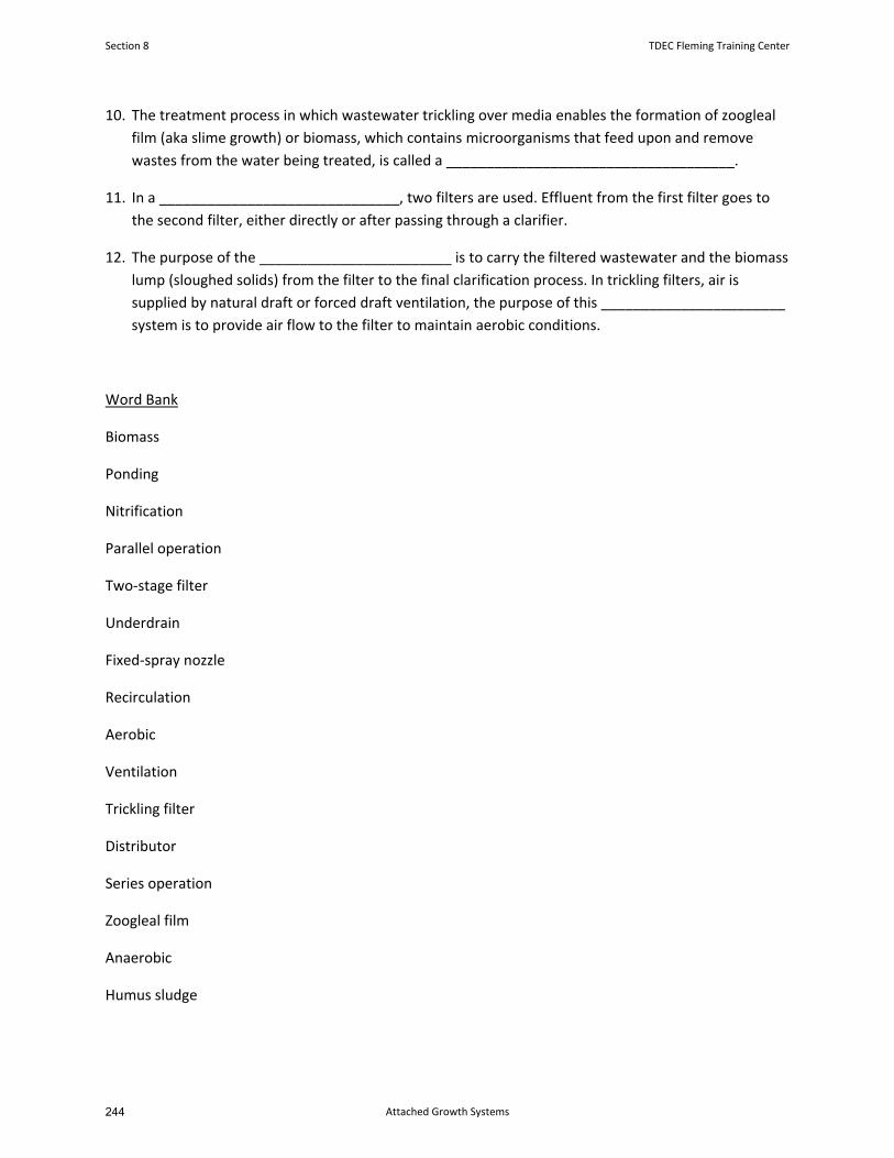
10. The treatment process in which wastewater trickling over media enables the formation of zoogleal
film (aka slime growth) or biomass, which contains microorganisms that feed upon and remove
wastes from the water being treated, is called a ____________________________________.
11. In a ______________________________, two filters are used. Effluent from the first filter goes to
the second filter, either directly or after passing through a clarifier.
12. The purpose of the ________________________ is to carry the filtered wastewater and the biomass
lump (sloughed solids) from the filter to the final clarification process. In trickling filters, air is
supplied by natural draft or forced draft ventilation, the purpose of this _______________________
system is to provide air flow to the filter to maintain aerobic conditions.
Word Bank
Biomass
Ponding
Nitrification
Parallel operation
Two‐stage filter
Underdrain
Fixed‐spray nozzle
Recirculation
Aerobic
Ventilation
Trickling filter
Distributor
Series operation
Zoogleal film
Anaerobic
Humus sludge
Section 8 TDEC Fleming Training Center
Attached Growth Systems244
Attached Growth Review Questions
1. Primary treatment is effective in removing __________________________ and
__________________________, but it is not nearly as effective in
removing_____________________________ and __________________________, which is why
secondary treatment is required.
Scum and floatable solids
Dissolved solids
Settleable solids
Small suspended solids
(colloids)
2. Describe the general wastewater treatment process of trickling filters and rotating biological
contactors (RBCs).
3. List the benefits of recirculation in a trickling filter.
4. How does recirculation increase the efficiency of a trickling filter?
5. Recirculation provides multiple benefits to a trickling filter, however, why is it advised to use the
minimum (lowest) recirculation rate that will still produce good quality effluent?
TDEC Fleming Training Center Section 8
Attached Growth Systems 243

6. What are the advantages of natural (rock) media? What are the advantages of synthetic (plastic)
media?
7. What is the function of a secondary clarifier following a trickling filter or RBC?
8. Explain why a trickling filter and an RBC would be intentionally shocked with chlorine.
9. Why would a cover or enclosure be used with an RBC?
10. Why is the RBC process divided into 4 or more stages?
Section 8 TDEC Fleming Training Center
Attached Growth Systems246
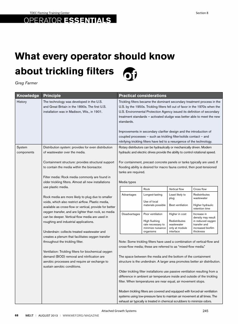
68 WE&T l AUGUST 2013 l WWW.WEF.ORG/MAGAZINE
What every operator should know
about trickling filtersGreg Farmer
OPERATOR ESSENTIALS
Knowledge Principle Practical considerationsHistory The technology was developed in the U.S.
and Great Britain in the 1890s. The first U.S.
installation was in Madison, Wis., in 1901.
Trickling filters became the dominant secondary treatment process in the
U.S. by the 1950s. Trickling filters fell out of favor in the 1970s when the
U.S. Environmental Protection Agency issued its definition of secondary
treatment standards — activated sludge was better able to meet the new
standards.
Improvements in secondary clarifier design and the introduction of
coupled processes — such as trickling filter/solids contact — and
nitrifying trickling filters have led to a resurgence of the technology.
System
components
Distribution system: provides for even distribution
of wastewater over the media.
Containment structure: provides structural support
to contain the media within the bioreactor.
Filter media: Rock media commonly are found in
older trickling filters. Almost all new installations
use plastic media.
Rock media are more likely to plug due to smaller
voids, which also restrict airflow. Plastic media,
available as cross-flow or vertical, provide for better
oxygen transfer, and are lighter than rock, so media
can be deeper. Vertical-flow media are used in
roughing and industrial applications.
Underdrain: collects treated wastewater and
creates a plenum that facilitates oxygen transfer
throughout the trickling filter.
Ventilation: Trickling filters for biochemical oxygen
demand (BOD) removal and nitrification are
aerobic processes and require air exchange to
sustain aerobic conditions.
Rotary distributors can be hydraulically or mechanically driven. Modern
hydraulic and electric drives provide the ability to control rotational speed.
For containment, precast concrete panels or tanks typically are used. If
flooding ability is desired for macro fauna control, then post-tensioned
tanks are required.
Media types
Note: Some trickling filters have used a combination of vertical-flow and
cross-flow media; these are referred to as “mixed-flow media.”
The space between the media and the bottom of the containment
structure is the underdrain. A larger area promotes better air distribution.
Older trickling filter installations use passive ventilation resulting from a
difference in ambient air temperature inside and outside of the trickling
filter. When temperatures are near equal, air movement stops.
Modern trickling filters are covered and equipped with forced-air ventilation
systems using low-pressure fans to maintain air movement at all times. The
exhaust air typically is treated in chemical scrubbers to minimize odors.
Rock Vertical flow Cross flow
Advantages Longest-lasting
Use of local materials possible
Least likely to plug
Best ventilation
Redistributes wastewater
Higher hydraulic retention time
Disadvantages Poor ventilation
High flushing rate necessary to minimize nuisance organisms
Higher in cost
Redistributes wastewater only at module interface
Increase in density may result in reduced oxygen transfer and increased biofilm thickness
TDEC Fleming Training Center Section 8
Attached Growth Systems 245
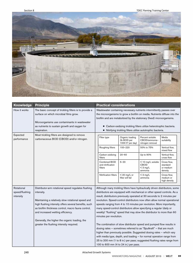
WWW.WEF.ORG/MAGAZINE l AUGUST 2013 l WE&T 69
Knowledge Principle Practical considerationsHow it works The basic concept of trickling filters is to provide a
surface on which microbial films grow.
Microorganisms use contaminants in wastewater
as nutrients to sustain growth and oxygen for
respiration.
Wastewater containing necessary nutrients intermittently passes over
the microorganisms to grow a biofilm on media. Nutrients diffuse into the
biofilm and are metabolized by the stationary (fixed) microorganisms.
■ Carbon-oxidizing trickling filters utilize heterotrophic bacteria.
■ Nitrifying trickling filters utilize autotrophic bacteria.
Expected
performance
Most trickling filters are designed to remove
carbonaceous BOD (CBOD) and/or nitrogen.
Rotational
speed/flushing
intensity
Distributor-arm rotational speed regulates flushing
intensity.
Maintaining a relatively slow rotational speed and
high flushing intensity offers several benefits, such
as biofilm thickness control, macro fauna control,
and increased wetting efficiency.
Generally, the higher the organic loading, the
greater the flushing intensity required.
Although many trickling filters have hydraulically driven distributors, some
distributors are equipped with mechanical or other speed controls. As a
result, distributors previously operated at 30 seconds to 2 minutes per
revolution. Speed-control distributors now often allow normal operational
speeds ranging from 4 to 10 minutes per revolution. More importantly,
many speed-control distributors allow specifying a regular (daily or
weekly) “flushing” speed that may slow the distributor to more than 60
minutes per revolution.
The combination of slow distributor speed and pumped flow results in
dosing rates — sometimes referred to as “Spulkraft” — that are much
higher than previously possible. Suggested dosing rates — which vary
with media type, depth, and loading — for normal operation range from
25 to 200 mm (1 to 8 in.) per pass; suggested flushing rates range from
100 to 600 mm (4 to 24 in.) per pass.
Filter type Organic loading (lb BOD per 1000 ft3 per day)
Percent soluble CBOD/ammonia–nitrogen removal
Media suitability
Roughing filters 100–220 50% to 75% Vertical flow, mixed flow
Carbon oxidizing filters
20–60 Up to 90% Vertical flow, cross flow
Combined BOD and nitrification filters
5–20 < 10 mg/L soluble CBOD< 3 mg/L ammonia
Cross flow, standard or medium density
Nitrification filters < 20 mg/L or filter will fail
< 3 mg/L ammonia
Cross flow, medium or high density
Section 8 TDEC Fleming Training Center
Attached Growth Systems248
70 WE&T l AUGUST 2013 l WWW.WEF.ORG/MAGAZINE
Greg Farmer is a process specialist at the Littleton/Englewood (Colo.) Wastewater Treatment Plant.
Knowledge Principle Practical considerationsMacro fauna Snails are the No. 1 reported predator
within trickling filters.
Detrimental effects of snail infestations include grazing of nitrifying biofilm and accumulation in aeration basins, process channels, and digesters. Trickling filters with higher organic loading rates typically do not undergo problems with snails.
Filter (Psychoda) and crane flies (look like large mosquitoes) lay eggs on the media. The larvae graze on the biofilm.
Many problems associated with macro fauna can be controlled by increasing flushing intensity. Snail-control mechanisms include filter flooding — either alone or with the addition of sodium hydroxide to raise pH — or maintaining high concentrations of ammonia, which is toxic to snails.
Some facilities have developed snail traps to contain and remove snails from trickling filter effluent lines and aeration tanks.
Recirculation and hydraulic wetting
The ability to recirculate flow to the trickling filter can be used to increase oxygen or ensure good wetting of the media.
The hydraulic wetting rate is the application rate of wastewater to the trickling filter, including recirculation, expressed as gal/min•ft2.
Recirculation provides the ability to maintain a consistent flow to the trickling filter during diurnal flow variations, provides for consistent rotation speeds for hydraulically driven distributor arms, and maintains proper wetting rates.
Low wetting rates can result in nonuniform application of wastewater and unwetted areas that can attract snails and filter flies. Biofilm that is not wetted continuously and supplied with food from the wastewater becomes ineffective. The typical suggested hydraulic wetting rate range for BOD removal systems is 30 to 40 L/min•m2 (0.75 to 1.0 gal/min•ft2). For nitrification systems, the range is 30 to 80 L/min•m2 (0.75 to 2.0 gal/min•ft2).
For speed-controlled distributors, the introduction of regular flushing of the trickling filter and improved wetting through high instantaneous dosing rates make past criteria for hydraulic wetting and recirculation of secondary or little concern. Operators should track the past criteria but may find better operation by establishing a good dosing program.
Boost Your Productivity in sludge dewatering
TDEC Fleming Training Center Section 8
Attached Growth Systems 247

250

Section 9
Disinfection
249
Wastewater Disinfection and Chlorination
TDEC - Fleming Training Center 1
Disinfection
• The MAIN purpose of disinfection is to destroypathogenic microorganisms and thus preventspread of disease
• Pathogenic = disease‐causing
• Ultimate measure of effectiveness isbacteriological result
TDEC - Fleming Training Center 2
Removal of Pathogenic Microorganisms
• Wastewater treatment removes some of thepathogenic microorganisms through theseprocesses:
– Physical removal through sedimentation andfiltration
– Natural die‐off in an unfavorable environment
– Destruction by chemicals introduced for treatment purposes
TDEC - Fleming Training Center 3
Effectiveness of Microorganism Removal
Treatment Process Microorganism Removal, %
Screening 10 – 20 %
Grit Channel 10 – 25 %
Primary Sedimentation 25 – 75 %
Chemical Precipitation 40 – 80 %
Trickling Filters 90 – 95 %
Activated Sludge 90 – 98 %
Chlorination 98 – 99 %
Ozone 98.5 – 99.5 %*
UV Radiation 99 – 99.9 %**
TDEC - Fleming Training Center 4
*Depends on microorganisms and contact time**Depends on microorganisms and UV intensity and contact time
Disinfection vs. Sterilization
• Disinfection is the destruction of allpathogenic microorganisms– Chlorination of wastewater is consideredadequate when the
• Fecal coliform count has been reduced to 200 cfu*/100 mL or less
• E. coli count has been reduced to 126 cfu/100 mL orless
• Sterilization is the destruction of ALLmicroorganisms
TDEC - Fleming Training Center 5
*cfu = colony forming unit
Pathogenic OrganismsDiseases that are spread through water (waterborne diseases):
◦ Bacterial
Cholera
Typhoid
Salmonellosis
Shigellosis, a bacillarydysentery
Gastroenteritis from enteropathogenic Escherichia coli
◦ Protozoa
Amoebic Dysentery
Giardiasis
Cryptosporidiosis
◦ Viral
Polio
Hepatitis A
Viral gastroenteritis
TDEC - Fleming Training Center 6
Section 9 TDEC Fleming Training Center
Disinfection252
Disinfection
• The main objective of disinfection is toprevent the spread of disease by protecting:– Public water supplies
– Receiving waters used for recreational purposes
• Protect water where human contact is likely
– Fisheries and shellfish growing areas
– Irrigation and agricultural waters
– Receiving waters that are a source of beneficial water reuse
TDEC - Fleming Training Center 7
Chlorine Chemicals
Elemental chlorine◦ Yellow‐green gas or amber liquid◦ 100% chlorine
Sodium hypochlorite – Bleach◦ Clear, pale yellow liquid◦ 5‐15% chlorine
Calcium hypochlorite – HTH◦ White, pale yellow granules or tablets◦ 65% chlorine
Chlorine dioxide◦ Green‐yellow gas generated on‐site
TDEC - Fleming Training Center 8
Chemical formulas
• Elemental chlorine (Free chlorine)
– Cl2
• Hypochlorite (OCl‐)
– Sodium hypochlorite ‐ Bleach
• NaOCl
– Calcium hypochlorite – HTH
• Ca(OCl)2
• Chlorine dioxide
– ClO2TDEC - Fleming Training Center 9
Chlorine
• Reacts with:
– Hydrogen sulfide (H2S)
– Iron
– Manganese
– Nitrite
– Phenols
– Ammonia
– And lastly used for disinfection
TDEC - Fleming Training Center 10
Chlorine Demand
What is Chlorine Demand?
• The difference between the amount ofchlorine added to water and the amount ofresidual remaining after a given contact time.
Demand = Dose ‐ Residual
• Chlorine demand may change with dosage,time, temperature, pH, and thenature/amount of impurities in the water
TDEC - Fleming Training Center 11
Chemistry of Chlorination
• Each form of chlorine (Cl2, OCl‐, ClO2) has a
similar reaction with water and forms:
Hypochlorous Acid or Hypochlorite
• Adding any form of chlorine to wastewaterresults in hydrolysis
Hydrolysis = a chemical reaction in which a compound is converted into another compoundby taking up water
TDEC - Fleming Training Center 12
TDEC Fleming Training Center Section 9
Disinfection 251
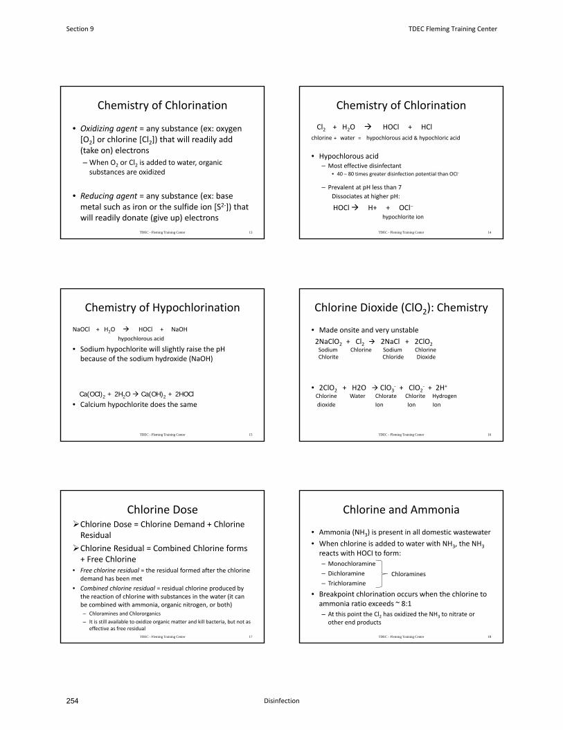
Chemistry of Chlorination
• Oxidizing agent = any substance (ex: oxygen[O2] or chlorine [Cl2]) that will readily add(take on) electrons
– When O2 or Cl2 is added to water, organicsubstances are oxidized
• Reducing agent = any substance (ex: basemetal such as iron or the sulfide ion [S2‐]) thatwill readily donate (give up) electrons
TDEC - Fleming Training Center 13
Chemistry of Chlorination
Cl2 + H2O HOCl + HCl
chlorine + water = hypochlorous acid & hypochloric acid
• Hypochlorous acid– Most effective disinfectant
• 40 – 80 times greater disinfection potential than OCI‐
– Prevalent at pH less than 7
Dissociates at higher pH:
HOCl H+ + OCl
hypochlorite ion
TDEC - Fleming Training Center 14
Chemistry of Hypochlorination
NaOCl + H2O HOCl + NaOH
hypochlorous acid
• Sodium hypochlorite will slightly raise the pHbecause of the sodium hydroxide (NaOH)
• Calcium hypochlorite does the same
TDEC - Fleming Training Center 15
Ca(OCl)2 + 2H2O Ca(OH)2 + 2HOCl
Chlorine Dioxide (ClO2): Chemistry
• Made onsite and very unstable
2NaClO2 + Cl2 2NaCl + 2ClO2Sodium Chlorine Sodium ChlorineChlorite Chloride Dioxide
• 2ClO2 + H2O ClO3‐ + ClO2
‐ + 2H+
Chlorine Water Chlorate Chlorite Hydrogen
dioxide Ion Ion Ion
TDEC - Fleming Training Center 16
Chlorine DoseChlorine Dose = Chlorine Demand + ChlorineResidual
Chlorine Residual = Combined Chlorine forms+ Free Chlorine
• Free chlorine residual = the residual formed after the chlorine demand has been met
• Combined chlorine residual = residual chlorine produced by the reaction of chlorine with substances in the water (it canbe combined with ammonia, organic nitrogen, or both)
– Chloramines and Chlororganics
– It is still available to oxidize organic matter and kill bacteria, but not as effective as free residual
TDEC - Fleming Training Center 17
Chlorine and Ammonia
• Ammonia (NH3) is present in all domestic wastewater
• When chlorine is added to water with NH3, the NH3
reacts with HOCI to form:
– Monochloramine
– Dichloramine
– Trichloramine
• Breakpoint chlorination occurs when the chlorine toammonia ratio exceeds ~ 8:1
– At this point the Cl2 has oxidized the NH3 to nitrate orother end products
TDEC - Fleming Training Center 18
Chloramines
Section 9 TDEC Fleming Training Center
Disinfection254
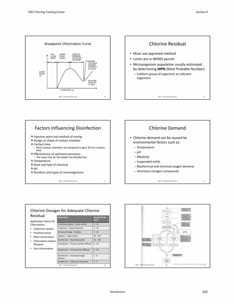
Breakpoint Chlorination Curve
TDEC - Fleming Training Center 19
Chlorine Residual
• Must use approved method
• Limits are in NPDES permit
• Microorganism population usually estimated by determining MPN (Most Probable Number)
– Coliform group of organisms as indicator organisms
TDEC - Fleming Training Center 20
Factors Influencing Disinfection
Injection point and method of mixing Design or shape of contact chamber Contact time◦ Most contact chambers are designed to give 30 min contact time
Effectiveness of upstream processes◦ The lower the SS, the better the disinfection
Temperature Dose and type of chemical pH Numbers and types of microorganisms
TDEC - Fleming Training Center 21
Chlorine Demand
• Chlorine demand can be caused by environmental factors such as:
– Temperature
– pH
– Alkalinity
– Suspended solids
– Biochemical and chemical oxygen demand
– Ammonia nitrogen compounds
TDEC - Fleming Training Center 22
Chlorine Dosages for Adequate Chlorine ResidualApplication Points for Chlorination:
• Collection system
• Prechlorination
• Plant chlorination
• Chlorination before filtration
• Post‐chlorination
Application Dosage Range, mg/L
Collection System – Slime control 1 ‐ 15
Treatment – Grease Removal 1 ‐ 10
Activated Sludge – Bulking 1 ‐ 10
Digester – Supernatant 20 ‐ 150
Disinfection – Raw Wastewater 10 ‐ 130
Disinfection – Primary Clarifier Effluent 5 ‐ 20
Disinfection – Trickling Filter Effluent 3 ‐ 20
Disinfection – Activated Sludge Effluent
2 ‐ 8
Disinfection – Advanced Treatment 1 ‐ 5
TDEC - Fleming Training Center 23 TDEC - Fleming Training Center 24Figure 10.3 Operation of Wastewater Treatment Plants, Vol II, Seventh edition, p.355
TDEC Fleming Training Center Section 9
Disinfection 253
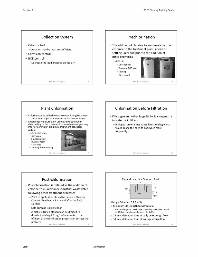
Collection System
• Odor control
– Aeration may be most cost efficient
• Corrosion control
• BOD control
– Decrease the load imposed on the STP
TDEC - Fleming Training Center 25
Prechlorination
• The addition of chlorine to wastewater at the entrance to the treatment plant, ahead of settling units and prior to the addition of other chemicals
– Aids in:
• Odor control
• Decrease BOD load
• Settling
• Oil removal
TDEC - Fleming Training Center 26
Plant Chlorination
• Chlorine can be added to wastewater during treatment– The point of application depends on the desired results
• Emergency measure only, use extreme care when chlorinating in the treatment process because you may interfere or inhibit biological treatment processes
• Aids in:– Control of odors– Corrosion– Sludge bulking– Digester foam– Filter flies– Trickling Filter Ponding
TDEC - Fleming Training Center 27
Chlorination Before Filtration
• Kills algae and other large biological organisms in water or in filters
– Biological growth may cause filters to clog which would cause the need to backwash more frequently
TDEC - Fleming Training Center 28
Post‐chlorination• Post‐chlorination is defined as the addition of chlorine to municipal or industrial wastewater following other treatment processes
– Point of application should be before a Chlorine Contact Chamber or Basin and after the final clarifier
– Sole purpose is disinfection
– A highly nitrified effluent can be difficult to disinfect, adding 1.5 mg/L of ammonia to the effluent of the nitrification process can correct the problem
TDEC - Fleming Training Center 29
Typical Layout ‐ Contact Basin
• Design Criteria (10.2.2.4‐5):
o Minimum 30:1 length to width ratioo The total length of the channel created by the baffles should
be 30 times the distance between the baffles
o 15 min. detention time at daily peak design flow
o 30 min. detention time at average design flow
TDEC - Fleming Training Center 30
Section 9 TDEC Fleming Training Center
Disinfection256
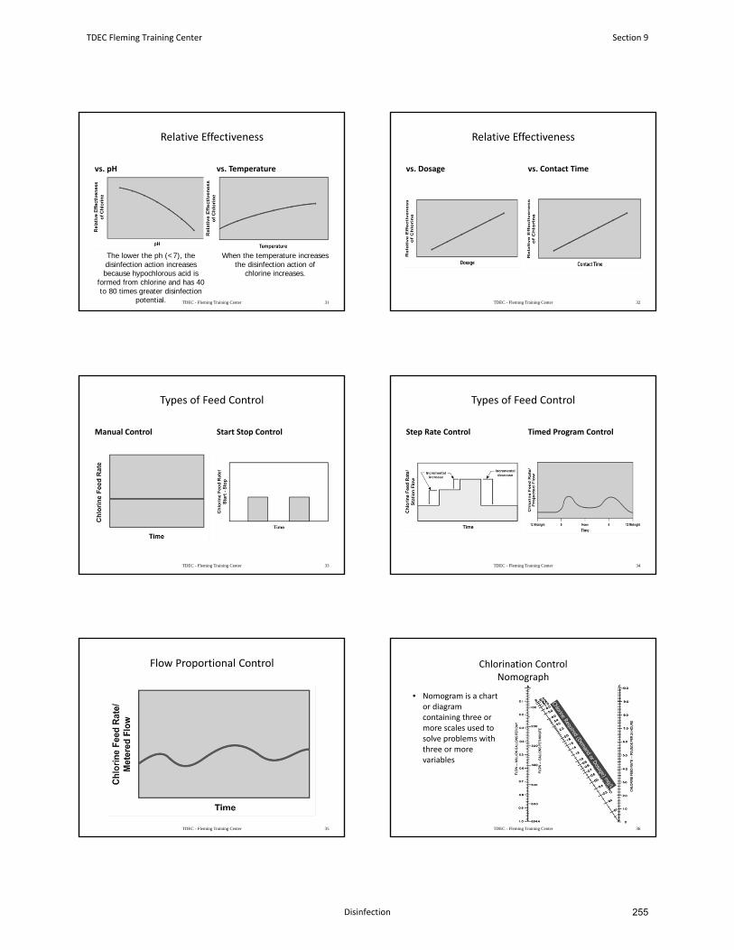
Relative Effectiveness
vs. pH vs. Temperature
TDEC - Fleming Training Center 31
When the temperature increases the disinfection action of
chlorine increases.
The lower the ph (<7), the disinfection action increases because hypochlorous acid is
formed from chlorine and has 40 to 80 times greater disinfection
potential.
Relative Effectiveness
vs. Dosage vs. Contact Time
TDEC - Fleming Training Center 32
Types of Feed Control
Manual Control Start Stop Control
TDEC - Fleming Training Center 33
Types of Feed Control
Step Rate Control Timed Program Control
TDEC - Fleming Training Center 34
Flow Proportional Control
TDEC - Fleming Training Center 35
Chlorination Control Nomograph
• Nomogram is a chart or diagram containing three or more scales used to solve problems with three or more variables
TDEC - Fleming Training Center 36
TDEC Fleming Training Center Section 9
Disinfection 255
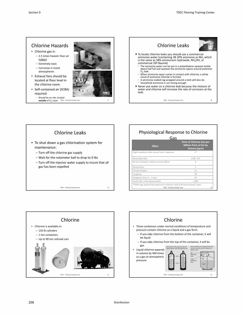
Chlorine Hazards• Chlorine gas is:
– 2.5 times heavier than air (video)
– Extremely toxic
– Corrosive in moist atmospheres
• Exhaust fans should be located at floor level in the chlorine room.
• Self‐contained air (SCBA) required– Should be on‐site, located
outside of Cl2 room TDEC - Fleming Training Center 37
Chlorine Leaks
To locate chlorine leaks you should use a commercial ammonia water (containing 28‐30% ammonia as NH3 which is the same as 58% ammonium hydroxide, NH4OH, or commercial 26º Baumé)◦ The ammonia water can be put in a polyethylene squeeze bottle
about half full and squeeze the ammonia vapors around potential Cl2 leak.
◦ When ammonia vapor comes in contact with chlorine, a white cloud of ammonia chloride is formed.
◦ A ammonia soaked rag wrapped around a stick will also do. ◦ Household ammonia is not strong enough.
Never put water on a chlorine leak because the mixture of water and chlorine will increase the rate of corrosion at the leak.
TDEC - Fleming Training Center 38
Chlorine Leaks
• To shut down a gas chlorination system for maintenance:
– Turn off the chlorine gas supply
– Wait for the rotameter ball to drop to 0 lbs
– Turn off the injector water supply to insure that all gas has been expelled
TDEC - Fleming Training Center 39
Physiological Response to Chlorine Gas
Effect
Parts of Chlorine Gas per Million Parts of Air by
Volume (ppm)
Slight symptoms after several hours’ exposure 1*
Detectable odor 0.08 – 0.4
60‐min inhalation without serious effects 4
Noxiousness 5
Throat irritation 15
Coughing 30
Dangerous from ½ ‐ 1 hour 40
Death after a few deep breaths 1,000
*OSHA regs specify that exposure to chlorine shall at NO time exceed 1 ppm.TDEC - Fleming Training Center 40
Chlorine• Chlorine is available in:
– 150 lb cylinders
– 1 ton containers
– Up to 90 ton railroad cars
TDEC - Fleming Training Center 41
Chlorine• These containers under normal conditions of temperature and
pressure contain chlorine as a liquid and a gas form.
– If you take chlorine from the bottom of the container, it will be liquid
– If you take chlorine from the top of the container, it will be gas
• Liquid chlorine expands in volume by 460 times as a gas at atmospheric pressure
TDEC - Fleming Training Center 42
Section 9 TDEC Fleming Training Center
Disinfection258
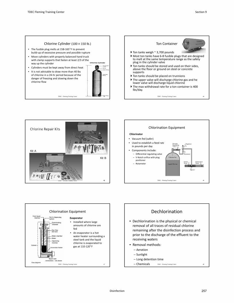
Chlorine Cylinder (100 or 150 lb.)
TDEC - Fleming Training Center 43
• The fusible plug melts at 158‐165°F to prevent build‐up of excessive pressure and possible rupture
• Move cylinders with properly balanced hand truck with clamp supports that fasten at least 2/3 of the way up the cylinder
• Cylinders must be kept away from direct heat
• It is not advisable to draw more than 40 lbsof chlorine in a 24‐hr period because of the danger of freezing and slowing down the chlorine flow
Ton Container
Ton tanks weigh ~ 3,700 poundsMost ton tanks have 6‐8 fusible plugs that are designed to melt at the same temperature range as the safety plug in the cylinder valve
Ton tanks should be stored and used on their sides, above the floor or ground on steel or concrete supports
Ton tanks should be placed on trunnions The upper valve will discharge chlorine gas and he lower valve will discharge liquid chlorine
The max withdrawal rate for a ton container is 400 lbs/day.
TDEC - Fleming Training Center 44
Chlorine Repair Kits
TDEC - Fleming Training Center 45
Kit A
Kit B
Chlorination Equipment
• Vacuum fed (safer)
• Used to establish a feed rate in pounds per day
• Components include:– Differential regulating valve
– V‐Notch orifice with plug positioner
– Rotameter
TDEC - Fleming Training Center 46
Chlorinator
Chlorination Equipment
Evaporator
• Installed where large amounts of chlorine are fed
• An evaporator is a hot water heater surrounding a steel tank and the liquid chlorine is evaporated to gas at 110‐120°F
TDEC - Fleming Training Center 47
Dechlorination
• Dechlorination is the physical or chemical removal of all traces of residual chlorine remaining after the disinfection process and prior to the discharge of the effluent to the receiving waters
• Removal methods:
– Aeration
– Sunlight
– Long detention time
– Chemicals TDEC - Fleming Training Center 48
TDEC Fleming Training Center Section 9
Disinfection 257
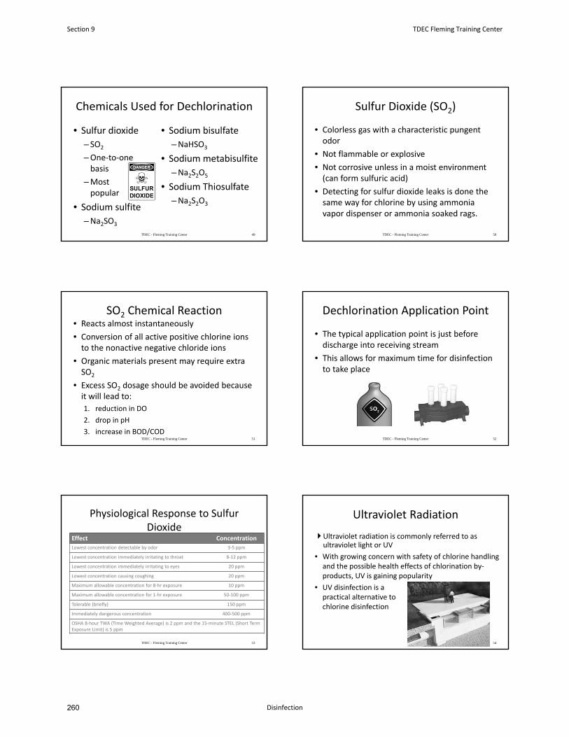
Chemicals Used for Dechlorination
• Sulfur dioxide
– SO2
–One‐to‐one basis
–Most popular
• Sodium sulfite
–Na2SO3
• Sodium bisulfate
–NaHSO3
• Sodium metabisulfite
–Na2S2O5
• Sodium Thiosulfate
–Na2S2O3
TDEC - Fleming Training Center 49
Sulfur Dioxide (SO2)
• Colorless gas with a characteristic pungent odor
• Not flammable or explosive
• Not corrosive unless in a moist environment (can form sulfuric acid)
• Detecting for sulfur dioxide leaks is done the same way for chlorine by using ammonia vapor dispenser or ammonia soaked rags.
TDEC - Fleming Training Center 50
SO2 Chemical Reaction• Reacts almost instantaneously
• Conversion of all active positive chlorine ions to the nonactive negative chloride ions
• Organic materials present may require extra SO2
• Excess SO2 dosage should be avoided because it will lead to:
1. reduction in DO
2. drop in pH
3. increase in BOD/CODTDEC - Fleming Training Center 51
Dechlorination Application Point
• The typical application point is just before discharge into receiving stream
• This allows for maximum time for disinfection to take place
TDEC - Fleming Training Center 52
Physiological Response to Sulfur Dioxide
Effect Concentration
Lowest concentration detectable by odor 3‐5 ppm
Lowest concentration immediately irritating to throat 8‐12 ppm
Lowest concentration immediately irritating to eyes 20 ppm
Lowest concentration causing coughing 20 ppm
Maximum allowable concentration for 8‐hr exposure 10 ppm
Maximum allowable concentration for 1‐hr exposure 50‐100 ppm
Tolerable (briefly) 150 ppm
Immediately dangerous concentration 400‐500 ppm
OSHA 8‐hour TWA (Time Weighted Average) is 2 ppm and the 15‐minute STEL (Short Term Exposure Limit) is 5 ppm
TDEC - Fleming Training Center 53
Ultraviolet Radiation
Ultraviolet radiation is commonly referred to as ultraviolet light or UV
• With growing concern with safety of chlorine handling and the possible health effects of chlorination by‐products, UV is gaining popularity
• UV disinfection is a practical alternative to chlorine disinfection
54
Section 9 TDEC Fleming Training Center
Disinfection260
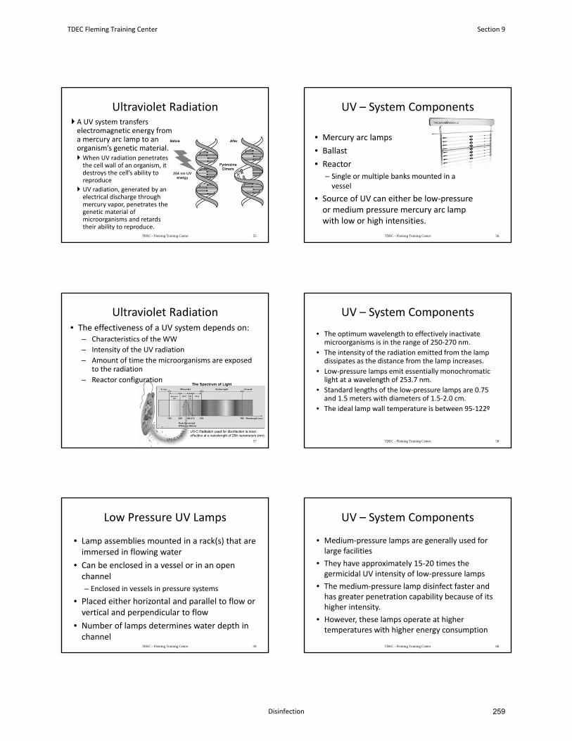
Ultraviolet Radiation A UV system transfers electromagnetic energy from a mercury arc lamp to an organism’s genetic material. When UV radiation penetrates the cell wall of an organism, it destroys the cell’s ability to reproduce
UV radiation, generated by an electrical discharge through mercury vapor, penetrates the genetic material of microorganisms and retards their ability to reproduce.
TDEC - Fleming Training Center 55
UV – System Components
• Mercury arc lamps
• Ballast
• Reactor
– Single or multiple banks mounted in a vessel
• Source of UV can either be low‐pressure or medium pressure mercury arc lamp with low or high intensities.
TDEC - Fleming Training Center 56
Ultraviolet Radiation• The effectiveness of a UV system depends on:
– Characteristics of the WW
– Intensity of the UV radiation
– Amount of time the microorganisms are exposed to the radiation
– Reactor configuration
57
UV – System Components
• The optimum wavelength to effectively inactivate microorganisms is in the range of 250‐270 nm.
• The intensity of the radiation emitted from the lamp dissipates as the distance from the lamp increases.
• Low‐pressure lamps emit essentially monochromatic light at a wavelength of 253.7 nm.
• Standard lengths of the low‐pressure lamps are 0.75 and 1.5 meters with diameters of 1.5‐2.0 cm.
• The ideal lamp wall temperature is between 95‐122º
TDEC - Fleming Training Center 58
Low Pressure UV Lamps
• Lamp assemblies mounted in a rack(s) that are immersed in flowing water
• Can be enclosed in a vessel or in an open channel
– Enclosed in vessels in pressure systems
• Placed either horizontal and parallel to flow or vertical and perpendicular to flow
• Number of lamps determines water depth in channel
TDEC - Fleming Training Center 59
UV – System Components
• Medium‐pressure lamps are generally used for large facilities
• They have approximately 15‐20 times the germicidal UV intensity of low‐pressure lamps
• The medium‐pressure lamp disinfect faster and has greater penetration capability because of its higher intensity.
• However, these lamps operate at higher temperatures with higher energy consumption
TDEC - Fleming Training Center 60
TDEC Fleming Training Center Section 9
Disinfection 259
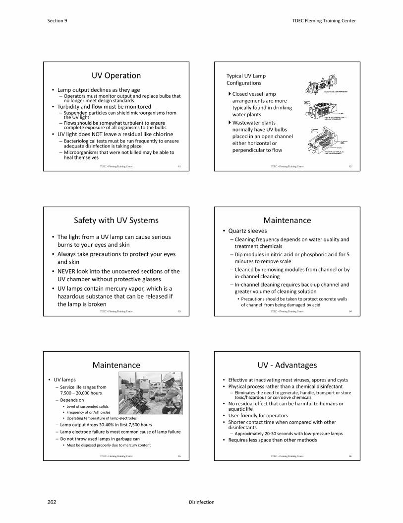
UV Operation
• Lamp output declines as they age– Operators must monitor output and replace bulbs that no longer meet design standards
• Turbidity and flow must be monitored– Suspended particles can shield microorganisms from the UV light
– Flows should be somewhat turbulent to ensure complete exposure of all organisms to the bulbs
• UV light does NOT leave a residual like chlorine– Bacteriological tests must be run frequently to ensure adequate disinfection is taking place
– Microorganisms that were not killed may be able to heal themselves
TDEC - Fleming Training Center 61
Typical UV Lamp Configurations
Closed vessel lamp arrangements are more typically found in drinking water plants
Wastewater plants normally have UV bulbs placed in an open channel either horizontal or perpendicular to flow
TDEC - Fleming Training Center 62
Safety with UV Systems
• The light from a UV lamp can cause serious burns to your eyes and skin
• Always take precautions to protect your eyes and skin
• NEVER look into the uncovered sections of the UV chamber without protective glasses
• UV lamps contain mercury vapor, which is a hazardous substance that can be released if the lamp is broken
TDEC - Fleming Training Center 63
Maintenance• Quartz sleeves
– Cleaning frequency depends on water quality and treatment chemicals
– Dip modules in nitric acid or phosphoric acid for 5 minutes to remove scale
– Cleaned by removing modules from channel or by in‐channel cleaning
– In‐channel cleaning requires back‐up channel and greater volume of cleaning solution
• Precautions should be taken to protect concrete walls of channel from being damaged by acid
TDEC - Fleming Training Center 64
Maintenance
• UV lamps
– Service life ranges from 7,500 – 20,000 hours
– Depends on
• Level of suspended solids
• Frequency of on/off cycles
• Operating temperature of lamp electrodes
– Lamp output drops 30‐40% in first 7,500 hours
– Lamp electrode failure is most common cause of lamp failure
– Do not throw used lamps in garbage can
• Must be disposed properly due to mercury content
TDEC - Fleming Training Center 65
UV ‐ Advantages
• Effective at inactivating most viruses, spores and cysts• Physical process rather than a chemical disinfectant
– Eliminates the need to generate, handle, transport or store toxic/hazardous or corrosive chemicals
• No residual effect that can be harmful to humans or aquatic life
• User‐friendly for operators• Shorter contact time when compared with other disinfectants – Approximately 20‐30 seconds with low‐pressure lamps
• Requires less space than other methods
TDEC - Fleming Training Center 66
Section 9 TDEC Fleming Training Center
Disinfection262
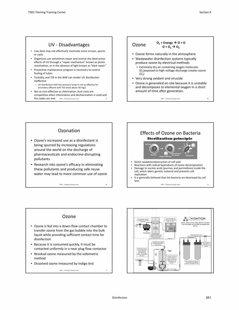
UV ‐ Disadvantages• Low dose may not effectively inactivate some viruses, spores
or cysts
• Organisms can sometimes repair and reverse the destructive effects of UV through a “repair mechanism” known as photo reactivation, or in the absence of light known as “dark repair”
• Preventive maintenance program is necessary to control fouling of tubes
• Turbidity and TSS in the WW can render UV disinfection ineffective
– UV disinfection with low‐pressure lamps is not as effective for secondary effluent with TSS levels above 30 mg/L
• Not as cost‐effective as chlorination, bust costs are competitive when chlorination and dechlorination is used and fire codes are met TDEC - Fleming Training Center 67
Ozone
• Ozone forms naturally in the atmosphere
• Wastewater disinfection systems typically produce ozone by electrical methods• Extremely dry air containing oxygen molecules (O2)exposed to high‐voltage discharge creates ozone (O3)
• Very strong oxidant and virucide
• Ozone is generated on‐site because it is unstable and decomposes to elemental oxygen in a short amount of time after generation.
TDEC - Fleming Training Center 68
O2 + Energy O + OO + O2 O3
Ozonation
• Ozone’s increased use as a disinfectant is being spurred by increasing regulations around the world on the discharge of pharmaceuticals and endocrine‐disrupting pollutants
• Research into ozone’s efficacy in eliminating these pollutants and producing safe reuse water may lead to more common use of ozone
TDEC - Fleming Training Center 69
Effects of Ozone on Bacteria
• Direct oxidation/destruction of cell wall• Reactions with radical byproducts of ozone decomposition• Damage to nucleic acids (purines and pyrimidines) inside the
cell, which alters genetic material and prevents cell replication
• It is generally believed that the bacteria are destroyed by cell lysis
TDEC - Fleming Training Center 70
Ozone
• Ozone is fed into a down‐flow contact chamber to transfer ozone from the gas bubble into the bulk liquid while providing sufficient contact time for disinfection
• Because it is consumed quickly, it must be contacted uniformly in a near plug flow contactor
• Residual ozone measured by the iodometricmethod
• Dissolved ozone measured by Indigo test
TDEC - Fleming Training Center 71 TDEC - Fleming Training Center 72
TDEC Fleming Training Center Section 9
Disinfection 261

Ozone
• Effectiveness depends on:
– Susceptibility of the target organisms
–Contact time
–Concentration of ozone
• The key process control guidelines are dose, mixing, and contact time
TDEC - Fleming Training Center 73
Maintenance
• Inspect electrical equipment and pressure vessels monthly
• Conduct a yearly preventive maintenance program
– Should be done by a factory representative or an operator trained by the manufacturer
• Lubricate moving parts according to manufacturer’s recommendations
TDEC - Fleming Training Center 74
Safety
• Ozone is a toxic gas and is a hazard to plants and animals
• When ozone breaks down in the atmosphere, the resulting pollutants can be very harmful
• Ozone contactors must have a system to collect ozone off‐gas.
– Ozone generating installations must include a thermal or catalytic ozone destroyer
TDEC - Fleming Training Center 75
Ozone ‐ Advantages
• More effective than chlorine in destroying viruses and bacteria
• Short contact time (10‐30 min)• No harmful residues left in water• No re‐growth of microorganisms
– Except for those protected by particulates in water
• Generated on‐site– Fewer safety problems associated with shipping and handling
• Elevates DO levels in effluent– Can eliminate needs for post aeration– Can raise DO levels in receiving stream
TDEC - Fleming Training Center 76
Ozone ‐ Disadvantages
• Low dose may not effectively inactivate some viruses, spores and cysts
• More complex technology– Requiring more complex equipment and efficient contacting
systems
• Very reactive and corrosive– Requiring corrosive‐resistant materials such as stainless steel
• Not economical for WW with high levels of solids, BOD, COD or total organic carbon (TOC)
• Extremely irritating and possibly toxic to humans at concentrations of 1 ppm or greater in air
• Cost can be high in capital and power intensiveness
TDEC - Fleming Training Center 77
Peracetic Acid (PAA)
• A mixture of acetic acid and hydrogen peroxide and water
• Strong “vinegar” smell
• Oxidation results in pathogenic cell lysis
TDEC - Fleming Training Center 78
Section 9 TDEC Fleming Training Center
Disinfection264
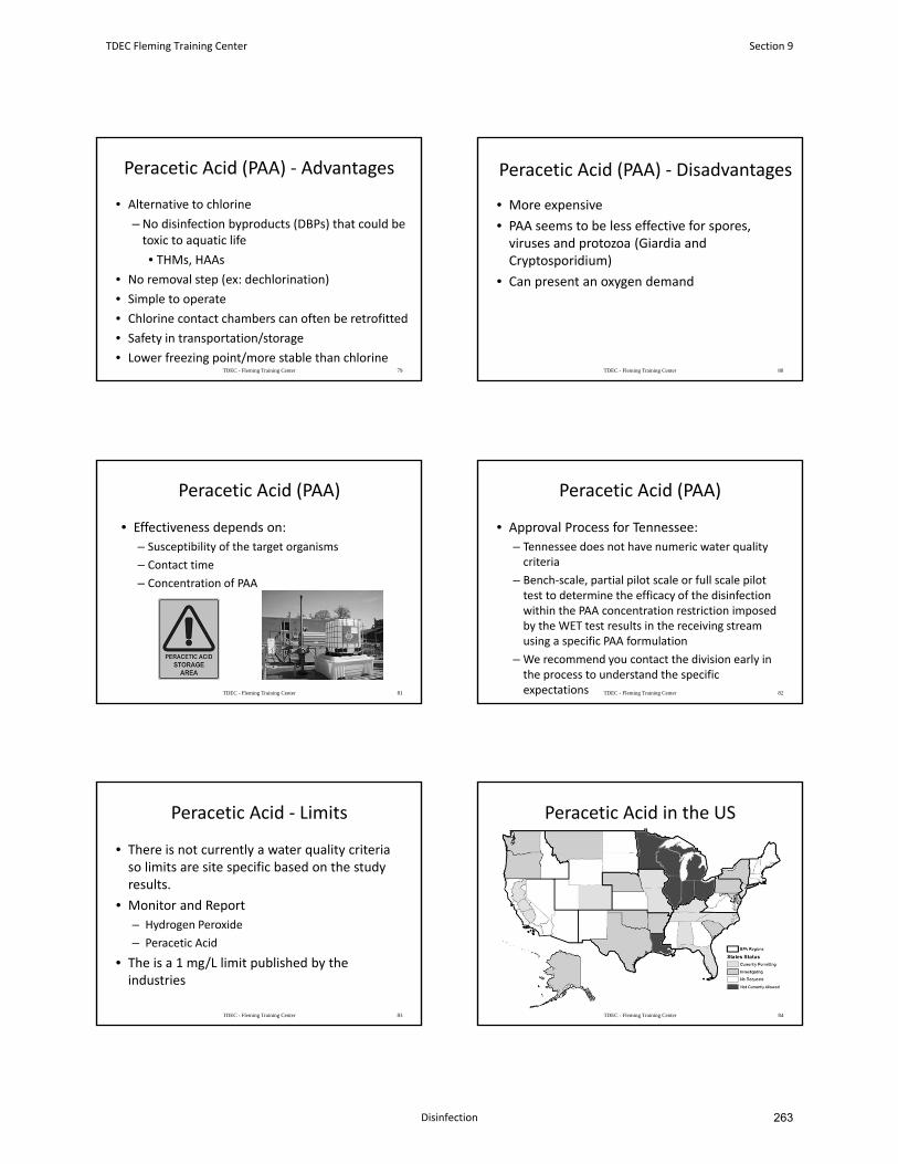
Peracetic Acid (PAA) ‐ Advantages
• Alternative to chlorine
– No disinfection byproducts (DBPs) that could be toxic to aquatic life
• THMs, HAAs
• No removal step (ex: dechlorination)
• Simple to operate
• Chlorine contact chambers can often be retrofitted
• Safety in transportation/storage
• Lower freezing point/more stable than chlorineTDEC - Fleming Training Center 79
Peracetic Acid (PAA) ‐ Disadvantages
• More expensive
• PAA seems to be less effective for spores, viruses and protozoa (Giardia and Cryptosporidium)
• Can present an oxygen demand
TDEC - Fleming Training Center 80
Peracetic Acid (PAA)
• Effectiveness depends on:
– Susceptibility of the target organisms
– Contact time
– Concentration of PAA
TDEC - Fleming Training Center 81
Peracetic Acid (PAA)
• Approval Process for Tennessee:
– Tennessee does not have numeric water quality criteria
– Bench‐scale, partial pilot scale or full scale pilot test to determine the efficacy of the disinfection within the PAA concentration restriction imposed by the WET test results in the receiving stream using a specific PAA formulation
– We recommend you contact the division early in the process to understand the specific expectations TDEC - Fleming Training Center 82
Peracetic Acid ‐ Limits
• There is not currently a water quality criteria so limits are site specific based on the study results.
• Monitor and Report
– Hydrogen Peroxide
– Peracetic Acid
• The is a 1 mg/L limit published by the industries
TDEC - Fleming Training Center 83
Peracetic Acid in the US
TDEC - Fleming Training Center 84
TDEC Fleming Training Center Section 9
Disinfection 263
Peracetic Acid in TN
• Tullahoma Utilities Authority WWTP
• Lexington, TN
• Memphis, TN
TDEC - Fleming Training Center 85
• Any Questions?
TDEC - Fleming Training Center 86
Section 9 TDEC Fleming Training Center
Disinfection266
January 2016 10-1 Design Criteria Ch. 10
CHAPTER 10
Disinfection
10.1 General
10.1.1 Requirement for Disinfection
10.1.2 Methods of Disinfection
10.1.3 Dechlorination
10.2 Chlorination
10.2.1 General
10.2.2 Design Considerations
10.2.3 Design Details
10.2.4 Safety
10.3 Alternate Methods
10.3.1 Ozonation
10.3.2 Ultraviolet Disinfection
TDEC Fleming Training Center Section 9
Disinfection 265
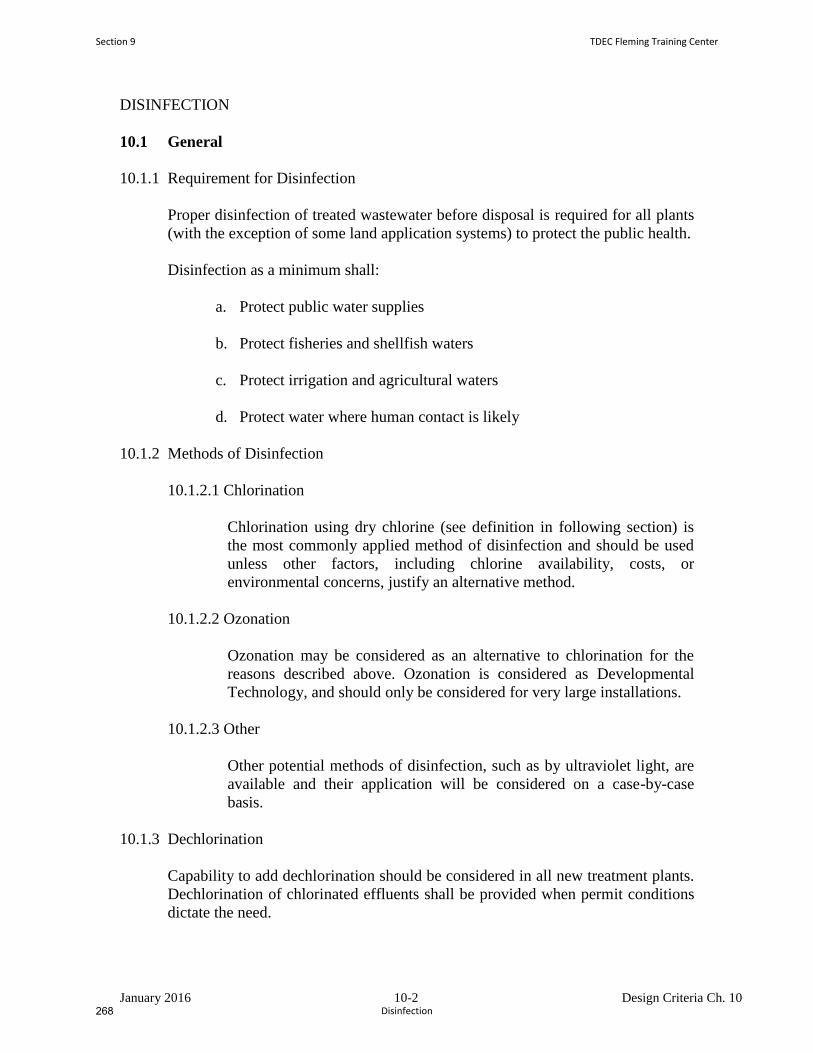
January 2016 10-2 Design Criteria Ch. 10
DISINFECTION
10.1 General
10.1.1 Requirement for Disinfection
Proper disinfection of treated wastewater before disposal is required for all plants
(with the exception of some land application systems) to protect the public health.
Disinfection as a minimum shall:
a. Protect public water supplies
b. Protect fisheries and shellfish waters
c. Protect irrigation and agricultural waters
d. Protect water where human contact is likely
10.1.2 Methods of Disinfection
10.1.2.1 Chlorination
Chlorination using dry chlorine (see definition in following section) is
the most commonly applied method of disinfection and should be used
unless other factors, including chlorine availability, costs, or
environmental concerns, justify an alternative method.
10.1.2.2 Ozonation
Ozonation may be considered as an alternative to chlorination for the
reasons described above. Ozonation is considered as Developmental
Technology, and should only be considered for very large installations.
10.1.2.3 Other
Other potential methods of disinfection, such as by ultraviolet light, are
available and their application will be considered on a case-by-case
basis.
10.1.3 Dechlorination
Capability to add dechlorination should be considered in all new treatment plants.
Dechlorination of chlorinated effluents shall be provided when permit conditions
dictate the need.
Section 9 TDEC Fleming Training Center
Disinfection268
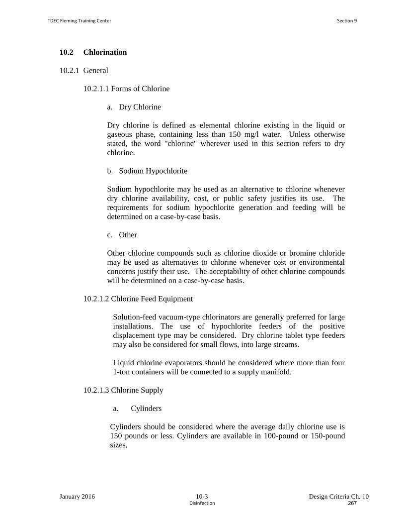
January 2016 10-3 Design Criteria Ch. 10
10.2 Chlorination
10.2.1 General
10.2.1.1 Forms of Chlorine
a. Dry Chlorine
Dry chlorine is defined as elemental chlorine existing in the liquid or
gaseous phase, containing less than 150 mg/l water. Unless otherwise
stated, the word "chlorine" wherever used in this section refers to dry
chlorine.
b. Sodium Hypochlorite
Sodium hypochlorite may be used as an alternative to chlorine whenever
dry chlorine availability, cost, or public safety justifies its use. The
requirements for sodium hypochlorite generation and feeding will be
determined on a case-by-case basis.
c. Other
Other chlorine compounds such as chlorine dioxide or bromine chloride
may be used as alternatives to chlorine whenever cost or environmental
concerns justify their use. The acceptability of other chlorine compounds
will be determined on a case-by-case basis.
10.2.1.2 Chlorine Feed Equipment
Solution-feed vacuum-type chlorinators are generally preferred for large
installations. The use of hypochlorite feeders of the positive
displacement type may be considered. Dry chlorine tablet type feeders
may also be considered for small flows, into large streams.
Liquid chlorine evaporators should be considered where more than four
1-ton containers will be connected to a supply manifold.
10.2.1.3 Chlorine Supply
a. Cylinders
Cylinders should be considered where the average daily chlorine use is
150 pounds or less. Cylinders are available in 100-pound or 150-pound
sizes.
TDEC Fleming Training Center Section 9
Disinfection 267
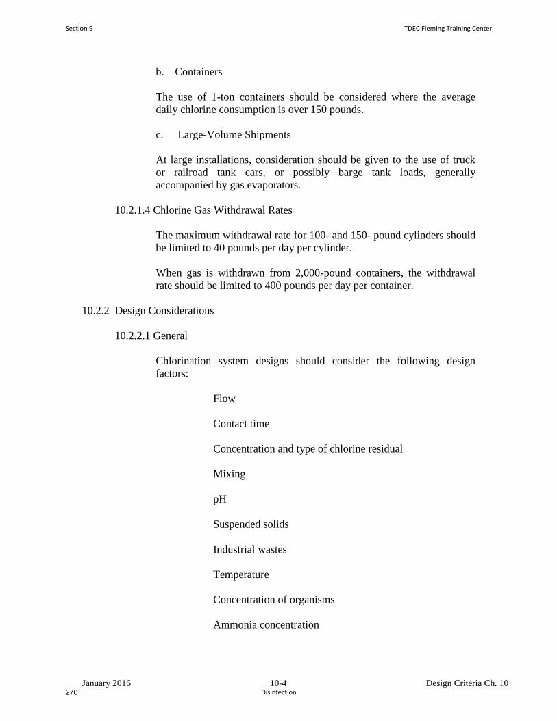
January 2016 10-4 Design Criteria Ch. 10
b. Containers
The use of 1-ton containers should be considered where the average
daily chlorine consumption is over 150 pounds.
c. Large-Volume Shipments
At large installations, consideration should be given to the use of truck
or railroad tank cars, or possibly barge tank loads, generally
accompanied by gas evaporators.
10.2.1.4 Chlorine Gas Withdrawal Rates
The maximum withdrawal rate for 100- and 150- pound cylinders should
be limited to 40 pounds per day per cylinder.
When gas is withdrawn from 2,000-pound containers, the withdrawal
rate should be limited to 400 pounds per day per container.
10.2.2 Design Considerations
10.2.2.1 General
Chlorination system designs should consider the following design
factors:
Flow
Contact time
Concentration and type of chlorine residual
Mixing
pH
Suspended solids
Industrial wastes
Temperature
Concentration of organisms
Ammonia concentration
Section 9 TDEC Fleming Training Center
Disinfection270
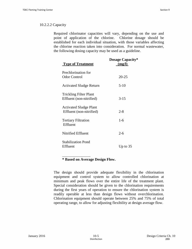
January 2016 10-5 Design Criteria Ch. 10
10.2.2.2 Capacity
Required chlorinator capacities will vary, depending on the use and
point of application of the chlorine. Chlorine dosage should be
established for each individual situation, with those variables affecting
the chlorine reaction taken into consideration. For normal wastewater,
the following dosing capacity may be used as a guideline.
Dosage Capacity*
Type of Treatment (mg/l)
Prechlorination for
Odor Control 20-25
Activated Sludge Return 5-10
Trickling Filter Plant
Effluent (non-nitrified) 3-15
Activated Sludge Plant
Effluent (non-nitrified) 2-8
Tertiary Filtration 1-6
Effluent
Nitrified Effluent 2-6
Stabilization Pond
Effluent Up to 35
* Based on Average Design Flow.
The design should provide adequate flexibility in the chlorination
equipment and control system to allow controlled chlorination at
minimum and peak flows over the entire life of the treatment plant.
Special consideration should be given to the chlorination requirements
during the first years of operation to ensure the chlorination system is
readily operable at less than design flows without overchlorination.
Chlorination equipment should operate between 25% and 75% of total
operating range, to allow for adjusting flexibility at design average flow.
TDEC Fleming Training Center Section 9
Disinfection 269
January 2016 10-6 Design Criteria Ch. 10
10.2.2.3 Mixing
The mixing of chlorine and wastewater can be accomplished by
hydraulic or mechanical mixing.
Hydraulic mixing is preferred in smaller plants over mechanical mixing
and should be done according to the following criteria.
a. Pipe Flow:
A Reynolds Number of greater than or equal to 1.9 X 10⁴ is required.
Pipes up to 30 inches in diameter: chlorine injected into center of pipe.
Pipes greater than 30 inches in diameter: chlorine injected with a
grid-type diffuser.
Chlorine applied at least 10 pipe diameters upstream from inlet to
contact tank.
b. Open channel flow:
A hydraulic jump with a minimum Froude Number of 4.5 is necessary to
provide adequate hydraulic mixing. Point of chlorine injection must be
variable because jump location will change with changes in flow.
When mechanical mixing must be used, the following criteria apply:
Use where Reynolds Number for pipe flow is less than 1.9 X 10⁴ or for
open channel flow without a hydraulic jump.
A mixer-reactor unit is necessary that provides 6 to 18 seconds contact.
Inject chlorine just upstream from mixer.
Mixer speed a minimum of 50 revolutions per minute (rpm).
Jet Chlorinators may be used in a separate chamber from the contact
chamber.
The contact chamber shall conform to Section 10.2.2.4 with an average
design flow minimum detention time reduced to 15 minutes and a peak
detention time of 7.5 minutes.
Section 9 TDEC Fleming Training Center
Disinfection272
January 2016 10-7 Design Criteria Ch. 10
10.2.2.4 Contact Period
Contact chambers shall be sized to provide a minimum of 30 minutes
detention at average design flow and 15 minutes detention at daily peak
design flow, whichever is greater. Contact chambers should be designed
so detention times are less than 2 hours for initial flows.
10.2.2.5 Contact Chambers
The contact chambers should be baffled to minimize short-circuiting
and backmixing of the chlorinated wastewater to such an extent that plug
flow is approached. It is recommended that baffles be constructed
parallel to the longitudinal axis of the chamber with a minimum
length-to-width ratio of 30:1 (the total length of the channel created by
the baffles should be 30 times the distance between the baffles).
Shallow unidirectional contact chambers should also have cross-baffles
to reduce short-circuiting caused by wind currents.
Provision shall be made for removal of floating and settleable solids
from chlorine contact tanks or basins without discharging inadequately
disinfected effluent. To accomplish continuous disinfection, the
chlorine contact tank should be designed with duplicate compartments to
permit draining and cleaning of individual compartments. A sump or
drain within each compartment, with the drainage flowing to a raw
sewage inlet, shall be provided for dewatering, sludge accumulation, and
maintenance. Unit drains shall not discharge into the outfall pipeline.
Baffles shall be provided to prevent the discharge of floating material.
A readily accessible sampling point shall be provided at the outlet end of
the contact chamber.
In some instances, the effluent line may be used as chlorine contact
chambers provided that the conditions set forth above are met.
10.2.2.6 Dechlorination
a. Sulfur Dioxide
Sulfur dioxide can be purchased, handled, and applied to wastewater in
the same way as chlorine. Sulfur dioxide gas forms sulfurous acid, a
strong reducing agent, when combined with water. When mixed with
free and combined chlorine residuals, sulfurous acid will neutralize these
active chlorine compounds to the nontoxic chloride ion.
Sulfur dioxide dosage required for dechlorination is 1 mg/l of SO2 for 1
mg/l of chlorine residual expressed as Cl2. Reaction time is essentially
TDEC Fleming Training Center Section 9
Disinfection 271
January 2016 10-8 Design Criteria Ch. 10
instantaneous. Detention time requirements are based on the time
necessary to assure complete mixing of the sulfur dioxide.
b. Other Methods
For very small treatment systems, detention ponds should be considered
for dechlorination.
Design rationale and calculations shall be submitted upon request to
justify the basis of design for all major components of other
dechlorination processes.
10.2.2.7 Sampling, Instrumentation, and Control
For treatment facility designs of 0.5 mgd and greater, continuously
modulated dosage control systems should be used. The control system
should adjust the chlorine dosage rate to accommodate fluctuations in
effluent chlorine demand and residual caused by changes in waste flow
and waste characteristics with a maximum lag time of five minutes.
These facilities should also utilize continuous chlorine residual
monitoring.
Flow proportional control is preferred over manual control for smaller
facilities and may be required on a case-by-case basis. The design shall
shut off the chlorination for small systems where the flow is zero, such
as late at night.
In all cases where dechlorination is required, a compound loop control
system or equivalent should be provided.
All sample lines should be designed so that they can be easily purged of
slimes and other debris and drain or be protected from freezing.
Alarms and monitoring equipment that adequately alert the operators in
the event of deficiencies, malfunctions, or hazardous situations related to
chlorine supply metering equipment, leaks, and residuals may be
required on a case-by-case basis.
Design of instrumentation and control equipment should allow operation
at initial and design flows.
Section 9 TDEC Fleming Training Center
Disinfection274
January 2016 10-9 Design Criteria Ch. 10
10.2.2.8 Residual Chlorine Testing
Equipment should be provided for measuring chlorine residual.
There are five EPA accepted methods for analysis of total residual
chlorine and they are:
1) Ion Selective Electrode,
2) Amperometric End Point Titration Method,
3) Iodometric Titration Methods I & II,
4) DPD Colormetric Method and,
5) DPD Ferrous Titrimetric Method.
Where the discharge occurs in critical areas, the installation of facilities
for continuous automatic chlorine residual analysis and recording
systems may be required.
10.2.3 Design Details
10.2.3.1 Housing
a. General
An enclosed structure shall be provided for the chlorination equipment.
Chlorine cylinder or container storage area shall be shaded from direct
sunlight.
Chlorination systems should be protected from fire hazards, and water
should be available for cooling cylinders or containers in case of fire.
Any building which will house chlorine equipment or containers should
be designed and constructed to protect all elements of the chlorine
system from fire hazards. If flammable materials are stored or processed
in the same building with chlorination equipment (other than that
utilizing hypochlorite solutions), a firewall should be erected to separate
the two areas.
If gas chlorination equipment and chlorine cylinders or containers are to
be in a building used for other purposes, a gastight partition shall
separate this room from any other portion of the building. Doors to this
room shall open only to the outside of the building and shall be equipped
with panic hardware. Such rooms should be at or above ground level
and should permit easy access to all equipment.
TDEC Fleming Training Center Section 9
Disinfection 273
January 2016 10-10 Design Criteria Ch. 10
A reinforced glass, gastight window shall be installed in an exterior door
or interior wall of the chlorinator room to permit the chlorinator to be
viewed without entering the room.
Adequate room must be provided for easy access to all equipment for
maintenance and repair. The minimum acceptable clearance around and
in back of equipment is 2 feet, except for units designed for wall or
cylinder mounting.
b. Heat
Chlorinator rooms should have a means of heating and controlling the
room air temperature above a minimum of 55° F. A temperature of 65°
F is recommended.
The room housing chlorine cylinders or containers in use should be
maintained at a temperature less than the chlorinator room, but in no
case less than 55° F unless evaporators are used and liquid chlorine is
withdrawn.
All rooms containing chlorine should also be protected from excess heat.
The room containing ozone generation units shall be maintained above
35oF at all times.
c. Ventilation
All chlorine feed rooms and rooms where chlorine is stored should be
force-ventilated, providing one air change per minute, except "package"
buildings with less than 16 square feet of floor space, where an entire
side opens as a door and sufficient cross-ventilation is provided by a
window. For ozonation systems, continuous ventilation to provide at
least 6 complete air changes per hour should be installed. The entrance
to the air exhaust duct from the room should be near the floor and the
point of discharge should be so located as not to contaminate the air inlet
to any building or inhabited areas. The air inlet should be located to
provide cross-ventilation by air at a temperature that will not adversely
affect the chlorination equipment.
Chlorinators and some accessories require individual vents to a safe
outside area. The vent should terminate not more than 25 feet above the
chlorinator or accessory and have a slight downward slope from the
highest point. The outside end of the vent should bend down to preclude
water entering the vent and be covered with a screen to exclude insects.
Section 9 TDEC Fleming Training Center
Disinfection276
January 2016 10-11 Design Criteria Ch. 10
d. Electrical
Electrical controls for lights and the ventilation system should operate
automatically when the entrance doors are opened. Manually controlled
override switches should be located adjacent to and outside of all
entrance doors, with an indicator light at each entrance. Electrical
controls should be excluded, insofar as possible, from rooms containing
chlorine cylinders, chlorine piping, or chlorination equipment.
e. Dechlorination equipment (SO2) shall not be placed in the same room
as the Cl2 equipment. SO2 equipment is to be located such that the
safety requirements of handling Cl2 are not violated in any form or
manner.
10.2.3.2 Piping and Connections
a. Dry Chlorine
Piping systems should be as simple as possible, with a minimum number
of joints; piping should be well supported, adequately sloped to allow
drainage, protected from mechanical damage, and protected against
temperature extremes.
The piping system to handle gas under pressure should be constructed of
Schedule 80 black seamless steel pipe with 2,000-pound forged steel
fittings. Unions should be ammonia type with lead gaskets. All valves
should be Chlorine Institute-approved. Gauges should be equipped with
a silver protector diaphragm.
Piping can be assembled by either welded or threaded connections. All
threaded pipe must be cleaned with solvent, preferably trichlorethylene,
and dried with nitrogen gas or dry air. Teflon tape should be used for
thread lubricant in lieu of pipe dope.
b. Injector Vacuum Line
The injector vacuum line between the chlorinator and the injector should
be Schedule 80 PVC or fiber cast pipe approved for moist chlorine use.
c. Chlorine Solution
The chlorine solution lines can be Schedule 40 or 80 PVC, rubber-lined
steel, saran-lined steel, or fiber cast pipe approved for moist chlorine
use. Valves should be PVC, PVC-lined, or rubber- lined.
TDEC Fleming Training Center Section 9
Disinfection 275
January 2016 10-12 Design Criteria Ch. 10
10.2.3.3 Water Supply
An ample supply of water shall be available for operating the
chlorinator. Where a booster pump is required, duplicate equipment
shall be provided, and, when necessary, standby power as well. When
connection is made from domestic water supplies, equipment for
backflow prevention shall be provided. Where treated effluent is used, a
wye strainer shall be required. Pressure gauges should be provided on
chlorinator water supply lines.
10.2.3.4 Standby Equipment and Spare Parts
Standby chlorination capabilities should be provided which will ensure
adequate disinfection with any unit out of operation for maintenance or
repairs. An adequate inventory of parts subject to wear and breakage
should be maintained at all times.
10.2.3.5 Scales
Scales shall be provided at all plants using chlorine gas. At large plants,
scales of the indicating and recording type are recommended. Scales
shall be provided for each cylinder or container in service; one scale is
adequate for a group of cylinders or containers connected to a common
manifold. Scales should be constructed of or coated with
corrosion-resistant material. Scales shall be recommended for day tanks
when using HTH.
10.2.3.6 Handling Equipment
Handling equipment should be provided as follows for 100- and
150-pound cylinders:
A hand truck specifically designed for cylinders
A method of securing cylinders to prevent them from falling over
Handling equipment should be provided as follows for 2,000-pound
containers:
Two-ton-capacity hoist
Cylinder lifting bar
Section 9 TDEC Fleming Training Center
Disinfection278
January 2016 10-13 Design Criteria Ch. 10
Monorail or hoist with sufficient lifting height to pass one cylinder over
another cylinder trunnions to allow rotating the cylinders for proper
connection.
10.2.3.7 Container Space
Sufficient space should be provided in the supply area for at least one
spare cylinder or container for each one in service.
10.2.3.8 Automatic Switchover of Cylinders and Containers
Automatic switchover of chlorine cylinders and containers at facilities
having less than continuous operator attendance is desirable and will be
required on a case-by-case basis.
10.2.4 Safety
10.2.4.1 Leak Detection and Controls
A bottle of 56% ammonium hydroxide solution shall be available for
detecting chlorine leaks.
All installations utilizing 2,000-pound containers and having less than
continuous operator attendance shall have suitable continuous chlorine
leak detectors. Continuous chlorine leak detectors would be desirable at
all installations. Whenever chlorine leak detectors are installed, they
should be connected to a centrally located alarm system and shall
automatically start exhaust fans.
10.2.4.2 Breathing Apparatus
At least one gas mask in good operating condition and of a type
approved by the National Institute for Occupational Safety and Health
(NIOSH) as suitable for high concentrations of chlorine gas shall be
available at all installations where chlorine gas is handled and shall be
stored outside of any room where chlorine is used or stored. Instructions
for using, testing, and replacing mask parts, including canisters, shall be
posted. At large installations, where 1-ton containers are used,
self- contained air breathing apparatus of the positive pressure type shall
be provided.
TDEC Fleming Training Center Section 9
Disinfection 277
January 2016 10-14 Design Criteria Ch. 10
10.2.4.3 Container Repair Kits
All installations utilizing 1-ton containers should have Chlorine Institute
Emergency Container Kits. Other installations using cylinders should
have access to kits stored at a central location.
10.2.4.4 Piping Color Codes
It is desirable to color code all piping related to chlorine systems.
10.3 Alternate Methods
10.3.1 Ozonation
10.3.1.1 Application
Ozonation may be substituted for chlorination whenever chlorine
availability, cost, or environmental benefits justify its
application.
Ozone is generated on-site from either air or high-purity oxygen.
Ozonation should be considered if high-purity oxygen is
available at the plant for other processes.
10.3.1.2 Design Basis
The design requirements for ozonation systems should be based
on pilot testing or similar full-scale installations.
As a minimum, the following design factors should be
considered:
a. Ozone dosage
b. Dispersion and mixing of ozone in wastewater
c. Contactor design
All design criteria shall be submitted upon request to justify the
basis of design of the ozonation system. The detailed design
requirements will be determined on a case-by-case basis.
Section 9 TDEC Fleming Training Center
Disinfection280
January 2016 10-15 Design Criteria Ch. 10
10.3.2 Ultraviolet Disinfection
10.3.2.1 Application
UV disinfection may be substituted for chlorination, particularly
whenever chlorine availability, cost, or environmental benefits
justify its application. For tertiary treatment plants where
dechlorination is required or chlorine toxicity is suspected, UV
disinfection is a viable alternative.
10.3.2.2 Design Basis
In the design of UV disinfection units there are three basic areas
that should be considered:
a. Reactor hydraulics
b. Factors affecting transmission of UV light to the
microorganisms
c. Properties of the wastewater being disinfected.
UV disinfection is considered as Developmental Technology and
all design criteria shall be submitted upon request to justify the
basis of the UV disinfection system. The detailed design
requirements will be determined on a case-by-case basis.
TDEC Fleming Training Center Section 9
Disinfection 279

Disinfection Vocabulary
1. Disease‐causing microorganisms, including bacteria, viruses, and parasites, are referred to as
_______________________ organisms. If this type of organism is found in water, it is capable of
causing a _________________________________, such as Typhoid.
2. The destruction of all pathogenic microorganisms is called ________________________, which is
not to be confused with ______________________________, in which all microorganisms
(pathogenic and nonpathogenic) are destroyed.
3. Elemental chlorine (Cl2), which is in a liquid or gaseous form, is also known as ________________
_____________________. It combines with water to form hypochlorous (HOCl) and hydrochloric
(HCl) acids. In wastewater, it will combine with ammonia or nitrogen (or other organic compounds)
to form combined chlorine compounds.
4. _________________________________ is the concentration of residual chlorine that is produced
by the reaction of chlorine with substances in the water (ex: combined with ammonia, organic
nitrogen, or both as a chloramine) and yet is still available to oxidize organic matter and kill bacteria,
although it is not as effective as free residual.
5. Any substance, such as oxygen (O2) or chlorine (Cl2), that will readily add (take on) electrons is called
an ___________________________________. When O2 or Cl2 is added to water or wastewater,
organic substances are oxidized. The opposite is a Reducing Agent.
6. The residual formed after the chlorine demand has been met is ____________________________.
7. The addition of chlorine to the plant discharge or effluent, following plant treatment, is called
______________________________.
8. The concentration of chlorine present in water after the chlorine demand has been satisfied is the
________________________________. Expressed in terms of total chlorine residual, it includes
both the free and combined/chemically bound chlorine residuals.
9. Any substance, such as base metal (iron) or the sulfide ion (S2‐),that will readily donate (give up)
electrons is called a _______________________________. The opposite is an Oxidizing Agent.
10. The demand by inorganic and organic materials is referred to as ____________________________.
In other words, it is the difference between the amount of chlorine added to water or wastewater
and the amount of residual chlorine remaining after a given contact time.
11. The addition of chlorine in the collection system, at the headworks, or prior to any other treatment
processes (mainly for odor and corrosion control) is called_________________________________.
12. ______________________________________is defined as the addition of chlorine to water or
wastewater until the chlorine demand has been satisfied. At this point, further additions of chlorine
will result in a free chlorine residual.
Section 9 TDEC Fleming Training Center
Disinfection282
13. This alternate type of disinfection is more effective than chlorine, leaves no harmful residuals, and is
generated onsite by exposing oxygen molecules to an energy source and converting them to an
unstable gas: ___________________________
14. The process of adding chlorine to water to kill disease‐causing organisms is known as
_____________________. Generally the purpose is disinfection, but frequently it is used to
accomplish other biological or chemical results.
15. _______________________________ uses ultraviolet light to destroy microorganisms by damaging
their genetic material.
Word Bank:
Chlorination
Pathogenic
Residual chlorine (aka Chlorine residual)
Oxidizing agent
Combined chlorine residual
Postchlorination
Free chlorine residual
UV disinfection
Chlorine demand
Waterborne disease
Free chlorine
Disinfection
Prechlorination
Reducing agent
Ozonation
Sterilization
Breakpoint Chlorination
TDEC Fleming Training Center Section 9
Disinfection 281
Disinfection Review Questions
1. List four infectious diseases that can be transmitted by water:
2. Explain the difference between disinfection and sterilization.
3. What are limitations of UV disinfection?
4. Name the three types of chlorine commonly used in wastewater.
5. Write out the formula for chlorine demand. Briefly describe the relationship between free chlorine
residual and combined residual chlorine.
6. When chlorine is added to water, it breaks down into two products. Name them:
Section 9 TDEC Fleming Training Center
Disinfection284
7. Which of the two products (in #6) is the most effective disinfectant?
8. Why is chlorination less effective at a higher pH?
9. What happens when chlorine is added to waters containing ammonia and why is this significant?
10. How do suspended solids and dissolved organic material in effluent affect the disinfection process?
11. The Design Criteria requires specific contact times in a chlorine contact basin, what are they?
12. What is the purpose of a fusible plug on chlorine containers? At what temperature will it melt?
13. Describe how you would look for a small chlorine leak? Why should water never be poured on a
chlorine leak?
TDEC Fleming Training Center Section 9
Disinfection 283
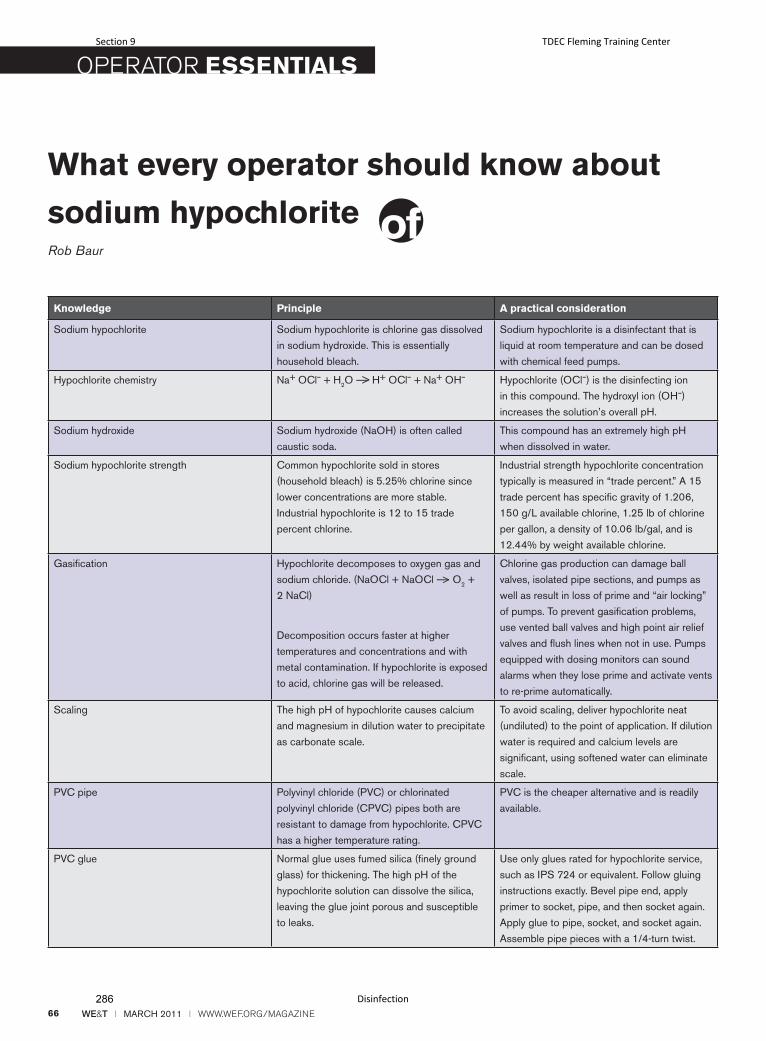
66 WE&T l MARCH 2011 l WWW.WEF.ORG/MAGAZINE
OPERATOR ESSENTIALS
What every operator should know about
sodium hypochloriteRob Baur
Knowledge Principle A practical consideration
Sodium hypochlorite Sodium hypochlorite is chlorine gas dissolved
in sodium hydroxide. This is essentially
household bleach.
Sodium hypochlorite is a disinfectant that is
liquid at room temperature and can be dosed
with chemical feed pumps.
Hypochlorite chemistry Na+ OCl– + H2O ——> H+ OCl– + Na+ OH– Hypochlorite (OCl–) is the disinfecting ion
in this compound. The hydroxyl ion (OH–)
increases the solution’s overall pH.
Sodium hydroxide Sodium hydroxide (NaOH) is often called
caustic soda.
This compound has an extremely high pH
when dissolved in water.
Sodium hypochlorite strength Common hypochlorite sold in stores
(household bleach) is 5.25% chlorine since
lower concentrations are more stable.
Industrial hypochlorite is 12 to 15 trade
percent chlorine.
Industrial strength hypochlorite concentration
typically is measured in “trade percent.” A 15
trade percent has specific gravity of 1.206,
150 g/L available chlorine, 1.25 lb of chlorine
per gallon, a density of 10.06 lb/gal, and is
12.44% by weight available chlorine.
Gasification Hypochlorite decomposes to oxygen gas and
sodium chloride. (NaOCl + NaOCl ——> O2 +
2 NaCl)
Decomposition occurs faster at higher
temperatures and concentrations and with
metal contamination. If hypochlorite is exposed
to acid, chlorine gas will be released.
Chlorine gas production can damage ball
valves, isolated pipe sections, and pumps as
well as result in loss of prime and “air locking”
of pumps. To prevent gasification problems,
use vented ball valves and high point air relief
valves and flush lines when not in use. Pumps
equipped with dosing monitors can sound
alarms when they lose prime and activate vents
to re-prime automatically.
Scaling The high pH of hypochlorite causes calcium
and magnesium in dilution water to precipitate
as carbonate scale.
To avoid scaling, deliver hypochlorite neat
(undiluted) to the point of application. If dilution
water is required and calcium levels are
significant, using softened water can eliminate
scale.
PVC pipe Polyvinyl chloride (PVC) or chlorinated
polyvinyl chloride (CPVC) pipes both are
resistant to damage from hypochlorite. CPVC
has a higher temperature rating.
PVC is the cheaper alternative and is readily
available.
PVC glue Normal glue uses fumed silica (finely ground
glass) for thickening. The high pH of the
hypochlorite solution can dissolve the silica,
leaving the glue joint porous and susceptible
to leaks.
Use only glues rated for hypochlorite service,
such as IPS 724 or equivalent. Follow gluing
instructions exactly. Bevel pipe end, apply
primer to socket, pipe, and then socket again.
Apply glue to pipe, socket, and socket again.
Assemble pipe pieces with a 1/4-turn twist.
Section 9 TDEC Fleming Training Center
Disinfection286
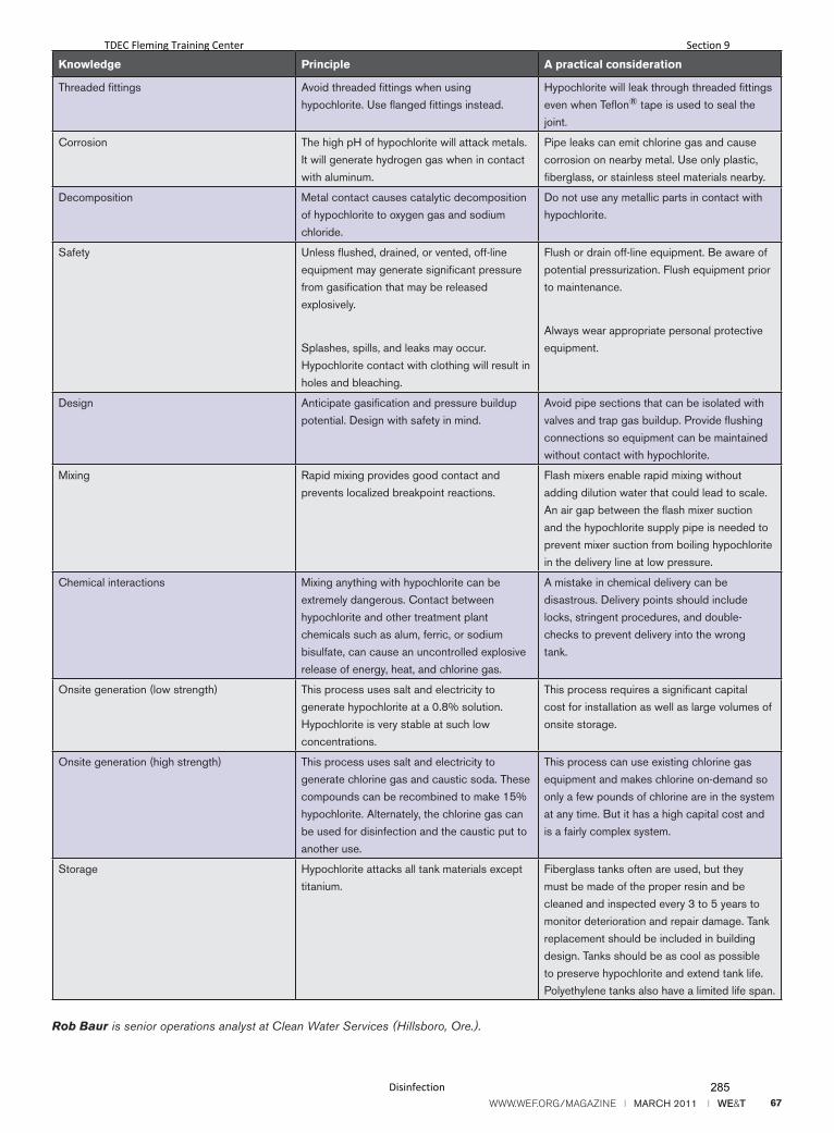
WWW.WEF.ORG/MAGAZINE l MARCH 2011 l WE&T 67
Rob Baur is senior operations analyst at Clean Water Services (Hillsboro, Ore.).
Knowledge Principle A practical consideration
Threaded fittings Avoid threaded fittings when using
hypochlorite. Use flanged fittings instead.
Hypochlorite will leak through threaded fittings
even when Teflon® tape is used to seal the
joint.
Corrosion The high pH of hypochlorite will attack metals.
It will generate hydrogen gas when in contact
with aluminum.
Pipe leaks can emit chlorine gas and cause
corrosion on nearby metal. Use only plastic,
fiberglass, or stainless steel materials nearby.
Decomposition Metal contact causes catalytic decomposition
of hypochlorite to oxygen gas and sodium
chloride.
Do not use any metallic parts in contact with
hypochlorite.
Safety Unless flushed, drained, or vented, off-line
equipment may generate significant pressure
from gasification that may be released
explosively.
Splashes, spills, and leaks may occur.
Hypochlorite contact with clothing will result in
holes and bleaching.
Flush or drain off-line equipment. Be aware of
potential pressurization. Flush equipment prior
to maintenance.
Always wear appropriate personal protective
equipment.
Design Anticipate gasification and pressure buildup
potential. Design with safety in mind.
Avoid pipe sections that can be isolated with
valves and trap gas buildup. Provide flushing
connections so equipment can be maintained
without contact with hypochlorite.
Mixing Rapid mixing provides good contact and
prevents localized breakpoint reactions.
Flash mixers enable rapid mixing without
adding dilution water that could lead to scale.
An air gap between the flash mixer suction
and the hypochlorite supply pipe is needed to
prevent mixer suction from boiling hypochlorite
in the delivery line at low pressure.
Chemical interactions Mixing anything with hypochlorite can be
extremely dangerous. Contact between
hypochlorite and other treatment plant
chemicals such as alum, ferric, or sodium
bisulfate, can cause an uncontrolled explosive
release of energy, heat, and chlorine gas.
A mistake in chemical delivery can be
disastrous. Delivery points should include
locks, stringent procedures, and double-
checks to prevent delivery into the wrong
tank.
Onsite generation (low strength) This process uses salt and electricity to
generate hypochlorite at a 0.8% solution.
Hypochlorite is very stable at such low
concentrations.
This process requires a significant capital
cost for installation as well as large volumes of
onsite storage.
Onsite generation (high strength) This process uses salt and electricity to
generate chlorine gas and caustic soda. These
compounds can be recombined to make 15%
hypochlorite. Alternately, the chlorine gas can
be used for disinfection and the caustic put to
another use.
This process can use existing chlorine gas
equipment and makes chlorine on-demand so
only a few pounds of chlorine are in the system
at any time. But it has a high capital cost and
is a fairly complex system.
Storage Hypochlorite attacks all tank materials except
titanium.
Fiberglass tanks often are used, but they
must be made of the proper resin and be
cleaned and inspected every 3 to 5 years to
monitor deterioration and repair damage. Tank
replacement should be included in building
design. Tanks should be as cool as possible
to preserve hypochlorite and extend tank life.
Polyethylene tanks also have a limited life span.
TDEC Fleming Training Center Section 9
Disinfection 285

288

Section 10
Effluent Disposal
287
EffluentDisposalIntro to Wastewater
TDEC
-Fl
emin
g Tr
aini
ng C
ente
r
1
EffluentDisposal• Dilution
• Lakes
• Rivers
• Streams
• WastewaterReclamation
• Land application
• Underground disposal
• Groundwater recharge basins
TDEC
-Fl
emin
g Tr
aini
ng C
ente
r
2
DisposalbyDilution
• Treatment required prior to discharge:
• Stabilize waste
• Protect public health
• Meet discharge requirements
• Site specific
• Most common method of effluent disposal
TDEC
-Fl
emin
g Tr
aini
ng C
ente
r
3
DisposalbyDilution
• Diffusers
• Cascading outfalls
• Increase D.O.
• Remove chlorine
• Remove sulfur dioxide
• Surface discharge
TDEC
-Fl
emin
g Tr
aini
ng C
ente
r
4
LandTreatmentofWastewaterEffluent
TDEC
-Fl
emin
g Tr
aini
ng C
ente
r
5
LandTreatmentSystems• When high‐quality effluent or even zero‐discharge is required, land treatment offers a means of reclamation or ultimate disposal
• Land treatment = the controlled application ofwastewater to the land surface to achieve adesigned degree of treatment through physical,chemical, and biological processes within theplant‐soil‐water matrix.
• Soil texture, soil structure, permeability, infiltration,available water capacity, and cation exchange capacity
• Adsorption and precipitation are the main processes involved in the retention of wastes in the soil
TDEC
-Fl
emin
g Tr
aini
ng C
ente
r
6
Section 10 TDEC Fleming Training Center
Effluent Disposal290
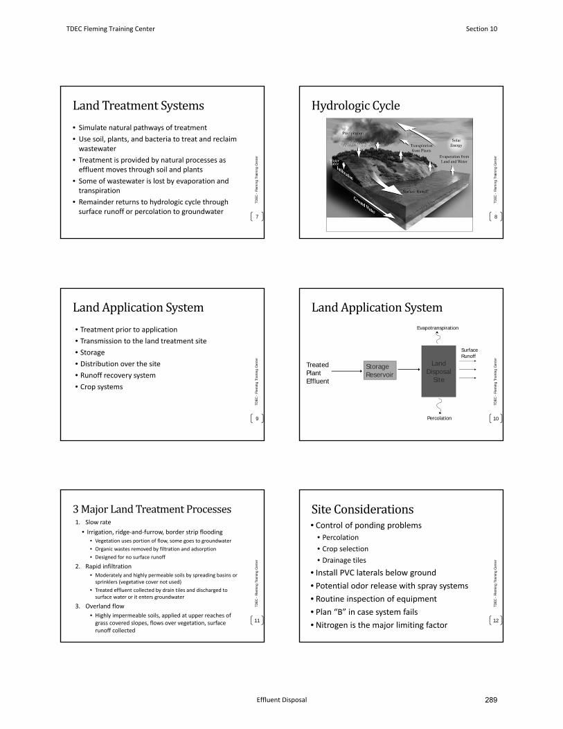
LandTreatmentSystems
• Simulate natural pathways of treatment
• Use soil, plants, and bacteria to treat and reclaim wastewater
• Treatment is provided by natural processes as effluent moves through soil and plants
• Some of wastewater is lost by evaporation andtranspiration
• Remainder returns to hydrologic cycle throughsurface runoff or percolation to groundwater
TDEC
-Fl
emin
g Tr
aini
ng C
ente
r
7
HydrologicCycle
TDEC
-Fl
emin
g Tr
aini
ng C
ente
r
8
LandApplicationSystem
• Treatment prior to application
• Transmission to the land treatment site
• Storage
• Distribution over the site
• Runoff recovery system
• Crop systems
TDEC
-Fl
emin
g Tr
aini
ng C
ente
r
9
LandApplicationSystem
TDEC
-Fl
emin
g Tr
aini
ng C
ente
r
10
Treated Plant Effluent
Storage Reservoir
Land Disposal
Site
Surface Runoff
Evapotranspiration
Percolation
3MajorLandTreatmentProcesses1. Slow rate
• Irrigation, ridge‐and‐furrow, border strip flooding• Vegetation uses portion of flow, some goes to groundwater
• Organic wastes removed by filtration and adsorption
• Designed for no surface runoff
2. Rapid infiltration• Moderately and highly permeable soils by spreading basins orsprinklers (vegetative cover not used)
• Treated effluent collected by drain tiles and discharged to surface water or it enters groundwater
3. Overland flow
• Highly impermeable soils, applied at upper reaches of grass covered slopes, flows over vegetation, surfacerunoff collected
11
TDEC
-Fl
emin
g Tr
aini
ng C
ente
r
SiteConsiderations• Control of ponding problems
• Percolation
• Crop selection
• Drainage tiles
• Install PVC laterals below ground
• Potential odor release with spray systems
• Routine inspection of equipment
• Plan “B” in case system fails
• Nitrogen is the major limiting factor
TDEC
-Fl
emin
g Tr
aini
ng C
ente
r
12
TDEC Fleming Training Center Section 10
Effluent Disposal 289
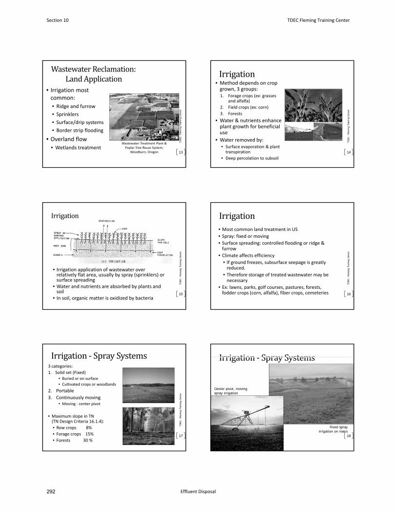
WastewaterReclamation:LandApplication
• Irrigation most common:
• Ridge and furrow
• Sprinklers
• Surface/drip systems
• Border strip flooding
• Overland flow• Wetlands treatment
TDEC
-Fl
emin
g Tr
aini
ng C
ente
r
13
Wastewater Treatment Plant & Poplar Tree Reuse System;
Woodburn, Oregon
Irrigation• Method depends on crop grown, 3 groups:1. Forage crops (ex: grasses
and alfalfa)
2. Field crops (ex: corn)
3. Forests
• Water & nutrients enhance plant growth for beneficial use
• Water removed by:• Surface evaporation & plant transpiration
• Deep percolation to subsoil
TDEC
-Fl
emin
g Tr
aini
ng C
ente
r
14
Irrigation
• Irrigation application of wastewater over relatively flat area, usually by spray (sprinklers) or surface spreading
• Water and nutrients are absorbed by plants and soil
• In soil, organic matter is oxidized by bacteria15
TDEC
-Fl
emin
g Tr
aini
ng C
ente
r
Irrigation• Most common land treatment in US
• Spray: fixed or moving
• Surface spreading: controlled flooding or ridge & furrow
• Climate affects efficiency
• If ground freezes, subsurface seepage is greatly reduced.
• Therefore storage of treated wastewater may be necessary
• Ex: lawns, parks, golf courses, pastures, forests, fodder crops (corn, alfalfa), fiber crops, cemeteries
TDEC
-Fl
emin
g Tr
aini
ng C
ente
r
16
Irrigation‐ SpraySystems3 categories:
1. Solid set (Fixed)• Buried or on surface
• Cultivated crops or woodlands
2. Portable
3. Continuously moving• Moving ‐ center pivot
• Maximum slope in TN (TN Design Criteria 16.1.4):
• Row crops 8%
• Forage crops 15%
• Forests 30 %
TDEC
-Fl
emin
g Tr
aini
ng C
ente
r
17
Irrigation‐ SpraySystems
18
Fixed spray irrigation on risers
Center pivot, moving spray irrigation
Section 10 TDEC Fleming Training Center
Effluent Disposal292
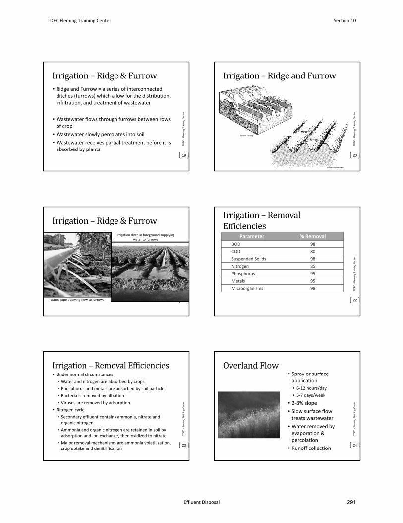
Irrigation– Ridge&Furrow• Ridge and Furrow = a series of interconnectedditches (furrows) which allow for the distribution,infiltration, and treatment of wastewater
• Wastewater flows through furrows between rows of crop
• Wastewater slowly percolates into soil
• Wastewater receives partial treatment before it is absorbed by plants
TDEC
-Fl
emin
g Tr
aini
ng C
ente
r
19
Irrigation– RidgeandFurrow
20
TDEC
-Fl
emin
g Tr
aini
ng C
ente
r
Source: fao.org
Source: colostate.edu
Irrigation– Ridge&Furrow
TDEC
-Fl
emin
g Tr
aini
ng C
ente
r
21Gated pipe applying flow to furrows
Irrigation ditch in foreground supplying water to furrows
Irrigation– RemovalEfficiencies
Parameter % Removal
BOD 98
COD 80
Suspended Solids 98
Nitrogen 85
Phosphorus 95
Metals 95
Microorganisms 98 TDEC
-Fl
emin
g Tr
aini
ng C
ente
r
22
Irrigation– RemovalEfficiencies• Under normal circumstances:
• Water and nitrogen are absorbed by crops
• Phosphorus and metals are adsorbed by soil particles
• Bacteria is removed by filtration
• Viruses are removed by adsorption
• Nitrogen cycle
• Secondary effluent contains ammonia, nitrate andorganic nitrogen
• Ammonia and organic nitrogen are retained in soil byadsorption and ion exchange, then oxidized to nitrate
• Major removal mechanisms are ammonia volatilization,crop uptake and denitrification
TDEC
-Fl
emin
g Tr
aini
ng C
ente
r
23
OverlandFlow• Spray or surfaceapplication
• 6‐12 hours/day
• 5‐7 days/week
• 2‐8% slope
• Slow surface flowtreats wastewater
• Water removed by evaporation &percolation
• Runoff collection
TDEC
-Fl
emin
g Tr
aini
ng C
ente
r
24
TDEC Fleming Training Center Section 10
Effluent Disposal 291
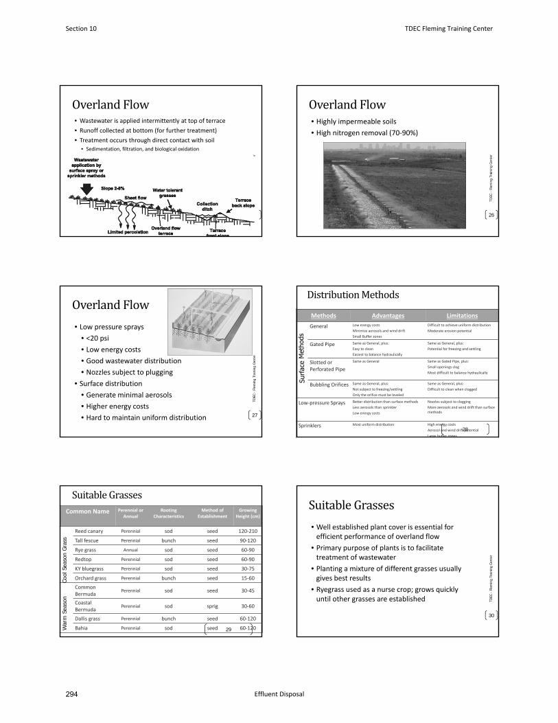
OverlandFlow• Wastewater is applied intermittently at top of terrace
• Runoff collected at bottom (for further treatment)
• Treatment occurs through direct contact with soil• Sedimentation, filtration, and biological oxidation
TDEC
-Fl
emin
g Tr
aini
ng C
ente
r
25
OverlandFlow• Highly impermeable soils
• High nitrogen removal (70‐90%)
26
TDEC
-Fl
emin
g Tr
aini
ng C
ente
r
OverlandFlow
• Low pressure sprays
• <20 psi
• Low energy costs
• Good wastewater distribution
• Nozzles subject to plugging
• Surface distribution
• Generate minimal aerosols
• Higher energy costs
• Hard to maintain uniform distribution
TDEC
-Fl
emin
g Tr
aini
ng C
ente
r
27
DistributionMethods
Methods Advantages Limitations
General Low energy costs
Minimize aerosols and wind drift
Small Buffer zones
Difficult to achieve uniform distribution
Moderate erosion potential
Gated Pipe Same as General, plus:
Easy to clean
Easiest to balance hydraulically
Same as General, plus:
Potential for freezing and settling
Slotted or Perforated Pipe
Same as General Same as Gated Pipe, plus:
Small openings clog
Most difficult to balance hydraulically
Bubbling Orifices Same as General, plus:
Not subject to freezing/settling
Only the orifice must be leveled
Same as General, plus:
Difficult to clean when clogged
Low‐pressure Sprays Better distribution than surface methods
Less aerosols than sprinkler
Low energy costs
Nozzles subject to clogging
More aerosols and wind drift than surface methods
Sprinklers Most uniform distribution High energy costs
Aerosol and wind drift potential
Large buffer zones
28
SuitableGrassesCommon Name Perennial or
AnnualRooting
CharacteristicsMethod of
EstablishmentGrowing
Height (cm)
Reed canary Perennial sod seed 120‐210
Tall fescue Perennial bunch seed 90‐120
Rye grass Annual sod seed 60‐90
Redtop Perennial sod seed 60‐90
KY bluegrass Perennial sod seed 30‐75
Orchard grass Perennial bunch seed 15‐60
Common Bermuda
Perennial sod seed 30‐45
Coastal Bermuda
Perennial sod sprig 30‐60
Dallis grass Perennial bunch seed 60‐120
Bahia Perennial sod seed 60‐12029
Cool
Sea
son
Gras
sW
arm
Sea
son
SuitableGrasses
• Well established plant cover is essential for efficient performance of overland flow
• Primary purpose of plants is to facilitate treatment of wastewater
• Planting a mixture of different grasses usually gives best results
• Ryegrass used as a nurse crop; grows quickly until other grasses are established TD
EC -
Flem
ing
Trai
ning
Cen
ter
30
Section 10 TDEC Fleming Training Center
Effluent Disposal294
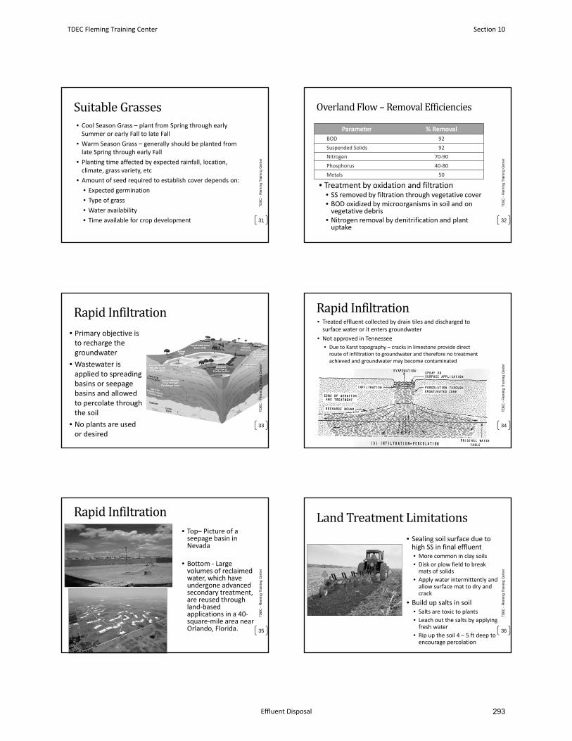
SuitableGrasses• Cool Season Grass – plant from Spring through early Summer or early Fall to late Fall
• Warm Season Grass – generally should be planted from late Spring through early Fall
• Planting time affected by expected rainfall, location, climate, grass variety, etc
• Amount of seed required to establish cover depends on:
• Expected germination
• Type of grass
• Water availability
• Time available for crop development
TDEC
-Fl
emin
g Tr
aini
ng C
ente
r
31
OverlandFlow–RemovalEfficiencies
Parameter % Removal
BOD 92
Suspended Solids 92
Nitrogen 70‐90
Phosphorus 40‐80
Metals 50
• Treatment by oxidation and filtration• SS removed by filtration through vegetative cover• BOD oxidized by microorganisms in soil and on vegetative debris
• Nitrogen removal by denitrification and plant uptake
32
TDEC
-Fl
emin
g Tr
aini
ng C
ente
r
RapidInfiltration• Primary objective is to recharge the groundwater
• Wastewater is applied to spreading basins or seepage basins and allowed to percolate through the soil
• No plants are used or desired
33
TDEC
-Fl
emin
g Tr
aini
ng C
ente
r
RapidInfiltration• Treated effluent collected by drain tiles and discharged to surface water or it enters groundwater
• Not approved in Tennessee
• Due to Karst topography – cracks in limestone provide direct route of infiltration to groundwater and therefore no treatment achieved and groundwater may become contaminated
TDEC
-Fl
emin
g Tr
aini
ng C
ente
r
34
RapidInfiltration• Top– Picture of a seepage basin in Nevada
• Bottom ‐ Large volumes of reclaimed water, which have undergone advanced secondary treatment, are reused through land‐based applications in a 40‐square‐mile area near Orlando, Florida.
TDEC
-Fl
emin
g Tr
aini
ng C
ente
r
35
LandTreatmentLimitations• Sealing soil surface due to high SS in final effluent• More common in clay soils
• Disk or plow field to break mats of solids
• Apply water intermittently and allow surface mat to dry and crack
• Build up salts in soil• Salts are toxic to plants
• Leach out the salts by applying fresh water
• Rip up the soil 4 – 5 ft deep to encourage percolation
TDEC
-Fl
emin
g Tr
aini
ng C
ente
r
36
TDEC Fleming Training Center Section 10
Effluent Disposal 293
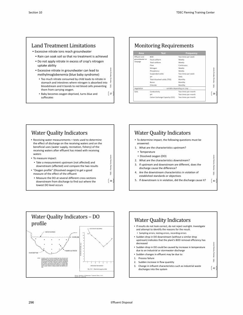
LandTreatmentLimitations• Excessive nitrate ions reach groundwater
• Rain can soak soil so that no treatment is achieved
• Do not apply nitrate in excess of crop’s nitrogenuptake ability
• Excessive nitrate in groundwater can lead tomethylmoglobenemia (blue baby syndrome)
• Too much nitrate consumed by child leads to nitrate instomach and intestines where nitrogen is absorbed intobloodstream and it bonds to red blood cells preventingthem from carrying oxygen.
• Baby becomes oxygen deprived, turns blue andsuffocates
TDEC
-Fl
emin
g Tr
aini
ng C
ente
r
37
MonitoringRequirementsArea Test Frequency
Effluent and groundwater or seepage
BOD
Fecal coliform
Total coliform
Flow
Nitrogen
Phosphorus
Suspended solids
pH
Total dissolved solids (TDS)
Boron
Chloride
Two times per week
Weekly
Weekly
Continuous
Weekly
Weekly
Two times per week
Daily
Monthly
Monthly
Monthly
Vegetation ‐ ‐ ‐ variable depending on crop ‐ ‐ ‐
Soils Conductivity
pH
Cation Exchange Capacity (CEC)
Two times per month
Two times per month
Two times per month
TDEC
-Fl
emin
g Tr
aini
ng C
ente
r
38
WaterQualityIndicators• Receiving water measurements = tests used to determinethe effect of discharge on the receiving waters and on the beneficial uses (water supply, recreation, fishery) of thereceiving waters after effluent has mixed with receivingwaters
• To measure impact:
• Take a measurement upstream (not affected) anddownstream (affected) and compare the two results
• “Oxygen profile” (Dissolved oxygen) to get a goodmeasure of the effect of the effluent
• Measure the DO at several different cross sections downstream from discharge to find out where thelowest DO level occurs
TDEC
-Fl
emin
g Tr
aini
ng C
ente
r
39
WaterQualityIndicators• To determine impact, the following questions must be answered:
1. What are the characteristics upstream?
• Temperature
• Dissolved oxygen (DO)
2. What are the characteristics downstream?
3. If upstream and downstream are different, does the discharge cause the difference?
4. Are the downstream characteristics in violation ofestablished standards or objectives
5. If downstream is in violation, did the discharge cause it? 40
TDEC
-Fl
emin
g Tr
aini
ng C
ente
r
WaterQualityIndicators– DOprofile
41
TDEC
-Fl
emin
g Tr
aini
ng C
ente
r
Source: Operation of Wastewater Treatment Plants, Vol II, seventh ed., p.250-251
WaterQualityIndicators• If results do not look correct, do not reject outright. Investigate and attempt to identify the reasons for the result.
• Sampling errors, testing errors, recording errors
• Sudden drop in DO downstream (without a similar dropupstream) indicates that the plant’s BOD removal efficiency has decreased
• Sudden drop in DO could be caused by increase in temperature due to an industrial or stormwater discharge
• Sudden changes in effluent may be due to:
1. Process failure
2. Sudden increase in flow quantity
3. Change in influent characteristics such as industrial waste discharges into the system 42
TDEC
-Fl
emin
g Tr
aini
ng C
ente
r
Section 10 TDEC Fleming Training Center
Effluent Disposal296
WaterQualityIndicators
• Plant effluent analyzed prior to discharge:
• In‐stream: pH, D.O., temperature
• In laboratory: BOD, COD, suspended solids,fecal coliforms, E. coli, N, P
• Disposal by dilution may require analysis ofreceiving stream upstream & downstream
• WET testing (Whole Effluent Toxicity)
43
TDEC
-Fl
emin
g Tr
aini
ng C
ente
r
WholeEffluentToxicity(WET)Testing• Whole Effluent Toxicity (WET) test refers to the combined toxiceffect to aquatic organisms from all pollutants contained in awastewater effluent
• Looks at the effluent as a single component
• WET tests measure wastewater's effects on specific testorganisms' ability to survive, grow and reproduce
• Acute toxicity
• Short term, lethal effects
• “End of pipe” conditions
• Chronic toxicity
• Long term, sub‐lethal effects
• Mixed water conditions
• More sensitive test
44
TDEC
-Fl
emin
g Tr
aini
ng C
ente
r
WholeEffluentToxicity(WET)Testing• NPDES permit limits found in Sections 3.4, 3.5
• Methods for compliance with NPDES permits in 40 CFR 136.3
• Test organisms:
• Water flea (Ceriodaphnia dubia)
• Invertebrate crustacean
• Fathead Minnow (Pimephales promelas)
• Vertebrate fish
45
TDEC
-Fl
emin
g Tr
aini
ng C
ente
r
AnyQuestions?
46
TDEC
-Fl
emin
g Tr
aini
ng C
ente
r
TDEC Fleming Training Center Section 10
Effluent Disposal 295
January 2016 16-1 Design Criteria Ch. 16
CHAPTER 16
Design Guidelines for Wastewater Treatment Systems
Using Spray Irrigation
16.1 General
16.1.1 General
16.1.2 Applicability
16.1.3 Location
16.1.4 Topography
16.1.5 Soils
16.2 Soil Investigations
16.2.1 General
16.2.2 Soil Soil Mapping
16.2.3 Soil Definitions
16.3 Preapplication Treatment Requirements
16.3.1 General
16.3.2 BOD and TSS Reduction, and Disinfection
16.3.3 Treatment and Storage Ponds
16.4 Inorganic Constituents of Treated Wastewater
16.5 Protection of Irrigation Equipment
16.6 Determination of Design Application Rates
16.6.1 General
16.6.2 Design Values
16.7 Determination of Design Wastewater Loading
16.7.1 General
16.8 Nitrogen Loading and Crop Selection and Management
16.8.1 General
16.8.2 Nitrogen Loading
16.8.3 Organic/BOD Loading
16.8.4 Cover Crop Selection and Management
Excerpt from TN Design Criteria for Sewage Works
Section 10 TDEC Fleming Training Center
Effluent Disposal298
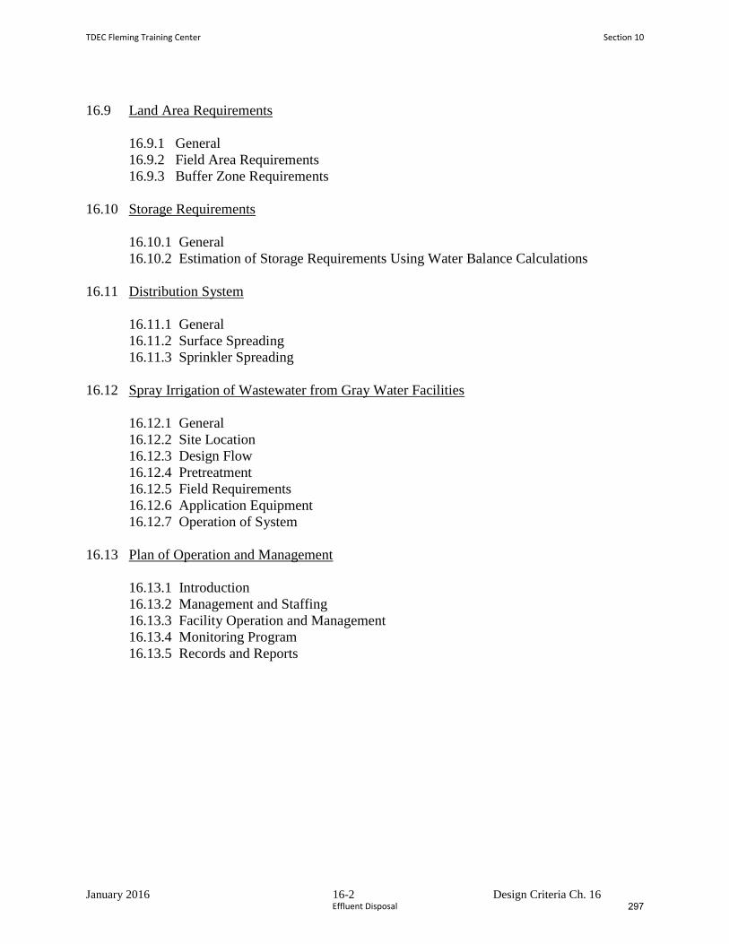
January 2016 16-2 Design Criteria Ch. 16
16.9 Land Area Requirements
16.9.1 General
16.9.2 Field Area Requirements
16.9.3 Buffer Zone Requirements
16.10 Storage Requirements
16.10.1 General
16.10.2 Estimation of Storage Requirements Using Water Balance Calculations
16.11 Distribution System
16.11.1 General
16.11.2 Surface Spreading
16.11.3 Sprinkler Spreading
16.12 Spray Irrigation of Wastewater from Gray Water Facilities
16.12.1 General
16.12.2 Site Location
16.12.3 Design Flow
16.12.4 Pretreatment
16.12.5 Field Requirements
16.12.6 Application Equipment
16.12.7 Operation of System
16.13 Plan of Operation and Management
16.13.1 Introduction
16.13.2 Management and Staffing
16.13.3 Facility Operation and Management
16.13.4 Monitoring Program
16.13.5 Records and Reports
TDEC Fleming Training Center Section 10
Effluent Disposal 297
January 2016 16-3 Design Criteria Ch. 16
SPRAY IRRIGATION
LAND TREATMENT SYSTEMS
16.1 General
16.1.1 General
This chapter provides guidelines and criteria for the design of surface spray irrigation
land treatment systems.
The wastewater loading rate is limited by the maximum amount of a particular
wastewater constituent that can be applied to a specific site. For wastewater from
municipalities, the limiting design factor is usually either the hydraulic capacity of the
soil or the nitrogen content of the wastewater. For industrial wastewater, the limiting
design factor may be the hydraulic capacity of the soil, nitrogen or any other wastewater
constituent such as metals, organics, etc.
16.1.2 Applicability
Spray irrigation wastewater treatment systems must be designed and operated so that
there is no direct discharge to surface waters. Treatment consists of evaporation directly
to the atmosphere, by transpiration to the atmosphere via vegetation uptake and by
percolation to groundwater. A State of Tennessee Operation Permit (SOP) is required for
operation of spray irrigation land treatment systems.
16.1.3 Location
The spray irrigation treatment site should be relatively isolated, easily accessible and not
susceptible to flooding. The site can be developed on agricultural land and/or forests or
can include parks, golf courses, etc. Site location shall take into account dwellings,
roads, streams, etc. A site evaluation by the Division of Water Pollution will be required
before review of the Engineering Report and/or application for an SOP.
16.1.4 Topography
Maximum grades for wastewater spray fields should be limited to 8% for row crops, 15%
for forage crops and 30% for forests. The greater the slope the greater potential for
lateral subsurface drainage, ponding and extended saturation of the soil. Depressions,
sink holes, etc., are to be avoided.
16.1.5 Soils
The infiltrative capacity of soil is a critical factor to be considered when designing any
type of spray irrigation system. If the profile of a particular soil considered for spray
irrigation extended to a significant depth without a restrictive horizon (most limiting
layer), the ability to load that soil per unit area would be relatively high.
Section 10 TDEC Fleming Training Center
Effluent Disposal300
January 2016 16-4 Design Criteria Ch. 16
On the other extreme, if a soil being considered for spray irrigation has a shallow
restrictive horizon, the ability to load that soil would be lower relative to the deeper soil.
Depth to restrictive horizon, soil permeability and slope of the restrictive horizon are
factors that control the amount and rate at which ground water can exit an area. If the
amount of treated effluent applied to an area, in combination with rainfall over the area
and groundwater moving into the area, exceed the soil profile’s ability to transmit the
water away from the application area, surface runoff of wastewater effluent will likely
occur.
Evaluation of a soil area’s suitability for spray irrigation should take into consideration
limiting aspects of the soil profile. Sites with shallow restrictive horizons overlain by
low permeability soils represent one of the more limited scenarios for spray irrigation and
the application rate and/or application area should be suitably modified.
Also critical when designing systems in soils with shallow restrictive horizons are the
presence and location of hydrologic boundaries such as drainage ways and waterways.
These hydrologic boundaries provide an outlet for ground water discharge. Not only is it
critical to identify these features in consideration of appropriate setbacks/buffers, it is
also critical to factor in their role in the overall hydrologic cycle of the landscape.
Horizons along which lateral flow would be expected include, but are not necessarily
limited to: bedrock, fragipans, and zones with high clay percentage overlain by more
permeable soil.
Spray irrigation design submittals should take into consideration all factors influencing
the infiltrative capacity of the soil and the ability of the soil and site to transport ground
water away from the application area. Spray pattern designs must properly utilize the site
soil and topography. It should be noted that the use of historical information from
existing systems installed and operated in similar soils, with documented loading rates,
landscape positions and design conditions similar to the proposed system may be
applicable. Therefore, soils that have been highly compacted and/or disturbed, such as
old road beds, foundations, etc., must be excluded when evaluating suitable areas for
surface spray irrigation systems.
16.2 Soil Investigations
16.2.1 General
Preliminary soil investigations should be done to identify areas best suited for surface
spray irrigation. The proposed surface spray area must be mapped at sufficient accuracy
to identify each soils series (or lowest possible level of soil classification) present and the
boundary location between series. Once those areas are identified, the more detailed
procedures outlined below will be employed.
It is required that all soil investigations be performed by a soil scientist currently on the
Ground Water Protection list of approved soil scientists/soil consultants.
For spray irrigation wastewater treatment systems, moderately permeable and well-
drained soils are desirable. However, the use of any soil is acceptable if it meets the
following four (4) criteria:
TDEC Fleming Training Center Section 10
Effluent Disposal 299
January 2016 16-5 Design Criteria Ch. 16
1. The applied effluent loading rate does not exceed the applicable hydraulic loading
rate in Table 16-1. The applicable hydraulic loading rate is determined by a
detailed site evaluation in which the site is mapped utilizing soil borings and pits
to determine the physical properties of soil horizons and soil map units.
2. The applied effluent maximum loading rate does not exceed 10% of the minimum
NRCS saturated vertical hydraulic conductivity (KSAT) for the soil series or 0.25
GPD/SF whichever is least. Note: this may have to be lowered based upon the
results of the nutrient loading rate calculation per Equation 16-1.
3. The soil does not have a restrictive horizon within its top twenty (20) inches.
4. The soil is well drained, or capable of being drained.
It is desirable to have a minimum depth of twenty (20) inches of undisturbed soil
above a restrictive horizon (eg., rock, fragipan, high water table, etc.)
Section 10 TDEC Fleming Training Center
Effluent Disposal302
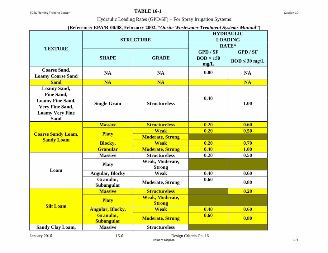
January 2016 16-6 Design Criteria Ch. 16
TABLE 16-1
Hydraulic Loading Rates (GPD/SF) – For Spray Irrigation Systems
(Reference: EPA/R-00/08, February 2002, “Onsite Wastewater Treatment Systems Manual”)
TEXTURE
STRUCTURE
HYDRAULIC
LOADING
RATE*
SHAPE GRADE
GPD / SF GPD / SF
BOD ≤ 150
mg/L BOD ≤ 30 mg/L
Coarse Sand, NA NA 0.80 NA
Loamy Coarse Sand
Sand NA NA NA
Loamy Sand,
Single Grain Structureless 0.40
1.00
Fine Sand,
Loamy Fine Sand,
Very Fine Sand,
Loamy Very Fine
Sand
Coarse Sandy Loam,
Sandy Loam
Massive Structureless 0.20 0.60
Platy Weak 0.20 0.50
Moderate, Strong
Blocky, Weak 0.20 0.70
Granular Moderate, Strong 0.40 1.00
Loam
Massive Structureless 0.20 0.50
Platy Weak, Moderate,
Strong
Angular, Blocky Weak 0.40 0.60
Granular,
Subangular Moderate, Strong
0.60 0.80
Silt Loam
Massive Structureless 0.20
Platy Weak, Moderate,
Strong
Angular, Blocky, Weak 0.40 0.60
Granular,
Subangular Moderate, Strong
0.60 0.80
Sandy Clay Loam, Massive Structureless
TDEC Fleming Training Center Section 10
Effluent Disposal 301
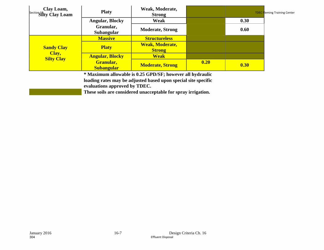
January 2016 16-7 Design Criteria Ch. 16
Clay Loam,
Silty Clay Loam Platy
Weak, Moderate,
Strong
Angular, Blocky Weak 0.30
Granular,
Subangular Moderate, Strong 0.60
Sandy Clay
Clay,
Silty Clay
Massive Structureless
Platy Weak, Moderate,
Strong
Angular, Blocky Weak
Granular,
Subangular Moderate, Strong
0.20 0.30
* Maximum allowable is 0.25 GPD/SF; however all hydraulic
loading rates may be adjusted based upon special site specific
evaluations approved by TDEC.
These soils are considered unacceptable for spray irrigation.
Section 18 TDEC Fleming Training Center
Effluent Disposal304
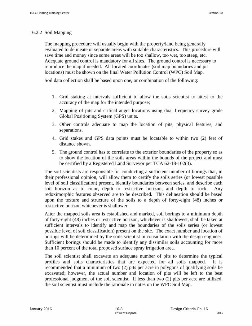
January 2016 16-8 Design Criteria Ch. 16
16.2.2 Soil Mapping
The mapping procedure will usually begin with the property/land being generally
evaluated to delineate or separate areas with suitable characteristics. This procedure will
save time and money since some areas will be too shallow, too wet, too steep, etc.
Adequate ground control is mandatory for all sites. The ground control is necessary to
reproduce the map if needed. All located coordinates (soil map boundaries and pit
locations) must be shown on the final Water Pollution Control (WPC) Soil Map.
Soil data collection shall be based upon one, or combination of the following:
1. Grid staking at intervals sufficient to allow the soils scientist to attest to the
accuracy of the map for the intended purpose;
2. Mapping of pits and critical auger locations using dual frequency survey grade
Global Positioning System (GPS) units.
3. Other controls adequate to map the location of pits, physical features, and
separations.
4. Grid stakes and GPS data points must be locatable to within two (2) feet of
distance shown.
5. The ground control has to correlate to the exterior boundaries of the property so as
to show the location of the soils areas within the bounds of the project and must
be certified by a Registered Land Surveyor per TCA 62-18-102(3).
The soil scientists are responsible for conducting a sufficient number of borings that, in
their professional opinion, will allow them to certify the soils series (or lowest possible
level of soil classification) present, identify boundaries between series, and describe each
soil horizon as to color, depth to restrictive horizon, and depth to rock. Any
redoximorphic features observed are to be described. This delineation should be based
upon the texture and structure of the soils to a depth of forty-eight (48) inches or
restrictive horizon whichever is shallower.
After the mapped soils area is established and marked, soil borings to a minimum depth
of forty-eight (48) inches or restrictive horizon, whichever is shallowest, shall be taken at
sufficient intervals to identify and map the boundaries of the soils series (or lowest
possible level of soil classification) present on the site. The exact number and location of
borings will be determined by the soils scientist in consultation with the design engineer.
Sufficient borings should be made to identify any dissimilar soils accounting for more
than 10 percent of the total proposed surface spray irrigation area.
The soil scientist shall excavate an adequate number of pits to determine the typical
profiles and soils characteristics that are expected for all soils mapped. It is
recommended that a minimum of two (2) pits per acre in polygons of qualifying soils be
excavated; however, the actual number and location of pits will be left to the best
professional judgment of the soil scientist. If less than two (2) pits per acre are utilized,
the soil scientist must include the rationale in notes on the WPC Soil Map.
TDEC Fleming Training Center Section 10
Effluent Disposal 303
January 2016 16-9 Design Criteria Ch. 16
The pit description must be entered onto a pedon sheet and submitted with the soils map
and engineering report. The “Soil Description” should include all of the information
contained on form NRCS-Soils-232G (5-86), U.S. Department of Agriculture, Natural
Resources Conservation Service (as shown in Chapter 17, Appendix D).
In their description of the pit profiles, the soil scientists must describe the soil’s structure,
texture, color, and any redoximorphic features present. They should also describe root
depth and presence of macropores, etc. The series name or lowest possible level of soil
classification will be recorded. The depth to hard rock using an auger or a tile probe must
be specified if the depth is less than forty-eight (48) inches and estimated if greater than
forty-eight (48) inches. The auger borings and soil backhoe pits should be located,
numbered and shown on the WPC Soil Map. The soil scientist will be required to
prepare and sign a detailed certification statement for each site evaluated as follows:
Water Pollution Control Soil Map Completed by:
Signature Date
John/Jane Doe, Soils Consultant
The following statement should appear on the map:
“I, (Soils Consultant’s Name) affirm that this Water Pollution Control Soil Map has
been prepared in accordance with accepted standards of soil science practice and the
standards and methodologies established in the NRCS Soil Survey Manual and USDA
Soil Taxonomy. No other warranties are made or implied.”
Soil profile information and pit excavation, as described in these design criteria, are
additional requirements deemed necessary to properly assess an area’s suitability for
surface spray irrigation.
Section 10 TDEC Fleming Training Center
Effluent Disposal306
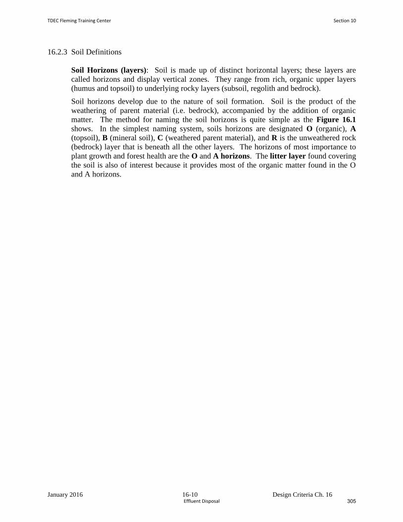
January 2016 16-10 Design Criteria Ch. 16
16.2.3 Soil Definitions
Soil Horizons (layers): Soil is made up of distinct horizontal layers; these layers are
called horizons and display vertical zones. They range from rich, organic upper layers
(humus and topsoil) to underlying rocky layers (subsoil, regolith and bedrock).
Soil horizons develop due to the nature of soil formation. Soil is the product of the
weathering of parent material (i.e. bedrock), accompanied by the addition of organic
matter. The method for naming the soil horizons is quite simple as the Figure 16.1
shows. In the simplest naming system, soils horizons are designated O (organic), A
(topsoil), B (mineral soil), C (weathered parent material), and R is the unweathered rock
(bedrock) layer that is beneath all the other layers. The horizons of most importance to
plant growth and forest health are the O and A horizons. The litter layer found covering
the soil is also of interest because it provides most of the organic matter found in the O
and A horizons.
TDEC Fleming Training Center Section 10
Effluent Disposal 305
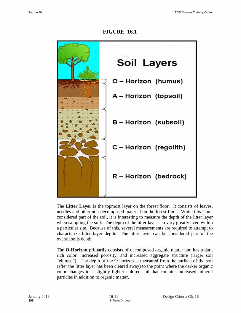
January 2016 16-11 Design Criteria Ch. 16
FIGURE 16.1
The Litter Layer is the topmost layer on the forest floor. It consists of leaves,
needles and other non-decomposed material on the forest floor. While this is not
considered part of the soil, it is interesting to measure the depth of the litter layer
when sampling the soil. The depth of the litter layer can vary greatly even within
a particular site. Because of this, several measurements are required to attempt to
characterize litter layer depth. The litter layer can be considered part of the
overall soils depth.
The O-Horizon primarily consists of decomposed organic matter and has a dark
rich color, increased porosity, and increased aggregate structure (larger soil
“clumps”). The depth of the O horizon is measured from the surface of the soil
(after the litter layer has been cleared away) to the point where the darker organic
color changes to a slightly lighter colored soil that contains increased mineral
particles in addition to organic matter.
Section 10 TDEC Fleming Training Center
Effluent Disposal308
January 2016 16-12 Design Criteria Ch. 16
The transition from the O to the A horizon can also be recognized by a significant
increase in the mineral soil particles. In many urban soils, the O horizon may
very thin if it exists at all. The O horizon can also be considered part of the
overall soils depth.
The A-Horizon is the mineral “topsoil” and consists of highly weathered parent
material (rocks), which is somewhat lighter in color than the O horizon due to a
decrease in organic matter. The particles in the A horizon are more granular and
“crumb-like”. Seeds germinate and plant roots grow in this layer. It is made up
of humus (decomposed organic matter) mixed with mineral particles. The depth
of the A horizon is measured from the region of color changes from the dark O
horizon to the transition to the B horizon. The transition to the B horizon can be
identified by increased clay content (see below) and the absence of organic
material: no root hairs, small pieces of needle, etc.
The most thorough soil study involves analysis on separate O and A horizon
samples. This requires separating and storing O and A horizon samples. It also
involves completing the entire soil analysis on both the O and A samples. If this
is not possible, the O and A samples can be combined (or composited) and the
analysis can be completed on the O and A sample together.
The B-Horizon is also called the subsoil - this layer is beneath the A horizon and
above the C horizon. It contains clay and mineral deposits (like iron, aluminum
oxides, and calcium carbonate) that it receives when soil solution containing
dissolved minerals drips from the soil above.
The B horizon is identified by increased clay content which makes the soil hold
together when moist. A simple test for clay content is to moisten a small handful
of soil and attempt to smear a small portion up the forefinger. Soils high in clay
will hold together and form a “ribbon”, soils with more sand and silt will be
granular and fall apart. It is lighter in color and often may be reddish due to the
iron content.
The C Horizon (layer beneath the B Horizon) consists of porous rock (broken-up
bedrock, bedrock with holes). It is also called regolith or saprolyte which means
"rotten rock." Plant roots do not penetrate into this layer; very little organic
material is found in this layer.
The R-Horizon is the unweathered rock (bedrock) layer that is beneath all the
other layers. For the purposes of drip dispersal designs, the R horizon is
considered an impermeable layer.
Water Pollution Control (WPC) Soils Map. A first order survey as defined in
the Soil Survey Manual, United States Department of Agriculture, October 1993.
These surveys are made for various land use that requires detailed soils
information.
TDEC Fleming Training Center Section 10
Effluent Disposal 307
January 2016 16-13 Design Criteria Ch. 16
Map scale should be one (1) inch equals one hundred (100) feet or a scale that
will allow the map to fill a 24” x 36” plan sheet. These maps should have
adequate cartographic detail to satisfy the requirements of project. The WPC
Soils Map is essentially a special map that shows a very high degree of soil and
landscape detail. Baseline mapping standards for these WPC Soil Maps prepared
in support of surface spray irrigation should be a first order survey in accordance
with the current edition of the Soil Survey Manual, United States Department of
Agricultural, October 1993. Soil profile information and pit excavation, as
described in these design criteria are additional requirements deemed necessary to
properly assess an area’s suitability for surface spray irrigation. These maps
should be clearly marked or labeled as “Water Pollution Control Soil Map”.
Soil map unit. A unique collection of areas that have common soil
characteristics and/or miscellaneous physical and chemical features.
Soil scientist. A person having the experience and education necessary to
measure soil properties and classify soils per Soil Taxonomy, synonymous with
the term “soil consultant”.
Soil series. A group of soils having similar properties; the lowest level of soil
classification.
Most limiting horizon. A horizon in the soil (bedrock or fragipan) that either
provides the greatest impediment to or completely stops, the downward
movement of liquids through the soil.
16.3 Preapplication Treatment Requirements
16.3.1 General
Wastewater spray irrigation systems have a demonstrated ability to treat high strength
organic wastes to low levels. However, such systems require a high degree of
management with particular attention paid to organic loading rates and aeration of the
soil profile between wastewater applications.
The Division of Water Pollution requires that all domestic and municipal wastewaters
receive biological treatment prior to irrigation.
This is necessary to:
a. Protect the health of persons contacting the irrigated wastewater.
b. Reduce the potential for odors in storage and irrigation.
Some industrial wastewaters may be suitable for direct land treatment by irrigation under
intensive management schemes. The Division of Water Pollution Control will evaluate
such systems on a case-by-case basis.
Section 10 TDEC Fleming Training Center
Effluent Disposal310
January 2016 16-14 Design Criteria Ch. 16
16.3.2 BOD and TSS Reduction, and Disinfection
Preapplication treatment standards for domestic and municipal wastewaters prior to
storage and/or irrigation are as follows:
a. Sites Closed to Public Access
All wastewater must be treated to a level afforded by lagoons which are designed in
accordance with Chapter 9.
Disinfection is generally not required for restricted and fenced access land treatment
sites. The Division of Water Pollution Control may, however, require disinfection
when deemed necessary.
b. Sites Open to Public Access
Sites open to public access include golf courses, cemeteries, green areas, parks, and
other public or private land where public use occurs or is expected to occur.
Wastewater that is spray irrigated on public access sites must not exceed a 5-day
Biochemical Oxygen Demand and Total Suspended Solids of 30 mg/L, as a monthly
average. Disinfection to reduce E. coli bacteria to 23 colonies/100 mL is required.
The preapplication treatment standards for wastewater that is to be applied to public
access areas will be reviewed by the Division of Water Pollution Control on a
case-by-case basis. More stringent preapplication treatment standards may be
required as the Division of Water Pollution Control deems necessary. The Division
of Water Pollution Control recommends that the engineer give preference to
pretreatment systems that will provide the greatest degree of reliability.
TDEC Fleming Training Center Section 10
Effluent Disposal 309
January 2016 16-15 Design Criteria Ch. 16
16.3.3 Treatment and Storage Ponds
The storage pond and irrigation pump station must be hydraulically separate from the
treatment cells (i.e., pumping must not affect hydraulic detention time in these cells).
The Division of Water Pollution Control recommends the use of Chapter 9 of the Design
Criteria for Sewage Works, as well as the United States Environmental Protection
Agency's October 1983 Design Manual: Municipal Wastewater Stabilization Ponds as a
reference for design of preapplication treatment ponds.
16.4 Inorganic Constituents of Treated Wastewater
Inorganic constituents of effluent from preapplication treatment should be compared with
Table 16-2 to insure compatibility with land treatment site soils and cover crops.
Section 10 TDEC Fleming Training Center
Effluent Disposal312
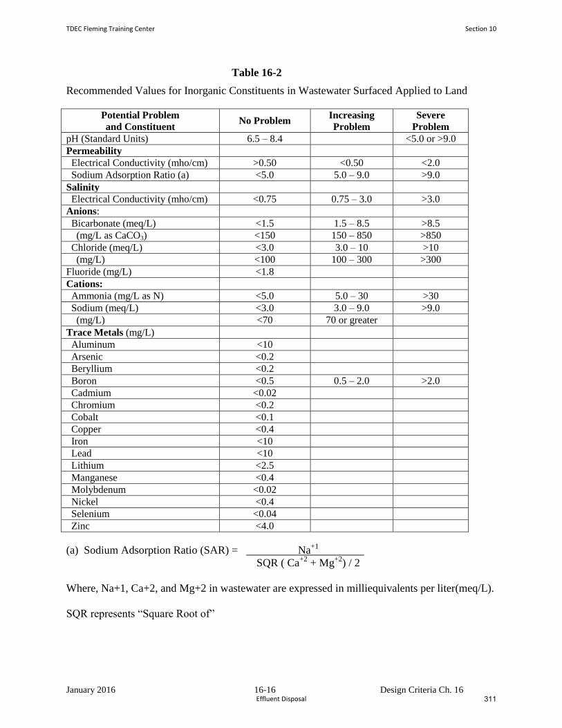
January 2016 16-16 Design Criteria Ch. 16
Table 16-2
Recommended Values for Inorganic Constituents in Wastewater Surfaced Applied to Land
Potential Problem
and Constituent No Problem
Increasing
Problem
Severe
Problem
pH (Standard Units) 6.5 – 8.4 <5.0 or >9.0
Permeability
Electrical Conductivity (mho/cm) >0.50 <0.50 <2.0
Sodium Adsorption Ratio (a) <5.0 5.0 – 9.0 >9.0
Salinity
Electrical Conductivity (mho/cm) <0.75 0.75 – 3.0 >3.0
Anions:
Bicarbonate (meq/L) <1.5 1.5 – 8.5 >8.5
(mg/L as CaCO3) <150 150 – 850 >850
Chloride (meq/L) <3.0 3.0 – 10 >10
(mg/L) <100 100 – 300 >300
Fluoride (mg/L) <1.8
Cations:
Ammonia (mg/L as N) <5.0 5.0 – 30 >30
Sodium (meq/L) <3.0 3.0 – 9.0 >9.0
(mg/L) <70 70 or greater
Trace Metals (mg/L)
Aluminum <10
Arsenic <0.2
Beryllium <0.2
Boron <0.5 0.5 – 2.0 >2.0
Cadmium <0.02
Chromium <0.2
Cobalt <0.1
Copper <0.4
Iron <10
Lead <10
Lithium <2.5
Manganese <0.4
Molybdenum <0.02
Nickel <0.4
Selenium <0.04
Zinc <4.0
(a) Sodium Adsorption Ratio (SAR) = Na+1
SQR ( Ca+2
+ Mg+2
) / 2
Where, Na+1, Ca+2, and Mg+2 in wastewater are expressed in milliequivalents per liter(meq/L).
SQR represents “Square Root of”
TDEC Fleming Training Center Section 10
Effluent Disposal 311
January 2016 16-17 Design Criteria Ch. 16
16.5 Protection of Irrigation Equipment
Prior to pumping to the spray field distribution system, the wastewater must be screened
to remove fibers, coarse solids, oil and grease which might clog distribution pipes or
spray nozzles. As a minimum, screens with a nominal diameter smaller than the smallest
flow opening in the distribution system should be provided. Screening to remove solids
greater than one-half (½) the diameter of the smallest sprinkler nozzle is recommended
by some sprinkler manufacturers. The planned method for disposal of the screenings
must be provided.
Pressurized, clean water for backwashing screens should be provided. This backwash
may be manual or automated. Backwashed screenings should be captured and removed
for disposal. These screenings should not be returned to the storage pond(s) or
preapplication treatment system.
16.6 Determination of Design Application Rates
16.6.1 General
One of the key steps in the design of a spray irrigation system is to develop a "design
application rate" in gallons per day per square foot (GPD/SF). This value is derived from
either the hydraulic (water) loading rate (Lwh) based upon the most restrictive of (1) the
NRCS hydraulic conductivity data and the texture and structure (per Table 16-1), or (2)
the nutrient (nitrogen) loading rate (Lwn) calculations to determine design wastewater
loading(s) and, thus, spray irrigation field area requirements.
16.6.2 Design Values
The most limiting horizon, of each soil series shall be identified. Any surface condition
which limits the vertical or lateral drainage of the soil profile shall also be identified.
Examples of such conditions are shallow bedrock, a high water table, aquitards, and
extremely anisotropic soil permeability. Design considerations relative to the soils per
Section 16.1.5 must be used.
Sites with seasonal high groundwater less than twenty-four (24) inches deep may require
drainage improvements before they can be utilized for spray irrigation land treatment.
The design hydraulic conductivity at such sites is a function of the design of the drainage
system.
Section 10 TDEC Fleming Training Center
Effluent Disposal314
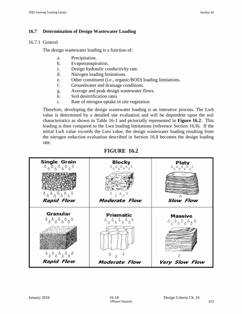
January 2016 16-18 Design Criteria Ch. 16
16.7 Determination of Design Wastewater Loading
16.7.1 General
The design wastewater loading is a function of:
a. Precipitation.
b. Evapotranspiration.
c. Design hydraulic conductivity rate.
d. Nitrogen loading limitations.
e. Other constituent (i.e., organic/BOD) loading limitations.
f. Groundwater and drainage conditions.
g. Average and peak design wastewater flows.
h. Soil denitrification rates
i. Rate of nitrogen uptake in site vegetation
Therefore, developing the design wastewater loading is an interative process. The Lwh
value is determined by a detailed site evaluation and will be dependent upon the soil
characteristics as shown in Table 16-1 and pictorially represented in Figure 16.2. This
loading is then compared to the Lwn loading limitations (reference Section 16.8). If the
initial Lwh value exceeds the Lwn value, the design wastewater loading resulting from
the nitrogen reduction evaluation described in Section 16.8 becomes the design loading
rate.
FIGURE 16.2
TDEC Fleming Training Center Section 10
Effluent Disposal 313
January 2016 16-19 Design Criteria Ch. 16
16.8 Nitrogen Loading and Crop Selection and Management
16.8.1 General
Nitrate concentration in percolate from wastewater spray irrigation systems will be
limited via a State Operation Permit (SOP) to not exceed 10 mg/L nitrate-nitrogen at the
site property line. Percolate nitrate concentration is a function of nitrogen loading, cover
crop, and management of vegetation and hydraulic loading. The design wastewater
loading determined from using the criteria stipulated in 16.1.5 for hydraulic loading rates
must be checked against nitrogen loading limitations.
16.8.2 Nitrogen Loading
In some instances, the amount of wastewater that can be applied to a site may be limited
by the amount of nitrogen in the wastewater. A particular site may be limited by the
nitrogen content of the wastewater during certain months of the year and limited by the
infiltration rate during the remainder of the year.
16.8.3 Organic / BOD Loading
When wastewater is high strength (above 150 mg/L BOD), the organic loading rate
should be limited as follows based upon the soil:
10,000 pounds of BOD per acre per year for Clays.
15, 000 pounds of BOD per acre per year for Loams.
20,000 pounds of BOD per acre per year for Sandy.
(Reference: Dr. Robert Rubin, NC State University, who cited work by Phillips and Carlile)
Section 10 TDEC Fleming Training Center
Effluent Disposal316
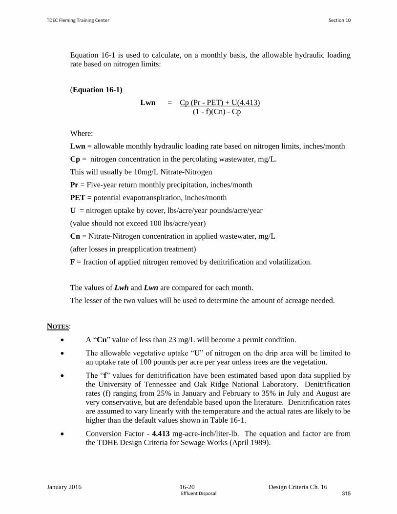
January 2016 16-20 Design Criteria Ch. 16
Equation 16-1 is used to calculate, on a monthly basis, the allowable hydraulic loading
rate based on nitrogen limits:
(Equation 16-1)
Lwn = Cp (Pr - PET) + U(4.413)
(1 - f)(Cn) - Cp
Where:
Lwn = allowable monthly hydraulic loading rate based on nitrogen limits, inches/month
Cp = nitrogen concentration in the percolating wastewater, mg/L.
This will usually be 10mg/L Nitrate-Nitrogen
Pr = Five-year return monthly precipitation, inches/month
PET = potential evapotranspiration, inches/month
U = nitrogen uptake by cover, lbs/acre/year pounds/acre/year
(value should not exceed 100 lbs/acre/year)
Cn = Nitrate-Nitrogen concentration in applied wastewater, mg/L
(after losses in preapplication treatment)
F = fraction of applied nitrogen removed by denitrification and volatilization.
The values of Lwh and Lwn are compared for each month.
The lesser of the two values will be used to determine the amount of acreage needed.
NOTES:
A “Cn” value of less than 23 mg/L will become a permit condition.
The allowable vegetative uptake “U” of nitrogen on the drip area will be limited to
an uptake rate of 100 pounds per acre per year unless trees are the vegetation.
The “f” values for denitrification have been estimated based upon data supplied by
the University of Tennessee and Oak Ridge National Laboratory. Denitrification
rates (f) ranging from 25% in January and February to 35% in July and August are
very conservative, but are defendable based upon the literature. Denitrification rates
are assumed to vary linearly with the temperature and the actual rates are likely to be
higher than the default values shown in Table 16-1.
Conversion Factor - 4.413 mg-acre-inch/liter-lb. The equation and factor are from
the TDHE Design Criteria for Sewage Works (April 1989).
TDEC Fleming Training Center Section 10
Effluent Disposal 315

January 2016 16-21 Design Criteria Ch. 16
The factor comes from assuming that one pound of contaminant of concern is
diluted within a volume of water equal to one acre-inch. For Example calculation
see Chapter 17, Appendix 17-A. For the derivation of this factor see Chapter 17,
Appendix 17-C.
Section 10 TDEC Fleming Training Center
Effluent Disposal318
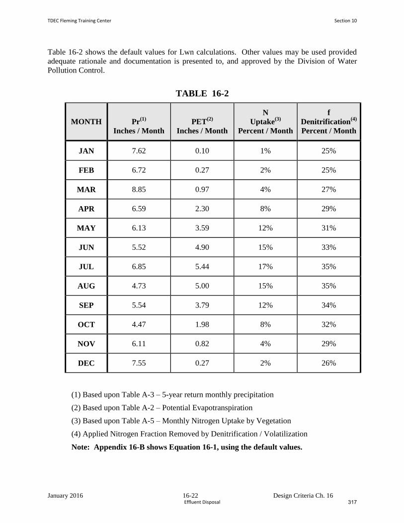
January 2016 16-22 Design Criteria Ch. 16
Table 16-2 shows the default values for Lwn calculations. Other values may be used provided
adequate rationale and documentation is presented to, and approved by the Division of Water
Pollution Control.
TABLE 16-2
MONTH Pr(1)
Inches / Month
PET(2)
Inches / Month
N
Uptake(3)
Percent / Month
f
Denitrification(4)
Percent / Month
JAN 7.62 0.10 1% 25%
FEB 6.72 0.27 2% 25%
MAR 8.85 0.97 4% 27%
APR 6.59 2.30 8% 29%
MAY 6.13 3.59 12% 31%
JUN 5.52 4.90 15% 33%
JUL 6.85 5.44 17% 35%
AUG 4.73 5.00 15% 35%
SEP 5.54 3.79 12% 34%
OCT 4.47 1.98 8% 32%
NOV 6.11 0.82 4% 29%
DEC 7.55 0.27 2% 26%
(1) Based upon Table A-3 – 5-year return monthly precipitation
(2) Based upon Table A-2 – Potential Evapotranspiration
(3) Based upon Table A-5 – Monthly Nitrogen Uptake by Vegetation
(4) Applied Nitrogen Fraction Removed by Denitrification / Volatilization
Note: Appendix 16-B shows Equation 16-1, using the default values.
TDEC Fleming Training Center Section 10
Effluent Disposal 317
January 2016 16-23 Design Criteria Ch. 16
16.8.4 Cover Crop Selection and Management
Row crops may be irrigated with wastewater via spray irrigation only when not intended
for direct human consumption. Livestock must not be allowed on wet fields so that
severe soil compaction and reduced soil infiltration rates can be avoided. Further, wet
grazing conditions can also lead to animal hoof diseases. Pasture rotation should be
practiced so that wastewater spray application can be commenced immediately after
livestock have been removed. In general, a pasture area should not be grazed longer than
7 days. Typical regrowth periods between grazings range from 14 to 35 days.
Depending on the period of regrowth provided, one to three spray applications can be
made during the regrowth period. At least 3 to 4 days drying time following an
application should be allowed before livestock are returned to the pasture. Unmanaged,
volunteer vegetation (i.e., weeds) is not an acceptable spray irrigation field cover.
Disturbed areas in forest systems must be initially grassed and replanted for succession to
forest.
Spray irrigation field cover crops require management and periodic harvesting to
maintain optimum growth conditions assumed in design. Forage crops should be
harvested and removed several times annually. Pine forest systems should be harvested
at 20 to 25 year intervals. Hardwood forest systems should be harvested at 40 to 60
years. It is recommended that whole tree harvesting be considered to maximize nutrient
removal. However, wastewater spray irrigation loadings following the harvesting of
forest systems must be reduced until the hydraulic capacity of the site is restored. Spray
field area to allow for harvesting and the regeneration cycle should be considered by the
design engineer.
While high in nitrogen and phosphorus, domestic and municipal wastewaters are usually
deficient in potassium and trace elements needed for vigorous agronomic cover crop
growth. High growth rate forage crops such as Alfalfa and Coastal Bermuda will require
supplemental nutrient addition to maintain nitrogen uptake rates assumed in design.
Industrial wastewaters considered for irrigation should be carefully evaluated for their
plant nutrient value.
16.9 Land Area Requirements
16.9.1 General
The land area to which wastewater is spray irrigated is termed a "field". The total land
requirement includes not only the field area, but also land for any preapplication
treatment facilities, storage reservoir(s), buffer zone, administration/maintenance
structures and access roads. Field and buffer zone requirements are addressed in this
Section. Land area for storage reservoirs is discussed in Section 16.10. All other land
requirements will be dictated by standard engineering practices and will not be addressed
in this document.
Section 10 TDEC Fleming Training Center
Effluent Disposal320
January 2016 16-24 Design Criteria Ch. 16
16.9.2 Field Area Requirements
The area required for the field is determined by using the following equation:
A = (Qy + V)C
Lwd (Eq. 16-2)
Where:
A = Field area, acres
Qy = Flow, MG per year
V = Net loss or gain in stored wastewater due to precipitation,
evaporation and/or seepage at the storage reservoir, gallons per day
Lwd = Design hydraulic loading rate, in/year
C = 1,000,000 gal x ft3 x 12 in x acre = 36.83
MG 7.48 gal ft 43,560 ft2
The first calculation of the field area must be made without considering the net gain or
loss from the storage reservoir. After the storage reservoir area has been calculated, the
value of V can be completed. The final field area is then recalculated to account for V.
The Appendix includes the use of Equation 16-2.
16.9.3 Buffer Zone Requirements
The objectives of buffer zones around land treatment sites are to control public access,
improve project aesthetics and, in case of spray irrigation, to minimize the transport of
aerosols. Since development of off-site property adjacent to the treatment site may be
uncontrolable, the buffer zone must be the primary means of separating the field area
from off-site property. Table 16-3 gives minimum widths of buffer zones for varying site
conditions:
TDEC Fleming Training Center Section 10
Effluent Disposal 319
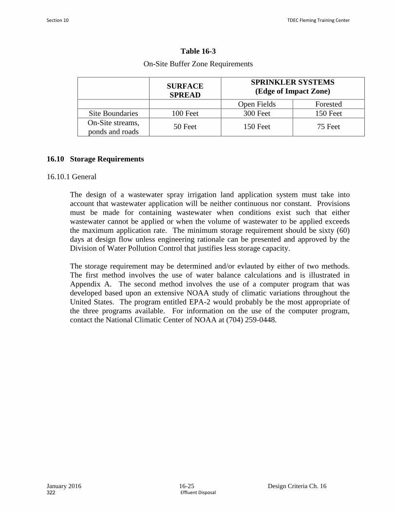
January 2016 16-25 Design Criteria Ch. 16
Table 16-3
On-Site Buffer Zone Requirements
SURFACE
SPREAD
SPRINKLER SYSTEMS
(Edge of Impact Zone)
Open Fields Forested
Site Boundaries 100 Feet 300 Feet 150 Feet
On-Site streams,
ponds and roads 50 Feet 150 Feet 75 Feet
16.10 Storage Requirements
16.10.1 General
The design of a wastewater spray irrigation land application system must take into
account that wastewater application will be neither continuous nor constant. Provisions
must be made for containing wastewater when conditions exist such that either
wastewater cannot be applied or when the volume of wastewater to be applied exceeds
the maximum application rate. The minimum storage requirement should be sixty (60)
days at design flow unless engineering rationale can be presented and approved by the
Division of Water Pollution Control that justifies less storage capacity.
The storage requirement may be determined and/or evlauted by either of two methods.
The first method involves the use of water balance calculations and is illustrated in
Appendix A. The second method involves the use of a computer program that was
developed based upon an extensive NOAA study of climatic variations throughout the
United States. The program entitled EPA-2 would probably be the most appropriate of
the three programs available. For information on the use of the computer program,
contact the National Climatic Center of NOAA at (704) 259-0448.
Section 10 TDEC Fleming Training Center
Effluent Disposal322
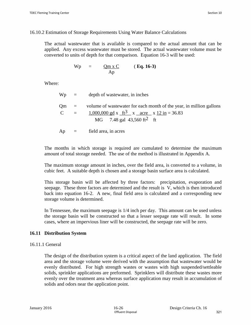
January 2016 16-26 Design Criteria Ch. 16
16.10.2 Estimation of Storage Requirements Using Water Balance Calculations
The actual wastewater that is available is compared to the actual amount that can be
applied. Any excess wastewater must be stored. The actual wastewater volume must be
converted to units of depth for that comparison. Equation 16-3 will be used:
Wp = Qm x C ( Eq. 16-3)
Ap
Where:
Wp = depth of wastewater, in inches
Qm = volume of wastewater for each month of the year, in million gallons
C = 1,000,000 gd x ft3 x acre x 12 in = 36.83
MG 7.48 gal 43,560 ft2 ft
Ap = field area, in acres
The months in which storage is required are cumulated to determine the maximum
amount of total storage needed. The use of the method is illustrated in Appendix A.
The maximum storage amount in inches, over the field area, is converted to a volume, in
cubic feet. A suitable depth is chosen and a storage basin surface area is calculated.
This storage basin will be affected by three factors: precipitation, evaporation and
seepage. These three factors are determined and the result is V, which is then introduced
back into equation 16-2. A new, final field area is calculated and a corresponding new
storage volume is determined.
In Tennessee, the maximum seepage is 1/4 inch per day. This amount can be used unless
the storage basin will be constructed so that a lesser seepage rate will result. In some
cases, where an impervious liner will be constructed, the seepage rate will be zero.
16.11 Distribution System
16.11.1 General
The design of the distribution system is a critical aspect of the land application. The field
area and the storage volume were derived with the assumption that wastewater would be
evenly distributed. For high strength wastes or wastes with high suspended/settleable
solids, sprinkler applications are preformed. Sprinklers will distribute these wastes more
evenly over the treatment area whereas surface application may result in accumulation of
solids and odors near the application point.
TDEC Fleming Training Center Section 10
Effluent Disposal 321
January 2016 16-27 Design Criteria Ch. 16
16.11.2 Surface Spreading
With surface spreading, wastewater is applied to the ground surface, usually by
perforated pipe or by an irrigation-type ditch, and flows uniformly over the field by
gravity. The uniform flow is critically dependent upon a constant slope of the field, both
horizontal and perpendicular to the direction of flow. Several other factors are of
importance:
a. Uniform distribution cannot be achieved on highly permeable soils. The
wastewater will tend to percolate into the soil that is nearest to the point of
application.
b. A relatively large amount of wastewater must be applied each time so that
wastewater will reach all portions of the field.
The dosing must account for the fact that the field area nearest the point of
application will be wetted for a longer period of time and, thus, will percolate
more wastewater.
c. Erosion and/or runoff may be a problem. Since a surface discharge will not be
allowed to occur, a return system may be necessary.
16.11.3 Sprinkler Spreading
Sprinkler systems can be classified into one of three general categories:
(1) solid set, (2) portable and (3) continuously moving.
The following factors should be considered during design:
a. The hydraulic conditions within the distribution system must be given a thorough
review. Head losses through pipes, bends, nozzles, etc., must be balanced so that
the wastewater is uniformly applied to the field.
b. Design must consider the effects of cold weather. Nozzles, risers, supply pipes,
etc., must be designed to prevent wastewater from freezing in the various parts.
c. Wind can distort the spray pattern. Also, aerosols may be carried off the field
area. A properly designed buffer zone should alleviate most of the aerosol
problems. Also, the O&M manual can include a provision which would prevent
spraying when the wind velocity is high enough to carry wastewater off the field
area.
d. Crop selection is important. The higher humidity level may lead to an increase in
crop disease.
e. Higher slopes can be used than in surface spreading. Also, slopes do not need to
be constant. Further, the type of crop is nearly unlimited. Forests can be irrigated
Section 10 TDEC Fleming Training Center
Effluent Disposal324
January 2016 16-28 Design Criteria Ch. 16
with solid set sprinklers. Forage crops can be irrigated with any of the three basic
types of systems.
f. The system layout must take into consideration the method that will be used for
harvesting the crop.
16.12 Spray Irrigation of Wastewater from Gray Water Facilities
16.12.1 General
This Section provides criteria for facilities that produce a "gray water" wastewater.
These facilities include coin-operated laundries, car washes and swimming pool
backwash filters.
Wastewater disposal requirements are not as complex as are those for domestic
wastewater. An engineering report which provides information on the design of the
facilities must be submitted to the Division of Water Pollution Control.
16.12.2 Site Location
16.12.2.1 The Division of Water Pollution Control must inspect and approve the
proposed site prior to any construction being undertaken.
16.12.2.2 The site must be chosen such that the operation of the system will not affect
surrounding property owners. No surface runoff or stream discharge will be allowed.
16.12.3 Design Flow
Since these are service enterprises, the amount of wastewater that is generated is directly
related to the desire of people to use the facilities. Thus, an estimate of the number of
potential users (and frequency) is extremely important.
Various factors must be taken into consideration:
a. A rural setting would tend to have a shorter daily usage period than would an
urban location.
b. An area that is predominately single-family houses would tend to have a lesser
usage rate for laundries and car washes than would an area with apartment
complexes.
c. The amount of water that washing machines use will vary among
manufacturers and models. The Division recommends the use of water-saving
machines.
TDEC Fleming Training Center Section 10
Effluent Disposal 323
January 2016 16-29 Design Criteria Ch. 16
The design engineer should use 250 gpd/washer for laundries and 700 gpd/bay for car
washes unless more reliable data is available.
16.12.4 Pretreatment
16.12.4.1 General
Facilities that produce gray water have different pretreatment requirements,
designed not only to the type of facility but also to the specific establishment.
16.12.4.2 Laundries
a. All laundry wastewater (does not include sanitary wastes) shall pass
through a series of lint screens.
A series will consist of five screens, starting with a screen with 1-inch
mesh and ending with a screen that is basically equivalent to a window
screen.
b. Since some detergents produce a wastewater with a pH in the range of
11.0 to 11.5, some type of pH adjustment may be necessary. This may
occur as a retrofit if the vegetation in the spray plots is being stressed
by the high pH.
c. Disinfection will generally not be required unless the operation of the
facilities will result in a potential hazard to the public. The need for
disinfection will be determined by the Division of Water Pollution
Control on a case-by-case basis.
16.12.4.3 Car Washes
a. All car wash wastewater shall pass through a grit removal unit. The
flow-through velocity shall be less than 0.5 feet per second. The grit
removal unit shall be constructed to facilitate the removal of grit.
b. The use of detergents with a neutral (or nearly neutral) pH is
recommended. The use of high-pH detergents may require
neutralization if the vegetation is being stressed by the high pH.
16.12.4.4 Swimming Pools
a. A holding tank/pond shall be provided to receive the backwash water
from the swimming pool filters. The solids shall be allowed to settle
to the bottom before the supernatant is removed for disposition on the
spray plots.
Section 10 TDEC Fleming Training Center
Effluent Disposal326
January 2016 16-30 Design Criteria Ch. 16
b. Dechlorination may be required if the vegetation on the plots is being
stressed by the chlorine in the water.
c. If the entire pool volume is to be emptied, by using the spray plots, the
rate shall be controlled so as to not exceed the application rate that is
specified in Section 16.7.
16.12.5 Field Requirements
16.12.5.1 The maximum wastewater that can be sprayed on a site is based either on the
nitrogen content of the wastewater or an amount equal to 10% of the infiltration rate of
the most restrictive layer of soil which shall be determined by the design engineer with
input from a qualified soil scientist.
16.12.5.2 The application of wastewater shall alternate between at least two separate
plots. Each plot shall not receive wastewater for more than three consecutive days and
must have at least three days rest between applications. Reserve land area of equivalent
capacity must be available for all gray water systems.
16.12.5.3 Ground slopes shall not exceed 30%. Extra precautions must be taken on
steep slopes (15-30%) to prevent runoff and erosion.
16.12.5.4 The field shall be covered with a good lawn or pasture grass unless an
existing forested area is chosen. The ground cover should be a sturdy perennial that will
resist erosion and washout. Forested areas should be chosen so that installation of
sprinkler equipment will not damage the root systems of the trees and will not produce
runoff due to the usual lack of grass in forested areas.
16.12.6 Application Equipment
16.12.6.1 Sprinklers shall be of a type and number such that the wastewater will be
evenly distributed over the entirety of a plot. Information on sprinklers shall
be included in the engineering report. In forest plots, sprinklers shall be on
risers which shall be tall enough to allow the wastewater to be sprayed above
the undergrowth. Sprinklers shall be of the type that are not susceptible to
clogging.
16.12.6.2 All piping (excluding risers) shall be buried to a depth that will prevent
freezing in the lines. An exception to this burial requirement can be made in
the case where piping will be laid in forested areas. Burial in this case may
be difficult, expensive and may kill some trees. All risers shall be designed
such that wastewater will drain from them when wastewater is not being
pumped. This can be accomplished by either draining all lines back into the
pump sump or by placing a gravel drain pit at the base of each riser. Each
riser would necessarily be equipped with a weep hole. Particular attention
TDEC Fleming Training Center Section 10
Effluent Disposal 325
January 2016 16-31 Design Criteria Ch. 16
must be given during the design so that the entire subsurface piping does not
drain into these pits.
16.12.6.3 The engineering report must contain hydraulic calculations that show that
each nozzle distributes an equivalent amount of wastewater. Differences in
elevation and decreasing pipe sizes will be factors which need to be
addressed.
16.12.6.4 The piping must be of a type that will withstand a pressure equal to or greater
than 1-1/2 times the highest pressure point in the system. The risers should
be of a type of material such that they can remain erect without support. The
pipe joints should comply with the appropriate ASTM requirements.
Adequate thrust blocks shall be installed as necessary.
16.12.6.5 A sump shall be provided into which the wastewater will flow for pumping to
the spray plots. The pump can be either a submersible type, located in the
sump, or a dry-well type, located immediately adjacent to the sump in a
dry-well. The pump shall be capable of pumping the maximum flow that can
be expected to enter the sump in any 10-minute period. The pump shall be
operated by some type of float mechanism. The float mechanism shall
activate the pump when the water level reaches 2/3 of the depth of the sump
and should de-activate the pump before the water level drops to the point to
where air can enter the intake.
If the distribution system is designed to drain back into the sump, the sump
shall be enlarged to account for that volume.
If desired, the sump for laundries can also contain the lint screens. The
screens shall, in any case, be constructed so that they cannot be bypassed.
They shall be built so that they can be easily cleaned. A container shall be
provided for disposal of the lint which is removed from the screens.
16.12.6.6 The pipe from the facility to the sump shall be large enough to handle the peak
instantaneous flow that could be realistically generated by the facility. Flow
quantities, head loss calculations, etc., shall be included in the engineering
report.
16.12.7 Operation of System
16.12.7.1 The operator shall insure that wastewater is applied to alternate plots on a
regular basis.
16.12.7.2 Monthly operating reports shall be submitted to the appropriate field office of
the Division of Water Pollution Control. The parameters to be reported shall
be delineated by field office personnel but should include, as a minimum,
dates of spray plot alternation.
Section 10 TDEC Fleming Training Center
Effluent Disposal328
January 2016 16-32 Design Criteria Ch. 16
16.12.7.3 The owner of the system shall apply for and receive an operating permit from
the Division of Water Pollution Control prior to initiation of operation of the
system.
16.12.7.4 The system operator shall inspect and maintain the pump and sprinklers in
accordance with manufacturer's recommendations. An operations manual
shall be located at the facility for ready reference.
16.12.7.5 The operator shall inspect the wastewater facilities on a regular basis. The
inspection shall include the spray plots to determine whether or not runoff
and/or erosion are or have occurred, the spray patterns of the sprinklers, the
physical condition of the system (looking for damage due to adverse pH
conditions, etc.)
16.12.7.6 The spray plots shall be mowed on a regular basis to enhance
evapotranspiration. Grass height shall not exceed 6-inches.
16.12.7.7 The lint screen at laundries shall be cleaned on a schedule that is frequent
enough to prevent upstream problems due to head loss through the screens.
Disposition of the lint shall be in accordance with applicable requirements.
16.12.7.8 The grit traps at car washes shall be cleaned at a frequency that is sufficient to
keep the trap in its designed operating condition.
16.12.7.9 If the car wash is equipped with an automatic wax cycle, the operator shall be
especially attentive to the possibility of wax build-up on the sump, pump and
all downstream piping.
16.12.7.10 The operator shall insure that the car wash facility is not used as a sanitary
dumping station for motor homes or for washing trucks/trailers that are used
for hauling livestock. If necessary, the facility shall be posted with signs
which clearly indicate this prohibition.
16.12.7.11 The sludge holding tank/pond at a swimming pool facility shall be cleaned at
a frequency that is sufficient to prevent solids from being carried over into
the pump sump. Cleaning shall be performed in a manner that will minimize
re-suspending the solids and allowing them to enter the pump sump.
16.13 Plan of Operation and Management
A Plan of Operation and Management (POM) is required before an Operation Permit
(SOP) can be issued. The Plan is written by the owner or the owner's engineer during
construction of the slow rate land treatment system. Once accepted by the Division, the
Plan becomes the operating and monitoring manual for the facility and is incorporated
by reference into the Permit.
TDEC Fleming Training Center Section 10
Effluent Disposal 327
January 2016 16-33 Design Criteria Ch. 16
This manual must be kept at the facility site and must be available for inspection by
personnel from the Tennessee Department of Health and Environment.
This POM should include, but not be limited to, the following information:
16.13.1 Introduction
a. System Description:
1. A narrative description and process design summary for the land treatment
facility including the design wastewater flow, design wastewater
characteristics, preapplication treatment system and spray fields.
2. A map of the land treatment facility showing the preapplication treatment
system, storage pond(s), spray fields, buffer zones, roads, streams, drainage
system discharges, monitoring wells, etc.
3. A map of force mains and pump stations tributary to the land treatment
facility. Indicate their size and capacity.
4. A schematic and plan of the preapplication treatment sytem and storage
pond(s) identifying all pumps, valves and process control points.
5. A schematic and plan of the irrigation distribution system identifying all
pumps, valves, gauges, sprinklers, etc.
b. Discuss the design life of the facility and factors that may shorten its useful life.
Include procedures or precautions which will compensate for these limitations.
c. A copy of facility's State Operation Permit.
16.13.2 Management and Staffing
a. Discuss management's responsibilities and duties.
b. Discuss staffing requirements and duties:
1. Describe the various job titles, number of positions, qualifications, experience,
training, etc.
2. Define the work hours, duties and responsibilities of each staff member.
Section 10 TDEC Fleming Training Center
Effluent Disposal330
January 2016 16-34 Design Criteria Ch. 16
16.13.3 Facility Operation and Management
a. Preapplication Treatment System:
1. Describe how the sytem is to be operated.
2. Discuss process control.
3. Discuss maintenance schedules and procedures
b. Irrigation System Management:
1. Wastewater Application.
Discuss how the following will be monitored and controlled.
Include rate and loading limits:
(a) Wastewater loading rate (inches/week)
(b) Wastewater application rate (inches/hour)
(c) Spray field application cycles
(d) Organic, nitrogen and phosphorus loadings (lbs/acre per month, etc)
2. Discuss how the system is to be operated and maintained.
(a) Storage pond(s)
(b) Irrigation pump station(s)
(c) Spray field force main(s) and laterals
3. Discuss start-up and shut-down procedures.
4. Discuss system maintenance.
(a) Equipment inspection schedules
(b) Equipment maintenance schedules
5. Discuss operating procedures for adverse conditions.
(a) Wet weather
TDEC Fleming Training Center Section 10
Effluent Disposal 329
January 2016 16-35 Design Criteria Ch. 16
(b) Freezing weather
(c) Saturated Soil
(d) Excessive winds
(e) Electrical and mechanical malfunctions
6. Provide troubleshooting procedures for common or expected problems.
7. Discuss the operation and maintenance of back-up, stand-by and support
equipment.
c. Vegetation Management:
1. Discuss how the selected cover crop is to be established, monitored and
maintained.
2. Discuss cover crop cultivation procedures, harvesting schedules and uses.
3. Discuss buffer zone vegetative cover and its maintenance.
d. Drainage System (if applicable):
1. Discuss operation and maintenance of surface drainage and runoff control
structures.
2. Discuss operation and maintenance of subsurface drainage systems.
16.13.4 Monitoring Program
a. Discuss sampling procedures, frequency, location and parameters for:
1. Preapplication treatment system.
2. Irrigation System:
(a) Storage pond(s)
(b) Groundwater monitoring wells
(c) Drainage system discharges (if applicable)
(d) Surface water (if applicable)
Section 10 TDEC Fleming Training Center
Effluent Disposal332
January 2016 16-36 Design Criteria Ch. 16
b. Discuss soil sampling and testing:
c. Discuss ambient conditions monitoring:
1. Rainfall
2. Wind speed
3. Soil moisture
d. Discuss the interpretation of monitoring results and facility operation:
1. Preapplication treatment system.
2. Spray fields.
3. Soils.
16.13.5 Records and Reports
a. Discuss maintenance records:
1. Preventive.
2. Corrective.
b. Monitoring reports and/or records should include:
1. Preapplication treatment system and storage pond(s).
(a) Influent flow
(b) Influent and effluent wastewater characteristics
2. Irrigation System.
(a) Wastewater volume applied to spray fields.
(b) Spray field scheduling.
(c) Loading rates.
3. Groundwater Depth.
4. Drainage system discharge parameters (if applicable).
TDEC Fleming Training Center Section 10
Effluent Disposal 331

January 2016 16-37 Design Criteria Ch. 16
5. Surface water parameters (if applicable).
6. Soils data.
7. Rainfall and climatic data.
Section 10 TDEC Fleming Training Center
Effluent Disposal334
February 2016 17-1 Design Criteria Ch. 17
CHAPTER 17
Design Guidelines for Wastewater Dispersal
Using Drip Irrigation
17.1 General
17.1.1 General
17.1.2 Applicability
17.1.3 Slopes and Buffers
17.1.4 Soils
17.1.5 Line Spacing
17.1.6 Line Depth
17.2 Soil Investigations
17.2.1 General
17.2.2 Soil Mapping
17.2.3 Definitions
17.2.4 Special Soil/Geologic Considerations
17.3 Determination of Design Percolation Rates
17.3.1 General
17.3.2 Design Values
17.4 Determination of Design Wastewater Loading
17.4.1 General
17.5 Nitrogen Loading and Crop Selection and Management
17.5.1 General
17.5.2 Nitrogen Loading
17.6 Plan of Operation and Management
17.6.1 Introduction
17.6.2 Management and Staffing
17.6.3 Facility Operation and Management
17.6.4 Monitoring Program
17.6.5 Records and Reports
Appendix 17-A Hydraulic Values and Conversion Factors
Appendix 17-B Example using Equation 17-2 (Nitrogen Loading Rate, Lwn)
Appendix 17-C Derivation of Conversion Factor for Equation 17-2
Excerpt from TN Design Criteria for Sewage WorksTDEC Fleming Training Center Section 10
Effluent Disposal 333
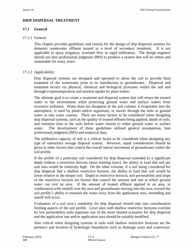
February 2016 17-2 Design Criteria Ch. 17
DRIP DISPERSAL TREATMENT
17.1 General
17.1.1 General
This chapter provides guidelines and criteria for the design of drip dispersal systems for
domestic wastewater effluent treated to a level of secondary treatment. It is not
applicable to spray irrigation, overland flow or rapid infiltration. The design engineer
should use best professional judgment (BPJ) to produce a system that will be robust and
sustainable for many years.
17.1.2 Applicability
Drip dispersal systems are designed and operated to allow the soil to provide final
treatment of the wastewater prior to its introduction to groundwater. Dispersal and
treatment occurs via physical, chemical and biological processes within the soil and
through evapotranspiration and nutrient uptake by plant matter.
The ultimate goal is to create a treatment and dispersal system that will return the treated
water to the environment while protecting ground water and surface waters from
excessive pollution. Water does not disappear in the soil column, it evaporates into the
atmosphere, is used by plants and/or organisms, or moves through the soils to ground
water or into water courses. There are many factors to be considered when designing
drip dispersal systems, such as the quality of treated effluent being applied, depth of soils,
and retention time in the soils before water returns to either ground water or surface
water. The development of these guidelines utilized general assumptions, best
professional judgment (BPJ) and empirical data.
The infiltrative capacity of soil is a critical factor to be considered when designing any
type of subsurface sewage disposal system. However, equal consideration should be
given to other factors that control the overall lateral movement of groundwater within the
soil profile.
If the profile of a particular soil considered for drip dispersal extended to a significant
depth without a restrictive horizon (most limiting layer), the ability to load that soil per
unit area would be relatively high. On the other extreme, if a soil being considered for
drip dispersal had a shallow restrictive horizon, the ability to load that soil would be
lower relative to the deeper soil. Depth to restrictive horizon, soil permeability and slope
of the restrictive horizon are factors that control the amount and rate at which ground
water can exit an area. If the amount of treated effluent applied to an area, in
combination with rainfall over the area and groundwater moving into the area, exceed the
soil profile’s ability to transmit the water away from the application area, mounding and
runoff will occur.
Evaluation of a soil area’s suitability for drip dispersal should take into consideration
limiting aspects of the soil profile. Level sites with shallow restrictive horizons overlain
by low permeability soils represent one of the more limited scenarios for drip dispersal
and the application rate and/or application area should be suitably modified.
Also critical when designing systems in soils with shallow restrictive horizons are the
presence and location of hydrologic boundaries such as drainage ways and waterways.
Section 18 TDEC Fleming Training Center
Effluent Disposal336
February 2016 17-3 Design Criteria Ch. 17
These hydrologic boundaries provide an outlet for ground water discharge. Not only is it
critical to identify these features in consideration of appropriate setbacks/buffers, it is
also critical to factor in their role in the overall hydrologic cycle of the landscape.
Horizons along which lateral flow would be expected include, but are not necessarily
limited to: bedrock, fragipans, and zones with high clay percentage overlain by more
permeable soil.
Drip dispersal design submittals should take into consideration all factors
influencing the infiltrative capacity of the soil and the ability of the soil and site to
transport ground water away from the application area. It should be noted that the
use of historical information from existing systems installed and operated in similar
soils, with documented loading rates, landscape positions and design conditions
similar to the proposed system may be applicable. Therefore, soils that have been
highly compacted and/or disturbed, such as old road beds, foundations, etc., must be
excluded when evaluating suitable areas for drip dispersal systems.
17.1.3 Slopes and Buffers
Slopes - Slopes up to and including 50% slope with suitable soils may be considered for
drip dispersal. Depending upon the overall shape of the slope (concave, convex or linear
on the planar and profile view) the design engineer may have to make adjustments in the
aspect ratio of the drip lines on the slope, the loading rate, or both to ensure that all
applied effluent will move down gradient and/or into the underlying formations without
surfacing. It is important to note that when the proposed drip field area slopes are greater
than 30%, the design engineer may need to a obtain a geologic investigation conducted
by a geologist or geotechnical engineer evaluating the slip potential of the slope under
operating conditions. When slopes increase above 10 percent, wastewater flow down the
slope (parallel to the slope) may control the hydraulic design of the system.
For land application areas with slopes between 10 percent and 50 percent and with a
restrictive horizon less than 48 inches, the design engineer should calculate the
percentage saturation of the soil column at the narrowest portion of the cross-sectional
area of the dispersal area perpendicular to the direction of flow. This landscape loading
rate analysis will determine the saturation depth at design load and flow of the most
restrictive cross-section in the down gradient flow path within and beyond the drip field.
The aspect of ratio of the drip field should be adjusted or the loading rate reduced as
necessary to ensure that surfacing does not occur.
Buffers - Treatment and dispersal system components should be located so as to protect
potable water supplies and distribution systems and surface waters. The design engineer
is responsible to identify setbacks on construction drawings. Setbacks from water bodies,
water courses, and sink holes will be a function of local subsurface geology and quality
of the applied effluent. It is important to note that varying site conditions may require
different distances of separation. The distances may increase or decrease as soil
conditions so warrant as determined by a qualified professional (engineer, soil scientist,
geologist, etc.).
If site buffers are different from Table 17-1, then the design engineer must provide
rationale used for the recommended site buffers which must be approved by the
Tennessee Department of Environment and Conservation.
TDEC Fleming Training Center Section 10
Effluent Disposal 335
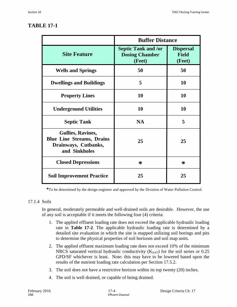
February 2016 17-4 Design Criteria Ch. 17
TABLE 17-1
17.1.4 Soils
In general, moderately permeable and well-drained soils are desirable. However, the use
of any soil is acceptable if it meets the following four (4) criteria:
1. The applied effluent loading rate does not exceed the applicable hydraulic loading
rate in Table 17-2. The applicable hydraulic loading rate is determined by a
detailed site evaluation in which the site is mapped utilizing soil borings and pits
to determine the physical properties of soil horizons and soil map units.
2. The applied effluent maximum loading rate does not exceed 10% of the minimum
NRCS saturated vertical hydraulic conductivity (KSAT) for the soil series or 0.25
GPD/SF whichever is least. Note: this may have to be lowered based upon the
results of the nutrient loading rate calculation per Section 17.5.2.
3. The soil does not have a restrictive horizon within its top twenty (20) inches.
4. The soil is well drained, or capable of being drained.
Buffer Distance
Site Feature Septic Tank and /or
Dosing Chamber
(Feet)
Dispersal
Field
(Feet)
Wells and Springs
Dwellings and Buildings
Property Lines
Underground Utilities
Septic Tank
Gullies, Ravines,
Blue Line Streams, Drains
Drainways, Cutbanks,
and Sinkholes
Closed Depressions
Soil Improvement Practice
*To be determined by the design engineer and approved by the Division of Water Pollution Control.
50
5
10
10
NA
25
25
* *
25
50
10
10
10
5
25
Section 10 TDEC Fleming Training Center
Effluent Disposal338
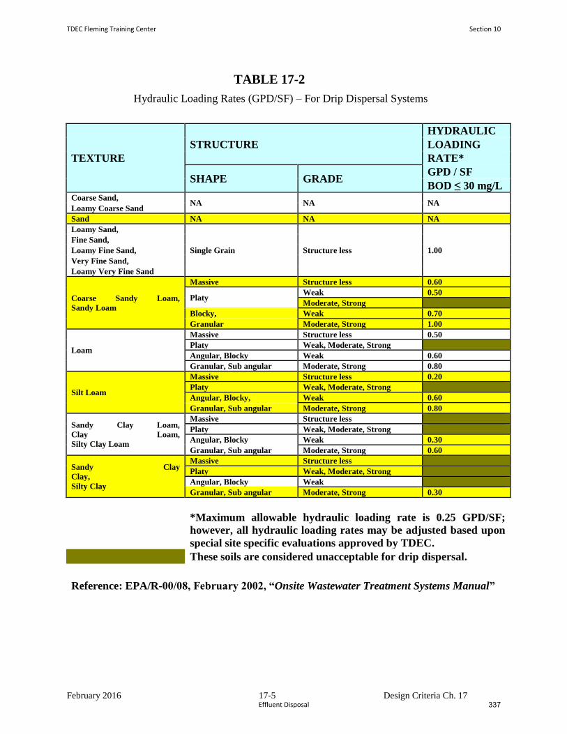
February 2016 17-5 Design Criteria Ch. 17
TABLE 17-2
Hydraulic Loading Rates (GPD/SF) – For Drip Dispersal Systems
TEXTURE
STRUCTURE
HYDRAULIC
LOADING
RATE*
SHAPE GRADE GPD / SF
BOD ≤ 30 mg/L Coarse Sand,
NA NA NA Loamy Coarse Sand
Sand NA NA NA
Loamy Sand,
Single Grain Structure less 1.00
Fine Sand,
Loamy Fine Sand,
Very Fine Sand,
Loamy Very Fine Sand
Coarse Sandy Loam,
Sandy Loam
Massive Structure less 0.60
Platy Weak 0.50
Moderate, Strong
Blocky, Weak 0.70
Granular Moderate, Strong 1.00
Loam
Massive Structure less 0.50
Platy Weak, Moderate, Strong
Angular, Blocky Weak 0.60
Granular, Sub angular Moderate, Strong 0.80
Silt Loam
Massive Structure less 0.20
Platy Weak, Moderate, Strong
Angular, Blocky, Weak 0.60
Granular, Sub angular Moderate, Strong 0.80
Sandy Clay Loam,
Clay Loam,
Silty Clay Loam
Massive Structure less
Platy Weak, Moderate, Strong
Angular, Blocky Weak 0.30
Granular, Sub angular Moderate, Strong 0.60
Sandy Clay
Clay,
Silty Clay
Massive Structure less
Platy Weak, Moderate, Strong
Angular, Blocky Weak
Granular, Sub angular Moderate, Strong 0.30
*Maximum allowable hydraulic loading rate is 0.25 GPD/SF;
however, all hydraulic loading rates may be adjusted based upon
special site specific evaluations approved by TDEC.
These soils are considered unacceptable for drip dispersal.
Reference: EPA/R-00/08, February 2002, “Onsite Wastewater Treatment Systems Manual”
TDEC Fleming Training Center Section 10
Effluent Disposal 337
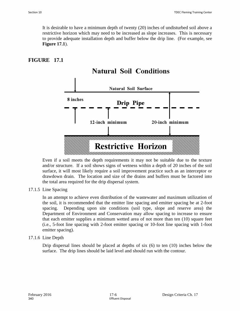
February 2016 17-6 Design Criteria Ch. 17
It is desirable to have a minimum depth of twenty (20) inches of undisturbed soil above a
restrictive horizon which may need to be increased as slope increases. This is necessary
to provide adequate installation depth and buffer below the drip line. (For example, see
Figure 17.1).
FIGURE 17.1
Even if a soil meets the depth requirements it may not be suitable due to the texture
and/or structure. If a soil shows signs of wetness within a depth of 20 inches of the soil
surface, it will most likely require a soil improvement practice such as an interceptor or
drawdown drain. The location and size of the drains and buffers must be factored into
the total area required for the drip dispersal system.
17.1.5 Line Spacing
In an attempt to achieve even distribution of the wastewater and maximum utilization of
the soil, it is recommended that the emitter line spacing and emitter spacing be at 2-foot
spacing. Depending upon site conditions (soil type, slope and reserve area) the
Department of Environment and Conservation may allow spacing to increase to ensure
that each emitter supplies a minimum wetted area of not more than ten (10) square feet
(i.e., 5-foot line spacing with 2-foot emitter spacing or 10-foot line spacing with 1-foot
emitter spacing).
17.1.6 Line Depth
Drip dispersal lines should be placed at depths of six (6) to ten (10) inches below the
surface. The drip lines should be laid level and should run with the contour.
Section 10 TDEC Fleming Training Center
Effluent Disposal340
February 2016 17-7 Design Criteria Ch. 17
17.2 Soil Investigations
17.2.1 General
Preliminary soil investigations should be done to identify areas best suited for subsurface
wastewater drip dispersal. The proposed drip dispersal area must be mapped at sufficient
accuracy to identify each soils series (or lowest possible level of soil classification)
present and the boundary location between series. Once those areas are identified, the
more detailed procedures outlined below will be employed. It is required that all soil
investigations be performed by a soil scientist currently on the Ground Water Protection
list of approved soil scientists/soil consultants.
17.2.2 Soil Mapping
The mapping procedure will usually begin with the property/land being generally
evaluated to delineate or separate areas with suitable characteristics. This procedure will
save time and money since some areas will be too shallow, too wet, too steep, etc.
Adequate ground control is mandatory for all sites. The ground control is necessary to
reproduce the map if needed. All located coordinates (soil map boundaries and pit
locations) must be shown on the final Water Pollution Control (WPC) Soils Map.
Soil data collection shall be based upon one, or combination of the following:
1. Grid staking at intervals sufficient to allow the soils scientist to attest to the
accuracy of the map for the intended purpose;
2. Mapping of pits and critical auger locations using dual frequency survey grade
Global Positioning System (GPS) units.
3. Other controls adequate to map the location of pits, physical features, and
separations.
4. Grid stakes and GPS data points must be locatable to within two (2) feet of
distance shown.
5. The ground control has to correlate to the exterior boundaries of the property so as
to show the location of the soils areas within the bounds of the project and must
be certified by a Registered Land Surveyor per TCA 62-18-102(3).
The soil scientists are responsible for conducting a sufficient number of borings that, in
their professional opinion, will allow them to certify the soils series (or lowest possible
level of soil classification) present, identify boundaries between series, and describe each
soil horizon as to color, depth to restrictive horizon, and depth to rock. Any
redoximorphic features observed are to be described. This delineation should be based
upon the texture and structure of the soils to a depth of forty-eight (48) inches or
restrictive horizon whichever is shallower.
After the mapped soils area is established and marked, soil borings to a minimum depth
of forty-eight (48) inches or restrictive horizon, whichever is shallowest, shall be taken at
sufficient intervals to identify and map the boundaries of the soils series (or lowest
possible level of soil classification) present on the site. The exact number and location of
borings will be determined by the soils scientist in consultation with the design engineer.
Sufficient borings should be made to identify any dissimilar soils accounting for more
than 10 percent of the total proposed drip dispersal area.
TDEC Fleming Training Center Section 10
Effluent Disposal 339
February 2016 17-8 Design Criteria Ch. 17
The soil scientist shall excavate an adequate number of pits to determine the typical
profiles and soils characteristics that are expected for all soils mapped. It is recommended
that a minimum of two (2) pits per acre in polygons of qualifying soils be excavated;
however, the actual number and location of pits will be left to the best professional
judgment of the soil scientist. If less than two (2) pits per acre are utilized, the soil
scientist must include the rationale in notes on the WPC Soil Map. The pit description
must be entered onto a pedon sheet and submitted with the soils map and engineering
report. The “Soil Description” should include all of the information contained on form
NRCS-Soils-232G (5-86), U.S. Department of Agriculture, Natural Resources
Conservation Service (as shown in Appendix D).
In their description of the pit profiles, the soil scientists must describe the soil’s structure,
texture, color, and any redoximorphic features present. They should also describe root
depth and presence of macropores, etc. The series name or lowest possible level of soil
classification will be recorded. The depth to hard rock using an auger or a tile probe must
be specified if the depth is less than forty-eight (48) inches and estimated if greater than
forty-eight (48) inches. The auger borings and soil backhoe pits should be located,
numbered and shown on the WPC Soils Map. The soil scientist will be required to
prepare and sign a detailed certification statement for each site evaluated as follows:
Water Pollution Control Soils Map Completed by:
Signature Date
John/Jane Doe, Soils Consultant
The following statement should appear on the map:
“I, (Soils Consultant’s Name) affirm that this Water Pollution Control Soils Map has
been prepared in accordance with accepted standards of soil science practice and the
standards and methodologies established in the NRCS Soil Survey Manual and USDA
Soil Taxonomy. No other warranties are made or implied.”
Soil profile information and pit excavation, as described in these design criteria, are
additional requirements deemed necessary to properly assess an area’s suitability for drip
dispersal.
17.2.3 Definitions:
Soil Horizons (layers): Soil is made up of distinct horizontal layers; these layers are
called horizons and display vertical zones. They range from rich, organic upper layers
(humus and topsoil) to underlying rocky layers (subsoil, regolith and bedrock).
Soil horizons develop due to the nature of soil formation. Soil is the product of the
weathering of parent material (i.e. bedrock), accompanied by the addition of organic
matter. The method for naming the soil horizons is quite simple as the Figure 17.2
shows.
Section 10 TDEC Fleming Training Center
Effluent Disposal342

February 2016 17-9 Design Criteria Ch. 17
In the simplest naming system, soils horizons are designated O (organic), A (topsoil), B
(mineral soil), C (weathered parent material), and R is the un-weathered rock (bedrock)
layer that is beneath all the other layers. The horizons of most importance to plant
growth and forest health are the O and A horizons. The litter layer found covering the
soil is also of interest because it provides most of the organic matter found in the O and A
horizons.
TDEC Fleming Training Center Section 10
Effluent Disposal 341
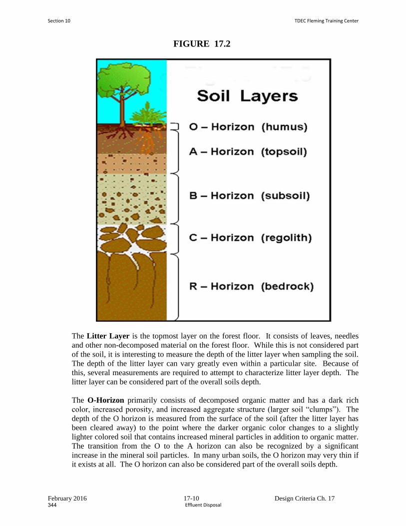
February 2016 17-10 Design Criteria Ch. 17
FIGURE 17.2
The Litter Layer is the topmost layer on the forest floor. It consists of leaves, needles
and other non-decomposed material on the forest floor. While this is not considered part
of the soil, it is interesting to measure the depth of the litter layer when sampling the soil.
The depth of the litter layer can vary greatly even within a particular site. Because of
this, several measurements are required to attempt to characterize litter layer depth. The
litter layer can be considered part of the overall soils depth.
The O-Horizon primarily consists of decomposed organic matter and has a dark rich
color, increased porosity, and increased aggregate structure (larger soil “clumps”). The
depth of the O horizon is measured from the surface of the soil (after the litter layer has
been cleared away) to the point where the darker organic color changes to a slightly
lighter colored soil that contains increased mineral particles in addition to organic matter.
The transition from the O to the A horizon can also be recognized by a significant
increase in the mineral soil particles. In many urban soils, the O horizon may very thin if
it exists at all. The O horizon can also be considered part of the overall soils depth.
Section 10 TDEC Fleming Training Center
Effluent Disposal344
February 2016 17-11 Design Criteria Ch. 17
The A-Horizon is the mineral “topsoil” and consists of highly weathered parent
material (rocks), which is somewhat lighter in color than the O horizon due to a decrease
in organic matter. The particles in the A horizon are more granular and “crumb-like”.
Seeds germinate and plant roots grow in this layer. It is made up of humus (decomposed
organic matter) mixed with mineral particles. The depth of the A horizon is measured
from the region of color changes from the dark O horizon to the transition to the B
horizon. The transition to the B horizon can be identified by increased clay content (see
below) and the absence of organic material: no root hairs, small pieces of needle, etc.
The most thorough soil study involves analysis on separate O and A horizon samples.
This requires separating and storing O and A horizon samples. It also involves
completing the entire soil analysis on both the O and A samples. If this is not possible,
the O and A samples can be combined (or composited) and the analysis can be completed
on the O and A sample together.
The B-Horizon is also called the subsoil - this layer is beneath the A horizon and above
the C horizon. It contains clay and mineral deposits (like iron, aluminum oxides, and
calcium carbonate) that it receives when soil solution containing dissolved minerals drips
from the soil above.
The B horizon is identified by increased clay content that makes the soil hold together
when moist. A simple test for clay content is to moisten a small handful of soil and
attempt to smear a small portion up the forefinger. Soils high in clay will hold together
and form a “ribbon”, soils with more sand and silt will be granular and fall apart. It is
lighter in color and often may be reddish due to the iron content.
The C Horizon (layer beneath the B Horizon) consists of porous rock (broken-up
bedrock, bedrock with holes). It is also called regolith or saprolyte which means "rotten
rock." Plant roots do not penetrate into this layer; very little organic material is found in
this layer.
The R-Horizon is the un-weathered rock (bedrock) layer that is beneath all the other
layers. For the purposes of drip dispersal designs, the R horizon is considered an
impermeable layer.
Water Pollution Control (WPC) Soils Map. A first order survey as defined in the Soil
Survey Manual, United States Department of Agriculture, October 1993. These surveys
are made for various land use that requires detailed soils information. Map scale should
be one (1) inch equals one hundred (100) feet or a scale that will allow the map to fill a
24” x 36” plan sheet. These maps should have adequate cartographic detail to satisfy the
requirements of project. The WPC Soils Map is essentially a special map that shows a
very high degree of soil and landscape detail. Baseline mapping standards for these WPC
Soils Maps prepared in support of drip dispersal should be a first order survey in
accordance with the current edition of the Soil Survey Manual, United States Department
of Agricultural; October 1993. Soil profile information and pit excavation, as described
in these design criteria are additional requirements deemed necessary to properly assess
an area’s suitability for drip dispersal. These maps should be clearly marked or labeled as
“Water Pollution Control Soils Map”.
TDEC Fleming Training Center Section 10
Effluent Disposal 343
February 2016 17-12 Design Criteria Ch. 17
Soil map unit. A unique collection of areas that have common soil characteristics and/or
miscellaneous physical and chemical features.
Soil scientist. A person having the experience and education necessary to measure soil
properties and classify soils per Soil Taxonomy, synonymous with the term “soil
consultant”.
Soil series. A group of soils that have similar properties; the lowest level of soil
classification.
Most limiting horizon. A horizon in the soil (bedrock or fragipan) that either provides
the greatest impediment to or completely stops the downward movement of liquids
through the soil.
17.2.4 Special Soil/Geologic Considerations
For sites with slopes between 30% and 50%, TDEC may request, a special investigation
(performed by a qualified professional, such as a geologist, geo-tech engineer,
engineering geologist, etc.) to be conducted to evaluate those sites. To adequately
complete these determinations the following information should be provided.
Strike and dip angle of underlying bedrock
Depth to either hard rock and partly weathered rock
Type of rock (limestone, shale, etc.)
Soil particle-size class designation to a depth of six (6) feet or to hard rock
whichever is less
Slippage potential of slope
Certification statement signed by a qualified professional that addresses all of
the above characteristics.
For sites with slopes between 30% and 50%, in addition to meeting all other soil
suitability requirements, the site should also meet the following requirements:
Have a vertical depth of at least twenty (20) inches of soil above the rock
layer.
Not have a predominant particle size class of fragmental or sandy-skeletal.
17.3 Determination of Design Application Rates
17.3.1 General
One of the key steps in the design of a drip dispersal system is to develop a "design
application rate" in gallons per day per square foot (GPD/SF). This value is derived from
either the hydraulic (water) loading rate (Lwh) based upon the most restrictive of (1) the
NRCS hydraulic conductivity data and the texture and structure (per Table 17-2), or (2)
the nutrient (nitrogen) loading rate (Lwn) calculations to determine design wastewater
loading(s) and, thus, drip field area requirements.
Section 10 TDEC Fleming Training Center
Effluent Disposal346
February 2016 17-13 Design Criteria Ch. 17
17.3.2 Design Values
The most limiting horizon, of each soil series (or lowest possible level of soil
classification) shall be identified. Any surface condition that limits the vertical or lateral
drainage of the soil profile shall also be identified. Examples of such conditions are
shallow bedrock, a high water table, aquitards, and extremely anisotropic soil
permeability. Design considerations relative to the soils per Section 17.1.4 must be used.
Sites with seasonal high groundwater less than twenty-four (24) inches deep may require
drainage improvements before they can be utilized for slow rate land treatment. The
design hydraulic conductivity at such sites is a function of the design of the drainage
system.
17.4 Determination of Design Wastewater Loading
17.4.1 General
The design wastewater loading is a function of:
a. Precipitation.
b. Evapotranspiration.
c. Design hydraulic conductivity rate.
d. Nitrogen loading limitations.
e. Other constituent loading limitations.
f. Groundwater and drainage conditions.
g. Average and peak design wastewater flows.
h. Soil denitrification rates
i. Rate of nitrogen uptake in site vegetation
Therefore, developing the design wastewater loading is an iterative process. The Lwh
value is determined by a detailed site evaluation and will be dependent upon the soil
characteristics as shown in Table 17-2 and pictorially represented in Figure 17.3. This
loading is then compared to the Lwn loading limitations (reference Section 17.5). If the
initial Lwh value exceeds the Lwn value, the design wastewater loading resulting from
the nitrogen reduction evaluation described in Section 17.5 becomes the design loading
rate.
TDEC Fleming Training Center Section 10
Effluent Disposal 345
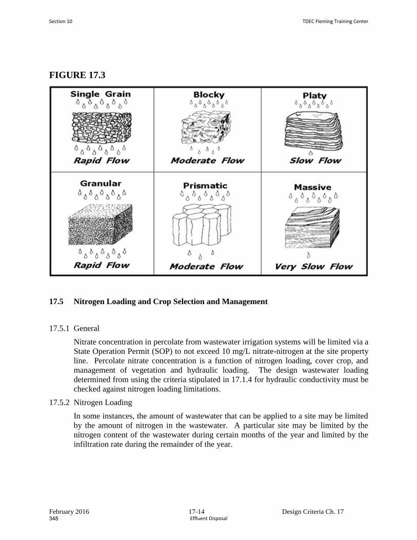
February 2016 17-14 Design Criteria Ch. 17
FIGURE 17.3
17.5 Nitrogen Loading and Crop Selection and Management
17.5.1 General
Nitrate concentration in percolate from wastewater irrigation systems will be limited via a
State Operation Permit (SOP) to not exceed 10 mg/L nitrate-nitrogen at the site property
line. Percolate nitrate concentration is a function of nitrogen loading, cover crop, and
management of vegetation and hydraulic loading. The design wastewater loading
determined from using the criteria stipulated in 17.1.4 for hydraulic conductivity must be
checked against nitrogen loading limitations.
17.5.2 Nitrogen Loading
In some instances, the amount of wastewater that can be applied to a site may be limited
by the amount of nitrogen in the wastewater. A particular site may be limited by the
nitrogen content of the wastewater during certain months of the year and limited by the
infiltration rate during the remainder of the year.
Section 10 TDEC Fleming Training Center
Effluent Disposal348
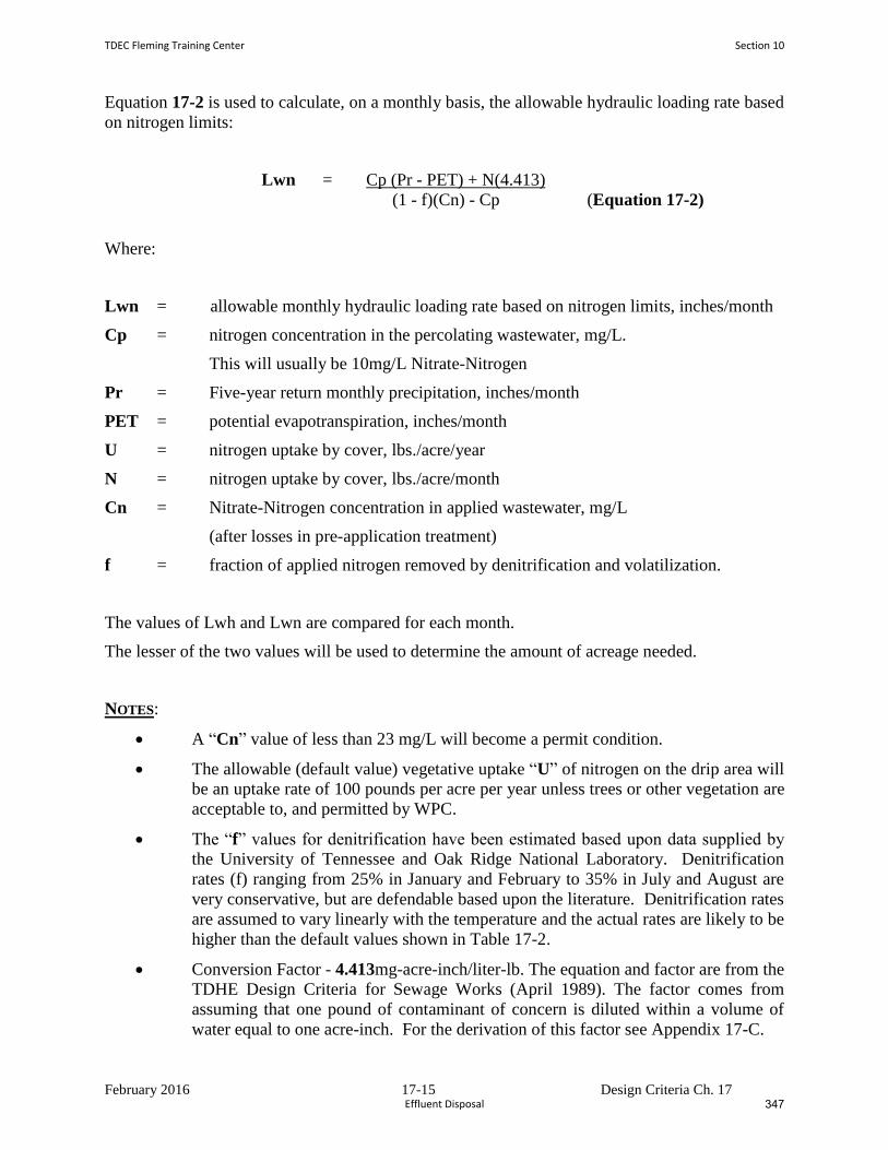
February 2016 17-15 Design Criteria Ch. 17
Equation 17-2 is used to calculate, on a monthly basis, the allowable hydraulic loading rate based
on nitrogen limits:
Lwn = Cp (Pr - PET) + N(4.413)
(1 - f)(Cn) - Cp (Equation 17-2)
Where:
Lwn = allowable monthly hydraulic loading rate based on nitrogen limits, inches/month
Cp = nitrogen concentration in the percolating wastewater, mg/L.
This will usually be 10mg/L Nitrate-Nitrogen
Pr = Five-year return monthly precipitation, inches/month
PET = potential evapotranspiration, inches/month
U = nitrogen uptake by cover, lbs./acre/year
N = nitrogen uptake by cover, lbs./acre/month
Cn = Nitrate-Nitrogen concentration in applied wastewater, mg/L
(after losses in pre-application treatment)
f = fraction of applied nitrogen removed by denitrification and volatilization.
The values of Lwh and Lwn are compared for each month.
The lesser of the two values will be used to determine the amount of acreage needed.
NOTES:
A “Cn” value of less than 23 mg/L will become a permit condition.
The allowable (default value) vegetative uptake “U” of nitrogen on the drip area will
be an uptake rate of 100 pounds per acre per year unless trees or other vegetation are
acceptable to, and permitted by WPC.
The “f” values for denitrification have been estimated based upon data supplied by
the University of Tennessee and Oak Ridge National Laboratory. Denitrification
rates (f) ranging from 25% in January and February to 35% in July and August are
very conservative, but are defendable based upon the literature. Denitrification rates
are assumed to vary linearly with the temperature and the actual rates are likely to be
higher than the default values shown in Table 17-2.
Conversion Factor - 4.413mg-acre-inch/liter-lb. The equation and factor are from the
TDHE Design Criteria for Sewage Works (April 1989). The factor comes from
assuming that one pound of contaminant of concern is diluted within a volume of
water equal to one acre-inch. For the derivation of this factor see Appendix 17-C.
TDEC Fleming Training Center Section 10
Effluent Disposal 347
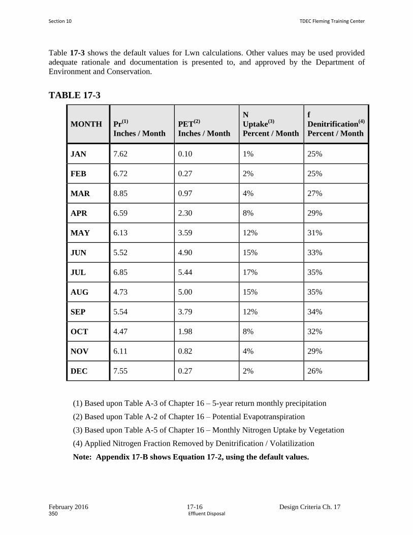
February 2016 17-16 Design Criteria Ch. 17
Table 17-3 shows the default values for Lwn calculations. Other values may be used provided
adequate rationale and documentation is presented to, and approved by the Department of
Environment and Conservation.
TABLE 17-3
MONTH Pr(1)
Inches / Month
PET(2)
Inches / Month
N
Uptake(3)
Percent / Month
f
Denitrification(4)
Percent / Month
JAN 7.62 0.10 1% 25%
FEB 6.72 0.27 2% 25%
MAR 8.85 0.97 4% 27%
APR 6.59 2.30 8% 29%
MAY 6.13 3.59 12% 31%
JUN 5.52 4.90 15% 33%
JUL 6.85 5.44 17% 35%
AUG 4.73 5.00 15% 35%
SEP 5.54 3.79 12% 34%
OCT 4.47 1.98 8% 32%
NOV 6.11 0.82 4% 29%
DEC 7.55 0.27 2% 26%
(1) Based upon Table A-3 of Chapter 16 – 5-year return monthly precipitation
(2) Based upon Table A-2 of Chapter 16 – Potential Evapotranspiration
(3) Based upon Table A-5 of Chapter 16 – Monthly Nitrogen Uptake by Vegetation
(4) Applied Nitrogen Fraction Removed by Denitrification / Volatilization
Note: Appendix 17-B shows Equation 17-2, using the default values.
Section 10 TDEC Fleming Training Center
Effluent Disposal350
February 2016 17-17 Design Criteria Ch. 17
17.6 Plan of Operation and Management
Each decentralized wastewater treatment system utilizing drip effluent dispersal should
be covered by a Plan of Operation and Management (POM). For public utility systems, a
General POM applicable to all of the utility’s facilities and covering the items discussed
below will suffice. The POM is written by the owner or the owner's engineer and once
accepted by the Division of Water Pollution Control, the POM becomes the operating and
monitoring manual for the facility. This manual should be kept on file by the facility
owner and should be available for inspection by personnel from the Tennessee
Department of Environment and Conservation.
This Plan should include, but not be limited to, the following information unless
previously submitted via the permit application process:
17.6.1 Introduction
a. System Description:
1. A narrative description and process design summary for the land treatment
facility including the design wastewater flow, design wastewater characteristics,
pre-application treatment system and drip fields.
2. A map of the land treatment facility showing the pre-application treatment
system, drip fields, buffer zones, roads, streams, drainage system discharges,
monitoring wells, etc.
3. A map of the collection system including gravity lines, force mains and pump
stations tributary to the land treatment facility. Indicate their size and capacity.
4. A schematic and plan of the pre-application treatment system identifying all
pumps, valves and process control points.
5. A schematic and plan of the irrigation distribution system identifying all
pumps, valves, gauges, etc.
b. Discuss the design life of the facility and factors that may shorten its useful life.
Include procedures or precautions that will compensate for these limitations.
17.6.2 Management and Staffing
a. Discuss management's responsibilities and duties.
b. Discuss staffing requirements and duties:
1. Describe the various job titles, number of positions, qualifications, experience,
training, etc.
2. Define the work hours, duties and responsibilities of each staff member.
3. Describe the location of operational and maintenance personnel relative to the
location of the treatment system.
17.6.3 Facility Operation and Management
a. Pre-application Treatment System:
TDEC Fleming Training Center Section 10
Effluent Disposal 349
February 2016 17-18 Design Criteria Ch. 17
1. Describe how the system is to be operated.
2. Discuss process control.
3. Discuss maintenance schedules and procedures.
4. Discuss the use of telemetry
b. Drip Dispersal System Management:
1. Wastewater Application. Discuss how the following will be monitored and
controlled. Include rate and loading limits.
(a) Wastewater loading rate
(gallons per day per square foot or inches/week)
(b) Drip dispersal field application cycles
2. Discuss how the system is to be operated and maintained.
(a) Storage pond(s), where utilized.
(b) Irrigation pump station(s)
(c) Drip dispersal field force main(s) and laterals
3. Discuss start-up and shut-down procedures.
4. Discuss system maintenance.
(a) Equipment inspection schedules
(b) Equipment maintenance schedules
5. Discuss operating procedures for adverse conditions.
(a) Electrical and mechanical malfunctions
6. Provide troubleshooting procedures for common or expected problems.
7. Discuss the operation and maintenance of back-up, stand-by and support
equipment.
c. Drainage System (if applicable):
1. Discuss operation and maintenance of surface drainage and run off control
structures.
2. Discuss operation and maintenance of subsurface drainage systems.
17.6.4 Monitoring Program
a. Discuss sampling procedures, frequency, location and parameters for:
1. Pre-application treatment system.
2. Drip Dispersal System:
(a) Storage pond(s), where utilized
(b) Groundwater monitoring wells
(c) Drainage system discharges (if applicable)
(d) Surface water (if applicable)
Section 10 TDEC Fleming Training Center
Effluent Disposal352
February 2016 17-19 Design Criteria Ch. 17
b. Discuss soil sampling and testing:
c. Discuss ambient conditions monitoring:
1. Rainfall
2. Soil moisture
d. Discuss the interpretation of monitoring results and facility operation:
1. Pre-application treatment system.
2. Drip dispersal fields.
3. Soils.
17.6.5 Records and Reports
a. Discuss maintenance records:
1. Preventive.
2. Corrective.
b. Monitoring reports and/or records should include:
1. Pre-application treatment system and storage pond(s).
(a) Influent flow
(b) Influent and effluent wastewater characteristics
2. Drip Dispersal System.
(a) Wastewater volume applied to drip dispersal fields.
(b) Loading rates.
3. Groundwater Depth.
4. Drainage system discharge parameters (if applicable).
5. Soils data.
6. Rainfall and climatic data.
TDEC Fleming Training Center Section 10
Effluent Disposal 351
Effluent Discharge, Reclamation, and Reuse Vocabulary
1. The term ________________________________ is used to describe any rivers, streams, lakes,
estuaries, or oceans into which wastewater effluent is discharged. Direct discharge into these waters
is the most common reuse method.
2. Chemicals are added to a sample in the field to prevent the water quality indicators of interest from
changing before the analysis can be conducted in the laboratory; this is known as a
___________________________________.
3. A ________________ sample is a single sample of water collected at a particular time and
place that represents the composition of the water only at that time and place.
4. A collection of individual samples obtained at regular intervals – usually every one or two
hours during a 24 hour period‐ which are combined to form a representative sample is
known as a __________________________ sample.
5. The process in which an organism takes in oxygen for its life processes and gives off carbon
dioxide is called ____________________________.
6. The process by which water vapor is released to the atmosphere from living plants; includes
the total water removed by plants and by evaporation from soil, snow, and water surfaces.
_________________________________
7. The most common form of land treatment for effluent disposal is ____________________,
which includes ridge and furrow, sprinklers, surface/drip systems, and border strip flooding.
8. A type of irrigation method, _____________________________ is a series of interconnected
ditches (furrows) which allow for the distribution, infiltration, and treatment of wastewater.
9. Another form of irrigation, ____________________________ are broken into 3 categories:
solid set (fixed), portable, or continuously moving.
10. This form of irrigation is used on highly impermeable soils; where wastewater is applied
intermittently at top of terrace, slowly runs down the slope, and runoff is collected at the
bottom for further treatment: ______________________________
11. One way to gauge the impact that effluent discharge is having on the receiving waters is to
measure DO at several different cross sections downstream from the discharge to
determine the lowest level; this is called a ______________________________.
Section 18 TDEC Fleming Training Center
Effluent Disposal354

12. The point, location, or structure where wastewater discharges from a sewer, drain, or other
conduit is called the _________________________. These locations will be identified and
numbered in your NPDES permit.
Word Bank
Composite
Irrigation
Surface waters
Ridge and furrow
Dissolved Oxygen profile (aka Oxygen profile)
Overland flow
Evapotranspiration
Respiration
Spray systems
Grab
Fixed sample
Outfall
TDEC Fleming Training Center Section 10
Effluent Disposal 353
Effluent Discharge, Reclamation, and Reuse Review Questions
1. What is the most common method of effluent discharge, reclamation, and reuse?
2. List other common methods of wastewater discharge, reclamation, and reuse.
3. Tennessee does not allow rapid infiltration due to the risk of rapid groundwater discharge. Why
would that be a problem?
4. How would you measure the impact of discharge on receiving waters?
5. What water quality indicators can be monitored or determined by in‐stream measurements?
6. What water quality indicators are usually determined by samples collected in the field and then
analyzed in the laboratory?
7. According to the TN Design Criteria, wastewater that is spray irrigated on public sites (such as golf
courses, cemeteries, green areas, parks, etc.) must not exceed a BOD5 and TSS of ________mg/L, as
a monthly average. Disinfection to reduce E. coli bacteria to _________ colonies/100 mL is required.
Section 10 TDEC Fleming Training Center
Effluent Disposal356

Section 1м
Treatment Plant Administration
and Management
355
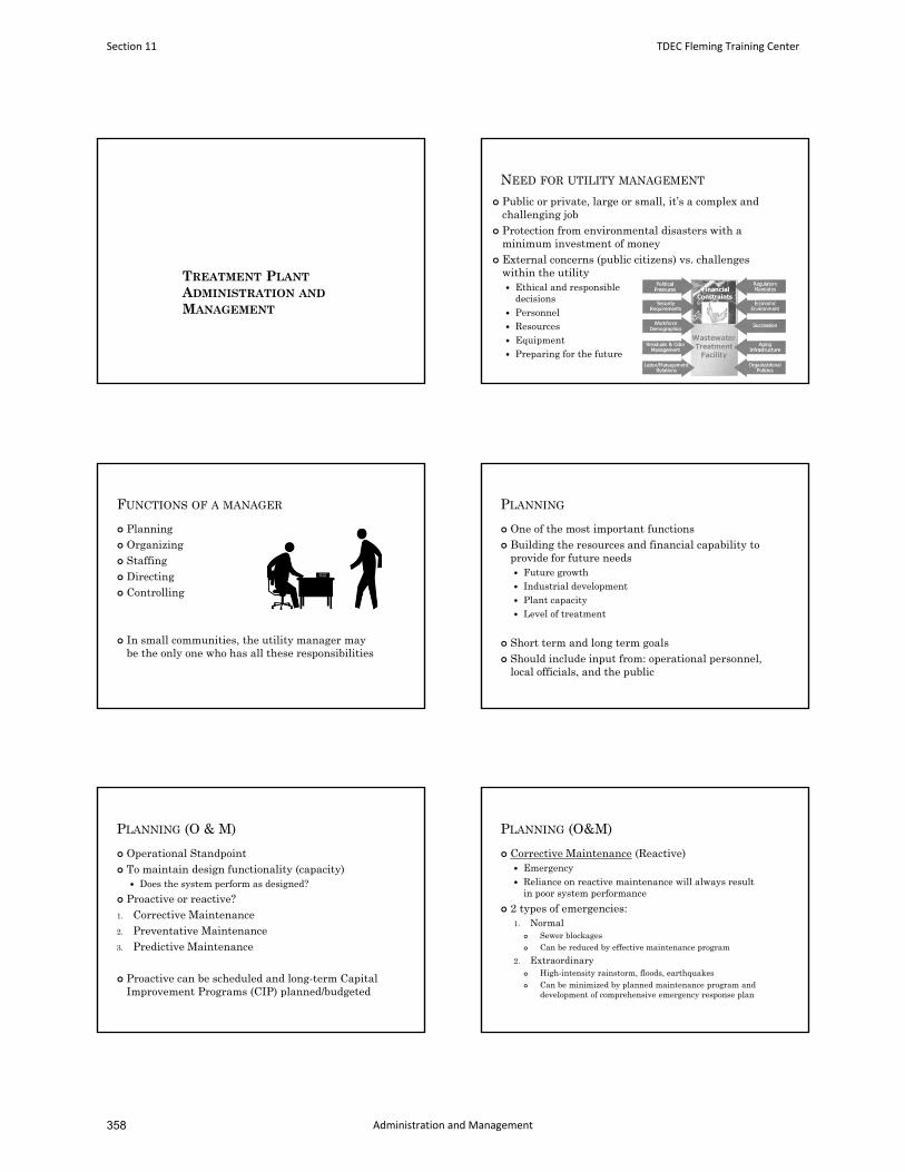
TREATMENT PLANT
ADMINISTRATION AND
MANAGEMENT
NEED FOR UTILITY MANAGEMENT
Public or private, large or small, it’s a complex andchallenging job
Protection from environmental disasters with aminimum investment of money
External concerns (public citizens) vs. challengeswithin the utility Ethical and responsible
decisions Personnel Resources Equipment Preparing for the future
FUNCTIONS OF A MANAGER
Planning Organizing Staffing Directing Controlling
In small communities, the utility manager maybe the only one who has all these responsibilities
PLANNING
One of the most important functions Building the resources and financial capability to
provide for future needs Future growth Industrial development Plant capacity Level of treatment
Short term and long term goals Should include input from: operational personnel,
local officials, and the public
PLANNING (O & M)
Operational Standpoint To maintain design functionality (capacity)
Does the system perform as designed?
Proactive or reactive?1. Corrective Maintenance2. Preventative Maintenance3. Predictive Maintenance
Proactive can be scheduled and long-term CapitalImprovement Programs (CIP) planned/budgeted
PLANNING (O&M)
Corrective Maintenance (Reactive) Emergency Reliance on reactive maintenance will always result
in poor system performance
2 types of emergencies:1. Normal
Sewer blockages Can be reduced by effective maintenance program
2. Extraordinary High-intensity rainstorm, floods, earthquakes Can be minimized by planned maintenance program and
development of comprehensive emergency response plan
Section 11 TDEC Fleming Training Center
Administration and Management358
PLANNING (O&M)
Preventative Maintenance (Proactive) Programmed, systematic approach Will always result in improved system performance Ex: lubrication of motors is frequently based on
running time
Major elements of good PM program: Planning and scheduling Records management
Spare parts management
Cost and Budget control Emergency repair procedures Training program
PLANNING (O&M)
Predictive Maintenance (Proactive) Method of establishing baseline performance data,
monitoring performance over time, observing changes so failure can be predicted
Goal: reduce Corrective and Emergency maintenance, thereby reducing system failures that result in stoppages and overflows
Goal of managing maintenance: minimizeinvestments of labor, materials, money, andequipment Major capital investments Reliability is critical
PLANNING
Emergency Response Plan (aka EmergencyOperating Plan or EOP) Natural or human disasters Contingency planning
1. Vulnerability Assessment2. Inventory organizational personnel3. Provide for a recovery operation (plan)4. Training programs for operators5. Coordinate with local agencies6. Establish communications procedure7. Provide protection for staff, equip, records, maps
BACK-UP REQUIREMENTS
TN Design Criteria: 14.3.1.2
All treatment facilities greater than 100,000 gpd shall be equipped with an emergency generator to provide an alternate power source
2.7.4 An emergency power source or auxiliary power is required
for all pumping stations larger than 1 MGD to ensure continuous operability unless experience has shown the frequency and duration of outages to be low and the pumping station and/or sewers provide storage sufficient for expected interruptions in power service.
ORGANIZING
Deciding who does what work and delegating authority to appropriate persons
Utility should have a written organizational plan and written policies Show who reports to whom Job descriptions
Authority = the power and resources to do a specific job or to get that job done
Responsibility = answering to those above in the chain of command to explain how and why you used your authority
Delegation = the act in which power is given to another person
Accountable = employee must ensure the manager is informed of results or events
TDEC Fleming Training Center Section 11
Administration and Management 357
ORGANIZING
Employees should not be asked to acceptresponsibilities beyond their level of authority
Authority and responsibility must be delegatedproperly to be effective
3 components present = successful delegation1. Proper job assignments2. Authority3. Responsibility
Follow-up is important
STAFFING
Should have established procedures for: Hiring
Analyzing staffing needs Qualifications profile, Advertising, Interviewing
Training New employee and ongoing Safety is extremely important, but not sole benefit
Protection of public’s investment Employee pride and recognition
Certification Supervisor training
Evaluating job performance Written evaluation strongly recommended for documentation Set goals
STAFFING
68-221-909. Certification of operators ResponsibilitiesMultiple functions.
(a) All operators of water and wastewater systems are encouraged to become certified, although this part requires only that a person in direct charge of a water treatment plant, wastewater treatment plant, water distribution system or wastewater collection system be certified.
(c) It is permissible for one (1) certified operator to have the responsibility for more than one (1) water and/or wastewater system where two (2) or more systems are involved in reasonable proximity to one another, and where the duties of operation are such that the work time of one (1) person may properly be divided among two (2) or more systems, or where a certified operator may adequately supervise the work of others in more than one (1) system.
[Acts 1984, ch. 812, § 8; T.C.A., § 68-13-909.]
COMMUNICATION
Both written and oral communication skills are needed to effectively organize and direct the operation of wastewater plant
2 part process: Info must be given Info must be understood (good listening skills)
Communicating with employees, your governing body, and the public
Annual report One of the most involved writing projects Review of what and how the utility operated the past year Include goals for next year
COMMUNICATION
Conducting Meetings Public Relations
Utility Operations Public image Open communication
Mass Media Being Interviewed Public Speaking Consumer Inquiries
Customer calls are frequently your first indication that something may be wrong
Education can be a valuable tool Franklin videos: flushable wipes, grease
Plant Tours
FINANCIAL MANAGEMENT
Budgeting is perhaps the most challengingtask for many managers
Must understand how the money was spent overthe last year, the needs of the utility, and howthe needs should be prioritized
Must have a Repair/Replacement Fund Wastewater treatment rates Capital Investments and funding in the future Financial Assistance
Section 11 TDEC Fleming Training Center
Administration and Management360
SAFETY
Regardless of size, utility must have a safety program Basic elements include: safety policy statement, safety
training and promotion, accident investigation and reporting
Regulatory agencies OSHA (TOSHA)
First Aid Hazard Communication/Right To Know Laws
29 CFR 1910.1200 SDS
Confined Space Entry Procedures Reporting Training
SECURITY MEASURES
Investing in security and infrastructureimprovements
Security of critical wastewater infrastructure Sanitary and Storm sewers is one of America’s most
valuable resources Vulnerabilities include:
Pumping and Lift Stations Manholes Chemical and fuel storage areas Outfall pipes
ETHICS
Performing illegal acts is always unethical.However, unethical acts are not always illegal.
What is ethics? Moral principles and rules of conduct The point of ethics is to benefit people Correct ethical actions are those that one does out of
consideration for others How people ought to treat each other Ethical concepts are based on the assumption that
everyone acts with consideration of all Everyone benefits when we act ethically towards others
ETHICS
Examples of illegal and unethical activities: Providing false information on an application for a
job or certification exam Cheating on your certification exam Copying certification exam questions Dry-labbing (writing down results without actually
performing the test) Falsifying results and reports Intentionally discharging toxic wastes to receiving
waters Harassing other employees Requiring operators to use unsafe equipment, work
under unsafe conditions, or occupy confined space with an unsafe atmosphere
ETHICS
Ask yourself: “Would I be uncomfortable with myactions if they were reported in the newspaper?”
Other areas where operators will encounter ethical situations: Collecting samples Preparation of reports Sabotaging someone else’s work Recommending a vendor or
consulting engineer Employee performance evaluations Cheating on an exam
TDEC Fleming Training Center Section 11
Administration and Management 359
ETHICS
Whistleblowing = the act of reporting illegal activity to an authority
Codes of Ethics Trustworthiness Respect Responsibility Caring Justice Civic virtue and citizenship
• Interactions between operators and the public
• Interactions among operators
• Approved professional conduct
• Service by operators to protect the public and the environment
ETHICS
0400-49-01-.11 Rules Governing Water andWastewater Operator Certification
An operator’s certificate may be revoked when: Operator has not used reasonable care, judgement, or
application of his/her knowledge in performance of their duties Intentional or negligent
Operator is incompetent to perform those duties Operator has practiced fraud or deception
Obtained certificate through fraud, deceit, or submission of inaccurate data regarding qualifications
False, inaccurate data on reports or lab analysis
ANY QUESTIONS?
Section 11 TDEC Fleming Training Center
Administration and Management362
Administration and Management Vocabulary
1. __________________ is the power and resources to do a specific job or to get that job done.
2. The act of _______________________ is defined as deciding who does what work and delegating authority
to the appropriate persons.
3. Answering to those above in the chain of command to explain how and why you have used your authority is
defined as ________________________.
4. A ______________________________ is a brief (10‐20 minutes) safety meeting held every 7 – 10 working
days.
5. Moral principles and rules of conduct define the concept of ___________________. An operator’s
certification may be revoked if they do not act with this concept in mind.
6. When a manager gives power/responsibility to an employee, and the employee ensures that the manager is
informed of results or events, that employee is demonstrating _____________________.
7. ________________________ is the act in which power is given to another person in the organization to
accomplish a specific job.
8. ______________________ maintenance is proactive and is defined as a programmed, systematic approach
to maintenance activities.
9. The nation's provides the essential services that underpin American society
and serve as the backbone of our nation's economy, security, and health. This includes the Water and
Wastewater Systems Sector, which includes water distribution and sewage collection systems.
10. Identifying system components, estimating disaster effects on those components, estimating customer
demand for service following a disaster, and identifying key system components that would be primarily
responsible for a system failure are all key steps that should be taken when conducting a
____________________ analysis.
11. The act of reporting illegal activity to an authority is called _______________________.
12. ______________________ maintenance is a method of establishing baseline performance data, monitoring
performance criteria over a period of time, and observing changes in performance so that failure can be
predicted and maintenance can be performed on a planned, scheduled basis.
Word Bank:
Accountability
Organizing
Preventative
Whistleblowing
Critical Infrastructure
Predictive
Ethics
Accountability
Responsibility
Tailgate Safety Meeting
Authority
Vulnerability
TDEC Fleming Training Center Section 11
Administration and Management 361
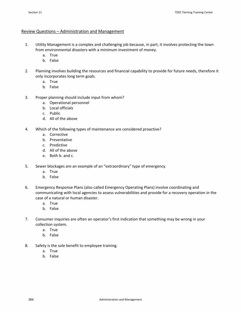
Review Questions – Administration and Management
1. Utility Management is a complex and challenging job because, in part, it involves protecting the townfrom environmental disasters with a minimum investment of money.
a. Trueb. False
2. Planning involves building the resources and financial capability to provide for future needs, therefore itonly incorporates long term goals.
a. Trueb. False
3. Proper planning should include input from whom?a. Operational personnelb. Local officialsc. Publicd. All of the above
4. Which of the following types of maintenance are considered proactive?a. Correctiveb. Preventativec. Predictived. All of the abovee. Both b. and c.
5. Sewer blockages are an example of an “extraordinary” type of emergency.a. Trueb. False
6. Emergency Response Plans (also called Emergency Operating Plans) involve coordinating andcommunicating with local agencies to assess vulnerabilities and provide for a recovery operation in thecase of a natural or human disaster.
a. Trueb. False
7. Consumer inquiries are often an operator’s first indication that something may be wrong in yourcollection system.
a. Trueb. False
8. Safety is the sole benefit to employee training.a. Trueb. False
Section 11 TDEC Fleming Training Center
Administration and Management364
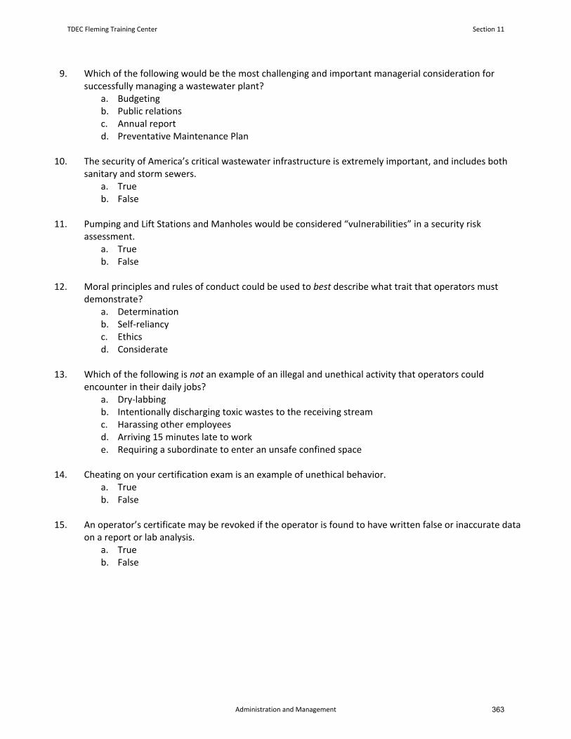
9. Which of the following would be the most challenging and important managerial consideration forsuccessfully managing a wastewater plant?
a. Budgetingb. Public relationsc. Annual reportd. Preventative Maintenance Plan
10. The security of America’s critical wastewater infrastructure is extremely important, and includes bothsanitary and storm sewers.
a. Trueb. False
11. Pumping and Lift Stations and Manholes would be considered “vulnerabilities” in a security riskassessment.
a. Trueb. False
12. Moral principles and rules of conduct could be used to best describe what trait that operators mustdemonstrate?
a. Determinationb. Self‐reliancyc. Ethicsd. Considerate
13. Which of the following is not an example of an illegal and unethical activity that operators couldencounter in their daily jobs?
a. Dry‐labbingb. Intentionally discharging toxic wastes to the receiving streamc. Harassing other employeesd. Arriving 15 minutes late to worke. Requiring a subordinate to enter an unsafe confined space
14. Cheating on your certification exam is an example of unethical behavior.a. Trueb. False
15. An operator’s certificate may be revoked if the operator is found to have written false or inaccurate dataon a report or lab analysis.
a. Trueb. False
TDEC Fleming Training Center Section 11
Administration and Management 363

366

Section 12
References and Need to Know
365
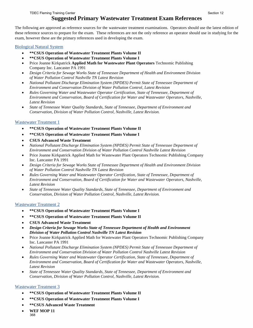
Suggested Primary Wastewater Treatment Exam References
The following are approved as reference sources for the wastewater treatment examinations. Operators should use the latest edition of
these reference sources to prepare for the exam. These references are not the only reference an operator should use in studying for the
exam, however these are the primary references used in developing the exam.
Biological Natural System
**CSUS Operation of Wastewater Treatment Plants Volume II
**CSUS Operation of Wastewater Treatment Plants Volume I
Price Joanne Kirkpatrick Applied Math for Wastewater Plant Operators Technomic Publishing
Company Inc. Lancaster PA 1991
Design Criteria for Sewage Works State of Tennessee Department of Health and Environment Division
of Water Pollution Control Nashville TN Latest Revision
National Pollutant Discharge Elimination System (NPDES) Permit State of Tennessee Department of
Environment and Conservation Division of Water Pollution Control, Latest Revision
Rules Governing Water and Wastewater Operator Certification, State of Tennessee, Department of
Environment and Conservation, Board of Certification for Water and Wastewater Operators, Nashville,
Latest Revision
State of Tennessee Water Quality Standards, State of Tennessee, Department of Environment and
Conservation, Division of Water Pollution Control, Nashville, Latest Revision.
Wastewater Treatment 1
**CSUS Operation of Wastewater Treatment Plants Volume II
**CSUS Operation of Wastewater Treatment Plants Volume I
CSUS Advanced Waste Treatment
National Pollutant Discharge Elimination System (NPDES) Permit State of Tennessee Department of
Environment and Conservation Division of Water Pollution Control Nashville Latest Revision
Price Joanne Kirkpatrick Applied Math for Wastewater Plant Operators Technomic Publishing Company
Inc. Lancaster PA 1991
Design Criteria for Sewage Works State of Tennessee Department of Health and Environment Division
of Water Pollution Control Nashville TN Latest Revision
Rules Governing Water and Wastewater Operator Certification, State of Tennessee, Department of
Environment and Conservation, Board of Certification for Water and Wastewater Operators, Nashville,
Latest Revision
State of Tennessee Water Quality Standards, State of Tennessee, Department of Environment and
Conservation, Division of Water Pollution Control, Nashville, Latest Revision.
Wastewater Treatment 2
**CSUS Operation of Wastewater Treatment Plants Volume I
**CSUS Operation of Wastewater Treatment Plants Volume II
CSUS Advanced Waste Treatment
Design Criteria for Sewage Works State of Tennessee Department of Health and Environment
Division of Water Pollution Control Nashville TN Latest Revision
Price Joanne Kirkpatrick Applied Math for Wastewater Plant Operators Technomic Publishing Company
Inc. Lancaster PA 1991
National Pollutant Discharge Elimination System (NPDES) Permit State of Tennessee Department of
Environment and Conservation Division of Water Pollution Control Nashville Latest Revision
Rules Governing Water and Wastewater Operator Certification, State of Tennessee, Department of
Environment and Conservation, Board of Certification for Water and Wastewater Operators, Nashville,
Latest Revision
State of Tennessee Water Quality Standards, State of Tennessee, Department of Environment and
Conservation, Division of Water Pollution Control, Nashville, Latest Revision.
Wastewater Treatment 3
**CSUS Operation of Wastewater Treatment Plants Volume II
**CSUS Operation of Wastewater Treatment Plants Volume I
**CSUS Advanced Waste Treatment
WEF MOP 11
TDEC Fleming Training Center Section 12
368
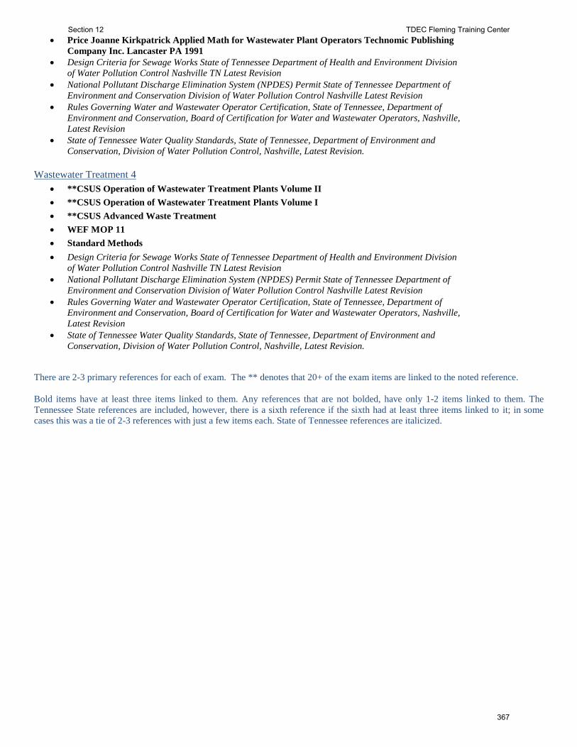
Price Joanne Kirkpatrick Applied Math for Wastewater Plant Operators Technomic Publishing
Company Inc. Lancaster PA 1991
Design Criteria for Sewage Works State of Tennessee Department of Health and Environment Division
of Water Pollution Control Nashville TN Latest Revision
National Pollutant Discharge Elimination System (NPDES) Permit State of Tennessee Department of
Environment and Conservation Division of Water Pollution Control Nashville Latest Revision
Rules Governing Water and Wastewater Operator Certification, State of Tennessee, Department of
Environment and Conservation, Board of Certification for Water and Wastewater Operators, Nashville,
Latest Revision
State of Tennessee Water Quality Standards, State of Tennessee, Department of Environment and
Conservation, Division of Water Pollution Control, Nashville, Latest Revision.
Wastewater Treatment 4
**CSUS Operation of Wastewater Treatment Plants Volume II
**CSUS Operation of Wastewater Treatment Plants Volume I
**CSUS Advanced Waste Treatment
WEF MOP 11
Standard Methods
Design Criteria for Sewage Works State of Tennessee Department of Health and Environment Division
of Water Pollution Control Nashville TN Latest Revision
National Pollutant Discharge Elimination System (NPDES) Permit State of Tennessee Department of
Environment and Conservation Division of Water Pollution Control Nashville Latest Revision
Rules Governing Water and Wastewater Operator Certification, State of Tennessee, Department of
Environment and Conservation, Board of Certification for Water and Wastewater Operators, Nashville,
Latest Revision
State of Tennessee Water Quality Standards, State of Tennessee, Department of Environment and
Conservation, Division of Water Pollution Control, Nashville, Latest Revision.
There are 2-3 primary references for each of exam. The ** denotes that 20+ of the exam items are linked to the noted reference.
Bold items have at least three items linked to them. Any references that are not bolded, have only 1-2 items linked to them. The
Tennessee State references are included, however, there is a sixth reference if the sixth had at least three items linked to it; in some
cases this was a tie of 2-3 references with just a few items each. State of Tennessee references are italicized.
Section 12 TDEC Fleming Training Center
367
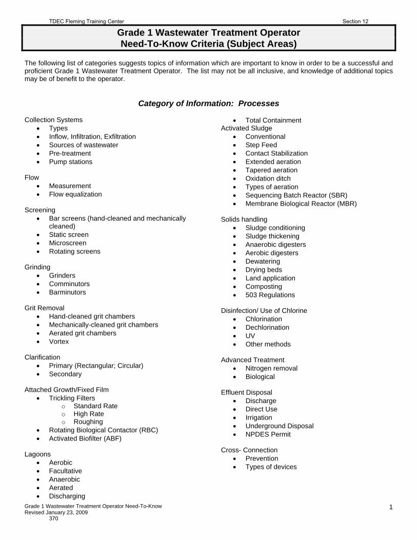
Grade 1 Wastewater Treatment Operator Need-To-Know Revised January 23, 2009
1
Grade 1 Wastewater Treatment Operator Need-To-Know Criteria (Subject Areas)
The following list of categories suggests topics of information which are important to know in order to be a successful and proficient Grade 1 Wastewater Treatment Operator. The list may not be all inclusive, and knowledge of additional topics may be of benefit to the operator.
Category of Information: Processes
Collection Systems
Types Inflow, Infiltration, Exfiltration Sources of wastewater Pre-treatment Pump stations
Flow
Measurement Flow equalization
Screening
Bar screens (hand-cleaned and mechanically cleaned)
Static screen Microscreen Rotating screens
Grinding
Grinders Comminutors Barminutors
Grit Removal
Hand-cleaned grit chambers Mechanically-cleaned grit chambers Aerated grit chambers Vortex
Clarification
Primary (Rectangular; Circular) Secondary
Attached Growth/Fixed Film
Trickling Filters o Standard Rate o High Rate o Roughing
Rotating Biological Contactor (RBC) Activated Biofilter (ABF)
Lagoons
Aerobic Facultative Anaerobic Aerated Discharging
Total Containment Activated Sludge
Conventional Step Feed Contact Stabilization Extended aeration Tapered aeration Oxidation ditch Types of aeration Sequencing Batch Reactor (SBR) Membrane Biological Reactor (MBR)
Solids handling
Sludge conditioning Sludge thickening Anaerobic digesters Aerobic digesters Dewatering Drying beds Land application Composting 503 Regulations
Disinfection/ Use of Chlorine
Chlorination Dechlorination UV Other methods
Advanced Treatment
Nitrogen removal Biological
Effluent Disposal
Discharge Direct Use Irrigation Underground Disposal NPDES Permit
Cross- Connection
Prevention Types of devices
TDEC Fleming Training Center Section 12
370
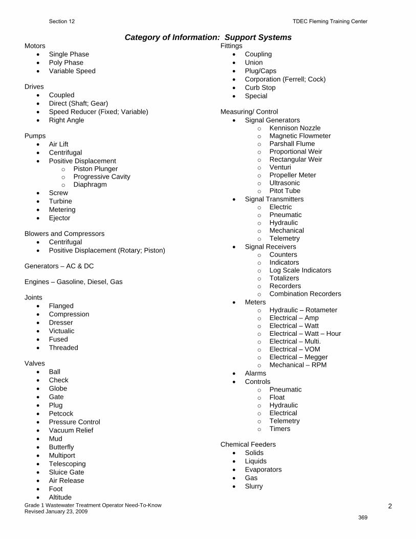
Grade 1 Wastewater Treatment Operator Need-To-Know Revised January 23, 2009
2
Category of Information: Support Systems
Motors Single Phase Poly Phase Variable Speed
Drives
Coupled Direct (Shaft; Gear) Speed Reducer (Fixed; Variable) Right Angle
Pumps
Air Lift Centrifugal Positive Displacement
o Piston Plunger o Progressive Cavity o Diaphragm
Screw Turbine Metering Ejector
Blowers and Compressors
Centrifugal Positive Displacement (Rotary; Piston)
Generators – AC & DC Engines – Gasoline, Diesel, Gas Joints
Flanged Compression Dresser Victualic Fused Threaded
Valves
Ball Check Globe Gate Plug Petcock Pressure Control Vacuum Relief Mud Butterfly Multiport Telescoping Sluice Gate Air Release Foot Altitude
Fittings Coupling Union Plug/Caps Corporation (Ferrell; Cock) Curb Stop Special
Measuring/ Control
Signal Generators o Kennison Nozzle o Magnetic Flowmeter o Parshall Flume o Proportional Weir o Rectangular Weir o Venturi o Propeller Meter o Ultrasonic o Pitot Tube
Signal Transmitters o Electric o Pneumatic o Hydraulic o Mechanical o Telemetry
Signal Receivers o Counters o Indicators o Log Scale Indicators o Totalizers o Recorders o Combination Recorders
Meters o Hydraulic – Rotameter o Electrical – Amp o Electrical – Watt o Electrical – Watt – Hour o Electrical – Multi. o Electrical – VOM o Electrical – Megger o Mechanical – RPM
Alarms Controls
o Pneumatic o Float o Hydraulic o Electrical o Telemetry o Timers
Chemical Feeders
Solids Liquids Evaporators Gas Slurry
Section 12 TDEC Fleming Training Center
369
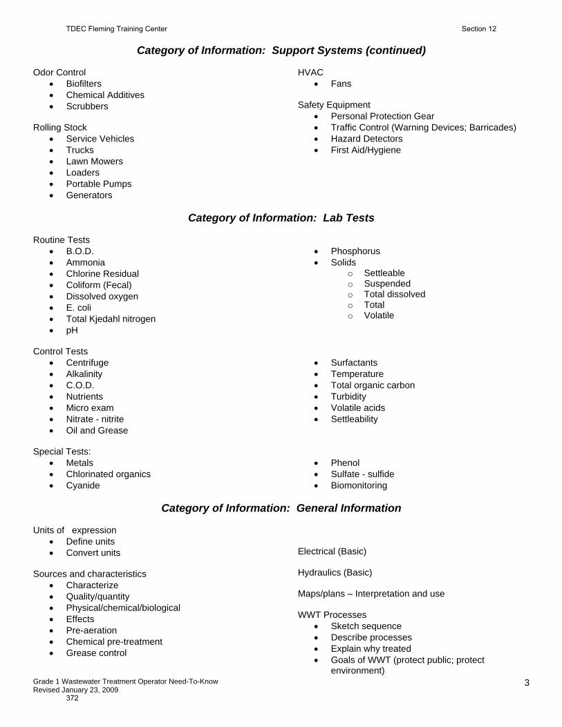
Grade 1 Wastewater Treatment Operator Need-To-Know Revised January 23, 2009
3
Category of Information: Support Systems (continued)
Odor Control
Biofilters Chemical Additives Scrubbers
Rolling Stock
Service Vehicles Trucks Lawn Mowers Loaders Portable Pumps Generators
HVAC
Fans Safety Equipment
Personal Protection Gear Traffic Control (Warning Devices; Barricades) Hazard Detectors First Aid/Hygiene
Category of Information: Lab Tests
Routine Tests
B.O.D. Ammonia Chlorine Residual Coliform (Fecal) Dissolved oxygen E. coli Total Kjedahl nitrogen pH
Phosphorus Solids
o Settleable o Suspended o Total dissolved o Total o Volatile
Control Tests
Centrifuge Alkalinity C.O.D. Nutrients Micro exam Nitrate - nitrite Oil and Grease
Surfactants Temperature Total organic carbon Turbidity Volatile acids Settleability
Special Tests:
Metals Chlorinated organics Cyanide
Phenol Sulfate - sulfide Biomonitoring
Category of Information: General Information
Units of expression
Define units Convert units
Sources and characteristics
Characterize Quality/quantity Physical/chemical/biological Effects Pre-aeration Chemical pre-treatment Grease control
Electrical (Basic) Hydraulics (Basic) Maps/plans – Interpretation and use WWT Processes
Sketch sequence Describe processes Explain why treated Goals of WWT (protect public; protect
environment)
TDEC Fleming Training Center Section 12
372
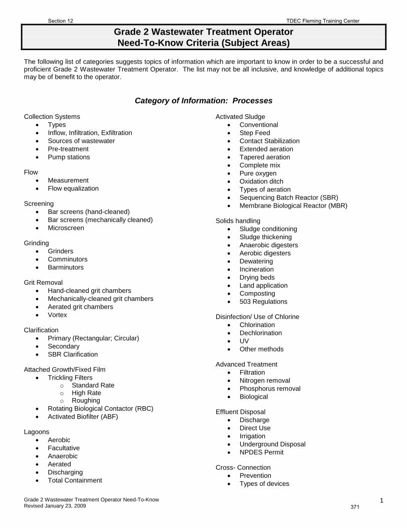
Grade 2 Wastewater Treatment Operator Need-To-Know Revised January 23, 2009
1
Grade 2 Wastewater Treatment Operator Need-To-Know Criteria (Subject Areas)
The following list of categories suggests topics of information which are important to know in order to be a successful and proficient Grade 2 Wastewater Treatment Operator. The list may not be all inclusive, and knowledge of additional topics may be of benefit to the operator.
Category of Information: Processes
Collection Systems
• Types • Inflow, Infiltration, Exfiltration • Sources of wastewater • Pre-treatment • Pump stations
Flow
• Measurement • Flow equalization
Screening
• Bar screens (hand-cleaned) • Bar screens (mechanically cleaned) • Microscreen
Grinding
• Grinders • Comminutors • Barminutors
Grit Removal
• Hand-cleaned grit chambers • Mechanically-cleaned grit chambers • Aerated grit chambers • Vortex
Clarification
• Primary (Rectangular; Circular) • Secondary • SBR Clarification
Attached Growth/Fixed Film
• Trickling Filters o Standard Rate o High Rate o Roughing
• Rotating Biological Contactor (RBC) • Activated Biofilter (ABF)
Lagoons
• Aerobic • Facultative • Anaerobic • Aerated • Discharging • Total Containment
Activated Sludge • Conventional • Step Feed • Contact Stabilization • Extended aeration • Tapered aeration • Complete mix • Pure oxygen • Oxidation ditch • Types of aeration • Sequencing Batch Reactor (SBR) • Membrane Biological Reactor (MBR)
Solids handling
• Sludge conditioning • Sludge thickening • Anaerobic digesters • Aerobic digesters • Dewatering • Incineration • Drying beds • Land application • Composting • 503 Regulations
Disinfection/ Use of Chlorine
• Chlorination • Dechlorination • UV • Other methods
Advanced Treatment
• Filtration • Nitrogen removal • Phosphorus removal • Biological
Effluent Disposal
• Discharge • Direct Use • Irrigation • Underground Disposal • NPDES Permit
Cross- Connection
• Prevention • Types of devices
Section 12 TDEC Fleming Training Center
371
Grade 2 Wastewater Treatment Operator Need-To-Know Revised January 23, 2009
2
Category of Information: Support Systems Motors
• Single Phase • Poly Phase • Variable Speed
Drives
• Coupled • Direct (Shaft; Gear) • Speed Reducer (Fixed; Variable) • Right Angle
Pumps
• Air Lift • Centrifugal • Positive Displacement
o Piston Plunger o Progressive Cavity o Diaphragm
• Screw • Turbine • Metering • Ejector
Blowers and Compressors
• Centrifugal • Positive Displacement (Rotary; Piston)
Generators – AC & DC Engines – Gasoline, Diesel & Gas Joints
• Flanged • Compression • Dresser • Victualic • Fused • Threaded
Valves
• Ball • Check • Globe • Gate • Plug • Petcock • Pressure Control • Vacuum Relief • Mud • Butterfly • Multiport • Telescoping • Sluice Gate • Air Release • Foot • Altitude
Fittings • Coupling • Union • Plug/Caps • Corporation (Ferrell; Cock) • Curb Stop • Special
Measuring/ Control
• Signal Generators o Kennison Nozzle o Magnetic Flowmeter o Parshall Flume o Proportional Weir o Rectangular Weir o Venturi o Propeller Meter o Ultrasonic o Pitot Tube
• Signal Transmitters o Electric o Pneumatic o Hydraulic o Mechanical o Telemetry
• Signal Receivers o Counters o Indicators o Log Scale Indicators o Totalizers o Recorders o Combination Recorders
• Meters o Hydraulic – Rotameter o Electrical – Amp o Electrical – Watt o Electrical – Watt – Hour o Electrical – Multi. o Electrical – VOM o Electrical – Megger o Mechanical – RPM
• Alarms • Controls
o Pneumatic o Float o Hydraulic o Electrical o Telemetry o Timers
TDEC Fleming Training Center Section 12
374
Grade 2 Wastewater Treatment Operator Need-To-Know Revised January 23, 2009
3
Category of Information: Support Systems (continued) Chemical Feeders
• Solids • Liquids • Evaporators • Gas • Slurry
Odor Control
• Biofilters • Chemical Additives • Scrubbers
Rolling Stock
• Service Vehicles • Trucks • Lawn Mowers • Loaders • Portable Pumps • Generators
HVAC • Heat Exchangers • Dehumidifiers • Fans • Compressors
Safety Equipment
• Personal Protection Gear • Traffic Control (Warning Devices; Barricades) • Hazard Detectors • First Aid/Hygiene
Category of Information: Lab Tests Routine Tests
• B.O.D. • Ammonia • Chlorine Residual • Coliform (Fecal) • Dissolved oxygen • E. coli • Total Kjedahl nitrogen • pH
• Phosphorus • Solids
o Settleable o Suspended o Total dissolved o Total o Volatile
Control Tests
• Centrifuge • Alkalinity • C.O.D. • Color • Conductance • Nutrients • Micro exam • Nitrate - nitrite
• Oil and Grease • Surfactants • Temperature • Total organic carbon • Turbidity • Volatile acids • Settleability
Special Tests:
• Metals • Chlorinated organics • Cyanide
• Phenol • Sulfate - sulfide • Biomonitoring
Category of Information: General Information
Units of expression
• Define units • Convert units
Sources and characteristics
• Characterize • Quality/quantity • Physical/chemical/biological
• Effects • Pre-aeration • Chemical pre-treatment • Grease control
Electrical (Basic) Hydraulics (Basic)
Section 12 TDEC Fleming Training Center
373

Grade 2 Wastewater Treatment Operator Need-To-Know Revised January 23, 2009
4
Category of Information: General Information(continued) Maps/plans – Interpretation and use WWT Processes
• Sketch sequence • Describe processes • Explain why treated • Goals of WWT (protect public; protect environment)
TDEC Fleming Training Center Section 12
376
Grade 3 Wastewater Treatment Operator Need-To-Know Revised January 23, 2009
1
Grade 3 Wastewater Treatment Operator Need-To-Know Criteria
The following list of categories suggests topics of information which are important to know in order to be a successful and proficient Grade 4 Wastewater Treatment Operator. The list may not be all inclusive, and knowledge of additional topics may be of benefit to the operator
Category of Information: Processes
Collection Systems
• Types • Inflow, Infiltration, Exfiltration • Pre-treatment • Sources of wastewater • Pump stations
Flow
• Measurement • Flow equalization
Screening
• Bar screens (hand-cleaned) • Bar screens (mechanically cleaned) • Static screen • Microscreen
Grinding
• Grinders • Comminutors • Barminutors
Grit Removal
• Hand-cleaned grit chambers • Mechanically-cleaned grit chambers • Aerated grit chambers • Vortex
Clarification
• Primary (Rectangular; Circular) • Secondary • SBR Clarification
Attached Growth/Fixed Film
• Trickling Filters o Standard Rate o High Rate o Roughing
• Rotating Biological Contactor (RBC) • Activated Biofilter (ABF)
Lagoons
• Aerobic • Facultative • Anaerobic • Aerated • Discharging
Activated Sludge • Conventional • Step Feed • Contact Stabilization • Extended aeration • Tapered aeration • Complete mix • Pure oxygen • Oxidation ditch • Types of aeration • Sequencing Batch Reactor (SBR) • Membrane Biological Reactor (MBR)
Solids handling
• Sludge conditioning • Sludge thickening • Anaerobic digestors • Aerobic digestors • Dewatering • Incineration • Drying beds • Land application • Composting • 503 Regulations
Disinfection/ Use of Chlorine
• Chlorination • Dechlorination • UV • Other methods
Advanced Treatment
• Filtration • Nitrogen removal • Phosphorus removal • Biological
Effluent Disposal
• Discharge • Direct Use • Irrigation • Underground Disposal • NPDES Permit
Cross- Connection
• Prevention • Types of devices
Section 12 TDEC Fleming Training Center
375
Grade 3 Wastewater Treatment Operator Need-To-Know Revised January 23, 2009
2
Category of Information: Support Systems Motors
• Single Phase • Poly Phase • Variable Speed
Drives
• Coupled • Direct (Shaft; Gear) • Speed Reducer (Fixed; Variable) • Right Angle
Pumps
• Air Lift • Centrifugal • Positive Displacement
o Piston Plunger o Progressive Cavity o Diaphragm
• Screw • Turbine • Metering • Ejector
Blowers and Compressors
• Centrifugal • Positive Displacement (Rotary; Piston)
Generators – AC & DC Engines – Gasoline, Diesel & Gas Joints
• Flanged • Compression • Dresser • Victualic • Fused • Threaded
Valves
• Ball • Check • Globe • Gate • Plug • Petcock • Pressure Control • Vacuum Relief • Mud • Butterfly • Multiport • Telescoping • Sluice Gate • Air Release • Foot • Altitude
Fittings • Coupling • Union • Plug/Caps • Corporation (Ferrell; Cock) • Curb Stop • Special
Cathodic Protection Devices
• Anode Rod/Bags • Cathode Rod/Bags • Rectifiers • Potentiometers
Measuring/ Control
• Signal Generators o Kennison Nozzle o Magnetic Flowmeter o Parshall Flume o Proportional Weir o Rectangular Weir o Venturi o Propeller Meter o Ultrasonic o Pitot Tube
• Signal Transmitters o Electric o Pneumatic o Hydraulic o Mechanical o Telemetry
• Signal Receivers o Counters o Indicators o Log Scale Indicators o Totalizers o Recorders o Combination Recorders
• Meters o Hydraulic – Rotameter o Electrical – Amp o Electrical – Watt o Electrical – Watt – Hour o Electrical – Multi. o Electrical – VOM o Electrical – Megger o Mechanical – RPM
• Alarms • Controls
o Pneumatic o Float o Hydraulic o Electrical o Telemetry o Timers
TDEC Fleming Training Center Section 12
378
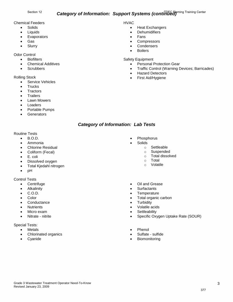
Grade 3 Wastewater Treatment Operator Need-To-Know Revised January 23, 2009
3
Category of Information: Support Systems (continued) Chemical Feeders
• Solids • Liquids • Evaporators • Gas • Slurry
Odor Control
• Biofilters • Chemical Additives • Scrubbers
Rolling Stock
• Service Vehicles • Trucks • Tractors • Trailers • Lawn Mowers • Loaders • Portable Pumps • Generators
HVAC • Heat Exchangers • Dehumidifiers • Fans • Compressors • Condensers • Boilers
Safety Equipment
• Personal Protection Gear • Traffic Control (Warning Devices; Barricades) • Hazard Detectors • First Aid/Hygiene
Category of Information: Lab Tests
Routine Tests
• B.O.D. • Ammonia • Chlorine Residual • Coliform (Fecal) • E. coli • Dissolved oxygen • Total Kjedahl nitrogen • pH
• Phosphorus • Solids
o Settleable o Suspended o Total dissolved o Total o Volatile
Control Tests
• Centrifuge • Alkalinity • C.O.D. • Color • Conductance • Nutrients • Micro exam • Nitrate - nitrite
• Oil and Grease • Surfactants • Temperature • Total organic carbon • Turbidity • Volatile acids • Settleability • Specific Oxygen Uptake Rate (SOUR)
Special Tests:
• Metals • Chlorinated organics • Cyanide
• Phenol • Sulfate - sulfide • Biomonitoring
Section 12 TDEC Fleming Training Center
377

Grade 3 Wastewater Treatment Operator Need-To-Know Revised January 23, 2009
4
Category of Information: General Information Units of expression
• Define units • Convert units
Electrical ( Basic) Hydraulics (Basic) Maps/plans – Interpretation and use Sources and characteristics
• Characterize • Quality/quantity • Physical/chemical/biological • Effects • Pre-aeration • Chemical pre-treatment • Grease control
WWT Processes • Sketch sequence • Describe processes • Explain why treated • Goals of WWT (protect public; protect
environment)
TDEC Fleming Training Center Section 12
380
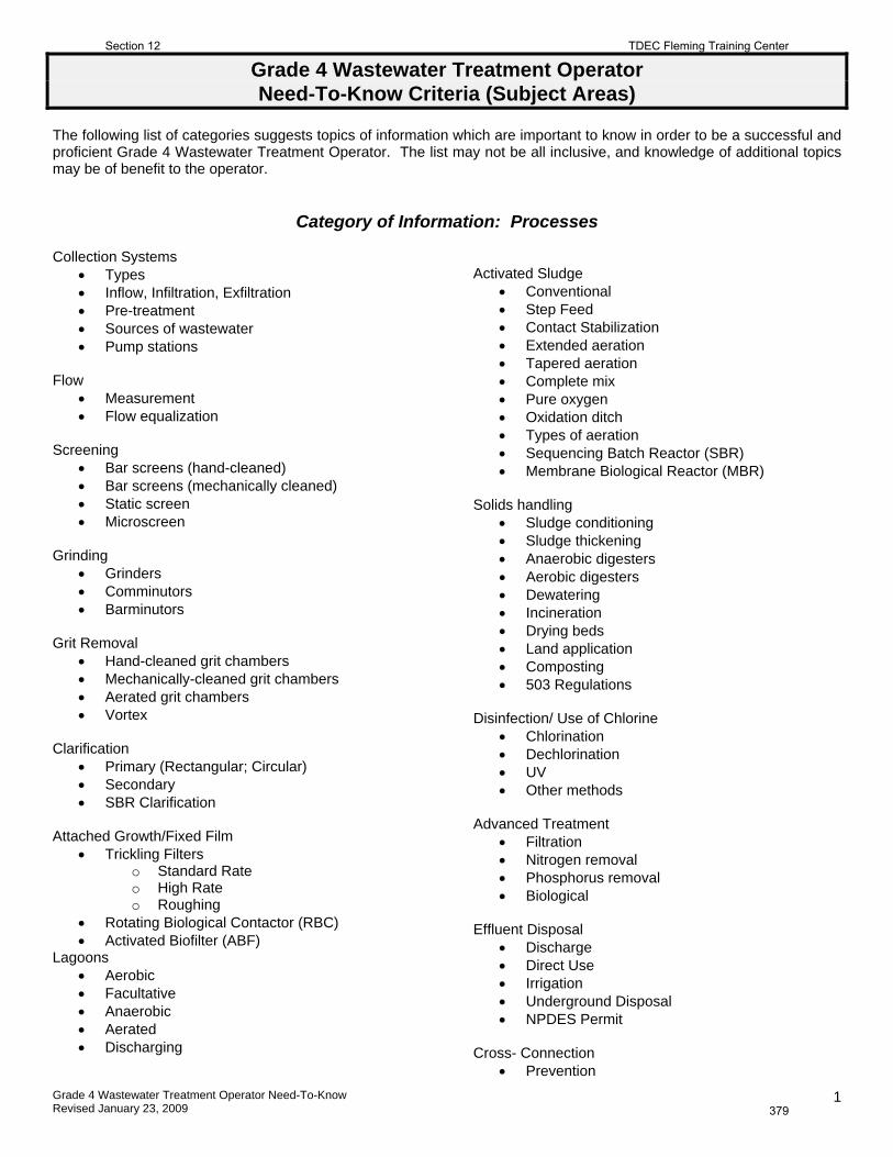
Grade 4 Wastewater Treatment Operator Need-To-Know Revised January 23, 2009
1
Grade 4 Wastewater Treatment Operator Need-To-Know Criteria (Subject Areas)
The following list of categories suggests topics of information which are important to know in order to be a successful and proficient Grade 4 Wastewater Treatment Operator. The list may not be all inclusive, and knowledge of additional topics may be of benefit to the operator.
Category of Information: Processes
Collection Systems
Types Inflow, Infiltration, Exfiltration Pre-treatment Sources of wastewater Pump stations
Flow
Measurement Flow equalization
Screening
Bar screens (hand-cleaned) Bar screens (mechanically cleaned) Static screen Microscreen
Grinding
Grinders Comminutors Barminutors
Grit Removal
Hand-cleaned grit chambers Mechanically-cleaned grit chambers Aerated grit chambers Vortex
Clarification
Primary (Rectangular; Circular) Secondary SBR Clarification
Attached Growth/Fixed Film
Trickling Filters o Standard Rate o High Rate o Roughing
Rotating Biological Contactor (RBC) Activated Biofilter (ABF)
Lagoons Aerobic Facultative Anaerobic Aerated Discharging
Activated Sludge
Conventional Step Feed Contact Stabilization Extended aeration Tapered aeration Complete mix Pure oxygen Oxidation ditch Types of aeration Sequencing Batch Reactor (SBR) Membrane Biological Reactor (MBR)
Solids handling
Sludge conditioning Sludge thickening Anaerobic digesters Aerobic digesters Dewatering Incineration Drying beds Land application Composting 503 Regulations
Disinfection/ Use of Chlorine
Chlorination Dechlorination UV Other methods
Advanced Treatment
Filtration Nitrogen removal Phosphorus removal Biological
Effluent Disposal
Discharge Direct Use Irrigation Underground Disposal NPDES Permit
Cross- Connection
Prevention
Section 12 TDEC Fleming Training Center
379
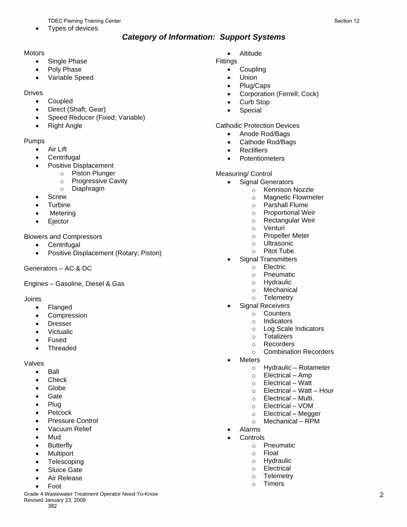
Grade 4 Wastewater Treatment Operator Need-To-Know Revised January 23, 2009
2
Types of devices Category of Information: Support Systems
Motors
Single Phase Poly Phase Variable Speed
Drives
Coupled Direct (Shaft; Gear) Speed Reducer (Fixed; Variable) Right Angle
Pumps
Air Lift Centrifugal Positive Displacement
o Piston Plunger o Progressive Cavity o Diaphragm
Screw Turbine Metering Ejector
Blowers and Compressors
Centrifugal Positive Displacement (Rotary; Piston)
Generators – AC & DC Engines – Gasoline, Diesel & Gas Joints
Flanged Compression Dresser Victualic Fused Threaded
Valves
Ball Check Globe Gate Plug Petcock Pressure Control Vacuum Relief Mud Butterfly Multiport Telescoping Sluice Gate Air Release Foot
Altitude Fittings
Coupling Union Plug/Caps Corporation (Ferrell; Cock) Curb Stop Special
Cathodic Protection Devices
Anode Rod/Bags Cathode Rod/Bags Rectifiers Potentiometers
Measuring/ Control
Signal Generators o Kennison Nozzle o Magnetic Flowmeter o Parshall Flume o Proportional Weir o Rectangular Weir o Venturi o Propeller Meter o Ultrasonic o Pitot Tube
Signal Transmitters o Electric o Pneumatic o Hydraulic o Mechanical o Telemetry
Signal Receivers o Counters o Indicators o Log Scale Indicators o Totalizers o Recorders o Combination Recorders
Meters o Hydraulic – Rotameter o Electrical – Amp o Electrical – Watt o Electrical – Watt – Hour o Electrical – Multi. o Electrical – VOM o Electrical – Megger o Mechanical – RPM
Alarms Controls
o Pneumatic o Float o Hydraulic o Electrical o Telemetry o Timers
TDEC Fleming Training Center Section 12
382
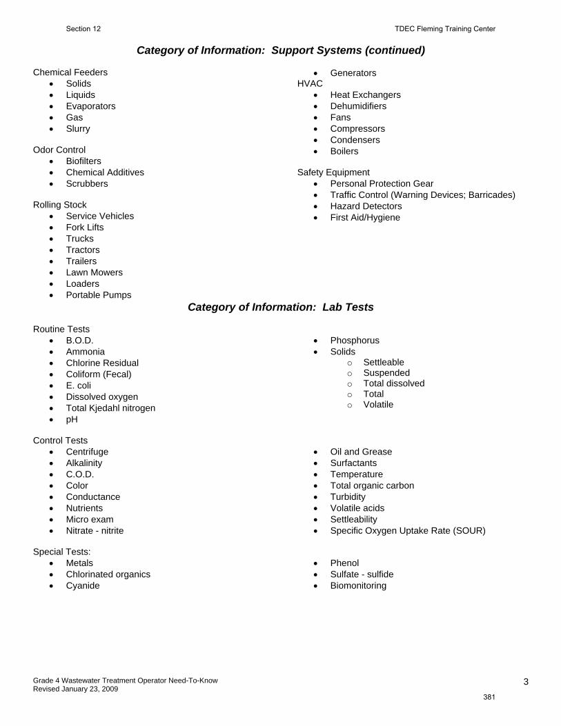
Grade 4 Wastewater Treatment Operator Need-To-Know Revised January 23, 2009
3
Category of Information: Support Systems (continued)
Chemical Feeders
Solids Liquids Evaporators Gas Slurry
Odor Control
Biofilters Chemical Additives Scrubbers
Rolling Stock
Service Vehicles Fork Lifts Trucks Tractors Trailers Lawn Mowers Loaders Portable Pumps
Generators HVAC
Heat Exchangers Dehumidifiers Fans Compressors Condensers Boilers
Safety Equipment
Personal Protection Gear Traffic Control (Warning Devices; Barricades) Hazard Detectors First Aid/Hygiene
Category of Information: Lab Tests Routine Tests
B.O.D. Ammonia Chlorine Residual Coliform (Fecal) E. coli Dissolved oxygen Total Kjedahl nitrogen pH
Phosphorus Solids
o Settleable o Suspended o Total dissolved o Total o Volatile
Control Tests
Centrifuge Alkalinity C.O.D. Color Conductance Nutrients Micro exam Nitrate - nitrite
Oil and Grease Surfactants Temperature Total organic carbon Turbidity Volatile acids Settleability Specific Oxygen Uptake Rate (SOUR)
Special Tests:
Metals Chlorinated organics Cyanide
Phenol Sulfate - sulfide Biomonitoring
Section 12 TDEC Fleming Training Center
381
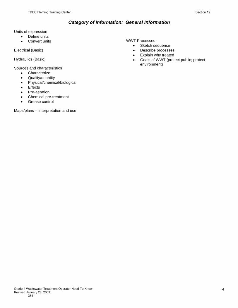
Grade 4 Wastewater Treatment Operator Need-To-Know Revised January 23, 2009
4
Category of Information: General Information
Units of expression
Define units Convert units
Electrical (Basic) Hydraulics (Basic) Sources and characteristics
Characterize Quality/quantity Physical/chemical/biological Effects Pre-aeration Chemical pre-treatment Grease control
Maps/plans – Interpretation and use
WWT Processes
Sketch sequence Describe processes Explain why treated Goals of WWT (protect public; protect
environment)
TDEC Fleming Training Center Section 12
384

Section 13
Answers to Review Questions
383
Section 1 Introduction Answers
Vocabulary:
1. Water Pollution
2. Inflow
3. Nutrient
4. Coliforms
5. Stabilization
6. BOD
7. Primary Treatment
8. Infiltration
9. Sanitary, Stormwater, Combined
10. Organic
11. Secondary Treatment
12. Receiving waters
13. Effluent
14. Inorganic
*See Section 2 for Math Answers
Section 3 Preliminary Treatment Answers
Vocabulary:
1. Diffuser
2. Grit
3. Hydrogen Sulfide
4. Mechanically, Screen
5. Fine
6. Wedgewire
7. Rotary Drum
8. Escalating Step Screen
9. Comminutor
10. Paint Filter Test
11. Septage
12. Grit Channel
13. Aerated Grit Chamber
14. Cyclonic Grit
15. Adsorption
16. Absorption
17. Flow Equalization
Review Questions:
1. The wastewater may turn septic, and hydrogen sulfide gas may be released by anaerobic bacteria feeding on the wastes. This can cause odor problems, damage concrete in the plant, and make the wastes more difficult to treat.
TDEC Fleming Training Center Section 13
386
2. C 3. Grit is abrasive and will rapidly wear out pumps and other equipment. Coarse debris can damage pumps,
plug up pipes, and take up valuable space in digesters 4. It is usually buried to prevent it from attracting pests or creating offensive odors 5. E 6. 1.36 ft3/MG 7. Bar racks and screens catch the debris found in wastewater whereas comminution units grind it up; The
debris caught by bar racks and screens is removed from the wastewater stream whereas the debris ground up by comminution units remains in the wastewater stream and is carried to downstream processes; The debris caught by bar racks and screens must be disposed of (burial or incineration), whereas comminution eliminates the disposal step
8. The blades may be out of alignment. 9. 0.5 ft/sec 10. Grit is washed to remove organic material before disposal. If the organic material is not separated and
removed, offensive odors could develop and attract flies and/or rats. If the grit is being used as fill material, settling can occur when the organic material starts to decompose.
11. D 12. Pre‐aeration helps to freshen the wastewater by adding dissolved oxygen; Prevent septic conditions, which
would prevent the formation of hydrogen sulfide; Improves sludge settleability; The older wastewater becomes, the more difficult it is for aerobic organisms to treat wastes and for solids to settle; Freshening the wastewater tends to make downstream treatment processes more effective; An added benefit of an aerated grit chamber is grease removal. The aeration of the flow stream will encourage the grease to float to the surface where it can be removed by skimmers. (Removes floatables)
Section 4 Flow Answers
Vocabulary:
1. Flow
2. Open Channel
3. Weir
4. Flume
5. Palmer‐Bowlus
6. Converging Section
7. Throat
8. Closed Channel
9. Primary
10. Diverging
11. Parshall Flume
12. Head loss
13. Secondary
14. Flow Equalization
Review Questions:
1. Open channel = the liquid flows with a free/uncovered surface
Closed channel = flow is in a completely filled conduit/pipe
2. Parshall flume – Common in wastewater treatment plants, good for water with high solids/debris content
Section 13 TDEC Fleming Training Center
385
Palmer‐Bowlus flume‐ Most commonly used to retrofit manholes
Trapezoidal flume – Primarily used in irrigation channels, for agricultural purposes
3. Used in situations with high solids/debris content since there are no sharp edges to collect debris.
TN regs (13.2.2) state “Parshall Flumes are ideal for measuring flows of raw sewage and primary effluents
because clogging problems are usually minimal.”
4. Converging section (Entrance), Throat, Diverging section (Discharge)
The Float (with a stilling well) is the most common secondary device used with a Parshall flume and it should
be located 2/3 upstream from the throat. TN regs (13.2.2.4) state “The location of the head measuring
points (stilling well) must be 2/3 the length of the converging sidewall upstream from the crest.”
5. They are very accurate and low maintenance. Because there is essentially no obstruction in flow, there is no
head loss. There are versions for both open and closed channels.
6. In order to properly control the basin’s operation and to optimize its effectiveness, you must know how
much is coming into and out of the basin. It can be beneficial to the plant to keep long term records of
increased flows going into the equalization basin that are associated with rain events (Inflow/Infiltration in
the collection system), and how they impact plant operations.
7. 1.0 mg/L DO
Section 5 Activated Sludge Part 1 Answers
Vocabulary:
1. Absorption
2. Biomass
3. Activated Sludge
4. Adsorption
5. Aeration Basin
6. Facultative
7. MLSS
8. Aerobic, Anaerobic
9. Filamentous
10. MLVSS
11. Anoxic
12. Endogenous Respiration
13. Mixed Liquor
14. Zoogleal
Review Questions:
1. A
2. D
3. A
4. B
5. B
6. C
7. D
TDEC Fleming Training Center Section 13
388
8. B
9. D
10. A
11. A
12. E
13. B
14. C
15. C
Section 6 Sedimentation Answers
Vocabulary:
1. Sludge
2. Bulking
3. Septic
4. Flocculation
5. Gasification
6. Coagulant
7. Secondary clarifier
8. Short circuiting
9. Surface Loading Rate
10. Colloid
11. Solids Loading Rate
12. Detention time
13. Flights
14. Denitrification
15. Weir
16. Weir Overflow Rate
17. Primary Clarifier
18. Launder
19. SVI
20. Flotation
21. Sloughings
Review Questions:
1. The function of primary clarifier is to remove settleable and floatable solids. Removal of organic settleable
solids is very important because they cause a high demand for oxygen (BOD).
The secondary clarifier is needed to remove the additional solids that were converted into settleable form
in the biological reactor (or whatever treatment processes preceded it).
2. Primary sludge is usually denser than secondary sludge. Typically, a primary clarifier will have an expected
removal efficiency of 95‐99% for settleable solids and 40‐60% for suspended solids.
3. Effluent from secondary clarifier is clearer than effluent from primary clarifier
Section 13 TDEC Fleming Training Center
387
4. Either the sludge will pile up higher on one side (the trailing side) or the flights will hang up and cause severe
damage to the collector mechanism.
5. Toxic waste – from industrial spills or dumps will kill beneficial microorganisms. The toxic material can
become bound in the sludge, which must be neutralized and disposed of (and not returned). This can cause
floating sludge (bulking).
Storm flows and hydraulic overloads – if this is a recurring problem, the sealing of sanitary sewers or the use
of a flow equalization basin may improve the quality of the clarifier effluent. An increase in flow rate can
cause a hydraulic overload.
Septicity from collection system problems – these can develop during hot weather when wastewater travel
times in the collection system become too long
6. At the Influent and Effluent points, preferably composite samples for a 24 hour period.
7. 55%
8. Sludge blanket could be too deep (pump out sludge if mechanism is okay)
The drive unit could have a bad sprocket or defective chain link
There could be a broken flight
A rock or stick may be jammed between the flight or squeegee blade and the floor of the tank
9. The types of solids in the wastewater (especially if there is a significant amount of industrial wastes)
The age of the wastewater when it reaches the plant (a.k.a. the time it spent in the collection system). Older
wastewater becomes stale or septic; solids do not settle properly because gas bubbles cling on the particles
and hold/keep them in suspension.
The hydraulic loading (is it over or under loaded)
Mechanical conditions of the collection mechanism and cleanliness of the clarifier
Proper sludge withdrawal. If sludge is not being wasted frequently enough, it could begin to gasify and
sludge may rise to the surface of the water
Suspended solids being returned to the primary clarifier from WAS, digester supernatant, and sludge
dewatering facilities.
10. Velocity is greater in some sections than others
Turbulence
Stratification due to temperature differences
11. If the velocity of water through a clarifier is too high, the solids/particles will not have enough time to settle
out and they will flow out the effluent. If velocity is too low, undesirable septic conditions can occur. Short
circuiting can be corrected or prevented by installing weir plates, baffles, port openings, and by proper
design of the inlet channel.
12. Detention time in the clarifier
Weir Overflow Rate
Surface Loading Rate
Solids Loading
13. The biological treatment processes following the primary clarifier convert more solids to the settleable form
and also produce floc containing microorganisms that have to be removed from the treated wastewater.
The secondary clarifier is needed to remove these additional solids.
TDEC Fleming Training Center Section 13
390
14. Sludge disposal depends on the particular design of the treatment plant and the characteristics of the
sludge. Sometimes it is transferred to the primary clarifier, other times it goes to the digester, other times it
is just wasted.
15. Examine weirs. If they are not perfectly level, this can lead to short‐circuiting.
16. To maintain constant hydraulic loading. Trickling Filters use a fixed media biological process, which means
the microorganisms need to have a constant spray of water on them to prevent them from drying out and
dying. Recirculating the effluent helps to ensure a constant water flow.
Section 7 Ponds and Lagoons Answers
Vocabulary:
1. Stabilization Ponds
2. Polishing Pond
3. Overturn/Turnover
4. Parallel
5. Aerobic Ponds
6. Anaerobic Ponds
7. Bioflocculation
8. Oxidation Ponds
9. Facultative Ponds
10. Photosynthesis
11. Algae
12. Respiration
13. Series
14. Thermocline
Review Questions:
1. Offensive odors do not necessarily indicate a problem. Actually, the greatest organic load destroyed per unit
of area (high treatment efficiency) may be accompanied by objectionable odors. Most odors are caused by
overloading or poor housekeeping. If a pond is being overloaded, stop loading and divert influent to other
ponds (if available) until odors stop. Recirculation from aerobic units, the use of floating aerators, and heavy
chlorination are common odor control options. In some areas, sodium nitrate has been added to serve as a
source of oxygen for microorganisms rather than sulfate compounds (which result in odors).
2. May produce odors
Requires a large area of land (would not be cost effective in an area with high land cost)
Treats wastes inconsistently depending on climatic conditions
May contaminate groundwaters
May leave high levels of suspended solids in the effluent
3. They could be located after the preliminary treatment (headworks/screening) and serve as the biological
process (aka biological reactor), followed by a chlorine contact basin.
Or, they can be located after a primary wastewater treatment plant to provide additional clarification, BOD
removal, and disinfection. These ponds are sometimes called “oxidation ponds.”
Section 13 TDEC Fleming Training Center
389
Or, ponds can be used after trickling filters as a form of tertiary treatment. These ponds are sometimes
called “polishing ponds.”
4. These are most common because it is almost impossible to maintain completely aerobic or anaerobic
conditions in all depths at all times in a pond.
5. This is critical to do in advance to prevent odors from developing, it prevents odors that are produced when
solid wastes are exposed to the atmosphere.
6. Higher temperatures are associated with more efficient treatment because the bacterial populations prefer
warmer temps.
7. During the day when it is sunny, algae are photosynthesizing, which means they are using up the carbon
dioxide (which raises the pH) and producing oxygen.
*During the night, when no sunlight is present, the algae use up the oxygen (that they produced during the
daylight) by respiration and produce carbon dioxide (carbon dioxide reacts with water to produce carbonic
acid, which lowers the pH).
Dissolved oxygen levels are being built up during the daylight hours (peak time is late afternoon around 3
pm), and then fall during the night due to the algae using it up.
8. Sparkling green: good, it indicates high pH and DO, and a flourishing algal population (although it should be
noted that there is a possibility of too much algae, which could result in high BOD and TSS)
Dull green to yellow: not so good, pH and DO declining, blue‐green algae are becoming established
Gray to black: bad, anaerobic conditions
Tan to brown: this can be ok if color is caused by an algae bloom, not good if resulting from silt or dike
erosion
Red or pink: presence of purple sulfur bacteria (anaerobic conditions) or red algae (aerobic conditions).
Daphnia blooms can cause a red color – this is generally not a problem except when they die off and may
create a large oxygen demand that could lead to anaerobic conditions.
Milky appearance: indicates system is approaching or is septic, typically from being overloaded.
9. Epilimnion/thermocline/hypolimnion
Turnover is the gentle, natural mixing of pond waters. It is caused by changing temperatures in surface
waters brought on by the progression of the seasons. When the water temperature becomes similar from
top to bottom, winds blowing across the surface of the pond will facilitate a complete mixing. This may
occur in the spring when surface waters warm, or in the fall when surface waters cool to the same
temperature as the water at the bottom.
Section 8 Attached Growth Systems Answers
Vocabulary:
1. Biomass, Zoogleal film
2. Aerobic, Anaerobic
3. Distributor
4. Fixed‐spray Nozzle
5. Nitrification
6. Humus Sludge
7. Series Operation, Parallel Operation
8. Ponding
TDEC Fleming Training Center Section 13
392
9. Recirculation
10. Trickling Filter
11. 2 Stage Filter
12. Underdrain, Ventilation
Review questions:
1. Scum and flotable solids, dissolved solids, settleable solids, small suspended solids (colloids)
2. The main function is to provide secondary treatment of primary settled wastewater. They function to
remove suspended solids and dissolved organics using microorganisms attached to the media. The slime
growth on the media oxidizes organic materials biologically to form a more stable material. As slime growth
increases, it sloughs off and is removed by settling in a final clarifier. The zoogleal film is mainly aerobic,
including bacteria, free swimming and stalked ciliates, rotifers, and nematodes (similar to those found in
other secondary biological treatment processes).
3. Increase efficiency
Maintain constant wetting rate and hydraulic loading
Dilute toxic wastes
Increase air flow
Recirculation flow dilutes the strength of raw wastewater & allows untreated wastewater to be passed
through the filter more than once.
Prevent freezing
During low‐inflow periods = keep slime growths wet, minimize fly growth, and wash off excess sloughings
Returning TF effluent to the 1°clarifier is an effective odor control measure
adds oxygen to incoming ww that is often septic
4. Recycling of filter effluent increases the contact time of the ww with the biological film and helps to seed
the lower portions of the filter with active organisms. Due to the increased flow rate per unit of area, these
higher flows tend to cause more continuous and uniform sloughing of excess or aged growths. Uniform and
continuous sloughing of growths is important because this provides a more aggressive surface of new
growths to treat the ww. Sloughings of growths prevents ponding and improves ventilation through the
filter. Increased hydraulic loadings also decrease the opportunity for snail and filter fly breeding.
5. To prevent ponding
6. Locally sourced stone/rock is less expensive than plastic. However, synthetic media provides greater surface
area per cubic foot and has a higher percentage of void spaces (growth occurs on outside and inside), which
allows for greater hydraulic and organic loads.
7. It removes the excess biological solids (sloughings) produced in the TF or RBC. As with other secondary
processes, this biological sludge is very close in density to water, so good secondary clarification is needed to
produce a good quality effluent.
8. TF: the main reason to shock with chlorine would be to cure a filter ponding problem by drastically reducing
the amount of biomass in the filter. Another reason to chlorinate would be to control snails, moss, and
roaches (a more likely problem in the southern part of the country). Chlorine can also be used in lower
dosages to control odors and filter flies.
RBC: The reasons for intentionally shocking with chlorine would be to prevent excessive build‐up of biomass
and to kill filamentous organisms or other undesirable growths (ex: Beggiatoa or Thiothrix).
Section 13 TDEC Fleming Training Center
391
9. Protect biological slimes from freezing
Prevent rain from washing off slime growth
Prevent media exposure to sunlight, which results in algae growth
Protect the media from UV rays, which can weaken them/make them brittle
Provide protection from the elements (provide protection for operators from the sun, rain, snow, or wind
while maintaining the equipment)
10. Staging is used to maximize the effectiveness of a given amount of media surface area.
Section 9 Disinfection Answers
Vocabulary:
1. Pathogenic, Waterborne Disease
2. Disinfection, Sterilization
3. Free Chlorine
4. Combined Chlorine
5. Oxidizing Agent
6. Free Chlorine Residual
7. Post Chlorination
8. Chlorine Residual
9. Reducing Agent
10. Chlorine Demand
11. Prechlorination
12. Breakpoint Chlorination
13. Ozonation
14. Chlorination
15. UV Disinfection
Review Questions:
1. See slide 5 for full list
Cholera, typhoid, salmonellosis, shigellosis, gastroenteritis, amoebic dysentery, giardiasis, cryptosporidiosis,
polio, hepatitis A, viral gastroenteritis
2. Disinfection is the destruction of all pathogenic microorganisms, whereas sterilization is the destruction of
ALL microorganisms (good and bad)
3. Lamp output declines with age
Suspended particles can be shield microorganisms
Microorganisms that were not killed may heal/repair themselves
4. Elemental chlorine, Sodium and Calcium hypochlorite, and Chlorine Dioxide
5. Demand = Dose – Residual
Free chlorine residual is the residual formed after the chlorine demand has been met. It’s the chlorine left
over that is free and available to actually disinfect.
Combined chlorine residual is produced when chlorine reacts with substances in the water (it can combine
with ammonia, organic nitrogen, or both to create chloramines). It is still available to oxidize organic matter
and kill bacteria, but not as effective as free residual.
TDEC Fleming Training Center Section 13
394
6. Hypochlorous acid and hypochlorite
7. Hypochlorous acid (hypochlorite ion is only 1% as effective as hypochlorous acid)
8. Hypochlorous acid is more prevalent at a pH less than 7, it will dissociate when the pH goes higher. It
dissociates into hydrogen and hypochlorite ion, which is less effective.
9. They can form chloramines
10. Organic material can combine with chlorine, which increases the demand. Suspended solids can harbor
bacteria.
11. 30 min detention time at average design flow or 15 minute detention time at daily peak design flow –
whichever is greater
12. To prevent build‐up of excessive pressure and possible rupture. 158 – 165 degrees F
13. Use a commercial ammonia water in a squeeze bottle. It could increase the rate of corrosion at the leak.
Section 10 Effluent Disposal Answers
Vocabulary:
1. Surface Waters
2. Fixed Sample
3. Grab
4. Composite
5. Respiration
6. Evapotranspiration
7. Irrigation
8. Ridge and Furrow
9. Spray Systems
10. Overland Flow
11. D.O. profile
12. Outfall
Review Questions:
1. Discharge into surface waters
2. (1) Discharge to land by use of irrigaton – slow rate, rapid infiltration, overland flow
(2) Groundwater recharge basin
(3) Underground discharge
3. It could contaminate groundwater aquifers. Due to Karst topography, cracks in limestone provide direct
route of infiltration to groundwater and therefore no treatment is achieved and groundwater may become
contaminated.
4. Take a measurement upstream (not affected) and downstream (affected) and compare the two results, and
then perform a DO profile.
5. Dissolved oxygen, pH, Temperature
6. Biochemical oxygen demand (BOD), Suspended solids (SS), Total coliform and fecal coliform bacteria,
Nutrients (Nitrogen and Phosphorus)
7. 30 mg/L BOD, TSS
Section 13 TDEC Fleming Training Center
393
23 colonies/100 mL for E. coli
Section 11 Administration and Management Answers
Vocabulary:
1. Authority
2. Organizing
3. Responsibility
4. Tailgate Safety Meeting
5. Ethics
6. Accountability
7. Delegation
8. Preventative
9. Critical Infrastructure
10. Vulnerability
11. Whistleblowing
12. Predictive
Review Questions:
1. A 2. B 3. D 4. E 5. B 6. A 7. A 8. B 9. A
10. A 11. A 12. C 13. D 14. A 15. A
TDEC Fleming Training Center Section 13
396