Embed Size (px)
Citation preview
1
INTRODUCTION
The buildings public and private are establishments which contain people and goods, its establishments must be protegés against all intrusions coming from
the exterior so as to protect the people and the good from these buildings. An analysis must be made for determiner the technology which will be able to
bind security and esthetic, make it possible to maximize the comfort of the people and the goods without decreasing the production or the daily use of the
buildings. we will center our study on the doors automated which ensure a security and
optimizes the output of use of the doors. Our study will be based on the mechanical part of the system of automation of the gate in order to determiner the efforts exerted by the gate which make it possible to choose the motoreductor able to produir the couple necessary to
the displacement of the gate.
2
Plan Introduction…………………………………………………………………………….………1
I. Definition……………………………………………………………………………….3
II. Choice between sliding or swinging gate………...……........………..4
1) Swing gate…………………………………………………………………..…………4 2) Sliding gate………………………………………………………………..…………..5 3) Benefits of automated sliding gate…………………………….…………..6 4) Safety……………………………………………………………………….…………….7
III. Composition of sliding gate………………………………….…………………8
1) Composition…………………………………………………………..……………….8
IV. Design of sliding gate………………………………………………….…………10
1) Friction of sliding gate……………………………………..………….………..10 2) Analyssis cinematic sliding gate……………………………………………..11 3) Analysis of inerties efforts………………………………………………………12 4) Calculate efforts……………………………………………..……………………..13 5) Choice of the motoreductor……………………………..……………………14
V. Sliding gate installation………………………………….………………………15
1) Installation…………………………………………………….……………………….15 2) Description…………………………………………………………………………….17
Conclusion………………………………………………………………………………………21
3
I. Definition
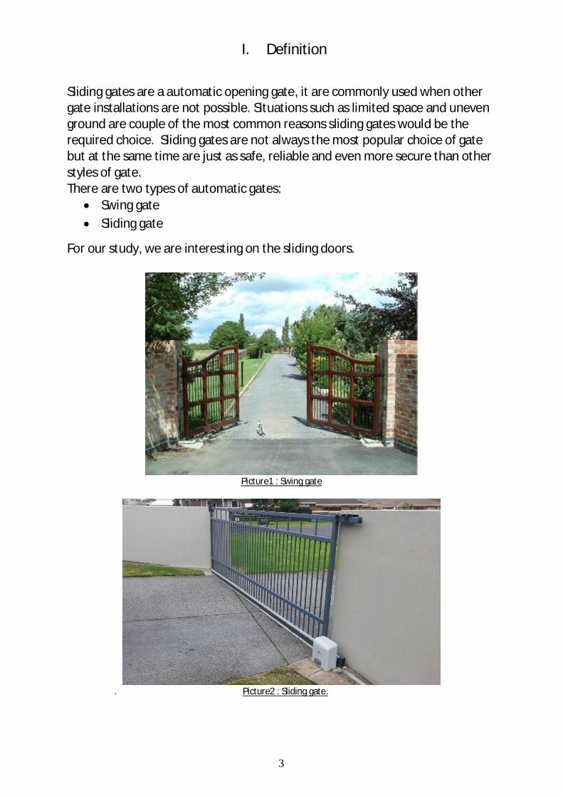
Sliding gates are a automatic opening gate, it are commonly used when other gate installations are not possible. Situations such as limited space and uneven ground are couple of the most common reasons sliding gates would be the required choice. Sliding gates are not always the most popular choice of gate but at the same time are just as safe, reliable and even more secure than other styles of gate. There are two types of automatic gates:
Swing gate Sliding gate
For our study, we are interesting on the sliding doors.
Picture1 : Swing gate
. Picture2 : Sliding gate.
4
II. Choice between sliding or swinging gate There are a number of factors in choosing whether to have a sliding or a swing gate. Often the choice is dictated by the layout of the gateway but aesthetics also play a part.
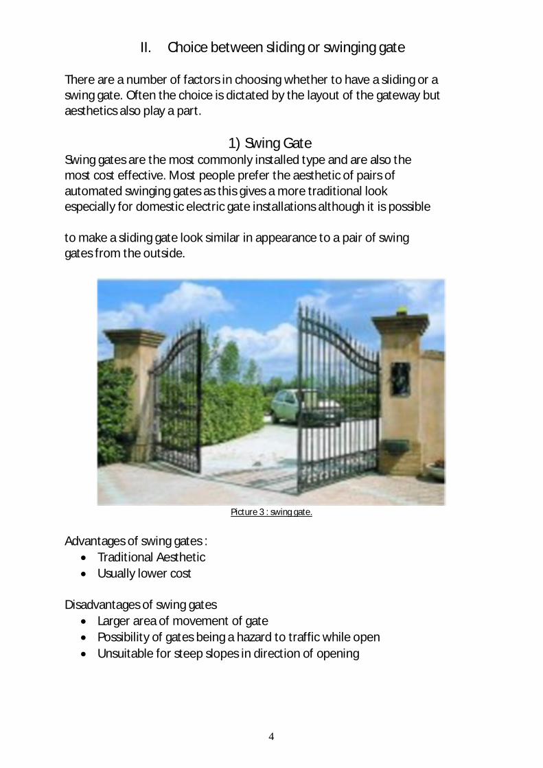
1) Swing Gate Swing gates are the most commonly installed type and are also the most cost effective. Most people prefer the aesthetic of pairs of automated swinging gates as this gives a more traditional look especially for domestic electric gate installations although it is possible to make a sliding gate look similar in appearance to a pair of swing gates from the outside.
Picture 3 : swing gate.
Advantages of swing gates :
Traditional Aesthetic Usually lower cost
Disadvantages of swing gates
Larger area of movement of gate Possibility of gates being a hazard to traffic while open Unsuitable for steep slopes in direction of opening
5
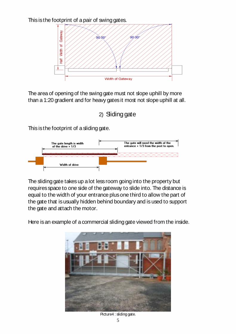
This is the footprint of a pair of swing gates.
The area of opening of the swing gate must not slope uphill by more than a 1:20 gradient and for heavy gates it most not slope uphill at all.
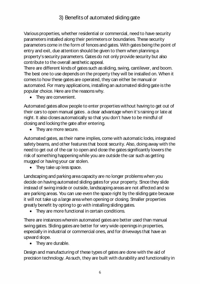
2) Sliding gate This is the footprint of a sliding gate.
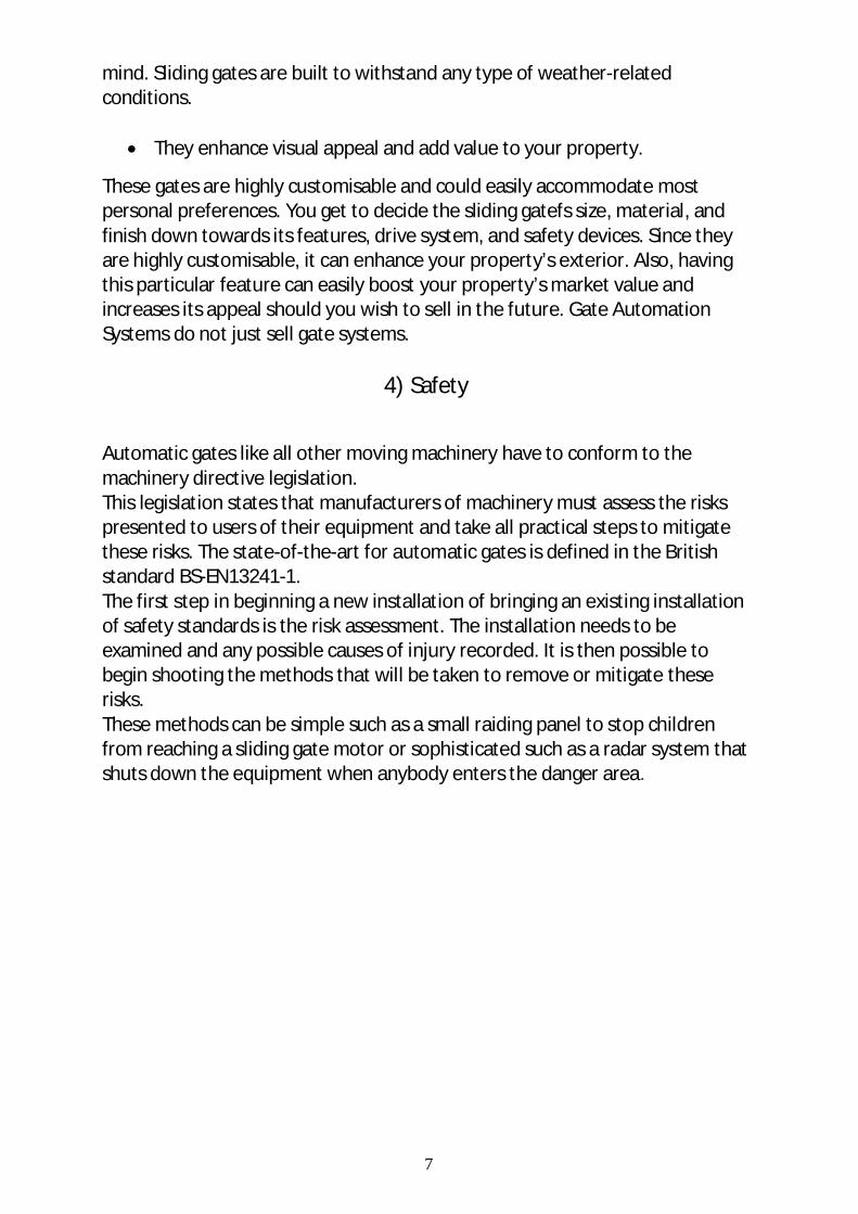
The sliding gate takes up a lot less room going into the property but requires space to one side of the gateway to slide into. The distance is equal to the width of your entrance plus one third to allow the part of the gate that is usually hidden behind boundary and is used to support the gate and attach the motor. Here is an example of a commercial sliding gate viewed from the inside.
Picture4 : sliding gate.
6
3) Benefits of automated sliding gate
Various properties, whether residential or commercial, need to have security parameters installed along their perimeters or boundaries. These security parameters come in the form of fences and gates. With gates being the point of entry and exit, due attention should be given to them when planning a property’s security parameters. Gates do not only provide security but also contribute to the overall aesthetic appeal. There are different kinds of gates such as sliding, swing, cantilever, and boom. The best one to use depends on the property they will be installed on. When it comes to how these gates are operated, they can either be manual or automated. For many applications, installing an automated sliding gate is the popular choice. Here are the reasons why.
They are convenient.
Automated gates allow people to enter properties without having to get out of their cars to open manual gates . a clear advantage when it’s raining or late at night. It also closes automatically so that you don’t have to be mindful of closing and locking the gate after entering.
They are more secure.
Automated gates, as their name implies, come with automatic locks, integrated safety beams, and other features that boost security. Also, doing away with the need to get out of the car to open and close the gates significantly lowers the risk of something happening while you are outside the car such as getting mugged or having your car stolen.
They take up less space.
Landscaping and parking area capacity are no longer problems when you decide on having automated sliding gates for your property. Since they slide instead of swing inside or outside, landscaping areas are not affected and so are parking areas. You can use even the space right by the sliding gate because it will not take up a large area when opening or closing. Smaller properties greatly benefit by opting to go with installing sliding gates.
They are more functional in certain conditions.
There are instances wherein automated gates are better used than manual swing gates. Sliding gates are better for very wide openings in properties, especially in industrial or commercial ones, and for driveways that have an upward slope.
They are durable.
Design and manufacturing of these types of gates are done with the aid of precision technology. As such, they are built with durability and functionality in
7
mind. Sliding gates are built to withstand any type of weather-related conditions.
They enhance visual appeal and add value to your property.
These gates are highly customisable and could easily accommodate most personal preferences. You get to decide the sliding gatefs size, material, and finish down towards its features, drive system, and safety devices. Since they are highly customisable, it can enhance your property’s exterior. Also, having this particular feature can easily boost your property’s market value and increases its appeal should you wish to sell in the future. Gate Automation Systems do not just sell gate systems.
4) Safety
Automatic gates like all other moving machinery have to conform to the machinery directive legislation. This legislation states that manufacturers of machinery must assess the risks presented to users of their equipment and take all practical steps to mitigate these risks. The state-of-the-art for automatic gates is defined in the British standard BS-EN13241-1. The first step in beginning a new installation of bringing an existing installation of safety standards is the risk assessment. The installation needs to be examined and any possible causes of injury recorded. It is then possible to begin shooting the methods that will be taken to remove or mitigate these risks. These methods can be simple such as a small raiding panel to stop children from reaching a sliding gate motor or sophisticated such as a radar system that shuts down the equipment when anybody enters the danger area.
8
III. Composition of sliding gate
1) Composition
the sliding doors are automated systems consisted of the several components such as:
Wheels (Roller)
It is a body which allows the displacement of the gate in a rotational movement.
Track
It makes it possible to guide the wheels of supports and avoids the contact of the wheels on the ground in order to limit the friction resistance.
Bracket (Roller Set)
It makes it possible to guide the gate in translation, it is an essential body in displacement in translation of the gate and puts the gate in the driving position.
Catcher or receiver
They have the same function that the bracket and makes it possible to block the gate.
Stopper (Bump stop)
It is a body which makes it possible to stop in translation the displacement of the gate.
Minilamp
It is a luminous indication which informs the displacement of the gate (opening of the gate).
Fotoswitch
It is a sensor which detects the presence of obstacles (someone or object) which could caused an accident during the opening or the closing of the gate.
Safety edge
It ensures the safety of the gate closing. T10 E
It is a sensor of ordering of opening of the gate, it receives the signal of the remote control in order to open or to close the gate.
Plus 433 E
It is a sound signalling hooter, it informs by a sound signal the opening or the closing the gate.
9
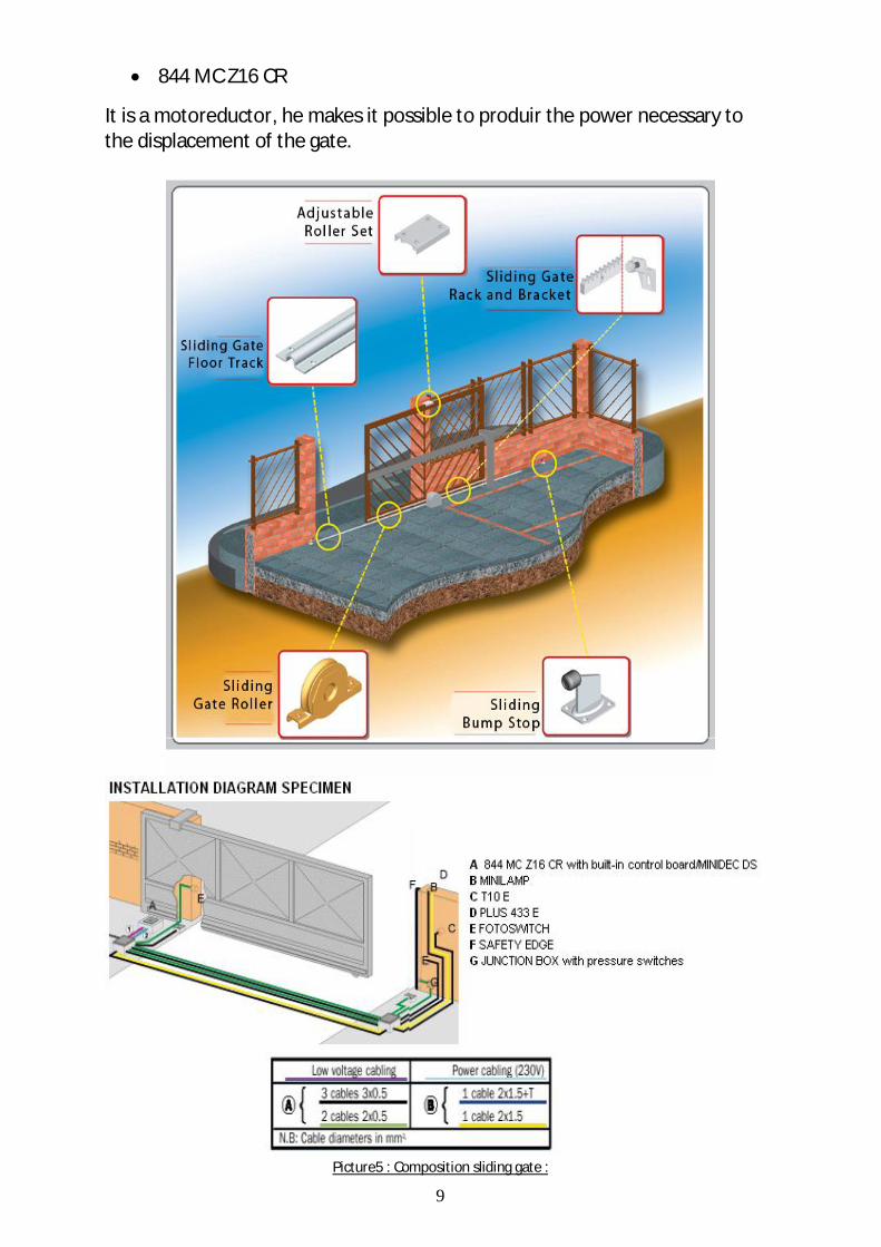
844 MC Z16 CR
It is a motoreductor, he makes it possible to produir the power necessary to the displacement of the gate.
Picture5 : Composition sliding gate :
10
IV. Design of sliding gate
the design of the carries sliding is done on the total load which genere a resistant couple which is necessary to the choice of the motoreductor to be able deplacer the sliding door. we will start with a study of the loads dynamic heads and forces of inértie.
1) Friction of sliding gate
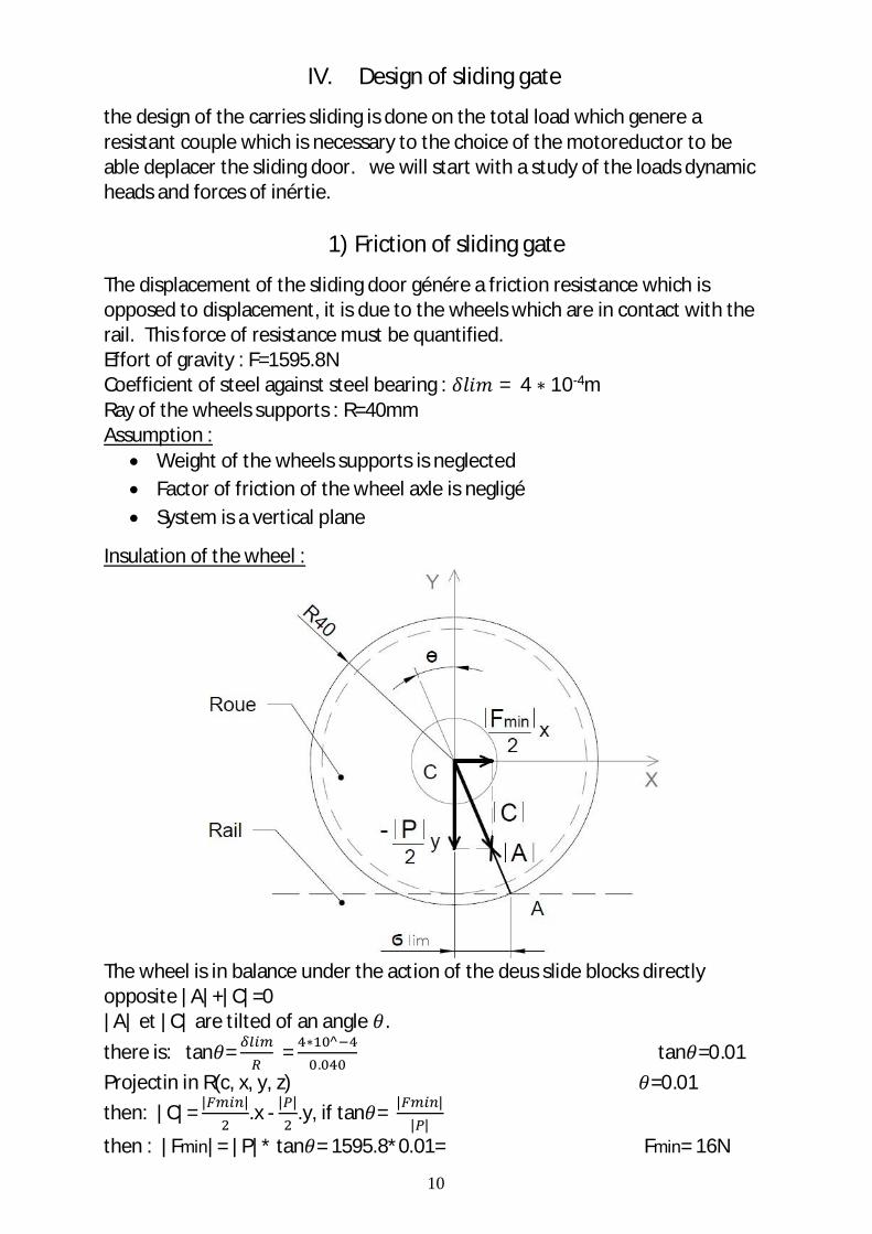
The displacement of the sliding door génére a friction resistance which is opposed to displacement, it is due to the wheels which are in contact with the rail. This force of resistance must be quantified. Effort of gravity : F=1595.8N Coefficient of steel against steel bearing : = 4 10-4m Ray of the wheels supports : R=40mm Assumption :
Weight of the wheels supports is neglected Factor of friction of the wheel axle is negligé System is a vertical plane
Insulation of the wheel :
The wheel is in balance under the action of the deus slide blocks directly opposite |A|+|C|=0 |A| et |C| are tilted of an angle . there is: tan = = ^
. tan =0.01
Projectin in R(c, x, y, z) =0.01 then: |C|= | |.x - | |.y, if tan = | |
| |
then : |Fmin|= |P|* tan = 1595.8*0.01= Fmin= 16N
11
2) Analysis cinematic sliding gate
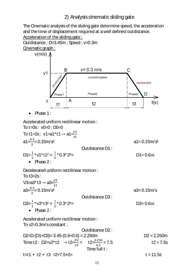
The Cinematic analysis of the sliding gate determine speed, the acceleration and the time of displacement required at a well defined outdistance. Acceleration of the sliding gate : Outdistance : D=3.45m ; Speed : v=0.3m Cinematic graph :
Phase 1 :
Accelerated uniform rectilinear motion : To t=0s : v0=0 ; D0=0 To t1=2s : v1=a1*t1 a1=
a1= . = 0.15m/s² a1= 0.15m/s² Outdistance D1 :
D1= *v1*t1² = *0.3*2²= D1= 0.6 Phase 2 :
Decelerated uniform rectilinear motion : To t3=2s : V3=a3*t3 a3=
a3= . = 0.15m/s² a3= 0.15m/s Outdistance D3 :
D3= *v3*t3² = *0.3*2²= D3= 0.6 Phase 2 :
Accelerated uniform rectilinear motion : To v2=0.3m/s constant :
Outdistance D2 : D2=D-(D1+D3)= 3.45-(0.6+0.6) = 2.250m D2 = 2.250m Time t2 : D2=v2*t2 t2= = t2= .
. = 7.5 t2 = 7.5s
Time full t : t= 1 + 2 + 3 =2+7.5+2= t = 11.5s
12
3) Analysis of inerties efforts
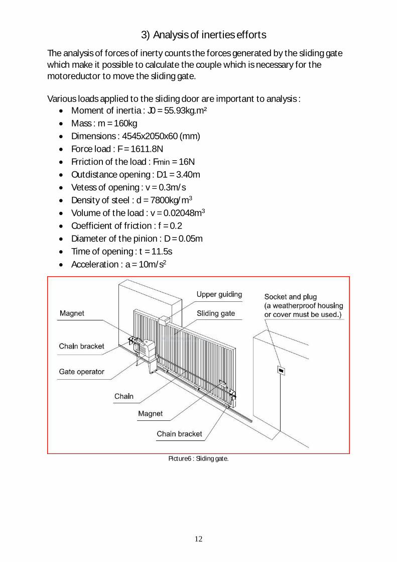
The analysis of forces of inerty counts the forces generated by the sliding gate which make it possible to calculate the couple which is necessary for the motoreductor to move the sliding gate. Various loads applied to the sliding door are important to analysis :
Moment of inertia : J0 = 55.93kg.m² Mass : m = 160kg Dimensions : 4545x2050x60 (mm) Force load : F = 1611.8N Frriction of the load : Fmin = 16N Outdistance opening : D1 = 3.40m Vetess of opening : v = 0.3m/s Density of steel : d = 7800kg/m3 Volume of the load : v = 0.02048m3 Coefficient of friction : f = 0.2 Diameter of the pinion : D = 0.05m Time of opening : t = 11.5s Acceleration : a = 10m/s2
Picture6 : Sliding gate.
13
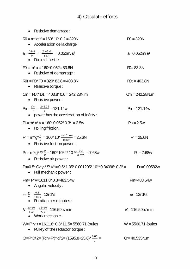
4) Calculate efforts
Resistive demarrage :
R0 = m*g*f = 160*10*0.2 = 320N R0 = 320N Acceleration de la charge :
a = ²
= ( . ). ²
= 0.052m/s2 a= 0.052m/s² Force d’inertie :
F0 = m*a = 160*0.052= 83.8N F0= 83.8N Resistive of demarrage :
R0t = R0*F0 = 320*83.8 = 403.8N R0t = 403.8N Resistive torque :
Cm = R0t*D1 = 403.8*0.6 = 242.28N.m Cm = 242.28N.m Resistive power :
Pn = = . = 121.14w Pn = 121.14w power has the acceleration of inérty :
Pi = m*a*v = 160*0.052*0.3* = 2.5w Pn = 2.5w Rolling friction :
Fr = m*g* = 160*10* ^.
= 25.6N Fr = 25.6N Resistive friction power :
Pr = m*g* * = 160*10*4*10-4* ..
= 7.68w Pr = 7.68w Resistive air power :
Pa=0.5*Cx* *S*V3 = 0.5*1.05*0.001205*103*0.34098*0.33 = Pa=0.00582w Full mechanic power :
Pm= F*v=1611.8*0.3=483.54w Pm=483.54w Angular velocity :
= = ..
= 12rd/s = 12rd/s Rotation per minutes :
= = = 116.59tr/min = 116.59tr/min Work mechanic :
W= F*v*t= 1611.8*0.3*11.5= 5560.71 Joules W = 5560.71 Joules Pulley of the reductor torque :
Cr=F*D/2= (Fch+Fr)*d/2= (1595.8+25.6)* . = Cr= 40.535N.m
14
Pulley of the rmotor torque :
Cmt= = = 1.367 Cm =1.367 Inerty to back pinion of the tree :
Jp= = =1.47Kg.m² Jp = 1.47Kg.m² Inerty to back pinion of the rack :
Jr= ²= 160 0.025² =0.1Kg.m² Jr = 0.1Kg.m² Inerty to back pinion of the rack :
Jp1= = =2.63*10-3Kg.m² Jp1 = 2.63*10-3Kg.m²
Resistive torque of load :
Tch= = =26.85N.m Tch = 26.85N.m Torque to back pinion of the tree :
Tr= = =1N.m² Tr = 1N.m
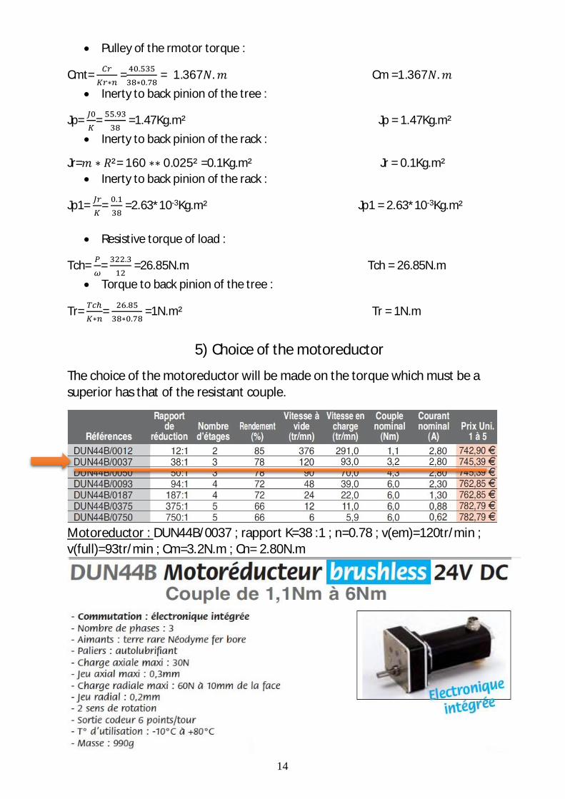
5) Choice of the motoreductor
The choice of the motoreductor will be made on the torque which must be a superior has that of the resistant couple.
Motoreductor : DUN44B/0037 ; rapport K=38 :1 ; n=0.78 ; v(em)=120tr/min ; v(full)=93tr/min ; Cm=3.2N.m ; Cn= 2.80N.m
15
V. Sliding gate installation
1) Installation
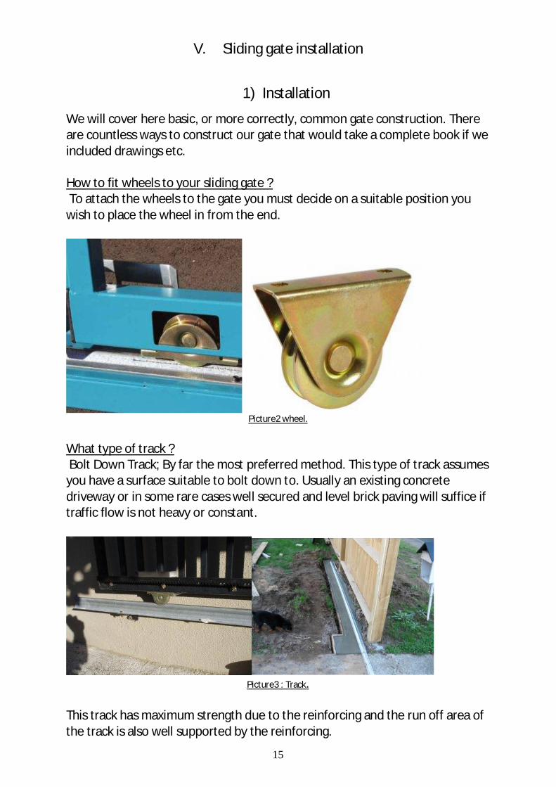
We will cover here basic, or more correctly, common gate construction. There are countless ways to construct our gate that would take a complete book if we included drawings etc. How to fit wheels to your sliding gate ? To attach the wheels to the gate you must decide on a suitable position you wish to place the wheel in from the end.
Picture2 wheel.
What type of track ? Bolt Down Track; By far the most preferred method. This type of track assumes you have a surface suitable to bolt down to. Usually an existing concrete driveway or in some rare cases well secured and level brick paving will suffice if traffic flow is not heavy or constant.
Picture3 : Track.
This track has maximum strength due to the reinforcing and the run off area of the track is also well supported by the reinforcing.
16
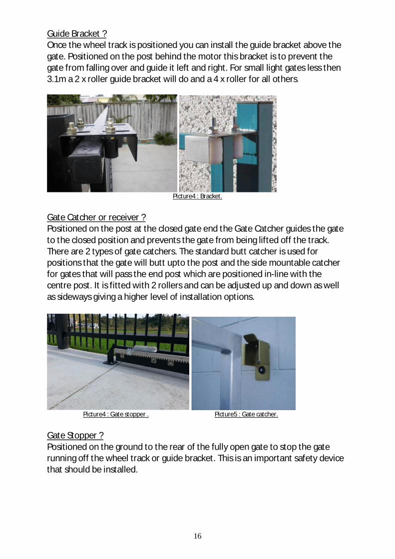
Guide Bracket ? Once the wheel track is positioned you can install the guide bracket above the gate. Positioned on the post behind the motor this bracket is to prevent the gate from falling over and guide it left and right. For small light gates less then 3.1m a 2 x roller guide bracket will do and a 4 x roller for all others.
Picture4 : Bracket.
Gate Catcher or receiver ? Positioned on the post at the closed gate end the Gate Catcher guides the gate to the closed position and prevents the gate from being lifted off the track. There are 2 types of gate catchers. The standard butt catcher is used for positions that the gate will butt upto the post and the side mountable catcher for gates that will pass the end post which are positioned in-line with the centre post. It is fitted with 2 rollers and can be adjusted up and down as well as sideways giving a higher level of installation options.
Picture4 : Gate stopper . Picture5 : Gate catcher.
Gate Stopper ? Positioned on the ground to the rear of the fully open gate to stop the gate running off the wheel track or guide bracket. This is an important safety device that should be installed.
17
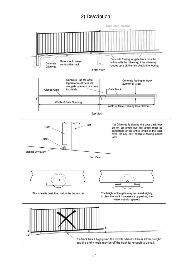
2) Description :
18
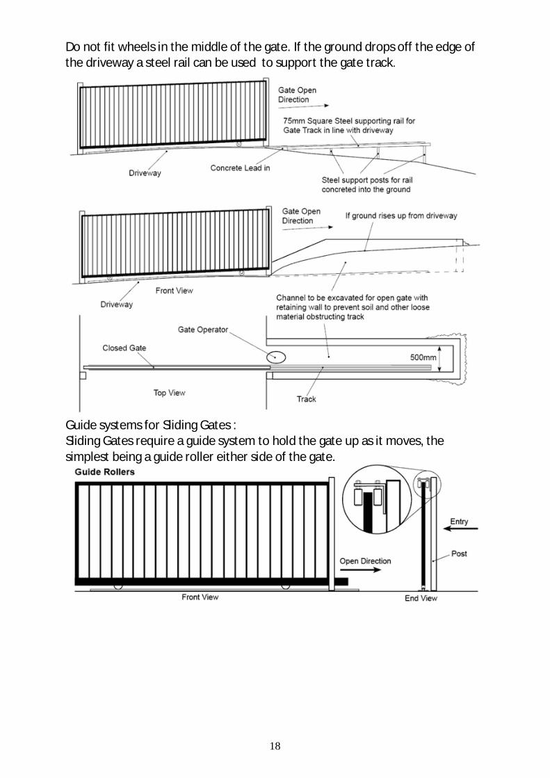
Do not fit wheels in the middle of the gate. If the ground drops off the edge of the driveway a steel rail can be used to support the gate track.
Guide systems for Sliding Gates : Sliding Gates require a guide system to hold the gate up as it moves, the simplest being a guide roller either side of the gate.
19
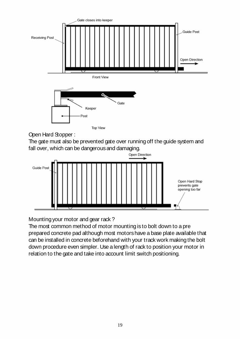
Open Hard Stopper : The gate must also be prevented gate over running off the guide system and fall over, which can be dangerous and damaging.
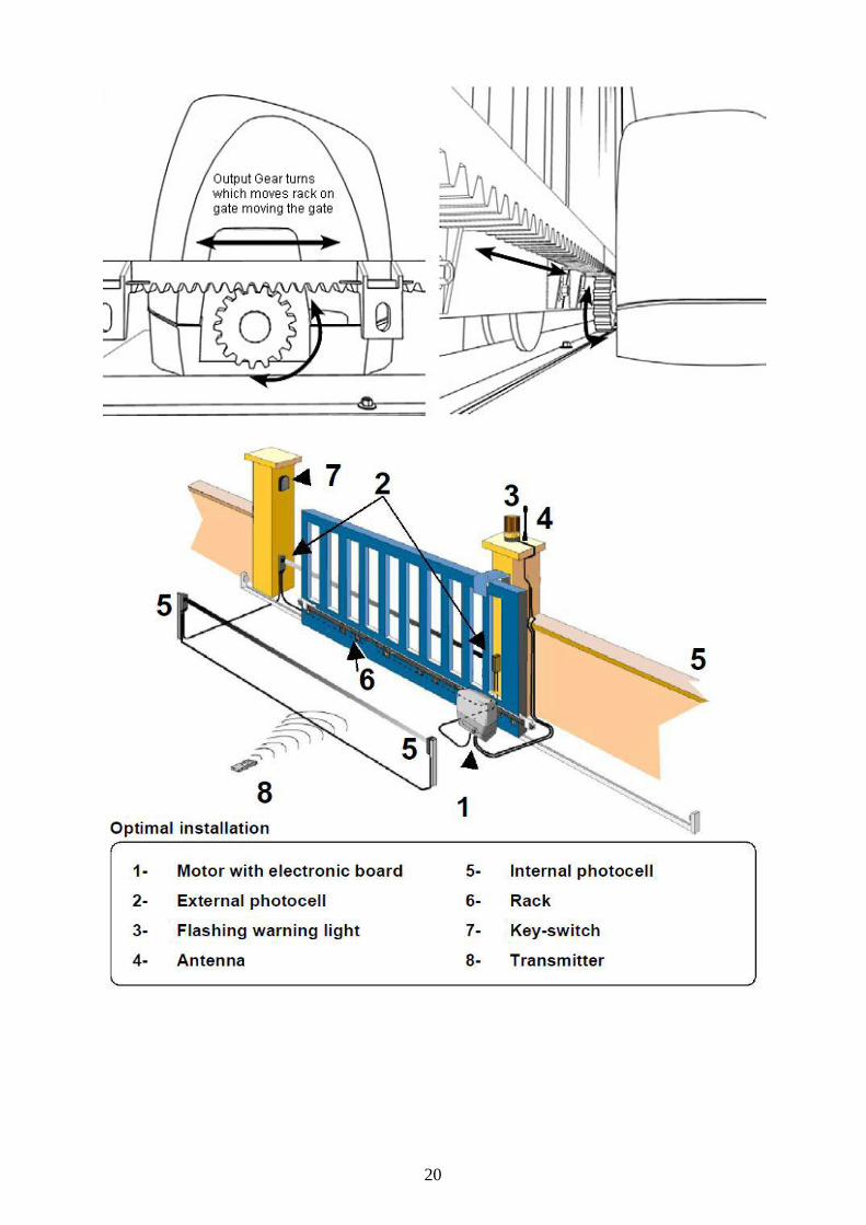
Mounting your motor and gear rack ? The most common method of motor mounting is to bolt down to a pre prepared concrete pad although most motors have a base plate available that can be installed in concrete beforehand with your track work making the bolt down procedure even simpler. Use a length of rack to position your motor in relation to the gate and take into account limit switch positioning.
20
21
CONCLUSION
The sliding doors is a inovant system which makes it possible to optimize the fluidity of passage in order to gain in time in louverture and the closing of the sliding door, sécursé the batiments.tout reside
in the choice and the systems design which ensures an output security flexibility of the system.
With an advantage of use and côut. it is an ideal system for any type of known use of the buildings, they are commercial buildings, school,
tiertiaires and industrialists.


