Embed Size (px)
Citation preview

Last Updated: March 1, 2016
INVITATION FOR BIDS
FOR CONSTRUCTING
FARMERS LANE WELL FACILITY
REHABILITATION
CONTRACT NUMBER
C01839
ISSUED BY
CAPITAL PROJECTS ENGINEERING DIVISION
CITY OF SANTA ROSA, CALIFORNIA
2017

STATE OF CALIFORNIA
INVITATION FOR BIDS
CONTAINING:
NOTICE TO BIDDERS
SPECIAL PROVISIONS
BID FORMS
CONTRACT
FOR
FARMERS LANE WELL FACILITY REHABILITATION
Contract No. C01839
A T T E N T I O N Prebid Conference See Page 1

FARMERS LANE WELL FACILITY REHABILITATION
TABLE OF CONTENTS
NOTICE TO BIDDERS
NOTICE TO BIDDERS ................ . .. .. .. ... .. ...... .... .... .. .... ... .. . .. ........ ... .... .. ....... ... .. ................. 1 SPECIAL PROVISIONS
GENERAL SPECIFICATIONS
1 Genera1 .. .... .. .. ............... ....................................................................................... 4 2 Bidding ..... ....... ... .................... .. ...... ........... ........... ... ... ... .. ... .. .. ..... ... ...... ............... 5 3 Contract Award and Execution ........ .... .. .. ... .. ....................... .. .. .... .... ... .. .. .... .......... 7 4 Scope of Work ... ..................... ............... .................. ....... ...... .. ... ........ .... ............ 11 5 Control of Work ........... .... ....... ....... ... .. ...... ... .. ... ...... ... .. .. .... .. ........... ................... 12 6 Control of Materials ...... ........ . .. ....... .. ..... ............... .. ... .. ....... ............................ .... 15 7 Legal Relations and Responsibility to the Public ................................................ 18 8 Prosecution and Progress ............. .... ............................... ................... .. ............. 22 9 Measurement and Payment ......................... ................. .... ....... .. .......... .............. 23
TECHNICAL SPECIFICATIONS ............ .. .. .. ............ .. .............. ..... ... .. ...... .. .................... .. 29
BID FORMS
Section 12 Section 13 Section 14 Section 15 Section 16 Section 19 Section 26 Section 51 Section 73 Section 75 Section 80 Section 90 Section 98 Section 99 Section 100 Section 101 Section 121 Section 150 Section 201 Appendix A Appendix B Section 202 Section A
Temporary Traffic Control .............. .. ... ........................................ 30 Water Pollution Control .... ........... ...... . .. ..... ....... ........................... 35 Environmental Stewardship .. ... .. ... .... .......................................... 38 Existing Facilities .......... .... .. ... .... ........ ............ ............................ .41 Clearing and Grubbing ...... ...... .. ...... ... ...... .. ................... .. ........... . 44 Earthwork .............. ........... ...... ... ... .... .. .... .......... .......... .. ............ .. 45 Aggregate Base .......................................................................... 49 Concrete Structures ...................... ...... ... .... .. .. .... ................. ..... ... 50 Concrete Curbs and Sidewalks .. .. .. ........ .. ......... .. ...... .................. 52 Miscellaneous Metal .................................................. ................ . 54 Fences .... ...... .. .. ........................... .............. .. ...... ...... ........... . .. .... . 57 Concrete .... ...... .. .. ... .... ...... .. .. ... ..... ..... .. .. .. ... .. ... .. .. .................. .. ... 58 Summary of Work ................................................................ .. .. ... 59 Water Main Construction ...... ..... .. .. ..... .. .. .. .. .. .. ..... . .. .... .. .. ............ 65 Pump Station Equipment .................. .. ........................................ 77 Paint & Coatings ...................................... .. .. ... .. .......................... 85 Notification ....... ......... ........... ... .... .. .. .................. ... ... .. ............. ..... 94 Build ing Construction .................... .. ................... .. ................. ... ... 95 Electrical .. ... ................... .. ......... .. .......... .. ... ..... .... ...... ................ 120 Test Forms ....... ........... .............. .............................. .. .. ............. 194 Device lndex ...... .............................. .. ...... .. ............... .. .... .. .. .. .... 212 Electrical System Analysis .. ... .... . .. ... ... ..... ..... ... ............... .......... 214 Fees and Permits ... ..... ...... . .. .... ... .... ..... ....... .............................. 223
Contract Bid .... ......... ... ..... ........... ... ....... ...... .. ..... .. ..... ... ...... ...................... .... ... .. ... .... 226 Unit Price Schedule ...... ..... ........... .... .... ........ .. ... ....... ........................... . .. .. ....... .... .. ... ... 227 List of Subcontractors .......................... .. ......... .. ... ...... .... .... .. ... ... .. ... .. ................ .......... . 229 List of Previous Similar Jobs .... .. ..... .. .. .. ............................... .. ................... .. ................ 230 Noncollusion Declaration ............... ... ..... ... ..... ... .... .. ... ...... .. .......... .. ...... ..... .. ....... ... ... .... 231 Bid Bond Affidavit and Bidder's Signature ...... .. ........ .. ...... .. ............... .. .................. .. .. .. 232
CONTRACT
Contract ..... . .. . .. .. .. ........... ............ .... ..... .. .. .. .. ........... ..... .... .... .. .. .... ..... .... ...... ... .... 233

CITY OF SANTA ROSA STATE OF CALIFORNIA
NOTICE TO BIDDERS
- IMPORTANT -
Bid Acceptance Deadline
Sealed bids will be accepted at the Transportation and Public Works Department, 69 Stony Circle, Santa Rosa, California 95401 until 2:00 p.m., August 17, 2017, for Farmers Lane Well Facility Rehabilitation, Contract No. C01839. (Engineer’s Estimate: $1,331,240.00.) Bids tendered after this deadline will not be accepted. The official time clock for accepting bids will be an electric date and time stamping clock, located in the Transportation and Public Works Department, 69 Stony Circle, Santa Rosa, California. In order to be accepted, bids must be received prior to 2:00 p.m. Therefore, a bid stamped in at 1:59 p.m. will be accepted, but one delivered at or after 2:00 p.m. is late and will not be accepted.
Pre-Bid Meeting
Prospective bidders, subcontractors, and material suppliers are invited to attend a pre-bid meeting scheduled to be held at 10:00 a.m., August 10,2017, in the Transportation and Public Works Department located at 69 Stony Circle, Santa Rosa, California.
Subcontractor Information; Department of Industrial Relations Registration
Bidders shall provide the names, business addresses and license numbers of all subcontractors listed on bidder’s List of Subcontractors. No contractor or subcontractor may be listed on a bid for this public works project unless registered with the Department of Industrial Relations (DIR) pursuant to Labor Code section 1725.5. No contractor or subcontractor may be awarded a contract for this public works project unless registered with the DIR pursuant to Labor Code section 1725.5. This public works project is subject to compliance monitoring and enforcement by the DIR.
➢ For technical questions regarding this project, contact Jillian Tilles at (707) 543-3878.
➢ For direct access to plans, specifications and planholders’ lists, go to www.srcity.org/bids and click on Bid/Proposal Opportunities or call (707) 543-3800.
➢ For direct access to bid results, go to www.srcity.org/bids. Under Link to Capital Projects, click on Capital Projects Contracts or call (707) 543-3835.
1 C01839

CITY OF SANTA ROSA ESTIMATED QUANTITIES
C01839 - FARMERS LANE WELL FACILITY REHABILITATION
Item
No. Description Quantity Units
1 MOBILIZATION/DEMOBILIZATION 1 LS
2 WATER POLLUTION CONTROL 1 LS
3 SHEETING, SHORING AND BRACING 1 LS
4 EARTHWORK 1 LS
5 OVEREXCAVATION OF UNSUITABLE MATERIALS 30 CY
6 UNDERGROUND PIPING AND STRUCTURES 1 LS
7 CONCRETE WORK 1 LS
8 MASONRY WELL BUILDINGS 1 LS
9 WELL HEAD AND PIPING 1 LS
10 ELECTRICAL/INSTRUMENTATION 1 LS
11 MECHANICAL AND SYSTEM TESTING 1 LS
12 SITE WORK 1 LS
13 CONTRACT EXECUTION INCENTIVE 1 LS
14 EARLY COMPLETION INCENTIVE 1 LS
15 LATE COMPLETION DISINCENTIVE 7 DAYS
Contract #: C01839
Project Title: FARMERS LANE WELL FACILITY REHABILITATION
2 C01839

3 C01839
The foregoing quantities are approximate only, being given as a basis for the comparison of bids, and the City of Santa Rosa does not expressly or by implication, agree that the actual amount of work will correspond therewith, but reserves the right to increase or decrease the amount of any class or portion of the work, as may be deemed necessary or expedient by the Engineer.
Bids shall be made in accordance with the prevailing hourly rate of per diem wages for this locality and project as determined by the Director of the Dl R pursuant to Labor Code sections 1770 et seq.
Contractor shall be responsible for compliance with the Immigration Reform Control Act of 1986.
If the project requires the employment of workers in any apprenticeable craft or trade, once awarded, Contractor and subcontractors must apply to the Joint Apprenticeship Council unless already covered by local apprentice standards (see Labor Code section 1777.5).
All bids are to be compared on the basis of the Engineer's estimate of the quantities of work to be performed. No bid will be awarded to a contractor who is not licensed in accordance with the provisions of Chapter 9 of Division 3 of the Business and Professions Code. Contractor must hold a Class A license for this project.
Project plans, bid and contract forms for C01839 Farmers Lane Well Facility Rehabilitation may be obtained through PlanetBids at www.srcity.org/bids. These documents can no longer be obtained at the Transportation and Public Works Department.
No bid will be accepted unless it is made on the contract bid forms furnished by the Transportation and Public Works Department through PlanetBids. The original of the completed bid forms bearing original signatures must be submitted. A bid will not be accepted unless the bidder registers as a vendor through PlanetBids at www.srcity.orglbids, downloads documents/attachments, and is added to the prospective bidders list for this project. If there is an addendum, bidders must log into PlanetBids and acknowledge the addendum to be eligible for bidding.
The successful bidder will be required to hold a current City of Santa Rosa business tax certificate issued pursuant to Chapter 6.04 of the Santa Rosa City Code before commencing work on this project. For information regarding the business tax, contact Revenue and Collections at (707) 543-3170.
For any moneys earned by Contractor and withheld by the City of Santa Rosa to ensure the performance of the Contract, Contractor may, at its request and expense, substitute securities equivalent to the amount withheld in the form and manner and subject to the conditions provided in Section 22300 of the California Public Contract Code.
The City of Santa Rosa reserves the right to reject any or all bids and the right to waive minor irregularities or informalities in any bid or bonds.
a/z/'f-Supervising Engineer Date

SPECIAL PROVISIONS
General Specifications
CITY OF SANTA ROSA, CALIFORNIA
FARMERS LANE WELL FACILITY REHABILITATION
1 GENERAL
The work described herein shall be done in accordance with the “Contract Documents,” which are the:
1. Special Provisions 2. Project Plans, consisting of 40 sheets entitled Farmers Lane Well Facility
Rehabilitation, 2017-0014 3. City of Santa Rosa Design and Construction Standards (City Standards) 4. City of Santa Rosa Construction Specifications for Public improvements (City
Specifications) 5. State of California Department of Transportation Standard Specifications 2010
(Standard Specifications), and 6. State of California Department of Transportation Standard Plans 2010 (Standard
Plans).
In the event of a conflict in any of these documents, the order of precedence shall be determined by Section 5-1.02 of these Special Provisions.
Whenever the Standard Specifications use the terms State of California, Department of Transportation, Director, Engineer, or Laboratory, the following terms shall be substituted therefor, and any reference to any of the foregoing terms shall be understood and interpreted to mean and refer to such substituted terms as follows:
For State of California - the City of Santa Rosa; For Department - the City of Santa Rosa Department of Transportation and Public Works or the City of Santa Rosa Water Department; For Director - the City Engineer of the City of Santa Rosa; For Engineer - the City Engineer of the City of Santa Rosa or the City Engineer’s authorized agents; For Laboratory – Materials Engineering of the City of Santa Rosa Water Department, or such other laboratory as may be authorized by the City.
Unless otherwise provided, whenever in these Special Provisions attention is directed to specific provisions in the Standard Specifications, such direction shall not be interpreted as excluding other applicable provisions of the Standard Specifications.
Unless otherwise provided, when sections and subsections of the Standard Specifications are used in these Special Provisions, such use is not exclusive and shall not be interpreted as excluding other applicable provisions of said sections and subsections, but is only intended to add to or modify such sections or subsections.
Unless otherwise provided, full compensation for compliance with these Special Provisions is included in the contract price and no additional allowance will be made to Contractor therefor. The Standard Specifications are hereby modified to delete any reference or incorporation of provisions providing for or requiring arbitration of any and all claims and disputes arising under this contract.
4 C01839

2 BIDDING
2-1.06 Bid Documents: Prospective bidders will be furnished with an Invitation for Bids which will state the location and description of the contemplated public works project and will show the approximate estimate of the various quantities and kinds of work to be performed and materials to be furnished with a schedule of items for which unit prices are requested. 2-1.07 Approximate Estimate: The quantities given in the Contract Documents are approximate only, being given as a basis for the comparison of bids, and the City does not, expressly or by implication, agree that the actual amount of work will correspond therewith, but reserves the right to increase or decrease the amount of any class or part of the work or to omit parts of the work, as may be deemed necessary or advisable by the Engineer. 2-1.31 Examination of Project Plans, Specifications, City Standards, Invitation for Bids and Work Site: Prior to submitting a bid, the bidder shall carefully examine the Project Plans, Invitation for Bids, City Standards and the proposed work site. If any person contemplating submitting a bid for this public works project is in doubt as to the meaning of any part of the Contract Documents, or finds discrepancies in or omissions from the Contract Documents, he or she may submit a written request for interpretation or correction to the Engineer. The written request must be received by the Engineer a minimum of 96 hours prior to bid opening. Any interpretation or correction of the Contract Documents prior to bid opening will be made only by written addendum issued by the City. A copy of such addendum will be mailed or faxed to each Planholder. The City will not be bound by any other explanations or interpretations of the Contract Documents. 2-1.33 Bid Document Completion: Any references to Opt Out of Payment Adjustments for Price Index Fluctuations in the Standard Specifications are deleted in their entirety. 2-1.33A Bid Forms: All bids shall be made on bid forms obtained from PlanetBids at www.srcity.org/bids. The bidder shall submit its bid on the original bid forms furnished by the City. Bids submitted on forms other than the forms furnished to the bidder by the City will not be considered.
The bid forms to be submitted at the time of and with the bid are: 1. Unit Price Schedule 2. List of Subcontractors 3. List of Previous Similar Jobs 4. Noncollusion Declaration 5. Bid Guaranty Information and Bidder's Information and Signature 6. Bid Guaranty (Bid Bond or alternate security)
All bids shall give the proposed prices and must bear the original signature of the bidder. Bidders shall fill in all blanks on the bid forms where required. A bid will not be accepted unless the bidder registers as a vendor through PlanetBids at www.srcity.org/bids, downloads documents/attachments, and is added to the prospective bidders list for this project. If there is an addendum, bidders must log into PlanetBids and acknowledge the addendum to be eligible for bidding. 2-1.33B Registration with DIR: No contractor or subcontractor may be listed on a bid for this public works project unless registered with the Department of Industrial Relations (DIR) pursuant to Labor Code section 1725.5. No contractor or subcontractor may be awarded a contract for this public works project unless registered with the DIR pursuant to Labor Code section 1725.5. This public works project is subject to compliance monitoring and enforcement by the DIR.
5 C01839

2-1.33C Subcontractors: The Subletting and Subcontracting Fair Practices Act, Public Contract Code sections 4100-4113, inclusive (the “Act”) shall apply to all subcontracts in excess of one-half of one percent of the total amount of a bid. The Act requires subcontractors, if used for such work, to be listed in the contractor's bid and prohibits the substitution of subcontractors, except as authorized by the Act. Each bidder shall, with respect to the work of any subcontractor in excess of one-half of one percent of the total amount of the bid, include as part of the bid on the bid form provided:
1. The name, business address and DIR registration number of each subcontractor who will perform work or labor or render services to the Contractor in or about the construction of the work or improvement, or a subcontractor licensed by the State of California who, under subcontract to the Contractor, specially fabricates and installs a portion of the work or improvement according to detailed drawings contained in the Project Plans or other Contract Documents in an amount in excess of one-half of one percent of the Contractor's total bid; and
2. The portion of the work that will be done by each subcontractor. Only one
subcontractor shall be listed for each portion. The purchase of sand, gravel, crushed rock, batched concrete, aggregate, ready-mixed concrete, and/or any other materials produced and furnished by established and recognized commercial plants, together with the delivery of such materials to the work site by the source of the materials or by recognized commercial hauling companies, is not considered as subcontracting under this section. 2-1.33E Rejection of Bids Containing Alterations, Erasures or Irregularities: Bids may be rejected if they show any alterations of forms, additions not called for, conditional bids, incomplete bids, erasures or irregularities of any kind. 2-1.34 Bid Guaranty: All bids shall be presented under sealed cover and shall be accompanied by cash, cashier's or certified check, or by a bidder's bond made payable to the City of Santa Rosa and executed as surety by a corporate surety authorized and admitted to transact a surety business in the State of California in an amount equal to ten percent of the amount of the bid. No bid shall be considered unless such cash, cashiers or certified check, or bidder's bond is enclosed with the bid. Any bidder's bond shall contain provisions for forfeiture consistent with California Public Contract Code section 20172. 2-1.40 Withdrawal of Bid: A bid may be withdrawn prior to, but not after, the hour fixed in the public notice for the opening of bids, provided that a written request to withdraw the bid, executed by the bidder or the bidder’s authorized representative, is filed with the Engineer before this deadline. The withdrawal of a bid shall not prejudice the right of a bidder to submit a new bid. 2-1.43 Public Opening of Bids: Bids will be opened and read publicly at the time and place indicated in the Notice to Bidders. Bidders or their authorized agents are invited to be present. 2-1.46 Disqualification of Bidders: Serial bids from the same bidder will not be accepted. This section shall not be interpreted to mean that the same contractor may not be the contractor in one bid and listed as a subcontractor in another bid, provided that no collusion exists. 2-1.48 Competency of Bidders: No bid will be accepted from or contract awarded to a contractor that is not licensed in accordance with the law, that does not hold a license qualifying it to perform work under this contract, to whom a bid form has not been issued by the Engineer, or that has not successfully completed projects of similar character, scope and cost to the proposed project. Bidders will be required to provide a list of previous similar jobs with their bids.
6 C01839

3 CONTRACT AWARD AND EXECUTION
3-1.04 Contract Award: The City reserves the right to reject any or all bids. Bids are required for the entire work described herein. All bids will be compared with the Engineer's estimate of the quantities of work to be completed. Contract award, if any, will be made to the lowest responsible bidder within sixty days from the date bids are opened. 3-1.05 Contract Bonds: Within ten days after receipt of the Notice of Award, the successful bidder shall provide the following bonds to the City: a. Performance Bond: A performance bond to guarantee the faithful performance of
the terms and conditions of the Contract by Contractor, which shall be executed in a sum of not less than one-half of the Contract price;
b. Labor and Materials Bond: A labor and materials bond (payment bond) in
accordance with Part 6 of Division 4, sections 8000 et seq. of the California Civil Code, to guarantee against any and all claims of subcontractors or other third parties furnishing labor, materials, or supplies for the Contract, which shall be executed in a sum of 100% of the Contract price; and
c. Material Guaranty Bond: A material guaranty bond (warranty bond) to serve as
surety for the guarantee requirements outlined in Section 6-3.01B, which shall be executed in a sum of not less than one-half of the Contract price.
The bond(s) shall be provided in a form acceptable to the City and issued by a corporate surety in good financial standing and authorized and admitted to transact a surety business in the state of California for the purposes and in the amount(s) stated above. Whenever the financial or legal status of any surety on any such bond(s) is/are unacceptable to the City, it may make a demand to Contractor for further bond(s) or additional surety, not exceeding the sums originally required. Thereafter, no payment shall be made upon the Contract to Contractor or any assignees of Contractor until such bond(s) or additional surety has/have been provided to the City. 3-1.07 Indemnification and Insurance: Indemnification: Contractor shall defend, hold harmless and indemnify City, its officers, agents and employees, and each and every one of them, from and against any and all actions, damages, costs, liabilities, claims, demands, losses, judgments, penalties, costs and expenses of every type and description, including, but not limited to, any fees and/or costs reasonably incurred by City’s staff attorneys or outside attorneys and any fees and expenses incurred in enforcing this provision (hereafter collectively referred to as “Liabilities”), including but not limited to Liabilities arising from personal injury or death; damage to personal, real or intellectual property or the environment; contractual or other economic damages, or regulatory penalties, arising out of or in any way connected with the performance of or the failure to perform the Contract by Contractor, any subcontractor or agent, anyone directly or indirectly employed by any of them or anyone for whose acts any of them may be liable, whether or not such Liabilities are caused in part by a party indemnified hereunder, or such Liabilities are litigated, settled or reduced to judgment; provided, that the foregoing indemnity does not apply to liability for any damage or expense for death or bodily injury to persons or damage to property to the extent arising from (i) the sole negligence, or willful misconduct of, or defects in design furnished by City, its agents, servants, or independent contractors who are directly responsible to City (excluding Contractor), or (ii) the active negligence of City.
7 C01839

The existence of any of the insurance policies or coverages described in this Contract shall not affect or limit any of City’s rights hereunder, nor shall the limits of such insurance limit Contractor’s liability to the City hereunder. The provisions of this section shall survive any expiration or termination of the Contract. Insurance: Contractor shall maintain in full force and effect all of the insurance coverage described in and in accordance with the insurance requirements set forth below. Maintenance of such insurance coverage during the entire performance of the Contract is a material element of the Contract. Failure by Contractor to (i) maintain or renew coverage, (ii) provide notice of any changes, modifications, or reductions in coverage, or (iii) provide evidence of renewal, if necessary, may be deemed a material breach of the Contract by Contractor, whereas the City shall be entitled to all rights and remedies at law or in equity. Notwithstanding the foregoing, any failure by Contractor to maintain required insurance coverage shall not excuse or alleviate Contractor from any of its other duties or obligations under the Contract. In the event Contractor retains or utilizes any subcontractors or sub-consultants in performance of the work, Contractor shall assure that any such subcontractor has first obtained, and shall maintain, all of the insurance coverage requirements herein set forth below. Insurance Requirements:
A. Insurance Policies: Contractor shall maintain and keep in full force and effect, the following policies of insurance with minimum coverage as indicated below and issued by insurers with an AM Best rating of no less than A-:VI or a rating otherwise acceptable to the City.
Insurance Minimum Coverage Limits
Additional Coverage Requirements
1. Commercial general liability
$5 million per occurrence
Coverage must be at least as broad as ISO CG 00 01 and must include products liability and completed operations coverage which shall continue for a period of three years after acceptance of the work by the City. If insurance applies separately to a project/location, aggregate may be equal to per occurrence amount. Coverage may be met by a combination of primary and umbrella or excess insurance but umbrella and excess shall provide coverage at least as broad as specified for underlying coverage. Completed Operations Coverage can be provided in the form of an endorsement to Contractor’s insurance (at least as broad as ISO Form CG 20 37 04 13. See endorsements below for other Additional Insured Requirements. Coverage shall not exclude subsidence.
$5 million aggregate
2.
Business auto coverage
$3 million
Coverage at least as broad as ISO Form Number CA 00 01 covering any auto (Code 1). Insurance shall cover owned, non-owned and hired autos.
8 C01839

B. Endorsements:
1. All policies shall provide or be endorsed to provide that coverage shall not be canceled by either party, except after prior written notice has been provided to the City in accordance with the policy provisions.
2. Liability policies shall provide or be endorsed to provide the following: a. For any claims related to this Contract, Contractor’s insurance coverage
shall be primary and any insurance or self-insurance maintained by City shall be in excess of Contractor’s insurance and shall not contribute with it. Endorsements at least as broad as 20 01 04 13 or evidence of policy language will be required in non ISO CGL policies.
b. The City of Santa Rosa, its officers, agents and employees are to be covered as additional insureds on the CGL policy. Additional Insured Endorsements at least as broad as 20 10 04 13 or 20 38 04 13 are required.
C. Verification of Coverage and Certificates of Insurance: Contractor shall furnish City
with original certificates and endorsements effecting coverage required above. Certificates and endorsements shall make reference to policy numbers. All certificates and endorsements are to be received and approved by the City before work commences and must be in effect for the duration of the Contract. The City reserves the right to require complete copies of all required policies and endorsements during the duration of the Contract and for a period of three years following City’s acceptance of the work.
D. Other Insurance Provisions:
1. No policy required by this Contract shall prohibit Contractor from waiving any right of recovery prior to loss. Contractor hereby waives such right with regard to the indemnitees.
2. All insurance coverage amounts provided by Contractor and available or applicable to this Contract are intended to apply to the full extent of the policies. Nothing contained in this Contract limits the application of such insurance coverage. Coverage for an additional insured shall NOT be limited to the insured’s vicarious liability. Defense costs must be paid in addition to coverage amounts.
3. Self-insured retentions above $10,000 must be approved by the City. At the City’s option, Contractor may be required to provide financial guarantees.
3. Workers’ compensation and Employer’s Liability
$1 million As required by the State of California, with Statutory Limits and Employer’s Liability Insurance with limit of no less than $1 million per accident for bodily injury or disease. The Workers’ Compensation policy shall be endorsed with a waiver of subrogation in favor of the City for all work performed by Contractor, its employees, agents and subcontractors.
4. Contractor’s pollution legal liability and/or asbestos legal liability and/or errors and omission
$1 million per occurrence or claim
If the work involves lead-based paint or asbestos identification/remediation, the pollution liability policy must not contain lead-based paint or asbestos exclusions. If the work involves mold identification, the pollution liability policy must not contain a mold exclusion and a definition of “Pollution” in said policy shall include microbial matter including mold.
$2 million aggregate
9 C01839

4. City reserves the right to modify these insurance requirements, including limits, based on the nature of the risk, prior experience, insurer, coverage, or other special circumstances.
3-1.18 Contract Execution: The fully executed Contract, original bonds and insurance certificates and endorsements required under the Contract shall be delivered to the City within ten calendar days of Contractor’s receipt of the Notice of Award. Contract Execution Incentive - The City shall pay the successful bidder the Contract
Execution Incentive if the successful bidder returns the signed contracts with one copy each of
the required bonds and the correct insurance certificates complete and in a format fully
acceptable to the City within five (5) working days from the date of the Notice of Award. If the
aforementioned contractual paperwork is incomplete, incorrect, or returned to the City after the
passage of five (5) working days from the date of the Notice of Award, no contract execution
incentive payment will be made.
The Engineer will supply Contractor with up to ten sets of the Invitation for Bids and Project Plans. At least one complete set of the Invitation for Bids and Project Plans shall be kept at the construction site in good condition and made available to the Engineer at all times. Additional copies of the Invitation for Bids and Project Plans will be provided by the Engineer at Contractor’s cost. 3-1.20 Failure to Execute Contract: Contractor’s failure to deliver to the City the fully executed Contract within ten calendar days of Contractor’s receipt of the Notice of Award shall be cause for the cancellation of the award and the forfeiture of the bid guaranty to the City. If the successful bidder refuses or fails to execute the Contract, the City may award the Contract to the second lowest responsible bidder. If the second lowest responsible bidder refuses or fails to execute the Contract, the City may award the Contract to the third lowest responsible bidder. The refusal or failure by the second or third lowest responsible bidder to deliver to the City the fully executed Contract within ten calendar days of receipt of the Notice of Award to the respective bidder shall likewise be cause for the cancellation of the award and the forfeiture of the bid guaranty of the respective bidder. In its discretion, the City may then re-advertise the project or construct it by day labor. 3-1.21 Return of Bid Guarantees: Within ten days after the opening of bids, the City will return the bid guarantees to all bidders except the three lowest responsible bidders. The bid guarantees of the three lowest responsible bidders will be retained until the Contract has been fully executed. In the event all bids are rejected, all bid guarantees will be returned to the respective bidders. 3-1.22 Subcontractors: The successful bidder shall furnish a list of all subcontractors as required under Sections 2-1.33C. The list shall include the name, business address, DIR registration number and the state contractor’s license number of each subcontractor on the list and the names of the responsible managing employees whose names appear on the subcontractors’ licenses.
10 C01839

4 SCOPE OF WORK
4-1.05 Changes and Extra Work: All changes to the Contract shall be made by written change order only. All extra work shall be recorded by Contractor on a daily report signed by both the City and Contractor. The “daily reports” shall thereafter be considered the true record of extra work performed. A copy of the daily reports will be furnished to Contractor. Contractor is directed to Section 9-1.04 of this Invitation for Bids. 4-1.05C Compensation for Altered Quantities: Payment and compensation for altered quantities shall conform to the provisions of Section 9-1.06 of the Standard Specifications, except as modified herein.
11 C01839

5 CONTROL OF WORK
5-1.02 Contractor's Copies of Contract Documents: In the event of a conflict in any of the Contract Documents, the order of precedence from highest to lowest shall be as follows:
1. Special Provisions 2. Project Plans, consisting of 40 sheets entitled Farmers Lane Well Facility Rehabilitation, 2017-0014 3. City Standards 4. City Specifications 5. Standard Specifications 6. Standard Plans
5-1.05 Order of Work: The work as shown on the Project Plans and as specified in the Invitation for Bids shall be constructed in a sequence that is satisfactory to and approved by the Engineer.
Contractor shall prepare a work schedule per Section 8-1.02 of the Standard Specifications.
With the exception of trenching, all existing street, street light base, curb and gutter, storm drain, water line, and sewer line work shall be completed before any existing street paving is removed.
Full compensation for the conformance to the requirements of this section is included in the Contract price and no additional allowance will be made to Contractor for this work.
5-1.17 Character of Workers: Contractor is directed to Section 5-1.17 of the Standard Specifications which states:
"If any subcontractor or person employed by the Contractor shall appear to the Engineer to be incompetent or to act in a disorderly or improper manner, he shall be discharged immediately on the request of the Engineer, and such person shall not again be employed on the work."
No additional compensation shall be granted to Contractor in the event City exercises any part of its rights under this section and any and all costs related to such exercise shall be borne by Contractor.
5-1.20 Cooperation with Other Entities: Attention is directed to Section 5-1.20 of the Standard Specifications.
Other construction including but not limited to utility, power, and pipe line relocation, may be in progress by other forces within and adjacent to the project area at the same time work is being performed under this Contract by Contractor.
Contractor shall cooperate with the forces performing other work, to the end that such forces may conduct their operations with as little inconvenience and delay as possible. Contractor shall grant such forces access to the project area as is reasonable and necessary to transport materials and equipment to the site of operations by the other forces.
5-1.20B(4)(a) Offsite Staging Areas and Construction Yards: Attention is directed to Santa Rosa City Code section 20-52.040, Temporary Use Permit.
A Temporary Use Permit shall be obtained for any offsite construction yard on private property to be used for any of the following:
a. Stockpiling of equipment and/or materials; b. Staging of construction; c. Placement of work trailers or mobile offices;
12 C01839

d. Storage of trench spoils; or e. Other construction related activities not specifically enumerated above.
5-1.26 Lines and Grades: Contractor shall carefully preserve all bench marks, grade stakes, and all other survey markers. In the case of willful or careless destruction, Contractor shall bear the cost of replacing the markers.
Contractor shall contact the Engineer directly for coordination of survey staking. Written staking requests must be submitted at least two working days in advance of the date and time stakes are needed.
5-1.27B Examination and Audit: Pursuant to California Government Code section 8546.7, any contract with the City involving expenditures in excess of $10,000 shall be subject to the examination and audit of the California State Auditor for a period of three years after final payment is made to Contractor by City under this Contract. Any such examination and audit will be confined to those matters connected with the performance of this Contract.
5-1.30A Inspection: Contractor shall bear all costs associated with the re-inspection of any defective, rejected or unauthorized work as determined by the Engineer in Engineer’s sole discretion. Such costs of re-inspection, including any costs incurred by the City for additional staff time or fees for third-party consultant inspectors, will be deducted from one or more progress payments hereunder.
5-1.36A Property and Facility Preservation: Attention is directed to Section 5-1.36 of the Standard Specifications.
At Contractor's sole expense, all fences, gates, landscaping, drainage ditches, sidewalks, irrigation systems, and any other improvements that are damaged, removed or destroyed because of Contractor's operations, shall be replaced in accordance with City Standards at a minimum and restored to the same or better condition. Concrete surface treatment and score marks shall match adjacent existing concrete improvements.
5-1.36E Obstructions: Attention is directed to Section 5-1.36 of the Standard Specifications and to the possible existence of underground gas mains, high voltage lines, telephone ducts, storm drains and water and sewers systems, the locations of which are not shown on the Project Plans. The determination of the location of these facilities and the cost of repair or replacement in the event of damage to such facilities are the sole responsibility of Contractor.
Should Contractor alter any public utility or private improvements to facilitate its operations or for its sole benefit, which alteration would not be otherwise required, Contractor shall make whatever arrangements are necessary with the owner or controlling authorities, and shall bear all expenses in connection therewith. Any damages to any public utility or private improvement caused by Contractor shall be repaired by Contractor at its sole expense and to the full satisfaction of the Engineer or the controlling authority.
Any subsurface information and data furnished under any part of this Contract are not intended as a representation or warranty but are furnished for information only. It is expressly understood that the City will not be responsible for the accuracy thereof or for any deduction, interpretation or conclusion drawn therefrom by Contractor. The information is made available so that Contractor may have ready access to the same information available to the City and is not part of this Contract.
PRIOR TO STARTING ANY EXCAVATION, CONTRACTOR SHALL (AT LEAST TWO WORKING DAYS IN ADVANCE) CALL UNDERGROUND SERVICE ALERT (USA) toll free at (800) 227-2600 and provide USA with all necessary data relative to the proposed excavation. USA will accept calls and process information to participating agencies who have underground facilities in the area between the hours of 7:30 a.m. and 5:00 p.m. daily, except Saturdays, Sundays, and holidays. Between the hours of 5:00 p.m. and 7:30 a.m., calls will be recorded and then processed after
13 C01839

7:30 a.m. For emergency situations, after hours, and on Saturdays, Sundays and holidays, Contractor shall contact the owner of the affected facility.
Contractor shall coordinate all work with the appropriate City field personnel. When City work forces are required at the job site to perform Contract items of work, Contractor shall give a minimum of two working days advanced notification to the appropriate field office:
Water Division: (707) 543-4200 Sewer Division: (707) 543-4200 Street Division: (707) 543-3880 Survey Division: (707) 543-3834
5-1.43 Potential Claims and Dispute Resolution: “Claim” means a separate demand by Contractor sent by registered mail or certified mail with return receipt requested, for one or more of the following: (A) A time extension, including, without limitation, for relief from damages or penalties for delay assessed by the City under the Contract; (B) Payment by the City of money or damages arising from work done by, or on behalf of, Contractor pursuant to the Contract and payment for which is not otherwise expressly provided or to which the claimant is not otherwise entitled; or (C) Payment of an amount that is disputed by the City.
Upon receipt of a Claim, the City shall conduct a reasonable review of the Claim and, within a period not to exceed 45 days, shall provide Contractor a written statement identifying what portion of the Claim is disputed and what portion is undisputed, provided, the parties may extend the 45 day time period by mutual agreement.
If the City needs approval from the City Council to provide the claimant a written statement identifying the disputed portion and the undisputed portion of the Claim, and the Council does not meet within the 45 days or within the mutually agreed to extension of time following receipt of a Claim, the City shall have up to three days following the next duly publicly noticed meeting of the City Council after the 45-day period, or extension expires to provide Contractor a written statement identifying the disputed portion and the undisputed portion.
Any payment due on an undisputed portion of the Claim shall be processed and made within 60 days after the City issues its written statement. If the City fails to issue a written statement, the Claim shall be deemed rejected in its entirety.
If a Contractor disputes the City's written response, or if the City fails to respond to a Claim within the time prescribed, the Contractor may demand in writing an informal conference to meet and confer for settlement of the issues in dispute. Upon receipt of a demand in writing sent by registered mail or certified mail, return receipt requested, the City shall conduct a meet and confer conference within 30 days for settlement of the dispute. Within 10 business days following the conclusion of the meet and confer conference, if the Claim or any portion of the Claim remains in dispute, the City shall provide the Contractor a written statement identifying the portion of the Claim that remains in dispute and the portion that is undisputed. Any payment due on an undisputed portion of the Claim shall be processed and made within 60 days after the City issues its written statement. Any disputed portion of the Claim, as identified by Contractor in writing, shall be submitted to nonbinding mediation, with the City and the Contractor sharing the associated costs equally. The City and Contractor shall mutually agree to a mediator within 10 business days after the disputed portion of the Claim has been identified in writing. If the parties cannot agree upon a mediator, each party shall select a mediator and those mediators shall select a qualified neutral third party to mediate with regard to the disputed portion of the Claim. Each party shall bear the fees and costs charged by its respective mediator in connection with the selection of the neutral mediator.
14 C01839
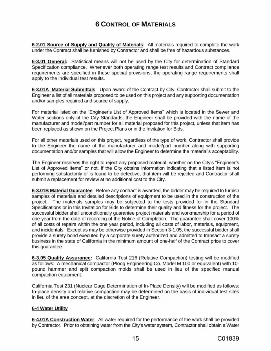
6 CONTROL OF MATERIALS
6-2.01 Source of Supply and Quality of Materials: All materials required to complete the work under the Contract shall be furnished by Contractor and shall be free of hazardous substances. 6-3.01 General: Statistical means will not be used by the City for determination of Standard Specification compliance. Whenever both operating range test results and Contract compliance requirements are specified in these special provisions, the operating range requirements shall apply to the individual test results. 6-3.01A Material Submittals: Upon award of the Contract by City, Contractor shall submit to the Engineer a list of all materials proposed to be used on this project and any supporting documentation and/or samples required and source of supply. For material listed on the “Engineer’s List of Approved Items” which is located in the Sewer and Water sections only of the City Standards, the Engineer shall be provided with the name of the manufacturer and model/part number for all material proposed for this project, unless that item has been replaced as shown on the Project Plans or in the Invitation for Bids. For all other materials used on this project, regardless of the type of work, Contractor shall provide to the Engineer the name of the manufacturer and model/part number along with supporting documentation and/or samples that will allow the Engineer to determine the material’s acceptability. The Engineer reserves the right to reject any proposed material, whether on the City’s “Engineer’s List of Approved Items” or not. If the City obtains information indicating that a listed item is not performing satisfactorily or is found to be defective, that item will be rejected and Contractor shall submit a replacement for review at no additional cost to the City. 6-3.01B Material Guarantee: Before any contract is awarded, the bidder may be required to furnish samples of materials and detailed descriptions of equipment to be used in the construction of the project. The materials samples may be subjected to the tests provided for in the Standard Specifications or in this Invitation for Bids to determine their quality and fitness for the project. The successful bidder shall unconditionally guarantee project materials and workmanship for a period of one year from the date of recording of the Notice of Completion. The guarantee shall cover 100% of all costs of repairs within the one year period, including all costs of labor, materials, equipment, and incidentals. Except as may be otherwise provided in Section 3-1.05, the successful bidder shall provide a surety bond executed by a corporate surety authorized and admitted to transact a surety business in the state of California in the minimum amount of one-half of the Contract price to cover this guarantee. 6-3.05 Quality Assurance: California Test 216 (Relative Compaction) testing will be modified as follows: A mechanical compactor (Ploog Engineering Co. Model M 100 or equivalent) with 10-pound hammer and split compaction molds shall be used in lieu of the specified manual compaction equipment.
California Test 231 (Nuclear Gage Determination of In-Place Density) will be modified as follows: In-place density and relative compaction may be determined on the basis of individual test sites in lieu of the area concept, at the discretion of the Engineer.
6-4 Water Utility 6-4.01A Construction Water: All water required for the performance of the work shall be provided by Contractor. Prior to obtaining water from the City's water system, Contractor shall obtain a Water
15 C01839

Use Permit from the City of Santa Rosa Water Department and rent a hydrant or bridge meter. Contractor is responsible for the cost of all water and the cost of all deposits, permits and fees. Contractor is prohibited from operating gate valves or fire hydrants on the City system. The acquisition of water from the City’s water system through un-metered hydrants or other facilities is a violation of City ordinance and State law. The use of water from sources other than the City's water system must be approved by the Engineer in advance of the use. Citations and fines will be levied for violation of these and other utility regulations and deductions will be made from payments consistent with Section 7-1.02A(1) of the Standard Specifications. 6-4.01B Water Utility Notification: Contractors or parties requiring work of any kind by the City of Santa Rosa Water Department forces shall request such services a minimum of 48 hours in advance of the time such services are desired. Work requests which will involve the City of Santa Rosa Water Department forces for more than eight hours or an extensive number of City parts shall be requested a minimum of seven calendar days in advance. If it is necessary to terminate or disrupt utility service to any customer, Contractor shall make the request for such work by City forces an additional 72 hours (three additional working days for a total of five working days advance notice) in advance of the time such services are desired to allow affected customers a minimum of 72 hours’ notice. Contractors who fail to keep field appointments will be billed for scheduled City of Santa Rosa Water Department crew standby time which was used and the Contractor shall bear the costs incurred by the City of Santa Rosa’s Water Department for re-notification of customers. City of Santa Rosa Water Department crews work a 9/80 schedule. This schedule may prohibit shutdowns for tie-ins on alternating Fridays. After hours work or weekend work may be performed if prior authorization from the Engineer is obtained. Other than the hours specified in this Invitation for Bids, requests by Contractor for after hours or weekend work is to be avoided whenever possible. Any overtime costs incurred by City for such work shall be borne by Contractor. Interruption of utilities service to commercial customers shall be coordinated with the customer to minimize disruption to the enterprise to the greatest extent practicable. After notification by the Contractor of the need, the City of Santa Rosa Water Department will contact all commercial customers and inform Contractor accordingly. 6-4.01C Water Facility Damage: All damage caused to the City’s water system shall be immediately reported to the Engineer. Damage caused to the City’s water system by Contractor’s operations shall be repaired by the Contractor at Contractor’s sole expense in a manner satisfactory to the City of Santa Rosa Water Department. Such repairs shall not be charged to the City or any City project. All repair work shall be witnessed and approved by the City of Santa Rosa Water Department prior to backfilling the excavation. The City will require re-excavation if backfilling occurs prior to inspection, which costs shall be borne by Contractor. Contractor is responsible for, at its sole cost and expense, the repair and remediation of damage to property and facilities caused by any of the following circumstances:
a. Contractor fails to make a written request for a markout or begins excavation without providing the City of Santa Rosa Water Department a reasonable opportunity to mark facilities;
16 C01839

b. Contractor destroys markouts; c. Contractor fails to perform hand digging or probing for utilities near markouts; or d. Contractor fails to use reasonable caution, regardless of whether markouts are
present or clear. Reasonable caution includes any efforts to avoid damaging existing facilities, such as when excavating in the vicinity of water mains.
City may, in its discretion, opt to make the repairs for which Contractor is responsible with its own forces. In such cases, the repairs will be made at Contractor’s expense in accordance with the emergency repair rate schedule of the City of Santa Rosa Water Department. The City may make repairs whenever restoration of service requires extraordinary speed or special equipment. Contractor will be billed accordingly and City shall have the right and option to withhold payment hereunder, or a portion thereof, for any such costs billed but not promptly paid by Contractor. 6-4.02 Salvage: All valves, hydrants, and other appurtenances of the water system that are the property of City and removed by Contractor shall be delivered to the City's Municipal Services Center (55 Stony Point Road) unless Contractor has obtained specific written approval from the City of Santa Rosa Water Department to otherwise dispose of the materials. 6-4.03 Trade Names and Alternatives: Unless otherwise specified, material and equipment specifications that identify a particular patent, trade name or manufacturer, may be satisfied through substitute materials and equipment accepted by the City. Contractor may offer substitute materials and equipment of equal or better quality y to the City. Any such offer shall be made in writing to the Engineer at least four weeks in advance of the time Contractor wishes to order the materials or equipment. Contractor shall include sufficient data which, together with any other information the Engineer may require, will enable the Engineer to determine the acceptability of the materials and equipment. When the substitute materials or equipment necessitate changes to any part of the work, the information shall include drawings and details showing all such changes and Contractor shall perform these changes as a part of any acceptance of substitute materials or equipment. The use of substituted materials and equipment will be permitted only after written acceptance of the materials and equipment by the Engineer. Such acceptance shall not relieve the Contractor from full responsibility for the sufficiency, quality and performance of the substitute materials and equipment. The City will not, under any circumstances, acknowledge or consider any offers to accept substitute materials or equipment between the dates of public notice of advertisement and the bid opening.
17 C01839

7 LEGAL RELATIONS AND RESPONSIBILITY TO THE PUBLIC
7-1.02A(1) Forfeitures for Health and Safety Violations: Contractor shall comply with all applicable provisions of the Santa Rosa City Code and any failure to do so shall constitute a breach of the Contract. In the event of any violation of the Santa Rosa City Code that may impact public health and safety, including, but not limited to Chapter 17-12, “Storm Water” and Chapter 13-04, “Street Encroachments,” City shall have the right to impose a charge against Contractor in an amount equal to $500.00 per violation per day. Prior to the imposition of any charge hereunder, City shall first provide a written notice to Contractor of the violation and setting forth a reasonable period of time for Contractor to cure the violation(s). In the event Contractor fails to cure any such violation within the time provided, City shall have the right, in addition to all other rights and remedies available to City, to deduct and withhold as a permanent forfeiture by Contractor the appropriate amounts from any payment otherwise due Contractor under this Contract. 7-1.02K(2) Wages: Pursuant to Labor Code sections 1770 et seq., each laborer or mechanic of Contractor or any subcontractor engaged in work on the project under this contract shall be paid not less than the hourly wage rate of per diem wages set forth in the prevailing wage rate schedule published by the Director of Industrial Relations, regardless of any contractual relationship which may be alleged to exist between Contractor or any subcontractor and such laborers and mechanics. A copy of the schedule of prevailing wage rates can be obtained online at www.dir.ca.gov or from the Department of Transportation and Public Works at 69 Stony Circle, Santa Rosa. Any laborer or mechanic employed to perform work on the public works project under this Contract, which work is not covered by any of the foregoing classifications, shall be paid not less than the prevailing wage rate of per diem wages specified herein for the classification which most nearly corresponds to the work to be performed by the worker. The foregoing specified prevailing wage rates are minimum rates only, and Contractor may pay any wage rate in excess of the applicable rate. Pursuant to Labor Code Section 1775, Contractor as a penalty to the owner shall forfeit not more than $200.00 for each calendar day, or a portion thereof, for each worker paid less than the prevailing wage rate established by the Department of Industrial Relations for such work or craft in which such worker is employed. The difference between such prevailing wage rates and the amount paid to each worker for each calendar day or portion thereof for which the worker was paid less than the prevailing wage rate shall be paid to each worker by Contractor. Contractor shall only provide prevailing wage reports upon written request from City. 7-1.02K(4) Apprentices: Contractor agrees to comply with Chapter 1, Part 7, Division 2, sections 1777.5 et seq. of the California Labor Code. These sections require contractors and subcontractors to employ apprentices in apprenticeable occupations in a ratio of not less than one hour of apprentice work for each five hours of journeyman work (unless an exception is granted in accordance with Section 1777.5), and the contractors and subcontractors shall not discriminate among otherwise qualified employees as apprentices solely on the ground of sex, race, religion, creed, national origin, ancestry, or color. Only apprentices as defined in Labor Code section 3077, who are in training under apprenticeship standards and who have written apprentice agreements will be employed on public works in apprenticeable occupations. The responsibility for compliance with these provisions is fixed with the prime contractor for all apprenticeable occupations.
18 C01839

7-1.02K(6)(a)(1) Notice to Vendors: Attention is directed to the current OSHA Standards. All equipment, tools and materials which are furnished and/or installed as part of this Contract shall meet or exceed the aforementioned standards in order to be considered acceptable. 7-1.02K(6)(b) Excavation Safety: When the digging or excavation occurs during project construction, Contractor shall: a. Promptly notify City in writing of the following conditions before any such conditions are
disturbed:
1. Material that the Contractor believes may be hazardous waste as defined in Health and Safety Code section 25117 that is required to be removed to a Class I, Class II or Class III disposal site in accordance with provisions of existing law;
2. Subsurface or latent physical conditions at the site differing from those indicated in the Invitation for Bids; and
3. Physical conditions at the site of any unusual nature, materially different from those ordinarily encountered and generally recognized as inherent in the type of work under the Contract.
b. The City will investigate the conditions and will issue a change order under the terms of the
Contract if it finds that the conditions warrant it. c. If a dispute arises between City and Contractor as to whether a change order is warranted,
Contractor shall not be excused from any scheduled completion date provided for in the Contract, but shall proceed with all work to be performed under the Contract.
7-1.02K(6)(b)(1) Trench Excavation Safety Plans: When the estimated cost for the excavation of any trench or trenches five feet or more in depth will exceed $25,000.00, Contractor shall submit to the Engineer in advance of excavation a detailed plan showing the design of shoring, bracing, sloping or other provisions to be made for worker protection from the hazard of caving ground during the excavation of such trench or trenches. If such plan varies from the shoring system standards established by the construction safety orders, or if the trench is anticipated to be greater than 20 feet, the plan shall be prepared by a registered civil or structural engineer. A permit to do the above described work shall be obtained from the State of California, Division of Industrial Safety. Proof of such permit shall be submitted to the Engineer prior to starting the trench work. Full compensation for complying with the provisions of this section shall be considered as included in the Contract price and no additional allowance will be made for the work.
7-1.02K(6)(d) Confined Space Safety: Any confined space entry for this project, including but not limited to manhole or water storage tank entry, will require a confined space entry permit pursuant to Cal/OSHA regulations as set forth in title 8 California Code of Regulations (CCR) sections 5157 or 5158. Confined space entry shall have the meaning ascribed in title 8 CCR sections 5157 and 5158. For any confined space entry for construction operations regulated by title 8 CCR section 1502, Contractor shall comply with title 8 CCR section 5158, “Other Confined Space Operations.” For any other confined space operations, Contractor shall comply with title 8 CCR section 5157, “Permit-Required Confined Spaces.” Attention is directed to the technical specifications in the Special Provisions for information regarding entry to any City maintained confined space. Pursuant to title 8 CCR section 5157, Contractor is required to obtain any available information regarding hazards and operations for any City maintained confined spaces. The City maintained Confined Space Entry Manual is available
19 C01839

for viewing at the City of Santa Rosa Water Department or Transportation and Public Works Department office at 69 Stony Circle, Santa Rosa. Contractor shall immediately inform the Engineer of any previously unidentified hazards confronted or created during confined space entry. 7-1.02L(2)(a) Patents and Royalties: All fees, royalties, or claims for any patented invention, article, process or method that may be used upon or in any manner connected with the work under this Contract shall be paid by Contractor. Contractor and its sureties shall protect and hold harmless City and its officers, agents, and employees from any and all demands made for such fees royalties or claims brought or made by any third party, and before the final payment is made on the account of the Contract, Contractor shall, if requested by City, furnish acceptable proof of a proper release from all such claims and liabilities. Should Contractor, its officers, agents, or employees, or any one of them be enjoined from furnishing or using any invention, article, material, or plans supplied or required to be supplied or used under the Contract, Contractor shall promptly substitute other articles, materials, or appliances in lieu thereof of equal efficiency, quality, finish, suitability, and market value, and satisfactory in all respects to the Engineer. In the event that the Engineer elects, in lieu of such substitution, to have supplied and to retain and use any such invention, article, materials, or plans as may be required to be supplied by the Contract, Contractor shall pay such royalties and secure such valid licenses as may be requisite and necessary for City, its officers, agents, and employees, or any one of them to use such invention, article, materials, or appliance without being disturbed or in any way interfered with by any proceeding in law of equity on account thereof. Should Contractor neglect or refuse to make the substitution promptly or to pay such royalties and secure such licenses as may be necessary, then in that event the Engineer shall have the right to make such substitutions or City may pay such royalties and secure such licenses and charge Contractor even though final payment under the Contract may have been made. 7-1.02M(3) Mined Materials: California Public Contract Code section 20676 prohibits surface mining operators which are subject to the Surface Mining and Reclamation Act of 1975 (SMARA) from selling California mined construction material to the City unless the operator is identified in a list referred as the 3098 List. The List, which is maintained by the Department of Conservation's Office of Mine Reclamation (OMR), changes throughout the year and can be viewed at the OMR website: http://www.consrv.ca.gov/OMR/ab_3098_list/index.htm. To confirm whether or not a specific operator is on the List at any given time, Contractor shall call the OMR at (916)323-9198. 7-1.03A Maintaining Traffic: Attention is directed to Sections 7-1.04 of the Standard Specifications and to the following modifications thereof. If construction is within City owned right-of-way, provisions shall be made for the safe passage of public traffic through the work site at all times consistent with the requirements of Santa Rosa City Code Chapter 13-04. Except for projects to be performed under a minor contract, Contractor shall install and maintain project identification signs at each end of the project or as directed by the Engineer two weeks prior to any construction activity. City shall furnish the appropriate sign panels upon request from Contractor. To mount the sign panels, Contractor shall furnish and install 4" X 4" posts or mount by other appropriate methods as approved by the Engineer. These sign panels shall be returned to the City Corporation Yard at 55 Stony Point Road after completion of the project. Two weeks prior to any construction activity, advance notice signs for road closures shall be furnished and installed by Contractor at each end of the project and shall remain in place throughout the duration of the subject closure. Details of panel construction and lettering shall be approved by the Engineer.
20 C01839

Contractor shall furnish, install, and maintain at its expense all barricades, signs, lights, and other devices necessary to adequately warn of any obstructions to the traveled and pedestrian way and provide flaggers as necessary for the safety of public traffic and pedestrians and to provide access to property adjacent to the work site and Contractor shall comply with the Americans with Disabilities Act of 1990 (42 U.S.C. 12101, et seq.) (ADA) and any regulations and guidelines issued pursuant to the ADA. Contractor shall comply with the current edition of the California Manual of Uniform Traffic Control Devices (CA MUTCD) for all items related to traffic within the work site. Rain and other occurrences that may cause the suspension or delay of the work shall in no way relieve Contractor of its responsibility to provide traffic control and public access through the work site as specified herein. At all times, Contractor shall keep at the work site such materials, forces and equipment as may be necessary to keep roads, streets, and driveways within the work site open to traffic and in good repair and shall expedite the passage of such traffic, using such forces and equipment as may be necessary. Should Contractor fail, in the opinion of the Engineer, to provide all the materials, forces and equipment necessary to maintain traffic through the work site as set forth herein, City may take steps necessary to remedy any such failure, including but not limited to causing such work to be performed and/or suspending any further work under the Contract. Any such remedial cost and expense incurred by the City, plus an administrative charge of 15%, shall be immediately due and payable by Contractor and may be deducted from any amounts owed to Contractor hereunder. In the event there are insufficient sums owed to Contractor hereunder to cover the foregoing costs and charges, City shall have the right to pursue any other remedy to recover the same, including but not limited to, proceeding against any surety or bond in favor of City. City’s rights under Section 7-1.02 are intended to be in addition to and not in lieu of any charges imposed by City against Contractor under Section 7-1.02A(1) above for violations of the Santa Rosa City Code. Contractor shall be responsible for informing emergency response agencies operating within the area of the work of obstructions to either public or private roads caused by reason of Contractor’s operations hereunder. Contractor shall make provisions for the safe passage of pedestrians around the project work site at all times.
21 C01839

8 PROSECUTION AND PROGRESS
8-1.01A Assignments: Once awarded, this Contract shall not be transferred, assigned, or sub-contracted, except as herein expressly provided without the prior written consent of the City in the City’s sole and absolute discretion. See Section 5-1.12 of the Standard Specifications. 8-1.03 Beginning of Work: The Contractor shall begin work within five (5) calendar days after the day authorized in the Notice to Proceed and shall diligently prosecute the contract to completion as specified in Section 8-1.06. 8-1.06 Time of Completion: Working days will be counted beginning with the day the Contractor begins work or with the fifth day after the day authorized in the Notice to Proceed, whichever shall occur first. Unless otherwise directed by Engineer, Contractor shall not conduct any activities that generate noise earlier than 7:00 a.m. or later than 7:00 p.m. The new pumps must be installed, tested and fully operational by May 15, 2018. Site restoration work must be completed by June 15, 2018. All construction work must be completed by June 15, 2018. Early Completion Incentive: The City shall pay the Contractor a lump sum of Ten Thousand Dollars ($10,000) if the new pumps are installed, tested and fully operational by May 15, 2018. Late Completion Disincentive: In the event the pumps are not fully operational before June 1, 2018, the City shall deduct Two Thousand Dollars ($2,000.00) per calendar day up to seven days. This amount is in addition to any Liquidated Damages as specified in Section 8-1.07. 8-1.07 Liquidated Damages: Contractor hereby agrees that Contractor shall pay to the City of Santa Rosa liquidated damages for each and every calendar day's delay over and beyond the completion date of June 15, 2018 as prescribed above for finishing the work in the amount shown in Section 8-1.10 of the Standard Specifications.
22 C01839

9 MEASUREMENT AND PAYMENT
9-1.01 General This section describes the pay items, which are further described in Section 98 Summary of Work.
9-1.02 Description of Pay Items
9-1.02A Section Includes:
Methods of measurement and payment for specific items of Work under this Contract.
9-1.02B Bid Components and Payment
The Bid Form is comprised of the following bid items:
1. Mobilization/Demobilization
2. Water Pollution Control
3. Sheeting, Shoring, and Bracing
4. Earthwork
5. Over-Excavation of Unsuitable Materials
6. Underground Piping and Structures
7. Concrete Work
8. Masonry Well Buildings
9. Well Head and Piping
10. Electrical and Instrumentation
11. Mechanical and System Testing
12. Site Work
13. Contract Execution Incentive
14. Early Completion Incentive
15. Late Completion Disincentive
Contractor’s cost for the above listed items shall cover all Work indicated by the Contract Documents. No measurement will be made for lump sum work. Lump sum work will be paid for on a progress payment basis based on the approved Schedule of Values.
9-1.02B(1) Bid Item 1 Mobilization/Demobilization
Payment for Mobilization and Demobilization will be made at the lump sum price named in the Bid Schedule(s) under Item No. 1 and shall constitute full compensation for furnishing all labor, materials, tools, equipment, incidentals, and all the work involved and necessary including:
1. Moving on to the site all of Contractor's equipment required for first month operations.
2. Establishing fire protection system.
3. Arranging for and erection of Contractor's work and storage yard.
4. Having all OSHA required notices and establishment of safety programs.
5. Performing all required potholing.
23 C01839

6. Having the Contractor's superintendent at the jobsite full time.
7. Submitting initial submittals.
8. Submitting erosion control plan and complying with all provisions of Division I and
II of the specifications (Sections 1 through 12, and 14). Section 13 will be paid for
under Water Pollution Control.
9. Construction staking.
10. Moving off of the site.
11. Leaving site in clean and orderly fashion.
9-1.02B(2) Bid Item 2 Sheeting Shoring and Bracing
Payment for Sheeting, Shoring, and Bracing will be made at the lump sum price named in the Bid Schedule(s) under Item No. 2 and shall constitute full compensation for furnishing all labor, materials, tools, equipment, incidentals, and all the work involved and necessary for worker safety including providing a detailed plan of worker safety and maintaining safety during construction, including conforming to Labor Code Section 6705, all applicable safety orders and permits.
9-1.02B(3) Bid Item 3 Water Pollution Control
Payment for Water Pollution Control will be made at the lump sum price named in the Bid Schedule under Item No. 3 and shall constitute full compensation for all work in Section 13 of the specifications, all in accordance with the requirements of the Contract Documents.
9-1.02B(4) Bid Item 4 Earthwork
Payment for Earthwork will be made at the lump sum price named in the Bid Schedule under Item No. 4 and shall constitute full compensation for demolition, disposal of materials, site preparation, subsurface investigation, excavation dewatering, and earthwork; all work under Section 15 of these specifications; and associated work, all in accordance with the requirements of the Contract Documents.
9-1.02B(5) Bid Item 5 Over-Excavation of Unsuitable Materials
Payment for Over-Excavation of Unsuitable Materials will be made at the price per cubic yard named in the Bid Schedule under Item No. 5 and shall constitute full compensation for conforming to these requirements, including all the labor, materials, tools, equipment and incidentals necessary for completion of the work, including excavation, hauling, disposal, and replacement with suitable materials, as specified in the Standard Specifications, these technical specifications, and as directed by the Engineer, and no additional compensation will be allowed. Only materials removed as directed by the Engineer will be measured.
9-1.02B(6) Bid Item 6 Underground Piping and Structures
Payment for Underground Piping and Structures will be made at the lump sum price named in the Bid Schedule under Item No. 6 and shall constitute full compensation for furnishing and installing underground piping, valves, and fittings; pre-cast concrete flow meter vaults and hatches; drain inlets; and, underdrains all in accordance with the requirements of the Contract Documents.
24 C01839

9-1.02B(7) Bid Item 7 Concrete Work
Payment for Concrete Work will be made at the lump sum price named in the Bid Schedule under Item No. 7 and shall constitute full compensation for furnishing and installing concrete, including equipment pads, walkways building foundation and slab, and concrete for well head; and associated work, all in accordance with the requirements of the Contract Documents.
9-1.02B(8) Bid Item 8 Masonry Well Buildings
Payment for Well Buildings will be made at the lump sum price named in the Bid Schedule under Item No. 8 and shall constitute full compensation for furnishing and installing masonry walls, doors, wood frame roof framing and roofing, insulation, skylights, penetrations, air conditioning units, coatings, gutters and downspouts; and associated work, all in accordance with the requirements of the Contract Documents.
9-1.02B(9) Bid Item 9 Well Head and Piping
Payment for Well Head and Piping will be made at the lump sum price named in the Bid Schedule under Item No. 9 and shall constitute full compensation for well head modifications, above ground piping and valves, coating, flushing, pressure testing and disinfection of above-grade and below-grade piping; coordinating with well pump contractor, and associated work, all in accordance with the requirements of the Contract Documents.
Concrete for Well Head will be paid for under Bid Item 5 Concrete Work.
9-1.02B(10) Bid Item 10 Electrical and Instrumentation
Payment for Electrical & Instrumentation will be made at the lump sum price named in the Bid Schedule under Item No. 10 and shall constitute full compensation for providing all electrical & instrumentation shown on drawings and as specified, including making final connections to all equipment, including pumps; building interior and exterior lighting; system analysis and testing; and associated work, all in accordance with the requirements of the Contract Documents.
9-1.02B(11) Bid Item 11 Mechanical Equipment and System Testing
Payment for Equipment and System Testing will be made at the lump sum price named in the Bid Schedule under Item No. 11 and shall constitute full compensation for mechanical system testing, including: planning, coordination with pump replacement contractor, functional tests, performance tests, and commissioning; safety and signage; and associated work, all in accordance with the requirements of the Contract Documents.
9-1.02B(12) Bid Item 12 Site Work
Payment for Site Work will be made at the lump sum price named in the Bid Schedule under Item No. 12 and shall constitute full compensation for asphalt repair and site work, including: fencing, gates, landscape restoration; associated work; and all items not included in other bid items, all in accordance with the requirements of the Contract Documents.
9-1.02B(13) Bid Item 13 Contract Execution Incentive
Payment for Contract Execution Incentive shall be made at the contract lump sum price named by the City in the Bid Schedule under Item No. 13 as described in Section 3-1.18.
25 C01839

9-1.02B(14) Bid Item 14 Early Completion Incentive
Payment for Early Completion Incentive will be made at the contract lump sum price as described in Section 8-1.06. All start up testing and commissioning must be completed prior to turning the facility over to the City.
9-1.02B(15) Bid Item 15 Late Completion Disincentive
Payment for Late Completion Disincentive will be made at the unit price per day named by the City in the Bid Schedule under Item No. 15 as described in Section 8-1.06.
9-1.04 Force Account Work: All work done on a force account basis shall be recorded daily on report sheets prepared by Contractor and signed by both the Engineer and Contractor. Such reports shall thereafter be considered the true record of force account work performed during the project. Such reports shall be furnished to the Engineer and a copy retained by Contractor. All extensions of labor, equipment, and material costs shall be completed by Contractor and submitted to the Engineer within 30 days of the completion of the extra work. Completed and extended extra work reports received later than the times herein prescribed may be deemed invalid and rejected without payment at the discretion of the Engineer. 9-1.07 Payment Adjustments For Price Index Fluctuations: Any references to Opt Out of Payment Adjustments for Price Index Fluctuations in the Standard Specifications are deleted in their entirety. 9-1.16 Progress Payments: Once each month for progress pay purposes, the City will prepare a written estimate of the total amount of completed work and accepted materials purchased by Contractor but not installed. The City shall retain five percent of such estimated value of the completed work and the unused materials and pay Contractor the balance after deducting all previous payments and all sums to be retained under the provisions of the Contract. No such estimate or payment shall be required to be made when, in the judgment of the Engineer, the work is not proceeding in accordance with the provisions of the Contract or when, in the Engineer’s judgment, the total value of the completed work since the last estimate is less than $500.00. No such estimate or payment shall be construed to be an acceptance of any defective work or improper materials. After Contract acceptance, the Engineer will prepare a written proposed final estimate of the proposed final quantities of work completed under the Contract and the value of such work and will submit such estimate to Contractor. The City shall retain five percent of such estimated value of the work done and shall pay to Contractor the balance after deducting all amounts to be retained under the provisions of the Contract. The City may, at its option and at any time, retain out of any amounts due Contractor sums sufficient to cover any unpaid claims of City or others, provided that sworn statements of all non-City claims shall have been filed with the Director of Finance. 9-1.16E(6) Substitution of Securities for Withheld Amounts: Pursuant to Public Contract Code section 22300, securities may be substituted for any moneys withheld by City to ensure performance under this Contract, provided that substitution of securities provisions shall not be required in contracts in which there will be financing provided by the Farmer's Home Administration of the United States Department of Agriculture pursuant to the Consolidated Farm and Rural Development Act (7 USC sections 1921 et seq.), and where federal regulations or policies or both do not allow the substitution of securities. At the request and expense of Contractor, securities equivalent to the amount withheld shall be deposited with the City, or with a state or federally chartered bank as the escrow agent, which shall then pay such moneys to Contractor. The Director of Finance is
26 C01839

authorized to execute substitution of securities agreements on behalf of the City. The City will return the securities to Contractor upon satisfactory completion of the Contract as determined by City in its sole discretion and the resolution of all outstanding claims against the securities. Contractor shall be the beneficial owner of any securities substituted for moneys withheld and shall receive any interest thereon. Securities eligible for investment under this section shall include those listed in Government Code section 16430, bank or savings and loan certificates of deposit, interest bearing demand deposit accounts, standby letters of credit or any other security mutually agreed to by Contractor and the City, provided that the substituted security is equal to or not less than five percent of the Contract amount. Security substitutions must be submitted by Contractor and approved by City prior to the time of the first progress payment to be made under the Contract. No other method of substituting securities for retention will be accepted. The security substitution shall be done only upon execution of an agreement satisfactory to City which includes the following provisions:
a. The amount of securities to be deposited; b. The terms and conditions of conversion to cash in case of the default of Contractor;
and c. The procedure for return of securities upon completion of the Contract.
9-1.17D Final Payment and Claims: The processing of payment of the final estimate shall not be commenced less than 35 days after the date of recording of the Notice of Completion with the County Recorder's Office. Contractor is advised that it takes approximately ten days for a check to be issued following a request for payment. Contractor shall submit its written statement of all claims for additional compensation under the Contract to the Engineer within 15 days after submission to Contractor of the proposed final estimate. If Contractor does not file a claim within the 15 day period, or upon Contractor's approval, the Engineer will issue a final written estimate and the City shall pay to Contractor the entire sum due after deducting all previous payments, if any, and all amounts to be retained under the provisions of the Contract. If Contractor files a claim within the 15 day period, the Engineer will furnish a semi-final estimate and pay the amount due under the semi-final estimate within 30 days. The semi-final estimate is conclusive as to the amount payable except as may be affected by claims and any amount retained. The Engineer shall then consider and investigate such claim, and shall make such revision in the final quantities as the Engineer may find to be due, and shall then make and issue a final written estimate. The City will pay the amount due, after deducting all previous payments, if any, and amounts to be retained under the provisions of the Contract. Any and all prior partial estimates and payments shall be subject to correction in the final estimate and payment. The final estimate shall be conclusive and binding against both parties to the Contract on all questions relating to the performance of the Contract and the amount of work done thereunder and compensation therefor, except in the case of gross error. 9-1.17D(3) Final Determination of Claims: Claims filed by Contractor shall be in sufficient detail to enable the Engineer to determine the basis and amount of the Claims. Contractor shall also furnish reasonable documentation to the City to support Claims. If additional information is required by the Engineer, Contractor shall provide such information to the Engineer no later than the 15th day after receipt of the written request from the Engineer. If the 15th day falls on a weekend, holiday, or day
27 C01839

City offices are closed, then the information shall be provided to the Engineer no later than close of the next business day. Failure to submit the requested information to the Engineer within the time specified will be sufficient cause for denying the Claim. Contractor shall keep full and complete records of the costs and additional time incurred for any work for which a claim for additional compensation is made. The Engineer or any designated Claim investigator or auditor shall have access to those records and any other records as may be reasonably required by the Engineer to determine the facts or contentions in each Claim. Failure to grant access to such records shall be sufficient cause for denying the Claims. 9-1.22 Arbitration: Any references to Arbitration in the Standard Specifications are deleted in their entirety. Claims submitted by Contractor shall be accompanied by a notarized certificate containing the following language: Under the penalty of law for perjury or falsification and with specific reference to the California False Claims Act, Government Code sections 12650 et seq., the undersigned, , (Name) of (Title) (Contractor) hereby certifies that the claim for additional compensation made herein is supported by a true statement of the actual costs incurred and time expended on this project, and is fully documented by records maintained by Contractor. Dated /s/ Subscribed and sworn before me this day of Notary Public My Commission Expires Failure to submit the notarized certificate will be sufficient cause for denying the claim. Any claim for overhead expenses, in addition to being certified as stated above, shall be supported by an audit report of an independent Certified Public Accountant. Any such overhead claim shall also be subject to audit by the City at its discretion. Any costs or expenses incurred by the City in reviewing or auditing any claims that are not supported by Contractor’s cost accounting or other records shall be deemed to be damages incurred by the City within the meaning of the California False Claims Act.
28 C01839

29 C01839
Special Provisions: Technical Specifications
For
Farmers Lane Well Rehabilitation Project
Contract No. C01839
July 2017
viF~l vos•
"SSOCI ... T[$

SECTION 12 TEMPORARY TRAFFIC CONTROL
12-1 GENERAL
12-1.01 General: Construction area traffic control devices shall be installed and maintained in accordance with the applicable sections of these Special Provisions, the Standard Specifications, the current Edition of the California Manual on Uniform Traffic Control Devices (CA MUTCD), the Americans with Disabilities Act (ADA) and as directed by the Engineer.
Both well sites have limited available space and are adjacent to private parking for local businesses. Contractor shall work with the City and Engineer to maintain access to private parking at all times.
Traffic control will be needed during the water service connection to the City’s water main at Well 4-2.
12-1.03 Flagging Costs: The first paragraph of Section 12-1.03, "Flagging Costs" is amended to read:
The cost of furnishing all flaggers, including transporting flaggers, to provide for passage of public traffic through the work under the provisions in Section 7-1.08, "Public Convenience", and Section 7-1.09, "Public Safety", shall be considered as included in the contract prices paid for the various contract items of work involved and no additional compensation will be allowed therefor.
12-3 TRAFFIC-HANDLING EQUIPMENT AND DEVICES
12-3.01 General: Prior to commencing construction which will affect existing vehicular and pedestrian traffic, the Contractor shall submit for review by the Engineer, Traffic Control Plans on 11" x 17" sheets of paper which contains only information specifically related to work zone vehicular and pedestrian traffic control. If the Contractor proposes to use the current edition of the CA MUTCD published by Caltrans in lieu of a traffic control plan, in specific work operations, they shall submit in writing for consideration which Typical Application Diagram will be used and how it will be applied for each work operation. Traffic Control Plans or proposals shall be submitted for review at least two weeks prior to implementation.
Traffic Control Plans shall contain a title block which contains the Contractor's name, address, phone number, project superintendent's name, contract name, dates and hours traffic control will be in effect, and a space for review acknowledgment.
The content of the Traffic Control Plan shall include, but is not limited to, the following:
1. Show location and limits of the work zone.
2. Give dimensions of lanes affected by traffic control that will be open to traffic.
3. Indicate signing, cone placement, and other methods of delineation and reference to appropriate City or Caltrans Standards.
30 C01839

4. Dimension location of signs and cone tapers.
5. Identify side streets and driveways affected by construction and show how they will be handled.
6. Show how pedestrian traffic will be handled through the construction site. Pedestrian pathways through the work zone shall be in compliance with the requirements of ADA during and after work hours.
7. Identify message board locations. A minimum of 3 changeable message boards shall be required. Location to be determined by Engineer.
8. Demonstrate how two-way traffic will be maintained.
No work except for installation of project identification signs will be allowed to commence prior to approval of the Work Zone Traffic Control Plans.
12-3.01A(3) Submittals: If construction will affect existing traffic on Farmers Lane, the contractor shall submit for review by the Engineer, a Traffic Control Plan on an 11" x 17" sheet of paper which contains only information specifically related to each work zone’s traffic control. If the Contractor proposes to use the current edition of CAMUTCD in specific work operations, they shall submit in writing for consideration which Typical Application Diagram will be used for each work operation. A Traffic Control Plan or proposal shall be submitted for review at least two weeks prior to implementation.
Additionally, prior to commencing construction affecting existing vehicular and pedestrian traffic on Farmers Lane and the State right-of-way, the Contractor shall submit for review by California Department of Transportation (Caltrans), a Traffic Control Plan on an 11" x 17" sheet of paper which contains only information specifically related to work zone traffic control. If the Contractor proposes to use the current edition of the CAMUTCD published by Caltrans in lieu of a traffic control plan in specific work operations, they shall submit in writing for consideration which Standard Plan will be used for each work operation. Actual work zone traffic control shall be shown as described below. A Traffic Control Plan or proposal shall be submitted for review at least two weeks prior to implementation to the Caltrans representative:
Contact: Jai Reddy Phone: (510) 579-2632 Email: [email protected] Address: 403 Occidental Road, Bldg A, Santa Rosa, CA 95401
Traffic Control Plans shall contain a title block which contains the contractor's name, address, phone number, project superintendent's name, contract name, dates and hours traffic control will be in effect, and a space for review acknowledgment.
Traffic Control Plans shall include, but are not limited to, the following:
1. Show location and limits of the work zone.
2. Give dimensions of lanes affected by traffic control that will be open to traffic.
31 C01839

3. Indicate signing, cone placement, and other methods of delineation and reference to appropriate CAMUTCD typical application.
4. Dimension location of signs and cone tapers.
5. Identify side streets and driveways affected by construction and show how they will be handled.
6. Show how pedestrian traffic will be accommodated through the construction site.
7. Demonstrate how two-way traffic will be maintained.
8. Identify message board locations. A minimum of 3 message boards shall be required.
All Traffic Control Plan shall be prepared, sealed, and signed by a Professional Engineer registered in the State of California.
No work except for installation of project identification signs will be allowed to commence prior to approval of the Work Zone Traffic Control Plan.
12-3.01C(1) Farmers Lane Construction: Attention is direct to Section B, Special Project Procedures, “B-01 All work in Farmers Lane”.
Arrow Boards will be required for this project and shall not impede into any travel lanes.
Where lanes are shifted and vehicles are detoured to the opposing direction of the street, 48-inch delineators are required.
12-4 MAINTAINING TRAFFIC
12-4.01 Maintaining Traffic:
1. The full width of the traveled way shall be open for use by public traffic on Saturday, Sundays and designated legal holiday(s), after 4:00 p.m. on Fridays and the day preceding designated legal holidays, and when construction operations are not actively in progress; unless work has specifically been authorized by the Engineer.
2. The location of traffic control signing, barricades, and other facilities shall be monitored frequently (four to five times per day) by the Contractor to verify their proper location. All traffic signal and other traffic control devices shall be maintained at all times.
3. The Contractor shall conduct his operations so as to cause the minimum obstruction and inconvenience to traffic and to places of business, multiple dwelling units and residences adjacent to the work. The Contractor shall notify the Engineer of his planned work and utility service interruption at least five working days in advance to allow time to notify residents and businesses.
4. When construction activities will prevent vehicle access to individual driveways the Contractor shall notify the affected businesses and residents per Section 12-1.03, “Traffic Control”, of these Special Provisions. Full access shall be provided to all driveways during non-working hours.
32 C01839

5. At locations where traffic is routed perpendicular to trench excavation, the excavation shall be conducted in a manner to provide a surface reasonably satisfactory for traffic at all times. Substructure installation or construction shall be conducted on only one-half the width of the roadway at a time, and that portion of the roadway being used by traffic shall be kept open and unobstructed until the opposite side of the roadway is ready for use. Upon completion of the rough grading, the surface of the roadbed shall be brought to a smooth, even condition free from humps and depressions and made satisfactory for traffic.
12-4.01A Construction Traffic: The Contractor shall submit a trucking route along with the traffic controls plans for approval by the Engineer. The route must minimize traffic on residential streets that are not part of the project.
Existing pavement damaged by the Contractor's operations and not shown to be replaced shall be replaced at the Contractor’s expense, per City Standards and to the satisfaction of the Engineer.
12-4.02 Closure Requirements: Attention is directed to Section 7-1.08, "Maintaining Traffic" and to Section 5-1.05, "Order of Work," of these Special Provisions.
Exact locations of Project Identification signs and Advance Notice signs (Section 7-1.08 "Maintaining Traffic") shall be determined in the field by the Engineer.
Lane closures of Farmers Lane will be allowed only during Mobilization/Demobilization and utility connections, and only during night-time (See Section B).
The work area provides the sole means of access for several homes and businesses. The Contractor shall maintain vehicle and pedestrian access to homes and businesses at all times while work is in progress.
The Contractor shall not park construction vehicles contractor employee vehicles, stage materials or stockpiles in front of any business or residential driveway access and the Contractor shall maintain access to private parking lots within the block where work is in progress. Construction vehicles shall not be left running for any length of time if parked in front of a business or residential unit.
The Contractor shall keep the City of Santa Rosa Fire Department informed regarding the closure of any traveled way. At a minimum, the Contractor shall call the Fire Department at 543-3535 and the Communications Center at 543-3666 daily to report any traveled way closure. This means immediately upon closure for that day and again immediately after removal of the closure. For closures over multiple days, the daily notification still applies. This requirement does not apply for single lane closures on multiple lane streets.
Barricades and flaggers shall be positioned to allow safe turns at intersections and curves.
33 C01839

The Contractor shall maintain traffic control as necessary and as directed by the Engineer for "cat-tracking" operations by City Forces. Flaggers, barricades, signing, etc., shall remain in place for protection of City personnel until all temporary lane delineation is complete.
12-7 TEMPORARY PEDESTRIAN WALKWAYS
12-7.01 Pedestrian Traffic Control: The Contractor is directed to Chapter 6D, Pedestrian and Worker Safety, in the CA MUTCD, the improvement plans and these Special Provisions.
Pedestrians shall be provided with a safe convenient and accessible path that, at a minimum, replicates the most desirable characteristics of the existing sidewalk, path or footpath. At no point along the road shall the sidewalks on both sides of the road be closed at the same time.
The Contractor shall construct and maintain temporary pedestrian pathways through the work zone, where required, that shall be in compliance with the requirements of the Americans with Disabilities Act (ADA), and the CA MUTCD.
Pedestrian routes shall not be impacted for the purposes of any non-construction activities such as parking of vehicles or equipment, or stock piling of materials. Pedestrians shall not be led into conflicts with work site vehicles, equipment or operations.
Pedestrian routes shall be open and accessible at the end of the work day unless an alternate ADA compliant route has been approved by the Engineer. The construction of curb ramps and/or long sections of sidewalk do not alleviate the Contractor from this requirement.
12-9 MEASUREMENT AND PAYMENT
12-9.01 Payment:
Full compensation for conforming to the provisions of this section shall be considered as included in the lump sum price paid for Mobilization/Demobilization and no additional compensation will be allowed therefor.
[Version: 04/29/15 DCM STD2010]
34 C01839

SECTION 13 - WATER POLLUTION CONTROL
13-1-GENERAL
13-1.01A
Water Pollution Control shall be performed in accordance with Section 13, Water Pollution Control, of the Standard Specifications and these technical specifications. In addition, construction activities shall comply with:
1. The California Water Quality Control Board, North Coast Region Order No. R1-2009-0050, National Pollutant Discharge Elimination System Municipal Storm Water Permit, Part 8 – Development Construction Program, Sections 1 through 5, commonly referred to as the “Storm Water Permit”. A copy of the Storm Water Permit is available for review at the City of Santa Rosa Transportation and Public Works Department, 69 Stony Circle, Santa Rosa, CA, and at http://www.srcity.org/stormwaterpermit.
2. The California Stormwater Quality Association Storm Water BMP Handbook for Construction (CASQA Handbook). BMPs shall be selected, installed and maintained in accordance with the latest edition. A copy of the handbook can be viewed at the City of Santa Rosa Department of Transportation and Public Works office at 69 Stony Circle or downloaded from CASQA, http://www.casqa.org/.
In this technical specification, the CASQA Handbook BMP numbers are appended to the associated Standard Specification sections. If a conflict occurs, the CASQA Handbook BMP’s shall govern.
13-2-WATER POLLUTION CONTROL PROGRAM
13-2.01B Submittals
The program to control water pollution required to be submitted under this section of the Standard Specifications shall include a spill contingency plan that establishes clean-up procedures that will be followed in the event of a spill of potentially hazardous, toxic, or polluting materials.
13-2.04 Payment
The City pays you to prepare a Water Pollution Control Program as the lump sum price for Water Pollution Control and as follows:
13-3-STORM WATER POLLUTION PREVENTION PLAN
13-3.01A Summary
This project is exempt from the State Water Resources Control Board General NPDES Permit for the Discharge of Storm Water related to Construction Activities (Construction General Permit), and not required to have a Storm Water Pollution Prevention Plan (SWPPP), therefore Section 13-3, Storm Water Pollution Prevention Plan, of the Standard Specifications does not apply to this project.
35 C01839

13-4-JOB SITE MANAGEMENT
13-4.03B: Spill Prevention and Control / CASQA Spill Prevention and Control (BMP WM-4)
If a spill occurs at the construction site and the contractor does not take immediate and adequate steps to contain and clean up the spill, especially if rain is threatening or if a discharge to a storm drain or creek could occur, the City shall have the right, in its sole and absolute discretion, to clean up the spill using City forces or an independent contractor. The cost of any such cleanup, in addition to recovery of any penalty or fine imposed upon the City, plus an administrative charge of fifteen percent (15%) of the costs incurred by the City, shall be deducted from any amounts owed to Contractor hereunder.
In the event there are insufficient amounts owed to Contractor hereunder to cover the foregoing costs and charges, the City shall have the right to pursue any other remedy to recover same, including, but not limited to, proceeding against any surety or bond in favor of the City. The City’s rights under this section are intended to be in addition to and not in lieu of any imposed by the City against Contractor for violations of City Code Chapter 17-12, “Storm Water”.
13-4.03C(2): Material Storage / CASQA Material Delivery and Storage (BMP WM-1)
13-4.03C(3): Stockpile Management / CASQA Stockpile Management (BMP WM-3)
Do not block storm water flows.
13-4.03D(1): Waste Management / CASQA Solid Waste Management (BMP WM-5)
The Contractor shall dispose of all trash, rubbish, and waste materials of any kind generated by the contractor, subcontractor, or any company hired by the Contractor on a daily basis.
13-4.03D(3): Concrete Waste / CASQA Concrete Waste Management (BMP WM-8)
Ensure the containment of concrete washout areas and other washout areas that may contain pollutants so there is no discharge into the underlying soil and onto the surrounding areas.
13-4.03D(4): Sanitary and Septic Waste / CASQA Sanitary and Septic Waste Management (BMP WM-9)
Sanitation facilities must be maintained periodically by a licensed service to keep them in good working order and prevent overflows. Portable toilets are required to have secondary containment.
13-4.03D(5): Liquid Waste
Liquid waste includes water generated from excavation dewatering.
Minimize transfer piping by locating containers near the excavation to be dewatered while protecting the containers from moving vehicles and equipment.
36 C01839
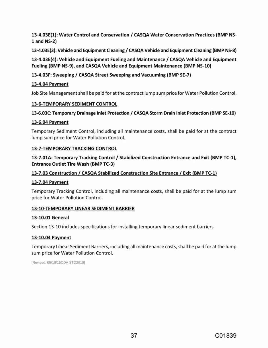
13-4.03E(1): Water Control and Conservation / CASQA Water Conservation Practices (BMP NS-1 and NS-2)
13-4.03E(3): Vehicle and Equipment Cleaning / CASQA Vehicle and Equipment Cleaning (BMP NS-8)
13-4.03E(4): Vehicle and Equipment Fueling and Maintenance / CASQA Vehicle and Equipment Fueling (BMP NS-9), and CASQA Vehicle and Equipment Maintenance (BMP NS-10)
13-4.03F: Sweeping / CASQA Street Sweeping and Vacuuming (BMP SE-7)
13-4.04 Payment
Job Site Management shall be paid for at the contract lump sum price for Water Pollution Control.
13-6-TEMPORARY SEDIMENT CONTROL
13-6.03C: Temporary Drainage Inlet Protection / CASQA Storm Drain Inlet Protection (BMP SE-10)
13-6.04 Payment
Temporary Sediment Control, including all maintenance costs, shall be paid for at the contract lump sum price for Water Pollution Control.
13-7-TEMPORARY TRACKING CONTROL
13-7.01A: Temporary Tracking Control / Stabilized Construction Entrance and Exit (BMP TC-1), Entrance Outlet Tire Wash (BMP TC-3)
13-7.03 Construction / CASQA Stabilized Construction Site Entrance / Exit (BMP TC-1)
13-7.04 Payment
Temporary Tracking Control, including all maintenance costs, shall be paid for at the lump sum price for Water Pollution Control.
13-10-TEMPORARY LINEAR SEDIMENT BARRIER
13-10.01 General
Section 13-10 includes specifications for installing temporary linear sediment barriers
13-10.04 Payment
Temporary Linear Sediment Barriers, including all maintenance costs, shall be paid for at the lump sum price for Water Pollution Control.
[Revised: 05/18/15CDA STD2010]
37 C01839

SECTION 14 - ENVIRONMENTAL STEWARDSHIP
14-2 CULTURAL RESOURCES
14-2.01 Historical Resource Discovery
If subsurface historical materials are encountered during construction activities, the piece of equipment that encounters the materials shall be stopped, and the City shall be notified immediately. The Contractor and City will coordinate to have the find inspected by a qualified historian/archaeologist. Project personnel shall not collect historical materials. If the historian/archaeologist determines that the find qualifies as a unique historical resource for purposes of CEQA (CEQA Guidelines Section 15064.5(c)(3)), all work must be stopped in the immediate vicinity to allow the archaeologist to evaluate any materials and recommend appropriate treatment. Such treatment and resolution shall include either modifying the Project to allow the materials to be left in place or undertaking data recovery of the materials in accordance with standard archaeological methods. Construction cannot continue until the treatment plan has been determined and implemented.
14-2.02 Archaeological Resource Discovery
If archaeological materials are encountered during construction activities, construction in the immediate vicinity shall be stopped, and the City shall be notified immediately. The Contractor and City will coordinate to have the find inspected by a qualified archaeologist. Project personnel shall not collect cultural materials. If the archaeologist determines that the find potentially qualifies as a unique archaeological resource for purposes of CEQA (CEQA Guidelines Section 15064.5(c)(3)), all work must remain stopped in the immediate vicinity to allow the archaeologist to evaluate any materials and recommend appropriate treatment. The City shall notify interested Native American tribes of such discoveries and consult with the tribe from which the resources originated, according to the Native American Heritage Commission. Construction cannot continue until the treatment plan has been determined and implemented.
California Health and Safety Code Section 7050.5 states that it is a misdemeanor to knowingly disturb a human grave. If human graves are encountered, the Contractor shall ensure that work shall halt in the vicinity and the City shall be notified immediately. The City will notify the County Coroner. At the same time, the City will contact a qualified archaeologist to evaluate the situation. If human remains are of Native American origin, the Coroner shall notify the Native American Heritage Commission within 24 hours of identification, pursuant to Public Resources Code 5097.98. The Native American Heritage Commission will identify the person or persons most likely descended from the deceased. The City shall notify the tribe(s) and coordinate with them regarding the Most Likely Descendant and preferred treatment of the remains with appropriate dignity. A Tribal Treatment Plan covering reburial of human remains and disposition of the artifacts and other cultural resources should be agreed to by all parties. Construction cannot continue until the treatment plan has been determined and implemented.
38 C01839
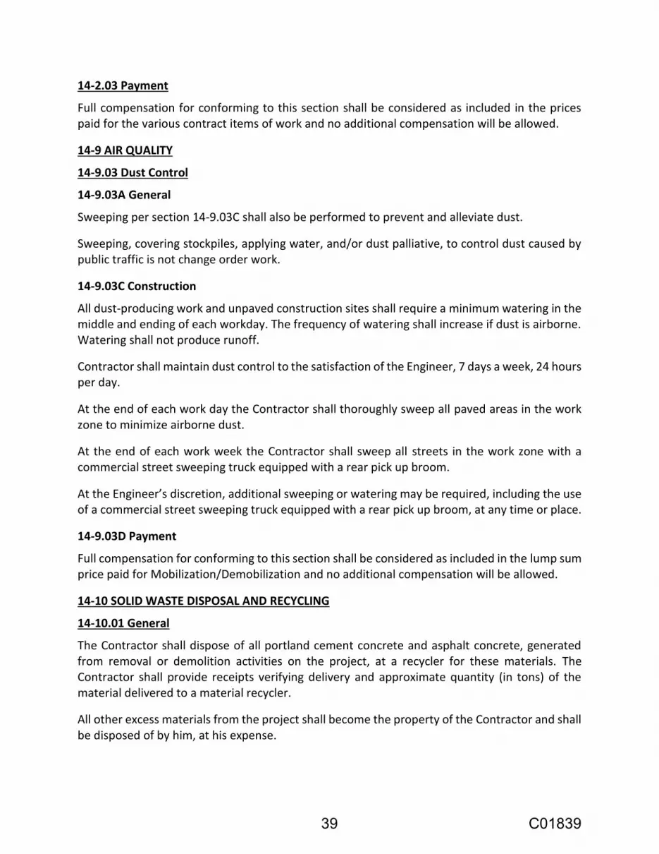
14-2.03 Payment
Full compensation for conforming to this section shall be considered as included in the prices paid for the various contract items of work and no additional compensation will be allowed.
14-9 AIR QUALITY
14-9.03 Dust Control
14-9.03A General
Sweeping per section 14-9.03C shall also be performed to prevent and alleviate dust.
Sweeping, covering stockpiles, applying water, and/or dust palliative, to control dust caused by public traffic is not change order work.
14-9.03C Construction
All dust-producing work and unpaved construction sites shall require a minimum watering in the middle and ending of each workday. The frequency of watering shall increase if dust is airborne. Watering shall not produce runoff.
Contractor shall maintain dust control to the satisfaction of the Engineer, 7 days a week, 24 hours per day.
At the end of each work day the Contractor shall thoroughly sweep all paved areas in the work zone to minimize airborne dust.
At the end of each work week the Contractor shall sweep all streets in the work zone with a commercial street sweeping truck equipped with a rear pick up broom.
At the Engineer’s discretion, additional sweeping or watering may be required, including the use of a commercial street sweeping truck equipped with a rear pick up broom, at any time or place.
14-9.03D Payment
Full compensation for conforming to this section shall be considered as included in the lump sum price paid for Mobilization/Demobilization and no additional compensation will be allowed.
14-10 SOLID WASTE DISPOSAL AND RECYCLING
14-10.01 General
The Contractor shall dispose of all portland cement concrete and asphalt concrete, generated from removal or demolition activities on the project, at a recycler for these materials. The Contractor shall provide receipts verifying delivery and approximate quantity (in tons) of the material delivered to a material recycler.
All other excess materials from the project shall become the property of the Contractor and shall be disposed of by him, at his expense.
39 C01839

14-10.02A(1) Submittals
Submit a Solid Waste Disposal and Recycling Report prior to final acceptance of work performed under the Contract. Show the types and amounts of project-generated solid waste taken to or diverted from landfills or reused on the project.
Submit a Solid Waste Disposal and Recycling Report prior to Contract acceptance. Show the types and amounts of project-generated solid waste taken to or diverted from landfills or reused on the project.
14-10.02D Payment
Full compensation for material recycling as specified herein shall be considered as included in the lump sum price paid for Mobilization/Demobilization, and no additional compensation will be allowed therefor.
[Revised: 05/18/15-DCM STD2010]
40 C01839

SECTION 15 EXISTING FACILITIES
15-1 GENERAL
15-1.03 Construction
15-1.03A General:
Existing facilities disturbed by construction shall conform to the applicable provisions of Section 5-1.36. All existing active utilities found to reside in excavated areas shall be supported in place with service maintained during construction. The Contractor shall be responsible for any damage caused by their operations and any needed repairs shall be completed to the Engineer’s satisfaction.
Existing storm drains found to reside in excavated areas shall be supported, removed, or replaced at the Contractor's option and at no additional cost to the City. The Contractor shall be responsible for maintaining the existing line and grade of the storm drains. If the Contractor elects to remove and replace, it shall be done per applicable City Standards and Specifications.
Existing utility trenches and/or structures that are in close proximity to proposed trenches shall be safeguarded in an appropriate manner from damage.
15-1.04 Payment:
Full compensation for supporting, removal and disposal of existing utilities and their appurtenances is considered as included in the lump sum price paid for Earthwork, and no additional allowance will be made therefor.
15-2 MISCELLANEOUS FACILITIES
15-2.02 Remove
15-2.02N Asbestos Cement Pipe: The Contractor is advised that asbestos cement pipe (ACP) will be encountered on the project and must be cut, handled, and disposed of according to the Contractor's State Licensing Law and all other applicable laws and regulations.
Full compensation for the cutting, removal and disposal of asbestos cement pipe shall be considered as included in the prices paid for various contract items of work and no additional allowance will be made therefor.
15-2.04 Reconstruct
15-2.04G Reconstruct Curb, Gutter, and Sidewalk:
Reconstruct sidewalk drain shall be done in conformance with requirements of Section 73 of the City Specifications and as directed by the Engineer.
Contractor shall remove portions of existing curb, gutter, and sidewalk, and install new curb,
gutter and sidewalk/walkway at the location designated and as directed by the Engineer.
41 C01839

15-2.10 Adjust
15-2.10B Adjust Frames, Covers, Grates, and Manholes:
Reset existing City facility boxes and lids to grade. The City will furnish at no cost to the Contractor new material to replace existing boxes and lids that do not comply with current City Standards or damaged prior to Contractor’s operations.
15-2.13 Payment:
Full compensation for conforming to the provisions of this section shall be considered as included in the lump sum price paid for Earthwork, and no additional compensation will be allowed therefor.
15-3 CONCRETE REMOVAL
15-3.03 Construction:
All removed concrete shall become the property of the Contractor and shall be immediately off-hauled. None of the removed concrete shall be dumped or stockpiled on the work site. The Contractor shall dispose of all removed concrete at a recycler for this material. Burying of broken concrete within the limits of the project will not be allowed.
All concrete which is to be removed from sidewalk, curb, gutter and driveway areas shall be removed to the nearest score mark or construction joint as directed by the Engineer unless otherwise noted on Project Plans. The edge of existing concrete to remain shall be neat and free of defects. Saw cutting may be required to achieve this.
Reinforcing steel may be encountered in portions of concrete to be removed and no additional allowance will be made for the removal of such steel.
Irrigation facilities may be encountered during concrete removal and replacement. The Contractor shall exercise care in this area and repair any damage done by their operations at no additional cost to the City.
Landscaping and other surfaces or structures shall be restored to original condition at no additional cost to the City.
15-3.04 Payment:
Payment for saw cutting, removal and disposal of concrete sidewalk, curb and gutter, driveway areas, and existing City monuments shall be included in the lump sum price paid for Earthwork and no additional allowance will be made therefor.
Full compensation for repair of existing irrigation facilities damaged during any phase of the work shall be included in the prices paid for various contract items of work and no additional allowance will be made therefor.
15-7 UTILITY CLEARANCES:
All items noted in this Section shall take place prior to any other construction activities.
42 C01839

Contractor shall investigate, confirm and/or determine the exact locations of existing utilities, and verify clearances between existing and proposed utilities at crossings and/or known potential conflicts. The Contractor shall determine elevations and alignments of existing utilities at connection points.
The Contractor shall determine elevations and alignments of existing sewer laterals, at the back of sidewalk, if a new proposed sewer main is at a higher elevation than the existing sewer main.
The Contractor shall provide all relevant information in writing to the Engineer immediately upon discovery of any conflict. Any delay in notification to the Engineer may delay direction and/or corrective action and a delay claim due to this reason shall not be considered by the City. The Contractor shall not proceed with any work that is in conflict until direction is provided by the Engineer and shall redirect crews to other contract work. All the information required to be obtained per this Section and any other information not noted but relative to the project shall be provided to the Engineer on a set of Plans when the investigative effort is complete.
15-7.01 Payment:
Full compensation for conforming to the provisions of this section shall be considered as included in the lump sum price paid for Earthwork, and no additional compensation will be allowed therefor.
15-8 TREE ROOT PRUNING:
All tree roots two inches and greater which are encountered during excavation must be pruned by hand. The root shall be cut cleanly with a saw to avoid splits. When digging within the drip line of trees, Contractor shall exercise extreme caution to avoid pulling on roots with excavation equipment. Hand dig around all roots greater than one inch in diameter. The Contractor shall notify the Engineer when encountering roots within the drip line of trees which are greater than one inch. If the Engineer elects to get direction from an arborist the Contractor shall redirect crews to other contract work after safeguarding the area.
15-8.01 Payment:
Full compensation for removing and pruning tree roots, hand digging to avoid root damaging roots, and excavating cautiously with respect to tree roots is considered as included in the lump sum price paid for Earthwork, and no additional allowance will be made therefor.
(STD2010)
43 C01839

SECTION 16 - CLEARING AND GRUBBING
16-1.01 General
Clearing, grubbing, and access shall be confined to the limits shown on the plans and shall not exceed the minimum necessary to complete operations.
The Contractor shall not remove any trees, brush, shrubs, or other natural objects outside the limits of construction as shown on the plans, unless directed by the Engineer.
Any trees, brush, shrubs, or other natural objects not ordered removed by the Engineer which have been removed, altered, or damaged shall be replaced in kind by the Contractor before completion of the project.
All unsuitable material shall be disposed of away from the site by the Contractor. The Contractor shall make all necessary arrangements for disposal of material.
16-1.03 Construction
The area to be cleared and grubbed shall be the area within the right-of-way shown on the plans, unless otherwise specified in the Special Provisions.
All stumps, large roots and other objectionable material shall be removed to a depth of three feet below finished grade in the area of construction. The resulting spaces shall be backfilled with material suitable for the planned use. Such suitable material shall be placed and compacted in layers as specified in Section 19-6 "Embankment Construction" of the Standard Specifications.
16-1.04 Payment
Full compensation for conforming to the provisions of this section shall be considered as included in the lump sum price paid for Earthwork, and no additional compensation will be allowed therefor. [Version: 10/21/14CDA STD2010]
44 C01839

SECTION 19 EARTHWORK
19-1 GENERAL
19-1.01 General:
Non-contaminated site: See section 19-2.03B, Surplus Material, of these Technical Specifications for disposal of surplus soil.
Contractor shall note that the groundwater aquifer is artesian and water will likely flow out of both wells if not properly sealed or dewatered. Groundwater may also seep into the excavation from the outside of the well. Current (April 2017) artesian flow at Well 4-1 is approximately 5 gpm. Contractor may install a temporary pump, suitable for potable water, into each well to draw down the water level. All water removed from the well shall be disposed of to the City sewer. A City clean out with a 6-inch diameter pipeline is located approximately 135 feet south of Well 4-1. A 6-inch diameter City lateral is available at the Well 4-2 site.
19-1.01A Summary:
Excavating for trenching
19-1.03 Construction
19-1.03B Unsuitable Material:
Excavate unsuitable material per Section 19-1.03B of the Standard Specifications.
19-1.03C Grade Tolerance:
When aggregate subbase or aggregate base are to be placed on the grading plane, the grading plane shall not vary more than 0.05’ above or 0.1’ below the grade established by the Engineer.
19-1.04 Payment:
Over-Excavation of Unsuitable Materials shall be paid for at the contract price per cubic yard as measured in the field below the grade of excavation shown on the plans. Price shall include full compensation for over-excavation, hauling, disposal, and backfill with suitable material per Section 19-6 of the Standard Specifications.
In the event of an increase or a decrease in the amount of the Engineer’s estimated quantity of Over-Excavation of Unsuitable Materials, such increase or decrease shall not be considered an alteration in excess of the 25 percent of the contract amount of such items under provisions of Section 4-1.05 of the Standard Specifications and no adjustment of the contract price for Over-Excavation of Unsuitable Materials will be made.
No additional compensation will be made for excavation beyond the limits of the areas marked by the Engineer or for excavation of locations other than those marked by the Engineer. Any excavation done by the Contractor to accommodate equipment width beyond the limits of the areas marked by the Engineer shall be at the Contractor's expense.
45 C01839

19-2 ROADWAY EXCAVATION
19-2.03B Surplus Material:
Surplus soil from this project has been approved for disposal at the City’s Pond 2 Decommissioning and Grading Project at 35 Stony Point Road Santa Rosa, CA.
The following Pond 2 surplus soil transport and placement conditions shall be adhered to:
1. Material must be free of asphalt concrete; asphalt and soil grindings associated with roadway excavation and reconstruction;
2. Soil beneath asphalt that was previously oiled for paving is not allowed;
3. Sewer, water or storm drain pipe of any kind or type are not allowed;
4. Concrete; metal; rock greater than 6” in size; vegetation; and other deleterious materials are not allowed;
5. The quantity of trucks and the volume of soil deposited in Pond 2 from this project will be tracked. Truck drivers will be required to sign a log and be subject to periodic inspections to insure that only soil from this project is deposited in Pond 2;
6. The Contractor shall spread and compact all project soils deposited into Pond 2 to 85% relative compaction and testing will be provided and performed by the City’s materials Engineering Laboratory. The cost of compaction testing will be borne by the City;
7. Contractor shall comply with all disposal regulations such as City, County, and/or State permits and licenses, as may be required;
8. Soil disposal shall be limited to Monday through Friday between the hours of 7:00 am and 4:30 pm. Advanced, 48-hour notice is required to the City inspector and Water prior to starting;
9. Pond 2 site access is directly affected by weather conditions. You should anticipate no access during and for some time after rain events, unless wet weather site conditions are met at your expense;
10. The haul route shall be through the City Municipal Service Yard. A 15 MPH speed limit shall be observed at all times with stopping at all crosswalks and stop signs. No trucks shall access the site via any other route;
11. Tracking of material from the disposal location onto any and all paved surfaces near the pond is not allowed. Should tracking become evident sweeping will be required at your cost no later than the end of day. Dust control shall be provided at all times in accordance with Section 14-9; and,
12. The Idling limits on In-Use Off-Road Diesel Vehicles in section 2449 (d) (3) in Title 13, article 4.8, chapter 9, California Code of Regulations (CCR) shall be effective and enforceable.
46 C01839

The City shall reserve the right to unconditionally suspend or revoke disposal at any time at no cost to the City.
19-2.04 Payment:
Full compensation for conforming to the provisions of this section shall be considered as included in the lump sum price paid for Earthwork and no additional compensation will be allowed therefor.
19-3 CONSTRUCTION
The subgrade preparation and fill placement recommendations are documented in the geotechnical report for this project (Geotechnical Study Report, Farmers Lane Well Improvements, 751 and 777 Farmers Lane, Santa Rosa, California, by RGH Consultants, January 17, 2017). See Section 98 for information regarding availability of the geotechnical report.
Imported fill, if needed, should be select. Select fill should be free of organic matter, have a low expansion potential, and conform in general to the following requirements:
SIEVE SIZE PERCENT PASSING (BY DRY WEIGHT)
6 inch 100
4 inch 90 – 100
No. 200 10 – 60
Liquid Limit – 40 Percent Maximum
Plasticity Index – 15 Percent Maximum
The surface exposed by stripping and removal of weak, compressible, expansive surface soils should be scarified to a depth of at least 6 inches, uniformly moisture-conditioned to at least 4 percent above optimum and compacted to at least 90 percent of the maximum dry density of the materials as determined by ASTM Test Method D1557. In expansive soil areas, moisture conditioning should be sufficient to completely close all shrinkage cracks for their full depth within pavement, exterior slab and building areas. If grading is performed during the dry season, the shrinkage cracks may extend to a few feet below the surface. Therefore, it may be necessary to excavate a portion of the cracked soils to obtain the proper moisture condition and degree of compaction. Approved fill material should then be spread in thin lifts, uniformly moisture-conditioned to near optimum and properly compacted.
19-3.04 Payment:
Full compensation for conforming to the provisions of this section shall be considered as included in the lump sum price paid for Earthwork and no additional compensation will be allowed therefor.
47 C01839

19-5 COMPACTION
19-5.03B Relative Compaction:
The compaction recommendations are documented in the geotechnical report for this project (Geotechnical Study Report, Farmers Lane Well Improvements, 751 and 777 Farmers Lane, Santa Rosa, California, by RGH Consultants, January 17, 2017). See Section 98 for information regarding availability of the geotechnical report.
As documented in the geotechnical report for this project, all structural fills, including those placed to establish site surface drainage, should be compacted to at least 90 percent relative compaction. Compaction shall meet the requirements listed in the following table.
SUMMARY OF COMPACTION REQUIREMENTS
AREA MINIMUM COMPACTION REQUIREMENTS (ASTM D-1557)
Preparation for areas to receive fill After preparation in accordance with Section 19-3, compact upper 6 inches to a minimum of 90 percent relative compaction.
General fill (native or import) Compact to a minimum of 90 percent relative compaction.
Structural fill beneath buildings Compact to a minimum of 90 percent relative compaction.
Trenches Compact to a minimum of 90 percent relative compaction. Compact the top 6 inches below vehicle pavement subgrade to a minimum of 95 percent relative compaction.
Pavements, extending outward to 3 foot beyond edge of pavement
Compact upper 6 inches of subgrade to a minimum of 95 percent relative compaction.
Concrete flatwork and exterior slabs, extending outward to 3 foot beyond edge of slab
Compact subgrade to a minimum of 90 percent relative compaction. Where subject to vehicle traffic, compact upper 6 inches of subgrade to at least 95 percent relative compaction.
Aggregate Base Compact aggregate base to at least 95 percent relative compaction.
19-5.04 Payment:
Full compensation for conforming to the provisions of this section shall be considered as included in the lump sum price paid for Earthwork and no additional compensation will be allowed therefor.
19-8 SUBGRADE ENHANCEMENT GEOTEXTILE (NOT USED)
[Version: 05/18/15 DCM STD2010]
48 C01839

SECTION 26 AGGREGATE BASE
26-1.01 Aggregate Base:
Aggregate base shall be Class 2 conforming to and placed in accordance with the requirements of Section 26 of the City Specifications, with the following modifications and additional requirements.
Compaction efforts shall commence immediately after spreading of the damp material and before the material has dried sufficiently to allow separation between the fine and coarse particles.
26-1.02B Quality Requirements:
The minimum sand equivalent shall be 31 for any individual test.
26-1.03E Compacting:
The surface of the finished aggregate base shall be firm and unyielding. Any visible movement vertically or horizontally of the aggregate base under the action of construction equipment or other maximum legal axle loads shall be considered as evidence that the aggregate base does not meet this requirement. Refer to Section 19-5 for compaction requirements.
26-1.04 Payment:
Full compensation for conforming to the provisions of this section shall be considered as included in the lump sum price paid for Earthwork, and no additional compensation will be allowed therefor.
[Version: 05/03/14 STD2010]
49 C01839

SECTION 51 CONCRETE STRUCTURES
51-1.01 Description:
Portland cement concrete structures shall be constructed in accordance with Section 51 of the Standard Specifications, the details and requirements shown on the Project Plans, these Special Provisions, and as directed by the Engineer.
Concrete shall conform to the provisions of Section 90 of the Standard Specifications and the requirements indicated on the Project Plans.
Concrete shall be cured in accordance with the requirements indicated on the Project Plans. Backfill for foundations shall not be placed until the concrete has cured to 75% of its design strength or no sooner than one week after being placed, whichever comes later.
51-1.01A Color:
For concrete floor slabs, aprons and other exposed (visible) concrete, a colored pigment designed for the integral coloring of concrete shall be added to the concrete mix in accordance with Section 73-1.01E.
51-1.03 Depth of Footings:
The elevations of the bottoms of footings shown on the plans shall be considered as approximate only, and the Engineer may order, in writing, such changes in elevations of footings as may be necessary to secure a satisfactory foundation.
The Contractor shall be responsible for any additional costs incurred should he elect to fabricate materials or do other work prior to the final determination of footing elevations.
51-1.07 Reinforcement:
Reinforcement shall conform to the provisions of Section 52 of the Standard Specifications and the requirements indicated on the Project Plans.
In lieu of the inspection of reinforcing steel as provided under Section 52-1.04 of the Standard Specifications, the Contractor shall furnish the Engineer with a certificate from the supplier of the reinforcing steel stating that the steel delivered complies with the requirements of Section 52-1.02 of the Standard Specifications.
51-1.10 Concrete Deposited Under Water:
Placing of concrete under water is not be permitted for this project.
51-1.16 Backfill:
Backfill material for concrete structures shall be Class 2 A.B or crushed rock, as shown on Drawings.
51-1.18A Ordinary Surface Finish:
50 C01839

Concrete shall be finished in accordance with Section 51-1.03F(2) of the Standard Specifications.
51-1.23 Payment:
Full compensation for furnishing and installing concrete structures shall be considered as included in the lump sum price paid for Concrete Work and no additional allowance will be made therefor.
51 C01839

SECTION 73 CONCRETE CURBS AND SIDEWALKS
73-1.01A Summary:
This work shall consist of curbs, gutters, sidewalks, driveways, island paving, curb ramps, and gutter depressions and shall be constructed in accordance with the details and at the location shown on the plans and in conformance to the requirements of Section 73 of the City Specifications, and Standard Specifications.
73-1.01E Color: A colored pigment designed for the integral coloring of concrete shall be added to the concrete mix. The pigment shall contain pure concentrated mineral pigments specifically processed for mixing into concrete and complying with ASTM C979. The colored pigment shall be Davis Colors color #860, applied in a dosage of 1 pound per 94 pound sack of cement (approximately 6 pounds per cubic yard of concrete for a 6 sack mix), or L. M. Scofield color #SG860 applied in a dosage to produce an equivalent color, or an approved equal.
73-2.03 Construction: Curb construction shall be in accordance with Section 73-1.05 of the City Standards. Curb construction shall be in conformance to the details and at the locations shown on the plans and in accordance with City Specifications.
Curb and gutter shall be constructed in conformance to City STD-241, the details and locations shown on the plans and in accordance with the City Specifications.
Curb openings, for driveways, shall be constructed at existing driveways, and at locations indicated on the plans or directed by the Engineer.
All concrete which is to be removed from curb, gutter, and driveway areas shall be removed to the nearest construction joint or as directed by the Engineer.
Median curb per City STD-242 shall be constructed in conformance to the details and at the locations shown on the plans and in accordance with the City Specifications.
Curb and gutter and median curb shall be cured in accordance with the requirements of Section 90-1.03B of the Standard Specifications except that the Contractor may substitute other than a pigmented sealer upon the approval in writing of such substituted sealer by the Engineer.
All oil, paint, tire marks, and other discoloring shall be removed from the curb and gutter by sandblasting prior to acceptance by the Engineer. Cement mortar will not be an acceptable substitute for sandblasting. Vandalism to uncured concrete surface shall be removed. If it cannot be removed from the surface, then the vandalized concrete shall be removed and replaced to the nearest scoremark.
No deduction in measured length of curb and gutter to be paid for will be made for curb openings for driveways.
73-3.03 Sidewalk, Driveway, Island Paving, and Gutter Depression Construction: Sidewalk, driveway, island paving, and gutter depression shall be constructed in accordance with the details
52 C01839

and at the location shown on the plans and in conformance to the requirements of Section 73 of the City Specifications with the following modifications and additional requirements.
All concrete which is to be removed from sidewalk and driveway areas shall be removed to the nearest transverse score mark across the full width of sidewalk or construction joint as directed by the Engineer.
Soft or spongy material shall be removed and replaced with suitable material as required by the Engineer. See Over-Excavation of Unsuitable Material in Section 19 Earthwork.
Sidewalk, driveway, island paving, and gutter depression shall be cured in accordance with the requirements of Section 90-1.03B of the Standard Specifications except that the Contractor may substitute other than pigmented sealer upon approval in writing of such substituted sealer by the Engineer.
All oil, paint, tire marks, and other discoloring shall be removed from the driveway, island paving, and gutter depression by sandblasting prior to acceptance by the Engineer. Cement mortar will not be an acceptable substitute for sandblasting. Vandalism to uncured concrete surface shall be removed. If it cannot be removed from the surface, then the vandalized concrete shall be removed and replaced to the nearest scoremark.
Gutter Depression shall be constructed in accordance with the details and at the location shown on the plans and in conformance to the requirements of City STD-243 Standard Valley Gutter.
73-3.04 Payment: Full compensation for conforming to the provisions of this section shall be considered as included in the lump sum price paid for Concrete Work and no additional compensation will be allowed therefor.
[Version: 10/21/14CDA STD2010]
53 C01839

SECTION 75 MISCELLANEOUS METAL
75-1.01 General:
The work covered by this section of the specifications consists of furnishing all plant, labor, equipment, appliances and materials, and in performing all operations in connection with the installation of miscellaneous metal work, complete in accordance with the plans and as specified herein.
Metals shall be free from defects impairing strength, durability and appearance and be of the best commercial quality for the purpose specified.
All exposed fasteners shall be made of the same material, color and finish as the metal to which applied unless otherwise shown.
75-1.02 Miscellaneous Shapes, Plates and Bars: The Contractor shall provide and install all miscellaneous shapes, plates, and bars including connections complete as shown on the plans and as specified herein.
The Contractor shall fabricate, provide holes for proper installation, and set accurately in place all miscellaneous metal work, complete as shown on the plans and as specified herein.
The Contractor shall furnish and install additional miscellaneous braces, clips, connections etc., as may be required to provide a stable, rigid installation.
75-1.03 Bolts, Nuts and Anchors:
75-1.03A General:
All bolts, nuts and anchors shall be of adequate size and length for their intended use.
All bolts shall be standard Hex head with cold pressed nuts and locking washers or cut washers, unless otherwise indicated on the plans.
The length of all bolts and anchors shall be such that after joints are made up, the bolt protrudes through the nut one-eight (1/8) to one half (1/2) inch. Bolts protruding through the nut more than one-half (1/2) inch shall be cut back (no torches) and ground smooth.
Anchor bolts shall be imbedded to the depth shown on the plans, or a minimum of 6-inches if not specifically shown.
75-1.03B Materials:
Carbon steel bolts shall be ASTM A307 Grade B unless otherwise indicated on the plans. Nuts shall be ASTM A563 Grade A Hex style, unless otherwise indicated on the plans.
Nonheaded anchor bolts, either bent or straight to be used for structural anchorage purposes, unless otherwise indicated on the plans, shall conform to the requirements of ASTM Specification A36. Nuts shall be ASTM A563 Grade A.
54 C01839

All carbon steel fasteners shall be zinc coated by the hot dip process in accordance with the requirements of ASTM Specification A153 Class C.
All stainless steel bolts including anchor bolts shall be ASTM A320 Grade B8M (AISI Type 316). Nuts shall be austenitic alloy nuts conforming to ASTM A194 Grade 8M. Stainless steel concrete anchors shall be Simpson Strong-Tie “Strong-Bolt 2” expansion anchors or approved equivalent. All bolts, nuts and anchors located below any design water surface level shall be stainless steel.
75-1.04 Fabrication: Insofar as possible, the work shall be fitted and shop assembled, ready for erection. Work shall be executed in strict accordance with the plans, details, and approved shop drawings.
Shop and field connections shall be bolted or welded, as required. No welding of stainless steel to carbon steel shall be allowed without prior approval from the Engineer.
Jointing and intersection of metals shall be accurately made, tightly fitted and made in true planes, with adequate fastenings.
Holes and connections shall be made for work of other trades and connection shall be made thereto, unless otherwise indicated or directed by the Engineer.
Welding and welding equipment shall conform to the requirements of the American Welding Society's Code of Welding in Building Construction.
Fabricators and welders shall be licensed operators. Welding shall conform to the best modern practice. All welds shall be of adequate strength and durability, with jointing made tight, flush, in true planes with base metals and shall be clean and ground smooth.
All field welding of steel shall be done by an unvarying arc welding process which excludes the atmosphere during the process of deposition and while the metal is in a molten state. The type and size of electrode used, and the current and voltage required shall in all cases be of common acceptable practice. Previously used or otherwise damaged electrodes shall not be used and violation of this provision shall be sufficient cause for rejection of the work. All welds shall be of uniform composition, neat, smooth, full strength, and ductile; shall be free from undercut, porosity and clinker; and shall be made with a technique which will insure uniform distribution of load throughout the welded section with a minimum tendency to produce eccentric stress or distortion of the weld or in the metal adjacent thereto. Welding shall be continuous along the entire line of contact.
75-1.05 Galvanizing: All exposed ferrous metal except stainless steel, including supports, clips, braces, hangers, bolts, washers and nuts shall be fabricated as shown on the approved shop drawings and hot dip galvanized after fabrication in accordance with ASTM A 123 "Specification for Zinc (Hot-Galvanized) Coatings on Products Fabricated from Rolled, Pressed, Forged Steel Shapes, Plates, Bars, and Strips” and ASTM A 153 "Specification for Zinc Coating (Hot-Dip) on Iron and Steel Hardware."
55 C01839

75-1.06 Payment: Full compensation for miscellaneous metal as specified herein shall be considered as included in the lump sum price paid for Well Head and Piping and no additional compensation will be allowed therefor.
The Contract prices paid for the various contract items that include miscellaneous metal shall include compensation for furnishing all labor, materials, tools and equipment, and doing all the work involved as specified herein and as directed by the Engineer.
56 C01839

SECTION 80 FENCES
80-1.01 Description:
All fence shall be constructed in accordance with Section 80 of the Standard Specifications, the details as shown on the plans, these Special Provisions, and as directed by the Engineer.
Remove and replace existing chain link fence at Well 4-1 as shown on the Project Plans. Provide new fence posts and additional mesh to match existing.
80-1.10 Payment: Full compensation for conforming to the provisions of this section shall be considered as included in the lump sum price paid for Site Work and no additional compensation will be allowed therefor.
[Updated: 10/3014CDA STD2010]
57 C01839

SECTION 90 CONCRETE
90-1.01C(6) Mix Design:
The proportions of the water, sand and aggregate shall be regulated so as to produce a plastic, workable and cohesive mixture.
90-1.01D(2) Cementitious Material Content: Concrete shall contain a minimum of 564 pounds of cementitious material per cubic yard. The amount of cement by weight of the specified cementitious material shall be 75 to 85 percent.
90-1.01D(5) Compressive Strength: The 28 day compressive strength of concrete shall be 4000 pounds per square inch (psi) or greater.
90-1.01D(6) Curing Compound: Concrete shall be cured per Section 90-1.03B of the Standard Specifications. Pigmented curing compound or any other material that will leave a noticeable residue shall not be allowed.
90-1.02E(2) Chemical Admixtures: An admixture shall not be used to reduce the amount of cementitious material content.
90-1.03 Payment:
Full compensation for conforming to the provisions of this section shall be considered as included in the prices paid for various contract items of work and no additional compensation will be allowed therefor.
05/18/2015 DCM 2010STD
58 C01839

SECTION 98 SUMMARY OF WORK
98-1 GENERAL:
98-1.01 Scope:
This section describes various contract and work flow items, required Contractor submittals, and warranty information. The pay items are described in Section 9.
Photographs of the existing well facilities, are included in the Exhibits. The pump replacement procurement documents and site geotechnical report are available upon request or for viewing at the City of Santa Rosa, Transportation and Public Works Front Counter located at 69 Stony Circle, Santa Rosa, 95401.
98-1.01A City General Construction Notes
1. All workmanship, materials and construction shall conform to the City of Santa Rosa design and construction standards, the special provisions for this project and the State Standard Specifications and Standard Plans. The Contractor is responsible for understanding all standards pertaining to this project.
2. The Contractor shall call PG&E at (707) 579-6200 no less than 2 working days prior to commencing work in the vicinity of high voltage or high pressure gas mains.
3. The locations of underground utilities shown on the plans are based on the best available information. The Contractor shall pothole and determine the exact location of all existing utilities in accordance with the special provisions.
4. All work and equipment shall comply with federal and State occupational health and safety administration (OSHA) requirements.
5. Damage to City or private property caused by the Contractor 's operations shall be repaired or replaced at the Contractor 's expense and to the satisfaction of the Engineer.
6. The Contractor shall arrange for groundwater disposal as per City specifications.
7. The Contractor shall be responsible for recycling of all bituminous pavement, concrete (including reinforcement) and spoils not needed for backfill, as required by the Engineer and per the City specifications. Under no circumstances can pavement concrete, or similar debris be buried on site or used as backfill.
8. Landscaping, irrigation, or other public or private improvements disturbed by the Contractor 's operations shall be repaired or replaced at the Contractor's expense and to the satisfaction of the Engineer.
9. The Contractor shall arrange to have an arborist on site when digging within the drip line of any oak tree or as directed by the Engineer. The Contractor shall seek direction from the Engineer if roots encountered are larger than 2 inches.
10. The Contractor shall maintain access to all driveways and parking lots during construction.
59 C01839

11. The Contractor shall provide continuous sewer and water service at all times during construction to the satisfaction of the customer and the City Utilities Department.
12. The Contractor shall pave trenches at the end of each workday per City specifications.
13. All traveled walkways shall be safe and useable at the end of each workday or as directed by the Engineer.
14. The Contractor shall maintain traffic control during construction in accordance with the latest edition of the California department of transportation manual of traffic for construction and maintenance of work zones. Signs shall be constructed with reflective material on a backing of metal or fabric only. Signs shall be covered when not required.
15. The Contractor shall protect and preserve City monuments wherever possible. The Contractor shall coordinate with the project inspector 10 working days (min.) Prior to disturbing any monument.
16. Overhead utility service drops are not shown on the plans. The Contractor shall investigate the site prior to construction and be aware of limited overhead clearances.
17. The Contractor shall bore under curb and gutter for lateral construction unless otherwise directed by the Engineer. Where boring disturbs supporting soil under the curb and gutter as determined by the Engineer, the Contractor shall replace curb and gutter at own expense.
18. The Contractor shall remove and replace sidewalk and concrete planter strips to the nearest transverse score mark on both sides of new sewer laterals, water services and fire hydrant installations.
19. The Contractor is cautioned that the locations of underground obstructions shown on the plans are approximate only and should not be taken as final or complete. The Contractor is cautioned that the City of Santa Rosa and the Engineer assume no responsibility for obstructions that may be encountered.
20. All traffic detection systems damaged shall be replaced per State Standard ES-5E and City of Santa Rosa traffic standards. Damage to home runs will require full replacement of loop systems with splicing at hand holes only.
98-1.02 Description of Pay Items
98-1.02A Section Includes:
Methods of measurement and payment for specific items of Work under this Contract.
98-1.02B Bid Components and Payment
The Bid Form is comprised of the following bid items as described in Section 9:
1. Mobilization/Demobilization
2. Water Pollution Control
3. Sheeting, Shoring, and Bracing
60 C01839

4. Earthwork
5. Over-Excavation of Unsuitable Materials
6. Underground Piping and Structures
7. Concrete Work
8. Masonry Well Buildings
9. Well Head and Piping
10. Electrical and Instrumentation
11. Mechanical and System Testing
12. Site Work
13. Contract Execution Incentive
14. Early Completion Incentive
15. Late Completion Disincentive
Contractor’s cost for the above listed items shall cover all Work indicated by the Contract Documents. No measurement will be made for lump sum work. Lump sum work will be paid for on a progress payment basis based on the approved Schedule of Values.
98-1.03 Contractor Submittals
Contractor shall provide submittals for each piece of equipment proposed for use on the Project that will be furnished by the Contractor (does not include City furnished equipment). Include:
1. Assembly and installation drawings including, part nomenclature, material list, outline dimensions, and shipping weights.
2. Required anchor bolt sizes for all equipment (including pumps) based on 316 stainless steel cast-in-place anchor bolts.
3. Calculations for seismic attachments, braces and anchorages clearly showing the criteria used for the design. Calculations for anchorage of components assigned a component importance factor of 1.5 in accordance with ASCE 7, Chapter 13 shall be sealed by a registered Professional Engineer.
4. Operation and Maintenance Manuals for equipment provided.
Contractor shall verify location of existing pump discharge piping at each well site and adjust vertical dimension of flow meter vault, if necessary, prior to providing flow meter vault submittal.
In addition, Contractor shall provide a construction schedule and schedule of values as described below.
Contractor shall submit a Sheeting, Shoring, and Bracing plan in conformance with Labor Code Section 6705, all applicable safety orders and permits.
61 C01839

98-1.04 Schedule of Values
Format: Identify each line item in the Schedule of Values with number and title of the major Specification sections. Submit typed schedule on 8½ x 11-inch paper; Contractor's standard form or media-driven printout will be considered on request.
Within four (4) weeks after award of contract, submit a preliminary Schedule of Values to the Engineer for review. The Contractor shall incorporate any review comments from the Engineer, and submit a final Schedule of Values at least 21 days prior to submitting the first Application for Payment.
The Schedule of Values shall assign a fair, reasonable and equitable dollar value for each activity on the Contractor's construction schedule. The Schedule of Values shall include anticipated progress payments for each item in the bid schedule through the final payment. In addition, a detailed breakdown of lump sum prices shall be included in the Schedule of Values.
The Schedule of Values shall specifically indicate installed cost for materials and equipment for each bid and sub-bid item.
Each activity's assigned value shall consist of labor, equipment and materials cost and a prorata contribution to overhead and profit. Breakdown shall be so organized as to facilitate assessment of work and payment of subcontractors.
The sum of the assigned values shall equal the lump sum price of the activity.
If, in the opinion of the Engineer, the Schedule of Values is not balanced, the Contractor shall provide documentation substantiating the cost allocations of those activities believed to be unbalanced. Cost allocation will be considered unbalanced if an activity on the construction schedule has been assigned a disproportionate allocation of labor, direct, or overhead and profit costs which result in progress payment request(s) which would create a condition where insufficient funds are available to complete the unfinished work. Upon request by Engineer, support values shall be given with data that will substantiate their accuracy. Upon Engineer's request, the Contractor shall submit additional detailed cost information.
Upon acceptance of the Schedule of Values, it shall be used as a basis for processing all progress payment requests.
98-1.05 Operation and Maintenance Manuals
Provide five (5) paper copies and one electronic (PDF) copy of operation and maintenance manuals covering all equipment and materials provided under project.
98-1.06 Construction Schedule
The Construction Schedule is driven by the City’s need to place the wells in service at the May 2018. Contractor shall provide a proposed construction schedule within four weeks of contract award. The construction schedule shall provide sufficient detail and show milestones to allow Engineer to track project progress. Contractor shall coordinate with Engineer and Pump Replacement Contractor to ensure coordination of work.
62 C01839
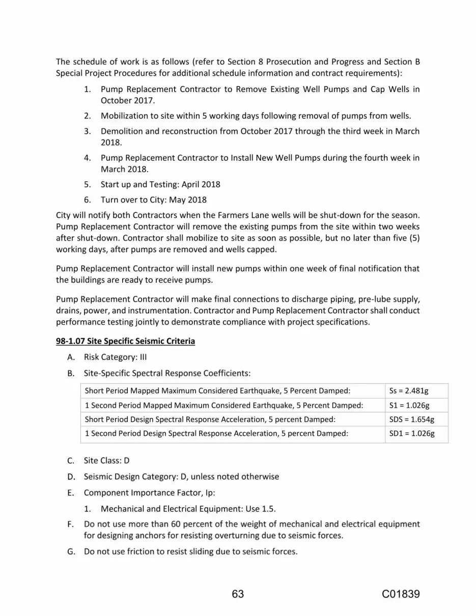
The schedule of work is as follows (refer to Section 8 Prosecution and Progress and Section B Special Project Procedures for additional schedule information and contract requirements):
1. Pump Replacement Contractor to Remove Existing Well Pumps and Cap Wells in October 2017.
2. Mobilization to site within 5 working days following removal of pumps from wells.
3. Demolition and reconstruction from October 2017 through the third week in March 2018.
4. Pump Replacement Contractor to Install New Well Pumps during the fourth week in March 2018.
5. Start up and Testing: April 2018
6. Turn over to City: May 2018
City will notify both Contractors when the Farmers Lane wells will be shut-down for the season. Pump Replacement Contractor will remove the existing pumps from the site within two weeks after shut-down. Contractor shall mobilize to site as soon as possible, but no later than five (5) working days, after pumps are removed and wells capped.
Pump Replacement Contractor will install new pumps within one week of final notification that the buildings are ready to receive pumps.
Pump Replacement Contractor will make final connections to discharge piping, pre-lube supply, drains, power, and instrumentation. Contractor and Pump Replacement Contractor shall conduct performance testing jointly to demonstrate compliance with project specifications.
98-1.07 Site Specific Seismic Criteria
Short Period Mapped Maximum Considered Earthquake, 5 Percent Damped: Ss = 2.481g
1 Second Period Mapped Maximum Considered Earthquake, 5 Percent Damped: S1 = 1.026g
Short Period Design Spectral Response Acceleration, 5 percent Damped: SDS = 1.654g
1 Second Period Design Spectral Response Acceleration, 5 percent Damped: SD1 = 1.026g
1. Mechanical and Electrical Equipment: Use 1.5.
63 C01839

98-1.08 Warranty
The manufacturer shall furnish the City with a written warranty to cover all equipment and materials provided under this Project against defects in workmanship and material for a period of one year and rotating parts for a period of a minimum of two (2) years under normal use and service from the date of acceptance of installation by the manufacturer’s representative. Warranty for the well pumps will be provided by others.
The manufacturer’s warranty shall be issued in the City’s name.
The Contractor shall, upon the receipt of notice in writing from the City, promptly make all repairs arising out of defective materials, workmanship, or equipment. The City is hereby authorized to make such repairs, and the Contractor and its Surety shall be liable for the cost thereof, if ten (10) days after giving of such notice to the Contractor, the Contractor has failed to make or undertake the repairs with due diligence. In case of emergency, where in the opinion of the City delay could cause serious loss or damage, repairs may be made without notice being sent to the Contractor, and the expense in connection therewith shall be charged to the Contractor, and its Surety shall be liable for the cost thereof.
For the purpose of this paragraph, acceptance of the Work or a portion of the Work by the City, shall not extinguish any covenant or agreement on the part of the Contractor to be performed or fulfilled under this Contract which has not, in fact, been performed or fulfilled at the time of such acceptance. All covenants and agreements shall continue to be binding on the Contractor until they have been fulfilled.
The City and the Contractor agree that warranty on the parts of the work possessed and used by the City in accordance with these Specifications, shall commence on the date that the City takes possession of such work and so notifies the Contractor in writing. The City and the Contractor further agree that such possession, and use of the work shall not be deemed as Substantial Completion or acceptance of any other part of the Work.
If, after installation, the operation or use of the materials or equipment furnished under this Contract proves to be unsatisfactory to the Engineer or City, the City shall have the right to operate and use such materials or equipment until it can, without damage to the City, be taken out of service for correction or replacement. Such period of use of the defective materials or equipment pending correction or replacement shall in no way decrease the guarantee period required for the acceptable corrected or replaced items of materials or equipment.
Nothing in this Section shall be construed to limit, relieve or release the Contractor's, subcontractor's and equipment supplier's liability to the City for damages sustained as the result of latent defects in the equipment furnished caused by the negligence of the supplier's agents, employees or subcontractors. Stated in another manner, the warranty contained in this Section shall not amount to nor shall it be deemed to be a waiver by the City of any rights or remedies (or time limits in which to enforce such rights or remedies) it may have against the supplier of the equipment to be furnished under these Specifications for defective workmanship or defective materials under the laws of this State pertaining to acts of negligence.
64 C01839

SECTION 99 WATER MAIN CONSTRUCTION
99-1 GENERAL:
All water mains and related appurtenances shall conform to Section 99 of the City Specifications and Standards, with the following modifications and additional requirements:
This section applies to both above-grade and below grade water pipes.
Contractor shall provide as-built information within a week of the final tie-in when vertical or horizontal field adjustments result in a deviation from the Project Plans or when elevations are not shown on the Project Plans. Recorded elevations shall be no greater than every 25 lineal feet of installed pipe. Recorded information shall be provided on a full set of Project Plans.
99-1.01 City General Water Construction Notes
1. For hot tap connections, the Contractor shall provide excavation, shoring, backfill and trench surfacing. Contractor shall provide and install the tapping valve sleeve and related hardware. City personnel will execute the actual hot tap. No hot tap will be allowed within four feet of a joint as measured from joint to centerline of intersecting pipe. In such circumstances, the joint shall be removed and the proposed hot tap shall be replaced with a cut-in tee. The Contractor shall coordinate and schedule the hot tap with the Engineer.
2. Water service taps up to 1 inch require 18 inch (min.) of spacing along main. For larger service taps the Contractor shall refer to the standard specifications for minimum spacing requirements.
3. Only City utility department personnel may operate valves on the existing water system. Required notification is 2 working days for residential and 3 working days for commercial.
4. Cut-in tees and final water main tie-ins shall be made under the inspection of City utility department personnel. It is the Contractor's responsibility to coordinate with the Engineer for utility department inspections. As locations and depths of existing water lines are approximate, Contractor shall provide all fittings required to establish horizontal and vertical alignment.
5. Water services not shown on the plans shall not be installed without the approval of the Engineer.
6. Water service markouts are approximate. The City assumes no responsibility for their accuracy or omission. The Contractor shall cautiously excavate until service is exposed or as directed by the Engineer.
7. The Contractor shall pothole all crossing utilities prior to trenching and shall gradually depress the water main to provide 6 inches vertical clearance under conflicting utilities "other than sewer" by deflecting joints and/or body of pipe per manufacturer's recommendations.
65 C01839

8. Where conflicts with existing underground facilities occur, the Contractor shall depress the new water main to maintain a minimum 12-inch clearance under, or 4 inches over the existing facilities unless otherwise shown on the plans, or as directed by the Engineer. When minimum cover cannot be maintained and depression is required to be 2 feet or more, drop water main per typical detail, City Standard 855.
9. There shall be no unmetered connections to the City of Santa Rosa water system, including connections for obtaining construction water. Unmetered connections will be severed by the City Utilities Department and will result in penalties including fines and payment of estimated water usage fees. City Utilities Department personnel will install a temporary 2-inch meter with check valve for construction water upon completion of application at MSCS, 69 Stony Circle, (707)543-4200.
10. Meter boxes shall be installed out of traffic loading areas wherever possible.
11. Leaded joints encountered in existing water mains to remain in service shall be removed by the Contractor under Utilities Department inspection.
12. All temporary blow-offs used for removing swabs during water main cleaning shall be constructed with an elbow and vertical stand pipe the same size to prevent trench water from flowing back into the main during swab removal. After swab removal, install mechanical joint cap on stand pipe. Cap stand pipe with Mega-Lugs to allow testing.
13. All water facilities shall be installed in compliance with the California separation criteria for water and sewer mains (City Water Standards Appendix A).
14. All branch connections from a tee or cross to a valve, or reducer and valve, shall be a flanged connection unless noted otherwise.
15. All pipe and appurtenances shown to be abandoned shall be abandoned in accordance with City standards.
16. All joints at horizontal and vertical bends shall be restrained.
99-1.02 Materials:
Where CL150 DR18 or CL200 DR14 PVC pipe is called for in these Special Provisions, on the Project Plans or in the City Standards, the Contractor shall instead use PC235 DR18 or PC305 DR14 respectively.
All materials used shall be lead free per California Health & Safety Code Section 116875.
Per U.S. et al., ex rel. Hendrix v. J-M Manufacturing Co., Inc., et al., Case No. ED CV-06-0055-GW (C.D. of CA), the City of Santa Rosa is not currently accepting PVC pipe manufactured by J-M Manufacturing Co. or JM Eagle for installation on City projects.
The Contractor shall use a single manufacturer for each of the following items supplied for this project unless otherwise approved by the Engineer:
1. Pipe
66 C01839

2. Fittings
3. Valves
The Contactor shall submit the installation location for any proposed use of flange fittings not already specified herein.
99-2 PRODUCTS
99-2.01 Pipe:
99-2.01A General: Any pipe that is delivered to the job site that exhibits, in the opinion of the Engineer, signs of contamination, damage and/or defect, will be rejected.
All ductile iron pipe systems buried underground shall be encased with 8 mil (minimum) polyethylene film in tube form. Polyethylene material and installation procedure for the encasement shall conform to ANSI/AWWA C105/A21.5-10 or most recent issue.
Tracer wire shall be installed on all water pipe and HDPE tubing unless otherwise specified. Tracer wire shall be 12 AWG solid copper wire with a blue type UF 60 mil insulation that is designed for use in the detection of underground utilities.
99-2.01B Ductile Iron Water Pipe: Ductile iron water pipe shall be Class 350 per AWWA C151 per City Standards.
99-2.02 Water Service Tubing
99-2.02A Copper Water Service Tubing: All copper service tubing shall be Mueller Streamline PlumbShield blue coated Type K soft temper tubing for 1-inch services and type K hard temper tubing for 1-1/2-inch & 2-inch services, or an approved equivalent.
99-2.02B High Density Polyethylene (HDPE) Water Service Tubing: All HDPE water service tubing shall be blue in color, and shall be copper tubing size (CTS) SDR9 tubing, and shall conform to both AWWA C901 and ASTM D2737and shall be either PE3608 - 200psi tubing or PE4710 - 250psi tubing.
If soil contamination is suspected during construction, the Contractor shall notify the Engineer prior to the installation of HDPE material. Use of HDPE material within or adjacent to areas of known contaminated soils is strictly prohibited.
99-2.03 Fittings: All fittings shall be ductile iron mechanical joint type unless otherwise specified.
Flanged fittings shall only be used on above ground installations or as shown on the Project Plans unless otherwise specified.
All non-stainless fasteners shall be coated with Permatex spray-on heavy duty rubberized under-coating or approved equivalent. All surfaces to be coated shall be dry prior to coating.
67 C01839

99-2.03A Restrained Joint Fittings: Mechanical joint type restrained fittings shall be installed on all joints of a water main tie-in, cross, tee and anywhere a fitting is required to make a bend in the alignment of the water main unless otherwise specified.
Because the tie-in at Well 4-2 is to a pipe that is believed to be asbestos cement, which would not accept a restrained joint fitting, provide unrestrained joint at the tie-in and provide thrust restraint at the flow meter vault, as shown on Project Plans. See Section 100 for specification.
99-2.04 Gate Valves:
Buried gate valves shall be mechanical joint type unless otherwise specified.
New gate valves that are to be installed by “cut-in” on an existing main shall be done by removing a section of the existing main, including any disturbed joints, and installing the required gate valve, pipe and couplings. Sections of pipe used shall be at least 18 inches in length.
When any part of the new water system is pressurized, all effective gate valves shall be accessible to City personnel at all times. Valves that require “valve stem risers” shall not be considered accessible unless the riser is in place.
Gate valves for above-grade service shall be flanged with outside stem and yoke. Provide with hand wheel actuator.
99-2.05 Valve Boxes: Valve box riser pipe shall be installed centered over and plumb with the valve stem nut prior to final paving. If the riser pipe needs to be lowered for paving it shall be cut by hand square and neat. If sections need to be added after paving it shall be done in accordance with City Standard 877. The riser pipe shall extend into the bottom of the valve box a minimum of 2 inches and the upper section shall be no shorter than 1-foot in length.
Valve stem risers shall be installed and inspected for operation prior to paving.
99-3 CONSTRUCTION
99-3.01 Excavation, Backfill, and Resurfacing: Excavation, backfill and resurfacing shall conform to all applicable City Specifications and Standards, and any modifications herein and/or on the Project Plans.
An air gap shall be in use at all times when dewatering to the sanitary sewer system.
Blasting shall not be permitted.
It is the Contractor’s responsibility to ensure that water system components are laid and bedded on sound, stable material. All existing material that has been disturbed must be removed from the trench prior to the installation of new bedding material. The Contractor shall promptly notify the Engineer of any field conditions that may affect alignment and/or grade.
All excavations shall be able to accommodate compaction and testing equipment and personnel required for backfilling. If, due to vertical and/or horizontal obstructions, typical methods cannot
68 C01839

be used, the Engineer may require the use of a pneumatic Pogo Stick/Powder Puff type compactor at no additional cost to the City.
All lateral services constructed under curb, gutter and driveway culverts shall be accomplished by use of a trenchless method approved by the Engineer, unless otherwise specified. Boring under sidewalks and/or concrete filled planter strips will not be allowed. Boreholes shall be only large enough to allow for the size of pipe to be installed. If the Contractor’s operations disturb the supporting soil, the Engineer may require the removal and replacement of any undermined sidewalk, curb, gutter or culvert; and/or the use of controlled density fill (CDF) backfill at the Contractor’s expense. The limits of curb and gutter replacement and any required dwelling will be at the discretion of the Engineer.
The Contractor shall remove and replace sidewalk and planter strips as required for all water work to the nearest transverse score mark on both sides and full sidewalk width. All areas of sidewalk removed for construction shall be backfilled and compacted level with temporary asphalt concrete or covered with 1 inch thick plywood, laid flat with ADA compliant temporary asphalt concrete taper on both ends.
All excavated material shall be removed from the job site by the end of each workday.
99-3.01A Trench Bracing and Shoring – Water: All bracing and shoring shall conform to Section 7-1.02K(6)(b) and Section 7-1.02K(6)(b)(1) of these Special Provisions, and Section 7-1.02K(6) of the Standard Specifications, and the Division of Industrial Safety Construction Safety Orders which are currently in use.
The Contractor shall take all necessary measures to protect the workers and adjacent areas and structures from the hazards of the trenching or excavation operations.
Trench sheeting or boxes shall be withdrawn in such a manner as to prevent caving at the walls of excavations or damage to piping or other structures. Sheeting shall be completely removed from the trench and no backfill shall be installed against the sheeting before it is removed.
99-3.02 Laying and Handling Pipe Materials: All pipe stockpiled on the job shall be stored with the ends covered to prevent the entrance of foreign matter. The Engineer may reject stockpiled pipe with exposed ends. Whenever pipe laying is not in progress, the open ends of installed pipe shall be closed water tight by mechanical plug, cap or other means approved by the Engineer.
If proper separation between new sanitary sewer lines and water mains, per the latest guidelines from the California State Water Resources Control Board cannot be maintained, the Contractor shall inform the Engineer immediately to get direction, unless direction has already been provided on the Project Plans or otherwise specified.
Where new mains cannot start on the same lines and grades as the existing main, restrained fittings shall be used to make grade and/or alignment transitions for tie-ins to existing mains. This does not eliminate the requirement for thrust blocking unless otherwise specified.
69 C01839

Proposed water main elevations may need to be adjusted in the field to allow for the required separation with sanitary sewer lines and other facilities. If water system components are proposed to be installed prior to sanitary sewer or storm drain components, the Contractor shall investigate for the possibility of conflicts or inadequate separation of facilities. The Contractor shall perform this investigation prior to water system installation and provide all relevant information in writing to the Engineer immediately upon discovery of any conflict.
If the Contractor installs a highpoint in the water system not shown on the Project Plans the Engineer may require the installation of a new combination air and vacuum valve, per City Standards, at no additional cost to the City.
99-3.03 Water Services: The Contractor shall install new water service laterals at the locations shown on the Project Plans, including removal and disposal of old meter boxes and removal, disposal and replacement of sidewalk, curb and gutter and/or landscaping. Typically, new service laterals shall be as close as possible to existing laterals. The Contractor shall coordinate with the Engineer for the exact location in the field prior to saw cutting or any concrete removal. New service laterals shall be installed with a minimum horizontal clearance of 5 feet from sewer laterals and 3 feet from gas laterals.
Water service tie-ins to existing building service lines of 3/4-inch or 1-inch in size shall be made with type "K" hard or soft temper copper or schedule 80 PVC tubing and shall match the size of the existing service line.
When connecting to any service line under 4 inches that has a backflow device, threaded brass or type "K" hard temper copper tubing shall be used. If the existing pipe between the meter and backflow device is found to be plastic the Contractor shall notify the Inspector and is directed to replace the existing pipe with threaded brass or type "K" hard temper copper.
When any existing service line being connected to is galvanized pipe, dielectric protection is required.
Bends and/or fittings shall not be permitted under the sidewalk, and all tie-ins to the existing service lines shall be made behind the sidewalk unless otherwise specified.
Submittals are required on all material used for water service tie-ins. Plastic or galvanized dresser type couplers will not be considered as acceptable material.
When connecting a 1-inch water service to a 5/8-inch x 3/4-inch meter the street side curb stop shall be a 1-inch x 3/4-inch angle meter ball valve (submittal required), and the meter box shall be per City Standard 863.
After the new water system is connected to the existing City system the Contractor shall purge the new service of air and sediment prior to transferring the meter.
The Contractor shall notify each customer before shutting down their existing service and transferring the meter and prior to turning their water back on after the transfer is complete. The Contractor shall also shut off any available property side valve after notifying but prior to
70 C01839

cutting into the existing service line. All meter transfers and service tie-ins shall be witnessed by the field Inspector, and it is the Contractor’s responsibility to coordinate this inspection.
Prior to activating the new service the Contractor shall open the property side valve and flush the new service for a minimum of 5 minutes and until the water is clear and free of all air and foreign matter.
The existing building service line to be connected to may be metal or plastic and may not be the same size as the new service. The Contractor shall provide couplings, connectors and fittings as necessary to complete the connection to the new water service at no additional cost to the City.
Where new services are connected to existing backflow devices the Contractor shall provide documentation that the backflow devices have been certified after installation. Certifications must be completed by a certified tester off the “City of Santa Rosa Approved List of Backflow Testers" herein. All necessary paperwork shall be completed by the Tester and one copy given to the property owner and one to the Engineer within 72 hours after connection.
Where a new water service is shown to be connected to an existing water main, the connection shall be made by hot tap. The Contractor shall coordinate the work and excavate and install all necessary materials, and City Forces shall tap the main. There shall be a minimum distance of 18 inches between all taps, whether new or existing, unless otherwise approved by the Engineer.
If the Contractor damages any new or existing water service during construction, they shall replace the service at their own expense from the corporation stop at the main to the water meter without splicing.
99-3.03A High Density Polyethylene (HDPE) Water Services: HDPE services shall be installed per applicable City Standard and any modifications herein and/or on the Project Plans. Any HDPE water service may be replaced with a copper water service if deemed necessary by the Engineer.
99-3.03B Copper Water Services: Copper water services shall be installed per applicable City Standards and any modification here in and/or on the Project Plans. All brass material and sections of copper tubing where the polyethylene coating is removed shall be wrapped with an approved waterproof pipe wrap. The wrap shall extend a minimum of 4 inches beyond any exposed brass or copper.
99-3.03C Backflow Device Installation: The Contractor shall coordinate their work to provide minimum out-of-service time to the customer.
All piping downstream of the backflow device shall be of the same material specified for between the meter and backflow device unless otherwise specified.
Only brass unions shall be installed unless otherwise approved by the Engineer.
New backflow devices and piping shall match the size of the new water service. When the existing building service line is galvanized iron, dielectric protection is required.
71 C01839

Where excavation for a new backflow prevention device occurs within the drip line of any street tree, the Contractor shall hand dig to protect tree roots, as directed by the Engineer.
After installation, the backflow prevention device must be certified. Certifications shall be completed by a certified tester off the Approved List of Backflow Contractors herein. All necessary paperwork shall be completed by the Tester and one copy given to the property owner and one to the City within 72 hours after connection to the existing building service line.
Submittals are required for all backflow device and related materials.
99-3.04 Thrust Blocking: Regardless of restrained joint installation, thrust blocks shall be installed behind all tees, when connecting to any existing line larger than 2”, and where restrained joints cannot be used or alone are deemed insufficient by the Engineer.
99-3.05 Cleaning, Flushing and Chlorination of the New Water System: Cleaning, flushing and chlorination of the new water system shall conform to all applicable City Specifications and Standards, and any modifications herein and/or on the Project Plans.
During the installation of new water main(s), the Contractor shall insert an appropriately sized flexible polyurethane foam sweeping or cleaning style swab (density: 2 lbs. cu. ft.) complete with polyurethane drive seal, into the beginning or ending of each pipe segment, (e.g. if a tee is installed as part of the new system, swabs shall be placed so both the “run” and “branch” segments are able to be swabbed). The swab shall remain there until the pipeline is completed. The Engineer may allow, at their discretion, segments of new main less than 80 feet in length to be cleaned by flushing only.
Cleaning and flushing shall be accomplished by propelling the swab down the pipeline to the exit point with an approved source of potable water. After removal of the swab(s) a unidirectional flush of the new system shall continue until the water is completely clear.
After swabbing is complete, all segments of main that were not swabbed, and every lateral, shall be flushed until free of air and debris.
Water used for flushing shall be considered contaminated after exiting the new system and shall not be allowed to reenter the new system. If, in the opinion of the Engineer, the new system becomes contaminated the Contractor shall be required to re-disinfect the system, all or in part, at no additional cost to the City.
After all lines have been cleaned and flushed, and the hydrostatic test is accepted by the Engineer, the Contractor shall disinfect the new water system components.
All equipment used for hydrostatic testing and chlorination must first be approved by the Engineer.
Liquid chlorine shall be applied as stated herein. The point of application of the chlorination agent shall be through a corporation stop or temporary blow off installed in the newly laid pipe at the beginning of the pipe extension, or at a valve location.
72 C01839

Water from the existing distribution system shall be used to fill the new mains at a slow controlled rate of flow during the application of chlorine; this rate of flow shall not exceed the limits of any installed air release valves. Precautions shall be taken to prevent back pressure causing a reversal of flow into the City’s water system. In the process of chlorinating, all valves and other appurtenances on the new pipe shall be operated in such a way to allow the chlorine mixture to be fully distributed to all parts of the new water system.
The rate of chlorine feed shall be in such proportion to the rate of water entering the pipe that the chlorine dose applied to the water entering the newly laid pipe shall be at least 100 ppm and not greater than 200 ppm. The chlorine solution shall be retained in the pipe for a period of 24 hours. After 24 hours, chlorine levels shall not be less than 50% of the initial dosage, if the chlorine level is less than 50% of the initial dosage, the above chlorine procedures shall be repeated. The chlorinated water shall then be discharged as stated herein under “Discharge of Chlorinated Water” and all new mains and laterals shall be given a final flush and then filled with water from the City’s distribution system.
24 hours after the final flush of chlorinated water, the chlorine residual shall be taken at locations determined by the Engineer. All locations shall have at least 0.5 ppm but not greater than 1 ppm prior to the taking of the initial bacteria samples.
The initial bacteria samples shall consist of 2 consecutive sets of acceptable sample results taken at least 24 hours apart from the same locations as stipulated by the California Water Works Standard Chapter 16, Article 5, Section 64580 “Disinfection of New or Repaired Mains.”
If bacteria tests indicate contamination, or if the sampling procedure is questioned by the Engineer, the chlorination procedure shall be repeated until confirmed tests show that the water sampled from the newly laid pipe conforms to the requirements specified herein.
Costs for the collection and analysis of the initial bacteria test samples will be paid for by the City. Samples shall be taken at a minimum; on each blow off of the new water system and on at least one water service between each of two blow-offs. The exact location and quantity of the samples will be determined in the field by the Engineer. There shall not be more than 1200 feet between sample points. If either of the initial bacteria tests fails at any sampling site, two consecutive passing bacteria tests must be obtained at that sampling site prior to making the tie-in.
The City will pay labor and analytical fees for collecting and analyzing up to 2 additional individual bacteria samples at each sampling site. If additional testing is required, the total costs of sampling and analysis will be deducted from the following progress payment. The Engineer may require a complete Title 22 potable water test at the Contractor's expense.
The initial bacteria tests are valid for 10 calendar days after the second set has been taken. All other individual bacteria tests are valid for 10 calendar days. If there is more than a 10 calendar day lapse between a bacteria test and the applicable tie-in, the bacteria test shall be repeated prior to performing the tie-in.
73 C01839

DISCHARGE OF CHLORINATED WATER Chlorinated water used to disinfect the new water system is the property of the Contractor and its disposal is the responsibility of the Contractor. Chlorinated water used to disinfect the new system shall be disposed of in accordance with all laws and regulations. Discharge to the storm drain system or a waterway is not permitted without a permit from the North Coast Regional Water Quality Control Board.
Discharges may be allowed to be disposed of into the sanitary sewer system, but must first meet the following requirements:
1. The City of Santa Rosa Subregional Reclamation Facility shall be notified by the Engineer in coordination with the Contractor, prior to the discharge being disposed of in the sanitary sewer system. The payment of any fees required will be the responsibility of the Contractor.
2. The pH of the water must be between 6.0 and 9.5.
3. The Contractor shall maintain an “air gap” from the discharge conduit to the receiving sewer facility with a minimum vertical distance of twice the diameter of the discharge conduit.
99-3.06 Water Main Connection Work: Upon completion of construction and testing of new water mains, services and appurtenances, final connection shall be made by the Contractor under City inspection.
The Contractor shall schedule all hot taps and system shutdowns regardless of the nature of work with the Engineer. Tie-ins will not be scheduled until the Engineer has received documentation of all required passing bacteria tests. The Contractor shall submit a separate written request to the Engineer to schedule each individual shutdown required to facilitate a tie-in or any other work where a shutdown may be necessary. The Contractor shall submit written shut down requests at least 2 working days and 3 working days in advance for residential and commercial shutdowns respectively. The City will attempt to facilitate shutdowns within these timeframes; however, extenuating circumstances may result in response times in excess of those mentioned above. Under such conditions, no claims related to work delays shall be considered. System shutdown scheduling shall also be subject to the limitations of Section 6-4.01B, “Water Utility Notification”, of these Special Provisions. All shutdowns and valve turning operations shall be performed by authorized City personnel only. Authorized City personnel must be present during any operation requiring a shutdown unless otherwise approved by the Engineer and provided to the Contractor in writing. Tie-ins shall not be performed without prior authorization by the Engineer.
Excavations for individual tie-ins and hot taps must be completed as much as possible without causing damage to new or existing facilities and plated a minimum of 1 working day in advance of the scheduled work. If this requirement is not met, the scheduled work will be cancelled. All materials for the proposed work shall be on site for inspection the morning of the scheduled work.
Contractors who fail to keep field appointments shall be billed for City personnel and equipment time used, and the Contractor shall bear the costs incurred by the City for notification of its customers for the subsequent appointment.
74 C01839

After notification by the Contractor for such a need, the City will contact commercial customers for service interruption needs and will inform the Contractor accordingly.
City crews work a 9/80 schedule; this schedule may prohibit hot taps and shutdowns on alternating Fridays.
Individual hot taps may be requested a minimum of 2 working days in advance, if the request is for multiple hot taps to be done on the same day the request shall be made a minimum of 5 working days in advance. The City will attempt to facilitate hot taps within these timeframes; however, extenuating circumstances may result in response times in excess of those mentioned herein. Under such conditions, no claims related to hot tap delays will be considered. Hot tap scheduling shall also be subject to the limitations of Section 6-4.01B, “Water Utility Notification”, of these Special Provisions.
Hot taps shall not be allowed within 4 feet of a joint unless first receiving approval from the Engineer.
During the work, the Contractor shall exercise all necessary precautions to prevent the entrance of trench water or any other foreign material into the water main and appurtenances and shall conduct all operations in accordance with the most stringent sanitation practices. The interior of all appurtenances being installed, as well as the outside of pipe that will come in contact with distribution water when the system is active, shall be thoroughly swabbed with a one to three percent liquid chlorine solution prior to installation.
Connections to cast iron, PVC, or ductile iron pipes shall be made with mechanical joint solid sleeves. When connecting to asbestos cement and/or “over-sized” cast iron pipe, “wide range” style couplings from Ford, Smith-Blair, Romac or an approved equivalent shall be used. Submittals are required for all couplings.
When connecting to an existing water main the Contractor shall install temporary and permanent thrust blocking, as necessary, for restraint and to allow for reenergizing of the water main immediately after all plumbing is complete.
When installing new components by “cut-in” to an existing PVC or ductile iron main, all new joints shall be mechanically restrained.
99-3.07 Construction Water: Construction water for the work under this contract will not be furnished by the City.
At no time shall water trucks or any other unapproved vessel be used in the application of loading newly laid water mains unless first approved of by the Engineer.
99-4 MEASUREMENT AND PAYMENT
99-4.01 Measurement
Percent complete will be determined from the approved Schedule of Values.
75 C01839

99-4.02 Payment:
Full compensation for conforming to the provisions of this section shall be considered as included in the lump sum prices paid for Underground Piping and Structures or Well Head and Piping, as appropriate, and no additional compensation will be allowed therefor.
76 C01839
SECTION 100 PUMP STATION EQUIPMENT
100-1 GENERAL
100-1.01 Scope:
The work covered by this section of the Specifications consist of furnishing all labor, equipment and materials and performing all operations in connection with the construction of the pump station equipment, complete in accordance with the Plans and as specified herein.
This section includes mechanical equipment required for the project, including check valves, special fittings, air valves, and special equipment, and coordination with well pumping equipment supplier.
Refer to Section 98 Summary of Work for additional information.
100-2 WELL PUMPS
100-2.01 General
Applies to a submersible turbine pump for use at Farmers Lane Well 4-1 and a lineshaft vertical turbine pump for use at Farmers Lane Well 4-2.
City has contracted separately for removal of the existing pumps from both wells prior to mobilization and installation of replacement pump once pump building construction is sufficiently advanced. Procurement documents for Well Pump Replacement Project are included in the Exhibits for Contractor reference and are not part of this Contract.
Contractor shall provide all materials shown on Project Plans and as specified, except those items specifically called out as by others. Contractor shall coordinate pump removal and replacement schedules, and system testing and startup schedules with Engineer and pump supplier.
Contractor shall provide anchor bolts to anchor the top plate to the well head, and anchor bolt sizing calculations based on information to be provided by the pump supplier.
Final electrical and mechanical connections to the replacement pumps will be by pump supplier.
100-3 MISCELLANEOUS EQUIPMENT
100-3.01 General
Provide additional equipment, fittings, valves, and appurtenances as described below.
100-3.02 Silent Check Valve
Valve shall be of the silent operating type that begins to close as the forward flow diminishes and fully closes at zero velocity preventing flow reversal and resultant water hammer.
Valves shall be certified to NSF/ANSI 61, Drinking Water System Components – Health Effects, and certified to be Lead-Free in accordance with NSF/ANSI 372.
Valves shall have Class 125 flat faced flanges in accordance with ASME B16.1.
77 C01839
The valve design shall incorporate a center guided, spring loaded disc and have a short linear stroke that generates a flow area equal to the nominal valve size.
All component parts shall be field replaceable without the need of special tools. Valve shall be provided with a replaceable guide bushing held in position by the spring. The spring shall be designed to withstand 100,000 cycles without failure and provide a cracking pressure of 0.5 psi.
Disc shall be concave to the flow direction providing for disc stabilization, maximum strength, and a minimum flow velocity to open the valve.
The valve disc and seat shall have a seating surface finish of 16 micro-inch or better to ensure positive seating at all pressures. The leakage rate shall not exceed the allowable rate for metal seated valves allowed by AWWA Standard C508.
Valve bodies shall be constructed of ASTM A126 Class B cast iron.
Seat and disc shall be ASTM B584 Alloy C83600 cast bronze or ASTM B148 Alloy C95200 aluminum bronze.
Compression spring shall be ASTM A313 Type 316 stainless steel with ground ends.
Valve interiors and exteriors shall be coated with an NSF/ANSI 61 certified fusion bonded epoxy in accordance with AWWA C550.
The valves shall be hydrostatically tested at 1.5 times their rated cold working pressure and seat tested at the valve cold working pressure.
Silent Check Valves shall be Series 1800 (Globe Style) as manufactured by Val-Matic® Valve & Mfg. Corporation, Elmhurst, IL USA or approved equal.
100-3.03 Air Valves
100-3.03A Air Release Valve
Air release valves shall be of the simple lever type, 1/2-inch inlet and outlet unless otherwise shown, designed to have a small 3/32-inch venting orifice to vent the accumulation of air and other gases that may occur within a pipeline while the pump is operating. In closed position valve to seat against resilient seat to prevent water leakage. Body and cover, cast or ductile iron; float and trim, stainless steel; seat, Viton or Buna-N. Provide return vent pipe turned 180 degrees downward and discharging to floor drain. Isolation valves shall be provided below each air valve.
Manufacturers and Products: APCO, Model 142; Val Matic, Model 22; or approved equal.
100-3.03B Air/Vacuum Valve
Air/Vacuum valve shall be single-body construction.
Air/vacuum valves shall have a large venting orifice to permit the release of air as the well casing is filling or relieve the vacuum as the well casing is draining or is under negative pressure.
78 C01839

Valve shall have a one-inch inlet and outlet unless otherwise shown.
Materials: Body and cover shall be cast or ductile iron; float and trim shall be stainless steel; seat shall be Viton or Buna-N.
Provide return vent pipe turned 180 degrees downward. Isolation valves shall be provided below each air valve.
Valve shall be APCO Series 140/150; Val Matic Series 100; or approved equal.
100-3.03C Combination Air Valve
Combination air valve shall be single-body construction.
Combination air valves shall have a small venting orifice to vent the accumulation of air and other gases with the line or system under pressure and shall have a large venting orifice to permit the release of air as the line is filling or relieve the vacuum as the line is draining or is under negative pressure.
Valve shall have a one-inch inlet and outlet unless otherwise shown and designed to have a small 3/32-inch venting orifice.
Materials: Body and cover shall be cast or ductile iron; float and trim shall be stainless steel; seat shall be Viton or Buna-N.
Provide return vent pipe turned 180 degrees downward. Isolation valves shall be provided below each air valve.
Valve shall be APCO Series 140/150; Val Matic Series 201C; or approved equal.
100-3.04 Expansion Joint
Expansion joint shall be Cablesphere by Metraflex, or approved equal. Provide with stainless steel cables.
100-3.05 Restrained Flanged Coupling Adapters
Restrained flanged coupling adapters shall be Series 2100 MEGAFLANGE by EBAA Iron, Romac RFCA, or approved equal.
100-3.06 Unrestrained Flanged Coupling Adapters
Unrestrained flanged coupling adapter for connection to existing asbestos cement pipe shall be Romac FCA 501, or approved equal.
100-3.07 Flexible Couplings
Flexible couplings for cast or ductile iron pipe and equivalent sizes shall be Rockwell (Smith-Blair) Series 411, Dresser Style 38, or equal. Sleeves shall be 10 inches minimum length and have a fusion bonded coating suitable for potable water. All coupling gaskets shall be synthetic rubber suitable for potable water.
79 C01839

Tie rods shall be provided in accordance with AWWA M11 Design Manual, Figures 19.15 and 19.16, and Tables 19.7 and 19.8. Thrust protection shall be for 1-1/2 times the specified test pressure for the pipe.
100-3.08 Pipe Boot
Pipe boots shall be equal to #7 size (14-inch square base) by Master Flash, or approved equal.
100-3.09 Pressure Taps, Gauges, and Pump Lubrication Items
Pressure gauge shall be four-inch diameter, 1.5 percent accuracy, full scale, and suitable for bottom stem mounting. Pressure gauge scales shall be 0 to 50 psi range.
Gauges shall have a Type 316 stainless steel Bourdon tube. All gages shall have a 300 stainless steel case, shatterproof glass, and a 1/2 inch NPT bottom connection.
Gauges shall be Ashcroft Duragauge Fig. 1279, Ametek 1981L, or approved equal. Supply with 1/2-inch brass gauge cock. Gage cocks shall be Robertshaw 1303, Ashcroft 1095, or approved equal.
Protect the exposed threads of each gauge cock by a brass plug. Snubbers or orifices shall not be utilized.
Provide solenoid valve for the water lubrication line.
Provide flow regulator valve. Valve shall deliver a constant a volume of water flow over a wide pressure drop range. The constant flow of water shall be maintained by the use of a flexible orifice. The flow rate shall be maintained ±15% between 15 and 125 psi. Valve shall be nickel plated brass as manufactured GE Infrastructure.
100-3.10 Insulating Dielectric Unions and Flanges
Provide between ferrous and nonferrous piping and where otherwise required for electrically insulated connection, as shown.
Materials galvanically compatible with piping to which attached and pressure ratings suitable for system working pressures.
Unions 2 Inches and Smaller: Screwed or solder-joint type.
Unions 2 1/2 inches and Larger: Flanged type, complete with bolt insulators, dielectric gasket, bolts, and nuts.
100-3.11 Pipe Hangers and Supports
Horizontal Piping: Support with adjustable swivel-ring, split-ring, or clevis type hangers, as manufactured by Grinnell, B Line, or approved equal.
80 C01839

Vertical Piping: Support by channels and pipe clamps on ten-foot maximum centers, as manufactured by Unistrut, Super Strut. Isolate copper, and plastic piping from channels and pipe clamps with pipe isolators.
100-4 EXECUTION
100-4.01 Installation
Install equipment in strict conformance with manufacturer’s instructions and as shown on the Project Plans.
100-4.02 Testing
100-4.02A General
The objective of the testing program is to demonstrate, to the Owner’s complete satisfaction, that the systems and equipment provided under this Contract meet the specified performance requirements.
Testing program also provides a base-line operating condition for the Owner to use in a preventative maintenance program.
Testing sequence consists of Pre-Operational Checkout, Functional Tests, Performance Testing and Operational Testing. These tests are required regardless of whether Factory Tests were conducted on the same piece of equipment or system.
Each item of mechanical, electrical, and instrumentation equipment installed under this Contract shall be tested by the Contractor to demonstrate compliance with the performance requirements of this project.
Contractor shall provide labor, outside services, materials, test equipment and other items required to complete the specified testing and startup requirements. Furnish power, water, chemicals, fuel, oil, grease and other materials needed to conduct the specified tests, unless excluded by other section of this specification.
Contractor shall install temporary valves, gauges, piping and other materials required to conduct the specified tests.
In coordination with the Pump Replacement Contractor, prepare a testing schedule setting forth the sequence contemplated for performing the test work. Identify the contemplated start date, duration of the test and completion of each test.
Test results shall be within the tolerances set forth in the detailed specification sections of the Contract Documents. If no tolerances have been specified, test results shall conform to tolerances established by recognized industry practice and/or manufacturer recommendations.
100-4.02B Pre-Operational Checkout
Pre-Operational Checkout shall be undertaken by the Manufacturer’s Representative, or equipment supplier if authorized by manufacturer.
81 C01839
Pre-Operational Checkout includes basic checks of the equipment installation prior to starting the equipment to determine if the equipment and related components have been correctly installed and is ready for starting.
Pre-Operational Checkout includes the following:
a. Alignment of equipment, shafts and shaft couplings, drives, belts and pulleys.
b. Filling and checking lubrication reservoirs.
c. Checking shaft seals, packing and seal lubrication system.
d. Manufacturer’s recommendations for pre-start preparation.
e. Proper motor rotation
f. Circuit continuity testing, electrical testing, and instrumentation and control system testing in accordance with the requirements of Division 16.
g. Demonstrate operational controls function as intended.
h. Calibration and adjustment of electrical and instrumentation devices.
Verify tanks, pipes, conduits, vessels and equipment are clean and free of debris that may interfere with the testing or operation of the equipment. Remove debris prior to start of testing.
Following completion of the Pre-Operational Checkout, the Manufacturer’s Representative shall complete and sign a field certification form and submit to the Owner.
100-4.02C Functional Tests
After successful completion of the Pre-Operational Checkout, start individual items of equipment and systems and operate under simulated operating conditions to determine as nearly as possible whether the equipment and systems meet the requirements of these specifications.
Operate the equipment for a sufficient period of time to determine machine operating and characteristics, including noise, temperatures and vibration; to observe and document performance characteristics; and to permit initial adjustment of operating controls.
Obtain baseline operating data on all equipment with motors greater than 10 horsepower to include amperage draw, bearing temperatures, and vibration as required. This baseline data will be collected for the Owner to enter in their preventive maintenance system.
Post-Test Inspection: When Functional Tests have been completed, recheck equipment for proper alignment, unacceptably loose connections, unusual movement, or other indications of improper operating characteristics. Correct any deficiencies to the satisfaction of the Engineer.
Machines or devices which exhibit unusual or unacceptable operating characteristics shall be disassembled and inspected. Repair any defects found during the course of the inspection and identify and correct the cause of such defect. Replace specific parts, or the entire equipment item, to the complete satisfaction of the Engineer at no cost to the Owner.
82 C01839

100-4.02D Operational and Performance Tests
After successfully completing functional tests, conduct an operational test of each system to verify correct operation. During the operational test, conduct performance testing to verify that the system complies with the performance requirements contained in the individual equipment specifications.
Operate all parts of each system for a continuous, uninterrupted period of not less than 8 hours. During this period, the Contractor and shall undertake performance testing and shall monitor the characteristics of each machine according to manufacturer information and specifications and report any unusual conditions to the Engineer.
Undertake performance tests of mechanical, electrical, and instrumentation equipment and systems to demonstrate and confirm compliance with the performance requirements specified in the individual equipment specifications.
Should the operational testing be halted for any reason related to the facilities constructed or the equipment furnished under this Contract, the operational testing program shall be repeated until the specified continuous period has been accomplished without interruption.
Following successful completion of the Operational Test, commissioning of the system may begin.
100-4.02D(1) Pump Field Tests
Conduct field performance tests to demonstrate that pump operation and controls meet the requirements required in the above specifications. Coordinate testing with Pump Replacement Contractor.
The following field testing shall be conducted:
1. Startup, check, and operate the pump system over its allowable speed range.
a. The pump and motor shall be tested at full speed.
b. Vibration shall be within the amplitude limits recommended by the Hydraulic Institute Standards.
2. Obtain concurrent readings of motor voltage, amperage, depth to water, and pump discharge head for at least 2 pumping conditions at full speed. Check each power lead to the motor for proper current balance.
Pump field testing will be witnessed by the Engineer. The Contractor shall furnish 3 days advance notice of field testing.
In the event any pumping system fails to meet the indicated requirements, the pump shall be modified or replaced and re-tested as above until it satisfies the requirements.
The Contractor shall be responsible for all costs of field tests, including related services of the manufacturer's representative, except for power and water, which the City will bear.
83 C01839

Test complete assemblies for correct rotation, proper alignment and connection, and quiet operation.
Retesting: If any portion of the work should fail to fulfill the Contract requirements and is adjusted, altered, renewed, or replaced, tests on that portion, together with all other portions of the work as are affected thereby, shall be repeated within reasonable time and in accordance with the specified conditions.
100-4.02E Commissioning Period
After completion of the Operational Test, the Contractor shall remove all temporary piping, controls and other alterations to the permanent systems that may have been needed during the facility testing and shall perform the tasks necessary to make the improvements constructed under this contract fully operational.
The commissioning period system shall be continuous period of 14 days. Should the commissioning period be interrupted at any time due to the Contractor's work, the commissioning period shall be restarted from the beginning of the full 14-day period. No additional compensation will be provided.
During the commissioning period, the City shall be responsible for normal operational costs and the Contractor shall bear the costs of necessary repairs or replacements, including labor and materials, required to keep the facility operational.
The Contractor shall be available at all times during commissioning periods to provide immediate assistance in case of trouble or failure of any portion of the facility. The commissioning period shall be considered ended when all corrections required by the Engineer to assure a reliable and completely operational facility are complete. The completion of the commissioning period is required prior to final acceptance.
100-5 MEASUREMENT AND PAYMENT
100-5.01 Measurement
Percent complete will be determined from the approved Schedule of Values.
100-5.02 Payment
Full compensation for Pump Station Equipment is considered as included in the lump sum prices paid for Well Head and Piping, or Mechanical and System Testing, as appropriate, and no additional allowance will be made therefor.
84 C01839

SECTION 101 PAINT & COATINGS
101-1 GENERAL
101-1.01 Scope:
The work covered by this section consists of furnishing all materials, equipment, appliances, and labor and performing all operations in connection with coating, recoating, overcoating and touch-up coating on all piping, fittings, bracing, carpentry, structural steel, buildings, building accessories and other items requiring coatings; related preparation and finish work, and; cleanup as specified herein and as shown on the Plans.
Damage to coatings due to welding or cutting operations associated with other items of work under this contract, shall be fully repaired from bare metal.
All coating materials shall be stored in a safe, secure, and environmentally responsible manner and shall be kept above manufacturer’s minimum storage temperature or 35 degrees Fahrenheit, whichever is higher, at all times. Coating materials that are found or suspected to have dropped below this temperature shall not be used to fulfill the requirements of this Contract. All empty or discarded coating containers or other surface preparation or coating debris / waste / garbage shall be stored in a covered, watertight dumpster or equivalent container immediately after being generated and shall be disposed of legally. In general, the jobsite shall be maintained free of coating related refuse at all times.
101-1.02 General: This section includes the coating and finishing of all surfaces of work in the Contract as specified and as shown on the Plans.
Colors used shall be selected by the City from the manufacturer’s standard and custom color charts.
The following items shall not be coated:
1. Stainless Steel
2. Aluminum
3. Electrical Control Panels*
4. Buried Pipe
5. Name Plates & Glass Items
6. Grates and Grate Frames
7. Concrete (except as specifically noted herein)
8. Kynar (or similar) factory coated roofing materials
*Electrical and control panels shall be required to have a shop applied epoxy coating suitable for outdoor installation with a color approved by the Engineer or as specified herein elsewhere.
Before start of work the Contractor shall submit to the Engineer the name and manufacturer of coating materials including material descriptions and literature giving instructions for application and suitability of coating materials for the intended use.
85 C01839

Contractor shall apply coatings only when weather conditions are favorable in regards to air temperature and humidity and substrate temperature as per manufacturer's application instructions. At all times coating is in progress, Contractor shall have a psychrometer, satisfactory to the Engineer, available on the job for measuring relative humidity and dew point. Contractor shall also have on site a method to convert temperature readings and variance to dew point such as the US Weather Bureau Psychrometric Tables. A means to measure the temperature of the surface is also necessary.
Coating materials shall be properly stored in accordance with manufacturer's instructions and protected from moisture, direct sunlight and extreme temperature.
Coating material containers shall have labels bearing manufacturer's name, name and type of material, and color name and number. In addition, thinning instructions and application instructions shall be available at the job site.
Coating shall be done at such times that dust-free and neat work can be obtained. All coating shall be done strictly in accordance with the manufacturer's instructions and in a neat workmanlike manner. All surfaces not being coated shall be protected from over-spray, drip and splatter by covering or masking. All drip and spatter marks shall be immediately cleaned from adjacent surfaces to the satisfaction of the Engineer. Contractor shall take care in preventing off-site over-spray as there are numerous private residences adjacent to portions of the work areas. All costs associated with any damage claims by third parties shall be borne by the Contractor.
Except where factory application of finish coatings is permitted elsewhere in these Specifications, all items of equipment shall be finish-coated after installation. Shop priming will be permitted in all cases. Materials and applications as specified herein shall govern regardless of whether coatings are factory-applied or field-applied. After installation, any damaged areas in prime or finish coatings shall be repaired as directed by the Engineer.
101-2 SURFACE PREPARATION:
101-2.01 General: All surfaces to be coated shall be prepared in a workmanlike manner with the objective of obtaining a clean and dry surface. No coating shall be applied before the prepared surfaces are inspected by the Engineer. On the first day of any coating, the Contractor shall establish with the inspector a schedule so that all surface preparation may be inspected and approved prior to application of any coating, for the duration of the project.
Surface preparation of steel items shall conform with specifications set forth in the Society for Protective Coatings "SSPC Painting Manual, Volume 2, 2005 Edition", or as specified by the Engineer.
Surface preparation shall be based upon comparison with: "Pictorial Surface Preparation Standards for Painting Steel Structures" (SSPC-Vis 1), "NACE" Standard TM-01-70, or as described below. Anchor profile for prepared surfaces shall be measured by use of a non-destructive instrument such as a Keane-Tator Surface Profile Comparator, Testex Press-O-Film System or Clemtox Anchor Pattern Comparator.
86 C01839

To facilitate inspection, the Contractor shall on the first day of abrasive blast cleaning operations, blast clean a set of metal panels to the standard specified. These panels shall be equivalent to the plate stock which is to be coated and shall have minimum measurement of 8-1/2 inches by 11 inches (216 mm x 280 mm). After agreeing that a specific panel meets the requirements of the specification, it shall be initialed by the Contractor and Engineer and coated with a clear non-changing finish. Panels shall be utilized for inspection purposes throughout the duration of blast cleaning operation.
All surfaces to be coated shall be prepared in strict conformance with the coating manufacturer's surface preparation requirements. The Contractor shall submit the surface preparation proposed and product data sheets containing the manufacturer's surface preparation requirements.
Building structural steel shall receive an abrasive blast in accordance with SSPC-SP-6, commercial blast condition.
The Contractor shall keep particulates, overspray, and odors below levels that are detectable to the Engineer or general public at the perimeter of the jobsite. This includes keeping overspray below detectable levels on adjacent houses and cars traveling or parked on adjacent streets. The Contractor shall be solely responsible for any claims arising from lack of sufficient containment.
All ferrous metal to be primed in the shop shall have all rust, dust, and scale, as well as all other foreign substances removed by sandblasting (SSPC-SP-10 Near White Blast) or pickling. Cleaned metal shall be primed with specified primer immediately after cleaning to prevent new rusting. All ferrous metals not primed in the shop shall have all sharp edges, burrs, and weld spatter ground smooth and shall be sandblasted or otherwise cleaned in the field (as approved by the Engineer) prior to application of the primer.
All exposed bituminous coated metal shall receive an abrasive blast (SSPC-SP-6 Commercial Blast) to remove all existing bituminous coating. Provide a minimum anchor pattern of 1.5 mils. It is not the intent to remove the annealing. Trace amounts of bituminous coating (not a film) may remain in the pores of the metal. The first two (2) new coats shall be roller applied or if spray applied, shall be immediately backrolled. (Bituminous coatings may be encountered on piping.)
All nonferrous metals, whether to be shop or field primed, shall be solvent cleaned prior to the application of the pretreatment and/or primer. In addition, galvanized surfaces intended for immersion duty shall be sandblasted to provide a profile of 1.5 to 2.0 mils. Galvanized surfaces for exterior exposure shall be prepared in the same manner or by SSPC-SP2 and/or SP3 to remove insoluble contaminants such as white and/or red rust, then chemically treated as recommended by coating manufacturer. Careful attention will be given to prevent blasting through galvanizing. If damaged, galvanized surfaces will have to be repaired in a manner to achieve a smooth transition between the existing substrate to the new galvanized surface.
Epoxy coated steel pipe and fittings shall be brush-off blasted per SSPC-SP-7/NACE 4 Commercial Blast Cleaning or scarified to provide tooth for coating adhesion. If the epoxy coating is to be brush off blasted or scarified in the field, the Contractor shall follow the procedures set forth by the coating supplier. The written procedure provided by the coating supplier shall be submitted
87 C01839

to the Engineer. In the event that the underlying epoxy coating is thinned to below the minimum allowable thickness specified in these specifications by the surface preparation procedures, the pipe or fitting shall be fully recoated with epoxy at the Contractor's expense. Field repairs or spot patching shall not be allowed.
All shop blasting, shop priming and shop coating shall be made available to be witnessed and inspected by the Engineer or his Inspector. Contractor shall notify Engineer 14 days in advance of shop blasting, shop priming and shop coating and make the work available for inspection.
The Contractor's shop blasting, shop priming and shop coating equipment shall be designed for application of materials specified and shall be maintained in first class working condition. Compressors shall have suitable traps and filters to remove water and oils from air. The contractor shall insure that the shop blasting, shop priming and shop coating equipment has been purged of water, oils, solvents and undesirable coating materials by discharging pressurized air into a white cloth prior to the addition of coating into the spray coating equipment. The contractor shall notify the Engineer with 24 hours advance notice when a “clean air” test is to be performed.
Surfaces not intended to be coated shall be adequately protected from the effects of cleaning and coating. Any such surfaces which have been damaged by the Contractor shall be repaired or replaced to the condition which existed prior to the damage, all at the Contractor's expense.
In case of questions concerning the quality of the blast cleaning provided, SSPC blasting standards for visual comparison (SSPC-Vis 1) and corresponding definitions shall be consulted. The Engineer shall be sole judge as to whether the quality of blast cleaning conforms to visual comparison standards, and his decision as to any allowable deviation there from shall be final.
Slag, weld accumulations and spatters shall be removed by chipping and grinding. All sharp edges shall be peened, ground smooth, or otherwise blunted. All weld repairs will be made and approved by the Engineer prior to any coating application.
The Contractor shall keep the area of his work in a clean condition and shall not permit blasting materials to accumulate as to institute a nuisance or hazard to the performance of the work or the operation of the existing facilities. Blast materials should be disposed of daily and kept separate from other debris. Abrasive blast waste materials containing hazardous substances shall be kept in sealed containers on site until they can be picked up and removed by a licensed transporter.
No coating shall be applied over a damp or moist surface. All surfaces with condensation or other moisture shall be blown or wiped dry. If rust is present, all surfaces shall be re-blasted per specification. Climatic conditions and surface conditions shall be measured, recorded and approved by the Engineer prior to the application of any coatings.
101-2.02 Coating Touch-Up Surface Preparation: Abrasive blast cleaning (SSPC–SP-7) for the exterior (non-wetted) surfaces requiring minor touch-up shall remove all loose or poorly adhering coatings and provide an adequately scarified surface for touch-up coating. Where coatings are removed to bare metal, the surface shall receive a Commercial Blast Cleaning (SSPC-SP-6). Approximately 4-inches of the existing coatings adjacent to the bare metal patches shall
88 C01839

be tapered and feathered by abrasive blast or mechanical methods. Where zinc based materials are used, overcoating will not be allowed. In order to avoid overcoating, the contractor will either brush apply touch up materials or use spray equipment with spray pattern controls adjusted to avoid overcoating any areas or exceeding maximum DFT. Due care shall be taken to avoid visual accentuation of repaired areas.
101-3 COATINGS:
101-3.01 General: All metal surfaces, excluding those materials listed in Section 101-1.02, shall be coated. In no case shall metal be left uncoated, even though not specifically defined herein. Concrete and masonry surfaces shall only be coated as specified herein. Coating operations on water tank exteriors shall be contained to prevent overspray from traveling offsite and onto neighboring properties or streets.
Without limiting the general aspects and other requirements of these Specifications, all surface preparation and coating of surfaces shall conform to the applicable requirements of the National Association of Corrosion Engineers (NACE), the Society for Protective Coatings (SSPC), and the Manufacturer's printed instructions. The Engineer's decision shall be final as to interpretation and/or conflict between any of the reference Specifications and Standards contained herein.
The Contractor shall hold a valid State Contractor's C-33 License for performing surface preparation and coating work.
The Contractor shall provide and require use of protective life saving equipment for persons working in or about the project site in accordance with requirements set forth by regulatory agencies applicable to the construction industry and manufacturers printed instructions and appropriate technical bulletins and manuals. The Contractor shall furnish, maintain and remove prior to departing the job site, a compressor and/or compressed air bottles capable of providing NIOSH-approved Class D breathing air for use at the work site.
All work shall be performed by skilled craftsmen qualified to perform the required work in a manner comparable with the best standards of practice. Continuity of personnel shall be maintained and transfers of key personnel shall be coordinated with the Engineer.
Refer to Section 101-2.01 regarding overspray and odor containment.
101-3.02 Materials:
101-3.02(1) General:
All coatings, primers, and paint products shall be as manufactured by Tnemec, Devoe, Kelly Moore, or approved equivalent, and shall be the system recommended by the manufacturer for the type and exposure of the surface to be coated and that meets the requirements of the performance criteria and systems specified herein. No request for substitution will be considered which decreases the film thickness designated and/or the number of coats specified. Requests for substitution shall contain the full name of each product, descriptive literature, including directions for use, its generic type, performance data and its nonvolatile content by volume. Coating systems that meet the specified performance criteria will be acceptable upon approval
89 C01839

by the Engineer. Only integral systems of the same manufacturer shall be used and no deviations will be permitted.
Where thinning is necessary only the products of the manufacturer furnishing the coating, and for the particular purpose, shall be allowed and all such thinning shall be done strictly in accordance with the manufacturer's instructions.
Coating materials specified herein are those which have been evaluated for the specific service. Specific products have been listed to establish a standard of quality. Equivalent coating systems by other manufacturers will be acceptable upon approval by the Engineer.
All material shall be brought to the job site in the original sealed containers. They shall not be used until the Engineer has inspected their contents and obtained data from information on containers or labels. Materials exceeding storage life recommended by the manufacturer, or one year (whichever is shorter) shall be rejected. Materials shall be mixed as full kits.
All coatings shall be stored in enclosed structures and according to manufacturer’s recommendations to protect them from weather and excessive heat or cold. Flammable coatings shall be stored in conformance with County, State and/or Local Codes for flammable materials. All materials shall have a batch number and date of manufacture on each container. Coatings in excess of one year old will not be allowed.
Material Safety Data Sheets for all coating materials shall be submitted at least thirty (30) days prior to start of coating operations.
101-3.03 Coatings for Buildings:
101.3.03(1) General:
Coating systems for the buildings shall be as specified herein below, or in cases where the specified coating material may have been superseded by the manufacturer, consult with the manufacturer and use their current equivalent product. All surface preparations and coating applications shall be completed in accordance with the manufacturer’s written instructions.
101-3.04 Coating System – Interior Concrete Sealant System: Sealant system shall be used on all interior concrete including floors, pedestals, housekeeping pads, etc. Sealing system: as follows:
• Kelly-Moore RUST-OLEUM Concrete Saver, 6000 System Epoxy, Color: Clear (6010) or approved equivalent.
Contractor shall determine compatibility of concrete curing compound with this product prior to pouring concrete to ensure that the final coating appearance is uniform.
101-3.05 Coating System – Interior Masonry Walls: Pump building interior masonry walls shall be coated prior to the installation of any equipment. Coating system: as follows:
Primer: Kelly-Moore Chem-Guard Acrylic Masonry Primer / 247-100 (white) – 2.0 mils DFT or approved equivalent.
90 C01839

Intermediate/Finish Coat: Kelly-Moore Acry-Plex Latex Semi-Gloss Enamel 1650-14 (Frost) – Two coats, 2.0 mils DFT, each coat or approved equivalent.
Total DFT – 6.0 mils DFT
101-3.06 Other Coating Systems: Coatings applied to all other items not specified elsewhere herein shall meet the requirements of the following paint schedule. In some cases the coating specified may have been superseded by the manufacturer, consult with the manufacturer and use their current equivalent product:
SURFACE TYPE NO. OF
COATS
TRADE NAME(c) COVERAGE FT2/GAL.
DFT PER COAT INTERNATIONAL TNEMEC
Wood and Wallboard
Acrylic 3 Intercryl Series 6 275 2.5
Unprimed Metal
Epoxy
Acrylic
1
2
Intercure 420
Intercryl 520
N27L9503
Series 29
265
340
4.0
1.75
Immersed Metal(a)
Epoxy 2 Interseal 670HS Series 69 180 5.0
Galvanized Metal
Epoxy
Acrylic
1
2
Intercure 420
Intercryl 520
N27L9503
Series 29
265
340
4.0
1.75
Shop Primed Metal
Acrylic 2 Intercryl 520 Series 29 340 1.75
Fusion-Bonded Epoxy Coated Metal
Acrylic 1 Interthane 990HS Series 75 225-380 3.0-5.0
Immersed Bituminous Coated Metal(b)
Epoxy
Epoxy
Epoxy
1
1
1
Interseal 670HS
Interseal 850 White
Interline 850 Gray
Series 69-WH01
Series 61-5002
Series 61-5001
175-275
210-335
215-335
4.0-6.0
4.0-6.0
4.0-6.0
Bituminous Coated Metal(b)
Epoxy
Epoxy
Acrylic
1
1
1
Interseal 670
Interseal 670
Interthane 990HS
Series 69-WH01
Series 69-IN01
Series 75
175-280
175-280
225-380
4.0-6.0
4.0-6.0
3.0-5.0 (a) The prime coat should be Series 69 or Interseal 670HS or approved equivalent. Shop applied primers may
not be compatible with Series 69 or Interseal 670HS or approved equivalent. (b) Surface Preparation: Abrasive blast to remove all existing bituminous coating. Provide a minimum anchor pattern
of 1.5 mils. It is not the intent to remove the annealing. Trace amounts of bituminous coating (not a film) may remain in the pores of the metal. First two (2) coats shall be roller applied or if spray applied, shall be immediately backrolled.
(c) Or approved equivalent.
101-3.07 Coating Colors: The Contractor shall submit color samples for approval by the City from a selection of manufacturer’s color chart samples submitted to the Engineer at least thirty (30) days prior to start of operations.
91 C01839

101-4 COATING APPLICATION:
101-4.01 General: The Contractor shall apply each coat of paint at the rate specified by the manufacturer to achieve the minimum dry mil thickness required. If material has thickened and must be diluted, the coating shall be built up to the same film thickness achieved with undiluted material. In other words, one gallon of coating as originally furnished by the manufacturer must not cover a greater square foot area than when applied unthinned. Deficiencies in film thickness shall be corrected by the application of one or more additional coats of paint. Total DFT exceeding the NSF approved coating thickness of tank interior applied coatings shall be removed and reapplied at the Contractor’s expense. On porous surfaces, it shall be the Contractor's responsibility to achieve a uniform, protective finish free of imperfections either by decreasing the coverage rate or by applying additional coats of paint.
Drying time shall be construed to mean "under normal conditions" or as specified by the manufacturer. Where conditions are other than normal because of cold weather or because coating must be done in confined spaces, longer drying times will be necessary. Additional coats of paint shall not be applied, nor shall units be returned to service until coatings are thoroughly dry. See discussion of dehumidification and environmental monitoring requirements found elsewhere in these special provisions.
Each succeeding coat of paint shall have a slightly different color to readily distinguish between coats.
Coatings shall not be applied in extreme heat or cold; in dusty or smoke-laden air; windy, foggy, damp, or humid weather. During damp weather, when the temperature of the surface to be coated is within 10°F of the dew point, the surfaces shall be heated to prevent moisture condensation thereon.
During painting, and for a period of at least 8 hours after the paint has been applied, the temperature of the surfaces to be painted, the painted surfaces, and the atmosphere in contact shall be maintained at or above 50°F and not less than 10°F above the dew point.
Fans or heaters shall be used inside enclosed areas where conditions causing condensation are severe.
Paint shall not be applied on surfaces hotter than 120°F.
Particular care must be taken to obtain a uniform, unbroken coating over all bolts, threads, nuts, welds, edges, and corners.
If coating is applied by spray, the air and/or fluid pressure used shall be within the ranges recommended by the coating and spray equipment manufacturers.
Spray coating shall be conducted under controlled conditions, and the Contractor shall be fully responsible for any damage occurring from spray coating.
92 C01839

On the first day of any coating, the Contractor shall establish, with the Engineer, a schedule so that all surface preparation may be inspected and approved prior to the application of any coatings for the duration of this project.
The Contractor is hereby notified that the Engineer will inspect the project prior to the expiration of the warranty period and all defects in workmanship and materials shall be repaired by the Contractor.
101-5 MEASUREMENT AND PAYMENT
Full compensation for work in this section shall be considered as included in the lump sum prices paid for Masonry Well Buildings and Well Head and Piping, as appropriate, and no additional allowances will be made therefor.
93 C01839

SECTION 121 - NOTIFICATION
121-1.01 General
The Contractor shall notify the Engineer of any work to be performed on any given work day either on the afternoon of the prior working day or before 8:30 a.m. on the given working day. Any work completed for which the Engineer has not received prior notification of its scheduling MAY NOT BE ACCEPTED FOR PAYMENT.
121-3.01 Payment
Full compensation for conforming to the provisions of this section shall be considered as included in the lump sum price paid for Mobilization/Demobilization, and no additional compensation will be allowed therefor.
[Version: 10/13/14-CDA STD2010]
94 C01839

SECTION 150 BUILDING CONSTRUCTION
150-1 GENERAL
150-1.01 Scope: The work covered by this section of the Specifications consist of furnishing all labor, equipment and materials and performing all operations in connection with the construction of the pump station building, complete in accordance with the Plans and as specified herein.
The Contractor shall comply with all applicable City of Santa Rosa ordinances, regulations and codes and the currently adopted edition of the CBC for Type II construction and Group U, Division 1 occupancies.
150-1.02 Contractor Submittals
Refer to Section 98 and Section 150 subsections.
150-10 CONCRETE MASONRY UNIT CONSTRUCTION
150-10.01 Scope: Contractor shall furnish all labor, material and equipment and perform all operations required to complete all masonry work as indicated on the plans and as specified herein.
150-10.02 Description:
1. Reinforced Concrete, Section 51
150-10.03 Quality Assurance: Published specifications, standards, tests or recommended methods of trade, industry or governmental organizations apply to work of this section where cited by abbreviations noted below.
150-10.04 Contractor Submittals: Contractor shall be responsible for submitting each of the following items in a timely manner.
95 C01839

150-10.05 Testing and Inspection: Special inspections done by an independent testing laboratory are required as noted on the plans.
150-10.06 Product Delivery, Storage and Handling:
150-10.07 Job Conditions:
150-10.08 Materials:
1. General: All concrete masonry units shall be hollow and suitable for bearing wall construction. All blocks shall be lightweight concrete and shall conform to the requirements of ASTM C 90. In addition, the units shall have a maximum linear shrinkage of 0.05 percent for the saturated state to the oven dry condition.
2. Masonry units shall have a minimum net area compressive strength of 1,900 psi in order to attain a compressive strength of masonry, f’m, of 1,500 psi. Net area compressive strength of concrete shall be determined in accordance with ASTM C140.
3. Masonry units shall have cured for not less than 28 days when placed in the structure.
4. All cells shall be grouted solid unless noted otherwise on the drawings.
5. Block Type: Nominal 8” high x 8” deep x 16” long block as manufactured by Basalite, Calstone, or approved equal.
6. Finishes: Exterior surface of building walls shall be split face or precision (smooth) surface as shown on the drawings. Interior surface of building walls shall be precision (smooth) surface.
96 C01839
7. Color: Color to be selected by the Construction Manager from manufacturer’s palette of standard colors.
1. For Mortar: ASTM C-144
2. For Grout: ASTM C-404
150-10.09 Fabrication:
150-10.10 Mixes and Mixing:
1. Mix Design for mortar shall conform to CBC Section 2103.2 and ASTM C270. Mortar shall be Type S, with a minimum compressive strength of: 1,800 psi at 28 days.
2. Mix in batch mechanical mixer permitting accurate control of water amounts.
3. Mix materials for at least three minutes with minimum amount of water to produce workable consistency.
4. Use and place mortar in final position within 2-1/2 hours after mixing. Mortars that have stiffened due to evaporation of water may be retempered with water as frequently as required to restore required consistency during this time period.
5. Provide integrally colored mortar to match block. Colors to be submitted to Construction Manager for approval. Add mortar colors in accordance with manufacturer's recommendations. Ensure uniformity of mix and coloration.
97 C01839

1. General:
a. One lb. Grout Aid per sack of cement. Six lb maximum per cubic yard.
b. Slump: 8 to 10 inches
c. Conform to CBC Section 2103.3, ASTM C476, and approved mix design.
2. Concrete masonry grout compressive strength: Minimum 2500 psi after 28 days. Mixes designed by a qualified source shall contain a minimum of 6 sacks of cement per cubic yard of grout.
1. Measure materials accurately. Shovel measurements will not be permitted.
2. Use mechanical mixer of at least one sack capacity.
3. Mix for minimum of three minutes and in no case less than time required for securing uniform mass.
4. Completely empty drum before charging succeeding batch of materials.
5. Exercise extreme care in measuring ingredients for partial batches.
150-10.11 Inspection by Contractor:
1. That foundation surface is level to permit bed joint within range of 1/4-to 3/4-inch.
2. That edge is true to line to permit projection of masonry to less than 1/4-inch.
3. That projecting dowels are free from loose scale, dirt, concrete or other bond-inhibiting substances and properly located.
150-10.12 Preparation:
150-10.13 Reinforcement:
98 C01839

150-10.14 Placement:
1. Ensure masonry units are sound, clean and free of cracking at time of placement.
2. Accurately cut and fit units as required to accommodate work of other sections using masonry saws.
3. Lay masonry units plumb, true to line with level courses accurately placed. Maximum tolerance 1/4" in 8'-0".
4. Adjust unit to final position while mortar is soft and plastic.
5. Align vertical cells accurately.
6. Remove units disturbed after stiffening of mortar, clean joints and relay unit with fresh mortar.
7. Do not attach construction supports to walls.
8. Install anchor bolts and other embedded items accurately as work progresses. Use templates as necessary to meet required tolerance of other's work.
9. Brace and shore walls adequately until supporting structure is complete.
10. Do not place conduit, pipes, wire, etc. in cells containing reinforcing steel unless noted or detailed otherwise.
1. Fill joints; ensure full coverage of face shells in both horizontal and vertical joints and on webs.
2. Tool (concave) and finish joints as specified to achieve solid, smooth, watertight compacted joint.
3. Immediately fill holes made by line pin with mortar when pin is withdrawn.
4. Remove surplus mortar from joints.
5. Provide vertical control joints at 40' o.c. maximum and as detailed on the structural drawings.
1. When daily temperature is below 50 degrees Fahrenheit, ensure reinforcing, masonry units, etc. contacting mortar and grout are free of frost.
2. Protect all mortar and grout from freezing for at least 48 hours after installation whenever temperature falls below 40 degrees Fahrenheit.
3. Maintain mortar and grout at temperature no lower than 50 degrees Fahrenheit. while being used and until installed.
99 C01839

4. Provide equipment of adequate size for heating of mortar and grout when required in freezing or near freezing weather.
5. Do not add water to mix at temperature greater than 140 degrees Fahrenheit.
6. Use of admixtures or antifreezes will not be permitted.
1. When daily temperature is at 90 degrees Fahrenheit or above, submit hot masonry placement procedures for review. Follow PCA/ACI recommendations for hot weather construction.
1. Protect face materials against staining.
2. Remove misplaced grout or mortar immediately.
3. Protect sills, ledges, off-sets and similar items from mortar drippings or other damage during construction.
1. Lay up walls full height prior to grouting. First course shall be inverted bond units to facilitate clean out.
2. Build vertical grout barriers or dam of solid masonry across grout space at no more than 25-foot centers to control horizontal flow of grout.
3. Provide cleanouts by leaving out cells as necessary in bottom course; seal after inspection and before grouting.
4. During laying up, remove mortar fins and other foreign matter from grout spaces with high pressure stream of water or stick and compressed air.
1. Bond: Running bond unless specifically noted otherwise.
2. Joint Thickness: 3/8-inch both vertically and horizontally.
3. Joint Treatment:
a. Typical exterior and interior walls; tool joint for weather tightness.
b. Construction joints to be sealed with joint sealant or high strength grout as noted on the Project Plans.
4. Use proper units to provide for doors, bond beams lintels, etc., in order to minimize cutting.
5. Do not wet units.
6. Align vertical cells to provide continuous, unobstructed opening for grouting.
7. Corners: Provide standard masonry bond by overlapping units.
8. Provide inverted bond units at beginning of each lift to aid in cleaning and flushing.
100 C01839

150-10.15 Concrete Grouting:
1. Grout cells of concrete block and void between wythes.
2. Ensure grout flows into voids and completely surrounds reinforcing steel.
3. Stop grout approximately one inch below top of last course except at top course without a concrete cap.
4. Grout from inside face of masonry wherever possible.
5. Where necessary to stop longitudinal run, provide suitable dam to retain grout in place.
6. Clean all cells at bottom of lift space prior to grouting. Remove all loose mortar, etc.
7. Consolidate grout with a mechanical vibrator with a 3/4" head.
8. Slushing cells with mortar will not be permitted.
9. Use grout pump, hopper or bucket to place grout.
10. Do not wet down grout spaces prior to grouting.
11. Locate clean-outs to minimize visual impact. Verify with Engineer.
1. No lift will be permitted to exceed six times width of grout space and 32 inches maximum. No grout lift shall exceed that height which cells can be effectively and thoroughly cleaned. Provide clean outs where thorough cleaning and flushing is difficult. Provide inverted bond block at first and each lift to facilitate cleaning.
1. Do not grout until units have been laid full story.
2. Provide cleanouts and ensure cleanout has been properly sealed before grouting.
3. Pour first lift to depth not in excess of four feet; allow settlement time before pouring second lift not in excess of four feet.
4. Consolidate with vibrator immediately after placement and reconsolidate after volume loss and before final set before plasticity is lost.
5. Combined reconsolidation of previous lift with consolidation of following lift will be permitted.
6. Complete pour in sequence with other lifts not in excess of four feet.
7. Reconsolidate final lift as special operation.
8. Allow mortar to set prior to grouting. Blow-outs and other masonry failures during grouting is cause for rejection of the wall.
101 C01839

150-10.16 Pointing and Cleaning:
150-10.17 Waterproofing: The exterior surface of all concrete masonry unit walls shall be treated with a clear, penetrating water repellant. The water repellant shall be a clear, one component, penetrating water repellant containing an oligomeric siloxane resin in a mineral spirit carrier. The water repellant shall be Thorosiloxane 85 or approved equivalent.
150-20 ROUGH CARPENTRY
150-20.01 Scope: Furnishing all material, supplies, equipment, tools, transportation and facilities and performing all labor and services necessary for, required in connection with or properly incidental to furnishing and installing rough carpentry, as described in this section of the specifications, shown on the accompanying drawings, or reasonably implied therefrom.
150-20.02 Codes and Standards:
1. “California Building Code”, 2016 Edition (CBC).
2. National Forest Products Association, “National Design Specification for Wood Construction”.
3. American Plywood Association, “U.S. Product Standard PS 1”.
150-20.03 Grade Marks:
102 C01839

150-20.04 Submittals:
150-20.05 Delivery, Storage and Handling:
150-20.06 Sequencing and Scheduling:
150-20.07 Framing:
1. 2x, 3x, 4x, plates, rafters, joists beams, outriggers, and braces No. 1 (1,000F-b), Para. 123-b, unless noted otherwise on the drawings.
2. 2x4, 3x4, 4x4, studs, furring and blocking, construction grade, (1,000F-b), Para. 122-b.
3. 2x fascias shall be California Redwood No. 2 conforming to the Standard Specifications for grades of California Redwood lumber of the Redwood Inspection Service, as amended to date.
103 C01839

150-20.08 Roof Plywood:
150-20.09 Roof Trusses:
1. Top Chord Dead Load: 7 psf (+ self-weight)
2. Top Chord Live Load: 20 psf
3. Bottom Chord Dead Load: 7 psf (+ self-weight)
4. Bottom Chord Live Load: 10 psf (Non-concurrent with top chord LL)
5. Wind Loads: 22 psf (vertical), 8 psf (horizontal). Apply loads concurrently and in worst-case direction.
6. Seismic Loads: as shown on the Contract Drawings.
150-20.10 Light Gage Metal Connections: Simpson Strong-Tie Connectors installed per manufacturer’s recommendations.
150-20.11 Nails: Bright common wire nails, galvanized for exterior work; conform to Federal Specification FF-N-105B.
150-20.12 Bolts: Conform to ASTM A307, Manufacturer to American Standard bolt and nut dimensions with “Free Fit – Class 2” threads.
150-20.13 Screws: Lag screws shall be ASTM A307 fasteners. Lead holes shall be drilled as follows: for a depth equal to the unthreaded portion of the shank, the lead hole shall be the same diameter as the shank; for the threaded portion, the diameter shall be 40% to 70% of the diameter of the shank to the specified depth of penetration. Lead holes shall be lubricated prior to installation. ‘SDS’ screws by Simpson Strong-Tie. Screw size: As shown on the drawings.
150-20.14 Execution:
104 C01839

150-21 FINISH CARPENTRY
150-21.01 Scope: Furnishing all material, supplies, equipment, tools, transportation and facilities and performing all labor and services necessary for, required in connection with or properly incidental to furnishing and installing finish carpentry, as described in this section of the specifications, shown on the accompanying drawings, or reasonably implied therefrom.
105 C01839

150-21.02 Materials:
150-21.03 Execution:
150-22 FIBER CEMENT PRODUCTS
150-22.01 Scope: Furnishing all material, supplies, equipment, tools, transportation and facilities and performing all labor and services necessary for, required in connection with or properly incidental to furnishing and installing fiber cement products, as described in this section of the specifications, shown on the accompanying drawings, or reasonably implied therefrom.
150-22.02 Materials:
150-22.03 Execution
106 C01839

150-30 BUILDING INSULATION, MOISTURE PROOFING AND WALLBOARD
150-30.01 Scope: Section includes thermal insulation above building ceiling, gypsum wallboard, and vapor barrier.
150-30.02 Thermal Insulation: Thermal insulation above the wallboard ceiling shall conform to FEDSPEC HH-I-521F, Type II, noncombustible mineral fiber batts or blankets. Thermal insulation shall be "Thermafiber" as manufactured by Owens Corning, or an equivalent product by Johns Manville, or approved equal. Provide insulation with foil facing and flanges on one side. Material shall be of sufficient thickness to provide an insulation value of R-30 above the ceiling.
150-30.03 Vapor Barrier: Plastic membrane for moisture proofing underlay shall be polyethylene film with a thickness of 10 mils. Pressure sensitive tape shall be 2-inch wide polyethylene tape.
150-30.04 Gypsum Wallboard: Gypsum wallboard shall be tapered edge sheets, fire resistant, conforming to ASTM C36, of 5/8-inch thickness unless otherwise shown. The tape, adhesive and reinforcement shall be standard products recommended by the manufacturer of the gypsum wallboard used in the work.
150-30.05 Execution:
150-31 ASPHALT SHINGLES
150-31.01 Scope: Section includes asphalt roofing shingles and underlayment.
107 C01839

150-31.02 Submittals: Manufacturer's data sheets on each product to be used, showing compliance with requirements and manufacturer's installation instructions, showing required preparation and installation procedures.
150-31.03 Quality Assurance:
150-31.04 Regulatory Requirements:
150-31.05 Delivery, Storage, and Handling:
150-31.06 Warranty: Provide to the Owner a GAF Shingle & Accessory Ltd. Warranty.
150-31.07 Manufacturer: Acceptable Manufacturer: GAF, Residential Roofing Products, which is located at: 1 Campus Drive Parsippany, NJ 07054; Toll Free Tel: 800 ROOF-411; Tel: 800-766-3411; Fax: 973-628-3451; Email: [email protected]; Web: www.gaf.com or approved equal.
150-31.08 Shingles: Timberline Cool Series Lifetime Shingles, by GAF, color to be selected by the Construction Manager from the manufacturers submitted list of standard colors.
108 C01839

150-31.09 Underlayment: Premium, water repellant, breather type non-asphaltic underlayment. UV stabilized polypropylene construction. Meets or exceeds ASTM D226 and D4869. Approved by Dade Country, Florida Building Code, and ICC. Roll available in 10 squares (approximately 1003 sq. ft.) of material at 54in. x 223ft. and 4 square (approximately 400.2 sq.ft.) of material at 36in. x 133.4ft. Deck-Armor Premium Breathable Roof Deck Protection, by GAF or approved equal.
150-31.10 Roofing Cement: Asphalt Plastic Roofing Cement meeting the requirements of ASTM D 4586, Type I or II.
150-31.11 Nails: Standard round wire, zinc-coated steel or aluminum; 10 to 12 gauge, smooth, barbed or deformed shank, with heads 3/8 inch (9mm) to 7/16 inch (11mm) in diameter. Length must be sufficient to penetrate into solid wood at least 3/4 inch (19mm) or through plywood or oriented strand board by at least 1/8 inch (3.18mm).
150-31.12 Examination: Do not begin installation until roof deck has been properly prepared. If roof deck preparation is the responsibility of another installer, notify Architect or building owner of unsatisfactory preparation before proceeding.
150-31.13 Installation of Underlayment: Install using methods recommended by manufacturer in accordance with local building code. When local codes and application instructions are in conflict, the more stringent requirements shall take precedence.
109 C01839

150-31.14 Installation of Shingles:
150-31.15 Protection: Stage work progress so that traffic is minimized over completed roofing. Protect installed products until completion of project
150-32 FLASHING AND SHEET METAL
150-32.01 Scope: Section includes installation of sheet metal flashing and gutters.
150-32.02 Standards: Perform work in accordance with the following:
1. NRCA (National Roofing Contractors Association) - Roofing Manual.
2. SMACNA (Sheet Metal and Air Conditioning Contractors National Association) - Architectural Sheet Metal Manual.
150-32.03 Storage and Handling: Store galvanized metal under dry conditions in such a manner as to prevent twisting, bending, or abrasion, and to provide ventilation.
150-32.04 Flashing: Zinc-aluminum coated steel; 24-gauge core steel, with AZ-50 coating per ASTM A924/A792.
150-32.05 Gutters: Six inch (6”) seamless gutters, 20-gauge zinc-aluminum coated steel conforming to ASTM A924/A792. Gutters shall be shop pre-coated with Kynar 500 coating of selected color. Color and style to be selected by the Construction Manager from manufacturer’s palette of standard colors and styles.
110 C01839

150-32.06 Accessories:
1. Sealant: Butyl type, specified in Section 150-34.
2. Reglets: Surface mounted zinc-aluminum coated steel.
3. Cleats and Stiffeners: As required to make all sections rigid.
150-32.07 Fabrication:
1. Hem exposed edges on underside 1/2"; miter and seam corners. Fabricate vertical faces with bottom edge formed outward 1/4" and hemmed to form drip.
150-32.08 Execution:
1. Install starter and edge strips, and cleats.
2. Fit components tight in place. Make corners square, surfaces true and straight in planes, and lines accurate to profiles.
3. Seal metal joints watertight.
4. Attach gutters per manufacturer’s recommendations.
150-33 ROOF HATCHES
150-33.01 Scope: Provide factory-fabricated roof hatches for equipment access.
150-33.02 Submittals:
1. Shop Drawings: Submit shop drawings including profiles, accessories, location, adjacent construction interface, electric motor operation and dimensions.
2. Warranty: Submit executed copy of manufacturer’s standard warranty.
150-33.03 Quality Assurance:
1. Installer: A minimum of 2 years experience installing similar products.
2. Manufacturer’s Quality System: Registered to ISO 9001:2008 Quality Standards including in-house engineering for product design activities.
150-33.04 Delivery, Storage and Handling: Deliver products in manufacturer’s original packaging. Store materials in a dry, protected, well-vented area. Inspect product upon receipt
111 C01839

and report damaged material immediately to delivering carrier and note such damage on the carrier’s freight bill of lading.
150-33.05 Warranty: Provide manufacturer’s standard warranty. Materials shall be free of defects in material and workmanship for a period of five years from the date of purchase. Should a part fail to function in normal use within this period, manufacturer shall furnish a new part at no charge.
150-33.06 Manufacturer: Basis-of-Design Manufacturer: Type F Roof Hatch by The Bilco Company, P.O. Box 1203, New Haven, CT 06505, 1-800-366-6530, Fax: 1-203-933-8478, Web: www.bilco.com or approved equal.
150-33.07 Roof Hatch:
1. Operation of the cover shall be smooth and easy with controlled operation throughout the entire arc of opening and closing.
2. Operation of the cover shall not be affected by temperature.
3. Entire hatch shall be weathertight with fully welded corner joints on cover and curb.
112 C01839

1. Heavy pintle hinges shall be provided
2. Cover shall be equipped with a spring latch with interior and exterior turn handles
3. Roof hatch shall be equipped with interior and exterior padlock hasps.
4. The latch strike shall be a stamped component bolted to the curb assembly.
5. Cover shall automatically lock in the open position with a rigid hold open arm equipped with a 1” (25mm) diameter red vinyl grip handle to permit easy release for closing.
6. Compression spring tubes shall be an anti-corrosive composite material and all other hardware shall be zinc plated and chromate sealed.
7. Cover hardware shall be bolted into heavy gauge channel reinforcing welded to the underside of the cover and concealed within the insulation space.
150-33.08 Examination: Examine substrates and openings for compliance with requirements for installation tolerances and other conditions affecting performance. Proceed with installation only after unsatisfactory conditions have been corrected.
150-33.09 Installation: Install products in strict accordance with manufacturer’s instructions and approved submittals. Locate units level, plumb, and in proper alignment with adjacent work. Test units for proper function and adjust until proper operation is achieved. Repair finishes damaged during installation. Restore finishes so no evidence remains of corrective work.
150-33.10 Adjusting and Cleaning: Clean exposed surfaces using methods acceptable to the manufacturer which will not damage finish.
150-34 SEALANTS AND CAULKING
150-34.01 Scope: Section includes sealants and caulking as shown and as specified. At Contractor’s option, provide the sealant and caulking work by own forces, by a specialty contractor, or by the subcontractors for the various parts of the work who normally provide their own sealants and caulking, or by any combination of the above choices.
150-34.02 Submittals: Submit manufacturer’s specifications, recommendations, and installation instructions for each type of sealant, caulking and associated miscellaneous material required. Include manufacturer’s published data, letter of certification, or certified laboratory test report, indicating that each material complies with the requirements of the Contract Documents, and is intended for the uses and applications shown and/or specified.
150-34.03 Products:
113 C01839

1. Provide colors matching materials being sealed. Where compound is not exposed to view in finished work, provide manufacturer’s color which has best performance.
2. Provide non-sagging sealant for vertical joints.
3. Sealants for horizontal joints may be self-leveling.
4. Before use of any sealant, investigate its compatibility with joint surfaces, fillers and other materials in joint system. Use only compatible materials.
5. Obtain sealing compounds from manufacturers who will provide manufacturers’ field service representatives at project site for purpose of advising and instructing installers in proper procedures. Provide such services, at no expense to the City.
6. All Areas: Polyurethane or silicone.
7. Use compressible sealant where indicated.
8. Sealant materials shall be commercial grade products.
1. Control joint depth.
2. Break bond of sealant at bottom of joint.
3. Provide proper shape of sealant bead.
1. Size so that width of material is twice joint width.
2. Foamed polyurethane strip saturated with polymerized polybutylene waterproofing on front face with non-reactive release agent that will act as bond breaker for applied sealant: Polytite-B.
150-34.04 Preparation: Installer shall inspect the work to which sealants and/or caulking is to be applied and notify the Contractor in writing, with copy to the Engineer, of all conditions detrimental to the timely completion of the work. Do not proceed with the work of this Section until all unsatisfactory conditions have been corrected in a manner acceptable to the manufacturer of the materials.
114 C01839
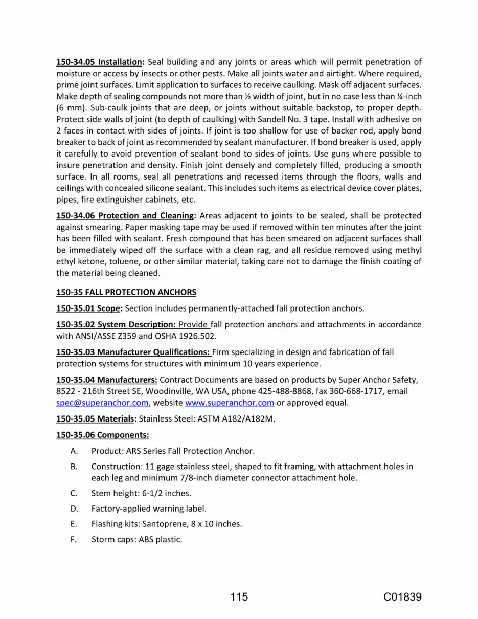
150-34.05 Installation: Seal building and any joints or areas which will permit penetration of moisture or access by insects or other pests. Make all joints water and airtight. Where required, prime joint surfaces. Limit application to surfaces to receive caulking. Mask off adjacent surfaces. Make depth of sealing compounds not more than ½ width of joint, but in no case less than ¼-inch (6 mm). Sub-caulk joints that are deep, or joints without suitable backstop, to proper depth. Protect side walls of joint (to depth of caulking) with Sandell No. 3 tape. Install with adhesive on 2 faces in contact with sides of joints. If joint is too shallow for use of backer rod, apply bond breaker to back of joint as recommended by sealant manufacturer. If bond breaker is used, apply it carefully to avoid prevention of sealant bond to sides of joints. Use guns where possible to insure penetration and density. Finish joint densely and completely filled, producing a smooth surface. In all rooms, seal all penetrations and recessed items through the floors, walls and ceilings with concealed silicone sealant. This includes such items as electrical device cover plates, pipes, fire extinguisher cabinets, etc.
150-34.06 Protection and Cleaning: Areas adjacent to joints to be sealed, shall be protected against smearing. Paper masking tape may be used if removed within ten minutes after the joint has been filled with sealant. Fresh compound that has been smeared on adjacent surfaces shall be immediately wiped off the surface with a clean rag, and all residue removed using methyl ethyl ketone, toluene, or other similar material, taking care not to damage the finish coating of the material being cleaned.
150-35 FALL PROTECTION ANCHORS
150-35.01 Scope: Section includes permanently-attached fall protection anchors.
150-35.02 System Description: Provide fall protection anchors and attachments in accordance with ANSI/ASSE Z359 and OSHA 1926.502.
150-35.03 Manufacturer Qualifications: Firm specializing in design and fabrication of fall protection systems for structures with minimum 10 years experience.
150-35.04 Manufacturers: Contract Documents are based on products by Super Anchor Safety, 8522 - 216th Street SE, Woodinville, WA USA, phone 425-488-8868, fax 360-668-1717, email [email protected], website www.superanchor.com or approved equal.
150-35.05 Materials: Stainless Steel: ASTM A182/A182M.
150-35.06 Components:
A. Product: ARS Series Fall Protection Anchor.
B. Construction: 11 gage stainless steel, shaped to fit framing, with attachment holes in each leg and minimum 7/8-inch diameter connector attachment hole.
C. Stem height: 6-1/2 inches.
D. Factory-applied warning label.
E. Flashing kits: Santoprene, 8 x 10 inches.
F. Storm caps: ABS plastic.
115 C01839

150-35.07 Accessories:
A. Fasteners: Manufacturer’s standard, corrosion resistant coated steel.
150-35.08 Installation:
A. Install fall protection anchors in accordance with manufacturer’s instructions and approved Shop Drawings.
B. Separate dissimilar metals with bituminous coating or gaskets to prevent electrolysis.
C. Place anchors level, aligned, evenly spaced, and tightly fitted.
D. Coordinate installation of anchors and flashings with adjacent materials installation to produce watertight installation.
150-40 DOORS
150-40.01 Exterior Entry Doors: All exterior entry doors not otherwise specified shall be 1-3/4-inch heavy duty with 18 gauge flat, cold rolled steel panels. The doors shall have 12-gauge closer reinforcement, 6-gauge hinge reinforcements and 14-gauge lock reinforcement. The door
core shall have a Standard K Factor of 0.24 at 70 Fahrenheit mean temperature with a capillary rating of zero.
The doors shall be custom fit with a door frame and door size suitable for the actual opening size. The door frame shall be secured to the block wall with suitable anchors sized and spaced in accordance with the door manufacturer’s recommendations. There shall be door louvers with insect screens on each door. The doors shall be 1-3/4-inch Series 1500 Supercore Doors Model design LI as manufactured by Amweld or equivalent.
150-40.02 Entry Door Hardware:
Door Hardware Type A as follows:
150-50 AIR CONDITIONING UNITS
150-50.01 Scope: This Section includes packaged wall-mounted air-conditioning units with refrigerant compressors, air-cooled condensers, and controls.
150-50.02 Submittals:
116 C01839

150-50.03 Quality Assurance:
150-50.04 Warranty: Manufacturer's standard form in which manufacturer agrees to repair or replace self-contained air-conditioning units that fail in materials and workmanship within five years from date of Substantial Completion.
150-50.05 Manufacturers and Models:
1. Frigidaire, Carrier, Mitsubishi, or Daikin.
1. Frigidaire Model FFTA1422R2 or equivalent product by Carrier, Mitsubishi, or Daikin.
150-50.06 Packaged Units:
1. Insulation: Minimum 1/2-inch- (13-mm) thick, acoustic duct liner on cabinet interior and control panel.
2. Discharge Plenum: Cabinet extension with directional louvers.
3. Corrosion-Resistant Treatment: Phenolic coating on unit interior and exterior.
1. Drive: Direct, with fan and motor resiliently mounted.
2. Fan Sheaves: Cast-iron or steel sheaves, dynamically balanced, bored to fit shafts and keyed.
3. Motor Sheave: Variable and adjustable pitch selected so required rpm are obtained when set at midposition.
4. Motors: Multispeed.
117 C01839

1. Time-Delay Relay: Five-minute delay to prevent compressor cycling.
2. Adjustable Thermostat: Unit mounted to control the following:
a. Supply fan.
b. Compressor.
3. System Selector Switch: Off- auto-cool
4. Fan Control Switch: Auto-on.
1. Barometric Outside-Air Damper: Adjustable-blade damper allowing induction of up to 15 percent outside air when evaporator fan is running.
150-50.07 Installation:
150-50.08 Field Quality Control:
150-70 PLUMBING
150-70.01 General:
The Contractor shall comply with all applicable local ordinances, regulations and codes and with the latest edition of the Uniform Plumbing Code.
Where directions for installation and rough-in for plumbing are not shown on the Plans or Specifications, the Contractor shall follow the manufacturer's directions.
118 C01839

Drain pipes shall have a minimum slope of 1/4 inch per foot.
All threaded joints shall be carefully reamed and jointed with red lead on male thread only (or cement and oil compound).
Clean-out plugs shall be lubricated with graphite or oil.
Chromium-plated flanges shall be provided where pipes pass through walls or floors in finished rooms.
All exposed metal surfaces shall be cleaned of grease, dirt or other foreign material. All chrome plated piping, trim and fittings shall be polished after construction.
All fixtures shall be protected from damage during construction and cleaned.
150-70.02 Materials:
Sewer and drain lines may be either cast iron soil pipe and fittings conforming to ASTM A74-82, latest edition or cast iron soil pipe and fittings for hubless cast iron sanitary systems per Cast Iron Soil Pipe Institute HSN-85, latest edition. Drain lines shall also comply with all applicable provisions of the Uniform Plumbing Code, latest edition.
Water supply lines shall be Type L copper.
150-70.03 Fixtures:
All fixtures shall be installed as recommended by the manufacturer.
Floor drains shall be Zurn Z-415 body with 6-inch Type B strainer or approved equivalent. Heavy duty floor drains shall be furnished with a heavy duty slotted grate. Outlet size and type shall be compatible with and match that of connected drain piping shown on the plans.
Hub Drain (Equipment Drain) shall be coated cast iron with standard cast iron hub with hub above floor. Each hub drain shall be equipped with a deep seal vented trap.
Cleanouts shall match City Standards.
150-100 MEASUREMENT AND PAYMENT
150-100.01 Measurement
Percent complete will be determined from the approved Schedule of Values.
150-100.02 Payment
Full compensation for Building Construction is considered as included in the lump sum price paid for Masonry Well Buildings, and no additional allowance will be made therefor.
119 C01839

SECTION 201 ELECTRICAL
201-1 GENERAL
201-1.01 Scope of Work
A. The Contractor shall install, ready for use, the electrical system as specified herein and shown on the Contract drawings. This document describes the function and operation of the system and particular components, but does not necessarily describe all necessary devices. All components and devices shall be furnished and installed as necessary to provide a complete operable and reliable system for accomplishing the functions and meeting the performance set forth hereinafter.
1. Thoroughly examine existing conditions before submitting his bid proposal to perform any work. He shall compare site conditions with data given on the plans or in these Specifications. No allowance shall be made for any additional costs incurred by the Contractor due to his failure to have examined the site or to have failed to report any discrepancies to the Owner prior to bid.
2. It is the Contractor's responsibility to be fully familiar with the existing utility locations, conditions and local requirements and regulations.
3. Verify all measurements and conditions and shall be responsible for the correctness of same. No extra compensation will be allowed because of differences between Work shown on the Drawings and measurements at the site.
120 C01839

1. Meter/Main Switchboard (MMS), Power Distribution Switchboard, including Variable Frequency Drive (VFDs).
2. Control Panels including Programmable Logic Controllers and Operator Interface.
3. Instrumentation and miscellaneous devices.
4. Panelboard and panelboard transformer.
5. Conduits and the field interconnection wiring between the MMS, MCC, Control Panels, instrumentation, etc. and equipment provided under all other Sections.
6. Lighting and security system.
7. Provide all necessary conduits, junction boxes, grounding system, field interconnection wiring, hardware, fittings, and devices to connect the designated equipment and wiring.
8. Provide all necessary hardware, fittings, and devices to connect the designated equipment and wiring.
9. All necessary miscellaneous shut off, sample, and calibration valves to sensors.
10. Provide trenching, backfilling, and compaction for all underground conduit routes, concrete pads, and pull boxes.
11. Grounding system and equipment grounding.
12. Concrete pads and supports for electrical and instrumentation equipment.
13. Remove and dispose of all excess dirt, paving, concrete, and other materials from site work.
14. Coordination for connection of utility services.
15. Modify existing WTP PLC Control Panel for new fiber connection.
16. PLC & OI programming, configuration of SCADA system and WTP PLC programming will be by others.
121 C01839

1. Krug-Bixby-Long Associates (KBL) (phone 510 887-1117).
2. Technical Systems, Inc. (TSI) (phone 707 678-1111).
3. Primex (formerly MCC Control Systems and Meyer Control Corporation), (phone 707 449-0341).
4. Tesco (phone 916 395-8800).
201-1.02 Codes and Standards
1. ANSI – American National Standards Institute, Inc.
2. CEC – California Electrical Code, 2013 Edition
3. EIA – Electronics Industries Association.
4. ETL – Electrical Testing Laboratories.
5. FM – Factory Mutual.
6. GO128 – General Order No. 128, Rules for Construction of Underground Electrical Supply and Communication Systems, Public Utilities Commission of the State of California.
7. IEEE – Institute of Electrical and Electronics Engineers.
8. ICEA – Insulated Power Cable Engineers' Association.
9. ISA – International Society of Automation (ISA) Standards (formerly Instrument Society of America.
10. NEC – National Electrical Code, 2014 Edition.
122 C01839

11. NEMA – National Electrical Manufacturers Association.
12. NETA – Acceptance Testing Specifications for Electrical Power Distribution Equipment and Systems, International Electrical Testing Association.
13. NESC – National Electrical Safety Code.
14. NFPA – National Fire Protection Agency & NFPA820
15. OSHA – Occupational Safety and Health Act Standards.
16. UL – Underwriter's Laboratories, Inc.
201-1.03 Related Work in Other Sections
1. Section 202 – Electrical Systems Analysis.
201-1.04 Electrical Contractor Qualifications
123 C01839

1. Has a current C-10 Electrical Subcontractor's License.
2. Has regularly engaged in similar electrical contracting for the Municipal Water and Wastewater Industry.
3. Has successfully performed work of similar or greater complexity on at least two previous projects under one company name and under the present company name.
4. Has all persons performing work as electricians certified by the California Apprenticeship Council per California Labor Code Section 3099.
5. Has been actively engaged in the type of electrical and instrumentation work specified in this Section 201 for a minimum of two years.
1. Provide completion dates of projects.
2. References of Owner representative in charge of project, including contact name and telephone number.
201-1.05 Contract Documents
124 C01839

125 C01839

1. The following lists the record documents shall be as-built by electrical Contractor:
a. E-Series Drawings.
b. Panelboard schedules.
c. Conduit and Wire Routing Schedule.
1) A copy of the Conduit and Wire Routing Schedule and electrical plans showing conduit routing shall be updated weekly by the Contractor. Progress payments will be withheld if during monthly checks it is found that the Contractor fails to maintain the Conduit Schedule updates.
d. Lighting Schedule.
e. Duct banks and their routing with offset measurement and indicate changes in depth.
f. Interconnection Drawings.
2. The following lists the record documents that shall be as-built by System Supplier to be maintained by electrical Contractor:
a. I-Series Drawings.
126 C01839

b. Instrumentation Index.
3. Record Drawings shall be maintained and provided per other Sections. Record documents shall be kept current weekly with all "change orders", submittal modifications, and construction changes shown. Record Documents shall be subject to the inspection by the Engineer at all times, progress payments or portions thereof may be withheld if Record Documents are not accurate or current.
4. When documents are changed, they shall be marked with erasable colored pencils using the following coloring scheme:
a. Additions - red.
b. Deletions - green.
c. Comments - blue.
d. Dimensions - black.
5. Show the following on the electrical (E-Series) Record Contract Drawings by dimension from readily obtained base lines:
a. Exact location, type and function of electrical and instrumentation equipment and devices.
b. Precise routing and locations of underground conduits, pullboxes, junction boxes, and appurtenances that make-up the raceway system.
c. Show the dimensions, location and routing of electrical work, which will become permanently concealed.
d. Show complete routing and sizing of any significant revisions to the systems shown.
201-1.06 Coordination
1. The Contractor shall field verify the locations for the underground primary and secondary conduit runs, pull boxes, and transformer pad with utility representative prior to installation.
127 C01839

2. Provide all the equipment and materials not provided by the power utility company for permanent service at the locations shown on the Contract Drawings. All work shall meet the requirements of the serving power utility companies.
3. Coordinate all work with the serving power utility, Pacific Gas & Electric (PG&E) for the work shown on Contract Drawings. The Contractor shall obtain the required inspections.
a. Submit to the power utility the proposed metering details including, but not limited to, proposed meter enclosure, meter socket and service entrance drawing details. Provide a written statement from the utility that shows approval of the proposed metering.
b. All work associated with material and installation for the utility power service not paid by the utility shall be borne by the Contractor.
c. Contractor shall be responsible for obtaining utility engineered drawings.
d. The Contractor shall provide and install all material, conduits, wiring, pull ropes, pole risers, pull boxes, transformer pads, bollards, and other work specified and shown on PG&E engineered drawings for new power service.
e. Conflicts between the Contract drawings and the utility engineered drawings shall be brought to the attention of the Engineer. Contractor shall meet all utility requirements at no additional cost to the Owner.
f. All fees and charges for the utility power service hook-up will be paid by the Owner.
1. The Contractor shall limit all unscheduled shutdown periods to less than 2 hours (120 minutes) and only with prior approval of the Owner.
2. The Contractor shall coordinate the shutdown and removal of the existing Electrical Switchboard and MCC with the Owner.
3. Carry out scheduled shut downs only after the time, date, and sequence of work proposed to be accomplished during shutdown has been favorably reviewed by the Owner. Submit shutdown schedule and plans at least 10 working days in advance of when the scheduled shutdown is to occur.
4. Contractor shall make provisions for portable generators and automatic transfer switches when facilities will be without power.
5. The Owner reserves the right to delay, change, or modify any shutdown at any time, at no additional cost to the Owner, when the risk of such a shutdown would jeopardize the operation of system.
128 C01839

6. Contractor is advised that during change out of existing MCCs, meter/main, pumps, demolition of existing conduits, installation of new conduits, etc., Contractor is responsible to keep equipment running for all necessary station operation. The Contractor shall install temporary generators, motor controls, panelboards, power panelboards, wiring, etc. to keep all facility equipment powered and automatic controls functional.
201-1.07 Supervision
129 C01839

201-1.08 Inspections
201-1.09 Job Conditions
130 C01839

201-1.10 Submittal and Drawing Requirements
1. Product (item) name used herein and on the Contract Drawings.
2. The manufacturer's model or other designation.
3. Tag name/number per the drawings or schedules.
4. Index Binder Tab Dividers.
131 C01839
5. Detailed electrical one line, elementary control diagrams and interconnection diagrams showing all wiring requirements for each system.
6. Complete documentation with full description of operation.
7. Complete catalog cuts with full description of equipment. General sales literature will not be acceptable. The part or model number with options to be provided shall be clearly identified. Where more than one item or catalog number appears on a catalog cut, the specific item(s) or catalog numbers(s) proposed shall be clearly identified.
8. Location of assembly at which it is installed.
9. Input-output characteristics.
10. Range, size, and graduations as required.
11. Physical size with dimensions and mounting details.
12. Enclosure fabrication and color.
13. Enclosure layout and elevation drawings to scale.
14. Quantity and quality requirements for electric power, air, and/or water supply.
15. Materials of construction of components.
16. Nameplate schedule.
17. Interconnection diagrams.
18. Failure to provide submittals with heavy duty permanent plastic labeled index tabs may be grounds for immediate rejection without review.
19. A complete Bill of Materials list shall be provided at the inside of the front cover. The Contractor shall provide Bill of Material formatted as shown in Appendix A. A separate set of Material Listing forms shall be provided for each MCC bucket, control panel and another listing all field equipment. All spare parts shall be listed separately at the end of the Bill of Materials list. Generic names or part numbers used by a distributor or Systems House are not acceptable; originating manufacturer's name and part number shall be listed.
20. A separate instrument data sheet shall be provided for each instrument per ISA S20 standards or approved equal. Provide an index with proper identification and cross-referencing of each data sheet.
21. Submit USB drive copies of all submitted drawing in AutoCAD format.
22. For each resubmittal, provide a copy of submittal comments and a separate letter, on Company letterhead, identifying how each submittal comment has been addressed in the resubmittal.
23. Electronic PDF version of submittals shall follow hard copy format of submittal and shall be “bookmarked” at each index, subtab, copy of appropriate checkmarked Specification Section, bill of materials, copy of submittal comments (for resubmittals), Contractor’s response to submittal comments (for resubmittals),
132 C01839

drawings, etc. Failure to bookmark PDF may be grounds for immediate rejection without review.
24. Electronic submissions of submittals may be provided for submittals less than 40 pages and without drawings. Submittals equal to or over 40 pages or those that contain drawings shall be provided in a hardcopy format. Hardcopy submittals shall be provided in binders as specified herein. The Owner reserves the right to reject submittals that fail to be organized as described herein.
1. Electrical one-line diagrams detailing all devices associated with the power distribution system. The following applicable information or data shall be shown on the one-line diagram: location, size and amperage rating of bus; size and amperage rating of wire or cable; breaker ratings, number of poles, and frame sizes; standby generator; automatic transfer switch, utility metering, voltage, amperage, number of wires and phases; fault interrupt ratings; ground size and connections; neutral size and connections; power fail and other protective devices; fuse size and type; distribution transformer; panelboard; starters; contactor size and overload range; motor full load amperage of submitted motor and horsepower; rating for miscellaneous loads; etc. Submit a list for each piece of equipment containing the motor voltage, phase and full load amps with one-lines for verification of accuracy of submitted one-line drawings.
2. Elementary diagrams shall be provided for all relay logic, power supplies, PLC I/O and other wiring. All elementary diagrams shall be drawn in EMP/EGP format and standards similar to those shown on the E-series elementary diagrams showing ladder rung numbers and coil and contact cross referencing numbers.
3. Enclosure and Elevation layout diagrams; show all front panel and backpanel devices drawn to scale. Show fabrication methods and details; including material of construction, paint color, support and latching mechanisms, fans and ventilation system, and conduit entrance areas. Provide enclosures with removable metal filters.
4. Analog and digital I/O wiring diagrams showing the wiring requirements for each instrument loop. Graphic symbols shall conform with ISA S5.4 drawing standards. A loop diagram shall be furnished for each analog and digital I/O process and all PLC I/O cards. Loop diagrams shall include the following as a minimum:
a. The loop diagram shall be drawn with sufficient detail to express control philosophy. The diagram shall show all components and accessories of the instrument loop, highlighting special safety and other requirements. These diagrams shall be arranged to emphasize device elements and their functions as
133 C01839

an aid to understanding the operation of a system and for maintaining or troubleshooting that system.
b. A separate drawing shall be prepared for each analog and digital card. Each card shall be arranged on the diagram in the same order as the physical arrangement of the card terminations. All termination points on the diagram shall be shown with the actual equipment identification, device and relay terminal number or letter, and I/O point P&ID English descriptor and tag name. A separate drawing shall be prepared for each card.
c. Energy sources - electrical power, air supply, pneumatic and hydraulic fluid supply, designating voltage, current, pressure, etc. shall be shown in detail on the diagram. Input and output signals (e.g., 1-5 VDC, 4-20 mA DC, 3-15 psig, etc.), power and instrument supplies to devices (e.g. 120 VAC, 24 VDC, 80 psig, etc.) shall be shown.
d. Engineering units shall be shown on the diagram. Each wire label, equipment identification terminal number or letter and color code shall be shown. Signal and DC polarities shall be shown.
e. All spare wires, cables, and termination points shall be shown. All jumpers, grounding, shielding, power supply details shall be shown.
5. Interconnections diagram shall show for each piece of equipment all wiring between all devices, panels, cabinets, terminal boxes, control equipment, motor control centers and any other devices and equipment. An interconnection diagram shall be furnished for each electrical and instrumentation system, even if one was not shown explicitly on the Contract Drawings. Interconnection diagrams shall be prepared for all conduits listed in the "Conduit and Wire Routing Schedule." Each interconnection diagram shall show the following as a minimum:
a. Interconnect drawings shall be prepared for all equipment by the System Supplier.
b. The diagrams shall be utilized by the electrician during all phases of installation and connection of all conductors to ensure coordination of equipment interconnects.
c. The diagrams shall show wiring as field labeled at the end of the project when as-builts are submitted.
d. Each wire labeling code as actually installed shall be shown. The wiring labeling code for each end of the same wire must be identical.
e. All device and equipment labeling codes shall be shown.
f. Interconnections shall be shown point to point with identified lines. Diagrams of the wireless or wire schedule type are not acceptable. Bundled wires shall be shown as a single line with the direction of entry/exit of individual wires clearly shown. Interconnect diagrams shall not be combined with loop or elementary diagrams.
134 C01839

g. All terminations points on the diagram shall be shown with the actual equipment identification terminal number or letter. This identification of terminations includes terminal blocks, junction boxes, all devices, computer I/O points, etc.
h. Diagrams shall include raceway numbers, raceway size, raceway type, cable numbers, wire color code, and wire numbers.
i. Each wire size, and cable size and color code shall be shown. Each conduit with the conduit label and conduit size and wire fill shall be shown. Wire and cable routing through conduits, wireways, manholes, handholes, junction boxes, terminal boxes and other electrical enclosures shall be shown with the appropriate equipment labels. All spare wires, cable, and termination points shall be shown. Cable shields shall be shown.
j. Labeling codes for terminal blocks, terminals, wires, cables, panels, cabinets, instruments, devices, and equipment shall be shown. Place "øA", "øB", and "øC" label next to each breaker to identify phase connected to.
k. Schematic symbols shall be used for field devices, showing electrical contacts. Signal and DC circuit polarities shall be shown.
l. The diagrams shall show all other Contract and Supplier Drawing numbers, for reference, that are associated with each device that is interconnected.
m. Attached to each interconnect, a copy of all the support documents used in preparing interconnects shall be submitted. This includes current issues of panel schematics, elementary diagrams, panelboard schedules, conduit schedules, one-line diagrams, connection diagrams, terminal block diagrams, submittals, contract drawings, vendor drawings and all other data used to develop the interconnection diagram as noted in the "Reference Documents" corner of interconnect drawings.
n. Interconnects shall include list of all applicable reference drawings, request for clarifications, field instructions and change orders. All deletions and additions of equipment, wire and cables shall be clearly shown.
o. Field wiring shall not start before the interconnection Drawing has been submitted by the Contractor and approved by the Owner.
p. Do not show the same wires or jumpers, or panel wiring on both the connection and interconnection diagrams. All jumper, shielding, and grounding termination details not shown on the connection diagrams shall be shown on the interconnection diagrams.
q. Interconnection diagrams shall be submitted and approved by Owner for each electrical and instrumentation system. The Contractor shall not pull in any wires into conduits that do not have approved interconnects. If the Contractor pulls in wire without Owner approval of associated Interconnect Drawings, the Contractor will not be reimbursed for labor for re-pulling in wires even if there was an error in wire fill or sizing. Also, if the Contractor pulls in wire without Owner approval of associated Interconnect Drawings, then all progress
135 C01839

payments related to field wiring for that particular area of work will be withheld until approved Interconnect Drawings are in use.
r. All interconnection diagrams shall be prepared by a System Supplier under the supervision of or by a State of California Registered Electrical Engineer and shall bear that Engineer's professional stamp and signature for all Interconnection Drawings submitted for approval including as-builts and those used in the field installation. All deletions and additions of equipment, wire, and cables shall be clearly shown. Interconnects shall include list of all applicable reference Drawings, request for clarifications, field instructions, and change orders. Failure to provide backup references or signed and stamped drawings may be grounds for immediate rejection.
s. Example format of Interconnection diagram is shown on Contract "E" Series Drawings or may be obtained from the Engineer.
t. All Interconnection wires listed in the conduit schedule for each conduit shall be shown only on one interconnect drawing. Interconnect drawings submitted with wiring of a single conduit run separated onto multiple interconnect drawings will be rejected without review. A single conduit run with wiring shown on separate interconnect drawings will be allowed only after written approval is given by the Engineer for each conduit run prior to submitting the associated interconnect drawings.
u. Only field wiring between MCCs, Panelboards, Control Panels, and other electrical and instrumentation devices or equipment shall be shown on interconnection drawings. No internal panel wiring shall be shown on interconnect drawings except jumper or other wiring to be installed in field by electrical Contractor.
v. Interconnect Drawings along with the corresponding support documents shall be submitted in a separate submittal package. Interconnect drawings submitted with non-interconnect drawing packages will be rejected. The latest support documents shall be obtained by system supplier from Contractor for all non- Section 201 instruments, panels, and equipment, and included with interconnect drawing submittal. Support documents shall have their submittal number marked in upper right hand corner.
w. Interconnect drawings shall be prepared for all equipment by the System Supplier with the exception of the Security Alarm System which may be produce their own interconnect drawings.
x. Provide a notes section on each interconnect drawing. In the note section, list any variances from the Contract conduit schedule necessary for completing the interconnections. Change orders regarding wire fill, conduit schedule and errors in plans regarding conduits and wires will not be processed until interconnect drawings have been received for such work.
y. The field electrician shall mark-up all interconnection diagrams during installation to show accurate as-built wiring, conduits runs, terminations, etc. If
136 C01839

interconnection drawings are not properly as-built, the electrical Contractor will have cost deducted from the Contract for the Owner to field verify and prepare as-built interconnection drawings amount. The amount of the deduction shall be determined on a time and material basis. The cost of such work shall be $120.00 per hour plus expenses.
z. The system supplier shall be responsible to collect all information necessary to complete each interconnection drawing. This includes making field trips to collect all terminal connection data for new and existing, panels, switchboards, panelboards, instruments, equipment and electrical panels.
aa. An index of drawings shall be provided with each Interconnection submittal listing the unique drawing number and the description of the interconnect drawing (e.g. Drawing 4321-IC1004 Pump 1004 Interconnect Drawing).
bb. Provide conduit and interconnect drawing cross reference indexes. Interconnect Conduit Index shall list all conduits listed in the Conduit & Wire Routing schedule and its associated Interconnection Drawing number. An Interconnection Drawing Index shall list all Interconnection drawings and the conduits shown on that specific drawing. These two indexes shall be at the front of all interconnection drawing submittals.
cc. Interconnection submittals that contain more than two motor control panels/centers shall be submitted separately.
6. Submit full size drawing of all nameplates and tags, as specified herein, to be used on project. The Engineer has the right to adjust nameplate engraving titles during submittals at no additional cost to the Owner. Submittal to include the following:
a. Dimensions of nameplate.
b. Exact lettering and font for each nameplate.
c. Color of nameplate.
d. Color of lettering.
e. Materials of construction.
f. Method and materials for attachment.
g. Drawing showing location of nameplate on each panel.
7. Copying contract drawings and providing them as submittals will be considered unresponsive and the submittal will be rejected without review
1. Each binder shall be appropriately labeled on the outside spine & front cover with the project name, contract number, equipment supplier's name, specification section(s), and major material contained therein.
137 C01839

2. An index shall be provided at the inside of the front cover. This index shall itemize the contents of each tab and sub tab section. Also, list the project name, contract number and equipment supplier's name, address, phone number, and contact person on the index page. Index dividers (tabs) shall be provided to separate each section.
3. Field equipment shop documents, panel equipment shop documents, drawings, and bill of materials shall be grouped under separate tabs. Catalog cuts shall be ordered in the same sequence as their corresponding Contract specification subsection.
4. All copies shall be clear and legible. Data sheets shall be provided for each instrument, with an index and proper identification and cross-referencing.
5. Exceptions to the Contract specifications or drawings shall be clearly defined by the equipment supplier.
a. Data shall contain sufficient details so a proper evaluation may be made by the Engineer. Contractor shall provide separate letter (located in the front of the submittal) detailing specific exceptions to the Contract Specifications or Drawings.
b. Exceptions that are noted in the marked-up Drawings or Specifications, but not listed on the Exceptions/Clarifications letter, will be considered as non-responsive and not accepted as changes to the Contract Documents.
6. Request for information (RFIs) shall not be included in submittals. RFIs shall be submitted separately in its individual submittal number.
7. Resubmittals shall be provided with a copy of the previous submittal comments and a separate letter, on company letterhead, identifying how each submittal comment has been addressed in the resubmittal.
8. Failure to provide submittals with heavy duty permanent plastic labeled index tabs may be grounds for immediate rejection without review.
1. Shop Drawings with less than 20 sheets total in the submittal, may be provided in an 11-1/2-inch by 17-1/2-inch reinforced folder.
2. All Interconnection Drawings or Shop Drawings of 20 sheets or more shall be provided in separate heavy duty three-ring binder to allow drawings to be easily removed. Binder shall be Cardinal D-Ring Easy Open Ledger Binder with locking D-Rings or approved equal.
3. Failure to provide drawing submittal in correct binder format may be grounds for immediate rejection without review.
138 C01839

4. Each drawing title block shall contain the English description name for drawing contents (i.e. Lift Pump No. 1 Interconnect Drawing) and drawing number. All pages and drawings in the submittal shall be numbered sequentially (with no number skipped) in lower right hand corner.
5. Drawings that are "C" or "D" size shall be folded, with the title block visible and placed in reinforced clear plastic pockets.
1. 1st submittal: 1.
2. 1st resubmittal: 1A.
3. 2nd resubmittal: 1B, etc.
201-2 MATERIALS
201-2.01 Quality
139 C01839
201-2.02 Nameplates and Tags
140 C01839

1. For each major piece of electrical equipment provide a manufacturer's nameplate showing the Contract specified name and number designation, the manufacturer's name, model designation, part number, serial number, and pertinent ratings such as voltage, amperage, # of phases, range, calibration, etc.
2. For each device with a specific identity (pushbutton, indicator, instrument, etc.) mounted on the exterior or deadfront of a piece of equipment provide a nameplate with the inscription as shown in the Contract documents. Where no inscription is indicated in the Contract documents, furnish nameplates with an appropriate inscription providing the name and number of device.
3. For all receptacles and switches, provide a faceplate engraved or stamped with the panelboard and circuit number it is fed from. Also, include on faceplate or on a separate nameplate for each light switch identification use such as "OUTSIDE BUILDING LIGHTS," "PERIMETER LIGHTS," "MCC ROOM," etc.
4. All field instruments and devices shall be labeled with designation shown on P&ID diagrams.
5. All transformers and panelboards shall have nameplates with 1/2-inch high letters and be engraved with designations as shown on one-line Drawings.
6. All safety and disconnect switches shall have nameplates with 1/2-inch high letters and be engraved with designations as shown on one-line drawings.
7. Underground Pull Box and Vault Cover Identification: Engrave or bead weld pull box covers with minimum 1/4” thickness and 1/2” letters and Covers shall be engraved with designations as shown on Contract drawings or as directed by Owner.
8. Aboveground Pull Box Cover Identification: 316 stainless steel screws attached stamped 316 stainless steel plate nameplates with 1/2” letters and be engraved with designations as shown on Contract drawings or as directed by Owner.
9. Provide engraved nameplate at service entrance equipment (red with white lettering) indicating type and location of standby generator per NEC 702.7 (A).
10. Provide engraved nameplate at service entrance equipment per NEC 702.7(B)
11. Generator receptacles and generator lug panels shall have engraved nameplate with 1/2” letters (red with white lettering) per NEC 702.7.(C)
141 C01839

201-2.03 Devices
1. Fuses used in circuits 200 VAC and above shall be time- delay type FNQ or approved equal, 13/32-inch x 1-1/2-inch, and have an interrupting rating of 10,000 AIC at 500 VAC. Fuse holders shall be of the barrier type and rated 600 VAC.
2. Fuses used in 120 VAC shall be time-delay type MDL or approved equal, 1/4-inch x 11/4-inch, and have a rating of 250 VAC. Fuse-holders shall be terminal block type.
3. Fuses used in signal and 24 VDC circuits shall be fast acting type ABC or approved equal, 1/4-inch x 1-1/4-inch, and have a rating of 250 VAC. Fuse-holders shall be of the terminal block type.
4. Fuses shall be sized in conformance with the NEC.
1. Switches (HS) and pushbuttons (HC) for general purpose applications shall be water and oil tight as defined by NEMA 4X, corrosion resistant as defined by NEMA ICS 6-110.58, U.L. listed, standard 30 mm diameter, with round plastic clamp ring. Switches shall be Allen-Bradley 800H, IDEC ITE, or approved equal.
2. Switches and pushbuttons shall have contacts rated 10 amperes continuous and 600 VAC. Contract blocks shall have IP2X finger-safe protection.
142 C01839

3. Manufacturer's standard size legend plates shall be provided and engraved to specify each switch and pushbutton function. The legend plate color shall be black.
4. Selector switch handles and pushbutton caps shall be black.
5. Selector switches for hand-off-auto (HOA) applications shall have the hand position to the left, off in center, and auto in the right position.
6. Lockout stop shall be a pushbutton with red cap and pad locking assembly for pushbutton.
1. General: Relays and timers shall be provided with N.O. or N.C. contacts as shown on the Contract drawings. All spare contacts shown shall be provided. Contacts shall be rated 10 amps minimum at 120 VAC, 60 Hz unless otherwise stated. Supply power or coil voltage shall be 120 VAC unless shown otherwise on the Contract drawings. Relays and timers shall be designed for continuous duty. All relays shall be U.L. listed. The following is a summary of abbreviations associated with relays and timers:
a. CR – Control Relay.
b. TR – Timing Relay.
c. PFR – Power Fail Relay.
d. TDOE – Time Delay On Energization.
e. TDOD – Time Delay On De-Energization.
2. Control relays (CR) shall be plug-in type with indicating lights and clear see-through sealed or enclosed housing to exclude dust. Sockets for plug-in relays shall be standard industrial type octal 8 or 11 pin with barrier pressure screw terminals. Provide IDEC Type RR, Potter and Brumfield KU, or approved equal. Two form-C contacts (minimum) shall be provided on each relay.
3. Time delay relays (TR) on energization or de-energization shall be solid state plug-in relays with a timer adjustable over the range 1 second to 3 minutes unless other ranges are indicated or required. Provide LED timer energized indicator lamp. Sockets for plug-in timers shall be standard industrial type octal 8 or 11 pin with barriered pressure screw terminals. Time delay relays shall be IDEC RTE, SSAC TD, or approved equal.
4. The power fail relay (PFR) shall continuously monitor the three phases for power loss, low voltage, phase loss, and phase reversal. The power fail monitor shall have a drop-out voltage adjustment, an adjustable delay on make time delay (0.2 to 8.0 minutes) and a status indicating LED. Power fail relays shall be Diversified SLJ, Time Mark, or approved equal.
1. Indicating Lights for general purpose applications shall be water and oil tight as defined by NEMA 4X, corrosion resistant as defined by NEMA ICS 6-110.58, U.L. listed, High intensity multi-chip LEDs, full voltage (unless shown otherwise), standard 30 mm
143 C01839

diameter, with round plastic lens and miniature bayonet lamp base. Indication lights shall be Allen-Bradley 800H, IDEC ALD, or approved equal.
2. Manufacturer's standard size legend plates shall be provided and engraved to specify each light's function. The legend plate color shall be black.
3. Indicating lights designated "PTT" shall be provided with a push-to-test switch and wiring.
4. Indicating light type and color of lens shall be as shown on the Drawings or specified in the Contract documents. Lamp color will be as follows:
a. Open/On Red
b. Closed/Off Green
c. Alarm Amber
d. Power On White
1. Circuit breakers shall be of the indicating type, providing ON, OFF and TRIPPED positions of the operating handle. Circuit breakers shall be quick-make, quick-break, with a thermal-magnetic (TM) action or Motor Circuit Protectors (MCP) as shown on One-Line Diagrams. Circuit breakers feeding Soft Starters or VFDs shall have true adjustable Long, Short and Instantaneous trip units. Circuit breakers shall be the bolted on type. The use of tandem or dual circuit breakers in a normal single-pole space to provide the number of poles or spaces specified are not acceptable. All multiple-pole circuit breakers shall be designed so that an overload on one pole automatically causes all poles to open. Circuit breakers and motor circuit protectors shall be manufactured by Eaton, G.E., ITE, or approved equal.
2. Each 480 volt or 240V circuit breaker shall have a minimum interrupting capacity of 65,000 amperes. Each 120 volt breaker shall be rated for a minimum 10,000 amperes interrupting capacity. Breakers shall be sized as shown on Drawings and as necessary for the supplied equipment.
3. Fused disconnects shall not be used in place of breakers.
4. All breakers shall be supplied with the correct sized copper only lugs for wire sizes as listed in "Conduit & Wire Routing Schedule". Provide larger frame breaker or lug adapters as necessary when connecting to the listed oversized wire.
1. The surge protective device (SPD) shall be rated for use on a 3 phase system at voltage shown on Contract One Line diagram. The transient current the surge protective device shall dissipate 80,000 amps minimum. The SPD shall also have a maximum transient energy (10 x 1000 µsec waveform) per phase of 2,560 joules. Provide fuses feeding the SPD. Locate SPD so that the indicating lights are viewable without removing panels. The surge protective device shall be Leviton 32000 series, Eaton or approved equal.
144 C01839

1. Control power transformer (CPT) shall be provided with a time-delay, slow-blow secondary fuse rated to protect the transformer and interrupt 10,000 amperes at 120VAC. Two primary fuses with KAIC interrupt rating of corresponding power connection shall be provided. Transformer size minimum ratings shall be as shown on Contract E-Series Drawings.
1. The clean power variable frequency drive shall be ABB ACS 800 with remote digital controller and display unit to match Owner Standard. Each VFD shall have motor terminator unit supplied and provided to for installation by other near the motor.
2. Digital programmer/controller –The VFD shall be provided with a door mounted alpha-numeric human interface module (HIM) digital display with keypad to view and adjust the setpoints, parameters, diagnostic, and status indicators. Cable for remote digital programmer/controller shall be supplied. Start/Stop/Jog single function keys from keyboard. The remote controller shall be deadfront door mounted with bezel to provide NEMA 4 rating.
3. Radio frequency interference (RFI) noise filters shall be provided at the power line input for removing interference from/to any device on the existing power distribution system.
4. Each VFD shall not be affected by or generate excessive electro-magnetic interference (EMI). The VFD shall be provided with a radio interference filter (RIF) to meet the following requirements:
a. The use of a 4 Watt hand-held VHF/UHF transceiver within three feet of the VFD with its doors closed shall not cause erratic operation, loss of configuration, or any other deviation from normal operation.
b. The worst case conducted and radiated EMI generated by the VFD shall not be enough to prevent the use of hand held VHF-UHF transceivers within three feet of the VFD with its doors closed.
5. Opening of the VFD’s input switches, or breakers while the VFD is operating under load shall not result in damage to the VFD power or control circuit components.
6. Each VFD shall be capable of starting and operating without a motor load connected.
7. Phase loss protection shall be provided to prevent single phasing of the motor load.
8. Each VFD shall have stall prevention circuitry which utilizes current fold-back in the following sequence:
a. In an operation mode, whenever the output current exceeds its rated VFD current, VFD controls shall stop increasing the output frequency and shall decrease it according to the set deceleration ramp until the output current is reduced below its rated current. The inverter then resumes normal operation and the output frequency increases to the set frequency.
145 C01839

1. Each VFD shall be protected from excessive regeneration by a full function regeneration limit circuit which avoids nuisance tripping when overhauling loads occur. The full function regeneration limit circuit reduces the negative current limit of the drive during periods of excessive regeneration allowing the drive to remain fully operational without exceeding the level of regenerated energy which can be safely accepted and dissipated by the inverter. The following performance characteristics shall be provided:
a. The regeneration circuit automatically adjusts the negative current limit, allowing the load to decelerate at the fastest rate possible without excessive regenerated energy. Deceleration torque is automatically limited to its maximum safe level.
b. If the load tends to overhaul the drive motor, the negative current limit is automatically adjusted to prevent excessive regeneration. The inverter hold back torque decreases and allows the motor to follow the load while maintaining hold back torque at its maximum safe level.
2. Automatic fault reset to automatically restart the drive after any type of fault condition. This automatic restart shall repeat up to three attempts. This automatic reset shall be provided to prevent a drive fault from completely locking out on isolated nuisance fluctuations. When the drive is locked out after its automatic reset attempts the operator shall be able to reset VFD by a local or remote manual reset pushbutton. Fault lockout shall be indicated on the door mounted drive fail pilot light.
3. Each controller shall automatically restart upon reapplication of power after a loss of line power without requiring a manual reset. Momentary or sustained power failures shall not fault trip out the controller or blow any fuses.
4. Each VFD shall be capable of continued operation during an intermittent loss of incoming line power up to five cycles.
5. Any configuration of adjustments or controls not set by a switch or potentiometer shall be stored in nonvolatile memory. No configuration information shall be lost due to power failures of any duration.
6. Each VFD shall be capable of starting into a rotating motor without tripping out on a fault.
7. Each VFD shall have an adjustable voltage boost control capable of providing additional starting torque to the motor at start. This control shall provide the additional voltage only at the frequency range required to start the motor thus reducing the additional motor heating excess voltage would cause at normal operating speeds.
146 C01839

8. VFDs shall be equipped with critical frequency jump circuitry which allows the VFD to be setup to skip two bands of frequencies which cause excessive vibration or noise.
9. Copper lugs and provisions for connecting the motor power leads to output of VFD shall be provided at the bottom or the enclosure.
10. VFD shall incorporate fans for cooling. The air flow through the VFD compartment shall provide proper cooling of the operating VFD at an ambient temperature of 104-degree F. The thermostat shall be designed to regulate and monitor air temperature in the VFD enclosure. Thermostat shall have bi-metallic adjustable set point range of 30 to 140° F. Thermostat shall have a switching capacity of 10A at 120 VAC. Provide additional air conditioner to meet the operating ambient temperature of 104-degree F. Provide removable metal filters for all louvers.
11. The complete VFD unit, including the enclosure assembly, shall be UL listed for a minimum symmetrical ampere fault withstand capability shown on Contract One-Line drawings. VFD assemblies consisting of the VFD, enclosure and all accessories that are not UL listed will not be approved.
12. VFD shall be protected by a long time and instantaneously adjustable disconnect circuit breaker. This disconnect breakers shall be externally operated and shall have an operator mechanism that is an integral part of the enclosure to disconnect all power and controls inside enclosure. An operator mechanism shall be provided to allow padlocking the disconnect in the “off” position with up to two padlocks. Circuit breaker shall be provided with “true” adjustable long time and instantaneous settings.
13. Each VFD shall have an instantaneous electronic trip circuit to protect the VFD from output line-to-line and line-to-ground short circuits. Output line-to-line and line-to-ground short circuits shall not damage the VFD.
14. AC input fuses shall be provided to isolate VFD internal power circuitry with respect to ground upon a fault condition. Equipment Supplier is responsible for sizing fuses, and shall install larger fuses are required.
15. Copper lugs shall be provided for the wire sizes listed in the Conduit and Wire Routing Schedule.
16. Provide ABB ramp for removal of filters labeled with Station name and specific VFD (including equipment number) the ramp is associated with. Label material shall be clear plastic with black machine printed lettering as produced by a KROY, Brother or similar machine. The size of the nameplate tape shall be no smaller than 2 inches in height with 3/8-inch lettering unless otherwise approved by the Engineer. Securely fasten nameplates in place on a clean surface using the adhesion of the tape.
1. Control panel terminal blocks:
a. Terminal blocks to be clamp type, 6mm spacing, 600 volt, minimum rating of 30 amps, and mounted on DIN rail, Entrelec M4/6 colored. DIN rail shall be same
147 C01839

type as used for the relays. Install an extra DIN rail on each type of terminal strip with 4 terminals for future additions.
b. Provide terminal blocks with "follower" plates which compress the wires and have wire guide tangs for ease of maintenance. Terminal blocks which compress the wires with direct screw compression are unacceptable. All power, control and instrument wires entering and leaving a compartment shall terminate on terminal blocks with wire numbers on terminals and on both ends of the wires.
c. Terminal Tags and Markers: Each terminal strip shall have a unique identifying alphanumeric code at one end (i.e.: TB1, TB2, etc.) and plastic marking strip running the entire length with a unique number for each terminal. On each terminal strip, terminal numbers shall be assigned starting with #1 at one end, incrementing in alphanumerical order (i.e.: 1,2,3,4....). Numbers shall be assigned to all blocks except grounding blocks. Fuse blocks shall be assigned unique tag numbers such as FU1, FU2. No two fuses shall be assigned the same tag number.
d. Plastic marking tabs shall be provided to label each terminal block. These marking tabs shall have a unique number/letter for each terminal which is identical to the "elementary" and "loop" diagram wire designation. Numbers on these marking strips shall be machine printed and 1/8-inch high minimum.
e. Terminal blocks shall be physically separated into groups by the level of signal and voltage served. Power and control wiring above 100 volts shall have a separate group of terminal blocks from terminal blocks for wiring below 100 volts, intermixing of these two types of wiring on the same group of terminal blocks is not allowed.
f. Provide a ground terminal or connection point for each grounding conductor.
g. Provide a separate common or neutral terminal for every two (maximum) inputs and/or outputs.
2. MCC cubicle terminal blocks shall be pull-apart, as supplied standard by MCC manufacturer.
3. Power Termination Blocks shall be rated for 600V main power connection. The power termination blocks shall be rated to accept Copper or Aluminum cable rated as shown on Contract one-line diagrams. The power termination block shall be capable of being mounted anywhere in a termination box. Each termination block shall be provided with lug shield to prevent contact with power connections. The power termination blocks shall be Connectron or approved equal.
1. Device boxes shall be deep, FD type, cast or galvanized steel type with shape and size best suited for the particular application, rated for the location installed, and shall be supported directly to support structure by means of stainless steel screws, anchors, or bolts.
148 C01839

2. Box dimensions shall be in accordance with size, quantity of conductors, and conduit clearances per NEC articles 314 requirements. Boxes shall be deep FD type.
3. Boxes exposed to the weather or in moist/corrosive locations where GRS-PVC conduits are to be used shall be weatherproof (WP) PVC coated cast type with threaded hubs or stainless steel with watertight Myers hubs. Boxes shall be deep, FD type. Single gang boxes shall have cast hubs.
1. General purpose switches shall be manufactured in accordance with UL 20. Switches shall be one pole rated, 20 amps, at 277 VAC. Bodies shall be of ivory phenolic compound supported by mounting strap having plaster ears. Switches shall have copper alloy contact arm with silver cadmium oxide contacts. Switches shall have slotted terminal screws and a separate green grounding screw. Furnish Hubbell 1221, Leviton, or approved equal.
1. General purpose receptacles shall be duplex and rated 20 amps, 120 VAC, 2 pole, 3 wire grounding, NEMA 5-20R configuration, specification grade, and side wired to screw terminals. Face color shall be brown in industrial areas and white or ivory in finished areas. General purpose receptacles shall be Bryant, Hubbell, or approved equal.
2. GFI (ground fault circuit interrupting) receptacles shall be used for providing power to miscellaneous cord powered equipment. GFI receptacles shall be duplex, 20A, 120V, with "test" and "reset" buttons with shallow design for mounting and standard screw terminals for direct wiring. Receptacles shall be designed, manufactured, and tested to prevent nuisance tripping from voltage spikes, RFI, EMI, or electronic component failures. Chaining multiple receptacles from one GFI unit is not acceptable. GFI receptacles shall be Arrow-Hart "specification grade", Leviton or approved equal.
3. Twist lock receptacles shall be rated 20 amps, 120 VAC, 2 pole, 3 wire grounding, NEMA L5-20R configuration, UL listed, Type 4X, back wired to screw terminals. Receptacles with safety shroud shall be NEMA 4X rated and have cover with lockout/tagout provisions. Provide matching plug and box adapters for a complete and operable system. Twist-lock receptacle shall be Mennekes HMI Series, Hubbell Watertight Safety-Shroud Twist-Lock series with matching plug, receptacle, inlet, box adapters, or approved equal.
1. General purpose device plates and covers shall be anodized aluminum. Plates or covers shall be attached with stainless steel screws. Circuit breaker number and panelboard name shall be stamped on each cover.
2. PVC coated device boxes shall have PVC coated gasketed covers.
149 C01839

3. Weatherproof switch, outlet, and receptacle boxes shall be fitted with gasketed covers rated for wet locations in accordance with NEC 404.4.
4. Weatherproof switch, outlet, and receptacle boxes shall be fitted with cast aluminum gasketed cover rated for wet locations. Each receptacle access cover shall have a gasketed spring door to maintain the weatherproof integrity with plug inserted in accordance with NEC 406.8 for unattended locations. Final decision of type of access cover for specific location shall be per Engineer. Screws and hinge springs shall be 316 stainless steel. Receptacles located outside shall have tumbler key lock.
5. Weatherproof access covers shall be Hubbell, Crouse-Hinds, or TayMac Safety Outlet Enclosures, or approved equal.
6. Receptacle and light switch plates shall be stamped or engraved as specified herein.
201-2.04 Main Switchboard
150 C01839
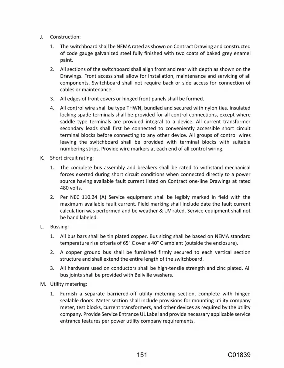
1. The switchboard shall be NEMA rated as shown on Contract Drawing and constructed of code gauge galvanized steel fully finished with two coats of baked grey enamel paint.
2. All sections of the switchboard shall align front and rear with depth as shown on the Drawings. Front access shall allow for installation, maintenance and servicing of all components. Switchboard shall not require back or side access for connection of cables or maintenance.
3. All edges of front covers or hinged front panels shall be formed.
4. All control wire shall be type THWN, bundled and secured with nylon ties. Insulated locking spade terminals shall be provided for all control connections, except where saddle type terminals are provided integral to a device. All current transformer secondary leads shall first be connected to conveniently accessible short circuit terminal blocks before connecting to any other device. All groups of control wires leaving the switchboard shall be provided with terminal blocks with suitable numbering strips. Provide wire markers at each end of all control wiring.
1. The complete bus assembly and breakers shall be rated to withstand mechanical forces exerted during short circuit conditions when connected directly to a power source having available fault current listed on Contract one-line Drawings at rated 480 volts.
2. Per NEC 110.24 (A) Service equipment shall be legibly marked in field with the maximum available fault current. Field marking shall include date the fault current calculation was performed and be weather & UV rated. Service equipment shall not be hand labeled.
1. All bus bars shall be tin plated copper. Bus sizing shall be based on NEMA standard temperature rise criteria of 65° C over a 40° C ambient (outside the enclosure).
2. A copper ground bus shall be furnished firmly secured to each vertical section structure and shall extend the entire length of the switchboard.
3. All hardware used on conductors shall be high-tensile strength and zinc plated. All bus joints shall be provided with Bellville washers.
1. Furnish a separate barriered-off utility metering section, complete with hinged sealable doors. Meter section shall include provisions for mounting utility company meter, test blocks, current transformers, and other devices as required by the utility company. Provide Service Entrance UL Label and provide necessary applicable service entrance features per power utility company requirements.
151 C01839

2. Service equipment and meter sockets shall be subject to the approval of the power utility company. The Equipment Supplier shall be responsible for obtaining utility approval in writing of the metering switchboard. A copy of this utility approval shall be forwarded to the Owner.
1. Each breaker shall be three-pole unit, electrically, and mechanically trip-free power circuit breaker with solid state overcurrent trip device. Breaker arrangement, trip, and frame ratings shall be as shown on Contract single-line diagram.
2. Each breaker shall have a hasp for padlocking the breaker in the OFF position. Each breaker shall be thermal magnetic (TM) type.
3. Tripping devices shall be automatic and self-contained within the breaker frame, and shall not require any external relaying or power supplies.
4. Where shown, circuit breakers with a frame size of 450 amperes to 1200 amperes shall be molded case with electronic microprocessor based RMS trip elements. Molded case circuit breakers with electronic trip shall be Eaton Series C N-Frame Type NG-H with Digitrip 310+ Electronic ALSIG trip unit, or approved equal. The interrupting capacity of all main, and feeder branch circuit breakers shall be a minimum of 65,000 RMS symmetrical amperes at operating voltage. Ground fault shall be provided where indicated on Contract Drawings and for all service disconnects rated 1,000 amps or more. Where shown, breaker trip units shall be equipped with 24 VDC coil for “Maintenance Mode” for arc flash reduction. Maintenance mode selection switch (Maintenance Mode or Normal Mode selection) and LED indicator light shall be installed on Switchboard/MCC face near circuit breaker. 24 VDC supply shall come from PLC Control Panel.
5. Circuit breakers shall be open frame, Cutler-Hammer, GE or approved equal.
1. The switchboard shall be completely assembled, wired and tested at the factory. After assembly, the complete switchboard will be tested for operation under simulated service conditions to assure the accuracy of the wiring and the functioning of all equipment. The main bus shall be given a dielectric test of 2200 volts for one minute between live parts and ground and between opposite polarities. A certified test report of all tests shall be submitted to the Owner for approval.
201.2.05 Power Distribution Switchboard
1. Switchboards: One of the following or equal:
a. Eaton Corporation, "Pow-R-Line C".
b. General Electric Company, "Spectra" Series.
152 C01839

1. Furnish and install indoor dead-front type, low voltage metal-enclosed front-only, accessible switchboard. With NEMA rating as shown on Contract Drawings.
2. Switchboard and equipment: Conform to current applicable standards of organizations listed under References.
3. Furnish and install a complete lineup of switchboard and control as detailed herein. Furnish and install devices or accessories not described, but necessary for the proper installation and operation of the equipment.
4. Suitable for use as service entrance equipment in accordance with UL requirements. Complete assembly shall bear a UL label.
5. Rate complete switchboard assembly to withstand mechanical forces exerted during short circuit conditions when connected directly to a power source having available fault current listed on Contract Drawing One-Line diagram. Test switchboard for conformance according to applicable NEMA and UL Standards.
6. Manufacturer of the assembly to be manufacturer of circuit breakers contained therein.
1. Design and construct switchboard for use on a 3-phase, 60 Hertz system with entire assembly suitable for 600 VAC maximum service.
2. Continuous and Short Circuit Interrupt Rating: As indicated on the Contract one-line Drawings.
1. Fabricate main bus of high conductivity, flat, copper plated copper bar having rounded edges suitably braced and supported on high dielectric strength insulators and arranged in the same vertical plane. Buses to have a continuous current-carrying capacity of not less than that specified herein or indicated on the Drawings.
2. Insulate buses to protect against spread of arcing faults and accidental contact by people or foreign objects. Provide bus joints with Bellville spring type washers.
3. Mount bus on insulated supports with coordinated dielectric properties, and strength to withstand magnetic stresses developed by rated fault current at rated voltage.
4. Fabricate bus supports from insulation possessing flame-retardant and self-extinguishing, dielectric and anti-hygroscopic properties.
1. Ground Bus: copper plated copper bar, extending through all sections.
2. Provide bus joints with Bellville spring type washers.
3. Ground each housing directly to this bus.
153 C01839

1. Utilize construction in formation of housing in order to provide a rigid, self-supporting and self-contained enclosure. Fabricate each stationary structure of heavy, formed, specially smoothed and leveled steel sheets and structural members.
2. Provide lugs including grounding lugs, suitable for copper cable, of quantity and size as indicated on the Drawings.
3. After fabrication, bonderize, chemically clean & paint exterior and interior surfaces of the switchboard with a rust inhibiting primer followed by a gray ANSI 49 or 61 finish coat to match color of MCCs or other equipment.
4. Distribution Sections requiring side or rear access for installation and maintenance are not acceptable.
5. Provide required ventilation at switchboard where shown on Contract Drawings.
1. Circuit Breaker: Thermal Magnetic
a. Individually mounted when rated for over 1,000 amperes.
b. Group-mounted when rated for 1,000 amperes and below.
c. Bolt-on type; stab plug-in type are not acceptable.
d. Changeable trip rating plugs available to its maximum frame size amps where shown on Contract one-line diagrams.
e. The breakers shall have a hasp for padlocking the breaker in the OFF position.
1. Wire and factory test switchboard to satisfy the requirements of the operation described or necessary.
2. Switchboard Wiring: Single-conductor, stranded copper, rated 600 volts bundled and secured with nylon ties. Provide flexible stranding for swinging panels. Minimum wire size: No. 14 for control circuits, and No. 12 for potential and current transformer circuits.
3. Route outgoing control wires to master terminal blocks with suitable numbering strips numbered in agreement with the manufacturer's detailed wiring diagrams.
4. Terminate control wiring in molded, compression terminal blocks; screw-type terminal blocks are not acceptable. Provide a minimum of 10% spare terminal blocks for each circuit breaker and auxiliary compartment.
5. Provide wire labels per Section 16120 – Wire, Fuses & Terminal Blocks.
1. Provide engraved plastic nameplates to identify switchboard units, door mounted components, and internal components as specified herein. Include nameplate identifying manufacturer’s associated job number, date of manufacturer, etc.
154 C01839

2. Black phenolic with white letters fastened with round head stainless steel screws, engraved with the designation shown on the Drawings.
3. Label switchboard per requirements of NEC 110.21 and 110.22.
1. Each digital power monitoring system to be as manufactured by Electro Industries Shark 200 with all six virtual upgrade packs (V-Switch), to match City Standard. Power monitor shall display: Voltage (phase A-B, A-N, B-N); current (Phases A, B); power (KW, KVA); power factor, total harmonic distortion and frequency. Monitor shall have 10 amp secondary, multifunction meter only. Provide two (2) external current transformers with rating as indicated on the drawing or sized for incoming service. Provide two (2) external potential transformers (when necessary) with rating as indicated on the drawing or sized for incoming service. Power monitor shall include Ethernet port for connection to PLC.
201-2.06 Control Panel
1. Allen-Bradley 1769 L2 series with power supply, sixteen 24DC digital inputs, sixteen 24DC digital outputs, four counters, four analog inputs, and two analog outputs with Operator Interface no equal as shown on the I-series Drawings.
a. Group all telemetry tables together for future efficient data transfer to SCADA Central. Submit proposed communications data tables in Excel format for approval by City.
b. All wiring from the PLC I/O terminals shall be wired to interface terminal blocks, including all spares, as shown on Contract drawings to match the I/O of the City’s Standard PLC, Program Configuration and I/O wiring.
1. Devices:
a. Lights, switches, pushbuttons, terminal blocks etc. to match those specified under Devices subsection.
b. Connection between Ethernet Port and Ethernet hub shall be made with Cat 6 patch cable. Patch cable shall be 4 pair stranded PVC cable with HI-FLEX conductors. Length shall be 5 feet minimum. Color of cable shall be red.
c. RFI filters to be for power line radio frequency protection, Eaton Aegis series AGPH 12015 to match City standard.
d. Receptacle to be duplex and rated 20 amps, 120 VAC, 2 pole, 3 wire grounding, NEMA 5-20R configuration, specification grade, and side wired to screw terminals.
155 C01839

e. Isolator shall provide complete isolation of the 4-20 mA output signal from the input signal and isolator power supply. Each isolator shall have all solid state circuitry mounted in a plug-in module. The 4-20 mA output signal shall be capable of driving a 600 ohm load. Both accuracy and linearity shall be +/- 0.10% of span. The isolator shall be powered as shown on Contract Drawings. Each isolator shall be as manufactured by AGM Electronics, Action Instruments, or approved equal.
f. Plug strips shall have power switch and power conditioning built in and be provided with 6 single 3 wire, 20 ampere receptacles mounted on the front cover.
1. Provide Operator Interface (OI) Automation Direct (C-More) 10” TFT Color Touchpanel system, or approved equal. OI to be panel mounted through cutout in Control Panel door. Provide all cables, configuration software, user manual and mounting hardware necessary for a complete and operable system.
2. Provide an operator interface that meets the following requirements:
a. Touch screen operator interface with built-in Ethernet Communication Port and USB port.
b. Operator interface with 10.4” TFT color liquid crystal display with analog resistive NEMA 4X touch screen.
c. 24VDC powered
d. Compatible with Modicon Quantum.
e. Operator terminal capable of setup using standard PC.
1. Full programming software to be licensed and delivered to Owner.
1. The UPS shall be on line system which provides continuous, no break power during complete blackouts or momentary interruptions. The UPS shall not utilize a ferroresonant transformer. The UPS shall provide +/- 3% load regulation while producing computer grade power with less than 5% THD. The UPS shall be rated to provide a minimum of VA output shown on Contract drawings at 120 VAC at an efficiency of 95%.
2. Mount UPS in control compartment and provide all necessary power wiring. Plug cords and receptacles shall be provided so that the UPS can be readily bypassed with power being obtained directly from the panelboard.
3. Submit load calculations of all connected 120 VAC loads showing UPS is adequately sized.
4. The UPS shall be an American Power Conversion (APC) Smart-Slot, or approved equal.
156 C01839

1. Ethernet Converter/Switches shall be provided for PLC system as shown on Contract Drawings. Managed Ethernet switches shall have 6 ports (unless otherwise noted), 10/100 Base T and ST connections. Fiber optic switches shall be N-Tron 900-Series, Hirschmann RS2, or approved equal.
2. Install additional managed Ethernet switch in existing WTP PLC Control Panel.
201-2.07 Field Devices
1. The sensor module:
a. The pressure transmitter shall incorporate a high-accuracy capacitance sensor. With this sensor, process pressure is transmitted through the isolating diaphragm and fill fluid to the sensing diaphragm in the center of the capacitance cell. Capacitor plates on both sides of the sensing diaphragm detect its position. The differential capacitance between the sensing diaphragm and the capacitor plates shall be directly proportional to process pressure.
b. The transmitter shall incorporate a temperature measurement to compensate for thermal effects.
c. The pressure transmitter electronics shall convert the capacitance and temperature input signals directly into digital format for further processing by the electronics module.
d. The pressure transmitter shall have the HART communication superimposed on the device, which uses an industry standard Bell 202 Frequency Shift Keying (FSK) technique.
e. Configuration data shall be stored in nonvolatile EEPROM memory in the electronics module of the transmitter.
2. Software functionality:
a. The PC base HART protocol software shall be provided.
b. Configuration: The transmitter shall be configured by the System Supplier. Configuration shall consist of operational/parameters and informational data.
c. Test: The pressure transmitter shall perform continuous self-tests.
d. Format: The format function is used during the initial setup of a transmitter and for maintenance of the digital electronics.
e. Requirements:
Output: Two-wire 4-20 mA output. Digital process variable superimposed on 4-20 mA signal.
Power Supply: External power supply required.
157 C01839

Indication: 4-digit LCD meter.
Zero Elevation and Suppression: Anywhere within the sensor limits.
Overpressure Limits: Limit is 0 psig to 3,626 psig (25 Mpa) without damage to the transmitter.
Temperature Limits: Process: 0° F to 185°F (-18° C to 85°C) Ambient: -4°F to 175°F (-20° C to 80°C).
Humidity Limits: 0 – 100% relative humidity.
Accuracy: 0.075% of span for spans from 1:1 to 10:1 of URL.
Stability: 0.2% of URL for 12 months.
Process-Wetted Parts: Isolating Diaphragms: 316 SST.
Drain/Vent Valves: 316 SST.
Flanges: 316 SST.
Wetted O-rings: Glass-filled TFE.
3. The pressure transmitter shall be Rosemount Smart family 3051TG (rated for 300PSI
regardless of scaling), to match Owner standard.
1. Each calibration valve assembly shall have integral stainless steel block and bleed valving. Valve shall have a non-rotating tip stem and a fully back-seated bonnet. Block and bleed valve shall be Hex HB59 (phone 800-543-7311) or approved equal.
1. Submersible level probe to be range shown in Instrument Index with minimum accuracy of ± 1% with 4-20 mA output loop powered Drexelbrook Smart CheckWell series with integral electronics & swivel mount assembly, or approved equal.
1. Flange connections shall be ANSI Class 150 as required by mechanical Drawings. Flanges shall be coordinated with Contractor installing piping.
2. Stainless steel grounding rings shall be provided at both ends of the flow tube when required by the manufacturer. The tube internal liner material shall be polyurethane, unless recommended otherwise by the manufacturer for the application and approved by the Engineer. Electrode material shall be 316 stainless steel and shall be flush type. The meter shall incorporate a high impedance amplifier of 100,000 Megohms or greater, eliminating the need for electrode cleaning systems.
3. The converter electronics shall be mounted remotely as shown on Contract P&ID Drawings. The converter shall be microprocessor controlled, utilizing digital signal processing with automatic zero correction to provide a linear 4-20 mA signal proportional to the forward and reverse flow rate specified. Electronics shall provide and control output rated for 24VDC switching for remote monitoring of forward or
158 C01839

reverse flow indication. Rangeability shall be field adjustable over a 100 to 1 range. Field adjustable signal dampening shall be provided. Low flow cutoff shall be provided to eliminate flow transients when no flow is present in the pipe. A rate indicator and totalizer scaled in engineering units shall be provided and shall be viewable on a LCD display(s) through a clear window in the enclosure. The converter shall have self-diagnostics which constantly check for proper operation. If a failure occurs, a fault indication shall be provided to notify the operator of a problem. The converter shall contain a self-test mode to allow the operator to manually simulate the output 4-20 mA signal to any value between 0% and 100% to check out any driven devices in the loop. The converter shall be rated to operate in an ambient temperature range from -4°F to 131°F.
4. The converter electronics shall be designed for operation from a power source of 24 VDC, with a power consumption of less than 24 watts.
5. When converter electronics are shown to be mounted remotely, additional special cabling without any splices (Cabling between flow element and remote mounted flow indicating transmitter), mounting hardware, and devices necessary to complete the installation shall be provided by the manufacturer at no additional cost to the Owner. Flowmeter cable shall be factory installed and potted to IP68 rating.
6. Electronics shall be provided in NEMA rated enclosures specified in Instrumentation and Device Index.
7. The meter shall be hydraulically calibrated at a facility located in the United States and the calibration shall be traceable to the National Bureau of Standards. A certified copy of the calibration test results shall be submitted to the Owner prior to shipment of the meter.
8. The accuracy of the complete metering system including flow tube and converter electronics shall be 0.25% of rate over the range settings of 0.033 to 33 feet per second. Variations in temperature, voltage, and frequency within the ranges listed herein shall not affect the accuracy in excess of 0.5% of flow rate. Where shown, the flowmeter shall be accidental submergence proof for forty-eight house under 30 feet of water. Conduits between flowmeter element and electronics shall be sealed to retain submergence rating per flowmeter manufacturer's requirements.
9. The flow meter shall be Rosemount 8750WD with converter/indicator unit to match City Standard.
1. The flow switch shall be vane operated to actuate one single-pole double throw snap switch. Flow switch shall be stainless steel. The flow switch shall be sized per the piping. The flow switch shall have a minimum electrical switch rating of 10A at 125VAC. The flow switch shall be W.E. Anderson (Dwyer) V6 series, Omega, or approved equal.
159 C01839

1. Building Doors - Each intrusion door switch shall have a wide gap magnetic sensor with S.P.D.T. contacts mounted in a rugged steel housing with a 3-foot stainless steel armored cable for wiring to a junction box. Intrusion door switches shall be Sentrol 2507-A, or approved equal.
201-2.08 Wire
1. Conductors shall be copper, with a minimum of 98% conductivity.
2. Wire shall be Class B stranded.
3. Insulation of all conductors and cables shall be rated 600 volt.
4. Insulation type for conductors smaller than #6 AWG shall be moisture and heat resistant thermoplastic THWN, rated 90 °C in dry locations and 75 °C in wet locations, or approved equal. Conductors #6 AWG and larger shall be RHW-2 insulation rated 90 °C in dry locations and 75 °C in wet locations.
5. Field wire minimum AWG sizes:
a. #12 for wires used for individual conductor circuits 100 volt and above.
b. #14 for wires used for individual conductor circuits below 100 volt.
6. Non-field or equipment wire minimum AWG sizes:
a. #14 for wires used for individual conductor circuits 100 volt and above.
b. #18 for wires used for individual conductor circuits below 100 volt.
7. Instrument wiring:
a. General: Instrument cables shall have 600V rated insulation and 100% individual shielded twisted pair #16 conductors with drain wire. Single twisted shielded pair (T.S.PR.) cables shall be Belden, or approved equal.
160 C01839

WIRES COLOR CODE TABLE
DESCRIPTION PHASE/CODE
LETTER FIELD WIRE
WIRE OR TAPE COLOR NON-FIELD WIRE
COLOR
480 V, 3 PHASE A BROWN BROWN
B ORANGE ORANGE
C YELLOW YELLOW
240 V or 208 V, 3P A BLACK -
B RED (ORANGE if high leg) -
C BLUE -
240 / 120 V, 1 P L1 BLACK BLACK
L2 RED -
12V POSITIVE 12P DARK BLUE DARK BLUE
12V NEGATIVE 12N BLACK/RED STRIPE BLACK/RED STRIPE
24V POSITIVE 24P PINK PINK
24V NEGATIVE 24N BLACK/WHITE STRIPE BLACK/WHITE STRIPE
AC CONTROL VIOLET RED (YELLOW FOR FOREIGN CIRCUITS)
DC CONTROL BLUE BLUE
NEUTRAL N WHITE WHITE
GROUND G GREEN GREEN
SHIELDED PAIR + BLACK RED
- CLEAR (WHITE) BLACK
1. Note #1: High leg of open delta shall be colored orange per NEC 110.15.
2. The same color shall be connected to the same phase throughout the panel.
3. All wires shall be properly fused or protected by a breaker at the amperage rating allowed by the NEC.
4. Neutral used for AC Control shall be white.
5. Phase color insulation shall be provided for complete length of #8 wire or smaller; colored phase tape is not allowed on #8 and smaller wire.
1. Wire identification: All wire terminations including field interconnect as well as wiring interior MCC cubicles, switchboard, panels, equipment, junction panels and boxes shall be identified with machine printed labels. Hand lettered labels are not acceptable and shall be replaced at the Contractor's expense. The wire identification code for all field interconnect and panel interior wiring, shall be similar to the designations shown on the Contract example drawings.
161 C01839

2. Wire Labels: The labels shall be machine printed with indelible ink, heat shrink type capable of accepting a minimum of 23 machine printed characters per sleeve label by Brady “Bradysleeve” or approved equal. Labeling shall be neatly installed for visibility and shall be clearly legible. Each wire and conductor shall be labeled with wire label as shown on approved loop, elementary and interconnect Drawings. Labels shall not be wrap-around or snap-on type.
3. Where there is insufficient space for labels on locally interconnected neutral wires such as jumpers between adjacent auxiliary relay coil neutral terminals, these labels may be omitted. "Locally" is defined as wires no longer than 8".
4. Wire labels for lighting and receptacles shall be installed and consist of the panelboard and circuit number (i.e., Panelboard “LP1”, circuit breaker #3 would have wire label line “LP1-L3” and neutral “LP1-N3”).
5. All spare wires shall be labeled with equipment number followed by SP1, SP2, etc. (i.e. P11001-SP1 for first spare wire).
6. All control and signal wiring terminations shall have the correct wire label applied prior to making connection.
1. Manufacturer supplied cables (MNFR CBL): Cables and wiring for special systems shall be provided by the manufacturer with the equipment and installed per the manufacturer's recommendations.
2. Indoor CAT 6 communication cable meet the following requirements:
a. TIA/EIA-568-C.2 Category 6 100 MHz specifications.
b. #24 AWG solid bare copper conductor, 4 twisted pairs.
c. Polyolefin insulation.
d. Shielded bulk cable.
e. PVC jacket.
f. Nominal Impedance: 100 ohms.
g. Nominal capacitance: 15 pf/ft. maximum.
h. UL listed.
i. Non-plenum usage rated when routed in conduit.
j. Plenum usage rated when routed in plenum spaces.
k. Cable shall be rated for water.
3. PLC Fiber Cable
a. Belden 10Gx series or approved equal.
b. The PLC communication system shall use fiber optic cable to connect the Well PLCs to the existing WTP PLC. All fiber optic cable shall be provided and connected under this Section. The fiber optic cable shall be multimode 62.5/125
162 C01839

micrometer diameter with six glass fibers, Kevlar strength member and PVC jacket material with OFNR UL rating. All active and spare fiber optic cables shall be terminated with spider fan-out kits and LC style connectors. Provide six spare connectors. Fiber optic cable shall be Superior Essex TeraGain multimode fiber or approved equal.
c. Fiber optic cable shall be tested for optical loss in accordance with Standard Fiber Optic Cable OTDR Test procedures and verified to have an optical loss below that required to perform optimum communications throughput. All new fiber optic cable shall be installed and terminated by Company specializing in the area.
201-2.09 Conduit, Raceways, and Wireways
1. All wiring shall be installed in conduits, raceways, or wireways when interconnecting equipment and devices.
2. The Contractor shall use special conduit, raceways, wireways, construction methods, and materials as shown on the Contract drawings; which shall take precedence over any general methods and materials specified in this Section.
3. The minimum size conduit shall be 3/4-inch unless indicated otherwise on the Drawings or for special connections to equipment. Buried, encased, or conduits located in walls shall be 1-inch minimum.
4. Conduit stubs for future use shall be capped with coupling, nipple, plug and cap and each end identified with conduit labels.
5. Conduits to be abandoned that protrude above graded shall be cut flush and filled with grout
6. Conduits shall not be filled to more than 50% of their total cross - sectional area.
7. Conduit marking:
a. All conduits and raceways listed in Conduit & Wire Routing Schedule shall have conduit tags at both ends of each conduit segment. This includes all conduits in pullboxes and vaults.
b. Tag material shall be aluminum or brass with machine stamped lettering. The size of the tag shall be 2-inch diameter. No letters are allowed smaller than 7/16-inch. Securely fasten tags in place using stainless steel cables. Engrave the tags with the conduit number as listed in the conduit schedule on the Contract "E"-series Drawings. Labeling shall be neatly installed for visibility and shall be clearly legible.
c. Prior to encasement, concealment, backfilling of conduits, temporary conduit labels shall be provided at each end of conduit. Temporary conduit labels shall
163 C01839

have 1/2-inch (minimum) lettering at all transition points. After encasement and concealment temporary conduit labels shall be placed at each exposed end.
1. Rigid steel conduit, couplings, bends and nipples shall be in accordance with ANSI C80.1 and UL-6.
2. Hotdip galvanized inside and outside after fabrication and then coated with a zinc dichromate finish. Provide threaded type fittings, couplings, and connectors; set screw type and compression type are not acceptable.
3. Minimum trade size - three-quarters inch (3/4-inch) unless otherwise shown on Contract Drawings.
4. Conduits entering enclosures shall be fitted with insulated grounding bushing; O-Z "HBLG", Appleton "GIB", or approved equal. All grounding bushings shall be tied to the grounding system with properly sized bonding conductors per the NEC code.
5. Galvanized rigid steel factory elbows for 90 degree transitions.
6. EMT or IMC is not considered an equivalent to GRS.
7. GRS conduit is allowed only when specifically called out in the "Conduit and Wire Routing Schedule."
8. Pipe straps for conduits larger than 3/4" shall be two-hole pipe straps. 3/4" conduits may have GRS-PVC single-hole pipe straps with clamp back spacer.
1. Standard weight, galvanized conduit with a 40-mil thick polyvinylchloride coating bonded to both the outside and urethane interior coating. Conduit shall be hot-dip galvanized conforming to NEMA RN 1. GRS-PVC conduit and fittings to be Robroy Plasti-bond Red or approved equal.
2. Provide PVC coated galvanized rigid steel factory ells for 90 degree transitions.
3. Fittings and boxes shall be stainless steel or galvanized cast ferrous metal with a PVC 40 mils thick coating. Provide threaded-type fittings, couplings, and connectors; set-screw type and compression-type are not acceptable.
4. All junction boxes shall be galvanized with exterior surfaces PVC coated to 40 mils thickness, except where stainless steel boxes are called out.
5. Conduits entering enclosures shall be fitted with insulated grounding bushing; O-Z "HBLG", Appleton "GIB", or approved equal. All grounding bushings shall be tied to the grounding system with properly sized bonding conductors per the NEC code.
6. Support channel and pipe straps shall be PVC coated. Exposed metal/nuts, all-thread rod shall be 316 stainless steel.
7. PVC coating patching material shall be as provided by the manufacturer.
8. PVC coated Aluminum conduit is not acceptable.
164 C01839

1. Shall be high impact polyvinylchloride suitable for use underground, direct burial and for use with 90 C wires, and shall conform to UL 651. Shall be UL listed and labeled for "direct" burial.
2. A copper bonding conductor shall be pulled in each raceway and bonded to equipment at each end with approved lugs.
3. Each underground run shall be placed in a trench with a minimum of four (4) inch sand bed evenly compacted on all sides, top and bottom.
4. Bends, elbows, and risers shall be made with PVC coated galvanized rigid steel (GRS-PVC) conduit using threaded adapters. Bond each metallic portion to each other and to equipment connected at each end of conduit run.
5. PVC fittings shall have solvent-weld-type conduit connections.
6. PVC conduit shall be stored on a flat surface and shielded from the sun.
7. PVC conduit shall not be used above grade.
1. All flex conduits shall have water tight outer jackets.
2. Connectors:
a. Non-NEMA 1 or 12 areas: PVC coated metallic with insulated bushings.
b. NEMA 1 or 12 areas: Metallic with insulated bushings.
3. Final connections to vibrating equipment such as motors and fans shall be made with flexible conduits.
4. Flexible conduit lengths shall not be greater than 36 inches.
5. Flexible metallic conduit shall not be considered as a ground conductor, install a separate wire for equipment bonding.
6. Flexible conduit shall only be installed in exposed or accessible locations.
7. Flexible conduits shall be used for conduit coupling to all vibrating and shifting equipment.
201-2.10 Pull Boxes
165 C01839

201-2.11 Grounding System
166 C01839

201-2.12 Panelboard
201-2.13 Panelboard Transformer
167 C01839

201-2.14 Electrical Enclosures and Boxes
201-2.15 Generator Connectors
201-2.16 Fiber Termination Patch Panel
168 C01839

201-3 EXECUTION
201-3.01 Electrical Workmanship
201-3.02 Electrical Construction Methods, General
169 C01839

1. Splices of #10 and smaller, including fixture taps, shall be made with see-thru nylon self-insulated twist on wire joints; T & B "Piggys," Ideal "Wing Nut," or approved equal.
2. Splices of #8 and larger shall be hex key screw two way connectors, with built in lock washers; T & B "Locktite," O-Z type XW, or approved equal, insulated with 3M Scotch Super #88, Plymouth, or approved equal.
3. Splices in underground pullboxes shall be insulated and moisture sealed with 3M "Scotchcast" cast resin splice kits and shall have a date marking for shelf life. Do not use splice kits with a date marking for shelf life that has expired.
4. Wire splicing devices shall be sized according to manufacturer's recommendations.
5. Tape on splices shall not be allowed.
1. Use connector or socket type terminals furnished with component.
2. Connections to binding post screw, stud or bolt use:
a. For #10 and smaller wire, T & B "Sta-Kon," Buchanan "Termend" or approved equal, self-insulated locking forked tongue lug.
b. For #8 to #4/0 wire, T & B "Locktite," Burndy QA or approved equal lug of shape best suited.
3. Use ratchet type crimping tool which does not release until proper crimp pressure has been applied.
4. Splices for motor leads shall be made with 3M Motor Lead Pigtail Splice kit 5300 series, or approved equal.
170 C01839

201-3.03 Electrical Equipment, General
1. Wires carrying 120 VAC shall be separated as much as possible from other low voltage wires and signal cables, and shall be routed only in ducts for 120 VAC. If the power wiring has to cross the signal wiring, the crossing shall be as close to a right angle as possible.
171 C01839

2. Ducts for 24 VDC wiring shall be used for all other wires and cables. Routing of 120 VAC in combined ducts is not allowed without prior written approval of the Owner.
3. Wires and cable shall be routed along the shortest route between termination points, excepting routes which would result in routing 120 VAC and other wires and cables in the same duct. Wires and cables shall have sufficient length to allow slack and to avoid any strain or tension in the wire or cable.
4. Wires and cables shall be placed in the ducts in a straight, neat and organized fashion and shall not be kinked, tangled or twisted together. Additional wire ducting shall be provided for use by the electrical subcontractor for routing field wires to their landing points in the each electrical and instrumentation panel.
5. Wiring not routed in duct work shall be neatly bundled, treed, and laced with plastic ties. Wiring across door hinges shall be carefully made up and supported to avoid straining and chafing of the conductors or from putting any strain on their terminals.
1. Provide 2-inch minimum separation between wireway and terminal blocks. Installation of wireways too close to terminal blocks will be required to be completely reworked to the satisfaction of the Owner.
2. For captive screw pressure plate type terminals, the insulation shall be removed from the last 0.25 inch of the conductor. The conductors shall be inserted under the pressure plate to full length of the bare portion of the conductor and the pressure plate tightened without excess force. No more than two conductors shall be installed in a single terminal. All strands of the conductor shall be captured under the pressure plate.
3. For screw terminals, appropriately sized locking forked spade lugs shall be used. Lugs shall be crimp on type that form gas tight connections. All crimping shall be done using a calibrated crimping tool made specifically for the lug type and size being crimped.
4. On shielded cables, the drain wire shall be covered with insulating tubing along its full bare length between the cable jacket and the terminal lug or terminal pressure plate.
5. For screwless terminals, wire shall be stripped back and inserted per the manufacturer's instructions. When stripping insulation from conductors, do not score or otherwise damage conductor.
6. Heat shrink shall be placed on ends of shielded cable to cover foil.
7. Additional condulets with terminal blocks shall be supplied for wire termination to devices with leads instead of terminals (i.e. solenoid valves, level probe, etc.)
172 C01839

8. Terminate all status, control, and analog I/O wiring on terminal blocks, including spares. Provide additional relay, DIN rails, terminal blocks and side panels as required.
201-3.04 Delivery
201-3.05 Damaged Products
201-3.06 Fasteners & Lugs
173 C01839

201-3.07 Installation, General
1. Install all products per manufacturer's recommendations and the Drawings.
2. Contract Drawings are intended to show the basic functional requirements of the electrical system and instrumentation system and do not relieve the Contractor from the responsibility to provide a complete and functioning system.
3. Device mounting heights:
a. Mounting heights of fixtures and devices shall be as follows unless otherwise indicated or when height has to be adjusted to be over or under counter tops.
1) Wall switches => 48 inches
2) Convenience outlets => 18 inches finished areas
=> 24 inches non-finished areas
=> Top of box no more than 48 inches above floor
3) Telephone outlets => 54 inches
4) Bracket fixtures => 7 feet 6 inches
1. Provide additional devices, wiring, conduits, relays, signal converters, isolators, boosters, and other miscellaneous devices as required to complete interfaces of the electrical and instrumentation system.
2. Changing normally open contacts to normally closed contacts or vice versa.
3. Adding additional relays to provide more contacts as necessary.
4. Installing additional terminal blocks to land wires.
1. Install panels and enclosures at the location shown on the Plans or approved by the Engineer.
2. Install level and plumb.
174 C01839

3. Seal all enclosure openings to prevent entrance of insects and rodents.
4. Seal around bottom edge of all pad mounted enclosures to prevent entrance of insects, rodents, dirt, debris, etc.
5. Clearance about electrical equipment shall meet the minimum requirements of NEC 110.26.
6. Box supports shall be located and oriented as directed in field by Owner.
7. All conduits entering outdoor panels and enclosures shall use watertight hubs. These hubs shall be located on sides or bottom only. Top entry of outdoor panels or enclosures is not allowed unless specifically shown on Contract Drawings.
1. Care shall be exercised to avoid interference with the work of other trades. This work shall be planned and coordinated with the other trades to prevent such interference. Pipes shall have precedence over conduits for space requirements. Exposed conduits shall be neatly arranged with runs perpendicular or level and parallel to walls. Bends shall be concentric.
2. Install conduit free from dents and bruises.
3. All conduits shall be labeled on all ends; at junction boxes, pull boxes, enclosures, stub-outs, or other terminations.
4. A maximum of three equivalent 90 degree elbows are allowed in any continuous runs. Install pull boxes where required to limit bends in conduit runs to not more than 270 degrees or where pulling tension would exceed the maximum allowable for the cable.
5. Route all above grade outdoor conduits or conduits in rated areas parallel or perpendicular to structure lines and/or piping.
6. Conduits installed outdoor or in NEMA 4X rated areas above grade shall be braced in place with stainless steel Unistrut stanchions or PVC coated clamps with backplates.
7. Duct-taping conduits together is not acceptable. Conduits, installed into concrete pads, shall be installed with a minimum of 2” distance between conduits to allow installation of bushings.
8. Special "Soft–Jaw" type pipe clamps shall be used to prevent damage to PVC-coated conduits while field threading, cutting to length, and coupling sections.
9. Conduits shall be painted to match the color of surface attached to as directed by Owner.
10. All existing conduits that are reused:
b. Shall have a mandrel or conduit piston pulled through the entire conduit run to prove the length contains no blockages or obstructions. Mandrelling shall be witness by the Owner.
175 C01839

c. Install new conduit tags for reused conduits at all transition boxes and endpoints. Conduit & Wire Routing Schedule shall be updated as these modifications take place.
1. Conduit material, wire size, and quantity listed in schedule take precedence over Section 201 Specifications.
2. All of the entries for each line in the conduit schedule apply to each conduit when multiple quantity of conduits multiple quantity of conduits (quantity of which are indicated by number entered in conduit no. column in schedule) are listed in the schedule.
3. Wire sizes listed are in AWG or Kcmil and are copper conductors.
4. Extra wire was intentionally placed in the "Conduit & Wire Routing Schedule" which shall be labeled on both ends with a unique wire label.
5. Contractor to supply and install all conduits and wiring as shown on utility engineered design drawings. Utility primary and secondary conduit and wiring shown in "Conduit and Wire Routing Schedule" is for bid purposes only. A credit or add-on will be provided by Contractor based on the actual work performed by Contractor for the utility service.
6. All control and signal wiring terminations shall have the correct wire label applied prior to making connection.
7. Conduit entries listed as "GRS-PVC" in the Conduit & Wire Routing Schedule are to be "Galvanized Rigid Conduits with PVC coating" the entire length.
8. Vertical offsets and sloping of conduits are not detailed on plans, the electrical Contractor shall include in his bid the price for the complete conduit run utilizing the civil & mechanical plans to measure vertical & slope distances.
9. Exposed conduits runs shall not be run directly on the ground or roof. Secure conduits to stainless steel unistrut.
10. Seal around all conduits, wires, and cables penetrating between electrical panels, walls, ceilings, and floors in all buildings with a fire stop material. Seal shall be made at both ends of the conduit with a fire-stop putty. Seal shall have a minimum two-hour rating. Fire stop sealing shall be International Protective Coatings Flamesafe, or approved equal.
11. Conduit entrances to Panels:
a. Seal around all conduits, wires, and cables penetrating between walls, ceilings, and floors in all buildings with a fire stop material. Seal shall be made at both ends of the conduit with a fire-stop putty. Seal shall have a minimum two-hour rating. Fire stop sealing shall be International Protective Coatings Flamesafe, or approved equal.
176 C01839

b. Seal around conduits entering outside to inside structures and around bottom of free standing enclosures to maintain watertight integrity of structure.
c. Place conduit seal inside each underground conduit riser into panels and enclosures to prevent entrance of insects and rodents.
d. Seal each conduit entrance from below grade into the MCC and other electrical enclosures with plugging compound sealant to prevent the entrance of insects and rodents. Conduits between the Power & Control Connection Boxes and the MCC shall be sealed with plugging compound sealant on each end. Plugging compound sealant shall be PRC-DeSoto (formerly Courtaulds) Aerospace (609 456-5700) Semco PR-868 or approved equal.
1. The electrical Contractor shall provide the excavation for equipment foundations, and trenches for conduits or buried cables. Repave any area that was paved prior to excavation. Backfill and surface all areas as shown on the Drawings or where not shown to the original condition that was present prior to the excavation.
2. Trenches for all underground utility lines shall be excavated to the required depths.
3. Repave any area that was paved prior to excavation. Backfill and surface all areas as shown on the Drawings or where not shown to the original condition that was present prior to the excavation.
4. Underground conduits outside of structures shall have a minimum cover of 24 inches, except for utility conduits depth shall be as required by the governing utility requirements. Back filling shall be done only after conduits have been inspected.
5. Contractor shall uncover any uninspected covered conduit trenches, at no additional cost to Owner, to verify proper installation.
6. Excavation and back fill conduit trenches shall conform to the requirements of the Earthwork Section of these Specifications, unless modified on plans, and to other entities as required.
7. At all times during the installation of the electrical distribution system, the Contractor shall provide barricades, fences, guard rails, etc., to safeguard all personnel, including small children, from excavated trenches.
177 C01839

1. Concrete housekeeping pads are required for all free standing electrical equipment. Housekeeping pads shall be 3-1/2 inches above surrounding finished floor or grade unless otherwise shown and shall be 4 inches (minimum) larger in width on all sides of equipment. The depth of housekeeping pads shall be 18 inches (minimum).
2. Housekeeping pads shall be installed for future units as shown on the Contract Drawings.
3. Housekeeping pad shall be Class “A” concrete with rebar crossway network. The minimum size rebar allowed is #4. Concrete shall be precisely leveled so that equipment set in place will not require shimming.
1. Remove all grease and metal cuttings.
2. Any discoloration or other damage to parts of the building, the finish, or the furnishings, shall be repaired.
3. Thoroughly clean any of his exposed work requiring same.
4. Vacuum and clean the inside of all MCC and electrical and instrumentation enclosures prior to applying power and a second time immediately prior to the final acceptance inspection.
5. Clean all above and below ground pull boxes, junction boxes, and vaults from all foreign debris prior to final acceptance.
6. Paint all scratched or blemished surfaces with the necessary coats of quick drying paint to match adjacent color, texture, and thickness. This shall include all prime painted electrical equipment, including enclosures, panels, poles, boxes, devices, etc.
7. Remove all decals and lettering from both sides of support plates.
8. Repair damage to factory finishes with repair products recommended by Manufacturer.
9. Repair damage to PVC or paint finishes with matching touchup coating recommended by Manufacturer.
201-3.08 Operation and Maintenance Manuals
1. Each set bound in a three-ring binder and organized as specified herein.
2. "As Constructed" set of submittal shop documents, data sheets, and drawings for all items in the electrical system.
178 C01839

3. A complete list of the equipment supplied, including serial numbers, ranges, options, and pertinent data necessary for ordering replacement parts.
4. Full, technical specifications on each item.
5. Detailed service, maintenance and operation instructions for each item supplied. Schematic diagrams of all electronic devices shall be included. A complete parts lists with stock numbers shall be provided on the components that make up the assembly.
6. Record of each motor nameplate data including manufacturer, full part number, size, voltage, amps, service factor, bearings, etc.
7. Record of each breaker and overload heater element including manufacturer, full part number, size, setting etc.
8. Safety precautions and procedures.
9. Special maintenance requirements particular to this system shall be clearly defined, along with special calibration and test procedures.
10. Spread sheet listing all setpoints and programmable parameters entered for this project for VFD, UPS, HIM, etc.
11. Include all completed and signed test data and forms from factory and field testing.
12. No photo copies are allowed of standard published manuals available from manufacturers, such as for the RTU. All of the manuals shall be originals.
13. Warranty certificate with start dates, duration and contact information.
14. Trouble shooting instructions.
15. Record of all settings or parameters for all programmable devices.
1. As-built Contract electrical and instrumentation drawings prepared for this project.
2. As-built set of all required Drawings as specified herein for the project.
3. As-built sets of other computer generated documents prepared for this project, including and Bill of Materials prepared for this project.
4. Electronic PDF version of O&M manual. Version format shall follow the hard copy submittal of the O&M, including index, equipment record sheet, warranty information, theory of operation, maintenance instruction, etc. PDF shall be "bookmarked" at each index and subtab listed in O&M.
5. These drives shall be the property of the Owner, for its use on this and future projects.
179 C01839
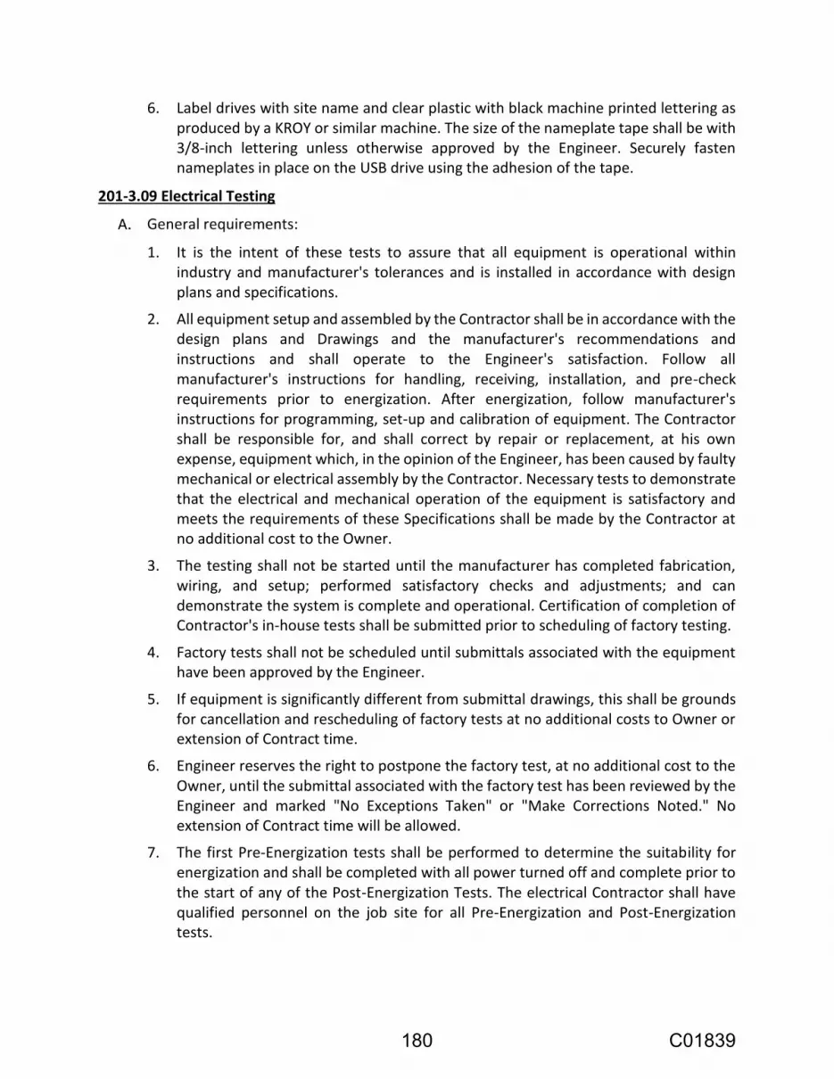
6. Label drives with site name and clear plastic with black machine printed lettering as produced by a KROY or similar machine. The size of the nameplate tape shall be with 3/8-inch lettering unless otherwise approved by the Engineer. Securely fasten nameplates in place on the USB drive using the adhesion of the tape.
201-3.09 Electrical Testing
1. It is the intent of these tests to assure that all equipment is operational within industry and manufacturer's tolerances and is installed in accordance with design plans and specifications.
2. All equipment setup and assembled by the Contractor shall be in accordance with the design plans and Drawings and the manufacturer's recommendations and instructions and shall operate to the Engineer's satisfaction. Follow all manufacturer's instructions for handling, receiving, installation, and pre-check requirements prior to energization. After energization, follow manufacturer's instructions for programming, set-up and calibration of equipment. The Contractor shall be responsible for, and shall correct by repair or replacement, at his own expense, equipment which, in the opinion of the Engineer, has been caused by faulty mechanical or electrical assembly by the Contractor. Necessary tests to demonstrate that the electrical and mechanical operation of the equipment is satisfactory and meets the requirements of these Specifications shall be made by the Contractor at no additional cost to the Owner.
3. The testing shall not be started until the manufacturer has completed fabrication, wiring, and setup; performed satisfactory checks and adjustments; and can demonstrate the system is complete and operational. Certification of completion of Contractor's in-house tests shall be submitted prior to scheduling of factory testing.
4. Factory tests shall not be scheduled until submittals associated with the equipment have been approved by the Engineer.
5. If equipment is significantly different from submittal drawings, this shall be grounds for cancellation and rescheduling of factory tests at no additional costs to Owner or extension of Contract time.
6. Engineer reserves the right to postpone the factory test, at no additional cost to the Owner, until the submittal associated with the factory test has been reviewed by the Engineer and marked "No Exceptions Taken" or "Make Corrections Noted." No extension of Contract time will be allowed.
7. The first Pre-Energization tests shall be performed to determine the suitability for energization and shall be completed with all power turned off and complete prior to the start of any of the Post-Energization Tests. The electrical Contractor shall have qualified personnel on the job site for all Pre-Energization and Post-Energization tests.
180 C01839

8. All tests shall be witnessed by the Engineer and/or Owner personnel. The test forms shall be completed by the testing person for field checkout, testing, and calibration of all equipment and instruments. Filled in test forms shall be given to the Engineer and/or Owner the day of the test. Fill in two sets of test forms if Contractor wants to keep a copy. All tests shall be documented in writing by the supplier and signed by the Engineer as satisfactory completed. The supplier shall keep a detailed log of all tests that failed or did not meet specifications, including date of occurrence and correction. Completed forms with proper signatures and dates shall be included and become a component of the Operations and Maintenance Manual for each of the respective systems.
9. The Contractor shall notify the Owner and the Engineer of the Supplier's readiness to begin all factory and field tests in writing (a minimum of ten working days prior to start), and shall schedule system checkout on dates agreed to by the Owner and the Engineer in order that the testing be scheduled and witnessed.
10. The Contractor shall fill in & submit for approval the "Scheduled Test Request Form" located in Appendix A for each requested inspection, factory and field test.
11. The supplier shall submit for approval, the proposed factory & field testing sheets at least 2 weeks prior to the start of the tests. Each testing sheet shall have a title giving the type of test and entry spaces for the name of the person who performed the test, name of the person who witnessed the test and the date. Tests performed without approved forms shall be retested at no additional cost to Owner.
12. Separate test procedures in separate binders shall be submitted for approval for the Factory and Field Tests. Testing shall not commence until the test procedures have been reviewed and approved by the Owner. Tests forms shall be similar to those shown on Appendix A.
1. Any system material or workmanship which is found defective on the basis of acceptance tests shall be reported to the Engineer. The Contractor shall replace the defective material or equipment and have tests repeated until test proves satisfactory to the Engineer without additional cost to the Owner.
2. If the results of any of tests are unacceptable to the Engineer, the Contractor shall make corrections and perform the tests again until they are acceptable to the Engineer; these additional tests shall be done at no additional cost to the Owner.
3. If testing, installation or configuration work performed is deemed inadequate by Owner or Engineer, then the Contractor shall provide a qualified technician to meet these requirements. No extension of Contract time will be allowed.
1. Testing shall conform to the respective manufacturer's recommendations. All manufacturer's safety precautions shall be followed.
181 C01839

2. The procedures stated herein are guidelines for the intended tests, the Contractor shall be responsible to modify these tests to fit the particular application and ensure personnel safety. Absolutely no tests shall be performed that endanger personal safety.
3. The Contractor shall have two or more personnel present at all tests.
4. Two non-licensed portable radios are to be made available by the Contractor for the testing organization to conduct tests.
5. California Electrical Safety Orders (ESO) and Occupational Safety and Health Act (OSHA): The Contractor is cautioned that testing and equipment shall comply with ESO and OSHA as to safety, clearances, padlocks and barriers around electrical equipment energized during testing.
6. Field inspections and pre-energization tests shall be completed prior to applying power to equipment.
1. The System supplier shall conduct a thorough and complete factory test by qualified factory-trained personnel witnessed by Owner per the criteria specified herein. Factory test shall be held within 150 miles of project location.
2. The "System set-up" for factory testing shall consist of, but is not limited to MMS, MCC, distribution switchboard, VFDs, PLC control panels, and any miscellaneous associated electrical equipment.
3. Temporary wiring and equipment shall be setup during these tests to simulate the complete assembled system.
4. The length of the factory testing for the "System setup" shall be a minimum of two (2) working days. If in the opinion of the Owner or Engineer the factory testing is not completed at the end of the working day, the testing shall be extended, at no additional cost to the Owner or extension in Contract time. The Contractor shall agree that the sum set forth hereafter is a reasonable amount to be charged as liquidated damages; and it is therefore agreed that the Contractor will pay the Owner the sum of one thousand five hundred dollars ($1500.00) in liquidated damages for each and every calendar day beyond the time prescribed above for the completion of factory testing for the System set-up. Liquidated damages will be assessed to the Contractor each and every day past the time allotted for factory testing.
5. All factory tests shall be conducted at the Supplier's facility. All factory tests shall be completed prior to shipment of any of the "System set-up" to the jobsite. The "System set-up" shall be fully assembled, programmed, and connected as it will be installed in the final configuration. If the "System set-up" is found to be not fully and completely ready for factory testing, the Contractor shall be responsible for paying for the Owner and Engineer to return for the factory testing. Factory testing is to ensure that there are no defects. The hardware and software shall be tested for
182 C01839

compliance with the plans and Specifications included herein and for the ability to perform the control functions.
6. The testing shall not be started until the manufacturer has completed fabrication, wiring, setup, and programming; performed satisfactory checks and adjustments; factory testing sheets approved by Owner; and can demonstrate the system is complete and operational. If Owner Representative determines that the System Set-up is not ready for testing, the Owner Representative reserves the right to cancel the Factory Test as the equipment is found to be not fully and completely ready for factory testing. The Contractor shall be responsible for paying for the Owner and Engineer to return for the factory testing when it has been cancelled.
7. All components of the system setup shall be completely assembled and thoroughly pre-tested by the supplier or manufacturer before start of factory test.
8. Provide a complete clean copy of System Supplier drawings for Owner and Engineer's use during Factory Test prior to starting the tests. These drawings shall reflect the equipment being tested.
a. If Owner Representative determines that these drawings do not adequately reflect the actual equipment being tested or differs substantially from the approved equipment submittal, the Owner Representative reserves the right to cancel the Factory Test as the equipment is found to be not fully and completely ready for factory testing.
b. Equipment that differs substantially from the approved equipment submittal shall be resubmitted. Factory test will be rescheduled after revised submittals have been reviewed by the Engineer and marked "No Exceptions Taken" or "Make Corrections Noted".
c. No extension of Contract time will be allowed. Cancellation and rescheduling of factory tests shall occur at no additional costs to Owner.
d. The Contractor shall be responsible for paying for the Owner and Engineer to return for the factory testing when it has been cancelled.
9. The associated factory tests for each of the factory testing sheets that are to be performed by the supplier and witnessed by the Owner/Engineer shall include the following for the "System set-up" as a minimum:
a. Inspections of the panels as follows:
1) Visual and mechanical:
a) Inspect for physical damage, proper support, and wiring.
b) Check all starters, breakers, and other components for proper sizes.
c) The Contractor shall fill in test form TF4 located in Appendix A.
d) Testing of the panels as follows:
183 C01839
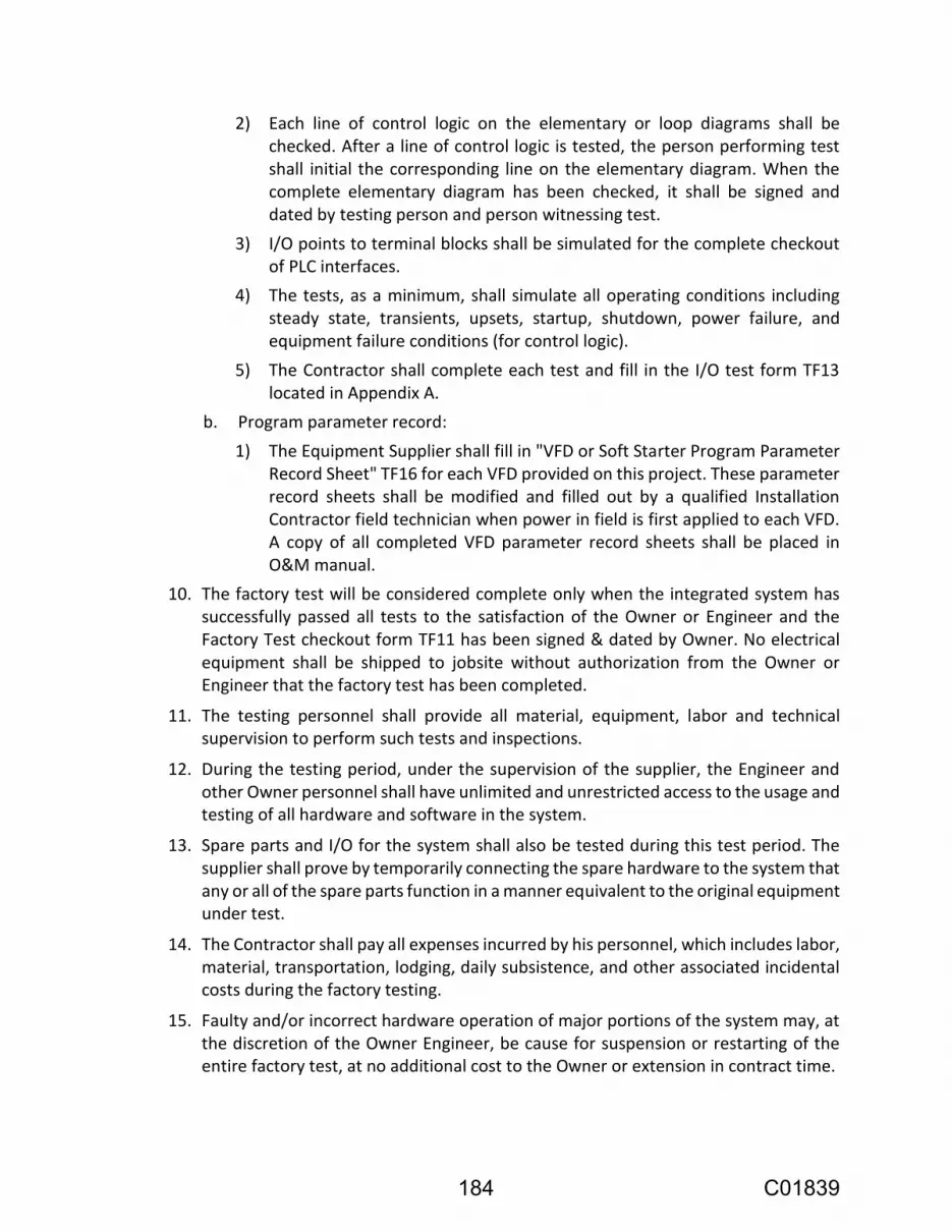
2) Each line of control logic on the elementary or loop diagrams shall be checked. After a line of control logic is tested, the person performing test shall initial the corresponding line on the elementary diagram. When the complete elementary diagram has been checked, it shall be signed and dated by testing person and person witnessing test.
3) I/O points to terminal blocks shall be simulated for the complete checkout of PLC interfaces.
4) The tests, as a minimum, shall simulate all operating conditions including steady state, transients, upsets, startup, shutdown, power failure, and equipment failure conditions (for control logic).
5) The Contractor shall complete each test and fill in the I/O test form TF13 located in Appendix A.
b. Program parameter record:
1) The Equipment Supplier shall fill in "VFD or Soft Starter Program Parameter Record Sheet" TF16 for each VFD provided on this project. These parameter record sheets shall be modified and filled out by a qualified Installation Contractor field technician when power in field is first applied to each VFD. A copy of all completed VFD parameter record sheets shall be placed in O&M manual.
10. The factory test will be considered complete only when the integrated system has successfully passed all tests to the satisfaction of the Owner or Engineer and the Factory Test checkout form TF11 has been signed & dated by Owner. No electrical equipment shall be shipped to jobsite without authorization from the Owner or Engineer that the factory test has been completed.
11. The testing personnel shall provide all material, equipment, labor and technical supervision to perform such tests and inspections.
12. During the testing period, under the supervision of the supplier, the Engineer and other Owner personnel shall have unlimited and unrestricted access to the usage and testing of all hardware and software in the system.
13. Spare parts and I/O for the system shall also be tested during this test period. The supplier shall prove by temporarily connecting the spare hardware to the system that any or all of the spare parts function in a manner equivalent to the original equipment under test.
14. The Contractor shall pay all expenses incurred by his personnel, which includes labor, material, transportation, lodging, daily subsistence, and other associated incidental costs during the factory testing.
15. Faulty and/or incorrect hardware operation of major portions of the system may, at the discretion of the Owner Engineer, be cause for suspension or restarting of the entire factory test, at no additional cost to the Owner or extension in contract time.
184 C01839

16. The factory test will be considered complete only when the system setup has successfully passed all tests both structured and unstructured to the satisfaction of the Owner Engineer. No equipment shall be installed without authorization from the Owner Engineer that the factory test has been completed.
17. Acceptance and witnessing of the factory tests does not relieve or exclude the Contractor from conforming to the requirements of the Contract Documents.
18. All modifications to drawings and documentation as a result of the factory tests shall be corrected and completed before shipment of drawings with equipment and the submittal and delivery of "operation and maintenance" manuals.
19. Copies of the completed, signed, and witnessed factory testing forms shall be placed in the Operation and Maintenance Manual.
1. Prior to any field testing, Interconnection Drawings and Operation & Maintenance Manuals shall have been submitted by the Contractor and approved by the Engineer.
2. The Contractor shall engage and pay for the services of an approved qualified testing company for the purpose of performing inspections and tests as herein specified. The testing company shall provide all material, equipment, labor and technical supervision to perform such tests and inspections. The electrical Contractor shall be present on site for all field tests.
3. The Electrical Contractor shall complete and submit “Schedule Test Request Form” as illustrated in Appendix “A” for each electrical field test.
4. The Electrical Contractor shall be at the jobsite to assist with all Electrical Field Tests.
5. Pre-energization tests: These tests shall be completed prior to applying power to any equipment.
a. Inspections:
1) Visual and mechanical inspections:
a) Inspect for physical damage, proper anchorage and grounding.
b) Compare equipment nameplate data with design plans and starter schedule.
c) Compare overload setting with motor full load current for proper size.
2) Performed NETA acceptance testing for each piece of equipment.
3) The Contractor shall fill in, for each piece of equipment, Test Form TF4 located in Appendix A.
b. Torque connections:
1) All electrical, mechanical and structural threaded connections inside equipment shall be tightened in the field after all wiring connections have been completed. Every worker tightening screwed or bolted connections
185 C01839

shall be required to have and utilize a torque screwdriver/wrench at all times. Torque connections to the value recommended by the equipment manufacturer. If they are not available, use NEC 110-14 for torque values as guidelines.
c. Wire insulation & continuity tests:
1) All devices that are not rated to withstand the 500V megger potential shall be disconnected prior to the megger tests.
2) Megger insulation resistances of all 600 volt insulated conductors using a 500 volt megger for 10 seconds. Make tests with circuits installed in conduit and isolated from source and load. Each field conductor shall be meggered conductor to conductor and conductor to ground. These tests shall be made on cable after installation with all splices made up and terminators installed but not connected to the equipment.
3) Each megger reading shall not be less than 10 Meg-ohms resistive. Corrective action shall be taken if values are recorded less than 10 Meg-ohms. Values of different phases of conductors in the same conduit run showing substantially different Meg-ohm values, even if showing above 10 Meg-ohms shall be replaced.
4) Each instrumentation conductor twisted shielded pair shall have the conductor and shield continuity measured with an ohmmeter. Conductors with high ohm values, that do not match similar lengths of conductors the same size, shall be replaced at no additional cost to the Owner.
5) The Contractor shall fill in test forms Power and Control Conductor Test Form TF1 and Instrumentation Conductor Test Form TF2 located in Appendix A.
d. Grounding system tests:
1) Visual and Mechanical Inspection:
a) Verify ground system is in compliance with Drawings and Specifications.
2) Electrical tests:
a) Before backfilling trenches, and placement of sidewalks, landscape and paving, measure the resistance of each electrode to ground using a ground resistance tester. Perform the test not less than two days after the most recent rainfall and in the afternoon after any ground condensation (dew) has evaporated.
b) After all individual ground electrode readings have been made, interconnect as required and measure the system's ground resistance.
c) The grounding test shall be in conformance with IEEE Standard 81.
186 C01839

d) Measurements shall be made at 10 feet intervals beginning 25 feet from the test electrode and ending 75 feet from it in a direct line between the system being tested and the test electrode.
e) Point-to-point.
3) Perform point-to-point tests to determine the resistance between the main grounding system and all major electrical equipment frames, system neutral, and/or derived neutral points.
4) Test values:
a) The resistance between the main grounding electrode and equipment ground shall be no greater than five ohms per IEEE Standard 142.
b) Investigate point-to-point resistance values that exceed 0.5 ohms.
c) The Contractor shall fill in Grounding System Test Form TF3 located in Section 16010 Appendix A.
d) Plots of ground resistance shall be made and submitted to the Engineer for approval.
e. Panelboard tests:
1) Visual and mechanical inspection:
a) Inspect for physical damage, proper anchorage and grounding.
b) Compare equipment nameplate data with design plans and panelboard schedules.
c) Compare breaker legend for accuracy.
d) Check torque of bolted connections.
2) The Contractor shall fill in Panelboard Test Form TF5 located in Appendix A.
f. Breaker test:
1) All breakers shall be checked for proper mounting, conductor size, and feeder designation. Operate circuit breaker to ensure smooth operation. Inspect case for cracks or other defects. Check tightness of connection with torque wrench in accordance with manufacturer's recommendations.
2) All breakers 100 amps and above shall be tested. Time current characteristic tests shall be performed bypassing three hundred percent (300%) rated current through each pole separately. Trip amps and time shall be measured. Instantaneous pickup current shall be determined by run up or pulse method. Clearing times should be within four (4) cycles or less. All trip times shall fall within NETA Table values. Instantaneous pickup current levels should be within 20% of manufacturer's published values. Certification stickers, listing date and company who performed the tests, shall be attached to the inside of the breaker compartment door right after the breaker has passed all tests.
187 C01839

3) Contact and insulation resistance: Contact resistance shall be measured and be compared to adjacent poles and similar breaker. Deviations of more than 50% shall be reported to Engineer. Insulation resistance shall be measured and shall not be less than 50 megohms.
4) At end of test the all breakers trip settings shall be set by Contractor to values listed in protective device coordination study to properly protect equipment.
5) The Contractor shall fill in MCC Device Test Form TF8 and Breaker Test Form TF9 located in Appendix A.
6. Post energization tests:
a. Panels and enclosure tests:
1) During these tests, test all local and remote control operations and interlocks.
2) Electrical tests.
3) Perform operational tests by initiating control devices to affect proper operation.
4) The Contractor shall fill in Operational Device Checks and Tests Form TF6.
b. Phase rotation tests:
1) Check connections to all equipment for proper phase relationship. During this test, disconnect all devices which could be damaged by the application of voltage or reversed phase sequence. Three phase equipment shall be tested for the phase sequence "ABC" front to back, left to right, and top to bottom.
2) All three phase motors shall be tested for proper phase rotation. Revise wire color codes to indicate correct phase color if wires are swapped.
3) The Contractor shall fill in Phase Rotation Test Form TF7 located in Appendix A.
c. Motor testing:
1) Record the amperage draw on all phases of each motor operating under full load. Ensure that these values do not exceed the motor nameplate full load amperage.
2) Record the voltage between all phases of each motor operating under full load. If the voltage balance is not within plus or minus 5 percent of nominal, request the utility power company or other responsible party to correct the problem.
3) The Contractor shall compile, by visual inspection of equipment installed for each motor, the following data in neatly tabulated form and be placed in the O&M manual:
a) Equipment driven.
188 C01839

b) Motor horsepower.
c) Nameplate amperes.
d) Service factor.
e) Temperature rating.
f) Overload catalog number.
g) Overload current range and setting.
h) Circuit breaker rating.
i) Circuit breaker trip setting, for magnetic only circuit breakers.
4) The Contractor shall fill in Motor Test Form TF10, located in Appendix A.
d. VFD measurement and tests:
1) Measure the voltage and current 5th, 7th, 9th, 11th harmonics at the load side of the ATS with a harmonic analyzer with each combination of pumps or as designated by Engineer at start-up in operation on the utility source and Generator source. Measure and record the results, per the Harmonic Measurements Test Form TF12.
e. Instrumentation tests:
1) The Contractor shall provide a minimum of two (2) hours of field acceptance testing for each instrument. If any instrument has not been fully tested during its allotted time, the Contractor shall provide additional hours for finishing testing of the instrument, to be paid by the Contractor.
2) The overall accuracy of each instrument loop shall be checked to ensure that it is within acceptable tolerance.
3) As a minimum, all the tests indicated/specified on the test form TF14 in Appendix A shall be performed by the Contractor for each of the instruments listed in Appendix B Device Index.
4) Test equipment used for testing shall be of suitable quality so as not to mask performance deficiencies. All test equipment shall be traceable to National Bureau of Standards and have been calibrated within six months of test date.
5) Testing shall be accomplished using simulated inputs only with prior written approval of the Owner.
6) Calibration stickers shall be supplied for all equipment and instruments. Calibration stickers shall list the following information:
a) Tag number.
b) Calibrated by whom (name), firm, city and telephone number.
c) Date calibrated.
d) Calibration range.
e) Comments.
189 C01839

f. Control system tests:
1) All the I/O points for the PLC shall be tested by the system supplier in the field for proper operation of alarms, status, analog, control, autodialer and operator interface (OI) display functions. Where practical, the final element shall be used, i.e. trip the intrusion switch or change levels. Testing shall be accomplished using simulated inputs only when necessary.
2) During this task the System supplier shall have:
a) Qualified field technician with experience in the startup of similar systems with PLC controls, and other field devices.
b) Test instruments as required.
c) A pair of radios for communication.
d) Laptop with programming software for PLC.
3) Contractor to fill in "I/O Point Checkout Sheet" TF13 located in Appendix A.
g. Program parameter record:
1) The Contractor shall fill in "VFD or Soft Starter Program Parameter Record Sheet" TF16 for each VFD provided on this project. These parameter record sheets shall be filled out by a qualified Contractor field technician when power in field is first applied to each VFD. Completion of VFD record sheets shall be witnessed by Owner and copies provided to Owner on day records are filled in by Contractor. A copy of all completed VFD parameter record sheets shall be placed in O&M manual.
h. Trial operations:
1) The entire electrical installation shall be either tested or trial operated to verify Contract compliance. That is, controls, heaters, fans, light switches, convenience receptacles, lights, etc. shall be trial operated. Contractor shall conduct trial operations in the presence of the Engineer and Operations and Maintenance personnel.
1. After all the previous tests in this subsection are complete, the Contractor shall conduct operational testing.
2. The Contractor shall demonstrate operation of each part of the control and instrumentation system to the satisfaction of the Owner and/or Engineer. Tests shall be repeated by the Contractor at no additional cost to the Owner and at the discretion of the Owner and/or Engineer to resolve whether the system has been demonstrated that it will operate under all modes of operations and varying conditions.
3. For the operational testing the new equipment shall be activated to automatically run for 5 days, Monday through Friday 24 hours a day. During this 5-day period the Owner will run the different combinations of the pump control options. If equipment
190 C01839

failure occurs during the 5 days of operational testing, the Contractor shall repair or replace the defective equipment and shall begin another 5-day operational test, Monday through Friday 24 hours a day. This shall be continued until the new equipment functions acceptably for 5 consecutive days.
4. The Electrical Contractor, testing firm and System Supplier shall re-visit the jobsite as often as necessary until all field tests, start-up and operation tests are completed and approved.
201-3.10 Training
201-3.11 Spare Parts
1. Five (5) fuses for each type of fuse.
2. Five (5) lamps for each type of light.
3. One (1) relay for each type of control, power fail and time delay relay.
201-3.12 Warranty
191 C01839

1. Manufacturer's name, service contact person, phone number, and address.
2. Material and equipment description, equipment number, part number, serial number, and model number.
3. Manufacturer's warranty expiration date.
201-3.13 Final Acceptance
192 C01839

1. At the end of the project, following the completion of the field tests, and prior to final acceptance, the Supplier shall:
a. Remove all temporary services, equipment, material, and wiring from the site.
b. Verify Service equipment has been legibly marked in field with the maximum available fault current per NEC 110.24 (A). Field marking shall include date the fault current calculation was performed and be weather & UV rated. Service equipment shall not be hand labeled.
c. Verify that as-installed drawings have been placed in all new or modified panels
2. Provide to the Owner:
a. Listing of warranty information.
b. Each "operation and maintenance" manual shall be modified or supplemented by the Supplier to reflect all field changes and as-built conditions.
c. Four (4) USB drives with copies of all final documentation to reflect as-built conditions.
d. Submit each key with matching duplicate. Wire all keys for each lock securely together. Tag and plainly mark with lock number or equipment identification, and indicate physical location, such as panel or switch number.
201-4 MEASUREMENT AND PAYMENT
201-4.01 Payment
Full compensation for all work in this section is considered as included in the lump sum prices paid for various contract items of work Electrical and Instrumentation, and no additional allowance will be made therefor.
193 C01839

APPENDIX A TEST FORMS
Index of Forms:
Bill of Material Schedule Test Request Form TF1 Power and Control Conductor Test Form TF2 Instrumentation Conductor Test Form TF3 Grounding System Test Form TF4 Visual and Mechanical Inspection Form TF5 Panelboard Test Form TF6 Operational Device Checks and Tests Form TF7 Phase Rotation Test Form TF8 MCC Device Test Form TF9 Breaker Device Test Form TF10 Motor Test Form TF11 Factory Test Checkout Form TF12 Harmonic Measurement TF13 I/O Point Checkout Test Sheet TF14 Instrument Data Sheet and Calibration Record TF16 VFD or Soft Starter Program Parameter Record Sheet
194 C01839

BILL OF MATERIAL
PROJECT: DATE / /
LOCATION: PAGE
SPECIFICATION QTY TAG
SECTION DESCRIPTION MFG. PART NUMBER No.
195 C01839

SCHEDULED TEST REQUEST FORM
COMPANY PERFORMING TEST: ____________________
TESTING PERSONNEL : ____________________ ____________________
PHONE NUMBER OF COMPANY: ____________________
TEST PROCEDURE SUBMITTAL: ____________________ APPROVED : ___/___/___
SCHEDULED TEST DATE : ____________________ DATE : ___/___/___
TIME DESCRIPTION OF TEST
8:00
9:00
10:00
11:00
12:00
13:00
14:00
15:00
16:00
NOTES:
TESTED BY : _____________________ DATE : ____/____/____
WITNESSED BY: _____________________
196 C01839

POWER AND CONTROL CONDUCTOR TEST FORMTEST FORM (TF1)
EQUIPMENT
NAME : ______________________ LOCATION : ______________________
INSULATION TESTS
CONDUCTOR PHASE TO GROUND PHASE TO PHASE
NUMBER
A B C AB BC CA
NOTES:
Record insulation test values in meg-ohms.
TESTED BY : _____________________ DATE : ____/____/____
WITNESSED BY: _____________________
197 C01839

INSTRUMENTATION CONDUCTOR TEST FORMTEST FORM (TF2)
EQUIPMENT
NAME : _________________________ LOCATION : _________________________
CONDUCTOR CONTINUITY TESTS INSULATION TESTS
PAIR CONDUCTOR CONDUCTOR CONDUCTOR CONDUCTORS SHIELD
NUMBER TO TO TO TO TO
CONDUCTOR SHIELD CONDUCTOR GROUND* GROUND
NOTES: * With both conductors tied together
Record continuity test values in ohms.
record insulation test values in meg-ohms.
TESTED BY : _____________________ DATE : ____/____/____
WITNESSED BY: _____________________
198 C01839

GROUNDING SYSTEM TEST FORMTEST FORM (TF3)
FALL IN POTENTIAL TEST
MAIN APPLIED MEASURED MEASURED MEASURED CALCULATED
GROUND VOLTAGE POINT 1 POINT 2 POINT 3 RESISTANCE
LOCATION V VOLTAGE VOLTAGE VOLTAGE OHMS
TWO POINTS TESTS
EQUIPMENT EQUIPMENT CIRCUIT APPLIED MEASURED CALCULATED
NAME # # CURRENT VOLTAGE RESISTANCE
OHMS
NOTES:
TESTED BY : _____________________ DATE : ____/____/____
WITNESSED BY: _____________________
199 C01839

VISUAL AND MECHANICAL INSPECTION FORMTEST FORM (TF4)
EQUIPMENT
NAME : ______________________ LOCATION : ______________________
NAMEPLATE DATA
MFGR. : _____________ SERIES # : _____________
MODEL # : _____________ U.L. # : _____________
VOLTAGE : _____________ PHASE : _____________
AMPERAGE : _____________ SERVICE : _____________
BUS TYPE : _____________ BUS BRACING: _____________
VERT. BUS : _____________ HORZ. BUS : _____________
GND. BUS : _____________ NEU. BUS : _____________
ENCLOSURE : _____________ _____________
_____________ _____________
INSPECTION CHECK LIST
ENTER: A-ACCEPTABLE R-NEEDS REPAIR OR REPLACEMENT NA-NOT APPLICABLE
TIGHTEN ALL BOLTS AND SCREWS _____________
TIGHTEN ALL WIRING AND BUS CONNECTIONS _____________
VERIFY ALL BREAKERS AND FUSES HAVE PROPER RATING _____________
CHECK BUS BRACING AND CLEARANCE _____________
CHECK MAIN GROUNDING CONNECTION AND SIZE _____________
INSPECT GROUND BUS BONDING _____________
CHECK EQUIPMENT GROUNDS _____________
CHECK CONDUIT GROUNDS AND BUSHINGS _____________
INSPECT NEUTRAL BUS AND CONNECTIONS _____________
CHECK HEATERS AND THERMOSTATS _____________
CHECK VENTILATION AND FILTERS _____________
CHECK FOR BROKEN OR DAMAGED DEVICES _____________
CHECK DOOR AND PANEL ALIGNMENT _____________
INSPECT ANCHORAGE _____________
CHECK FOR PROPER CLEARANCES AND WORKING SPACE _____________
REMOVE ALL DIRT AND DUST ACCUMULATION _____________
INSPECT ALL PAINT SURFACES _____________
CHECK FOR PROPER WIRE COLOR CODES _____________
INSPECT ALL WIRING FOR WIRE LABELS _____________
CHECK FOR PROPER WIRE TERMINATIONS _____________
CHECK FOR PROPER WIRE SIZES _____________
INSPECT ALL DEVICES FOR NAMEPLATES _____________
CHECK IF DRAWINGS MATCH EQUIPMENT _____________
CHECK ACCURACY OF OPERATION & MAINTENANCE _____________
_____________
TESTED BY : _____________________ DATE : ____/____/____
WITNESSED BY: _____________________
200 C01839

PANEL-BOARD TEST FORMTEST FORM (TF5)
PANEL NAME: ______________________ LOCATION : ______________________
NAMEPLATE DATA
MFGR. : _____________ SERIES # : _____________
MODEL # : _____________ U.L. # : _____________
VOLTAGE : _____________ PHASE : _____________
AMPERAGE : _____________ SERVICE : _____________
BUS TYPE : _____________ BUS BRACING: _____________
VERT. BUS : _____________ HORZ. BUS : _____________
GND. BUS : _____________ NEU. BUS : _____________
ENCLOSURE : _____________ MAIN BKR : _____________
INSULATION RESISTANCE TESTS - MEGOHMS
A-GND B-GND C-GND
INSPECTION CHECK LIST
ENTER: A-ACCEPTABLE R-NEEDS REPAIR OR REPLACEMENT NA-NOT APPLICABLE
TIGHTEN ALL BOLTS AND SCREWS _____________
TIGHTEN ALL WIRING AND BUS CONNECTIONS _____________
VERIFY ALL BREAKERS AND FUSES HAVE PROPER RATING _____________
CHECK BUS BRACING AND CLEARANCE _____________
CHECK MAIN GROUNDING CONNECTION AND SIZE _____________
INSPECT GROUND BUS BONDING _____________
CHECK EQUIPMENT GROUNDS _____________
CHECK CONDUIT GROUNDS AND BUSHINGS _____________
INSPECT NEUTRAL BUS AND CONNECTIONS _____________
CHECK FOR BROKEN OR DAMAGED DEVICES _____________
CHECK DOOR AND PANEL ALIGNMENT _____________
INSPECT ANCHORAGE _____________
CHECK FOR PROPER CLEARANCES AND WORKING SPACE _____________
REMOVE ALL DIRT AND DUST ACCUMULATION _____________
INSPECT ALL PAINT SURFACES _____________
CHECK FOR PROPER WIRE COLOR CODES _____________
INSPECT ALL WIRING FOR WIRE LABELS _____________
CHECK FOR PROPER WIRE TERMINATIONS _____________
CHECK FOR PROPER WIRE SIZES _____________
INSPECT ALL DEVICES FOR PROPER LEGEND NAMEPLATES _____________
_____________
CALIBRATION TEST EQUIPMENT PART NO. DATE CALIBRATED:
TESTED BY : _____________________ DATE : ____/____/____
WITNESSED BY: _____________________
201 C01839

OPERATIONAL DEVICE CHECKS AND TESTS FORM
TEST FORM (TF6)
NAME : ______________________ LOCATION : ______________________________
LOCAL SITE DEVICE CHECKS AND TESTS REMOTE SITE DEVICE CHECKS & TESTS
CUB. EQUIPMENT EQUIP SELECTOR INDICATOR PUSHBUTTON METERING OVERLOAD INTERLOCKS ALARM SELECTOR INDICATOR PUSHBUTTON
# NAME # SWITCH LIGHTS & LOS & INDICATORS RESET & CONTROL & STATUS SWITCH LIGHTS & LOS
NOTES:
TESTED BY : ______________________ DATE : ____/____/____
WITNESSED BY : ______________________
202 C01839

PHASE ROTATION TEST FORMTEST FORM (TF7)
PHYSICAL PHASE MEASURED
EQUIPMENT EQUIPMENT CIRCUIT PHASE COLOR PHASE
NAME # # LOCATION CODE ROTATION
NOTES:
Use phase tester to verify all circuits and equipment have a clockwise A-B-C phase rotation.
Physical phase locations: Left to Right - LR or Top to Bottom - TB
Phase color codes: Brown, Orange, & Yellow -BOY
Black, Red, & Blue -BkRBe
TESTED BY : _____________________ DATE : ____/____/____
WITNESSED BY: _____________________
203 C01839

MCC DEVICE TEST FORMTEST FORM (TF8)
MCC # : ______________________ CUBICLE : ______________________
EQUIP NAME: ______________________ EQUIP # : ______________________
MOTOR DATA CONTACTOR DATA
H.P. : ____________ MFGR. : ____________ PART # : ______________
F.L.A. : ____________ NEMA SIZE : ____________ COIL VOLT : ______________
OVERLOAD TESTS
MFGR. : ____________ HEATER # : ____________ RANGE : ______________
PART # : ____________ FINAL OVERLOAD SETTING: ______________
TEST MEASURE TRIP TIME @ TEST AMPS MFGR LISTED AMBIENT
AMPS PHASE A PHASE B PHASE C TRIP TIME COMPENSATION
BREAKER TESTS
MRGR. : ____________ PART # : ____________ FRAME # : ______________
CONTACT RESISTANCE TESTS - OHMS INSULATION RESISTANCE TESTS-MEGOHMS
PHASE A PHASE B PHASE C A-GND B-GND C-GND
MFGR TRIP TIME @300% MIN:___________ BREAKER RATING / RANGE: ______________
MFGR TRIP TIME @300% MAX:___________ FINAL BREAKER SETTING: ______________
MFGR INST. PICKUP AMPS: ______________
TIME-CURRENT TEST
TRIP TIME IN SECONDS @ 300% AMPS INSTANTANEOUS TRIP TEST - AMPS
PHASE A PHASE B PHASE C PHASE A PHASE B PHASE C
NOTES:
TESTED BY : _____________________ DATE : ____/____/____
WITNESSED BY: _____________________
204 C01839

BREAKER DEVICE TEST FORMTEST FORM (TF9)
FEEDER : ____________ LOCATION : ____________
EQUIP NAME: ____________ EQUIP # : ____________
EQUIP H.P. : ____________ EQUIP KVA : ____________
MFGR. : ____________ PART # : ____________FRAME # : __________
VOLTAGE : ____________ INTERRUPT : ____________ CHARACTER: __________
RATING CURVE
CONTACT RESISTANCE TESTS - OHMS INSULATION RESISTANCE TESTS - MEGOHMS
PHASE A PHASE B PHASE C A-GND B-GND C-GND
MFGR TRIP TIME @300% MIN : ____________ BREAKER RATING / RANGE: __________
MFGR TRIP TIME @300% MAX: ____________ FINAL BREAKER SETTING : __________MFGR INST. PICKUP APMS:
TEST-CURRENT TESTS
TRIP TIME IN SECONDS @ 300% AMPS INSTANTANEOUS TRIP TEST - AMPS
PHASE A PHASE B PHASE C PHASE A PHASE B PHASE C
ADDITIONAL TESTS AND SETTING AS APPLICABLE
PICKUP DELAY-TIME
FUNCTION RANGE SETTING RANGE SETTING
LONG TIME
SHORT TIME
GROUND FLT.
NOTES:
TESTED BY : _____________________ DATE : ____/____/____
WITNESSED BY: _____________________
205 C01839

MOTOR TEST FORMTEST FORM (TF10)
EQUIPMENT
NUMBER : ____________________ NAME : ___________________________
NAMEPLATE DATA - FIELD RECORDED
MANUFACTURER MODEL # SERIAL # FRAME #
H.P. R.P.M F.L.A VOLTS PHASE FREQ. P.F. S.F.
CODE N.E.M.A. INSUL. ENCLOSR. DUTY DESIGN
INSULATION TESTS MOTOR FRAME MOTOR MOTOR
PHASE TO GROUND GROUNDING SYSTEM TEST HEATER THERMAL
MEG-OHMS APPLIED MEAS. CALC. MEAS. TRIP
A B C VOLTS AMPS OHMS AMPS TEST
MOTOR TESTS - MEASURED VALUES
AMPERAGE VOLTAGE POWER
A B C AB BC CA FACTOR WATTAGE
NOTES:
VOLTAGE, AMPERAGE, POWER FACTOR, & WATTAGE SHALL BE RECORDED WITH
A TRUE RMS METER.
TESTED BY : _____________________ DATE : ____/____/____
WITNESSED BY: _____________________
206 C01839

Z:\ateem\Spec Test Forms\TF11-MCC & CP Checkout.doc
FACTORY TEST MCC/CONTROL PANEL CHECKOUT FORM (TF11)
Manufacturer: Location:
Job No.:
Tel: Fax:
MCC / Control Panel: TEST RESULT
OVERALL PANEL INSPECTION Pass Fail
1. All front panel and back panel components mounted securely......................
2. All wiring terminated and labeled correctly...................................................
3. All components, wiring, and labeling accurately reflected on the drawings..
POWER-UP INSPECTION
1. Voltage levels on load side of circuit breakers...............................................
2. Voltage levels at the DC terminals of the power supply................................
3. Voltage levels at the DC power distribution terminals...................................
POWER DISTRIBUTION AND GENERAL COMPONENT TESTING
1. Power distribution to the appropriate components.........................................
2. Operation of the ancillary components such as receptacles, work lights, etc.
CONTROL COMPONENTS CHECKS
1. Operators (push buttons, selector switches, pilot lights)................................
2. Inputs from External Sources.........................................................................
3. Outputs to External Sources...........................................................................
4. Relay Logic.....................................................................................................
5. PLC I/O and Program Verification.................................................................
6. O/I Display Verification.................................................................................
Notes:
1. For relay logic checks, each rung of the elementary or loop diagram is to be highlighted in yellow as
they are verified for correct control functions.
2. For PLC I/O and program verification, the control strategies shall be highlighted in yellow as each
logic function is tested.
Tested by: Witnessed by:
Date:
207 C01839

HARMONIC MEASUREMENTSTEST FORM (TF12)
PUMP # ____ RUNNING
VFD SPEED 100% 90% 80% 70% 60% 50%
TIME
AVG. VOLTS
TOTAL AMPS
TOTAL KW
TOTAL KVA
TOTAL KVAR
PF
dP
VOLTAGE THD
AMPS THD
5th
7th
11th
13th
PUMP # ____ RUNNING
VFD SPEED 100% 90% 80% 70% 60% 50%
TIME
AVG. VOLTS
TOTAL AMPS
TOTAL KW
TOTAL KVA
TOTAL KVAR
PF
dP
VOLTAGE THD
AMPS THD
5th
7th
11th
13th
208 C01839

I/O POINT CHECKOUT TEST FORMTEST FORM (TF13)
I/O TYPE : ____________________ LOCATION : __________________________
TEST DATE
I/O I/O INPUT DISPLAY PLC TEST RESULT OF
POINT POINT VALUE % VALUE % REGISTER FAIL OR PASS CORRECTIVE
TAGNAME ADDRESS 0 50 100 0 50 100 VALUE COMMENTS ACTION
NOTES:
TESTED BY : _____________________ DATE : ____/____/____
WITNESSED BY: _____________________
209 C01839

INSTRUMENTATION DATA SHEET AND CALIBRATION RECORD TEST FORM (TF14)
Component Description Manufacturer Location
Name Site
Component Tag Name Model Equip
Serial #
Range Unit General Notes
Indicator Range 1) Attach Calibration Curves for dp Flowmeters
Input Range 2) Include mounting elevations for level Instruments
Output Range 3) All entries within solid box to be typed in prior to start of test
Input Signal Output Eng. Value Input Output
Notes
Tested by (Print Name) Witnessed by (Print Name)
Signature Signature
Date / / Date / /
Designed Calibration
Comments
Measured Calibration
210 C01839

VFD OR SOFT STARTER PROGRAM PARAMETER RECORD SHEETTEST FORM (TF16)
EQUIPMENT
NAME : _________________________ LOCATION : _________________________
PARAMETER PARAMETER DEFAULT FIELD
NUMBER SETTING SETTING
NOTES:
TESTED BY : _____________________ DATE : ____/____/____
WITNESSED BY: _____________________
DESCRIPTION
211 C01839

APPENDIX B
DEVICE INDEX
212 C01839

213C
01839
SECTION 201 -APPENDIX "B" DEVICE INDEX
MINIMUM DWG REF DET I 201
P&ID NEMA SP/ NOTES AND TEST E-DWG DWG TAG NO. DESCRIPTION TYPE SPECIFICATION RATING SIZE RANGE UNITS MOUNTING ACCESSORIES FORM
E41 12 PIT 4161 Press Indicating Transmitter Gauge 201-2.05.A 4X - 0-50 PSI E12 D Cal Val 201-2.05.B TF-14 - r::,- . . . E42 13 PIT 4261 Press lnd1catmg Transm1tter Gauge 201-2.05.A 4X - 0-50 PSI E12 D TF-14 E41 12 FE 4171 Flow Element Mag 201-2.05.0 - - - - E12 E -E41 12 FIT 4171 Flow Indicating Transmitter Mag 201-2 05.0 - - 0-1000 - GPM PANEL TF-14 E42 13 FE 4271 Flow Element Mag 201-2.05.0 - - - - E12 E -- ---- -- --E42 13 FIT 4271 Flow Indicating Transmitter Mag 201-2.05.0 - - 0-2000 GPM PANEL TF-14 E42 13 FSL 4211 Flow Switch Paddle 201-2.05.E - - 1 GPM TF-14 E42 13 sv 4211 Solenoid Valve - 100 - - 1 GPM Pipe TF-14 E41 12 L T 4151 Level Transmitter Gauge 201-2.05.C - - 0-375 FT Well 380' below top well TF-7
·-fT Gauge - -
E42 13 4251 Level Transmitter 201-2.05.C - - 0-255 FT Well 250' below top well TF-7 - -E41 12 TSH 411 1 Temperature Switch N.C. 100 - - - - - Motor TF-7 - - -E41 12 MSH 411 1 Moisture Switch N.C. 100 - - - - - Motor TF-7 ---E42 13 TSH 4211 Temperature Switch N.C. 100 - - - - - Motor TF-7 - 14 zs 4191 A Position Switch N.C. 201-2.05F - - - - Bldg Door TF-7 -- -
I 14 zs 4291 A_ l'<>slti()_n _S_Y.fitch _ N.C. 201-2.05F Bldg Door TF-7 ---
- - - -- - -------- -------- ---------- - - - ---- ----- ------------

SECTION 202 ELECTRICAL SYSTEM ANALYSIS
202-1 GENERAL
202-1.01 Submittals
1. Short Circuit Study.
2. Coordination Study
3. Arc Flash Study.
1. Itemize all exceptions and clarifications to the Contract Documents in a letter (located in the front of the submittal) on company letterhead.
2. Exceptions that are noted in the study, but not listed on the Exceptions/Clarifications letter, will be considered as non-responsive and not accepted as changes to the Contract Documents.
3. All exceptions taken from the Drawings and specifications shall be documented with justifications. When noting the exception, list which Drawings or which Specification Subsection number the exception is taken.
4. Clarification requests shall list which Drawing or Specification Subsection number the clarification is required for.
202-1.02 Sequencing and Scheduling
214 C01839

202-2 MATERIALS
202-2.01 General
215 C01839

202-2.02 Short Circuit Study
1. Cable impedances based on copper conductors.
2. Bus impedances based on copper bus bars.
3. Transformer impedances based on tolerances specified in ANSI C57.12.00.
4. Source date (i.e. cable lengths, sizes, and quantity, for all runs in study, listing of bus loads, etc.).
5. Utility data:
a. Size of Utility transformer.
b. Impedance of Utility transformer.
c. Primary voltage of Utility transformer.
d. Fault information on primary side of Utility transformer:
1) Three phase bolted fault.
2) X/R ratio (positive sequence).
3) Line to ground fault.
4) X/R ratio (zero sequence).
e. Protective relays (type & settings).
6. Voltage drop and current flow at each node and load in system.
1. Power transformer’s primary
2. Main Switchboard.
3. All Motor Control Centers (MCCs).
4. All panelboards.
5. All 480V, 3-phase motor and equipment loads.
6. All 3-phase transformer secondaries.
7. All 240/208V equipment.
1. Equipment and protective devices are applied within their ratings.
2. Adequacy of switchboard, panelboard and MCC bus bars to withstand Short Circuit stresses.
3. Adequacy of transformer windings to withstand Short Circuit stresses and over-current.
4. Cable sizes for ability to withstand normal and fault load currents.
216 C01839

1. Calculation methods and assumptions.
2. Input data.
3. Short circuit data.
a. Impedances.
b. X to R ratios.
c. Asymmetry factors.
d. Motor contributions.
e. Short Circuit kVA.
f. Symmetrical and asymmetrical line-to-line and line-to-ground fault currents.
g. Device evaluation including rating of equipment.
h. Bus evaluation including rating of equipment.
i. Source data, from Electric Utility Company.
4. Source data from Generator Supplier (where applicable).
5. Tabulations of calculated quantities.
6. Results, conclusions, and recommendations.
7. One line diagram of distribution system
8. Impedance diagram showing the resistances and reactances for all cables of the distribution system.
9. Two studies (minimum) – one for one for actual equipment operating and one for arc flash reduction switch enabled (where applicable).
10. Calculations for maximum and minimum contributions of fault current magnitude. The minimum calculation shall assume the minimum motor load. Conversely, the maximum calculation shall assume a maximum contribution from the Utility and shall assume motors to be operating under full-load conditions. The Study shall also calculate the fault current using in-rush current values.
202-2.03 Protective Device Coordination Study
1. Graphically diagram displaying coordination time-current curves on conventional log-log curve sheets. Each time-current curve shall have a unique identifier label. This identifier shall be used in the tabulated settings spreadsheet and on the associated one-line diagram.
2. Time-current curves shall include the following curves (minimum):
a. Utility relays (phase & ground) and high voltage switchgear relays (phase and ground).
217 C01839

b. All upstream protective devices and breakers.
c. All MCP breaker and associated motor or equipment load. Duplicates of the same sized protective device and motor size may be omitted (i.e., when there are 3 pumps for same application).
d. All transformers and associated primary and secondary protection.
e. Unique identifier for each protective device.
f. Provide separate TCC for phase and ground curves. Ground curves shall not be placed on the same curve as phase curves.
3. One-line diagram that applies to specific portion of distribution system associated with time-current curves. One-line diagram shall include the following:
a. Location of each device.
b. Power and voltage ratings, primary and secondary transformers amperages.
c. All significant circuit elements such as transformers, cables, breakers, fuses, relays, etc. with their corresponding amperage ratings.
d. Tag of each branch and node (shall be the same tags used in short circuit study).
e. English description, equipment name, HP, and full load amp rating of motors and other 3 phase loads.
f. Terminate device characteristic curves at a point reflecting maximum fault current to which device is exposed as calculated in short circuit study.
1. Protective current relays.
2. Fuses including manufacturer’s minimum melts, total clearing, tolerance, and damage bands.
3. Circuit breaker trip devices, including manufacturer’s tolerance bands.
4. Transformer full-load currents at 100% and 600%.
5. Motors fed from VFDs and Soft Starters shall have their curves adjusted according to inrush currents on the TCC.
6. Transformer magnetizing inrush currents.
7. Transformer damage curves.
8. ANSI transformer withstand parameters.
9. Fault currents.
10. Ground fault protective device settings.
11. Other electronic protective devices.
1. Relay settings including CT values.
218 C01839

2. Circuit Breakers adjustments:
a. Long Delay Pickup and Time.
b. Short Time Pickup and Time.
c. Instantaneous Pickup and Time.
d. Ground Pickup and Time.
3. Programmable settings for all electronic devices. Settings for non-current relay settings shall also be provided.
4. Settings shall be given both in amps and seconds as well as the corresponding physical setting (i.e. 30A and setting B on MCP) for device.
5. Identify protective device associated with each curve by manufacturer type, function and part number.
202-2.04 Arc Flash Hazard Study
1. Arc flash boundary and incident energy shall be calculated using a PC computer program at all significant locations in the electrical network, including switchgears, switchboards, MCCs, transformers, and other major equipment where work could be performed on energized equipment.
2. Arc flash computation shall include both line and load side of main breaker calculations, where necessary.
3. Document method of calculation.
1. All significant locations in 480 volt, 240 volt and 208 volt systems fed from transformers equal to or greater than 125 kVA.
2. Incident energy and flash protection boundary calculations in spreadsheet format in the Arc Flash Hazard study report.
3. Provide the following incident energy and flash protection boundary calculations in spreadsheet format in the Arc Flash Hazard study report (values shall be calculated for all electrical equipment in the power distribution system):
a. Arcing fault magnitude
b. Device clearing time
c. Duration of arc
d. Boundary for:
1) Arc flash limited shock approach
2) Limited shock approach
219 C01839

3) Restricted shock approach
e. Working distance
f. Incident energy at 18 inches (in cal/sq-cm)
g. Recommendations for arc flash energy reduction for each location having more than 8 cal/sq-cm. Provide preliminary cost estimate for implementing recommendations.
4. Provide recommendations for the Personal Protective Equipment (PPE) that the Owner should maintain on site for the level of hazard.
5. Provide recommendations for safety label design that should be posted on electrical equipment.
6. Provide separate studies with ARM switch.
7. Spreadsheet summarizing incident energy and flash protection boundary list Arc Flash Boundary in inches on label. No fractional distance in feet.
202-2.05 Study Reports
1. Scope of Studies performed.
2. Explanation of bus and branch numbering system.
3. Report calculations, tabulations and spreadsheets.
4. Selected equipment deficiencies.
5. Results of Studies.
6. Comments, recommendations or suggestions regarding:
a. Changes and additions to equipment rating and/or characteristics.
b. Circuit protective devices improperly rated for overload or fault conditions.
c. Arc Flash protective equipment and safety labels.
7. Tabulation spreadsheet for all protective device settings with the following column entries (minimum):
Device Code
Description MFR Type Plug Trip
Frame KAIC Long Time Short Time Inst Ground
Amps Time Amps Time Amps Amps Time
8. Stamped, signed and dated by Electrical Engineer registered in the State of California
who performed the analysis.
220 C01839

202-3 EXECUTION
202-3.01 General
202-3.02 Field Tests
202-3.03 Arc Flash Warning Labels
1. Nominal system voltage
2. Arc Flash boundary
3. Available incident energy and working distance (in inches)
4. Minimum arc rating of clothing
5. Site specific level of PPE
6. Engineering report number, revision number and issue date
1. Working distances
2. Shock hazard voltage
3. Shock Approach Boundaries:
a. Limited
b. Restricted
221 C01839

1. 480V and applicable 208V panelboards
2. MCCs
3. Switchboard
4. Switchgears
5. Control Panels
6. All electrical equipment with an incident energy level greater than 1.2 Cal/cm2.
7. Where Switchgear, Switchboard, MCC, Panelboard, Distribution Panel, etc. feed multiple circuit breakers from the enclosure, provide separate line and load side Arc Flash Labels for the Main Circuit Breaker.
8. Provide separate labels at each circuit breaker that has arc flash reduction switches indicating the appropriate values when the switch is enabled.
202-3.04 Arc Flash Training
202-4 MEASUREMENT AND PAYMENT
202-4.01 Payment
Full compensation for all work in this section is considered as included in the lump sum prices paid for various contract items of work Electrical and Instrumentation, and no additional allowance will be made therefor.
222 C01839

SUPPLEMENTARY SPECIA L PROVISIONS
SECTION A - FEES AND PERMITS
The Contractor shall obtain all necessary and required permits for the project. All permits issued by the City Building Department will be issued at no cost to the Contractor; these fees will be paid by an appropriate City department. All other required permits shall be obtained at the Contractor's expense.
All electrical service charges or fees that may be required by Pacific Gas and Electric Company shall be paid for by an appropriate City department.
[Version: 2/2/15CDA STD2010]
223 C01839

SECTION B - SPECIAL PROJECT PROCEDURES
B-01 All work in Farmers Lane: The Contractor shall be fully informed of the following requirements:
1. Special working hours for this portion of the project are between 9:00 pm and 6:00 am, Monday through Friday, excluding Federal holidays.
2. During special work hours, the Contractor will be allowed to use one southbound lane
3. Additional traffic and pedestrian control and construction lighting measures will be required for special working hours.
B-02 725 Farmers Lane: The City has has a pending Temporary Construction Easement (TCE) from this property to allow contractor staging. The Contractor shall be fully informed of the following requirements:
1. Contractor shall protect or restore in kind the ground surface impacted by construction operations, including asphalt paving, parking lot striping, landscaping, and other features such as feature lighting and irrigation lines. Areas of the public sidewalk impacted by the project will also be restored in kind. The Contractor shall assume sole and complete responsibility in this area and repair any damage done by their operations at no additional cost to the City.
B-03 745-755 Farmers Lane: The City has has a pending Temporary Construction Easement (TCE) from this property. The Contractor shall be fully informed of the following requirements:
1. Due to higher customer traffic after 3 pm on weekdays, Contractor shall cease major activities that limit parking after 3pm. No work shall be performed the week between Christmas and New Year’s Day at Well 4-1.
2. Contractor shall protect or restore in kind the ground surface impacted by construction operations, including asphalt paving, parking lot striping, landscaping, and other features such as feature lighting and irrigation lines. Areas of the public sidewalk impacted by the project will also be restored in kind. The Contractor shall assume sole and complete responsibility in this area and repair any damage done by their operations at no additional cost to the City.
B-04 777 Farmers Lane: The City has obtained a right of entry from this property. The Contractor shall be fully informed of the following requirements:
1. Major Operations limiting parking shall be done outside of business hours .
2. Contractor shall protect or restore in kind the ground surface impacted by construction operations, including asphalt paving, parking lot striping, landscaping, and other features such as feature lighting and irrigation lines. Areas of the public sidewalk impacted by the project will also be restored in kind. The Contractor shall assume sole and complete responsibility in this area and repair any damage done by their operations at no additional cost to the City.
224 C01839
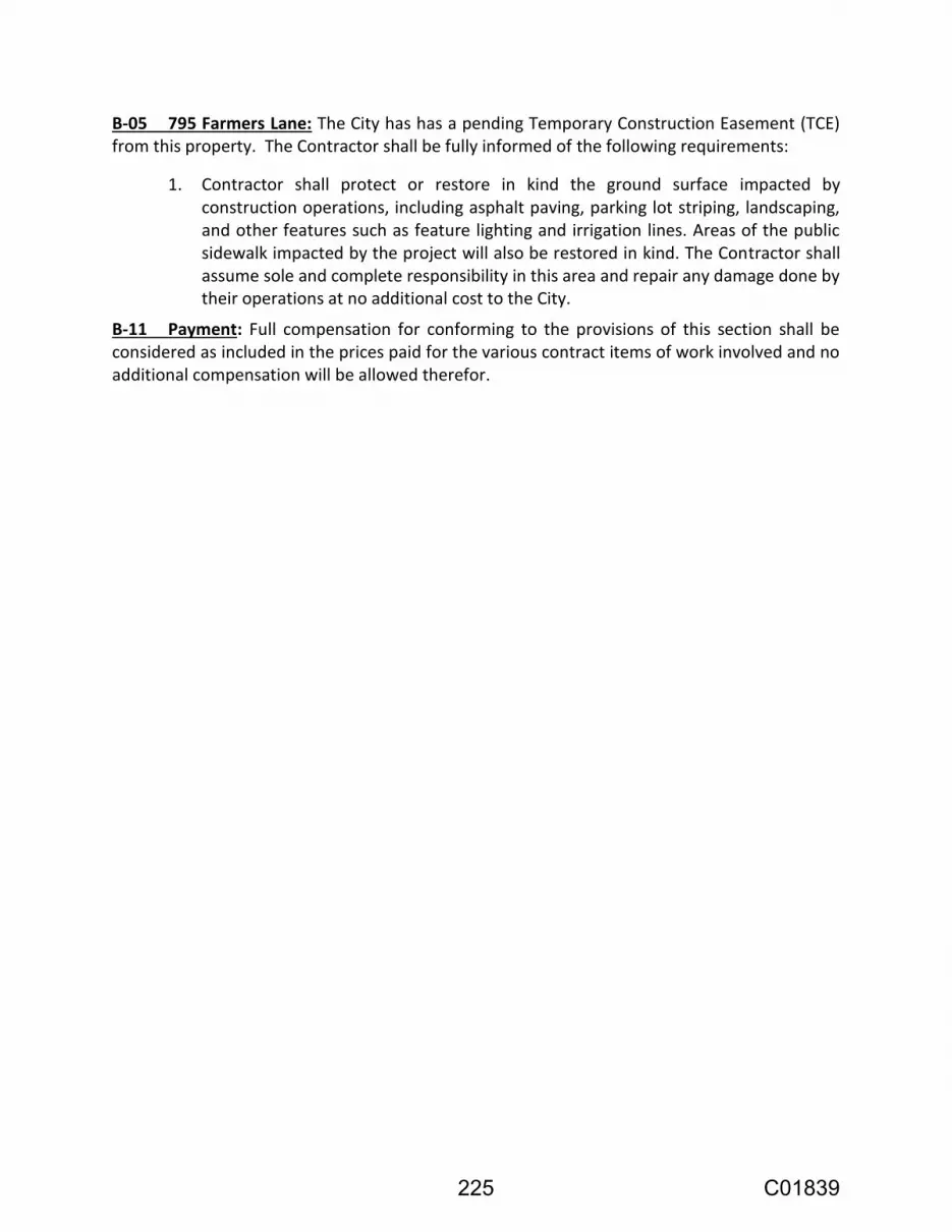
B-05 795 Farmers Lane: The City has has a pending Temporary Construction Easement (TCE) from this property. The Contractor shall be fully informed of the following requirements:
1. Contractor shall protect or restore in kind the ground surface impacted by construction operations, including asphalt paving, parking lot striping, landscaping, and other features such as feature lighting and irrigation lines. Areas of the public sidewalk impacted by the project will also be restored in kind. The Contractor shall assume sole and complete responsibility in this area and repair any damage done by their operations at no additional cost to the City.
B-11 Payment: Full compensation for conforming to the provisions of this section shall be considered as included in the prices paid for the various contract items of work involved and no additional compensation will be allowed therefor.
225 C01839

BID FORMS
C I T Y O F S A N T A R O S A
STATE OF CALIFORNIA
FARMERS LANE WELL FACILITY REHABILITATION The work to be performed and referred to herein is in the City of Santa Rosa, California and consists of improvements to be constructed in accordance with the provisions of the Invitation for Bids, containing the Notice to Bidders, the Special Provisions, the Project Plan(s), the Bid Forms and the Contract, all of which are by reference incorporated herein, and each Addendum, if any is issued, to any of the above which is also incorporated by reference herein.
TO THE AWARD AUTHORITY OF THE CITY OF SANTA ROSA The undersigned, as bidder, declares that the only person or parties interested in this bid as principals are those named herein; that this bid is made without collusion with any other person, firm, or corporation; that Contractor has carefully examined the Project Plans, Invitation for Bids and conditions therefor, and is familiar with all bid requirements, that Contractor has examined this Contract and the provisions incorporated by reference herein, and Contractor hereby proposes, and agrees that if its bid is accepted by the City, Contractor will provide all necessary machinery, tools, apparatuses, and other means of construction, and to do all the work and furnish all the materials and services required to complete the construction in accordance with the Contract, the Special Provisions, the Project Plan(s), and Addenda to any of the above as incorporated by reference, in the time stated herein, for the unit prices and/or lump sum prices as follows:
226 C01839
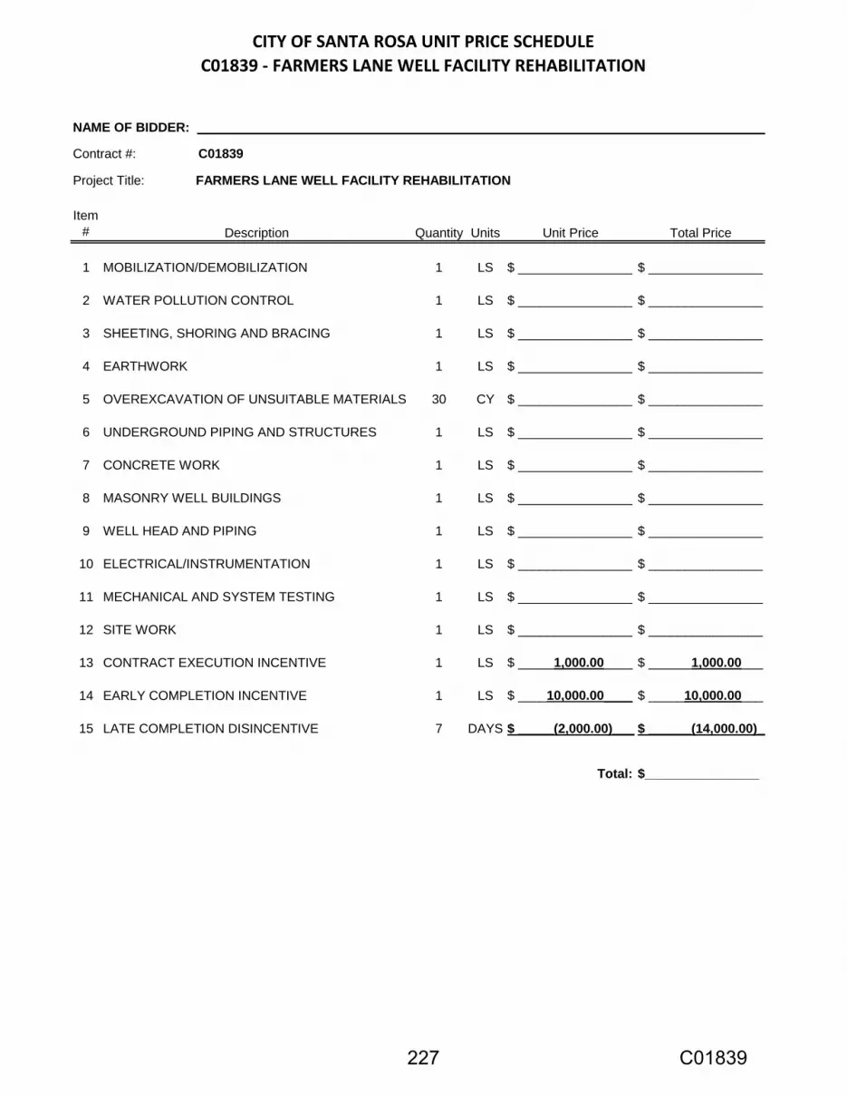
CITY OF SANTA ROSA UNIT PRICE SCHEDULE
C01839 - FARMERS LANE WELL FACILITY REHABILITATION
Item
# Description Quantity Units Unit Price Total Price
1 MOBILIZATION/DEMOBILIZATION 1 LS $ ________________ $ ________________
2 WATER POLLUTION CONTROL 1 LS $ ________________ $ ________________
3 SHEETING, SHORING AND BRACING 1 LS $ ________________ $ ________________
4 EARTHWORK 1 LS $ ________________ $ ________________
5 OVEREXCAVATION OF UNSUITABLE MATERIALS 30 CY $ ________________ $ ________________
6 UNDERGROUND PIPING AND STRUCTURES 1 LS $ ________________ $ ________________
7 CONCRETE WORK 1 LS $ ________________ $ ________________
8 MASONRY WELL BUILDINGS 1 LS $ ________________ $ ________________
9 WELL HEAD AND PIPING 1 LS $ ________________ $ ________________
10 ELECTRICAL/INSTRUMENTATION 1 LS $ ________________ $ ________________
11 MECHANICAL AND SYSTEM TESTING 1 LS $ ________________ $ ________________
12 SITE WORK 1 LS $ ________________ $ ________________
13 CONTRACT EXECUTION INCENTIVE 1 LS $ _____1,000.00____ $ ______1,000.00___
14 EARLY COMPLETION INCENTIVE 1 LS $ ____10,000.00____ $ _____10,000.00___
15 LATE COMPLETION DISINCENTIVE 7 DAYS $ _____(2,000.00)____$ ______(14,000.00)___
Total: $________________
NAME OF BIDDER: ______________________________________________________________________________________
Project Title: FARMERS LANE WELL FACILITY REHABILITATION
Contract #: C01839
227 C01839

In the case of any discrepancy between the unit price and the total set forth for the item, the unit price shall prevail; provided, however, that if the amount set forth as a unit price is ambiguous, unintelligible or uncertain for any reason, or is omitted, or in the case of lump sum items, is not the same amount as the entry in the "Total" column, then the amount set forth in the "Total" column for the item shall prevail in accordance with the following:
1. As to lump sum items, the amount set forth in the "Total" column shall be the unit price;
2. As to unit basis items, the amount set forth in the "Total" column shall be divided by
the estimated quantity for the item and the price thus obtained shall be the unit price. The Total Base Bid shall be the sum of the "Total" column. In case of discrepancy between the sum of the "Total" column and the amount entered as Total Base Bid, the sum of the "Total" column shall prevail. The bid comparison will be based on the sum of the "Total" column for each bidder. If this Contract Bid is accepted by the City and the undersigned fails to execute the Contract and to give all the bonds required under the Contract, with a surety satisfactory to the Award Authority of the City of Santa Rosa, within ten calendar days after bidder has received the Notice of Award from the Engineer, then the Award Authority may, at its option, determine that the bidder has abandoned the Contract, and thereupon this bid and the acceptance thereof shall be null and void, and the forfeiture of the security accompanying this bid shall be in accordance with California Public Contract Code section 20172. The undersigned understands and agrees that the City is not responsible for any error or omissions on the part of the undersigned in making this bid. The bidder to whom the Contract is awarded agrees to execute the Contract in favor of the City, in the form attached, and to deliver any and all required bond(s) and insurance certificates within ten calendar days from the date of Contractor’s receipt of the Notice of Award. Following the award of the Contract, Contractor shall commence work within ten calendar days from the day authorized in the Notice to Proceed and diligently prosecute the same to completion in accordance with Section 8-1.04.
228 C01839

NAME OF BIDDER:
LIST OF SUBCONTRACTORS
The following is a list of each subcontractor who will perform work or labor or render services to the undersigned for the construction of the project in an amount in excess of ½ of 1% of the total amount of this bid. The undersigned agrees that any portion of the work in excess of ½ of 1% of the total amount of this bid and for which no subcontractor is designated herein will be performed by the undersigned.
SUBCONTRACTOR NAME
SUBCONTRACTOR LICENSE NUMBER
SUBCONTRACTOR DIR
REGISTRATION NUMBER
SUBCONTRACTOR BUSINESS ADDRESS
DESCRIPTION OF WORK (ITEM NO.)
229 C01839

NAME OF BIDDER:
LIST OF PREVIOUS SIMILAR JOBS
230 C01839

NONCOLLUSION DECLARATION TO BE EXECUTED BY BIDDER AND SUBMITTED WITH BID
The undersigned declares: I am the __________________ of ____________________________, the party making the foregoing bid. The bid is not made in the interest of, or on behalf of, any undisclosed person, partnership, company, association, organization, or corporation. The bid is genuine and not collusive or sham. The bidder has not directly or indirectly induced or solicited any other bidder to put in a false or sham bid. The bidder has not directly or indirectly colluded, conspired, connived, or agreed with any bidder or anyone else to put in a sham bid, or to refrain from bidding. The bidder has not in any manner, directly or indirectly, sought by agreement, communication, or conference with anyone to fix the bid price of the bidder or any other bidder, or to fix any overhead, profit, or cost element of the bid price, or of that of any other bidder. All statements contained in the bid are true. The bidder has not, directly or indirectly, submitted his or her bid price or any breakdown thereof, or the contents thereof, or divulged information or data relative thereto, to any corporation, partnership, company, association, organization, bid depository, or to any member or agent thereof, to effectuate a collusive or sham bid, and has not paid, and will not pay, any person or entity for such purpose. Any person executing this declaration on behalf of a bidder that is a corporation, partnership, joint venture, limited liability company, limited liability partnership, or any other entity, hereby represents that he or she has full power to execute, and does execute, this declaration on behalf of the bidder. I declare under penalty of perjury under the laws of the State of California that the foregoing is true and correct and that this declaration is executed on _________________ [date], at _______________________________ [city], ________ [state]. NOTE: The above Noncollusion Declaration is part of the Contract Bid. Signing this Bid on
the signature portion thereof shall also constitute signature of this Noncollusion Declaration.
231 C01839

BID BOND AFFIDAVIT AND BIDDER’S SIGNATURE PAGE Accompanying this bid is a guaranty in the form of (Notice: Insert the words "cash $," "Cashier's Check," "Certified Check," or "Bidder's Bond" as the case may be): in an amount equal to at least ten percent of the total of this bid. The undersigned further agrees that if Contractor does not execute the Contract and deliver the necessary bonds to the City within the period of time specified in this Invitation for Bids, the proceeds of the security accompanying this bid shall become the property of the City of Santa Rosa, California, and this bid and the acceptance thereof may, at the option of the City, be considered null and void. The undersigned is licensed in accordance with an act providing for the registration of Contractors, License No. , Class , expiration date . The undersigned in registered with the Department of Industrial Relations, Registration No. ______________. IMPORTANT NOTICE: If bidder or other interested person is a corporation, state legal name of corporation, also names of the president, secretary, treasurer, and manager of the corporation; if a partnership, state true name of partnership, also the names of all partners in the partnership; if the bidder is a sole proprietor, state the business name and the proprietor's name in full. Secretary of State Business Entity Number: .
Business Address
Telephone Number
I declare under penalty of perjury that the foregoing is true and correct.
BIDDER'S SIGNATURE:
TITLE:
DATE:
232 C01839

CONTRACT
CITY OF SANTA ROSA
CALIFORNIA
CONTRACT NO. C01839 FARMERS LANE WELL FACILITY REHABILITATION
This Contract is made and entered into as of date to be added upon award at Santa Rosa, California, between the City of Santa Rosa (“City") and ___________________ of ________________ ("Contractor"). ARTICLE I - For and in consideration of the payment and agreement hereinafter mentioned, to be made and performed by City, and under the conditions expressed in the required bonds hereunto annexed, Contractor agrees that for the benefit of City, at its own cost and expense, to do all the work and furnish all the materials, except such as are mentioned in the Special Provisions to be furnished by City, necessary to construct and complete the work herein described in a good, workmanlike, and substantial manner. The work embraced herein shall be done in accordance with the Standard Specifications of the State of California Department of Transportation, dated 2010, insofar as the same may apply (Standard Specifications); in accordance with the City of Santa Rosa Construction Specifications for Public Improvements (City Specifications); in accordance with the City of Santa Rosa Design and Construction Standards, (City Standards); in accordance with the State of California Department of Transportation Standard Plans, dated 2010 (Standard Plans), (collectively, “Contract Documents”) and in accordance with the Special Provisions hereinabove set forth, all of which are hereby incorporated into and made part of this Contract. The work to be performed is further shown upon a plan consisting of 40 sheets entitled, Farmers Lane Well Facility Rehabilitation, File Number 2017-0014, approved by the Deputy Director of Transportation and Public Works, hereinafter referred to as the Project Plan(s). ARTICLE II - Contractor agrees to receive and accept the following prices as full compensation for furnishing all materials and doing all the work contemplated and embraced in this Contract; also for all loss or damages arising out of the nature of the work aforesaid, or from the acts of the elements, or from any unforeseen difficulties or obstructions which may arise or be encountered in the prosecution of the work until its acceptance by City and for all expenses incurred by or in consequence of the suspension or discontinuance of work, and for well and faithfully completing the work, and the whole thereof in the manner and according to the Project Plans and Invitation for Bids therefor, and the requirements of the Engineer under them to wit:
233 C01839

ITEM NUMBER QUANTITY DESCRIPTION UNIT PRICE TOTAL
$ $
TOTAL BASE BID (SUM OF "TOTAL" COLUMN) $
BID ITEMS IN THIS SECTION WILL BE INSERTED UPON AWARD OF THE CONTRACT AND SHALL BE
THE SAME AS THOSE BID UPON.
234 C01839

ARTICLE III - City and Contractor hereby promise and agree that Contractor shall provide the materials and do the work according to the terms and conditions herein contained and referred to, for the prices aforesaid, and City hereby agrees to pay for the same at the time, in the manner, and upon the conditions set forth; and the parties for themselves, their heirs, executors, administrators, successors, and assigns, do hereby agree to full performance of the covenants herein stated. ARTICLE IV - By execution of this Contract, Contractor hereby represents and certifies that Contractor is aware of the provisions of Labor Code section 3700 which require every employer to be insured against liability for Workers’ Compensation or to undertake self-insurance in accordance with the provisions of that Code, and Contractor hereby agrees to comply with such provisions before commencing the performance of the work of this Contract. ARTICLE V - It is further expressly agreed by and between the parties hereto that the Invitation for Bids, containing the Notice to Bidders including any required Bonds, the Contract Documents, and any Addenda are all essential parts of this Contract and are specially referred to and by such reference made a part hereof. In the event of any conflict in the provisions thereof, the terms of said documents shall control each over the other, in the following order:
1. Special Provisions 2. Project Plans 3. City Standards 4. City Specifications 5. Standard Specifications 6. Standard Plans
ARTICLE VI - Contractor agrees to commence work pursuant to this Contract within ten calendar days from the date authorized in the Notice to Proceed and to diligently prosecute the same to completion in accordance with Section 8-1.04C of the Special Provisions. This Contract shall not be transferred or assigned without the prior written consent of City, which may be withheld by City in its sole and absolute discretion. If Contractor is a corporation, two corporate officers of Contractor, one from each of the following two groups shall execute this Contract: a) the chairman of the board, president or any vice-president; b) the secretary, any assistant secretary, chief financial officer, or any assistant treasurer. The name and title of the corporate officers shall be printed under the signature. In witness whereof, the parties hereto have executed this Contract as of the date first written above.
City: City of Santa Rosa, a Municipal corporation By: Title: ATTEST: By: Title: Approved as to form: By: Office of City Attorney
Contractor: Name of Contractor, Type of entity By: Name: Title: By: Name: Title:
235 C01839