Embed Size (px)
Citation preview

FP XP-Modules Hardware Manual - EN
I/O Expansion Modules for IIoT Gateways Hardware Manual
Version: 2.0.2
© 2018 -2021 FP InovoLabs GmbH
www.inovolabs.com
Publication date: 23/02/2021
This manual is protected by copyright. Any further dissemination is only permitted with permission from the issuer. This also applies to copies, microfilms, translations, and storing and processing in electronic systems. Trade and brand names used in this manual are registered trademarks of the applicable companies even if they are not designated as such explicitly.

51.0072.9001.01 Rev.01 FP XP-Modules Hardware Manual
2
Table of contents
1. What are the FP I/O expansion modules? ......................................................................................................... 3
1.1 Model variants for the FP I/O expansion modules ............................................................................................ 3
2. Connecting the FP I/O expansion modules ........................................................................................................ 5
2.1 Connecting to the FP gateway ........................................................................................................................... 5 2.2 Wiring the digital inputs and outputs ................................................................................................................ 5 2.3 XS00: Wiring the inputs and outputs ................................................................................................................. 6
3. Visual indications on the FP I/O expansion modules ......................................................................................... 7
4. Technical data .................................................................................................................................................... 7
4.1 General data (all modules) ................................................................................................................................. 7 4.2 XP84D, XP84DR, XP88 ........................................................................................................................................ 7
4.2.1 Inputs and outputs ...................................................................................................................................... 7
4.3 XS00, S1 plug-in modules ................................................................................................................................... 8 4.3.1 XS00 basic module ....................................................................................................................................... 8
4.3.2 Inputs and outputs on the plug-in modules ............................................................................................... 9
5. Using the S1 plug-in modules ..........................................................................................................................10
5.1 Plug-in module S1-AE3 (3 analogue inputs) .................................................................................................... 10 5.2 S1-AE3.P V2.0 (3 analogue inputs, optional current feed) ............................................................................. 12 5.3 Plug-in module S1-S03 (3 pulse inputs) ........................................................................................................... 15 5.4 Plug-in module S1-D50 (5 digital inputs) ......................................................................................................... 20 5.5 Plug-in module S1-D30G (3 digital inputs, galvanically isolated) .................................................................... 21 5.6 Plug-in module S1-D05 (5 digital outputs) ....................................................................................................... 22 5.7 Plug-in module S1-D03G (3 digital outputs, galvanically isolated) .................................................................. 22 5.8 Plug-in module S1-PT3 (3 PT1000 inputs) ....................................................................................................... 23 5.9 Plug-in module S1-WL2 (2 relay outputs, changeover contact) ...................................................................... 23 5.10 Plug-in module S1-AA2 (2 analogue outputs) ............................................................................................... 24

51.0072.9001.01 Rev.01 FP XP-Modules Hardware Manual
3 What are the FP I/O expansion modules? 3
1. What are the FP I/O expansion modules? _____________________________________________________________________________________________________________________________
The FP I/O expansion modules are used to expand the FP gateway with additional inputs and outputs. They are connected to the FP gateway using the IO-Bus and also supplied with power from there.
Note: Due to the modular layout of the FP system comprising one basic device and up to 8 expansions, it can be adjusted flexibly to all possible application situations and expanded to up to 128 inputs and outputs.
The FP IO bus provides the serial synchronous two-wire bus I²C (Inter-IC bus). This bus is a bidirectional bus in the master/slave architecture with an integrated transmission protocol and software addressing, which only re-quired two connection lines between the ICs. In addition to the I²C bus, the FP IO-Bus has 2 control lines and the 5V power supply.
If you wish to connect more than one I/O expansion module to an FP device, please contact FP InovoLabs GmbH technical support.
1.1 Model variants for the FP I/O expansion modules Various versions of the modules are available, each of which has a different combination of inputs and outputs.
Up to 8 I/O modules with up to 128 I/Os can be coupled to an FP Gateway via the I/O expansion bus.
Module types
XP84D 8 digital inputs (switchable via potential-free contacts, max. 5 V) 4 digital outputs (potential-free, AC/DC 125 V, max. 130 mA)
XP88D 8 digital inputs (switchable via potential-free contacts, max. 5 V) 8 digital outputs (potential-free, AC/DC 125 V, max. 130 mA)
XP84DR 8 digital inputs (switchable via potential-free contacts, max. 5 V) 4 relays; (potential-free, 230 VAC 3 A, 110 VDC 0.3 A)
XS00 Two free slots for S1 expansion modules (see “S1 expansion modules ...” table)
The XS00 module is a special case. It can be equipped with two S1 plug-in modules:
S1-expansion modules (requires optional Xs00-module expansion)
Up to two S1 plug-in modules can be installed per XS00 module. Several XS00-module expansions are cascadable.
Inputs
S1-D50 5x digital inputs, max. 24 V -
S1-D30G 3x digital inputs, galvanically isolated (0 - +/- 60 V; input current 2.2 - 3.1 mA) -
S1-AE3 3x analogue inputs 0 - 10 V / 0 - 20 mA (can be adjusted using jump-ers) 0.2 % +/- 5 mV
S1-PT3 3x Pt-1000 inputs; resolution 0.3K +/- 1.2 K
S1-PT3C 3x Pt-100 inputs; resolution 0.3K +/- 1.2 K
S1-S03 3x pulse inputs S0 for read contacts; cable length max. 30 m (98 ft); optional battery backup via button cells (2 hardware variants)
-
Outputs
S1-D05 5x digital outputs, max. 48 V, 120 mA -
S1-D03G 3x digital outputs, galvanically isolated -
S1-AA2 2x analogue outputs 0 - 10 V / 0 - 20 mA (can be adjusted using jump-ers) A separate 24 V power supply is required on the XS00 module
1 % +/- 6 mV
S1-WL2 2x changeover relay, max. 230 V / 3 A -

51.0072.9001.01 Rev.01 FP XP-Modules Hardware Manual
4 What are the FP I/O expansion modules?
An overview of the connections for the different variants is provided here:
XP-88D XP-84D XP-84DR
XS-00

51.0072.9001.01 Rev.01 FP XP-Modules Hardware Manual
5 Connecting the FP I/O expansion modules 5
2. Connecting the FP I/O expansion modules _____________________________________________________________________________________________________________________________
2.1 Connecting to the FP gateway Proceed as follows to connect the FP I/O expansion modules to the FP gateway:
1. Attach the FP gateway to the 35 mm top hat rail as shown in the following sketch:
2. Attach the FP I/O expansion module to the right of this. Leave a gap of a few centimetres between the de-vices.
3. Check whether the six-pin connection plug on the expansion module is aligned so that it can be guided into the FP IO bus socket without exerting force.
Note: In order to ensure that the components are tight on the supporting rail (top hat rail), we recom-mend setting end holders on both sides. You can use E/UK from Phoenix Contact as end holders among others.
2.2 Wiring the digital inputs and outputs Digital input
The inputs in the device can be used to evaluate digital signals. Digital inputs I0-I7 on the devices can be switched potential-free using a switch or a relay.
Digital signals can also be connected (max. 5 V).
Digital output The digital outputs Q0-Q7 (model XP88D) or Q0-Q3 (model XP84D) are poten-tial-free and can switch DC or AC voltages of up to 125 V. The capacity per out-put is 0.12 A.

51.0072.9001.01 Rev.01 FP XP-Modules Hardware Manual
6 Connecting the FP I/O expansion modules
2.3 XS00: Wiring the inputs and outputs The XS00 expansion modules are equipped with 2 sockets that can be equipped with I/O plug-in modules from the S1 range. The plug-in modules are normally installed in the factory according to the customer’s require-ments.
The signals for the S1 modules are accessible via screw terminals. Up to 6 signals are available per module. The screw terminals are marked with numbers 1 to 6:
Lower screw terminals Upper screw terminals
The following table shows the assignment of signals to screw terminals.
Module type Terminal 1 Terminal 2 Terminal 3 Terminal 4 Terminal 5 Terminal 6
S1-D50 GND IN0 IN1 IN2 IN3 IN4
S1-D03G OUT0
OUT1
OUT2
S1-AE3 v1 GND IN0 GND IN1 GND IN2
S1-S03 GND IN0 GND IN1 GND IN2
S1-PT3 GND IN0 GND IN1 GND IN2
S1-WL2 NO1 COM1 NC1
NO2 COM2 NC2
S1-AA2 GND OUT0 GND GND GND OUT1
S1-AE203 In0- In0+ In1- In1+ In2- In2+
S1-D30G -IN1 +IN1 -IN2 +IN2 -IN3 +IN3
The 24V supply on the "24Vdc" connection is only required if modules "S1-AA2" or "S1-AE203" are used. In this case, the "-" connection must have the same potential as the "-" connection on the main device.

51.0072.9001.01 Rev.01 FP XP-Modules Hardware Manual
7 Visual indications on the FP I/O expansion modules 7
3. Visual indications on the FP I/O expansion modules _____________________________________________________________________________________________________________________________
The statuses for the inputs and outputs for the modules are indicated by LEDs (except for XS00). Their meanings are described in the following table:
LED Logical status Electrical status
Inputs
ON 0 closed OFF 1 open
Outputs2
ON 1 closed OFF 0 open
2Only XP-88D and XP-84D
4. Technical data _____________________________________________________________________________________________________________________________
4.1 General data (all modules) Power supply provided by the FP gateway (basic device for top hat rail models)
LED indicator Power, status indications for inputs and outputs
Housing/assembly DIN rail housing/on 35 mm top hat rail according to EN50022 (horizontal or vertical)
Conformity EMC EN55022, EN55024, EN60950
Temperature range
Operation 0 - +50 °C (32 °F to 122 °F) Storage -30 - +70 °C (-22 °F to 158 °F)
Permitted humidity 5 - 95% relative humidity, non-condensing
Protection class IP20
Degree of contamination Degree of contamination 2
Dimensions (W × H × D) 53 mm × 90 mm × 58 mm (2.09" × 3.54" × 2.28") Top hat rail installation: Standard profile rail according to DIN EN 50022-35x15 and DIN EN 50022-35x7.5
Weight XP84D: 103 g (0.23 lb) XP88D: 104 g (0.23 lb) XP84DR: 126 g (0.28lb) XS00 (with 2 modules and battery installed): approx. 110 g (0.24lb)
4.2 XP84D, XP84DR, XP88
4.2.1 Inputs and outputs
Inputs digital Switchable via potential-free contacts or digital signals
(max. 5V)
Outputs digital Potential-free, AC/DC 125 V, 130 mA Relay potential-free, 230 VAC 3 A, 110 VDC 0.3 A
Connections Inputs/outputs
Screw terminal (pattern 5.08 mm / 0.2"), cross-section max. 2.5 mm2(AWG 14)

51.0072.9001.01 Rev.01 FP XP-Modules Hardware Manual
8 Technical data
4.3 XS00, S1 plug-in modules
4.3.1 XS00 basic module
The XS00 expansion module has 2 sockets for S1 plug-in modules. The S1 plug-in modules can also be used in the FP wall box (FP S-ENGuard W500 / W600).
Basic module printed circuit board view:
The 24 V supply on the "24Vdc" connection is only required if modules "S1-AA2" or "S1-AE203" are used. In this case, the "-" connection must have the same potential as the "-" connection on the main device.
The battery can be used if using modules S1-S03 so that no pulses get lost if the power fails.
Inputs None
Outputs None
External power supply 24 Vdc; only if using S1-AA2 / S1-AE203
Connections Inputs/outputs
Screw terminal (pattern 5.08 mm / 0.2"), cross-section max. 2.5 mm2(AWG 14)
Battery Type CR2032, optional when using the S1-S03 module
P in 1
P in 1
S1-Module 1S1-Module 2
Battery

51.0072.9001.01 Rev.01 FP XP-Modules Hardware Manual
9 Technical data 9
4.3.2 Inputs and outputs on the plug-in modules
Module Inputs Outputs Technical data
S1-D50 5x digital - Low: 0-1.0 V; high: 3.5-24 V Internal pull-up approx. 2 kOhm
S1-D03G - 3x digital Independent inputs/outputs, galvanically isolated via optocoupler. Outputs: max. 350 V (not suitable for mains voltage!) max. 100 mA; OnResistance: 25 Ohm
S1-D05 - 5x digital
Outputs: Via optocoupler with common earth (earth is connected to device earth) max. 350 V (not suitable for mains voltage!) max. 100 mA; OnResistance: 25 Ohm
S1-AE3 v1 3x analogue -
Hardware revision 1 Switchable between 0-10 V and 0-20 mA Voltage input: 0-10 V, internal resistance=100 kOhm Current input: 0-20 mA, internal resistance=120 Ohm
S1-AE3 v2 3x analogue -
Hardware revision 2 (with optional active current feed) Switchable between 0-10 V and 0-20 mA Voltage input: 0-10 V, internal resistance=100 kOhm Current input: 0-20 mA, passive or active current feed
Internal resistance=120 Ohm
S1-D30G 3x digital -
Independent inputs, galvanically isolated Low: 0- +9.2 V, high: +10.4 V - +60 V Maximum input voltage: -60 V - + 60 V Input current: 2.2 - 3.1 mA
S1-AA2 - 2x analogue Switchable between 0-10 V and 0-20 mA; resolution: 12 Bit Voltage output: 0-10 V, max. 15 mA (short-circuit proof) Current output: 0-20 mA, max. 22 V
S1-S03 3x impulse - For Reed contacts; contact current can be configured (18 µA / 5 mA), < 5 V
S1-PT3 3x PT1000 - Measuring current approx. 100 µA, measuring range -80°C - +200 °C (-112 °F to 392 °F); resolution: 12 Bit
S1-WL2 - 2x relay 2 inverters; 250 Vac (400 Vdc), max. 3 A

51.0072.9001.01 Rev.01 FP XP-Modules Hardware Manual
10 Using the S1 plug-in modules
5. Using the S1 plug-in modules _____________________________________________________________________________________________________________________________
Each S1 plug-in module is addressed via a module address: C0aa C=expansion module 0=bus number (fixed) aa=module address (jumper)
Example C03e = S1 expansion module with module address x3e
Note: Ensure that the polarity is correct when installing the modules! In order to ensure that the expansion modules are detected automatically, the addresses with jumpers must be set so that all addresses are only allocated one time each.
5.1 Plug-in module S1-AE3 (3 analogue inputs)
• 3 analogue inputs; resolution 11 bit • Voltage input: 0 – 10 V, Ri = 100 kOhm • Current input; 0 – 20 mA, Ri = 120 Ohm • Default address: C092
The analogue inputs can be switched between 0 – 10 V and 0 – 20 mA via jumpers. The factory setting is 0 – 10 V.
The A/D converters for the analogue inputs provide raw values be-tween 0 and 2047 (corresponds to 0 - 10 V).
To scale the values to 0 - 10000, the Periphery database must be con-figured as follows (the module is jumpered to address 94 in this case):
[<SetConfig _="PROCCFG" ver="y">
<Periphery> <Module Name="ADC 4*11bit" Address="C094"> <!-- Channel 1 = Analogue Input (1) --> <Numerator0 _="10000"/> <Denominator0 _="2047"/>
<!-- Channel 2 = Analogue Input (2) --> <Numerator1 _="10000"/> <Denominator1 _="2047"/>
<!-- Channel 3 = Analogue Input (3) --> <Numerator2 _="10000"/> <Denominator2 _="2047"/>
<!-- These values apply to all channels --> <Tolerance _="1"/> <Rate _="1000"/> </Module> </Periphery> </SetConfig>]
When setting 0 - 20 mA for the analogue inputs, the Periphery database must be adapted (NumeratorX _="20", DenominatorX _="2047"; X = channel number 0 - 2).
GN
D
In0
GN
D
In1
GN
D
In2
Conversion of the analogue values to an input range of 4 - 20 mA
Not allowed!

51.0072.9001.01 Rev.01 FP XP-Modules Hardware Manual
11 Using the S1 plug-in modules 11
Many analogue sensors use a range from 4 - 20 mA. The main advantage of these sensors is easy detection of cable breaks, as the current is < 4 mA in the event of a cable break.
Process variable are used for conversion to real values. Example Pressure sensor, range from 0 - 6000 mbar on channel 1 for the internal analogue input on a WE660 0 mbar = 4 mA; 6000 mbar = 20 mA
Maximum value for the analogue input (raw value) = 2047 Raw values from 0 - 2047 therefore correspond to 0 - 20 mA Raw values from 0.2*2047 - 2047 therefore correspond to 4 - 20 mA 4 mA = 409 (raw value) 20 mA = 2047 Calculation of the actual pressure value: x * (409 - 409) * 8 / 10 = 0 x * (2047 - 409) * 8 / 10 = 6000 x * 1310.4 = 6000 => This results in x = 6000 / 1310.4 Configuration via process variables: [<SetConfig _="PROCCFG" ver="y"> <ProcessVars> <!-- this variable (x) outputs the converted value in mbar --> <PT1000_1 type="float"> <Value> <!-- Channel 1 --> <LD _="/Process/C094/AI_PPSSAAA/P0" /> <!-- Convert value to float --> <I2F/> <SUBF _="409"/> <!-- adjust the following value to the required value range ! --> <MULF _="6000" /> <!-- the following value is a fixed separator (do not change!) --> <DIVF _="1310,4" /> </Value> </PT1000_1> <!-- if this variable has value 1, there is an error --> <PT1000_1_NOK type="float"> <Value> <LT _="/Process/C094/AI_PPSSAAA/P0" v2="400" /> </Value> </PT1000_1_NOK> </ProcessVars> </SetConfig>]

51.0072.9001.01 Rev.01 FP XP-Modules Hardware Manual
12 Using the S1 plug-in modules
5.2 S1-AE3.P V2.0 (3 analogue inputs, optional current feed) • 3x analogue inputs; resolution 11 bit • Voltage input: 0-10 V, Ri=100 kOhm • Current input (passive): 0-20 mA, Ri=120 Ohm • Current input (active, with optional current feed): 0-20 mA • Default address for automatic detection: 0x92
The S1-AE3.P expansion module can be used to measure both voltages of up to 10 V (factory setting) and current of up to 20 mA (active and passive). The operating mode is selected via 9 jumpers. In “voltage = U” and “current = I passive” (factory setting) operating mode, the lower jumpers per channel must be set to “A” (2 jumpers per channel!). In “current = I passive” mode, the module behaves like a S1-AE3 in “I” mode. In “current = I active” operating mode, the lower jumpers per channel must be set to “P” (2 jumpers per channel!). In active mode (for current loop sensors), a current limited voltage of approx. 24 V is provided to supply the sensor. This changes the assign-ment of the screw terminals. The A/D converters for the analogue inputs provide raw values be-tween 0 and 2047 (corresponds to 0 - 10 V or 0 - 20mA). To scale the values to 0 - 10000, the PROCCFG database must be con-figured as follows (the module is jumpered to address 94 in this case, plugged into socket 5; bus number is therefore = 6): [<SetConfig _="PROCCFG" ver="y"> <Periphery> <Module Name="S1-AE3" Address="C694"> <!-- Channel 1 = Analogue input (1) "C1.x" --> <Numerator0 _="10000"/> <Denominator0 _="2047"/> <!-- Channel 2 = Analogue input (2) "C2.x" --> <Numerator1 _="10000"/> <Denominator1 _="2047"/> <!-- Channel 3 = Analogue input (3) "C3.x --> <Numerator2 _="10000"/> <Denominator2 _="2047"/> <!-- These values apply to all channels --> <Tolerance _="1"/> <Rate _="1000"/> </Module> </Periphery> </SetConfig>]
C1
.1
C1.2
C2.1
C2.2
C3.1
C3.2
Representation of the inputs on the process branch Example: Voltage measurement, address 0x92, scaling 0 - 10000 mV, socket 4 (bus 5):
<Process> <C592> <AI_AAA> <P0 _="5000"/> <P1 _="2500"/> <P2 _="0"/> </AI_AAA> </C592> </Process>
Measurement: Input 1 = 5000 mV, input 2 = 2500 mV, input 3 = 0 mV
Not
allo
wed
!

51.0072.9001.01 Rev.01 FP XP-Modules Hardware Manual
13 Using the S1 plug-in modules 13
Attention: 1. Please do not use module addresses x90 and x94 in the wall box! 2. Ensure that the polarity is correct when installing the modules! Details on the operating modes 1. Voltage measurement
When measuring voltage, voltages of 0 - 10 V can be measured against earth (factory setting).
The left screw terminal of a channel (C1.1, C2.1, C3.1) is the earth connection, the right screw terminal (C1.2, C2.2, C3.2) is the voltage input.
The two-pin upper jumper must be open.
On the three-pin lower jumpers, the top two contacts must be connected.
2. Current measurement (passive)
In “Passive current measurement” mode, current from 0 - 20 mA is measured against earth.
The left screw terminal of a channel (C1.1, C2.1, C3.1) is the earth connection, the right screw terminal (C1.2, C2.2, C3.2) is the current input.
The two-pin upper jumper must be closed.
On the three-pin lower jumpers, the top two contacts must be connected.

51.0072.9001.01 Rev.01 FP XP-Modules Hardware Manual
14 Using the S1 plug-in modules
3. Current measurement (active)
In “Active current measurement” mode for current loop sen-sors, a current limited voltage of approx. 24 V is provided.
The left screw terminal of a channel (C1.1, C2.1, C3.1) is the negative -input, the right screw terminal (C1.2, C2.2, C3.2) is the positive -input.
The two-pin upper jumper must be closed.
On the three-pin lower jumpers, the bottom two contacts must be connected.

51.0072.9001.01 Rev.01 FP XP-Modules Hardware Manual
15 Using the S1 plug-in modules 15
5.3 Plug-in module S1-S03 (3 pulse inputs) • 3 pulse inputs according to IEC 62053-31 for passive S0
devices (to connect Reed contacts) • S1-S03: 3x S0 inputs:
Contact current can be switched, 18 µA / 5 mA, <5 V 5 mA: at 230 V; maximum cable length: 30 m (98.4 ft) 18 µA for battery supply; max. cable length: 5 m (16.4 ft)
• Pulse width >= 30 ms (+/- 2 ms) each • Default address: C03C
The modules are suitable for counting pulses as defined in standard IEC 62053-31. The inputs are designed for passive S0 devices (Reed contacts). Each channel uses a DWORD (32 bit) count register. Various count modes and scales are supported, which are configured via the Periphery database.
Synchronisation mechanism The pulses counted at the inputs are first loaded into a temporary memory.
The data from the temporary memory is then saved either cyclically via an internal configurable timer or a synchronous pulse at one of the pulse inputs into an internal read-only variable, which can then be used as a source for data logging or EventHandler.
For example, the measuring pulse of the power supply can be used as an external synchronous pulse.
Please note: There are 2 hardware versions (V1.0 and V2.0).
GN
D
In0
GN
D
In1
GN
D
In2
Jumper settings for hardware version 2.0:
Address PX1 PX2 0x3E - - 0x3C (3-4) - 0x3A (1-3) - 0xB0 - (1-2) 0xB2 (3-4) (1-2) 0xB4 (1-3) (1-2) 0xB6 - (3-4) 0xB8 (3-4) (3-4) 0xBA (1-3) (3-4) 0xBC - (1-2) (3-4) 0xBE (3-4) (1-2) (3-4) 0xC0 (1-3) (1-2) (3-4) 0xC2 - (5-6) 0xC4 (3-4) (5-6) 0xC6 (1-3) (5-6) 0xC8 - (1-2) (5-6) 0xCA (3-4) (1-2) (5-6) 0xCC (1-3) (1-2) (5-6) 0xCE - (1-2) (5-6) 0xD0 (3-4) (3-4) (5-6) 0xD2 (1-3) (3-4) (5-6) 0xD4 - (1-2) (3-4) (5-6) 0xD6 (3-4) (1-2) (3-4) (5-6) 0xD8 (1-3) (1-2) (3-4) (5-6)
GN
D
In0
GN
D
In1
GN
D
In2

51.0072.9001.01 Rev.01 FP XP-Modules Hardware Manual
16 Using the S1 plug-in modules
The S0 pulses are counted by a separate, battery-supported microcontroller. Even in the event of a power failure, the pulses continue counting in the modes "sync1", "sync2" or "abs".
Note: If a channel is synchronised by channel 1, the synchronised channel counts relatively, i.e. the dis-played count value is always the number of pulses during the last measuring cycle.
The counting registers are cleared under the following circumstances: a) A configuration with "off,off,off" mode is imported b) When the system is restarted in "rel" mode
Database path: /PROCCFG/Periphery
Syntax: [<SetConfig _="PROCCFG" ver="y"> <Periphery> <Module Name="S0 (PIC)" Address="Address"> <Mode _="Mode"/> <SyncPeriod _="SyncPeriod"/> <Numerator1 _="Numerator"/> <Denominator1 _="Denominator"/> <StartValue1 _="StartValue"/> <Numerator2 _="Numerator"/> <Denominator2 _="Denominator"/> <StartValue2 _="StartValue"/> <Numerator3 _="Numerator"/> <Denominator3 _="Denominator"/> <StartValue3 _="StartValue"/> </Module> </Periphery> </SetConfig>]
Modules: Identifies the module. Elements: Name "S0 PIC" (predefined) Address C0aa 0=bus number (predefined) aa=module address (Jumper)
Mode: Defines the pulse interface mode:
sync1, [off | abs | rel] Channel 1 synchronises channel 2. Channel 3 is off, absolute or relative.
or
sync2 Channel 1 synchronises channels 2 and 3.
or
[ off | abs | rel ] , [ off | abs | rel ] , [ off | abs | rel ]
No synchronisation input is used. Each channel is configured separately.
off: Channel is not used abs: Absolute count, synchronised by SyncPeriod. During synchronisation, the counted value is copied into a read-only variable and the internal channel counter is not reset.

51.0072.9001.01 Rev.01 FP XP-Modules Hardware Manual
17 Using the S1 plug-in modules 17
rel: Relative count, synchronised by SyncPeriod. During synchronisation, the counted value is copied into a read-only variable and the internal channel counter is reset to 0.
Note: If a channel is synchronised by channel 1, the synchronised channel counts relatively, i.e. the dis-played count value is always the number of pulses during the last measuring cycle.
Examples
sync1,off Channel 2 is synchronised by channel 1, channel 3 is not used sync1,rel Channel 2 is synchronised by channel 1, channel 3 counts in relative mode (synchronised by SyncPeriod) sync2 Channel 2 and channel 3 are synchronised by channel 1 rel,abs,off Channel 1 counts relatively, channel 2 absolutely, both channels are synchronised by
SyncPeriod. Channel 3 is not used
SyncPeriod (optional): Time between two synchronous pulses (in seconds). The default is 900 (15 minutes). Only used for the channels for which no synchronous input is configured.
Scaling for each channel X (X=1-3): Numerator/Denominator NumeratorX (optional):
Multiplier for the counted pulses.
DenominatorX (optional): Number of pulses per energy unit (Must be >0).
StartValueX (optional; X=1-3):
Specifies the start value for each channel. Pulse interface variables:
These variables are created automatically by the system and displayed in the process branch below the module address for the S0 module:
P0: Channel 1: counted pulses converted with numerator and denominator plus start value P1: Channel 2: counted pulses converted with numerator and denominator plus start value P2: Channel 3: counted pulses converted with numerator and denominator plus start value P3: Channel 1: counted pulses (without start value) P4: Channel 2: counted pulses (without start value) P5: Channel 3: counted pulses (without start value) P6: Seconds since the last synchronisation event P7: ChangeToggle
Toggles between 0 and 1 when something has changed on any channel or a synchronisation pulse (expiration of the internal sync period or external sync pulse) has occurred.
P8: Number of channels supported by the module (can be 2 or 3)
P0-P2 are always converted via Numerator/Denominator.
Note: All variables for a module are always displayed in the process branch even if these channels are not used or not available. The displayed value of unused or missing variables is 0 (zero).

51.0072.9001.01 Rev.01 FP XP-Modules Hardware Manual
18 Using the S1 plug-in modules
In the process branch, current values for an S0 module are only displayed if there is a corresponding configura-tion. In addition to the module identification (“Module”), a definition of the operating mode (“Mode”) is manda-tory.
Default values exist for the remaining configuration entries: SyncPeriod: 900 NumeratorX, DenominatorX: 1 StartValueX: 0
Example 1 S1-S03 module with 3 channels has module address 0x3E (bus 0). Channel 1 = absolute counting, channel 2 = relative counting, channel 3 is not used. Scaling for channel 2 with (4/1). Synchronisation every 5 minutes (300s):
[<SetConfig _="PROCCFG" ver="y"> <Periphery>
<Module Name="S0 (PIC)" Address="C03E"> <Mode _="abs,rel,off"/> <SyncPeriod _="300"/> <Numerator1 _="1"/> <Denominator1 _="1"/> <Numerator2 _="4"/> <Denominator2 _="1"/> <Numerator3 _="1"/> <Denominator3 _="1"/>
</Module> </Periphery> </SetConfig>]
Values in the first cycle, after 100 pulses on both interfaces in the process branch: <C03E> <Counter> <P0 _="100" /> <P1 _="400" /> <P2 _="0" /> <P3 _="100" /> <P4 _="100" /> <P5 _="0" /> <P6 _="300" /> <P7 _="0" /> (1 if read within 1 second after synchronisation) <P8 _="3" /> <Counter> <C03E>
Values in the second cycle, after 50 pulses on both channels in the process branch:
<C03E> <Counter> <P0 _="150" /> <P1 _="200" /> <P2 _="0" /> <P3 _="150" /> <P4 _="50" /> <P5 _="0" /> <P6 _="300" /> <P7 _="0" /> (1 if read within 1 second after synchronisation) <P8 _="3" /> <Counter> <C03E>

51.0072.9001.01 Rev.01 FP XP-Modules Hardware Manual
19 Using the S1 plug-in modules 19
Example 2 S1-S03 plug-in module with 3 channels has module address 0x3C (bus 0). Channel 1 = synchronous channel for channel 2, channel 3 = absolute counting. No scaling used. Synchronisation every 15 minutes (900s; only applies to channel 3 because channel 2 is syn-chronised by channel 1), start value for channel 3 = 1400:
<Periphery> <Module Name="S0 (PIC)" Address="C03C">
<Mode _="sync1,abs"/> <SyncPeriod _="900"/> <Numerator1 _="1"/> <Denominator1 _="1"/> <Numerator2 _="1"/> <Denominator2 _="1"/> <Numerator3 _="1"/> <Denominator3 _="1"/> <StartValue3 _="1400"/>
</Module> </Periphery>
Values in the process branch for the first cycle after 100 pulses on channels 2 and 3 (for simplification, it should be assumed that the synchronous pulse for channel 1 occurs simultaneously with the internal synchronous event after 900 seconds):
<C03C> <Counter> <P0 _="0" /> <P1 _="100" /> <P2 _="1500" /> <P3 _="0" /> <P4 _="100" /> <P5 _="100" /> <P6 _="900" /> <P7 _="0" /> (1 if read within 1 second after synchronisation) <P8 _="3" /> <Counter> <C03C>
Values for the second cycle after 50 pulses on channel 2 and 3 (for simplification, it is assumed that the synchro-nous pulse for channel 1 occurs simultaneously with the internal synchronous event after 900 seconds): <C03C> <Counter> <P0 _="0" /> <P1 _="50" /> <P2 _="1550" /> <P3 _="0" /> <P4 _="50" /> <P5 _="150" /> <P6 _="900" /> <P7 _="0" /> (1 if read within 1 second after synchronisation) <P8 _="3" /> <Counter> <C03C>
51.0072.9001.01 Rev.01 FP XP-Modules Hardware Manual
20 Using the S1 plug-in modules
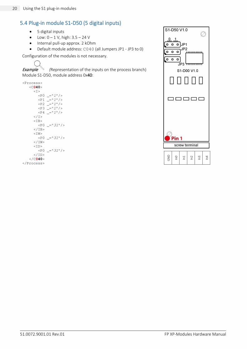
5.4 Plug-in module S1-D50 (5 digital inputs)
• 5 digital inputs • Low: 0 – 1 V, high: 3.5 – 24 V • Internal pull-up approx. 2 kOhm • Default module address: C040 (all Jumpers JP1 - JP3 to 0)
Configuration of the modules is not necessary. Example (Representation of the inputs on the process branch) Module S1-D50, module address 0x40: <Process> <C040> <I> <P0 _="1"/> <P1 _="1"/> <P2 _="1"/> <P3 _="1"/> <P4 _="1"/> </I> <IB> <P0 _="31"/> </IB> <IW> <P0 _="31"/> </IW> <ID> <P0 _="31"/> </ID> </C040> </Process>
GN
D
In0
In1
In2
In3
In4

51.0072.9001.01 Rev.01 FP XP-Modules Hardware Manual
21 Using the S1 plug-in modules 21
5.5 Plug-in module S1-D30G (3 digital inputs, galvanically isolated)
• 3x digital inputs, galvanically isolated • Low: 0- +9.2 V, high: +10.4 V - +60 V • Maximum input voltage: -60 V - + 60 V • Input current: 2.2 - 3.1 mA • Creepage and clearance distance between individual inputs:
0.8 mm • Creepage and clearance distance between external input and
internal circuit: 2.2 mm • Default module address: 0x40 (all 3 jumpers in position 0)
The S1-D30G expansion module offers 3 digital inputs that are galvani-cally isolated from each other. Each of the three channels has a status LED which illuminates red at high level. Configuration of the modules is not necessary.
Displaying the logical levels In contrast to the other digital input modules, an open input in the process branch of the S1-D30G is indicated as “0”. When the high level is reached, the display changes to “1”.
Representation of the inputs on the process branch
Example: Module S1-D50, module address 0x40, socket 2 (bus 3):
<Process> <C340> <I> <P0 _="1"/> <P1 _="0"/> <P2 _="1"/> </I> <IB> <P0 _="5"/> </IB> <IW> <P0 _="5"/> </IW> <ID> <P0 _="5"/> </ID> </C340> </Process>
-In1
+In1
-In2
+In2
-In3
+In3
In the example shown above, input 1 (In1) and input 3 (In3) are at high level and input 2 (In2) at low level.

51.0072.9001.01 Rev.01 FP XP-Modules Hardware Manual
22 Using the S1 plug-in modules
5.6 Plug-in module S1-D05 (5 digital outputs)
• 5 digital outputs; optocoupler with common earth (earth is connected to device earth)
• Dielectric strength: 48 V • Max. current: 100 mA; OnResistance: approx. 25 Ohm • Default module address: C040 (all Jumpers JP1 - JP2 to 0)
Example (Representation of the outputs on the process branch) Module S1-D05, module address 0x40: <Process>
<C040> <Q> <P0 _="1"/> <P1 _="0"/> <P2 _="1"/> <P3 _="1"/> <P4 _="0"/> </Q> <QB> <P0 _="31"/> </QB> <QW> <P0 _="31"/> </QW> <QD> <P0 _="31"/> </QD> </C040>
</Process>
GN
D
Out
0
Out
1
Out
2
Out
3
Out
4
5.7 Plug-in module S1-D03G (3 digital outputs, galvanically isolated)
• 3 independent digital outputs; galvanically isolated via optocoupler
• Dielectric strength: 48 V • max. current: 100 mA; OnResistance: approx. 25 Ohm • Default module address: C040 (all Jumpers JP1 - JP3 to 0)
Example (Representation of the outputs on the process branch) Module S1-D03G, module address 0x42: <Process> <C042> <Q> <P0 _="0"/> <P1 _="0"/> <P2 _="0"/> </Q> <QB> <P0 _="0"/> </QB> <QW> <P0 _="0"/> </QW> <QD> <P0 _="0"/> </QD> </C042> </Process>
Out0
Out1
Out2

51.0072.9001.01 Rev.01 FP XP-Modules Hardware Manual
23 Using the S1 plug-in modules 23
5.8 Plug-in module S1-PT3 (3 PT1000 inputs)
• 3 PT1000 inputs • Default module address: C096
The conversion from voltage U [mV] to degrees Celsius is automatic. The raw value of the A/D converter is not displayed.
The display in the process branch is in milli degrees (m°C)
Example (Representation of the outputs on the process branch) Module S1-PT3, module address 0x96: <Process> <C096> <I> <P0 _="0"/> <P1 _="22410"/> <P2 _="0"/> </I> </C096> </Process>
In the example above, the value 22410 milli degrees Celsius = 22.41 °C is displayed for the PT1000 temperature sensor at input 2, the other PT1000 temperature sensors show the value 0.
If no PT1000 temperature sensor is connected, the value “199996” is displayed.
Note: Do not use the module addresses x90 and x94.
GN
D
In0
GN
D
In1
GN
D
In2
5.9 Plug-in module S1-WL2 (2 relay outputs, changeover contact)
• 2 relay outputs (changeover contact) • Maximum 230 V/3 A • Default module address: C042
Example (Representation of the outputs on the process branch) Module S1-WL2, module address 0x42: <Process> <C042> <Q> <P0 _="0"/> <P1 _="1"/> </Q> </C042> </Process>
In the example, relay 1 is open and relay 2 is closed.
NO1 COM1 NC1
NO2 COM2 NC2

51.0072.9001.01 Rev.01 FP XP-Modules Hardware Manual
24 Using the S1 plug-in modules
5.10 Plug-in module S1-AA2 (2 analogue outputs)
• 2x analogue outputs; resolution 12 bit • Voltage output: 0 – 10 V, Ri = 100 kOhm • Current output: 0 – 20 mA, Ri= 120 Ohm • Default address for automatic detection: 0x18/0x1A
The analogue outputs can be switched between 0 – 10 V and 0 – 20 mA via jumpers. The factory setting is 0 – 10 V.
The D/A converters for the analogue outputs use raw values between 0 and 4095 (corresponds to 0 - 10 V).
Example (Representation of the outputs on the process branch)
Module S1-AA2, address 0x10 / 0x12, socket 5 (bus 6): Output 1: <C610> <AO> <P0 _="1000"/> </AO> </C610>
Output 2: <C612> <AO> <P0 _="1000"/> </AO> </C612>
GN
D
Out
0
GN
D
In1
GN
D
Out
1
Not allowed!


