Embed Size (px)
Citation preview

lable at ScienceDirect
International Journal of Naval Architecture and Ocean Engineering 13 (2021) 246e259
Contents lists avai
International Journal of Naval Architecture and Ocean Engineering
journal homepage: http: / /www.journals .elsevier .com/internat ional- journal-of -naval-archi tecture-and-ocean-engineering/
A quantitative methodology for evaluating the ship stability using theindex for marine ship intact stability assessment model
Nam-Kyun IM a, Hun CHOE b, *
a Division of Navigation Science, Mokpo National Maritime University, Mokpo, South Koreab Department of Maritime Transportation System, Mokpo National Maritime University, Mokpo, South Korea
a r t i c l e i n f o
Article history:Received 21 August 2020Received in revised form14 December 2020Accepted 12 January 2021
Keywords:Ship stabilityGZ CurveIMO Stability regulationsStability assessmentStability index
* Corresponding author.E-mail addresses: [email protected] (N.-K.
(H. CHOE).Peer review under responsibility of The Society o
https://doi.org/10.1016/j.ijnaoe.2021.01.0052092-6782/© 2021 Society of Naval Architects of Kocreativecommons.org/licenses/by-nc-nd/4.0/).
a b s t r a c t
IMO stability regulations include various stability parameters such as GM values. To assess the stability ofthe ships, we should check all stability parameters of the IMO requirements. However, since this processis complex, a more convenient way to evaluate stability performance is required. In this research, theindex for marine ship intact stability assessment (IMSISA) model was developed to solve these problems.The IMSISA model consists of a stability index calculation module and a stability assessment module. Inthe stability index calculation module, ten stability parameters, including GM, were used to develop thestability index, which has the advantage of being able to quantify the ship stability. The stabilityassessment module uses the stability index value to determine the stability status of the ship andprovides the captain with stability management guidelines. To verify the proposed model, the basicstability calculations were performed for two model ships in 32 loading situations. The proposed modelwas found to provide better performance in the stability assessment than the previous study. By applyingthe IMSISA model to the ships, the captain can assess the ship stability more quantitatively andefficiently.© 2021 Society of Naval Architects of Korea. Production and hosting by Elsevier B.V. This is an open access
article under the CC BY-NC-ND license (http://creativecommons.org/licenses/by-nc-nd/4.0/).
1. Introduction
The purpose of the IMO (International Maritime Organization)Stability Regulations is to improve the safety of the ships byproviding the captain with the guidelines for securing the stability.The IMO Stability Regulations were established through the Reso-lution A.562 (IMO, 1985) Convention in IMO and was amended inResolution A.749 (IMO,1993)) and ResolutionMSC.267 (85), IS Code(IMO, 2008).
Several related researches were also conducted in the 1930s,before IMO played the important role in establishing the standardsfor ship stability. Pierrottet (1935) built the basic concept of whatlater will be the Weather criterion. Rahola (1939) tried to provideprocedure by which we may judge with adequate certainty theamount of the stability of a vessel. These researches laid thefoundation of ship stability research in the beginning of themodernage.
IM), [email protected]
f Naval Architects of Korea.
rea. Production and hosting by El
Since the modern era, IMO has long developed intact stabilitycriteria for various types of ships, culminating in the completion ofthe Code on Intact Stability for All Types of Ships. The IS Codeincluded fundamental principles such as general precautionsagainst capsizing; weather criterion (severe wind and rolling cri-terion); effect of free surfaces and icing; and watertight integrity.The IS Code also addressed related operational aspects like infor-mation for the master, including stability and operating bookletsand operational procedures in heavy weather. Generally, thesecriteria could be regarded as the first-generation intact stabilitycriteria.
In these empirical criteria, the casualty data of ships of 100 mlength or less were used to determine the relationship between GZcurve parameters and ship stability safety. Many researchers havetried to develop methods for evaluating the ship intact stability in avariety of ways depending on the ship type and sea conditions.
The first international intact ship stability rule finally originatedby a recommendation contained in the conclusions of SOLAS060(Francescutto, 2016). The general Stability Criteria based on right-ing arm characteristics was adopted by IMCO (IMO, 1968).Kobylinski (1975) suggested an academic concept for stabilitycriteria problems. The standard issue of weather criterion in intact
sevier B.V. This is an open access article under the CC BY-NC-ND license (http://

Nomenclature
f0 Angle of heel under action of steady windf1 Angle of roll to windward due to wave actionf2 Angle of down-flooding(ff ) or 50� or fc, whichever is
lessfc Angle of second intercept between wind heeling
lever lw2 and GZ curvesff Angle of heel at which openings in the hull,
superstructures or deckhouses which cannot beclosed weather tight immerse
ai ith IMO Stability Parameterai IMO IMO Criterion of ith IMO stability parameterai SafetyLimit ith IMO Stability Parameter when all stability
parameters satisfy the IMO stability regulation forthe first time as stability improves
ai FullLoading ith IMO Stability Parameter in standard full loadingCondition
Anglecoeff Heeling Angle CoefficientAnglemaxGZ Heel angle corresponding to maximum GZAnglepassenger The angle of heel on account of crowding of
passengers to one side
Angleturning The angle of heel on account of turningArea0�30deg Area under GZ curve between 0� and 30�
Area0�40deg Area under GZ curve between 0� and 40� (orflooding angle, whichever is less)
Area30�40deg Area under GZ curve between 30� and 40� (orflooding angle, whichever is less)
GoM Initial metacentric heightGZ30deg GZ at a heeling angle of 30� or moreIMSISA Index for marine ship intact stability assessmentk Stability Index Coefficientlw1 Steady wind heeling leverlw2 Gust wind heeling leverRangeGZ The residual range of positive stability in degreeSIai ith IMO Stability Parameter IndexSIIMO Stability Index by IMO Stability RegulationSIIMSISA Stability Index by IMSISA modelSIwave Stability Index by Wave Conditionswavecrit The minimum, or critical, wave height that might
capsize the vesselwaveIMO The sea state in which a vessel might be vulnerable if
it just complies with the IMO minimaSGISC The Second-Generation Intact Stability Criteria
N.-K. IM and H. CHOE International Journal of Naval Architecture and Ocean Engineering 13 (2021) 246e259
stability was already dealt with by several researchers (Yamagata,1959; Goldberg and Sarchin 1962). Following these movements,many researchers also carried out related issues.
Mantari et al. (2011) reviewed the intact stability of fishingvessels under beamwaves and wind, and Hu et al. (2015) evaluatedthe stability of a sail-assisted ship using the Weather Criteria of theintact stability regulation. Deybach (1997) reviewed the stability ofNaval Ships using the IMO Intact Regulations and noted the limi-tations that could occur when applying the IMO Intact Regulationsdue to the characteristics of Naval Ships that are different fromgeneral ships. Marutheri Parambath (2019) conducted a study todevelop intact stability criteria for weather criterion applicable toriver-sea.
As mentioned above, various research approaches have beenproposed by many researchers to evaluate the ship’s intact stabilitycriteria, however there are still limitations. It may be inappropriateto adopt such existing criteria to large and modern ships such ascontainership, car carriers and RoPax ships employing advanceddesign technologies (Umeda, 2016). As a result, the research on theSecond-Generation Intact Stability Criteria (SGISC) have launchedin 2001 as a part of the revision of the intact stability code at theIMO (Francescutto, 2016). The characteristics of the approach in theSGISC is physics-based and multi-tiered rather than empiricalmethod.
Kobylinski (2009) studied the development of evaluationcriteria for the second-generation intact stability assessmentmethod mentioned at the Sub-committee SLF of IMO meeting.Umeda et al. (2009) studied stability in Capsizing, Broaching, andParametric Rolling, which are the initial studies to prepare theevaluation criteria for the second-generation intact stability.Belenky et al. (2011) proposed the criteria for intact stability inconsideration of pure loss of stability, and broaching-to. Andrei andBlagovest, (2013, 2015, Andrei, 2017) proposed the intact stabilitycriteria and method for examining the parametric rolling and pureloss of ships in longitudinal waves.
Hasanudin and Chen (2015) conducted a study to present theevaluation criteria for evaluating ship survivability in a situationwhere the ship is overturned, considering the limitation that theIMO stability rule can be applied only to ships operated by Calm
247
Water. Tompuri et al. (2016) mentioned that the second-generationintact stability evaluation itemmay cause operational limitations inthe ship design stage. Chung et al. (2020) reviewed the progress ofresearch on second-generation intact stability and presentedprospects for future research.
There are several categories in research contributions for theSGISC. The first group includes papers which focus on analyzing thesimplified stability failure assessment methods (Umeda andFrancescutto, 2016). The second group deals with more higher-level criterion, “direct stability assessment”, which requires moreadvanced calculation tool such as computer or experimental facil-ities. The third group focus on the research of the main five dy-namic stability failure modes, i.e. parametric roll resonance, pureloss of stability, surf-riding and broaching, dead ship condition andexcessive accelerations (Manderbacka et al., 2019). Currently, onlyvulnerability criteria with a limited number of remaining issueswere agreed in the IMO (IMO, 2015 and 2016).
Meanwhile various ship stability researches have been con-ducted separately from or partly related with the researches of theSGISC. These studies were carried out with the main purpose ofdeveloping a system that acquires ship motion data by mounting areal sensor and communication system and uses these data toevaluate the ship’s intact stability performance in real time.
Brown and Witz (1996) studied a method for evaluating thestability of a ship in real time using rolling measurement. �AlvarezSantullano and Souto-Iglesias (2014) analyzed the relationshipbetween the stability and safety of a ship using data from a smallship. Caama~no et al. (2018) developed a system to identify the GMof a ship and evaluate its stability using lateral fluctuations in mid-sized fishing vessels. Terada et al. (2018) proposed a system toevaluate the GM of a ship by measuring natural frequency on theroll motion for container ships. Gonz�alez et al. (2016) conducted astudy to evaluate the stability of a vessel in operation in real time ona fishing vessel. Ariffin et al. (2016) proposed a real-time evaluationsystem for second-generation intact stability using data providedby Radar and Buoy.
These studies are considered very effective in terms of practi-cality, as they can provide useful tools to evaluate the ship intactstability performance in real time.

N.-K. IM and H. CHOE International Journal of Naval Architecture and Ocean Engineering 13 (2021) 246e259
Finally, a number of intact stability assessment studies havebeen conducted to provide convenient functionality from the ship’soperator’s perspective. The main goal of these researches is todevelop functions that are more convenient and easier for captainsto understand the situations of ship intact stability.
Wolfson Unit (2005) proposed the estimation formula for thesignificant wave height that can cause the vessel to capsize using amodel ship experiment. The estimation formula is composed ofvariables related to the GZ Curve. In addition, Wolfson Unit (2006)proposed estimation equation for a significant wave height usingthe ship length to induce the ship’s rollover when the ship stabilitymeets the IMO minimum requirement through the case where theship capsized. Deakin B (2006, 2010) developed the guideline forstability assessment for ship owners and crew based on theresearch of theWolfson Unit. MMGonz�alez et al. (2012) proposed aprocess of evaluating the stability performance of fishing vesselswith a single numerical value and a program that provides themaster with stability information. This study has the merit that it iseasy to show the satisfaction of IMO stability regulation as onenumber, but there is a limitation that it does not provide infor-mation other than regulation satisfaction. Im et al. (2018) proposedan evaluation method for expressing the IMO intact stability eval-uation items with one value except for Weather criteria.
These researches are characterized by providing a useful func-tion for easily evaluating the ship intact stability from the shipoperator’s point of view. Ship operators may have relatively lessknowledge on ship motion or design compared to ship designers.Therefore, these studies are considered effective from the pointview of ship operators.
As mentioned in literature review, although there have beenmany studies on the intact stability evaluation of ships, there arefew studies on the comprehensive and quantitative assessment tothe intact stability of ships. The IMO stability standards includemany of the intact stability parameters required to determine thestability of ships. All stability parameters should be reviewed todetermine whether the ship meets IMO requirements. It is also noteasy to quantify the stability of the ships, because the current IMOintact stability regulations only show the minimum standardsnecessary to meet the requirements.
From these perspective, this study suggests the IMSISA (Indexfor Marine Ship Intact Stability Assessment) model which providesthe ability to assess the intact stability of ships based on the indexof ship stability performance, called the Ship Stability Index. Thisstudy was conducted to develop an improved method for evalu-ating intact ship stability based on the parameters of the first-generation intact stability IMO regulation. Even if all parametersof the SGISC are finalized in the future, the first-generation intactstability criteria will still be critical factors for the SGISC. Damagestability issues are outside the scope of this study. Since the mainobjectives of this study are to express ship stability as one number,only intact stability issues are included in the research scope.However, the results of this research could be extended to a newmethod, which evaluates ship stability by further including theparameters of the SGISC when all criteria for the SGISC are deter-mined in the future.
Compared with the previous researches, the main contributionsof this article are as follows.
First, the concept of stability index was proposed, which canquantify and assess the stability of ships with a single indicatorvalue. Currently, the captain should review 6 to 10 stability pa-rameters to verify the stability performance of the vessel under theIS Code of IMO regulations. However, the IMSISA model has theadvantage of being able to quantify the ship stability using a singlestability index, which combined various stability parameters.
Second, it provides a numerical representation of the safety of
248
ship stability. Currently, the IMO ship stability regulations onlyassess whether the stability of the ship is satisfactory or unsatis-factory. It is not easy to quantify and evaluate the stability of ships.However, the stability index makes it possible to estimate thestability satisfaction of the ship quantitatively.
Third, the stability index provides guidelines for evaluatingintact stability to the ship’s captain. The captain can utilize theguidelines to review the IMO intact stability performance andsecure a means to intuitively check the stability of the ship.
To develop the IMSISA model, IMO stability regulations werereviewed, and basic stability calculations were performed forvarious cargo loading scenarios for two model vessels. Ten stabilityparameters, including GM, were evaluated, and the stability indexwas derived by applying the stability index formula to the results.Based on the derived stability index, the stability of the ship wasevaluated, and the guidelines of the stability assessment forsecuring ship safety were presented. The following two methodswere used to verify the IMSISA model. First, basic stability calcu-lations for various loading conditions were performed. It wasconfirmed that the proposed stability index adequately explainsthe ship stability based on existing IMO stability requirements. Thestability index was proven to assess the safety of ship stabilityadequately. Second, the proposed stability index was verified incomparison with the previous study. The IMSISA model wasconfirmed to be an alternative and improved stability assessmentmethod that can overcome the limitations of previous studies.
2. Parameters of IMO intact stability regulations
The core work of the IMSISA model is to suggest the stabilityindex. Ten stability parameters, including the GM of IMO stabilityrequirements, were considered to derive the stability index.
Table 1 summarizes the stability parameters and their criteriaused to calculate the stability index. Eight out of the ten stabilityparameters, including GM, are general criteria that apply to cargoships. The two parameters (Angleturning and Anglepassenger), rudderand passenger induced heeling angle, can be used as stability in-dicators for passenger ships.
The ten stability parameters are summarized as follows: GM(Metacentric Height) refers to the height from the center of gravityto the transverse metacenter, taking into account the influence ofthe free surface of the liquid. The GZ30deg means the righting arm at30� of the heeling angle. The AnglemaxGZ is the angle at which the GZreaches the largest value in the range. Fig. 1 shows three patterns ofthe area under the GZ curve in the IMO stability regulation. TheArea0�30deg refers to the area of “a" under GZ curve between 0� and30� of the heeling angle, the Area30�40deg is the area of “b" between30� and 40�(or flooding angle, whichever is less) and theArea0�40deg means the area of “aþb" between 0� and 40�(orflooding angle, whichever is less). Fig. 2 illustrates the weathercriterion. Steady wind pressure on the ship causes a heeling arm(lw1). As a result, a heel angle (f0) is generated to achieve equilib-rium, and the wave motion causes the ship to heel with an angle(f1) against the wind. At this moment, it should not exceed thevalue of 16� or 80% of the immersion angle, whichever is less. Also,due to the gust wind pressure, the ship is subjected to happen theinclination. In this case, the area of “d" should be larger than thearea of “c".
On the other hand, when evaluating the stability of a passengership, it is necessary to further examine the heeling angle on accountof the ship’s turning and the crowding of passengers to one side.The heeling angle (Angleturning) generated by the rudder operationshould not exceed 10�. The heel angle can be calculated by applyingthe balance between the turning moment and static righting
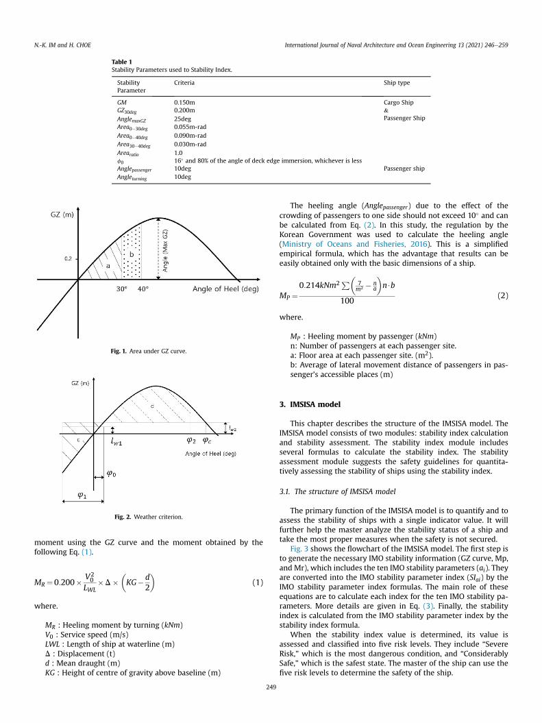
Table 1Stability Parameters used to Stability Index.
StabilityParameter
Criteria Ship type
GM 0.150m Cargo Ship&Passenger Ship
GZ30deg 0.200mAnglemaxGZ 25degArea0�30deg 0.055m-radArea0�40deg 0.090m-radArea30�40deg 0.030m-radArearatio 1.0f0 16� and 80% of the angle of deck edge immersion, whichever is lessAnglepassenger 10deg Passenger shipAngleturning 10deg
Fig. 1. Area under GZ curve.
Fig. 2. Weather criterion.
N.-K. IM and H. CHOE International Journal of Naval Architecture and Ocean Engineering 13 (2021) 246e259
moment using the GZ curve and the moment obtained by thefollowing Eq. (1).
MR ¼0:200� V20
LWL�D�
�KG� d
2
�(1)
where.
MR : Heeling moment by turning (kNm)V0 : Service speed (m/s)LWL : Length of ship at waterline (m)D : Displacement (t)d : Mean draught (m)KG : Height of centre of gravity above baseline (m)
249
The heeling angle (Anglepassenger) due to the effect of thecrowding of passengers to one side should not exceed 10� and canbe calculated from Eq. (2). In this study, the regulation by theKorean Government was used to calculate the heeling angle(Ministry of Oceans and Fisheries, 2016). This is a simplifiedempirical formula, which has the advantage that results can beeasily obtained only with the basic dimensions of a ship.
MP ¼0:214kNm2 P�
7m2 � n
a
�n$b
100(2)
where.
MP : Heeling moment by passenger (kNm)n: Number of passengers at each passenger site.a: Floor area at each passenger site. (m2).b: Average of lateral movement distance of passengers in pas-senger’s accessible places (m)
3. IMSISA model
This chapter describes the structure of the IMSISA model. TheIMSISA model consists of two modules: stability index calculationand stability assessment. The stability index module includesseveral formulas to calculate the stability index. The stabilityassessment module suggests the safety guidelines for quantita-tively assessing the stability of ships using the stability index.
3.1. The structure of IMSISA model
The primary function of the IMSISA model is to quantify and toassess the stability of ships with a single indicator value. It willfurther help the master analyze the stability status of a ship andtake the most proper measures when the safety is not secured.
Fig. 3 shows the flowchart of the IMSISA model. The first step isto generate the necessary IMO stability information (GZ curve, Mp,and Mr), which includes the ten IMO stability parameters (ai). Theyare converted into the IMO stability parameter index (SIai) by theIMO stability parameter index formulas. The main role of theseequations are to calculate each index for the ten IMO stability pa-rameters. More details are given in Eq. (3). Finally, the stabilityindex is calculated from the IMO stability parameter index by thestability index formula.
When the stability index value is determined, its value isassessed and classified into five risk levels. They include “SevereRisk," which is the most dangerous condition, and “ConsiderablySafe," which is the safest state. The master of the ship can use thefive risk levels to determine the safety of the ship.

N.-K. IM and H. CHOE International Journal of Naval Architecture and Ocean Engineering 13 (2021) 246e259
3.2. Stability index calculation module
The IMSISA model calculates the stability index by Eqs. (3) and(4). The ten stability parameters (ai) are normalized to the IMOstability parameters index (SIai) using the IMO stability parameterindex formula, Eq. (3).
As shown in Eq. (3), we divided normalization into two groups.The first group includes the seven components (a1 � a7), which aregeneral parameters applied to cargo ships. In this group, the higherthe parameter value is, the better the stability performance is.However, in the second group, which includes the three parameters(a8 � a10), the lower the parameter value is, the better the stabilityperformance is. Each group uses a different formula to determinethe IMO stability parameter index.
}if i¼1;2;…;7}
SIai ¼ k� aiai�IMO
ðif 0� ai < ai�IMOÞ
¼ kþð1� kÞ� ai � ai�IMO
ai�SafetyLimit � ai�IMO
�if ai�IMO � ai < ai�SafetyLimit
�
¼ 1þ ai � ai�SafetyLimit
ai�FullLoading � ai�SafetyLimit
�if ai�SafetyLimit � ai < ai�FullLoading
�
¼ 2þ ai � ai�FullLoading
ai�FullLoading
�if ai�FullLoading � ai
�
¼ 1þ�����
ai � ai�SafetyLimit
ai�FullLoading � ai�SafetyLimit
������if ai�SafetyLimit � ai > ai�FullLoading
�
¼ 2þ�����ai � ai�FullLoading
ai�FullLoading
������if ai�FullLoading � ai
�� 1
}if i¼8; 9; 10}
SIai ¼ k������
Anglecoeff � aiAnglecoeff � ai�IMO
������if Anglecoeff � ai > ai�IMO
�
¼ kþð1� kÞ������
ai � ai�IMO
ai�SafetyLimit � ai�IMO
������if ai�IMO � ai > ai�SafetyLimit
�
¼ 1þ�����
ai � ai�SafetyLimit
ai�FullLoading � ai�SafetyLimit
������if ai�SafetyLimit � ai > ai�FullLoading
�
¼ 2þ�����ai � ai�FullLoading
ai�FullLoading
������if ai�FullLoading � ai
�
(3)
In Eq. (3), k denotes the stability index coefficient chosen to be0.5 to indicate that 50% of parameters meet the IMO requirements.ai�IMO means IMO Criterion of ith IMO stability parameter as listedin Table 1. ai�SafetyLimit indicates “the value of ith IMO StabilityParameter” when all stability parameters satisfy the IMO stabilityregulation for the first time as stability improves. These mean thevalues of IMO stability parameters at the point in time when all 10stability parameters meet the IMO regulations with the minimumvalues. The definition of “standard full loading condition” inai�FullLoading refers to IS Code (2008). It means the loading conditionof a ship in the fully loaded departure condition with cargo, fullstores and fuel and with the full number of passengers with theirluggage. The Anglecoeff denotes the maximum heeling angle coef-ficient. In this study, assuming that the heeling angle due to the
250
passenger and rudder is to be 30� in the worst case, the value is setto 30�. After obtaining each index value (SIai) for the ten IMO sta-bility parameters, the stability index is calculated finally using Eq.(4). As can be seen from the formula, the stability index is deter-mined as the average of the parameters.
SIIMSISA ¼Pn
i¼1SIain
(4)
where.
SIai : ith IMO Stability Parameter Indexn : The number of parameters (n ¼ 8 for cargo ships, n ¼ 10 forpassenger ships)
3.3. Stability index assessment module
The principal purpose of the stability index (SIIMSISA) is to ex-press the stability of ships as a single indicator value in order toquantitatively evaluate the stability of the ships. Therefore, it isrequired to suggest the guidelines that can quantitatively andcomprehensively assess stability conditions. In this study, the sta-bility assessment guidelines in Table 2 were proposed to numeri-cally evaluate the stability of ships according to the value of thestability index.
As shown in Table 2, the stability of ships is classified into threecategories in terms of satisfaction with IMO stability regulations.The details are as follows. If the stability index is less than 0.5, itmeans that more than 50% of the stability parameters do not meetthe IMO requirements and stability is rated as “Severe Risk." Whenthe stability index value is between 0.5 and 1.0, several of thestability parameters (less than 50%) do not comply with the IMO

N.-K. IM and H. CHOE International Journal of Naval Architecture and Ocean Engineering 13 (2021) 246e259
minimum requirements and the stability is evaluated as “Danger".Finally, if the stability index value is greater than or equal to 1.0, allstability parameters comply with IMO requirements and stability israted “Safety condition". In addition, the details of stability evalu-ation guidelines and navigational instructions are summarized asfollows.
1) 0.0 � SIIMSISA < 0.5
It is significantly vulnerable situations becausemore than 50% ofstability parameters do not satisfy IMO stability minimum re-quirements. The captain must take prompt action to improve thestability.
2) 0.5 � SIIMSISA < 1.0
More than 50% of the stability parameters meet the IMO sta-bility requirements but are still dangerous because they do notentirely fulfill the IMO stability minimum requirements. The cap-tain shall take proper actions to ensure that the stability index isabove 1.0 by appropriate measures to improve the stability.
3) 1.0 � SIIMSISA < 1.2
All stability parameters satisfy IMO stability requirements. It is asafe condition. However, there is not enough margin for the
Fig. 3. Flow Chart of
251
stability performance of the ship. The captain shall endeavor toensure the stability index of 1.2 or more through appropriatemeasures. To ensure sufficient stability, it is recommended to haveat least a 20% margin over IMO stability requirements. In thisresearch, the margin was set at 20% by referring to the ship’s seamargin value. It has been empirically found to be in the 15e30%range (ITTC, 2017; Magnussen, 2017).
4) 1.2 � SIIMSISA < 2.0
All the stability parameters meet the IMO requirements andmaintain a stability margin of more than 20%. It is a safe conditionin terms of ship stability. However, since the stability is somewhatlower than the standard full loaded condition, which is the stabilityindex of 2.0, the captain should try to maintain the current stabilitysituations.
5) 2.0 � SIIMSISA
All stability parameters meet IMO requirements and maintainstability performance over standard full load conditions. The cap-tain is advised to keep the current ship’s stability and stability indexover 2.0. The IMSISA model calculates the stability index that helpsthe master efficiently determine whether the ship meets the IMOstability regulations. It also gives the master a stability assessmentguideline that quantifies the stability of the ships.
IMSISA model.

Table 2Guideline of stability assessment by SIIMSISA
SIIMSISA Compliance with IMO StabilityReg
Assessment of Ship Stability Recommendations
0.0e0.5 Incompliant (Less than 50% ofthe parameters comply withIMO Stability regulation)
Severe Risk The captain must take prompt action to improve stability.
0.5e1.0 Incompliant (More than 50% ofthe parameters comply withIMO Stability regulation)
Danger The captain shall take proper actions to ensure that the stability index isabove 1.0 by appropriate measures to improve stability.
1.0e1.2 Compliant (All parameters arecomply with IMO Stabilityregulation)
MinimumSafety Condition
The captain shall endeavor to ensure the stability index of 1.2 or morethrough appropriate measures.
1.2e2.0 NormalSafety Condition
The captain should try to maintain the current stability situations.
2.0 [ ConsiderablySafe
The captain is advised to keep the current ship’s stability and stability indexover 2.0
N.-K. IM and H. CHOE International Journal of Naval Architecture and Ocean Engineering 13 (2021) 246e259
4. Application of IMSISA model
In this chapter, we applied the IMSISA model to calculate theship’s stability index (SIIMSISA) and investigated whether the resultadequately assesses the ship’s stability performance. To accomplishthis, a total of 32 loading scenarios were implemented using twomodel ships, and the stability performance was evaluated for eachsituation.
4.1. Model ships and loading conditions
Two types of vessels were selected as models. The basic infor-mation and general layout of the two ships are shown in Table 3 andFig. 4. The first model is a 16,000-ton-class coastal roro/passengership operated in Korea’s Mokpo-Jeju route. The second model is a4600-ton-class Mokpo Maritime University training ship.
A variety of cargo loading situations were implemented usingthe model ships to investigate the stability performance undervarious loading conditions. As can be seen in Table 4, the value ofthe GMwas changed by the center of gravity while maintaining therange of 80%e100% of the displacement of the ships. The cargoloading situations comprise 32 scenarios, among which 18 for roro/passenger ship and 14 for training ship. The roro/passenger ship hasthe GM of 0.1e2.93M, and the training vessel has 0.1e2.0M.
4.2. Basic stability calculation
In this section, the IMO stability performance was calculated for32 loading scenarios. GZ curves were plotted, and ten stabilityparameters of the IMO stability regulations were also calculated foreach scenario.
Fig. 5 and Fig. 6 show the GZ curves for the twomodel ships. Thecommon point in the two graphs is that the smallest GZ curve isdrawn in scenario No.1, which has the lowest GM value, and thelargest GZ curve is formed in scenario No.18 (roro/passenger ship)and No.14 (training ship), which have the largest GM values. Inaddition, the stability characteristics of the two ships are different
Table 3The particular of Model Ships.
Items roro/passenger ship Training Ship
Length O. A. 189m 103mLength B. P. 171m 94mBreadth(B) 27.00m 15.60mDraft(d) 6.65m 5.40mFull Displacement 16,044.74 ton 4,6262.70 tonCb < 0.509 0.566Passenger capacity 1425 per 208 per
252
from each other. In the case of the roro/passenger ship, the value ofGM is relatively larger than that of the training ship, while the rangeof GZ is relatively narrow. For the training ship, the initial GM issmaller than that of the roro/passenger ship, but the GZ valuemaintained positive until the heeling angle increases to large, sothe range of stability of the ship is more extensive than that of theroro/passenger ship.
The ten IMO stability parameters were calculated based on theGZ curves for 32 loading scenarios. The results are shown in Table 5and Table 6. With roro/passenger ship, four scenarios (No.1e4) donot meet the IMO requirements, and scenarios No.5 to No.18 showstability performance satisfying IMO minimum requirements.
In general, the captain highly depends on the GM value whenevaluating the stability of the ship. However, as shown in scenariosNo.2 to 4, even though the GM exceeds the IMO criterion value,other stability parameters do not meet the IMO stability re-quirements, hence, the stability of the ship does not entirelycomply with IMO minimum requirements.
As the number of scenarios increases in Tables 5 and 6, stabilityis improved steadily. In scenario No.5 (passenger and training ship),all stability parameters comply with the IMO requirements. Inthese cases, since the parameter of Angleturning becomes to meet theIMO requirements so that the overall stability parameters satisfythe IMO minimum requirements. The parameters of these sce-narios are used as ai�SafetyLimit in Eq. (3). They mean the parametervalues at the point where all parameters meet the IMO re-quirements for the first time as the stability improves.
On the other hand, the IMO stability booklet is regulated toperform stability calculations in various loading situations,including “full loading condition". In this study, basic ship stabilitywas calculated for the standard full loading condition, and the re-sults applied to the stability index which indicates the stabilitycondition of “Considerable Safe" as defined in the stability assess-ment guideline, Table 2. The standard full loading condition is usedas an indicator of considerably safe stability in the IMSISA model.Scenarios No.13(roro/passenger ship) and No.11(training ship) inTables 5 and 6 show the stability parameter values of two modelships under standard full loading conditions. These values are usedin Eq. (3) as ai�FullLoading .
4.3. Calculation of stability index
This section reviews the calculation results of the stability indexand the IMO stability parameter index. They were derived from thebasic stability calculation performed in the previous section. Theresults are shown in Table 7 and Table 8. The computation resultscan be evaluated as follows.
In Tables 7 and 8, the stability index should be less than 1.0 in

Fig. 4. Model ships.
Table 4Scenarios of loading condition.
Roro/passenger ship Training Ship
ScenarioNumber
GM (m) KG (m) Disp. (ton) Draft (m) ff (deg) ScenarioNumber
GM (m) KG (m) Disp. (ton) Draft (m) ff (deg)
1 0.100 13.259 16,044.740 6.650 47.3 1 0.100 7.659 4626.7 5.42 86.52 0.200 13.159 16,044.740 6.650 47.3 2 0.200 7.558 4626.7 5.42 86.53 0.400 12.959 16,044.740 6.650 47.3 3 0.300 7.460 4626.7 5.42 86.54 0.600 12.759 16,044.740 6.650 47.3 4 0.400 7.359 4626.7 5.42 86.55 0.781 12.597 16,044.740 6.650 47.3 5 0.500 7.261 4626.7 5.42 86.56 0.800 12.559 16,044.740 6.650 47.3 6 0.600 7.160 4626.7 5.42 86.57 1.000 12.359 16,044.740 6.650 47.3 7 0.800 6.961 4626.7 5.42 86.58 1.200 12.159 16,044.740 6.650 47.3 8 1.000 6.758 4626.7 5.42 86.59 1.381 12.036 15,098.160 6.362 48.6 9 1.200 6.559 4626.7 5.42 86.510 1.418 12.000 15,098.160 6.362 48.6 10 1.400 6.360 4626.7 5.42 86.511 1.884 11.475 16,044.740 6.650 47.3 11 1.550 6.210 4626.7 5.42 86.512 1.905 11.677 13,860.215 5.973 50.3 12 1.600 6.161 4626.7 5.42 86.513 1.919 11.441 16,044.740 6.650 47.3 13 1.800 5.960 4626.7 5.42 86.514 2.362 11.092 14,806.796 6.270 49.0 14 2.000 5.759 4626.7 5.42 86.515 2.408 11.306 13,171.339 5.749 51.216 2.519 11.233 12,984.919 5.688 51.517 2.829 10.717 14,117.920 6.054 49.918 2.931 10.642 13,931.500 5.995 50.2
Fig. 5. GZ Curves of Roro/passenger ship. Fig. 6. GZ curves of training ship.
N.-K. IM and H. CHOE International Journal of Naval Architecture and Ocean Engineering 13 (2021) 246e259
scenarios No.1e4 (passenger and training ship) because thesescenarios do not meet IMO stability requirements. Considering thatthe stability index was calculated from 0.28 to 0.87 in these sce-narios, it can be said that the stability index appropriately evaluatesthe ships’ stability.
Also, since all stability parameters in scenarios No.5 to 18 (roro/passenger ship) and 5 to 14 (training ship) comply with IMOminimum requirements, the stability index must be 1.0 or higher.The stability index ranges from 1.00 to 2.27, which is the case of the
253
roro/passenger ship and 1.01 to 2.23 of the training ship. It showsthat the stability index accurately assesses if the two ships complywith the IMO stability minimum requirements.
Scenarios No.13e18 of the roro/passenger ship and No.11e14 ofthe training ship have better stability than that of the standard fullloading condition. Thus, their stability index should be 2.0 orhigher. Since the computed stability index shows the range of 2.0and 2.23, it can be said that the stability index accurately assessedthe ships’ stability.
A stability index value of less than 0.5 in the IMSISA model

Table 5Result of Stability Calculation (Roro/passenger ship).
Table 6Result of stability calculation (training Ship).
N.-K. IM and H. CHOE International Journal of Naval Architecture and Ocean Engineering 13 (2021) 246e259
shows that less than 50% of all stability parameters meet IMOminimum requirements. It is a hazardous stability condition. Twoscenarios(No.1 and 2 in the training ship) are the cases of whichstability conditions are very vulnerable, and their stability indexwas to be 0.28 and 0.41, as shown in Table 8. Considering that sevento eight IMO stability parameters do not meet the IMO stabilitycriteria, we estimate the stability index value to assess the ship’sstability of two scenarios accurately.
On the other hand, a stability index value in the range of 0.5e1.0means that a stability parameter of at least 50% satisfies the IMOstability criteria. That is the case with six scenarios (No.1e4: roro/passenger ship, No.3e4: training ship). Since one to three stabilityparameters in these scenarios (except scenario No.3 in the trainingship) do not meet the stability criteria, the stability index weighted
254
the ship stability with the range of 0.55e0.87 as shown in Tables 7and 8 However, in scenario No.3 of the training ship, even thoughover 50% of stability parameters do not comply with IMO regula-tion, the index value exceeds 0.5. It is assumed that this erroroccurred because the index value of the AnglemaxGZ andAnglepassenger in scenario No.3 is relatively higher than the otherparameters. Overall, however, the evaluation performance of thestability index was excellent.
We summarize the evaluation accuracy of the stability index inTable 9. According to Tables 5 and 6, 24 scenarios out of 32 complywith IMO minimum requirements. Hence, the stability index ofthem should be above 1.0. For eight scenarios below the IMOstandard, the value should be less than 1.0. Tables 7 and 8 show thatthe calculated stability index adequately assessed whether
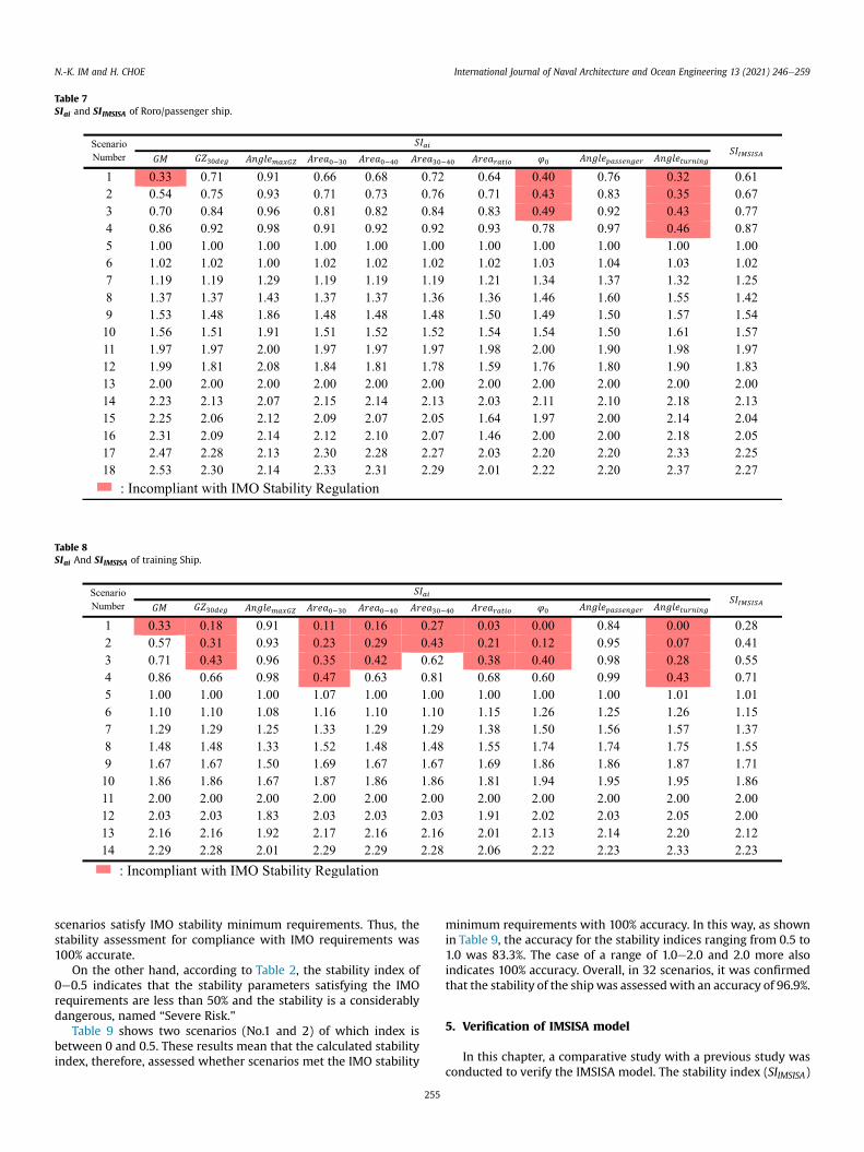
Table 7SIai and SIIMSISA of Roro/passenger ship.
Table 8SIai And SIIMSISA of training Ship.
N.-K. IM and H. CHOE International Journal of Naval Architecture and Ocean Engineering 13 (2021) 246e259
scenarios satisfy IMO stability minimum requirements. Thus, thestability assessment for compliance with IMO requirements was100% accurate.
On the other hand, according to Table 2, the stability index of0e0.5 indicates that the stability parameters satisfying the IMOrequirements are less than 50% and the stability is a considerablydangerous, named “Severe Risk."
Table 9 shows two scenarios (No.1 and 2) of which index isbetween 0 and 0.5. These results mean that the calculated stabilityindex, therefore, assessed whether scenarios met the IMO stability
255
minimum requirements with 100% accuracy. In this way, as shownin Table 9, the accuracy for the stability indices ranging from 0.5 to1.0 was 83.3%. The case of a range of 1.0e2.0 and 2.0 more alsoindicates 100% accuracy. Overall, in 32 scenarios, it was confirmedthat the stability of the ship was assessedwith an accuracy of 96.9%.
5. Verification of IMSISA model
In this chapter, a comparative study with a previous study wasconducted to verify the IMSISA model. The stability index (SIIMSISA)

Table 9Accuracy of stability assessment by.SIIMSISA
< Compliance with IMO Reg >SIIMSISA Compliance with IMO Reg. The number of Scenarios The number of scenarios in which the result of IMO Reg. and SIIMSISA match Accuracy (%)
0.0e1.0 Incompliance 8 8 100.01.0 [ Compliance 24 24 100.0Total 32 32 100.0
< Ship Stability Assessment >SIIMSISA Compliance with IMO Reg. The number of Scenarios The number of scenarios in which the result of IMO Reg. and SIIMSISA match Accuracy (%)
0.0e0.5 Severe Risk 2 2 100.00.5e1.0 Danger 6 5 83.31.0e2.0 Safety Condition 14 14 100.02.0 [ Considerably Safe 10 10 100.0Total 32 31 96.9
N.-K. IM and H. CHOE International Journal of Naval Architecture and Ocean Engineering 13 (2021) 246e259
calculated in the charter 4 was compared with the stability evalu-ation method of a previous research and the effectiveness of theIMSISA model was verified.
Fig. 7. SIIMSISA and SIwave of model ships.
5.1. Introduction of previous study
Deakin and Wolfson Unit (2005, 2006) proposed an index toestimate the significant wave height at which the ship canmaintainsafe stability. This technique determines the significant waveheight at which the ship can be capsized in the current cargoloading situation and another significant wave height that couldcause the capsizing in the imaginary cargo loading condition thatsatisfies the minimum IMO stability regulation. These two waveheights represent the ship’s stability performance as one numericalvalue, called the stability index. The previous study used statisticaldata from ship model tests to estimate the stability index.
In this study, the stability performance of ships can be evaluatedby Eqs. (5)e(7). Eq. (5) estimates the significant wave height atwhich the ship may capsize when the ship is in a specific stabilitycondition.
wavecrit ¼RangeGZ
ffiffiffiffiffiffiffiffiffiffiffiffiffiffiffiffiffiffiffiffiffiffiD� GZmax
p20� B
ðmÞ (5)
where.
RangeGZ : The range over which the ship has positive rightingarms (degree)D : Ship displacement (ton)GZmax : The maximum GZ (m)B : Ship breath (m)
Eq. (6) also estimates the significant wave height at which avessel can be capsized when the ship meets the minimum IMOstability requirements (Deakin andWolfson Unit, 2006). The lengthof the ship was considered here.
waveIMO ¼ffiffiffiffiffiffiffiffiffiffiffiffiffiffiffiffiffiffiffiffiffiffiffiffi1þ 0:4� L
p� 1 ðmÞ (6)
where.
L : Ship Length (LOA, Length Over All) (m)
The stability index for evaluating the ship’s stability perfor-mance is calculated by Eq. (7). The value of 1.0 or higher means thatthe stability of the ship meets the IMO stability criteria and below1.0 means that the ship does not meet the IMO stability criteria.
256
SIwave ¼ wavecritwaveIMO
(7)
where.
SIwave : Stability index considering significant wavewavecrit : Minimum significant wave height to capsizewaveIMO : Significant wave height implies complying with theminimum IMO requirements.
5.2. Comparative study with previous study
The stability performance of two model ships was calculatedusing the previous study, and the results were compared with thestability index by the IMSISAmodel. To confirm the similarity of thetwo stability evaluation methods, the stability index values calcu-lated by the two techniques are shown in Fig. 7.
As shown in the figure, there is a very similar tendency betweenthe two stability indices. In particular, the roro/passenger shipshows a strong similarity. Even for the training ship, there isconsiderable similarity in most scenarios except scenariosNo.12e14. Overall, the stability index of the previous study waslarger than that of the IMSISA model. It indicates that the previousstudy overestimates the stability of the ships compared to theIMSISA model. For this reason, the stability indices of scenariosNo.1e4 were calculated to be above 1.0 in the previous study, eventhough their stability is deficient and not in compliance with IMO

Table 10Correlation Coefficient between IMSISA and the previous study.
Category Correlation Coefficient
Roro/passenger ship 0.99Training Ship 0.97Roro/passenger ship þ Training Ship 0.95
N.-K. IM and H. CHOE International Journal of Naval Architecture and Ocean Engineering 13 (2021) 246e259
minimum requirements. On the other hand, the IMSISA modelaccurately calculates these stability index value below 1.0. There-fore, it is concluded that the IMSISA model shows better assess-ment performance than the previous study.
Fig. 7 show a considerable similarity between the stabilityindices of the two studies. Correlation analysis was performed toanalyze the relationship more quantitatively. The correlation co-efficient is a numerical value indicating the correlation strengthbetween two variables. In this study, the correlation coefficient iscalculated using Eq. (8). It is known that the correlation coefficientis close to 1 as the correlation of two variables is stronger, and thevalue is close to 0 as the correlation is weak (Rea and Parker, 2014).
r¼P�
x� x�y� y
ffiffiffiffiffiffiffiffiffiffiffiffiffiffiffiffiffiffiffiffiffiffiffiffiffiffiffiffiffiffiffiffiffiffiffiffiffiffiffiffiffiffiffiffiffiffiffiffiffiffiffiffiffiP �
x� x2 �P�
y� y2q (8)
where,
x,y : Random variablex,y : Sample Mean of x,yr : Sample correlation coefficient of x,y
The distribution of the stability index values by the IMSISAmodel and previous study is shown in Fig. 8 the correlation co-efficients are summarized in Table 10. The correlation coefficientsof the two variables were calculated as 0.99 (roro/passenger ship),0.97 (training ship), and 0.95 (total). Based on these results, it canbe seen that the stability index value of the IMSISA model is quitesimilar to the previous study. The quantitative analysis of thesimilarity of the two stability indices revealed a “Very Strong Pos-itive Correlation”.
For further verification, the stability of the two model ships wasevaluated by the previous study, and the results were compared tothe IMSISA model.
Table 11 shows the calculation results of the two ships. In case ofthe roro/passenger ship, scenarios No.1e4 out of a total of 18 sce-narios refer to poorly loaded ships that do not meet the IMO sta-bility criteria. On the other hand, the stability of scenarios No.5e18complies with IMO stability requirements. According to the SIwave
calculated in the previous study, scenarios No.1e4 were evaluatedto meet the IMO stability criteria, which is an obvious error. TheIMSISA model, on the contrary, assessed that these scenarios didnot meet IMO stability minimum requirements. The previous study
Fig. 8. The distribution of SIIMSISA and.SIwave
257
accurately evaluated the ship stability for 14 of 18 scenarios, whichis 77.8% accurate. But the IMSISA model assessed them with 100%accuracy.
In other hands, when we reviewed the case of training ship inthe table, scenarios No.1e4 refers to poorly loaded ships that do notmeet the IMO stability criteria. The scenarios No.5e14 mean thecases when the stability conditions comply with IMO minimumrequirements. In the previous study, scenario No.4 was rated asmeeting the IMO stability criteria, which is an error. The accuracy ofthe previous research was 92.8% since there is a performance errorin scenario No.4 out of a total of 14 cases. On the other hand, theIMSISA model assessed all 14 scenarios with 100% accuracy.
It was confirmed that the previous study evaluated ship stabilityfor 32 scenarios, with 84.4% of accuracy, while the IMSISA modelshowed 100% accuracy.
Since the previous study used approximate estimation formulasto determine whether the ship stability complies with IMO re-quirements, it is assumed that these errors happened.
The summary of the validation of the IMSISAmodel is as follows.The stability index of the IMSISA model was compared with that ofthe previous study, and the correlation coefficient was found to be0.95. A high similarity between the two index values has beenconfirmed. The 32 ship loading scenarios were evaluated forcompliance with the IMO stability requirements. While the previ-ous study showed 84.4% accuracy, the IMSISA model was 100%accurate in determining whether the IMO stability minimum re-quirements were satisfactory. The stability index of the IMSISAmodel showed better performance than the previous study.
6. Conclusion
The captain in a ship must be familiar with the IMO stabilityregulations to review the ship’s stability performance. Dependingon the type of ships, it is necessary to investigate 6e10 stabilityparameters to determine whether the vessel meets the IMO sta-bility minimum requirements.
In addition, current IMO stability regulations have limitations inquantitatively determining how well a ship’s stability meets IMOminimum requirements. This study newly proposed the IMSISAmodel that can efficiently and quantitatively evaluate the stabilityperformance of the ships. The results of this study are summarizedas follows.
- The IMSISA model quantifies the stability of ships based on theship stability index. The ship stability indexwas calculated usingthe combination of the ten IMO stability parameters. The modelcomprises the stability index calculation module and the sta-bility assessment module. The stability index calculation mod-ule provides a numerical representation of the safety of shipstability. The stability assessment module provides the ship’scaptain with the safety guidelines for stability assessment. TheIMSISA model can assess ship stability more accurately andefficiently.
- To verify the IMSISA model, 32 ship loading scenarios wereimplemented for two model ships and the stability index wascalculated for each situation. As a result, the stability index was

Table
11Com
parison
ofthemod
elsh
ip’sstab
ility
assessmen
tby
twostudies.
Scen
ario
Numbe
rCom
plia
nce
withIM
OReg
.SI
IMSISA
SIwav
e
Value
ofSI
IMSISA
Com
plia
nce
withIM
OReg
.bySI
IMSISA
Equivalen
cebe
twee
nStab
ility
Calcu
lation
Resultof
IMO
Reg
.andSI
IMSISA
Valueof
SIwav
eCom
plia
nce
withIM
OReg
.bySI
wav
e
Equivalen
cebe
twee
nStab
ility
Calcu
lation
Resultof
IMO
Reg
.andSI
wav
e
Roro/passenge
rSh
ipTraining
Ship
Roro/passenge
rsh
ipTraining
Ship
Roro/passenge
rsh
ipTraining
Ship
Roro/passenge
rsh
ipTraining
Ship
Roro/
passenge
rsh
ip
Training
Ship
Roro/
passenge
rsh
ip
Training
Ship
Roro/passenge
rsh
ipTraining
Ship
1�
�0.61
0.28
��
BB
1.13
0.60
B�
�B
2�
�0.67
0.41
��
BB
1.22
0.80
B�
�B
3�
�0.77
0.55
��
BB
1.41
0.98
B�
�B
4�
�0.87
0.71
��
BB
1.60
1.16
BB
��
5B
B1.00
1.01
BB
BB
1.75
1.32
BB
BB
6B
B1.02
1.15
BB
BB
1.79
1.51
BB
BB
7B
B1.25
1.37
BB
BB
1.98
1.87
BB
BB
8B
B1.42
1.55
BB
BB
2.16
2.24
BB
BB
9B
B1.54
1.71
BB
BB
2.25
2.64
BB
BB
10B
B1.57
1.86
BB
BB
2.28
3.06
BB
BB
11B
B1.97
2.00
BB
BB
2.82
3.39
BB
BB
12B
B1.83
2.00
BB
BB
2.48
3.50
BB
BB
13B
B2.00
2.12
BB
BB
2.84
3.99
BB
BB
14B
B2.13
2.23
BB
BB
3.05
4.52
BB
BB
15B
e2.04
eB
eB
e2.80
eB
eB
e
16B
e2.05
eB
eB
e2.84
eB
eB
e
17B
e2.25
eB
eB
e3.36
eB
eB
e
18B
e2.27
eB
eB
e3.41
eB
eB
e
(o):
Com
plia
ntor
Equivalen
t,(x):
Inco
mplia
ntor
Uneq
uivalen
t.
N.-K. IM and H. CHOE International Journal of Naval Architecture and Ocean Engineering 13 (2021) 246e259
258

N.-K. IM and H. CHOE International Journal of Naval Architecture and Ocean Engineering 13 (2021) 246e259
100% accurate in determining the compliance with IMO stabilityminimum requirements and the stability assessment guidelineevaluated the stability of the ship at 96.9% accuracy.
- For further verification, the stability of the two model ships wasevaluated by the previous study, and the results were comparedto the IMSISA model. The correlation coefficient between theIMSISA model and the previous study was found to be very highat 0.95. While the previous study showed 84.4% accuracy indetermining whether the ship stability complies with IMOminimum requirements, the IMSISA model was 100% accurate.The IMSISA model showed better performance in the stabilityassessment than the previous study.
In this study, it was confirmed that the IMSISA model quantifiedthe ship’s stability by the stability index and presented stabilityassessment guidance to help the captain manage the stabilitysafety. This research was carried out as a basic approach to developa stability index that expresses the ship intact stability numerically.Therefore, various further studies should follow in the future. Inthis research, only two ships were used as models, but it is neces-sary to develop a stability index that considers more diverse shiptypes. In addition, the current stability index simply averages thevalues of ten IMO stability parameters. In the future, other moreefficient methods should be introduced to improve the stabilityindex.
Declaration of competing interest
The authors declare that they have no known competingfinancial interests or personal relationships that could haveappeared to influence the work reported in this paper.
Acknowledgements
This work was supported by the National Research Foundationof South Korea grant funded by the Korea government (NRF-2020R1F1A1050113).
References
�Alvarez Santullano, F.M., Souto-Iglesias, A., 2014. Stability, safety and operability ofsmall fishing vessels. Ocean Eng. 79, 81e91.
Andrei, C., 2017. A proposed new generation of intact stability criteria for assess-ment of ship stability in longitudinal waves. IOP Conf. Ser. Mater. Sci. Eng. 227,012005.
Andrei, C., Blagovest, B., 2013. A proposed criterion for the assessment of theparametric rolling of ships in longitudinal waves. J. Maritime Transport andEngineering 2 (2), 4e13.
Andrei, C., Lamba, M., Pazara, R., 2015. A proposed criterion for assessment the pureloss of stability of ships in longitudinal waves. UPB Scientific Bulletin, Series D:Mech. Eng. 77, 83e96.
Ariffin, A., Laurens, J.M., Mansor, S., 2016. Real-time Evaluation of Second Genera-tion Intact Stability Criteria.
Belenky, V., Bassler, C., Spyrou, K., 2011. Development of Second Generation IntactStability Criteria.
Brown, D., Witz, J., 1996. Estimation of vessel stability at sea using roll motion re-cords. Transactions of the R.I.N.A 139, 130e146.
Caama~no, L.S., Gonz�alez, M.M., Cas�as, V.D., 2018. On the feasibility of a real timestability assessment for fishing vessels. Ocean Eng. 159, 76e87.
Chung, J., Shin, D., Kim, W., Moon, B., 2020. Current status of the 2nd generation ofintact stability: investigation of the pure loss of stability and parametric rollmode. J. Ocean Eng. Technol. 34, 55e65.
Deakin, B., 2006. Developing Simple Safety Guidance for Fishermen.Deakin, B., 2010. Collating evidence for a universal method of stability assessment
or guidance. The International Journal of Maritime Engineering 152, 85e91.Deybach, F., 1997. Intact Stability Criteria for Naval Ships.
259
Francescutto, A., 2016. Intact stability criteria of ships - past, present and future.Ocean Eng. 120, 312e317.
Goldberg, L.L., Sarchin, T.H., 1962. Stability and buoyancy criteria for u.s. navalsurface ships. Trans.Am.Soc.Nav.Arch. Mar.Eng. 70, 418e458.
Gonz�alez, M.M., Cas�as, V.D., Caama~no, L.S., 2016. Real-time stability assessment inmid-sized fishing vessels.
Hasanudin, Chen, J.H., 2015. Modification of the intact stability criteria to assess theship survivability from capsizing. Procedia Earth and Planetary Science 14. In:The 2nd International Seminar on Ocean and Coastal Engineering, Environmentand Natural Disaster Management, pp. 64e75, 2014.
Hu, Y., Tang, J., Xue, S., Liu, S., 2015. Stability criterion and its calculation for sail-assisted ship. International Journal of Naval Architecture and Ocean Engineer-ing 7, 1e9.
Im, N.K., Hwang, S.J., Choe, H., 2018. Development of stability index for vessel op-erators support system. Journal of the Korean Society of Marine Environmentand Safety 24, 1e9.
IMO, 1968. Recommendation on intact stability for passenger and cargo ships under100 meters in length. Resolution A 167 (ES.IV).
IMO, 1985. Recommendation on a Severe Wind and Rolling Criterion (WeatherCriterion) for the Intact Stability of Passenger and Cargo Ship of 24 Metres inLength and over Resolution A, 562 (14).
IMO, 1993. Code of intact stability for all ships covered by imo instruments. Reso-lution A 749 (18).
IMO, 2008. Code of intact stability for all ships covered by imo instruments. Res-olution MSC 267 (85).
IMO, 2015. Information collected by the correspondence group on intact stabilityregarding second generation intact stability criteria SDC 3. Int. News Fats, OilsRelat. Mater. (INF) 10.
IMO, 2016. Finalization of Second Generation Intact Stability Criteria SDC 3/WP.5.ITTC, 2017. Recommended Procedure and Guidelines e Predicting Powering Mar-
gins (7.5-02-03-01.5) Revision 02.Kobylinski, L., 1975. Rational stability criteria and the probability of capsizing. In:
Proceeding (1st) of Theinternational Conference on Stability of Ships and OceanVehicles, pp. 1e4.
Kobylinski, L., 2009. Future Generation Stability Criteria e Prospects andPossibilities.
Magnussen, A.K., 2017. Rational Calculation of Sea Margin, Master Thesis. Depart-ment of Marine Technology, Norwegian University of Science and Technology(NTNU).
Manderbacka, T., Themelis, N., Ba£kalov, I., Boulougouris, E., Eliopoulou, E.,Hashimoto, H., Konovessis, D., Leguen, J.F., Gonz�alez, M.M., Rodríguez, C.A.,Ros�en, A., Ruponen, P., Shigunov, V., Schreuder, M., Terada, D., 2019. An over-view of the current research on stability of ships and ocean vehicles: thestab2018 perspective. Ocean Eng. 186, 106090.
Mantari, J., Silva, S., Guedes Soares, C., 2011. Intact stability of fishing vessels undercombined action of fishing gear, beam waves and wind. Ocean Engineering -OCEAN ENG 38.
Marutheri Parambath, J.I., 2019. Development of Intact Stability Weather CriterionApplicable to River-Sea Vessels. unpublished master’s thesis).
Ministry of Oceans and Fisheries, 2016. Criteria of the Ship Stability, pp. 16e88.MMGonz�alez, P.C.S., �Alvarez, R.T., Cas�as, V.D., L�opez, A.M., Pe~na, F.L., 2012. Fishing
vessel stability assessment system. Ocean Eng. 41, 67e78.Pierrottet, E., 1935. Standards of stability for ships. Trans.Inst.Nav.Archit. 77,
208e222.Rahola, J., 1939. The Judging of the Stability of Ships and the Determination of the
Minimum Amount of Stability Especially Considering the Vessels NavigatingFinnish Waters. Ph.D. thesis. Technical University of Finland, Helsinki.
Rea, L.M., Parker, R.A., 2014. Designing and Conducting Survey Research: AComprehensive Guide: A Comprehensive Guide. John Wiley & Son.
Terada, D., Tamashima, M., Nakao, I., Matsuda, A., 2018. Estimation of metacentricheight using onboard monitoring roll data based on time series analysis. J. Mar.Sci. Technol. 24.
Tompuri, M., Ruponen, P., Lindroth, D., 2016. Second Generation Intact StabilityCriteria and Operational Limitations in Initial Ship Design.
Umeda, N., Francescutto, A., 2016. Current state of the second generation intactstability critera - achievements and remaining issues. In: Proceeding of the 15thInternational Ship Stability Workshop.
Umeda, N., Maki, A., Izawa, S., Sano, H., 2009. New generation intact stabilitycriteria: a step forward. Proceeding of the 10th international Conference onStability of Ships and Ocean Vehicles 129e139.
Unit, Wolfson, 2005. Mca Research Project 509. Hsc e ’evaluation of ExistingCriteria’.
Unit, Wolfson, 2006. Mca Research Project 560. Simplified Presentation of FishingVessels Stability Information for Vessels 12 M Registered Length and over.Phase 2 Final Report.
Yamagata, M., 1959. Standard of stability adopted in Japan. Trans. Inst. Nav. Archi-tects 101, 417e443.


