Embed Size (px)
Citation preview
22
1
3rd International Colloquium Transformer Research and Asset Management Split, Croatia, October 15 – 17, 2014
Zdenko Godec Vjenceslav Kuprešanin Končar - Electrical Engineering Institute Inc. Končar - Electrical Engineering Institute Inc. [email protected] [email protected]
TEMPERATURE RISE OF POWER TRANSFORMERS: COMMENTS AND PROPOSALS TO IEC 60076-2:2011
SUMMARY
Two years ago, a new, third edition of IEC 60076-2 standard was published [1]. Over a period of two years, we have had the opportunity to evaluate this new standard in practice. In the paper, it is shown that the criterion for stagnation 1K/ h + 3h is not entirely satisfying. Better criterion is 1K/3h, or extrapolation to stagnation - as given in second edition of the standard. A formula for hot-spot determination is not complete and it is suggested how to improve it. In the new standard, three formulas for winding average temperature determination are given. Based on experiments, we conclude that the best formula is the simplest one, and two additional formulas are without any benefit. According to [1], paragraph 7.11, measurement uncertainty estimates of results should be given in test reports - but only as information. No procedure for measurement uncertainty estimation is given, and measurement uncertainty is not used in decision-making. Therefore, the third edition of the standard is uncompleted and not motivating in terms of efforts to increase the quality of the measurement results. In the paper, the procedure for measurement uncertainty estimation is proposed and suggestion is given for appropriate decision making.
Key words: Power transformers, temperature rise test, measurement uncertainty, decision-making
1. INTRODUCTION
A brief overview and comments on major changes in [1] is given in [2]. This paper emphasizes procedure for estimation of measurement uncertainties of characteristic temperature rises of transformer parts, and proposes some improvements in the standard [1].
2. THE PROCEDURE FOR ESTIMATING MEASUREMENT UNCERTAINTY OF TEMPERATURE RISES
2.1. Temperature rise test in short
The purpose of the transformer temperature rise test is to establish steady-state temperature rises of transformer characteristic parts. It is performed by the short-circuit method and consists, in principle, of two steps. In the first step, transformer is heated with total losses and steady-state oil temperature rise over the external cooling medium is determined. In the second step, transformer is heated with rated current to establish average winding to oil temperature gradient. Finally, the average
Z. Godec, V. Kuprešanin, Temperature rise of power transformers: Comments and proposals to IEC 60076-2:2011, Journal of Energy, vol. 63 Number 1–4 (2014) Special Issue, p. 22-34
Journal of Energy
journal homepage: http://journalofenergy.com/
VOLUME 63 Number 1–4 | 2014 Special Issue
23
2
temperature rises of windings and windings hot spots over external medium are calculated, based on the simplified thermal model of transformer [1].
To evaluate the uncertainty of oil and windings temperature rises, it is necessary to pre-estimate the uncertainty of measurement of losses, alternating current, temperature and winding resistances.
2.2. Measurement uncertainty of losses
In the first part of the temperature rise test transformer is short-circuited and heated with total losses. Losses are measured using instrument transformers and power analyzer (PA). Standard uncertainties of measured total losses (sum of load losses and no-load losses) are estimated as:
22 )()()( NLLLLtot PuPuPu and
NLLLL
NLLNLLLLLLtot PP
PuPPuPPu
2
%2
%%
)()()( (1)
PLL are previously measured load losses at rated current and reference temperature ref , and PNLL are previously measured no-load losses (corrected to a sine waveform voltage). The standard uncertainties u(PLL)% and u(PNLL)% are input parameters, which should be given in load loss and no-load loss test reports. Total losses should be maintained constant during the first part of the test (i.e. measured and controlled) to the moment when the rate of the change of top-oil temperature rise has fallen below 1 K/h and has remained there for a period of 3 h [1]. Due to the instability of the electrical source, losses vary and arithmetic mean value of the measured losses in the last hour of the first part of the test is declared relevant. Generally, measured and regulated heating losses PHL are:
totHL PhP (2)
where the parameter h is not constant with no uncertainty, but varies depending on the measurement uncertainty of losses and uncertainty of the arithmetic mean of losses in the last hour of the first part of
the test: 2%2
%% )()( HLHLm PuPuhu (3)
Thus, the total (standard) uncertainty of losses )( HLPu consists of three components:
2%2
%2
%% )()()()( HLHLmtotHL PuPuPuPu (4)
- %tot)(Pu uncertainty of the input data on the total losses which should heat transformer, according to equation (1)
- %)( HLmPu uncertainty of loss measurement estimated according to [3]
- %)( HLPu uncertainty of arithmetic mean of measured losses in the last hour of the first part
of the test:
%10011
)( 1
2
%
HL
HLHL;
HL P
PPnnPu
n
ii
(5)
n is the number of losses measurements in the last hour of the first part of the heating.
Losses HLP are generally equal to the sum of PLL and PNLL, i.e. nominally is h = 1. Because of
limited power of the power source, HLP is sometimes less than required, which is taken into account by correction of steady-state oil temperature rise (19).
Z. Godec, V. Kuprešanin, Temperature rise of power transformers: Comments and proposals to IEC 60076-2:2011, Journal of Energy, vol. 63 Number 1–4 (2014) Special Issue, p. 22-34
24
3
2.3. Measurement uncertainty of alternating current
In the second part of the temperature rise test transformer is heated with rated AC current for one hour with the purpose to determine winding to oil temperature rise.
Current is measured using current transformers and PA. Standard uncertainty of current %Iu is estimated according to [3]. Rated current has no measurement uncertainty. Due to the instability of the power source the component of uncertainty caused by variation of the current through the last hour of heating should be added:
%10011
)( 1
2
%
I
IImmIu
m
ii
(6)
m is the number of current measurements in the last hour.
Total (standard) measurement uncertainty of the current in the last hour is equal to:
2%2
%% IuIuIu HC (7)
2.4. Uncertainty of temperature measurement
Temperatures of the transformer parts are usually measured in three ways: with thermocouples (or thermo resistances) and digital thermometers, with fibre optic thermometer, and indirectly, by calculating the average winding temperature based on the change of winding
resistance
2.4.1. Uncertainty of temperature measurements with thermocouples
The most practical temperature measurement of coolant (oil, water and air) is with thermocouples and digital thermometer (DTM).
Copper-constantan thermocouples (type T) for measuring the temperature in the range from - 40 C to +350 °C are classified into two classes of accuracy ( TCG ) [4]: 1) 0.5 ° C, or 0.004 (relevant is the higher value; for temperature range from -40 °C to +100 °C, TCG = 0.5 ° C), 2) 1.0 ° C, or 0.0075 .
For a relatively accurate DTM, accuracy (maximum permissible error) DTMG is usually 1.0 °C (for a period of one year and an ambient temperature in the range from 18 °C to 28°C).
Total (standard) uncertainty of temperature measurements by thermocouples and DTM is:
CDTM2TP 64,015,0
31
31)( 222GGu (8)
2.4.2. Uncertainty of measurement of temperature with fibre optic thermometer
Temperature of hot spots on transformer windings are directly measured with fibre optic thermometers. Since the fibre optics are made from electrical insulating material, measurement system is insensitive to the effects of electric and magnetic fields and the temperature measurements are possible even in the presence of high AC voltage. Usually the accuracy of fibre optic thermometers is 2 °C in the temperature range from -30 °C to +230 °C. It is a direct measurement, and the (standard) measurement uncertainty according to [5] is estimated as:
Z. Godec, V. Kuprešanin, Temperature rise of power transformers: Comments and proposals to IEC 60076-2:2011, Journal of Energy, vol. 63 Number 1–4 (2014) Special Issue, p. 22-34
25
4
Coh 2,13
2)( u (9)
In addition, for measurement of winding hot-spot temperature, an indirect method is also used [1]. Procedure for estimation of temperature (or temperature rise) combined uncertainty is described in Chapter 2.8.1.
2.4.3. Measurement uncertainty of average winding temperature determined by measurement of winding resistance
It is an indirect method for measuring average winding temperature based on the measurements of winding resistance by V-C method of "cold" winding (to which reference temperature is associated) and hot winding resistance at the instant of shut down [1]. The average temperature of hot winding is determined using the change of resistance (see Chapters 2.6 and 2.7.).
2.5. Measurement uncertainty of oil temperature rise
Temperature rise of oil is not measured directly, but is calculated as a temperature difference:
aoiloil (10)
oil is measured oil temperature, and a is measured external cooling medium temperature.
Estimation of uncertainty of determining the instantaneous temperature rise is based on the assumption that the measurements of oil temperature and external cooling medium temperature are mutually independent:
)(2)( uu oil (11)
According to [1] steady-state oil temperature rise oil is defined as the average temperature rise in the last hour. So the uncertainty of steady-state average oil temperature rise is equal to:
2
2 )()()(
L
uuu oilAoiloil
(12)
)( oilA u is the component of the uncertainty of the individual measurements of temperature rise in the last hour of the first part of heating, and L is the number of readings in the last hour. When estimating the uncertainty of steady-state temperature rise, uncertainty of type B is dominant, while the second member in (12) can be neglected. Thus, the uncertainty of steady-state oil temperature rise will be equal to a measurement uncertainty of the single temperature rise measurement (11), because L values are correlated (as they are measured with the same sensor and the same channel of DTM) and the uncertainty caused by random influences )(A Θu can be neglected:
)(2)()( uuu oiloil (13)
Note. The new standard [1] does not provide extrapolation for determination of accurate steady-state oil temperature rise, as the old one does. The systematic error caused by criterion 1 K / h + 3 h depends on the thermal time constants of oil and is about -1.0 K for the thermal time constant of transformer oil not greater than three hours [6, 7]. If the heat run test is carried out successively for the transformer with two modes of cooling (e.g. ONAN/ONAF), and the steady-state temperature rise is greater for the first mode of cooling, the error is positive about +1.0 K. The better criterion, with smaller systematic errors, will be 1 K/ 3h [6]. This systematic error will not be taken into account in here suggested procedure, because the standardized method [1] defines the steady-state oil temperature rise as average value in the last hour of heating.
Z. Godec, V. Kuprešanin, Temperature rise of power transformers: Comments and proposals to IEC 60076-2:2011, Journal of Energy, vol. 63 Number 1–4 (2014) Special Issue, p. 22-34
26
5
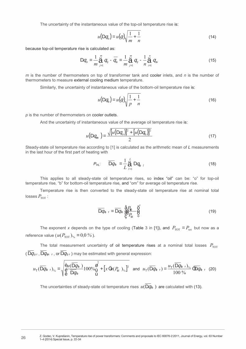
The uncertainty of the instantaneous value of the top-oil temperature rise is:
nm
uu 11 o (14)
because top-oil temperature rise is calculated as:
n
ii
m
jj
m
jj nmm 111
111atato (15)
m is the number of thermometers on top of transformer tank and cooler inlets, and n is the number of thermometers to measure external cooling medium temperature.
Similarly, the uncertainty of instantaneous value of the bottom-oil temperature rise is:
np
uu 11 b (16)
p is the number of thermometers on cooler outlets.
And the uncertainty of instantaneous value of the average oil temperature rise is:
2
22bo
om
uu
u (17)
Steady-state oil temperature rise according to [1] is calculated as the arithmetic mean of L measurements in the last hour of the first part of heating with
PHL:
L
llL 1
1oil;oil (18)
This applies to all steady-state oil temperature rises, so index “oil” can be: “o” for top-oil temperature rise, “b” for bottom-oil temperature rise, and “om” for average oil temperature rise.
Temperature rise is then converted to the steady-state oil temperature rise at nominal total losses TOTP :
x
PP
HL
TOToilroil; (19)
The exponent x depends on the type of cooling (Table 3 in [1]), and totTOT PP but now as a
reference value ( %,Pu 00)( %TOT ).
The total measurement uncertainty of oil temperature rises at a nominal total losses TOTP
( ro; , rom; , or rb; ) may be estimated with general expression:
2%
2
% )(%100)()( HLoil
oilroil;T Puxuu
and roil;
roil;Troil;T
%100)()( %uu (20)
The uncertainties of steady-state oil temperature rises )( oilu are calculated with (13).
Z. Godec, V. Kuprešanin, Temperature rise of power transformers: Comments and proposals to IEC 60076-2:2011, Journal of Energy, vol. 63 Number 1–4 (2014) Special Issue, p. 22-34
27
6
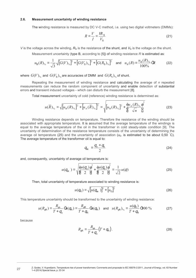
2.6. Measurement uncertainty of winding resistance
The winding resistance is measured by DC V-C method, i.e. using two digital voltmeters (DMMs):
S
S
VVR
IVR (21)
V is the voltage across the winding, RS is the resistance of the shunt, and VS is the voltage on the shunt.
Measurement uncertainty (type B, according to [5]) of winding resistance R is estimated as:
2%2
%2
%% )()()(3
1)( SSB RGVGVGRu and RRuRu %100)()( %B
B (22)
where %)(VG and %)( SVG are accuracies of DMM and %S)(RG of shunt.
Repeating the measurement of winding resistance and calculating the average of n repeated measurements can reduce the random component of uncertainty and enable detection of substantial errors and transient induced voltages - which can disturb the measurement [8].
Total measurement uncertainty of cold (reference) winding resistance is determined as:
2
%A2%B
2%A
2%B%
)()()()()(
nRu
RuRuRuRu (23)
Winding resistance depends on temperature. Therefore the resistance of the winding should be associated with appropriate temperature. It is assumed that the average temperature of the windings is equal to the average temperature of the oil in the transformer in cold steady-state condition [9]. The uncertainty of determination of the resistance temperature consists of the uncertainty of determining the average oil temperature (25) and the uncertainty of association (u is estimated to be about 0,50 °C). The average temperature of the transformer oil is equal to:
2bo
om
(24)
and, consequently, uncertainty of average oil temperature is:
)(2
12
)(2
)()(22
uuuu
bo
om (25)
Then, total uncertainty of temperature associated to winding resistance is:
22)()( uuu omR (26)
This temperature uncertainty should be transformed to the uncertainty of winding resistance:
)()()( RR
RR
o
oR
uT
RuT
RRu
and %100)()( %
R
RR
T
uRu (27)
because
Ro
oR
TT
RR . (28)
Z. Godec, V. Kuprešanin, Temperature rise of power transformers: Comments and proposals to IEC 60076-2:2011, Journal of Energy, vol. 63 Number 1–4 (2014) Special Issue, p. 22-34
28
7
where RR is resistance at temperature R , oR and o are reference resistance and temperature, and T is constant, for copper 235 K and for aluminium 225 K [1].
Finally, total uncertainty of winding resistance with associated temperature is:
2%2
%% )()()( RT RuRuRu (29)
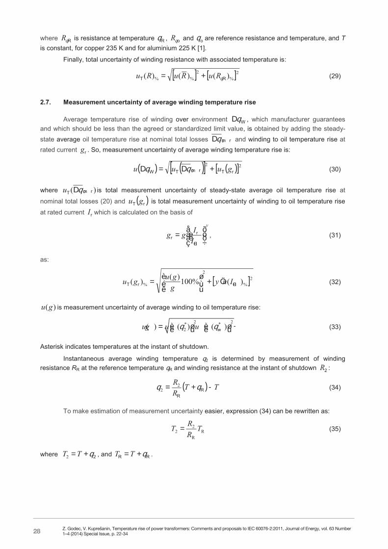
2.7. Measurement uncertainty of average winding temperature rise
Average temperature rise of winding over environment W , which manufacturer guarantees and which should be less than the agreed or standardized limit value, is obtained by adding the steady-state average oil temperature rise at nominal total losses rom; and winding to oil temperature rise at rated current rg . So, measurement uncertainty of average winding temperature rise is:
22rTrom;TW guuu (30)
where )( rom;T u is total measurement uncertainty of steady-state average oil temperature rise at
nominal total losses (20) and rT gu is total measurement uncertainty of winding to oil temperature rise
at rated current rI which is calculated on the basis of
y
IIgg
HC
rr , (31)
as:
2%
2
% )(%100)()( HCrT Iuyggugu
(32)
)(gu is measurement uncertainty of average winding to oil temperature rise:
2 2* *
2( ) ( ) ( )omu g u u (33)
Asterisk indicates temperatures at the instant of shutdown.
Instantaneous average winding temperature 2 is determined by measurement of winding resistance RR at the reference temperature R and winding resistance at the instant of shutdown 2R :
TTRR
RR
22 (34)
To make estimation of measurement uncertainty easier, expression (34) can be rewritten as:
RR
22 T
RRT (35)
where 2TT2 , and RR TT .
Z. Godec, V. Kuprešanin, Temperature rise of power transformers: Comments and proposals to IEC 60076-2:2011, Journal of Energy, vol. 63 Number 1–4 (2014) Special Issue, p. 22-34
29
8
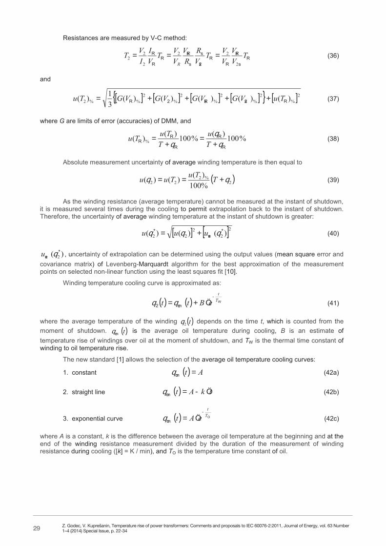
Resistances are measured by V-C method:
Rs
Rs
RR
2s
s
s
RsR
R
R TVV
VVT
VR
RV
VVT
VI
IVT
R 2
22
2
22 (36)
and
2%2
%2
%2
%2
%%2 )()()()()(31)( R2sRs2R TuVGVGVGVGTu (37)
where G are limits of error (accuracies) of DMM, and
%100)(%100)()( %R
R
R
RR
Tu
TTuTu (38)
Absolute measurement uncertainty of average winding temperature is then equal to
2%2
22 %100)()()( TTuTuu (39)
As the winding resistance (average temperature) cannot be measured at the instant of shutdown, it is measured several times during the cooling to permit extrapolation back to the instant of shutdown. Therefore, the uncertainty of average winding temperature at the instant of shutdown is greater:
2*2
22
*2 )()()( exuuu (40)
)( *2exu , uncertainty of extrapolation can be determined using the output values (mean square error and
covariance matrix) of Levenberg-Marquardt algorithm for the best approximation of the measurement points on selected non-linear function using the least squares fit [10].
Winding temperature cooling curve is approximated as:
Wom2
Tt
eBtt
(41)
where the average temperature of the winding t2 depends on the time t, which is counted from the moment of shutdown. tom is the average oil temperature during cooling, B is an estimate of temperature rise of windings over oil at the moment of shutdown, and TW is the thermal time constant of winding to oil temperature rise.
The new standard [1] allows the selection of the average oil temperature cooling curves:
1. constant At om (42a)
2. straight line tkAt om (42b)
3. exponential curve Oom
Tt
eAt
(42c)
where A is a constant, k is the difference between the average oil temperature at the beginning and at the end of the winding resistance measurement divided by the duration of the measurement of winding resistance during cooling ([k] = K / min), and TO is the temperature time constant of oil.
Z. Godec, V. Kuprešanin, Temperature rise of power transformers: Comments and proposals to IEC 60076-2:2011, Journal of Energy, vol. 63 Number 1–4 (2014) Special Issue, p. 22-34
30
9
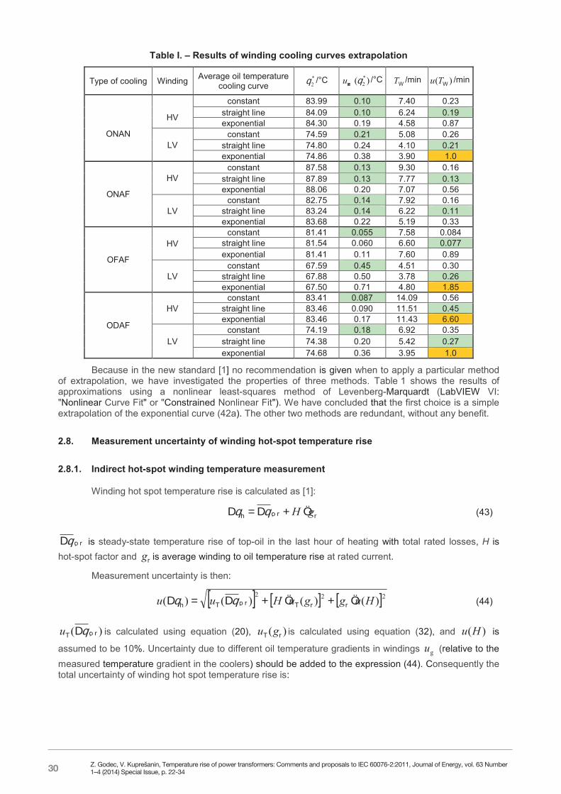
Table I. – Results of winding cooling curves extrapolation
Type of cooling Winding Average oil temperature cooling curve
*2 /°C )( *
2exu /°C WT /min )( WTu /min
ONAN
HV
constant 83.99 0.10 7.40 0.23 straight line 84.09 0.10 6.24 0.19 exponential 84.30 0.19 4.58 0.87
LV constant 74.59 0.21 5.08 0.26
straight line 74.80 0.24 4.10 0.21 exponential 74.86 0.38 3.90 1.0
ONAF
HV constant 87.58 0.13 9.30 0.16
straight line 87.89 0.13 7.77 0.13 exponential 88.06 0.20 7.07 0.56
LV constant 82.75 0.14 7.92 0.16
straight line 83.24 0.14 6.22 0.11 exponential 83.68 0.22 5.19 0.33
OFAF
HV constant 81.41 0.055 7.58 0.084
straight line 81.54 0.060 6.60 0.077 exponential 81.41 0.11 7.60 0.89
LV constant 67.59 0.45 4.51 0.30
straight line 67.88 0.50 3.78 0.26 exponential 67.50 0.71 4.80 1.85
ODAF
HV constant 83.41 0.087 14.09 0.56
straight line 83.46 0.090 11.51 0.45 exponential 83.46 0.17 11.43 6.60
LV constant 74.19 0.18 6.92 0.35
straight line 74.38 0.20 5.42 0.27 exponential 74.68 0.36 3.95 1.0
Because in the new standard [1] no recommendation is given when to apply a particular method of extrapolation, we have investigated the properties of three methods. Table 1 shows the results of approximations using a nonlinear least-squares method of Levenberg-Marquardt (LabVIEW VI: "Nonlinear Curve Fit" or "Constrained Nonlinear Fit"). We have concluded that the first choice is a simple extrapolation of the exponential curve (42a). The other two methods are redundant, without any benefit.
2.8. Measurement uncertainty of winding hot-spot temperature rise
2.8.1. Indirect hot-spot winding temperature measurement
Winding hot spot temperature rise is calculated as [1]:
rro;h gH (43)
ro; is steady-state temperature rise of top-oil in the last hour of heating with total rated losses, H is hot-spot factor and rg is average winding to oil temperature rise at rated current.
Measurement uncertainty is then:
222)()()()( HugguHuu rrTro;Th (44)
)( ro;T u is calculated using equation (20), )( rT gu is calculated using equation (32), and )(Hu is
assumed to be 10%. Uncertainty due to different oil temperature gradients in windings gu (relative to the measured temperature gradient in the coolers) should be added to the expression (44). Consequently the total uncertainty of winding hot spot temperature rise is:
Z. Godec, V. Kuprešanin, Temperature rise of power transformers: Comments and proposals to IEC 60076-2:2011, Journal of Energy, vol. 63 Number 1–4 (2014) Special Issue, p. 22-34
31
10
2ghhT uuu 2)()( (45)
For ON.. and OD.. cooled transformers it is estimated that the uncertainty due to different temperature gradients of oil in the individual windings is approximately 2 K. For OF.. cooled transformers oil temperature gradient in windings is greater than the gradient of oil temperature in coolers, and systematic error is estimated to be approximately 10 K with an uncertainty of about 2 K.
2.8.2. Direct hot-spot winding temperature measurement
If the temperature of the hot-spot is measured directly with fibre optic thermometer, the hot-spot temperature rise is calculated as:
rho;ro;h (46)
ro; is steady-state top-oil temperature rise in the last hour of heating with total losses and rho; is hot-spot winding temperature rise over top-oil recalculated to the rated current:
z
II
HC
rhorho; (47)
where the exponent z depends on the type of cooling (Table 3 in [1]), and ho is winding hot-spot temperature rise over top-oil measured at current IHC:
*o
*hho (48)
Measurement uncertainty is then:
22rho;Tro;Th uuu (49)
)( ro;T u is calculated using equation (20), and )( rho;T u is on the basis of (47):
2%
2
% )(%100)(%100
)(%100
)( HCho
horho;rho;T
rho;rho;T Iuzuuu
(50)
Measurement uncertainty of winding hot-spot temperature rise over oil is calculated on the basis of (48):
2
2 )()()(
muuu hho (51)
3. MEASUREMENT UNCERTAINTY AND DECISION MAKING
Measurement is a process which product is complete measurement result [5]. It consists of measured value {M}, standard measurement uncertainty {u}, coverage factor k and measurement unit [M]:
MukMM . (52)
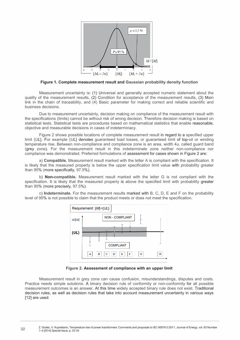
Figure 1 shows the complete measurement result. The curve above is probability density function called Normal or Gaussian distribution. The area that encloses the curve above and the complete measurement result is equal to the probability that the true value of the measured quantity is within the complete measurement result (which is for k = 2 approximately 95%).
Z. Godec, V. Kuprešanin, Temperature rise of power transformers: Comments and proposals to IEC 60076-2:2011, Journal of Energy, vol. 63 Number 1–4 (2014) Special Issue, p. 22-34
32
11
Figure 1. Complete measurement result and Gaussian probability density function
Measurement uncertainty is: (1) Universal and generally accepted numeric statement about the quality of the measurement results, (2) Condition for acceptance of the measurement results, (3) Main link in the chain of traceability, and (4) Basic parameter for making correct and reliable scientific and business decisions.
Due to measurement uncertainty, decision making on compliance of the measurement result with the specifications (limits) cannot be without risk of wrong decision. Therefore decision making is based on statistical tests. Statistical tests are procedures based on mathematical statistics that enable reasonable, objective and measurable decisions in cases of indeterminacy.
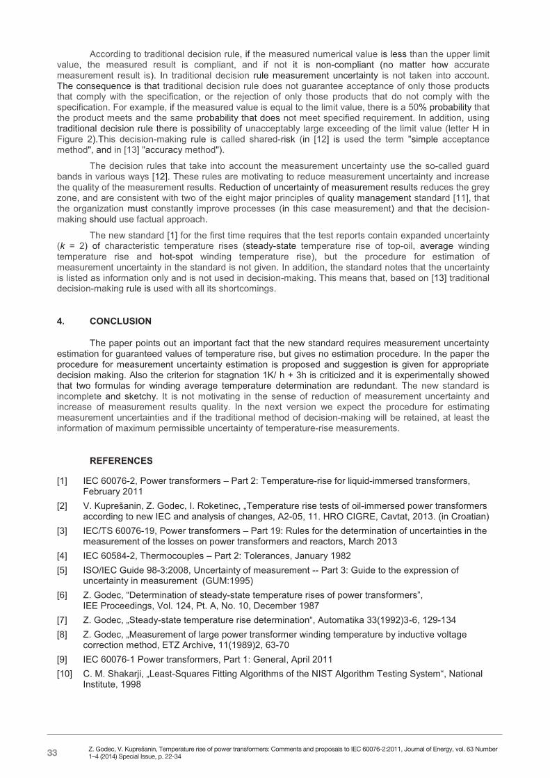
Figure 2 shows possible locations of complete measurement result in regard to a specified upper limit {UL}. For example {UL} denotes guaranteed load losses, or guaranteed limit of top-oil or winding temperature rise. Between non-compliance and compliance zone is an area, width 4u, called guard band (grey zone). For the measurement result in this indeterminate zone neither non-compliance nor compliance was demonstrated. Preferred formulations of assessment for cases shown in Figure 2 are:
a) Compatible. Measurement result marked with the letter A is compliant with the specification. It is likely that the measured property is below the upper specification limit value with probability greater than 95% (more specifically, 97.5%).
b) Non-compatible. Measurement result marked with the letter G is not compliant with the specification. It is likely that the measured property is above the specified limit with probability greater than 95% (more precisely, 97.5%).
c) Indeterminate. For the measurement results marked with B, C, D, E and F on the probability level of 95% is not possible to claim that the product meets or does not meet the specification.
Figure 2. Assessment of compliance with an upper limit
Measurement result in grey zone can cause confusion, misunderstandings, disputes and costs. Practice needs simple solutions. A binary decision rule of conformity or non-conformity for all possible measurement outcomes is an answer. At this time widely accepted binary rule does not exist. Traditional decision rules, as well as decision rules that take into account measurement uncertainty in various ways [12] are used.
Z. Godec, V. Kuprešanin, Temperature rise of power transformers: Comments and proposals to IEC 60076-2:2011, Journal of Energy, vol. 63 Number 1–4 (2014) Special Issue, p. 22-34
33
12
According to traditional decision rule, if the measured numerical value is less than the upper limit value, the measured result is compliant, and if not it is non-compliant (no matter how accurate measurement result is). In traditional decision rule measurement uncertainty is not taken into account. The consequence is that traditional decision rule does not guarantee acceptance of only those products that comply with the specification, or the rejection of only those products that do not comply with the specification. For example, if the measured value is equal to the limit value, there is a 50% probability that the product meets and the same probability that does not meet specified requirement. In addition, using traditional decision rule there is possibility of unacceptably large exceeding of the limit value (letter H in Figure 2).This decision-making rule is called shared-risk (in [12] is used the term "simple acceptance method", and in [13] "accuracy method").
The decision rules that take into account the measurement uncertainty use the so-called guard bands in various ways [12]. These rules are motivating to reduce measurement uncertainty and increase the quality of the measurement results. Reduction of uncertainty of measurement results reduces the grey zone, and are consistent with two of the eight major principles of quality management standard [11], that the organization must constantly improve processes (in this case measurement) and that the decision-making should use factual approach.
The new standard [1] for the first time requires that the test reports contain expanded uncertainty (k = 2) of characteristic temperature rises (steady-state temperature rise of top-oil, average winding temperature rise and hot-spot winding temperature rise), but the procedure for estimation of measurement uncertainty in the standard is not given. In addition, the standard notes that the uncertainty is listed as information only and is not used in decision-making. This means that, based on [13] traditional decision-making rule is used with all its shortcomings.
4. CONCLUSION
The paper points out an important fact that the new standard requires measurement uncertainty estimation for guaranteed values of temperature rise, but gives no estimation procedure. In the paper the procedure for measurement uncertainty estimation is proposed and suggestion is given for appropriate decision making. Also the criterion for stagnation 1K/ h + 3h is criticized and it is experimentally showed that two formulas for winding average temperature determination are redundant. The new standard is incomplete and sketchy. It is not motivating in the sense of reduction of measurement uncertainty and increase of measurement results quality. In the next version we expect the procedure for estimating measurement uncertainties and if the traditional method of decision-making will be retained, at least the information of maximum permissible uncertainty of temperature-rise measurements.
REFERENCES
[1] IEC 60076-2, Power transformers – Part 2: Temperature-rise for liquid-immersed transformers, February 2011
[2] V. Kuprešanin, Z. Godec, I. Roketinec, „Temperature rise tests of oil-immersed power transformers according to new IEC and analysis of changes, A2-05, 11. HRO CIGRE, Cavtat, 2013. (in Croatian)
[3] IEC/TS 60076-19, Power transformers – Part 19: Rules for the determination of uncertainties in the measurement of the losses on power transformers and reactors, March 2013
[4] IEC 60584-2, Thermocouples – Part 2: Tolerances, January 1982 [5] ISO/IEC Guide 98-3:2008, Uncertainty of measurement -- Part 3: Guide to the expression of
uncertainty in measurement (GUM:1995) [6] Z. Godec, “Determination of steady-state temperature rises of power transformers”,
IEE Proceedings, Vol. 124, Pt. A, No. 10, December 1987 [7] Z. Godec, „Steady-state temperature rise determination“, Automatika 33(1992)3-6, 129-134 [8] Z. Godec, „Measurement of large power transformer winding temperature by inductive voltage
correction method, ETZ Archive, 11(1989)2, 63-70 [9] IEC 60076-1 Power transformers, Part 1: General, April 2011 [10] C. M. Shakarji, „Least-Squares Fitting Algorithms of the NIST Algorithm Testing System“, National
Institute, 1998
Z. Godec, V. Kuprešanin, Temperature rise of power transformers: Comments and proposals to IEC 60076-2:2011, Journal of Energy, vol. 63 Number 1–4 (2014) Special Issue, p. 22-34
34
13
[11] ISO 9001: 2008, Quality management system - Requirements [12] JCGM 106: 2012, Evaluation of measurement data – The role of measurement uncertainty in
conformity assessment [13] IEC Guide 115: 2007, Application of uncertainty of measurement to conformity assessment
activities in the electrotechnical sector
Z. Godec, V. Kuprešanin, Temperature rise of power transformers: Comments and proposals to IEC 60076-2:2011, Journal of Energy, vol. 63 Number 1–4 (2014) Special Issue, p. 22-34


