Embed Size (px)
Citation preview
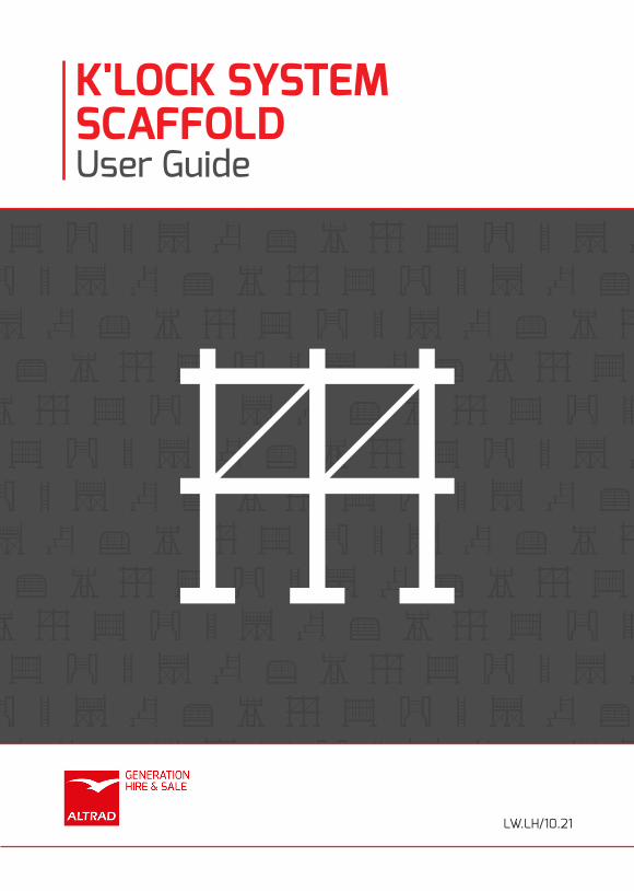
K'LOCK SYSTEM SCAFFOLDUser Guide
LW.LH/10.21
BEST QUALITYWe work in partnership with our suppliers to ensure we deliver consistent
quality every time. We guarantee that our hire and sales products will meet
and conform or exceed all statutory requirements and not let you down.
OUR CUSTOMER PROMISE IS TO DELIVER:
Altrad Generation is one of the largest suppliers of Scaffolding, Temporary
Fencing and Access. Also supplying to multiple sectors in Groundworks,
Safety, Edge Protection and within Ireland, formwork and falsework.
BEST PRICESWe use our position as the largest supplier of scaffolding, fencing and access
products to negotiate the best rates for you. We guarantee you will get the
best value products and service when you hire or buy from us.
BEST PARTNERSHIPWe provide a full range of engineering, design and business services to
partner and work with our customers. Talk to us today about how we can
help you to grow your business.
BEST AVAILABILITY We have the largest available inventory of temporary fencing, water filled
and pedestrian barrier products. Our branch network and delivery fleet will
ensure that we deliver what you need, when you need it.
1
2
3
4
Altrad GenerationShaping The Future Of Construction & Industry.
K'Lock System Scaffolding
Intoduction ................................................................................................................................................................4
Scaffolding Safety ................................................................................................................................................5-7
Components
Tube Components .............................................................................................................................................8-12
Omega Components ..................................................................................................................................... 12-13
Battens .....................................................................................................................................................................14
Component Safe Working Loads
Standards ................................................................................................................................................................15
Bracing,Tying and Safe Working Heights
Bracing Requirements ..........................................................................................................................................17
Maxiumum Heights and Tie Patterns ...............................................................................................................17
Tie Details ................................................................................................................................................................19
Tie Patterns .............................................................................................................................................................20
Buckling Loads
Tube Transoms ......................................................................................................................................................21
Omega Transoms ..................................................................................................................................................21
Loading Classification and Safe Working Heights ..........................................................................................22
Partial Load Factors
Tube Transoms ......................................................................................................................................................23
Omega Transoms ..................................................................................................................................................24
Erection And Dismantling
Erection Sequence ................................................................................................................................................24
Assembly Using Standard Scaffold Boards .....................................................................................................25
Omega Batten System ..........................................................................................................................................26
Increasing the height of scaffolding ..................................................................................................................27
Dismantling the Scaffold ......................................................................................................................................27
Storage,Maintenance and Repair
Storage .....................................................................................................................................................................30
Maintenance ...........................................................................................................................................................30
Repairs .....................................................................................................................................................................31
Transport .................................................................................................................................................................31
Contents
3 www.altradgeneration.com
Corner DetailsCorners and Insde Board Platforms (Tube Transoms) ......................................................................... 32-33
Corners and Inside Board Platforms (Omega Transoms) .................................................................... 34-35
Circular Access .......................................................................................................................................................36
Circular AccessCircular Access .......................................................................................................................................................36
Loading PlatformsLoading Platforms .................................................................................................................................................37
Permissible Uniformly Distributed LoadsPermissible Uniformly Distributed Loads ........................................................................................................38
Stair Access ....................................................................................................................................................................................39
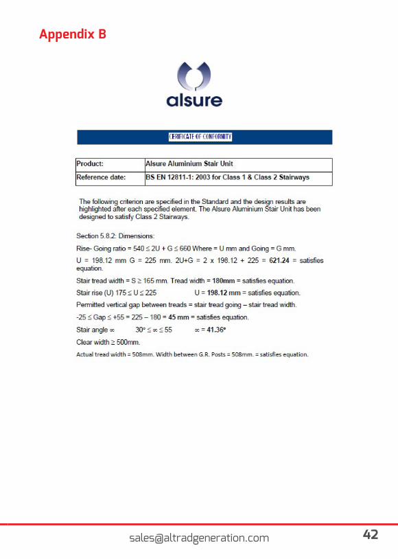
AppendixAppendix A ............................................................................................................................ ..................................40
Appendix B ............................................................................................................................ ........................... 41-48
Disclaimer & CopyrightDisclaimer ................................................................................................................................................................49
Copyright .................................................................................................................................................................49
Contents
K'Lock System Scaffold
IntroductionThis user guide has been prepared in accordance with the guidance as set out within BS EN12810-1:2003 clause 8, the NASC Code of Practice and where applicable additional information within associated European Standards.
Altrad Generation Hire & Sale K-Lock has been independently tested and assessed against the standards noted below. It is a fully galvanised multi purpose steel scaffold, suitable for general access. Robust and versatile the system can be erected in various configurations and is available for use with either steel or timber battens or traditional scaffold boards.
The system can provide savings in erection and dismantling times over traditional scaffoldingand is easy to store and transport.
Horizontal and vertical members are manufactured from 48.3mm OD x 3.2mm wall thicknesshigh tensile steel with a minimum grade of Grade 50c or S355.
Components are protected against corrosion by hot dipped galvanising.
Strength
K’Lock independent tied access scaffolds built with bay widths up to 2.5m have a load capacityof 3kN/m2. For other applications, such as birdcage, mobile towers and staircase the loadingsmay vary, and advice should be sought from your design office.
Safety ComplianceAll access scaffolds must comply with the general requirements of the following:
Work at Height Regulations 2005
Code of Practice BSEN12811-1
Statutory Regulations:
Health & Safety at Work Act 1974
Work at Height Regulations 2005
British Standards and Codes of practice for Steel Scaffolding:BSEN12810-1:2003BSEN12810-2:2003BSEN12811-1:2003BSEN12811-2:2003
5 www.altradgeneration.com
K'Lock System Scaffold - Scaffolding Safety• This guidance is not intended to replace any relevant British standards, European codes, work atheight regulations, company procedures, or other legislation but is a practical guide to good scaffolding practice.• Ensure that you follow your company’s safe systems of work at all times.• Ensure that all persons erecting, dismantling or modifying any structure are competent to carryout the task.• Ensure that all persons erecting, dismantling or modifying any structure are working to the latestversion of the National Access & Scaffolding Confederation SG4 guidance as a minimum.• Access scaffolding should at all times comply with the latest version of the NASC TG20 best practice for access and working scaffold structures in steel.• Ensure all personal protective equipment is suitable and worn as appropriate.• Consideration should be given as to where additional hazards may be present whilst scaffoldingoperations are taking place, such as overhead power cables, roadways, schools and if protectionis required, if the scaffold is to be sheeted, who is responsible for the design.• Always display warning notices when the scaffold is under construction or being adapted and erect fixed barriers to prevent any unauthorized access.• Scaffold structures are required to be inspected and recorded at regular intervals by a competent person not exceeding 7 days, in addition to the structure being taken into use for the first time, after any alteration, after adverse weather or any event that is likely to affect its stability.• No tradesman should work on the scaffold structure whilst it is being erected.• Only genuine K’Lock components are to be used• Never use any defective or modified equipment• Access and egress should be considered as early as practicable, with both the scaffold operatives and end user in mind. Ladders should be used by the scaffolder’s when erecting, modifying or dismantling any structure. Ledgers, Braces etc. must not be used as a means of support.• Employers must ensure that work at height is: • Properly planned • Appropriately supervised • Carried out in a safe manner “so far as is reasonably practicable” Include planning for emergencies and rescue • Weather conditions do not jeopardise health and safety• Never Bomb scaffold equipment or any other materials up or down• Never undertake work at height when there is a potential to fall without wearing your safetyharness correctly and clipping the lanyard to a secure anchor point ideally above head height.• Never remove or interfere with guards, they are there to protect you• Never over load the scaffold you are erecting / dismantling with spare materials or rest scaffoldequipment against an object if there is a potential for it to fall.• All working platforms from which a person could fall must be fitted with a double guardrail andtoe board.• Never leave an exposed edge where people or materials could fall.• Never accept and instruction from a client or anyone else that does not conform to the advicegiven in this guide.
K'Lock System Scaffold - Scaffolding Safety• If you are in any doubt with regard to any of the information contained within this Handbook orneed further advice please contact your local Altrad Generation Hire & Sale office.• Should the need arise to use scaffold components outside the K’Lock range the following standards must be specified: • Tube – EN39:2001 • Fittings – to appropriate standard EN 74-1:2005 or BS 1139-2:2009• Ensure when the structure is handed over a signature is obtained from the competent personaccepting the structure i.e. the client/hirer.
Site InspectionBefore commencing the erection of any K’Lock System Scaffold, care should be taken to seethat the ground is suitable, on soft or made up ground the scaffold should be erected on timber sole plates of appropriate size, bricks or blocks must never be used. The scaffold should be started on the highest part of the ground, this makes levelling easier as the scaffolding progresses horizontally. Always allow for any inside batten platform when determining the distance from the building the scaffold is to be positioned.
Safety HarnessUnder guidance from the NASC, endorsed by the HSE, all scaffold erectors must wear a harness and lanyard whilst erecting, dismantling and working on scaffolding. All methods of erection/dismantling scaffolding and the use of safety harnesses should be used in conjunction with the latest version of the NASC SG4 guidance notes.
Who can erect the scaffold?A competent person suitably trained and appointed by the company can erect, modify or dismantle a scaffold, the balance of the scaffold gang is to be determined by the company based on the complexity of the structure.
Power LinesFor information please review NASC latest guidance note SG5 and ensure detailed and robustsafe systems of work are devised to identify and eliminate/control the hazards present.
TrafficIf the scaffold is to be built in an area that is used by cars or other mobile machinery, the vehicles should either be re-routed or operatives provided to direct the traffic.
7 www.altradgeneration.com
K'Lock System Scaffold - Scaffolding Safety
CranesScaffolding and people within the operational radius or line of travel of a crane are at risk fromsuspended loads and/or the crane itself. In such circumstances the following precautions arerecommended:
• Ensure the scaffold does not have any unnecessary projections such as oversizedcomponents• Clear the scaffold of personnel during crane operations• Develop an operations plan for the crane for work carried out in the vicinity of the scaffold.
User’s responsibilitiesOnce the scaffold is complete and handed over, it may be used by various personnel for general working. During this period of working, the scaffold may be subjected to many load variations and possible misuse or abuse. It is important that all people using the scaffold are aware of their responsibilities for the correct use and maintenance of the scaffold.
• The client must ensure that the scaffold erectors are made fully aware of all loading requirements and use for which the scaffold is required.
• The client must ensure that the designated site for the erection of scaffolding is clear and suitable for the erection of the structure and that the building foundations are suitable for the loadings applied from the scaffold.
• Where applicable the client must obtain all necessary permits.
• When the scaffold is completed, the client must satisfy themselves that the scaffold meets the requirements and that all materials have been erected in a safe and secure manner. It is recommended the client obtains a standard hand over certificate for the scaffold erector.
• Clear passageways must be maintained on working platforms.
• Under no circumstances should any alterations of the scaffold be undertaken by any persons other than the scaffold contractor responsible for the original erection of the scaffold.
• The scaffold must only be used and loaded to the original specification.
• The addition of extra components such as sheeting, extra boards must only be undertaken by the original erectors of the scaffold.
Any event that may affect the strength or stability of the scaffold such as damage from vehicles, trench excavation etc., must be reported to the original scaffold contractor immediately.
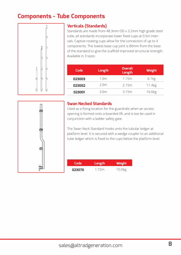
Standards are made from 48.3mm OD x 3.2mm high grade steel tube, all standards incorporate lower fixed cups at 0.5m inter-vals. Captive rotating cups allow for the connection of up to 4components. The lowest base cup joint is 80mm from the base of the standard to give the scaffold improved structural strength.Available in 3 sizes:
Used as a fixing location for the guardrails when an access opening is formed onto a boarded lift, and is toe be used in conjunction with a ladder safety gate.
The Swan Neck Standard hooks onto the tubular ledger at platform level. It is secured with a wedge coupler to an additional tube ledger which is fixed to the cups below the platform level.
Code Length Overall Length Weight
023003 1.0m 1.15m 6.1kg
023002 2.0m 2.15m 11.4kg
023001 3.0m 3.15m 16.6kg
Code Length Weight
023070 1.72m 10.0kg
Verticals (Standards)
Swan Necked Standards
Components - Tube Components
9 www.altradgeneration.com
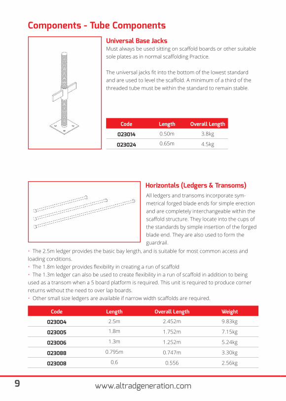
Must always be used sitting on scaffold boards or other suitable sole plates as in normal scaffolding Practice.
The universal jacks fit into the bottom of the lowest standard and are used to level the scaffold. A minimum of a third of the threaded tube must be within the standard to remain stable.
All ledgers and transoms incorporate sym-metrical forged blade ends for simple erection and are completely interchangeable within the scaffold structure. They locate into the cups of the standards by simple insertion of the forged blade end. They are also used to form the guardrail.
Code Length Overall Length
023014 0.50m 3.8kg
023024 0.65m 4.5kg
Code Length Overall Length Weight
023004 2.5m 2.452m 9.83kg
023005 1.8m 1.752m 7.15kg
023006 1.3m 1.252m 5.24kg
023088 0.795m 0.747m 3.30kg
023008 0.6 0.556 2.56kg
Universal Base Jacks
Horizontals (Ledgers & Transoms)
Components - Tube Components
• The 2.5m ledger provides the basic bay length, and is suitable for most common access and loading conditions. • The 1.8m ledger provides flexibility in creating a run of scaffold • The 1.3m ledger can also be used to create flexibility in a run of scaffold in addition to being used as a transom when a 5 board platform is required. This unit is required to produce corner returns without the need to over lap boards. • Other small size ledgers are available if narrow width scaffolds are required.
Horizontals (Ledgers & Transoms)
Components - Tube Components
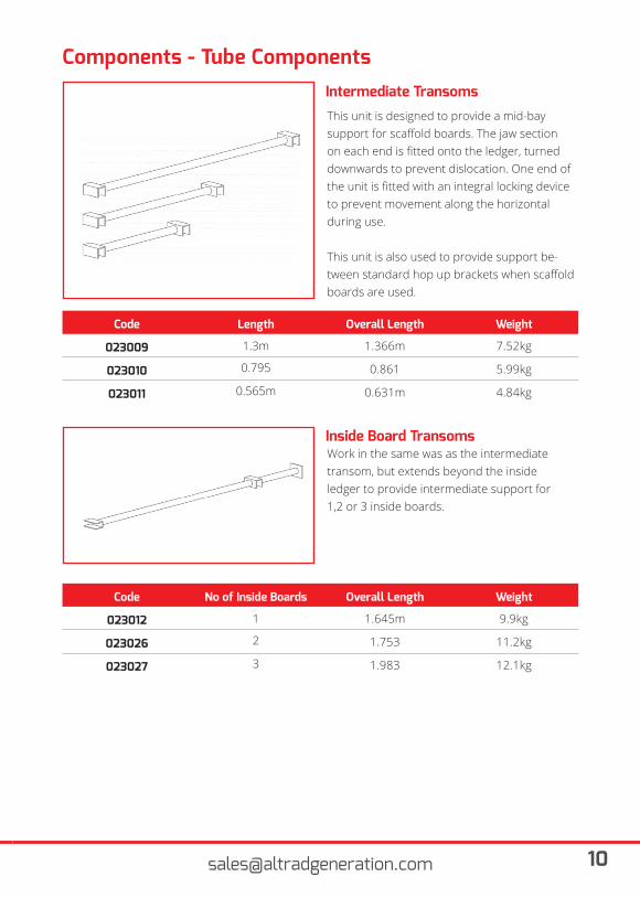
This unit is designed to provide a mid-bay support for scaffold boards. The jaw section on each end is fitted onto the ledger, turned downwards to prevent dislocation. One end of the unit is fitted with an integral locking device to prevent movement along the horizontal during use.
This unit is also used to provide support be-tween standard hop up brackets when scaffold boards are used.
Code Length Overall Length Weight
023009 1.3m 1.366m 7.52kg
023010 0.795 0.861 5.99kg
023011 0.565m 0.631m 4.84kg
Intermediate Transoms
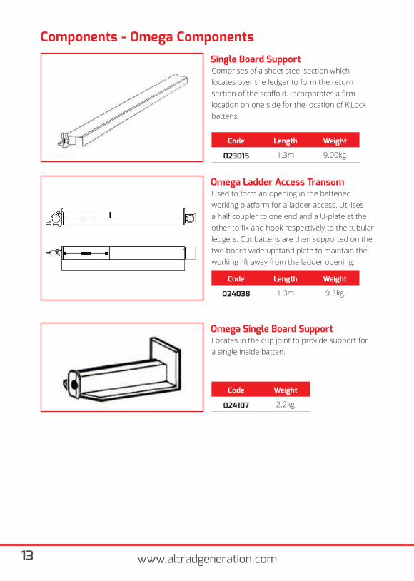
Work in the same was as the intermediatetransom, but extends beyond the insideledger to provide intermediate support for1,2 or 3 inside boards.
Code No of Inside Boards Overall Length Weight
023012 1 1.645m 9.9kg
023026 2 1.753 11.2kg
023027 3 1.983 12.1kg
Inside Board Transoms
11 www.altradgeneration.com
Components - Tube Components
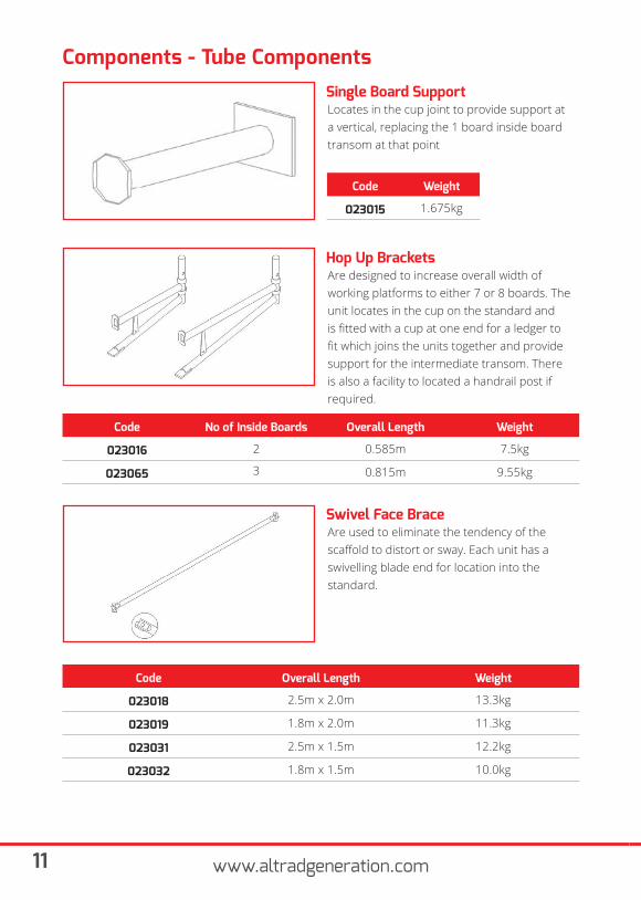
Locates in the cup joint to provide support at a vertical, replacing the 1 board inside board transom at that point
Single Board Support
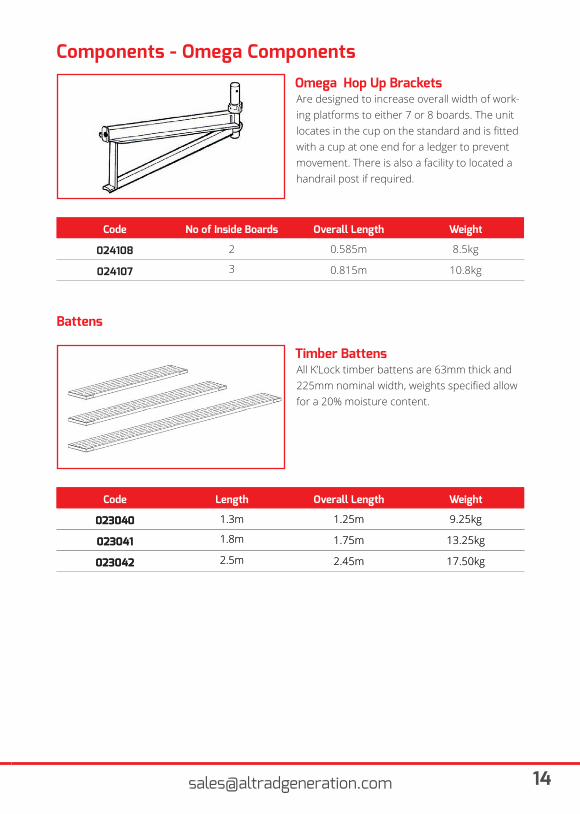
Are designed to increase overall width of working platforms to either 7 or 8 boards. The unit locates in the cup on the standard and is fitted with a cup at one end for a ledger to fit which joins the units together and provide support for the intermediate transom. There is also a facility to located a handrail post if required.
Code No of Inside Boards Overall Length Weight
023016 2 0.585m 7.5kg
023065 3 0.815m 9.55kg
Hop Up Brackets
Code Weight
023015 1.675kg
Are used to eliminate the tendency of thescaffold to distort or sway. Each unit has aswivelling blade end for location into the standard.
Code Overall Length Weight
023018 2.5m x 2.0m 13.3kg
023019 1.8m x 2.0m 11.3kg
023031 2.5m x 1.5m 12.2kg
023032 1.8m x 1.5m 10.0kg
Swivel Face Brace
Components - Tube Components
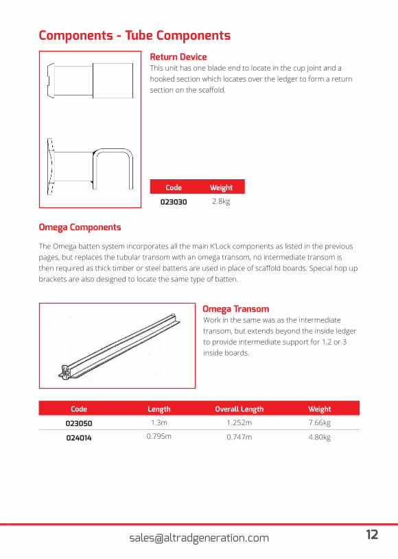
This unit has one blade end to locate in the cup joint and a hooked section which locates over the ledger to form a return section on the scaffold.
Return Device
Code Weight
023030 2.8kg
Omega Components
The Omega batten system incorporates all the main K’Lock components as listed in the previous pages, but replaces the tubular transom with an omega transom, no intermediate transom is then required as thick timber or steel battens are used in place of scaffold boards. Special hop up brackets are also designed to locate the same type of batten.
Work in the same was as the intermediatetransom, but extends beyond the inside ledger to provide intermediate support for 1,2 or 3 inside boards.
Code Length Overall Length Weight
023050 1.3m 1.252m 7.66kg
024014 0.795m 0.747m 4.80kg
Omega Transom
13 www.altradgeneration.com
Components - Omega Components
Comprises of a sheet steel section whichlocates over the ledger to form the returnsection of the scaffold. Incorporates a firmlocation on one side for the location of K’Lockbattens.
Single Board Support
Used to form an opening in the battenedworking platform for a ladder access. Utilisesa half coupler to one end and a U-plate at theother to fix and hook respectively to the tubular ledgers. Cut battens are then supported on the two board wide upstand plate to maintain the working lift away from the ladder opening.
Omega Ladder Access Transom
Locates in the cup joint to provide support fora single inside batten.
Omega Single Board Support
Code Length Weight
023015 1.3m 9.00kg
Code Length Weight
024038 1.3m 9.3kg
Code Weight
024107 2.2kg
Components - Omega Components
Battens
All K’Lock timber battens are 63mm thick and 225mm nominal width, weights specified allow for a 20% moisture content.
Code Length Overall Length Weight
023040 1.3m 1.25m 9.25kg
023041 1.8m 1.75m 13.25kg
023042 2.5m 2.45m 17.50kg
Timber Battens
Are designed to increase overall width of work-ing platforms to either 7 or 8 boards. The unit locates in the cup on the standard and is fitted with a cup at one end for a ledger to prevent movement. There is also a facility to located a handrail post if required.
Code No of Inside Boards Overall Length Weight
024108 2 0.585m 8.5kg
024107 3 0.815m 10.8kg
Omega Hop Up Brackets
Code Length Overall Length Weight
023040 1.3m 1.25m 9.25kg
023041 1.8m 1.75m 13.25kg
023042 2.5m 2.45m 17.50kg
15 www.altradgeneration.com
Components
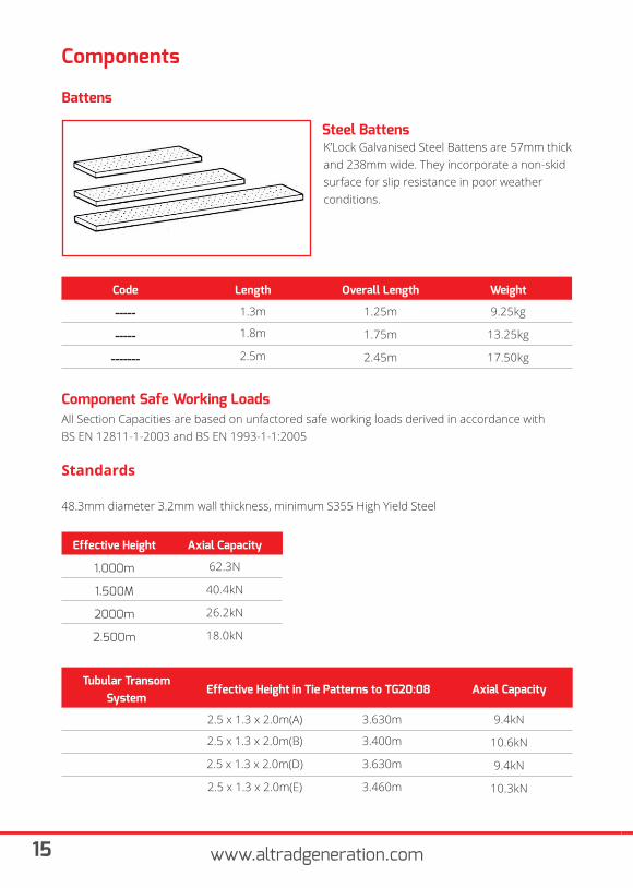
Battens
K’Lock Galvanised Steel Battens are 57mm thick and 238mm wide. They incorporate a non-skid surface for slip resistance in poor weather conditions.
Steel Battens
Code Length Overall Length Weight
----- 1.3m 1.25m 9.25kg
----- 1.8m 1.75m 13.25kg
------- 2.5m 2.45m 17.50kg
Tubular Transom System
Effective Height in Tie Patterns to TG20:08 Axial Capacity
2.5 x 1.3 x 2.0m(A) 3.630m 9.4kN
2.5 x 1.3 x 2.0m(B) 3.400m 10.6kN
2.5 x 1.3 x 2.0m(D) 3.630m 9.4kN
2.5 x 1.3 x 2.0m(E) 3.460m 10.3kN
Component Safe Working LoadsAll Section Capacities are based on unfactored safe working loads derived in accordance withBS EN 12811-1-2003 and BS EN 1993-1-1:2005
Standards
48.3mm diameter 3.2mm wall thickness, minimum S355 High Yield Steel
Effective Height Axial Capacity
1.000m 62.3N
1.500M 40.4kN
2000m 26.2kN
2.500m 18.0kN
Component Safe Working Loads
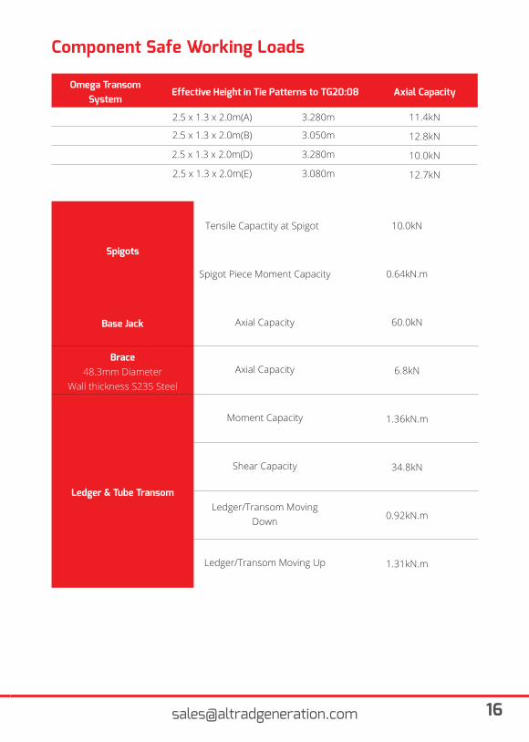
Omega Transom System
Effective Height in Tie Patterns to TG20:08 Axial Capacity
2.5 x 1.3 x 2.0m(A) 3.280m 11.4kN
2.5 x 1.3 x 2.0m(B) 3.050m 12.8kN
2.5 x 1.3 x 2.0m(D) 3.280m 10.0kN
2.5 x 1.3 x 2.0m(E) 3.080m 12.7kN
Spigots
Tensile Capactity at Spigot8 10.0kN
Spigot Piece Moment Capacity 0.64kN.m
Base Jack Axial Capacity 60.0kN
Brace48.3mm Diameter
Wall thickness S235 Steel
Axial Capacity 6.8kN
Ledger & Tube Transom
Moment Capacity 1.36kN.m
Shear Capacity 34.8kN
Ledger/Transom Moving Down 0.92kN.m
Ledger/Transom Moving Up 1.31kN.m
17 www.altradgeneration.com
Bracing, Tying and Safe Working Heights
Bracing Requirements
Diagonal Face Bracing:
All scaffolds require a certain amount of diagonal face bracing to eliminate the tendency of the scaffold to distort or sway. Face bracing is required on all K’Lock access structures in two bays every six bays, i.e. every sixth bay, for the full height of the scaffold. For a scaffold more than 10 metres (4 bays) long, a minimum of 2 bays should be face braced. Bracing the end bays should be avoided if possible.
Ledger and Plan Bracing:
K’Lock access structures do not generally require ledger or plan bracing. Exceptions occur where ties cannot be placed in the correct position, where ties have to be removed for some reason, or in scaffolds that extend above the building. Where these situations apply please consult your design office.
Maximum Heights and Tie Patterns
Maximum Working Heights and Tying-in Pattern Requirements
The maximum height to which a K’Lock scaffold may be erected is dependent upon a numberof factors, the most important of which are: 1. The vertical and horizontal distances between tied points on a standard. 2. The lift height. 3. Wind loading. 4. The vertical loadings in the legs due to self-weight and the working platform loading. 5. Whether or not the cantilever platforms are used. 6. Whether or not the foot ties are used. 7. The inclusion of Debris Netting or Sheeting to the Scaffold.
The parameters detailed in this manual are based on calculations and the results of testing.
IMPORTANTThe maximum height given for scaffolds in the following tables has been limited to 30 metres, in-corporating a maximum of 2 working lifts. Scaffolds above 30 metres and / or incorporating more than 2 working lifts can be constructed, but special consideration should be given to their design and the necessary design advice sought.
Bracing,Tying and Safe Working Heights
General Notes
The safe working height tables should be read in conjunction with the safe working loads -axial capacities on Page 15 of this user guide which illustrates the permissible leg loads for therespective tie patterns. The tie patterns themselves are shown on Page 20. The tie patterns considered are those illustrated in TG20:08 under arrangements A, B, D and E.
The proposal within TG20:08 for providing guidance scaffold arrangements with internal lightly loaded boards with an intensity of 0.75kN/m2 has been incorporated into the safe working height tables. This allows the safe working height table to be compared to TG20:08 as an alternative to tube and fitting access scaffolds using this loading criteria.
The tabulated values are for scaffolds having no working lifts above the last tied level. For scaffolds having working platforms above the last tied level, ledger bracing must be used in the lifts.
Given the complexity of the wind loading code, these tables have had wind loading applied inaccordance with requirements of BS EN 12811-1:2003. A temporary works engineer should be consulted for suitable wind loading design on any structures in excess of 10 metres high or in extreme positions, such as the top of a hill, exposed landscapes, sea views or in-between closely spaced buildings for further guidance.
The safe height tables and section capacities contained within this User Guide are based uponlive loading from the intended use only. Additional loading may accrue on the working platforms or components as a consequence of atmospheric precipitations such as ice, snow, sand or dust. The working processes may also cause debris such as sand, grit or demolition debris to accumulate on the working platform of components which will increase the live loading above that allowed for within the design. Where this is known or observed to occur, further design advice should be sought.
All access scaffolds will impose forces upon the structure they are fixed to through their ties. An assessment should be initially made regarding the ability of the structure to sustain the loads either globally, due to its own instability, or locally as a result of defective finishes. Loadings from the ties into the supporting structure are dependent upon the live loading to the working platforms, the height of the scaffold and in the majority of cases the wind loading imposed upon the scaffold and its cladding status. For guidance with regards to the design of ties into building façades refer to Section 5 of TG20:08 or seek appropriate design advice.
19 www.altradgeneration.com
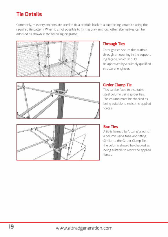
Tie Details
Commonly, masonry anchors are used to tie a scaffold back to a supporting structure using the required tie pattern. When it is not possible to fix masonry anchors, other alternatives can be adopted as shown in the following diagrams.
Through ties secure the scaffold through an opening in the support-ing façade, which shouldbe approved by a suitably qualified structural engineer.
Through Ties
Ties can be fixed to a suitable steel column using girder ties. The column must be checked as being suitable to resist the applied forces.
Girder Clamp Tie
A tie is formed by ‘boxing’ around a column using tube and fitting. Similar to the Girder Clamp Tie, the column should be checked as being suitable to resist the applied forces.
Box Ties
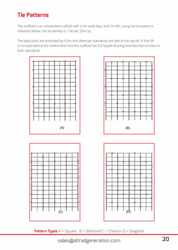
Tie Patterns
The scaffold is an unboarded scaffold with 2.5m wide bays and 2m lifts, using the tie patternsindicated below, the tie density is 1 tie per 20m sq.
The base jacks are extended by 0.5m and alternate standards are tied at the top lift. A foot liftis incorporated at the lowest level and the scaffold has full façade bracing and ties that connect to both standards.
Pattern Types A = Square B = Diamond C = Chevron D = Diagonal
21 www.altradgeneration.com
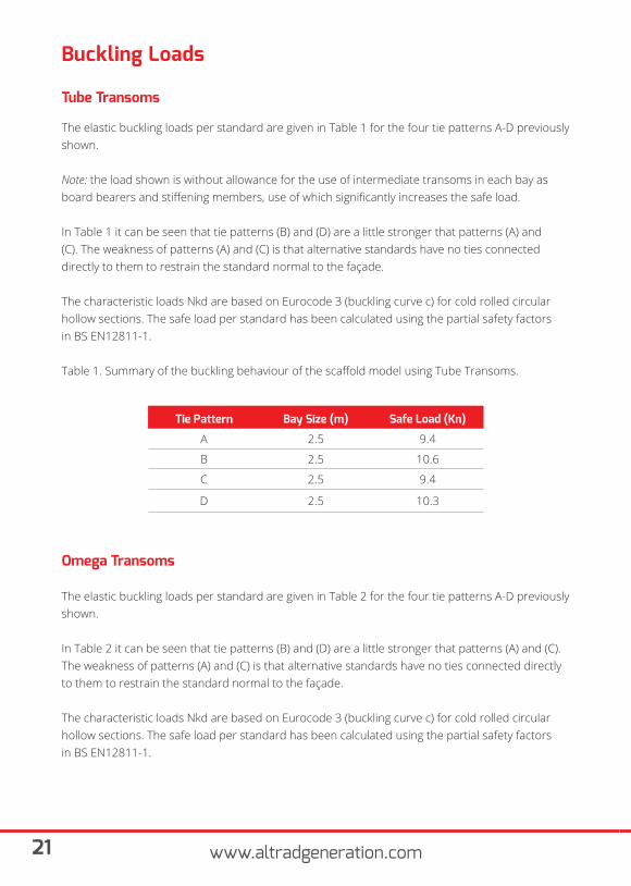
Buckling Loads
Tube Transoms
The elastic buckling loads per standard are given in Table 1 for the four tie patterns A-D previously shown.
Note: the load shown is without allowance for the use of intermediate transoms in each bay as board bearers and stiffening members, use of which significantly increases the safe load.
In Table 1 it can be seen that tie patterns (B) and (D) are a little stronger that patterns (A) and(C). The weakness of patterns (A) and (C) is that alternative standards have no ties connecteddirectly to them to restrain the standard normal to the façade.
The characteristic loads Nkd are based on Eurocode 3 (buckling curve c) for cold rolled circularhollow sections. The safe load per standard has been calculated using the partial safety factorsin BS EN12811-1.
Table 1. Summary of the buckling behaviour of the scaffold model using Tube Transoms.
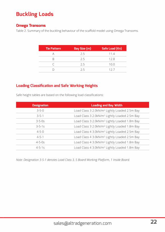
Omega Transoms
The elastic buckling loads per standard are given in Table 2 for the four tie patterns A-D previously shown.
In Table 2 it can be seen that tie patterns (B) and (D) are a little stronger that patterns (A) and (C). The weakness of patterns (A) and (C) is that alternative standards have no ties connected directly to them to restrain the standard normal to the façade.
The characteristic loads Nkd are based on Eurocode 3 (buckling curve c) for cold rolled circular hollow sections. The safe load per standard has been calculated using the partial safety factorsin BS EN12811-1.
Tie Pattern Bay Size (m) Safe Load (Kn)
A 2.5 9.4
B 2.5 10.6
C 2.5 9.4
D 2.5 10.3
Buckling Loads
Omega Transoms
Tie Pattern Bay Size (m) Safe Load (Kn)
A 2.5 11.4
B 2.5 12.8
C 2.5 10.0
D 2.5 12.7
Designation Loading and Bay Width
3-5-0 Load Class 3 2.0kN/m2 Lightly Loaded 2.5m Bay
3-5-1 Load Class 3 2.0kN/m2 Lightly Loaded 2.5m Bay
3-5-0s Load Class 3 2.0kN/m2 Lightly Loaded 1.8m Bay
3-5-1s Load Class 3 2.0kN/m2 Lightly Loaded 1.8m Bay
4-5-0 Load Class 4 3.0kN/m2 Lightly Loaded 2.5m Bay
4-5-1 Load Class 4 3.0kN/m2 Lightly Loaded 2.5m Bay
4-5-0s Load Class 4 3.0kN/m2 Lightly Loaded 1.8m Bay
4-5-1s Load Class 4 3.0kN/m2 Lightly Loaded 1.8m Bay
Table 2. Summary of the buckling behaviour of the scaffold model using Omega Transoms.
Loading Classification and Safe Working Heights
Safe height tables are based on the following load classifications:
Note: Designation 3-5-1 denotes Load Class 3, 5 Board Working Platform, 1 Inside Board.
Omega Transoms
23 www.altradgeneration.com
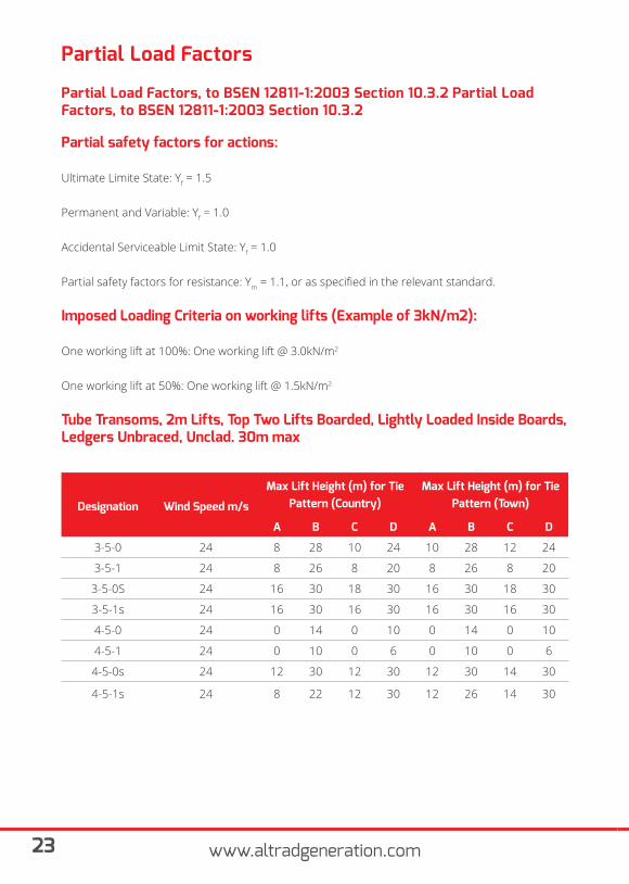
Partial Load Factors
Partial Load Factors, to BSEN 12811-1:2003 Section 10.3.2 Partial Load Factors, to BSEN 12811-1:2003 Section 10.3.2
Partial safety factors for actions:
Ultimate Limite State: Yf = 1.5
Permanent and Variable: Yf = 1.0
Accidental Serviceable Limit State: Yf = 1.0
Partial safety factors for resistance: Ym = 1.1, or as specified in the relevant standard.
Imposed Loading Criteria on working lifts (Example of 3kN/m2):
One working lift at 100%: One working lift @ 3.0kN/m2
One working lift at 50%: One working lift @ 1.5kN/m2
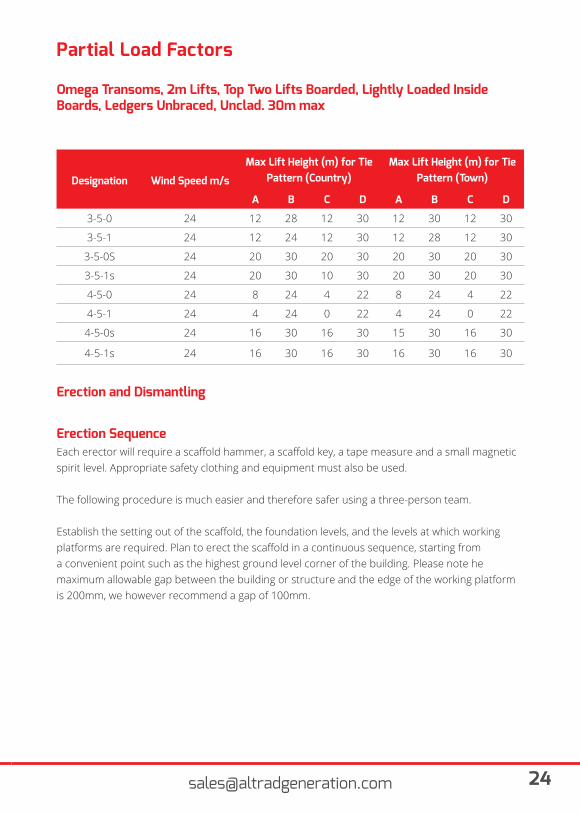
Tube Transoms, 2m Lifts, Top Two Lifts Boarded, Lightly Loaded Inside Boards,Ledgers Unbraced, Unclad. 30m max
Designation Wind Speed m/s
Max Lift Height (m) for Tie Pattern (Country)
Max Lift Height (m) for Tie Pattern (Town)
A B C D A B C D
3-5-0 24 8 28 10 24 10 28 12 24
3-5-1 24 8 26 8 20 8 26 8 20
3-5-0S 24 16 30 18 30 16 30 18 30
3-5-1s 24 16 30 16 30 16 30 16 30
4-5-0 24 0 14 0 10 0 14 0 10
4-5-1 24 0 10 0 6 0 10 0 6
4-5-0s 24 12 30 12 30 12 30 14 30
4-5-1s 24 8 22 12 30 12 26 14 30
Partial Load Factors
Designation Wind Speed m/s
Max Lift Height (m) for Tie Pattern (Country)
Max Lift Height (m) for Tie Pattern (Town)
A B C D A B C D
3-5-0 24 12 28 12 30 12 30 12 30
3-5-1 24 12 24 12 30 12 28 12 30
3-5-0S 24 20 30 20 30 20 30 20 30
3-5-1s 24 20 30 10 30 20 30 20 30
4-5-0 24 8 24 4 22 8 24 4 22
4-5-1 24 4 24 0 22 4 24 0 22
4-5-0s 24 16 30 16 30 15 30 16 30
4-5-1s 24 16 30 16 30 16 30 16 30
Omega Transoms, 2m Lifts, Top Two Lifts Boarded, Lightly Loaded Inside Boards, Ledgers Unbraced, Unclad. 30m max
Erection and Dismantling
Erection SequenceEach erector will require a scaffold hammer, a scaffold key, a tape measure and a small magnetic spirit level. Appropriate safety clothing and equipment must also be used.
The following procedure is much easier and therefore safer using a three-person team.
Establish the setting out of the scaffold, the foundation levels, and the levels at which working platforms are required. Plan to erect the scaffold in a continuous sequence, starting from a convenient point such as the highest ground level corner of the building. Please note he maximum allowable gap between the building or structure and the edge of the working platform is 200mm, we however recommend a gap of 100mm.
25 www.altradgeneration.com
Erection and Dismantling
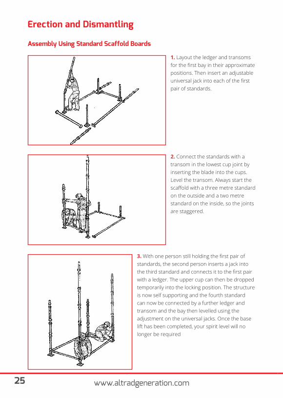
Assembly Using Standard Scaffold Boards
1. Layout the ledger and transoms for the first bay in their approximate positions. Then insert an adjustable universal jack into each of the first pair of standards.
2. Connect the standards with a transom in the lowest cup joint by inserting the blade into the cups. Level the transom. Always start the scaffold with a three metre standard on the outside and a two metre standard on the inside, so the joints are staggered.
3. With one person still holding the first pair of standards, the second person inserts a jack into the third standard and connects it to the first pair with a ledger. The upper cup can then be dropped temporarily into the locking position. The structure is now self supporting and the fourth standard can now be connected by a further ledger and transom and the bay then levelled using the adjustment on the universal jacks. Once the base lift has been completed, your spirit level will no longer be required
Erection and Dismantling
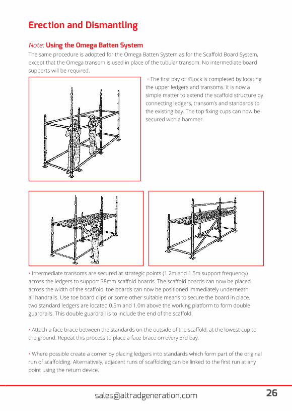
Note: Using the Omega Batten SystemThe same procedure is adopted for the Omega Batten System as for the Scaffold Board System, except that the Omega transom is used in place of the tubular transom. No intermediate board supports will be required.
• The first bay of K’Lock is completed by locating the upper ledgers and transoms. It is now a simple matter to extend the scaffold structure by connecting ledgers, transom’s and standards to the existing bay. The top fixing cups can now be secured with a hammer.
• Intermediate transoms are secured at strategic points (1.2m and 1.5m support frequency) across the ledgers to support 38mm scaffold boards. The scaffold boards can now be placed across the width of the scaffold, toe boards can now be positioned immediately underneath all handrails. Use toe board clips or some other suitable means to secure the board in place. two standard ledgers are located 0.5m and 1.0m above the working platform to form double guardrails. This double guardrail is to include the end of the scaffold.
• Attach a face brace between the standards on the outside of the scaffold, at the lowest cup to the ground. Repeat this process to place a face brace on every 3rd bay.
• Where possible create a corner by placing ledgers into standards which form part of the original run of scaffolding. Alternatively, adjacent runs of scaffolding can be linked to the first run at any point using the return device.
27 www.altradgeneration.com
Erection and DismantlingIncreasing the height of scaffolding• When erecting additional lifts, erectors must work off fully boarded bays of scaffold.
• Always fix single guardrails 1 metre above the temporary working platform as soon as is practicable during the erection process. Where no guard rail is in place, safety harnesses will be worn.
• All equipment must be raised or lowered using a suitable rope and wheel.
The recommended and maximum lift height for each and every lift above the first lift is 2 meters, and for the first lift is 1.5 meters. This “splice” in a standard is the joint where 2 standards are connected, using this method the height of the splice will never be more than 1.3m above the temporary working platforms, provided that all lifts are of the recommended height of 2m. This configuration will eliminate the occurrence of a “height splice” in the standards, making the erection process easier and contributing to the safety of the erectors.
Once the first base lift has been completed continue to erect the scaffold using the sequencebelow:
• Add a 2m standard on top of all existing standards on the scaffold, if it is intended to extend the scaffold by more than one lift, it is recommended that 3m standards are used. Then fix the ledgers and transoms 2m above the existing working platform to create the next 2m lift.
• A diagonal cross brace should then be fitted to each end of the scaffold between the outside and inside standards. End braces should run continuously from the bottom cup on the lowest standard to the top working lift of the scaffold.
• Diagonal face braces should be fixed to the end bay of the scaffold and at least every third bay along the scaffold. Face braces should also run continuously from the bottom cup on the lowest standard to the top working lift of the scaffold.
• The scaffold should now be tied to the building or structure using tube and doublecouplers to create a series of positive ties.
Erection and DismantlingIncreasing the height of scaffoldingPlease note: The correct placement of bracing and positive ties is critical to ensuring the stability and strength of any scaffold and consequently the safety of persons using it. Work must not proceed on the scaffold until the bracing and ties are securely in position.
• Working form the existing working platform below, place a full set of boards in the newly created lift – working from the end furthest from the access point, if the lower working platform is not required in the final structure , working from the end bay, then backwards towards the access point the platform can be raised to the lift immediately above.
• The placement of the extra set of boards in the bay ensures that the scaffolder always has a full set of boards on which to work. The boards are removed from their existing position by rolling the outside plank onto the adjacent plank and sliding it back into the bay in which the scaffolder is standing. Two people should move the last plank in each bay, as one of the two will only have the steel frame of the scaffold on which to stand. Therefore they should be equipped with a suitable safety harness and lanyard with which to connect themselves to the scaffold.
• Working out from the access point on the temporary working platform, place a standard (if necessary) in the first standard point. A ledger is then fixed to the second bottom cup up from the working platform. This process is then repeated in each individual bay until there is a single handrail to the outside standards. In certain circumstances it may also be necessary to place a handrail on the inside of the scaffold.
Please note: If the temporary scaffold is to be used as a working platform a double handrail and toe board should be fitted.
29 www.altradgeneration.com
Erection and Dismantling
Dismantling the ScaffoldThis process is equally important as the erection and safety must be considered to ensure thewell being of all operatives and the safety of the scaffolding
• Visually inspect that the scaffold has been correctly erected and that the bracing and ties are still in place.
• All materials and debris are to be removed from the working deck prior to the commencement of dismantling.
• The work area should be barricaded off to prevent access to other workers and members of the public.
• Dismantle the scaffold one complete lift at a time and leave the handrails in place until the other components are dismantled. Remove ties in a sequence so that there are never more than 2 lifts of scaffold above the top row of ties.
• Ensure all scaffold components are removed from the structure as it is dismantled. Never “Bomb” scaffold equipment down as this would cause damage to the component or injury to people below
• Continue the dismantling process on the next lift; in necessary relocate the boards to the lift below to ensure you have a full working platform on which to continue the process.
• When the scaffold is dismantled to the base lift remove the bottom transom, leaving the standard supported by the ledger. Then hold the standard and unlock the top cup to remove one end of the ledger only. Lift the standard off the jack and stack into a pallet.
• All scaffold equipment should then be stacked into pallets for collection. Battens should be stacked on suitable bearers so they can be lifted by forklift or crane.
Instructions for Storage,Maintenance and Repair
Storage
Maintenance
• Prefabricated components shall be stored, if possible, under a suitable cover, protected from weather in a dry location. They shall be exposed to good ventilation. They shall be supported during storage so as to avoid permanent set.
• At the work site, provide enough space to drive the forklift and other vehicles otherwise there are chances of damages to the components.
• Tags should be used to differentiate good components from the damaged components.
• All the components shall be stored in a marked storage place.
• Do not stack any items on the road to avoid injury to passersby
• Before allowing people or material on the scaffold structure ensure that it has been erected correctly and complies with the user’s requirements.
• Ensure that all people using the scaffold are aware of the purpose for which it is intended to be used and the maximum loading to which it can be subjected.
• Ensure that users understand that any unauthorised modification to the scaffold or removal of components other than those which have been specifically designed for it will materially weaken the scaffold and create a safety hazard.
• Carry out regular inspections to check that components have not been removed or damaged, or that components have not been removed and replaced incorrectly.
• Alterations or extensions-(e.g. removal or repositioning of ties, removal of guardrails orhandrails, the addition of boarded platform, sheeting, debris netting, etc) should only be carried out within the restrictions set out in this handbook or under the direction of a competent designer who is prepared to accept the onus of his modifications.
• Provide barriers and warning notices to prevent access to incomplete sections of scaffolding.
• Ensure that safe access and egress routes are provided to all working platforms, and that such route, including ladders or preferably stairways, are kept clear.
31 www.altradgeneration.com
Instructions for Storage,Maintenance and Repair
Maintenance (Cont.)
Repairs
Transport
• Do not overload platforms-use properly designed loading towers and ensure that crane and forklift drivers understand loading restrictions on each part of the scaffold structure.
• Where necessary ensure that all areas below scaffolds in use are marked so that site personnel can avoid the area. If the area has to be accessed then the site personnel should be made aware of the potential risks or hazards.
• Because of the increased use of mechanical lifting plant on site there is an increased possibility for scaffolding components to become found / caught. When using cranes or other mechanical lifting devices near any scaffold structure care should be taken to ensure that nothing catches under any part of the scaffold otherwise uplift could occur with potentially dangerous consequences.
• If any scaffold gets damaged, inform the scaffolding contractor or authorised person thenrepairs can be carried out. The repaired item is only to be used after the approval of saidcompetent person.
During transportation it should be ensured that the prefabricated components are loaded properly and securely tightened to the vehicle to avoid dropping of components during travelling. Loading and unloading should be carried out under the supervision of a competent person to avoid damage to the components
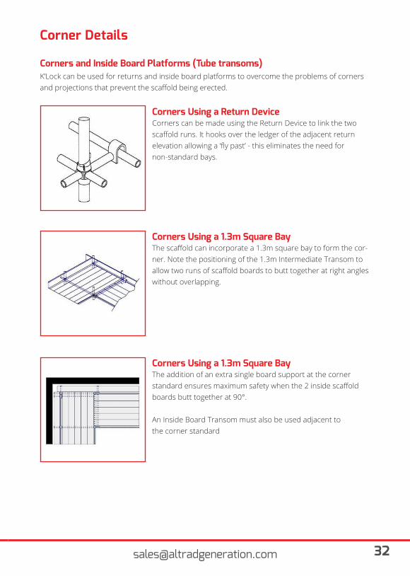
Corners can be made using the Return Device to link the two scaffold runs. It hooks over the ledger of the adjacent return elevation allowing a ‘fly past’ - this eliminates the need for non-standard bays.
The scaffold can incorporate a 1.3m square bay to form the cor-ner. Note the positioning of the 1.3m Intermediate Transom to allow two runs of scaffold boards to butt together at right angles without overlapping.
The addition of an extra single board support at the corner standard ensures maximum safety when the 2 inside scaffold boards butt together at 90°.
An Inside Board Transom must also be used adjacent tothe corner standard
Corners Using a Return Device
Corners Using a 1.3m Square Bay
Corners Using a 1.3m Square Bay
Corners and Inside Board Platforms (Tube transoms)
Corner Details
K’Lock can be used for returns and inside board platforms to overcome the problems of corners and projections that prevent the scaffold being erected.
33 www.altradgeneration.com
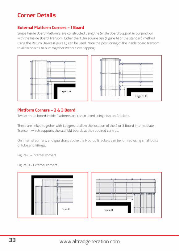
External Platform Corners – 1 Board
Platform Corners – 2 & 3 Board
Corner Details
Single Inside Board Platforms are constructed using the Single Board Support in conjunctionwith the Inside Board Transom. Either the 1.3m square bay (Figure A) or the standard methodusing the Return Device (Figure B) can be used. Note the positioning of the inside board transom to allow boards to butt together without overlapping.
Two or three board Inside Platforms are constructed using Hop-up Brackets.
These are linked together with Ledgers to allow the location of the 2 or 3 Board Intermediate Transom which supports the scaffold boards at the required centres.
On internal corners, end guardrails above the Hop-up Brackets can be formed using small butts of tube and fittings.
Figure C – Internal corners
Figure D – External corners
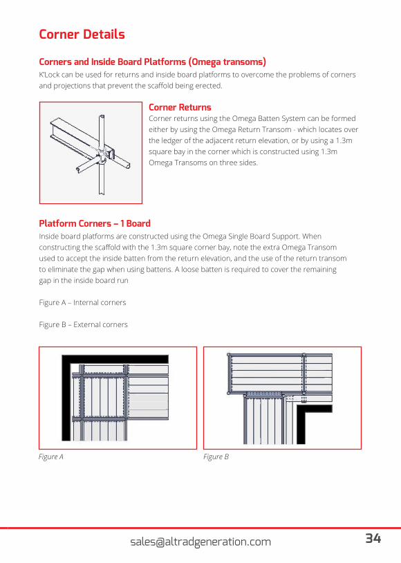
Corner returns using the Omega Batten System can be formed either by using the Omega Return Transom - which locates over the ledger of the adjacent return elevation, or by using a 1.3m square bay in the corner which is constructed using 1.3mOmega Transoms on three sides.
Corner Returns
Corners and Inside Board Platforms (Omega transoms)
Corner Details
K’Lock can be used for returns and inside board platforms to overcome the problems of corners and projections that prevent the scaffold being erected.
Platform Corners – 1 BoardInside board platforms are constructed using the Omega Single Board Support. Whenconstructing the scaffold with the 1.3m square corner bay, note the extra Omega Transomused to accept the inside batten from the return elevation, and the use of the return transomto eliminate the gap when using battens. A loose batten is required to cover the remaininggap in the inside board run
Figure A – Internal corners
Figure B – External corners
Figure A Figure B
35 www.altradgeneration.com
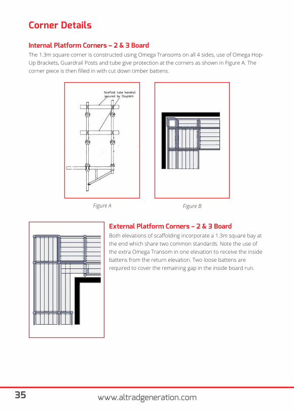
Internal Platform Corners – 2 & 3 Board
Corner Details
The 1.3m square corner is constructed using Omega Transoms on all 4 sides, use of Omega Hop-Up Brackets, Guardrail Posts and tube give protection at the corners as shown in Figure A. The corner piece is then filled in with cut down timber battens.
Figure A Figure B
External Platform Corners – 2 & 3 BoardBoth elevations of scaffolding incorporate a 1.3m square bay at the end which share two common standards. Note the use of the extra Omega Transom in one elevation to receive the insidebattens from the return elevation. Two loose battens are required to cover the remaining gap in the inside board run.
Circular Access
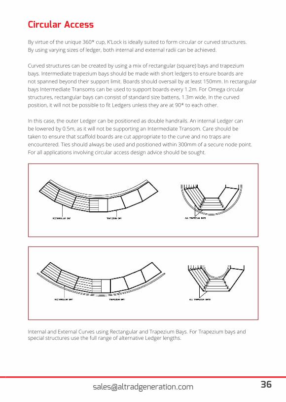
By virtue of the unique 360* cup, K’Lock is ideally suited to form circular or curved structures.By using varying sizes of ledger, both internal and external radii can be achieved.
Curved structures can be created by using a mix of rectangular (square) bays and trapeziumbays. Intermediate trapezium bays should be made with short ledgers to ensure boards arenot spanned beyond their support limit. Boards should oversail by at least 150mm. In rectangular bays Intermediate Transoms can be used to support boards every 1.2m. For Omega circular structures, rectangular bays can consist of standard size battens, 1.3m wide. In the curved position, it will not be possible to fit Ledgers unless they are at 90* to each other.
In this case, the outer Ledger can be positioned as double handrails. An internal Ledger canbe lowered by 0.5m, as it will not be supporting an Intermediate Transom. Care should betaken to ensure that scaffold boards are cut appropriate to the curve and no traps are encountered. Ties should always be used and positioned within 300mm of a secure node point. For all applications involving circular access design advice should be sought.
Internal and External Curves using Rectangular and Trapezium Bays. For Trapezium bays and special structures use the full range of alternative Ledger lengths.
37 www.altradgeneration.com
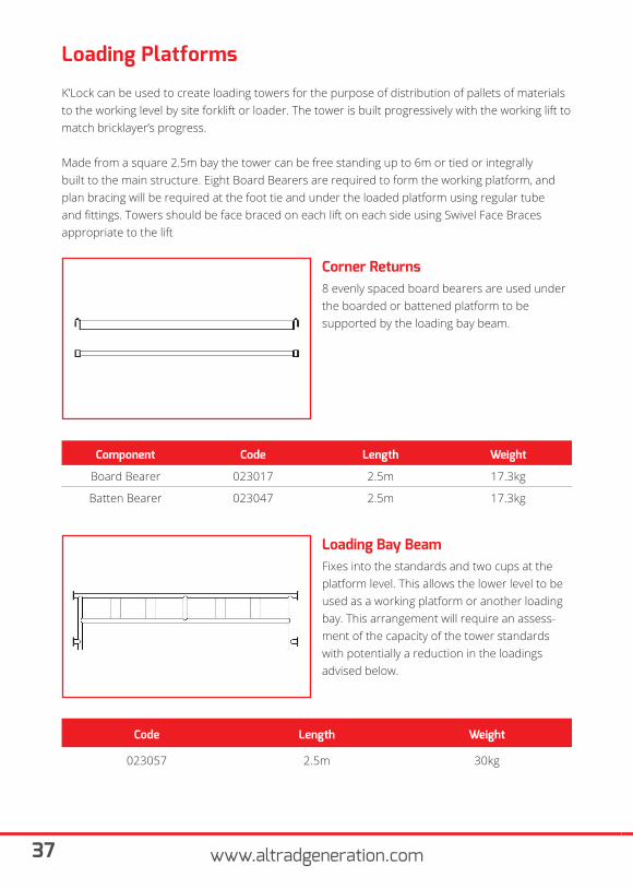
Loading Platforms
K’Lock can be used to create loading towers for the purpose of distribution of pallets of materials to the working level by site forklift or loader. The tower is built progressively with the working lift to match bricklayer’s progress.
Made from a square 2.5m bay the tower can be free standing up to 6m or tied or integrally built to the main structure. Eight Board Bearers are required to form the working platform, and plan bracing will be required at the foot tie and under the loaded platform using regular tube and fittings. Towers should be face braced on each lift on each side using Swivel Face Braces appropriate to the lift
8 evenly spaced board bearers are used underthe boarded or battened platform to besupported by the loading bay beam.
Corner Returns
Component Code Length Weight
Board Bearer 023017 2.5m 17.3kg
Batten Bearer 023047 2.5m 17.3kg
Fixes into the standards and two cups at theplatform level. This allows the lower level to beused as a working platform or another loadingbay. This arrangement will require an assess-ment of the capacity of the tower standards with potentially a reduction in the loadings advised below.
Loading Bay Beam
Code Length Weight
023057 2.5m 30kg
Permissible Uniformly Distributed Loads
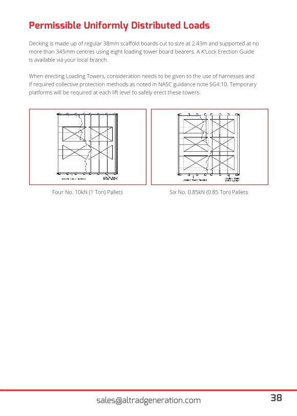
Decking is made up of regular 38mm scaffold boards cut to size at 2.43m and supported at nomore than 345mm centres using eight loading tower board bearers. A K’Lock Erection Guideis available via your local branch.
When erecting Loading Towers, consideration needs to be given to the use of harnesses andif required collective protection methods as noted in NASC guidance note SG4:10. Temporaryplatforms will be required at each lift level to safely erect these towers.
Four No. 10kN (1 Ton) Pallets Six No. 0.85kN (0.85 Ton) Pallets
39 www.altradgeneration.com
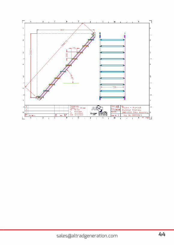
Stair Access
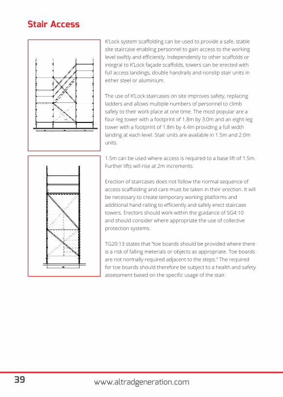
K’Lock system scaffolding can be used to provide a safe, stable site staircase enabling personnel to gain access to the working level swiftly and efficiently. Independently to other scaffolds or integral to K’Lock façade scaffolds, towers can be erected with full access landings, double handrails and nonslip stair units in either steel or aluminium.
The use of K’Lock staircases on site improves safety, replacing ladders and allows multiple numbers of personnel to climb safely to their work place at one time. The most popular are a four-leg tower with a footprint of 1.8m by 3.0m and an eight-leg tower with a footprint of 1.8m by 4.4m providing a full width landing at each level. Stair units are available in 1.5m and 2.0m units.
1.5m can be used where access is required to a base lift of 1.5m. Further lifts will rise at 2m increments.
Erection of staircases does not follow the normal sequence of access scaffolding and care must be taken in their erection. It willbe necessary to create temporary working platforms and additional hand railing to efficiently and safely erect staircase towers. Erectors should work within the guidance of SG4:10 and should consider where appropriate the use of collective protection systems.
TG20:13 states that “toe boards should be provided where there is a risk of falling meterials or objects as appropriate. Toe boards are not normally required adjacent to the steps.” The required for toe boards should therefore be subject to a health and safety assessment based on the specific usage of the stair.
Altrad Generation Hire & Sale K’LOCK 4 LEG STAIRCASE (1.8m WIDE) QUANTITY LIST
Platform Height 1.5m 2.0m 3.5m 4.0m 4.5m 5.0m 5.5m 6.0m
023002K’LOCK-STANDARD
2.0M- 2 4 2 2 2 4 4
023001K’LOCK-STANDARD
3.0M4 4 4 6 6 8 8 8
023008 K’LOCK-LEDGER 0.6M 8 8 12 12 16 16 16 16
023007 K’LOCK-LEDGER 0.9M 4 4 4 4 4 4 4 4
023005 K’LOCK-LEDGER 1.8M 8 8 12 12 16 16 16 16
023022 K’LOCK-LEDGER 3.0M 4 4 6 6 8 8 8 8
023032K’LOCK BRACE 1.8M X 1.5M
4 - 4 - 12 8 4 -
023019K’LOCK BRACE 1.8M X 2.0M
- 6 6 12 - 6 12 18
023028K’LOCK BRACE 2.0M X 3.0M
2 2 4 4 6 6 6 6
023014 K’LOCK- JACK 500MM 4 4 4 4 4 4 4 4
023044K’LOCK-AL STAIR
UNIT 2.0M- 1 1 2 - 1 2 3
023045K’LOCK-AL STAIR
UNIT 1.5M1 - 1 - 3 2 1 -
023046K’LOCK-STAIR POST
(4-LEG)6 6 9 9 12 12 12 12
023110K’LOCK-MESH
LANDING2 2 3 3 4 4 4 4
Appendix A
41 www.altradgeneration.com
Altrad Generation Hire & Sale K’LOCK 4 LEG STAIRCASE (1.8m WIDE) QUANTITY LIST
Platform Height 6.5m 7.0M 7.5M 8.0M 9.0M 10M 11M 12M
023002K’LOCK-STANDARD
2.0M4 2 2 4 2 2 4
023001K’LOCK-STANDARD
3.0M8 10 12 12 12 14 16 16
023008 K’LOCK-LEDGER 0.6M 20 20 20 20 24 24 28 28
023007 K’LOCK-LEDGER 0.9M 4 4 4 4 4 4 4 4
023005 K’LOCK-LEDGER 1.8M 20 20 20 20 24 24 28 28
023022 K’LOCK-LEDGER 3.0M 10 10 10 10 12 12 14 14
023032K’LOCK BRACE 1.8M X 1.5M
12 8 4 - 8 - 8 -
023019K’LOCK BRACE 1.8M X 2.0M
6 12 18 24 18 30 24 36
023028K’LOCK BRACE 2.0M X 3.0M
8 8 8 8 10 10 12 12
023014 K’LOCK- JACK 500MM 4 4 4 4 4 4 4 4
023044K’LOCK-AL STAIR
UNIT 2.0M1 2 3 4 3 5 4 6
023045K’LOCK-AL STAIR
UNIT 1.5M3 2 1 - 2 - 2 -
023046K’LOCK-STAIR POST
(4-LEG)15 15 15 15 18 18 21 21
023110K’LOCK-MESH
LANDING5 5 5 5 6 6 7 7
43 www.altradgeneration.com
45 www.altradgeneration.com
47 www.altradgeneration.com
49 www.altradgeneration.com
Disclaimer & Copyright
Disclaimer Whilst Generation (UK) Ltd has taken every reasonable effort to ensure the information contained within this publication is correct and complete at the time of printing, you should be aware that there will be periodical changes and Generation (UK) Ltd does not accept any liability for any inconvenience, loss or damage caused as a result of any inaccuracy or omission within this publication.
CopyrightNo unauthorised reproduction of any images, text or other matter contained herein is permitted. All rights are expressly reserved, including copyright, design right, moral and patent rights (where applicable). We reserve the right to take legal action in respect of any infringement of said rights.
Dundee 01382 227 552Edinburgh (E) 0131 552 7534Edinburgh (W) 01506 863 864 Glasgow (E) 0141 810 8350Glasgow (S) 0141 647 6969 Salsburgh 01698 870 200
SCOTLAND
Brigg 01652 601 390Northampton 01604 580 444Raunds 01933 462190Nottingham 0115 946 7660Peterborough 01733 890009
EAST MIDLANDS Bournemouth 01202 591255Bristol (E) 0117 972 4550Bristol (W) 0117 972 3353Truro 01872 870078
SOUTH WEST
Cork + 353 21 4866400Dublin (N) + 353 1 9018690Dublin (W) + 353 1 6011500Galway + 353 93 60470
IRELAND
Birmingham (N) 0121 366 7840Birmingham (E) 0121 706 0000Birmingham (W) 0121 544 3355
WEST MIDLANDS
Chelmsford 01277 841 670Chichester 01243 558 290Croydon 0208 6896044Frimley 01252 838 696 Grays 01375 312 120 London (E) 020 7473 6056 Luton 01582 491000London (W) 01895 527666West Thurrock 020 7476 4760Reading Coming Soon
SOUTH EAST
Cardiff 029 2046 3835 CardiffDocks 029 2079 1188
WALES
Kings Lynn 01553 771 465Norwich 01603 309 010
EAST ANGLIA
Gateshead 0191 490 6866Newcastle 0191 492 1190
NORTH EAST
Manchester 0161 477 0131Widnes 0151 420 3331
NORTH WEST
Leeds (SE) 0113 277 8822 Leeds (SW) 0113 387 0630Rotherham 01709 554 149
YORKSHIRE
Generation UK Ltd.Generation Head Office, Trinity Street, Off Tat Bank Road, Oldbury, West Midlands, B69 4LA - United Kingdom
Tel. 0121 543 2950 - Fax. 0121 543 2953 - [email protected]
YOUR LOCAL BRANCH
SCAN METO FIND