Embed Size (px)
Citation preview
Kollmorgen Automation SuiteAKT2G I/O Manual
Document Edition: C, December 2021Valid for KAS Software Revision 3.07Part Number: 959721-00
For safe and proper use, follow theseinstructions. Keep for future use.

Trademarks and Copyrights
CopyrightsInformation in this document is subject to change without notice. The software package described in thisdocument is furnished under a license agreement. The software package may be used or copied only inaccordance with the terms of the license agreement.This document is the intellectual property of Kollmorgen and contains proprietary and confidentialinformation. The reproduction, modification, translation or disclosure to third parties of this document (inwhole or in part) is strictly prohibited without the prior written permission of Kollmorgen.
Trademarks
l KAS and AKD are registered trademarks of Kollmorgen.l Kollmorgen is part of the Altra Industrial Motion Company.l EtherCAT is a registered trademark and patented technology, licensed by Beckhoff Automation
GmbHl Windows is a registered trademark of Microsoft Corporationl PLCopen is an independent association providing efficiency in industrial automation.
Kollmorgen Automation Suite is based on the work of:
l 7-zip (distributed under the terms of the LGPL and the BSD 3-clause licenses - see terms)l The C++ Mathematical Expression Library (distributed under the MIT License)l curl software libraryl JsonCpp software (distributed under the MIT License – see terms)l Mongoose software (distributed under the MIT License - see terms)l Qt cross-platform SDK (distributed under the terms of the LGPL3; Qt source is available on KDN)l Qwt project (distributed under the terms of the Qwt License)l U-Boot, a universal boot loader is used by the AKD PDMM and PCMM (distributed under the terms of
the GNU General Public License). The U-Boot source files, copyright notice, and readme are availableon the distribution disk that is included with the AKD PDMM and PCMM.
l Zlib software library
All other product and brand names listed in this document may be trademarks or registered trademarks of theirrespective owners.
DisclaimerThe information in this document (Version C published on 11/30/2021) is believed to be accurate and reliable at the timeof its release. Notwithstanding the foregoing, Kollmorgen assumes no responsibility for any damage or loss resultingfrom the use of this help, and expressly disclaims any liability or damages for loss of data, loss of use, and propertydamage of any kind, direct, incidental or consequential, in regard to or arising out of the performance or form of thematerials presented herein or in any software programs that accompany this document.
All timing diagrams, whether produced by Kollmorgen or included by courtesy of the PLCopen organization, are providedwith accuracy on a best-effort basis with no warranty, explicit or implied, by Kollmorgen. The user releases Kollmorgenfrom any liability arising out of the use of these timing diagrams.
2 Kollmorgen | kdn.kollmorgen.com | December 2021

1 Table of Contents
1 Table of Contents 32 About This Manual 9
2.1 Intended audience 92.2 Origin of the document 92.3 Currentness 92.4 Product features 92.5 Disclaimer 92.6 Safety Instructions 10
2.6.1 Delivery state 102.6.2 Operator's obligation to exercise diligence 102.6.3 Description of safety symbols 10
2.7 Interference-Free EtherCAT Terminals 113 Mounting and Wiring of I/O Terminals 12
3.1 Instructions for ESD Protection 123.2 Installation on mounting rails 13
3.2.1 Assembly 133.2.2 Disassembly 143.2.3 Connections within a bus terminal block 143.2.4 PE power contact 15
3.3 Installation instructions for enhanced mechanical load capacity 163.3.1 Additional checks 163.3.2 Additional installation instructions 16
3.4 Connection 173.4.1 Connection system 17
3.4.1.1 Overview 173.4.1.2 Standard wiring (AKT2G/AKT-xx) 17
3.4.2 Wiring 183.4.2.1 Terminals for standard wiring AKT2G-xx/AKT-xx 18
3.4.3 Shielding 193.5 Installation positions 20
3.5.1 Optimum installation position (standard) 203.5.2 Other installation positions 20
3.6 Positioning of Passive Terminals 213.6.1 Examples for positioning of passive terminals (highlighted) 21
3.7 UL Notice 223.7.1 Basic principles 22
3.8 Continuative documentation about explosion protection 224 Safety I/O Information 23
4.1 Safety Operation 234.1.1 Environmental Conditions 234.1.2 Safety Instructions 234.1.3 Transport / Storage 234.1.4 Mechanical Installation 24
4.1.4.1 Control cabinet / terminal box 244.1.4.2 Installation position and minimum distances 24
Kollmorgen | kdn.kollmorgen.com | December 2021 3

4.2 Safety Terminal Reaction Times 254.2.1 Typical Reaction Time 254.2.2 Worst-Case Reaction Time 26
4.3 Safety I/O Maintenance 275 Remote Input/Output Terminals 28
5.1 AKT2G-AC-FAN-001 295.1.1 Introduction 295.1.2 Technical Data 305.1.3 Mounting and Demounting 31
5.1.3.1 Mounting 315.1.3.2 Removal 34
5.1.4 LED Display and Connection 355.1.4.1 Diagnosis LED 355.1.4.2 Connection 35
5.1.5 Basic Function Principles and Commissioning 365.1.5.1 Area of application 365.1.5.2 Commissioning 36
5.2 AKT2G-AN-240-000 375.2.1 Technology RTD Measuring 38
5.2.1.1 Function 385.2.1.2 Ratiometric Voltage Measurement 385.2.1.3 Connection Techniques 395.2.1.4 Overview of Suitable Resistance Sensors 40
5.2.2 Basic Principles of RTD Technology 425.2.3 LEDs and Connection 455.2.4 Connection of Analog RTD Signal Lines 47
5.2.4.1 Measures 475.2.4.2 Shielding Measures 47
5.2.5 Settings and Application Notes for AN-240 495.2.5.1 Default setting 495.2.5.2 Notice regarding Resistance Measurement mode 49
5.2.6 Basics About Signal Isolators, Barriers 505.2.7 Technical Data 525.2.8 AKT2G-AN-240 CoE Object Description 52
5.2.8.1 Introduction 535.2.8.2 Objects for Commissioning 535.2.8.3 Profile-specific objects (0x6000-0xFFFF) 56
5.3 AKT2G-AN-400-000 585.3.1 Thermocouple Technology Basics 59
5.3.1.1 Measuring principle of the thermocouple 595.3.1.2 Internal conversion of the thermovoltage and the reference voltage 605.3.1.3 Overview of suitable thermocouples 60
5.3.2 LEDs 615.3.3 Connection Instructions for Earthed/Potential-Free Thermocouples 62
5.3.3.1 Shielding Measures 625.3.4 Data Processing - TC Temperature 645.3.5 Settings 65
5.3.5.1 Presentation 65
4 Kollmorgen | kdn.kollmorgen.com | December 2021
5.3.5.2 Siemens bits 665.3.5.3 Underrange, Overrange 665.3.5.4 Notch filter (conversion times) 665.3.5.5 Limit 1 and Limit 2 675.3.5.6 Calibration 685.3.5.7 Producer Codeword 69
5.3.6 Operation with an external cold junction 705.3.7 Interference From Equipment 715.3.8 Wire Break Detection 715.3.9 Status Word 725.3.10 Technical Data 735.3.11 AKT2G-AN-400 Object Description and Parameterization 74
5.3.11.1 Restore Object 745.3.11.2 Configuration Data 755.3.11.3 Profile-specific objects 775.3.11.4 Configuration Data (vendor-specific) 775.3.11.5 Input Data 775.3.11.6 Output Data 785.3.11.7 Information and Diagnostic Data 78
5.4 AKT2G-AN-430-000 805.4.1 Configuration of 0/4..20 mA Differential Inputs 80
5.4.1.1 Technical Background 805.4.1.2 Summary 82
5.4.2 CoE Object Description and Parameterization 835.4.2.1 Restore Object 835.4.2.2 Configuration Data 835.4.2.3 Input Data 86
5.4.3 Technical Data 875.5 AKT2G-AT-410-000 90
5.5.1 LEDs 915.5.2 Object Description and Parameterization 92
5.5.2.1 Restore objects 925.5.2.2 Configuration data 925.5.2.3 Output Data 94
5.5.3 Technical Data 955.6 AKT2G-AT-425-000 96
5.6.1 LEDs 975.6.2 Object Description and Parameterization 98
5.6.2.1 Restore objects 985.6.2.2 Configuration data 985.6.2.3 Output Data 100
5.6.3 Technical Data 1015.7 AKT2G-BRC-000-000 102
5.7.1 Technical Data 1035.7.2 LEDs and Pin Assignment 104
5.7.2.1 Pin Assignment 1045.7.2.2 LEDs 105
5.7.3 Brake Chopper Quick Start 1065.7.4 AKT2G-BRC-000 Basic Function Principles 107
Kollmorgen | kdn.kollmorgen.com | December 2021 5
5.7.4.1 Chopper Operation 1075.7.4.2 Temperature Model for the External Resistor 1075.7.4.3 Software Filter 108
5.7.5 Determination of the Specific Resistance Data From A Temperature Curve 1115.7.5.1 Guiding Values of Common Resistors 112
5.7.6 Objects 1135.7.6.1 BCT Inputs 1135.7.6.2 Restore Object 1145.7.6.3 Profile-Specific Objects (0x6000-0xFFFF) 1145.7.6.4 Configuration Data 1145.7.6.5 Command Object 1165.7.6.6 Configuration Data (vendor-specific) 1165.7.6.7 Input Data 1175.7.6.8 Information and Diagnostic Data 118
5.8 AKT2G-DN-002-000 1195.8.1 LEDs and Connection 120
5.8.1.1 LEDs 1205.8.1.2 Connection 121
5.8.2 Basic Function Principles 1215.8.3 Operating Mode Selection 1225.8.4 Objects for Commissioning 1245.8.5 Profile-specific objects (0x6000-0xFFFF) 1275.8.6 Technical Data 131
5.9 AKT2G-DN-008-000 1325.9.1 LEDs 1325.9.2 Connection 1325.9.3 Technical Data 133
5.10 AKT2G-DNH-008-000 1345.10.1 LEDs 1345.10.2 Connection 1345.10.3 Technical Data 135
5.11 AKT2G-DT-008-000 1365.11.1 AKT2G-DT-008 LEDs and Connection 136
5.11.1.1 LEDs 1365.11.1.2 Connection 136
5.11.2 Technical Data 1385.12 AKT2G-ECT-000-000 139
5.12.1 Overview of EtherCAT Couplers 1395.12.2 EtherCAT Coupler for E-bus terminals 1395.12.3 EtherCAT Coupler Port Allocation 1405.12.4 Power Supply, Potential Groups 142
5.12.4.1 Bus Coupler power supply 1425.12.4.2 Input for power contacts 1425.12.4.3 Power contacts 1425.12.4.4 Electrical isolation 1425.12.4.5 GND concept 1435.12.4.6 Fuse protection 143
5.12.5 ECT-000 Diagnostic LEDs 1445.12.5.1 LEDs for Power Supply Diagnostics 144
6 Kollmorgen | kdn.kollmorgen.com | December 2021
5.12.5.2 Diagnostic LEDs for the EtherCAT State Machine/PLC 1445.12.5.3 LEDs for Fieldbus Diagnosis 144
5.12.6 Technical Data 1465.13 AKT2G-EM-000-000 1485.14 AKT2G-ENC-180-000 150
5.14.1 Incremental Encoder Interface AKT2G-ENC-180 1505.14.2 AKT2G-ENC-180 Technical Data 1515.14.3 AKT2G-ENC-180-000 LEDs and Pin Assignment 1515.14.4 Commissioning AKT2G-ENC-180-000 152
5.14.4.1 Basic function principles 1525.14.4.2 Operating modes and settings 154
5.15 AKT2G-ENC-190-000 1635.15.1 Technology 164
5.15.1.1 AKT2G-ENC-190-000 input impedance 1645.15.1.2 Gate/latch input 1645.15.1.3 Level on interface 164
5.15.2 Technical Data 1665.15.3 AKT2G-ENC-190-000 LEDs and Connection 166
5.15.3.1 Connection 1675.15.3.2 LEDs 168
5.15.4 Commissioning AKT2G-ENC-190-000 1685.15.4.1 Normal Operation Mode 1685.15.4.2 Enhanced Operation Mode 175
5.16 AKT2G-PSF-024-000 1855.16.1 Connections 1865.16.2 LEDs 1865.16.3 Technical Data 187
5.17 AKT2G-SDI-004-000 1895.17.1 Safety terminal with 4 digital fail-safe inputs 1895.17.2 Intended use 1905.17.3 Technical Data 1915.17.4 Safety Parameters 1935.17.5 Characteristic curve of the inputs 1935.17.6 Dimensions 1945.17.7 Block Diagram of the AKT2G-SDI-004 1945.17.8 AKT2G-SDI-004 Pin Assignment 1955.17.9 Signal Cables 196
5.17.9.1 Permitted cable length 1965.17.9.2 Cable routing 1975.17.9.3 Test pulses 197
5.17.10 Address Settings on Safety Terminals with 65535 Possible Addresses 1985.17.11 Safety Terminal Address and Parameters 198
5.17.11.1 AKT2G-SDI-004 configuration for light barriers, light grids, light curtainsetc. 2005.17.11.2 Configuration of the AKT2G-SDI-004 for safety switching mats 200
5.17.12 AKT2G-SDI-004 Diagostic LEDs 2005.17.12.1 Diag 1 (green) 2015.17.12.2 Diag 2 (red) 2015.17.12.3 Diag 3 (red) and Diag 4 (red) 201
Kollmorgen | kdn.kollmorgen.com | December 2021 7
5.17.13 AKT2G-SDI-004 Diagostic Objects 2025.17.14 Certificates 203
5.18 AKT2G-SDO-004-000 2055.18.1 Safety terminal with 4 digital fail-safe outputs 2055.18.2 Intended use 2075.18.3 Technical Data 2085.18.4 Safety Parameters 2105.18.5 Dimensions 2115.18.6 Block Diagram of the AKT2G-SDO-004 2115.18.7 AKT2G-SDO-004 Pin Assignment 2125.18.8 Signal Cables 213
5.18.8.1 Permitted cable length 2135.18.8.2 Cable routing 2145.18.8.3 Test Pulses 214
5.18.9 Address Settings on Safety Terminals with 1023 Possible Addresses 2145.18.10 Safety Terminal Address and Parameters 2155.18.11 AKT2G-SDO-004 Diagostic LEDs 216
5.18.11.1 Diag 1 (green) 2165.18.11.2 Diag 2 (red) 2165.18.11.3 Diag 3 (red) and Diag 4 (red) 217
5.18.12 Possible Causes of Diagnostic Messages - AKT2G-SDO-004 2175.18.13 Certificates 219
5.19 AKT2G-SM-L15-000 2205.19.1 Technical Data 2215.19.2 AKT2G-SM-L15 LEDs & Connections 222
5.19.2.1 LEDs 2235.19.2.2 Terminal Points 224
5.19.3 AKT2G-SM-L15 General Connection Examples 2255.19.3.1 Connection types 225
5.20 AKT2G-SM-L50-000 2265.20.1 Technical Data 2265.20.2 AKT2G-SM-L50 LEDs & Connections 228
5.20.2.1 LEDs 2285.20.2.2 Terminal Points 230
5.20.3 AKT2G-SM-L50 General Connection Examples 2315.20.3.1 Connection types 231
6 Notices on Analog Specifications 2336.1 Measuring Error / Measurement Deviation 2336.2 Temperature Coefficient tK [ppm/K] 2336.3 Single-Ended / Differential Typification 234
6.3.1 Explanation 2356.3.2 Typification of the 2/3/4-wire connection of current sensors 236
6.3.2.1 Self-supplied sensors 2366.3.3 Externally Supplied Sensors 236
6.4 Common-mode voltage and reference ground (based on differential inputs) 2386.5 Dielectric strength 2396.6 Temporal Aspects of Analog/Digital Conversion 239
8 Kollmorgen | kdn.kollmorgen.com | December 2021
2 About This ManualThis manual provides installation and operating instructions for Kollmorgen AKT2G I/O slicedevices, including Safety devices.
2.1 Intended audienceThis description is only intended for the use of trained specialists in control and automationengineering who are familiar with the applicable national standards.It is essential that the following notes and explanations are followed when installing andcommissioning these components.The responsible staff must ensure that the application or use of the products described satisfy allthe requirements for safety, including all the relevant laws, regulations, guidelines and standards.
2.2 Origin of the documentThis documentation was originally written in German. All other languages are derived from theGerman original.Safety content derived from the following original files:
l EL1904.pdf, v2.2.0, 2020-07-17l EL2904.pdf, v2.2.0, 2020-07-17
2.3 CurrentnessPlease check whether you are using the current and valid version of this document. The currentversion of the PDF can be downloaded from Kollmorgen's support website athttps://www.kollmorgen.com/en-us/developer-network/downloads/. In case of doubt, pleasecontact Technical Support.An alternative resource is to use the KAS online help. The online help will always have the latestinformation in electronic form. See http://webhelp.kollmorgen.com/kas/
2.4 Product featuresOnly the product features specified in the current user documentation are valid.
2.5 DisclaimerThe documentation has been prepared with care. The products described are subject to cyclicalrevision. For that reason the documentation is not in every case checked for consistency withperformance data, standards or other characteristics. We reserve the right to revise and changethe documentation at any time and without prior announcement. No claims for the modification ofproducts that have already been supplied may be made on the basis of the data, diagrams anddescriptions in this documentation.
AKT2G I/O Manual | 2 About This Manual
Kollmorgen | kdn.kollmorgen.com | December 2021 9
AKT2G I/O Manual | 2 About This Manual
2.6 Safety Instructions
2.6.1 Delivery stateAll the components are supplied in particular hardware and software configurations appropriatefor the application. Modifications to hardware or software configurations other than thosedescribed in the documentation are not permitted, and nullify the liability of Kollmorgen.
2.6.2 Operator's obligation to exercise diligenceThe operator must ensure that
l the safety products are only used as intended (see chapter Product description);l the safety products are only operated in sound condition and in working order.l the safety products are operated only by suitably qualified and authorized personnel.l the personnel is instructed regularly about relevant occupational safety and environmental
protection aspects, and is familiar with the operating instructions and in particular the safetyinstructions contained herein.
l the operating instructions are in good condition and complete, and always available forreference at the location where the safety products are used.
l none of the safety and warning notes attached to the safety products are removed, and allnotes remain legible.
2.6.3 Description of safety symbolsIn these operating instructions the following symbols are used with an accompanying safetyinstruction or note. The safety instructions must be read carefully and followed without fail!
Serious risk of injury!Failure to follow the safety instructions associated with this symbol directlyendangers the life and health of persons.
Risk of injury!Failure to follow the safety instructions associated with this symbol endangers the lifeand health of persons.
Personal injuries!Failure to follow the safety instructions associated with this symbol can lead toinjuries to persons.
AttentionDamage to the environment or devicesFailure to follow the instructions associated with this symbol can lead to damage tothe environment or equipment.
Tip or pointerThis symbol indicates information that contributes to better understanding.
10 Kollmorgen | kdn.kollmorgen.com | December 2021

2.7 Interference-Free EtherCAT TerminalsUse of interference-free EtherCAT Terminals in safety applicationsIf an EtherCAT Terminal is described as interference-free, this means that the consecutive terminalbehaves passively in a safety application (e.g. in the case of the all-pole switch-off of a po- tentialgroup).In this case the terminals do not represent an active part of the safety controller and do not affectthe Safety Integrity Level (SIL) or Performance Level (PL) attained in the safety application.
AKT2G I/O Manual | 2 About This Manual
Kollmorgen | kdn.kollmorgen.com | December 2021 11

AKT2G I/O Manual | 3 Mounting and Wiring of I/O Terminals
3 Mounting and Wiring of I/O Terminals
3.1 Instructions for ESD Protection
Desctruction of the devices by electrostatic discharge possible!The devices contain components at risk from electrostatic discharge caused by improperhandling.
l Please ensure you are electrostatically discharged and avoid touching the contacts of thedevice directly.
l Avoid contact with highly insulating materials (synthetic fibers, plastic film, etc.).l Surroundings (working place, packaging, and personnel) should be grounded properly
when handling the devices.l Each assembly must be terminated at the right hand end with an AKT2G-EM-000-000 bus
end cap to ensure the protection class and ESD protection.
Figure 2-1: Spring contacts of the I/O components.
12 Kollmorgen | kdn.kollmorgen.com | December 2021
3.2 Installation on mounting rails
Risk of electric shock and damage of device!Bring the bus terminal system into a safe, powered down state before starting installation,disassembly or wiring of the bus terminals!
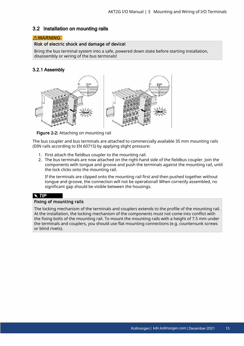
3.2.1 Assembly
Figure 2-2: Attaching on mounting rail
The bus coupler and bus terminals are attached to commercially available 35 mm mounting rails(DIN rails according to EN 60715) by applying slight pressure:
1. First attach the fieldbus coupler to the mounting rail.2. The bus terminals are now attached on the right-hand side of the fieldbus coupler. Join the
components with tongue and groove and push the terminals against the mounting rail, untilthe lock clicks onto the mounting rail.If the terminals are clipped onto the mounting rail first and then pushed together withouttongue and groove, the connection will not be operational! When correctly assembled, nosignificant gap should be visible between the housings.
Fixing of mounting railsThe locking mechanism of the terminals and couplers extends to the profile of the mounting rail.At the installation, the locking mechanism of the components must not come into conflict withthe fixing bolts of the mounting rail. To mount the mounting rails with a height of 7.5 mm underthe terminals and couplers, you should use flat mounting connections (e.g. countersunk screwsor blind rivets).
AKT2G I/O Manual | 3 Mounting and Wiring of I/O Terminals
Kollmorgen | kdn.kollmorgen.com | December 2021 13

AKT2G I/O Manual | 3 Mounting and Wiring of I/O Terminals
3.2.2 Disassembly
Figure 2-3: Disassembling of terminal
Each terminal is secured by a lock on the mounting rail, which must be released for disassembly:
1. Pull the terminal by its orange-colored lugs approximately 1 cm away from the mountingrail. In doing so for this terminal the mounting rail lock is released automatically and you canpull the terminal out of the bus terminal block easily without excessive force.
2. Grasp the released terminal with thumb and index finger simultaneous at the upper andlower grooved housing surfaces and pull the terminal out of the bus terminal block.
3.2.3 Connections within a bus terminal blockThe electric connections between the Bus Coupler and the Bus Terminals are automatically realizedby joining the components:
l The six spring contacts of the E-Bus/K-Bus deal with the transfer of the data and the supplyof the Bus Terminal electronics.
l The power contacts deal with the supply for the field electronics and thus represent a supplyrail within the bus terminal block. The power contacts are supplied via terminals on the BusCoupler (up to 24 V) or for higher voltages via power feed terminals.
Power ContactsDuring the design of a bus terminal block, the pin assignment of the individual BusTerminals must be taken account of, since some types (e.g. analog Bus Terminals or digital4-channel Bus Terminals) do not or not fully loop through the power contacts. Power FeedTerminals (AKT2G-PSF-024-000) interrupt the power contacts and thus represent the startof a new supply rail.
14 Kollmorgen | kdn.kollmorgen.com | December 2021

3.2.4 PE power contactThe power contact labeled PE can be used as a protective earth. For safety reasons this contactmates first when plugging together, and can ground short-circuit currents of up to 125 A.
Figure 2-4: Power contact on left side
Possible damage of the deviceNote that, for reasons of electromagnetic compatibility, the PE contacts are capacitativelycoupled to the mounting rail. This may lead to incorrect results during insulation testing or todamage on the terminal (e.g. disruptive discharge to the PE line during insulation testing of aconsumer with a nominal voltage of 230 V). For insulation testing, disconnect the PE supply line atthe Bus Coupler or the Power Feed Terminal! In order to decouple further feed points for testing,these Power Feed Terminals can be released and pulled at least 10 mm from the group ofterminals.
Risk of electric shock!The PE power contact must not be used for other potentials!
AKT2G I/O Manual | 3 Mounting and Wiring of I/O Terminals
Kollmorgen | kdn.kollmorgen.com | December 2021 15
AKT2G I/O Manual | 3 Mounting and Wiring of I/O Terminals
3.3 Installation instructions for enhanced mechanical load capacity
Risk of injury through electric shock and damage to the device!Bring the Bus Terminal system into a safe, de-energized state before starting mounting,disassembly or wiring of the Bus Terminals!
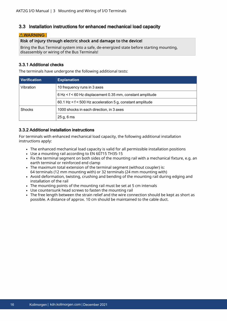
3.3.1 Additional checksThe terminals have undergone the following additional tests:
Verification Explanation
Vibration 10 frequency runs in 3 axes
6 Hz < f < 60 Hz displacement 0.35 mm, constant amplitude
60.1 Hz < f < 500 Hz acceleration 5 g, constant amplitude
Shocks 1000 shocks in each direction, in 3 axes
25 g, 6 ms
3.3.2 Additional installation instructionsFor terminals with enhanced mechanical load capacity, the following additional installationinstructions apply:
l The enhanced mechanical load capacity is valid for all permissible installation positionsl Use a mounting rail according to EN 60715 TH35-15l Fix the terminal segment on both sides of the mounting rail with a mechanical fixture, e.g. an
earth terminal or reinforced end clampl The maximum total extension of the terminal segment (without coupler) is:
64 terminals (12 mm mounting with) or 32 terminals (24 mm mounting with)l Avoid deformation, twisting, crushing and bending of the mounting rail during edging and
installation of the raill The mounting points of the mounting rail must be set at 5 cm intervalsl Use countersunk head screws to fasten the mounting raill The free length between the strain relief and the wire connection should be kept as short as
possible. A distance of approx. 10 cm should be maintained to the cable duct.
16 Kollmorgen | kdn.kollmorgen.com | December 2021

3.4 Connection
3.4.1 Connection system
Risk of electric shock and damage of device!Bring the bus terminal system into a safe, powered down state before starting installation,disassembly or wiring of the bus terminals!
3.4.1.1 Overview
The Bus Terminal system offers different connection options for optimum adaptation to therespective application:
l The terminals of AKT2G and AKT series with standard wiring include electronics andconnection level in a single enclosure.
3.4.1.2 Standard wiring (AKT2G/AKT-xx)
Figure 2-5: Standard wiring
The terminals of AKT2G and AKT series have been tried and tested for years.They feature integrated screwless spring force technology for fast and simple assembly.
AKT2G I/O Manual | 3 Mounting and Wiring of I/O Terminals
Kollmorgen | kdn.kollmorgen.com | December 2021 17
AKT2G I/O Manual | 3 Mounting and Wiring of I/O Terminals
3.4.2 Wiring
Risk of electric shock and damage of device!Bring the bus terminal system into a safe, powered down state before starting installation,disassembly or wiring of the Bus Terminals!
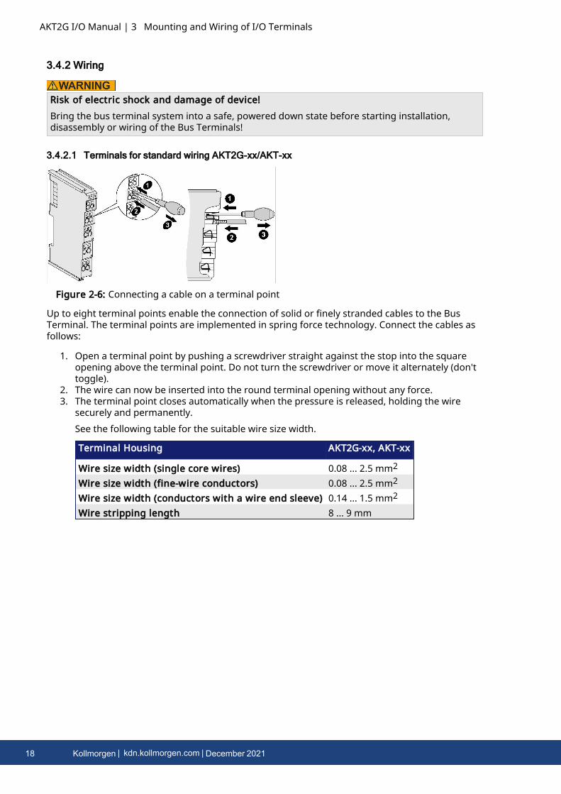
3.4.2.1 Terminals for standard wiring AKT2G-xx/AKT-xx
Figure 2-6: Connecting a cable on a terminal point
Up to eight terminal points enable the connection of solid or finely stranded cables to the BusTerminal. The terminal points are implemented in spring force technology. Connect the cables asfollows:
1. Open a terminal point by pushing a screwdriver straight against the stop into the squareopening above the terminal point. Do not turn the screwdriver or move it alternately (don'ttoggle).
2. The wire can now be inserted into the round terminal opening without any force.3. The terminal point closes automatically when the pressure is released, holding the wire
securely and permanently.See the following table for the suitable wire size width.
Terminal Housing AKT2G-xx, AKT-xx
Wire size width (single core wires) 0.08 ... 2.5 mm2
Wire size width (fine-wire conductors) 0.08 ... 2.5 mm2
Wire size width (conductors with a wire end sleeve) 0.14 ... 1.5 mm2
Wire stripping length 8 ... 9 mm
18 Kollmorgen | kdn.kollmorgen.com | December 2021

3.4.3 Shielding
ShieldingEncoder, analog sensors and actors should always be connected with shielded, twisted pairedwires.
Observe the special conditions for the intended use of Kollmorgen fieldbus componentswith extended temperature range (ET) in potentially explosive areas (directive2014/34/EU)!
l The certified components are to be installed in a suitable housing that guarantees aprotection class of at least IP54 in accordance with EN 60079-15! The environmentalconditions during use are thereby to be taken into account!
l For dust (only the fieldbus components of certificate no. KEMA 10ATEX0075 X Issue 9): Theequipment shall be installed in a suitable enclosure providing a degree of protection ofIP54 according to EN 60079-0 for group IIIA or IIIB and IP6X for group IIC, taking intoaccount the environmental conditions under which the equipment is used.
l If the temperatures during rated operation are higher than 70°C at the feed-in points ofcables, lines or pipes, or higher than 80°C at the wire branching points, then cables mustbe selected whose temperature data correspond to the actual measured temperaturevalues!
l Observe the permissible ambient temperature range of -25 to 60°C for the use ofKollmorgen fieldbus components with extended temperature range (ET) in potentiallyexplosive areas!
l Measures must be taken to protect against the rated operating voltage being exceeded bymore than 40% due to short-term interference voltages!
l The individual terminals may only be unplugged or removed from the Bus Terminal systemif the supply voltage has been switched off or if a non-explosive atmosphere is ensured!
l The connections of the certified components may only be connected or disconnected if thesupply voltage has been switched off or if a non-explosive atmosphere is ensured!
l The fuses of the AKT2G-PSF-024-000 power feed terminals may only be exchanged if thesupply voltage has been switched off or if a non-explosive atmosphere is ensured!
l Address selectors and ID switches may only be adjusted if the supply voltage has beenswitched off or if a non-explosive atmosphere is ensured!
AKT2G I/O Manual | 3 Mounting and Wiring of I/O Terminals
Kollmorgen | kdn.kollmorgen.com | December 2021 19
AKT2G I/O Manual | 3 Mounting and Wiring of I/O Terminals
3.5 Installation positions
Constraints regarding installation position and operating temperature rangePlease refer to the technical data for a terminal to ascertain whether any restrictions regardingthe installation position and/or the operating temperature range have been specified. Wheninstalling high power dissipation terminals ensure that an adequate spacing is maintainedbetween other components above and below the terminal in order to guarantee adequateventilation!
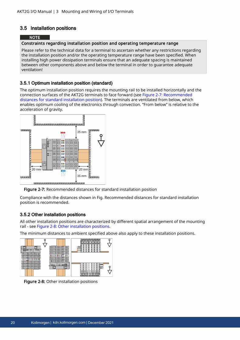
3.5.1 Optimum installation position (standard)The optimum installation position requires the mounting rail to be installed horizontally and theconnection surfaces of the AKT2G terminals to face forward (see Figure 2-7: Recommendeddistances for standard installation position). The terminals are ventilated from below, whichenables optimum cooling of the electronics through convection. “From below” is relative to theacceleration of gravity.
Figure 2-7: Recommended distances for standard installation position
Compliance with the distances shown in Fig. Recommended distances for standard installationposition is recommended.
3.5.2 Other installation positionsAll other installation positions are characterized by different spatial arrangement of the mountingrail - see Figure 2-8: Other installation positions.The minimum distances to ambient specified above also apply to these installation positions.
Figure 2-8: Other installation positions
20 Kollmorgen | kdn.kollmorgen.com | December 2021
3.6 Positioning of Passive Terminals
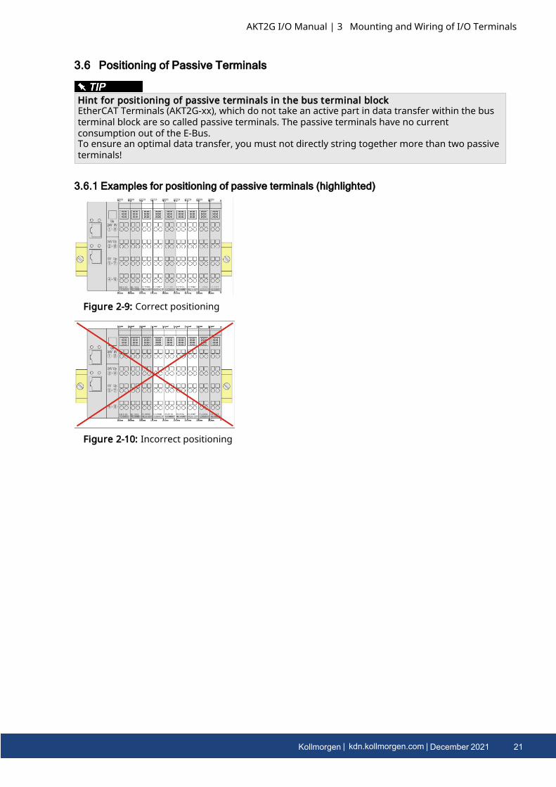
Hint for positioning of passive terminals in the bus terminal blockEtherCAT Terminals (AKT2G-xx), which do not take an active part in data transfer within the busterminal block are so called passive terminals. The passive terminals have no currentconsumption out of the E-Bus.To ensure an optimal data transfer, you must not directly string together more than two passiveterminals!
3.6.1 Examples for positioning of passive terminals (highlighted)
Figure 2-9: Correct positioning
Figure 2-10: Incorrect positioning
AKT2G I/O Manual | 3 Mounting and Wiring of I/O Terminals
Kollmorgen | kdn.kollmorgen.com | December 2021 21
AKT2G I/O Manual | 3 Mounting and Wiring of I/O Terminals
3.7 UL Notice
Application
Kollmorgen EtherCAT modules are intended for use with Kollmorgen’s UL ListedEtherCAT System only.ExaminationFor cULus examination, the Kollmorgen I/O System has only been investigated for riskof fire and electrical shock (in accordance with UL508 and CSA C22.2 No. 142).For devices with Ethernet connectorsNot for connection to telecommunication circuits.
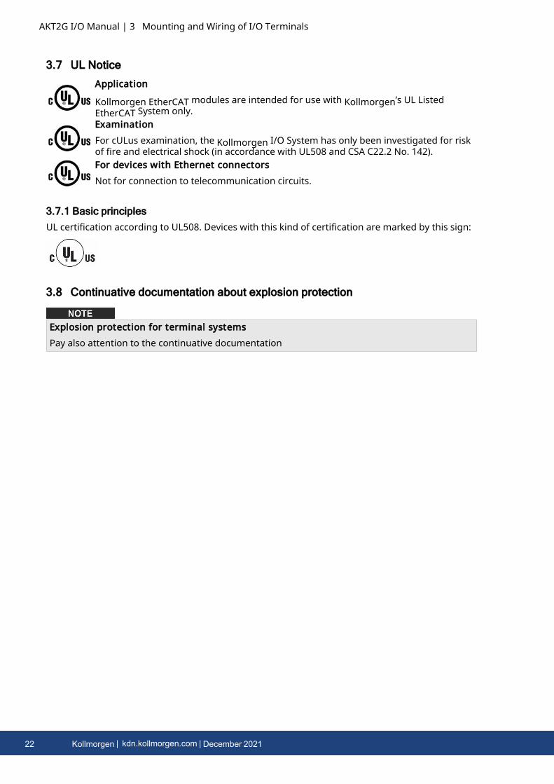
3.7.1 Basic principlesUL certification according to UL508. Devices with this kind of certification are marked by this sign:
3.8 Continuative documentation about explosion protection
Explosion protection for terminal systemsPay also attention to the continuative documentation
22 Kollmorgen | kdn.kollmorgen.com | December 2021

4 Safety I/O Information
4.1 Safety Operation
4.1.1 Environmental ConditionsPlease ensure that the safety components are only transported, stored and operated under thespecified conditions (see technical data)!
Risk of injury!The safety components must not be used under the following operating conditions.
l under the influence of ionizing radiation (that exceeds the level of the naturalenvironmental radiation)
l in corrosive environmentsl in an environment that leads to unacceptable soiling of the safety component
Electromagnetic compatibilityThe safety components comply with the current standards on electromagnetic compatibility withregard to spurious radiation and immunity to interference in particular.However, in cases where devices such as mobile phones, radio equipment, transmitters or high-frequency systems that exceed the interference emissions limits specified in the standards areoperated near safety components, the function of the safety components may be impaired.
4.1.2 Safety InstructionsBefore installing and commissioning the safety components please read the Safety Instructions inthis documentation.
Commissioning TestBefore the AKT2G-SDI-004-000/AKT2G-SDO-004-000 can be used for the safety task, the usermust carry out a commissioning test so that sensor and actuator wiring errors can be ruled out.
4.1.3 Transport / StorageUse the original packaging in which the components were delivered for transporting and storingthe safety components.
Note the specified environmental conditionsPlease ensure that the digital safety components are only transported and stored under thespecified environmental conditions (see technical data).
AKT2G I/O Manual | 4 Safety I/O Information
Kollmorgen | kdn.kollmorgen.com | December 2021 23
AKT2G I/O Manual | 4 Safety I/O Information
4.1.4 Mechanical Installation
Risk of injury!Bring the bus system into a safe, de-energized state before starting installation, disassembly orwiring of the devices!
Use ferrules with plastic collarsWhen using fine-wire cables for signal connections, use ferrules with plastic collars. This leads toa higher system availability when test pulses for the corresponding channels are switched off.
4.1.4.1 Control cabinet / terminal box
The safety terminals must be installed in a control cabinet or terminal box with IP54 protectionclass according to IEC 60529 as a minimum.
4.1.4.2 Installation position and minimum distances
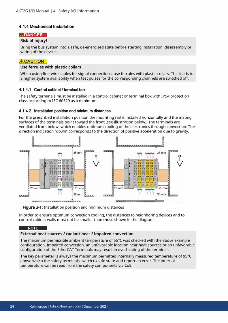
For the prescribed installation position the mounting rail is installed horizontally and the matingsurfaces of the terminals point toward the front (see illustration below). The terminals areventilated from below, which enables optimum cooling of the electronics through convection. Thedirection indication “down” corresponds to the direction of positive acceleration due to gravity.
Figure 3-1: Installation position and minimum distances
In order to ensure optimum convection cooling, the distances to neighboring devices and tocontrol cabinet walls must not be smaller than those shown in the diagram.
External heat sources / radiant heat / impaired convectionThe maximum permissible ambient temperature of 55°C was checked with the above exampleconfiguration. Impaired convection, an unfavorable location near heat sources or an unfavorableconfiguration of the EtherCAT Terminals may result in overheating of the terminals.The key parameter is always the maximum permitted internally measured temperature of 95°C,above which the safety terminals switch to safe state and report an error. The internaltemperature can be read from the safety components via CoE.
24 Kollmorgen | kdn.kollmorgen.com | December 2021
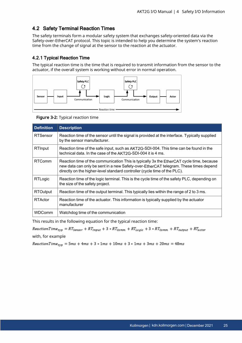
4.2 Safety Terminal Reaction TimesThe safety terminals form a modular safety system that exchanges safety-oriented data via theSafety-over-EtherCAT protocol. This topic is intended to help you determine the system's reactiontime from the change of signal at the sensor to the reaction at the actuator.
4.2.1 Typical Reaction TimeThe typical reaction time is the time that is required to transmit information from the sensor to theactuator, if the overall system is working without error in normal operation.
Figure 3-2: Typical reaction time
Definition Description
RTSensor Reaction time of the sensor until the signal is provided at the interface. Typically suppliedby the sensor manufacturer.
RTInput Reaction time of the safe input, such as AKT2G-SDI-004. This time can be found in thetechnical data. In the case of the AKT2G-SDI-004 it is 4 ms.
RTComm Reaction time of the communication This is typically 3x the EtherCAT cycle time, becausenew data can only be sent in a new Safety-over-EtherCAT telegram. These times dependdirectly on the higher-level standard controller (cycle time of the PLC).
RTLogic Reaction time of the logic terminal. This is the cycle time of the safety PLC, depending onthe size of the safety project.
RTOutput Reaction time of the output terminal. This typically lies within the range of 2 to 3 ms.
RTActor Reaction time of the actuator. This information is typically supplied by the actuatormanufacturer
WDComm Watchdog time of the communication
This results in the following equation for the typical reaction time:
with, for example
AKT2G I/O Manual | 4 Safety I/O Information
Kollmorgen | kdn.kollmorgen.com | December 2021 25
AKT2G I/O Manual | 4 Safety I/O Information
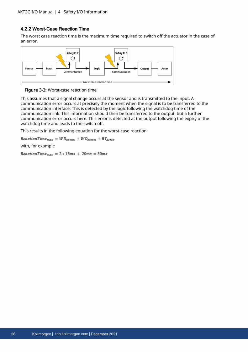
4.2.2 Worst-Case Reaction TimeThe worst case reaction time is the maximum time required to switch off the actuator in the case ofan error.
Figure 3-3: Worst-case reaction time
This assumes that a signal change occurs at the sensor and is transmitted to the input. Acommunication error occurs at precisely the moment when the signal is to be transferred to thecommunication interface. This is detected by the logic following the watchdog time of thecommunication link. This information should then be transferred to the output, but a furthercommunication error occurs here. This error is detected at the output following the expiry of thewatchdog time and leads to the switch-off.This results in the following equation for the worst-case reaction:
with, for example
26 Kollmorgen | kdn.kollmorgen.com | December 2021

4.3 Safety I/O MaintenanceMaintenanceThe safety components are maintenance-free!Environmental conditions
Observe the specified environmental conditions!Please ensure that the safety components are only stored and operated under the specifiedconditions (see technical data).
If the safety component is operated outside the permitted temperature range it will switch toGlobal Shutdown state.CleaningProtect the safety component from unacceptable soling during operation and storage!If the safety component was subjected to unacceptable soiling it may no longer be operated!
Have soiled terminals checked!Cleaning of the safety component by the user is not permitted!Please send soiled terminals to the manufacturer for inspection and cleaning!
AKT2G I/O Manual | 4 Safety I/O Information
Kollmorgen | kdn.kollmorgen.com | December 2021 27
AKT2G I/O Manual | 5 Remote Input/Output Terminals
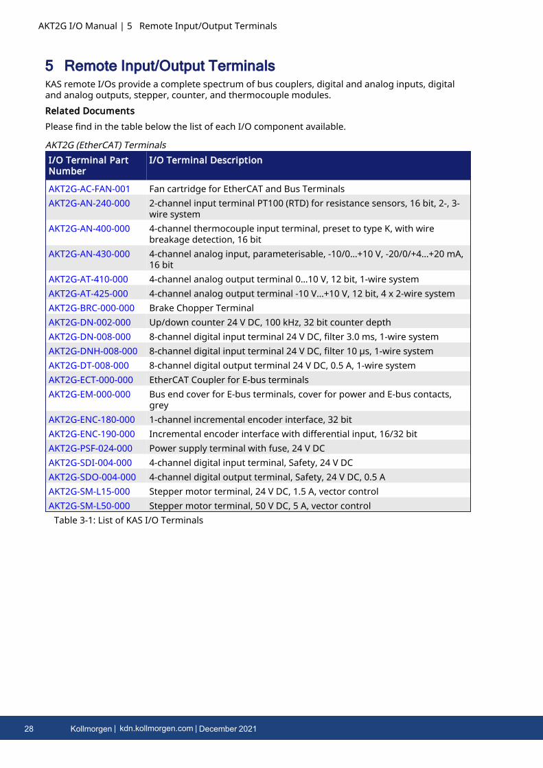
5 Remote Input/Output TerminalsKAS remote I/Os provide a complete spectrum of bus couplers, digital and analog inputs, digitaland analog outputs, stepper, counter, and thermocouple modules.Related DocumentsPlease find in the table below the list of each I/O component available.
I/O Terminal PartNumber
I/O Terminal Description
AKT2G-AC-FAN-001 Fan cartridge for EtherCAT and Bus TerminalsAKT2G-AN-240-000 2-channel input terminal PT100 (RTD) for resistance sensors, 16 bit, 2-, 3-
wire systemAKT2G-AN-400-000 4-channel thermocouple input terminal, preset to type K, with wire
breakage detection, 16 bitAKT2G-AN-430-000 4-channel analog input, parameterisable, -10/0…+10 V, -20/0/+4…+20 mA,
16 bitAKT2G-AT-410-000 4-channel analog output terminal 0…10 V, 12 bit, 1-wire systemAKT2G-AT-425-000 4-channel analog output terminal -10 V…+10 V, 12 bit, 4 x 2-wire systemAKT2G-BRC-000-000 Brake Chopper TerminalAKT2G-DN-002-000 Up/down counter 24 V DC, 100 kHz, 32 bit counter depthAKT2G-DN-008-000 8-channel digital input terminal 24 V DC, filter 3.0 ms, 1-wire systemAKT2G-DNH-008-000 8-channel digital input terminal 24 V DC, filter 10 µs, 1-wire systemAKT2G-DT-008-000 8-channel digital output terminal 24 V DC, 0.5 A, 1-wire systemAKT2G-ECT-000-000 EtherCAT Coupler for E-bus terminalsAKT2G-EM-000-000 Bus end cover for E-bus terminals, cover for power and E-bus contacts,
greyAKT2G-ENC-180-000 1-channel incremental encoder interface, 32 bitAKT2G-ENC-190-000 Incremental encoder interface with differential input, 16/32 bitAKT2G-PSF-024-000 Power supply terminal with fuse, 24 V DCAKT2G-SDI-004-000 4-channel digital input terminal, Safety, 24 V DCAKT2G-SDO-004-000 4-channel digital output terminal, Safety, 24 V DC, 0.5 AAKT2G-SM-L15-000 Stepper motor terminal, 24 V DC, 1.5 A, vector controlAKT2G-SM-L50-000 Stepper motor terminal, 50 V DC, 5 A, vector control
AKT2G (EtherCAT) Terminals
Table 3-1: List of KAS I/O Terminals
28 Kollmorgen | kdn.kollmorgen.com | December 2021
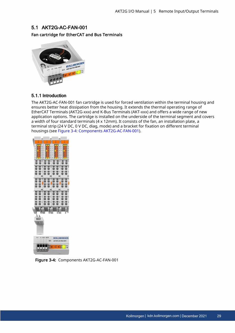
5.1 AKT2G-AC-FAN-001Fan cartridge for EtherCAT and Bus Terminals
5.1.1 IntroductionThe AKT2G-AC-FAN-001 fan cartridge is used for forced ventilation within the terminal housing andensures better heat dissipation from the housing. It extends the thermal operating range ofEtherCAT Terminals (AKT2G-xxx) and K-Bus Terminals (AKT-xxx) and offers a wide range of newapplication options. The cartridge is installed on the underside of the terminal segment and coversa width of four standard terminals (4 x 12mm). It consists of the fan, an installation plate, aterminal strip (24 V DC, 0 V DC, diag, mode) and a bracket for fixation on different terminalhousings (see Figure 3-4: Components AKT2G-AC-FAN-001).
Figure 3-4: Components AKT2G-AC-FAN-001
AKT2G I/O Manual | 5 Remote Input/Output Terminals
Kollmorgen | kdn.kollmorgen.com | December 2021 29
AKT2G I/O Manual | 5 Remote Input/Output Terminals
5.1.2 Technical Data
Technical data AKT2G-AC-FAN-001
Number of channels 1 fan
Nominal voltage 24 V DC (-15 %/+20 %)
Current consumption (at 24 Voperating voltage)
ca. 45 mA
Operating modes temperature-controlled, full speed, frequency controlled
Rotational frequency fan adjustable in 9 steps via frequency (1…9 Hz), max. ~5,500 rpm
Diagnostics, max. output current fan fault, 15 mA
Life span MTBF typ. = 280,000 h@ 20°C
Special features increased performance and extended temperature range forvarious terminals
Dimensions (W x H x D) 47 mm x 22 mm x 55 mm
Weight 32 g (incl. bracket)
Operating / storage temperature -25…+70°C/-40…+85°C
Relative humidity 95 %, no condensation
Vibration / shock resistance conforms to EN 60068-2-6/EN 60068-2-27
EMC immunity / emission conforms to EN 61000-6-2/EN 61000-6-4
Protect. class / installation pos. IP 20/see Mounting and Demounting
Approval CE, cULus
30 Kollmorgen | kdn.kollmorgen.com | December 2021

5.1.3 Mounting and DemountingThe AKT2G-AC-FAN-001 fan cartridge is snapped onto a 48-mm wide terminal group of Kollmorgenstandard or highdensity (HD) terminals using the "8-channel/16-channel fan cartridge holder"supplied as an accessory.
Fan cartridge holder, 8-channel
Fan cartridge holder, 16-channelThe width of the individual terminals may be 12mm (single width) or 24mm (double width) or acombination of both.The mounting of the AKT2G-AC-FAN-001 is described below by way of an example.
5.1.3.1 Mounting
Risk of injury through electric shock and damage to the device!Bring the Bus Terminals system into a safe, de-energized state before starting mounting,disassembly or wiring of the Bus Terminals.
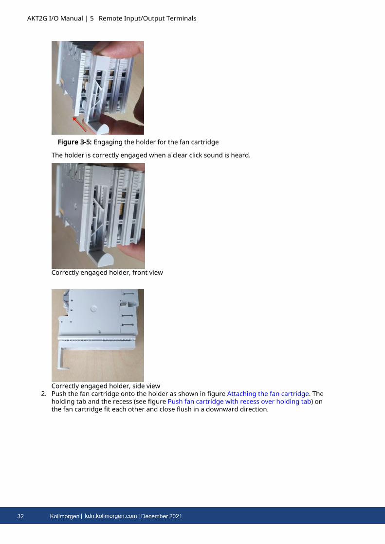
1. Assemble the terminals to be ventilated into a group with a width of 48mm and snap theholder on the left in the lower ventilation cut-outs of the first terminal to be ventilated, asshown in Figure 3-5: Engaging the holder for the fan cartridge.
AKT2G I/O Manual | 5 Remote Input/Output Terminals
Kollmorgen | kdn.kollmorgen.com | December 2021 31
AKT2G I/O Manual | 5 Remote Input/Output Terminals
Figure 3-5: Engaging the holder for the fan cartridge
The holder is correctly engaged when a clear click sound is heard.
Correctly engaged holder, front view
Correctly engaged holder, side view2. Push the fan cartridge onto the holder as shown in figure Attaching the fan cartridge. The
holding tab and the recess (see figure Push fan cartridge with recess over holding tab) onthe fan cartridge fit each other and close flush in a downward direction.
32 Kollmorgen | kdn.kollmorgen.com | December 2021
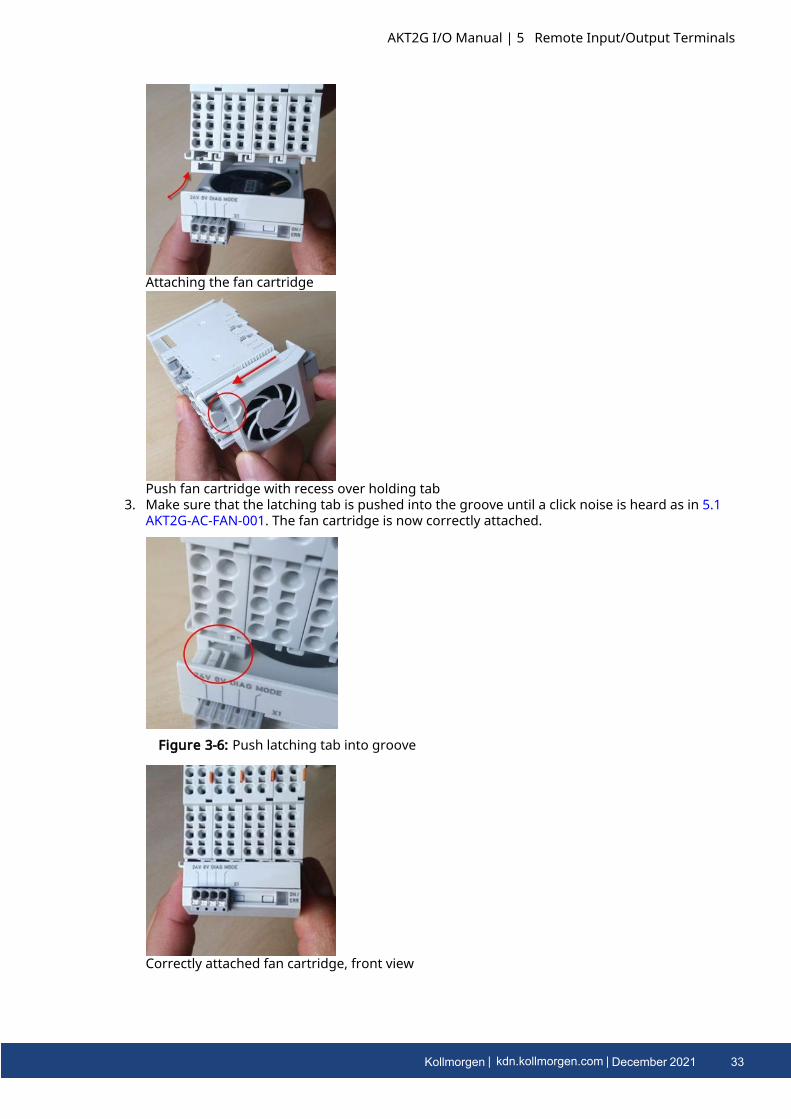
Attaching the fan cartridge
Push fan cartridge with recess over holding tab3. Make sure that the latching tab is pushed into the groove until a click noise is heard as in 5.1
AKT2G-AC-FAN-001. The fan cartridge is now correctly attached.
Figure 3-6: Push latching tab into groove
Correctly attached fan cartridge, front view
AKT2G I/O Manual | 5 Remote Input/Output Terminals
Kollmorgen | kdn.kollmorgen.com | December 2021 33
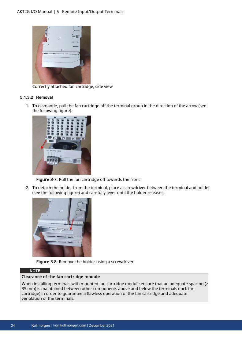
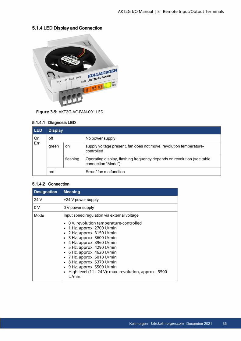
AKT2G I/O Manual | 5 Remote Input/Output Terminals
Correctly attached fan cartridge, side view
5.1.3.2 Removal
1. To dismantle, pull the fan cartridge off the terminal group in the direction of the arrow (seethe following figure).
Figure 3-7: Pull the fan cartridge off towards the front
2. To detach the holder from the terminal, place a screwdriver between the terminal and holder(see the following figure) and carefully lever until the holder releases.
Figure 3-8: Remove the holder using a screwdriver
Clearance of the fan cartridge moduleWhen installing terminals with mounted fan cartridge module ensure that an adequate spacing (>35 mm) is maintained between other components above and below the terminals (incl. fancartridge) in order to guarantee a flawless operation of the fan cartridge and adequateventilation of the terminals.
34 Kollmorgen | kdn.kollmorgen.com | December 2021
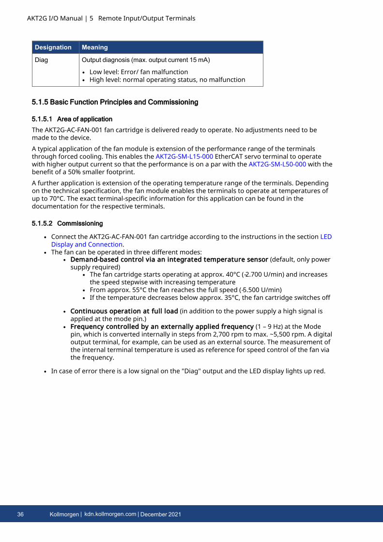
5.1.4 LED Display and Connection
Figure 3-9: AKT2G-AC-FAN-001 LED
5.1.4.1 Diagnosis LED
LED Display
OnErr
off No power supply
green on supply voltage present, fan does not move, revolution temperature-controlled
flashing Operating display, flashing frequency depends on revolution (see tableconnection “Mode”)
red Error / fan malfunction
5.1.4.2 Connection
Designation Meaning
24 V +24 V power supply
0 V 0 V power supply
Mode Input speed regulation via external voltage
l 0 V, revolution temperature-controlledl 1 Hz, approx. 2700 U/minl 2 Hz, approx. 3150 U/minl 3 Hz, approx. 3600 U/minl 4 Hz, approx. 3960 U/minl 5 Hz, approx. 4290 U/minl 6 Hz, approx. 4620 U/minl 7 Hz, approx. 5010 U/minl 8 Hz, approx. 5370 U/minl 9 Hz, approx. 5500 U/minl High level (11 - 24 V): max. revolution, approx.. 5500
U/min.
AKT2G I/O Manual | 5 Remote Input/Output Terminals
Kollmorgen | kdn.kollmorgen.com | December 2021 35
AKT2G I/O Manual | 5 Remote Input/Output Terminals
Designation Meaning
Diag Output diagnosis (max. output current 15 mA)
l Low level: Error/ fan malfunctionl High level: normal operating status, no malfunction
5.1.5 Basic Function Principles and Commissioning
5.1.5.1 Area of application
The AKT2G-AC-FAN-001 fan cartridge is delivered ready to operate. No adjustments need to bemade to the device.A typical application of the fan module is extension of the performance range of the terminalsthrough forced cooling. This enables the AKT2G-SM-L15-000 EtherCAT servo terminal to operatewith higher output current so that the performance is on a par with the AKT2G-SM-L50-000 with thebenefit of a 50% smaller footprint.A further application is extension of the operating temperature range of the terminals. Dependingon the technical specification, the fan module enables the terminals to operate at temperatures ofup to 70°C. The exact terminal-specific information for this application can be found in thedocumentation for the respective terminals.
5.1.5.2 Commissioning
l Connect the AKT2G-AC-FAN-001 fan cartridge according to the instructions in the section LEDDisplay and Connection.
l The fan can be operated in three different modes:l Demand-based control via an integrated temperature sensor (default, only power
supply required)l The fan cartridge starts operating at approx. 40°C ( ̴2.700 U/min) and increases
the speed stepwise with increasing temperaturel From approx. 55°C the fan reaches the full speed ( ̴5.500 U/min)l If the temperature decreases below approx. 35°C, the fan cartridge switches off
l Continuous operation at full load (in addition to the power supply a high signal isapplied at the mode pin.)
l Frequency controlled by an externally applied frequency (1 – 9 Hz) at the Modepin, which is converted internally in steps from 2,700 rpm to max. ~5,500 rpm. A digitaloutput terminal, for example, can be used as an external source. The measurement ofthe internal terminal temperature is used as reference for speed control of the fan viathe frequency.
l In case of error there is a low signal on the "Diag" output and the LED display lights up red.
36 Kollmorgen | kdn.kollmorgen.com | December 2021
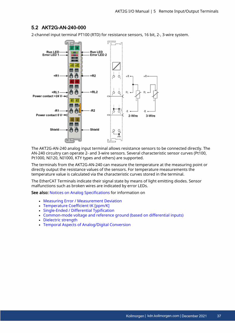
5.2 AKT2G-AN-240-0002-channel input terminal PT100 (RTD) for resistance sensors, 16 bit, 2-, 3-wire system.
The AKT2G-AN-240 analog input terminal allows resistance sensors to be connected directly. TheAN-240 circuitry can operate 2- and 3-wire sensors. Several characteristic sensor curves (Pt100,Pt1000, NI120, NI1000, KTY types and others) are supported.The terminals from the AKT2G-AN-240 can measure the temperature at the measuring point ordirectly output the resistance values of the sensors. For temperature measurements thetemperature value is calculated via the characteristic curves stored in the terminal.The EtherCAT Terminals indicate their signal state by means of light emitting diodes. Sensormalfunctions such as broken wires are indicated by error LEDs.See also: Notices on Analog Specifications for information on
l Measuring Error / Measurement Deviationl Temperature Coefficient tK [ppm/K]l Single-Ended / Differential Typificationl Common-mode voltage and reference ground (based on differential inputs)l Dielectric strengthl Temporal Aspects of Analog/Digital Conversion
AKT2G I/O Manual | 5 Remote Input/Output Terminals
Kollmorgen | kdn.kollmorgen.com | December 2021 37
AKT2G I/O Manual | 5 Remote Input/Output Terminals
5.2.1 Technology RTD Measuring
5.2.1.1 Function
The AKT2G-AN-240 analog input terminals allow resistance sensors in the range 0 - 4096 Ohm to beconnected directly.Functions:
l Resistance measurementl Measuring range 0 to 1024 Ω: Resolution 1/64 Ohml Measuring range 0 to 4096 Ω: Resolution 1/16 Ohml The use of the terminal in the range from 0 to 10 Ohm is not recommended due to the
relatively low measuring accuracy.l With the AN-240 the external bridge must be inserted between +R and +RL in 3-wire
mode
l Temperature measurementThe measured sensor resistance is converted directly into a temperature by the internal µCvia the desired linearization characteristic curve
l Standard resolution 1/10 °C (1 digit = 0.1 °C) according to a theoretically representabletemperature range [- 3276.7 to 3276.8 °C]The physically specified temperature range for the respective sensor is to be observed!
l Various PTC sensor characteristic curves are implemented over their completemeasuring range for selection in the AN-240 series: Pt/Ni xxxx, KTY xx
l Scaling and presentation can be changed
Additional notes:
l The resistance is determined by means of Ratiometric Voltage Measurement.l The error state "broken wire" is detected as overrange, signaled as an error to the controller
and indicated by the ERROR LED.l The error state "short-circuit" is detected as underrange if the resistance is smaller than the
smallest resistance of the measuring range, signaled as an error to the controller andindicated by the ERROR LED.
l In the delivery state, the measured value is displayed in increments of 1/10° C in two'scomplement format (integer).
l Other methods of display, e.g. high resolution with 1/100 °C can be selected via CoE0x80n0:02.When using the high resolution a temperature range of -320 to +320 °C (-32566 to 32567) ismeasurable by the 2-byte PDO.
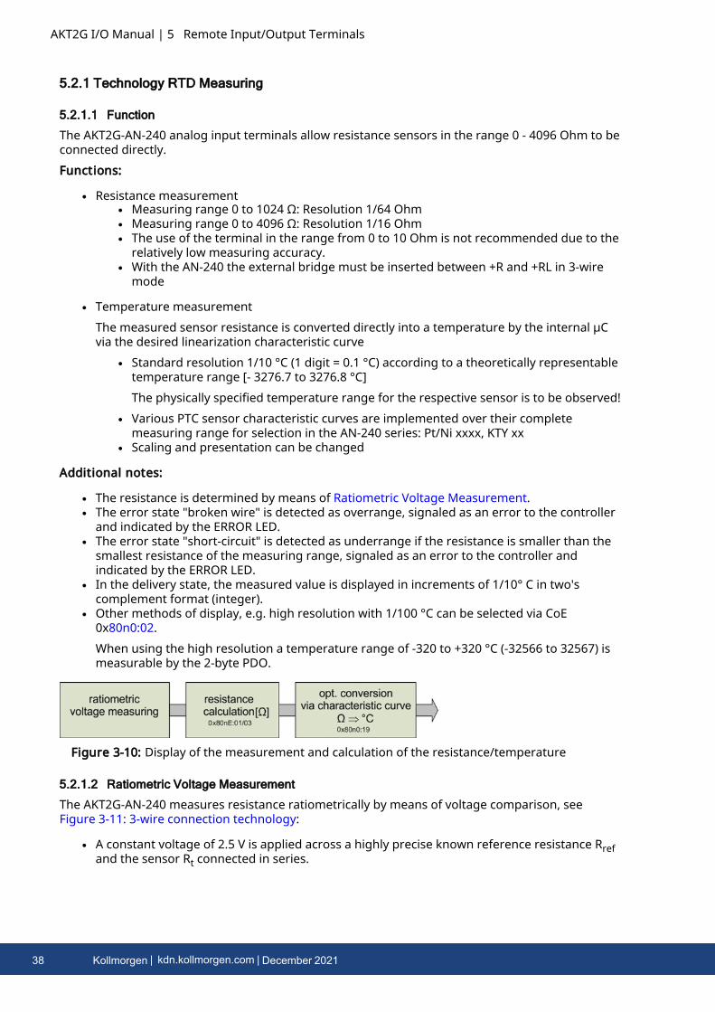
Figure 3-10: Display of the measurement and calculation of the resistance/temperature
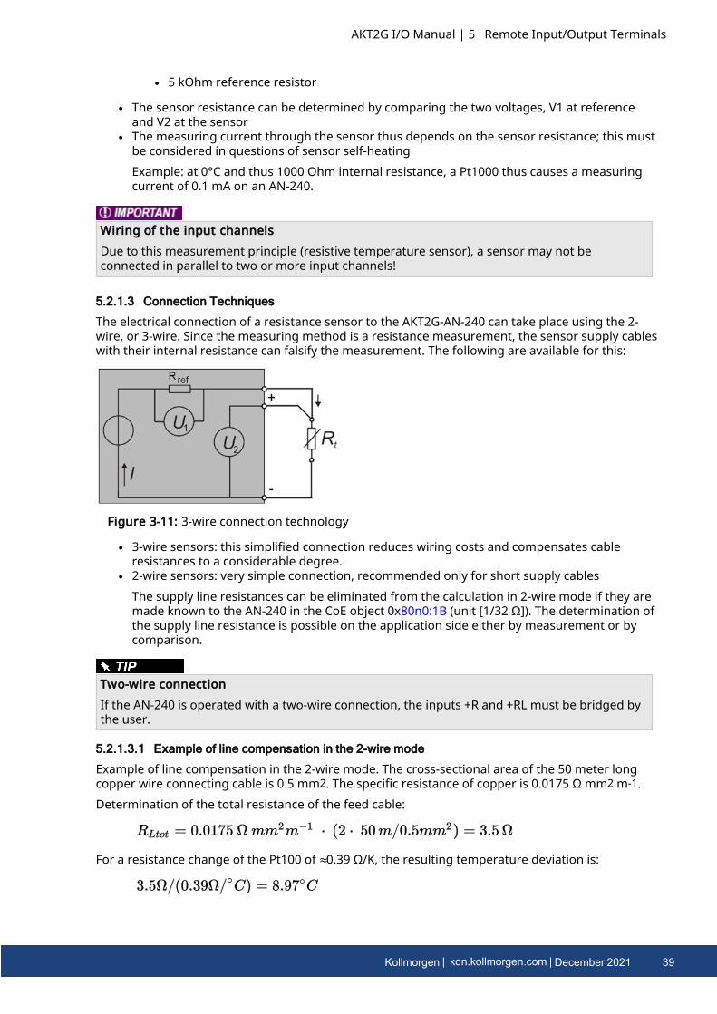
5.2.1.2 Ratiometric Voltage Measurement
The AKT2G-AN-240 measures resistance ratiometrically by means of voltage comparison, seeFigure 3-11: 3-wire connection technology:
l A constant voltage of 2.5 V is applied across a highly precise known reference resistance Rrefand the sensor Rt connected in series.
38 Kollmorgen | kdn.kollmorgen.com | December 2021
l 5 kOhm reference resistor
l The sensor resistance can be determined by comparing the two voltages, V1 at referenceand V2 at the sensor
l The measuring current through the sensor thus depends on the sensor resistance; this mustbe considered in questions of sensor self-heatingExample: at 0°C and thus 1000 Ohm internal resistance, a Pt1000 thus causes a measuringcurrent of 0.1 mA on an AN-240.
Wiring of the input channelsDue to this measurement principle (resistive temperature sensor), a sensor may not beconnected in parallel to two or more input channels!
5.2.1.3 Connection Techniques
The electrical connection of a resistance sensor to the AKT2G-AN-240 can take place using the 2-wire, or 3-wire. Since the measuring method is a resistance measurement, the sensor supply cableswith their internal resistance can falsify the measurement. The following are available for this:
Figure 3-11: 3-wire connection technology
l 3-wire sensors: this simplified connection reduces wiring costs and compensates cableresistances to a considerable degree.
l 2-wire sensors: very simple connection, recommended only for short supply cablesThe supply line resistances can be eliminated from the calculation in 2-wire mode if they aremade known to the AN-240 in the CoE object 0x80n0:1B (unit [1/32 Ω]). The determination ofthe supply line resistance is possible on the application side either by measurement or bycomparison.
Two-wire connectionIf the AN-240 is operated with a two-wire connection, the inputs +R and +RL must be bridged bythe user.
5.2.1.3.1 Example of line compensation in the 2-wire mode
Example of line compensation in the 2-wire mode. The cross-sectional area of the 50 meter longcopper wire connecting cable is 0.5 mm2. The specific resistance of copper is 0.0175 Ω mm2 m-1.Determination of the total resistance of the feed cable:
For a resistance change of the Pt100 of ≈0.39 Ω/K, the resulting temperature deviation is:
AKT2G I/O Manual | 5 Remote Input/Output Terminals
Kollmorgen | kdn.kollmorgen.com | December 2021 39
AKT2G I/O Manual | 5 Remote Input/Output Terminals
if the line resistance is not taken into account. If the 3.5 Ohm are now entered as
in 0x8000:1B (see "80n0:1B" on page 56) this is subtracted from the measured value and thetemperature is corrected accordingly.
5.2.1.4 Overview of Suitable Resistance Sensors
The following resistance sensors are suitable for temperature measurement with the AKT2G-AN-240 and can be selected via the object 0x80n0:19.
Type Resistancerange
Implemented temperaturerange
Pt100 (0.00385 Ω/Ω/°C, IEC60751 characteristiccurve Pt385)
~ 18 ... ~390Ohm
-200°C to 850°C
Ni100 -60°C to 250°C
Pt1000 (0.00385 Ω/Ω/°C, IEC60751 characteristiccurve Pt385)
~180 ... ~3900Ohm
-200°C to 850°C
Pt500 -200°C to 850°C
Pt200 -200°C to 1370°C
Ni1000 -60°C to 250°C
Ni1000
TK5000
100°C: 1500 ohm
-30 to 160°C
Ni120 -60°C to 320°C
KT100/110/130/210/230
KTY10/11/13/16/19
~500 ... ~2200Ohm
-55 ...150°C
KTY81/82-110,120,150
KTY81-121
KTY81-122
KTY81-151
KTY81-152
KTY81/82-210,220,250
KTY81-221
KTY81-222
KTY81-251
KTY81-252
40 Kollmorgen | kdn.kollmorgen.com | December 2021
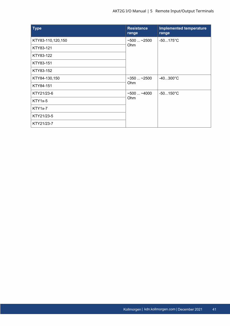
Type Resistancerange
Implemented temperaturerange
KTY83-110,120,150 ~500 ... ~2500Ohm
-50...175°C
KTY83-121
KTY83-122
KTY83-151
KTY83-152
KTY84-130,150 ~350 ... ~2500Ohm
-40...300°C
KTY84-151
KTY21/23-6 ~500 ... ~4000Ohm
-50...150°C
KTY1x-5
KTY1x-7
KTY21/23-5
KTY21/23-7
AKT2G I/O Manual | 5 Remote Input/Output Terminals
Kollmorgen | kdn.kollmorgen.com | December 2021 41
AKT2G I/O Manual | 5 Remote Input/Output Terminals
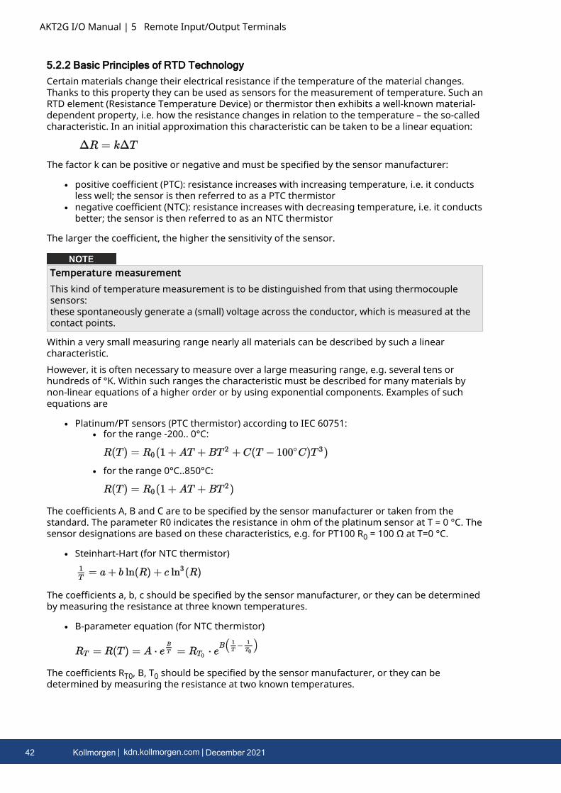
5.2.2 Basic Principles of RTD TechnologyCertain materials change their electrical resistance if the temperature of the material changes.Thanks to this property they can be used as sensors for the measurement of temperature. Such anRTD element (Resistance Temperature Device) or thermistor then exhibits a well-known material-dependent property, i.e. how the resistance changes in relation to the temperature – the so-calledcharacteristic. In an initial approximation this characteristic can be taken to be a linear equation:
The factor k can be positive or negative and must be specified by the sensor manufacturer:
l positive coefficient (PTC): resistance increases with increasing temperature, i.e. it conductsless well; the sensor is then referred to as a PTC thermistor
l negative coefficient (NTC): resistance increases with decreasing temperature, i.e. it conductsbetter; the sensor is then referred to as an NTC thermistor
The larger the coefficient, the higher the sensitivity of the sensor.
Temperature measurementThis kind of temperature measurement is to be distinguished from that using thermocouplesensors:these spontaneously generate a (small) voltage across the conductor, which is measured at thecontact points.
Within a very small measuring range nearly all materials can be described by such a linearcharacteristic.However, it is often necessary to measure over a large measuring range, e.g. several tens orhundreds of °K. Within such ranges the characteristic must be described for many materials bynon-linear equations of a higher order or by using exponential components. Examples of suchequations are
l Platinum/PT sensors (PTC thermistor) according to IEC 60751:l for the range -200.. 0°C:
l for the range 0°C..850°C:
The coefficients A, B and C are to be specified by the sensor manufacturer or taken from thestandard. The parameter R0 indicates the resistance in ohm of the platinum sensor at T = 0 °C. Thesensor designations are based on these characteristics, e.g. for PT100 R0 = 100 Ω at T=0 °C.
l Steinhart-Hart (for NTC thermistor)
The coefficients a, b, c should be specified by the sensor manufacturer, or they can be determinedby measuring the resistance at three known temperatures.
l B-parameter equation (for NTC thermistor)
The coefficients RT0, B, T0 should be specified by the sensor manufacturer, or they can bedetermined by measuring the resistance at two known temperatures.
42 Kollmorgen | kdn.kollmorgen.com | December 2021
The B-parameter equation is a simplified version of the Steinhart-Hart equation. The B-parameteritself is only constant in a small range, e.g. between 25°C.. 50°C or 25°C.. 85°C, which is identifiedas follows: B25/50 or B25/85. The accuracy of the equation strongly depends on the B-parameter. Thelarger the measuring range, the lower the accuracy. If a larger measuring range required, it ispreferable to use the Steinhart-Hart equation.
l and others
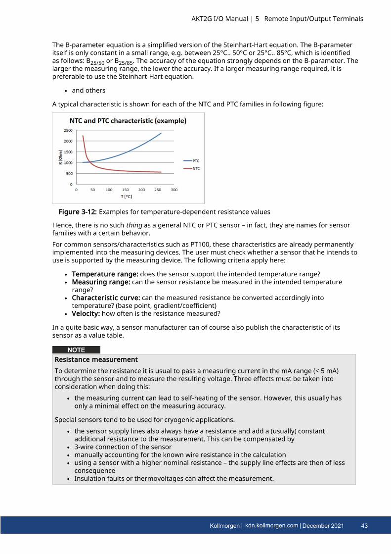
A typical characteristic is shown for each of the NTC and PTC families in following figure:
Figure 3-12: Examples for temperature-dependent resistance values
Hence, there is no such thing as a general NTC or PTC sensor – in fact, they are names for sensorfamilies with a certain behavior.For common sensors/characteristics such as PT100, these characteristics are already permanentlyimplemented into the measuring devices. The user must check whether a sensor that he intends touse is supported by the measuring device. The following criteria apply here:
l Temperature range: does the sensor support the intended temperature range?l Measuring range: can the sensor resistance be measured in the intended temperature
range?l Characteristic curve: can the measured resistance be converted accordingly into
temperature? (base point, gradient/coefficient)l Velocity: how often is the resistance measured?
In a quite basic way, a sensor manufacturer can of course also publish the characteristic of itssensor as a value table.
Resistance measurementTo determine the resistance it is usual to pass a measuring current in the mA range (< 5 mA)through the sensor and to measure the resulting voltage. Three effects must be taken intoconsideration when doing this:
l the measuring current can lead to self-heating of the sensor. However, this usually hasonly a minimal effect on the measuring accuracy.
Special sensors tend to be used for cryogenic applications.l the sensor supply lines also always have a resistance and add a (usually) constant
additional resistance to the measurement. This can be compensated byl 3-wire connection of the sensorl manually accounting for the known wire resistance in the calculationl using a sensor with a higher nominal resistance – the supply line effects are then of less
consequencel Insulation faults or thermovoltages can affect the measurement.
AKT2G I/O Manual | 5 Remote Input/Output Terminals
Kollmorgen | kdn.kollmorgen.com | December 2021 43

AKT2G I/O Manual | 5 Remote Input/Output Terminals
For classification there follows an overview of the NTC/PTC properties of various sensors:
NTC PTC
many semiconductors many metals
various ceramics various ceramics
NTC20, NTC100, etc. Pt100, Pt1000, ..
KTY ..
Ni100, Ni1000, ..
FeT
NTC and PTC Properties
Sensor exchangePlease note that 1:1 exchangeability is not always guaranteed, especially in the case ofmanufacturer-specified sensors. If necessary, the new sensor must be re-calibrated in the system.
44 Kollmorgen | kdn.kollmorgen.com | December 2021
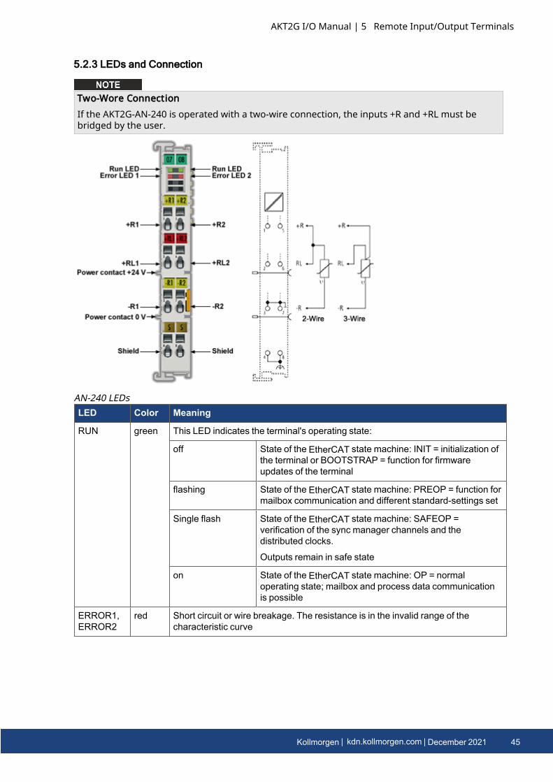
5.2.3 LEDs and Connection
Two-Wore ConnectionIf the AKT2G-AN-240 is operated with a two-wire connection, the inputs +R and +RL must bebridged by the user.
LED Color Meaning
RUN green This LED indicates the terminal's operating state:
off State of the EtherCAT state machine: INIT = initialization ofthe terminal or BOOTSTRAP = function for firmwareupdates of the terminal
flashing State of the EtherCAT state machine: PREOP = function formailbox communication and different standard-settings set
Single flash State of the EtherCAT state machine: SAFEOP =verification of the sync manager channels and thedistributed clocks.
Outputs remain in safe state
on State of the EtherCAT state machine: OP = normaloperating state; mailbox and process data communicationis possible
ERROR1,ERROR2
red Short circuit or wire breakage. The resistance is in the invalid range of thecharacteristic curve
AN-240 LEDs
AKT2G I/O Manual | 5 Remote Input/Output Terminals
Kollmorgen | kdn.kollmorgen.com | December 2021 45
AKT2G I/O Manual | 5 Remote Input/Output Terminals
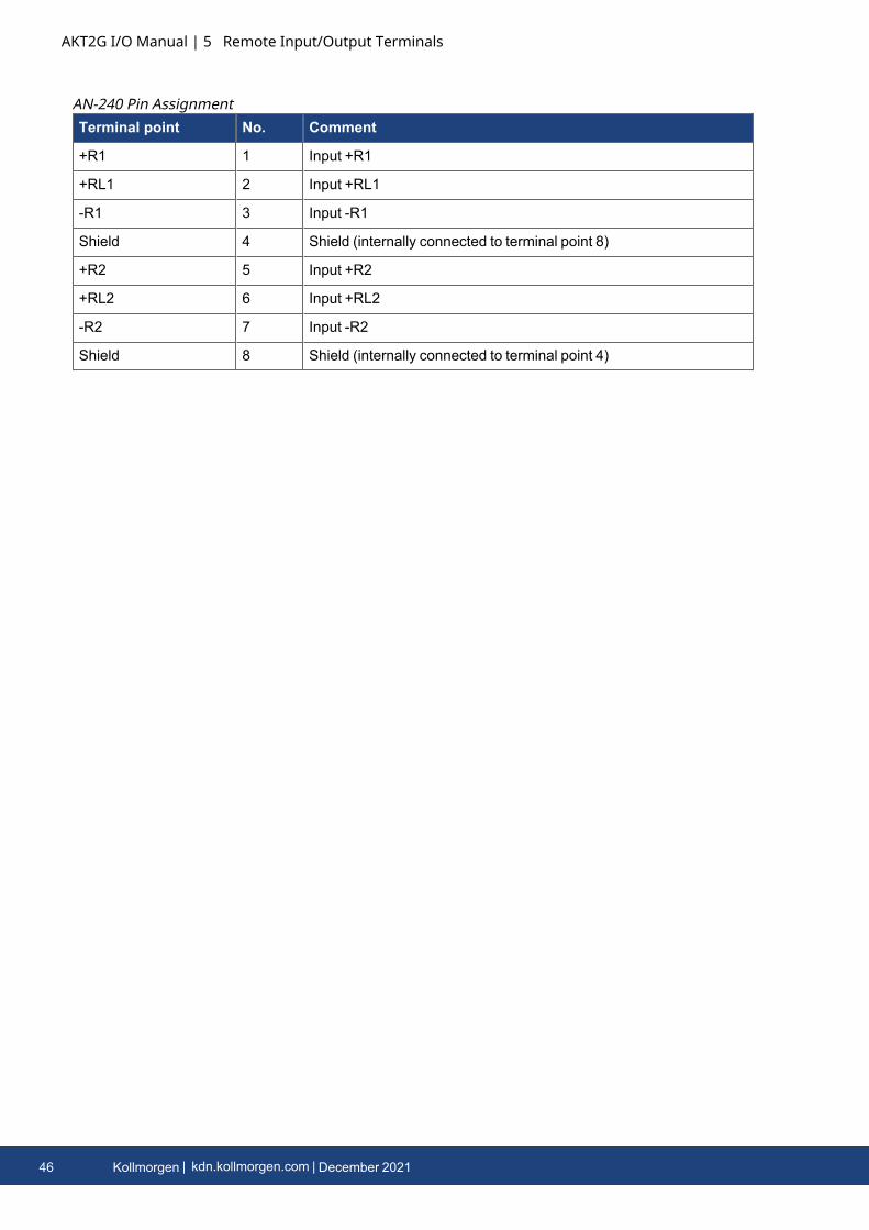
Terminal point No. Comment
+R1 1 Input +R1
+RL1 2 Input +RL1
-R1 3 Input -R1
Shield 4 Shield (internally connected to terminal point 8)
+R2 5 Input +R2
+RL2 6 Input +RL2
-R2 7 Input -R2
Shield 8 Shield (internally connected to terminal point 4)
AN-240 Pin Assignment
46 Kollmorgen | kdn.kollmorgen.com | December 2021
5.2.4 Connection of Analog RTD Signal LinesThe RTD input terminals of the AN-240 measure the analog resistance of the sensor. The voltagedrop at the sensor (including the line resistances, depending on the connection technology) isequivalent to the sensor resistance and therefore a measure for the sensor temperature, if thecharacteristic sensor curve is known. The following procedure serves for connecting analog signalcables in order to ensure error-free measurement of the analog signals.
5.2.4.1 Measures
l Sensor cable to be usedl Tightly twistedl Shielded copper braidl Use low-impedance cable, particularly for 2-wire connection
l Keep the sensor and sensor cables free from external potential.On no account should the GND connections (3/7) be connected with other potentials.
l The resistor for the RTD sensor (e.g. 100 or 1000 Ω nominal) should be chosen based on theratio between sensor resistance and line resistance, taking account of the connection type(2/3-wire).
5.2.4.2 Shielding Measures
Shielding MeasuresDue to the complexity in the "EMC" area, there is no generally applicable guideline, but onlytechnical measures in accordance with the state of the art, which can sometimes contradict eachother. These must be checked for feasibility and effectiveness, taking into account the plantspecifications, and applied by the plant installer following assessment.The following notes on shielding are to be understood as technical suggestions that have proventhemselves from time to time in practical use. It must be checked in each case which measurescan be applied, depending on the installation and plant. The effectiveness of each measure mustbe checked individually. The formal transferability of measures to other types of plant is ingeneral not possible.Priority is to be given to typical national or general normative specifications.
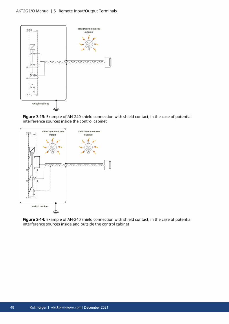
A shielding approach is described below that in many cases improves the measurement quality.The suggested measures must be checked for feasibility and effectiveness in the actual plant.
l Apply the shield with a low resistance and enveloping the cable by 360°l at the entry point into the control cabinet, the shield should be earthed conductivelyl the shield should be earthed again at the terminal
l at the terminal connection point, if presentl if no terminal connection point is available, earth the shield as close to the terminal as
possible.l to avoid ground loops the shield can be undone after entry into the control cabinet. A
capacitive connection to the terminal shield contact is possible.l avoid unshielded cable lengths of > 50 cm!
AKT2G I/O Manual | 5 Remote Input/Output Terminals
Kollmorgen | kdn.kollmorgen.com | December 2021 47
AKT2G I/O Manual | 5 Remote Input/Output Terminals
Figure 3-13: Example of AN-240 shield connection with shield contact, in the case of potentialinterference sources inside the control cabinet
Figure 3-14: Example of AN-240 shield connection with shield contact, in the case of potentialinterference sources inside and outside the control cabinet
48 Kollmorgen | kdn.kollmorgen.com | December 2021
5.2.5 Settings and Application Notes for AN-240
5.2.5.1 Default setting
The AKT2G-AN-240 can be used for direct temperature or resistance measurements. Thecorresponding CoE settings are shown in the following table.The relationship between temperature and resistance of a Pt100/Pt1000 sensor is shown below:
Temperature typical resistance, approx.
850°C Pt1000: 3.9 kΩ
Pt100: 390 Ω
320°C Pt1000: 2.2 kΩ
Pt100: 220 Ω
-200°C Pt1000: 180 Ω
Pt100: 18 Ω
Characteristic sensor curves are available from the sensor manufacturers.
AKT2G-AN-240
Default/factorysetting
l 2-wire connectionl Pt100 (CoE 0x80n0:19)l Presentation signed (CoE 0x80n0:02)l Limits disabledl 50 Hz filter enabledl All channels enabled
Area ofapplication
The terminal is calibrated in the measuring range “1/16 Ω” (10 Ω to 4 kΩ) and can beused in this resistance range.
5.2.5.2 Notice regarding Resistance Measurement mode
In Resistance Measurement mode the measured value is always displayed unsigned, irrespective ofthe Presentation setting (object 0x80n0:02), as 0..xFFFF with the respective value.1/16 Ω -> ~62 mΩ/Digit1/64 Ω -> ~15 mΩ/Digit
AKT2G I/O Manual | 5 Remote Input/Output Terminals
Kollmorgen | kdn.kollmorgen.com | December 2021 49
AKT2G I/O Manual | 5 Remote Input/Output Terminals
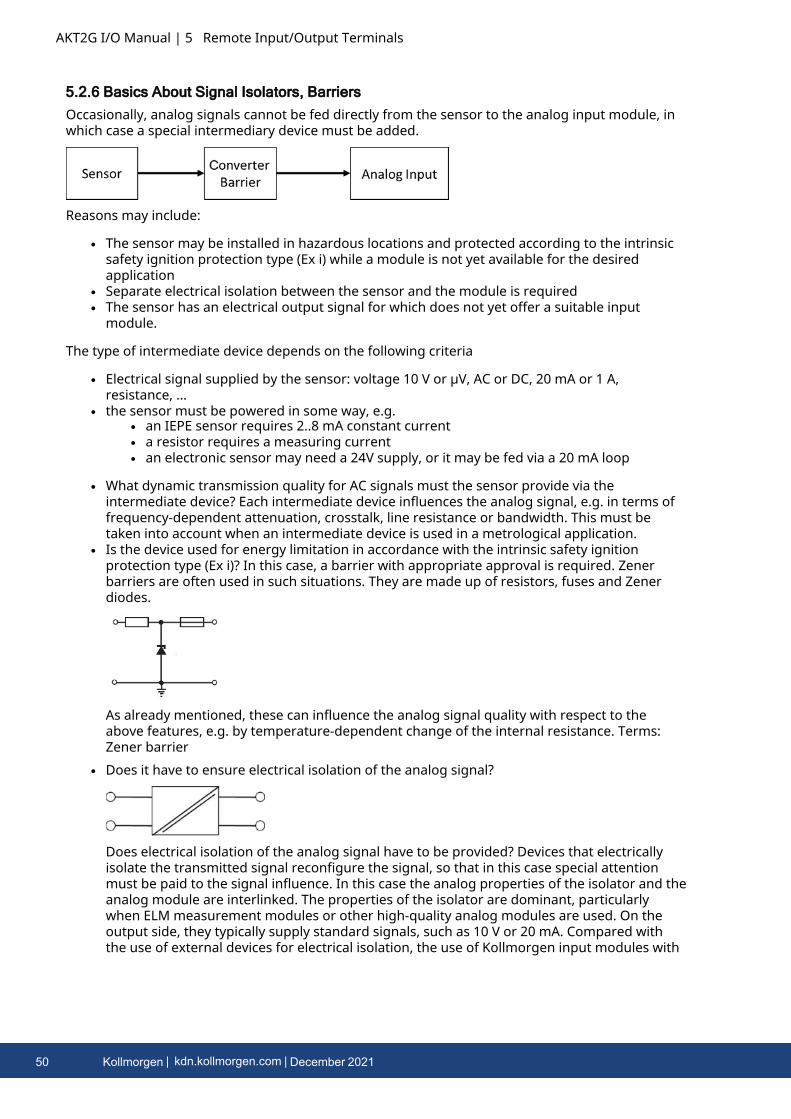
5.2.6 Basics About Signal Isolators, BarriersOccasionally, analog signals cannot be fed directly from the sensor to the analog input module, inwhich case a special intermediary device must be added.
Reasons may include:
l The sensor may be installed in hazardous locations and protected according to the intrinsicsafety ignition protection type (Ex i) while a module is not yet available for the desiredapplication
l Separate electrical isolation between the sensor and the module is requiredl The sensor has an electrical output signal for which does not yet offer a suitable input
module.
The type of intermediate device depends on the following criteria
l Electrical signal supplied by the sensor: voltage 10 V or µV, AC or DC, 20 mA or 1 A,resistance, …
l the sensor must be powered in some way, e.g.l an IEPE sensor requires 2..8 mA constant currentl a resistor requires a measuring currentl an electronic sensor may need a 24V supply, or it may be fed via a 20 mA loop
l What dynamic transmission quality for AC signals must the sensor provide via theintermediate device? Each intermediate device influences the analog signal, e.g. in terms offrequency-dependent attenuation, crosstalk, line resistance or bandwidth. This must betaken into account when an intermediate device is used in a metrological application.
l Is the device used for energy limitation in accordance with the intrinsic safety ignitionprotection type (Ex i)? In this case, a barrier with appropriate approval is required. Zenerbarriers are often used in such situations. They are made up of resistors, fuses and Zenerdiodes.
As already mentioned, these can influence the analog signal quality with respect to theabove features, e.g. by temperature-dependent change of the internal resistance. Terms:Zener barrier
l Does it have to ensure electrical isolation of the analog signal?
Does electrical isolation of the analog signal have to be provided? Devices that electricallyisolate the transmitted signal reconfigure the signal, so that in this case special attentionmust be paid to the signal influence. In this case the analog properties of the isolator and theanalog module are interlinked. The properties of the isolator are dominant, particularlywhen ELM measurement modules or other high-quality analog modules are used. On theoutput side, they typically supply standard signals, such as 10 V or 20 mA. Compared withthe use of external devices for electrical isolation, the use of Kollmorgen input modules with
50 Kollmorgen | kdn.kollmorgen.com | December 2021

channel-based electrical isolation is advantageous. Terms: signal isolator, signal converter,signal transducer, isolating amplifier, measuring amplifier, level transducer
l Are both measures, i.e. explosion protection according to ignition protection type Ex i andelectrical isolation necessary? In this case, so-called isolation barriers are used, which ensureenergy limitation for intrinsic safety and also electrical isolation of the signal. Please refer tothe notes on analog signal influence referred to above.
From a metrological point of view, signal-influencing intermediate devices should be avoided ifpossible.
AKT2G I/O Manual | 5 Remote Input/Output Terminals
Kollmorgen | kdn.kollmorgen.com | December 2021 51
AKT2G I/O Manual | 5 Remote Input/Output Terminals
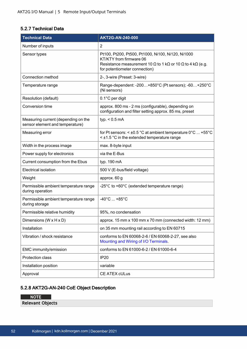
5.2.7 Technical Data
Technical Data AKT2G-AN-240-000
Number of inputs 2
Sensor types Pt100, Pt200, Pt500, Pt1000, Ni100, Ni120, Ni1000KT/KTY from firmware 06Resistance measurement 10 Ω to 1 kΩ or 10 Ω to 4 kΩ (e.g.for potentiometer connection)
Connection method 2-, 3-wire (Preset: 3-wire)
Temperature range Range-dependent: -200…+850°C (Pt sensors); -60…+250°C(Ni sensors)
Resolution (default) 0.1°C per digit
Conversion time approx. 800 ms - 2 ms (configurable), depending onconfiguration and filter setting approx. 85 ms, preset
Measuring current (depending on thesensor element and temperature)
typ. < 0.5 mA
Measuring error for Pt sensors: < ±0.5 °C at ambient temperature 0°C ... +55°C< ±1.5 °C in the extended temperature range
Width in the process image max. 8-byte input
Power supply for electronics via the E-Bus
Current consumption from the Ebus typ. 190 mA
Electrical isolation 500 V (E-bus/field voltage)
Weight approx. 60 g
Permissible ambient temperature rangeduring operation
-25℃ to +60℃ (extended temperature range)
Permissible ambient temperature rangeduring storage
-40°C ... +85°C
Permissible relative humidity 95%, no condensation
Dimensions (W x H x D) approx. 15 mm x 100 mm x 70 mm (connected width: 12 mm)
Installation on 35 mmmounting rail according to EN 60715
Vibration / shock resistance conforms to EN 60068-2-6 / EN 60068-2-27, see alsoMounting andWiring of I/O Terminals.
EMC immunity/emission conforms to EN 61000-6-2 / EN 61000-6-4
Protection class IP20
Installation position variable
Approval CE ATEX cULus
5.2.8 AKT2G-AN-240 CoE Object Description
Relevant Objects
52 Kollmorgen | kdn.kollmorgen.com | December 2021
The object description refers to the analog input terminals for Pt100 (RTD) in 1 to 8 channelversions. Observe the indices with regard to the objects relevant for the respective terminal(channel dependent).
5.2.8.1 Introduction
The CoE overview contains objects for different intended applications:
l Objects required for parameterization and profile-specific objects required duringcommissioning
l Objects for indicating internal settings (may be fixed)
The following section first describes the objects required for normal operation, followed by acomplete overview of missing objects.
5.2.8.2 Objects for Commissioning
Index(hex)
Name Meaning Datatype
Flags Default value
1011:0 Restoredefaultparameters
Restore default parameters UINT8 RO 0x01 (1dec)
1011:01 SubIndex001
If this object is set to "0x64616F6C" inthe set value dialog, all backup objectsare reset to their delivery state.
UINT32 RW 0x00000000(0dec)
Index 1011 Restore default parameters
Index(hex)
Name Meaning Data type Flags Default value
80n0:0 RTD Settings Maximum subindex UINT8 RO 0x1B (27dec)
80n0:01 Enable userscale
User scale is active. BOOLEAN RW 0x00 (0dec)
80n0:02 Presentation 0: Signed presentation
1: Absolute value with MSB assign Signed amountrepresentation
2: High resolution (1/100 C°)[default for
BIT3 RW 0x00 (0dec)
80n0:05 Siemens bits The S5 bits are superimposed onthe three low-order bits(value60n0:11)
Bit 0 = 1 (“overrange” or“underrange”)
Bit 1 (not used)
Bit 2 (not used)
BOOLEAN RW 0x00 (0dec)
80n0:06* Enable filter Enable filter, which makes PLC-cycle-synchronous data exchangeunnecessary
BOOLEAN RW 0x00 (0dec)
Index 80n0 RTD settings for 0 ≤n ≤7 (Ch. 1 - 8)
AKT2G I/O Manual | 5 Remote Input/Output Terminals
Kollmorgen | kdn.kollmorgen.com | December 2021 53
AKT2G I/O Manual | 5 Remote Input/Output Terminals
Index(hex)
Name Meaning Data type Flags Default value
80n0:07* Enable limit 1 The status bits are set in relation toLimit 1
BOOLEAN RW 0x00 (0dec)
80n0:08* Enable limit 2 The status bits are set in relation toLimit 2
BOOLEAN RW 0x00 (0dec)
8010:09* Enableautomaticcalibration
A calibration is cyclically started.(optional)
BOOLEAN RW 0x00 (0dec)
80n0:0A Enable usercalibration
Enabling of the user calibration BOOLEAN RW 0x00 (0dec)
80n0:0B Enable vendorcalibration
Enabling of the vendor calibration BOOLEAN RW 0x01 (1dec)
80n0:11 User scaleoffset
User scaling offset INT16 RW 0x0000(0dec)
80n0:12 User scalegain
This is the user scaling gain.
The gain is represented in fixed-point format, with the factor 2-16.
The value 1 corresponds to 65535(0x00010000).
INT32 RW 0x00010000
(65536dec)
80n0:13* Limit 1 First limit value for setting thestatus bits (resolution
0.1 °C)
INT16 RW 0x0000(0dec)
80n0:14* Limit 2 Second limit value for setting thestatus bits (resolution 0.1 °C)
INT16 RW 0x0000(0dec)
80n0:15 Filter settings This object determines the digitalfilter settings, if it is active viaEnable filter (index 0x80n0:06).
The possible settings aresequentially numbered.
0. 50 Hz1. 60 Hz2. 100 Hz3. 500 Hz4. 1 kHz5. 2 kHz6. 3.75 kHz7. 7.5 kHz8. 15 kHz9. 30 kHz
10. 5 Hz11. 10 Hz
UINT16 RW 0x0000(0dec)
80n0:17 Usercalibrationoffset
User offset calibration INT16 RW 0x0000(0dec)
54 Kollmorgen | kdn.kollmorgen.com | December 2021
Index(hex)
Name Meaning Data type Flags Default value
80n0:18 Usercalibrationgain
User gain compensation UINT16 RW 0xFFFF(65535dec)
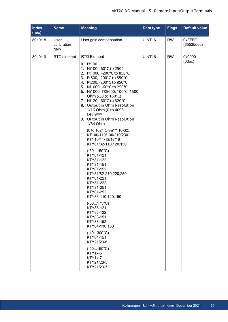
80n0:19 RTD element RTD Element
0. Pt1001. Ni100, -60°C to 250°2. Pt1000, -200°C to 850°C3. Pt500, -200°C to 850°C4. Pt200, -200°C to 850°C5. Ni1000, -60°C to 250°C6. Ni1000, TK5000, 100°C: 1500
Ohm (-30 to 160°C)7. Ni120, -60°C to 320°C8. Output in Ohm Resolution
1/16 Ohm (0 to 4096Ohm***
9. Output in Ohm Resolution1/64 Ohm(0 to 1024 Ohm*** 10-32:KT100/110/130/210/230KTY10/11/13/16/19KTY81/82-110,120,150
(-50...150°C)KTY81-121KTY81-122KTY81-151KTY81-152KTY81/82-210,220,250KTY81-221KTY81-222KTY81-251KTY81-252KTY83-110,120,150
(-50...175°C)KTY83-121KTY83-122KTY83-151KTY83-152KTY84-130,150
(-40...300°C)KTY84-151KTY21/23-6
(-50...150°C)KTY1x-5KTY1x-7KTY21/23-5KTY21/23-7
UINT16 RW 0x0000(0dec)
AKT2G I/O Manual | 5 Remote Input/Output Terminals
Kollmorgen | kdn.kollmorgen.com | December 2021 55
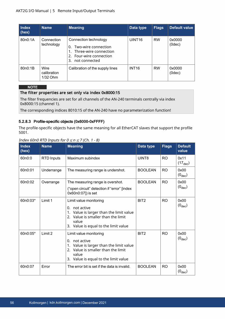
AKT2G I/O Manual | 5 Remote Input/Output Terminals
Index(hex)
Name Meaning Data type Flags Default value
80n0:1A Connectiontechnology
Connection technology
0. Two-wire connection1. Three-wire connection2. Four-wire connection3. not connected
UINT16 RW 0x0000(0dec)
80n0:1B Wirecalibration1/32 Ohm
Calibration of the supply lines INT16 RW 0x0000(0dec)
The filter properties are set only via index 0x8000:15The filter frequencies are set for all channels of the AN-240 terminals centrally via index0x8000:15 (channel 1).The corresponding indices 8010:15 of the AN-240 have no parameterization function!
5.2.8.3 Profile-specific objects (0x6000-0xFFFF)
The profile-specific objects have the same meaning for all EtherCAT slaves that support the profile5001.
Index(hex)
Name Meaning Data type Flags Defaultvalue
60n0:0 RTD Inputs Maximum subindex UINT8 RO 0x11(17dec)
60n0:01 Underrange The measuring range is undershot. BOOLEAN RO 0x00(0dec)
60n0:02 Overrange The measuring range is overshot.
(“open circuit” detection if “error” [index0x60n0:07]) is set
BOOLEAN RO 0x00(0dec)
60n0:03* Limit 1 Limit value monitoring
0. not active1. Value is larger than the limit value2. Value is smaller than the limit
value3. Value is equal to the limit value
BIT2 RO 0x00(0dec)
60n0:05* Limit 2 Limit value monitoring
0. not active1. Value is larger than the limit value2. Value is smaller than the limit
value3. Value is equal to the limit value
BIT2 RO 0x00(0dec)
60n0:07 Error The error bit is set if the data is invalid. BOOLEAN RO 0x00(0dec)
Index 60n0 RTD Inputs for 0 ≤n ≤7 (Ch. 1 - 8)
56 Kollmorgen | kdn.kollmorgen.com | December 2021

Index(hex)
Name Meaning Data type Flags Defaultvalue
60n0:0F TxPDO State Validity of the data of the associatedTxPDO (0 = valid, 1 = invalid).
BOOLEAN RO 0x00(0dec)
60n0:10 TxPDOToggle
The TxPDO toggle is toggled by theslave when the data of the associatedTxPDO is updated.
BOOLEAN RO 0x00(0dec)
60n0:11 Value The analog input data INT16 RO 0x00(0dec)
AKT2G I/O Manual | 5 Remote Input/Output Terminals
Kollmorgen | kdn.kollmorgen.com | December 2021 57
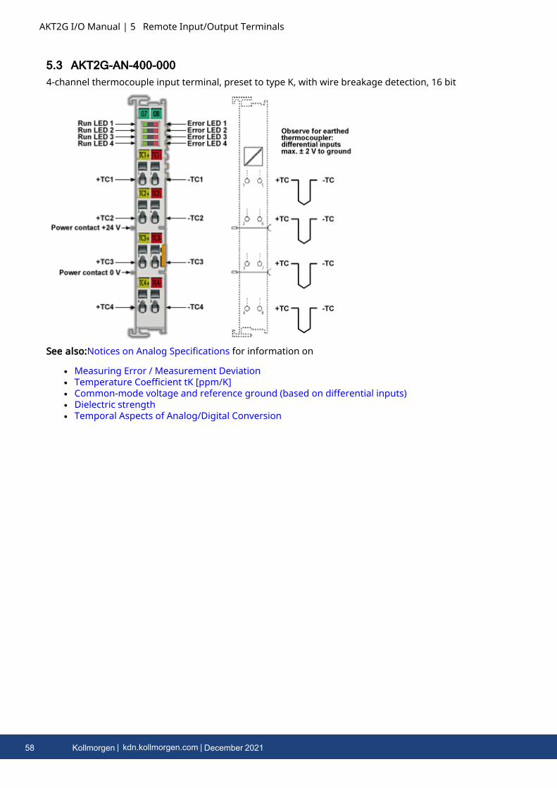
AKT2G I/O Manual | 5 Remote Input/Output Terminals
5.3 AKT2G-AN-400-0004-channel thermocouple input terminal, preset to type K, with wire breakage detection, 16 bit
See also:Notices on Analog Specifications for information on
l Measuring Error / Measurement Deviationl Temperature Coefficient tK [ppm/K]l Common-mode voltage and reference ground (based on differential inputs)l Dielectric strengthl Temporal Aspects of Analog/Digital Conversion
58 Kollmorgen | kdn.kollmorgen.com | December 2021
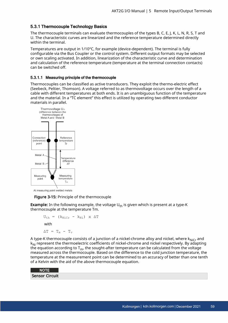
5.3.1 Thermocouple Technology BasicsThe thermocouple terminals can evaluate thermocouples of the types B, C, E, J, K, L, N, R, S, T andU. The characteristic curves are linearized and the reference temperature determined directlywithin the terminal.Temperatures are output in 1/10°C, for example (device-dependent). The terminal is fullyconfigurable via the Bus Coupler or the control system. Different output formats may be selectedor own scaling activated. In addition, linearization of the characteristic curve and determinationand calculation of the reference temperature (temperature at the terminal connection contacts)can be switched off.
5.3.1.1 Measuring principle of the thermocouple
Thermocouples can be classified as active transducers. They exploit the thermo-electric effect(Seebeck, Peltier, Thomson). A voltage referred to as thermovoltage occurs over the length of acable with different temperatures at both ends. It is an unambiguous function of the temperatureand the material. In a “TC element” this effect is utilized by operating two different conductormaterials in parallel.
Figure 3-15: Principle of the thermocouple
Example: In the following example, the voltage Uth is given which is present at a type-Kthermocouple at the temperature Tm.
Uth = (kNiCr - kNi) x ΔT
with
ΔT = Tm - Tv
A type-K thermocouple consists of a junction of a nickel-chrome alloy and nickel, where kNiCr andkNi represent the thermoelectric coefficients of nickel-chrome and nickel respectively. By adaptingthe equation according to Tm, the sought-after temperature can be calculated from the voltagemeasured across the thermocouple. Based on the difference to the cold junction temperature, thetemperature at the measurement point can be determined to an accuracy of better than one tenthof a Kelvin with the aid of the above thermocouple equation.
Sensor Circuit
AKT2G I/O Manual | 5 Remote Input/Output Terminals
Kollmorgen | kdn.kollmorgen.com | December 2021 59
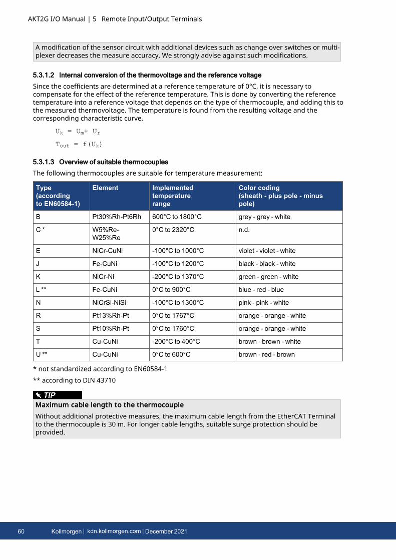
AKT2G I/O Manual | 5 Remote Input/Output Terminals
A modification of the sensor circuit with additional devices such as change over switches or multi-plexer decreases the measure accuracy. We strongly advise against such modifications.
5.3.1.2 Internal conversion of the thermovoltage and the reference voltage
Since the coefficients are determined at a reference temperature of 0°C, it is necessary tocompensate for the effect of the reference temperature. This is done by converting the referencetemperature into a reference voltage that depends on the type of thermocouple, and adding this tothe measured thermovoltage. The temperature is found from the resulting voltage and thecorresponding characteristic curve.
Uk = Um+ Ur
Tout = f(Uk)
5.3.1.3 Overview of suitable thermocouples
The following thermocouples are suitable for temperature measurement:
Type(accordingto EN60584-1)
Element Implementedtemperaturerange
Color coding(sheath - plus pole - minuspole)
B Pt30%Rh-Pt6Rh 600°C to 1800°C grey - grey - white
C * W5%Re-W25%Re
0°C to 2320°C n.d.
E NiCr-CuNi -100°C to 1000°C violet - violet - white
J Fe-CuNi -100°C to 1200°C black - black - white
K NiCr-Ni -200°C to 1370°C green - green - white
L ** Fe-CuNi 0°C to 900°C blue - red - blue
N NiCrSi-NiSi -100°C to 1300°C pink - pink - white
R Pt13%Rh-Pt 0°C to 1767°C orange - orange - white
S Pt10%Rh-Pt 0°C to 1760°C orange - orange - white
T Cu-CuNi -200°C to 400°C brown - brown - white
U ** Cu-CuNi 0°C to 600°C brown - red - brown
* not standardized according to EN60584-1** according to DIN 43710
Maximum cable length to the thermocoupleWithout additional protective measures, the maximum cable length from the EtherCAT Terminalto the thermocouple is 30 m. For longer cable lengths, suitable surge protection should beprovided.
60 Kollmorgen | kdn.kollmorgen.com | December 2021
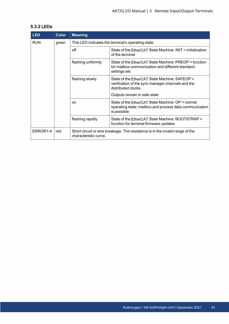
5.3.2 LEDs
LED Color Meaning
RUN green This LED indicates the terminal's operating state:
off State of the EtherCAT State Machine: INIT = initializationof the terminal
flashing uniformly State of the EtherCAT State Machine: PREOP = functionfor mailbox communication and different standard-settings set
flashing slowly State of the EtherCAT State Machine: SAFEOP =verification of the sync manager channels and thedistributed clocks.
Outputs remain in safe state
on State of the EtherCAT State Machine: OP = normaloperating state; mailbox and process data communicationis possible
flashing rapidly State of the EtherCAT State Machine: BOOTSTRAP =function for terminal firmware updates
ERROR1-4 red Short circuit or wire breakage. The resistance is in the invalid range of thecharacteristic curve.
AKT2G I/O Manual | 5 Remote Input/Output Terminals
Kollmorgen | kdn.kollmorgen.com | December 2021 61
AKT2G I/O Manual | 5 Remote Input/Output Terminals
5.3.3 Connection Instructions for Earthed/Potential-Free ThermocouplesDue to the differential inputs of the terminals, different connection types are recommendeddepending on the type of thermocouple used. For earthed thermocouples, ground is notconnected to the shielding. If the thermocouple does not have a ground connection, the groundand shielding contacts can be connected (see 5.3 AKT2G-AN-400-000).
Connection instructions for thermocouplesl Earthed thermocouple
l Do not connect GND to the shielding
l Potential-free / earth-free thermocouplel GND can be connected to the shieldingl or: GND can connected to any potential, max. 35 V to 0 V power
l Non-potential-free thermocouplel Do not connect GND to the shieldingl Do not connect GND to thermocouple potential.l Thermocouple-potential max. 35 V to 0 V power
l Unused inputsl Unused inputs should be short-circuited (low-resistance connection of +TC, -TC)
5.3.3.1 Shielding Measures
Shielding MeasuresDue to the complexity in the "EMC" area, there is no generally applicable guideline, but onlytechnical measures in accordance with the state of the art, which can sometimes contradict eachother. These must be checked for feasibility and effectiveness, taking into account the plantspecifications, and applied by the plant installer following assessment.The following notes on shielding are to be understood as technical suggestions that have proventhemselves from time to time in practical use. It must be checked in each case which measurescan be applied, depending on the installation and plant. The effectiveness of each measure mustbe checked individually. The formal transferability of measures to other types of plant is ingeneral not possible.Priority is to be given to typical national or general normative specifications.
A shielding approach is described below that in many cases improves the measurement quality.The suggested measures must be checked for feasibility and effectiveness in the actual plant.
l Apply the shield with a low resistance and enveloping the cable by 360°l at the entry point into the control cabinet, the shield should be earthed conductivelyl the shield should be earthed again at the terminal
l at the terminal connection point, if presentl if no terminal connection point is available, earth the shield as close to the terminal as
possible.l to avoid ground loops the shield can be undone after entry into the control cabinet. A
capacitive connection to the terminal shield contact is possible.l avoid unshielded cable lengths of > 50 cm!
62 Kollmorgen | kdn.kollmorgen.com | December 2021
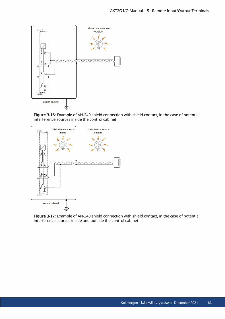
Figure 3-16: Example of AN-240 shield connection with shield contact, in the case of potentialinterference sources inside the control cabinet
Figure 3-17: Example of AN-240 shield connection with shield contact, in the case of potentialinterference sources inside and outside the control cabinet
AKT2G I/O Manual | 5 Remote Input/Output Terminals
Kollmorgen | kdn.kollmorgen.com | December 2021 63
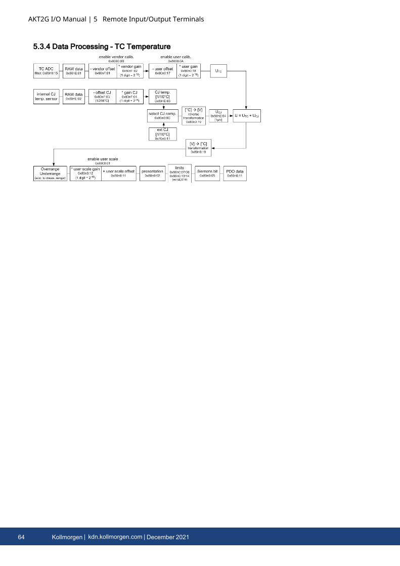
AKT2G I/O Manual | 5 Remote Input/Output Terminals
5.3.4 Data Processing - TC Temperature
64 Kollmorgen | kdn.kollmorgen.com | December 2021
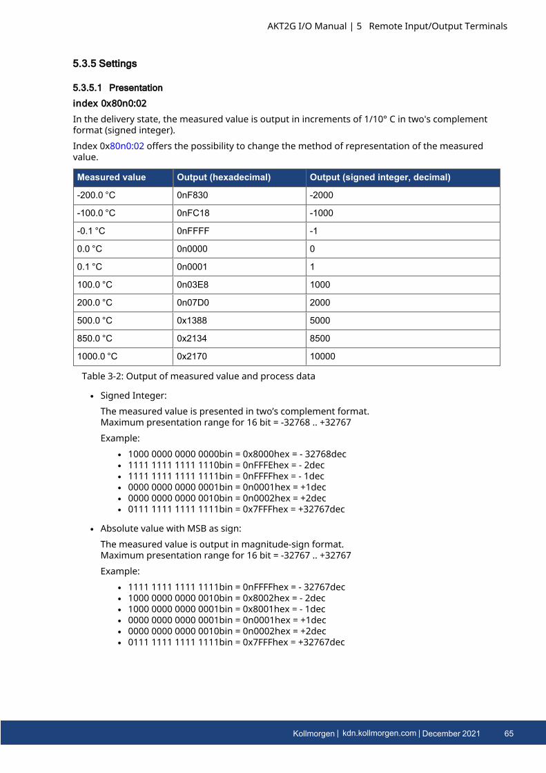
5.3.5 Settings
5.3.5.1 Presentation
index 0x80n0:02In the delivery state, the measured value is output in increments of 1/10° C in two's complementformat (signed integer).Index 0x80n0:02 offers the possibility to change the method of representation of the measuredvalue.
Measured value Output (hexadecimal) Output (signed integer, decimal)
-200.0 °C 0nF830 -2000
-100.0 °C 0nFC18 -1000
-0.1 °C 0nFFFF -1
0.0 °C 0n0000 0
0.1 °C 0n0001 1
100.0 °C 0n03E8 1000
200.0 °C 0n07D0 2000
500.0 °C 0x1388 5000
850.0 °C 0x2134 8500
1000.0 °C 0x2170 10000
Table 3-2: Output of measured value and process data
l Signed Integer:The measured value is presented in two’s complement format.Maximum presentation range for 16 bit = -32768 .. +32767Example:
l 1000 0000 0000 0000bin = 0x8000hex = - 32768decl 1111 1111 1111 1110bin = 0nFFFEhex = - 2decl 1111 1111 1111 1111bin = 0nFFFFhex = - 1decl 0000 0000 0000 0001bin = 0n0001hex = +1decl 0000 0000 0000 0010bin = 0n0002hex = +2decl 0111 1111 1111 1111bin = 0x7FFFhex = +32767dec
l Absolute value with MSB as sign:The measured value is output in magnitude-sign format.Maximum presentation range for 16 bit = -32767 .. +32767Example:
l 1111 1111 1111 1111bin = 0nFFFFhex = - 32767decl 1000 0000 0000 0010bin = 0x8002hex = - 2decl 1000 0000 0000 0001bin = 0x8001hex = - 1decl 0000 0000 0000 0001bin = 0n0001hex = +1decl 0000 0000 0000 0010bin = 0n0002hex = +2decl 0111 1111 1111 1111bin = 0x7FFFhex = +32767dec
AKT2G I/O Manual | 5 Remote Input/Output Terminals
Kollmorgen | kdn.kollmorgen.com | December 2021 65
AKT2G I/O Manual | 5 Remote Input/Output Terminals
l High resolution (1/100 C°):The measured value is output in 1/100 °C steps.
5.3.5.2 Siemens bits
index 0x80n0:05If the bit in index 0x80n0:05 is set, status displays are shown for the lowest 3 bits. In the error case"overrange" or "underrange", bit 0 is set.
5.3.5.3 Underrange, Overrange
Undershoot and overshoot of the measuring range (underrange, overrange), index 0x60n0:02,0x60n0:03
l Uk > Ukmax: Index 0x60n0:02 and index 0x60n0:07 (overrange and error bit) are set. Thelinearization of the characteristic curve is continued with the coefficients of the overrangelimit up to the limit stop of the A/D converter or to the maximum value of 0x7FFF.
l Uk < Ukmax: Index 0x60n0:01 and index 0x60n0:07 (underrange and error bit) are set. Thelinearization of the characteristic curve is continued with the coefficients of the underrangelimit up to the limit stop of the A/D converter or to the minimum value of 0x8000.
For overrange or underrange the red error LED is switched on.
5.3.5.4 Notch filter (conversion times)
5.3.5.4.1 Notch filter, index 0x80n0:06
The AN-400 terminals are equipped with a digital filter. The filter performs a notch filter functionand determines the conversion time of the terminal. It is parameterized via the indices 0x80n0:15.The higher the filter frequency, the faster the conversion time.
Index 0x80n0:06The filter function is always active even if the bit is not set, since this is obligatory for themeasurement process!
The filter characteristics are set via index 0x8000:15The filter frequencies are set for all channels of the AN-400 terminals centrally via index0x8000:15 (channel 1, see "80n0:15" on page 76). The corresponding indices 0x8010:15,0x8020:15, 0x8030:15 have no parameterization function.
Conversion timeThe conversion time is determined as follows:No. of active channels * no. of measurements * no. of filter periods + computing time =conversion time
Example: (2 channels), 3 measurements (thermocouple, wire breakage, cold junction), filter 50 Hz
2 channels * 3 measurements * (1/50 Hz) + 6 ms ≈ 126 ms
Example: (4 channels), 3 measurements (thermocouple, wire breakage, cold junction), filter 50 Hz
4 channels * 3 measurements * (1/50 Hz) + 12 ms ≈ 252 ms
66 Kollmorgen | kdn.kollmorgen.com | December 2021
Filter frequency AKT2G-AN-400
5 Hz 2.4 s
10 Hz 1.2 s
50 Hz 250 ms
60 Hz 210 ms
100 Hz 130 ms
500 Hz 33 ms
1000 Hz 24 ms
2000 Hz 20 ms
3750 Hz 19 ms
7500 Hz 19 ms
15000 Hz 19 ms
30000 Hz 19 ms
mV range 12 ms
Typical conversion times with 3 measurements (thermocouple, broken wire, cold junction)
Table 3-3: Conversion times in relation to the filter frequencies
5.3.5.5 Limit 1 and Limit 2
Limit 1 and limit 2, index 0x80n0:13, index 0x80n0:14A temperature range can be set that is limited by the values in the indices 0x80n0:13 and0x80n0:14. If the limit values are overshot, the bits in indices 0x80n0:07 and 0x80n0:08 are set.The temperature value is entered with a resolution of 0.1 °C.Example:Limit 1= 30 °CValue index 0x80n0:13 = 300
AKT2G I/O Manual | 5 Remote Input/Output Terminals
Kollmorgen | kdn.kollmorgen.com | December 2021 67
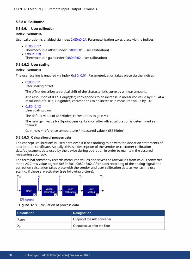
AKT2G I/O Manual | 5 Remote Input/Output Terminals
5.3.5.6 Calibration
5.3.5.6.1 User calibration
index 0x80n0:0AUser calibration is enabled via index 0x80n0:0A. Parameterization takes place via the indices
l 0x80n0:17Thermocouple offset (index 0x80nF:01, user calibration)
l 0x80n0:18Thermocouple gain (index 0x80nF:02, user calibration)
5.3.5.6.2 User scaling
index 0x80n0:01The user scaling is enabled via index 0x80n0:01. Parameterization takes place via the indices
l 0x80n0:11User scaling offsetThe offset describes a vertical shift of the characteristic curve by a linear amount.At a resolution of 0.1°, 1 digit(dec) corresponds to an increase in measured value by 0.1° At aresolution of 0.01°, 1 digit(dec) corresponds to an increase in measured value by 0.01
l 0x80n0:12User scaling gainThe default value of 65536(dec) corresponds to gain = 1.The new gain value for 2-point user calibration after offset calibration is determined asfollows:Gain_new = reference temperature / measured value x 65536(dec)
5.3.5.6.3 Calculation of process data
The concept "calibration" is used here even if it has nothing to do with the deviation statements ofa calibration certificate. Actually, this is a description of the vendor or customer calibrationdata/adjustment data used by the device during operation in order to maintain the assuredmeasuring accuracy.The terminal constantly records measured values and saves the raw values from its A/D converterin the ADC raw value objects 0x80nE:01, 0x80nE:02. After each recording of the analog signal, thecorrection calculation takes place with the vendor and user calibration data as well as the userscaling, if these are activated (see following picture).
Figure 3-18: Calculation of process data
Calculation Designation
XADC Output of the A/D converter
XF Output value after the filter
68 Kollmorgen | kdn.kollmorgen.com | December 2021
Calculation Designation
YH = (XADC – BH) x AH x 2-14 Measured value after vendor calibration,
YA = (YH – BA) x AA x 2-14 Measured value after vendor and user calibration
YS= YA x AS x 2-16 + BS Measured value following user scaling
Name Designation Index
XADC Output value of the A/D converter 0x80nE:01
XF Output value after the filter -
BH Vendor calibration offset (not changeable) 0x80nF:01
AH Vendor calibration gain (not changeable) 0x80nF:02
BA User calibration offset (can be activated via index 0x80n0:0A) 0x80n0:17
AA User calibration gain (can be activated via index 0x80n0:0A) 0x80n0:18
BS User scaling offset (can be activated via index 0x80n0:01) 0x80n0:11
AS User scaling gain (can be activated via index 0x80n0:01) 0x80n0:12
YS Process data for controller -
Legend for previous table
Measurement ResultThe accuracy of the result may be reduced if the measured value is smaller than 32767 / 4 due toone or more multiplications.
5.3.5.7 Producer Codeword
Producer CodewordThe vendor reserves the authority for the basic calibration of the terminals. The Producercodeword is therefore at present reserved.
AKT2G I/O Manual | 5 Remote Input/Output Terminals
Kollmorgen | kdn.kollmorgen.com | December 2021 69
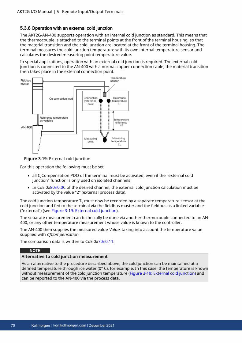
AKT2G I/O Manual | 5 Remote Input/Output Terminals
5.3.6 Operation with an external cold junctionThe AKT2G-AN-400 supports operation with an internal cold junction as standard. This means thatthe thermocouple is attached to the terminal points at the front of the terminal housing, so thatthe material transition and the cold junction are located at the front of the terminal housing. Theterminal measures the cold junction temperature with its own internal temperature sensor andcalculates the desired measuring point temperature value.In special applications, operation with an external cold junction is required. The external coldjunction is connected to the AN-400 with a normal copper connection cable, the material transitionthen takes place in the external connection point.
Figure 3-19: External cold junction
For this operation the following must be set
l all CJCompensation PDO of the terminal must be activated, even if the "external coldjunction" function is only used on isolated channels
l In CoE 0x80n0:0C of the desired channel, the external cold junction calculation must beactivated by the value "2" (external process data).
The cold junction temperature Tv must now be recorded by a separate temperature sensor at thecold junction and fed to the terminal via the fieldbus master and the fieldbus as a linked variable("external") (see Figure 3-19: External cold junction).The separate measurement can technically be done via another thermocouple connected to an AN-400, or any other temperature measurement whose value is known to the controller.The AN-400 then supplies the measured value Value, taking into account the temperature valuesupplied with CJCompensation:The comparison data is written to CoE 0x70n0:11.
Alternative to cold junction measurementAs an alternative to the procedure described above, the cold junction can be maintained at adefined temperature through ice water (0° C), for example. In this case, the temperature is knownwithout measurement of the cold junction temperature (Figure 3-19: External cold junction) andcan be reported to the AN-400 via the process data.
70 Kollmorgen | kdn.kollmorgen.com | December 2021
5.3.7 Interference From EquipmentWhen operating the AKT2G-AN-400 analog EtherCAT terminals, high frequency superimposedsignals from interfering devices (e.g. proportional valves, stepper motors or DC motor outputstages) can be picked up by the terminal. In order to guarantee interference-free operation, werecommend the use of separate power supply units for the terminals and the interference-causingdevices.
5.3.8 Wire Break DetectionThe AKT2G-AN-400 terminals provide a wire break detection of the connected thermocouple. Aperiodical testing current of several µA will be given to the thermocouple for detection. No voltagemeasurement takes place during test.Due to particular cases, the testing current could have a disturbing effect, the wire break detectioncan be disabled by CoE (object 0x80n0:0E, "Disable wire break detection") since following firmwareversions:
AKT2G-AN-400
Firmware 04
ESI / Revision 0023
AKT2G I/O Manual | 5 Remote Input/Output Terminals
Kollmorgen | kdn.kollmorgen.com | December 2021 71

AKT2G I/O Manual | 5 Remote Input/Output Terminals
5.3.9 Status WordThe status information for each channel of the AN-400 is transmitted cyclically from the terminal tothe EtherCAT Master as process data (PDO). Two versions of the device description are available forthe AN-400, representing the process image in individual and extended forms.The AN-400 transmits the following process data:
l Underrange: Measurement is below rangel Overrange: Range of measurement exceeded ("Cable break" together with "Error")l Limit 1: Limit value monitoring 0: ok, 1: Limit value overshot , 2: limit range undershotl Limit 2: Limit value monitoring 0: ok, 1: Limit value overshot , 2: limit range undershotl Error: The error bit is set if the process data is invalid (cable break, overrange, underrange)l TxPDO State: Validity of the data of the associated TxPDO (0 = valid, 1 = invalid).l TxPDO Toggle: The TxPDO toggle is toggled by the slave when the data of the associated
TxPDO isupdated. This allows the currently required conversion time to be derived.
The limit evaluation is set in the "8000" objects in the CoE directory.
72 Kollmorgen | kdn.kollmorgen.com | December 2021
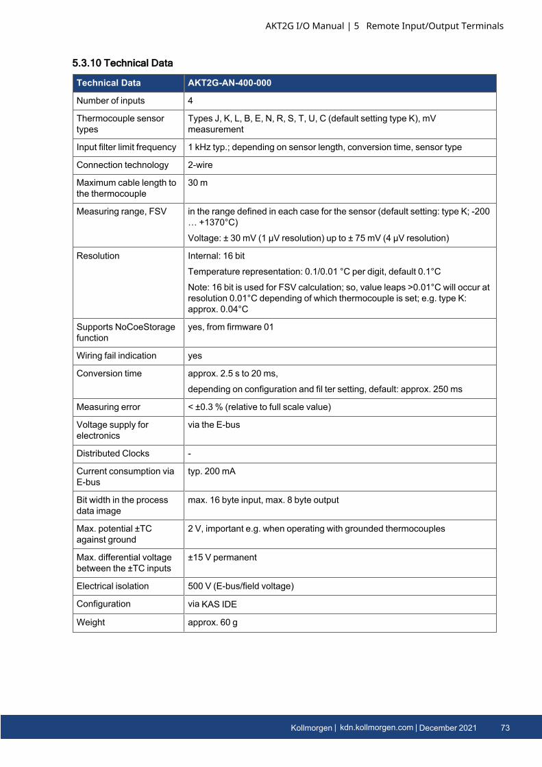
5.3.10 Technical Data
Technical Data AKT2G-AN-400-000
Number of inputs 4
Thermocouple sensortypes
Types J, K, L, B, E, N, R, S, T, U, C (default setting type K), mVmeasurement
Input filter limit frequency 1 kHz typ.; depending on sensor length, conversion time, sensor type
Connection technology 2-wire
Maximum cable length tothe thermocouple
30 m
Measuring range, FSV in the range defined in each case for the sensor (default setting: type K; -200… +1370°C)
Voltage: ± 30 mV (1 µV resolution) up to ± 75 mV (4 µV resolution)
Resolution Internal: 16 bit
Temperature representation: 0.1/0.01 °C per digit, default 0.1°C
Note: 16 bit is used for FSV calculation; so, value leaps >0.01°C will occur atresolution 0.01°C depending of which thermocouple is set; e.g. type K:approx. 0.04°C
Supports NoCoeStoragefunction
yes, from firmware 01
Wiring fail indication yes
Conversion time approx. 2.5 s to 20 ms,
depending on configuration and fil ter setting, default: approx. 250 ms
Measuring error < ±0.3 % (relative to full scale value)
Voltage supply forelectronics
via the E-bus
Distributed Clocks -
Current consumption viaE-bus
typ. 200 mA
Bit width in the processdata image
max. 16 byte input, max. 8 byte output
Max. potential ±TCagainst ground
2 V, important e.g. when operating with grounded thermocouples
Max. differential voltagebetween the ±TC inputs
±15 V permanent
Electrical isolation 500 V (E-bus/field voltage)
Configuration via KAS IDE
Weight approx. 60 g
AKT2G I/O Manual | 5 Remote Input/Output Terminals
Kollmorgen | kdn.kollmorgen.com | December 2021 73
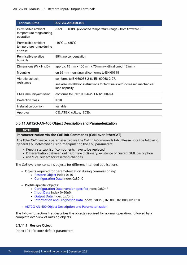
AKT2G I/O Manual | 5 Remote Input/Output Terminals
Technical Data AKT2G-AN-400-000
Permissible ambienttemperature range duringoperation
-25°C ... +60°C (extended temperature range), from firmware 06
Permissible ambienttemperature range duringstorage
-40°C ... +85°C
Permissible relativehumidity
95%, no condensation
Dimensions (W x H x D) approx. 15 mm x 100 mm x 70 mm (width aligned: 12 mm)
Mounting on 35 mmmounting rail conforms to EN 60715
Vibration/shockresistance
conforms to EN 60068-2-6 / EN 60068-2-27,
see also installation instructions for terminals with increased mechanicalload capacity
EMC immunity/emission conforms to EN 61000-6-2 / EN 61000-6-4
Protection class IP20
Installation position variable
Approval CE, ATEX, cULus, IECEx
5.3.11 AKT2G-AN-400 Object Description and Parameterization
Parameterization via the CoE Init-Commands (CAN over EtherCAT)The EtherCAT device is parameterized via the CoE Init-Commands tab . Please note the followinggeneral CoE notes when using/manipulating the CoE parameters:
l Keep a startup list if components have to be replacedl Differentiation between online/offline dictionary, existence of current XML descriptionl use “CoE reload” for resetting changes
The CoE overview contains objects for different intended applications:
l Objects required for parameterization during commissioning:l Restore Object index 0x1011l Configuration Data index 0x80n0
l Profile-specific objects:l Configuration Data (vendor-specific) index 0x80nFl Input Data index 0x60n0l Output Data index 0x70n0l Information and Diagnostic Data index 0x80nE, 0xF000, 0xF008, 0xF010
l AKT2G-AN-400 Object Description and Parameterization
The following section first describes the objects required for normal operation, followed by acomplete overview of missing objects.
5.3.11.1 Restore Object
Index 1011 Restore default parameters
74 Kollmorgen | kdn.kollmorgen.com | December 2021
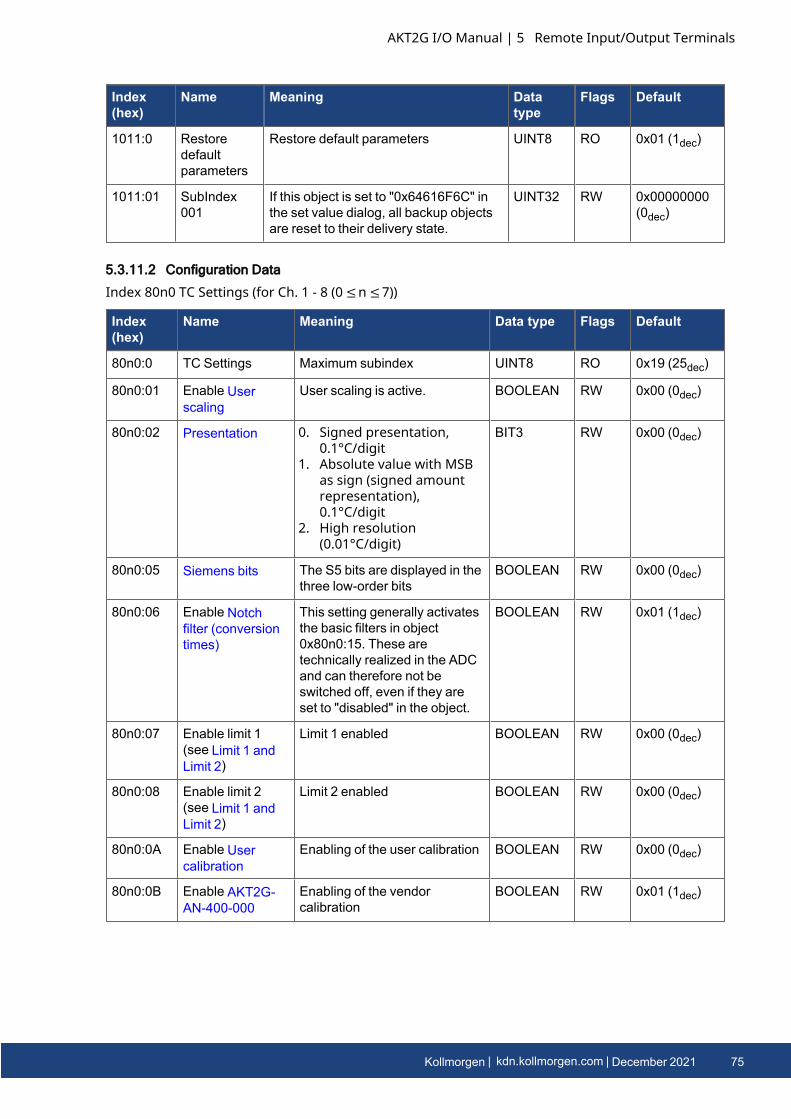
Index(hex)
Name Meaning Datatype
Flags Default
1011:0 Restoredefaultparameters
Restore default parameters UINT8 RO 0x01 (1dec)
1011:01 SubIndex001
If this object is set to "0x64616F6C" inthe set value dialog, all backup objectsare reset to their delivery state.
UINT32 RW 0x00000000(0dec)
5.3.11.2 Configuration Data
Index 80n0 TC Settings (for Ch. 1 - 8 (0 ≤n ≤7))
Index(hex)
Name Meaning Data type Flags Default
80n0:0 TC Settings Maximum subindex UINT8 RO 0x19 (25dec)
80n0:01 Enable Userscaling
User scaling is active. BOOLEAN RW 0x00 (0dec)
80n0:02 Presentation 0. Signed presentation,0.1°C/digit
1. Absolute value with MSBas sign (signed amountrepresentation),0.1°C/digit
2. High resolution(0.01°C/digit)
BIT3 RW 0x00 (0dec)
80n0:05 Siemens bits The S5 bits are displayed in thethree low-order bits
BOOLEAN RW 0x00 (0dec)
80n0:06 Enable Notchfilter (conversiontimes)
This setting generally activatesthe basic filters in object0x80n0:15. These aretechnically realized in the ADCand can therefore not beswitched off, even if they areset to "disabled" in the object.
BOOLEAN RW 0x01 (1dec)
80n0:07 Enable limit 1(see Limit 1 andLimit 2)
Limit 1 enabled BOOLEAN RW 0x00 (0dec)
80n0:08 Enable limit 2(see Limit 1 andLimit 2)
Limit 2 enabled BOOLEAN RW 0x00 (0dec)
80n0:0A Enable Usercalibration
Enabling of the user calibration BOOLEAN RW 0x00 (0dec)
80n0:0B Enable AKT2G-AN-400-000
Enabling of the vendorcalibration
BOOLEAN RW 0x01 (1dec)
AKT2G I/O Manual | 5 Remote Input/Output Terminals
Kollmorgen | kdn.kollmorgen.com | December 2021 75
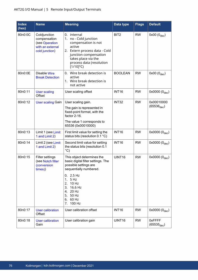
AKT2G I/O Manual | 5 Remote Input/Output Terminals
Index(hex)
Name Meaning Data type Flags Default
80n0:0C Coldjunctioncompensation(see Operationwith an externalcold junction)
0. internal1. no - Cold junction
compensation is notactive
2. Extern process data - Coldjunction compensationtakes place via theprocess data (resolution[1/10]°C)
BIT2 RW 0x00 (0dec)
80n0:0E Disable WireBreak Detection
0. Wire break detection isactive
1. Wire break detection isnot active
BOOLEAN RW 0x00 (0dec)
80n0:11 User scalingOffset
User scaling offset INT16 RW 0x0000 (0dec)
80n0:12 User scaling Gain User scaling gain.
The gain is represented infixed-point format, with thefactor 2-16.
The value 1 corresponds to65536 (0x00010000)
INT32 RW 0x00010000(65536dec)
80n0:13 Limit 1 (see Limit1 and Limit 2)
First limit value for setting thestatus bits (resolution 0.1 °C)
INT16 RW 0x0000 (0dec)
80n0:14 Limit 2 (see Limit1 and Limit 2)
Second limit value for settingthe status bits (resolution 0.1°C)
INT16 RW 0x0000 (0dec)
80n0:15 Filter settings(see Notch filter(conversiontimes))
This object determines thebasic digital filter settings. Thepossible settings aresequentially numbered.
0. 2.5 Hz1. 5 Hz2. 10 Hz3. 16.6 Hz4. 20 Hz5. 50 Hz6. 60 Hz7. 100 Hz
UINT16 RW 0x0000 (0dec)
80n0:17 User calibrationOffset
User calibration offset INT16 RW 0x0000 (0dec)
80n0:18 User calibrationGain
User calibration gain UINT16 RW 0xFFFF(65535dec)
76 Kollmorgen | kdn.kollmorgen.com | December 2021
Index(hex)
Name Meaning Data type Flags Default
80n0:19 TC Element Thermocouple
Implemented temperaturerange
0. Type: K -200°C to 1370°C1. Type: J -100°C to 1200°C2. Type: L 0°C to 900°C3. Type: E -100°C to 1000°C4. Type: T -200°C to 400°C5. Type: N -100°C to 1300°C6. Type: U 0°C to 600°C7. Type: B 600°C to 1800°C8. Type: R 0°C to 1767°C9. Type: S 0°C to 1760°C
10. Type: C 0°C to 2320°C
100: ± 30 mV (1 µV resolution)
101: ± 60 mV (2 µV resolution)
102: ± 75 mV (4 µV resolution)
UINT16 RW 0x0000 (0dec)
5.3.11.3 Profile-specific objects
5.3.11.3.1 0x6000-0xFFFF
The profile-specific objects have the same meaning for all EtherCAT slaves that support the profile5001.
5.3.11.4 Configuration Data (vendor-specific)
Index 80nF TC Vendor data (for Ch. 1 - 8 (0 ≤n ≤7))
Index(hex)
Name Meaning Datatype
Flags Default
80nF:0 TC Vendor data Maximum subindex UINT8 RO 0x04 (4dec)
80nF:01 Calibrationoffset TC
Thermocouple offset (vendorcalibration)
INT166 RW 0x002D(45dec)
80nF:02 Calibration gainTC
Thermocouple gain (vendorcalibration)
UINT16 RW 0x5B9A(23450dec)
80nF:03 Calibrationoffset CJ
Cold junction offset [Pt1000] (vendorcalibration)
INT16 RW 0x01B8
(440dec)
80nF:04 Calibration gainCJ
Cold junction gain [Pt1000] (vendorcalibration)
UINT16 RW 0x39B2(14770dec)
5.3.11.5 Input Data
Index 60n0 TC Inputs (for Ch. 1 - 8 (0 ≤n ≤7))
AKT2G I/O Manual | 5 Remote Input/Output Terminals
Kollmorgen | kdn.kollmorgen.com | December 2021 77
AKT2G I/O Manual | 5 Remote Input/Output Terminals
Index(hex)
Name Meaning Data type Flags Default
60n0:0 TC Inputs Maximum subindex UINT8 RO 0x11(17dec)
60n0:01 Underrange Value below measuring range. BOOLEAN RO 0x00(0dec)
60n0:02 Overrange Measuring range exceeded.
("wire breakage" together with "error"[index 0x60n0:07])
BOOLEAN RO 0x00(0dec)
60n0:03 Limit 1 Limit value monitoring
0. not activated1. limit range exceeded 2: limit range
undershot
BIT2 RO 0x00(0dec)
60n0:05 Limit 2 Limit value monitoring
0. not activated1. limit range exceeded 2: limit range
undershot
BIT2 RO 0x00(0dec)
60n0:07 Error The error bit is set if the value is invalid(wire breakage, overrange, underrange).
BOOLEAN RO 0x00(0dec)
60n0:0F TxPDO State Validity of the data of the associatedTxPDO (0 = valid, 1 = invalid).
BOOLEAN RO 0x00(0dec)
60n0:10 TxPDOToggle
The TxPDO toggle is toggled by the slavewhen the data of the associated TxPDOis updated.
BOOLEAN RO 0x00(0dec)
60n0:11 Value Analog input value
(resolution: see Configuration Data index0x80n0:02)
INT16 RO 0x0000(0dec)
5.3.11.6 Output Data
Index 70n0 TC Outputs (for Ch. 1 - 8 (0 ≤n ≤7))
Index(hex)
Name Meaning Datatype
Flags Default
70n0:0 TC Outputs Maximum subindex UINT8 RO 0x11(17dec)
70n0:11 CJCompensation Temperature of the cold junction(resolution in 1/10 °C) (index0x80n0:0C, comparison via the processdata)
INT16 RO 0x0000(0dec)
5.3.11.7 Information and Diagnostic Data
Index 80nE TC Internal data (for Ch. 1 - 8 (0 ≤n ≤7))
78 Kollmorgen | kdn.kollmorgen.com | December 2021
Index(hex)
Name Meaning Datatype
Flags Default
80nE:0 TC Internaldata
Maximum subindex UINT8 RO 0x05(5dec)
80nE:01 ADC raw valueTC
ADC raw value thermocouple UINT32 RO 0x0000(0dec)
80nE:02 ADC raw valuePT1000
ADC raw value PT1000 UINT32 RO 0x0000(0dec)
80nE:03 CJtemperature
Cold junction temperature (resolution[1/10]°C)
INT16 RO 0x0000(0dec)
80nE:04 CJ voltage Cold junction voltage (resolution 1 µV) INT16 RO 0x0000(0dec)
80nE:05 CJ resistor Cold junction resistance (PT1000temperature sensor) (resolution 1/10 Ohm)
UINT16 RO 0x0000(0dec)
Index F000 Modular device profile
Index(hex)
Name Meaning Datatype
Flags Default
F000:0 Modular deviceprofile
General information for the modulardevice profile
UINT8 RO 0x02(2dec)
F000:01 Module indexdistance
Index spacing of the objects of theindividual channels
UINT16 RO 0x0010(16dec)
F000:02 Maximum numberof modules
Number of channels UINT16 RO 0x0004(4dec)
Index F008 Code word
Index (hex) Name Meaning Data type Flags Default
F008:0 Code word currently reserved UINT32 RW 0x0000 (0dec)
AKT2G I/O Manual | 5 Remote Input/Output Terminals
Kollmorgen | kdn.kollmorgen.com | December 2021 79
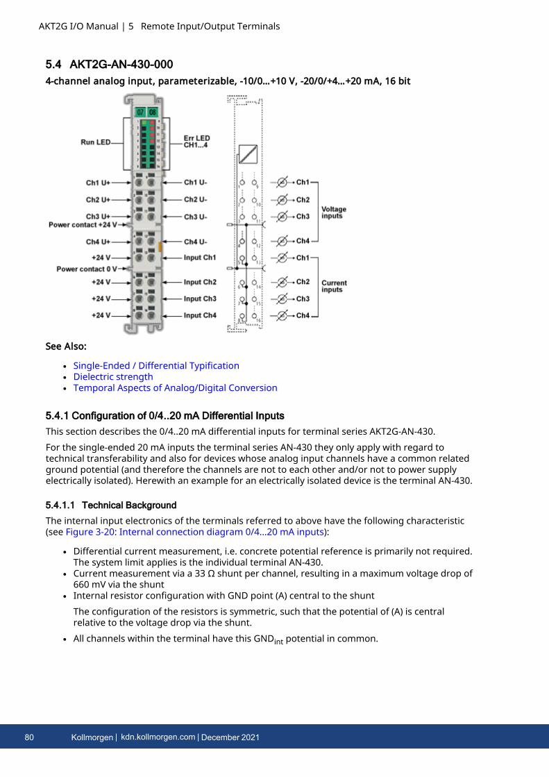
AKT2G I/O Manual | 5 Remote Input/Output Terminals
5.4 AKT2G-AN-430-0004-channel analog input, parameterizable, -10/0…+10 V, -20/0/+4…+20 mA, 16 bit
See Also:
l Single-Ended / Differential Typificationl Dielectric strengthl Temporal Aspects of Analog/Digital Conversion
5.4.1 Configuration of 0/4..20 mA Differential InputsThis section describes the 0/4..20 mA differential inputs for terminal series AKT2G-AN-430.For the single-ended 20 mA inputs the terminal series AN-430 they only apply with regard totechnical transferability and also for devices whose analog input channels have a common relatedground potential (and therefore the channels are not to each other and/or not to power supplyelectrically isolated). Herewith an example for an electrically isolated device is the terminal AN-430.
5.4.1.1 Technical Background
The internal input electronics of the terminals referred to above have the following characteristic(see Figure 3-20: Internal connection diagram 0/4...20 mA inputs):
l Differential current measurement, i.e. concrete potential reference is primarily not required.The system limit applies is the individual terminal AN-430.
l Current measurement via a 33 Ω shunt per channel, resulting in a maximum voltage drop of660 mV via the shunt
l Internal resistor configuration with GND point (A) central to the shuntThe configuration of the resistors is symmetric, such that the potential of (A) is centralrelative to the voltage drop via the shunt.
l All channels within the terminal have this GNDint potential in common.
80 Kollmorgen | kdn.kollmorgen.com | December 2021
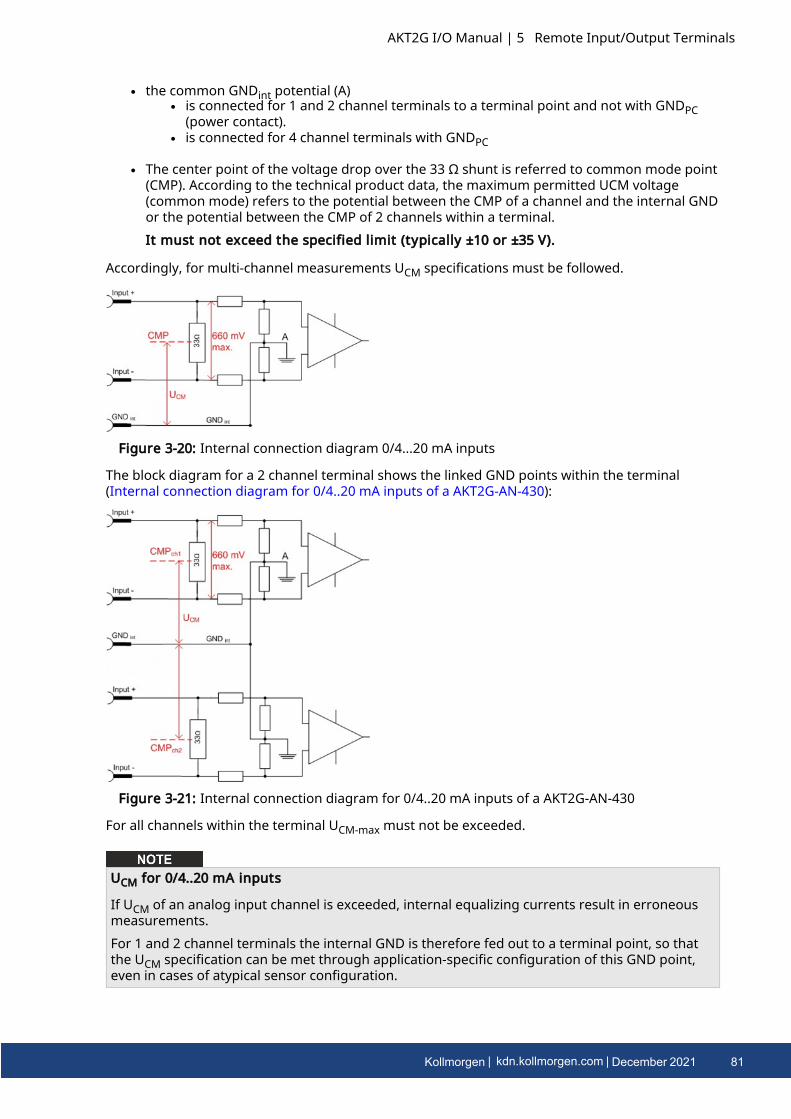
l the common GNDint potential (A)l is connected for 1 and 2 channel terminals to a terminal point and not with GNDPC
(power contact).l is connected for 4 channel terminals with GNDPC
l The center point of the voltage drop over the 33 Ω shunt is referred to common mode point(CMP). According to the technical product data, the maximum permitted UCM voltage(common mode) refers to the potential between the CMP of a channel and the internal GNDor the potential between the CMP of 2 channels within a terminal.It must not exceed the specified limit (typically ±10 or ±35 V).
Accordingly, for multi-channel measurements UCM specifications must be followed.
Figure 3-20: Internal connection diagram 0/4...20 mA inputs
The block diagram for a 2 channel terminal shows the linked GND points within the terminal(Internal connection diagram for 0/4..20 mA inputs of a AKT2G-AN-430):
Figure 3-21: Internal connection diagram for 0/4..20 mA inputs of a AKT2G-AN-430
For all channels within the terminal UCM-max must not be exceeded.
UCM for 0/4..20 mA inputs
If UCM of an analog input channel is exceeded, internal equalizing currents result in erroneousmeasurements.For 1 and 2 channel terminals the internal GND is therefore fed out to a terminal point, so thatthe UCM specification can be met through application-specific configuration of this GND point,even in cases of atypical sensor configuration.
AKT2G I/O Manual | 5 Remote Input/Output Terminals
Kollmorgen | kdn.kollmorgen.com | December 2021 81
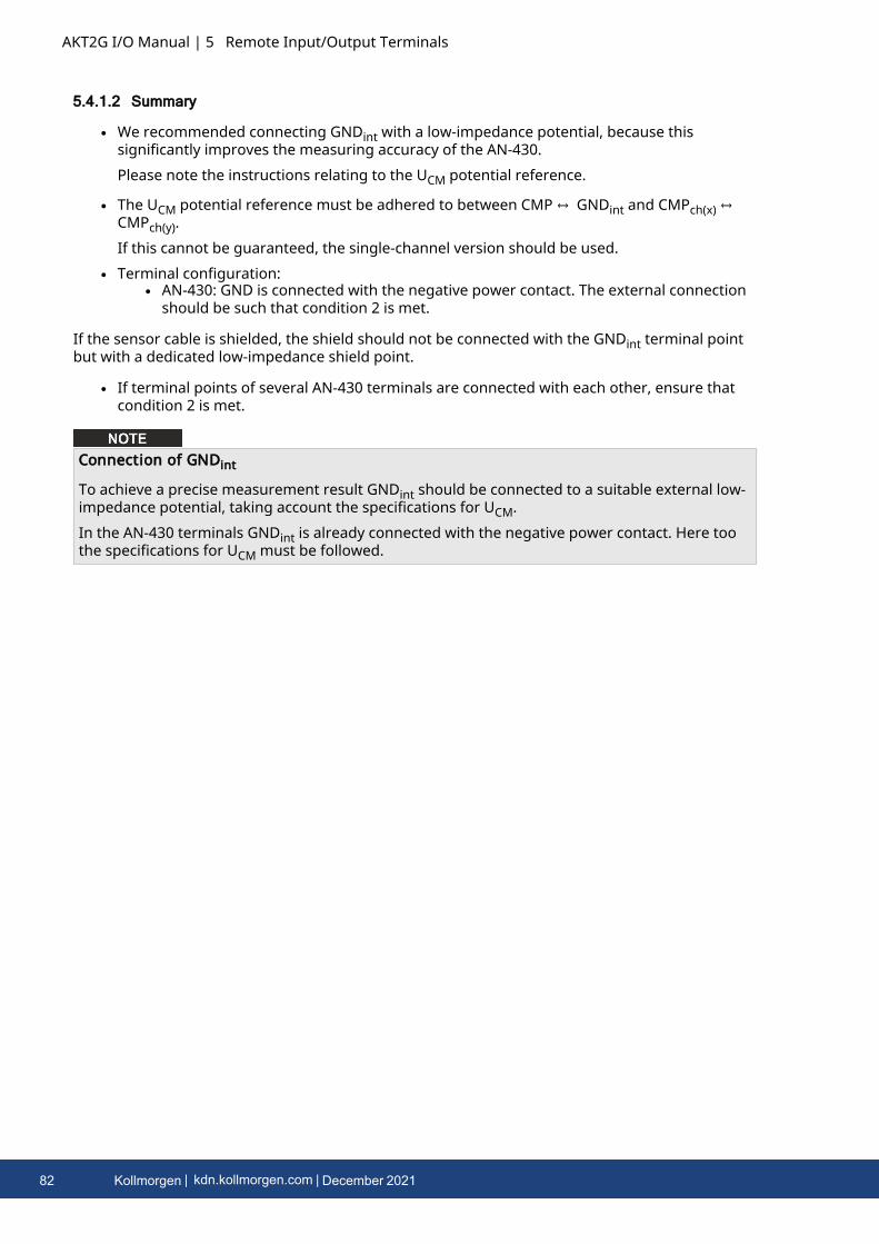
AKT2G I/O Manual | 5 Remote Input/Output Terminals
5.4.1.2 Summary
l We recommended connecting GNDint with a low-impedance potential, because thissignificantly improves the measuring accuracy of the AN-430.Please note the instructions relating to the UCM potential reference.
l The UCM potential reference must be adhered to between CMP ↔ GNDint and CMPch(x) ↔CMPch(y).If this cannot be guaranteed, the single-channel version should be used.
l Terminal configuration:l AN-430: GND is connected with the negative power contact. The external connection
should be such that condition 2 is met.
If the sensor cable is shielded, the shield should not be connected with the GNDint terminal pointbut with a dedicated low-impedance shield point.
l If terminal points of several AN-430 terminals are connected with each other, ensure thatcondition 2 is met.
Connection of GNDint
To achieve a precise measurement result GNDint should be connected to a suitable external low-impedance potential, taking account the specifications for UCM.In the AN-430 terminals GNDint is already connected with the negative power contact. Here toothe specifications for UCM must be followed.
82 Kollmorgen | kdn.kollmorgen.com | December 2021
5.4.2 CoE Object Description and Parameterization
5.4.2.1 Restore Object
Index(hex)
Name Meaning Datatype
Flags Default
1011:0 Restoredefaultparameters
Restore default parameters UINT8 RO 0x01 (1dec)
1011:01 SubIndex001
If this object is set to “0x64616F6C” inthe set value dialog, all backup objectsare reset to their delivery state.
UINT32 RW 0x00000000(0dec)
Index 1011 Restore default parameters
5.4.2.2 Configuration Data
Index(hex)
Name Meaning Data type Flags Default
80n0:0 AI Settings Maximum subindex UINT8 RO 0x18 (24dec)
80n0:01 Enable userscale
User scale is active. BOOLEAN RW 0x00 (0dec)
80n0:02 Presentation 0. Signed presentation1. Unsigned presentation2. Absolute value with MSB as
signSigned amountrepresentation
BIT3 RW 0x00 (0dec)
80n0:05 Siemens bits The S5 bits are displayed in thethree low-order bits
BOOLEAN RW 0x00 (0dec)
80n0:06 Enable filter Enable filter, which makes PLC-cycle-synchronous data exchangeunnecessary
BOOLEAN RW 0x00 (0dec)
80n0:07 Enable limit 1 Limit 1 enabled BOOLEAN RW 0x00 (0dec)
80n0:08 Enable limit 2 Limit 2 enabled BOOLEAN RW 0x00 (0dec)
80n0:0A Enable usercalibration
Enabling of the user calibration BOOLEAN RW 0x00 (0dec)
80n0:0B Enable vendorcalibration
Enabling of the vendor calibration BOOLEAN RW 0x01 (1dec)
80n0:0E Swap limit bits Changing of the Limit Bits BOOLEAN RW 0x00 (0dec)
80n0:11 User scaleoffset
User scaling offset INT16 RW 0x0000 (0dec)
Index 80n0*** AI settings (for 0 ≤n ≤3)
AKT2G I/O Manual | 5 Remote Input/Output Terminals
Kollmorgen | kdn.kollmorgen.com | December 2021 83
AKT2G I/O Manual | 5 Remote Input/Output Terminals
Index(hex)
Name Meaning Data type Flags Default
80n0:12 User scalegain
User scaling gain.
The gain is represented in fixed-point format, with the factor 2-16.
The value 1 corresponds to65536dec (0x00010000) and islimited to ±0x7FFFF
INT32 RW 0x00010000
(65536dec)
80n0:13 Limit 1 First limit value for setting thestatus bits
INT16 RW 0x0000 (0dec)
80n0:14 Limit 2 Second limit value for setting thestatus bits
INT16 RW 0x0000 (0dec)
80n0:15 Filter settings This object determines the digitalfilter settings, if it is active viaEnable filter (index 0x80n0:06).The possible settings aresequentially numbered.
0. 50 Hz FIR1. 60 Hz FIR2. IIR 13. IIR 24. IIR 35. IIR 46. IIR 57. IIR 68. IIR 79. IIR 8
UINT16 RW 0x0000 (0dec)
80n0:17 Usercalibrationoffset
User offset compensation INT16 RW 0x0000 (0dec)
80n0:18 Usercalibrationgain
User calibration gain INT16 RW 0x4000
(16384dec)
The filter characteristics are set via index 0x8000:15 (see "80n0:15" on page 84)The filter frequencies are set for all channels of the AN-430 terminals centrally via index0x8000:15 (channel 1). All other corresponding indices 0x80n0:15 have no parameterizationfunction!
Index(hex)
Name Meaning Datatype
Flags Default
80nD:0 AI AdvancedSettings
Maximum subindex UINT8 RO 0x12 (18dec)
Index 80nD AI Advanced settings (for 0 ≤n ≤3)
84 Kollmorgen | kdn.kollmorgen.com | December 2021
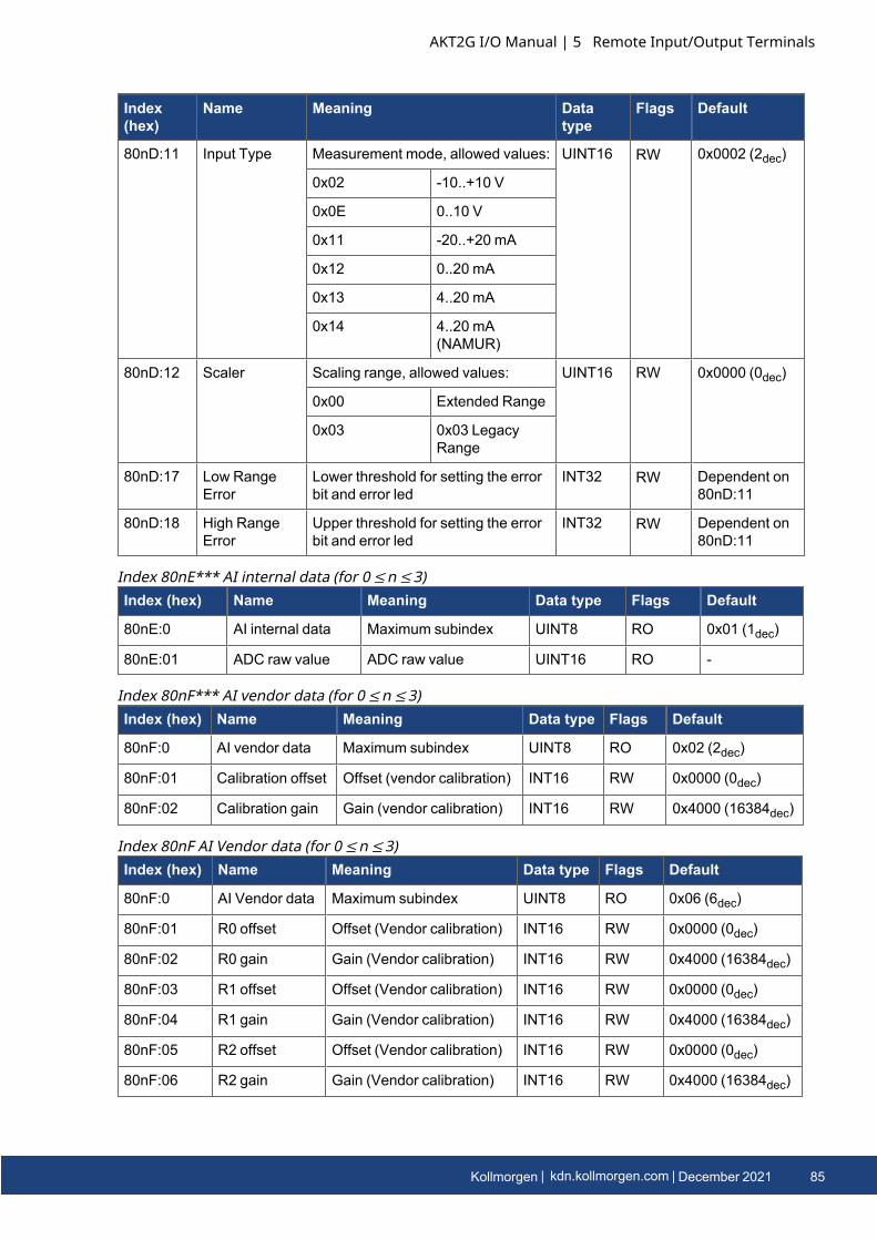
Index(hex)
Name Meaning Datatype
Flags Default
80nD:11 Input Type Measurement mode, allowed values: UINT16 RW 0x0002 (2dec)
0x02 -10..+10 V
0x0E 0..10 V
0x11 -20..+20 mA
0x12 0..20 mA
0x13 4..20 mA
0x14 4..20 mA(NAMUR)
80nD:12 Scaler Scaling range, allowed values: UINT16 RW 0x0000 (0dec)
0x00 Extended Range
0x03 0x03 LegacyRange
80nD:17 Low RangeError
Lower threshold for setting the errorbit and error led
INT32 RW Dependent on80nD:11
80nD:18 High RangeError
Upper threshold for setting the errorbit and error led
INT32 RW Dependent on80nD:11
Index (hex) Name Meaning Data type Flags Default
80nE:0 AI internal data Maximum subindex UINT8 RO 0x01 (1dec)
80nE:01 ADC raw value ADC raw value UINT16 RO -
Index 80nE*** AI internal data (for 0 ≤n ≤3)
Index (hex) Name Meaning Data type Flags Default
80nF:0 AI vendor data Maximum subindex UINT8 RO 0x02 (2dec)
80nF:01 Calibration offset Offset (vendor calibration) INT16 RW 0x0000 (0dec)
80nF:02 Calibration gain Gain (vendor calibration) INT16 RW 0x4000 (16384dec)
Index 80nF*** AI vendor data (for 0 ≤n ≤3)
Index (hex) Name Meaning Data type Flags Default
80nF:0 AI Vendor data Maximum subindex UINT8 RO 0x06 (6dec)
80nF:01 R0 offset Offset (Vendor calibration) INT16 RW 0x0000 (0dec)
80nF:02 R0 gain Gain (Vendor calibration) INT16 RW 0x4000 (16384dec)
80nF:03 R1 offset Offset (Vendor calibration) INT16 RW 0x0000 (0dec)
80nF:04 R1 gain Gain (Vendor calibration) INT16 RW 0x4000 (16384dec)
80nF:05 R2 offset Offset (Vendor calibration) INT16 RW 0x0000 (0dec)
80nF:06 R2 gain Gain (Vendor calibration) INT16 RW 0x4000 (16384dec)
Index 80nF AI Vendor data (for 0 ≤n ≤3)
AKT2G I/O Manual | 5 Remote Input/Output Terminals
Kollmorgen | kdn.kollmorgen.com | December 2021 85
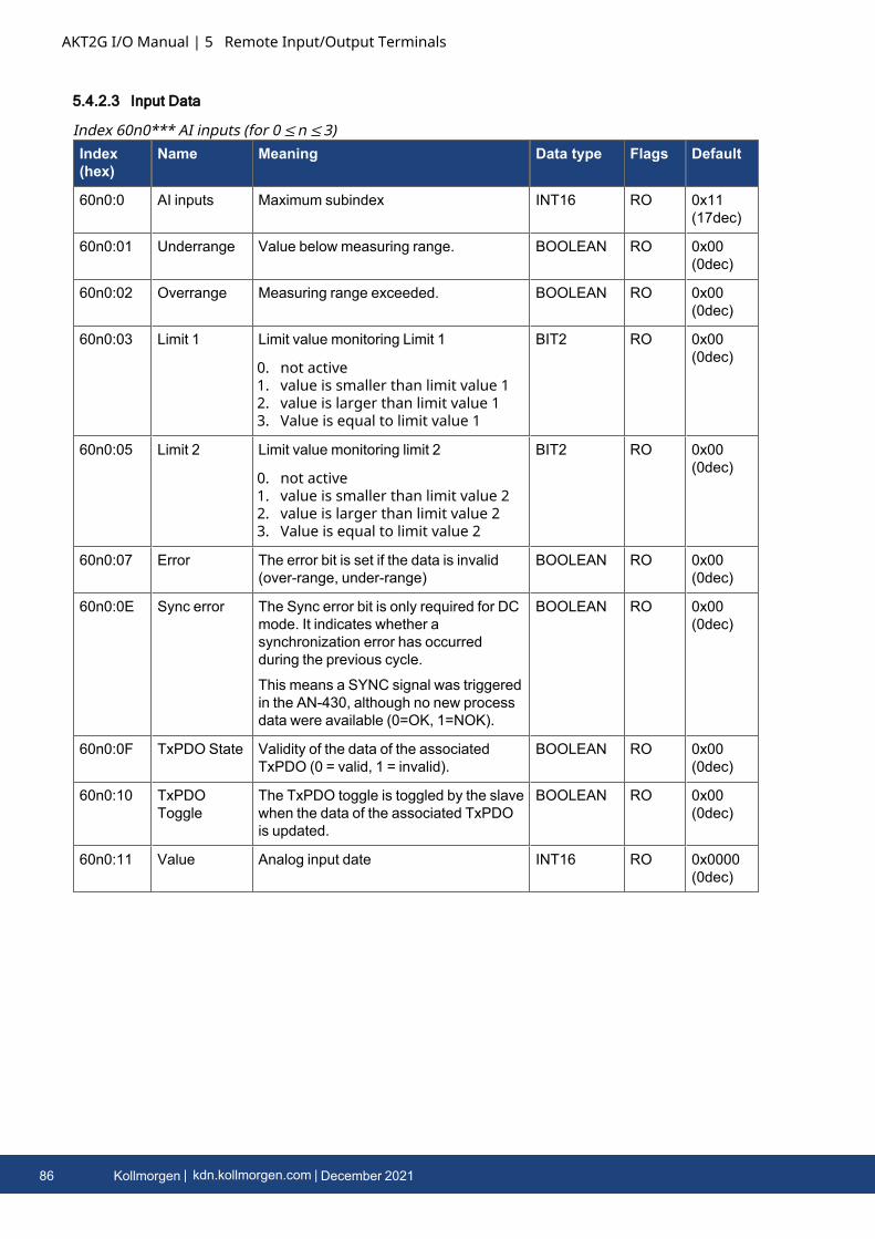
AKT2G I/O Manual | 5 Remote Input/Output Terminals
5.4.2.3 Input Data
Index(hex)
Name Meaning Data type Flags Default
60n0:0 AI inputs Maximum subindex INT16 RO 0x11(17dec)
60n0:01 Underrange Value below measuring range. BOOLEAN RO 0x00(0dec)
60n0:02 Overrange Measuring range exceeded. BOOLEAN RO 0x00(0dec)
60n0:03 Limit 1 Limit value monitoring Limit 1
0. not active1. value is smaller than limit value 12. value is larger than limit value 13. Value is equal to limit value 1
BIT2 RO 0x00(0dec)
60n0:05 Limit 2 Limit value monitoring limit 2
0. not active1. value is smaller than limit value 22. value is larger than limit value 23. Value is equal to limit value 2
BIT2 RO 0x00(0dec)
60n0:07 Error The error bit is set if the data is invalid(over-range, under-range)
BOOLEAN RO 0x00(0dec)
60n0:0E Sync error The Sync error bit is only required for DCmode. It indicates whether asynchronization error has occurredduring the previous cycle.
This means a SYNC signal was triggeredin the AN-430, although no new processdata were available (0=OK, 1=NOK).
BOOLEAN RO 0x00(0dec)
60n0:0F TxPDO State Validity of the data of the associatedTxPDO (0 = valid, 1 = invalid).
BOOLEAN RO 0x00(0dec)
60n0:10 TxPDOToggle
The TxPDO toggle is toggled by the slavewhen the data of the associated TxPDOis updated.
BOOLEAN RO 0x00(0dec)
60n0:11 Value Analog input date INT16 RO 0x0000(0dec)
Index 60n0*** AI inputs (for 0 ≤n ≤3)
86 Kollmorgen | kdn.kollmorgen.com | December 2021
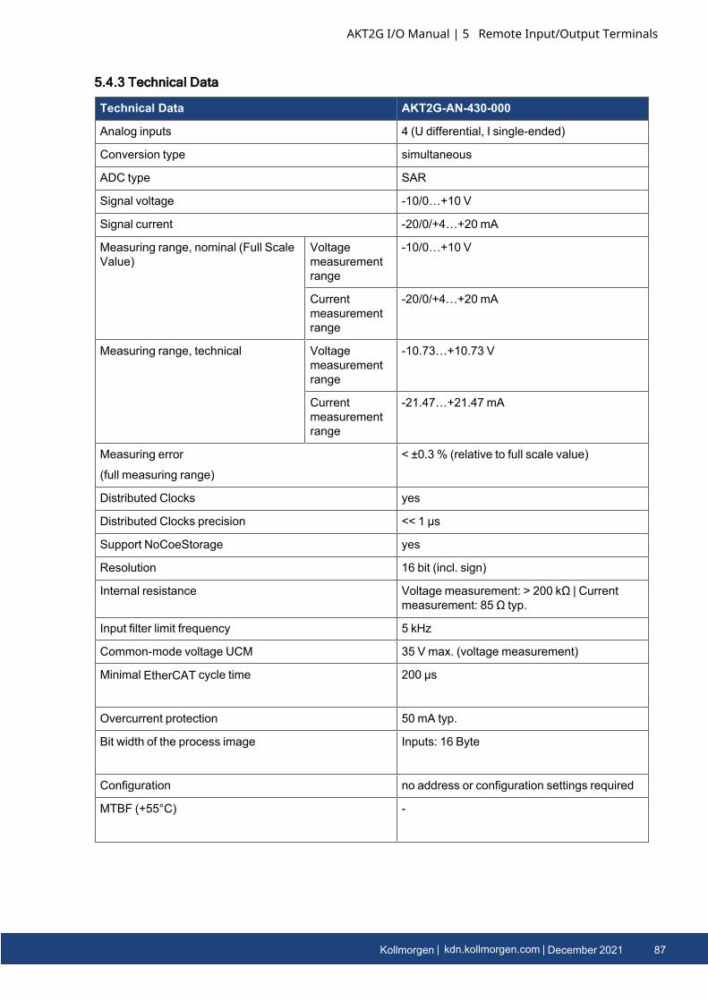
5.4.3 Technical Data
Technical Data AKT2G-AN-430-000
Analog inputs 4 (U differential, I single-ended)
Conversion type simultaneous
ADC type SAR
Signal voltage -10/0…+10 V
Signal current -20/0/+4…+20 mA
Measuring range, nominal (Full ScaleValue)
Voltagemeasurementrange
-10/0…+10 V
Currentmeasurementrange
-20/0/+4…+20 mA
Measuring range, technical Voltagemeasurementrange
-10.73…+10.73 V
Currentmeasurementrange
-21.47…+21.47 mA
Measuring error
(full measuring range)
< ±0.3 % (relative to full scale value)
Distributed Clocks yes
Distributed Clocks precision << 1 µs
Support NoCoeStorage yes
Resolution 16 bit (incl. sign)
Internal resistance Voltage measurement: > 200 kΩ | Currentmeasurement: 85 Ω typ.
Input filter limit frequency 5 kHz
Common-mode voltage UCM 35 V max. (voltage measurement)
Minimal EtherCAT cycle time 200 µs
Overcurrent protection 50 mA typ.
Bit width of the process image Inputs: 16 Byte
Configuration no address or configuration settings required
MTBF (+55°C) -
AKT2G I/O Manual | 5 Remote Input/Output Terminals
Kollmorgen | kdn.kollmorgen.com | December 2021 87
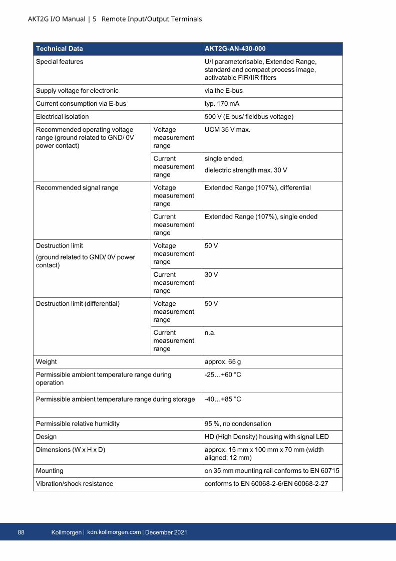
AKT2G I/O Manual | 5 Remote Input/Output Terminals
Technical Data AKT2G-AN-430-000
Special features U/I parameterisable, Extended Range,standard and compact process image,activatable FIR/IIR filters
Supply voltage for electronic via the E-bus
Current consumption via E-bus typ. 170 mA
Electrical isolation 500 V (E bus/ fieldbus voltage)
Recommended operating voltagerange (ground related to GND/ 0Vpower contact)
Voltagemeasurementrange
UCM 35 V max.
Currentmeasurementrange
single ended,
dielectric strength max. 30 V
Recommended signal range Voltagemeasurementrange
Extended Range (107%), differential
Currentmeasurementrange
Extended Range (107%), single ended
Destruction limit
(ground related to GND/ 0V powercontact)
Voltagemeasurementrange
50 V
Currentmeasurementrange
30 V
Destruction limit (differential) Voltagemeasurementrange
50 V
Currentmeasurementrange
n.a.
Weight approx. 65 g
Permissible ambient temperature range duringoperation
-25…+60 °C
Permissible ambient temperature range during storage -40…+85 °C
Permissible relative humidity 95 %, no condensation
Design HD (High Density) housing with signal LED
Dimensions (W x H x D) approx. 15 mm x 100 mm x 70 mm (widthaligned: 12 mm)
Mounting on 35 mmmounting rail conforms to EN 60715
Vibration/shock resistance conforms to EN 60068-2-6/EN 60068-2-27
88 Kollmorgen | kdn.kollmorgen.com | December 2021
Technical Data AKT2G-AN-430-000
EMC immunity/emission conforms to EN 61000-6-2/EN 61000-6-4
Protection class IP20
Installation position variable
Approval CE, cULus
AKT2G I/O Manual | 5 Remote Input/Output Terminals
Kollmorgen | kdn.kollmorgen.com | December 2021 89

AKT2G I/O Manual | 5 Remote Input/Output Terminals
5.5 AKT2G-AT-410-000Four-channel analog output terminals, 0..10 V, 12 bitThe AKT2G-AT-410 analog output terminal generates signals in the range between 0 and 10 V. Thevoltage is supplied to the process level with a resolution of 12 bits, and is electrically isolated. Theoutput channels of the EtherCAT Terminal has a common ground potential. The output stages arepowered by the 24 V supply. The signal state of the EtherCAT Terminals is indicated by lightemitting diodes. The AT-410 supports distributed clocks, i.e. the input data can be monitoredsynchronously with other data that are also linked to distributed clock terminals. The accuracyacross the system is < 100 ns.See Also:
l Temporal Aspects of Analog/Digital Conversionl Map Input and Output to Variables
90 Kollmorgen | kdn.kollmorgen.com | December 2021

5.5.1 LEDs
LED Color Meaning
RUN green This LED indicates the terminal's operating state:
off State of the EtherCAT State Machine: INIT = initialization of the terminal,state of the EtherCAT State Machine: BOOTSTRAP = function for firmwareupdates of the terminal
flashing State of the EtherCAT State Machine: PREOP = function for mailboxcommunication and different standard-settings set
singleflash
State of the EtherCAT State Machine: SAFEOP = verification of the SyncManager channels and the distributed clocks.
Outputs remain in safe state
on State of the EtherCAT State Machine: OP = normal operating state;mailbox and process data communication is possible
If several RUN LEDs are present, all of them have the same function.
AKT2G I/O Manual | 5 Remote Input/Output Terminals
Kollmorgen | kdn.kollmorgen.com | December 2021 91
AKT2G I/O Manual | 5 Remote Input/Output Terminals
5.5.2 Object Description and Parameterization
5.5.2.1 Restore objects
Index(hex)
Name Meaning Datatype
Flags Default
1011:0 Restoredefaultparameters
Restore default parameters UINT8 RO 0x01 (1dec)
1011:01 SubIndex001
If this object is set to “0x64616F6C” inthe set value dialog, all backup objectsare reset to their delivery state.
UINT32 RW 0x00000000(0dec)
Index 1011 Restore default parameters
5.5.2.2 Configuration data
Index(hex)
Name Meaning Data type Flags Default
8pp0:0 AO settingsCh.1-8
Max. Subindex UINT8 RO 0x16 (22dec)
8pp0:01 Enable userscale
User scale is active. BOOLEAN RW 0x00 (0dec)
8pp0:02 Presentation 0. Signed presentationThe measured value ispresented in two’s complementformat.
Maximum representation rangefor 16 bits = -32768dec ...+32767dec
1. Unsigned presentationMaximum presentation rangefor 16 bit : 0 .. +65535dec
2. Absolute value with MSB assignThe measured value is outputin magnitude-sign format.
Maximum representation rangefor 16 bits = -32768dec ...+32767dec
3. Absolute valueNegative numbers are alsooutput as positive numbers.
BIT3 RW 0x00 (0dec)
Index 8pp0 AO settings Ch.1-8
92 Kollmorgen | kdn.kollmorgen.com | December 2021
Index(hex)
Name Meaning Data type Flags Default
8pp0:05 Watchdog 0: Default watchdog value
0. The default value (8pp0:13) isactive.
1. Watchdog rampThe ramp (8pp0:14) for movingto the default value is active.
2. Last output valueIn the event of a watchdog dropthe last process data is issued.
BIT2 RW 0x00 (0dec)
8pp0:07 Enable usercalibration
Enable user calibration BOOLEAN RW 0x00 (0dec)
8pp0:08 Enable vendorcalibration
Enable vendor calibration BOOLEAN RW 0x01 (1dec)
8pp0:11 Offset User scaling offset INT16 RW 0x0000 (0dec)
8pp0:12 Gain User scaling gain.
The gain is represented in fixed-point format, with the factor 2-16.
The value 1 corresponds to 65535(0x00010000).
INT32 RW 0x00010000(65536dec)
8pp0:13 Default output default output value INT16 RW 0x0000 (0dec)
8pp0:14 Default outputramp
Ramp for ramping down to thedefault value Value in digits/ms.
UINT16 RW 0xFFFF(65535dec)
8pp0:15 Usercalibrationoffset
User calibration offset INT16 RW 0x0000 (0dec)
8pp0:16 Usercalibration gain
User calibration gain UINT16 RW 0xFFFF(65535dec)
Index (hex) Name Meaning Data type Flags Default
8ppE:0 AO internal data Ch.1-8 Max. Subindex UINT8 RO 0x01 (1dec)
8ppE:01 DAC raw value DAC raw value UINT16 RO 0x0000 (0dec)
Index 8ppE AO internal data Ch.1-8
Index (hex) Name Meaning Data type Flags Default
8ppF:0 AO vendor data Ch.1-8
Max. Subindex UINT8 RO 0x02 (2dec)
8ppF:01 Calibration offset Vendor calibrationoffset
INT16 RW 0x0000 (0dec)
8ppF:02 Calibration gain Vendor calibration gain UINT16 RW 0x1EFA(7930dec)
Index 8ppF AO vendor data Ch.1-8
AKT2G I/O Manual | 5 Remote Input/Output Terminals
Kollmorgen | kdn.kollmorgen.com | December 2021 93

AKT2G I/O Manual | 5 Remote Input/Output Terminals
5.5.2.3 Output Data
Index (hex) Name Meaning Data type Flags Default
7pp0:0 AO outputs Ch.1-8 Max. Subindex UINT8 RO 0x01 (1dec)
7pp0:01 Analog output Analog output data INT16 RO 0x0000 (0dec)
Index 7pp0 AO outputs Ch.1-8
94 Kollmorgen | kdn.kollmorgen.com | December 2021

5.5.3 Technical Data
Technical Data AKT2G-AT-410-000
Number of outputs 4
Power supply 24 V DC via the power contacts
Signal voltage 0..10 V
Load > 5 kΩ (short-circuit-proof)
Measuring error < ± 0.1% (at 0 °C ... +55 °C, relative to the full scale value)
< ± 0.2% (when the extended temperature range is used)
Resolution 12 bit
Conversion time ~ 250 µs
Power supply for electronics via the E-bus
Distributed Clocks yes
Current consumption via Ebus typ. 140 mA
Electrical isolation 500 V (E-bus/field voltage)
Bit width in process image 4 x 16-bit AO output
Configuration via KAS IDE
Weight approx. 60 g
Permissible ambient temperature rangeduring operation
-25 °C ... +60 °C
(extended temperature range)
Permissible ambient temperature rangeduring storage
-40 °C ... +85 °C
Permissible relative humid- ity 95%, no condensation
Dimensions (W x H x D) approx. 15 mm x 100 mm x 70 mm (width aligned: 12mm)
Mounting on 35 mmmounting rail conforms to EN 60715
Vibration/shock resistance conforms to EN 60068-2-6 / EN 60068-2-27,
see also installation instructions for enhancedmechanical load capacity
EMC immunity/emission conforms to EN 61000-6-2 / EN 61000-6-4
Protection class IP20
Installation position variable
Approval CE, ATEX, cULus
AKT2G I/O Manual | 5 Remote Input/Output Terminals
Kollmorgen | kdn.kollmorgen.com | December 2021 95
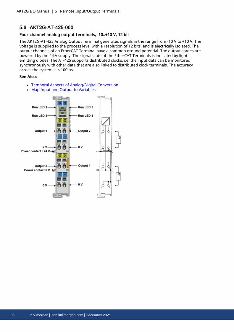
AKT2G I/O Manual | 5 Remote Input/Output Terminals
5.6 AKT2G-AT-425-000Four-channel analog output terminals, -10..+10 V, 12 bitThe AKT2G-AT-425 Analog Output Terminal generates signals in the range from -10 V to +10 V. Thevoltage is supplied to the process level with a resolution of 12 bits, and is electrically isolated. Theoutput channels of an EtherCAT Terminal have a common ground potential. The output stages arepowered by the 24 V supply. The signal state of the EtherCAT Terminals is indicated by lightemitting diodes. The AT-425 supports distributed clocks, i.e. the input data can be monitoredsynchronously with other data that are also linked to distributed clock terminals. The accuracyacross the system is < 100 ns.See Also:
l Temporal Aspects of Analog/Digital Conversionl Map Input and Output to Variables
96 Kollmorgen | kdn.kollmorgen.com | December 2021
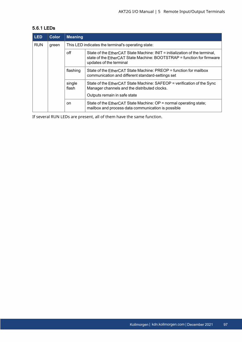
5.6.1 LEDs
LED Color Meaning
RUN green This LED indicates the terminal's operating state:
off State of the EtherCAT State Machine: INIT = initialization of the terminal,state of the EtherCAT State Machine: BOOTSTRAP = function for firmwareupdates of the terminal
flashing State of the EtherCAT State Machine: PREOP = function for mailboxcommunication and different standard-settings set
singleflash
State of the EtherCAT State Machine: SAFEOP = verification of the SyncManager channels and the distributed clocks.
Outputs remain in safe state
on State of the EtherCAT State Machine: OP = normal operating state;mailbox and process data communication is possible
If several RUN LEDs are present, all of them have the same function.
AKT2G I/O Manual | 5 Remote Input/Output Terminals
Kollmorgen | kdn.kollmorgen.com | December 2021 97

AKT2G I/O Manual | 5 Remote Input/Output Terminals
5.6.2 Object Description and Parameterization
5.6.2.1 Restore objects
Index(hex)
Name Meaning Datatype
Flags Default
1011:0 Restoredefaultparameters
Restore default parameters UINT8 RO 0x01 (1dec)
1011:01 SubIndex001
If this object is set to “0x64616F6C” inthe set value dialog, all backup objectsare reset to their delivery state.
UINT32 RW 0x00000000(0dec)
Index 1011 Restore default parameters
5.6.2.2 Configuration data
Index(hex)
Name Meaning Data type Flags Default
8pp0:0 AO settingsCh.1-8
Max. Subindex UINT8 RO 0x16 (22dec)
8pp0:01 Enable userscale
User scale is active. BOOLEAN RW 0x00 (0dec)
8pp0:02 Presentation 0. Signed presentationThe measured value ispresented in two’s complementformat.
Maximum representation rangefor 16 bits = -32768dec ...+32767dec
1. Unsigned presentationMaximum presentation rangefor 16 bit : 0 .. +65535dec
2. Absolute value with MSB assignThe measured value is outputin magnitude-sign format.
Maximum representation rangefor 16 bits = -32768dec ...+32767dec
3. Absolute valueNegative numbers are alsooutput as positive numbers.
BIT3 RW 0x00 (0dec)
Index 8pp0 AO settings Ch.1-8
98 Kollmorgen | kdn.kollmorgen.com | December 2021

Index(hex)
Name Meaning Data type Flags Default
8pp0:05 Watchdog 0: Default watchdog value
0. The default value (8pp0:13) isactive.
1. Watchdog rampThe ramp (8pp0:14) for movingto the default value is active.
2. Last output valueIn the event of a watchdog dropthe last process data is issued.
BIT2 RW 0x00 (0dec)
8pp0:07 Enable usercalibration
Enable user calibration BOOLEAN RW 0x00 (0dec)
8pp0:08 Enable vendorcalibration
Enable vendor calibration BOOLEAN RW 0x01 (1dec)
8pp0:11 Offset User scaling offset INT16 RW 0x0000 (0dec)
8pp0:12 Gain User scaling gain.
The gain is represented in fixed-point format, with the factor 2-16.
The value 1 corresponds to 65535(0x00010000).
INT32 RW 0x00010000(65536dec)
8pp0:13 Default output default output value INT16 RW 0x0000 (0dec)
8pp0:14 Default outputramp
Ramp for ramping down to thedefault value Value in digits/ms.
UINT16 RW 0xFFFF(65535dec)
8pp0:15 Usercalibrationoffset
User calibration offset INT16 RW 0x0000 (0dec)
8pp0:16 Usercalibration gain
User calibration gain UINT16 RW 0xFFFF(65535dec)
Index (hex) Name Meaning Data type Flags Default
8ppE:0 AO internal data Ch.1-8 Max. Subindex UINT8 RO 0x01 (1dec)
8ppE:01 DAC raw value DAC raw value UINT16 RO 0x0000 (0dec)
Index 8ppE AO internal data Ch.1-8
Index (hex) Name Meaning Data type Flags Default
8ppF:0 AO vendor data Ch.1-8
Max. Subindex UINT8 RO 0x02 (2dec)
8ppF:01 Calibration offset Vendor calibrationoffset
INT16 RW 0x0000 (0dec)
8ppF:02 Calibration gain Vendor calibration gain UINT16 RW 0x1EFA(7930dec)
Index 8ppF AO vendor data Ch.1-8
AKT2G I/O Manual | 5 Remote Input/Output Terminals
Kollmorgen | kdn.kollmorgen.com | December 2021 99

AKT2G I/O Manual | 5 Remote Input/Output Terminals
5.6.2.3 Output Data
Index (hex) Name Meaning Data type Flags Default
7pp0:0 AO outputs Ch.1-8 Max. Subindex UINT8 RO 0x01 (1dec)
7pp0:01 Analog output Analog output data INT16 RO 0x0000 (0dec)
Index 7pp0 AO outputs Ch.1-8
100 Kollmorgen | kdn.kollmorgen.com | December 2021
5.6.3 Technical Data
Technical Data AKT2G-AT-425-000
Number of outputs 4
Power supply 24 V DC via the power contacts
Signal voltage -10 ..+10 V
Load > 5 kΩ (short-circuit-proof)
Measuring error < ± 0.1% (at 0 °C ... +55 °C, relative to the full scale value)
< ± 0.2% (when the extended temperature range is used)
Resolution 12 bit
Conversion time ~ 250 µs
Power supply for electronics via the E-bus
Distributed Clocks yes
Current consumption via Ebus typ. 140 mA
Electrical isolation 500 V (E-bus/field voltage)
Bit width in process image 4 x 16-bit AO output
Configuration via KAS IDE
Weight approx. 60 g
Permissible ambient temperature rangeduring operation
-25 °C ... +60 °C
(extended temperature range)
Permissible ambient temperature rangeduring storage
-40 °C ... +85 °C
Permissible relative humidity 95%, no condensation
Dimensions (W x H x D) approx. 15 mm x 100 mm x 70 mm (width aligned: 12mm)
Mounting on 35 mmmounting rail conforms to EN 60715
Vibration/shock resistance conforms to EN 60068-2-6 / EN 60068-2-27,
see also installation instructions for enhancedmechanical load capacity
EMC immunity/emission conforms to EN 61000-6-2 / EN 61000-6-4
Protection class IP20
Installation position variable
Approval CE, ATEX, cULus
AKT2G I/O Manual | 5 Remote Input/Output Terminals
Kollmorgen | kdn.kollmorgen.com | December 2021 101
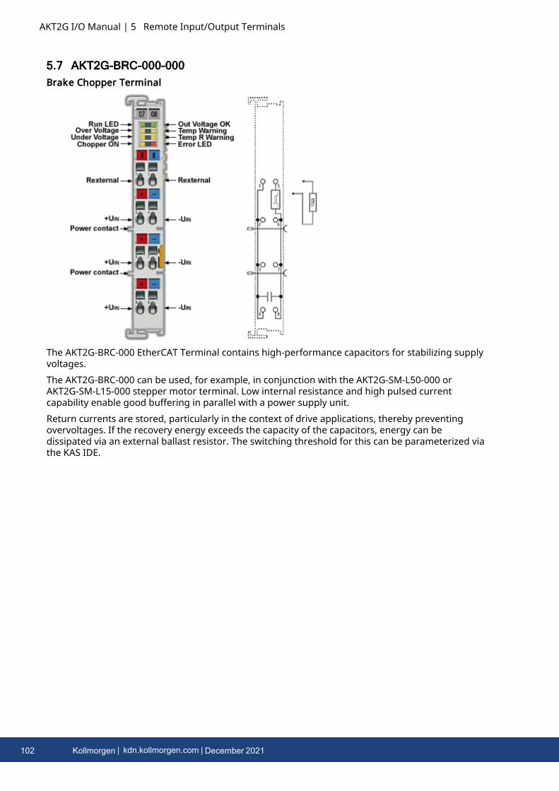
AKT2G I/O Manual | 5 Remote Input/Output Terminals
5.7 AKT2G-BRC-000-000Brake Chopper Terminal
The AKT2G-BRC-000 EtherCAT Terminal contains high-performance capacitors for stabilizing supplyvoltages.The AKT2G-BRC-000 can be used, for example, in conjunction with the AKT2G-SM-L50-000 orAKT2G-SM-L15-000 stepper motor terminal. Low internal resistance and high pulsed currentcapability enable good buffering in parallel with a power supply unit.Return currents are stored, particularly in the context of drive applications, thereby preventingovervoltages. If the recovery energy exceeds the capacity of the capacitors, energy can bedissipated via an external ballast resistor. The switching threshold for this can be parameterized viathe KAS IDE.
102 Kollmorgen | kdn.kollmorgen.com | December 2021
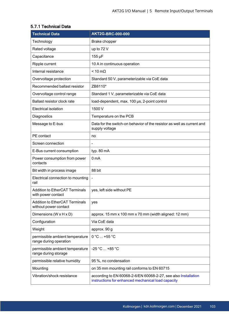
5.7.1 Technical Data
Technical Data AKT2G-BRC-000-000
Technology Brake chopper
Rated voltage up to 72 V
Capacitance 155 µF
Ripple current 10 A in continuous operation
Internal resistance < 10 mΩ
Overvoltage protection Standard 50 V, parameterizable via CoE data
Recommended ballast resistor ZB8110*
Overvoltage control range Standard 1 V, parameterizable via CoE data
Ballast resistor clock rate load-dependent, max. 100 µs, 2-point control
Electrical isolation 1500 V
Diagnostics Temperature on the PCB
Message to E-bus Data for the switch-on behavior of the resistor as well as current andsupply voltage
PE contact no
Screen connection -
E-Bus current consumption typ. 80 mA
Power consumption from powercontacts
0 mA
Bit width in process image 88 bit
Electrical connection to mountingrail
-
Addition to EtherCAT Terminalswith power contact
yes, left side without PE
Addition to EtherCAT Terminalswithout power contact
yes
Dimensions (W x H x D) approx. 15 mm x 100 mm x 70 mm (width aligned: 12 mm)
Configuration Via CoE data
Weight approx. 90 g
permissible ambient temperaturerange during operation
0 °C ... +55 °C
permissible ambient temperaturerange during storage
-25 °C ... +85 °C
permissible relative humidity 95 %, no condensation
Mounting on 35 mmmounting rail conforms to EN 60715
Vibration/shock resistance according to EN 60068-2-6/EN 60068-2-27, see also Installationinstructions for enhanced mechanical load capacity
AKT2G I/O Manual | 5 Remote Input/Output Terminals
Kollmorgen | kdn.kollmorgen.com | December 2021 103
AKT2G I/O Manual | 5 Remote Input/Output Terminals
Technical Data AKT2G-BRC-000-000
EMC immunity/emission conforms to EN 61000-6-2 / EN 61000-6-4
Protection class IP20
Installation position Any, see Mounting andWiring of I/O Terminals
Approval CE, cULus
* depending on the application, a larger resistor may be necessary
5.7.2 LEDs and Pin Assignment
Correct supply voltage is necessary for operation!In addition to the supply voltage via the contacts on the front panel, the voltage from the E-busmust also be present in order for the terminal to work properly, since the integrated logic of theBus Terminal is supplied with this voltage. The Bus Terminal does not work if the supply isincorrect.
Match the resistor power to the expected power!When selecting the external resistor, make sure that the rated power of the resistor is matched tothe expected power, since otherwise the resistor and adjacent components can be damaged. Inaddition, the temperature model is to be adapted to this resistor.
5.7.2.1 Pin Assignment
Terminal Point Description
Name No.
R 50 V (Rexternal) 1 + connection of external resistor
50 V (+Uin) 2 + supply voltage connection
50 V (+Uin) 3 + supply voltage connection
50 V (+Uin) 4 + supply voltage connection
R GND (Rexternal) 5 - connection of external resistor
GND (-Uin) 6 - supply voltage connection
GND (-Uin) 7 - supply voltage connection
GND (-Uin) 8 - supply voltage connection
104 Kollmorgen | kdn.kollmorgen.com | December 2021
5.7.2.2 LEDs
LED Color Meaning
RUN green This LED indicates the terminal's operating state:
off State of the EtherCAT State Machine : INIT =initialization of the terminal
flashing State of the EtherCAT State Machine: PREOP = functionfor mailbox communication and different standard-settings set
single flash State of the EtherCAT State Machine: SAFEOP =verification of the Sync Manager channels and thedistributed clocks.The outputs remain in safe state.
on State of the EtherCAT State Machine: OP = normaloperating state; mailbox and process datacommunication is possible
flickering State of the EtherCAT State Machine: BOOTSTRAP =function for firmware updates of the terminal
OutvoltageOK
green ON Supply voltages are OK, there are no errors
OFF l Supply voltage is incorrect, i.e. too high or too lowl Overtemperature in the temperature simulationl Temperature at the terminal too high
Overvoltage
yellow ON The supply voltage has exceeded the threshold value forovervoltage.
Tempwarning
yellow ON Temperature threshold value for the temperature on thePCB has been exceeded.
Undervoltage
yellow ON The supply voltage is too low, or has fallen below thecorresponding threshold value in the CoE data.
Temp Rwarning
yellow ON The “I2T warning level” threshold value has beenexceeded.
ChopperOn
yellow ON The external resistor is switched on.
Error red ON + “Undervolt age”LED
The supply voltage is not connected or is so low that the“supply voltage” and “ResistorCurrent” values cannot beread.
ON + “Temp RWarning” LED +“Overvolta ge” LED
There is an overtemperature in the internal temperaturesimulation for the external resistor.
AKT2G I/O Manual | 5 Remote Input/Output Terminals
Kollmorgen | kdn.kollmorgen.com | December 2021 105

AKT2G I/O Manual | 5 Remote Input/Output Terminals
5.7.3 Brake Chopper Quick StartProceed as follows for standard commissioning of the AKT2G-BRC-000 with an external resistor.
1. Install the AKT2G-BRC-000 in the E-bus terminal segment on an EtherCAT coupler,.2. For operation the AKT2G-BRC-000 requires a supply voltage at connections 2 and 6 (UIN) of
the terminal as well as a power supply via the E-Bus. The following must be observed:l The supply voltage must be at least 18 VDC.l The resistor must be designed to handle the expected power and must be
parameterized accordingly via CoE Init-Commands.l The voltage supply must be designed for the switching on of the corresponding
resistor.l Supply quality: the most stable and noise-free supply possible must be ensured.
3. Parameterize the resistor you are using with CoE Init-Commands according to the data sheetfor the resistor.
l Reverse any previous parameter changes by means of a CoE reset: enter 0x64616F6Cin object 0x1011:01.
l Enter the ambient temperature of the resistor in °C in 0x8000:15.l Enter the thermal resistance of the electrical resistor to the environment in m°C/W in
0x8000:16.
106 Kollmorgen | kdn.kollmorgen.com | December 2021

5.7.4 AKT2G-BRC-000 Basic Function Principles
The brake chopper terminal transfers several items of information about the operating status viathe process data.
5.7.4.1 Chopper Operation
The brake chopper terminal has an internal capacitance that takes up the dissipated energy frombrake applications up to the complete charging of the capacitors. In order to be able to protectconnected devices after charging as well, an external resistor is switched on after the set thresholdvalue is exceeded (default 50 V) in order to be able to convert the surplus energy into thermalenergy.
5.7.4.2 Temperature Model for the External Resistor
The surplus energy is converted into thermal energy via the external resistor. In the event of anerror or in case of large motors, there is a possibility of the resistor overheating, which can damagethe resistor itself as well as adjacent components. For this reason a temperature model has beenintegrated in the Bus Terminal that simulates the temperature of the resistor and, if a settemperature is exceeded, switches the resistor off until the temperature falls below the thresholdvalue for the warning bit.The switch-off can be deactivated via the CoE Init-Command (“Disable Chopper onOvertemperature”). In this case chopping also continues in the case of overheating.The temperature model is adjusted via the CoE data for the resistor employed:
l The “Ambient temperature offset” parameter should be set to the ambient temperature ofthe external resistor. The temperature model calculates the difference to the ambienttemperature due to the power dissipation. In order to be able to estimate the actualtemperature, the ambient temperature is set by this parameter.
l The thermal resistance of the ballast resistor to the environment is set by the “Absolutethermal resistance” parameter. This value is required for the calculation of the temperature.When the ZB8110 is used, the value is 1300 m°C/W.
l Analogous to the previous parameter the thermal time constant of the resistor is set by the“Thermal time constant”. The thermal resistance and the thermal time constant can be takenfrom the data sheet for many resistors. If this is not the case, the data can also bedetermined manually by the user by means of a diagram or a measurement. (See the SectionMeasuring the resistance for this). When the ZB8110 is used, the value is 550 s.
l The “I2T warn level” parameter specifies the threshold value for the warning bit in theprocess data and the LED on the front panel of the Bus Terminal. In the case that the“Disable chopper on overtemperature” bit is set (default), the lower end of the switch-offhysteresis loop of the temperature model is defined by this parameter. The upper end is the“I2T error level” parameter.
l The switch-off threshold for the temperature model is defined by the “I2T-Model” settingvalue. If the “Disable chopper on overtemperature” bit is activated and this temperature isexceeded, the resistor is not switched on again until the calculated temperature in thetemperature model has fallen below the “I2T warn level” threshold. If the temperature isallowed to rise still further due to the settings in the CoE data, the overtemperature issignaled via the “Error” LED on the front panel and the corresponding bit is output in theprocess data.
AKT2G I/O Manual | 5 Remote Input/Output Terminals
Kollmorgen | kdn.kollmorgen.com | December 2021 107
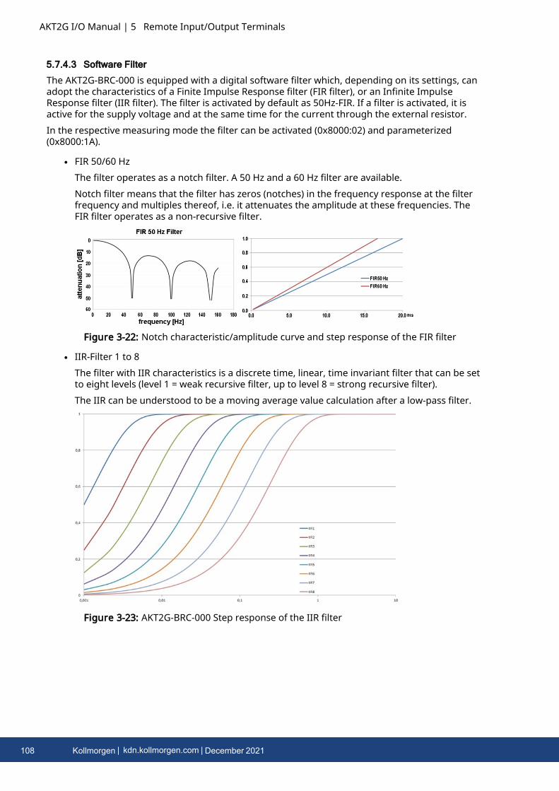
AKT2G I/O Manual | 5 Remote Input/Output Terminals
5.7.4.3 Software Filter
The AKT2G-BRC-000 is equipped with a digital software filter which, depending on its settings, canadopt the characteristics of a Finite Impulse Response filter (FIR filter), or an Infinite ImpulseResponse filter (IIR filter). The filter is activated by default as 50Hz-FIR. If a filter is activated, it isactive for the supply voltage and at the same time for the current through the external resistor.In the respective measuring mode the filter can be activated (0x8000:02) and parameterized(0x8000:1A).
l FIR 50/60 HzThe filter operates as a notch filter. A 50 Hz and a 60 Hz filter are available.Notch filter means that the filter has zeros (notches) in the frequency response at the filterfrequency and multiples thereof, i.e. it attenuates the amplitude at these frequencies. TheFIR filter operates as a non-recursive filter.
Figure 3-22: Notch characteristic/amplitude curve and step response of the FIR filter
l IIR-Filter 1 to 8The filter with IIR characteristics is a discrete time, linear, time invariant filter that can be setto eight levels (level 1 = weak recursive filter, up to level 8 = strong recursive filter).The IIR can be understood to be a moving average value calculation after a low-pass filter.
Figure 3-23: AKT2G-BRC-000 Step response of the IIR filter
108 Kollmorgen | kdn.kollmorgen.com | December 2021
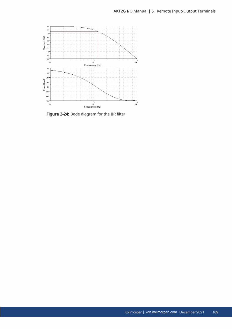
Figure 3-24: Bode diagram for the IIR filter
AKT2G I/O Manual | 5 Remote Input/Output Terminals
Kollmorgen | kdn.kollmorgen.com | December 2021 109
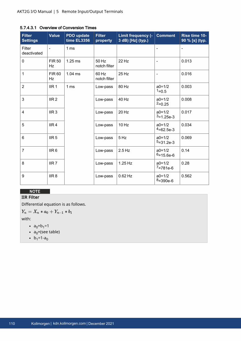
AKT2G I/O Manual | 5 Remote Input/Output Terminals
5.7.4.3.1 Overview of Conversion Times
FilterSettings
Value PDO updatetime EL3356
Filterproperty
Limit frequency (-3 dB) [Hz] (typ.)
Comment Rise time 10-90 % [s] (typ.
Filterdeactivated
- 1 ms - -
0 FIR 50Hz
1.25 ms 50 Hznotch filter
22 Hz - 0.013
1 FIR 60Hz
1.04 ms 60 Hznotch filter
25 Hz - 0.016
2 IIR 1 1 ms Low-pass 80 Hz a0=1/21=0.5
0.003
3 IIR 2 Low-pass 40 Hz a0=1/22=0.25
0.008
4 IIR 3 Low-pass 20 Hz a0=1/23=1.25e-3
0.017
5 IIR 4 Low-pass 10 Hz a0=1/24=62.5e-3
0.034
6 IIR 5 Low-pass 5 Hz a0=1/25=31.2e-3
0.069
7 IIR 6 Low-pass 2.5 Hz a0=1/26=15.6e-6
0.14
8 IIR 7 Low-pass 1.25 Hz a0=1/27=781e-6
0.28
9 IIR 8 Low-pass 0.62 Hz a0=1/28=390e-6
0.562
IIR FilterDifferential equation is as follows.
with:l a0+b1=1l a0=(see table)l b1=1-a0
110 Kollmorgen | kdn.kollmorgen.com | December 2021
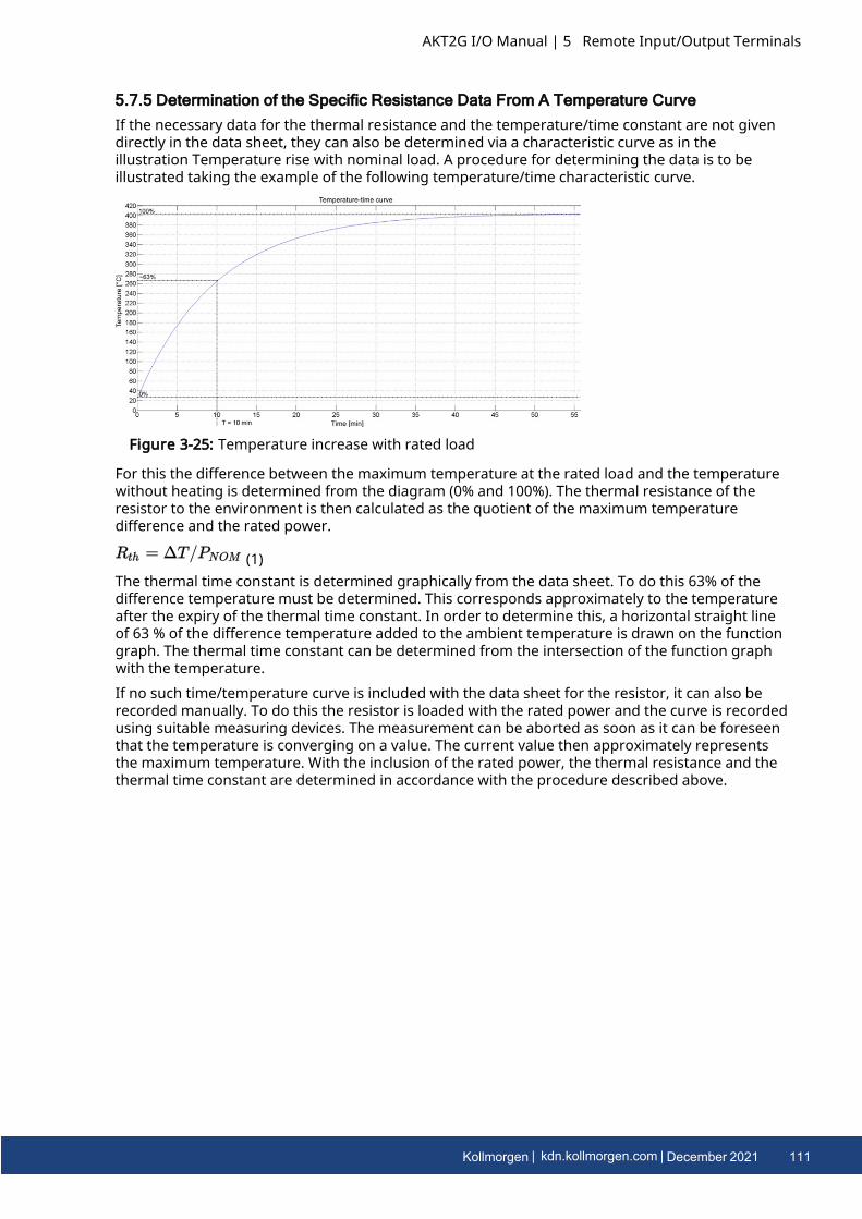
5.7.5 Determination of the Specific Resistance Data From A Temperature CurveIf the necessary data for the thermal resistance and the temperature/time constant are not givendirectly in the data sheet, they can also be determined via a characteristic curve as in theillustration Temperature rise with nominal load. A procedure for determining the data is to beillustrated taking the example of the following temperature/time characteristic curve.
Figure 3-25: Temperature increase with rated load
For this the difference between the maximum temperature at the rated load and the temperaturewithout heating is determined from the diagram (0% and 100%). The thermal resistance of theresistor to the environment is then calculated as the quotient of the maximum temperaturedifference and the rated power.
(1)The thermal time constant is determined graphically from the data sheet. To do this 63% of thedifference temperature must be determined. This corresponds approximately to the temperatureafter the expiry of the thermal time constant. In order to determine this, a horizontal straight lineof 63 % of the difference temperature added to the ambient temperature is drawn on the functiongraph. The thermal time constant can be determined from the intersection of the function graphwith the temperature.If no such time/temperature curve is included with the data sheet for the resistor, it can also berecorded manually. To do this the resistor is loaded with the rated power and the curve is recordedusing suitable measuring devices. The measurement can be aborted as soon as it can be foreseenthat the temperature is converging on a value. The current value then approximately representsthe maximum temperature. With the inclusion of the rated power, the thermal resistance and thethermal time constant are determined in accordance with the procedure described above.
AKT2G I/O Manual | 5 Remote Input/Output Terminals
Kollmorgen | kdn.kollmorgen.com | December 2021 111
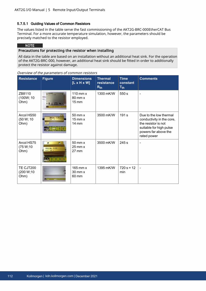
AKT2G I/O Manual | 5 Remote Input/Output Terminals
5.7.5.1 Guiding Values of Common Resistors
The values listed in the table serve the fast commissioning of the AKT2G-BRC-000EtherCAT BusTerminal. For a more accurate temperature simulation, however, the parameters should beprecisely matched to the resistor employed.
Precautions for protecting the resistor when installingAll data in the table are based on an installation without an additional heat sink. For the operationof the AKT2G-BRC-000, however, an additional heat sink should be fitted in order to additionallyprotect the resistor against damage.
Resistance Figure Dimensions[L x H x W]
ThermalresistanceRth
TimeconstantTth
Comments
ZB8110(100W; 10Ohm)
110 mm x80 mm x15 mm
1300 mK/W 550 s -
Arcol HS50(50 W; 10Ohm)
50 mm x15 mm x14 mm
3500 mK/W 191 s Due to the low thermalconductivity in the core,the resistor is notsuitable for high pulsepowers far above therated power
Arcol HS75(75 W;10Ohm)
50 mm x25 mm x27 mm
3500 mK/W 245 s -
TE CJT200(200 W;10Ohm)
165 mm x30 mm x60 mm
1395 mK/W 720 s = 12min
-
Overview of the parameters of common resistors
112 Kollmorgen | kdn.kollmorgen.com | December 2021
5.7.6 Objects
5.7.6.1 BCT Inputs
This section describes the main PDOs and their content. A PDO (Process Data Object) is a unit oncyclically transmitted process values. Such a unit can be an individual variable (e.g. the supplyvoltage as a 32-bit value) or a group/structure of variables.
Index(hex)
Size(byte.bit)
Datatype
Name Unit Description
6000:01 0.1 BOOL Terminalovertemperature
- If this bit is activated there is anovertemperature on the PCB.
6000:02 0.1 BOOL I2T error - If this bit is activated there is anovertemperature in the external resistoraccording to the internal simulation.However, the resistor continues to heatup because the setting “DisableChopper on overtemperature” has notbeen set.
6000:03 0.1 BOOL I2T warning - The warning temperature thresholdvalue from the CoE data has beenexceeded by the temperature model. Ifthe setting “Disable Chopper onovertemperature” is active , the chopperswitches on again in case of overvoltageonly after the voltage falls below thisvalue.
6000:04 0.1 BOOL Overvoltage - The overvoltage threshold value hasbeen exceeded. The chopper isswitched on in case of adherence to thetemperatures from the internaltemperature model.
6000:05 0.1 BOOL Undervoltage - The voltage has fallen below theundervoltage threshold value from theCoE data.(Analog input)
6000:06 0.1 BOOL Chopper on - The external resistor is active, i.e.electrical energy is being converted tothermal energy in the resistor.
6000:11 4.0 UDINT DC link voltage mV External supply voltage in mV
6000:13 4.0 UDINT Resistor current mA Current through the external resistor inmA
6000:14 1.0 USINT Duty cycle % Temporal utilization of the externalresistor in the last 100 ms in %.
Index 0x6000: BCT Inputs
AKT2G I/O Manual | 5 Remote Input/Output Terminals
Kollmorgen | kdn.kollmorgen.com | December 2021 113
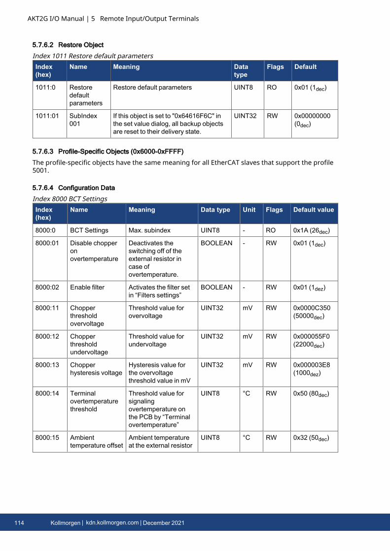
AKT2G I/O Manual | 5 Remote Input/Output Terminals
5.7.6.2 Restore Object
Index(hex)
Name Meaning Datatype
Flags Default
1011:0 Restoredefaultparameters
Restore default parameters UINT8 RO 0x01 (1dec)
1011:01 SubIndex001
If this object is set to "0x64616F6C" inthe set value dialog, all backup objectsare reset to their delivery state.
UINT32 RW 0x00000000(0dec)
Index 1011 Restore default parameters
5.7.6.3 Profile-Specific Objects (0x6000-0xFFFF)
The profile-specific objects have the same meaning for all EtherCAT slaves that support the profile5001.
5.7.6.4 Configuration Data
Index(hex)
Name Meaning Data type Unit Flags Default value
8000:0 BCT Settings Max. subindex UINT8 - RO 0x1A (26dec)
8000:01 Disable chopperonovertemperature
Deactivates theswitching off of theexternal resistor incase ofovertemperature.
BOOLEAN - RW 0x01 (1dec)
8000:02 Enable filter Activates the filter setin “Filters settings”
BOOLEAN - RW 0x01 (1dez)
8000:11 Chopperthresholdovervoltage
Threshold value forovervoltage
UINT32 mV RW 0x0000C350(50000dec)
8000:12 Chopperthresholdundervoltage
Threshold value forundervoltage
UINT32 mV RW 0x000055F0(22000dec)
8000:13 Chopperhysteresis voltage
Hysteresis value forthe overvoltagethreshold value in mV
UINT32 mV RW 0x000003E8(1000dez)
8000:14 Terminalovertemperaturethreshold
Threshold value forsignalingovertemperature onthe PCB by “Terminalovertemperature”
UINT8 °C RW 0x50 (80dec)
8000:15 Ambienttemperature offset
Ambient temperatureat the external resistor
UINT8 °C RW 0x32 (50dec)
Index 8000 BCT Settings
114 Kollmorgen | kdn.kollmorgen.com | December 2021
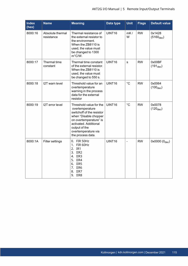
Index(hex)
Name Meaning Data type Unit Flags Default value
8000:16 Absolute thermalresistance
Thermal resistance ofthe external resistor tothe environment.When the ZB8110 isused, the value mustbe changed to 1300m°C/W.
UINT16 mK /W
RW 0x1428(5160dec)
8000:17 Thermal timeconstant
Thermal time constantof the external resistor.When the ZB8110 isused, the value mustbe changed to 550 s.
UINT16 s RW 0x00BF(191dec)
8000:18 I2T warn level Threshold value for anovertemperaturewarning in the processdata for the externalresistor
UINT16 °C RW 0x0064(100dec)
8000:19 I2T error level Threshold value for theovertemperatureswitchoff of the resistorwhen “Disable chopperon overtemperature” isactivated. Additionaloutput of theovertemperature viathe process data.
UINT16 °C RW 0x0078(120dec)
8000:1A Filter settings 0. FIR 50Hz1. FIR 60Hz2. IR13. IIR24. IIR35. IIR46. IIR57. IIR68. IIR79. IIR8
UINT16 - RW 0x0000 (0dec)
AKT2G I/O Manual | 5 Remote Input/Output Terminals
Kollmorgen | kdn.kollmorgen.com | December 2021 115
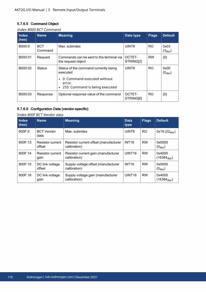
AKT2G I/O Manual | 5 Remote Input/Output Terminals
5.7.6.5 Command Object
Index(hex)
Name Meaning Data type Flags Default
B000:0 BCTCommand
Max. subindex UINT8 RO 0x03(3dec)
B000:01 Request Commands can be sent to the terminal viathe request object
OCTET-STRING[2]
RW {0}
B000:02 Status Status of the command currently beingexecuted
l 0: Command executed withouterror.
l 255: Command is being executed
UINT8 RO 0x00(0dec)
B000:03 Response Optional response value of the command OCTET-STRING[6]
RO {0}
Index B000 BCT Command
5.7.6.6 Configuration Data (vendor-specific)
Index(hex)
Name Meaning Datatype
Flags Default
800F:0 BCT Vendordata
Max. subindex UINT8 RO 0x16 (22dec)
800F:13 Resistor currentoffset
Resistor current offset (manufacturercalibration)
INT16 RW 0x0000(0dec)
800F:14 Resistor currentgain
Resistor current gain (manufacturercalibration)
UINT16 RW 0x4000(16384dez)
800F:15 DC link voltageoffset
Supply voltage offset (manufacturercalibration)
INT16 RW 0x0000(0dez)
800F:16 DC link voltagegain
Supply voltage gain (manufacturercalibration)
UINT16 RW 0x4000(16384dec)
Index 800F BCT Vendor data
116 Kollmorgen | kdn.kollmorgen.com | December 2021
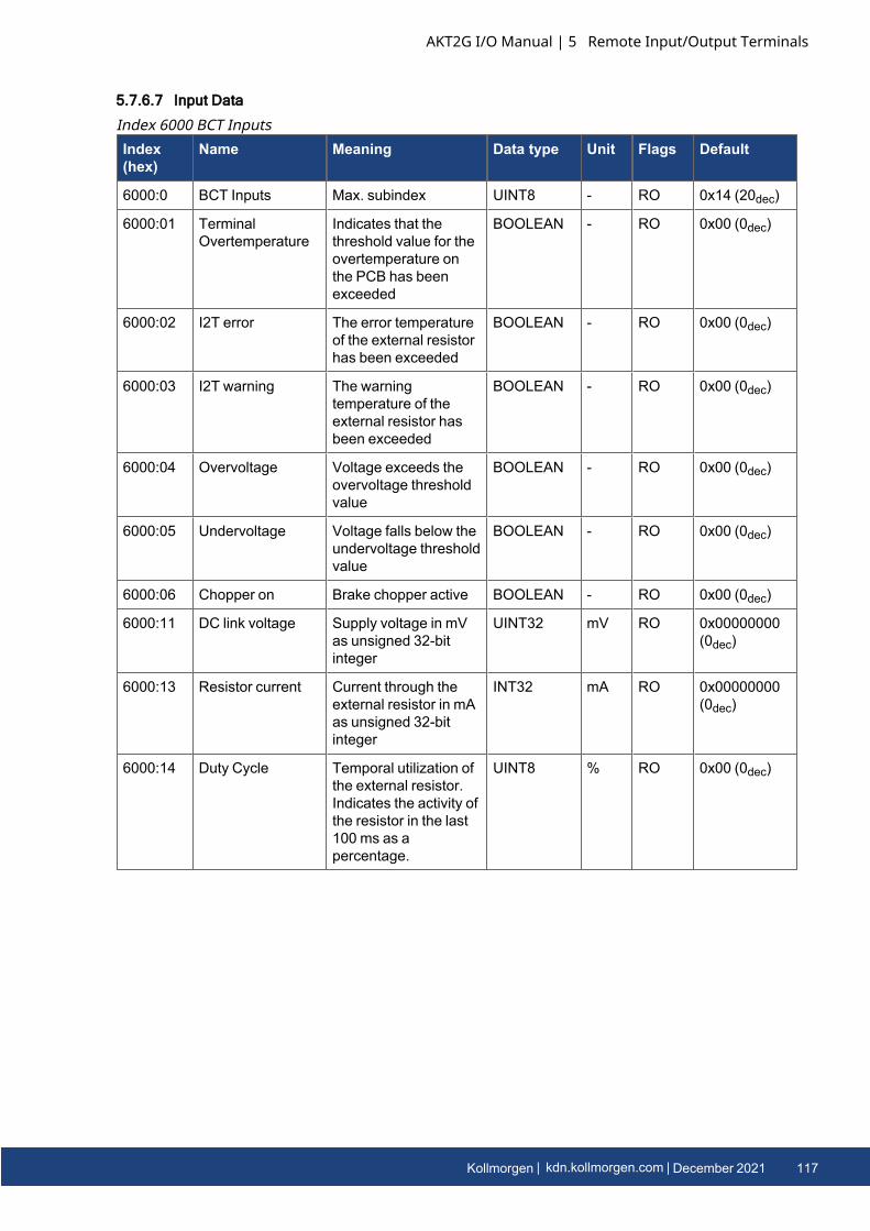
5.7.6.7 Input Data
Index(hex)
Name Meaning Data type Unit Flags Default
6000:0 BCT Inputs Max. subindex UINT8 - RO 0x14 (20dec)
6000:01 TerminalOvertemperature
Indicates that thethreshold value for theovertemperature onthe PCB has beenexceeded
BOOLEAN - RO 0x00 (0dec)
6000:02 I2T error The error temperatureof the external resistorhas been exceeded
BOOLEAN - RO 0x00 (0dec)
6000:03 I2T warning The warningtemperature of theexternal resistor hasbeen exceeded
BOOLEAN - RO 0x00 (0dec)
6000:04 Overvoltage Voltage exceeds theovervoltage thresholdvalue
BOOLEAN - RO 0x00 (0dec)
6000:05 Undervoltage Voltage falls below theundervoltage thresholdvalue
BOOLEAN - RO 0x00 (0dec)
6000:06 Chopper on Brake chopper active BOOLEAN - RO 0x00 (0dec)
6000:11 DC link voltage Supply voltage in mVas unsigned 32-bitinteger
UINT32 mV RO 0x00000000(0dec)
6000:13 Resistor current Current through theexternal resistor in mAas unsigned 32-bitinteger
INT32 mA RO 0x00000000(0dec)
6000:14 Duty Cycle Temporal utilization ofthe external resistor.Indicates the activity ofthe resistor in the last100 ms as apercentage.
UINT8 % RO 0x00 (0dec)
Index 6000 BCT Inputs
AKT2G I/O Manual | 5 Remote Input/Output Terminals
Kollmorgen | kdn.kollmorgen.com | December 2021 117
AKT2G I/O Manual | 5 Remote Input/Output Terminals
5.7.6.8 Information and Diagnostic Data
Index (hex) Name Meaning Data type Flags Default
A000:0 BCT Diag data Max. subindex UINT8 RO 0x11 (17dec)
A000:11 Temperature Temperature on the PCB UINT8 RO 0x00 (0dec)
Index A000 BCT Diag data
Index(hex)
Name Meaning Datatype
Flags Default
F000:0 Modular deviceprofile
General information for the modulardevice profile
UINT8 RO 0x02(2dec)
F000:01 Module indexdistance
Index distance of the objects of theindividual channels
UINT16 RO 0x0010(16dec)
F000:02 Maximum numberof modules
Number of channels UINT16 RO 0x0001(1dec)
Index F000 Modular device profile
Index (hex) Name Meaning Data type Flags Default
F008:0 Code word reserved UINT32 RW 0x00000000 (0dec)
Index F008 Code word
Index (hex) Name Meaning Data type Flags Default
F010:0 Module list UINT8 RW 0x01 (1dec)
F010:01 SubIndex 001 UINT32 RW 0x00000384 (900dec)
Index F010 Module list
118 Kollmorgen | kdn.kollmorgen.com | December 2021
5.8 AKT2G-DN-002-000Up/Down Counter 24 VDC, 100 kHz, 32 bit counter depth
The up/down counter counts binary pulses, and transmits the counter state, in an electricallyisolated form, to the higher-level automation device.The AKT2G-DN-002 EtherCAT Terminal can alternatively be operated as:
l a single-channel counter (32 bit) that can be toggled between counting up and down via theU/D input (delivery state)
l a single-channel counter (32 bit) that is controlled via the gate connectionl two separate logic counters (32 bit) that can count in one direction only with the Clock 1 and
Clock 2 inputs
The signal state of the inputs and outputs is indicated by light emitting diodes.The two outputs (Output 1 and Output 2) are switched in relation to the counter value and can thusbe used as fast control signals for field devices.The AKT2G-DN-002 supports distributed clocks, i.e. the input data can be monitored synchronouslywith other data that are also linked to distributed clock terminals. The accuracy across the systemis < 100 ns.
AKT2G I/O Manual | 5 Remote Input/Output Terminals
Kollmorgen | kdn.kollmorgen.com | December 2021 119
AKT2G I/O Manual | 5 Remote Input/Output Terminals
5.8.1 LEDs and Connection
5.8.1.1 LEDs
LED Color Meaning
UP/DOWN, GATECLOCK CH.1
green Signal at U/D, Gate input (operating mode 32 bit up/down counter,32 bit gated counter)
Signal at the Clock input, channel 1 (operating mode 2 x 32 bitcounter)
see "Operating Mode Selection" on page 122
CLOCK
CLOCK CH.2
green Signal at Clock input (operating mode 32 bit up/down counter, 32 bitgated counter)
Signal at the Clock input, channel 2 (operating mode 2 x 32 bitcounter
see "Operating Mode Selection" on page 122
OUTPUT1
OUTPUT2
green Signal at the corresponding output
120 Kollmorgen | kdn.kollmorgen.com | December 2021
5.8.1.2 Connection
Terminal Point Description
Name No.
U/D, GateClock Ch.1
1 Up/down input (operating mode 32 bit up/down counter),
Gate input (operating mode 32 bit counter with gate function) Clock 1 input(operating mode 2 x 32 bit counter)
see "Operating Mode Selection" on page 122
+24 V 2 +24 V (internally connected to terminal point 6 and positive power contact)
0 V 3 0 V (internally connected to terminal point 7 and negative power contact)
Output 1 4 Output 1
Clock
Clock Ch.2
5 Clock input (operating mode 32 bit up/down counter) and (operating mode 32 bitcounter with gate function)
Clock 2 input (operating mode 2 x 32 bit counter)
see "Operating Mode Selection" on page 122
+24 V 6 +24 V (internally connected to terminal point 2 and positive power contact)
0 V 7 0 V (internally connected to terminal point 3 and negative power contact)
Output 2 8 Output 2
5.8.2 Basic Function PrinciplesThe AKT2G-DN-002 input terminals count binary pulses and transfer the current value to thehigher-level controller.In addition to the 32 bit up/down counter, further available operating modes are a 32 bit gatedcounter or two 32 bit counters. In gated counter mode, a low or high level at the Gate input inhibitsthe counting function of the terminal.If two 32 bit counters are active, the U/D input (terminal point 1) is configured as the input for thefirst counter and the Clock 2 input (terminal point 5) as the input for the second counter.Beyond that, two digital outputs can be set.The maximum input frequency is limited to 100 kHz for the AKT2G-DN-002; the counters react tothe rising edge of the input signal.
AKT2G I/O Manual | 5 Remote Input/Output Terminals
Kollmorgen | kdn.kollmorgen.com | December 2021 121
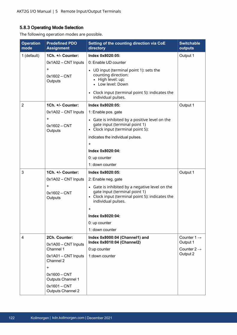
AKT2G I/O Manual | 5 Remote Input/Output Terminals
5.8.3 Operating Mode SelectionThe following operation modes are possible.
Operationmode
Predefined PDOAssignment
Setting of the counting direction via CoEdirectory
Switchableoutputs
1 (default) 1Ch. +/- Counter:0x1A02 – CNT Inputs
+
0x1602 – CNTOutputs
Index 0x8020:05:0: Enable UD counter
l UD input (terminal point 1): sets thecounting direction:l High level: up;l Low level: Down
l Clock input (terminal point 5): indicates theindividual pulses.
Output 1
2 1Ch. +/- Counter:0x1A02 – CNT Inputs
+
0x1602 – CNTOutputs
Index 0x8020:05:1: Enable pos. gate
l Gate is inhibited by a positive level on thegate input (terminal point 1)
l Clock input (terminal point 5):
indicates the individual pulses.
+
Index 0x8020:04:0: up counter
1: down counter
Output 1
3 1Ch. +/- Counter:0x1A02 – CNT Inputs
+
0x1602 – CNTOutputs
Index 0x8020:05:2: Enable neg. gate
l Gate is inhibited by a negative level on thegate input (terminal point 1)
l Clock input (terminal point 5): indicates theindividual pulses.
+
Index 0x8020:04:0: up counter
1: down counter
Output 1
4 2Ch. Counter:0x1A00 – CNT InputsChannel 1
0x1A01 – CNT InputsChannel 2
+
0x1600 – CNTOutputs Channel 1
0x1601 – CNTOutputs Channel 2
Index 0x8000:04 (Channel1) andIndex 0x8010:04 (Channel2)0:up counter
1:down counter
Counter 1→Output 1
Counter 2→Output 2
122 Kollmorgen | kdn.kollmorgen.com | December 2021

In addition, the distributed clock function may be activated for the AKT2G-DN-002.Single-channel up/down counter, gated counter (operating mode 1-3)
1. Selection of the PDOs for "1Ch.+/-Counter"2. CoE Init-command to configure index 0x8020:05:
l "Enable UD counter" – single-channel up/down counter (operating mode 1)If a high signal level is encountered at the up/down input of the terminal (terminalpoint 1), the counter counts up in the event of positive edges at the clock input(terminal point 5), with a low signal level it counts down.
l "Enable pos. gate" – single-channel gated counter closes in the case of a high level(operating mode 2)The counter is inhibited if a high level is encountered at the gate input of the terminal(terminal point 1).The counting direction is set by index 0x8020:04 (0: up, 1: down). The clock input(terminal point 5) indicates the individual pulses.
l "Enable neg. gate" – single-channel gated counter closes in the case of a low level(operating mode 3)The counter is inhibited if a low level is encountered at the gate input of the terminal(terminal point 1).The counting direction is set by index 0x8020:04 (0: up, 1: down).The clock input (terminal point 5) indicates the individual pulses.
Two-channel up/down counter (operating mode 4)
1. Selection of the PDOs for "2Ch. Counter"The terminal points 1 or 5 serve as clock input for 32 bit counter 1 or 2.
2. CoE Init-commands to configure the indices 0x8000:04 for channel 1 and 0x8010:04 forchannel. Two options are available per channel:
l 0: up counterl 1: down counter
AKT2G I/O Manual | 5 Remote Input/Output Terminals
Kollmorgen | kdn.kollmorgen.com | December 2021 123
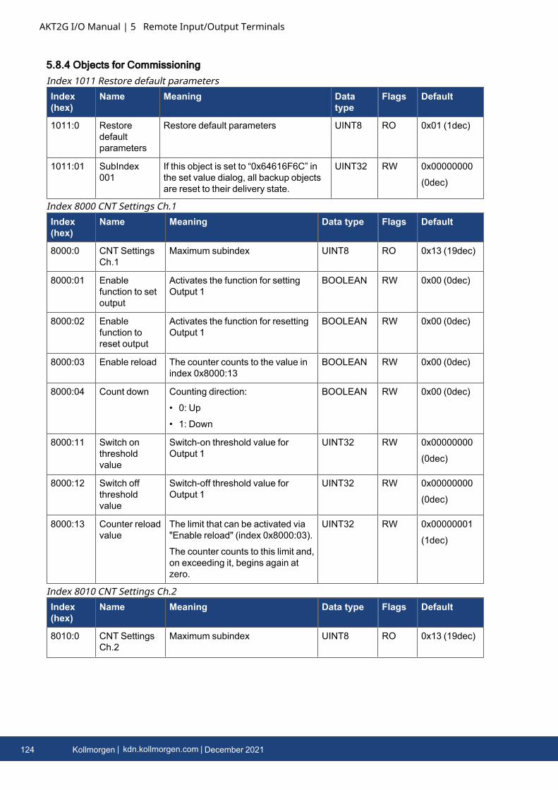
AKT2G I/O Manual | 5 Remote Input/Output Terminals
5.8.4 Objects for Commissioning
Index(hex)
Name Meaning Datatype
Flags Default
1011:0 Restoredefaultparameters
Restore default parameters UINT8 RO 0x01 (1dec)
1011:01 SubIndex001
If this object is set to “0x64616F6C” inthe set value dialog, all backup objectsare reset to their delivery state.
UINT32 RW 0x00000000
(0dec)
Index 1011 Restore default parameters
Index(hex)
Name Meaning Data type Flags Default
8000:0 CNT SettingsCh.1
Maximum subindex UINT8 RO 0x13 (19dec)
8000:01 Enablefunction to setoutput
Activates the function for settingOutput 1
BOOLEAN RW 0x00 (0dec)
8000:02 Enablefunction toreset output
Activates the function for resettingOutput 1
BOOLEAN RW 0x00 (0dec)
8000:03 Enable reload The counter counts to the value inindex 0x8000:13
BOOLEAN RW 0x00 (0dec)
8000:04 Count down Counting direction:
• 0: Up
• 1: Down
BOOLEAN RW 0x00 (0dec)
8000:11 Switch onthresholdvalue
Switch-on threshold value forOutput 1
UINT32 RW 0x00000000
(0dec)
8000:12 Switch offthresholdvalue
Switch-off threshold value forOutput 1
UINT32 RW 0x00000000
(0dec)
8000:13 Counter reloadvalue
The limit that can be activated via"Enable reload" (index 0x8000:03).
The counter counts to this limit and,on exceeding it, begins again atzero.
UINT32 RW 0x00000001
(1dec)
Index 8000 CNT Settings Ch.1
Index(hex)
Name Meaning Data type Flags Default
8010:0 CNT SettingsCh.2
Maximum subindex UINT8 RO 0x13 (19dec)
Index 8010 CNT Settings Ch.2
124 Kollmorgen | kdn.kollmorgen.com | December 2021
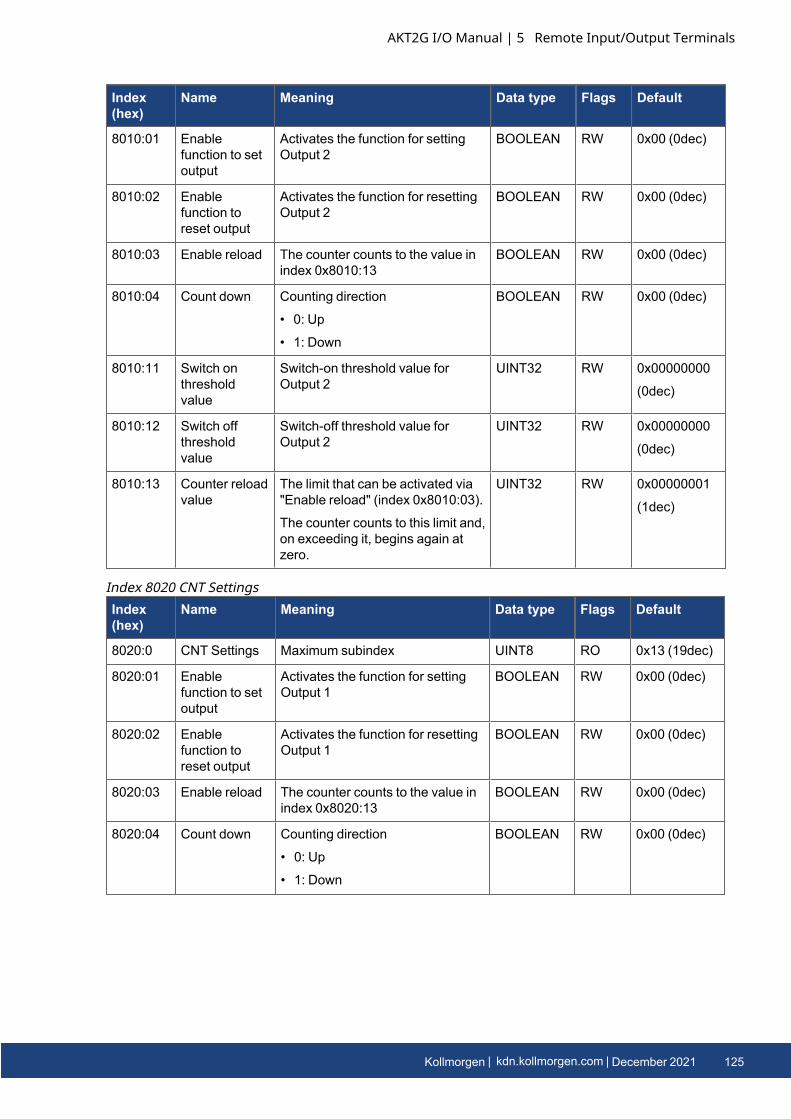
Index(hex)
Name Meaning Data type Flags Default
8010:01 Enablefunction to setoutput
Activates the function for settingOutput 2
BOOLEAN RW 0x00 (0dec)
8010:02 Enablefunction toreset output
Activates the function for resettingOutput 2
BOOLEAN RW 0x00 (0dec)
8010:03 Enable reload The counter counts to the value inindex 0x8010:13
BOOLEAN RW 0x00 (0dec)
8010:04 Count down Counting direction
• 0: Up
• 1: Down
BOOLEAN RW 0x00 (0dec)
8010:11 Switch onthresholdvalue
Switch-on threshold value forOutput 2
UINT32 RW 0x00000000
(0dec)
8010:12 Switch offthresholdvalue
Switch-off threshold value forOutput 2
UINT32 RW 0x00000000
(0dec)
8010:13 Counter reloadvalue
The limit that can be activated via"Enable reload" (index 0x8010:03).
The counter counts to this limit and,on exceeding it, begins again atzero.
UINT32 RW 0x00000001
(1dec)
Index(hex)
Name Meaning Data type Flags Default
8020:0 CNT Settings Maximum subindex UINT8 RO 0x13 (19dec)
8020:01 Enablefunction to setoutput
Activates the function for settingOutput 1
BOOLEAN RW 0x00 (0dec)
8020:02 Enablefunction toreset output
Activates the function for resettingOutput 1
BOOLEAN RW 0x00 (0dec)
8020:03 Enable reload The counter counts to the value inindex 0x8020:13
BOOLEAN RW 0x00 (0dec)
8020:04 Count down Counting direction
• 0: Up
• 1: Down
BOOLEAN RW 0x00 (0dec)
Index 8020 CNT Settings
AKT2G I/O Manual | 5 Remote Input/Output Terminals
Kollmorgen | kdn.kollmorgen.com | December 2021 125
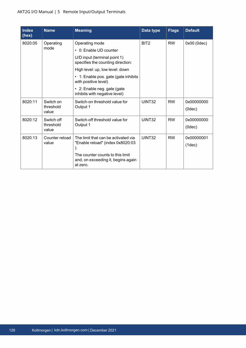
AKT2G I/O Manual | 5 Remote Input/Output Terminals
Index(hex)
Name Meaning Data type Flags Default
8020:05 Operatingmode
Operating mode
• 0: Enable UD counter
U/D input (terminal point 1)specifies the counting direction:
High level: up, low level: down
• 1: Enable pos. gate (gate inhibitswith positive level)
• 2: Enable neg. gate (gateinhibits with negative level)
BIT2 RW 0x00 (0dec)
8020:11 Switch onthresholdvalue
Switch-on threshold value forOutput 1
UINT32 RW 0x00000000
(0dec)
8020:12 Switch offthresholdvalue
Switch-off threshold value forOutput 1
UINT32 RW 0x00000000
(0dec)
8020:13 Counter reloadvalue
The limit that can be activated via"Enable reload" (index 0x8020:03).
The counter counts to this limitand, on exceeding it, begins againat zero.
UINT32 RW 0x00000001
(1dec)
126 Kollmorgen | kdn.kollmorgen.com | December 2021
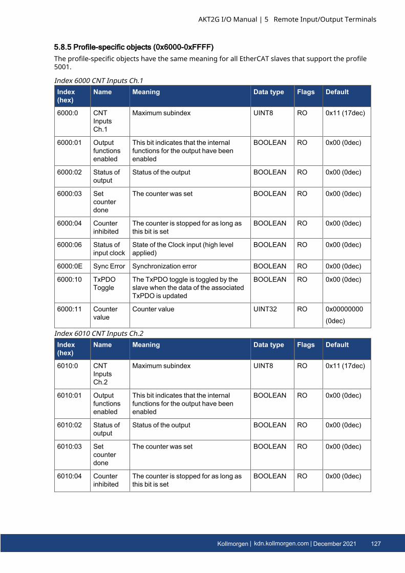
5.8.5 Profile-specific objects (0x6000-0xFFFF)The profile-specific objects have the same meaning for all EtherCAT slaves that support the profile5001.
Index(hex)
Name Meaning Data type Flags Default
6000:0 CNTInputsCh.1
Maximum subindex UINT8 RO 0x11 (17dec)
6000:01 Outputfunctionsenabled
This bit indicates that the internalfunctions for the output have beenenabled
BOOLEAN RO 0x00 (0dec)
6000:02 Status ofoutput
Status of the output BOOLEAN RO 0x00 (0dec)
6000:03 Setcounterdone
The counter was set BOOLEAN RO 0x00 (0dec)
6000:04 Counterinhibited
The counter is stopped for as long asthis bit is set
BOOLEAN RO 0x00 (0dec)
6000:06 Status ofinput clock
State of the Clock input (high levelapplied)
BOOLEAN RO 0x00 (0dec)
6000:0E Sync Error Synchronization error BOOLEAN RO 0x00 (0dec)
6000:10 TxPDOToggle
The TxPDO toggle is toggled by theslave when the data of the associatedTxPDO is updated
BOOLEAN RO 0x00 (0dec)
6000:11 Countervalue
Counter value UINT32 RO 0x00000000
(0dec)
Index 6000 CNT Inputs Ch.1
Index(hex)
Name Meaning Data type Flags Default
6010:0 CNTInputsCh.2
Maximum subindex UINT8 RO 0x11 (17dec)
6010:01 Outputfunctionsenabled
This bit indicates that the internalfunctions for the output have beenenabled
BOOLEAN RO 0x00 (0dec)
6010:02 Status ofoutput
Status of the output BOOLEAN RO 0x00 (0dec)
6010:03 Setcounterdone
The counter was set BOOLEAN RO 0x00 (0dec)
6010:04 Counterinhibited
The counter is stopped for as long asthis bit is set
BOOLEAN RO 0x00 (0dec)
Index 6010 CNT Inputs Ch.2
AKT2G I/O Manual | 5 Remote Input/Output Terminals
Kollmorgen | kdn.kollmorgen.com | December 2021 127
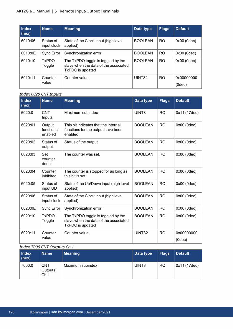
AKT2G I/O Manual | 5 Remote Input/Output Terminals
Index(hex)
Name Meaning Data type Flags Default
6010:06 Status ofinput clock
State of the Clock input (high levelapplied)
BOOLEAN RO 0x00 (0dec)
6010:0E Sync Error Synchronization error BOOLEAN RO 0x00 (0dec)
6010:10 TxPDOToggle
The TxPDO toggle is toggled by theslave when the data of the associatedTxPDO is updated
BOOLEAN RO 0x00 (0dec)
6010:11 Countervalue
Counter value UINT32 RO 0x00000000
(0dec)
Index(hex)
Name Meaning Data type Flags Default
6020:0 CNTInputs
Maximum subindex UINT8 RO 0x11 (17dec)
6020:01 Outputfunctionsenabled
This bit indicates that the internalfunctions for the output have beenenabled
BOOLEAN RO 0x00 (0dec)
6020:02 Status ofoutput
Status of the output BOOLEAN RO 0x00 (0dec)
6020:03 Setcounterdone
The counter was set. BOOLEAN RO 0x00 (0dec)
6020:04 Counterinhibited
The counter is stopped for as long asthis bit is set
BOOLEAN RO 0x00 (0dec)
6020:05 Status ofinput UD
State of the Up/Down input (high levelapplied)
BOOLEAN RO 0x00 (0dec)
6020:06 Status ofinput clock
State of the Clock input (high levelapplied)
BOOLEAN RO 0x00 (0dec)
6020:0E Sync Error Synchronization error BOOLEAN RO 0x00 (0dec)
6020:10 TxPDOToggle
The TxPDO toggle is toggled by theslave when the data of the associatedTxPDO is updated
BOOLEAN RO 0x00 (0dec)
6020:11 Countervalue
Counter value UINT32 RO 0x00000000
(0dec)
Index 6020 CNT Inputs
Index(hex)
Name Meaning Data type Flags Default
7000:0 CNTOutputsCh.1
Maximum subindex UINT8 RO 0x11 (17dec)
Index 7000 CNT Outputs Ch.1
128 Kollmorgen | kdn.kollmorgen.com | December 2021
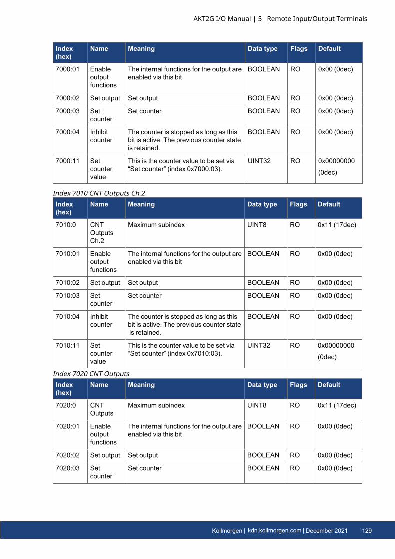
Index(hex)
Name Meaning Data type Flags Default
7000:01 Enableoutputfunctions
The internal functions for the output areenabled via this bit
BOOLEAN RO 0x00 (0dec)
7000:02 Set output Set output BOOLEAN RO 0x00 (0dec)
7000:03 Setcounter
Set counter BOOLEAN RO 0x00 (0dec)
7000:04 Inhibitcounter
The counter is stopped as long as thisbit is active. The previous counter stateis retained.
BOOLEAN RO 0x00 (0dec)
7000:11 Setcountervalue
This is the counter value to be set via“Set counter” (index 0x7000:03).
UINT32 RO 0x00000000
(0dec)
Index(hex)
Name Meaning Data type Flags Default
7010:0 CNTOutputsCh.2
Maximum subindex UINT8 RO 0x11 (17dec)
7010:01 Enableoutputfunctions
The internal functions for the output areenabled via this bit
BOOLEAN RO 0x00 (0dec)
7010:02 Set output Set output BOOLEAN RO 0x00 (0dec)
7010:03 Setcounter
Set counter BOOLEAN RO 0x00 (0dec)
7010:04 Inhibitcounter
The counter is stopped as long as thisbit is active. The previous counter stateis retained.
BOOLEAN RO 0x00 (0dec)
7010:11 Setcountervalue
This is the counter value to be set via“Set counter” (index 0x7010:03).
UINT32 RO 0x00000000
(0dec)
Index 7010 CNT Outputs Ch.2
Index(hex)
Name Meaning Data type Flags Default
7020:0 CNTOutputs
Maximum subindex UINT8 RO 0x11 (17dec)
7020:01 Enableoutputfunctions
The internal functions for the output areenabled via this bit
BOOLEAN RO 0x00 (0dec)
7020:02 Set output Set output BOOLEAN RO 0x00 (0dec)
7020:03 Setcounter
Set counter BOOLEAN RO 0x00 (0dec)
Index 7020 CNT Outputs
AKT2G I/O Manual | 5 Remote Input/Output Terminals
Kollmorgen | kdn.kollmorgen.com | December 2021 129
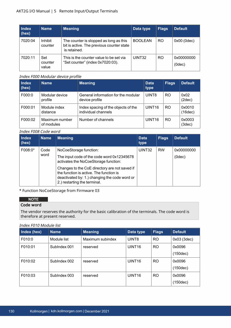
AKT2G I/O Manual | 5 Remote Input/Output Terminals
Index(hex)
Name Meaning Data type Flags Default
7020:04 Inhibitcounter
The counter is stopped as long as thisbit is active. The previous counter stateis retained.
BOOLEAN RO 0x00 (0dec)
7020:11 Setcountervalue
This is the counter value to be set via“Set counter” (index 0x7020:03).
UINT32 RO 0x00000000
(0dec)
Index(hex)
Name Meaning Datatype
Flags Default
F000:0 Modular deviceprofile
General information for the modulardevice profile
UINT8 RO 0x02(2dec)
F000:01 Module indexdistance
Index spacing of the objects of theindividual channels
UINT16 RO 0x0010(16dec)
F000:02 Maximum numberof modules
Number of channels UINT16 RO 0x0003(3dec)
Index F000 Modular device profile
Index(hex)
Name Meaning Datatype
Flags Default
F008:0* Codeword
NoCoeStorage function:
The input code of the code word 0x12345678activates the NoCoeStorage function:
Changes to the CoE directory are not saved ifthe function is active. The function isdeactivated by: 1.) changing the code word or2.) restarting the terminal.
UINT32 RW 0x00000000
(0dec)
Index F008 Code word
* Function NoCoeStorage from Firmware 03
Code wordThe vendor reserves the authority for the basic calibration of the terminals. The code word istherefore at present reserved.
Index (hex) Name Meaning Data type Flags Default
F010:0 Module list Maximum subindex UINT8 RO 0x03 (3dec)
F010:01 SubIndex 001 reserved UINT16 RO 0x0096
(150dec)
F010:02 SubIndex 002 reserved UINT16 RO 0x0096
(150dec)
F010:03 SubIndex 003 reserved UINT16 RO 0x0096
(150dec)
Index F010 Module list
130 Kollmorgen | kdn.kollmorgen.com | December 2021
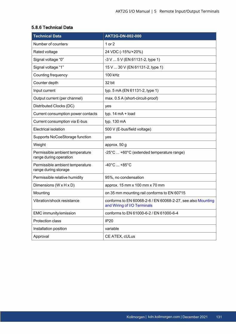
5.8.6 Technical Data
Technical Data AKT2G-DN-002-000
Number of counters 1 or 2
Rated voltage 24 VDC (-15%/+20%)
Signal voltage “0” -3 V ... 5 V (EN 61131-2, type 1)
Signal voltage “1” 15 V ... 30 V (EN 61131-2, type 1)
Counting frequency 100 kHz
Counter depth 32 bit
Input current typ. 5 mA (EN 61131-2, type 1)
Output current (per channel) max. 0.5 A (short-circuit-proof)
Distributed Clocks (DC) yes
Current consumption power contacts typ. 14 mA + load
Current consumption via E-bus typ. 130 mA
Electrical isolation 500 V (E-bus/field voltage)
Supports NoCoeStorage function yes
Weight approx. 50 g
Permissible ambient temperaturerange during operation
-25°C ... +60°C (extended temperature range)
Permissible ambient temperaturerange during storage
-40°C ... +85°C
Permissible relative humidity 95%, no condensation
Dimensions (W x H x D) approx. 15 mm x 100 mm x 70 mm
Mounting on 35 mmmounting rail conforms to EN 60715
Vibration/shock resistance conforms to EN 60068-2-6 / EN 60068-2-27, see also MountingandWiring of I/O Terminals
EMC immunity/emission conforms to EN 61000-6-2 / EN 61000-6-4
Protection class IP20
Installation position variable
Approval CE ATEX, cULus
AKT2G I/O Manual | 5 Remote Input/Output Terminals
Kollmorgen | kdn.kollmorgen.com | December 2021 131

AKT2G I/O Manual | 5 Remote Input/Output Terminals
5.9 AKT2G-DN-008-0008-channel Digital Input Terminal 24 V DC, filter 3.0 ms, 1-wire systemThe DN-008 digital input terminal acquires binary control signals from the process level andtransmit them, in an electrically isolated form, to the higher-level automation device. The digitalinput terminals of the DN-008 feature an input filter (3 ms) and indicate their signal state throughan LED for each channel.
5.9.1 LEDs
LED Color Meaning
INPUT 1- 8 green off Signal voltage "0" (-3 V ... 5 V)
on Signal voltage "1" (11 V ... 30 V)
5.9.2 Connection
Terminal Point Description
Name No.
Input 1 1 Input 1
Input 3 2 Input 3
Input 5 3 Input 5
Input 7 4 Input 7
Input 2 5 Input 2
Input 4 6 Input 4
Input 6 7 Input 6
Input 8 8 Input 8
132 Kollmorgen | kdn.kollmorgen.com | December 2021
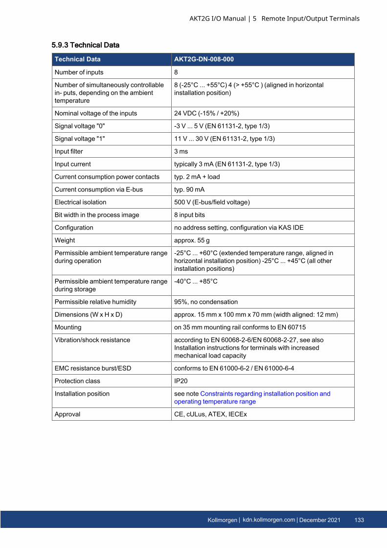
5.9.3 Technical Data
Technical Data AKT2G-DN-008-000
Number of inputs 8
Number of simultaneously controllablein- puts, depending on the ambienttemperature
8 (-25°C ... +55°C) 4 (> +55°C ) (aligned in horizontalinstallation position)
Nominal voltage of the inputs 24 VDC (-15% / +20%)
Signal voltage "0" -3 V ... 5 V (EN 61131-2, type 1/3)
Signal voltage "1" 11 V ... 30 V (EN 61131-2, type 1/3)
Input filter 3 ms
Input current typically 3 mA (EN 61131-2, type 1/3)
Current consumption power contacts typ. 2 mA + load
Current consumption via E-bus typ. 90 mA
Electrical isolation 500 V (E-bus/field voltage)
Bit width in the process image 8 input bits
Configuration no address setting, configuration via KAS IDE
Weight approx. 55 g
Permissible ambient temperature rangeduring operation
-25°C ... +60°C (extended temperature range, aligned inhorizontal installation position) -25°C ... +45°C (all otherinstallation positions)
Permissible ambient temperature rangeduring storage
-40°C ... +85°C
Permissible relative humidity 95%, no condensation
Dimensions (W x H x D) approx. 15 mm x 100 mm x 70 mm (width aligned: 12 mm)
Mounting on 35 mmmounting rail conforms to EN 60715
Vibration/shock resistance according to EN 60068-2-6/EN 60068-2-27, see alsoInstallation instructions for terminals with increasedmechanical load capacity
EMC resistance burst/ESD conforms to EN 61000-6-2 / EN 61000-6-4
Protection class IP20
Installation position see note Constraints regarding installation position andoperating temperature range
Approval CE, cULus, ATEX, IECEx
AKT2G I/O Manual | 5 Remote Input/Output Terminals
Kollmorgen | kdn.kollmorgen.com | December 2021 133
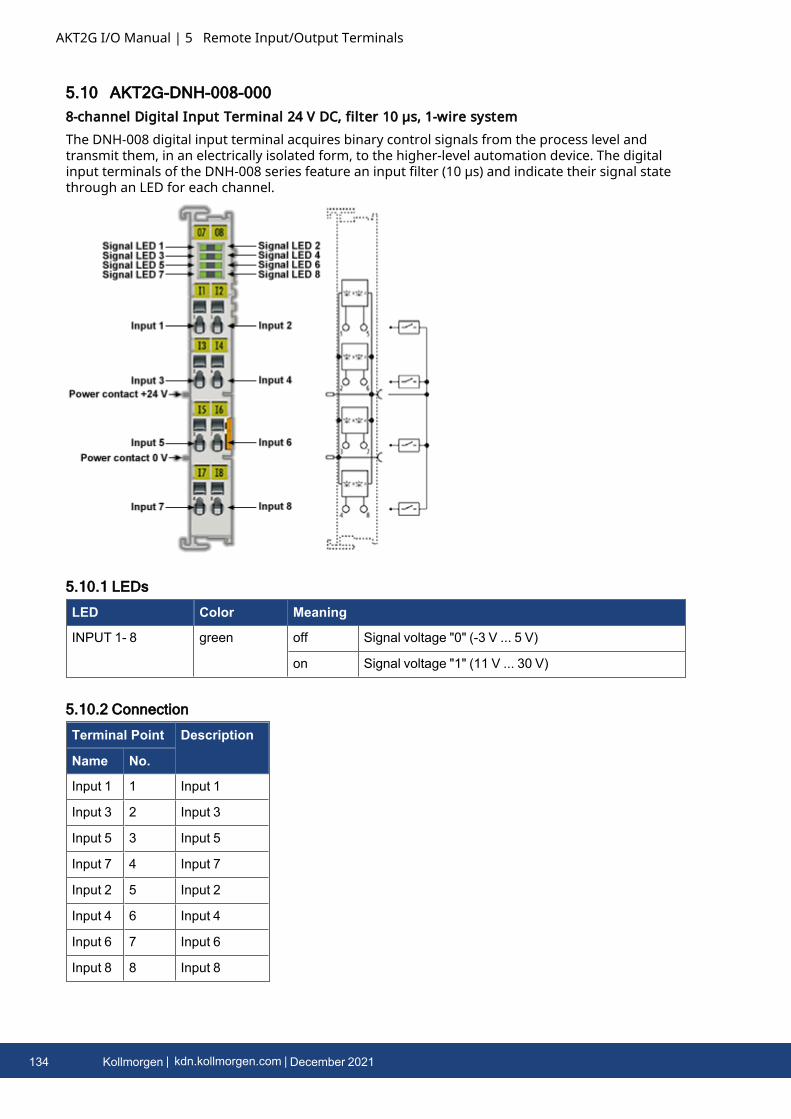
AKT2G I/O Manual | 5 Remote Input/Output Terminals
5.10 AKT2G-DNH-008-0008-channel Digital Input Terminal 24 V DC, filter 10 µs, 1-wire systemThe DNH-008 digital input terminal acquires binary control signals from the process level andtransmit them, in an electrically isolated form, to the higher-level automation device. The digitalinput terminals of the DNH-008 series feature an input filter (10 µs) and indicate their signal statethrough an LED for each channel.
5.10.1 LEDs
LED Color Meaning
INPUT 1- 8 green off Signal voltage "0" (-3 V ... 5 V)
on Signal voltage "1" (11 V ... 30 V)
5.10.2 Connection
Terminal Point Description
Name No.
Input 1 1 Input 1
Input 3 2 Input 3
Input 5 3 Input 5
Input 7 4 Input 7
Input 2 5 Input 2
Input 4 6 Input 4
Input 6 7 Input 6
Input 8 8 Input 8
134 Kollmorgen | kdn.kollmorgen.com | December 2021
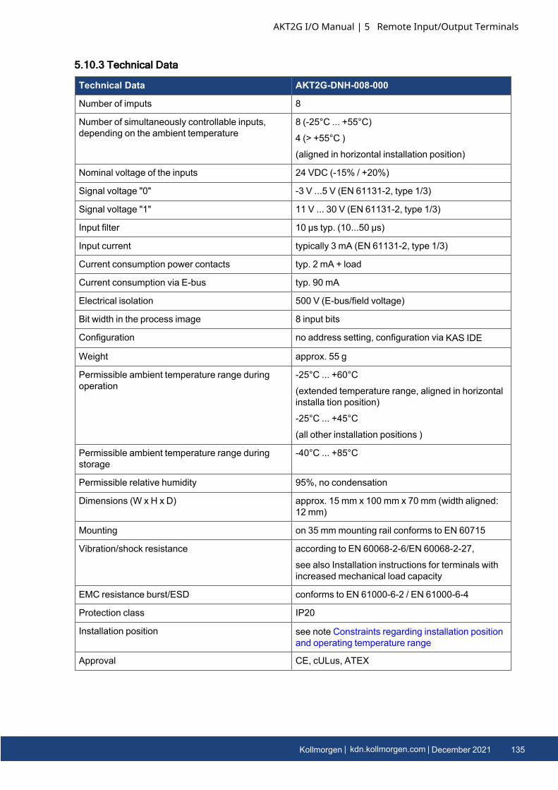
5.10.3 Technical Data
Technical Data AKT2G-DNH-008-000
Number of imputs 8
Number of simultaneously controllable inputs,depending on the ambient temperature
8 (-25°C ... +55°C)
4 (> +55°C )
(aligned in horizontal installation position)
Nominal voltage of the inputs 24 VDC (-15% / +20%)
Signal voltage "0" -3 V ...5 V (EN 61131-2, type 1/3)
Signal voltage "1" 11 V ... 30 V (EN 61131-2, type 1/3)
Input filter 10 µs typ. (10...50 µs)
Input current typically 3 mA (EN 61131-2, type 1/3)
Current consumption power contacts typ. 2 mA + load
Current consumption via E-bus typ. 90 mA
Electrical isolation 500 V (E-bus/field voltage)
Bit width in the process image 8 input bits
Configuration no address setting, configuration via KAS IDE
Weight approx. 55 g
Permissible ambient temperature range duringoperation
-25°C ... +60°C
(extended temperature range, aligned in horizontalinstalla tion position)
-25°C ... +45°C
(all other installation positions )
Permissible ambient temperature range duringstorage
-40°C ... +85°C
Permissible relative humidity 95%, no condensation
Dimensions (W x H x D) approx. 15 mm x 100 mm x 70 mm (width aligned:12 mm)
Mounting on 35 mmmounting rail conforms to EN 60715
Vibration/shock resistance according to EN 60068-2-6/EN 60068-2-27,
see also Installation instructions for terminals withincreased mechanical load capacity
EMC resistance burst/ESD conforms to EN 61000-6-2 / EN 61000-6-4
Protection class IP20
Installation position see note Constraints regarding installation positionand operating temperature range
Approval CE, cULus, ATEX
AKT2G I/O Manual | 5 Remote Input/Output Terminals
Kollmorgen | kdn.kollmorgen.com | December 2021 135
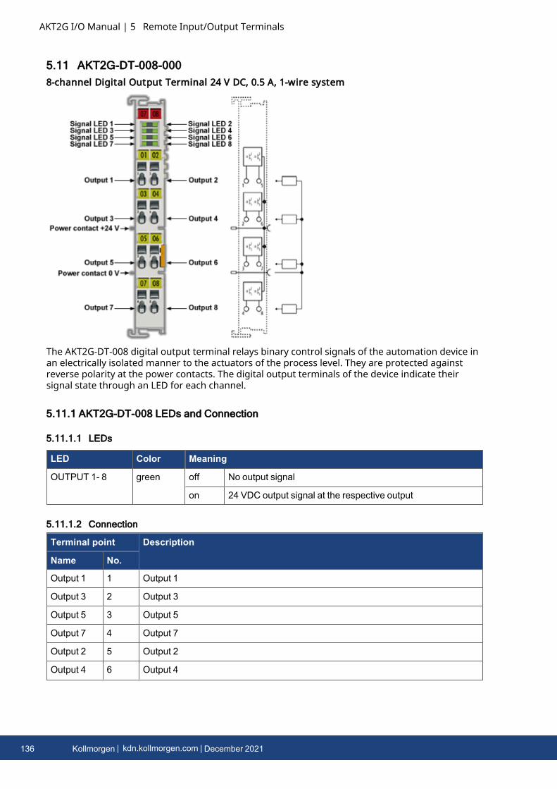
AKT2G I/O Manual | 5 Remote Input/Output Terminals
5.11 AKT2G-DT-008-0008-channel Digital Output Terminal 24 V DC, 0.5 A, 1-wire system
The AKT2G-DT-008 digital output terminal relays binary control signals of the automation device inan electrically isolated manner to the actuators of the process level. They are protected againstreverse polarity at the power contacts. The digital output terminals of the device indicate theirsignal state through an LED for each channel.
5.11.1 AKT2G-DT-008 LEDs and Connection
5.11.1.1 LEDs
LED Color Meaning
OUTPUT 1- 8 green off No output signal
on 24 VDC output signal at the respective output
5.11.1.2 Connection
Terminal point Description
Name No.
Output 1 1 Output 1
Output 3 2 Output 3
Output 5 3 Output 5
Output 7 4 Output 7
Output 2 5 Output 2
Output 4 6 Output 4
136 Kollmorgen | kdn.kollmorgen.com | December 2021

Terminal point Description
Name No.
Output 6 7 Output 6
Output 8 8 Output 8
AKT2G I/O Manual | 5 Remote Input/Output Terminals
Kollmorgen | kdn.kollmorgen.com | December 2021 137
AKT2G I/O Manual | 5 Remote Input/Output Terminals
5.11.2 Technical Data
Technical Data AKT2G-DT-008-000
Number of outputs 8
Non-reactive outputs yes (see Interference-Free EtherCAT Terminals)
Load type ohmic, inductive, lamp load
Nominal output voltage 24 VDC (-15% / +20%)
Switching times TON: 60 µs typ.; TOFF: 300 µs typ.
Output current per channel maximum 0.5 A (short-circuit proof)
Switch-off energy (inductive) max. 150 mJ/channel
Current consumption from load voltage(power contacts)
typ. 15 mA
Supply voltage for electronic via the E-Bus
Current consumption via E-bus typ. 110 mA
Electrical isolation 500 V (E-bus/field voltage)
Bit width in the process image 8 output bits
Configuration no address setting, configuration via KAS IDE
Weight approx. 55 g
Permissible ambient temperature rangeduring operation
Aligned in horizontal installation position:
-25°C ... +60°C (extended temperature range)
All other installation positions: -25°C ... +45°C
Permissible ambient temperature rangeduring storage
-40°C ... +85°C
Permissible relative humidity 95%, no condensation
Dimensions (W x H x D) approx. 15 mm x 100 mm x 70 mm (width aligned: 12 mm)
Mounting on 35 mmmounting rail conforms to EN 60715
Vibration/shock resistance according to EN 60068-2-6/EN 60068-2-27,
see also Installation instructions for terminals with increasedmechanical load capacity
EMC resistance burst/ESD conforms to EN 61000-6-2 / EN 61000-6-4
Protection class IP20
Installation position see note Constraints regarding installation position andoperating temperature range
Approval CE, cULus, ATEX
138 Kollmorgen | kdn.kollmorgen.com | December 2021

5.12 AKT2G-ECT-000-000EtherCAT Coupler for E-bus Terminals
5.12.1 Overview of EtherCAT CouplersAn EtherCAT coupler is required in order to connect EtherCAT Terminals with E-bus-communicationto an EtherCAT network. This coupler relays the communication from the higher level EtherCATnetwork to the terminals.
5.12.2 EtherCAT Coupler for E-bus terminals
The ECT-000 coupler connects the EtherCAT Device Protocol with the EtherCAT Terminals. Onestation consists of a coupler, any number of EtherCAT Terminals and a bus end terminal (AKT2G-EM-000-000).The coupler converts the telegrams from Ethernet 100BASE-TX to E-bus signal representation inpassing with minimum latency. The coupler is connected to the network via the upper Ethernetinterface. The lower RJ-45 socket may be used to connect further EtherCAT devices in the samestrand.The coupler supplies the connected terminals with the necessary E-bus current for communication.The coupler can supply a maximum of 5 V/2 A. Power feed terminals (AKT2G-PSF-024-000) must beintegrated if more current is required.In the EtherCAT network, the coupler can be installed anywhere, including before, after, or in themiddle of the EtherCAT servo drives. However, the coupler does not support MAC Unicast orIP addressing from a switch or a router.
AKT2G I/O Manual | 5 Remote Input/Output Terminals
Kollmorgen | kdn.kollmorgen.com | December 2021 139
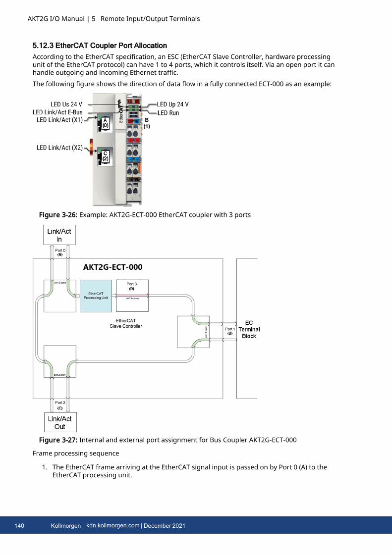
AKT2G I/O Manual | 5 Remote Input/Output Terminals
5.12.3 EtherCAT Coupler Port AllocationAccording to the EtherCAT specification, an ESC (EtherCAT Slave Controller, hardware processingunit of the EtherCAT protocol) can have 1 to 4 ports, which it controls itself. Via an open port it canhandle outgoing and incoming Ethernet traffic.The following figure shows the direction of data flow in a fully connected ECT-000 as an example:
Figure 3-26: Example: AKT2G-ECT-000 EtherCAT coupler with 3 ports
Figure 3-27: Internal and external port assignment for Bus Coupler AKT2G-ECT-000
Frame processing sequence
1. The EtherCAT frame arriving at the EtherCAT signal input is passed on by Port 0 (A) to theEtherCAT processing unit.
140 Kollmorgen | kdn.kollmorgen.com | December 2021

2. The EtherCAT frame arrives at Port 1 (B) and the data frame departs via Port 1 (B) to thefollowing slave in the EtherCAT terminal network (if a slave is connected there and reports‘Link’).
3. After the arrival of the data frame at Port 1 (B) from the terminal network, this is passed onto Port 2 (C) and leaves the coupler at the following EtherCAT output (if a slave is connectedthere and reports ‘Link’).
4. The data frame arrives at Port 2 (C). This is now forwarded to port 0 (A) and leaves the ECT-000 via the EtherCAT input.
Processing of the dataThe data in the EtherCAT datagrams are processed only between Ports 0 (A) and 3 (D) in theEtherCAT processing unit. The non-implemented (internal) Port 3 (D) is considered to be closedand passes on the datagram to Port 1 (B).
AKT2G I/O Manual | 5 Remote Input/Output Terminals
Kollmorgen | kdn.kollmorgen.com | December 2021 141
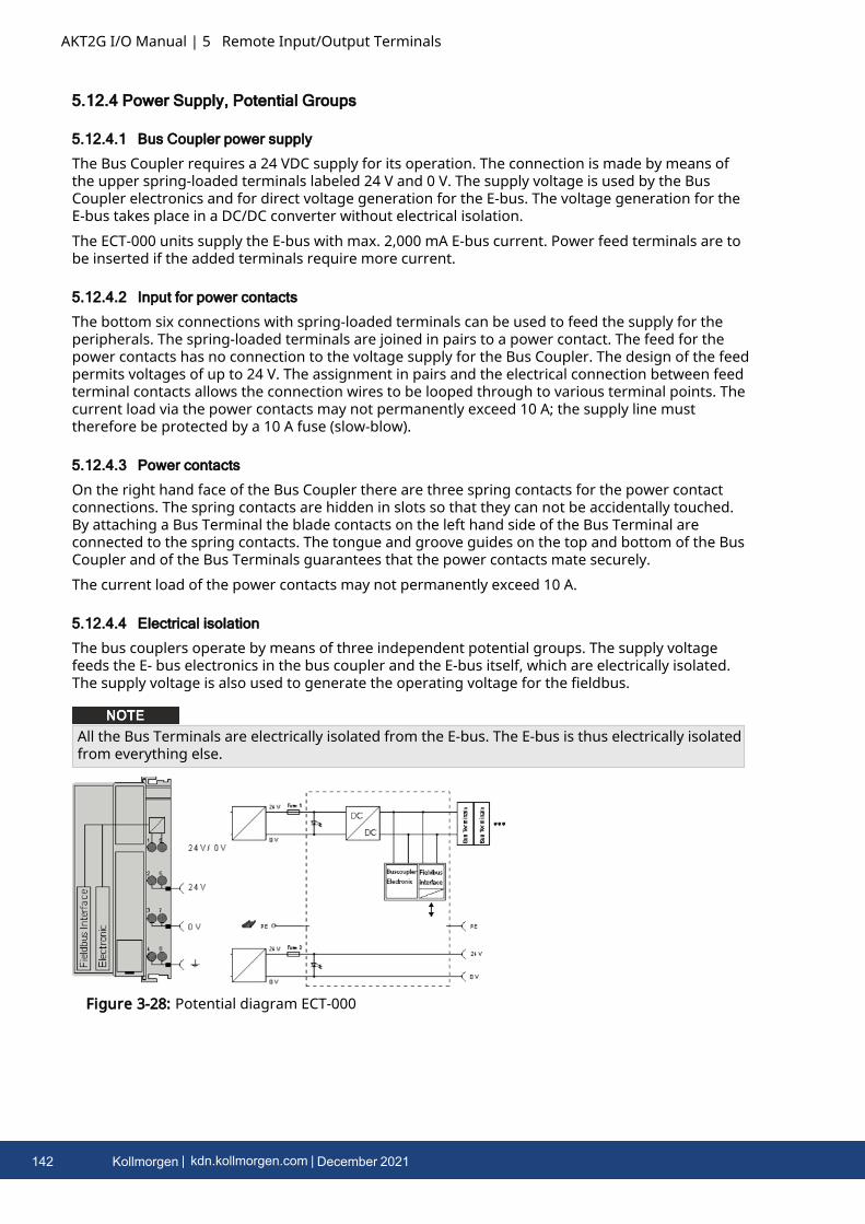
AKT2G I/O Manual | 5 Remote Input/Output Terminals
5.12.4 Power Supply, Potential Groups
5.12.4.1 Bus Coupler power supply
The Bus Coupler requires a 24 VDC supply for its operation. The connection is made by means ofthe upper spring-loaded terminals labeled 24 V and 0 V. The supply voltage is used by the BusCoupler electronics and for direct voltage generation for the E-bus. The voltage generation for theE-bus takes place in a DC/DC converter without electrical isolation.The ECT-000 units supply the E-bus with max. 2,000 mA E-bus current. Power feed terminals are tobe inserted if the added terminals require more current.
5.12.4.2 Input for power contacts
The bottom six connections with spring-loaded terminals can be used to feed the supply for theperipherals. The spring-loaded terminals are joined in pairs to a power contact. The feed for thepower contacts has no connection to the voltage supply for the Bus Coupler. The design of the feedpermits voltages of up to 24 V. The assignment in pairs and the electrical connection between feedterminal contacts allows the connection wires to be looped through to various terminal points. Thecurrent load via the power contacts may not permanently exceed 10 A; the supply line musttherefore be protected by a 10 A fuse (slow-blow).
5.12.4.3 Power contacts
On the right hand face of the Bus Coupler there are three spring contacts for the power contactconnections. The spring contacts are hidden in slots so that they can not be accidentally touched.By attaching a Bus Terminal the blade contacts on the left hand side of the Bus Terminal areconnected to the spring contacts. The tongue and groove guides on the top and bottom of the BusCoupler and of the Bus Terminals guarantees that the power contacts mate securely.The current load of the power contacts may not permanently exceed 10 A.
5.12.4.4 Electrical isolation
The bus couplers operate by means of three independent potential groups. The supply voltagefeeds the E- bus electronics in the bus coupler and the E-bus itself, which are electrically isolated.The supply voltage is also used to generate the operating voltage for the fieldbus.
All the Bus Terminals are electrically isolated from the E-bus. The E-bus is thus electrically isolatedfrom everything else.
Figure 3-28: Potential diagram ECT-000
142 Kollmorgen | kdn.kollmorgen.com | December 2021
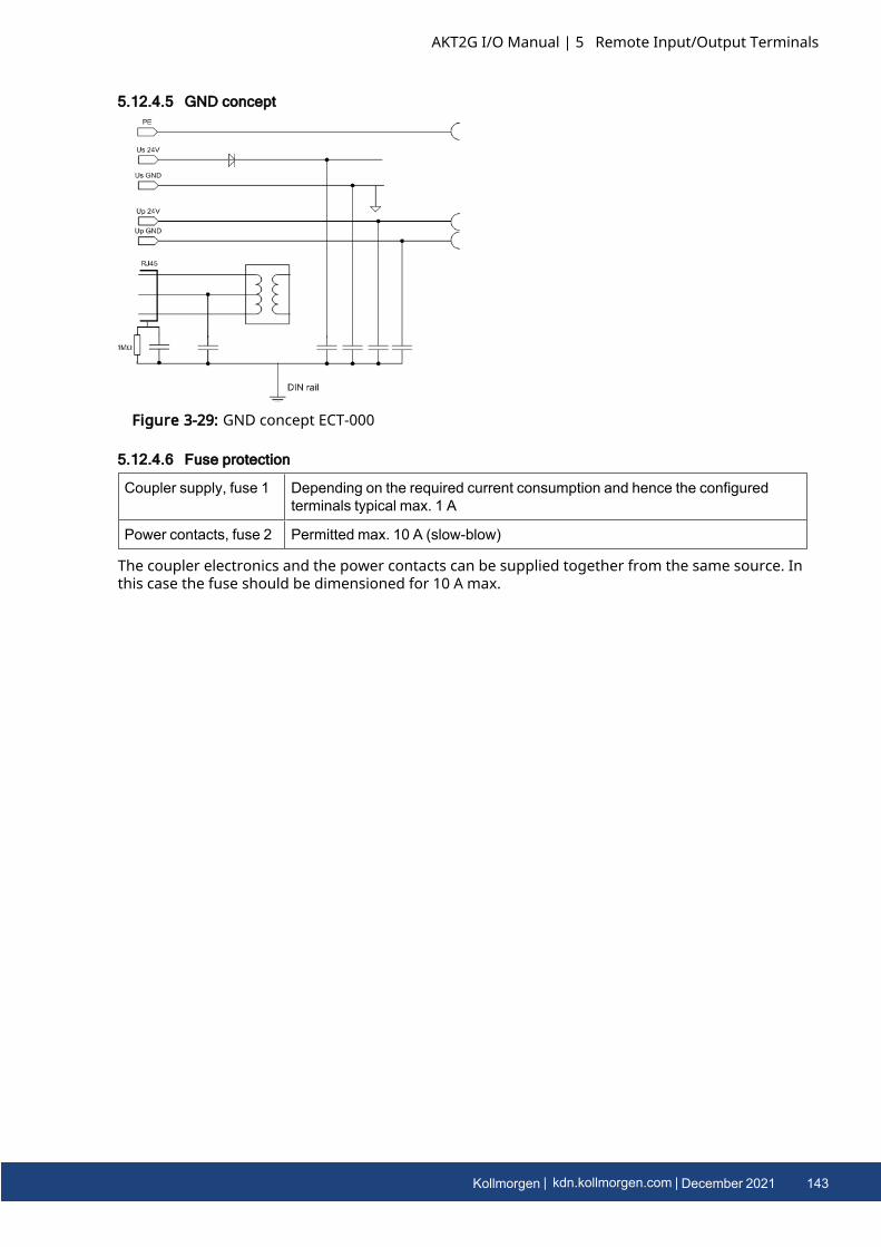
5.12.4.5 GND concept
Figure 3-29: GND concept ECT-000
5.12.4.6 Fuse protection
Coupler supply, fuse 1 Depending on the required current consumption and hence the configuredterminals typical max. 1 A
Power contacts, fuse 2 Permitted max. 10 A (slow-blow)
The coupler electronics and the power contacts can be supplied together from the same source. Inthis case the fuse should be dimensioned for 10 A max.
AKT2G I/O Manual | 5 Remote Input/Output Terminals
Kollmorgen | kdn.kollmorgen.com | December 2021 143
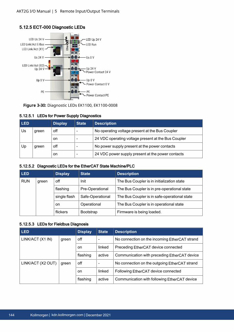
AKT2G I/O Manual | 5 Remote Input/Output Terminals
5.12.5 ECT-000 Diagnostic LEDs
Figure 3-30: Diagnostic LEDs EK1100, EK1100-0008
5.12.5.1 LEDs for Power Supply Diagnostics
LED Display State Description
Us green off - No operating voltage present at the Bus Coupler
on - 24 VDC operating voltage present at the Bus Coupler
Up green off - No power supply present at the power contacts
on - 24 VDC power supply present at the power contacts
5.12.5.2 Diagnostic LEDs for the EtherCAT State Machine/PLC
LED Display State Description
RUN green off Init The Bus Coupler is in initialization state
flashing Pre-Operational The Bus Coupler is in pre-operational state
single flash Safe-Operational The Bus Coupler is in safe-operational state
on Operational The Bus Coupler is in operational state
flickers Bootstrap Firmware is being loaded.
5.12.5.3 LEDs for Fieldbus Diagnosis
LED Display State Description
LINK/ACT (X1 IN) green off - No connection on the incoming EtherCAT strand
on linked Preceding EtherCAT device connected
flashing active Communication with preceding EtherCAT device
LINK/ACT (X2 OUT) green off - No connection on the outgoing EtherCAT strand
on linked Following EtherCAT device connected
flashing active Communication with following EtherCAT device
144 Kollmorgen | kdn.kollmorgen.com | December 2021

LED Display State Description
LINK / ACT E-
bus
green off - No connection to internal E-bus
on linked Connection to internal E-bus
flashing active Connection/communication internal E-bus
AKT2G I/O Manual | 5 Remote Input/Output Terminals
Kollmorgen | kdn.kollmorgen.com | December 2021 145
AKT2G I/O Manual | 5 Remote Input/Output Terminals
5.12.6 Technical Data
Characteristic AKT2G-ECT-000-000
Protection class IP20
Higher level network technology 100 MBit FastEthernet (100BASE-TX)
Higher level network - max. connection length 100 m
Higher level network connection technology RJ45
higher-level network protocol EtherCAT Device Protocol
supports HotConnect with address setting on the device yes, Fast-Hot-Connect
Technical Data AKT2G-ECT-000-000
Task in the EtherCAT system Coupling of EtherCAT Terminals (ECT-xxx) to 100BASE-TXEtherCAT networks
Number of EtherCAT Terminals up to 65535 in the overall system
Number of peripheral signals max. 4.2 GB addressable IO points
Data transfer medium Ethernet 100BASE-TX (at least Ethernet CAT5 cable)
Cable length between 2 BusCouplers
max. 100 m (100BASE-TX)
Protocol / Baud rate EtherCAT Device Protocol / 100 MBaud
HotConnect no
Delay 1 µs typ.
Bus connection 2 x RJ45
Power supply 24 VDC (-15%/+20%)
Current consumption 70 mA + (∑ E-bus current/4)
E-bus power supply (5 V) max. 2 A (-25 °C ... +55 °C)
max. 1 A (> +55 °C)
Power contacts max. 24 VDC, max. 10 A
Electrical isolation 500 V (power contact/supply voltage/EtherCAT)
Dimensions (W x H x D) approx. 44 mm x 100 mm x 68 mm
Weight approx. 105 g
Permissible ambient temperaturerange during operation
-25°C ... +60°C (extended temperature range)
Permissible ambient temperaturerange during storage
-40°C ... + 85°C
Permissible relative air humidity 95%, no condensation
Mounting on 35 mmmounting rail according to EN 60715
146 Kollmorgen | kdn.kollmorgen.com | December 2021

Technical Data AKT2G-ECT-000-000
Vibration / shock resistance conforms to EN 60068-2-6 / EN 60068-2-27, see also Installationinstructions] for enhanced mechanical load capacity
EMC immunity / emission conforms to EN 61000-6-2 / EN 61000-6-4
Protection class IP20
Installation position variable
Approval CE, ATEX, cULus, IECEx
AKT2G I/O Manual | 5 Remote Input/Output Terminals
Kollmorgen | kdn.kollmorgen.com | December 2021 147
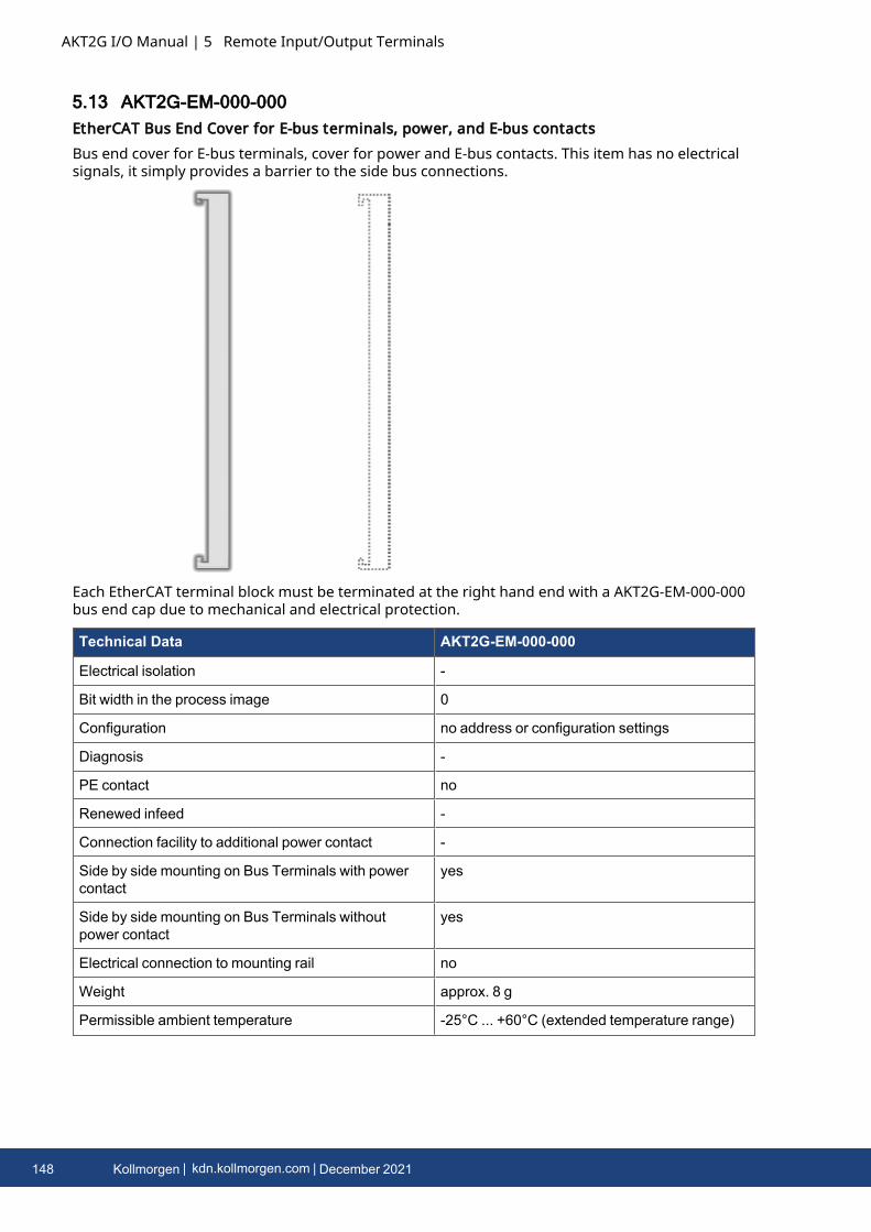
AKT2G I/O Manual | 5 Remote Input/Output Terminals
5.13 AKT2G-EM-000-000EtherCAT Bus End Cover for E-bus terminals, power, and E-bus contactsBus end cover for E-bus terminals, cover for power and E-bus contacts. This item has no electricalsignals, it simply provides a barrier to the side bus connections.
Each EtherCAT terminal block must be terminated at the right hand end with a AKT2G-EM-000-000bus end cap due to mechanical and electrical protection.
Technical Data AKT2G-EM-000-000
Electrical isolation -
Bit width in the process image 0
Configuration no address or configuration settings
Diagnosis -
PE contact no
Renewed infeed -
Connection facility to additional power contact -
Side by side mounting on Bus Terminals with powercontact
yes
Side by side mounting on Bus Terminals withoutpower contact
yes
Electrical connection to mounting rail no
Weight approx. 8 g
Permissible ambient temperature -25°C ... +60°C (extended temperature range)
148 Kollmorgen | kdn.kollmorgen.com | December 2021
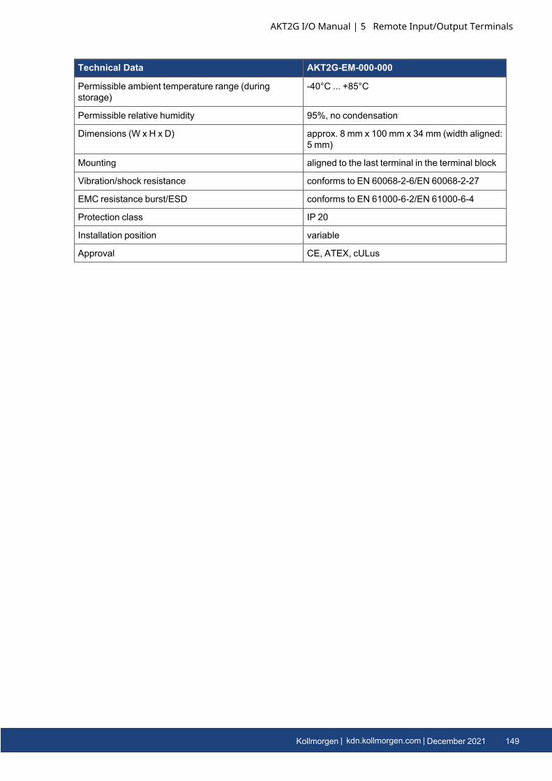
Technical Data AKT2G-EM-000-000
Permissible ambient temperature range (duringstorage)
-40°C ... +85°C
Permissible relative humidity 95%, no condensation
Dimensions (W x H x D) approx. 8 mm x 100 mm x 34 mm (width aligned:5 mm)
Mounting aligned to the last terminal in the terminal block
Vibration/shock resistance conforms to EN 60068-2-6/EN 60068-2-27
EMC resistance burst/ESD conforms to EN 61000-6-2/EN 61000-6-4
Protection class IP 20
Installation position variable
Approval CE, ATEX, cULus
AKT2G I/O Manual | 5 Remote Input/Output Terminals
Kollmorgen | kdn.kollmorgen.com | December 2021 149
AKT2G I/O Manual | 5 Remote Input/Output Terminals
5.14 AKT2G-ENC-180-0001-channel incremental encoder interface, 32 bit
5.14.1 Incremental Encoder Interface AKT2G-ENC-180The AKT2G-ENC-180 EtherCAT Terminal is an interface with 24 V inputs for the direct connection ofincremental encoders. A 32 bit counter with a quadrature decoder and a 32 bit latch for the zeropulse can be read, set or enabled.The measurement of period and frequency is possible. The gate input allows the locking of thecounter, selectively with a high or low level. The latch input is similarly configurable and evaluateshigh or low levels.The AKT2G-ENC-180 supports distributed clocks, i.e. the input data can be synchronously acquiredwith other data that are similarly connected, distributed to distributed clock terminals. Theuniversal system accuracy is around < 100 ns.With a moving axis, the micro-increment functionality offers 256 times higher axis positionresolution than physically provided by the encoder.The AKT2G-ENC-180 can also be used as a single-channel 32/16 bit counter on channel A, in whichcase the signal level on channel B defines the count direction.
150 Kollmorgen | kdn.kollmorgen.com | December 2021
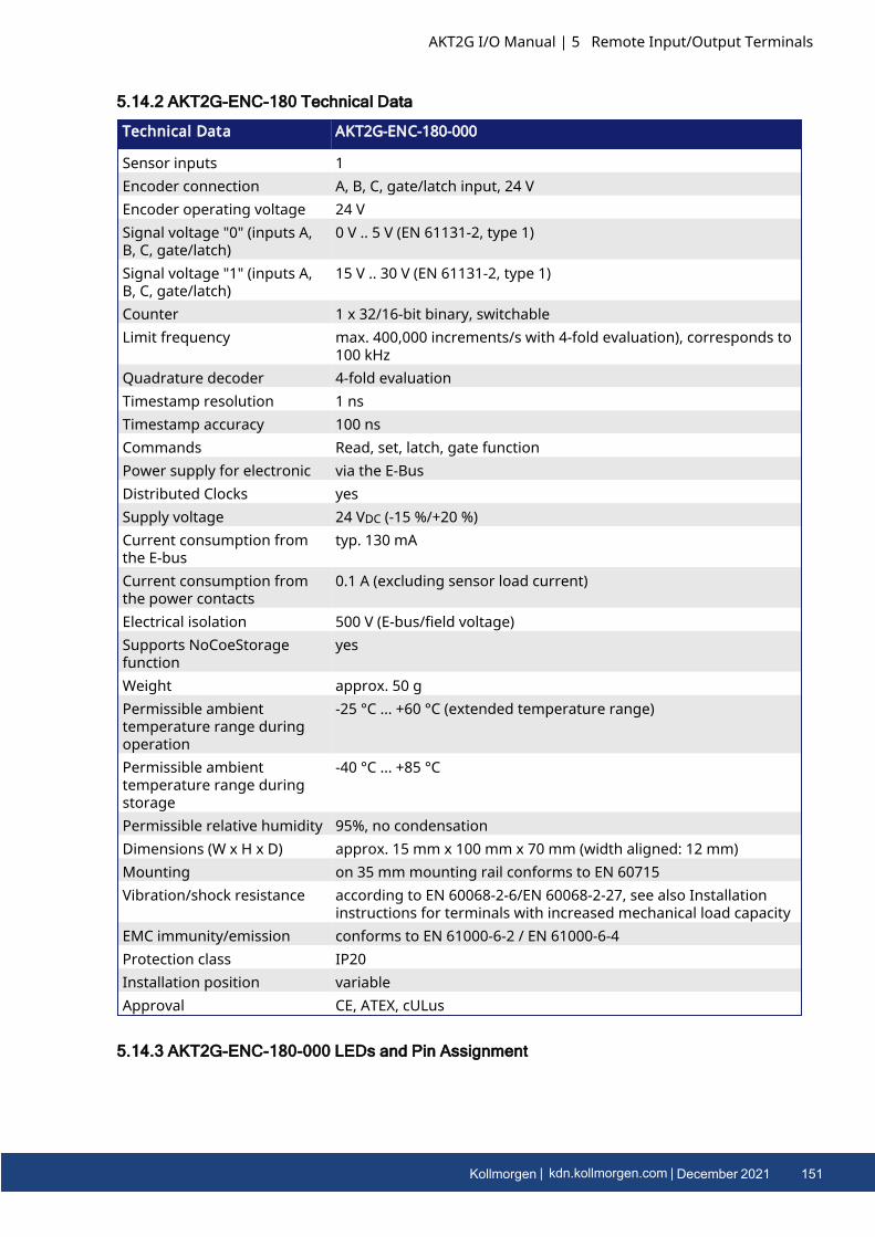
5.14.2 AKT2G-ENC-180 Technical Data
Technical Data AKT2G-ENC-180-000
Sensor inputs 1Encoder connection A, B, C, gate/latch input, 24 VEncoder operating voltage 24 VSignal voltage "0" (inputs A,B, C, gate/latch)
0 V .. 5 V (EN 61131-2, type 1)
Signal voltage "1" (inputs A,B, C, gate/latch)
15 V .. 30 V (EN 61131-2, type 1)
Counter 1 x 32/16-bit binary, switchableLimit frequency max. 400,000 increments/s with 4-fold evaluation), corresponds to
100 kHzQuadrature decoder 4-fold evaluationTimestamp resolution 1 nsTimestamp accuracy 100 nsCommands Read, set, latch, gate functionPower supply for electronic via the E-BusDistributed Clocks yesSupply voltage 24 VDC (-15 %/+20 %)Current consumption fromthe E-bus
typ. 130 mA
Current consumption fromthe power contacts
0.1 A (excluding sensor load current)
Electrical isolation 500 V (E-bus/field voltage)Supports NoCoeStoragefunction
yes
Weight approx. 50 gPermissible ambienttemperature range duringoperation
-25 °C ... +60 °C (extended temperature range)
Permissible ambienttemperature range duringstorage
-40 °C ... +85 °C
Permissible relative humidity 95%, no condensationDimensions (W x H x D) approx. 15 mm x 100 mm x 70 mm (width aligned: 12 mm)Mounting on 35 mm mounting rail conforms to EN 60715Vibration/shock resistance according to EN 60068-2-6/EN 60068-2-27, see also Installation
instructions for terminals with increased mechanical load capacityEMC immunity/emission conforms to EN 61000-6-2 / EN 61000-6-4Protection class IP20Installation position variableApproval CE, ATEX, cULus
5.14.3 AKT2G-ENC-180-000 LEDs and Pin Assignment
AKT2G I/O Manual | 5 Remote Input/Output Terminals
Kollmorgen | kdn.kollmorgen.com | December 2021 151
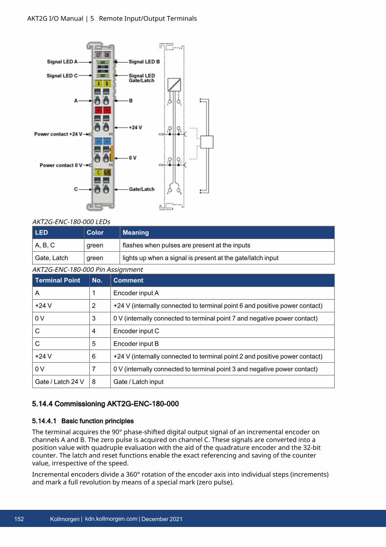
AKT2G I/O Manual | 5 Remote Input/Output Terminals
LED Color Meaning
A, B, C green flashes when pulses are present at the inputs
Gate, Latch green lights up when a signal is present at the gate/latch input
AKT2G-ENC-180-000 LEDs
Terminal Point No. Comment
A 1 Encoder input A
+24 V 2 +24 V (internally connected to terminal point 6 and positive power contact)
0 V 3 0 V (internally connected to terminal point 7 and negative power contact)
C 4 Encoder input C
C 5 Encoder input B
+24 V 6 +24 V (internally connected to terminal point 2 and positive power contact)
0 V 7 0 V (internally connected to terminal point 3 and negative power contact)
Gate / Latch 24 V 8 Gate / Latch input
AKT2G-ENC-180-000 Pin Assignment
5.14.4 Commissioning AKT2G-ENC-180-000
5.14.4.1 Basic function principles
The terminal acquires the 90° phase-shifted digital output signal of an incremental encoder onchannels A and B. The zero pulse is acquired on channel C. These signals are converted into aposition value with quadruple evaluation with the aid of the quadrature encoder and the 32-bitcounter. The latch and reset functions enable the exact referencing and saving of the countervalue, irrespective of the speed.Incremental encoders divide a 360° rotation of the encoder axis into individual steps (increments)and mark a full revolution by means of a special mark (zero pulse).
152 Kollmorgen | kdn.kollmorgen.com | December 2021
The phase angle between the signals on channels A and B sets the counting direction.Up: signal on channel A leads signal on channel B by 90°Down: signal on channel A lags signal on channel B by 90°In case of single evaluation, the positive edges on channel A are counted.In case of quadruple evaluation, the positive and negative edges on channel A and channel B arecounted.
Figure 3-31: Quadrature decoder
Whereas absolute value encoders deliver an absolute and unambiguous position value over thecomplete travel path directly after switching on, it is necessary with incremental encoders toperform a reference run homing after switching on in order to be able to determine anunambiguous position.Referencing can be carried out, for example, with the aid of reference cams or using the zero pulseof the encoder.
AKT2G I/O Manual | 5 Remote Input/Output Terminals
Kollmorgen | kdn.kollmorgen.com | December 2021 153

AKT2G I/O Manual | 5 Remote Input/Output Terminals
5.14.4.2 Operating modes and settings
5.14.4.2.1 General
The AKT2G-ENC-180 incremental encoder interface terminal enables connection of incrementalencoders with the Bus Coupler or the PLC. A 32-bit counter with quadrature decoder as well as a32-bit latch can be read, set or activated (switchable to 16-bit). In addition to the encoder inputs A,B and C, a gate/latch input (24 V) is also available on the AKT2G-ENC-180 for latching/saving thecounter value. The gate/latch input is parameterizable via the CoE directory. no function, ordisabling the counter at HIGH or LOW signal level.The AKT2G-ENC-180 can also be used as a single-channel 32/16 bit counter on channel A, in whichcase the signal level on channel B defines the count direction. The changeover to this mode takesplace via the CoE directory.The Counter Value input value represents a 32-bit “position counter”. At the period input the periodbetween two positive edges of channel A is measured with a resolution of 100 ns (default setting,decimal value x 100 ns). Depending on the setting (index 0x8000:14, index 0x8000:16), the periodlength may be up to 1.6 s or 3.2 s.
154 Kollmorgen | kdn.kollmorgen.com | December 2021
5.14.4.2.2 Operating modes
Permissible operating modes for the AKT2G-ENC-180The following modes are available for the AKT2G-ENC-180. They apply both for the encoderanalysis and counter terminal mode.The combinations of DC, PDO and CoE settings listed below are permissible per mode. Othersettings can lead to irregular process data and error messages in the Safety PLC System ManagerLogger window.
Mode DC Pain PDO Optional PDO 1 Optional PDO 2 Features CoE
1 FreeRun Predefined PDO Assignment: Standard 32-bit (MDP 511):0x1A00 + 0x1600 + 0x1A02
CoE combinations0x8000:nn
0x1A00 Inputs:16 Bit Status,32 Bit CounterValue,32 Bit Latch Value
+
0x1600 Outputs:16 Bit Control,32 Bit Set CounterValue
0x1A0232 Bit Period
or
0x1A0332 Bit Frequency
--
2 FreeRun Predefined PDO Assignment: Standard 16-bit (MDP 511):0x1A01 + 0x1601 + 0x1A02
CoE combinations0x8000:nn
0x1A01 Inputs:16 Bit Status,16 Bit CounterValue,16 Bit Latch Value
+
0x1601 Outputs:16 Bit Control16 Bit Set CounterValue
0x1A0232 Bit Period
or
0x1A0332 Bit Frequency
--
3 DC/DCi Predefined PDO Assignment:Standard 32 Bit with 64 Bit Timestamp (MDP 511):0x1A00 + 0x1600 + 0x1A02 + 0x1A04
CoE combinations0x8000:nn
0x1A00 Inputs:16 Bit Status,32 Bit CounterValue,32 Bit Latch Value
+
0x1600 Outputs:16 Bit Control,32 Bit Set CounterValue
0x1A0232 Bit Period
or
0x1A0332 Bit Frequency
0x1A0464 Bit Timestamp
or
0x1A0532 Bit Timestamp(compact)
AKT2G I/O Manual | 5 Remote Input/Output Terminals
Kollmorgen | kdn.kollmorgen.com | December 2021 155
AKT2G I/O Manual | 5 Remote Input/Output Terminals
Mode DC Pain PDO Optional PDO 1 Optional PDO 2 Features CoE
4 DC/DCi Predefined PDO Assignment:Standard 16 Bit with 32 Bit Timestamp (MDP 511):0x1A01 + 0x1601 + 0x1A02 + 0x1A05
CoE combinations0x8000:nn
0x1A01 Inputs:16 Bit Status,16 Bit CounterValue,16 Bit Latch Value
+
0x1601 Outputs:16 Bit Control,16 Bit Set CounterValue
0x1A0232 Bit Period
or
0x1A0332 Bit Frequency
0x1A0464 Bit Timestamp
or
0x1A0532 Bit Timestamp(compact)
156 Kollmorgen | kdn.kollmorgen.com | December 2021
5.14.4.2.3 Explanatory notes for parameters and modes
5.14.4.2.3.1 Frequency
l The timeframe for the frequency calculation as well as the resolution can be parameterizedin the CoE objects Frequency window (index: 0x80n0:11), Frequency scaling (index:0x80n0:13), Frequency resolution (index: 0x80n0:15) and Frequency wait time (index:0x80n0:17). • The positive edges of track A are counted in the specified timeframe (seeFrequency modes) and the next subsequent edge including the time until it arrives iscounted. The waiting time for the edge can be set in the CoE object Frequency Wait Time(index: 0x80n0:17) (unit: ms) and is set as standard to 1.6 seconds. This is also the maximumvalue.
l The frequency is always specified as a positive number, irrespective of the sense of rotation.l The size of the timeframe is 10 ms (default), but at the least the basic unit Frequency window
base (index: 0x80n0:0F).l This calculation is carried out in the terminal in free-running mode without reference to the
distributed clocks system. It is therefore independent of the DC mode.l AKT2G-ENC-180: No frequency measurement is possible if the counter is blocked by the gate.
In this case the period can be measured regardless.l AKT2G-ENC-180: A C or external reset restarts the frequency measurement. The last
frequency value remains unchanged until a new frequency value is determined.l The object Frequency window base (index: 0x80n0:0F) is used for switching the basic unit for
the Frequency window between 1 µs and 1 ms, in order to adjust the time window for themeasurement. The following maximum measuring windows are therefore possible:
Basic unit Max. timeframe
1 µs 65.5 ms
1 ms 65 s
l on expiry of the measuring window Frequency window (index: 0x80n0:11), the subsequentpositive edge on track A is awaited, but at the longest for 1.6 s or the time from Frequencywait time (index: 0x80n0:17).
l The frequency is measured with different accuracies depending on the selected basic unitFrequency window base (index 0x80n0:0F) and the window size.
AKT2G I/O Manual | 5 Remote Input/Output Terminals
Kollmorgen | kdn.kollmorgen.com | December 2021 157
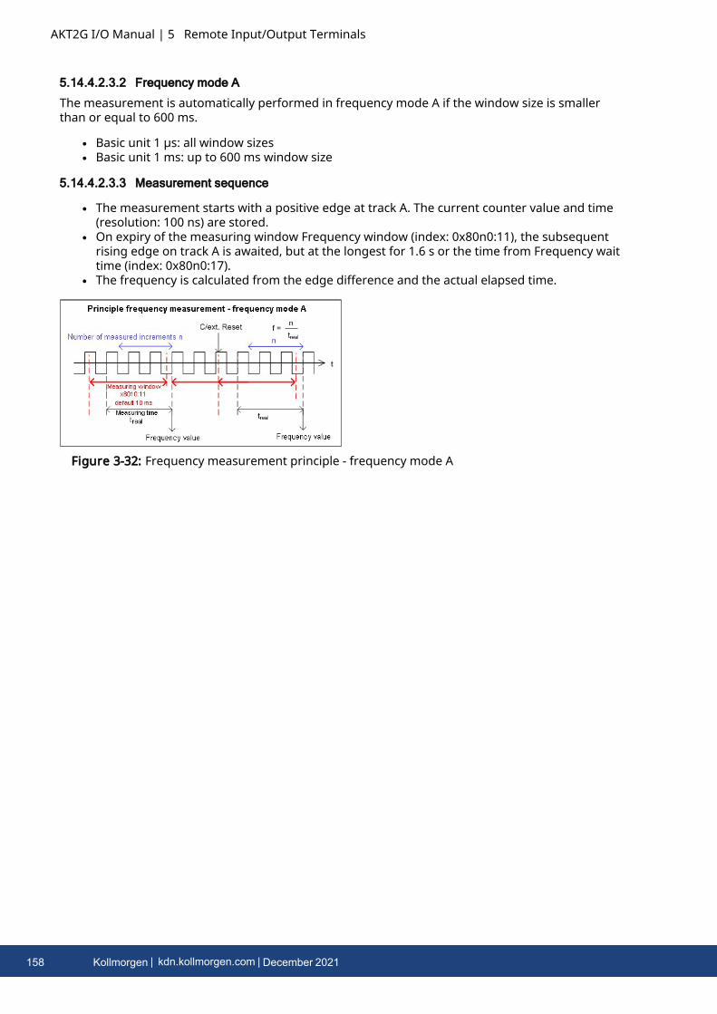
AKT2G I/O Manual | 5 Remote Input/Output Terminals
5.14.4.2.3.2 Frequency mode A
The measurement is automatically performed in frequency mode A if the window size is smallerthan or equal to 600 ms.
l Basic unit 1 µs: all window sizesl Basic unit 1 ms: up to 600 ms window size
5.14.4.2.3.3 Measurement sequence
l The measurement starts with a positive edge at track A. The current counter value and time(resolution: 100 ns) are stored.
l On expiry of the measuring window Frequency window (index: 0x80n0:11), the subsequentrising edge on track A is awaited, but at the longest for 1.6 s or the time from Frequency waittime (index: 0x80n0:17).
l The frequency is calculated from the edge difference and the actual elapsed time.
Figure 3-32: Frequency measurement principle - frequency mode A
158 Kollmorgen | kdn.kollmorgen.com | December 2021
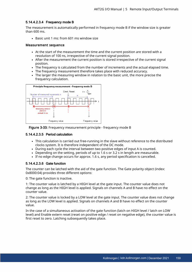
5.14.4.2.3.4 Frequency mode B
The measurement is automatically performed in frequency mode B if the window size is greaterthan 600 ms.
l Basic unit 1 ms: from 601 ms window size
Measurement sequence
l At the start of the measurement the time and the current position are stored with aresolution of 100 ns, irrespective of the current signal position.
l After the measurement the current position is stored irrespective of the current signalposition.
l The frequency is calculated from the number of increments and the actual elapsed time.l The frequency measurement therefore takes place with reduced accuracy.l The larger the measuring window in relation to the basic unit, the more precise the
frequency calculation.
Figure 3-33: Frequency measurement principle - frequency mode B
5.14.4.2.3.5 Period calculation
l This calculation is carried out free-running in the slave without reference to the distributedclocks system. It is therefore independent of the DC mode.
l During each cycle the interval between two positive edges of input A is counted.l Depending on the setting, periods of up to 1.6 s or 3.2 s in length are measurable.l If no edge change occurs for approx. 1.6 s, any period specification is cancelled.
5.14.4.2.3.6 Gate function
The counter can be latched with the aid of the gate function. The Gate polarity object (index:0x8000:04) provides three different options:0: The gate function is inactive.1: The counter value is latched by a HIGH level at the gate input. The counter value does notchange as long as the HIGH level is applied. Signals on channels A and B have no effect on thecounter value.2: The counter value is locked by a LOW level at the gate input. The counter value does not changeas long as the LOW level is applied. Signals on channels A and B have no effect on the countervalue.In the case of a simultaneous activation of the gate function (latch on HIGH level / latch on LOWlevel) and Enable extern reset (reset on positive edge / reset on negative edge), the counter value isfirst reset to zero. Latching subsequently takes place.
AKT2G I/O Manual | 5 Remote Input/Output Terminals
Kollmorgen | kdn.kollmorgen.com | December 2021 159

AKT2G I/O Manual | 5 Remote Input/Output Terminals
5.14.4.2.3.7 Latch
Activating the latch C input (“C”) and latching the counter value
l The counter value is saved in Latch value (index: 0x6000:12) upon the first latch pulse(positive edge on input “C”) after setting the bit (TRUE) in Enable latch C (index: 0x7000:01)(takes priority over Enable latch extern on positive / negative edge index: 0x7000:02 /0x7000:04). If the bit is set, the subsequent pulses on the other inputs have no effect on thelatch value in Latch value (index: 0x6000:12).
l After re-activation of Enable latch C (index: 0x7000:01), the next counter value at the latchinput can be written only if the value of the Latch C valid bit (index 0x6000:01 FALSE) hasbeen reset.
Activation of the external latch input and saving (“latching”) of the counter value (index 0x7000:02,0x7000:04)
l The counter value at the latch input Latch value (index 0x6000:12) will be saved upon the firstexternal latch pulse with a positive edge if the bit (TRUE) is set in Enable extern latch onpositive edge (index: 0x7000: 02). The subsequent pulses have no influence on the latchvalue in Latch value (index: 0x6000:12).
l The counter value at the latch input Latch value (index: 0x6000:12) will be saved upon thefirst external latch pulse with a negative edge if the bit (TRUE) is set in Enable extern latch onnegative edge (index: 0x7000: 04). The subsequent pulses have no influence on the latchvalue in Latch value (index: 0x6000:12).
l After re-activation, a new counter value on the latch input can be written only if the value ofthe Latch extern valid bit (index: 0x6000:02) has been reset.
5.14.4.2.3.8 Reset
The counter can be reset via Enable C reset (index: 0x8000:01) or via Enable extern reset (index:0x8000:02). Extern reset polarity (index: 0x8000:10) defines whether the reset takes place on apositive or negative edge at the external latch input.“Enable C reset” (index: 0x8000:01)
l For activation the bit in Enable C reset (index: 0x8000:01) is set to TRUE.The counter value is reset to zero if the zero pulse is present on channel C.
“Enable extern reset” (index: 0x8000:02),
l For activation the bit in Enable extern reset (index: 0x8000:02) is set to TRUE.l “Extern reset polarity” (index: 0x8000:10)
l Bit not set: the counter is set to zero with a negative edge at the external latch input.l Bit set: the counter is set to zero with a positive edge at the external latch input.
The simultaneous activation of the functions Enable C reset (index: 0x8000:01) und Enableextern reset (index: 0x8000:02) is not possible.
160 Kollmorgen | kdn.kollmorgen.com | December 2021
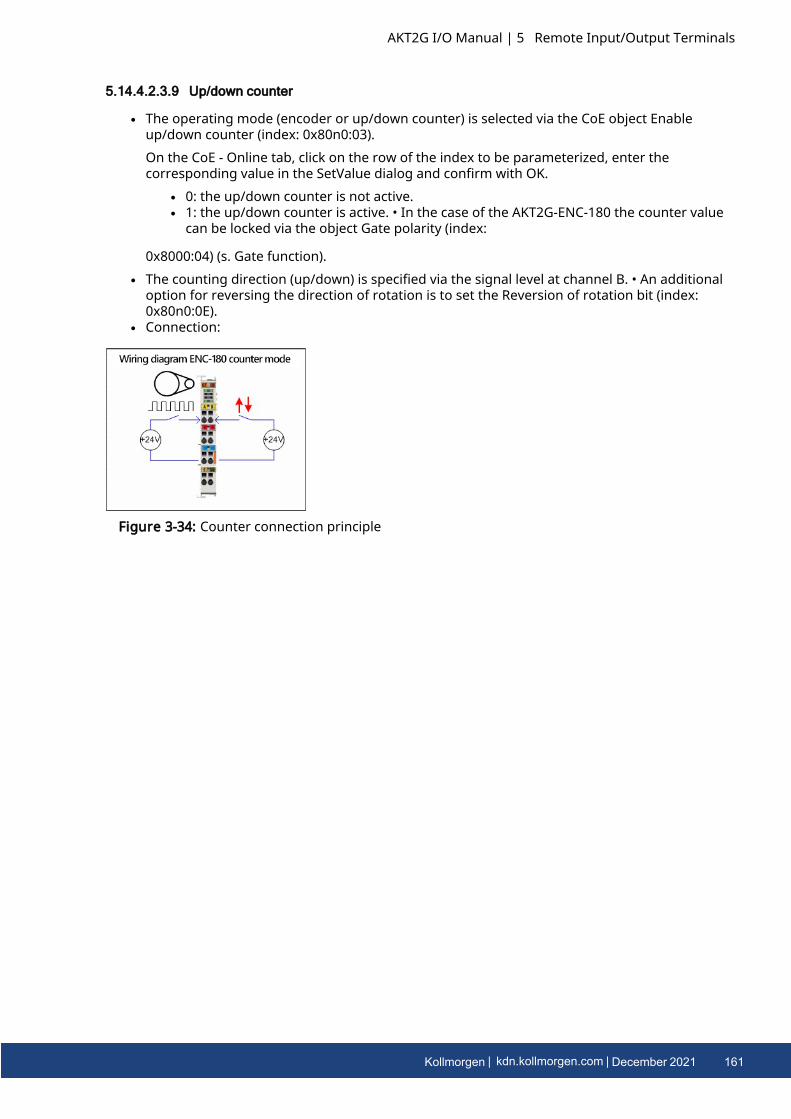
5.14.4.2.3.9 Up/down counter
l The operating mode (encoder or up/down counter) is selected via the CoE object Enableup/down counter (index: 0x80n0:03).On the CoE - Online tab, click on the row of the index to be parameterized, enter thecorresponding value in the SetValue dialog and confirm with OK.
l 0: the up/down counter is not active.l 1: the up/down counter is active. • In the case of the AKT2G-ENC-180 the counter value
can be locked via the object Gate polarity (index:
0x8000:04) (s. Gate function).l The counting direction (up/down) is specified via the signal level at channel B. • An additional
option for reversing the direction of rotation is to set the Reversion of rotation bit (index:0x80n0:0E).
l Connection:
Figure 3-34: Counter connection principle
AKT2G I/O Manual | 5 Remote Input/Output Terminals
Kollmorgen | kdn.kollmorgen.com | December 2021 161
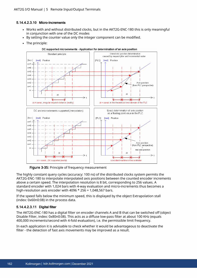
AKT2G I/O Manual | 5 Remote Input/Output Terminals
5.14.4.2.3.10 Micro-increments
l Works with and without distributed clocks, but in the AKT2G-ENC-180 this is only meaningfulin conjunction with one of the DC modes
l By setting the counter value only the integer component can be modified.l The principle:
Figure 3-35: Principle of frequency measurement
The highly constant query cycles (accuracy: 100 ns) of the distributed clocks system permits theAKT2G-ENC-180 to interpolate interpolated axis positions between the counted encoder incrementsabove a certain speed. The interpolation resolution is 8 bit, corresponding to 256 values. Astandard encoder with 1,024 bars with 4-way evaluation and micro-increments thus becomes ahigh-resolution axis encoder with 4096 * 256 = 1,048,567 bars.If the speed falls below the minimum speed, this is displayed by the object Extrapolation stall(index: 0x60n0:08) in the process data.
5.14.4.2.3.11 Digital filter
The AKT2G-ENC-180 has a digital filter on encoder channels A and B that can be switched off (objectDisable Filter, index: 0x80n0:08). This acts as a diffuse low-pass filter at about 100 KHz (equals400,000 increments/second with 4-fold evaluation), i.e. the permissible limit frequency.In each application it is advisable to check whether it would be advantageous to deactivate thefilter - the detection of fast axis movements may be improved as a result.
162 Kollmorgen | kdn.kollmorgen.com | December 2021
5.15 AKT2G-ENC-190-000Incremental encoder interface with differential input, 16/32 bit
Figure 3-36: AKT2G-ENC-190-000
The AKT2G-ENC-190-000 EtherCAT Terminal is an interface for direct connection of incrementalencoders with differential inputs (RS422). A 16-bit counter (in normal operating mode) or aswitchable 16/32-bit counter (in enhanced operating mode) with a quadrature decoder and a 16-bitlatch (in normal operating mode) or 32-bit latch (in enhanced operating mode) for the zero pulsecan be read, set or enabled. Incremental encoders with alarm output can be connected at thenegative switching status input of the interface. The measurement of period and frequency ispossible. The gate input allows the locking of the counter, alternatively with a high or low level. Thelatch input is similarly configurable and evaluates high or low levels. The AKT2G-ENC-190-000 canalso be used as bidirectional counter on channel A; channel B specifies the count direction.
AKT2G I/O Manual | 5 Remote Input/Output Terminals
Kollmorgen | kdn.kollmorgen.com | December 2021 163
AKT2G I/O Manual | 5 Remote Input/Output Terminals
5.15.1 TechnologyThe AKT2G-ENC-190-000 incremental encoder interface terminal enables connection of incrementalencoders withA/B/C track to the Bus Coupler and the PLC. A 16-bit counter (in normal operating mode) or aswitchable 16/32-bit counter (in enhanced operating mode) with a quadrature decoder and a 16-bitlatch (in normal operating mode) or 32-bit latch (in enhanced operating mode) can be read, set orenabled. Differential signals based on RS422 are provided as encoder connection. From hardware09 single-ended 5 V signals are possible for the AKT2G-ENC-190-000 based on pull-up resistors.In addition to the encoder inputs A, B and C, an additional latch input G1 (24 V) and a gate input G2(24 V) for locking the counter during operation are available.The terminal is supplied as a 4-fold quadrature decoder with complementary analysis of the sensorsignals A, B, C. If the incremental encoder has an alarm output it can be connected to the INPUT 1status input of the AKT2G-ENC-190-000. The AKT2G-ENC-190-000 can optionally be operated as abidirectional counter terminal on channel A.
5.15.1.1 AKT2G-ENC-190-000 input impedance
The signal source must be able to operate the input impedance of the AKT2G-ENC-190-000(typically 220 Ω, subject to modification) with adequate voltage levels according to RS422.
5.15.1.2 Gate/latch input
For gate and latch inputs (24 V) a max. input frequency of 1 MHz is permitted. Subject tomodification.
5.15.1.3 Level on interface
In differential mode the AKT2G-ENC-190-000 expects the signal levels after RS422. The data aretransferred without ground reference as voltage difference between two cables (signal A andinverted signal /A). The terminal analyses signal levels in the range -200 mV < Vid < +200 mV asvalid signals. The differential signal must be in the common mode range (<+13.2 V and >-10 V, withrespect to GND) (cf. diagram). Signal levels outside this range can lead to destruction.
164 Kollmorgen | kdn.kollmorgen.com | December 2021
Figure 3-37: Level interface
In differential mode only the voltage difference is evaluated, so that common-mode interferenceon the transmission link does not lead to corruption of the wanted signal, since any interferenceaffects both cables simultaneously.If the AKT2G-ENC-190-000 is only operated in single-ended mode, a nominal level voltage between3.5 V and 5.5 V is expected.
AKT2G I/O Manual | 5 Remote Input/Output Terminals
Kollmorgen | kdn.kollmorgen.com | December 2021 165
AKT2G I/O Manual | 5 Remote Input/Output Terminals
5.15.2 Technical Data
Technical Data AKT2G-ENC-190-000
Sensor connection A, ¬A, B, ¬B, C, ¬C (RS422 differential inputs) also single-endedconnection (5 V ±20%) possible
Additional inputs gate, latch (24 VDC, both max. 1 MHz permitted),status input (max. 5 VDC, potential-free, switching to negativepotential)
Encoder operating voltage /Encoder supply
5 VDC (generated from the 24 V DC power contacts)
Sensor output current 0.5 ACounter 16 bit, 16/32 bit switchableZero pulse latch 16 bit, 16/32 bit switchableLimit frequency 1 MHz (equals 4 million increments with 4-fold evaluation)Quadrature decoder 4-fold evaluationDistributed Clocks in enhanced operating modeBroken wire detection tosensor
in enhanced operating mode
Commands read, set, enableCycle time min. 100 µsCurrent consumption via Ebus typ. 130 mACurrent consumption from thepower contacts
0.1 A (excluding sensor load current)
Electrical isolation 500 V (E-bus/field voltage)Bit width in process image up to 6 bytes outputs, 22 bytes inputs, depends on
parametrizationMTBF (+55°C) -Weight approx. 100 gPermissible ambienttemperature range duringoperation
-25°C ... +60°C (extended temperature range)
Permissible ambienttemperature range duringstorage
-40°C ... +85°C
Permissible relative humidity 95%, no condensationDimensions (W x H x D) approx. 27 mm x 10 mm x 70 mm (width aligned: 24 mm)Mounting on 35 mm mounting rail conforms to EN 60715Vibration/shock resistance conforms to EN 60068-2-6 / EN 60068-2-27, see also
installation instructions for enhanced mechanical load capacityEMC immunity/emission conforms to EN 61000-6-2 / EN 61000-6-4Protection class IP20Installation position variableApproval CE ATEX cULus
5.15.3 AKT2G-ENC-190-000 LEDs and Connection
166 Kollmorgen | kdn.kollmorgen.com | December 2021
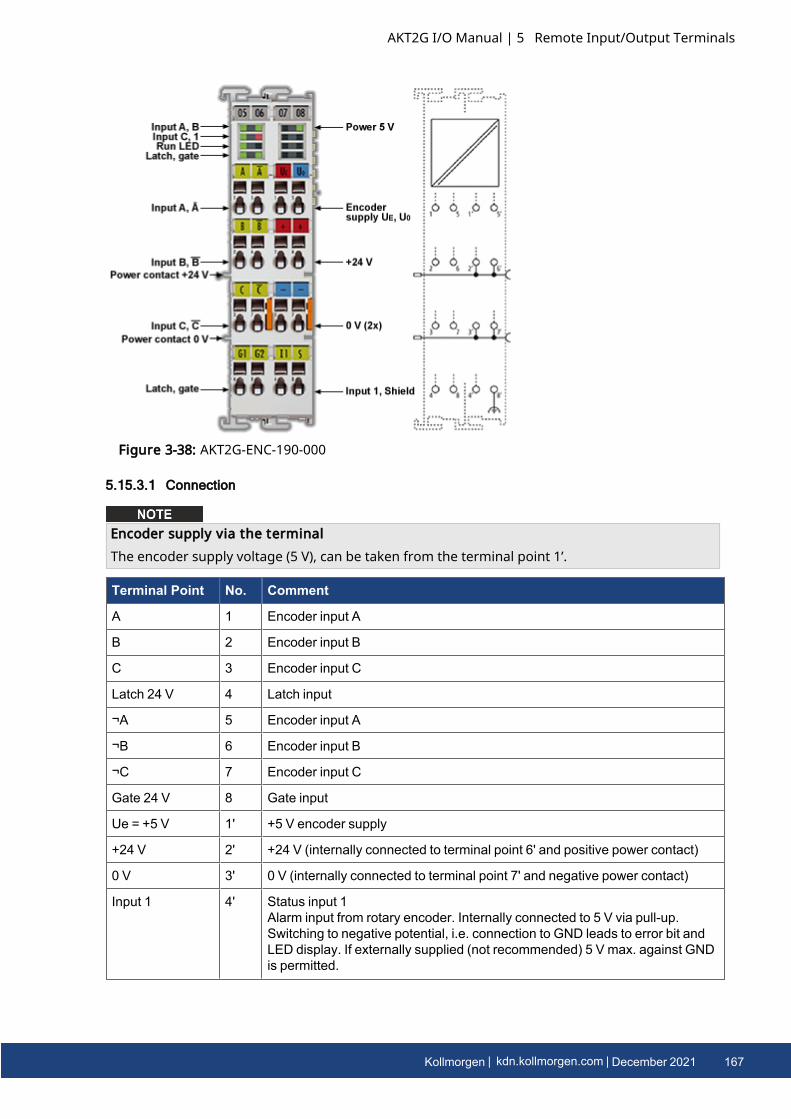
Figure 3-38: AKT2G-ENC-190-000
5.15.3.1 Connection
Encoder supply via the terminalThe encoder supply voltage (5 V), can be taken from the terminal point 1’.
Terminal Point No. Comment
A 1 Encoder input A
B 2 Encoder input B
C 3 Encoder input C
Latch 24 V 4 Latch input
¬A 5 Encoder input A
¬B 6 Encoder input B
¬C 7 Encoder input C
Gate 24 V 8 Gate input
Ue = +5 V 1' +5 V encoder supply
+24 V 2' +24 V (internally connected to terminal point 6' and positive power contact)
0 V 3' 0 V (internally connected to terminal point 7' and negative power contact)
Input 1 4' Status input 1Alarm input from rotary encoder. Internally connected to 5 V via pull-up.Switching to negative potential, i.e. connection to GND leads to error bit andLED display. If externally supplied (not recommended) 5 V max. against GNDis permitted.
AKT2G I/O Manual | 5 Remote Input/Output Terminals
Kollmorgen | kdn.kollmorgen.com | December 2021 167
AKT2G I/O Manual | 5 Remote Input/Output Terminals
Terminal Point No. Comment
Uo = 0 V 5' 0 V encoder supply
+24 V 6' +24 V (internally connected to terminal point 2' and positive power contact)
0 V 7' 0 V (internally connected to terminal point 3' and negative power contact)
Shield 8' Screen
5.15.3.2 LEDs
LED Color Meaning
LED Color Meaning
INPUT A, B,C
green indicates TRUE level
INPUT 1 red is lit, if INPUT 1 is connected to GND
[INPUT 1 is connected to an internal 5 V HIGH level though internal pull-up(default)]
LATCH green is lit, if a signal (+24 V) is connected to the latch input
GATE green is lit, if a signal (+24 V) is connected to the gate input
RUN green This LED indicates the terminal's operating state:
offState of the EtherCAT State Machine: INIT = initialization of theterminal or BOOTSTRAP = function for firmware updates of theterminal
flashing State of the EtherCAT State Machine: PREOP = function formailbox communication and different standard-settings set
single flashState of the EtherCAT State Machine: SAFEOP = verification ofthe Sync Manager channels and the distributed clocks.
Outputs remain in safe state
on State of the EtherCAT State Machine: OP = normal operatingstate; mailbox and process data communication is possible
POWER 5 V green Operating voltage display for incremental encoder power supply
5.15.4 Commissioning AKT2G-ENC-190-000
5.15.4.1 Normal Operation Mode
5.15.4.1.1 Process data and modes - Normal Operation Mode
In AKT2G-ENC-190-000 “normal operation mode” the following modes are available:
168 Kollmorgen | kdn.kollmorgen.com | December 2021
Mode DistributedClock
MainPDO
Comment OptionalPDO 1
Comment FeaturesCoE
Comment
1 Operational 0x1A00
+0x1600
16 bitValue/Latch
Byte-Alignment
0x1A02 Frequency:32 bit
Period: 16bit
Window: 16bit CoEobject0x8001:02
0x8000:01 +
0x8001:02
Registerreload +ReloadValue
2 Operational " " " " 0x8000:02 IndexReset
3 Operational " " " " 0x8000:03,:04, :05
FWD Cnt +pos/ negGate
4 Operational 0x1A01
+0x1601
16 bitValue/Latch
WordAlignment
0x1A02 Frequency:32 bit
Period: 16bit
Window: 16bit CoEobject0x8001:02
0x8000:01 +
0x8001:02
Registerreload +ReloadValue
5 Operational " " " " 0x8000:02 IndexReset
6 Operational " " " " 0x8000:03,:04, :05
FWD Cnt +pos/ negGate
Frequencyl The timeframe for the frequency calculation is set to 10 ms (see Fig. “Process data” tab); in
addition a variably configurable measuring window is available (parameterization viaobject 0x8001:01, output frequency value in object 0x6000:06).
l Only the increment edges in the specified time window are counted.l If no edge change occurs for approx. 1.6 s, any frequency specification is cancelled.l This calculation is carried out in the slave without reference to the distributed clocks
system. It is therefore independent of the DC mode.l No frequency measurement is possible if the counter is blocked by the gate. In this case
the period can be measured regardless.l If an encoder signal is only present at input A/A and the frequency/period is to be
measured, the terminal must be set to “Enable FWD count” in CoE 0x8000:03.l A C or external reset restarts the frequency measurement. The last frequency value
remains unchanged until a new frequency value is determined.
AKT2G I/O Manual | 5 Remote Input/Output Terminals
Kollmorgen | kdn.kollmorgen.com | December 2021 169
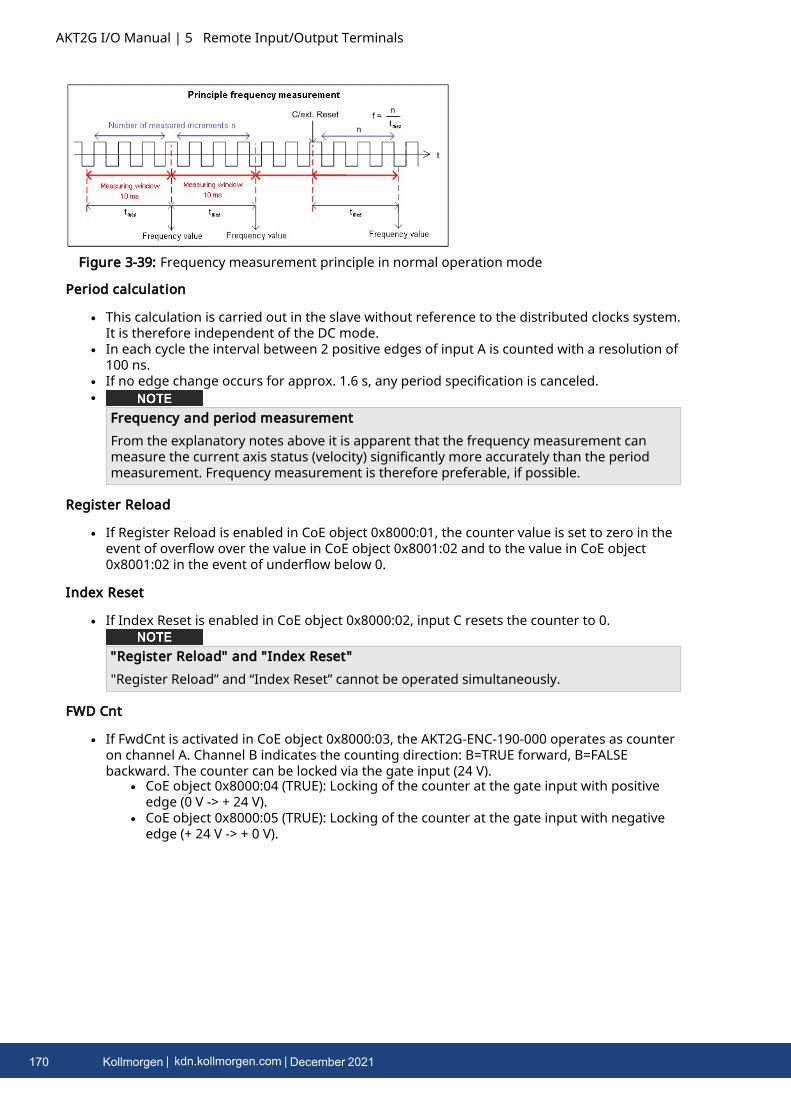
AKT2G I/O Manual | 5 Remote Input/Output Terminals
Figure 3-39: Frequency measurement principle in normal operation mode
Period calculation
l This calculation is carried out in the slave without reference to the distributed clocks system.It is therefore independent of the DC mode.
l In each cycle the interval between 2 positive edges of input A is counted with a resolution of100 ns.
l If no edge change occurs for approx. 1.6 s, any period specification is canceled.l
Frequency and period measurementFrom the explanatory notes above it is apparent that the frequency measurement canmeasure the current axis status (velocity) significantly more accurately than the periodmeasurement. Frequency measurement is therefore preferable, if possible.
Register Reload
l If Register Reload is enabled in CoE object 0x8000:01, the counter value is set to zero in theevent of overflow over the value in CoE object 0x8001:02 and to the value in CoE object0x8001:02 in the event of underflow below 0.
Index Reset
l If Index Reset is enabled in CoE object 0x8000:02, input C resets the counter to 0.
"Register Reload" and "Index Reset""Register Reload” and “Index Reset” cannot be operated simultaneously.
FWD Cnt
l If FwdCnt is activated in CoE object 0x8000:03, the AKT2G-ENC-190-000 operates as counteron channel A. Channel B indicates the counting direction: B=TRUE forward, B=FALSEbackward. The counter can be locked via the gate input (24 V).
l CoE object 0x8000:04 (TRUE): Locking of the counter at the gate input with positiveedge (0 V -> + 24 V).
l CoE object 0x8000:05 (TRUE): Locking of the counter at the gate input with negativeedge (+ 24 V -> + 0 V).
170 Kollmorgen | kdn.kollmorgen.com | December 2021
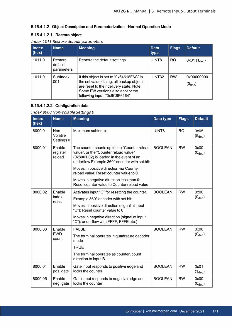
5.15.4.1.2 Object Description and Parameterization - Normal Operation Mode
5.15.4.1.2.1 Restore object
Index(hex)
Name Meaning Datatype
Flags Default
1011:0 Restoredefaultparameters
Restore the default settings UINT8 RO 0x01 (1dec)
1011:01 SubIndex001
If this object is set to “0x64616F6C” inthe set value dialog, all backup objectsare reset to their delivery state. Note:Some FW versions also accept thefollowing input: "0x6C6F6164".
UINT32 RW 0x00000000
(0dec)
Index 1011 Restore default parameters
5.15.4.1.2.2 Configuration data
Index(hex)
Name Meaning Data type Flags Default
8000:0 Non-VolatileSettings 0
Maximum subindex UINT8 RO 0x05(5dec)
8000:01 Enableregisterreload
The counter counts up to the “Counter reloadvalue”, or the “Counter reload value”(0x8001:02) is loaded in the event of anunderflow Example 360° encoder with set bit:
Moves in positive direction via Counterreload value: Reset counter value to 0.
Moves in negative direction less than 0:Reset counter value to Counter reload value
BOOLEAN RW 0x00(0dec)
8000:02 Enableindexreset
Activates input “C” for resetting the counter.
Example 360° encoder with set bit:
Moves in positive direction (signal at input“C”): Reset counter value to 0
Moves in negative direction (signal at input“C”): underflow with FFFF, FFFE etc.)
BOOLEAN RW 0x00(0dec)
8000:03 EnableFWDcount
FALSE
The terminal operates in quadrature decodermode
TRUE
The terminal operates as counter, countdirection to input B
BOOLEAN RW 0x00(0dec)
8000:04 Enablepos. gate
Gate input responds to positive edge andlocks the counter
BOOLEAN RW 0x01(1dec)
8000:05 Enableneg. gate
Gate input responds to negative edge andlocks the counter
BOOLEAN RW 0x00(0dec)
Index 8000 Non-Volatile Settings 0
AKT2G I/O Manual | 5 Remote Input/Output Terminals
Kollmorgen | kdn.kollmorgen.com | December 2021 171
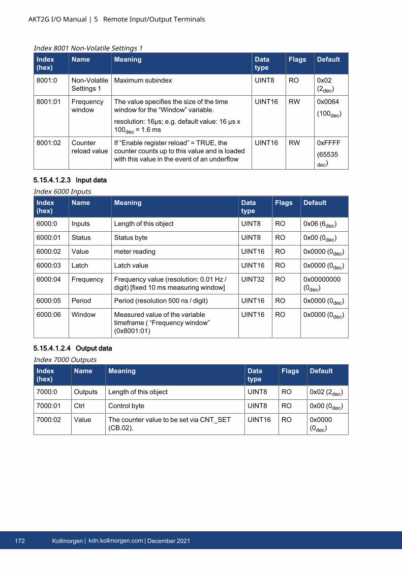
AKT2G I/O Manual | 5 Remote Input/Output Terminals
Index(hex)
Name Meaning Datatype
Flags Default
8001:0 Non-VolatileSettings 1
Maximum subindex UINT8 RO 0x02(2dec)
8001:01 Frequencywindow
The value specifies the size of the timewindow for the “Window” variable.
resolution: 16µs; e.g. default value: 16 µs x100dec = 1.6 ms
UINT16 RW 0x0064
(100dec)
8001:02 Counterreload value
If “Enable register reload” = TRUE, thecounter counts up to this value and is loadedwith this value in the event of an underflow
UINT16 RW 0xFFFF
(65535dec)
Index 8001 Non-Volatile Settings 1
5.15.4.1.2.3 Input data
Index(hex)
Name Meaning Datatype
Flags Default
6000:0 Inputs Length of this object UINT8 RO 0x06 (6dec)
6000:01 Status Status byte UINT8 RO 0x00 (0dec)
6000:02 Value meter reading UINT16 RO 0x0000 (0dec)
6000:03 Latch Latch value UINT16 RO 0x0000 (0dec)
6000:04 Frequency Frequency value (resolution: 0.01 Hz /digit) [fixed 10 ms measuring window]
UINT32 RO 0x00000000(0dec)
6000:05 Period Period (resolution 500 ns / digit) UINT16 RO 0x0000 (0dec)
6000:06 Window Measured value of the variabletimeframe ( “Frequency window”(0x8001:01)
UINT16 RO 0x0000 (0dec)
Index 6000 Inputs
5.15.4.1.2.4 Output data
Index(hex)
Name Meaning Datatype
Flags Default
7000:0 Outputs Length of this object UINT8 RO 0x02 (2dec)
7000:01 Ctrl Control byte UINT8 RO 0x00 (0dec)
7000:02 Value The counter value to be set via CNT_SET(CB.02).
UINT16 RO 0x0000(0dec)
Index 7000 Outputs
172 Kollmorgen | kdn.kollmorgen.com | December 2021
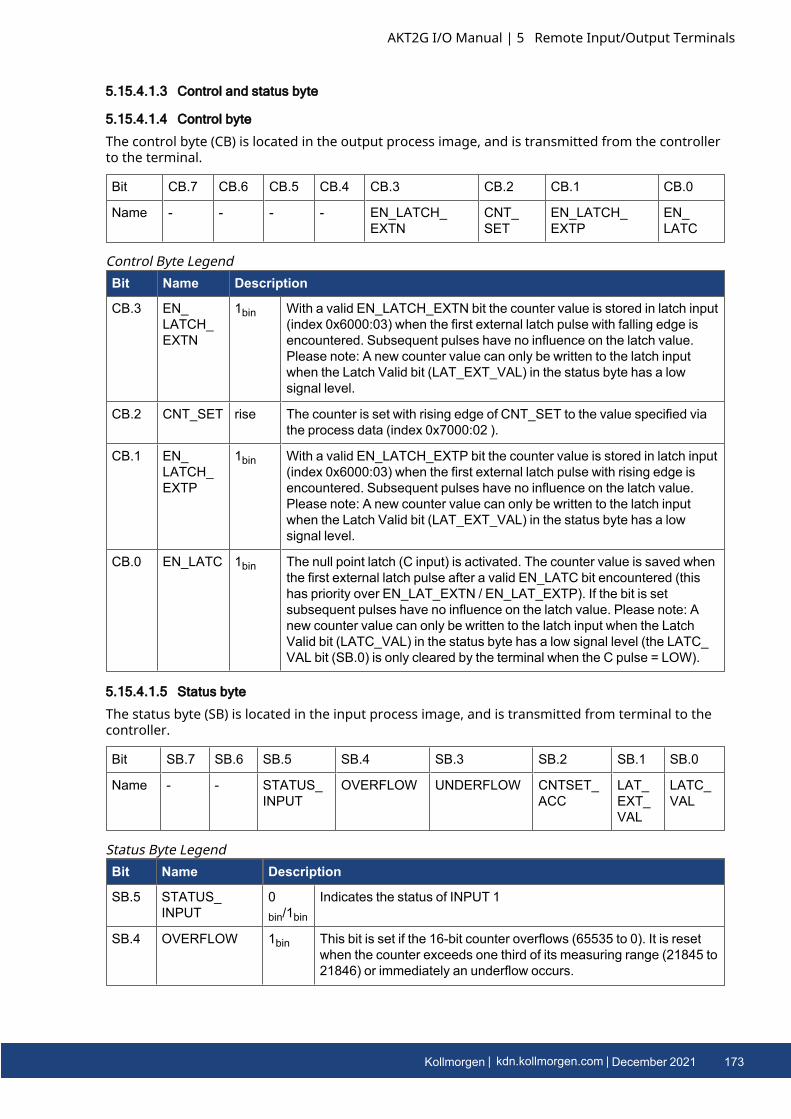
5.15.4.1.3 Control and status byte
5.15.4.1.4 Control byte
The control byte (CB) is located in the output process image, and is transmitted from the controllerto the terminal.
Bit CB.7 CB.6 CB.5 CB.4 CB.3 CB.2 CB.1 CB.0
Name - - - - EN_LATCH_EXTN
CNT_SET
EN_LATCH_EXTP
EN_LATC
Bit Name Description
CB.3 EN_LATCH_EXTN
1bin With a valid EN_LATCH_EXTN bit the counter value is stored in latch input(index 0x6000:03) when the first external latch pulse with falling edge isencountered. Subsequent pulses have no influence on the latch value.Please note: A new counter value can only be written to the latch inputwhen the Latch Valid bit (LAT_EXT_VAL) in the status byte has a lowsignal level.
CB.2 CNT_SET rise The counter is set with rising edge of CNT_SET to the value specified viathe process data (index 0x7000:02 ).
CB.1 EN_LATCH_EXTP
1bin With a valid EN_LATCH_EXTP bit the counter value is stored in latch input(index 0x6000:03) when the first external latch pulse with rising edge isencountered. Subsequent pulses have no influence on the latch value.Please note: A new counter value can only be written to the latch inputwhen the Latch Valid bit (LAT_EXT_VAL) in the status byte has a lowsignal level.
CB.0 EN_LATC 1bin The null point latch (C input) is activated. The counter value is saved whenthe first external latch pulse after a valid EN_LATC bit encountered (thishas priority over EN_LAT_EXTN / EN_LAT_EXTP). If the bit is setsubsequent pulses have no influence on the latch value. Please note: Anew counter value can only be written to the latch input when the LatchValid bit (LATC_VAL) in the status byte has a low signal level (the LATC_VAL bit (SB.0) is only cleared by the terminal when the C pulse = LOW).
Control Byte Legend
5.15.4.1.5 Status byte
The status byte (SB) is located in the input process image, and is transmitted from terminal to thecontroller.
Bit SB.7 SB.6 SB.5 SB.4 SB.3 SB.2 SB.1 SB.0
Name - - STATUS_INPUT
OVERFLOW UNDERFLOW CNTSET_ACC
LAT_EXT_VAL
LATC_VAL
Bit Name Description
SB.5 STATUS_INPUT
0bin/1bin
Indicates the status of INPUT 1
SB.4 OVERFLOW 1bin This bit is set if the 16-bit counter overflows (65535 to 0). It is resetwhen the counter exceeds one third of its measuring range (21845 to21846) or immediately an underflow occurs.
Status Byte Legend
AKT2G I/O Manual | 5 Remote Input/Output Terminals
Kollmorgen | kdn.kollmorgen.com | December 2021 173
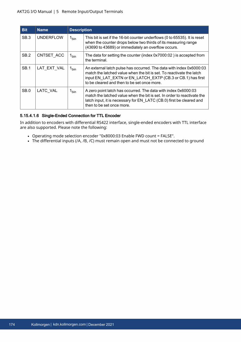
AKT2G I/O Manual | 5 Remote Input/Output Terminals
Bit Name Description
SB.3 UNDERFLOW 1bin This bit is set if the 16-bit counter underflows (0 to 65535). It is resetwhen the counter drops below two thirds of its measuring range(43690 to 43689) or immediately an overflow occurs.
SB.2 CNTSET_ACC 1bin The data for setting the counter (index 0x7000:02 ) is accepted fromthe terminal.
SB.1 LAT_EXT_VAL 1bin An external latch pulse has occurred. The data with index 0x6000:03match the latched value when the bit is set. To reactivate the latchinput EN_LAT_EXTN or EN_LATCH_EXTP (CB.3 or CB.1) has firstto be cleared and then to be set once more.
SB.0 LATC_VAL 1bin A zero point latch has occurred. The data with index 0x6000:03match the latched value when the bit is set. In order to reactivate thelatch input, it is necessary for EN_LATC (CB.0) first be cleared andthen to be set once more.
5.15.4.1.6 Single-Ended Connection for TTL Encoder
In addition to encoders with differential RS422 interface, single-ended encoders with TTL interfaceare also supported. Please note the following:
l Operating mode selection encoder "0x8000:03 Enable FWD count = FALSE".l The differential inputs (/A, /B, /C) must remain open and must not be connected to ground
174 Kollmorgen | kdn.kollmorgen.com | December 2021
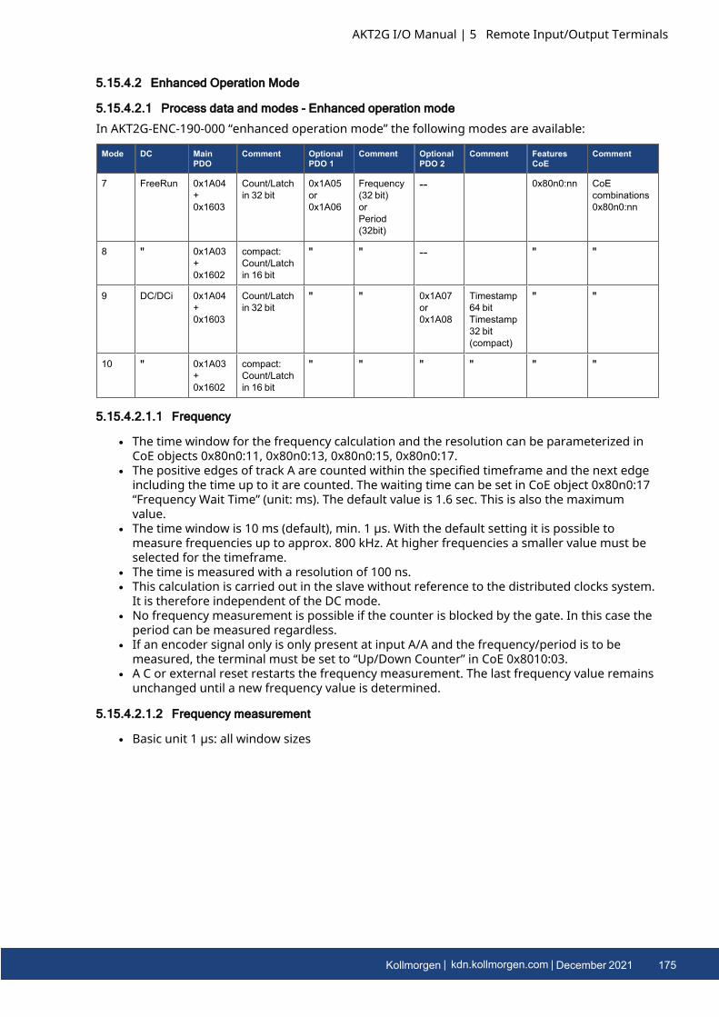
5.15.4.2 Enhanced Operation Mode
5.15.4.2.1 Process data and modes - Enhanced operation mode
In AKT2G-ENC-190-000 “enhanced operation mode” the following modes are available:
Mode DC MainPDO
Comment OptionalPDO 1
Comment OptionalPDO 2
Comment FeaturesCoE
Comment
7 FreeRun 0x1A04+0x1603
Count/Latchin 32 bit
0x1A05or0x1A06
Frequency(32 bit)orPeriod(32bit)
-- 0x80n0:nn CoEcombinations0x80n0:nn
8 " 0x1A03+0x1602
compact:Count/Latchin 16 bit
" " -- " "
9 DC/DCi 0x1A04+0x1603
Count/Latchin 32 bit
" " 0x1A07or0x1A08
Timestamp64 bitTimestamp32 bit(compact)
" "
10 " 0x1A03+0x1602
compact:Count/Latchin 16 bit
" " " " " "
5.15.4.2.1.1 Frequency
l The time window for the frequency calculation and the resolution can be parameterized inCoE objects 0x80n0:11, 0x80n0:13, 0x80n0:15, 0x80n0:17.
l The positive edges of track A are counted within the specified timeframe and the next edgeincluding the time up to it are counted. The waiting time can be set in CoE object 0x80n0:17“Frequency Wait Time” (unit: ms). The default value is 1.6 sec. This is also the maximumvalue.
l The time window is 10 ms (default), min. 1 µs. With the default setting it is possible tomeasure frequencies up to approx. 800 kHz. At higher frequencies a smaller value must beselected for the timeframe.
l The time is measured with a resolution of 100 ns.l This calculation is carried out in the slave without reference to the distributed clocks system.
It is therefore independent of the DC mode.l No frequency measurement is possible if the counter is blocked by the gate. In this case the
period can be measured regardless.l If an encoder signal only is only present at input A/A and the frequency/period is to be
measured, the terminal must be set to “Up/Down Counter” in CoE 0x8010:03.l A C or external reset restarts the frequency measurement. The last frequency value remains
unchanged until a new frequency value is determined.
5.15.4.2.1.2 Frequency measurement
l Basic unit 1 µs: all window sizes
AKT2G I/O Manual | 5 Remote Input/Output Terminals
Kollmorgen | kdn.kollmorgen.com | December 2021 175
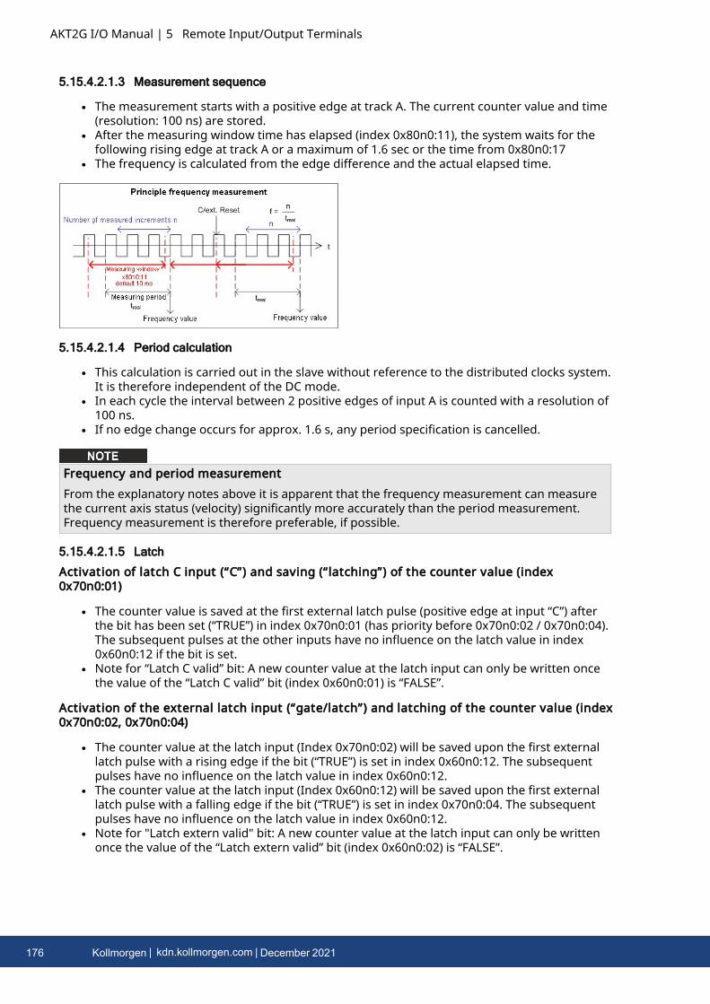
AKT2G I/O Manual | 5 Remote Input/Output Terminals
5.15.4.2.1.3 Measurement sequence
l The measurement starts with a positive edge at track A. The current counter value and time(resolution: 100 ns) are stored.
l After the measuring window time has elapsed (index 0x80n0:11), the system waits for thefollowing rising edge at track A or a maximum of 1.6 sec or the time from 0x80n0:17
l The frequency is calculated from the edge difference and the actual elapsed time.
5.15.4.2.1.4 Period calculation
l This calculation is carried out in the slave without reference to the distributed clocks system.It is therefore independent of the DC mode.
l In each cycle the interval between 2 positive edges of input A is counted with a resolution of100 ns.
l If no edge change occurs for approx. 1.6 s, any period specification is cancelled.
Frequency and period measurementFrom the explanatory notes above it is apparent that the frequency measurement can measurethe current axis status (velocity) significantly more accurately than the period measurement.Frequency measurement is therefore preferable, if possible.
5.15.4.2.1.5 Latch
Activation of latch C input (“C”) and saving (“latching”) of the counter value (index0x70n0:01)
l The counter value is saved at the first external latch pulse (positive edge at input “C”) afterthe bit has been set (“TRUE”) in index 0x70n0:01 (has priority before 0x70n0:02 / 0x70n0:04).The subsequent pulses at the other inputs have no influence on the latch value in index0x60n0:12 if the bit is set.
l Note for “Latch C valid” bit: A new counter value at the latch input can only be written oncethe value of the “Latch C valid” bit (index 0x60n0:01) is “FALSE”.
Activation of the external latch input (“gate/latch”) and latching of the counter value (index0x70n0:02, 0x70n0:04)
l The counter value at the latch input (Index 0x70n0:02) will be saved upon the first externallatch pulse with a rising edge if the bit (“TRUE”) is set in index 0x60n0:12. The subsequentpulses have no influence on the latch value in index 0x60n0:12.
l The counter value at the latch input (Index 0x60n0:12) will be saved upon the first externallatch pulse with a falling edge if the bit (“TRUE”) is set in index 0x70n0:04. The subsequentpulses have no influence on the latch value in index 0x60n0:12.
l Note for "Latch extern valid" bit: A new counter value at the latch input can only be writtenonce the value of the “Latch extern valid” bit (index 0x60n0:02) is “FALSE”.
176 Kollmorgen | kdn.kollmorgen.com | December 2021
5.15.4.2.1.6 Reset
l Counter reset (index 0x80n0:01, 0x80n0:02, 0x80n0:10): For a counter reset via input C setthe bit in index 0x80n0:01, for a reset via the external latch input set the bit in index0x80n0:02.
l The functions “Enable C reset” (0x80n0:01) and “Enable extern reset” (0x80n0:02) cannot beactivated simultaneously.
l Note for “Extern reset polarity”, index 0x80n0:10: The edge for setting the counter to zerocan be selected via index 0x80n0:10.Bit not set: counter is set to zero with falling edge.Bit set: counter is set to zero with rising edge.
5.15.4.2.1.7 Up/down counter
l The mode (encoder or up/down counter) is set via the CoE objects (profile-specific objects,tab CoE Online, index 0x80n0:03 “Enable up/down counter”). Click on the corresponding rowof the index to be parameterized, enter 1 in the SetValue dialog and confirm with OK.
l Set the gate polarity accordingly via object 0x80n0:04.l An additional option for reversing the rotation direction is available by setting the bit in
index 0x80n0:0E.
5.15.4.2.1.8 Overflow/underflow
l Overflow/underflow control is inactive in combination with an activated reset function(C/external).
l The underflow bit (0x60n0:04) is set if an underflow ...00 → ...FF occurs. It is reset if 2/3 of thecounter range are underrun.
l The overflow bit (0x60n0:05) is set if an overflow FF...→ 00... occurs. It is reset if 1/3 of thecounter range is exceeded.
5.15.4.2.1.9 Open circuit detection
l A separate open circuit detection can be activated for each of the channels A, B and C (index0x80n0:0B, 0x80n0:0C, 0x80n0:0D).
l Open circuit detection is activated for channels A and B by default.l A differential voltage of typically -1.5 V >Vid > +1.5 V is detected as an open circuit.l If an open circuit is detected, it is indicated as process data open circuit = TRUE. The bit in
object 0x60n0:07 is set. An open circuit is indicated separately in indices 0xA0n0:01 (track A),0xA0n0:02 (track B) and 0xA0n0:03 (track C).
l TxPDO state also becomes TRUE if an open circuit is detected, since invalid data have to beassumed.
Open circuit detection vs. single-ended lines (TTL interface)The open circuit detection does principally not work with single-ended lines (TTL interface).
AKT2G I/O Manual | 5 Remote Input/Output Terminals
Kollmorgen | kdn.kollmorgen.com | December 2021 177
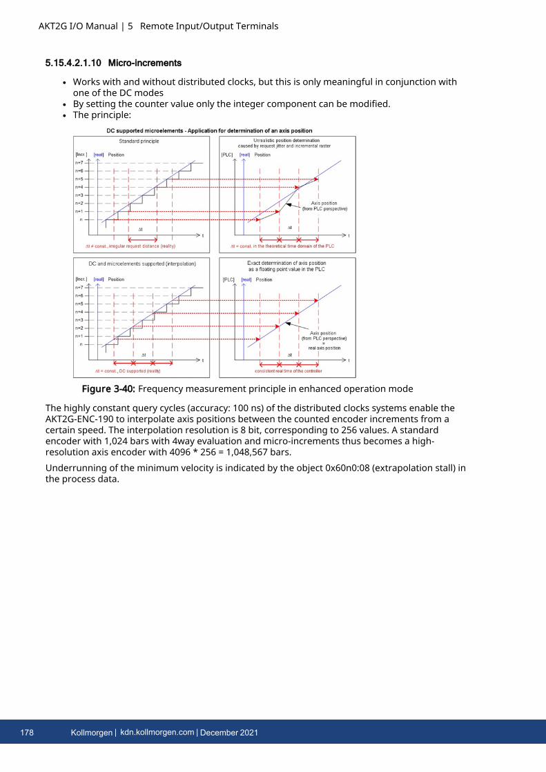
AKT2G I/O Manual | 5 Remote Input/Output Terminals
5.15.4.2.1.10 Micro-increments
l Works with and without distributed clocks, but this is only meaningful in conjunction withone of the DC modes
l By setting the counter value only the integer component can be modified.l The principle:
Figure 3-40: Frequency measurement principle in enhanced operation mode
The highly constant query cycles (accuracy: 100 ns) of the distributed clocks systems enable theAKT2G-ENC-190 to interpolate axis positions between the counted encoder increments from acertain speed. The interpolation resolution is 8 bit, corresponding to 256 values. A standardencoder with 1,024 bars with 4way evaluation and micro-increments thus becomes a high-resolution axis encoder with 4096 * 256 = 1,048,567 bars.Underrunning of the minimum velocity is indicated by the object 0x60n0:08 (extrapolation stall) inthe process data.
178 Kollmorgen | kdn.kollmorgen.com | December 2021
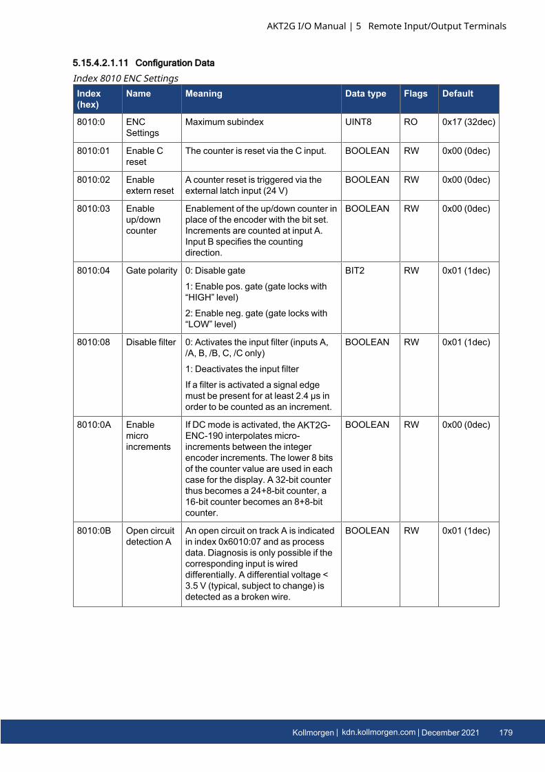
5.15.4.2.1.11 Configuration Data
Index(hex)
Name Meaning Data type Flags Default
8010:0 ENCSettings
Maximum subindex UINT8 RO 0x17 (32dec)
8010:01 Enable Creset
The counter is reset via the C input. BOOLEAN RW 0x00 (0dec)
8010:02 Enableextern reset
A counter reset is triggered via theexternal latch input (24 V)
BOOLEAN RW 0x00 (0dec)
8010:03 Enableup/downcounter
Enablement of the up/down counter inplace of the encoder with the bit set.Increments are counted at input A.Input B specifies the countingdirection.
BOOLEAN RW 0x00 (0dec)
8010:04 Gate polarity 0: Disable gate
1: Enable pos. gate (gate locks with“HIGH” level)
2: Enable neg. gate (gate locks with“LOW” level)
BIT2 RW 0x01 (1dec)
8010:08 Disable filter 0: Activates the input filter (inputs A,/A, B, /B, C, /C only)
1: Deactivates the input filter
If a filter is activated a signal edgemust be present for at least 2.4 µs inorder to be counted as an increment.
BOOLEAN RW 0x01 (1dec)
8010:0A Enablemicroincrements
If DC mode is activated, the AKT2G-ENC-190 interpolates micro-increments between the integerencoder increments. The lower 8 bitsof the counter value are used in eachcase for the display. A 32-bit counterthus becomes a 24+8-bit counter, a16-bit counter becomes an 8+8-bitcounter.
BOOLEAN RW 0x00 (0dec)
8010:0B Open circuitdetection A
An open circuit on track A is indicatedin index 0x6010:07 and as processdata. Diagnosis is only possible if thecorresponding input is wireddifferentially. A differential voltage <3.5 V (typical, subject to change) isdetected as a broken wire.
BOOLEAN RW 0x01 (1dec)
Index 8010 ENC Settings
AKT2G I/O Manual | 5 Remote Input/Output Terminals
Kollmorgen | kdn.kollmorgen.com | December 2021 179
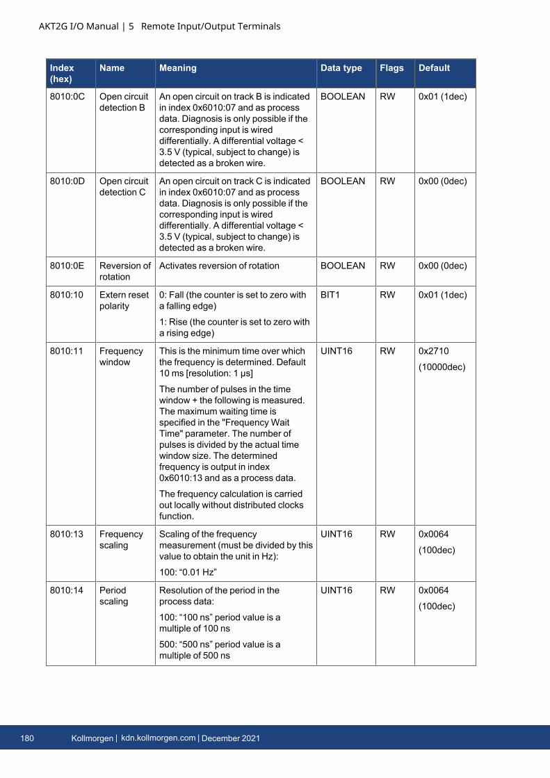
AKT2G I/O Manual | 5 Remote Input/Output Terminals
Index(hex)
Name Meaning Data type Flags Default
8010:0C Open circuitdetection B
An open circuit on track B is indicatedin index 0x6010:07 and as processdata. Diagnosis is only possible if thecorresponding input is wireddifferentially. A differential voltage <3.5 V (typical, subject to change) isdetected as a broken wire.
BOOLEAN RW 0x01 (1dec)
8010:0D Open circuitdetection C
An open circuit on track C is indicatedin index 0x6010:07 and as processdata. Diagnosis is only possible if thecorresponding input is wireddifferentially. A differential voltage <3.5 V (typical, subject to change) isdetected as a broken wire.
BOOLEAN RW 0x00 (0dec)
8010:0E Reversion ofrotation
Activates reversion of rotation BOOLEAN RW 0x00 (0dec)
8010:10 Extern resetpolarity
0: Fall (the counter is set to zero witha falling edge)
1: Rise (the counter is set to zero witha rising edge)
BIT1 RW 0x01 (1dec)
8010:11 Frequencywindow
This is the minimum time over whichthe frequency is determined. Default10 ms [resolution: 1 µs]
The number of pulses in the timewindow + the following is measured.The maximum waiting time isspecified in the "Frequency WaitTime" parameter. The number ofpulses is divided by the actual timewindow size. The determinedfrequency is output in index0x6010:13 and as a process data.
The frequency calculation is carriedout locally without distributed clocksfunction.
UINT16 RW 0x2710
(10000dec)
8010:13 Frequencyscaling
Scaling of the frequencymeasurement (must be divided by thisvalue to obtain the unit in Hz):
100: “0.01 Hz”
UINT16 RW 0x0064
(100dec)
8010:14 Periodscaling
Resolution of the period in theprocess data:
100: “100 ns” period value is amultiple of 100 ns
500: “500 ns” period value is amultiple of 500 ns
UINT16 RW 0x0064
(100dec)
180 Kollmorgen | kdn.kollmorgen.com | December 2021
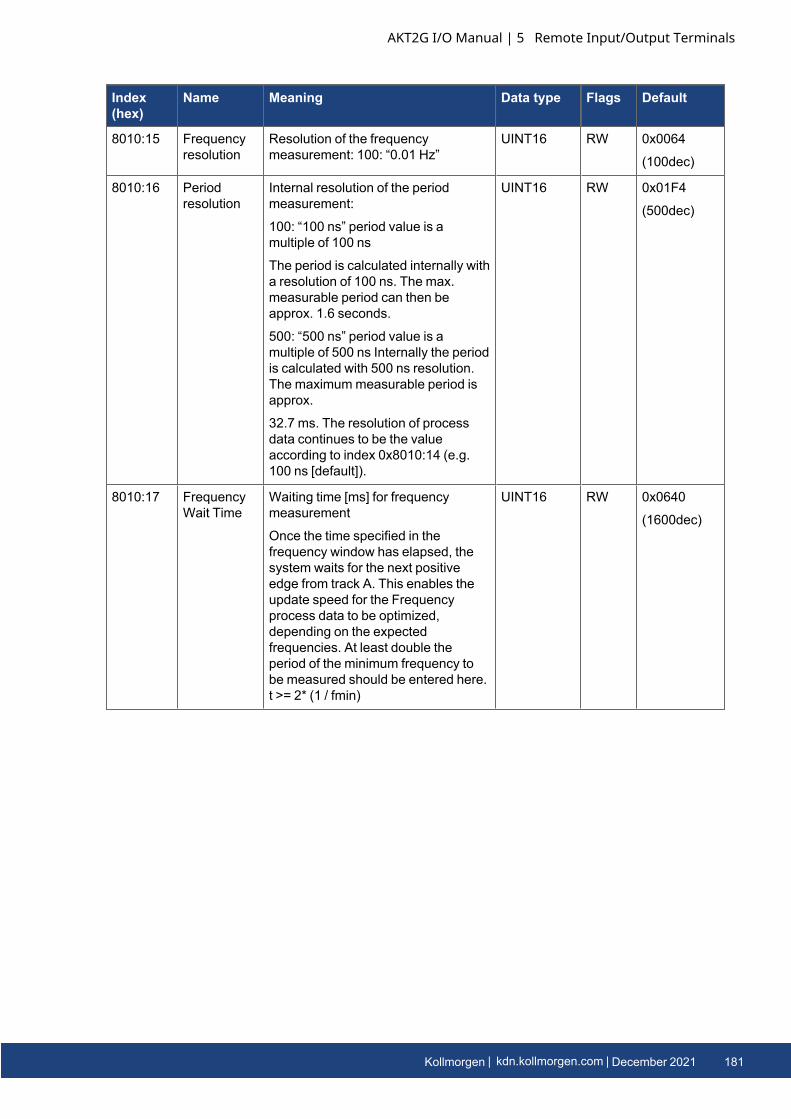
Index(hex)
Name Meaning Data type Flags Default
8010:15 Frequencyresolution
Resolution of the frequencymeasurement: 100: “0.01 Hz”
UINT16 RW 0x0064
(100dec)
8010:16 Periodresolution
Internal resolution of the periodmeasurement:
100: “100 ns” period value is amultiple of 100 ns
The period is calculated internally witha resolution of 100 ns. The max.measurable period can then beapprox. 1.6 seconds.
500: “500 ns” period value is amultiple of 500 ns Internally the periodis calculated with 500 ns resolution.The maximummeasurable period isapprox.
32.7 ms. The resolution of processdata continues to be the valueaccording to index 0x8010:14 (e.g.100 ns [default]).
UINT16 RW 0x01F4
(500dec)
8010:17 FrequencyWait Time
Waiting time [ms] for frequencymeasurement
Once the time specified in thefrequency window has elapsed, thesystem waits for the next positiveedge from track A. This enables theupdate speed for the Frequencyprocess data to be optimized,depending on the expectedfrequencies. At least double theperiod of the minimum frequency tobe measured should be entered here.t >= 2* (1 / fmin)
UINT16 RW 0x0640
(1600dec)
AKT2G I/O Manual | 5 Remote Input/Output Terminals
Kollmorgen | kdn.kollmorgen.com | December 2021 181
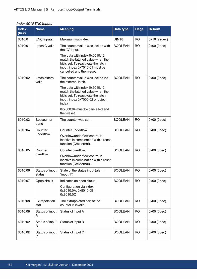
AKT2G I/O Manual | 5 Remote Input/Output Terminals
Index(hex)
Name Meaning Data type Flags Default
6010:0 ENC Inputs Maximum subindex UINT8 RO 0x16 (22dec)
6010:01 Latch C valid The counter value was locked withthe “C” input.
The data with index 0x6010:12match the latched value when thebit is set. To reactivate the latchinput, index 0x7010:01 must becancelled and then reset.
BOOLEAN RO 0x00 (0dec)
6010:02 Latch externvalid
The counter value was locked viathe external latch.
The data with index 0x6010:12match the latched value when thebit is set. To reactivate the latchinput, index 0x7000:02 or objectindex
0x7000:04 must be cancelled andthen reset.
BOOLEAN RO 0x00 (0dec)
6010:03 Set counterdone
The counter was set. BOOLEAN RO 0x00 (0dec)
6010:04 Counterunderflow
Counter underflow.
Overflow/underflow control isinactive in combination with a resetfunction (C/external).
BOOLEAN RO 0x00 (0dec)
6010:05 Counteroverflow
Counter overflow.
Overflow/underflow control isinactive in combination with a resetfunction (C/external).
BOOLEAN RO 0x00 (0dec)
6010:06 Status of inputstatus
State of the status input (alarm“input 1”)
BOOLEAN RO 0x00 (0dec)
6010:07 Open circuit Indicates an open circuit.
Configuration via index0x8010:0A, 0x8010:0B,0x8010:0C
BOOLEAN RO 0x00 (0dec)
6010:08 Extrapolationstall
The extrapolated part of thecounter is invalid
BOOLEAN RO 0x00 (0dec)
6010:09 Status of inputA
Status of input A BOOLEAN RO 0x00 (0dec)
6010:0A Status of inputB
Status of input B BOOLEAN RO 0x00 (0dec)
6010:0B Status of inputC
Status of input C BOOLEAN RO 0x00 (0dec)
Index 6010 ENC Inputs
182 Kollmorgen | kdn.kollmorgen.com | December 2021
Index(hex)
Name Meaning Data type Flags Default
6010:0C Status of inputgate
The state of the gate input BOOLEAN RO 0x00 (0dec)
6010:0D Status ofextern latch
Status of the extern latch input BOOLEAN RO 0x00 (0dec)
6010:0E Sync Error The Sync error bit is only requiredfor DC mode. It indicates whether asynchronization error has occurredduring the previous cycle.
This means a SYNC signal wastriggered in the AKT2G-ENC-190,although no new process datawere available (0=OK, 1=NOK).
BOOLEAN RO 0x00 (0dec)
6010:0F TxPDO State Validity of the data of theassociated TxPDO (0 = valid, 1 =invalid).
BOOLEAN RO 0x00 (0dec)
6010:10 TxPDO Toggle The TxPDO toggle is toggled bythe slave when the data of theassociated TxPDO is updated.
BOOLEAN RO 0x00 (0dec)
6010:11 Counter value Counter value UINT32 RO 0x00000000
(0dec)
6010:12 Latch value Latch value UINT32 RO 0x00000000
(0dec)
6010:13 Frequencyvalue
The frequency (setting of thescaling and resolution in index0x8010:13 and 0x8010:15)
UINT32 RO 0x00000000
(0dec)
6010:14 Period value The period (setting of the scalingand resolution in index 0x8010:14and 0x8010:16)
UINT32 RO 0x00000000
(0dec)
6010:16 Timestamp Timestamp of the last counterchange
UINT64 RO
Index(hex)
Name Meaning Data type Flags Default
7010:0 ENC Outputs Maximum subindex UINT8 RO 0x11 (17dec)
7010:01 Enable latch C Activate latching via input “C”. BOOLEAN RO 0x00 (0dec)
7010:02 Enable latchextern on positiveedge
Activate external latch withpositive edge.
BOOLEAN RO 0x00 (0dec)
7010:03 Set counter Set counter BOOLEAN RO 0x00 (0dec)
7010:04 Enable latchextern on negativeedge
Activate external latch withnegative edge.
BOOLEAN RO 0x00 (0dec)
Index 7010 ENC Outputs
AKT2G I/O Manual | 5 Remote Input/Output Terminals
Kollmorgen | kdn.kollmorgen.com | December 2021 183
AKT2G I/O Manual | 5 Remote Input/Output Terminals
Index(hex)
Name Meaning Data type Flags Default
7010:11 Set counter value The counter value to be set via“Set counter” (index0x7010:03).
UINT32 RO 0x00000000
(0dec)
5.15.4.2.1.12 Information / Diagnostic Data (Channel Specific)
Index (hex) Name Meaning Data type Flags Default
A010:0 ENC Diag data Maximum subindex UINT8 RO 0x03 (3dec)
A010:01 Open circuit A Open circuit on track A BOOLEAN RO 0x00 (0dec)
A010:02 Open circuit B Open circuit on track B BOOLEAN RO 0x00 (0dec)
A010:03 Open circuit C Open circuit on track C BOOLEAN RO 0x00 (0dec)
Index A010 ENC Diag data
5.15.4.2.2 Single-ended connection for TTL encoder
In addition to encoders with differential RS422 interface, single-ended encoders with TTL interfaceare also supported. Please note the following:
l Operating mode selection encoder "0x80n0:03 Enable up/down counter = FALSE".l The differential inputs (/A, /B, /C) must remain open and must not be connected to groundl The option to reverse the direction of rotation is given by setting the bit in index 0x80n0:0E
"reversion of rotation =TRUE".l The open circuit detection does not work in principle conditionally with single-ended
connection
184 Kollmorgen | kdn.kollmorgen.com | December 2021
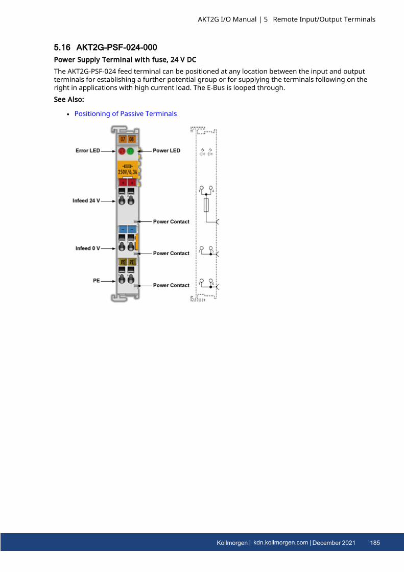
5.16 AKT2G-PSF-024-000Power Supply Terminal with fuse, 24 V DCThe AKT2G-PSF-024 feed terminal can be positioned at any location between the input and outputterminals for establishing a further potential group or for supplying the terminals following on theright in applications with high current load. The E-Bus is looped through.See Also:
l Positioning of Passive Terminals
AKT2G I/O Manual | 5 Remote Input/Output Terminals
Kollmorgen | kdn.kollmorgen.com | December 2021 185
AKT2G I/O Manual | 5 Remote Input/Output Terminals
5.16.1 Connections
Terminal Point Description
Indication Number
+24 V 1 Supply input + 24 V (connected internally with terminal 4 and positive powercontact)
0 V 2 0 V for supply input (connected internally with terminal 5 and negative powercontact)
PE 3 PE (connected internally with terminal 6 and PE power contact)
+24 V 4 Supply input + 24 V (connected internally with terminal 1 and positive powercontact)
0 V 5 0 V for supply input (connected internally with terminal 2 and negative powercontact)
PE 6 PE (connected internally with terminal 3 and PE power contact)
5.16.2 LEDs
LED Color Meaning
Power LED green off No input voltage at supply input
on 24 VDC at supply input
Error LED red off Fuse OK
on Fuse error
186 Kollmorgen | kdn.kollmorgen.com | December 2021
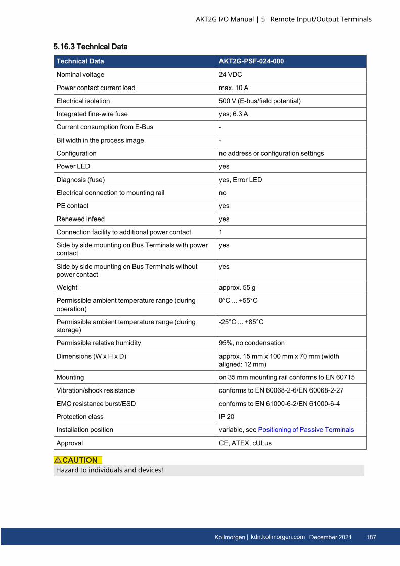
5.16.3 Technical Data
Technical Data AKT2G-PSF-024-000
Nominal voltage 24 VDC
Power contact current load max. 10 A
Electrical isolation 500 V (E-bus/field potential)
Integrated fine-wire fuse yes; 6.3 A
Current consumption from E-Bus -
Bit width in the process image -
Configuration no address or configuration settings
Power LED yes
Diagnosis (fuse) yes, Error LED
Electrical connection to mounting rail no
PE contact yes
Renewed infeed yes
Connection facility to additional power contact 1
Side by side mounting on Bus Terminals with powercontact
yes
Side by side mounting on Bus Terminals withoutpower contact
yes
Weight approx. 55 g
Permissible ambient temperature range (duringoperation)
0°C ... +55°C
Permissible ambient temperature range (duringstorage)
-25°C ... +85°C
Permissible relative humidity 95%, no condensation
Dimensions (W x H x D) approx. 15 mm x 100 mm x 70 mm (widthaligned: 12 mm)
Mounting on 35 mmmounting rail conforms to EN 60715
Vibration/shock resistance conforms to EN 60068-2-6/EN 60068-2-27
EMC resistance burst/ESD conforms to EN 61000-6-2/EN 61000-6-4
Protection class IP 20
Installation position variable, see Positioning of Passive Terminals
Approval CE, ATEX, cULus
Hazard to individuals and devices!
AKT2G I/O Manual | 5 Remote Input/Output Terminals
Kollmorgen | kdn.kollmorgen.com | December 2021 187

AKT2G I/O Manual | 5 Remote Input/Output Terminals
When designing a Bus Terminal block with different potentials on the power contacts (e.g. 230 VAC and 24 V DC), please note that it is mandatory to use potential separation terminals!Bring the bus system into a safe, powered down state before starting installation, disassembly orwiring of the Bus Terminals!
188 Kollmorgen | kdn.kollmorgen.com | December 2021
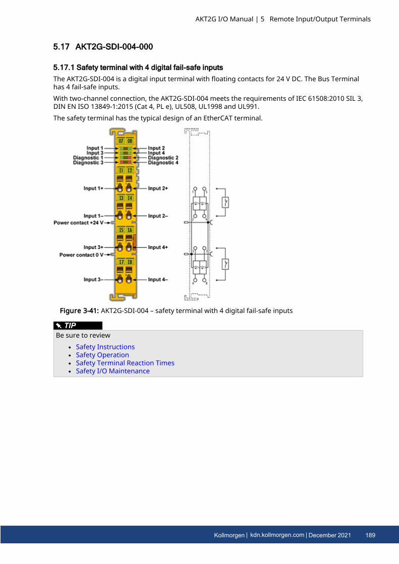
5.17 AKT2G-SDI-004-000
5.17.1 Safety terminal with 4 digital fail-safe inputsThe AKT2G-SDI-004 is a digital input terminal with floating contacts for 24 V DC. The Bus Terminalhas 4 fail-safe inputs.With two-channel connection, the AKT2G-SDI-004 meets the requirements of IEC 61508:2010 SIL 3,DIN EN ISO 13849-1:2015 (Cat 4, PL e), UL508, UL1998 and UL991.The safety terminal has the typical design of an EtherCAT terminal.
Figure 3-41: AKT2G-SDI-004 – safety terminal with 4 digital fail-safe inputs
Be sure to reviewl Safety Instructionsl Safety Operationl Safety Terminal Reaction Timesl Safety I/O Maintenance
AKT2G I/O Manual | 5 Remote Input/Output Terminals
Kollmorgen | kdn.kollmorgen.com | December 2021 189
AKT2G I/O Manual | 5 Remote Input/Output Terminals
5.17.2 Intended use
Caution - Risk of injury!Safety components may only be used for the purposes described below!
The safety terminals expand the application range of the E-Bus terminal system with functions thatenable them to be used for machine safety applications. The safety terminals are designed formachine safety functions and directly associated industrial automation tasks. They are thereforeonly approved for applications with a defined fail-safe state. This safe state is the wattless state.Fail-safety according to the relevant standards is required.The safety terminals enable connection of:
l 24 VDC sensors (AKT2G-SDI-004) such as emergency off pushbutton switches, pull cordswitches, position switches, two-hand switches, safety mats, light curtains, light barriers,laser scanner, etc.
l 24 VDC actuators (AKT2G-SDO-004 ) such as contactors, protection door switches withtumbler, signal lamps, servo drives, etc.
Test pulsesWhen selecting actuators please ensure that the AKT2G-SDO-004 test pulses do not lead toactuator switching or diagnostic message from the AKT2G-SDO-004.
The following safety components have been developed for these tasks:
l The AKT2G-SDI-004 is an EtherCAT Terminal with 4 digital fail-safe inputs.l The AKT2G-SDO-004 is an EtherCAT Terminal with 4 digital fail-safe outputs.
These safety components are suitable for operation on the
l Kollmorgen AKT2G-ECT-000-000 series Bus Couplers
Power supply from SELV/PELV power supply unit!The safety components must be supplied with 24 VDC by an SELV/PELV power supply unit with anoutput voltage limit Umax of 36 VDC. Failure to observe this can result in a loss of safety.
Follow the machinery directive!The safety components may only be used in machines as defined in the machinery directive.
Ensure traceability!The buyer has to ensure the traceability of the device via the serial number.
190 Kollmorgen | kdn.kollmorgen.com | December 2021
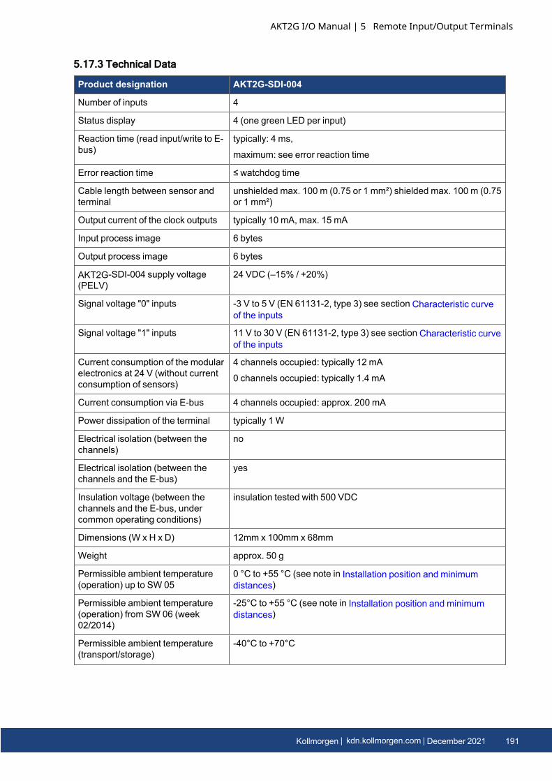
5.17.3 Technical Data
Product designation AKT2G-SDI-004
Number of inputs 4
Status display 4 (one green LED per input)
Reaction time (read input/write to E-bus)
typically: 4 ms,
maximum: see error reaction time
Error reaction time ≤ watchdog time
Cable length between sensor andterminal
unshielded max. 100 m (0.75 or 1 mm²) shielded max. 100 m (0.75or 1 mm²)
Output current of the clock outputs typically 10 mA, max. 15 mA
Input process image 6 bytes
Output process image 6 bytes
AKT2G-SDI-004 supply voltage(PELV)
24 VDC (–15% / +20%)
Signal voltage "0" inputs -3 V to 5 V (EN 61131-2, type 3) see section Characteristic curveof the inputs
Signal voltage "1" inputs 11 V to 30 V (EN 61131-2, type 3) see section Characteristic curveof the inputs
Current consumption of the modularelectronics at 24 V (without currentconsumption of sensors)
4 channels occupied: typically 12 mA
0 channels occupied: typically 1.4 mA
Current consumption via E-bus 4 channels occupied: approx. 200 mA
Power dissipation of the terminal typically 1 W
Electrical isolation (between thechannels)
no
Electrical isolation (between thechannels and the E-bus)
yes
Insulation voltage (between thechannels and the E-bus, undercommon operating conditions)
insulation tested with 500 VDC
Dimensions (W x H x D) 12mm x 100mm x 68mm
Weight approx. 50 g
Permissible ambient temperature(operation) up to SW 05
0 °C to +55 °C (see note in Installation position and minimumdistances)
Permissible ambient temperature(operation) from SW 06 (week02/2014)
-25°C to +55 °C (see note in Installation position and minimumdistances)
Permissible ambient temperature(transport/storage)
-40°C to +70°C
AKT2G I/O Manual | 5 Remote Input/Output Terminals
Kollmorgen | kdn.kollmorgen.com | December 2021 191
AKT2G I/O Manual | 5 Remote Input/Output Terminals
Product designation AKT2G-SDI-004
Permissible air humidity 5% to 95%, non-condensing
Permissible air pressure(operation/storage/transport)
750 hPa to 1100 hPa
(this corresponds to a height of approx. -690 m to 2450 m over sealevel assuming an international standard atmosphere)
Climate category according to EN60721-3-3
3K3
(the deviation from 3K3 is possible only with optimalenvironmental conditions and also applies only to the technicaldata which are specified differently in this documentation)
Permissible level of contaminationaccording to EN 60664-1
level of contamination 2
(comply with the section Safety I/O Maintenance
Impermissible operating conditions Safety terminals must not be used under the following operatingconditions:
• under the influence of ionizing radiation (that exceeds the levelof the natural environmental radiation)
• in corrosive environments
• in an environment that leads to unacceptable soiling of the BusTerminal
EMC immunity/emission conforms to EN 61000-6-2 / EN 61000-6-4
Vibration/shock resistance conforms to EN 60068-2-6 / EN 60068-2-27
Shocks 15 g with pulse duration 11 ms in all three axes
Protection class IP20
Permitted operating environment In the control cabinet or terminal box, with minimum protectionclass IP54 according to IEC 60529
Permissible installation position see section Installation position and minimum distances
Approvals CE, cULus
192 Kollmorgen | kdn.kollmorgen.com | December 2021
5.17.4 Safety Parameters
Key Figures AKT2G-SDI-004
Lifetime [a] 20
Prooftest Interval [a] not required 1
PFHD 1.11E-09
%SIL3 1.11%
PFD 8.29E-05
%SIL3 8.29 %
MTTFd high
DC high
Performance level PL e
Category 4
HFT 1
Element classification 2 Type B
1. Special proof tests are not required during the entire service life of the AKT2G-SDI-004EtherCAT terminal.
2. Classification according to IEC 61508-2:2010 (chapter 7.4.4.1.2 and 7.4.4.1.3)
The AKT2G-SDI-004 EtherCAT Terminal can be used for safety-related applications within themeaning of IEC 61508:2010 up to SIL3 and EN ISO 13849-1 up to PL e (Cat4).For the calculation or estimation of the MTTFd value from the PFHD value, further information canbe found in ISO 13849-1:2015 Table K.1.
5.17.5 Characteristic curve of the inputsThe characteristic curve of the inputs is similar to type 3 according to EN 61131-2.
Figure 3-42: Characteristic curve of the inputs
AKT2G I/O Manual | 5 Remote Input/Output Terminals
Kollmorgen | kdn.kollmorgen.com | December 2021 193
AKT2G I/O Manual | 5 Remote Input/Output Terminals
5.17.6 Dimensions
Width 12 mm (side-by-side installation)Height 100 mmDepth 68 mm
Figure 3-43: Dimensions of the AKT2G-SDI-004.
5.17.7 Block Diagram of the AKT2G-SDI-004
Figure 3-44: Block diagram of the AKT2G-SDI-004
The block diagram shows the basic configuration of a channel in the AKT2G-SDI-004. The part witha red border is present four times in the terminal.
194 Kollmorgen | kdn.kollmorgen.com | December 2021
5.17.8 AKT2G-SDI-004 Pin Assignment
Figure 3-45: AKT2G-SDI-004 pin assignment
Terminal point Input Signal
1 1 Input 1+
2 Input 1-
3 3 Input 3+
4 Input 3-
5 2 Input 2+
6 Input 2-
7 4 Input 4+
8 Input 4-
Configurable inputsThe inputs 1 to 4 can be occupied as you want with normally closed contacts or normally opencontacts. The corresponding analysis is carried out in the safety PLC.
AKT2G I/O Manual | 5 Remote Input/Output Terminals
Kollmorgen | kdn.kollmorgen.com | December 2021 195
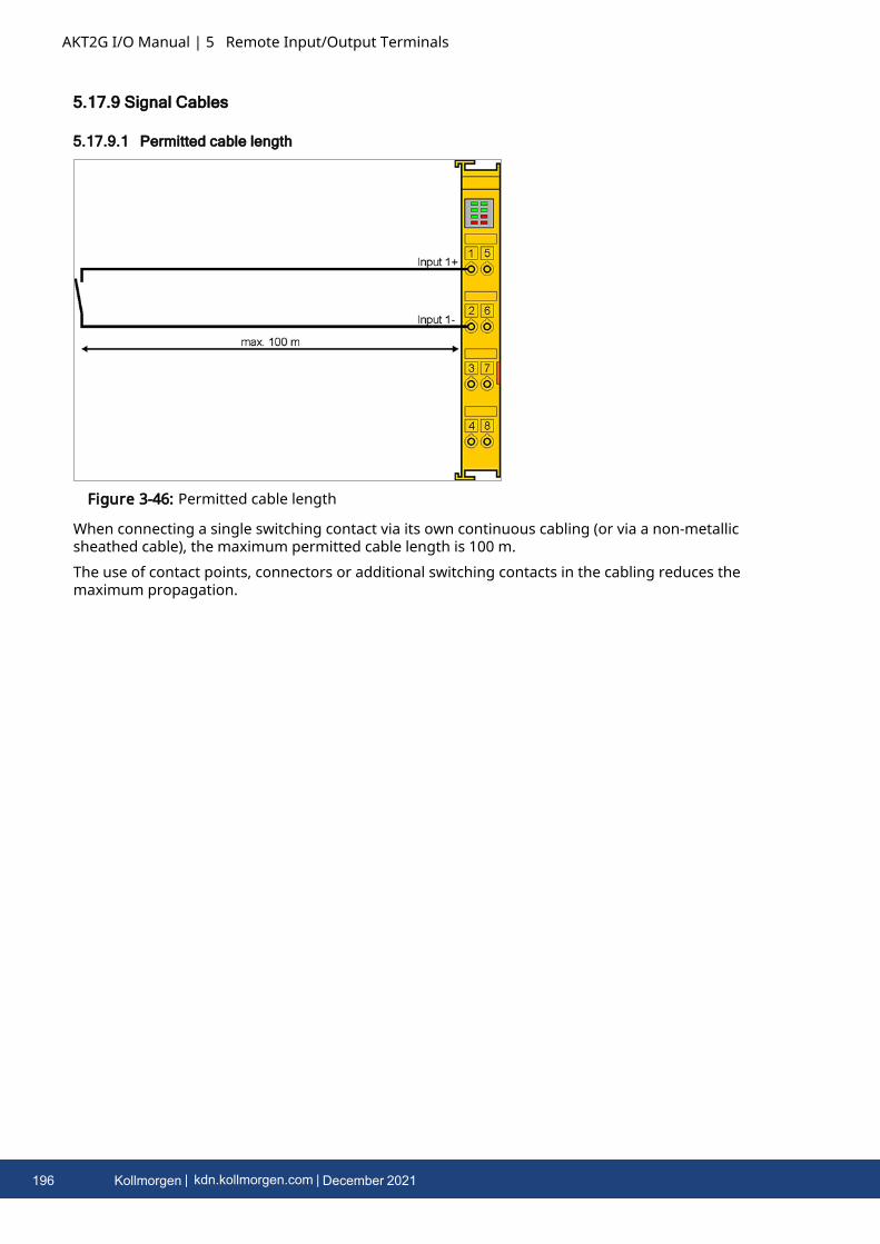
AKT2G I/O Manual | 5 Remote Input/Output Terminals
5.17.9 Signal Cables
5.17.9.1 Permitted cable length
Figure 3-46: Permitted cable length
When connecting a single switching contact via its own continuous cabling (or via a non-metallicsheathed cable), the maximum permitted cable length is 100 m.The use of contact points, connectors or additional switching contacts in the cabling reduces themaximum propagation.
196 Kollmorgen | kdn.kollmorgen.com | December 2021
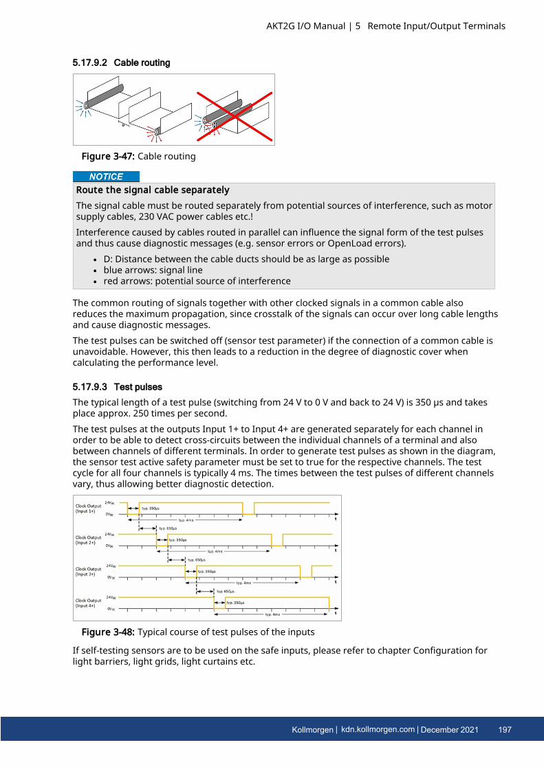
5.17.9.2 Cable routing
Figure 3-47: Cable routing
Route the signal cable separatelyThe signal cable must be routed separately from potential sources of interference, such as motorsupply cables, 230 VAC power cables etc.!Interference caused by cables routed in parallel can influence the signal form of the test pulsesand thus cause diagnostic messages (e.g. sensor errors or OpenLoad errors).
l D: Distance between the cable ducts should be as large as possiblel blue arrows: signal linel red arrows: potential source of interference
The common routing of signals together with other clocked signals in a common cable alsoreduces the maximum propagation, since crosstalk of the signals can occur over long cable lengthsand cause diagnostic messages.The test pulses can be switched off (sensor test parameter) if the connection of a common cable isunavoidable. However, this then leads to a reduction in the degree of diagnostic cover whencalculating the performance level.
5.17.9.3 Test pulses
The typical length of a test pulse (switching from 24 V to 0 V and back to 24 V) is 350 µs and takesplace approx. 250 times per second.The test pulses at the outputs Input 1+ to Input 4+ are generated separately for each channel inorder to be able to detect cross-circuits between the individual channels of a terminal and alsobetween channels of different terminals. In order to generate test pulses as shown in the diagram,the sensor test active safety parameter must be set to true for the respective channels. The testcycle for all four channels is typically 4 ms. The times between the test pulses of different channelsvary, thus allowing better diagnostic detection.
Figure 3-48: Typical course of test pulses of the inputs
If self-testing sensors are to be used on the safe inputs, please refer to chapter Configuration forlight barriers, light grids, light curtains etc.
AKT2G I/O Manual | 5 Remote Input/Output Terminals
Kollmorgen | kdn.kollmorgen.com | December 2021 197
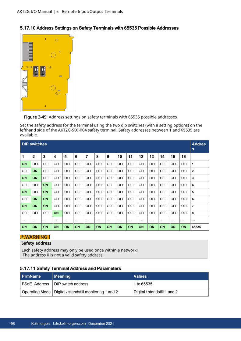
AKT2G I/O Manual | 5 Remote Input/Output Terminals
5.17.10 Address Settings on Safety Terminals with 65535 Possible Addresses
Figure 3-49: Address settings on safety terminals with 65535 possible addresses
Set the safety address for the terminal using the two dip switches (with 8 setting options) on thelefthand side of the AKT2G-SDI-004 safety terminal. Safety addresses between 1 and 65535 areavailable.
DIP switches Address
1 2 3 4 5 6 7 8 9 10 11 12 13 14 15 16ON OFF OFF OFF OFF OFF OFF OFF OFF OFF OFF OFF OFF OFF OFF OFF 1
OFF ON OFF OFF OFF OFF OFF OFF OFF OFF OFF OFF OFF OFF OFF OFF 2
ON ON OFF OFF OFF OFF OFF OFF OFF OFF OFF OFF OFF OFF OFF OFF 3
OFF OFF ON OFF OFF OFF OFF OFF OFF OFF OFF OFF OFF OFF OFF OFF 4
ON OFF ON OFF OFF OFF OFF OFF OFF OFF OFF OFF OFF OFF OFF OFF 5
OFF ON ON OFF OFF OFF OFF OFF OFF OFF OFF OFF OFF OFF OFF OFF 6
ON ON ON OFF OFF OFF OFF OFF OFF OFF OFF OFF OFF OFF OFF OFF 7
OFF OFF OFF ON OFF OFF OFF OFF OFF OFF OFF OFF OFF OFF OFF OFF 8
… … … … … … … … … … … … … … … … …
ON ON ON ON ON ON ON ON ON ON ON ON ON ON ON ON 65535
Safety addressEach safety address may only be used once within a network!The address 0 is not a valid safety address!
5.17.11 Safety Terminal Address and Parameters
PrmName Meaning Values
FSoE_Address DIP switch address 1 to 65535
Operating Mode Digital / standstill monitoring 1 and 2 Digital / standstill 1 and 2
198 Kollmorgen | kdn.kollmorgen.com | December 2021
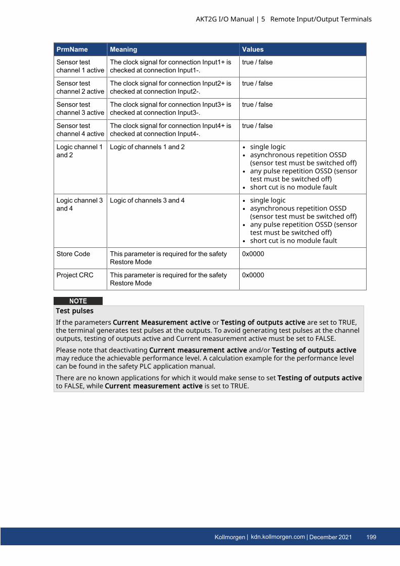
PrmName Meaning Values
Sensor testchannel 1 active
The clock signal for connection Input1+ ischecked at connection Input1-.
true / false
Sensor testchannel 2 active
The clock signal for connection Input2+ ischecked at connection Input2-.
true / false
Sensor testchannel 3 active
The clock signal for connection Input3+ ischecked at connection Input3-.
true / false
Sensor testchannel 4 active
The clock signal for connection Input4+ ischecked at connection Input4-.
true / false
Logic channel 1and 2
Logic of channels 1 and 2 l single logicl asynchronous repetition OSSD
(sensor test must be switched off)l any pulse repetition OSSD (sensor
test must be switched off)l short cut is no module fault
Logic channel 3and 4
Logic of channels 3 and 4 l single logicl asynchronous repetition OSSD
(sensor test must be switched off)l any pulse repetition OSSD (sensor
test must be switched off)l short cut is no module fault
Store Code This parameter is required for the safetyRestore Mode
0x0000
Project CRC This parameter is required for the safetyRestore Mode
0x0000
Test pulsesIf the parameters Current Measurement active or Testing of outputs active are set to TRUE,the terminal generates test pulses at the outputs. To avoid generating test pulses at the channeloutputs, testing of outputs active and Current measurement active must be set to FALSE.Please note that deactivating Current measurement active and/or Testing of outputs activemay reduce the achievable performance level. A calculation example for the performance levelcan be found in the safety PLC application manual.There are no known applications for which it would make sense to set Testing of outputs activeto FALSE, while Current measurement active is set to TRUE.
AKT2G I/O Manual | 5 Remote Input/Output Terminals
Kollmorgen | kdn.kollmorgen.com | December 2021 199
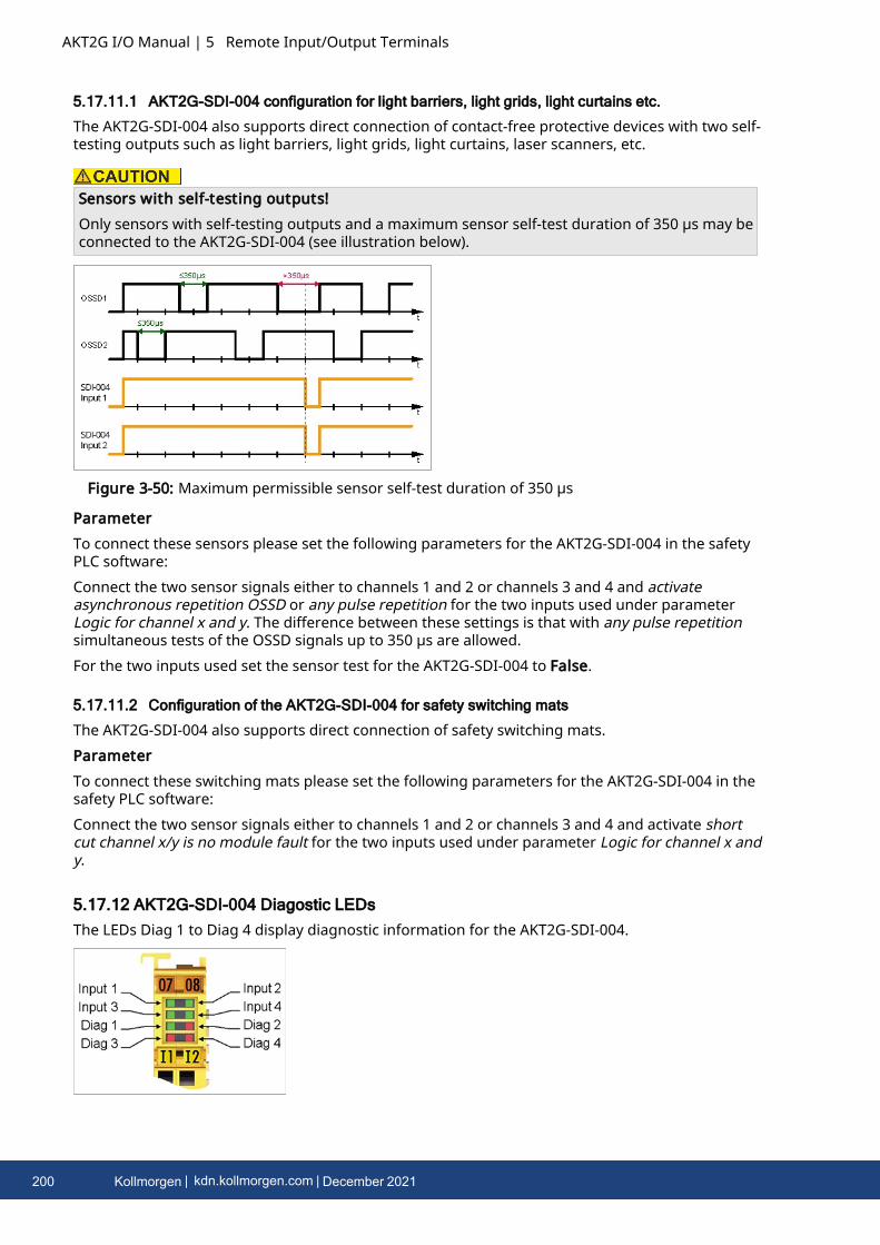
AKT2G I/O Manual | 5 Remote Input/Output Terminals
5.17.11.1 AKT2G-SDI-004 configuration for light barriers, light grids, light curtains etc.
The AKT2G-SDI-004 also supports direct connection of contact-free protective devices with two self-testing outputs such as light barriers, light grids, light curtains, laser scanners, etc.
Sensors with self-testing outputs!Only sensors with self-testing outputs and a maximum sensor self-test duration of 350 µs may beconnected to the AKT2G-SDI-004 (see illustration below).
Figure 3-50: Maximum permissible sensor self-test duration of 350 µs
ParameterTo connect these sensors please set the following parameters for the AKT2G-SDI-004 in the safetyPLC software:Connect the two sensor signals either to channels 1 and 2 or channels 3 and 4 and activateasynchronous repetition OSSD or any pulse repetition for the two inputs used under parameterLogic for channel x and y. The difference between these settings is that with any pulse repetitionsimultaneous tests of the OSSD signals up to 350 µs are allowed.For the two inputs used set the sensor test for the AKT2G-SDI-004 to False.
5.17.11.2 Configuration of the AKT2G-SDI-004 for safety switching mats
The AKT2G-SDI-004 also supports direct connection of safety switching mats.ParameterTo connect these switching mats please set the following parameters for the AKT2G-SDI-004 in thesafety PLC software:Connect the two sensor signals either to channels 1 and 2 or channels 3 and 4 and activate shortcut channel x/y is no module fault for the two inputs used under parameter Logic for channel x andy.
5.17.12 AKT2G-SDI-004 Diagostic LEDsThe LEDs Diag 1 to Diag 4 display diagnostic information for the AKT2G-SDI-004.
200 Kollmorgen | kdn.kollmorgen.com | December 2021
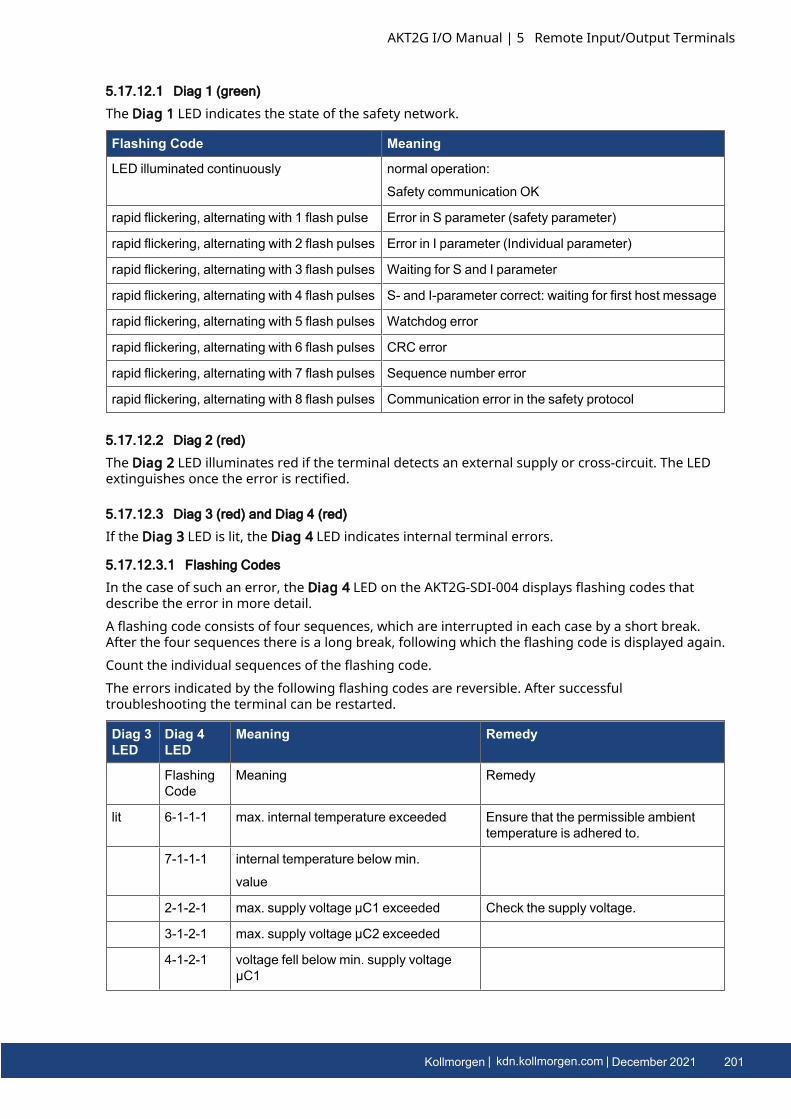
5.17.12.1 Diag 1 (green)
The Diag 1 LED indicates the state of the safety network.
Flashing Code Meaning
LED illuminated continuously normal operation:
Safety communication OK
rapid flickering, alternating with 1 flash pulse Error in S parameter (safety parameter)
rapid flickering, alternating with 2 flash pulses Error in I parameter (Individual parameter)
rapid flickering, alternating with 3 flash pulses Waiting for S and I parameter
rapid flickering, alternating with 4 flash pulses S- and I-parameter correct: waiting for first host message
rapid flickering, alternating with 5 flash pulses Watchdog error
rapid flickering, alternating with 6 flash pulses CRC error
rapid flickering, alternating with 7 flash pulses Sequence number error
rapid flickering, alternating with 8 flash pulses Communication error in the safety protocol
5.17.12.2 Diag 2 (red)
The Diag 2 LED illuminates red if the terminal detects an external supply or cross-circuit. The LEDextinguishes once the error is rectified.
5.17.12.3 Diag 3 (red) and Diag 4 (red)
If the Diag 3 LED is lit, the Diag 4 LED indicates internal terminal errors.
5.17.12.3.1 Flashing Codes
In the case of such an error, the Diag 4 LED on the AKT2G-SDI-004 displays flashing codes thatdescribe the error in more detail.A flashing code consists of four sequences, which are interrupted in each case by a short break.After the four sequences there is a long break, following which the flashing code is displayed again.Count the individual sequences of the flashing code.The errors indicated by the following flashing codes are reversible. After successfultroubleshooting the terminal can be restarted.
Diag 3LED
Diag 4LED
Meaning Remedy
FlashingCode
Meaning Remedy
lit 6-1-1-1 max. internal temperature exceeded Ensure that the permissible ambienttemperature is adhered to.
7-1-1-1 internal temperature below min.
value
2-1-2-1 max. supply voltage µC1 exceeded Check the supply voltage.
3-1-2-1 max. supply voltage µC2 exceeded
4-1-2-1 voltage fell below min. supply voltageµC1
AKT2G I/O Manual | 5 Remote Input/Output Terminals
Kollmorgen | kdn.kollmorgen.com | December 2021 201
AKT2G I/O Manual | 5 Remote Input/Output Terminals
Diag 3LED
Diag 4LED
Meaning Remedy
5-1-2-1 voltage fell below min. supply voltageµC2
8-1-1-1 Temperature difference between themeasuring points exceeded
Check the installation position and theambient temperature.
If another flashing code is displayed, this means that there is an internal terminal error that hasstopped the terminal. In this case the terminal must be checked by Kollmorgen.
Note the flashing codes and return the terminalNote the flashing code displayed and include this information with the terminal when you returnit.
5.17.13 AKT2G-SDI-004 Diagostic Objects
Do not change CoE objects!Do not make any modifications to the CoE objects in the safety components! Any modifications ofthe CoE objects will permanently set the safety components to the Fail-Stop state.
Index FA80hex: Internal temperature values
The CoE object FA80hex indicates the current internal temperature values of the AKT2G-SDI-004.
Index Name Meaning Flags Default
FA80:01 Temperature 1 Temperature measurement 1 RO 0bin
FA80:02 Temperature 2 Temperature measurement 2 RO 0bin
Index 800Ehex: diagnostic information
The CoE object 800Ehex displays further diagnostic information.
Index Name Meaning Flags Default
800E:0 Diag The following sub-indices contain detaileddiagnostic information.
RO
800E:0A Sensor test error Bit Error during the sensor test RO
0 1bin Error at input 1 0bin
1 1bin Error at input 2 0bin
2 1bin Error at input 3 0bin
3 1bin Error at input 4 0bin
202 Kollmorgen | kdn.kollmorgen.com | December 2021
Index Name Meaning Flags Default
800E:0B Error during twochannel evaluation
Bit Error during the contiguousevaluation of two channels, i.e. thetwo channels contradict each other.
RO
0 1bin Error in the firstinput pair
0bin
1 1bin Error in thesecond input pair
0bin
800E:0C Error in the safetymat operationmode: input pairdisagree
Bits Error in the input pair RO
1, 0 11bin Error in the firstinput pair
00bin
3, 2 11bin Error in thesecond input pair
00bin
800E:0D Error in the safetymat operationmode: externalsupply
Bit Error in the test pulses in the safetymat operating mode; i.e. theterminal has detected an externalsupply.
RO
0 1bin Error at input 1 0bin
1 1bin Error at input 2 0bin
2 1bin Error at input 3 0bin
3 1bin Error at input 4 0bin
Differing diagnostic messages possibleDue to the variable order or execution of the test series, diagnostic messages differing fromthose given in the table above are possible.
5.17.14 CertificatesThe AKT2G-SDI-004-000 has been tested to the following directives and standards.
l 2006/42/ECl EN 61508-1:2010 (up to SIL 3)l EN 61508-2:2010 (up to SIL 3)l EN 61508-3:2010 (up to SIL 3)l EN 62061:2005/A2:2015 (up to SILCL 3)l EN ISO 13849-1:2015 (Cat. 4, PL e)l EN 81-20:2014l EN 81-22:2014l EN 81-50:2014l EN 13243:2015
Note on approval accroding to EN 81-20, EN 81-22, and EN 81-50l The Safety components may only be used in machines that have been designed and
installed in accordance with the requirements of the EN 60204-1 standard.l Provide a surge filter for the supply voltage of the Safety components against
overvoltages. (Reduction to overvoltage category II)
AKT2G I/O Manual | 5 Remote Input/Output Terminals
Kollmorgen | kdn.kollmorgen.com | December 2021 203

AKT2G I/O Manual | 5 Remote Input/Output Terminals
l EN 81 requires that in the case of devices with internal temperature monitoring, a stopmust be reached in the event of an overtemperature. In this case, passengers must be ableto disembark (see EN 81-20 chapter 5.10.4.3, for example). To ensure this, applicationmeasures are necessary. The internal terminal temperature of the Safety components canbe read out by the user. There is a direct switch-off at the maximum permissibletemperature of the respective Safety component (see Installation position and minimumdistances).
l The user must select a temperature threshold below the maximum temperature such thata stop can be reached in all cases before the maximum temperature is reached.Information on the optimum terminal configuration can be found under Notes on thearrangement of Safety components and under Example configuration for temperaturemeasurement.
l For the use of the Safety components according to EN 81-22 and EN 81-50, the conditionsdescribed in the manuals for achieving category 4 according to EN ISO 13849-1:2015 mustbe observed.
l The use of Safety components is limited to indoor applications.l Basic protection against direct contact must be provided, either by fulfilling protection
class IP2X or by installing the Safety components in a control cabinet which corresponds atleast to protection class IP54 according to EN 60529.
l The ambient conditions regarding temperature, humidity, heat dissipation, EMC andvibrations, as specified in the operating instructions under technical data, must beobserved.
l The operating conditions in potentially explosive atmospheres (ATEX) are specified in theoperating instructions.
l The safe state (triggering) of the application must be the de-energized state. The safe stateof the Safety components is always the de-energized, switched-off state, and this cannot bechanged.
l The service life specified in the operating instructions must be observed.l If the Safety component is operated outside the permissible temperature range, it changes
to "Global Shutdown" state.l The Safety components must be installed in a control cabinet with protection class IP54
according to EN 60529, so that the requirement for contamination level 3 according to EN60664-1 can be reduced to level 2.
l The Safety components must be supplied by a SELV/PELV power supply unit with amaximum voltage of Umax ≤36 VDC.
204 Kollmorgen | kdn.kollmorgen.com | December 2021
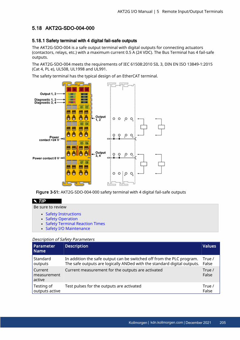
5.18 AKT2G-SDO-004-000
5.18.1 Safety terminal with 4 digital fail-safe outputsThe AKT2G-SDO-004 is a safe output terminal with digital outputs for connecting actuators(contactors, relays, etc.) with a maximum current 0.5 A (24 VDC). The Bus Terminal has 4 fail-safeoutputs.The AKT2G-SDO-004 meets the requirements of IEC 61508:2010 SIL 3, DIN EN ISO 13849-1:2015(Cat 4, PL e), UL508, UL1998 and UL991.The safety terminal has the typical design of an EtherCAT terminal.
Figure 3-51: AKT2G-SDO-004-000 safety terminal with 4 digital fail-safe outputs
Be sure to reviewl Safety Instructionsl Safety Operationl Safety Terminal Reaction Timesl Safety I/O Maintenance
ParameterName
Description Values
Standardoutputs
In addition the safe output can be switched off from the PLC program.The safe outputs are logically ANDed with the standard digital outputs.
True /False
Currentmeasurementactive
Current measurement for the outputs are activated True /False
Testing ofoutputs active
Test pulses for the outputs are activated True /False
Description of Safety Parameters
AKT2G I/O Manual | 5 Remote Input/Output Terminals
Kollmorgen | kdn.kollmorgen.com | December 2021 205
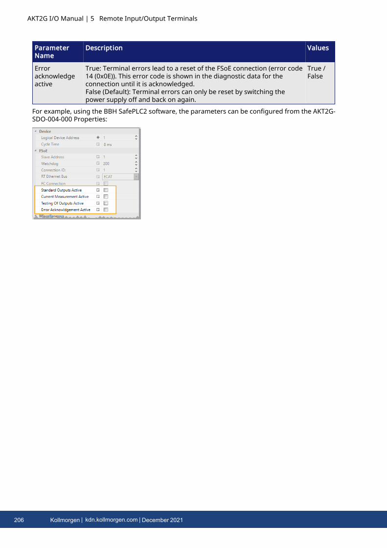
AKT2G I/O Manual | 5 Remote Input/Output Terminals
ParameterName
Description Values
Erroracknowledgeactive
True: Terminal errors lead to a reset of the FSoE connection (error code14 (0x0E)). This error code is shown in the diagnostic data for theconnection until it is acknowledged.False (Default): Terminal errors can only be reset by switching thepower supply off and back on again.
True /False
For example, using the BBH SafePLC2 software, the parameters can be configured from the AKT2G-SDO-004-000 Properties:
206 Kollmorgen | kdn.kollmorgen.com | December 2021
5.18.2 Intended use
Caution - Risk of injury!Safety components may only be used for the purposes described below!
The safety terminals expand the application range of the E-Bus terminal system with functions thatenable them to be used for machine safety applications. The safety terminals are designed formachine safety functions and directly associated industrial automation tasks. They are thereforeonly approved for applications with a defined fail-safe state. This safe state is the wattless state.Fail-safety according to the relevant standards is required.The safety terminals enable connection of:
l 24 VDC sensors (AKT2G-SDI-004) such as emergency off pushbutton switches, pull cordswitches, position switches, two-hand switches, safety mats, light curtains, light barriers,laser scanner, etc.
l 24 VDC actuators (AKT2G-SDO-004 such as contactors, protection door switches withtumbler, signal lamps, servo drives, etc.
Test pulsesWhen selecting actuators please ensure that the AKT2G-SDO-004 test pulses do not lead toactuator switching or diagnostic message from the AKT2G-SDO-004.
The following safety components have been developed for these tasks:
l The AKT2G-SDI-004 is an EtherCAT Terminal with 4 digital fail-safe inputs.l The AKT2G-SDO-004 is an EtherCAT Terminal with 4 digital fail-safe outputs.
These safety components are suitable for operation on the
l Kollmorgen AKT2G-ECT-000-000 series Bus Couplers
Power supply from SELV/PELV power supply unit!The safety components must be supplied with 24 VDC by an SELV/PELV power supply unit with anoutput voltage limit Umax of 36 VDC. Failure to observe this can result in a loss of safety.
Follow the machinery directive!The safety components may only be used in machines as defined in the machinery directive.
Ensure traceability!The buyer has to ensure the traceability of the device via the serial number.
AKT2G I/O Manual | 5 Remote Input/Output Terminals
Kollmorgen | kdn.kollmorgen.com | December 2021 207
AKT2G I/O Manual | 5 Remote Input/Output Terminals
5.18.3 Technical Data
Product designation AKT2G-SDO-004-000
Number of outputs 4
Status display 4 (one green LED per output)
Error reaction time ≤ watchdog times
Output current per channel max. 500 mA, min. 20 mA with parameter current measurementactive set
Actuators When selecting actuators please ensure that the AKT2G-SDO-004-000 test pulses do not lead to actuator switching.
Cable length between actuator andterminal
unshielded max. 100 m shielded max. 100 m
Wire cross section min. 0.75 mm2
Input process image 6 bytes
Output process image 6 bytes
AKT2G-SDO-004-000 supplyvoltage (PELV)
24 VDC (–15%/+20%)
Current consumption via E-bus approx. 221 mA
Power dissipation of the terminal typically 2 W
Electrical isolation (between thechannels)
no
Electrical isolation (between thechannels and the E-bus)
yes
Insulation voltage (between thechannels and the E-bus, undercommon operating conditions)
insulation tested with 500 VDC
Dimensions (W x H x D) 24mm x 100mm x 68mm
Weight approx. 100 g
Permissible ambient temperature(operation) up to SW 03
0°C to +55°C (see note in Installation position and minimumdistances)
Permissible ambient temperature(operation) from SW 04 (week02/2014)
-25°C to +55 °C (see note in Installation position and minimumdistances)
Permissible ambient temperature(transport/storage)
-40°C to +70°C
Permissible air humidity 5% to 95%, non-condensing
Permissible air pressure(operation/storage/transport)
750 hPa to 1100 hPa
(this corresponds to a height of approx. -690 m to 2450 m over sealevel assuming an international standard atmosphere)
208 Kollmorgen | kdn.kollmorgen.com | December 2021
Product designation AKT2G-SDO-004-000
Climate category according to EN60721-3-3
3K3
(the deviation from 3K3 is possible only with optimal environmentalconditions and also applies only to the technical data which arespecified differently in this documentation)
Permissible level of contaminationaccording to EN 60664-1
level of contamination 2
(comply with the section Safety I/O Maintenance
Impermissible operating conditions safety terminals must not be used under the following operatingconditions:
l under the influence of ionizing radiation (that exceeds thelevel of the natural environmental radiation)
l in corrosive environmentsl in an environment that leads to unacceptable soiling of the
Bus Terminal
EMC immunity/emission conforms to EN 61000-6-2 / EN 61000-6-4
Vibration/shock resistance conforms to EN 60068-2-6 / EN 60068-2-27
Shocks 15 g with pulse duration 11 ms in all three axes
Protection class IP20
Permitted operating environment In the control cabinet or terminal box, with minimum protectionclass IP54 according to IEC 60529
Permissible installation position see section Installation position and minimum distances
Approvals CE, cULus
AKT2G I/O Manual | 5 Remote Input/Output Terminals
Kollmorgen | kdn.kollmorgen.com | December 2021 209
AKT2G I/O Manual | 5 Remote Input/Output Terminals
5.18.4 Safety Parameters
Key Figures AKT2G-SDO-004-000
Lifetime [a] 20
Prooftest Interval [a] not required 1
PFHD 1.25E-09
%SIL3 1,25 %
PFD 8.45E-05
%SIL3 8,45 %
MTTFd high
DC high
Performance level PL e
Category 4
HFT 1
Element classification 2 Type B
1. Special proof tests are not required during the entire service life of the AKT2G-SDO-004EtherCAT terminal.
2. Classification according to IEC 61508-2:2010 (chapter 7.4.4.1.2 and 7.4.4.1.3)
The AKT2G-SDO-004 EtherCAT Terminal can be used for safety-related applications within themeaning of IEC 61508:2010 up to SIL3 and EN ISO 13849-1 up to PL e (Cat4).For the calculation or estimation of the MTTFd value from the PFHD value, further information canbe found in ISO 13849-1:2015 Table K.1.
210 Kollmorgen | kdn.kollmorgen.com | December 2021
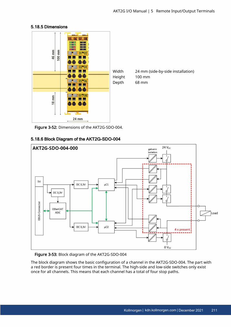
5.18.5 Dimensions
Width 24 mm (side-by-side installation)Height 100 mmDepth 68 mm
Figure 3-52: Dimensions of the AKT2G-SDO-004.
5.18.6 Block Diagram of the AKT2G-SDO-004
Figure 3-53: Block diagram of the AKT2G-SDO-004
The block diagram shows the basic configuration of a channel in the AKT2G-SDO-004. The part witha red border is present four times in the terminal. The high-side and low-side switches only existonce for all channels. This means that each channel has a total of four stop paths.
AKT2G I/O Manual | 5 Remote Input/Output Terminals
Kollmorgen | kdn.kollmorgen.com | December 2021 211
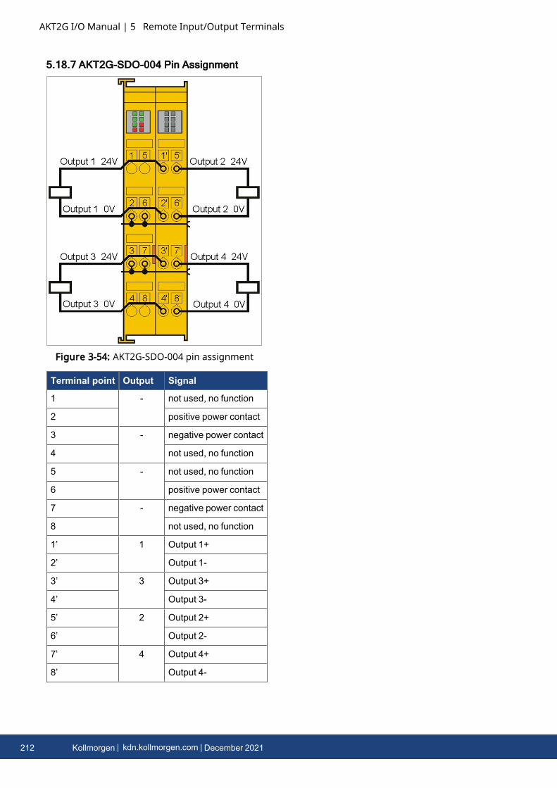
AKT2G I/O Manual | 5 Remote Input/Output Terminals
5.18.7 AKT2G-SDO-004 Pin Assignment
Figure 3-54: AKT2G-SDO-004 pin assignment
Terminal point Output Signal
1 - not used, no function
2 positive power contact
3 - negative power contact
4 not used, no function
5 - not used, no function
6 positive power contact
7 - negative power contact
8 not used, no function
1’ 1 Output 1+
2’ Output 1-
3’ 3 Output 3+
4’ Output 3-
5’ 2 Output 2+
6’ Output 2-
7’ 4 Output 4+
8’ Output 4-
212 Kollmorgen | kdn.kollmorgen.com | December 2021
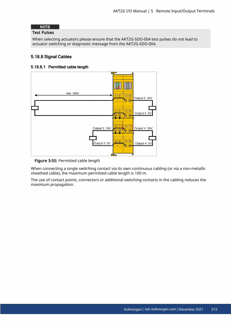
Test PulsesWhen selecting actuators please ensure that the AKT2G-SDO-004 test pulses do not lead toactuator switching or diagnostic message from the AKT2G-SDO-004.
5.18.8 Signal Cables
5.18.8.1 Permitted cable length
Figure 3-55: Permitted cable length
When connecting a single switching contact via its own continuous cabling (or via a non-metallicsheathed cable), the maximum permitted cable length is 100 m.The use of contact points, connectors or additional switching contacts in the cabling reduces themaximum propagation.
AKT2G I/O Manual | 5 Remote Input/Output Terminals
Kollmorgen | kdn.kollmorgen.com | December 2021 213

AKT2G I/O Manual | 5 Remote Input/Output Terminals
5.18.8.2 Cable routing
Figure 3-56: Cable routing
Route the signal cable separatelyThe signal cable must be routed separately from potential sources of interference, such as motorsupply cables, 230 VAC power cables etc.!Interference caused by cables routed in parallel can influence the signal form of the test pulsesand thus cause diagnostic messages (e.g. sensor errors or OpenLoad errors).
l D: Distance between the cable ducts should be as large as possiblel blue arrows: signal linel red arrows: potential source of interference
The common routing of signals together with other clocked signals in a common cable alsoreduces the maximum propagation, since crosstalk of the signals can occur over long cable lengthsand cause diagnostic messages.The test pulses can be switched off (sensor test parameter) if the connection of a common cable isunavoidable. However, this then leads to a reduction in the degree of diagnostic cover whencalculating the performance level.
5.18.8.3 Test Pulses
The typical length of test pulse (switching from 24 V to 0 V and back to 24 V) is 300 µs to 800 µs.Testing usually takes place 5 to 7 times per second.
Test pulses for the outputsThe following diagram shows a typical test pulse curve for the four outputs of an AKT2G-SDO-004.The parameters Current measurement active and Testing of outputs active are enabled.
Figure 3-57: Typical course of test pulses of the outputs.
5.18.9 Address Settings on Safety Terminals with 1023 Possible Addresses
214 Kollmorgen | kdn.kollmorgen.com | December 2021
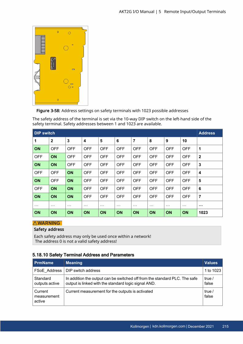
Figure 3-58: Address settings on safety terminals with 1023 possible addresses
The safety address of the terminal is set via the 10-way DIP switch on the left-hand side of thesafety terminal. Safety addresses between 1 and 1023 are available.
DIP switch Address
1 2 3 4 5 6 7 8 9 10
ON OFF OFF OFF OFF OFF OFF OFF OFF OFF 1
OFF ON OFF OFF OFF OFF OFF OFF OFF OFF 2
ON ON OFF OFF OFF OFF OFF OFF OFF OFF 3
OFF OFF ON OFF OFF OFF OFF OFF OFF OFF 4
ON OFF ON OFF OFF OFF OFF OFF OFF OFF 5
OFF ON ON OFF OFF OFF OFF OFF OFF OFF 6
ON ON ON OFF OFF OFF OFF OFF OFF OFF 7
… … … … … … … … … … …
ON ON ON ON ON ON ON ON ON ON 1023
Safety addressEach safety address may only be used once within a network!The address 0 is not a valid safety address!
5.18.10 Safety Terminal Address and Parameters
PrmName Meaning Values
FSoE_Address DIP switch address 1 to 1023
Standardoutputs active
In addition the output can be switched off from the standard PLC. The safeoutput is linked with the standard logic signal AND.
true /false
Currentmeasurementactive
Current measurement for the outputs is activated true /false
AKT2G I/O Manual | 5 Remote Input/Output Terminals
Kollmorgen | kdn.kollmorgen.com | December 2021 215
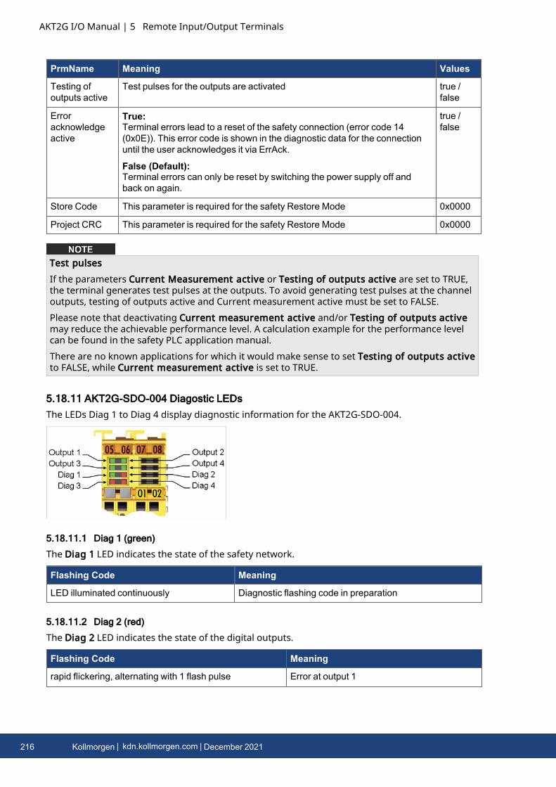
AKT2G I/O Manual | 5 Remote Input/Output Terminals
PrmName Meaning Values
Testing ofoutputs active
Test pulses for the outputs are activated true /false
Erroracknowledgeactive
True:Terminal errors lead to a reset of the safety connection (error code 14(0x0E)). This error code is shown in the diagnostic data for the connectionuntil the user acknowledges it via ErrAck.
False (Default):Terminal errors can only be reset by switching the power supply off andback on again.
true /false
Store Code This parameter is required for the safety Restore Mode 0x0000
Project CRC This parameter is required for the safety Restore Mode 0x0000
Test pulsesIf the parameters Current Measurement active or Testing of outputs active are set to TRUE,the terminal generates test pulses at the outputs. To avoid generating test pulses at the channeloutputs, testing of outputs active and Current measurement active must be set to FALSE.Please note that deactivating Current measurement active and/or Testing of outputs activemay reduce the achievable performance level. A calculation example for the performance levelcan be found in the safety PLC application manual.There are no known applications for which it would make sense to set Testing of outputs activeto FALSE, while Current measurement active is set to TRUE.
5.18.11 AKT2G-SDO-004 Diagostic LEDsThe LEDs Diag 1 to Diag 4 display diagnostic information for the AKT2G-SDO-004.
5.18.11.1 Diag 1 (green)
The Diag 1 LED indicates the state of the safety network.
Flashing Code Meaning
LED illuminated continuously Diagnostic flashing code in preparation
5.18.11.2 Diag 2 (red)
The Diag 2 LED indicates the state of the digital outputs.
Flashing Code Meaning
rapid flickering, alternating with 1 flash pulse Error at output 1
216 Kollmorgen | kdn.kollmorgen.com | December 2021
Flashing Code Meaning
rapid flickering, alternating with 2 flash pulses Error at output 2
rapid flickering, alternating with 3 flash pulses Error at output 3
rapid flickering, alternating with 4 flash pulses Error at output 4
rapid flickering, alternating with 5 flash pulses Field voltage too low
rapid flickering, alternating with 6 flash pulses Field voltage too high
rapid flickering, alternating with 7 flash pulses Internal terminal temperature too low
rapid flickering, alternating with 8 flash pulses Internal terminal temperature too high
rapid flickering, alternating with 9 flash pulses Temperature difference error
rapid flickering, alternating with 10 flash pulses Error in output circuit
5.18.11.3 Diag 3 (red) and Diag 4 (red)
If the Diag 3 LED is lit, the Diag 4 LED indicates internal terminal errors.These errors lead to shutdown of the terminal. The terminal must be checked by Kollmorgen.
5.18.11.3.1 Flashing Codes
In the case of such an error, the Diag 4 LED on the AKT2G-SDO-004 displays flashing codes thatdescribe the error in more detail.A flashing code consists of four sequences, which are interrupted in each case by a short break.After the four sequences there is a long break, following which the flashing code is displayed again.Count the individual sequences of the flashing code.
Note the flashing codes and return the terminalNote the flashing code displayed and include this information with the terminal when you returnit.
5.18.12 Possible Causes of Diagnostic Messages - AKT2G-SDO-004
AKT2G I/O Manual | 5 Remote Input/Output Terminals
Kollmorgen | kdn.kollmorgen.com | December 2021 217
AKT2G I/O Manual | 5 Remote Input/Output Terminals
Diagnostics Possible cause Remedial actions
Diag 2 LED
Flash code 1to 4 or
10
If parameters "Testing of outputsactive" and/or "Currentmeasurement active" are enabled:
Faulty test pulses.
Cause: external supply or cross-circuit.
Eliminate cross-circuit or external supply.
Faulty test pulses.
Cause: parallel routed cables withhigh capacitive
coupling and dynamized signals,possibly also in common cables
Isolate lines and lay in separate non-metallicsheathed cable.
Create a distance between the non-metallicsheathed cables.
Cause: Current is below the limit of20 mA or above the limit of 500 mA.
Select actuator accordingly.
Current > 20mA and
< 500mA
Regardless of whether theparameters "Testing of outputsactive" and/or "Currentmeasurement active" are enabled:
The output voltage lies below thepermissible voltage range (24V -15%/+20%).
A possible cause is a short-circuit atthe output or e.g. a voltage drop atthe instant of switching.
Eliminate short-circuit.
Design power supply accordingly.
Check supply lines for voltage drop.
EMC faults Take suitable EMCmeasures
Internal defect Replace terminal
Diag 2 LEDFlash code 5
Voltage at the power contacts notswitched on.
Switch on voltage at the power contacts and resetthe error display through PowerOn Reset of theterminal
Voltage at the power contacts wasswitched on after the terminal supply
Switch on voltage at the power contacts before orat the same time as the terminal supply and resetthe error display through PowerOn Reset of theterminal
Voltage on the power contacts toolow.
Increase the voltage at the power contacts andreset the error display through PowerOn Reset ofthe terminal
EMC faults Take suitable EMCmeasures
Internal defect Replace terminal
218 Kollmorgen | kdn.kollmorgen.com | December 2021
Diagnostics Possible cause Remedial actions
Diag 2 LEDFlash code 6
Field voltage too high.
Voltage on the power contacts toohigh.
Reduce the voltage at the power contacts andreset the error display through PowerOn Reset ofthe terminal
Voltage briefly too high due toexternal influences, such asswitching contactors off.
Use an R/C or diode-based protective circuit onthe actuators
EMC faults Take suitable EMCmeasures
Internal defect Replace terminal
Diag 2 LEDFlash code 7
Terminal temperature too low Comply with the specified temperature range
EMC faults Take suitable EMCmeasures
Internal defect Replace terminal
Diag 2 LEDFlash code 8
Terminal temperature too high Comply with the specified temperature range
EMC faults Take suitable EMCmeasures
Internal defect Replace terminal
Diag 2 LEDFlash code 9
Terminal temperature difference toolarge:
one of the 3 internal measuringpoints is faulty
Replace terminal
Terminal temperature difference toolarge:
An internal measuring point showsan elevated temperature due toinadequate convection.
Check the installation position of the terminal andmodify it according to the specifications in sectionMechanical installation, if required
EMC faults Take suitable EMCmeasures
Internal defect Replace terminal
5.18.13 CertificatesThe AKT2G-SDO-004-000 has been tested to the following directives and standards.
l 2006/42/ECl EN 61508-1:2010 (up to SIL 3)l EN 61508-2:2010 (up to SIL 3)l EN 61508-3:2010 (up to SIL 3)l EN 62061:2005/A2:2015 (up to SILCL 3)l EN ISO 13849-1:2015 (Cat. 4, PL e)l EN 81-20:2014l EN 81-22:2014l EN 81-50:2014l EN 13243:2015
Note on approval accroding to EN 81-20, EN 81-22, and EN 81-50l The Safety components may only be used in machines that have been designed and
installed in accordance with the requirements of the EN 60204-1 standard.
AKT2G I/O Manual | 5 Remote Input/Output Terminals
Kollmorgen | kdn.kollmorgen.com | December 2021 219
AKT2G I/O Manual | 5 Remote Input/Output Terminals
l Provide a surge filter for the supply voltage of the Safety components againstovervoltages. (Reduction to overvoltage category II)
l EN 81 requires that in the case of devices with internal temperature monitoring, a stopmust be reached in the event of an overtemperature. In this case, passengers must be ableto disembark (see EN 81-20 chapter 5.10.4.3, for example). To ensure this, applicationmeasures are necessary. The internal terminal temperature of the Safety components canbe read out by the user. There is a direct switch-off at the maximum permissibletemperature of the respective Safety component (see Installation position and minimumdistances).
l The user must select a temperature threshold below the maximum temperature such thata stop can be reached in all cases before the maximum temperature is reached.Information on the optimum terminal configuration can be found under Notes on thearrangement of Safety components and under Example configuration for temperaturemeasurement.
l For the use of the Safety components according to EN 81-22 and EN 81-50, the conditionsdescribed in the manuals for achieving category 4 according to EN ISO 13849-1:2015 mustbe observed.
l The use of Safety components is limited to indoor applications.l Basic protection against direct contact must be provided, either by fulfilling protection
class IP2X or by installing the Safety components in a control cabinet which corresponds atleast to protection class IP54 according to EN 60529.
l The ambient conditions regarding temperature, humidity, heat dissipation, EMC andvibrations, as specified in the operating instructions under technical data, must beobserved.
l The operating conditions in potentially explosive atmospheres (ATEX) are specified in theoperating instructions.
l The safe state (triggering) of the application must be the de-energized state. The safe stateof the Safety components is always the de-energized, switched-off state, and this cannot bechanged.
l The service life specified in the operating instructions must be observed.l If the Safety component is operated outside the permissible temperature range, it changes
to "Global Shutdown" state.l The Safety components must be installed in a control cabinet with protection class IP54
according to EN 60529, so that the requirement for contamination level 3 according to EN60664-1 can be reduced to level 2.
l The Safety components must be supplied by a SELV/PELV power supply unit with amaximum voltage of Umax ≤36 VDC.
5.19 AKT2G-SM-L15-000Stepper motor terminal, 24 V DC, 1.5 A, vector controlThe AKT2G-SM-L15 EtherCAT Terminal is intended for stepper motors with low performance range.The PWM output stages cover a wide range of voltages and currents. Together with two inputs forlimit switches, they are located in the EtherCAT Terminal.The SM-L15 can be adjusted to the motor and the application by changing just a few parameters.These stepper motors can be operated with vector control. This control technique offers variousbenefits, such as better dynamics and lower power consumption. Together with a stepper motorand an encoder, the SM-L15 represents an inexpensive small servo axis.The LEDs indicate status, warning and error messages as well as possibly active limitations.
220 Kollmorgen | kdn.kollmorgen.com | December 2021
More information about using steppers may be found in the online help.
5.19.1 Technical Data
Technical Data AKT2G-SM-L15
Number of outputs 1 stepper motor, 2 phases
Number of digital inputs 2 limit position, 4 for an encoder system
Number of digital outputs 1 configurable for brake (0.5 A)
Supply voltage 24 V DC (-15%/+20%)
Motor Current/Phase (RMS) valueswithout fan cartridge ZB8610
1.06 A
Motor Current/Phase (RMS) valueswith fan cartridge ZB8610
1.12 A
Maximum output current without fancartridge ZB8610
1.5 A (overload- and short-circuit-proof)
Maximum output current with fancartridge ZB8610
3.0 A (overload- and short-circuit-proof)
Operating modes l Standard mode (velocity direct / position controller)l Field-oriented control (extended velocity mode /
extended position mode)l Sensorless operationl Travel distance control (positioning interface)
Maximum step frequency 1000, 2000, 4000, 8000 or 16000 full steps/s (configurable)
Step pattern up to 64-fold micro stepping (automatic switching, speed-dependent)
Current controller frequency approx. 30 kHz
Encoder pulse frequency maximum 400,000 increments/s (4-fold evaluation)
Input signal voltage "0" -3 V… 2 V
Input signal voltage "1" 3.7 V… 28 V
Input Current typ. 5 mA
Diagnostics LED Warning strand A and B, error strand A and B, power, enable
AKT2G I/O Manual | 5 Remote Input/Output Terminals
Kollmorgen | kdn.kollmorgen.com | December 2021 221
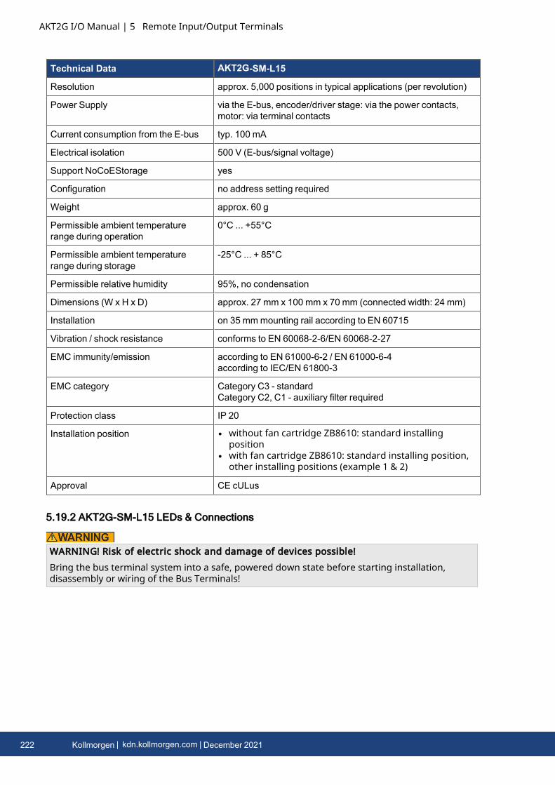
AKT2G I/O Manual | 5 Remote Input/Output Terminals
Technical Data AKT2G-SM-L15
Resolution approx. 5,000 positions in typical applications (per revolution)
Power Supply via the E-bus, encoder/driver stage: via the power contacts,motor: via terminal contacts
Current consumption from the E-bus typ. 100 mA
Electrical isolation 500 V (E-bus/signal voltage)
Support NoCoEStorage yes
Configuration no address setting required
Weight approx. 60 g
Permissible ambient temperaturerange during operation
0°C ... +55°C
Permissible ambient temperaturerange during storage
-25°C ... + 85°C
Permissible relative humidity 95%, no condensation
Dimensions (W x H x D) approx. 27 mm x 100 mm x 70 mm (connected width: 24 mm)
Installation on 35 mmmounting rail according to EN 60715
Vibration / shock resistance conforms to EN 60068-2-6/EN 60068-2-27
EMC immunity/emission according to EN 61000-6-2 / EN 61000-6-4according to IEC/EN 61800-3
EMC category Category C3 - standardCategory C2, C1 - auxiliary filter required
Protection class IP 20
Installation position l without fan cartridge ZB8610: standard installingposition
l with fan cartridge ZB8610: standard installing position,other installing positions (example 1 & 2)
Approval CE cULus
5.19.2 AKT2G-SM-L15 LEDs & Connections
WARNING! Risk of electric shock and damage of devices possible!Bring the bus terminal system into a safe, powered down state before starting installation,disassembly or wiring of the Bus Terminals!
222 Kollmorgen | kdn.kollmorgen.com | December 2021
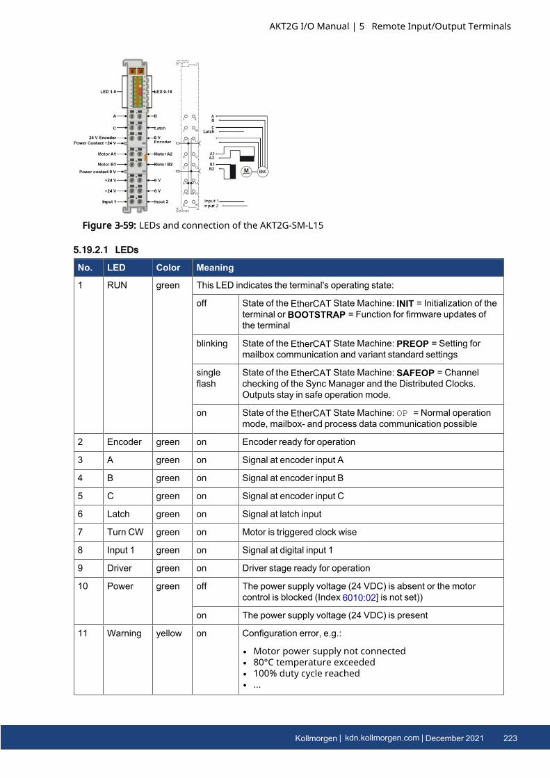
Figure 3-59: LEDs and connection of the AKT2G-SM-L15
5.19.2.1 LEDs
No. LED Color Meaning
1 RUN green This LED indicates the terminal's operating state:
off State of the EtherCAT State Machine: INIT = Initialization of theterminal or BOOTSTRAP = Function for firmware updates ofthe terminal
blinking State of the EtherCAT State Machine: PREOP = Setting formailbox communication and variant standard settings
singleflash
State of the EtherCAT State Machine: SAFEOP = Channelchecking of the Sync Manager and the Distributed Clocks.Outputs stay in safe operation mode.
on State of the EtherCAT State Machine: OP = Normal operationmode, mailbox- and process data communication possible
2 Encoder green on Encoder ready for operation
3 A green on Signal at encoder input A
4 B green on Signal at encoder input B
5 C green on Signal at encoder input C
6 Latch green on Signal at latch input
7 Turn CW green on Motor is triggered clock wise
8 Input 1 green on Signal at digital input 1
9 Driver green on Driver stage ready for operation
10 Power green off The power supply voltage (24 VDC) is absent or the motorcontrol is blocked (Index 6010:02] is not set))
on The power supply voltage (24 VDC) is present
11 Warning yellow on Configuration error, e.g.:
l Motor power supply not connectedl 80°C temperature exceededl 100% duty cycle reachedl ...
AKT2G I/O Manual | 5 Remote Input/Output Terminals
Kollmorgen | kdn.kollmorgen.com | December 2021 223
AKT2G I/O Manual | 5 Remote Input/Output Terminals
No. LED Color Meaning
12 Error A red on Configuration error of output stage A, e.g.:
l 100°C temperature exceededl short circuitl ...
13 Error B red on Configuration error of output stage B, e.g.:
l 100°C temperature exceededl short circuitl ...
14 Enable green off The motor control is blocked (Index 6010:02] is not set) or SM-L15 is not ready for operation
on The motor control is activated (Index 6010:02] is set) or SM-L15is ready for operation
15 TurnCCW
green on Motor is triggered counter clock wise
16 Input 2 green on Signal at digital input 2
5.19.2.2 Terminal Points
Terminalpoint
Name Signal
1 A Encoder input A
2 C Encoder input C (zero input). If object 7000:01 is set in the control word and arising edge occurs at encoder input C, the current counter value is stored as areference mark in the latch register.
3 Encodersupply+24V
Encoder supply + 24 V, internally connected with positive power contact and pin6, 7
4 A1 Motor winding A1
5 B1 Motor winding B1
6 +24V +24 VDC, internally connected with positive power contact and pin 3, 7
7 +24V +24 VDC, internally connected with positive power contact and pin 3, 7
8 Input 1 Digital input 1 (24 VDC)
9 B Encoder input B
10 Latch Latch input. The current counter value is stored as a reference mark in the latchregister, if
l object 7000:02 is set and a rising edge occurs at the latch input; orl object 7000:04 is set and a falling edge occurs at the latch input.
11 Encodersupply 0V
Encoder supply 0 V, internally connected with negative power contact and pin14, 15
12 A2 Motor winding A2
224 Kollmorgen | kdn.kollmorgen.com | December 2021
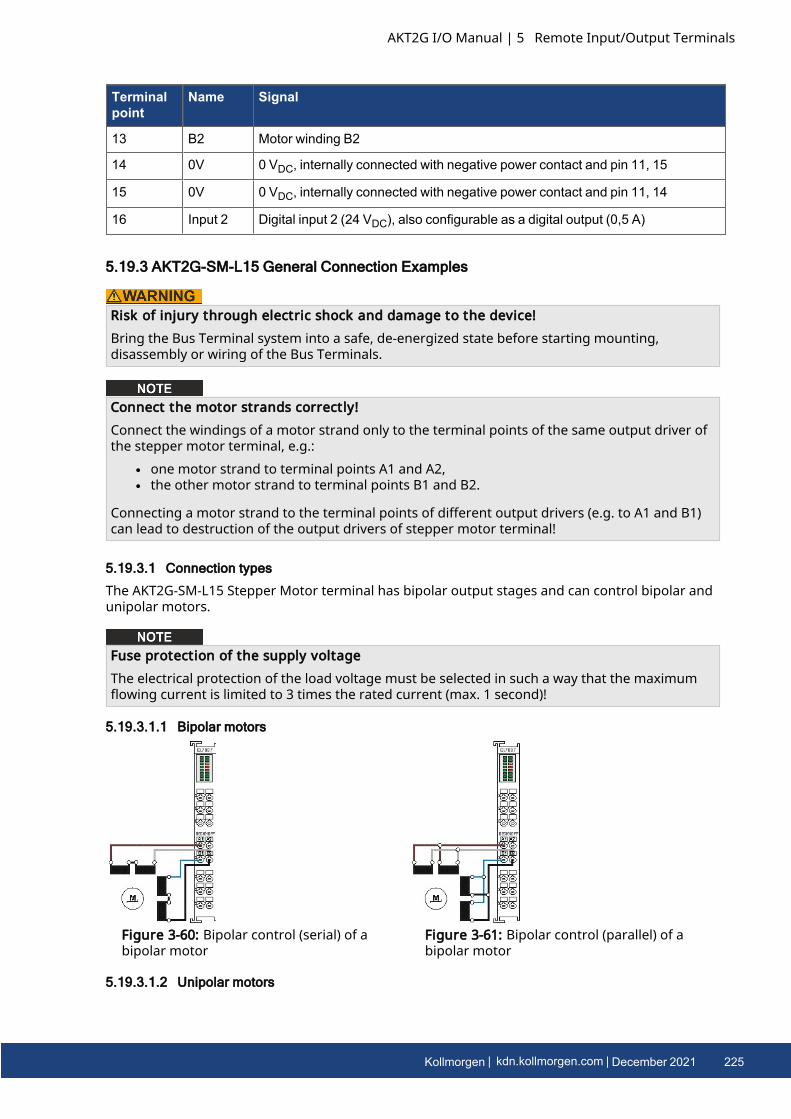
Terminalpoint
Name Signal
13 B2 Motor winding B2
14 0V 0 VDC, internally connected with negative power contact and pin 11, 15
15 0V 0 VDC, internally connected with negative power contact and pin 11, 14
16 Input 2 Digital input 2 (24 VDC), also configurable as a digital output (0,5 A)
5.19.3 AKT2G-SM-L15 General Connection Examples
Risk of injury through electric shock and damage to the device!Bring the Bus Terminal system into a safe, de-energized state before starting mounting,disassembly or wiring of the Bus Terminals.
Connect the motor strands correctly!Connect the windings of a motor strand only to the terminal points of the same output driver ofthe stepper motor terminal, e.g.:
l one motor strand to terminal points A1 and A2,l the other motor strand to terminal points B1 and B2.
Connecting a motor strand to the terminal points of different output drivers (e.g. to A1 and B1)can lead to destruction of the output drivers of stepper motor terminal!
5.19.3.1 Connection types
The AKT2G-SM-L15 Stepper Motor terminal has bipolar output stages and can control bipolar andunipolar motors.
Fuse protection of the supply voltageThe electrical protection of the load voltage must be selected in such a way that the maximumflowing current is limited to 3 times the rated current (max. 1 second)!
5.19.3.1.1 Bipolar motors
Figure 3-60: Bipolar control (serial) of abipolar motor
Figure 3-61: Bipolar control (parallel) of abipolar motor
5.19.3.1.2 Unipolar motors
AKT2G I/O Manual | 5 Remote Input/Output Terminals
Kollmorgen | kdn.kollmorgen.com | December 2021 225
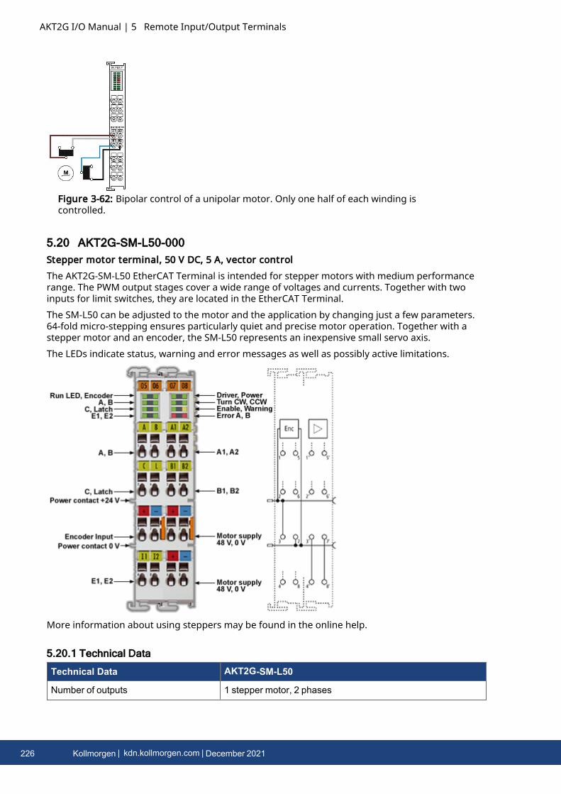
AKT2G I/O Manual | 5 Remote Input/Output Terminals
Figure 3-62: Bipolar control of a unipolar motor. Only one half of each winding iscontrolled.
5.20 AKT2G-SM-L50-000Stepper motor terminal, 50 V DC, 5 A, vector controlThe AKT2G-SM-L50 EtherCAT Terminal is intended for stepper motors with medium performancerange. The PWM output stages cover a wide range of voltages and currents. Together with twoinputs for limit switches, they are located in the EtherCAT Terminal.The SM-L50 can be adjusted to the motor and the application by changing just a few parameters.64-fold micro-stepping ensures particularly quiet and precise motor operation. Together with astepper motor and an encoder, the SM-L50 represents an inexpensive small servo axis.The LEDs indicate status, warning and error messages as well as possibly active limitations.
More information about using steppers may be found in the online help.
5.20.1 Technical Data
Technical Data AKT2G-SM-L50
Number of outputs 1 stepper motor, 2 phases
226 Kollmorgen | kdn.kollmorgen.com | December 2021
Technical Data AKT2G-SM-L50
Number of digital inputs 2 limit position, 4 for an encoder system
Number of digital outputs 1 configurable for brake (0.5 A)
Supply voltage 8… 50 V DC
Motor Current/Phase (RMS) valueswithout fan cartridge ZB8610
3.53 A
Motor Current/Phase (RMS) values withfan cartridge ZB8610
4.59 A
Maximum output current without fancartridge AKT2G-AC-FAN-001
5 A (overload- and short-circuit-proof)
Maximum output current with fancartridge AKT2G-AC-FAN-001
6.5 A (overload- and short-circuit-proof)
Operating modes l Standard mode (velocity direct / position controller)l Field-oriented control (extended velocity mode /
extended position mode)l Sensorless operationl Travel distance control (positioning interface)
Maximum step frequency 1000, 2000, 4000, 8000 or 16000 full steps/s (configurable)
Step pattern up to 64-fold micro stepping (automatic switching, speed-dependent)
Current controller frequency approx. 30 kHz
Encoder pulse frequency maximum 400,000 increments/s (4-fold evaluation)
Input signal voltage "0" -3 V… 2 V
Input signal voltage "1" 3.7 V… 28 V
Input Current typ. 5 mA
Diagnostics LED Warning strand A and B, error strand A and B, power, enable
Resolution approx. 5,000 positions in typical applications (per revolution)
Power Supply via the E-bus, encoder/driver stage: via the power contacts,motor: via terminal contacts
Current consumption from the E-bus typ. 140 mA
Electrical isolation 500 V (E-bus/signal voltage)
Support NoCoEStorage yes
Configuration no address setting required
Weight approx. 105 g
Permissible ambient temperature rangeduring operation
0°C ... +55°C
Permissible ambient temperature rangeduring storage
-25°C ... + 85°C
Permissible relative humidity 95%, no condensation
AKT2G I/O Manual | 5 Remote Input/Output Terminals
Kollmorgen | kdn.kollmorgen.com | December 2021 227
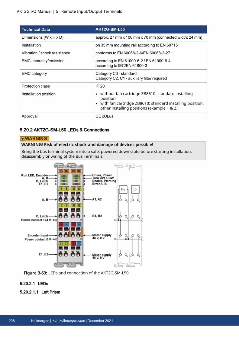
AKT2G I/O Manual | 5 Remote Input/Output Terminals
Technical Data AKT2G-SM-L50
Dimensions (W x H x D) approx. 27 mm x 100 mm x 70 mm (connected width: 24 mm)
Installation on 35 mmmounting rail according to EN 60715
Vibration / shock resistance conforms to EN 60068-2-6/EN 60068-2-27
EMC immunity/emission according to EN 61000-6-2 / EN 61000-6-4according to IEC/EN 61800-3
EMC category Category C3 - standardCategory C2, C1 - auxiliary filter required
Protection class IP 20
Installation position l without fan cartridge ZB8610: standard installingposition
l with fan cartridge ZB8610: standard installing position,other installing positions (example 1 & 2)
Approval CE cULus
5.20.2 AKT2G-SM-L50 LEDs & Connections
WARNING! Risk of electric shock and damage of devices possible!Bring the bus terminal system into a safe, powered down state before starting installation,disassembly or wiring of the Bus Terminals!
Figure 3-63: LEDs and connection of the AKT2G-SM-L50
5.20.2.1 LEDs
5.20.2.1.1 Left Prism
228 Kollmorgen | kdn.kollmorgen.com | December 2021
LED Color Meaning
RUN green This LED indicates the terminal's operating state:
off State of the EtherCAT State Machine: INIT = Initialization of theterminal or BOOTSTRAP = Function for firmware updates of theterminal
blinking State of the EtherCAT State Machine: PREOP = Setting for mailboxcommunication and variant standard settings
singleflash
State of the EtherCAT State Machine: SAFEOP = Channel checking ofthe Sync Manager and the Distributed Clocks. Outputs stay in safeoperation mode.
on State of the EtherCAT State Machine:OP = Normal operation mode,mailbox- and process data communication possible
Encoder green on Encoder ready for operation
A green on Signal at encoder input A
B green on Signal at encoder input B
C green on Signal at encoder input C
Latch green on Signal at latch input
Input 1 green on Signal at digital input 1
Input 2 green on Signal at digital input 2
5.20.2.1.2 Right Prism
LED Color Meaning
Driver green on Driver stage ready for operation
Power green off The power supply voltage (50 VDC) is absent or the motor control is blocked(Index 6010:02] is not set))
on The power supply voltage (50 VDC) is present
Turn CW green on Motor is triggered clock wise
TurnCCW
green on Motor is triggered counter clock wise
Enable green off The motor control is blocked (Index 6010:02] is not set) or SM-L50 is notready for operation
on The motor control is activated (Index 6010:02] is set) or SM-L50 is ready foroperation
Warning yellow off No errors
on Configuration error, e.g.:
l Motor power supply not connectedl 80°C temperature exceededl 100% duty cycle reachedl ...
AKT2G I/O Manual | 5 Remote Input/Output Terminals
Kollmorgen | kdn.kollmorgen.com | December 2021 229
AKT2G I/O Manual | 5 Remote Input/Output Terminals
LED Color Meaning
Error A red on Configuration error of output stage A, e.g.:
l 100°C temperature exceededl short circuitl ...
Error B red on Configuration error of output stage B, e.g.:
l 100°C temperature exceededl short circuitl ...
5.20.2.2 Terminal Points
5.20.2.2.1 Left-hand section of the housing
Terminalpoint
Name Signal
1 A Encoder input A
2 C Encoder input C (zero input). If object 7000:01 is set in the control word and arising edge occurs at encoder input C, the current counter value is stored as areference mark in the latch register.
3 Encodersupply+24V
Encoder supply (from positive power contact)
4 Input 1 Digital input 1 (24 VDC)
5 B Encoder input B
6 Latch /Gate
Latch input. The current counter value is stored as a reference mark in the latchregister, if
l object 7000:02 is set and a rising edge occurs at the latch input; orl object 7000:04 is set and a falling edge occurs at the latch input.
7 Encodersupply 0V
Encoder supply (from negative power contact)
8 Input 2 Digital input 2 (24 VDC)
5.20.2.2.2 Right-hand section of the housing
Terminal point Name Signal
1' A1 Motor winding A1
2' B1 Motor winding B1
3' Motor supply +50V Feeding for output stage (max. +50 VDC)
4' Motor supply +50V Feeding for output stage (max. +50 VDC)
5' A2 Motor winding A2
6' B2 Motor winding B2
7' Motor supply 0V Feeding for output stage (0 VDC)
230 Kollmorgen | kdn.kollmorgen.com | December 2021
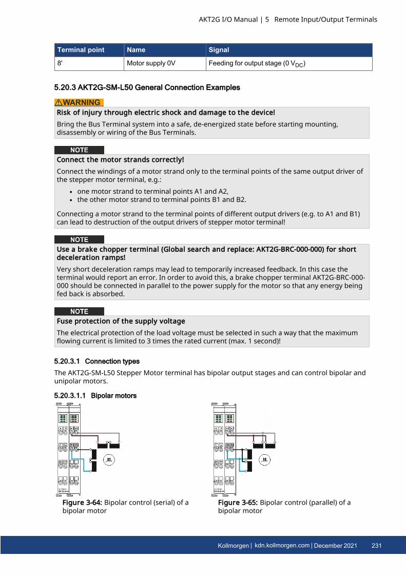
Terminal point Name Signal
8' Motor supply 0V Feeding for output stage (0 VDC)
5.20.3 AKT2G-SM-L50 General Connection Examples
Risk of injury through electric shock and damage to the device!Bring the Bus Terminal system into a safe, de-energized state before starting mounting,disassembly or wiring of the Bus Terminals.
Connect the motor strands correctly!Connect the windings of a motor strand only to the terminal points of the same output driver ofthe stepper motor terminal, e.g.:
l one motor strand to terminal points A1 and A2,l the other motor strand to terminal points B1 and B2.
Connecting a motor strand to the terminal points of different output drivers (e.g. to A1 and B1)can lead to destruction of the output drivers of stepper motor terminal!
Use a brake chopper terminal (Global search and replace: AKT2G-BRC-000-000) for shortdeceleration ramps!Very short deceleration ramps may lead to temporarily increased feedback. In this case theterminal would report an error. In order to avoid this, a brake chopper terminal AKT2G-BRC-000-000 should be connected in parallel to the power supply for the motor so that any energy beingfed back is absorbed.
Fuse protection of the supply voltageThe electrical protection of the load voltage must be selected in such a way that the maximumflowing current is limited to 3 times the rated current (max. 1 second)!
5.20.3.1 Connection types
The AKT2G-SM-L50 Stepper Motor terminal has bipolar output stages and can control bipolar andunipolar motors.
5.20.3.1.1 Bipolar motors
Figure 3-64: Bipolar control (serial) of abipolar motor
Figure 3-65: Bipolar control (parallel) of abipolar motor
AKT2G I/O Manual | 5 Remote Input/Output Terminals
Kollmorgen | kdn.kollmorgen.com | December 2021 231
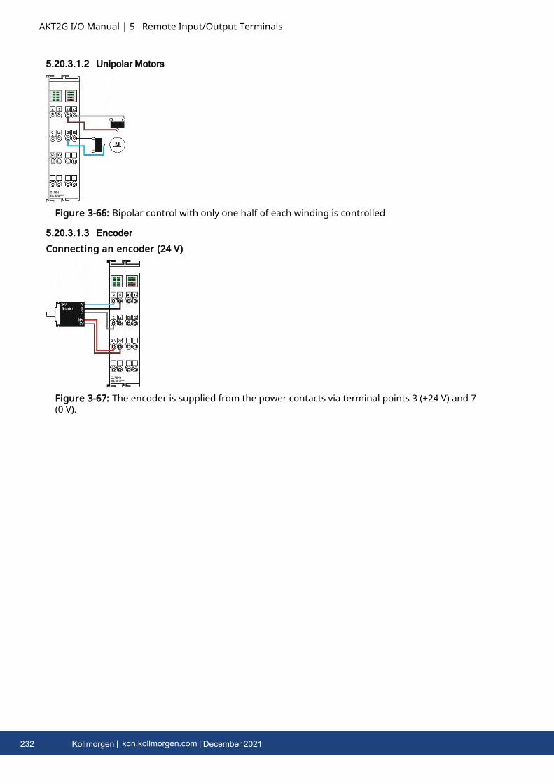
AKT2G I/O Manual | 5 Remote Input/Output Terminals
5.20.3.1.2 Unipolar Motors
Figure 3-66: Bipolar control with only one half of each winding is controlled
5.20.3.1.3 Encoder
Connecting an encoder (24 V)
Figure 3-67: The encoder is supplied from the power contacts via terminal points 3 (+24 V) and 7(0 V).
232 Kollmorgen | kdn.kollmorgen.com | December 2021
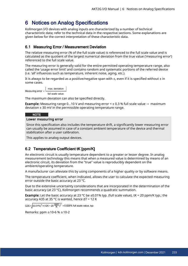
6 Notices on Analog SpecificationsKollmorgen I/O devices with analog inputs are characterized by a number of technicalcharacteristic data; refer to the technical data in the respective sections. Some explanations aregiven below for the correct interpretation of these characteristic data.
6.1 Measuring Error / Measurement DeviationThe relative measuring error (% of the full scale value) is referenced to the full scale value and iscalculated as the quotient of the largest numerical deviation from the true value (‘measuring error’)referenced to the full scale value.The measuring error is generally valid for the entire permitted operating temperature range, alsocalled the ‘usage error limit’ and contains random and systematic portions of the referred device(i.e. ‘all’ influences such as temperature, inherent noise, aging, etc.).It is always to be regarded as a positive/negative span with ±, even if it is specified without ± insome cases.
The maximum deviation can also be specified directly.Example: Measuring range 0...10 V and measuring error < ± 0.3 % full scale value → maximumdeviation ± 30 mV in the permissible operating temperature range.
Lower measuring errorSince this specification also includes the temperature drift, a significantly lower measuring errorcan usually be assumed in case of a constant ambient temperature of the device and thermalstabilization after a user calibration.This applies to analog output devices.
6.2 Temperature Coefficient tK [ppm/K]An electronic circuit is usually temperature dependent to a greater or lesser degree. In analogmeasurement technology this means that when a measured value is determined by means of anelectronic circuit, its deviation from the "true" value is reproducibly dependent on theambient/operating temperature.A manufacturer can alleviate this by using components of a higher quality or by software means.The temperature coefficient, when indicated, allows the user to calculate the expected measuringerror outside the basic accuracy at 23 °C.Due to the extensive uncertainty considerations that are incorporated in the determination of thebasic accuracy (at 23 °C), Kollmorgen recommends a quadratic summation.Example: Let the basic accuracy at 23 °C be ±0.01% typ. (full scale value), tK = 20 ppm/K typ.; theaccuracy A35 at 35 °C is wanted, hence ΔT = 12 K
Remarks: ppm ≙10-6 % ≙10-2
AKT2G I/O Manual | 6 Notices on Analog Specifications
Kollmorgen | kdn.kollmorgen.com | December 2021 233
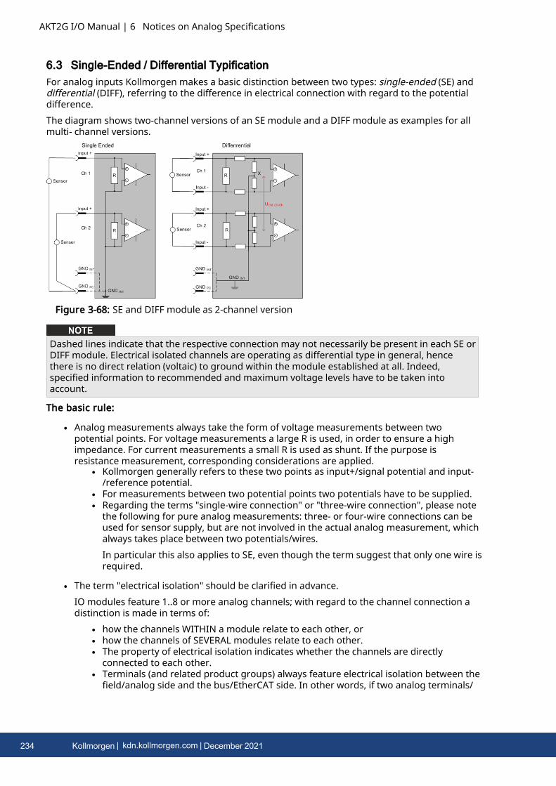
AKT2G I/O Manual | 6 Notices on Analog Specifications
6.3 Single-Ended / Differential TypificationFor analog inputs Kollmorgen makes a basic distinction between two types: single-ended (SE) anddifferential (DIFF), referring to the difference in electrical connection with regard to the potentialdifference.The diagram shows two-channel versions of an SE module and a DIFF module as examples for allmulti- channel versions.
Figure 3-68: SE and DIFF module as 2-channel version
Dashed lines indicate that the respective connection may not necessarily be present in each SE orDIFF module. Electrical isolated channels are operating as differential type in general, hencethere is no direct relation (voltaic) to ground within the module established at all. Indeed,specified information to recommended and maximum voltage levels have to be taken intoaccount.
The basic rule:
l Analog measurements always take the form of voltage measurements between twopotential points. For voltage measurements a large R is used, in order to ensure a highimpedance. For current measurements a small R is used as shunt. If the purpose isresistance measurement, corresponding considerations are applied.
l Kollmorgen generally refers to these two points as input+/signal potential and input-/reference potential.
l For measurements between two potential points two potentials have to be supplied.l Regarding the terms "single-wire connection" or "three-wire connection", please note
the following for pure analog measurements: three- or four-wire connections can beused for sensor supply, but are not involved in the actual analog measurement, whichalways takes place between two potentials/wires.In particular this also applies to SE, even though the term suggest that only one wire isrequired.
l The term "electrical isolation" should be clarified in advance.IO modules feature 1..8 or more analog channels; with regard to the channel connection adistinction is made in terms of:
l how the channels WITHIN a module relate to each other, orl how the channels of SEVERAL modules relate to each other.l The property of electrical isolation indicates whether the channels are directly
connected to each other.l Terminals (and related product groups) always feature electrical isolation between the
field/analog side and the bus/EtherCAT side. In other words, if two analog terminals/
234 Kollmorgen | kdn.kollmorgen.com | December 2021

boxes are not connected via the power contacts (cable), the modules are effectivelyelectrically isolated.
l If channels within a module are electrically isolated, or if a single-channel module hasno power contacts, the channels are effectively always differential. See alsoexplanatory notes below. Differential channels are not necessarily electrically isolated.
l Analog measuring channels are subject to technical limits, both in terms of therecommended operating range (continuous operation) and the destruction limit. Pleaserefer to the respective terminal/ box documentation for further details.
6.3.1 Explanation
l differential (DIFF)l Differential measurement is the most flexible concept. The user can freely choose
both connection points, input+/signal potential and input-/reference potential, withinthe framework of the technical specification.
l A differential channel can also be operated as SE, if the reference potential of severalsensors is linked. This interconnection may take place via the system GND.
l Since a differential channel is configured symmetrically internally (see Figure 3-68: SEand DIFF module as 2-channel version), there will be a mid-potential (X) between thetwo supplied potentials that is the same as the internal ground/reference ground forthis channel. If several DIFF channels are used in a module without electrical isolation,the technical property VCM (common-mode voltage) indicates the degree to which themean voltage of the channels may differ.
l The internal reference ground may be accessible as connection point at the terminal/box, in order to stabilize a defined GND potential in the terminal/ box. In this case it isparticularly important to pay attention to the quality of this potential (noiselessness,voltage stability). At this GND point a wire may be connected to make sure thatVCM,max is not exceeded in the differential sensor cable. If differential channels are notelectrically isolated, usually only one VCM, max is permitted. If the channels areelectrically isolated this limit should not apply, and the channels voltages may differup to the specified separation limit.
l Differential measurement in combination with correct sensor wiring has the specialadvantage that any interference affecting the sensor cable (ideally the feed and returnline are arranged side by side, so that interference signals have the same effect onboth wires) has very little effect on the measurement, since the potential of both linesvaries jointly (hence the term common mode). In simple terms: Common-modeinterference has the same effect on both wires in terms of amplitude and phasing.
l Nevertheless, the suppression of common-mode interference within a channel orbetween channels is subject to technical limits, which are specified in the technicaldata.
l Single Ended (SE)l If the analog circuit is designed as SE, the input/reference wire is internally fixed to a
certain potential that cannot be changed. This potential must be accessible fromoutside on at least one point for connecting the reference potential, e.g. via the powercontacts (cable).
l In other words, in situations with several channels SE offers users the option to avoidreturning at least one of the two sensor cables to the terminal/ box (in contrast toDIFF). Instead, the reference wire can be consolidated at the sensors, e.g. in thesystem GND.
l A disadvantage of this approach is that the separate feed and return line can result involtage/ current variations, which a SE channel may no longer be able to handle. Seecommon-mode interference. A VCM effect cannot occur since the module channels areinternally always "hard- wired" through the input/reference potential.
AKT2G I/O Manual | 6 Notices on Analog Specifications
Kollmorgen | kdn.kollmorgen.com | December 2021 235
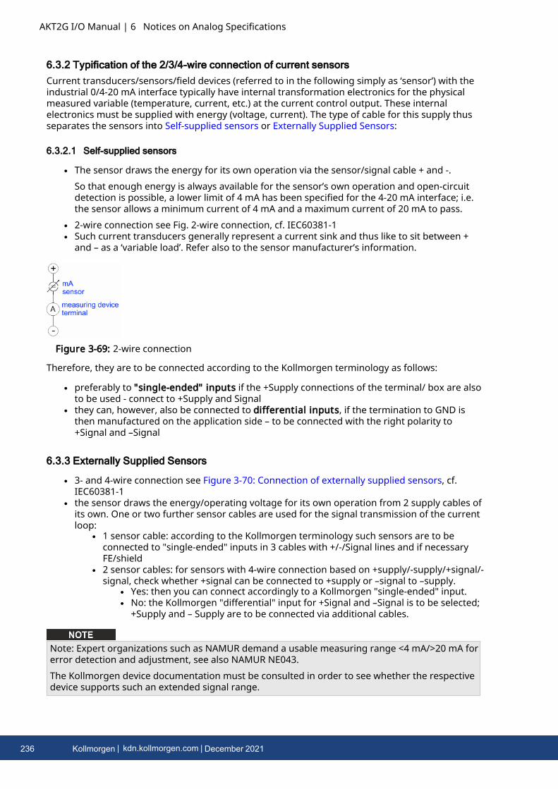
AKT2G I/O Manual | 6 Notices on Analog Specifications
6.3.2 Typification of the 2/3/4-wire connection of current sensorsCurrent transducers/sensors/field devices (referred to in the following simply as ‘sensor’) with theindustrial 0/4-20 mA interface typically have internal transformation electronics for the physicalmeasured variable (temperature, current, etc.) at the current control output. These internalelectronics must be supplied with energy (voltage, current). The type of cable for this supply thusseparates the sensors into Self-supplied sensors or Externally Supplied Sensors:
6.3.2.1 Self-supplied sensors
l The sensor draws the energy for its own operation via the sensor/signal cable + and -.So that enough energy is always available for the sensor’s own operation and open-circuitdetection is possible, a lower limit of 4 mA has been specified for the 4-20 mA interface; i.e.the sensor allows a minimum current of 4 mA and a maximum current of 20 mA to pass.
l 2-wire connection see Fig. 2-wire connection, cf. IEC60381-1l Such current transducers generally represent a current sink and thus like to sit between +
and – as a ‘variable load’. Refer also to the sensor manufacturer’s information.
Figure 3-69: 2-wire connection
Therefore, they are to be connected according to the Kollmorgen terminology as follows:
l preferably to "single-ended" inputs if the +Supply connections of the terminal/ box are alsoto be used - connect to +Supply and Signal
l they can, however, also be connected to differential inputs, if the termination to GND isthen manufactured on the application side – to be connected with the right polarity to+Signal and –Signal
6.3.3 Externally Supplied Sensors
l 3- and 4-wire connection see Figure 3-70: Connection of externally supplied sensors, cf.IEC60381-1
l the sensor draws the energy/operating voltage for its own operation from 2 supply cables ofits own. One or two further sensor cables are used for the signal transmission of the currentloop:
l 1 sensor cable: according to the Kollmorgen terminology such sensors are to beconnected to "single-ended" inputs in 3 cables with +/-/Signal lines and if necessaryFE/shield
l 2 sensor cables: for sensors with 4-wire connection based on +supply/-supply/+signal/-signal, check whether +signal can be connected to +supply or –signal to –supply.
l Yes: then you can connect accordingly to a Kollmorgen "single-ended" input.l No: the Kollmorgen "differential" input for +Signal and –Signal is to be selected;
+Supply and – Supply are to be connected via additional cables.
Note: Expert organizations such as NAMUR demand a usable measuring range <4 mA/>20 mA forerror detection and adjustment, see also NAMUR NE043.The Kollmorgen device documentation must be consulted in order to see whether the respectivedevice supports such an extended signal range.
236 Kollmorgen | kdn.kollmorgen.com | December 2021
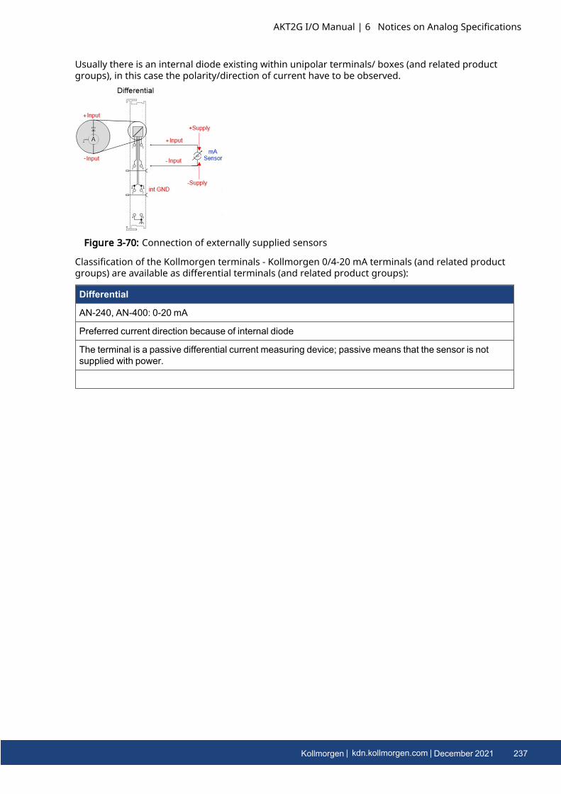
Usually there is an internal diode existing within unipolar terminals/ boxes (and related productgroups), in this case the polarity/direction of current have to be observed.
Figure 3-70: Connection of externally supplied sensors
Classification of the Kollmorgen terminals - Kollmorgen 0/4-20 mA terminals (and related productgroups) are available as differential terminals (and related product groups):
Differential
AN-240, AN-400: 0-20 mA
Preferred current direction because of internal diode
The terminal is a passive differential current measuring device; passive means that the sensor is notsupplied with power.
AKT2G I/O Manual | 6 Notices on Analog Specifications
Kollmorgen | kdn.kollmorgen.com | December 2021 237
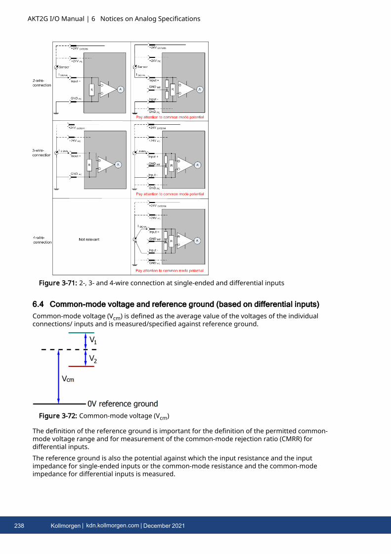
AKT2G I/O Manual | 6 Notices on Analog Specifications
Figure 3-71: 2-, 3- and 4-wire connection at single-ended and differential inputs
6.4 Common-mode voltage and reference ground (based on differential inputs)Common-mode voltage (Vcm) is defined as the average value of the voltages of the individualconnections/ inputs and is measured/specified against reference ground.
Figure 3-72: Common-mode voltage (Vcm)
The definition of the reference ground is important for the definition of the permitted common-mode voltage range and for measurement of the common-mode rejection ratio (CMRR) fordifferential inputs.The reference ground is also the potential against which the input resistance and the inputimpedance for single-ended inputs or the common-mode resistance and the common-modeimpedance for differential inputs is measured.
238 Kollmorgen | kdn.kollmorgen.com | December 2021
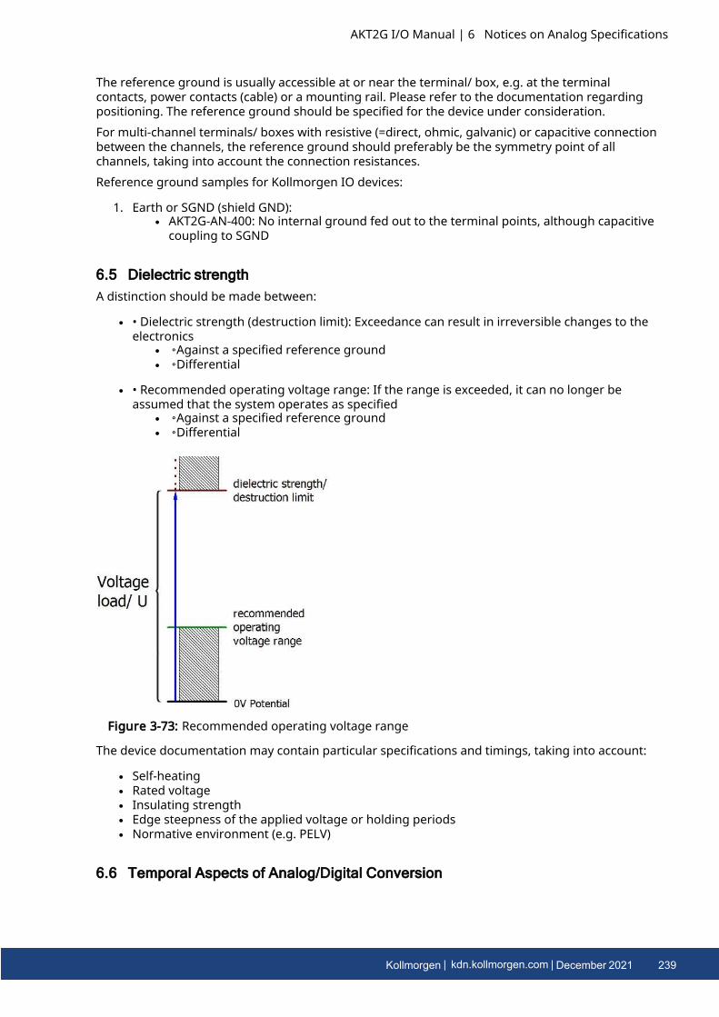
The reference ground is usually accessible at or near the terminal/ box, e.g. at the terminalcontacts, power contacts (cable) or a mounting rail. Please refer to the documentation regardingpositioning. The reference ground should be specified for the device under consideration.For multi-channel terminals/ boxes with resistive (=direct, ohmic, galvanic) or capacitive connectionbetween the channels, the reference ground should preferably be the symmetry point of allchannels, taking into account the connection resistances.Reference ground samples for Kollmorgen IO devices:
1. Earth or SGND (shield GND):l AKT2G-AN-400: No internal ground fed out to the terminal points, although capacitive
coupling to SGND
6.5 Dielectric strengthA distinction should be made between:
l • Dielectric strength (destruction limit): Exceedance can result in irreversible changes to theelectronics
l ◦Against a specified reference groundl ◦Differential
l • Recommended operating voltage range: If the range is exceeded, it can no longer beassumed that the system operates as specified
l ◦Against a specified reference groundl ◦Differential
Figure 3-73: Recommended operating voltage range
The device documentation may contain particular specifications and timings, taking into account:
l Self-heatingl Rated voltagel Insulating strengthl Edge steepness of the applied voltage or holding periodsl Normative environment (e.g. PELV)
6.6 Temporal Aspects of Analog/Digital Conversion
AKT2G I/O Manual | 6 Notices on Analog Specifications
Kollmorgen | kdn.kollmorgen.com | December 2021 239
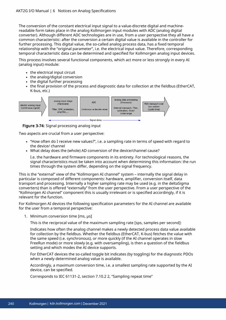
AKT2G I/O Manual | 6 Notices on Analog Specifications
The conversion of the constant electrical input signal to a value-discrete digital and machine-readable form takes place in the analog Kollmorgen input modules with ADC (analog digitalconverter). Although different ADC technologies are in use, from a user perspective they all have acommon characteristic: after the conversion a certain digital value is available in the controller forfurther processing. This digital value, the so-called analog process data, has a fixed temporalrelationship with the “original parameter”, i.e. the electrical input value. Therefore, correspondingtemporal characteristic data can be determined and specified for Kollmorgen analog input devices.This process involves several functional components, which act more or less strongly in every AI(analog input) module:
l the electrical input circuitl the analog/digital conversionl the digital further processingl the final provision of the process and diagnostic data for collection at the fieldbus (EtherCAT,
K-bus, etc.)
Figure 3-74: Signal processing analog input
Two aspects are crucial from a user perspective:
l “How often do I receive new values?”, i.e. a sampling rate in terms of speed with regard tothe device/ channel
l What delay does the (whole) AD conversion of the device/channel cause?I.e. the hardware and firmware components in its entirety. For technological reasons, thesignal characteristics must be taken into account when determining this information: the runtimes through the system differ, depending on the signal frequency.
This is the “external” view of the “Kollmorgen AI channel” system – internally the signal delay inparticular is composed of different components: hardware, amplifier, conversion itself, datatransport and processing. Internally a higher sampling rate may be used (e.g. in the deltaSigmaconverters) than is offered “externally” from the user perspective. From a user perspective of the“Kollmorgen AI channel” component this is usually irrelevant or is specified accordingly, if it isrelevant for the function.For Kollmorgen AI devices the following specification parameters for the AI channel are availablefor the user from a temporal perspective:
1. Minimum conversion time [ms, µs]This is the reciprocal value of the maximum sampling rate [sps, samples per second]:Indicates how often the analog channel makes a newly detected process data value availablefor collection by the fieldbus. Whether the fieldbus (EtherCAT, K-bus) fetches the value withthe same speed (i.e. synchronous), or more quickly (if the AI channel operates in slowFreeRun mode) or more slowly (e.g. with oversampling), is then a question of the fieldbussetting and which modes the AI device supports.For EtherCAT devices the so-called toggle bit indicates (by toggling) for the diagnostic PDOswhen a newly determined analog value is available.Accordingly, a maximum conversion time, i.e. a smallest sampling rate supported by the AIdevice, can be specified.Corresponds to IEC 61131-2, section 7.10.2 2, “Sampling repeat time”
240 Kollmorgen | kdn.kollmorgen.com | December 2021
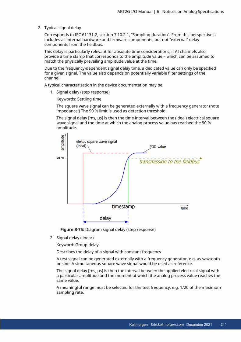
2. Typical signal delayCorresponds to IEC 61131-2, section 7.10.2 1, “Sampling duration”. From this perspective itincludes all internal hardware and firmware components, but not “external” delaycomponents from the fieldbus.This delay is particularly relevant for absolute time considerations, if AI channels alsoprovide a time stamp that corresponds to the amplitude value – which can be assumed tomatch the physically prevailing amplitude value at the time.Due to the frequency-dependent signal delay time, a dedicated value can only be specifiedfor a given signal. The value also depends on potentially variable filter settings of thechannel.A typical characterization in the device documentation may be:
1. Signal delay (step response)Keywords: Settling timeThe square wave signal can be generated externally with a frequency generator (noteimpedance!) The 90 % limit is used as detection threshold.The signal delay [ms, µs] is then the time interval between the (ideal) electrical squarewave signal and the time at which the analog process value has reached the 90 %amplitude.
Figure 3-75: Diagram signal delay (step response)
2. Signal delay (linear)Keyword: Group delayDescribes the delay of a signal with constant frequencyA test signal can be generated externally with a frequency generator, e.g. as sawtoothor sine. A simultaneous square wave signal would be used as reference.The signal delay [ms, µs] is then the interval between the applied electrical signal witha particular amplitude and the moment at which the analog process value reaches thesame value.A meaningful range must be selected for the test frequency, e.g. 1/20 of the maximumsampling rate.
AKT2G I/O Manual | 6 Notices on Analog Specifications
Kollmorgen | kdn.kollmorgen.com | December 2021 241
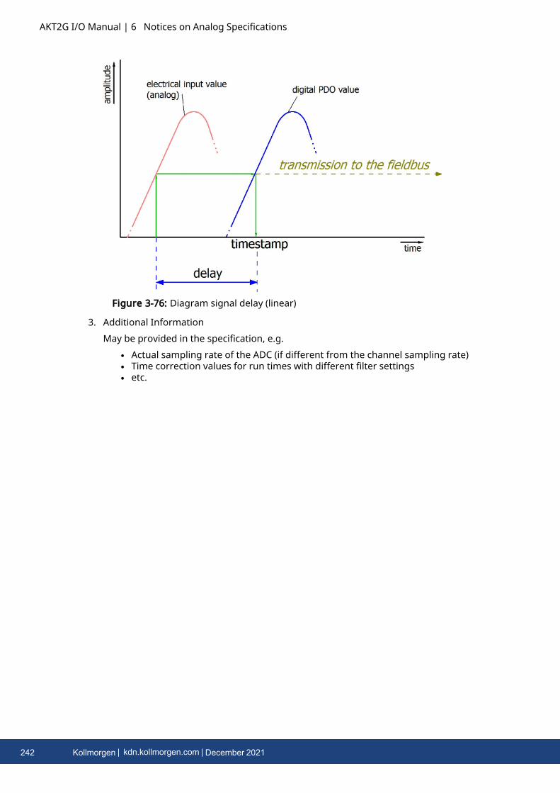
AKT2G I/O Manual | 6 Notices on Analog Specifications
Figure 3-76: Diagram signal delay (linear)
3. Additional InformationMay be provided in the specification, e.g.
l Actual sampling rate of the ADC (if different from the channel sampling rate)l Time correction values for run times with different filter settingsl etc.
242 Kollmorgen | kdn.kollmorgen.com | December 2021

About KOLLMORGEN
Kollmorgen is a leading provider of motion systems and components for machine builders.Through world-class knowledge in motion, industry-leading quality and deep expertise in linkingand integrating standard and custom products, Kollmorgen delivers breakthrough solutions thatare unmatched in performance, reliability and ease-of-use, giving machine builders anirrefutable marketplace advantage.
Join the Kollmorgen Developer Network for product support. Ask thecommunity questions, search the knowledge base for answers, getdownloads, and suggest improvements.
North AmericaKOLLMORGEN201 West Rock RoadRadford, VA 24141, USAWeb: www.kollmorgen.comMail: [email protected].: +1 - 540 - 633 - 3545Fax: +1 - 540 - 639 - 4162
EuropeKOLLMORGEN Europe GmbHPempelfurtstr. 140880 Ratingen, GermanyWeb: www.kollmorgen.comMail: [email protected].: +49 - 2102 - 9394 - 0Fax: +49 - 2102 - 9394 - 3155
South AmericaKOLLMORGENAvenida João Paulo Ablas, 2970Jardim da Glória, Cotia – SPCEP 06711-250, BrazilWeb: www.kollmorgen.comMail: [email protected].: +55 11 4615-6300
China and SEAKOLLMORGENRoom 302, Building 5, Lihpao Plaza,88 Shenbin Road, Minhang District,Shanghai, China.Web: www.kollmorgen.cnMail: [email protected].: +86 - 400 668 2802Fax: +86 - 21 6248 5367


