Embed Size (px)
Citation preview

This page intentionally left blank
LAN WiringThird Edition
James Trulove
McGraw-HillNew York Chicago San Francisco Lisbon
London Madrid Mexico City Milan New DelhiSan Juan Seoul Singapore Sydney Toronto

Copyright © 2006 by James Trulove. All rights reserved. Manufactured in the United States of America. Except as permit-ted under the United States Copyright Act of 1976, no part of this publication may be reproduced or distributed in any formor by any means, or stored in a database or retrieval system, without the prior written permission of the publisher.
0-07-148345-4
The material in this eBook also appears in the print version of this title: 0-07-145975-8.
All trademarks are trademarks of their respective owners. Rather than put a trademark symbol after every occurrence of atrademarked name, we use names in an editorial fashion only, and to the benefit of the trademark owner, with no intentionof infringement of the trademark. Where such designations appear in this book, they have been printed with initial caps.
McGraw-Hill eBooks are available at special quantity discounts to use as premiums and sales promotions, or for use incor-porate training programs. For more information, please contact George Hoare, Special Sales, at [email protected] or (212) 904-4069.
TERMS OF USE
This is a copyrighted work and The McGraw-Hill Companies, Inc. (“McGraw-Hill”) and its licensors reserve all rights in andto the work. Use of this work is subject to these terms. Except as permitted under the Copyright Act of 1976 and the right tostore and retrieve one copy of the work, you may not decompile, disassemble, reverse engineer, reproduce, modify, createderivative works based upon, transmit, distribute, disseminate, sell, publish or sublicense the work or any part of it withoutMcGraw-Hill’s prior consent. You may use the work for your own noncommercial and personal use; any other use of the workis strictly prohibited. Your right to use the work may be terminated if you fail to comply with these terms.
THE WORK IS PROVIDED “AS IS.” McGRAW-HILL AND ITS LICENSORS MAKE NO GUARANTEES OR WAR-RANTIES AS TO THE ACCURACY, ADEQUACY OR COMPLETENESS OF OR RESULTS TO BE OBTAINED FROMUSING THE WORK, INCLUDING ANY INFORMATION THAT CAN BE ACCESSED THROUGH THE WORK VIAHYPERLINK OR OTHERWISE, AND EXPRESSLY DISCLAIM ANY WARRANTY, EXPRESS OR IMPLIED,INCLUDING BUT NOT LIMITED TO IMPLIED WARRANTIES OF MERCHANTABILITY OR FITNESS FOR A PAR-TICULAR PURPOSE. McGraw-Hill and its licensors do not warrant or guarantee that the functions contained in the workwill meet your requirements or that its operation will be uninterrupted or error free. Neither McGraw-Hill nor its licensorsshall be liable to you or anyone else for any inaccuracy, error or omission, regardless of cause, in the work or for any dam-ages resulting therefrom. McGraw-Hill has no responsibility for the content of any information accessed through the work.Under no circumstances shall McGraw-Hill and/or its licensors be liable for any indirect, incidental, special, punitive, con-sequential or similar damages that result from the use of or inability to use the work, even if any of them has been advisedof the possibility of such damages. This limitation of liability shall apply to any claim or cause whatsoever whether suchclaim or cause arises in contract, tort or otherwise.
DOI: 10.1036/0071459758

We hope you enjoy thisMcGraw-Hill eBook! If
you’d like more information about this book,its author, or related books and websites,please click here.
Professional
Want to learn more?
Contents
Introduction . . . . . . . . . . . . . . . . . . . . . . . . . . . . . . . . . . . . . . . . . . . . . . . . . . . . .xv
Acknowledgments . . . . . . . . . . . . . . . . . . . . . . . . . . . . . . . . . . . . . . . . . . . . . . .xix
PART ONE
LAN Wiring Systems 1
Chapter 1 Designing LAN Wiring Systems . . . . . . . . . . . . . . . . . . . . . . . . . . . . . . 3
Evolutionary and Revolutionary Advances . . . . . . . . . . . . . . . . . . . 5Goals of a Structured Design . . . . . . . . . . . . . . . . . . . . . . . . . . . . . . 6
Installability . . . . . . . . . . . . . . . . . . . . . . . . . . . . . . . . . . . . . . . . . 7Reusability . . . . . . . . . . . . . . . . . . . . . . . . . . . . . . . . . . . . . . . . . . 8Reliability and Maintainability . . . . . . . . . . . . . . . . . . . . . . . . . . 9
Reliability and Maintainability . . . . . . . . . . . . . . . . . . . . . . . . . . . 10Cost Factors in Cabling Systems . . . . . . . . . . . . . . . . . . . . . . . . 13Mixing Data and Telephone. . . . . . . . . . . . . . . . . . . . . . . . . . . . 14
Designing a Structured Cabling System . . . . . . . . . . . . . . . . . . . . . 16Basic Structured Cabling Terminology . . . . . . . . . . . . . . . . . . . . 17Structured Wiring. . . . . . . . . . . . . . . . . . . . . . . . . . . . . . . . . . . . 19
Structured Wiring’s Component Parts . . . . . . . . . . . . . . . . . . . . . . 20A Structured Cabling Design Example . . . . . . . . . . . . . . . . . . . . . . 33Advances in LAN Wiring Technology . . . . . . . . . . . . . . . . . . . . . . 36
Chapter 2 Popular LAN Topologies . . . . . . . . . . . . . . . . . . . . . . . . . . . . . . . . . . 39
Three Basic Topologies: Bus, Ring, and Star . . . . . . . . . . . . . . . . . 40Ethernet Twisted Pair. . . . . . . . . . . . . . . . . . . . . . . . . . . . . . . . . . . 42
10/100BaseT Networking . . . . . . . . . . . . . . . . . . . . . . . . . . . . . 43
v
For more information about this title, click here
10/100BaseT and Structured Wiring . . . . . . . . . . . . . . . . . . . . . 46100BaseT Cabling Issues . . . . . . . . . . . . . . . . . . . . . . . . . . . . . . 49
Ethernet Fiber, 10/100/1000 Mbps . . . . . . . . . . . . . . . . . . . . . . . . 5210BaseFx Wiring . . . . . . . . . . . . . . . . . . . . . . . . . . . . . . . . . . . . 53Fast Ethernet 100BaseFX and SX Wiring. . . . . . . . . . . . . . . . . . 54Gigabit Ethernet 1000BaseSX and LX Wiring . . . . . . . . . . . . . . 54
10 Gigabit Ethernet 10GBaseSX, LX4, LR, and Copper 10GBaseT and CX Wiring . . . . . . . . . . . . . . . . . . . . . . 55
Token-Ring . . . . . . . . . . . . . . . . . . . . . . . . . . . . . . . . . . . . . . . . . . 56Token-Ring Cabling . . . . . . . . . . . . . . . . . . . . . . . . . . . . . . . . . . 57
Chapter 3 Structured Cabling Systems. . . . . . . . . . . . . . . . . . . . . . . . . . . . . . . . 61
Structured Cabling Perspective. . . . . . . . . . . . . . . . . . . . . . . . . . . . 63TIA-568-C Structured Cabling. . . . . . . . . . . . . . . . . . . . . . . . . . 64TIA-568 Cabling Options . . . . . . . . . . . . . . . . . . . . . . . . . . . . . 65TIA-568 Component Categories . . . . . . . . . . . . . . . . . . . . . . . . 65TIA-568 Connector Standards . . . . . . . . . . . . . . . . . . . . . . . . . . 67TIA-568 Uses . . . . . . . . . . . . . . . . . . . . . . . . . . . . . . . . . . . . . . . 68
Avaya/Lucent (AT&T) Systimax PDS. . . . . . . . . . . . . . . . . . . . . . . 68IBM Cabling System . . . . . . . . . . . . . . . . . . . . . . . . . . . . . . . . . . . 70Other Standard Cabling Systems . . . . . . . . . . . . . . . . . . . . . . . . . . 75
NORDX/CDT IBDN . . . . . . . . . . . . . . . . . . . . . . . . . . . . . . . . . 75DECconnect . . . . . . . . . . . . . . . . . . . . . . . . . . . . . . . . . . . . . . . . 76
Chapter 4 LAN Wiring for Future Needs. . . . . . . . . . . . . . . . . . . . . . . . . . . . . . . 79
Picking the Next Wiring Technology . . . . . . . . . . . . . . . . . . . . . . . 80100/1000 Mbps Networking Compatibility. . . . . . . . . . . . . . . . 81Category 5e/6/AC6/7 Testing and Certification . . . . . . . . . . . . . 83The Need for Speed . . . . . . . . . . . . . . . . . . . . . . . . . . . . . . . . . . 84
The Importance of Category . . . . . . . . . . . . . . . . . . . . . . . . . . . . . 85“Enhanced” Category X . . . . . . . . . . . . . . . . . . . . . . . . . . . . . . 86
Fiber to the Front. . . . . . . . . . . . . . . . . . . . . . . . . . . . . . . . . . . . . . 87The Future of Copper Wiring . . . . . . . . . . . . . . . . . . . . . . . . . . . . 88Future (Wiring) Shock . . . . . . . . . . . . . . . . . . . . . . . . . . . . . . . . . . 90
Preparing for Higher-Speed Networking . . . . . . . . . . . . . . . . . . 90The Tubing Pull . . . . . . . . . . . . . . . . . . . . . . . . . . . . . . . . . . . . . 92
vi Contents
PART TWO
LAN Wiring Technology 93
Chapter 5 Wire and Cable Technology for LANs. . . . . . . . . . . . . . . . . . . . . . . . 95
Basic Cable Types . . . . . . . . . . . . . . . . . . . . . . . . . . . . . . . . . . . . . 96Twisted-Pair UTP and STP Cable. . . . . . . . . . . . . . . . . . . . . . . . 96UTP/STP General Construction . . . . . . . . . . . . . . . . . . . . . . . . . 97UTP/STP Wire Sizes . . . . . . . . . . . . . . . . . . . . . . . . . . . . . . . . . . 98UTP/STP Electrical Characteristics. . . . . . . . . . . . . . . . . . . . . . . 99UTP/STP Insulation . . . . . . . . . . . . . . . . . . . . . . . . . . . . . . . . . 101
The FEP Controversy. . . . . . . . . . . . . . . . . . . . . . . . . . . . . . . . . . 103UTP/STP Color Coding and Marking . . . . . . . . . . . . . . . . . . . 104UTP/STP Shielding and Screening . . . . . . . . . . . . . . . . . . . . . . 107
Fiber-Optic General Construction . . . . . . . . . . . . . . . . . . . . . . . . 108The Fiber Debate . . . . . . . . . . . . . . . . . . . . . . . . . . . . . . . . . . . 109Fiber-Optic Sizes . . . . . . . . . . . . . . . . . . . . . . . . . . . . . . . . . . . 112Fiber-Optical Characteristics . . . . . . . . . . . . . . . . . . . . . . . . . . 112Fiber-Optic Insulation/Jacketing. . . . . . . . . . . . . . . . . . . . . . . . 115Fiber-Optic Color Coding and Marking. . . . . . . . . . . . . . . . . . 116Fiber-Optic Shielding and Armoring . . . . . . . . . . . . . . . . . . . . 116
Special Purpose Wire . . . . . . . . . . . . . . . . . . . . . . . . . . . . . . . . . . 117Plenum and Riser Rating . . . . . . . . . . . . . . . . . . . . . . . . . . . . . 117UV Light Rating. . . . . . . . . . . . . . . . . . . . . . . . . . . . . . . . . . . . 118Outside Locations . . . . . . . . . . . . . . . . . . . . . . . . . . . . . . . . . . 118Hazardous Locations . . . . . . . . . . . . . . . . . . . . . . . . . . . . . . . . 119
Chapter 6 Work Area Outlets . . . . . . . . . . . . . . . . . . . . . . . . . . . . . . . . . . . . . . 121
Outlet Jack Mountings . . . . . . . . . . . . . . . . . . . . . . . . . . . . . . . . 122Flush Mounts. . . . . . . . . . . . . . . . . . . . . . . . . . . . . . . . . . . . . . 122Surface Mounts . . . . . . . . . . . . . . . . . . . . . . . . . . . . . . . . . . . . 127
Modular Jacks for Twisted Pair . . . . . . . . . . . . . . . . . . . . . . . . . . 129Jack Plate Types . . . . . . . . . . . . . . . . . . . . . . . . . . . . . . . . . . . . 130Termination Types . . . . . . . . . . . . . . . . . . . . . . . . . . . . . . . . . . 132Nonmodular Jacks for Category 7 . . . . . . . . . . . . . . . . . . . . . . 136
Standard Jack Pin-Outs . . . . . . . . . . . . . . . . . . . . . . . . . . . . . . . . 136TIA Performance Category . . . . . . . . . . . . . . . . . . . . . . . . . . . 140Keyed-Plug Entry . . . . . . . . . . . . . . . . . . . . . . . . . . . . . . . . . . . 140
Contents vii
Fiber-Optic Outlet Jacks . . . . . . . . . . . . . . . . . . . . . . . . . . . . . . . 141Fiber-Optic Connectors . . . . . . . . . . . . . . . . . . . . . . . . . . . . . . 142Small Form Factor (SFF) Connectors . . . . . . . . . . . . . . . . . . . . 144
Other Outlet Jack Types . . . . . . . . . . . . . . . . . . . . . . . . . . . . . . . 147IBM Cabling System Jacks . . . . . . . . . . . . . . . . . . . . . . . . . . . . 147Coax Jacks. . . . . . . . . . . . . . . . . . . . . . . . . . . . . . . . . . . . . . . . 148
Marking Outlets . . . . . . . . . . . . . . . . . . . . . . . . . . . . . . . . . . . . . 149Workmanship. . . . . . . . . . . . . . . . . . . . . . . . . . . . . . . . . . . . . . . . 150
Chapter 7 Telecommunication Room Terminations . . . . . . . . . . . . . . . . . . . . 153
Punchdown Blocks. . . . . . . . . . . . . . . . . . . . . . . . . . . . . . . . . . . . 155Type 110 Connecting Blocks . . . . . . . . . . . . . . . . . . . . . . . . . . 155Type 66M Connecting Blocks . . . . . . . . . . . . . . . . . . . . . . . . . 160Other Connecting Systems . . . . . . . . . . . . . . . . . . . . . . . . . . . . 167
Routing and Dressing Devices . . . . . . . . . . . . . . . . . . . . . . . . . . . 171Standoffs and Distribution Rings . . . . . . . . . . . . . . . . . . . . . . . 172Wire Management Panels. . . . . . . . . . . . . . . . . . . . . . . . . . . . . 173
User Equipment Location . . . . . . . . . . . . . . . . . . . . . . . . . . . . . . 174Fiber-Optic Termination. . . . . . . . . . . . . . . . . . . . . . . . . . . . . . . . 177
AB/BA Fiber Polarity Orientation . . . . . . . . . . . . . . . . . . . . . . 178Fiber-Optic Termination Fixtures . . . . . . . . . . . . . . . . . . . . . . . 180
Marking. . . . . . . . . . . . . . . . . . . . . . . . . . . . . . . . . . . . . . . . . . . . 183Workmanship. . . . . . . . . . . . . . . . . . . . . . . . . . . . . . . . . . . . . . . . 184
Chapter 8 Patch Panels, Cross Connects, and Patch Cords. . . . . . . . . . . . . . 187
Patch Panels versus Cross-Connects. . . . . . . . . . . . . . . . . . . . . . . 188Traditional Cross-Connect Termination . . . . . . . . . . . . . . . . . . 188Modern Patch-Panel Termination . . . . . . . . . . . . . . . . . . . . . . 190Pros and Cons of Patches and Cross-Connects . . . . . . . . . . . . 190
Patch Panels . . . . . . . . . . . . . . . . . . . . . . . . . . . . . . . . . . . . . . . . . 191Patch Panel Specifications . . . . . . . . . . . . . . . . . . . . . . . . . . . . 192Patch Panel Wire Management . . . . . . . . . . . . . . . . . . . . . . . . 195Connectorized Patch Panels . . . . . . . . . . . . . . . . . . . . . . . . . . . 196
Patch Panel Location and Marking . . . . . . . . . . . . . . . . . . . . . . . 199Patch Cords . . . . . . . . . . . . . . . . . . . . . . . . . . . . . . . . . . . . . . . . . 202
UTP Patch Cords . . . . . . . . . . . . . . . . . . . . . . . . . . . . . . . . . . . 203Screened Twisted Pair (ScTP) Patch Cords . . . . . . . . . . . . . . . . 204
Cross-Connect Jumpers . . . . . . . . . . . . . . . . . . . . . . . . . . . . . . . . 205
viii Contents
Cross-Connect Wire Size and Type . . . . . . . . . . . . . . . . . . . . . 206Cross-Connect Wire Category . . . . . . . . . . . . . . . . . . . . . . . . . 207Cross-Connect Routing and Marking . . . . . . . . . . . . . . . . . . . 208Cross-Connect Workmanship. . . . . . . . . . . . . . . . . . . . . . . . . . 209
Fiber-Optic Patches and Cords. . . . . . . . . . . . . . . . . . . . . . . . . . . 211
Chapter 9 User Cords and Connectors . . . . . . . . . . . . . . . . . . . . . . . . . . . . . . 217
Cable-End Connectors . . . . . . . . . . . . . . . . . . . . . . . . . . . . . . . . . 218Modular Connectors . . . . . . . . . . . . . . . . . . . . . . . . . . . . . . . . 218
User Cords . . . . . . . . . . . . . . . . . . . . . . . . . . . . . . . . . . . . . . . . . . 225Construction . . . . . . . . . . . . . . . . . . . . . . . . . . . . . . . . . . . . . . 226Category . . . . . . . . . . . . . . . . . . . . . . . . . . . . . . . . . . . . . . . . . 227Length and Routing . . . . . . . . . . . . . . . . . . . . . . . . . . . . . . . . . 228Workmanship and Quality. . . . . . . . . . . . . . . . . . . . . . . . . . . . 229
Chapter 10 Open Office Wiring. . . . . . . . . . . . . . . . . . . . . . . . . . . . . . . . . . . . . . 231
Modular Offices—Modern Problems. . . . . . . . . . . . . . . . . . . . . . 232
TIA-568 TSB-75 Guidelines . . . . . . . . . . . . . . . . . . . . . . . . . . . . . 235Consolidation Point . . . . . . . . . . . . . . . . . . . . . . . . . . . . . . . . . 235Multiuser Telecommunications Outlet Assembly (MUTOA) . . 237
Fiber-Optic Cabling in Open Offices . . . . . . . . . . . . . . . . . . . . . . 240Fiber-Optic MUTOA Cabling . . . . . . . . . . . . . . . . . . . . . . . . . 240
Separation Anxiety. . . . . . . . . . . . . . . . . . . . . . . . . . . . . . . . . . . . 241
Chapter 11 Fiber-Optic Techniques . . . . . . . . . . . . . . . . . . . . . . . . . . . . . . . . . . 243
Fiber-Optic Basics . . . . . . . . . . . . . . . . . . . . . . . . . . . . . . . . . . . . 244Fiber-Optic Transmission . . . . . . . . . . . . . . . . . . . . . . . . . . . . . 245Fiber Types. . . . . . . . . . . . . . . . . . . . . . . . . . . . . . . . . . . . . . . . 248Fiber-Optic Cable Configurations . . . . . . . . . . . . . . . . . . . . . . 249Fiber-Optic Connectors . . . . . . . . . . . . . . . . . . . . . . . . . . . . . . 252Optical Fiber Bandwidth . . . . . . . . . . . . . . . . . . . . . . . . . . . . . 256VCSEL Laser Source Multimode Problem . . . . . . . . . . . . . . . . 258
Standardized Fiber-Optic LAN Cabling . . . . . . . . . . . . . . . . . . . . 259Structured Fiber Cabling—TIA Standards . . . . . . . . . . . . . . . . 260Centralized Fiber Cabling—TSB-72 and TIA-568-C . . . . . . . . 261Standard Fiber-Optic Network Links. . . . . . . . . . . . . . . . . . . . 263
Fiber-Optic Equipment Considerations . . . . . . . . . . . . . . . . . . . . 263Fiber to the Desktop . . . . . . . . . . . . . . . . . . . . . . . . . . . . . . . . 264
Contents ix
Copper to Fiber Conversion. . . . . . . . . . . . . . . . . . . . . . . . . . . 265Fiber-Optic Installation Practices . . . . . . . . . . . . . . . . . . . . . . . . . 266
Fiber Cable Protection . . . . . . . . . . . . . . . . . . . . . . . . . . . . . . . 266Fiber Terminations . . . . . . . . . . . . . . . . . . . . . . . . . . . . . . . . . . 268Fiber-Optic Testing. . . . . . . . . . . . . . . . . . . . . . . . . . . . . . . . . . 270
Safety Considerations. . . . . . . . . . . . . . . . . . . . . . . . . . . . . . . . . . 273Chemicals. . . . . . . . . . . . . . . . . . . . . . . . . . . . . . . . . . . . . . . . . 274Glass Fiber Safety. . . . . . . . . . . . . . . . . . . . . . . . . . . . . . . . . . . 274Laser Safety and Classes of Operation . . . . . . . . . . . . . . . . . . . 275
Fiber-Optic Future . . . . . . . . . . . . . . . . . . . . . . . . . . . . . . . . . . . . 276
Chapter 12 Gigabit and 10 Gigabit Cabling Technology . . . . . . . . . . . . . . . . . 277
Gigabit Ethernet. . . . . . . . . . . . . . . . . . . . . . . . . . . . . . . . . . . . . . 279Fiber-Optic Standards for Gigabit Ethernet . . . . . . . . . . . . . . . 280Copper Standards for Gigabit Ethernet . . . . . . . . . . . . . . . . . . 2841000BaseCX . . . . . . . . . . . . . . . . . . . . . . . . . . . . . . . . . . . . . . 286ATM Gigabit Standards . . . . . . . . . . . . . . . . . . . . . . . . . . . . . . 286
Wiring Standards to Support Gigabit Speeds . . . . . . . . . . . . . . . . 288Gigabit Wiring Standards for Fiber . . . . . . . . . . . . . . . . . . . . . 289Gigabit Wiring Standards for Copper . . . . . . . . . . . . . . . . . . . 290Planning a Gigabit Installation. . . . . . . . . . . . . . . . . . . . . . . . . 296Specifying Gigabit Cabling. . . . . . . . . . . . . . . . . . . . . . . . . . . . 298Testing Gigabit Cabling . . . . . . . . . . . . . . . . . . . . . . . . . . . . . . 299
10 Gigabit Ethernet Technology. . . . . . . . . . . . . . . . . . . . . . . . . . 30110 Gigabit Standards and Cabling for Fiber . . . . . . . . . . . . . . 30210 Gigabit Standards and Cabling for Copper. . . . . . . . . . . . . 306
Flexible Tubing . . . . . . . . . . . . . . . . . . . . . . . . . . . . . . . . . . . . . . 309Quality Counts . . . . . . . . . . . . . . . . . . . . . . . . . . . . . . . . . . . . . . 309
Chapter 13 Wireless LANs . . . . . . . . . . . . . . . . . . . . . . . . . . . . . . . . . . . . . . . . . . 311
Wireless Applications. . . . . . . . . . . . . . . . . . . . . . . . . . . . . . . . . . 312Wireless Basics . . . . . . . . . . . . . . . . . . . . . . . . . . . . . . . . . . . . . . . 313
Radio-Frequency Operation. . . . . . . . . . . . . . . . . . . . . . . . . . . 313Modulation . . . . . . . . . . . . . . . . . . . . . . . . . . . . . . . . . . . . . . . 315Line-of-Sight Concepts. . . . . . . . . . . . . . . . . . . . . . . . . . . . . . . 316Antenna Operation . . . . . . . . . . . . . . . . . . . . . . . . . . . . . . . . . 316Interference Sources . . . . . . . . . . . . . . . . . . . . . . . . . . . . . . . . . 319
Spread Spectrum Technology . . . . . . . . . . . . . . . . . . . . . . . . . . . . 320
x Contents
Frequency-Spreading Variants: DSSS, QFDM, and FHSS. . . . . 320Resistance to Interference. . . . . . . . . . . . . . . . . . . . . . . . . . . . . 320
Wireless LAN Standards . . . . . . . . . . . . . . . . . . . . . . . . . . . . . . . 321IEEE 802.11 Standard Operation . . . . . . . . . . . . . . . . . . . . . . 321
2.4 and 5 GHz Channel Plans . . . . . . . . . . . . . . . . . . . . . . . . . . . 325Bluetooth IEEE 802.15.1 WLAN Operation . . . . . . . . . . . . . . 326HiperLAN Operation. . . . . . . . . . . . . . . . . . . . . . . . . . . . . . . . 328Home RF SWAP WLAN Proposal . . . . . . . . . . . . . . . . . . . . . . 328
Enhancing Wireless Features with VLANs and Security. . . . . . . . 328Wireless Link Types . . . . . . . . . . . . . . . . . . . . . . . . . . . . . . . . . . . 329
Indoor Point-to-Multipoint LANs . . . . . . . . . . . . . . . . . . . . . . 329Outdoor Point-to-Point Links . . . . . . . . . . . . . . . . . . . . . . . . . 330Outdoor Point-to-Multipoint Systems . . . . . . . . . . . . . . . . . . . 331
Planning a Wireless System . . . . . . . . . . . . . . . . . . . . . . . . . . . . . 332Determining Coverage Area . . . . . . . . . . . . . . . . . . . . . . . . . . . 332Situating Wireless Network Bridges . . . . . . . . . . . . . . . . . . . . . 333Using Range Extender Antennas . . . . . . . . . . . . . . . . . . . . . . . 334Site Survey for Wireless LANs . . . . . . . . . . . . . . . . . . . . . . . . . 335Outdoor Operation . . . . . . . . . . . . . . . . . . . . . . . . . . . . . . . . . 337
Troubleshooting Wireless LANs. . . . . . . . . . . . . . . . . . . . . . . . . . 338Determine the Scope . . . . . . . . . . . . . . . . . . . . . . . . . . . . . . . . 338Line-of-Sight Problems. . . . . . . . . . . . . . . . . . . . . . . . . . . . . . . 339Interference . . . . . . . . . . . . . . . . . . . . . . . . . . . . . . . . . . . . . . . 340Software and Compatibility Issues . . . . . . . . . . . . . . . . . . . . . . 341
Power over Ethernet (PoE) for APs . . . . . . . . . . . . . . . . . . . . . . . 342Plan for the Future. . . . . . . . . . . . . . . . . . . . . . . . . . . . . . . . . . . . 344
Stay Compatible. . . . . . . . . . . . . . . . . . . . . . . . . . . . . . . . . . . . 344The Place of Wireless in a Wired LAN. . . . . . . . . . . . . . . . . . . . . 345
PART THREE
LAN Wire Management 347
Chapter 14 Telecommunications Rooms and Wire Management . . . . . . . . . 349
Defining the Telecommunications Room (TR) . . . . . . . . . . . . . . . 350Traditional Cabling Heirarchy . . . . . . . . . . . . . . . . . . . . . . . . . 350Fitting LANs into the Structured Cabling Heirarchy . . . . . . . . 351
Horizontal and Backbone Wiring . . . . . . . . . . . . . . . . . . . . . . . . 352Color Coding the Telecommunications Room . . . . . . . . . . . . . 352
Contents xi
Making Horizontal Runs . . . . . . . . . . . . . . . . . . . . . . . . . . . . . 353Distance Considerations. . . . . . . . . . . . . . . . . . . . . . . . . . . . . . . . 354
Maximum Drop Length . . . . . . . . . . . . . . . . . . . . . . . . . . . . . . 356Accessibility and Appearance . . . . . . . . . . . . . . . . . . . . . . . . . . 358
Size Requirements for Telecommunications Rooms . . . . . . . . . . . 359Power Requirements for Telecommunications Rooms . . . . . . . . . 360Backbones and Concentration . . . . . . . . . . . . . . . . . . . . . . . . . . . 362
Chapter 15 Testing and Certifying LAN Wiring. . . . . . . . . . . . . . . . . . . . . . . . . . 367
Certifying Cable and Connecting Hardware . . . . . . . . . . . . . . . . 368Performance Levels . . . . . . . . . . . . . . . . . . . . . . . . . . . . . . . . . 370Pitfalls and Specsmanship . . . . . . . . . . . . . . . . . . . . . . . . . . . . 375Cable Plant Certification . . . . . . . . . . . . . . . . . . . . . . . . . . . . . 377
Testing Installed Cable . . . . . . . . . . . . . . . . . . . . . . . . . . . . . . . . . 378Performance Levels . . . . . . . . . . . . . . . . . . . . . . . . . . . . . . . . . 380Testing Costs . . . . . . . . . . . . . . . . . . . . . . . . . . . . . . . . . . . . . . 382
Testing Methods . . . . . . . . . . . . . . . . . . . . . . . . . . . . . . . . . . . . . 384The Channel and the Permanent Link . . . . . . . . . . . . . . . . . . . 384Equipment and Testing Requirements . . . . . . . . . . . . . . . . . . . 384Reporting Pass and Fail Criteria . . . . . . . . . . . . . . . . . . . . . . . 391
Test Equipment . . . . . . . . . . . . . . . . . . . . . . . . . . . . . . . . . . . . . . 393Continuity Testers (Voltmeter, Continuity Tester) . . . . . . . . . . 394Cable Wire Map Testers. . . . . . . . . . . . . . . . . . . . . . . . . . . . . . 396Cable Tracers . . . . . . . . . . . . . . . . . . . . . . . . . . . . . . . . . . . . . . 397Cable Scanners. . . . . . . . . . . . . . . . . . . . . . . . . . . . . . . . . . . . . 398Analog versus Digital Field Testers . . . . . . . . . . . . . . . . . . . . . 400TDRs/OTDRs . . . . . . . . . . . . . . . . . . . . . . . . . . . . . . . . . . . . . 402Basic Fiber-Optic Testers . . . . . . . . . . . . . . . . . . . . . . . . . . . . . 403
Chapter 16 Monitoring and Administering LAN Wiring . . . . . . . . . . . . . . . . . . 405
Cable System Monitoring Methods . . . . . . . . . . . . . . . . . . . . . . . 406Physical Cable Monitoring. . . . . . . . . . . . . . . . . . . . . . . . . . . . 407Remote Cable System Monitoring . . . . . . . . . . . . . . . . . . . . . . 407SNMP Monitoring and Control. . . . . . . . . . . . . . . . . . . . . . . . 408Remote Control of Physical Connections. . . . . . . . . . . . . . . . . 409
LAN System Documentation . . . . . . . . . . . . . . . . . . . . . . . . . . . . 409LAN Documentation Standard TIA/EIA-606-A . . . . . . . . . . . . 409
Documenting through Cable Administration Tools . . . . . . . . . . . 413
xii Contents
Chapter 17 Troubleshooting LAN Wiring . . . . . . . . . . . . . . . . . . . . . . . . . . . . . . 415
Common Failure Modes . . . . . . . . . . . . . . . . . . . . . . . . . . . . . . . 416Copper Cable Failure Modes . . . . . . . . . . . . . . . . . . . . . . . . . . 416Fiber-Optic Cable Failure Modes . . . . . . . . . . . . . . . . . . . . . . . 425Fiber-Optic Link Failures . . . . . . . . . . . . . . . . . . . . . . . . . . . . . 426
Troubleshooting Approaches . . . . . . . . . . . . . . . . . . . . . . . . . . . . 428
Chapter 18 Training and Certification . . . . . . . . . . . . . . . . . . . . . . . . . . . . . . . . 431
Computer Network History. . . . . . . . . . . . . . . . . . . . . . . . . . . . . 432Wiring Complexity . . . . . . . . . . . . . . . . . . . . . . . . . . . . . . . . . . . 434Training versus Certification . . . . . . . . . . . . . . . . . . . . . . . . . . . . 435Job Descriptions and Skill Levels . . . . . . . . . . . . . . . . . . . . . . . . . 436
Cable System Designer . . . . . . . . . . . . . . . . . . . . . . . . . . . . . . . 437Network Designer . . . . . . . . . . . . . . . . . . . . . . . . . . . . . . . . . . 437Cabling Technician. . . . . . . . . . . . . . . . . . . . . . . . . . . . . . . . . . 438Cabling Installer. . . . . . . . . . . . . . . . . . . . . . . . . . . . . . . . . . . . 439
Training Goals . . . . . . . . . . . . . . . . . . . . . . . . . . . . . . . . . . . . . . . 440Training Resources. . . . . . . . . . . . . . . . . . . . . . . . . . . . . . . . . . . . 441
General-Purpose Training . . . . . . . . . . . . . . . . . . . . . . . . . . . . 442Manufacturer-Specific Training . . . . . . . . . . . . . . . . . . . . . . . . 443
Certification Programs . . . . . . . . . . . . . . . . . . . . . . . . . . . . . . . . . 444General-Purpose Certification . . . . . . . . . . . . . . . . . . . . . . . . . 444Manufacturer-Specific Certification . . . . . . . . . . . . . . . . . . . . . 445
Sources of Information . . . . . . . . . . . . . . . . . . . . . . . . . . . . . . . . 445
PART FOUR
Appendixes 447
Appendix A Legacy Wire and Cable . . . . . . . . . . . . . . . . . . . . . . . . . . . . . . . . . . 449
Table of Standard Wire Gauges . . . . . . . . . . . . . . . . . . . . . . . . . . 450Coaxial Cable . . . . . . . . . . . . . . . . . . . . . . . . . . . . . . . . . . . . . . . 451
Coax General Construction . . . . . . . . . . . . . . . . . . . . . . . . . . . 451Coax Wire Sizes . . . . . . . . . . . . . . . . . . . . . . . . . . . . . . . . . . . . 454Coax Electrical Characteristics. . . . . . . . . . . . . . . . . . . . . . . . . 455Coax Insulation . . . . . . . . . . . . . . . . . . . . . . . . . . . . . . . . . . . . 456Coax Color Coding and Marking . . . . . . . . . . . . . . . . . . . . . . 456Coax Shielding. . . . . . . . . . . . . . . . . . . . . . . . . . . . . . . . . . . . . 456
Nonpaired Cable . . . . . . . . . . . . . . . . . . . . . . . . . . . . . . . . . . . . . 457
Contents xiii
Nonpaired General Construction . . . . . . . . . . . . . . . . . . . . . . . 457Nonpaired Wire Sizes. . . . . . . . . . . . . . . . . . . . . . . . . . . . . . . . 460Nonpaired Electrical Characteristics . . . . . . . . . . . . . . . . . . . . 460Nonpaired Insulation . . . . . . . . . . . . . . . . . . . . . . . . . . . . . . . . 460Nonpaired Color Coding and Marking . . . . . . . . . . . . . . . . . . 460Nonpaired Shielding . . . . . . . . . . . . . . . . . . . . . . . . . . . . . . . . 461
Appendix B Legacy and Less Common Cabling Systems . . . . . . . . . . . . . . . . . 463
Ethernet Coax . . . . . . . . . . . . . . . . . . . . . . . . . . . . . . . . . . . . . . . 464Thicknet (10Base5) Cabling . . . . . . . . . . . . . . . . . . . . . . . . . . . 465Thinnet (10Base2) Cabling. . . . . . . . . . . . . . . . . . . . . . . . . . . . 468Ethernet Grounding . . . . . . . . . . . . . . . . . . . . . . . . . . . . . . . . . 470
Coax Connectors . . . . . . . . . . . . . . . . . . . . . . . . . . . . . . . . . . . . . 470IBM Cabling System and Data Connectors . . . . . . . . . . . . . . . . . 473STP-A Data Connectors . . . . . . . . . . . . . . . . . . . . . . . . . . . . . . . . 473ARCnet . . . . . . . . . . . . . . . . . . . . . . . . . . . . . . . . . . . . . . . . . . . . 475Other Network Types . . . . . . . . . . . . . . . . . . . . . . . . . . . . . . . . . 479
100VG-AnyLAN . . . . . . . . . . . . . . . . . . . . . . . . . . . . . . . . . . . 479Isochronous Ethernet . . . . . . . . . . . . . . . . . . . . . . . . . . . . . . . . 480AppleTalk/LocalTalk . . . . . . . . . . . . . . . . . . . . . . . . . . . . . . . . 480FDDI . . . . . . . . . . . . . . . . . . . . . . . . . . . . . . . . . . . . . . . . . . . . 481ATM . . . . . . . . . . . . . . . . . . . . . . . . . . . . . . . . . . . . . . . . . . . . 482
Appendix C Online Resources . . . . . . . . . . . . . . . . . . . . . . . . . . . . . . . . . . . . . . . 485
Appendix D Standards Organizations . . . . . . . . . . . . . . . . . . . . . . . . . . . . . . . . . 487
Appendix E Standards for LAN Wiring. . . . . . . . . . . . . . . . . . . . . . . . . . . . . . . . . 491
Appendix F Membership and Training Organizations. . . . . . . . . . . . . . . . . . . . 499
Index . . . . . . . . . . . . . . . . . . . . . . . . . . . . . . . . . . . . . . . . . . . . . . . . . . . . . . . . . 503
xiv Contents
Introduction
LAN wiring, in the form of copper and fiber-optic cabling, continues to play anextremely vital role in digital communication. It is critical to our voice and data com-munications infrastructure. Yet, this standardized cabling is the Mark Twain of com-munications: “The reports of [its] death are greatly exaggerated!” For over a decade,the demise first of copper cabling and ultimately of all wired technologies has beentrumpeted by pundits and prognosticators. We have heard, “copper cannot supportgigabit data rates” and “fiber has limited bandwidth,… limited distance, … is tooexpensive.” More recently, it was pronounced, “10 gigabit will never run over cop-per.” Now, many quarters have declared, “wiring is dead, wireless is the future.”
In spite of all this, physical cabling still rules the seas of communications.Copper not only supports Gigabit Ethernet, but indeed now supports 10 GigabitEthernet. Fiber surprised everyone, first by carrying Gigabit Ethernet to 70 km, andthen by supporting multiple wavelength multiplexing. This dense wave-divisionmultiplexing has multiplied the effective bandwidth of single-mode fiber by 100times or more.
Copper cabling has advanced the state-of-the-art for balanced-pair transmis-sion, and has added twist-geometry stability, extended-bandwidth connectors, andnow pair shielding to raise the bandwidth into the near-microwave region. Fiber-optic cabling has evolved new connector types, new extended wavelength cores, andoptical multiplexing techniques to reduce costs and simplify assembly, to expandbandwidth and distances, and to multiply services per fiber link.
Copper and fiber-optic wiring have overcome every hurdle put before them butone. The final frontier is certainly the threat of wireless. To some, wireless is theanswer to everything. To borrow a concept from Stephen W. Hawking, some peo-ple think that wireless is “The Theory of Everything.” It solves all problems. It curesall ills. It costs virtually nothing, and it is of infinite capacity. It must be very cool.
Unfortunately, as with older theories of the universe, wireless must bow to thelaws of physics, quantum mechanics notwithstanding. There simply is no such thing
xv
Copyright © 2006 by James Trulove. Click here for terms of use.
as unlimited bandwidth, at least as far as wireless is concerned. First, the frequenciesare limited, and many are already in use by other important services, such as radio,television, microwave, police, fire, emergency services, and on and on. Second, it issimply not possible for two signals to occupy the same physical space at the same fre-quency without destructive interference. Given these facts, wireless cools off.
Most of these “…whatever…is dead” claims are made for self-serving reasons.One cannot totally condemn the proponents (and venture capitalists) of new tech-nologies for shameless self-promotion. One simply does not have to believe them—completely. As with all half-truths, half of what they say is true. Fiber did carrygigabit (and later 10 gigabit), and copper did not—initially. Fiber did have limitedbandwidth and distance—initially. Wireless truly is amazing and can do things onecannot do with conventional wiring—but not all things, and not without constraints.
OK, what can copper and fiber cabling do that wireless cannot? Lots of things!For one, unlike structured cabling, wireless has terrible interference problems. Andits security problems are legend. Implementation is rather interesting: no propertyrights on most frequencies, and no way to mitigate interference. The frequencybands of wireless LANs are fraught with troublesome interferers, includingmicrowave ovens, cordless phones, competing technologies, and (yes, as unbeliev-able as it seems) even radio frequency lighting.
Wireless communications, by its very nature, travels with little regard to walls,ceilings, or property lines. The average urban home can probably detect from 5 to25 wireless LAN signals, not including their own. Transmission bandwidths limitthe channel capacity of the most popular band (2.4 GHz) to only three nonoverlap-ping channels (two actually overlap a little). Security has been a joke, with any jokerable to crack the limited encryption method most often used, if one even bothers toimplement it at all. Popular wireless LAN implementations operate in unlicensedbands, so you cannot even depend on long-term use of a channel for a wireless linkor coverage area, unless you own the land for a considerable distance. The popularwireless protocol, being quite the gentleman, obliges the use of the channel for anyother user, no matter how uncouth.
How then can structured cabling be inferior? LAN wiring has no interferenceissues, other than a few very minor concerns that are easily eliminated with propercable routing and placement.
LAN Wiring has no frequency issues: within its rated bandwidth, you getexclusive use of the cable link. And, you can place as many parallel cables as youwish. One cable, one gigabit (or even 10 gigabits). Two cables, two gigabits (or 20).One hundred cables, 100 gigabits. Easy math, easy to do, no particular problems,other than the size of 100 cables, but with fiber, you could multiply that bandwidthmany-fold in a fraction of the size.
xvi Introduction
On security, again LAN wiring is superior. Granted, there are sophisticatedtechniques that can allow one to sample data from a cable from a very close range.But, physical security of a home, building, campus, or government facility is gener-ally quite good. In contrast, the wireless signal at best can travel miles, and at worstcan be easily detected from across the parking lot with a high-gain antenna and low-noise amplifier. You can get the code-breakers for free on the ‘net. In contrast, thevery latest high-bandwidth Category 6 and 7 cables are low-radiation technologies,so the signal stays close. And fiber is inherently secure, as it essentially does not radi-ate at all.
Well, let’s talk distance. In an ideal world, with no other users and no objectsin the way, wireless distance is limited only by the transmit power, the receiver sen-sitivity, and the distance in between. Today, that environment exists only in thedesert and that won’t last for long. Depending on the technology you use, cablingcan go 100 m, 2000 m, or even 70 km, or more. Not only across that desert, butright through the most dense population areas in the world, crisscrossed as manytimes as you like.
To be fair, copper and fiber cabling do have infrastructure costs and implemen-tation issues. It takes time, planning, and skill to create a network of structuredcabling. The details of planning, installation, and testing do matter. That’s whatwe’re here to learn about.
LAN Wiring, 3rd edition, will take you through the steps of designing andbuilding a modern structured cabling system. Along the way, we will show you howto plan your installation, how to lay out wiring rooms, and how to install and ter-minate the components of a structured system. We will discuss cable types, connec-tors, patch panels, and outlets. In addition, we will cover best practices and tricksof the trade you will need to know to design, contract, or install structured cabling.And, as an added bonus, we will cover details on LAN topologies, legacy cabling,international standards, and … oh, yes … wireless LANs. Finally, we will show youhow to performance test and troubleshoot an installed system. You will find loadsof drawings, photos, and tables to help you understand the concepts and to use asa permanent reference for all your LAN wiring needs.
This edition has been completely revised to bring you the very latest in struc-tured cabling technology. We have rearranged the material to get you to the core ofthe subject more quickly, while maintaining our coverage of the entire range of tech-nology used for LAN wiring. We wish you all the success in your cabling adventures.
James TruloveLAN Wiring 3rd [email protected]
Introduction xvii

This page intentionally left blank

Acknowledgments
Many people have contributed to this third edition and the previous editions of LANWiring. We would like to gratefully acknowledge the assistance of the following: FrankBisbee, Donna Ballast, Jim Bordyn, Larry Campbell, Hugo Draye, Scott Fairbairn, LeeHaas, Kevin Reed, John Jankowski, Bob Jensen, Mark Johnston, Paul Kish, HenreicusKoeman, Bryan Lane, Malcolm Myler, Mark Odie, Stephen Paulov and staff, DukePortenier, and Masood Sharrif, as well as Carrie Higbie, Priscilla Gagnon, ValerieRybinski, Marjorie Spencer, John Wyzalek, and many, many others, including all thefine folks at McGraw-Hill: Judy Bass, Diana Mattingly, Patricia Wallenburg ofTypeWriting, and all the myriad of artists, copy editors, production people, and otherindividuals who helped in the creation of this book, and finally to Ruth Ann, whohelped with the entire writing process, including editing of the final copy.
xix
Copyright © 2006 by James Trulove. Click here for terms of use.

This page intentionally left blank

LAN Wiring

This page intentionally left blank

PART ONE
LAN Wiring Systems
Copyright © 2006 by James Trulove. Click here for terms of use.

This page intentionally left blank
CHAPTER 1
Designing LAN WiringSystems
Highlights
■ Goals of structured cabling
■ Basic terminology
■ Horizontal and backbone structures
■ A structured design example
■ Mixing data and telephone
■ Advances in LAN wiring technology
3
Copyright © 2006 by James Trulove. Click here for terms of use.
Local area network (LAN) wiring is the system of Structured Cabling we use tointerconnect computers, printers, routers, switches, and other devices. It is the phys-ical backbone of our networks; it is the medium over which all computer commu-nication functions. Of all the advanced components in our modern computer andcommunication environment, LAN wiring is the technology that makes it all possi-ble. Without the high-speed connections of today’s Structured Cabling, computingwould be limited to large batch-process mega-computers, with no ability for inter-active, distributed, personal communication. However, because of the rapid evolu-tion of network wiring, we can send data (as well as voice and video) atmind-boggling speeds of up to 10 gigabits per second (Gbps) over local networksand long distances, alike.
Our major corporations, governments, and institutions are bound together,and to all of us, through gossamer threads of tiny copper wires and glass fibers.Virtually all modern communication utilizes these delicate electronic trails, and wenow propel much of our lives with Ethernet and IP (Internet Protocol). Perhaps it isno accident that one synonym for gossamer is ethereal. Data has always had a homewith Ethernet and IP. Now voice and video have come, not only to visit, but to stay.Voice over IP (VoIP) and IP-video services are being deployed and accepted at anamazing pace.
It is a digital world, and essentially all of that world is connected with structuredLAN wiring. Data is obviously digital in nature, but many of us don’t know that ourvoice conversations are often digitized at or near the source, and both broadcast andcable television are rapidly moving to an all-digital format. Even wireless communi-cations, from cellular telephones to satellite links, are digital. At some point, and per-haps for the entire length of each of these communication links, the digital signalstravel over LAN wiring’s twisted-pair copper and fiber-optic cables.
Underlying this rapid move to digital communications are the infrastructurecables that move the bits around. Our cities are crisscrossed with fiber and coppercables. Our offices, and increasingly our homes, are likewise embedded with a webof wiring. The demands that are placed on this network of wiring are many andgreat. We must understand this medium to maximize its function, and we must learnthe ways of our modern wiring in order to properly plan, install, and operate ourcabled networks.
Over the years, LAN wiring has developed into a highly sophisticated sciencewith a tremendous impact on the performance, reliability, and maintainability ofyour network. While a LAN comprises many components, the underlying wiringsystem is the foundation upon which all else rests. Without the proper physical con-nections of copper wire, fiber-optic strands, connectors, punchdown blocks, jumpercables, patch panels, and user cables, the network will not operate reliably.
4 PART ONE LAN Wiring Systems
It is quite important that you properly plan, specify, and implement a LANcabling system that will provide your organization with a reliable level of service.The use of the appropriate component parts and good workmanship in your wiringsystem will ensure that it can meet the performance standards that are expected forthe type of LAN you are installing. In addition, you should always plan for as muchfuture growth as is feasible, within obvious financial limits.
Evolutionary and Revolutionary Advances
LAN wiring systems are in a constant state of change, as are all computer systems.As with computer technology, some of the changes in LAN wiring technology areevolutionary and some are revolutionary.
For example, accepted LAN wiring techniques, components, and practices tendto evolve as manufacturers, installers, and users refine the existing wiring technol-ogy. The introduction of tighter cable link performance standards and the trendtoward guarantees of component performance are perfect examples of evolutionarychange. Likewise, the introduction of new cable types, outlets, and patch paneldesigns are also evolutionary. An evolutionary new product does not represent amajor technology shift; the refined product merely has an enhanced level of per-formance or is more convenient to use.
On the other hand, some changes are revolutionary. A revolutionary change isone that breaks with the past. In technology, this implies a product or method thatis no longer compatible with past items, but offers greatly increased capability. Forexample, an increase in LAN speed is revolutionary. For the most part, the technol-ogy required to increase from 10 Mbps to 100 Mbps (or to 1 Gbps or even 10 Gbps)is a clear break from the previous practice, and is highly desirable, but no longercompatible with the past. Revolutionary changes tend to be abrupt.
The main focus of a LAN wiring system design effort must be to keep up withevolutionary changes in the wiring technology that will enhance the value of yoursystem, while attempting to plan for the next revolutionary jump in LAN technology.
When LAN wiring over-twisted-pair-wire first began, little was known aboutthe importance of wire performance. The initial interest in “twisted-pair Ethernet”was to be able to avoid bulky coaxial cable systems and use one’s existing telephonewiring for the installation of the network, thus saving the enormous cost ofinstalling new cabling. However, we soon found out that the typical specificationsthat were fine for telephone use were rather marginal for LAN frequencies thatneeded much higher twists-per-cable-foot, as well as much better impedance andcrosstalk control. To make matters worse, deregulation of the telephone industry atthat time meant that cost-conscious installers sometimes used an even cheaper grade
CHAPTER 1 Designing LAN Wiring Systems 5
of telephone cable that had two twists per foot or less, making it totally inadequatefor LAN data use.
To use twisted pair with confidence, the LAN manager and the LAN installerneeded to be certain that a LAN cable would perform adequately. Performance spec-ifications evolved that categorized cable performance by intended use. An earlyattempt to indicate expected performance by setting up cable manufacturing qual-ity “levels” eventually led to a well-researched and detailed set of industry-standardperformance specifications in five “categories.” The LAN user now could knowwith certainty that a Category 3 cable would operate well on LANs up to 16 mega-hertz (MHz) bandwidth, and that a Category 5e cable would perform to 1000 Mbps(1 Gbps).
Many connector and wire specifications have evolved in this way, along withstandardized workmanship practices, to provide a platform of internationally rec-ognized standards that virtually guarantee a properly performing LAN wiring sys-tem. This process is not difficult to understand, but the LAN manager, installer, andtechnician must have a thorough understanding of the standards, procedures, andspecifications needed for a network cabling plan that complies with LAN operatingstandards. The careful planning of a standards-compliant cabling system is calledstructured wiring.
This chapter will give you an overview of the philosophies in designing, plan-ning, and estimating a LAN wiring system. The items in these sections should beready knowledge before you delve into the rest of the book. A central theme of thisbook is that any wiring design should be a standard installation that supports atleast the minimum performance criteria, is simple to install and maintain, and pro-vides adequate future expandability and growth.
Goals of a Structured Design
Maintaining the proper standards in your cable installation is the key to getting themost from your LAN cabling system. The internationally recognized standards existto ensure that the combination of wiring, connectors, hubs, and network adapterswill all perform properly in a completed network. The newly revised wiring stan-dards make special note of specific cable installation guidelines and workmanshippractices that have been found necessary for the more demanding modern networksat speeds of 100 Mbps and beyond.1
6 PART ONE LAN Wiring Systems
1 Throughout this book, we concentrate on the advanced structured wiring system embodied in thestandards from the Telecommunications Industry Association (e.g., TIA/EIA-568-B) and theInternational Standards Organization (e.g., ISO/IEC 11801).
LAN wiring standards cover everything from electrical performance to safetyissues. Should you dream up an exotic wiring system that meets your creative needs?Should you try to use some existing older data or telephone wiring and add what-ever else you need to make the system work? Should you pick and choose from var-ious manufacturers’ catalogs?
How do you sort out all the options?One way to proceed is to choose a very structured LAN wiring installation that
uses the standards to your advantage. In such an installation, you will wire yourcables in a manner that will support the widest variety of current and future applica-tions. This means you must use the proper cable, install it properly, maintain lengthswithin the maximum proscribed distances, use only connectors and jacks that meetthe category of operation you need, and use proper installation techniques.
In addition, you will want to thoroughly test and document your cable systemfor the appropriate level of performance. Of course, any future changes and addi-tions to your standard cable system must also be done the same way.
Designing a standards-compliant, conventional installation will have distinctadvantages. For example, your properly installed cable will never contribute to aconnectivity failure. You can be assured that any problems will be found in the net-work hardware or software that utilizes your cabling system, not in the cable itself.That is true, assuming no inadvertent change has occurred in a cable. Naturally, itis always possible that someone could damage a cable while doing unrelated workon an electrical, plumbing, heating, ventilating, and air conditioning (HVAC), oreven telephone problem. Remember also that user cables (from the workstation tothe wall jack) are considered part of the cabling system, and their failure can indeeddisable a network connection.
Your standard installation will also ensure that any trained cable installer willbe able to easily expand, troubleshoot, or repair your cabling system. If you testyour cable when it is installed, you will be able to retest any cable drop and com-pare the results to the original cable certification done at installation. You will alsoknow that your cable system meets the electrical and fire protection standardsrequired by local and national authorities.
The standards you will need to reference are described throughout this bookand are listed in the appendix. The appendix also contains sources for copies of thepertinent standards.
Installability
Your LAN wiring system should be easy to install and maintain. A variety of wiretypes, connector types, termination devices, and patching devices exist to support
CHAPTER 1 Designing LAN Wiring Systems 7
network wiring. The best choices are those that support your application, presentand future, and are easy to properly install, using a minimum of special equipment.
However, you must make many additional choices concerning the particularwiring components to be used. For example, what types of jacks are the easiestand most reliable to use? Should you use a punchdown termination and cross-con-nect wiring in the wiring closet, or should you terminate cables directly onto apatch panel? Where should the telecommunications rooms be located? Howshould the individual cables be run to avoid electrical interference and other per-formance-decreasing factors? What color should the cable and connector platesbe?
Some guidance to these choices is provided by recognized installation stan-dards, but many are a matter of personal preference. For example, some jacks usewire termination methods that require special tools, while others do not. The expe-rience level of those who will install and maintain the cabling system is also a fac-tor. Some items are more easily installed and use such things as color code markingto simplify the process. Outlet plates are available that have modular construction,allowing you to mix connections for data, phone, and even CATV.
Installability will also have an effect on system cost. Whether you are doing thewiring yourself or using a contractor, factors such as time-to-install and reliabilitywill be important. The easier the wiring components are to install, the lower will beyour cost of installation, and a contractor will charge less because the installationwill take less time. Doing the work yourself will cost less as well. Installability, how-ever, does not mean the taking of shortcuts. Your goal is to achieve a very installablecabling system that is easy to maintain and meets all appropriate standards and per-formance criteria for your present and foreseeable future needs.
The sections on wiring devices in Part Two of this book will show you a vari-ety of wire termination devices, such as jacks and patches, and will compare the dif-ferent installation techniques that impact installability.
Reusability
Everybody involved with computers and networking knows by now that technologymoves very quickly. Changes are constantly made to upgrade performance andthroughput. (As we all know, nothing stays the same but change itself.)
You cannot always afford to install the true leading-edge technology, but youshould at least design your cabling network to allow for a future upgrade withoutreplacing the cable. To do this means that you must design a cabling system thattotally meets your current needs. If the current need is 100BaseT, then the cable sys-tem should be specified so that it meets that requirement, as a minimum. If possi-
8 PART ONE LAN Wiring Systems
ble, it may be convenient to design your system so that it could support multipleapplications, such as data and voice, or data and videoconferencing.
Then you should assess what future standards for which you might reasonablybe expected to use the cabling system. You should also take into account the usefullife of your facility, which might be five years, or even 20 years. Are your offices inleased space? You might expect to move in less time than if you owned the space. Itmight be best to “overwire” by putting in more cables or cable pairs than you cur-rently need.
You may wish to use a modular outlet jack that allows the connector to bechanged without re-terminating the wire.
It may be virtually impossible to make any accurate technological predictionmore than five or 10 years out. Consider for a moment what technology changeshave taken place over the last 10 years! Undoubtedly, someone, somewhere, madean accurate prediction. However, there were also several predicted technology direc-tions that simply didn’t come true. Of the predictions for the next decade, whichshould you choose?
The only practical approach to cabling futures is to determine a cablingmethod that meets at least the current, widely deployed technology requirements.You then should consider installing to meet cabling standards that are at least onelevel beyond those current requirements.
If this is not cost-prohibitive, your cable system will be able to go through atleast one generational upgrade without replacement. For example, if you currentlyneed a 100BaseT or 100 megabit (Mb) Token-Ring network cabling system, youshould consider installing a cabling system that will support 1000 Mb gigabit tech-nology. Because much of the current componentry is being manufactured so as toexceed that data rate, your system will probably support a second upgrade to 1000Mb rates, should that occur.
Changes in cabling technology are a challenge for any book author. To helpyou keep informed on the latest developments and standards, we have developed an Internet site to use as a resource on current LAN developments. Consultwww.lanwiringguide.com, or see Appendix C, “Online Resources,” for information.
Reliability and Maintainability
Does anyone ever want an unreliable network cabling system? No, of course not!You, or someone else if you use a third-party installer, will be making many deci-sions regarding the components and methods used to install your LAN cable.Many of these decisions will have a long-term effect on how well your networkperforms.
CHAPTER 1 Designing LAN Wiring Systems 9
On the other hand, if you install cable for someone else, you will want to makesure that the installation will stand the test of time. Your reputation is on the line,and you may be responsible for repairs should failures occur at some later time.
A very good philosophy is to install LAN cabling in such a manner that, whennetwork problems occur, it will never be the cable system that is at fault. If youadhere to this guideline, you will save countless hours of tedious and expensive trou-bleshooting. Even though wiring components are relatively simple physical devices,they have technically sophisticated operating characteristics that require expensiveequipment and trained technicians to troubleshoot. The performance issues aregreatly compounded if you use the wiring to its maximum capability.
Because many companies with LAN installations do not have access to sophis-ticated wire test equipment, many LAN managers start troubleshooting a problemby looking at the servers, routers, hubs, and workstations connected to the cablingsystem. They check the configurations of network software, drivers, and applica-tions. They may even change out hardware, including computers, printers, hubcards, or whatever seems to be related to the problem. After all that thrashingabout, you never want the cable to be at fault. Too much emotional and physicalenergy has been tied up in troubleshooting by the time they get to the cable. It hadbetter not be a cable fault!
So, to prevent all of this energy from getting expended at you, just make cer-tain the cable system is done right. Proper installation of LAN wiring has becomeconsiderably more difficult as LAN speeds push upward. You should install all yourwire in accordance with the latest standards, particularly those that address cablerouting, telecommunications room locations, handling of the cable itself, and work-manship.
Proper planning, components, installation practices, and workmanship willmake your cable system installation both reliable and maintainable.
The Structure of Cabling
The concept of Structured Cabling is basic to the philosophy of modern LANwiring. Structured Cabling is a hierarchical system of wiring structures that aredesigned to distribute connectivity from a central concentration point, throughintermediate concentration points, to individual workstation locations.
With the higher speeds of today’s networks, it is recognized that the totallength of cable that connects from the hub to a workstation or other device has afinite maximum length. The entire networking system must therefore be broken upinto chunks that allow workstation (or station) wire to be concentrated, with eachcable length short enough to support the desired data rate. Structured wiring stan-
10 PART ONE LAN Wiring Systems
dards have been developed to help the LAN user plan a wiring system that stayswithin the maximum wiring distance for various LAN topologies.
For example, in the case of 100BaseT, this cable must be no more than 100 m(328 ft), including patch and equipment cords. This same “structure” works for 10and 1000BaseT, as well.
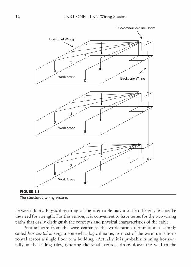
We achieve the needed wiring concentration by placing telecommunicationsrooms (wiring centers) at appropriate locations in a building and then interconnect-ing those wiring closets as needed to provide the total network connectivity for thebuilding. Typically, a model of a multistory building is used to illustrate this struc-tured concept, as shown in Fig. 1.1.
On each floor of our model, a telecommunications room (TR) concentrates allof the station cables for that floor. Each workstation location has a wall or surface-mounted jack. The network cable is terminated at that jack and runs directly to thewire center. This is called a home run, as there are no intermediate connections,splices, taps, or daisy-chains.
The wire may run in wire trays or conduit, or be draped over supports (run-ning over a drop ceiling; the type with push-up ceiling tiles is no longer permitted).Larger floors may require more than one TR per floor.
At the TR, each station wire is terminated on an appropriate punchdown ter-mination, or directly onto a patch panel location. The punchdowns or patch panelsmay be mounted to a wall or in a freestanding rack or cabinet. In the telecommuni-cations room, some type of network device, such as a hub or concentrator, is con-nected to each station cable and electrically terminates the cable run.
The hub passes the LAN signals on to other stations or wire centers for ulti-mate connectivity with the entire network. The process is essentially the same fordifferent network topologies, although Token-Ring uses passive wiring concentra-tors called multistation access units (MSAUs), rather than the active hubs of 10/100/1000BaseT.
A TR is typically connected to the TRs on other floors. This center-to-centerwiring is usually done from floor to floor to floor, as a backbone, with LAN hubs oneach floor. In some cases, it may be more effective to connect TRs on several floorsto a single backbone concentrator on one of the floors. Ideally, TRs should be locateddirectly above one another, to minimize the cable runs between them, but that variesfrom building to building. Fiber-optic cable is sometimes a good choice for wiringbetween TRs, as it totally eliminates grounding and bonding concerns that exist withmetallic cable and can often be run longer distances than copper cable.
Obviously, there are differences between the wiring considerations for stationwiring on a single floor and for TR-to-TR wiring between floors. For one thing, thefire protection requirements may be different for the vertical riser cabling used
CHAPTER 1 Designing LAN Wiring Systems 11
between floors. Physical securing of the riser cable may also be different, as may bethe need for strength. For this reason, it is convenient to have terms for the two wiringpaths that easily distinguish the concepts and physical characteristics of the cable.
Station wire from the wire center to the workstation termination is simplycalled horizontal wiring, a somewhat logical name, as most of the wire run is hori-zontal across a single floor of a building. (Actually, it is probably running horizon-tally in the ceiling tiles, ignoring the small vertical drops down the wall to the
12 PART ONE LAN Wiring Systems
Horizontal Wiring
Backbone Wiring
Telecommunications Room
Work Areas
Work Areas
Work Areas
FIGURE 1.1
The structured wiring system.
outlet.) The TR-to-TR cables are called backbone wiring, since they form a unify-ing structure between TRs. Of course, a very large floor would have more than oneTR, to adhere to the station wire maximums, but the wire between those TRs wouldstill be referred to as backbone. All the details of this structured wiring concept arecovered later in this chapter.
Cost Factors in Cabling Systems
A variety of methods exist to implement LAN wiring schemes; most methods incommon use will be described in succeeding chapters. These methods vary in threesignificant degrees, all of which have cost implications.
First, some LAN topologies require that certain types of wire and connectionsbe used. For example, the Ethernet 10BaseT can use Category 3 twisted pair andjacks, while 100BaseTX and 1000BaseT require Category 5e twisted-pair wire andjacks, and 100BaseFX and 1000BaseSX/LX require the proper mode fiber and con-nectors. Although your network requirements will frequently dictate which topologyyou must use, you may have several choices to make that will influence initial cablingcost as well as the cost of future expansion. In some cases, it would be possible tochoose an older wiring technology such as 10BaseT on the basis of cost. However,when you consider the cost of a future upgrade to 100 or 1000 Mbps, a Category 5eunshielded twisted-pair installation would only support 10 Mbps 10BaseT today, but100 Mbps 100BaseTX (and Gigabit) for the future. Likewise, you may want to investin Category 6 or 7 wiring components to support future upgrades.
Second, LAN wiring methods vary in the extent to which they will supporthigher speed network data rates, including future standards that may not be fullyimplemented yet. For example, it is probably less expensive to install a Category 5ecabling system that supports your current need for 10/100 Mbps networking thanit would be to install an advanced Category 6 or 7 facility. Category 5e will support1000 Mbps on four pairs, but that is its limit. You might never need the1000/10,000 Mbps (1–10 Gbps) capability, particularly if your facility will be occu-pied for less than 5 years. What if you had to stay longer? Should you put inCategory 5e jacks and cable to save money, or should you go ahead and install aCategory 6 (or even Category 7) system now, in case the future comes along a littlesooner than expected?
Third, you may choose combinations of cable and connection hardware thatdiffer in features and cost. This factor may also influence the final, installed cost ofyour network cable system. Even among manufacturers that offer products certifiedto identical performance ratings, there is a lot of price variation. You may choose abig-name manufacturer whose cable and connectors cost more than the little guy’s.
CHAPTER 1 Designing LAN Wiring Systems 13
Some manufacturers have products with extra features, such as modular snap-inconstruction or fancy color inserts. Some even offer special 10- or 15-year war-ranties if you use their cable, connectors, and certified installers.
Others offer separate wire termination and jack modules that plug together. Inmany cases, the extra features will cost you extra money. You will have to judge thebenefit of these extra cost features for your situation.
In the other sections of this book, we will try to point out the cost trade-offsof the devices that are described. You should be aware that any time a connector,cable, or other wiring device is referred to as “easier to use” or “flexible,” theremight be cost implications. Remember too that your goal is not necessarily to spec-ify or install the cheapest wiring solution, but to find the balance among features,cost, and reliability that meets both your current and planned future needs.
Mixing Data and Telephone
Combining conventional analog or digital telephone signals with data on differentpairs of the same cable is sometimes a consideration for cost savings and efficiency.This so-called mixed media approach is an option that may work fine in a lower-speed network environment, such as 10BaseT or Token-Ring, but it may be fraughtwith problems at higher 100 to 1000 Mbps LAN speeds. (At the least, there are lotsof “ifs.”) If your telephones are analog, your LAN speed is conventional, and thetelephone cross-connect is in the same TR as the LAN hubs, then you probablycould use the same cable for data and phone very successfully. This case assumesthat you are using at least Category 3 cable, the minimum data grade, and that thecable runs are not too close to the 90 m maximum.
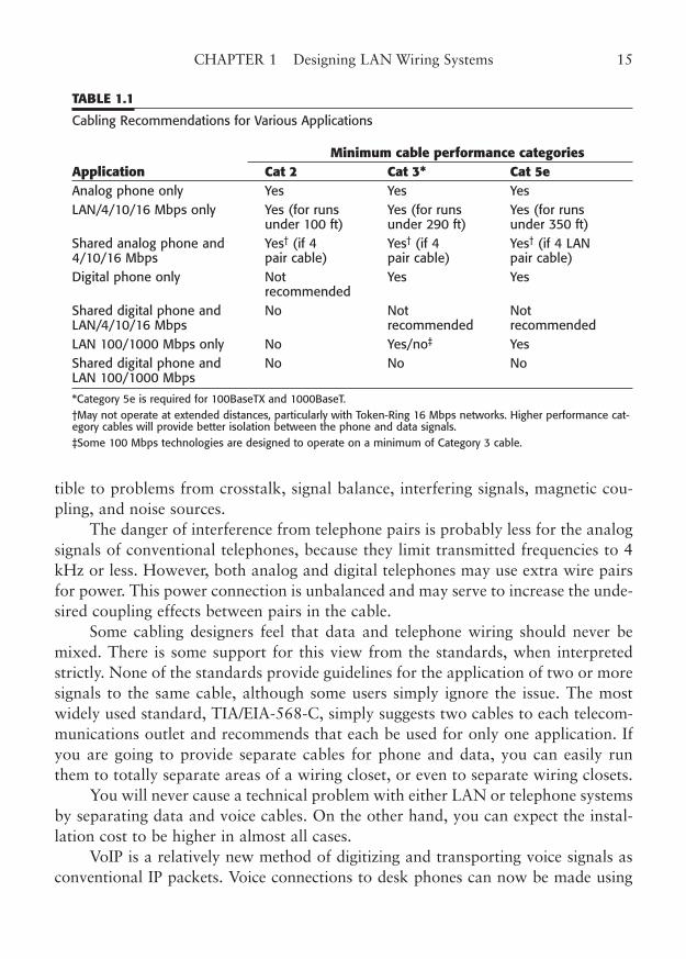
However, if your telephones are digital, or you intend to use 100 or 1000 MbpsLAN data, or you are installing the LAN hubs in a separate TR from the telephoneinterconnects, then you should run two separate cables for data and voice (even ifyour voice is VoIP). For that matter, if you know that the telephone installers are aptto be overly creative around the LAN wiring, you should run separate cables (color-coded for added protection). Table 1.1 shows some of the typical recommendationsfor telephone and data.
The reason for the concern for mixing voice and data is the phenomenon ofcrosstalk that occurs between pairs of the same cable. The higher frequency compo-nents of 100/1000 Mbps LAN signals, along with their greater attenuation per footof cable run, make them much more susceptible to interference from other sources.Such sources clearly include digital telephones and other LAN signals. Even mag-netic fields from fluorescent light fixtures can cause problems. At cable run distancesthat approach the maximum limit, these LAN signals are significantly more suscep-
14 PART ONE LAN Wiring Systems
tible to problems from crosstalk, signal balance, interfering signals, magnetic cou-pling, and noise sources.
The danger of interference from telephone pairs is probably less for the analogsignals of conventional telephones, because they limit transmitted frequencies to 4kHz or less. However, both analog and digital telephones may use extra wire pairsfor power. This power connection is unbalanced and may serve to increase the unde-sired coupling effects between pairs in the cable.
Some cabling designers feel that data and telephone wiring should never bemixed. There is some support for this view from the standards, when interpretedstrictly. None of the standards provide guidelines for the application of two or moresignals to the same cable, although some users simply ignore the issue. The mostwidely used standard, TIA/EIA-568-C, simply suggests two cables to each telecom-munications outlet and recommends that each be used for only one application. Ifyou are going to provide separate cables for phone and data, you can easily runthem to totally separate areas of a wiring closet, or even to separate wiring closets.
You will never cause a technical problem with either LAN or telephone systemsby separating data and voice cables. On the other hand, you can expect the instal-lation cost to be higher in almost all cases.
VoIP is a relatively new method of digitizing and transporting voice signals asconventional IP packets. Voice connections to desk phones can now be made using
CHAPTER 1 Designing LAN Wiring Systems 15
TABLE 1.1
Cabling Recommendations for Various Applications
Minimum cable performance categoriesApplication Cat 2 Cat 3* Cat 5eAnalog phone only Yes Yes Yes LAN/4/10/16 Mbps only Yes (for runs Yes (for runs Yes (for runs
under 100 ft) under 290 ft) under 350 ft) Shared analog phone and Yes† (if 4 Yes† (if 4 Yes† (if 4 LAN 4/10/16 Mbps pair cable) pair cable) pair cable) Digital phone only Not Yes Yes
recommendedShared digital phone and No Not Not LAN/4/10/16 Mbps recommended recommended LAN 100/1000 Mbps only No Yes/no‡ Yes Shared digital phone and No No No LAN 100/1000 Mbps
*Category 5e is required for 100BaseTX and 1000BaseT.†May not operate at extended distances, particularly with Token-Ring 16 Mbps networks. Higher performance cat-egory cables will provide better isolation between the phone and data signals.‡Some 100 Mbps technologies are designed to operate on a minimum of Category 3 cable.
the same data cable as the workstation computer. However, totally mixing voice anddata in this manner is potentially problematic. Some voice experts recommend totallyseparate physical networks, including cabling, for VoIP networks. If you have anydoubts about the basis for this approach, consider first how often your computer net-work goes down, and then try to remember the last time the phones failed.
Designing a Structured Cabling System
The three keys to a successful structured LAN wiring installation are proper design,quality materials, and good workmanship. Proper design involves the carefulorchestration of several complex factors, applied in a standard fashion, to producea successful installation plan that will meet your needs for today and for many yearsto come. These factors include the length of run, wire type, wire terminations, androuting. Many of the technical details are covered in other areas of this book. Here,we will give you an overview of how these factors come into play in creating a suc-cessful design.
In creating your cabling design, you will have to make many decisions. Mostof these decisions can be reduced to a few simple rules, so that your overall perform-ance requirements actually dictate the proper components to choose. In this way,you will ensure that the final wiring system design will provide the connectivity, per-formance, and growth that you need.
This section gives a brief explanation of structured cabling concepts with asummary of some of the design considerations involved and culminates in a simpledesign example. In later chapters, we will explain many of the common wire typesand wiring systems that are, or have been, used in LAN wiring. Although some ofthe older cabling methods are no longer being used in new installations, it is impor-tant that they be here for completeness and for those who must add to or modifyolder cabling systems. For the most part, we will talk about unshielded twisted-pairwiring when citing design factors and installation techniques. This has been the areaof heated activity in the specification of wire, installation and performance stan-dards, and introduction of new technologies. This is clearly where the action is.
Fiber-optic cabling is also a current technology, but its use in the workplace islimited at present. It is more expensive to buy, more difficult and expensive toinstall, requires more expensive workstation and hub interfaces, and generallyexceeds the bandwidth required for the current and next generation of LAN datathroughput. Fiber-optic cabling does, however, have several unique and very bene-ficial characteristics that can be of great assistance in larger cabling designs. For thatreason, a description of fiber-optic cabling is included wherever that medium is par-ticularly useful.
16 PART ONE LAN Wiring Systems
Basic Structured Cabling Terminology
In order to talk about intricacies of a subject such as structured LAN wiring, we needa common lexicon. Unfortunately, the cabling industry has developed as a combina-tion of many technologies and disciplines, each with its own vocabulary and termi-nology. Many of the twisted-pair wiring techniques we use in today’s LAN wiringwere initially the domain of the telephone industry. In fact, the styles of wire, connec-tors, terminations, and even color codes that we use today were developed decadesbefore anyone considered using telephone-type wire for digital networks. Many ofthese telephone terms have been made directly a part of LAN wiring vocabularies.On the other hand, all of the terms that are used for LAN wiring signals, cables, stan-dards, and termination equipment come from the computer networking industry.Now that we are “pushing the envelope” into the stratosphere of LAN speed per-formance, we are beginning to encounter even newer terms that may be unfamiliarto many of us, but would make any radio-frequency (RF) engineer smile.
In this book, we will attempt to be as consistent as possible in terminology sothat you will always know what we mean by a particular word or phrase. We willparticularly avoid jargon that is used only by a narrow segment of the industry, otherthan to explain special meanings of terms that you may encounter when dealing withcontractors and suppliers. It will be necessary to use some terms almost interchange-ably, such as the terms wiring and cabling. To not do so would be a disservice to youthe reader, because you will certainly encounter all of these interchangeable terms inyour everyday work. We will always try to be clear in our meaning.
A complete glossary appears at the end of this book. Each time we introduce anew term, we will define it. Some LAN wiring terms are common words or phrasesthat have a particular meaning in the cabling industry. For the most part, after theseare introduced, we will simply use them with their special meanings, withoutemphasis. In a few instances, special words or terms will be capitalized. Examplesof this are Channel and Permanent Link, which are very specific terms used in oneof the service bulletins that revise, amplify, or clarify EIA/TIA standards. Such termsare not in general use, and their meanings are specific to the definitions in a stan-dards document. Acronyms and abbreviations are also part of the world of LANwiring. The common terms will be formally introduced only once, although the lesscommon ones may have their definitions repeated at the beginning of a section.
Specific, commonly accepted terms can be very useful in providing shortcuts tounderstanding and explanation of a complex system such as LAN wiring. However,jargon that is peculiar to a narrow part of an industry can be tedious and even con-fusing. We will therefore stick to more commonly used computer networking termsthat are widely understood. If you have a technical background in a specific area,
CHAPTER 1 Designing LAN Wiring Systems 17
such as the telephone industry, you should easily understand the terms we use.Please do not be offended if we refer to LAN wire to the workstation as UTP cable,or horizontal cable, rather than inside wire (IW) or station wire. The former termsare much more specific to the LAN wiring that is our subject.
Twisted-Pair Wiring. The basic wire type for most current LAN wiring installa-tions is called twisted pair. Some refer to this wire as “unshielded” twisted pair(UTP) to differentiate it from “shielded” twisted pair. This style of wire is relativelyinexpensive, is easy to connect, and provides self-shielding properties to minimizeharmful interference to or from the cable. Twisted-pair wire was originally used bythe telephone industry to enable the widely separated individual wires that oncepopulated telephone poles to be replaced by wire pairs in very close proximity. Thistwisted pairing allows more than one telephone conversation to be carried withinthe same cable jacket. The twisting causes the electromagnetic coupling from onewire to another to be canceled out and eliminates interfering crosstalk betweenpairs. Any significant amount of crosstalk coupling limits the length of cable thatcan be used. While the amount of coupling is insignificant at audio (voice) frequen-cies, it becomes much greater at the higher LAN frequencies. That is one of the rea-sons we do have to limit the length of LAN cabling. The construction of twisted-paircable is described in more detail in Chapter 5.
The use of twisted-pair cable is a key component in LAN wiring system design.The properties of this type of cable define the maximum usable length of a worksta-tion cable at any given LAN data rate. The characteristics of LAN cable are care-fully specified in the applicable standards. Particularly at the higher LAN speeds,these performance characteristics are traditionally the limiting factor. At 100 Mbps,we were supposedly pushing the capabilities of twisted-pair wire. At 155 Mbps, wethought we were at the practical limit for a useful cable length to the workstationfor two pair connections, but several new methods use all four pairs to jump to1000 Mbps (1 Gbps) and are still not at the limit. And new types of cable and con-nectors are now offering to take copper cabling to 10 Gbps.
The Electronic Industries Alliance (EIA) and Telecommunications IndustryAssociation (TIA) standards specify the maximum length from the wiring closet tothe workstation as 100 m (90 m for the horizontal cable, or station cable to the walljack, and 10 m for the patch cord plus the user cords). This is approximately 328ft, and should be sufficient for most building installations. However, it does put oneat the outer limit of performance where everything becomes critical, from routingand handling, to measurement and certification.
In addition to Ethernet networks, structured cabling standards allow for all types of other networks. For example, several standards of the Asynchronous
18 PART ONE LAN Wiring Systems
Transmission Mode (ATM) Forum specify twisted-pair wiring for the medium.These new connectivity options range in speed from 25 Mbps to 155 Mbps and usethe TIA/EIA-568-C 90 m (295 ft) horizontal cable link as the model. Some high-speed networking proposals use two pairs, while others use four pairs. The higherspeeds may require the use of premium Category 5e cable and connecting hardware,but they still operate on conventional metallic twisted-pair cable. Clearly, twisted-pair wiring has a lot to offer for the future of networking.
Structured Wiring
Structured wiring based on the standards (such as TIA/EIA-568-C) assumes that thetotal wiring system will be divided into simple wiring units. These wiring units canbe repeated as needed, combined into larger structures, and those structures inter-connected to produce the overall wiring system. Although some standards exist forimplementing particular LAN topologies, such as 10/100BaseT, over a wiring sys-tem, most of the standards simply require a generic, multipurpose, reusable wiringand cabling system that could be used for anything from voice to video. Of course,these standards are designed to allow LAN traffic to properly operate at specificdata rates, and specify test parameters to ensure performance. However, the stan-dards for the cabling itself are not at all specific to any type of LAN.
This is an enormous advantage to you, as the cable system designer, installer,or LAN manager. If you install a standards-based structured wiring system, you donot need to know anything at all about the exact type of LAN that will be installedin your wiring system. All you do need to know is what data rate will be expectedof the LAN, because that will define the category of cable that must be used.
The most significant standard in LAN wiring is the “ANSI/TIA/EIA-568-CCommercial Building Telecommunications Wiring Standard.” Along with relatedstandards and bulletins, this standard defines a universal cabling system that meetsa variety of needs. The TIA is really the moving force behind this standard, althoughit is approved by EIA and ANSI and coordinated with many national and interna-tional standards. (By the way, one normally says the letters T, I, A individually,though you could certainly say it as a word.)
Any type of voice, data, or LAN signals can be connected to your structuredcabling system. For example, the twisted-pair wiring system that is specified byTIA/EIA-568-C will allow you to run analog or digital voice, 10BaseT Ethernet,100BaseTX Ethernet, 100BaseT4 Ethernet, 1000BaseT, 100VG-AnyLAN,LocalTalk/AppleTalk (TM), Arcnet, 4 Mbps Token-Ring, 16 Mbps Token-Ring, 100Mbps Token-Ring, CDDI (Copper FDDI at 100 Mbps), and ATM at 25, 51, 155,and 622 Mbps. Of course, integrated services digital network (ISDN), Switched 56
CHAPTER 1 Designing LAN Wiring Systems 19
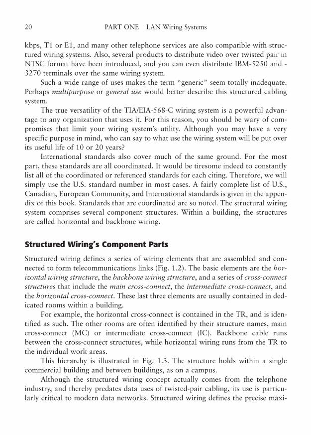
kbps, T1 or E1, and many other telephone services are also compatible with struc-tured wiring systems. Also, several products to distribute video over twisted pair inNTSC format have been introduced, and you can even distribute IBM-5250 and -3270 terminals over the same wiring system.
Such a wide range of uses makes the term “generic” seem totally inadequate.Perhaps multipurpose or general use would better describe this structured cablingsystem.
The true versatility of the TIA/EIA-568-C wiring system is a powerful advan-tage to any organization that uses it. For this reason, you should be wary of com-promises that limit your wiring system’s utility. Although you may have a veryspecific purpose in mind, who can say to what use the wiring system will be put overits useful life of 10 or 20 years?
International standards also cover much of the same ground. For the mostpart, these standards are all coordinated. It would be tiresome indeed to constantlylist all of the coordinated or referenced standards for each citing. Therefore, we willsimply use the U.S. standard number in most cases. A fairly complete list of U.S.,Canadian, European Community, and International standards is given in the appen-dix of this book. Standards that are coordinated are so noted. The structural wiringsystem comprises several component structures. Within a building, the structuresare called horizontal and backbone wiring.
Structured Wiring’s Component Parts
Structured wiring defines a series of wiring elements that are assembled and con-nected to form telecommunications links (Fig. 1.2). The basic elements are the hor-izontal wiring structure, the backbone wiring structure, and a series of cross-connectstructures that include the main cross-connect, the intermediate cross-connect, andthe horizontal cross-connect. These last three elements are usually contained in ded-icated rooms within a building.
For example, the horizontal cross-connect is contained in the TR, and is iden-tified as such. The other rooms are often identified by their structure names, maincross-connect (MC) or intermediate cross-connect (IC). Backbone cable runsbetween the cross-connect structures, while horizontal wiring runs from the TR tothe individual work areas.
This hierarchy is illustrated in Fig. 1.3. The structure holds within a singlecommercial building and between buildings, as on a campus.
Although the structured wiring concept actually comes from the telephoneindustry, and thereby predates data uses of twisted-pair cabling, its use is particu-larly critical to modern data networks. Structured wiring defines the precise maxi-
20 PART ONE LAN Wiring Systems
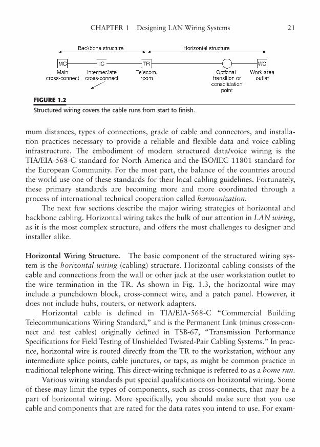
mum distances, types of connections, grade of cable and connectors, and installa-tion practices necessary to provide a reliable and flexible data and voice cablinginfrastructure. The embodiment of modern structured data/voice wiring is theTIA/EIA-568-C standard for North America and the ISO/IEC 11801 standard forthe European Community. For the most part, the balance of the countries aroundthe world use one of these standards for their local cabling guidelines. Fortunately,these primary standards are becoming more and more coordinated through aprocess of international technical cooperation called harmonization.
The next few sections describe the major wiring strategies of horizontal andbackbone cabling. Horizontal wiring takes the bulk of our attention in LAN wiring,as it is the most complex structure, and offers the most challenges to designer andinstaller alike.
Horizontal Wiring Structure. The basic component of the structured wiring sys-tem is the horizontal wiring (cabling) structure. Horizontal cabling consists of thecable and connections from the wall or other jack at the user workstation outlet tothe wire termination in the TR. As shown in Fig. 1.3, the horizontal wire mayinclude a punchdown block, cross-connect wire, and a patch panel. However, itdoes not include hubs, routers, or network adapters.
Horizontal cable is defined in TIA/EIA-568-C “Commercial BuildingTelecommunications Wiring Standard,” and is the Permanent Link (minus cross-con-nect and test cables) originally defined in TSB-67, “Transmission PerformanceSpecifications for Field Testing of Unshielded Twisted-Pair Cabling Systems.” In prac-tice, horizontal wire is routed directly from the TR to the workstation, without anyintermediate splice points, cable junctures, or taps, as might be common practice intraditional telephone wiring. This direct-wiring technique is referred to as a home run.
Various wiring standards put special qualifications on horizontal wiring. Someof these may limit the types of components, such as cross-connects, that may be apart of horizontal wiring. More specifically, you should make sure that you usecable and components that are rated for the data rates you intend to use. For exam-
CHAPTER 1 Designing LAN Wiring Systems 21
FIGURE 1.2
Structured wiring covers the cable runs from start to finish.
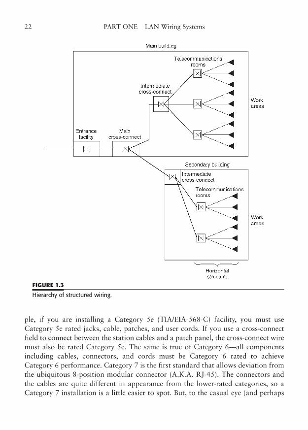
ple, if you are installing a Category 5e (TIA/EIA-568-C) facility, you must useCategory 5e rated jacks, cable, patches, and user cords. If you use a cross-connectfield to connect between the station cables and a patch panel, the cross-connect wiremust also be rated Category 5e. The same is true of Category 6—all componentsincluding cables, connectors, and cords must be Category 6 rated to achieveCategory 6 performance. Category 7 is the first standard that allows deviation fromthe ubiquitous 8-position modular connector (A.K.A. RJ-45). The connectors andthe cables are quite different in appearance from the lower-rated categories, so aCategory 7 installation is a little easier to spot. But, to the casual eye (and perhaps
22 PART ONE LAN Wiring Systems
FIGURE 1.3
Hierarchy of structured wiring.
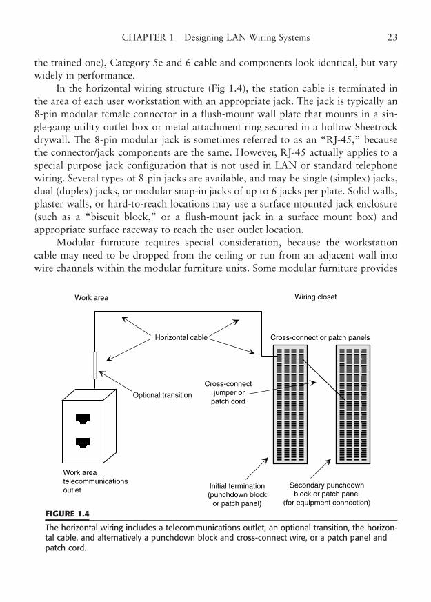
the trained one), Category 5e and 6 cable and components look identical, but varywidely in performance.
In the horizontal wiring structure (Fig 1.4), the station cable is terminated inthe area of each user workstation with an appropriate jack. The jack is typically an8-pin modular female connector in a flush-mount wall plate that mounts in a sin-gle-gang utility outlet box or metal attachment ring secured in a hollow Sheetrockdrywall. The 8-pin modular jack is sometimes referred to as an “RJ-45,” becausethe connector/jack components are the same. However, RJ-45 actually applies to aspecial purpose jack configuration that is not used in LAN or standard telephonewiring. Several types of 8-pin jacks are available, and may be single (simplex) jacks,dual (duplex) jacks, or modular snap-in jacks of up to 6 jacks per plate. Solid walls,plaster walls, or hard-to-reach locations may use a surface mounted jack enclosure(such as a “biscuit block,” or a flush-mount jack in a surface mount box) andappropriate surface raceway to reach the user outlet location.
Modular furniture requires special consideration, because the workstationcable may need to be dropped from the ceiling or run from an adjacent wall intowire channels within the modular furniture units. Some modular furniture provides
CHAPTER 1 Designing LAN Wiring Systems 23
Optional transition
Initial termination(punchdown block
or patch panel)
Secondary punchdownblock or patch panel
(for equipment connection)
Work areatelecommunicationsoutlet
Horizontal cable
Cross-connect jumper orpatch cord
Work area Wiring closet
Cross-connect or patch panels
FIGURE 1.4
The horizontal wiring includes a telecommunications outlet, an optional transition, the horizon-tal cable, and alternatively a punchdown block and cross-connect wire, or a patch panel andpatch cord.
special channels for telephone and computer wiring that is separated from the ACpower wiring channels. Caution should be used when sharing the power wiringchannel with data cabling. Not only is there a potential safety concern from havingthe LAN wire so close to power wire voltages, but there may be performance prob-lems, particularly for Category 5e performance. Some guidelines specify a 2-in ormore separation from power wires, while others specify a greater distance. In addi-tion, local and national installation codes generally prohibit low-voltage wiringfrom being installed in the same conduit as power wires. Some local authorities mayconsider the open wiring channels of modular furniture to be in fact a conduit andtherefore subject to this rule. Modular channels with a divider avoid this problem.
Horizontal wiring is specified according to performance categories defined inTIA/EIA-568-C. Both cable and connecting hardware (jacks and plugs) must meetperformance guidelines appropriate for their use. Not all cable or components meetthe minimum standards required for LAN use.
One of the factors affecting performance in outlet jacks is the method of wiretermination. The station cable connects to the jack by means of either screw termi-nals or some sort of insulation-displacement termination. Screw terminations wereacceptable in Category 3 installations, but are prohibited in Category 5e or 6 instal-lations, because of performance constraints. Category 3 is adequate for 10- or 16-MHz bandwidth networks, Category 4 for 20 MHz, and Category 5e for 100 MHz.For the most part, no networks require Category 4 specifications, although it wasused if you desired a “high-grade” Category 3 installation. Some references suggestCategory 4 for Token-Ring networks, but the legacy standards required onlyCategory 3. Category 5e is now the minimum specification.
Insulation-displacement terminations use a split metal contact upon which theinsulated wire is forced, thereby cutting through the insulation and making metal-to-metal contact with the copper wire. Several types of insulation-displacement connec-tors (IDCs) exist, including modular snap-together IDC jacks, modular 110-type IDCjacks, and older 66-type IDC jack plates. Except for the 66-type jacks, all are com-monly available in models that are certified to Category 5e performance standards.
Category 5e 66-blocks do exist, but the installer may have difficulty maintain-ing the required twist all the way to the termination point.
From the workstation outlet jack, the horizontal station cable is run to the des-ignated wiring closet. This cable run is designed to be within (possibly well within)the 90 m maximum specified by the standards. It may be routed with other individ-ual station cables in wiring trays, through support rings over support beams orframes, through firewalls, or even in conduit. If you have special performance crite-ria, such as Category 5e or 6, you should take precautions to avoid fluorescent lightbaluns (the transformer in each light fixture), electrical wiring, heavy equipment
24 PART ONE LAN Wiring Systems
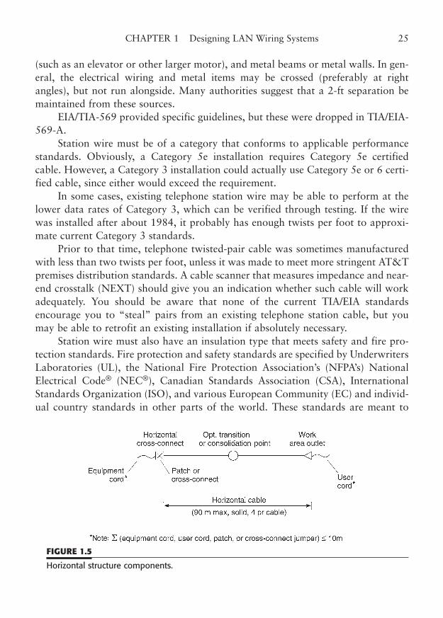
(such as an elevator or other larger motor), and metal beams or metal walls. In gen-eral, the electrical wiring and metal items may be crossed (preferably at rightangles), but not run alongside. Many authorities suggest that a 2-ft separation bemaintained from these sources.
EIA/TIA-569 provided specific guidelines, but these were dropped in TIA/EIA-569-A.
Station wire must be of a category that conforms to applicable performancestandards. Obviously, a Category 5e installation requires Category 5e certifiedcable. However, a Category 3 installation could actually use Category 5e or 6 certi-fied cable, since either would exceed the requirement.
In some cases, existing telephone station wire may be able to perform at thelower data rates of Category 3, which can be verified through testing. If the wirewas installed after about 1984, it probably has enough twists per foot to approxi-mate current Category 3 standards.
Prior to that time, telephone twisted-pair cable was sometimes manufacturedwith less than two twists per foot, unless it was made to meet more stringent AT&Tpremises distribution standards. A cable scanner that measures impedance and near-end crosstalk (NEXT) should give you an indication whether such cable will workadequately. You should be aware that none of the current TIA/EIA standardsencourage you to “steal” pairs from an existing telephone station cable, but youmay be able to retrofit an existing installation if absolutely necessary.
Station wire must also have an insulation type that meets safety and fire pro-tection standards. Fire protection and safety standards are specified by UnderwritersLaboratories (UL), the National Fire Protection Association’s (NFPA’s) NationalElectrical Code® (NEC®), Canadian Standards Association (CSA), InternationalStandards Organization (ISO), and various European Community (EC) and individ-ual country standards in other parts of the world. These standards are meant to
CHAPTER 1 Designing LAN Wiring Systems 25
FIGURE 1.5
Horizontal structure components.
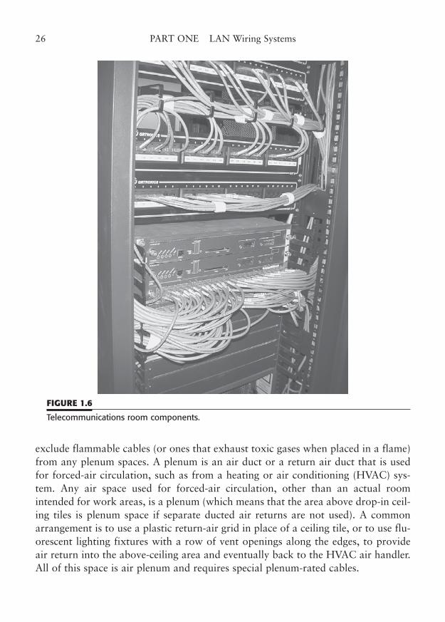
exclude flammable cables (or ones that exhaust toxic gases when placed in a flame)from any plenum spaces. A plenum is an air duct or a return air duct that is usedfor forced-air circulation, such as from a heating or air conditioning (HVAC) sys-tem. Any air space used for forced-air circulation, other than an actual roomintended for work areas, is a plenum (which means that the area above drop-in ceil-ing tiles is plenum space if separate ducted air returns are not used). A commonarrangement is to use a plastic return-air grid in place of a ceiling tile, or to use flu-orescent lighting fixtures with a row of vent openings along the edges, to provideair return into the above-ceiling area and eventually back to the HVAC air handler.All of this space is air plenum and requires special plenum-rated cables.
26 PART ONE LAN Wiring Systems
FIGURE 1.6
Telecommunications room components.
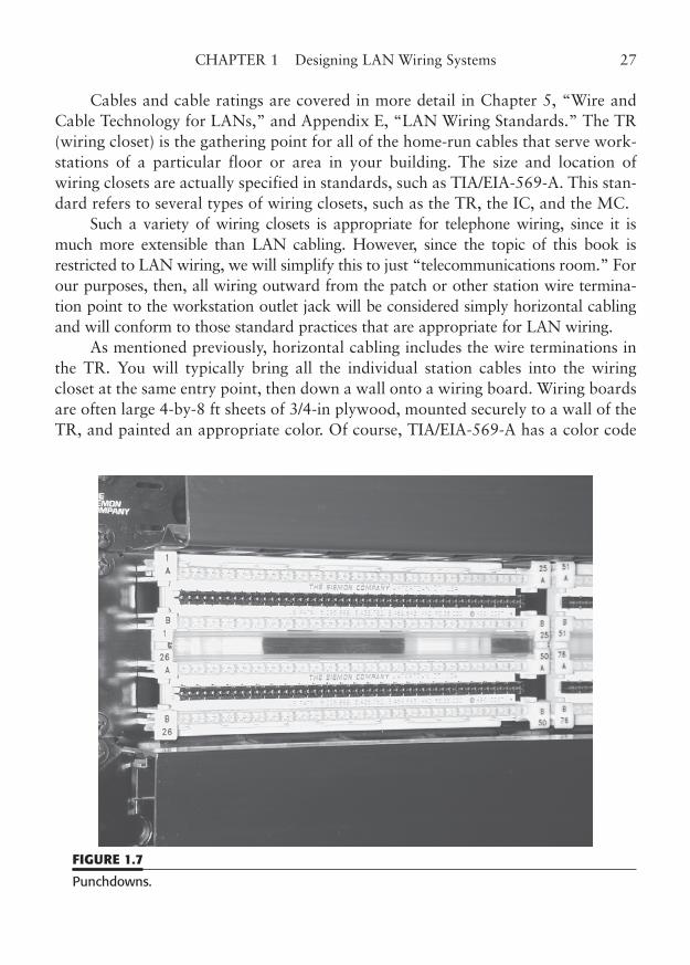
Cables and cable ratings are covered in more detail in Chapter 5, “Wire andCable Technology for LANs,” and Appendix E, “LAN Wiring Standards.” The TR(wiring closet) is the gathering point for all of the home-run cables that serve work-stations of a particular floor or area in your building. The size and location ofwiring closets are actually specified in standards, such as TIA/EIA-569-A. This stan-dard refers to several types of wiring closets, such as the TR, the IC, and the MC.
Such a variety of wiring closets is appropriate for telephone wiring, since it ismuch more extensible than LAN cabling. However, since the topic of this book isrestricted to LAN wiring, we will simplify this to just “telecommunications room.” Forour purposes, then, all wiring outward from the patch or other station wire termina-tion point to the workstation outlet jack will be considered simply horizontal cablingand will conform to those standard practices that are appropriate for LAN wiring.
As mentioned previously, horizontal cabling includes the wire terminations inthe TR. You will typically bring all the individual station cables into the wiringcloset at the same entry point, then down a wall onto a wiring board. Wiring boardsare often large 4-by-8 ft sheets of 3/4-in plywood, mounted securely to a wall of theTR, and painted an appropriate color. Of course, TIA/EIA-569-A has a color code
CHAPTER 1 Designing LAN Wiring Systems 27
FIGURE 1.7
Punchdowns.
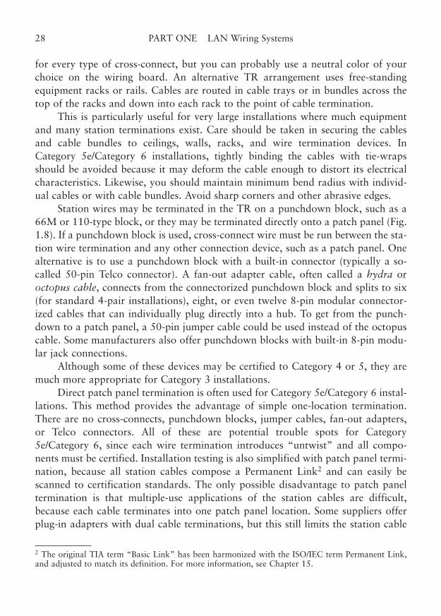
for every type of cross-connect, but you can probably use a neutral color of yourchoice on the wiring board. An alternative TR arrangement uses free-standingequipment racks or rails. Cables are routed in cable trays or in bundles across thetop of the racks and down into each rack to the point of cable termination.
This is particularly useful for very large installations where much equipmentand many station terminations exist. Care should be taken in securing the cablesand cable bundles to ceilings, walls, racks, and wire termination devices. InCategory 5e/Category 6 installations, tightly binding the cables with tie-wrapsshould be avoided because it may deform the cable enough to distort its electricalcharacteristics. Likewise, you should maintain minimum bend radius with individ-ual cables or with cable bundles. Avoid sharp corners and other abrasive edges.
Station wires may be terminated in the TR on a punchdown block, such as a66M or 110-type block, or they may be terminated directly onto a patch panel (Fig.1.8). If a punchdown block is used, cross-connect wire must be run between the sta-tion wire termination and any other connection device, such as a patch panel. Onealternative is to use a punchdown block with a built-in connector (typically a so-called 50-pin Telco connector). A fan-out adapter cable, often called a hydra oroctopus cable, connects from the connectorized punchdown block and splits to six(for standard 4-pair installations), eight, or even twelve 8-pin modular connector-ized cables that can individually plug directly into a hub. To get from the punch-down to a patch panel, a 50-pin jumper cable could be used instead of the octopuscable. Some manufacturers also offer punchdown blocks with built-in 8-pin modu-lar jack connections.
Although some of these devices may be certified to Category 4 or 5, they aremuch more appropriate for Category 3 installations.
Direct patch panel termination is often used for Category 5e/Category 6 instal-lations. This method provides the advantage of simple one-location termination.There are no cross-connects, punchdown blocks, jumper cables, fan-out adapters,or Telco connectors. All of these are potential trouble spots for Category5e/Category 6, since each wire termination introduces “untwist” and all compo-nents must be certified. Installation testing is also simplified with patch panel termi-nation, because all station cables compose a Permanent Link2 and can easily bescanned to certification standards. The only possible disadvantage to patch paneltermination is that multiple-use applications of the station cables are difficult,because each cable terminates into one patch panel location. Some suppliers offerplug-in adapters with dual cable terminations, but this still limits the station cable
28 PART ONE LAN Wiring Systems
2 The original TIA term “Basic Link” has been harmonized with the ISO/IEC term Permanent Link,and adjusted to match its definition. For more information, see Chapter 15.
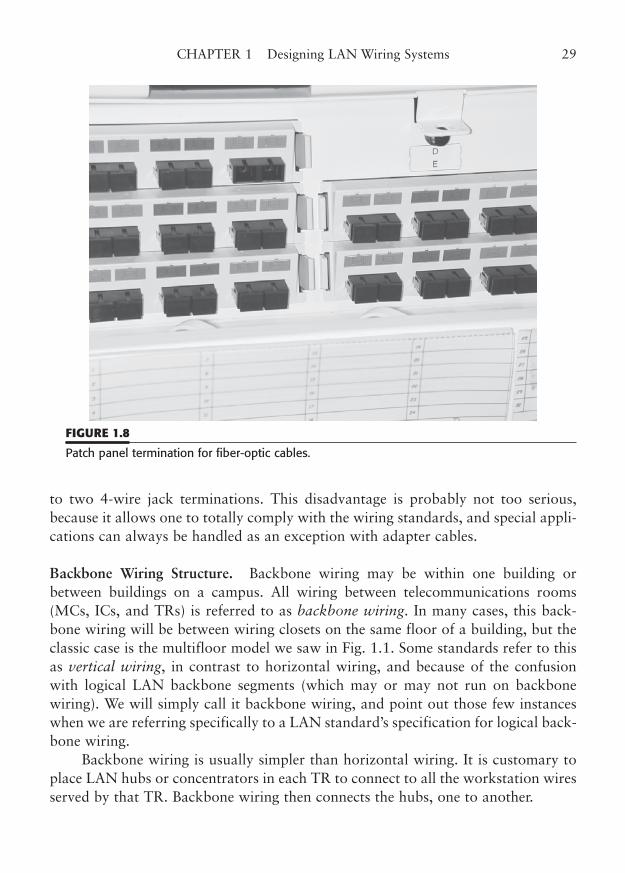
to two 4-wire jack terminations. This disadvantage is probably not too serious,because it allows one to totally comply with the wiring standards, and special appli-cations can always be handled as an exception with adapter cables.
Backbone Wiring Structure. Backbone wiring may be within one building orbetween buildings on a campus. All wiring between telecommunications rooms(MCs, ICs, and TRs) is referred to as backbone wiring. In many cases, this back-bone wiring will be between wiring closets on the same floor of a building, but theclassic case is the multifloor model we saw in Fig. 1.1. Some standards refer to thisas vertical wiring, in contrast to horizontal wiring, and because of the confusionwith logical LAN backbone segments (which may or may not run on backbonewiring). We will simply call it backbone wiring, and point out those few instanceswhen we are referring specifically to a LAN standard’s specification for logical back-bone wiring.
Backbone wiring is usually simpler than horizontal wiring. It is customary toplace LAN hubs or concentrators in each TR to connect to all the workstation wiresserved by that TR. Backbone wiring then connects the hubs, one to another.
CHAPTER 1 Designing LAN Wiring Systems 29
FIGURE 1.8
Patch panel termination for fiber-optic cables.
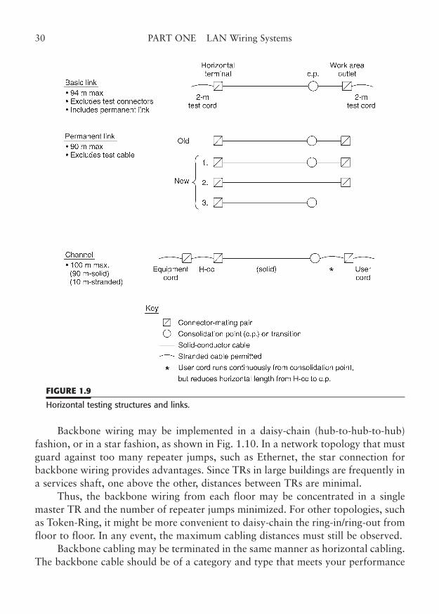
Backbone wiring may be implemented in a daisy-chain (hub-to-hub-to-hub)fashion, or in a star fashion, as shown in Fig. 1.10. In a network topology that mustguard against too many repeater jumps, such as Ethernet, the star connection forbackbone wiring provides advantages. Since TRs in large buildings are frequently ina services shaft, one above the other, distances between TRs are minimal.
Thus, the backbone wiring from each floor may be concentrated in a singlemaster TR and the number of repeater jumps minimized. For other topologies, suchas Token-Ring, it might be more convenient to daisy-chain the ring-in/ring-out fromfloor to floor. In any event, the maximum cabling distances must still be observed.
Backbone cabling may be terminated in the same manner as horizontal cabling.The backbone cable should be of a category and type that meets your performance
30 PART ONE LAN Wiring Systems
FIGURE 1.9
Horizontal testing structures and links.
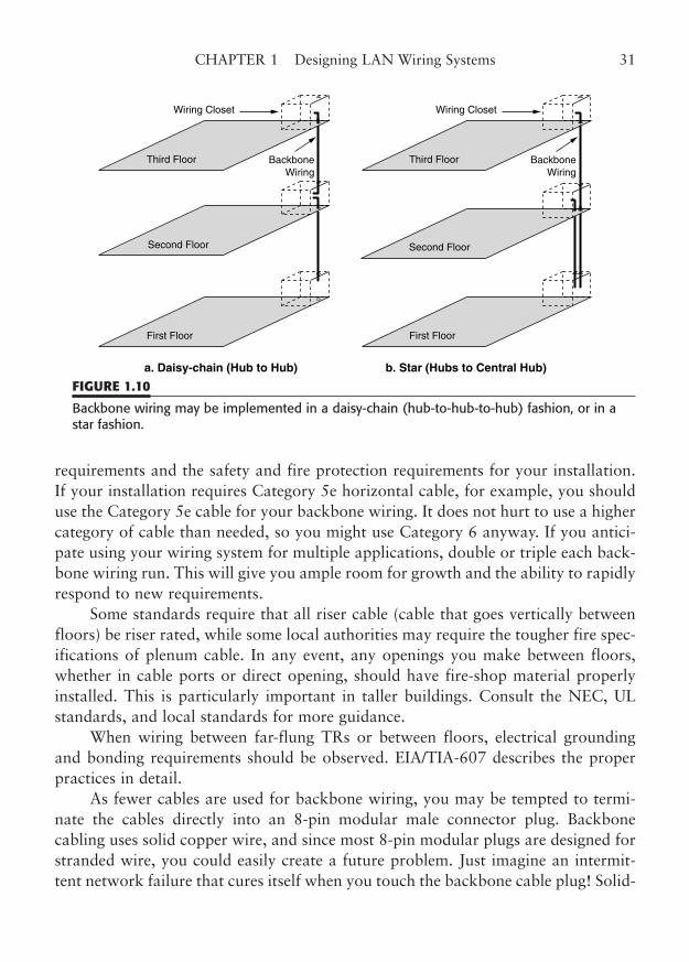
requirements and the safety and fire protection requirements for your installation.If your installation requires Category 5e horizontal cable, for example, you shoulduse the Category 5e cable for your backbone wiring. It does not hurt to use a highercategory of cable than needed, so you might use Category 6 anyway. If you antici-pate using your wiring system for multiple applications, double or triple each back-bone wiring run. This will give you ample room for growth and the ability to rapidlyrespond to new requirements.
Some standards require that all riser cable (cable that goes vertically betweenfloors) be riser rated, while some local authorities may require the tougher fire spec-ifications of plenum cable. In any event, any openings you make between floors,whether in cable ports or direct opening, should have fire-shop material properlyinstalled. This is particularly important in taller buildings. Consult the NEC, ULstandards, and local standards for more guidance.
When wiring between far-flung TRs or between floors, electrical groundingand bonding requirements should be observed. EIA/TIA-607 describes the properpractices in detail.
As fewer cables are used for backbone wiring, you may be tempted to termi-nate the cables directly into an 8-pin modular male connector plug. Backbonecabling uses solid copper wire, and since most 8-pin modular plugs are designed forstranded wire, you could easily create a future problem. Just imagine an intermit-tent network failure that cures itself when you touch the backbone cable plug! Solid-
CHAPTER 1 Designing LAN Wiring Systems 31
a. Daisy-chain (Hub to Hub) b. Star (Hubs to Central Hub)
BackboneWiring
BackboneWiring
Wiring Closet
Third Floor
Second Floor
First Floor
Wiring Closet
Third Floor
Second Floor
First Floor
FIGURE 1.10
Backbone wiring may be implemented in a daisy-chain (hub-to-hub-to-hub) fashion, or in astar fashion.
wire 8-in modular connectors are certainly available, but they are impossible to dis-tinguish without close examination, and most installers recommend against theiruse. A better approach is to simply use the same patch panel or punchdown that ter-minates the station cables to terminate the backbone cables. Mark the backbonecable patch position clearly to differentiate it.
You may wish to more clearly identify backbone wiring by using cable colors,cross-connect/patch panel colors, and special markings. These colors and markings,identified in EIA/TIA-569-A, are covered in later chapters.
If your backbone wiring actually involves floor-to-floor cabling in verticalshafts or cable ports, you may need to use special riser cable that has a fire-retar-dant sheath, certified to meet NEC low-flame requirements.
The NEC requires that riser cable meets UL flammability tests to be used inhigh-rise buildings. Local regulations may supplement or amend these requirements.Local building inspectors should be able to advise you about the requirements inyour area.
As a last word on backbone wiring, fiber-optic cable may provide some signif-icant advantages over copper. Fiber-optic cable is not subject to electrical or mag-netic interference, and thus may be run in locations, such as elevator shafts oralongside power lines, that would cause problems for metallic cable. In addition, acabling system may be electrically isolated between buildings or between floors ofthe same building by using fiber-optic cable. Metallic cable, on the other hand, mustbe carefully installed with adequate consideration of grounding and bonding.
Fiber-optic cable may also be used for multiple applications with the use offiber optic multiplexers (WDM, wave-division multiplexing). Thus, it would be pos-sible for one fiber-optic connection to carry Ethernet, Token-Ring, T1, ATM, andFDDI all at the same time. Fiber-optic cabling must meet the same plenum and riserspecifications as metallic cable.
Location and Routing. The importance of location and routing of your cablingsystem components depends upon the level of cable facility that you intend toinstall.
Category 3 installations have much more flexibility in routing than Category5e/Category 6 installations. For networks that must provide 100 to 1000 Mbpsspeeds, and have horizontal runs that approach the 90 m limit, you must be veryattentive to installation details. Location and routing of the station cables are criti-cal to high-performance operation.
TRs should be located so that they are within 90 m “as the cable runs” fromthe proposed workstation outlets that are to be served. In some cases, the number ofTRs may have to be increased or relocated to stay below this distance. A scaled plan
32 PART ONE LAN Wiring Systems
drawing should be prepared and cable runs planned out and measured (on the draw-ing) to be certain. Allow an extra 3.5 to 5 m for each vertical drop from the ceilingto the wall outlet and 2 to 3.5 m for the drop from the ceiling to the patch panel.Remember that the vertical drop must start well above the ceiling grid, because rulesforbid placing the wire directly on the ceiling grid. If your patch panel is not wall-mounted, allow additional distance for the cable run to the rack or cabinet.
Remember also that cable is normally run at right angles on the wiring boardor in the rack. It is amazing how much extra cable all of these right angles require.
EIA/TIA-569-A specifies the minimum size and suggested locations for“telecommunication spaces” such as TRs. It would be ideal if you could adhere tothose standards, but some buildings may not allow such luxuries. Keep in mind thatthe network managers and technicians need to have quick and easy access to thepatches and hubs in the TRs. If you absolutely must share space, place the wire ter-mination point in a corner of the room that will not be blocked by storage or officeequipment. Place it at an easily reachable level where there is adequate light, venti-lation, and power. Several manufacturers make wall-mounted cabinets that concealand protect your wiring and hubs.
All LAN cables should be routed away from potential sources of interference.Avoid fluorescent lights, motors, pipes, structural steel, and power lines. TheNational Electrical Code®, TIA/EIA-568-C, and ancillary documents specify theseparation distances, both for safety and for interference. With the exception of flu-orescent lights and electric motors, most interfering conductors can be crossed atright angles, but you should still maintain a minimum separation for safety reasons.
Some authorities advocate direct physical support Category 5e/Category 6LAN cables. This requires the use of cable trays, ducts, cable hangers, or conduit forthe entire route of each cable. In many situations, these extensive precautions aresimply impossible or cost-prohibitive.
However, in large buildings with suspended ceiling grids, it may be desirable touse a cable tray routing system to help organize and protect the LAN cable. The keyelement is to eliminate any deformation in the insulation or twist integrity of thecable. That generally means that you must avoid long unsupported spans of wire,sharp bends, kinks, binds, nicks, and tight tie-wraps.
A Structured Cabling Design Example
To illustrate a basic data-only wiring system design, we will show a cabling plan fora simple two-story building using the concepts we have covered in this chapter.
Our example will have 24 workstations per floor. We will use Category 5especifications, direct patch panel termination, and will have one TR per floor. We
CHAPTER 1 Designing LAN Wiring Systems 33
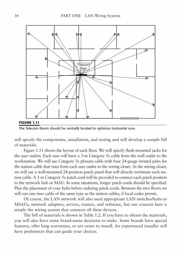
will specify the components, installation, and testing and will develop a sample billof materials.
Figure 1.11 shows the layout of each floor. We will specify flush-mounted jacks forthe user outlets. Each user will have a 3-m Category 5e cable from the wall outlet to theworkstation. We will use Category 5e plenum cable with four 24-gauge twisted pairs forthe station cable that runs from each user outlet to the wiring closet. At the wiring closet,we will use a wall-mounted 24-position patch panel that will directly terminate each sta-tion cable. A 1-m Category 5e patch cord will be provided to connect each patch positionto the network hub or MAU. In some situations, longer patch cords should be specified.Plan the placement of your hubs before ordering patch cords. Between the two floors wewill run one riser cable of the same type as the station cables, if local codes permit.
Of course, the LAN network will also need appropriate LAN switches/hubs orMSAUs, network adapters, servers, routers, and software, but our concern here issimply the wiring system that connects all these devices.
The bill of materials is shown in Table 1.2. If you have to obtain the materials,you will also have some brand-name decisions to make. Some brands have specialfeatures, offer long warranties, or are easier to install. An experienced installer willhave preferences that can guide your choices.
34 PART ONE LAN Wiring Systems
TelecomRoom
FIGURE 1.11
The Telecom Room should be centrally located to optimize horizontal runs.
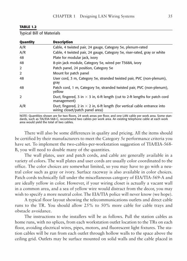
There will also be some differences in quality and pricing. All the items shouldbe certified by their manufacturers to meet the Category 5e performance criteria youhave set. To implement the two-cables-per-workstation suggestion of TIA/EIA-568-B, you will need to double many of the quantities.
The wall plates, user and patch cords, and cable are generally available in avariety of colors. The wall plates and user cords are usually color coordinated to theoffice. The color choices are somewhat limited, so you may have to go with a neu-tral color such as gray or ivory. Surface raceway is also available in color choices.Patch cords technically fall under the miscellaneous category of EIA/TIA-569-A andare ideally yellow in color. However, if your wiring closet is actually a vacant wallin a common area, and a sea of yellow wire would distract from the decor, you maywish to specify a more neutral color. The EIA/TIA police will never know (we hope).
A typical floor layout showing the telecommunications outlets and direct cableruns to the TR. You should allow 25% to 50% more cable for cable trays andobstacle avoidance.
The instructions to the installers will be as follows. Pull the station cables ashome runs, with no splices, from each workstation outlet location to the TRs on eachfloor, avoiding electrical wires, pipes, motors, and fluorescent light fixtures. The sta-tion cables will be run from each outlet through hollow walls to the space above theceiling grid. Outlets may be surface mounted on solid walls and the cable placed in
CHAPTER 1 Designing LAN Wiring Systems 35
TABLE 1.2
Typical Bill of Materials
Quantity DescriptionA/R Cable, 4 twisted pair, 24 gauge, Category 5e, plenum-rated A/R Cable, 4 twisted pair, 24 gauge, Category 5e, riser-rated, gray or white 48 Plate for modular jack, ivory 48 8-pin jack module, Category 5e, wired per T568A, ivory 2 Patch panel, 24 position, Category 5e 2 Mount for patch panel 48 User cord, 3 m, Category 5e, stranded twisted pair, PVC (non-plenum),
gray 48 Patch cord, 1 m, Category 5e, stranded twisted pair, PVC (non-plenum),
yellow2 Duct, fingered, 3 in � 3 in, 6-ft length (cut to 2-ft lengths for patch cord
management)A/R Duct, fingered, 2 in � 2 in, 6-ft length (for vertical cable entrance into
wiring closet/patch panel area)
NOTE: Quantities shown are for two floors, 24 work areas per floor, and one LAN cable per work area. Some stan-dards, such as TIA/EIA-568-C, recommend two cables per work area. An existing telephone cable at each workarea would yield the total of two cables.
surface conduit to reach the area above the ceiling grid. Cables should be run sup-ported as much as possible with no tight tie-wraps, no kinks, and respecting the min-imum bend radius for Category 5e (approximately four times the cable diameter).
Cable runs must not exceed 90 m from outlet to patch. The patches should bemounted at a convenient height on the wall of each wiring closet with adequate sup-port for the cable bundle and no tight tie-wraps.
The riser cable should be run in an existing cable port in a vertical shaft or util-ity area, if possible. Fire stopping material should be placed where the riser cableruns between floors.
The cable pairs should be wired using the T568A pattern of TIA/EIA-568-C.Proper workmanship standards should be observed, including the minimum twiststandard for connecting Category 5e cable. After installation, each station cableconnection should be scanned from outlet to patch with a Category 5e cable scan-ner that complies with TIA/EIA-568-C. If a cable run is near the 90-m maximumlength, the entire channel should be scanned, including the patch and user cords thatare to be used for the workstation connection. A printed report will be provided,including a plan diagram showing the numbering of all outlets. All cables, outlets,and patch panels are to be marked in accordance with EIA/TIA-606.
Well, that pretty much covers an ideal, concise wiring system specification. Youcould mention a few more standards, if you wish. As you will see in later chapters,there are quite a number of standards that more closely define your installation.Keep in mind that most of these standards are voluntary and exist to makeabsolutely certain your wiring system will be up to stringent performance specifica-tions. Many of the standards overlap or are “coordinated,” so that they actually saythe same thing. Too much reference to standards may actually raise the price of yourinstallation. Some of the standards are overkill for small simple networks. Forexample, it is doubtful that you could make use of half the detailed marking speci-fications in a 10- or 20-user network.
However, if you are planning a 1000- or 2000-user wiring system, adherenceto the marking standard will be extremely useful. Likewise, the color codes and eventhe routing guidelines may be less significant for smaller networks with shorter runs.You will have to be the judge. The standards do not imply that your network willfail if you do not observe all the guidelines; they simply say that it will work at thespecified performance category if you do.
Advances in LAN Wiring Technology
Many exciting advances have occurred in the art and practice of LAN wiring. As wehave learned more about the operation of our cabling system, both copper and fiber,
36 PART ONE LAN Wiring Systems
at advanced frequencies and data rates, we have been able to further refine thecabling components. These refinements have added orders of magnitude to ourLAN capabilities. The norm in network copper cabling is now Category 5e, whichhas all but replaced Category 5 in the marketplace. However, the Category 6 speci-fications are out, with their operation to over 200 MHz and superior performanceat the lower frequencies, and many are already specifying Category 6 as a minimum.Category 7, with operation to 600 MHz, is close behind, with some manufacturersalready offering components that meet the presumed parameters of this technology.Copper cabling is capable of 1 Gbps operation at lowly Category 5e, with its 100MHz bandwidth. Imagine what you can do with 600 MHz cable!
In the fiber arena, multimode 62.5/125 µm fiber is now in wide use. However,the high-bandwidth needs of gigabit operation have revealed concerns with run-of-the-mill fiber, and new formulations now abound to better support gigabit speeds atreasonable distances. In addition, new 50/125 µm multimode fiber constructions arenow standardized, and many applications lend themselves to single-mode fiber. Anentire catalog of new fiber connector types is available to better support our modu-lar world. Although the fiber and connector types are not given the convenience ofthe copper world’s categories, there is nevertheless a myriad of options, with com-mensurate capabilities.
Certified training in appropriate technology is a mandatory requirement forthe network cable technician of today. The practical knowledge has become sodetailed and the installation practices have become so crucial that every personinvolved in the LAN wiring process must possess specialized education and experi-ence, as well as the corresponding credentials. In addition, every link in every LANwiring system must be rigorously tested to the proper performance specifications,whether copper or fiber (or even wireless). Wiring has progressed from “anythinggoes as long as the pattern is right” to “it works only if the components and instal-lation techniques are perfect.” Those of us who are involved in LAN wiring providethe superhighways over which the high-speed traffic of the network now ride, anda wild ride it is indeed. Over the past decade, we have seen routine network speedsmove from a mere 10 Mbps all the way up to 1 Gbps—100 times the speed. Andnow, speeds have been extended to 10 Gbps—1000 times the first commonly usedEthernet speed.
What will occur over the next decade? More of the same, no doubt! Modernnetworks often lag at 100 Mbps (remember when the same was true of 10 Mbps?).As always, there are some who rapidly push their networks to the next level, andsome who wait until network sluggishness or a major move pushes them to the nextlevel. With structured networks, as with expressways, traffic moves faster if net-work capacity is increased at the center of the network. In a typical structured net-
CHAPTER 1 Designing LAN Wiring Systems 37
work, the edges are connected at 100 Mbps, and the edge switches linked into thebackbone by gigabit links, while in the network center, the servers may be connectedby multi-gigabit links or even 10 gigabit links.
The Internet, which is the ultimate connection of many networks, is also rap-idly advancing in access speed. Corporate networks that were satisfied at 1.5Mbps/T1 speeds are now bottlenecked at less than DS-3, 45 Mbps. Metropolitancarriers are offering Ethernet over Fiber connections at 100 to 1000 Mbps, and theirpeering connections to the Internet backbone may be at or above those speeds. TheInternet itself has quickly expanded its backbone speeds, and an amazing intercon-nection between universities, called Internet2 (or Internet II), with a minimum con-nection speed of 100 Mbps and a backbone of 40 Gbps. Much like the Internetprecursor ARPANET, originally used to link university researchers and the U.S.Department of Defense, the purpose of Internet2 is to provide a reliable ultra-high-speed link between universities to assist in research, as well as to foster the develop-ment and implementation of new, higher-speed data transfer protocols. One of theseprotocols, IPV6, involves expanding the addressing scheme of IP so that eventually,practically every atom in the known world can have an Internet address. Start yourengines, lower your visor, and buckle your seat belts. The future is at hand, and youare headed there at light speed.
38 PART ONE LAN Wiring Systems
CHAPTER 2
Popular LAN Topologies
Highlights
■ Ethernet from 10 Mbps to 10 Gbps
■ Ethernet UTP pinouts
■ Ethernet fiber
■ Token-Ring
39
Copyright © 2006 by James Trulove. Click here for terms of use.
LAN topology is the logical and physical system of interconnection of devices in aLAN. In a Structured Cabling installation, we provide the “highways” to move thedata from one location to another. The topology of the LAN describes how eachdevice will interact with others, and how the sum of all devices will be intercon-nected to function as a network. An understanding of LAN topology—how thewires are hooked up—will be very useful in our discussion of LAN wiring.
In this book, we cover structured wiring suitable for many of the popular typesof LAN topologies used today. Most of the other chapters are concerned with gen-eral-use wiring devices and installation techniques that are not specific to any par-ticular LAN topology. This chapter will detail the two most popular types of LANs:Ethernet and Token-Ring. We will show several of their variations and show youhow our system of structured cables can be used for each LAN.
We will explain the wiring patterns and interconnections, called the topology,that are needed to support each type of network. We will not be covering the inti-mate details of a LAN’s protocols, as this is not our topic; we will just show youhow to connect them over Structured Cabling to make the “net work.”
If you are generally familiar with common LANs or with the Open SystemsInterface (OSI) model, you will recognize the LAN topology as Layer 1, the Physicallayer. Layer 1 is subdivided into additional layers. Part of Layer 1 comprises theactual wire, connectors, and hubs that must be connected properly for the rest ofthe protocol model to function. This wiring layer is critical to the functioning of thenetwork. If the wiring fails, the network fails. Nothing else in the protocol stackmatters. This may be held over the head of the nearest cable installer (perhaps yourown head), if it gives you any comfort (or motivation).
Most types of modern LAN topologies can be supported on the twisted-pair wiringdescribed in this book. In addition, there are a number of older, legacy topologies. Someof these legacy networks work great over twisted pairs, but many older LAN topologiesfunction on other types of wiring. Those older (in some cases, obsolete) technologies areimportant for understanding the development of modern wiring, and some may still bein use. For completeness, we will cover legacy topologies in Appendix B. Although someof these older technologies can use twisted-pair cabling, many use coax, twinax, and thelike. So, in this chapter, other than a very brief history of Ethernet cabling, we will stickto more modern shielded and unshielded twisted-pair copper, optical-fiber cabling, andthe corresponding Ethernet and Token-Ring networks that use these types of cabling.
Three Basic Topologies: Bus, Ring, and StarThe three basic types of network topologies are bus, ring, and star. Some LANs,such as Ethernet, use more than one basic type. The three topologies are illustratedin Fig. 2.1. Each topology has its advantages and disadvantages.
40 PART ONE LAN Wiring Systems
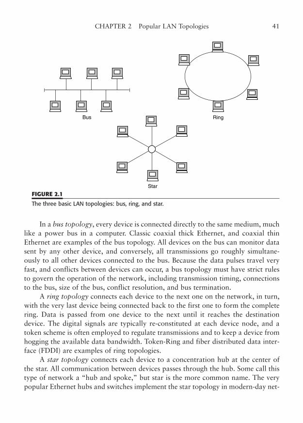
In a bus topology, every device is connected directly to the same medium, muchlike a power bus in a computer. Classic coaxial thick Ethernet, and coaxial thinEthernet are examples of the bus topology. All devices on the bus can monitor datasent by any other device, and conversely, all transmissions go roughly simultane-ously to all other devices connected to the bus. Because the data pulses travel veryfast, and conflicts between devices can occur, a bus topology must have strict rulesto govern the operation of the network, including transmission timing, connectionsto the bus, size of the bus, conflict resolution, and bus termination.
A ring topology connects each device to the next one on the network, in turn,with the very last device being connected back to the first one to form the completering. Data is passed from one device to the next until it reaches the destinationdevice. The digital signals are typically re-constituted at each device node, and atoken scheme is often employed to regulate transmissions and to keep a device fromhogging the available data bandwidth. Token-Ring and fiber distributed data inter-face (FDDI) are examples of ring topologies.
A star topology connects each device to a concentration hub at the center ofthe star. All communication between devices passes through the hub. Some call thistype of network a “hub and spoke,” but star is the more common name. The verypopular Ethernet hubs and switches implement the star topology in modern-day net-
CHAPTER 2 Popular LAN Topologies 41
Ring
Star
Bus
FIGURE 2.1
The three basic LAN topologies: bus, ring, and star.
works. As the data signal passes from any connected device to the hub or switch, aprocess called “repeating” in Ethernet reconstitutes the signal.
Some network topologies are a hybrid of the basic topologies. For example, inToken-Ring, the “ring” is normally cabled like a “star,” but the arms of the star areinterconnected at the Token-Ring hub (MSAU) in the TR so as to form the ring. Asyou can imagine, each topology and LAN standard has its fans, as well as its detrac-tors. We will stay away from that contest, except to point out when a wiring methodcan be used for several topologies.
In this chapter, we will concentrate only on current technologies includingtwisted-pair and fiber-optic Ethernet and Token-Ring. In Appendix B, we will coverthe legacy topologies and the lesser technologies, including Ethernet coax, Arcnet,100VG-AnyLAN, isochronous Ethernet, AppleTalk, Local Talk, FDDI, and ATM(as a local area networking topology, rather than a wide-area protocol). You mayencounter some of these older or less-common LAN topologies, and some of them,such as FDDI and ATM, are still in use for many applications, although none aregenerally considered for new cabling installations.
Ethernet Twisted Pair
The introduction of twisted-pair wiring into standard Ethernet networking ushered in anew age of network connectivity. For some time, frustrated users had been experiment-ing with thinnet-to-twisted-pair baluns in order to use existing telephone wire for net-work links. Several manufacturers even introduced proprietary network adapters andhubs for twisted-pair Ethernet. Eventually, a standard was fashioned, under the umbrellaof the IEEE 802.3, to deploy a new twisted pair Ethernet topology called 10BaseT.
This new standard and its higher-speed successors were very well accepted androbust, indeed. They have been so successful that they have virtually eliminated theinstallation of new 10Base5 and 10Base2 networks. The need to specify a system ofuniversal telecommunications cabling that would allow the proper operation of10BaseT (originally) gave rise to a series of new cable, wiring, and component stan-dards that eventually resulted in an industry standard called EIA/TIA-568.
Nowadays, that original 10 Mbps Ethernet is beginning to seem very slow.Ethernet networking has taken a jump first to 100 Mbps, then to 1000 Mbps (1Gbps), and now even to 10 Gbps over twisted-pair cable. Fortunately, the standardscommittees have kept pace with these developments and have released 100 Mbps,1000 Mbps, and 10 Gbps standards for network adapters, hubs, switches, cable,and wiring components.
We will cover classic copper (twisted-pair) 10BaseT topology first, because it isessentially identical to 100/1000BaseT in topology. In fact, combination network cards
42 PART ONE LAN Wiring Systems
and switches that operate at either 10 or 100 Mbps (referred to as 10/100BaseT) havebecome ubiquitous. Then we will point out the things that make 100 and 1000BaseTdifferent. Copper 10 Gbps networking, called 10GBaseT, is covered in another chapter,but it essentially is just a faster version of 1000BaseT4. Other 10-Gig copper variationsand the fiber-optic 10-Gig standards are covered in the same chapter.
10/100BaseT Networking
The 10/100BaseT (and 1000BaseT) Ethernet topology is an active star, rather thanthe Tapped Bus topology of 10Base5 and 10Base2 (see Appendix B). The operationof 100BaseT is identical to 10BaseT.1 This star topology is quite compatible withthe standard home-run method of commercial telephone-style wiring. Although theuse of existing telephone wiring was originally the goal of a twisted-pair Ethernet,the standards now recommended that special LAN-certified twisted-pair wire beused exclusively for the LAN network connection. Telephone wiring should be doneusing a separate cable to be totally in step with the standard.
10/100BaseT Hubs. A typical 10/100BaseT installation is shown in Fig. 2.2. Thecenter of the star topology is a 10/100BaseT hub. Each workstation (or server) hasa 10/100BaseT network adapter port that is connected to the hub over a twisted-pair cable. The standard specifies a maximum 90-m distance for each cable leg, plusa total of 10 m for interconnection, both at the workstation and at the hub.Modular cords, jacks, punchdowns, cross-connects, and patches are all allowed.While these wiring devices resemble their telephone counterparts, there are impor-tant differences that make them “data grade.” Some of these differences are evidentby the performance certifications needed to meet the standards for LAN wiring.
A significant difference between 10/100BaseT and Ethernet coax topologies isthe addition of an active hub device. 10/100BaseT still uses the CSMA/CD signal-ing method. Remember, with the Ethernet coax topologies, any transmission by astation is passively distributed by the coax cable to all the other connected stations.In 10/100BaseT, however, a transmission by a workstation first goes to the hub,which then repeats (retransmits) the signal to all of the other connected stations.Each port thus acts as a transceiver (repeater hop).2
CHAPTER 2 Popular LAN Topologies 43
1 In fact, most Ethernet hubs/switches today are dual 10/100 speed ports, often with a high-speed (giga-bit) uplink. All-gigabit switches are available, as well as modular switches that let you mix speeds asneeded.2 Ethernet switches do not necessarily repeat all packets received to every other port, unless it is abroadcast packet. But, for purposes of topology, each port-to-port link “counts” as a repeater hop.Switches, or switch-hubs, will be covered later in this section.
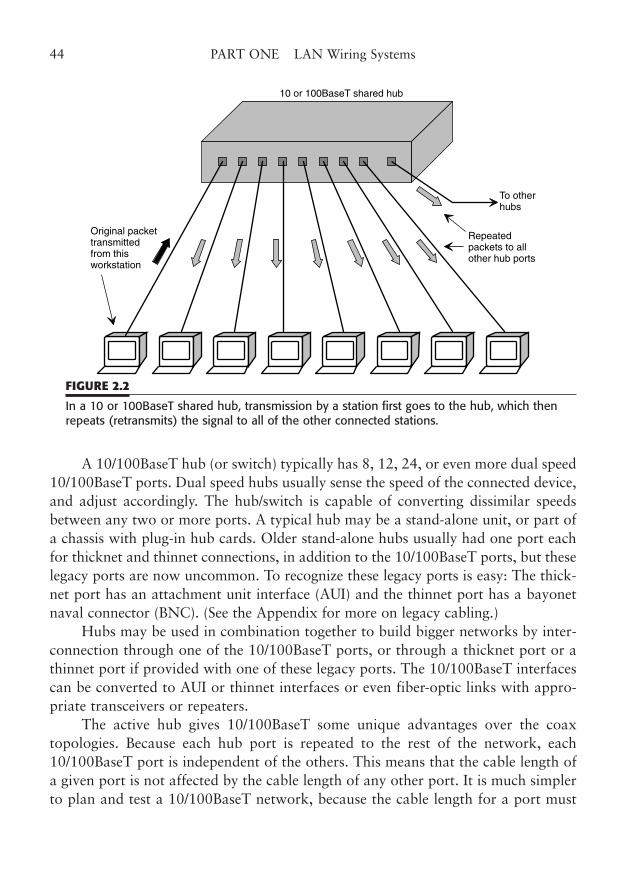
A 10/100BaseT hub (or switch) typically has 8, 12, 24, or even more dual speed10/100BaseT ports. Dual speed hubs usually sense the speed of the connected device,and adjust accordingly. The hub/switch is capable of converting dissimilar speedsbetween any two or more ports. A typical hub may be a stand-alone unit, or part ofa chassis with plug-in hub cards. Older stand-alone hubs usually had one port eachfor thicknet and thinnet connections, in addition to the 10/100BaseT ports, but theselegacy ports are now uncommon. To recognize these legacy ports is easy: The thick-net port has an attachment unit interface (AUI) and the thinnet port has a bayonetnaval connector (BNC). (See the Appendix for more on legacy cabling.)
Hubs may be used in combination together to build bigger networks by inter-connection through one of the 10/100BaseT ports, or through a thicknet port or athinnet port if provided with one of these legacy ports. The 10/100BaseT interfacescan be converted to AUI or thinnet interfaces or even fiber-optic links with appro-priate transceivers or repeaters.
The active hub gives 10/100BaseT some unique advantages over the coaxtopologies. Because each hub port is repeated to the rest of the network, each10/100BaseT port is independent of the others. This means that the cable length ofa given port is not affected by the cable length of any other port. It is much simplerto plan and test a 10/100BaseT network, because the cable length for a port must
44 PART ONE LAN Wiring Systems
10 or 100BaseT shared hub
Original packettransmittedfrom thisworkstation
To otherhubs
Repeatedpackets to allother hub ports
FIGURE 2.2
In a 10 or 100BaseT shared hub, transmission by a station first goes to the hub, which thenrepeats (retransmits) the signal to all of the other connected stations.
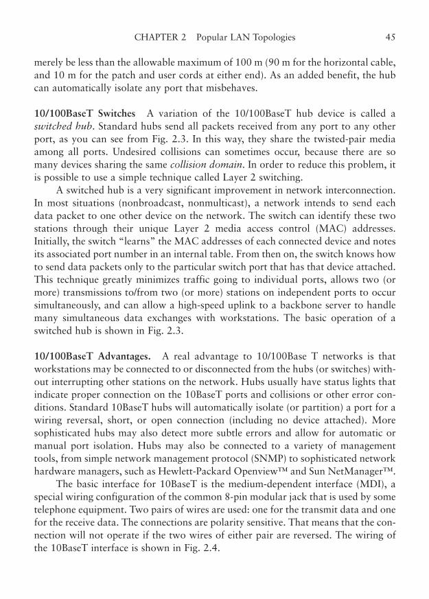
merely be less than the allowable maximum of 100 m (90 m for the horizontal cable,and 10 m for the patch and user cords at either end). As an added benefit, the hubcan automatically isolate any port that misbehaves.
10/100BaseT Switches A variation of the 10/100BaseT hub device is called aswitched hub. Standard hubs send all packets received from any port to any otherport, as you can see from Fig. 2.3. In this way, they share the twisted-pair mediaamong all ports. Undesired collisions can sometimes occur, because there are somany devices sharing the same collision domain. In order to reduce this problem, itis possible to use a simple technique called Layer 2 switching.
A switched hub is a very significant improvement in network interconnection.In most situations (nonbroadcast, nonmulticast), a network intends to send eachdata packet to one other device on the network. The switch can identify these twostations through their unique Layer 2 media access control (MAC) addresses.Initially, the switch “learns” the MAC addresses of each connected device and notesits associated port number in an internal table. From then on, the switch knows howto send data packets only to the particular switch port that has that device attached.This technique greatly minimizes traffic going to individual ports, allows two (ormore) transmissions to/from two (or more) stations on independent ports to occursimultaneously, and can allow a high-speed uplink to a backbone server to handlemany simultaneous data exchanges with workstations. The basic operation of aswitched hub is shown in Fig. 2.3.
10/100BaseT Advantages. A real advantage to 10/100Base T networks is thatworkstations may be connected to or disconnected from the hubs (or switches) with-out interrupting other stations on the network. Hubs usually have status lights thatindicate proper connection on the 10BaseT ports and collisions or other error con-ditions. Standard 10BaseT hubs will automatically isolate (or partition) a port for awiring reversal, short, or open connection (including no device attached). Moresophisticated hubs may also detect more subtle errors and allow for automatic ormanual port isolation. Hubs may also be connected to a variety of managementtools, from simple network management protocol (SNMP) to sophisticated networkhardware managers, such as Hewlett-Packard Openview™ and Sun NetManager™.
The basic interface for 10BaseT is the medium-dependent interface (MDI), aspecial wiring configuration of the common 8-pin modular jack that is used by sometelephone equipment. Two pairs of wires are used: one for the transmit data and onefor the receive data. The connections are polarity sensitive. That means that the con-nection will not operate if the two wires of either pair are reversed. The wiring ofthe 10BaseT interface is shown in Fig. 2.4.
CHAPTER 2 Popular LAN Topologies 45
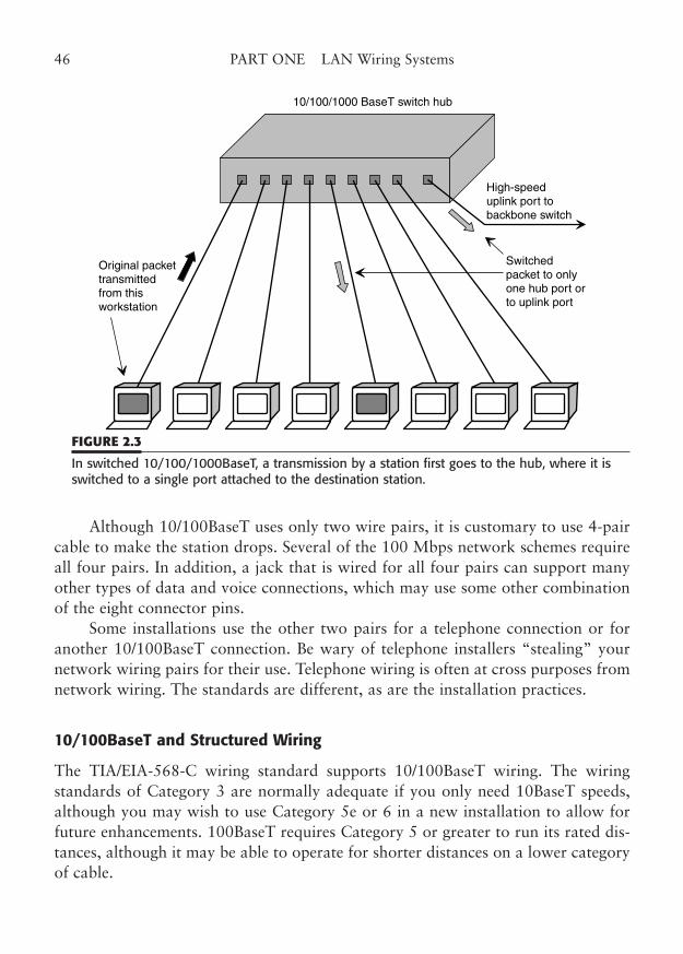
Although 10/100BaseT uses only two wire pairs, it is customary to use 4-paircable to make the station drops. Several of the 100 Mbps network schemes requireall four pairs. In addition, a jack that is wired for all four pairs can support manyother types of data and voice connections, which may use some other combinationof the eight connector pins.
Some installations use the other two pairs for a telephone connection or foranother 10/100BaseT connection. Be wary of telephone installers “stealing” yournetwork wiring pairs for their use. Telephone wiring is often at cross purposes fromnetwork wiring. The standards are different, as are the installation practices.
10/100BaseT and Structured Wiring
The TIA/EIA-568-C wiring standard supports 10/100BaseT wiring. The wiringstandards of Category 3 are normally adequate if you only need 10BaseT speeds,although you may wish to use Category 5e or 6 in a new installation to allow forfuture enhancements. 100BaseT requires Category 5 or greater to run its rated dis-tances, although it may be able to operate for shorter distances on a lower categoryof cable.
46 PART ONE LAN Wiring Systems
10/100/1000 BaseT switch hub
Original packettransmittedfrom thisworkstation
High-speeduplink port tobackbone switch
Switchedpacket to onlyone hub port orto uplink port
FIGURE 2.3
In switched 10/100/1000BaseT, a transmission by a station first goes to the hub, where it isswitched to a single port attached to the destination station.
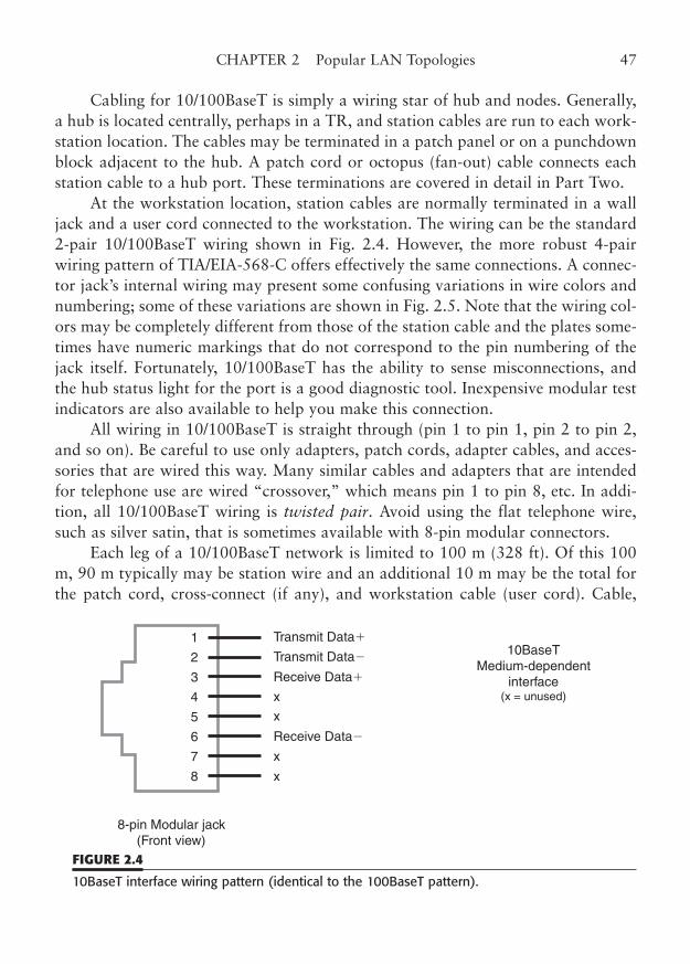
Cabling for 10/100BaseT is simply a wiring star of hub and nodes. Generally,a hub is located centrally, perhaps in a TR, and station cables are run to each work-station location. The cables may be terminated in a patch panel or on a punchdownblock adjacent to the hub. A patch cord or octopus (fan-out) cable connects eachstation cable to a hub port. These terminations are covered in detail in Part Two.
At the workstation location, station cables are normally terminated in a walljack and a user cord connected to the workstation. The wiring can be the standard2-pair 10/100BaseT wiring shown in Fig. 2.4. However, the more robust 4-pairwiring pattern of TIA/EIA-568-C offers effectively the same connections. A connec-tor jack’s internal wiring may present some confusing variations in wire colors andnumbering; some of these variations are shown in Fig. 2.5. Note that the wiring col-ors may be completely different from those of the station cable and the plates some-times have numeric markings that do not correspond to the pin numbering of thejack itself. Fortunately, 10/100BaseT has the ability to sense misconnections, andthe hub status light for the port is a good diagnostic tool. Inexpensive modular testindicators are also available to help you make this connection.
All wiring in 10/100BaseT is straight through (pin 1 to pin 1, pin 2 to pin 2,and so on). Be careful to use only adapters, patch cords, adapter cables, and acces-sories that are wired this way. Many similar cables and adapters that are intendedfor telephone use are wired “crossover,” which means pin 1 to pin 8, etc. In addi-tion, all 10/100BaseT wiring is twisted pair. Avoid using the flat telephone wire,such as silver satin, that is sometimes available with 8-pin modular connectors.
Each leg of a 10/100BaseT network is limited to 100 m (328 ft). Of this 100m, 90 m typically may be station wire and an additional 10 m may be the total forthe patch cord, cross-connect (if any), and workstation cable (user cord). Cable,
CHAPTER 2 Popular LAN Topologies 47
1
8
7
6
5
4
3
2
8-pin Modular jack(Front view)
x
Transmit Data�
Transmit Data�
x
x
x
Receive Data�
Receive Data�
10BaseTMedium-dependent
interface(x = unused)
FIGURE 2.4
10BaseT interface wiring pattern (identical to the 100BaseT pattern).
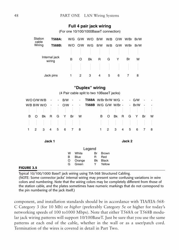
component, and installation standards should be in accordance with TIA/EIA-568-C Category 3 (for 10 Mb) or higher (preferably Category 5e or higher for today’snetworking speeds of 100 to1000 Mbps). Note that either T568A or T568B modu-lar jack wiring patterns will support 10/100BaseT. Just be sure that you use the samepatterns at each end of the cable, whether in the wall or as a user/patch cord.Termination of the wires is covered in detail in Part Two.
48 PART ONE LAN Wiring Systems
Full 4 pair jack wiring(For one 10/100/1000BaseT connection)
StationcableWiring
T568A:
T568B:
W/G
W/O
Br/W
Br/W
W/Br
W/Br
O/W
G/W
W/B
W/B
B/W
B/W
W/O
W/G
G/W
O/W
B WBrYGRBkO
1 8765432
Internal jackwiring
Jack pins
"Duplex" wiring(4 Pair cable split to two 10BaseT jacks)
W/O
W/B
B/W
O/W
W/B
W/O
O/W
B/W
B WBrYGRBkO
1 8765432
T568A
T568B
W/Br
W/G
G/W
Br/W
-
-
W/G
W/Br
Br/W
G/W
B WBrYGRBkO
1 8765432
-
-
-
-
-
-
-
-
-
-
-
-
-
-
Jack 1 Jack 2
W WhiteB BlueO OrangeG Green
Br BrownR RedBk BlackY Yellow
Legend
FIGURE 2.5
Typical 10/100/1000 BaseT jack wiring using TIA-568 Structured Cabling.(NOTE: Some connector jacks’ internal wiring may present some confusing variations in wirecolors and numbering. Note that the wiring colors may be completely different from those ofthe station cable, and the plates sometimes have numeric markings that do not correspond tothe pin numbering of the jack itself.)
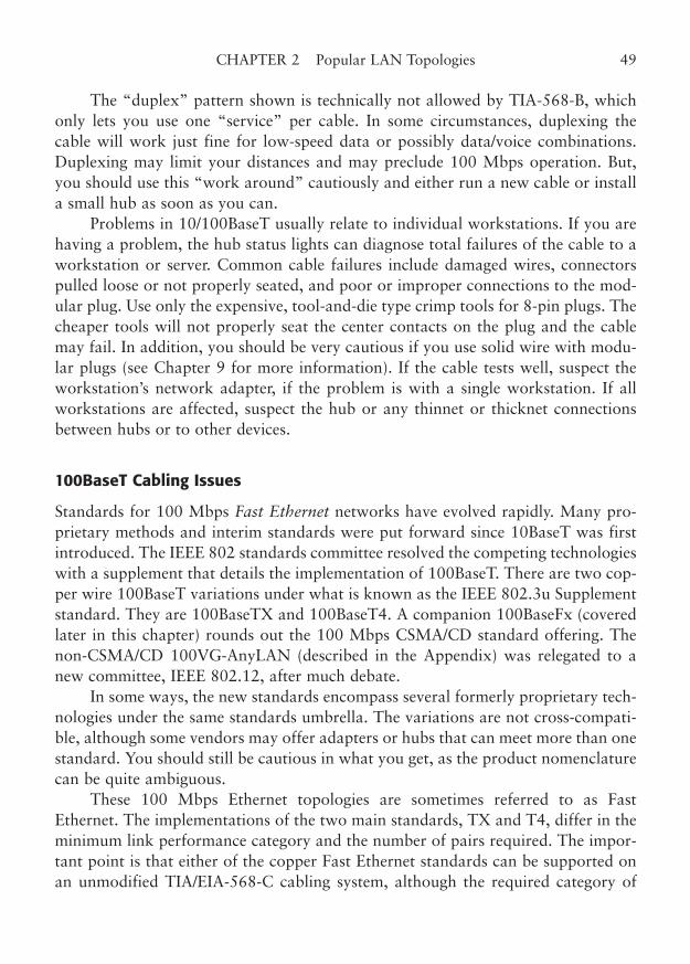
The “duplex” pattern shown is technically not allowed by TIA-568-B, whichonly lets you use one “service” per cable. In some circumstances, duplexing thecable will work just fine for low-speed data or possibly data/voice combinations.Duplexing may limit your distances and may preclude 100 Mbps operation. But,you should use this “work around” cautiously and either run a new cable or installa small hub as soon as you can.
Problems in 10/100BaseT usually relate to individual workstations. If you arehaving a problem, the hub status lights can diagnose total failures of the cable to aworkstation or server. Common cable failures include damaged wires, connectorspulled loose or not properly seated, and poor or improper connections to the mod-ular plug. Use only the expensive, tool-and-die type crimp tools for 8-pin plugs. Thecheaper tools will not properly seat the center contacts on the plug and the cablemay fail. In addition, you should be very cautious if you use solid wire with modu-lar plugs (see Chapter 9 for more information). If the cable tests well, suspect theworkstation’s network adapter, if the problem is with a single workstation. If allworkstations are affected, suspect the hub or any thinnet or thicknet connectionsbetween hubs or to other devices.
100BaseT Cabling Issues
Standards for 100 Mbps Fast Ethernet networks have evolved rapidly. Many pro-prietary methods and interim standards were put forward since 10BaseT was firstintroduced. The IEEE 802 standards committee resolved the competing technologieswith a supplement that details the implementation of 100BaseT. There are two cop-per wire 100BaseT variations under what is known as the IEEE 802.3u Supplementstandard. They are 100BaseTX and 100BaseT4. A companion 100BaseFx (coveredlater in this chapter) rounds out the 100 Mbps CSMA/CD standard offering. Thenon-CSMA/CD 100VG-AnyLAN (described in the Appendix) was relegated to anew committee, IEEE 802.12, after much debate.
In some ways, the new standards encompass several formerly proprietary tech-nologies under the same standards umbrella. The variations are not cross-compati-ble, although some vendors may offer adapters or hubs that can meet more than onestandard. You should still be cautious in what you get, as the product nomenclaturecan be quite ambiguous.
These 100 Mbps Ethernet topologies are sometimes referred to as FastEthernet. The implementations of the two main standards, TX and T4, differ in theminimum link performance category and the number of pairs required. The impor-tant point is that either of the copper Fast Ethernet standards can be supported onan unmodified TIA/EIA-568-C cabling system, although the required category of
CHAPTER 2 Popular LAN Topologies 49
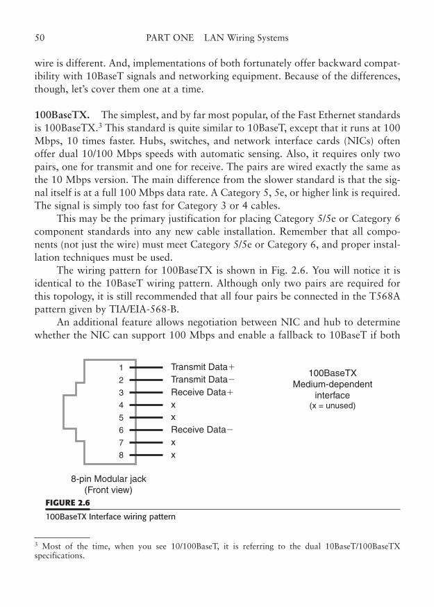
wire is different. And, implementations of both fortunately offer backward compat-ibility with 10BaseT signals and networking equipment. Because of the differences,though, let’s cover them one at a time.
100BaseTX. The simplest, and by far most popular, of the Fast Ethernet standardsis 100BaseTX.3 This standard is quite similar to 10BaseT, except that it runs at 100Mbps, 10 times faster. Hubs, switches, and network interface cards (NICs) oftenoffer dual 10/100 Mbps speeds with automatic sensing. Also, it requires only twopairs, one for transmit and one for receive. The pairs are wired exactly the same asthe 10 Mbps version. The main difference from the slower standard is that the sig-nal itself is at a full 100 Mbps data rate. A Category 5, 5e, or higher link is required.The signal is simply too fast for Category 3 or 4 cables.
This may be the primary justification for placing Category 5/5e or Category 6component standards into any new cable installation. Remember that all compo-nents (not just the wire) must meet Category 5/5e or Category 6, and proper instal-lation techniques must be used.
The wiring pattern for 100BaseTX is shown in Fig. 2.6. You will notice it isidentical to the 10BaseT wiring pattern. Although only two pairs are required forthis topology, it is still recommended that all four pairs be connected in the T568Apattern given by TIA/EIA-568-B.
An additional feature allows negotiation between NIC and hub to determinewhether the NIC can support 100 Mbps and enable a fallback to 10BaseT if both
50 PART ONE LAN Wiring Systems
3 Most of the time, when you see 10/100BaseT, it is referring to the dual 10BaseT/100BaseTX specifications.
1
8
7
6
5
4
3
2
8-pin Modular jack(Front view)
x
Transmit Data�
Transmit Data�
xx
x
Receive Data�
Receive Data�
100BaseTXMedium-dependent
interface(x = unused)
FIGURE 2.6
100BaseTX Interface wiring pattern

devices are not 100BaseT compatible. This is a real advantage if you are graduallyupgrading to 100 Mbps.
You can install dual 10/100 Mbps NIC cards in all your new workstations atrelatively little extra cost. As a matter of fact, at this time, it may be rather difficultto locate 10 Mbps-only cards. When you change your hubs to 100BaseTX, the dual-speed cards will automatically upshift to 10 times the old speed, and the link willrun at 100 Mbps.
A 100BaseTX network has some rather severe distance restrictions in a sharedhub-only environment. Because of the timing constraints of CSMA/CD, the total“radius” of the network is one-tenth the size of a 100 Mbps Ethernet network.Hubs may be linked, but only on a very short backbone of 5 m.
The hub ports (which function as repeaters) can be linked to stations by 100m of cable, which fits into the TIA-568-C limit of 90 m + 10 m nicely. This com-putes to a maximum station-to-station distance of 205 m (100 + 100 + 5). A fiberlink from a hub to a bridge, router, or switch can be up to 225 m, and a nonhubfiber link can be 450 m with CSMA/CD enabled and 2 km, disabled. These limitsencourage the use of Fast Ethernet switches. Switches, strictly speaking, are notrepeaters, but rather Layer 2 bridges, and absolve you from the tight timing limitsof hubs and repeaters.
An interesting problem exists if the environment has both 10 and 100 Mbpsstations. Any simple hub must be only one speed, either 10 or 100, because a 100Mbps station obviously could not transmit to a 10 Mbps station, without some con-version. The hub (or switch) must buffer the high-speed data packets and restrainthe higher-speed port to allow time to send the packets out at the slower data rate.
100BaseT4. Originally, for networks built to accommodate 10BaseT wire speeds,the move to 100 Mbps was a tough one. Many twisted-pair networks were installedwith Category 3 wiring standards that do not accommodate the 100BaseTX linespeed. For those installations that have installed 4-pair Category 3 cable, a standardcalled 100BaseT4 allows the operation of a 100 Mbps CSMA/CD connection overCategory 3 cable, by using all four pairs, rather than only two.
For older installations, the implications of this are enormous if you have a largeinstalled base of 10 Mbps (or 16 Mbps) users. You can selectively increase yourLAN connections to 100 Mbps without pulling new Category 5 cable. This can savea lot of money if you have a large number of terminals.
As with normal 10/100Base T, many of the suppliers of 100BaseT4 worksta-tion adapters offer dual-speed operation at 10 and 100 Mbps. The adapter automat-ically detects which speed is in operation and makes its connection at that speed.The main drawback to 100BaseT4 is its low acceptance in the market. The choices
CHAPTER 2 Popular LAN Topologies 51
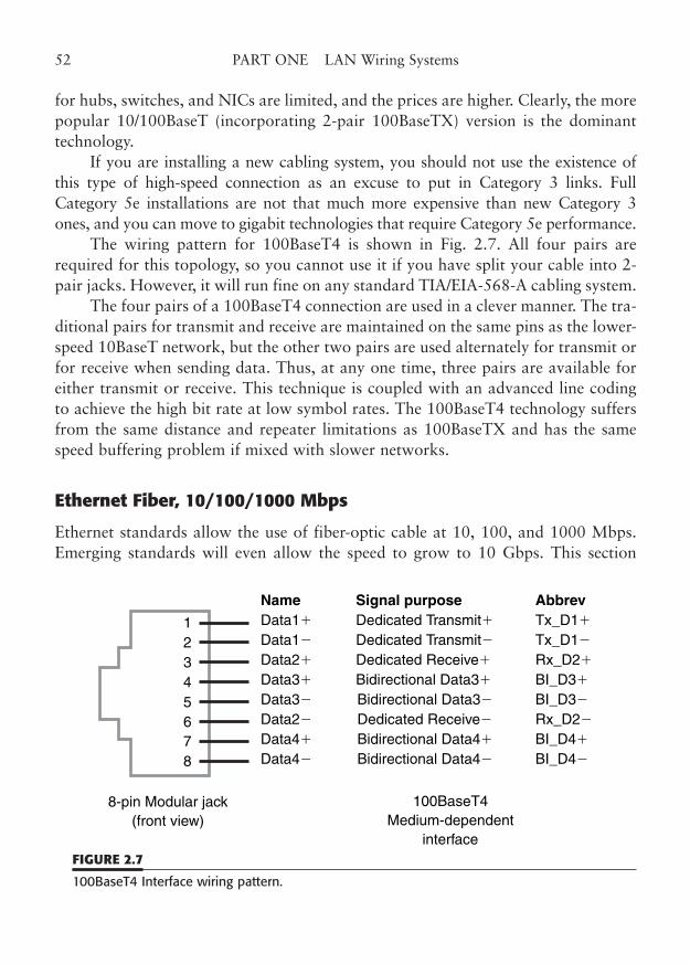
for hubs, switches, and NICs are limited, and the prices are higher. Clearly, the morepopular 10/100BaseT (incorporating 2-pair 100BaseTX) version is the dominanttechnology.
If you are installing a new cabling system, you should not use the existence ofthis type of high-speed connection as an excuse to put in Category 3 links. FullCategory 5e installations are not that much more expensive than new Category 3ones, and you can move to gigabit technologies that require Category 5e performance.
The wiring pattern for 100BaseT4 is shown in Fig. 2.7. All four pairs arerequired for this topology, so you cannot use it if you have split your cable into 2-pair jacks. However, it will run fine on any standard TIA/EIA-568-A cabling system.
The four pairs of a 100BaseT4 connection are used in a clever manner. The tra-ditional pairs for transmit and receive are maintained on the same pins as the lower-speed 10BaseT network, but the other two pairs are used alternately for transmit orfor receive when sending data. Thus, at any one time, three pairs are available foreither transmit or receive. This technique is coupled with an advanced line codingto achieve the high bit rate at low symbol rates. The 100BaseT4 technology suffersfrom the same distance and repeater limitations as 100BaseTX and has the samespeed buffering problem if mixed with slower networks.
Ethernet Fiber, 10/100/1000 Mbps
Ethernet standards allow the use of fiber-optic cable at 10, 100, and 1000 Mbps.Emerging standards will even allow the speed to grow to 10 Gbps. This section
52 PART ONE LAN Wiring Systems
1
8765432
8-pin Modular jack(front view)
100BaseT4Medium-dependent
interface
Name Signal purpose AbbrevData1� Dedicated Transmit� Tx_D1�
Data1� Dedicated Transmit� Tx_D1�
Data2� Dedicated Receive� Rx_D2�
Data3� Bidirectional Data3� BI_D3�
Data3� Bidirectional Data3� BI_D3�
Data2� Dedicated Receive� Rx_D2�
Data4� Bidirectional Data4� BI_D4�
Data4� Bidirectional Data4� BI_D4�
FIGURE 2.7
100BaseT4 Interface wiring pattern.
will briefly describe the Ethernet fiber standards. More information is contained inChapter 11.
10BaseFx Wiring
The increasing use of fiber optics to transport Ethernet signals over extended dis-tances or between buildings eventually led to the standardization of this method bythe IEEE committees. The 802.3 standard now recognizes several variations of thefiber-optic link that started out (fiber -ptic inter-repeater link (FOIRL). The replace-ment for FOIRL is known as 10BaseFL. This standard, as the original name implies,is used to interconnect repeaters, although several manufacturers have used it to linkstations as well. Additionally, supplements to the 802.3 standard have added10BaseFB and 10BaseFP.
The 10BaseFB specification is a “synchronous Ethernet” link between repeatersthat extends the limit for repeaters and segments in a single unbridged network.Normal repeaters use a portion of the preamble of the Ethernet package to distin-guish incoming data from noise and to synchronize with the data. Each repeater, ineffect, gobbles up some of these “sync” bits, which limits the number of repeaters apacket can traverse.
Remember, a repeater does not store and forward a packet, so the lost bits can-not be replaced in the outgoing signal. Synchronizing the links means that the repeatermust only distinguish data from noise and the entire preamble may be preserved.
The 10BaseFP specification is a passive star configuration for fiber optics. Thesignal is shared with other fiber arms of the star via a unique system of optical dis-tribution.
All of these 10BaseF standards use graded-index 62.5/125 µm fiber-optic cablewith two fibers per link (one for transmit and one for receive). Distance limits are 2km for 10BaseFL and 10BaseFB, and 500 m for passive star 10BaseFP. The 10BaseFxdata rates, of course, are the same 10 Mbps as copper 10BaseT, and consequentlyoffer distance and electrical isolation as the primary advantages over copper.
Active point-to-point fiber-optic links offer few problems that are not quicklyrevealed by the link status indicators. The 10BaseFP installation, however, does pres-ent the same problems as the coax copper star of Arcnet, since the hub is passive andhas no indicators. Fiber-optic links offer unique advantages such as extended trans-mission distances and immunity to interference. However, fiber is not indestructibleand may require some special handling during and after installation. For example,fiber-optic cable is susceptible to moderate to severe performance degradation froma one-time bending of the fiber below the bending minimum radius. While light maystill transfer past the microfracture, transmission loss may soar.
CHAPTER 2 Popular LAN Topologies 53
Fiber cables may also fracture when they receive a sharp impact. Fiber-opticlight sources, meters, and even optical time-domain reflectometers (OTDRs) may berequired to troubleshoot a fiber-optic installation.
Fast Ethernet 100BaseFX and SX Wiring
The 100BaseFX standard allows Ethernet transmission at 100 Mbps using multi-mode fiber at the long wavelength, 1300 nm. The 100BaseFX standard allows linksof up to 2000 m and is widely used both in high-speed fiber backbone uplinks andin campus links between buildings. The less expensive light-emitting diode (LED)transmit sources are generally used. As FX uses a different light wavelength than10BaseFL, it is not compatible or upgradable.
The 100BaseSX standard, on the other hand, uses the same short, 850 nm,wavelength that 10BaseFL uses. This allows a transceiver to be designed that canhandle either speed and allows for a gradual migration from 10 to 100 Mbps (oreven 1000 Mbps). However, the SX distance is limited to about 500 m because ofthe characteristics of multimode fiber at that wavelength.
Both 100BaseFX and 100BaseSX support the relatively short 100-m distancesof the horizontal cabling in TIA/EIA-568-C. The 100-m link is no problem to fiber,with its inherently greater signaling distances. The moderate backbone connectionsof 300 m are also easily accomplished by 100 Mbps Ethernet fiber.
Chapter 11 covers much more information on fiber-optic cabling.
Gigabit Ethernet 1000BaseSX and LX Wiring
The majority of Gigabit Ethernet cabling is done on either 1000BaseSX or 1000BaseLXstandards. As fiber was the first available technology for gigabit, it naturally has a sig-nificant installed base. However, both these gigabit fiber standards are relatively limitedin distance capability (at fiber norms). They will both easily handle the 100-m horizon-tal limit of TIA-EIA-568-C but, when used for backbone or centralized fiber, range indistance from as little as 220 m to about 550 m. Of course, these are the minimum lim-its for IEEE 802.3z, so most manufacturers exceed these distances by moderate amounts.
As with the other fiber standards, the “S” stands for the short wavelength of850 nm and is used with multimode fiber. The “L” indicates the longer wavelength,which is 1300 nm for multimode and 1310 nm for single mode fiber. As it turns out,the distance ranges for each technology also mock the S (short distance) and L(longer distance). Much more technical detail is shown in Chapter 12.
Several longer-range offerings are emerging for the extension of GigabitEthernet into large campus and metropolitan area networks. Among these are pro-
54 PART ONE LAN Wiring Systems
prietary operating modes called SLX, ELX, and ZX that extend the fiber distancesto 10, 70, and 80 km, respectively. These longer-distance Gigabit Ethernet connec-tions mean that many networking applications can use the commonly associated IPnetworking within a metro area.
10 Gigabit Ethernet 10GBaseSX, LX4, LR, and Copper 10GBaseT and CX Wiring
Who would have thought 20 years ago that we would seriously be talking abouttransmitting 10 Gbps of data over fiber-optic cable, let alone over twisted-pair cop-per? Yet, that is what we have achieved. As with any new technology, 10 GigEthernet (or 10 GbE, as the IEEE often calls it) is primarily used for high-capacitybackbones in high-performance environments. For example, the so-called backbonenetwork that interconnects large computers or large Web server networks is anapplication made for multi-gigabit connections. Although we have had multiplexedgigabit trunks for some time, there is something really sweet about a single 10-Gigconnection, like the sound when a baseball player hits one out of the park.
As with 1 GbE, 10 GbE offers choices between multimode and single-modefiber, and between unshielded twisted pair and twinax copper. Officially, the physi-cal interconnections for 10 GbE are called 10GBaseX, where the X stands for oneor two letters that describe the cabling technology. The fiber options for 10GbaseXinclude SX, LX4, and LR. Some of these run over multimode fiber (not very far),and some run over single-mode fiber (up to 10 km, which is very respectable). Aswith 1 GbE, multimode fiber’s optical bandwidth greatly influences the 10 GbEtransmission distances. And in all cases, 50-micron fiber fares much better thanolder 62.5-micron fiber. Single-mode fiber has an easier time of it, and can actuallylet you reach up to 10 km.
The basic topology of 10GBase networks is essentially the same as its slowercousins. Wiring can be run directly between two devices, or through an active-starhub or switch. Fiber still gets you the greatest distance, but you may have to replaceolder fiber types to achieve the distances you want.
Copper 10GBaseT, on the other hand, endeavors to hit the magic 100 m rangeof TIA-568-C sstructured Cabling. Unfortunately, it is unlikely you can get10GBaseT to work without a cable-plant upgrade, unless you were fortunate enoughto install an “enhanced” version of Category 6 cabling (equivalent to AugmentedClass E using the ISO/IEC 11801–European Standard that corresponds to TIA-568-C), or have very good quality Cat 5e or Cat 6 and can accept shorter distances—pos-sibly up to 55 m. Enhanced Class F (ISO/IEC 11801) and Category 7 cabling areshielded systems that can support 10GBaseT fairly easily, which certainly throws
CHAPTER 2 Popular LAN Topologies 55
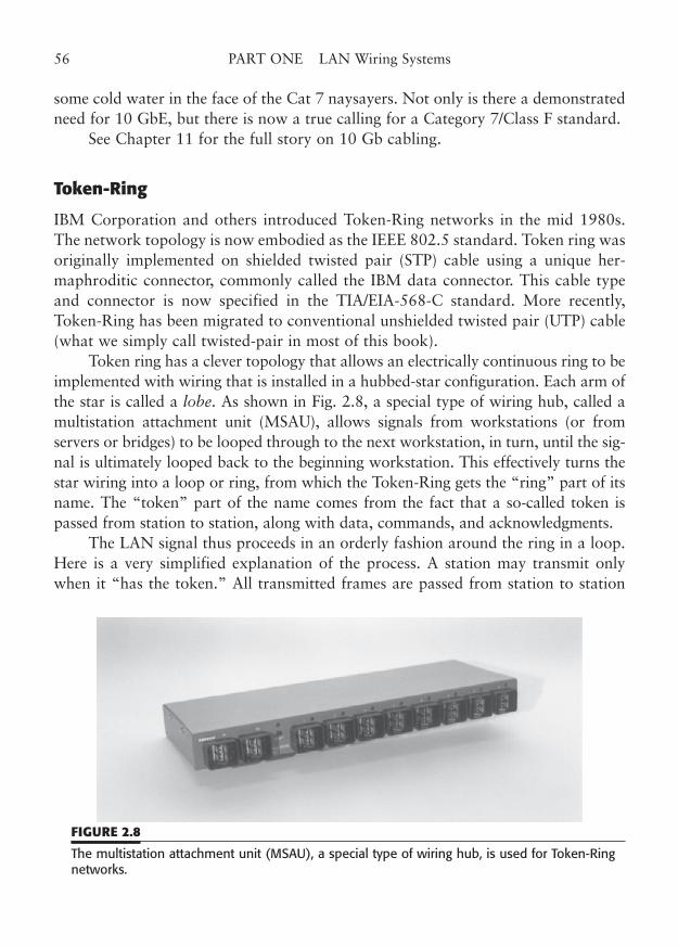
some cold water in the face of the Cat 7 naysayers. Not only is there a demonstratedneed for 10 GbE, but there is now a true calling for a Category 7/Class F standard.
See Chapter 11 for the full story on 10 Gb cabling.
Token-Ring
IBM Corporation and others introduced Token-Ring networks in the mid 1980s.The network topology is now embodied as the IEEE 802.5 standard. Token ring wasoriginally implemented on shielded twisted pair (STP) cable using a unique her-maphroditic connector, commonly called the IBM data connector. This cable typeand connector is now specified in the TIA/EIA-568-C standard. More recently,Token-Ring has been migrated to conventional unshielded twisted pair (UTP) cable(what we simply call twisted-pair in most of this book).
Token ring has a clever topology that allows an electrically continuous ring to beimplemented with wiring that is installed in a hubbed-star configuration. Each arm ofthe star is called a lobe. As shown in Fig. 2.8, a special type of wiring hub, called amultistation attachment unit (MSAU), allows signals from workstations (or fromservers or bridges) to be looped through to the next workstation, in turn, until the sig-nal is ultimately looped back to the beginning workstation. This effectively turns thestar wiring into a loop or ring, from which the Token-Ring gets the “ring” part of itsname. The “token” part of the name comes from the fact that a so-called token ispassed from station to station, along with data, commands, and acknowledgments.
The LAN signal thus proceeds in an orderly fashion around the ring in a loop.Here is a very simplified explanation of the process. A station may transmit onlywhen it “has the token.” All transmitted frames are passed from station to station
56 PART ONE LAN Wiring Systems
FIGURE 2.8
The multistation attachment unit (MSAU), a special type of wiring hub, is used for Token-Ringnetworks.
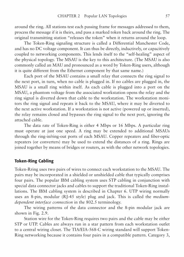
around the ring. All stations test each passing frame for messages addressed to them,process the message if it is theirs, and pass a marked token back around the ring. Theoriginal transmitting station “releases the token” when it returns around the loop.
The Token-Ring signaling structure is called a Differential Manchester Code,and has no DC voltage component. It can thus be directly, inductively, or capacitivelycoupled to networking components. This lends itself to the “self-healing” aspect ofthe physical topology. The MSAU is the key to this architecture. (The MSAU is alsocommonly called an MAU and pronounced as a word by Token-Ring users, althoughit is quite different from the Ethernet component by that same name.)
Each port of the MSAU contains a small relay that connects the ring signal tothe next port, in turn, when no cable is plugged in. If no cables are plugged in, theMSAU is a small ring within itself. As each cable is plugged into a port on theMSAU, a phantom voltage from the associated workstation opens the relay and thering signal is diverted down that cable to the workstation. The workstation moni-tors the ring signal and repeats it back to the MSAU, where it may be diverted tothe next active workstation. If a workstation is not active (powered up or inserted),the relay remains closed and bypasses the ring signal to the next port, ignoring theattached cable.
The data rate of Token-Ring is either 4 Mbps or 16 Mbps. A particular ringmust operate at just one speed. A ring may be extended to additional MSAUsthrough the ring-in/ring-out ports of each MSAU. Copper repeaters and fiber-opticrepeaters (or converters) may be used to extend the distances of a ring. Rings arejoined together by means of bridges or routers, as with the other network topologies.
Token-Ring Cabling
Token-Rring uses two pairs of wires to connect each workstation to the MSAU. Thepairs may be incorporated in a shielded or unshielded cable that typically comprisesfour pairs. The popular IBM cabling system uses STP cabling in conjunction withspecial data connector jacks and cables to support the traditional Token-Ring instal-lations. The IBM cabling system is described in Chapter 6. UTP wiring normallyuses an 8-pin, modular (RJ-45 style) plug and jack. This is called the medium-dependent interface connection in the 802.5 terminology.
The wiring patterns of the data connector and the 8-pin modular jack areshown in Fig. 2.9.
Station wire for the Token-Ring requires two pairs and the cable may be eitherSTP or UTP. Cables are always run in a star pattern from each workstation outletto a central wiring closet. The TIA/EIA-568-C wiring standard will support Token-Ring networking because it contains four pairs in a compatible pattern. Category 3,
CHAPTER 2 Popular LAN Topologies 57
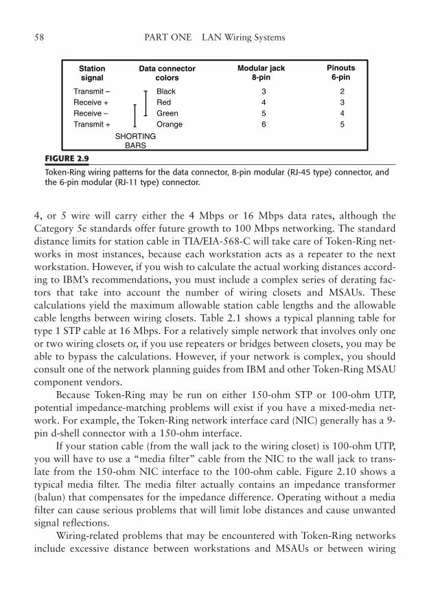
4, or 5 wire will carry either the 4 Mbps or 16 Mbps data rates, although theCategory 5e standards offer future growth to 100 Mbps networking. The standarddistance limits for station cable in TIA/EIA-568-C will take care of Token-Ring net-works in most instances, because each workstation acts as a repeater to the nextworkstation. However, if you wish to calculate the actual working distances accord-ing to IBM’s recommendations, you must include a complex series of derating fac-tors that take into account the number of wiring closets and MSAUs. Thesecalculations yield the maximum allowable station cable lengths and the allowablecable lengths between wiring closets. Table 2.1 shows a typical planning table fortype 1 STP cable at 16 Mbps. For a relatively simple network that involves only oneor two wiring closets or, if you use repeaters or bridges between closets, you may beable to bypass the calculations. However, if your network is complex, you shouldconsult one of the network planning guides from IBM and other Token-Ring MSAUcomponent vendors.
Because Token-Ring may be run on either 150-ohm STP or 100-ohm UTP,potential impedance-matching problems will exist if you have a mixed-media net-work. For example, the Token-Ring network interface card (NIC) generally has a 9-pin d-shell connector with a 150-ohm interface.
If your station cable (from the wall jack to the wiring closet) is 100-ohm UTP,you will have to use a “media filter” cable from the NIC to the wall jack to trans-late from the 150-ohm NIC interface to the 100-ohm cable. Figure 2.10 shows atypical media filter. The media filter actually contains an impedance transformer(balun) that compensates for the impedance difference. Operating without a mediafilter can cause serious problems that will limit lobe distances and cause unwantedsignal reflections.
Wiring-related problems that may be encountered with Token-Ring networksinclude excessive distance between workstations and MSAUs or between wiring
58 PART ONE LAN Wiring Systems
Stationsignal
Data connectorcolors
Modular jack8-pin
Pinouts6-pin
Transmit – Black 3 2Receive + Red 4 3Receive – Green 5 4Transmit + Orange 6 5
SHORTINGBARS
FIGURE 2.9
Token-Ring wiring patterns for the data connector, 8-pin modular (RJ-45 type) connector, andthe 6-pin modular (RJ-11 type) connector.
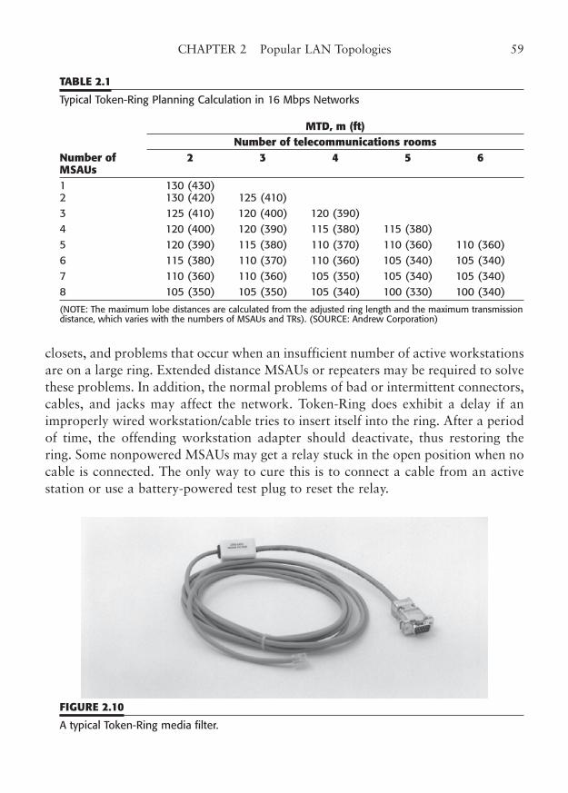
closets, and problems that occur when an insufficient number of active workstationsare on a large ring. Extended distance MSAUs or repeaters may be required to solvethese problems. In addition, the normal problems of bad or intermittent connectors,cables, and jacks may affect the network. Token-Ring does exhibit a delay if animproperly wired workstation/cable tries to insert itself into the ring. After a periodof time, the offending workstation adapter should deactivate, thus restoring thering. Some nonpowered MSAUs may get a relay stuck in the open position when nocable is connected. The only way to cure this is to connect a cable from an activestation or use a battery-powered test plug to reset the relay.
CHAPTER 2 Popular LAN Topologies 59
TABLE 2.1
Typical Token-Ring Planning Calculation in 16 Mbps Networks
MTD, m (ft)Number of telecommunications rooms
Number of 2 3 4 5 6MSAUs1 130 (430)2 130 (420) 125 (410)3 125 (410) 120 (400) 120 (390)4 120 (400) 120 (390) 115 (380) 115 (380)5 120 (390) 115 (380) 110 (370) 110 (360) 110 (360)6 115 (380) 110 (370) 110 (360) 105 (340) 105 (340)7 110 (360) 110 (360) 105 (350) 105 (340) 105 (340)8 105 (350) 105 (350) 105 (340) 100 (330) 100 (340)
(NOTE: The maximum lobe distances are calculated from the adjusted ring length and the maximum transmissiondistance, which varies with the numbers of MSAUs and TRs). (SOURCE: Andrew Corporation)
FIGURE 2.10
A typical Token-Ring media filter.

This page intentionally left blank
CHAPTER 3
Structured Cabling Systems
Highlights
■ TIA/EIA-568-C Structured Cable
■ Avaya/Lucent (AT&T) Systimax Premises Distribution System
■ IBM Cabling System
■ NORDX/CDT IBDN
■ DECconnect
61
Copyright © 2006 by James Trulove. Click here for terms of use.
Structured Cabling has become the watchword of the cabling industry. Today’sstructured cabling systems offer the promise, no, the guarantee of a consistent high-performance wiring infrastructure that can support a very wide variety of data andvoice communications functions. The structured system is a boon for both equip-ment manufacturers and communication system users, because it provides a com-mon, predictable medium for interconnecting high-speed computers andworkstations, as well as low-tech voice and fax, and medium-speed wide area net-work (WAN) circuits (such as DSL and T1). One structure can support virtually allapplications.
That is the ideal, and it is deliverable with properly designed and installedstructured cabling. There are several systems of structured cabling, but the current“king of the hill” is called ANSI/TIA/EIA-568 (alternately referred to simply as TIA-568). This key standard has been the guiding light of the data cabling industry sinceits inception. Created and managed by what is now the TR 42 Standards Committeeof the Telecommunications Industry Association (TIA), the standard has undergonemany addenda, revisions, and technical bulletins. Beginning with the pivotal “-A”revision, the 568 standard has dominated the implementation and development ofcabling infrastructure and considerably influenced many associated standards, suchas IEEE 802.3 Ethernet, which it was arguably created to support, and IEEE 802.5Token-Ring. Its international, European-based counterpart is ISO/IEC 11801, andprovisions of both are carefully coordinated to support a host of interfaces, appli-cations, cable types, testing parameters, and connecting devices.
With the “-B” revision, known as TIA-568-B, the standard took on a multifac-eted character. Rather than try to coordinate the diverse technological progressionof structured cabling designers and the copper/fiber dichotomy, the TR 42 commit-tee elected to split the standard into multiple subsections, each with its own stand-ing body and revision process. The result was a triumvirate of standards,TIA-568-B.1, -B.2, and -B.3, supporting overall system design standards, coppercabling components, and fiber cabling components, respectively. Each standard divi-sion proceeded independently of the others, although the overall goal remains torevise the overall standard on approximately a 4-year cycle.
Now the latest “-C” revision is upon us, and a new section, called “C.0” hasbeen added. The C.0 section will cover generic cabling information, while the C.1section will continue to cover the current design standards for commercial buildingtelecom cabling, as well as supporting newly emerging ones. The draft revisions ofall four sections of TIA-568-C are in various stages of the approval process. The endresult will be a more comprehensive standard that extends the structured cablingsystem for several of the latest applications, including 10 gigabit fiber, copper, andcoax.
62 PART ONE LAN Wiring Systems
Structured Cabling Perspective
The concept of an orderly system of telecommunications cabling has actually beenaround for many years. In a way, it was inspired by the hierarchical system of outside-plant cabling for the telephone industry. The concept was (and is still) simple: Fromwiring centers (central offices), large pair-count cables run to outdoor subscriber-lineinterface cabinets, where smaller multi-pair cables interconnect. These smaller cablesthen run to nearby neighborhoods or business areas, where the subscriber lines (drops)are connected to individual users. Inside the central offices, a similar hierarchical sys-tem of main and intermediate distribution frames fan out the connections to the cen-tral switch. Finally, between these wiring centers, the network equivalent of backbonecables interconnect central offices, and ultimately the long-distance system (PSTN).
Inside multi-tenant and larger commercial buildings, a similar hierarchical sys-tem of main and intermediate wiring rooms is used to distribute telephone servicefirst to every company (or physical floor or wing) in the building, and then to everytelephone. This building-wire system formed the core concept of modern structuredcabling, because data distribution has a very similar topology to telephone distribu-tion. Structured cabling was developed to standardize the media and connection sys-tems so that high-speed LAN data could travel the infrastructure.
We will describe several LAN cabling systems in this chapter. These systemsdefine the characteristics of cable, connectors, and general wiring schemes withoutregard to any of the specific LAN topologies that were described in Chapter 2, andall of them also use some form of twisted-pair wire as their basis. The general pur-pose TIA-568-C cabling system will be described, as will several of the proprietarycabling systems that are in wide use.
Many proprietary cabling plans have been offered over the history of LANwiring technology. Early on, the direction of LAN cabling was uncertain and severalmajor equipment vendors devised detailed cabling systems that met the needs oftheir equipment. Any customer who followed their guidelines could be reasonablyassured of a LAN cable plant that would operate well with that vendor’s products.Of course, use of a particular vendor’s products also frequently implied use of a par-ticular LAN topology.
Over time, many LAN technologists have learned that the use of a particularvendor’s cabling plan might actually limit the utility of their cable plant for otheruses. In some cases, adherence to a cabling system might significantly increase sys-tem cost over other methods. However, a few cable plans offered wide connectivityof both voice and data. Out of those plans, a universal cabling system finallyemerged, EIA/TIA 568, now revised as TIA/EIA-568-C (the “/EIA” portion of thestandard number is often omitted, even in official documents from the TIA).
CHAPTER 3 Structured Cabling Systems 63
It is widely agreed that the flexibility and utility of the standard TIA-568-C sys-tem offers the best alternative for new installations.
The standard can be used in lieu of the proprietary cabling systems, with littledifference in performance. It can easily support a wide variety of LAN topologies,and offers growth to 100 Mbps and beyond.
TIA-568-C Structured Cabling
The TIA-568-C Commercial Building Telecommunications Wiring Standarddescribes a generic cabling system that can support many types of LANs, as well asmany other telecommunications applications.
In this section, we will cover the hardware and wiring issues presented by thestandard. And, of course, the details of many of the wiring components are coveredelsewhere in this book. We will rather loosely group the requirements of TIA/EIA-568-C and its predecessor documents, EIA/TIA 568, TIA/EIA-568-B, TSB-36, TSB-40, TSB-53, TSB-67, TSB-72, and TSB-95 under the label “TIA-568-C.” Theinstalled link testing requirements of TSB 67 (which you may see in older docu-ments) and many measurement enhancements are incorporated into TIA/EIA-568-C, and provide testing guidelines for this cabling system.
64 PART ONE LAN Wiring Systems
TIA/EIA-568-C HighlightsThe latest enhancement to the famous TIA-568 standard is the “C” revision.
The standard is split into four parts, designated “C.0,” “C.1,” “C.2,” and “C.3” thatcover generic cabling requirements, commercial building cabling design, 100-ohmtwisted-pair cabling components, and optical-fiber cabling components, respectively.Here are the formal standard names and their predecessor documents.
ANSI/TIA/EIA-568-C 2006 Commercial Building TelecommunicationsCabling Standard (formerly ANSI/TIA/EIA-568-B 2000)This new standard replaces ANSI/TIA/EIA-568-B; incorporates and refines the technicalcontent of TSB-67, -72, -75, -125, -140, -155, and -162; ANSI/TIA/EIA-568-B.1, includ-ing Addenda AD-1 through AD-7; ANSI/TIA/EIA-568-B.2, including Addenda AD-1through AD-11; and ANSI/TIA/EIA-568-B.3, including Addenda AD-1.
TIA/EIA-568-C.0 Commercial Building Telecommunications Cabling Standard, Part 0: Generic Cabling Requirements,TIA/EIA-568-C.1 Commercial BuildingTelecommunications Cabling Standard, Part 1: General Requirements, TIA/EIA-568-C.2Commercial Building Telecommunications Cabling Standard, Part 2: 100-Ohm BalancedTwisted-Pair Cabling Components Standard, TIA/EIA-568-C.3 Commercial Building
TIA-568 Cabling Options
The TIA-568-C cabling system actually includes four types of cable options:unshielded twisted-pair (UTP), shielded twisted-pair (STP), multimode 50/125 and62.5/125 optical fiber, and single-mode fiber (50-ohm coax is grandfathered forexisting installations only). See Chapter 11 for a discussion of fiber-optic cabling.
TIA-568 Component Categories
TIA-568-C cabling combines the low cost of modular wiring connections andtwisted-pair cable with a system of performance classifications and installation pro-
CHAPTER 3 Structured Cabling Systems 65
Telecommunications Cabling Standard, Part 3: Optical Fiber Cabling ComponentsStandard. The C revision basically incorporates the technology within TIA-568-B, plus allof the addenda and the applicable telecommunications standards bulletins (TSBs) thatwere approved at the time of the draft final vote.
The new structure allows the specifications for the wiring components to be com-pletely separate from the general structured guidelines. It also allows each section tobe separately revised and additional sections to be added as necessary.
Some of the New Changes in 568-B and -C:■ Divides the standard into three sections (-B) or four sections (-C), with separate
draft and ratification processes.■ Replaces “telecommunications closet” with “telecommunications room.” ■ Defines performance specifications for Category 6, Augmented Category 6 (AC6),
and 5e balanced 100-ohm cabling (keeps Category 3 and drops reference toCategories 4 and 5, in favor of Category 5e).
■ Adds specifications for Category 7, 4-pair, individually foil-shielded, balanced coppercabling.
■ Incorporates provisions for IEEE 802.3af DTE Power via MDI (commonly referredto as “Power over Ethernet”, or PoE).
■ Defines performance specifications for 50/125 µm optical-fiber cables (in addi-tion to the 62.5/125 µm cables).
■ Allows alternative fiber connector designs in addition to 568-SC (such as the newSFF, small-form factor, fiber connectors).
■ Adds many performance parameters for copper cabling, including such things asattenuation-to-crosstalk ratio (ACR), delay-skew, power-sum near-end crosstalk(PSNEXT), and far-end crosstalk (FEXT and ELFEXT), and alien ELFEXT (ANEXT),which is crosstalk induced by unwanted coupling from a neighboring pair and isneeded to accommodate 10-Gb speeds.
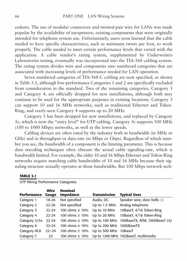
cedures. The use of modular connectors and twisted-pair wire for LANs was madepopular by the availability of inexpensive, existing components that were originallyintended for telephone system use. Unfortunately, users soon learned that the cableneeded to have specific characteristics, such as minimum twists per foot, to workproperly. The cable needed to meet certain performance levels that varied with theapplication. A cable vendor’s rating system, supplemented by UnderwritersLaboratories testing, eventually was incorporated into the TIA-568 cabling system.The rating system divides wire and components into numbered categories that areassociated with increasing levels of performance needed for LAN operation.
Seven numbered categories of TIA-568-C cabling are now specified, as shownin Table 3.1, although low-performance Categories 1 and 2 are specifically excludedfrom consideration in the standard. Two of the remaining categories, Category 3and Category 4, are officially dropped for new installations, although both maycontinue to be used for the appropriate purposes in existing locations. Category 3can support 10 and 16 MHz networks, such as traditional Ethernet and Token-Ring, and rarely-seen Category 4 supports up to 20 MHz.
Category 5 has been dropped for new installations, and replaced by Category5e, which is now the “entry level” for UTP cabling. Category 5e supports 100 MHz(100 to 1000 Mbps) networks, as well as the lower speeds.
Cabling devices are often rated by the industry both in bandwidth (in MHz orGHz) and in throughput or data rate (in Mbps or Gbps). Regardless of which num-ber you see, the bandwidth of a component is the limiting parameter. This is becausedata encoding techniques often obscure the actual cable signaling-rate, which isbandwidth limited. For example, the older 10 and 16 Mbps Ethernet and Token-Ringnetworks require matching cable bandwidths of 10 and 16 MHz because their sig-naling structure actually operates at those bandwidths. But 100 Mbps network tech-
66 PART ONE LAN Wiring Systems
TABLE 3.1
UTP Wiring Performance Categories
Wire NominalPerformance Gauge Impedance Transmission Typical UsesCategory 1 18-26 Not specified Audio, DC Speaker wire, door bells :-) Category 2 22-26 Not specified Up to 1.5 MHz Analog telephone Category 3 22-24 100 ohms ± 10% Up to 16 MHz 10BaseT, 4/16 Token-Ring Category 4 22-24 100 ohms ± 10% Up to 20 MHz 10BaseT, 4/16 Token-Ring Category 5/5e 22-24 100 ohms ± 10% Up to 100 MHz 100BaseTX, ATM, 1000BaseT (4) Category 6 22-24 100 ohms ± 10% Up to 200 MHz 1000BaseTXCategory AC6 22–24 100 ohms ± 10% Up to 500 MHz 10BaseTCategory 7 22 100 ohms ± 10% Up to 1200 MHz 10GBaseT, multimedia
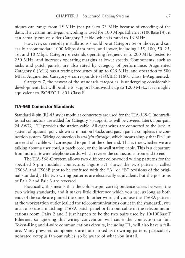
niques can range from 15 MHz (per pair) to 33 MHz because of encoding of thedata. If a certain multi-pair encoding is used for 100 Mbps Ethernet (100BaseT4), itcan actually run on older Category 3 cable, which is rated to 16 MHz.
However, current-day installations should be at Category 5e or above, and caneasily accommodate 1000 Mbps data rates, and lower, including 155, 100, 50, 25,16, and 10 Mbps. Category 6 extends operating frequencies to 200 MHz (tested to250 MHz) and increases operating margins at lower speeds. Components, such asjacks and patch panels, are also rated by category of performance. AugmentedCategory 6 (AC6) has a testing frequency of up to 625 MHz, and operation to 500MHz. Augmented Category 6 corresponds to ISO/IEC 11801 Class E-Augmented.
Category 7, the newest of the standards categories, is undergoing considerabledevelopment, but will be able to support bandwidths up to 1200 MHz. It is roughlyequivalent to ISO/IEC 11801 Class F.
TIA-568 Connector Standards
Standard 8-pin (RJ-45 style) modular connectors are used for the TIA-568-C (nontradi-tional connectors are added for Category 7 support, as will be covered later). Four-pair,24 AWG, UTP provides the station cable. All eight wires are connected to the jack. Asystem of optional punchdown termination blocks and patch panels completes the con-nection system. Wiring connection is straight through, which means simply that Pin 1 atone end of a cable will correspond to pin 1 at the other end. This is true whether we aretalking about a user cord, a patch cord, or the in-wall station cable. This is a departurefrom normal 6-wire telephone cords, which reverse the connections from end to end.
The TIA-568-C system allows two different color-coded wiring patterns for thespecified 8-pin modular connectors. Figure 3.1 shows the two patterns, calledT568A and T568B (not to be confused with the “A” or “B” revisions of the origi-nal standard). The two wiring patterns are electrically equivalent, but the positionsof Pair 2 and Pair 3 are reversed.
Practically, this means that the color-to-pin correspondence varies between thetwo wiring standards, and it makes little difference which you use, as long as bothends of the cable are pinned the same. In other words, if you use the T568A patternat the workstation outlet (called the telecommunications outlet in the standard), youmust also use a matching T568A patch panel or fan-out cable in the telecommuni-cations room. Pairs 2 and 3 just happen to be the two pairs used by 10/100BaseTEthernet, so ignoring this wiring convention will cause the connection to fail.Token-Ring and 4-wire communications circuits, including T1, will also have a fail-ure. Many prewired components are not marked as to wiring pattern, particularlynonrated octopus fan-out cables, so be aware of what you install.
CHAPTER 3 Structured Cabling Systems 67
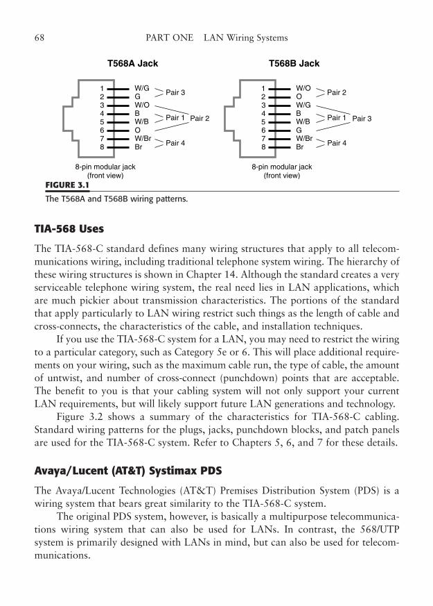
TIA-568 Uses
The TIA-568-C standard defines many wiring structures that apply to all telecom-munications wiring, including traditional telephone system wiring. The hierarchy ofthese wiring structures is shown in Chapter 14. Although the standard creates a veryserviceable telephone wiring system, the real need lies in LAN applications, whichare much pickier about transmission characteristics. The portions of the standardthat apply particularly to LAN wiring restrict such things as the length of cable andcross-connects, the characteristics of the cable, and installation techniques.
If you use the TIA-568-C system for a LAN, you may need to restrict the wiringto a particular category, such as Category 5e or 6. This will place additional require-ments on your wiring, such as the maximum cable run, the type of cable, the amountof untwist, and number of cross-connect (punchdown) points that are acceptable.The benefit to you is that your cabling system will not only support your currentLAN requirements, but will likely support future LAN generations and technology.
Figure 3.2 shows a summary of the characteristics for TIA-568-C cabling.Standard wiring patterns for the plugs, jacks, punchdown blocks, and patch panelsare used for the TIA-568-C system. Refer to Chapters 5, 6, and 7 for these details.
Avaya/Lucent (AT&T) Systimax PDS
The Avaya/Lucent Technologies (AT&T) Premises Distribution System (PDS) is awiring system that bears great similarity to the TIA-568-C system.
The original PDS system, however, is basically a multipurpose telecommunica-tions wiring system that can also be used for LANs. In contrast, the 568/UTP system is primarily designed with LANs in mind, but can also be used for telecom-munications.
68 PART ONE LAN Wiring Systems
1
8765432
8-pin modular jack(front view)
8-pin modular jack(front view)
W/B
W/GG
BrW/Br
B
O
W/O
Pair 3
Pair 2
Pair 4
Pair 1
T568A Jack
1
8765432
W/B
W/OO
BrW/Br
B
G
W/G
Pair 2
Pair 3
Pair 4
Pair 1
T568B Jack
FIGURE 3.1
The T568A and T568B wiring patterns.
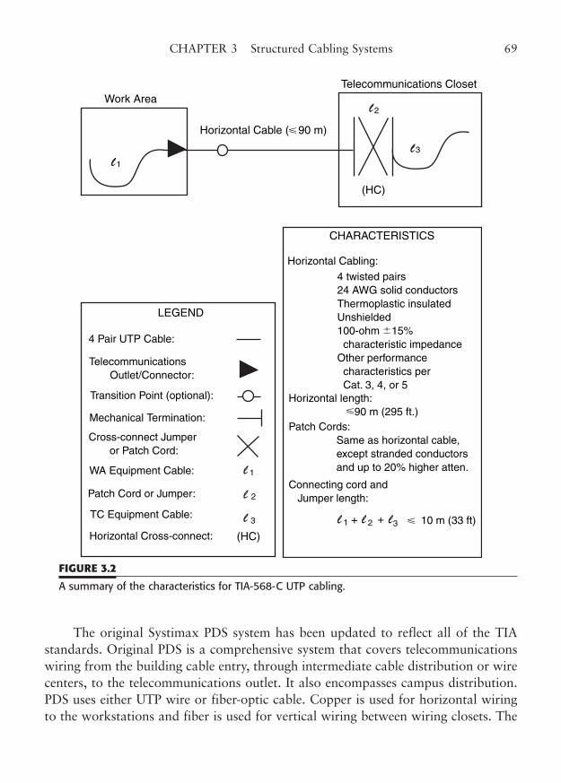
The original Systimax PDS system has been updated to reflect all of the TIAstandards. Original PDS is a comprehensive system that covers telecommunicationswiring from the building cable entry, through intermediate cable distribution or wirecenters, to the telecommunications outlet. It also encompasses campus distribution.PDS uses either UTP wire or fiber-optic cable. Copper is used for horizontal wiringto the workstations and fiber is used for vertical wiring between wiring closets. The
CHAPTER 3 Structured Cabling Systems 69
LEGEND
4 Pair UTP Cable:
Telecommunications Outlet/Connector:
Transition Point (optional):
Mechanical Termination:
Cross-connect Jumper or Patch Cord:
WA Equipment Cable:
Patch Cord or Jumper:
TC Equipment Cable:
Horizontal Cross-connect: (HC)
CHARACTERISTICS
Horizontal Cabling:
4 twisted pairs24 AWG solid conductorsThermoplastic insulatedUnshielded100-ohm 15% characteristic impedanceOther performance characteristics per Cat. 3, 4, or 5
Horizontal length: 90 m (295 ft.)Patch Cords: Same as horizontal cable, except stranded conductors
and up to 20% higher atten.
Connecting cord and Jumper length:
1
2
3
�
�
1 2 3 �+ + 10 m (33 ft)
Work Area
Horizontal Cable ( 90 m)�
1
2
3
(HC)
Telecommunications Closet
FIGURE 3.2
A summary of the characteristics for TIA-568-C UTP cabling.
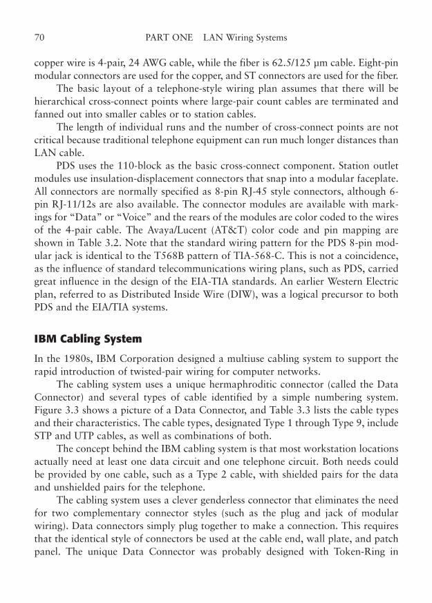
copper wire is 4-pair, 24 AWG cable, while the fiber is 62.5/125 µm cable. Eight-pinmodular connectors are used for the copper, and ST connectors are used for the fiber.
The basic layout of a telephone-style wiring plan assumes that there will behierarchical cross-connect points where large-pair count cables are terminated andfanned out into smaller cables or to station cables.
The length of individual runs and the number of cross-connect points are notcritical because traditional telephone equipment can run much longer distances thanLAN cable.
PDS uses the 110-block as the basic cross-connect component. Station outletmodules use insulation-displacement connectors that snap into a modular faceplate.All connectors are normally specified as 8-pin RJ-45 style connectors, although 6-pin RJ-11/12s are also available. The connector modules are available with mark-ings for “Data” or “Voice” and the rears of the modules are color coded to the wiresof the 4-pair cable. The Avaya/Lucent (AT&T) color code and pin mapping areshown in Table 3.2. Note that the standard wiring pattern for the PDS 8-pin mod-ular jack is identical to the T568B pattern of TIA-568-C. This is not a coincidence,as the influence of standard telecommunications wiring plans, such as PDS, carriedgreat influence in the design of the EIA-TIA standards. An earlier Western Electricplan, referred to as Distributed Inside Wire (DIW), was a logical precursor to bothPDS and the EIA/TIA systems.
IBM Cabling System
In the 1980s, IBM Corporation designed a multiuse cabling system to support therapid introduction of twisted-pair wiring for computer networks.
The cabling system uses a unique hermaphroditic connector (called the DataConnector) and several types of cable identified by a simple numbering system.Figure 3.3 shows a picture of a Data Connector, and Table 3.3 lists the cable typesand their characteristics. The cable types, designated Type 1 through Type 9, includeSTP and UTP cables, as well as combinations of both.
The concept behind the IBM cabling system is that most workstation locationsactually need at least one data circuit and one telephone circuit. Both needs couldbe provided by one cable, such as a Type 2 cable, with shielded pairs for the dataand unshielded pairs for the telephone.
The cabling system uses a clever genderless connector that eliminates the needfor two complementary connector styles (such as the plug and jack of modularwiring). Data connectors simply plug together to make a connection. This requiresthat the identical style of connectors be used at the cable end, wall plate, and patchpanel. The unique Data Connector was probably designed with Token-Ring in
70 PART ONE LAN Wiring Systems
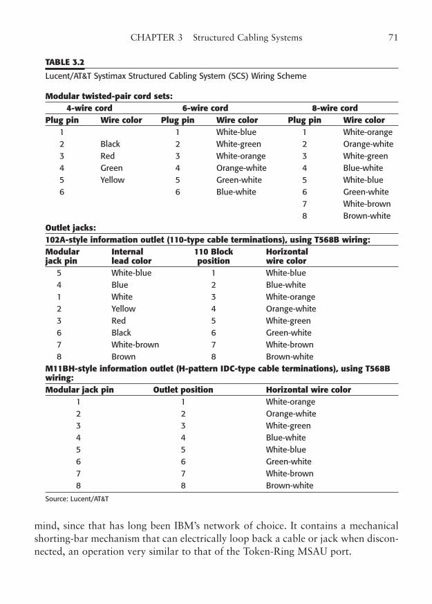
mind, since that has long been IBM’s network of choice. It contains a mechanicalshorting-bar mechanism that can electrically loop back a cable or jack when discon-nected, an operation very similar to that of the Token-Ring MSAU port.
CHAPTER 3 Structured Cabling Systems 71
TABLE 3.2
Lucent/AT&T Systimax Structured Cabling System (SCS) Wiring Scheme
Modular twisted-pair cord sets:4-wire cord 6-wire cord 8-wire cord
Plug pin Wire color Plug pin Wire color Plug pin Wire color1 1 White-blue 1 White-orange 2 Black 2 White-green 2 Orange-white 3 Red 3 White-orange 3 White-green 4 Green 4 Orange-white 4 Blue-white 5 Yellow 5 Green-white 5 White-blue 6 6 Blue-white 6 Green-white
7 White-brown8 Brown-white
Outlet jacks:102A-style information outlet (110-type cable terminations), using T568B wiring:Modular Internal 110 Block Horizontal jack pin lead color position wire color
5 White-blue 1 White-blue 4 Blue 2 Blue-white1 White 3 White-orange 2 Yellow 4 Orange-white 3 Red 5 White-green 6 Black 6 Green-white 7 White-brown 7 White-brown 8 Brown 8 Brown-white
M11BH-style information outlet (H-pattern IDC-type cable terminations), using T568Bwiring:Modular jack pin Outlet position Horizontal wire color
1 1 White-orange 2 2 Orange-white 3 3 White-green 4 4 Blue-white 5 5 White-blue 6 6 Green-white 7 7 White-brown 8 8 Brown-white
Source: Lucent/AT&T
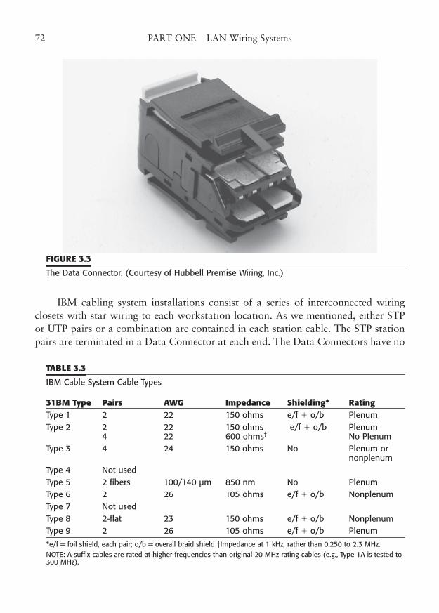
IBM cabling system installations consist of a series of interconnected wiringclosets with star wiring to each workstation location. As we mentioned, either STPor UTP pairs or a combination are contained in each station cable. The STP stationpairs are terminated in a Data Connector at each end. The Data Connectors have no
72 PART ONE LAN Wiring Systems
FIGURE 3.3
The Data Connector. (Courtesy of Hubbell Premise Wiring, Inc.)
TABLE 3.3
IBM Cable System Cable Types
31BM Type Pairs AWG Impedance Shielding* RatingType 1 2 22 150 ohms e/f � o/b Plenum Type 2 2 22 150 ohms e/f � o/b Plenum
4 22 600 ohms† No Plenum Type 3 4 24 150 ohms No Plenum or
nonplenumType 4 Not used Type 5 2 fibers 100/140 µm 850 nm No Plenum Type 6 2 26 105 ohms e/f � o/b Nonplenum Type 7 Not used Type 8 2-flat 23 150 ohms e/f � o/b Nonplenum Type 9 2 26 105 ohms e/f � o/b Plenum
*e/f = foil shield, each pair; o/b = overall braid shield †Impedance at 1 kHz, rather than 0.250 to 2.3 MHz.NOTE: A-suffix cables are rated at higher frequencies than original 20 MHz rating cables (e.g., Type 1A is tested to300 MHz).
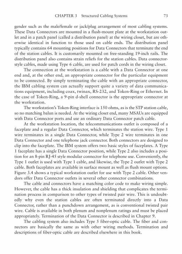
gender such as the male/female or jack/plug arrangement of most cabling systems.These Data Connectors are mounted in a flush-mount plate at the workstation out-let and in a patch panel (called a distribution panel) at the wiring closet, but are oth-erwise identical in function to those used on cable ends. The distribution paneltypically contains 64 mounting positions for Data Connectors that terminate the endof the station cables. It is customarily mounted on free-standing 19-inch rails. Thedistribution panel also contains strain reliefs for the station cables. Data connector-style cables, made using Type 6 cable, are used for patch cords in the wiring closet.
The connection at the workstation is a cable with a Data Connector at oneend and, at the other end, an appropriate connector for the particular equipmentto be connected. By simply terminating the cable with an appropriate connector,the IBM cabling system can actually support quite a variety of data communica-tions equipment, including coax, twinax, RS-232, and Token-Ring or Ethernet. Inthe case of Token-Ring, a 9-pin d-shell connector is the appropriate connector atthe workstation.
The workstation’s Token-Ring interface is 150 ohms, as is the STP station cable,so no matching balun is needed. At the wiring closet end, many MSAUs are equippedwith Data Connector ports and use an ordinary Data Connector patch cable.
At the workstation location, the telecommunications outlet is composed of afaceplate and a regular Data Connector, which terminates the station wire. Type 1wire terminates in a single Data Connector, while Type 2 wire terminates in oneData Connector and one telephone jack connector. Both connectors are designed toclip into the faceplate. The IBM system offers two basic styles of faceplates. A Type1 faceplate has a single Data Connector position, while Type 2 also includes a posi-tion for an 8-pin RJ-45 style modular connector for telephone use. Conveniently, theType 1 outlet is used with Type 1 cable, and likewise, the Type 2 outlet with Type 2cable. Both faceplates are available in surface mount as well as flush mount options.Figure 3.4 shows a typical workstation outlet for use with Type 2 cable. Other ven-dors offer Data Connector outlets in several other connector combinations.
The cable and connectors have a matching color code to make wiring simple.However, the cable has a thick insulation and shielding that complicates the termi-nation process in comparison to other types of twisted pair wire. This is undoubt-edly why even the station cables are often terminated directly into a DataConnector, rather than a punchdown arrangement, as is conventional twisted pairwire. Cable is available in both plenum and nonplenum ratings and must be placedappropriately. Termination of the Data Connector is described in Chapter 9.
The cabling system also includes Type 5 fiber-optic cable. The fiber and con-nectors are basically the same as with other wiring methods. Termination anddescriptions of fiber-optic cable are described elsewhere in this book.
CHAPTER 3 Structured Cabling Systems 73
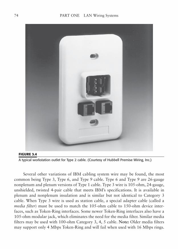
Several other variations of IBM cabling system wire may be found, the mostcommon being Type 3, Type 6, and Type 9 cable. Type 6 and Type 9 are 26-gaugenonplenum and plenum versions of Type 1 cable. Type 3 wire is 105-ohm, 24-gauge,unshielded, twisted 4-pair cable that meets IBM’s specifications. It is available inplenum and nonplenum insulation and is similar but not identical to Category 3cable. When Type 3 wire is used as station cable, a special adapter cable (called amedia filter) must be used to match the 105-ohm cable to 150-ohm device inter-faces, such as Token-Ring interfaces. Some newer Token-Ring interfaces also have a105-ohm modular jack, which eliminates the need for the media filter. Similar mediafilters may be used with 100-ohm Category 3, 4, 5 cable. Note: Older media filtersmay support only 4 Mbps Token-Ring and will fail when used with 16 Mbps rings.
74 PART ONE LAN Wiring Systems
FIGURE 3.4
A typical workstation outlet for Type 2 cable. (Courtesy of Hubbell Premise Wiring, Inc.)
The IBM cabling system provides some important advantages in a mixed appli-cation environment that may use coax, twinax, and twisted-pair terminations. Thecable has been designed to support all these types of signals using the properadapters or impedance matching baluns.
However, in a LAN-only environment, such as Token-Ring, the functions mayall be satisfactorily accomplished by the TIA-568-C system at a lower cost. In fact,most estimates place the cost of an IBM cabling system installation at two to threetimes that of a standard TIA-568-C installation.
Other Standard Cabling Systems
Many other vendors have developed proprietary wiring patterns for cabling of dataand voice. Most of these plans support specific features of that manufacturer’sequipment and are not general purpose at all. Others incorporate variations of thecabling systems previously mentioned. Of these, two other systems are widely usedand deserve mention.
NORDX/CDT IBDN
Another variant of twisted-pair wiring is the Integrated Building DistributionSystem originally put forth by Northern Telecom, often referred to as Nortel.
The IBDN components are now marketed by NORDX/CDT, a Nortel spinoff.This system is quite similar to the Avaya/Lucent/AT&T PDS and primarily supportstelecommunications wiring. As we saw with PDS, data networks can be run oversuch systems, but the distance limitations and other installation practices must beobserved.
IBDN uses the common system of modular connectors with cross-connectsbased around the BIX block. IBDN also contains fiber components, as does thePDS. While the IBDN system is not specifically designed to match TIA-568-Crequirements, it will allow common types of network connections if the distancelimitations for the network are not exceeded. When used in accordance with theguidelines in the standard, an IBDN installation can be said to be TIA-568-Ccompliant.
All of the modular connectors, jacks, cable, and color codes of the AT&T PDSsystem are common for IBDN. The interconnection component, of course, is theBIX block, rather than the 110 block. In general, the IBDN system is compatiblewith TIA-568 Structured Wiring, and its components may be substituted where theymeet the standard’s performance specifications. Please refer to the PDS section inthis chapter and the BIX block section of Chapter 7 for more information.
CHAPTER 3 Structured Cabling Systems 75
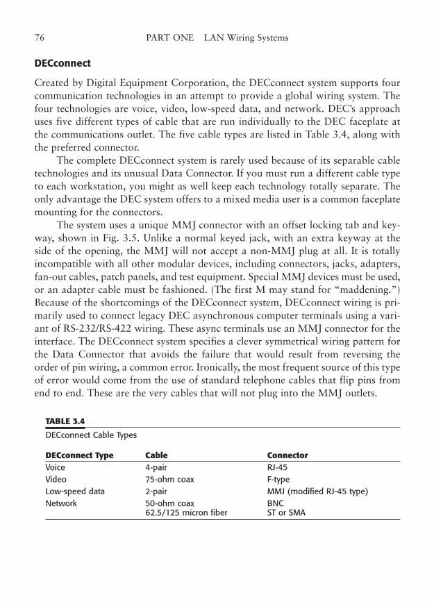
DECconnect
Created by Digital Equipment Corporation, the DECconnect system supports fourcommunication technologies in an attempt to provide a global wiring system. Thefour technologies are voice, video, low-speed data, and network. DEC’s approachuses five different types of cable that are run individually to the DEC faceplate atthe communications outlet. The five cable types are listed in Table 3.4, along withthe preferred connector.
The complete DECconnect system is rarely used because of its separable cabletechnologies and its unusual Data Connector. If you must run a different cable typeto each workstation, you might as well keep each technology totally separate. Theonly advantage the DEC system offers to a mixed media user is a common faceplatemounting for the connectors.
The system uses a unique MMJ connector with an offset locking tab and key-way, shown in Fig. 3.5. Unlike a normal keyed jack, with an extra keyway at theside of the opening, the MMJ will not accept a non-MMJ plug at all. It is totallyincompatible with all other modular devices, including connectors, jacks, adapters,fan-out cables, patch panels, and test equipment. Special MMJ devices must be used,or an adapter cable must be fashioned. (The first M may stand for “maddening.”)Because of the shortcomings of the DECconnect system, DECconnect wiring is pri-marily used to connect legacy DEC asynchronous computer terminals using a vari-ant of RS-232/RS-422 wiring. These async terminals use an MMJ connector for theinterface. The DECconnect system specifies a clever symmetrical wiring pattern forthe Data Connector that avoids the failure that would result from reversing theorder of pin wiring, a common error. Ironically, the most frequent source of this typeof error would come from the use of standard telephone cables that flip pins fromend to end. These are the very cables that will not plug into the MMJ outlets.
76 PART ONE LAN Wiring Systems
TABLE 3.4
DECconnect Cable Types
DECconnect Type Cable ConnectorVoice 4-pair RJ-45 Video 75-ohm coax F-type Low-speed data 2-pair MMJ (modified RJ-45 type) Network 50-ohm coax BNC
62.5/125 micron fiber ST or SMA
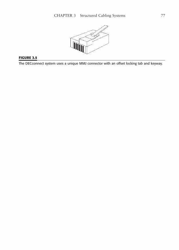
CHAPTER 3 Structured Cabling Systems 77
FIGURE 3.5
The DECconnect system uses a unique MMJ connector with an offset locking tab and keyway.

This page intentionally left blank
CHAPTER 4
LAN Wiring for Future Needs
Highlights
■ 100/1000 Mbps networking
■ The importance of Category
■ “Enhanced” Category X
■ Fiber and copper for the future
■ Future (wiring) shock
79
Copyright © 2006 by James Trulove. Click here for terms of use.
It has been said that the only thing that remains constant is change itself, and that’scertainly true in reference to changes in computer technology. In many ways, the rateof change is also uniform—exponential, it almost seems. We have often heard thatwe have left normal historical time and are now living on Internet time. Even so, itis possible to accurately predict the near-term future of LAN wiring technology.
One of the interesting features of technological change in the computer indus-try is the steady progression of a technology from experimental to leading-edge, andthen to widely accepted. While experimental technologies are quite divergent, thosethat are feasible eventually become the hot new technologies that define the truestate of the art. Of course, a new feature or capability does not immediately sup-plant existing products, but eventually, products with useful new features becomereadily available at a reasonable cost. At that point, standardization emerges,whether formal or de facto, and the product becomes widely accepted.
Picking the Next Wiring Technology
Picking the best emerging technology for your network is an exciting and potentiallyrewarding game. The game is really not in trying to guess which experimental devel-opments will become accepted, but rather in observing which leading-edge technolo-gies have begun to be accepted, and then employing them in the future. The creationof recognized standards is the key to which technologies will be used in the future.
In local area networking, we are fortunate because we must operate in a mul-tivendor environment. The need for interoperability means that we must havestrong, internationally accepted standards for networking.
Another fortunate circumstance is that no proprietary technology dominatesthe field. Many, if not most, of the technologies that have become widely used area result of unprecedented industry cooperation through partnerships, consortia, andstandards committees. In addition, because of the need for interoperability, stan-dards tend not to change radically once they are implemented. This is particularlytrue of LAN wiring.
You can expect your LAN wiring system to remain totally usable over manyyears if your needs remain relatively constant. This is not to say that if you progressfrom simple printer and file sharing to high-bandwidth graphic or video applica-tions that you might not need to upgrade some network components. However,most LANs support organizations with relatively constant needs. For example, ifyou have a standard 100BaseT network in place today, you may reasonably expectit to remain viable for a number of years. On the other hand, if you are installingnew network wiring, you should plan for the future. For LAN wiring, the future isfairly clear.
80 PART ONE LAN Wiring Systems
There will be a gradual move from the current 100 Mbps network speeds to1000 Mbps, and soon to 10 Gbps. There are even higher speeds in development.There may be no immediate need (or budget) to convert your entire network to1000 Mbps, but you should probably not install any new cable that will not servethat speed. And you will be surprised how quickly you will develop a need for atleast some of the connections to be gigabit.
So, how do you plan for the future? How do you put in a 1000 Mbps network?Should you use copper wire or consider fiber? Can you hedge your bets? Let’s see.
100/1000 Mbps Networking Compatibility
If you currently are using 10/100 Mbps Ethernet or 16 to 100 Mbps Token-Ring,you may not be using LAN wiring components that will move you to higher speedssuch as 1000 Mbps. Or you may be getting along (maybe limping along) on 10Mbps for your current network. These lower speeds are much less demanding intheir need for transmission media than the high-speed networks, such as FastEthernet and Gigabit Ethernet.
For example, 10BaseT will run at a workstation-to-hub distance of 100 m onCategory 3 cable. If you try to upgrade such a network to 10 times the speed, how-ever, it will probably fail. Gigabit speeds would be impossible.
So, what can you do if you may need to upgrade to 1000 Mbps? The answeris to install a LAN wiring system that meets the performance specifications for thehigher speed now; it will operate very satisfactorily at the lower speed for the pres-ent and will provide additional service as you upgrade to high speeds.
One sure way to provide such a wiring system is to use the TIA/EIA-568-Cstandard for a Category 6 or Augmented Category 6 (AC6) cable system.1 EvenCategory 5e wiring is designed to support full 1000 Mbps speeds, and Cat AC6 and7 will go to 10 Gb. At the same time, Category 5e, 6, AC6, and even 72 wiring willfully support lower network speeds, such as 10/100BaseT Token-Ring, and CDDIas well as intermediate speeds for ATM and Fast Token-Ring. For that matter, it willalso support voice, ISDN, and T1/E1 circuits very nicely. Table 4.1 shows a tablethat summarizes the supported uses of Category 3–7 installations.
“True” Category 5e, 6, AC6, and proposed Cat 7 wiring should be used for asingle application, not shared between data and voice, for instance. If your needs areuncertain, you may wish to overwire your workstations by pulling more than one
CHAPTER 4 LAN Wiring for Future Needs 81
1 Although Augmented Category 6 is an emerging standard, most manufacturers already have compo-nents that meet the requirements.2 Category 7 may use connectors that are not compatible with lower categories, but you can getadapter cords.
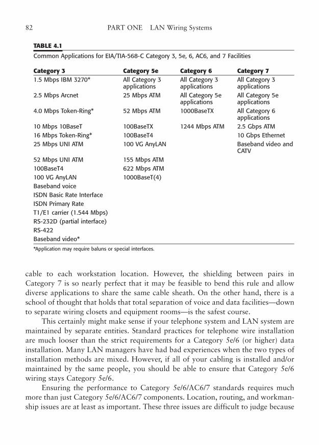
cable to each workstation location. However, the shielding between pairs inCategory 7 is so nearly perfect that it may be feasible to bend this rule and allowdiverse applications to share the same cable sheath. On the other hand, there is aschool of thought that holds that total separation of voice and data facilities—downto separate wiring closets and equipment rooms—is the safest course.
This certainly might make sense if your telephone system and LAN system aremaintained by separate entities. Standard practices for telephone wire installationare much looser than the strict requirements for a Category 5e/6 (or higher) datainstallation. Many LAN managers have had bad experiences when the two types ofinstallation methods are mixed. However, if all of your cabling is installed and/ormaintained by the same people, you should be able to ensure that Category 5e/6wiring stays Category 5e/6.
Ensuring the performance to Category 5e/6/AC6/7 standards requires muchmore than just Category 5e/6/AC6/7 components. Location, routing, and workman-ship issues are at least as important. These three issues are difficult to judge because
82 PART ONE LAN Wiring Systems
TABLE 4.1
Common Applications for EIA/TIA-568-C Category 3, 5e, 6, AC6, and 7 Facilities
Category 3 Category 5e Category 6 Category 71.5 Mbps IBM 3270* All Category 3 All Category 3 All Category 3
applications applications applications 2.5 Mbps Arcnet 25 Mbps ATM All Category 5e All Category 5e
applications applications 4.0 Mbps Token-Ring* 52 Mbps ATM 1000BaseTX All Category 6
applications10 Mbps 10BaseT 100BaseTX 1244 Mbps ATM 2.5 Gbps ATM 16 Mbps Token-Ring* 100BaseT4 10 Gbps Ethernet 25 Mbps UNI ATM 100 VG AnyLAN Baseband video and
CATV 52 Mbps UNI ATM 155 Mbps ATM 100BaseT4 622 Mbps ATM 100 VG AnyLAN 1000BaseT(4) Baseband voice ISDN Basic Rate Interface ISDN Primary Rate T1/E1 carrier (1.544 Mbps) RS-232D (partial interface) RS-422 Baseband video*
*Application may require baluns or special interfaces.
they are related to the installation process. You can buy the finest certified compo-nents and still have them installed improperly.
That is why we have devoted an entire part of this book to the installation ofthe wiring devices.
Category 5e/6/AC6/7 Testing and Certification
The simplest proof of 100/1000 Mbps network performance is to connect your100/1000 Mbps switch-hubs and workstations and see if they work! Unfortunately,many of us must install cabling systems long before we buy the first 1000 Mbpshardware. Even if high-speed hardware were to be installed immediately, the time tocure cable problems is during the build-out stage of construction, not after move-in.
The solution is to have the cable system tested and certified as part of theinstallation process. This testing and certification process is described in more detailin Chapter 15, but is summarized here.
The first step in certification is to use the proper materials. All cables, jacks,patch panels, patch and user cords, and connecting blocks should be certified to theproper category by the manufacturer. There is no major benefit to specifying all thisby brand name unless you are using a particular manufacturer’s connecting hard-ware system that offers unique features. For a smaller installation of 50 stationdrops or less, this will probably just raise the price and narrow the field of bidders.
The second step is to use properly trained installers, particularly for Category5e/6/AC6/7 installations. Several certification programs exist for cable installers.The vendor-specific programs generally emphasize a common set of workmanshiptechniques and are adequate training in most situations.
You should not insist that installers be certified by a particular vendor unlessyou are willing to put up with the extra expense and aggravation of such a policy;it is more important that each installer either be formally trained at a recent courseor be closely supervised during the installation.
A few industry-wide certification programs exist, including the RegisteredCommunications Distribution Designer (RCDD) program from BICSI, Inc. (for-merly the Building Industry Consulting Service International, Inc.). The RCDDrequires experience and successful completion of a test. A Network TransportSystems Specialist program also exists. And there is now an installer registrationprogram that does not require membership in the organization. See Chapter 18 foradditional information on training and certification/registration.
The third step is to individually test and certify each workstation link. Theworst-case link performance criteria and testing guidelines of TIA/EIA-568-C are anexcellent basis for certification. Each link should pass all the tests specified for the
CHAPTER 4 LAN Wiring for Future Needs 83
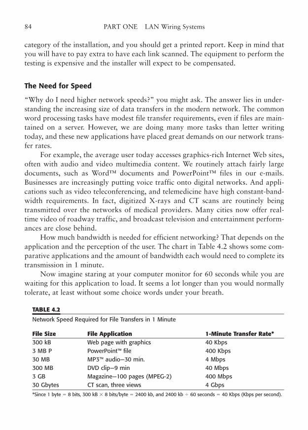
category of the installation, and you should get a printed report. Keep in mind thatyou will have to pay extra to have each link scanned. The equipment to perform thetesting is expensive and the installer will expect to be compensated.
The Need for Speed
“Why do I need higher network speeds?” you might ask. The answer lies in under-standing the increasing size of data transfers in the modern network. The commonword processing tasks have modest file transfer requirements, even if files are main-tained on a server. However, we are doing many more tasks than letter writingtoday, and these new applications have placed great demands on our network trans-fer rates.
For example, the average user today accesses graphics-rich Internet Web sites,often with audio and video multimedia content. We routinely attach fairly largedocuments, such as Word™ documents and PowerPoint™ files in our e-mails.Businesses are increasingly putting voice traffic onto digital networks. And appli-cations such as video teleconferencing, and telemedicine have high constant-band-width requirements. In fact, digitized X-rays and CT scans are routinely beingtransmitted over the networks of medical providers. Many cities now offer real-time video of roadway traffic, and broadcast television and entertainment perform-ances are close behind.
How much bandwidth is needed for efficient networking? That depends on theapplication and the perception of the user. The chart in Table 4.2 shows some com-parative applications and the amount of bandwidth each would need to complete itstransmission in 1 minute.
Now imagine staring at your computer monitor for 60 seconds while you arewaiting for this application to load. It seems a lot longer than you would normallytolerate, at least without some choice words under your breath.
84 PART ONE LAN Wiring Systems
TABLE 4.2
Network Speed Required for File Transfers in 1 Minute
File Size File Application 1-Minute Transfer Rate*300 kB Web page with graphics 40 Kbps 3 MB P PowerPoint™ file 400 Kbps 30 MB MP3™ audio—30 min. 4 Mbps 300 MB DVD clip—9 min 40 Mbps 3 GB Magazine—100 pages (MPEG-2) 400 Mbps 30 Gbytes CT scan, three views 4 Gbps
*Since 1 byte � 8 bits, 300 kB � 8 bits/byte � 2400 kb, and 2400 kb � 60 seconds � 40 Kbps (Kbps per second).
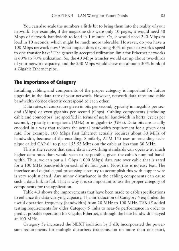
You can also scale the numbers a little bit to bring them into the reality of yournetwork. For example, if the magazine clip were only 10 pages, it would need 40Mbps of network bandwidth to load in 1 minute. Or, it would need 240 Mbps toload in 10 seconds, which might be much more tolerable. However, do you have a100 Mbps network now? What impact does devoting 40% of your network’s speedto one transfer have? The generally accepted utilization limit for Ethernet networksis 60% to 70% utilization. So, the 40 Mbps transfer would eat up about two-thirdsof your network capacity, and the 240 Mbps would chew out about a 30% hunk ofa Gigabit Ethernet pipe.
The Importance of Category
Installing cabling and components of the proper category is important for futureupgrades in the data rate of your network. However, network data rates and cablebandwidth do not directly correspond to each other.
Data rates, of course, are given in bits per second, typically in megabits per sec-ond (Mbps) or even gigabits per second (Gbps). Cabling components (includingcable and connectors) are specified in terms of useful bandwidth in hertz (cycles persecond), typically in megahertz (MHz) or in gigahertz (GHz). Data bits are usuallyencoded in a way that reduces the actual bandwidth requirement for a given datarate. For example, 100 Mbps Fast Ethernet actually requires about 30 MHz ofbandwidth, because of the encoding. Similarly, ATM 155 uses an encoding tech-nique called CAP-64 to place 155.52 Mbps on the cable at less than 30 MHz.
This is the reason that some data networking standards can operate at muchhigher data rates than would seem to be possible, given the cable’s nominal band-width. Thus, we can put a 1 Gbps (1000 Mbps) data rate over cable that is ratedfor a 100 MHz bandwidth on each of its four pairs. Now, this is no easy feat. Theinterface and digital signal processing circuitry to accomplish this with copper wireis very sophisticated. Any minor disturbance in the cabling components can causesuch a data link to fail. That is why it is so important to use the proper category ofcomponents for the application.
Table 4.3 shows the improvements that have been made to cable specificationsto enhance the data-carrying capacity. The introduction of Category 5 expanded theuseful operation frequency (bandwidth) from 20 MHz to 100 MHz. TSB-95 addedtesting requirements for older Category 5 links to near-5e performance in order topredict possible operation for Gigabit Ethernet, although the base bandwidth stayedat 100 MHz.
Category 5e increased the NEXT isolation by 3 dB, incorporated the power-sum requirements for multiple disturbers (transmission on more than one pair),
CHAPTER 4 LAN Wiring for Future Needs 85
added far-end crosstalk requirements (FEXT), added propagation delay and skew,and added return loss to the more modest Category 5 parameters.
Category 6, AC6, and Category 7 increase working bandwidth to 200, 350,and 450 MHz, respectively. You may have heard these numbers as 250, 500, and600 MHz, but those are the required test limits. The attenuation-to-crosstalk ratio(ACR) must be positive to the lower frequency limit, and that is the generallyaccepted measure of the “useful bandwidth” of cables and connecting hardware.Some Category 7 hardware actually exceeds even the 600 MHz specification (someby more than double) and this may be subject to future standards making.
“Enhanced” Category X
The categories and classes of operation of the international cabling standards organ-izations specify minimum performance parameters for cabling, components, andlinks used in structured LAN wiring systems. It is the purpose of the standard to setelectrical characteristics of the wiring system, without regard to the particular typeof LAN network technology that is used with the cabling.
Each of the category specifications, in reality, has been targeted at the operat-ing requirements of a current or anticipated LAN topology. Consequently,Category 5 conveniently handles Fast Ethernet, Category 5e handles GigabitEthernet (4-pair simultaneous transmit/receive), and Category 6 handles the 2-pairtransmit/2-pair receive version of Gigabit Ethernet, as well as ATM-622/1244(OC-12 and OC-24 rates). AC6 can handle 10 Gb Ethernet and fiber channel (justbarely), and Category 7 can do 10 Gigs sitting down. With those technical guide-
86 PART ONE LAN Wiring Systems
TABLE 4.3
Comparison of Category Parameters
Cat 3 Cat 5 TSB-95 Cat 5e Cat 6 Cat 7Max. operating frequency, MHz 20 100 100 100 200 475 Test frequency, MHz 20 100 100 100 250 600 Attenuation YesNEXT Yes +3dbPS-NEXT YesPS-ELFEXT YesPropagation delay YesDelay skew YesReturn loss Yes +2dB
lines, each category/class allows a wide range of applications in addition to theclassic Ethernet ones.
However, it is quite possible and probably desirable for a manufacturer to buildcabling components that actually exceed the minimum specifications of a particular tar-geted category. For example, at one time, Category 5 was considered the ultimate andwas a manufacturing challenge. Soon the leading manufacturers discovered that theycould use innovative designs and production methods not only to comply withCategory 5, but to actually exceed the parameter requirements, often by a significantmargin. These better quality cables and connectors were initially called EnhancedCategory 5 and ultimately were found to be all but necessary to achieve GigabitEthernet operation. Now the same has happened with Category 6, resulting inAugmented Cat 6, or AC6. Some exceed Cat 7 preliminary specs by more than double.
The lesson here is that good engineering can create components that have bet-ter performance than the standards require. Can you benefit from those enhance-ments? Yes, you can, particularly if you operate near the limits of distance or datarate. Better still, you may be able to plug in new technologies that were not evendreamed of when the cable standard was defined. Those of us who specifiedenhanced Category 5e were rewarded with the ability to jump to Gigabit Ethernetover copper as soon as it became available, because our cable already met the TSB-95 and/or Category 5e performance levels that were later made part of the -B stan-dard. By the same token, enhanced cable and components for Category 6 and 7already exist, and may well prove to offer more long-term stability as well.
You should buy the best cabling components you can afford, keeping in mindthat the network technologies of today are transient and will be obsolete in a fewyears. Stepping beyond the envelope may be a little risky, as some predicted tech-nologies never reach critical market mass. So, try to plan for one or two steps inincreased network speed and leave the rocket science for the experimenters. In thatway, you will have a network infrastructure that will provide optimum performanceat minimum cost with a reasonable useful life.
Fiber to the Front
The importance of fiber-optic cable cannot be overemphasized. Fiber cable hasunique characteristics that make it suitable in many types of high-bandwidth,high-interference, and interbuilding applications. As recent very high-speed tech-nologies have emerged, fiber interfaces have been developed and marketed consid-erably in advance of their copper counterparts. Whereas copper cables are limitedto 100 m for almost all applications above 100 Mbps, such a short distance is triv-ial for fiber.
CHAPTER 4 LAN Wiring for Future Needs 87
Although structured standards still spec the 100 m limit, it would be just aspractical to double or triple this distance limit for even the most rigorous high-speednetwork requirements. Not only has multimode fiber been able to handle 100 and1000 Mbps networking, but it can also support multimode 10 Gbps at over 300 m,and single-mode fiber can go 10 Gigs at 10 km!
Fiber connector technology has been refined to greatly reduce interconnectionlosses, and to minimize reflections at the connections. This means that systems thatuse full-duplex transmission/reception on each fiber are feasible, and that the fibermay be used in critical applications such as CATV, where minor reflections can causeserious problems. In addition, quick-connect fiber connectors are being offered thatdecrease costs, assembly labor, and required training for fiber termination.
The popular TIA/EIA-568-C standard still requires only two cables to eachworkstation. One must now be Category 5e or above, and is presumably targetedfor conventional telephone connection (either analog or digital ISDN). The othercable may be Category 5e or better, or it may be an accepted fiber. Why not chooseboth? Until IP telephony is in widespread use, you will probably still need to pro-vide the Category 5e or better cable for telephone use. But why choose between cop-per and fiber for your data?
Here is an ideal scenario for LAN wiring for your future. Run two Category 6(or 5e or AC6) cables and a 2-pair fiber-optic cable to each work area outlet. Youcould actually use a fiber cable with one multimode pair and one single-mode pairif you really wanted to be ready for future applications. Or, you could use one62.5/125 pair and one 50/125 pair, both multimode. Fiber core specs are critical inmultimode fiber. A 50 µ-core fiber can handle greater speeds at the same distancesor the same speeds at greater distances. It never approaches single-mode, but makes10 Gbps at 100 m practical, and 1000 MHz at 300 m a snap.
Use a modular, four-jack connector plate. Now you have two copper cables,either of which will run virtually all voice, and high-speed data technologies, andyou have the flexibility of using fiber for high-speed data or even video.
Chapter 11 contains a lot of additional information on fiber-optic cablingoptions. Fiber-optic cabling is clearly in our networking future.
The Future of Copper Wiring
In a paraphrase of Mark Twain, the report of the demise of copper wire is greatlyexaggerated. There has been a great deal of press for several years that copper wirecabling should be abandoned in favor of either fiber-optic cabling or wireless net-working. While the claims of the proponents are not without merit, they are alsonot unbiased. The loudest supporters of copperless networking are the companies
88 PART ONE LAN Wiring Systems
that produce those competing technologies. It is only natural that they would seetheir products as being technologically superior to older methods.
Truth, as often is the case, probably lies between the extremes. There is a cer-tain philosophical attractiveness to alternatives for copper wire.
The fiber alternative offers a considerable increase in bandwidth, which translates toan increase in LAN data rates. Unfortunately, it may come at greater cost and more lim-ited flexibility. No one would argue that it would be difficult to adapt the hub, patch panel,and workstation outlet to fiber. Fiber has its own set of installation and testing difficulties,in addition to a higher component expense. Most of your existing networking equipmentwould have to be scrapped and replaced with optically interfaced equipment and adapters.Advantages in one area may be disadvantages in another. For example, the voltage isola-tion inherent in fiber-optic cabling would make it impossible to centrally power telephoneinstruments, so communications could not be maintained in a power outage.
The solution, for the time being, is that fiber has an important place in telecom-munications systems, but it will not immediately supplant copper wire as the cableof choice within buildings, if one must choose between the two. Fiber will continueto provide interbuilding links, links between far-flung hubs, and links needinggreater bandwidth/distance performance than copper can provide.
The wireless alternative is an intriguing one. It eliminates the need for anydirect placement of cable, whether copper or fiber. It is heavily promoted as thefuture of networking. However, it has some inherent disadvantages.
The first disadvantage is that it knows no bounds. That means that your net-work connection signal can travel far beyond your immediate office (even outsideyour building). Not only is the signal transmitted where it is not wanted, but thewireless LAN adapter is also susceptible to outside receive interference. Second, asmore and more wireless devices are placed in close proximity (“close” can be hun-dreds of meters in distance), more interfering signal clashes occur. Do you remem-ber the early days of cellular radio, when the service actually met its claims of clear,interference-free communication from almost anywhere?
The addition of thousands of users has greatly degraded the quality of recep-tion. The same degradation can happen to crowded wireless LANs, except that theinterference cannot be heard; it simply slows down the network in silence.
The third disadvantage is troubleshooting and management. A direct cable net-work is easy to manage and repair. With modern hubs, problems in the networkcabling are easily isolated to one station, and monitoring of the process is straight-forward. Finding a radio-frequency problem in a random, deterministic, virtual net-work is a much more challenging task. Fourth, wireless networking is moreexpensive in relation to direct cabling. Wireless network adapters are still usuallytwo to four times the cost of copper cabling systems, including the copper adapters.
CHAPTER 4 LAN Wiring for Future Needs 89
Wireless networking, however, has a clear advantage in places where runningcable is impractical, impossible, or prohibitively expensive. It may be used as a verycost-effective link between buildings, especially across public rights-of-way.Practical or aesthetic reasons may tilt the scales toward wireless. For instance, a con-nection in a large arena or auditorium might be much easier to accomplish with awireless link. Finally, if the workstation is mobile, wireless is crucial. (Picture a fork-lift-mounted workstation with a network cable trailing along behind!) CheckChapter 13 for more wireless information.
No, the demise of copper wiring is not imminent, but neither does it meet allpossible needs. Each technology should be applied where it is the most appropriateand cost-effective.
Future (Wiring) Shock
Alvin Toffler, in his famous work, Future Shock, spoke of the pace of technologicaladvancement as a shock to the individual and to society. In some ways, we in thecomputer industry have become accustomed to the rapid obsolescence of our equip-ment and methods. Computers, printers, and even network switches are relativelyeasy to upgrade or replace, as they are movable objects, attached only by their wireconnections. LAN wiring is more of an immovable object, fixed into place withinwalls, ceilings, and cubicles. What can be the result when the irresistible force ofchange meets your wiring? How can you prevent this from happening?
Migrating to Higher Speeds
The Queen kept crying “Faster! Faster!”“Are we nearly there?” Alice managed to pant out at last.
“Nearly there!” the Queen repeated. “Why, we passed it 10 minutes ago!Faster!”
Higher network speeds are upon us, like it or not. Actually, many data-transfer applications have begun to overload some networks, so the changemay be welcome indeed. However, few network managers have the luxury ofbeing able to totally upgrade their networks to the higher speeds of 1000Mbps or higher. These networks will have to be gradually migrated to higherdata rates, as money and the availability of technology allow.
Preparing for Higher-Speed Networking
Migrating to higher speed networks is a much broader subject than the LANwiring issues being covered in this book. So, for simplicity, we will outline onlythe wiring implications of high-speed networking.
90 PART ONE LAN Wiring Systems
How can you plan a migration to higher-speed network cabling? First,unless you are designing a completely new facility, or planning to replace all ofyour existing network cabling, you should find where you are right now.
For example, if you currently have a Category 5e facility, you canupgrade from 100 to 1000 Mbps easily. You will not be able to use1000BaseTX or ATM-1244 at all, without replacing your cable with newCategory 6 or AC6 cable. On the other hand, if you already have Category 6cable, you can upgrade to any of the 1000 Mbps technologies—that is, if thatcable was installed to Category 6 standards.
If you already have fiber installed, you are probably set for any of the cur-rently envisioned higher speeds. At the worst case, you may have to adapt theconnectors or reterminate the fibers, replacing SC connectors with newer SFFconnectors. You can also get to the higher speeds by installing new fiber, or byincluding a fiber run along with conventional twisted pair to each workstationarea.
New installations that will initially employ lower-speed networking havea special problem. How can the network manager plan for the future imple-mentation of these higher speeds when the exact technology choice is not yetknown? The best bet is to put in the highest grade facility you can afford. Itwould be ideal to pull both fiber and copper to each work area. However, ifyour budget limits you to twisted pair, you should at least put in a full AC6cabling system, so you will get all the bandwidth possible. And remember, anydecisions you make now may still not keep up with the future, but perhapsthey will at least last through the 5- to 15-year useful life projected for mostcabling systems.
“A slow sort of country!” said the Queen. “Now, here, you see, it takesall the running you can do, to keep in the same place. If you want to getsomewhere else, you must run at least twice as fast as that!” …and Alicebegan to remember that she was a Pawn, and that it would soon be time forher to move.
Lewis Carroll(Through the Looking Glass)
Well, one thing you can do is to plan for the future. Design new cable systemsso they meet tomorrow’s needs as well as today’s. If you are installing a 100BaseTnetwork, that means you should install a cable facility that can go to the next step,1000 Mbps. If you have an existing facility, add Category 6/AC6 cabling and hard-ware when you add workstation drops. Plan the additions so the old cable can even-tually be converted to the new system. A graceful migration such as this can beaccomplished over a period of time to minimize the budget impact.
Proper planning can give a cable system an extended life. Providing for thefuture may cost a little more now, but it will simplify change when it eventuallycomes.
CHAPTER 4 LAN Wiring for Future Needs 91
The Tubing Pull
In some ways, it is impossible to predict every twist and turn technology will make.It would be nice to have some way of replacing the wiring periodically if needed.You might need to upgrade to fiber-optic cable.
Maybe each workstation will need another cable and outlet to add an applica-tion such as video. What if you could simply go to the telecommunications roomand pull in some new cable?
It may be possible to do just that. A technique that works well in closed-ceil-ing buildings can also be extended to conventional grid-ceiling buildings. As thebuilding is constructed, continuous plastic tubing home runs are made from thetelecommunications room to a flushmounted outlet box at each workstation. A pullstring may be blown through the tube, or pulled in with a snake. The cable is thenpulled through the tubing to the outlet and terminated normally on both ends. Asneeds change, new cables are pulled through the tube using the old cable as a pullstring. One type of compatible tubing is called “3/4 Flex” in the electrical trades.Another thinner tubing is used in so-called blown-in fiber installations.
This method works very well in closed construction, which is very expensiveto rewire. It also works in smaller offices, where the cable runs are not too long. Itmay have a special advantage for Category 5e/6/AC6/7 runs, as it avoids the per-formance-robbing problems of kinks, minimum bend radius, tight tie-wraps, andmetallic runs along pipes and structural steel.
92 PART ONE LAN Wiring Systems

PART TWO
LAN Wiring Technology
Copyright © 2006 by James Trulove. Click here for terms of use.

This page intentionally left blank
CHAPTER 5
Wire and Cable Technologyfor LANs
Highlights
■ Basic cable types
■ Unshielded-twisted pair (UTP) cable
■ Shielded-twisted pair (STP) cable
■ Fiber-optic cable
■ Special-purpose wire
95
Copyright © 2006 by James Trulove. Click here for terms of use.
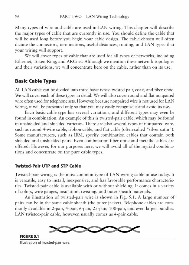
Many types of wire and cable are used in LAN wiring. This chapter will describethe major types of cable that are currently in use. You should define the cable thatwill be used long before you begin your cable design. The cable chosen will oftendictate the connectors, terminations, useful distances, routing, and LAN types thatyour wiring will support.
We will cover types of cable that are used for all types of networks, includingEthernet, Token-Ring, and ARCnet. Although we mention these network topologiesand their variations, we will concentrate here on the cable, rather than on its use.
Basic Cable Types
All LAN cable can be divided into three basic types: twisted pair, coax, and fiber optic.We will cover each of these types in detail. We will also cover round and flat nonpairedwire often used for telephone sets. However, because nonpaired wire is not used for LANwiring, it will be presented only so that you may easily recognize it and avoid its use.
Each basic cable type has several variations, and different types may even befound in combination. An example of this is twisted-pair cable, which may be foundin unshielded and shielded varieties. There are also several types of nonpaired wire,such as round 4-wire cable, ribbon cable, and flat cable (often called “silver satin”).Some manufacturers, such as IBM, specify combination cables that contain bothshielded and unshielded pairs. Even combination fiber-optic and metallic cables areoffered. However, for our purposes here, we will avoid all of the myriad combina-tions and concentrate on the pure cable types.
Twisted-Pair UTP and STP Cable
Twisted-pair wiring is the most common type of LAN wiring cable in use today. Itis versatile, easy to install, inexpensive, and has favorable performance characteris-tics. Twisted-pair cable is available with or without shielding. It comes in a varietyof colors, wire gauges, insulation, twisting, and outer sheath materials.
An illustration of twisted-pair wire is shown in Fig. 5.1. A large number ofpairs can be in the same cable sheath (the outer jacket). Telephone cables are com-monly available in 2-pair, 4-pair, 6-pair, 25-pair, 100-pair, and even larger bundles.LAN twisted-pair cable, however, usually comes as 4-pair cable.
96 PART TWO LAN Wiring Technology
FIGURE 5.1
Illustration of twisted-pair wire.
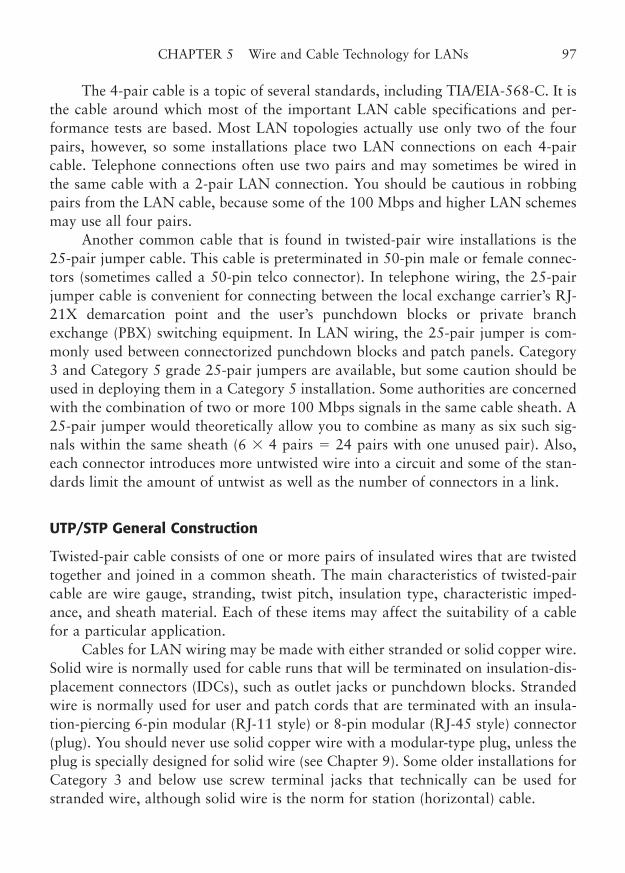
The 4-pair cable is a topic of several standards, including TIA/EIA-568-C. It isthe cable around which most of the important LAN cable specifications and per-formance tests are based. Most LAN topologies actually use only two of the fourpairs, however, so some installations place two LAN connections on each 4-paircable. Telephone connections often use two pairs and may sometimes be wired inthe same cable with a 2-pair LAN connection. You should be cautious in robbingpairs from the LAN cable, because some of the 100 Mbps and higher LAN schemesmay use all four pairs.
Another common cable that is found in twisted-pair wire installations is the25-pair jumper cable. This cable is preterminated in 50-pin male or female connec-tors (sometimes called a 50-pin telco connector). In telephone wiring, the 25-pairjumper cable is convenient for connecting between the local exchange carrier’s RJ-21X demarcation point and the user’s punchdown blocks or private branchexchange (PBX) switching equipment. In LAN wiring, the 25-pair jumper is com-monly used between connectorized punchdown blocks and patch panels. Category3 and Category 5 grade 25-pair jumpers are available, but some caution should beused in deploying them in a Category 5 installation. Some authorities are concernedwith the combination of two or more 100 Mbps signals in the same cable sheath. A25-pair jumper would theoretically allow you to combine as many as six such sig-nals within the same sheath (6 � 4 pairs � 24 pairs with one unused pair). Also,each connector introduces more untwisted wire into a circuit and some of the stan-dards limit the amount of untwist as well as the number of connectors in a link.
UTP/STP General Construction
Twisted-pair cable consists of one or more pairs of insulated wires that are twistedtogether and joined in a common sheath. The main characteristics of twisted-paircable are wire gauge, stranding, twist pitch, insulation type, characteristic imped-ance, and sheath material. Each of these items may affect the suitability of a cablefor a particular application.
Cables for LAN wiring may be made with either stranded or solid copper wire.Solid wire is normally used for cable runs that will be terminated on insulation-dis-placement connectors (IDCs), such as outlet jacks or punchdown blocks. Strandedwire is normally used for user and patch cords that are terminated with an insula-tion-piercing 6-pin modular (RJ-11 style) or 8-pin modular (RJ-45 style) connector(plug). You should never use solid copper wire with a modular-type plug, unless theplug is specially designed for solid wire (see Chapter 9). Some older installations forCategory 3 and below use screw terminal jacks that technically can be used forstranded wire, although solid wire is the norm for station (horizontal) cable.
CHAPTER 5 Wire and Cable Technology for LANs 97
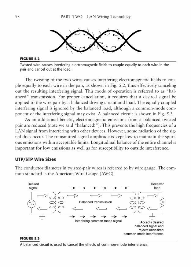
The twisting of the two wires causes interfering electromagnetic fields to cou-ple equally to each wire in the pair, as shown in Fig. 5.2, thus effectively cancelingout the resulting interfering signal. This mode of operation is referred to as “bal-anced” transmission. For proper cancellation, it requires that a desired signal beapplied to the wire pair by a balanced driving circuit and load. The equally coupledinterfering signal is ignored by the balanced load, although a common-mode com-ponent of the interfering signal may exist. A balanced circuit is shown in Fig. 5.3.
As an additional benefit, electromagnetic emissions from a balanced twistedpair are reduced (note we said “balanced!”). This prevents the high frequencies of aLAN signal from interfering with other devices. However, some radiation of the sig-nal does occur. The transmitted signal amplitude is kept low to maintain the spuri-ous emissions within acceptable limits. Longitudinal balance of the entire channel isimportant for low emissions as well as for susceptibility to outside interference.
UTP/STP Wire Sizes
The conductor diameter in twisted-pair wires is referred to by wire gauge. The com-mon standard is the American Wire Gauge (AWG).
98 PART TWO LAN Wiring Technology
FIGURE 5.2
Twisted wire causes interfering electromagnetic fields to couple equally to each wire in thepair and cancel out at the load.
Desiredsignal
Balanced transmission
Interfering common-mode signal Accepts desiredbalanced signal and
rejects undesiredcommon-mode interference
Receiverload
FIGURE 5.3
A balanced circuit is used to cancel the effects of common-mode interference.
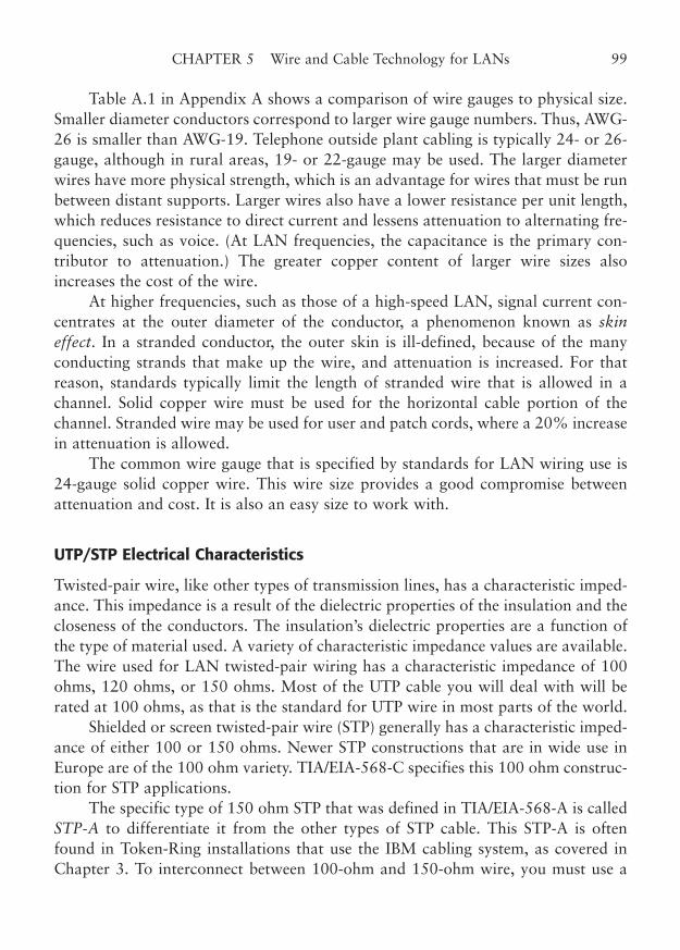
Table A.1 in Appendix A shows a comparison of wire gauges to physical size.Smaller diameter conductors correspond to larger wire gauge numbers. Thus, AWG-26 is smaller than AWG-19. Telephone outside plant cabling is typically 24- or 26-gauge, although in rural areas, 19- or 22-gauge may be used. The larger diameterwires have more physical strength, which is an advantage for wires that must be runbetween distant supports. Larger wires also have a lower resistance per unit length,which reduces resistance to direct current and lessens attenuation to alternating fre-quencies, such as voice. (At LAN frequencies, the capacitance is the primary con-tributor to attenuation.) The greater copper content of larger wire sizes alsoincreases the cost of the wire.
At higher frequencies, such as those of a high-speed LAN, signal current con-centrates at the outer diameter of the conductor, a phenomenon known as skineffect. In a stranded conductor, the outer skin is ill-defined, because of the manyconducting strands that make up the wire, and attenuation is increased. For thatreason, standards typically limit the length of stranded wire that is allowed in achannel. Solid copper wire must be used for the horizontal cable portion of thechannel. Stranded wire may be used for user and patch cords, where a 20% increasein attenuation is allowed.
The common wire gauge that is specified by standards for LAN wiring use is24-gauge solid copper wire. This wire size provides a good compromise betweenattenuation and cost. It is also an easy size to work with.
UTP/STP Electrical Characteristics
Twisted-pair wire, like other types of transmission lines, has a characteristic imped-ance. This impedance is a result of the dielectric properties of the insulation and thecloseness of the conductors. The insulation’s dielectric properties are a function ofthe type of material used. A variety of characteristic impedance values are available.The wire used for LAN twisted-pair wiring has a characteristic impedance of 100ohms, 120 ohms, or 150 ohms. Most of the UTP cable you will deal with will berated at 100 ohms, as that is the standard for UTP wire in most parts of the world.
Shielded or screen twisted-pair wire (STP) generally has a characteristic imped-ance of either 100 or 150 ohms. Newer STP constructions that are in wide use inEurope are of the 100 ohm variety. TIA/EIA-568-C specifies this 100 ohm construc-tion for STP applications.
The specific type of 150 ohm STP that was defined in TIA/EIA-568-A is calledSTP-A to differentiate it from the other types of STP cable. This STP-A is oftenfound in Token-Ring installations that use the IBM cabling system, as covered inChapter 3. To interconnect between 100-ohm and 150-ohm wire, you must use a
CHAPTER 5 Wire and Cable Technology for LANs 99
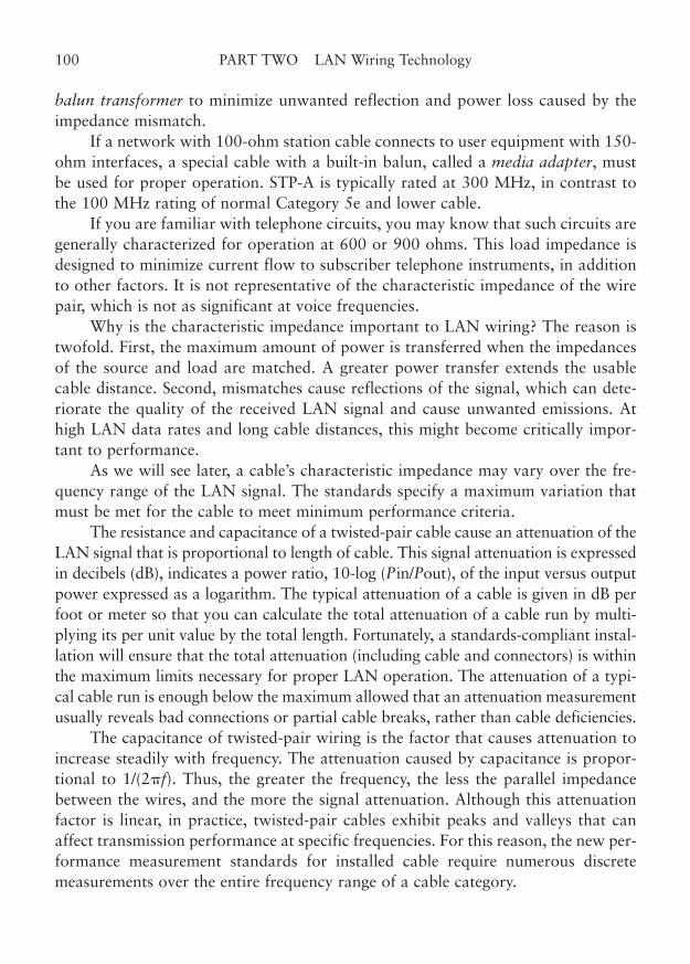
balun transformer to minimize unwanted reflection and power loss caused by theimpedance mismatch.
If a network with 100-ohm station cable connects to user equipment with 150-ohm interfaces, a special cable with a built-in balun, called a media adapter, mustbe used for proper operation. STP-A is typically rated at 300 MHz, in contrast tothe 100 MHz rating of normal Category 5e and lower cable.
If you are familiar with telephone circuits, you may know that such circuits aregenerally characterized for operation at 600 or 900 ohms. This load impedance isdesigned to minimize current flow to subscriber telephone instruments, in additionto other factors. It is not representative of the characteristic impedance of the wirepair, which is not as significant at voice frequencies.
Why is the characteristic impedance important to LAN wiring? The reason istwofold. First, the maximum amount of power is transferred when the impedancesof the source and load are matched. A greater power transfer extends the usablecable distance. Second, mismatches cause reflections of the signal, which can dete-riorate the quality of the received LAN signal and cause unwanted emissions. Athigh LAN data rates and long cable distances, this might become critically impor-tant to performance.
As we will see later, a cable’s characteristic impedance may vary over the fre-quency range of the LAN signal. The standards specify a maximum variation thatmust be met for the cable to meet minimum performance criteria.
The resistance and capacitance of a twisted-pair cable cause an attenuation of theLAN signal that is proportional to length of cable. This signal attenuation is expressedin decibels (dB), indicates a power ratio, 10-log (Pin/Pout), of the input versus outputpower expressed as a logarithm. The typical attenuation of a cable is given in dB perfoot or meter so that you can calculate the total attenuation of a cable run by multi-plying its per unit value by the total length. Fortunately, a standards-compliant instal-lation will ensure that the total attenuation (including cable and connectors) is withinthe maximum limits necessary for proper LAN operation. The attenuation of a typi-cal cable run is enough below the maximum allowed that an attenuation measurementusually reveals bad connections or partial cable breaks, rather than cable deficiencies.
The capacitance of twisted-pair wiring is the factor that causes attenuation toincrease steadily with frequency. The attenuation caused by capacitance is propor-tional to 1/(2�f). Thus, the greater the frequency, the less the parallel impedancebetween the wires, and the more the signal attenuation. Although this attenuationfactor is linear, in practice, twisted-pair cables exhibit peaks and valleys that canaffect transmission performance at specific frequencies. For this reason, the new per-formance measurement standards for installed cable require numerous discretemeasurements over the entire frequency range of a cable category.
100 PART TWO LAN Wiring Technology
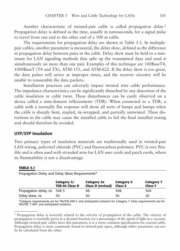
Another characteristic of twisted-pair cable is called propagation delay.1
Propagation delay is defined as the time, usually in nanoseconds, for a signal pulseto travel from one end to the other end of a 100 m cable.
The requirements for propagation delay are shown in Table 5.1. In multiple-pair cables, another parameter is measured, the delay skew, defined as the differencein propagation delay between pairs in the cable. Delay skew must be held to a min-imum for LAN signaling methods that split up the transmitted data and send itsimultaneously on more than one pair. Examples of this technique are 100BaseT4,1000BaseT (T4 and TX), ATM-155, and ATM-622. If the delay skew is too great,the data pulses will arrive at improper times, and the receiver circuitry will beunable to reassemble the data packets.
Installation practices can adversely impact twisted wire cable performance.The impedance characteristics can be significantly disturbed by any distortion of thecable insulation or cable twist. These disturbances can be easily observed on adevice called a time-domain reflectometer (TDR). When connected to a TDR, acable with a normally flat response will show all sorts of lumps and bumps whenthe cable is sharply bent, stapled, tie-wrapped, and partially untwisted. These dis-tortions in the cable may cause the installed cable to fail the final installed testingand should therefore be avoided.
UTP/STP Insulation
Two primary types of insulation materials are traditionally used in twisted-pairLAN wiring, polyvinyl chloride (PVC) and fluorocarbon polymers. PVC is very flex-ible and is often used with stranded wire for LAN user cords and patch cords, whereits flammability is not a disadvantage.
CHAPTER 5 Wire and Cable Technology for LANs 101
1 Propagation delay is inversely related to the velocity of propagation of the cable. The velocity ofpropagation is normally given as a decimal fraction (or a percentage) of the speed of light in a vacuum.Although twisted-pair cables have this parameter, it is a more common specification for coaxial cable.Propagation delay is more commonly found in twisted-pair specs, although either parameter can eas-ily be calculated from the other.
TABLE 5.1
Propagation Delay and Delay Skew Requirements*
Category 5/ Category 5e Category 6 Category 7 TSB-95 Class D Class D (revised) Class E Class F
Propagation delay, ns 548 5 48 548 504 Delay skew, ns 50 50 50 20
*Category requirements are for TIA/EIA-568-C and anticipated revisions for Category 7. Class requirements are forISO/IEC 11801 and anticipated revisions.
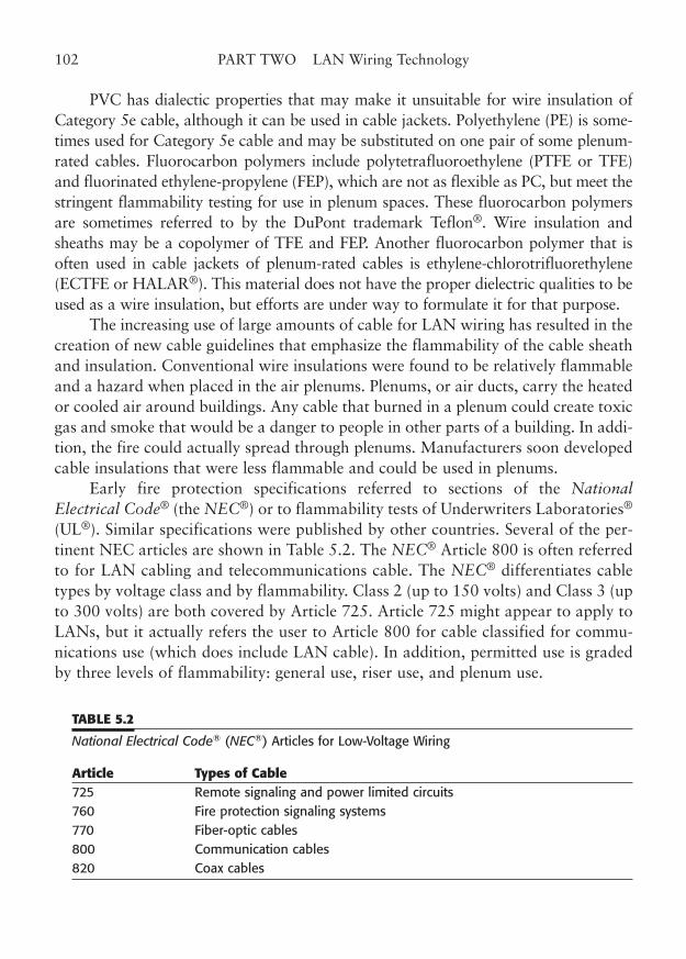
PVC has dialectic properties that may make it unsuitable for wire insulation ofCategory 5e cable, although it can be used in cable jackets. Polyethylene (PE) is some-times used for Category 5e cable and may be substituted on one pair of some plenum-rated cables. Fluorocarbon polymers include polytetrafluoroethylene (PTFE or TFE)and fluorinated ethylene-propylene (FEP), which are not as flexible as PC, but meet thestringent flammability testing for use in plenum spaces. These fluorocarbon polymersare sometimes referred to by the DuPont trademark Teflon®. Wire insulation andsheaths may be a copolymer of TFE and FEP. Another fluorocarbon polymer that isoften used in cable jackets of plenum-rated cables is ethylene-chlorotrifluorethylene(ECTFE or HALAR®). This material does not have the proper dielectric qualities to beused as a wire insulation, but efforts are under way to formulate it for that purpose.
The increasing use of large amounts of cable for LAN wiring has resulted in thecreation of new cable guidelines that emphasize the flammability of the cable sheathand insulation. Conventional wire insulations were found to be relatively flammableand a hazard when placed in the air plenums. Plenums, or air ducts, carry the heatedor cooled air around buildings. Any cable that burned in a plenum could create toxicgas and smoke that would be a danger to people in other parts of a building. In addi-tion, the fire could actually spread through plenums. Manufacturers soon developedcable insulations that were less flammable and could be used in plenums.
Early fire protection specifications referred to sections of the NationalElectrical Code® (the NEC®) or to flammability tests of Underwriters Laboratories®
(UL®). Similar specifications were published by other countries. Several of the per-tinent NEC articles are shown in Table 5.2. The NEC® Article 800 is often referredto for LAN cabling and telecommunications cable. The NEC® differentiates cabletypes by voltage class and by flammability. Class 2 (up to 150 volts) and Class 3 (upto 300 volts) are both covered by Article 725. Article 725 might appear to apply toLANs, but it actually refers the user to Article 800 for cable classified for commu-nications use (which does include LAN cable). In addition, permitted use is gradedby three levels of flammability: general use, riser use, and plenum use.
102 PART TWO LAN Wiring Technology
TABLE 5.2
National Electrical Code® (NEC®) Articles for Low-Voltage Wiring
Article Types of Cable725 Remote signaling and power limited circuits 760 Fire protection signaling systems 770 Fiber-optic cables 800 Communication cables 820 Coax cables
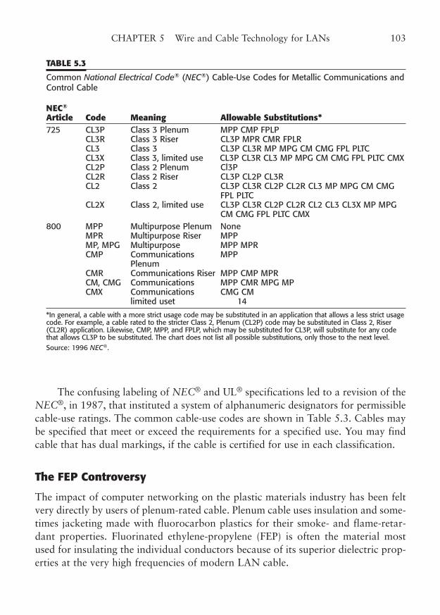
The confusing labeling of NEC® and UL® specifications led to a revision of theNEC®, in 1987, that instituted a system of alphanumeric designators for permissiblecable-use ratings. The common cable-use codes are shown in Table 5.3. Cables maybe specified that meet or exceed the requirements for a specified use. You may findcable that has dual markings, if the cable is certified for use in each classification.
The FEP Controversy
The impact of computer networking on the plastic materials industry has been feltvery directly by users of plenum-rated cable. Plenum cable uses insulation and some-times jacketing made with fluorocarbon plastics for their smoke- and flame-retar-dant properties. Fluorinated ethylene-propylene (FEP) is often the material mostused for insulating the individual conductors because of its superior dielectric prop-erties at the very high frequencies of modern LAN cable.
CHAPTER 5 Wire and Cable Technology for LANs 103
TABLE 5.3
Common National Electrical Code® (NEC®) Cable-Use Codes for Metallic Communications andControl Cable
NEC®
Article Code Meaning Allowable Substitutions*725 CL3P Class 3 Plenum MPP CMP FPLP
CL3R Class 3 Riser CL3P MPR CMR FPLR CL3 Class 3 CL3P CL3R MP MPG CM CMG FPL PLTC CL3X Class 3, limited use CL3P CL3R CL3 MP MPG CM CMG FPL PLTC CMX CL2P Class 2 Plenum Cl3P CL2R Class 2 Riser CL3P CL2P CL3R CL2 Class 2 CL3P CL3R CL2P CL2R CL3 MP MPG CM CMG
FPL PLTC CL2X Class 2, limited use CL3P CL3R CL2P CL2R CL2 CL3 CL3X MP MPG
CM CMG FPL PLTC CMX 800 MPP Multipurpose Plenum None
MPR Multipurpose Riser MPP MP, MPG Multipurpose MPP MPR CMP Communications MPP
PlenumCMR Communications Riser MPP CMP MPR CM, CMG Communications MPP CMR MPG MP CMX Communications CMG CM
limited uset 14
*In general, a cable with a more strict usage code may be substituted in an application that allows a less strict usagecode. For example, a cable rated to the stricter Class 2, Plenum (CL2P) code may be substituted in Class 2, Riser(CL2R) application. Likewise, CMP, MPP, and FPLP, which may be substituted for CL3P, will substitute for any codethat allows CL3P to be substituted. The chart does not list all possible substitutions, only those to the next level.Source: 1996 NEC®.
The problem is that the increasing use of this popular plenum-rated materialoften outpaces the ability of the material manufacturers to produce sufficient quan-tities for the cable industry. Additionally, the rapid growth of LANs and the ten-dency to overwire new installations for future requirements has thus far madeincreases in manufacturing capacity only a short-term cure. Of course, some dou-ble-ordering from cable and material users has occurred, which has caused theappearance of shortages to be even more severe.
For the cable user, the FEP crisis may mean that supplies of cable are periodi-cally lower than normal, or that the favored manufacturer, style, or even jacketcolor is not available on short notice. Deliveries may be extended, selection limited,and prices higher.
Several cable manufacturers have substituted other types of insulation on oneor more of the four pairs in popular LAN cables to stretch the supply.Unfortunately, they are very restricted in the types of material that can be used forthe very high-speed data rates of modern LAN systems. Common substitutions arepolyethylene, polyolefin, and some special polyvinyl chloride compounds. Some ofthese materials, in pure form, would not be able to pass the UL flame-spread tests,but are acceptable when used in conjunction with three normal FEP pairs and aplenum-rated jacket.
Costs of plenum-rated cables of all types have increased because of these mate-rial shortages. Some question remains whether the substitution of alternate materi-als may affect the long-term stability of the cable. However, there is only limitedevidence of problems at this point, as the alternative polyethylene and polyolefinmaterials are normally quite suitable for high frequency use in nonplenum applica-tions. The current controversy centers around dielectric property differences thatcause a delay skew failure in a mix such as 2-2 or 3-1, and the tendency of non-FEPplenum cables to flame up dramatically in simulations, even though they are able topass the smoke-tunnel tests.
Experimentation is ongoing to find other materials, such as from the chloro-fluorocarbon family, that can meet plenum requirements and have adequate dielec-tric characteristics for Category 5e and 6 LAN use. You will see some of thesematerials on the market today.
At the current rate of growth of LAN networks, we will continue to experienceperiodic material shortages for years to come.
UTP/STP Color Coding and Marking
Each insulated wire of a twisted-pair LAN cable is colored differently. The colorsform a standard code, so that each wire may be easily found and terminated prop-
104 PART TWO LAN Wiring Technology
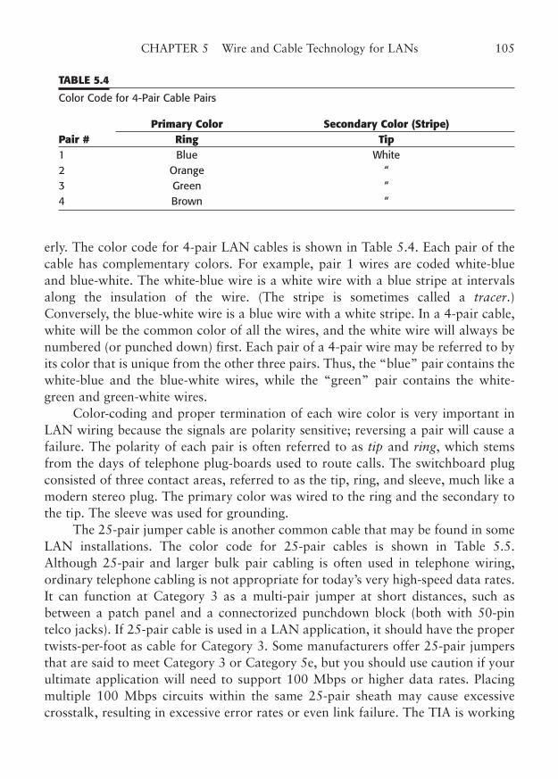
erly. The color code for 4-pair LAN cables is shown in Table 5.4. Each pair of thecable has complementary colors. For example, pair 1 wires are coded white-blueand blue-white. The white-blue wire is a white wire with a blue stripe at intervalsalong the insulation of the wire. (The stripe is sometimes called a tracer.)Conversely, the blue-white wire is a blue wire with a white stripe. In a 4-pair cable,white will be the common color of all the wires, and the white wire will always benumbered (or punched down) first. Each pair of a 4-pair wire may be referred to byits color that is unique from the other three pairs. Thus, the “blue” pair contains thewhite-blue and the blue-white wires, while the “green” pair contains the white-green and green-white wires.
Color-coding and proper termination of each wire color is very important inLAN wiring because the signals are polarity sensitive; reversing a pair will cause afailure. The polarity of each pair is often referred to as tip and ring, which stemsfrom the days of telephone plug-boards used to route calls. The switchboard plugconsisted of three contact areas, referred to as the tip, ring, and sleeve, much like amodern stereo plug. The primary color was wired to the ring and the secondary tothe tip. The sleeve was used for grounding.
The 25-pair jumper cable is another common cable that may be found in someLAN installations. The color code for 25-pair cables is shown in Table 5.5.Although 25-pair and larger bulk pair cabling is often used in telephone wiring,ordinary telephone cabling is not appropriate for today’s very high-speed data rates.It can function at Category 3 as a multi-pair jumper at short distances, such asbetween a patch panel and a connectorized punchdown block (both with 50-pintelco jacks). If 25-pair cable is used in a LAN application, it should have the propertwists-per-foot as cable for Category 3. Some manufacturers offer 25-pair jumpersthat are said to meet Category 3 or Category 5e, but you should use caution if yourultimate application will need to support 100 Mbps or higher data rates. Placingmultiple 100 Mbps circuits within the same 25-pair sheath may cause excessivecrosstalk, resulting in excessive error rates or even link failure. The TIA is working
CHAPTER 5 Wire and Cable Technology for LANs 105
TABLE 5.4
Color Code for 4-Pair Cable Pairs
Primary Color Secondary Color (Stripe)Pair # Ring Tip1 Blue White 2 Orange “3 Green “4 Brown “
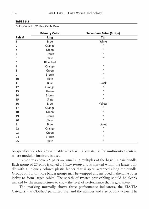
on specifications for 25-pair cable which will allow its use for multi-outlet centers,where modular furniture is used.
Cable sizes above 25 pairs are usually in multiples of the basic 25-pair bundle.Each group of 25 pairs is called a binder group and is marked within the larger bun-dle with a uniquely colored plastic binder that is spiral-wrapped along the bundle.Groups of four or more binder groups may be wrapped and included in the same outerjacket to form larger cables. The sheath of twisted-pair cabling should be clearlymarked by the manufacturer to show the level of performance that is guaranteed.
The marking normally shows three performance indicators, the EIA/TIACategory, the UL/NEC permitted use, and the number and size of conductors. The
106 PART TWO LAN Wiring Technology
TABLE 5.5
Color Code for 25-Pair Cable Pairs
Primary Color Secondary Color (Stripe)Pair # Ring Tip1 Blue White 2 Orange “3 Green “4 Brown “5 Slate “6 Blue Red 7 Orange “8 Green “9 Brown “10 Slate “11 Blue Black 12 Orange “13 Green “14 Brown “15 Slate “16 Blue Yellow 17 Orange “18 Green “19 Brown “20 Slate “21 Blue Violet 22 Orange “23 Green “24 Brown “25 Slate “
manufacturer’s name and part number are also normally shown. A typical markingmight be:
4PR—24GA—CMP—Category 5e—XYZ Cable Company—PN 99999
This example of a cable marking would indicate a 4-pair, 24 AWG cable, testedfor fire/smoke/voltage ratings to CMP standards of the NEC, certified to Category5e TIA standards, manufactured by XYZ Cable Company, with a part number of99999.
Because standards for cable have changed so much over the past few years, youmay encounter older cables with a variety of markings for their transmission char-acteristics and fire and smoke ratings. Because the TIA standards have been contin-ually refined, you might find cables that bear markings of the older standardrevisions or the levels program (for example, TSB-40, Level 5, or EIA/TIA-568). Theplenum rating might be marked as “Article 800” or “UL 910,” rather than the CMPwire use type. This cable is acceptable if already installed in appropriate applications(such as 10BaseT, for example), but should not be installed for new service. Most ofthis early cable will not meet the rigorous standards for today’s Category 5e, whichshould really be the minimum quality cable for any new installations.
UTP/STP Shielding and Screening
Shielding is sometimes used with twisted-pair cable to provide better noise immu-nity and lower emissions. Two types of shielding are commonly available for STPcable: the foil shield and the braided wire shield.
The foil shield usually has a bare stranded wire, called a drain wire, that is incontact with the shield and provides the electrical connection for the foil. Braidedshields may have a drain wire, or the braid may be formed into a wire or clampedto make electrical contact. Some cables may have combination foil/braid shields ordouble shields.
Screening is another term that is often applied to the type of electromagneticshielding used with twisted-pair cables. The term has gained new acceptance withthe latest revisions to the international standards.
Cables that are referred to as screened are generally constructed with an over-all foil screen, which means that the foil screen wraps completely around all fourpairs (or all 25 pairs in a multi-pair jumper cable).
Screened cables are in much greater use in Europe than in North America,where their use is found mostly in high-interference locations.
Screened cables require special plugs and jacks to allow for the screen intercon-nection. In addition, the connection of cable screens to a building ground (earth) can
CHAPTER 5 Wire and Cable Technology for LANs 107
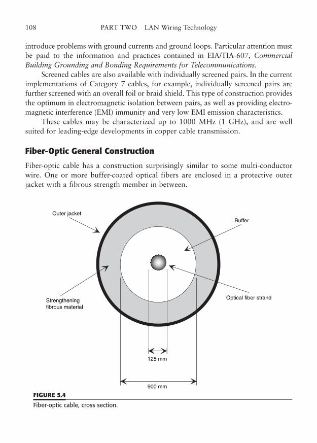
introduce problems with ground currents and ground loops. Particular attention mustbe paid to the information and practices contained in EIA/TIA-607, CommercialBuilding Grounding and Bonding Requirements for Telecommunications.
Screened cables are also available with individually screened pairs. In the currentimplementations of Category 7 cables, for example, individually screened pairs arefurther screened with an overall foil or braid shield. This type of construction providesthe optimum in electromagnetic isolation between pairs, as well as providing electro-magnetic interference (EMI) immunity and very low EMI emission characteristics.
These cables may be characterized up to 1000 MHz (1 GHz), and are wellsuited for leading-edge developments in copper cable transmission.
Fiber-Optic General Construction
Fiber-optic cable has a construction surprisingly similar to some multi-conductorwire. One or more buffer-coated optical fibers are enclosed in a protective outerjacket with a fibrous strength member in between.
108 PART TWO LAN Wiring Technology
Outer jacketBuffer
Strengtheningfibrous material
Optical fiber strand
125 mm
900 mm
FIGURE 5.4
Fiber-optic cable, cross section.
This construction is shown in Fig. 5.4. The buffer is rather like the insulationthat surrounds a copper wire in a conventional cable. The strength fibers are addedto prevent stretching of the cable, which would fracture the optical fiber.
Optical fiber is made of extruded glass (silica) or plastic, specially formulated topass light of specific wavelengths with very little loss. Most fiber-optic LAN wiringis used for backbone wiring and uses glass fiber. Plastic step-index fiber is availablefrom a few sources, but has traditionally suffered from high attenuation and limitedbandwidth, factors that are critical to the deployment of fiber technology.
Recent developments in graded-index plastic optical fiber (GIPOF) may offerincreased bandwidths in the future, perhaps with lower cost and suitable attenua-tion when compared to glass fiber. Plastic fiber construction is not yet blessed by thestandards for LAN wiring, so the rest of this section will concentrate on the charac-teristics of standard glass fiber.
The Fiber Debate
The choice between installing copper wiring and fiber-optic cable to the workstationis the subject of much debate—an important issue, particularly in new cablinginstallations where the cable plant is expected to have a useful life of 15 to 20 years.Few would suggest that anything but fiber should be used for campus wiring or forlonger high-speed cable runs between wiring closets. The controversy centers onwhether fiber should be used from the wiring closet to the workstation—so-called“fiber to the desktop.” Current estimates for horizontal fiber range from 5% to15% of all installations. Copper wiring installations still dwarf fiber installations,yet there is much disagreement on the issue.
What are the two sides to the debate? The proponents of fiber argue that itoffers greater signal bandwidth, runs longer distances, offers future growth, costsnearly the same, and is now easy to install and more rugged than generally thought.Proponents of copper over fiber argue that expanded bandwidth is being imple-mented for copper, that network switching equipment often does not support fiber,that the installed cost of fiber is greater than copper, and that fiber is subject tobreaks that are expensive to repair. In general, the most avid fiber supporters areeither those companies that offer fiber-optic cable, connectors, and related hard-ware, or they are installers and users who have made a significant investment infiber-optic technology and very naturally defend their decision. Please do not con-strue this statement to mean that either of these two groups is wrong, but simplythat they have a certain bias that leads them to the conclusion that fiber is alwaysthe best choice. In some circumstances, fiber cabling may clearly be the best, if notthe only reasonable choice. But, in many other situations, the issue is less clear.
CHAPTER 5 Wire and Cable Technology for LANs 109
What should be your choice?The fiber-versus-copper issue can be reduced to three questions:
■ Should fiber be used because of its greater bandwidth and for future migrationto higher-speed networking?
■ What are the cost implications of installing fiber over copper?■ Are there any special applications that favor fiber over cooper?
The bandwidth question is a moving target. Technology simply will not staystill, so we might as well give up trying to say with certainty what the future willbring. We can say one thing for certain: Future networking applications will usemuch more data bandwidth than in general use today. Copper twisted-pair tech-nologies, particularly with the use of enhanced Category 5e products, easily support100 to 1000 Mbps now. Of course, fiber can certainly take that signal over longerdistances, but 100 m is all that is required in horizontal cabling.
The question of relative cost is easier to approach. Fiber proponents havestated that installed fiber costs only about 20% more than Category 5e copper.Fiber-optic cable is indeed much less expensive than it used to be.
However, users may wish to use protective innerduct or use more expensivestrengthened cable. In addition, no one would argue that the interface adapters fornetwork equipment and hubs cost more for fiber-optic capability.
How much do the installation components relative to copper and cable cost?Let’s look at fiber versus copper termination components first. The traditionaldrawback to fiber installation has been the amount of time it takes to prepare,cleave, epoxy, and polish each fiber connection. New, quick-termination fiber con-nector assemblies are available that cut termination time to about 1 minute per con-nector. However, these connectors may cost (the end-user) about $10 each, so youare trading installation labor for component cost.
Adding the cost of the fiber-optic outlet box with one duplex 568SC adapter(total cost about $35) to the cost of the two quick-termination connectors yields afiber termination components cost of about $55. In contrast, a good-qualityCategory 5e modular connector and plate would cost about $15 (to the end-user).Installation labor, at best, would be approximately the same, but the fiber termina-tion requires the purchase of an installation kit, at a cost of approximately $500 to$1,000.
Cable prices bounce around a lot because of periodic shortages in plenum-rated materials, but the ratios remain about the same. If the installation calls forplenum-rated cable, then plenum-rated jacketing and inner materials must be usedeven for fiber cable. The recent plenum price for two-strand plenum 62.5/125 fiber
110 PART TWO LAN Wiring Technology
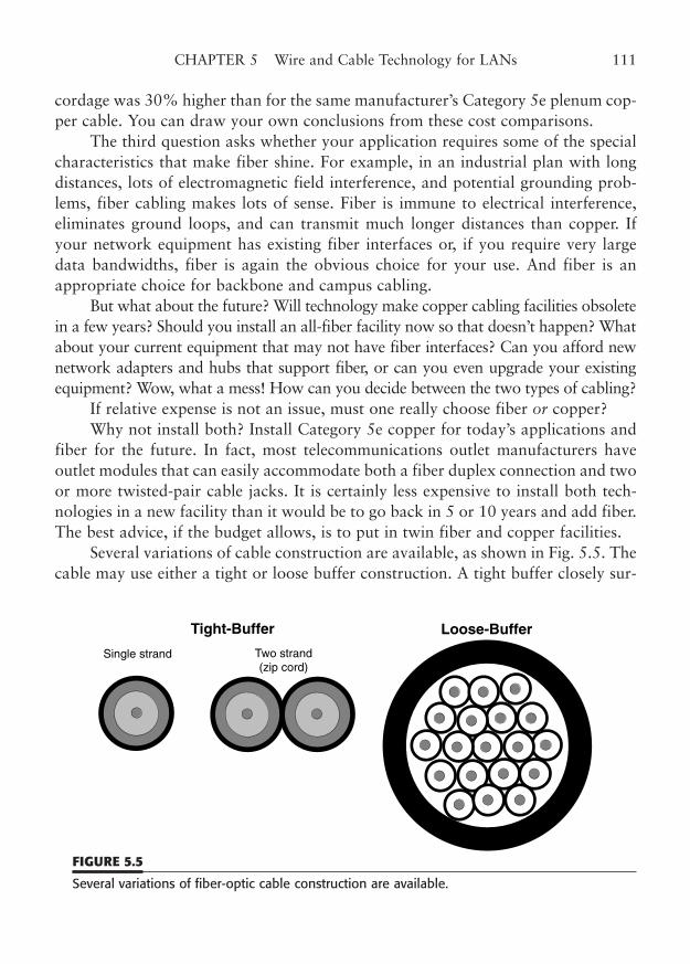
cordage was 30% higher than for the same manufacturer’s Category 5e plenum cop-per cable. You can draw your own conclusions from these cost comparisons.
The third question asks whether your application requires some of the specialcharacteristics that make fiber shine. For example, in an industrial plan with longdistances, lots of electromagnetic field interference, and potential grounding prob-lems, fiber cabling makes lots of sense. Fiber is immune to electrical interference,eliminates ground loops, and can transmit much longer distances than copper. Ifyour network equipment has existing fiber interfaces or, if you require very largedata bandwidths, fiber is again the obvious choice for your use. And fiber is anappropriate choice for backbone and campus cabling.
But what about the future? Will technology make copper cabling facilities obsoletein a few years? Should you install an all-fiber facility now so that doesn’t happen? Whatabout your current equipment that may not have fiber interfaces? Can you afford newnetwork adapters and hubs that support fiber, or can you even upgrade your existingequipment? Wow, what a mess! How can you decide between the two types of cabling?
If relative expense is not an issue, must one really choose fiber or copper?Why not install both? Install Category 5e copper for today’s applications and
fiber for the future. In fact, most telecommunications outlet manufacturers haveoutlet modules that can easily accommodate both a fiber duplex connection and twoor more twisted-pair cable jacks. It is certainly less expensive to install both tech-nologies in a new facility than it would be to go back in 5 or 10 years and add fiber.The best advice, if the budget allows, is to put in twin fiber and copper facilities.
Several variations of cable construction are available, as shown in Fig. 5.5. Thecable may use either a tight or loose buffer construction. A tight buffer closely sur-
CHAPTER 5 Wire and Cable Technology for LANs 111
Tight-Buffer Loose-Buffer
Single strand Two strand(zip cord)
FIGURE 5.5
Several variations of fiber-optic cable construction are available.
rounds the fiber and adheres to it. The tight buffer must be removed with a tool sim-ilar to a wire insulation stripper before the fiber can be terminated in a connector.Loose buffer cables use buffer tubes to surround and protect each fiber, which isloose in the tube. A variation of tight buffer cable is intended for breakout of thefibers without requiring a protection breakout box to safeguard the exposed fibers.The type of cable encloses each fiber in a breakout jacket that contains its ownstrength fibers. The entire assembly is covered with a protective outer jacket. Fillercords may be used to make the overall cable round. A variation of the breakoutcable is the two-fiber duplex, or zip cord, fiber cable that is often used for jumperor patch cords.
Fiber-optic cables are commonly available with 1 to 36 fibers. At two fibersand above, even numbers of fibers are the most common (e.g., 2, 4, 6, 12) becausefibers are often used in pairs for full-duplex circuits.
Cables are also available with a combination of optical fibers and metallicpairs. These special-use cables combine the properties of each type of cable, includ-ing the advantages and disadvantages.
Fiber-Optic Sizes
The most common fiber size that is used in LAN wiring is multimode 62.5/125 µmfiber. This number describes the diameter in micrometers, of the fiber core and thecladding. The tight buffer surrounds the cladding and brings the overall diameter toabout 900 µm. One of the fibers that is specified in TIA/EIA-568-C is 62.5/125 µm.It can be used for many applications, including Ethernet 10BaseF, 100BaseFX,1000BaseF, FOIRL, optical Token-Ring, FDDI, and ATM. (See Fig. 5.6.)
Other fiber sizes that are commonly available include 50/125, 85/125, and100/140 µm fiber. The 50/125 µm fiber was added in TIA/EIA-568-B because itoffers better performance in some applications, such as Gigabit Ethernet. It isimportant to use the same type and size of fiber in an installation, since transitionsbetween sizes can cause excessive loss. Also, the light-emitting transmitters andreceivers are optimized for fiber of a certain size. Using the wrong size fiber willcause some of the light signal to be lost because of poor coupling. This may resultin marginal operation or even circuit failure.
Fiber-Optical Characteristics
Unlike copper wire, which can carry electrical signals of any frequency from DC tomany megahertz, fiber optic cable is designed to carry light in a range of opticalwavelengths. These wavelengths are typically from around 800 to over 1500
112 PART TWO LAN Wiring Technology
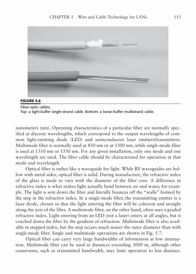
nanometers (nm). Operating characteristics of a particular fiber are normally spec-ified at discrete wavelengths, which correspond to the output wavelengths of com-mon light-emitting diode (LED) and semiconductor laser emitters/transmitters.Multimode fiber is normally used at 850 nm or at 1300 nm, while single-mode fiberis used at 1310 nm or 1550 nm. For any given installation, only one mode and onewavelength are used. The fiber cable should be characterized for operation at thatmode and wavelength.
Optical fiber is rather like a waveguide for light. While RF waveguides are hol-low with metal sides, optical fiber is solid. During manufacture, the refractive indexof the glass is made to vary with the diameter of the fiber core. A difference inrefractive index is what makes light actually bend between air and water, for exam-ple. The light is sent down the fiber and literally bounces off the “walls” formed bythe step in the refractive index. In a single-mode fiber, the transmitting emitter is alaser diode, chosen so that the light entering the fiber will be coherent and straightalong the axis of the fiber. A multimode fiber, on the other hand, often uses a gradedrefractive index. Light entering from an LED (not a laser) enters at all angles, but iscoached down the fiber by the gradient of refraction. Multimode fiber is also avail-able in stepped index, but the step occurs much nearer the outer diameter than withsingle-mode fiber. Single and multimode operations are shown in Fig. 5.7.
Optical fiber can carry very large bandwidths of information at low attenua-tion. Multimode fiber can be used at distances exceeding 3000 m, although otherconstraints, such as transmitted bandwidth, may limit operation to less distance.
CHAPTER 5 Wire and Cable Technology for LANs 113
FIGURE 5.6
Fiber-optic cables. Top: a tight-buffer single-strand cable. Bottom: a loose-buffer multistrand cable.
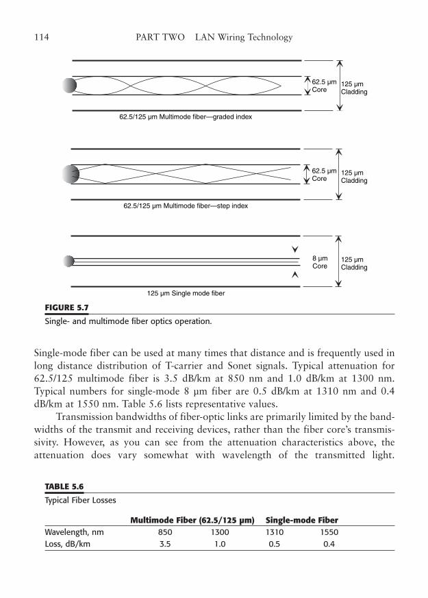
Single-mode fiber can be used at many times that distance and is frequently used inlong distance distribution of T-carrier and Sonet signals. Typical attenuation for62.5/125 multimode fiber is 3.5 dB/km at 850 nm and 1.0 dB/km at 1300 nm.Typical numbers for single-mode 8 µm fiber are 0.5 dB/km at 1310 nm and 0.4dB/km at 1550 nm. Table 5.6 lists representative values.
Transmission bandwidths of fiber-optic links are primarily limited by the band-widths of the transmit and receiving devices, rather than the fiber core’s transmis-sivity. However, as you can see from the attenuation characteristics above, theattenuation does vary somewhat with wavelength of the transmitted light.
114 PART TWO LAN Wiring Technology
62.5/125 µm Multimode fiber—graded index
62.5/125 µm Multimode fiber—step index
62.5 µmCore
125 µmCladding
125 µmCladding
125 µmCladding
8 µmCore
62.5 µmCore
125 µm Single mode fiber
FIGURE 5.7
Single- and multimode fiber optics operation.
TABLE 5.6
Typical Fiber Losses
Multimode Fiber (62.5/125 µm) Single-mode FiberWavelength, nm 850 1300 1310 1550 Loss, dB/km 3.5 1.0 0.5 0.4
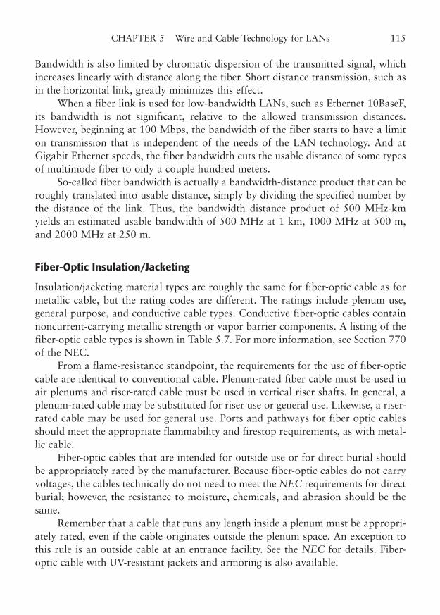
Bandwidth is also limited by chromatic dispersion of the transmitted signal, whichincreases linearly with distance along the fiber. Short distance transmission, such asin the horizontal link, greatly minimizes this effect.
When a fiber link is used for low-bandwidth LANs, such as Ethernet 10BaseF,its bandwidth is not significant, relative to the allowed transmission distances.However, beginning at 100 Mbps, the bandwidth of the fiber starts to have a limiton transmission that is independent of the needs of the LAN technology. And atGigabit Ethernet speeds, the fiber bandwidth cuts the usable distance of some typesof multimode fiber to only a couple hundred meters.
So-called fiber bandwidth is actually a bandwidth-distance product that can beroughly translated into usable distance, simply by dividing the specified number bythe distance of the link. Thus, the bandwidth distance product of 500 MHz-kmyields an estimated usable bandwidth of 500 MHz at 1 km, 1000 MHz at 500 m,and 2000 MHz at 250 m.
Fiber-Optic Insulation/Jacketing
Insulation/jacketing material types are roughly the same for fiber-optic cable as formetallic cable, but the rating codes are different. The ratings include plenum use,general purpose, and conductive cable types. Conductive fiber-optic cables containnoncurrent-carrying metallic strength or vapor barrier components. A listing of thefiber-optic cable types is shown in Table 5.7. For more information, see Section 770of the NEC.
From a flame-resistance standpoint, the requirements for the use of fiber-opticcable are identical to conventional cable. Plenum-rated fiber cable must be used inair plenums and riser-rated cable must be used in vertical riser shafts. In general, aplenum-rated cable may be substituted for riser use or general use. Likewise, a riser-rated cable may be used for general use. Ports and pathways for fiber optic cablesshould meet the appropriate flammability and firestop requirements, as with metal-lic cable.
Fiber-optic cables that are intended for outside use or for direct burial shouldbe appropriately rated by the manufacturer. Because fiber-optic cables do not carryvoltages, the cables technically do not need to meet the NEC requirements for directburial; however, the resistance to moisture, chemicals, and abrasion should be thesame.
Remember that a cable that runs any length inside a plenum must be appropri-ately rated, even if the cable originates outside the plenum space. An exception tothis rule is an outside cable at an entrance facility. See the NEC for details. Fiber-optic cable with UV-resistant jackets and armoring is also available.
CHAPTER 5 Wire and Cable Technology for LANs 115
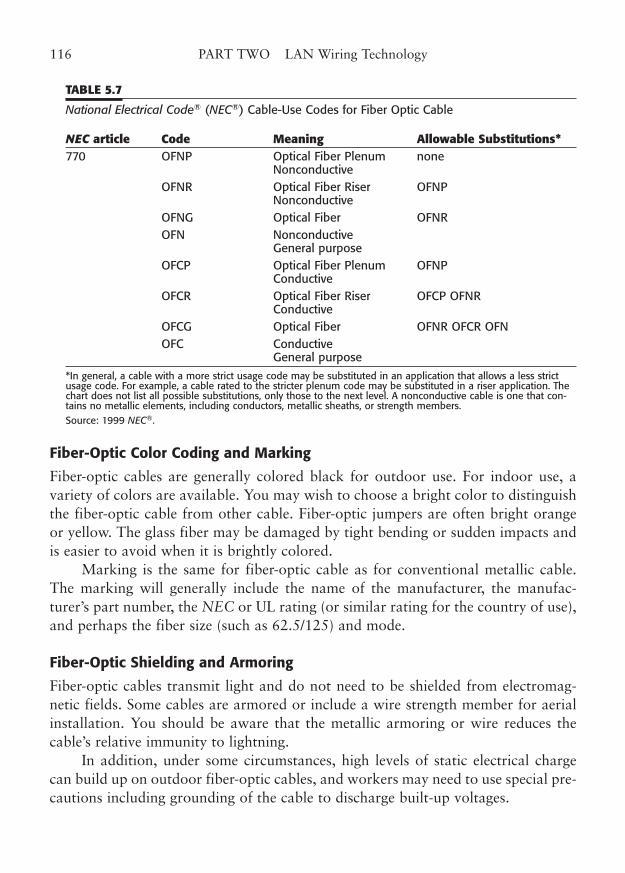
Fiber-Optic Color Coding and Marking
Fiber-optic cables are generally colored black for outdoor use. For indoor use, avariety of colors are available. You may wish to choose a bright color to distinguishthe fiber-optic cable from other cable. Fiber-optic jumpers are often bright orangeor yellow. The glass fiber may be damaged by tight bending or sudden impacts andis easier to avoid when it is brightly colored.
Marking is the same for fiber-optic cable as for conventional metallic cable.The marking will generally include the name of the manufacturer, the manufac-turer’s part number, the NEC or UL rating (or similar rating for the country of use),and perhaps the fiber size (such as 62.5/125) and mode.
Fiber-Optic Shielding and Armoring
Fiber-optic cables transmit light and do not need to be shielded from electromag-netic fields. Some cables are armored or include a wire strength member for aerialinstallation. You should be aware that the metallic armoring or wire reduces thecable’s relative immunity to lightning.
In addition, under some circumstances, high levels of static electrical chargecan build up on outdoor fiber-optic cables, and workers may need to use special pre-cautions including grounding of the cable to discharge built-up voltages.
116 PART TWO LAN Wiring Technology
TABLE 5.7
National Electrical Code® (NEC®) Cable-Use Codes for Fiber Optic Cable
NEC article Code Meaning Allowable Substitutions*770 OFNP Optical Fiber Plenum none
NonconductiveOFNR Optical Fiber Riser OFNP
NonconductiveOFNG Optical Fiber OFNR OFN Nonconductive
General purpose OFCP Optical Fiber Plenum OFNP
ConductiveOFCR Optical Fiber Riser OFCP OFNR
ConductiveOFCG Optical Fiber OFNR OFCR OFN OFC Conductive
General purpose*In general, a cable with a more strict usage code may be substituted in an application that allows a less strictusage code. For example, a cable rated to the stricter plenum code may be substituted in a riser application. Thechart does not list all possible substitutions, only those to the next level. A nonconductive cable is one that con-tains no metallic elements, including conductors, metallic sheaths, or strength members.Source: 1999 NEC®.
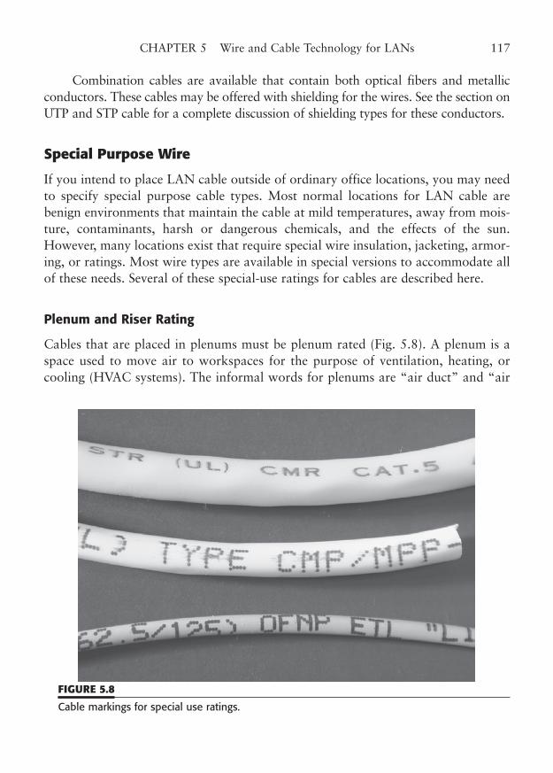
Combination cables are available that contain both optical fibers and metallicconductors. These cables may be offered with shielding for the wires. See the section onUTP and STP cable for a complete discussion of shielding types for these conductors.
Special Purpose Wire
If you intend to place LAN cable outside of ordinary office locations, you may needto specify special purpose cable types. Most normal locations for LAN cable arebenign environments that maintain the cable at mild temperatures, away from mois-ture, contaminants, harsh or dangerous chemicals, and the effects of the sun.However, many locations exist that require special wire insulation, jacketing, armor-ing, or ratings. Most wire types are available in special versions to accommodate allof these needs. Several of these special-use ratings for cables are described here.
Plenum and Riser Rating
Cables that are placed in plenums must be plenum rated (Fig. 5.8). A plenum is aspace used to move air to workspaces for the purpose of ventilation, heating, orcooling (HVAC systems). The informal words for plenums are “air duct” and “air
CHAPTER 5 Wire and Cable Technology for LANs 117
FIGURE 5.8
Cable markings for special use ratings.
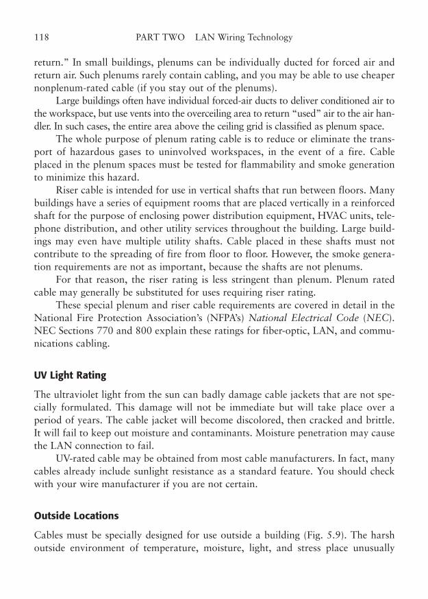
return.” In small buildings, plenums can be individually ducted for forced air andreturn air. Such plenums rarely contain cabling, and you may be able to use cheapernonplenum-rated cable (if you stay out of the plenums).
Large buildings often have individual forced-air ducts to deliver conditioned air tothe workspace, but use vents into the overceiling area to return “used” air to the air han-dler. In such cases, the entire area above the ceiling grid is classified as plenum space.
The whole purpose of plenum rating cable is to reduce or eliminate the trans-port of hazardous gases to uninvolved workspaces, in the event of a fire. Cableplaced in the plenum spaces must be tested for flammability and smoke generationto minimize this hazard.
Riser cable is intended for use in vertical shafts that run between floors. Manybuildings have a series of equipment rooms that are placed vertically in a reinforcedshaft for the purpose of enclosing power distribution equipment, HVAC units, tele-phone distribution, and other utility services throughout the building. Large build-ings may even have multiple utility shafts. Cable placed in these shafts must notcontribute to the spreading of fire from floor to floor. However, the smoke genera-tion requirements are not as important, because the shafts are not plenums.
For that reason, the riser rating is less stringent than plenum. Plenum ratedcable may generally be substituted for uses requiring riser rating.
These special plenum and riser cable requirements are covered in detail in theNational Fire Protection Association’s (NFPA’s) National Electrical Code (NEC).NEC Sections 770 and 800 explain these ratings for fiber-optic, LAN, and commu-nications cabling.
UV Light Rating
The ultraviolet light from the sun can badly damage cable jackets that are not spe-cially formulated. This damage will not be immediate but will take place over aperiod of years. The cable jacket will become discolored, then cracked and brittle.It will fail to keep out moisture and contaminants. Moisture penetration may causethe LAN connection to fail.
UV-rated cable may be obtained from most cable manufacturers. In fact, manycables already include sunlight resistance as a standard feature. You should checkwith your wire manufacturer if you are not certain.
Outside Locations
Cables must be specially designed for use outside a building (Fig. 5.9). The harshoutside environment of temperature, moisture, light, and stress place unusually
118 PART TWO LAN Wiring Technology
stringent requirements on cable of any type. Outside cable is suspended long aerialdistances, run in underground cable ducts, and directly buried. Cable may need tobe gel-filled or pressurized to exclude moisture. It may need special strength mem-bers of an integral messenger cable to span aerial distances. Metallic armoring maybe needed to resist damage from animals.
If you must run outside cables into buildings, you may want to consider a cablethat is also rated for indoor use. Such cable meets the NEC code requirements forindoor use as well as being designed for the harsher outside environment. The NECspecifies that typical outdoor cable may only be extended 50 feet inside a building,unless that cable is rated for the proposed indoor use. The alternative is to place ajunction or splice point inside the building, near the point of cable entry, to convertto inside-rated cable.
Hazardous Locations
Special cable, conduit, and junction boxes may be required for cable that is run inso-called hazardous locations, including places where flammable or explosive gasesor liquids might be present. Surprisingly, hydrogen and oxygen gas fit into thisdescription, as do volatile liquids such as gasoline and solvents. The NEC addressesthe installation of cabling in hazardous areas.
CHAPTER 5 Wire and Cable Technology for LANs 119
FIGURE 5.9
Outside plant cable (built with steel “messenger” cable bonded to the top of the data cable).

This page intentionally left blank
CHAPTER 6
Work Area Outlets
Highlights
■ Outlet jack mountings
■ Modular jacks for twisted pair
■ Standard jack pin-outs
■ Fiber-optic outlet jacks
■ Marking outlets
■ Workmanship
121
Copyright © 2006 by James Trulove. Click here for terms of use.
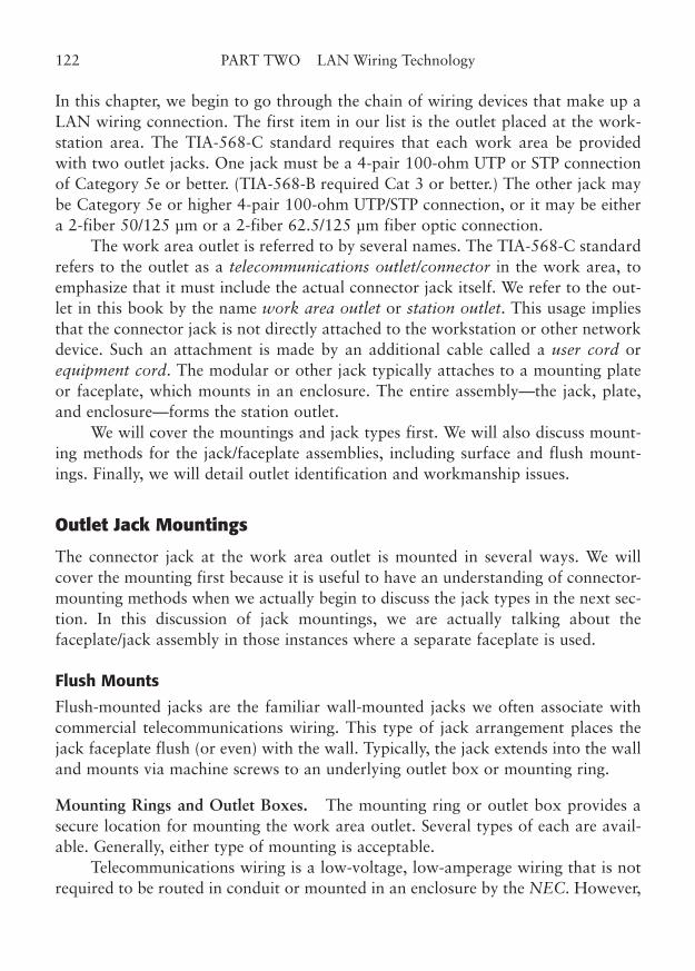
In this chapter, we begin to go through the chain of wiring devices that make up aLAN wiring connection. The first item in our list is the outlet placed at the work-station area. The TIA-568-C standard requires that each work area be providedwith two outlet jacks. One jack must be a 4-pair 100-ohm UTP or STP connectionof Category 5e or better. (TIA-568-B required Cat 3 or better.) The other jack maybe Category 5e or higher 4-pair 100-ohm UTP/STP connection, or it may be eithera 2-fiber 50/125 µm or a 2-fiber 62.5/125 µm fiber optic connection.
The work area outlet is referred to by several names. The TIA-568-C standardrefers to the outlet as a telecommunications outlet/connector in the work area, toemphasize that it must include the actual connector jack itself. We refer to the out-let in this book by the name work area outlet or station outlet. This usage impliesthat the connector jack is not directly attached to the workstation or other networkdevice. Such an attachment is made by an additional cable called a user cord orequipment cord. The modular or other jack typically attaches to a mounting plateor faceplate, which mounts in an enclosure. The entire assembly—the jack, plate,and enclosure—forms the station outlet.
We will cover the mountings and jack types first. We will also discuss mount-ing methods for the jack/faceplate assemblies, including surface and flush mount-ings. Finally, we will detail outlet identification and workmanship issues.
Outlet Jack Mountings
The connector jack at the work area outlet is mounted in several ways. We willcover the mounting first because it is useful to have an understanding of connector-mounting methods when we actually begin to discuss the jack types in the next sec-tion. In this discussion of jack mountings, we are actually talking about thefaceplate/jack assembly in those instances where a separate faceplate is used.
Flush Mounts
Flush-mounted jacks are the familiar wall-mounted jacks we often associate withcommercial telecommunications wiring. This type of jack arrangement places thejack faceplate flush (or even) with the wall. Typically, the jack extends into the walland mounts via machine screws to an underlying outlet box or mounting ring.
Mounting Rings and Outlet Boxes. The mounting ring or outlet box provides asecure location for mounting the work area outlet. Several types of each are avail-able. Generally, either type of mounting is acceptable.
Telecommunications wiring is a low-voltage, low-amperage wiring that is notrequired to be routed in conduit or mounted in an enclosure by the NEC. However,
122 PART TWO LAN Wiring Technology
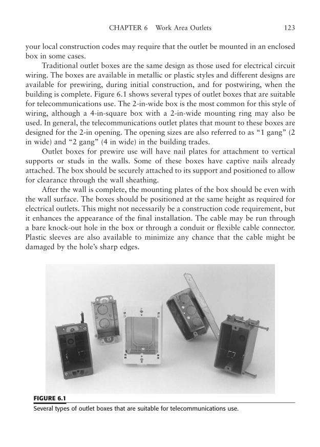
your local construction codes may require that the outlet be mounted in an enclosedbox in some cases.
Traditional outlet boxes are the same design as those used for electrical circuitwiring. The boxes are available in metallic or plastic styles and different designs areavailable for prewiring, during initial construction, and for postwiring, when thebuilding is complete. Figure 6.1 shows several types of outlet boxes that are suitablefor telecommunications use. The 2-in-wide box is the most common for this style ofwiring, although a 4-in-square box with a 2-in-wide mounting ring may also beused. In general, the telecommunications outlet plates that mount to these boxes aredesigned for the 2-in opening. The opening sizes are also referred to as “1 gang” (2in wide) and “2 gang” (4 in wide) in the building trades.
Outlet boxes for prewire use will have nail plates for attachment to verticalsupports or studs in the walls. Some of these boxes have captive nails alreadyattached. The box should be securely attached to its support and positioned to allowfor clearance through the wall sheathing.
After the wall is complete, the mounting plates of the box should be even withthe wall surface. The boxes should be positioned at the same height as required forelectrical outlets. This might not necessarily be a construction code requirement, butit enhances the appearance of the final installation. The cable may be run througha bare knock-out hole in the box or through a conduit or flexible cable connector.Plastic sleeves are also available to minimize any chance that the cable might bedamaged by the hole’s sharp edges.
CHAPTER 6 Work Area Outlets 123
FIGURE 6.1
Several types of outlet boxes that are suitable for telecommunications use.
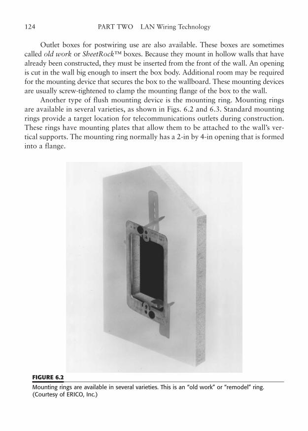
Outlet boxes for postwiring use are also available. These boxes are sometimescalled old work or SheetRock™ boxes. Because they mount in hollow walls that havealready been constructed, they must be inserted from the front of the wall. An openingis cut in the wall big enough to insert the box body. Additional room may be requiredfor the mounting device that secures the box to the wallboard. These mounting devicesare usually screw-tightened to clamp the mounting flange of the box to the wall.
Another type of flush mounting device is the mounting ring. Mounting ringsare available in several varieties, as shown in Figs. 6.2 and 6.3. Standard mountingrings provide a target location for telecommunications outlets during construction.These rings have mounting plates that allow them to be attached to the wall’s ver-tical supports. The mounting ring normally has a 2-in by 4-in opening that is formedinto a flange.
124 PART TWO LAN Wiring Technology
FIGURE 6.2
Mounting rings are available in several varieties. This is an “old work” or “remodel” ring.(Courtesy of ERICO, Inc.)
The flange protrudes forward from the wall support and is the right depth tobe flush with the front of the wall surface, when it is later attached. The top andbottom edges of the ring have mounting holes to which the mounting screws of theoutlet attach.
Mounting rings for postwiring are also available. These rings have flexible metalfingers at the top and bottom of the opening that are part of the stamping. A rectan-gular hole of an appropriate size is cut into the wallboard. Then, the mounting ring isplaced in the hole until it is flush with the wall. The metal fingers are bent around intothe hole and back against the rear surface of the wallboard to secure the ring. An alter-native design has a vertical screw slot incorporated into the metal fingers. After thefingers are bent into the mounting hole, a provided screw clamps the front flange ofthe ring tightly to the wall, using the slotted finger as a rear clamp. This prevents anyundesired movement in the ring that would occur with the other type of ring.
CHAPTER 6 Work Area Outlets 125
FIGURE 6.3
Mounting rings are available in varieties for use during initial construction of a building. This isa typical prewire ring. (Courtesy of ERICO, Inc.)
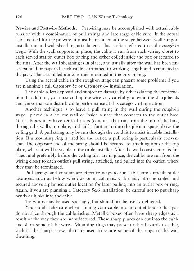
Prewire and Postwire Methods. Prewiring may be accomplished with actual cableruns or with a combination of pull strings and late-stage cable runs. If the actualcable is used for the prewire, it must be installed at the stage between wall supportinstallation and wall sheathing attachment. This is often referred to as the rough-instage. With the wall supports in place, the cable is run from each wiring closet toeach served station outlet box or ring and either coiled inside the box or secured tothe ring. After the wall sheathing is in place, and usually after the wall has been fin-ish-painted or papered, each cable is trimmed to working length and terminated inthe jack. The assembled outlet is then mounted in the box or ring.
Using the actual cable in the rough-in stage can present some problems if youare planning a full Category 5e or Category 6+ installation.
The cable is left exposed and subject to damage by others during the construc-tion. In addition, you must coil up the wire very carefully to avoid the sharp bendsand kinks that can disturb cable performance at this category of operation.
Another technique is to leave a pull string in the wall during the rough-instage—placed in a hollow wall or inside a riser that connects to the outlet box.Outlet boxes may have vertical risers (conduit) that run from the top of the box,through the wall’s top plate, and half a foot or so into the plenum space above theceiling grid. A pull string may be run through the conduit to assist in cable installa-tion. If a mounting ring is used for the outlet, a pull string is particularly conven-ient. The opposite end of the string should be secured to anything above the topplate, where it will be visible to the cable installer. After the wall construction is fin-ished, and preferably before the ceiling tiles are in place, the cables are run from thewiring closet to each outlet’s pull string, attached, and pulled into the outlet, wherethey may be terminated.
Pull strings and conduit are effective ways to run cable into difficult outletlocations, such as below windows or in columns. Cable may also be coiled andsecured above a planned outlet location for later pulling into an outlet box or ring.Again, if you are planning a Category 5e/6 installation, be careful not to put sharpbends or kinks into the cable.
Tie wraps may be used sparingly, but should not be overly tightened.You should take care when running your cable into an outlet box so that you
do not slice through the cable jacket. Metallic boxes often have sharp edges as aresult of the way they are manufactured. These sharp places can cut into the cableand short some of the wires. Mounting rings may present other hazards to cable,such as the sharp screws that are used to secure some of the rings to the wallsheathing.
126 PART TWO LAN Wiring Technology
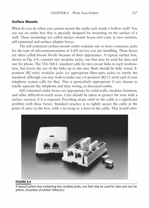
Surface Mounts
What do you do when you cannot mount the outlet jack inside a hollow wall? Youcan use an outlet box that is specially designed for mounting on the surface of awall. These mountings are called surface mount boxes and come in two varieties,self-contained and surface adapter boxes.
The self-contained surface-mount outlet contains one or more connector jacksfor the type of telecommunications or LAN service you are installing. These boxesare often called biscuit blocks because of their appearance. A typical surface box,shown in Fig. 6.4, contains two modular jacks, one that may be used for data andone for phone. The TIA-568-C standard calls for two circuit links to each worksta-tion, but leaves the use of the links up to the user. Both should be fully wired, 8-position (RJ style) modular jacks (or appropriate fiber-optic jacks) to satisfy thestandard, although you may wish to make one a 6-position (RJ-11 style) jack if yourtelephone system calls for that. This is particularly appropriate if you choose tototally separate the telephone and data wiring, as discussed earlier.
Self-contained outlet boxes are appropriate for solid walls, modular furniture,and other difficult-to-reach areas. Care should be taken to protect the wire with asurface raceway if it is exposed. Providing strain relief to the cable is a significantproblem with these boxes. Standard practice is to tightly secure the cable at thepoint of entry to the box, with a tie-wrap or a knot in the cable. This would obvi-
CHAPTER 6 Work Area Outlets 127
FIGURE 6.4
A typical surface box containing two modular jacks, one that may be used for data and one forphone. (Courtesy of Leviton Telecom.)
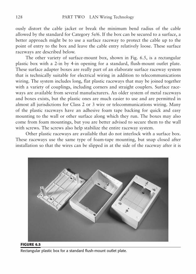
ously distort the cable jacket or break the minimum bend radius of the cableallowed by the standard for Category 5e/6. If the box can be secured to a surface, abetter approach might be to use a surface raceway to protect the cable up to thepoint of entry to the box and leave the cable entry relatively loose. These surfaceraceways are described below.
The other variety of surface-mount box, shown in Fig. 6.5, is a rectangularplastic box with a 2-in by 4-in opening for a standard, flush-mount outlet plate.These surface adapter boxes are really part of an elaborate surface raceway systemthat is technically suitable for electrical wiring in addition to telecommunicationswiring. The system includes long, flat plastic raceways that may be joined togetherwith a variety of couplings, including corners and straight couplers. Surface race-ways are available from several manufacturers. An older system of metal racewaysand boxes exists, but the plastic ones are much easier to use and are permitted inalmost all jurisdictions for Class 2 or 3 wire or telecommunications wiring. Manyof the plastic raceways have an adhesive foam tape backing for quick and easymounting to the wall or other surface along which they run. The boxes may alsocome from foam mountings, but you are better advised to secure them to the wallwith screws. The screws also help stabilize the entire raceway system.
Other plastic raceways are available that do not interlock with a surface box.These raceways use the same type of foam-tape mounting, but snap closed afterinstallation so that the wires can be slipped in at the side of the raceway after it is
128 PART TWO LAN Wiring Technology
FIGURE 6.5
Rectangular plastic box for a standard flush-mount outlet plate.
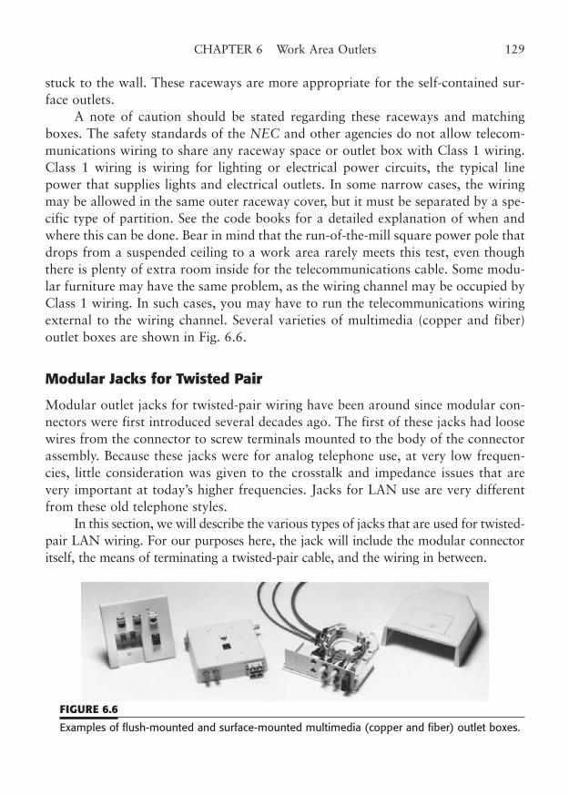
stuck to the wall. These raceways are more appropriate for the self-contained sur-face outlets.
A note of caution should be stated regarding these raceways and matchingboxes. The safety standards of the NEC and other agencies do not allow telecom-munications wiring to share any raceway space or outlet box with Class 1 wiring.Class 1 wiring is wiring for lighting or electrical power circuits, the typical linepower that supplies lights and electrical outlets. In some narrow cases, the wiringmay be allowed in the same outer raceway cover, but it must be separated by a spe-cific type of partition. See the code books for a detailed explanation of when andwhere this can be done. Bear in mind that the run-of-the-mill square power pole thatdrops from a suspended ceiling to a work area rarely meets this test, even thoughthere is plenty of extra room inside for the telecommunications cable. Some modu-lar furniture may have the same problem, as the wiring channel may be occupied byClass 1 wiring. In such cases, you may have to run the telecommunications wiringexternal to the wiring channel. Several varieties of multimedia (copper and fiber)outlet boxes are shown in Fig. 6.6.
Modular Jacks for Twisted Pair
Modular outlet jacks for twisted-pair wiring have been around since modular con-nectors were first introduced several decades ago. The first of these jacks had loosewires from the connector to screw terminals mounted to the body of the connectorassembly. Because these jacks were for analog telephone use, at very low frequen-cies, little consideration was given to the crosstalk and impedance issues that arevery important at today’s higher frequencies. Jacks for LAN use are very differentfrom these old telephone styles.
In this section, we will describe the various types of jacks that are used for twisted-pair LAN wiring. For our purposes here, the jack will include the modular connectoritself, the means of terminating a twisted-pair cable, and the wiring in between.
CHAPTER 6 Work Area Outlets 129
FIGURE 6.6
Examples of flush-mounted and surface-mounted multimedia (copper and fiber) outlet boxes.
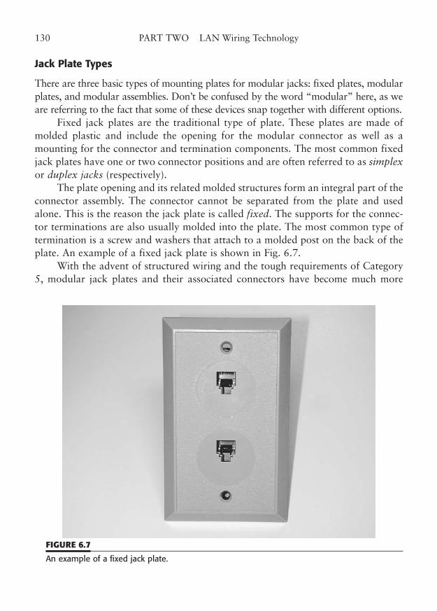
Jack Plate Types
There are three basic types of mounting plates for modular jacks: fixed plates, modularplates, and modular assemblies. Don’t be confused by the word “modular” here, as weare referring to the fact that some of these devices snap together with different options.
Fixed jack plates are the traditional type of plate. These plates are made ofmolded plastic and include the opening for the modular connector as well as amounting for the connector and termination components. The most common fixedjack plates have one or two connector positions and are often referred to as simplexor duplex jacks (respectively).
The plate opening and its related molded structures form an integral part of theconnector assembly. The connector cannot be separated from the plate and usedalone. This is the reason the jack plate is called fixed. The supports for the connec-tor terminations are also usually molded into the plate. The most common type oftermination is a screw and washers that attach to a molded post on the back of theplate. An example of a fixed jack plate is shown in Fig. 6.7.
With the advent of structured wiring and the tough requirements of Category5, modular jack plates and their associated connectors have become much more
130 PART TWO LAN Wiring Technology
FIGURE 6.7
An example of a fixed jack plate.
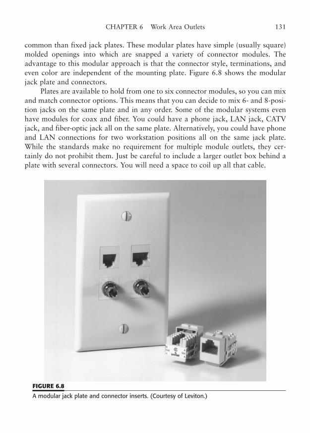
common than fixed jack plates. These modular plates have simple (usually square)molded openings into which are snapped a variety of connector modules. Theadvantage to this modular approach is that the connector style, terminations, andeven color are independent of the mounting plate. Figure 6.8 shows the modularjack plate and connectors.
Plates are available to hold from one to six connector modules, so you can mixand match connector options. This means that you can decide to mix 6- and 8-posi-tion jacks on the same plate and in any order. Some of the modular systems evenhave modules for coax and fiber. You could have a phone jack, LAN jack, CATVjack, and fiber-optic jack all on the same plate. Alternatively, you could have phoneand LAN connections for two workstation positions all on the same jack plate.While the standards make no requirement for multiple module outlets, they cer-tainly do not prohibit them. Just be careful to include a larger outlet box behind aplate with several connectors. You will need a space to coil up all that cable.
CHAPTER 6 Work Area Outlets 131
FIGURE 6.8
A modular jack plate and connector inserts. (Courtesy of Leviton.)
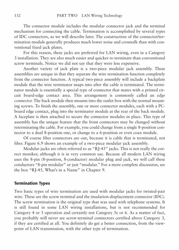
The connector module includes the modular connector jack and the terminalmechanism for connecting the cable. Termination is accomplished by several typesof IDC connectors, as we will describe later. The construction of the connector/ter-mination module generally produces much lower noise and crosstalk than with con-ventional fixed jack plates.
For this reason, these jacks are preferred for LAN wiring, even in a Category3 installation. They are also much easier and quicker to terminate than conventionalscrew terminals. Notice we did not say that they were less expensive.
Another variety of jack plate is a two-piece modular jack assembly. Theseassemblies are unique in that they separate the wire termination function completelyfrom the connector function. A typical two-piece assembly will include a backplatemodule that the wire terminator snaps into after the cable is terminated. The termi-nator module is essentially a special type of connector that mates with a printed cir-cuit board-edge contact area. This arrangement is commonly called an edgeconnector. The back module then mounts into the outlet box with the normal mount-ing screws. To finish the assembly, one or more connector modules, each with a PC-board edge contact, plug into the terminator module at the rear of the back module.A faceplate is then attached to secure the connector modules in place. This type ofassembly has the unique feature that the front connectors may be changed withoutreterminating the cable. For example, you could change from a single 8-position con-nector to a dual 8-position one, or change to a 6-position or even coax module.
Of course fiber connectors are out, because it is cable that is terminated, notfiber. Figure 6.9 shows an example of a two-piece modular jack assembly.
Modular jacks are often referred to as “RJ-45” jacks. This is not really the cor-rect moniker, although it is in very common use. Because all modern LAN wiringuses the 8-pin (8-position, 8-conductor) modular plug and jack, we will call theseconductors “8-pin modular” or just “modular.” For a more complete discussion, seethe box “RJ-45, What’s in a Name” in Chapter 9.
Termination Types
Two basic types of wire termination are used with modular jacks for twisted-pairwire. These are the screw terminal and the insulation-displacement connector (IDC).The screw termination is the original type that was used with telephone systems. Itis still found in some LAN wiring installations, but is not recommended forCategory 4 or 5 operation and certainly not Category 5e or 6. As a matter of fact,you probably will never see screw-terminal connectors certified above Category 3,if they are certified at all. You definitely do get a better connection, from the view-point of LAN transmission, with the other type of termination.
132 PART TWO LAN Wiring Technology
For that reason, many installers do not recommend screw terminals for anyLAN work. Of course, you do not need to rush around and pull out all of your oldscrew terminal plates that might be in your network now. Just remember that theycannot perform above Category 3 and that old installations may have “space-wired”station cable that is untwisted or crossed before it even gets to the screw terminals.
Nevertheless, there is still a right and wrong way to terminate wire on screw ter-minals. Proper wire termination for screw terminals is illustrated in Fig. 6.10. Thescrew terminal consists of a screw, two washers, and the plastic post of the jack plate.The jack’s connector wires are normally terminated in an open-end spade lug that ispositioned between the plastic post and the lower of the two washers. To terminatethe station cable, the screw is first loosened. Each station wire’s insulation should bestripped back about 3/8-inch and the bare copper portion wrapped between the twowashers. The wire may be preformed before it is placed into position.
The screw is tightened moderately and electrical contact is made in the sand-wich made by the washers and the plastic post. The proper direction for the wrapis clockwise around the screw (and it must be between the two washers). No insu-lation should be between the washers, and the wire should not wrap back acrossitself (to avoid breaking the wire when the screw is tightened). Some installers stripan inch or more and wrap the wire around the screw (with no overwrap). The excess
CHAPTER 6 Work Area Outlets 133
FIGURE 6.9
An example of a two-piece modular jack assembly. (Courtesy of AMP Incorporated.)
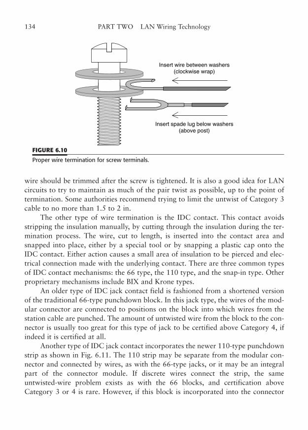
wire should be trimmed after the screw is tightened. It is also a good idea for LANcircuits to try to maintain as much of the pair twist as possible, up to the point oftermination. Some authorities recommend trying to limit the untwist of Category 3cable to no more than 1.5 to 2 in.
The other type of wire termination is the IDC contact. This contact avoidsstripping the insulation manually, by cutting through the insulation during the ter-mination process. The wire, cut to length, is inserted into the contact area andsnapped into place, either by a special tool or by snapping a plastic cap onto theIDC contact. Either action causes a small area of insulation to be pierced and elec-trical connection made with the underlying contact. There are three common typesof IDC contact mechanisms: the 66 type, the 110 type, and the snap-in type. Otherproprietary mechanisms include BIX and Krone types.
An older type of IDC jack contact field is fashioned from a shortened versionof the traditional 66-type punchdown block. In this jack type, the wires of the mod-ular connector are connected to positions on the block into which wires from thestation cable are punched. The amount of untwisted wire from the block to the con-nector is usually too great for this type of jack to be certified above Category 4, ifindeed it is certified at all.
Another type of IDC jack contact incorporates the newer 110-type punchdownstrip as shown in Fig. 6.11. The 110 strip may be separate from the modular con-nector and connected by wires, as with the 66-type jacks, or it may be an integralpart of the connector module. If discrete wires connect the strip, the sameuntwisted-wire problem exists as with the 66 blocks, and certification aboveCategory 3 or 4 is rare. However, if this block is incorporated into the connector
134 PART TWO LAN Wiring Technology
Insert wire between washers(clockwise wrap)
Insert spade lug below washers(above post)
FIGURE 6.10
Proper wire termination for screw terminals.
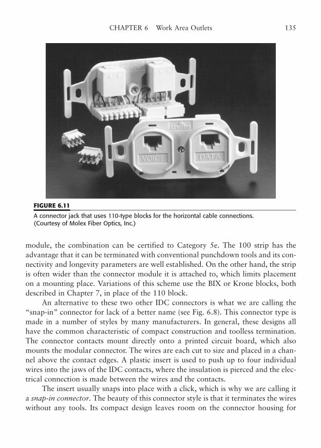
module, the combination can be certified to Category 5e. The 100 strip has theadvantage that it can be terminated with conventional punchdown tools and its con-nectivity and longevity parameters are well established. On the other hand, the stripis often wider than the connector module it is attached to, which limits placementon a mounting place. Variations of this scheme use the BIX or Krone blocks, bothdescribed in Chapter 7, in place of the 110 block.
An alternative to these two other IDC connectors is what we are calling the“snap-in” connector for lack of a better name (see Fig. 6.8). This connector type ismade in a number of styles by many manufacturers. In general, these designs allhave the common characteristic of compact construction and toolless termination.The connector contacts mount directly onto a printed circuit board, which alsomounts the modular connector. The wires are each cut to size and placed in a chan-nel above the contact edges. A plastic insert is used to push up to four individualwires into the jaws of the IDC contacts, where the insulation is pierced and the elec-trical connection is made between the wires and the contacts.
The insert usually snaps into place with a click, which is why we are calling ita snap-in connector. The beauty of this connector style is that it terminates the wireswithout any tools. Its compact design leaves room on the connector housing for
CHAPTER 6 Work Area Outlets 135
FIGURE 6.11
A connector jack that uses 110-type blocks for the horizontal cable connections. (Courtesy of Molex Fiber Optics, Inc.)
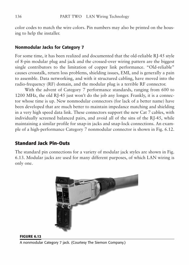
color codes to match the wire colors. Pin numbers may also be printed on the hous-ing to help the installer.
Nonmodular Jacks for Category 7
For some time, it has been realized and documented that the old-reliable RJ-45 styleof 8-pin modular plug and jack and the crossed-over wiring pattern are the biggestsingle contributors to the limitation of copper link performance. “Old-reliable”causes crosstalk, return loss problems, shielding issues, EMI, and is generally a painto assemble. Data networking, and with it structured cabling, have moved into theradio-frequency (RF) domain, and the modular plug is a terrible RF connector.
With the advent of Category 7 performance standards, ranging from 600 to1200 MHz, the old RJ-45 just won’t do the job any longer. Frankly, it is a connec-tor whose time is up. New nonmodular connectors (for lack of a better name) havebeen developed that are much better to maintain impedance matching and shieldingin a very high speed data link. These connectors support the new Cat 7 cables, withindividually screened balanced pairs, and avoid all of the sins of the RJ-45, whilemaintaining a similar profile for snap-in jacks and snap-lock connections. An exam-ple of a high-performance Category 7 nonmodular connector is shown in Fig. 6.12.
Standard Jack Pin-Outs
The standard pin connections for a variety of modular jack styles are shown in Fig.6.13. Modular jacks are used for many different purposes, of which LAN wiring isonly one.
136 PART TWO LAN Wiring Technology
FIGURE 6.12
A nonmodular Category 7 jack. (Courtesy The Siemon Company.)
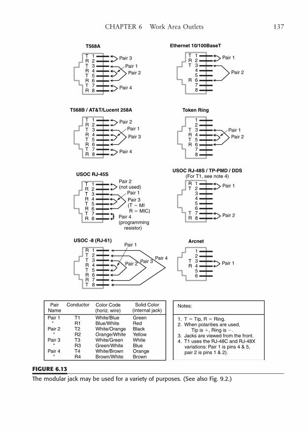
CHAPTER 6 Work Area Outlets 137
Solid Color(internal jack)
Pair 1 T1 White/Blue Green " R1 Blue/White RedPair 2 T2 White/Orange Black " R2 Orange/White YellowPair 3 T3 White/Green White " R3 Green/White BluePair 4 T4 White/Brown Orange " R4 Brown/White Brown
Notes:
1. T � Tip, R � Ring.2. When polarities are used, Tip is �, Ring is �.3. Jacks are viewed from the front.4. T1 uses the RJ-48C and RJ-48X variations: Pair 1 is pins 4 & 5, pair 2 is pins 1 & 2).
1
8765432
T568A
T
RTRTRTR Pair 3
Pair 4
Pair 2Pair 1
1
8765432
T568B / AT&T/Lucent 258A
T
RTRTRTR
Pair 2
Pair 4
Pair 3
Pair 1
1
8765432
USOC RJ-45S
T
RTRTRTR
Pair 2(not used)
Pair 4(programming resistor)
Pair 3(T � MI R � MIC)
Pair 1
1
8765432
USOC -8 (RJ-61)
R
TRRTRTT
Pair 3Pair 4
Pair 2
Pair 1
1
8765432
Ethernet 10/100BaseT
T
R
TR
Pair 1
Pair 2
1
8765432
Token Ring
RTRT
Pair 2Pair 1
1
8765432
USOC RJ-48S / TP-PMD / DDS(For T1, see note 4)
R
RT
T Pair 1
Pair 2
1
65432
Arcnet
RT Pair 1
PairName
Conductor Color Code(horiz. wire)
FIGURE 6.13
The modular jack may be used for a variety of purposes. (See also Fig. 9.2.)
The TIA-568-C standard describes two different wiring patterns for wiring the8-pin modular jack. The two patterns are called T568A and T568B, and are shownin Fig. 6.13. The two patterns differ only in placement of Pairs 2 and 3 of the tra-ditional 4-pair order. This order is defined as Pair 1 = Blue, Pair 2 = Orange, Pair 3= Green, and Pair 4 = Brown. The T568A pattern places Pair 2 on Pins 3 and 6 ofthe jack, and Pair 3 on Pins 1 and 2. The T568B pattern places Pair 2 on Pins 1 and2 of the jack, and Pair 3 on Pins 3 and 6. The A-pattern is actually unique to theTIA standard, but it is now the recommended pattern. The B-pattern is the tradi-tional Avaya/Lucent (AT&T) 258A pattern specified in their premises distributionsystem. Ironically, the A-pattern better follows the progression of wiring patternsfrom the 2-pair pattern for 6-pin modular jacks that is used with many telephonesets (the RJ-11/12 style jack). By the way, the “–” is used before the C in TIA-568-C specifically so there is less confusion with the wiring pattern called T568B.
There has been considerable controversy as to which pattern is the proper oneto use. Depending upon whom you ask and where you ask, you can get strong opin-ions on either side of the question. The TIA standard, however, is quite clear. The“pin/pair assignments shall be… [T568A].” Optionally, the T568B may be used, butonly “if necessary to accommodate certain 8-pin cabling systems.” These certainsystems are ones that already use the optional pattern, for the most part. If you donot need to connect to an existing system, cable, patch, etc., that uses T568B, youshould use the recommended T568A pattern.
What difference does it make which pattern you use—T568A or T568B?Electrically, it makes no difference, as long as exactly the same pattern is used at bothends. Let’s say that again: The two patterns are electrically equivalent, as long as bothends of a cable run are wired with the same pattern. As has been said, “the electronsdon’t know the wire color.” This means that as long as Pin 1 and Pin 2 on one endof a link connect to Pin 1 and Pin 2 on the other end, and the same is true of Pins 3and 6, you can use either pattern. Both the outlet and the telecommunications roomterminations (punchdown block or patch) of a horizontal cable run should be wiredwith the same pattern, as should both ends of any patch or user cord.
Technically, you can use either pattern; however, some patches, fan-out cables,equipment connectors, and adapters are prewired with the T568B pattern and youmust match that pattern at the other end of the cable for the link to work. You can,however, mix patterns from one cable run to the next within the same link. Forexample, a patch cord could be wired with either pattern without regard to how thehorizontal cable was terminated.
A common wiring pattern problem can occur in the horizontal cross-connect.If you terminate the horizontal cable into a punch block first, then cross-connect toa patch, you should be sure that the patch wiring matches that of the corresponding
138 PART TWO LAN Wiring Technology
wall outlet, and that you have preserved the pair order during punchdown andcross-connect. See Chapter 8 on patch panels for more details on the internal wiringpattern of a patch panel.
The official stance of the TIA is that the A pattern is preferred. That statementcertainly applies to new installations, since it would be problematic to switch thepattern in an older installation. You could also justifiably choose the B pattern ifAvaya/Lucent (AT&T) components are used, since that is their standard offering.There is great debate over which pattern is used the most. The truth is in the hear-ing. The customary pattern varies widely, depending upon whom you ask and whatpart of the country (or the world) you live in. However, it seems that the A patternoriginally was not used as much because it was different from the pattern that hadhistorically been required for telephone use. Now that most manufacturers offerboth, you are free to follow the TIA’s preference, or yours.
What happens if you use one pattern on one end of a cable run and another onthe other end? Most LAN network connections will fail, and telephone connectionsthat require two pairs will also fail. Pairs 2 or 3 are used by almost every device weconnect to an 8-pin modular jack.
The TIA wiring patterns are considered universal in that they are applicableto several types of connections, because they cover all eight pins of the modularconnector. For example, the TIA patterns can be used for any of the Ethernetconnections, such as 10 and 100BaseT. The TX and T4 variations are both han-dled, as are 100VG-AnyLAN, 1000BaseT(4), and 1000BaseTX, since all fourpairs are specified. In addition, the TIA patterns can support Token-Ring,ARCnet, ISDN, T1, ATM-PMD variations, and, of course, telephone wiring inits many variations.
You can make a very good argument that the TIA-568-C wiring system is asclose to a universal wiring system as we will ever get. Of course, there will alwaysbe situations that do not fit this standard model, but more and more equipment isbeing designed to take advantage of its characteristics. If you choose to diverge fromthe standard, to implement some of the 2-pair technologies, for example, you maybe left out in the cold in a very short time. For example, the only practical way toincrease data rates on unshielded twisted-pair wiring beyond the current 1000 Mbpsdata rates is to use additional pairs in a multiplexing or encoding scheme. Thismeans that you can go to 1000 Mbps data rates without having to replace installedCategory 5e cable links, which are nominally rated to 100 MHz. However, thesetechnologies need all four pairs. You cannot very well use four pairs if you decidedto wire just two, just to save a little money in the short term. It is therefore stronglyrecommended that any new installations adhere very closely to the TIA standards,including the number of pairs to each outlet jack.
CHAPTER 6 Work Area Outlets 139
TIA Performance Category
It is very important to fully understand the categories of operation of the variousmodular jacks. The TIA-568-C standard contains strict performance requirementsfor the outlet connectors that are used for Category 3 or 5e or 6/AC6 operation. Therequirements differ somewhat by category, although Category 4 and 5 parametersare often the same, and thus Category 4 has now been dropped. AlthoughCategories 1 and 2 exist, they are not the subject of the standards because they reallyare not appropriate for any type of LAN cabling.
Components, as well as cable, should be marked as certified for a particularcategory of use. Thus, a connector that is intended for Category 5e use should bemarked for Category 5e, as explained below. However, you may have occasion toneed to determine the appropriate use of an unmarked jack. While it may not bepossible to categorize an unmarked jack without some uncertainty, there are someguidelines that can help out. If you can identify the jack assembly style, you shouldbe able to determine its probable category of rating. The jack styles and their appro-priate categories for use are shown here:
TIA performance category Termination style1-3 Screw terminal or IDC 4 IDC, including 66- and 110-type 5e IDC using PC board, only* 6/AC6/7 IDC using PC board, offset pins*7 nonmodular IDC, crimp, or solder flow
*Category 5e/6 jacks can also use 110, BIX, and Krone type connections.
Of course, any jack that is rated for a higher category than the intended usecan be substituted. For example, it is perfectly acceptable to use a Category 6 or 5ejack for a Category 5e installation. However, you could possibly upgrade the entirewiring system for very little more cost. The IDC jacks are so easy to use, they areoften used even when their higher category of operation is not required.
Keyed-Plug Entry
Some modular jacks have an extra slot at the side to supposedly limit connectionsto cable plugs with a matching slot. These side-keyed jacks are largely uselessbecause they easily accommodate a nonkeyed plug.
The original intent was to protect delicate digital equipment from the highervoltages that can sometimes be present on telephone circuits. For example, the com-mon open circuit voltage for a telephone line in the United States is –48 DC, and the
140 PART TWO LAN Wiring Technology
ring voltage can approach 90 V AC (both at low current). However, modern datacircuits are fairly immune to these voltages and the fact that the keyed jacks are eas-ily defeated has led to their disuse.
An alternate style of keyed jack is the MMJ style that was used by DigitalEquipment Corp., described in Chapter 3. This jack has primarily been used for theconnection of RS-232 and RS-422 low-speed devices and is rarely found in otheruses. It is not appropriate for standards-compliant LAN wiring.
Fiber-Optic Outlet Jacks
Fiber-optic technology has become so important that we have devoted an entirechapter to it, Chapter 11. Outlet jacks for fiber-optic connections have severalunique requirements. The fiber-optic outlet must allow the station cable fibers to beterminated and connected into a jack plate. In addition, the design of the jack platemust allow the easy attachment of an optical jumper to the workstation equipment.A special passive coupling device, called an adapter, is used to connect the two fiber-optic cables at the outlet jack.
Unlike the termination of metallic conductors, the traditional termination of anoptical fiber can be a delicate and time-consuming process, although the time maybe reduced by using more expensive “quick-termination” connectors. The fibermust be stripped of its protective coverings, including the binder. It must then beprecisely cleaved before being inserted into the mechanical coupling that is looselycalled the optical connector. Some fiber connectors require the use of an epoxy orglue to secure the fiber and may use a crimp or clamp-in arrangement in addition(or in lieu of) the glue. Finally, the connectorized fiber end must be carefully pol-ished to a smooth surface so that light entering or exiting the fiber is not bent offaxis (the polishing step is not required for a quick-termination connector).
In order for light to couple properly between connectors, the internal fibersmust be carefully aligned and placed virtually in contact by the coupling device. Infiber optics, this coupling device is called an adapter, rather than a connector,because it does not actually terminate any fibers. It mounts in the fiber-optic outletplate much as a coax bulkhead barrel adapter does in coax systems. The fiberadapter provides a keyed location where the terminated station fiber connects on theback side of the outlet plate. The plate is then mounted in the fiber-optic outlet box.
The fiber-optic user cord is connected to the section of the adapter that is onthe front side of the outlet plate. Because of the nature of fiber optic transmission,two fibers and connectors are generally required for each LAN connection, one fortransmit and one for receive. Keying these two connections, or differentiating themby color, is used to orient the transmit and receive fibers.
CHAPTER 6 Work Area Outlets 141
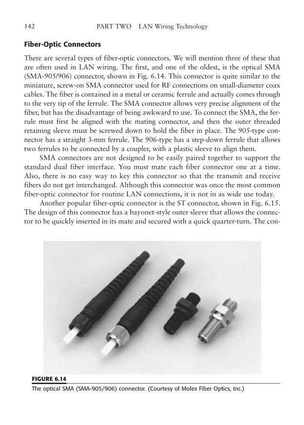
Fiber-Optic Connectors
There are several types of fiber-optic connectors. We will mention three of these thatare often used in LAN wiring. The first, and one of the oldest, is the optical SMA(SMA-905/906) connector, shown in Fig. 6.14. This connector is quite similar to theminiature, screw-on SMA connector used for RF connections on small-diameter coaxcables. The fiber is contained in a metal or ceramic ferrule and actually comes throughto the very tip of the ferrule. The SMA connector allows very precise alignment of thefiber, but has the disadvantage of being awkward to use. To connect the SMA, the fer-rule must first be aligned with the mating connector, and then the outer threadedretaining sleeve must be screwed down to hold the fiber in place. The 905-type con-nector has a straight 3-mm ferrule. The 906-type has a step-down ferrule that allowstwo ferrules to be connected by a coupler, with a plastic sleeve to align them.
SMA connectors are not designed to be easily paired together to support thestandard dual fiber interface. You must mate each fiber connector one at a time.Also, there is no easy way to key this connector so that the transmit and receivefibers do not get interchanged. Although this connector was once the most commonfiber-optic connector for routine LAN connections, it is not in as wide use today.
Another popular fiber-optic connector is the ST connector, shown in Fig. 6.15.The design of this connector has a bayonet-style outer sleeve that allows the connec-tor to be quickly inserted in its mate and secured with a quick quarter-turn. The con-
142 PART TWO LAN Wiring Technology
FIGURE 6.14
The optical SMA (SMA-905/906) connector. (Courtesy of Molex Fiber Optics, Inc.)
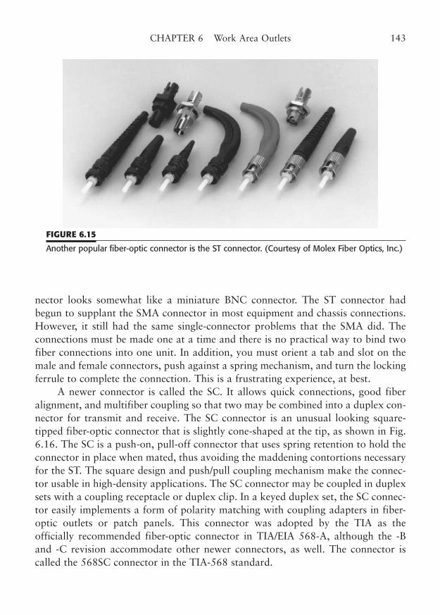
nector looks somewhat like a miniature BNC connector. The ST connector hadbegun to supplant the SMA connector in most equipment and chassis connections.However, it still had the same single-connector problems that the SMA did. Theconnections must be made one at a time and there is no practical way to bind twofiber connections into one unit. In addition, you must orient a tab and slot on themale and female connectors, push against a spring mechanism, and turn the lockingferrule to complete the connection. This is a frustrating experience, at best.
A newer connector is called the SC. It allows quick connections, good fiberalignment, and multifiber coupling so that two may be combined into a duplex con-nector for transmit and receive. The SC connector is an unusual looking square-tipped fiber-optic connector that is slightly cone-shaped at the tip, as shown in Fig.6.16. The SC is a push-on, pull-off connector that uses spring retention to hold theconnector in place when mated, thus avoiding the maddening contortions necessaryfor the ST. The square design and push/pull coupling mechanism make the connec-tor usable in high-density applications. The SC connector may be coupled in duplexsets with a coupling receptacle or duplex clip. In a keyed duplex set, the SC connec-tor easily implements a form of polarity matching with coupling adapters in fiber-optic outlets or patch panels. This connector was adopted by the TIA as theofficially recommended fiber-optic connector in TIA/EIA 568-A, although the -Band -C revision accommodate other newer connectors, as well. The connector iscalled the 568SC connector in the TIA-568 standard.
CHAPTER 6 Work Area Outlets 143
FIGURE 6.15
Another popular fiber-optic connector is the ST connector. (Courtesy of Molex Fiber Optics, Inc.)
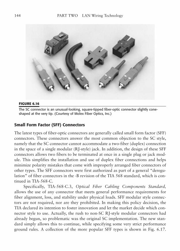
Small Form Factor (SFF) Connectors
The latest types of fiber-optic connectors are generally called small form factor (SFF)connectors. These connectors answer the most common objection to the SC style,namely that the SC connector cannot accommodate a two-fiber (duplex) connectionin the space of a single modular (RJ-style) jack. In addition, the design of these SFFconnectors allows two fibers to be terminated at once in a single plug or jack mod-ule. This simplifies the installation and use of duplex fiber connections and helpsminimize polarity mistakes that come with improperly arranged fiber connectors ofother types. The SFF connectors were first authorized as part of a general “deregu-lation” of fiber connectors in the -B revision of the TIA 568 standard, which is con-tinued in TIA-568-C.
Specifically, TIA-568-C.3, Optical Fiber Cabling Components Standard,allows the use of any connector that meets general performance requirements forfiber alignment, loss, and stability under physical loads. SFF modular style connec-tors are not required, nor are they prohibited. In making this policy decision, theTIA declared its intention to foster innovation and let the market decide which con-nector style to use. Actually, the rush to non-SC RJ-style modular connectors hadalready begun, so problematic was the original SC implementation. The new stan-dard simply allows this to continue, while specifying some very strict performanceground rules. A collection of the more popular SFF types is shown in Fig. 6.17.
144 PART TWO LAN Wiring Technology
FIGURE 6.16
The SC connector is an unusual-looking, square-tipped fiber-optic connector slightly cone-shaped at the very tip. (Courtesy of Molex Fiber Optics, Inc.)
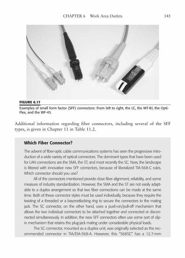
Additional information regarding fiber connectors, including several of the SFFtypes, is given in Chapter 11 in Table 11.2.
Which Fiber Connector?
The advent of fiber-optic cable communications systems has seen the progressive intro-duction of a wide variety of optical connectors. The dominant types that have been usedfor LAN connections are the SMA, the ST, and most recently the SC. Now, the landscapeis littered with innovative new SFF connectors, because of liberalized TIA-568-C rules.Which connector should you use?
All of the connectors mentioned provide close fiber alignment, reliability, and somemeasure of industry standardization. However, the SMA and the ST are not easily adapt-able to a duplex arrangement so that two fiber connections can be made at the sametime. Both of these connector styles must be used individually, because they require thetwisting of a threaded or a bayonetlocking ring to secure the connectors to the matingjack. The SC connector, on the other hand, uses a push-on/pull-off mechanism thatallows the two individual connectors to be attached together and connected or discon-nected simultaneously. In addition, the new SFF connectors often use some sort of clip-in mechanism that retains the plug-jack mating under considerable physical loads.
The SC connector, mounted as a duplex unit, was originally selected as the rec-ommended connector in TIA/EIA-568-A. However, this “568SC” has a 12.7-mm
CHAPTER 6 Work Area Outlets 145
FIGURE 6.17
Examples of small form factor (SFF) connectors: From left to right, the LC, the MT-RJ, the Opti-Flex, and the WF-45.
(0.5-in) ferrule spacing, which prevents it from mounting within the space of the RJ-style module plates that have achieved almost universal acceptance.
The only alternative has been to redesign the plates, and often the modules,so that a dual-insert 568-SC jack could be accommodated. Even so, the SC takes uptwo module positions for one circuit connection, besides tying up a lot of real estateon router and switch option blades.
The answer to mating two fibers within the modular footprint is obviously touse one of the SFF connector designs that began to appear as soon as the SC prob-lem was known. But there are now more than a half-dozen incompatible SFF con-nectors, each with its own advantages, available from multiple manufacturers.Moreover, the TIA now makes absolutely no recommendation, other than its generalfiber connector requirements. For a solution to this dilemma, one could turn to theequipment manufacturers. Again, there is no unanimity, as switch and router manu-facturers are split on SFF connector choices, and many continue to use the SC con-nectors. Because the TIA has decided not to decide, the market will eventually showa preference, but it will likely make no firm decision either. Just as there are manydifferent types of computers, and many different makes of automobiles, there willcontinue to be many types of fiber connectors.
Over time, a few of the designs, perhaps two or three, will gain a majority ofthe market. Since the leading manufacturers have each licensed other strong pro-ducers to offer their designs, it is unlikely that only one will really emerge as a defacto standard. So, how should you choose which connector style to use for yournetwork fiber?
The simple answer is to choose the connector that you believe will be the bestfor your environment. In reality, fiber-optic transceivers are not actually connectedinto the patch terminations or the work area outlets. You must use a patch cord, usercord, or equipment cord to make the final connection. Also, it is unlikely that you willhave the same SFF connector styles on all your equipment and workstation inter-faces. Since different fiber connectors offer near identical optical performance, youcan simply use a cord with the appropriate connectors at each end. Use a fixed con-nector and fiber cable combination that you feel comfortable with for your horizon-tal runs. Then get appropriate adapter cables for hub/switch/router equipment andfor workstation network interface cards.
Most manufacturers offer adapter cords to transition their SFF connectors tovirtually any other SFF design. It doesn’t particularly matter if the cord ends are dif-ferent, other than for arguing the fine points of connector performance. Fortunately,the TIA’s performance guidelines assure that connector alignment and return loss willbe well within that needed for almost all applications.
146 PART TWO LAN Wiring Technology
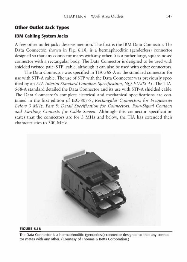
Other Outlet Jack Types
IBM Cabling System Jacks
A few other outlet jacks deserve mention. The first is the IBM Data Connector. TheData Connector, shown in Fig. 6.18, is a hermaphroditic (genderless) connectordesigned so that any connector mates with any other. It is a rather large, square-nosedconnector with a rectangular body. The Data Connector is designed to be used withshielded twisted pair (STP) cable, although it can also be used with other connectors.
The Data Connector was specified in TIA-568-A as the standard connector foruse with STP-A cable. The use of STP with the Data Connector was previously spec-ified by an EIA Interim Standard Omnibus Specification, NQ-EIA/IS-43. The TIA-568-A standard detailed the Data Connector and its use with STP-A shielded cable.The Data Connector’s complete electrical and mechanical specifications are con-tained in the first edition of IEC-807-8, Rectangular Connectors for FrequenciesBelow 3 MHz, Part 8: Detail Specification for Connectors, Four-Signal Contactsand Earthing Contacts for Cable Screen. Although this connector specificationstates that the connectors are for 3 MHz and below, the TIA has extended theircharacteristics to 300 MHz.
CHAPTER 6 Work Area Outlets 147
FIGURE 6.18
The Data Connector is a hermaphroditic (genderless) connector designed so that any connec-tor mates with any other. (Courtesy of Thomas & Betts Corporation.)
The color codes for horizontal 150-ohm STP-A cable are:
Pair ColorsPair 1 Red, GreenPair 2 Orange, Black
This color code corresponds to the markings for the IDC contacts within the DataConnector and makes the cable conductors very easy to match with their proper contact.
The Data Connector outlet is a version of the standard Data Connector that ismounted in a cover plate. The cover plate is attached to a standard outlet box. TheSTP-A station cable is terminated directly in the outlet connector. Versions of DataConnector faceplates are available that contain both the Data Connector and oneor more standard modular jacks.
The Data Connector and STP-A cabling system is a robust system that offerscertification to 300 MHz, three times the current maximum frequency specificationof standard UTP systems.
Coax Jacks
Coax jacks are another type of outlet jack. The BNC coax jack is commonlyencountered in 10Base2 Ethernet cabling systems. This cabling system calls for thethinnet segment cable to be run from one workstation position to the next, and soon, until you reach the end of the segment. At each workstation location, the twocable sections are joined together by a BNC-T, and the center position of the T isconnected to the workstation network adapter. The workstation essentially taps thecoax line to become a part of the network. The method generally does not allow anextra stub of coax from the tap to the workstation; both cable sections must beextended all the way to the T at the workstation adapter.
Each fixed 10Base2 coax outlet, thus, needs two coax connectors, one for eachcable section leading to the workstation. The customary outlet has two separatefemale BNC connectors on the faceplate, each connected to one of the two cable sec-tions at the rear of the faceplate. There are two methods to connect the cable sec-tions to the rear of the faceplate.
One method connects bulkhead-mounted female connectors directly to eachcable end. Each connector is inserted through a d-keyed hole in the plate andsecured with a thin washer and nut. The alternative method places two bulkhead-mount barrel connector/adapters in the holes of the plate. The coax cable ends inthe wall are terminated with male BNC connectors, which are then connected to theback side of the bulkhead adapters. From the front, the plates look the same, regard-less of the method you use to connect the cable ends.
148 PART TWO LAN Wiring Technology
From the dual coax outlet, connection to the workstation is made with twocoax jumper cables, with two BNC male connectors on each cable end. At the work-station, a BNC-T is connected to the network adapter and the two cables connectedto the arms of the T. If the workstation is at the end of the coax segment, only onecable is used and a 50-ohm terminator is placed on the other T position. If there isno workstation in place, a short coax jumper cable is used to connect the two bulk-head connectors on the outlet’s faceplate, in order to complete the cable circuit tothe next workstation. If the workstation position would have been at the end of acoax segment, a single terminator may be used instead. The 10Base2 system requiresend-to-end connectivity and dual-ended termination of the coax segment for properoperation. Any disconnected cables or terminators may cause the entire cable seg-ment to cease to function.
Marking Outlets
Outlet jacks should be clearly identified on the faceplate. The identification shouldinclude a cable number and jack number, as well as an indication of whether thejack supports data (such as a LAN connection) or telephone. Some jack inserts andfaceplates are marked to indicate “data” or “phone.” Telephone extension numbersgenerally should not be marked on the plate, since many phone systems allow thenumber to be assigned to any physical outlet. The same applies for data jacks thatcorrespond to a particular port number on a LAN hub or other network connec-tion. You should keep a chart to match each extension or port number to each jacknumber. The scheme in EIA/TIA-606 is a good basis for marking the jacks. Themarkings should be clearly visible with bold lettering about 3/8 in high.
The standard calls for marking at the front of the jack position, above or belowthe jack. However, you might also want to consider a neat marking on the top ofthe plate, so it can be read from above. (If you ever have to peer down behind a deskor a cabinet to identify an outlet, you will be thankful for the top markings.)
The outlet markings should identify the cable number, and, in a large facility,the wiring closet as well. For example, a marking for wiring closet number 3, cable42, might be W3-42, or W3-J42 to differentiate it from a cable number. It is best ifthe outlet number corresponds to the cable number in the wiring closet. The cableitself can also be marked with a variety of vinyl labels, but the type of label that ispart of a tiewrap should be avoided on Category 5 cables, for the reasons previouslymentioned. If all else fails, fine-point indelible markers will also effectively markcable numbers on a cable jacket. Station cables are usually either in the wall or at therear of termination blocks in the wiring closet, so the marking doesn’t have to bepretty. Neatness counts, however, as you must be able to read the cable number later.
CHAPTER 6 Work Area Outlets 149
Outlet jacks are often color-coordinated with the room decor, which is fine aslong as standard NEMA® electrical colors are chosen. Nonstandard colors maycause a clash with other electrical outlet plates and may be difficult to obtain. If theelectrical plates have already been selected, you should try to match those colors.Modular outlet jacks offer a variety of colors for the modular inserts.
In theory, the color markings allow one to easily differentiate between, say,voice and data jacks. However, there are really no universal standards for these col-ors. What may seem to be a logical color choice to you could be the opposite ofwhat someone else might choose. You might simply want to leave all the colors thesame neutral color as the faceplate and differentiate the jack functions with the platemarkings. Alternatively, you may choose to leave the telephone connector neutraland use a differing color for the LAN jack.
Workmanship
The subject of workmanship is particularly important with regard to jack termina-tion. The higher categories of wiring have strict guidelines for the amount of untwistthat may be present at any point of termination.
When a pair of wires is untwisted, even slightly, it can cause a greater disrup-tion to the high-bandwidth signal transmission than almost any other noncontinu-ity defect. Furthermore, there are several points of unavoidable untwist in any cablelink, and the effects of untwist are somewhat additive. You should carefully inspectat least a sampling of cable terminations to make sure they are done properly.
Figure 6.19 shows a sample of a cable link with one improperly untwisted con-nector termination. You can see that there is a very large cable anomaly at approx-imately 72 feet from the tester. This test link was made up with an intentional excessuntwist of 3/4 in at one of the connectors of the 1 ft patch cord. When you comparethe size of this anomaly to the other connectors (which are all properly made), youcan clearly see the reason we emphasize good workmanship. Patch cords are easy toinspect visually, but your outlet jack wiring is hidden in the wall. Be sure that theperson who installs your wiring is properly trained to do these connections well, andtest each horizontal cable run with a cable scanner.
Another workmanship issue that affects station outlets is the amount of excesscable that is left at the outlet. Standard practice is to leave no more than 18 in ofextra cable length in wiring the outlet. This distance is measured from the wall open-ing to the jack before it is installed. Excess cable should be trimmed before the out-let is terminated. You should leave a reasonable length of extra cable to simplify theinitial termination and any subsequent inspections or re-terminations of a cable run.
150 PART TWO LAN Wiring Technology
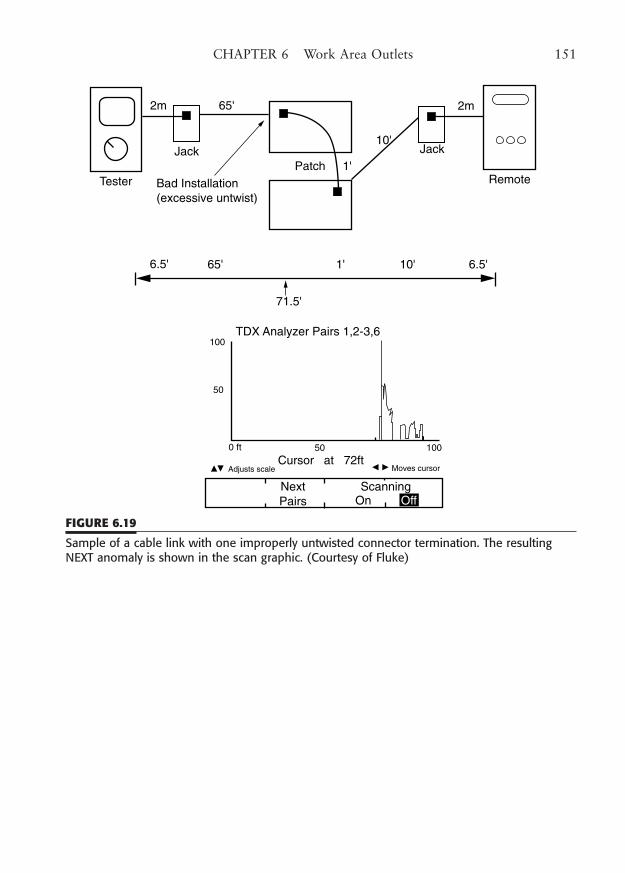
CHAPTER 6 Work Area Outlets 151
2m 65'
Tester
Jack
Bad Installation(excessive untwist)
Patch 1'
10'Jack
2m
Remote
71.5'
6.5' 65' 1' 10' 6.5'
TDX Analyzer Pairs 1,2-3,6100
50
0 ft 50 100
Cursor at 72ftAdjusts scale Moves cursor
NextPairs
ScanningOn Off
FIGURE 6.19
Sample of a cable link with one improperly untwisted connector termination. The resultingNEXT anomaly is shown in the scan graphic. (Courtesy of Fluke)

This page intentionally left blank
CHAPTER 7
Telecommunication RoomTerminations
Highlights
■ 110 and 66 punchdown blocks
■ Other connecting systems
■ Routing and dressing devices
■ Fiber-optic termination
■ Marking and workmanship
153
Copyright © 2006 by James Trulove. Click here for terms of use.
The telecommunications room is another important area in the chain of wiringdevices that makes up a structured LAN wiring installation. The telecommunica-tions room (TR) is the point of termination of all of the “horizontal run” cables thatgo from the TR to the workstation areas as well as the cables that interconnect toother TRs. The TR typically contains the punchdown blocks, patches (Chapter 8),and other termination and wire-routing devices necessary for the interconnection ofhorizontal and backbone cabling. It may also contain various types of equipment,such as wiring hubs, routers, and even network servers. All the wiring terminationmethods and devices described in this chapter apply as well to similar wiring facili-ties, including the main cross-connect, intermediate cross-connect, equipment room,and entrance facility.
In the generalized model of universal, structured cabling, the TR also may con-tain telephone switching and distribution equipment. Much of what we cover in thischapter will be equally applicable to telephone wiring, but we will emphasize theLAN wiring aspects wherever possible. It is interesting that the TR is one placewhere the differing needs of telephone and LAN wiring are most apparent.
The very strict length and workmanship guidelines that are required for asuccessful LAN wiring system are very much relaxed if you are installing tele-phone wiring. For example, telephone wiring is often run through multiple sets ofpunchdown blocks in several wiring closets with little regard to total distance orcare in routing. (Although the TIA standards do have strict guidelines, they areoften excessively strict for telephone connections.) The much lower audio fre-quencies of most telephone installations allow these signals to run thousands ofmeters on very loosely twisted pairs. However, if you intend for your wiring sys-tem to be general purpose, so that you can run either voice or network signals,you must design your system to meet the more stringent operating rules embod-ied in the TIA or similar ISO standards. LAN wiring requires strict adherence tolength, routing, rating, and workmanship rules to operate properly. The extrarequirements for LAN operation are really the determining factors in the designof a modern structured wiring system.
In this chapter, we will cover all of the types of termination and routingdevices, except patch panels, that are used in the TR. Patch panels, jumpers, andcross-connects are covered in the next chapter. In higher-category cabling systems,it is very common to terminate horizontal cables directly into a patch panel.However, the termination blocks used will very likely be a variation of the 110-styleconnecting block described in this chapter. In addition, we will also cover some ofthe mounting and location issues of the TR, including the options for locating hubequipment.
154 PART TWO LAN Wiring Technology
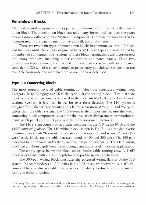
Punchdown Blocks
The fundamental component for copper wiring termination in the TR is the punch-down block. The punchdown block can take many forms, and has over the yearsevolved into a rather complex “system” component. The punchdown can even beincorporated into a patch panel, but we will talk about that later.
There are two main types of punchdown blocks in common use: the 110 blockand the older 66M block, both originated by AT&T. Both types are now offered bya number of companies, and versions of these block terminations are incorporatedinto many products, including outlet connectors and patch panels. These twopunchdown types dominate the installed and new markets, so we will cover them insome detail. We will also cover a couple of proprietary punchdown systems that areavailable from only one manufacturer or are not as widely used.
Type 110 Connecting Blocks
The most popular style of cable termination block for structured wiring fromCategory 5e to Category 6/AC6 is the type 110 connecting block.1 The 110-styleblock is a relative newcomer, compared to the older 66 block, described in the nextsection. Even so, it has been in use for over three decades. The 110 system isdesigned for higher wiring density and a better separation of “input” and “output”cables than the older system. The 110 system is also important because the 4-pairconnecting block component is used for the insulation-displacement termination inmany patch panel and outlet jack systems by various manufacturers.
The 110 system consists of two basic components, the 110 wiring block and the110C connecting block. The 110 wiring block, shown in Fig. 7.1, is a molded plasticmounting block with “horizontal index strips” that organize and secure 25 pairs (50wires) each. Blocks are available that accommodate 100 and 300 pairs. The 100-pairblock has four horizontal index strips, and the 300-pair block has 12. The 110A wiringblock has a 3.25-in depth from the mounting plane and is used in normal applications.
The empty space below the block makes feeder cable routing easy. A 110Dblock is available with a 1.4-in depth for low-profile special applications.
The 300-pair wiring block illustrates the potential wiring density of the 110system. It accommodates all 300 pairs in a 10.75-in square footprint. A 110T dis-connect block is also available that provides the ability to disconnect a circuit fortesting in either direction.
CHAPTER 7 Telecommunication Room Terminations 155
1 Category 7 termination is not done with punchdown blocks, but rather consists of a terminating con-nector array, similar to the way that fiber cables are terminated. See Chapter 8 for more information.
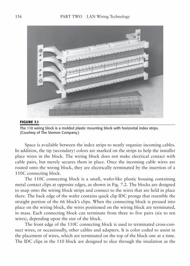
Space is available between the index strips to neatly organize incoming cables.In addition, the tip (secondary) colors are marked on the strips to help the installerplace wires in the block. The wiring block does not make electrical contact withcable pairs, but merely secures them in place. Once the incoming cable wires arerouted onto the wiring block, they are electrically terminated by the insertion of a110C connecting block.
The 110C connecting block is a small, wafer-like plastic housing containingmetal contact clips at opposite edges, as shown in Fig. 7.2. The blocks are designedto snap onto the wiring block strips and connect to the wires that are held in placethere. The back edge of the wafer contains quick clip IDC prongs that resemble thestraight portion of the 66 block’s clips. When the connecting block is pressed intoplace on the wiring block, the wires positioned on the wiring block are terminated,in mass. Each connecting block can terminate from three to five pairs (six to tenwires), depending upon the size of the block.
The front edge of the 110C connecting block is used to terminated cross-con-nect wires, or occasionally, other cables and adapters. It is color coded to assist inthe placement of wires, which are terminated on the top of the block one at a time.The IDC clips in the 110 block are designed to slice through the insulation as the
156 PART TWO LAN Wiring Technology
FIGURE 7.1
The 110 wiring block is a molded plastic mounting block with horizontal index strips.(Courtesy of The Siemon Company.)
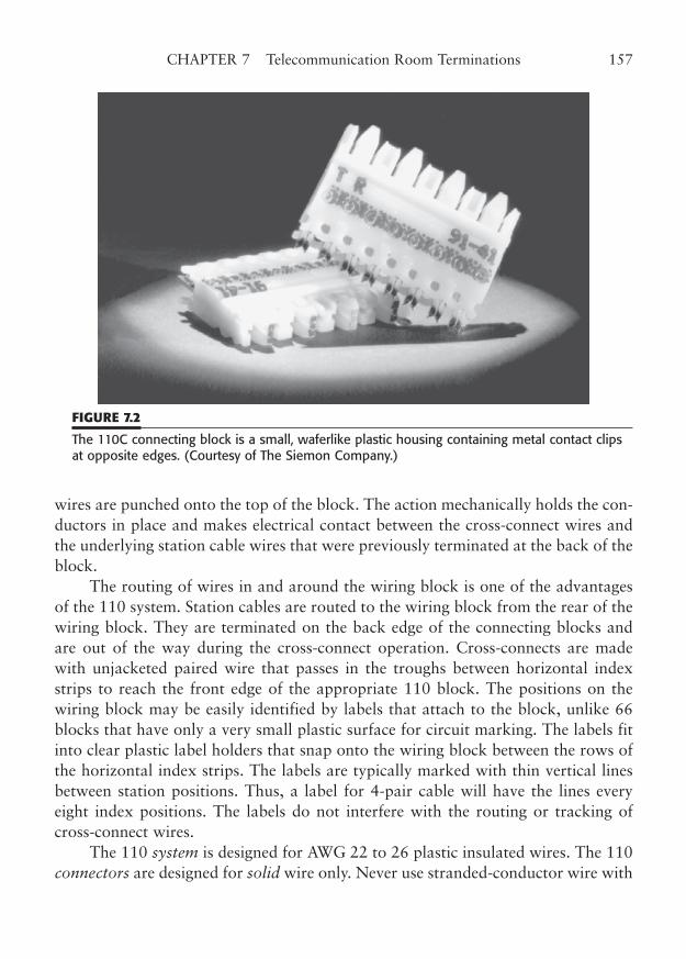
wires are punched onto the top of the block. The action mechanically holds the con-ductors in place and makes electrical contact between the cross-connect wires andthe underlying station cable wires that were previously terminated at the back of theblock.
The routing of wires in and around the wiring block is one of the advantagesof the 110 system. Station cables are routed to the wiring block from the rear of thewiring block. They are terminated on the back edge of the connecting blocks andare out of the way during the cross-connect operation. Cross-connects are madewith unjacketed paired wire that passes in the troughs between horizontal indexstrips to reach the front edge of the appropriate 110 block. The positions on thewiring block may be easily identified by labels that attach to the block, unlike 66blocks that have only a very small plastic surface for circuit marking. The labels fitinto clear plastic label holders that snap onto the wiring block between the rows ofthe horizontal index strips. The labels are typically marked with thin vertical linesbetween station positions. Thus, a label for 4-pair cable will have the lines everyeight index positions. The labels do not interfere with the routing or tracking ofcross-connect wires.
The 110 system is designed for AWG 22 to 26 plastic insulated wires. The 110connectors are designed for solid wire only. Never use stranded-conductor wire with
CHAPTER 7 Telecommunication Room Terminations 157
FIGURE 7.2
The 110C connecting block is a small, waferlike plastic housing containing metal contact clipsat opposite edges. (Courtesy of The Siemon Company.)
these connectors. The incoming station wires are inserted and trimmed using a 788-type impact tool, shown in Fig. 7.3.
This tool can insert and trim up to five pairs (10 wires) at a time on the wiringblock. It also seats the 110C connecting block onto a wiring block position. Cross-connect wires are terminated and trimmed one at a time with a punchdown tool thathas a 110-type blade.
A 110-block system is used to terminate multipair station cables and allow thecross-connection to other punchdown locations. A typical LAN installation mighthave an appropriate number of wall-mounted or rack-mounted 110 blocks withcross-connect jumpers to a patch panel.
Distribution frame assemblies are available that have preterminated 25-pairmulticonductor cables connected to the back positions of the connecting blocks. Themulticonductor cables terminate in 50-pin telco connectors that may provide massconnections to hub, telephone, or other equipment.
As stated before, each horizontal strip of the wiring block unit contains posi-tions for 50 wires, or 25 pairs. This strip, in many ways, corresponds one side of the66 block. Using the same math we did for 66 blocks, the 110 strip can accommo-date six individual 4-pair station cables (or eight each 3-pair cables, or 12 each 2-pair cables). It can also terminate one 25-pair cable. As with the other type of block,
158 PART TWO LAN Wiring Technology
FIGURE 7.3
The station wires are inserted into the 110 wiring block and trimmed by using a 788-typeimpact tool. Cross-connect wires are punched down using a 110 blade (see Fig. 7.4). (Courtesy of The Siemon Company.)
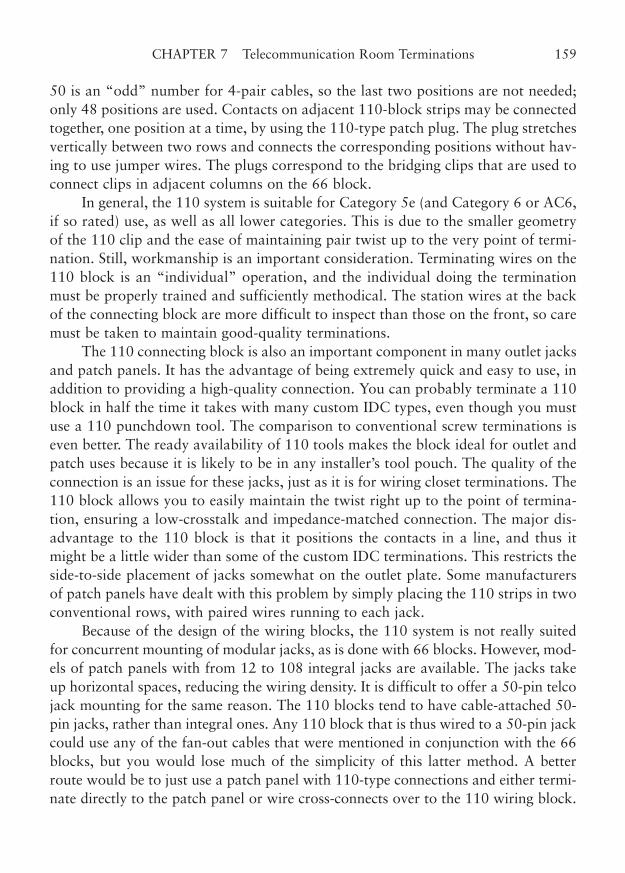
50 is an “odd” number for 4-pair cables, so the last two positions are not needed;only 48 positions are used. Contacts on adjacent 110-block strips may be connectedtogether, one position at a time, by using the 110-type patch plug. The plug stretchesvertically between two rows and connects the corresponding positions without hav-ing to use jumper wires. The plugs correspond to the bridging clips that are used toconnect clips in adjacent columns on the 66 block.
In general, the 110 system is suitable for Category 5e (and Category 6 or AC6,if so rated) use, as well as all lower categories. This is due to the smaller geometryof the 110 clip and the ease of maintaining pair twist up to the very point of termi-nation. Still, workmanship is an important consideration. Terminating wires on the110 block is an “individual” operation, and the individual doing the terminationmust be properly trained and sufficiently methodical. The station wires at the backof the connecting block are more difficult to inspect than those on the front, so caremust be taken to maintain good-quality terminations.
The 110 connecting block is also an important component in many outlet jacksand patch panels. It has the advantage of being extremely quick and easy to use, inaddition to providing a high-quality connection. You can probably terminate a 110block in half the time it takes with many custom IDC types, even though you mustuse a 110 punchdown tool. The comparison to conventional screw terminations iseven better. The ready availability of 110 tools makes the block ideal for outlet andpatch uses because it is likely to be in any installer’s tool pouch. The quality of theconnection is an issue for these jacks, just as it is for wiring closet terminations. The110 block allows you to easily maintain the twist right up to the point of termina-tion, ensuring a low-crosstalk and impedance-matched connection. The major dis-advantage to the 110 block is that it positions the contacts in a line, and thus itmight be a little wider than some of the custom IDC terminations. This restricts theside-to-side placement of jacks somewhat on the outlet plate. Some manufacturersof patch panels have dealt with this problem by simply placing the 110 strips in twoconventional rows, with paired wires running to each jack.
Because of the design of the wiring blocks, the 110 system is not really suitedfor concurrent mounting of modular jacks, as is done with 66 blocks. However, mod-els of patch panels with from 12 to 108 integral jacks are available. The jacks takeup horizontal spaces, reducing the wiring density. It is difficult to offer a 50-pin telcojack mounting for the same reason. The 110 blocks tend to have cable-attached 50-pin jacks, rather than integral ones. Any 110 block that is thus wired to a 50-pin jackcould use any of the fan-out cables that were mentioned in conjunction with the 66blocks, but you would lose much of the simplicity of this latter method. A betterroute would be to just use a patch panel with 110-type connections and either termi-nate directly to the patch panel or wire cross-connects over to the 110 wiring block.
CHAPTER 7 Telecommunication Room Terminations 159
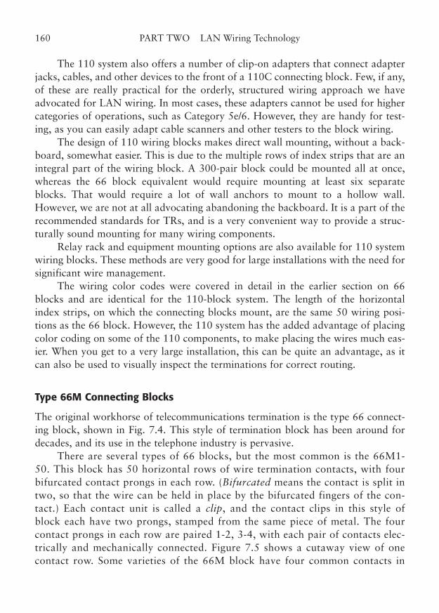
The 110 system also offers a number of clip-on adapters that connect adapterjacks, cables, and other devices to the front of a 110C connecting block. Few, if any,of these are really practical for the orderly, structured wiring approach we haveadvocated for LAN wiring. In most cases, these adapters cannot be used for highercategories of operations, such as Category 5e/6. However, they are handy for test-ing, as you can easily adapt cable scanners and other testers to the block wiring.
The design of 110 wiring blocks makes direct wall mounting, without a back-board, somewhat easier. This is due to the multiple rows of index strips that are anintegral part of the wiring block. A 300-pair block could be mounted all at once,whereas the 66 block equivalent would require mounting at least six separateblocks. That would require a lot of wall anchors to mount to a hollow wall.However, we are not at all advocating abandoning the backboard. It is a part of therecommended standards for TRs, and is a very convenient way to provide a struc-turally sound mounting for many wiring components.
Relay rack and equipment mounting options are also available for 110 systemwiring blocks. These methods are very good for large installations with the need forsignificant wire management.
The wiring color codes were covered in detail in the earlier section on 66blocks and are identical for the 110-block system. The length of the horizontalindex strips, on which the connecting blocks mount, are the same 50 wiring posi-tions as the 66 block. However, the 110 system has the added advantage of placingcolor coding on some of the 110 components, to make placing the wires much eas-ier. When you get to a very large installation, this can be quite an advantage, as itcan also be used to visually inspect the terminations for correct routing.
Type 66M Connecting Blocks
The original workhorse of telecommunications termination is the type 66 connect-ing block, shown in Fig. 7.4. This style of termination block has been around fordecades, and its use in the telephone industry is pervasive.
There are several types of 66 blocks, but the most common is the 66M1-50. This block has 50 horizontal rows of wire termination contacts, with fourbifurcated contact prongs in each row. (Bifurcated means the contact is split intwo, so that the wire can be held in place by the bifurcated fingers of the con-tact.) Each contact unit is called a clip, and the contact clips in this style ofblock each have two prongs, stamped from the same piece of metal. The fourcontact prongs in each row are paired 1-2, 3-4, with each pair of contacts elec-trically and mechanically connected. Figure 7.5 shows a cutaway view of onecontact row. Some varieties of the 66M block have four common contacts in
160 PART TWO LAN Wiring Technology
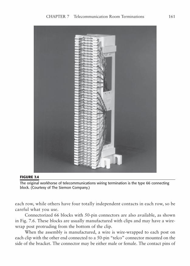
each row, while others have four totally independent contacts in each row, so becareful what you use.
Connectorized 66 blocks with 50-pin connectors are also available, as shownin Fig. 7.6. These blocks are usually manufactured with clips and may have a wire-wrap post protruding from the bottom of the clip.
When the assembly is manufactured, a wire is wire-wrapped to each post oneach clip with the other end connected to a 50-pin “telco” connector mounted on theside of the bracket. The connector may be either male or female. The contact pins of
CHAPTER 7 Telecommunication Room Terminations 161
FIGURE 7.4
The original workhorse of telecommunications wiring termination is the type 66 connectingblock. (Courtesy of The Siemon Company.)
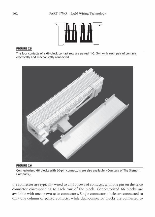
the connector are typically wired to all 50 rows of contacts, with one pin on the telcoconnector corresponding to each row of the block. Connectorized 66 blocks areavailable with one or two telco connectors. Single-connector blocks are connected toonly one column of paired contacts, while dual-connector blocks are connected to
162 PART TWO LAN Wiring Technology
FIGURE 7.5
The four contacts of a 66-block contact row are paired, 1-2, 3-4, with each pair of contactselectrically and mechanically connected.
FIGURE 7.6
Connectorized 66 blocks with 50-pin connectors are also available. (Courtesy of The SiemonCompany.)
both, one on each side of the block. The connectors may be used to attach preassem-bled 25-pair jumper cables or to attach a modular fan-out (octopus) cable.
The fan-out cables, if used, come in several varieties, with 2-, 3-, or 4-pairmodular legs (so they are often not “octo” cables at all). The 4-pair variety fans outto cable six legs, each terminated in an 8-pin modular plug. The legs may be orderedto length, but the wire should be stranded twisted-pair wire and rated to the appro-priate category in order to conform to LAN wiring guidelines. Because the 66M has50 contact rows, and a 4-pair leg has eight wires to terminate, and eight divides into50 rows only six times evenly, there are thus six legs from the fan-out when 4-paircable legs are used. The last two rows of the 66M are not needed in most pairings,so only 48 of the 50 rows are used. Similarly, the 3-pair fan-out has eight legs [48� (2 � 3) � 8], and the 2-pair fan-out has 12 legs [48 � (2 � 2) � 12]. The mod-ular plugs of fan-out cables may be wired with any of several wiring patterns,including T568A and T568B. When ordering these fan-out cables, you should spec-ify which pattern you want, and ensure that the corresponding outlet jack (at theother end of the station cable) is wired the same. See Chapters 7 and 10 for moreinformation.
Horizontal station cables (or backbone cables) are routed down the mountingbackboard underneath the 66 block for termination. They are threaded out throughthe openings in the side of the mounting bracket where they are to be terminated.The outer jacket of the cable is removed to expose the wire pairs. The pairs arefanned out, sorted by color, and routed to the appropriate contact. Each wire passesthrough one of the narrow slots in the face of the block. The wires generally enterthe slot that is just above the target contact row and are wrapped down into thejaws of the contact for termination. The contact has a hook on one prong to helpposition the wire until it is punched down.
The side slots hold the wires in place-order, although they do not in any waysupport or strain-relieve the wires. (By the way, the process of fanning out, sorting,wrapping, and terminating wires on a block is called stitching. And one punchesdown the wire with the impact tool, equipped with an appropriate blade for 66-block termination.)
The 66 block has a TOP marking to indicate the way it should be positioned.If it is connectorized, the connector pins will be numbered upside down if the blockis accidentally reversed. If the block is not connectorized, mounting it upside downjust looks amateurish (and you will get comments). You should always punch downall the wires of a station cable, even if you do not intend to use all of them immedi-ately. It is impractical to later use the extra pairs of a cable if they are not alreadypunched down, because there is nowhere to terminate them. If, for some reason, youmust install a cable that has more pairs than you generally use (such as a 4-pair
CHAPTER 7 Telecommunication Room Terminations 163
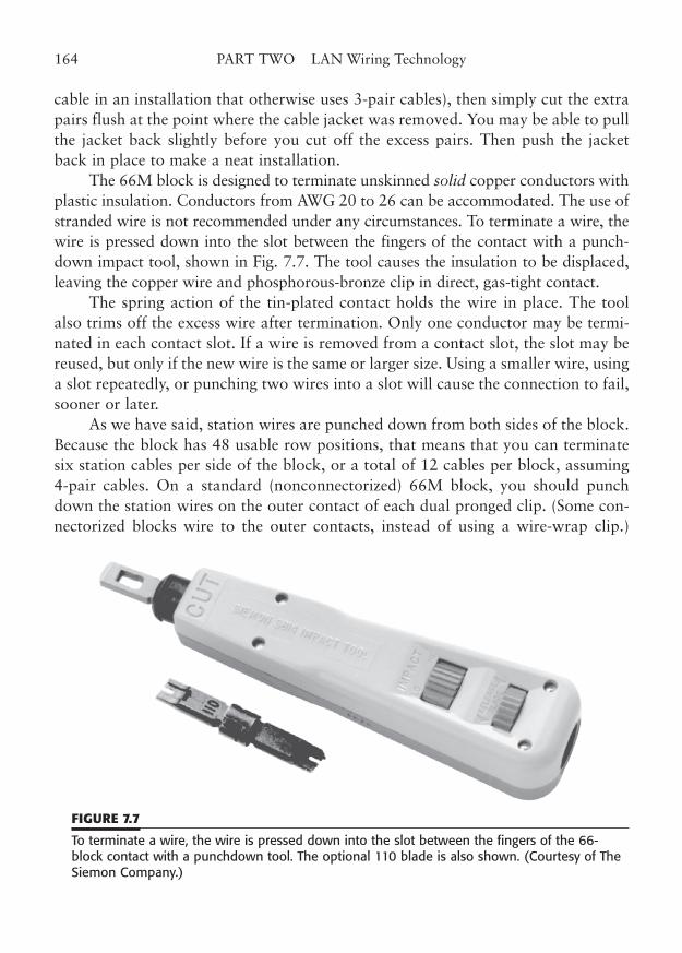
cable in an installation that otherwise uses 3-pair cables), then simply cut the extrapairs flush at the point where the cable jacket was removed. You may be able to pullthe jacket back slightly before you cut off the excess pairs. Then push the jacketback in place to make a neat installation.
The 66M block is designed to terminate unskinned solid copper conductors withplastic insulation. Conductors from AWG 20 to 26 can be accommodated. The use ofstranded wire is not recommended under any circumstances. To terminate a wire, thewire is pressed down into the slot between the fingers of the contact with a punch-down impact tool, shown in Fig. 7.7. The tool causes the insulation to be displaced,leaving the copper wire and phosphorous-bronze clip in direct, gas-tight contact.
The spring action of the tin-plated contact holds the wire in place. The toolalso trims off the excess wire after termination. Only one conductor may be termi-nated in each contact slot. If a wire is removed from a contact slot, the slot may bereused, but only if the new wire is the same or larger size. Using a smaller wire, usinga slot repeatedly, or punching two wires into a slot will cause the connection to fail,sooner or later.
As we have said, station wires are punched down from both sides of the block.Because the block has 48 usable row positions, that means that you can terminatesix station cables per side of the block, or a total of 12 cables per block, assuming4-pair cables. On a standard (nonconnectorized) 66M block, you should punchdown the station wires on the outer contact of each dual pronged clip. (Some con-nectorized blocks wire to the outer contacts, instead of using a wire-wrap clip.)
164 PART TWO LAN Wiring Technology
FIGURE 7.7
To terminate a wire, the wire is pressed down into the slot between the fingers of the 66-block contact with a punchdown tool. The optional 110 blade is also shown. (Courtesy of TheSiemon Company.)
Cross-connect wire pairs are introduced to the row in the same way, through the slotjust above each contact row, but punched down on the inner contact of each clip.The cross-connect wire overlaps the station wire that was punched into the outercontact, but the color code of each should still be visible. When punching, take carethat the punchdown tool is turned the correct way so that the excess wire, and notthe intended connection, gets trimmed off.
The tendency to fan the wires out, and the amount of untwist that exists wherethe wires of a pair pass through the side slots, creates a problem for higher wiringcategories, such as Category 5e and 6. The contact clip also is a rather large pieceof metal that can contribute to impedance mismatch and crosstalk at higher fre-quencies. For that reason, old-style standard 66M blocks are not suitable for useabove Category 3.
Most manufacturers have introduced low-crosstalk 66 blocks that are rated toCategory 5e, but that’s about as far as the venerable 66 block will go. Even withthese special blocks, the normal wiring technique of one-wire-per-slot can still causean unacceptably high amount of crosstalk. If special 66 blocks are used for Category5e, the wire pair should be inserted intact through the side slot between the two tar-get contact rows, rather than split and run through two side slots.
The wires of each pair are then wrapped up or down (whichever is appropri-ate) into the contact and terminated. You must be meticulous about rotating thepunchdown tool, or you will accidentally cut the wire you are attempting to termi-nate, as well as jamming the remaining stub of wire that should have been cut offinto the jaws of the contact. However, this method maintains the amount of untwistwell under the 1/2-in maximum, and it can help you achieve the category of opera-tion you seek. Unfortunately, this technique also makes reading of the color stripeson the wires difficult after termination, so you should be very methodical whenwrapping the wires to be sure you do it right the first time. A subsequent termina-tion on the inner contact will make the color stripes of the wires on the outer con-tact of that row almost impossible to discern.
Many accessories, including adapters, bridging clips, and plug-on jacks, existfor the 66M block. Virtually all of these are inappropriate for use in permanentlyinstalled LAN wiring systems. The most stable connection system for LAN wiringis to use cross-connect wires between punchdown blocks and patches, or to termi-nate directly on the patch and skip the punchdown block altogether.
A version of the 66 block incorporates 8-pin modular jacks into the assembly.The jacks are mounted in groups of four or so at the side of the mounting bracket.This type of block may eliminate the need for a separate patch panel. However, it ismore difficult to see and access the jacks on the side of the block, and potential wiremanagement methods are poor. In addition, you must be certain that the assembly
CHAPTER 7 Telecommunication Room Terminations 165
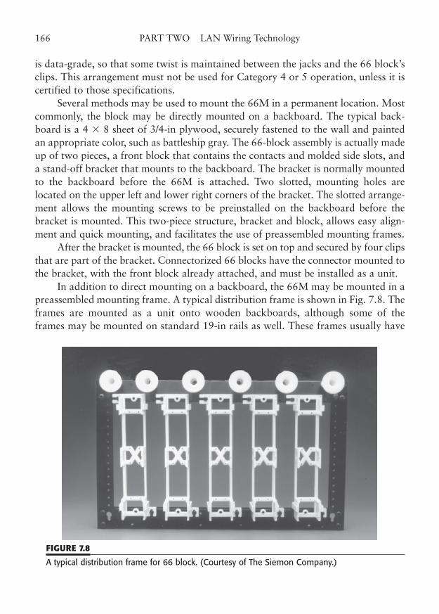
is data-grade, so that some twist is maintained between the jacks and the 66 block’sclips. This arrangement must not be used for Category 4 or 5 operation, unless it iscertified to those specifications.
Several methods may be used to mount the 66M in a permanent location. Mostcommonly, the block may be directly mounted on a backboard. The typical back-board is a 4 � 8 sheet of 3/4-in plywood, securely fastened to the wall and paintedan appropriate color, such as battleship gray. The 66-block assembly is actually madeup of two pieces, a front block that contains the contacts and molded side slots, anda stand-off bracket that mounts to the backboard. The bracket is normally mountedto the backboard before the 66M is attached. Two slotted, mounting holes arelocated on the upper left and lower right corners of the bracket. The slotted arrange-ment allows the mounting screws to be preinstalled on the backboard before thebracket is mounted. This two-piece structure, bracket and block, allows easy align-ment and quick mounting, and facilitates the use of preassembled mounting frames.
After the bracket is mounted, the 66 block is set on top and secured by four clipsthat are part of the bracket. Connectorized 66 blocks have the connector mounted tothe bracket, with the front block already attached, and must be installed as a unit.
In addition to direct mounting on a backboard, the 66M may be mounted in apreassembled mounting frame. A typical distribution frame is shown in Fig. 7.8. Theframes are mounted as a unit onto wooden backboards, although some of theframes may be mounted on standard 19-in rails as well. These frames usually have
166 PART TWO LAN Wiring Technology
FIGURE 7.8
A typical distribution frame for 66 block. (Courtesy of The Siemon Company.)
preinstalled mounting brackets, into which the appropriate 66M block can besnapped. The frames may also have plastic stand-offs (sometimes called “mush-rooms”) and brackets for cable and cross-connect wire management. Frames areavailable in various sizes and can be used to implement full intermediate or maindistribution frame (IDF or MDF) facilities.
Various wiring color codes for the 66 block are shown in Fig. 7.9. The cablesare terminated on the 66 block according to these standard color codes. The 4-paircode may be used to implement a TIA-568-C wiring system.
The overall color pattern is laid out in five “groups” of five pairs (10 wires) each.Each group of five pairs has one primary color that is the same for all the pairs. (Notethat these are not “primary” colors, as taught in art class; rather, the term refers to thefirst color in a pair of wires.) The primary colors, in order, are white, red, black, yellow,and violet (sometimes called purple) and are commonly abbreviated W, R, BK, Y, V (orP), although other abbreviations are sometimes used for readability, such as WHT, RED,BLK, YEL, and VIO or PUR. The first wire group, for example, has a white wire in eachpair, along with a second wire of a different color. The secondary wire colors are blue,orange, green, brown, and slate (sort of a silver/gray) and are abbreviated BL, O, G, BR,and S (or sometimes BLU, ORG, GRN, BRN, and SLT). Note that TIA-568-C uses theshortened abbreviations (the first letter of each color where there is no ambiguity and asecond letter where needed). For example, for a 4-pair cable, the color abbreviations areW (the primary color) and BL, O, G, and BR (the secondary colors).
Each wire in a pair bears a helical or round stripe that is the same color as itsmate. The pair is referred to by its primary and secondary colors. Thus, the first pairof the first group is the W/BL pair (said “white-blue”) and consists of a white wirewith a blue stripe and a blue wire with a white stripe. The primary-colored wire isalways punched down first (from top to bottom of the block). Thus, the top row ofthe punchdown block will have a W/BL wire, the second row a BL/W wire, the thirdrow a W/O, and so forth.
Four-pair wires are a special case because they only use four pairs from the firstprimary color group. Because of this, there is no confusion if the pairs are referredto by their secondary color only, such as “the blue pair” or “the green pair.” Justmake sure you punch down each pair’s white wire first. TIA-568-C also allows analternative color coding for patch cords. See Chapter 8.
Other Connecting Systems
We will mention two other connecting systems that are beginning to be used in moreand more installations. One is the NORDX/CDT (formerly Nortel NorthernTelecom) BIX system and the other is the Krone system.
CHAPTER 7 Telecommunication Room Terminations 167
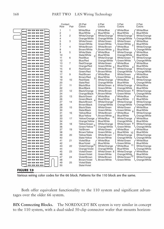
Both offer equivalent functionality to the 110 system and significant advan-tages over the older 66 system.
BIX Connecting Blocks. The NORDX/CDT BIX system is very similar in conceptto the 110 system, with a dual-sided 50-clip connector wafer that mounts horizon-
168 PART TWO LAN Wiring Technology
Contact 25 Pair 4 Pair 3 Pair 2 PairRow Pair Colors Colors Colors Colors
1 1 White/Blue White/Blue White/Blue White/Blue2 Blue/White Blue/White Blue/White Blue/White3 2 White/Orange White/Orange White/Orange White/Orange4 Orange/White Orange/White Orange/White Orange/White5 3 White/Green White/Green White/Green White/Blue6 Green/White Green/White Green/White Blue/White7 4 White/Brown White/Brown White/Blue White/Orange8 Brown/White Brown/White Blue/White Orange/White9 5 White/Slate White/Blue White/Orange White/Blue10 Slate/White Blue/White Orange/White Blue/White11 6 Red/Blue White/Orange White/Green White/Orange12 Blue/Red Orange/White Green/White Orange/White13 7 Red/Orange White/Green White/Blue White/Blue14 Orange/Red Green/White Blue/White Blue/White15 8 Red/Green White/Brown White/Orange White/Orange16 Green/Red Brown/White Orange/White Orange/White17 9 Red/Brown White/Blue White/Green White/Blue18 Brown/Red Blue/White Green/White Blue/White19 10 Red/Slate White/Orange White/Blue White/Orange20 Slate/Red Orange/White Blue/White Orange/White21 11 Black/Blue White/Green White/Orange White/Blue22 Blue/Black Green/White Orange/White Blue/White23 12 Black/Orange White/Brown White/Green White/Orange24 Orange/Black Brown/White Green/White Orange/White25 13 Black/Green White/Blue White/Blue White/Blue26 Green/Black Blue/White Blue/White Blue/White27 14 Black/Brown White/Orange White/Orange White/Orange28 Brown/Black Orange/White Orange/White Orange/White29 15 Black/Slate White/Green White/Green White/Blue30 Slate/Black Green/White Green/White Blue/White31 16 Yellow/Blue White/Brown White/Blue White/Orange32 Blue/Yellow Brown/White Blue/White Orange/White33 17 Yellow/Orange White/Blue White/Orange White/Blue34 Orange/Yellow Blue/White Orange/White Blue/White35 18 Yellow/Green White/Orange White/Green White/Orange36 Green/Yellow Orange/White Green/White Orange/White37 19 Yel/Brown White/Green White/Blue White/Blue38 Brown/Yellow Green/White Blue/White Blue/White39 20 Yellow/Slate White/Brown White/Orange White/Orange40 Slate/Yellow Brown/White Orange/White Orange/White41 21 Violet/Blue White/Blue White/Green White/Blue42 Blue/Violet Blue/White Green/White Blue/White43 22 Violet/Orange White/Orange White/Blue White/Orange44 Orange/Violet Orange/White Blue/White Orange/White45 23 Violet/Green White/Green White/Orange White/Blue46 Green/Violet Green/White Orange/White Blue/White47 24 Violet/Brown White/Brown White/Green White/Orange48 Brown/Violet Brown/White Green/White Orange/White49 25 Violet/Slate50 Slate/Violet
1 1 1
2
3
4
5
6
2
3
4
5
6
7
8
2
3
4
5
6
7
8
9
10
11
12
FIGURE 7.9
Various wiring color codes for the 66 block. Patterns for the 110 block are the same.
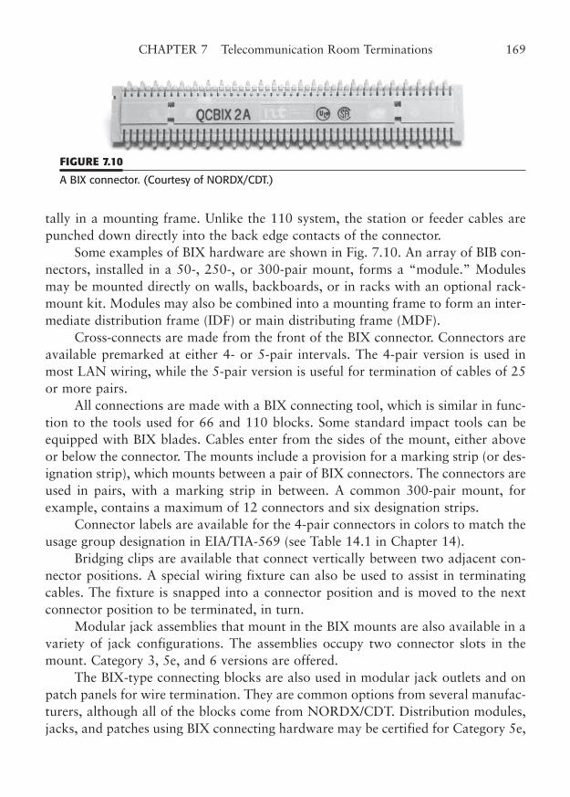
tally in a mounting frame. Unlike the 110 system, the station or feeder cables arepunched down directly into the back edge contacts of the connector.
Some examples of BIX hardware are shown in Fig. 7.10. An array of BIB con-nectors, installed in a 50-, 250-, or 300-pair mount, forms a “module.” Modulesmay be mounted directly on walls, backboards, or in racks with an optional rack-mount kit. Modules may also be combined into a mounting frame to form an inter-mediate distribution frame (IDF) or main distributing frame (MDF).
Cross-connects are made from the front of the BIX connector. Connectors areavailable premarked at either 4- or 5-pair intervals. The 4-pair version is used inmost LAN wiring, while the 5-pair version is useful for termination of cables of 25or more pairs.
All connections are made with a BIX connecting tool, which is similar in func-tion to the tools used for 66 and 110 blocks. Some standard impact tools can beequipped with BIX blades. Cables enter from the sides of the mount, either aboveor below the connector. The mounts include a provision for a marking strip (or des-ignation strip), which mounts between a pair of BIX connectors. The connectors areused in pairs, with a marking strip in between. A common 300-pair mount, forexample, contains a maximum of 12 connectors and six designation strips.
Connector labels are available for the 4-pair connectors in colors to match theusage group designation in EIA/TIA-569 (see Table 14.1 in Chapter 14).
Bridging clips are available that connect vertically between two adjacent con-nector positions. A special wiring fixture can also be used to assist in terminatingcables. The fixture is snapped into a connector position and is moved to the nextconnector position to be terminated, in turn.
Modular jack assemblies that mount in the BIX mounts are also available in avariety of jack configurations. The assemblies occupy two connector slots in themount. Category 3, 5e, and 6 versions are offered.
The BIX-type connecting blocks are also used in modular jack outlets and onpatch panels for wire termination. They are common options from several manufac-turers, although all of the blocks come from NORDX/CDT. Distribution modules,jacks, and patches using BIX connecting hardware may be certified for Category 5e,
CHAPTER 7 Telecommunication Room Terminations 169
FIGURE 7.10
A BIX connector. (Courtesy of NORDX/CDT.)
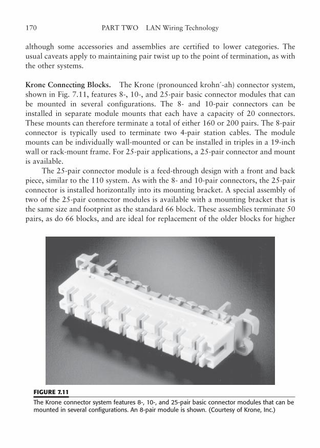
although some accessories and assemblies are certified to lower categories. Theusual caveats apply to maintaining pair twist up to the point of termination, as withthe other systems.
Krone Connecting Blocks. The Krone (pronounced krohn´-ah) connector system,shown in Fig. 7.11, features 8-, 10-, and 25-pair basic connector modules that canbe mounted in several configurations. The 8- and 10-pair connectors can beinstalled in separate module mounts that each have a capacity of 20 connectors.These mounts can therefore terminate a total of either 160 or 200 pairs. The 8-pairconnector is typically used to terminate two 4-pair station cables. The modulemounts can be individually wall-mounted or can be installed in triples in a 19-inchwall or rack-mount frame. For 25-pair applications, a 25-pair connector and mountis available.
The 25-pair connector module is a feed-through design with a front and backpiece, similar to the 110 system. As with the 8- and 10-pair connectors, the 25-pairconnector is installed horizontally into its mounting bracket. A special assembly oftwo of the 25-pair connector modules is available with a mounting bracket that isthe same size and footprint as the standard 66 block. These assemblies terminate 50pairs, as do 66 blocks, and are ideal for replacement of the older blocks for higher
170 PART TWO LAN Wiring Technology
FIGURE 7.11
The Krone connector system features 8-, 10-, and 25-pair basic connector modules that can bemounted in several configurations. An 8-pair module is shown. (Courtesy of Krone, Inc.)
performance applications. They also mount in distribution frames intended for 66blocks. The availability of 66-type mounts means that versions of the block can beoffered with integral 50-pin telco connectors, just as with the 66 blocks.
Station and cross-connect wires are terminated on the bottom and on the top,respectively, of a Krone connector. The connector offers a unique “disconnect” con-tact as an option. Connectors with the disconnect feature can be temporarily openedfor isolated testing to either leg of the circuit.
Krone connectors may also be found in outlet jacks and patch panels for wiretermination. Many manufacturers offer the Krone wire termination system as anoption. The connector hardware may be certified to Category 5e/6, but again, theusual guidelines for wire pair termination must be observed.
Routing and Dressing Devices
Cabling, cross-connects, and patching in wiring closets should result in an installa-tion that is neat and orderly. Unfortunately, all these wires and cords have a natu-ral tendency to be very disorderly, it seems. To avoid the mess and stress it brings,you should use the proper wire-management devices to put the wire in its place.Proper planning, layout, and dressing-in of the wire and patch cords can result in avery nice installation.
The process of properly routing and dressing your cable can keep yourwiring closet much more “user-friendly.” If you are the user, you will really appre-ciate the neatness every time you need access to your cable system. If you are theinstaller, your customer will be much more pleased with your installation. Thesystem of routing and dressing-in (putting in place) twisted-pair wiring is rela-tively simple. The principle is that all the wires and cables should be run alongwiring channels or trays, secured in place with cable ties or other devices, makerelatively square corners, and be out of sight as much as possible when securingthe wire is not practical.
You can divide the wire management problems into two separate issues. Oneissue is how you should deal with relatively permanent wiring, such as horizontalstation cables and cross-connects. The other issue is how you manage temporarywiring, such as patch cords (and equipment cords). Station cable and cross-connectsconsist of solid core wires and cables.
These wires are relatively easy to bend into position, wrap around standoffs orbrackets, and secure with a few cable ties. The solid wire tends to bend into placeand stay with a minimum of restraint. The stranded-wire cable used in patch cordsis not as well behaved. It is used specifically because it is so flexible, relative to solid-wire cable.
CHAPTER 7 Telecommunication Room Terminations 171
These patch cords are truly a mess to deal with, leading some to try to avoidtheir use entirely and use semi-permanent cross-connect wire instead. In LANwiring, flexible equipment cords are often used between a patch panel and the LANhub. Many hub ports must be connected with an 8-pin modular cord, unless theyare equipped with mass-terminated connectors, such as the 50-pin telco connector.Thus, the use of stranded-wire cords may be unavoidable.
How you handle cable management will be a function of the size of your TRand how it is laid out. If you have a small, wall-mounted wire termination systemwith a few wall-mounted hubs, you may be able to deal with the cables by securingthe station wires with tie wraps and standoffs, running cross-connects (if any)around standoff posts or through cable rings, and letting the patch or equipmentcords droop (neatly, we hope). On the other hand, if you have a large facility, orhave equipment and wiring devices that are mounted in floor racks, you should usea system of cable trays, panels, raceways, and brackets that routes all types of cableand keeps them very neat. There is nothing more troublesome than having to pickyour way through a curtain of patch cords to find a patch jack. There are much bet-ter ways to install your cable and cords, and we will cover some of them here.
We should caution you first that using tie wraps (cable ties) that are excessivelytightened can cause performance problems on Category 5e/6 wiring and should beavoided. However, relatively loose ties that do not distort the cable jacket should be allright. The effect is cumulative, so 20 tie wraps are worse than five. You can use a newtype of wrap made with hook-and-loop mesh (Velcro-type) in lieu of traditional nylontie wraps. This new wrap is wider, so it does not pinch the cable as badly. It is also eas-ily removable so that new cables can be added without adding tie-wrap clutter.
Standoffs and Distribution Rings
The most basic accessories for wire management are plastic standoffs and plastic ormetal distribution rings. Some examples of standoffs are shown in Fig. 7.12. Theplastic standoffs (sometimes called wire spools or mushrooms) are designed to holdcables or cross-connect wires underneath the outer lip (which gives it the mushroomlook). Wires are wrapped over a standoff, or down the side of a line of standoffsand routed to their destination. The wire is usually bent around the post veryslightly to give the wire a “set” and hold it in place. Tie wraps may also be used tohold wires in place, subject to precautions applicable to Category 5e/6 use. Thestandoffs are hollow and may be secured to the wiring board with a captive woodscrew or machine screw. Standoffs are also supplied without a screw. These devicesare very widely used in cross-connect fields, especially with the 66-style connectingblock, which has little native cable management.
172 PART TWO LAN Wiring Technology
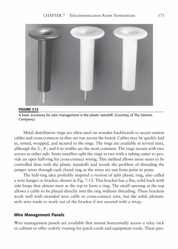
Metal distribution rings are often used on wooden backboards to secure stationcables and cross-connects as they are run across the board. Cables may be quickly laidin, sorted, wrapped, and secured to the rings. The rings are available in several sizes,although the 2-, 4-, and 6-in widths are the most common. The rings mount with twoscrews at either side. Some installers split the rings in two with a tubing cutter to pro-vide an open half-ring for cross-connect wiring. This method allows more wires to becontrolled than with the plastic standoffs and avoids the problem of threading thejumper wires through each closed ring as the wires are run from point to point.
The half-ring idea probably inspired a version of split plastic ring, also calleda wire hanger or bracket, shown in Fig. 7.13. This bracket has a flat, solid back withside loops that almost meet at the top to form a ring. The small opening at the topallows a cable to be placed directly into the ring without threading. These bracketswork well with stranded wire cable or cross-connect wire, but the solid, plenum-style wire tends to work out of the bracket if not secured with a wrap.
Wire Management Panels
Wire management panels are available that mount horizontally across a relay rackor cabinet to offer orderly routing for patch cords and equipment cords. These pan-
CHAPTER 7 Telecommunication Room Terminations 173
FIGURE 7.12
A basic accessory for wire management is the plastic standoff. (Courtesy of The SiemonCompany.)
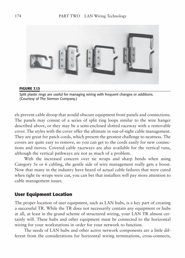
els prevent cable droop that would obscure equipment front panels and connections.The panels may consist of a series of split ring loops similar to the wire hangerdescribed above, or they may be a semi-enclosed slotted raceway with a removablecover. The styles with the cover offer the ultimate in out-of-sight cable management.They are great for patch cords, which present the greatest challenge to neatness. Thecovers are quite easy to remove, so you can get to the cords easily for new connec-tions and moves. Covered cable raceways are also available for the vertical runs,although the vertical pathways are not as much of a problem.
With the increased concern over tie wraps and sharp bends when usingCategory 5e or 6 cabling, the gentle side of wire management really gets a boost.Now that many in the industry have heard of actual cable failures that were curedwhen tight tie wraps were cut, you can bet that installers will pay more attention tocable management issues.
User Equipment Location
The proper location of user equipment, such as LAN hubs, is a key part of creatinga successful TR. While the TR does not necessarily contain any equipment or hubsat all, at least in the grand scheme of structured wiring, your LAN TR almost cer-tainly will. These hubs and other equipment must be connected to the horizontalwiring for your workstations in order for your network to function.
The needs of LAN hubs and other active network components are a little dif-ferent from the considerations for horizontal wiring terminations, cross-connects,
174 PART TWO LAN Wiring Technology
FIGURE 7.13
Split plastic rings are useful for managing wiring with frequent changes or additions. (Courtesy of The Siemon Company.)
and patches. Wiring and termination components simply need a fixed mountinglocation, wire management devices, and accessibility.
The hubs and other equipment need power, ventilation, and connectivity totheir respective station links. The wiring components tend to be fixed in place forthe life of the installation. The equipment components, however, may need room togrow and to be reconfigured as network needs change and as technology changes.
The best location for the equipment is one that places the hubs and the wiringcomponents as close together as practical, while maintaining a logical separation ofthe two functions. Remember, too, that some expandability of horizontal wiringconnections should be allowed, and that correspondingly more room should beallowed for future changes in equipment technology.
In a small installation of less than 100 station terminations, you have a choiceof wall or rack mounting for both the equipment and the cable terminations. Thereare advantages (and disadvantages) to both. Wall mounting will give you the mostfree and open space in the center of a small wiring closet. However, it limits accessand cable routing options for the wiring components, and wall mounting of hubsand other equipment may be difficult. Rack mounting may be used both for wiringcomponents and for hubs, but you will have added expense for the rack, cable trays,and other accessories.
In larger installations, serious consideration should be given to rack-mountingall components. This is particularly appropriate with the wide range of wire man-agement devices for cable racks. You may face an interesting dilemma trying todecide in which racks to put the hubs. Should they be in the same racks, or shouldthey be in adjacent racks?
While there may be a certain logic to separating the wiring termination blocksand patches from the hubs, remember that you must generally run lots of patchcords between the two. With separate racks, all those patch cords would have topass up through one rack and across and down into the other rack to make connec-tions. Not only is such a long run probably unnecessary, but it may stretch you tothe limit for the channel link. Remember that you are allowed only 10 m (33 ft) forall equipment cords in a channel, including both the user cords in the work area andthe patch/equipment cords in the TR.2
If you required a 5-m (16-ft) equipment cord to reach to the hub rack, youwould only have a 5-m (16-ft) allowance in the work area. It is not unusual forlarger work area offices to need 6- to 8-m (18- to 25-ft) user cords, so you wouldbe better off using as short a TR equipment cord as possible.
CHAPTER 7 Telecommunication Room Terminations 175
2 TIA/EIA-568-B actually now limits the total to 5 m (16 ft) for user cords in the work area, and 5 m(16 ft) for all equipment cords, patch cords, and cross-connect jumpers in the telecommunications room.
The easy way to keep patch and equipment cords short is to locate the hori-zontal wire terminations and the hubs in the same rack. The terminations might beon connecting blocks, with cross-connects to patch panels, or directly to patch pan-els. You can use wire management panels to route the patch wires to the side railsand down to the hub. Most modern wire termination blocks feature a very high con-nection density, so they should not take up much rack space. Also, patch panels with96 or more jacks consume very little vertical rack space. So, it should be possible toplace both equipment and terminations in the same rack, with plenty of room forfuture expansion of both. A popular alternative mounting scheme is to place thewiring terminations in wall mountings and place the LAN hubs in relay racks. Thishybrid approach is serviceable, as long as the equipment cord runs are not too longfrom the wall to the racked hubs. In a variation to this approach, you could placethe connecting block terminations on the wall, as before, and run cross-connectjumpers to patch panels in relay racks. Then, relatively short equipment cords couldbe connected between the patch panels and hubs in the same rack. Remember thatthe cross-connect jumpers count as part of the 5-m (16-ft) limit.
“To patch or not to patch, that is the question.” You can get into a consider-able debate with some wiring managers of large facilities about this very question.There is definitely a downside to the use of patch panels in a large facility. The prob-lems with patch panels are that they are an added expense, provide an additionalpoint of failure, may provide questionable long-term connections, and add lots ofspaghetti-mess (from the myriad of patch cords that must be used). Their modularconnectors may also add unnecessary crosstalk. If connections to the hubs can bemade with cross-connect wires, you may be able to avoid the use of patch panelsaltogether. Simply terminate your station cables on the connecting block of yourchoice and run a cross-connect jumper over to a mass-termination connector for thehub. The larger card-cage hubs offer port connections on 50-pin telco connectors,among other options. The hub’s 50-pin connectors can be extended to connectingblocks, such as the 110 system blocks, and the cross-connects can be made directlyto the station punchdowns, without using patch panels.
The patchless approach has at least three disadvantages. First, troubleshootingis more difficult, as you cannot simply unplug a modular equipment cord and inserta tester. You must either disconnect the cross-connect wire and use a test jackadapter that fits onto the connecting block, or you must have used one of the typesof connecting blocks with a built-in disconnect capability and still use a test adapter.Second, it is much more difficult, on average, to locate the connections for a partic-ular station cable, since the circuit markings are imbedded in the high-density con-necting block. Third, you may double the potential workmanship problems. Forexample, if you had directly terminated on a patch panel, that would be the only
176 PART TWO LAN Wiring Technology
field termination that might have excessive untwist or other problems. The patchcords would hopefully be factory terminated, carefully inspected, and certified.With cross-connection, you add four points for potential workmanship problems:the connecting block, the two end connections of the cross-connect jumper, and themulticircuit termination leading to the hub.
Which is right for you? That may depend on the size of your facility and thetraining of LAN maintenance personnel. The patchless approach should probablybe avoided in TRs having under 100 to 200 connections, unless you have trainedpeople with the ability to do complex wire tracing and the workmanship skills tomake high-quality connections.
Fiber-Optic Termination
Fiber-optic cables are treated a little differently in the TR than are conventionalmetallic cables. However, the concepts are the same. Basically, in the telecommuni-cations room, cables from the horizontal distribution to work areas are all broughttogether in some fixed, orderly arrangement for interconnection to network hubsand other equipment. Fiber-optic cables may be used for the horizontal cabling, inplace of traditional metallic wire. Fiber-optic cables are also widely used for thebackbone cabling that runs between TRs. Differences in the TR terminations forfiber-optic cables exist because of the nature of the signals (light) and the fact thatthe transmission medium (glass fiber) requires special handling. These differenceslimit the number of ways the cables may be terminated, severely limit routing andhandling considerations, and cause fundamental differences in the structure ofpatch panels.
In addition, fiber-optic connections have what might be called “polarity.”Because a single fiber sends its signal in only one direction, a fiber-optic link alwaysrequires two fiber connections, one to transmit the signal in each direction. To oper-ate properly, the transmitted signal from one end must connect to the receiver portat the other end, and vice versa. This is called a crossover connection.
In contrast, metallic cable link standards use straight-through wiring for mostconnections. This is accomplished by defining two types of equipment interfaces,such as the DTE and DCE interfaces of RS-232 that are meant to connect “termi-nal” and “communication” devices. The same type of pattern exists in10/100/1000BaseT (adapter versus hub) and AUI (repeater versus transceiver).However, the fiber-optic equipment interfaces have traditionally been identical, pro-viding signal identification only by the label beside each of the two fiber-optic con-nectors. That means that the user/installer must provide fiber cabling thataccomplishes the crossover.
CHAPTER 7 Telecommunication Room Terminations 177
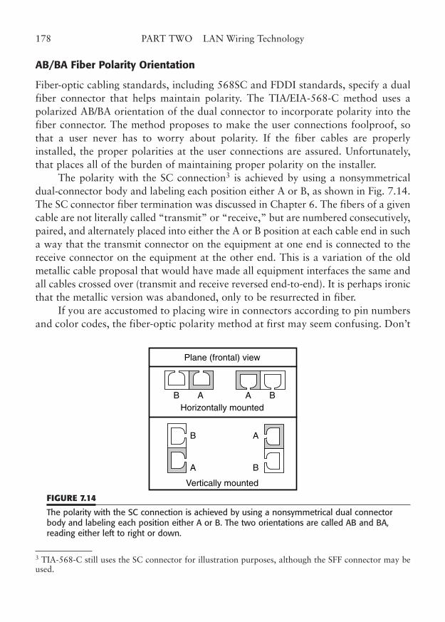
AB/BA Fiber Polarity Orientation
Fiber-optic cabling standards, including 568SC and FDDI standards, specify a dualfiber connector that helps maintain polarity. The TIA/EIA-568-C method uses apolarized AB/BA orientation of the dual connector to incorporate polarity into thefiber connector. The method proposes to make the user connections foolproof, sothat a user never has to worry about polarity. If the fiber cables are properlyinstalled, the proper polarities at the user connections are assured. Unfortunately,that places all of the burden of maintaining proper polarity on the installer.
The polarity with the SC connection3 is achieved by using a nonsymmetricaldual-connector body and labeling each position either A or B, as shown in Fig. 7.14.The SC connector fiber termination was discussed in Chapter 6. The fibers of a givencable are not literally called “transmit” or “receive,” but are numbered consecutively,paired, and alternately placed into either the A or B position at each cable end in sucha way that the transmit connector on the equipment at one end is connected to thereceive connector on the equipment at the other end. This is a variation of the oldmetallic cable proposal that would have made all equipment interfaces the same andall cables crossed over (transmit and receive reversed end-to-end). It is perhaps ironicthat the metallic version was abandoned, only to be resurrected in fiber.
If you are accustomed to placing wire in connectors according to pin numbersand color codes, the fiber-optic polarity method at first may seem confusing. Don’t
178 PART TWO LAN Wiring Technology
B A
A
B
B
A
A BHorizontally mounted
Vertically mounted
Plane (frontal) view
FIGURE 7.14
The polarity with the SC connection is achieved by using a nonsymmetrical dual connectorbody and labeling each position either A or B. The two orientations are called AB and BA,reading either left to right or down.
3 TIA-568-C still uses the SC connector for illustration purposes, although the SFF connector may beused.
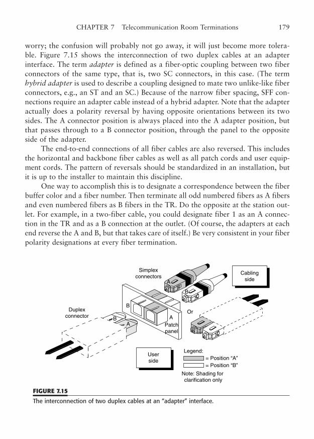
worry; the confusion will probably not go away, it will just become more tolera-ble. Figure 7.15 shows the interconnection of two duplex cables at an adapterinterface. The term adapter is defined as a fiber-optic coupling between two fiberconnectors of the same type, that is, two SC connectors, in this case. (The termhybrid adapter is used to describe a coupling designed to mate two unlike-like fiberconnectors, e.g., an ST and an SC.) Because of the narrow fiber spacing, SFF con-nections require an adapter cable instead of a hybrid adapter. Note that the adapteractually does a polarity reversal by having opposite orientations between its twosides. The A connector position is always placed into the A adapter position, butthat passes through to a B connector position, through the panel to the oppositeside of the adapter.
The end-to-end connections of all fiber cables are also reversed. This includesthe horizontal and backbone fiber cables as well as all patch cords and user equip-ment cords. The pattern of reversals should be standardized in an installation, butit is up to the installer to maintain this discipline.
One way to accomplish this is to designate a correspondence between the fiberbuffer color and a fiber number. Then terminate all odd numbered fibers as A fibersand even numbered fibers as B fibers in the TR. Do the opposite at the station out-let. For example, in a two-fiber cable, you could designate fiber 1 as an A connec-tion in the TR and as a B connection at the outlet. (Of course, the adapters at eachend reverse the A and B, but that takes care of itself.) Be very consistent in your fiberpolarity designations at every fiber termination.
CHAPTER 7 Telecommunication Room Terminations 179
Duplexconnector
Simplexconnectors
Userside
Cablingside
Legend:
Note: Shading for clarification only
B
B
B
AA
A
= Position “A” = Position “B”
Or
Patchpanel
FIGURE 7.15
The interconnection of two duplex cables at an “adapter” interface.
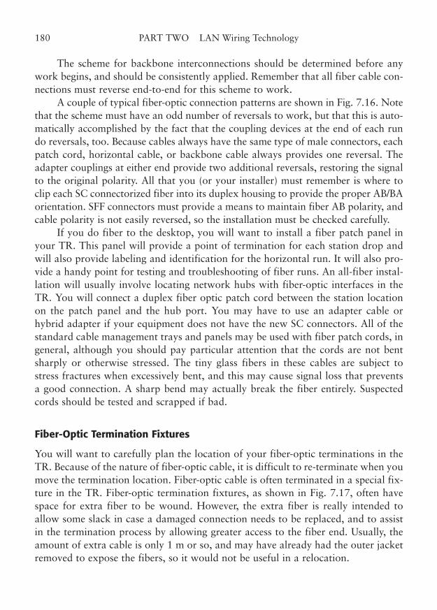
The scheme for backbone interconnections should be determined before anywork begins, and should be consistently applied. Remember that all fiber cable con-nections must reverse end-to-end for this scheme to work.
A couple of typical fiber-optic connection patterns are shown in Fig. 7.16. Notethat the scheme must have an odd number of reversals to work, but that this is auto-matically accomplished by the fact that the coupling devices at the end of each rundo reversals, too. Because cables always have the same type of male connectors, eachpatch cord, horizontal cable, or backbone cable always provides one reversal. Theadapter couplings at either end provide two additional reversals, restoring the signalto the original polarity. All that you (or your installer) must remember is where toclip each SC connectorized fiber into its duplex housing to provide the proper AB/BAorientation. SFF connectors must provide a means to maintain fiber AB polarity, andcable polarity is not easily reversed, so the installation must be checked carefully.
If you do fiber to the desktop, you will want to install a fiber patch panel inyour TR. This panel will provide a point of termination for each station drop andwill also provide labeling and identification for the horizontal run. It will also pro-vide a handy point for testing and troubleshooting of fiber runs. An all-fiber instal-lation will usually involve locating network hubs with fiber-optic interfaces in theTR. You will connect a duplex fiber optic patch cord between the station locationon the patch panel and the hub port. You may have to use an adapter cable orhybrid adapter if your equipment does not have the new SC connectors. All of thestandard cable management trays and panels may be used with fiber patch cords, ingeneral, although you should pay particular attention that the cords are not bentsharply or otherwise stressed. The tiny glass fibers in these cables are subject tostress fractures when excessively bent, and this may cause signal loss that preventsa good connection. A sharp bend may actually break the fiber entirely. Suspectedcords should be tested and scrapped if bad.
Fiber-Optic Termination Fixtures
You will want to carefully plan the location of your fiber-optic terminations in theTR. Because of the nature of fiber-optic cable, it is difficult to re-terminate when youmove the termination location. Fiber-optic cable is often terminated in a special fix-ture in the TR. Fiber-optic termination fixtures, as shown in Fig. 7.17, often havespace for extra fiber to be wound. However, the extra fiber is really intended toallow some slack in case a damaged connection needs to be replaced, and to assistin the termination process by allowing greater access to the fiber end. Usually, theamount of extra cable is only 1 m or so, and may have already had the outer jacketremoved to expose the fibers, so it would not be useful in a relocation.
180 PART TWO LAN Wiring Technology
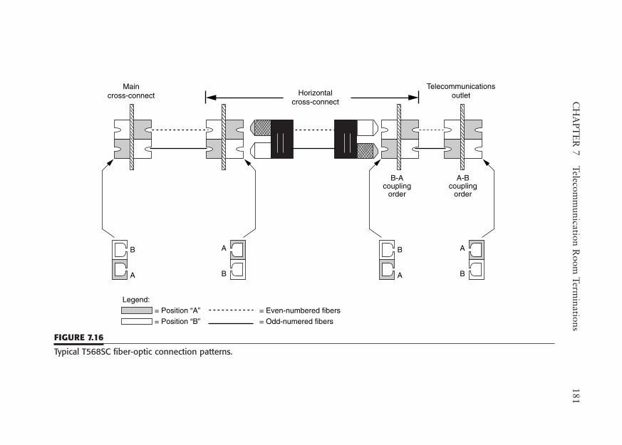
CH
APT
ER
7Telecom
munication R
oom Term
inations181
A
B
B
A
A
B
B
A
Maincross-connect
Telecommunicationsoutlet
A-Bcoupling
order
B-Acoupling
order
Legend:= Position “A” = Position “B”
= Even-numbered fibers= Odd-numered fibers
Horizontalcross-connect
FIGURE 7.16
Typical T568SC fiber-optic connection patterns.
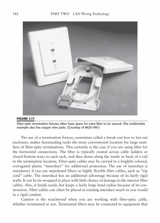
The use of a termination fixture, sometimes called a break-out box or fan-outenclosure, makes freestanding racks the most conventional location for large num-bers of fiber-optic terminations. This certainly is the case if you are using fiber forthe horizontal connections. The fiber is typically routed across cable ladders orclosed-bottom trays to each rack, and then down along the inside or back of a railto the termination location. Fiber-optic cables may be carried in a brightly colored,corrugated plastic “innerduct” for additional protection. The use of innerduct ismandatory if you use unjacketed fibers or highly flexible fiber cables, such as “zipcord” cable. The innerduct has an additional advantage because of its fairly rigidwalls. It can be tie-wrapped in place with little chance of damage to the interior fibercables. Also, it bends easily, but keeps a fairly large bend radius because of its con-struction. Fiber cables can often be placed in existing interduct much as you wouldin a rigid conduit.
Caution is the watchword when you are working with fiber-optic cable,whether terminated or not. Terminated fibers may be connected to equipment that
182 PART TWO LAN Wiring Technology
FIGURE 7.17
Fiber-optic termination fixtures often have space for extra fiber to be wound. This multimediaexample also has copper wire jacks. (Courtesy of MOD-TAP.)
emits hazardous levels of laser light, especially if you are using single-mode fiber.Appropriate eye protection should be worn and appropriate precautions takenwhen you are dealing with laser emitters that transmit above Hazard Level 1. ANSIZ136.2 contains more information on these precautions. Even nonlaser light maybe a hazard if held close to the eye. A good rule is to never look into a fiber. Thefiber wavelengths are in the invisible infrared spectrum anyhow, so looking onlysubjects you to a hazard, as you cannot see the light. The hazard exists even withunterminated fiber ends, so treat them as you would terminated fiber. Although vis-ible light testers are sometimes used during troubleshooting, you would be saferwhen using these if you simply point the connector or fiber at your hand and lookfor a dot of light, rather than trying to look directly at the fiber. Bad habits are hardto break, so don’t start one.
The tiny glass slivers that result from cutting, cleaving, and sometimes polish-ing fibers are also an eye hazard. Always wear safety glasses when terminating fiber.You also don’t want to inhale any of the fiber dust, but you should be able to avoidit when field-terminating fiber cables under normal circumstances.
See Chapter 11 for more information on fiber-optic installation practices.
Marking
As we discussed for station outlets, proper identification of TR terminations is cru-cial to a high-quality, serviceable wiring installation. This includes a consistentmethod of cable and termination numbering.
Each and every cable, termination fixture, patch panel, and cross-connectshould be clearly identified. EIA/TIA-606 provides a method of marking just abouteverything in the telecommunications wiring world, with wiring terminations beingno exception. The guidelines call for each item to be marked with a unique identi-fication that is clearly visible. That generally means you should use 3/8-in-high let-tering and designate each cable termination and patch position in some orderlyfashion, such as with the TR number, cable number, position, etc.
Some connecting blocks make marking difficult, while others seem to havemarking panels as part of the design. Contrasting examples are 66 blocks and 110blocks. Some older patch panels leave little room for markings, other than the smallfactory-marked jack number. In a very small installation, this does not cause toomuch difficulty, but larger installations require more detailed, explanatory markings.
You also may choose to use color to help designate wire termination areas. Theofficial colors for grouping different types of cable terminations are given in Chapter14. The colors are defined in EIA/TIA-569-A, Commercial Building Standard forTelecommunications Pathways and Spaces.
CHAPTER 7 Telecommunication Room Terminations 183
Workmanship
One of the keys to a successful LAN wiring installation is good workmanship.You can use all the finest components, the most expensive mountings, and the
highest ratings, and still have a poor installation because of improper installationtechniques. The TR is as much in need of good installation practice as any other area.
In some ways, there are more places in a typical TR to do things that mightadversely affect your cable link performance than elsewhere. For example, you maymake one station cable termination, two cross-connects, and one patch terminationall in the same cable link. Add to that the patch cords and equipment cords, andthere is a lot of room for error.
The first workmanship guideline is to properly route the cables. You shouldminimize the sharp bends, avoid tight tie-wraps, avoid proximity to magnetic fields,and limit exposure to mechanical damage. You should ensure that the pairs are kepttwisted as close to the point of electrical termination as possible. See Chapter 6 foran example of the effect of slightly untwisted wire.
The standards for preserving wire pair twists are defined in TIA/EIA-568-C.For Category 5e and Category 6 terminations, the maximum amount of untwist is13 mm (0.5 in). For Category 3, it is 75 mm (3.0 in).
The twist must be preserved within these limits at each point of termination toconnecting hardware, including connecting blocks. The practice is not optional; it ismandatory. Even Category 3 links can suffer from the increased crosstalk andimpedance mismatch problems of excessive untwisted wire.
The cable jacket should only be removed to the length necessary to terminatethe pairs. This means that you do not strip back the jacket 4 or 5 in, but only about25 mm (1 in) more than is needed for the termination of a single pair.
When punching down wires in a 66-type block, there is a possibility thatanother adjacent wire may accidentally get cut, along with the wire you intend toterminate and trim. The punchdown tools usually have one bright yellow side withthe word “CUT.” If you wrap the wire in from the top of the contact, the cuttingedge of the blade should trim excess wire on the bottom. To do this, the CUT sideis down. If you see the word CUT, turn the tool around, so that you don’t cut thewire in the wrong place. If you are using the minimum-untwist technique forCategory 5e described earlier (see Type 66 connecting blocks at the beginning of thischapter), you must use the tool in both orientations, as one wire of a pair will enterits contact from the bottom and the other from the top. This takes a little extrathinking and dexterity to master, but can be done quickly once you get used to it.
Do not leave the cut-off excess wire in between the contact rows of the block.You may accidentally force it into a contact slot or cause a short when you termi-
184 PART TWO LAN Wiring Technology
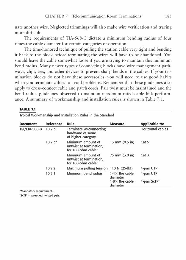
nate another wire. Neglected trimmings will also make wire verification and tracingmore difficult.
The requirements of TIA-568-C dictate a minimum bending radius of fourtimes the cable diameter for certain categories of operation.
The time-honored technique of pulling the station cable very tight and bendingit back to the block before terminating the wires will have to be abandoned. Youshould leave the cable somewhat loose if you are trying to maintain this minimumbend radius. Many newer types of connecting blocks have wire management path-ways, clips, ties, and other devices to prevent sharp bends in the cables. If your ter-mination blocks do not have these accessories, you will need to use good habitswhen you terminate cables to avoid problems. Remember that these guidelines alsoapply to cross-connect cable and patch cords. Pair twist must be maintained and thebend radius guidelines observed to maintain maximum rated cable link perform-ance. A summary of workmanship and installation rules is shown in Table 7.1.
TABLE 7.1
Typical Workmanship and Installation Rules in the Standard
Document Reference Rule Measure Applicable to:TIA/EIA-568-B 10.2.3 Terminate w/connecting Horizontal cables
hardware of same of higher category
10.2.3* Minimum amount of 13 mm (0.5 in) Cat 5 untwist at termination, for 100-ohm cable: Minimum amount of 75 mm (3.0 in) Cat 3 untwist at termination, for 100-ohm cable:
10.2.2 Maximum pulling tension 110 N (25-lbf) 4-pair UTP 10.2.1 Minimum bend radius 4� the cable 4-pair UTP
diameter8� the cable 4-pair ScTP†
diameter
*Mandatory requirement.†ScTP = screened twisted pair.
CHAPTER 7 Telecommunication Room Terminations 185

This page intentionally left blank
CHAPTER 8
Patch Panels, Cross Connects,and Patch Cords
Highlights
■ Patch panels
■ Patch cords
■ Cross-connect jumpers
■ Fiber-optic patches and cords
■ Category 7 patches and cords
187
Copyright © 2006 by James Trulove. Click here for terms of use.
The next step in structured cabling is the interconnection of cabling in the telecom-munications room (TR). As we will see, patch panels, patch cords, and cross-con-nect jumpers form a vital part of LAN wiring. Patch panels may be used as theprimary termination for horizontal and backbone cabling, in lieu of punchdowns(described in the previous chapter). As a matter of fact, patch-panel termination isbecoming increasingly popular with advanced performance categories, such asCategory 5e, 6, AC6, and 7. It is the only practical means of termination forCategory 7, although that “patch” actually consists of an array of Cat 7 connectors.Fiber termination is also done with the same type of patch-array, utilizing a cabling“adapter” to secure the connectors and align the fibers.
In this chapter, we will describe the wiring, cables, and devices used for patchpanels, patch cords, and cross-connects, for both fiber and copper cabling systemsdesigned for LAN use. In the last chapter, we covered the actual termination of thestation cables into punchdown blocks in the TR. We did not yet cover the cross-con-nect wiring or jumper cables. In addition, although we have mentioned the wiringmethod of terminating horizontal cables directly into patch panels, we have waiteduntil now to describe the patches themselves.
Patch Panels versus Cross-Connects
Traditionally, there has been an ongoing debate about the alternatives of patch pan-els and cross-connects. Figure 8.1 shows the two alternatives to cable terminationand the interconnection to equipment in the TR.
Traditional Cross-Connect Termination
The first alternative shown in the figure copies the cross-connect methodology usedfor traditional telephone equipment room wiring. In this method, horizontal (sta-tion) cable is terminated on a connecting block, such as a 110 or 66 block. Then,cross-connect wires are run from each station position on the horizontal connectingblocks to a second field of connecting blocks, which is a point of termination formultipair cables from the common equipment such as a telephone switch or PBX.This common equipment connection in a telephone system corresponds to the net-work hub connection in a local area network (LAN).
The common equipment connections and the station cable connections arerather like the input/output of the cross-connect field. Both types of cables are hardwired to the connecting blocks and then cross-connected with unjacketed wire pairscalled jumpers. To make a connection across the field, a cross-connect jumper (con-
188 PART TWO LAN Wiring Technology
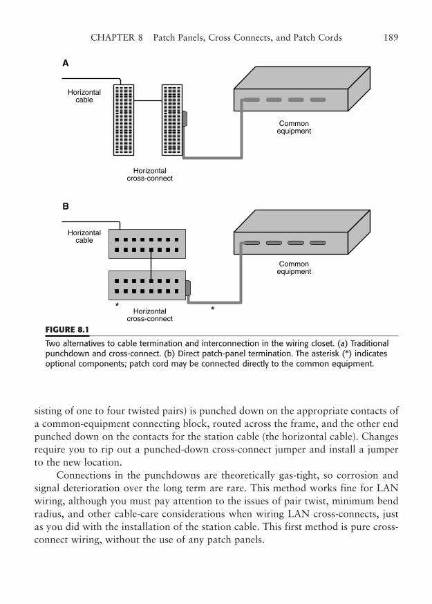
sisting of one to four twisted pairs) is punched down on the appropriate contacts ofa common-equipment connecting block, routed across the frame, and the other endpunched down on the contacts for the station cable (the horizontal cable). Changesrequire you to rip out a punched-down cross-connect jumper and install a jumperto the new location.
Connections in the punchdowns are theoretically gas-tight, so corrosion andsignal deterioration over the long term are rare. This method works fine for LANwiring, although you must pay attention to the issues of pair twist, minimum bendradius, and other cable-care considerations when wiring LAN cross-connects, justas you did with the installation of the station cable. This first method is pure cross-connect wiring, without the use of any patch panels.
CHAPTER 8 Patch Panels, Cross Connects, and Patch Cords 189
A
Horizontalcable
Horizontalcross-connect
Commonequipment
Horizontalcable
Horizontalcross-connect
Commonequipment
B
FIGURE 8.1
Two alternatives to cable termination and interconnection in the wiring closet. (a) Traditionalpunchdown and cross-connect. (b) Direct patch-panel termination. The asterisk (*) indicatesoptional components; patch cord may be connected directly to the common equipment.
Modern Patch-Panel Termination
With the second alternative, patch panels, the horizontal cables are directly terminatedinto modular patch panels (unless you use a hybrid method of termination, describedlater). Patch cords are connected between the patch panel jacks and the equipment hubs(or between horizontal and backbone cables), and connections may be reconfigured atwill. This method is very convenient for smaller installations that use hubs (or otherequipment) with discrete modular jacks. You must use some sort of modular connec-tion to these hubs, and the patch allows the use of individual modular cords, and avoidsthe use of multipair fan-out cables and connectorized punchdown blocks. It is alsohandy for companies that frequently move connections or add stations to the network.
Patch panel termination has several advantages for a high-performance Category5e/6/AC6 system. Permanent link and channel testing (Chapter 15) are easier, becauseyou have the cable terminated in an approved outlet connector. In contrast, a channeltest cannot be performed on a punchdown system until the final cross-connects aremade. If the cross-connect has too much untwist, or if the jumper is later distorted insome way, the link may fail later in the life of the channel. Patch connections are solidand reproducible, and it is virtually impossible to diminish link performance, once theinitial termination has passed muster. And, future moves/adds/changes can be made byvirtually anyone, with no need for a trained cabling technician.
Testing a patch panel installation is very easy. You simply disconnect a patchcord and connect your tester. The patch jacks are also more spread out than thecable termination areas on cross-connects, and this may make it easier to provideproper circuit marking. (If you have ever tried to mark on the little tabs of a 66block, you can appreciate this a lot.) Newer designs for patch panel terminations useIDC connections that are similar to those on traditional connecting blocks or outletjacks. These designs help preserve the pair twist on terminated cables and use inter-nal jack wiring that is designed to meet the new categories of performance.
Direct patch panel termination of station cables, however, limits the flexibilityof a terminated cable, because the station cable pairs are available only on the cor-responding patch jack. To gain access to unused cable pairs, an external adapter orsplitter must be used. Because of this limitation and other factors, there are differ-ing opinions on whether you should use patch panels or cross-connect fields.
Pros and Cons of Patches and Cross-Connects
Obviously, there are valid arguments on each side of this question. On the one hand,when you terminate your horizontal cables directly onto a patch panel, you avoidthe muss and fuss of at least three terminations (the horizontal punchdown and the
190 PART TWO LAN Wiring Technology
two cross-connect terminations). Using the direct patch approach also saves spacein the wiring closet, saves installation labor, and provides for quick reconfigurationof your network connections. On the other hand, you still have all the patch cablesto deal with, and each of your station cables is forever terminated in a single 8-pinjack. You have no easy way to grab a pair or two to use for another purpose, suchas a modem line or a second network connection. In addition, the patch cords arenormally available only in standard length increments (unless you make your own),and thus rarely fit a connection exactly.
On some points, the two opposing cable termination techniques each have dis-advantages that compensate for their advantages. For example, the exclusive use ofcross-connect fields eliminates the crosstalk and contact resistance problems ofpatch panel jacks, but it compensates by introducing two more terminations (eachend of the cross-connect wire) where the finest workmanship may still introduceuntwist to the link (thus causing more crosstalk, etc.). Also, the ease of moving con-nections on the patch belies the fact that an average mature installation may actu-ally need only 2% to 5% of its connections moved in a year.
Although we have mentioned two termination techniques—direct patch termi-nation and cross-connect field termination—a third hybrid method uses a combina-tion of both. In this method, the horizontal cable is terminated in a connecting block(such as a 110 block). Then, a cross-connect is made between the connecting blockand a patch panel.
The patch panel may allow for directly connecting the cross-connect wire, orit may be connectorized, requiring multipair cables that terminate in a second con-necting block. The patch cords are connected from the patch panel to the hub equip-ment. This hybrid method offers wiring flexibility between the station cable and thepatch: A cable may easily be reconfigured, shared, or moved to another patch posi-tion. Equipment connections may be made quickly or reconfigured at will, becauseof the use of patch cords. However, the patch jacks and cords are still there, with alltheir other potential disadvantages.
It’s almost impossible to take sides in this argument, as there are valid reasonsbehind both viewpoints. However, you should know that there is a definite choice tobe made and you should have an understanding of the issues surrounding that choice.The next few sections will describe cross-connect wiring (the connecting blocks werecovered in Chapter 7), multipair jumper cables, patch panels, and patch cords.
Patch Panels
Patch panels are used to provide flexible connections between horizontal stationcables and the equipment ports in the wiring closet. Patch panels have modular
CHAPTER 8 Patch Panels, Cross Connects, and Patch Cords 191
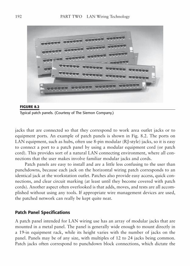
jacks that are connected so that they correspond to work area outlet jacks or toequipment ports. An example of patch panels is shown in Fig. 8.2. The ports onLAN equipment, such as hubs, often use 8-pin modular (RJ-style) jacks, so it is easyto connect a port to a patch panel by using a modular equipment cord (or patchcord). This provides sort of a natural LAN connecting environment, where all con-nections that the user makes involve familiar modular jacks and cords.
Patch panels are easy to install and are a little less confusing to the user thanpunchdowns, because each jack on the horizontal wiring patch corresponds to anidentical jack at the workstation outlet. Patches also provide easy access, quick con-nections, and clear circuit marking (at least until they become covered with patchcords). Another aspect often overlooked is that adds, moves, and tests are all accom-plished without using any tools. If appropriate wire management devices are used,the patched network can really be kept quite neat.
Patch Panel Specifications
A patch panel intended for LAN wiring use has an array of modular jacks that aremounted in a metal panel. The panel is generally wide enough to mount directly ina 19-in equipment rack, while its height varies with the number of jacks on thepanel. Panels may be of any size, with multiples of 12 to 24 jacks being common.Patch jacks often correspond to punchdown block connections, which dictate the
192 PART TWO LAN Wiring Technology
FIGURE 8.2
Typical patch panels. (Courtesy of The Siemon Company.)
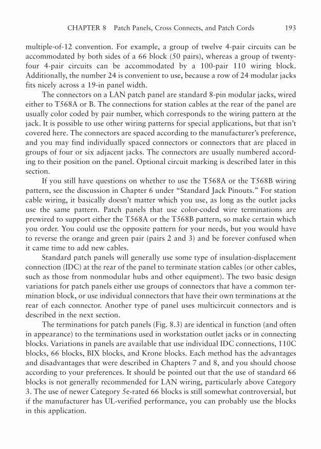
multiple-of-12 convention. For example, a group of twelve 4-pair circuits can beaccommodated by both sides of a 66 block (50 pairs), whereas a group of twenty-four 4-pair circuits can be accommodated by a 100-pair 110 wiring block.Additionally, the number 24 is convenient to use, because a row of 24 modular jacksfits nicely across a 19-in panel width.
The connectors on a LAN patch panel are standard 8-pin modular jacks, wiredeither to T568A or B. The connections for station cables at the rear of the panel areusually color coded by pair number, which corresponds to the wiring pattern at thejack. It is possible to use other wiring patterns for special applications, but that isn’tcovered here. The connectors are spaced according to the manufacturer’s preference,and you may find individually spaced connectors or connectors that are placed ingroups of four or six adjacent jacks. The connectors are usually numbered accord-ing to their position on the panel. Optional circuit marking is described later in thissection.
If you still have questions on whether to use the T568A or the T568B wiringpattern, see the discussion in Chapter 6 under “Standard Jack Pinouts.” For stationcable wiring, it basically doesn’t matter which you use, as long as the outlet jacksuse the same pattern. Patch panels that use color-coded wire terminations areprewired to support either the T568A or the T568B pattern, so make certain whichyou order. You could use the opposite pattern for your needs, but you would haveto reverse the orange and green pair (pairs 2 and 3) and be forever confused whenit came time to add new cables.
Standard patch panels will generally use some type of insulation-displacementconnection (IDC) at the rear of the panel to terminate station cables (or other cables,such as those from nonmodular hubs and other equipment). The two basic designvariations for patch panels either use groups of connectors that have a common ter-mination block, or use individual connectors that have their own terminations at therear of each connector. Another type of panel uses multicircuit connectors and isdescribed in the next section.
The terminations for patch panels (Fig. 8.3) are identical in function (and oftenin appearance) to the terminations used in workstation outlet jacks or in connectingblocks. Variations in panels are available that use individual IDC connections, 110Cblocks, 66 blocks, BIX blocks, and Krone blocks. Each method has the advantagesand disadvantages that were described in Chapters 7 and 8, and you should chooseaccording to your preferences. It should be pointed out that the use of standard 66blocks is not generally recommended for LAN wiring, particularly above Category3. The use of newer Category 5e-rated 66 blocks is still somewhat controversial, butif the manufacturer has UL-verified performance, you can probably use the blocksin this application.
CHAPTER 8 Patch Panels, Cross Connects, and Patch Cords 193
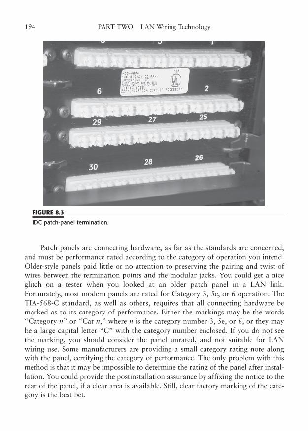
Patch panels are connecting hardware, as far as the standards are concerned,and must be performance rated according to the category of operation you intend.Older-style panels paid little or no attention to preserving the pairing and twist ofwires between the termination points and the modular jacks. You could get a niceglitch on a tester when you looked at an older patch panel in a LAN link.Fortunately, most modern panels are rated for Category 3, 5e, or 6 operation. TheTIA-568-C standard, as well as others, requires that all connecting hardware bemarked as to its category of performance. Either the markings may be the words“Category n” or “Cat n,” where n is the category number 3, 5e, or 6, or they maybe a large capital letter “C” with the category number enclosed. If you do not seethe marking, you should consider the panel unrated, and not suitable for LANwiring use. Some manufacturers are providing a small category rating note alongwith the panel, certifying the category of performance. The only problem with thismethod is that it may be impossible to determine the rating of the panel after instal-lation. You could provide the postinstallation assurance by affixing the notice to therear of the panel, if a clear area is available. Still, clear factory marking of the cate-gory is the best bet.
194 PART TWO LAN Wiring Technology
FIGURE 8.3
IDC patch-panel termination.
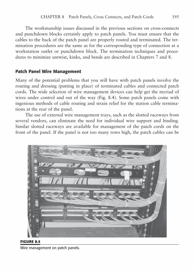
The workmanship issues discussed in the previous sections on cross-connectsand punchdown blocks certainly apply to patch panels. You must ensure that thecables to the back of the patch panel are properly routed and terminated. The ter-mination procedures are the same as for the corresponding type of connection at aworkstation outlet or punchdown block. The termination techniques and proce-dures to minimize untwist, kinks, and bends are described in Chapters 7 and 8.
Patch Panel Wire Management
Many of the potential problems that you will have with patch panels involve therouting and dressing (putting in place) of terminated cables and connected patchcords. The wide selection of wire management devices can help get the myriad ofwires under control and out of the way (Fig. 8.4). Some patch panels come withingenious methods of cable routing and strain relief for the station cable termina-tions at the rear of the panel.
The use of external wire management trays, such as the slotted raceways fromseveral vendors, can eliminate the need for individual wire support and binding.Similar slotted raceways are available for management of the patch cords on thefront of the panel. If the panel is not too many rows high, the patch cables can be
CHAPTER 8 Patch Panels, Cross Connects, and Patch Cords 195
FIGURE 8.4
Wire management on patch panels.
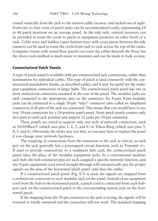
routed vertically from the jack to the nearest cable raceway and tucked out of sight.From two to four rows of patch jacks can be accommodated easily, representing 24to 48 patch positions on an average panel. At the side rails, vertical raceways canbe provided to route the cords to patch or equipment positions on other levels of arack. Cable trays and ladders (open bottom trays with cross pieces between the siderunners) can be used to route the cords from rack to rack across the top of the racks.Computer rooms with raised floor panels can route the cables beneath the floor, butthe above-rack method is much easier to maintain and can be made to look as neat.
Connectorized Patch Panels
A type of patch panel is available with pre-connectorized jack connections, rather thanterminations for individual cables. This type of patch is used extensively with the con-nectorized punchdown blocks, as described earlier, and it may be useful for the multi-port equipment connections of larger hubs. The connectorized patch panel has one ormore multicircuit connectors mounted at the rear of the panel. The modular jacks areeach connected to the appropriate pins on the connector. Six 4-pair, 8-pin modularjacks can be connected to a single 50-pin “telco” connector (also called an Amphenolconnector), if all pins of the jack are connected. This means that you would have to usefour 50-pin connectors for a 24-position patch panel. Some patch panels connect onlytwo pairs to each jack position and support 12 jacks per 50-pin connector.
These panels are wired to support only one style of network connection, suchas 10/100BaseT (which uses pins 1, 2, 3, and 6) or Token-Ring (which uses pins 3,4, 5, and 6). Obviously, the styles may not mix, so you may have to replace the panelif you change your network hardware.
The mapping of connections from the connector to the jack is critical, as eachpair on the jack generally has a preassigned circuit function, such as Transmit +/–.If used to provide connectivity to a multiport hub card, the connectorized patchpanel takes the place of the modular equipment jacks. In a conventional modularjack hub, the hub connector pins are each assigned a specific network function, andany 4-pair equipment cord wired straight-through will automatically put the propersignals on the pins of the horizontal patch panel (and thus the cable).
If a connectorized patch panel (Fig. 8.5) is used, the signals are mapped froma multicircuit connector to each modular jack on the panel. Instead of an equipmentcord from the hub to the horizontal patch, a patch cord is connected from each hub-port jack on the connectorized patch to the corresponding station jack on the hori-zontal patch.
If the mapping from the 50-pin connector to the jack is wrong, the signals will bereversed or totally miswired and the connection will not work. The standard mapping
196 PART TWO LAN Wiring Technology
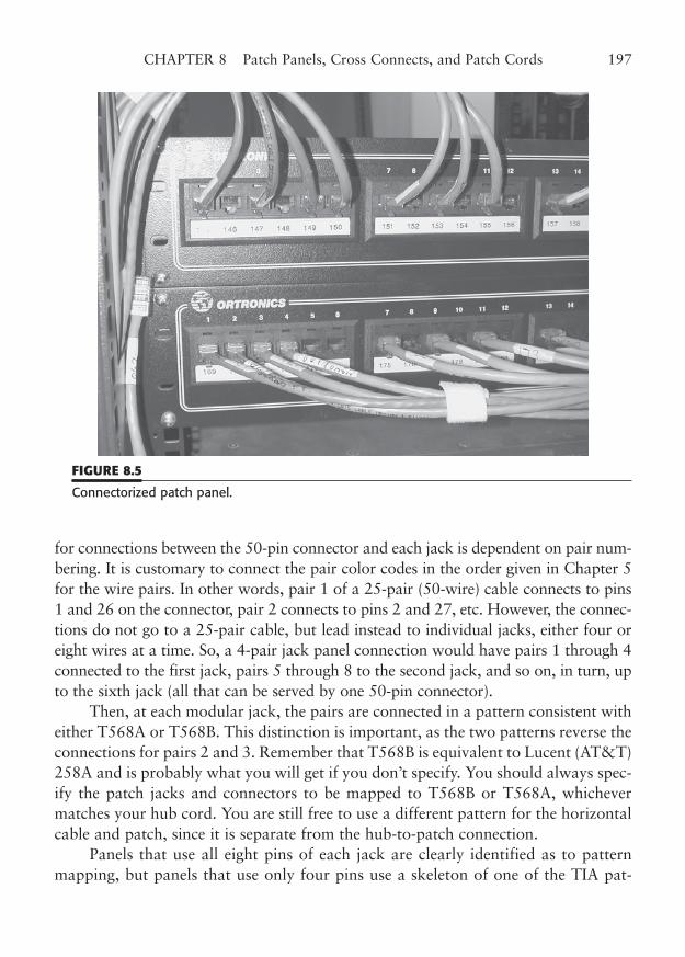
for connections between the 50-pin connector and each jack is dependent on pair num-bering. It is customary to connect the pair color codes in the order given in Chapter 5for the wire pairs. In other words, pair 1 of a 25-pair (50-wire) cable connects to pins1 and 26 on the connector, pair 2 connects to pins 2 and 27, etc. However, the connec-tions do not go to a 25-pair cable, but lead instead to individual jacks, either four oreight wires at a time. So, a 4-pair jack panel connection would have pairs 1 through 4connected to the first jack, pairs 5 through 8 to the second jack, and so on, in turn, upto the sixth jack (all that can be served by one 50-pin connector).
Then, at each modular jack, the pairs are connected in a pattern consistent witheither T568A or T568B. This distinction is important, as the two patterns reverse theconnections for pairs 2 and 3. Remember that T568B is equivalent to Lucent (AT&T)258A and is probably what you will get if you don’t specify. You should always spec-ify the patch jacks and connectors to be mapped to T568B or T568A, whichevermatches your hub cord. You are still free to use a different pattern for the horizontalcable and patch, since it is separate from the hub-to-patch connection.
Panels that use all eight pins of each jack are clearly identified as to patternmapping, but panels that use only four pins use a skeleton of one of the TIA pat-
CHAPTER 8 Patch Panels, Cross Connects, and Patch Cords 197
FIGURE 8.5
Connectorized patch panel.
terns. As we said, hub connections often use only two pairs per port (four wires) tominimize the number of ports per connector.
Here is an example of the problem of connection mapping. Let’s say you intendto install a 10/100BaseT network using hubs with multicircuit connectors instead ofsingle port jacks. Such hubs typically use a card rack with plug-in cards. You willrun cables from your hub cards to a patch panel to fan out the individual ports tomodular jacks. Naturally, you will want the 8-pin modular jacks on the patch tohave the same pinouts as a standard 8-pin modular jack on a hub with individualconnectors.
A standard 10/100BaseT modular hub jack defines pin 1 as transmit �, pin 2as transmit �, pin 3 as receive �, and pin 4 as receive �. A multicircuit hub con-nector could assign eight pins to each port, but only four pins are needed for10/100BaseT, so assigning four pins per port achieves twice the density on the con-nector. For our example, let’s say that your hub card connector assigns four pins perport, representing two pairs of the multiconductor cable. This gives you a total oftwelve 10/100BaseT ports per 50-pin connector. The cable connects between thehub card and the patch.
Now, let’s look at the way the ports are mapped from the 50-pin connector toeach modular jack on the patch panel. Standard 10/100BaseT uses four pins of the8-pin jack. These four pins correspond to two of the regular 4-pair groupings of thejack, pairs 2 and 3. Remember that T568A and B simply reverse the order of thesetwo pairs.
The “first” pair for each of the ports on the 50-pin connector usually corre-sponds to “transmit �/–”. Now, here is the mapping part: the transmit �/– pairmust connect to pins 1 and 2 on the 8-pin jack, while the receive �/– goes to Pins 3and 6, for proper 10/100BaseT connectivity. If the patch uses the T568B pattern toconnect the patch jack, the transmit and receive pairs will appear on the proper pins.But if the patch is wired for the T568A pattern, the two pairs will be in reverse orderand the connection will not work (unless the pair order on the 50-pin connector hasalso been reversed—a rare circumstance because the TIA recognizes only the stan-dard color code pattern for that connector, not a pair order).
This is one place where the TIA’s preferred T568A pattern will get you intotrouble. Note, however, that all of your modular patch cords, horizontal cable patchpanels, and workstation outlet jacks can still use the A pattern. The rule is that bothends of a connection must be the same, whether that connection is a horizontalcable, a patch cord, or (yes) a patch panel fan-out of a multicircuit hub port. Alwaysensure that you match the LAN connections on the hub card’s connector with theconnector-to-jack mapping on the patch panel so that the correct LAN signals willbe on the pins of the patch panel jacks.
198 PART TWO LAN Wiring Technology
Connectorized patch panels may be rated by category as with any connecting hard-ware and should be properly marked. The actual internal wiring between the connectorand the jacks must be appropriate for the category of operation, such as Category 5e/6.The manufacturer will normally provide testing and verification by an independent lab-oratory, such as UL, to attest to their claimed category of operation. As with regularpatch panels, connectorized panels that are not marked or otherwise certified, should notbe used in any application that requires Category 5e or 6 performance.
Patch Panel Location and Marking
Patch panels are usually designed to be mounted in 19-in relay racks.They also mount on simple, freestanding mounting rails, in equipment cabi-
nets, and on wall mounts. You should carefully plan the location of your patch pan-els, as you should all your connectivity hardware. If you choose to use patch panels,rather than direct cross-connection, you will also have to plan for routing and dress-ing of the patch cords from origin to destination jacks. If you route the cords usingwire management brackets and accessories, you will avoid the “cable curtain” thatsometimes infects patch panel installations.
As stated before, patch panels may be used for both the horizontal cable andthe equipment (hub) port connections. If you use patches for both, you will have toprovide a TR layout that brings the two types of panels conveniently together forreasonable patch cord lengths. If your installation involves the frequent reconfigu-ration of networks and workstations, you should definitely plan to have the twopanels as close together as possible. In large installations, each type of patch loca-tion may actually be composed of several panels. You may want to place them onmultibay relay racks (side by side) so that patch cords can go directly across betweenracks to make connections, rather than climb the rails in a route across the top ofthe racks. Wire management accessories for adjacent racks are available to makethis job easier (Fig. 8.6).
If you terminate the horizontal cables in punchdown blocks and then cross-connect to patch panels, you should plan the layout in such a way that you mini-mize both the length of cross-connect wire and the length of equipment cords (orpatch cords) to the network hubs. You can easily mount punchdown blocks andpatch panels on wiring closet backboards (wall mount), but the hubs will probablymount in an equipment rack, unless the installation is very small. This may increasethe length of the cords from the horizontal patches to the equipment connections.Proper planning will minimize this distance.
You should carefully plan your TR installation, including the location of thepatch panels and hubs, to keep the total cross-connect and cord lengths within the
CHAPTER 8 Patch Panels, Cross Connects, and Patch Cords 199
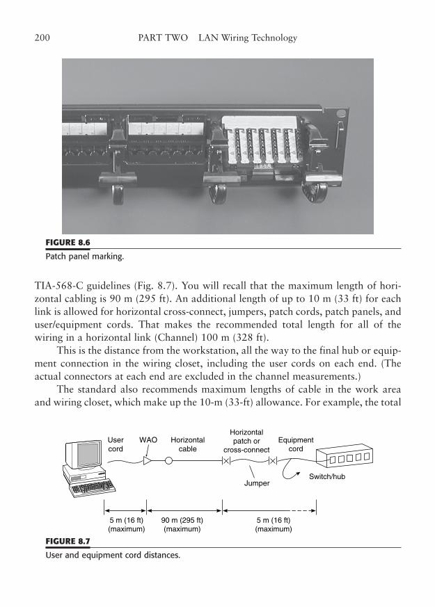
TIA-568-C guidelines (Fig. 8.7). You will recall that the maximum length of hori-zontal cabling is 90 m (295 ft). An additional length of up to 10 m (33 ft) for eachlink is allowed for horizontal cross-connect, jumpers, patch cords, patch panels, anduser/equipment cords. That makes the recommended total length for all of thewiring in a horizontal link (Channel) 100 m (328 ft).
This is the distance from the workstation, all the way to the final hub or equip-ment connection in the wiring closet, including the user cords on each end. (Theactual connectors at each end are excluded in the channel measurements.)
The standard also recommends maximum lengths of cable in the work areaand wiring closet, which make up the 10-m (33-ft) allowance. For example, the total
200 PART TWO LAN Wiring Technology
FIGURE 8.6
Patch panel marking.
5 m (16 ft)(maximum)
5 m (16 ft)(maximum)
Horizontalcable
Horizontalpatch or
cross-connectUsercord
Equipmentcord
WAO
JumperSwitch/hub
90 m (295 ft)(maximum)
FIGURE 8.7
User and equipment cord distances.
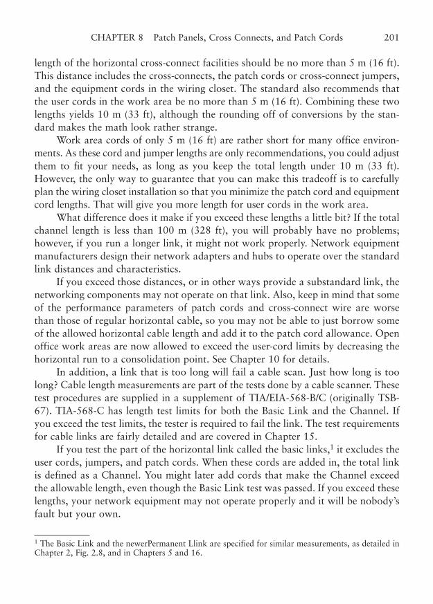
length of the horizontal cross-connect facilities should be no more than 5 m (16 ft).This distance includes the cross-connects, the patch cords or cross-connect jumpers,and the equipment cords in the wiring closet. The standard also recommends thatthe user cords in the work area be no more than 5 m (16 ft). Combining these twolengths yields 10 m (33 ft), although the rounding off of conversions by the stan-dard makes the math look rather strange.
Work area cords of only 5 m (16 ft) are rather short for many office environ-ments. As these cord and jumper lengths are only recommendations, you could adjustthem to fit your needs, as long as you keep the total length under 10 m (33 ft).However, the only way to guarantee that you can make this tradeoff is to carefullyplan the wiring closet installation so that you minimize the patch cord and equipmentcord lengths. That will give you more length for user cords in the work area.
What difference does it make if you exceed these lengths a little bit? If the totalchannel length is less than 100 m (328 ft), you will probably have no problems;however, if you run a longer link, it might not work properly. Network equipmentmanufacturers design their network adapters and hubs to operate over the standardlink distances and characteristics.
If you exceed those distances, or in other ways provide a substandard link, thenetworking components may not operate on that link. Also, keep in mind that someof the performance parameters of patch cords and cross-connect wire are worsethan those of regular horizontal cable, so you may not be able to just borrow someof the allowed horizontal cable length and add it to the patch cord allowance. Openoffice work areas are now allowed to exceed the user-cord limits by decreasing thehorizontal run to a consolidation point. See Chapter 10 for details.
In addition, a link that is too long will fail a cable scan. Just how long is toolong? Cable length measurements are part of the tests done by a cable scanner. Thesetest procedures are supplied in a supplement of TIA/EIA-568-B/C (originally TSB-67). TIA-568-C has length test limits for both the Basic Link and the Channel. Ifyou exceed the test limits, the tester is required to fail the link. The test requirementsfor cable links are fairly detailed and are covered in Chapter 15.
If you test the part of the horizontal link called the basic links,1 it excludes theuser cords, jumpers, and patch cords. When these cords are added in, the total linkis defined as a Channel. You might later add cords that make the Channel exceedthe allowable length, even though the Basic Link test was passed. If you exceed theselengths, your network equipment may not operate properly and it will be nobody’sfault but your own.
CHAPTER 8 Patch Panels, Cross Connects, and Patch Cords 201
1 The Basic Link and the newerPermanent Llink are specified for similar measurements, as detailed inChapter 2, Fig. 2.8, and in Chapters 5 and 16.
Proper marking of the patch positions is also an important part of an instal-lation. Generally, each wiring closet, cable termination, rack, patch, and hub isrequired to have a unique identification, according to EIA/TIA 606. In the case ofpatch panels, you will have to provide your own circuit or jack position identifi-cation, separate from the panel’s numbering, unless you have a very small instal-lation and can use the jack numbers as your station numbers. The detailedrequirements for circuit identification have occurred fairly recently, and it is alsodifficult to provide labeling for closely spaced jacks, so many patch panel manu-facturers just provide a stick-on label holder that can be positioned above orbelow a row of jacks.
A typical patch position might need to be marked with a wiring closet number,patch number, cable number, and jack position number such as “W4-P10-C321-J15.” However, the space allowed for each jack might require this to be shortenedto “C321-J15,” with the patch number marked on the panel itself and the closetnumber obvious from where the panel was located. The rules for marking identifi-cation numbers are part of an emerging standard and will get more detailed as timegoes on. Panel manufacturers will begin to incorporate more of the marking guide-lines in their product’s features. For the time being, we may have to make do withadhesive label strips and other marking methods.
Patch Cords
A patch cord consists of a length of flexible cable, terminated at either end by an 8-pin modular plug. The patch cord, in reality, is identical to the user cables in thework area and the wiring closet. As a matter of fact, all of these cords go by a num-ber of names that reflect their purpose, rather than their construction. For example,a cord from a patch to another patch is called a patch cord, but an identical cordfrom a patch to a hub is technically an equipment cord. The cord from the work-station to the outlet connector is also an equipment cord. Equipment cords aresometimes called user cords, because they are presumably connected by the user, notthe cable installer, to the user’s equipment. Oh, yes, all of these cords are sometimescalled cables instead.
The one distinguishing feature of the patch cord is that it is usually shorter thanthe user cords. We will describe the wire and connectors for these types of cables inthe next chapter. In this section, we will concentrate on the characteristics that makea good patch cord, with the understanding that these same characteristics apply toall user cables.
202 PART TWO LAN Wiring Technology
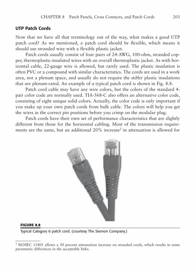
UTP Patch Cords
Now that we have all that terminology out of the way, what makes a good UTPpatch cord? As we mentioned, a patch cord should be flexible, which means itshould use stranded wire with a flexible plastic jacket.
Patch cords usually consist of four pairs of 24-AWG, 100-ohm, stranded cop-per, thermoplastic-insulated wires with an overall thermoplastic jacket. As with hor-izontal cable, 22-gauge wire is allowed, but rarely used. The plastic insulation isoften PVC or a compound with similar characteristics. The cords are used in a workarea, not a plenum space, and usually do not require the stiffer plastic insulationsthat are plenum-rated. An example of a typical patch cord is shown in Fig. 8.8.
Patch cord cable may have any wire colors, but the colors of the standard 4-pair color code are normally used. TIA-568-C also offers an alternative color code,consisting of eight unique solid colors. Actually, the color code is only important ifyou make up your own patch cords from bulk cable. The colors will help you getthe wires in the correct pin positions before you crimp on the modular plug.
Patch cords have their own set of performance characteristics that are slightlydifferent from those for the horizontal cabling. Most of the transmission require-ments are the same, but an additional 20% increase2 in attenuation is allowed for
CHAPTER 8 Patch Panels, Cross Connects, and Patch Cords 203
2 ISO/IEC 11801 allows a 50 percent attenuation increase on stranded cords, which results in someparametric differences in the acceptable links.
FIGURE 8.8
Typical Category 6 patch cord. (courtesy The Siemon Company.)
the stranded construction and “design differences.” This is one of the reasons thatthe lengths of the patch and user cords are limited by the standards. The attenua-tion limits vary for the three categories of performance and are prorated from thevalues per 100 m (328 ft). The allowable attenuation values for patch cords areshown in Table 8.1. If you purchase preassembled patch cords, you should be surethat the cords are certified by the manufacturer to comply with TIA-568-C for theappropriate category of performance. Certification testing by an outside agency,such as UL, is a good indication of quality and assurance.
The testing of patch cords presents somewhat of a dilemma, both for the man-ufacturer and for you. The standard contains detailed performance requirementsfor the cable and the connectors that are used to make up patch cords, but thereare no specifications for assembled cords. In addition, certain tests, such as NEXT,are known to be unreliable for links less than 15 m, because of a phenomenoncalled resonance. Many testers will not test a cable that is less than 6 m, except forwire map.
Because of these factors, the only assurance of patch cord performance you willhave (until the cord becomes part of a larger link) is the use of quality componentsand cable, and good workmanship. Workmanship is important because the cablepairs must be untwisted before the modular plug can be attached. If the amount ofuntwist is not minimized, the plug will contribute even more degradation to the linkthan is inherent in its design. By the way, the unavoidable amount of untwist in themodular connector design is one of the reasons that these connectors are not lookedupon favorably for high-frequency performance. Annex B of TIA/EIA-568-B.2shows a detailed procedure for assembling modular cable ends. Although this pro-cedure is for the preparation of connectors that are to be used in the testing of con-necting hardware, it represents an ideal method to maximize the performance ofpatch cord plugs.
Screened Twisted Pair (ScTP) Patch Cords
Screened twisted pair (ScTP) patch cords are a new addition to the TIA-568 stan-dard (as of the -B revision), and are described in the normative Annex E, whichmeans the annex sets mandatory performance and installation requirements whenScTP is used in lieu of UTP. As frequencies rise on network cabling, the use of ScTPis increasing to minimize interference emissions and to decrease susceptibility to out-side interference sources. TIA-recognized ScTP consists of four twisted pairs with anoverall shield.
The cable impedance is specified at 100 ohms, and either AWG 24 or AWG 26plastic-insulated, stranded conductors may be used. The standard allows a 50%
204 PART TWO LAN Wiring Technology
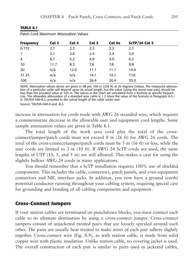
increase in attenuation for cords made with AWG 26 stranded wire, which requiresa commensurate decrease in the allowable user and equipment cord lengths. Somesample attenuation values are given in Table 8.1.
The total length of the work area cord plus the total of the cross-connect/jumper/patch cords must not exceed 8 m (26 ft) for AWG 26 cords. Thetotal of the cross-connect/jumper/patch cords must be 5 m (16 ft) or less, while theuser cords are limited to 3 m (10 ft). If AWG 24 ScTP cords are used, the samelengths of UTP (10, 5, and 5 m) are still allowed. This makes a case for using theslightly bulkier AWG 24 cords in many applications.
You should remember that a ScTP installation requires 100% use of shieldedcomponents. This includes the cable, connectors, patch panels, and even equipmentconnectors and NIC interface jacks. In addition, you now have a ground (earth)potential conductor running throughout your cabling system, requiring special carefor grounding and bonding of all cabling components and equipment.
Cross-Connect Jumpers
If your station cables are terminated on punchdown blocks, you must connect eachcable to its ultimate destination by using a cross-connect jumper. Cross-connectjumpers consist of unjacketed twisted pairs that are loosely spiraled around eachother. The pairs are usually heat treated to make wires of each pair adhere slightlytogether. Cross-connect wire (Fig. 8.9), as with station cable, is made from solidcopper wire with plastic insulation. Unlike station cable, no covering jacket is used.The overall construction of each pair is similar to pairs used in jacketed cables,
CHAPTER 8 Patch Panels, Cross Connects, and Patch Cords 205
TABLE 8.1
Patch Cord Maximum Attenuation Values
Frequency Cat 3 Cat 4 Cat 5 Cat 5e ScTP/26 Cat 50.772 2.7 2.3 2.2 2.2 2.7 1 3.1 2.6 2.4 2.4 3.0 4 6.7 5.2 4.9 4.9 6.2 10 11.7 8.3 7.8 7.8 9.8 20 n/a 12.0 11.1 11.1 14.0 31.25 n/a n/a 14.1 14.1 17.6 100 n/a n/a 26.4 26.4 33.0
NOTE: Attenuation values above are given in dB per 100 m (328 ft) at 20 degrees Celsius. The measured attenua-tion of a particular cable will depend upon its actual length, but the value (using the worst-case pair) should beless than the prorated value at 100 m. The values in the chart are calculated from a formula at specific frequen-cies. The allowable attenuation of a stranded wire cable is 1.2 times the value of the formula in Paragraph 6.4.1in TIA/EIA-568-B.2, prorated to the actual length of the cable under test.Source: TIA/EIA-568-A and -B.2.
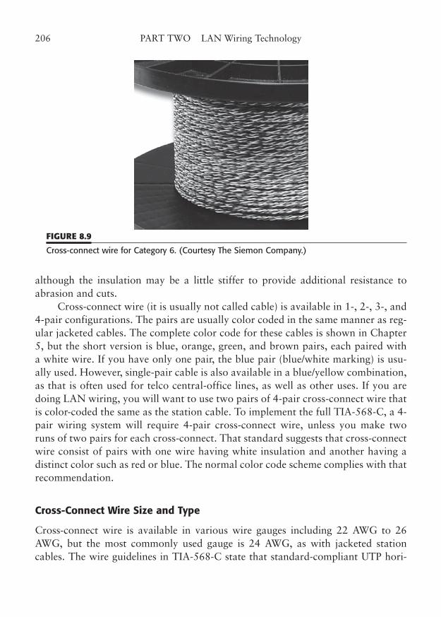
although the insulation may be a little stiffer to provide additional resistance toabrasion and cuts.
Cross-connect wire (it is usually not called cable) is available in 1-, 2-, 3-, and4-pair configurations. The pairs are usually color coded in the same manner as reg-ular jacketed cables. The complete color code for these cables is shown in Chapter5, but the short version is blue, orange, green, and brown pairs, each paired witha white wire. If you have only one pair, the blue pair (blue/white marking) is usu-ally used. However, single-pair cable is also available in a blue/yellow combination,as that is often used for telco central-office lines, as well as other uses. If you aredoing LAN wiring, you will want to use two pairs of 4-pair cross-connect wire thatis color-coded the same as the station cable. To implement the full TIA-568-C, a 4-pair wiring system will require 4-pair cross-connect wire, unless you make tworuns of two pairs for each cross-connect. That standard suggests that cross-connectwire consist of pairs with one wire having white insulation and another having adistinct color such as red or blue. The normal color code scheme complies with thatrecommendation.
Cross-Connect Wire Size and Type
Cross-connect wire is available in various wire gauges including 22 AWG to 26AWG, but the most commonly used gauge is 24 AWG, as with jacketed stationcables. The wire guidelines in TIA-568-C state that standard-compliant UTP hori-
206 PART TWO LAN Wiring Technology
FIGURE 8.9
Cross-connect wire for Category 6. (Courtesy The Siemon Company.)
zontal cable should use 24-gauge wire, but that 22-gauge wire that meets the trans-mission requirements of the standard may also be used. It is vague about the wiresize of cross-connect wire, requiring only that the wire meet the same transmissioncharacteristics as regular horizontal UTP cable.
Cross-connect wire is normally used in wiring closets ,so it does not need to beplenum rated. The normal insulation for cross-connect wire is PVC. Some localcodes may require riser or plenum rating for these locations.
Cross-Connect Wire Category
The performance categories for cross-connect wire are the same as for horizontalcable. The proper category of wire should always be used when making your cross-connects. This means that a Category 5e installation will require Category 5ecross-connect wire and that lower category installations will require wire thatmeets at least the specified link category. You may always use a higher category rat-ing, as with any cable or component. For example, you may use Category 5e or 6(or AC6, “Augmented” Category 6) wire in a Category 3 or 4 installation.3
However, the category of the installation becomes the lowest category of anyinstalled component (connector, cable, patch, and punchdown), so be sure to usethe correctly rated components.
Because there is no jacket to show the wire ratings, the category of installedcross-connect wire is difficult to determine, unless it is Category 5e or higher wire.Category 5e cross-connect wire has an extreme amount of twist to each pair, so it iseasily recognized, because there is no plastic jacket to hide the twists. Category 5eand Category 6 are difficult to distinguish, as are Category 3 wire and Category 2(or uncategorized wire), since the appearances may be similar. You may need to keeptrack of all the cross-connect wire used in your facility. The category, if any, shouldbe clearly marked on the wire spool. If you are in an environment where you havetotal control over all the wire and cable, you may want to use Category 5e or 6, thehighest category of cross-connect wire available, for all your cross-connects. Ahigher category may always be used, and the benefit is greater “headroom” on theperformance parameters. Keep in mind, however, that the tight twists also make thiswire a little harder to terminate, particularly in 66 blocks.
There are not-too-subtle differences between category ratings from differentmanufacturers. A manufacturer normally indicates that its premium cable is better
CHAPTER 8 Patch Panels, Cross Connects, and Patch Cords 207
3 Category 6 and AC6 cables are simply very high performance versions of Category 5e and may befreely substituted without the 5e/6 connector compatibility issues.
because of extended testing and greater marginal performance over the minimumsrequired by the performance category. As is the case with jacketed pairs, consistencyin the geometry of the pair has a big influence on the transmission characteristics ofcross-connect wire. This means that pairs manufactured to very tight specificationscan produce a superior jumper that will have a very low return loss, indicating veryconsistent impedance. This carefully controlled manufacturing also achieves betterperformance in some of the other transmission parameters. You can indeed buy bet-ter wire and cable, but you will probably pay more for the privilege.
Cross-Connect Routing and Marking
Cross-connect wires are routed between two termination points using the standoffs,brackets, and other wire management devices that were described in Chapter 7.Because of the lack of a jacket, cross-connect wiring will require a little extra carein handling to maintain performance characteristics. Some of the standard practicesthat are used in running telephone-grade cross-connects are not at all appropriatefor the higher performance categories of LAN wiring. For example, it is commonpractice to sharply bend jumpers when they are wrapped around wire managementbrackets and posts. These sharp bends may be less than the minimum bend radiusrecommended in cabling standards such as TIA-568-C. This standard calls for abend radius to be not less than four times the diameter of the cable. Cross-connectwire has no jacket, so its overall diameter is not as easily determined, but it is prob-ably less than jacketed cable. It is certainly easier to bend, as the jacket imparts addi-tional stiffness to regular cables.
Connections on wooden backboards are fairly easy to route. If you need addi-tional routing paths, you simply add the appropriate brackets or standoffs to theboard. Wire is routed around or through the devices from start to end of a jumper.Distant blocks or patches just require longer cross-connect jumpers. If you use con-necting blocks or patch panels that are in separate relay racks, as may be the casewith large installations, you will probably need to route the wire up the side rail ofthe rack, across a wiring tray to the other rack, and down the other side rail. Wiremanagement brackets, hangers, raceways, and trays are essential for proper protec-tion and containment of the wire.
Cross-connects must be marked, just as with all other wiring components,pathways, and cables. Obviously, the cross-connect wire itself is difficult to mark,so you will have to ensure that the points of termination of the cross-connect aremarked clearly to indicate the identification of the cross-connect. The particulartype of connecting block that you use will make a big difference in your ability toprovide marking for each connection. Ideally, you would mark the termination in
208 PART TWO LAN Wiring Technology
such a way that identifies both the point of termination and the associated connec-tion at the other end of the cross-connect. In some cases, it may not be practical tomark anything other than the termination ID on the block. Some connecting blockshave additional labels, clips, covers, and brackets that can contain additional iden-tification. However, some of these items have to be removed to terminate wires orto test connections, and thus, they are easily lost.
You should keep comprehensive paper or database records of your intercon-nections to compensate for the shortcomings of connector block and jumper mark-ing. The standards do allow placing a listing of circuit identifications adjacent to apoint of termination, if the design of the devices makes direct marking impractical.Keep your records up to date, including all adds and moves, so that you can easilyfind the needed circuit links if you need to do troubleshooting or changes.
Cross-Connect Workmanship
In addition to the routing and cable handling issues mentioned in the previous sec-tion, several other installation practices need to be observed in using cross-connectwiring for LAN cabling. Preserving pair twist is probably the most important singlerequirement to maintain the transmission characteristics of a link. Pair twistintegrity becomes more critical with increasing link performance category. The verylow speed links, such as LocalTalk and ARCnet, will operate on very slightly twistedpairs. The modest speeds of 10BaseT and 4 Mbps Token-Ring are not very particu-lar about maintaining cable twist, as long as the amount of untwisted wire is mini-mal and the link does not push the distance limit. However, at the higher wire speedsof 16 Mbps Token-Ring, 100VG, 100/1000BaseT, and ATM, the preservation ofpair twist becomes increasingly more critical.
The effect of adding connecting blocks necessarily adds some amount ofuntwisted conductor paths to any cable run. However, you can certainly minimizethe link degradation by maintaining the natural twist of wire pairs as close to theactual point of termination as possible. The maximum amount of untwist allowedby TIA-568-C is 75 mm (3.0 in) for Category 3 terminations and only 13 mm (0.5in) for Category 5e terminations. Category 6 untwist should be the same as thatfor Category 5e. That should certainly be easy to accomplish. If you use even lessuntwisted wire at any termination, you will simply have a higher-quality connec-tion. The effects of untwist are somewhat cumulative, so neatness counts at everytermination point in a link. You will find that some types of connecting blocks aremore difficult to terminate with minimum twist than others. For this reason, manyauthorities do not recommend the use of traditional 66 blocks, even for Category3 operation.
CHAPTER 8 Patch Panels, Cross Connects, and Patch Cords 209
However, some manufacturers do offer 66 blocks rated at Category 5e thatshould operate at the prescribed level of performance if the proper termination pro-cedures are used. Chapter 7 describes a technique for minimizing the amount ofuntwisted wire when using a 66 block.
Many multipair cables are manufactured with a carefully controlled variationin twist pitch and pair spiraling in order to meet tough performance parameterssuch as near-end crosstalk (NEXT) and structural return loss (SRL). These parame-ters are maintained, at least in part, by the cable jacket that holds the pairs in theirrelative places. Cross-connect wire has no jacket, which means that you may havemore difficulty keeping the pairs in approximately the same geometry, but youshould try to do so if possible. It may be beneficial to use cross-connect wire thatalready has the number of pairs spiraled together that you need for the jumper con-nection, rather than making the connection with two or more individual jumperpairs. Using jumpers with the proper number of pairs will also make wire tracingand connection easier.
Remember to remove any unwanted jumpers completely. Nothing is morefrustrating than having to fight through abandoned jumpers to trace down a con-nection or to make a new cross-connect. The cross-connect field should always beneat and orderly. The jumpers should be placed in wire management brackets orother devices and loosely bundled. (Hook and loop straps are good for this.) Neveruse tight tie wraps to bind jumpers together. The tie wraps distort the pair geome-try and can produce the same performance degradation as with regular jacketedcables.
Punchdown (connecting) blocks are intended to have only one wire connectionper contact. That means you should never punch down a second cross-connect wirein a slot where another wire is already punched. The integrity of the insulation dis-placement method used in these contacts depends on the tight positioning of thecontact jaws.
The jaws are opened somewhat during the termination of the first wire, and asecond wire will often not make good electrical or mechanical connection with thecontact. The traditional 66 block is the most prone to this type of wiring error,because incoming and outgoing wires of a connection are lapped over each other asthey are introduced to the block for termination. The cross-connect wires should beplaced on the second (inner) set of contacts on this type of block. The 110 and sim-ilar types of connecting blocks are less subject to this type of error, because theyphysically separate incoming and outgoing wires on opposite sides of the contactblock.
210 PART TWO LAN Wiring Technology
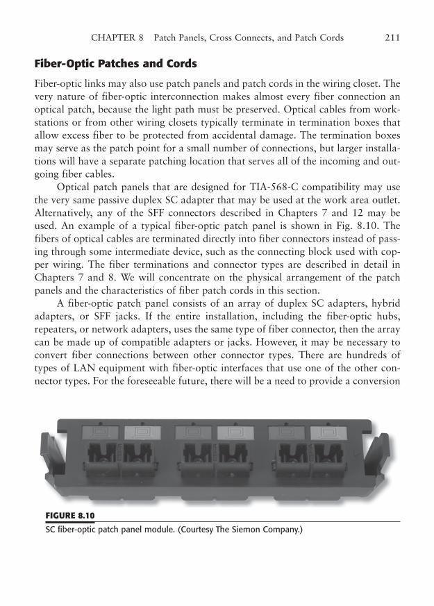
Fiber-Optic Patches and Cords
Fiber-optic links may also use patch panels and patch cords in the wiring closet. Thevery nature of fiber-optic interconnection makes almost every fiber connection anoptical patch, because the light path must be preserved. Optical cables from work-stations or from other wiring closets typically terminate in termination boxes thatallow excess fiber to be protected from accidental damage. The termination boxesmay serve as the patch point for a small number of connections, but larger installa-tions will have a separate patching location that serves all of the incoming and out-going fiber cables.
Optical patch panels that are designed for TIA-568-C compatibility may usethe very same passive duplex SC adapter that may be used at the work area outlet.Alternatively, any of the SFF connectors described in Chapters 7 and 12 may beused. An example of a typical fiber-optic patch panel is shown in Fig. 8.10. Thefibers of optical cables are terminated directly into fiber connectors instead of pass-ing through some intermediate device, such as the connecting block used with cop-per wiring. The fiber terminations and connector types are described in detail inChapters 7 and 8. We will concentrate on the physical arrangement of the patchpanels and the characteristics of fiber patch cords in this section.
A fiber-optic patch panel consists of an array of duplex SC adapters, hybridadapters, or SFF jacks. If the entire installation, including the fiber-optic hubs,repeaters, or network adapters, uses the same type of fiber connector, then the arraycan be made up of compatible adapters or jacks. However, it may be necessary toconvert fiber connections between other connector types. There are hundreds oftypes of LAN equipment with fiber-optic interfaces that use one of the other con-nector types. For the foreseeable future, there will be a need to provide a conversion
CHAPTER 8 Patch Panels, Cross Connects, and Patch Cords 211
FIGURE 8.10
SC fiber-optic patch panel module. (Courtesy The Siemon Company.)
between the various connectors. The TIA-568-C standard contains suggestions formigrating to the new connector systems. The reason the standard has chosen toallow the SFF connectors is to encourage innovation and allow quickconnection/disconnection and easily combined polarized pairs.
To convert between fiber connector types, you need to use a hybrid adapter ora conversion cable. A hybrid adapter is a passive coupler that joins two differentconnector types, while a conversion cable simply has one connector type on one endand the other type on the opposite end.
For example, to convert an ST equipment interface to SC, you need a fibercable with one of the connectors on each end. The duplex (two-fiber) cord describedlater is convenient to use, because you will need two fibers for each link connection.Some of the other types of fiber connectors usually have no built-in polarization, soyou will have to pay attention to which connector goes to transmit and which toreceive. The standard, at present, gives no guidance as to which A or B position ofeach orientation (AB or BA) should contain the transmit signal and which thereceive. The designation of one fiber as transmit and one as receive is a little diffi-cult anyway, because the transmit from the one end of a cable is the receive from theother. You will have to create your own standard practices for which connectorposition at the patch panel is transmit or receive.
Fiber-optic patch cords are usually made from flexible duplex fiber cables,often referred to as “zip cords” because of their resemblance to the household elec-trical cords by the same name. Fiber zip cords differ in that the conductors arereplaced by fibers, insulation does not have to meet any electrical specifications, andcolor is usually bright. Because the fibers are always patched in pairs, the dual-fiberconstruction is handy in that it easily splits out for two individual connectors.
Most SFF connectors are duplex by nature, and A/B orientation is part of thedesign. A duplex clip can be used to attach the two SC connectors together. Fiberconnector pairs that are thus clipped together have an orientation just as theadapters do. This is so that the A and B connections will be placed into the properposition in the mating adapter. There are two orientations for the connectors of afiber patch cord, the AB and BA orientation, which were described in Chapter 7. Itdoes not really matter which orientation you use for each end of the patch cord, aslong as the two ends of the cord have opposite orientations, and the fiber polarityis flipped between the two ends.
Adapters and connectors may be marked with a distinctive color, such as redor white, to assist in the installation and later connection of mating plugs. TheTIA standard does not specify or define these “shadings” at the present time, butyou can use them in your facility to help differentiate the A and B positions of themating connections. Remember that neither the A nor B designation specifies the
212 PART TWO LAN Wiring Technology
direction of the optical signal, but merely acts similar to pin numbers in a conven-tional connector.
Furthermore, because every fiber cable and adapter coupling reverses the A/Border, you could not tell which fiber carried which signal, even if you knew how thesignals started out, unless you traced every fiber through all the polarity reversals.As a user, the only thing that you would know is that the reversals had beenarranged in such a way that whatever signal started out on the A position at one endof the link will be on the B position at the other end. This is done to create the trans-mit/receive reversal that must be done for a fiber link to function.
Remember that some fiber-optic links may use laser illumination that is poten-tially hazardous. Most LAN connections that you encounter will use optical powerlevels far below that which would actually cause a problem, but you should still usereasonable precautions when working around fiber. As we cover in Chapters 8 and12, you should never look directly into an open fiber connector (or an unterminatedfiber that might be part of an active circuit). The light wavelengths used for thesesignals are in the infrared part of the spectrum and are quite invisible to the eye.Some fiber transmitters that are intended for long distances may actually have lev-els of light that would be hazardous, so just don’t get into a bad habit.
Category 7 (Class F) Patches and Cords. The new Category 7 (Class F) cablingstandards extend the frequency performance of twisted-pair cable to 600 MHz (typ-ically characterized to 750 MHz). Category 7 has been a long time coming. Thecable that forms the basis for Category 7 operation (see Chapter 5) is a dramaticdeparture from tried-and-true UTP. The same can be said for the patches and cordsthat are used for Category 7.
The first thing to understand about Category 7 is that the cabling system usesindividually shielded4 pairs, bundled as four pairs within an overall shield. Fromthe standpoint of patches and patch cords, this means that both must also beshielded, to get the proper performance from a Category 7 system.
The second major feature of Category 7 is that it allows two radically differ-ent types of connectors, known as “RJ” and “non-RJ” types. As you might guess,the RJ-type is a fairly conventional 8-pin modular jack and plug similar to thefamous RJ-45 connector. However, both mating connectors must be shielded toaccommodate the shield connection of Category 7 cable. There are several varia-tions of this scheme, but the basic idea is to try to be backward compatible witholder Category 5e/6/AC6 cabling components and equipment interfaces.
CHAPTER 8 Patch Panels, Cross Connects, and Patch Cords 213
4 The terms shielded and screened are used rather interchangeably, although specific standards mayprefer one term over the other. Foils, braids, or both may be used to increase the immunity to electro-magnetic fields.
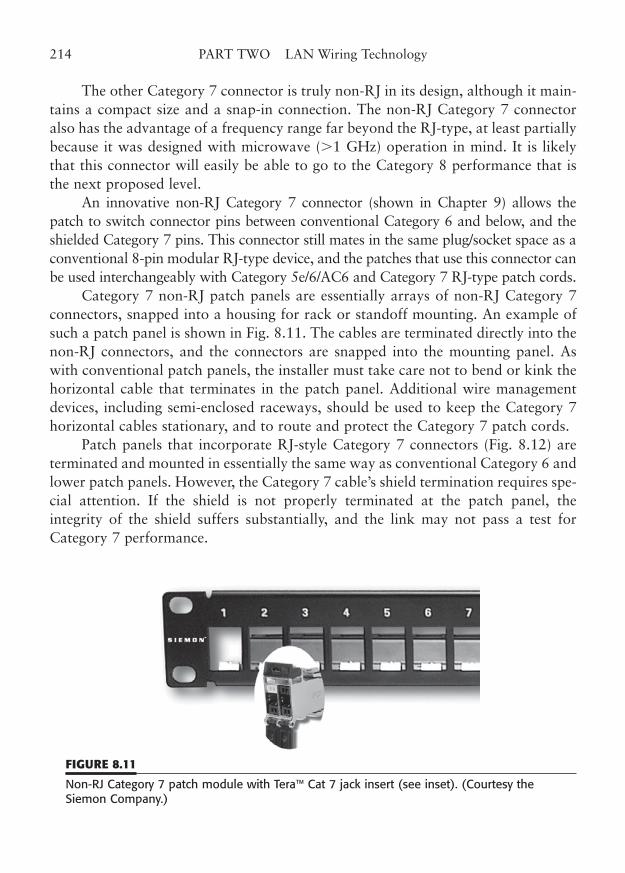
The other Category 7 connector is truly non-RJ in its design, although it main-tains a compact size and a snap-in connection. The non-RJ Category 7 connectoralso has the advantage of a frequency range far beyond the RJ-type, at least partiallybecause it was designed with microwave (1 GHz) operation in mind. It is likelythat this connector will easily be able to go to the Category 8 performance that isthe next proposed level.
An innovative non-RJ Category 7 connector (shown in Chapter 9) allows thepatch to switch connector pins between conventional Category 6 and below, and theshielded Category 7 pins. This connector still mates in the same plug/socket space as aconventional 8-pin modular RJ-type device, and the patches that use this connector canbe used interchangeably with Category 5e/6/AC6 and Category 7 RJ-type patch cords.
Category 7 non-RJ patch panels are essentially arrays of non-RJ Category 7connectors, snapped into a housing for rack or standoff mounting. An example ofsuch a patch panel is shown in Fig. 8.11. The cables are terminated directly into thenon-RJ connectors, and the connectors are snapped into the mounting panel. Aswith conventional patch panels, the installer must take care not to bend or kink thehorizontal cable that terminates in the patch panel. Additional wire managementdevices, including semi-enclosed raceways, should be used to keep the Category 7horizontal cables stationary, and to route and protect the Category 7 patch cords.
Patch panels that incorporate RJ-style Category 7 connectors (Fig. 8.12) areterminated and mounted in essentially the same way as conventional Category 6 andlower patch panels. However, the Category 7 cable’s shield termination requires spe-cial attention. If the shield is not properly terminated at the patch panel, theintegrity of the shield suffers substantially, and the link may not pass a test forCategory 7 performance.
214 PART TWO LAN Wiring Technology
FIGURE 8.11
Non-RJ Category 7 patch module with Tera™ Cat 7 jack insert (see inset). (Courtesy theSiemon Company.)
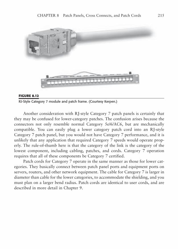
Another consideration with RJ-style Category 7 patch panels is certainly thatthey may be confused for lower-category patches. The confusion arises because theconnectors not only resemble normal Category 5e/6/AC6, but are mechanicallycompatible. You can easily plug a lower category patch cord into an RJ-styleCategory 7 patch panel, but you would not have Category 7 performance, and it isunlikely that any application that required Category 7 speeds would operate prop-erly. The rule-of-thumb here is that the category of the link is the category of thelowest component, including cabling, patches, and cords. Category 7 operationrequires that all of these components be Category 7 certified.
Patch cords for Category 7 operate in the same manner as those for lower cat-egories. They basically connect between patch panel ports and equipment ports onservers, routers, and other network equipment. The cable for Category 7 is larger indiameter than cable for the lower categories, to accommodate the shielding, and youmust plan on a larger bend radius. Patch cords are identical to user cords, and aredescribed in more detail in Chapter 9.
CHAPTER 8 Patch Panels, Cross Connects, and Patch Cords 215
FIGURE 8.12
RJ-Style Category 7 module and patch frame. (Courtesy Kerpen.)

This page intentionally left blank
CHAPTER 9
User Cords and Connectors
Highlights
■ Modular user cords
■ Modular cable-end connectors
■ RJ-45: What’s in a name?
■ Connector pin-outs
■ 8-pin modular wiring patterns
■ Modular cord assembly
217
Copyright © 2006 by James Trulove. Click here for terms of use.
This chapter will describe the various types of connectors that are used to terminatecable ends. We have previously covered station cable termination, so this sectionwill concentrate on the 8-pin modular plugs that are used on freestanding cablessuch as patch cords and user cords (sometimes called user cables). We will also lookat the user cords that are used in the work areas and the equipment rooms for con-nection to network hardware.
This is a good time to point out the distinction between “cables” and “cords”as used here and in many of the standards. Obviously, both cables and cords usedin telecommunications employ jacketed, multi-paired cables, but it is customary torefer to the flexible, stranded-wire, plug-terminated cables that connect to worksta-tions, hubs, and patches as “cords.” This is the convention followed by most of thestandards. The usage rule is probably more consistent when referring to patch cords,which are inevitably referred to as “cords.” The terms “user cord” and “user cable”are used interchangeably, as are the terms “equipment cord” and “equipmentcable.” For consistency in this book, we have tried to use the word “cable” to referto any solid-conductor cables that are terminated in a jack or punchdown, and usethe word “cord” to refer to any stranded-conductor cables that are terminated inmodular plugs. With regard to coax cables, they are normally referred to as“cables,” regardless of their location. By the same token (pun intended), IBM dataconnector cables are normally referred to as “cables.” Both of these last cable typesare identical in composition and termination whether they are used in the wall orby the equipment user.
Cable-End Connectors
We will primarily cover modular cable connectors in this chapter. Coax connectorsand IBM data connectors are considered legacy connectors and are covered inAppendix B. Fiber-optic connectors are described in Chapters 6, 7, and 11 and willnot be covered here. Of the three other types of connectors, the modular connectoris obviously the most favored for modern LAN wiring, because of the increasing useof unshielded twisted-pair cable. Coax has long been used for traditional Ethernetand ARCnet LANs, but is gradually being phased out in most locations. The dataconnector is an important connector in shielded twisted-pair wiring systems, and itis now included in the TIA-568-C standard.
Modular Connectors
The modular connector used in LAN systems is the same connector that is used inmodular telephone wiring systems. This connector is available in several possible
218 PART TWO LAN Wiring Technology
sizes and pin configurations, ranging from four to eight positions, with from two toeight contact pins. The popular styles are often referred to by a Universal ServiceOrder Code (USOC) “RJ” number, even though the connector may not actually beused in the designated application called for by the USOC code. For example, thecommon 6-pin modular telephone plug is often called an RJ-11, and the 8-pin mod-ular plug is often called an RJ-45. The 8-pin modular plug is used in the TIA-568-C wiring standard for both telephone and data. The 8-pin modular plug is also theconnector that is used for 10BaseT, 100BaseT, 1000BaseT, 100VG-AnyLAN, token-ring/UTP, and many other LAN applications.
This 8-pin modular plug is probably the most subject to name abuse, becauseit resembles the specialized RJ-45 connector. However, the RJ-45 wiring pattern(which includes an interface programming resistor) is so radically different fromthat of T568A and B that it really should not be called by that name at all. In thisbook, we have tried to always use the “8-pin modular,” or simply “modular,”description, as it leads to less confusion.
In truth, all modular plugs are identical until terminated. Then, they shouldprobably be called by a name that reflects their wiring pattern. For example, youcould certainly connect only four pins of an 8-pin modular plug in a 10/100BaseTpattern. It would not truly be either T568A or B, because both require eight con-nected pins. It would not be an RJ-45, because the wiring pattern would be wrongand the programming resistor would be missing. Why not call it a 10/100BaseT con-nector, as that would be its purpose and its unique wiring pattern? If all eight wiresare connected in an approved pattern, you could call it a “TIA” connector, or even“T568A or B.” Well, until the habit is changed, we will probably still find people
CHAPTER 9 User Cords and Connectors 219
RJ-45: What’s in a Name?The 8-pin modular connector is often improperly referred to as an “RJ-45.”The terminology is in such wide use that even manufacturers who knowbetter frequently use the RJ-45 name in their marketing materials. Some willcall it RJ-45 “style” or “type.” In truth, the RJ-45 designation is for a particu-lar interface most often used for programmable analog modem connectionsto leased telephone lines. This true RJ-45 just happens to use the 8-pin (8-position, 8-contact), 8P8C, modular jack and plug that are found in manyother LAN and telephone connections that have nothing whatever to dowith the original intent of the RJ-45 connection, Many other common inter-faces use the same type of modular connector, including RJ-48,10/100/1000BaseT, Token-Ring/UTP, UNI-PMD, T1, ISDN, and on and on.
who call the connectors “RJ-45s,” however wrong the term might be.The 8-pin modular plug that is used in standard LAN wiring is specified by IEC
603-7, “detailed specification for connectors, 8-way, including fixed and free con-nectors with common mating features.” This is the plug that is specified in TIA-568-C and related documents, and in ISO/IEC IS-11801.
Modular connectors are primarily intended for terminating cables withstranded conductors. In fact, the original connector was designed to terminate a flatcable containing from two to eight stranded conductors.
It was also designed primarily for the audio frequencies of telephone lines,although the connector is officially rated for use up to 3 MHz. Unfortunately, theindustry not only uses the connector at frequencies far above that, but also needs toplace twisted-pair conductors, encased in a round cable jacket, into the modularplug. To allow the use of the modular connector at LAN frequencies from 10 to 100MHz, the TIA has simply specified performance criteria (primarily attenuation andNEXT) that the connector must meet. As long as these criteria are met, the connec-tor can be used in applications up to Category 5e.
The Category 6 plugs and jacks, while physically compatible with theirCategory 5e cousins, are specially configured to reduce near-end crosstalk (NEXT)when mated. This electrical compensation can actually cause a link failure whenCategory 6 connectors are mated to Category 5e connectors.
Modular connectors are available for solid wire, although some authorities dis-courage using solid wire for cords, even with these special connectors. The differ-ence between the two connector designs is shown in Fig. 9.1. As you can see, themodular pin is a flat contact with a pointed end that pierces through the insulationof the wire and makes electrical contact with the stranded wires. The contact may
220 PART TWO LAN Wiring Technology
This common usage error would matter very little if you were nevergoing to use high-speed data networks. However, the TIA-568-C version ofthe 8-pin modular connector interface has very specific performancerequirements that may not be met by the generic nonrated connector thatsimply goes by the RJ-45 name. It would have been convenient if the TIAhad given this connector a new name commensurate with its specifications.Perhaps it could have been called the “T568-8/Cat5e” connector, or howabout just “T568-RJ” to borrow from both the past and the present.
When will people stop calling it an “RJ-45”? Don’t hold your breath!Don’t grit your teeth either! Just get used to thinking that a very special typeof connector is meant when a “RJ-45” is used in your LAN wiring system.And, oh yes, never ever use the “RJ” word on the ’net!
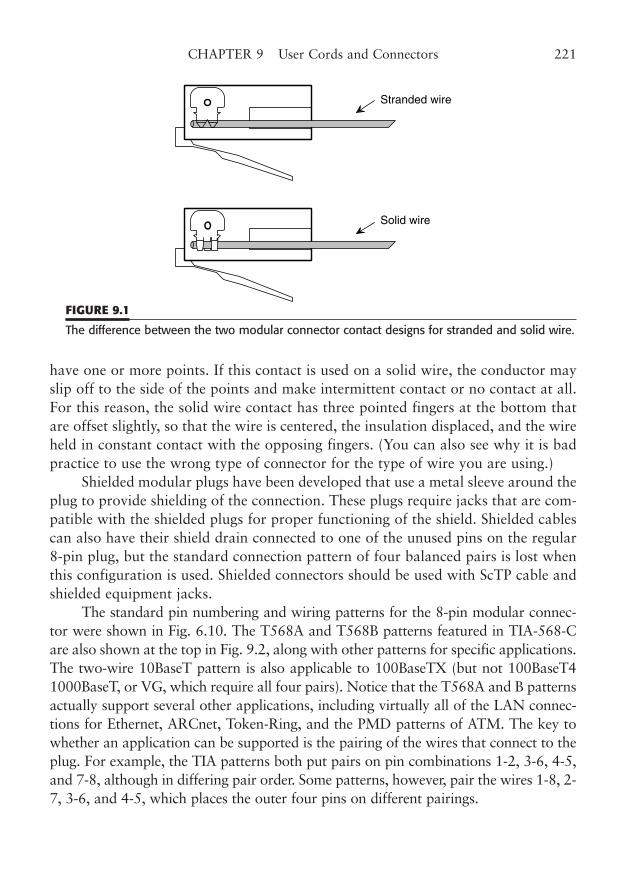
have one or more points. If this contact is used on a solid wire, the conductor mayslip off to the side of the points and make intermittent contact or no contact at all.For this reason, the solid wire contact has three pointed fingers at the bottom thatare offset slightly, so that the wire is centered, the insulation displaced, and the wireheld in constant contact with the opposing fingers. (You can also see why it is badpractice to use the wrong type of connector for the type of wire you are using.)
Shielded modular plugs have been developed that use a metal sleeve around theplug to provide shielding of the connection. These plugs require jacks that are com-patible with the shielded plugs for proper functioning of the shield. Shielded cablescan also have their shield drain connected to one of the unused pins on the regular8-pin plug, but the standard connection pattern of four balanced pairs is lost whenthis configuration is used. Shielded connectors should be used with ScTP cable andshielded equipment jacks.
The standard pin numbering and wiring patterns for the 8-pin modular connec-tor were shown in Fig. 6.10. The T568A and T568B patterns featured in TIA-568-Care also shown at the top in Fig. 9.2, along with other patterns for specific applications.The two-wire 10BaseT pattern is also applicable to 100BaseTX (but not 100BaseT41000BaseT, or VG, which require all four pairs). Notice that the T568A and B patternsactually support several other applications, including virtually all of the LAN connec-tions for Ethernet, ARCnet, Token-Ring, and the PMD patterns of ATM. The key towhether an application can be supported is the pairing of the wires that connect to theplug. For example, the TIA patterns both put pairs on pin combinations 1-2, 3-6, 4-5,and 7-8, although in differing pair order. Some patterns, however, pair the wires 1-8, 2-7, 3-6, and 4-5, which places the outer four pins on different pairings.
CHAPTER 9 User Cords and Connectors 221
Stranded wire
Solid wire
FIGURE 9.1
The difference between the two modular connector contact designs for stranded and solid wire.
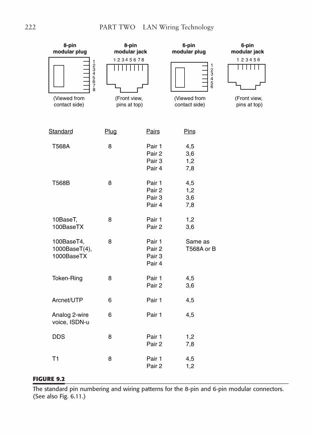
222 PART TWO LAN Wiring Technology
12345678
8-pinmodular plug
8-pinmodular jack
1 2 3 4 5 6 7 8
(Viewed fromcontact side)
(Front view, pins at top)
(Front view, pins at top)
6-pinmodular plug
123456
(Viewed fromcontact side)
6-pinmodular jack
1 2 3 4 5 6
Standard Plug Pairs Pins
T568A 8 Pair 1 4,5 Pair 2 3,6
Pair 3 1,2Pair 4 7,8
T568B 8 Pair 1 4,5Pair 2 1,2Pair 3 3,6Pair 4 7,8
10BaseT, 8 Pair 1 1,2 100BaseTX Pair 2 3,6
100BaseT4, 8 Pair 1 Same as 1000BaseT(4), Pair 2 T568A or B 1000BaseTX Pair 3
Pair 4
Token-Ring 8 Pair 1 4,5Pair 2 3,6
Arcnet/UTP 6 Pair 1 4,5
Analog 2-wire 6 Pair 1 4,5 voice, ISDN-u
DDS 8 Pair 1 1,2 Pair 2 7,8
T1 8 Pair 1 4,5Pair 2 1,2
FIGURE 9.2
The standard pin numbering and wiring patterns for the 8-pin and 6-pin modular connectors.(See also Fig. 6.11.)
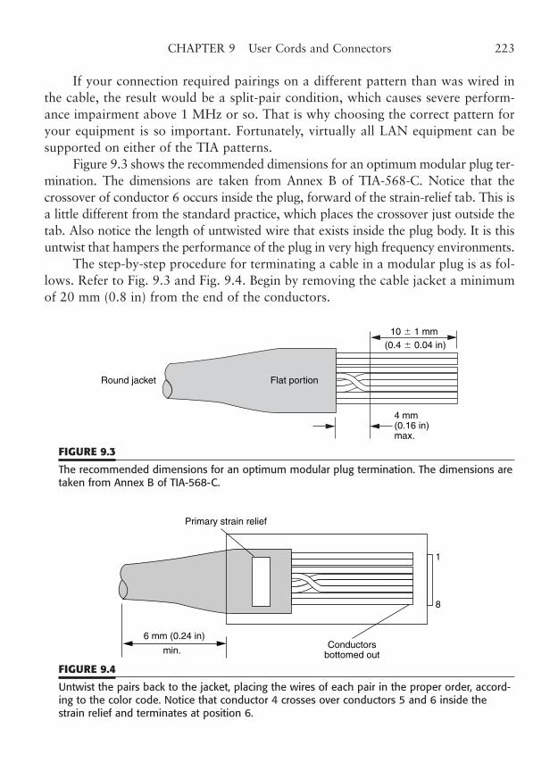
If your connection required pairings on a different pattern than was wired inthe cable, the result would be a split-pair condition, which causes severe perform-ance impairment above 1 MHz or so. That is why choosing the correct pattern foryour equipment is so important. Fortunately, virtually all LAN equipment can besupported on either of the TIA patterns.
Figure 9.3 shows the recommended dimensions for an optimum modular plug ter-mination. The dimensions are taken from Annex B of TIA-568-C. Notice that thecrossover of conductor 6 occurs inside the plug, forward of the strain-relief tab. This isa little different from the standard practice, which places the crossover just outside thetab. Also notice the length of untwisted wire that exists inside the plug body. It is thisuntwist that hampers the performance of the plug in very high frequency environments.
The step-by-step procedure for terminating a cable in a modular plug is as fol-lows. Refer to Fig. 9.3 and Fig. 9.4. Begin by removing the cable jacket a minimumof 20 mm (0.8 in) from the end of the conductors.
CHAPTER 9 User Cords and Connectors 223
Round jacket Flat portion
4 mm(0.16 in)max.
10 � 1 mm(0.4 � 0.04 in)
FIGURE 9.3
The recommended dimensions for an optimum modular plug termination. The dimensions aretaken from Annex B of TIA-568-C.
Primary strain relief
6 mm (0.24 in)
min.Conductors
bottomed out
1
8
FIGURE 9.4
Untwist the pairs back to the jacket, placing the wires of each pair in the proper order, accord-ing to the color code. Notice that conductor 4 crosses over conductors 5 and 6 inside thestrain relief and terminates at position 6.
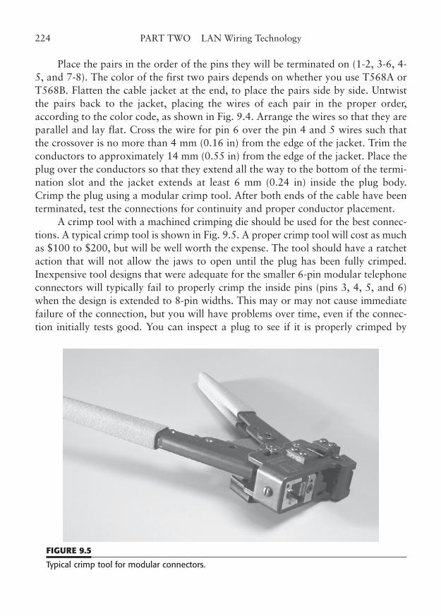
Place the pairs in the order of the pins they will be terminated on (1-2, 3-6, 4-5, and 7-8). The color of the first two pairs depends on whether you use T568A orT568B. Flatten the cable jacket at the end, to place the pairs side by side. Untwistthe pairs back to the jacket, placing the wires of each pair in the proper order,according to the color code, as shown in Fig. 9.4. Arrange the wires so that they areparallel and lay flat. Cross the wire for pin 6 over the pin 4 and 5 wires such thatthe crossover is no more than 4 mm (0.16 in) from the edge of the jacket. Trim theconductors to approximately 14 mm (0.55 in) from the edge of the jacket. Place theplug over the conductors so that they extend all the way to the bottom of the termi-nation slot and the jacket extends at least 6 mm (0.24 in) inside the plug body.Crimp the plug using a modular crimp tool. After both ends of the cable have beenterminated, test the connections for continuity and proper conductor placement.
A crimp tool with a machined crimping die should be used for the best connec-tions. A typical crimp tool is shown in Fig. 9.5. A proper crimp tool will cost as muchas $100 to $200, but will be well worth the expense. The tool should have a ratchetaction that will not allow the jaws to open until the plug has been fully crimped.Inexpensive tool designs that were adequate for the smaller 6-pin modular telephoneconnectors will typically fail to properly crimp the inside pins (pins 3, 4, 5, and 6)when the design is extended to 8-pin widths. This may or may not cause immediatefailure of the connection, but you will have problems over time, even if the connec-tion initially tests good. You can inspect a plug to see if it is properly crimped by
224 PART TWO LAN Wiring Technology
FIGURE 9.5
Typical crimp tool for modular connectors.
looking at the plug end. A properly crimped plug will have all eight contacts fullyengaged and even on the tops, which will be very slightly below the plastic channelsbetween the contact pins. An improperly crimped plug will show a distinct roundingupward of the center contacts. Side-action crimp tools may favor the contacts on oneside of the plug. The plug should also be inspected from the front and top to ensurethat the contacts have not drifted to the side, as can happen with inexpensive modu-lar plugs. As simple as these plugs are, there are still significant differences in quality.
It would not be proper in a discussion of LAN cable terminations to ignore theproblems that result from the choice of the classic 8-pin modular plug and its mat-ing jack as the standard UTP connector. These components are responsible for themajority of limitations with this generation of high-speed networking. The connec-tor, as stated before, was designed for frequencies well below 3 MHz, and it has verypoor characteristics at frequencies approaching 100 MHz. The NEXT performanceof the plug and jack is so bad at 100 MHz that you will see few manufacturers quoteperformance margins that exceed the TIA performance standards by more than 1 or2 dB, if they quote a margin at all. Test equipment manufacturers even create spe-cialized low-NEXT adapters or digital processing techniques to compensate for theperformance deficiencies of the modular connector in their own test equipment.
Nevertheless, with quality materials, proper assembly procedures, carefulworkmanship, and proper testing, the modular connector can support the highestperformance metallic cable networks in wide use today.
User Cords
User cords are the final connection step in a LAN wiring system. They are the cablesthat connect between the installed universal wiring system and the network equip-ment. They exist on both ends of a link, at the work area and in the wiring closet.In most modern LAN installations, the telecommunications room will containwiring hubs that consolidate all the station cables into a contiguous network.Telecommunications rooms that contain network equipment in the form of hubs,repeaters, and servers are also “equipment rooms,” which add a few requirementsover and above those for a simple telecommunications room, but we will just callthem telecommunications rooms to keep things simple.
User cords include workstation cords and equipment cords. Technically, usercords do not include patch cords, which are part of the horizontal cross-connect.Sometimes all modular cords are called patch cords, regardless of their function, butwe will make a distinction between true patch cords and user cords. Patch cords,which were covered in the last chapter, are essentially the same as user cords, exceptfor length and color.
CHAPTER 9 User Cords and Connectors 225
User cords are a required part of the Channel, the total end-to-end LAN con-nection, but they are not part of the Basic Link or Permanent Link, both of whichexclude user cords. These terms are defined in TIA-568-C.1, Sec. 11, “CablingTransmission Performance and Test Requirements,” and they are very useful indescribing the component parts of a cable link. The theory is that a cable plant couldbe installed and tested before any of the user network hardware is installed. To dothe testing, we need to have performance specifications for the portion of the hori-zontal cabling that excludes the user cables. That portion is called the Basic Link orPermanent Link. However, channel performance levels are also defined, so we couldalso test with the user cables in place. In fact, that type of test is the ultimate assur-ance that a link meets the requirements for a particular category of operation. Moreinformation on Channel and Permanent Link is included in Chapters 1 and 15.
Construction
User cords are flexible, 4-pair cables, terminated at either end in an 8-pin (IEC 603-7) modular plug. The cords may be provided in various lengths, as needed for theapplication. The cords should meet the transmission and construction requirementsfor patch cords in TIA-568-C, as user cords are not explicitly defined elsewhere inthat standard. The color code for the conductors and the wiring pattern connectionsfor the modular plug are the standard configuration, as shown in the first part ofthis chapter, as well as in Chapters 2 and 5. Either the T568A or B pattern may beused, as long as the same pattern is used at both ends of the cord. The standard alsoallows an alternative color pattern consisting of eight solid colors that can be usedfor user cords.
User cords are made from AWG 24, stranded, thermoplastic insulated conduc-tors, arranged into four pairs, with an outer thermoplastic jacket (Fig. 9.6).Conductors of 22-gauge wire may be used, if the cord meets the same performancerequirements, but you must be certain that the connector plugs are designed for thelarger wire size. The various jacketing materials are described in Chapter 5.Stranded wire is used because of its flexibility.
From a technical standpoint, solid wire could be used, but it lacks flexibilityand is more difficult to connect with modular plugs. In most locations, nonplenuminsulation, such as PVC, is acceptable. PVC is also much more flexible than mostplenum-rated plastics and it is more easily tinted.
The outer jacket color should be appropriate for the office environment.Some of the cable manufacturers offer Category 5e cable in a bright color, to
distinguish it from lower category wire. There is no need to use this bright color inthe work areas. The cable should be marked to indicate the category if there is any
226 PART TWO LAN Wiring Technology
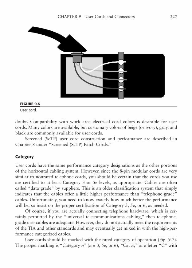
doubt. Compatibility with work area electrical cord colors is desirable for usercords. Many colors are available, but customary colors of beige (or ivory), gray, andblack are commonly available for user cords.
Screened (ScTP) user cord construction and performance are described inChapter 8 under “Screened (ScTP) Patch Cords.”
Category
User cords have the same performance category designations as the other portionsof the horizontal cabling system. However, since the 8-pin modular cords are verysimilar to nonrated telephone cords, you should be certain that the cords you useare certified to at least Category 3 or 5e levels, as appropriate. Cables are oftencalled “data grade” by suppliers. This is an older classification system that simplyindicates that the cables offer a little higher performance than “telephone grade”cables. Unfortunately, you need to know exactly how much better the performancewill be, so insist on the proper certification of Category 3, 5e, or 6, as needed.
Of course, if you are actually connecting telephone hardware, which is cer-tainly permitted by the “universal telecommunications cabling,” then telephone-grade user cables are adequate. However, they do not actually meet the requirementsof the TIA and other standards and may eventually get mixed in with the high-per-formance categorized cables.
User cords should be marked with the rated category of operation (Fig. 9.7).The proper marking is “Category n” (n = 3, 5e, or 6), “Cat n,” or a letter “C” with
CHAPTER 9 User Cords and Connectors 227
FIGURE 9.6
User cord.
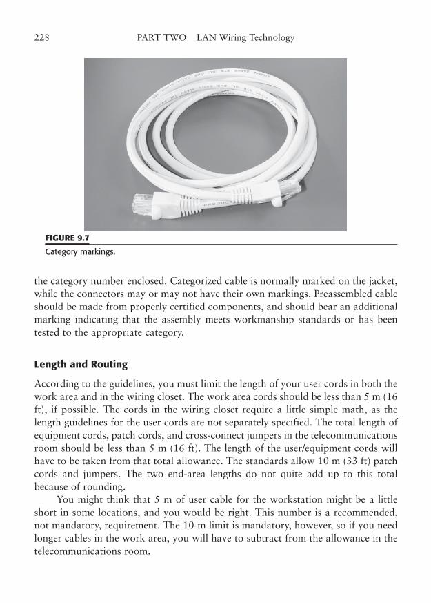
the category number enclosed. Categorized cable is normally marked on the jacket,while the connectors may or may not have their own markings. Preassembled cableshould be made from properly certified components, and should bear an additionalmarking indicating that the assembly meets workmanship standards or has beentested to the appropriate category.
Length and Routing
According to the guidelines, you must limit the length of your user cords in both thework area and in the wiring closet. The work area cords should be less than 5 m (16ft), if possible. The cords in the wiring closet require a little simple math, as thelength guidelines for the user cords are not separately specified. The total length ofequipment cords, patch cords, and cross-connect jumpers in the telecommunicationsroom should be less than 5 m (16 ft). The length of the user/equipment cords willhave to be taken from that total allowance. The standards allow 10 m (33 ft) patchcords and jumpers. The two end-area lengths do not quite add up to this totalbecause of rounding.
You might think that 5 m of user cable for the workstation might be a littleshort in some locations, and you would be right. This number is a recommended,not mandatory, requirement. The 10-m limit is mandatory, however, so if you needlonger cables in the work area, you will have to subtract from the allowance in thetelecommunications room.
228 PART TWO LAN Wiring Technology
FIGURE 9.7
Category markings.
In reality, the total length of each horizontal link is the real operating limit ofa LAN circuit. This limit is 100 m (328 ft) for the entire Channel, including all ofthe cables, cords, and jumpers that run all the way from the back of the worksta-tion to the network hub. The 100 m (328 ft) includes 10 m (33 ft) for all the cordsand jumpers, with the understanding that the stranded wires used in these cordshave a 20% greater attenuation.
Although the standard requires that all horizontal cables be solid wire, youcould safely exceed the 10-m (33 ft) limit for user cords and jumpers by a little bitif you were well below the 90-m (295 ft) limit for the horizontal cable.
User cords in the work area should be routed with the same guidelines as forthe horizontal cable runs. You should avoid sharp bends, kinks, and abrasions ofthe cable, and you should route it away from potential interference sources, such asfluorescent lights and motors.
Modular furniture usually requires that user cords be placed in raceways thatare built into the furniture. Remember that the guidelines suggest a separation of 2to 5 in from power conductors, such as the AC outlets (or mains) in the furniturechannels. Furniture manufacturers are beginning to recognize the need for totallyseparate telecommunications raceways, so you may be able to specify furniture thatmeets this requirement. The placement of Category 5e and 6 cable is much moresensitive than lower categories. If you are still operating a 10BaseT or Token-Ring16 network, you really do not need Category 5 performance, and you may want torelax the rules somewhat. Routing of user cables in the telecommunications roomwill not be covered here, as it is identical to patch cord routing, which was coveredin Chapters 6 and 7.
Workmanship and Quality
If you build your own user cords, or if you manufacture them for others, the qual-ity of construction is a very important factor in the performance of the cord. Youshould first ensure that all connectors and cable used in the assembly of the cord arecertified by the manufacturer for the level of performance you desire for the com-pleted cord. Then, you should use proper techniques to assemble the cord for max-imum performance. It is known to be difficult to test short lengths of cable,particularly with regard to NEXT, so your best performance guarantee is goodworkmanship. Basic continuity and wire map, of course, can be completely testedwithout regard to length.
The section on patch cords in Chapter 8 and the earlier section on modularconnectors in this chapter describe some techniques to ensure a high-quality termi-nation that will perform up to expectations.
CHAPTER 9 User Cords and Connectors 229

This page intentionally left blank
CHAPTER 10
Open Office Wiring
Highlights
■ Modular offices
■ TIA-568-C, TSB-75 guidelines
■ Consolidation point
■ Multiuser telecommunications outlets (MUTOA)
■ Fiber optic cabling
■ Separation from AC power cables
231
Copyright © 2006 by James Trulove. Click here for terms of use.
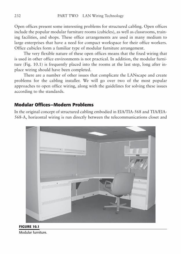
Open offices present some interesting problems for structured cabling. Open officesinclude the popular modular furniture rooms (cubicles), as well as classrooms, train-ing facilities, and shops. These office arrangements are used in many medium tolarge enterprises that have a need for compact workspace for their office workers.Office cubicles form a familiar type of modular furniture arrangement.
The very flexible nature of these open offices means that the fixed wiring thatis used in other office environments is not practical. In addition, the modular furni-ture (Fig. 10.1) is frequently placed into the rooms at the last step, long after in-place wiring should have been completed.
There are a number of other issues that complicate the LANscape and createproblems for the cabling installer. We will go over two of the most popularapproaches to open office wiring, along with the guidelines for solving these issuesaccording to the standards.
Modular Offices—Modern ProblemsIn the original concept of structured cabling embodied in EIA/TIA-568 and TIA/EIA-568-A, horizontal wiring is run directly between the telecommunications closet and
232 PART TWO LAN Wiring Technology
FIGURE 10.1
Modular furniture.
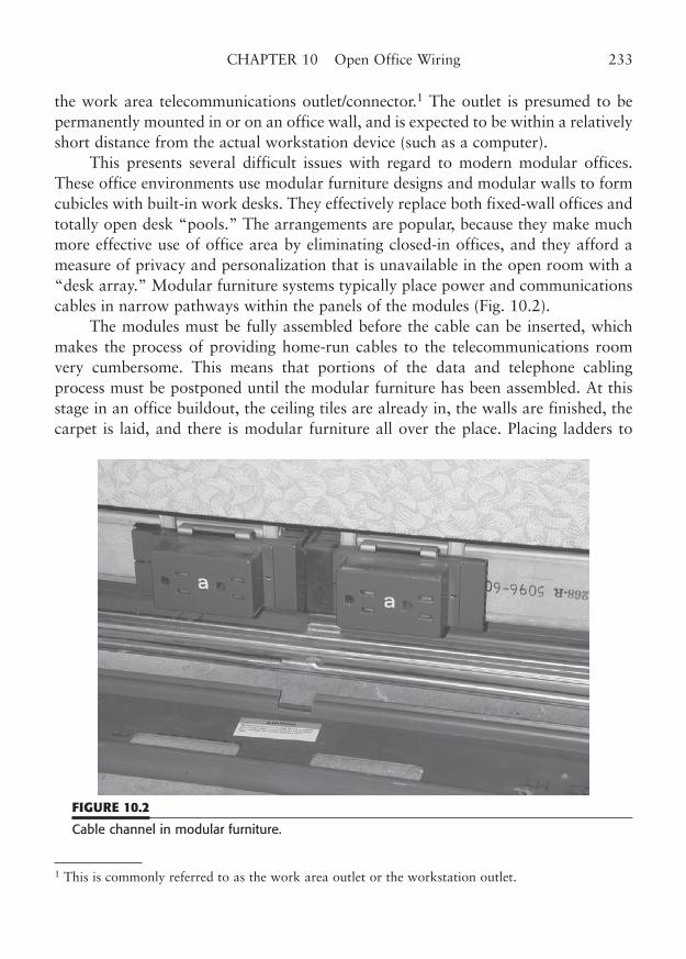
the work area telecommunications outlet/connector.1 The outlet is presumed to bepermanently mounted in or on an office wall, and is expected to be within a relativelyshort distance from the actual workstation device (such as a computer).
This presents several difficult issues with regard to modern modular offices.These office environments use modular furniture designs and modular walls to formcubicles with built-in work desks. They effectively replace both fixed-wall offices andtotally open desk “pools.” The arrangements are popular, because they make muchmore effective use of office area by eliminating closed-in offices, and they afford ameasure of privacy and personalization that is unavailable in the open room with a“desk array.” Modular furniture systems typically place power and communicationscables in narrow pathways within the panels of the modules (Fig. 10.2).
The modules must be fully assembled before the cable can be inserted, whichmakes the process of providing home-run cables to the telecommunications roomvery cumbersome. This means that portions of the data and telephone cablingprocess must be postponed until the modular furniture has been assembled. At thisstage in an office buildout, the ceiling tiles are already in, the walls are finished, thecarpet is laid, and there is modular furniture all over the place. Placing ladders to
CHAPTER 10 Open Office Wiring 233
1 This is commonly referred to as the work area outlet or the workstation outlet.
FIGURE 10.2
Cable channel in modular furniture.
install standard horizontal runs is difficult, even if the cable has been prepulled to theexpected area of the power/communications riser (commonly called the power pole)of the module. If prepulled, enough wire must be left coiled in the ceiling to run downlater through the pole and through the wire pathways to an outlet/connector. Thisleads to wasted wire, in the best case, and insufficient wire in the worst case.
In addition to the wire-pulling problems, the installer has the delightful task ofcrawling down on the floor and under the modular desk, with flashlight and tools,to terminate the horizontal cable at an outlet. After all this is done, the installer canfinally use a cable scanner to see if the link passes. Then, any problems that haveoccurred must be solved at great time and expense.
The next significant cabling problem that occurs with the use of modularoffices, is that the modules can be easily rearranged. The furniture modules are veryeasy to move about. The modules simply unbolt the same way they originally boltedtogether, and then are moved as needed to reconfigure the office to meet new per-sonnel requirements. In most of these modular furniture systems, the electrical con-nections either snap together as the modules are joined, or they are easily cabled andextended by a system of plugs and receptacles. Unfortunately, the communicationswiring, including our LAN wiring, must be painstakingly removed and rerouted intothe new furniture layout.
In many instances, the relatively delicate fiber and copper cables are the wronglength in the new arrangement and cannot be reused. The only option in such ahome-run environment is to pull an entirely new cable to each relocated worksta-tion. At an earlier time, this was the only approved method to run and rerun stan-dards-compliant Category 5e and higher links, as the standard allowed no splices orintermediate couplings.2
However, a much better alternative is to run the horizontal cables to a series ofdistribution points within an open area. Typically, these points of termination arealong the walls in the same area where electrical power will connect to a set of mod-ular furniture. In some instances, the distribution point might be in a ceiling areawith the communications wires distributed to the furniture modules nearby. Then,after the furniture is installed, cables can be extended from the distribution point tothe workstation outlets within the modules. This has now become an almost univer-sal practice in open-office installations.
This method is not only much more practical, but also a good deal less expen-sive, labor-wise, than dealing with home runs. Despite the standards to the contrary,these links normally work fine and pass the applicable link tests. Early on, however,
234 PART TWO LAN Wiring Technology
2 A transition point is allowed; however, this is narrowly defined as a connection between the roundhorizontal cable and flat undercarpet cable.
a few links failed, and it became obvious that some standard practices needed to becreated to ensure that the needed performance parameters were preserved for theappropriate category of operation.
TIA-568 TSB-75 Guidelines
TSB-75, Additional Horizontal Cabling Practices for Open Offices 1996,3 originallyadded the rules for handling modular furniture. A Telecommunications ServiceBulletin (TSB) provides additional information and practices to supplement anapproved standard, in this case TIA/EIA-568-A. TSA-75 put down on paper the infor-mation that installers need to properly provide standards-compliant cabling in anopen-office environment. In investigating the open-office practices that were in use, itwas determined that essentially two variations were popular and successful: providinga location to group or consolidate cables, and placing the equivalent of a workstationoutlet at the cable grouping and running longer user cords to each workstation.
The consolidation point method initially terminates the horizontal cable on anappropriate punchdown block at an intermediate distribution point between thetelecommunications room (TR) and a group of open office workstations. When it istime to extend the link to the office module, another length of horizontal cable isconnected to the punchdown and run onto the workstation outlet.
The multiuser outlet method actually places the workstation outlet at the dis-tribution point (in multiples to match the served modules) and runs an extended-length user cord to the work area.
We will go into each of these methods in some detail in the sections that fol-low. The provision of this standards bulletin gives the system designer and installerthe ability to provide approved intermediate interconnection points for modularoffices. Guidelines for cable length allowances that will meet the performancerequirements are given in the standard, and we will summarize these here.
Consolidation Point
A consolidation point is a point within the horizontal cable run where two cablesare interconnected (Fig. 10.3). In reality, it is a reusable connector, such as a punch-down block, that effectively joins the two cable segments without being officiallycalled a “splice.” In fact, cable splices are still forbidden, presumably because theydo not allow reusability and may make poor connections when viewed from the per-spective of crosstalk and return loss.
CHAPTER 10 Open Office Wiring 235
3 The practices in TSB-75 have now been incorporated into TIA-568-C.
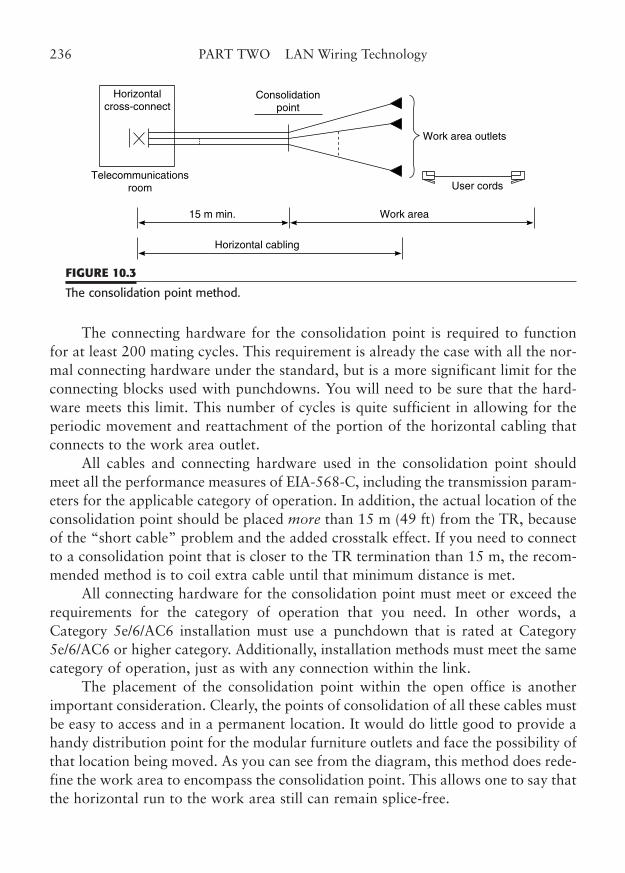
The connecting hardware for the consolidation point is required to functionfor at least 200 mating cycles. This requirement is already the case with all the nor-mal connecting hardware under the standard, but is a more significant limit for theconnecting blocks used with punchdowns. You will need to be sure that the hard-ware meets this limit. This number of cycles is quite sufficient in allowing for theperiodic movement and reattachment of the portion of the horizontal cabling thatconnects to the work area outlet.
All cables and connecting hardware used in the consolidation point shouldmeet all the performance measures of EIA-568-C, including the transmission param-eters for the applicable category of operation. In addition, the actual location of theconsolidation point should be placed more than 15 m (49 ft) from the TR, becauseof the “short cable” problem and the added crosstalk effect. If you need to connectto a consolidation point that is closer to the TR termination than 15 m, the recom-mended method is to coil extra cable until that minimum distance is met.
All connecting hardware for the consolidation point must meet or exceed therequirements for the category of operation that you need. In other words, aCategory 5e/6/AC6 installation must use a punchdown that is rated at Category5e/6/AC6 or higher category. Additionally, installation methods must meet the samecategory of operation, just as with any connection within the link.
The placement of the consolidation point within the open office is anotherimportant consideration. Clearly, the points of consolidation of all these cables mustbe easy to access and in a permanent location. It would do little good to provide ahandy distribution point for the modular furniture outlets and face the possibility ofthat location being moved. As you can see from the diagram, this method does rede-fine the work area to encompass the consolidation point. This allows one to say thatthe horizontal run to the work area still can remain splice-free.
236 PART TWO LAN Wiring Technology
Horizontalcross-connect
Telecommunicationsroom
Consolidationpoint
Work area outlets
User cords
Work area15 m min.
Horizontal cabling
FIGURE 10.3
The consolidation point method.
All other cabling distance guidelines remain the same. The horizontal limit isstill 90 m, and the user cord limit is still 5 m (16 ft). The consolidation point is sim-ply placed somewhere within that 90 m run. The main advantage to this cablingmethod is that it does allow for an intermediate connection point for the last partof the horizontal run to the work area outlet. In the event that the furniture is movedor reconfigured, only the portion of the horizontal run from the workstation outletto the consolidation point has to be replaced, and most of that cable would have tobe rerun within the modular furniture’s pathways, anyhow.
The requirements for marking the cables in the consolidation point are thesame as in any other cabling location. The details on the marking of these facilitiesare covered in ANSI/TIA/EIA-606-A and elsewhere in this book. Keep in mind thatyou may have an additional opportunity to lose track of cable connections becauseof the consolidation point.
The best practice is to be very orderly in placing the modular furniture ends of thehorizontal cables onto the consolidation hardware. Mark both cable ends as you go,and try to keep the numbering consistent. For example, rather than label an entire cablerun with the number C310, you could differentiate between the two legs on either sideof the consolidation point by designating one as C310a and the other as C310b.
Multiuser Telecommunications Outlet Assembly (MUTOA)
The consolidation point architecture is one of the most common methods of provid-ing for open-office cabling. However, it is not the only alternative. Another logicalmethod is to simply extend the length of the user cord far beyond the normal 5 mlimit. It turns out that lengthening the user cord can be successfully accomplishedon shorter horizontal cable runs. This accounts for the early success of some open-office wiring methods, prior to the existence of these standard practices.
The most logical arrangement for an open office with extended user cords is tobring all the cords together at a wall or other permanent structure upon which theappropriate number of workstation outlets can be mounted. This description essen-tially defines a multiuser outlet arrangement that TIA-568-C calls a multiusertelecommunications outlet assembly.
Fortunately, the industry has nicknamed this a MUTOA, or just a multiuseroutlet. The multiuser outlet method is illustrated in Fig. 10.4.
The basic premise of the multiuser outlet method is that the operating param-eters of the channel must be maintained for proper operation of equipment that isconnected according to TIA-568-C. So, as long as the installed-link criteria are met,there can be allowable variations in the absolute lengths of the horizontal cablingand the user cords.
CHAPTER 10 Open Office Wiring 237
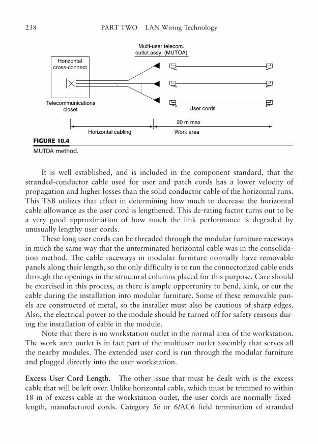
It is well established, and is included in the component standard, that thestranded-conductor cable used for user and patch cords has a lower velocity ofpropagation and higher losses than the solid-conductor cable of the horizontal runs.This TSB utilizes that effect in determining how much to decrease the horizontalcable allowance as the user cord is lengthened. This de-rating factor turns out to bea very good approximation of how much the link performance is degraded byunusually lengthy user cords.
These long user cords can be threaded through the modular furniture racewaysin much the same way that the unterminated horizontal cable was in the consolida-tion method. The cable raceways in modular furniture normally have removablepanels along their length, so the only difficulty is to run the connectorized cable endsthrough the openings in the structural columns placed for this purpose. Care shouldbe exercised in this process, as there is ample opportunity to bend, kink, or cut thecable during the installation into modular furniture. Some of these removable pan-els are constructed of metal, so the installer must also be cautious of sharp edges.Also, the electrical power to the module should be turned off for safety reasons dur-ing the installation of cable in the module.
Note that there is no workstation outlet in the normal area of the workstation.The work area outlet is in fact part of the multiuser outlet assembly that serves allthe nearby modules. The extended user cord is run through the modular furnitureand plugged directly into the user workstation.
Excess User Cord Length. The other issue that must be dealt with is the excesscable that will be left over. Unlike horizontal cable, which must be trimmed to within18 in of excess cable at the workstation outlet, the user cords are normally fixed-length, manufactured cords. Category 5e or 6/AC6 field termination of stranded
238 PART TWO LAN Wiring Technology
Horizontalcross-connect
Telecommunicationscloset
Multi-user telecom.outlet assy. (MUTOA)
User cords
20 m max
Work areaHorizontal cabling
FIGURE 10.4
MUTOA method.
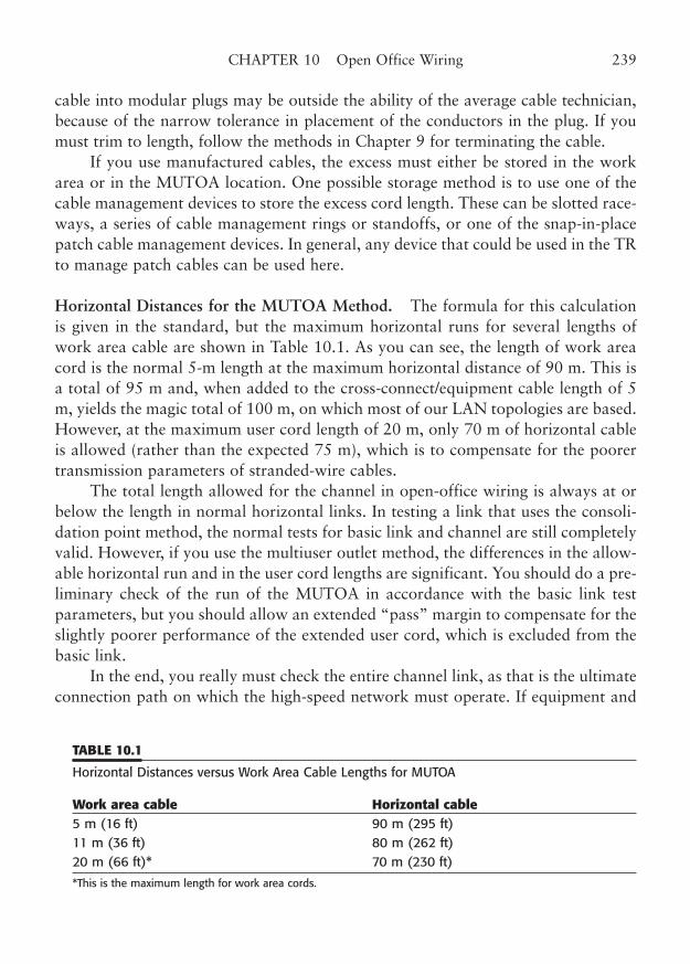
cable into modular plugs may be outside the ability of the average cable technician,because of the narrow tolerance in placement of the conductors in the plug. If youmust trim to length, follow the methods in Chapter 9 for terminating the cable.
If you use manufactured cables, the excess must either be stored in the workarea or in the MUTOA location. One possible storage method is to use one of thecable management devices to store the excess cord length. These can be slotted race-ways, a series of cable management rings or standoffs, or one of the snap-in-placepatch cable management devices. In general, any device that could be used in the TRto manage patch cables can be used here.
Horizontal Distances for the MUTOA Method. The formula for this calculationis given in the standard, but the maximum horizontal runs for several lengths ofwork area cable are shown in Table 10.1. As you can see, the length of work areacord is the normal 5-m length at the maximum horizontal distance of 90 m. This isa total of 95 m and, when added to the cross-connect/equipment cable length of 5m, yields the magic total of 100 m, on which most of our LAN topologies are based.However, at the maximum user cord length of 20 m, only 70 m of horizontal cableis allowed (rather than the expected 75 m), which is to compensate for the poorertransmission parameters of stranded-wire cables.
The total length allowed for the channel in open-office wiring is always at orbelow the length in normal horizontal links. In testing a link that uses the consoli-dation point method, the normal tests for basic link and channel are still completelyvalid. However, if you use the multiuser outlet method, the differences in the allow-able horizontal run and in the user cord lengths are significant. You should do a pre-liminary check of the run of the MUTOA in accordance with the basic link testparameters, but you should allow an extended “pass” margin to compensate for theslightly poorer performance of the extended user cord, which is excluded from thebasic link.
In the end, you really must check the entire channel link, as that is the ultimateconnection path on which the high-speed network must operate. If equipment and
CHAPTER 10 Open Office Wiring 239
TABLE 10.1
Horizontal Distances versus Work Area Cable Lengths for MUTOA
Work area cable Horizontal cable5 m (16 ft) 90 m (295 ft) 11 m (36 ft) 80 m (262 ft) 20 m (66 ft)* 70 m (230 ft)
*This is the maximum length for work area cords.
patch cords are not yet installed in the TC, you might consider testing the channelusing the actual extended user cord and the 5 m maximum equipment/patch cord.
Fiber-Optic Cabling in Open Offices
No discussion of the shortcomings of twisted-pair cabling would be complete with-out mentioning fiber-optic cabling. Most of the problems with copper cabling occurat the points of termination and interconnection. This is the place where the imped-ance mismatches, untwist, NEXT, and FEXT occur. The only similar problem forfiber is the introduction of a very small additional attenuation and mismatch thatoccurs at a termination. In a typical fiber-optic link, there is plenty of margin for asmall transition attenuation.
For that reason, the only structured cabling limitation placed on fiber opticsfor open-office use is that the total length of cables and patch cords may not exceedthe 100 m (328 ft) limit that is otherwise stated in the standard. With a typical con-nector loss of about 0.2 dB, you can add a lot of terminations, patches, and spliceswith little or no effect at only 100 m.
In addition, you can use the TSB-72 guidelines for length if you are connectingopen-office workstations using a centralized fiber network scheme. Consult Chapter11 for more information on fiber cabling.
Fiber-Optic MUTOA Cabling
Fiber-optic cabling in the open office is always considered to be the multiuser out-let method. Fiber cabling does not use the punchdown method of copper wire, andthus cannot use the consolidation point method. However, there are still severalimportant considerations for using fiber with open offices.
Fiber-optic cable must be very carefully managed, to prevent any possible dam-age to the fiber during and after installation. At the MUTOA, the fiber cable willhave to be separated out to individual fibers and each terminated in a fiber connec-tor. At this stage, the fibers are tiny, relatively unprotected jacketed strands that arehighly susceptible to damage. An enclosure, such as a fiber termination tray, is thebest way to deal with this problem.
The best fiber termination enclosures are the same ones that are used in the TR.Smaller versions are available for use with multiuser distribution points. In very lim-ited modular furniture terminations, it may be possible to use some of the innova-tive multiple connector outlet boxes that are designed to terminate from four toeight fiber pairs. These outlet boxes are designed to contain the extra lengths ofunjacketed fiber strands that are required at the point of termination. They are often
240 PART TWO LAN Wiring Technology
available in surface-mount versions that are easy to place above the ceiling grid onthe walls surrounding the open-office space.
The availability of small form factor (SFF) connectors for fiber makes thismethod even more practical. The SFF connectors place two fiber strands in an RJ-size modular jack that snaps into the outlet box in the same way as the modularjacks designed for copper.
Because fiber is terminated and interconnected in a fundamentally differentmanner from copper, all open-office wiring systems for fiber are considered to bethe MUTOA method. This is true whether you are using the standard horizontal runfrom a telecommunications closet, or the optional centralized cabling method cov-ered in Chapter 12.
Fiber cable strands are generally terminated in a male connector, which is inter-connected by aligning the fibers in an adapter receptacle. The terminations and con-nections at the hub/switch in the TR, at the patch panel, at the MUTOA, and at thework area outlet are identical. The insertion and return loss that result from eachtermination are comparable to a normal termination, and the only parameters thatmust be watched are the total path loss and the optical bandwidth. As a result, thepoint of interconnection of fiber runs can be just as easily placed in the open-officearea as in the telecommunications closet.
Separation Anxiety
One of the side issues that arise in open-office cabling is the separation of commu-nications cables from power cables. The reason for this is that there is some concernregarding the potential interference from power cables, and there are naturallysafety concerns about having dangerous voltages in close proximity to low-voltagecommunications wiring.
In other sections of this book, we have discussed the issue of separation frompower cables. Many authorities have attempted to create guidelines on this issue.The recommendations range from a 2-in separation in electrical codes all the wayto a 3-ft guideline from a building standards organization. This leaves a lot to theimagination. What issues should be considered?
The interference issue is fairly straightforward. Electrical power lines are notlimited to carrying only 50 or 60 Hz electrical energy. They can, in fact, inadver-tently carry interfering signals at hundreds of megahertz. In one famous case, a 243MHz interfering signal, generated incredibly by a malfunctioning air-conditioningrelay, was carried hundreds of feet along power lines from the offending source.Commercial and military aircraft use 243.0 MHz as an emergency beacon and com-munications frequency; thus, this unusual power-line interference was very serious.
CHAPTER 10 Open Office Wiring 241
Eventually, the periodic nature of the interference caused the researcher to suspectthat it might be an HVAC system that was the culprit.
We routinely use LAN equipment that generates and is susceptible to interfer-ence to/from power lines. The closer we allow the wires to be, and the longer weallow them to run in proximity, the greater the potential for interference. Thus, thebasic guideline here is to limit both the run length and the separation of these typesof cables. In a divided power/communications cable tray, it is very easy to run thetwo types of cables beside each other for hundreds of feet. This increases the chancefor interference to couple between the cables, even if the separation is moderate.
A good rule of thumb is to place power and communications cables in separateruns, to avoid long parallel runs. The cables can generally cross at right angles orbriefly run together with little or no coupling. Fortunately, the tight twisting andcontrolled geometry of modern LAN wiring minimizes the coupling to and fromoutside conductors.
The safety issue is a little more ominous. Electrical codes, such as the NEC, for-bid placing power conductors and communications cables in the same raceway.Power conductors are considered Class 1 circuits, and are expected to have haz-ardous voltages and the ability to deliver dangerous levels of current.Communications cables, on the other hand, are Class 2 circuits, as defined by NEC,Article 800 Communications Circuits.
The NEC also specifies a 2-in (50.8-mm) separation from electric light, power,and other Class 1 circuits, except when they are in a raceway or metallic sheath, orwhere they are separated permanently. For example, a LAN cable and a power con-ductor can be contained in the same power pole, or modular furniture pathway, ifthey are run in totally separate raceway sections.
The main idea to get from this discussion of power/data separation is that youneed to keep power and data cables widely separated, except in that last runthrough the modular furniture fixtures, where the cables must at least be placed inseparate raceways.
Modular furniture presents challenges for LAN wiring, but it is an office tech-nology that is here to stay. As more manufacturers respond to the special needs ofdata and communications cabling, the process of running the needed cabling in thistype of furniture will become routine.
242 PART TWO LAN Wiring Technology
CHAPTER 11
Fiber-Optic Techniques
Highlights
■ Fiber-optic basics
■ Fiber-optic cable configurations
■ Fiber-optic connectors
■ Structured/centralized fiber
■ Equipment considerations
■ Safety considerations
243
Copyright © 2006 by James Trulove. Click here for terms of use.
Fiber optics has an important place in LAN wiring. Fiber can generally supportfaster applications over longer distances than copper cabling. Fiber is also the firstmedium chosen for implementing new high-speed technologies, such as gigabit and10 Gigabit Ethernet. Fiber-optic cabling occupies an increasingly important place inthe networking arena and it is important to understand this key technology.
Optical fiber was initially used for intercity telecommunications links toreplace antiquated and overloaded microwave links at a lower cost than satellitelinks. In this application, T-carrier links, and later SONET links, provided exten-sions of the telecommunications services over long distances. The intercity fiber fea-tured advantages of long range, wide bandwidth, interference immunity, andrelatively low installation cost, compared to the bandwidth provided. In fact, it wasthis lower-cost, relatively high bandwidth fiber-optic technology that fueled themodern wide area communications revolution.
In the wide area, the availability of right-of-way for fiber cable installation was thekey to building a fiber network. One of the earliest implementers utilized partnershipswith railway companies to place fiber along rail lines from coast to coast. Internationalcommunications also benefited from this technology, as literally thousands of fibers offiber-optic cable were placed along the ocean beds between continents.
The development of this high-volume intercity fiber network required signifi-cant advancements in the technology of both optical fiber and optical transceivers.As the technology moved forward, devices and materials became available for usein the bandwidth-hungry LAN domain as well.
LANs have quickly adopted faster data transmission technologies during thesame period of time. These data topologies, such as gigabit and 10 Gigabit Ethernet,require high transmission bandwidths and have really put twisted-pair copper to thetest. Fiber-optic cable, in contrast, has a vastly superior bandwidth capability, par-ticularly at the shorter distances prevalent in LANs.
The focus of this chapter will be to provide a concise explanation of the utility offiber-optic technology in the LAN environment. We will explore the many facets offiber-optic technology as they relate to LAN applications. Some of these topics overlapwiring technologies that are covered in other parts of this book. We will repeat the keypoints here with reference to chapters in the book for supplementation where appro-priate. Fiber-optic components are an integral part of structured cabling and may beused in concert with copper components, with each technology doing what it does best.
Fiber-Optic BasicsBefore we delve into the LAN applications, let’s review the basics of fiber-optic tech-nology. We need to understand how optical transmission works and what the keyterms and parameters are.
244 PART TWO LAN Wiring Technology
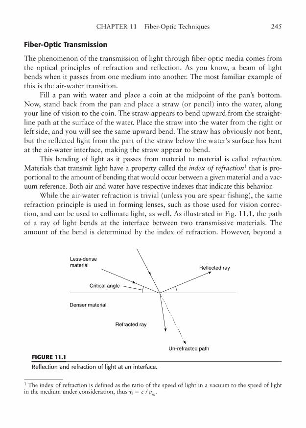
Fiber-Optic Transmission
The phenomenon of the transmission of light through fiber-optic media comes fromthe optical principles of refraction and reflection. As you know, a beam of lightbends when it passes from one medium into another. The most familiar example ofthis is the air-water transition.
Fill a pan with water and place a coin at the midpoint of the pan’s bottom.Now, stand back from the pan and place a straw (or pencil) into the water, alongyour line of vision to the coin. The straw appears to bend upward from the straight-line path at the surface of the water. Place the straw into the water from the right orleft side, and you will see the same upward bend. The straw has obviously not bent,but the reflected light from the part of the straw below the water’s surface has bentat the air-water interface, making the straw appear to bend.
This bending of light as it passes from material to material is called refraction.Materials that transmit light have a property called the index of refraction1 that is pro-portional to the amount of bending that would occur between a given material and a vac-uum reference. Both air and water have respective indexes that indicate this behavior.
While the air-water refraction is trivial (unless you are spear fishing), the samerefraction principle is used in forming lenses, such as those used for vision correc-tion, and can be used to collimate light, as well. As illustrated in Fig. 11.1, the pathof a ray of light bends at the interface between two transmissive materials. Theamount of the bend is determined by the index of refraction. However, beyond a
CHAPTER 11 Fiber-Optic Techniques 245
1 The index of refraction is defined as the ratio of the speed of light in a vacuum to the speed of lightin the medium under consideration, thus � c / vm.
Less-densematerial Reflected ray
Refracted ray
Un-refracted path
Denser material
Critical angle
FIGURE 11.1
Reflection and refraction of light at an interface.
certain incident angle, called the critical angle, the ray of light is reflected from theinterface, rather than refracted into the medium. That is exactly the reason that thecoin in the water seems to disappear when you try to view it from a low angle tothe water’s surface. By the way, the angle at which the light is bent depends on thewavelength (color) of the light, which is how prisms (and rainbows) work. This phe-nomenon actually causes lots of problems for multimode fiber, as we will see later.
For years, we concentrated on the incident angles that were necessary for theeffective transmission and refraction of light from one medium to another, throughthe interface. This was useful for the design of eyeglasses, binoculars, telescopes, andmicroscopes. However, if the transmission medium is formed into a solid strand ofglass or plastic, we can use the reflective and refractive principles to guide the raysof light within the strand, along its length.
Carefully constructed fibers of glass or plastic can efficiently transfer light forlong distances along their length, with very little loss of light outside the fiber. Youare probably familiar with the decorative lamps made with hundreds of short plas-tic fibers. The fiber strands glow very slightly along their length when a light sourceilluminates the strand ends placed at the base of the lamp, but the fiber ends shinebrightly. Similar fibers are used to transmit light along the network pathway ofLANs. We simply modulate (vary) the light beam in order to carry data.
Optical fibers can be either glass or plastic, but for most of this discussion, wewill refer to the fiber-optic material as glass, since silica compounds are used in mostcurrent LAN implementations.
These silica fibers are sometimes called light pipes, because light seems to beconducted through the flexible fiber, just like water through a tube. Optical fiber isnot actually a pipe for light, as stated previously. Light passes through the glass, notthrough a pipe formed from the glass. The refractive properties of the glass are usedto direct the light through the center portion of the fiber, as shown in Fig. 11.2.Depending on the type of fiber core, the incident light beam reflects or refracts itsway down the length of the fiber, staying roughly in the center portion of the core,much as water in a pipe (thus the analogy). An appropriate light source is used tosend a communications signal through the optical fiber.
Here is how data transmission over a fiber works. A data-modulated electricalsignal, such as a LAN packet, is first applied to the light source, which converts thesignal into light. The beam of light from the source is then directed at one end ofthe fiber, which transmits it through the fiber all the way to the other end. At thefar end of the fiber, a light-sensitive device is used to detect the light from the fiberand convert it back to the electrical signal.
The device that actually creates the light is called the source and the device thatreceives the light is called the detector. Light-emitting diodes (LEDs) and laser
246 PART TWO LAN Wiring Technology
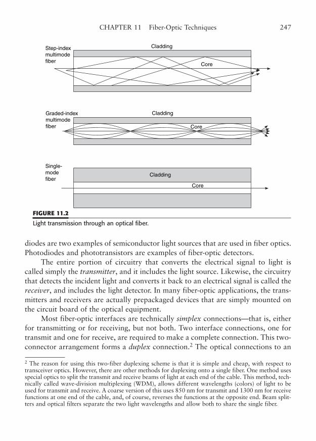
diodes are two examples of semiconductor light sources that are used in fiber optics.Photodiodes and phototransistors are examples of fiber-optic detectors.
The entire portion of circuitry that converts the electrical signal to light iscalled simply the transmitter, and it includes the light source. Likewise, the circuitrythat detects the incident light and converts it back to an electrical signal is called thereceiver, and includes the light detector. In many fiber-optic applications, the trans-mitters and receivers are actually prepackaged devices that are simply mounted onthe circuit board of the optical equipment.
Most fiber-optic interfaces are technically simplex connections—that is, eitherfor transmitting or for receiving, but not both. Two interface connections, one fortransmit and one for receive, are required to make a complete connection. This two-connector arrangement forms a duplex connection.2 The optical connections to an
CHAPTER 11 Fiber-Optic Techniques 247
CladdingStep-indexmultimodefiber
Graded-indexmultimodefiber
Single-modefiber
Core
Core
Core
Cladding
Cladding
FIGURE 11.2
Light transmission through an optical fiber.
2 The reason for using this two-fiber duplexing scheme is that it is simple and cheap, with respect totransceiver optics. However, there are other methods for duplexing onto a single fiber. One method usesspecial optics to split the transmit and receive beams of light at each end of the cable. This method, tech-nically called wave-division multiplexing (WDM), allows different wavelengths (colors) of light to beused for transmit and receive. A coarse version of this uses 850 nm for transmit and 1300 nm for receivefunctions at one end of the cable, and, of course, reverses the functions at the opposite end. Beam split-ters and optical filters separate the two light wavelengths and allow both to share the single fiber.
equipment interface are thus paired, and are usually marked Tx and Rx (or T andR) to indicate transmit and receive, respectively. Taken together, the transmit andreceive optics are called an optical transceiver.
Some optical connector pairs are arranged with an exact spacing, so that a pairof optical plugs can attach simultaneously. Fibers are terminated into two separateplugs, and then snapped into a duplex adapter. Both the 568-SC connector and theso-called SFF connectors specified in TIA-568-C are duplexed this way. Paired fibercords, called duplex cords or zip cords, are normally used for fiber-optic jumpers.The cords should be terminated with the appropriate type of fiber-optic connectorfor the application.
For transmission over the fiber, the light from the optical source may be colli-mated into a narrow beam to more efficiently couple its energy into the fiber. In thecase of the laser sources, the light beam is already quite collimated and must simplybe aimed accurately at the fiber core. As a matter of fact, the coupling of the opti-cal source and the interconnection of terminated fibers are critical parts of fiber-optic transmission technology. If the termination is properly done, the connectorhardware will normally ensure that the fiber-to-fiber or fiber-to-source coupling ismaximally effective, resulting in an absolute minimum coupling loss.
Fiber Types
Optical fiber is available in both glass and plastic compositions. Glass is the mostprevalent in LAN uses, because of its inherently greater bandwidth. Several uses forplastic fiber exist, and this is an area that has had more development over the pastseveral years.3 However, at this point in time, the higher bandwidth and longer dis-tance requirements of modern networking still demand the use of silica-based fiberin most applications.
The fiber’s core actually transmits the light beam, while the cladding providesstrength, flexibility, and a controlled stop in refractive index. All are necessary forproper fiber-optic operation. Do not mistake the cladding for the plastic buffer andthe primary coating that coat the fiber strand in a tight-buffer cable construction.The buffer and the primary coating are removed by a stripping tool in preparationfor the termination of a strand. The cladding, on the other hand, is an integral partof the fiber strand and cannot be removed.
Optical fiber is also available in two modal compositions, single-mode andmultimode, described by the light modes that each will propagate (see Fig. 11.2).
248 PART TWO LAN Wiring Technology
3 Graduated-index plastic optical fiber (GIPOF), for example, can be used to transmit moderately fastLAN signals over shorter distances.
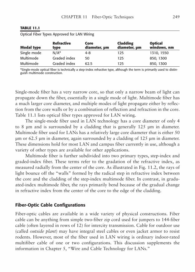
Single-mode fiber has a very narrow core, so that only a narrow beam of light canpropagate down the fiber, essentially in a single mode of light. Multimode fiber hasa much larger core diameter, and multiple modes of light propagate either by reflec-tion from the core walls or by a combination of reflection and refraction in the core.Table 11.1 lists optical fiber types approved for LAN wiring.
The single-mode fiber used in LAN technology has a core diameter of only 4to 8 µm and is surrounded by a cladding that is generally 125 µm in diameter.Multimode fiber used for LANs has a relatively large core diameter that is either 50µm or 62.5 µm in diameter, again surrounded by a cladding of 125 µm in diameter.These dimensions hold for most LAN and campus fiber currently in use, although avariety of other types are available for other applications.
Multimode fiber is further subdivided into two primary types, step-index andgraded-index fiber. These terms refer to the gradation of the refractive index, asmeasured radially from the center of the core. As illustrated in Fig. 11.2, the rays oflight bounce off the “walls” formed by the radical step in refractive index betweenthe core and the cladding of the step-index multimode fiber. In contrast, in gradu-ated-index multimode fiber, the rays primarily bend because of the gradual changein refractive index from the center of the core to the edge of the cladding.
Fiber-Optic Cable Configurations
Fiber-optic cables are available in a wide variety of physical constructions. Fibercable can be anything from simple two-fiber zip cord used for jumpers to 144-fibercable (often layered in rows of 12) for intercity transmission. Cable for outdoor use(called outside plant) may have integral steel cables or even jacket armor to resistrodents. However, most of the fiber used in LAN wiring is ordinary indoor-ratedmultifiber cable of one or two configurations. This discussion supplements theinformation in Chapter 5, “Wire and Cable Technology for LANs.”
CHAPTER 11 Fiber-Optic Techniques 249
TABLE 11.1
Optical Fiber Types Approved for LAN Wiring
Refractive Core Cladding Optical Modal type type diameter, µm diameter, µm windows, nmSingle mode N/A* 4-8 125 1310, 1550 Multimode Graded index 50 125 850, 1300 Multimode Graded index 62.5 125 850, 1300
*Single-mode optical fiber is technically a step-index refractive type, although the term is primarily used to distin-guish multimode construction.
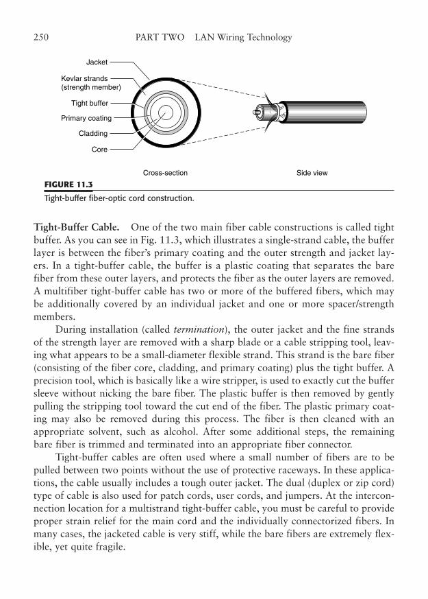
Tight-Buffer Cable. One of the two main fiber cable constructions is called tightbuffer. As you can see in Fig. 11.3, which illustrates a single-strand cable, the bufferlayer is between the fiber’s primary coating and the outer strength and jacket lay-ers. In a tight-buffer cable, the buffer is a plastic coating that separates the barefiber from these outer layers, and protects the fiber as the outer layers are removed.A multifiber tight-buffer cable has two or more of the buffered fibers, which maybe additionally covered by an individual jacket and one or more spacer/strengthmembers.
During installation (called termination), the outer jacket and the fine strandsof the strength layer are removed with a sharp blade or a cable stripping tool, leav-ing what appears to be a small-diameter flexible strand. This strand is the bare fiber(consisting of the fiber core, cladding, and primary coating) plus the tight buffer. Aprecision tool, which is basically like a wire stripper, is used to exactly cut the buffersleeve without nicking the bare fiber. The plastic buffer is then removed by gentlypulling the stripping tool toward the cut end of the fiber. The plastic primary coat-ing may also be removed during this process. The fiber is then cleaned with anappropriate solvent, such as alcohol. After some additional steps, the remainingbare fiber is trimmed and terminated into an appropriate fiber connector.
Tight-buffer cables are often used where a small number of fibers are to bepulled between two points without the use of protective raceways. In these applica-tions, the cable usually includes a tough outer jacket. The dual (duplex or zip cord)type of cable is also used for patch cords, user cords, and jumpers. At the intercon-nection location for a multistrand tight-buffer cable, you must be careful to provideproper strain relief for the main cord and the individually connectorized fibers. Inmany cases, the jacketed cable is very stiff, while the bare fibers are extremely flex-ible, yet quite fragile.
250 PART TWO LAN Wiring Technology
Cross-section Side view
Jacket
Kevlar strands(strength member)
Tight buffer
Primary coating
Cladding
Core
FIGURE 11.3
Tight-buffer fiber-optic cord construction.
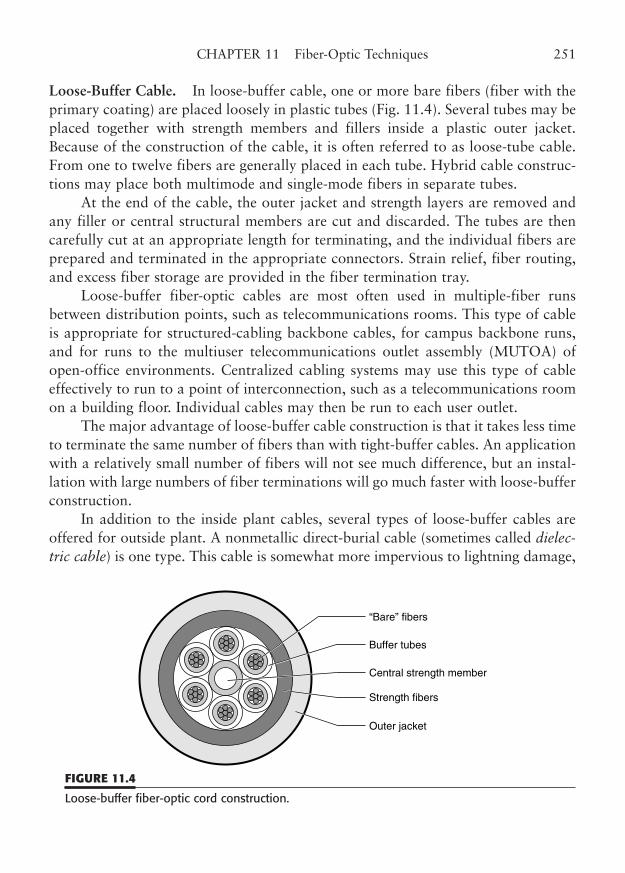
Loose-Buffer Cable. In loose-buffer cable, one or more bare fibers (fiber with theprimary coating) are placed loosely in plastic tubes (Fig. 11.4). Several tubes may beplaced together with strength members and fillers inside a plastic outer jacket.Because of the construction of the cable, it is often referred to as loose-tube cable.From one to twelve fibers are generally placed in each tube. Hybrid cable construc-tions may place both multimode and single-mode fibers in separate tubes.
At the end of the cable, the outer jacket and strength layers are removed andany filler or central structural members are cut and discarded. The tubes are thencarefully cut at an appropriate length for terminating, and the individual fibers areprepared and terminated in the appropriate connectors. Strain relief, fiber routing,and excess fiber storage are provided in the fiber termination tray.
Loose-buffer fiber-optic cables are most often used in multiple-fiber runsbetween distribution points, such as telecommunications rooms. This type of cableis appropriate for structured-cabling backbone cables, for campus backbone runs,and for runs to the multiuser telecommunications outlet assembly (MUTOA) ofopen-office environments. Centralized cabling systems may use this type of cableeffectively to run to a point of interconnection, such as a telecommunications roomon a building floor. Individual cables may then be run to each user outlet.
The major advantage of loose-buffer cable construction is that it takes less timeto terminate the same number of fibers than with tight-buffer cables. An applicationwith a relatively small number of fibers will not see much difference, but an instal-lation with large numbers of fiber terminations will go much faster with loose-bufferconstruction.
In addition to the inside plant cables, several types of loose-buffer cables areoffered for outside plant. A nonmetallic direct-burial cable (sometimes called dielec-tric cable) is one type. This cable is somewhat more impervious to lightning damage,
CHAPTER 11 Fiber-Optic Techniques 251
“Bare” fibers
Buffer tubes
Central strength member
Strength fibers
Outer jacket
FIGURE 11.4
Loose-buffer fiber-optic cord construction.
but be assured that if the cable is run alongside metallic cables, as is frequently thecase in aerial runs (between telephone poles), a direct lightning strike will blow a holein this type of cable just the same. An interesting technique wraps a steel wire aroundthe length of the nonmetallic cable to add strength to the cable runs between poles.
Outside plant cable may also be duplexed with a steel cable (called a messen-ger cable) for aerial installations. For direct burial applications, a metal-armoredcable is used. The armor is often a wound layer of copper, steel, or lead (Pb) tapethat is placed between two outer jacket layers.
Fiber-Optic Connectors
Fiber-optic technology is notable for its use of an incredible number of incompatibleconnectors. In defense of the fiber industry, traditional fiber-optic applications havebeen more esoteric than copper applications,4 and the interactions of the fiber, the con-nectors, and the transceivers have been far more complex and subtle. This has resultedin a parade of improved connection technology that has attempted to address a pro-gression of assembly, usage, and alignment issues that have arisen over the years. Fiberconnectors have tended to be redesigned to meet performance and convenience objec-tives, rather than the radical technology changes of copper networking.
Table 11.2 lists some of the more popular fiber-optic connectors, listed inapproximate order of their introduction (except for the SFF connectors, which haveall been introduced at about the same time). A surprising number of the legacy con-nectors are still in use.
The latest issues that have demanded further modifications of connector stan-dards are pluggability and duplexing. Prior to the -A revision of EIA/TIA-568, theSMA and ST connector types were in common use.
The SMA is a threaded single-fiber connector, whereas the ST is a bayonet(push and turn to lock) single-fiber connector. Both are rather like miniature, opti-cal versions of the type N and BNC connectors (respectively) that we are familiarwith from the early days of Ethernet.
Unfortunately, the SMA and ST connectors had to be mated to correspondingchassis or patch connectors individually. Even if the connectors were somehow marked
252 PART TWO LAN Wiring Technology
4 Ethernet cabling has encompassed three incompatible connector types: Type N, BNC, and 8P8Cmodular (RJ type) for the medium-dependent interface. A fourth type that is semi-compatible with the8P8C is under consideration for Cat 6 and Cat 7 applications, and a noncompatible Cat 7 variationhas also been chosen. Token-Ring has used three: data connector, 9-pin D-shell, and 8P8C modular.Some readers may be familiar only with the newer 8P8C modular connectors used with10/100BaseTX. Copper applications have rapidly obsolesced the older connector types as the technol-ogy has progressed.
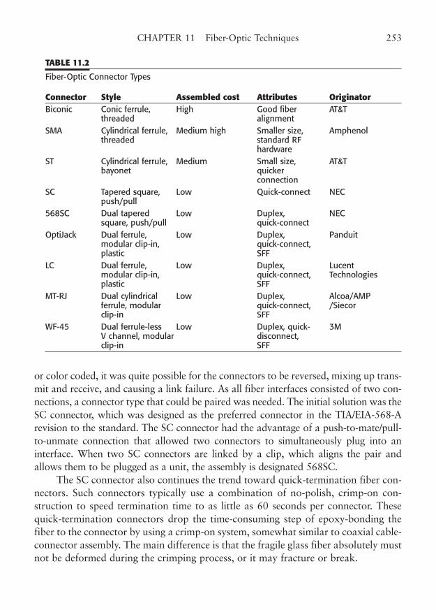
or color coded, it was quite possible for the connectors to be reversed, mixing up trans-mit and receive, and causing a link failure. As all fiber interfaces consisted of two con-nections, a connector type that could be paired was needed. The initial solution was theSC connector, which was designed as the preferred connector in the TIA/EIA-568-Arevision to the standard. The SC connector had the advantage of a push-to-mate/pull-to-unmate connection that allowed two connectors to simultaneously plug into aninterface. When two SC connectors are linked by a clip, which aligns the pair andallows them to be plugged as a unit, the assembly is designated 568SC.
The SC connector also continues the trend toward quick-termination fiber con-nectors. Such connectors typically use a combination of no-polish, crimp-on con-struction to speed termination time to as little as 60 seconds per connector. Thesequick-termination connectors drop the time-consuming step of epoxy-bonding thefiber to the connector by using a crimp-on system, somewhat similar to coaxial cable-connector assembly. The main difference is that the fragile glass fiber absolutely mustnot be deformed during the crimping process, or it may fracture or break.
CHAPTER 11 Fiber-Optic Techniques 253
TABLE 11.2
Fiber-Optic Connector Types
Connector Style Assembled cost Attributes OriginatorBiconic Conic ferrule, High Good fiber AT&T
threaded alignment SMA Cylindrical ferrule, Medium high Smaller size, Amphenol
threaded standard RF hardware
ST Cylindrical ferrule, Medium Small size, AT&T bayonet quicker
connectionSC Tapered square, Low Quick-connect NEC
push/pull568SC Dual tapered Low Duplex, NEC
square, push/pull quick-connect OptiJack Dual ferrule, Low Duplex, Panduit
modular clip-in, quick-connect, plastic SFF
LC Dual ferrule, Low Duplex, Lucent modular clip-in, quick-connect, Technologies plastic SFF
MT-RJ Dual cylindrical Low Duplex, Alcoa/AMP ferrule, modular quick-connect, /Siecorclip-in SFF
WF-45 Dual ferrule-less Low Duplex, quick- 3M V channel, modular disconnect, clip-in SFF
In addition, some of the new connector implementations now use a pretermi-nated connector arrangement. As you may know, one of the most time-consumingsteps in conventional fiber optic connector assembly is the polishing of the end of theterminated fiber that pokes through the tip of the fiber connector. One style of preter-minated connector has a built-in prepolished fiber stub at the tip of the connector.
The bare fiber strand is inserted through the back of the connector and into aspecial “matching fluid” that closely matches the index of refraction of both fiberpieces. The result is that the usual deflection of the incident light rays that wouldoccur at an angled fiber end is essentially absent. Instead, the beam passes into thematching fluid and then into the fiber stub with virtually no refraction, eliminatinga very time-consuming step from the assembly process. An alternative process usesan index-matched optical-quality sphere to minimize the light dispersion at the endof the fiber and direct it to the prepolished fiber stub.
However, there is sometimes a price to pay in using the quick-termination fiberconnectors. A standard cut-and-polish fiber termination normally has a lower con-nector loss than the quick-termination type.
Small Form Factor (SFF) Connectors. The small form factor (SFF) connector is avery new type of fiber-optic connection. Although the SC connector met the push-pull and duplex criteria, it was a large connector that required two adjacent slots ina modular faceplate. Patch panels had to be completely redesigned to fit this con-nector, and it prevented the high-density arrangement needed for fiber blades(option cards) in switches, hubs, and routers. The concept of the SFF connector wasput forth to remedy this size problem.
The SFF connector is generally defined as a fiber-optic connector that termi-nates two fiber connections within the form factor of a single insert in a modularjack plate. This arrangement generally complies with the requirement to align aduplex fiber connection. The TIA-568-C.3, Optical Fiber Cabling ComponentsStandard, drops the requirement for a specific connector on the basis that this willencourage innovation and that the market will determine usage. The connector canbe of any configuration that meets certain requirements and does not have to beexactly like the copper modular (RJ-type) connector. Figure 11.5 shows some of themore popular SFF connector types in contrast to the conventional 568SC connector.
There are two major requirements that must be met by any SFF connector thatcomplies with TIA-568-C.3. First, the alignment of the optical components mustmeet the applicable FOCIS5 document. Second, the connector must allow the two-
254 PART TWO LAN Wiring Technology
5 FOCIS, Fiber Optic Connector Intermateability Standard, ANSI/TIA/EIA-604-3, sets standards foroptical alignment and loss for single-mode plugs, multimode plugs, and adapters.
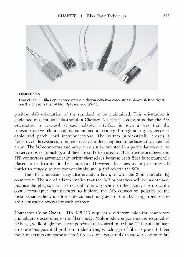
position A/B orientation of the standard to be maintained. This orientation isexplained in detail and illustrated in Chapter 7. The basic concept is that the A/Borientation is reversed at each adapter interface in such a way that thetransmit/receive relationship is maintained absolutely throughout any sequence ofcable and patch cord interconnections. The system automatically creates a“crossover” between transmit and receive at the equipment interfaces at each end ofa run. The SC connectors and adapters must be oriented in a particular manner topreserve this relationship, and they are still often used to illustrate the arrangement.SFF connectors automatically orient themselves because each fiber is permanentlyplaced in its location in the connector. However, this does make pair reversalsharder to remedy, as one cannot simply unclip and reverse the SCs.
The SFF connectors may also include a latch, as with the 8-pin modular RJconnectors. The use of a latch implies that the A/B orientation will be maintained,because the plug can be inserted only one way. On the other hand, it is up to theconnector/adapter manufacturer to indicate the A/B connection polarity to theinstaller, since the whole fiber interconnection system of the TIA is organized to cre-ate a consistent reversal at each adapter.
Connector Color Codes. TIA-568-C.3 requires a different color for connectorsand adapters according to the fiber mode. Multimode components are required tobe beige, while single-mode components are required to be blue. This can eliminatean enormous potential problem in identifying which type of fiber is present. Fibermode mismatch can cause a 4 to 6 dB loss (one way) and can cause a system to fail
CHAPTER 11 Fiber-Optic Techniques 255
FIGURE 11.5
Four of the SFF fiber-optic connectors are shown with two older styles. Shown (left to right)are the 568SC, ST, LC, MT-RJ, OptiJack, and WF-45.
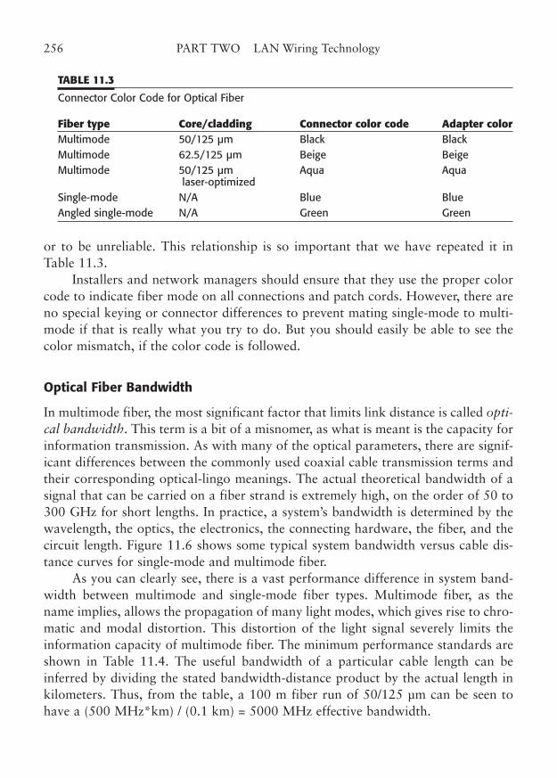
or to be unreliable. This relationship is so important that we have repeated it inTable 11.3.
Installers and network managers should ensure that they use the proper colorcode to indicate fiber mode on all connections and patch cords. However, there areno special keying or connector differences to prevent mating single-mode to multi-mode if that is really what you try to do. But you should easily be able to see thecolor mismatch, if the color code is followed.
Optical Fiber Bandwidth
In multimode fiber, the most significant factor that limits link distance is called opti-cal bandwidth. This term is a bit of a misnomer, as what is meant is the capacity forinformation transmission. As with many of the optical parameters, there are signif-icant differences between the commonly used coaxial cable transmission terms andtheir corresponding optical-lingo meanings. The actual theoretical bandwidth of asignal that can be carried on a fiber strand is extremely high, on the order of 50 to300 GHz for short lengths. In practice, a system’s bandwidth is determined by thewavelength, the optics, the electronics, the connecting hardware, the fiber, and thecircuit length. Figure 11.6 shows some typical system bandwidth versus cable dis-tance curves for single-mode and multimode fiber.
As you can clearly see, there is a vast performance difference in system band-width between multimode and single-mode fiber types. Multimode fiber, as thename implies, allows the propagation of many light modes, which gives rise to chro-matic and modal distortion. This distortion of the light signal severely limits theinformation capacity of multimode fiber. The minimum performance standards areshown in Table 11.4. The useful bandwidth of a particular cable length can beinferred by dividing the stated bandwidth-distance product by the actual length inkilometers. Thus, from the table, a 100 m fiber run of 50/125 µm can be seen tohave a (500 MHz*km) / (0.1 km) = 5000 MHz effective bandwidth.
256 PART TWO LAN Wiring Technology
TABLE 11.3
Connector Color Code for Optical Fiber
Fiber type Core/cladding Connector color code Adapter colorMultimode 50/125 µm Black BlackMultimode 62.5/125 µm Beige Beige Multimode 50/125 µm Aqua Aqua
laser-optimizedSingle-mode N/A Blue BlueAngled single-mode N/A Green Green
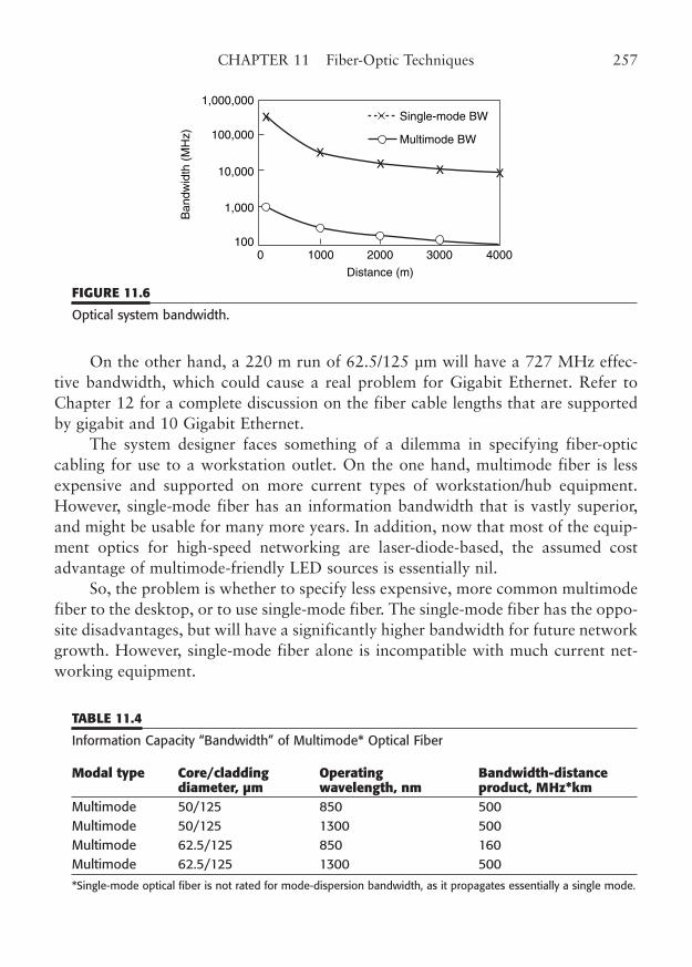
On the other hand, a 220 m run of 62.5/125 µm will have a 727 MHz effec-tive bandwidth, which could cause a real problem for Gigabit Ethernet. Refer toChapter 12 for a complete discussion on the fiber cable lengths that are supportedby gigabit and 10 Gigabit Ethernet.
The system designer faces something of a dilemma in specifying fiber-opticcabling for use to a workstation outlet. On the one hand, multimode fiber is lessexpensive and supported on more current types of workstation/hub equipment.However, single-mode fiber has an information bandwidth that is vastly superior,and might be usable for many more years. In addition, now that most of the equip-ment optics for high-speed networking are laser-diode-based, the assumed costadvantage of multimode-friendly LED sources is essentially nil.
So, the problem is whether to specify less expensive, more common multimodefiber to the desktop, or to use single-mode fiber. The single-mode fiber has the oppo-site disadvantages, but will have a significantly higher bandwidth for future networkgrowth. However, single-mode fiber alone is incompatible with much current net-working equipment.
CHAPTER 11 Fiber-Optic Techniques 257
1,000,000
100,000
10,000
1,000
1000 1000 2000
Distance (m)
Ban
dwid
th (
MH
z)
3000
Single-mode BW
Multimode BW
X
XX X X
4000
FIGURE 11.6
Optical system bandwidth.
TABLE 11.4
Information Capacity “Bandwidth” of Multimode* Optical Fiber
Modal type Core/cladding Operating Bandwidth-distance diameter, µm wavelength, nm product, MHz*km
Multimode 50/125 850 500 Multimode 50/125 1300 500 Multimode 62.5/125 850 160 Multimode 62.5/125 1300 500
*Single-mode optical fiber is not rated for mode-dispersion bandwidth, as it propagates essentially a single mode.
The answer that many are realizing is that you can do both. The standard spec-ifies a minimum of two cables to each work area outlet, one of which may be fiber.However, it does not prohibit placing more than two cables to a work area.Virtually all modular cover plate designs allow at least four module inserts. So, theoptimum solution for today and the future is to place two copper cables and twofiber cables, one single-mode and one multimode, in each outlet box. If you use thenew SFF fiber connectors, and Category 5e or Category 6 copper modules, youshould be set for many application/years to come.
VCSEL Laser Source Multimode Problem
A popular laser source for high-speed networking is the vertical-cavity surface-emit-ter laser (VCSEL). This semiconductor diode combines high bandwidth with lowcost and is an ideal choice for the gigabit networking options. In a single-mode fiberenvironment, the laser source works flawlessly. Its highly collimated beam of lightis easily aimed right down the center of the narrow single-mode core and propagatesin essentially a single mode of transmission, with all the attendant advantages.
However, as we just covered, much of the installed fiber in the local networkworld is actually multimode fiber. Back when we were using LED sources for thelower-speed technologies, such as 10BaseFL and 100BaseFX, we simply aimed theLED at the transmit end of a multimode fiber and let things happen. In effect, theexcess light that did not fill the core was lost, but the light that did enter the core ofthe fiber propagated along the core in all modes (thus the term multimode). Themethod of applying the source light to the fiber is called the launch, and applyingmore light than is needed is an overfilled launch.
Unfortunately, when multimode fiber was made in the past, little attention waspaid to minor defects in the glass core. If multiple modes are launched into the fiber,a tiny aberration here and there causes little harm, because all the other modes (rays)of light get through just fine. At most, these defects might cause a small increase incable attenuation. Nothing to be worried about, unless you launch with a laser source!
Remember that a laser is an extremely narrow beam of coherent light, on theorder of 1 µm from most VCSELs, that is launched precisely down the center axis ofthe fiber core. This means that any minor defect may deflect a substantial amount ofthe available light energy, causing an excessive amount of attenuation. This may, inturn, cause a link failure if the system cannot tolerate an extra 2 to 10 dB of loss.Worse yet, minor deflections of the fiber, which might be caused by mechanical move-ments or even temperature changes, can cause the link problem to be intermittent.
Two solutions exist to what has been dubbed the VCSEL problem. One is toget better fiber. Certainly, if you are installing new cable, this is the best option. You
258 PART TWO LAN Wiring Technology
must be sure that the fiber cable you specify is rated for laser operation, as well asextended bandwidth (the bandwidth-distance product). Such fiber is often calledgigabit-ready or laser-compatible.
If you have existing multimode fiber, you may have to use a short conditionallaunch adapter cable to spread the single-mode laser source to multiple modes. Thebad news is that the adapter may add from $50 to $100 to the cost of your installa-tion. If you suspect that there may be a problem with your older multimode cable, youmay still be able to use 1000BaseSX, as many of the transceivers for this technologyinclude built-in mode conditioning. Check with your equipment manufacturer.
Standardized Fiber-Optic LAN Cabling
The basic principle of the standardized cabling infrastructure is predictability. Astrong measure of network integrity and reliability can be realized by utilizing astandards-based cabling system. Much has been said about the value of providing astructured cable plant that meets recognized standards for copper cable installa-tions. A standards-based installation for fiber-optic cabling is just as important.Manufacturers of networking equipment depend on the cable standards of the TIAand the operating standards of the IEEE, among others, for the compatibility andperformance parameters of their products. The cabling designer and network man-ager depend on these standards as well.
With an inside cable plant that is designed and installed according to the stan-dards, you can be assured that the equipment you purchase will operate properly tothe limits specified. Actually, the two types of standards work in concert to bring theperformance of the network up to the necessary levels. The TIA committees care-fully consider the existing and planned LAN technology innovations when they cre-ate their cable standards. Likewise, the IEEE standards committees consider existingand planned cabling standards and the ability of emerging networking technologiesto use these widely deployed cabling plants.
Initially, the network technologies that were to be supported required modestperformance parameters to support networks with 10 to 20 MHz bandwidths.However, that speed target has moved rapidly upward until we find the standardsnow supporting link testing limits of 100 MHz, 250 MHz, and even 600 MHz. Asthe cabling standards have moved forward, the ability to place these higher-speednetworks on the cable plant has advanced as well. Fiber-optic cabling is an impor-tant part of cabling technology and adds to the wealth of options available to thenetwork technologist.
Although fiber-optic cabling has an inherent bandwidth advantage over copperin many applications, it is still subject to standards of installation and operation.
CHAPTER 11 Fiber-Optic Techniques 259
From the connectors to the very fiber itself, every feature of a fiber link must beappropriate for the application and for the equipment with which it will be used.
For this reason, we will spend some time describing the two types of fiber-opticcabling standards that are currently in use. These standards are the structuredcabling system and centralized cabling.
Structured Fiber Cabling—TIA Standards
The tried-and-true method of fiber connection is the structured cabling system con-ceptualized in TIA-568-C. As you recall, this standard allows for both single-modeand multimode fiber, although the earlier -A version really encouraged the use ofmultimode in the horizontal structure and single-mode in the backbone. Multimodefiber and the lower-speed LED optics have traditionally been less expensive than sin-gle-mode fiber and laser optics. As a result, much of the fiber that has been installedin conformance with the structured wiring pattern is multimode fiber.
Multimode fiber in the structured environment works equally well for Ethernet,Fast Ethernet, and Gigabit Ethernet. This is quite an accomplishment, when youthink about it. Part of the reason for this high-speed capability is the 90-m horizon-tal runs of structured cabling. This short distance limit is really dictated by the atten-uation and crosstalk parameters of twisted-pair cable, when tested to 100 MHz. It isno small irony that fiber advocates can thank the use of Category 5e copper cable forthis relatively short run, and the consequent longevity of multimode fiber. The gamenow is to standardize multimode for 55 and 100 m runs for 10 Gigabit Ethernet.
As you can see from Fig. 11.7, backbone cabling runs are made from a centraldistribution point, such as the main cross-connect (MC) shown, to the telecommu-nications rooms (TRs) throughout the building. At each TR, a fiber hub or switchdistributes the network signal to individual horizontal fiber runs, one per worksta-tion to be served. An optional multiuser telecommunications outlet adapter(MUTOA) may be placed in the horizontal run, between the TR and the work areaoutlet/connector (WOA). As explained in Chapter 10, open-office wiring practicesallow the use of the fiber-optic MUTOA.
In the strict sense, the run from the MUTOA to the workstation is supposed tobe a user cord that plugs directly into the workstation. However, the designer maywish to use a fixed WOA to protect the longer fiber run back to the MUTOA. Thisis not permitted for copper cables, primarily because each termination and intercon-nection adds significantly to the crosstalk problem. With good fiber terminations,only a few tenths of a decibel of additional link loss are added, and the additionalinterconnection at the WOA is generally insignificant. In addition, the potential fordamage to the duplex-fiber user cord is greater than with the more robust copper
260 PART TWO LAN Wiring Technology
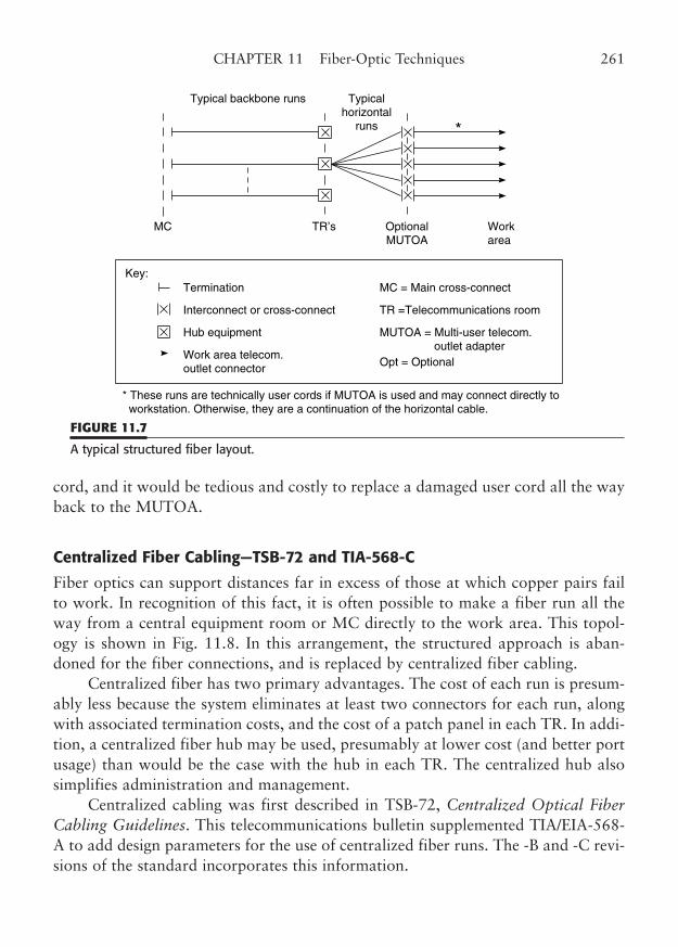
cord, and it would be tedious and costly to replace a damaged user cord all the wayback to the MUTOA.
Centralized Fiber Cabling—TSB-72 and TIA-568-C
Fiber optics can support distances far in excess of those at which copper pairs failto work. In recognition of this fact, it is often possible to make a fiber run all theway from a central equipment room or MC directly to the work area. This topol-ogy is shown in Fig. 11.8. In this arrangement, the structured approach is aban-doned for the fiber connections, and is replaced by centralized fiber cabling.
Centralized fiber has two primary advantages. The cost of each run is presum-ably less because the system eliminates at least two connectors for each run, alongwith associated termination costs, and the cost of a patch panel in each TR. In addi-tion, a centralized fiber hub may be used, presumably at lower cost (and better portusage) than would be the case with the hub in each TR. The centralized hub alsosimplifies administration and management.
Centralized cabling was first described in TSB-72, Centralized Optical FiberCabling Guidelines. This telecommunications bulletin supplemented TIA/EIA-568-A to add design parameters for the use of centralized fiber runs. The -B and -C revi-sions of the standard incorporates this information.
CHAPTER 11 Fiber-Optic Techniques 261
Typical backbone runs Typicalhorizontal
runs *
Key:
* These runs are technically user cords if MUTOA is used and may connect directly to workstation. Otherwise, they are a continuation of the horizontal cable.
TR’s
Termination
Interconnect or cross-connect
Hub equipment
Work area telecom.outlet connector
MC = Main cross-connect
TR =Telecommunications room
MUTOA = Multi-user telecom. outlet adapterOpt = Optional
OptionalMUTOA
Workarea
MC
FIGURE 11.7
A typical structured fiber layout.
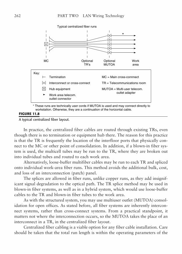
In practice, the centralized fiber cables are routed through existing TRs, eventhough there is no termination or equipment hub there. The reason for this practiceis that the TR is frequently the location of the interfloor ports that physically con-nect to the MC or other point of consolidation. In addition, if a blown-in fiber sys-tem is used, the multicell tubes may be run to the TR, where they are broken outinto individual tubes and routed to each work area.
Alternatively, loose-buffer multifiber cables may be run to each TR and splicedonto individual work-area fiber runs. This method avoids the additional bulk, cost,and loss of an interconnection (patch) panel.
The splices are allowed in fiber runs, unlike copper runs, as they add insignif-icant signal degradation to the optical path. The TR splice method may be used inblown-in fiber systems, as well as in a hybrid system, which would use loose-buffercables to the TR and blown-in fiber tubes to the work area.
As with the structured system, you may use multiuser outlet (MUTOA) consol-idation for open offices. As stated before, all fiber systems are inherently intercon-nect systems, rather than cross-connect systems. From a practical standpoint, itmatters not where the interconnection occurs, so the MUTOA takes the place of aninterconnect in a TR, in the centralized fiber layout.
Centralized fiber cabling is a viable option for any fiber cable installation. Careshould be taken that the total run length is within the operating parameters of the
262 PART TWO LAN Wiring Technology
Typical centralized fiber runs
*
MC OptionalTR’s
OptionalMUTOA
Workarea
Key:
* These runs are technically user cords if MUTOA is used and may connect directly to workstation. Otherwise, they are a continuation of the horizontal cable.
Termination
Interconnect or cross-connect
Hub equipment
Work area telecom.outlet connector
MC = Main cross-connnect
TR = Telecommunications room
MUTOA = Multi-user telecom. outlet adapter
FIGURE 11.8
A typical centralized fiber layout.
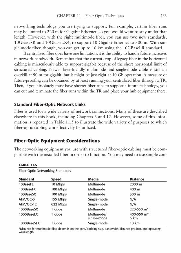
networking technology you are trying to support. For example, certain fiber runsmay be limited to 220 m for Gigabit Ethernet, so you would want to stay under thatlength. However, with the right multimode fiber, you can use two new standards,10GBaseSR and 10GBaseLX4, to support 10 Gigabit Ethernet to 300 m. With sin-gle-mode fiber, though, you can get up to 10 km using the 10GBaseLR standard.
If centralized fiber does have one limitation, it is the ability to handle future increasesin network bandwidth. Remember that the current crop of legacy fiber in the horizontalcabling is miraculously able to support gigabit because of the short horizontal limit ofstructured cabling. Newer laser-friendly multimode and single-mode cable is still anoverkill at 90 m for gigabit, but it might be just right at 10 Gb operation. A measure offuture-proofing can be obtained by at least running your centralized fiber through a TR.Then, if you absolutely must have shorter fiber runs to support a future technology, youcan cut and terminate the fiber runs within the TR and place your hub equipment there.
Standard Fiber-Optic Network Links
Fiber is used for a wide variety of network connections. Many of these are describedelsewhere in this book, including Chapters 6 and 12. However, some of this infor-mation is repeated in Table 11.5 to illustrate the wide variety of purposes to whichfiber-optic cabling can effectively be utilized.
Fiber-Optic Equipment Considerations
The networking equipment you use with structured fiber-optic cabling must be com-patible with the installed fiber in order to function. You may need to use simple con-
CHAPTER 11 Fiber-Optic Techniques 263
TABLE 11.5
Fiber Optic Networking Standards
Standard Speed Media Distance10BaseFL 10 Mbps Multimode 2000 m 100BaseFX 100 Mbps Multimode 400 m 100BaseSX 100 Mbps Multimode 300 m ATM/OC-3 155 Mbps Single-mode N/A ATM/OC-12 622 Mbps Single-mode N/A 1000BaseSX 1 Gbps Multimode 220-550 m* 1000BaseLX 1 Gbps Multimode/ 400-550 m*
single-mode 5 km 1000BaseSLX 1 Gbps Single-mode 10 km
*Distance for multimode fiber depends on the core/cladding size, bandwidth-distance product, and operatingwavelength.
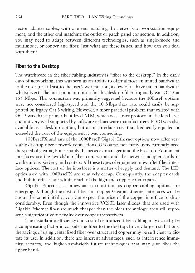
nector adapter cables, with one end matching the network or workstation equip-ment, and the other end matching the outlet or patch panel connection. In addition,you may need to adapt between different technologies, such as single-mode andmultimode, or copper and fiber. Just what are these issues, and how can you dealwith them?
Fiber to the Desktop
The watchword in the fiber cabling industry is “fiber to the desktop.” In the earlydays of networking, this was seen as an ability to offer almost unlimited bandwidthto the user (or at least to the user’s workstation, as few of us have much bandwidthwhatsoever). The most popular option for this desktop fiber originally was OC-3 at155 Mbps. This connection was primarily suggested because the 10BaseF optionswere not considered high-speed and the 10 Mbps data rate could easily be sup-ported on legacy Cat 3 wiring. However, a more practical problem that existed withOC-3 was that it primarily utilized ATM, which was a rare protocol in the local areaand not very well supported by software or hardware manufacturers. FDDI was alsoavailable as a desktop option, but at an interface cost that frequently equaled orexceeded the cost of the equipment it was connecting.
100BaseFX and any of the 1000BaseF Gigabit Ethernet options now offer veryviable desktop fiber network connections. Of course, not many users currently needthe speed of gigabit, but certainly the network manager (and the boss) do. Equipmentinterfaces are the switch/hub fiber connections and the network adapter cards inworkstations, servers, and routers. All these types of equipment now offer fiber inter-face options. The cost of the interfaces is a matter of supply and demand. The LEDoptics used with 100BaseFX are relatively cheap. Consequently, the adapter cardsand hub interfaces are within reach of the high-end copper counterparts.
Gigabit Ethernet is somewhat in transition, as copper cabling options areemerging. Although the cost of fiber and copper Gigabit Ethernet interfaces will beabout the same initially, you can expect the price of the copper interface to dropconsiderably. Even though the innovative VCSEL laser diodes that are used withGigabit Ethernet fiber are much cheaper than the older technology, they still repre-sent a significant cost penalty over copper transceivers.
The installation efficiency and cost of centralized fiber cabling may actually bea compensating factor in considering fiber to the desktop. In very large installations,the savings of using centralized fiber over structured copper may be sufficient to dic-tate its use. In addition, there are inherent advantages, such as interference immu-nity, security, and higher-bandwidth future technologies that may give fiber theupper hand.
264 PART TWO LAN Wiring Technology
Copper to Fiber Conversion
It is practically impossible to entirely avoid the use of copper interfaces. Many typesof equipment, such as printers and routers, may offer only copper interface options.It may be possible to use switch/hubs with both types of connections. The desktopworkstations and servers are connected normally via fiber, and the incompatibleequipment is connected to a switch/hub with an appropriate copper interface.
In cases where the hub-conversion method is impractical, you can simply use afiber to copper converter. You have several options on fiber to copper conversion.At 10 Mbps Ethernet, you can convert from fiber to the AUI, coax, or 10Base-Tconnections. The AUI is convenient because the interface includes a power sourcefor a transceiver, which can be used to power the converter. In all other cases, youcan expect to use one of the boxy wall-plug transformers and a power cord to theconverter.
Pay particular attention to the type of fiber-optic interface on your converter.The 100 Mbps fiber-optic interface is now available in either FX or SX versions, andthe wavelengths are totally different. Likewise, 10BaseFL and -FB are available,although the FB variety is rare. Gigabit Ethernet fiber interfaces are likewise avail-able in several varieties of wavelength and mode, so pay attention to the needs ofyour equipment and/or fiber cable when making a choice.
In addition to the copper to fiber converters, fiber mode converters are avail-able (Fig. 11.9). Because of the common connectors, nothing physically prevents theinterconnection of single-mode and multimode fibers. However, the connection willcause an excessive transmission loss if the optical direction is from multimode tosingle-mode. There is still an unexpected loss from single-mode to multimode, but
CHAPTER 11 Fiber-Optic Techniques 265
FIGURE 11.9
A fiber-optic mode converter. (Courtesy of Transition Networks, Inc.)
it is not as great. Consider that the transition from a large 50 µm fiber core to thetiny 4 to 8 µm single-mode core obviously wastes most of the incident light, unlessyou are fortunate enough to be using a laser source that has inadvertently positionedthe beam in the center of the multimode core.
Mode converters typically put a pair of wide-bandwidth transceivers back toback in a box. One set of optics is single-mode and the other is multimode. Inbetween the interfaces is the proper electronics to repeat the signal to the oppositeinterface. For this reason, you can expect fiber mode converters to cost several timesmore than a simple fiber to copper converter.
Fiber-Optic Installation Practices
This section will briefly describe some of the installation requirements for fiber-opticcable. Optical fibers vary widely in construction, unlike their copper counterparts.This is due in part to the fact that a complete fiber circuit requires only twostrands—one pair (although not twisted, we hope). Thus, the simplest fiber linkcould be two fiber strands with as little as the primary coating protecting the fiber.Conversely, a fiber link could be the same two fiber strands, but with tight buffer,strength members, thick jacketing, and even armor or imbedded steel cable. The firstcable type would need several types of protective routing devices, while the secondtype would need virtually none.
Fiber Cable Protection
The degree of physical protection a fiber link requires depends on two factors: con-struction of the fiber cable and location of the cable run. In a fiber distributionpanel, very little is needed in the way of physical protection for the fibers. What isneeded is some type of fiber management and fiber storage. On the other hand,fibers that are used for horizontal or backbone runs do need more protection. Thesefiber runs will require the use of moderate jacketing, trays, and raceways to providethe appropriate amount of additional physical protection.
Blown-in fiber places relatively unprotected strands inside plastic tubes thathave been preinstalled between the TR and the work area. The tubes are technicallyraceways. They must meet all the flammability and smoke requirements of anyplenum-rated device, if necessary. Likewise, the enclosed fibers must be appropri-ately rated for the installation location.
Another type of protective fiber raceway is called innerduct. Innerduct is usedin applications where several fiber cables must be protected (Fig. 11.10). The race-way is generally a ribbed construction to allow it to easily bend at a fairly large
266 PART TWO LAN Wiring Technology
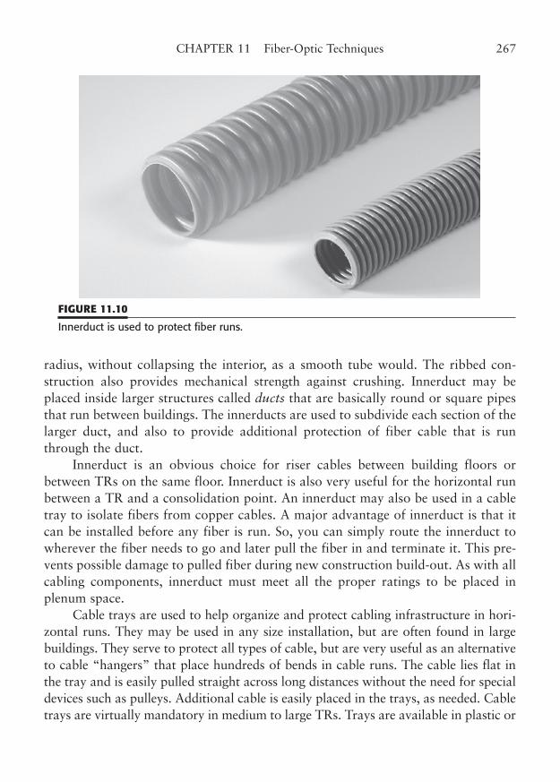
radius, without collapsing the interior, as a smooth tube would. The ribbed con-struction also provides mechanical strength against crushing. Innerduct may beplaced inside larger structures called ducts that are basically round or square pipesthat run between buildings. The innerducts are used to subdivide each section of thelarger duct, and also to provide additional protection of fiber cable that is runthrough the duct.
Innerduct is an obvious choice for riser cables between building floors orbetween TRs on the same floor. Innerduct is also very useful for the horizontal runbetween a TR and a consolidation point. An innerduct may also be used in a cabletray to isolate fibers from copper cables. A major advantage of innerduct is that itcan be installed before any fiber is run. So, you can simply route the innerduct towherever the fiber needs to go and later pull the fiber in and terminate it. This pre-vents possible damage to pulled fiber during new construction build-out. As with allcabling components, innerduct must meet all the proper ratings to be placed inplenum space.
Cable trays are used to help organize and protect cabling infrastructure in hori-zontal runs. They may be used in any size installation, but are often found in largebuildings. They serve to protect all types of cable, but are very useful as an alternativeto cable “hangers” that place hundreds of bends in cable runs. The cable lies flat inthe tray and is easily pulled straight across long distances without the need for specialdevices such as pulleys. Additional cable is easily placed in the trays, as needed. Cabletrays are virtually mandatory in medium to large TRs. Trays are available in plastic or
CHAPTER 11 Fiber-Optic Techniques 267
FIGURE 11.10
Innerduct is used to protect fiber runs.
metal construction, and must meet the same plenum requirements as cables. Cornersand bends will require the use of a cable pulley when cables are initially installed.
Fiber Terminations
The physical termination procedure for optical fibers varies enormously with the par-ticular type and brand of fiber connector you are using. Accordingly, we will not coverall of the options here. However, there are some common concepts that we can coverbriefly, so that you will understand what is required for this complex operation.
All fiber termination requires the preparation of a bare fiber for assemblywithin an appropriate connector. The outer jacket and fibrous plastic strength mem-bers must be removed if you are using a jacketed cable. In this type of cable, theouter jacket is slit around its circumference and slipped off the end of the cable.Next, the Kevlar fibers are combed to one side and cut off at the edge of the remain-ing jacket. The fibers are extremely fine, and a high-quality cross-cutter must beused to trim them back.
The buffer-coated fiber (or fibers) must now be prepared. The tight buffer isremoved with a tool that is essentially a wire stripper. The buffer-stripping tool is oftena fixed-opening tool that is specifically designed for the diameter of the bare fiber (coreand cladding), so that the fiber is not nicked when the buffer is removed. Any nick willseverely compromise the flexural strength of the silica fiber and may result in sponta-neous breakage. The rule of thumb is that such a break will always occur at the lastpossible moment, so that the installer will have to start over totally. So, the lesson isthat no nick is a good nick, or nothing can truly be done in the nick of time.
The fiber is now trimmed to the proper length, usually with a tool that pur-posely scores (yes, nicks) the fiber, and then breaks the unwanted portion away fromthe remaining fiber. The breaking process is called cleaving the fiber, and it shouldleave an orthogonal break at the fiber end. This brings some basic rules of opticsinto play. First, if this break is not precisely 90°, the light will exit the fiber at a slightangle. Second, the break is never exactly 90°. The cure in a quick-termination con-nector is to place the fiber end into a matching fluid, so that the off-axis break hasvirtually no effect. In a so-called field termination (slow-termination) connector, thefiber end is inserted through the connector ferrule so that it protrudes slightly fromthe end of the ferrule. That fiber end is then polished down until it is exactly flushwith the end of the ferrule, and consequently precisely square with the fiber.
Final assembly is done by inserting the fiber into the connector and securing thefiber mechanically (Fig. 11.11). Older connector types, such as the SMA and the ST,generally require the application and curing of epoxy to secure the fiber to the con-nector. Newer quick-termination connectors of this generation use mechanical crimp-
268 PART TWO LAN Wiring Technology
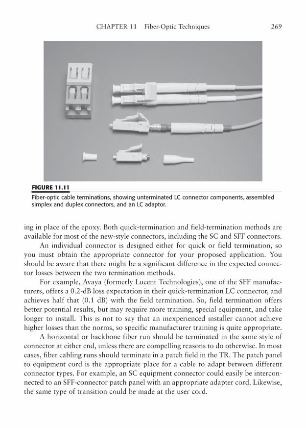
ing in place of the epoxy. Both quick-termination and field-termination methods areavailable for most of the new-style connectors, including the SC and SFF connectors.
An individual connector is designed either for quick or field termination, soyou must obtain the appropriate connector for your proposed application. Youshould be aware that there might be a significant difference in the expected connec-tor losses between the two termination methods.
For example, Avaya (formerly Lucent Technologies), one of the SFF manufac-turers, offers a 0.2-dB loss expectation in their quick-termination LC connector, andachieves half that (0.1 dB) with the field termination. So, field termination offersbetter potential results, but may require more training, special equipment, and takelonger to install. This is not to say that an inexperienced installer cannot achievehigher losses than the norms, so specific manufacturer training is quite appropriate.
A horizontal or backbone fiber run should be terminated in the same style ofconnector at either end, unless there are compelling reasons to do otherwise. In mostcases, fiber cabling runs should terminate in a patch field in the TR. The patch panelto equipment cord is the appropriate place for a cable to adapt between differentconnector types. For example, an SC equipment connector could easily be intercon-nected to an SFF-connector patch panel with an appropriate adapter cord. Likewise,the same type of transition could be made at the user cord.
CHAPTER 11 Fiber-Optic Techniques 269
FIGURE 11.11
Fiber-optic cable terminations, showing unterminated LC connector components, assembledsimplex and duplex connectors, and an LC adaptor.
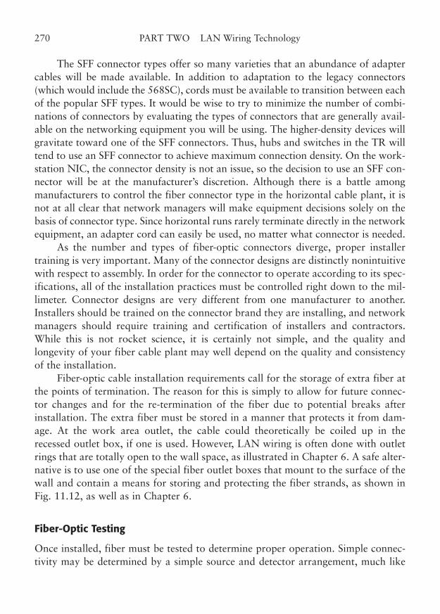
The SFF connector types offer so many varieties that an abundance of adaptercables will be made available. In addition to adaptation to the legacy connectors(which would include the 568SC), cords must be available to transition between eachof the popular SFF types. It would be wise to try to minimize the number of combi-nations of connectors by evaluating the types of connectors that are generally avail-able on the networking equipment you will be using. The higher-density devices willgravitate toward one of the SFF connectors. Thus, hubs and switches in the TR willtend to use an SFF connector to achieve maximum connection density. On the work-station NIC, the connector density is not an issue, so the decision to use an SFF con-nector will be at the manufacturer’s discretion. Although there is a battle amongmanufacturers to control the fiber connector type in the horizontal cable plant, it isnot at all clear that network managers will make equipment decisions solely on thebasis of connector type. Since horizontal runs rarely terminate directly in the networkequipment, an adapter cord can easily be used, no matter what connector is needed.
As the number and types of fiber-optic connectors diverge, proper installertraining is very important. Many of the connector designs are distinctly nonintuitivewith respect to assembly. In order for the connector to operate according to its spec-ifications, all of the installation practices must be controlled right down to the mil-limeter. Connector designs are very different from one manufacturer to another.Installers should be trained on the connector brand they are installing, and networkmanagers should require training and certification of installers and contractors.While this is not rocket science, it is certainly not simple, and the quality andlongevity of your fiber cable plant may well depend on the quality and consistencyof the installation.
Fiber-optic cable installation requirements call for the storage of extra fiber atthe points of termination. The reason for this is simply to allow for future connec-tor changes and for the re-termination of the fiber due to potential breaks afterinstallation. The extra fiber must be stored in a manner that protects it from dam-age. At the work area outlet, the cable could theoretically be coiled up in therecessed outlet box, if one is used. However, LAN wiring is often done with outletrings that are totally open to the wall space, as illustrated in Chapter 6. A safe alter-native is to use one of the special fiber outlet boxes that mount to the surface of thewall and contain a means for storing and protecting the fiber strands, as shown inFig. 11.12, as well as in Chapter 6.
Fiber-Optic Testing
Once installed, fiber must be tested to determine proper operation. Simple connec-tivity may be determined by a simple source and detector arrangement, much like
270 PART TWO LAN Wiring Technology
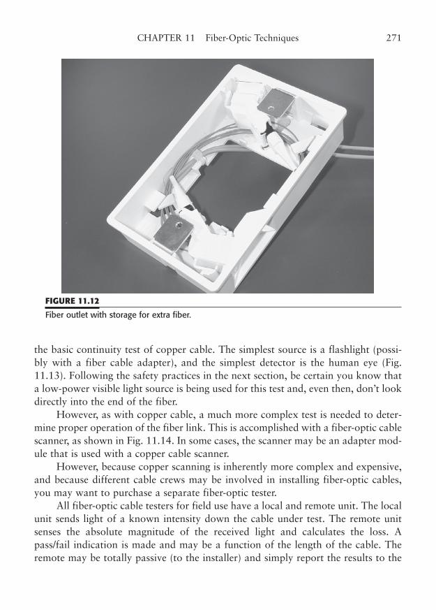
the basic continuity test of copper cable. The simplest source is a flashlight (possi-bly with a fiber cable adapter), and the simplest detector is the human eye (Fig.11.13). Following the safety practices in the next section, be certain you know thata low-power visible light source is being used for this test and, even then, don’t lookdirectly into the end of the fiber.
However, as with copper cable, a much more complex test is needed to deter-mine proper operation of the fiber link. This is accomplished with a fiber-optic cablescanner, as shown in Fig. 11.14. In some cases, the scanner may be an adapter mod-ule that is used with a copper cable scanner.
However, because copper scanning is inherently more complex and expensive,and because different cable crews may be involved in installing fiber-optic cables,you may want to purchase a separate fiber-optic tester.
All fiber-optic cable testers for field use have a local and remote unit. The localunit sends light of a known intensity down the cable under test. The remote unitsenses the absolute magnitude of the received light and calculates the loss. Apass/fail indication is made and may be a function of the length of the cable. Theremote may be totally passive (to the installer) and simply report the results to the
CHAPTER 11 Fiber-Optic Techniques 271
FIGURE 11.12
Fiber outlet with storage for extra fiber.
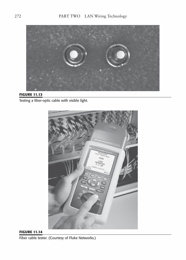
272 PART TWO LAN Wiring Technology
FIGURE 11.13
Testing a fiber-optic cable with visible light.
FIGURE 11.14
Fiber cable tester. (Courtesy of Fluke Networks.)
local tester. The two units may be interchangeable, or at least have dual displays, sothe installer at the remote end knows what is going on. Many of the tester pairs havemike/headphones and an optical “order wire” so the two installers can talk whenconnected to the same cable.
Testing installed fiber cable is a matter of measuring the link loss. In general,if the link loss is within budget for the standard (and within stricter link budgets forcertain applications), your cable is fine. You should really test at the appropriatewavelength for the application, and the tester should use time-domain reflectometry(TDR) to ensure that the cable length is within prescribed lengths. Some moresophisticated testers may ensure that return losses (a measure of reflections) arewithin limits, but if you use appropriate cable and connectors, this should not be aproblem. A really sophisticated test would be to measure the link’s bandwidth-length product, and it would catch cables that had insufficient bandwidth forgigaspeed operation at extended distances.
Most fiber-optic testers use the “overfilled launch” testing method, where theentire fiber core diameter is flooded with light, usually from an LED source. Thismethod is effective in dealing with 50 and 62.5 µm core diameters. In testers that use aVCSEL diode source, a mode dispersion technique is used to avoid the mode blockagethat can occur in some multimode fibers. You should be aware that this testing tech-nique can mask some problems that may be experienced when you actually hook upthe cable run to a piece of equipment. Be aware of the specifications and limitations ofyour particular tester. That takes care of the basic pass/fail testing of a fiber-optic link.
Troubleshooting a marginal or failed link is a different matter. One of the prob-lems you encounter with a failed link is determining where the failure is located,with respect to the cable ends. This issue is a problem whether you are troubleshoot-ing newly installed cable or cable that has been installed and operating for sometime. Your tester may be able to function as a field TDR, in addition to the basicloss measurements. If so, it is simple to determine the location of a fiber break or abotched connector installation. Knowing which connector is bad, or where the fiberis damaged, saves a lot of repair time. Fiber breaks are permitted to be splicedbecause splices have such inherently low loss. Bad connectors should simply bereplaced, so be thankful that extra fiber was left at the point of termination.
Safety Considerations
Fiber-optic technology has safety aspects that are quite different from those of cop-per cabling. As long as the proper procedures are followed, fiber-optic installationsshould be as safe as any type of cabling. Eye protection in the form of safety glassesshould be used for all fiber-optic assembly work.
CHAPTER 11 Fiber-Optic Techniques 273
Chemicals
Virtually all types of fiber cable termination use some type of chemical.The older epoxy-style connectors use a harsh, two-part resin and hardener
combination that can harm skin, clothes, and eyes. Some of the newer field-termi-nation connector designs use a cyano-acrylic composition that is much like a thick-ened version of “superglue.” It is harmful to all of the above, and in addition can“weld” skin together when in its preactivated state. The cyano-acrylics are activatedby water vapor, and are soluble in acetone (which many fingernail polish removerscontain). You would be wise to keep a supply of chemical wipes (a sort of heavywoven tissue) and acetone solvent handy when you are using these products.
If any of this superglue contacts the eye or the lid, seek medical attention imme-diately. You should not attempt to remove the material yourself.
In addition, the normal procedure is to use an alcohol wipe to clean the barefiber after removal of the tight buffer. Alcohol, of course, is flammable. In addition,the type of alcohol most commonly used for a cleaning solvent is poisonous wheningested, and is harmful to the eyes.
Glass Fiber Safety
Another aspect of fiber-optic safety is care with the fiber strands that are the objectof our interest. Although they are very flexible, optical fibers are still made of glass(silica) and can fragment, fracture, chip, and pulverize. Tiny fragments of the glasscan fly into the air (and the eye), splinter in the skin, and even be inhaled.Consequently, you should “handle like glass,” as the saying goes. For the most part,fiber connector assembly is uneventful, but you should always wear your safetyglasses, use the proper tools, and assemble the components on an appropriate sur-face. In the case of glass fiber, the most appropriate surface is a no-slip plastic orrubberized mat of a dark color. It is much easier to see the fiber (and any shards) ona black mat than on a normal light-colored table.
Use proper lighting and position the work surface at a convenient height. Placeany chemicals safely off to the side and out of the way when they are not being used.Keep all liquids and glues capped when not in immediate use. Stay away from allsources of flame or sparks.
In the unlikely event that you get a glass splinter in the skin, it is best to useplastic-coated tweezers to remove the splinter. Using regular metal tweezers cancause the splinter to break at the skin surface, which results in a more difficult (andpainful) problem. Always refer the removal of any glass particles in the eye to aqualified medical practitioner.
274 PART TWO LAN Wiring Technology
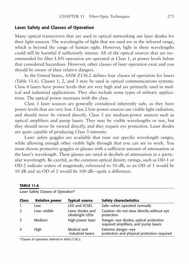
Laser Safety and Classes of Operation
Many optical transceivers that are used in optical networking use laser diodes fortheir light sources. The wavelengths of light that are used are in the infrared range,which is beyond the range of human sight. However, light in these wavelengthscould still be harmful if sufficiently intense. All of the optical sources that are rec-ommended for fiber LAN operation are operated at Class 1, at power levels belowthat considered hazardous. However, other classes of laser operation exist and youshould be aware of their relative dangers.
In the United States, ANSI Z136.2 defines four classes of operation for lasers(Table 11.6). Classes 1, 2, and 3 may be used in optical communications systems.Class 4 lasers have power levels that are very high and are primarily used in med-ical and industrial applications. They also include some types of military applica-tions. The optical power increases with the class.
Class 1 laser sources are generally considered inherently safe, as they havepower levels that are very low. Class 2 low-power sources use visible light radiation,and should never be viewed directly. Class 3 are medium-power sources such asoptical amplifiers and pump lasers. They may be visible wavelengths or not, butthey should never be viewed directly, and they require eye protection. Laser diodesare quite capable of producing Class 3 intensity.
Laser safety goggles are available that tune out specific wavelength ranges,while allowing enough other visible light through that you can see to work. Youmust choose protective goggles or glasses with a sufficient amount of attenuation atthe laser’s wavelength. These glasses are rated in decibels of attenuation at a partic-ular wavelength. Be careful, as the common optical density ratings, such as OD-1 orOD-2 indicate orders of magnitude, referenced to 10 dB, so an OD of 1 would be10 dB and an OD of 2 would be 100 dB—quite a difference.
CHAPTER 11 Fiber-Optic Techniques 275
TABLE 11.6
Laser Safety Classes of Operation*
Class Relative power Typical source Safety characteristics1 Low LED and VCSEL Safe—when operated normally 2 Low—visible Laser diodes and Caution—do not view directly without eye
ultrabright LEDs protection 3 Medium High-power laser Danger—eye diodes, optical protection
required amplifiers, and pump lasers 4 High Medical and Extreme danger—eye
industrial lasers protection and physical protection required
*Classes of operation defined in ANSI Z136.2.
For European standards, you should consult IEC 825-1 and IEC 825-2. Thesestandards cite levels of operation that differ from the U.S. standards.
In addition to the safe classes of laser operation mentioned above, you shouldbe aware that some Class 1 laser sources are theoretically capable of operating atlevels that might be harmful to the eye. In addition, some people are more sensitiveto very bright point-source light and can suffer brief effects that interfere with nor-mal vision. If you have ever had a laser pointer flash in your eyes, you may haveexperienced this problem.
Fiber-Optic Future
The future of optical fiber is secure. Fiber cable clearly provides an extreme amountof potential bandwidth, particularly in the case of single mode fiber. At present, theutilization of this incredible bandwidth is limited primarily by the speed of availableoptics and whether you put multiple wavelengths on the fiber.
Currently, 10 Gb Ethernet is in the corral, and transmission beyond that is notonly theoretically possible, it is happening right now. One factor that will influencethe introduction of these bandwidths is the need for speed. Another factor is cer-tainly the ability of the existing fiber plant (if such exists) to support these advancedspeeds. Future equipment interface implementations may actually borrow the mul-tiple pair technique from copper cabling. Another viable implementation uses mul-tiple wavelengths to multiply the effective bandwidth of the fiber.
In the end, it is all a matter of cost. If the demand is there, the volume willincrease, and the price will fall. The 100 Mbps links were initially very expensive,but their price has rapidly fallen to that level once occupied by 10 Mbps. The 1000Mbps links will definitely do the same, as in fact they already are. Now 10 Gbpslinks are available, for about the same cost that gigabit was when it was introduced.Fiber is definitely in our future.
276 PART TWO LAN Wiring Technology
CHAPTER 12
Gigabit and 10 GigabitCabling Technology
Highlights
■ Fiber Gigabit and 10 Gigabit Ethernet
■ Copper Gigabit and 10 Gigabit Ethernet
■ Ethernet in the First Mile (EFM)
■ ATM and optical carrier (OC) standards
■ TIA wiring standards
■ Augmented Category 6/ClassE (AC6) and Category 7/ClassF
■ RJ and non-RJ Category 7 connectors
277
Copyright © 2006 by James Trulove. Click here for terms of use.
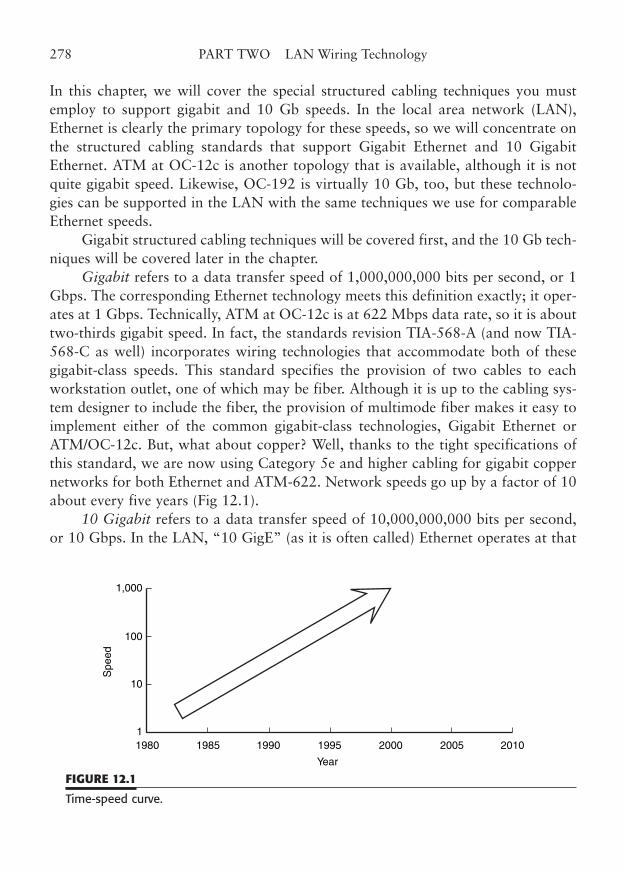
In this chapter, we will cover the special structured cabling techniques you mustemploy to support gigabit and 10 Gb speeds. In the local area network (LAN),Ethernet is clearly the primary topology for these speeds, so we will concentrate onthe structured cabling standards that support Gigabit Ethernet and 10 GigabitEthernet. ATM at OC-12c is another topology that is available, although it is notquite gigabit speed. Likewise, OC-192 is virtually 10 Gb, too, but these technolo-gies can be supported in the LAN with the same techniques we use for comparableEthernet speeds.
Gigabit structured cabling techniques will be covered first, and the 10 Gb tech-niques will be covered later in the chapter.
Gigabit refers to a data transfer speed of 1,000,000,000 bits per second, or 1Gbps. The corresponding Ethernet technology meets this definition exactly; it oper-ates at 1 Gbps. Technically, ATM at OC-12c is at 622 Mbps data rate, so it is abouttwo-thirds gigabit speed. In fact, the standards revision TIA-568-A (and now TIA-568-C as well) incorporates wiring technologies that accommodate both of thesegigabit-class speeds. This standard specifies the provision of two cables to eachworkstation outlet, one of which may be fiber. Although it is up to the cabling sys-tem designer to include the fiber, the provision of multimode fiber makes it easy toimplement either of the common gigabit-class technologies, Gigabit Ethernet orATM/OC-12c. But, what about copper? Well, thanks to the tight specifications ofthis standard, we are now using Category 5e and higher cabling for gigabit coppernetworks for both Ethernet and ATM-622. Network speeds go up by a factor of 10about every five years (Fig 12.1).
10 Gigabit refers to a data transfer speed of 10,000,000,000 bits per second,or 10 Gbps. In the LAN, “10 GigE” (as it is often called) Ethernet operates at that
278 PART TWO LAN Wiring Technology
1,000
100
10
1980 1985 1990
Year
Spe
ed
1995 2000 20051
2010
FIGURE 12.1
Time-speed curve.
exact throughput. There is another interface that is normally internal to equipment,which splits the data into four 2.5 Gbps signals that are combined by an interfaceadapter into the 10 Gb “stream.” ATM’s OC-192 is very close, but not exactly 10Gbps. The “optical carrier” OC rates are exact multiples of 51.84 Mbps (essentiallyOC-1). Thus, 192 � 51.84 � 9953.28 Mbps, or 9.95328 Gbps.
This is close enough for our purposes, and certainly close enough to be called10 Gb.
Gigabit Ethernet
Gigabit Ethernet is formally specified in the supplement to the base 802.3 standardknown as IEEE 802.3z, which includes the fiber implementations, and in IEEE802.3ab for twisted-pair copper. It is sometimes referred to as 1000Base-X. The“X” signifies a physical layer based on the ANSI X3.230 Fibre Channel1 standard,in the same manner that 100Base-X fiber modes were based on the FDDI physicallayer.
The choice of Fibre Channel signaling was made simply to expedite the intro-duction of the Gigabit Ethernet technology. At the time of first consideration ofexpanding Ethernet operation to the gigabit range, Fibre Channel existed as anaccepted standard. More importantly, integrated circuits existed to implement thesignaling, so it was very time- and cost-effective to utilize the same basic circuitry.The signaling rate was modified to allow for an 8-line by 125 Mbps interface toachieve a data rate of exactly 1000 Mbps. The actual medium-independent layer ofGigabit Ethernet is the 8-bit-wide gigabit media independent interface (GMII), cor-responding to the MII in Fast Ethernet and the AUI in standard Ethernet.
Gigabit Ethernet is topologically similar to Fast Ethernet (100BaseT). Allworkstations connect directly to a switch or hub, and collision domains are tightlycontrolled to allow the collision-detection mechanism to operate properly. As a mat-ter of fact, shared-medium operation of Gigabit Ethernet is virtually absent, asGigabit Ethernet switches are used in most hub-type applications. In essence, theswitch is an OSI Layer 2 bridge that operates much like its lower speed, multiportcounterparts.
Gigabit Ethernet was originally specified as a fiber-optic topology, because thebulk of installed cabling at the time was only Category 3. Cat 3 simply was notcapable of carrying the higher symbol rates needed to support 1 Gbps data. Today,all of the newly installed cabling is Cat 5e or above, which makes a copper imple-mentation possible.
CHAPTER 12 Gigabit and 10 Gigabit Cabling Technology 279
1 Fibre Channel is spelled according to the European convention, as it is an international standard.
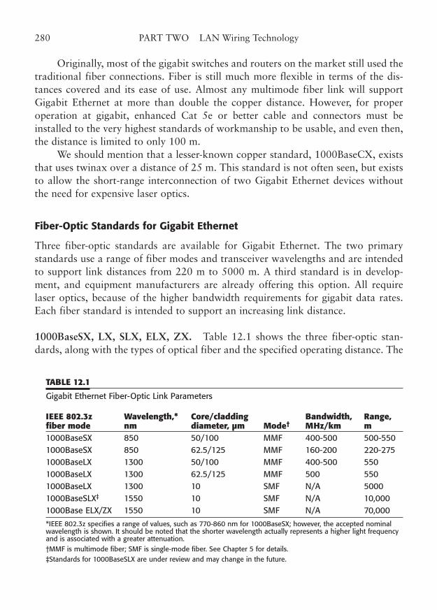
Originally, most of the gigabit switches and routers on the market still used thetraditional fiber connections. Fiber is still much more flexible in terms of the dis-tances covered and its ease of use. Almost any multimode fiber link will supportGigabit Ethernet at more than double the copper distance. However, for properoperation at gigabit, enhanced Cat 5e or better cable and connectors must beinstalled to the very highest standards of workmanship to be usable, and even then,the distance is limited to only 100 m.
We should mention that a lesser-known copper standard, 1000BaseCX, existsthat uses twinax over a distance of 25 m. This standard is not often seen, but existsto allow the short-range interconnection of two Gigabit Ethernet devices withoutthe need for expensive laser optics.
Fiber-Optic Standards for Gigabit Ethernet
Three fiber-optic standards are available for Gigabit Ethernet. The two primarystandards use a range of fiber modes and transceiver wavelengths and are intendedto support link distances from 220 m to 5000 m. A third standard is in develop-ment, and equipment manufacturers are already offering this option. All requirelaser optics, because of the higher bandwidth requirements for gigabit data rates.Each fiber standard is intended to support an increasing link distance.
1000BaseSX, LX, SLX, ELX, ZX. Table 12.1 shows the three fiber-optic stan-dards, along with the types of optical fiber and the specified operating distance. The
280 PART TWO LAN Wiring Technology
TABLE 12.1
Gigabit Ethernet Fiber-Optic Link Parameters
IEEE 802.3z Wavelength,* Core/cladding Bandwidth, Range, fiber mode nm diameter, µm Mode† MHz/km m1000BaseSX 850 50/100 MMF 400-500 500-550 1000BaseSX 850 62.5/125 MMF 160-200 220-275 1000BaseLX 1300 50/100 MMF 400-500 550 1000BaseLX 1300 62.5/125 MMF 500 550 1000BaseLX 1300 10 SMF N/A 5000 1000BaseSLX‡ 1550 10 SMF N/A 10,000 1000Base ELX/ZX 1550 10 SMF N/A 70,000
*IEEE 802.3z specifies a range of values, such as 770-860 nm for 1000BaseSX; however, the accepted nominalwavelength is shown. It should be noted that the shorter wavelength actually represents a higher light frequencyand is associated with a greater attenuation.†MMF is multimode fiber; SMF is single-mode fiber. See Chapter 5 for details.‡Standards for 1000BaseSLX are under review and may change in the future.
three standards are 1000BaseSX, 1000BaseLX, and 1000BaseSLX (an emergingstandard). Within the gigabit speed range, they are often referred to simply by thesuffix letters SX, LX, and SLX. The three suffixes actually refer to the wavelengthof light that is transmitted.
As shown in earlier chapters, the wavelengths commonly used for fiber-optictransmission are 850, 1350, and 1550 nm, with the last two being used primarilyon single-mode fiber. So, you can say that the SX on 850 is the “short” wavelength,the LX the “long” wavelength, and the SLX the “super-long” wave mode.Conveniently, the letters also correspond to the relative transmission distances ofeach operating mode. Thus, SX is short distance, LX is longer distance, and SLX issuper-long distance. Convenient, isn’t it? The new ELX and ZX standards offerextreme distances, way outside the needs of LAN wiring.
Understanding Fiber Performance at Gigabit Ethernet Speeds. Several factors affectthe bandwidth and range of Gigabit Ethernet fiber links. Most of these were dis-cussed in Chapter 5; however, they gain special importance at these much higher datarates. Chief among these factors is the bandwidth of the transmitting optics that“launch” the beam of light along the fiber. In lower-speed transmissions, inexpensivelight-emitting diodes (LEDs) are used. However, LEDs do not have the speed to sup-port gigabit transmission bandwidths, so more expensive laser diodes must be used.
Another problem that affects link performance is the spectral width of thetransmit optics. An ideal light source for fiber-optic transmission would have zerospectral width; it would produce a pure light of just one wavelength. In practice,these solid-state light sources produce light that is distributed across a band ofwavelengths, approximated as a bell-shaped curve, with the peak at the desirednominal wavelength. An LED has a relatively broad spectral width of about 150nm. That is, a device that operates at 850 nm actually produces light near 850 nmthat may range from 775 to about 900 nm. A typical laser diode source has a spec-tral width of about 5 nm. See Fig. 12.2.
The special width is important because of a phenomenon called chromatic disper-sion. As you know from looking at a prism, different colors of light are refracted dif-ferently when passing through the glass. The fiber core of a multimode graded-indexfiber will refract the different wavelengths of light accordingly, and the components ofa transmitted wave front will arrive at the destination receiver at slightly differing times.At the high data rate of Gigabit Ethernet, this signal distortion can make the signalunusable as the distance increases. For standard LEDs, with a very wide spectrum tobegin with, this usable distance is far too short to be used for a gigabit connection.
Laser diodes have a much narrower bandwidth, on the order of 5 to 10 nm,and therefore experience much less of the chromatic dispersion phenomenon.
CHAPTER 12 Gigabit and 10 Gigabit Cabling Technology 281
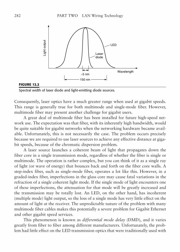
Consequently, laser optics have a much greater range when used at gigabit speeds.This range is generally true for both multimode and single-mode fiber. However,multimode fiber may present another challenge for gigabit users.
A great deal of multimode fiber has been installed for future high-speed net-work use. The expectation was that fiber, with its inherently high bandwidth, wouldbe quite suitable for gigabit networks when the networking hardware became avail-able. Unfortunately, this is not necessarily the case. The problem occurs preciselybecause we are required to use laser sources to achieve any effective distance at giga-bit speeds, because of the chromatic dispersion problem.
A laser source launches a coherent beam of light that propagates down thefiber core in a single transmission mode, regardless of whether the fiber is single ormultimode. The operation is rather complex, but you can think of it as a single rayof light (or wave of energy) that bounces back and forth on the fiber core walls. Astep-index fiber, such as single-mode fiber, operates a lot like this. However, in agraded-index fiber, imperfections in the glass core may cause fatal variations in therefraction of a single coherent light mode. If the single mode of light encounters oneof these imperfections, the attenuation for that mode will be greatly increased andthe transmission may be totally lost. An LED, on the other hand, has incoherent(multiple mode) light output, so the loss of a single mode has very little effect on theamount of light at the receiver. The unpredictable nature of the problem with manymultimode fiber cables makes this potentially a severe problem for Gigabit Ethernetand other gigabit speed services.
This phenomenon is known as differential mode delay (DMD), and it variesgreatly from fiber to fiber among different manufacturers. Unfortunately, the prob-lem had little effect on the LED transmission optics that were traditionally used with
282 PART TWO LAN Wiring Technology
Wavelength
LED
Laserdiode
~5 nm
150 nm
Ligh
t out
put
FIGURE 12.2
Spectral width of laser diode and light-emitting diode sources.
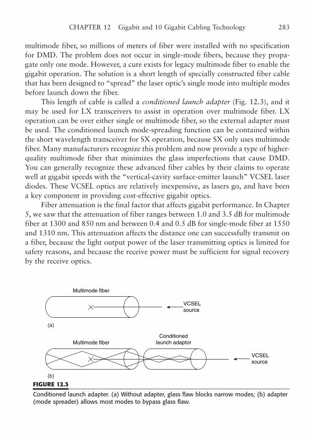
multimode fiber, so millions of meters of fiber were installed with no specificationfor DMD. The problem does not occur in single-mode fibers, because they propa-gate only one mode. However, a cure exists for legacy multimode fiber to enable thegigabit operation. The solution is a short length of specially constructed fiber cablethat has been designed to “spread” the laser optic’s single mode into multiple modesbefore launch down the fiber.
This length of cable is called a conditioned launch adapter (Fig. 12.3), and itmay be used for LX transceivers to assist in operation over multimode fiber. LXoperation can be over either single or multimode fiber, so the external adapter mustbe used. The conditioned launch mode-spreading function can be contained withinthe short wavelength transceiver for SX operation, because SX only uses multimodefiber. Many manufacturers recognize this problem and now provide a type of higher-quality multimode fiber that minimizes the glass imperfections that cause DMD.You can generally recognize these advanced fiber cables by their claims to operatewell at gigabit speeds with the “vertical-cavity surface-emitter launch” VCSEL laserdiodes. These VCSEL optics are relatively inexpensive, as lasers go, and have beena key component in providing cost-effective gigabit optics.
Fiber attenuation is the final factor that affects gigabit performance. In Chapter5, we saw that the attenuation of fiber ranges between 1.0 and 3.5 dB for multimodefiber at 1300 and 850 nm and between 0.4 and 0.5 dB for single-mode fiber at 1550and 1310 nm. This attenuation affects the distance one can successfully transmit ona fiber, because the light output power of the laser transmitting optics is limited forsafety reasons, and because the receive power must be sufficient for signal recoveryby the receive optics.
CHAPTER 12 Gigabit and 10 Gigabit Cabling Technology 283
Multimode fiber
VCSELsource
Multimode fiberConditioned
launch adaptor
VCSELsource
(a)
(b)
FIGURE 12.3
Conditioned launch adapter. (a) Without adapter, glass flaw blocks narrow modes; (b) adapter(mode spreader) allows most modes to bypass glass flaw.
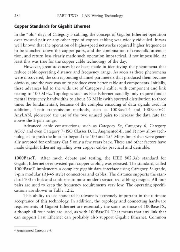
Copper Standards for Gigabit Ethernet
In the “old” days of Category 3 cabling, the concept of Gigabit Ethernet operationover twisted pair or any other type of copper cabling was widely ridiculed. It waswell known that the operation of higher-speed networks required higher frequenciesto be launched down the copper pairs, and the combination of crosstalk, attenua-tion, and return loss clearly made such operation impractical, if not impossible. Atleast this was true for the copper cable technology of the day.
However, great advances have been made in identifying the phenomena thatreduce cable operating distance and frequency range. As soon as these phenomenawere discovered, the corresponding channel parameters that produced them becameobvious, and the race was on to produce even better cable and components. Initially,these advances led to the wide use of Category 5 cable, with component and linktesting to 100 MHz. Topologies such as Fast Ethernet actually only require funda-mental frequency bandwidths to about 33 MHz (with spectral distribution to threetimes the fundamental), because of the complex encoding of data signals used. Inaddition, 4-pair transmission methods, such as 100BaseT4 and 100BaseVG-AnyLAN, pioneered the use of the two unused pairs to increase the data rate farabove the 2-pair range.
Advanced cable constructions, such as Category 5e, Category 6, CategoryAC6,2 and even Category 7 (ISO Classes D, E, Augmented-E, and F) now allow tech-nologists to push the limit far beyond the 100 and 155 Mbps limits that were gener-ally accepted for ordinary Cat 5 only a few years back. These and other factors havemade Gigabit Ethernet signaling over copper cables practical and desirable.
1000BaseT. After much debate and testing, the IEEE 802.3ab standard forGigabit Ethernet over twisted-pair copper cabling was released. The standard, called1000BaseT, implements a complete gigabit data interface using Category 5e-grade,8-pin modular (RJ-45 style) connectors and cables. The distance supports the stan-dard 100 m link and conforms to most modern structured cabling designs. All fourpairs are used to keep the frequency requirements very low. The operating specifi-cations are shown in Table 12.2.
This ability to use standard hardware is extremely important in the ultimateacceptance of this technology. In addition, the topology and connecting hardwarerequirements of Gigabit Ethernet are essentially the same as those of 100BaseTX,although all four pairs are used, as with 100BaseT4. That means that any link thatcan support Fast Ethernet can probably also support Gigabit Ethernet. Common
284 PART TWO LAN Wiring Technology
2 Augmented Category 6.
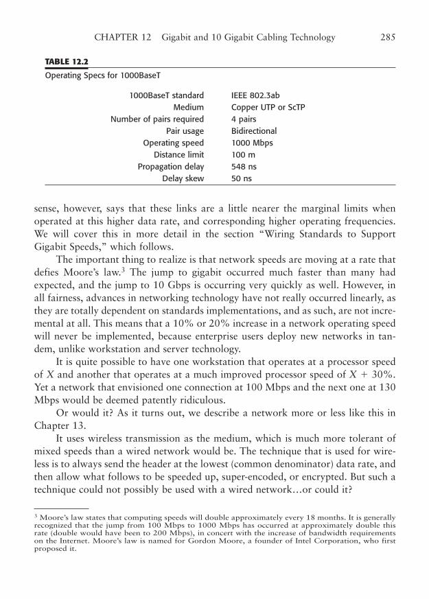
sense, however, says that these links are a little nearer the marginal limits whenoperated at this higher data rate, and corresponding higher operating frequencies.We will cover this in more detail in the section “Wiring Standards to SupportGigabit Speeds,” which follows.
The important thing to realize is that network speeds are moving at a rate thatdefies Moore’s law.3 The jump to gigabit occurred much faster than many hadexpected, and the jump to 10 Gbps is occurring very quickly as well. However, inall fairness, advances in networking technology have not really occurred linearly, asthey are totally dependent on standards implementations, and as such, are not incre-mental at all. This means that a 10% or 20% increase in a network operating speedwill never be implemented, because enterprise users deploy new networks in tan-dem, unlike workstation and server technology.
It is quite possible to have one workstation that operates at a processor speedof X and another that operates at a much improved processor speed of X � 30%.Yet a network that envisioned one connection at 100 Mbps and the next one at 130Mbps would be deemed patently ridiculous.
Or would it? As it turns out, we describe a network more or less like this inChapter 13.
It uses wireless transmission as the medium, which is much more tolerant ofmixed speeds than a wired network would be. The technique that is used for wire-less is to always send the header at the lowest (common denominator) data rate, andthen allow what follows to be speeded up, super-encoded, or encrypted. But such atechnique could not possibly be used with a wired network…or could it?
CHAPTER 12 Gigabit and 10 Gigabit Cabling Technology 285
TABLE 12.2
Operating Specs for 1000BaseT
1000BaseT standard IEEE 802.3abMedium Copper UTP or ScTP
Number of pairs required 4 pairsPair usage Bidirectional
Operating speed 1000 MbpsDistance limit 100 m
Propagation delay 548 nsDelay skew 50 ns
3 Moore’s law states that computing speeds will double approximately every 18 months. It is generallyrecognized that the jump from 100 Mbps to 1000 Mbps has occurred at approximately double thisrate (double would have been to 200 Mbps), in concert with the increase of bandwidth requirementson the Internet. Moore’s law is named for Gordon Moore, a founder of Intel Corporation, who firstproposed it.
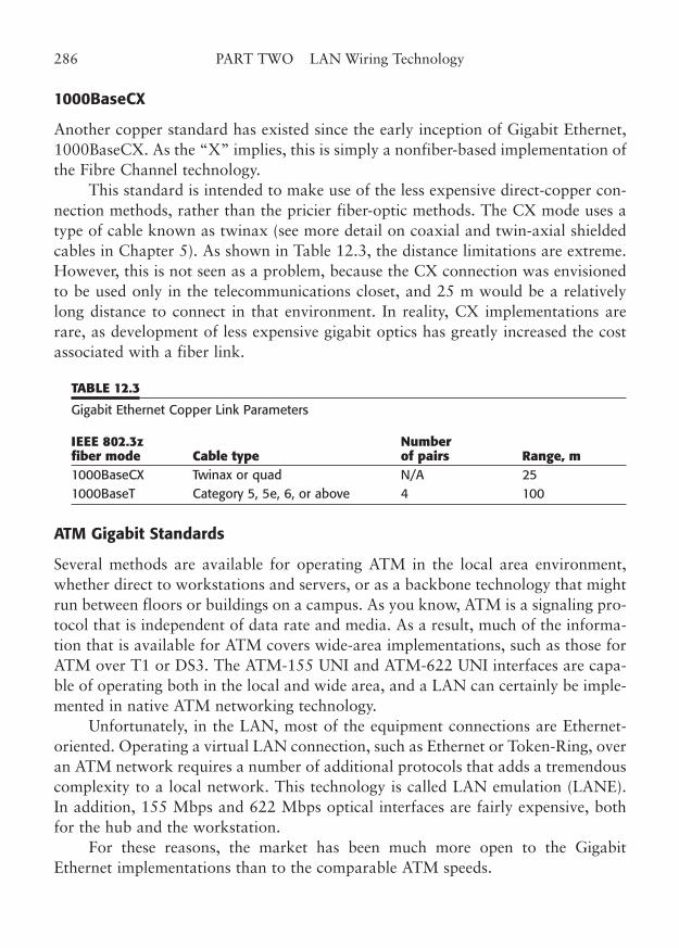
1000BaseCX
Another copper standard has existed since the early inception of Gigabit Ethernet,1000BaseCX. As the “X” implies, this is simply a nonfiber-based implementation ofthe Fibre Channel technology.
This standard is intended to make use of the less expensive direct-copper con-nection methods, rather than the pricier fiber-optic methods. The CX mode uses atype of cable known as twinax (see more detail on coaxial and twin-axial shieldedcables in Chapter 5). As shown in Table 12.3, the distance limitations are extreme.However, this is not seen as a problem, because the CX connection was envisionedto be used only in the telecommunications closet, and 25 m would be a relativelylong distance to connect in that environment. In reality, CX implementations arerare, as development of less expensive gigabit optics has greatly increased the costassociated with a fiber link.
ATM Gigabit Standards
Several methods are available for operating ATM in the local area environment,whether direct to workstations and servers, or as a backbone technology that mightrun between floors or buildings on a campus. As you know, ATM is a signaling pro-tocol that is independent of data rate and media. As a result, much of the informa-tion that is available for ATM covers wide-area implementations, such as those forATM over T1 or DS3. The ATM-155 UNI and ATM-622 UNI interfaces are capa-ble of operating both in the local and wide area, and a LAN can certainly be imple-mented in native ATM networking technology.
Unfortunately, in the LAN, most of the equipment connections are Ethernet-oriented. Operating a virtual LAN connection, such as Ethernet or Token-Ring, overan ATM network requires a number of additional protocols that adds a tremendouscomplexity to a local network. This technology is called LAN emulation (LANE).In addition, 155 Mbps and 622 Mbps optical interfaces are fairly expensive, bothfor the hub and the workstation.
For these reasons, the market has been much more open to the GigabitEthernet implementations than to the comparable ATM speeds.
286 PART TWO LAN Wiring Technology
TABLE 12.3
Gigabit Ethernet Copper Link Parameters
IEEE 802.3z Number fiber mode Cable type of pairs Range, m1000BaseCX Twinax or quad N/A 25 1000BaseT Category 5, 5e, 6, or above 4 100
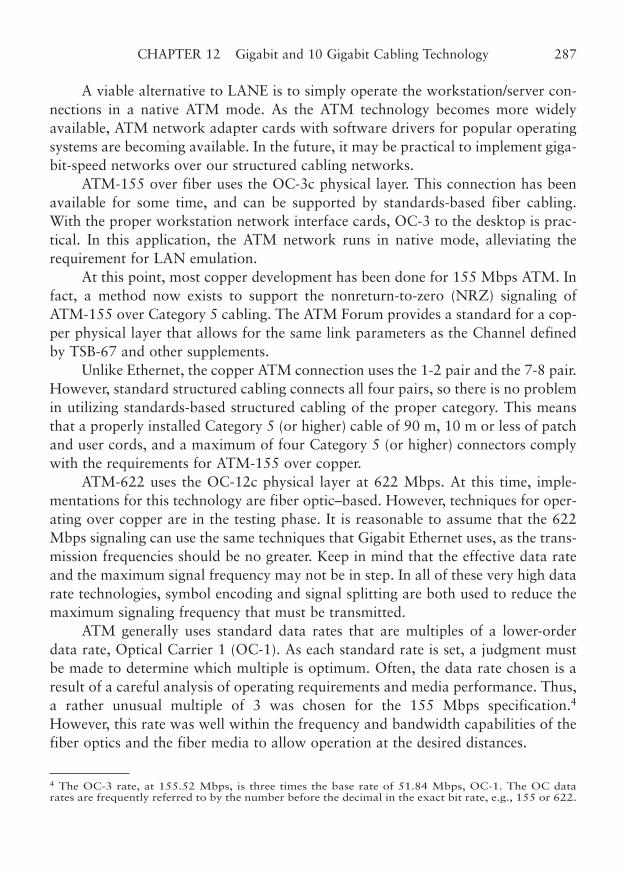
A viable alternative to LANE is to simply operate the workstation/server con-nections in a native ATM mode. As the ATM technology becomes more widelyavailable, ATM network adapter cards with software drivers for popular operatingsystems are becoming available. In the future, it may be practical to implement giga-bit-speed networks over our structured cabling networks.
ATM-155 over fiber uses the OC-3c physical layer. This connection has beenavailable for some time, and can be supported by standards-based fiber cabling.With the proper workstation network interface cards, OC-3 to the desktop is prac-tical. In this application, the ATM network runs in native mode, alleviating therequirement for LAN emulation.
At this point, most copper development has been done for 155 Mbps ATM. Infact, a method now exists to support the nonreturn-to-zero (NRZ) signaling ofATM-155 over Category 5 cabling. The ATM Forum provides a standard for a cop-per physical layer that allows for the same link parameters as the Channel definedby TSB-67 and other supplements.
Unlike Ethernet, the copper ATM connection uses the 1-2 pair and the 7-8 pair.However, standard structured cabling connects all four pairs, so there is no problemin utilizing standards-based structured cabling of the proper category. This meansthat a properly installed Category 5 (or higher) cable of 90 m, 10 m or less of patchand user cords, and a maximum of four Category 5 (or higher) connectors complywith the requirements for ATM-155 over copper.
ATM-622 uses the OC-12c physical layer at 622 Mbps. At this time, imple-mentations for this technology are fiber optic–based. However, techniques for oper-ating over copper are in the testing phase. It is reasonable to assume that the 622Mbps signaling can use the same techniques that Gigabit Ethernet uses, as the trans-mission frequencies should be no greater. Keep in mind that the effective data rateand the maximum signal frequency may not be in step. In all of these very high datarate technologies, symbol encoding and signal splitting are both used to reduce themaximum signaling frequency that must be transmitted.
ATM generally uses standard data rates that are multiples of a lower-orderdata rate, Optical Carrier 1 (OC-1). As each standard rate is set, a judgment mustbe made to determine which multiple is optimum. Often, the data rate chosen is aresult of a careful analysis of operating requirements and media performance. Thus,a rather unusual multiple of 3 was chosen for the 155 Mbps specification.4
However, this rate was well within the frequency and bandwidth capabilities of thefiber optics and the fiber media to allow operation at the desired distances.
CHAPTER 12 Gigabit and 10 Gigabit Cabling Technology 287
4 The OC-3 rate, at 155.52 Mbps, is three times the base rate of 51.84 Mbps, OC-1. The OC datarates are frequently referred to by the number before the decimal in the exact bit rate, e.g., 155 or 622.
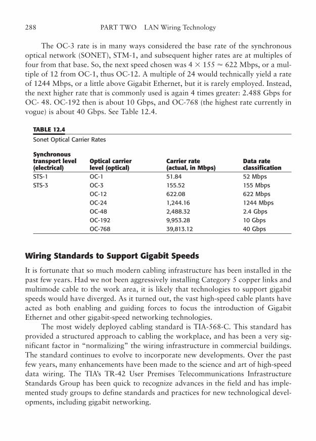
The OC-3 rate is in many ways considered the base rate of the synchronousoptical network (SONET), STM-1, and subsequent higher rates are at multiples offour from that base. So, the next speed chosen was 4 � 155 � 622 Mbps, or a mul-tiple of 12 from OC-1, thus OC-12. A multiple of 24 would technically yield a rateof 1244 Mbps, or a little above Gigabit Ethernet, but it is rarely employed. Instead,the next higher rate that is commonly used is again 4 times greater: 2.488 Gbps forOC- 48. OC-192 then is about 10 Gbps, and OC-768 (the highest rate currently invogue) is about 40 Gbps. See Table 12.4.
TABLE 12.4
Sonet Optical Carrier Rates
Synchronous transport level Optical carrier Carrier rate Data rate(electrical) level (optical) (actual, in Mbps) classificationSTS-1 OC-1 51.84 52 Mbps STS-3 OC-3 155.52 155 Mbps
OC-12 622.08 622 Mbps OC-24 1,244.16 1244 Mbps OC-48 2,488.32 2.4 Gbps OC-192 9,953.28 10 Gbps OC-768 39,813.12 40 Gbps
Wiring Standards to Support Gigabit Speeds
It is fortunate that so much modern cabling infrastructure has been installed in thepast few years. Had we not been aggressively installing Category 5 copper links andmultimode cable to the work area, it is likely that technologies to support gigabitspeeds would have diverged. As it turned out, the vast high-speed cable plants haveacted as both enabling and guiding forces to focus the introduction of GigabitEthernet and other gigabit-speed networking technologies.
The most widely deployed cabling standard is TIA-568-C. This standard hasprovided a structured approach to cabling the workplace, and has been a very sig-nificant factor in “normalizing” the wiring infrastructure in commercial buildings.The standard continues to evolve to incorporate new developments. Over the pastfew years, many enhancements have been made to the science and art of high-speeddata wiring. The TIA’s TR-42 User Premises Telecommunications InfrastructureStandards Group has been quick to recognize advances in the field and has imple-mented study groups to define standards and practices for new technological devel-opments, including gigabit networking.
288 PART TWO LAN Wiring Technology
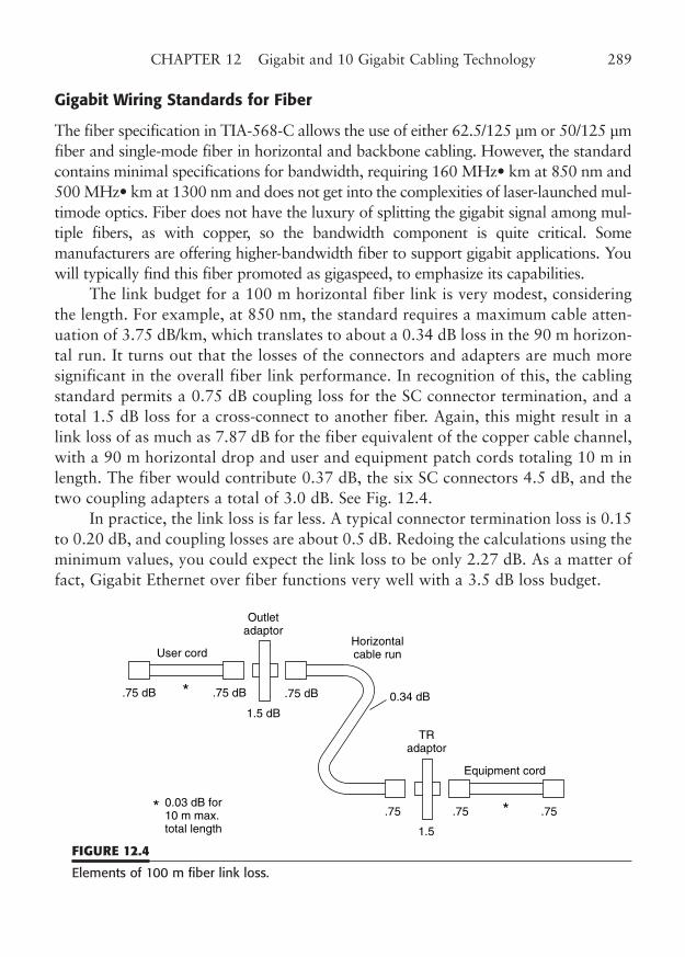
Gigabit Wiring Standards for Fiber
The fiber specification in TIA-568-C allows the use of either 62.5/125 µm or 50/125 µmfiber and single-mode fiber in horizontal and backbone cabling. However, the standardcontains minimal specifications for bandwidth, requiring 160 MHz• km at 850 nm and500 MHz• km at 1300 nm and does not get into the complexities of laser-launched mul-timode optics. Fiber does not have the luxury of splitting the gigabit signal among mul-tiple fibers, as with copper, so the bandwidth component is quite critical. Somemanufacturers are offering higher-bandwidth fiber to support gigabit applications. Youwill typically find this fiber promoted as gigaspeed, to emphasize its capabilities.
The link budget for a 100 m horizontal fiber link is very modest, consideringthe length. For example, at 850 nm, the standard requires a maximum cable atten-uation of 3.75 dB/km, which translates to about a 0.34 dB loss in the 90 m horizon-tal run. It turns out that the losses of the connectors and adapters are much moresignificant in the overall fiber link performance. In recognition of this, the cablingstandard permits a 0.75 dB coupling loss for the SC connector termination, and atotal 1.5 dB loss for a cross-connect to another fiber. Again, this might result in alink loss of as much as 7.87 dB for the fiber equivalent of the copper cable channel,with a 90 m horizontal drop and user and equipment patch cords totaling 10 m inlength. The fiber would contribute 0.37 dB, the six SC connectors 4.5 dB, and thetwo coupling adapters a total of 3.0 dB. See Fig. 12.4.
In practice, the link loss is far less. A typical connector termination loss is 0.15to 0.20 dB, and coupling losses are about 0.5 dB. Redoing the calculations using theminimum values, you could expect the link loss to be only 2.27 dB. As a matter offact, Gigabit Ethernet over fiber functions very well with a 3.5 dB loss budget.
CHAPTER 12 Gigabit and 10 Gigabit Cabling Technology 289
User cord
Equipment cord
.75 .75.75
.75 dB 0.34 dB.75 dB.75 dB
1.5 dB
1.5
*
*
Outletadaptor
Horizontalcable run
0.03 dB for10 m max.total length
*
TRadaptor
FIGURE 12.4
Elements of 100 m fiber link loss.
In most applications, Gigabit Ethernet is used as a backbone technology. TIA-568-A5 allowed slightly different requirements for the backbone links, permittingboth multimode and single-mode fiber. In this application, multimode fiber is usedmuch the same, although the bandwidth, mode dispersion, and transmission atten-uation are much more significant issues. These factors are the primary parameterslimiting the range of multimode fiber at gigabit data rates.
Here, the differences of using the previously recommended TIA-568-A62.5/125 µm fiber and the more expensive 50/125 µm fiber are clear. The 62.5 fiberis generally limited to a range of about 250 m, whereas the 50 mm fiber can extendover twice the distance using 850 nm optics (see Table 12.1). One must use moreexpensive 1300 nm optics to use the 62.5 µm fiber at 500 m. For this and otherreasons, the TIA-568-C standard allows the use of both 50/125 µm multimode andsingle-mode fiber in horizontal and other applications.
Gigabit Ethernet Fiber Optic Connectors. When the TIA-568-A standard wasfinalized, the preferred connector for horizontal and backbone fiber runs was the568 SC connector, an assembly of two SC fiber terminations linked together into apluggable module. However, that arrangement has an outlet footprint about 1 1/2times as wide as the modular RJ inserts used for copper connections. The only wayto use the 568 SC in a wall plate is to decouple the modules so they plug into a non-adjacent plate opening, or to redesign the plate and perhaps the snap-in modules sothat a two-wide insert can be accommodated.
Naturally, fiber connector manufacturers responded by beginning to developconnectors that allowed duplex fiber mating within the standard snap-in modulespace that was designed for the RJ connectors. In a departure from past standardi-zation actions, the TIA in TIA-568-C took the unusual step of declining a specificrecommendation for the small form factor connector, as it is called. Rather, theyspecify only the connector and mating performance characteristics and maintain thetransmit-receive A/B orientation of the connection. The result is that several differ-ent duplex fiber connectors are in use, each supported by up to 10 manufacturers.You can find more information on this issue in Chapter 11.
Gigabit Wiring Standards for Copper
TIA-568-A defined cabling standards for both twisted-pair copper and fiber-opticcabling. The minimum standard that is considered usable for gigabit networking isCategory 5. However, if you are planning on using Cat 5 installed cabling that was
290 PART TWO LAN Wiring Technology
5 TIA-568-C now allows single-mode fiber to be used in horizontal, backbone, centralized, and open-office applications.
tested before Addendum 5 to TIA-568-A, you should use the additional testingrequirements of TSB-95 to verify the cable for gigabit performance levels (asdescribed later in this section).
The original specifications for Category 5 components (connecting hardwareand cable) were developed with the view that 155 Mbps was about the limit for thetechnology. Also, it was assumed (rashly, in hindsight) that most implementationswould use only two pairs of the 4-pair cable, as was the case with 100BaseTX. Sothe test parameters based on a 100 MHz limit tested two pairs at a time, to allowfor the expected signaling structures. This allows for a third harmonic componentof a 33.3 MHz fundamental signal, essentially within the requirements for the 100and 155 Mbps technologies.
In order to place gigabit rates on the same type of cable, all four pairs arerequired. The net effect is that the rate is split by four, and through further encoding,reduced to allow operation within the 100 MHz-tested Channel. But just barely! Itis a little risky to place the reliable operation of your network on an infrastructurethat just meets the minimum criteria for operation on day one. This means that therecan be absolutely no room for any aging of any of the components, and no deterio-ration of the connections for the life of the installation. That borders on the absurd.
The solution has been to provide a series of enhanced-performance categoriesor levels to make certain that installed wiring could meet the needs of GigabitEthernet, and other technologies. So-called enhanced Category 5e cable becameavailable almost immediately. To sort out the various claims, the TIA began studiesto supplement and revise the TIA-568-A standard.
At the same time, Anixter, the wiring component distributor that began the sys-tem that resulted in the TIA’s component category definition, set up a new levels sys-tem for Category 5 cable. This system recognizes that “better” can be quantified(and, no doubt, priced as well). See Table 12.5.
The result was Category 5e (enhanced Cat 5). The most obvious difference inCat 5e cable performance is seen through crosstalk. A cable with a lower NEXT(and FEXT, the far-end measurement) will naturally perform better at all the fre-quencies. As a matter of fact, the point at which a link ceases to function for a par-ticular frequency range is where the attenuation and the NEXT are equal. For earlyconstructions of Cat 5 cable, this point was engineered to just over 100 MHz.
So, let’s look first at several of the critical component parameters at gigabitspeeds. Then, we will discuss the advances beyond Cat 5 that can get you reason-able performance margins at gigabit and beyond.
Attenuation at Gigabit Rates. As a signal travels along a cable, the resistance,capacitance, and inductance of the copper wires act to reduce the amplitude of the
CHAPTER 12 Gigabit and 10 Gigabit Cabling Technology 291
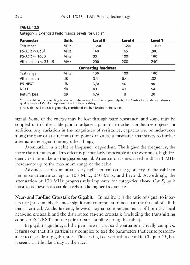
signal. Some of the energy may be lost through pure resistance, and some may becoupled out of the cable pair to adjacent pairs or to other conductive objects. Inaddition, any variation in the magnitude of resistance, capacitance, or inductancealong the pair or at a termination point can cause a mismatch that serves to furtherattenuate the signal (among other things).
Attenuation in a cable is frequency dependent. The higher the frequency, themore the attenuation. This effect is particularly noticeable at the extremely high fre-quencies that make up the gigabit signal. Attenuation is measured in dB in 1 MHzincrements up to the maximum range of the cable.
Advanced cables maintain very tight control on the geometry of the cable tominimize attenuation up to 100 MHz, 250 MHz, and beyond. Accordingly, theattenuation at 100 MHz progressively improves for categories above Cat 5, as itmust to achieve reasonable levels at the higher frequencies.
Near- and Far-End Crosstalk for Gigabit. In reality, it is the ratio of signal to inter-ference (presumably the most significant component of noise) at the far end of a linkthat is critical. At the far end, however, signal components exist of both the localnear-end crosstalk and the distributed far-end crosstalk (including the transmittingconnector’s NEXT and the pair-to-pair coupling along the cable).
In gigabit signaling, all the pairs are in use, so the situation is really complex.It turns out that it is particularly complex to test the parameters that cause perform-ance to degrade at gigabit rates. This testing is described in detail in Chapter 15, butit seems a little like a day at the races.
292 PART TWO LAN Wiring Technology
TABLE 12.5
Category 5 Extended Performance Levels for Cable*
Parameter Units Level 5 Level 6 Level 7Test range MHz 1-200 1-350 1-400 PS-ACR � 0dB† MHz 140 165 280 PS-ACR � 10dB MHz 80 100 180 Attenuation � 33 dB MHz 200 200 240
Connecting hardwareTest range MHz 100 100 100 Attenuation dB 0.4 0.4 .02 PS-NEXT dB N/A 40 50 NEXT dB 40 42 54 Return loss dB N/A 18 20
*These cable and connecting hardware performance levels were promulgated by Anixter Inc. to define advancedquality levels of Cat 5 components in structured cabling.†The 0 dB level of ACR is generally considered the bandwidth of the cable.
In the lead is attenuation, followed by NEXT, FEXT, ELFEXT,…, then comesreturn loss, impedance, and, close behind, ACR. Well, the resulting scramble for thetop technology spot keeps us all betting on next year’s network foals.
ACR—Attenuation-to-Crosstalk Ratio. The difference in dB between the meas-ured attenuation and NEXT at a particular frequency is commonly referred to asthe attenuation-to-crosstalk ratio (ACR). The ACR is given in dB, as are the atten-uation and NEXT of a cable. Because both those values are converted from actualpower levels, the ratio between those two power levels can be expressed in dB. Thus,the ratio is developed by simply subtracting the two measurements. For example, anattenuation of 37 dB and a NEXT of 40 dB yields an ACR of 3 dB. One could saythat, in essence, the remaining transmitted signal would be about 3 dB more thanthe potential interference from NEXT.
Beyond Category 5 to Cat 5e, 6/AC6, and 7. Enhanced Cat 5, or Category 5e,has now been canonized by the TIA. This recognizes the Cat 5 “levels” program,which was originally used to specify cable and connecting hardware that exceededthe basic Cat 5 standard. There is a compelling need to overengineer new struc-tured cabling systems to allow for future technology upgrades. Category 6, with its250 MHz bandwidth, certainly meets that need, and it is an integral part of TIA-568-C. Now, you can certainly specify components that exceed Cat 5e andCategory 6. Category AC6 and Category 7 are well along the standards road, andare soon to be a requirement for advanced network technologies. All of these haveanalogs in the ISO standards as Class D, E, E-Augmented, and F cable definitions.Looking at Table 12.6, you can see that there are substantial performance advan-tages to the higher cable categories. For more information on these new perform-ance categories, refer to Chapters 5 and 12 and the individual component sectionsin Part Two.
Using the advanced cabling categories will clearly enhance performance.However, the standard states that you should be able to operate Gigabit Ethernetover simple (but performance-verified) Category 5 cabling systems. The issue formost wiring designers is how much of a performance margin should be specified.Category 6 specs meet this need head-on. The situation was similar for the originalCategory 5 specification, where the parameter of delay skew was found to be criti-cal for 4-pair network link implementations. Those who specified Cat 5 cable whenonly Cat 3 was really required for their current application have been rewarded,now that most network hardware needs Cat 5. Fortunately, the hardware for Cat 3and Cat 5 is completely interchangeable, although a mixed use downgrades the linkperformance expectations to the lower category.
CHAPTER 12 Gigabit and 10 Gigabit Cabling Technology 293
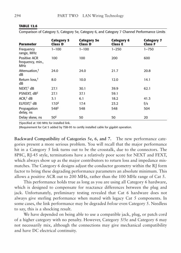
TABLE 12.6
Comparison of Category 5, Category 5e, Category 6, and Category 7 Channel Performance Limits
Category 5 Category 5e Category 6 Category 7 Parameter Class D Class D Class E Class FFrequency 1–100 1–100 1–250 1–750 range, MHz Positive ACR 100 100 200 600 frequency, min., MHz Attenuation,† 24.0 24.0 21.7 20.8 dBReturn loss,† 8.0 10.0 12.0 14.1 dBNEXT,† dB 27.1 30.1 39.9 62.1 PSNEXT, dB‡ 27.1 37.1 59.1 ACR,† dB 3.1 6.1 18.2 41.3 ELFEXT,† dB 17.0‡ 17.4 23.2 f/s Propagation 548‡ 548 548 504 delay, ns Delay skew, ns 50‡ 50 50 20
†Specified at 100 MHz for installed link.‡Requirement for Cat 5 added by TSB-95 to certify installed cable for gigabit operation.
Backward Compatibility of Categories 5e, 6, and 7. The new performance cate-gories present a more serious problem. You will recall that the major performancehit in a Category 5 link turns out to be the crosstalk, due to the connectors. The8P8C, RJ-45 style, terminations have a relatively poor score for NEXT and FEXT,which always show up as the major contributors to return loss and impedance mis-matches. The Category 6 designs adjust the conductor geometry within the RJ formfactor to bring these degrading performance parameters an absolute minimum. Thisallows a positive ACR out to 200 MHz, rather than the 100 MHz range of Cat 5.
This performance holds true as long as you are using all Category 6 hardware,which is designed to compensate for reactance differences between the plug andjack. Unfortunately, preliminary testing revealed that Cat 6 hardware does notalways give sterling performance when mated with legacy Cat 5 components. Insome cases, the link performance may be degraded below even Category 5. Needlessto say, this is a shocking result.
We have depended on being able to use a compatible jack, plug, or patch cordof a higher category with no penalty. However, Category 5/5e and Category 6 maynot necessarily mix, although the connections may give mechanical compatibilityand have DC electrical continuity.
294 PART TWO LAN Wiring Technology
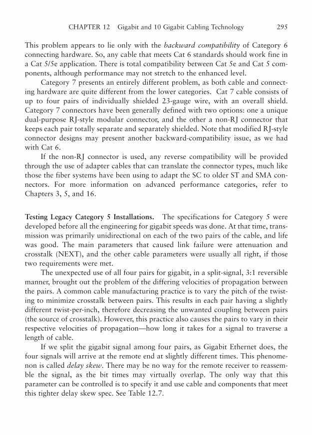
This problem appears to lie only with the backward compatibility of Category 6connecting hardware. So, any cable that meets Cat 6 standards should work fine ina Cat 5/5e application. There is total compatibility between Cat 5e and Cat 5 com-ponents, although performance may not stretch to the enhanced level.
Category 7 presents an entirely different problem, as both cable and connect-ing hardware are quite different from the lower categories. Cat 7 cable consists ofup to four pairs of individually shielded 23-gauge wire, with an overall shield.Category 7 connectors have been generally defined with two options: one a uniquedual-purpose RJ-style modular connector, and the other a non-RJ connector thatkeeps each pair totally separate and separately shielded. Note that modified RJ-styleconnector designs may present another backward-compatibility issue, as we hadwith Cat 6.
If the non-RJ connector is used, any reverse compatibility will be providedthrough the use of adapter cables that can translate the connector types, much likethose the fiber systems have been using to adapt the SC to older ST and SMA con-nectors. For more information on advanced performance categories, refer toChapters 3, 5, and 16.
Testing Legacy Category 5 Installations. The specifications for Category 5 weredeveloped before all the engineering for gigabit speeds was done. At that time, trans-mission was primarily unidirectional on each of the two pairs of the cable, and lifewas good. The main parameters that caused link failure were attenuation andcrosstalk (NEXT), and the other cable parameters were usually all right, if thosetwo requirements were met.
The unexpected use of all four pairs for gigabit, in a split-signal, 3:1 reversiblemanner, brought out the problem of the differing velocities of propagation betweenthe pairs. A common cable manufacturing practice is to vary the pitch of the twist-ing to minimize crosstalk between pairs. This results in each pair having a slightlydifferent twist-per-inch, therefore decreasing the unwanted coupling between pairs(the source of crosstalk). However, this practice also causes the pairs to vary in theirrespective velocities of propagation—how long it takes for a signal to traverse alength of cable.
If we split the gigabit signal among four pairs, as Gigabit Ethernet does, thefour signals will arrive at the remote end at slightly different times. This phenome-non is called delay skew. There may be no way for the remote receiver to reassem-ble the signal, as the bit times may virtually overlap. The only way that thisparameter can be controlled is to specify it and use cable and components that meetthis tighter delay skew spec. See Table 12.7.
CHAPTER 12 Gigabit and 10 Gigabit Cabling Technology 295
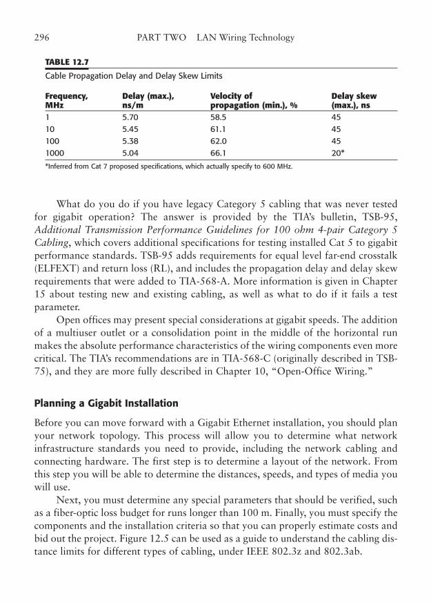
TABLE 12.7
Cable Propagation Delay and Delay Skew Limits
Frequency, Delay (max.), Velocity of Delay skew MHz ns/m propagation (min.), % (max.), ns1 5.70 58.5 45 10 5.45 61.1 45 100 5.38 62.0 45 1000 5.04 66.1 20*
*Inferred from Cat 7 proposed specifications, which actually specify to 600 MHz.
What do you do if you have legacy Category 5 cabling that was never testedfor gigabit operation? The answer is provided by the TIA’s bulletin, TSB-95,Additional Transmission Performance Guidelines for 100 ohm 4-pair Category 5Cabling, which covers additional specifications for testing installed Cat 5 to gigabitperformance standards. TSB-95 adds requirements for equal level far-end crosstalk(ELFEXT) and return loss (RL), and includes the propagation delay and delay skewrequirements that were added to TIA-568-A. More information is given in Chapter15 about testing new and existing cabling, as well as what to do if it fails a testparameter.
Open offices may present special considerations at gigabit speeds. The additionof a multiuser outlet or a consolidation point in the middle of the horizontal runmakes the absolute performance characteristics of the wiring components even morecritical. The TIA’s recommendations are in TIA-568-C (originally described in TSB-75), and they are more fully described in Chapter 10, “Open-Office Wiring.”
Planning a Gigabit Installation
Before you can move forward with a Gigabit Ethernet installation, you should planyour network topology. This process will allow you to determine what networkinfrastructure standards you need to provide, including the network cabling andconnecting hardware. The first step is to determine a layout of the network. Fromthis step you will be able to determine the distances, speeds, and types of media youwill use.
Next, you must determine any special parameters that should be verified, suchas a fiber-optic loss budget for runs longer than 100 m. Finally, you must specify thecomponents and the installation criteria so that you can properly estimate costs andbid out the project. Figure 12.5 can be used as a guide to understand the cabling dis-tance limits for different types of cabling, under IEEE 802.3z and 802.3ab.
296 PART TWO LAN Wiring Technology
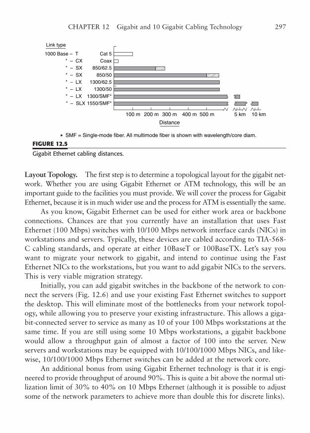
Layout Topology. The first step is to determine a topological layout for the gigabit net-work. Whether you are using Gigabit Ethernet or ATM technology, this will be animportant guide to the facilities you must provide. We will cover the process for GigabitEthernet, because it is in much wider use and the process for ATM is essentially the same.
As you know, Gigabit Ethernet can be used for either work area or backboneconnections. Chances are that you currently have an installation that uses FastEthernet (100 Mbps) switches with 10/100 Mbps network interface cards (NICs) inworkstations and servers. Typically, these devices are cabled according to TIA-568-C cabling standards, and operate at either 10BaseT or 100BaseTX. Let’s say youwant to migrate your network to gigabit, and intend to continue using the FastEthernet NICs to the workstations, but you want to add gigabit NICs to the servers.This is very viable migration strategy.
Initially, you can add gigabit switches in the backbone of the network to con-nect the servers (Fig. 12.6) and use your existing Fast Ethernet switches to supportthe desktop. This will eliminate most of the bottlenecks from your network topol-ogy, while allowing you to preserve your existing infrastructure. This allows a giga-bit-connected server to service as many as 10 of your 100 Mbps workstations at thesame time. If you are still using some 10 Mbps workstations, a gigabit backbonewould allow a throughput gain of almost a factor of 100 into the server. Newservers and workstations may be equipped with 10/100/1000 Mbps NICs, and like-wise, 10/100/1000 Mbps Ethernet switches can be added at the network core.
An additional bonus from using Gigabit Ethernet technology is that it is engi-neered to provide throughput of around 90%. This is quite a bit above the normal uti-lization limit of 30% to 40% on 10 Mbps Ethernet (although it is possible to adjustsome of the network parameters to achieve more than double this for discrete links).
CHAPTER 12 Gigabit and 10 Gigabit Cabling Technology 297
Cat 5
200 m100 m 300 m
Distance
500 m400 m 5 km 10 km
Coax850/62.5
850/501300/62.5
1300/501300/SMF*1550/SMF*
1000 Base
Link type
" – CX" – SX" – SX" – LX" – LX" – LX" – SLX
– T
SMF = Single-mode fiber. All multimode fiber is shown with wavelength/core diam.*FIGURE 12.5
Gigabit Ethernet cabling distances.
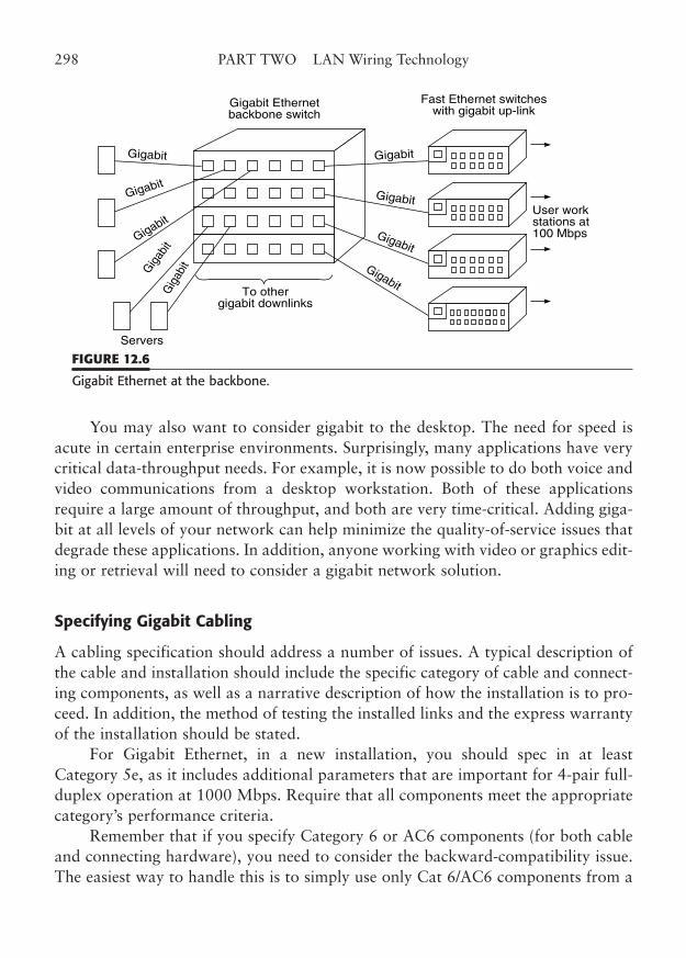
You may also want to consider gigabit to the desktop. The need for speed isacute in certain enterprise environments. Surprisingly, many applications have verycritical data-throughput needs. For example, it is now possible to do both voice andvideo communications from a desktop workstation. Both of these applicationsrequire a large amount of throughput, and both are very time-critical. Adding giga-bit at all levels of your network can help minimize the quality-of-service issues thatdegrade these applications. In addition, anyone working with video or graphics edit-ing or retrieval will need to consider a gigabit network solution.
Specifying Gigabit Cabling
A cabling specification should address a number of issues. A typical description ofthe cable and installation should include the specific category of cable and connect-ing components, as well as a narrative description of how the installation is to pro-ceed. In addition, the method of testing the installed links and the express warrantyof the installation should be stated.
For Gigabit Ethernet, in a new installation, you should spec in at leastCategory 5e, as it includes additional parameters that are important for 4-pair full-duplex operation at 1000 Mbps. Require that all components meet the appropriatecategory’s performance criteria.
Remember that if you specify Category 6 or AC6 components (for both cableand connecting hardware), you need to consider the backward-compatibility issue.The easiest way to handle this is to simply use only Cat 6/AC6 components from a
298 PART TWO LAN Wiring Technology
Gigabit Ethernetbackbone switch
Fast Ethernet switcheswith gigabit up-link
To othergigabit downlinks
Gigabit
User workstations at100 Mbps
Gigabit
Gigabit
Gigabit
Gigabit
Gigabit
Gigabit
Gig
abitGig
abit
Servers
FIGURE 12.6
Gigabit Ethernet at the backbone.
single manufacturer. This is simple to do if you are installing a new cable plant. Ifyou are the contractor, insist that the contract recognize that proper operation isguaranteed only with user patch cords that match the Category 6/AC6 specificationsof the outlet/patch manufacturer.
Manufacturer’s Warranty Programs. You may want to consider one of the manufac-turer’s installation warranty programs. These programs warrant performance of thecomponents and installation for a period of 15 or 20 years, as long as an installer whois manufacturer-certified is used. As we covered in earlier chapters, these warranty pro-grams require you to use specific brands (and material types) of connectors and cableto qualify. Generally, they guarantee that performance of the Basic Link (PermanentLink) will continue to meet minimum requirements for that category for the period ofthe warranty. The use of a certified installer will presumably result in the use of properinstallation practices. If a link is later shown to fail those same performance measure-ments, the manufacturer will pay to have the failed component replaced at its expense.
In a few cases, these programs are offered by manufacturers’ partnership, forexample, when neither makes both cable and connectors. Be aware that this mayproduce interesting (and unanticipated) results if a competing component vendoracquires one of the partners.
Although including a program warranty clause in your contract may producea warm fuzzy feeling, you know quite well that network requirements change muchfaster than once in 15 years. By that time, you will very likely need totally newcabling and hardware. On the other hand, the warranty essentially extends the stan-dard manufacturer’s defect period from a norm of 1 year to 15 or 20 years. The costto the manufacturer is negligible, as it is highly unlikely that a component that canlast a year will spontaneously fail in 5 or 10 years, and that is virtually the only wayperformance can change. The benefits to the manufacturer, however, are enormous,as it “guarantees” you will buy its components to the exclusion of all others.
Testing Gigabit Cabling
Most of the information you will need to know on testing installed cable is con-tained in Chapter 15. However, it might be of benefit to concentrate here on a fewissues that are particularly applicable to cable installations used for gigabit net-works. It is also useful to know some of the gigabit networking issues that maycause a link failure that is not the fault of the cabling.
Gigabit Limitations. The first item in the “not-the-cable” category is GigabitEthernet’s repeater limitation. Unlike older technologies, particularly 10 Mbps
CHAPTER 12 Gigabit and 10 Gigabit Cabling Technology 299
Ethernet, you cannot stack repeater hubs back to back. You will recall that you wereallowed to place up to four repeater hops on an Ethernet segment. Fast Ethernet lim-ited that to two, and Gigabit Ethernet limits that to one.
Gigabit Ethernet (as well as other gigabit-class technologies) has a very finitedistance limit, depending on the medium. Part of this limit is due to the actual lossesin transmission relative to noise (copper, particularly) and part is due to the physicsof the transmission (fiber dispersion, for example).
Loss Measurements. It seems self-evident, but you must use test and measurementequipment that is appropriate for the gigabit range. Sure, you can use simple wire mapand optical continuity testers during initial installation. But to ensure operation at giga-bit speeds, you must use cable scanners that are capable of measuring all the parame-ters for the category of links you are installing. In this case, you should be testing to Cat5e or higher, commensurate with the category of components you have installed.
For twisted pair, the measurements fall into four areas: attenuation, crosstalk,impedance, and propagation delay. Attenuation and impedance problems causedirect signal losses. Crosstalk, such as NEXT and ELFEXT, causes a lower signal-to-noise level, and indirectly affects signal range. Finally, differences in propagationdelay degrade 4-pair performance. All these areas are critical in gigabit applications.
In fiber links, the essential parameter areas are attenuation and bandwidth, asthey are the primary factors that limit range. Other “soft” parameters may radicallyaffect fiber link performance. For example, multimode fiber may have to be mode-conditioned to minimize the effect of normal fiber manufacturing characteristicswhen used with the laser diode sources of gigabit technologies.
If you have a multimode fiber link that appears to pass testing, but will notwork in the application, the first place to look is at differential mode delay prob-lems. Fiber testing is normally done with an overfilled launch (OFL) source, whichfills the fiber core with multiple modes.
DMD causes a problem when the core is illuminated with a laser source, whichuses only a few modes. This additional parameter is difficult to test for, so a simpletroubleshooting technique may be to keep a mode-conditioning patch cable handy.If the link works with this special patch cable, you will need to provide one on apermanent basis.
Another place to look on a fiber with excessive losses is a possible mode mis-match. The connectors on single and multimode fiber are the same, yet there is asubstantial loss coupling from one to the other. A mismatch that is less disastrous isa core-diameter mismatch. As we covered in the chapter on fiber-optic cabling, 50and 62.5 mm core fibers may be coupled, but with a dB loss that may be unaccept-able in a particular link.
300 PART TWO LAN Wiring Technology
Cable discontinuities can be found by time-domain reflectometry techniques.This applies to either copper or fiber. A substantial mismatch, in impedance or inrefraction, will clearly show up on most cable scanners with a graphic display. Youwill be able to determine the distance from the scanner to the cable defect. Be sureto subtract out the length of the test cord when you hunt for the problem.Ordinarily, this test will direct your attention to a termination point, such as cross-connect, patch, or outlet. Infrequently, you will find a problem within a cable run,often where the cable has been severely bent and straightened out improperly.
Finally, lost performance can come from older fiber that just does not have suf-ficient bandwidth to operate with gigabit at a given distance. For example, GigabitEthernet can operate to 275 m at 850 nm on 62.5/125 mm multimode fiber that hasa bandwidth product of 200 MHz•km. However, the link is limited to an expectedrange of only 220 m with 160 MHz•km fiber with the same core/cladding specs.
Workmanship. Frankly, at lower speeds, you can be fairly certain that any linkthat could pass the simple tests would also pass the full cable scan, as long as work-manship practices were reasonable.
However, at gigabit, you must be perfect. A single pair (our favorite is thebrown/white) that is not twisted up to the point of termination can cause the linkto fail. Fortunately, the workmanship practices are not particularly different fromwhat they were for Fast Ethernet. You must actually follow them with gigabit. Youcould get away with a few cable kinks, some sharp bends, and careless placement ofcable, but not with gigabit. It uses absolutely every ounce (or gram) of margin in aCategory 5 cable, and it cuts you no slack.
Be kind to your installers, though. Four or five years ago, cable installationtechniques were simpler. Many installations were accomplished with Category 5components before all the testing criteria were determined.
As a result, many installations were tested only to Category 3, although higher-performance components were used. In most of these installations, operation to FastEthernet speeds is fairly well assured. But too much new information and practicehas appeared for anyone to have provided for gigabit performance at that time. Thisis the reason the TSB-95 was created: to recognize that additional testing must bedone on legacy Cat 5 installations to ensure operation at gigabit.
10 Gigabit Ethernet Technology
At one time, speeds as great as 10 gigabits were considered almost science fiction.Before the rapid acceleration of the Internet lit up network cores at amazing trafficlevels, there seemed to be little need for 10 GigE outside the lab. However, moving
CHAPTER 12 Gigabit and 10 Gigabit Cabling Technology 301
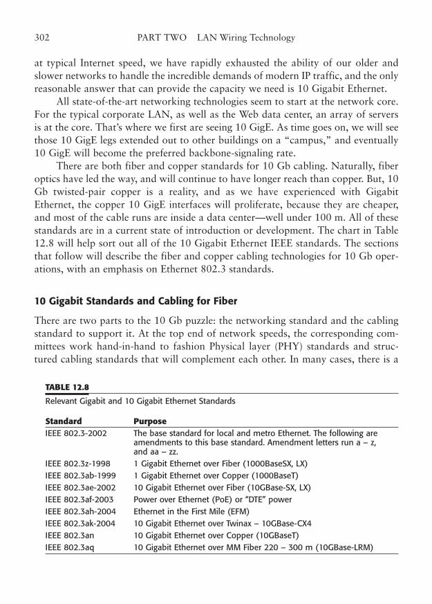
at typical Internet speed, we have rapidly exhausted the ability of our older andslower networks to handle the incredible demands of modern IP traffic, and the onlyreasonable answer that can provide the capacity we need is 10 Gigabit Ethernet.
All state-of-the-art networking technologies seem to start at the network core.For the typical corporate LAN, as well as the Web data center, an array of serversis at the core. That’s where we first are seeing 10 GigE. As time goes on, we will seethose 10 GigE legs extended out to other buildings on a “campus,” and eventually10 GigE will become the preferred backbone-signaling rate.
There are both fiber and copper standards for 10 Gb cabling. Naturally, fiberoptics have led the way, and will continue to have longer reach than copper. But, 10Gb twisted-pair copper is a reality, and as we have experienced with GigabitEthernet, the copper 10 GigE interfaces will proliferate, because they are cheaper,and most of the cable runs are inside a data center—well under 100 m. All of thesestandards are in a current state of introduction or development. The chart in Table12.8 will help sort out all of the 10 Gigabit Ethernet IEEE standards. The sectionsthat follow will describe the fiber and copper cabling technologies for 10 Gb oper-ations, with an emphasis on Ethernet 802.3 standards.
10 Gigabit Standards and Cabling for Fiber
There are two parts to the 10 Gb puzzle: the networking standard and the cablingstandard to support it. At the top end of network speeds, the corresponding com-mittees work hand-in-hand to fashion Physical layer (PHY) standards and struc-tured cabling standards that will complement each other. In many cases, there is a
302 PART TWO LAN Wiring Technology
TABLE 12.8
Relevant Gigabit and 10 Gigabit Ethernet Standards
Standard PurposeIEEE 802.3-2002 The base standard for local and metro Ethernet. The following are
amendments to this base standard. Amendment letters run a – z, and aa – zz.
IEEE 802.3z-1998 1 Gigabit Ethernet over Fiber (1000BaseSX, LX)IEEE 802.3ab-1999 1 Gigabit Ethernet over Copper (1000BaseT)IEEE 802.3ae-2002 10 Gigabit Ethernet over Fiber (10GBase-SX, LX)IEEE 802.3af-2003 Power over Ethernet (PoE) or “DTE” powerIEEE 802.3ah-2004 Ethernet in the First Mile (EFM)IEEE 802.3ak-2004 10 Gigabit Ethernet over Twinax – 10GBase-CX4IEEE 802.3an 10 Gigabit Ethernet over Copper (10GBaseT)IEEE 802.3aq 10 Gigabit Ethernet over MM Fiber 220 – 300 m (10GBase-LRM)
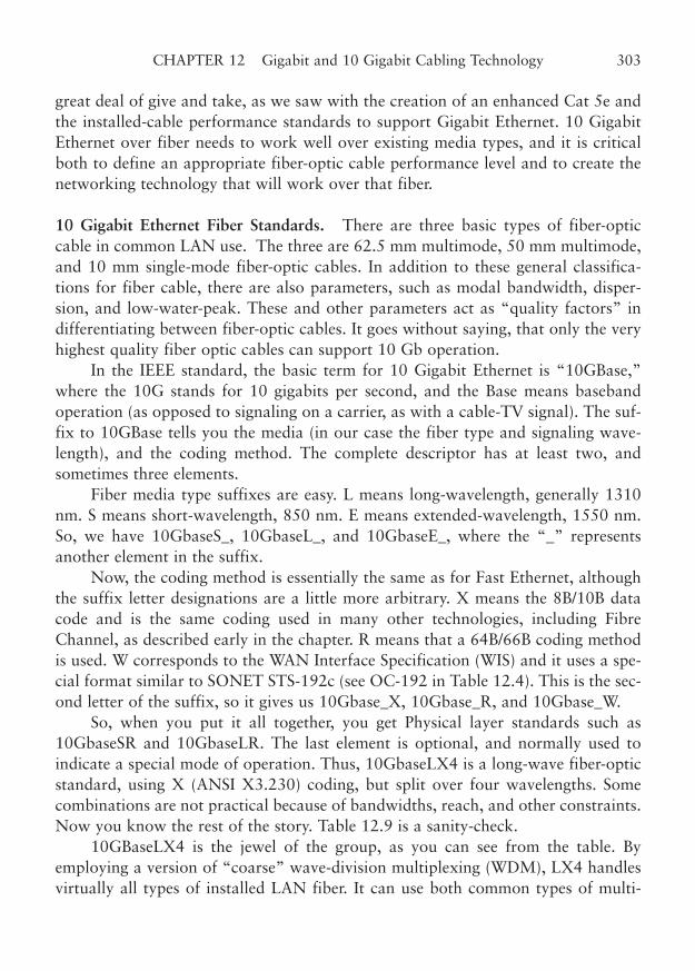
great deal of give and take, as we saw with the creation of an enhanced Cat 5e andthe installed-cable performance standards to support Gigabit Ethernet. 10 GigabitEthernet over fiber needs to work well over existing media types, and it is criticalboth to define an appropriate fiber-optic cable performance level and to create thenetworking technology that will work over that fiber.
10 Gigabit Ethernet Fiber Standards. There are three basic types of fiber-opticcable in common LAN use. The three are 62.5 mm multimode, 50 mm multimode,and 10 mm single-mode fiber-optic cables. In addition to these general classifica-tions for fiber cable, there are also parameters, such as modal bandwidth, disper-sion, and low-water-peak. These and other parameters act as “quality factors” indifferentiating between fiber-optic cables. It goes without saying, that only the veryhighest quality fiber optic cables can support 10 Gb operation.
In the IEEE standard, the basic term for 10 Gigabit Ethernet is “10GBase,”where the 10G stands for 10 gigabits per second, and the Base means basebandoperation (as opposed to signaling on a carrier, as with a cable-TV signal). The suf-fix to 10GBase tells you the media (in our case the fiber type and signaling wave-length), and the coding method. The complete descriptor has at least two, andsometimes three elements.
Fiber media type suffixes are easy. L means long-wavelength, generally 1310nm. S means short-wavelength, 850 nm. E means extended-wavelength, 1550 nm.So, we have 10GbaseS_, 10GbaseL_, and 10GbaseE_, where the “_” representsanother element in the suffix.
Now, the coding method is essentially the same as for Fast Ethernet, althoughthe suffix letter designations are a little more arbitrary. X means the 8B/10B datacode and is the same coding used in many other technologies, including FibreChannel, as described early in the chapter. R means that a 64B/66B coding methodis used. W corresponds to the WAN Interface Specification (WIS) and it uses a spe-cial format similar to SONET STS-192c (see OC-192 in Table 12.4). This is the sec-ond letter of the suffix, so it gives us 10Gbase_X, 10Gbase_R, and 10Gbase_W.
So, when you put it all together, you get Physical layer standards such as10GbaseSR and 10GbaseLR. The last element is optional, and normally used toindicate a special mode of operation. Thus, 10GbaseLX4 is a long-wave fiber-opticstandard, using X (ANSI X3.230) coding, but split over four wavelengths. Somecombinations are not practical because of bandwidths, reach, and other constraints.Now you know the rest of the story. Table 12.9 is a sanity-check.
10GBaseLX4 is the jewel of the group, as you can see from the table. Byemploying a version of “coarse” wave-division multiplexing (WDM), LX4 handlesvirtually all types of installed LAN fiber. It can use both common types of multi-
CHAPTER 12 Gigabit and 10 Gigabit Cabling Technology 303
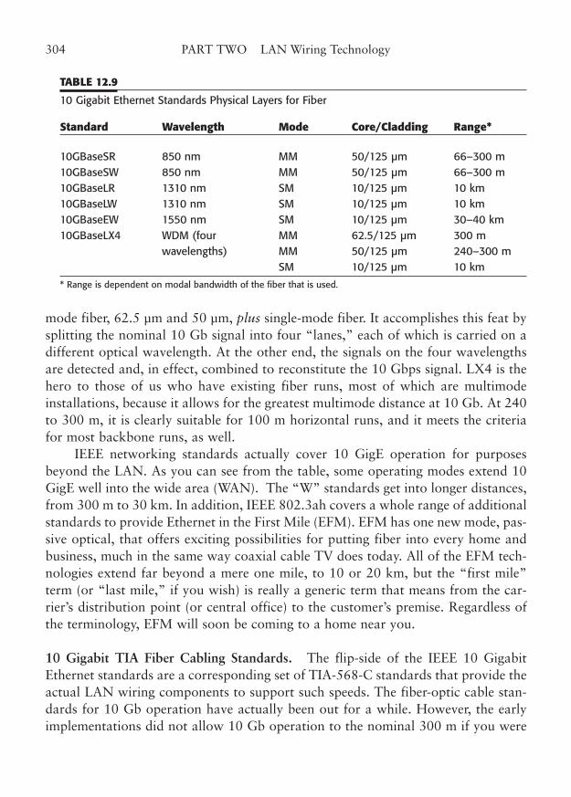
mode fiber, 62.5 µm and 50 µm, plus single-mode fiber. It accomplishes this feat bysplitting the nominal 10 Gb signal into four “lanes,” each of which is carried on adifferent optical wavelength. At the other end, the signals on the four wavelengthsare detected and, in effect, combined to reconstitute the 10 Gbps signal. LX4 is thehero to those of us who have existing fiber runs, most of which are multimodeinstallations, because it allows for the greatest multimode distance at 10 Gb. At 240to 300 m, it is clearly suitable for 100 m horizontal runs, and it meets the criteriafor most backbone runs, as well.
IEEE networking standards actually cover 10 GigE operation for purposesbeyond the LAN. As you can see from the table, some operating modes extend 10GigE well into the wide area (WAN). The “W” standards get into longer distances,from 300 m to 30 km. In addition, IEEE 802.3ah covers a whole range of additionalstandards to provide Ethernet in the First Mile (EFM). EFM has one new mode, pas-sive optical, that offers exciting possibilities for putting fiber into every home andbusiness, much in the same way coaxial cable TV does today. All of the EFM tech-nologies extend far beyond a mere one mile, to 10 or 20 km, but the “first mile”term (or “last mile,” if you wish) is really a generic term that means from the car-rier’s distribution point (or central office) to the customer’s premise. Regardless ofthe terminology, EFM will soon be coming to a home near you.
10 Gigabit TIA Fiber Cabling Standards. The flip-side of the IEEE 10 GigabitEthernet standards are a corresponding set of TIA-568-C standards that provide theactual LAN wiring components to support such speeds. The fiber-optic cable stan-dards for 10 Gb operation have actually been out for a while. However, the earlyimplementations did not allow 10 Gb operation to the nominal 300 m if you were
304 PART TWO LAN Wiring Technology
TABLE 12.9
10 Gigabit Ethernet Standards Physical Layers for Fiber
Standard Wavelength Mode Core/Cladding Range*
10GBaseSR 850 nm MM 50/125 µm 66–300 m10GBaseSW 850 nm MM 50/125 µm 66–300 m10GBaseLR 1310 nm SM 10/125 µm 10 km10GBaseLW 1310 nm SM 10/125 µm 10 km10GBaseEW 1550 nm SM 10/125 µm 30–40 km10GBaseLX4 WDM (four MM 62.5/125 µm 300 m
wavelengths) MM 50/125 µm 240–300 mSM 10/125 µm 10 km
* Range is dependent on modal bandwidth of the fiber that is used.
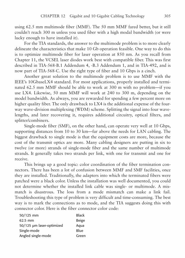
using 62.5 mm multimode fiber (MMF). The 50 mm MMF fared better, but it stillcouldn’t reach 300 m unless you used fiber with a high modal bandwidth (or werelucky enough to have installed it).
For the TIA standards, the answer to the multimode problem is to more clearlydelineate the characteristics that make 10 Gb operation feasible. One way to do thisis to optimize multimode fiber for laser operation at 850 nm. As you recall fromChapter 11, the VCSEL laser diodes work best with compatible fiber. This was firstdescribed in TIA-568-B.1 Addendum 4, -B.3 Addendum 1, and in TIA-492, and isnow part of TIA-568-C. Use the right type of fiber and 10 Gbps is a cinch.
Another great solution to the multimode problem is to use MMF with theIEEE’s 10GbaseLX4 standard. For most applications, properly installed and termi-nated 62.5 mm MMF should be able to work at 300 m with no problem—if youuse LX4. Likewise, 50 mm MMF will work at 240 to 300 m, depending on themodel bandwidth. As always, you are rewarded for spending a few percent more onhigher quality fiber. The only drawback to LX4 is the additional expense of the four-way wave-division multiplexing (WDM) scheme. Splitting the signal into four wave-lengths, and later recovering it, requires additional circuitry, optical filters, andsplitter/combiners.
Single-mode fiber (SMF), on the other hand, can operate very well at 10 Gbps,supporting distances from 10 to 30 km—far above the needs for LAN cabling. Thebiggest drawback to single mode is that the equipment costs are more, because thecost of the transmit optics are more. Many cabling designers are putting in six totwelve (or more) strands of single-mode fiber and the same number of multimodestrands. It generally takes two strands per link, with one for transmit and one forreceive.
This brings up a good topic: color coordination of the fiber termination con-nectors. There has been a lot of confusion between MMF and SMF facilities, oncethey are installed. Traditionally, the adapters into which the terminated fibers werepatched were a black color. Unless the installation was well documented, you couldnot determine whether the installed link cable was single- or multimode. A mis-match is disastrous. The loss from a mode mismatch can make a link fail.Troubleshooting this type of problem is very difficult and time-consuming. The bestway is to mark the connections as to mode, and the TIA suggests doing this withconnector color. Here is the fiber connector color code:
50/125 mm Black62.5 mm Beige50/125 µm laser-optimized AquaSingle-mode BlueAngled single-mode Green
CHAPTER 12 Gigabit and 10 Gigabit Cabling Technology 305
10 Gigabit Standards and Cabling for Copper
At the onset of 10 Gb LAN technology, users and installers of structured wiringfaced the usual two-pronged dilemma. How does one utilize existing cable and whatcable should be installed in new build-outs? As with its approach to gigabit cabling,the TIA has very good answers for both of these 10 Gb questions. The answers are:1) test installed cable to determine the performance parameters that will support 10GigE operation (is it possible with your cable, and to what extent?), and 2) specifynew performance categories for new cabling installations that will work for 10 GigEand everything else.
Existing Category 6 Cabling. Existing Category 6 cable plants constitute a signif-icant problem. TSB-155, from the TIA, handles this problem by specifying extendedperformance measurements that are needed for a 55 m range6 over existingCategory 6 facilities. One of the critical parameters that have been identified for 10Gbps is called alien crosstalk (ANEXT and AFEXT, as well as the power-sum com-ponents). Alien crosstalk is basically interference that comes from a source outsidethe cable jacket. This was not a test parameter in the original Category 6 standard,but greatly affects 10 Gb performance. Another very important new test parameteris the test frequency range of Cat 6. Originally, Cat 6 was tested only to 250 MHz,but testing to 500 MHz is needed for 10 Gb operation.
TSB-155 and IEEE 802.3an provide for this 55 m option over existingCategory 6 cabled runs. Realistically, a large number of runs are within 55 m (~165ft) and can support 10 GigE, as-is. You are in good shape if you bought (and prop-erly installed) cabling and components that meet enhanced performance levelsabove the Cat 6 minimums. You can certainly expect to be able to run 10 GigE to55 m and you might well approach 100 m.
Augmented Category 6 (AC6), Augmented Class E Cabling. Cable and connectormanufacturers have found ways to construct Cat 6 components with enhanced per-formance. This performance category is called Augmented Category 6 by the TIA orAC6, for short. The corresponding IEC standard is Augmented Class E. AC6 istested for both 250 and 500 MHz performance in a number of parameters, includ-ing alien crosstalk. Amendment 10 of TIA-568-B2 is the first to describe theseparameters. The objective is to support 10 GigE to at least 55 to 100 m with Cat 6,and the full 100 m on AC6 (Augmented Class E) cable. Now, doesn’t that give youhope for the future of copper cabling?
306 PART TWO LAN Wiring Technology
6 Although 100 m is the normal length of the shortest channels in TIA-568’s structured wiring, a 55m range is the best that can be expected for Category 6 channels that only meet the minimum specs.
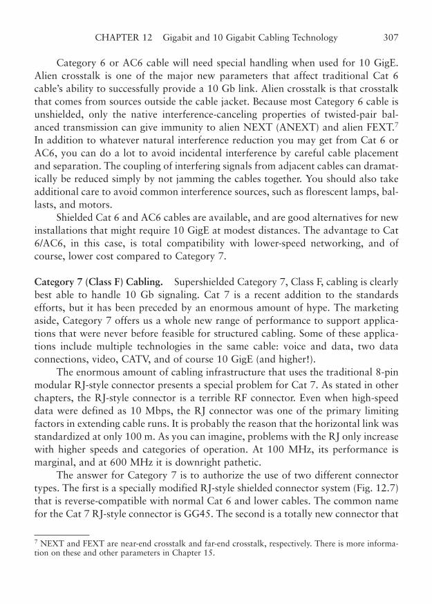
Category 6 or AC6 cable will need special handling when used for 10 GigE.Alien crosstalk is one of the major new parameters that affect traditional Cat 6cable’s ability to successfully provide a 10 Gb link. Alien crosstalk is that crosstalkthat comes from sources outside the cable jacket. Because most Category 6 cable isunshielded, only the native interference-canceling properties of twisted-pair bal-anced transmission can give immunity to alien NEXT (ANEXT) and alien FEXT.7
In addition to whatever natural interference reduction you may get from Cat 6 orAC6, you can do a lot to avoid incidental interference by careful cable placementand separation. The coupling of interfering signals from adjacent cables can dramat-ically be reduced simply by not jamming the cables together. You should also takeadditional care to avoid common interference sources, such as florescent lamps, bal-lasts, and motors.
Shielded Cat 6 and AC6 cables are available, and are good alternatives for newinstallations that might require 10 GigE at modest distances. The advantage to Cat6/AC6, in this case, is total compatibility with lower-speed networking, and ofcourse, lower cost compared to Category 7.
Category 7 (Class F) Cabling. Supershielded Category 7, Class F, cabling is clearlybest able to handle 10 Gb signaling. Cat 7 is a recent addition to the standardsefforts, but it has been preceded by an enormous amount of hype. The marketingaside, Category 7 offers us a whole new range of performance to support applica-tions that were never before feasible for structured cabling. Some of these applica-tions include multiple technologies in the same cable: voice and data, two dataconnections, video, CATV, and of course 10 GigE (and higher!).
The enormous amount of cabling infrastructure that uses the traditional 8-pinmodular RJ-style connector presents a special problem for Cat 7. As stated in otherchapters, the RJ-style connector is a terrible RF connector. Even when high-speeddata were defined as 10 Mbps, the RJ connector was one of the primary limitingfactors in extending cable runs. It is probably the reason that the horizontal link wasstandardized at only 100 m. As you can imagine, problems with the RJ only increasewith higher speeds and categories of operation. At 100 MHz, its performance ismarginal, and at 600 MHz it is downright pathetic.
The answer for Category 7 is to authorize the use of two different connectortypes. The first is a specially modified RJ-style shielded connector system (Fig. 12.7)that is reverse-compatible with normal Cat 6 and lower cables. The common namefor the Cat 7 RJ-style connector is GG45. The second is a totally new connector that
CHAPTER 12 Gigabit and 10 Gigabit Cabling Technology 307
7 NEXT and FEXT are near-end crosstalk and far-end crosstalk, respectively. There is more informa-tion on these and other parameters in Chapter 15.
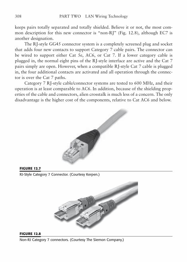
keeps pairs totally separated and totally shielded. Believe it or not, the most com-mon description for this new connector is “non-RJ” (Fig. 12.8), although EC7 isanother designation.
The RJ-style GG45 connector system is a completely screened plug and socketthat adds four new contacts to support Category 7 cable pairs. The connector canbe wired to support either Cat 5e, AC6, or Cat 7. If a lower category cable isplugged in, the normal eight pins of the RJ-style interface are active and the Cat 7pairs simply are open. However, when a compatible RJ-style Cat 7 cable is pluggedin, the four additional contacts are activated and all operation through the connec-tor is over the Cat 7 paths.
Category 7 RJ-style cable/connector systems are tested to 600 MHz, and theiroperation is at least comparable to AC6. In addition, because of the shielding prop-erties of the cable and connectors, alien crosstalk is much less of a concern. The onlydisadvantage is the higher cost of the components, relative to Cat AC6 and below.
308 PART TWO LAN Wiring Technology
FIGURE 12.7
RJ-Style Category 7 Connector. (Courtesy Kerpen.)
FIGURE 12.8
Non-RJ Category 7 connectors. (Courtesy The Siemon Company.)
Non-RJ Category 7 connectors are really a completely new connector systemfor one, two, or four pairs of a Category 7 cable. One of the primary advantages forCategory 7 cable is that it can support multiple applications, due to the extremeshielding between pairs. With this connector, the individual-pair shield is main-tained through the connection, and thus, you could have one cable support data,voice, and CATV video (RF video). Some of these applications only require one pair,while others need two or four pairs. This connector supports them all.
The non-RJ Category 7 system nearly yawns at 600 MHz, it’s so easy. Most ofthese systems can go to 1200 or even 1500 MHz. That makes 10 Gb networkingover copper a snap, and you can expect higher speeds in the future. Soon, the speedswill get so high, that the data will practically get there before you send it.
Flexible Tubing
In Chapter 4, we discussed a way to allow for future changes in cable technology byrunning flexible tubing to each workstation outlet, rather than hard-wiring cable.Admittedly, this method is somewhat more expensive than the conventional cable-in-place method. However, it does have a distinct advantage if and when new cablesmust be installed to meet future needs. With the tubing run, the old cable is simplyremoved and new cable pulled in. None of the ceiling tiles and work areas are dis-turbed, it takes very little time, and it can be easily done one workstation outlet ata time. When it comes time to re-cable, the costs are distinctly lower.
For fiber runs, an interesting technology called blown-in fiber can be used. Thismethod connects fiber distribution panels with workstation areas by small plastictubes. The tubes in a particular work area are gathered into a large tubing to bringthem back to the distribution point. For more information on this technique, con-sult Chapter 11, “Fiber-Optic Techniques.”
Quality Counts
For both copper and fiber structured cabling runs, better performance can beachieved with better quality cable. Well, that should be obvious. However, we nowknow more about what makes a better quality cable and connector, and can meas-ure the relative performance of such components. This involves choosing wiringcomponents with a higher ACR. Such components have lower transmission loss,lower return loss, and lower near-end and far-end crosstalk parameters.
From the information in earlier chapters, you should be able to choose wiringcomponents that meet your current and anticipated needs. Keep the data-rate-dou-bling rule in mind when you pick out a cable. Remember that it is much less expen-
CHAPTER 12 Gigabit and 10 Gigabit Cabling Technology 309

sive to spend 20% or 30% more on an advanced cable construction now, than tospend 100% more to redo your cabling when the future comes slamming in thedoor. Many in the industry are predicting a 5-year, factor-of-10 cycle in networkingspeeds.
That would mean that the gigabit network of today would routinely bereplaced by a 10 Gb network in only 5 years. Considering that the average cableplant is expected to last 15 to 20 years (and many manufacturers offer such war-ranties), it is likely that you will have to upgrade your network long before the cablebecomes physically unusable.
310 PART TWO LAN Wiring Technology
CHAPTER 13
Wireless LANs
Highlights
■ Wireless basics
■ Spread spectrum technology
■ Wireless LAN standards: 802.11, 802.15, 802.16
■ WiFi, WiMAX, Bluetooth, HiperLAN
■ Planning a wireless system
■ Troubleshooting wireless LANs
■ Power over Ethernet (PoE): 802.11af
311
Copyright © 2006 by James Trulove. Click here for terms of use.
Wireless LANs, or WLANs, are becoming a very popular way to extend the networkinto areas where fixed cabling is inconvenient or impossible. IT managers, cablingdesigners, and contractors are often asked to provide connectivity for wireless net-work hubs or even to install wireless networks. It is ironic that wireless networksactually need a certain amount of conventional structured cabling to connect to acorporate network or the Internet. In fact, it may even be possible to provide elec-trical power to wireless hubs over the same cable that gives the hub connectivity.This chapter will give you an understanding of wireless networking and the basicsof the technology. For a deeper understanding of WLANs, please consult Build YourOwn Wireless LAN, by James Trulove.
Wireless networks are an exciting new addition to the portfolio of the LANmanager. Many times, the requirements of the physical network are best served byusing a wireless connection to a workstation.
Wireless Applications
The applications where a wireless bridge should be considered fall into two generalcategories: need and value. The wireless applications that need portability are themost obvious.
For example, consider the use of wireless networking in a hospital environ-ment. Wireless sensors and laptop or tablet computers can be used to free bothpatients and staff from wires. Monitoring devices wirelessly convey each patient’svital signs to the central network. Doctors and nurses can have quick access to thehospital’s network from any patient’s room, without the expense and trouble of con-ventional wired computers. Clearly, the needs of this application are for the flexibil-ity and portability of a wireless network.
The same needs-based analysis may be applied in other circumstances. Forexample, portable or hand-held devices can be used in stores and warehouses to per-form inventory and order fulfillment functions. Even the forklift operator can takeadvantage of a wireless network.
Wireless networks may also be justified by their value, either through a directcost analysis, or through their relative value to the user. As an example, consider thecase of an older building that must be wired for network access. Many older build-ings are totally without the drop ceilings of modern office space. In some instances,using conventional wiring can be done only through extensive (and expensive) rout-ing of cable through older wall structures, masonry, crawl spaces, and attics. Theonly other wired alternative, the use of surface raceways, may detract from theappearance of the rooms and hallways. Only a short time ago, all that was availablewas one of these wired networking options.
312 PART TWO LAN Wiring Technology
However, now you can use a wireless network system to connect computerusers to the Internet, or to an in-house network. This can be done at a comparablecost of conventional wiring, in most cases, without conventional wiring’s disadvan-tages. Historic structures and architectural treasures can be preserved without for-going the benefits of modern technology.
Another example of the value-oriented decision is convenience. You could eas-ily connect to your corporate network at the conference table, in the cafeteria, or inthe lobby with wireless networking. In an educational setting, the instructor and thestudents could carry their laptop computers into the classroom and immediatelyconnect to the campus network anywhere in the lecture hall.
Visitor registration desks, security stations, conference rooms, and cafeteriascan easily be connected in a moment to a wireless network. The flexibility and con-venience is enormous, thus justifying the slight extra cost of wireless over wired con-nections. And who wouldn’t want to sit in a comfortable chair while fully connectedto the Internet? So, the complete value equation includes more than just cost. Thereis a value to convenience and comfort.
Wireless Basics
Let’s take a quick look at how wireless networking works. Wireless networking isjust a matter of sending and receiving data over radio frequencies. It works about thesame as how all radio devices work. The only differences are the modulation and theactual frequency that is used (it’s about 25 times the frequency of broadcast FM).
Wireless equipment is all around us. From pure audio-style radio, to broadcasttelevision, to cellular telephones, we use wireless technology every day. But to usewireless networks, we need to understand a little more detail about how wirelesstransmission and reception work.
Radio-Frequency Operation
Transmitting information through the air (or through space) is actually done by thegeneration of electromagnetic (EM) fields—radio waves—and then “modulating”content in the form of sound, coded pictures, or data.
These EM fields act a little like three-dimensional waves on a lake, becausethey propagate in all directions, reflect off walls and other objects, and are affectedby the medium they pass through. Radio waves bounce off anything that is metal,just like a water wave bouncing off a concrete object, like a dam. Sometimes, theradio wave can penetrate an object, if it is not too thick or does not contain toomuch metal. This is called attenuation, and saps the strength of the radio signal. If
CHAPTER 13 Wireless LANs 313
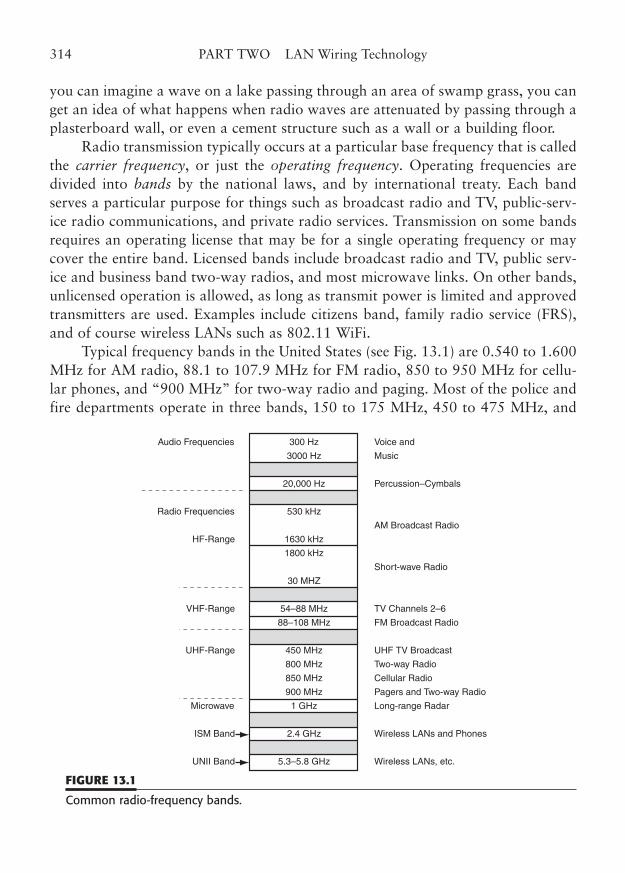
you can imagine a wave on a lake passing through an area of swamp grass, you canget an idea of what happens when radio waves are attenuated by passing through aplasterboard wall, or even a cement structure such as a wall or a building floor.
Radio transmission typically occurs at a particular base frequency that is calledthe carrier frequency, or just the operating frequency. Operating frequencies aredivided into bands by the national laws, and by international treaty. Each bandserves a particular purpose for things such as broadcast radio and TV, public-serv-ice radio communications, and private radio services. Transmission on some bandsrequires an operating license that may be for a single operating frequency or maycover the entire band. Licensed bands include broadcast radio and TV, public serv-ice and business band two-way radios, and most microwave links. On other bands,unlicensed operation is allowed, as long as transmit power is limited and approvedtransmitters are used. Examples include citizens band, family radio service (FRS),and of course wireless LANs such as 802.11 WiFi.
Typical frequency bands in the United States (see Fig. 13.1) are 0.540 to 1.600MHz for AM radio, 88.1 to 107.9 MHz for FM radio, 850 to 950 MHz for cellu-lar phones, and “900 MHz” for two-way radio and paging. Most of the police andfire departments operate in three bands, 150 to 175 MHz, 450 to 475 MHz, and
314 PART TWO LAN Wiring Technology
Audio Frequencies
Radio Frequencies
HF-Range
VHF-Range
UHF-Range
Microwave
ISM Band
UNII Band
Voice and
Music
Percussion–Cymbals
AM Broadcast Radio
Short-wave Radio
TV Channels 2–6
FM Broadcast Radio
UHF TV Broadcast
Two-way Radio
Cellular Radio
Pagers and Two-way Radio
Long-range Radar
Wireless LANs and Phones
Wireless LANs, etc.
300 Hz
3000 Hz
20,000 Hz
530 kHz
1630 kHz
1800 kHz
30 MHZ
54–88 MHz
88–108 MHz
450 MHz
800 MHz
850 MHz
900 MHz
1 GHz
2.4 GHz
5.3–5.8 GHz
FIGURE 13.1
Common radio-frequency bands.
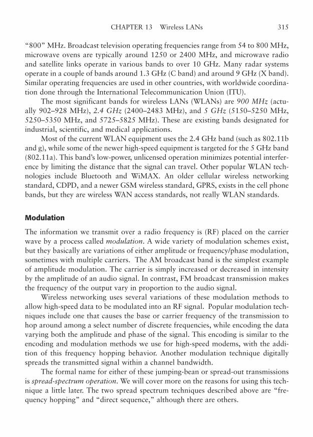
“800” MHz. Broadcast television operating frequencies range from 54 to 800 MHz,microwave ovens are typically around 1250 or 2400 MHz, and microwave radioand satellite links operate in various bands to over 10 GHz. Many radar systemsoperate in a couple of bands around 1.3 GHz (C band) and around 9 GHz (X band).Similar operating frequencies are used in other countries, with worldwide coordina-tion done through the International Telecommunication Union (ITU).
The most significant bands for wireless LANs (WLANs) are 900 MHz (actu-ally 902–928 MHz), 2.4 GHz (2400–2483 MHz), and 5 GHz (5150–5250 MHz,5250–5350 MHz, and 5725–5825 MHz). These are existing bands designated forindustrial, scientific, and medical applications.
Most of the current WLAN equipment uses the 2.4 GHz band (such as 802.11band g), while some of the newer high-speed equipment is targeted for the 5 GHz band(802.11a). This band’s low-power, unlicensed operation minimizes potential interfer-ence by limiting the distance that the signal can travel. Other popular WLAN tech-nologies include Bluetooth and WiMAX. An older cellular wireless networkingstandard, CDPD, and a newer GSM wireless standard, GPRS, exists in the cell phonebands, but they are wireless WAN access standards, not really WLAN standards.
Modulation
The information we transmit over a radio frequency is (RF) placed on the carrierwave by a process called modulation. A wide variety of modulation schemes exist,but they basically are variations of either amplitude or frequency/phase modulation,sometimes with multiple carriers. The AM broadcast band is the simplest exampleof amplitude modulation. The carrier is simply increased or decreased in intensityby the amplitude of an audio signal. In contrast, FM broadcast transmission makesthe frequency of the output vary in proportion to the audio signal.
Wireless networking uses several variations of these modulation methods toallow high-speed data to be modulated into an RF signal. Popular modulation tech-niques include one that causes the base or carrier frequency of the transmission tohop around among a select number of discrete frequencies, while encoding the datavarying both the amplitude and phase of the signal. This encoding is similar to theencoding and modulation methods we use for high-speed modems, with the addi-tion of this frequency hopping behavior. Another modulation technique digitallyspreads the transmitted signal within a channel bandwidth.
The formal name for either of these jumping-bean or spread-out transmissionsis spread-spectrum operation. We will cover more on the reasons for using this tech-nique a little later. The two spread spectrum techniques described above are “fre-quency hopping” and “direct sequence,” although there are others.
CHAPTER 13 Wireless LANs 315
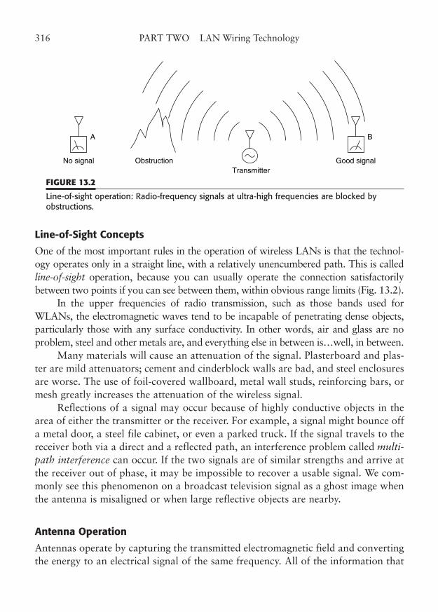
Line-of-Sight Concepts
One of the most important rules in the operation of wireless LANs is that the technol-ogy operates only in a straight line, with a relatively unencumbered path. This is calledline-of-sight operation, because you can usually operate the connection satisfactorilybetween two points if you can see between them, within obvious range limits (Fig. 13.2).
In the upper frequencies of radio transmission, such as those bands used forWLANs, the electromagnetic waves tend to be incapable of penetrating dense objects,particularly those with any surface conductivity. In other words, air and glass are noproblem, steel and other metals are, and everything else in between is…well, in between.
Many materials will cause an attenuation of the signal. Plasterboard and plas-ter are mild attenuators; cement and cinderblock walls are bad, and steel enclosuresare worse. The use of foil-covered wallboard, metal wall studs, reinforcing bars, ormesh greatly increases the attenuation of the wireless signal.
Reflections of a signal may occur because of highly conductive objects in thearea of either the transmitter or the receiver. For example, a signal might bounce offa metal door, a steel file cabinet, or even a parked truck. If the signal travels to thereceiver both via a direct and a reflected path, an interference problem called multi-path interference can occur. If the two signals are of similar strengths and arrive atthe receiver out of phase, it may be impossible to recover a usable signal. We com-monly see this phenomenon on a broadcast television signal as a ghost image whenthe antenna is misaligned or when large reflective objects are nearby.
Antenna Operation
Antennas operate by capturing the transmitted electromagnetic field and convertingthe energy to an electrical signal of the same frequency. All of the information that
316 PART TWO LAN Wiring Technology
No signal Obstruction
A
Good signalTransmitter
B
FIGURE 13.2
Line-of-sight operation: Radio-frequency signals at ultra-high frequencies are blocked byobstructions.
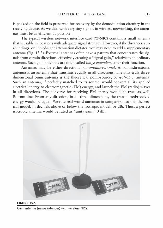
is packed on the field is preserved for recovery by the demodulation circuitry in thereceiving device. As we deal with very tiny signals in wireless networking, the anten-nas must be as efficient as possible.
The typical wireless network interface card (W-NIC) contains a small antennathat is usable in locations with adequate signal strength. However, if the distances, sur-roundings, or line-of-sight attenuation dictates, you may need to add a supplementaryantenna (Fig. 13.3). External antennas often have a pattern that concentrates the sig-nals from certain directions, effectively creating a “signal gain,” relative to an ordinaryantenna. Such gain antennas are often called range extenders, after their function.
Antennas may be either directional or omnidirectional. An omnidirectionalantenna is an antenna that transmits equally in all directions. The only truly three-dimensional omni antenna is the theoretical point-source, or isotropic, antenna.Such an antenna, if perfectly matched to its source, would convert all its appliedelectrical energy to electromagnetic (EM) energy, and launch the EM (radio) wavesin all directions. The converse for receiving EM energy would be true, as well.Bottom line: From any direction, in all three dimensions, the transmitted/receivedenergy would be equal. We rate real-world antennas in comparison to this theoret-ical model, in decibels above or below the isotropic model, or dBi. Thus, a perfectisotropic antenna would be rated as “unity gain,” 0 dBi.
CHAPTER 13 Wireless LANs 317
FIGURE 13.3
Gain antenna (range extender) with wireless NICs.
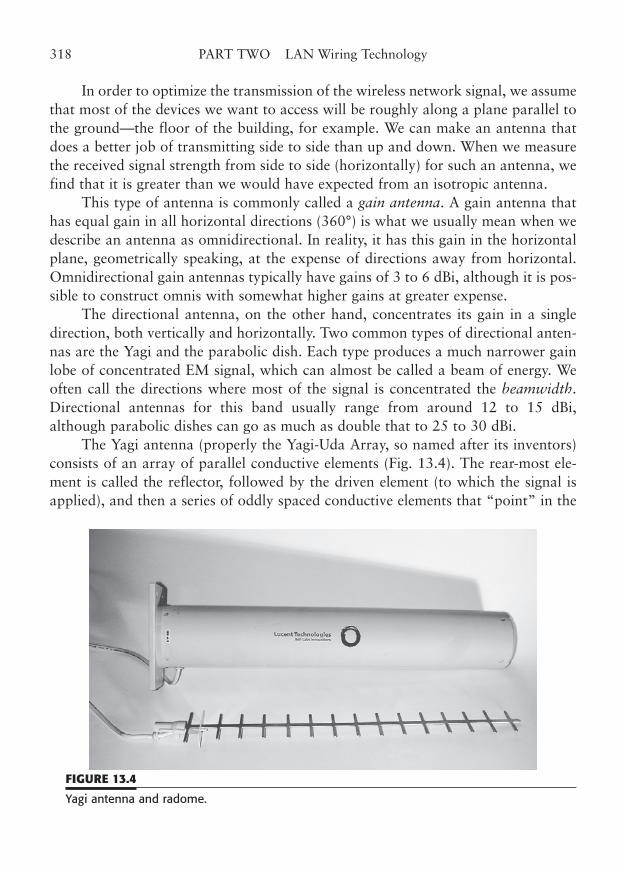
In order to optimize the transmission of the wireless network signal, we assumethat most of the devices we want to access will be roughly along a plane parallel tothe ground—the floor of the building, for example. We can make an antenna thatdoes a better job of transmitting side to side than up and down. When we measurethe received signal strength from side to side (horizontally) for such an antenna, wefind that it is greater than we would have expected from an isotropic antenna.
This type of antenna is commonly called a gain antenna. A gain antenna thathas equal gain in all horizontal directions (360°) is what we usually mean when wedescribe an antenna as omnidirectional. In reality, it has this gain in the horizontalplane, geometrically speaking, at the expense of directions away from horizontal.Omnidirectional gain antennas typically have gains of 3 to 6 dBi, although it is pos-sible to construct omnis with somewhat higher gains at greater expense.
The directional antenna, on the other hand, concentrates its gain in a singledirection, both vertically and horizontally. Two common types of directional anten-nas are the Yagi and the parabolic dish. Each type produces a much narrower gainlobe of concentrated EM signal, which can almost be called a beam of energy. Weoften call the directions where most of the signal is concentrated the beamwidth.Directional antennas for this band usually range from around 12 to 15 dBi,although parabolic dishes can go as much as double that to 25 to 30 dBi.
The Yagi antenna (properly the Yagi-Uda Array, so named after its inventors)consists of an array of parallel conductive elements (Fig. 13.4). The rear-most ele-ment is called the reflector, followed by the driven element (to which the signal isapplied), and then a series of oddly spaced conductive elements that “point” in the
318 PART TWO LAN Wiring Technology
FIGURE 13.4
Yagi antenna and radome.
direction of greatest gain. In most cases, you will see Yagis in the microwave fre-quency ranges (above 1 GHz) encased in a plastic cylindrical covering made of thesame material as a radar’s radome, transparent to the radio waves.
It is interesting to note that all practical antennas exhibit a phenomenon calledeffective area. Effective area is sort of a “capture” area of the antenna. Thus, anantenna with half the effective area would capture half the EM signal. For a dipoleantenna tuned to the frequency of operation, the effective area is inversely proportionalto the frequency of operation. For wireless networking, this means that the antennasused for 5 GHz will have about half the effective area of those we use at 2.4 GHz. Thisaccounts for a received signal that is about half that of the 2.4 GHz case, so we canexpect that there will be about a 3 dB lower signal.1 The net effect of all this is that wecan expect 5 GHz networks to be more limited in range for the same transmitted powerand that we may have to use higher gain antennas to compensate.
So-called parabolic antennas (really paraboloid-reflector antennas) are a spe-cial case. The actual antenna is a small dipole or a feed horn at the focus of the par-abolic dish. The dish essentially captures extra signal, thus artificially increasing theeffective area, and then reflects/concentrates it onto the feed point. Dish antennasare capable of truly awesome gain, and the increase in effective area is proportionalto their size. Practical dish antennas for 2.4 GHz are usually 12 to 18 inches indiameter, and can produce about 15 to 25 dB of gain, which is a little better than amulti-element Yagi.
Dish antennas are also more obtrusive, harder to mount, and more affected bywind. Still, if you could use a 30-m dish…wow!
Interference Sources
All radio transmission is subject to interference from a variety of causes. With the tinysignals (20–100 milliwatts) involved in the unlicensed low-power transmission of 2.4GHz and 5 GHz wireless networking, the most significant issues are the strength ofthe available receive signal, relative to other unwanted signals. Unfortunately, manyother types of RF equipment operate at nearby frequencies and all digital equipmentproduces unwanted or spurious signals. For example, a microwave transmitter,microwave oven, radar, or certain industrial equipment may produce interfering sig-nals. For that matter, other wireless devices operating in the same (or mathematicallyrelated) frequency ranges may interfere with a wireless network.
CHAPTER 13 Wireless LANs 319
1 A decibel (dB) is simply 10 times the log of the power input/output ratio, or 10 log (Pi/Po). Thus, apower ratio of 2:1 equals approximately 3 dB. Likewise, 4:1 corresponds to about 6 dB, and 10:1 cor-responds to 10 dB, exactly. The use of the logarithmic dB unit transforms all the gain/loss calculationsinto simple addition and subtraction.
The unlicensed nature of wireless networking technology also means that theuser must tolerate legal interference sources. This means that you must carefullydesign and site the network to avoid or minimize interference problems.
Spread Spectrum Technology
The term spread spectrum comes from a transmission method whereby the trans-mitted signal is spread out among many frequencies, rather than based at just onecarrier frequency, as with conventional AM and FM transmission. Spread spectrumoperation was originally developed for military use, where radio and radar trans-missions needed to be difficult to detect and relatively immune to detection or jam-ming. This method can put the transmitted signal level just above the level ofambient noise and uses a mathematical algorithm to allow the receiver to knowwhere to look for each signal increment.
Spread spectrum has many advantages in wireless networking applications. Itis inherently low power, and the transmission technique rejects most random inter-ference. Multiple devices can share the same set of frequencies, simply by hoppingto them at different times. The current level of electronic technology makes the com-plex RF and digital circuitry small and affordable.
Frequency-Spreading Variants: DSSS, QFDM, and FHSS
Several types of spread spectrum standards are available. The two most common aredirect sequence spread spectrum (DSSS), quadrature frequency-division multiplexing(QFDM), and frequency-hopping spread spectrum (FHSS). Direct sequence (DSSS) isthe method used for IEEE 802.11b (WiFi) wireless networking at 2.4 GHz and yieldsfrom 2 to 11 Mbps throughput. QFDM is used for 802.11a and 802.11g at 5 GHzand 2.4 GHz, respectively, boosting the maximum data rate to 54 Mbps. FHSS isused for Bluetooth and some older 802.11 equipment, both in the 2.4 GHz band.
In order to receive the spread-spectrum transmissions, the discrete transmit fre-quencies and their exact sequence must be known. Also, a method of synchronizingthe beginning of the sequence must be allowed. Any system that meets the interna-tional standards will use compatible methods of generating the sequence and recov-ering the transmitted data.
Resistance to Interference
Spread spectrum transmission is inherently tolerant of random interference. If, atany one instant an interfering signal is present on one of the hopping frequencies,
320 PART TWO LAN Wiring Technology
the encoding of the data will allow the recovery of the information. This is verymuch the case with pure noise interference. At any given time, a noise pulse may bepresent on a particular discrete frequency, but it is unlikely that it will reoccur onsubsequent hops to that frequency.
Ideally, the operation of the wireless NIC would be such that if the circuitrydetermines that a particular frequency is unavailable, because of a constant interfer-ing signal, the frequency could simply be avoided, thus lowering the data through-put. Unfortunately, regulations governing spread spectrum do not allow thisadaptive interference-avoidance, although some of the WLAN technologies handleit better than others.
Interference and distance can limit the ability of a WLAN signal to reach thehigher data rates. Fortunately, standard operating procedure allows for graceful fall-back of the operating data rate to allow for these conditions. In addition, some wire-less manufacturers offer advanced signal processing techniques to reduce thedegradation caused by multipath interference, and one of the techniques, OFDM, isinherently less susceptible.
Wireless LAN Standards
Several WLAN standards are in current use. Each wireless standard has been devel-oped to provide certain applications with the level of connectivity required. All ofthese standards are evolving, and are changing as new technologies and applicationsare developed.
IEEE 802.11 Standard Operation
The IEEE 802.11 committee was formed to implement standards for operatingEthernet networks over wireless connections. The standard, as usual, embraces sev-eral competing modes of operation, while lending interoperability and order tofuture developments. The Wireless LAN Interoperability Forum and the IEEE bothparticipate in bringing forth operating and protocol standards for this service. IEEE802.11 networks operate at 1 to 108 Mbps nominal data rates.
IEEE 802.11 is also often referred to as WiFi, an acronym for wireless fidelity.The WiFi name has become so universally recognized that the originator of the term,the Wireless Ethernet Compatibility Alliance (WECA), changed its name to the Wi-Fi Alliance. The Wi-Fi Alliance offers the WiFi certification to manufacturers toensure compatibility and interoperability.
The 11 Mbps rate (with a new 5.5 Mbps fall-back) was added in the IEEE802.11b supplement. It is roughly comparable in speed to the wired Ethernet at
CHAPTER 13 Wireless LANs 321
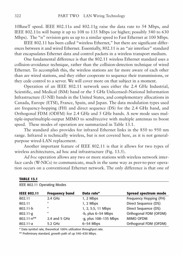
10BaseT speed. IEEE 802.11a and 802.11g raise the data rate to 54 Mbps, andIEEE 802.11n will bump it up to 108 to 135 Mbps (or higher; possibly 540 to 630Mbps). The “n” revision gets us up to a similar speed to Fast Ethernet at 100 Mbps.
IEEE 802.11 has been called “wireless Ethernet,” but there are significant differ-ences between it and wired Ethernet. Essentially, 802.11 is an “air interface” standardthat encapsulates Ethernet data and control packets in a wireless transport medium.
One fundamental difference is that the 802.11 wireless Ethernet standard uses acollision-avoidance technique, rather than the collision-detection technique of wiredEthernet. To accomplish this, the wireless stations are far more aware of each otherthan are wired stations, and they either cooperate to sequence their transmissions, orthey cede control to a server. We will cover more on that subject in a moment.
Operation of an IEEE 802.11 network uses either the 2.4 GHz Industrial,Scientific, and Medical (ISM) band or the 5 GHz Unlicensed–National InformationInfrastructure (U-NII) bands in the United States, and complementary allocations inCanada, Europe (ETSI), France, Spain, and Japan. The data modulation types usedare frequency-hopping (FH) and direct sequence (DS) for the 2.4 GHz band, andOrthogonal FDM (ODFM) for 2.4 GHz and 5 GHz bands. A new mode uses mul-tiple-input/multiple-output MIMO to send/receive with multiple antennas to boostspeed. These modes of operation are summarized in Table 13.1.
The standard also provides for infrared Ethernet links in the 850 to 950 nmrange. Infrared is technically wireless, but is not covered here, as it is not general-purpose wired-LAN replacement.
Another important feature of IEEE 802.11 is that it allows for two types ofwireless architectures, ad hoc and infrastructure (Fig. 13.5).
Ad hoc operation allows any two or more stations with wireless network inter-face cards (W-NICs) to communicate, much in the same way as peer-to-peer opera-tion occurs on a conventional Ethernet network. The only difference is that one of
322 PART TWO LAN Wiring Technology
TABLE 13.1
IEEE 802.11 Operating Modes
IEEE 802.11 Frequency band Data rate* Spread spectrum mode802.11 2.4 GHz 1, 2 Mbps Frequency Hopping (FH)802.11 " 1, 2 Mbps Direct Sequence (DS)802.11-b " 1, 2, 5.5, 11 Mbps Direct Sequence (DS)802.11-g " -b, plus 6–54 Mbps Orthogonal FDM (OFDM)802.11-n** 2.4 and 5 GHz -g, plus 108–135 Mbps MIMO OFDM802.11-a 5.2 GHz 6–54 Mbps Orthogonal FDM (OFDM)
* Data symbol rate, theoretical 100% utilization throughput rate.** Preliminary standard, growth path of up 540–630 Mbps.
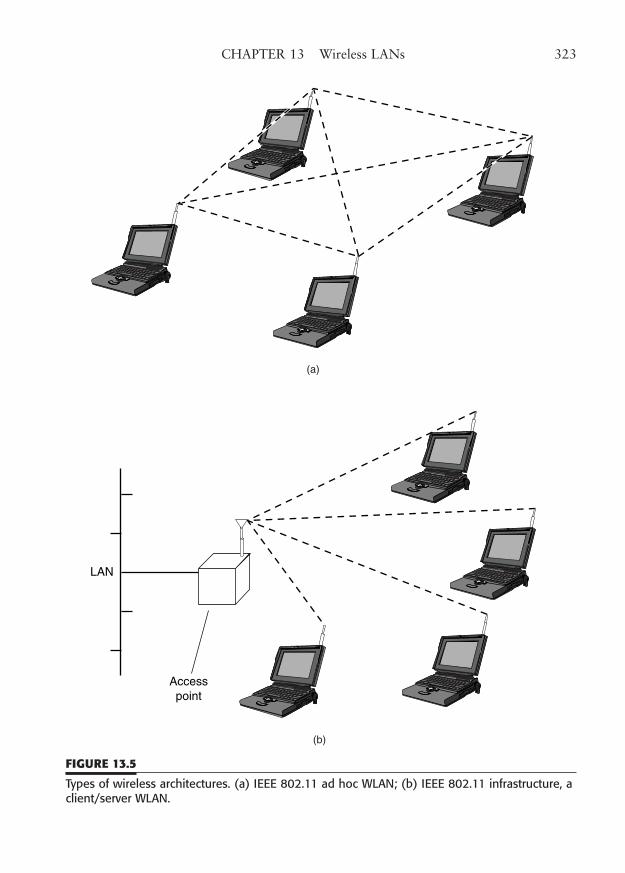
CHAPTER 13 Wireless LANs 323
(a)
LAN
Accesspoint
(b)
FIGURE 13.5
Types of wireless architectures. (a) IEEE 802.11 ad hoc WLAN; (b) IEEE 802.11 infrastructure, aclient/server WLAN.
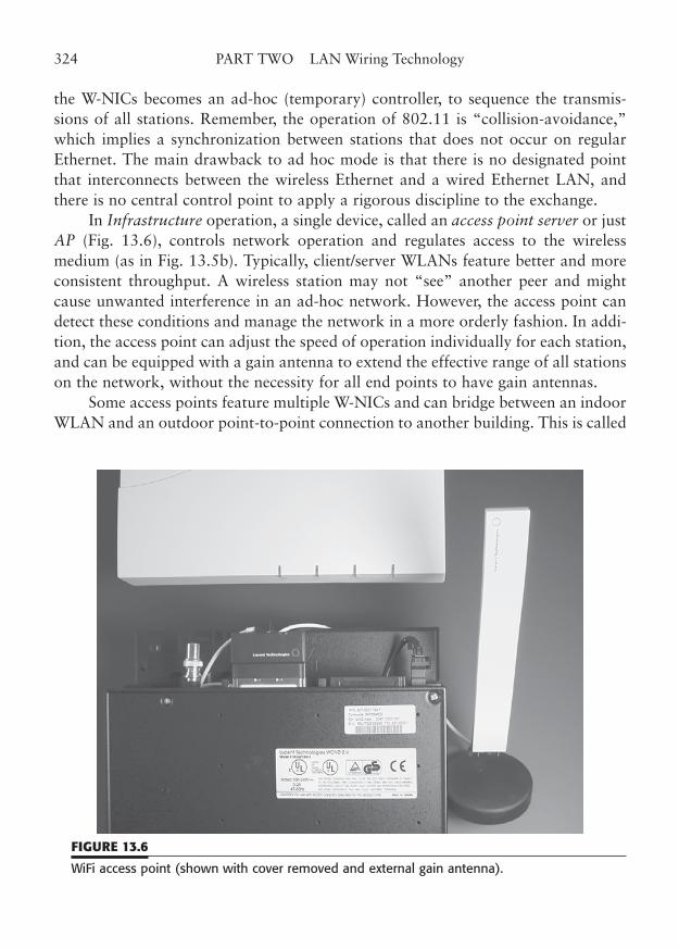
the W-NICs becomes an ad-hoc (temporary) controller, to sequence the transmis-sions of all stations. Remember, the operation of 802.11 is “collision-avoidance,”which implies a synchronization between stations that does not occur on regularEthernet. The main drawback to ad hoc mode is that there is no designated pointthat interconnects between the wireless Ethernet and a wired Ethernet LAN, andthere is no central control point to apply a rigorous discipline to the exchange.
In Infrastructure operation, a single device, called an access point server or justAP (Fig. 13.6), controls network operation and regulates access to the wirelessmedium (as in Fig. 13.5b). Typically, client/server WLANs feature better and moreconsistent throughput. A wireless station may not “see” another peer and mightcause unwanted interference in an ad-hoc network. However, the access point candetect these conditions and manage the network in a more orderly fashion. In addi-tion, the access point can adjust the speed of operation individually for each station,and can be equipped with a gain antenna to extend the effective range of all stationson the network, without the necessity for all end points to have gain antennas.
Some access points feature multiple W-NICs and can bridge between an indoorWLAN and an outdoor point-to-point connection to another building. This is called
324 PART TWO LAN Wiring Technology
FIGURE 13.6
WiFi access point (shown with cover removed and external gain antenna).
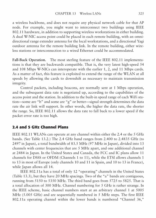
a wireless backbone, and does not require any physical network cable for that APnode. For example, you might want to interconnect two buildings using IEEE802.11 hardware, in addition to supporting wireless workstations in either building.A dual W-NIC access point could be placed in each remote building, with an omni-directional range extender antenna for the local workstations, and a directional Yagioutdoor antenna for the remote building link. In the remote building, either wire-less stations or interconnection to a wired Ethernet could be accommodated.
Fall-Back Operation. The most sterling feature of the IEEE 802.11 implementa-tions is that they are backwards compatible. That is, the very latest high-speed 54and 108 Mbps W-NICs can interoperate with the earlier 1, 2, and 11 Mbps cards.As a matter of fact, this feature is exploited to extend the range of the WLAN at allspeeds by allowing the cards to downshift as necessary to maintain transmissionintegrity.
Control packets, including beacons, are normally sent at 1 Mbps operation,and the subsequent data rate is negotiated up, according to the capabilities of theaccess point and the station. In addition to the built-in speed range of each WiFi sta-tion—some are “b” and some are “g” or better—signal strength determines the datarate the air link will support. In other words, the higher the data rate, the shorterthe range. So, IEEE 802.11 allows the data rate to fall back to a lower speed if thepacket error rate is too high.
2.4 and 5 GHz Channel Plans
IEEE 802.11 WLANs can operate at any channel within either the 2.4 or the 5 GHzbands. (See Table 13.2.) The 2.4 GHz band ranges from 2.400 to 2.4835 GHz (to2497 in Japan), a total bandwidth of 83.5 MHz (97 MHz in Japan), divided into 13channels with center frequencies that are 5 MHz apart, and one additional channelat 2484 in Japan. In the United States and Canada, the FCC and IC plans allow 11channels for DSSS or OFDM (Channels 1 to 11), while the ETSI allows channels 1to 13 in most of Europe (only channels 10 and 11 in Spain, and 10 to 13 in France),while Japan allows all 14.
IEEE 802.11a has a total of only 12 “operating” channels in the United States(Table 13.3), but they have 20 MHz spacings. Two of the “a” bands are contiguous,running from 5150 to 5350 MHz. The third band goes from 5725 to 5825. That isa total allocation of 300 MHz. Channel numbering for 5 GHz is rather strange. Inthe IEEE scheme, basic channel numbers start at an arbitrary channel 1 at 5005MHz (5.005 GHz) and are sequentially numbered in 5 MHz steps. The first IEEE802.11a operating channel within the lower bands is numbered “Channel 36,”
CHAPTER 13 Wireless LANs 325
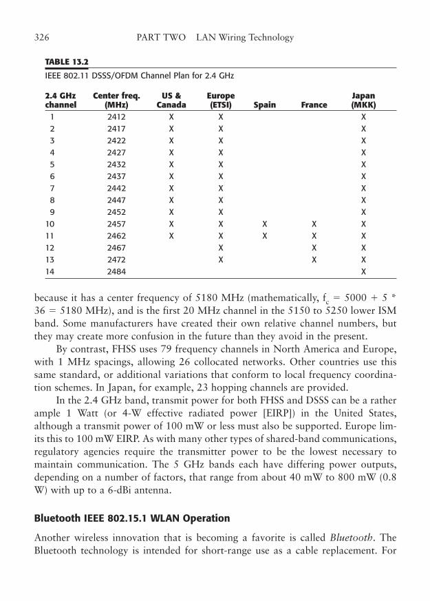
because it has a center frequency of 5180 MHz (mathematically, fc � 5000 � 5 *36 � 5180 MHz), and is the first 20 MHz channel in the 5150 to 5250 lower ISMband. Some manufacturers have created their own relative channel numbers, butthey may create more confusion in the future than they avoid in the present.
By contrast, FHSS uses 79 frequency channels in North America and Europe,with 1 MHz spacings, allowing 26 collocated networks. Other countries use thissame standard, or additional variations that conform to local frequency coordina-tion schemes. In Japan, for example, 23 hopping channels are provided.
In the 2.4 GHz band, transmit power for both FHSS and DSSS can be a ratherample 1 Watt (or 4-W effective radiated power [EIRP]) in the United States,although a transmit power of 100 mW or less must also be supported. Europe lim-its this to 100 mW EIRP. As with many other types of shared-band communications,regulatory agencies require the transmitter power to be the lowest necessary tomaintain communication. The 5 GHz bands each have differing power outputs,depending on a number of factors, that range from about 40 mW to 800 mW (0.8W) with up to a 6-dBi antenna.
Bluetooth IEEE 802.15.1 WLAN Operation
Another wireless innovation that is becoming a favorite is called Bluetooth. TheBluetooth technology is intended for short-range use as a cable replacement. For
326 PART TWO LAN Wiring Technology
TABLE 13.2
IEEE 802.11 DSSS/OFDM Channel Plan for 2.4 GHz
2.4 GHz Center freq. US & Europe Japanchannel (MHz) Canada (ETSI) Spain France (MKK)1 2412 X X X2 2417 X X X3 2422 X X X4 2427 X X X5 2432 X X X6 2437 X X X7 2442 X X X8 2447 X X X9 2452 X X X
10 2457 X X X X X11 2462 X X X X X12 2467 X X X13 2472 X X X14 2484 X
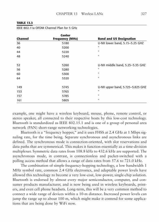
example, one might have a wireless keyboard, mouse, phone, remote control, orstereo speaker, all connected to their respective hosts by this low-cost technology.Bluetooth is standardized as IEEE 802.15.1 and is one of a group of personal areanetwork (PAN) short-range networking technologies.
Bluetooth is a “frequency hopper,” and it uses FHSS at 2.4 GHz at 1 Mbps sig-naling rate, for the time being. Separate synchronous and asynchronous links aredefined. The synchronous mode is connection-oriented, with slot reservations anddata paths that are symmetrical. This makes it function essentially as a time-divisionmultiplexer. Symmetric data rates from 108.8 kHz to 432.6 kHz are supported. Theasynchronous mode, in contrast, is connectionless and packet-switched with apolling access method that allows a range of data rates from 57.6 to 721.0 kHz.
The combination of simple frequency-hopping technology, a low bandwidth 1MHz symbol rate, common 2.4 GHz electronics, and adaptable power levels haveallowed this technology to become a very low-cost, low-power, single-chip solution.Bluetooth is endorsed by almost every major semiconductor, computer, and con-sumer products manufacturer, and is now being used in wireless keyboards, print-ers, and even cell phone headsets. Long-term, this will be a very common method toconnect a wide range of devices within a 10-m distance. Increased power levels canjump the range up to about 100 m, which might make it contend for some applica-tions that are being done by WiFi now.
CHAPTER 13 Wireless LANs 327
TABLE 13.3
IEEE 802.11a OFDM Channel Plan for 5 GHz
CenterChannel Frequency (MHz) Band and US Designation36 5180 U-NII lower band, 5.15–5.25 GHZ40 5200 "44 5220 "48 5240 "
52 5260 U-NII middle band, 5.25–5.35 GHZ56 5280 "60 5300 "64 5320 "
149 5745 U-NII upper band, 5.725–5.825 GHZ153 5765 "157 5785 "161 5805 "
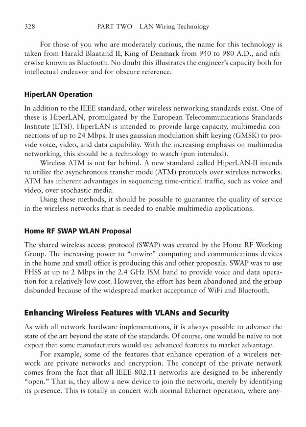
For those of you who are moderately curious, the name for this technology istaken from Harald Blaatand II, King of Denmark from 940 to 980 A.D., and oth-erwise known as Bluetooth. No doubt this illustrates the engineer’s capacity both forintellectual endeavor and for obscure reference.
HiperLAN Operation
In addition to the IEEE standard, other wireless networking standards exist. One ofthese is HiperLAN, promulgated by the European Telecommunications StandardsInstitute (ETSI). HiperLAN is intended to provide large-capacity, multimedia con-nections of up to 24 Mbps. It uses gaussian modulation shift keying (GMSK) to pro-vide voice, video, and data capability. With the increasing emphasis on multimedianetworking, this should be a technology to watch (pun intended).
Wireless ATM is not far behind. A new standard called HiperLAN-II intendsto utilize the asynchronous transfer mode (ATM) protocols over wireless networks.ATM has inherent advantages in sequencing time-critical traffic, such as voice andvideo, over stochastic media.
Using these methods, it should be possible to guarantee the quality of servicein the wireless networks that is needed to enable multimedia applications.
Home RF SWAP WLAN Proposal
The shared wireless access protocol (SWAP) was created by the Home RF WorkingGroup. The increasing power to “unwire” computing and communications devicesin the home and small office is producing this and other proposals. SWAP was to useFHSS at up to 2 Mbps in the 2.4 GHz ISM band to provide voice and data opera-tion for a relatively low cost. However, the effort has been abandoned and the groupdisbanded because of the widespread market acceptance of WiFi and Bluetooth.
Enhancing Wireless Features with VLANs and Security
As with all network hardware implementations, it is always possible to advance thestate of the art beyond the state of the standards. Of course, one would be naïve to notexpect that some manufacturers would use advanced features to market advantage.
For example, some of the features that enhance operation of a wireless net-work are private networks and encryption. The concept of the private networkcomes from the fact that all IEEE 802.11 networks are designed to be inherently“open.” That is, they allow a new device to join the network, merely by identifyingits presence. This is totally in concert with normal Ethernet operation, where any-
328 PART TWO LAN Wiring Technology
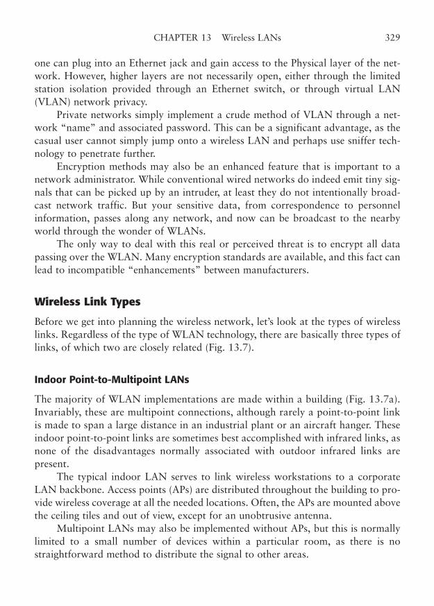
one can plug into an Ethernet jack and gain access to the Physical layer of the net-work. However, higher layers are not necessarily open, either through the limitedstation isolation provided through an Ethernet switch, or through virtual LAN(VLAN) network privacy.
Private networks simply implement a crude method of VLAN through a net-work “name” and associated password. This can be a significant advantage, as thecasual user cannot simply jump onto a wireless LAN and perhaps use sniffer tech-nology to penetrate further.
Encryption methods may also be an enhanced feature that is important to anetwork administrator. While conventional wired networks do indeed emit tiny sig-nals that can be picked up by an intruder, at least they do not intentionally broad-cast network traffic. But your sensitive data, from correspondence to personnelinformation, passes along any network, and now can be broadcast to the nearbyworld through the wonder of WLANs.
The only way to deal with this real or perceived threat is to encrypt all datapassing over the WLAN. Many encryption standards are available, and this fact canlead to incompatible “enhancements” between manufacturers.
Wireless Link Types
Before we get into planning the wireless network, let’s look at the types of wirelesslinks. Regardless of the type of WLAN technology, there are basically three types oflinks, of which two are closely related (Fig. 13.7).
Indoor Point-to-Multipoint LANs
The majority of WLAN implementations are made within a building (Fig. 13.7a).Invariably, these are multipoint connections, although rarely a point-to-point linkis made to span a large distance in an industrial plant or an aircraft hanger. Theseindoor point-to-point links are sometimes best accomplished with infrared links, asnone of the disadvantages normally associated with outdoor infrared links arepresent.
The typical indoor LAN serves to link wireless workstations to a corporateLAN backbone. Access points (APs) are distributed throughout the building to pro-vide wireless coverage at all the needed locations. Often, the APs are mounted abovethe ceiling tiles and out of view, except for an unobtrusive antenna.
Multipoint LANs may also be implemented without APs, but this is normallylimited to a small number of devices within a particular room, as there is nostraightforward method to distribute the signal to other areas.
CHAPTER 13 Wireless LANs 329
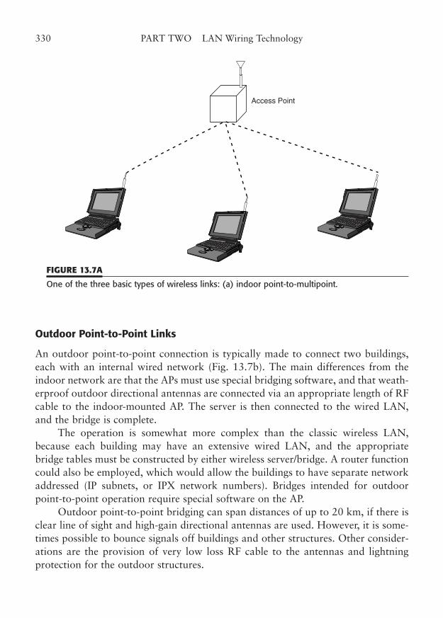
Outdoor Point-to-Point Links
An outdoor point-to-point connection is typically made to connect two buildings,each with an internal wired network (Fig. 13.7b). The main differences from theindoor network are that the APs must use special bridging software, and that weath-erproof outdoor directional antennas are connected via an appropriate length of RFcable to the indoor-mounted AP. The server is then connected to the wired LAN,and the bridge is complete.
The operation is somewhat more complex than the classic wireless LAN,because each building may have an extensive wired LAN, and the appropriatebridge tables must be constructed by either wireless server/bridge. A router functioncould also be employed, which would allow the buildings to have separate networkaddressed (IP subnets, or IPX network numbers). Bridges intended for outdoorpoint-to-point operation require special software on the AP.
Outdoor point-to-point bridging can span distances of up to 20 km, if there isclear line of sight and high-gain directional antennas are used. However, it is some-times possible to bounce signals off buildings and other structures. Other consider-ations are the provision of very low loss RF cable to the antennas and lightningprotection for the outdoor structures.
330 PART TWO LAN Wiring Technology
Access Point
FIGURE 13.7A
One of the three basic types of wireless links: (a) indoor point-to-multipoint.
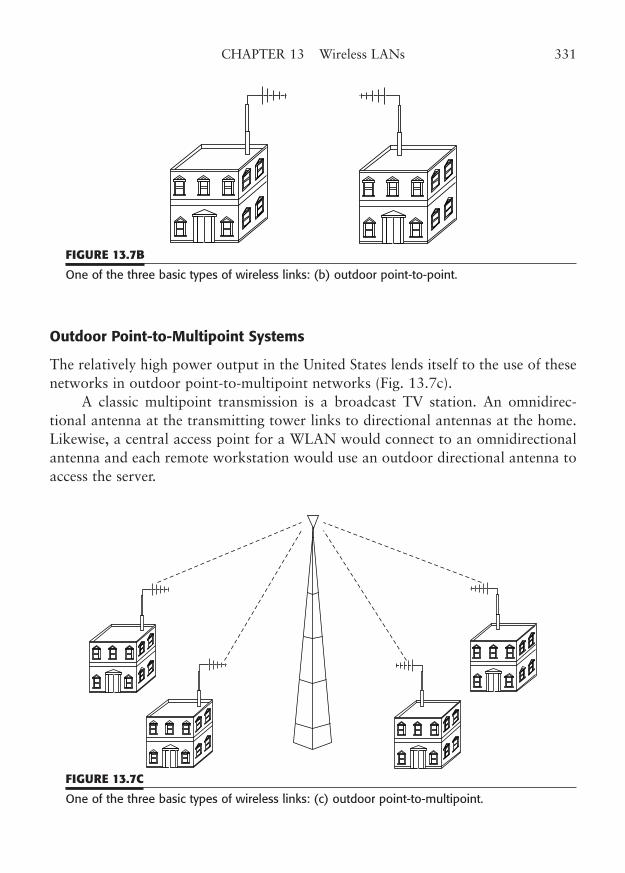
Outdoor Point-to-Multipoint Systems
The relatively high power output in the United States lends itself to the use of thesenetworks in outdoor point-to-multipoint networks (Fig. 13.7c).
A classic multipoint transmission is a broadcast TV station. An omnidirec-tional antenna at the transmitting tower links to directional antennas at the home.Likewise, a central access point for a WLAN would connect to an omnidirectionalantenna and each remote workstation would use an outdoor directional antenna toaccess the server.
CHAPTER 13 Wireless LANs 331
FIGURE 13.7B
One of the three basic types of wireless links: (b) outdoor point-to-point.
FIGURE 13.7C
One of the three basic types of wireless links: (c) outdoor point-to-multipoint.
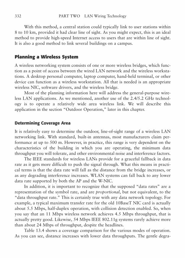
With this method, a central station could typically link to user stations within8 to 10 km, provided it had clear line of sight. As you might expect, this is an idealmethod to provide high-speed Internet access to users that are within line of sight.It is also a good method to link several buildings on a campus.
Planning a Wireless System
A wireless networking system consists of one or more wireless bridges, which func-tion as a point of access between the wired LAN network and the wireless worksta-tions. A desktop personal computer, laptop computer, hand-held terminal, or otherdevice can function as a wireless workstation. All that is needed is an appropriatewireless NIC, software drivers, and the wireless bridge.
Most of the planning information here will address the general-purpose wire-less LAN applications. As we mentioned, another use of the 2.4/5.2 GHz technol-ogy is to operate a relatively wide area wireless link. We will describe thisapplication in the section “Outdoor Operation,” later in this chapter.
Determining Coverage Area
It is relatively easy to determine the outdoor, line-of-sight range of a wireless LANnetworking link. With standard, built-in antennas, most manufacturers claim per-formance at up to 500 m. However, in practice, this range is very dependent on thecharacteristics of the building in which you are operating, the minimum datathroughput you will tolerate, and other environmental noise and interference factors.
The IEEE standards for wireless LANs provide for a graceful fallback in datarate as it gets more difficult to push the signal through. What this means in practi-cal terms is that the data rate will fall as the distance from the bridge increases, oras any degrading interference increases. WLAN systems can fall back to any lowerdata rate supported by both the AP and the W-NIC.
In addition, it is important to recognize that the supposed “data rates” are arepresentation of the symbol rate, and are proportional, but not equivalent, to the“data throughput rate.” This is certainly true with any data network topology. Forexample, a typical maximum transfer rate for the old 10BaseT NIC card is actuallyabout 5.5 Mbps, half-duplex operation, with collision detection enabled. So, whenyou say that an 11 Mbps wireless network achieves 4.5 Mbps throughput, that isactually pretty good. Likewise, 54 Mbps IEEE 802.11g systems rarely achieve morethan about 24 Mbps of throughput, despite the headlines.
Table 13.4 shows a coverage comparison for the various modes of operation.As you can see, distance increases with lower data throughputs. The gentle degra-
332 PART TWO LAN Wiring Technology
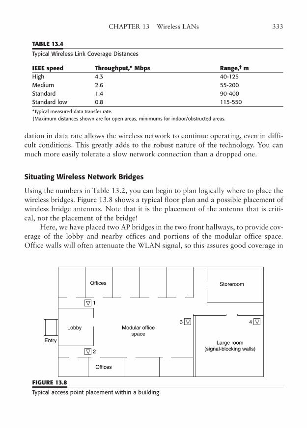
dation in data rate allows the wireless network to continue operating, even in diffi-cult conditions. This greatly adds to the robust nature of the technology. You canmuch more easily tolerate a slow network connection than a dropped one.
Situating Wireless Network Bridges
Using the numbers in Table 13.2, you can begin to plan logically where to place thewireless bridges. Figure 13.8 shows a typical floor plan and a possible placement ofwireless bridge antennas. Note that it is the placement of the antenna that is criti-cal, not the placement of the bridge!
Here, we have placed two AP bridges in the two front hallways, to provide cov-erage of the lobby and nearby offices and portions of the modular office space.Office walls will often attenuate the WLAN signal, so this assures good coverage in
CHAPTER 13 Wireless LANs 333
TABLE 13.4
Typical Wireless Link Coverage Distances
IEEE speed Throughput,* Mbps Range,† mHigh 4.3 40-125 Medium 2.6 55-200 Standard 1.4 90-400 Standard low 0.8 115-550
*Typical measured data transfer rate.†Maximum distances shown are for open areas, minimums for indoor/obstructed areas.
Large room(signal-blocking walls)
Entry
1
2
Offices
Offices
Storeroom
Lobby Modular officespace
3 4
FIGURE 13.8
Typical access point placement within a building.
these areas. A third bridge is placed at the back of the modular offices to providecoverage there, as well as to nearby offices and the storeroom. A large room (whichcould be an auditorium, a cafeteria, or a meeting room) has walls that obstruct thewireless signal, so bridge 4 is placed there.
In some cases, you can use bridges with multiple transceivers and antennas tocover additional areas. For example, some of the manufacturers offer dual-trans-ceiver bridges, so one antenna can be placed in an interior location and the otherplaced outside the building. In the example floor plan, it might be possible to elim-inate bridge 4 by using a dual NIC bridge in location 3, with one antenna inside thelarge room. In addition, an external antenna could be used either for outside wire-less coverage or to bridge to another building’s LAN.
The exact number of wireless devices that can be covered from a singlebridge/antenna depends totally on the conditions and the desired coverage area. Anupper limit is about 200 devices, but you will want to limit the number of devicesin the same way you would with a normal Ethernet segment. Most network man-agers like to keep this number well under 100 stations for a 10 Mbps Ethernet seg-ment, depending on usage and applications.
In a crowded environment, with limited coverage because of building walls orother obstructions, you will probably want to limit the number of wireless worksta-tions to no more than 50. Actually, this limit is not that low, as it may be difficultto get 50 wireless workstations within the 200- to 300-ft indoor range of the wire-less bridge.
Using Range Extender Antennas
Gain antennas may effectively extend the range of a wireless system (see Fig. 13.2).Antennas are rated in dB over isotropic, and the higher the number, the greater theamplitude of the transmitted or received signal. Decibels are a logarithmic powerratio. A good rule of thumb is that a 3 dB increase represents a doubling of the power.Unfortunately, the available captured power decreases as the square of the distancefrom the transmitter, so it takes about a 6 dB increase to effectively double the range.
Nevertheless, gain antennas are a very effective means of increasing the usablecoverage area of a wireless bridge. A cautious approach is to use gain antennas forevery bridge, and add a gain antenna for specific workstations that suffer the slowdata rates that go along with a marginal signal.
It is important to recognize that the effect of the extender antenna is bidirec-tional. That is, you increase both the received signal and the effective transmittedsignal. With a gain antenna, you really cannot lose.
334 PART TWO LAN Wiring Technology
You place the antennas where you want the signal. This means that you couldlocate a bridge some distance from the antenna, and connect the two with coaxialcable. Keep in mind that the dB losses increase rather quickly in proportion to thelength of the cable. So, you must use high-quality cable designed for operation atthe 2.4 GHz or higher frequencies to keep losses to a minimum. Most WLAN gainantennas come with a 3- to 10-m segment of coax. Feel free to have a custom lengthmade, with appropriate test results to guarantee performance. Extremely low-losscable is available for a premium.
For that matter, you could make up your own cables, if you have the propertools and knowledge. After all, you are capable of doing your own twisted-paircabling. Just keep in mind that you are dealing with frequencies up to 20 timeshigher than Ethernet networks, so you really have to construct these cables withcare. If you have access to a loss measuring device for 2.4 GHz, you can test theresulting cable to be sure you get what you are paying yourself for.
A word about the care and feeding of coaxial cable is appropriate here. Just as withour relatively fragile Category 5e and better cable, you must be careful with the handlingand routing of coaxial cable. As covered in Chapter 5, coax consists of an outer conduc-tive shield and an inner center conductor, separated by an insulating “dielectric” layer.Any distortion of the dielectric material, through bending or compression, will cause anattenuation of the signal. Attenuation is sort of like a negative gain.
So don’t crimp, bend, break, pull, or tie-wrap coaxial cables excessively. Takecare of your cable and it will take care of you.
Site Survey for Wireless LANs
In our simple building example, placing the wireless bridges was fairly easy. We hada small number of offices to cover in a simple building structure. However, this israrely the case in practice. To create a much better estimate of the number of bridgesand their placement, you should conduct a site survey.
There are two ways to do a site survey, and as you might expect, the survey’scost is the most apparent difference. However, the quality of the results is the realdefining factor. Be careful which you use, unless you have no problem adding addi-tional APs and resituating existing ones to optimize coverage. If you have bid aninstallation, with no caveats to the buyer, adding the additional bridge or two canbe very costly. On the other hand, if you are the user, and if you have a relativelysmall location to cover, it may be much cheaper to use the “casual” site survey andthe advice of a knowledgeable installer to make a best-effort estimate of yourrequirements.
CHAPTER 13 Wireless LANs 335
The two site survey methods are what we will call “casual” and “full.” In bothsituations, the building layout is considered, probable bridge locations plotted, andthe extent of wireless coverage is detailed.
The casual site survey is done with actual WLAN links. A wireless bridge is tem-porarily set up in each likely bridge location and the antenna that will be used is tem-porarily mounted at or near the expected permanent location. For example, if youplan to mount the bridges above the ceiling tile in a hallway, place the antenna in theapproximate planned location below the ceiling grid and drape the coax down to thebridge. Remember that it is the antenna that transmits the signal into space, and thebridge location does not matter. If you plan to use the internal antennas on thebridge’s transceiver card, then you really should try to get the bridge up near the ceil-ing. Try mounting the bridge on an 8-ft board (such as a 1 � 6 � 8 ft) and proppingthe board up against the wall to simulate mounting the bridge on the wall.
Now, use a laptop that is equipped with an appropriate W-NIC to test the sig-nal strength in the desired locations with the expected range of the bridge. The clientsoftware drivers for the W-NIC generally have a test mode that displays the signalstrength at each end of the link. You need to know how well the bridge is receivingthe remote signal, as well as how well you are receiving the bridge’s signal.
Remember that walls, ceilings, and even floors are important in relation to thewireless devices. So, place the laptop on a desk where it will be used to test the link.If you doubt this phenomenon, simply go to a distance from the bridge where thesignal becomes weak, and place your hand over the W-NIC’s antenna. The signalwill drop to unusable in an instant.
The full site survey is performed with sophisticated field-strength measuringequipment. A test signal is sent to a test antenna in the planned wireless bridge loca-tion and the receive signal strength is measured at various locations through thedesired coverage area. The test antenna is moved as necessary to achieve adequatesignal strength at every desired point. The path loss can be determined from themeasurements, and appropriate corrective actions taken. Typical actions thatincrease signal strength are to use gain antennas, use secondary antennas, adjustantenna (and possibly bridge) locations, and add additional bridge locations.
It is amazing what a tiny adjustment to a bridge antenna placement can do forthe received signal strength at these frequencies. For example, in a location wheremetallic shielding of sheet metal or foil-covered ductwork is a factor, a mere 6- to12-in change in antenna location can cause a 10- to 12-dB increase in signalstrength, measured 50 ft away!
It sometimes helps to pretend that you can sense the LAN signals. Try to imag-ine that the radio waves are light from a bulb. The farther away you go, the dim-mer the light, and the less the signal. If you move the light behind an opaque object,
336 PART TWO LAN Wiring Technology
the light decreases almost to darkness. If the light passes through a window screenor curtains, some of the light gets through, but it is much dimmer. It is just as if youhad increased the distance. That simulates the attenuation of ultrahigh-frequencysignals, except that real radio waves can go right through objects, such as plaster-board, that are quite opaque to light.
While this method is very useful in WLAN planning, please don’t tell anybodyelse you are doing this, and do try to keep it to a minimum. We wouldn’t want yourunning around acting as if radio waves are real.
Outdoor Operation
Outdoor operation of a WLAN has two requirements that differ from the indoorcounterparts. Those are the use of weatherproof wireless antennas (see Fig. 13.4),and the concept of LAN-to-LAN bridges. The first requirement is really rather triv-ial, as it exactly mimics the indoor operation, except that a waterproof antenna andcable are used, lightning protection must be provided, and special antenna mount-ing hardware and structures are required.
As with any outdoor mountings, you must make a stable mechanical mount-ing, and allow for the effects of wind, rain, sun, snow, and ice.
The outdoor Yagi antennas for 2.5 GHz and above are often mounted with plas-tic radome coverings that protect the antenna from many of the effects of weather andcorrosion. You should use highest-quality connectors on the connecting coaxial cable,and protect them from the elements with a clear silicone rubber material that isdesigned for this purpose. The sealant is available in most stores that sell TV antennas.
While national and local codes provide the exact specifications for lightningprotection of outdoor antenna systems, common sense should insist that you pro-vide the very best protection for the sensitive networking equipment that you can.Run the drain wires to appropriate ground rods or approved structures. Lightninghappens … don’t let it be your problem.
Outdoor operation can be also multipoint, with an omnidirectional antenna,and you could certainly connect to laptop computers outside. This would techni-cally be an outdoor application.
The LAN-to-LAN bridge, however, is generally what most vendors mean whenthey refer to “outdoor” operation. Point-to-point or point-to-multipoint operationoften requires special operating software for the bridges, in addition to the sameweatherproof antennas and mounts.
If you are connecting from a multiple-station LAN on one side of the link to amultiple-station LAN on the other side, you will need two bridges with the specialinter-LAN connection software. Some bridges actually have two wireless transceiver
CHAPTER 13 Wireless LANs 337
cards so they can connect between two wired LANs on either side and, in addition,to two wireless networks on either side of the link.
For outdoor LAN-to-LAN operation, use directional gain antennas. If you arestrictly point-to-point, which means only two end points, you can use directionalantennas at both bridges. Highly directional antennas are available to give you arange of 10 to 20 km. You will need Yagi or even parabolic antennas to achieve thisrange, and you must still have optical line of sight.
If you want to go point to multipoint, you will use an omnidirectional antennaat the main site, and directional antennas at the remote sites. These directionalantennas will be pointed at the main site, as before. The range will be reduced,because the central omnidirectional antenna will not have as high a gain as thedirectional antenna used in the point-to-point case. However, coverage will still beexcellent. Line of sight is required, as before. This mode of operation is suitable fora small campus connection to several buildings or even a connection between usersand an Internet service provider.
New options are available at data rates beyond 11 Mbps, to 54 MHz andabove. We have covered WLAN operation here. However, operation of wirelessconnections for non-LAN traffic is also possible with special hardware. For exam-ple, wireless devices are available to interconnect buildings at 56 kbps, T1, DS3, andOC-3 rates. In fact, all of the older microwave links used these rates, but theyrequired special licensing and siting, and were intended for long intercity links.
Our WLAN operation, on the other hand, uses unlicensed frequency bands,lower power, and shorter distances.
Troubleshooting Wireless LANs
All computer systems periodically require maintenance and repair. If you think ofthe wireless network as just another computer system, you can use the same tech-niques to troubleshoot and repair these networks.
We prefer a step-by-step approach that separates the overall system into eachcomponent part. We then determine which subset of component parts could becausing the symptoms we see. Then, through an orderly process of elimination andsubstitution, we isolate the component that has failed and make a repair.
Determine the Scope
First in this process is to determine specifically how much of the network isaffected by the problem. In the case of the wireless network, we are frequently
338 PART TWO LAN Wiring Technology
interconnected to a wired network, which forms the backbone for our wirelesssystem.
Ask logical questions about the network outage, even if parenthetically.Actually, if you ask the questions to yourself and then simply state the conclusionaloud, you may be seen as a wizard, rather than as a fool.
So, you might think, “Gee, are all the wireless devices out of service, or onlythose in one area?” But you would say, “Only the devices served by Bridge 3 are outof service, so let’s check it out first.” Then, you can begin to check the LAN connec-tion to the bridge, the W-NIC cards, the antenna, the coax, and even the power toBridge 3.
Line-of-Sight Problems
Many of the problems with wireless LANs are caused by simple obstructions in thepath from bridge to workstation. You need to know if something has changed inthat path. For example, remodeling could add walls or shielding metal to the path.Or, something as simple as a metal filing cabinet could have been moved in the way.Look for simple things first, and determine if something has changed to make thesignal strength marginal.
The easiest way to determine line-of-sight problems is to imagine the radiowaves’ path from workstation to AP. Remember that the signals can penetrate cer-tain types of structures, although there is always a signal decrease when this hap-pens. Use any built-in signal level indicator in the wireless client software to helpdiagnose this issue. You may add or move a range extender antenna at the worksta-tion. However, the antennas at the wireless AP should be relocated with caution, astheir position affects the reception at all workstations. Sometimes, a time-of-dayproblem may actually be a line-of-sight problem. For example, a delivery truckmight block signal from a nearby server.
In a few cases, you may actually be able to compensate for a line-of-sight prob-lem with a reflector made from sheet metal or foil. If all else fails, try to plot the sig-nal path and experiment with reflectors from 2 to 4 ft square. Radio waves bounceoff a reflector much like light off a mirror, so place the reflector accordingly. Whilealmost any metal object will reflect the wireless LAN signal (or attenuate it frompassing through), a highly conductive surface, such as a copper sheet, will workbest. If you are skeptical, simply take a close look at many of the microwave com-munication towers littering the landscape. You may note that many of them actu-ally have the transmitting dish mounted at ground level, pointed straight up to areflector high up on the tower.
CHAPTER 13 Wireless LANs 339
Interference
Many types of equipment can create interfering signals in the WLAN operatingbands. As stated before, these bands are shared with other services, and we must tol-erate any interference that is deemed to be a legal use of the band.
In some cases, the interference may be significant because of the relative weak-ness of our desired signal (for example, from the bridge). The cure may be to addan extender antenna to the workstation, or to the bridge. In severe cases, a direc-tional antenna with a higher gain may be necessary. Also, the application may sim-ply require an addition of another AP bridge. In rare cases, an improper level ofinterference may even be illegal.
You should be able to locate the source and measure the level of the interfer-ence with appropriate signal-strength equipment. The same type of equipment thatis used in a full site survey can also help locate these interference sources if you usea directional antenna for the tracking.
Typical sources of interference might be microwave ovens, microwave or radartransmissions, industrial heating and welding equipment, certain medical equip-ment, any digital equipment (such as a computer or a monitor), radio transmitters,and finally other WLANs. Any device that emits RF energy in the frequency bandsused by your WLAN is a potential culprit, whether the emission is intentional ornot. If you determine that it is improper, you can ask the owner of the interferencesource to correct its operation, or in extreme circumstances, you can take legalaction to shut down the source. Figure 13.9 shows several types of interference, ascaptured on a spectrum analyzer.
If the interference is from another WLAN, try changing the channel you areoperating on. The U.S. band plan, for example, comprises 11 channels in the 2.4Gbps band. Most equipment defaults to Channel 1 or 6. Simply change all thedefault channel settings to another channel. Note that this must be done in all theworkstation W-NICs as well as those of the APs. This brings up an interesting point.IEEE 802.11 allows a workstation to “roam,” that is, to scan for the best signalamong the complement of channels.
Many suppliers lock the W-NIC into a default channel, so it will not inadver-tently “catch” on another network with a good signal (what we might call a for-eign network). Although the workstation would generally not be authorized on theforeign network, the W-NIC might stay on that channel and not be able to connectto its home network. The safest practice is to determine exactly which channel youwill operate on and set the bridge and workstations to use this particular channel.Remember to check for this fault if a workstation inexplicably will not connect.
340 PART TWO LAN Wiring Technology

Software and Compatibility Issues
A WLAN is inherently more complex than a wired network. In the latter case, allyou have to worry about is the proper connections at each termination point, theproper components, and the proper installation techniques. However, a WLANactually takes you beyond the physical connection into the network hardware anddriver software.
For example, to install a WLAN, you must install the W-NIC into the work-station and install the driver software, either from disk or from CD. To install theAP, you must install conventional LAN wiring to a workstation outlet near theserver, securely mount the server and antenna, and connect the network and powerconnections.
CHAPTER 13 Wireless LANs 341
FIGURE 13.9
A spectrum analyzer shows interference from Bluetooth, a cordless phone, a microwave oven,and other wireless stations. (Courtesy of Berkeley Varitronics Systems.)
Then, you must configure the AP, usually through an RS-232 or Ethernet con-nection to a computer. You may be able to configure the AP wirelessly, from yourlaptop PC, but in any event, be sure to change the administrator password on theAP after you have it up and running.
The process of installing a simple AP used to be somewhat complicated, requir-ing special training for the installer. However, most of the latest wireless kits comewith the proper driver software and good setup programs to make the process reallyeasy. Don’t be fooled. The “default” setup of these kits will leave your wireless andwired computer network helplessly undefended against even amateur intruders. Youneed to change default passwords, enable encryption, and possibly create an access-control list of permitted MAC addresses for the client PCs that you want to haveaccess to your network. In addition, you may need to properly configure IPaddresses, WiFi channels, and, in some cases, network names (SSIDs) on both theAP and the W-NICs to get everything to work right (or at all).
This process can be fairly involved, and you may want to consult Build YourOwn Wireless LAN, by James Trulove, for more information.
Power over Ethernet (PoE) for APs
A relatively new innovation called DTE Power, or Power over Ethernet, adds thecapability of providing electrical power to data terminal equipment (DTE) over thesame cable that provides the data connection. The IEEE 802.3af-2003 Amendment:Data Terminal Equipment (DTE) Power via Media Dependent Interface covers thesubject completely. (Don’t you just love their names for this stuff?)
This is not a new idea, really. In fact, we have been doing power-over-the-sig-nal-cable for some time in the CATV and phone business. You can easily providepower to an amplifier or a satellite downconverter over the same coaxial cable thatcarries the signal.
For that matter, T1 repeaters and voice “line extenders” can use “span power”over phone lines, instead of DC converters. And, that plain-old telephone you are usedto is probably powered by –48v DC on the same pair you talk on. However, circuitpower is a new innovation for high-speed data networking cables, and standards hadto be developed to cover everything from the pin numbers to the voltage and current.
There are two ways to provide PoE, as it is called. The first way is to “phan-tom power” the line by using special transformers to inject and recover the powerfrom the LAN cable. The transformers are used to electrically isolate the phantomvoltage from the balanced pair, by creating a potential difference (voltage) betweenpairs. Carefully done, the balanced transmitters and receivers of the data interfacenever know what’s happening. Part of the PoE operation informs the connected
342 PART TWO LAN Wiring Technology
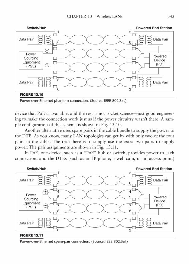
device that PoE is available, and the rest is not rocket science—just good engineer-ing to make the connection work just as if the power circuitry wasn’t there. A sam-ple configuration of this scheme is shown in Fig. 13.10.
Another alternative uses spare pairs in the cable bundle to supply the power tothe DTE. As you know, many LAN topologies can get by with only two of the fourpairs in the cable. The trick here is to simply use the extra two pairs to supplypower. The pair assignments are shown in Fig. 13.11.
In PoE, one device, such as a “PoE” hub or switch, provides power to eachconnection, and the DTEs (such as an IP phone, a web cam, or an access point)
CHAPTER 13 Wireless LANs 343
Switch/Hub Powered End Station
Data Pair
Data Pair
PowerSourcing
Equipment(PSE)
Data Pair
Data Pair
PoweredDevice(PD)
1
2
3
3
6
1
26
–
+
FIGURE 13.10
Power-over-Ethernet phantom connection. (Source: IEEE 802.3af.)
Switch/Hub Powered End Station
Data Pair
Data Pair
PowerSourcing
Equipment(PSE)
Data Pair
Data Pair
PoweredDevice(PD)
1
2
45
78
3
3
6
4
5
78
1
26
–
+
FIGURE 13.11
Power-over-Ethernet spare-pair connection. (Source: IEEE 802.3af.)
tap off the power, so they don’t need a separate electrical connection. You can alsoget PoE adapters that connect between your existing Ethernet hubs and the devicethat needs power. They inject the voltage that is needed to remotely power theDTE.
All you need to know about PoE from a wiring perspective is that the voltageis a nominal 4Vv open-circuit, that most PoE ports can supply about 350 mA, andthat the voltage is considered Class 1 (nonhazardous) by the NEC.2 You also needto know that a miswire on the power wires could cause a direct short and overheator damage some PoE supplies, but that is not supposed to happen. At the very least,the device doing the supplying will get very angry at you.
Plan for the Future
Wireless technology has been evolving much faster than ordinary LAN wiring.Many of the new technologies are complex to use and involve early versions ofequipment and wireless protocols. New wireless standards are coming out almostmonthly. How can you keep ahead of this?
Stay Compatible
One of the major considerations in making your network available for future inno-vations is to make sure that your wireless component vendors adhere strictly to thestandards. We cannot predict what twists and turns technology will take over manyyears, but fortunately, all the IEEE 802.11 innovations have so-far remained back-ward-compatible. This means that if you bought 11 Mbps hardware, it will stillwork within a faster 54 or 108 Mbps system. Consequently, the same should be trueof faster networks to come.
Standards compatibility is the key here. It is unfortunately true that final stan-dards are often not able to support early implementations. This was certainly truewith early twisted-pair Ethernet technology, and the same is true with wireless. Asa matter of fact, early nonstandards-based hardware is often discontinued overnightwhen a noncompatible standard is released.
As these new standards emerge, some manufacturers rush the latest innovationto market, often before the new standard has been approved. The motivation to
344 PART TWO LAN Wiring Technology
2 Do keep in mind that T1 span power may run as high as 165 volts or so open-circuit, and even atvery low current, it is enough to give you a very good shock. If you run that type of span power overyour cables, recommended practice requires you to use special red-topped bridge clips or protectiveboots to keep anyone from inadvertently touching the circuit terminals. We don’t want you to be partof the circuit. Your components can’t handle the voltage.
market is strong, because they get a jump on the competition, and may be able toinfluence the standards process in their favor. However, it is not unusual for a for-ward-looking “pre-” standard to be incompatible with the final standard. In a sig-nificant number of cases, the equipment cannot be upgraded to the final standard,and you are left with obsolete, incompatible equipment that soon will not be sup-ported even by the original manufacturer. Be very cautious if you buy into one ofthese “solutions,” and be prepared to either toss it all out later, or to put up withthe incompatibilities and lack of supply.
The Place of Wireless in a Wired LAN
Wireless technologies are great for quickly or temporarily expanding access to a net-work or to the Internet. In some cases, they offer a long-term solution where a wiredconnection would be impractical. In other situations, wireless offers freedom ofmotion and location that is impossible with a wired connection.
The best practice is to learn enough about both wired and wireless technolo-gies to recognize those situations where wireless is the best solution.
CHAPTER 13 Wireless LANs 345

This page intentionally left blank
PART THREE
LAN Wire Management
Copyright © 2006 by James Trulove. Click here for terms of use.

This page intentionally left blank
CHAPTER 14
Telecommunications Roomsand Wire Management
Highlights
■ Telecommunications rooms
■ Horizontal and backbone wiring
■ Accessibility and appearance
■ Room size requirements
■ Power requirements
■ Backbones and concentration
349
Copyright © 2006 by James Trulove. Click here for terms of use.
The concept of a series of interconnected telecommunications rooms (TR) is centralto structured cabling system design. The planning and placement of these telecom-munications rooms is a subject sufficiently important for the TelecommunicationsIndustry Association (TIA) to devote an entire standard to it, TIA 569-B,Commercial Building Standard for Telecommunications Pathways and Spaces.
In this chapter, we will discuss the placement of telecommunications rooms inmodern telecommunications installations. Naturally, this discussion will centeraround designing a wiring system for LAN use. This will impose some additionalconsiderations on the location of our telecommunications rooms, primarily becauseof the distance restrictions of LAN wiring.
Defining the Telecommunications Room (TR)
The telecommunications room is more broadly defined in TIA 569-B as a hierarchi-cal system of telecommunication spaces that are used for the concentration and con-nection of a building’s telecommunications wiring. This standard covers wiringspaces for all telecommunications activities and actually includes telephone as wellas computer wiring.
Because of the much lower operating frequency, telephone wiring is not sub-ject to the severe distance limitations of LAN wiring. For example, the standardallows a total distance of 800 m (2624 ft) for an unshielded twisted-pair circuit runthrough a combination of telecommunications rooms—far beyond that allowed fora single LAN leg, which is limited to 100 m (328 ft) without passing through arepeater or bridge. So, we will concentrate on criteria appropriate for LANs, andassume that the telephone wiring will either easily meet its requirements or be sep-arately handled.
Traditional Cabling Heirarchy
In this hierarchical telecommunications room system (so-called structured wiring),there are three types of wiring closets: the telecommunications room (TR), the inter-mediate cross-connect (IC), and the main cross-connect (MC). Figure 14.1 showsthis hierarchy. The structure does not assume that any of these telecommunicationsrooms necessarily contain equipment (such as hubs or telephone gear), but allowsfor any telecommunications room to be collocated with an equipment room (ER).In the traditional structured wiring installation for telephones, a cable from the localexchange carrier (LEC) would enter the building and run to the MC, which wouldgenerally also house the user’s telephone switching equipment (a PABX or EKTS).This would be a combination MC/ER.
350 PART THREE LAN Wire Management
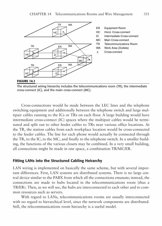
Cross-connections would be made between the LEC lines and the telephoneswitching equipment and additionally between the telephone switch and large mul-tipair cables running to the ICs or TRs on each floor. A large building would haveintermediate cross-connect (IC) spaces where the multipair cables would be termi-nated and split out to other feeder cables to TRs near various office locations. Atthe TR, the station cables from each workplace location would be cross-connectedto the feeder cables. The line for each phone would actually be connected throughthe TR, to the IC, to the MC, and finally to the telephone switch. In a smaller build-ing, the functions of the various closets may be combined. In a very small building,all connections might be made in one space, a combination TR/MC/ER.
Fitting LANs into the Structured Cabling Heirarchy
LAN wiring is implemented on basically the same scheme, but with several impor-tant differences. First, LAN systems are distributed systems. There is no large cen-tral device similar to the PABX from which all the connections emanate; instead, theconnections are made to hubs located in the telecommunications room (thus aTR/ER). Then, as we will see, the hubs are interconnected to each other and to com-mon resources such as servers.
With regard to LANs, telecommunications rooms are usually interconnectedwith no regard to hierarchical level, since the network components are distributed.Still, the telecommunications room hierarchy is a useful model.
CHAPTER 14 Telecommunications Rooms and Wire Management 351
MC
ICHC
ERTR
WA
WA
WA
HC
HC
IC
ER
x
x x
x
TR
x
ER Equipment Room
HC Horiz. Cross-connectIC Intermediate Cross-connectMC Main Cross-connectTR Telecommunications RoomWA Work Area (Outlets) x Cross-connect
TR
x
FIGURE 14.1
The structured wiring hierarchy includes the telecommunications room (TR), the intermediatecross-connect (IC), and the main cross-connect (MC).
Horizontal and Backbone Wiring
All of the wiring from workstations to telecommunications rooms and betweentelecommunications rooms is referred to as “horizontal” wiring and “backbone”wiring, respectively, in the terminology of structured wiring. Backbone wiring issometimes called vertical wiring. If we envision workstations on each floor of abuilding, and wiring closets vertically stacked with one per floor, this terminologymakes sense. However, multiple telecommunications rooms are often located on thesame floor, so the term “backbone” is clearer than the term “vertical”—the wiringfrom workstation to telecommunications room is the horizontal wiring and thewiring between rooms is the backbone wiring. If we also have additional telecom-munications rooms, such as the intermediate and main cross-connect rooms, thewiring between those rooms is also called backbone wiring. This terminology holdswhether the rooms are on multiple floors or are on the same floor.
The TIA standards always use the term backbone to refer to wiring betweentelecommunications rooms. Unfortunately, backbone has a very different meaningin LAN systems as compared to telephone systems. A LAN backbone is a logicalsubdivision of a network that has nothing to do with where the wiring goes. In fact,wiring on the same LAN backbone segment can be in two or more telecommunica-tions rooms, or two LAN backbones can be in the same telecommunications room.However, we will stick to the wording in the standards and refer to all wiringbetween telecommunications rooms as backbone wire (or cable), unless we arespecifically referring to that portion of a LAN system that interconnects multipleLAN hubs or bridges.
Color Coding the Telecommunications Room
TIA 569-B recommends that the cross-connects in a telecommunications room begrouped together, and prescribes a color code to further show this grouping. Table14.1 shows the recommended colors for various terminations and cross-connectlocations. For the cross-connect locations, the standard generally uses traditionalcolors, such as orange for the telco demarcation punch blocks, and blue for the sta-tion cable punchdown locations. Actually, the punch block itself is usually white,but its cover or mounting board may have the code color.
The standard also recommends that different jacket colors be used on thecables to distinguish between the usage types of the cables. This presents an inter-esting dilemma, as the colors in the standard bear little resemblance to the tradi-tional colors used in commercial cabling. For example, station wire (to theworkstation) has traditionally been run in beige or gray (the plenum-rated default),
352 PART THREE LAN Wire Management
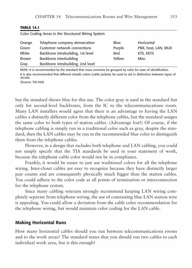
but the standard shows blue for this use. The color gray is used in the standard butonly for second-level backbones, from the IC to the telecommunications room.Many LAN installers would agree that there is an advantage to having the LANcables a distinctly different color from the telephone cables, but the standard assignsthe same color to both types of station cables. (Advantage lost!) Of course, if thetelephone cabling is simply run in a traditional color such as gray, despite the stan-dard, then the LAN cables may be run in the recommended blue color to distinguishthem from the telephone cables.
However, in a design that includes both telephone and LAN cabling, you couldnot simply specify that the TIA standards be used in your statement of work,because the telephone cable color would not be in compliance.
Frankly, it would be easier to just use traditional colors for all the telephonewiring. Inter-closet cables are easy to recognize because they have distinctly largerpair counts and are consequently physically much bigger than the station cables.You could adhere to the color code at all points of termination or interconnectionfor the telephone system.
Since many cabling veterans strongly recommend keeping LAN wiring com-pletely separate from telephone wiring, the use of contrasting blue LAN station wireis appealing. You could allow a deviation from the cable color recommendation forthe telephone wiring, but would maintain color coding for the LAN cable.
Making Horizontal Runs
How many horizontal cables should you run between telecommunications roomsand to the work areas? The standard states that you should run two cables to eachindividual work area, but is this enough?
CHAPTER 14 Telecommunications Rooms and Wire Management 353
TABLE 14.1
Color Coding Areas in the Structured Wiring System
Orange Telephone company demarcation Blue HorizontalGreen Customer network connections Purple PBX, host, LAN, MUXWhite Backbone intrabuilding, 1st level Red KTS, EKTSBrown Backbone interbuilding Yellow Misc.Gray Backbone intrabuilding, 2nd level
NOTE: It is recommended by the standard that cross-connects be grouped by color for ease of identification.It is also recommended that different sheath colors (cable jackets) be used to aid in distinction between types ofcircuits.(Source: TIA-569)
The answer to this question depends on many factors, but the two most impor-tant considerations are growth and utility. You must determine what amount of growthplanning is reasonable, and what it will cost to implement. For example, if you havelarge individual offices that may eventually include two workers, overwiring by a fac-tor of two would be reasonable. The type of work that is to be done is also important.
For example, some workers may eventually need two computers or two phonelines. In such cases, you should provide at least one additional station cable outletthat can be used for expansion. Generally, it is far less expensive to do a certainamount of overwiring during initial construction than it is to add outlets later.
What methods should you use to terminate the cables in the telecommunica-tions room? The answer to this question depends on whether you intend to installa universal wiring system, where any cable can serve your telephone or LAN sys-tems, or install separate telephone and LAN wiring systems. Telephone wiring isquite forgiving in that you may run longer distances and make a larger number ofcross-connects between the telephone instrument and the switching equipment.Modern LANs are much more restrictive in this regard. Early cabling standardsallowed two cross-connects for a single LAN connection, but the latest Category5e/6/7 wiring standards (as shown in Fig. 14.2) allow only one cross-connect andalso severely restrict cable lengths, including that for the cross-connect wire. This isto allow for the strict attenuation, delay, and crosstalk limits of 100 MHz andhigher networks. Many experts even recommend that the workstation cables be ter-minated directly into a patch panel, with no ICs at all.
One of the reasons for this cross-connect limit is that all wiring terminationsrequire that the pairs be slightly untwisted to be punched down at the point of ter-mination. When the cable being used is very tightly twisted, as with Category5e/6/AC6 cable, this untwisted portion increases crosstalk, introduces noise, dis-turbs the line impedance, and increases RF emissions. Too much untwist can causea link to fail at the higher LAN data rates, especially if the cable run is near theallowable length limit.
All punchdown blocks introduce untwist into a link. The extent of the prob-lem is less with the 110-style blocks than with the older 66-style blocks, but it existsnevertheless. The effect of untwist is more disruptive as the network speed increases.Terminating the station cables directly onto a patch panel minimizes the amount ofuntwisted wire and increases the performance of the link.
Distance Considerations
The primary guideline in locating telecommunications rooms is to place them nearthe work areas they will serve. Advisory language in the standard says to place them
354 PART THREE LAN Wire Management
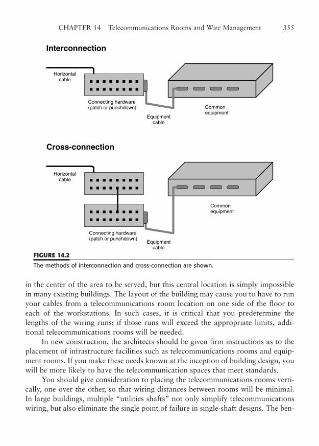
in the center of the area to be served, but this central location is simply impossiblein many existing buildings. The layout of the building may cause you to have to runyour cables from a telecommunications room location on one side of the floor toeach of the workstations. In such cases, it is critical that you predetermine thelengths of the wiring runs; if those runs will exceed the appropriate limits, addi-tional telecommunications rooms will be needed.
In new construction, the architects should be given firm instructions as to theplacement of infrastructure facilities such as telecommunications rooms and equip-ment rooms. If you make these needs known at the inception of building design, youwill be more likely to have the telecommunication spaces that meet standards.
You should give consideration to placing the telecommunications rooms verti-cally, one over the other, so that wiring distances between rooms will be minimal.In large buildings, multiple “utilities shafts” not only simplify telecommunicationswiring, but also eliminate the single point of failure in single-shaft designs. The ben-
CHAPTER 14 Telecommunications Rooms and Wire Management 355
Interconnection
Horizontalcable
Commonequipment
Equipmentcable
Connecting hardware(patch or punchdown)
Cross-connection
Horizontalcable
Commonequipment
Connecting hardware(patch or punchdown)
Equipmentcable
FIGURE 14.2
The methods of interconnection and cross-connection are shown.
efits of this approach go beyond the telecommunications issues. It is also a good ideato provide an orderly system of cable ducts or sleeves, both for interfloor and fire-wall use. Proper ducting will allow workers to place UL-rated firestopping materialin the ducts to enhance fire protection. Also, because many of the utility shafts areclosed and reinforced concrete structures, this avoids the problem of random wallpenetrations and “sneaker” cables that are forced alongside existing pipe andHVAC penetrations.
Maximum Drop Length
LAN wiring standards dictate strict distance limits for horizontal cable runs. Thesecable drop lengths include the entire cable from the point of termination in thetelecommunications room to the workstation outlet. Standards also cover the max-imum distances between telecommunications rooms. In this way, the requirementsof TIA 568-C and 569-B work together, in balance with the building’s architecture,to achieve a compliant wiring system for your LAN that will meet your needed per-formance.
The maximum length for a horizontal cable is 90 m (295 ft). This 90 m lengthexcludes the user cord that connects from the outlet to the user workstation (or tele-phone instrument) and the patch cord (or jumper) that connects from the patchpanel (or cross-connect field) to a hub or other device. This is a maximum accept-able length and not simply an average length or a goal. You should try to keep yourwiring well below this length in most cases. At least two telecommunications out-lets must be provided for each individual work area.
Although some of the lower-speed LANs, such as 10BaseT and even Token-Ring, may run to longer distances of as much as 150 m, exceeding the standardintentionally is a bad idea. You cannot expect such run lengths to support 100/1000Mbps data rates at all, and any equipment problems will be blamed on the exces-sive drop lengths. As a matter of fact, cable testers are required to fail a basic linklonger than 90 m, allowing for test cables and measurement accuracy. For a com-plete discussion of measuring cable lengths using cable testers, see Chapter 15.
The allowable backbone cable distances between telecommunications roomsdepend on the type of cable you use as well as practical considerations.
For example, the standard allows 2000 m (6560 ft) from TR to MC for fiber-optic cable, but only 800 m (2624 ft) for unshielded twisted-pair cable. The dis-tances are even less between ICs and the other two types of telecommunicationsrooms. However, practice may dictate much smaller distances. If you wish to con-nect between two telecommunications rooms on a 100BaseT or a gigabit link, forexample, you would have to limit the backbone run to the same 90 m you are lim-
356 PART THREE LAN Wire Management
ited to for any hub-to-workstation link. As mentioned previously, although somesituations may operate with slightly longer cable lengths, they do not meet therequirements for inevitable higher speeds of 100 Mbps or more.
Estimating Drop Length. Cable drops from the proposed telecommunicationsroom to the workstations to be served must be within the maximum allowable lengthof 90 m (295 ft). You should estimate these distances before finalizing your cable sys-tem design. If the estimates exceed the maximum length, you may need to add oneor more wiring closets. Although there are minimum size specifications and featuresfor telecommunications rooms (covered in a later section), you may be justified inputting in a substandard telecommunications space to get the drop lengths down.
To estimate the total length of a cable run, you must first know how the cablewill be routed and hung. Conventional wiring is often routed through metal floor orroof supports to keep it well above the ceiling tile. Alternatively, cable may be hungwith a variety of cable hangers, clips, and tie wraps from supporting structures. Insome installations, particularly old work, the cable is laid on top of the ceiling tilesupporting grid. Large buildings frequently have the cable placed in cable trays sus-pended between the ceiling grid and the floor above. This method is becoming morepopular for Category 5e/6 installations, where the slightest kink or sharp bend canimpair the cable performance. Any combination of the methods may be used as well.
The routing methods are important because the more orderly routings inevitablyrequire more wire. For example, routing through cable trays involves lots of rightangles (orthogonal routing) instead of diagonal runs, demanding up to 40% morecable. On the other hand, laying the cable directly on top of the ceiling grid with directrouting uses the least cable (although it is the hardest to maintain and may suffer EMIproblems more often). Cable trays are easiest to use during construction build-out,when the ceiling grid is not in place. They are more difficult to add once the officesare constructed or, worse, occupied. Trays carry significant weight from the manycables they contain, and must be well secured in place. For that reason, cable hangersand clips are often used to minimize disruption to an existing workplace.
To estimate an orthogonal wire placement, where cables are to be bundled orlaid in cable trays, you must calculate the length of run in the tray. This may involvea straight run or one with several corners. Add each leg of the run in the tray. Next,add the drop from the tray to the wall header above the workstation outlet, and thelengths of the vertical drops in the workstation wall and in the telecommunicationsroom, and add a factor for obstacles (2% to 5%, depending upon the building).Obstacles that might be encountered are HVAC units, duct work, firewalls,columns, and pipes. The vertical drops should allow for 18 in (0.5 m) of excess wireat the wall outlet plus the distance through the wall to the height of the cable tray
CHAPTER 14 Telecommunications Rooms and Wire Management 357
(not just the ceiling height). The vertical drop length in the telecommunicationsroom should include the drop from the tray to the final termination point of thecable, including all ducts, ports, channels, and trays through which the cable mustbe routed. Be sure to accurately estimate the twists and turns the cable may maketo “dress” the wires on the mounting board or in the equipment racks.
Allow another 6 to 12 inches here for termination. If your measurements areclose to the limit, remember that cables are typically routed along the length of a patchpanel to their termination points, which might add up to 19 in of additional length.
Diagonal wire placement is really direct routing. This means that the cable issimply run above the ceiling grid and routed directly to the workstation drop loca-tion. Routing is done either directly over the grid or through supporting structures.Sometimes wire hangers or clips are used, as are tie wraps.
The use of cable hangers and clips may allow a combination between orthog-onal wire placement and diagonal placement. Bundles of cable are typically routedthrough cable hangers orthogonally from the telecommunications room to groupsof work area locations, but individual work area drop cables may be diagonallyrouted from the nearest hanger.
Older buildings, houses, or buildings with fixed ceilings present special problemsto cable routing. Often the cables may be run in an attic or crawl spaces. Sometimescable must be run around baseboards or even over door frames to reach the worksta-tion location. The use of staples—a common mounting technique for telephone wires—is definitely out, even for Category 3 cable. Be careful when estimating cable lengths forthese buildings. Simple detours, such as doorways, can eat up lots of cable. For exam-ple, a 10 by 20 ft room would require 10 � 20 � 17 � 47 ft of cable simply to run toan opposite corner of the room, if one 7 by 3 ft (7 � 7 � 3) doorway has to be tra-versed. If a drop must be run through several adjacent rooms to reach from the wiringcloset to the work area, an enormous amount of cable may be required.
Accessibility and Appearance
The wiring centers of your network are key components of your LAN system, con-taining important networking hardware, the cable distribution points for yourusers, and important diagnostic and backup equipment. In addition, many impor-tant installation, configuration, and troubleshooting tasks take place there. Forthose reasons, you should devote the time and money necessary to maintain goodtelecommunications rooms and equipment rooms.
The first key to a good telecommunications room is accessibility. The wiringconnections and network hardware should have their own room, out of the way andyet easy to get to. The area should be as close to the work areas as possible, since
358 PART THREE LAN Wire Management
LAN workers will often have to travel between workstation locations and thetelecommunications room. That means that a location down the hallway near theelevators is not as useful as a small room or office near the work areas. The roomshould be used exclusively for LAN wiring terminations, hubs, routers, servers, andrelated equipment, but never for storage.
The second key is appearance. The telecommunications room should be orderly,well laid out, and well lighted. Adequate power and ventilation should be availableand designed for the specified purpose. Mounting boards on the walls should be fullsheets of 3/4-inch plywood and well secured to the wall’s interior structure. At leasttwo walls should be plywood-sheathed, and the boards should be painted a neutralcolor, such as gray. Areas for specific equipment should be well marked.
If you use equipment rails or racks to mount your hubs and patch panels, theyshould be placed a sufficient distance from the walls to work behind them. It is notat all a bad idea to place the hubs so they can be viewed from the doorway of thetelecommunications room. If you terminate the station cables directly onto a patchpanel, you can use cable trays across the top of the mounting rails to route yourcables. Wire management trays, mounting brackets, preassembled backboards, anddistribution rings are all available to help make a neat and serviceable cable arrange-ment. Proper routing (or “dressing”) of cables will make a neat, orderly appearancethat will save maintenance time and trouble in the long run.
Category 5e/6/7 wiring requires special precautions in installation and routing.The cable must be treated with great care during installation to preserve its perform-ance characteristics. This special care includes running the wire with a minimum ofsharp turns, no stretching, no staples, and no tight tie wraps. Many patch panelshave additional strain relief points at each cable termination to eliminate sharpbends and to help secure the cables with a minimum of stress.
The third key to a successful telecommunications room installation is security.Equipment located in the wiring closet needs to be secured. That is one reason whya separate room with a locked door is the best location for your telecommunicationsroom. If your telecommunications room is located in a common area outside youroffices, controlling access is essential. Telecommunications rooms that are withinyour offices still may need to be secured, particularly in a high-traffic location. Yourcompany’s mission may also dictate a need to control access to the room, becauseimportant servers are often located there in addition to the networking hubs.
Size Requirements for Telecommunications Rooms
Telecommunications rooms need to be large enough to provide a proper area forwiring termination, patch panels, and hubs. In some cases, other networking equip-
CHAPTER 14 Telecommunications Rooms and Wire Management 359
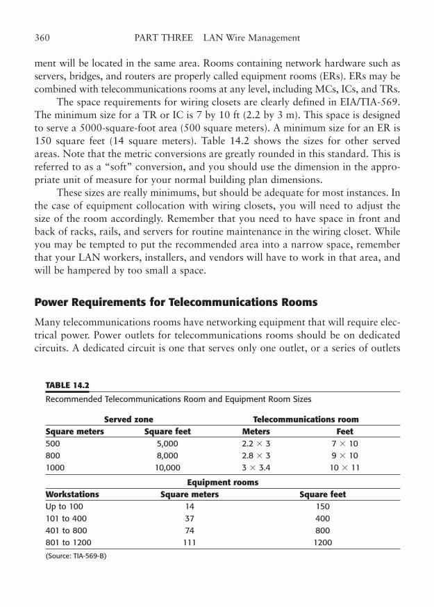
ment will be located in the same area. Rooms containing network hardware such asservers, bridges, and routers are properly called equipment rooms (ERs). ERs may becombined with telecommunications rooms at any level, including MCs, ICs, and TRs.
The space requirements for wiring closets are clearly defined in EIA/TIA-569.The minimum size for a TR or IC is 7 by 10 ft (2.2 by 3 m). This space is designedto serve a 5000-square-foot area (500 square meters). A minimum size for an ER is150 square feet (14 square meters). Table 14.2 shows the sizes for other servedareas. Note that the metric conversions are greatly rounded in this standard. This isreferred to as a “soft” conversion, and you should use the dimension in the appro-priate unit of measure for your normal building plan dimensions.
These sizes are really minimums, but should be adequate for most instances. Inthe case of equipment collocation with wiring closets, you will need to adjust thesize of the room accordingly. Remember that you need to have space in front andback of racks, rails, and servers for routine maintenance in the wiring closet. Whileyou may be tempted to put the recommended area into a narrow space, rememberthat your LAN workers, installers, and vendors will have to work in that area, andwill be hampered by too small a space.
Power Requirements for Telecommunications Rooms
Many telecommunications rooms have networking equipment that will require elec-trical power. Power outlets for telecommunications rooms should be on dedicatedcircuits. A dedicated circuit is one that serves only one outlet, or a series of outlets
360 PART THREE LAN Wire Management
TABLE 14.2
Recommended Telecommunications Room and Equipment Room Sizes
Served zone Telecommunications roomSquare meters Square feet Meters Feet500 5,000 2.2 � 3 7 � 10 800 8,000 2.8 � 3 9 � 101000 10,000 3 � 3.4 10 � 11
Equipment roomsWorkstations Square meters Square feetUp to 100 14 150 101 to 400 37 400 401 to 800 74 800 801 to 1200 111 1200
(Source: TIA-569-B)
in one room. Standard practice in the United States is to equip each dedicated out-let location with a bright orange outlet (either a duplex or simplex receptacle) to dis-tinguish it. The electrical circuit should be rated appropriately for the equipmentthat is to be connected. Some larger equipment may require its own separate dedi-cated outlet.
You should be sure that an adequate number of electrical outlets are provided,based on the equipment that needs to be installed. Racks or banks of equipmentmay need an outlet strip or a power bar with multiple outlets. Allow lots of roomfor growth. A good rule of thumb is to provide twice the number of outlets youthink you will need, and double that number! Remember to include open outletsthat can be used to provide power to test equipment.
The standard recommends two dedicated duplex outlets, AC outlets for equip-ment power, rated at 15 A, 110 V (or appropriate ratings for your locale) on sepa-rate circuits. It also recommends convenience outlets, wall-mounted every 1.8 m (6ft) around the telecommunications room, in addition to any power requirements forcollocation of an equipment room. Also specified is lots of ceiling mounted lighting,540 lux (50 ft-candles). Equipment roomss should have enough HVAC capacity tomaintain the room at 18 to 24°C (64 to 75°F).
Another item to consider is power conditioning and backup power. Yourpower connections should, at the minimum, contain surge protection. In areas thatare subject to power-line fluctuations, you might want to consider ferro-resonanttransformers that automatically compensate for sags and minor surges. True powerspikes must be dealt with by the use of line surge protectors. Several types of theseexist, including gas-discharge protectors, semiconductor protectors, and metal-oxide varistors (MOVs). The MOVs are the most common and the cheapest, andprovide the least protection—usually found in low-cost multi-outlet strips. Theirprimary drawbacks in such an application are their slow response time and theuser’s inability to determine if they have lost protection because of prior spikes.
A form of spike also occurs as a result of telecommunications wires that runoutside your building. The most common occurrence results from a nearby lightningstrike. The electrical discharge may induce destructive voltages in any outdoorcabling, including telephone and LAN cabling. It is very important to provideapproved protectors on all telecommunications cables at the point of entry to yourbuilding. Fiber-optic cabling with no metallic members can be an important tool ineliminating lightning risk.
Another potential power problem is a power outage. Equipment that might bedisrupted by a power outage should have emergency backup power supplies pro-vided. These power supplies usually connect between the equipment to be servedand the AC power outlet. One type of uninterruptible power supply (UPS) is the
CHAPTER 14 Telecommunications Rooms and Wire Management 361
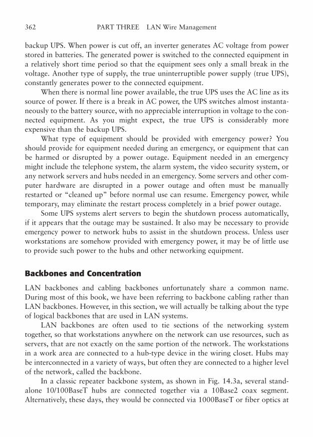
backup UPS. When power is cut off, an inverter generates AC voltage from powerstored in batteries. The generated power is switched to the connected equipment ina relatively short time period so that the equipment sees only a small break in thevoltage. Another type of supply, the true uninterruptible power supply (true UPS),constantly generates power to the connected equipment.
When there is normal line power available, the true UPS uses the AC line as itssource of power. If there is a break in AC power, the UPS switches almost instanta-neously to the battery source, with no appreciable interruption in voltage to the con-nected equipment. As you might expect, the true UPS is considerably moreexpensive than the backup UPS.
What type of equipment should be provided with emergency power? Youshould provide for equipment needed during an emergency, or equipment that canbe harmed or disrupted by a power outage. Equipment needed in an emergencymight include the telephone system, the alarm system, the video security system, orany network servers and hubs needed in an emergency. Some servers and other com-puter hardware are disrupted in a power outage and often must be manuallyrestarted or “cleaned up” before normal use can resume. Emergency power, whiletemporary, may eliminate the restart process completely in a brief power outage.
Some UPS systems alert servers to begin the shutdown process automatically,if it appears that the outage may be sustained. It also may be necessary to provideemergency power to network hubs to assist in the shutdown process. Unless userworkstations are somehow provided with emergency power, it may be of little useto provide such power to the hubs and other networking equipment.
Backbones and Concentration
LAN backbones and cabling backbones unfortunately share a common name.During most of this book, we have been referring to backbone cabling rather thanLAN backbones. However, in this section, we will actually be talking about the typeof logical backbones that are used in LAN systems.
LAN backbones are often used to tie sections of the networking systemtogether, so that workstations anywhere on the network can use resources, such asservers, that are not exactly on the same portion of the network. The workstationsin a work area are connected to a hub-type device in the wiring closet. Hubs maybe interconnected in a variety of ways, but often they are connected to a higher levelof the network, called the backbone.
In a classic repeater backbone system, as shown in Fig. 14.3a, several stand-alone 10/100BaseT hubs are connected together via a 10Base2 coax segment.Alternatively, these days, they would be connected via 1000BaseT or fiber optics at
362 PART THREE LAN Wire Management
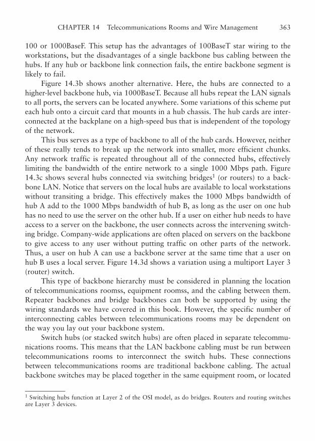
100 or 1000BaseF. This setup has the advantages of 100BaseT star wiring to theworkstations, but the disadvantages of a single backbone bus cabling between thehubs. If any hub or backbone link connection fails, the entire backbone segment islikely to fail.
Figure 14.3b shows another alternative. Here, the hubs are connected to ahigher-level backbone hub, via 1000BaseT. Because all hubs repeat the LAN signalsto all ports, the servers can be located anywhere. Some variations of this scheme puteach hub onto a circuit card that mounts in a hub chassis. The hub cards are inter-connected at the backplane on a high-speed bus that is independent of the topologyof the network.
This bus serves as a type of backbone to all of the hub cards. However, neitherof these really tends to break up the network into smaller, more efficient chunks.Any network traffic is repeated throughout all of the connected hubs, effectivelylimiting the bandwidth of the entire network to a single 1000 Mbps path. Figure14.3c shows several hubs connected via switching bridges1 (or routers) to a back-bone LAN. Notice that servers on the local hubs are available to local workstationswithout transiting a bridge. This effectively makes the 1000 Mbps bandwidth ofhub A add to the 1000 Mbps bandwidth of hub B, as long as the user on one hubhas no need to use the server on the other hub. If a user on either hub needs to haveaccess to a server on the backbone, the user connects across the intervening switch-ing bridge. Company-wide applications are often placed on servers on the backboneto give access to any user without putting traffic on other parts of the network.Thus, a user on hub A can use a backbone server at the same time that a user onhub B uses a local server. Figure 14.3d shows a variation using a multiport Layer 3(router) switch.
This type of backbone hierarchy must be considered in planning the locationof telecommunications roomss, equipment roomss, and the cabling between them.Repeater backbones and bridge backbones can both be supported by using thewiring standards we have covered in this book. However, the specific number ofinterconnecting cables between telecommunications rooms may be dependent onthe way you lay out your backbone system.
Switch hubs (or stacked switch hubs) are often placed in separate telecommu-nications rooms. This means that the LAN backbone cabling must be run betweentelecommunications rooms to interconnect the switch hubs. These connectionsbetween telecommunications rooms are traditional backbone cabling. The actualbackbone switches may be placed together in the same equipment room, or located
CHAPTER 14 Telecommunications Rooms and Wire Management 363
1 Switching hubs function at Layer 2 of the OSI model, as do bridges. Routers and routing switchesare Layer 3 devices.
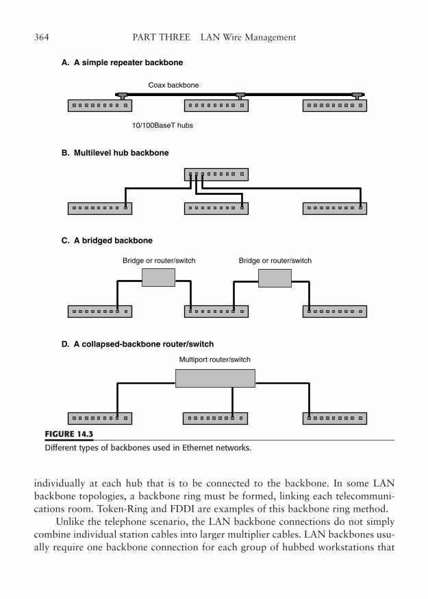
individually at each hub that is to be connected to the backbone. In some LANbackbone topologies, a backbone ring must be formed, linking each telecommuni-cations room. Token-Ring and FDDI are examples of this backbone ring method.
Unlike the telephone scenario, the LAN backbone connections do not simplycombine individual station cables into larger multiplier cables. LAN backbones usu-ally require one backbone connection for each group of hubbed workstations that
364 PART THREE LAN Wire Management
10/100BaseT hubs
A. A simple repeater backbone
C. A bridged backbone
D. A collapsed-backbone router/switch
B. Multilevel hub backbone
Coax backbone
Multiport router/switch
Bridge or router/switch Bridge or router/switch
FIGURE 14.3
Different types of backbones used in Ethernet networks.

is to be connected. Additional backbone cables may be run to provide backup forthe primary cables or to provide closure of a ring. Backup cables or cables to com-plete a ring are an integral part of the backbone hierarchy.
By the way, nothing in this implies that a backbone is either fiber optic or cop-per, as either one may serve your needs well. Keep in mind that the allowable dis-tances between closets in TIA-569-B exceed the distances for copper wire10/100/1000BaseT or Token-Ring, set without reference to a specific LAN topology.However, the use of fiber-optic cable can extend your cables to the limit of the TIAstandard.
CHAPTER 14 Telecommunications Rooms and Wire Management 365

This page intentionally left blank
CHAPTER 15
Testing and Certifying LAN Wiring
Highlights
■ Certifying cable and connecting hardware
■ Scanner performance
■ Cable plant certification
■ Testing methods
■ Test equipment
■ Analog versus digital testers
367
Copyright © 2006 by James Trulove. Click here for terms of use.
The testing of installed cable is a critical part of the process of creating a successful struc-tured cabling system. The major reason to specify a standards-based LAN wiring schemeis to ensure that your installed cable will meet the needed level of performance for yourintended use. There are three basic requirements for providing a cabling system that willmeet TIA-568-C performance standards. First, you must design a structured cable plantthat will meet the desired performance criteria when the other two requirements are met.Second, you must use cable and connecting components that are certified to the properlevel of performance. Third, you must employ proper installation methods so that theperformance potentials of the cabling and components are achieved.
This is a long way of saying that a well-designed LAN wiring system, using theproper cable and connectors, and installed with good workmanship, will operate atthe expected level of performance. Previous chapters in this book have described allof these key concepts, individually. This chapter will explore the ways in which youcan verify the proper operation of your installed cable system.
We will discuss some of the ways in which cable and components are certifiedto a particular level of performance by their manufacturers. In addition, we will seehow you can perform inspection and testing to ensure that your installed cable plantmeets the required performance levels. Next, we will talk about the test equipmentyou will need to verify your installation. Finally, we will show how to use that testequipment to do cable performance testing and link certification.
Certifying Cable and Connecting Hardware
The primary standard for LAN performance certification in the United States andmany other countries is TIA-568. The full name of the latest version of the standardis TIA-658-C, Commercial Building Telecommunications Wiring Standard. Severalother standards bodies, including the Canadian Standards Association (CSA) andthe International Organization for Standardization (ISO), have similar or coordi-nated standards, such as CSA-T529 and ISO/IEC IS-11801.
As cabling performance levels increased, the TIA realized that additional informa-tion and guidelines were necessary to ensure a properly functioning cable link. It wasimportant to identify those factors that allow an installed cable link to meet the desiredcategory of performance. Likewise, testing techniques were needed to certify the per-formance levels of individual cabling components, such as connecting hardware andeven patch cords. The TIA has continually issued documents called TelecommunicationsSystems Bulletins (TSBs) to provide supplementary information and procedures.
TSBs have provided the critical testing methods and standards to cover per-formance testing of installed cable. A very key early supplement, TSB-67 1995,Transmission Performance Specifications for Field Testing of Unshielded Twisted-
368 PART THREE LAN Wire Management
Pair Cabling Systems, provided the basic standards for the testing of installed links.Another supplement, TSB-95, Additional Transmission Performance Guidelines for100-ohm 4-Pair Category 5 Cabling, gave added standards for testing installed Cat5 cable to determine if it could successfully handle gigabit operation. TSB-155 pro-vides a similar testing standard to verify 10 GigE operation to 55 m over existingCategory 6 cabling. A number of “addenda” have been approved for each sectionof the base TIA-568 standard, which function essentially as amendments to the stan-dard. Eventually, the provisions of all of these supplements and addenda are incor-porated into the subsequent full “letter” revision of the standard, and the processstarts all over again.
The TIA-568-C standard contains information regarding the performance lev-els of connecting hardware and cable used for telecommunications wiring. Thisstandard contains explicit testing methods for some items and refers to documentsfrom other organizations, such as ASTM D-4566, for other items. Cable and con-necting hardware manufacturers offer components that are said to provide a certainlevel of performance, as delineated by the standard. The general measure of compo-nent performance is the “category” of operation. Categories 3, 5e, 6, and AC6 aredefined in the standard and its supplements, along with their corresponding recom-mended uses. Category 7 is forward-looking and is being defined in other docu-ments, but will be incorporated into the base standard eventually. Please refer toPart 2 for an explanation of the categories and how they affect your choice of cableand connecting components.
The parameters that are specified in TIA-568-C pertain to the performance ofthose components prior to their installation, and the performance testing of installedlinks. In addition to the base standard sections, each section includes built-in sup-plementary information in the form of Annexes. An Annex may be informational ormandatory (normative). The Annexes are an important part of the standard,because they may contain test setups, methods for verifying performance, and infor-mation on legacy cabling. For example, the requirements for additional testing oflegacy Category 5 cabling for gigabit operation, originally in TSB-95, is now anAnnex to TIA-568-C.2.
The actual testing of individual cabling components is the responsibility of themanufacturers of these items. Manufacturers may do their own testing to “certify”conformance with the standard, or they may use an outside testing facility. In somecases, manufacturers also have a recognized independent testing laboratory—suchas UL—verify that the testing was performed properly. Some independent labs alsooffer a continuing verification or certification program so that manufacturers mayfurther assure their prospective customers that their products meet the necessaryperformance criteria.
CHAPTER 15 Testing and Certifying LAN Wiring 369
As the cabling installer, you are responsible for using only components of aproper category, installing them properly, and for field testing of the installed cablelinks to verify proper operation for the rated category. If you are an IT manager, thisprocess may be done by you, your installation contractor, or an independent thirdparty to “certify” compliance at the rated category.
If you expect to provide a LAN wiring system with a particular level of per-formance, you must use only components and cable that have been certified for thatcategory of operation or higher. For example, for a Category 3 installation, you mayuse Category 3, 5e, or 6 components, but you must use only Category 5e or highercable and connecting hardware for a Category 5e system.
A common misconception is that using Category 6 cable is always better thanusing Category 5e cable for an application that requires only Cat 5e operation, suchas 100BaseT. However, if you use components and installation techniques that areonly appropriate for Category 3, you essentially get only that level of performance.The performance of a cabling system is only as good as its weakest link, and a cate-gory of performance is equal to the lowest certification and installation/workmanshipof any component. You could well argue that a higher category of cable will ensuremeeting a lower category of performance. The higher-grade cable may improve per-formance margins a bit. It will, but the only gain to you is in those instances when alower category of cable might reveal other marginal conditions, such as interferingelectrical fields or longer-than-permitted cable runs. A much better reason for using ahigher category component is that you could at a later time upgrade to Category 5e/6without repulling the wire. Be cautious, though, as this potential for later upgrademight be wasted if other Category 5e/6 installation practices are not followed.
Performance Levels
What does component certification really mean? Because recognized performancecategories exist, a cable or connector that is marketed as meeting the requirementsof a certain category should be tested to verify that claim. Because the manufactur-ers are responsible for testing these components themselves, they often provide typ-ical test results in their literature. Some manufacturers will provide detailed testreports upon request and offer product guarantees to back their claims.
In addition, independent laboratories offer manufacturer verification testingprograms that range from a one-time test report to a continuing test program withrandom testing. Obviously, you are more ensured of quality components with a con-tinuing verification program than with a single test sample.
TIA-568-C outlines the performance specifications and very detailed test pro-cedures that must be followed to certify components to a particular category. TIA-
370 PART THREE LAN Wire Management
568-C.1 (Part 1) describes the essential wiring structures and link testing methods,while Parts 2 and 3 cover cable and connecting hardware standards for 100-ohmunshielded twisted-pair (UTP) and fiber-optic cabling components, respectively.
Pluggable connector components present some unusual challenges in reliabilitytesting, as they must be checked for connectivity degradation. Random samples ofeach component are tested for degradation of contact resistance and insulationresistance in tests for durability, vibration, stress relaxation, thermal shock, andhumidity/temperature cycle. This testing is to be done by the manufacturer to cer-tify its parts to a recognized performance category. A cautious manufacturer mightchoose to have the certification verified by an independent testing laboratory,because a lot rides on the higher categories of operation.
Surprisingly, with regard to connector plugs and jacks, the TIA-568-C stan-dard calls for only 200 insertion/withdrawal cycles without failure (usually definedby excessive contact resistance). Some manufacturers may specify a usable life of500 to 2000 cycles for their connectors, although the standard only calls for 200cycles. The point is made that these components have a finite life. Modular connec-tors that are used in patch panels with frequent use may be expected to exceed thestandard’s parameter over normal equipment life. Moreover, connectors that areused in test equipment, such as for cable certification, can exceed that number ofcycles in a single afternoon! The user is only cautioned by the standards to “inspectthe connectors for signs of wear.” You would be much safer either to use connec-tors designed for high usage or to periodically replace the connectors on high-useequipment. You would also be wise to keep a usage log of your test cables andreplace them regularly, as the modular plugs used on these cables have the worstdegradation from multiple insertions.
Connectors must also be tested for transmission performance (attenuation andNEXT). Barring the degradation from excessive use, modular connectors have aninnate contact resistance that is not significant when compared to the bulk resist-ance of a length of cable. The wire pins that form the connector are typically gold-plated to minimize this contact resistance. However, the modular-type connectorsused in the current wiring standards do exhibit a significant amount of cross-cou-pling that appears as near-end crosstalk (NEXT). All of the 8-pin modular-style con-nectors are bad in this respect, but testing is done to make sure the NEXT is notworse than allowed.
Table 15.1 shows the attenuation and NEXT performance parameter limits forCategory 3, 5e, and 6 components. Category 5 is no longer sanctioned, but it hadabout 3 dB worse performance at 100 MHz. You can see from the values that littlecontribution to circuit loss is expected from the circuit hardware, as most comes fromcontact resistance. For comparison, the DC insertion resistance is only 0.3 ohms for
CHAPTER 15 Testing and Certifying LAN Wiring 371
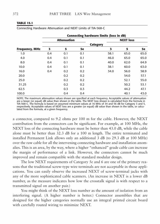
a connector, compared to 9.2 ohms per 100 m for the cable. However, the NEXTcontribution from the connectors can be significant. For example, at 100 MHz, theNEXT loss of the connecting hardware must be better than 43.0 dB, while the cablealone must be better than 32.3 dB for a 100 m length. The entire terminated andinstalled Permanent Link allows only an additional 3 dB (to 29.3 dB at 100 MHz)over the raw cable for all the intervening connecting hardware and installation anom-alies. This is an area, by the way, where a higher “enhanced” grade cable can increasethe margin of performance of a link. However, the connectors cannot be muchimproved and remain compatible with the standard modular design.
The low NEXT requirements of Category 5e and 6 are one of the primary rea-sons that the traditional screw-type wire terminals are not acceptable in those appli-cations. You can easily observe the increased NEXT of screw-terminal jacks withany of the more sophisticated cable scanners. (An increase in NEXT is a lower dBnumber, as the measure indicates how low the crosstalk signal is with respect to atransmitted signal on another pair.)
You might think of the NEXT loss number as the amount of isolation from aninterfering signal. (A higher number is better.) Connector assemblies that aredesigned for the higher categories normally use an integral printed circuit boardwith carefully routed wiring to minimize NEXT.
372 PART THREE LAN Wire Management
TABLE 15.1
Connecting Hardware Attenuation and NEXT Limits of TIA-568-C
Connecting hardware limits (loss in dB)Attenuation NEXT loss
CategoryFrequency, MHz 3 5 5e 3 5 5e
1.0 0.4 0.1 0.1 58.1 65.0 65.0 4.0 0.4 0.1 0.1 46.0 65.0 65.0 8.0 0.4 0.1 0.1 40.0 62.0 64.9
10.0 0.4 0.1 0.1 38.1 60.0 63.0 16.0 0.4 0.2 0.2 34.0 56.0 58.9 20.0 0.2 0.2 54.0 57.1 25.0 0.2 0.2 52.1 55.0 31.25 0.2 0.2 50.2 53.1 62.5 0.3 0.3 44.2 47.1
100.0 0.4 0.4 40.1 43.0
NOTE: The maximum attenuation values shown are specified at each frequency. Acceptable values of attenuationare a lesser (or equal) dB value than shown in the table. The NEXT loss shown is calculated from the formula inTIA-568-C. The formula is based on assumed minimum values at 16 MHz of 34 and 56 dB for Category 3 and 5,respectively. Acceptable values of NEXT loss are a greater (or equal) dB value than shown in the table, or calcu-lated from the formula, at a given frequency.
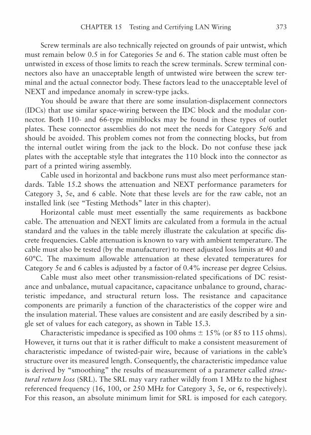
Screw terminals are also technically rejected on grounds of pair untwist, whichmust remain below 0.5 in for Categories 5e and 6. The station cable must often beuntwisted in excess of those limits to reach the screw terminals. Screw terminal con-nectors also have an unacceptable length of untwisted wire between the screw ter-minal and the actual connector body. These factors lead to the unacceptable level ofNEXT and impedance anomaly in screw-type jacks.
You should be aware that there are some insulation-displacement connectors(IDCs) that use similar space-wiring between the IDC block and the modular con-nector. Both 110- and 66-type miniblocks may be found in these types of outletplates. These connector assemblies do not meet the needs for Category 5e/6 andshould be avoided. This problem comes not from the connecting blocks, but fromthe internal outlet wiring from the jack to the block. Do not confuse these jackplates with the acceptable style that integrates the 110 block into the connector aspart of a printed wiring assembly.
Cable used in horizontal and backbone runs must also meet performance stan-dards. Table 15.2 shows the attenuation and NEXT performance parameters forCategory 3, 5e, and 6 cable. Note that these levels are for the raw cable, not aninstalled link (see “Testing Methods” later in this chapter).
Horizontal cable must meet essentially the same requirements as backbonecable. The attenuation and NEXT limits are calculated from a formula in the actualstandard and the values in the table merely illustrate the calculation at specific dis-crete frequencies. Cable attenuation is known to vary with ambient temperature. Thecable must also be tested (by the manufacturer) to meet adjusted loss limits at 40 and60°C. The maximum allowable attenuation at these elevated temperatures forCategory 5e and 6 cables is adjusted by a factor of 0.4% increase per degree Celsius.
Cable must also meet other transmission-related specifications of DC resist-ance and unbalance, mutual capacitance, capacitance unbalance to ground, charac-teristic impedance, and structural return loss. The resistance and capacitancecomponents are primarily a function of the characteristics of the copper wire andthe insulation material. These values are consistent and are easily described by a sin-gle set of values for each category, as shown in Table 15.3.
Characteristic impedance is specified as 100 ohms � 15% (or 85 to 115 ohms).However, it turns out that it is rather difficult to make a consistent measurement ofcharacteristic impedance of twisted-pair wire, because of variations in the cable’sstructure over its measured length. Consequently, the characteristic impedance valueis derived by “smoothing” the results of measurement of a parameter called struc-tural return loss (SRL). The SRL may vary rather wildly from 1 MHz to the highestreferenced frequency (16, 100, or 250 MHz for Category 3, 5e, or 6, respectively).For this reason, an absolute minimum limit for SRL is imposed for each category.
CHAPTER 15 Testing and Certifying LAN Wiring 373
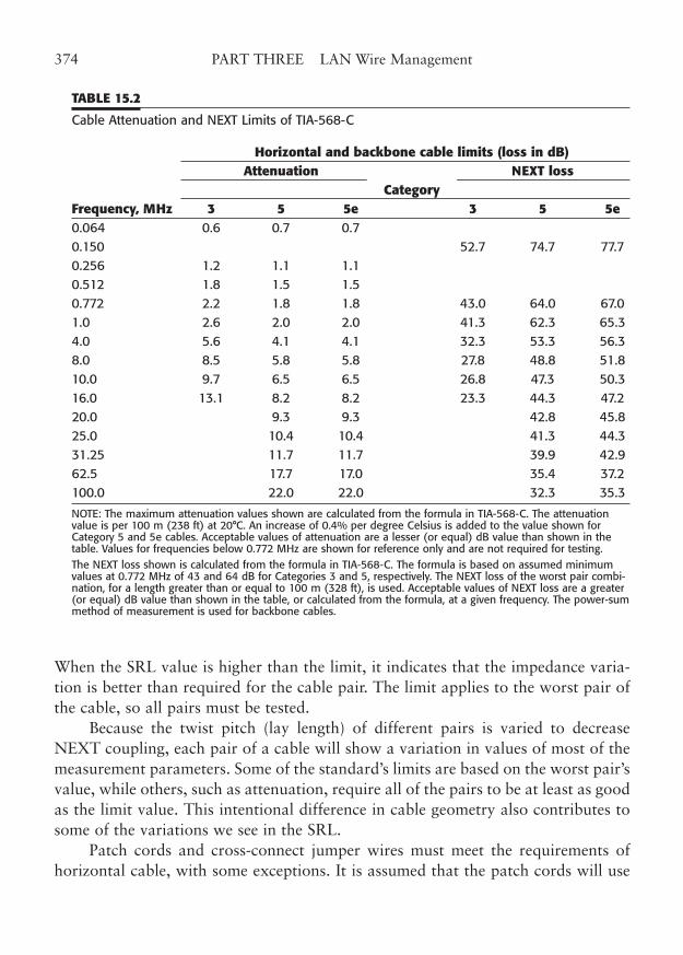
When the SRL value is higher than the limit, it indicates that the impedance varia-tion is better than required for the cable pair. The limit applies to the worst pair ofthe cable, so all pairs must be tested.
Because the twist pitch (lay length) of different pairs is varied to decreaseNEXT coupling, each pair of a cable will show a variation in values of most of themeasurement parameters. Some of the standard’s limits are based on the worst pair’svalue, while others, such as attenuation, require all of the pairs to be at least as goodas the limit value. This intentional difference in cable geometry also contributes tosome of the variations we see in the SRL.
Patch cords and cross-connect jumper wires must meet the requirements ofhorizontal cable, with some exceptions. It is assumed that the patch cords will use
374 PART THREE LAN Wire Management
TABLE 15.2
Cable Attenuation and NEXT Limits of TIA-568-C
Horizontal and backbone cable limits (loss in dB)Attenuation NEXT loss
CategoryFrequency, MHz 3 5 5e 3 5 5e0.064 0.6 0.7 0.7 0.150 52.7 74.7 77.7 0.256 1.2 1.1 1.1 0.512 1.8 1.5 1.5 0.772 2.2 1.8 1.8 43.0 64.0 67.0 1.0 2.6 2.0 2.0 41.3 62.3 65.3 4.0 5.6 4.1 4.1 32.3 53.3 56.3 8.0 8.5 5.8 5.8 27.8 48.8 51.8 10.0 9.7 6.5 6.5 26.8 47.3 50.3 16.0 13.1 8.2 8.2 23.3 44.3 47.2 20.0 9.3 9.3 42.8 45.8 25.0 10.4 10.4 41.3 44.3 31.25 11.7 11.7 39.9 42.9 62.5 17.7 17.0 35.4 37.2 100.0 22.0 22.0 32.3 35.3
NOTE: The maximum attenuation values shown are calculated from the formula in TIA-568-C. The attenuationvalue is per 100 m (238 ft) at 20°C. An increase of 0.4% per degree Celsius is added to the value shown forCategory 5 and 5e cables. Acceptable values of attenuation are a lesser (or equal) dB value than shown in thetable. Values for frequencies below 0.772 MHz are shown for reference only and are not required for testing.The NEXT loss shown is calculated from the formula in TIA-568-C. The formula is based on assumed minimumvalues at 0.772 MHz of 43 and 64 dB for Categories 3 and 5, respectively. The NEXT loss of the worst pair combi-nation, for a length greater than or equal to 100 m (328 ft), is used. Acceptable values of NEXT loss are a greater(or equal) dB value than shown in the table, or calculated from the formula, at a given frequency. The power-summethod of measurement is used for backbone cables.
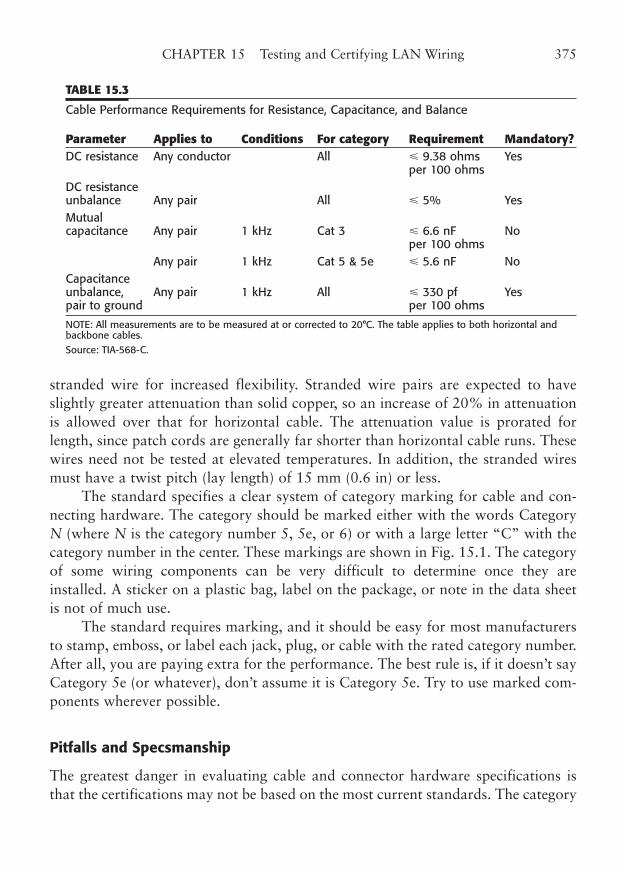
stranded wire for increased flexibility. Stranded wire pairs are expected to haveslightly greater attenuation than solid copper, so an increase of 20% in attenuationis allowed over that for horizontal cable. The attenuation value is prorated forlength, since patch cords are generally far shorter than horizontal cable runs. Thesewires need not be tested at elevated temperatures. In addition, the stranded wiresmust have a twist pitch (lay length) of 15 mm (0.6 in) or less.
The standard specifies a clear system of category marking for cable and con-necting hardware. The category should be marked either with the words CategoryN (where N is the category number 5, 5e, or 6) or with a large letter “C” with thecategory number in the center. These markings are shown in Fig. 15.1. The categoryof some wiring components can be very difficult to determine once they areinstalled. A sticker on a plastic bag, label on the package, or note in the data sheetis not of much use.
The standard requires marking, and it should be easy for most manufacturersto stamp, emboss, or label each jack, plug, or cable with the rated category number.After all, you are paying extra for the performance. The best rule is, if it doesn’t sayCategory 5e (or whatever), don’t assume it is Category 5e. Try to use marked com-ponents wherever possible.
Pitfalls and Specsmanship
The greatest danger in evaluating cable and connector hardware specifications isthat the certifications may not be based on the most current standards. The category
CHAPTER 15 Testing and Certifying LAN Wiring 375
TABLE 15.3
Cable Performance Requirements for Resistance, Capacitance, and Balance
Parameter Applies to Conditions For category Requirement Mandatory?DC resistance Any conductor All � 9.38 ohms Yes
per 100 ohmsDC resistance unbalance Any pair All � 5% Yes Mutualcapacitance Any pair 1 kHz Cat 3 � 6.6 nF No
per 100 ohmsAny pair 1 kHz Cat 5 & 5e � 5.6 nF No
Capacitanceunbalance, Any pair 1 kHz All � 330 pf Yespair to ground per 100 ohms
NOTE: All measurements are to be measured at or corrected to 20°C. The table applies to both horizontal andbackbone cables.Source: TIA-568-C.
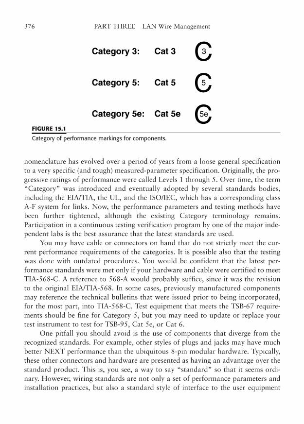
nomenclature has evolved over a period of years from a loose general specificationto a very specific (and tough) measured-parameter specification. Originally, the pro-gressive ratings of performance were called Levels 1 through 5. Over time, the term“Category” was introduced and eventually adopted by several standards bodies,including the EIA/TIA, the UL, and the ISO/IEC, which has a corresponding classA-F system for links. Now, the performance parameters and testing methods havebeen further tightened, although the existing Category terminology remains.Participation in a continuous testing verification program by one of the major inde-pendent labs is the best assurance that the latest standards are used.
You may have cable or connectors on hand that do not strictly meet the cur-rent performance requirements of the categories. It is possible also that the testingwas done with outdated procedures. You would be confident that the latest per-formance standards were met only if your hardware and cable were certified to meetTIA-568-C. A reference to 568-A would probably suffice, since it was the revisionto the original EIA/TIA-568. In some cases, previously manufactured componentsmay reference the technical bulletins that were issued prior to being incorporated,for the most part, into TIA-568-C. Test equipment that meets the TSB-67 require-ments should be fine for Category 5, but you may need to update or replace yourtest instrument to test for TSB-95, Cat 5e, or Cat 6.
One pitfall you should avoid is the use of components that diverge from therecognized standards. For example, other styles of plugs and jacks may have muchbetter NEXT performance than the ubiquitous 8-pin modular hardware. Typically,these other connectors and hardware are presented as having an advantage over thestandard product. This is, you see, a way to say “standard” so that it seems ordi-nary. However, wiring standards are not only a set of performance parameters andinstallation practices, but also a standard style of interface to the user equipment
376 PART THREE LAN Wire Management
Category 3: Cat 3
Category 5: Cat 5
Category 5e: Cat 5e
CCC
3
5
5e
FIGURE 15.1
Category of performance markings for components.
that allows multivendor interoperability with a high level of performance. Any itemthat does not comply with the standards is an exception and may be a potentialproblem for your network. This is, you see, also a way to hear “exceptional” thatsays it is noncompliant. For the time being, you may be taking a risk if you chooseto use some of these better (but nonstandard) connectivity options.
What is specsmanship? Specsmanship is a term for the exaggeration or mis-leading presentation of product specifications that sometimes occurs in the market-place. Fortunately, the existence of recognized national and international standardsminimizes the occurrence of specsmanship, but it still occurs. Were there no stan-dards, you can be sure that various manufacturers would make conflicting productclaims that would be impossible for the buyer to resolve. The tough standards fortelecommunications cabling make product differences clearly recognizable. All youhave to do is know which standard of performance you want the product to meet,and then be sure that the products you use meet that standard. There is a continu-ing controversy that involves connector performance.
The controversy concerns the relatively high NEXT of all modular connectorsand the measurable differences in longitudinal balance of some connector jackdesigns. Several types of nonmodular connectors are available that have signifi-cantly lower levels of NEXT than the popular 8-pin modular design. Some of theseconnectors are used for field test instruments to reduce the contribution to NEXTfrom the test set and are quite acceptable for testing the Permanent Link. However,a compatible lower-NEXT modular connector style would be much more desirablethan attempting to replace more than a decade of installed modular connectorswith another connector. Several manufacturers are working on the improved prod-ucts, and we’re already starting to see clever plug and jack designs emerge, but theissues of longitudinal balance and resonance phenomena are more subtle.Resonance phenomena can cause short links (particularly under 15 m) to exceedthe allowable NEXT performance and is related to the return loss and/or balanceof the link.
Cable Plant Certification
In addition to using properly rated cable and components in your LAN wiringinstallation, you should plan to test your installed wiring system to the expectedlevel of performance. Installing a cable plant or wiring system is a complex task,particularly if you intend for it to support high-performance 100/1000 Mbps net-works. Even 10 Mbps Ethernet and 16 Mbps Token-Ring had to have station cablesthat met a certain level of performance to have been considered reliable. Most LANwiring is put to use immediately after cable plant installation.
CHAPTER 15 Testing and Certifying LAN Wiring 377
Initial operation of the workstation is a good indication that the cable is allright, but it’s not positive proof that the cable is in perfect condition—particularlyif your workstations are still using 10 or 16 Mbps technology, and you plan to goto higher speeds. Also, it is not unusual for some of the station drops to remainunused until some later date. How will you know if those drops will work when youneed them?
Would you have a light fixture installed and not try the switch? Probably not.You need to test each drop of your cabling system as well. The best way to test cableis to use proper test equipment that looks only at the cable performance. In thatway, you avoid the nagging little network problems that obscure the real issues.Cable often gets blamed for problems that are really network hardware problemsand bad software configurations.
The best time to do the testing is before furnishings and people have beenmoved in. At this point, all outlet jacks are accessible, without the need to movedesks and other furniture. Any inspections and repairs that are needed can be donequickly and without disturbing anyone. Of course, modular furniture will have tobe in place because the cable must be installed in the furniture modules before it canbe tested.
TIA has offered TSB-72, now incorporated into TIA-568-C, as a means to pro-vide an intermediate point for interconnection to modular furniture. See the detailsin Chapter 10, “Open-Office Wiring.”
Testing Installed Cable
The testing of installed cable links is often referred to as “certification” of the instal-lation. Certification is normally performed by the installer and involves testing eachindividual cable link to a recognized standard. The end result of the certification isa report that shows the actual measurements of each cable link and the pass or faildetermination.
A dilemma initially existed in providing a method of testing and certifyinginstalled telecommunications cable. The original EIA/TIA-568 standard specificallystated that the performance standards for cable and connecting hardware did notapply to installed systems. The reason for this was that it was known that aninstalled cable run had performance that was below that of cable tested at the fac-tory. As a matter of fact, a correlation problem seemed to exist between cable testedwith a factory RF network analyzer and with the field test instruments. Whether thefield testers gave actual measurements of the parameters or judged the cable onpass/fail criteria, there were differences that might cause factory-certified cable tofail a field test.
378 PART THREE LAN Wire Management
Some of the differences were to be expected, as the installed cable had severalwire terminations, cross-connects, and modular connections that did not exist in thefactory. Also, the standard factory test was (and is) to lay the cable out on a non-conducting surface (such as a concrete floor) or loosely coiled and use special testadapters to connect to a network analyzer. Cable in the walls is bent, pulled, tie-wrapped, run along metal pipes and steel beams, placed in conduit, and installed inall manner of nonideal conditions that affect its performance. You would expect itto perform differently. Moreover, there were no standards for accuracy for fieldtesters, and their performance varied considerably. No wonder there was no corre-lation.
Fortunately, the situation is much improved with the newer standards, such asTIA-568-B and -C (originally embodied in TSB-67, and TSB-95). The performanceof installed cable is specified in detail, as is the accuracy of field testers.
Even the required tests, testing methods, and method of reporting the resultsare specified. The correlation of field tester performance with laboratory networkanalyzers is also made. All of this lends a wonderful consistency and reproducibil-ity to the testing of installed cabling that gives a real confidence factor to cable plantcertification.
Certification for installed cables may be done two standard ways, PermanentLink testing and Channel testing. Both of these testing methods are defined in TIA-568-C, which builds on the “worst case” link model. The Permanent Link coversthe horizontal cable from the workstation outlet at one end to the initial point oftermination at a cross-connect block or patch panel in the telecommunicationsroom, excluding the test cords for the test equipment and, of course, excluding anyuser cords. This is the portion of the horizontal cabling system that is permanentlyinstalled by the wiring contractor. It forms the essential litmus test of a proper struc-tured wiring installation job, and includes all the effects of component quality andworkmanship.
The test connection at the telecommunications room termination of a horizon-tal run may require special adapters unless the termination is directly into a modu-lar patch panel. For example, the test cord would have to terminate in a 110 adapterplug if that type of connecting block were used.
Originally, TIA documents identified the Permanent Link as the Basic Link, butterminology parallel to that of the ISO/IEC has been substituted in new revisions tothe TIA-568 standard. (See Fig. 1.9 in Chapter 1.)
The Channel includes the actual equipment cords (user cords, patch cords, andcross-connect wire) that connect to the network (or telephone) equipment at eachend. Keep in mind that the word “actual” means just that. Once you certify aChannel with a particular set of equipment cables, those cables are frozen in place,
CHAPTER 15 Testing and Certifying LAN Wiring 379
as far as the standard’s Channel testing method is concerned. If you change cables,to use a longer or shorter cable for example, you must re-certify the Channel.
The Permanent Link was designed to allow a cable installation to be certifiedonce the horizontal cables were installed by the installation contractor. As a matterof fact, the link was originally called the Contractor’s Link. Naturally, the user andpatch cords were not in place at this stage and would have been impossible to test.Nevertheless, the performance of the entire link (the Channel) is ultimately what theuser depends on, so this test was also included as an important benchmark of over-all link performance.
Which link test should you use? Permanent Link certification is probably suf-ficient in most cases of new installations. It will ensure that the 90 m (maximum) ofhorizontal cable is performing to specifications. The Permanent Link test is consid-ered the most reasonable performance testing standard for a turnkey cable systeminstallation, because the vendor may have little or no control over the cables usedto connect to the equipment.
Also, the build-out stage of construction is the best time to correct any problemsthat are revealed by a Permanent Link test. After the network equipment is installedand connected, it will be easiest and most useful to do Channel testing. The Channeltest is obviously very useful in dealing with network equipment vendors. You can relyon your cable system completely when it has been certified as a Channel.
Performance Levels
Two types of performance levels should be considered in making field tests, the firstbeing the performance category of the cable system. You should determine longbefore installation what category of performance you require and then test to thatlevel. The second type of performance is the accuracy level of the field tester youintend to use to certify the cable.
We have discussed the cable performance categories at length in previous chap-ters. The three categories of operation specified by TIA-568-C and related standardsare Categories 3, 5e, and 6. A new tighter version of Category 6, called AC6 orAugmented Category 6, is tested to 500 MHz or better. Other standards, such assome of the ISO documents, characterize similar performance levels, although withsome differences. For example, the ISO/IEC IS-11801 specifies identical categoriesfor uninstalled cable and components, but uses a class system for installed links.
Table 15.4 shows how the TIA categories correspond to the ISO classes. In mostinstances, the TIA categories are the same or tougher in test parameters and may besubstituted with no problems. If you are in a situation that needs to reference theseother standards, you should adjust your testing accordingly. While most of these
380 PART THREE LAN Wire Management
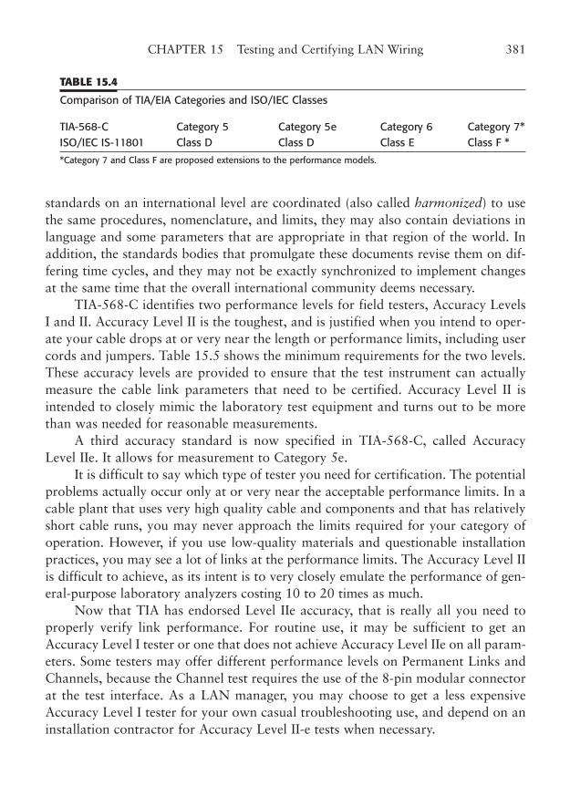
standards on an international level are coordinated (also called harmonized) to usethe same procedures, nomenclature, and limits, they may also contain deviations inlanguage and some parameters that are appropriate in that region of the world. Inaddition, the standards bodies that promulgate these documents revise them on dif-fering time cycles, and they may not be exactly synchronized to implement changesat the same time that the overall international community deems necessary.
TIA-568-C identifies two performance levels for field testers, Accuracy LevelsI and II. Accuracy Level II is the toughest, and is justified when you intend to oper-ate your cable drops at or very near the length or performance limits, including usercords and jumpers. Table 15.5 shows the minimum requirements for the two levels.These accuracy levels are provided to ensure that the test instrument can actuallymeasure the cable link parameters that need to be certified. Accuracy Level II isintended to closely mimic the laboratory test equipment and turns out to be morethan was needed for reasonable measurements.
A third accuracy standard is now specified in TIA-568-C, called AccuracyLevel IIe. It allows for measurement to Category 5e.
It is difficult to say which type of tester you need for certification. The potentialproblems actually occur only at or very near the acceptable performance limits. In acable plant that uses very high quality cable and components and that has relativelyshort cable runs, you may never approach the limits required for your category ofoperation. However, if you use low-quality materials and questionable installationpractices, you may see a lot of links at the performance limits. The Accuracy Level IIis difficult to achieve, as its intent is to very closely emulate the performance of gen-eral-purpose laboratory analyzers costing 10 to 20 times as much.
Now that TIA has endorsed Level IIe accuracy, that is really all you need toproperly verify link performance. For routine use, it may be sufficient to get anAccuracy Level I tester or one that does not achieve Accuracy Level IIe on all param-eters. Some testers may offer different performance levels on Permanent Links andChannels, because the Channel test requires the use of the 8-pin modular connectorat the test interface. As a LAN manager, you may choose to get a less expensiveAccuracy Level I tester for your own casual troubleshooting use, and depend on aninstallation contractor for Accuracy Level II-e tests when necessary.
CHAPTER 15 Testing and Certifying LAN Wiring 381
TABLE 15.4
Comparison of TIA/EIA Categories and ISO/IEC Classes
TIA-568-C Category 5 Category 5e Category 6 Category 7*ISO/IEC IS-11801 Class D Class D Class E Class F *
*Category 7 and Class F are proposed extensions to the performance models.
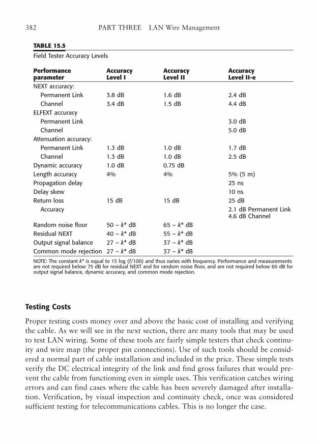
Testing Costs
Proper testing costs money over and above the basic cost of installing and verifyingthe cable. As we will see in the next section, there are many tools that may be usedto test LAN wiring. Some of these tools are fairly simple testers that check continu-ity and wire map (the proper pin connections). Use of such tools should be consid-ered a normal part of cable installation and included in the price. These simple testsverify the DC electrical integrity of the link and find gross failures that would pre-vent the cable from functioning even in simple uses. This verification catches wiringerrors and can find cases where the cable has been severely damaged after installa-tion. Verification, by visual inspection and continuity check, once was consideredsufficient testing for telecommunications cables. This is no longer the case.
382 PART THREE LAN Wire Management
TABLE 15.5
Field Tester Accuracy Levels
Performance Accuracy Accuracy Accuracy parameter Level I Level II Level II-eNEXT accuracy:
Permanent Link 3.8 dB 1.6 dB 2.4 dB Channel 3.4 dB 1.5 dB 4.4 dB
ELFEXT accuracy Permanent Link 3.0 dB Channel 5.0 dB
Attenuation accuracy: Permanent Link 1.3 dB 1.0 dB 1.7 dB Channel 1.3 dB 1.0 dB 2.5 dB
Dynamic accuracy 1.0 dB 0.75 dB Length accuracy 4% 4% 5% (5 m) Propagation delay 25 ns Delay skew 10 ns Return loss 15 dB 15 dB 25 dB
Accuracy 2.1 dB Permanent Link 4.6 dB Channel
Random noise floor 50 – k* dB 65 – k* dB Residual NEXT 40 – k* dB 55 – k* dB Output signal balance 27 – k* dB 37 – k* dB Common mode rejection 27 – k* dB 37 – k* dB
NOTE: The constant k* is equal to 15 log (f/100) and thus varies with frequency. Performance and measurementsare not required below 75 dB for residual NEXT and for random noise floor, and are not required below 60 dB foroutput signal balance, dynamic accuracy, and common mode rejection.
The demanding cable performance that is required by modern LAN applica-tions can no longer be met by such simple testing methods. To truly test a LANwiring system to meet one of the more rigorous performance categories requires theuse of very sophisticated test equipment.
Specialized field testers have been developed to reduce the cost of testing. Thesetesters are far less expensive to purchase than the ultrasophisticated laboratory RFnetwork analyzers (these test all sorts of electronic networks, not local area com-puter networks). Yet, the field testers yield useful results that closely match themeasurements to the LAN category standards, produce quick pass/fail indications,and print full reports.
These field testers are also very easy to use. They can run completely auto-mated tests, store the results, and pinpoint problem locations on the cable undertest. Most of the testers will operate for several hours on battery power, so you don’teven have to find a power outlet.
Although these testers provide many advantages, they are still much moreexpensive than the simple wiring verification tools, and they require additionalskill to operate properly. Consequently, you should expect to pay extra for havingyour cable “scanned” with one of these field testers. The cost of the tester, theskilled operator time, the preparation of reports, and the possible retesting shouldbe considered when budgeting for the additional cable scanning step. You shouldallow a budgetary cost from 5% to 15% of the installation cost per drop to certifyto Permanent Link standards. The cost variation is to allow for special circum-stances, such as an unusually difficult and expensive per-drop cost. If the scanningis done by a separate contractor, you should allow an additional factor for prob-lem determination or visual inspection. Scanning is best done before personnelhave moved into the office space. Although scanning involves only a brief visit toeach workstation outlet, labor costs will be higher if furniture (and people) have tobe moved.
If your intention is to install a full Category 5e or 6 wiring system, then youneed to plan for a complete certification scan. The component standards and instal-lation practices are simply too tough to not test completely for proper performance.If you have an existing facility that is supposed to meet Category 5 and you havenot previously tested it to 100 Mbps, then a new scan would be appropriate. Torecertify Category 5 links for Gigabit Ethernet, you should test to the limits in TSB-95, as the full Category 5e limits should not be required. Prior to the release of thetesting procedures and limits in TSB-67, standard practice was to use Category 5cable and components, install using the best current practices, and test using what-ever cable scanners were available at that time. The older EIA/TIA-568 standardspecifically excluded installed cable and connectors from its scope.
CHAPTER 15 Testing and Certifying LAN Wiring 383
Testing Methods
To properly test installed cabling components, it is necessary to define the “teststructures,” such as the Channel and the Permanent Link. Only by standardizing thetesting environment and detailing the expected (and necessary) performance param-eters, can we hope to determine whether the elements of a particular structuredcabling system will meet the needs of the LAN wiring application. This section willdescribe all of the test structures and the individual elements that are tested for cop-per and fiber cabling.
The Channel and the Permanent Link
The installed cable link components of a horizontal link are measured either as aPermanent Link or as a Channel. The difference between the two is that the Channelincludes the actual equipment cords (user cords), patch cords, horizontal cross-con-nect, and cross-connect jumpers that will ultimately connect to the LAN equipmentat each end of the horizontal link.
The Permanent Link excludes two test equipment cords, one at each end(including the connectors at the tester end), while the cords at the ends of theChannel must be plugged directly into the test instrument interface with noallowance for test cords. The Permanent Link and Channel are shown in Fig. 15.2.
As stated earlier, the reason for the two types of links is to facilitate testing atboth the construction phase and the post-installation phase. It is unusual for net-work hubs and workstations to be available during the construction phase of aninstallation. It would be time-consuming and difficult to wait to detect and repairbad cable runs at some later time. Moreover, the cable installer may have littleresponsibility or influence for the equipment cords. This two-step method of cablelink specification allows the installed “in-the-wall” cable to be tested as soon asinstallation is completed. The complete link, from network hub to workstation, canbe further tested during installation of that equipment.
Equipment and Testing Requirements
The purpose of the standards in TSB-67 is twofold. The full title of the TSB isTransmission Performance Specifications for Field Testing of Unshielded Twisted-Pair Cabling Systems. One explicit purpose, then, is to define cabling system per-formance after the cable has been installed.
The other purpose, which is implied by wanting to test in the field, is to definefield tester performance. Early field testers did not always produce consistent results
384 PART THREE LAN Wire Management
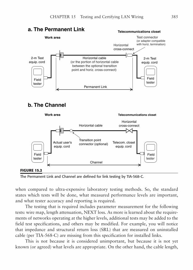
when compared to ultra-expensive laboratory testing methods. So, the standardstates which tests will be done, what measured performance levels are important,and what tester accuracy and reporting is required.
The testing that is required includes parameter measurement for the followingtests: wire map, length attenuation, NEXT loss. As more is learned about the require-ments of networks operating at the higher levels, additional tests may be added to thefield test specifications, and others may be modified. For example, you will noticethat impedance and structural return loss (SRL) that are measured on uninstalledcable (per TIA-568-C) are missing from this specification for installed links.
This is not because it is considered unimportant, but because it is not yetknown (or agreed) what levels are appropriate. On the other hand, the cable length,
CHAPTER 15 Testing and Certifying LAN Wiring 385
a. The Permanent Link
b. The Channel
Fieldtester
Horizontal cable(or the portion of horizontal cablebetween the optional transitionpoint and horiz. cross-connect)
Horizontalcross-connect
Telecommunications closet
Work area Test connector(or adapter compatiblewith horiz. termination)
2-m Testequip. cord
Permanent Link
Actual user'sequip. cord
Horizontal cableHorizontal
cross-connect
Telecommunications closetWork area
Telecom. closetequip. cord
Channel
Transition pointconnector (optional)
Fieldtester
Fieldtester
Fieldtester
2-m Testequip. cord
FIGURE 15.2
The Permanent Link and Channel are defined for link testing by TIA-568-C.
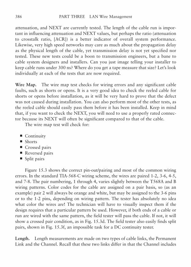
attenuation, and NEXT are currently tested. The length of the cable run is impor-tant in influencing attenuation and NEXT values, but perhaps the ratio (attenuationto crosstalk ratio, [ACR]) is a better indicator of overall system performance.Likewise, very high speed networks may care as much about the propagation delayas the physical length of the cable, yet transmission delay is not yet specified nortested. These new tests could be a boon to transmission engineers, but a bane tocable system designers and installers. Can you just image telling your installer tokeep cable runs under 300 ns? Where do you get a tape measure that size? Let’s lookindividually at each of the tests that are now required.
Wire Map. The wire map test checks for wiring errors and any significant cablefaults, such as shorts or opens. It is a very good idea to check the reeled cable forshorts or opens before installation, as it will be very hard to prove that the defectwas not caused during installation. You can also perform most of the other tests, asthe reeled cable should easily pass them before it has been installed. Keep in mindthat, if you want to check the NEXT, you will need to use a properly rated connec-tor because its NEXT will often be significant compared to that of the cable.
The wire map test will check for:
■ Continuity■ Shorts■ Crossed pairs■ Reversed pairs■ Split pairs
Figure 15.3 shows the correct pin-out/pairing and most of the common wiringerrors. In the standard TIA-568-C wiring scheme, the wires are paired 1-2, 3-6, 4-5,and 7-8. The pair numbering, 1 through 4, varies slightly between the T568A and Bwiring patterns. Color codes for the cable are assigned on a pair basis, so (as anexample) pair 2 will always be orange and white, but may be assigned to the 3-6 pinsor to the 1-2 pins, depending on wiring pattern. The tester has absolutely no ideawhat color the wires are! The technician will have to visually inspect them if thedesign requires that a particular pattern be used. However, if both ends of a cable orrun are wired with the same pattern, the field tester will pass the cable. If not, it willshow a crossed pair condition, as in Fig. 15.3d. The field tester also easily finds splitpairs, shown in Fig. 15.3f, an impossible task for a DC continuity tester.
Length. Length measurements are made on two types of cable links, the PermanentLink and the Channel. Recall that these two links differ in that the Channel includes
386 PART THREE LAN Wire Management
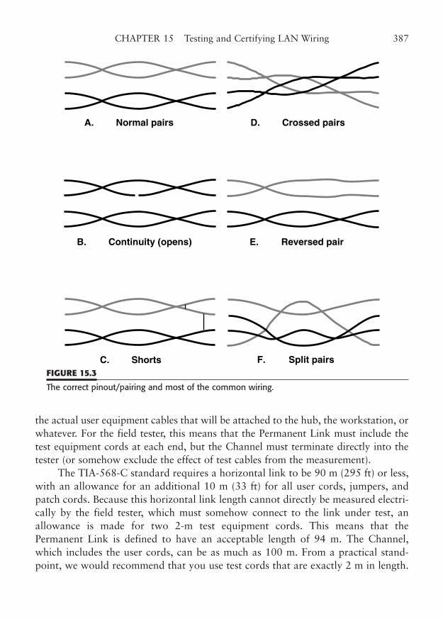
the actual user equipment cables that will be attached to the hub, the workstation, orwhatever. For the field tester, this means that the Permanent Link must include thetest equipment cords at each end, but the Channel must terminate directly into thetester (or somehow exclude the effect of test cables from the measurement).
The TIA-568-C standard requires a horizontal link to be 90 m (295 ft) or less,with an allowance for an additional 10 m (33 ft) for all user cords, jumpers, andpatch cords. Because this horizontal link length cannot directly be measured electri-cally by the field tester, which must somehow connect to the link under test, anallowance is made for two 2-m test equipment cords. This means that thePermanent Link is defined to have an acceptable length of 94 m. The Channel,which includes the user cords, can be as much as 100 m. From a practical stand-point, we would recommend that you use test cords that are exactly 2 m in length.
CHAPTER 15 Testing and Certifying LAN Wiring 387
A. Normal pairs
F. Split pairs
E. Reversed pair
D. Crossed pairs
B. Continuity (opens)
C. ShortsFIGURE 15.3
The correct pinout/pairing and most of the common wiring.
If you use a shorter cord, the tester may pass a link that exceeds the limit. If you usetoo long a cord, you may reject links that actually are legal.
Some testers require a test cord of at least 1 m. Never fear; because of individ-ual cable variations in nominal velocity of propagation (NVP), the standard allowsan additional 10% before it declares a length failure (plus a factor allowing for the� 1 m � 4% tester accuracy, although pass/fail results in this zone must be markedwith an asterisk).
An interesting distinction should be pointed out in regard to length. The phys-ical length of a Channel or Permanent Link is an important parameter. Physicallength may be measured or determined from markings on the cable. Cable testersestimate electrical length from the propagation delay of the cable. Because propaga-tion delay depends on the physical characteristics, such as the twist pitch (lay length)and dielectric properties of each pair, it varies with different categories of cable andeven with different lots of cable from the same manufacturer. To accurately correctfor manufacturing variations in cable, it is very important to measure the propaga-tion delay of each reel of cable installed. The cable pair with the shortest propaga-tion delay is used.
The procedure for calibrating length on a field tester is to physically measure alength of cable from the reel to be installed and calibrate the tester through an elec-trical length measurement on that same sample of cable. The particular length ofcable you use is not important, but it is important that its exact length be known.However, accuracy of the calibration is increased with a longer piece of cable. Alength of 15 m (or about 50 ft) or longer is commonly recommended. Realistically, itwould not be practical to cut and measure every reel of cable at a large job, but youshould calibrate for each different cable lot, if possible. You might cut a length forone of your cable runs to use to calibrate the cable, so as to not waste the sample.
Testers are required to have a length range of at least 310 m, so that a 1000-ftreel of cable can be measured. However, until the cable on a particular reel is cali-brated for NVP, this measurement should be considered only approximate. Statedlengths on reeled cable are not exact and should not be used exclusively to calibratethe NVP of a cable.
Attenuation. The maximum attenuation for the purposes of testing the PermanentLink or Channel has been based on the attenuation values given in TIA-568-C forhorizontal cable, connecting hardware, and jumper or patch cords. It prorates theloss values, given in dB per 100 m, and applies them to the worst-case length of thelink. Table 15.6 shows a summary of the allowable attenuation values for thePermanent Link and the Channel at selected frequencies. TSB-67 contains the for-mulas for calculating each of the components of Permanent Link or Channel atten-
388 PART THREE LAN Wire Management
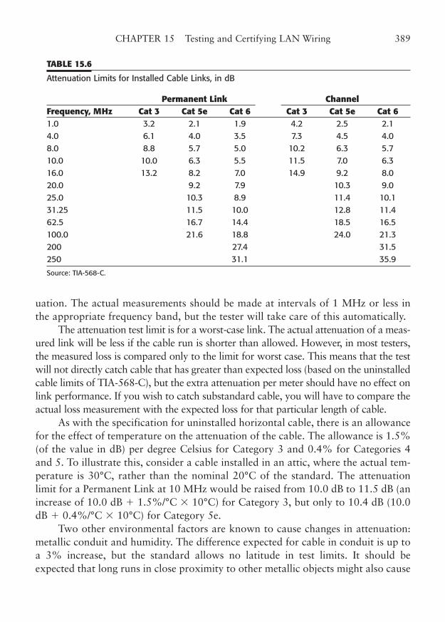
uation. The actual measurements should be made at intervals of 1 MHz or less inthe appropriate frequency band, but the tester will take care of this automatically.
The attenuation test limit is for a worst-case link. The actual attenuation of a meas-ured link will be less if the cable run is shorter than allowed. However, in most testers,the measured loss is compared only to the limit for worst case. This means that the testwill not directly catch cable that has greater than expected loss (based on the uninstalledcable limits of TIA-568-C), but the extra attenuation per meter should have no effect onlink performance. If you wish to catch substandard cable, you will have to compare theactual loss measurement with the expected loss for that particular length of cable.
As with the specification for uninstalled horizontal cable, there is an allowancefor the effect of temperature on the attenuation of the cable. The allowance is 1.5%(of the value in dB) per degree Celsius for Category 3 and 0.4% for Categories 4and 5. To illustrate this, consider a cable installed in an attic, where the actual tem-perature is 30°C, rather than the nominal 20°C of the standard. The attenuationlimit for a Permanent Link at 10 MHz would be raised from 10.0 dB to 11.5 dB (anincrease of 10.0 dB � 1.5%/°C � 10°C) for Category 3, but only to 10.4 dB (10.0dB � 0.4%/°C � 10°C) for Category 5e.
Two other environmental factors are known to cause changes in attenuation:metallic conduit and humidity. The difference expected for cable in conduit is up toa 3% increase, but the standard allows no latitude in test limits. It should beexpected that long runs in close proximity to other metallic objects might also cause
CHAPTER 15 Testing and Certifying LAN Wiring 389
TABLE 15.6
Attenuation Limits for Installed Cable Links, in dB
Permanent Link ChannelFrequency, MHz Cat 3 Cat 5e Cat 6 Cat 3 Cat 5e Cat 61.0 3.2 2.1 1.9 4.2 2.5 2.14.0 6.1 4.0 3.5 7.3 4.5 4.08.0 8.8 5.7 5.0 10.2 6.3 5.710.0 10.0 6.3 5.5 11.5 7.0 6.316.0 13.2 8.2 7.0 14.9 9.2 8.020.0 9.2 7.9 10.3 9.025.0 10.3 8.9 11.4 10.131.25 11.5 10.0 12.8 11.462.5 16.7 14.4 18.5 16.5100.0 21.6 18.8 24.0 21.3200 27.4 31.5250 31.1 35.9
Source: TIA-568-C.
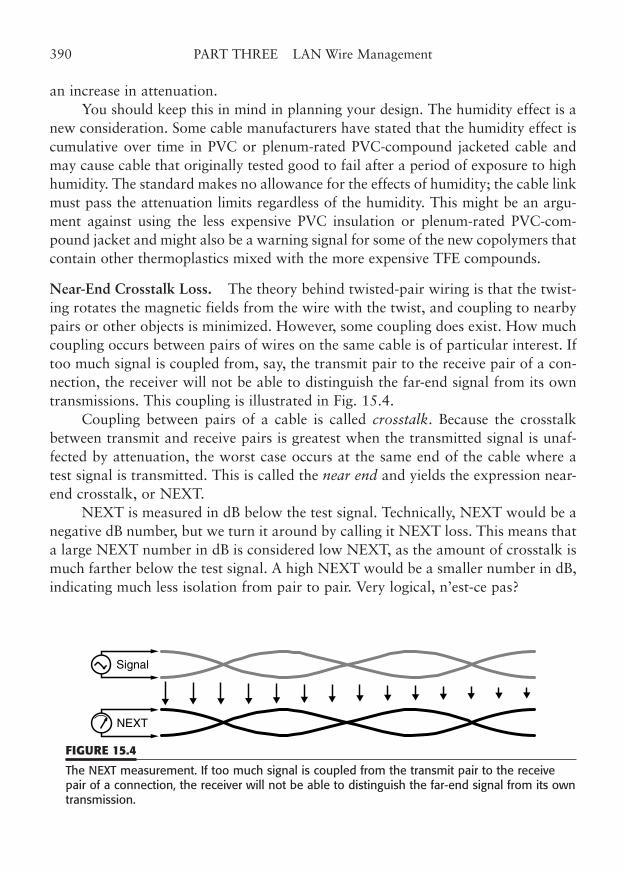
an increase in attenuation.You should keep this in mind in planning your design. The humidity effect is a
new consideration. Some cable manufacturers have stated that the humidity effect iscumulative over time in PVC or plenum-rated PVC-compound jacketed cable andmay cause cable that originally tested good to fail after a period of exposure to highhumidity. The standard makes no allowance for the effects of humidity; the cable linkmust pass the attenuation limits regardless of the humidity. This might be an argu-ment against using the less expensive PVC insulation or plenum-rated PVC-com-pound jacket and might also be a warning signal for some of the new copolymers thatcontain other thermoplastics mixed with the more expensive TFE compounds.
Near-End Crosstalk Loss. The theory behind twisted-pair wiring is that the twist-ing rotates the magnetic fields from the wire with the twist, and coupling to nearbypairs or other objects is minimized. However, some coupling does exist. How muchcoupling occurs between pairs of wires on the same cable is of particular interest. Iftoo much signal is coupled from, say, the transmit pair to the receive pair of a con-nection, the receiver will not be able to distinguish the far-end signal from its owntransmissions. This coupling is illustrated in Fig. 15.4.
Coupling between pairs of a cable is called crosstalk. Because the crosstalkbetween transmit and receive pairs is greatest when the transmitted signal is unaf-fected by attenuation, the worst case occurs at the same end of the cable where atest signal is transmitted. This is called the near end and yields the expression near-end crosstalk, or NEXT.
NEXT is measured in dB below the test signal. Technically, NEXT would be anegative dB number, but we turn it around by calling it NEXT loss. This means thata large NEXT number in dB is considered low NEXT, as the amount of crosstalk ismuch farther below the test signal. A high NEXT would be a smaller number in dB,indicating much less isolation from pair to pair. Very logical, n’est-ce pas?
390 PART THREE LAN Wire Management
Signal
NEXT
FIGURE 15.4
The NEXT measurement. If too much signal is coupled from the transmit pair to the receivepair of a connection, the receiver will not be able to distinguish the far-end signal from its owntransmission.
NEXT must be measured in both directions on the cable link, to prevent thesituation where one end of a cable passes NEXT and the other end fails. Single-ended measurements are often made in the telecommunications room, as it elimi-nates carrying the tester around to each workstation outlet. Excessive untwist at theconnector is more often found at the workstation end, however, because the outletsnaturally separate the conductors, and because the individual jack plates are moredifficult to inspect. Also, the workmanship may be less because the supervisory con-trol may not be as great as would exist in the telecommunications room. So, if youonly measure at one end, you are likely to miss more of the high NEXT connections.The equipment at both ends requires appropriately low NEXT to operate properly.
A related figure of merit for a cable link is ACR. Although not yet specified bythe standards, ACR is a very good measure of how the attenuation and the NEXTcan influence the performance of networking interface devices. Attenuation may beused to calculate the received signal strength of a signal transmitted from the farend. NEXT can yield the level of the interfering crosstalk signal from the near-endtransmitter. The near-end receiver is thus required to cope with a signal-to-noiseratio that is basically the ratio of the two signals: the attenuated far-end transmis-sion and the near-end crosstalk.
Since both attenuation and NEXT are directly measured as part of the testing,it is very simple to ratio the two to produce the ACR figure. The higher the ACRnumber, the better the expected performance. Since a ratio of two logarithmic quan-tities is their numerical difference, the ratio is simply: ACR � attenuation (in dB) �NEXT loss (in dB). One of the things that concerns network hardware designers isthat the ACR decreases steadily with frequency. This means that at 100 MHz, theACR margin may be very small indeed. Thus, it may be of benefit to those planningto eventually go beyond 100 MHz to purchase cable with the highest ACR possible.
Reporting Pass and Fail Criteria
An important part of TSB-67 is the carefully detailed requirements for the reportingof test results. In general, the standard requires that each measured result bereported in units appropriate for the test and that a Pass or Fail determination bereported. Measurements, such as for attenuation or NEXT, that might be very closeto the limits are reported with an asterisk in addition to the Pass or Fail.
A data report is simply the visual indication of the field test set. In all of themodern cable scanners, the visual display is a liquid crystal display (LCD) that alsoallows the display of some graphics. Of course, it is important for a permanentrecord of the report to be made, so the testers also allow the test data for each cableto be stored and later printed out. Figure 15.5 shows a typical cable scanning report.
CHAPTER 15 Testing and Certifying LAN Wiring 391
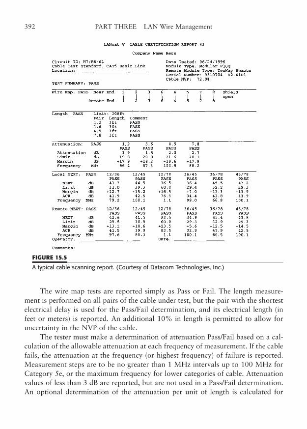
The wire map tests are reported simply as Pass or Fail. The length measure-ment is performed on all pairs of the cable under test, but the pair with the shortestelectrical delay is used for the Pass/Fail determination, and its electrical length (infeet or meters) is reported. An additional 10% in length is permitted to allow foruncertainty in the NVP of the cable.
The tester must make a determination of attenuation Pass/Fail based on a cal-culation of the allowable attenuation at each frequency of measurement. If the cablefails, the attenuation at the frequency (or highest frequency) of failure is reported.Measurement steps are to be no greater than 1 MHz intervals up to 100 MHz forCategory 5e, or the maximum frequency for lower categories of cable. Attenuationvalues of less than 3 dB are reported, but are not used in a Pass/Fail determination.An optional determination of the attenuation per unit of length is calculated for
392 PART THREE LAN Wire Management
FIGURE 15.5
A typical cable scanning report. (Courtesy of Datacom Technologies, Inc.)
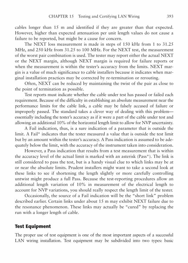
cables longer than 15 m and identified if they are greater than that expected.However, higher than expected attenuation per unit length values do not cause afailure to be reported, but might be a cause for concern.
The NEXT loss measurement is made in steps of 150 kHz from 1 to 31.25MHz, and 250 kHz from 31.25 to 100 MHz. For the NEXT test, the measurementof the worst pair combination is used. The tester may report either the actual NEXTor the NEXT margin, although NEXT margin is required for failure reports orwhen the measurement is within the tester’s accuracy from the limits. NEXT mar-gin is a value of much significance to cable installers because it indicates when mar-ginal installation practices may be corrected by re-termination or rerouting.
Often, NEXT can be reduced by maintaining the twist of the pair as close tothe point of termination as possible.
Test reports must indicate whether the cable under test has passed or failed eachrequirement. Because of the difficulty in establishing an absolute measurement near theperformance limits for the cable link, a cable may be falsely accused of failure orimproperly passed. The standard takes a clever way of dealing with this problem—essentially including the tester’s accuracy as if it were a part of the cable under test andallowing an additional 10% of the horizontal length limit to allow for NVP uncertainty.
A Fail indication, thus, is a sure indication of a parameter that is outside thelimit. A Fail* indicates that the tester measured a value that is outside the test limitbut by an amount within the tester’s accuracy. A Pass indication is assumed to be ade-quately below the limit, with the accuracy of the instrument taken into consideration.
However, a Pass indication that results from a test measurement that is withinthe accuracy level of the actual limit is marked with an asterisk (Pass*). The link isstill considered to pass the test, but is a handy visual clue to which links may be ator near the absolute limits. Prudent installers might want to take a second look atthese links to see if shortening the length slightly or more carefully controllinguntwist might produce a full Pass. Because the test-reporting procedures allow anadditional length variation of 10% in measurement of the electrical length toaccount for NVP variations, you should really respect the length limit of the tester.
Occasionally, the source of a Fail indication will be the “short link” problemdescribed earlier. Certain links under about 15 m may exhibit NEXT failure due tothe resonance phenomenon. These links may actually be “cured” by replacing therun with a longer length of cable.
Test Equipment
The proper use of test equipment is one of the most important aspects of a successfulLAN wiring installation. Test equipment may be subdivided into two types: basic
CHAPTER 15 Testing and Certifying LAN Wiring 393
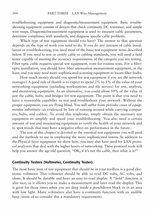
troubleshooting equipment and diagnostic/measurement equipment. Basic trouble-shooting equipment consists of devices that check continuity, DC resistance, and simplewire maps. Diagnostic/measurement equipment is used to measure cable parameters,determine compliance with standards, and diagnose specific cable problems.
Which type of test equipment should you have? The answer to that questiondepends on the type of work you need to do. If you do any amount of cable instal-lation or troubleshooting, you need most of the basic test equipment items describedbelow. If you need to test or certify cable to cabling standards, you will need a fieldtester capable of meeting the accuracy requirements of the category you are testing.Fiber optic cable requires special test equipment, even for routine tests. For a fiber-optic installation, you should have fiber attenuation measurement equipment, at theleast, and you may need more sophisticated scanning equipment to locate fiber faults.
How much money should you spend for test equipment if you are the networkmanager? A good rule of thumb is to expect to spend 2% to 5% of the value of yournetworking equipment (including workstations and file servers) for test, analysis,and monitoring equipment. As an alternative, you could allow 10% of the value ofjust the cable, hubs, and bridges for test equipment. The point is that you need tohave a reasonable capability to test and troubleshoot your network. Without theproper equipment, you are flying blind. You will suffer from periodic cases of equip-mentus substitutis (as evidenced by lots of running around while carrying comput-ers, hubs, and cables). To avoid this syndrome, simply obtain the necessary testequipment to simplify and speed your troubleshooting. You also need a certainamount of test and monitoring equipment to verify the health of your network andto spot trends that may have a negative effect on performance in the future.
The rest of this chapter is devoted to the essential test equipment you will needand the methods to use in employing the more sophisticated testers. In addition tothe Physical layer equipment we show here, you may also have need for LAN proto-col analyzers that deal with the higher layers of networking. These protocol tools willhelp you answer the age-old question, “OK, if it’s not the cable, then what is it?”
Continuity Testers (Voltmeter, Continuity Tester)
The most basic item of test equipment that should be in your toolbox is a good elec-tronic voltmeter. This voltmeter should be able to read DC volts, AC volts, andohms. It should be durable and have an easy-to-read display. A “hold” function isalso nice, as it allows you to make a measurement and later read the display. Thisis great for those times when you are deep inside a punchdown block or in an areawith low light. Many voltmeters also have a continuity function with an audiblebeep (some of us consider this a mandatory requirement).
394 PART THREE LAN Wire Management
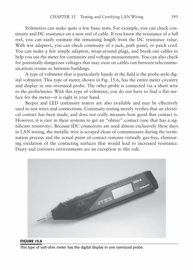
Voltmeters can make quite a few basic tests. For example, you can check con-tinuity and DC resistance on a new reel of cable. If you know the resistance of a fullreel, you can easily estimate the remaining length from the DC resistance value.With test adapters, you can check continuity of a jack, path panel, or patch cord.You can make a few simple adapters, wrap-around plugs, and break-out cables tohelp you use the meter for continuity and voltage measurements. You can also checkfor potentially dangerous voltages that may exist on cables run between telecommu-nications rooms or between buildings.
A type of voltmeter that is particularly handy in the field is the probe-style dig-ital voltmeter. This type of meter, shown in Fig. 15.6, has the entire meter circuitryand display in one oversized probe. The other probe is connected via a short wireto the probe/meter. With this type of voltmeter, you do not have to find a flat sur-face for the meter—it is right in your hand.
Beeper and LED continuity testers are also available and may be effectivelyused to test wires and connections. Continuity testing merely verifies that an electri-cal contact has been made, and does not really measure how good that contact is.However, it is rare in these systems to get an “ohmic” contact (one that has a sig-nificant resistivity). Because IDC connectors are used almost exclusively these daysin LAN wiring, the metallic wire is scraped clean of contaminants during the termi-nation process and the actual point of contact remains virtually gas-free, eliminat-ing oxidation of the contacting surfaces that would lead to increased resistance.Dusty and corrosive environments are an exception to this rule.
CHAPTER 15 Testing and Certifying LAN Wiring 395
FIGURE 15.6
This type of volt-ohm meter has the digital display in one oversized probe.
Cable Wire Map Testers
A very good device to test an installed cable link is the wire map tester. These littletesters give an indication of cable continuity and proper pin-out. They are generallyused for installed cables or assembled cords.
One type has a main tester and a remote unit. The two units communicateacross the cable to perform a wire map test and, of course, a basic continuity test.Most of these testers can easily find all of the standard connection errors and prob-lems, such as opens, shorts, reversed wires, and crossed connections. (These cablefaults are all explained in the next section.) Simple miswirings are probably the mostcommon cable installation problem, and the easiest to fix.
The simple wire map tester performs a simple DC continuity test and checksfor undesired connections. It does not check for proper pairing, as with a split-pairfault. A split pair is a condition where one of the two wires in one pair is acciden-tally exchanged for one of the wires in another pair. For example, the white-greenand the white-brown might be exchanged. This actually means that two pairs aremixed, and the balance and self-shielding properties of the paired wires is lost. Inthis type of miswire, DC connectivity tests fine and it would pass a simple wire maptest, but the cable would fail if tested for AC signal balance by a cable scanner. Inmany instances, a cable with a split-pair fault will cause a LAN link to fail, whichis why it is important to test for this with the more sophisticated scanners.
A specialized version of the wire map tester is used to test assembled cables.This cable continuity tester has two modular jacks where each end of the cable isplugged in. When a button on the tester is pressed, LEDs light to indicate continu-ity of each wire in the cable, one by one.
A Pass is indicated by observing that the LEDs each light up in order throughthe number of pins in the cable.
This type of tester may be used for 6-pin modular connectors in addition to the8-pin connectors used for LAN wiring. Frequently, the same test jack is used forboth sizes of connectors. This creates a potential false-failure problem for pins 1 and8 of the 8-pin plug. Although the 6-wire plug will fit into the jack of the tester, theplastic sides of the plug may permanently bend the jack’s first and eighth pins, mak-ing them no longer contact Pins 1 and 8 of an 8-position plug and giving a false indi-cation of failure. The solution is to never use 6-pin plugs in a tester you intend touse for 8-pin plugs! If you believe a false failure has occurred, you can usually forma small stiff wire (such as a paper clip) to bend the jack wires back into position.Then, test the cable again.
396 PART THREE LAN Wire Management
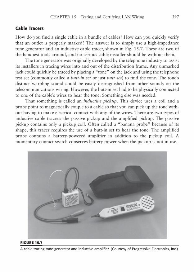
Cable Tracers
How do you find a single cable in a bundle of cables? How can you quickly verifythat an outlet is properly marked? The answer is to simply use a high-impedancetone generator and an inductive cable tracer, shown in Fig. 15.7. These are two ofthe handiest tools around, and no serious cable installer should be without them.
The tone generator was originally developed by the telephone industry to assistits installers in tracing wires into and out of the distribution frame. Any unmarkedjack could quickly be traced by placing a “tone” on the jack and using the telephonetest set (commonly called a butt-in set or just butt set) to find the tone. The tone’sdistinct warbling sound could be easily distinguished from other sounds on thetelecommunications wiring. However, the butt-in set had to be physically connectedto one of the cable’s wires to hear the tone. Something else was needed.
That something is called an inductive pickup. This device uses a coil and aprobe point to magnetically couple to a cable so that you can pick up the tone with-out having to make electrical contact with any of the wires. There are two types ofinductive cable tracers: the passive pickup and the amplified pickup. The passivepickup contains only a pickup coil. Often called a “banana probe” because of itsshape, this tracer requires the use of a butt-in set to hear the tone. The amplifiedprobe contains a battery-powered amplifier in addition to the pickup coil. Amomentary contact switch conserves battery power when the pickup is not in use.
CHAPTER 15 Testing and Certifying LAN Wiring 397
FIGURE 15.7
A cable tracing tone generator and inductive amplifier. (Courtesy of Progressive Electronics, Inc.)
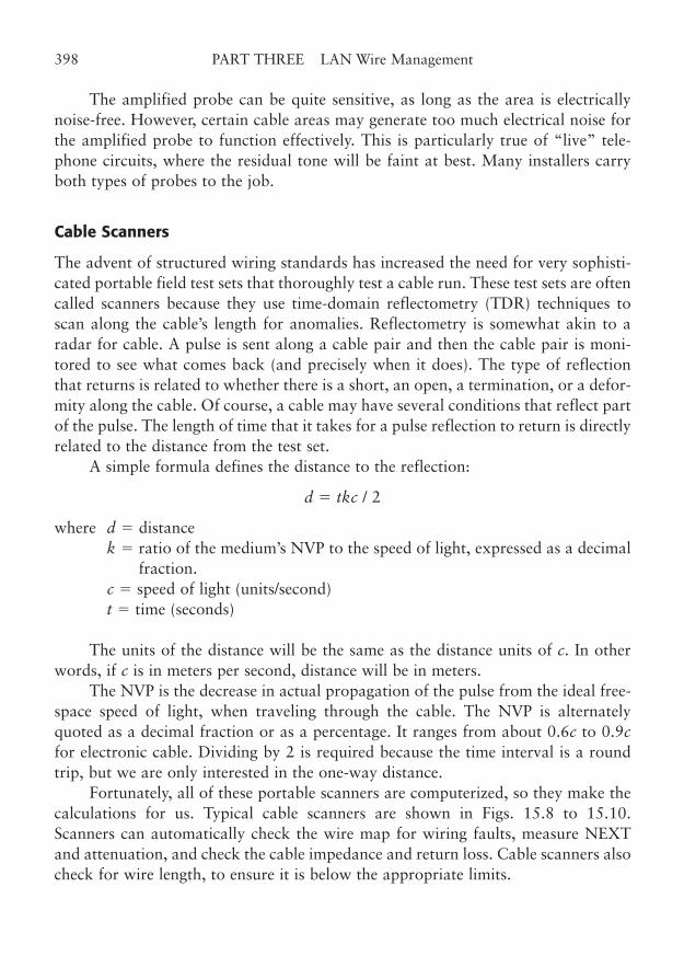
The amplified probe can be quite sensitive, as long as the area is electricallynoise-free. However, certain cable areas may generate too much electrical noise forthe amplified probe to function effectively. This is particularly true of “live” tele-phone circuits, where the residual tone will be faint at best. Many installers carryboth types of probes to the job.
Cable Scanners
The advent of structured wiring standards has increased the need for very sophisti-cated portable field test sets that thoroughly test a cable run. These test sets are oftencalled scanners because they use time-domain reflectometry (TDR) techniques toscan along the cable’s length for anomalies. Reflectometry is somewhat akin to aradar for cable. A pulse is sent along a cable pair and then the cable pair is moni-tored to see what comes back (and precisely when it does). The type of reflectionthat returns is related to whether there is a short, an open, a termination, or a defor-mity along the cable. Of course, a cable may have several conditions that reflect partof the pulse. The length of time that it takes for a pulse reflection to return is directlyrelated to the distance from the test set.
A simple formula defines the distance to the reflection:
d � tkc / 2
where d � distancek � ratio of the medium’s NVP to the speed of light, expressed as a decimal
fraction.c � speed of light (units/second)t � time (seconds)
The units of the distance will be the same as the distance units of c. In otherwords, if c is in meters per second, distance will be in meters.
The NVP is the decrease in actual propagation of the pulse from the ideal free-space speed of light, when traveling through the cable. The NVP is alternatelyquoted as a decimal fraction or as a percentage. It ranges from about 0.6c to 0.9cfor electronic cable. Dividing by 2 is required because the time interval is a roundtrip, but we are only interested in the one-way distance.
Fortunately, all of these portable scanners are computerized, so they make thecalculations for us. Typical cable scanners are shown in Figs. 15.8 to 15.10.Scanners can automatically check the wire map for wiring faults, measure NEXTand attenuation, and check the cable impedance and return loss. Cable scanners alsocheck for wire length, to ensure it is below the appropriate limits.
398 PART THREE LAN Wire Management
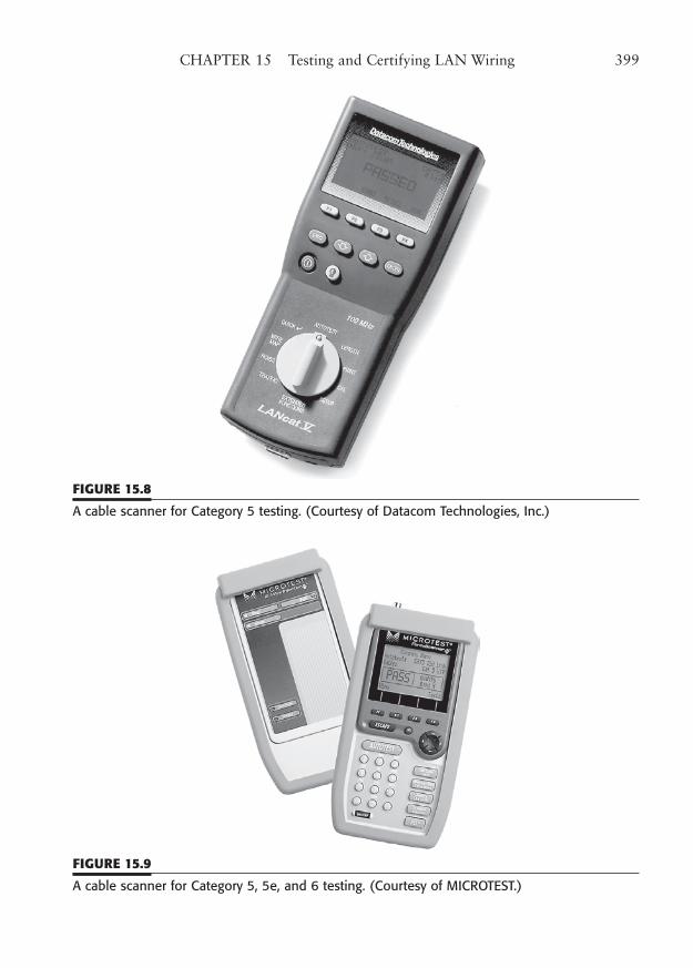
CHAPTER 15 Testing and Certifying LAN Wiring 399
FIGURE 15.8
A cable scanner for Category 5 testing. (Courtesy of Datacom Technologies, Inc.)
FIGURE 15.9
A cable scanner for Category 5, 5e, and 6 testing. (Courtesy of MICROTEST.)
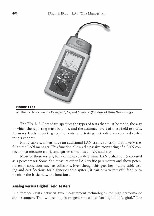
The TIA-568-C standard specifies the types of tests that must be made, the wayin which the reporting must be done, and the accuracy levels of these field test sets.Accuracy levels, reporting requirements, and testing methods are explained earlierin this chapter.
Many cable scanners have an additional LAN traffic function that is very use-ful to the LAN manager. This function allows the passive monitoring of a LAN con-nection to measure traffic and gather some basic LAN statistics.
Most of these testers, for example, can determine LAN utilization (expressedas a percentage). Some also measure other LAN traffic parameters and show poten-tial error conditions such as collisions. Even though this goes beyond the cable test-ing and certifications for a generic cable system, it can be a very useful feature tomonitor the basic network functions.
Analog versus Digital Field Testers
A difference exists between two measurement technologies for high-performancecable scanners. The two techniques are generally called “analog” and “digital.” The
400 PART THREE LAN Wire Management
FIGURE 15.10
Another cable scanner for Category 5, 5e, and 6 testing. (Courtesy of Fluke Networking.)
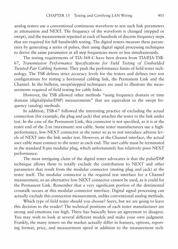
analog testers use a conventional continuous waveform to test such link parametersas attenuation and NEXT. The frequency of the waveform is changed (stepped orswept), and the measurement repeated at each of hundreds of discrete frequency stepsthat are required for full bandwidth testing. The digital testers measure these param-eters by generating a series of pulses, then using digital signal processing techniquesto derive the same parameters at all step frequencies more or less simultaneously.
The testing requirements of TIA-568-C have been drawn from TIA/EIA-TSB-67, Transmission Performance Specifications for Field Testing of UnshieldedTwisted-Pair Cabling Systems. They push the performance limits of field tester tech-nology. The TSB defines strict accuracy levels for the testers and defines two testconfigurations for testing a horizontal cabling link, the Permanent Link and theChannel. In the bulletin, swept/stepped techniques are used to illustrate the meas-urements required of field testing for cable links.
However, the TSB allowed other methods “using frequency domain or timedomain (digital/pulse/DSP) measurements” that are equivalent to the swept fre-quency (analog) methods.
In addition, TSB-67 followed the interesting practice of excluding the actualconnection (for example, the plug and jack) that attaches the tester to the link undertest. In the case of the Permanent Link, this connector is not specified, as it is at thetester end of the 2-m (maximum) test cable. Some tester manufacturers use a high-performance, low-NEXT connector at the tester so as to not introduce adverse lev-els of NEXT into the link under test. However, at the Channel interface, the actualuser cable must connect to the tester at each end. The user cable must be terminatedin the standard 8-pin modular plug, which unfortunately has relatively poor NEXTperformance.
The most intriguing claim of the digital tester advocates is that the pulse/DSPtechnique allows them to totally exclude the contribution to NEXT and otherparameters that result from the modular connector (mating plug and jack) at thetester itself. The modular connector is the required test interface for a Channelmeasurement, so an alternative low-NEXT connector cannot be used, as it could forthe Permanent Link. Remember that a very significant portion of the detrimentalcrosstalk occurs at this modular connector interface. Digital signal processing canactually exclude this connection measurement, unlike conventional analog methods.
Which type of field tester should you choose? Sorry, but we are going to leavethis decision to the reader! The technical positions of each tester manufacturer arestrong and emotions run high. There has basically been an agreement to disagree.You may wish to look at several different models and make your own judgment.Frankly, the many testers on the market actually differ in features, options, report-ing format, price, and measurement speed in addition to the measurement tech-
CHAPTER 15 Testing and Certifying LAN Wiring 401
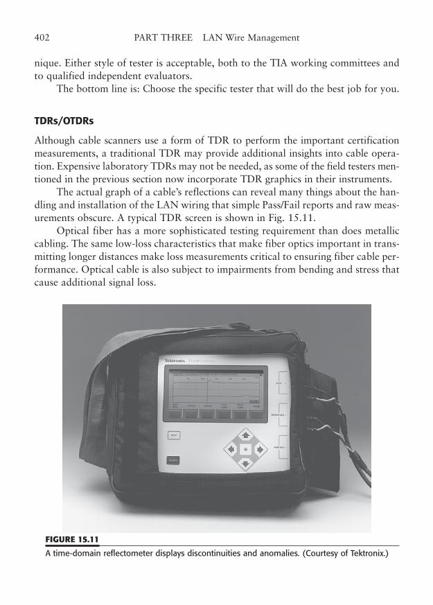
nique. Either style of tester is acceptable, both to the TIA working committees andto qualified independent evaluators.
The bottom line is: Choose the specific tester that will do the best job for you.
TDRs/OTDRs
Although cable scanners use a form of TDR to perform the important certificationmeasurements, a traditional TDR may provide additional insights into cable opera-tion. Expensive laboratory TDRs may not be needed, as some of the field testers men-tioned in the previous section now incorporate TDR graphics in their instruments.
The actual graph of a cable’s reflections can reveal many things about the han-dling and installation of the LAN wiring that simple Pass/Fail reports and raw meas-urements obscure. A typical TDR screen is shown in Fig. 15.11.
Optical fiber has a more sophisticated testing requirement than does metalliccabling. The same low-loss characteristics that make fiber optics important in trans-mitting longer distances make loss measurements critical to ensuring fiber cable per-formance. Optical cable is also subject to impairments from bending and stress thatcause additional signal loss.
402 PART THREE LAN Wire Management
FIGURE 15.11
A time-domain reflectometer displays discontinuities and anomalies. (Courtesy of Tektronix.)
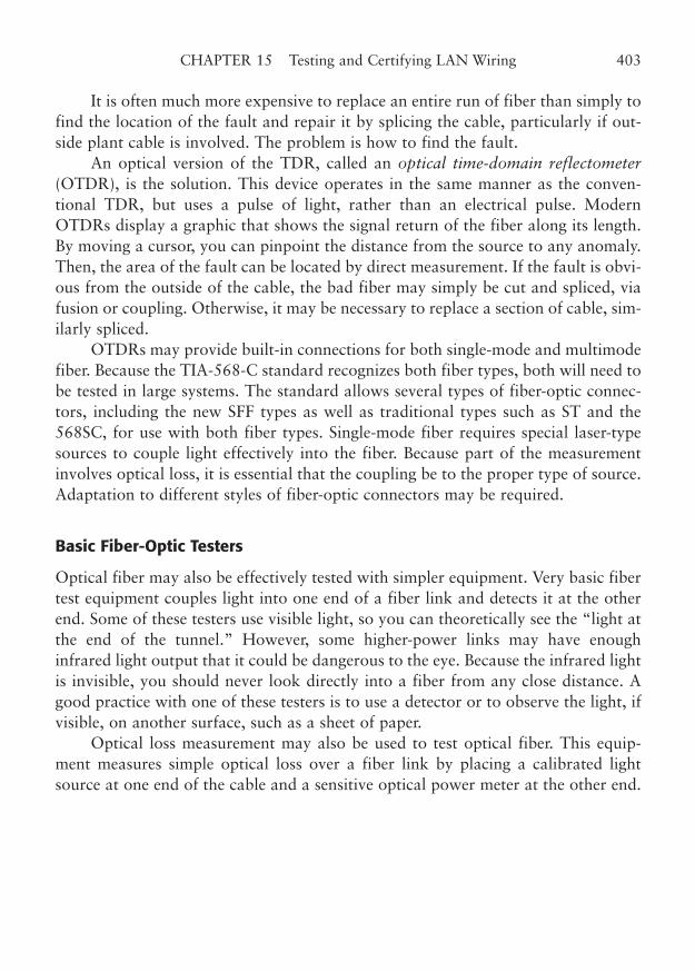
It is often much more expensive to replace an entire run of fiber than simply tofind the location of the fault and repair it by splicing the cable, particularly if out-side plant cable is involved. The problem is how to find the fault.
An optical version of the TDR, called an optical time-domain reflectometer(OTDR), is the solution. This device operates in the same manner as the conven-tional TDR, but uses a pulse of light, rather than an electrical pulse. ModernOTDRs display a graphic that shows the signal return of the fiber along its length.By moving a cursor, you can pinpoint the distance from the source to any anomaly.Then, the area of the fault can be located by direct measurement. If the fault is obvi-ous from the outside of the cable, the bad fiber may simply be cut and spliced, viafusion or coupling. Otherwise, it may be necessary to replace a section of cable, sim-ilarly spliced.
OTDRs may provide built-in connections for both single-mode and multimodefiber. Because the TIA-568-C standard recognizes both fiber types, both will need tobe tested in large systems. The standard allows several types of fiber-optic connec-tors, including the new SFF types as well as traditional types such as ST and the568SC, for use with both fiber types. Single-mode fiber requires special laser-typesources to couple light effectively into the fiber. Because part of the measurementinvolves optical loss, it is essential that the coupling be to the proper type of source.Adaptation to different styles of fiber-optic connectors may be required.
Basic Fiber-Optic Testers
Optical fiber may also be effectively tested with simpler equipment. Very basic fibertest equipment couples light into one end of a fiber link and detects it at the otherend. Some of these testers use visible light, so you can theoretically see the “light atthe end of the tunnel.” However, some higher-power links may have enoughinfrared light output that it could be dangerous to the eye. Because the infrared lightis invisible, you should never look directly into a fiber from any close distance. Agood practice with one of these testers is to use a detector or to observe the light, ifvisible, on another surface, such as a sheet of paper.
Optical loss measurement may also be used to test optical fiber. This equip-ment measures simple optical loss over a fiber link by placing a calibrated lightsource at one end of the cable and a sensitive optical power meter at the other end.
CHAPTER 15 Testing and Certifying LAN Wiring 403

This page intentionally left blank
CHAPTER 16
Monitoring andAdministering LAN Wiring
Highlights
■ LAN system documentation
■ EIA/TIA 606
■ Cable system monitoring methods
■ SNMP monitoring and control
■ Remote control
405
Copyright © 2006 by James Trulove. Click here for terms of use.
A LAN wiring system is a dynamic entity in many ways, changing and growingmuch like a living thing. If the LAN operating system is like the lifeblood of yournetwork, the signal wiring certainly is like the nervous system, carrying importantmessages from point to point. LAN wiring must be monitored and tracked, so thatyou can constantly know the status of your interconnections.
LAN wiring systems are not truly passive systems. They are active in the sensethat they can change characteristics over time and can disrupt the LAN if they fail.When a failure occurs, you will need to make quick repairs. How well you are ableto respond to a cable problem depends on the methods available to you to isolatethe problem and find the offending cable system component. Proper documentationof your wiring will assist you in your installation and troubleshooting efforts. Thisis the essence of monitoring and administration.
Cable System Monitoring Methods
Monitoring of a cable system can be accomplished either directly or indirectly. Formost installed LAN systems, the networking equipment (servers and worksta-tions) can do a part of the job indirectly. We call this indirect monitoring, becauseit is a part of the normal operations of the connected systems, which sense the sta-tus of the network links indirectly. If a workstation cannot connect to a server, itmay mean that there is a connectivity problem, such as a bad cable or other wiringcomponent.
Unfortunately, indirect monitoring of the Channel may indicate a communica-tions problem even when the cable connectivity is fine. For example, a bad work-station network interface or a software problem at the workstation, switch, orserver would appear as a network communication problem, even though the cablingis good.
Direct monitoring uses the capabilities of the hubs, patches, or network inter-face cards (NICs) to directly monitor the cable link. This type of monitoring sensesthe condition of a cable and allows direct control and/or testing of the Channel.Direct monitoring may be done on either a local or a remote basis. Local monitor-ing simply uses the built-in status indicators on hubs and NICs. To monitor link sta-tus, one simply looks at the LED indicators on the devices. Of course, this assumesthat the devices you are using have indicator lights.
Remote monitoring uses intelligence built into the hubs or other networkdevices to report status to a monitoring station. Remote monitoring can use stan-dard network monitoring software, such as SNMP, described later in this chapter.Remote monitoring is rather new and offers an exciting new view of the LAN wiringas a separable entity. It is, unfortunately, still somewhat too expensive to implement
406 PART THREE LAN Wire Management
on the low-end networking devices. However, as network speeds increase, and as thecosts of networking equipment decrease, it will become more sensible to use moni-toring devices to determine the health of the wiring system.
Physical Cable Monitoring
Physical monitoring of installed LAN wiring presents some very special problems.Most of the simple ways that can be used require that the monitoring be performedby the connected LAN devices (such as 10/100 BaseT or Token-Ring hubs). The hubmonitors the condition of the link and reports it by indicator lights on the frontpanel of the hub, or by sending messages to a remote monitoring station. Thesedevices and their capabilities are specific to the type of LAN you are using.
All 10BaseT, 100BaseTX, and 1000BaseT Ethernet twisted pair systems pro-vide a positive indication of link operation. A continuous link signal is built into thephysical layer protocol, that indicates both link status and link speed. Standard10/100/1000BaseT systems actually only evaluate the integrity of the received signalfrom the other end of the link, but enhanced systems can indicate integrity of thecomplete link (local and remote ends) and report the link status to a remote moni-toring system.
A Token-Ring multi-station access unit (MSAU), in contrast, uses DC connec-tivity on the link to set or reset a sensitive relay in the MSAU. Even a simple MSAUcan easily provide an LED indicator on the front panel to indicate link condition.Intelligent MSAUs are able to report the status of any lobe to a remote monitor. Ofcourse, the indication shows more than just the integrity of the cable, because theworkstation operation is also a factor in lobe status. Nevertheless, this is an effec-tive means of physical monitoring.
Remote Cable System Monitoring
Another type of direct cable monitoring system pays no attention to the LAN pro-tocol, but has custom electronics that is designed to indicate the integrity of a con-nection. These monitored patching systems can provide connectivity monitoringwith virtually any type of LAN. The way this works is that these systems use pairson the cable that are unused by the LAN to indicate connectivity, and in some cases,even the cable map—where each patch cord terminates. For example, 10BaseT,100BaseTX, and Token-Ring use only two of the pairs on the cable. The other twoare available for other purposes such as connectivity monitoring. While this doesnot truly indicate that the two network pairs are connected, it certainly will indicatewhether a patch cable is connected or disconnected.
CHAPTER 16 Monitoring and Administering LAN Wiring 407

Some systems can even detect where a patch cord has been moved to andreport an alarm to a monitoring station. The monitored patch system in Fig. 16.1 isan example of this capability.
SNMP Monitoring and Control
Effective remote access to network devices may be provided by using the simple net-work management protocol (SNMP). This protocol communicates over the networkto a management workstation via an extension of the popular TCP/IP suite.Monitoring of all sorts of hubs, bridges, routers, and other devices can be accom-plished by using SNMP. SNMP management can be expanded to almost any devicewith a network connection. Some devices that have no native LAN ports, such asT1/E1 communication equipment, are now being equipped with a LAN port just foran SNMP interface.
SNMP-based monitoring and control techniques may also be applied to cablemanagement. Particularly with hub-based cable management, SNMP is a welcometool for both management and control. Some of the intelligent patch panel equip-ment can communicate via SNMP for both monitoring and control. As networkinghardware becomes more complex, global network management solutions willbecome more important. Often, these management tools will offer some degree ofcable management along with their other functions.
408 PART THREE LAN Wire Management
FIGURE 16.1
The monitored patch system. (Courtesy of RIT Technologies Ltd.)
Remote Control of Physical Connections
In some circumstances, you may have need for remote control of your physical net-work connections. For example, you might want to disconnect or reconnect a work-station from your network monitoring location. This can be effective in preventinga single workstation from causing a global network problem.
Many intelligent hubs and similar devices can provide this remote controlcapability. The most common method is to use in-band signaling via SNMP or aproprietary protocol. However, this method does have one disadvantage. If yournetwork is being jammed by an offending workstation, it may be impossible to com-municate over the LAN to command the hub.
Another remote control option is an out-of-band control system using a con-trol port. This control port remains free of any network disruptions and can keepyou in the game. A control port can also be used to make a modem connection to aremote system, regardless of the network connectivity.
Some remote-controlled equipment can perform other monitoring functionssuch as environmental monitoring and access control. A remote temperature alarmcould alert you to a condition that might eventually cause the devices in an equip-ment room to fail. Or, you could simply have a remote system start the coffee beforeyou arrive.
LAN System Documentation
Good documentation is the key to controlling your LAN wiring environment.Whether you are troubleshooting a LAN outage or simply adding a cable drop, hav-ing well organized records will save you a great deal of time and trouble.
The systematic marking and identification of all of the components of yourLAN wiring system is an essential part of good documentation. Each item of theLAN wiring should be clearly marked with an identifying number. This applies toeach cable, each termination, and all of the points in between. As a matter of fact,many of the mounting structures and pathways that are used in support of LANwiring are best identified as well.
LAN Documentation Standard TIA/EIA-606-A
In an effort to standardize the administration of telecommunications cabling, theTIA has published EIA/TIA-606-A, Administration Standard for CommercialTelecommunications Infrastructure. This standard covers the identification, nomen-clature, and documentation of wiring, pathways, and grounding/bonding in com-
CHAPTER 16 Monitoring and Administering LAN Wiring 409
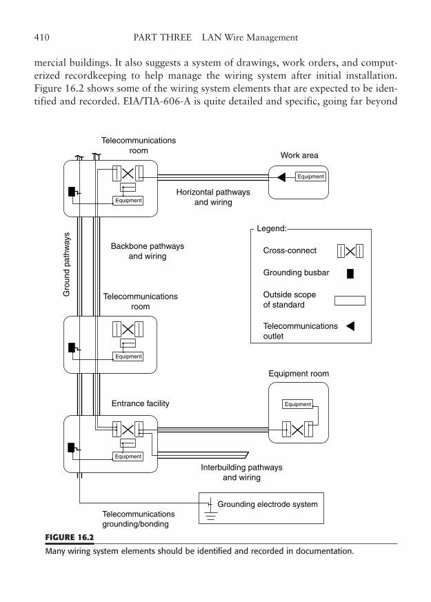
mercial buildings. It also suggests a system of drawings, work orders, and comput-erized recordkeeping to help manage the wiring system after initial installation.Figure 16.2 shows some of the wiring system elements that are expected to be iden-tified and recorded. EIA/TIA-606-A is quite detailed and specific, going far beyond
410 PART THREE LAN Wire Management
Work area
Legend:
Cross-connect
Grounding busbar
Outside scopeof standard
Equipment room
Grounding electrode systemTelecommunicationsgrounding/bonding
Interbuilding pathwaysand wiring
Backbone pathwaysand wiring
Equipment
Telecommunicationsroom
Equipment
Telecommunicationsroom
Equipment
Equipment
Horizontal pathwaysand wiring
EquipmentEntrance facility
Gro
und
path
way
s
Telecommunicationsoutlet
FIGURE 16.2
Many wiring system elements should be identified and recorded in documentation.
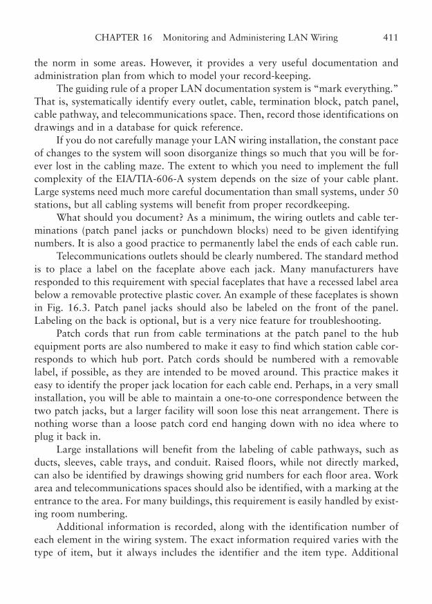
the norm in some areas. However, it provides a very useful documentation andadministration plan from which to model your record-keeping.
The guiding rule of a proper LAN documentation system is “mark everything.”That is, systematically identify every outlet, cable, termination block, patch panel,cable pathway, and telecommunications space. Then, record those identifications ondrawings and in a database for quick reference.
If you do not carefully manage your LAN wiring installation, the constant paceof changes to the system will soon disorganize things so much that you will be for-ever lost in the cabling maze. The extent to which you need to implement the fullcomplexity of the EIA/TIA-606-A system depends on the size of your cable plant.Large systems need much more careful documentation than small systems, under 50stations, but all cabling systems will benefit from proper recordkeeping.
What should you document? As a minimum, the wiring outlets and cable ter-minations (patch panel jacks or punchdown blocks) need to be given identifyingnumbers. It is also a good practice to permanently label the ends of each cable run.
Telecommunications outlets should be clearly numbered. The standard methodis to place a label on the faceplate above each jack. Many manufacturers haveresponded to this requirement with special faceplates that have a recessed label areabelow a removable protective plastic cover. An example of these faceplates is shownin Fig. 16.3. Patch panel jacks should also be labeled on the front of the panel.Labeling on the back is optional, but is a very nice feature for troubleshooting.
Patch cords that run from cable terminations at the patch panel to the hubequipment ports are also numbered to make it easy to find which station cable cor-responds to which hub port. Patch cords should be numbered with a removablelabel, if possible, as they are intended to be moved around. This practice makes iteasy to identify the proper jack location for each cable end. Perhaps, in a very smallinstallation, you will be able to maintain a one-to-one correspondence between thetwo patch jacks, but a larger facility will soon lose this neat arrangement. There isnothing worse than a loose patch cord end hanging down with no idea where toplug it back in.
Large installations will benefit from the labeling of cable pathways, such asducts, sleeves, cable trays, and conduit. Raised floors, while not directly marked,can also be identified by drawings showing grid numbers for each floor area. Workarea and telecommunications spaces should also be identified, with a marking at theentrance to the area. For many buildings, this requirement is easily handled by exist-ing room numbering.
Additional information is recorded, along with the identification number ofeach element in the wiring system. The exact information required varies with thetype of item, but it always includes the identifier and the item type. Additional
CHAPTER 16 Monitoring and Administering LAN Wiring 411
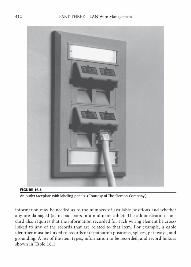
information may be needed as to the numbers of available positions and whetherany are damaged (as in bad pairs in a multipair cable). The administration stan-dard also requires that the information recorded for each wiring element be cross-linked to any of the records that are related to that item. For example, a cableidentifier must be linked to records of termination positions, splices, pathways, andgrounding. A list of the item types, information to be recorded, and record links isshown in Table 16.1.
412 PART THREE LAN Wire Management
FIGURE 16.3
An outlet faceplate with labeling panels. (Courtesy of The Siemon Company.)
TABLE 16.1
Items that Must Be Recorded in the Cable System Documentation
Record Type ID? Type Other info: Linkage to records for:Wiring Pathway Y Y Fill, loading Cable, space, pathway, spaces grounding
Space Y Y Cable, pathway, grounding Wiring Cable Y Y Unterminated, damaged, Termination position,
available pairs splice, pathway, grounding Termination Y Y Hardware, damaged Termination position, space,
position numbers grounding Position Y Y User code, cable pair Cable, term. position, term.
numbers hardware, space Splice Y Y Cable, space
Grounding, TMGB Y Y Grounding conductor, Bonding conductor, space bonding resistance to earth,
date of measurement Bonding Y Y Conductor Grounding, pathway cond.TGB Y Y Bonding conductor, space
Source: EIA/TIA-606-A.
Documenting through Cable Administration Tools
Automated database documentation systems can also be very useful. Some cableadministration software has a graphical interface that lets you point to items in yourcable plant and see the pertinent information that is recorded. A cable administra-tion system can really be operated apart from the network management system(NMS) for your LAN.
NMSs tend to concentrate on network node and hub management and controland are not concerned with what cable duct a particular pair might be located in.In addition, the cable administration software can cover telecommunications cableuses that are far beyond the LAN.
CHAPTER 16 Monitoring and Administering LAN Wiring 413

This page intentionally left blank
CHAPTER 17
Troubleshooting LAN Wiring
Highlights
■ Common failure modes
■ Copper faults
■ Fiber faults
■ Category and workmanship
■ Troubleshooting approaches
415
Copyright © 2006 by James Trulove. Click here for terms of use.
Any complex system is subject to periodic failures, and LAN wiring systems are nodifferent. Throughout this book, we have emphasized the installation of a reliablewiring system. We have spent a great deal of time showing the proper components andinstallation techniques that are required to create a properly functioning, reliable cableplant. The precept for this careful construction is that when anything does go wrong,it should very rarely be the cabling. (Some might say “never” rather than “rarely,” butyour LAN wiring is in an environment where it cannot totally be protected from thoseuncaring souls without the proper respect for these thin little wires.)
The fact of the matter is that failures do happen. Fortunately, most of the fail-ures happen during installation, where the link operation is not critical. Still, thefailed cable must be repaired, regardless of the circumstances. If the link has been inoperation, it is all the more important that we make the repairs quickly.
Cable link failures can be divided into two broad classes with respect to LAN wiring.The classes of failures correspond to the types of test equipment for each. Failures involv-ing basic cable function can be determined by the basic test equipment we talked aboutin Chapter 15. This equipment can check cable link connectivity and DC wire map.Failures involving performance- based cable function must be determined by the diagnos-tic and measurement equipment we covered. This equipment tests the performance of thecable link at the level of performance required for your particular LAN application. Ittests for split pairs, impedance, NEXT, length, attenuation, and other parameters that arerequired for proper LAN operation. The basic function can be fine, but the link will stillnot operate if it doesn’t meet your performance needs. For example, you could probablyget DC connectivity on a barbed-wire fence, but you wouldn’t be able to run data on it.
In this chapter, we will detail many of the types of cable link failures, whetherthey are from installation errors or cable damage after installation. We will givesome approaches to finding the problem and repairing the cable link. Also, we willsay a little about a successful troubleshooting approach that you may find useful.
Common Failure Modes
It is important to understand how LAN cabling can fail, in order to help you isolateand troubleshoot problems with your cabling. In this section, we will examine thecommon problems that may occur with an installed cable system and how to deter-mine the best way to alleviate the problem.
Copper Cable Failure Modes
Copper cabling is the LAN wiring type that is most prone to failure, both during theinstallation phase and after the cable has been “in the wall” for a while. Ideally, the
416 PART THREE LAN Wire Management
installer should do a good job of routing and terminating each cable, and shouldverify that the link is properly connected and passes the performance measures forthe desired category. However, if a failure occurs, you must examine the cable andconnections to find the problem. Even if the cable link was once in perfect condi-tion, cable runs can be physically damaged, and poorly made connections can fail.Occasionally, even cabling components such as connectors can fail.
Wire Break. One of the most common wiring failures is a broken wire. Mosttesters will report the wire as an “open,” meaning that the circuit is open. Sometesters may actually declare the entire pair bad, although only one wire might beopen. A wire that was never connected will also test open, even though the failureis not a result of wire damage. If only one wire of a multiwire cable is open, youshould probably look for a bad connection at one of the termination points.
Connections in insulation-displacement connectors, such as 66M or 110blocks, sometimes are not driven home, resulting in a bad or intermittent connec-tion. What happens is that the insulation is not quite stripped away, and an appar-ently good connection will actually have a thin layer of insulating plastic remaining.You should never reuse old 66M blocks.
The contact jaws can deform outward just enough to cause a problem whennew wires are punched. This can also happen if a larger-gauge wire was previouslypunched down. These blocks may also have the same problem with jumper wiresthat are frequently moved. You may be able to “rehabilitate” a contact by squeez-ing the empty contact jaws together with sharp-nosed pliers, or even by rocking thepunchdown tool back and forth on the contact. The 110-type blocks are much lessprone to this problem, as they use a cutting-displacement method of termination,where the connector contact actually slices through the wire’s insulation.
Stranded wire must never be used in a 66 or 110-type connecting block. Theseblocks require solid wire, and connections made with stranded wire will often fail.The insulation-displacement contact (IDC) needs to actually cut into the solid con-ductor slightly, and there is simply no way to do that with stranded wire. Thestrands move out of the way and deform their shape when pushed down into anIDC terminal. The connection now depends on very slight pressure and low contactresistance. These stranded-wire connections will often fail over time, and temporar-ily heal when the wire is touched. Although this is not technically a break, the symp-toms are the same.
If inspection of the cable termination ends does not reveal the open wire, use acable scanner to measure the length to the open wire. Mid-cable open wires may bevery hard to find visually, unless there is obvious mechanical damage to the cable.You never want to find out that an installed cable has an open due to a manufac-
CHAPTER 17 Troubleshooting LAN Wiring 417
turing defect, because it is almost impossible to prove that the break did not occurduring installation.
It is a good idea to do a continuity check on each reel of cable prior to instal-lation. During installation, be careful not to pull the cables over sharp edges, as thecable might be cut. See the next two sections for advice on how to repair a twisted-pair cable open or short.
Wire Short. A wire short in some ways is easier to deal with than an open. A shortis rarely caused by a bad connection at a termination, so you can initially skip thatinspection. A cable scanner may be able to locate the short within a few feet. If youdo not have access to a scanner, use a sensitive ohmmeter and the specification forcable resistance per linear foot (26 ohms per 1000 ft for AWG 26 wire) to find theapproximate location of the short. If more than two wires are shorted, this test maybe useless, as the linear resistance will be much less than expected.
Shorts are often caused by other contractors trapping the cable between sharpobjects during construction and remodeling. For example, the cable might be pinchedbetween metal studs as a wall is assembled. The ubiquitous plasterboard screw alsodoes a very nice job of piercing right through a cable, shorting the wires in theprocess. Sometimes (very infrequently, we hope) cable installers will pull the cablepast a sharp edge, cutting through the insulation and shorting wires in the cable.
The method used for repair of a short or an open depends on the type of cableand the performance requirements. Coax cable may be cut in half, the two ends con-nectorized, and a barrel connector used to join the ends. Fiber may be spliced, asmentioned later.
Twisted-pair cable repair methods depend on the category of performancedesired. Technically, the TIA-568-C standard allows no splices in a horizontal cablerun. However, practical considerations may dictate some variance with Category 3cable runs. Category 3 has a more gentle twist than Category 5e or Category 6, andit is possible to carefully perform a splice using a shrink-wrap solder splice availablefrom several sources. This hollow, shrinkable-plastic splice is a tiny tube about 1 inlong with a narrow ring of low-temperature solder in the middle. The insulation isremoved on the wires to be joined. About 1 cm is enough. The wires to be joinedare then placed into the splice from opposite ends and the splice heated with aproper heat-gun tool to melt the solder and shrink the plastic. (A pocket lighter isnot a proper tool, but it works well just the same if used with care.) The next con-ductor from the same pair is wrapped around the first wire in the same direction asthe natural twist and the wire ends are joined in the same manner. This approxi-mately maintains the gentle Category 3 twist, but is not adequate for Category 5e/6splices.
418 PART THREE LAN Wire Management
An alternative method will form a temporary splice, even for Category 5e.TIA-568-C allows one transition point from round to flat cable in a horizontal cablerun. This means that an allowance has been made for the inevitable untwist andNEXT that would result from terminating each cable end at the point of transition.Logically, you should be able to insert a plug and jack coupling to repair a cable cutor short, but that is not really allowed as it amounts to a splice. However, if a quicksolution will get the network back running, this method can be used temporarilyuntil new cable can be pulled. You should only use a properly rated plug and jackfor the cable’s category of operation.
It may seem easier to use two cable-end plugs and an 8-pin F/F coupler for this,but that is actually two plug/jack combinations, not one. Also, it is very unlikelythat the 8-pin coupler will meet any standard higher than Category 3. In addition,many of these couplers also reverse the order of the pins, causing yet a different typeof failure.
Finally, mark the point of the splice on your cable map. If the splice is tempo-rary, you will want to go back and pull a new cable as soon as you can, as the needto replace the cable will be inversely proportional to how long you wait. If you wantto have a Category 5e facility, but are using only Category 3 applications now, thesplice may work now, but may fail when you upgrade to higher-speed applications.
Kinks, Bends, and Breaks. The effect of kinks and bends in cable also varies withthe type of cable. Coax cable is probably the most resistant to this type of damage,because of the size and durability of the cable. However, severe kinks and verysharp, sustained bends will affect the transmission loss on the cable and may evencause an impedance reflection that could cause a failure.
Twisted-pair cable may also be subject to transmission impairment due tokinks or sharp bends. As unbelievable as it may sound, even tight tie-wraps may dis-tort the cable enough to cause this problem. The real problem with kinks or bendsin twisted-pair cable is that the defect actually distorts the geometry of the cable.This can easily be observed on the screen of a time-domain reflectometer (TDR).Distorting the cable shows up as a reflection hump in the returned signal. Severebending can actually cause permanent signal impairment. How serious this impair-ment is will depend on the category of operation and just how near the operatingmargins of the link you are operating.
A major source of kinks in cables is the use of boxed (rather than reeled) cable.These cable boxes are designed to allow the cable to feed in a spiral fashion, with-out the need for conventional cable spools and reel holders.
Unfortunately, the cable can sometimes feed more than one loop of cable andthe loops get mixed together trying to get out of the feedhole in the box. Other
CHAPTER 17 Troubleshooting LAN Wiring 419
times, a single loop twists so that it does not feed in a spiral fashion; as the loop col-lapses, a kink results. Of course, kinks can occur easily in loose coils of cable thathave been unboxed or unreeled. Try to avoid kinks, particularly in Category 5e/6operation. If a kink occurs, attempt to smooth out the kink as much as possible, butbe aware that you may have to replace the run if it later fails in testing.
The TIA-568-C standard recommends a minimum bend radius of four timesthe cable diameter. For most cables, that radius is about 3/4 to 1 in. Try to avoidpulling cable tightly around corners and use cable management retainers to providea smooth transition to the point of termination.
Connector Opens. Modular connectors may fail because of open connections. Themost common conditions are bad plug crimps, dislodged wire, bent jack pins, andbad connector seating. The popularity of modular plugs in telephone wiring hasresulted in the availability of low-cost, 6-pin crimp tools. These tools may be madefrom plastic or lightweight steel. Unfortunately, the flimsy design has been extendedto 8-position crimpers.
The 8-pin modular plug is much more difficult to properly crimp than plugswith 6 pins. A low-cost tool often cannot properly seat the connector contacts in thecenter of the plug. This may result in one or more of the stranded wires not makingcontact or, worse, making intermittent contact. You can easily identify plugscrimped with one of the inferior tools. When viewed from the front, the middle con-tacts are visibly higher than the contacts near the edge of the connector plug.Recrimping rarely makes any difference, unless it is done with a proper crimp tool.
You should spend the extra money to purchase a high-quality crimp tool.These tools are heavily constructed and will be quite a bit more expensive than thelow-cost tools. Some may have interchangeable dies for different sizes of modularconnectors. A high-quality crimp tool for 8-pin modular plugs should cost $100 to$200, depending on additional features.
Bad crimps may also allow a wire to be pulled out of the plug contact area. Thesame type of problem can happen in a cable termination at a workstation outlet jackor at the patch or punchdown in the telecommunications room. These connectionsare not made for very large pulling forces, and may fail when overstressed. Usercords in the work area are particularly subject to this kind of damage, because theyoften are run along the floor in the path of chair legs, furniture, and feet. Alwaysinspect both cable ends of a cord that is suspected of having a bad connection.Replace the cord if there appears to be damage.
A source of intermittent connections in modular plugs is the use of solid wire.These plugs were really designed for stranded wire, and solid wire does not workwell. Special versions of modular plugs are allegedly designed to work with solid
420 PART THREE LAN Wire Management
wire, and they do work better, but you will be much better off if you use onlystranded wire with these plugs.
In rare cases, modular connector jacks may not seat properly in the connectorfaceplate. Some designs include the plug channel in the molded plate, with a sepa-rate jack assembly that snaps into the plate. If the rear module is not seated prop-erly, the jack wires may be too far back to properly connect with the plug contacts,even though the plug clip seats with a sharp click.
In rare cases, modular jack pins may get crossed or bent. This will usually testas a shorted wire from the far end and as an open connection from the near end.The design of these jacks places the pins (which are really bent wire pins) in narrowplastic slots so they can move as the plug is inserted. At the top of the tracks, mostjacks have an open area where the pins could slide from side to side if the wire pinis pushed upward too far. If the pin is allowed to slip into another pin’s track (eitherduring assembly or use), the pins will short together and one or both of them maybe prevented from making any contact at all with their corresponding plug contact.If you suspect this problem, visually inspect the plate and replace the jack if it isdamaged. This defect tends to permanently bend the wire pin and you may havecontinuing problems. It is a good idea to glance at the pins in each jack insert beforeyou terminate the station cables. This only takes a second, and will save you hoursof frustration later.
Modular jacks should be mounted so that the pins are on the top side of thejack opening. The theory is that this keeps dust and dirt from contaminating thepins. Jacks are also available with dust covers, which should be left in place untilthe jack is used and replaced when a plug is removed.
A punchdown block or patch panel punch block is a special type of connector.Some older-style 66M punchdown blocks require the use of a metal clip to connectbetween contacts in different columns. The standard 66M block has four columns ofcontacts across each punchdown position. Generally, the contacts are internallywired as pairs, so that Column 1 and Column 2 contacts are connected in common,as are Column 3 and 4. However, some connectorized designs make all four columnsindependent, so that a clip must be placed across the contacts in adjacent columns tocomplete the circuit. A missing clip will cause a problem with the circuit.
An additional problem with punch blocks of any type concerns the use ofstranded wire. These side-displacement or insulation-cutting terminals are designedfor solid wire only. Do not use stranded wire with these blocks. The wire may notmake good contact, because the contacts press in from the side, instead of clampingthe wire or piercing into the strands. Even if an initial contact is made, the wire maypull free more easily, because much of the strain resistance of the contact dependson trapping a solid wire in the contact.
CHAPTER 17 Troubleshooting LAN Wiring 421
Occasionally, a connector block open can occur when the punchdown tool cutsthe cable end of the wire being terminated, rather than the scrap end. A tool maysometimes cut an adjacent wire to the wire being terminated. It is a good idea tocheck the terminated wires to be sure none seem loose. Cut or loose wires should bereterminated.
Coax cables are subject to having their connections pulled open by connectorstress. Crimped or soldered center conductor pins are fairly sturdy, but the pin maysometimes be pulled back into the connector body and not make contact with the mat-ing jack. A visual inspection will show a pin that seems too short. The center pin shouldbe approximately even with the edge of the shield sleeve (not the bayonet sleeve).
Cables that are pulled on while mated may also break the shield wires. If acoax shield is improperly stripped, many of the tiny wires that form the braid willbe severed, with only a few remaining to make the connection. When pulled, theselast few wires will break easily, leaving an open. The proper solution is to cut offthe end, prepare the wire properly, and replace the connector.
Any coax LAN wiring that uses BNC-Ts or terminators may be subject to opensdue to failure of the T or terminator. As a matter of fact, many technicians considerthe T component to be the primary cause of coax network problems. The connectormay fail by literally falling apart, or it may exhibit intermittent connections that justadd to the frustration. Low-cost connectors are the worst offenders. You would bewise to use only high-quality connectors, Ts, and terminators on these systems.
Wrong Pin-Out. All of the wiring problems that we discussed in the test equipmentin Chapter 15 are common failures of cable links. Among these are reversing theorder of some of the wires, crossing two pairs, flipping the wiring order, splittingpairs, and total miswires. Reversing the order occurs in pairs. A common mistake isto reverse the primary and tracer colors of a single pair. Another common mistake isto mix up the green and brown pairs, or split these pairs, since the color differencemay be subtle in some cable. If you try to count pin numbers in a modular jack, besure to position the jack correctly (see Chapter 6). Flipping the wiring order of a usercord is a common error with flat (silver satin) telephone-style wire. Of course, youshould never, never, never use flat cable for LAN wiring cords. Never.
Inspect the wiring order by holding both cord ends side by side. The colors (tothe extent you can see them) should be in the same order straight across the plug.Better yet, use a cable checker.
The standard color code for 4-pair cables should be followed in wiring all jacksand telecommunications room terminations. This code is different for punchdownblocks and modular jacks. Modular jacks actually have two color code standards,T568A and T568B. You must use the same standard throughout a horizontal cable
422 PART THREE LAN Wire Management
run. This means that you must use the T568A wiring pattern at the workstation out-let if T568A was used at the patch panel termination. Keeping this straight is muchmore difficult if you use preassembled octopus (fan-out) cables for your equipmentconnection. Be certain which wiring pattern standard is used with the octopus cableand use the same at the workstation outlet jack. Using different wiring patternsresults in a reversed-pairs indication on a tester. See Part 2 of this book for moredetails on these color codes and wiring patterns.
There are nearly as many ways to connect station wires to modular jacks asthere are modular jack manufacturers. The most confusing jack wiring problemsstem from the fact that the pairs are not connected to the pins of the modular jackin the same order as they are punched down in the telecommunications room. Forexample, in the telecommunications room, the cable is terminated on the 66M or110 block in the pair order 1, 2, 3, and 4. That means that the blue-white Pair 1gets punched down first on the first two pins of the cable position, the orange-whitePair 2 on the next two positions, and so on. At the modular jack, however, Pair 1 isterminated such that it connects to Pins 4 and 5. The orange-white or the green-white pair is terminated on Pins 1 and 2, depending on whether you are using theT568A or T568B wiring pattern. If the terminations on the jack module are num-bered the same as the pin order, you must be sure to place the wires into the correctslots before you terminate them. This order will be very different from that on thepunchdown block. Fortunately, many jack modules have color-coded wire slots, soyou can ignore the confusing position numbers.
If you choose to split your station cables into two jacks, with two pairs perjack, you will have extra fun figuring out what color code to use at each jack. If youmust do this, one approach is to call each pair in a 2-pair set Pair A or Pair B. Planwhich pins on the modular jack should respond to each pair, and draw a connectiondiagram, skipping the unused wire positions on the jack. This avoids the obviousdifficulty you would have placing your Pair 1 in the Pair 2/3 position at the jack. Ofcourse, all of the color codes on the jack will be completely wrong, but you wantedto do it this way, didn’t you?
A far better approach, and one that is allowed by TIA-568-C, is to wire up thejack with the normal T568A or B pattern and use an adapter cable external to theoutlet jack. Simply make (or have made) an adapter that connects two 2-pair cables,terminated in two plugs at one end, to a single modular plug, with each wire placedappropriately. That will split out the station cable to the two applications and avoidmaking your jack plate totally nonstandard.
Wrong Category. Another common failure of high-performance applicationsresults from the use of the wrong category of cable and/or connectors. Either mis-
CHAPTER 17 Troubleshooting LAN Wiring 423
take will cause most performance-critical applications to fail. Remember that thecategory of performance is limited by the lowest category or component or cableused in a link. In addition, of course, you must maintain the distance below thelimit, route the wire away from potential interference sources, and maintain theminimum twist of the pairs.
Many older cabling systems can support Category 3 operation. Cable that is 4pairs and has a minimum of 2 to 3 twists per foot should operate, although not nec-essarily at the distance limit. But cable that barely meets Category 3 cannot be usedfor Category 5e or higher. Multipair cables of 25 or more pairs should be limited to6 circuits (12 pairs) to minimize the effects of crosstalk that occurs on such cables.Analog telephone circuits can usually be accommodated on pairs in the same cablesheath, as their frequency of operation is much lower than LAN frequencies.However, you must use caution when placing digital telephone signals, includingISDN, in the same cable jacket as LAN data, as the two may very well interfere witheach other. Many modern phone systems are digital systems, and fall into this areaof caution. The best rule is to use only one application per cable, even with analogsystems. A later upgrade of your phone equipment might inadvertently shut downyour LAN.
Excessive Untwist. The amount of untwisted cable that is allowable when operat-ing at Category 3 is so great that it is easy to view the Category 5e/6 requirementswith skepticism. After all, how could you go from a generous allowance of two ormore inches of loosely twisted wire to a ridiculous requirement of less than 1/2 in(13 mm)? Well, the answer is easily found when you consider that the maximum fre-quency of “interest” of the two categories jumps from 10 to 100 (or to 250) MHz.Obviously, the Category 5e/6 requirements are much more stringent because theyhave to be to assure cable link performance at this level.
Good cabling practice is to limit the amount of untwist to only that requiredto terminate the wires. This is good practice, whether you are terminating Category6 or Category 3. Another good practice is to strip back only enough of the outerjacket as is needed to terminate the pairs.
This maintains the cable twist and the positioning of the individual pairs inrelation to each other. The better connectors and cable terminations have additionalcable management devices to secure the wire in place and to minimize stress andbending of the wire.
Wrong Impedance. Throughout this book we have talked about UTP cabling with100-ohm impedance and STP cabling with 150-ohm impedance. Any mixing ofthese two types of wire in the same cable link will result in an impedance mismatch
424 PART THREE LAN Wire Management
that may cause the link to fail. The different impedances cause a signal reflection atthe point of intersection that will affect even lower-speed network links. At thehigher speeds, the impedance match is critical to overall circuit performance. Thestandards generally allow for the expected variations in impedance from one lot ofcable to the next. A variation of � 15% is allowed and more may be acceptable onshort cable runs, although it would technically not meet the standard.
The real problem is that network equipment is designed to expect a cableimpedance of 100 (or 150) ohms. Using a cable with a higher or lower impedancewill cause less power to be coupled to the cable pair and result in a lower receivedsignal arriving at the other end. If that end also sees an impedance mismatch, evenmore power will be lost in the transfer. Receiver performance depends on a certainminimum signal strength to override the crosstalk interference from the near-endtransmission. If a lower-than-expected signal strength is received, link performancewill suffer and may even cause the link to fail.
One final note of caution: Other twisted-pair cables exist with different imped-ances than are in the standard. For example, in some parts of the world, 120-ohmtwisted-pair cable is widely available. This cable should not be mixed with 100-ohmcable in LAN wiring applications. Be sure your cable is the proper impedance forstandard LAN installations.
Fiber-Optic Cable Failure Modes
Fiber-optic cabling always takes a back seat to copper cabling when people are con-sidering field failures. At one time, this was logical, because only two simple typesof cabling were available, and there were only a small number of potential fiber-optic connectors, of which one, the ST, was clearly dominant. Nowadays, nothingcould be farther from the truth.
Modern fiber-optic cabling systems are nearly as complex as their copper coun-terparts, as long as pair-reversals and crossed-pairs are discounted.
Fiber-Optic Installation Errors. At the initial installation phase, fiber-optic cablesare terminated into fiber-optic patch panels in the telecommunications room. Theinstaller must verify that the link meets the appropriate transmission performancestandards, including link loss, return loss, and bandwidth. The installer must alsoverify that the proper connectors were used, and that the connections were properlymarked.
Marking fiber-optic connections is extremely important. As we covered in thechapter on fiber-optic technology, each pair of fibers are aligned into an “A” and a“B” connector position. The reason for this is to ensure that the transmit and receive
CHAPTER 17 Troubleshooting LAN Wiring 425
polarities can be maintained when equipment cables are plugged in. Another impor-tant marking is the specific type of fiber terminated at the connector. Multimodeand single-mode fiber optics are not compatible, and mismatch can cause an unac-ceptable level of signal loss. There are two popular core diameters for multimodefiber, and a similar signal loss will occur if you don’t know which type of jumpercable to use for the equipment connection. In addition, newer types of multimodefiber may be laser optimized, and this needs to be properly marked.
Mixed-mode fiber-optic cables are popular as a method of future-proofing afiber run. Installation of fiber tends to be more expensive than copper, and users canavoid some future installation delays and costs by putting in more strands andmodes than you currently need. Fiber-optic cables are available with a mix of sin-gle-mode strands, multimode strands, and even copper pairs. You must keep trackof which strand is which mode. Terminating two different fiber modes in the sametermination box can cause a great deal of confusion in the future. Be certain thatyou or your installer clearly mark each fiber-optic connector with the mode and corediameter.
Ignoring the fine details of these installation points may reduce the capabilityof a fiber link considerably, or even keep a link from functioning at all. It isextremely difficult to determine fiber type after installation is complete. Most of thetime, it is a real bother to try to trace terminated fibers to their cable jacket, so youcan look up the cable type on the jacket. It is much easier for the installer to justmark the outlets on the fiber termination box or patch.
Fiber-Optic Link Failures
A properly installed fiber-optic link can still fail for a variety of reasons. In-placefiber-optic channels normally only fail for mechanical reasons. However, it is quiteimpossible for transmitter or receiver optics to become marginal or fail. After instal-lation of a fiber run, many connection failures result from simply picking the wrongpatch or user cords. Others are mismatches between the installed fiber strands andthe optical transceivers on either end of the fiber. The game is to quickly diagnosethe nature of the problem and then determine the proper cure.
Fiber-Optic Bends and Breaks. The most obvious reason for a link to fail while inoperation is physical damage to the cable. Fiber strands, although very robust, can-not tolerate excessive bending. As a fiber strand is bent, its link loss will graduallyincrease, and this may cause the received power to fall below the optical receiver’ssensitivity. A fiber may be bent excessively during or after installation. The individ-ual strands inside the fiber-optic termination box are the most fragile.
426 PART THREE LAN Wire Management
If a strand is bent too far, it may form micro-fractures and the resultantincreased loss may cause the link to be marginal or to fail. It is rare for a fiber to bebent so far that it fractures completely, but it is possible. That is why we are verycareful to keep individual strands protected within fiber outlet boxes or fiber termi-nation boxes.
The best way to find micro-fracture faults is with a fiber-optic test set. If yourinstallation has good records, you should have the link loss measurements of all ofyour fiber strands. An increased loss reading indicates either a connector failure ora fiber fracture. By testing a strand with a time-domain reflectometer (TDR), youwill be able to determine exactly where the severe bend or break has occurred. Ifyou have the same failure at about the same place in multiple strands, you can besure that there is a mechanical problem with the cable at that point.
It is also possible to simply cut through a fiber-optic cable. Cable cuts usuallyoccur during construction or remodeling. However, cuts can also happen whenother unrelated systems are being maintained. In any event, you can use the TDRmethod to optically measure where the cut has occurred, and then physically locatethe problem.
Fiber-optic cables may be fusion spliced, if there is sufficient slack in the cable.In other cases, a jumper-splice can be used. For most applications, a fusion splicewill function almost at the same level as the original strand. But be careful, as newrules recognize the additional loss and misalignment that can occur with fusionsplices.
Fiber-Optic Mode and Core Mismatches. After the initial installation, the mostcommon problem with fiber-optic cable is mismatching user and patch cords withthe installed fiber-optic cable strands. Remember that optical fiber comes in threemain types, 50/125 µm multimode, 62.5/125 µm multimode, and 10 µm single-mode fiber. In addition, some multimode fiber is “laser optimized” so it can handlegigabit and 10 Gigabit Ethernet.
The most serious problems are mode mismatches. If a multimode transmitterand receiver are inadvertently patched into a single-mode horizontal or backbonecable, the losses can be excessive. The optical power that should have been spreadover a 50 or 60 micron core is faced with a tiny 10 micron core. In addition, onlyone mode of light from the transmitter source will propagate down the single-modefiber. The result is generally no useable connection, even though the user cords(sometimes called fiber jumpers) look just fine.
For multimode mismatches, the problem is less serious, but trying to couple62.5 micron fibers or optics into a 50 micron fiber creates a significant signal loss,almost 40% of the signal cross-section. Fortunately, going the other way is not as
CHAPTER 17 Troubleshooting LAN Wiring 427
bad. So, you may see a situation where one side of the link seems OK, but the otherside fails. This is simply explained by the fact that a 50 micron launch will illumi-nate a 62.5 micron fiber or receiver fairly well. So, one direction works, and theother does not. The transmit link is fine, but the receive link fails, or vice versa,depending on which end of the link has the mismatched jumper or transceiver.
Troubleshooting Approaches
Troubleshooting involves active problem solving in an operating environment. Tothose of us who do troubleshooting on a daily basis, the process may seem obvious.However, to one learning about complex system operation, or to one who has tosupervise such operations, it may be useful to cover some of the important trou-bleshooting concepts.
If you had to reduce troubleshooting methodology to just four phrases, theywould surely be as follows: Observe the problem, logically divide the componentparts, test each portion of the whole, and make no assumptions. The first threeitems are logical, sequential steps. The last item (“make no assumptions”) reallyshould be included at every step. Let’s examine each step, one at a time.
First, you should observe the problem. Many times the problem you will beasked to troubleshoot will involve more than just cable and wiring. To distinguishthe problem from normal operation, you should be familiar with the normal oper-ation. If not, you should at least get a description of normal operation that is asdetailed as possible. In many cases, the best source of this description is an equip-ment manual or an expert source. The user may be of little help. Here is an exam-ple. You are told by a user that the link to the server is down, but the user’scomputer is working fine in all other respects. You walk to the equipment room,find the link’s hub connection (from your excellent documentation), and observethat the hub card status lights are all off. If you are familiar with the hub operation,you know that at least one light should always be on, even with the patch cableremoved. You wouldn’t really need to check the cabling, because you have found ahub card failure.
The next step is to logically divide the problem. Let us say that we found thehub card lights normal, except for the one indicating a bad link to our problemworkstation. Now we divide the problem logically.
A workstation computer connects to the wall outlet, horizontal cable runs tothe telecommunications room, the terminated cable is cross-connected to a patchpanel, and a patch cord runs to the hub equipment.
The hub and computer both look fine, so let’s check the channel. Disconnectthe user cord (at the workstation!) and the patch cord (at the hub!), then test the
428 PART THREE LAN Wire Management
cable for shorts or opens. The cable link was working before the failure, so we don’thave to be too concerned about other miswires.
Of course, if the application is a Category 5e 100 Mbps one, we would wantto use a cable scanner set for Category 5e tests, since cable operation at the higherfrequencies could be impaired without affecting DC continuity. If the cable checksgood, the physical connection is no longer suspect. Next, you could look at the com-puter setup, interface card, server setup, and all the other network items that couldcause a logical connection to fail.
Another way to logically divide the problem is through substitution of known-good components. Alternatively, you could use substitution to verify the properoperation of suspected components including the computer and hub. For example,you could move a known-good computer to the suspected-bad outlet, or move thesuspected computer to a known-good outlet. Substitution causes you to guess whichcomponent might be bad and then test your guess. It can be done with very little testequipment, but it requires you to proceed very methodically and with no precon-ceived assumptions.
The third step, testing each portion of the whole, you might notice has fol-lowed immediately after we logically divided the problem. You must be very certainwhat you test, or your tests may be invalid. For example, what if we had tested thePermanent Link instead of the Channel in our prior example? Does that test all ofthe cable? No, it does not! If the problem had been a failed user or patch cord, wewould have missed it.
So, be methodical, be sure you understand the problem, carefully structureyour testing so that it eliminates as many variables as possible, and make noabsolute assumptions.
CHAPTER 17 Troubleshooting LAN Wiring 429

This page intentionally left blank
CHAPTER 18
Training and Certification
Highlights
■ Training versus certification
■ Job descriptions and skill levels
■ Training resources
■ Certification programs
■ Sources of information
431
Copyright © 2006 by James Trulove. Click here for terms of use.
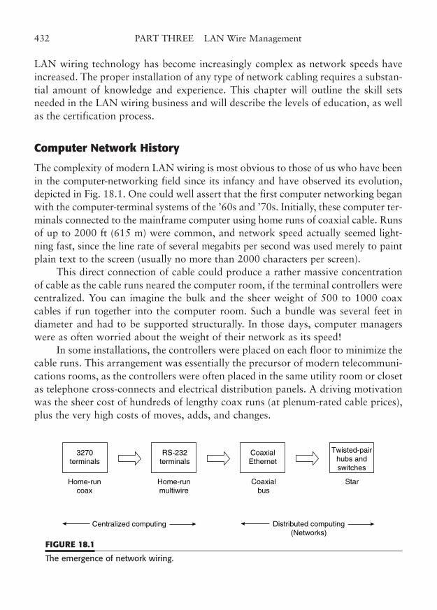
LAN wiring technology has become increasingly complex as network speeds haveincreased. The proper installation of any type of network cabling requires a substan-tial amount of knowledge and experience. This chapter will outline the skill setsneeded in the LAN wiring business and will describe the levels of education, as wellas the certification process.
Computer Network History
The complexity of modern LAN wiring is most obvious to those of us who have beenin the computer-networking field since its infancy and have observed its evolution,depicted in Fig. 18.1. One could well assert that the first computer networking beganwith the computer-terminal systems of the ’60s and ’70s. Initially, these computer ter-minals connected to the mainframe computer using home runs of coaxial cable. Runsof up to 2000 ft (615 m) were common, and network speed actually seemed light-ning fast, since the line rate of several megabits per second was used merely to paintplain text to the screen (usually no more than 2000 characters per screen).
This direct connection of cable could produce a rather massive concentrationof cable as the cable runs neared the computer room, if the terminal controllers werecentralized. You can imagine the bulk and the sheer weight of 500 to 1000 coaxcables if run together into the computer room. Such a bundle was several feet indiameter and had to be supported structurally. In those days, computer managerswere as often worried about the weight of their network as its speed!
In some installations, the controllers were placed on each floor to minimize thecable runs. This arrangement was essentially the precursor of modern telecommuni-cations rooms, as the controllers were often placed in the same utility room or closetas telephone cross-connects and electrical distribution panels. A driving motivationwas the sheer cost of hundreds of lengthy coax runs (at plenum-rated cable prices),plus the very high costs of moves, adds, and changes.
432 PART THREE LAN Wire Management
3270terminals
Centralized computing Distributed computing(Networks)
Home-runcoax
RS-232terminals
Home-runmultiwire
CoaxialEthernet
Coaxialbus
Twisted-pairhubs andswitches
Star
FIGURE 18.1
The emergence of network wiring.
In many ways, the apparent speed and extreme cable lengths of these primitivecomputer connections created the set of expectations for modern cabling. To thisday, centralized fiber-optic cabling (at speeds below gigabit) is the only networkingmethod that approaches old coax-terminal connection distances. Fortunately, thepractice of placing remote terminal servers (controllers) in each workspace coinci-dentally limited the run length from controller to terminal. Even in a large building,a controller was rarely over 200 cable-feet from its terminals. This has made thesubsequent 90-m TIA limit much more palatable to the mainframe manager, whenforced into the role of overseeing a distributed computer network.
In addition to the coax terminals, some computer installations used a new typeof computer-terminal serial data interconnection often referred to by the applicablestandard, RS-232. These connections required multiconductor cable, rather thancoax, and more severely limited the distance to the terminals. Eventually, we foundthat you could easily exceed the recommended 50-ft operating limit of RS-232 byutilizing “special” cable with twisted-pair stranded wires. In fact, the similarities totelephone wire were inescapable. Network training at this point included knowledgeof which pins of the 25-pin interface to use, how to connect them in the proper pat-tern (including the crossover or “null modem”), and how to arrange the pairing ofthe unbalanced interface to maximize distance. Using the right techniques, youcould easily get 200 to 300 ft (about 60 to 90 m) reliably.
At about the same time, distributed computer networks arose, with the adventof coaxial Ethernet. Actually, early Ethernet was a real bother to install. The coax-ial bus topology required a thick and bulky coaxial cable to be run from each work-station to another, and then required an equally thick AUI cable from the coax tapto the workstation. Not only was it difficult to deal with, but an inexperiencedinstaller could create not-so-subtle network problems, from flaky connections tototal network outages.
Ethernet made the shift to thin coax in the mid-1980s at about the same timewe were beginning to do RS-232 over twisted pair. Naturally, transmission engi-neers soon learned how to convert Ethernet’s unbalanced thin coax signal to a bal-anced twisted pair, and an industry was born. Thin Ethernet was also unreliable,whether it was true coax or was converted to twisted pair by balun transformers.However, the twisted-pair concept was a natural path to structured wire concentra-tion in telecommunications rooms. Several manufacturers began to insert activehubs into these networks, located in the telecommunications room.
Finally, the first modern hub-and-spoke, or star, networks were a reality, andnetwork wiring technology began to get serious. Standards were developed forstructured cabling, originally by the Electronic Industries Association (EIA), andlater by a subgroup, formed from an amalgam of industry groups and named the
CHAPTER 18 Training and Certification 433
Telecommunications Industry Association (TIA). Network technology was nolonger a trivial endeavor, but had become the basic currency upon which our net-work economy is founded. Now, education and training are necessities.
Wiring Complexity
To understand the nature of wiring complexity, one needs to appreciate the scienceand engineering involved in modern networking. To some, LAN wiring may seemto be a simple matter of connecting tiny wires in the right order. This approach issimilar to simple telephone wiring, which almost anyone can do. Perhaps the sim-plicity is seemingly apparent to anyone who has connected a basic telephone jack ina home, or who knows how to plug the modular cord into an inexpensive phone,but the simplicity wanes when you approach the first cross-connect. A quick glanceat the mass of cables and wires that exist in the average telephone room will con-vince anyone that even telephone wiring is not a simple matter. That is exactly whywe have spent so much of this book describing the twisted-pair wiring devices andtheir corresponding wiring patterns and installation practices.
In fact, high-speed network wiring adds one or two layers of complexity to thealready complex field of telephone wiring. At the speed of networks today, the sim-ple twisted pair has become a radio-frequency transmission line. The design of thecomponents that create this high-speed network is a marvel, as well as a radicalchange for the cabling component manufacturers. They routinely use RF-engineer-ing tools and practices in the creation of everything from low-crosstalk connectorsto geometry-stabilized cables. In fact, most of the new terms, such as attenuationand return loss, come from that RF domain. Just ask any microwave engineer.Microwave? Well, the definition of microwave frequencies is any frequency at orabove 1000 MHz, which certainly includes the base frequency of Gigabit Ethernet.Now, in reality, we do not place frequencies quite that high on our copper cables—yet—but we are close enough for many of the same concepts to apply.
In addition to proper design of these near-microwave network components,their proper installation is critical if we are able to reach the very high performancelevels needed for our modern networks. We no longer have the luxury of simplicity.We must lay out and install our networks to very exacting standards. Althoughevery installation is different, we have a system of rule-based design standards andinstallation practices that help us through the fray. However, rules are only as goodas the players, and we need the certification referee to ensure the players are prop-erly trained.
434 PART THREE LAN Wire Management
Training versus Certification
Network installations have required a certain amount of training since the days oftwist-on coax connectors. Twisted-pair connections require knowledge and skill toreach near-microwave performance levels. Fiber-optic connections also requireunderstanding and skill. We need to know what types of components are appropri-ate for each network installation, and how to properly install those components toachieve the expected network performance.
The process of gaining that knowledge and those skills is called training.Training takes many forms. You are clearly gaining the knowledge phase
through reading this book. Some of the skills can be gained by following theinstallation and termination techniques here, particularly in conjunction withinstructions that many manufacturers include with their products. In addition,many courses and resources are available to help supply cabling knowledge andskill. Of course, experience is the best teacher, particularly when supplemented bya skilled coworker or instructor. Many of us have used trial and error to success-fully compensate for the lack of formal training. As long as the errors are quicklyremedied, there is really nothing wrong with this approach. As a matter of fact,most approaches to wiring techniques (including the very design of successful con-necting hardware) have been the result of educated trial and error, or at least trialand testing.
Now that the best of these techniques and practices are known, it is paramountthat we quickly teach the best methods to the new installers and teach new methodsto the experienced ones. This process is done through the dissemination of trainingmanuals, training classes, and videos to the widest audience possible. Many organ-izations can provide cable installation training, as we will see later. However, as anetwork technician, how can you prove your level of expertise to a potentialemployer? Likewise, how can you as a contractor or business manager recognize thecredentials of prospective new employees or contractors?
The credentials can best be supplied by a training certificate or a testing certifi-cate. Formal training courses normally issue a “certificate of completion” to theattendee. In most cases, this certificate indicates that the student has successfullycompleted the course of instruction, which may or may not include an end-of-courseexam. The testing certification is provided by an organization that may or may nothave actually provided the training. In some cases, testing may be done by a govern-ment agency, as a requisite part of formal licensing. This is the same process thatmany skilled workers go through, from truck drivers to aircraft pilots, from auto-motive mechanics to airframe technicians, and indeed from programmers to net-work engineers. In an end-user organization, the particular level of training and
CHAPTER 18 Training and Certification 435
certification that is necessary is up to the employer and the employee. Additionaltraining and certification can be a source of job security and advancement, as wellas potential job mobility, to the employee.
In outside contracting, some form of certification is almost mandatory. At theleast, the lead technicians should be certified as installers for the type of installationbeing done, and the contractor should have a staff member with the appropriatecabling design certification. The certification is the proof to the customer that thecontractor can perform to the level of services required for a successful networkcabling installation. It also ensures that the installation will meet the entire scope ofthe specification, not just the modest network performance for the current network-ing need. (For example, a Category 5e installation should meet that performancelevel, even though the customer is using a lower network speed now.) With a properinstallation, the network manager will be able to confidently use newer and fastertechnology, up to the limits to the performance spec, without concern about thewiring integrity.
Job Descriptions and Skill Levels
A very good way to determine the knowledge and training levels that are requiredfor a career in any aspect of computer network cabling is to delineate the variousjobs that must be done. Many of the training courses define their course offeringsby using sample job titles. The job responsibilities and skill set are easily divided intothe same categories, although in any situation, an individual may perform at morethan one level. In fact, most cabling and certification programs presume that anyparticular level of knowledge includes the levels below it. However, in reality, the“designer” job tasks need only a basic understanding of detailed installation tech-niques and skills, as others perform those tasks. Conversely, the installer levelsrequire a high degree of installation skill, but not much knowledge of the finerpoints of network and cabling design.
For this discussion, we have divided the job descriptions into four levels: cablesystem designer, network designer, cabling technician, and cabling installer (Table18.1). These levels basically describe the different areas of technical knowledgerequired of someone who works in the field of LAN wiring. The knowledge levelsare more easily understood if we characterize each level with a job title and descrip-tion. We will describe each of these jobs briefly, but keep in mind that there are areasof specialization within each level. For example, a person may be an experiencedand knowledgeable copper cabling installer, with no experience in fiber-opticcabling. Thus, within each level, appropriate skills must be included for the specificnetwork-wiring task.
436 PART THREE LAN Wire Management
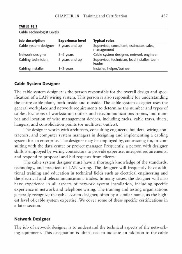
Cable System Designer
The cable system designer is the person responsible for the overall design and spec-ification of a LAN wiring system. This person is also responsible for understandingthe entire cable plant, both inside and outside. The cable system designer uses thegeneral workplace and network requirements to determine the number and types ofcables, locations of workstation outlets and telecommunications rooms, and num-ber and location of wire management devices, including racks, cable trays, ducts,hangers, and consolidation points (or multiuser outlets).
The designer works with architects, consulting engineers, builders, wiring con-tractors, and computer system managers in designing and implementing a cablingsystem for an enterprise. The designer may be employed by, contracting for, or con-sulting with the data center or project manager. Frequently, a person with designerskills is employed by wiring contractors to provide expertise, interpret requirements,and respond to proposal and bid requests from clients.
The cable system designer must have a thorough knowledge of the standards,technology, and practices of LAN wiring. The designer will frequently have addi-tional training and education in technical fields such as electrical engineering andthe electrical and telecommunications trades. In many cases, the designer will alsohave experience in all aspects of network system installation, including specificexperience in network and telephone wiring. The training and testing organizationsgenerally recognize the cable system designer, often by a similar name, as the high-est level of cable system expertise. We cover some of these specific certifications ina later section.
Network Designer
The job of network designer is to understand the technical aspects of the network-ing equipment. This designation is often used to indicate an addition to the cable
CHAPTER 18 Training and Certification 437
TABLE 18.1
Cable Technologist Levels
Job description Experience level Typical rolesCable system designer 5 years and up Supervisor, consultant, estimator, sales,
managementNetwork designer 3–5 years Cable system designer, network engineer Cabling technician 5 years and up Supervisor, technician, lead installer, team
leaderCabling installer 1–3 years Installer, helper/trainee
system designer’s skills and knowledge. For our purposes here, this job descriptionand knowledge set is primarily intended to complement the wiring knowledge of thecabling system.1
The network designer must thoroughly understand the operating parameters ofthe network technology and topology that the enterprise will use. This includesknowledge of the standards-compliant cable technology, the allowable cabling dis-tances, basic network hardware setup, and network troubleshooting. The actualnetworking standards, such as those for Fast Ethernet and Gigabit Ethernet, are thefocus of this job. Network wiring must be chosen that is appropriate for the net-work technology being used.
This person may be employed either by the user or by the cabling contractor,but the skill set is particularly appropriate for the contractor. It is important that thewiring contractor ensures that an installation will operate properly for the networktopology planned, not just that it was installed according to a particular set of bidspecifications.
The network designer is the wiring person who knows the difference, forexample, between 1000BaseSX and 1000BaseLX and understands the distance lim-itations and the cabling requirements for each. It is every contractor’s nightmare toinstall a cabling system that is according to spec, but inoperable. At the design stage,it is the network designer’s job to cross-check the run lengths, the layouts, and thenumber and placement of telecommunications outlets, and to question the assump-tions that others may make.
A network software technician may possess the skills and knowledge of thenetwork designer, particularly if that person is responsible for the hardware connec-tivity of the network. However, one should not necessarily assume that the certifi-cation testing for software skills prepares one for networking hardware layout ordesign. Many of the cable-skills certification programs now recognize the impor-tance of this networking job category in the overall success of a computer networkinstallation. In fact, the membership organizations that offer certification may offerthe only manufacturer-independent certification of generic networking skills.
Cabling Technician
The cabling technician’s knowledge and experience is at the very heart of LANwiring implementation. This is the person who follows the best workmanship prac-
438 PART THREE LAN Wire Management
1 Many other jobs and knowledge levels exist for the fields of network engineering and computer oper-ation, but training and certification for these network-operation jobs are handled by product-specifictraining programs from the major vendors of applications software and operating systems.
tices, has vast experience with a wide variety of cabling components, and has aworking-level knowledge of the appropriate installation standards. The cablingtechnician should know how to install all of the cabling components and support-ing structures used in LAN wiring. This includes general experience with most typesof cabling devices, from plugs and jacks to patch panels and cross-connects.
A cabling technician should know the proper workmanship procedures,including those practices that are crucial to proper operation of the higher wiringcategories. This person should be able to design and install simple cabling systemsthat will meet all applicable performance specifications. In addition to installationtasks, the cabling technician should be an expert with the appropriate cable scan-ning gear, and should be able to quickly diagnose and remedy link failures. This isthe person who will generally supervise and informally train the cabling installer,described in the next section.
A cabling technician typically has considerable experience and training in cableinstallation, and will often be a current or former lead installer. This person will oftenorder the cabling components, select the appropriate components for each stage ofthe job, supervise installers, inspect each stage of the job, direct or perform link test-ing, and act as the main point of contact with the customer during the job. In manyways, there is a good degree of overlap between the experienced cabling installer andthe cabling technician. The level of knowledge, experience, organization skills, andpeople skills are probably what most differentiate the two job categories.
Training and certification testing for the cabling technician are more extensivethan for the installer. This job level is relied on for expertise, rather than just com-petency. Consequently, the training programs emphasize this top-end knowledge inall aspects of cabling technology.
This is the person who makes the decisions about components and techniquesto use for plenums, firestops, grounding and bonding, cable management, andworker safety on a daily basis. For the most part, the training programs leave thepeople skills to the individual or to management. But they do an excellent job oftransferring technical knowledge.
Cabling Installer
The entry level to cabling technology is the cabling installer. Actually, this level mayencompass several steps in knowledge and experience. Many of the training pro-grams recognize these steps by dividing this job category into two or more levels.
The distinguishing characteristics of the cabling installer, as compared to thecabling technician, are the level of knowledge and experience and the need for super-vision in the overall job. The beginning installer may essentially be merely a helper,
CHAPTER 18 Training and Certification 439
working directly with experienced installers as part of a two- or three-person team. At this stage, the helper learns some of the basic terminology and prac-tices of cable installation. Most training at this level is on-the-job-training. Any formaltraining is introductory in nature. The pay scale for this entry level is frequently wellbelow that of an installer with a reasonable amount of experience. However, withadditional training and an aptitude for cabling, the beginner may advance rapidly.
Additional formal training for the new installer is generally manufacturer-specific. Most cabling contractors install a limited number of component brands,and can easily arrange for training in one or two component styles. Once aninstaller has had exposure to the basic workmanship concepts of copper cabling,that knowledge easily transfers to other similar component designs. For example,many manufacturers use 110-type wire termination in their outlet jacks, as well asin patches and cross-connects. So, once an installer understands the proper cabledressing, untwist limits, and punchdown techniques on one brand of components,that knowledge can be easily applied to other similar brands, albeit with minorrefinements.
As the cabling installer progresses in knowledge and experience, it may becomeincreasingly important to document that competence through formal training andcertification testing. Many jobs require that someone on the team be certified to aparticular level, and that all installers have appropriate manufacturer-specific train-ing. The cable contractor realizes that these classes and tests are necessary andshould be considered mandatory for the employee to progress in responsibility.
The classes are a lot of work, and the installer may need additional motivationto complete the training. Some contractors include a pay-rate incentive for certifica-tion in particular areas. Certainly, a well-trained installer is more valuable, both tothe employer and to the customer, and should be rewarded for taking additionalresponsibility.
A cabling installer with a high degree of experience and formal training maybecome a team leader or lead installer. As such, this person becomes a workingcoach for the installation team, supervising, inspecting, motivating, and training theothers on the team. This concept allows the contractor to place multiple teams ofinstallers into a job site with a distribution of management responsibilities.
Training Goals
There are two general approaches to training programs for LAN wiring: general-pur-pose and product-specific. The two types of training have slightly different purposesand goals. General-purpose training is essentially more conceptual in approach. Itcovers both the details of installation standards and practices, and the broad, general
440 PART THREE LAN Wire Management
philosophy of cable design and installation. Don’t assume that general-purpose train-ing is simple or easy. It can be quite rigorous. Some training organizations enumer-ate and delineate wiring rules in a particular fashion, and you must memorize andreproduce their methodology in order to pass the certification tests.
The goal of a general-purpose training program is to give the installer or designerthe knowledge to create standards-compliant cabling systems using all the proper lay-out, fire-protection, electrical, grounding, and workmanship rules. Such a programavoids specific product references, other than for examples of hardware type or forgeneric installation training. The idea is to give the cabling installer/designer the gen-eral rules and techniques for LAN wiring, without focusing on any particular manu-facturer’s products or methodology. It is assumed that the manufacturers or theirdesignated training organizations will provide specific product training.
Manufacturer-specific training is rather self-defining. This type of training isprovided or sponsored by individual manufacturers, particularly those with com-plete wiring systems. The advantage of this type of training is that you learn thetechniques and methods for installing a particular brand of wiring components.Most manufacturers use similar wire-termination methods for copper cable.However, very specific assembly techniques may be required to ensure performanceto Category 5e, Category 6, and beyond. In addition, the proper assembly of fiber-optic connectors is quite manufacturer-specific, as designs and assembly tools varywidely.
Manufacturer-specific training may be provided by component suppliers or bythird-party training organizations, in addition to direct manufacturer-providedtraining. In many instances, the training is offered at no cost, or for a nominal fee.It is in the best interest of the manufacturer that prospective installers have theproper training and experience in using their wiring components. Part of the prod-uct-specific training methodology occurs because installers will develop a clear pref-erence for products on which they have been trained. The training givesmanufacturers an opportunity to stress the benefits and presumed superiority oftheir products, and allows them to show the shortcomings of their competitors’products.
Training Resources
The availability of training for LAN wiring is a constantly changing subject.Training sessions are scheduled throughout the year in a variety of locations. Youmay want to choose from several appropriate training organizations, depending onthe locations, the dates, and the type of training offered. As with all our discussionon training, both general and specific classes are offered.
CHAPTER 18 Training and Certification 441
General-Purpose Training
General-purpose training is provided by educational institutions and by industryorganizations. Many colleges and universities have begun to respond to the need foradvanced education in wiring technology. Some notable institutions that offer suchprograms include Mississippi State University, Texas A&M University, andWashington State University.
Many others offer such education, but are too numerous to mention here. Also,the programs are constantly changing and expanding. You may consult the LANwiring Web site, www.LanWiringGuide.com, for links to these and other trainingresources.
The “granddaddy” of general-purpose training is BICSI (pronounced “bik’-see”). BICSI is an industry association that was originally called Building IndustryConsulting Services, International. It was formed in the 1970s as an association withties to the corresponding Bell System units that provided commercial buildingtelecommunications system designs. In the 1990s, the association realigned its offi-cial name to BICSI: A Telecommunications Association to emphasize the tie to thetelecommunications industry.
BICSI offers extensive training and certification testing for the telecommunica-tions cabling industry. In addition to direct training, BICSI also licenses organiza-tions to give BICSI-approved training to individuals.
The BICSI Telecommunications Distribution Methods Manual (TDMM) is oneof the most comprehensive standards and practices manuals available. In manyareas, the methods go far beyond the general-purpose international standards toillustrate and describe virtually all installation techniques that BICSI endorses.
BICSI offers training at several levels. The Registered CommunicationsDistribution Designer (RCDD) track includes courses in introductory voice/datacabling, telecommunications design, grounding and protection, LAN and internet-working, fiber-optic design, and project management.
The installation program has three levels, Apprentice, Installer, and Technician.The installation track includes extensive cable pulling, termination, testing, andcabling technology. Attendees receive a certificate of completion for each course.
BICSI also hosts a number of seminars and conferences that include basic andsupplementary training as well as manufacturers’ displays. One of BICSI’s majorgoals is to educate its members, and the meetings are organized to forward this aim.
The Association of Cabling Professionals (ACP), in conjunction with theCabling Business Institute, offers another general-purpose training program. Installertraining includes information on all aspects of copper and fiber cabling, from basiccable termination to detailed installation practices. The training is layered into phases,
442 PART THREE LAN Wire Management
with intensive classroom training interspersed with self-study sessions. After comple-tion of the final session, an end-of-course exam is administered. Additional courses areoffered in commercial and residential structured cabling design, fiber-optic cabling,local area networks, outside plant design, estimating, sales, and project management.
The ACP offers several seminars, conferences, and trade shows throughout theyear. Some of these are in association with industry publications and manufacturers.The Cabling Business Institute is associated with the publisher of Cabling BusinessMagazine. The magazine holds an annual conference that includes comprehensivetraining sessions that are requisites to the institute’s certification program. Trainingvideos, seminars, and trade shows are also offered by Cabling Installation &Maintenance, a trade magazine.
In addition to these training programs from industry associations, shortcourses are available from a variety of private training organizations.
Several excellent technology training organizations offer appropriate trainingfor cabling installers and designers. Consult the LAN wiring Web site for currentinformation on companies and offerings. In some instances, these outside trainingresources may include the requisite information for formal certification. Such train-ing may be offered more frequently or in more convenient locations than the train-ing from the industry associations.
Manufacturer-Specific Training
Product-specific training is offered through a number of sources, but this training isalways sponsored or sanctioned in some way by a particular manufacturer or con-sortium. The best way to obtain this type of training is through a business relation-ship with a cable-component supplier or manufacturer. Many of the componentdistributors have their own training programs, which are often underwritten by thevarious manufacturers. In a few of these, training in several products may beoffered, particularly when those products require similar installation techniques.For example, training on 110-type outlet connectors is essentially the same from onemanufacturer to the next. Likewise, many fiber-optic connectors are assembled inthe same manner, and the basic techniques for preparing the fiber for terminationare quite similar.
Links for a number of manufacturer/supplier training resources are included onthe LAN wiring Web site, www.LanWiringGuide.com. Training may also be offeredthrough multimedia courses. Videotapes and CD-ROM training are availablethrough several sources. Videos offer a great way to introduce new installer-traineesto the concepts and practices of cable installation and are a good source of generalinformation.
CHAPTER 18 Training and Certification 443
Certification Programs
Formal certification plans match up with the types of training. There are several lev-els of certification within each plan, and you may or may not need to progress lin-early from one to another. In several cases, the installer certification levels have beendeveloped more recently, and no installer precertification may be needed for thedesigner level certificate.
The formal certification of cabling technology knowledge is rather like adiploma from one of the training programs. In many cases, the certification alsoimplies a certain amount of on-the-job experience as well. Certification is importantas an employment qualification, as well as a testament to prospective clients thatyou and your installers have the proper knowledge and training to install the cablingcomponents properly, thus ensuring the proper level of performance.
In some areas, such training and certification may be required for local licens-ing and permits.
General-Purpose Certification
General-purpose training usually offers a test-based certification of competence.These training program certifications are often required by contracts for wiringjobs. In addition, employers may require a specific certification as a job prerequi-site, or may offer additional pay and status to employees with these industry certi-fications. In many ways, the certifications offer the cabling technologist statussimilar to that of the certified network engineer in LAN technology.
BICSI offers certification of Apprentice, Installer, Technician, RegisteredCommunication Distribution Designer (RCDD®), RCDD Network TransportSystems (NTS) Specialist, RCDD/Outside Plant (OSP) Specialist, and RCDD/Wireless Design (WD) Specialist.
ACP offers similar completion certificates for courses from Installer andJourneyman to Designer and LAN Specialist, although the only formal program atpresent is the Installer designation.
Other general-purpose programs offer a completion certificate as evidence ofcompletion. The certificate may in some cases be obtained only after an end-of-course exam is successfully passed. Some college classes offer college credit for thecourses, while others merely offer a completion certificate.
Some of the certification programs, such as those offered by BICSI, require contin-uing education to maintain the designation. This is similar to the continuing recertifica-tion requirement of software training. Continuing education requirements recognize thechanging face of wiring technology and the need to stay current in the field.
444 PART THREE LAN Wire Management
Manufacturer-Specific Certification
Manufacturer-specific product training usually offers a certificate of completion asevidence of certification. Naturally, all that is certified is that the person hasattended the class, and presumably has received all the relevant information andtraining. In a few instances, the trainee will be given an end-of-course test, and mayhave to demonstrate assembly competence on the product being covered.
Some manufacturers require that the organization performing an installationbe trained on their products in order for the end-user to receive a long-term war-ranty. These warranties are valuable to the end-user because they guarantee cablelink performance to the prescribed level for up to 15 years. The value to the manu-facturer is that an additional incentive is provided the end-user in return for speci-fying that manufacturer’s wiring products. In some cases, two or moremanufacturers may coordinate a warranty program, as long as properly trained andcertified personnel install each manufacturer’s components. This type of programwould allow a connector and a cable manufacturer to cooperate, and to competeagainst manufacturers who offer both components with an extended performancewarranty.
Many contractors will offer manufacturer-certified installation technicians asan incentive to the customer to use their services. Conversely, many end-users mayrequire such certification for installation work that they contract out. Specific prod-uct installation training is an important supplement to general-purpose training atany level.
Sources of Information
Training and certification resources are constantly changing. Fortunately, a compi-lation of training information is available on the LAN wiring Web site athttp://www.LanWiringGuide.com. This information is updated regularly from avariety of industry sources, including industry associations, manufacturers, publicinstitutions, and independent training organizations. You may also consult many ofthese organizations through their contact information in the Appendixes.
CHAPTER 18 Training and Certification 445

This page intentionally left blank

PART FOUR
Appendixes
Copyright © 2006 by James Trulove. Click here for terms of use.

This page intentionally left blank
APPENDIX A
Legacy Wire and Cable
Highlights
■ AWG wire gauges
■ Coaxial cable
■ Nonpaired cable
449
Copyright © 2006 by James Trulove. Click here for terms of use.
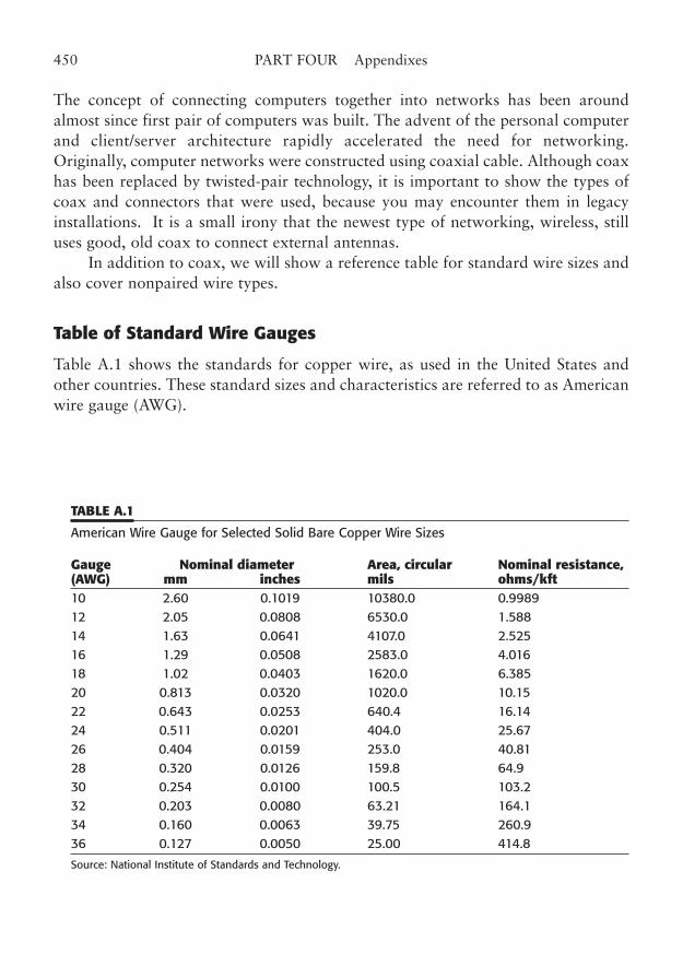
The concept of connecting computers together into networks has been aroundalmost since first pair of computers was built. The advent of the personal computerand client/server architecture rapidly accelerated the need for networking.Originally, computer networks were constructed using coaxial cable. Although coaxhas been replaced by twisted-pair technology, it is important to show the types ofcoax and connectors that were used, because you may encounter them in legacyinstallations. It is a small irony that the newest type of networking, wireless, stilluses good, old coax to connect external antennas.
In addition to coax, we will show a reference table for standard wire sizes andalso cover nonpaired wire types.
Table of Standard Wire Gauges
Table A.1 shows the standards for copper wire, as used in the United States andother countries. These standard sizes and characteristics are referred to as Americanwire gauge (AWG).
450 PART FOUR Appendixes
TABLE A.1
American Wire Gauge for Selected Solid Bare Copper Wire Sizes
Gauge Nominal diameter Area, circular Nominal resistance, (AWG) mm inches mils ohms/kft10 2.60 0.1019 10380.0 0.9989 12 2.05 0.0808 6530.0 1.588 14 1.63 0.0641 4107.0 2.525 16 1.29 0.0508 2583.0 4.016 18 1.02 0.0403 1620.0 6.385 20 0.813 0.0320 1020.0 10.15 22 0.643 0.0253 640.4 16.14 24 0.511 0.0201 404.0 25.67 26 0.404 0.0159 253.0 40.81 28 0.320 0.0126 159.8 64.9 30 0.254 0.0100 100.5 103.2 32 0.203 0.0080 63.21 164.1 34 0.160 0.0063 39.75 260.9 36 0.127 0.0050 25.00 414.8
Source: National Institute of Standards and Technology.
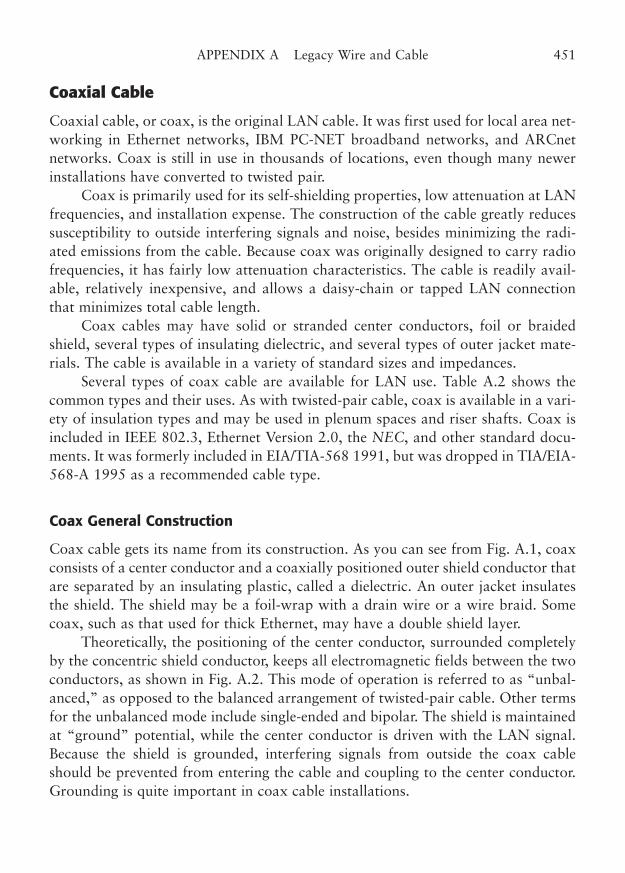
Coaxial Cable
Coaxial cable, or coax, is the original LAN cable. It was first used for local area net-working in Ethernet networks, IBM PC-NET broadband networks, and ARCnetnetworks. Coax is still in use in thousands of locations, even though many newerinstallations have converted to twisted pair.
Coax is primarily used for its self-shielding properties, low attenuation at LANfrequencies, and installation expense. The construction of the cable greatly reducessusceptibility to outside interfering signals and noise, besides minimizing the radi-ated emissions from the cable. Because coax was originally designed to carry radiofrequencies, it has fairly low attenuation characteristics. The cable is readily avail-able, relatively inexpensive, and allows a daisy-chain or tapped LAN connectionthat minimizes total cable length.
Coax cables may have solid or stranded center conductors, foil or braidedshield, several types of insulating dielectric, and several types of outer jacket mate-rials. The cable is available in a variety of standard sizes and impedances.
Several types of coax cable are available for LAN use. Table A.2 shows thecommon types and their uses. As with twisted-pair cable, coax is available in a vari-ety of insulation types and may be used in plenum spaces and riser shafts. Coax isincluded in IEEE 802.3, Ethernet Version 2.0, the NEC, and other standard docu-ments. It was formerly included in EIA/TIA-568 1991, but was dropped in TIA/EIA-568-A 1995 as a recommended cable type.
Coax General Construction
Coax cable gets its name from its construction. As you can see from Fig. A.1, coaxconsists of a center conductor and a coaxially positioned outer shield conductor thatare separated by an insulating plastic, called a dielectric. An outer jacket insulatesthe shield. The shield may be a foil-wrap with a drain wire or a wire braid. Somecoax, such as that used for thick Ethernet, may have a double shield layer.
Theoretically, the positioning of the center conductor, surrounded completelyby the concentric shield conductor, keeps all electromagnetic fields between the twoconductors, as shown in Fig. A.2. This mode of operation is referred to as “unbal-anced,” as opposed to the balanced arrangement of twisted-pair cable. Other termsfor the unbalanced mode include single-ended and bipolar. The shield is maintainedat “ground” potential, while the center conductor is driven with the LAN signal.Because the shield is grounded, interfering signals from outside the coax cableshould be prevented from entering the cable and coupling to the center conductor.Grounding is quite important in coax cable installations.
APPENDIX A Legacy Wire and Cable 451
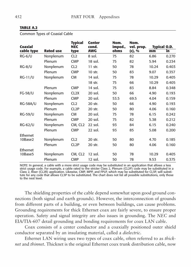
The shielding properties of the cable depend somewhat upon good ground con-nections (both signal and earth grounds). However, the interconnection of groundsfrom different parts of a building, or even between buildings, can cause problems.Grounding requirements for thick Ethernet coax are fairly severe, to ensure properoperation. Safety and signal integrity are also issues in grounding. The NEC andEIA/TIA-607 detail grounding and bonding requirements for coax LAN cable.
Coax consists of a center conductor and a coaxially positioned outer shieldconductor separated by an insulating material, called a dielectric.
Ethernet LAN wiring uses two types of coax cable, often referred to as thick-net and thinnet. Thicknet is the original Ethernet coax trunk distribution cable, now
452 PART FOUR Appendixes
TABLE A.2
Common Types of Coaxial Cable
Typical Center Nom. Nom. Coaxial NEC cond. imped., vel. prop. Typical O.D.cable type Rated use type AWG ohms (c), % mm inRG-6/U Nonplenum CL2 8 sol. 75 82 6.86 0.270
Plenum CMP 18 sol. 75 82 5.94 0.234 RG-8/U Nonplenum CL2 11 str. 50 78 10.24 0.403
Plenum CMP 10 str. 50 83 9.07 0.357RG-11/U Nonplenum CM 14 sol. 75 78 10.29 0.405
18 str. 75 66 10.29 0.405 Plenum CMP 14 sol. 75 83 8.84 0.348
FG-58/U Nonplenum CL2X 20 sol. 50 66 4.90 0.193 Plenum CMP 20 sol. 53.5 69.5 4.04 0.159
RG-58A/U Nonplenum CL2 20 str. 50 66 4.90 0.193 Plenum CL2P 20 str. 50 80 4.06 0.160
RG-59/U Nonplenum CM 20 sol. 75 78 6.15 0.242 Plenum CMP 20 sol. 75 82 5.38 0.212
RG-62/U Nonplenum CM, CL2 22 sol. 93 84 6.15 0.240 Plenum CMP 22 sol. 93 85 5.08 0.200
Ethernet10Base2 Nonplenum CL2 20 str. 50 80 4.70 0.185
Plenum CL2P 20 str. 50 80 4.06 0.160 Ethernet10Base5 Nonplenum CM, CL2 12 sol. 50 78 10.29 0.405
Plenum CMP 12 sol. 50 78 9.53 0.375
NOTE: In general, a cable with a more strict usage code may be substituted in an application that allows a lessstrict usage code. For example, a cable rated to the stricter Class 2, Plenum (CL2P) code may be substituted in aClass 2, Riser (CL2R) application. Likewise, CMP, MPP, and FPLP, which may be substituted for CL3P, will substi-tute for any code that allows CL3P to be substituted. The chart does not list all possible substitutions, only thoseto the next level.
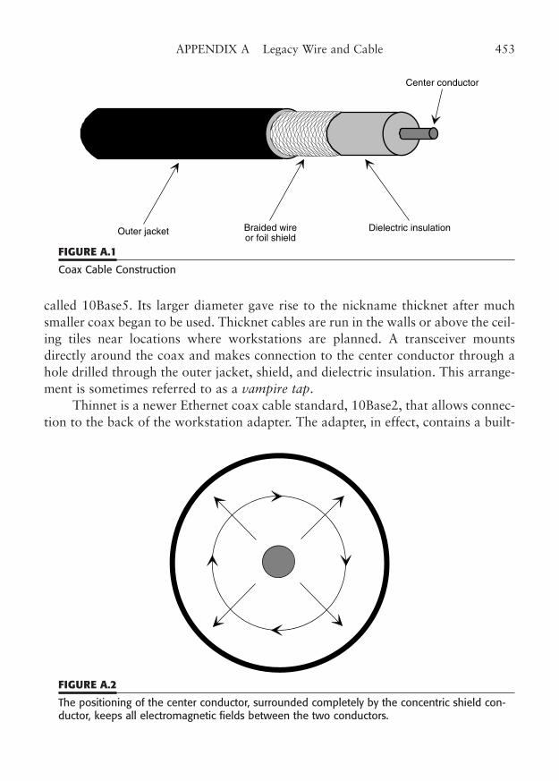
called 10Base5. Its larger diameter gave rise to the nickname thicknet after muchsmaller coax began to be used. Thicknet cables are run in the walls or above the ceil-ing tiles near locations where workstations are planned. A transceiver mountsdirectly around the coax and makes connection to the center conductor through ahole drilled through the outer jacket, shield, and dielectric insulation. This arrange-ment is sometimes referred to as a vampire tap.
Thinnet is a newer Ethernet coax cable standard, 10Base2, that allows connec-tion to the back of the workstation adapter. The adapter, in effect, contains a built-
APPENDIX A Legacy Wire and Cable 453
Outer jacket Braided wireor foil shield
Dielectric insulation
Center conductor
FIGURE A.1
Coax Cable Construction
FIGURE A.2
The positioning of the center conductor, surrounded completely by the concentric shield con-ductor, keeps all electromagnetic fields between the two conductors.
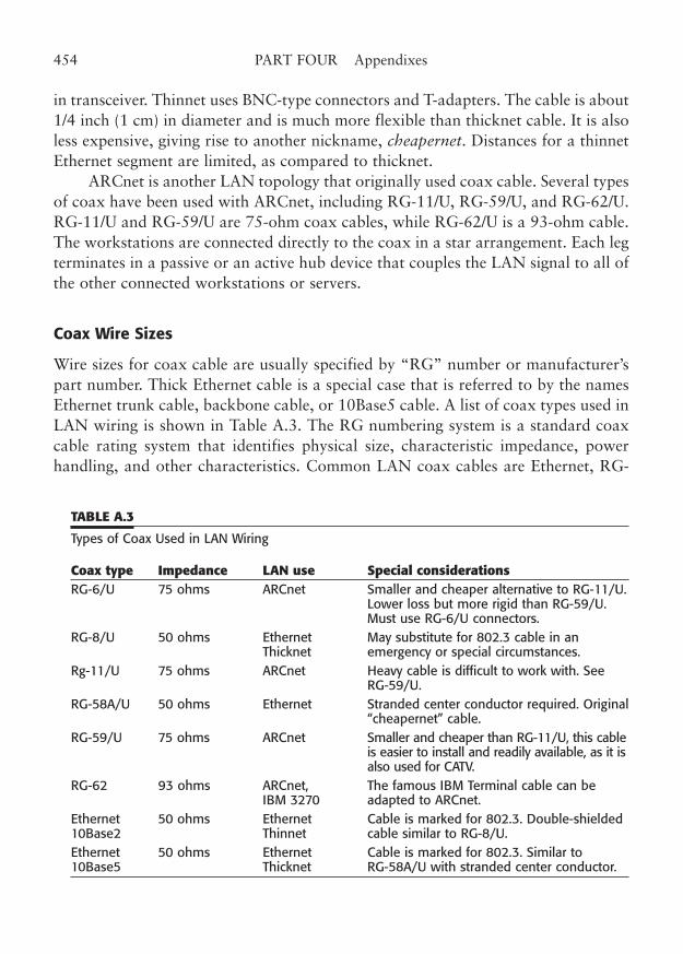
in transceiver. Thinnet uses BNC-type connectors and T-adapters. The cable is about1/4 inch (1 cm) in diameter and is much more flexible than thicknet cable. It is alsoless expensive, giving rise to another nickname, cheapernet. Distances for a thinnetEthernet segment are limited, as compared to thicknet.
ARCnet is another LAN topology that originally used coax cable. Several typesof coax have been used with ARCnet, including RG-11/U, RG-59/U, and RG-62/U.RG-11/U and RG-59/U are 75-ohm coax cables, while RG-62/U is a 93-ohm cable.The workstations are connected directly to the coax in a star arrangement. Each legterminates in a passive or an active hub device that couples the LAN signal to all ofthe other connected workstations or servers.
Coax Wire Sizes
Wire sizes for coax cable are usually specified by “RG” number or manufacturer’spart number. Thick Ethernet cable is a special case that is referred to by the namesEthernet trunk cable, backbone cable, or 10Base5 cable. A list of coax types used inLAN wiring is shown in Table A.3. The RG numbering system is a standard coaxcable rating system that identifies physical size, characteristic impedance, powerhandling, and other characteristics. Common LAN coax cables are Ethernet, RG-
454 PART FOUR Appendixes
TABLE A.3
Types of Coax Used in LAN Wiring
Coax type Impedance LAN use Special considerationsRG-6/U 75 ohms ARCnet Smaller and cheaper alternative to RG-11/U.
Lower loss but more rigid than RG-59/U.Must use RG-6/U connectors.
RG-8/U 50 ohms Ethernet May substitute for 802.3 cable in an Thicknet emergency or special circumstances.
Rg-11/U 75 ohms ARCnet Heavy cable is difficult to work with. SeeRG-59/U.
RG-58A/U 50 ohms Ethernet Stranded center conductor required. Original“cheapernet” cable.
RG-59/U 75 ohms ARCnet Smaller and cheaper than RG-11/U, this cableis easier to install and readily available, as it isalso used for CATV.
RG-62 93 ohms ARCnet, The famous IBM Terminal cable can be IBM 3270 adapted to ARCnet.
Ethernet 50 ohms Ethernet Cable is marked for 802.3. Double-shielded 10Base2 Thinnet cable similar to RG-8/U.Ethernet 50 ohms Ethernet Cable is marked for 802.3. Similar to 10Base5 Thicknet RG-58A/U with stranded center conductor.
8/U, RG-11/U, RG-58A/U, RG-59/U, and RG-62/U. The outer jacket of RG-8/Uand RG-11/U is roughly 1/2 inch (12.7 mm), while RG-58A/U, 59/U, and 62/U areon the order of 1/4 inch (6.4 mm). Plenum versions of these cables are usually a lit-tle smaller. The wire sizes of the center conductor and the diameter of the outerjacket (including dielectric and shield) are defined by the RG number and the insu-lation type. You must specify whether you want connectors for PVC or plenum insu-lation types, since the cable dimensions are not the same.
Coax Electrical Characteristics
Coax cables are available in a variety of standard characteristic impedances.Because the primary use for coax is the transmission of RF signals, the coax imped-ances often reflect the needs of RF equipment.
These standard impedances are 50 ohms, 75 ohms, and 92 ohms. The dimen-sions and properties of the center conductor, dielectric, and shield combine todefine the coax cable’s characteristic impedance. The dielectric constant in flame-resistant cable is very different from that of conventional polyethylene or foamdielectric cable. It is for this reason that plenum cable typically has a smaller cablediameter.
The attenuation of coax cable is less than 1.5 dB per 100 ft at 10 MHz. At 100MHz, the typical attenuation is under 5 dB per 100 ft. Obviously, the useful coaxcable length is reduced as the frequency goes up. Some types of networks base theirmaximum coax cable runs on the total allowable loss from end to end (the lossbudget), while other types of networks have timing constraints that limit the usabledistance.
As with other wiring types, the capacitance of the cable is the primary contrib-utor to attenuation at higher frequencies. Even so, coax has a greater maximumusable length than twisted pair. For example, a 10 Mbps Ethernet segment can be500 m (1640.5 ft) using thicknet and 185 m (607 ft) using thinnet. (Note: Segmentlengths in Ethernet are limited by attenuation and frequency-based signal distortion,while network span is limited by timing constraints.) ARCnet, which runs at 2.5Mbps, allows 2000 ft (610 m) for each coax leg with an active hub. For compari-son, twisted-pair wiring is limited to 100 m (328 ft).
The standard coax dielectrics are polyethylene and PTFE or FEP, although sev-eral other materials are also used. The loss characteristics of the dielectric materialcontribute to the loss at any given frequency.
Low-loss dielectric materials and constructions, such as foam or helicaldielectrics, are available. However, those low-loss cables are cost-prohibitive fornormal LAN cable installations.
APPENDIX A Legacy Wire and Cable 455
Coax Insulation
The insulation in coax cables includes the jacket as well as the insulating dielectricthat separates the center conductor and the shield.
The primary types of insulation materials used with coax are polyethylene,polypropylene, various synthetic rubber compounds, polyvinyl chloride (PVC), andfluorocarbon polymers such as polytetrafluoroethylene (PTFE), fluorinated ethyl-ene-propylene (FEP), and ethylene-chlorotrifluorethylene (ECTFE or HALAR®).Nonplenum coax cables generally use polyethylene as the dielectric that surroundsthe center conductor, and use noncontaminating synthetic resin for the outer jacket.Plenum-rated coax cables use a PTFE dielectric (such as Teflon®) or FEP and a sim-ilar outer jacket.
Coax Color Coding and Marking
The most common color for nonplenum coax cable is black. Most of the nonplenumcable that is used for LAN wiring will have a black synthetic rubber or PVC outerjacket with white markings. Plenum cable usually has a white or translucent jacketwith black markings. A notable exception to this rule is classic “thick” Ethernet(10Base5) cable. Thick Ethernet cable is usually a very bright color, such as yellow.
Coax cable should be marked in a similar manner as twisted pair. The cablewill generally have a manufacturer’s name and part number, the UL/NEC class oruse marking, and the appropriate “RG” number. It may also have EIA/TIA mark-ings or IEEE 802.3 markings. Coax use ratings are covered in NEC Articles 800 and820. If you use RG-58 type cable for thinnet, you should be aware that some of thistype of cable does not meet 802.3 specifications and may not be usable at the max-imum length for thinnet. You should be sure to specify RG-58A/U that is certifiedfor 802.3 use. EIA/TIA-568 1991 contains specifications for coax, and those mark-ings may be on the cable jacket.
Ethernet trunk cable (thicknet) will have marking bands every 2.5 m to indi-cate locations for transceiver tap installation.
Coax Shielding
A concentric shield conductor surrounds the center conductor and dielectric insula-tion in a coax cable. This outer shielding layer causes the electrical and magneticfields to be contained within the cable and shields the center conductor from fieldsoutside the cable.
Two types of shielding are generally used in coax cables: foil and braid. Thefoil shield, sometimes called an overall foil shield, is a very thin metallic foil that
456 PART FOUR Appendixes
totally surrounds the dielectric. The braid shield consists of a wire mesh of very finewire conductors. As with the foil shield, the braid surrounds the dielectric and formsa shield. The braid is effective at LAN frequencies even though there are small gapsbetween the wires. The gaps are not significant compared to the wavelength of theLAN frequencies. Some coax, such as Ethernet trunk cable, uses a double-braidshield to further increase the shielding properties. Cables with braid shields are gen-erally more expensive than cable with foil shields.
Nonpaired Cable
We will cover nonpaired cable in this section to help you identify it. Nonpairedcable is not proper for use as LAN wiring because it lacks the self-shielding prop-erties of twisted-pair wire. It both generates and is susceptible to interference,which means that it will probably violate the allowable emission standards ofnational and international organizations with government entities such as the U.S.Federal Communications Commission (FCC). This is also a legal violation.Nonpaired cable also may not exhibit a consistent characteristic impedance andmay create crosstalk between the pairs. This crosstalk happens even at voice fre-quencies, as you may know if you have two phone lines in your house and haveolder, nonpaired wiring. At LAN frequencies, the crosstalk between the transmitand receive pairs may mean that you will receive enough of your transmitted sig-nal to cause an error.
You will undoubtedly encounter those who have used short lengths of non-paired cable (such as the flat telephone cord that is used with RJ-11 connectors)with no apparent problems. Don’t believe them. In all likelihood, they are actuallyexperiencing undetected data errors that just slow down their network. In any event,such cable is a problem waiting to happen. What works at 2.5 MHz may be mar-ginal at 10 MHz, impossible at 16 MHz, and a joke at 100 MHz. Don’t let non-paired cable be used anywhere in your network!
Nonpaired General Construction
Nonpaired wire may be divided into two general classifications: round cable and flatcable. Both consist of two or more insulated wire conductors and may have a cov-ering jacket over the wires. As with paired cable, nonpaired cable may be shieldedwith either a foil or a braid conductor.
Round cable, as the name implies, consists of two or more wires that are con-tained within a round protective jacket. An example of round nonpaired wire isshown in Fig. A.3.
APPENDIX A Legacy Wire and Cable 457
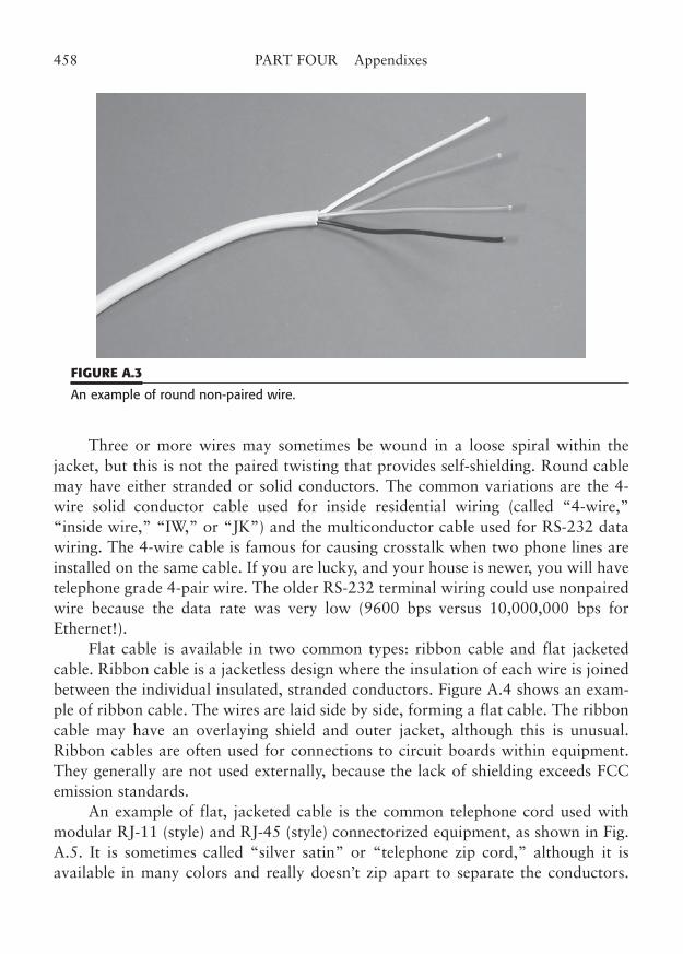
Three or more wires may sometimes be wound in a loose spiral within thejacket, but this is not the paired twisting that provides self-shielding. Round cablemay have either stranded or solid conductors. The common variations are the 4-wire solid conductor cable used for inside residential wiring (called “4-wire,”“inside wire,” “IW,” or “JK”) and the multiconductor cable used for RS-232 datawiring. The 4-wire cable is famous for causing crosstalk when two phone lines areinstalled on the same cable. If you are lucky, and your house is newer, you will havetelephone grade 4-pair wire. The older RS-232 terminal wiring could use nonpairedwire because the data rate was very low (9600 bps versus 10,000,000 bps forEthernet!).
Flat cable is available in two common types: ribbon cable and flat jacketedcable. Ribbon cable is a jacketless design where the insulation of each wire is joinedbetween the individual insulated, stranded conductors. Figure A.4 shows an exam-ple of ribbon cable. The wires are laid side by side, forming a flat cable. The ribboncable may have an overlaying shield and outer jacket, although this is unusual.Ribbon cables are often used for connections to circuit boards within equipment.They generally are not used externally, because the lack of shielding exceeds FCCemission standards.
An example of flat, jacketed cable is the common telephone cord used withmodular RJ-11 (style) and RJ-45 (style) connectorized equipment, as shown in Fig.A.5. It is sometimes called “silver satin” or “telephone zip cord,” although it isavailable in many colors and really doesn’t zip apart to separate the conductors.
458 PART FOUR Appendixes
FIGURE A.3
An example of round non-paired wire.
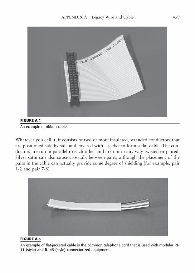
Whatever you call it, it consists of two or more insulated, stranded conductors thatare positioned side by side and covered with a jacket to form a flat cable. The con-ductors are run in parallel to each other and are not in any way twisted or paired.Silver satin can also cause crosstalk between pairs, although the placement of thepairs in the cable can actually provide some degree of shielding (for example, pair1-2 and pair 7-8).
APPENDIX A Legacy Wire and Cable 459
FIGURE A.4
An example of ribbon cable.
FIGURE A.5
An example of flat-jacketed cable is the common telephone cord that is used with modular RJ-11 (style) and RJ-45 (style) connectorized equipment.
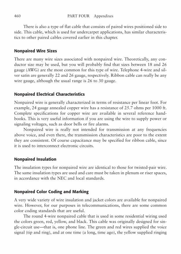
There is also a type of flat cable that consists of paired wires positioned side toside. This cable, which is used for undercarpet applications, has similar characteris-tics to other paired cables covered earlier in this chapter.
Nonpaired Wire Sizes
There are many wire sizes associated with nonpaired wire. Theoretically, any con-ductor size may be used, but you will probably find that sizes between 18 and 26gauge (AWG) are the most common for this type of wire. Telephone 4-wire and sil-ver satin are generally 22 and 26 gauge, respectively. Ribbon cable can really be anywire gauge, although the usual range is 26 to 30 gauge.
Nonpaired Electrical Characteristics
Nonpaired wire is generally characterized in terms of resistance per linear foot. Forexample, 24 gauge annealed copper wire has a resistance of 25.7 ohms per 1000 ft.Complete specifications for copper wire are available in several reference hand-books. This is very useful information if you are using the wire to supply power orsignaling voltages, such as door bells or fire alarms.
Nonpaired wire is really not intended for transmission at any frequenciesabove voice, and even there, the transmission characteristics are poor to the extentthey are consistent. Of course capacitance may be specified for ribbon cable, sinceit is used to interconnect electronic circuits.
Nonpaired Insulation
The insulation types for nonpaired wire are identical to those for twisted-pair wire.The same insulation types are used and care must be taken in plenum or riser spaces,in accordance with the NEC and local standards.
Nonpaired Color Coding and Marking
A very wide variety of wire insulation and jacket colors are available for nonpairedwire. However, for our purposes in telecommunications, there are some commoncolor coding standards that are useful.
The round 4-wire nonpaired cable that is used in some residential wiring usedthe colors green, red, yellow, and black. This cable was originally designed for sin-gle-circuit use—that is, one phone line. The green and red wires supplied the voicesignal (tip and ring), and at one time (a long, time ago), the yellow supplied ringing
460 PART FOUR Appendixes
voltage and the black, ground. The 4-wire cable continued to be used long after theringing voltage was moved to the tip and ring and the ground was deleted. For atime in the 1960s, the yellow and black were used to supply power from a wall-mounted transformer to the lamp that lit the dial of the famous “Princess” phone.This was later eliminated when the lamp power was also supplied on the tip andring wires. When a second phone line was to be added, the yellow and black wireswere generally available, and that’s where it went. Unfortunately, the nonpaired 4-wire cable can generate serious crosstalk between the pairs, and you may faintlyhear the other person when you are on a different line. This may be an advantagefor parents, but is a problem for LAN circuits and must be avoided.
Nonpaired Shielding
Nonpaired cables may be shielded with foil or braid shields, as with twisted-paircable. A typical use for a shielded, nonpaired cable is for microphone cable. Evenflat cable may be shielded. Such cables are useful in meeting electromagnetic inter-ference (EMI) requirements of regulating agencies.
APPENDIX A Legacy Wire and Cable 461

This page intentionally left blank
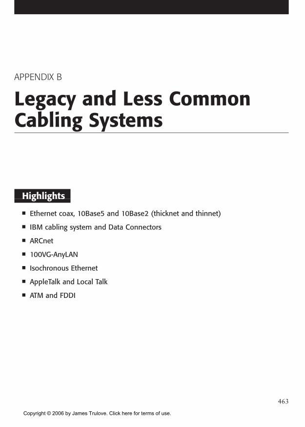
APPENDIX B
Legacy and Less CommonCabling Systems
Highlights
■ Ethernet coax, 10Base5 and 10Base2 (thicknet and thinnet)
■ IBM cabling system and Data Connectors
■ ARCnet
■ 100VG-AnyLAN
■ Isochronous Ethernet
■ AppleTalk and Local Talk
■ ATM and FDDI
463
Copyright © 2006 by James Trulove. Click here for terms of use.
Cabling technology to support computer networking has had a very interesting his-tory. Along the way, quite a number of alternatives have been developed to meet theneeds of a rapidly changing networking world. Eventually, one particular technol-ogy, twisted-pair Ethernet, became dominant and displaced all of the others. Theonly current competition to Ethernet is Token-Ring, and the two are covered in themain portions of this book. However, to be a complete reference to LAN wiring,many of the older technologies, including coaxial Ethernet, will be covered in thisAppendix.
You may still encounter some of these technologies in older installations, andit is useful to have this information for reference if you ever need to repair an oldernetwork, or to just shake your head in fascination at how far we have come fromthe old days.
Ethernet Coax
Ethernet topology is the “granddaddy” of LAN systems. It was the first widelyaccepted, nonproprietary, standardized multiple-access network. Intended for theroutine connection of computers and workstations, it allowed many devices to sharea high-speed communications line without regard to the customary hierarchy of per-manent computer-to-terminal connections.
Ethernet was originally developed by the Xerox Corporation at its Palo AltoResearch Center. In the late 1970s, Xerox Corporation, Digital EquipmentCorporation (DEC), and Intel Corporation agreed to jointly promote Ethernet as anopen standard for computing. This standard eventually became the IEEE 802.3standard, administered by the Institute of Electrical and Electronics Engineers. IEEE802.3 has been revised and refined several times and now includes coax, twistedpair, and fiber optics.1 Modern Ethernet, as embodied in IEEE 802.3, actually dif-fers in some ways from the original Xerox/DEC/Intel standard (sometimes calledDIX). This older standard has been revised and lives on as Ethernet Version 2.However, most installations have shifted to the IEEE standard and we will refer tothat simply as “Ethernet” in accordance with common usage, unless there is a sig-nificant difference.
Ethernet uses a method of signaling called Carrier Sense Multiple Access withCollision-Detect (CSMA/CD). At the signaling rate of 10 Mbps, it uses a specialmethod, called Manchester coding, to preserve a null DC level on the cable; thisallows collisions to be detected when they occur. Each device listens to the network
464 PART FOUR Appendixes
1 Wireless multiple-access connection methods are standardized in IEEE 802.11, which is covered inChap. 13.
for transmissions from other devices. If a transmission is received that matches thedevice’s address, it is processed in accordance with higher-level protocols. If not, thetransmission is simply ignored. When a device wishes to transmit, it first “listens”for another existing transmission. If none is present, it transmits its message, andthen notes the voltage level on the line to see if another device happened to trans-mit at the same time. This would be called a collision. If a collision occurs, eachdevice waits a short, random time period and retransmits, after checking for anexisting transmission. Thus, many devices have access to the network (multipleaccess), they each listen before transmitting (carrier sense), and they retransmit if acollision occurs (collision detect).
Newer 100 and 1000 Mbps Ethernet technologies use variations of this basicscheme to encode data and detect carrier and/or collisions.
Thicknet (10Base5) Cabling
The original implementation of Ethernet used a large, 50-ohm coax trunk cable thatis now referred to as thicknet. This cable is specified in the 10Base52 standard ofIEEE 802.3, and is used at the 10 Mbps signaling rate.
A 10Base5 network consists of a thicknet backbone cable that is tapped witha series of transceivers or media attachment units (MAUs). Each workstation orserver is connected to a single transceiver with a transceiver cable. Thicknet is atapped bus topology. A typical thicknet installation is shown in Fig B.1. The trans-ceiver literally taps directly into the Ethernet cable by means of a drilled hole and aprobe contact. The transceiver has a 15-pin connector, which carries the Ethernet 10Mbps LAN signal, error and status signals, and power. This interface is called theattachment unit interface (AUI). The transceiver is connected by a transceiver cable,often called an AUI cable, to the workstation or server.
This AUI cable is a stranded, 20-gauge, 4-twisted-pair, shielded cable termi-nated at each end by a 15 pin d-shell connector with a special locking mount. TheAUI connections are shown in Fig. B.2.
The thicknet cable is run in a continuous fashion, from a starting point to anarea near each workstation or server that is to be connected. If a cable is cut, or ifanother length of cable is to be attached, both cable ends are connectorized and abarrel connector is used to join the two sections. Type-N connectors are used withthicknet. The backbone cable must be terminated at each end by a 50-ohm termi-nating resistor, which is usually incorporated into a coax connector. The terminat-
APPENDIX B Legacy and Less Common Cabling Systems 465
2 The “5” in 10Base5 indicates the segment maximum length of 500 m. The 10 indicates the symbolrate of 10 Mbps. In Manchester coding, the symbol rate is the same as the signaling rate (in MHz).
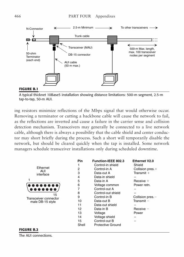
ing resistors minimize reflections of the Mbps signal that would otherwise occur.Removing a terminator or cutting a backbone cable will cause the network to fail,as the reflections are inverted and cause a failure in the carrier sense and collisiondetection mechanism. Transceivers may generally be connected to a live networkcable, although there is always a possibility that the cable shield and center conduc-tor may short briefly during the process. Such a short will temporarily disable thenetwork, but should be cleared quickly when the tap is installed. Some networkmanagers schedule transceiver installations only during scheduled downtime.
466 PART FOUR Appendixes
50-ohmTerminator(each end)
N-Connector
Transceiver (MAU)
DB-15 connector
AUI cable(50 m max.)
Trunk cable
2.5-m Minimum To other transceivers
500-m Max. length,max. 100 transceivernodes per segment
FIGURE B.1
A typical thicknet 10Base5 installation showing distance limitations: 500-m segment, 2.5-mtap-to-tap, 50-m AUI.
1
15Transceiver connector
male DB-15 style
EthernetAUI
interface
Pin Function-IEEE 802.3 Ethernet V2.0 1 Control-in shield Shield 2 Control-in A Collision pres.� 3 Data-out A Transmit � 4 Data-in shield – 5 Data-in A Receive � 6 Voltage common Power retn. 7 Control-out A – 8 Control-out shield – 9 Control-in B Collision pres.� 10 Data-out B Transmit � 11 Data-out shield – 12 Data-in B Receive � 13 Voltage Power 14 Voltage shield – 15 Control-out B – Shell Protective Ground
FIGURE B.2
The AUI connections.
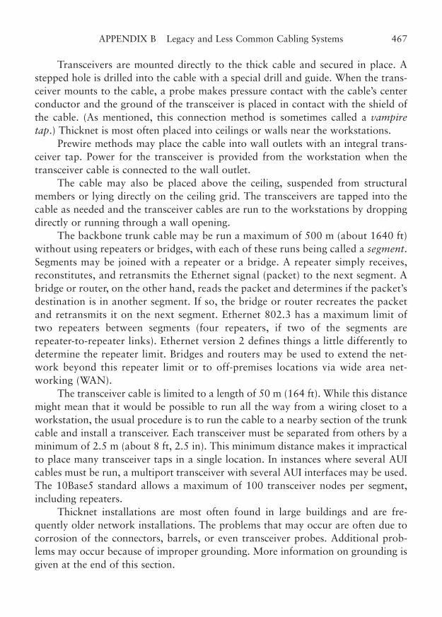
Transceivers are mounted directly to the thick cable and secured in place. Astepped hole is drilled into the cable with a special drill and guide. When the trans-ceiver mounts to the cable, a probe makes pressure contact with the cable’s centerconductor and the ground of the transceiver is placed in contact with the shield ofthe cable. (As mentioned, this connection method is sometimes called a vampiretap.) Thicknet is most often placed into ceilings or walls near the workstations.
Prewire methods may place the cable into wall outlets with an integral trans-ceiver tap. Power for the transceiver is provided from the workstation when thetransceiver cable is connected to the wall outlet.
The cable may also be placed above the ceiling, suspended from structuralmembers or lying directly on the ceiling grid. The transceivers are tapped into thecable as needed and the transceiver cables are run to the workstations by droppingdirectly or running through a wall opening.
The backbone trunk cable may be run a maximum of 500 m (about 1640 ft)without using repeaters or bridges, with each of these runs being called a segment.Segments may be joined with a repeater or a bridge. A repeater simply receives,reconstitutes, and retransmits the Ethernet signal (packet) to the next segment. Abridge or router, on the other hand, reads the packet and determines if the packet’sdestination is in another segment. If so, the bridge or router recreates the packetand retransmits it on the next segment. Ethernet 802.3 has a maximum limit oftwo repeaters between segments (four repeaters, if two of the segments arerepeater-to-repeater links). Ethernet version 2 defines things a little differently todetermine the repeater limit. Bridges and routers may be used to extend the net-work beyond this repeater limit or to off-premises locations via wide area net-working (WAN).
The transceiver cable is limited to a length of 50 m (164 ft). While this distancemight mean that it would be possible to run all the way from a wiring closet to aworkstation, the usual procedure is to run the cable to a nearby section of the trunkcable and install a transceiver. Each transceiver must be separated from others by aminimum of 2.5 m (about 8 ft, 2.5 in). This minimum distance makes it impracticalto place many transceiver taps in a single location. In instances where several AUIcables must be run, a multiport transceiver with several AUI interfaces may be used.The 10Base5 standard allows a maximum of 100 transceiver nodes per segment,including repeaters.
Thicknet installations are most often found in large buildings and are fre-quently older network installations. The problems that may occur are often due tocorrosion of the connectors, barrels, or even transceiver probes. Additional prob-lems may occur because of improper grounding. More information on grounding isgiven at the end of this section.
APPENDIX B Legacy and Less Common Cabling Systems 467
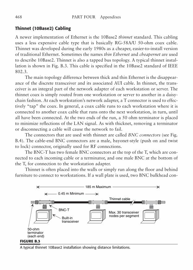
Thinnet (10Base2) Cabling
A newer implementation of Ethernet is the 10Base2 thinnet standard. This cablinguses a less expensive cable type that is basically RG-58A/U 50-ohm coax cable.Thinnet was developed during the early 1980s as a cheaper, easier-to-install versionof traditional Ethernet. Sometimes the names thin Ethernet and cheapernet are usedto describe 10Base2. Thinnet is also a tapped bus topology. A typical thinnet instal-lation is shown in Fig. B.3. This cable is specified in the 10Base2 standard of IEEE802.3.
The main topology difference between thick and thin Ethernet is the disappear-ance of the discrete transceiver and its associated AUI cable. In thinnet, the trans-ceiver is an integral part of the network adapter of each workstation or server. Thethinnet coax is simply routed from one workstation or server to another in a daisy-chain fashion. At each workstation’s network adapter, a T connector is used to effec-tively “tap” the coax. In general, a coax cable runs to each workstation where it isconnected to another coax cable that runs onto the next workstation, in turn, untilall have been connected. At the two ends of the run, a 50 ohm terminator is placedto minimize reflections of the LAN signal. As with thicknet, removing a terminatoror disconnecting a cable will cause the network to fail.
The connectors that are used with thinnet are called BNC connectors (see Fig.B.4). The cable-end BNC connectors are a male, bayonet-style (push on and twistto lock) connector, originally used for RF connections.
The BNC-T has two female BNC connectors at the top of the T, which are con-nected to each incoming cable or a terminator, and one male BNC at the bottom ofthe T, for connection to the workstation adapter.
Thinnet is often placed into the walls or simply run along the floor and behindfurniture to connect to workstations. If a wall plate is used, two BNC bulkhead con-
468 PART FOUR Appendixes
50� 50�
0.45 m Minimum
185 m Maximum
Thinnet cable
BNC-T
50-ohmterminator(each end)
Built-intransceiver
Max. 30 transceivernodes per segment
FIGURE B.3
A typical thinnet 10Base2 installation showing distance limitations.
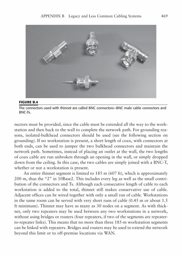
nectors must be provided, since the cable must be extended all the way to the work-station and then back to the wall to complete the network path. For grounding rea-sons, isolated-bulkhead connectors should be used (see the following section ongrounding). If no workstation is present, a short length of coax, with connectors atboth ends, can be used to jumper the two bulkhead connectors and maintain thenetwork path. Sometimes, instead of placing an outlet at the wall, the two lengthsof coax cable are run unbroken through an opening in the wall, or simply droppeddown from the ceiling. In this case, the two cables are simply joined with a BNC-T,whether or not a workstation is present.
An entire thinnet segment is limited to 185 m (607 ft), which is approximately200 m, thus the “2” in 10Base2. This includes every leg as well as the small contri-bution of the connectors and Ts. Although each consecutive length of cable to eachworkstation is added to the total, thinnet still makes conservative use of cable.Adjacent offices can be wired together with only a small run of cable. Workstationsin the same room can be served with very short runs of cable (0.45 m or about 1.5ft minimum). Thinnet may have as many as 30 nodes on a segment. As with thick-net, only two repeaters may be used between any two workstations in a network,without using bridges or routers (four repeaters, if two of the segments are repeater-to-repeater links). This means that no more than three 185-m workstation segmentscan be linked with repeaters. Bridges and routers may be used to extend the networkbeyond this limit or to off-premise locations via WAN.
APPENDIX B Legacy and Less Common Cabling Systems 469
FIGURE B.4
The connectors used with thinnet are called BNC connectors—BNC male cable connectors andBNC-Ts.
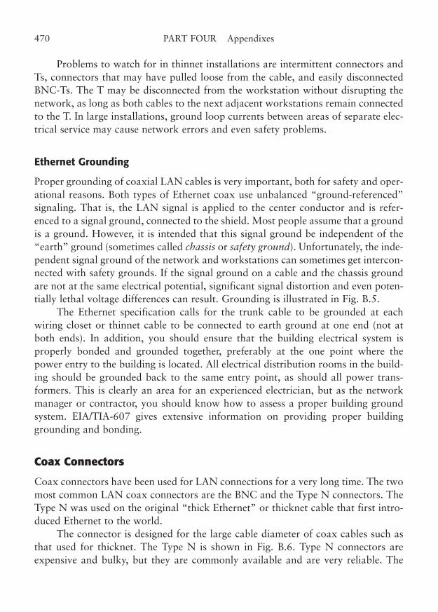
Problems to watch for in thinnet installations are intermittent connectors andTs, connectors that may have pulled loose from the cable, and easily disconnectedBNC-Ts. The T may be disconnected from the workstation without disrupting thenetwork, as long as both cables to the next adjacent workstations remain connectedto the T. In large installations, ground loop currents between areas of separate elec-trical service may cause network errors and even safety problems.
Ethernet Grounding
Proper grounding of coaxial LAN cables is very important, both for safety and oper-ational reasons. Both types of Ethernet coax use unbalanced “ground-referenced”signaling. That is, the LAN signal is applied to the center conductor and is refer-enced to a signal ground, connected to the shield. Most people assume that a groundis a ground. However, it is intended that this signal ground be independent of the“earth” ground (sometimes called chassis or safety ground). Unfortunately, the inde-pendent signal ground of the network and workstations can sometimes get intercon-nected with safety grounds. If the signal ground on a cable and the chassis groundare not at the same electrical potential, significant signal distortion and even poten-tially lethal voltage differences can result. Grounding is illustrated in Fig. B.5.
The Ethernet specification calls for the trunk cable to be grounded at eachwiring closet or thinnet cable to be connected to earth ground at one end (not atboth ends). In addition, you should ensure that the building electrical system isproperly bonded and grounded together, preferably at the one point where thepower entry to the building is located. All electrical distribution rooms in the build-ing should be grounded back to the same entry point, as should all power trans-formers. This is clearly an area for an experienced electrician, but as the networkmanager or contractor, you should know how to assess a proper building groundsystem. EIA/TIA-607 gives extensive information on providing proper buildinggrounding and bonding.
Coax Connectors
Coax connectors have been used for LAN connections for a very long time. The twomost common LAN coax connectors are the BNC and the Type N connectors. TheType N was used on the original “thick Ethernet” or thicknet cable that first intro-duced Ethernet to the world.
The connector is designed for the large cable diameter of coax cables such asthat used for thicknet. The Type N is shown in Fig. B.6. Type N connectors areexpensive and bulky, but they are commonly available and are very reliable. The
470 PART FOUR Appendixes
connectors are designed for use at many times the frequencies of Ethernet LANs, sotheir use in networks is no problem. The use of thicknet cable and the correspon-ding Type N connector has decreased greatly with the advent of thinnet cabling andits BNC connectors.
BNC coax connectors are smaller, less expensive connectors compared to theType N. BNC connectors are used with “thin Ethernet” or thinnet cable that wasintroduced during the 1980s as a cheaper alternative to thicknet. The BNC connec-tor is also used for ARCnet coax connections.
The typical measurements to prepare a coax cable for BNC termination areshown in Fig. B.7. BNC connectors are available in two- and three-piece construc-tions that are designed for termination using screw-on, crimp-on, or solder assembly.
The crimp-on style is the most popular for field termination of LAN cables.The assembly process is as follows. The crimp-on sleeve (of a three-piece connector)is placed over the end of the coax. The coax cable is stripped in the manner shown
APPENDIX B Legacy and Less Common Cabling Systems 471
Cable shieldbonded toground.
Thicknettrunkcable
Building ground
Bonding conductorbetween floors
Main wiring closet Intermediate wiring closet Wiring closet
etc.
Thicknet grounding
50W 50W
Thinnet grounding
Building ground
Thinnet cable segment
Bond tobuildingground
For best performance, thinnet is grounded only at oneend of the cable segment, not at intermediate points suchas other BNC-Ts. However, building and electrical codesmay require bonding on each floor or wiring closet. Bondingis always recommended at any building cable entrance.
FIGURE B.5
Typical grounding recommendations for coaxial Ethernet cabling.
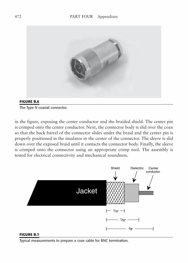
in the figure, exposing the center conductor and the braided shield. The center pinis crimped onto the center conductor. Next, the connector body is slid over the coaxso that the back barrel of the connector slides under the braid and the center pin isproperly positioned in the insulator in the center of the connector. The sleeve is sliddown over the exposed braid until it contacts the connector body. Finally, the sleeveis crimped onto the connector using an appropriate crimp tool. The assembly istested for electrical connectivity and mechanical soundness.
472 PART FOUR Appendixes
FIGURE B.6
The Type N coaxial connector.
7/32"
7/16"
5/8"
Jacket
Centerconductor
Shield Dielectric
FIGURE B.7
Typical measurements to prepare a coax cable for BNC termination.
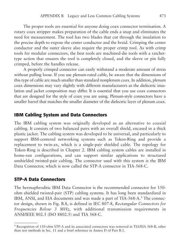
The proper tools are essential for anyone doing coax connector termination. Arotary coax stripper makes preparation of the cable ends a snap and eliminates theneed for measurement. The tool has two blades that cut through the insulation tothe precise depth to expose the center conductor and the braid. Crimping the centerconductor and the outer sleeve also require the proper crimp tool. As with crimptools for modular connectors, the best tools are machined-die tools with a ratchet-type action that ensures the tool is completely closed, and the sleeve or pin fullycrimped, before the handles release.
A properly crimped connector can easily withstand a moderate amount of stresswithout pulling loose. If you use plenum-rated cable, be aware that the dimensions ofthis type of cable are much smaller than standard nonplenum coax. In addition, plenumcoax dimensions may vary slightly with different manufacturers as the dielectric insu-lation and jacket composition may differ. It is essential that you use coax connectorsthat are designed for the style of coax you are using. Plenum-style connectors have asmaller barrel that matches the smaller diameter of the dielectric layer of plenum coax.
IBM Cabling System and Data Connectors
The IBM cabling system was originally developed as an alternative to coaxialcabling. It consists of two balanced pairs with an overall shield, encased in a thickplastic jacket. The cabling system was developed to be universal, and particularly tosupport IBM-centered networking systems such as Token-Ring and provide areplacement to twin-ax, which is a single-pair shielded cable. The topology forToken-Ring is described in Chapter 2. IBM cabling system cables are installed inhome-run configurations, and can support similar applications to structuredunshielded twisted-pair cabling. The connector used with this system is the IBMData Connector, which is now called the STP-A connector in TIA-568-C.
STP-A Data Connectors
The hermaphroditic IBM Data Connector is the recommended connector for 150-ohm shielded twisted-pair (STP) cabling systems. It has long been standardized inIBM, ANSI, and EIA documents and was made a part of TIA-568-A.3 The connec-tor design, shown in Fig. B.8, is defined in IEC 807-8, Rectangular Connectors forFrequencies Below 3 MHz, with additional transmission requirements inANSI/IEEE 802.5 (ISO 8802.5) and TIA 568-C.
APPENDIX B Legacy and Less Common Cabling Systems 473
3 Recognition of 150-ohm STP-A and its associated connectors was removed in TIA/EIA 568-B, otherthan test methods in Sec. 11 and a brief reference in Annex D of Part B.1.
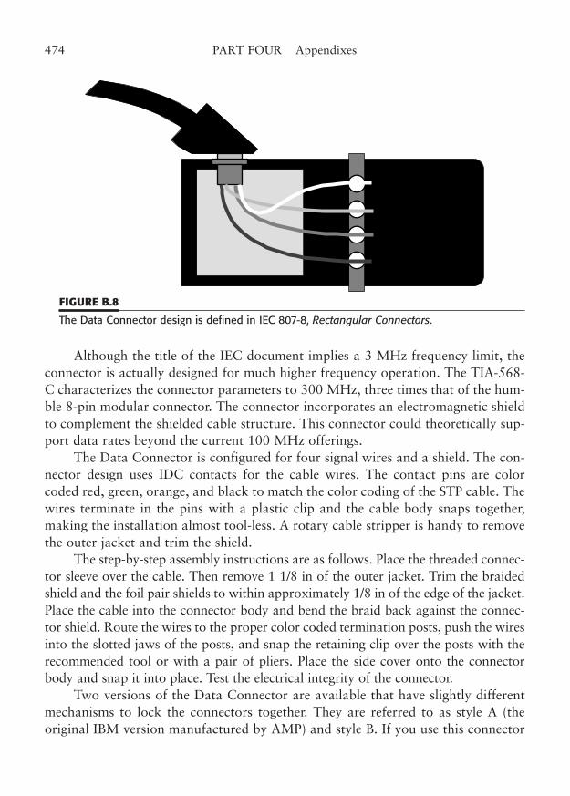
Although the title of the IEC document implies a 3 MHz frequency limit, theconnector is actually designed for much higher frequency operation. The TIA-568-C characterizes the connector parameters to 300 MHz, three times that of the hum-ble 8-pin modular connector. The connector incorporates an electromagnetic shieldto complement the shielded cable structure. This connector could theoretically sup-port data rates beyond the current 100 MHz offerings.
The Data Connector is configured for four signal wires and a shield. The con-nector design uses IDC contacts for the cable wires. The contact pins are colorcoded red, green, orange, and black to match the color coding of the STP cable. Thewires terminate in the pins with a plastic clip and the cable body snaps together,making the installation almost tool-less. A rotary cable stripper is handy to removethe outer jacket and trim the shield.
The step-by-step assembly instructions are as follows. Place the threaded connec-tor sleeve over the cable. Then remove 1 1/8 in of the outer jacket. Trim the braidedshield and the foil pair shields to within approximately 1/8 in of the edge of the jacket.Place the cable into the connector body and bend the braid back against the connec-tor shield. Route the wires to the proper color coded termination posts, push the wiresinto the slotted jaws of the posts, and snap the retaining clip over the posts with therecommended tool or with a pair of pliers. Place the side cover onto the connectorbody and snap it into place. Test the electrical integrity of the connector.
Two versions of the Data Connector are available that have slightly differentmechanisms to lock the connectors together. They are referred to as style A (theoriginal IBM version manufactured by AMP) and style B. If you use this connector
474 PART FOUR Appendixes
FIGURE B.8
The Data Connector design is defined in IEC 807-8, Rectangular Connectors.
in legacy applications, you should decide which style works best for you and stickwith it throughout your installation.
ARCnet
The ARCnet network type actually comprises a variety of physical wiring topolo-gies that share a common signaling protocol. ARCnet protocol is implemented as atoken-passing RF bus that combines some of the features of other network methods,although it was independently developed by Datapoint Corporation in the mid1970s. ARCnet can be implemented on coaxial cable, twisted-pair cable, fiber-opticcable, or a combination of the three. The defining factor is the particular type of net-work adapter cards (NICs) you choose.
ARCnet operates at 2.5 Mbps, although a newer ARCnetPlus at 20 Mbps hasbeen introduced. There are also proprietary implementations at 100 Mbps. Themethod of protocol operation is similar to Token-Ring, but without a physical ring.All stations are connected to a common bus.
When any station transmits, it is simultaneously (more or less) received by allother stations. A token is passed to each station, in a logical sequence, and a stationmust have the token to transmit. When a transmission is made, the receiving stationmakes an acknowledgment reply.
The topology of ARCnet can be a star, a bus, or a daisy-chain bus. The startopology may be used with coax, fiber, or twisted pair. The center of the star is eithera passive hub or an active hub. A passive hub simply combines all signal inputs (sothey may be shared), and provides impedance matching (to minimize reflections).Some of the signal is lost in this process, depending on the number of hub connec-tions, so passive hubs are limited to a small number of ports. Active hubs amplifyeach incoming signal and distribute it to the other ports. Passive hubs are used withcoax cable. Active hubs come in varieties for coax, twisted pair, or fiber. An exam-ple of an ARCnet star network is shown in Fig. B.9.
The ARCnet coaxial bus topology is shown in Fig. B.10. It is quite similar instructure to Ethernet thinnet, using coax cables with BNC-Ts and terminators.However, because it does not provide for any active signal amplification, it is gen-erally limited to about eight stations.
Several types of coax cable may be used for ARCnet, depending on the partic-ular NICs you are using. ARCnet may be used with RG-62/U coax at distances upto 2000 ft, which might be useful as a method to upgrade from IBM 3270 terminalsto PC networking without extensive rewiring. ARCnet is also used with 75-ohmRG-59/U and the larger RG-11/U coax. A table of cabling alternatives and some oftheir properties is shown in Table B.1.
APPENDIX B Legacy and Less Common Cabling Systems 475
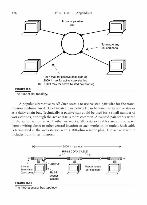
A popular alternative to ARCnet coax is to use twisted-pair wire for the trans-mission medium. An ARCnet twisted pair network can be wired as an active star oras a daisy-chain bus. Technically, a passive star could be used for a small number ofworkstations, although the active star is more common. A twisted-pair star is wiredin the same fashion as with other networks. Workstation cables are run outwardfrom a wiring closet or other central location to each workstation outlet. Each cableis terminated at the workstation with a 100-ohm resistor plug. The active star hubincludes built-in terminators.
476 PART FOUR Appendixes
Active or passivestar
Terminate anyunused ports
100 ft max for passive coax star leg2000 ft max for active coax star leg
100–500 ft max for active twisted pair star leg
FIGURE B.9
The ARCnet star topology.
93� 93�
2000 ft maximum
RG-62 COAX CABLE
BNC-T93-ohmTerminator(each end) Built-in
Arcnetadapter
Max. 8 nodesper segment
FIGURE B.10
The ARCnet coaxial bus topology.
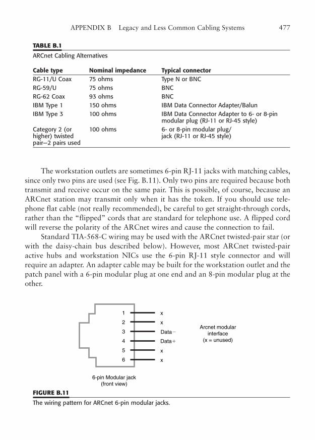
The workstation outlets are sometimes 6-pin RJ-11 jacks with matching cables,since only two pins are used (see Fig. B.11). Only two pins are required because bothtransmit and receive occur on the same pair. This is possible, of course, because anARCnet station may transmit only when it has the token. If you should use tele-phone flat cable (not really recommended), be careful to get straight-through cords,rather than the “flipped” cords that are standard for telephone use. A flipped cordwill reverse the polarity of the ARCnet wires and cause the connection to fail.
Standard TIA-568-C wiring may be used with the ARCnet twisted-pair star (orwith the daisy-chain bus described below). However, most ARCnet twisted-pairactive hubs and workstation NICs use the 6-pin RJ-11 style connector and willrequire an adapter. An adapter cable may be built for the workstation outlet and thepatch panel with a 6-pin modular plug at one end and an 8-pin modular plug at theother.
APPENDIX B Legacy and Less Common Cabling Systems 477
TABLE B.1
ARCnet Cabling Alternatives
Cable type Nominal impedance Typical connectorRG-11/U Coax 75 ohms Type N or BNC RG-59/U 75 ohms BNC RG-62 Coax 93 ohms BNC IBM Type 1 150 ohms IBM Data Connector Adapter/Balun IBM Type 3 100 ohms IBM Data Connector Adapter to 6- or 8-pin
modular plug (RJ-11 or RJ-45 style) Category 2 (or 100 ohms 6- or 8-pin modular plug/higher) twisted jack (RJ-11 or RJ-45 style) pair—2 pairs used
Data�
Data�
Arcnet modularinterface
(x = unused)
1
6
5
4
3
2
6-pin Modular jack(front view)
x
x
x
x
FIGURE B.11
The wiring pattern for ARCnet 6-pin modular jacks.
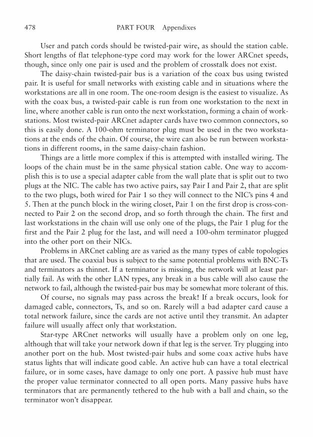
User and patch cords should be twisted-pair wire, as should the station cable.Short lengths of flat telephone-type cord may work for the lower ARCnet speeds,though, since only one pair is used and the problem of crosstalk does not exist.
The daisy-chain twisted-pair bus is a variation of the coax bus using twistedpair. It is useful for small networks with existing cable and in situations where theworkstations are all in one room. The one-room design is the easiest to visualize. Aswith the coax bus, a twisted-pair cable is run from one workstation to the next inline, where another cable is run onto the next workstation, forming a chain of work-stations. Most twisted-pair ARCnet adapter cards have two common connectors, sothis is easily done. A 100-ohm terminator plug must be used in the two worksta-tions at the ends of the chain. Of course, the wire can also be run between worksta-tions in different rooms, in the same daisy-chain fashion.
Things are a little more complex if this is attempted with installed wiring. Theloops of the chain must be in the same physical station cable. One way to accom-plish this is to use a special adapter cable from the wall plate that is split out to twoplugs at the NIC. The cable has two active pairs, say Pair I and Pair 2, that are splitto the two plugs, both wired for Pair 1 so they will connect to the NIC’s pins 4 and5. Then at the punch block in the wiring closet, Pair 1 on the first drop is cross-con-nected to Pair 2 on the second drop, and so forth through the chain. The first andlast workstations in the chain will use only one of the plugs, the Pair 1 plug for thefirst and the Pair 2 plug for the last, and will need a 100-ohm terminator pluggedinto the other port on their NICs.
Problems in ARCnet cabling are as varied as the many types of cable topologiesthat are used. The coaxial bus is subject to the same potential problems with BNC-Tsand terminators as thinnet. If a terminator is missing, the network will at least par-tially fail. As with the other LAN types, any break in a bus cable will also cause thenetwork to fail, although the twisted-pair bus may be somewhat more tolerant of this.
Of course, no signals may pass across the break! If a break occurs, look fordamaged cable, connectors, Ts, and so on. Rarely will a bad adapter card cause atotal network failure, since the cards are not active until they transmit. An adapterfailure will usually affect only that workstation.
Star-type ARCnet networks will usually have a problem only on one leg,although that will take your network down if that leg is the server. Try plugging intoanother port on the hub. Most twisted-pair hubs and some coax active hubs havestatus lights that will indicate good cable. An active hub can have a total electricalfailure, or in some cases, have damage to only one port. A passive hub must havethe proper value terminator connected to all open ports. Many passive hubs haveterminators that are permanently tethered to the hub with a ball and chain, so theterminator won’t disappear.
478 PART FOUR Appendixes
Other Network Types
Some other types of networks can operate in the office environment. Some of theseother technologies have similarities to standard Ethernet and Token-Ring, but arenot truly a part of those networking methods.
We will cover a few of the other networks here. As Ethernet twisted-pair tech-nology has become dominant, these network systems are truly deserving of beingcalled “other.” In some cases, many technologies, such as isochronous Ethernet and100VG-AnyLAN, are offered as alternatives to standard Ethernet, but are notwidely used. The Apple networking technologies and protocols have given way toEthernet and Internet protocol, for the most part.
100VG-AnyLAN
A new technology called 100VG-AnyLAN overcomes some of the distance andrepeater limitations of the 100BaseT and allows operation on 4-pair Category 3cable. The standard specification for 100VG-AnyLAN is contained in IEEE802.12.
The 100VG-AnyLAN technology is an interesting combination of asynchro-nous communication, such as that employed by Ethernet, and round-robin messagescheduling, such as that of Token-Ring. The 100VG-AnyLAN topology is an arbi-trated star arrangement, that is, a star with transmission control in the hub.Workstations and servers are on the legs of the star, with an intelligent hub at thecenter. The hub performs the functions of an arbitrated gateway and a switch. Aworkstation that wants to transmit a message makes a request to the hub. If thenetwork is idle, the request is granted. The workstation transmits its message andthe hub switches it to the proper outgoing port. If more than one station needs totransmit, the hub acknowledges each one in turn, according to a predeterminedpriority scheme.
The wiring systems supported by a 100VG-AnyLAN include 4-pair Category3 or higher UTP, 2-pair STP-A, and single or multimode optical fiber. The signalingrate on 4-pair UTP is kept low by splitting the signal into four data streams, one percable pair. The bandwidth requirement of approximately 15 MHz is within thecapability of standard Category 3 cabling. The wiring pattern for 100VG-AnyLANis the same as for any standard TIA-568-C cabling system.
Because 100VG-AnyLAN is not dependent on a collision detection mechanism,it is not subject to the distance limitations of unswitched Fast Ethernet. Some100VG-AnyLAN adapter implementations offer dual speed capabilities, as with the100BaseT products.
APPENDIX B Legacy and Less Common Cabling Systems 479
Isochronous Ethernet
One of the greatest challenges in integrating voice, data, and even video, is that thetechnologies heretofore have used entirely different means of encoding and trans-mitting information. The only practical solution has been to separate those signalsin separate cables, each routed to its respective switching or distribution equipment.Isochronous Ethernet proposes to end that divergent situation by combining multi-ple signals onto the same data stream, so that all three technologies can be simulta-neously carried on the same physical medium. Indeed, the technology actuallyallows quite a number of channels to be carried over the standard 100 m 4-paircable link. Isochronous Ethernet is standardized in IEEE 802.9, and the informationhere reflects the proposed draft revisions to become IEEE 802.9a.
Isochronous Ethernet uses a clever scheme of time-division multiplexing(TDM) and signal encoding to place a full 10 Mbps Ethernet channel plus an addi-tional 6 Mbps or so into the same composite signal. The total data rate in the sig-nal is 16.384 Mbps. A 4B/5B encoding scheme is used instead of the Manchestercoding of standard Ethernet. This yields a 10.24 MHz line transmission rate, thusmaking the signal well within the capabilities of Category 3 cable or higher cable.
Two modes of operation are available. In the multi-service mode, the signal isdivided into three user channels, the 10 Mbps (actually 10.016) Ethernet P-channel,a 6.144 Mbps bearer C-channel, and a 64 kbps signaling D-channel. The C-channelis easily further divided into 96 channels of 64 kbps subchannels. Of course, the sub-channels are exactly the same size as an ISDN bearer channel, so the network caneasily support data, digital voice, or compressed video. An alternative isochronous-only mode divides the total signal into 248 bearer subchannels, each of 64 kbps.
A third mode of operation allows the devices to operate as standard 10BaseT,Manchester encoded network interfaces, in full accordance with IEEE 802.3 andwith no support for the TDM channels.
AppleTalk/LocalTalk
AppleTalk has turned into a somewhat generic term that is generally used todescribe Apple LocalTalk networks. AppleTalk is actually a higher level protocolthat can be transported over several types of network topologies. The wiring forclassic LocalTalk is a low-speed two-wire bus that is usually run in a daisy-chainfashion from computer to computer.
The unique feature of most Apple computers since the introduction of theMacintosh is the built-in LocalTalk networking port. The provision of a built-in net-working capability has made printer sharing and file transfer a normal part of oper-ation with Apple computers.
480 PART FOUR Appendixes
The ease of networking, even though it is a slow, peer-to-peer method, has bothhelped and hurt Apple users. It has helped by making the network a quick and nat-ural solution to data and print sharing that must have made IBM-style PC users envi-ous (or at least confused). On the other hand, the relatively low speed andproprietary nature of the native network, without expensive upgrade modules forEthernet or Token-Ring, initially put AppleTalk users at a comparative disadvantage.
The original LocalTalk connection used a cumbersome shielded cable, but thenFarallon Computing made a compatible adaptation called PhoneNet on twisted pairwiring. This is the simple LocalTalk connection that most users are familiar with.Many users employ standard telephone cord to connect devices. This telephone cordis typically the flat silver-satin type 4-wire cable, although twisted-pair cable willwork even better. The network runs at only 230.4 kbps, so the normal crosstalk andattenuation problems are not as severe. LocalTalk can operate well on TIA-568-C.
The same comments apply to potential wiring problems with LocalTalk thatwere stated for any of the twisted-pair networks. Because LocalTalk can use ordi-nary flat phone wire, many users will simply purchase preassembled cables, whichhave few faults. However, this wiring method sometimes leads to long runs of wirebeing routed around furniture and across traffic areas. Any abrasions or cuts in thecable will have network consequences. Often a network must be split at some pointand terminated to diagnose such cable problems.
FDDI
Fiber Distributed Data Interface (FDDI) is a fiber-optic networking technology thatoperates at 100 Mbps. It employs dual, counter-rotating, token-passing rings. Thenetwork concept is actually fairly complex and is different from either Ethernet orToken-Ring.
Network nodes that sit on the primary fiber ring are called dual-attach nodesand employ a sophisticated automatic wraparound of the FDDI signal in the eventof a cut in the ring. This is somewhat akin to the backup path in Token-Ring, butthe fiber in an FDDI ring is expected to take a diverse path to the next node in line.In the event of a fiber cut or other failure, the dual-attach nodes at each end auto-matically loop back and the network continues without the missing component.
Each dual-attach node has two dual fiber connectors for a total of four individualfiber-optic connections. Each connector has a fiber input and output, but the FDDI signalactually passes from one input, through the node processor, and out the opposite connec-tor’s output fiber onto the next node. This produces dual signals in opposite directions.
Another type of node, called a single-attach node, implements the basic FDDIprotocol, but attaches point-to-point in a star fashion to a concentrating node. This
APPENDIX B Legacy and Less Common Cabling Systems 481
concentrating node is customarily on the actual ring (and is dual-attach), and bene-fits from its fault-tolerant design. The single-attach node lacks the loop back pathto its concentrator node, and so is normally used within the same building wherethe fiber cuts would be rare.
The FDDI topology is an American National Standards Institute (ANSI) stan-dard. The fiber is standard 62.5/125 mm fiber terminated in the unique duplexFDDI connector. Both multimode and single-mode fiber are supported, although theinterface module is different, since single mode requires a laser-diode transmitter. AnFDDI single-attach connection could be supported on a TIA-568-C fiber-optic link,but an adapter cable would have to be used to connect to the 568-SC connectors inthe workstation outlet.
Because FDDI is neither an Ethernet nor a Token-Ring protocol, those andother protocols are usually encapsulated into an FDDI packet and decoded at thereceiving station. This method simply uses the FDDI link as a transport mechanismthat frees one from the point-to-point nature of most WAN links.
ATM
Asynchronous transmission mode (ATM) is a very high speed communications pro-tocol that does not really imply a particular LAN topology. As a matter of fact, theATM protocol can be used over long distances in what is often called the wide areanetwork (WAN). The ATM protocol specifies a 53-byte “cell” that is somewhatanalogous to a packet or frame of conventional variable-length MAC-layer proto-cols. Unlike those protocols, the ATM cell does not always contain source and des-tination addresses, nor does it contain the higher-level addressing and control oflonger packets.
ATM is actually a very abbreviated point-to-point, switched protocol. An ATMmessage typically sets up a virtual connection between a source and destination,transmits cell-size chunks of the message, and ends the connection. The cells may gothrough many switching points before reaching the destination. The protocol allowscells to be received at the destination out of order and reordered before being pre-sented to the receiving application.
ATM can be transported at many rates and over a wide variety of media. ATMprotocol is implemented over copper and fiber at rates from about 25 Mbps to over2 Gbps. Because the protocol is not dependent on a particular connection scheme,many ATM-based technologies have emerged under the ATM umbrella. They are notthe same, and should be treated as separate topologies that share a common link basis.
Fiber implementations of ATM often run at SONETt physical parameters, suchas 155 Mbps OC3 and 2.4 Gbps OC48. Copper implementations have been intro-
482 PART FOUR Appendixes
duced at 25, 52, 100, and 155 Mbps. The 25 and 52 Mbps speeds are intended tooperate over Category 3 twisted-pair cabling. The current ATM UNI-155 standardrequires a full Category 5 link for operation.
You should be aware that the ATM speeds shown are rounded off from theactual data rates. For example, UNI-155 and OC3 actually run at 155.52 Mbps. Toget the exact data rate, multiply 51.84 Mbps by the multiple. For example, OC12would be 51.84 Mbps � 12, or 622.08 Mbps.
Not to be outdone by fiber optics, copper-based 622 Mbps technologies areunder development at this very moment. Watch your mailbox for details! Copperproponents claim that 1 GHz bandwidths are possible for twisted pair, although itis doubtful that this could be achieved with the present complement of connectorsand cabling.
Unlike the standard LAN topologies, ATM is a switched protocol. It is notreally suitable for standard bus or shared star (repeater-coupled) topologies. It doesnot imply a collision detection or a token passing mechanism. When used for aLAN, it is switched, with the physical switch being at the hub of a star of worksta-tion legs. Often, LAN protocols such as Ethernet or Token-Ring are transportedover ATM links via a method of LAN emulation.
APPENDIX B Legacy and Less Common Cabling Systems 483

This page intentionally left blank

APPENDIX C
Online Resources
485
Copyright © 2006 by James Trulove. Click here for terms of use.

World Wide Web—Internet Resources
For updated information on LAN wiring and links to standards groups, manufac-turers, and other resources, refer to www.LanWiringGuide.com.
Additional Web Resources
■ American National Standards Institute (ANSI) www.ansi.org ■ ATM Forum www.atmforum.com ■ Canadian Standards Association (CSA) www.csa-international.org ■ Electronic Industries Association (EIA) www.eia.org ■ Fiber Optic LAN Section (FOLS) of TIA www.fols.org ■ Gigabit Ethernet Alliance www.gigabit-ethernet.org ■ Institute of Electrical and Electronics Engineers www.ieee.org
(IEEE) standards.ieee.org ■ International Electrotechnical Commission (IEC) www.iec.ch ■ International Organization for Standards (ISO) www.iso.ch ■ ISO/IEC Joint Technical Committee 1 (JTC1) www.jtc1.org ■ Internet Engineering Task Force (IETF) www.ietf.org ■ Telecommunications Industry Association (TIA) www.tiaonline.org ■ Underwriters Laboratories (UL) www.ul.com ■ Underwriters Laboratories Canada (ULC) www.ulc.ca
Where to Order Copies of Standards on the Web
■ Global Engineering Documents global.ihs.com ■ Document Center Home Page www.document-center.com
Newsgroups
■ Data Communications—Cabling comp.dcom.cabling ■ Data Communications—LANs—Ethernet comp.dcom.lans.ethernet ■ Data Communications—LANs—Token-Ring comp.dcom.lans.token-ring
486 PART FOUR Appendixes

APPENDIX D
Standards Organizations
487
Copyright © 2006 by James Trulove. Click here for terms of use.

U.S. Standards Organizations
ANSI (American National Standards Institute)11 W. 42nd St., 13th Floor, New York, NY 10036212-642-4900(Originates, recognizes, and promulgates standards. ANSI is the U.S. member to theISO.)
ASTM (American Society for Testing and Materials)100 Barr Harbor Drive, West Conshohocken, PA 19428-2959610-832-9500(Develops standards and testing methods for materials.)
ATM Forum303 Vintage Park Drive, Foster City, CA 94404Info line, 415-578-6860; fax on demand, 415-688-4318; [email protected](Industry consortium for the development of ATM standards.)
EIA (Electronic Industries Association)2500 Wilson Blvd., Arlington, VA 22201703-907-7500(An industry organization that provides standards for electronic components andequipment.)
IEEE (Institute of Electrical and Electronics Engineers)345 East 47th St., New York, NY 10017212-705-7900 Order publications from IEEE Operations Center; see “Where to GetCopies of Standards” in Appendix C.(Professional engineering association that develops standards for electronic technol-ogy.)
NFPA (National Fire Protection Association1 Batterymarch Park, P.O. Box 9101, Quincy, MA 02269-9101617-770-3000To order publications, see “Where to Get Copies of Standards” in Appendix C.(Provides electrical code that is the basis of most local building codes. Generally rec-ognized as the authority on permitted uses and proper practice in electrical wiring,including LAN cabling.)
488 PART FOUR Appendixes

TIA (Telecommunication Industry Association)2500 Wilson Blvd., Arlington, VA 22201703-907-7700(An industry organization that provides standards for telecommunications compo-nents and equipment.)
UL (Underwriters Laboratories Inc.333 Pfingsten Rd., Northbrook, IL [email protected] UL offices worldwide.(Provides standards and testing services, including flammability standards and per-formance certifications for cable and connecting hardware.)
See www.LanWiringGuide.com for links to these and other standards organizations.
Other National Standards Organizations
Standards Council of Canada (SCC)178 Rexdale Blvd., Rexdale (Toronto), Ontario M9W 1R3, Canada 416-747-4000www.scc.ca
Canadian Standards Association (CSA)178 Rexdale Blvd., Etobicoke (Toronto), Ontario, M9W 1R3, Canada 416-747-4000; fax 416-747-4149 (In United States and Canada, call toll free 1-800-463-6727)[email protected]@csa-international.org
Deutsches Institut für Normung (DIN)Burggrafenstrasse 6, DE-10787 Berlin, Germany+49 30 26 01-0; fax +49 30 26 01 12 31www.din.de; [email protected]
Underwriters’ Laboratories of Canada (ULC)7 Crouse Rd., Toronto, Ontario M1R 3A9, Canada [email protected]; www.ulc.ca
APPENDIX D Standards Organizations 489

Appendixes
See www.LanWiringGuide.com for links to these and other standards organizations.
International Standards Organizations
International Organization for Standardization (ISO)1, rue de Varembé, Case postale 56, CH-1211 Genève 20, Switzerland+41 22 749 01 11; fax +41 22 733 34 [email protected](A university-sponsored Internet site is available at http://www.iso.ch/infoe/order.html.)
International Electrotechnical Commission (IEC)3, rue de Varembé, Case Postale 131, CH-1211 Genève 20, Switzerland+41 22 919 02 11
See www.LanWiringGuide.com for links to these and other standards organizations.
490 PART FOUR Appendixes
APPENDIX E
Standards for LAN Wiring1
491
1 Note: Selected standards that apply to LAN wiring are shown. The standards organizations marked with anasterisk do not supply copies of standards directly. Standards for these organizations may be obtained fromthe sources listed in “Where to Get Copies of Standards,” later in this Appendix.
Copyright © 2006 by James Trulove. Click here for terms of use.
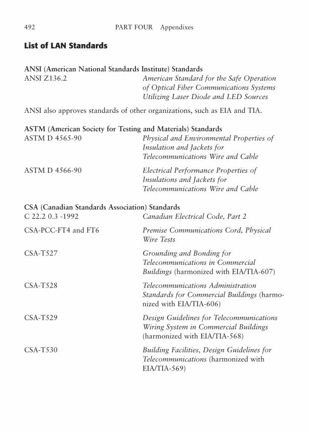
List of LAN Standards
ANSI (American National Standards Institute) StandardsANSI Z136.2 American Standard for the Safe Operation
of Optical Fiber Communications SystemsUtilizing Laser Diode and LED Sources
ANSI also approves standards of other organizations, such as EIA and TIA.
ASTM (American Society for Testing and Materials) StandardsASTM D 4565-90 Physical and Environmental Properties of
Insulation and Jackets forTelecommunications Wire and Cable
ASTM D 4566-90 Electrical Performance Properties ofInsulations and Jackets forTelecommunications Wire and Cable
CSA (Canadian Standards Association) StandardsC 22.2 0.3 -1992 Canadian Electrical Code, Part 2
CSA-PCC-FT4 and FT6 Premise Communications Cord, PhysicalWire Tests
CSA-T527 Grounding and Bonding forTelecommunications in CommercialBuildings (harmonized with EIA/TIA-607)
CSA-T528 Telecommunications AdministrationStandards for Commercial Buildings (harmo-nized with EIA/TIA-606)
CSA-T529 Design Guidelines for TelecommunicationsWiring System in Commercial Buildings(harmonized with EIA/TIA-568)
CSA-T530 Building Facilities, Design Guidelines forTelecommunications (harmonized withEIA/TIA-569)
492 PART FOUR Appendixes
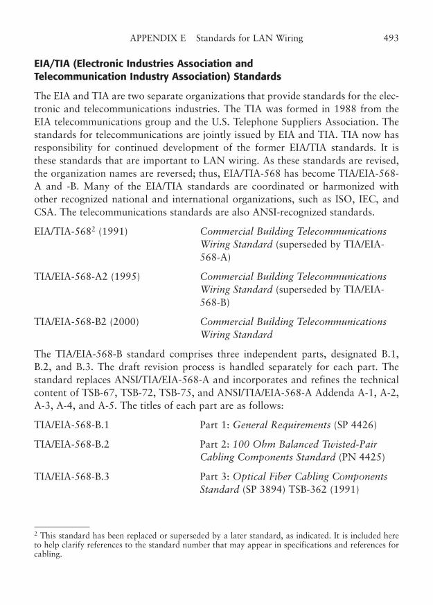
EIA/TIA (Electronic Industries Association and Telecommunication Industry Association) Standards
The EIA and TIA are two separate organizations that provide standards for the elec-tronic and telecommunications industries. The TIA was formed in 1988 from theEIA telecommunications group and the U.S. Telephone Suppliers Association. Thestandards for telecommunications are jointly issued by EIA and TIA. TIA now hasresponsibility for continued development of the former EIA/TIA standards. It isthese standards that are important to LAN wiring. As these standards are revised,the organization names are reversed; thus, EIA/TIA-568 has become TIA/EIA-568-A and -B. Many of the EIA/TIA standards are coordinated or harmonized withother recognized national and international organizations, such as ISO, IEC, andCSA. The telecommunications standards are also ANSI-recognized standards.
EIA/TIA-5682 (1991) Commercial Building TelecommunicationsWiring Standard (superseded by TIA/EIA-568-A)
TIA/EIA-568-A2 (1995) Commercial Building TelecommunicationsWiring Standard (superseded by TIA/EIA-568-B)
TIA/EIA-568-B2 (2000) Commercial Building TelecommunicationsWiring Standard
The TIA/EIA-568-B standard comprises three independent parts, designated B.1,B.2, and B.3. The draft revision process is handled separately for each part. Thestandard replaces ANSI/TIA/EIA-568-A and incorporates and refines the technicalcontent of TSB-67, TSB-72, TSB-75, and ANSI/TIA/EIA-568-A Addenda A-1, A-2,A-3, A-4, and A-5. The titles of each part are as follows:
TIA/EIA-568-B.1 Part 1: General Requirements (SP 4426)
TIA/EIA-568-B.2 Part 2: 100 Ohm Balanced Twisted-PairCabling Components Standard (PN 4425)
TIA/EIA-568-B.3 Part 3: Optical Fiber Cabling ComponentsStandard (SP 3894) TSB-362 (1991)
APPENDIX E Standards for LAN Wiring 493
2 This standard has been replaced or superseded by a later standard, as indicated. It is included hereto help clarify references to the standard number that may appear in specifications and references forcabling.
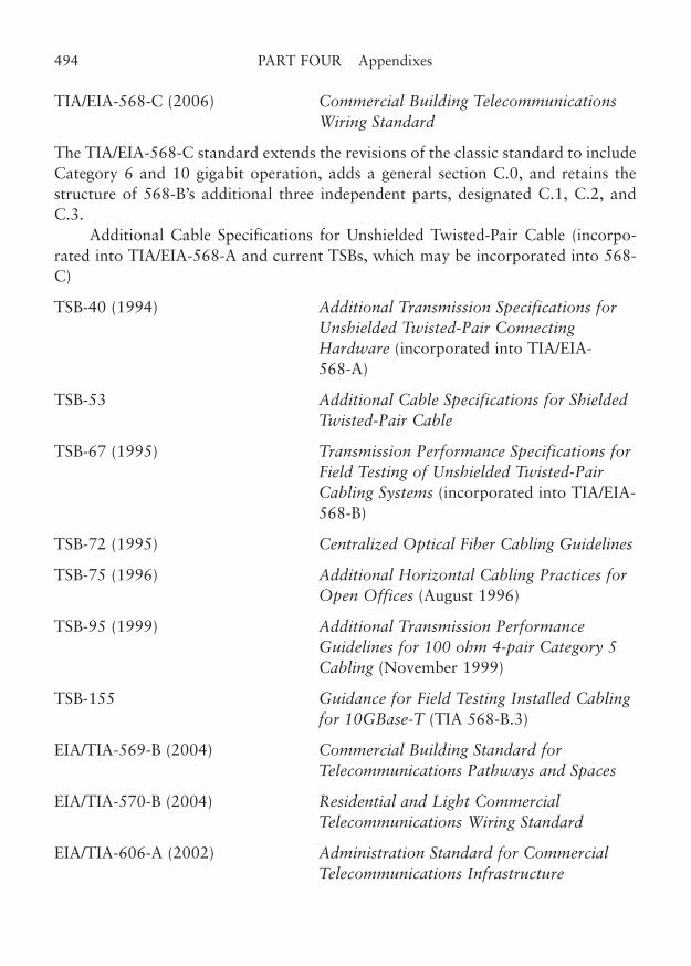
TIA/EIA-568-C (2006) Commercial Building TelecommunicationsWiring Standard
The TIA/EIA-568-C standard extends the revisions of the classic standard to includeCategory 6 and 10 gigabit operation, adds a general section C.0, and retains thestructure of 568-B’s additional three independent parts, designated C.1, C.2, andC.3.
Additional Cable Specifications for Unshielded Twisted-Pair Cable (incorpo-rated into TIA/EIA-568-A and current TSBs, which may be incorporated into 568-C)
TSB-40 (1994) Additional Transmission Specifications forUnshielded Twisted-Pair ConnectingHardware (incorporated into TIA/EIA-568-A)
TSB-53 Additional Cable Specifications for ShieldedTwisted-Pair Cable
TSB-67 (1995) Transmission Performance Specifications forField Testing of Unshielded Twisted-PairCabling Systems (incorporated into TIA/EIA-568-B)
TSB-72 (1995) Centralized Optical Fiber Cabling Guidelines
TSB-75 (1996) Additional Horizontal Cabling Practices forOpen Offices (August 1996)
TSB-95 (1999) Additional Transmission PerformanceGuidelines for 100 ohm 4-pair Category 5Cabling (November 1999)
TSB-155 Guidance for Field Testing Installed Cablingfor 10GBase-T (TIA 568-B.3)
EIA/TIA-569-B (2004) Commercial Building Standard forTelecommunications Pathways and Spaces
EIA/TIA-570-B (2004) Residential and Light CommercialTelecommunications Wiring Standard
EIA/TIA-606-A (2002) Administration Standard for CommercialTelecommunications Infrastructure
494 PART FOUR Appendixes

EIA/TIA-607 (2002) Commercial Building Grounding (Earthing)and Bonding Requirements forTelecommunications (ANSI/TIAEIA-J-STD-607)
Note: The term TSB was formerly “Technical Systems Bulletin” when these standardswere managed by the EIA. The TIA term was changed to “TelecommunicationsSystems Bulletin” for TIA standard supplements, beginning with TBSs issued afterthe 568-A revision to the primary commercial cabling standard.
All of the above EIA/TIA standards shown are approved by the AmericanNational Standards Institute (ANSI).
IEEE (Institute of Electrical and Electronic Engineers) Standards
IEEE/ISO 8802-3 (IEEE 802.3) Information Technology—Local and MetropolitanArea Networks—Part 3: Carrier Sense Multiple Access with Collision Detection(CSMA/CD) Access Method and Physical Layer Specifications (and Supplements J,K, L, and P-Q)
IEEE/ISO 8802-5 (IEEE 802.5) Information Technology—Local and MetropolitanArea Networks—Part 5: Token Ring Access Method and Physical LayerSpecifications (and Supplements B, C, and J)
IEEE 802.11 Wireless LAN Medium Access Control (MAC) and Physical Layer(PHY) Specifications—commonly known as WiFi
IEEE 802.12 Standard for Demand Priority Access Method. Physical Layer andRepeater Specifications for 100 Megabits per Second Operation
IEEE 802.16 Air Interface for Fixed Broadband Wireless Access Systems—com-monly known as WiMAX
Note: IEEE Standards 802.2, 802.3, 802.4, 802.5, and 802.6 are now ISO-approvedand have been renumbered to match the ISO numbering system.
ISO/IEC (International Standards Organization/International Electrotechnical Commission) Standards
IEC 603-7 Connectors for frequencies below 3 MHz for use with printed boards
IEC 807-8 Rectangular Connectors for Frequencies below 3 MHz, Part 8: DetailSpecification for Connectors, Four-Signal Contacts, and Earthing Contacts forCable, First Edition
APPENDIX E Standards for LAN Wiring 495

ISO/IEC 11801 (1995) Information technology—Generic cabling for customerpremises
Note: ISO/IEC 11801 corresponds to TIA/EIA 568-B. Additional ISO-approvedstandards are listed in the IEEE section. ISO standards may be ordered from the ISOmember in each member country (ANSI in the United States) or from the documentdistributors listed in “Where to Get Copies of Standards” later in this Appendix.
NFPA (National Fire Protection Association) Standards
National Electrical Code®
2005 ISBN 0-87765-432-8 National Electrical Code Handbook, 2005 ISBN 0-87765-437-9Order from NFPA at 1-800-344-3555 or by ISBN from any bookstore.
UL (Underwriters Laboratories) Standards
UL 910(Flamespread tests) UL 1863 Standard for Communication Circuit Accessories
Where to Get Copies of Standards
Direct sales from standards organizations:
ANSI and ISO StandardsAmerican National Standards Institute 11 W. 42nd St., 13th Floor, New York, NY 10036212-642-4900
ATM Forum StandardsThe ATM Forum 303 Vintage Park Dr., Foster City, CA 94404Info line, 415-578-6860; fax on demand, 415-688-4318; [email protected]
IEEE StandardsIEEE Operations Center 445 Hoes Lane, P.O. Box 1331, Piscataway, NJ 08855-13311-800-678-4333 or 908-562-0060
496 PART FOUR Appendixes

National Fire Protection Association StandardsNFPA Headquarters 1 Batterymarch Park, P.O. Box 9101, Quincy, MA 02269-91011-800-344-3555 or 617-770-3000
UL StandardsUnderwriters Laboratories Inc.333 Pfingsten Rd., Northbrook, IL 60022-20961-800-676-9473 or 1-800-786-9473 or 708-272-8800
CSA Standards
Canadian Standards Association 178 Rexdale Blvd., Rexdale (Toronto), Ontario M9W 1R3, CanadaOrders, 416-747-4044; main, 416-747-4000
Document Distributors
Most of the standards from the above organizations and standards from EIA, TIA,ANSI, ISO, ASTM, CSA, and other standards organizations are available from thefollowing document distributors:
Global Engineering Documents15 Inverness Way East, Englewood, CO 80112-57661-800-854-7179 (United States and Canada); 303-792-2181; global.ihs.com
Document Center1504 Industrial Way, Unit 9, Belmont, CA 94002415-591-7600; www.document-center.com
For additional information on availability of standards documents, see the stan-dards sections at http://www.LanWiringGuide.com.
APPENDIX E Standards for LAN Wiring 497

This page intentionally left blank
APPENDIX F
Membership and TrainingOrganizations
499
Copyright © 2006 by James Trulove. Click here for terms of use.
Membership Organizations
The following organizations are of general interest to those involved in LANs andLAN wiring.
BICSIBICSI: A Telecommunications Association8610 Hidden River Pkwy., Tampa, FL 33637-1000800-242-7405; 813-979-1991(A membership organization for individuals and companies. Provides designer andinstaller certifications, building guidelines handbook.)
EIAElectronic Industries Association2500 Wilson Blvd., Arlington, VA 22201703-907-7500(An industry organization that develops standards for a wide range of devices, fromsemiconductors to complex electronic equipment. The original parent of TIA.)
IEEEInstitute of Electrical and Electronics Engineers345 East 47th St., New York, NY 10017212-705-7900(A professional membership organization for individuals with extensive educationaland standards activities. Develops standards for LAN networking of several types,including Ethernet, Token-Rring, and AnyLAN.)
NFPANational Fire Protection Association1 Batterymarch Park, P.O. Box 9101, Quincy, MA 02269-9101 617-770-3000(A membership organization for individuals and companies that develops fire safetyand electrical standards. Publishes the National Electrical Code that is used as abasis for building codes worldwide.)
TIATelecommunication Industries Association2500 Wilson Blvd., Arlington, VA 22201 703-907-7700
500 PART FOUR Appendixes

(An industry organization for the telecommunications industry. Develops fortelecommunications wiring, including the TIA-568-C standard. Originally part ofEIA.)
Training and Certification Organizations
The following organizations offer workshops, seminars, trade shows, trainingclasses, videos, and formal certification programs for the LAN wiring industry.
BICSI: A Telecommunications Association8610 Hidden River Pkwy., Tampa, FL 33637-1000800-242-7405; 813-979-1991
Association of Cabling Professionals (ACP)4160 Southside Blvd., Suite 3, Jacksonville, FL 32216-5470 904-645-6018; fax 904-645-3181
Cabling Business Magazine12035 Shiloh Rd., Suite 350, Dallas, TX 75228 214-328-1717; fax 214-319-6077
Cabling Business Institute12035 Shiloh Rd., Suite 350, Dallas, TX 75228 214-328-1717; www.cablingbusiness.com
Cabling Installation and Maintenance98 Spit Brook, Nashua, NH 03062-5737 603-891-0123; fax 603-891-0587; www.cable-install.com
APPENDIX F Membership and Training Organizations 501

This page intentionally left blank

Index
Note: Boldface numbers indicate illustrations. Italic t indicates a table.
503
10 Gigabit Ethernet. See gigabit and 10 giga-bit Ethernet, 277
10Base2, 42, 453–454, 468–470, 46810Base5, 42, 454–455, 454t, 465–467, 46610BaseF, 26410BaseFB, 26510baseFL, 258, 26510BaseT, 13, 19, 42, 43–49
connectorized patch panels in, 196–199,197
connectors, jacks and, 139, 219cross-connects and, 209fiber-optics and, 265user and equipment cords and, 229
10GBase, 30310GBaseCX, 55–5610GBaseLR, 55–56, 26310GBaseLX4, 55–56, 303–304
fiber-optics and, 26310GBaseSR, 26310GBaseSX, 55–5610GBaseT, 43, 55–56100BaseFX, 13, 53–54
fiber-optics and, 258, 264100BaseSX, 54100BaseT (Fast Ethernet), 8, 9, 11, 42–49,
85, 279, 370Category 5 and, 86connectorized patch panels in, 196–199, 197connectors, jacks and, 139, 219
100BaseT (Fast Ethernet) (continued)cross-connects and, 209fiber-optics and, 260
100BaseT4, 19, 51–52, 52, 284connectors, jacks and, 139
100BaseTX, 13, 19, 50–51, 50, 291connectors, jacks and, 139
100BaseVG-AnyLAN, 19, 42, 284cross-connects and, 209connectors, jacks and, 139, 219
110 block. See Type 110 connecting blocks,155
1000BaseCX, 286, 286t1000BaseELX, 280–281, 280t1000BaseEW, 304t1000BaseF, 2641000BaseLR, 304t1000BaseLW, 304t1000BaseLX, 13, 54–55, 280–281, 280t1000BaseLX4, 304t1000BaseSLX, 280–281, 280t1000BaseSR, 304t1000BaseSW, 304t1000BaseSX, 13, 54–55, 280–281, 280t1000BaseT, 11, 13, 19, 42–43, 284–285, 284t
connectors, jacks and, 139, 219cross-connects and, 209
1000BaseTR, connectors, jacks, 1391000baseTX, connectors, jacks, 1391000BaseZX, 280–281, 280t
Copyright © 2006 by James Trulove. Click here for terms of use.

6M connecting block. See Type 66M con-necting blocks, 160
802.11 WiFi, 314
AB/BA fiber polarity orientation,178–180, 178
access control, in wireless LANs, 329access point servers
wireless LANs and, 324–325, 325access points (APs)
Power over Ethernet (PoE) for accesspoints in, 342–344, 342
wireless LANs and, 329–330, 330,341–342, 341
accessibility, in telecommunication rooms(TR), 358–359
accuracy levels, 381, 382tadapters, fiber-optics, 141, 179, 179advances in LAN wiring, 5–6alien crosstalk (ANEXT), 10-Gigabit
Ethernet, 306, 307American National Standards Institute
(ANSI), 482, 486, 487, 492, 496American Society for Testing and
Materials (ASTM), 487, 492American Wire Gauge (AWG), 98–99,
450, 450tanalog vs. digital field testers, 400–402ANSI Z136.2, 183, 492ANSI/IEEE 802.5, 473ANSI/TIA/EIA-568, 62ANSI/TIA/EIA-606-A, 237ANSI/TIA/EIA–568–B Commercial
Building Telecommunication WiringStandard, 19
antenna operation, wireless LANs,316–319, 319, 334–335
appearance telecommunication rooms(TR) and wire management,358–359
AppleTalk/LocalTalk, 19, 42, 480–481arbitrated star topology, 479ARCnet, 19, 42, 475–478, 476, 477t, 477
coax and, 218, 454connectors, jacks and, 139
armoring, fiber-optics, 116–117ARPANET, 38Association of Cabling Professionals
(ACP), 442, 444, 501ASTM D 4565-90, 492Asynchronous Transmission Mode
(ATM), 19, 32, 42, 85, 278,482–483
connectors, jacks and, 139cross-connects and, 209Gigabit Ethernet and, 286–288, 288twireless LANs and, 328
Asynchronous Transmission Mode (ATM)Forum, 18–19, 487, 496
AT&T, 25, 68–70, 139, 197punchdown blocks and. See punchdown
blocks, 155ATM–155 UNI, 286attachment unit interface (AUI), 265,
465–466, 466tattenuation, 14–15
attenuation to crosstalk ratio (ACR) in,293, 310
coax and, 455fiber-optics and, 114–115Gigabit Ethernet and, 291–292,
295–296patch cords and, 204, 205ttesting and, 385, 386, 388–390, 389ttwisted-pair (UTP/STP) and, 100wireless LANs and, 313–314, 316
attenuation to crosstalk ratio (ACR), 86,293, 310, 386, 391
Avaya/Lucent (AT&T) Systimax PDS,68–70, 71t, 139, 269
backbone cabling, 13, 20, 29–32, 154,362–365
coax and, 467color codes for, 32daisy chains in, 30, 31fiber-optics and, 32, 260fire and safety standards in, 31, 32Gigabit Ethernet and, 290, 297, 298hub location in, 29–30, 362–363, 364
504 Index

backbone cabling (continued)modular plugs in, 31–32repeater type, 362–363, 364riser cables in, 31star topology in, 30, 31telecommunication rooms (TR) and,
352–354Token-Ring in, 30wire management and, 352–354
backup/uninterruptible power supplies(UPS), 361–362
balance, testing, requirements, 373–375,375t
balanced circuit, twisted-pair (UTP/STP),98, 98
balun transformers, twisted-pair(UTP/STP), 100
banana probe, 397bandwidth, 66, 84–85
fiber-optics and, 110, 113–115,256–258, 256, 257, 259–260
Basic Link, 201–202, 379, 380, 384, 385testing and, 386–388, 401user and equipment cords and, 226
beamwidth, wireless LANs, 318bend radius, 28, 185
fiber-optics and, 182kinked, bent, broken wires in, 419–420,
426–427bends in cabling, 28BICSI and BICSI certification, 83, 442,
444, 500, 501bill of materials for wiring, 34, 35binder groups, twisted-pair (UTP/STP),
colors of, 106biscuit blocks, 127, 127BIX connecting blocks, 168–170, 169, 193blown-in fiber optic cable, 309Bluetooth wireless LANs, 315, 320,
326–328BNC connectors, 143, 148–149, 252,
468–469, 469, 470–473, 472break-out box, 182bridges, wireless LANs, locating,
333–334, 333
broken wires, 417–418buffer, in fiber-optics, 248Building Industry Consulting Service
International Inc. See BICSIBuild Your Own Wireless LAN, 312, 342bundling, tieing, securing cable, 28bus topology, 40–42, 41butt set, 397
C-22.2 0.3-1992, 492cable administration tools, documentation,
413cable scanners, 398–400, 399, 400cable system designer, 437cable tracers, 397–398, 387cable trays and hangers, 267–268cable-end connectors for user and equip-
ment cords, 218–225. See alsoconnectors and jacks
1000BaseT, 219100BaseT, 219100VG-AnyLAN, 21910baseT, 219Category 5e and, 220Category 6 and, 220crimp tool for, 224–225, 224dimensions for, 223, 223modular connectors in, 218–225NEXT and, 220, 225pin numbering for, 221, 222, 223–224problems and troubleshooting with, 225RJ numbered, 219RJ-11 connectors, 219RJ-45 connectors, 219–220, 295shielded, 221terminating wires in, 224Token-Ring, 219twisted-pair and, 220–221, 221universal service order code (USOC)
numbers in, 219cables vs. cords, terminology of, 202Cabling Business Institute, 501Cabling Business Magazine, 443, 501Cabling Installation & Maintenance
magazine, 443
Index 505
Cabling Installation and Maintenanceorganization, 501
cabling installers, 37, 439–440cabling technicians, 438–439Canadian Standards Association (CSA),
25, 368, 486, 488, 492, 497. Seealso CSAxx standards
CAP-64 encoding, 85capacitance
coax and, 455testing and, requirements, 373–375, 375ttwisted-pair (UTP/STP) and, 100
carrier frequency in wireless LANs, 314carrier sense multiple access with collision
detection (CSMA/CD), 464categories of cable and connectors, 6,
66–68, 66t, 85–87, 86taccuracy levels, 381, 382tapplications and recommendations, 15tconnectors, jacks and, 140, 140tconsolidation points and, 236cross-connects and, 207–208, 207enhanced Category X in, 86–87Gigabit Ethernet and, 298–299ISO/IEC classes and, 380–381, 381tmarkings for, 375, 376mismatches and errors of application in,
423–424user and equipment cords and, 226,
227–228Category 1, 66
connectors, jacks and, 140, 140tCategory 2, 66
connectors, jacks and, 140, 140tcross-connects and, 207
Category 3, 6, 13, 66, 67, 370100baseT4 in, 52100BaseTX in, 50–51, 50100VG-AnyLAN and, 479asynchronous transmission mode (ATM)
and, 483connectors, jacks and for, 24, 132, 140,
140tcross-connects and, 207–208data rates and speed of, 86t
Category 3 (continued)Ethernet and, 46, 48Gigabit Ethernet and, 279, 293, 301isochronous Ethernet in, 480location and routing of cables in, 32markings for, 375, 376NEXT limits for, 371–375, 372t, 374tpatch panel termination in, 28–29, 193,
194performance level testing, 370–375SONET and, 483station wire performance standards for,
25Token-Ring and, 57–58twisted-pair (UTP/STP) and, 97Type 66M connecting blocks in,
165–167wire twist preservation in, 184–185,
185twork area outlets and, 122
Category 4, 66100BaseTX in, 50–51, 50connectors, jacks and, 24, 132, 140,
140tpatch panel termination in, 28–29, 28Token-Ring and, 57–58
Category 5, 66100BaseTX in, 50–51, 50connectors, jacks and, 132, 140, 140tdata rates and speed of, 85, 86tFast Ethernet and, 86Gigabit Ethernet and, 290–291,
293–296, 301markings for, 375, 376NEXT limits for, 371–375, 372t, 374tperformance level testing, 370–375Token-Ring and, 57–58twisted-pair (UTP/STP) and, 97
Category 5e, 6, 13, 22, 37, 66, 67, 370100/1000-Mbps networking compatibil-
ity and, 81–83, 82t1000BaseT in, 284–285, 284t100BaseT4 in, 52100BaseTX in, 50–51, 50backbone wiring for, 31
506 Index
Category 5e (continued)connectorized patch panels in, 198connectors, jacks and, 24, 36, 132, 139,
140, 140t, 220consolidation points and, 236cross-connects and, 207–208, 209data rates and speed of, 85–86, 86t, 110Ethernet and, 46, 48, 55Gigabit Ethernet and, 86, 279,
284–285, 291, 292t, 298–299high-speed networking and, 91insulation in, 102location and routing of cables in, 32markings for, 375, 376NEXT limits for, 85–86, 371–375, 372t,
374topen office wiring and, 234patch panel termination in, 28–29, 190,
193, 194performance level testing, 370–375standoffs and distribution rings in,
172–173, 173, 174station wire performance standards for,
25training and certification for, 83–84tubing pulls and, 92Type 110 connecting blocks in,
155–160, 156Type 66M connecting blocks in,
165–167user and equipment cords and, 229wire management and, 174, 359wire twist preservation in, 184–185,
185twork area outlets and, 122
Category 6, 13, 22, 37, 67, 370100/1000-Mbps networking compatibil-
ity and, 81–83, 82t100BaseTX in, 50–51, 50backbone wiring for, 31connectorized patch panels in, 198connectors, jacks and for, 24, 132, 140,
140t, 220consolidation points and, 236cross-connects and, 207–208, 209
Category 6 (continued)data rates and speed of, 86tEthernet and, 46, 55fiber-optics and, 88Gigabit Ethernet and, 86, 284–285,
293–295, 294t, 298–299high-speed networking and, 91location and routing of cables in, 32patch panel termination in, 28–29, 190,
194standoffs and distribution rings in,
172–173, 173, 174training and certification for, 83–84tubing pulls and, 92Type 110 connecting blocks in,
155–160, 156Type 66M connecting blocks in,
165–167user and equipment cords and, 229wire management and, 174, 359wire twist preservation in, 184–185, 185t
Category (Augmented) 6 (AC6), 10-Gigabit Ethernet and, 306–307100/1000-Mbps networking compatibil-
ity and, 81–83, 82t10–GB Ethernet and, 86connectors, jacks and, 140, 140tconsolidation points and, 236Gigabit Ethernet and, 284–285,
293–295, 294t, 298–299high-speed networking and, 91patch-panel termination in, 190training and certification for, 83–84tubing pulls and, 92Type 110 connecting blocks in,
155–160, 156Type 66M connecting blocks in,
165–167Category 7, 13, 22–23, 37, 67
10-Gigabit Ethernet and, 307–309, 308100/1000-Mbps networking compatibil-
ity and, 81–83, 82t10–Gb Ethernet and, 86connectors, jacks and, nonmodular
jacks for, 136–137, 140, 140t
Index 507

Category 7 (continued)data rates and speed of, 86tEthernet and, 55–56fiber-optics patches and cords in,
213–216, 215Gigabit Ethernet and, 284–285,
293–295, 294ttraining and certification for, 83–84tubing pulls and, 92wire management and, 359
CATV, 8CDPD, in wireless LANs, 315centralized fiber-optics cabling (TSB–72
and TIA–568–C), 261–263, 262certification of cabling, cable plant,
377–378certification. See training and certification,
431Channel, 17, 201–202, 380, 384, 385
testing of, 386–388, 401user and equipment cords and, 226
channel plans, for wireless LANs,325–328, 326t, 327t
characteristics of cabling, 68, 69chassis ground, 470, 471cheapernet, 454chemical safety, in fiber-optics, 274chromatic dispersion, in fiber-optics, 281cladding, in fiber-optics, 248Class 1 vs. Class 2 wiring, 129, 242. See
also electrical wiringclasses of lasers, in fiber-optics, 275–276,
275tcleaving of fibers, in fiber-optics, 268clips, in 66M connecting blocks, 160coax, 40, 450, 432–433, 451–457, 451t,
45310base2 in, 453–45410Base5 in, 454–455, 454t, 465–467,
466ARCnet and, 218, 454, 475–478, 476,
477t, 477attachment unit interface (AUI) in,
465–466, 466tattenuation in, 455
coax (continued)backbone cabling using, 467BNC connectors and, 468–469, 469,
470–473, 472capacitance of, 455cheapernet in, 454color codes and marking for, 456conductor and shielding in, 453connectors and jacks for, 148–149,
470–473, 472dielectric in, 452, 455electrical characteristics of, 455Ethernet and, 218, 451, 464–470general construction of, 451–454, 453grounding for, 470, 471insulation in, 456N type connectors in, 470–473, 472shielding and ground in, 451–452, 453,
456–457sizes of, 454–455, 454tthicknet in, 452–454, 465–467, 465thinnet in, 452–454, 468–470, 468vampire taps in, 453, 467
collision domains, in Ethernet, 45collisions, Ethernet, 464–465color codes, 35, 67
10-Gigabit Ethernet and, 305backbone wiring, 32coax and, 456connectors and jacks, optical, 67,
255–256, 256tcross-connects and, 206Ethernet and, 47fiber-optics and, 116, 213nonpaired cables and, 460–461outlets and jacks, 150patch panels and, 193STP-A cable/connectors, 148, 148ttelecommunication rooms (TR) and,
352–353, 353ttwisted-pair (UTP/STP) and, 104–107,
105t, 106tType 110 connecting blocks and, 160Type 66M connecting blocks and, 167,
168
508 Index

color codes (continued)user and equipment cords and, 226–227wire management and, 352–353, 353twiring boards, 27–28
compatibility issues, 81–83in upgrading the LAN and, 81–83in wireless LANs and, 341–342,
344–345complexity of network wiring, 434component parts in LAN, 20–33, 65–67conditional launch adapters, for fiber-
optics, 259, 283, 283connecting blocks. See punchdown blocksconnectorized patch panels, 196–199, 197connectors and jacks, 6, 23, 24, 36, 66,
70, 72, 122–129. See also user andequipment cords
10BaseT, 21910-Gigabit Ethernet and, 305100BaseT, 219100BaseT4 in, 52100VG-AnyLAN, 2191000BaseT, 219adapters, in fiber-optics, 141, 179, 179ARCnet, 477biscuit blocks for, 127, 127BIX connecting blocks in, 169–170, 169BNC connectors for, 143, 148–149,
252, 468–469, 459, 470–473, 472cable-end connectors for user and equip-
ment cords, 218–225Category 5e and, 220Category 6 and, 220Category 7 and, nonmodular jacks for,
136–137category of, 22coax, 148–149, 470–473, 472color coding of, 67connectorized patch panels in, 196–199,
197consolidation points and, 236crimp tool for, 224–225, 224data connector (IBM) in, 70, 72,
147–148, 147, 473–475, 474dimensions for, 223, 223
connectors and jacks (continued)duplex, 130edge connector type, 132Ethernet and, 44, 47, 48excess cable to, 150Fiber Optic Connector Intermateabilty
Standard (FOCIS) for, 254fiber-optic, 88, 132, 141–146, 180–183,
182, 252–256, 253t, 268–270, 290,305
fixed plates for, 130flush mounts for, 122–126Gigabit Ethernet and, 295IBM cabling system, 147–148, 147inserts for, 131, 131insulation displacement (IDC), 24, 97,
132, 134–135, 135, 190, 193, 194,417
jack plate inserts for, 131, 131keyed-plug entry in, 140–141LC connectors for, 269, 269marking outlets for, 149–150MMJ, 76, 77modular, 23, 97, 129–136, 129, 218mounting rings for, 122–123, 125N type, 470–473, 472National Electrical Code (NEC) and,
122–123NEXT and, 220, 225nonpaired cables, 458old work or SheetRock boxes for, 124,
124open, as a fault, 420–422outlet mountings for, 122–129, 123patch panels and, 192, 193performance categories for, 24, 140,
140tpin outs for, 136–141, 137, 221, 222,
223–224, 386, 387, 422–423 plate types for, 130–132, 130polarity of, 45, 177, 178–180, 178,
212–213postwiring outlet boxes for, 124prewiring vs. postwiring methods for,
126
Index 509

connectors and jacks (continued)problems and troubleshooting with,
225pulling cable to, 126raceways for wiring to, 128–129RJ numbered, 219RJ-11, 97, 127, 219, 458RJ-45, 23, 97, 132, 136, 214, 219–220,
295, 307–309, 308, 458RS-232 connections and, 177, 433, 458SC connectors for, 143, 144, 145–146,
178–179, 178, 211–212, 269, 290,295
screw terminals as, 97, 132–134, 134shielded, 221simplex, 130SMA connectors, 142–144, 142,
145–146, 252–253, 268, 295small form factor (SFF) connectors for,
144–145, 145, 146, 211–212, 241,252, 254–255, 255, 269, 270
snap-in connectors for, 135–136ST connectors for, 142–144, 143,
145–146, 252–253, 268, 295STP-A twisted-pair and, 147–148, 148tstraight-through connection in, 67strain relief to cable in, 127structured cabling and, 67, 68surface mounts for, 127–129, 127, 128telecommunication rooms (TR) and,
354, 355terminating wires in, 224termination types for, 132–136testing and, 368–379, 371Token-Ring and, 57, 219twisted-pair and, 220–221, 221two-piece modular assembly type, 132Type 110 connecting blocks and,
159–160Type 66M connecting blocks in,
165–167universal service order code (USOC)
numbers in, 219untwisted cable end and, 150, 151,
184–185, 185t, 184
connectors and jacks (continued)wire management and, 354, 355wiring patterns for, 138–139
consolidation points, 235–237, 236continuity testers, 394–395, 395converter, copper-to-fiber, 265–266, 265copper cabling. See twisted-paircopper FDDI (CDDI), 19copper-to-fiber conversion, 265–266, 265core, in fiber-optics, 248cost factors, 13–14, 35
fiber-optics and, 110–111Gigabit Ethernet and, 296testing and, 382–383
coverage area, for wireless LANs,332–333, 333t
crimp tool for modular connectors,224–225, 224
critical angle, in fiber-optics, 246cross-connects, 20, 187, 188–191, 189,
205–210, 206, 350–351categories of performance in, 207–208,
207color codes in, 206horizontal, 20, 154, 350intermediate, 20, 154, 350jumpers and, 188–189, 205–210, 206length of cabling and, 209–210, 209main, 20, 154, 350marking and identification of, 208–209next and structural return loss (SRL),
210pros and cons of, 190–191punchdown blocks and, 210routing of, 208–209wire size and type for, 207workmanship in, 209–210
crosstalk, 15, 85–86, 390. See also far-endcrosstalk; near-end crosstalk
CSA PCC FT 4, 492CSA PCC FT6, 492CSA T527, 492CSA T528, 492CSA T529, 368, 492CSA T530, 492
510 Index

daisy chains, 11, 30, 31data and telephone combined, 14–16data connector (IBM), 70, 72, 147–148,
147, 473–475, 474data rates and speed, 4, 6, 10, 14, 18,
37–38, 66–67, 84–85, 84t, 90–9210-Gigabit Ethernet and, 303categories of cabling/connectors in,
85–87, 86tEthernet and, 42–43fiber-optics and, 110, 113–115, 244,
257–258, 257t, 259–260Gigabit Ethernet and, 278–279, 278,
297–298high-speed networking in, 90–92Token-Ring and, 57
DCE devices, fiber-optics, 177DECconnect systems, 76, 76tdecibels, 319F, 319delay skew, 295–296, 296t
twisted-pair (UTP/STP) and, 101, 101tdesigners of LAN networks, 437–438designing LAN wiring systems, 3–38
advances in technology of, 36–38advances in, evolutionary vs. revolution-
ary, 5–6backbone wiring in, 13, 20, 29–32bill of materials for, 34, 35color codes and, 35component parts in, 20–33connectors, jacks and in, 23cost factors in, 13–14, 35cross-connects in, 20daisy chains in, 11data and telephone combined in, 14–16Ethernet in, 18–19example of, 33–36, 34fiber-optics and, 16goals of structured design in, 6–10hierarchy of components within, 20, 22,
350–351, 351home run in, 11, 21–22horizontal cross-connect in, 20horizontal wiring in, 12–13, 20, 21–29,
23
designing LAN wiring systems (continued)hubs in, 11installability goals for, 7–8intermediate cross-connect in, 20keys to, 16–20length of cabling in, 10–16, 35, 36location and routing in, 32–33location of telecommunication rooms
(TR) in, 11main cross-connect in, 20modular furniture placement and,
23–24multistation access units (MSAUs) in,
11quality vs. price in, 35reliability and maintainability in, 9–10reusability in, 8–9standards in, 6–7structured cabling in, 10–16, 11, 19–20supports for cabling in, 33telecommunication room (TR) in, 27terminology of, 17–19twisted-pair in, 18–19
detector, fiber-optics, 246Deutsches Institut fur Normung (DIN),
488dielectric, coax, 452, 455dielectric cable, fiber-optics, 251–252differential Manchester code, Token-Ring,
57differential mode delay (DMD) in fiber
optics, 282–283, 300Digital Equipment Corporation (DEC),
76, 464Direct Sequence Spread Spectrum (DSSS),
320direct sequence (DS), 322directional antennas, wireless LANs,
318–319distribution frame for 66M connecting
blocks, 166–167, 166distribution points, in open office wiring,
234–235distribution rings, 172–173, 173, 174Document Center, 497
Index 511
documentation of wiring, 409–413cable administration tools for, 413marking and identification used in,
410–413, 410, 412, 413TIA/EIA-606-A standards for, 409–413
drain wires, twisted-pair (UTP/STP), 107drop length of cable, 356–358DS3, 286DSL, 62DTE devices, fiber-optics, 177duplex connection, fiber-optics, 247–248duplex jacks, 130duplex patterns, Ethernet, 49DuPont, 102
edge connectors, 132effective area of antenna, in wireless
LANs, 319effective radiated power (EIRP), in wire-
less LANs, 326EIA/TIA- 568, 232, 451, 493EIA/TIA-569, 25EIA/TIA-569-A, 32, 183EIA/TIA-569-B, 494EIA/TIA-570-B, 494EIA/TIA-606, 183, 202EIA/TIA-606-A, 494EIA/TIA-607, 31, 108, 452, 470, 495electrical characteristics, twisted-pair
(UTP/STP), 99–101electrical standards, 7electrical wiring
Class 1 vs. Class 2 wiring, 129, 242Power over Ethernet (PoE) for access
points in, 342–344, 343telecommunication rooms (TR) and,
requirements of, 360–362uninterruptible power supplies (UPS)
for, 361–362electromagnetic (EM) fields, in wireless
LANs, 313–314, 317electromagnetic fields and coupling, in
twisted-pair (UTP/STP), 98, 98electromagnetic interference (EMI), in
twisted-pair (UTP/STP), 108
Electronic Industries Association (EIA),17–19, 433, 486, 487, 493, 500
encryption, 329enhanced Category X, 86–87equal level far-end crosstalk (ELFEXT),
296, 300equipment cord. See user or equipment
cordequipment room (ER), telecommunication
rooms (TR), 350–351Ethernet, 4, 18–19, 32, 38, 40, 62, 66,
43310Base2 in, 453–454, 468–470, 46810Base5 in, 454–455, 454t, 465–467,
46610BaseT, 42, 43–4910GBaseCX in, 55–5610GBaseLR in, 55–5610GBaseLX4 in, 55–5610GBaseSX in, 55–5610GBaseT in, 55–56100BaseFX in, 53–54100BaseSX in, 54100BaseT, 43–49100BaseT4 in, 51–52, 52100VG-AnyLAN in, 4791000BaseLX in, 54–551000BaseSX in, 54–55100BaseTX in, 50–51, 50AppleTalk/LocalTalk and, 481asynchronous transmission mode (ATM)
and, 483attachment unit interface (AUI) in,
465–466, 466tAvaya/Lucent (AT&T) Systimax PDS in,
68–70, 71t, 139bandwidth requirements of, 66–67carrier sense multiple access with colli-
sion detection (CSMA/CD) in, 464Category 3 in, 46, 48Category 5e in, 46, 48Category 6 in, 46cheapernet in, 454coax and, 218, 451, 464–470collision domains in, 45
512 Index
Ethernet (continued)collisions in, 464–465color codes in, 47connectors, jacks and, 44, 47, 48, 139duplex patterns in, 49Fast Ethernet and, 49–52fiber-optics inter repeater link (FOIRL)
in, 53fiber-optics, 52–55, 260Gigabit Ethernet in. See Gigabit and 10-
GB Ethernetgrounding for, 470, 471history of, 464hubs in, 41–42, 43–45, 44, 51IBM cabling system in, 70–75, 72t,
147–148, 147IEEE 802.3 and, 464interface wiring in, 47, 47isochronous Ethernet in, 480length of cabling in, 47–48management tools for, 45Manchester coding and, 464–465media access control (MAC) addresses
and, 45media attachment units (MAUs) in, 465medium dependent interface (MDI) in,
45polarity of connections in, 45problems and troubleshooting in, 49speeds of, evolution in, 42–43structured wiring for, 46–49switched hubs in, 45, 46switches in, 45, 46synchronous, 53thicknet in, 452–454, 465–467thinnet in, 452–454, 468–470transceivers in, 465, 467twisted-pair, 42–52upgrading the LAN and, 100/1000-
Mbps networking compatibilityand, 81–83
wide area networks (WAN) and, 467,469
wireless LANs and, 322–324Ethernet in the first mile (EFM), 304
ethylenechlorotrifluorethylene (ECTFE orHALAR), 102
European Community (EC), 25European Telecommunications Standard
Institute (ETSI), 328evolution of computer network wiring,
432–434, 433evolutionary changes in LAN, 5–6
fall-back operation, in wireless LANs, 325fan-out box, 182fan-out cables, 163far-end crosstalk (FEXT), 86, 292
10-Gigabit Ethernet and, 306, 307equal level far-end crosstalk (ELFEXT)
in, 296, 300Gigabit Ethernet and, 292–293
Fast Ethernet, 49–52. See also 100BaseT;Ethernet
Federal Communications Commission(FCC), 457
fiber distributed data interface (FDDI), 32,41, 42, 264, 364, 481–482
Fiber Optic Connector IntermateabiltyStandard (FOCIS), 254
fiber-optics, 4, 16, 37, 38, 87–88, 89,108–117, 108, 177–183, 243–276
10 Gigabit Ethernet and, 257, 276,289–301, 289, 302–305, 302
10BaseF and, 26410BaseFB and, 26510BaseFL and, 258, 26510BaseT and, 26510GBaseLR in, 55–56, 26310GBaseLX4 in, 55–56, 26310GBaseSR and, 26310GBaseSX in, 55–56100BaseFX and, 53–54, 258, 264100BaseSX in, 541000BaseELX in, 280–281, 280t1000BaseF and, 2641000BaseLX in, 54–55, 280–281, 280t1000BaseSLX in, 280–281, 280t1000BaseSX in, 54–55, 280–281, 280t1000BaseZX in, 280–281, 280t
Index 513

fiber-optics (continued)adapters in, 141, 179, 179attenuation in, 114–115AUIs and, 265backbone cabling and, 32, 260bandwidth and, 110, 113–115,
256–258, 256, 257, 259–260basic technology of, 244–259bend radius in, 182, 185benefits and drawbacks of, 109–112blown-in fiber for, 309BNC connectors for, 252buffer in, 248cable trays and hangers for, 267–268Category 7 (Class F) patches and cords
for, 213–216, 215centralized fiber cabling (TSB–72 and
TIA–568–C), 261–263, 262characteristics of, 112–114chemical safety in, 274chromatic dispersion and, 281cladding in, 248classes of operation of lasers in,
275–276, 275tcleaving of fibers in, 268color codes for, 116, 213, 255–256,
256t, 305combination twisted-pair and, 117conditional launch adapters for, 259,
283, 283configurations available for, 249–242connection patterns for, typical, 180,
181connectors and jacks for, 88, 132,
141–146, 142, 252–256, 253t,268–270, 290, 305
copper vs., 109–112, 109copper-to-fiber conversion in, 265–266,
265core in, 248cost factors in, 110–111critical angle in, 246cross-section of fiber in, 108data rates and speed in, 110, 113–115,
244, 257–258, 257t, 259–260
fiber-optics (continued)desktop, fiber to the desktop, 264detector in, 246dielectric cable in, 251–252differential mode delay (DMD) in,
282–283, 300DTE and DCE devices for, 177duplex connection in, 247–248equipment considerations in, 263–266Ethernet and, 52–55, 260excess cable in, 270, 271Fast Ethernet and, 260fiber distributed data interface (FDDI)
in, 264, 481–482 Fiber Optic Connector Intermateabilty
Standard (FOCIS) and, 254fiber-optics inter repeater link (FOIRL)
in, 53fire and safety standards and, 115flexible tubing for, 309FOCIS standards for, 254future of, 276Gigabit Ethernet and, 112, 257, 260,
262–263, 264, 265, 279–283, 280t,296
gigabit speeds and performance of,281–283
gigabit-ready or laser-compatible, 258glass fiber safety (eye) in, 274graded-index, 249graded-index plastic optical fiber
(GIPOF) in, 109high-speed networking and, 91index of refraction in, 245innerduct for, 182, 266–267, 267installation errors in, 425–426installation practices for, 266–273insulation and jacketing for, 115–116interference and, 111kinked, bent, broken wires in, 426–427laser light safety precautions for,
182–183, 213, 273, 275–276, 275t,275
laser light source for, 258–259, 273,281–283, 282, 283
514 Index

fiber-optics (continued)launch of signal in, 258LC connectors for, 269, 269light emitting diodes (LED) and, 113,
246–247, 281–282, 282light pipes in, 246link failures in, 426–428links in, 263loose-buffer, 251–252, 251losses in, 114, 114tmarking and identification in, 425–426materials used in manufacture of, 109messenger cable with, 252mode and core mismatches in, 427–428multimode, 113–114, 114, 248–249,
258, 260, 282, 305multiuser telecommunication outlet
assembly (MUTOA) in, 240–241,251, 260, 262
National Electrical Code (NEC), 115,116t
OC–3 and, 264open office wiring and, 240–241optical connectors, 141outside cable/wire using, 249, 251–252overfilled launch in, 258patch cords for, 211–216patch panels for, 180, 211–216, 211plenums, plenum-rated cable, 115polarity (AB/BA) of connections in, 177,
178–180, 178, 212–213primary coating in, 248problems and troubleshooting in, 273protecting the cable, 266–268quick termination connectors for, 141raceways for, 266receiver for, 247refraction and reflection in, 245–248, 245RJ–45 connectors and jacks in,
214–216, 215RS-232 connections and, 177SC connectors for, 143, 144, 145–146,
178–179, 211–212, 269, 290, 295shielding and armoring of, 116–117simplex connection in, 247
fiber-optics (continued)single-mode, 113–114, 114, 248–249,
260, 282, 305single-mode to multimode conversion
in, 265–266sizes of, 112SMA connector for, 142–144, 142,
145–146, 252–253, 268, 295small form factor (SFF) connectors for,
144–146, 145, 211–212, 241, 252,254–255, 255, 269, 270
SONET and, 114source of light/signal in, 246–247,
258–259, 281ST connectors for, 142–144, 143,
145–146, 252–253, 262, 295standards for, 254, 259–263, 263tstep-index, 109, 249structured (standardized) cabling for,
65, 259–263, 261T-carrier and, 114telecommunication room (TR) and, 260terminating, 177–183, 182, 248,
268–270, 268testing of, 270–273, 272, 403tight- vs. loose-buffer, 111–112, 111,
113 250, 250time domain reflectometry (TDR) in,
273, 301, 402–403, 402transceivers in, 248transmission of signals through,
245–248, 245, 247transmitter for, 247troubleshooting and, 425–428types of, 248–249upgrading the LAN and, 111uses for, 244vertical cavity surface emitting laser
(VCSEL) for, 258–259, 273, 283,305
wire management with, 267–268wireless networking and, 89–90work area outlet (WOA) and, 260workmanship and quality in, 310zip cord and, 112, 212
Index 515
Fibre Channel, 279, 286fire and safety standards, 7, 25–26. See
also electrical wiring; plenum-ratedcable
backbone wiring, 31, 32Class 1 vs. Class 2 wiring, 129, 242fiber-optics and, 115power cables vs. telecommunication
cables, separation of, 241–242raceways for wiring and, 129twisted-pair (UTP/STP) and, 102, 102t,
103t, 103–104fixed jack plates, 130fixtures, fiber-optics termination,
180–183, 182flexible tubing, in fiber-optics, 309fluorinated ethylene-propylene (FEP) insu-
lation, twisted-pair (UTP/STP),103–104
fluorocarbon insulation, twisted-pair(UTP/STP), 101, 102
FOCIS standards, in fiber-optics, 254frequency allocation, in wireless LANs,
314–315, 314t, 322frequency hopping (FH), 322frequency hopping spread spectrum
(FHSS), 320, 327future needs, wiring for. See upgrading the
LANFuture Shock, 90
gain antennas, in wireless LANs, 318,334–335
Gigabit and 10 Gigabit Ethernet,277–310, 277
Gigabit Ethernet, 4, 5, 13, 43, 54–56, 85,434
1000BaseCX in, 286, 286t1000BaseELX in, 280–281, 280t1000BaseLX in, 280–281, 280t1000BaseSLX in, 280–281, 280t1000BaseSX in, 280–281, 280t1000BaseT in, 284–285, 284t1000BaseZX in, 280–281, 280tATM in, 286–288, 288t
Gigabit Ethernet (continued)attenuation in, 291–292, 295–296attenuation to crosstalk ratio (ACR)
in, 293, 310backbone cabling and, 290, 297, 298 backward compatibility to, 294–295categories of cabling for, 298–299Category 3 and, 279, 293, 301Category 5 in, 290–291, 293, 294,
295–296, 301Category 5e and, 86, 279, 284–285,
291, 292t, 298–299Category 6 and, 86, 284–285,
293–295, 294t, 298–299Category (Augmented) 6 (AC6) in,
284–285, 293–295, 294t, 298–299Category 7 in, 284–285, 293–295,
294tchromatic dispersion in fiber-optics
and, 281conditional launch adapters for fiber-
optics in, 283, 283connectors and jacks for, 295connectors and jacks for, in fiber-
optics networks, 290cost factors in, 296data rates and speed in, 278–279,
278, 297–298delay skew in, 295–296, 296tdesktop, gigabit to the desktop and,
298differential mode delay (DMD) in
fiber optics and, 282–283, 300enhanced Category 5 and, 86–87equal level far-end crosstalk
(ELFEXT) in, 296, 300Ethernet and, 286Fast Ethernet and, 279FEXT in, 292–293fiber performance at gigabit speeds
and, 281–283fiber-optics and, 257, 276, 260,
262–265, 279–283, 280t, 289–301Fibre Channel and, 279, 286horizontal cabling and, 289
516 Index
Gigabit Ethernet (continued)interference in, 292–293LAN emulation (LANE) and, 286–287laser light sources for fiber-optics in,
281–283length of cabling in, 296–298, 297tlight emitting diodes (LED) and fiber-
optics in, 281–282, 282limitations of, 299–300loss measurements in, 300–301manufacturer’s warranty programs for
cabling in, 299NEXT in, 292–293, 295–296, 300OC-12c, 287–288, 288tOC-3 and, 287–288, 288toverfilled launch (OFL) in, 300planning for installation of, 296–298propagation delay in, 295–296, 296treturn loss (RL) in, 296SONET and, 288standards for, 284–285, 288–301switches and, 297testing of, 299–301time domain reflectometry (TDR) test-
ing in, 301Token-Ring and, 286twisted-pair (copper) in, 290–296twisted-pair (copper) standards for,
284–285vertical cavity surface emitting laser
(VCSEL) for fiber-optics in, 283workmanship in, 301
10-Gigabit Ethernet, 301–3091000BaseEW in, 304t1000BaseLR in, 304t1000BaseLW in, 304t1000BaseLX4 in, 304t1000BaseSR in, 304t1000BaseSW in, 304t10GBase in, 30310GBaseLX4, 303–304alien crosstalk (ANEXT) in, 306, 307Category 6 in, 306Category (Augmented) 6 (AC6) in, 86,
306–307, 309
Gigabit Ethernet (continued)Category 7 in, 86, 307–309, 308color codes for, 305connectors and jacks in, 305data rates and speeds of, 303Ethernet in the first mile (EFM) in, 304FEXT in, 306, 307fiber-optics in, 302–305IEEE standards for, 304multimode fiber (MMF) in, 305OC-192 in, 303physical layer standards for, 303–304,
304tRJ–45 connectors and jacks, 307–309,
308single-mode fiber (SMF) in, 305SONET and, 303standards for, 302–305, 302t,
306–309TIA standards for, 304–305twisted-pair (copper) standards for,
306–309vertical cavity surface emitting laser
(VCSEL) for, 258–259, 305WAN Interface Specification (WIS)
and, 303wave-division multiplexing (WDM)
in, 303–304, 303, 305wide area networks (WAN) and,
304workmanship and quality in, 310X3.230 coding in, 303
gigabit-ready fiber-optics, 258Global Engineering Documents, 497goals of structured design, 6–10GPRS, in wireless LANs, 315graded-index fiber-optics, 249graded-index plastic optical fiber
(GIPOF), 109grounding, Ethernet coax, 470, 471
HALAR, 102harmonization of standards, 21harmonized standards, 381hazardous-location cabling, 119
Index 517
heating/air conditioning (HVAC) systems,26, 117–118, 242
plenum-rated cable in, 117–118telecommunication rooms (TR) and,
361hierarchy of components/cabling within
structured LAN wiring, 20, 22,350–351, 351
high-speed networking, 90–92HiperLAN operation, in wireless LANs,
328history of computer networks, 432–434Home RF wireless LANs, 328home run, 11, 21–22 horizontal cabling/wiring, 12–13, 20–29,
23, 154bundling, tieing, securing cable in, 28Category of cables and connectors in,
22–23components of, 25connectors, jacks and in, 23, 24consolidation points in, 235–237,
236fire and safety standards in, 25–26Gigabit Ethernet and, 289interference and, 24–25modular furniture placement and,
23–24near-end crosstalk (NEXT) and, 25patch panel termination in, 28–29, 29plenums, plenum-rated cable in, 26punchdown blocks in, 28telecommunication room (TR) and, 27,
352–354testing structures and links in, 28, 30wire management and, 352–354wiring boards in, 27–28
horizontal cross-connect, 20, 154, 350horizontal runs, 353–354hubs, 11, 29–30, 41–42, 433
backbone cabling configuration for,362–365, 364
Ethernet and, 43–45, 44, 51patch panels and location and, 199–202switch type, 363–364
TR location and, 174–177hydra cable, 28
IBM cabling system, 70–75, 72t, 147–148,147, 473–475
IEC 603 7, 495IEC 807 8, 147, 473, 495IEEE 802.3, 296, 451, 464IEEE 802.3an, 306IEEE 802.11, 321–325, 322t, 323, 495
wireless LANs and, 325–326, 326t,327t
IEEE 802.12, 495IEEE 802.15.1 Bluetooth, 326–328, 326IEEE 802.16, 495IEEE/ISO 8802–3, 495IEEE/ISO 8802–5, 495IEFT, 486impact tool (788-type), 158, 158impedance, 25impedance mismatch, 424–425index of refraction, 245indoor point-to-multipoint wireless LANs,
329–330, 330inductive pickup, 397Industrial, Scientific, and Medical (ISM)
band, 322infrastructure operation, wireless LANs,
324innerduct, 182
fiber-optics and, 266–267, 267inside wire (IW), 18installability of wiring design, 7–8installers, cabling, 37, 439–440Institute of Electrical and Electronics
Engineers (IEEE), 486, 487, 495,496, 500
insulationfiber-optics and, 115–116twisted-pair (UTP/STP) and, 101–104
insulation displacement connectors (IDC),24, 97, 132, 134–135, 135, 190,193, 194, 417
integrated building distribution network(IBDN), 75
518 Index
integrated services digital network (ISDN),19
interference, 15, 25Federal Communications Commission
(FCC) regulations for, 457fiber-optics and, 111Gigabit Ethernet and, 292–293horizontal wiring placement and, 24–25near-end crosstalk (NEXT) in, 25nonpaired cable in, 457–461, 458power cables as cause of, 241–242telephone wires and, 15twisted-pair (UTP/STP) and, 98, 98,
108wireless LANs and, 316, 319–321, 340
intermediate cross-connect, 20, 154, 350International Electrotechnical Commission
(IEC), 489International Organization for
Standardization (ISO), 25, 368,486, 489, 495–496
international standards organizations, 489International Telecommunications Union
(ITU), 314Internet, 38, 84Internet Protocol (IP), 4Internet resources, 486Internet2, 38IP addresses, 38IPV6, 38ISDN, 88, 139ISO 8802.5, 473ISO/IEC 11801, 21, 55, 62, 368, 380, 496ISO/IEC classes of cabling, 380–381, 381tisochronous Ethernet, 42, 480isotropic antennas, wireless LANs, 317
jacketing, in fiber-optics, 115–116jacks. See connectors and jacksjargon, 17job descriptions and skill levels, 436–440,
437tJTC1, 486jumpers, 154, 188–189
cross-connects and, 205–210, 206
keyed-plug entry, in connectors and jacks,140–141
kinked, bent, broken wires. See bendradius
Krone connecting blocks, 170–171, 170,193
LAN emulation (LANE), in GigabitEthernet, 286–287
laser light safety precautions, in fiber-optics, 182–183, 213, 273,275–276, 275
laser light source, for fiber-optics,258–259, 273, 281–283, 282
laser-compatible fiber-optics, 258launch of signal, in fiber-optics, 258layers in LAN network topologies, 40LC connectors, 269, 269legacy systems, 40, 432, 449–461, 463–483
100VG-AnyLAN, 479American Wire Gauge (AWG) sizes in,
450, 450tAppleTalk/LocalTalk in, 480–481ARCnet and, 475–478, 476, 477t, 477asynchronous transmission mode (ATM)
and, 482–483coax, 450, 451–457, 451t, 453, 464–470fiber distributed data interface (FDDI)
in, 481–482IBM cabling system in, 473–475isochronous Ethernet in, 480nonpaired cable in, 457–461, 458ribbon cable in, 459silver satin in, 459, 459SONET in, 482–483
length of cable, 10–16, 35, 36, 433cross-connects and, 209–210Ethernet and, 47–48Gigabit Ethernet and, 296–298, 297tmaximum drop length to, 356–358multiuser telecommunication outlet
assembly (MUTOA) and, 239–240,239t
patch cords and, 175–177, 205patch panels and, 199–202, 200
Index 519

length of cable (continued)telecommunication rooms (TR) and,
354–359testing and, 386–388Token-Ring and, 58, 59ttwisted-pair (UTP/STP) and, 100–101user and equipment cords and, 228–229wire management and, 354–359
light emitting diodes (LED), 113,246–247, 281–282, 282
light pipes, 246line-of-sight concepts for wireless LANs,
315–316, 316, 339links
fiber-optics and, 263wireless LANs and, 329–332
lobes, Token-Ring, 56local area networks (LANs), 4local exchange carrier (LEC) cabling,
telecommunication rooms (TR), 350Local Talk. See AppleTalk/LocalTalklocation of cables, 32–33location of patch panels, 199–202location of telecommunication rooms
(TR), 11loose-buffer fiber-optics, 111–112, 111,
113, 251–252, 251loss measurements, in Gigabit Ethernet,
300–301Lucent, 197Lucent (AT&T) Systimax PDS, 68–70,
71t, 139
magnetic coupling, 15main cross-connect, 20, 154, 350maintainability of wiring systems, 9–10management tools, in Ethernet, 45Manchester coding, 464–465manufacturer’s warranty programs for
cabling, 299manufacturer-specific training and certifi-
cation, 443, 445marking and identification, 410–413, 410,
412, 413. See also color codesCategory, 375, 376
marking and identification (continued)coax and, 456consolidation points and, 237cross-connects and, 208–209nonpaired cable and, 460–461open office wiring and, 237patch panels and, 199–202, 200telecommunication room (TR) and, 183troubleshooting and, 425–426twisted-pair (UTP/STP), 106–107. See
also color codesuser and equipment cords and,
227–228, 228maximum drop length to, 356–358media access control (MAC) addresses, in
Ethernet, 45media adapters, in twisted-pair
(UTP/STP), 100media attachment units (MAUs), in
Ethernet, 465media filters, 74
Token-Ring and, 58, 59medium dependent interface (MDI)
Ethernet and, 45Token-Ring and, 57
membership and training organizations,499–501
messenger cable, in fiber-optics and, 252
MMJ connectors, 76, 77modular connectors, 97, 218modular furniture and wiring, 23–24. See
also open office wiringcable channels/raceways in, 233, 233open office wiring and, 232–235, 232user and equipment cords and, 229
modular jacks, 23, 31–32. See alsoRJ-xx
modulation, in wireless LANs, 315monitored patch system, 408, 408monitoring and administering LAN
wiring, 405–413. See also documen-tation; wire management
documentation in, 409–413monitored patch system in, 408, 408
520 Index

monitoring and administering LAN wiring(continued)
network management systems (NMS)and, 413
physical cable monitoring in, 407remote control of physical connections
in, 409remote or indirect vs. direct monitoring
in, 406–408 simple network management protocol
(SNMP) in, 408Moore’s Law, 285mounting rings, for connectors, jacks,
122–123, 125multimode fiber-optics, 113–114, 114,
248–249, 258, 260, 282, 30510-Gigabit Ethernet and, 305mode and core mismatches in, 427–428
multipath interference in wireless LANs,316
multiple input/multiple output (MIMO),322
multistation access units (MSAUs), 11, 42,56–57, 56
multiuser telecommunication outlet assem-bly (MUTOA)
fiber-optics and, 251, 260, 262open office wiring and, 235, 237–240,
238mushrooms, 172
N type connectors, 470–473, 472National Electrical Code (NEC), 25, 33,
102, 102t, 103t, 496coax and, 452connectors, jacks and, 122–123fiber-optics and, 115, 116thazardous-location cabling and, 119outside cable/wire and, 119plenum-rated cable and, 118power cables vs. telecommunication
cables, separation of, 242raceways for wiring and, 129
National Fire Protection Association(NFPA), 25, 118, 487, 496, 497, 500
near-end crosstalk (NEXT), 25, 151, 204,292
alien crosstalk (ANEXT) in, 306, 307attenuation to crosstalk ratio (ACR) in,
293, 310Category 5e, 85–86connectors, jacks, and, 220, 225cross-connects and, 210Gigabit Ethernet and, 292–293,
295–296, 300testing and limits of, 371–375, 372t,
374t, 376, 377, 385, 386, 390–391,390, 393, 401
user and equipment cords and, 229NetManager, 45network designer, 437–438network engineering, 438Fnetwork management systems (NMS), 413Network Transport Systems (NTS)
Specialist, 444newsgroups, 486noise, 15nonmodular jacks, 136–137nonpaired cable, 457–461, 458nonreturn to zero (NRZ) signaling, in
Gigabit Ethernet, 287NORDX/CDT IBDN/BIX system, 75,
167. See also BIX connectingblocks, 167
Northern Telecom (Nortel), 75NQ–EIA/IS–43, 147
OC-1, 287–288, 288tOC-12c, 278
Gigabit Ethernet and, 287–288, 288tOC-192, 278
10-Gigabit Ethernet and, 303OC-3
fiber-optics and, 264Gigabit Ethernet and, 287–288, 288t
octopus cable, 28, 163office. See open office wiringold work or SheetRock boxes, 124, 124omindirectional antennas, in wireless
LANs, 317–318
Index 521

online resources, 485–486open connector fault, 420–422open office wiring, 231–242. See also
modular furniturecable channels/raceways in, 233, 233cabling length in (MUTOA), 239–240,
239tCategory 5e and, 234consolidation points in, 235–237, 236damage to cables in, 234distribution point layout for, 234–235excess cable lengths and, 238–239fiber-optics in, 240–241marking and identification of wiring in,
237modular furniture and, 232–235,
232multiuser telecommunication outlet
assembly (MUTOA) in, 235,237–241, 240, 251, 260, 262
power cables and, separation of,241–242
problems and troubleshooting with,232, 233–234
pulling cables for, 233–234standards for, 232–233, 235–240
Open Systems Interconnect (OSI) model,40
Openview, 45operating frequency in wireless LANs,
314–315Optical Carrier. See OC-xoptical connectors, 141optical time domain reflectometry
(OTDR), 402–403, 402orthogonal frequency division multiplex-
ing (OFDM), 322, 325–328, 326t,327t
outdoor point-to-multipoint systems, wire-less LANs, 331–332, 331, 337–338
outdoor point-to-point links, wirelessLANs, 330–331, 331, 337–338
outlets. See work area outlets, 121outside cable/wire, 118–119, 119
fiber-optics as, 249, 251–252
Outside Plant (OSP) Specialist, 444overfilled launch (OFL), 258, 300
parabolic dish antennas, in wireless LANs,318–319
pass and fail test criteria, reporting,391–393
patch cords, 175–177, 187, 202–205,203, 225
ARCnet, 478attenuation values, maximum, 204,
205tfiber-optics, 211–216length of, 205performance characteristics, 204plenums, plenum-rated cable, 203screened twisted-pair (ScTP), 204–205testing, 204twisted-pair (UTP), 203
patch panels, 28–29, 29, 154, 187,191–199, 192
Basic Links in, 201–202BIX connecting blocks in, 193Category 3, 193, 194Category 5e/6/AC6 and, 190, 193, 194Channels in, 201–202color codes in, 193connectorized, 196–199, 197connectors, jacks and, 192, 193cross-connects vs., 188–191, 189fiber-optics and, 180, 211–216, 211hub location and, 199–202insulation displacement connectors
(IDC) and, 190, 193, 194jumpers and, 188–189Krone connecting blocks in, 193length of cabling to, 199–202, 200location of, 199–202markings and identification in,
199–202, 200monitored patch system in, 408, 408Permanent Links in, 201–202pros and cons of, 190–191punchdown blocks in, 193specifications for, 192–195
522 Index

patch panels (continued)termination into, modular, 190testing, 190, 201–202Type 110 connecting blocks in and, 193Type 66M connecting blocks in, 193wire management for, 195–196, 195wiring patterns in, connectorized,
197–199workmanship and, 195
performance levels and testing, 370–375Permanent Link, 17, 28, 201–202, 379,
380, 384, 385testing, 386–38, 401user and equipment cords and, 226
personal area networks (PANs), 327physical layer standards, 10-Gigabit
Ethernet, 303–304, 304tpin outs for connectors, jacks, 136–141,
137, 221, 222, 223–224, 386, 387,422–423
plates for jacks, 130–132, 130plenums, plenum-rated cable, 26, 102,
103, 117–118fiber-optics and, 115patch cords and, 203
point-to-multipoint wireless LANs,329–330, 330, 331–332, 331,337–338
point-to-point wireless LANs, 330–331,331, 337–338
polarity of connectionsEthernet and, 45fiber-optics (AB/BA) and, 177, 178–180,
178, 212–213polyethylene (PE) insulation, in twisted-
pair (UTP/STP), 102polytetrafluoroethylene (PTFE or TFE),
102polyvinyl chloride (PVC) insulation, in
twisted-pair (UTP/STP), 101, 102power cables, separation of, 241–242Power over Ethernet (PoE) for access
points, in wireless LANs, 342–344,343
primary coating, in fiber-optics, 248
propagation delay, 101, 101t, 295–296,296t
proprietary systems, 63manufacturer-specific training and
certification in, 443, 445pulling cable, 126. See also wire manage-
mentcross-connects and, 208–209horizontal runs to, 353–354maximum drop length to, 356–358open office wiring. See open office
wiringstrain relief to cable in, 127user and equipment cords and, 228–229
punchdown block, 27, 28, 155–171, 156,188–189
BIX connecting blocks in, 168–170,169, 193
cross-connects and, 210impact tool (788-type) for, 158, 158Krone connecting blocks in, 170–171,
170, 193patch panels and, 193Type 110 connecting blocks in,
155–160, 156, 193Type 66M connecting blocks in,
160–167, 161, 162, 184, 193punchdown tool, for 66M connecting
block, 164, 164
quadrature frequency division multiplex-ing (QFDM), 320
quality vs. price, 35quick termination connectors for fiber-
optics, 141
raceways, 128–129fiber-optics and, 266open office wiring and, 233, 233patch panels and, 195–196user and equipment cords and, 229
radio frequency operation, in wirelessLANs, 313–315
range extending antennas, in wirelessLANs, 334–335
Index 523
RCDD/Network Transport Systems (NTS)Specialist, 444
RCDD/Outside Plant (OSP) Specialist,444
RCDD/Wireless Design (WD) Specialist,444
receiver, fiber-optics, 247reflection, fiber-optics, 245–248, 245refraction, fiber-optics, 245–248, 245Registered Communications Distribution
Designer (RCDD), 83, 442, 444reliability of wiring systems, 9–10remote control of physical connections, 409resistance, testing, requirements, 373–375,
375tresources, for training and certification,
441–443, 445return loss (RL), 296reusability of wiring, 8–9revolutionary changes in LAN, 5–6ribbon cable, 459ring topology, 40–42, 41riser cable, 31, 117–118RJ-type connectors, 219RJ-11 connectors, 97, 127, 219, 458RJ-45 connectors, 23, 97, 132, 136,
214–216, 215, 219–220, 295,307–309, 308, 458
routing and dressing devices, 171–174.See also wire management
routing of cables, 32–33RS-232 connections, 177, 433, 458
safety ground, 470, 471SC connectors, 143, 144, 145–146,
178–179, 178, 211–212, 269, 290,295
scanners, cable, 398–400, 399, 400scanning report generated by testing, sam-
ple of, 391–393, 392screened twisted-pair (ScTP) patch cords,
204–205screw terminals, 97, 132–134, 134security issues, for wireless LANs,
328–329
shared wireless access protocol (SWAP),328
SheetRock boxes, 124, 124shielded connectors, 221shielded twisted-pair. See twisted-pair
(UTP/STP)shielding
fiber-optics and, 116–117coax and, 456–457twisted-pair (UTP/STP) and, 99–100,
107–108shorted wires, 418–419, 418signal balance, 15silver satin, 459, 459simple network management protocol
(SNMP), 45, 408simplex connection, in fiber-optics, 247simplex jacks, 130single mode fiber-optics, 113–114, 114,
248–249, 260, 28210-Gigabit Ethernet and, 305mode and core mismatches in,
427–428site surveys, for wireless LANs, 335–337skill levels, required by job descriptions,
436–440, 437tskin effect, in twisted-pair (UTP/STP), 99SMA connector, 145–146, 252–253, 268,
295small form factor (SFF) connectors,
144–146, 145, 211–212, 241, 252,254–255, 255, 269, 270
snap-in connectors, 135–136software and compatibility issues in wire-
less LANs, 341–342, 344–345SONET, 244, 482–483
10-Gigabit Ethernet and, 303fiber-optics and, 114Gigabit Ethernet and, 288
source of light/signal, for fiber-optics,246–247, 258–259, 281
specifications, 6. See also standardsspecsmanship, 375–377spectrum analyzer, 340, 341speed. See data rate and speed
524 Index

spread-spectrum operation, in wirelessLANs, 315, 320–321, 325–328,326t, 327t
ST connectors, 142–144, 143, 145–146,252–253, 268, 295
standards, 6–7, 17, 18, 19–20, 21, 62,491–497
10-Gigabit Ethernet and, 302–305,302t, 306–309
connectors, jacks and, wiring patterns,138–139
document distributors for, 497documentation and, 409–413fiber-optics and, 254, 259–263, 263tfire and safety, 25–26Gigabit Ethernet and, 284–285,
288–301harmonization of, 21, 381international, 489obtaining copies of, 496–497online sources for, 486open office wiring and, 232–233, 235–240organizations governing, 487–490patch panels and, 192–195revisions to, 62structured cabling and, 62, 63–68telecommunication room (TR) and, 154,
184–185, 185tuser and equipment cords and, 226wireless LANs and, 314, 321–325wiring patterns, for jacks and connectors,
138–139work area outlets and, 122
Standards Council of Canada, 488standards organizations, 487–490standoffs and distribution rings, 172–173,
173, 174star topology, 30, 31, 40–42, 41, 433station wire, 18step-index fiber, 109, 249stitching, in 66M connecting blocks, 163STP-A
color codes for, 148, 148ttwisted-pair (UTP/STP) and, 99–100,
147–148, 148t, 473–475, 474
straight-through connection, 67strain relief to cable, 127structural return loss (SRL), 385
cross-connects and, 210structural return loss (SRL), 373–374, 373structured (standardized) wiring
fiber-optics and, 259–263, 261structured cabling, 4, 6–16, 11, 19–20,
61–77Avaya/Lucent (AT&T) Systimax PDS in,
68–70, 71t, 139cabling options for, 65categories of cabling/connectors in,
66–68, 66tcharacteristics of cabling in, 68, 69color coding in, 67component categories for, 65–67connectors in, 66, 67, 68, 70, 72data rates and speed in, 66–67DECconnect in, 76, 76tEthernet and, 46fiber-optics, 65IBM cabling system in, 70–75, 72t,
147–148, 147, 473–475NORDX/CDT IBDN system in, 75, 167proprietary plans in, 63standards of, 62, 63–68TIA/EIA-568-C standard and, 64–68twisted-pair in, 65uses of, 68
supports for cabling, 33surface mounts for connectors, jacks,
127–129, 127surge protection, 361switched T1/E1, 19–20, 19switches, switching hubs, 363–364
Ethernet and, 45, 46Gigabit Ethernet and, 297
synchronous Ethernet, 53Systimax PDS, 68–70, 71t, 139
T-carrier (T1/E1), 19–20, 62, 114, 244,286
fiber-optics and, 114connectors, jacks and, 139
Index 525

T56A, 422–423T56B, 422–423TBS 155, 306technicians, cabling, 438–439technology advances, 36–38Teflon, 102Telecommunication Industry Association
(TIA), 18, 62telecommunication room (TR), 26, 27, 34,
153–185, 349–365accessibility in, 358–359appearance of, 358–359backbone cabling and, 154, 352–354,
362–365bend radius and, 185BIX connecting blocks in, 168–170,
169, 193color codes in, 352–353, 353tconnectors and jacks in, 354, 355cross-connects in, 154, 350–351definition of, 350–351distribution frame for 66M connecting
blocks in, 166–167, 166equipment room (ER) and, 350–351fiber-optics termination in, 177–183, 260hierarchy of cabling/components in,
350–351, 351horizontal cabling in, 154, 352–354horizontal cross-connect in, 350horizontal runs to, 353–354hub location and, 174–177HVAC requirements for, 361intermediate cross-connect in, 350jumpers in, 154Krone connecting blocks in, 170–171,
170, 193length of cable to, 354–359local exchange carrier (LEC) cabling in,
350location of, 11, 174–177location and routing of cables in, 32–33main cross-connect in, 350marking and identification in, 183maximum drop length to, 356–358patch cords in, 175–177
telecommunication room (TR) (continued)patch panels in, 154, 188power requirements for, 360–362punchdown blocks in, 155–171, 156routing and dressing devices in,
171–174size requirements of, 359–360, 360tstandards for, 154, 184–185, 185tstandoffs and distribution rings in,
172–173, 173, 174surge protection in, 361Type 110 connecting blocks in,
155–160, 156, 193Type 66M connecting blocks in,
160–167, 161, 162, 184, 193uninterruptible power supplies (UPS) in,
361–362user equipment location and, 174–177wire management in, 173–174, 349–365wire twist preservation and, 184–185,
185tworkmanship in, 184–185, 185t
Telecommunications Distribution MethodsManual (TDMM), 442
Telecommunications Industry Association(TIA), 17, 19, 350, 434, 486, 488,493, 500
Telecommunications Systems Bulletins(TSBs), TIA updates, 368
telephone, 68connectors, jacks and, 139telephone and data combined, 14–16
terminology of LAN cabling, 17–19testing, 367–403
accuracy levels, 381, 382tanalog vs. digital field testers for,
400–402attenuation, 385, 386, 388–390, 389tattenuation to crosstalk ratio (ACR),
386, 391cable and connecting hardware,
368–379cable plant certification in, 377–378cable scanners for, 398–400, 399, 400cable tracers for, 397–398, 387
526 Index

testing (continued)Channel, 380, 384, 385, 386–388, 401connectors and jacks, 371continuity testers for, 394–395, 395costs of, 382–383equipment for, 384–391, 393–403fiber-optics and, 270–273, 272, 403Gigabit Ethernet and, 299–301installed cable and, 378–383installed cable, performance levels of,
380–382length of cabling and, 386–388methods for, 384–393NEXT limits, 371–375, 372t, 374t, 376,
377, 385, 386, 390–391, 390, 393,401
pass and fail criteria in, reporting,391–393
patch cords and, 204patch panels and, 201–202performance levels, 370–375Permanent and Basic Link, 379, 380,
384, 385, 386–388, 401pinouts and wiring errors, 386, 387pitfalls of, 375–377resistance, capacitance, balance require-
ments, 373–375, 375tscanning report generated by, sample of,
391–393, 392specsmanship and, 375–377structural return loss (SRL), 373–374, 385time domain reflectometry (TDR) in,
402–403, 402twisted-pair, 371wire map testers for, 396wire maps in, 386
thicknet, 452–454, 465–467thinnet, 452–454, 468–470, 468TIA-568-A, 146, 278, 290–296TIA-568-A1, 235TIA-568-B2, 306TIA-568-C, 144, 194, 203, 204, 207, 211,
226, 237, 248, 261–263, 278,288–301, 304–305, 368–403, 423,473, 477
TIA-568-C.3, 254, 255TIA-569-B, 352TIA/EIA-568-A, 232, 451TIA/EIA-568-A2, 493TIA/EIA-568-B, 62, 64, 122, 178, 204TIA/EIA-568–B.1, 493TIA/EIA-568–B.2, 493TIA/EIA-568–B.3, 493TIA/EIA-568-C, 15, 19–22, 24, 33, 36,
46–51, 54–59 64–68, 139, 494TIA/EIA-569 A, 25, 27TIA/EIA-606-A documentation standards,
409–413tight-buffer fiber-optics, 111–112, 111,
113, 250, 250time division multiplexing (TDM), 480time domain reflectometer (TDR), 101,
273, 301, 402–403, 402, 419Toffler, Alvin, 90Token-Ring, 9, 11, 19, 24, 30, 32, 40,
56–59, 62, 66, 364100VG-AnyLAN in, 479AppleTalk/LocalTalk and, 481ARCnet and, 475–478, 476, 477t, 477asynchronous transmission mode (ATM)
and, 483Avaya/Lucent (AT&T) Systimax PDS in,
68–70, 71t, 139bandwidth requirements of, 66–67, 66cabling for, 57–59Category 3 in, 57–58Category 4 in, 57–58Category 5 in, 57–58connectors in, 57connectors, jacks and, 57, 139, 219cross-connects and, 209differential Manchester code in, 57Gigabit Ethernet and, 286IBM cabling system in, 70–75, 72t,
147–148, 147, 473–475length of cabling in, 58, 59tlobes in, 56media filters in, 58, 59, 74medium dependent interface (MDI) in,
57
Index 527
Token-Ring (continued)multistation access units (MSAUs) in,
11, 42, 56–57, 56problems and troubleshooting in, 58–59speed or data rate in, 57topologies of, 41twisted-pair and, 56, 57–58upgrading the LAN and, 100/1000-
Mbps networking compatibilityand, 81–83
user and equipment cords and, 229wiring patterns for, 57–58, 58
topologies for LANs, 39–59, 433–434. Seealso legacy systems
100VG-AnyLAN, 479ARCnet and, 475–478, 476, 477t, 477bus, 40–42, 41Ethernet as. See Ethernetfiber distributed data interface (FDDI)
in, 41hubs in, 41–42layers in, 40legacy systems and, 40Open Systems Interconnect (OSI) model
in, 40ring, 40–42, 41star, 40–42, 41Token-Ring as. See Token-Ring, 40
training and certification, 431–445, 501Association of Cabling Professionals
(ACP), 442, 444BICSI, 83, 442, 444cable system designer, 437cabling installers, 37, 439–440cabling technicians, 438–439Category 5e/6/AC6/7 and, 83–84complexity of network wiring and, 434evolution of computer network wiring
and, 432–434, 433general-purpose, 442–443, 444goals of training in, 440–441information sources for, 445job descriptions and skill levels in,
436–440, 437tlegacy systems and, 432
training and certification (continued)manufacturer-specific, 443, 445network designer, 437–438network engineering, 438FRCDD/Network Transport Systems
(NTS) Specialist, 444RCDD/Outside Plant (OSP) Specialist,
444RCDD/Wireless Design (WD) Specialist,
444Registered Communications
Distribution Designer (RCDD), 83,442, 444
resources for, 441–443, 445training vs. certification, defining,
435–436training organizations, 499–501, 499transceivers
Ethernet and, 465, 467fiber-optics and, 248
transmission of signals through fiber-optics, 245–248, 245, 247
transmitter, fiber-optics, 247troubleshooting, 415–429
approaches to, 428–429ARCnet, 478broken wires in, 417–418cable-end connectors, 225Category errors in, 423–424connectors and jacks, 225copper cabling failure modes and,
416–425Ethernet, 49failure modes common to LANs and,
416–428fiber-optics and, 273, 425–428fiber-optics link failures in, 426–428fiber-optics mode and core mismatches
in, 427–428impedance mismatch in, 424–425kinked, bent, broken wires in, 419–420,
426–427open connectors in, 420–422open office wiring and, 232, 233–234pin out errors in, 422–423
528 Index

troubleshooting (continued)shorted wires in, 418–419Token-Ring, 58–59untwisted wires in, 424wireless LANs, 338–342
TSA 75, 235TSB 40, 494TSB 53, 494TSB 67, 494TSB 72, 261–263, 494TSB 75, 235, 494TSB 95, 291, 296, 494TSB 155, 494tubing pull, 92twinax, 40twisted-pair (UTP/STP), 4, 5–6, 18–19,
40, 96–108, 96, 43310-Gigabit Ethernet and, 306–309100VG-AnyLAN and, 4791000BaseCX in, 286, 286t2-pair type, 974-pair type, 9725-pair type, 97ARCnet and, 476–478attenuation in, 100, 291–292attenuation to crosstalk ratio (ACR) in,
293, 310balanced circuit using, 98, 98balun transformers and, 100bend radius and, 185binder groups and, colors of, 106broken wires in, 417–418capacitance in, 100Category 3 and, 97Category 5 and, 97category mismatches and errors of
application in, 423–424color coding in, 104–107, 105t, 106tcombination fiber-optics and, 117connectors, jacks and, 129–136,
220–221, 221delay skew in, 101, 101t, 295–296,
296tdrain wires in, 107electrical characteristics of, 99–101
twisted-pair (UTP/STP) (continued)electromagnetic interference (EMI) and,
108equal level far-end crosstalk (ELFEXT)
in, 296, 300Ethernet use of, 42–52failure modes common to, 416–425far-end crosstalk (FEXT) in, 292–293fiber-optics and vs., 109–112fiber-to-copper conversion in, 265–266,
265fire and safety standards for, 102, 102t,
103t, 103–104fluorinated ethylene-propylene (FEP)
insulation in, 103–104general construction of, 97–98Gigabit Ethernet and, 284–285,
290–296impedance mismatch in, 424–425insulation for, 101–104interference and, 98, 98, 108kinked, bent, broken wires in, 419–420length vs. attenuation in, 100–101markings and codes on, 106–107media adapters and, 100near-end crosstalk (NEXT) in, 292–293nonpaired cable in, 457–461, 458open connectors in, 420–422patch cords of, 203pin out errors in, 422–423plenums, plenum-rated cable in, 102, 103propagation delay in, 101, 101t,
295–296, 296treturn loss (RL) in, 296shielding or screening in, 99–100,
107–108shorted wires in, 418–419skin effect in, 99STP-A type data connectors in,
473–475, 474STP-A type, 99–100, 147–148, 148tstructured cabling and, 65testing and, 371time domain reflectometer (TDR) for,
101, 419
Index 529

twisted-pair (UTP/STP) (continued)Token-Ring and, 56, 57–58troubleshooting and, 416–425twist preservation in, 150, 151,
184–185, 185t, 424upgrading the LAN and, 88–90wire sizes (AWG) in, 98–99, 450, 450t
Type 110 connecting blocks, 155–160,156, 157, 193. See also punchdownblocks
Type 66M connecting blocks, 160–167,161, 162, 184, 193. See also punch-down blocks
UL 910, 496ultraviolet light ratings, 118Underwriters Laboratories (UL), 25, 66,
103, 369, 486, 488, 496, 497Underwriters Laboratories of Canada
(ULC), 486, 488uninterruptible power supplies (UPS),
361–362Unlicensed National Information
Infrastructure (U-NIII) band, 322unshielded twisted-pair. See twisted-pair
(UTP/STP)untwisted wires, as fault, 424upgrading the LAN, 8–9, 79–82
100/1000-Mbps networking compatibil-ity and, 81–83
categories of cabling/connectors in,85–87, 86t
Category 5e/6/AC6/7 and, 81–84, 82t
choosing next wiring technology in,80–85
copper wiring in, 88–90cost factors in, 13–14data rates and speed in, 84–85, 84tenhanced Category X in, 86–87fiber-optics in, 87–88, 89, 111high-speed networking and, 90–92tubing pulls and, 92twisted-pair in, 88–90wireless LANs and, 89–90, 344–345
user and equipment cords, 122, 217,225–229. See also patch cords
ARCnet, 478Basic Link/Permanent Link and, 226cable-end connectors for, 218–225Category 5e and, 229Category 6 and, 229category of, 226, 227–228Channel and, 226color code for, 226–227construction of, 226–227excess length of, 238–239length of and routing for, 199–292, 200,
228–229markings and identification on,
227–228, 228modular furniture and raceways for, 229NEXT and, 229patch cords vs., 225standards for, 226workmanship and quality in, 229
user equipment location, vs. TR, 174–177
vampire taps, 453, 467vertical cavity surface emitting laser
(VCSEL), 258–259, 273, 283, 305vertical wiring, 29, 352. See also back-
bone wiring virtual LANs (VLANs), 328–329Voice over IP (VoIP), 4, 15–16voltmeters, 394–395, 395
WAN Interface Specification (WIS), 10-Gigabit Ethernet, 303
wave-division multiplexing (WDM), 10-Gigabit Ethernet, 303–304, 305
wide area network (WAN), 62, 467, 469asynchronous transmission mode (ATM)
and, 482–48310-Gigabit Ethernet and, 304
WiFi, 314, 320, 321–325. See also wirelessLANs
WiFi Alliance, 321WiMAX, 315
530 Index

wire and cable technology, 95–119. Seealso fiber-optics; twisted-pair(UTP/STP)
wire management, 171–174, 349–365. Seealso color codes; documentation;marking and identification
accessibility in, 358–359appearance of, 358–359backbone wiring in, 352–354Category 5e in, 359Category 6 in, 359Category 7 in, 359color codes in, 352–353, 353tcomplexity of network wiring and, 434connectors and jacks in, 354, 355fiber-optics and, 267–268horizontal runs and, 353–354horizontal wiring in, 352–354legacy systems, 432length of cable and, 354–359mapping, wire maps in, 386marking and identification used in,
410–413, 410, 412, 413maximum drop length to, 356–358patch panels and, 195–196, 195routing and dressing devices in,
171–174standoffs and distribution rings in,
172–173, 173telecommunication rooms (TR) and,
349wire management panels in, 173–174
wire management panels, 173–174wire map testers, 396wire maps, 386wire spools, 172Wireless Design (WD) Specialist, 444Wireless Ethernet Compatibility Alliance
(WECA), 321. See also WiFiAlliance, 321
wireless LANs, 89–90, 89, 311–3452.4- and 5-GHz channel plans for,
325–328, 326t, 327taccess control and encryption in, 329access point servers for, 324–325, 324
wireless LANs (continued)access points (APs) in, 329–330, 330,
341–342, 341antenna operation in, 316–319, 317,
334–335applications and uses for, 312–313, 345architectures for, 323ATM and, 328attenuation in, 313–314, 316beamwidth in, 318Bluetooth in, 315, 320, 326–328bridge locations for, 333–334, 333carrier frequency in, 314CDPD in, 315channel plans for, 325–328, 326t, 327tcoverage area for, 332–333, 333tdirect sequence spread spectrum (DSSS)
in, 320, 325–328, 326t, 327tdirect sequence (DS) in, 322directional antennas in, 318–319effective area of antenna in, 319effective radiated power (EIRP) in,
326electromagnetic (EM) fields and,
313–314, 317Ethernet and, 322–324, 322fall-back operation in, 325frequency allocation for, 314–315, 314t,
322frequency hopping (FH) in, 322frequency hopping spread spectrum
(FHSS) in, 320, 327gain antennas in, 318, 334–335GPRS in, 315HiperLAN operation in, 328Home RF in, 328IEEE 802.11 standard for, 321–325,
322t, 323, 325–326, 326t, 327tindoor point-to-multipoint LANs in,
329–330, 330Industrial, Scientific, and Medical (ISM)
band in, 322infrastructure operation in, 324interference in, 316, 319–321, 340isotropic antennas in, 317
Index 531
wireless LANs (continued)line-of-sight concepts for, 315–316, 316,
339links for, 329–332modulation in, 315multipath interference in, 316multiple input/multiple output (MIMO)
in, 322omindirectional antennas in, 317–318operating frequency in, 314–315orthogonal frequency division multi-
plexing (OFDM) in, 322, 325–328,326t, 327t
outdoor operations of, 337–338outdoor point-to-multipoint systems in,
331–332, 331, 337–338outdoor point-to-point links in,
330–331, 331 337–338parabolic dish antennas in, 318–319personal area networks (PANs) and, 327planning for, 332–338Power over Ethernet (PoE) for access
points in, 342–344, 343problems and troubleshooting in,
338–342quadrature frequency division multi-
plexing (QFDM) in, 320radio frequency operation in, 313–315range extending antennas in, 334–335security issues in, 328–329shared wireless access protocol (SWAP)
and, 328site surveys for, 335–337software and compatibility issues in,
341–342, 344–345spectrum analyzer for, 340, 341spread-spectrum operation in, 315,
320–321, 325–328, 326t, 327tstandards for, 314, 321–325Unlicensed National Information
Infrastructure (U-NIII) band in, 322
wireless LANs (continued)upgrading and future planning for,
344–345virtual LANs (VLANs) and, 328–329WiFi Alliance and, 321WiFi in, 314, 320, 321–325WiMAX in, 315Wireless Ethernet Compatibility Alliance
(WECA) and, 321wireless network interface card (W-NIC)
for, 317, 321, 322–325, 340Yagi antennas in, 318–319
wireless network interface card (W-NIC),317, 321–325, 340
wiring boards, 27–28work area outlets (WOA), 121–151. See
also connectors and jacksARCnet, 477color coding of outlets in, 150excess cable at outlet, 150fiber-optics and, 260marking outlets in, 149–150multiuser telecommunication outlet
assembly (MUTOA) in, 237–240,238
outlet jack mountings in, 122–129standards for, 122telecommunication outlet/connector in,
122type 2 cable in, 74user or equipment cord in, 122workmanship in, 150, 151
world wide web resources, 486
X3.230 coding, 10-Gigabit Ethernet, 303Xerox Corporation, Ethernet, 464
Yagi antennas, wireless LANs, 318–319
zip cord, 112, 212
532 Index
About the Author
James Trulove has accumulated more than twenty-five years of experience in LAN,WLAN, and data communications systems with companies including Intel, Motorola,Lucent, Cisco, and Nortel. Mr. Trulove has an extensive background in designing,installing, and troubleshooting LAN cabling and networks, and currently works for aleading manufacturer of wireless networking test systems and equipment. He is a long-time consultant on wired and wireless networks for home and business, and the author ofa number of books and articles on networking technologies.
Copyright © 2006 by James Trulove. Click here for terms of use.