Embed Size (px)
Citation preview
ARTICLE IN PRESS
0263-8231/$ - se
doi:10.1016/j.tw
�Corresponduniversite, Univ
Urion CS 9013
fax: +333 83 68
E-mail addr
Thin-Walled Structures 46 (2008) 290–302
www.elsevier.com/locate/tws
Lateral buckling of thin-walled beam-column elementsunder combined axial and bending loads
Foudil Mohria,c,�, Cherif Bouzerirab, Michel Potier-Ferryc
aDepartement Genie Civil. Le Montet, Nancy-universite, Universite Henri Poincare, IUT Nancy-Brabois, Rue du Doyen Urion CS 90137,
54601 Villers les Nancy, FrancebNon-Destructive Tests Laboratory, Civil Engineering Department, Jijel University, Algeria
cLPMM, UMR CNRS 7554, ISGMP, Universite Paul Verlaine-Metz, Ile du Saulcy, 57045 Metz, France
Received 20 October 2006; received in revised form 29 June 2007; accepted 4 July 2007
Available online 24 October 2007
Abstract
Based on a non-linear stability model, analytical solutions are derived for simply supported beam-column elements with bi-symmetric I
sections under combined bending and axial forces. An unique compact closed-form is used for some representative load cases needed in
design. It includes first-order bending distribution, load height level, pre-buckling deflection effects and presence of axial loads. The
proposed solutions are validated by recourse to non-linear FEM software where shell elements are used in mesh process. The agreement
of the proposed solutions with bifurcations observed on non-linear equilibrium paths is good. It is proved that classical linear stability
solutions underestimate the real resistance of such element in lateral buckling stability especially for I section with large flanges.
Numerical study of incidence of axial forces on lateral buckling resistance of redundant beams is carried out. When axial displacements
of a beam are prevented important tension axial forces are generated in the beam. This results in important reduction of displacements
and for some sections, the beam behaviour becomes non-linear without any bifurcation.
r 2007 Elsevier Ltd. All rights reserved.
Keywords: Beam-column; Finite element; Non linear; Open section; Stability; Thin-wall
1. Introduction
The continued importance and vitality of research onstability problems is due to technical and economicdevelopments that demand the use of ever stronger andever higher structures in an increasingly wider range ofapplications. Such an expansion of use is made possible bydevelopments in manufacturing, fabrication technology,computer-aided-design, economic competition and con-struction efficiency. These developments continually do notonly change the way in which traditional structures aredesigned and built, but they also make possible theeconomical use of material in other areas of application,
e front matter r 2007 Elsevier Ltd. All rights reserved.
s.2007.07.017
ing author. Departement Genie Civil. Le Montet, Nancy-
ersite Henri Poincare, IUT Nancy-Brabois, Rue du Doyen
7, 54601 Villers les Nancy, France. Tel.: +33 3 83 68 25 77;
25 32.
ess: [email protected] (F. Mohri).
such as offshore structures, transportation vehicles, andouter-space structures. In all these applications, needs forhigher strength and lighter weight, inexorably lead tostructures in which a consideration of stability must play acrucial role in design. Increased strength and slendernessinvariably spell more problems with instability. Beamcolumns are defined as members subjected to a combina-tion of axial and bending forces. They therefore provide alink between a column under pure axial load and a beamunder lateral loads. When an unrestrained I section beam isbent about its major axis there exists a tendency for it tofail by deflecting sideways and twisting, phenomenoncurrently called lateral buckling instability. The presenceof a compressive axial load when such a member is used asa beam-column will only serve to accentuate this tendency,since the preferred mode of failure under pure axial loadwould normally be by buckling about the minor axis.Unrestrained beam-column elements loaded in strong
axis bending therefore exhibit an interaction between
ARTICLE IN PRESS
z
loads
y
z
y
loads
Fundamental stateLateral buckling state
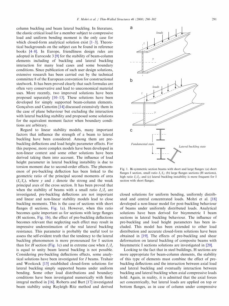
Fig. 1. Bi-symmetric section beams with short and large flanges: (a) short
flanges I section, small ratio Iz/Iy; (b) large flanges sections (H sections),
high ratio Iz/Iy; and (c) lateral buckling instability is more frequent for I
section with short flanges.
F. Mohri et al. / Thin-Walled Structures 46 (2008) 290–302 291
column buckling and beam lateral buckling. In literature,the elastic critical load for a member subject to compressiveload and uniform bending moment is the only case forwhich closed-form analytical solution exist [1–3]. Theore-tical backgrounds on the subject can be found in referencebooks [4–8]. In Europe, friendliness design rules areadopted in Eurocode 3 [9] for the stability of beam-columnelements including of buckling and lateral bucklinginteraction for many load cases and some boundaryconditions. Since publication of such user design solutions,extensive research has been carried out by the technicalcommittee 8 of the European convention for constructionalsteelwork. It has been proved clearly that such formulas areoften very conservative and lead to uneconomical materialuses. More recently, two improved solutions have beenproposed separately [10–13]. These solutions have beendeveloped for simply supported beam-column elements.Gonc-alves and Camotim [14] discussed extensively them inthe case of plane behaviour but excluding the interactionwith lateral buckling stability and proposed some solutionsfor the equivalent moment factor when boundary condi-tions are arbitrary.
Regard to linear stability models, many importantfactors that influence the strength of a beam to lateralbuckling have been considered. Among them are pre-buckling deflections and load height parameter effects. Forthis purpose, more complex models have been developed innon-linear context and some other solutions have beenderived taking them into account. The influence of loadheight parameter in lateral buckling instability is due totorsion moment due to second-order effects. The phenom-enon of pre-buckling deflection has been linked to thegeometric ratio of the principal second moments of area(Iz/Iy), where y and z denote the strong and the weakprincipal axes of the cross section. It has been proved thatwhen the stability of beams with a small ratio Iz/Iy areinvestigated, pre-buckling deflections are not importantand linear and non-linear stability models lead to closebuckling moments. This is the case of sections with shortflanges (I sections, Fig. 1a). However, when this ratiobecomes quite important as for sections with large flanges(H sections, Fig. 1b), the effect of pre-buckling deflectionsbecomes relevant that neglecting such effect may result inimpressive underestimation of the real lateral bucklingresistance. This parameter is probably the useful tool toassess the self-evident truth that the tendency to the lateralbuckling phenomenon is more pronounced for I sectionthan for H section (Fig. 1c) and in extreme case when Iz/Iy
is equal to unity beam lateral buckling is not possible.Considering pre-buckling deflections effects, some analy-tical solutions have been investigated for I beams. Trahairand Woolcock [15] established closed-form solutions forlateral buckling simply supported beams under uniformbending. Some other load distributions and boundaryconditions have been investigated numerically with finiteintegral method in [16]. Roberts and Burt [17] investigatedbeam stability using Rayleigh–Ritz method and derived
closed solutions for uniform bending, uniformly distrib-uted and central concentrated loads. Mohri et al. [18]developed a non-linear model for post-buckling behaviourof beams under uniformly distributed loads. Analyticalsolutions have been derived for bisymmetric I beamsections in lateral buckling behaviour. The influence ofpre-buckling and load height parameters has been in-cluded. This model has been extended to other loaddistribution and accurate closed-form solutions have beenobtained in [19]. The effects of pre-buckling and sheardeformation on lateral buckling of composite beams withbisymmetric I sections solutions are investigated in [20].Looking to the fact that in steel buildings, H sections are
more appropriate for beam-column elements, the stabilityof this type of elements must combine the effect of pre-buckling deflections and the interaction between axial loadand lateral buckling and eventually interaction betweenbuckling and lateral buckling when axial compressive loadshold. Again, in reality, it is admitted that the axial forcesact concentrically, but lateral loads are applied on top orbottom flanges, as in case of column under compressive
ARTICLE IN PRESSF. Mohri et al. / Thin-Walled Structures 46 (2008) 290–302292
gravity loads and lateral bending loads resulting from windactions.
To writer’s knowledge, except the solution carried out in[15] for stability of beam-column element combininguniform bending and axial loads, no other closed-formsolutions exist in literature for flexural–torsional beam-column stability including effects of pre-buckling deflec-tions, load height level and axial loads. In this framework,a non-linear model is investigated in the present work.Equilibrium equations are derived from stationary condi-tions. Closed-form solutions are established for the lateralbuckling loads of an element with bisymmetric section,in presence of a known axial load. Due to non-linearcontext of the equilibrium equations, these solutionsare carried out from the singularity of the tangent stiffnessmatrix. The obtained solutions take into account forpre-buckling deflection, load height level and interactionbetween buckling and lateral buckling. The case ofsimply supported element in both bending and torsion isconsidered. Different load cases are investigated: uniformlydistributed load, concentrated loads and uniformbending. The proposed solutions are validated by recourseto non-linear finite element software. The model isextended for stability of redundant beams when importantaxial forces are generated in the beam due to non-lineardeformations.
2. A non-linear model for beam-column elements
2.1. Deformation fields
In a previous work, Vlasov’s model has been extended tolarge displacements and non-linear stability analyses [21].
z
x y
G
ω /2
C(yc, zc)
M
qz
θx
v
u
ws
s’
qx
qz
ez
ey
C y
qz
qx
z
x
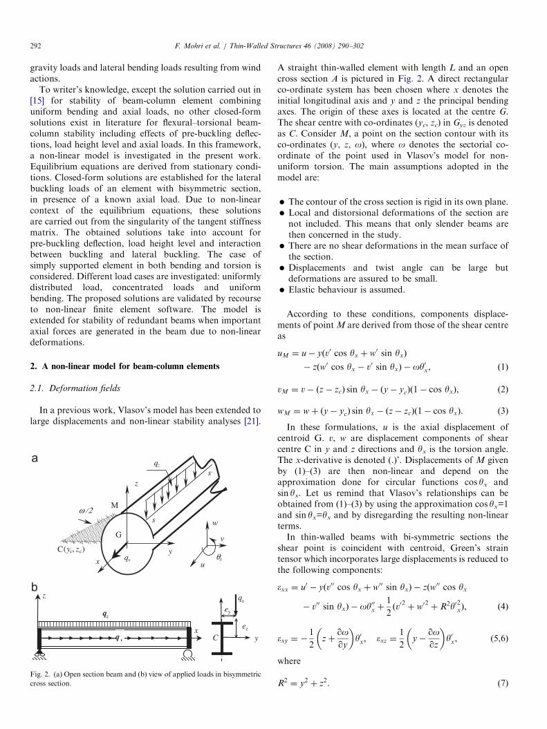
Fig. 2. (a) Open section beam and (b) view of applied loads in bisymmetric
cross section.
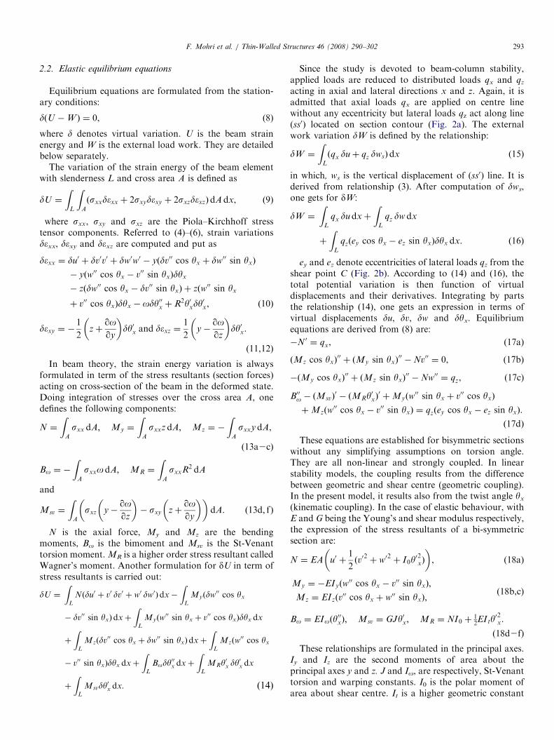
A straight thin-walled element with length L and an opencross section A is pictured in Fig. 2. A direct rectangularco-ordinate system has been chosen where x denotes theinitial longitudinal axis and y and z the principal bendingaxes. The origin of these axes is located at the centre G.The shear centre with co-ordinates (yc, zc) in Gyz is denotedas C. Consider M, a point on the section contour with itsco-ordinates (y, z, o), where o denotes the sectorial co-ordinate of the point used in Vlasov’s model for non-uniform torsion. The main assumptions adopted in themodel are:
�
The contour of the cross section is rigid in its own plane. � Local and distorsional deformations of the section arenot included. This means that only slender beams arethen concerned in the study.
� There are no shear deformations in the mean surface ofthe section.
� Displacements and twist angle can be large butdeformations are assured to be small.
� Elastic behaviour is assumed.According to these conditions, components displace-ments of point M are derived from those of the shear centreas
uM ¼ u� yðv0 cos yx þ w0 sin yxÞ
� zðw0 cos yx � v0 sin yxÞ � oy0x, ð1Þ
vM ¼ v� ðz� zcÞ sin yx � ðy� ycÞð1� cos yxÞ, (2)
wM ¼ wþ ðy� ycÞ sin yx � ðz� zcÞð1� cos yxÞ. (3)
In these formulations, u is the axial displacement ofcentroid G. v, w are displacement components of shearcentre C in y and z directions and yx is the torsion angle.The x-derivative is denoted (.)’. Displacements of M givenby (1)–(3) are then non-linear and depend on theapproximation done for circular functions cos yx andsin yx. Let us remind that Vlasov’s relationships can beobtained from (1)–(3) by using the approximation cos yx=1and sin yx=yx and by disregarding the resulting non-linearterms.In thin-walled beams with bi-symmetric sections the
shear point is coincident with centroid, Green’s straintensor which incorporates large displacements is reduced tothe following components:
�xx ¼ u0 � yðv00 cos yx þ w00 sin yxÞ � zðw00 cos yx
� v00 sin yxÞ � oy00x þ1
2ðv0
2þ w0
2þ R2y02xÞ, ð4Þ
�xy ¼ �1
2zþ
qoqy
� �y0x; �xz ¼
1
2y�
qoqz
� �y0x, (5,6)
where
R2 ¼ y2 þ z2. (7)
ARTICLE IN PRESSF. Mohri et al. / Thin-Walled Structures 46 (2008) 290–302 293
2.2. Elastic equilibrium equations
Equilibrium equations are formulated from the station-ary conditions:
dðU �W Þ ¼ 0, (8)
where d denotes virtual variation. U is the beam strainenergy and W is the external load work. They are detailedbelow separately.
The variation of the strain energy of the beam elementwith slenderness L and cross area A is defined as
dU ¼
ZL
ZA
ðsxxd�xx þ 2sxyd�xy þ 2sxzd�xzÞdAdx, (9)
where sxx, sxy and sxz are the Piola–Kirchhoff stresstensor components. Referred to (4)–(6), strain variationsdexx, dexy and dexz are computed and put as
d�xx ¼ du0 þ dv0v0 þ dw0w0 � yðdv00 cos yx þ dw00 sin yxÞ
� yðw00 cos yx � v00 sin yxÞdyx
� zðdw00 cos yx � dv00 sin yxÞ þ zðw00 sin yx
þ v00 cos yxÞdyx � ody00x þ R2y0xdy0x, ð10Þ
d�xy ¼ �1
2zþ
qoqy
� �dy0x and d�xz ¼
1
2y�
qoqz
� �dy0x.
(11,12)
In beam theory, the strain energy variation is alwaysformulated in term of the stress resultants (section forces)acting on cross-section of the beam in the deformed state.Doing integration of stresses over the cross area A, onedefines the following components:
N ¼
ZA
sxx dA; My ¼
ZA
sxxz dA; Mz ¼ �
ZA
sxxydA,
(13a2c)
Bo ¼ �
ZA
sxxodA; MR ¼
ZA
sxxR2 dA
and
Msv ¼
ZA
sxz y�qoqz
� �� sxy zþ
qoqy
� �� �dA. ð13d; fÞ
N is the axial force, My and Mz are the bendingmoments, Bo is the bimoment and Msv is the St-Venanttorsion moment. MR is a higher order stress resultant calledWagner’s moment. Another formulation for dU in term ofstress resultants is carried out:
dU ¼
ZL
Nðdu0 þ v0 dv0 þ w0 dw0Þdx�
ZL
Myðdw00 cos yx
� dv00 sin yxÞdxþ
ZL
Myðw00 sin yx þ v00 cos yxÞdyx dx
þ
ZL
Mzðdv00 cos yx þ dw00 sin yxÞdxþ
ZL
Mzðw00 cos yx
� v00 sin yxÞdyx dxþ
ZL
Body00x dxþ
ZL
MRy0x dy
0x dx
þ
ZL
Msvdy0x dx. ð14Þ
Since the study is devoted to beam-column stability,applied loads are reduced to distributed loads qx and qz
acting in axial and lateral directions x and z. Again, it isadmitted that axial loads qx are applied on centre linewithout any eccentricity but lateral loads qz act along line(ss0) located on section contour (Fig. 2a). The externalwork variation dW is defined by the relationship:
dW ¼
ZL
ðqx duþ qz dwsÞdx (15)
in which, ws is the vertical displacement of (ss0) line. It isderived from relationship (3). After computation of dws,one gets for dW:
dW ¼
ZL
qx du dxþ
ZL
qz dwdx
þ
ZL
qzðey cos yx � ez sin yxÞdyx dx. ð16Þ
ey and ez denote eccentricities of lateral loads qz from theshear point C (Fig. 2b). According to (14) and (16), thetotal potential variation is then function of virtualdisplacements and their derivatives. Integrating by partsthe relationship (14), one gets an expression in terms ofvirtual displacements du, dv, dw and dyx. Equilibriumequations are derived from (8) are:
�N 0 ¼ qx, (17a)
ðMz cos yxÞ00þ ðMy sin yxÞ
00�Nv00 ¼ 0, (17b)
�ðMy cos yxÞ00þ ðMz sin yxÞ
00�Nw00 ¼ qz, (17c)
B00o � ðMsvÞ0� ðMRy
0xÞ0þMyðw
00 sin yx þ v00 cos yxÞ
þMzðw00 cos yx � v00 sin yxÞ ¼ qzðey cos yx � ez sin yxÞ.
ð17dÞ
These equations are established for bisymmetric sectionswithout any simplifying assumptions on torsion angle.They are all non-linear and strongly coupled. In linearstability models, the coupling results from the differencebetween geometric and shear centre (geometric coupling).In the present model, it results also from the twist angle yx
(kinematic coupling). In the case of elastic behaviour, withE and G being the Young’s and shear modulus respectively,the expression of the stress resultants of a bi-symmetricsection are:
N ¼ EA u0 þ1
2ðv0
2þ w0
2þ I0y
02xÞ
� �, (18a)
My ¼ �EIyðw00 cos yx � v00 sin yxÞ;
Mz ¼ EIzðv00 cos yx þ w00 sin yxÞ;
(18b,c)
Bo ¼ EIoðy00xÞ; Msv ¼ GJy0x; MR ¼ NI0 þ
12EIty
02x.
(18d2f)
These relationships are formulated in the principal axes.Iy and Iz are the second moments of area about theprincipal axes y and z. J and Io, are respectively, St-Venanttorsion and warping constants. I0 is the polar moment ofarea about shear centre. It is a higher geometric constant
ARTICLE IN PRESSF. Mohri et al. / Thin-Walled Structures 46 (2008) 290–302294
[21]. In numerical approach, circular functions cos yx andsin yx are approximated by
cos yx ¼ 1�y2x2; sin yx ¼ yx. (19a,b)
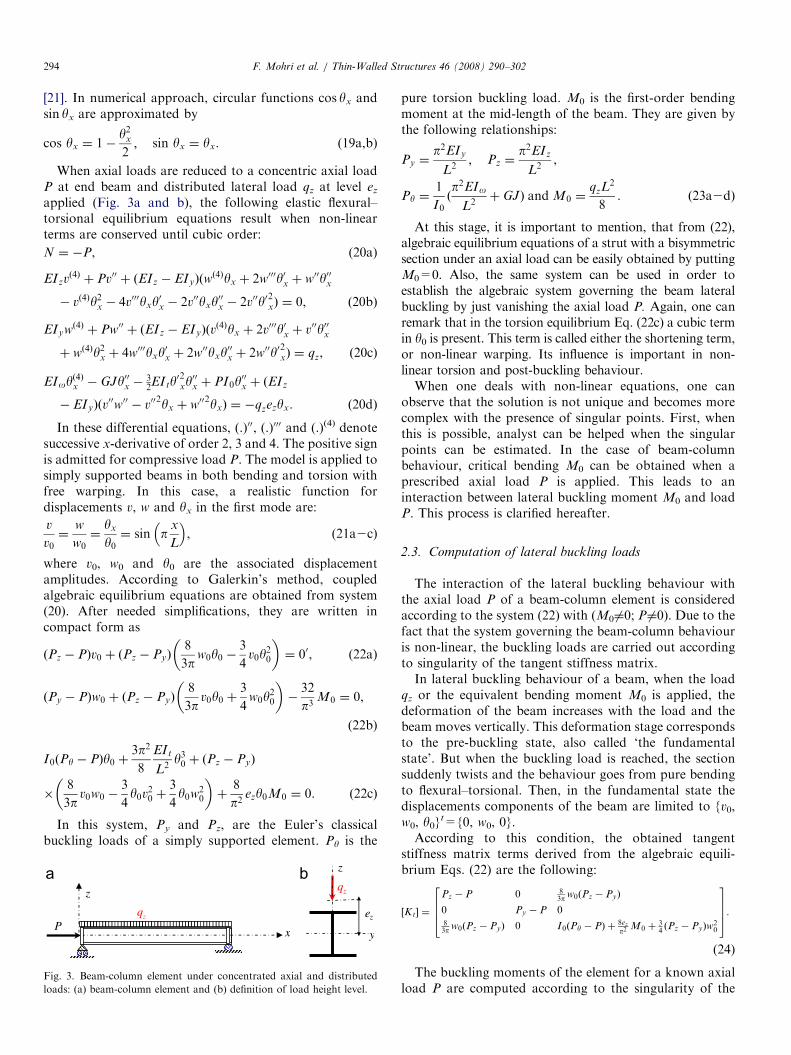
When axial loads are reduced to a concentric axial loadP at end beam and distributed lateral load qz at level ez
applied (Fig. 3a and b), the following elastic flexural–torsional equilibrium equations result when non-linearterms are conserved until cubic order:
N ¼ �P, (20a)
EIzvð4Þ þ Pv00 þ ðEIz � EIyÞðwð4Þyx þ 2w000y0x þ w00y00x
� vð4Þy2x � 4v000yxy0x � 2v00yxy
00x � 2v00y02xÞ ¼ 0, ð20bÞ
EIywð4Þ þ Pw00 þ ðEIz � EIyÞðvð4Þyx þ 2v000y0x þ v00y00x
þ wð4Þy2x þ 4w000yxy0x þ 2w00yxy
00x þ 2w00y02xÞ ¼ qz, ð20cÞ
EIoyð4Þx � GJy00x �
32EIty
02xy00x þ PI0y
00x þ ðEIz
� EIyÞðv00w00 � v00
2yx þ w002yxÞ ¼ �qzezyx. ð20dÞ
In these differential equations, (.)00, (.)000 and (.)(4) denotesuccessive x-derivative of order 2, 3 and 4. The positive signis admitted for compressive load P. The model is applied tosimply supported beams in both bending and torsion withfree warping. In this case, a realistic function fordisplacements v, w and yx in the first mode are:
v
v0¼
w
w0¼
yx
y0¼ sin p
x
L
� �, (21a2c)
where v0, w0 and y0 are the associated displacementamplitudes. According to Galerkin’s method, coupledalgebraic equilibrium equations are obtained from system(20). After needed simplifications, they are written incompact form as
ðPz � PÞv0 þ ðPz � PyÞ8
3pw0y0 �
3
4v0y
20
� �¼ 00, (22a)
ðPy � PÞw0 þ ðPz � PyÞ8
3pv0y0 þ
3
4w0y
20
� ��
32
p3M0 ¼ 0,
(22b)
I0ðPy � PÞy0 þ3p2
8
EIt
L2y30 þ ðPz � PyÞ
�8
3pv0w0 �
3
4y0v20 þ
3
4y0w2
0
� �þ
8
p2ezy0M0 ¼ 0. ð22cÞ
In this system, Py and Pz, are the Euler’s classicalbuckling loads of a simply supported element. Py is the
qz
ez
yP
qz
x
z
Fig. 3. Beam-column element under concentrated axial and distributed
loads: (a) beam-column element and (b) definition of load height level.
pure torsion buckling load. M0 is the first-order bendingmoment at the mid-length of the beam. They are given bythe following relationships:
Py ¼p2EIy
L2; Pz ¼
p2EIz
L2,
Py ¼1
I0ðp2EIo
L2þ GJÞ and M0 ¼
qzL2
8. ð23a2dÞ
At this stage, it is important to mention, that from (22),algebraic equilibrium equations of a strut with a bisymmetricsection under an axial load can be easily obtained by puttingM0=0. Also, the same system can be used in order toestablish the algebraic system governing the beam lateralbuckling by just vanishing the axial load P. Again, one canremark that in the torsion equilibrium Eq. (22c) a cubic termin y0 is present. This term is called either the shortening term,or non-linear warping. Its influence is important in non-linear torsion and post-buckling behaviour.When one deals with non-linear equations, one can
observe that the solution is not unique and becomes morecomplex with the presence of singular points. First, whenthis is possible, analyst can be helped when the singularpoints can be estimated. In the case of beam-columnbehaviour, critical bending M0 can be obtained when aprescribed axial load P is applied. This leads to aninteraction between lateral buckling moment M0 and loadP. This process is clarified hereafter.
2.3. Computation of lateral buckling loads
The interaction of the lateral buckling behaviour withthe axial load P of a beam-column element is consideredaccording to the system (22) with (M06¼0; P 6¼0). Due to thefact that the system governing the beam-column behaviouris non-linear, the buckling loads are carried out accordingto singularity of the tangent stiffness matrix.In lateral buckling behaviour of a beam, when the load
qz or the equivalent bending moment M0 is applied, thedeformation of the beam increases with the load and thebeam moves vertically. This deformation stage correspondsto the pre-buckling state, also called ‘the fundamentalstate’. But when the buckling load is reached, the sectionsuddenly twists and the behaviour goes from pure bendingto flexural–torsional. Then, in the fundamental state thedisplacements components of the beam are limited to {v0,w0, y0}
t={0, w0, 0}.According to this condition, the obtained tangent
stiffness matrix terms derived from the algebraic equili-brium Eqs. (22) are the following:
½Kt� ¼
Pz � P 0 83p w0ðPz � PyÞ
0 Py � P 083p w0ðPz � PyÞ 0 I0ðPy � PÞ þ 8ez
p2M0 þ
34ðPz � PyÞw
20
2664
3775.(24)
The buckling moments of the element for a known axialload P are computed according to the singularity of the
ARTICLE IN PRESSF. Mohri et al. / Thin-Walled Structures 46 (2008) 290–302 295
tangent matrix [Kt]. After vanishing the determinant of[Kt], one gets the following quadratic equation in w0:
ðPz � PÞ I0ðPy � PÞ þ8
p2M0ez
� �
�64
9p2� ðPz � PyÞ
2w20 þ
3
4ðPz � PÞðPz � PyÞ
� �� w2
0 ¼ 0.
ð25Þ
This relationship can be simplified as indicated below.Firstly, we can check that the last two terms can becombined to get:
�64
9p2ðPz � PyÞ
2w20 þ
34ðPz � PÞðPz � PyÞw
20
¼64
9p2ðPz � PyÞðPy � PÞw2
0. ð26Þ
Secondly, in the fundamental state, the bending momentM0 and the deflection w0 are not independent. Using first-order assumptions in Eq. (22b), one obtains:
w0 ¼32
p3M0
Py � P. (27)
Taking into account for (26) and (27), Eq. (25) becomes:
65; 536
9p8ðPz � PyÞM
20 þ
8
p2ðPz � PÞðPy � PÞM0ez
þ I0ðPz � PÞðPy � PÞðPy � PÞ ¼ 0. ð28aÞ
After needed simplifications and considering that theratio Pz=Py ¼ Iz=Iy, this yields to:
�65; 536
9p81�
Iz
Iy
� �M2
0 þ8
p2Pz 1�
P
Pz
� �1�
P
Py
� �M0ez
þ I0PyPz 1�P
Pz
� �1�
P
Py
� �1�
P
Py
� �¼ 0. ð28bÞ
Buckling moments are derived from solutions of (28b)and yield to:
M0;bðPÞ ¼ C1p2EIz
L2
� ðC2ezÞ �
ffiffiffiffiffiffiffiffiffiffiffiffiffiffiffiffiffiffiffiffiffiffiffiffiffiffiffiffiffiffiffiffiffiffiffiffiffiffiffiffiffiffiffiffiffiffiffiffiffiffiffiffiffiffiffiðC2ezÞ
2þ
Io
Iz
1þGJL2
p2EIo
� �s24
35
�ffiffiffiffiffiffiffiffiffiffiF ðPÞ
p. ð29aÞ
This expression is usual in beam lateral buckling with a newterm F(P) which is function on the axial load P and given by
F ðPÞ ¼ 1�P
Py
� �1�
P
Pz
� �1�
P
Py
� �. (29b)
One gets for coefficients C1 and C2 the followingrelationships:
C1 ¼1:14ffiffiffiffiffi
k1
p ; C2 ¼0:46ffiffiffiffiffi
k1
pffiffiffiffiffiffiffiffiffiffiGðPÞ
p. (30a2b)
Terms k1 and G(P) are given by:
k1 ¼ 1�Iz
Iy
; GðPÞ ¼ 1�P
Py
� �1�
P
Pz
� �1�
P
Py
� ��1.
(31a,b)
One can observe that the coefficient C1 depends only onpre-buckling deflections represented by the k1 parameter,but C2 relationship (30b) includes not only pre-bucklingdeflections effect but also has a strong interaction withaxial force P. If the axial force P vanishes, functions F(P)and G(P) are reduced to 1.0. One yields the samecoefficients obtained in [18] for beam lateral bucklingstability. This means that the beam lateral buckling isviewed as a particular case of a beam-column element.According to Trahair [6], an approximate expression is
presented from linear stability for simply supported beamsunder uniformly distributed load of central concentratedload. Buckling moment is obtained from solution ofquadratic equations. After solution for distributed load,one gets for C1 and C2 (C1 ¼ 1.13, C2 ¼ 0:45ð1� ðP=PzÞÞ).These values are quite different to (30a,b) since pre-buckling deflection effects are omitted and a linearinteraction between axial load and load height level isadmitted in C2. In the present model which includes theeffects of the pre-buckling deflections, load height level andthe presence of the axial load P, a coefficient C2 is presentin addition to C1 in the analytical solution (29). Asestablished in (30a,b), these coefficients are not constantbut depend on the section shape and the axial load P.According to (30a), for I sections (IybIz), the term k1 isclose to 1.0 and C1 term are reduced to the constant valueusually found in linear stability (C1 ¼ 1.14). But, for Hsections (IyEIz), this term C1 is quite different to the usualconstant values used in linear stability. When loads act farfrom shear point, C2 term in (30b) intervene in bucklingmoment solutions. Again, this term is derived in term of k1and axial load P. To our knowledge, relationship similar to(30b) is not available in literature. When I sections withsort flanges are investigated, k1 is close to unity and onegets for this term C2 ¼ 0:46
ffiffiffiffiffiffiffiffiffiffiGðPÞ
p. But when H sections
are considered, the term k1 is very less than unity, the C2
term is then much higher than 0:46ffiffiffiffiffiffiffiffiffiffiGðPÞ
p. The difference
between the linear and non-linear stability should be thenimportant.Again, the present model can be employed in lateral
buckling of beams under concentrated loads. In suchsituations, Dirac’s function is used and the same procedurecan be followed as in [22]. As an example, in the case of abeam under two concentrated loads Qz applied at L/4 fromeach end, the relationship (26) is fulfilled but the relation-ships (Qz, M0) and (M0, w0) are the following:
M0 ¼ Qz
L
4; w0 ¼
11p2
96
M0
Py � P. (32a,b)
One arrives to a quadratic equation similar to (28b).Then, the relationship (29) for buckling moments holds
ARTICLE IN PRESS
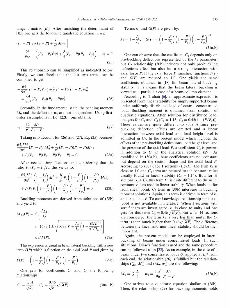
Table 1
Formulation of coefficients C1 and C2 needed for lateral buckling stability
of a beam-column element under some representative load cases
Load case M0 C1 C2
qzL2
8
1:13ffiffiffiffik1p � 0:46ffiffiffiffi
k1p
ffiffiffiffiffiffiffiffiffiffiGðPÞ
p�
QzL4
1:36ffiffiffiffik1p � 0:55ffiffiffiffi
k1
pffiffiffiffiffiffiffiffiffiffiGðPÞ
p�
QzL4
1:05ffiffiffiffik1p � 0:43ffiffiffiffi
k1p
ffiffiffiffiffiffiffiffiffiffiGðPÞ
p�
QzL3
1:10ffiffiffiffik1p � 0:50ffiffiffiffi
k1p
ffiffiffiffiffiffiffiffiffiffiGðPÞ
p�
M01:0ffiffiffiffi
k1p �
(*): k1 ¼ 1� ðIz=IyÞ; GðPÞ ¼ð1�ðP=PyÞÞð1�ðP=PzÞÞ
ð1�ðP=PyÞÞ.
qz
P3
2
1
Fig. 4. View of the uniform shell mesh adopted for beam I section.
F. Mohri et al. / Thin-Walled Structures 46 (2008) 290–302296
but the coefficients C1 and C2 are exchanged, respectively,into:
C1 ¼1:04ffiffiffiffiffi
k1
p ; C2 ¼0:42ffiffiffiffiffi
k1
pffiffiffiffiffiffiffiffiffiffiGðPÞ
p. (33a2b)
Terms k1 and G(P) are the same as in (31a,b). The sameprocedure is followed for other load cases encountered andcoefficients C1 and C2 are derived. Their values arepresented in Table 1.
At this stage, an analytical solution has been derived forlateral buckling stability of simply supported beam-columnelements with bi-symmetric sections. It takes into accountfor pre-buckling deformation, load height level and theinteraction with the presence of axial loads. This compactformulation is established for the more useful design loadcases such as distributed, concentrated loads and uniformbending moments. Different coefficients C1 and C2 aregiven for these load cases. Once more, notice that in theliterature, the stability of beam-column elements includingpre-buckling deflections is restricted to uniform bending.The present analytical solution developed from a non-linear model includes pre-buckling deflections and loadheight level is then more general and constitutes an originalcontribution to the stability of beam-column elementsindependently to the section shape of the element.
3. Numerical investigations
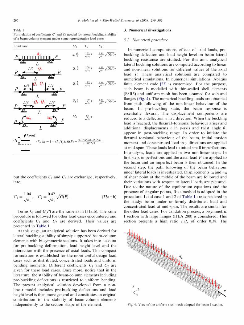
3.1. Numerical procedure
In numerical computations, effects of axial loads, pre-buckling deflection and load height level on beam lateralbuckling resistance are studied. For this aim, analyticallateral buckling solutions are computed according to linearand non-linear solutions for different values of the axialload P. These analytical solutions are compared tonumerical simulations. In numerical simulations, Abaqusfinite element code [23] is customized. For the purpose,each beam is modelled with thin-walled shell elements(S8R5) and uniform mesh has been assumed for web andflanges (Fig. 4). The numerical buckling loads are obtainedfrom path following of the non-linear behaviour of thebeam. In pre-buckling state, the beam response isessentially flexural. The displacement components arereduced to a deflection w in z direction. When the bucklingload is reached, the flexural–torsional behaviour arises andadditional displacements v in y-axis and twist angle yx
appear in post-buckling range. In order to initiate theflexural–torsional behaviour of the beam, initial torsionmoment and concentrated load in y directions are appliedat mid-span. These loads lead to initial small imperfections.In analysis, loads are applied in two non-linear steps. Infirst step, imperfections and the axial load P are applied tothe beam and an imperfect beam is then obtained. In thesecond step, the path following of the beam behaviourunder lateral loads is investigated. Displacements v0 and w0
of shear point at the middle of the beam are followed andtheir variations with respect to lateral loads are pictured.Due to the nature of the equilibrium equations and thepresence of singular points, Riks method is adopted in theprocedure. Load case 1 and 2 of Table 1 are considered inthe study: beam under uniformly distributed load andconcentrated load at mid-span. The results are similar forthe other load cases. For validation process, a bisymmetricI section with large flanges (HEA 200) is considered. Thissection presents a high ratio Iz/Iy of order 0.38. The
ARTICLE IN PRESS
H200
0-
-
50
100
150
200
250
300
0.02 0.04 0.06 0.08 0.10 0.12
v (m)
M0
(kN
m)
H200
0
50
100
150
200
250
300
0.05 0.10 0.15 0.20 0.25 0.30w (m)
M0
(kN
m)
238.97
P = 0
P = 0.5 Pz
P = 0.5 Pz
124.20
v
qz
qz
L=6m
P
238.97
P = 0
124.20
qz
qz
L=6m
P
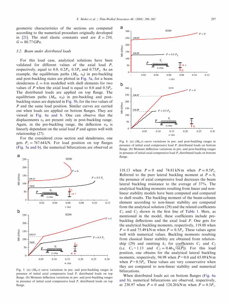
Fig. 6. (a) (M0,v) curve variations in pre- and post-buckling ranges in
presence of initial axial compressive load P, distributed loads on bottom
flange. (b) Moment deflection variations in pre- and post-buckling ranges
F. Mohri et al. / Thin-Walled Structures 46 (2008) 290–302 297
geometric characteristics of the sections are computedaccording to the numerical procedure originally developedin [21]. The steel elastic constants used are E ¼ 210,G ¼ 80.77GPa.
3.2. Beam under distributed loads
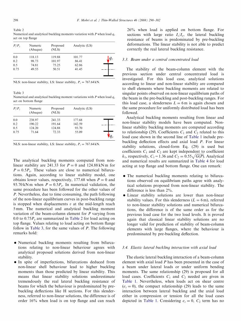
For this load case, analytical solutions have beenvalidated for different values of the axial load P,respectively, equal to 0.0, 0.2Pz, 0.5Pz and 0.75Pz. As anexample, the equilibrium paths (M0, v0) in pre-bucklingand post-buckling states are plotted in Fig. 5a, for a beamslenderness L ¼ 6m modelled with shell elements for twovalues of P when the axial load is equal to 0.0 and 0.5Pz.The distributed loads are applied on top flange. Theequilibrium paths (M0, w0) in pre-buckling and post-buckling states are depicted in Fig. 5b, for the two values ofP and the same load position. Similar curves are carriedout when loads are applied on bottom flanges. They areviewed in Fig. 6a and b. One can observe that thedisplacements v0 are present only in post-buckling range.Again, in the pre-buckling range, the deflection w0 islinearly dependant on the axial load P and agrees well withrelationship (27).
For the considered cross section and slenderness, onegets Pz ¼ 767.64 kN. For load position on top flanges(Fig. 5a and b), the numerical bifurcations are observed at
H200
0
50
100
150
200
250
0.02 0.04 0.06 0.08 0.10 0.12
v (m)
M0
(kN
m)
118.13
74.81
P = 0
P = 0.5 Pz
qzv
qz
L=6m
P
H200
0
50
100
150
200
250
0.05 0.10 0.15 0.20 0.25 0.30
w (m)
M0
(kN
m)
118.13
P = 0
P = 0.5 Pz
74..81qz
w
qz
L=6m
P
-
-
Fig. 5. (a) (M0,v) curve variations in pre- and post-buckling ranges in
presence of initial axial compressive load P, distributed loads on top
flange. (b) Moment deflection variations in pre- and post-buckling ranges
in presence of initial axial compressive load P, distributed loads on top
flange.
in presence of initial axial compressive load P, distributed loads on bottom
flange.
118.13 when P ¼ 0 and 74.81 kNm when P ¼ 0.5Pz.Referred to the pure lateral buckling moment at P ¼ 0,the presence of axial compressive load decreases the beamlateral buckling resistance to the average of 37%. Theanalytical buckling moments resulting from linear and non-linear stability models have been computed and comparedto shell results. The buckling moment of the beam-columnelement according to non-linear stability are computedfrom the analytical solution (29) and the related coefficientsC1 and C2 shown in the first line of Table 1. Here, asmentioned in the model, these coefficients include pre-buckling deflections and the axial load P. One gets forthe analytical buckling moments, respectively, 119.88 whenP ¼ 0 and 75.49 kNm when P ¼ 0.5Pz. These values agreewell with numerical values. Buckling moments resultingfrom classical linear stability are obtained from relation-ship (29) and omitting k1 for coefficients C1 and C2
(i.e. C1=1.13 and C2 ¼ 0:46ffiffiffiffiffiffiffiffiffiffiGðPÞ
p). For this load
position, one obtains for the analytical lateral bucklingmoments, respectively, 94.98 when P=0.0 and 65.09 kNmwhen P=0.5Pz. These values are very conservative whenthey are compared to non-linear stability and numericalbifurcations.When distributed loads act on bottom flanges (Fig. 6a
and b), numerical bifurcations are observed, respectively,at 238.97 when P ¼ 0 and 124.20 kNm when P ¼ 0.5Pz.
ARTICLE IN PRESS
Table 2
Numerical and analytical buckling moments variation with P when load qz
act on top flange
P/Pz Numeric
(Abaqus)
Proposed
(NLS)
Analytic (LS)
0.0 118.13 119.88 101.77
0.2 98.73 101.97 86.41
0.5 74.81 75.25 62.86
0.75 49.55 50.51 41.45
NLS: non-linear stability, LS: linear stability, Pz ¼ 767.64 kN.
Table 3
Numerical and analytical buckling moment variations with P when load qz
act on bottom flange
P/Pz Numeric
(Abaqus)
Proposed
(NLS)
Analytic (LS)
0.0 238.97 241.33 177.68
0.2 190.22 191.64 142.59
0.5 124.20 124.88 93.70
0.75 71.64 72.33 55.09
NLS: non-linear stability, LS: linear stability, Pz ¼ 767.64 kN.
F. Mohri et al. / Thin-Walled Structures 46 (2008) 290–302298
The analytical buckling moments computed from non-linear stability are 241.33 for P ¼ 0 and 124.88 kNm forP ¼ 0.5Pz. These values are close to numerical bifurca-tions. Again, according to linear stability model, oneobtains lower values, respectively, 177.68 when P ¼ 0 and93.70 kNm when P ¼ 0.5Pz. In numerical validation, thesame procedure has been followed for the other values ofP. Nevertheless, due to time consuming, the path followingof the non-linear equilibrium curves in post-buckling rangeis stopped when displacements v at the mid-length reach5mm. The numerical and analytical buckling momentvariation of the beam-column element for P varying from0.0 to 0.75Pz are summarized in Table 2 for load acting ontop flange. Values relating to load acting on bottom flangefollow in Table 3, for the same values of P. The followingremarks hold:
�
Numerical buckling moments resulting from bifurca-tions relating to non-linear behaviour agrees withanalytical proposed solutions derived from non-linearstability. � In spite of imperfections, bifurcations deduced fromnon-linear shell behaviour lead to higher bucklingmoments than those predicted by linear stability. Thismeans that linear stability solutions underestimatetremendously the real lateral buckling resistance ofbeams for which the behaviour is predominated by pre-buckling deflections like H sections. For this slender-ness, referred to non-linear solutions, the difference is oforder 16% when load is on top flange and can reach
26% when load is applied on bottom flange. Forsections with large ratio Iz/Iy, the lateral bucklingresistance of beams is predominated by pre-bucklingdeformations. The linear stability is not able to predictcorrectly the real lateral buckling resistance.
3.3. Beam under a central concentrated load
The stability of the beam-column element with theprevious section under central concentrated load isinvestigated. For this load case, analytical solutionsaccording to linear and non-linear stability are comparedto shell elements where buckling moments are related tosingular points observed on non-linear equilibrium paths ofthe beam in the pre-buckling and post-buckling ranges. Forthis load case, a slenderness L ¼ 6m is again chosen andthe same procedure for uniformly distributed load has beenfollowed.Analytical buckling moments resulting from linear and
non-linear stability models have been computed. Non-linear stability buckling moments are computed accordingto relationship (29). Coefficients C1 and C2 related to thisload case shown in the second line of Table 1 include pre-buckling deflection effects and axial load P. For linearstability solutions, closed-form Eq. (29) is used butcoefficients C1 and C2 are kept independent to coefficientk1, respectively, C1=1.36 and C2 ¼ 0:55
ffiffiffiffiffiffiffiffiffiffiGðPÞ
p. Analytical
and numerical results are summarized in Table 4 for loadacting at top flange and bottom flange. One can remark:
�
The numerical buckling moments relating to bifurca-tions observed on equilibrium paths agree with analy-tical solutions proposed from non-linear stability. Thedifference is less than 2%. � Linear stability solutions are lower than non-linearstability values. For this slenderness (L ¼ 6m), referredto non-linear stability solutions and numerical bifurca-tions, the difference is of the same order as for theprevious load case for the two load levels. It is provedagain that classical linear stability solutions are nolonger valid for prediction of stability of beam-columnelements with large flanges, where the behaviour ispredominated by pre-buckling deflection.
3.4. Elastic lateral buckling interaction with axial load
The elastic lateral buckling interaction of a beam-columnelement with axial load P has been presented in the case ofa beam under lateral loads or under uniform bendingmoments. The same relationship (29) is proposed for allload cases. Coefficients C1 and C2 needed are given inTable 1. Nevertheless, when loads act on shear centre(ez ¼ 0), the compact relationship (29) leads to the sameinteraction between lateral buckling and the axial loadeither in compression or tension for all the load casesdepicted in Table 1. Considering ez ¼ 0, C2 term has no
ARTICLE IN PRESS
Table 4
Numerical and analytical buckling moment variation with P for a beam column element under a central concentrated load Qz
P/Pz Load on top flange Load on bottom flange
Numeric (Abaqus) Proposed (NLS) Analytic (LS) Numeric (Abaqus) Proposed (NLS) Analytic (LS)
0.00 131.00 134.60 115.70 297.46 309.14 224.79
0.20 113.85 115.76 98.74 237.00 244.92 179.47
0.50 84.45 86.25 72.51 154.50 157.16 116.84
0.75 58.20 58.48 48.34 88.55 89.85 67.94
NLS: non-linear stability, LS: linear stability, Pz ¼ 767.64 kN.
H200
0.00
0.25
0.50
0.75
1.00
1.25
1.50
1.75
2.00
-1.00 -0.80 -0.60 -0.40 -0.20 - 0.20 0.40 0.60 0.80 1.00
P/Pz
Mb(P) / Mb(0)
Pz/Pθ = 0.5
P in compressionP in tension
Pz/Pθ=1.0
Pz/Pθ = 0.2
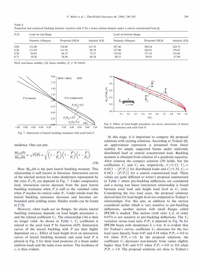
Fig. 7. Interaction of lateral buckling resistance with axial load P.
qz
qz
qz
qz
L = 6m
P
0.0
0.2
0.4
0.6
0.8
1.0
- 0.1 0.2 0.3 0.4 0.5 0.6 0.7 0.8 0.9 1.0
P/Pz
M0.
b(P
)/M
0.b(
0)
Fig. 8. Effect of load height parameter on curves interaction of lateral
buckling resistance and axial load P.
F. Mohri et al. / Thin-Walled Structures 46 (2008) 290–302 299
incidence. One can put:
M0;bðPÞ
M0;bð0Þ¼
ffiffiffiffiffiffiffiffiffiffiF ðPÞ
p¼
ffiffiffiffiffiffiffiffiffiffiffiffiffiffiffiffiffiffiffiffiffiffiffiffiffiffiffiffiffiffiffiffiffiffiffiffiffiffiffiffiffiffiffiffiffiffiffiffiffiffiffiffiffiffiffiffiffiffiffiffiffi1�
P
Py
� �1�
P
Pz
� �1�
P
Py
� �s.
(34)
Here M0,b(0) is the pure lateral buckling moment. Thisrelationship is well known in literature. Interaction curvesof the selected section for some slenderness represented bythe ratio Pz/Py are depicted in Fig. 7. Under compressiveload, interaction curves decrease from the pure lateralbuckling resistance when P is null to the vanished valuewhen P reaches its critical value Pz. Under tensile load thelateral buckling resistance increases and becomes un-bounded until yielding arises. Similar results can be foundin [7,8].
However, when loads act on flanges, the elastic lateralbuckling resistance depends on load height parameter ez
and the related coefficient C2. The relationship (34) is thenno longer valid. As shown in Table 1, C2 coefficient isrelated to the axial load P by function G(P). Interactioncurves of the lateral buckling with P are then highlydependant on ez. Effect of load height level on interactioncurves of lateral buckling moment and axial load P isplotted in Fig. 8 for three load positions of a beam underuniform loads and the same cross section. The incidence ofez is then evident.
At this stage, it is important to compare the proposalsolutions with existing solutions. According to Trahair [6],an approximate expression is presented from linearstability for simply supported beams under uniformlydistributed load or central concentrated load. Bucklingmoment is obtained from solution of a quadratic equation.After solution the compact solution (29) holds, but thecoefficients C1 and C2 are, respectively, C1=1.13, C2 ¼
0:45 1� P=Pz
for distributed loads and C1=1.35, C2 ¼
0:54 1� P=Pz
for a central concentrated load. These
values are quite different to writer’s proposal summarizedin Table 1 where pre-buckling deflections are consideredand a strong non linear interaction relationship is foundbetween axial load and height load level in C2 term.Considering the two load cases, the proposal solutionsderived here for load height level are compared to Trahair’srelationships. For this aim, in addition to the sectionconsidered earlier which is very sensitive to pre-bucklingdeflections, another section with small flanges calledIPE300 is studied. This section (with ratio Iz/Iy of order0.075) is not sensitive to pre-buckling deflections. The C2
variation versus load ratio P/Pz is depicted in Fig. 9a forIPE300 beam with slenderness L ¼ 6m. It is evident thatfor Trahair’s curves, coefficient C2 decreases for the twoload cases linearly from 0.45 and 0.54 when P/Pz ¼ 0.0 to0.0 when P/Pz ¼ 1.0. In the proposal solutions, thecoefficient C2 decreases non-linearly from values slightlyhigher than 0.45 and 0.55 when P/Pz ¼ 0.0 to 0.0 whenP/Pz ¼ 1.0. The proposal solutions are close to Trahair’s
ARTICLE IN PRESS
qzP
6m
H200,L=6m
0.0
0.2
0.4
0.6
0.8
- 0.2 0.4 0.6 0.8 1.0
P/Pz
C2
QzP
6m
Trahair (1993)Proposal
Trahair (1993)Proposal
I300,L = 6m
0.0
0.2
0.4
0.6
- 0.2 0.4 0.6 0.8 1.0
P/Pz
C2
QzP
6m
qzP
6m
Fig. 9. (a) Variation of height load level coefficient C2 versus load P for
simply supported beams under uniformly ditributed and central concen-
trated loads (IPE300 section). (b) Variation of height load level coefficient
C2 versus load P for simply supported beams under uniformly distributed
and central concentrated loads (HEA 200 section).
F. Mohri et al. / Thin-Walled Structures 46 (2008) 290–302300
predictions only at P/Pz ¼ 0.0 and 1.0. Important differ-ence is observed elsewhere.
The variation of C2 versus P/Pz is pictured in Fig. 9b forHEA200 section with the same slenderness. In Trahair’sformulation, coefficient C2 is independent to section shapethe same curves are obtained as for section IPE300. In theproposal solutions which account for pre-buckling deflec-tions, the coefficient C2 decreases non-linearly from 0.58for distributed loads to 0.0. Under central concentratedload, it decreases from 0.70 to 0.0. Important difference isremarked between the different solutions. The linear curvesare more questionable.
3.5. Case of redundant beams
Previous studies have outlined effects of applied axialloads on lateral buckling of determinate beams. Beamlateral buckling resistance increases when the axial load isin tension and decreases in presence of compressive axialload. Nevertheless, in redundant beams, section axialforces arise from non-linear deformations either the beamis initially in pure bending. Most of analytical solutionscarried out for beam lateral buckling neglect the effect ofaxial force resulting from non-linear beam deformation. Innumerical analysis, such solutions are fulfilled with free
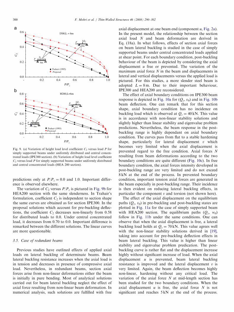
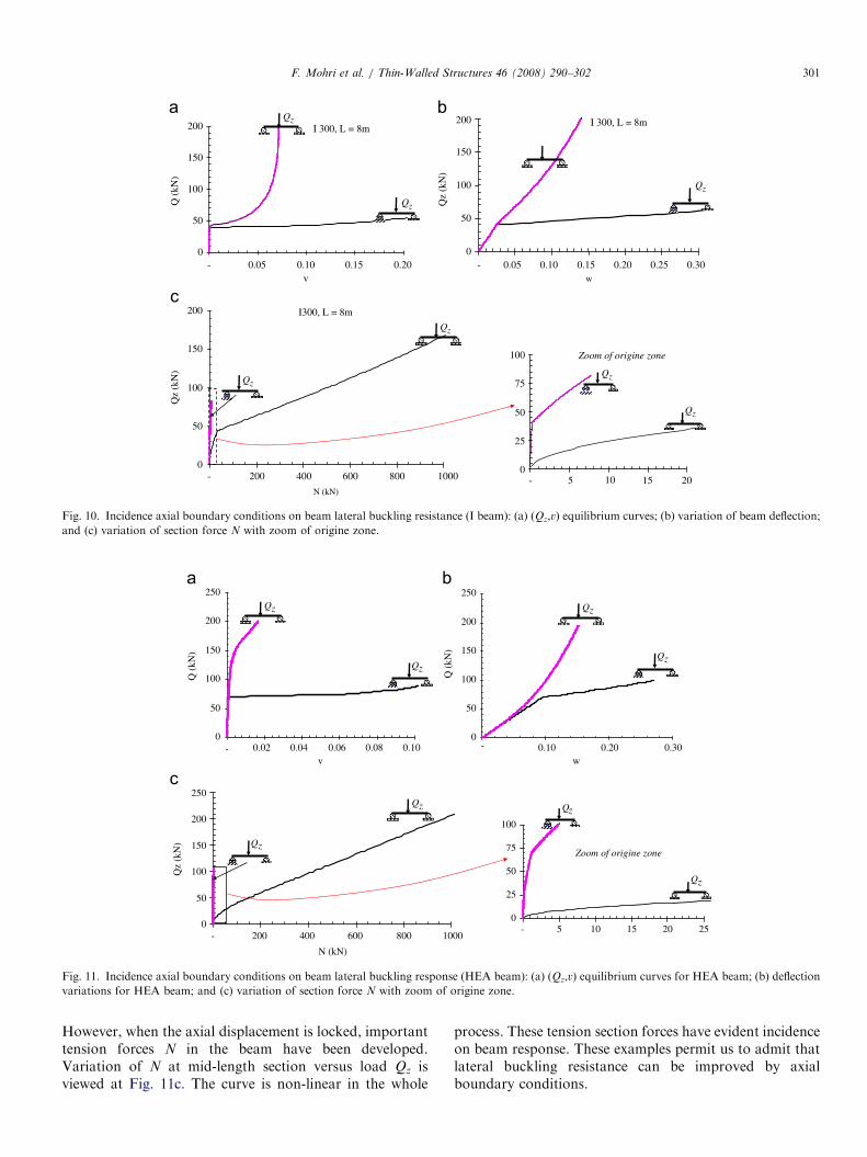
axial displacement at one beam end (component u, Fig. 2a).In the present model, the relationship between the sectionaxial load N and beam deformation are derived inEq. (18a). In what follows, effects of section axial forceson beam lateral buckling is studied in the case of simplysupported beams under central concentrated loads appliedat shear point. For each boundary condition, post-bucklingbehaviour of the beam is depicted by considering the axialdisplacement u free or prevented. The variation of themaximum axial force N in the beam and displacements inlateral and vertical displacements versus the applied load ispictured. For this studies, a more slender steel beam isadopted L ¼ 8m. Due to their important behaviour,IPE300 and HEA200 are reconsidered.The effect of axial boundary conditions on IPE300 beam
response is depicted in Fig. 10a for (Qz, v0) and in Fig. 10bbeam deflection. One can remark that for this sectionshape, axial boundary condition has no incidence onbuckling load which is observed at Qz ¼ 40 kN. This valueis in accordance with non-linear stability solutions andslightly higher than linear stability and eigenvalue problempredictions. Nevertheless, the beam response in the post-buckling range is highly dependant on axial boundarycondition. The curves pass from flat to a stable hardeningshape, particularly for lateral displacement v whichbecomes very limited when the axial displacement isprevented regard to the free condition. Axial forces N
resulting from beam deformations according to the twoboundary conditions are quite different (Fig. 10c). In freeboundary condition, the axial forces intensity developed inpost-buckling range are very limited and do not exceed8 kN at the end of the process. In prevented boundarycondition, important tension axial forces are generated inthe beam especially in post-buckling range. Their incidenceis then evident on reducing lateral buckling effects, inparticular the component v and torsion (not shown here).The effect of the axial displacement on the equilibrium
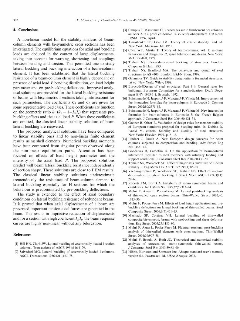
paths (Qz, v0) in pre-buckling and post-buckling states areplotted in Fig. 11a for the case of simply supported beamwith HEA200 section. The equilibrium paths (Qz, w0)follow in Fig. 11b under the same conditions. One canobserve that when the axial displacement is free, a lateralbuckling load holds at Qz ¼ 70 kN. This value agrees wellwith the non-linear stability solutions derived in [19],taking into account for pre-buckling deflection effects inbeam lateral buckling. This value is higher than linearstability and eigenvalue problem predication. The post-buckling curve is rather flat and the displacement increasehighly without significant increase of load. When the axialdisplacement u is prevented, beam lateral bucklingresistance is improved and the lateral displacement v isvery limited. Again, the beam deflection becomes highlynon-linear, hardening without any critical load. Thevariation of the axial force N at mid-length section hasbeen studied for the two boundary conditions. When theaxial displacement u is free, the axial force N is notsignificant and reaches 5 kN at the end of the process.
ARTICLE IN PRESS
I 300, L = 8m
0
50
100
150
200
0
50
100
150
200
- 0.05 0.10 0.15 0.20v
Q (
kN)
I 300, L = 8m
- 0.05 0.10 0.15 0.20 0.25 0.30 w
Qz
(kN
)
Qz
Qz
Qz
I300, L = 8m
0
50
100
150
200
- 200 400 600 800 1000
N (kN)
Qz
(kN
)
Qz
Qz
Qz
Qz
0
25
50
75
100
- 5 10 15 20
Zoom of origine zone
Fig. 10. Incidence axial boundary conditions on beam lateral buckling resistance (I beam): (a) (Qz,v) equilibrium curves; (b) variation of beam deflection;
and (c) variation of section force N with zoom of origine zone.
0
50
100
150
200
250
- 0.02 0.04 0.06 0.08 0.10v
Q (
kN)
Qz
Qz
0
50
100
150
200
250
- 0.10 0.20 0.30w
Q (
kN)
Qz
Qz
0
50
100
150
200
250
- 200 400 600 800 1000
N (kN)
Qz
(kN
) Qz
Qz
0
25
50
75
100
- 5 10 15 20 25
Zoom of origine zone
Qz
Qz
Fig. 11. Incidence axial boundary conditions on beam lateral buckling response (HEA beam): (a) (Qz,v) equilibrium curves for HEA beam; (b) deflection
variations for HEA beam; and (c) variation of section force N with zoom of origine zone.
F. Mohri et al. / Thin-Walled Structures 46 (2008) 290–302 301
However, when the axial displacement is locked, importanttension forces N in the beam have been developed.Variation of N at mid-length section versus load Qz isviewed at Fig. 11c. The curve is non-linear in the whole
process. These tension section forces have evident incidenceon beam response. These examples permit us to admit thatlateral buckling resistance can be improved by axialboundary conditions.
ARTICLE IN PRESSF. Mohri et al. / Thin-Walled Structures 46 (2008) 290–302302
4. Conclusions
A non-linear model for the stability analysis of beam-column elements with bi-symmetric cross sections has beeninvestigated. The equilibrium equations for axial and bendingloads are deduced in the context of large displacements,taking into account for warping, shortening and couplingsbetween bending and torsion. This permitted one to studylateral buckling and buckling interaction of a beam-columnelement. It has been established that the lateral bucklingresistance of a beam-column element is highly dependant onpresence of axial load P bending distribution, on load heightparameter and on pre-buckling deflections. Improved analy-tical solutions are provided for the lateral buckling resistanceof beams with bisymmetric I sections taking into account forsuch parameters. The coefficients C1 and C2 are given forsome representative load cases. These coefficients are functionon the geometric ratio k1 (k1 ¼ 1�Iz/Iy) that represents pre-buckling effects and the axial load P. When these coefficientsare omitted, the classical linear stability solutions of beamlateral buckling are recovered.
The proposed analytical solutions have been comparedto linear stability ones and to non-linear finite elementresults using shell elements. Numerical buckling momentshave been computed from singular points observed alongthe non-linear equilibrium paths. Attention has beenfocused on effects of load height parameter and theintensity of the axial load P. The proposed solutionspredict well beam lateral buckling resistance independentlyof section shape. These solutions are close to FEM results.The classical linear stability solutions underestimatetremendously the resistance of beam-column element tolateral buckling especially for H sections for which thebehaviour is predominated by pre-buckling deflections.
The study is extended to the effect of axial boundaryconditions on lateral buckling resistance of redundant beams.It is proved that when axial displacements of a beam areprevented important tension axial forces are generated in thebeam. This results in impressive reduction of displacementsand for a section with high coefficient Iz/Iy, the beam responsecurves are highly non-linear without any bifurcation.
References
[1] Hill HN, Clark JW. Lateral buckling of eccentrically loaded I-section
columns. Transactions of ASCE 1951;116:1179.
[2] Salvadori MG. Lateral buckling of eccentrically loaded I columns.
ASCE Transactions 1956;121:1163–78.
[3] Campus F, Massonnet C. Recherches sur le flambement des colonnes
an acier A37 a profil en double Te sollicites obliquement. CR Rech.
IRSIA, 1956, April.
[4] Timoshenko SP, Gere JM. Theory of elastic stability. 2nd ed.
New York: McGraw-Hill; 1961.
[5] Chen WF, Atsuta T. Theory of beam-columns, vol. 1: in-plane
behaviour and design; vol. 2, space behaviour and design. New York:
McGraw-Hill; 1977.
[6] Trahair NS. Flexural–torsional buckling of structures. London:
Chapman & Hall; 1993.
[7] Trahair NS, Bradford MA. The behaviour and design of steel
structures to AS 4100. London: E&FN Spon; 1998.
[8] Galambos TV. Guide to stability design criteria for metal structures.
1st ed. New York: Wiley; 1998.
[9] Eurocode3Design of steel structures, Part 1.1: General rules for
buildings. European Committee for standardization. Draft Docu-
ment ENV 1993-1-1, Brussels, 1992.
[10] Boissonnade N, Jaspart J-P, Muzeau J-P, Villette M. Improvement of
the interaction formulae for beam-columns in Eurocode 3. Comput
Struct 2002;80:2375–85.
[11] Boissonnade N, Jaspart J-P, Muzeau J-P, Villette M. New interaction
formulae for beam-columns in Eurocode 3: the French–Belgian
approach. J Construct Steel Res 2004;60:421–31.
[12] Greiner R, Ofner R. Validation of design rules for member stability
of European standards proposal for buckling rules. In: Dubina D,
Ivanyi M, editors. Stability and ductility of steel structures.
New York: Elsevier; 1999. p. 81–8.
[13] Lindner J, Rusch A. New European design concepts for beam
columns subjected to compression and bending. Adv Struct Eng
2001;4:20–41.
[14] Gonc-alves R, Camotim D. On the application of beam-column
interaction formulae to steel members with arbitrary loading and
support conditions. J Construct Steel Res 2004;60:433–50.
[15] Trahair NS, Woolcock ST. Effect of major axis curvature on I-beam
stability. J Eng Mech Div ASCE 1973;99(1):85–98.
[16] Vacharajittiphan P, Woolcock ST, Trahair NS. Effect of in-plane
deformation on lateral buckling. J Struct Mech ASCE 1974;3(11):
29–60.
[17] Roberts TM, Burt CA. Instability of mono symmetric beams and
cantilevers. Int J Mech Sci 1985;27(5):313–24.
[18] Mohri F, Azrar L, Potier-Ferry M. Lateral post-buckling analysis
of thin-walled open section beams. Thin-Walled Struct 2002;40:
1013–36.
[19] Mohri F, Potier-Ferry M. Effects of load height application and pre-
buckling deflections on lateral buckling of thin-walled beams. Steel
Composite Struct 2006;6(5):401–15.
[20] Machado SP, Cortınez VH. Lateral buckling of thin-walled
composite bisymmetric beams with prebuckling and shear deforma-
tion. Eng Struct 2005;27:1185–96.
[21] Mohri F, Azrar L, Potier-Ferry M. Flexural–torsional post-buckling
analysis of thin-walled elements with open sections. Thin-Walled
Struct 2001;39:907–38.
[22] Mohri F, Brouki A, Roth JC. Theoretical and numerical stability
analyses of unrestrained, mono-symmetric thin-walled beams.
J Construct Steel Res 2003;59:63–90.
[23] Hibbit, Karlsson and Sorensen Inc. Abaqus standard user’s manual,
version 6.4. Pawtucket, RI, USA: Abaqus; 2003.