Embed Size (px)
Citation preview

Fundamentals of Food Process EngineeringProf. Jayeeta Mitra
Department of Agricultural and Food Engineering Indian Institute of Technology, Kharagpur
Lecture - 41Mechanical Separation Techniques
Hello everyone welcome to the NPTEL online certification course on Fundamentals of
Food Process Engineering. Today we will start a new chapter on Mechanical Separation
Techniques. We know that in food processing, different phase of material or different
kind of material we need to separate for example, sometime the liquid and gasses need to
be separated, sometime liquid and vapour need to be separated or sometime different
liquid samples need to be separated.
And all these separations are done based on certain principle for example, diffusional
mechanism, molecular diffusion mechanism or some chemical based on certain chemical
parameter, but there are certain requirement also there, in that case we used a mechanical
means to separate different size fractions or different material.
So, these kind of separation that we perform by I mean that that we call the mechanical
separation, that is being done based on the physical parameter or physical properties of
food. And those are also very important in certain cases we will see them eventually. So,
that is why we will start the topic of mechanical separation today.
(Refer Slide Time: 01:57)

Separations are extremely important unit operation; basically in food and chemical this is
very important. Most of the processing equipment are used to separate one phase or one
material from the other. So, as I said that when we use the diffusion; that means, we want
to separate in the molecular scale, that is maybe for separation of the gas and liquid or
vapour and liquid etcetera.
But mechanical separation these are applicable to heterogeneous mixture based on
physical differences between them. That means, physical differences between the
particles that we want to separate and what are those physical difference maybe? They
will be size, shape or density or surface property, surface charge, wettability all such may
be the parameter on which we want to separate by using the mechanical force to separate
these particles.
(Refer Slide Time: 03:11)
Classification of mechanical separation methods. So, for classification of mechanical
separation, we need to see based on selective barrier such as screen or filter cloth. We
call it selective barrier because we fox the shape or size of that so, that a particular
fraction can pass through and all other can retain over there. So, filter cloth also or screen
also we can select and other is based on the difference in phase density alone. That
means the hydrostatic separated that when we use. So, that work based on the phase
density difference between the two material or two different phases.
Third one is based on the fluid and particle mechanics; also we can perform the

mechanical separation based on the surface or electrical characteristics of the particle.
And based on all these above classification mechanical separation can be categorised as
screening, filtration, centrifugation and sedimentation. So, we will see them in a bit detail
in our this particular class.
(Refer Slide Time: 04:50)
So, first is screening. So, in screening we mention about screening a bit when we dealt
the different particle size analysis thing. So, the different fraction, the different size of the
particle different mean size of the particle we have calculated a further for the size
reduction and then for analysis of those different fraction, we use a screen there are many
method, but screen is a one effective method.
So, like that here also for mechanical separation according to the size alone we need
screens. Standard screens range in mesh size from 4 to 400 mesh and woven metal
screen with opening as small as 1 micro meter are commercially available. In screens the
particles drop to the opening by gravity, brush or centrifugal force. And coarse particles
drop easily through the large opening, but with fine particles the screen surface must be
agitated by shaking or gyrating or vibrating motion, otherwise what happen those fine
particle may clog the force of the screens. So, to separate to get a particular size fraction
we can use a screen, and the size opening or the mesh size of that screen can give us two
fractions, one is retain over the screen and the other which is pass through the screen.
(Refer Slide Time: 06:39)
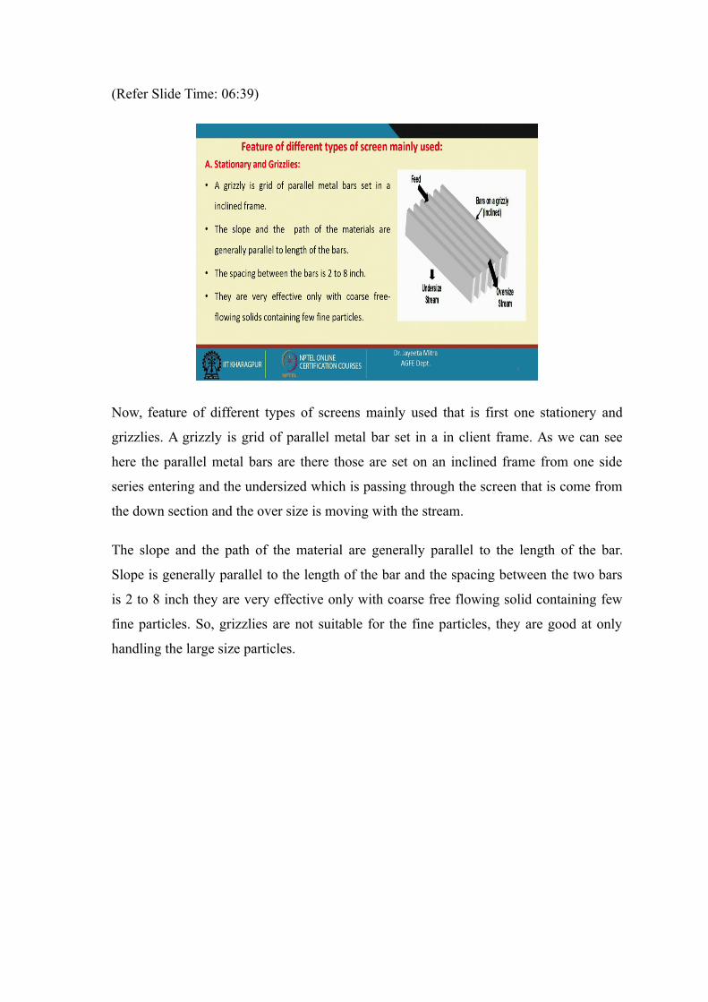
Now, feature of different types of screens mainly used that is first one stationery and
grizzlies. A grizzly is grid of parallel metal bar set in a in client frame. As we can see
here the parallel metal bars are there those are set on an inclined frame from one side
series entering and the undersized which is passing through the screen that is come from
the down section and the over size is moving with the stream.
The slope and the path of the material are generally parallel to the length of the bar.
Slope is generally parallel to the length of the bar and the spacing between the two bars
is 2 to 8 inch they are very effective only with coarse free flowing solid containing few
fine particles. So, grizzlies are not suitable for the fine particles, they are good at only
handling the large size particles.

(Refer Slide Time: 07:50)
Now gyrating screens. So, gyrating screens in this case the casing and screens are
gyrated in vertical plate, about the horizontal axis by an eccentric that is set halfway
between the feed point and the discharge. And the rate of gyration is again varies from
600 to 800 revolution per minute. Finer screens are gyrated at a feed end in a horizontal
plane and the discharge end reciprocate but not gyrate. So, gyratory arrangement we
have seen when we have discussed the different size reduction equipment, here also
gyrating screens are very common where we can use we can use this kind of screen to
separate different fraction of material.
(Refer Slide Time: 08:53)

Now, vibrating screen; so, this is another screen layer which can be vibrated horizontally
or vertically. So, this screens are rapidly vibrated with small amplitude and are less likely
to blind the blind that gyrating screens. So, because of this vibration, small amplitude
vibration that we are providing the screens are less likely to blind than the gyrating
screen.
So, the particle small particle would not clog or fill the small fine particles in the screen.
So, that is why it is beneficial compared to the gyrating screens. The vibration may be
generated mechanically or electrically mechanical vibrations are usually transmitted
from high speed eccentric to casing of the unit and therefore, to the steeply inclined
screens.
So, generally these screens are a bit incline to have a easy flow of the material; electrical
vibrations from heavy duty solenoids are transmitted to the casing or directly to the
screens. So, thereby the casing will vibrate with small magnitude. So, the first one, the
first figure is shows the heavy duty vertically gyrated and the second one is the
electrically vibrated screens.
(Refer Slide Time: 10:29)
Now, motion of screen can be of many types; are the first one is the gyration in
horizontal plane figure a, b is the gyration in particle plane, c the eccentric gyration. So,
gyration at one end shaking at the other end; gyration at one end and shaking at the other
end, d is shaking only and e is the mechanically vibrated screen and f is the electrically
vibrated screen.
So, all are the different arrangement of the screen that we can use based on product to
product or based on the efficiency. So, because inclination also is the flow of the grain
forward direction, gyration and shaking both help in the you know proper screening, and
they prevent the clogging of the mesh.
(Refer Slide Time: 11:33)
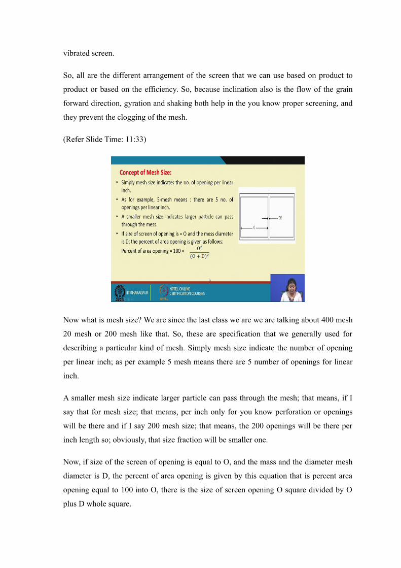
Now what is mesh size? We are since the last class we are we are talking about 400 mesh
20 mesh or 200 mesh like that. So, these are specification that we generally used for
describing a particular kind of mesh. Simply mesh size indicate the number of opening
per linear inch; as per example 5 mesh means there are 5 number of openings for linear
inch.
A smaller mesh size indicate larger particle can pass through the mesh; that means, if I
say that for mesh size; that means, per inch only for you know perforation or openings
will be there and if I say 200 mesh size; that means, the 200 openings will be there per
inch length so; obviously, that size fraction will be smaller one.
Now, if size of the screen of opening is equal to O, and the mass and the diameter mesh
diameter is D, the percent of area opening is given by this equation that is percent area
opening equal to 100 into O, there is the size of screen opening O square divided by O
plus D whole square.

So, mesh diameter is D and size of screen opening is O. So, O square divided by O plus
D square into 100 that gives us the percentage area opening.
(Refer Slide Time: 13:10)
Now, material balance over screens; so, as I mentioned that whenever we run some
material through a particular size of the perforation of a screen, so, some material will
definitely retain over the screen and some will pass through.
So, if we want to categorise that, we can have three fraction one is the feed that is the
size of the input that is coming on the on the screen, and another is the oversize that is
retain on the screen, and the other is the undersized which is pass through the particular
dimension or the particular mess size of that screen.
So, if we consider let us say F D and B are the mass flow rate of feed, respectively
overflow D and underflow B of the material. So, feed radius F over flow rate is D and
underflow flow rate is B. Now, the mass fraction of material A into three streams are X F,
X D and X B.
So, let us say I am separating the mixture of A and B and the fraction of A in all three
streams that is inlet stream or feed stream overflow stream, and underflow steam that I
have categorised as X F, X D and X B. Then material B if you want to identify what will
be the fraction of material B, in all the three streams that will be 1 minus X F that is in
the feed then 1 minus X D that is in the overflow and 1 minus X B that is in the

underflow. Because all the overflow and underflow or in the feed the total fraction will
remain 1. So, 1 minus X F 1 minus X D and on minus X B will be the mass fraction of
the material B in the feed overflow and underflow.
Now, according to the mass balance feed will be divided into or distributed into two
sections, overflow D and underflow B. So, F equal to D plus B. Now applying natural
balance we can write for a suppose if you want to do first F into X F that is equal to D
into X D plus B into X B. So, here the cumulative mass fraction larger than a particular
size B has been plotted with D. So, this kind of plot the cumulative mass distribution plot
we have seen in the particle size reduction class also. So, here the undersize and the
oversize and also the field has been plot in. So, we can get that if the critical diameter D
pc we want to calculate that for D pc if it is the feed. So, what will be the oversize
sample and what is the undersize sample of that.
(Refer Slide Time: 16:29)
So, then from both this equation that F equal to D plus B and F into X F equal to D into
X B plus B into X B, but I can get is D by F equal to X F minus X B divide by X D
minus X D. So, here over flow by feed we have expressed similarly we can express
underflow by feed that is X D minus X F by X D minus X B.
So, what is it overflow D minus feed that is equal to amount of fraction of A in feed X F
minus amount of fraction in B that is the underflow. So, X F minus X D divide by X D
that is amount of fraction of A in the overflow minus amount of that that is going in the

underflow similarly we can calculate B by F.
Now screen effectiveness; this is the effectiveness of a screen is a measure of success of
a screen in closely separating the material A and B. So, it has been ideally separate A and
B; completely the size has been define in such a way, a common measure of screen
effectiveness is the ratio of the oversize material A that is actually in the overflow to the
amount of A enduring with the feed.
So, screen effectiveness or oversize material are given as follows. So, E A based on the
material A which is the oversize material, D in to X D that is the fraction of A that has
gone into the, that has present in the overflow. So, D into X D divided by the that was
present in the feed so, F into X F.
Similarly, the screen effectiveness of undersized material is given as well as follows E B
that is call to B into 1 minus X B that means, the undersized fraction that has gone to the
undersize, divided by the undersized fraction present in feed.
(Refer Slide Time: 18:46)
So, combining all those two efficiency based on oversize and undersize we can write E
equal to D into B in to X D into 1 minus X D divided by F square that is feed rate square
into X F into 1 minus X F.
And again if you want to change the value of that D and B and replace with the fraction
so, D by F and B by F has been replaced by this two factor D by F and B by F. So, we are
getting X F minus X D by X D minus X D multiplied with X D minus X F by X D minus
X D. So, putting that into this equation we are getting an overall efficiency expression as
E equal to X F minus X B into X D minus X F into X D into 1 minus X B divided by X
D minus X B square into 1 minus X F into X F. So, this is the final expression of
effectiveness, screen effectiveness.
(Refer Slide Time: 20:02)
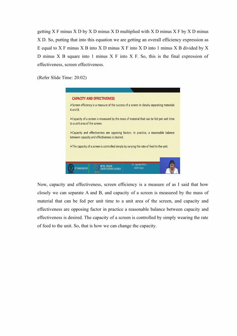
Now, capacity and effectiveness, screen efficiency is a measure of as I said that how
closely we can separate A and B, and capacity of a screen is measured by the mass of
material that can be fed per unit time to a unit area of the screen, and capacity and
effectiveness are opposing factor in practice a reasonable balance between capacity and
effectiveness is desired. The capacity of a screen is controlled by simply wearing the rate
of feed to the unit. So, that is how we can change the capacity.

(Refer Slide Time: 20:42)
Effect of mesh size on capacity of the screen; the probability of passage of a particle
through a screen depends upon diffraction of the total surface represented by screen
opening. It depends upon the ratio of diameter of the particle to the width of an opening
of the screen on the number of contact between the particle and the screen surface. So,
many factors are there.
First is the ratio of the diameter of the particle to the width of opening of the screen and
on the number of contact between the particle and the screen surface. So, the size of the
largest particle is just equal to the width of the screen opening which is D pc critical
diameter the larger size and the largest particle, and the number of opening per unit
screen area is proportional to 1 by D pc square. Because we have mention that the
particle that has been retained in a time, the you know the number of opening per unit
screen should be proportional to the 1 by D p square.
So, the particle size that has been retained on that; that means it is having a bigger size
particle and perforation size or the screen mesh size is lower than that. So, mass of one
particle is proportional to D p the linear dimension q because volume that is d p q into
density therefore, the capacity is again based on the area and area is here proportional to
1 by D p square. So, capacity width unit time of the screen will proportional to 1 by D pc
square into D pc cube; that means it will vary directly with the D pc that is the critical
diameter which is the size just above just little above the mesh opening size of a

particular screen.
(Refer Slide Time: 22:51)
Now, here one problem is given where a quartz mixture having the screen analysis
shown in the below table, screen to a standard ten mesh screen, calculate the mesh mass
ratio of overflow or underflow to the feed and over a effectiveness of the screen.
Now, the similar kind of analysis you can do by any grain sample as well any mixture of
the grain particle or other different size fraction you take and do the you know see the
analysis in a similar way. We have taken this data from book that is why this distribution
has been given on the quartz, but same principle we can use for food material for any
ground flow distribution as well. So, mesh size has been given and particle diameter D p
is given, feed rate overflow and underflow rate is also given. Now, what we need to see?
We need to see the critical diameter, what is the critical diameter?

(Refer Slide Time: 23:56)
So, the cut point diameter is the mesh size diameter of the screen, which is 1.651 mm.
So, this has been taken from the tabulated data, for this screen that is 1.651 this particular
size for this particular set of screen that we have use we have calculated the X F, X D and
X B.
So, D p size 1.651 for this size see the feed is 0.47 overflow is 0.85 and underflow is
0.195. So, we are expecting that maximum fraction of they should come in the overflow.
So, if that happens once we have got this value of X F, X D and X D the ratio of
overflow to feed that is D by F we will calculate and underflow to feed that is B by F that
we will calculate. So, that is coming respect respectively 0.420 divided 0.420 and 0.58.
Now, we will use the effectiveness formula which is overall effectiveness based on
oversize and undersize and put all such values that is value of the X F minus X B 0.47
minus 0.195 into X D minus X F that is 0.85 minus 0.47 into 1 minus X B that is 1 minus
0.195 into X D divided by X D minus X B square. So, 0.85 minus 0.195 square into this
into this factor 0.47 that is X F and 0.58 that is the value of B by F.
So, if we just checking with the equation, this was our equation X F into 1 minus X F.
So, that thing we will just put it here all the values, and then we can get the overall
effectiveness of the screen. So, this is how we can solve the, we can calculate the
effectiveness of a screen and also we can find out from what will be the oversize fraction
and undersize fraction and capacity of the screen also. So, in the next class we will move

on to the other different mechanical separation techniques in this chapter.
Thank you.


![41 \]'[;plouytdsaz 5 - NJ.gov](https://img.pdfslide.net/doc/110x75/631bc6d87051d371800f2c5b/41-plouytdsaz-5-njgov.jpg)


