Embed Size (px)
Citation preview
MEC 267-FLUID MECHANICS –I
BYBY
ENGR. FAHMAN RAHMAN
ME Faculty, IUBAT
LECTURE-11
LAMINAR FLOW THROUGH CIRCULAR PIPE
DERIVATION OF HAGEN-POISELLIE’S EQUATION
FRICTIONAL HEAD LOSS IN PIPE FOR BOTH LAMINAR & TURBULENT FLOW
DARCY-WEISBACH EQUATION AND DARCY FRICTION FACTOR
Fazlar Rahman, ME, IUBAT; MEC267; LEC 11 2
(ALL SEE HAND ANALYSIS)

Kinetic Energy Correction Factor
DERIVATION OF HAGEN-POISELLIE’S E
(ALL SEE HAND ANALYSIS)
Fazlar Rahman, ME, IUBAT; MEC267; LEC 11 3
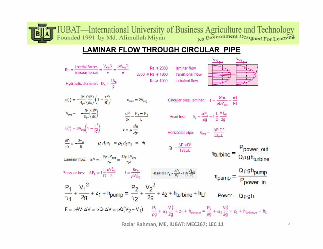
LAMINAR FLOW THROUGH CIRCULAR PIPE
Fazlar Rahman, ME, IUBAT; MEC267; LEC 11 4
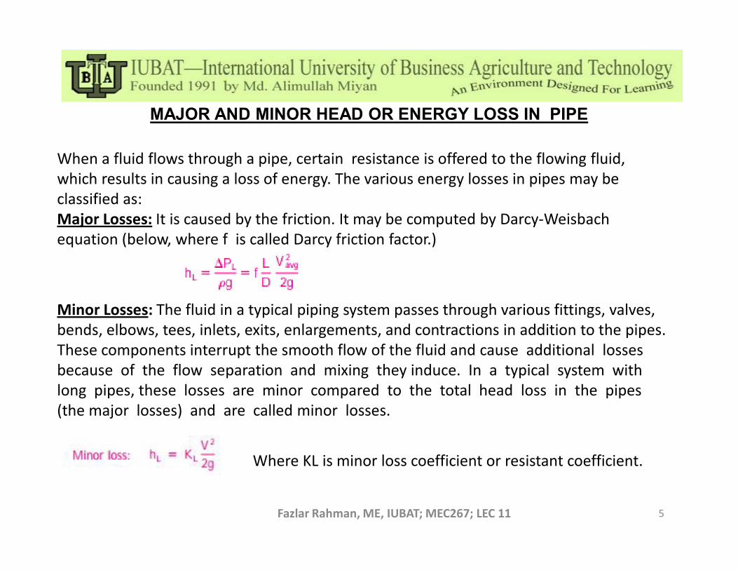
MAJOR AND MINOR HEAD OR ENERGY LOSS IN PIPE
When a fluid flows through a pipe, certain resistance is offered to the flowing fluid, which results in causing a loss of energy. The various energy losses in pipes may be classified as:Major Losses: It is caused by the friction. It may be computed by Darcy-Weisbach equation (below, where f is called Darcy friction factor.)
Fazlar Rahman, ME, IUBAT; MEC267; LEC 11 5
Minor Losses: The fluid in a typical piping system passes through various fittings, valves,bends, elbows, tees, inlets, exits, enlargements, and contractions in addition to the pipes. These components interrupt the smooth flow of the fluid and cause additional losses because of the flow separation and mixing they induce. In a typical system with long pipes, these losses are minor compared to the total head loss in the pipes (the major losses) and are called minor losses.
Where KL is minor loss coefficient or resistant coefficient.

MINOR HEAD OR ENERGY LOSS IN PIPE
Minor Losses (continue): Minor losses are also expressed in terms of the equivalent length Lequiv defined as ,
Frictional head Loss:
where f is the friction factor and D is the diameter of the pipe that contains the component. The head loss caused by the component is equivalent to the head loss caused by a section
Fazlar Rahman, ME, IUBAT; MEC267; LEC 11 6
The head loss caused by the component is equivalent to the head loss caused by a section of the pipe whose length is Lequiv . Once all the loss coefficients are available, the total head loss in a piping system is determined from
where i represents each pipe section with constant diameter and j represents each component that causes a minor loss. If the entire piping system being analyzed has a constant diameter,
where V is the average flow velocity through the entire system (V is constant since D is constant)

MINOR HEAD OR ENERGY LOSS IN PIPE
Minor Losses (continue): Value of KL can be found by using following table.
Fazlar Rahman, ME, IUBAT; MEC267; LEC 11 7

MINOR HEAD OR ENERGY LOSS IN PIPE
Minor Losses (continue): Value of KL can be found by using following table.
Fazlar Rahman, ME, IUBAT; MEC267; LEC 11 8
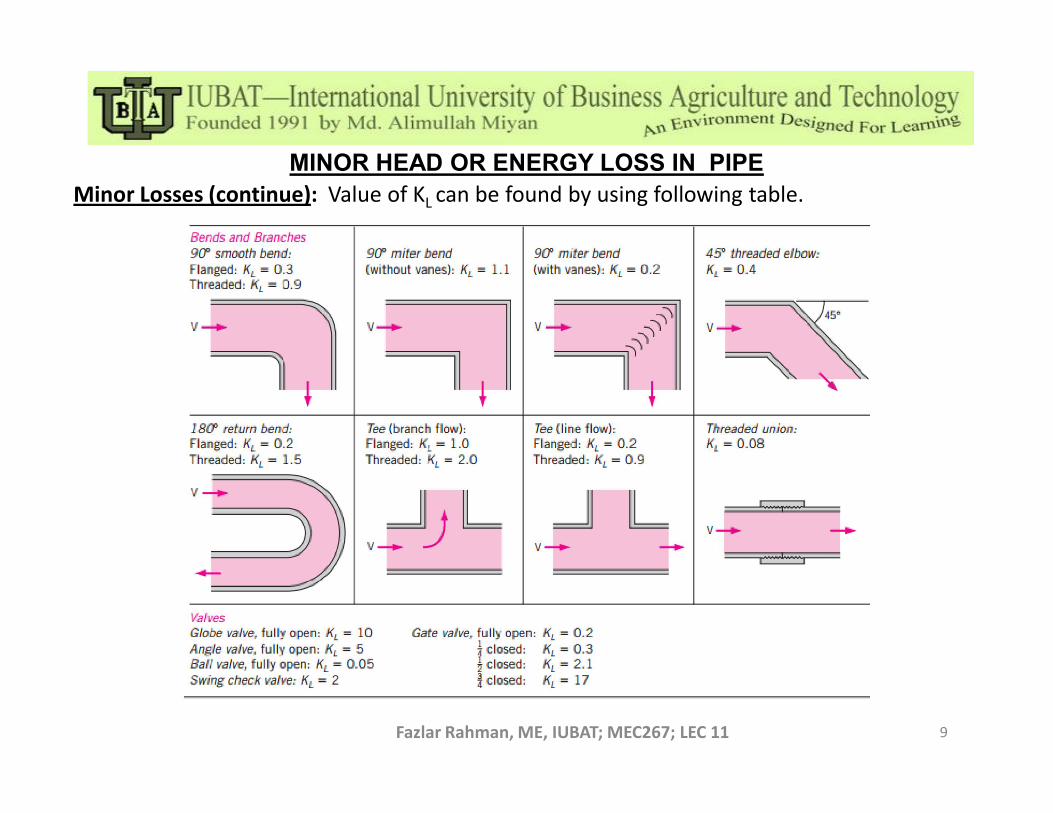
MINOR HEAD OR ENERGY LOSS IN PIPE
Minor Losses (continue): Value of KL can be found by using following table.
Fazlar Rahman, ME, IUBAT; MEC267; LEC 11 9
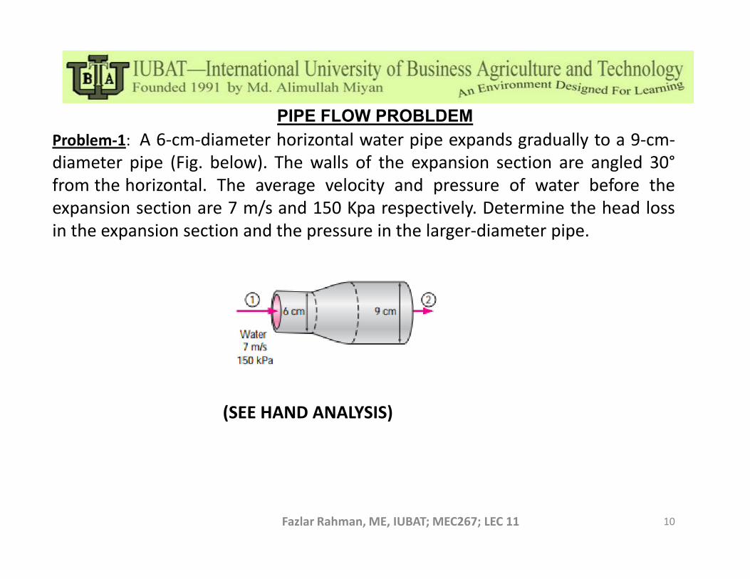
PIPE FLOW PROBLDEM
Problem-1: A 6-cm-diameter horizontal water pipe expands gradually to a 9-cm-diameter pipe (Fig. below). The walls of the expansion section are angled 30°from the horizontal. The average velocity and pressure of water before theexpansion section are 7 m/s and 150 Kpa respectively. Determine the head lossin the expansion section and the pressure in the larger-diameter pipe.
Fazlar Rahman, ME, IUBAT; MEC267; LEC 11 10
(SEE HAND ANALYSIS)
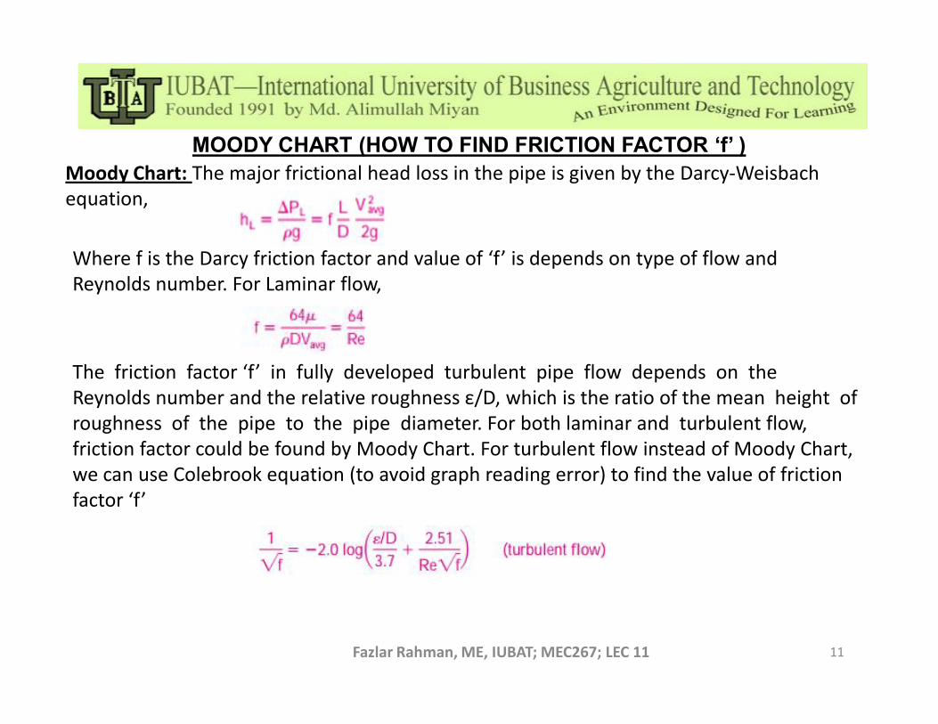
MOODY CHART (HOW TO FIND FRICTION FACTOR ‘f’ )
Moody Chart: The major frictional head loss in the pipe is given by the Darcy-Weisbach equation,
Where f is the Darcy friction factor and value of ‘f’ is depends on type of flow and Reynolds number. For Laminar flow,
The friction factor ‘f’ in fully developed turbulent pipe flow depends on the
Fazlar Rahman, ME, IUBAT; MEC267; LEC 11 11
The friction factor ‘f’ in fully developed turbulent pipe flow depends on the Reynolds number and the relative roughness ε/D, which is the ratio of the mean height of roughness of the pipe to the pipe diameter. For both laminar and turbulent flow, friction factor could be found by Moody Chart. For turbulent flow instead of Moody Chart, we can use Colebrook equation (to avoid graph reading error) to find the value of friction factor ‘f’

MOODY CHART (HOW TO FIND FRICTION FACTOR ‘f’ )
Fazlar Rahman, ME, IUBAT; MEC267; LEC 11 12
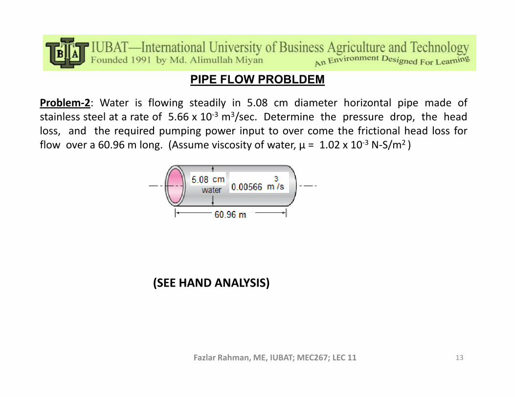
PIPE FLOW PROBLDEM
Problem-2: Water is flowing steadily in 5.08 cm diameter horizontal pipe made ofstainless steel at a rate of 5.66 x 10⁻³ m3/sec. Determine the pressure drop, the headloss, and the required pumping power input to over come the frictional head loss forflow over a 60.96 m long. (Assume viscosity of water, μ = 1.02 x 10⁻³ N-S/m2 )
Fazlar Rahman, ME, IUBAT; MEC267; LEC 11 13
(SEE HAND ANALYSIS)
PIPE FLOW PROBLDEM
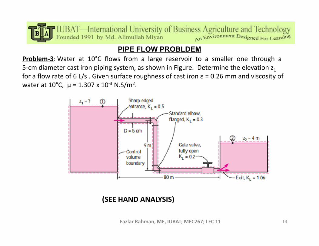
Problem-3: Water at 10°C flows from a large reservoir to a smaller one through a 5-cm diameter cast iron piping system, as shown in Figure. Determine the elevation z1
for a flow rate of 6 L/s . Given surface roughness of cast iron ε = 0.26 mm and viscosity of water at 10°C, μ = 1.307 x 10⁻³ N.S/m2.
Fazlar Rahman, ME, IUBAT; MEC267; LEC 11 14
(SEE HAND ANALYSIS)


