Embed Size (px)
Citation preview
technical guide LED control
Philips Dynalite Technical Guide – LED Control Page 1 of 10
overview
Offering exceptional life, versatile control flexibility and unlimited colour mixing potential, LED sources
are becoming increasingly prevalent in architectural lighting applications. The vast range of LED fittings
and sources now available provides a multitude of creative illumination design possibilities. Harnessing
this potential requires a sophisticated control system. Philips Dynalite has responded to this need and
developed a comprehensive range of controllers, designed to directly connect and drive most popular
conventions of LED fittings and sources. This guide outlines LED fitting circuit design concepts and
provides instruction on selecting appropriate dimming control solutions.
LED fundamentals
Light Emitting Diodes (LEDs) are semi-conductor devices that emit photon energy (light) when an
electrical current is passed through them. Detailed below is the electrical symbol that is commonly used
to represent an LED.
Anode(+) Cathode(-)
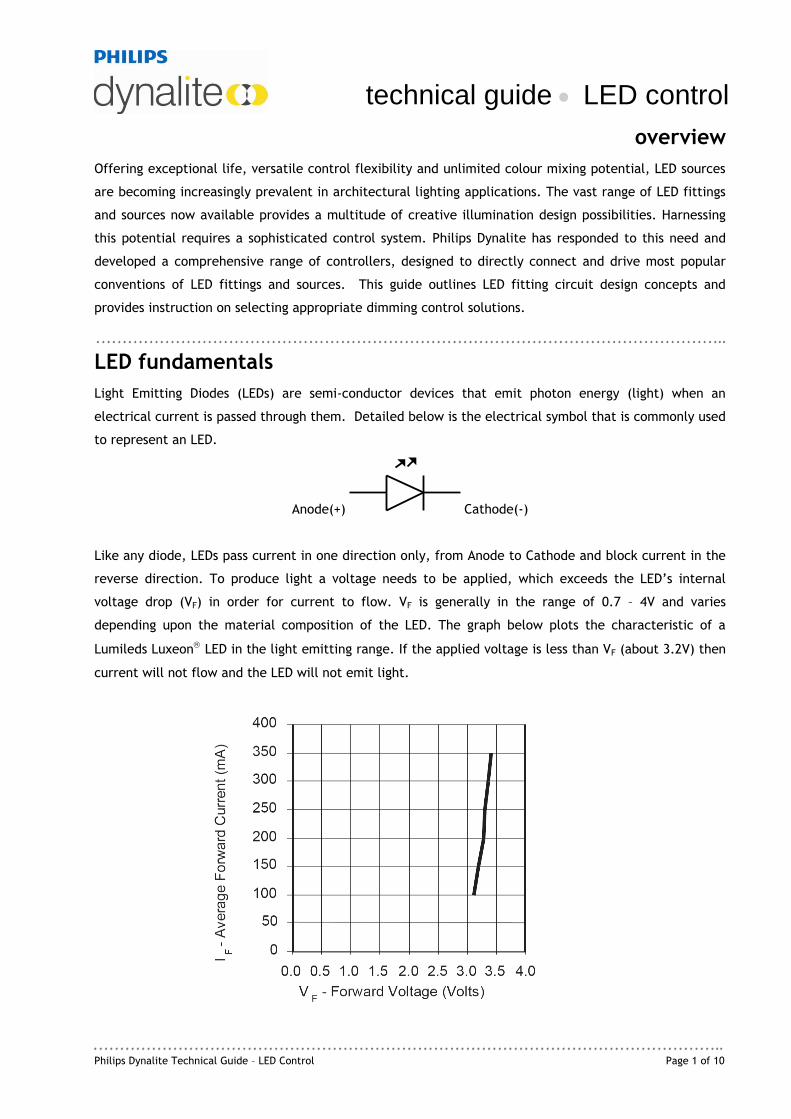
Like any diode, LEDs pass current in one direction only, from Anode to Cathode and block current in the
reverse direction. To produce light a voltage needs to be applied, which exceeds the LED’s internal
voltage drop (VF) in order for current to flow. VF is generally in the range of 0.7 – 4V and varies
depending upon the material composition of the LED. The graph below plots the characteristic of a
Lumileds Luxeon LED in the light emitting range. If the applied voltage is less than VF (about 3.2V) then
current will not flow and the LED will not emit light.
Page 2 of 10 Philips Dynalite Technical Guide – LED Control
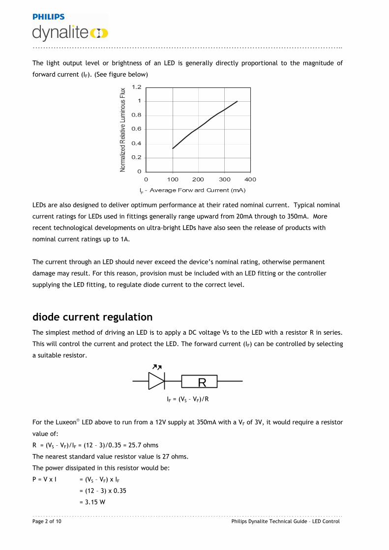
The light output level or brightness of an LED is generally directly proportional to the magnitude of
forward current (IF). (See figure below)
LEDs are also designed to deliver optimum performance at their rated nominal current. Typical nominal
current ratings for LEDs used in fittings generally range upward from 20mA through to 350mA. More
recent technological developments on ultra-bright LEDs have also seen the release of products with
nominal current ratings up to 1A.
The current through an LED should never exceed the device’s nominal rating, otherwise permanent
damage may result. For this reason, provision must be included with an LED fitting or the controller
supplying the LED fitting, to regulate diode current to the correct level.
diode current regulation
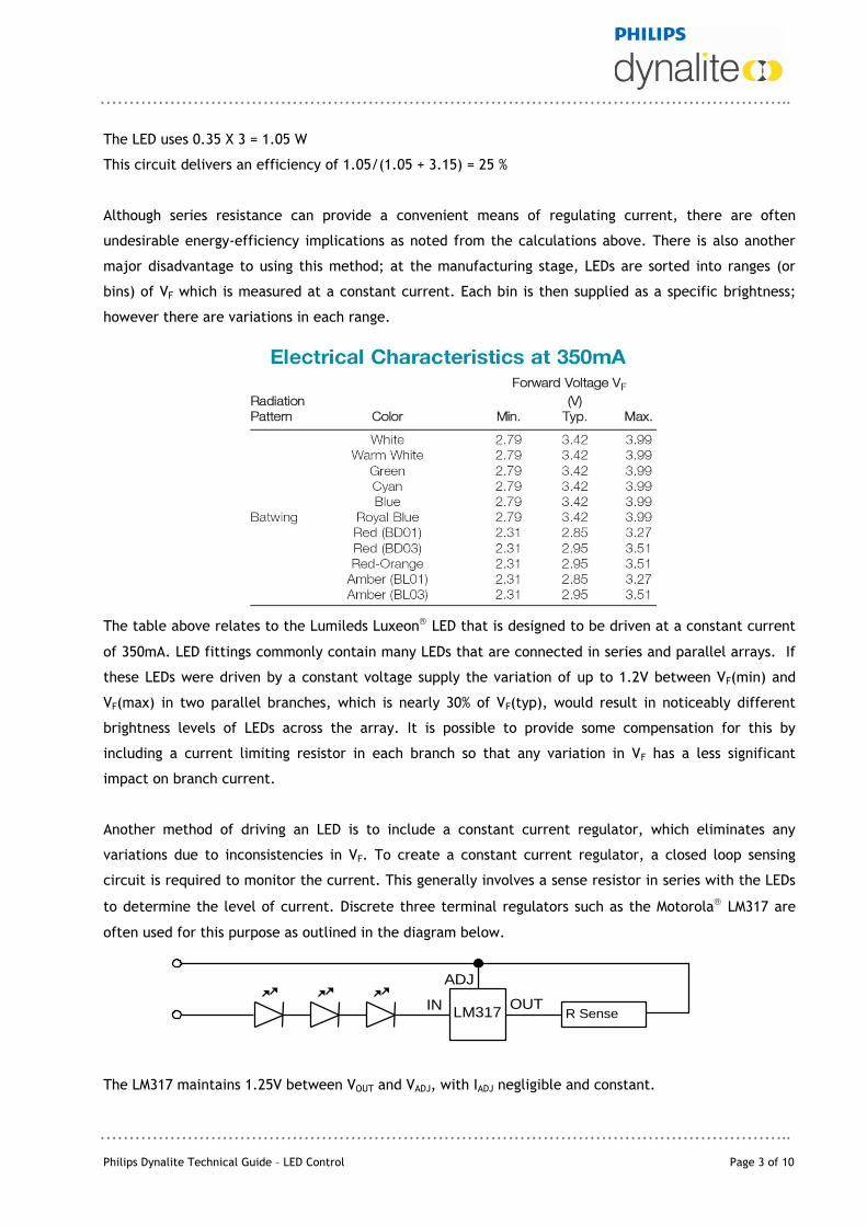
The simplest method of driving an LED is to apply a DC voltage Vs to the LED with a resistor R in series.
This will control the current and protect the LED. The forward current (IF) can be controlled by selecting
a suitable resistor.
R
IF = (VS – VF)/R
For the Luxeon LED above to run from a 12V supply at 350mA with a VF of 3V, it would require a resistor
value of:
R = (VS – VF)/IF = (12 – 3)/0.35 = 25.7 ohms
The nearest standard value resistor value is 27 ohms.
The power dissipated in this resistor would be:
P = V x I = (VS – VF) x IF
= (12 – 3) x 0.35
= 3.15 W
Philips Dynalite Technical Guide – LED Control Page 3 of 10
The LED uses 0.35 X 3 = 1.05 W
This circuit delivers an efficiency of 1.05/(1.05 + 3.15) = 25 %
Although series resistance can provide a convenient means of regulating current, there are often
undesirable energy-efficiency implications as noted from the calculations above. There is also another
major disadvantage to using this method; at the manufacturing stage, LEDs are sorted into ranges (or
bins) of VF which is measured at a constant current. Each bin is then supplied as a specific brightness;
however there are variations in each range.
The table above relates to the Lumileds Luxeon LED that is designed to be driven at a constant current
of 350mA. LED fittings commonly contain many LEDs that are connected in series and parallel arrays. If
these LEDs were driven by a constant voltage supply the variation of up to 1.2V between VF(min) and
VF(max) in two parallel branches, which is nearly 30% of VF(typ), would result in noticeably different
brightness levels of LEDs across the array. It is possible to provide some compensation for this by
including a current limiting resistor in each branch so that any variation in VF has a less significant
impact on branch current.
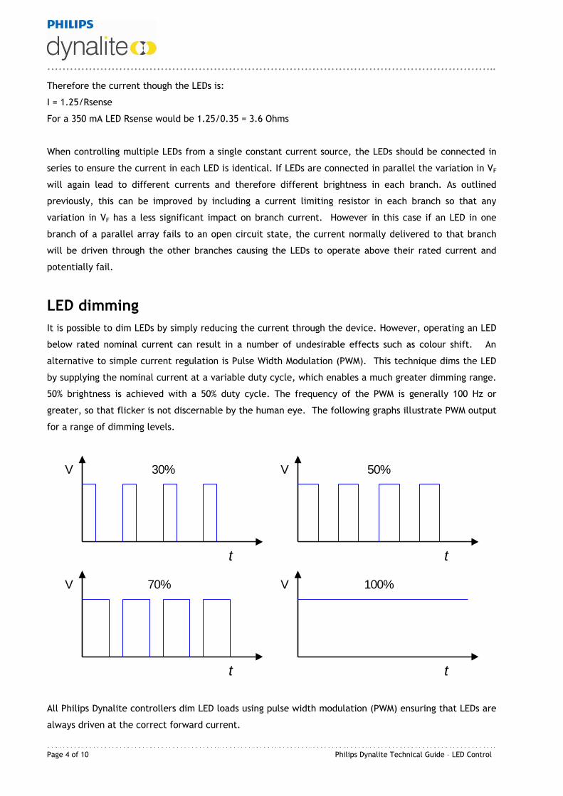
Another method of driving an LED is to include a constant current regulator, which eliminates any
variations due to inconsistencies in VF. To create a constant current regulator, a closed loop sensing
circuit is required to monitor the current. This generally involves a sense resistor in series with the LEDs
to determine the level of current. Discrete three terminal regulators such as the Motorola LM317 are
often used for this purpose as outlined in the diagram below.
The LM317 maintains 1.25V between VOUT and VADJ, with IADJ negligible and constant.
IN OUT
ADJ
LM317 R Sense
Page 4 of 10 Philips Dynalite Technical Guide – LED Control
Therefore the current though the LEDs is:
I = 1.25/Rsense
For a 350 mA LED Rsense would be 1.25/0.35 = 3.6 Ohms
When controlling multiple LEDs from a single constant current source, the LEDs should be connected in
series to ensure the current in each LED is identical. If LEDs are connected in parallel the variation in VF
will again lead to different currents and therefore different brightness in each branch. As outlined
previously, this can be improved by including a current limiting resistor in each branch so that any
variation in VF has a less significant impact on branch current. However in this case if an LED in one
branch of a parallel array fails to an open circuit state, the current normally delivered to that branch
will be driven through the other branches causing the LEDs to operate above their rated current and
potentially fail.
LED dimming
It is possible to dim LEDs by simply reducing the current through the device. However, operating an LED
below rated nominal current can result in a number of undesirable effects such as colour shift. An
alternative to simple current regulation is Pulse Width Modulation (PWM). This technique dims the LED
by supplying the nominal current at a variable duty cycle, which enables a much greater dimming range.
50% brightness is achieved with a 50% duty cycle. The frequency of the PWM is generally 100 Hz or
greater, so that flicker is not discernable by the human eye. The following graphs illustrate PWM output
for a range of dimming levels.
V
t
V
t
V
t
V
t
30% 50%
70% 100%
All Philips Dynalite controllers dim LED loads using pulse width modulation (PWM) ensuring that LEDs are
always driven at the correct forward current.
Philips Dynalite Technical Guide – LED Control Page 5 of 10
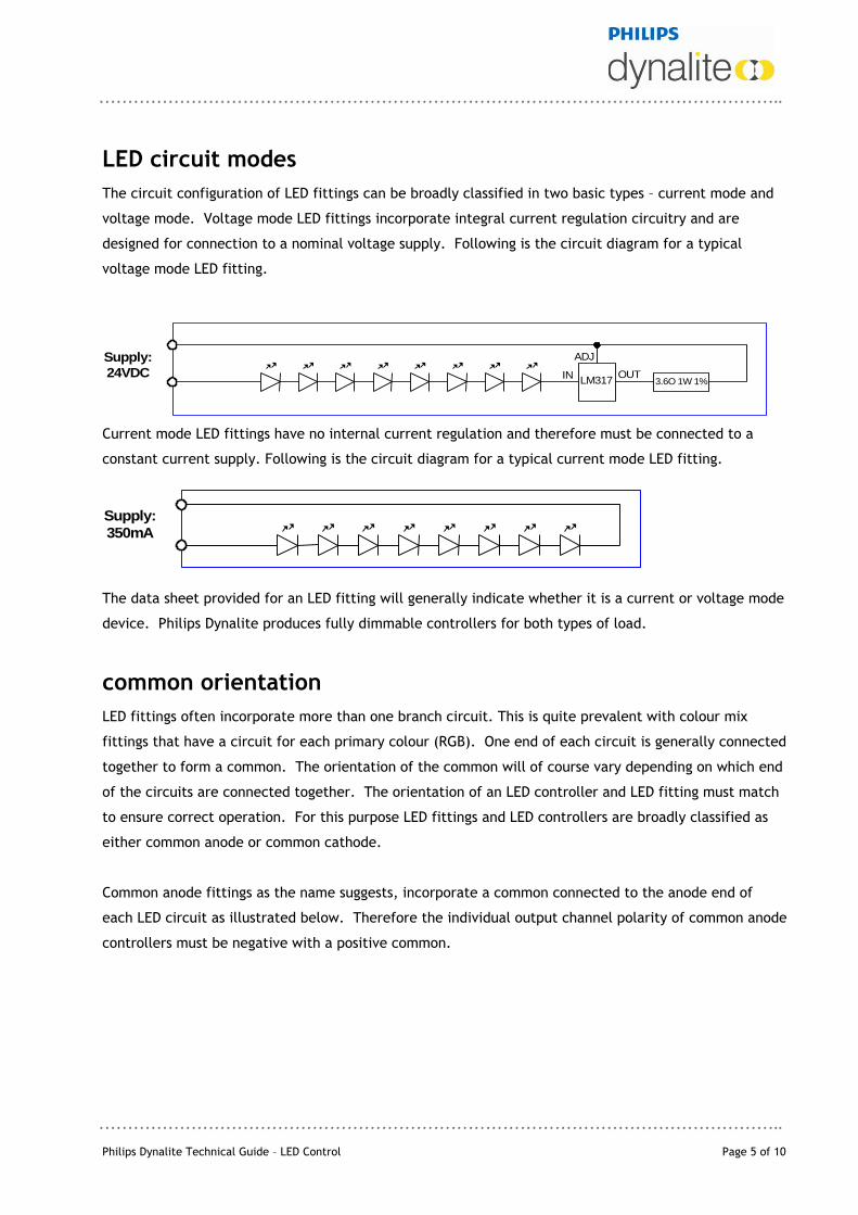
LED circuit modes
The circuit configuration of LED fittings can be broadly classified in two basic types – current mode and
voltage mode. Voltage mode LED fittings incorporate integral current regulation circuitry and are
designed for connection to a nominal voltage supply. Following is the circuit diagram for a typical
voltage mode LED fitting.
IN OUT
ADJ
LM317 3.6O 1W 1%
Supply:
24VDC
Current mode LED fittings have no internal current regulation and therefore must be connected to a
constant current supply. Following is the circuit diagram for a typical current mode LED fitting.
Supply:
350mA
The data sheet provided for an LED fitting will generally indicate whether it is a current or voltage mode
device. Philips Dynalite produces fully dimmable controllers for both types of load.
common orientation
LED fittings often incorporate more than one branch circuit. This is quite prevalent with colour mix
fittings that have a circuit for each primary colour (RGB). One end of each circuit is generally connected
together to form a common. The orientation of the common will of course vary depending on which end
of the circuits are connected together. The orientation of an LED controller and LED fitting must match
to ensure correct operation. For this purpose LED fittings and LED controllers are broadly classified as
either common anode or common cathode.
Common anode fittings as the name suggests, incorporate a common connected to the anode end of
each LED circuit as illustrated below. Therefore the individual output channel polarity of common anode
controllers must be negative with a positive common.
Page 6 of 10 Philips Dynalite Technical Guide – LED Control
CH3
CH2
COM
CH1
Conversely, common cathode fittings incorporate a common connected to the cathode end of each LED
circuit. In this case the individual output channel polarity of common cathode controllers must be
positive with a negative common.
CH3
CH2
COM
CH1
In both cases the common is not necessarily at ground potential and should therefore never be
connected to a supply ground at any point.
The orientation of proprietary LED fittings currently available is predominantly common anode. For this
reason Dynalite LED controllers are designed to provide common anode output. Common cathode
configuration is available as an option on certain Dynalite LED controllers. Please refer to product data
sheet for specific option detail.
controller selection - voltage mode fittings
Selecting a suitable controller for voltage mode fittings is a straightforward process. First it is necessary
to select a controller that can deliver the nominal fitting voltage. The data sheet for a typical constant
voltage fitting will generally include values for the power consumed by the fitting and also the required
nominal voltage VF. Certain Philips Dynalite controllers which incorporate an integral power supply
deliver a specific output voltage i.e. 24VDC, in line with popular nominal voltage conventions. Other
Philips Dynalite controllers utilise external power supplies permitting a range of output voltages
dependant upon the voltage of the external power supply. For multi-circuit fittings the common
orientation should also be confirmed as compatible with the controller output. Finally, the controller
channel output current capacity should be selected to exceed the connected load. The total load can
be easily calculated by multiplying the total number of fittings per channel by the current per fitting. If
only the power rating of the fitting is available the following expression can be used:
Philips Dynalite Technical Guide – LED Control Page 7 of 10
IT = n x PF
VN
IT = Total current per channel
PF = Power rating of LED fitting
VN = Nominal voltage of fitting
n = Number of LED fittings per channel
The controller selection process for voltage mode fittings can be summarised as follows:
Select output voltage to match fitting nominal voltage.
For multi-circuit LED fittings confirm common orientation aligns with controller.
Select output current rating to exceed connected load.
The following table summarises the current range of Philips Dynalite voltage mode controllers.
Item Code DDLEDC401 DDLEDC605
Controller Voltage 24VDC,
12VDC (optional)
18-32VDC,
12-15VDC selectable
Common Orientation Common anode
Common cathode (optional)
Common anode
Channels 4 6
Output current per channel 1A 5A
Total controller load 20A
Power supply Integral mains 240VAC External safety extra low voltage
Housing DIN Rail DIN Rail
controller selection - current mode fittings
The considerations for selecting an appropriate controller for current mode fittings relate more to the
controller’s internal capacity to dissipate energy. This is because a constant current driver regulates the
current flow through the LED circuit by effectively absorbing any excess voltage to maintain the nominal
current level. In general, drive circuit internal power dissipation and thus heat generation is inversely
proportional to the number of LEDs in series. Circuits with fewer LEDs in series will have greater heat
generation in the drive circuit for a specific supply voltage. Therefore it is ideal to be aware of the
power dissipation limits of the controller during the fitting design process.
The first step in selecting a suitable controller is to determine the appropriate supply voltage and
confirm it falls within the maximum and minimum limits applicable for the controller. Following are
calculations for determining these limits.
Maximum Supply Voltage
Page 8 of 10 Philips Dynalite Technical Guide – LED Control
VS max = PC + (n x VF) or VC max, whichever is the lesser ID
VS max = Maximum supply voltage
PC = Max controller internal power dissipation per channel
ID = Nominal LED current
n = Number of diodes in series per channel
VF = LED forward voltage
VC max = Maximum controller voltage
Minimum Supply Voltage
VS min = 4 + (n x VF) or 12VDC, whichever is the greater
VS min = Minimum supply voltage
n = Number of diodes in series per channel
VF = LED forward voltage
Once again, for multi-circuit fittings the common orientation should be confirmed as compatible with
the controller output. The final step is to calculate the controller internal power dissipation and ensure
it is within the controller’s limits. Following is the expression that should be used to determine this.
PD = (VS - (VF x n)) x ID
PD = Power dissipation per channel
VS = Supply voltage
VF = Diode forward voltage
n = Number of diodes in series per channel
ID = Nominal diode current
It is sometimes necessary to increase the number of LEDs or introduce Zener diodes in series to increase
the total VF and therefore reduce the internal power dissipation.
The controller selection process for current mode fittings can be summarised as follows:
Confirm required supply voltage is within acceptable limits for the controller.
For multi circuit LED fittings confirm common orientation aligns with controller.
Calculate and ensure internal power dissipation is within controller limits.
Philips Dynalite Technical Guide – LED Control Page 9 of 10
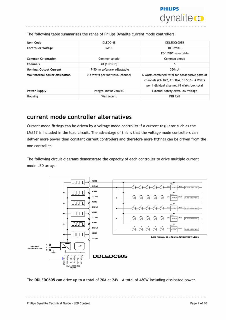
The following table summarizes the range of Philips Dynalite current mode controllers. Item Code DLEDC-48 DDLEDC60035
Controller Voltage 36VDC 18-32VDC,
12-15VDC selectable
Common Orientation Common anode Common anode
Channels 48 (16xRGB) 6
Nominal Output Current 17-50mA software adjustable 350mA
Max internal power dissipation 0.4 Watts per individual channel 6 Watts combined total for consecutive pairs of
channels (Ch 1&2, Ch 3&4, Ch 5&6). 4 Watts
per individual channel.18 Watts box total
Power Supply Integral mains 240VAC External safety extra low voltage
Housing Wall Mount DIN Rail
current mode controller alternatives
Current mode fittings can be driven by a voltage mode controller if a current regulator such as the
LM317 is included in the load circuit. The advantage of this is that the voltage mode controllers can
deliver more power than constant current controllers and therefore more fittings can be driven from the
one controller.
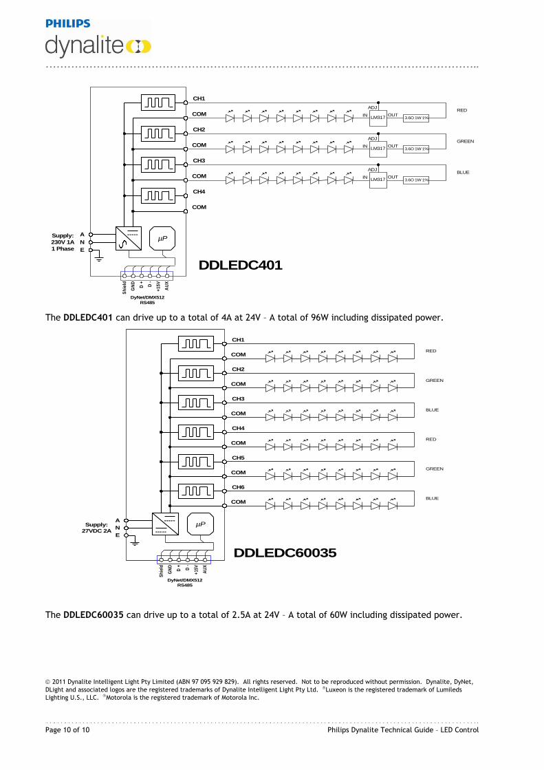
The following circuit diagrams demonstrate the capacity of each controller to drive multiple current
mode LED arrays.
CH4
COM
DyNet/DMX512
RS485
AU
X
+15VD + D -
GN
D
Shi
eld
Supply:
28-30VDC 5A
+
-
E
µP
CH3
COM
CH2
COM
CH1
COM
CH5
COM
CH6
COM
DDLEDC605
IN OUT
ADJ
LM317
IN OUT
ADJ
LM317
IN OUT
ADJ
LM317
IN OUT
ADJ
LM317 8.2O 0.25W 1%
IN OUT
ADJ
LM317
8.2O 0.25W 1%
8.2O 0.25W 1%
8.2O 0.25W 1%
8.2O 0.25W 1%
LED Fitting, 25 x Nichia NFSW036T LEDs
The DDLEDC605 can drive up to a total of 20A at 24V – A total of 480W including dissipated power.
Page 10 of 10 Philips Dynalite Technical Guide – LED Control
CH4
COM
DyNet/DMX512
RS485
AU
X
+1
5V
D + D -
GN
D
Sh
ield
Supply:
230V 1A
1 Phase
A
N
E
µP
CH3
COM
CH2
COM
CH1
COM IN OUT
ADJ
LM317
IN OUT
ADJ
LM317
IN OUT
ADJ
LM317
RED
GREEN
BLUE
3.6O 1W 1%
3.6O 1W 1%
3.6O 1W 1%
DDLEDC401
The DDLEDC401 can drive up to a total of 4A at 24V – A total of 96W including dissipated power.
CH4
COM
DyNet/DMX512
RS485
AU
X
+15
V
D + D -
GN
D
Sh
ield
Supply:
27VDC 2A
A
N
E
µP
CH3
COM
CH2
COM
CH1
COMRED
GREEN
BLUE
CH5
COM
CH6
COM
RED
GREEN
BLUE
DDLEDC60035
The DDLEDC60035 can drive up to a total of 2.5A at 24V – A total of 60W including dissipated power.
2011 Dynalite Intelligent Light Pty Limited (ABN 97 095 929 829). All rights reserved. Not to be reproduced without permission. Dynalite, DyNet,
DLight and associated logos are the registered trademarks of Dynalite Intelligent Light Pty Ltd. Luxeon is the registered trademark of Lumileds
Lighting U.S., LLC. Motorola is the registered trademark of Motorola Inc.


![4`^aVeZ_X eYV`cZVd+ 6iZe a`]]d gd ]ReV efc_`fe ... - Daily Pioneer](https://img.pdfslide.net/doc/110x75/6337b1365b431bfc0700d32b/4avezx-eyvczvd-6ize-ad-gd-rev-efcfe-daily-pioneer.jpg)


