Embed Size (px)
Citation preview

LED SLIT LAMP
MW50D
Instructions
February 2017
D046-2E

1
CAUTION Read this instruction manual before using the instrument.
This instruction manual was written to provide the user with information
about safe operation of the LED SLIT LAMP MW50D.
This manual contains operating instructions, safety precautions, and
specifications for the instrument.
For installation instructions, contact your local dealer.
The material in this manual complies with the ISO and IEC standards.
Read this manual thoroughly and familiarize yourself with the operation of
the instrument and safety precautions before using the instrument.
Keep this instruction manual handy and refer to it whenever necessary.
If you have any questions regarding this manual, contact your local dealer.
・No reproduction of this manual in any form, in whole or in part, may be
made without written permission from Right MFG. Co., Ltd.
・The information contained in this manual is subject to change without
notice.

2
Contents
1. GENERAL INFORMATION .................................................................................................. 10
1-1. PRODUCT DESCRIPTION, STANDARD COMPONENTS, AND OPTIONAL ACCESSORIES ........ 10
1-2. INSTRUMENT CLASSIFICATIONS ............................................................................................. 11
1-3. SYMBOLS FOUND ON THE INSTRUMENT ................................................................................ 12
1-4. SAFETY LABELS ....................................................................................................................... 13
2. PICTORIAL NOMENCLATURE AND FUNCTIONS ........................................................ 14
2-1. SYSTEM CONFIGURATION ....................................................................................................... 14
2-2. EYEPIECE BLOCK .................................................................................................................... 15
2-3. ILLUMINATOR BLOCK .............................................................................................................. 15
2-4. CROSS-SLIDE TABLE ............................................................................................................... 16
2-5. CHIN REST ................................................................................................................................ 17
2-6. POWER SUPPLY UNIT .............................................................................................................. 17
3. INSTALLATION ..................................................................................................................... 17
3-1. CHECKING BEFORE USE .......................................................................................................... 18
3-2. EYEPIECE LENS ....................................................................................................................... 18
3-3. INSTALLING THE MIRROR ....................................................................................................... 19
3-4. DIOPTER ADJUSTMENT ........................................................................................................... 19
3-5. BACKGROUND ILLUMINATION UNIT ...................................................................................... 20
4. OPTIONAL ACCESSORIES .................................................................................................. 21
4-1. TONOMETER ADAPTER ............................................................................................................ 21
4-2. GUIDE PLATE ........................................................................................................................... 22
4-3. BREATH GUARD ....................................................................................................................... 22
4-4. HOLDING BARS ........................................................................................................................ 22
4-5. 78D AND 90D HOLDERS .......................................................................................................... 23
4-6. IMAGING UNIT .......................................................................................................................... 23
4-7. INCLINATION TUBE .................................................................................................................. 23
4-8. BEAM SPLITTER, CCTV ATTACHMENT, C-MOUNT(1/2),C-MOUNT(1/3) .............................. 24
4-9. DETACHABLE BACKGROUND ILLUMINATION UNIT ............................................................... 24
5. MAINTENANCE ..................................................................................................................... 25
5-1. REPLACING FUSES ................................................................................................................... 25
5-2. INSTALLING THE CHIN REST PAPER ...................................................................................... 25
5-3. CLEANING THE FOREHEAD REST, CHIN REST, AND HOLDING BARS ................................. 26
5-4. CLEANING THE LENS............................................................................................................... 26
5-5. CLEANING THE EXTERIOR OF THE INSTRUMENT .................................................................. 26
5-6. LIST OF SPARES AND SERVICE PARTS .................................................................................... 26
5-7. ZERO-POSITION ADJUSTMENT OF THE SLIT WIDTH ADJUSTMENT KNOB ......................... 27

3
5-8. IF THE SLIT WIDTH GETS NARROWER DURING OBSERVATION: ......................................... 28
6. TROUBLESHOOTING........................................................................................................... 29
7. SPECIFICATIONS .................................................................................................................. 31
■CONNECTION WITH PC ...................................................................................................... 33
■PATIENT ENVIRONMENT .................................................................................................. 33
■INFORMATION OF EMC (ELECTRO MAGNETIC COMPATIBILITY) ......................... 34
■EMC (ELECTROMAGNETIC COMPATIBILITY) .............................................................. 35

4
■Read First For Your Safety
Safety symbols used in this manual
Righton products are designed to provide you utmost safety during use. However,
incorrect operation or disregard of the instructions can cause personal injury or
property damage. Read the instruction manual carefully and thoroughly before using
the instrument. Keep this manual handy for quick reference. The following safety alert
symbols are used in this manual. Make sure you understand the meaning of the
symbols and observe the instructions given with it.
Symbol Meaning
WARNING: This symbol shows that a death or personal injury might occur
if you disregard this warning and use the instrument
improperly.
CAUTION: This symbol shows a potentially hazardous situation which, if
not avoided, may result in minor or moderate injury, or
property damage.
WARNING: To avoid the risk of electric shock, the instrument must only be connected
to a supply mains with protective earth.
WARNING: Do not modify the instrument without authorization of the manufacturer.
WARNING: The light emitted from this instrument is potentially hazardous. The longer the duration of exposure, the greater the risk of ocular damage. Exposure to light from this instrument when operated at maximum intensity will exceed the safety guideline after 2 min.
Spectrum of light souce
5
CAUTION 1. Intended use
Use the MW50D only for ophthalmic observation and microphotography
purposes. Do not use this instrument for any other purpose.
CAUTION 2. Do not disassemble
Disassembling this instrument may lead to electric shock and/or malfunction of
the instrument. Never disassemble this instrument.
CAUTION 3. Precautions to take when installing or carrying the instrument
・Always rest the instrument on a stable surface. Do not put it on a tilted surface.
The instrument may fall or drop and cause personal injury.
・Recommended operating conditions are as follows: barometric pressure 700 to
1060 hPa; ambient temperature 10 to 40ºC; and humidity 30 to 90%.
・This instrument complies with the EMC standards (IEC60601-1-2:2014).
However, it emits weak radio waves. This means that the instrument may
cause interference with radio communications. If this instrument does cause
interference with radio or television reception, try to increase the distance
between the instrument and the device that is receiving the interference, or
reorient the instrument.
・Remember that this instrument is not water-proof. Do not ever use or install it in
a location where exposure to liquids (such as rainwater, drinks, chemicals) may
occur.
・If condensation (dew) forms, do not use the instrument until the condensation
disappears.
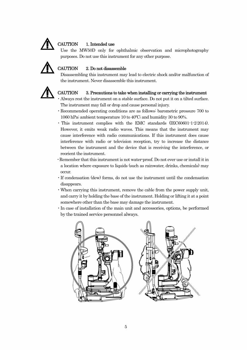
・When carrying this instrument, remove the cable from the power supply unit,
and carry it by holding the base of the instrument. Holding or lifting it at a point
somewhere other than the base may damage the instrument.
・In case of installation of the main unit and accessories, options, be performed
by the trained service personnel always.

6
CAUTION 4. Precautions to take before and during observation
・When positioning a patient’s head in the main unit, use caution not to allow any
moving parts of the instrument to hit the person’s face while preparing the
instrument for observation. Preparations include adjustment of the observation
position, focus, observation and illumination angles, etc.
・Do not use the instrument in a dusty room.
・The best place to install the instrument is in a dimly-lit room. Do not have the
patient’s side of the instrument face a bright window or a light source. This may
adversely affect observations.
・Replace the lamp bulb with a new one when the bulb starts to dim. Insufficient
light may lead to improper observations.
・The eyesight of the patient may be temporarily impaired after an examination
because of the intense light used. Allow the patient to rest a while after an
examination, until the patient’s eyesight returns to normal.
・Do not use an excessive amount of light during an examination, to avoid placing
an unnecessary burden on the patient. Improper illumination intensity may
prevent correct observations.
・Allow a patient who has trouble viewing stereoscopically or one who squints to
wear their prescription lenses. A patient whose diopter correction is ±8D or
more will also need the correction offered by their glasses.
・Be careful not to pinch your fingers between the moving parts of the instrument
during observation.
・Keep other people away from the instrument during an examination. The patient
may be distracted, resulting in incorrect results.

7
CAUTION 5. Precautions to the light hazard
Because prolonged intense light exposure can damage the retina, the use of the
device for observation should not be unnecessarily prolonged, and the brightness
setting should not exceed what is needed to provide clear visualization of the
target structures. This device should be used with filters that eliminate UV
radiation (< 400 nm) and, whenever possible, filters that eliminate
short-wavelength blue light (<420 nm).
The retinal exposure dose for the light hazard is a product of the radiance and the
exposure time. If the value of radiance were reduced in half, twice the time would
be needed to reach the maximum exposure limit.
While no acute optical radiation hazards have been identified for slit lamps, it is
recommended that the intensity of light directed into the patient’s eye be
limited to the minimum level which is necessary for diagnosis.
Infants, senior citizens, aphakes and persons with diseased eyes will be at greater
risk.
The risk may also be increased if the person being examined has had any
exposure with the same device or any other ophthalmic device using a visible
light source during the previous 24 hours. This will apply particularly if the eye
has been exposed to retinal photography.
CAUTION 6. Other precautions to take during handling
・When positioning a patient’s head in the main unit, use caution not to allow any
moving parts of the instrument to hit the person’s face while preparing the
instrument for observation. Preparations include adjustment of the observation
position, focus, observation and illumination angles, etc.
・Do not scratch, break or alter the power cord, or overly bend, pull, twist or bundle
it. Also, placing heavy object on the power cord or subjecting it to heat may cause
it to break, resulting in fire or electric shock. If the power cord becomes damaged,
replace it with a new one.
・Do not connect or disconnect the power cord with a wet hand.
・If there is any dust on the power plug blades or the surface they connect to, pull
out the power plug and remove the dust. The dust or grime can make the power
plug and AC power outlet to be out of contact and may result in fire.
・Connect the power supply unit to a grounded electric outlet that meets the power
supply requirements of the unit. Failure to do so may affect the performance of
the instrument adversely or result in malfunction of the instrument, electrical
leaks, electric shock, or fire.
・Connect the power cord plug securely. Improper connection may cause a fire.
・Do not place obstacles near the instrument which might interfere when
operating the power switch or connecting and disconnecting the power cord from
the wall outlet.

8
・When replacing the fuse in the instrument with a new one (See 5-1. Replacing
Fuses), turn off the power and disconnect the power cord from the electrical
outlet. Do not use any fuses other than those specified. A fire or electrical shock
may result.
Specified fuse:
LITTELFUSE 0215.400XP (T400mAH 250V φ5×20mm)
・This instrument is a precision optical device containing many electronic
components. Handle it carefully and do not subject it to strong physical shock.
・Do not drop the instrument or bump it against other objects.
・If the instrument fails, remove the power cord from the wall outlet and contact
your dealer. Do not attempt to repair it by yourself.
・Please use the power supply cord of the attachment.
Area Order number
100V area:DDB20207
120V area:DDB20201-UL (hospital grade)
220V area:DDB20202
240V area:DDB20203
240V area:DDB20209 (China)
・The operator must not touch the external instrument and the external monitor
connected with this equipment and the patient simultaneously. Electrical shock
can result.
・When the device is return for maintenance or repair, clean the surface of the
device (especially, forehead rest, chinrest) with a cloth dampened with rubbing
alcohol for disinfection.
・Accessory equipment connected to the analog and digital interfaces must be
certified according to the appropriate national standards.
Furthermore, all configurations shall comply with the IEC 60601-1. Anyone
who connects additional equipment to the signal input part or signal output
part is responsible for making sure that the system complies with the
requirements of the IEC 60601-1.
If in doubt, consult the technical service department or your local
representative.
CAUTION
7. Precautions to take when transporting and storing the instrument
・The recommended transportation condition is as follows: ambient temperature
-40 to +70ºC , humidity 10 to 95% and atmospheric pressure 500 to 1060hPa.
・The recommended storage condition is as follows: ambient temperature -10 to
+55ºC , humidity 10 to 95% and atmospheric pressure 700 to 1060hPa..
・Store the instrument in a dust free location not subject to vibration or mechanical
shock.
9
・Be careful not to scratch or break the lens when cleaning it. (See5-4. Cleaning the
Lens)
・After examining each patient, clean and disinfect the areas that are in contact
with the patient. Failure to do so may result in spreading an infection to other
patients. (See5-3. Cleaning the Forehead Rest, Chin Rest, and Holding Bars)
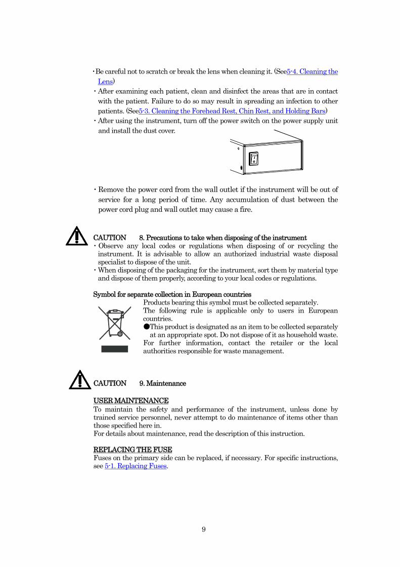
・After using the instrument, turn off the power switch on the power supply unit
and install the dust cover.
・Remove the power cord from the wall outlet if the instrument will be out of
service for a long period of time. Any accumulation of dust between the
power cord plug and wall outlet may cause a fire.
CAUTION 8. Precautions to take when disposing of the instrument ・Observe any local codes or regulations when disposing of or recycling the
instrument. It is advisable to allow an authorized industrial waste disposal specialist to dispose of the unit.
・When disposing of the packaging for the instrument, sort them by material type and dispose of them properly, according to your local codes or regulations.
Symbol for separate collection in European countries
Products bearing this symbol must be collected separately. The following rule is applicable only to users in European countries. ●This product is designated as an item to be collected separately
at an appropriate spot. Do not dispose of it as household waste. For further information, contact the retailer or the local authorities responsible for waste management.
CAUTION 9. Maintenance
USER MAINTENANCE
To maintain the safety and performance of the instrument, unless done by trained service personnel, never attempt to do maintenance of items other than those specified here in. For details about maintenance, read the description of this instruction. REPLACING THE FUSE Fuses on the primary side can be replaced, if necessary. For specific instructions, see 5-1. Replacing Fuses.

10
1. General Information
1-1. Product Description, Standard Components, and Optional Accessories
The MW50D slit lamps are designed for ophthalmic observation and microphotography.
These slit lamps is 5 step magnification microscopes that can be used for ophthalmic
observation.
This equipment is intended for use by medical doctors and optometrists.
This equipment is intended to use in the hospital.
Each instrument consists primarily of the main unit and the power supply unit.
<Operating principles>
Illuminates the observed part such as cornea, lens and etc by the illumination light emitted
from the illumination optical system and allows enlargement observation by binocular
stereoscopic microscope.
<Standard Components>
●Main unit (1) ●Power supply unit (1) ●12.5X eyepiece (1)、
12.5X eyepiece with reticle (1)
●Dust blower (1) ●*Mirrors (2) ●*Target rod (1)
(Large) (Small)
●*Protective cap (1) ●Power cord(1)
●Dust cover (1)
●Fuse (2) 0215.400XP (T400mAH 250V φ5×20mm)
●Instruction manual (this book) (1)
●Basic instruction (1)
●Power supply mounting plate (2)
●Three kinds of fixing screw for the table (each 4)
●Hex-key wrench ( 3 mm) (1)
* Detachable accessory
3.0m
100V area:DDB20207
120V area:DDB20201-UL (hospital grade)
220V area:DDB20202
240V area:DDB20203
240V area:DDB20209 (China)

11
<Optional Accessories>
●90D holder ●78D holder ●Chin rest paper ●Holding bar ●Breath guard ●Guide plate
●Tonometer adapter ●Imaging unit ●Inclination tube●Beam splitter ●CCTV attachment
●C-mount (1/2), C-mount (1/3) ●Detachable background illumination unit ●Software
instruction manual for the imaging unit
●CD-ROM (imaging unit software program MW File) ●Security key
Refer to 4. Optional Accessories for detail.
1-2. Instrument Classifications
<Classification under 93/42 EEC(MDD)>
Class I
<Type of protection against electrical shock>
Class I
This instrument is classified as equipment whose protection against electric shock does
not rely on basic insulation only, but which includes an additional safety precaution, in
that means are provided for the connection of the equipment to a protective earth
conductor in the fixed wiring of the installation in such a way that accessible metal parts
cannot become hazardous electric potential in the event of a failure of the basic
insulation.
Be sure to use the power cord that is supplied with the instrument, and connect it to a
grounded electrical outlet.
<Degree of protection against electrical shock>
Type-B applied part
The chin rest and forehead rest of the instrument are classified as “type-B applied parts”.
This instrument has undergone the tests (a patient leakage current test and a patient
auxiliary current test) specified in the relevant standard, and is equipped with a reliable
means to protect against electrical shock.
<Protection against harmful contamination by water or small particles>
IPX0
This instrument is not protected against exposure to water or other liquids.
Keep liquids away from the instrument.
<Degree of safety when used in a flammable atmosphere>
This instrument is not suitable for use in a flammable atmosphere.
Do not use this instrument if any flammable gases are present.
<Sterilization and disinfection methods permitted by the manufacturer>
Clean the chin rest, forehead rest, and holding bars with a clean, soft cloth soaked with
rubbing alcohol.
<Operation mode>
This instrument can be operated continuously.

12
<ISO15004-2 classification>
Group 2
The light emitted from this instrument is potentially hazardous.
The longer the duration of exposure, the greater the risk of ocular damage. Exposure to
light from this instrument when operated at maximum intensity will exceed the safety
guideline after 2 min
1-3. Symbols Found on the Instrument
:Calls your attention to a caution.
:Indicates a type-B applied part that complies with the specified requirements to
provide protection against electrical shocks.
:Indicates a connection to be used for DC power (alternating current) only.
:This symbol indicates the necessity of referring to the relevant part of the
instruction manual before use.
:Output
:Marked on the power switch. The power is on when this side is pressed down.
:Marked on the power switch. The power is off when this side is pressed down.
:Fuse
:Manufacturer
:Year of Manufacture
:Mind your finger warning symbol. Beware of moving mechanical parts to avoid
clipping fingers.

13
1-4. Safety Labels
The safety labels found on the instrument contain important information for the safety
of the user.
● Main unit
●Power supply unit
●Type-B applied parts
・Forehead rest ・Chin rest

14
2. Pictorial Nomenclature and Functions
2-1. System Configuration
●MW50D Clinical set (without Imaging unit)
MW50D digital imaging set (with Imaging unit)
]
Power supply unit
Main unit
*PC not supplied.
The operator must not touch the power/communication connectors
and the patient simulataneously.Electrical shock can result.
Power supply unit
Main unit
Imaging unit
PC for recording*

15
2-2. Eyepiece Block
2-3. Illuminator Block
Turn this ring before starting observation to compensate for differences in eyesight between the left and right eyes of the examiner and ensure easy viewing.
Adjust the spacing between the left and right eyepiece tubes to the pupilary distance of the examiner.
Used to change the magnification 5 step (5x 10x 16x 25x 50x).
Magnification control knob
Eyepiece tube
Slit aperture window
Move this lever left or right to select the filter to be used. The filters are assigned to the lever positions as follows from left to right. :Transparent filter
:ND (12.5% transmission) filter
:Green filter
:Cobalt blue filter
Slit adjustment knob Swing this knob left or right to rotate the slit. Turning this knob changes the slit aperture within a range of 0.2, 1, 2, 5, 10, 14, and 16 mm dia. and the slit length from 1 to 12 mm.
Filter selector lever Used to observe or photograph the anterior segment of the patient’s eye. Keep the diffuser in the down position when not in use.
Diffuser
Barrier filter knob
Switches the barrier filter ON and OFF. When performing observations using fluorescent light, use the filter selector lever in the illuminator block to select a cobalt blue filter. Then switch the barrier filter on. Observation through the barrier filter (a yellow filter) in the eyepiece block allows high-contrast imaging.
Displays the slit aperture that has been adjusted using the slit adjustment knob.
Diopter adjustment ring
G
B

16
2-4. Cross-Slide Table
Slit width adjustment knob Turned to change the slit width continuously.
Centering knob
Turning the knob counterclockwise loosens the unit so that the slit image can swing horizontally. Turning the knob clockwise tightens the unit so that slit image returns to the center position. Installed to protect the
positioning rod (that holds the guide plate in place) from injuring the patient.
Illumination lock knob Turned to lock the angle between the illumination and observation systems.
Tilting stopper
Tilting lever
Shutter button
Observation lock knob
Turned to clamp the observation system.
Turned to clamp the cross-slide.
Turning this knob clockwise increases the brightness and turning it counterclockwise decreases it. The brightness can also be decreased by using the ND filter.
Tilting the joystick finely adjusts the position of the main unit (illuminator, microscope, and base). For coarse adjustment, slide the base while holding the joystick. Turning the joystick adjusts the height of the main unit (illuminator and microscope).
Cross-slide lock knob
Illumination control knob
Pressed to make the tilting of the illumination lamp free. The tilting angles are 0, 5, 10, 15, and 20 degrees.
Protective cap
Press the button to take a static image. This switch is used when observations are being made using the imaging unit.
Joystick Pilot lamp
Comes on when power is present and the power supply unit is in operation.

17
2-5. Chin Rest
2-6. Power Supply Unit
Patient eye level index The upper index of the two indexes grooved on each of the chin rest columns serves as a guide for the patient eye level.
Turning this handle moves the chin rest up or down.
Chin rest elevation handle
Forehead rest
Chin rest
Power switch
Flexible fixation lamp
Used to fix the patient’s line of sight. The flexible arm allows you to select the desired position easily.
Fuse is built.
Fuse holder
Connect to the power supply
cable from the main unit.
Power supply output connector
for main unit. AC inlet
This connector is used to
connect the power cord.
Connect to the power supply
cable from the table.
Power supply output connector
for fixation lamp
Turns the power on or off.
Power ON:
Power OFF:

18
3. Installation
3-1. Checking before use
(1) Switch on the power supply unit and make sure that the pilot lamp lights in green.
Also, open the slit and check if the illumination lamp emits light.
(2) Do preparation according to 5-2. Installing the Chin Rest Paper , if you use the chin
rest paper (spare parts).
3-2. Eyepiece Lens
The eyepiece is fixed with the index line facing up.
Make sure to insert each eyepiece lens fully. Failure to do so may prevent the
microscope from focusing properly.
Insert the eyepiece with the reticle into the right eyepiece tube sleeve.
Reticle View in the right eyepiece.
Pilot lamp. Check if green
light is on.
Power supply unit
Check if emits light
Eyepiece lens (Set the lens with reticle in the right sleeve.)
Eyepiece tube
Index line
Eyepiece lens fixation screw
・ Change a new chin rest paper for each patient.
・ Tear the paper towards operator side for faster changing of paper.
・ Beware of pulling off the pin while tearing the paper upwards.
Power switch
Flip to the [ ] side

19
3-3. Installing the Mirror
Insert the mirror as shown below.
Two types of mirror are available: a large one with a projection and a small one
without a projection.
When using the instrument in the tilt-up mode, use a mirror without a projection to
prevent eclipse from occurring in the view field.
3-4. Diopter Adjustment
(1) Insert the end of the target rod into the center hole, which is the center of rotation, in
the microscope block and illuminator block and turn it so that its black flat surface
faces the microscope mirror.
(2) Set the illuminator block to the 0-degree position.
(3) Turn on the power supply unit. Set the slit width to an appropriate value for easy
viewing.
(4) Turn the magnification control knob to the 16x magnification position.
(5) Set the pupil distance by adjusting the spacing between the left and right eyepiece
tubes.
(6) Turn the diopter adjustment ring of the right-side eyepiece fully counterclockwise.
(7) While observing through the right eyepiece tube, turn the diopter adjustment ring
Perform a diopter adjustment before starting an observation or photography session.
Skipping this step may result in out-of-focus observation or picture, or in improper
slit movement.
(Large) (Small) Mirror for tilting
Diopter adjustment ring
Target rod

20
clockwise until the reticle in the eyepiece is seen most sharply.
(If the ring is turned too far, turn the ring counterclockwise again to its end and
restart the adjustment.)
(8) Turn the diopter adjustment ring of the left eyepiece fully counterclockwise.
(9) While observing through the left eyepiece tube, turn the diopter adjustment ring
clockwise until the flat surface of the target rod is seen most sharply.
(If the ring is turned too far, turn the ring counterclockwise again to its end and
restart the adjustment.)
(10) Turn the right eyepiece without moving the diopter adjustment ring so that the
reticle in the right eyepiece rests horizontally in the view field.
(11) Turn the eyepiece lens fixation screw and fix the eyepiece.
3-5. Background Illumination Unit
The background illumination unit allows you to observe and photograph the surroundings together with the object itself.
Back ground illumination brightness can be adjusted by background illumination
knob
Background illumination unit
Background illumination knob
An examiner who wear spectacles should collapse the rubber eyecup.
Rubber eyecup

21
4. Optional Accessories
The following are available as optional accessories.
4-1. Tonometer adapter
Adapter for hanging type tonometer. Attach to the top of microscope unit.
For information on compatible tonometers, contact your dealer.
Tonometer adapter
Installing tonometer
Holding bar
78D holder
Imaging unit
Breath guard
Tonometer adapter
Inclination tube
Guide plate
Beam splitter
CCTV attachment
C-mount (1/2),
C-mount (1/3)
Detachable background
illumination unit
90D holder

22
4-2. Guide Plate
Positioning plate for a stationary tonometer.
As shown below, secure the guide plate so that it engages the positioning pin. Then
install a stationary tonometer, aligning it with the curved area ① and the hole ②.
For information on compatible tonometers, contact your dealer.
4-3. Breath Guard
Breath guard is the plate prevent from blowing to the patient.
4-4. Holding Bars
Holding bars are designed for the patient to grip, to permit stable observation.
②
Positioning plate for stationary tonometer
Breath guard
Holding bars
①

23
4-5. 78D and 90D Holders
The 78D or 90D holder, when used with 78D or 90D lens, enable stable fundus
observations. See the figure shown below to install the 78D or 90D holder.
For instructions on the 78D and 90D lenses, refer to the instruction manual attached
to each lens.
4-6. Imaging unit
The Imaging unit allows you to observe video and record still images, video on a PC. Video : 1296 x 972 Still images : 2592 x1944
* see the instruction manual for the filing soft. The R/L sensor can automatically distinguish between the left and right eyes, and send that information to the filing program.
4-7. Inclination tube
It is possible to tilt the optical path of 15 ° by attaching the device.
User can make easy observation by attitude such as looking down.
Height is adjustable while eyepiece tube is being installed in rotated direction. Make sure
to place the eyepiece with reticle to right side after installed the eyepiece tube in rotated
direction.
Imaging unit Connect to PC to review
movie or capture image.
Normal Installation Rotate Installation
90D lens

24
4-8. Beam splitter, CCTV attachment, C-mount(1/2),C-mount(1/3)
External camera unit can be installed to the unit by adopting beam splitter and CCTV
device. When using external camera unit, make sure to turn the beam splitter to IN.
By turning the depth of field switch, operator can adjust the intensity and depth of field.
4-9. Detachable background illumination unit
Detachable background illumination unit enables to light the objects in any angle.
Examiner can hold and use the detached background illumination.
* If detachable background illumination unit is used, standard background
illumination unit is not able to use, however, light adjustment can be made by the
standard background light control knob.
External Camera Unit
C Mount(1/2) or C Mount (1/3)
Select according to the type of
external camera unit
Aperture lever Adjust the intensity and depth of
field.
Focus adjustment knob If the image is out of
focus, turn the knob while
looking at the image to
make adjustment.
Detahchable background
illumination unit It is possible to illuminate
any position. (upper and
lower, right and left, and
rotating.)
Beam splitter The image can be seen by
making beam splitter IN.

25
5. Maintenance
This device does not require periodic calibration.
Adjust the eyepiece diopter every time before using the device. (Refer to 3-4. Diopter
Adjustment)
5-1. Replacing Fuses
CAUTION
Insert the tip of the screwdriver into each of the fuse holder latches and pull out the
fuse holder toward you.
5-2. Installing the Chin Rest Paper
Remove the two chin rest paper pins from the chin rest. Place the chin rest paper (one
piece or more as needed) on the chin rest. Then install the pins to secure the paper.
Used chin rest paper can be removed from the chin rest without removing those pins.
Turn off the power and disconnect the power cord from the electrical outlet before checking
or replacing the fuses.
Use the following types of fuses. Do not use any fuses other than those specified. To order
spare fuses, contact your dealer.
LITTELFUSE time lag fuse:
0215.400XP (T400mAH 250V φ5×20mm)
Chin rest paper
Chin rest paper pins
Chin rest
Power supply unit
AC inlet
Fuse holder

26
5-3. Cleaning the Forehead Rest, Chin Rest, and Holding Bars
Cleaning should be done before the observation. Clean the Chin rest, Forehead and
Holding Bars with soft cloth soaked with rubbing alcohol.
ex)“Schnelldesinfektion”, ” Sixtan® Desinfektion”:They are registered in the VAH list.
When using the chin rest paper, use a new sheet for each patient. For the replacement
method of the chin rest paper, Refer 5-2 “Installing the Chin Rest Paper.”
5-4. Cleaning the Lens
If the lens gets dirty, blow the dust off the lens three or four times using the blower
that came with the instrument. If the dust is still not removed, gently wipe the lens
using a lens cleaning solution or absolute alcohol (commercially available).
5-5. Cleaning the Exterior of the Instrument
Do not use any organic solvents (alcohol, ether, thinner, etc.) when cleaning the coated,
plastic, or printed areas on the instrument. Discoloration or removal of the printing
may result. In cases of stubborn dirt, gently wipe the surface with gauze slightly
moistened with a diluted mix of water and mild detergent.
5-6. List of Spares and Service Parts
Part Name Part No. Remarks
Fuse
LITTELFUSE time lag fuse
0215.400XP
T400mAH 250V
φ5×20mm
Chin rest paper RXA30101
(Order No.) 500 pcs. per package
Be careful not to scratch or break the lens when cleaning it.
Chin rest
Forehead rest
Holding bars

27
5-7. Zero-Position Adjustment of the Slit Width Adjustment Knob
If there is any difference between the scale on the slit width adjustment knob and the
actual slit length, use the following procedure to adjust the zero position of the slit
width adjustment knob.
(1) While observing through the eyepiece lens, turn the slit width adjustment knob
clockwise and stop when the slit is fully closed.
(2) Loosen the slotted screw (located between the seals on the knob bottom) on the
scale ring to set the scale ring free.
Turn the scale ring until the “0” index on the seal on the scale ring is in alignment with
the reference index and tighten the slotted screw you loosened in step (2).
Never turn the slit width adjustment knob counterclockwise.
Do not turn the slit width adjustment knob at this moment.
Do not turn the slit width adjustment knob at this moment.
Scale ring
Hex-head wrench
Slit width adjustment knob
Viewed from bottom
Hexagon socket setscrew

28
(3) Turn the slit width adjustment knob one turn clockwise and make sure that the
slit is closed when the index line is set to “0”. Repeat steps (1) to (3) if the slit is not
closed.
5-8. If the Slit Width Gets Narrower During Observation:
The problem of the slit width becoming narrower during observation can occur if the
slotted screw in the center of the slit width adjustment knob has become loose.
Turn this screw clockwise a little with an Allen wrench (Hex-head wrench).
● Excessive tightening of the slotted screw clockwise will make the movement of the
slit width adjustment knob slower.
● Do not turn the slotted screw fully counterclockwise. The screw will come off. Once
this screw is removed, you may have to call your dealer for repair.
・
Hex-head wrench
Torque adjusted knob Viewed from bottom
Hexagon socket setscrew

29
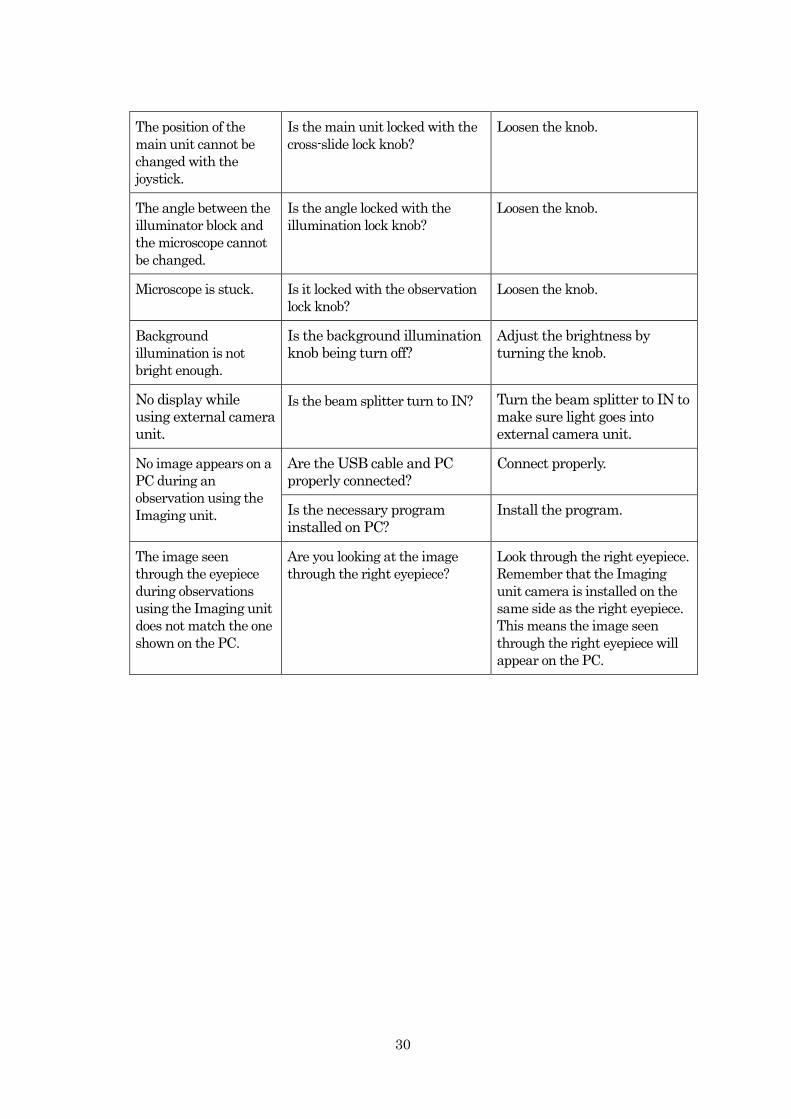
6. Troubleshooting
If you have any problem with the instrument, check the following before asking your
dealer for assistance.
Problem Checks Remedy
Pilot lamp on the cross
slide table does not
come on, nor does the
illumination lamp.
Is the fuse blown? Replace the fuse.
Is the power cord firmly
connected to the wall outlet and
to the power supply unit?
Connect firmly.
Pilot lamp on the cross
slide table comes on,
but the illumination
lamp does not come on.
Is the slit closed? Open the slit.
Is the illumination knob being
turned off?
Rotate the knob to adjust the
brightness.
Is the illumination lamp blown? Replace the lamp.
Contact your dealer for exchange
service.
Uneven illumination Check the slit width adjust
knob position.
Turn the knob back to the click
position.
Is the illumination lamp blown? Replace the lamp.
Contact your dealer for exchange
service.
Insufficient
illumination
Is the ND filter installed? Remove ND filter using the filter
selector lever.
Is the illumination control knob
set too dark?
Turn the knob to adjust the
amount of light.
Microscope does not
focus.
Is the eyepiece lens fully
inserted?
Fully insert the eyepiece lens
and fix..
Did you perform a diopter
adjustment before starting the
observation?
Perform a diopter adjustment.
Refer to section 3-4. Diopter
Adjustment.
Slit does not return to
the center position.
Is the centering knob loose
enough that the slit position has
moved accidentally?
Turn the knob clockwise to
tighten it.
Slit aperture is not
centered.
Is the slit adjustment knob not
sitting in a detent?
Turn the knob until you feel a
click at the desired setting.
Slit width gets
narrower during
observation.
Is the set screw in the center of
the slit width adjustment knob
loose?
Tighten the screw. Refer to
section 5-8. If the Slit Width
Gets Narrower During
Observation
30
The position of the
main unit cannot be
changed with the
joystick.
Is the main unit locked with the
cross-slide lock knob?
Loosen the knob.
The angle between the
illuminator block and
the microscope cannot
be changed.
Is the angle locked with the
illumination lock knob?
Loosen the knob.
Microscope is stuck. Is it locked with the observation
lock knob?
Loosen the knob.
Background
illumination is not
bright enough.
Is the background illumination
knob being turn off?
Adjust the brightness by
turning the knob.
No display while
using external camera
unit.
Is the beam splitter turn to IN? Turn the beam splitter to IN to
make sure light goes into
external camera unit.
No image appears on a
PC during an
observation using the
Imaging unit.
Are the USB cable and PC
properly connected?
Connect properly.
Is the necessary program
installed on PC?
Install the program.
The image seen
through the eyepiece
during observations
using the Imaging unit
does not match the one
shown on the PC.
Are you looking at the image
through the right eyepiece?
Look through the right eyepiece.
Remember that the Imaging
unit camera is installed on the
same side as the right eyepiece.
This means the image seen
through the right eyepiece will
appear on the PC.

31
7. Specifications
<Instrument Name> LED SLIT LAMP MW50D
Main Unit
■ Microscope
Type 5 step magnifications microscope
Objective angle 13.2 º
Total magnification 5x, 10x, 16x, 25x, 50x
Actual field of view φ44.5,φ22.3, φ14.2, φ9, φ4.5
Eyepiece lens magnification
12.5x
Eyepiece diopter adjustment range
-8D to +8D
PD adjustment range 55 mm to 80 mm
Binocular tube
convergence angle.
8°
Working distance 100.5 mm
Reaching distance 314.0 mm
■ Illumination system
Light source White LED 5W
Slit width 0 to 16 mm (continuous)
Slit rotation angle 90º to the right and left
Slit aperture φ0.2, 1, 2, 5, 10, 14, 16 mm; 1 to 12 mm (continuous)
Slit tilting angle 0, 5, 10, 15, 20º (from bottom)
Slit swing 8 mm to the left or right (on the target face)
Filters Transparent, ND (12.5%), green and cobalt blue filters
■ Arm
Rotation angle 90º to the left or right
■ Cross-slide table
Horizontal motion (Forward/Back and Left/Right)
100 x 110 mm (via joystick) (Forward: 30 mm; Back: 70 mm; Left/Right: 55 mm)
Vertical motion 30 mm (15 mm up or down via joystick)
■ Chin rest
Vertical motion 30 mm up or down from the reference position which is 274 mm above the table top.
■ Wight
Main unit without Imaging unit
13 kg
Main unit with Imaging unit
14 kg
■ Dimensions
Main unit with metal table
350 x 387 x678.5 mm (width x depth x height)

32
Height from table top to patient’s eye
374 mm
Power supply unit
Input AC100V- 240V 50/60Hz
Output DC12V
Power consumption 35VA
Rated fuse T400mAH 250V / φ5×20mm
Dimensions 105 x 130 x 48.5mm (width x depth x height)
Wight 450 g
Imaging unit
Optical path division ratio
(T/R)
30:70
Image size 2592(H) x 1944(V)
Movie size 1296(H) x 972(V)
Aspect ratio 4:3
Interface USB 3.0
Inclination tube
Inclination angle. 15°
Beam splitter
Optical path division ratio
(T/R)
30:70
CCTV attachment
Aperture diameter φ9-φ1.6 mm (Linear Variable)
Click position φ9, 4.5, 2.3 mm
Adjustment range of focus ±3 mm
■ ISO10939 : 2007 Compliance

33
■Connection with PC
CAUTION
Accessory equipment connected to the analog and digital interfaces must be certified
according to the appropriate national standards.
Furthermore, all configurations shall comply with the system standard IEC 60601-1.
Anyone who connects additional equipment to the signal input part or signal output part is
responsible for making sure that the system complies with the requirements of the system
standard IEC 60601-1.
If in doubt, consult the technical service department or your local representative.
■Patient environment
The patient environment represents a space where there is a possibility of direct contact
between the patient or the operator and third person.
When another type of device is used in the patient environment, use a device that complies
with IEC 60601-1. If the devices that do not comply with IEC 60601-1 are used, it is
necessary to use an isolating transformer to power the device or to connect the devices to
additional protective grounding.
Radius of 1.5m
1.5m 1.5m
2.5m

34
■Information of EMC (Electro Magnetic Compatibility)
CAUTION
1. Reorient or relocate the receiving device. Reorient or relocate the receiving device.
2. Increase the distance to the device.
3. Correct the device into an outlet on a circuit different from that to which the other
device(s) are connected.
4. Consult the manufacturer or field service technician for assistance.
・In installation and operation of the device, observe the following instructions about EMC
(electromagnetic compatibility):
1. Do not use the device simultaneously with other electronic equipment to avoid
electromagnetic interference with the operation of the device.
2. Do not use the device near, on, or under other electronic equipment to avoid
electromagnetic interference with the operation of the device.
3. Do not use the device in the same room with other equipment such as life-support
equipment, other equipment that has major affects on the life of the patient and
results of treatment, or other measurement or treatment equipment that involves
small electric current.
4. Do not use the device simultaneously with portable and mobile radio frequency
communication systems because it may have an adverse effect on operation of the
device.
5. Do not use cables and accessories that are not specified for the device because that
may increase the emission of electromagnetic waves from the device or the system
and decrease the immunity of the device to electromagnetic disturbance.

35
■EMC (Electromagnetic Compatibility)
The Electromagnetic Compatibility Directive sets the essential requirements for electrical and electronic equipment that
may disturb or even be disturbed by other equipment. The MW50D complies with these requirements as tabled below.
Follow the guidance on the tables for use of the device in the electromagnetic environment.
WARNING: The use of this equipment adjacent to or stacked with other equipment
should be avoided because it could result improper operation.
If such use is necessary, this equipment and the other equipment should
be observed to verify that they are operating normally.
WARNING: The use of accessories and cables other than those specified or provided by
the RIGHT MFG. CO., LTD. of MW50D could result in increased
electromagnetic emissions or decreased electromagnetic immunity of
MW50D and result in improper operation.
(A):Environments for MW50D
This device is applied for use in professional healthcare facility environment.
-Doctor's offices, clinics, medical facilities, hospital, etc.
(B)List of cables, Length of cables
Model name Model No. Length
Power cord 100V area DDB20207 3.0m
Power cord 120V area (Hospital grade) DDB20201-UL 3.0m
Power cord 120V area DDB20202 3.0m
Power cord 240V area DDB20203 3.0m
Power cord 240V area(China) DDC20209 3.0m

36
(C)EMC (IEC60601-1-2:2014)
(1)Emission guidance MW50D is intended for use in the electromagnetic environment specified below. The customer or the user of the
MW50D should assure that they are used in such an environment.
Emissions test Basic EMC standard or test method※1
Conducted and radiated RF
EMISSION CISPRE 11 Group 1 ClassB
Harmonic EMISSION IEC61000-3-2※2
Voltage fluctuations and flicker IEC61000-3-3※2
※1:See “(A) Environments for MW50D” for information about the environments of INTENED USE.
※2:This test is not applicable in this environment unless the ME EQUIPMENT and ME SYSTEMS used there will be connected to the
PUBLIC MAINS NETWORK and the power input is otherwise within the scope of the Bacis EMC standard.
(2)Immunity guidance MW50D is intended for use in the electromagnetic environment specified below. The customer or the MW50D
should assure that they are used in such an environment.
・Enclosure port
Phenomenon
Basic EMC
standard or test
method
IMMUNITY TEST LEVELS
Professional healthcare facility environment
Electrostatic discharge IEC 61000-4-2 ±8 kV contact
±2 kV, ±4 kV, ±8 kV, ±15 kV air
Radiated RF EM fields※1 IEC 61000-4-3
3 V/m※6
80 MHz – 2,7 GHz※2
80% AM at 1 kHz※3
Proximity fields from RF
wireless communications
equipment
IEC 61000-4-3
See (C)-(3)
Test Specifications for ENCLOSURE PORT IMMUNITY
to RF wireless communications equipment
Rated power frequency
magnetic fields※4※5 IEC 61000-4-8
30 A/m※7
50 Hz or 60 Hz
※1:The interface between the PATIENT physiological signal simulation, if used, and the ME EQUIPMENT or ME
SYSTEM shall be located within 0,1 m of the vertical plane of the uniform field area in one orientation of the ME
EQUIPMENT or ME SYSTEM.
※2:ME EQUIPMENT and ME SYSTEMS that intentionally receive RF electromagnetic energy for the purpose of their
operation shall be tested at the frequency of reception. Testing may be performed at other modulation frequencies
identified by the RISK MANAGEMENT PROCESS. This test assesses the BASIC SAFETY and ESSENTIAL
PERFORMANCE of an intentional receiver when an ambient signal is in the passband.It is understood that the
receiver might not achieve normal reception during the test.
※3:Testing may be performed at other modulation frequencies identified by the RISK MANAGEMENT PROCESS.
※4:Applies only to ME EQUIPMENT and ME SYSTEMS with magnetically sensitive components or circuitry.
※5:During the test, the ME EQUIPMENT or ME SYSTEM may be powered at any NOMINAL input voltage, but with
the same frequency as the test signal
※6:Before modulation is applied.
※7:This test level assumes a minimum distance between the ME EQUIPMENT or ME SYSTEM and sources of power
frequency magnetic field of at least 15 cm. if the RISK ANALYSIS shows that the ME EQUIPMENT or ME
SYSTEM will be used closer than 15 cm to sources of power frequency magnetic field, the IMMUNITY TEST
LEVEL shall be adjusted as appropriate for the minimum expected distance.

37
・Input a.c. power port
Phenomenon
Basic EMC
standard or test
method
IMMUNITY TEST LEVELS
Professional healthcare facility environment
Electrical fast transients /
bursts※1※12※15 IEC 61000-4-4
±2 kV
100 kHz repetition frequency
Surges ※1※2※10※15
Line-to-line IEC 61000-4-5 ±0,5 kV, ±1 kV
Surges※1※2※10※11※15
Line-to-ground IEC 61000-4-5 ±0,5 kV, ±1 kV, ±2 kV
Conducted disturbances
induced by RF fields※3※4※15 IEC 61000-4-6
3 V ※13
0,15 MHz – 80 MHz
6 V※13 in ISM bands between 0,15 MHz and 80 MHz※14
80% AM at 1 kHz※5
Voltage dips ※6※16※18 IEC 61000-4-11
0% UT; 0,5 cycle※7
At 0°, 45°, 90°, 135°, 180°, 225°, 270° and 315°※17
0% UT; 1 cycle and 70% UT; 25/30 cycles※8
Single phase: at 0°
Voltage interruptions※6※9※15※18 IEC 61000-4-11 0% UT; 250/300 cycle※8
※1:The test may be performed at any one power input voltage within the ME EQUIPMENT or ME SYSTEM RATED
voltage range. If the ME EQUIPMENT or ME SYSTEM is tested at one power input voltage, it is not necessary to
re-test at additional voltages.
※2: All ME EQUIPMENT and ME SYSTEM cables are attached during the test.
※3:Calibration for current injection clamps shall be performed in a 150 Ω system.
※4:If the frequency stepping skips over an ISM or amateur band, as applicable, an additional test frequency shall be
used in the ISM or amateur radio band. This applies to each ISM and amateur radio band within the specified
frequency range.
※5:Testing may be performed at other modulation frequencies identified by the RISK MANAGEMENT PROCESS.
※6:ME EQUIPMENT and ME SYSTEMS with a d.c. power input intended for use with a.c.-to-d.c. converters shall be
tested using a converter that meets the specifications of the MANUFACTURER of the ME EQUIPMENT orME
SYSTEM. The IMMUNITY TEST LEVELS are applied to the a.c. power input of the converter.
※7:Applicable only to ME EQUIPMENT and ME SYSTEMS connected to single-phase a.c. mains.
※8:E.g. 10/12 means 10 periods at 50 Hz or 12 periods at 60 Hz.
※9:ME EQUIPMENT and ME SYSTEMS with RATED input current greater than 16 A / phase shall be interrupted
once for 250/300 cycles at any angle and at all phases at the same time (if applicable). ME EQUIPMENT and ME
SYSTEMS with battery backup shall resume line power operation after the test. For ME EQUIPMENT and ME
SYSTEMS with RATED input current not exceeding 16 A, all phases shall be interrupted simultaneously.
※10:ME EQUIPMENT and ME SYSTEMS that do not have a surge protection device in the primary power circuit may
be tested only at ± 2 kV line(s) to earth and ± 1 kV line(s) to line(s).
※11:Not applicable to CLASS II ME EQUIPMENT and ME SYSTEMS.
※12:Direct coupling shall be used.
※13:r.m.s., before modulation is applied.
※14:The ISM (industrial, scientific and medical) bands between 0,15 MHz and 80 MHz are 6,765 MHz to 6,795 MHz;
13,553 MHz to 13,567 MHz; 26,957 MHz to 27,283 MHz; and 40,66 MHz to 40,70 MHz. The amateur radio bands
between 0,15 MHz and 80 MHz are 1,8 MHz to 2,0 MHz, 3,5 MHz to 4,0 MHz, 5,3 MHz to 5,4 MHz, 7 MHz to 7,3
MHz, 10,1 MHz to 10,15MHz, 14 MHz to 14,2 MHz, 18,07 MHz to 18,17 MHz, 21,0 MHz to 21,4 MHz, 24,89 MHz to
24,99 MHz, 28,0 MHz to 29,7 MHz and 50,0 MHz to 54,0 MHz.
※15:Applicable to ME EQUIPMENT and ME SYSTEMS with RATED input current less than or equal to 16 A /
phase and ME EQUIPMENT and ME SYSTEMS with RATED input current greater than 16 A / phase.

38
※16:Applicable to ME EQUIPMENT and ME SYSTEMS with RATED input current less than or equal to 16 A / phase.
※17:At some phase angles, applying this test to ME EQUIPMENT with transformer mains power input might cause an
overcurrent protection device to open. This can occur due to magnetic flux saturation of the transformer core after
the voltage dip. If this occurs, the ME EQUIPMENT or ME SYSTEM shall provide BASIC SAFETY during and
after the test.
※18:For ME EQUIPMENT and ME SYSTEMS that have multiple voltage settings or auto ranging voltage capability,
the test shall be performed at the minimum and maximum RATED input voltage. ME EQUIPMENT and ME
SYSTEMS with a RATED input voltage range of less than 25% of the highest RATED input voltage shall be
tested at one RATED input voltage within the rage.
・Signal input/output parts port
Phenomenon
Basic EMC
standard or test
method
IMMUNITY TEST LEVELS
Professional healthcare facility environment
Electrostatic discharge※4 IEC61000-4-2 ± 8 kV contact
± 2 kV, ± 4 kV, ± 8 kV, ± 15 kV air
Conducted disturbance by RF
field※1※3※5 IEC61000-4-6
3 V※6
0,15 MHz – 80 MHz
6 V※6 in ISM bands between 0,15 MHz and 80 MHz※7
80% AM at 1 kHz※2
※1: SIP/SOPS whose maximum cable length is less than 3 m in length are excluded.
※2: Testing may be performed at other modulation frequencies identified by the RISK MANAGEMENT PROCESS.
※3: Calibration for current injection clamps shall be performed in a 150 Ω system.
※4: Connectors shall be tested per 8.3.2 and Table 4 of IEC 61000-4-2:2008. For insulated connector shells, perform air
discharge testing to the connector shell and the pins using the rounded tip finger of the ESD generator, with the
exception that the only connector pins that are tested are those that can be contacted or touched, under conditions of
INTENDED USE, by the standard test finger shown in Figure 6 of the general standard, applied in a bent or
straight position.
※5: If the frequency stepping skips over an ISM or amateur radio band, as applicable, an additional test frequency
shall be used in the ISM or amateur radio band. This applies to each ISM and amateur radio band within the
specified frequency range.
※6: r.m.s., before modulation is applied.
※7: The ISM (industrial, scientific and medical) bands between 150 kHz and 80 MHz are 6,765 MHz to 6,795 MHz;
13,553 MHz to 13,567 MHz; 26,957 MHz to 27,283 MHz; and 40,66 MHz to 40,70 MHz.
The amateur radio bands between 0,15 MHz and 80 MHz are 1,8 MHz to 2,0 MHz, 3,5 MHz to 4,0 MHz, 5,3 MHz to
5,4 MHz, 7 MHz to 7,3 MHz, 10,1 MHz to 10,15 MHz, 14 MHz to 14,2 MHz, 18,07 MHz to 18,17 MHz, 21,0 MHz to
21,4 MHz, 24,89 MHz to 24,99 MHz, 28,0 MHz to 29,7 MHz and 50,0 MHz to 54,0 MHz.

39
(3)Test Specifications for ENCLOSURE PORT IMMUNITY to RF wireless
communications equipment Test
Frequency
(MHz)
Band※1
(MHz)
Service※1 Modulation※2
Maximum
power
(W)
Distance
(m)
IMMUNITY
TEST LEVEL
(V/m)
385 380-390 TETRA400
Pulse
Modulation※2
18Hz
1.8 0,3 27
450 430-470 GMRS460
FRS460
FM※3
±5kHz deviation
1kHz sine
2 0,3 28
710
745
780
704-787 LTE Band 13,
17
Pulse
modulation※2
217Hz
0,2 0,3 9
810
870
930
800-960
GSM800/900,
TETRA800,
iDEN820,
CDMA850,
LTE Band 5
Pulse
modulation※2
18Hz
2 0,3 28
1720
1845
1970
1700-1990
GSM1800;
CDMA1900;
GSM1900;
DECT;
LTE Band 1, 3,
4, 25;
UMTS
Pulse
modulation※2
217Hz
2 0,3 28
2450 2400-2570
Bluetooth,
WLAN,
802.11 b/g/n,
FRID 2450,
LTE Band 7
Pulse
modulation※2
217Hz
2 0,3 28
5240
5500
5785
5100-5800 WLAN 802.11 a/n
Pulse
modulation※2
217Hz
0,2 0,3 9
NOTE:If necessary to achive the IMMUNITY TEST LEVEL,the distance between the transmitting antenna and the
ME EQUIPMENT or ME SYSTEM may be reduced to 1m. The 1m test distance is permitted by IEC61000-4-3.
※1:For some services, only the uplink frequencies are included.
※2:The carrier shall be modulated using a 50% duty cycle square wave signal.
※3:As an alternative to FM modulation, 50% pulse modulation at 18Hz may be used because while it does not
represent actual modulation, it would be worst case

RIGHT MFG. CO., LTD.
1‐47‐3, Maeno-cho, Itabashi-ku, Tokyo, 174‐8633 Japan.
Tel : +81‐3‐3960‐2275 Fax : +81‐3‐3960‐2285
TOHOKU RIGHT MFG. CO., LTD.
Ophthalmic service, Factory
45‐1, Aza Yashikimae, Nakamura Osato-cho, Kurokawa-gun, Miyagi
981‐3521 Japan.
Tel : +81‐22‐359‐3113 Fax : +81‐22‐359‐3213
Medical Device Safety Service GmbH
Schiffgraben 41
30175 Hannover, Germany


