Embed Size (px)
Citation preview

Missouri University of Science and Technology Missouri University of Science and Technology
Scholars' Mine Scholars' Mine
International Specialty Conference on Cold-Formed Steel Structures
(1975) - 3rd International Specialty Conference on Cold-Formed Steel Structures
Nov 24th, 12:00 AM
Local Buckling in Channel Columns Local Buckling in Channel Columns
John T. DeWolf
Follow this and additional works at: https://scholarsmine.mst.edu/isccss
Part of the Structural Engineering Commons
Recommended Citation Recommended Citation DeWolf, John T., "Local Buckling in Channel Columns" (1975). International Specialty Conference on Cold-Formed Steel Structures. 2. https://scholarsmine.mst.edu/isccss/3iccfss/3iccfss-session1/2
This Article - Conference proceedings is brought to you for free and open access by Scholars' Mine. It has been accepted for inclusion in International Specialty Conference on Cold-Formed Steel Structures by an authorized administrator of Scholars' Mine. This work is protected by U. S. Copyright Law. Unauthorized use including reproduction for redistribution requires the permission of the copyright holder. For more information, please contact [email protected].
brought to you by COREView metadata, citation and similar papers at core.ac.uk
provided by Missouri University of Science and Technology (Missouri S&T): Scholars' Mine

LOCAL BUCKLING IN CHANNEL COLUMNS
by
John T. DeWolf*
INTRODUCTION
In cold-formed sections the width-thickness ratios of the elements
are often large so that local plate buckling occurs prior to attainment
of the maximum member strength. The postbuckling strength of these
elements is increasingly utilized in design, yielding substantial economics
in many cases.
Many thin-walled open shapes loaded compressively are subject to
torsional-flexural buckling as well as flexural buckling. Examples are
channels, hat sections, angle sections and I-sections with uneaual flanges.
In these the centroid and the shear center do not coincide so that when
the axial load is applied through the centroid, resulting in a uniform
compressive stress distribution, buckling may involve tvisting as well as
translation.
This paper concerns itself with uniformly compressed channel columns
subject to local buckling. As the load is increased, failure occurs in
one of the following patterns: (l) for low slenderness ratios, local
plate buckling occurs followed by the development of postbuckling strength,
with failure occurring when the compressive strength of the component
plates is reached; (2) for moderate slenderness ratios, local plate
buckling occurs followed by the development of postbuckling strength,
*Assistant Professor of Civil Engineering, University of Connecticut, Storrs, Connecticut.
27

28 THIRD SPECIALTY CONFERENCE
with failure precipitated b:v either overall flexural column buckling
about the axis of non-symmetry or b:v torsional-flexural buckling with
translation perpendicular to the axis of SyF~etr:v and twisting; (3) for
large slenderness ratios, failure occurs by overall flexural buckling
or by torsional-flexural buckling with no prior local plate buckling.
Whether flexural buckling or torsional-flexural buckling occurs depends
on the relative dimensions of the cross-section.
Flexural buckling and torsional-flexural buckling have been exten-
sively studied, considering both elastic and inelastic behavior. Plate
buckling has received much attention, including postbuckling behavior.
Though the effect of local plate buckling on flexural buckling has been
studied, with a recent investigation by DeWolf, Pekoz, and Winter (4 l
concerning cold-formed sections, the subject of the interaction of local
buckling with torsional-flexural buckling has been neglected. For the
design of such sections, the American Iron and Steel Institute Specifi
cation (6 ) utilizes a method similar to its procedure for predicting the
flexural buckling load of locally buckled sections. Winter ( 9 ) states
that the method is conservative because the effects of local buckling,
which are interrelated to torsional-flexural buckling, are in effect
counted for separately.
This paper presents a method in which the effects of local buckling
are directly included in the overall column behavior, yielding a con-
ceptually simple procedure for predicting the maximum column strength.
Though the results are presented for channel columns, with and without
lips, the approach is general and can be utilized for all thin-walled
sections.
LOCAL BUCKLING IN COLUMNS 29
ANALYTICAL APPROACH
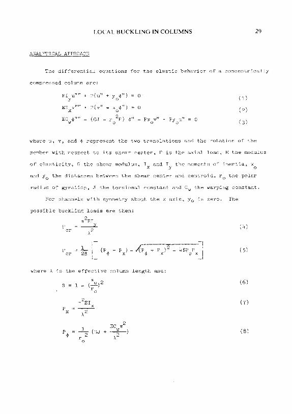
The differential equations for the elastic behavior of a concentrically
compressed column are:
J£I u"" + P(u" + yo¢") 0 ( l) y
EI X
v"" + P(v" xo¢") 0 ( 2)
ECw¢"" (GJ - r 2
P) 0
¢" Px v" + Py0
u'' 0 (3) 0
where u, v, and ¢ represent the two translations anri the rotation of the
member with respect to its shear center, P is the axial load, E the modulus
of elasticity, G the shear modulus, Ix and Iy the moments of inertia, x0
and y0
the distances between the shear center and centroid, r0
the polar
radius of gyration, J the torsional constant and Cw the warping constant.
For channels with symmetry about the x axis, y 0 is zero. The
possible bucklin~ loads are then:
p cr
p cr
TI2EI
_.:£_
,\2
,------:::c------1 c p + p ) - A p + p ) 2 4 e.P p I
<jJ X <jJ X <jlx
where A is the effective column length and:
6 l -(xu)2
r 0
1r2EI
p X
X ,\2
EC 1r 2
p¢ .....L (GJ + _w_)
2 ,\2 r 0
( 4)
( 5)
(6)
(7)
(8)

JO THIRD SPECIALTY CONFERENCE
Eq. 4 is the flexural bucklin~ load about they axis and Eq. 5 is
the lesser of the two torsional-flexural buckling loads. 'I'he smaller
value from these two equations determines the column strength.
No rigorous theory exists for the determination of the torsional-
flexural buckling loads in the inelastic range. Chajes, Fang, and
Winter (l) discuss attempts to include inelastic behavior and in an
extensive experimental and analytical investigation into the torsional-
flexural buckling of cold-formed members, found that replacing E with
Et, the tangent modulus, and G with G(Et/E) yielded good results.
For the determination of the inelastic buckling stress, the authors
used the following approximate expression:
CE ~-~ _ y
(l- ~)I y _
where a is the stress, cry the yield stress and C a constant depending
on the material. This equation is the basis of the CRC column formula
(5) and was used satisfactorily in the previously mentioned work of
this author. Chajes, Fang, and Winter used C = 4.5 for their material
with a proportional limit equal to 2/3oy.
The proposed method for considering the effects of local buckling
in the above predictions of column buckling is now discussed. Treating
the postbuckling behavior of plates in a rigorous theoretical manner !.s
extremely difficult. The complication of large deflections combined
with inelastic behavior in the later stages of postbuckling makes a
widely applicable solution untractable. Solutions which do exist are
limited to specific sections or are limited to the earlier stages of
postbuckling.

LOCAL BUCKLING IN COLUMNS Jl
Fortunately, a much simpler, generally applicable means exists for
determining the load on a plate in all stages of its postbuckling range.
This is the effective width approach, developed from test data. In various
forms it has been used successfully in all types of design. The most
widely used form in the United States is that developed by Winter (8)
for stiffened elements, flat elements with both edges parallel to the
direction of stress stiffened by a web, flange, or stiffener which
supplies sufficient rigidity to prevent out-of-plane distortion at the
edges. His effective width expression is:
b w I
r--
1 °cr 0
max (l.O -0.22 0) I a;;; (10)
where b is the effective width, w the full width, omax the maximum or
edge stress, and ocr the classical plate buckling stress given by Bryan's
formula:
0 cr
TI2E k ---"--==---
2 2 l2(l-jJ l(fl (ll)
JJ is Poisson's ratio, t the plate thickness, and k a factor which accounts
for the actual edge conditions, ranging from 4.00 to 6.97 for stiffened
elements. The width of the plate is replaced with an effective, smaller
width assuming the plate is loaded with a uniform stress equal to omax
as shown in Fig. la. The equivalent load on the buckled plate is btomax·
The width at ultimate strength is obtained by replacing omax with oy.
Since the out-of-plane deformations can be excessive, the postbuckling
range has not been fully utilized in the design of unstiffened elements,
flat elements with one edge stiffened and the other free. However, in

32 THIRD SPECIALTY CONFERENCE
some cases the deformations are not great and use of the postbuckling
range can lead to substantial economy.( 4 ) In such cases Winter's effective
width expression can be utilized for unstiffened elements with appropriate
changes ink, from 0.425 to 1.277. The effective width is shown in
Fig. 2 a.
In addition to using Eq. 10 to determine the bad on the plate,
DeWolf, Pekoz and Winter have shown it is also possible to use it to obtain
the element's contribution towards the member's stiffness. The stiffness
of a column, both flexural and torsional, is related to the actual stress
distribution, and thus for each element the effective area, equal to bt,
should be distributed in a manner similar to the actual stress distribu
tion. While the actual stress distribution is non-linear and unknown, it
was shown that a linear distribution is adequate for cold-formed columns
subject to flexural buckling. Thus the area should be distributed as shown
in Figs. l band 2 b for the stiffened and unstiffened elements,respectively.
If the effective area is equal to or greater than one-half of the full area,
the effective thickness is to be decreased linearly from the actual thick
ness at the point of maximum stress, the supported edge or edges, to the
appropriately calculated thickness at the point of minimum stress, the
center for stiffened elements and the free edge for unstiffened elements.
If the effective area is less than one-half of the full area, its thickness
should decrease linearly from a value of less than the actual thickness
at the supported edge, or edges, to zero at the center for stiffened elements
and at the free edge for unstiffened elements. The assumed stress on the
effective area is then uniform and equal to the edge stress amax The
effective sections for plain and lipped channels are shown in Fig. 3.

LOCAL BUCKLING IN COLUMNS
The lips are assumed fully effective.
The load on the column is then:
where Aeff is the area of the effective column section. The average
stress on the full, unreduced cross-section is then:
p
A
where A is the area of the full, unreduced cross-section.
(13)
33
Thus to include the effects of local buckling in columns subject
to flexual buckling, it was shown that it is only necessary to reduce
the column section to an effective one using Eq. 10. It is logical
that the same procedure can be used for sections subject to torsional-
flexural buckling. Once the section is reduced to an effective one,
Ix, Iy, J, and Cw are calculated taking into account the variable thick-
ness for the locally buckled elements. The calculation of I and I is X y
straightforward. J is the summation of 1/3 w t3 for sections composed
of rectangular elements. For the locally buckled variable thickness
elements it is necessary to integrate this over the element length.
Chilver ( 2 ) has shown the importance of including the effect of variable
thickness for calculating C in sections containing elements of differw
ing thickness and gives a procedure for doing so. This is also presented
by the American Iron and Steel Institute (T) and should be used for the
effective section.
Once the effective section properties are calculated, the flexural
and torsional-flexural buckling loads are obtained using Eqs. 4 and 5-
If omax is above the proportional limit, the values of Per from Eqs. 4
and 5 are multiplied by (Et/E), where Et is given by Eq. 9 with a equal

34 THIRD SPECIALTY CONFERENCE
0 max·
Thus for a given column len~th, it is necessary to assume a value
of omax' calculate the effective section properties using Eq. 10, and
then find Fer from Eqs. 4 and 5, modifying if necessary for inelastic
behavior. If either of the values of Per are not equal to omaxAeff' a
new estimation of omax should be made and the process repeated.
The procedure for determining the flexural buckling load of locally
buckled columns is analogous to that proposed by Devlolf, Pekoz and Winter.
EXAMPLE COLUMN CURVES
Tvo types of steel sections are treated usin~ the proposed method of
analysis; plain channels, designated by PC, and channels with lips,
designated by LC. A material is assumed which has a yield stress of 45
ksi. and a proportional limit equal to 2/3 ov.
For each type, four sets of dimensions are considered, shown in
Table l. Two contain flange width-thickness ratios equal to tva-thirds
those of the web and tvo have flange ratios equal to the veb ratio.
Specimens FC-1, PC-3, LC-1 and LC-3 have width-thickness ratios approxi
mately 15 percent greater than the ratios at which local plate buckling
occurs at yield and the remaining specimens have ratios approximately
30 percent greater. The lips are dimensioned according to the AISI
Specification and are assumed fully effective at all stresses.
Values for k are chosen according to graphs presented by Chilver (3)
and are given in Table 2. Note that in the plain channels k for the web
is smaller than 4.00, the minimum value for stiffened elements. Since
buckling in the elements occurs simultaneously, with all plates buckling
into the same number of half-waves, it is not correct to consider each

LOCAL BUCKLING IN COLUMNS 35
element separately. Thus for the relative width-thickness ratios given,
the flanges do not sufficiently stiffen the web so that it behaves as
a stiffened element. Similarly, k is below 4.00 for the flanges in sections
LC-1 and LC-2. The elastic local buckling stresses determined from Eq.ll
are also given in Table 2.
Column curves, stress versus slenderness ratio about the y axis
where both quantitites are based on the full, unreduced cross-section, are
given in Figs. 4 and 5 for the plain channels and in Figs. 6 and 7 for
the lipped channels. Four curves are given in each. The flexural buckling
strength utilizing the effective section is designated as 'Effective
Section: Flexural' and the torsional-flexural buckling strength using the
effective section is designated as 'Effective Section: Torsional-Flexural'.
The predicted stresses at buckling using the AISI Specification are also
given. These are designated as 'AISI: Flexural' and 'AISI: Torsional
Flexural'.
For all sections, the flexural and torsional-flexural buckling curves
overlap in the region of low slenderness ratios. In this region, column
buckling does not occur, and the column strength is governed by the post
buckling strength of the component plates. In the region of moderate
slenderness ratios, the stress, and thus column load, at which torsional
flexural buckling occurs are smaller than those at which flexural buckling
occurs indicating failure in the former manner.
For the plain channels, the AISI values are considerably below those
predicted by the proposed method, as much as 36 percent for section PC-3.
This is primarily because the AISI Specification does not utilize the
potential postbuckling strength for unstiffened elements. The previously

36 THIRD SPECIALTY CONFERENCE
mentioned York by DeWolf, Pekoz and Winter has shoYn that it is possible
to utilize the postbuckling strength of unstiffened elements with Yidth
thickness ratios up to approximately 30 for steel columns Yith cry = 41.9 ksi.
In addition, the AISI Specification is based on using k equal to 0.50 for
unstiffened elements and 4.00 for stiffened elements. For those channels
investigated k is much greater than the AISI value for the flanges and
considerably smaller for the Yeb. The combined effect is for increased
strength over that predicted by the AISI Specification. Another factor
that has a small effect in the region of moderate slenderness ratios is
the difference in the stress at Yhich the material becomes inelastic,
2/3 ay for the assumed material while the AISI procedure is based on
l/2ay.
For the channels with lips, both approaches yield very similar results.
For sections LC-3 and LC-4 the two procedures give maximum stresses for
both torsional-flexural buckling and flexural buckling Yhich differ by
no more than about 2 percent. For sections LC-1 and LC-2 the AISI predic-
tions are as much as 6 percent greater. This is because the flange k factors
are considerably smaller than the assumed AISI value of 4.00, Yhile the
Yeb k factor is greater, Yith the former having a larger effect. Note that
it is not correct to assume that the lips are fully effective. HoYever,
the reduction in effective area of the lip due to buckling is negligible.
The results clearly demonstrate the effect of using the postbuckling
strength for unstiffened elements. The use of more accurate k values for
the sections in this study indicates that present practice might be con-
servative in some cases and unconservative in others, though it appears
that this can only be fully substantiated by tests. Additionally, the

LOCALBUCKUNGINCOLUMNS 37
proposed method considers directly reduction in stiffness due to local
buckling as opposed to the AISI procedure. It is also not limited to
the assumption that local buckling only effects columns subjected to
compressive loads greater than half the stub column strength. The major
disadvantage with the proposed method is of course the increased numerical
effort involved.
CONCLUSIONS
A simple, logical analytical approach utilizing previous experimental
and analytical results is presented for estimating the torsional-flexural
buckling strength of singly symmetrical open thin-walled columns subject
to local buckling. The cross-section is reduced when local buckling occurs,
resulting in an effective section which can be used to model both the
total load on the column and its stiffness, both flexural and torsional.
Results are given for channel columns with and without lips. Though
presently based on the CRC Column Curve approach, the method can be adapted
to any other procedure for predicting torsional-flexural buckling loads.
Though what is presented here seems evident from previous research,
experimental verification is thought advisable and would perhaps yield
further insight into the torsional-flexural buckling strength of locally
buckled columns. In addition, further simpli~ication would be necessary
for routine use since the procedure is iterative and the calculation of
the warping constant is quite involved.
ACKNOWLEDGEMENT
Acknowledgement is made to the University of Connecticut Computer
Center for the use of its facilities during this investigation.
38 THIRD SPECIALTY CONFERENCE
APPENDIX I - REFERENCES
1. Chajes, A., Fang, P. J., and Winter, G., "Torsional Flexural Buckling, Elastic and Inelastic, of Cold-Formed Thin Walled Columns," Cornell Engineering Research Bulletin No. 66-1, Cornell University, Ithaca, N.Y., Aug., 1966.
2. Chilver, A. H., "Average Warping in the Torsion of Thin-Walled OpenSection Beams," Journal of the Mechanics anci Physics of Solids, Vol. 3, 1955, pp. 267-274.
3. Chilver, A. H., "Structural Problems in the Use of Colci-Formed Steel Sections," Proceedings of the Institution of Civil Engineers, Vol. 20, Paper No. 6495, Oct. 20, 1961, pp. 233-257.
4. DeWolf, J. T., Pekoz, T., and Winter, G., "Local and Overall Buckling of Cold-Formed Members," Journal of the Structural Division, ASCE, Vol. 100, No. STlO, Proc. Paper 10875, Oct., 1974, pp. 2017-2036.
5. Johnston, B. G., ed., "Design Criteria for Metal Compression Members," 2nd ed., John Wiley and Sons, Inc., New York, N.Y., 1966.
6. "Specification for the Design of Cold-Formed Steel Structural Members," 1968 ed., American Iron and Steel Institute, New York, N.Y., 1968.
7. "Supplementary Information on the 1968 Edition of the Specification for the Design of Cold-Formed Steel Structural Members," American Iron and Steel Institute, New York, N.Y., 1971.
8. Winter, G., "Thin-Walled Structures -- Theoretical Solutions and Test Results," Preliminary Publication of the Eighth Congress, International Association for Bridge and Structural Engineering, 1968, pp. 101-112.
9. Winter, G. , "Commentary on the 1968 Edition of the Specification for the Design of Cold-Formed Steel Structural Members," American Iron and Steel Institute, New York, N.Y., 1970.

A
Aeff
b
c
c w
D
E
Et
G
I x' I y
J
k
kf, k w
L
p
p cr
r 0
T
t
u, v
w
w
LOCALBUCKUNGINCOLUMNS
APPENDIX II - NOTATION
full, unreduced area of cross-section
sum of effective areas of those elements which are partially effective and full areas of other elements
effective width of flat plate element
material stress-strain constant
warping constant
channel depth
modulus of elasticity
tangent modulus
modulus of elasticity in shear
moments of inertia with respect to x, y axis
St. Venant torsional constant
edge support coefficient for plate buckling
edge support coefficients for flanEe, web
length of lip in lipped channels
column axial load
flexural or torsional-flexural column buckling load
polar radius of gyration about shear center
plate thickness in channel sections
plate thickness
displacements in x, y directions
channel flange width
flat width of element exclusive of fillets
39

40
x, y
8
(J
(J cr
(J max
(J y
¢
THIRD SPECIALTY CONFERENCE
principal coordinates for channel cross-sections
distances between the shear center and centroid in the principal directions
constant given by EQ. 6
effective column length
Poisson's ratio
stress
plate buckling stress
maximum stress in plate element; also uniform stress on effective section
yield stress
rotation of cross-section with respect to shear center

LOCALBUCKUNGINCOLUMNS 41
TABLE l
DIMENSIONS OF SECTIONS
W* D L T Speciman (in) (in) (in) (in)
Plain Channels
PC-1 1.55 2.34 0.06
PC-2 l. 15 2.64 0.06
PC-3 1.62 1.65 0.06
PC-4 1.82 1.85 0.06
Lipped Channels
LC-1 2.62 3.91 0.51 0.06
LC-2 2.96 4.41 0.60 0.06
LC-3 3.46 3.46 0.64 0.06
LC-4 3.91 3.91 0.66 0.06
* Shovn in Fig. 3.

42 THIRD SPECIALTY CONFERENCE
Speciman
PC-l
PC-2
PC-3
PC-4
LC-l
LC-2
LC-3
LC-4
TABLE 2
k VALUES AND LOCAL
BUCKLING STRESS
Kf'lange Kweb
Plain Channels
0.83 l.85
0.83 l.85
0.89 0.89
0.89 0.89
Lipped Channels
2.33 5.25
2.33 5.25
4.10 4.10
4.10 4.10
a cr (ksi)
35.6
27.7
36.3
28.4
35.3
27.4
35.2
27.2

LOCALBUCKUNGINCOLUMNS 43
~----J b/2 b/2
D --·-- __ _, .. 1
w
(a) Element with Stress Distribution
lb: Distribution to Renresent Stiffness
FI 1~. l EP'EC'J'I'/E 1>ll!JT!I REFRESENTATlON
i"OR o'l'Fl·'ENED ELEMENTS

44 THIRD SPECIALTY CONFERENCE
-... 1- ....... ........ ..... ....... _
-, I
I. ..j b
£Vl-~:' I. .I
:a) Element with Stress Distribution
::a ..J
(b) Distribution to Represent Stiffness
F l'~. 2 EFFEC'r lVE WIDTH REPRESENTATION
FOR UNSTIFFENED ELEHENTS

LOCALBUCKUNGINCOLUMNS 45
D X
_l T
·' ~ H
(a) Plain Channel
y
JL
D X
(b) Lipped Channel
FIG. 3 EFFECTIVE COLUMN SECTIONS

46
50
·rl 40 UJ ~
~ ---... 30 ""
UJ
~ 20 '"' +'
(f)
·rl UJ ~
~ "" UJ UJ
"' '"' +' (f)
10
50
40
30
20
10
0 0
THIRD SPECIALTY CONFERENCE
PC-1
...................... -+---... -::1::::..._- ...... ....... ·--- -....,.,;: ........
______ ..... _- ........ ...... _ .......
......... ---
50 100 150
Slenderness Ratio = \lr ' y
200
Effective Section: Torsional-Flexural Effective Section: Flexural
~·- AISI: Torsional-Flexural +- + AISI: Flexural
FIG. 4 COLUMN CURVES FOR PC-1
AND PC-2

50
"'" "' 40 -"'
<>: .._ ~ 30
"' "' (!) 20 •~ ~ (f)
10
0
50
"' 40 ....:
<>: ~"
""' )0
UJ
"' (!) 20 ·~ +-'
(f)
10
0 0
LOCAL BUCKLING IN COLUMNS
PC-3
--....... ........
.............. -+- -_,_ .......... .._, - ......... _ ...... , -- -.... .......
-~-
-----....... -........ ........ _._ _ _.._ __ ........................ ---- ..._........._ -~----
50 100 150 200
Slenderness Ratio = \/rv
Effective Section: Torsional-Flexural Effective Section: ~lexural AISI:
+-+ AISI: Torsional-Flexural Flexural
FIG. ) COLUMN CURVES FOR PC- 3 AND
PC-4
47

48
·rl U)
~
~
""' u;
"' <l! ,, ...., [j)
10
0
50
•rl
40 U)
~
.,; ...... 0., 30
UJ UJ <l! 20 S.. ....,
tJ)
10
0 0
THIRD SPECIALTY CONFERENCE
50 100 150 200
Slenderness Ratio \fry
Effective Section: Torsional-Flexural Effective Section: Flexural AISI: Torsional-Flexural
-+-- + AISI: Flexural
FIG. 6 COLUMN CURVES FOR LC-1
AND LC-2

50
~
•rl 40 "' -'"
.,;
----"-" 30
"' "' OJ 20 '" +'
rJl
10
0
50
"' 40 -'"
.,;
----"-" 30
"' "' 20 OJ
'" +' rJl
10
0 0
LOCAL BUCKLING IN COLUMNS
LC-3
-:-::;..--. ------~ ---::.:...-·,, -:;:::::--..
~ '"' ....... .......... ........ ...._ ----
50 100
LC-4
........ ---150
-200
Slenderness Ratio = A/ry -----Effective Section: Torsional-Flexural ---Effective Section: Flexural -·- AISI: Torsional-Flexural -+---+- AISI: Flexural
FIG. 7 COLUMN CURVES FOR LC-3
AND LC-4
49


