Embed Size (px)
Citation preview
Masaryk UniversityFaculty of Informatics
Locating mobile phones usingsignal strength measurements
Master’s Thesis
Jakub Martinka
Brno, Fall 2019

Masaryk UniversityFaculty of Informatics
Locating mobile phones usingsignal strength measurements
Master’s Thesis
Jakub Martinka
Brno, Fall 2019

This is where a copy of the official signed thesis assignment and a copy of theStatement of an Author is located in the printed version of the document.

Declaration
Hereby I declare that this paper is my original authorial work, whichI have worked out on my own. All sources, references, and literatureused or excerpted during elaboration of this work are properly citedand listed in complete reference to the due source.
Jakub Martinka
Advisor: RNDr. Jiří Kůr Ph.D.
i

Acknowledgements
I would like to thank my advisor, RNDr. Jiří Kůr, Ph.D. for all thepatience, guidance, knowledge and valuable ideas he provided to methroughout the writing of this thesis. I would also like to thank mybeloved wife for her patience and endless support. Last but not least,I would like to thank my family and friends for their encouragementand support. Dakujem kotol
iii
Abstract
Nowadays, mobile phones have become an essential part of our lives.An ability to track position of a phone leads to revealing a position ofits owner. In this work, different methods of mobile phone locationtracking are explained with the main focus given on methods using sig-nal strength of surrounding mobile network base stations. An Androidapplication was developed for taking signal strength measurements.The data obtained from this scanner were used for evaluation and test-ing of implemented localization techniques: fingerprinting, weightedcentroid and trilateration.
iv
Keywords
location, mobile phone, position, tracking, triangulation, trilateration,RSSI, fingerprinting
v

Contents
1 Introduction 1
2 RF technology 32.1 Signal propagation . . . . . . . . . . . . . . . . . . . . . . 32.2 Mobile phone cellular network . . . . . . . . . . . . . . . . 7
3 Positioning techniques 113.1 Global Navigation Satellite System - GNSS . . . . . . . . . 123.2 WiFi access point . . . . . . . . . . . . . . . . . . . . . . . 143.3 Bluetooth beacon . . . . . . . . . . . . . . . . . . . . . . . 153.4 Mobile network connection . . . . . . . . . . . . . . . . . . 15
3.4.1 RRLP and LPP . . . . . . . . . . . . . . . . . . . 163.4.2 Cell-ID . . . . . . . . . . . . . . . . . . . . . . . . 163.4.3 Timing advance - TA . . . . . . . . . . . . . . . . 173.4.4 Angle of arrival - AoA . . . . . . . . . . . . . . . 173.4.5 Time of arrival - ToA . . . . . . . . . . . . . . . . 193.4.6 Time difference of arrival - TDoA . . . . . . . . . 213.4.7 Weighted centroid . . . . . . . . . . . . . . . . . 223.4.8 Received signal strength - RSS . . . . . . . . . . 233.4.9 Fingerprinting . . . . . . . . . . . . . . . . . . . . 24
4 Molotras - Mobile phone location tracking system 274.1 Android scanner . . . . . . . . . . . . . . . . . . . . . . . 274.2 Core . . . . . . . . . . . . . . . . . . . . . . . . . . . . . . 30
4.2.1 Cell database . . . . . . . . . . . . . . . . . . . . 314.2.2 Localization algorithms . . . . . . . . . . . . . . 324.2.3 GUI . . . . . . . . . . . . . . . . . . . . . . . . . . 35
5 Evaluation 37
6 Future work and possible extensions 41
7 Conclusions 43
Bibliography 45
vii
A Evaluation 49
B Molotras source files and measured data 51
viii
1 Introduction
In last decades a huge technical progress in radio technologies andchange of industry orientation led to building new network infras-tructures making wireless technologies available for public use andthey are nowadays part of everyday life for most of the people. Weuse mobile phones on a daily basis and have them constantly by hand.Because of this, ability to track phones indirectly leads to trackingpeople.
Information that some user was at some place at some time is notmuch useful in general but it may be very important and useful in spe-cific contexts. Mobile operators have to provide all of the informationabout their customers to the law enforcement agencies if the agencieshave a corresponding court permission. In some countries there arealso data retention rules that order the operators to store user data forcertain period of time, usually 6 or 12 months. This include not onlylocation information but also communication metadata such as timeand duration of phone calls, from who or to whom they were made,text and communicants of SMS and other data.
Investigators may obtain such data and process it so they obtaindetailed information about user’s communication and also his positionin a time period. It is possible to use the data to create a profile of thetarget including his daily habits, favorite places, people he meets andalso to reveal relationships between them. Connecting this kind of datawith public data from social networks may result in very precise profileof the target. This may be a good data source for security agency butit may be easily misused as there is sometimes very thin line betweenhelping and spying.
Some countries prohibit usage of satellite phones that do not useterrestrial network but allow usage of phones connected to mobilecellular networks. This indicates that governments have control of thenetwork up to some extent. It can be monitored and shut down in caseof any critical situations. Collecting data about mobile phone usersnecessary for correct functionality of service is generally acceptablebut sometimes these data are gathered silently without the users’knowledge and possibly against their will.
1
1. Introduction
Location Based Services (LBS) are very well established in emer-gency services because the callers are often too young or injured somuch they can not report their precise position. The position of thecaller should be available at the public safety answering point at thetime the emergency call starts or very shortly after. In some countriesLBS are even anchored in law. For example, Federal CommunicationsCommission, federal agency responsible for implementing and en-forcing communications law and regulations in the USA, publishedan order effective from 2011 for the telecommunication providers todeliver localization services precision of 100 meters in 67% of emer-gency calls and 300 meters in 90% of emergency calls allowing someexclusions for heavily forested areas [1].
The main topic of this thesis is the mobile phone localization. To setthis topic into wider context, radio technology and radio signal prop-agation are described together with basics of cellular networks andtheir topology. Mobile operators posses capabilities to obtain positionof the user’s phone. The methods that can be used by mobile operatorsas well as positioning techniques that exclude mobile operators areexplained in the theoretical part of this thesis.
The aim of this thesis is to evaluate and compare localization tech-niques based on measurements of signal strengths of signals trans-mitted by a cellular network. These measurements are under somecircumstances available for mobile operators. An Android applica-tion that simulates the generation of such measurement report isimplemented and used for data gathering in a city and a village envi-ronments. Three different localization methods are implemented andcollected data are used for their evaluation.
The rest of this thesis is organized as follows: In chapter 2 the radiotechnology is introduced with focus on signal propagation and usein cellular network. Different mobile phone positioning techniquesare presented and explained in chapter 3. Chapter 4 describes the im-plementation of chosen localization algorithms that are subsequentlyanalyzed in chapter 5. Finally, possible future directions and summaryof this research are discussed in chapters 6 and 7.
2
2 RF technology
Location based services are tightly connected with physical character-istics of radio signals. First part of this chapter describes basic charac-teristic of radio signal and introduces factors influencing radio signalpropagation. Second part explains basics of mobile cellular networksnecessary to understand how and what type of information may beused in localization algorithms.
2.1 Signal propagation
Radio frequency (RF) is the oscillation rate of an alternating electriccurrent in the frequency range approximately from 20 kHz to 300 GHz.Energy from RF currents in conductors can be radiated into the freespace as electromagnetic (radio) waves. Basic characteristics of theelectromagnetic wave is given by its frequency, amplitude and phase.For transmitting digital data, the carrier signal is combined with thedata signal by changing its basic characteristics (modulation).
Electromagnetic radiation waves that travel in the direct path froma transmitter to a receiver follow so called Line-of-sight (LOS) propaga-tion [2]. On the contrary, Non-line-of-sight (NLOS) propagation occurswhen the transmission path is partially obstructed and the signaltravels in an indirect path. Some of many phenomenons that distortthe signal are diffraction, refraction, reflection or even absorption byobstacles (e.g. mountains, buildings, trees) in the path. Radio waves ortheir part may be reflected and scattered multiple times on their pathto the receiver so the signals arriving at the receiver may come fromdifferent directions, with different strengths and with a shift of theirphases resulting in a signal that is hard or impossible to decode. An-other effect causing an increase in error rate is interference that occursif there are transmissions of the same frequency from two or moresources. Interference can be explained on the example of talking per-sons. If Alice and Bob communicate over a distance, they have to speakloudly enough to hear each other. If Cyril starts speaking near them,they have to either speak louder or to come closer to each other. Thevery same applies in the RF technologies with the receiver unable toproperly isolate individual incoming signals. Communication channel
3
2. RF technology
and its quality may also be time varying when the transmitter or thereceiver are moving through different environments. All these effectsinfluencing signal propagation have to be taken into account in design-ing and planning any radio network. Computing signal propagationin real environment would be very time and resource consuming as itwould require precise position and composition of all objects in thearea together with information about RF propagation in particularmaterials. A map with precise signal propagation is usually not nec-essary for network planning and the whole process is simplified bypath loss models.
A model of radio signal propagation is mathematical equationdetermining path loss - the measure describing how is the signalattenuated over the specific path. We can generally state that signalstrength at the receiver (Pr) is equal to strength of the transmittedsignal (Pt) diminished by the characteristics of the path - path loss(PL). This relation is shown in equation 2.1 where Pr and Pt are in dBmand PL in dB.
Pr = Pt − PL (2.1)
The aim of using propagation models is homogenization of highlyheterogeneous environment. This means that an area (e.g. a city) ismodeled as if the signal is propagating at all places and in all directionsequally even if the obstacles (e.g. buildings) are of different magnitudesand composed of different materials.
Free Space Path Loss
The most basic propagation model is Free Space Path Loss (FSPL) [2]model defined by equation 2.2. FSPL represents how the LOS signal isattenuated over the free space, typically over the air. The intensity ofelectromagnetic radiation decreases with the distance by the inversesquare law or in other words path loss grows with the square of thedistance. This means that if the distance between transmitter andreceiver is doubled, the signal attenuation is four times higher and sothe strength at the receiver is lowered to one quarter of the referencesignal.
4
2. RF technology
PLFS = 10 · log
((4πd
λ
)2)
= 20 · log(
4πdλ
)(2.2)
where
PLFS − Free Space Path Loss [dB]d − distance from the transmitterλ − carrier wavelength in the same units as d
Okumura-Hata model
The Okumura model is empirical model based on extensive measure-ments taken in Tokyo, Japan. The data from okumura model lead tofurther developed Hata model also known as Okumura-Hata model[3] defined in equation 2.3. Path loss equations introduce signal prop-agation in a large city and correction functions are applied for otherenvironments. The environment categories used in the model are:Rural area: Large open space, minimum of obstaclesSuburban area: Village or highway, obstacles typically trees and housesUrban area: City with large buildings, many different obstacles
Parameters and constraints used in Okumura-Hata model:L − Path loss [dB]fc − carrier frequency [MHz], 150 MHz ≥ fc ≥ 1500 MHzhb − base station height [m], 30 m ≥ hb ≥ 200 mhm − mobile station height [m], 1 m < hm < 10 m
d − great circle distance between base station and mobile station [km]
L = A + B · log d −
C Rural areas
D Suburban areas
E Urban areas
(2.3)
5
2. RF technology
where
A = 69.55 + 26.16 · log fc − 13.82 · log hb
B = 44.9 − 6.55 · log hb
C = 4.78 · (log fc)2 − 18.33 · log fc + 40.94
D = 2 · (log( fc/28))2 + 5.4
E =
3.2 · (log(11.75 · hm))2 − 4.97 fc ≥ 300MHz
8.29 · (log(1.54 · hm))2 − 1.1 fc < 300MHzlarge cities
(1.1 · log fc − 0.7) · hm − (1.56 · log fc − 0.8) medium / small cities
Since Okumura-hata is defined for frequencies up to 1.5 GHz, itwas extended to cover 1.5 − 2 GHz band in COST 231-Hata model.Many radio propagation models are available and they are suitable fordifferent types of applications. More information about propagationmodels may be found in [2] or [3].
Note on decibels
Signal strength is usually measured either in absolute units such aswatts (W), milliwatts (mW) or decibel − milliwatts (dBm) or in somecases we use relative decibel (dB) unit. Decibel is very important unit inpropagation studies and it is also often source of confusion. To avoidany confusions in the later work, relations between mentioned powerunits are explained in equations 2.4-2.7.
The bel (equation 2.4) is a logarithmic unit of power ratio repre-senting an increase in power P by a factor of 10 relative to power Pre f .1 bel therefore means that the power P is 10 times higher than Pre f .
Pbel = logPmW
Pre f mW
(2.4)
The decibel (equation 2.5) is one tenth of the bel and it is more conve-nient to use than bel. 10 times higher power than the reference means10 dB, 100 times higher power means 20 dB and so on. Decibel unitsare usually used for expressing path loss, attenuation or gain of RF
6
2. RF technology
components (e.g. attenuator, power amplifier, antenna) with referenceto the input power.
PdB = 10 · logPmW
Pre f mW
(2.5)
While bel and decibel are relative units that can be used only if it isknown what is the reference power, decibel − milliwatt (equation 2.6)is an absolute unit that is referenced to 1 mW. Power in dBm thereforerepresents how many times (on the logarithmic scale) is the signalstronger or weaker than 1 mW. dBm have very convenient expressionpower for both low power 10−13 W = −100 dBm and high power107 W = 100 dBm while units are still in a "nice" range ⟨−100, 100⟩.
PdBm = 10 · logPmW
1 mW= 30 + 10 · log
PW
1 W(2.6)
To convert dBm values to mW (or W), equation 2.7 is used. It is straight-forward that equations 2.6 and 2.7 are inverses to each other.
PmW = 1 mW · 10PdBm
10 = 1 W · 10PdBm−30
10 (2.7)
2.2 Mobile phone cellular network
Radio frequency technology is nowadays used for a large varietyof services but one of the most important is mobile telecommuni-cation network using carrier signal frequencies usually from range300 kHz − 3 GHz. This chapter explains basic principles of mobilephone networks with emphasis on principles that are necessary tounderstand localization techniques such as network topology andhandover process.
The cellular infrastructure built almost all over the world providesreliable communication service with massive outreach. Each operatorproviding telecommunication service uses its own base transceiverstations (BTS) but it is a common practice that operators share theinfrastructure especially at some strategic geographic locations. Forexample the only high building in a small village has usually mountedmultiple antennas of base stations of different operators on its rooftop.Base stations have dedicated frequency ranges at which they operate.This holds for stations of different operators as well as for neighboring
7
2. RF technology
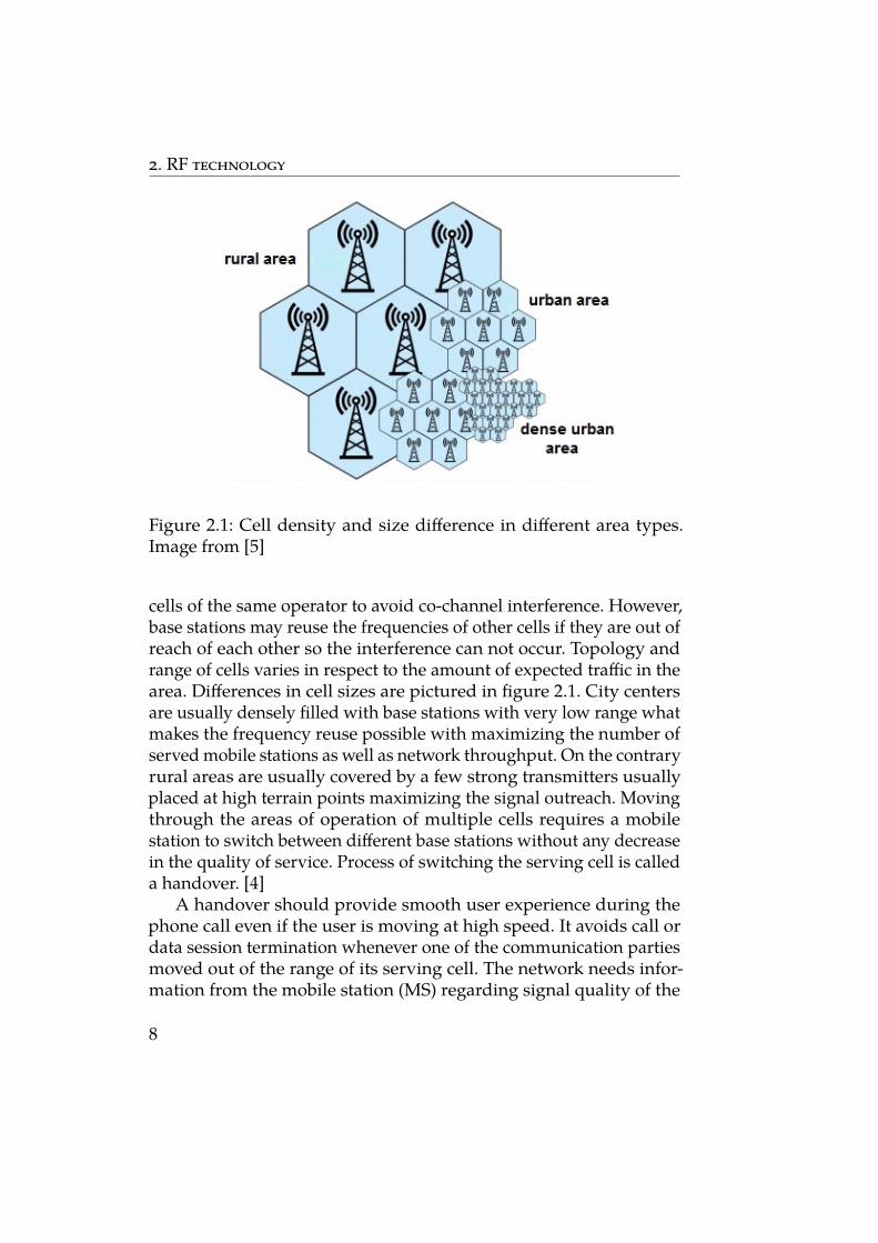
Figure 2.1: Cell density and size difference in different area types.Image from [5]
cells of the same operator to avoid co-channel interference. However,base stations may reuse the frequencies of other cells if they are out ofreach of each other so the interference can not occur. Topology andrange of cells varies in respect to the amount of expected traffic in thearea. Differences in cell sizes are pictured in figure 2.1. City centersare usually densely filled with base stations with very low range whatmakes the frequency reuse possible with maximizing the number ofserved mobile stations as well as network throughput. On the contraryrural areas are usually covered by a few strong transmitters usuallyplaced at high terrain points maximizing the signal outreach. Movingthrough the areas of operation of multiple cells requires a mobilestation to switch between different base stations without any decreasein the quality of service. Process of switching the serving cell is calleda handover. [4]
A handover should provide smooth user experience during thephone call even if the user is moving at high speed. It avoids call ordata session termination whenever one of the communication partiesmoved out of the range of its serving cell. The network needs infor-mation from the mobile station (MS) regarding signal quality of the
8
2. RF technology
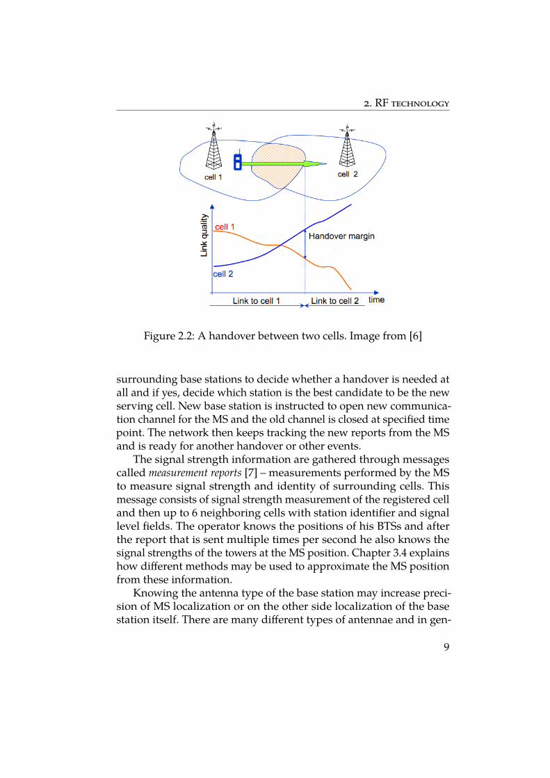
Figure 2.2: A handover between two cells. Image from [6]
surrounding base stations to decide whether a handover is needed atall and if yes, decide which station is the best candidate to be the newserving cell. New base station is instructed to open new communica-tion channel for the MS and the old channel is closed at specified timepoint. The network then keeps tracking the new reports from the MSand is ready for another handover or other events.
The signal strength information are gathered through messagescalled measurement reports [7] – measurements performed by the MSto measure signal strength and identity of surrounding cells. Thismessage consists of signal strength measurement of the registered celland then up to 6 neighboring cells with station identifier and signallevel fields. The operator knows the positions of his BTSs and afterthe report that is sent multiple times per second he also knows thesignal strengths of the towers at the MS position. Chapter 3.4 explainshow different methods may be used to approximate the MS positionfrom these information.
Knowing the antenna type of the base station may increase preci-sion of MS localization or on the other side localization of the basestation itself. There are many different types of antennae and in gen-
9
2. RF technology
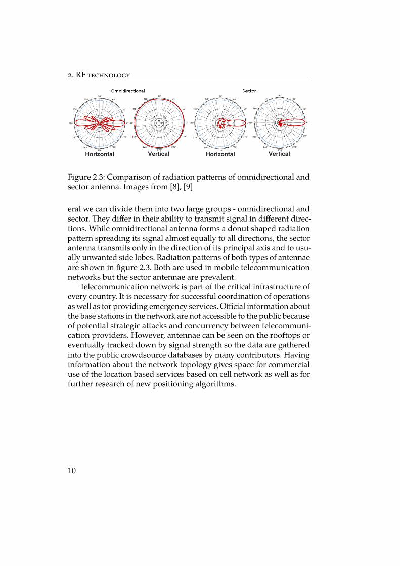
Figure 2.3: Comparison of radiation patterns of omnidirectional andsector antenna. Images from [8], [9]
eral we can divide them into two large groups - omnidirectional andsector. They differ in their ability to transmit signal in different direc-tions. While omnidirectional antenna forms a donut shaped radiationpattern spreading its signal almost equally to all directions, the sectorantenna transmits only in the direction of its principal axis and to usu-ally unwanted side lobes. Radiation patterns of both types of antennaeare shown in figure 2.3. Both are used in mobile telecommunicationnetworks but the sector antennae are prevalent.
Telecommunication network is part of the critical infrastructure ofevery country. It is necessary for successful coordination of operationsas well as for providing emergency services. Official information aboutthe base stations in the network are not accessible to the public becauseof potential strategic attacks and concurrency between telecommuni-cation providers. However, antennae can be seen on the rooftops oreventually tracked down by signal strength so the data are gatheredinto the public crowdsource databases by many contributors. Havinginformation about the network topology gives space for commercialuse of the location based services based on cell network as well as forfurther research of new positioning algorithms.
10
3 Positioning techniques
Because of high demand for precise location tracking on both devel-opers’ and customers’ sides there are various methods to accomplishthis demand with their specific pros and cons. The most relevant fac-tors are availability, power consumption and accuracy. Sometimes thecombination of multiple methods is used to obtain better accuracyimplying higher reliability of the system.
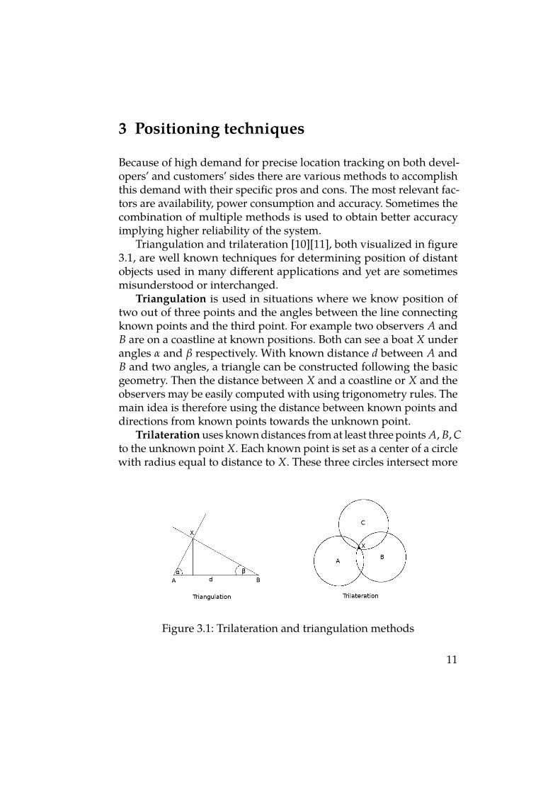
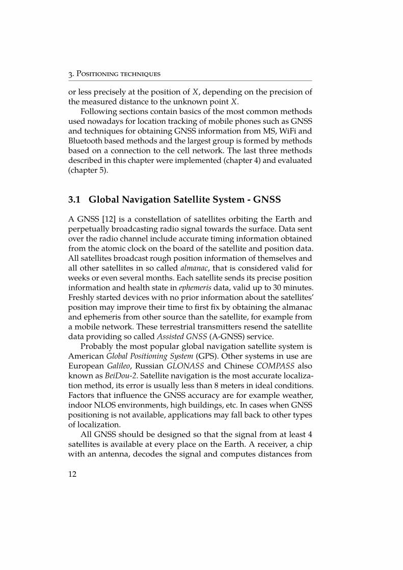
Triangulation and trilateration [10][11], both visualized in figure3.1, are well known techniques for determining position of distantobjects used in many different applications and yet are sometimesmisunderstood or interchanged.
Triangulation is used in situations where we know position oftwo out of three points and the angles between the line connectingknown points and the third point. For example two observers A andB are on a coastline at known positions. Both can see a boat X underangles α and β respectively. With known distance d between A andB and two angles, a triangle can be constructed following the basicgeometry. Then the distance between X and a coastline or X and theobservers may be easily computed with using trigonometry rules. Themain idea is therefore using the distance between known points anddirections from known points towards the unknown point.
Trilateration uses known distances from at least three points A, B, Cto the unknown point X. Each known point is set as a center of a circlewith radius equal to distance to X. These three circles intersect more
Figure 3.1: Trilateration and triangulation methods
11
3. Positioning techniques
or less precisely at the position of X, depending on the precision ofthe measured distance to the unknown point X.
Following sections contain basics of the most common methodsused nowadays for location tracking of mobile phones such as GNSSand techniques for obtaining GNSS information from MS, WiFi andBluetooth based methods and the largest group is formed by methodsbased on a connection to the cell network. The last three methodsdescribed in this chapter were implemented (chapter 4) and evaluated(chapter 5).
3.1 Global Navigation Satellite System - GNSS
A GNSS [12] is a constellation of satellites orbiting the Earth andperpetually broadcasting radio signal towards the surface. Data sentover the radio channel include accurate timing information obtainedfrom the atomic clock on the board of the satellite and position data.All satellites broadcast rough position information of themselves andall other satellites in so called almanac, that is considered valid forweeks or even several months. Each satellite sends its precise positioninformation and health state in ephemeris data, valid up to 30 minutes.Freshly started devices with no prior information about the satellites’position may improve their time to first fix by obtaining the almanacand ephemeris from other source than the satellite, for example froma mobile network. These terrestrial transmitters resend the satellitedata providing so called Assisted GNSS (A-GNSS) service.
Probably the most popular global navigation satellite system isAmerican Global Positioning System (GPS). Other systems in use areEuropean Galileo, Russian GLONASS and Chinese COMPASS alsoknown as BeiDou-2. Satellite navigation is the most accurate localiza-tion method, its error is usually less than 8 meters in ideal conditions.Factors that influence the GNSS accuracy are for example weather,indoor NLOS environments, high buildings, etc. In cases when GNSSpositioning is not available, applications may fall back to other typesof localization.
All GNSS should be designed so that the signal from at least 4satellites is available at every place on the Earth. A receiver, a chipwith an antenna, decodes the signal and computes distances from
12
3. Positioning techniques
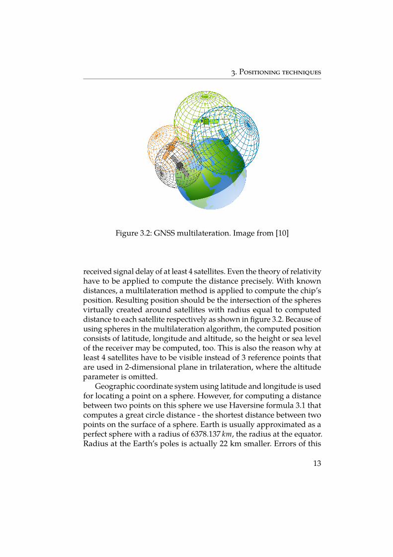
Figure 3.2: GNSS multilateration. Image from [10]
received signal delay of at least 4 satellites. Even the theory of relativityhave to be applied to compute the distance precisely. With knowndistances, a multilateration method is applied to compute the chip’sposition. Resulting position should be the intersection of the spheresvirtually created around satellites with radius equal to computeddistance to each satellite respectively as shown in figure 3.2. Because ofusing spheres in the multilateration algorithm, the computed positionconsists of latitude, longitude and altitude, so the height or sea levelof the receiver may be computed, too. This is also the reason why atleast 4 satellites have to be visible instead of 3 reference points thatare used in 2-dimensional plane in trilateration, where the altitudeparameter is omitted.
Geographic coordinate system using latitude and longitude is usedfor locating a point on a sphere. However, for computing a distancebetween two points on this sphere we use Haversine formula 3.1 thatcomputes a great circle distance - the shortest distance between twopoints on the surface of a sphere. Earth is usually approximated as aperfect sphere with a radius of 6378.137 km, the radius at the equator.Radius at the Earth’s poles is actually 22 km smaller. Errors of this
13
3. Positioning techniques
approximation are negligible for relatively small distances betweentwo points.
a = sin2(∆φ/2) + cos φ1 · cos φ2 · sin2(∆λ/2)
c = 2 · atan2(√
a,√
1 − a)d = R · c
(3.1)
whereφ is latitude [rad]∆φ equals φ2 − φ1λ is longitude [rad]∆λ equals λ2 − λ1R is a sphere radius (Earth) [m]d is a great circle distance between two points [m]
3.2 WiFi access point
Another possible technique for location tracking is based on the loca-tion of the WiFi access points. The device has to have turned on WiFibut it does not have to be connected to any access point. Mobile stationreceives information about all access points in the close proximity soif it has also an information about location of these access points, itis able to precisely locate itself. It is hard to obtain accurate and largedatabase of all WiFi access points all over the world, unless usingthe power of the crowd. There are many crowdsource databases ofaccess points (defined by MAC address) and their GPS coordinates.Anybody may contribute to these projects either by manually addingtheir WiFi access point location or by running an application that isautomatically monitoring nearby area and sending measured datato the remote server that filters the data and updates the database.There are applications focused specifically on this purpose and alsoapplications that monitors surrounding environment just as a sideeffect while providing other services to the user. Typically applicationsthat use this type of databases also collect new data and contribute tothese databases.
WiFi access point based technique consumes less power than GNSSon the MS but is also less accurate. Usually applications use thismethod together with cell-id method as an alternative to the GNSS,
14
3. Positioning techniques
for example in cases when users do not need very high precision butonly rough location estimate.
3.3 Bluetooth beacon
Bluetooth beacon [13] is a hardware transmitter from a category ofBluetooth Low Energy (BLE) devices that transmits its universallyunique identifier, optionally with other data, to the nearby area withlow energy consumption. Beacon is a one way communicator - ittransmits data but it does not receive any. So it is up to the receiverto react, typically some mobile application monitors the Bluetoothdevices in a close proximity and once it captures specific data, it pushesa notification to the user. Beacons are installed for example in shops orother centers of interest and are mostly used for advertisement whenuser has compatible application active on his device. Important facthere is that an application has to be installed on the user device andthat is the element responsible for location determining. Other usecase include multiple beacons in a building so a trilateration techniquemay be applied to find the user’s position and navigate him throughthe building.
3.4 Mobile network connection
Large group of phone localization algorithms is based on their con-nection to the cellular network. These algorithms typically use fixedposition of base stations to determine phone position. Mobile oper-ators have advantage of knowing exact position of the base stationstogether with their technical specification. Some methods, e.g. Angleof Arrival, Time of Arrival, Time difference of Arrival, require additionalnetwork cooperation such as additional synchronization messages orantennae modifications so they are unusable for any third party.
Location tracking based on cell network is surely less accurate thanpositioning by GPS but it may locate the user device with precisionhigher than 100 m what makes it usable for a lot of applications that donot need very high precision or real time availability and in situationswhere GPS position is not available.
15
3. Positioning techniques
Positioning methods may be divided into 2 groups according tothe actor performing actual computation:
Network-based - data from MS are captured by one or multipleBTSs and then forwarded to central processing point that estimatesthe MS position. In this case network computes the MS position fromMS provided data.
Handset-based - MS obtains signals from multiple (more than 3)sources with known position and determines its own position. Wellknown example is GPS.
Both approaches are actually symmetric: the former one uses onetransmitter (MS) with unknown position and multiple receivers withfixed position (BTS) and the latter one uses multiple transmitters withknown position (BTS) and one receiver (MS) with unknown position.It is possible to use some methods, e.g. AoA (subsection 3.4.4), in bothNetwork and Handset-based modes.
3.4.1 RRLP and LPP
Radio Resource Location services Protocol (RRLP) used in GSM/UMTSnetworks and LTE Positioning Protocol (LPP) used in LTE network areprotocols for position message exchange between MS and BTS [14].Base station may request measurement data (signal strength, Doppler,etc.) of the phone and compute the distance itself or let the MS computeits position and request its coordinates directly. This request does nothave to be a part of any session (call, SMS) so it may be performedwithout the knowledge of the user. Use of RRLP/LPP was specifiedfor emergency services but it can be used also by law enforcementagencies.
Global navigation systems are used in mobile networks providingmuch more precision than is needed for correct network functioningbut making the whole localization process in critical situations muchsimpler and more accurate.
3.4.2 Cell-ID
Every phone connected to a mobile network is connected to one basestation at a time. In Cell-ID method, position of the MS is determinedto be equal to the position of currently serving cell. When the cell
16
3. Positioning techniques
identifier is known, position of the station may be looked up in acrowdsource database. Accuracy of this method is highly dependenton physical infrastructure of the network since base stations may haveeffective radial range from 10 m to 30 km so the knowledge of basiccharacteristics of the base station including output power (range) andantenna type (explained in section 2.2) improves the precision. Thismethod is often used as a fall back method if no other is applicable. Itis also possible to combine it with other methods to improve accuracy,for example using Timing advance described in the next section.
3.4.3 Timing advance - TA
While it is possible to obtain the center of an area and its max rangewith Cell-ID, this area of possible location of the MS may be reducedwith Timing advance. In technologies using Time Division Multiple Ac-cess (TDMA) such as GSM and LTE a TA parameter is used to correctsignal delays caused by distance between transmitter and receiver.Base station is monitoring these time delays through specific mes-sages and then commands the MS to increase or decrease its TA, thevalue specifying time offset the MS needs to send its data in advanceto fit its allocated time window. TAs are limited by the speed of light(signal). Each TA level corresponds approximately to 554 m and 78 mstep in GSM and LTE respectively.
For localization purposes a TA means the minimal and maximaldistance from the base station, forming an annulus around it or onlya sector of the annulus if base station uses a sector antenna. Reflectionof the signal causes large inaccuracies because the NLOS path of theconnection is longer than the LOS path, meaning the TA is also higher,but the actual physical distance between the base station and MS islower than length of the NLOS signal path.
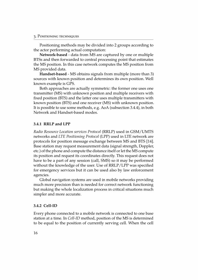
3.4.4 Angle of arrival - AoA
Some antennae are able to determine the direction of the incomingsignal. Similar result may be reached by using multiple directional re-ceivers. The Angle of Arrival [16][15] may be used in both handset-basedand network-based setup but both require mentioned special hardware
17
3. Positioning techniques
Figure 3.3: Triangullation usedin AoA method. Image from [15]
18
3. Positioning techniques
solution. As the name of the method outlines, the underlying localiza-tion technique is triangulation.
In network-based approach, multiple stations track the direction ofsignal transmitted from MS and send these data to central processingpoint where an intersection of the lines following the angle of arrivaldirection is computed. This intersection is the MS position estimate.
Symmetrically in the handset-based setup the MS tracks the direc-tion of incoming signals from surrounding base stations and computeits own position itself using the same triangulation algorithm as thenetwork-based approach. This setup is feasible only if the precise po-sition of the BTSs is known and MS is able to measure the angle ofarrival. The latter is not trivial as additional hardware is necessary.
The AoA is very sensitive to multipath distortion because the verysame sample of the received signal arrives from multiple directions sothe angle is not determined precisely rather than a range. To overcomeinaccuracies caused by multipath usually the later samples are filteredout considered to be propagated in NLOS path.
3.4.5 Time of arrival - ToA
Time of arrival (ToA) [11][15] is popular technique for determiningrange. The most notable radiolocating system using ToA is GPS. Thismethod is based on 3 types of information:
1. Exact time tt when the signal is sent from the source
2. Exact time tr when the signal is received at the reference point
3. A speed of signal propagation c (in most cases the speed of light)
The distance d between the transmitter and the receiver is computedby formula 3.2. Distance is specified as the length of the path thatsignal travels over time t at speed c. The speed of radio signal mayvary according to the medium it is traveling through.
d = c · (tr − tt) (3.2)
For locating the receiver in n dimensions, at least n + 1 distance mea-surements are necessary. With known distances from reference pointswith known position, the trilateration or multirateration is used to
19
3. Positioning techniques
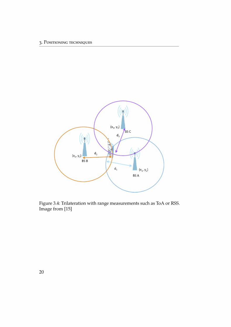
Figure 3.4: Trilateration with range measurements such as ToA or RSS.Image from [15]
20
3. Positioning techniques
compute the position of a node. While mentioned GPS using ToAis a handset-based method, the network-based method may be im-plemented in the mobile network without any additional hardware,as opposed to AoA method, because transmission times are alreadymeasured by network thanks to synchronization messages. If syn-chronization can not be maintained, it is possible to use Round TripTime (RTT) method - base stations transmits an ToA signal and MSresponds with another one so the base station obtains the doubledtime of the path that can be averaged out.
To counteract NLOS effects, analysis should be performed on theincoming signal as to avoid positioning based on signals that havetraveled a longer path than the direct one. There are different strategiesto avoid NLOS, most of which exclude unreasonable measurementsby comparing all the incoming signals and keeping only those thatare likely to be LOS signals.
3.4.6 Time difference of arrival - TDoA
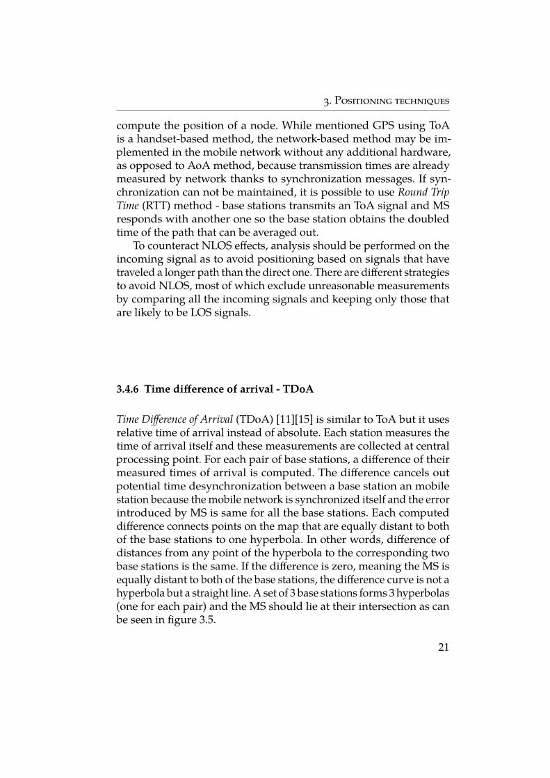
Time Difference of Arrival (TDoA) [11][15] is similar to ToA but it usesrelative time of arrival instead of absolute. Each station measures thetime of arrival itself and these measurements are collected at centralprocessing point. For each pair of base stations, a difference of theirmeasured times of arrival is computed. The difference cancels outpotential time desynchronization between a base station an mobilestation because the mobile network is synchronized itself and the errorintroduced by MS is same for all the base stations. Each computeddifference connects points on the map that are equally distant to bothof the base stations to one hyperbola. In other words, difference ofdistances from any point of the hyperbola to the corresponding twobase stations is the same. If the difference is zero, meaning the MS isequally distant to both of the base stations, the difference curve is not ahyperbola but a straight line. A set of 3 base stations forms 3 hyperbolas(one for each pair) and the MS should lie at their intersection as canbe seen in figure 3.5.
21
3. Positioning techniques
Figure 3.5: TDoA hyperbolas formed for each pair of base stationswith mobile station at their intersection. Image from [15]
3.4.7 Weighted centroid
Cell-ID method uses only the registered cell for MS localization. Anobvious improvement to this approach is to take into considerationnot only the position of the serving cell but also the neighboring cells.Already presented measurement report carries exactly this informationso it is directly applicable on the network side.
The MS position is not united with the position of the registeredcell as in Cell-ID but instead a cluster of cells visible by the MS isformed. The centroid of a polygon or a cluster is an arithmetic mean ofcoordinates of the vertices. The weighted centroid [17] is computed withdifferent vertices having different weight to propagate to the result. Inthis case the higher the signal strength, the closer is the centroid to thatstation. This assumption is not always true since there are situationswhere two BTS have equal measured signal strength at the receiver butone is located further transmitting stronger signal while the secondone is closer and transmitting weaker signal. Situations like this aredirectly increasing the position error. The coordinates of the centroidcx,y of n vertices Vix,y of weight wi are computed according to equation
22
3. Positioning techniques
3.3.
cx =∑n
i=1 Vix · wi
∑ni=1 wi
cy =∑n
i=1 Viy · wi
∑ni=1 wi
(3.3)
An interesting fact regarding the vertex weight is that the serv-ing cell does not have to be the one with strongest signal. The mainfactor affecting an accuracy of the weighted centroid technique is oneside shadowing. Measured low signal of one cell or more cells fromroughly same direction due to an obstacle may massively influencethe computation of coordinates of the centroid. Some antennae inmobile stations are very sensitive to the orientation so it is possiblethat even rotating the phone may end up with different measurementand therefore different centroid coordinates.
3.4.8 Received signal strength - RSS
Another distance computing approach is measuring the signal strengthat the receiver. As shown in equation 2.2, a radio signal is in the freespace attenuated according to the inverse square law. This can beturned into the benefit of localization algorithm because once the re-ceived signal strength is measured, it can be compared to the signalstrength at the transmitter so we obtain the path attenuation. Fol-lowing one of many signal propagation models, the distance can becomputed by inverting the model equation. Instead of computing thepath loss given the distance, we compute the distance given the pathloss.
The obvious drawback of this method is that the signal strength ofthe base station has to be known but that is not a public information.This is not a problem for a network provider that sets up the stationsand designs whole network topology. For applications without theknowledge of transmit power, it can be measured at the referencedistance (e.g. 100 m) prior to the actual localization. This process maybe directly included in the data gathering for crowdsource databasesso we can generally state that signal strength of the transmitter at thereference point is available if the position of the transmitter is alsoavailable.
The unknown signal strength of the transmitters may be also pre-dicted if position of the BTS in the area is known by performing atleast one calibration measurement. Position of the calibration point is
23
3. Positioning techniques
known as well as position of the BTS so the distances between themcan be computed and signal strength at given distance is measured. Atthis point the signal strength at the reference point, distance betweenreference point and BTS and propagation pattern are known so theactual transmit power may be calculated. This process highly dependson the accuracy of the propagation model and that signals from allthe BTS in the area are measured so all of them are calibrated.
The core principle of this method is transformation of receivedsignal strength into distance and than using trilateration to obtainposition of the MS. This approach is very similar to ToA (subsection3.4.5) where time is used as a measured metrics instead of signalstrength.
3.4.9 Fingerprinting
In the data collection phase of cell database, a contributor moves in anarea and signal strength measurements are taken every given periodof time. The purpose is to collect the globally unique identifiers ofthe BTS and signal strength is measured to apply algorithms iden-tifying position of the BTS. Such algorithm is for example finding acentral point of a cluster of measurements where the signal strengthis expected to be the highest possible value. In fingerprinting [18] thisalgorithm is not applied but a database of measurements is createdinstead.
Each signal measurement is bound to GPS coordinates so thedatabase is actually a map with reference points (places where the mea-surements were taken) describing what base stations are visible at thethese points together with their signal strengths. The reference pointsmay be grouped to form small areas with averaged signal strengthfor each BTS. These reference points are called fingerprints and theprocess of collecting such fingerprints is called war-driving, war-cyclingor war-walking with respect to the mean of transport.
After forming the database, any new measurement can be com-pared with all the fingerprints. This comparison may be implementedin many ways but the point is to find the fingerprint as much similarto the measurement as possible. Result of this method is therefore afingerprint whose signal strengths of the base stations are very closeto those present in given measurement. The accuracy of fingerprint-
24
3. Positioning techniques
ing depends on the amount of fingerprints. Long term maintenancerequires repetitive scanning of all the areas of interest. [18]
An error may be introduced if a different device was used for war-driving and different for location tracking because different antennaeend up with different power measurements so the fingerprint doesnot have to be properly matched.
25

4 Molotras - Mobile phone location trackingsystem
From all the techniques described in chapter 3 the last three wereimplemented and evaluated as a pat of this thesis. Weighted centroid,RSS trilateration and fingerprinting were chosen because they are allbased on signal strength measurement what is crucial when we wantto demonstrate localization using measurement reports on the mobileoperator side. These methods also do not need any precise synchro-nization with the network, any additional communication with thenetwork nor any additional hardware or hardware modifications.
Implemented system Molotras consists of two standalone parts: ascanner application for Android phones that gathers power measure-ments of the surrounding cells simulating the measurement reportsand core application with implementation of localization methodsthat use data gathered from the scanner. These main parts of the sys-tem are described in a greater detail in the following sections of thischapter.
4.1 Android scanner
Android operating system introduced a permission system to protectthe privacy of its users [19]. Every Android application that requestsaccess to sensitive user data (contacts, SMS, photos, etc.) or certainsystem features (camera, internet access, sensors, etc.) has to be grantedpermission of corresponding class. The idea behind this Androidsecurity architecture is that no application has by default a permissionto adversely impact other applications, operating system itself or userand his data. This also include features like keeping the device awake.
Applications requesting location information are limited by lo-cation permission. This is also the case of the Android part of thisproject. Here Android distinguishes two different types of locationpermissions: ACCESS_COARSE_LOCATION that allows the applica-tion to access approximate location and ACCESS_FINE_LOCATIONthat allows an access to precise location. Both of these permissionshave protection level dangerous that means that the user has to ex-
27
4. Molotras - Mobile phone location tracking system
plicitly allow this permission. Accessing GPS location requires finelocation permission and accessing information about currently con-nected cell and neighboring cells requires coarse location permissionthat is weaker and allows access to specific subset of classes. Thoseare of course also accessible with stronger fine location permission.
With respect to the aim of this project, these information aboutandroid security architecture and permission politics reveal multipleinteresting facts. Location by cell network connectivity is not onlytheoretically possible but also functional and widely used. It is alsopart of Android location API – applications may use LocationManagerclass with multiple providers working in the background includingGPS, WiFi access points, cell towers or Internet access. Another factis that usage of cell network data is guarded by permission so thereis no privacy breach. The last thing that is obvious from permissionmanagement is that GPS is the best option with respect to accuracyand other means may be useful but end up only with supposedlyinaccurate result.
After installing the app, user has to grant permissions to accessprecise position (GPS) and to manipulate data in the file system. Af-ter starting the app, 2 files ”Documents/Molotras/cell_data.csv” and”Documents/Molotras/shots_data.csv” are created. If they already ex-ist, they will remain unchanged. Those files are external and publictherefore everybody should be able to access them either directly inthe phone file system, e.g. read them, send them using other appli-cation, etc. or access them from external device, for example afterconnecting the phone to a PC, the data should be visible and available.
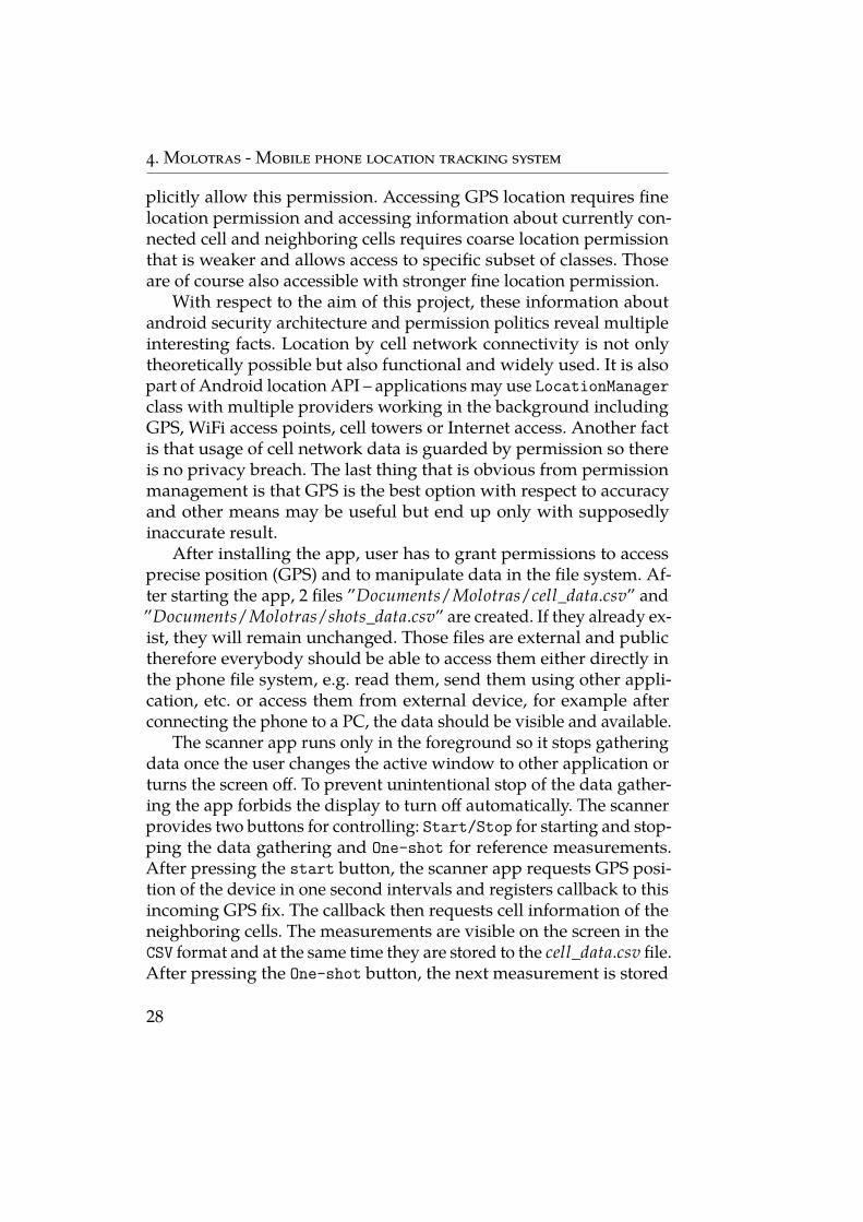
The scanner app runs only in the foreground so it stops gatheringdata once the user changes the active window to other application orturns the screen off. To prevent unintentional stop of the data gather-ing the app forbids the display to turn off automatically. The scannerprovides two buttons for controlling: Start/Stop for starting and stop-ping the data gathering and One-shot for reference measurements.After pressing the start button, the scanner app requests GPS posi-tion of the device in one second intervals and registers callback to thisincoming GPS fix. The callback then requests cell information of theneighboring cells. The measurements are visible on the screen in theCSV format and at the same time they are stored to the cell_data.csv file.After pressing the One-shot button, the next measurement is stored
28
4. Molotras - Mobile phone location tracking system
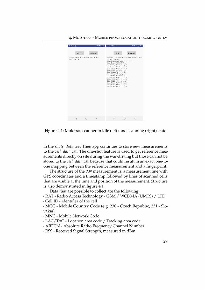
Figure 4.1: Molotras-scanner in idle (left) and scanning (right) state
in the shots_data.csv. Then app continues to store new measurementsto the cell_data.csv. The one-shot feature is used to get reference mea-surements directly on site during the war-driving but those can not bestored to the cell_data.csv because that could result in an exact one-to-one mapping between the reference measurement and a fingerprint.
The structure of the CSV measurement is: a measurement line withGPS coordinates and a timestamp followed by lines of scanned cellsthat are visible at the time and position of the measurement. Structureis also demonstrated in figure 4.1.
Data that are possible to collect are the following:- RAT - Radio Access Technology - GSM / WCDMA (UMTS) / LTE- Cell ID - identifier of the cell- MCC - Mobile Country Code (e.g. 230 - Czech Republic, 231 - Slo-vakia)- MNC - Mobile Network Code- LAC/TAC - Location area code / Tracking area code- ARFCN - Absolute Radio Frequency Channel Number- RSS - Received Signal Strength, measured in dBm
29
4. Molotras - Mobile phone location tracking system
- ASU level - Arbitrary (signal) Strength Unit- TA - Timing Advance (2G, 4G)- BSIC - Base Station Identity code (2G)- PSC - Primary Scrambling Code (3G)- PCI - Physical Cell Id (4G)- CQI - Channel Quality Indicator (4G)- RSRP - Reference Signal Received Power (4G)- RSRQ - Reference Signal Received Quality (4G)- RSSNR - Reference Signal Signal to Noise Ratio (4G)
Every cell tower should be globally uniquely identified by MCC,MNC, LAC and CID. MCC and MNC are public information main-tained by ITU (International Telecommunication Union) and LACand CID are custom properties defined by operator. For the localiza-tion purposes it is enough to obtain these four values together withreceived signal strength.
Problems regarding the scanner include invalid or missing data inthe measurement. Responses from the phone are many times invalidvalues, e.g. maximal possible value for corresponding data type. Thereason may be actual unavailability of the data at the time of measure-ment or the underlying implementation of the method is not provided.Typically these methods send a request to a baseband processor thatsends the requested data as a response. It may be the case that thebaseband processor does not recognize the request so the data are inthe default, invalid state. Because of this, additional data sanitizationand filtering need to be done before use.
4.2 Core
The core part of Molotras can be further divided into three components:crowdsource database of cells, implementation of weighted centroid,trilateration and fingerprinting methods and third GUI for visualizingresults of these methods.
30
4. Molotras - Mobile phone location tracking system
4.2.1 Cell database
Implemented localization algorithms use cell databases for referencepositions of cells in the area of measurement. For this purpose theOpenCellid [20] database, available at www.opencellid.org was used,where anybody can contribute to and also use this database for free.There are more alternatives to OpenCellid but they are very similar andusually they are forks of OpenCellid so any significant improvementin using other open database is not expected. There are applicationsthat use OpenCellid API queries to obtain position – data consumersand applications that contribute to database with new measurements– data providers. OpenCellid gathers the data from data providers,updates the database and releases new updated version every day.
Data consumers do not have to use online API queries, becausethe complete database with cells from all over the world is availablefor download and offline use. At the time of writing this thesis thedatabase is stored and distributed as a 3.5 GB large CSV file. Thedata stored in the database are similar to the data gathered by theimplemented Android scanner. The most important fields are RAT,MCC, MNC, LAC and CID to uniquely identify the cell and its GPScoordinates given by latitude and longitude. Other values like numberof measurement samples of each cell, source of the measurement,timestamp and others are not important for the aim of the thesis.
Integrating cell database to the project is performed by parsingthe downloaded CSV file and loading all the data to MySQL database.For performance reasons database was prior filtered to contain onlycells of Czech and Slovak Republic. After loading the CSV to MySQLdatabase, it is ready to be used in the localization algorithms.
A typical problem with cell database is that it does not take intoaccount the direction of cell tower antennae. Position of the cell toweris usually computed as a centroid of measurements obtained fromdata providers. If the antenna of the cell is directional, the centroidis incorrectly determined as a point somewhere in the main lobe ofthe transmission instead of the point at the beginning of the lobe.This means that centroid method is relatively precise for determiningposition of omnidirectional antennae but it introduces an error withdirectional antennae. After forming the database, it is impossible torecognize if the cell record is precisely determined record of omnidi-
31
4. Molotras - Mobile phone location tracking system
rectional cell or imprecise record of directional cell. For localizationof MS, all the records of cells are considered to be omnidirectional sothere definitely is an error in accuracy caused by this assumption.
Another issue is the crowdsourcing itself. As the database is open,anybody may contribute with correct measurements but it is possiblethat there is a lot of measurements that are either not accurate enough,invalid or misleading by purpose. Some records in the OpenCellidcontain values that are invalid and can not occur in real environmentso it is probable that database inputs are sanitized weakly or not at all.
4.2.2 Localization algorithms
The Molotras-core is a module developed in python (version 3.7.3) con-taining implementation of weighted centroid, trilateration based onRSS and fingerprinting method used for comparison and evaluationof these methods. All three methods expect one complete measure-ment with the same structure as in the Android scanner. Provideddata therefore contain list of cells and corresponding measured signalstrengths as well as GPS coordinates of the measurement. The celllist is used to estimate GPS coordinates of the MS on which the mea-surement was performed and then haversine distance, explained insection 3.1, between position estimate and actual position is computedand return as a result of the method. The smaller is the distance be-tween the position estimate and actual position the more accurate themethod is.
Centroid technique is basically implementation of equation 3.3.For all the cells in the input list the cell record is looked up in thedatabase. If no such record exists, this cell is omitted and the result iscomputed without it. Usually these situations decrease the accuracyof the result.
The weight of the vertices (cells) is the signal strength measuredin dBm. Typically the signal strength falls in the interval −112 dBmweakest to −50 dBm strongest. To use the signal strength as a vertexweight where all the values are negative and the higher number meansthe higher weight, the inverse of the signal strength is used in thecomputation. For example if a cell has signal strength of −82 dBm itsweight is − 1
82 . The computation is then trivial following the equation3.3, we multiply the position of the cell by its weight divided by the
32
4. Molotras - Mobile phone location tracking system
sum of the all weights, obtaining a measure of how much is the cellaffecting the result.
This method assumes that all the cells have the same transmitpower so the weight is computed equally for all of the cells. In realenvironment it does not have to hold that if a phone measures signalstrengths of cells A and B and A has a stronger signal, the phone iscloser to the cell A. It may be for example the case that A is further buthas stronger transmission than B that is located closer to the phone.
Trilateration using received signal strength is technically an im-provement of a centroid method. It is actually translating the signalstrength to the distance. Generally if we use trilateration and assumethat all the cells transmit at the same out power level, we should obtainvery similar results to the centroid. This is because the transformationof the signal strength to distance is performed equally for all the cellsso we are again in the state where the stronger signal means the lowerdistance.
This approach is therefore benefiting from additional necessaryinformation that is the signal strength at the transmitter point or inother words an out power of the cell. Usually this information is notavailable so an estimate or calibration is needed.
This implementation uses Okumura-Hata signal propagation modelthat is used for both calibration as well as for computation itself. Thecalibration is performed at the beginning of the algorithm. The calibra-tion set provided as an input is a list of measurements from the area ofinterest. For calibration of a cell, a measurement where this cell has thestrongest signal is chosen. Then a haversine distance between the celland the point of measurement is computed. Then an Okumura-Hatapath loss is computed at the computed distance. Finally when weknow what is the expected signal path loss at the specific distance, wecan sum received signal strength with the path loss to obtain expectedoutput power of the cell. This algorithm is applied for all the cells inthe provided calibration list.
Each cell from the input list is looked up in the cell database toobtain its position and then looked up in the calibration set to obtainits output power. If at least one of these look ups fails, the cell isomitted from actual positioning and probably introducing an errorin the resulting position estimate. Once having a list of cells withcomputed distances to them, the trilateration is started. In ideal case
33
4. Molotras - Mobile phone location tracking system
one intersection of the circles would appear and this point would bethe result. In reality there is usually set of circles that have either verylarge intersection area or there is no intersection at all. Sometimes someof the cells form large intersection and another part is not intersectingat all. To handle all these situation, the algorithm uses optimizationfunction that minimizes the distance to all the circles. The startingguess is taken to be the weighted centroid. Then this point is moved inall directions trying to minimize the error function, where the error isdistance to the circles. Used optimization function is function minimizefrom module scipy.optimize.
The Fingerprinting method is the last implemented method usingcompletely different approach. Instead of using cell database to obtainpositions of cells, it uses database of fingerprints.
Before starting the fingerprinting method, actual database of fin-gerprints has to be created. Again the input is a list of measurements,ideally dense measurements completely covering the area of interest.Coordinates with lowest and highest longitude and latitude are takenas border lines of the area. This rectangle is then divided into smallsquare tiles with arbitrary size. For each tile a fingerprint is computed.A fingerprint groups all the measurements with GPS coordinatesinside the tile and an average signal strength is computed for eachcell.
The tile size has direct impact on localization accuracy. Biggertiles mean each tile has more cell measurements bound to itself. Thedrawback is that once the tile is determined as the result, it introducesan implicit error. The error is determined to be the distance betweenthe center of the tile and the furthest point still belonging to the tile. Insquare tiles this is the corner vertex so the error is a circle of diameterequal to the length of the diagonal of the tile. The radius of this circleis obviously half of the length of the diagonal. For example if a tiledimensions are 100 m × 100 m, the final error would be a circle with aradius of approximately 70 m.
After the fingerprint database is computed, an input measurementmay be evaluated. The signal strengths of the cells in the measure-ment are compared to the signal strengths present in each fingerprint.Comparison is actually computing a vector distance of two vectors ofsignal strengths. If a cell present in the measurement is not present inthe fingerprint, a penalty is introduced. In this implementation the
34
4. Molotras - Mobile phone location tracking system
penalty equals to −113 dBm as if the cell was visible with the lowestpossible signal strength. It may happen that multiple tiles have exactlythe same best score. In this case the resulting distance between thereference position of the measurement and computed position is de-termined as the average of distances between the reference point andcenter of each of the tiles.
4.2.3 GUI
A graphical user interface with Molotras-core in the backend maybe used to visualize the positioning algorithms. For this purpose apython web framework CherryPy [21] was used. The frontend part iswritten in classic joint of JavaScript, HTML and CSS.
The biggest benefit of using GUI is visualizing on the map. Themap server used in this project is well known Google Maps JavaScriptAPI [22]. This service is no longer free so to be able to use it, the userhas to pay per API request.
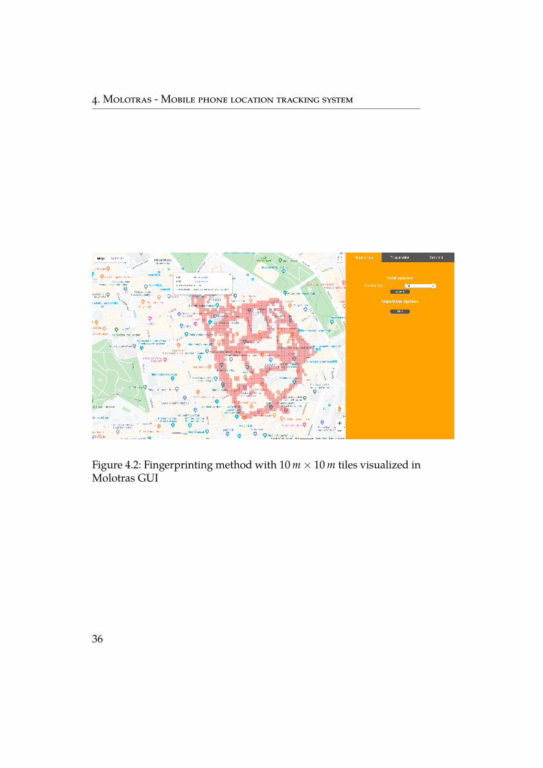
Since Molotras is able to run as a web server, GUI is accessiblethrough any browser at port 8080. It consists of a map where allthe methods are visualized and a right panel with settings for eachof the methods. The map shows tiles, circles and points specific forthe technique. After computing the result, both the reference pointand computed coordinates are displayed together with distance error.Overview of the GUI is shown in figure 4.2.
35
4. Molotras - Mobile phone location tracking system
Figure 4.2: Fingerprinting method with 10 m × 10 m tiles visualized inMolotras GUI
36
5 Evaluation
Implemented localization methods weighted centroid, RSS trilaterationand fingerprinting were evaluated on three mobile phones and at twodifferent locations. The data gathering, evaluation process and ob-tained results are described in this chapter.
To diminish an error caused by specific hardware, three phones ofdifferent manufacturer were used for data gathering and subsequentevaluation. The tested phones are Nokia 6.1, Moto G6 Play and GooglePixel. All the phones had SIM card of the same operator.
Signal propagation is dependent on the surrounding environmentso different results are expected for different environments. Two suchenvironments were chosen for evaluation, a city and a village envi-ronment. The city measurements were taken in the centre of Brno,Czech Republic and the village measurements are from peripheryof Trenčianska Turná, Slovak Republic. These two environments arefurther referenced as the city and the village.
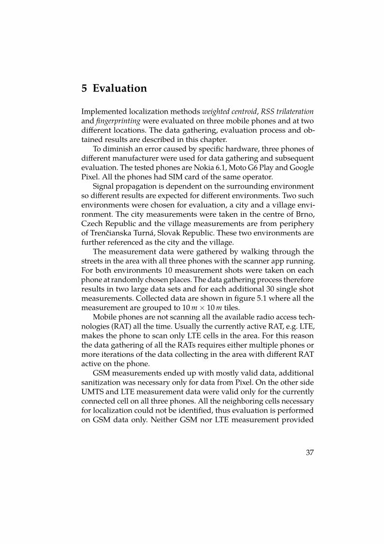
The measurement data were gathered by walking through thestreets in the area with all three phones with the scanner app running.For both environments 10 measurement shots were taken on eachphone at randomly chosen places. The data gathering process thereforeresults in two large data sets and for each additional 30 single shotmeasurements. Collected data are shown in figure 5.1 where all themeasurement are grouped to 10 m × 10 m tiles.
Mobile phones are not scanning all the available radio access tech-nologies (RAT) all the time. Usually the currently active RAT, e.g. LTE,makes the phone to scan only LTE cells in the area. For this reasonthe data gathering of all the RATs requires either multiple phones ormore iterations of the data collecting in the area with different RATactive on the phone.
GSM measurements ended up with mostly valid data, additionalsanitization was necessary only for data from Pixel. On the other sideUMTS and LTE measurement data were valid only for the currentlyconnected cell on all three phones. All the neighboring cells necessaryfor localization could not be identified, thus evaluation is performedon GSM data only. Neither GSM nor LTE measurement provided
37
5. Evaluation
Figure 5.1: Maps of collected GSM data in Brno CZ (left) and Trenčian-ska Turná SK (right)
valid timing advance data so the timing advance method could not beevaluated.
Data sanitization was necessary for data gathered at Pixel, becausethe MNC value was missing and also currently registered cell was inthe measurement list two times, with different signal strengths. MNCwas manually corrected to the corresponding value for the Czech andSlovak mobile operator and the record with lower signal strength wasremoved from the list.
Each method was evaluated with 30 measurement samples. Thelarge data sets of measurements captured by different phones weremerged together and used for creating the fingerprint database forfingerprinting method and for calibration for RSS trilateration method.The measured metric in the evaluation process is the haversine dis-tance (great circle distance) between actual position where the mea-surement was taken and estimated position. A method is thereforemore accurate when the distance error is smaller.
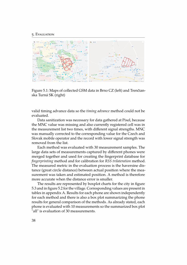
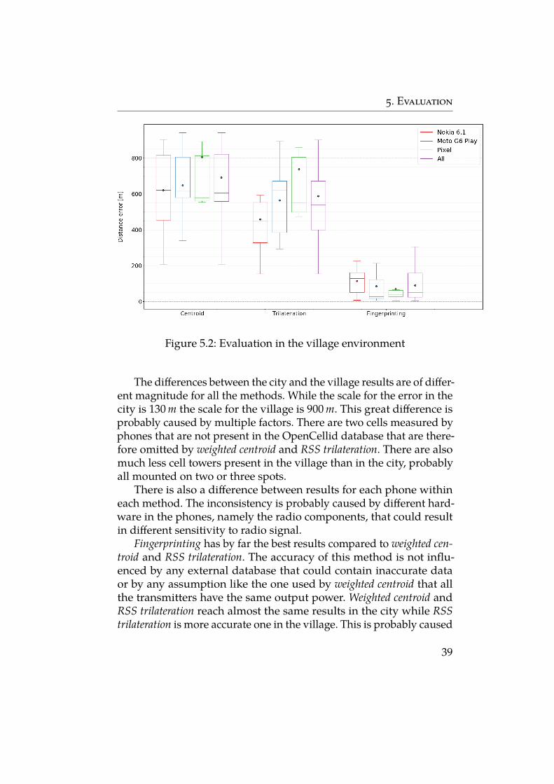
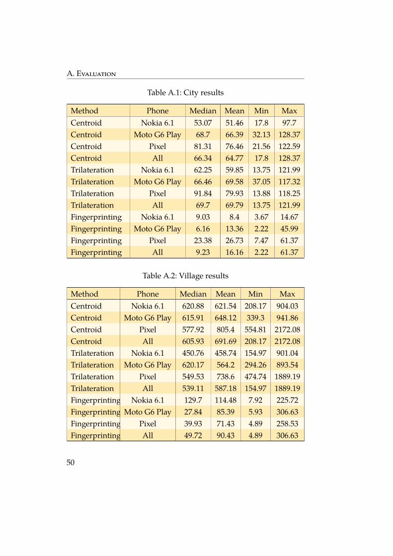
The results are represented by boxplot charts for the city in figure5.3 and in figure 5.2 for the village. Corresponding values are present intables in appendix A. Results for each phone are shown independentlyfor each method and there is also a box plot summarizing the phoneresults for general comparison of the methods. As already stated, eachphone is evaluated with 10 measurements so the summarized box plot"all" is evaluation of 30 measurements.
38
5. Evaluation
Figure 5.2: Evaluation in the village environment
The differences between the city and the village results are of differ-ent magnitude for all the methods. While the scale for the error in thecity is 130 m the scale for the village is 900 m. This great difference isprobably caused by multiple factors. There are two cells measured byphones that are not present in the OpenCellid database that are there-fore omitted by weighted centroid and RSS trilateration. There are alsomuch less cell towers present in the village than in the city, probablyall mounted on two or three spots.
There is also a difference between results for each phone withineach method. The inconsistency is probably caused by different hard-ware in the phones, namely the radio components, that could resultin different sensitivity to radio signal.
Fingerprinting has by far the best results compared to weighted cen-troid and RSS trilateration. The accuracy of this method is not influ-enced by any external database that could contain inaccurate dataor by any assumption like the one used by weighted centroid that allthe transmitters have the same output power. Weighted centroid andRSS trilateration reach almost the same results in the city while RSStrilateration is more accurate one in the village. This is probably caused
39
5. Evaluation
Figure 5.3: Evaluation in the city environment
by better signal propagation since there are less and smaller obstaclesso the Okumura-Hata propagation model is more precise.
40
6 Future work and possible extensions
The main goal of this thesis was to prove that mobile phone locationtracking based on received signal strength is possible with publiclyavailable resources and to compare and evaluate some of the methodsusing this approach. There are many possible ways to improve orfurther research positioning techniques, some of them are introducedin this chapter.
The scanner implemented for Android OS is already used in aresearch studying possibilities of using machine learning to obtainbetter results or to compute more fingerprints from a given fingerprintset. Some places are hard or forbidden to enter so measuring the dataaround the object while still obtaining reliable fingerprints inside thearea may dramatically improve the position estimate.
Data collected during war-driving may be used not only for a finger-print database but also for forming new cell database. The differenceis that measurements would be used for localization of transceiverstations and possibly new characteristics not present in OpenCellidcould be measured as well, for example determine the output powerof the transmitter or direction of the antenna.
Another use for the war-driving data could be the calibration forRSS trilateration. Calibration for Molotras was performed on a singlecell with highest signal strength. There could be used more advancedalgorithms that would use multiple reference points and estimatethe output power of the base station in a way it makes sense for allthe points. This would need to take directivity of the antenna in theconsideration.
Kalman filter is an estimator used for indirect measurements whereit is impossible to measure the subject directly or if the measurementsare taken in a noisy environment. The aim of the Kalman filter is to ac-curately estimate real system state based on imprecise measurementsand estimate from the previous step. This estimator is memory-less soall already performed estimates are aggregated to the last one. Jean-Pierre Dubois et al. used Kalman filter in GSM networks [23] and theysuccessfully decreased the position error over time. This system is nota brand new approach, it is rather an optimization combining resultsof already introduced methods to obtain the best possible location
41
6. Future work and possible extensions
estimate assuming there are errors that can be smoothed out. Kalmanfilter is used for iterative measurements to minimize the error overtime so it is not applicable to one time measurements. The futureresearch of position estimation should be aimed also in this directionusing consecutive independent measurements.
42
7 Conclusions
This thesis explains basics of radio technology, radio signal propaga-tion and characteristics of mobile cellular networks that are necessaryto understand localization techniques. Different location determina-tion approaches were introduced with main focus on those based onsignal strength measurements.
Implemented Android application that gathers the signal strengthmeasurements of the surrounding cells and captures GPS position wasused to create a fingerprint database and reference measurements fortesting. The measurements were taken at two different locations, in thecenter of Brno and in a village Trenčianska Turná. To avoid hardwarespecific errors, the measurements were taken on three phones, namelyNokia 6.1, Moto G6 Play and Pixel by Google.
Three localization methods were chosen and implemented. Fin-gerprinting, weighted centroid and trilateration are all based on signalstrength measurement of cell towers in the nearby area.
Data obtained by the Android scanner were used to evaluate im-plemented methods. Evaluation was based on the signals from GSMnetwork only. The most accurate results were obtained by fingerprint-ing that introduces a distance error approximately 10 meters in the cityand 50 meters in the village. Other two methods reach similar accuracyof 70 and 600 meters in the city and in the village correspondingly.
43

Bibliography
1. FEDERAL COMMUNICATIONS COMMISSION. Wireless E911Location Accuracy Requirements. 2011. https://www.fcc.gov/document/wireless-e911-location-accuracy-requirements-1.
2. SAUNDERS, Simon R; ARAGÓN-ZAVALA, Alejandro. Antennasand propagation for wireless communication systems. 2nd ed. JohnWiley & Sons, 2007. ISBN 978-0-470-84879-1.
3. A.MAWJOUD, Sami. Path Loss Propagation Model Predictionfor GSM Network Planning. International Journal of Computer Ap-plications. 2013, vol. 84, pp. 30–33. Available from DOI: 10.5120/14592-2830.
4. MUNIR, Muhammad. Different Generations of Cellular Net-works System. 2005. Available from DOI: 10.13140/RG.2.1.3341.2004.
5. TNUDA. Cellular Communication Network Technologies [online].2016 [visited on 2019-11-27]. Available from: https : / / www .tnuda.org.il/en/physics-radiation/radio-frequency-rf-radiation/cellular-communication-network-technologies.
6. LANAROL, Isuru Mahesh. Telecommunication Engineering Con-cepts: GSM Handover/Handoff [online]. 2012 [visited on 2019-12-08]. Available from: http://telecommunicationengineeringconcepts.blogspot.com/2012/05/gsm-handoverhandoff.html.
7. KEYSIGHT. Measurement Reports [online]. 2010 [visited on 2019-12-08]. Available from: http://rfmw.em.keysight.com/rfcomms/refdocs/gsm/gprsla_meas_reports.html.
8. MP ANTENNA, LTD. Omnidirectional Antenna Radiation Patterns[online]. 2019 [visited on 2019-11-27]. Available from: https ://www.mpantenna.com/omnidirectional-antenna-radiation-patterns-of-different-antenna-designs/.
9. MIRO. Part 4 of 5: Introduction to Wireless Communication (An-tennas) [online]. 2017 [visited on 2019-11-27]. Available from:https://www.miro.co.za/part-4-5introduction-wireless-communication-antennas/.
45
BIBLIOGRAPHY
10. GISGEOGRAPHY. Trilateration vs Triangulation – How GPS Re-ceivers Work [online]. 2019 [visited on 2019-11-28]. Available from:https://gisgeography.com/trilateration-triangulation-gps/.
11. SHOJAIFAR, Alireza. Evaluation and Improvement of the RSSI-based Localization Algorithm : Received Signal Strength Indica-tion (RSSI). In: 2015.
12. FERNÁNDEZ-PRADES, Carles; CLOSAS, Pau; VILÀ-VALLS,Jordi; FIGUEROA-NAHARRO, Marta; TORNÉ-SANJOSÉ, Albert.Assisted GNSS in LTE-Advanced Networks and Its Applicationto Vector Tracking Loops. In: 2012, vol. 2.
13. DICKINSON, Patrick; CIELNIAK, Gregorz; SZYMANEZYK, Oliver;MANNION, Mike. Indoor positioning of shoppers using a net-work of Bluetooth Low Energy beacons. In: 2016, pp. 1–8. Avail-able from DOI: 10.1109/IPIN.2016.7743684.
14. SCHÜTZ, Jan. LTE Location Based Services Technology Intro-duction White paper. In: 2013.
15. TAHAT, Ashraf; KADDOUM, Georges; YOUSEFI, Siamak; VALAEE,Shahrokh; GAGNON, François. A Look at the Recent WirelessPositioning Techniques With a Focus on Algorithms for MovingReceivers. IEEE Access. 2016, vol. 4, pp. 6652–6680. Available fromDOI: 10.1109/ACCESS.2016.260648.
16. ZIMMERMANN, Lars; GOETZ, Alexander; FISCHER, Georg;WEIGEL, Robert. GSM mobile phone localization using time dif-ference of arrival and angle of arrival estimation. 2012. Availablefrom DOI: 10.1109/SSD.2012.6197970.
17. OLIVEIRA, Leonardo; DESSBESELL, Gustavo; MARTINS, Joao;MONTEIRO, José. Hardware implementation of a centroid-basedlocalization algorithm for mobile sensor networks. In: 2011, pp. 2829–2832. Available from DOI: 10.1109/ISCAS.2011.5938194.
18. SARAIVA CAMPOS, Rafael; LOVISOLO, Lisandro. Fingerprint-ing Location Techniques. In: Handbook of Position Location. JohnWiley and Sons, Ltd, 2019, chap. 15, pp. 497–529. ISBN 9781119434610.Available from DOI: 10.1002/9781119434610.ch15.
46
BIBLIOGRAPHY
19. ANDROID DEVELOPERS. Permissions overview [online]. 2019[visited on 2019-12-08]. Available from: https://developer.android.com/guide/topics/permissions/overview.
20. UNWIRED LABS. OpenCellid [online]. 2019 [visited on 2019-12-08]. Available from: https://opencellid.org.
21. CHERRYPY TEAM. CherryPy — A Minimalist Python Web Frame-work [online]. 2019 [visited on 2019-12-08]. Available from: https://cherrypy.org/.
22. GOOGLE MAPS. Maps JavaScript API [online]. 2019 [visited on2019-12-08]. Available from: https://developers.google.com/maps/documentation/javascript/tutorial.
23. DUBOIS, Jean-Pierre; DABA, Jihad S.; NADER, M.; FERKH, C. El.GSM Position Tracking using a Kalman Filter. International Jour-nal of Electronics and Communication Engineering. 2012, vol. 6, no.8, pp. 867–876. ISSN eISSN: 1307-6892. Available also from: https://publications.waset.org/vol/68.
47

A Evaluation
Following tables contain all measured values for all the methods andphones that were used in this thesis.
49
A. Evaluation
Table A.1: City results
Method Phone Median Mean Min MaxCentroid Nokia 6.1 53.07 51.46 17.8 97.7Centroid Moto G6 Play 68.7 66.39 32.13 128.37Centroid Pixel 81.31 76.46 21.56 122.59Centroid All 66.34 64.77 17.8 128.37Trilateration Nokia 6.1 62.25 59.85 13.75 121.99Trilateration Moto G6 Play 66.46 69.58 37.05 117.32Trilateration Pixel 91.84 79.93 13.88 118.25Trilateration All 69.7 69.79 13.75 121.99Fingerprinting Nokia 6.1 9.03 8.4 3.67 14.67Fingerprinting Moto G6 Play 6.16 13.36 2.22 45.99Fingerprinting Pixel 23.38 26.73 7.47 61.37Fingerprinting All 9.23 16.16 2.22 61.37
Table A.2: Village results
Method Phone Median Mean Min MaxCentroid Nokia 6.1 620.88 621.54 208.17 904.03Centroid Moto G6 Play 615.91 648.12 339.3 941.86Centroid Pixel 577.92 805.4 554.81 2172.08Centroid All 605.93 691.69 208.17 2172.08Trilateration Nokia 6.1 450.76 458.74 154.97 901.04Trilateration Moto G6 Play 620.17 564.2 294.26 893.54Trilateration Pixel 549.53 738.6 474.74 1889.19Trilateration All 539.11 587.18 154.97 1889.19Fingerprinting Nokia 6.1 129.7 114.48 7.92 225.72Fingerprinting Moto G6 Play 27.84 85.39 5.93 306.63Fingerprinting Pixel 39.93 71.43 4.89 258.53Fingerprinting All 49.72 90.43 4.89 306.63
50
B Molotras source files and measured data
The electronic archive of this thesis contains the following data attach-ments:
∙ source files of the Android scanner - Molotras-scanner
∙ source files of the implemented localization method - Molotras-core
∙ collected data that were used for evaluation of methods
51


