Embed Size (px)
Citation preview

58
ISSN 1392 - 1207. MECHANIKA. 2010. Nr.6(86)
Logbuild - CAD/CAM system for log houses
L. Portjanski*, G. Nekrassov**, R. Zahharov***, E. Shevtshenko**** *Tallinn University of Technology, Ehitajatee tee 5,198086 Tallinn, Estonia, E-mail: [email protected] **Tallinn University of Technology, Ehitajate tee 5,198086 Tallinn, Estonia, E-mail: [email protected] ***Pharmadule OÜ, Kesk tee 22, Jüri, Rae vald, 75301 Harjumaa, Estonia, E-mail: [email protected] ****Tallinn University of Technology, Ehitajatee tee 5,198086 Tallinn, Estonia, E-mail: [email protected] 1. Introduction
The popularity of the houses constructed from natural materials is increased lately. The wooden logs with round section are the good example of such materials. To-day the log houses are designed and manufactured glob-ally. The manufacturing environment during later several decades has changed very much; it became modern and competitive for mastering new design and manufacturing methods in many industrial fields. The need of new prod-ucts development and processes manufacturing engineer-ing at the same time has increased. The increase of new products variety and performance, and decrease in produc-tion volume, product lead time and manufacturing cost pursues the developers and researchers to search new effi-cient methods and techniques for manufacturing engineer-ing [1]. Navackas has developed the 3-D model for lateral etching processes, which is possible to apply in new device manufacturing processes [2]. At the same time Burneika has developed the product configurator which enables a user to make product adjustments [3]. Karaulova [4] re-searched manufacturing process reliability.
The problem is that the specific peculiarities of log houses (Fig. 1) are not fully covered by the existing architectural CAD systems, and as a consequence the de-sign is carried out manually. The existing architectural CAD systems give the graphic image of a design, kinds, sections and 3D views and the main integrated characteris-tics of a building (volume building materials, area of ele-ments and etc.) [5, 6]. In such CAD systems it is difficult to create the complete Bill of Materials (BOM) and it is not possible to describe the parts manufacturing process during the log house design. The integrated CAD/CAM system for log houses was designed in order to eliminate those drawbacks. The list of problems that should be solved by the integrated CAD/CAM system is:
1. The design and creation of technical drawings of log houses are simplified. It is a traditional problem of architectural CAD systems. The CAD system for the wooden design should meet additional requirements:
• taking into account the overhang of logs for the design durability;
• the walls height should consider the ratio of logs; • the positions for windows, doors and apertures and
their mutual coordination at crossing of walls should consider the frequency rate of the logs;
• an automated positioning of rafters and planks. 2. House specification or Bill of Materials (BOM)
should include not only the list of components (like win-dows, doors), required for house manufacturing, but also the separate logs of required length with the indication of location.
Fig. 1 Log house designed in LOGBUILD CAD/CAM system build by PALMATIN
3. The House routing includes the list of manufac-
turing process operations for each separate log. This rout-ing can be created automatically after the analysis of the main constructive elements of the house and additional elements is performed, when the characteristics of each log are given. The related problem solved – is the computation of dimensional chains in order to define the location of each processed element.
4. The manufacturing process optimization for all logs, included in the design of a log house. The optimiza-tion enables to minimize the material waste through left-overs reuse and to maximize the use of surplus, left from other houses. 2. Log house design
The design of a house consists of the following basic elements [7, 8].
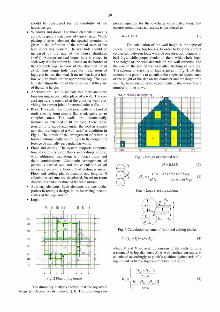
• The main axes of the house are building axes. For log houses design the main axes are placed in par-allel to mutually perpendicular axes X and Y of the plan. Usually these axes are marked by letters in one direction and by figures in perpendicular di-rection. The main axes are the basic dimensional characteristics of the house, the reference point. The other elements are bind to this point which simplifies the size changes and movement of the elements. If the size of the main axes is changed, all the other elements connected to these axes will be automatically resized. The knots of the building are formed in the points of main axes cross-section (Fig. 2).
• House wall. The walls can be located only on the main axes (Fig. 3). The extent of a wall is also given from the main axes. However the extend of the wall, dependent on the overhang of logs,
59
D
H
should be considered for the durability of the house design.
• Windows and doors. For those elements a user is able to prepare a catalogue of typical sizes. While placing a given element the special attention is given to the definition of the vertical sizes of the hole under this element. The real hole should be increased by the size of the house shrinkage (= 6%). Appropriate real bogus hole is placed in such way that its bottom is located on the border of the complete log (in view of the direction of an axis). Thus bogus hole, used for installation of logs, can be less than real. It means that later a hol-low will be made on the appropriate log. The sys-tem also aligns the top of the holes, so that they are of the same height.
• Apertures are used to indicate that there are some logs missing in particular place of a wall. The cre-ated aperture is mirrored at the crossing wall, pro-viding the correct joint of perpendicular walls.
• Roof. The system can build practically any kind of roofs starting from simple flat, shed, gable up to complex ones. The walls are automatically trimmed or extended to fit the roof. There is the possibility to move axes under the roof in a man-ner, that the height of a wall satisfies condition in Fig. 4. The circuit of the arrangement of rafters is formed automatically accordingly to the height dif-ference of mutually perpendicular walls.
• Floor and ceiling. The system supports computa-tion of various types of floors and ceilings: simple, with additional insulation, with black floor and their combinations. Automatic arrangement of planks is carried out, and the calculation of all necessary parts of a floor or/and ceiling is made. Floor and ceiling planks quantity and lengths (l) calculation scheme are developed, based on room dimensions and curvature of the wall surface.
• Auxiliary elements. Such elements are axes under probes fastening a design, holes for wiring, peculi-arities of the logs and etc.
• Logs.
Fig. 2 Plan of log house The durability analysis showed that the log over-
hangs (B) depend on its diameter (D). The following em-
pirical equation for the overhang value calculation, that ensures good industrial results, is introduced as 1.17B D= (1)
The calculation of the wall height is the topic of
special interest for log houses. In order to keep the correct connection between logs, walls of one direction begin with half logs, while perpendicular to them with whole logs. The height of the wall depends on the wall direction and the size of the rise of the wall after stacking of one log. The scheme of stacking of logs is given in Fig. 4. By this scheme it is possible to calculate the empirical dependence of the height of the rise on the diameter and the height of a wall Hw based on collected experimental data, where N is a number of lines in wall.
Fig. 3 Design of selected wall
0.88H D= (2)
0.5 for half ,, for wholew
H N D logsH
H N logs−⎧
= ⎨⎩
(3)
Fig. 4 Logs stacking scheme
D
Hα Hkp
Hp
Hpl Htp
Fig. 5 Calculation scheme of floor and ceiling planks
( ) pKDTTl +−−= 12 (4) where T1 and T2 are axial dimensions of the walls forming a room; D is log diameter; Kp is wall surface curvature is calculated accordingly to plank’s position against axis of a log – plank is below log axis or above it (Fig. 5).
1
/ 2
/ 2
kp pl
pkp pl
H Htan
KH H H
tan
α
α
−⎧⎪⎪= ⎨ − −⎪⎪⎩
(5)
60
3. House specification
The list of typical sizes is made for the windows and doors. The designation of those elements is given on the technical drawing. In addition general length of plat bands is computed.
The list of used rafters and planks, general length of boards for floor, ceiling and roof, and the total charac-teristics of additional elements such as warming, laths for black floor and etc. is made for roofs, floors and ceilings.
In order to create the list of logs automatically, it is necessary to place all the logs on the walls and if re-quired changes could be manually done by designer. The offered allocation algorithm takes into account the re-quirement to arrange the logs with the length more than 6 meters on rows in chess order. It also eliminates the pos-sibility to place the log in holes for windows and doors. It computes the length of the log under inclined roof and checks joint logs on crossed axes. The algorithm enables to start the walls from the half or whole logs. In specification
the designation is marked on the each log accordingly to the following structure ZZ/YYYXX − (6) where XX is name of a wall; YYY is serial number of a line; ZZ is serial number of the log in line.
It enables to assemble the house in the correct and simple way.
The following information is provided by the sys-tem.
1. The timber processing technology, which in-cludes:
• logs processing technology, which considers the special features of equipment;
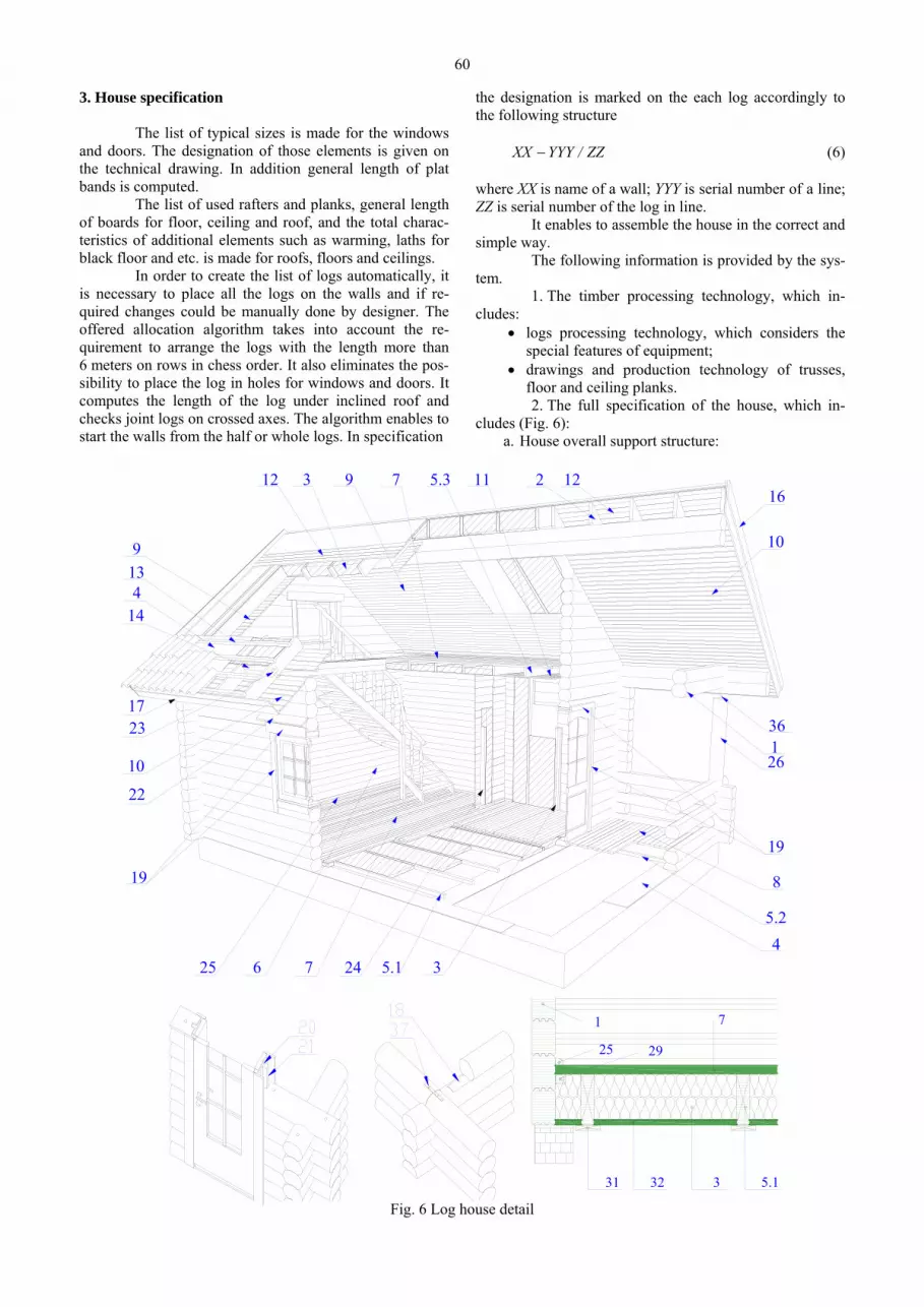
• drawings and production technology of trusses, floor and ceiling planks. 2. The full specification of the house, which in-
cludes (Fig. 6): a. House overall support structure:
19
10
14
8
17
4
12 3 9 7 11 2 1216
10
26
3247625
19
23
139
45.1
5.2
5.3
136
22
2925
1 7
5.131 32 3
Fig. 6 Log house detail

61
• the total length of main logs 1, including columns 26;
• the amount of insulation installed between logs 18; the appropriate amount of waterproof membrane installed between the wooden part of the house and the foundation 4;
• the list of windows and doors by type and dimen-sions, accordingly to company internal specifica-tion or client specific nomenclature;
• quantity and length of casings 19 and visors 22, considering their mounting specifics;
• quantity and length of guiding planks 20 and col-umns 21 for windows and doors installation;
• quantity and length of fixing wood dowel pins 34, fixing bolts 35, columns adjustment bolts and structural elements of the house, that do not shrink 36.
b. Floors and ceiling construction: • quantity and length of floor planks 5.1, terrace
planks 5.2, ceiling planks 5.3 and secondary floor planks 29;
• the quantity and length of floor 25 and ceiling plinths;
• the quantity and length of black support floor joists 31 and its timber planks 32;
• the quantity and length of floor joists 7 and terrace joists 8;
• the quantity and length of ceiling lining planks, both horizontal 11 and attic ceiling (under roof) 9;
• amount of insulation for floor 3, roof and addi-tional insulation for walls, considering their thick-ness.
c. Roof construction: • quantity and length of rafters 2 and secondary raf-
ters; • quantity and length of inter rafters planks 14; • quantity and length of roof lining planks 12; • quantity and length of timber roof battens 13; • quantity and length of cornice planks 16, 17; • quantity and length of visor lining planks 10; • quantity and length of columns 24 and walls inter-
nal lining 6. d. The additional house elements: • quantity and length of walls internal lining or main
plank imitation 6; • quantity of metal fittings (frame and rafters fixture
sliding elements 23, connection strip 37. e. Main logs packing scheme given either to assembly
order or the maximum packing density. 4. Technology formation
If to consider a separate log placed on a wall it is possible to notice, that the main constructive elements of a house, concerning or crossing this log, form geometrical entities (GE) on it. These geometrical entities are given in Fig. 7.
• Log end faces – are defined by the borders of loca-tion of the log.
• Cut at the end face takes place if the log contacts the left or right border of aperture under window.
• Cut on length – arises at the crossing with the real
aperture under door or window. • Cut for joint logs – arises at the contact or crossing
with the wall. • Aperture under a fastening – arises at the crossing
with an axis under fastening probes or with a wall.
Fig. 7 Geometrical entities of log
Their main characteristic, except their sizes, is the
distance from the left-end face of log to base axis or geo-metrical entity (GE). Each GE is an elementary cut surface. It means that one operation of a technological process is required for its processing. If to arrange the geometrical elements incrementally the sequence of processing of the given log is received as a first approximation. The devel-oped heuristic algorithm engages GE in the sequence re-quired for processing in case of identical distances (Fig. 8).
Fig. 8 Technological process of log manufacturing
To calculate those dimensions the sizes of the main axes of a house (on plan) are bind to the axes of co-ordinates OXY (Fig. 9). An adjacency matrix of graph G on the axis X is made. The given problem is characterized by the fact that the meanings of elements of the adjacency matrix can be negative if the direction from one top to an-other is opposite to the direction of axes of the chosen co-ordinate system.
We shall designate as ija the number of arches U,
going from ix to jx . The square matrix ( )ijaA = with n
rows and n column refers to the adjacency matrix the graph [9, 10] ( )U,XG = (7) where 1 2, ,..., nx x x are top of the graph G; i
ja is element, worth on crossing of row i and column j;
( )in
iii a,...,a,aa 21= is designates i - a vector a row;
( )njjjj a,...,a,aa 21= is designates j - a vector a column.

62
1
2
3 4
56
Axis X graph
220
110 220
330
110
1
2 3 4 5 6
A
B
C
D
E
220 330
220
330
330
110
110
110
220 X
Y
110
Fig. 9 Interdependency of dimensions
We shall define two operations, which we shall name as generalized addition ( )2121 λλλλ ,min=⊕ and generalized multiplication 2121 λλλλ +=⊗ .
We shall consider two matrixes ( )ijaA = and ,
( )ijbB = elements of which are real elements, then the
generalized sum of these matrixes is a matrix ( )i
jsBAS =⊕= (8) where i
jij
ij bas ⊕= . The generalized product is a
( )i
jpBAP =⊗= (9) where ( ) ( ) ( )n
jinj
ij
iij ba...babap ⊗⊕⊕⊗⊕⊗= 2
21
1 . For graph G, each arch u which has referred length
l(u), we shall consider a matrix A ( )i
jaA = (10)
where ( ) ( )
( )( )⎪
⎩
⎪⎨
⎧
=∉∈
∞=ji
Ux,xUx,x
,,,x,xl
a ji
jijiij
0.
For example in Fig.9 we receive the following matrix of the sizes of the main axes of the house on co-ordinate axis OX, taking into account their orientation:
⎟⎟⎟⎟⎟⎟⎟⎟
⎠
⎞
⎜⎜⎜⎜⎜⎜⎜⎜
⎝
⎛
−∞∞∞∞∞∞−∞
∞∞∞−∞∞∞∞−∞∞−∞∞∞∞
=
01101100330
02200110
33022011002202200
A (11)
The common element of the matrix A is equal to ( )j
kki
ij aamina += , where i
ja is the dimension between walls ip and jp .
As it was previously mentioned we are able to find all missing dimensions, by using described algorithm of generalized product of matrixes
⎟⎟⎟⎟⎟⎟⎟⎟
⎠
⎞
⎜⎜⎜⎜⎜⎜⎜⎜
⎝
⎛
−∞∞−∞−−−−
∞−−−∞−−
−∞
=
=⊗=
01104401100110220330550
11001102204402201100110330
44033022011002205504403302200
2 AAA
(12)
⎟⎟⎟⎟⎟⎟⎟⎟
⎠
⎞
⎜⎜⎜⎜⎜⎜⎜⎜
⎝
⎛
−−−−−−−−−
−−−−−
−
=
=⊗=
011022033044066011001102203305502201100110220440330220110011033044033022011002206605504403302200
23 AAA
(13)
There is a certain natural number N, for which the
condition ...AAA NNN === ++ 21 is carried out. For our
variant 3 4 5 NA A A A= = = . The given matrix and algorithm of generalized
multiplication are used in the offered system for finding all the dimensions between geometrical elements of the house on all coordinate axes. 5. Optimization of manufacturing
In the following chapter, we shall use “trunks” for work pieces to produce some logs. This problem is one of the particular cases of optimal material consumption. It can be formulated in the following way. Suppose we have trunks with k different dimensions. We want to cut these trunks into m different logs (Fig. 10).
)( sija
)( sija
)(sjc
m
k
Ms
s
ns - number of splitting ways (methods)
Trunks
Logs Ni
12
m
j
i
Logs amount
1 ns
Cost of wastes
C s( )
Cost of trunk
aij-Logs amount of size i produced using j method
Fig. 10 Enunciation of the objective function
A trunk with given size s (s = 1, 2, …, k) could be
split by ns in different ways. Using j method we could pro-duce ( )s
ija logs of the size i from trunk s (where j = 1, 2, …, ns; i = 1, 2, …, m). The cost of one trunk is proportional to its length ( )sC ~ ( )sL . Hereinafter we consider the length in objective function. ( )s
jC is the cost of waste after cutting the trunk s by the method j.
The total quantity Ni of each type of logs is given, which should be cut up from all trunks and the quantity Ms.

63
of each size we have. It is required to discover, how many trunks of
each size we need, get Ni (i = 1, 2 ,..., m) trunks produced from these by each of possible methods ( )s
jx , taking into account that the total length of all used trunks should be minimized in order to avoid the waste.
Hence, this problem will be formulated in the fol-lowing way. It is required to find a minimum of objective function [11]
( ) ( ) ( )
1 1( )
snks s s
j js j
L L L x= =
= −∑∑ (14)
in condition: ( ) ( )
1 1( 1,2,..., ),
snks s
ij j is j
a x N i m= =
≥ =∑ ∑
( )
1 ( 1,2,..., ),
sns
j sj
x M s k=
≤ =∑
( ) 0 ( 1,2,..., ; 1,2,..., ), sj sx s k j n≥ = = ( ) int .s
jx eger− The equation shows, that we have to produce
given quantity of logs of type i using all trunks of the sizes k and all the methods. There will be as many equations m of such kind as the sizes of logs we have. Inequalities show that we have to cut only the given quantity of trunk with the given size s.
The objective function can be transformed, if some assumptions are made. It is possible to minimize the total length of waste, or the length of all trunks, i.e. to minimize the objective function
( ) ( )
1 1
snks s
js j
L F x= =
= ∑ ∑ or ( ) ( )
1 1
snks s
j j js j
L F x= =
= ∑ ∑ (15)
In this case the problem is formulated as follows:
from trunks of one given length (s = 1) it is necessary to produce logs with m different lengths. One trunk can be split on length by n in different ways. In case when we use j method from one trunk we will get ija logs of type i (i = 1, 2, 3, ...,m; j = 1,2,3,...,n) and jc - size of waste from the trunk. We have to produce iN logs of type i.
It is required to find the total number of trunks ix , which we split by the j methods in order to produce the given quantity iN of logs of each length with minimum waste, i.e. to minimize the objective function
j
n
jj xcL ∑
=
=1
(16)
at such restrictions: 1
( 1, 2,3,..., ),n
ij j ij
a x N i m=
≥ =∑
0 ( 1, 2,3,..., ),jx j n≥ = .egerintx j − To solve the given problem we use the method of
sequential improvement of the plan using an inverse matrix (modified simplex method using the usual form of an in-verse matrix) [12]. The solution could be found faster if we apply the method of sequential improvement of the plan, which uses the inverse matrix.
If when the total length of logs for building a one-storey log house (area about 25 square meters) with a gable roof (angle 45º), is about 1200 meters, then the economy of 6-10 percents of logs equals to 72-120 meters. It is consid-erable amount. Accordingly to the case study data received from the company, where the hand-operated design was used, the percentage of irrevocable wastes to manufacture such a house makes on the average 13-15%. The hand-operated designing is rather labour-consuming and requires 10-12 hours for the above described house.
If the described algorithm is applied it is possible to reduce the percentage of irrevocable wastes up to 2-3%. Small percentage of irrevocable wastes is one of the advan-tages of the given method, but there are several prerequi-sites.
• All the sizes of the trunks should be known before the optimization method is applied. It is an advan-tage, because if we know all the lengths of trunks we can quickly order the necessary logs from sup-plier firms.
• The disadvantage is that the large space in the warehouse is needed to store the elements of a house. It is possible to pre assemble the walls on the control table only after all the logs of the house are manufactured. Thus the size of the ready pro-duction warehouse should be the same as the size of all the walls of the log house that affects the cost of the house.
• It is impossible to control the optimization process before it is completed. It can be an advantage as well as a disadvantage. There is common situation when some part with defects is non-suitable for production. In such situation it is required to put the given trunk a side, in order not to change initial parameters (initial trunk length) of the process of optimization, or to interrupt this process and to start up it again. In such case the parts produced before excluded from the optimization. There are a number of restrictions in the applica-
tion of the optimization in manufacturing. • The lengths of all the trunks are unknown in ad-
vance, because they are coming directly from warehouse or supplied by vendors. But in both cases the exact length of trunks, suitable for manu-facturing logs is known only after lathe operation, followed by control and measurement.
• Some part can be damaged during the processing and should be rejected. Such a part should be pro-duced again. The rejected part should be reused in production if possible. The length of the trunks should be updated every time after lathe operation. It means that the real time control of the optimiza-tion process is required.
• Technological process restrictions. There Work in Process (WIP) is limited to the certain amount of walls because the warehouse space is limited. Only after a particular wall is checked on the control ta-ble it can be packed and transported.
• In splitting process the longest logs should be pro-duced first. For this purpose the processing is started from the walls with the maximum average length of the logs. In the conditions of the real factory it is not possi-

64
ble to consider all and authors offer to solve the problem of optimization by step-by-step method. This method consists of searching a local minimum waste of each trunk being manufactured. Although involvement of a person in the process of optimization does not permit to receive a global minimum, it provides decision close to it.
The process of local optimization consists on the following operations. At the beginning a longest part of the first wall in production is made from the trunk of the given size. The surplus left is used as another trunk for recur-rence of the previous step of search. The priority of possi-ble splitting method function selection depends on the size of surplus and the quantity of logs made from trunk in use. Later the process is repeated for a detail of the main wall.
As the result the optimization function offers to the user several variants with the least priority. The user operates with the offered variants of splitting and the func-tion of priority based on the quantity of logs, that is possi-ble to receive. The user can change the initial parameters in order to reduce the quantity of variants. The acceptable choice can be done if the size of the surplus and the quan-tity of logs are known (Fig. 11).
If there are no suitable additional logs in the main wall, the system is able to select the additional logs from any other wall. Any available wall can be manually added by the user or the most suitable one can be selected auto-matically.
If the user is not satisfied with result of the opti-
mization, the system enables to repeat the process of opti-mization from any point. The surplus from the manufactur-ing process and defect log are stored in the warehouse and can be used for logs if required and the waste information is available to the user.
The developed service tools enable to search for the information related to additional and available walls. This information is used for the process of local optimiza-tion (review of amount and lengths of logs making a wall). Those tools also show the total percentage of waste and amount of produced logs and walls.
The optimization enables to order the amount of logs required for a particular house manufacturing. In addi-tion this model also supports the preliminary optimization, when the parts are not directly manufactured, but used as the base for the formation of the logs list. This data is used later for the complete optimization.
It is possible to output the result of optimization with the technology of processing of each detail directly to the screen, to print it out or to forward directly into NC machine.
The optimization algorithm described above is also used for the parts packing list creation, with minor changes of input and output data parameters. The optimiza-tion parameters are also different. For example the width of the cut is equal to zero and acceptable waste percentage (empty space in a series of one package) can be up to 15%. The main menu of optimization is presented in Fig. 11.
Loghouse name: example Trunk length : 600 Total waste Working walls : 8 Waste length : 0.0 % Amount of logs in wall: 11/30 Number of logs from trunk : 2 2.7
Variants of splitting Reiteration parameters Serves Waste 20=520>8-15/2+60>8-18/1 Change waste length View working wall Waste 50=550>8-16/2 Change number of logs from trunk View all walls Waste 60=480>8-15/1+60>8-18/1 Automatically add new additional wall Delete additional wall Waste 210=195>8-13/4+195>8-12/4 Manually add new additional wall Printing Waste 315=150>8-10/2+135>8-14/3 Change additional wall Reiteration Waste 330=135>8-14/3+135>8-13/3 Correct mistakes or rejection Waste 540=60>8-18/1 Make from waste Change initial parameters
Fig. 11 Main menu of optimization opportunities 6. Conclusion
The optimization algorithm and the integrated CAD/CAM system for log house design and production was developed by authors. The software system is written on algorithmic programming language C++ and is imple-mented in production at the “PALMATIN” company. The software is used both for the automatic design of timber and log houses and for processing technology of all logs with minimum material waste in manufacturing process.
The following tasks are solved by developed CAD/CAM system for log houses:
• wooden house structure design and creation of technical drawings;
• specification of house complete parts list; • generation of processing technology for each indi-
vidual log; • calculation of dimension chains; • Optimization of production and packaging of logs.
Accordingly to the data received from
“PALMATIN” [13] company the waste percentage was reduced by 10-12%, compared to manual optimization. The time required for house design and optimization was reduced 80 times. The results of the offered optimization methods analysis are given in Table.
Table Comparison of splitting methods
Name Manually Full optimiza-tion
Local optimi-zation
Design time (hour) 10-12 0.5-1 1-2 Percentage of mate-rial waste 13-15 2.5-3 4-5
Design control Full Lack Full Acknowledgements
Would like to thank the Estonian Science Founda-tion for the targeted financing schemes SF0140113Bs08 and SF0142684s05 that enabled us to carry out this work.

65
References 1. Bargelis, A., Mankute, R. Impact of manufacturing
engineering efficiency to the industry advancement. -Mechanika. -Kaunas: Technologija, 2010, Nr.4(84), p.38-44.
2. Navickas, R. 3-D modelling of nanostructures evolution in lateral etching processes. -Mechanika. -Kaunas: Technologija, 2008, Nr.5(73), p.54-58.
3. Burneika, L. Product configurator for product data management system: design of internal structure. -Mechanika. -Kaunas: Technologija, 2008, Nr.3(71), p.51-56.
4. Pribytkova, M., Polyanchikov, I., Karaulova, T. Influence of variability on a reliable production proc-ess. -Zadar: Proceedings of DAAAM International, 2010, p.329-330.
5. http://3dekspert.ee/. 6. http://www.mad.fi/. 7. Keppo, J. Log House Construction. -Tallinn: Library
Builder, 2001.-132p. (in Estonian). 8. Maso, T. The Design and Construction of Log Houses.
-Tallinn: Library Builder, 1999.-175p. (in Estonian). 9. Berge Claude. The Theory of Graphs and Its Applica-
tions. -New York: Wiley, 1962.-247p. 10. West Douglas Brent. Introduction to Graph Theory,
2nd ed. Englewood Cliffs. -New York: Prentice-Hall, 2000.-608p.
11. George, B. Dantzig, Mukund N. Thapa. Linear Pro-gramming: Theory and Extensions. -New York-Berlin-Heidelberg: Springer-Verlag, 2003.-448p.
12. Monahhov, V., Beljaeva, E., Krasner, N. Optimisa-tion Methods. Application of Mathematical Methods in Economy.-Moscow, 1978.-176p. (in Russian).
13. http://www.palmatin.com/eng/language/3.
L. Portjanski, G. Nekrassov, R. Zahharov, E. Shevtchenko
RĄSTINIŲ NAMŲ CAD/CAM PROJEKTAVIMO SISTEMA LOGBUILD
R e z i u m ė
Naudojant autorių sukurtą integruotą CAD/CAM sistemą LOGBUILD, galima projektuoti rąstinius namus ir paruošti ne tiktai projekto brėžinius bet ir visą namą suda-rančių detalių (rąstų ir jų apdirbimo technologijų, langų, duris, gegnių ir lentų) specifikaciją. Pasiūlytas matmenų grandinių skaičiavimo algoritmas. Gautus rezultatus pa-naudojus automatizuotos gamybos sistemoje galima ga-minti detales iš gamybai pateiktų ruošinių. Optimizavimo metodų analizė parodė, kad realios gamybos negalima vi-siškai optimizuoti. Pasiūlyta lokali optimizacija apima de-talių parinkimą, kad esant užsakovo nustatytam ruošinio ilgiui, atliekų būtų kuo mažiau ir užtikrina leistiną atliekų procentą. Optimizacijos algoritmas taip pat panaudojamas detalių tiekimo aprašui sudaryti.
Ši CAD/CAM rąstinių namų projektavimo siste-ma sukurta algoritmine kalba C++ ir įdiegta į gamybą fir-moje „Palmatin“ rąstinių ir tašinių namų mašininiam pro-jektavimui, taip pat sudaryti tokiai rąstų apdirbimo techno-logijai, kad medžiagų atliekų gamybos ir įpakavimo metu būtų kuo mažiau.
L. Portjanski, G. Nekrassov, R. Zahharov, E. Shevtchenko
LOGBUILD - CAD/CAM system for log houses
S u m m a r y
The complex problems of product design, manufacturing and transportation of parts are not solved by existing design systems. Such problems can be solved by the integrated CAD/CAM applications. The integrated CAD/CAM system for the log houses production should support the design of tecnological process and the calculation of dimensional chains.
In this paper we propose the integrated CAD/CAM system with novel dimensional chain calculation algorithm. This system supports the design of log houses, preparation of construction drawings, preparation of manufacturing technology and production of of a complete part list (logs, windows, doors, rafters, boards etc.). The integration of product data with CAM system enables to optimise the lengh of the cuted out parts. The optimization methods analysis showed that it is difficult to achieve the full optimisation of log houses building process in real manufacturing conditions. For this purpose the local optimisation is proposed, which selects the parts to be processed with a user defined fixed raw material length. It assures the material waste is within the allowed boundaries and generates the packing list.
Л. Портянский, Г. Некрасов, Р. Захаров, Э. Шевченко
LOGBUILD – CAD/CAM СИСТЕМА ДЛЯ БРЕВЕНЧАТЫХ ДОМОВ
Р е з ю м е
Разработанная авторами интегрированная CAD/CAM система LOGBUILD позволяет проектиро-вать бревенчатые дома и выдавать не только чертежи проекта, но и полную спецификацию составляющих дом деталей (бревен с технологией их обработки, окон, дверей, стропил, лаг и досок). Предложен алгоритм расчета размерных цепей. Связывание полученных результатов с системой автоматизированного произ-водства обеспечивает возможность раскроя деталей из поступающих в производство заготовок. Анализ мето-дов оптимизации показал невозможность применения полной оптимизации в реальных производственных условиях. Предложенная локальная оптимизация за-ключается в подборе деталей, составляющих мини-мальный отход при заданной пользователем длине за-готовки и обеспечивает допустимый процент отходов. Алгоритм оптимизации также используется для созда-ния упаковочного листа деталей.
Данная CAD/CAM система бревенчатых до-мов реализована на алгоритмическом языке С++ и вне-дрена в производство на фирме “Palmatin” для машин-ного конструирования бревенчатых и получения тех-нологии обработки всех бревен c минимальным отхо-дом материалов при их изготовлении и упаковке.
Received June 16, 2010 Accepted December 07, 2010


