Embed Size (px)
Citation preview

M3000/M4000 SeriesUser’s Manual
A G R E A T E R M E A S U R E O F C O N F I D E N C E
WARRANTY
Hardware
Keithley Instruments, Inc. warrants that, for a period of one (1) year from the date of shipment (3 years for Models 2000, 2001, 2002, 2010 and 2700), the Keithley Hardware product will be free from defects in materials or workmanship. This warranty will be honored provided the defect has not been caused by use of the Keithley Hardware not in accordance with the instructions for the product. This warranty shall be null and void upon: (1) any modification of Keithley Hardware that is made by other than Keithley and not approved in writing by Keithley or (2) operation of the Keithley Hardware outside of the environmental specifications therefore.
Upon receiving notification of a defect in the Keithley Hardware during the warranty period, Keithley will, at its option, either repair or replace such Keithley Hard-ware. During the first ninety days of the warranty period, Keithley will, at its option, supply the necessary on site labor to return the product to the condition prior to the notification of a defect. Failure to notify Keithley of a defect during the warranty shall relieve Keithley of its obligations and liabilities under this warranty.
Other Hardware
The portion of the product that is not manufactured by Keithley (Other Hardware) shall not be covered by this warranty, and Keithley shall have no duty of obligation to enforce any manufacturers' warranties on behalf of the customer. On those other manufacturers’ products that Keithley purchases for resale, Keithley shall have no duty of obligation to enforce any manufacturers’ warranties on behalf of the customer.
Software
Keithley warrants that for a period of one (1) year from date of shipment, the Keithley produced portion of the software or firmware (Keithley Software) will conform in all material respects with the published specifications provided such Keithley Software is used on the product for which it is intended and other-wise in accordance with the instructions therefore. Keithley does not warrant that operation of the Keithley Software will be uninterrupted or error-free and/or that the Keithley Software will be adequate for the customer's intended application and/or use. This warranty shall be null and void upon any modification of the Keithley Software that is made by other than Keithley and not approved in writing by Keithley.
If Keithley receives notification of a Keithley Software nonconformity that is covered by this warranty during the warranty period, Keithley will review the conditions described in such notice. Such notice must state the published specification(s) to which the Keithley Software fails to conform and the manner in which the Keithley Software fails to conform to such published specification(s) with sufficient specificity to permit Keithley to correct such nonconfor-mity. If Keithley determines that the Keithley Software does not conform with the published specifications, Keithley will, at its option, provide either the programming services necessary to correct such nonconformity or develop a program change to bypass such nonconformity in the Keithley Software. Failure to notify Keithley of a nonconformity during the warranty shall relieve Keithley of its obligations and liabilities under this warranty.
Other Software
OEM software that is not produced by Keithley (Other Software) shall not be covered by this warranty, and Keithley shall have no duty or obligation to enforce any OEM's warranties on behalf of the customer.
Other Items
Keithley warrants the following items for 90 days from the date of shipment: probes, cables, rechargeable batteries, diskettes, and documentation.
Items not Covered under Warranty
This warranty does not apply to fuses, non-rechargeable batteries, damage from battery leakage, or problems arising from normal wear or failure to follow instructions.
Limitation of Warranty
This warranty does not apply to defects resulting from product modification made by Purchaser without Keithley's express written consent, or by misuse of any product or part.
Disclaimer of Warranties
EXCEPT FOR THE EXPRESS WARRANTIES ABOVE KEITHLEY DISCLAIMS ALL OTHER WARRANTIES, EXPRESS OR IMPLIED, INCLUD-ING WITHOUT LIMITATION, ALL IMPLIED WARRANTIES OF MERCHANTABILITY AND FITNESS FOR A PARTICULAR PURPOSE. KEI-THLEY DISCLAIMS ALL WARRANTIES WITH RESPECT TO THE OTHER HARDWARE AND OTHER SOFTWARE.
Limitation of Liability
KEITHLEY INSTRUMENTS SHALL IN NO EVENT, REGARDLESS OF CAUSE, ASSUME RESPONSIBILITY FOR OR BE LIABLE FOR: (1) ECONOMICAL, INCIDENTAL, CONSEQUENTIAL, INDIRECT, SPECIAL, PUNITIVE OR EXEMPLARY DAMAGES, WHETHER CLAIMED UNDER CONTRACT, TORT OR ANY OTHER LEGAL THEORY, (2) LOSS OF OR DAMAGE TO THE CUSTOMER'S DATA OR PROGRAM-MING, OR (3) PENALTIES OR PENALTY CLAUSES OF ANY DESCRIPTION OR INDEMNIFICATION OF THE CUSTOMER OR OTHERS FOR COSTS, DAMAGES, OR EXPENSES RELATED TO THE GOODS OR SERVICES PROVIDED UNDER THIS WARRANTY.
Keithley Instruments, Inc.
28775 Aurora Road • Cleveland, Ohio 44139 • 440-248-0400 • Fax: 440-248-6168
1-888-KEITHLEY (534-8453) • www.keithley.com
Sales Offices: BELGIUM: Bergensesteenweg 709 • B-1600 Sint-Pieters-Leeuw • 02-363 00 40 • Fax: 02/363 00 64 CHINA: Yuan Chen Xin Building, Room 705 • 12 Yumin Road, Dewai, Madian • Beijing 100029 • 8610-6202-2886 • Fax: 8610-6202-2892FINLAND: Tietäjäntie 2 • 02130 Espoo • Phone: 09-54 75 08 10 • Fax: 09-25 10 51 00FRANCE: 3, allée des Garays • 91127 Palaiseau Cédex • 01-64 53 20 20 • Fax: 01-60 11 77 26GERMANY: Landsberger Strasse 65 • 82110 Germering • 089/84 93 07-40 • Fax: 089/84 93 07-34GREAT BRITAIN: Unit 2 Commerce Park, Brunel Road • Theale • Berkshire RG7 4AB • 0118 929 7500 • Fax: 0118 929 7519INDIA: Flat 2B, Willocrissa • 14, Rest House Crescent • Bangalore 560 001 • 91-80-509-1320/21 • Fax: 91-80-509-1322ITALY: Viale San Gimignano, 38 • 20146 Milano • 02-48 39 16 01 • Fax: 02-48 30 22 74JAPAN: New Pier Takeshiba North Tower 13F • 11-1, Kaigan 1-chome • Minato-ku, Tokyo 105-0022 • 81-3-5733-7555 • Fax: 81-3-5733-7556KOREA: 2FL., URI Building • 2-14 Yangjae-Dong • Seocho-Gu, Seoul 137-888 • 82-2-574-7778 • Fax: 82-2-574-7838NETHERLANDS: Postbus 559 • 4200 AN Gorinchem • 0183-635333 • Fax: 0183-630821SWEDEN: c/o Regus Business Centre • Frosundaviks Allé 15, 4tr • 169 70 Solna • 08-509 04 679 • Fax: 08-655 26 10SWITZERLAND: Kriesbachstrasse 4 • 8600 Dübendorf • 01-821 94 44 • Fax: 01-820 30 81TAIWAN: 1FL., 85 Po Ai Street • Hsinchu, Taiwan, R.O.C. • 886-3-572-9077• Fax: 886-3-572-9031
4/02
M3OOU/M4UUU SERIES
USER’S MANUAL

New Contact Information
Keithley Instruments, Inc.28775 Aurora Road
Cleveland, OH 44139
Technical Support: 1-888-KEITHLEYMonday – Friday 8:00 a.m. to 5:00 p.m (EST)
Fax: (440) 248-6168
Visit our website at http://www.keithley.com
Part Number: 24809 Revision Level: A
First Printing: March 1989
Copyright 0 1989
WARNING
MetraByte Corporation assumes no liability for damages consequent to the use of this product. This product is not designed with components of a level of retiabi[ity suitable for use
in life support or critical applications.
All rights reserved. No part of this publication may be reproduced. stored in a retrieval system. or transmitted, in any form by any means, electronic. mechanical, photocopying, recording. or
otherwise, without the express prior wriien permission of MetraByte Corporation.
Information furnished by MetraByte Corporation is believed to be accurate and reliable. However, no responsibility is assumed by MetraByte Corporation for its use; nor for any
infringements of patents or other rights of third parties which may result from its use. No license is granted by implication or otherwise under any patent tights of MetraByte Corporation.
M3000/M4000 modules are not intrinsically safe devices and should not be used in an explosive environment unless enclosed in approved explosion-proof housings.
MetraBytem is a trademark of MetraByte Corporation.
IBMB PC/XT/AT is a registered trademark of International Business Machines Corporation.

Safety Precautions
The following safety precautions should be observed before usingthis product and any associated instrumentation. Although some in-struments and accessories would normally be used with non-haz-ardous voltages, there are situations where hazardous conditionsmay be present.
This product is intended for use by qualified personnel who recog-nize shock hazards and are familiar with the safety precautions re-quired to avoid possible injury. Read and follow all installation,operation, and maintenance information carefully before using theproduct. Refer to the manual for complete product specifications.
If the product is used in a manner not specified, the protection pro-vided by the product may be impaired.
The types of product users are:
Responsible body
is the individual or group responsible for the useand maintenance of equipment, for ensuring that the equipment isoperated within its specifications and operating limits, and for en-suring that operators are adequately trained.
Operators
use the product for its intended function. They must betrained in electrical safety procedures and proper use of the instru-ment. They must be protected from electric shock and contact withhazardous live circuits.
Maintenance personnel
perform routine procedures on the productto keep it operating properly, for example, setting the line voltageor replacing consumable materials. Maintenance procedures are de-scribed in the manual. The procedures explicitly state if the operatormay perform them. Otherwise, they should be performed only byservice personnel.
Service personnel
are trained to work on live circuits, and performsafe installations and repairs of products. Only properly trained ser-vice personnel may perform installation and service procedures.
Keithley products are designed for use with electrical signals thatare rated Installation Category I and Installation Category II, as de-scribed in the International Electrotechnical Commission (IEC)Standard IEC 60664. Most measurement, control, and data I/O sig-nals are Installation Category I and must not be directly connectedto mains voltage or to voltage sources with high transient over-volt-ages. Installation Category II connections require protection forhigh transient over-voltages often associated with local AC mainsconnections. Assume all measurement, control, and data I/O con-nections are for connection to Category I sources unless otherwisemarked or described in the Manual.
Exercise extreme caution when a shock hazard is present. Lethalvoltage may be present on cable connector jacks or test fixtures. TheAmerican National Standards Institute (ANSI) states that a shockhazard exists when voltage levels greater than 30V RMS, 42.4Vpeak, or 60VDC are present.
A good safety practice is to expectthat hazardous voltage is present in any unknown circuit beforemeasuring.
Operators of this product must be protected from electric shock atall times. The responsible body must ensure that operators are pre-vented access and/or insulated from every connection point. Insome cases, connections must be exposed to potential human con-tact. Product operators in these circumstances must be trained toprotect themselves from the risk of electric shock. If the circuit iscapable of operating at or above 1000 volts,
no conductive part ofthe circuit may be exposed.
Do not connect switching cards directly to unlimited power circuits.They are intended to be used with impedance limited sources.NEVER connect switching cards directly to AC mains. When con-necting sources to switching cards, install protective devices to lim-it fault current and voltage to the card.
Before operating an instrument, make sure the line cord is connect-ed to a properly grounded power receptacle. Inspect the connectingcables, test leads, and jumpers for possible wear, cracks, or breaksbefore each use.
When installing equipment where access to the main power cord isrestricted, such as rack mounting, a separate main input power dis-connect device must be provided, in close proximity to the equip-ment and within easy reach of the operator.
For maximum safety, do not touch the product, test cables, or anyother instruments while power is applied to the circuit under test.ALWAYS remove power from the entire test system and dischargeany capacitors before: connecting or disconnecting cables or jump-ers, installing or removing switching cards, or making internalchanges, such as installing or removing jumpers.
Do not touch any object that could provide a current path to the com-mon side of the circuit under test or power line (earth) ground. Alwaysmake measurements with dry hands while standing on a dry, insulatedsurface capable of withstanding the voltage being measured.
The instrument and accessories must be used in accordance with itsspecifications and operating instructions or the safety of the equip-ment may be impaired.
Do not exceed the maximum signal levels of the instruments and ac-cessories, as defined in the specifications and operating informa-tion, and as shown on the instrument or test fixture panels, orswitching card.
When fuses are used in a product, replace with same type and ratingfor continued protection against fire hazard.
Chassis connections must only be used as shield connections formeasuring circuits, NOT as safety earth ground connections.
If you are using a test fixture, keep the lid closed while power is ap-plied to the device under test. Safe operation requires the use of alid interlock.
5/02
If or is present, connect it to safety earth ground using thewire recommended in the user documentation.
The symbol on an instrument indicates that the user should re-fer to the operating instructions located in the manual.
The symbol on an instrument shows that it can source or mea-sure 1000 volts or more, including the combined effect of normaland common mode voltages. Use standard safety precautions toavoid personal contact with these voltages.
The
WARNING
heading in a manual explains dangers that mightresult in personal injury or death. Always read the associated infor-mation very carefully before performing the indicated procedure.
The
CAUTION
heading in a manual explains hazards that coulddamage the instrument. Such damage may invalidate the warranty.
Instrumentation and accessories shall not be connected to humans.
Before performing any maintenance, disconnect the line cord andall test cables.
To maintain protection from electric shock and fire, replacementcomponents in mains circuits, including the power transformer, testleads, and input jacks, must be purchased from Keithley Instru-ments. Standard fuses, with applicable national safety approvals,may be used if the rating and type are the same. Other componentsthat are not safety related may be purchased from other suppliers aslong as they are equivalent to the original component. (Note that se-lected parts should be purchased only through Keithley Instrumentsto maintain accuracy and functionality of the product.) If you areunsure about the applicability of a replacement component, call aKeithley Instruments office for information.
To clean an instrument, use a damp cloth or mild, water basedcleaner. Clean the exterior of the instrument only. Do not applycleaner directly to the instrument or allow liquids to enter or spillon the instrument. Products that consist of a circuit board with nocase or chassis (e.g., data acquisition board for installation into acomputer) should never require cleaning if handled according to in-structions. If the board becomes contaminated and operation is af-fected, the board should be returned to the factory for propercleaning/servicing.
!
TABLE OF CONTENTS
Warranty
CHAPTER 1
CHAPTER 2
CHAPTER 3
CHAPTER 4
CHAPTER 5
CHAPTER 6
CHAPTER 7 CHAPTER 8 CHAPTER 9 CHAPTER 10
Appendix A Appendix B
4
Getting Started Terminal Designations 1-1 Default Mode 1-2 Quick Hook-Up 1-3 Functional Description Block Diagram 2-3 Communications
Multi-party Connection 3-3 Software Considerations 3-4 Changing Baud Rate 3-5
RS-485 Multidrop System 3-7 Command Set Table of Commands 4-6 User Commands 4-7 Error Messages 4-20 Setup Information and Command Command Syntax 5-2 Setup Hints 5-9 Digital 110 Function Manual ModedDigital Inputs 6-1 Controller Input 6-4 Limit Switches 6-5 Power Supply Troubleshooting Cali brat ion M4000 Features Slope Control 10-1 Input Data Scaling 10-4 Watchdog Timer 10-6 Analog Readback 10-7 (ASCII TABLE ) M3000/4000 Data Sheet
RS-232C 3-2
RS-485 3-6
3
WARRANTY MetraByte warrants each M3000 and M4000 series module to be free from defects in materials and workmanship under normal conditions of use and service and will replace any component found to be defective, on its return to MetraByte, transpor- tation charges prepaid within one year of its original purchase. MetraByte assumes no liability, expressed or implied, beyond its obligation to replace any component involved. Such warranty is in lieu of all other warranties expressed or implied.
WARNING The circuits and software contained in M3000 and M4000 series modules are proprietary. Purchase of these products does not transfer any rights or grant any license to the circuits or software used in these products. Disassembling or decompiling of the software program is explicitly prohibited. Reproduction of the software program by any means is illegal. As explained in the setup section, all setups are performed entirely from the outside of the M3000/4000 module. There is no need to open the module because there are no user-serviceable parts inside. Removing the cover or tampering with, modifying, or repairing by unauthorized personnel will auto- matically void the warranty. MetraByte is not responsible for any consequen- tial damages.
RETURNS When returning products for any reason, contact the factory and request a Return Authorization Number and shipping instructions. Write the Return Authorization Numberon the outside ofthe shipping box. MetraBytestrongly recommendsthat you insure the product for value prior to shipping. ttems should not be returned collect as they will not be accepted.
4
Chapter 1 Getting Started
Introduction The MetraByte M3000/4000 is a series of completely self-contained computer-to- analog output interfaces. They are designed to be mounted remotely from a host computer and communicate with standard RS-232 and RS-485 serial ports. Simple ASCII commands are used to control a 1 2-bit DAC (Digital-to-Analog Converter) which is scaled to provide commonly used current and voltage ranges. An on-board microprocessor is used to provide the communications interface and many intelli- gent analog output functions.
M3000 versions provide a basic computer-to-analog output interface for cost- sensitive applications where some of the intelligent enhancements are not required. M3000 units feature step-function outputs, fixed input scaling, and no analog read back.
M4000 versions perform alI of the M3000 functions plus many additional intelligent enhancements :
Controlled output slew rates True analog readback Programmable input data scaling Programmable starting value Watchdog timer
This manual has been written to be a guide for both the M3000 and M4000 units. Basic operating characteristics of both models are identical and unless otherwise noted, the information in this manual applies to both versions. Commands and functions exclusive to the M4000 are so noted in the text.
Terminal Designations All M3000 and M4000 units have similar terminal designations, although there are slight variations between currentholtage and RS-232/RS-485 models.
Pin 1 Pin 2
Pins 1 and 2 are the connections to the analog output signal. On voltage models, the input data is scaled so that the voltage at +V OUT is positive with respect to -V OUT. Voltage outputs can source or sink current.
+ I OUT or +V OUT - I OUT or -V OUT
1-2 M3000/4000 USERS MANUAL
On current output models, the output current flows from the +I OUT terminal to the -I OUT terminal, so for a typical resistive load, the + I OUT terminal will be at a more positive voltage level than the -1 OUT terminal. Current outputs can only source current.
Pins 1 and 2 are electrically isolated from the other pins.
Pin 3 D12 Pin 4 DI 1 /UP* Pin 5 DIO/DN*
Pins 3-5 are digital input pins. They may be used as general-purpose inputs or they may be set-up to provide special functions that control the analog output. The standard factory set-up configures the UP* and DN* pins to provide manual up and down control of the analog output. The * designation indicates that the labels are negative true. A full functional description of these pins may be found in Chapter 6.
Pin 6 DEFAULT*
Grounding this pin places the module in Default Mode, described in detail below.
Pin 7 TRANSMIT or DATA Pin 8 RECEIVE or DATA*
Pins 7 and 8 are connections to the serial communications lines connecting the module to the host computer or terminal.
On RS-232 models, the TRANSMIT pin is the serial output connection from the module. The RECEIVE pin is the serial input into the module.
On RS-485 versions, DATA and DATA* are connections to the balanced RS-485 communications lines. DATA and DATA* are sometimes labeled DATA+ and DATA- respectively.
Pin 9 V+ Pin 1OGND
Pins 9 and 10 are the powerconnections. The M3000/4000 modules operate on 10- 30V unregulated power.
Default Mode All M3000/4000 modulescontain an EEPROM (Electrically Erasable Programmable Read Only Memory) to store setup information and calibration constants. The EEPROM replaces the usual array of switches and pots necessary to specify baud rate, address, parity, etc. The memory is nonvolatile which means that the informa- tion is retained even if power is removed. No batteries are used so it is never necessary to open the module case.
The EEPROM provides tremendous system flexibility since all of the module’s setup parameters may be configured remotely through the communications port without having to physically change switch and pot settings. However, there is one minor drawback in using EEPROM instead of switches; there is no visual indication of the

Getting Started 1-3
setup information in the module. It is impossible to tell just by looking at the module what the baud rate, address, parity and other settings are. It is difficult to establish communications with a module whose address and baud rate are unknown. To overcome this, each module has an input pin labeled DEFAULT*. By connecting this pin to Ground, the module is put in a known communications setup called Default Mode.
The Default Mode setup is: 300 baud, no parity, any address is recognized.
Grounding the DEFAULT* pin does not change any of the setupsstored in EEPROM. The setup may be read back with the Read Setup (RS) command to determine all of the setups stored in the module. In Default Mode, all commands are available.
A module in Default Mode will respond to any address. A dummy address must be included in every command for proper responses. The ASCII value of the module address may be read back with the RS command. An easy way to determine the address character is to deliberately generate an error message. The error message outputs the module’s address directly after the “?” prompt.
Setup information in a module may be changed at will with the Setup (SU) command. Baud rate and parity setups may be changed without affecting the Default values of 300 baud and no panty. When the DEFAULT* pin is released, the module automati- cally performs a program reset and configures itself to the baud rate and parity stored in the setup information.
The Default Mode is intended to be used with asingle module connected toaterminal orcomputer forthe purpose of identifying and modifying setupvalues. In most cases, a module in Default Mode may not be used in a string with other modules.
RS-232 & RS-485 Quick Hook-Up Software is not required to begin using your M3000/4000 module. We recommend that you begin to get familiar with the module by setting it up on the bench. Start by using a dumb terminal or a computer that acts like a dumb terminal. Make the connectionsshown inthequick hook-updrawings, Figures 1.1 or 1.2. Putthe module in the Default Mode by grounding the DEFAULT* terminal. Initialize the terminal communications package on yourcornputerto put it into the “terminal” mode. Since this step varies from computer to computer, refer to your computer manual far inst ructions.
Connect a suitable voltmeter or ammeter to the output connections of the module to monitor the output signal. If an ammeter is not available to measure the signals from current-output modules, a sense resistor and a voltmeter may be used as shown in Fig. 1.1. Turn power on to the module. Momentarily ground the UP* pin on the connector. The output signal should increase in value as the UP* pin is held low. Now release the UP* pin and ground the DN* (down) pin. The output signal should decrease in value as the pin is held low.
1-4 M3000/4000 USERS MANUAL
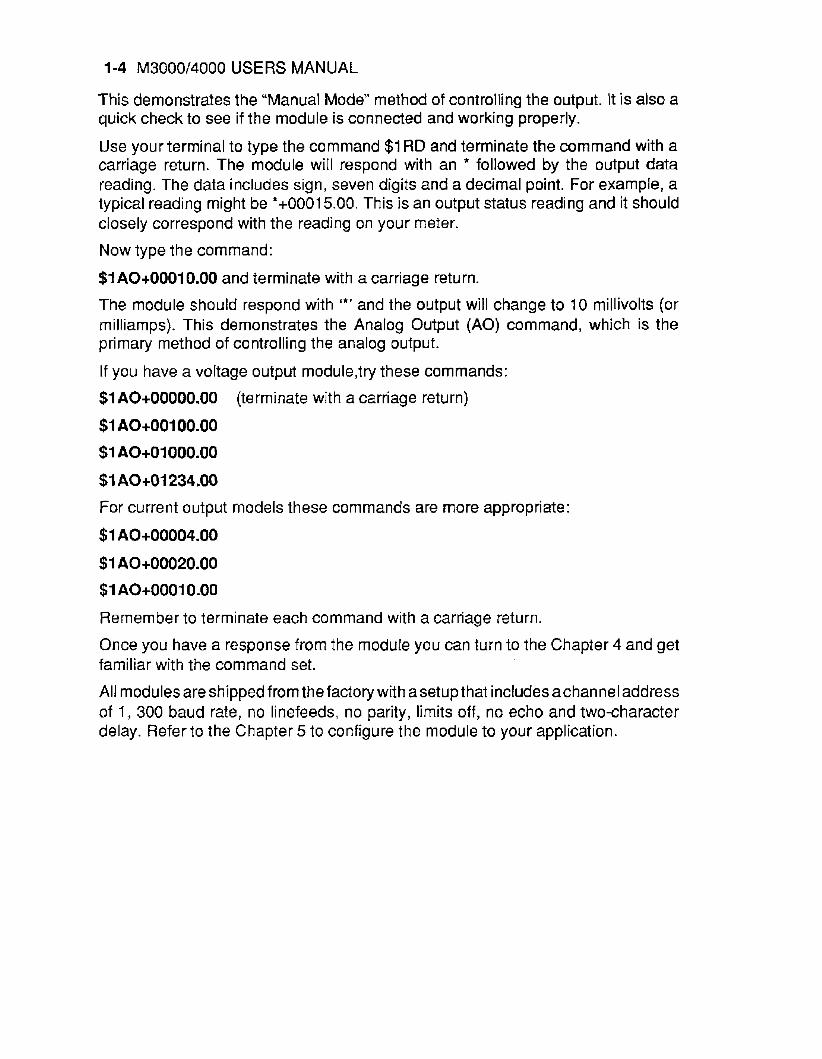
This demonstrates the “Manual Mode” method of controlling the output. It is also a quick check to see if the module is connected and working properly.
Use your terminal to type the command $1 RD and terminate the command with a carriage return. The module will respond with an * followed by the output data reading. The data includes sign, seven digits and a decimal point. For example, a typical reading might be *+00015.00. This is an output status reading and it should closely correspond with the reading on your meter.
Now type the command:
$1 A0+00010.00 and terminate with a carriage return.
The module should respond with I*’ and the output will change to 10 millivolts (or rnilliamps). This demonstrates the Analog Output (AO) command, which is the primary method of controlling the analog output.
If you have a voltage output module,try these commands:
$1 A0+00000.00
$1 AO+OOlOO.OO
$1 A0+01000.00
$1 A0+01234.00
Far current output models these commands are more appropriate:
$1 A0+00004.00
$1 A0+00020.00
$1 A0+00010.00
Remember to terminate each command with a carriage return.
Once you have a response from the module you can turn to the Chapter 4 and get familiar with the command set.
All modulesareshippedfromthefactory with asetupthat includesachanneladdress of 1, 300 baud rate, no linefeeds, no parity, limits off, no echo and two-character delay. Refer to the Chapter 5 to configure the module to your application.
(terminate with a carriage return)
Getting Started 1-5
Current Y Q k q e Output Output
-f--l Ammeter voltmeter
M 3QQQ Analog Output RS232C
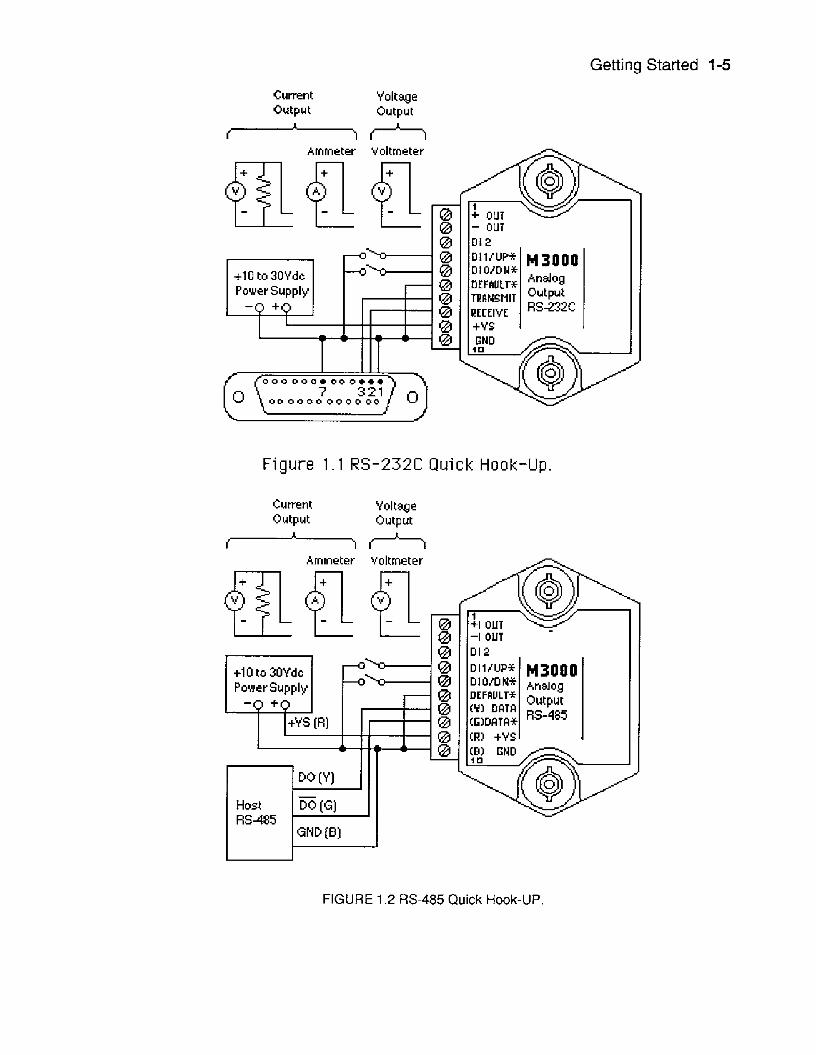
Figure 1 . 1 RS-232C Quick Hook-Up.
Cumnt Voltwe Output Output
Ammeter voltmeter
FIGURE 1.2 RS-485 Quick Hook-UP.
1-6 M3000/4000 USERS MANUAL
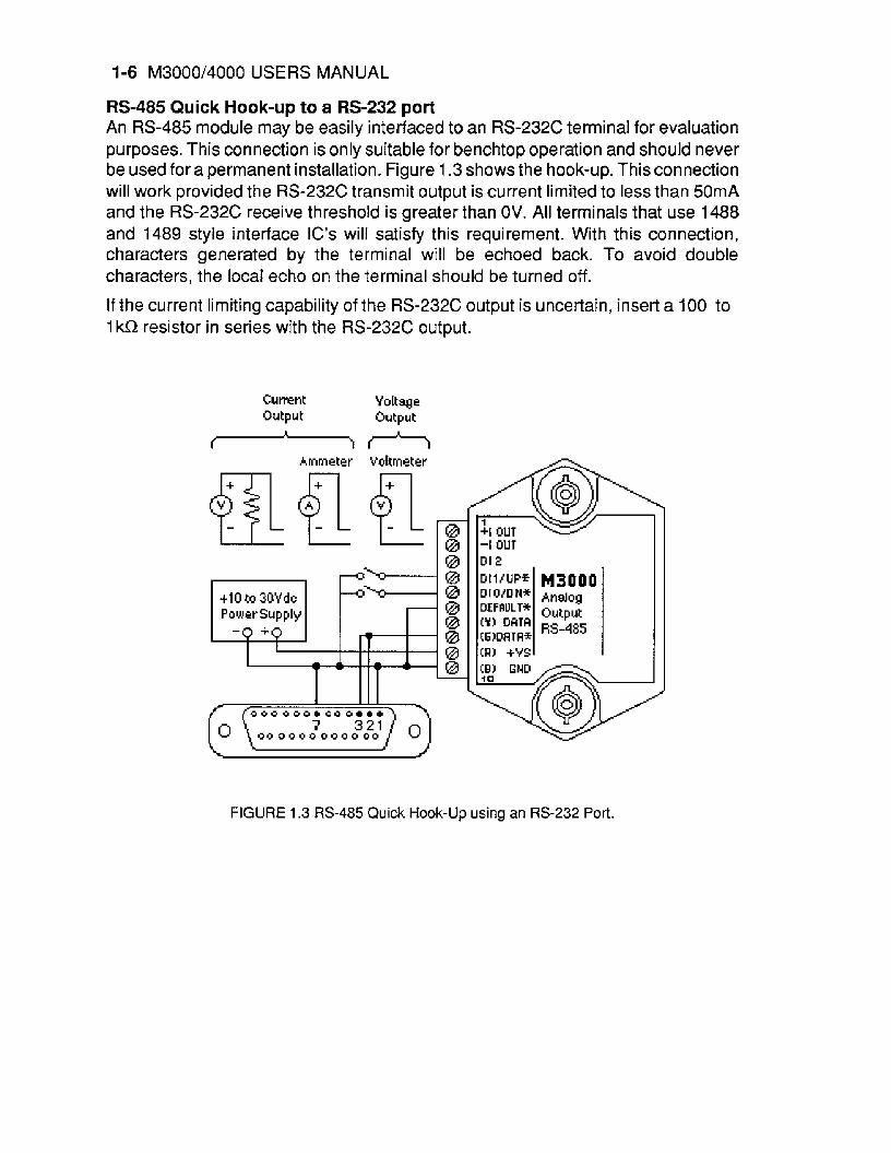
RS-485 Quick Hook-up to a RS-232 port An RS-485 module may be easily interfaced to an RS-232C terminal for evaluation purposes. This connection is only suitable for benchtop operation and should never be used for a permanent installation. Figure 1.3 shows the hook-up. This connection will work provided the RS-232C transmit output is current limited to less than 50mA and the RS-232C receive threshold is greater than OV. All terminals that use 1488 and 1489 style interface IC’s will satisfy this requirement. With this connection, characters generated by the terminal will be echoed back. To avoid double characters, the IocaI echo on the terminal should be turned off.
If the current limiting capability of the RS-232C output is uncertain, insert a 100 to 1 kQ resistor in series with the RS-232C output.
Cumnt Y d t q e Output Output
-i-b Ammeter Vottmeter
FIGURE 1.3 RS-485 Quick Hook-Up using an RS-232 Port.
Chapter 2 Functional Description
The MetraByte 13000/4000 Computerto Analog Output interfaces provide accurate analog process control signals in response to simple digital commands from a host computer. The M3000/4000 units are completely self-contained and are designed to be operated remotely from the host. Digital commands are transmitted to the M3000/ 4000 units using standard RS-232 or RS-485 communications links. Commands and responses are in the form of simple English ASCII character strings for ease of use. The ASCII protocol allows the units to be interfaced with dumb terminals and modems as well as intelligent controllers and computers.
Figure2.1 shows afunctional blockdiagrarn ofthe M3000/4000. The key block is the 12-bit Digital to Analog Converter (DAC). The DAC converts digital data derived from host commands info the desired analog output. All of the other components provide a supporting role for proper operation of the DAC.
An 8-bit CMOS microprocessor is used to provide an intelligent interface between the host and the DAC. The microprocessor receives commands and data from the host computer through a serial communications port. Specialized communications components are used to interface the microprocessor to either RS-232 or RS-485 communications standards. Commands received by the microprocessor are thor- oughly checked for syntax and data errors. Valid commands are then processed to complete the desired function. A wide variety of commands are available to control the DAC, read status information, and to configure the module to fit the user’s requirements. Responses to the host commands are then produced by the micropro- cessor and transmitted back to the host over the RS-232/RS-485 serial link.
An Electrically Erasable Programmable Read-only Memory (EEPROM) is used to retain important data even if the module is powered down. The EEPROM contains setup information such as the address, baud rate, and parity as well as calibration data.
In response to host commands, the microprocessor produces the appropriate digital data necessary to control the DAC. Digital data is transmitted to the DAC through opto-isolators which provide electrical isolation. The DAC produces a precise analog current that is directly proportional to the magnitude of the digital data. The DAC output current is then processed and amplified by signal conditioning circuits to produce the desired output voltage orcurrent. Output protection circuits are included

2-2 M3000/4000 USERS MANUAL
to protect the module from potentially damaging output faults.
M4000 models also feature asimple Analog to Digital Converter (ADC) which is used to monitor the output signal. The ADC input is tied directly to the analog output and converts the signal level to digital data. The digital data is optically isolated and may be read by the microprocessor. This circuitry allows the M4000 user to directly monitor the output signal and ensure its integrity.
The last major block in the diagram is the power supply. The power supply converts the raw 1Oto30voltssupplied bytheuserintoregulatedvoltagesusedinthe module. It produces +5V necessary to operate the microprocessor and EEPROM. On RS- 232 units, the power supply produces +1 OV necessary for the RS-232 communica- tions standard. It also produces +I5 volts to power the DAC and associated output circuitry.
The power supplied to the DAC and output circuitry is transformer isolated from the input power and communications connections. The transformer along with the opto- isoIators provide an isolation barrier between the output section and the rest of the circuitry. The isolation barrier is extremely helpful in breaking ground loops and isolating troublesome common-mode voltages that are often found in large systems. The isolation barrier also provides damage protection for the module and the host in cases where the output lines may accidently contact AC power lines.
The combination of an accurate high-resolution DAC and a dedicated rnicroproces- sor produces a very powerful system for the generation of process control signals. The power of the microprocessor is used to provide software addressing for multidrop capability, data formatting in engineering units, limit checking, digital calibration, and a host of other features not possible with unintelligent analog output systems.
During normal operation, the microprocessor constantly updates the DAC data at a rate of 1000 times per second, even if the output is stable. The M4000 fully utilizes this characteristic to provide controlled output slew rates. Linear output ramp signals are created by incrementally stepping the DAC every millisecond with values precisely calculated by the microprocessor. The small output steps created at millisecond intervals are used to approximate ramp outputs. Slope rates are programmable and may be changed at any time with simple commands. Linear ramps may be initialized with a single command from the host computer. No further intervention or monitoring is required from the host; the M4000 does the rest.

Functional Description 2-3
Chapter 3 Communications
Introduction The M3000/4000 modules have been carefully designed to be easy to interface to all popular computers and terminals. All communications to and from the modules are performed with printable ASCII characters. This allows the information to be processed with string functions common to most high-level languages such as BASIC. For computers that support RS-232C, no special machine language soft- ware drivers are necessary for operation. The modules can be connected to auto- answer modems for long-distance operation without the need for a supervisory computer. The ASCII format makes system debugging easy with a dumb terminal.
The MetraByte system allows multiple modules to be connected to a communica- tions port with a single 4-wire cable. Up to 32 RS-485 modules may be strung togetheron one cable; 124 with repeaters. A practical limit for RS-232C units is about ten, although a string of 124 units is possible. The modules communicate with the host on a polling system; that is, each module responds to its own unique address and must be interrogated by the host. A module can never initiate acommunications sequence. A simple command/response protocol must be strictly observed to avoid communications collisions and data errors.
Communications to the M3000/4000 modules are performed with two or three- character ASCII command codes such as RD to Read Data from the analog output. A complete description of all commands is given in the Chapter 4. A typical command/response sequence would look like this:
Command: $1 RD Response: *+00123.00
A command/response sequence is not complete until a valid response is received. The host may not initiate a new command until the response from a previous command is complete. Failure to observe this rule will result in communications collisions. A valid response can be in one of three forms:
1 ) a normal response indicated by a ' * ' prompt 2) an error message indicated by a ' ? ' prompt 3) a communications time-out error
When a module receives a valid command, it must interpret the command, perform the desired function, and then communicate the response back to the host Each

3-2 M3000/4000 USERS MANUAL
command has an associated delay time in which the module is busy calculating the response. If the host does not receive a response in an appropriate amount of time specified in Table 3.1, a communications time-out error has occurred. After the communications time-out it is assumed that no response data is forthcoming. This error usually results when an improper command prompt or address is transmitted. The table below lists the timeout specification for each command:
Mnemonic Timeout
DI, HX, WE 3mS ID 130mS All other commands 35 mS Table 3.1 Response Timeout Specifications.
The timeout specification is the turn-around time from the receipt of a command to when the module starts to transmit a response.
Data Format All MetraByte modules communicate in standard NRZ asynchronous data format. This format provides one start bit, seven data bits, one panty bit and one stop bit for each character.
RS-232C RS-232C is the most widely used communications standard for information transfer between computing equipment. RS-232C versions of the M3000/4000 will interface to virtually all popular computers without any additional hardware. Although the RS- 232C standard is designed to connect a single piece of equipment to a computer, the MetraByte system allows for several modules to be connected in a daisy-chain network structure.The advantages offered by the RS-232C standard are:
1) widely used by all computing equipment 2) no additional interface hardware in most cases 3) separate transmit and receive lines ease debugging 4) compatible with dumb terminals
1) low noise immunity 2) short usable distance - 50 to 200 feet 3) maximum baud rate - 19200 4) greater communications delay in multiple-module systems 5) less re lia ble-daisy-c hai n connection 6) wiring is slightly more complex than RS-485 7) host software must handle echo characters
However, RS-232G suffers from several disadvantages:
Single Module Connection Figure 1.1 shows the connections necessaryto attach one moduleto a host. Use the Default Mode to enter the desired address, baud rate, and other setups (see Setups).
Communications 3-3
The use of echo is not necessary when using a single module on the communications line.
Multi-party Connection RS-232C is not designed to be used in a multiparty system; however the M3000/ 4000 modules can be daisy-chained to allow many modules to be connected to a single communications port. The wiring necessary to create the daisy-chain isshown in Figure 3.1. Notice that starting with the host, each TRANSMIT output is wired to the RECEIVE input of the next module in the daisy chain. This wiring sequence must be followed until the output of the last module in the chain is wired tathe Receive input of the host. All modules in the chain must be setup to the same baud rate and must echo all received data (see Setups). Each module must be setup with its own unique address to avoid communications collisions (see Setups). In this network, any characters transmitted by the host are received by each module in the chain and passed on to the next station until the information is echoed backto the Receive input ofthe host. Inthis mannerallthecommandsgiven bythe host areexamined byevery module. If a module in the chain is correctly addressed and receives a valid command, it will respond by transmitting the response on the daisy chain network. The response data will be ripple through any other modules in the chain until it reaches its final destination, the Receive input of the host.
3-4 M3000/4000 USERS MANUAL
The daisy chain network must be carefully implemented to avoid the pitfalls inherent in its structure. The daisy-chain is aseries-connected structure and any break in the communications link will bring down the whole system. Several rules must be observed to create a working chain:
1. All wiring connections must be secure; any break in the wiring,
2. All modules must be plugged into their connectors. 3. All modules must be setup for the same baud rate. 4. All modules must be setup for echo.
power, ground or communications breaks the chain.
Software Considerations If the host device is a computer, it must be able to handle the echoed command messages on its Receive input along with the responses from the module. This can be handled by software string functions by observing that a module response always begins with a ' * ' or ' ? ' character and ends with a carriage return.
A properly addressed M3000/4000 module in a daisy chain will echo all of the characters in the command including the terminating carriage return. Upon receiving the carriage return, the module will immediately calculate and transmit the response to the command. During this time, the module will not echo any characters that appear on its receive input. However, if a character is received during this compu- tation period, it will be stored in the module's internal receive buffer. This character will be echoed after the response string is transmitted by the module. This situation will occur if the host computer appends a linefeed character on the command carriage return. In this case the linefeed character will be echoed after the response string has been transmitted.
The daisy chain also affects the command timeout specifications. When a module in the chain receives a character it is echoed by retransmitting the characterthrough the module's internal UART. This method is used to provide more reliable comrnu- nications since the UART eliminates any slewing errors caused by the transmission lines. However, this method creates adelay in propagating the character through the chain. The delay is equal to the time necessary to retransmit one character using the baud rate setup in the module:
Baud Rate Delay 300 33.30 m S 600 16.70mS 1200 8.33mS 2400 4.17mS 4800 2.08mS 9600 1.04rnS 19200 520pS 38400 260pS
Communications 3-5
One delay time is accumulated for each module in the chain. For example, if four modules are used in a chain operating at 1200 baud, the accumulated delay time is 4 X 8.33 rnS = 33.3 mS This time must be added to the times listed in Table 3.1 to calculate the correct communications time-out error.
For modules with RS-232C outputs, the programmed communications delay speci- fied in the setup data (see Chapter 5) is implemented by sending a NULL character (00) followed by an idle line condition for one character time. This results in a delay of two character periods. For longer delay times specified in the setup data, this sequence is repeated. Programmed communications delay is seldom necessary in an RS-232C daisy chain since each module in the chain adds one character of communications delay.
Changing Baud Rate It is possible to change the baud rate of an RS-232Cdaisychain on-line. This process must be done carefully to avoid breaking the communications link.
1. Use the Setup (SU) command to change the baud rate setup on each module in the chain. Be careful not to generate a reset during this process. A reset can be caused by the Remote Reset (RR) command or power interruptions.
2. Verify that all the modules in the chain contain the new baud rate setup using the Read Setup (RS) command. Every module in the chain must be setup for the same baud rate.
3. Remove power from all the modules for at least 10 seconds. Restore power to the modules. This generates a power-up reset in each module and loads in the new baud rate.
4. Change the host baud rate to the new value and check communications.
5. Be sure to compensate for a different communications delay as a result of the new baud rate.
Using A Daisy-Chain With A Dumb Terminal A dumb terminal can be used to communicate to a daisy-chained system. The terminal is connected in the same manner as a computer used as a host. Any commands typed into the dumb terminal will be echoed by the daisy chain. To avoid double characters when typing commands, set the terminal to full duplex mode or turn off the local echo. The daisy chain will provide the input command echo.
RS-485 is a recently developed communications standard to satisfy the need for rnultidropped systems that can communicate at high data rates over long distances. RS-485 is similar to RS-422 in that it uses a balanced differential pair of wires switching from 0 to 5Vto communicate data. RS-485 receivers can handle common mode voltages from -7V to +12V without loss of data, making them ideal for transmission over great distances. RS-485 differs from RS-422 by using one
RS-485
3-6 M3000/4000 USERS MANUAL
balanced pair of wires for both transmitting and receiving. Since an RS-485 system cannot transmit and receive at the same time it is inherently a half-duplex system. RS-485 offers many advantages over RS-232C:
1) balanced line gives excellent noise immunity 2) can communicate with MetraByte modules at 38400 baud 3) communications distances up to 10,000 feet. 4) true multidrop; modules are connected in parallel 5 ) can disconnect modules without losing communications 6) up to 32 modules on one line; 124 with repeaters 7) no communications delay due to multiple modules 8) simplified wiring using standard telephone cable
RS-485 does have disadvantages. Very few computers or terminals have built-in support for this new standard. Interface boards are available for the IBM PC and compatibles and other RS-485 equipment will become available as the standard gains popularity. An RS-485 system usually requires an interface.
MetraByte offers interface converters to convert RS-232C and RS-422 to RS-485. These converters also include power supplies to power up to 32 MetraByte modules. To expand an RS-485 system even further, repeater boxes are available from MetraByte to string up to 124 modules on one communications port.
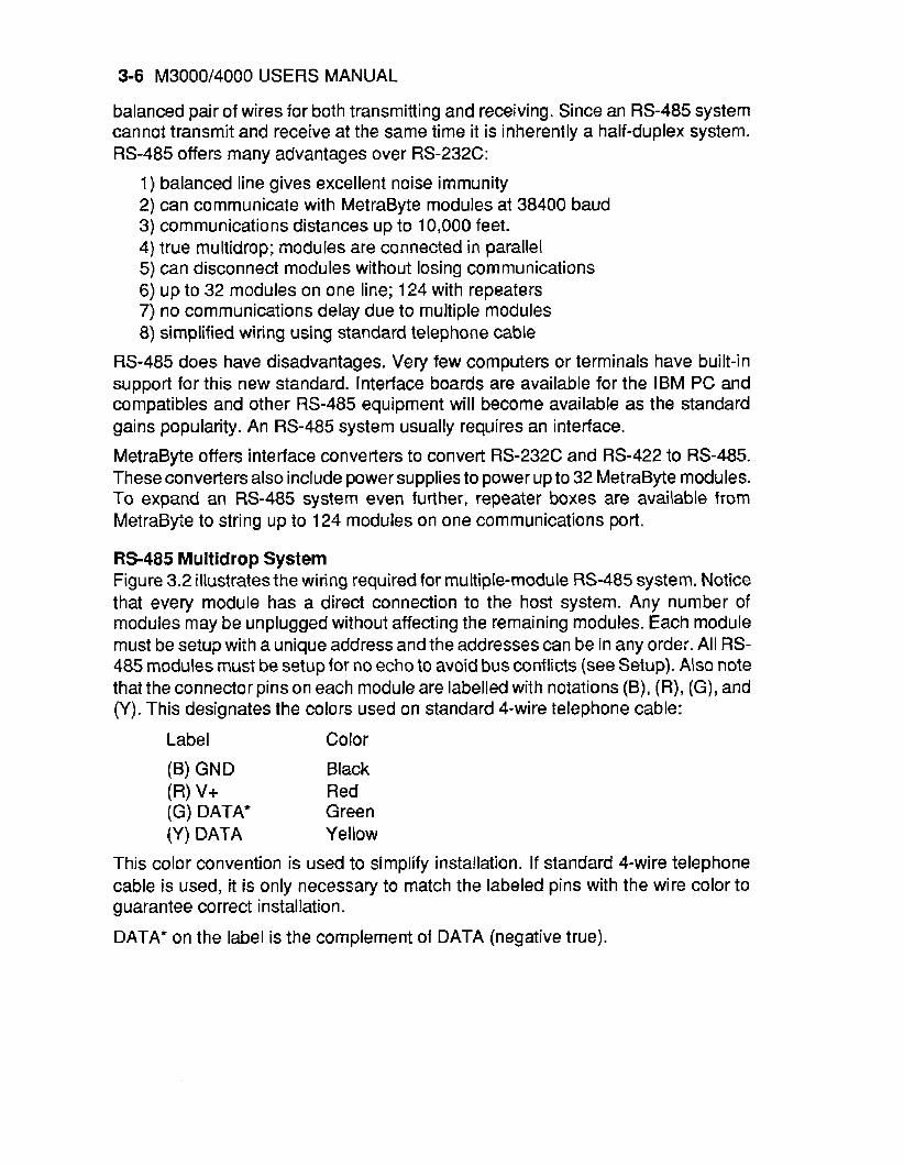
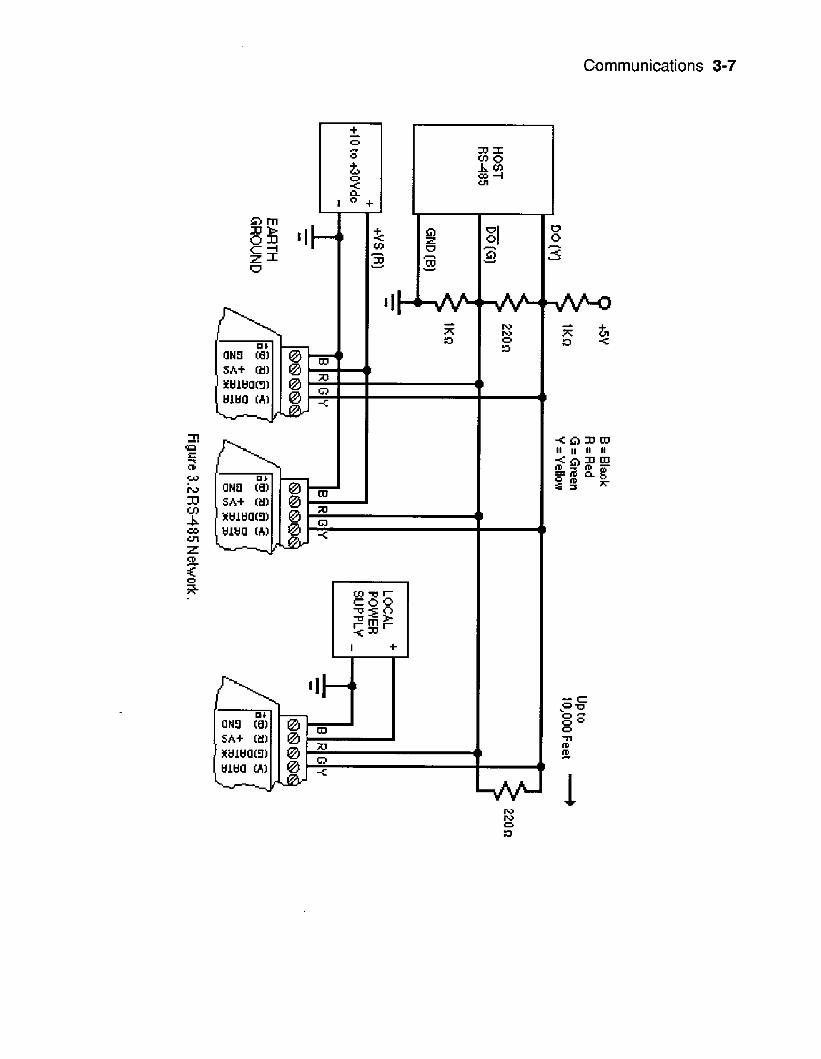
RS-485 Multidrop System Figure 3.2 illustrates the wiring required for multiple-module RS-485 system. Notice that every module has a direct connection to the host system. Any number of modules may be unplugged without affecting the remaining modules. Each module must be setup with a unique address and the addresses can be in any order. All RS- 485 modules must be setup for no echo to avoid bus conflicts (see Setup). Also note that the connector pins on each module are labelled with notations (B), (R), (G), and (Y). This designates the colors used on standard 4-wire telephone cable:
Label Color
(6) GND Black (R) v+ Red (G) DATA* Green (Y) DATA Yellow
This color convention is used to simplify installation. If standard 4-wire telephone cable is used, it is only necessary to match the labeled pins with the wire color to guarantee correct installation.
DATA* on the label is the complement of DATA (negative true).
Co rnmunications 3-7
I
3-8 M3000/4000 USERS MANUAL
To minimize unwanted reflections on the transmission line, the bus should be arranged as a line going from one module to the next. ‘Tree’ or random structures of the transmission line should be avoided. When using long transmission lines and/ or high baud rates, the data lines should be terminated at each end with 200 ohm resistors. Standard values of 180R or 220Q are acceptable.
During normal operation, there are periods of time where all RS-485 drivers are off and the communications lines are in an ‘idle’ high impedance condition. During this condition, the lines are susceptible to noise pickup which may be interpreted as random characters on the communications line. To prevent noise pickup, all RS-485 systems should incorporate 1K ohm bias resistors as shown in Figure 3.2. The resistors will maintain the data lines in a ‘mark‘ condition when all drivers are off.
MetraByte A1 000 series converter boxes have the 1 Ki2 resistors built-in.
Special care must be taken with very long busses (greaterthan 1000 feet) to ensure error-free operation. Long busses must be terminated as described above. The use of twisted cable for the DATA and DATA* lines will greatly enhance signal fidelity. Use parity and checksums along with the ‘# form of all commands to detect transmission errors. In situations where many modules are used on a long line, voltage drops in the power leads becomes an important consideration. The GND wire is used both as a power connection and the common reference for the transmission line receivers in the modules. Voltage drops in the GND leads appear as acommon-mode voltage to the receivers. The receivers are rated for a maximum of -7V. of common-mode voltage. For reliable operation, the common mode voltage should be kept below -5V.
To avoid problems with voltage drops, modules may be powered locally rather than transmitting the power from the host. Inexpensive ’calculator’ type power supplies are useful in remote locations. When local supplies are used, be sure to provide a ground reference with a third wire to the host or through a good earth ground. With local supplies and an earth ground, only two wires for the data connections are necessary.
Communications Delay All MetraByte modules with RS-485 outputs are setup at the factory to provide two units of communications delay after a command has been received (see Chapter 5). This delay is necessary when using host computers that transmit a carriage return as a carriage return-linefeed string. Without the delay, the linefeed character may collide with the first transmitted character from the module, resulting in garbled data. If the host computertransmits acarriage return as a single character, the delay may be set to zero to improve communications response time.
Chapter 4 Command Set
The M3000/4000 modules operate with a simple command/response protocol to control all module functions. A command must be transmitted to the module by the host computer or terminal before the module will respond with useful data. A module can never initiate a communications sequence. A variety of commands exists to exploit the full functionality of the modules. A list of available commands and a sample format for each command is listed in Table 4.1.
Command Structure Each command message from the host must begin with a command prompt character to signal to the modules that a command message is to follow. There are two valid prompt characters; a dollar sign character ($) is used to generate a short response message from the module. A short response is the minimum amount of data necessary to complete the command. The second prompt character is the pound sign character (#) which generates long responses (will be covered later).
The prompt character must be followed by asingle address character identifying the module to which the command is directed. Each module attached to a common communications port must be setup with its own unique address so that commands may be directed to the proper unit. Module addresses are assigned by the user with the Setup (SU) command. Printable ASCII characters such as ‘1 ’ (ASCII $31) or ‘A’ (ASCII $41) are the best choices for address characters.
The address character is followed by a two or three-character command that identifies the function to be performed by the module. All of the available commands are listed in Table 4.1 along with a short function definition. Commands must be transmitted as upper-case characters.
Atwo-characterchecksum may be appendedto any command message (except the ID command) as a user option. See ‘Checksum’ later in this chapter
All commands must be terminated by a Carriage Return character (ASCII $OD). (In all command examples in this text the Carriage Return is either implied or denoted by the symbol ‘CR’.)
Data Structure Many commands require additional data values to complete the command definition as shown in the example commands in Table 4.1. The particular data necessary for these commands is described in full in the complete command descriptions.
4-2 M3000/4000 USERS MANUAL
The most common type of data used in commands and responses is analog data. Analog data is always represented in the same format for all models in the M3000/ 4000 series. Analog data is represented as a nine-character string consisting of a sign, five digits, decimal point, and two additional digits. The string represents a decimal value in engineering units. Examples:
+ I 2345.68 +00100.00 -00072.10 -00000.00
When using commands that require analog data as an argument, the full nine- character string must be used, even if some digits are not significant. Failure to do this results in a SYNTAX ERROR.
Analog data responses from the module will always be transmitted in the nine- character format. This greatly simplifies software parsing routines since all analog data is in the same format for all module types.
In many cases, some of the digits in the analog data may not be significant. For instance, in the M3151 0 to 20mA output module, the data is scaled in mitliamps. The full scale output is +00020.00mA. The left three digits have no significance. However, the data format is always adhered to in order to maintain compatibility with other module types.
The maximum computational resolution of the module is 16 bits, which is less than the resolution that may be represented by an analog datavariable. This may lead to round-off errors in some cases. For example, a limit value may be stored in a M3000/ 4000 module using the ‘HI’ command:
Command: $1 Hl+l2345.67 Response: t
The limit value is read back with the Read Hlgh (RHI) command:
Command: $1 RHI Response: *+12345.60
It appears that the data read backdoes not match the value that was originally saved. The error is caused by the fact that the value saved exceeds the computational resolution of the module. This type of round-off error only appears when large data values saved in the module’s EEPROM are read back. In most practical applications, the problem is non-existent.
The Digital Input, Hex Output and Setup commands use hexadecimal representa- tions of data. The data structures for these commands are detailed in the command descriptions.
Write Protection Many of the commands listed in Table 4.1 are underthe heading of ‘Write Protected Commands’. These commands are used to alter setup data in the module’s
Command Set 4-3
EEPROM. They are write protected to guard against accidental loss of setup data. All write-protected commands must be preceded by a Write Enable (WE) command before the protected command may be executed.
MisceIlaneous Protocol Notes The address character must be transmitted immediately after the command prompt character. After the address character the module will ignore any character below ASCII $23 (except, of course, CR). This allows the use of spaces (ASCII $20) within the command message for better readability if desired.
The length of acommand message is limited to 20 printable characters. If a properly addressed module receives a command message of more than 20 characters the module will abort the whole command sequence and no response will result.
If a properly addressed module receives a second command prompt before it receives a CR, the command will be aborted and no response will result.
Response Structure Response messages from the module begin with either an asterisk ' ' (ASCII $2A) or a question mark ' ? ' (ASCII $3F) prompt. The ' * ' prompt indicates acknowledg- ment of a valid command. The ' ? ' prompt precedes an error message. All response messages are terminated with a CR. Many commands simpIy return a ' * ' character to acknowledge that the command has been executed by the module. Other commands send data information following the ' ' prompt. The response format of all commands may be found in the detailed command description.
The maximum response message length is 20 characters.
A command/response sequence is not complete until a valid response is received. The host may not initiate a new command until the response from a previous command is complete. Failure to observe this rule will result in communications collisions. A valid response can be in one of three forms:
I ) a normal response indicated by a * ' prompt 2) an error message indicated by a ? prompt 3) a communications time-out error
When a module receives avalid command, it must interpret the command, perform the desired function, and the communicate the response back to the host. Each command has an associated delay time in which the module is busy calculating the response. If the host does not receive a response in an appropriate amount of time specified in Table 3.1 a communications time-out error has occurred. After the communications time-out it is assumed that no response data is forthcoming. This error usually results when an improper command prompt or address is transmitted.
Long Form Responses When the pound sign ' # I command prompt is used, the module respondswith a'long form' response. This type of response will echo the command message, supply the
4-4 M3000/4000 USERS MANUAL
necessary response data and will add a two-character checksum to the end of the message. Long form responses are used when the host wishes to verify the command received by the module. The checksum is included to verify the integrity of the response data. The ‘ # ‘ command prompt may be used with any command. For example:
Command: $1 RD Response: *+00072.10
(short form)
Command: #I RD (long form) Response: *1 RD+00072.1 OA4 (A4=c hec ksu m)
Checksum Checksum is atwo character hexadecimal value appended to the end of a message. It verifies that the message received is exactly the same as the message sent. The checksum ensures the integrity of the information communicated.
Command Checksum A two-character checksum may be appended to any command (except ‘ID’) to the module as a user option. When a module interprets a command, it looks for the two extra characters and assumes that it is a checksum. If the checksum is not present, the module will perform the command normally. If the two extra characters are present, the module calculates the checksum for the message. If the calculated checksum does not agree with the transmitted checksum, the module responds with a ‘BAD CHECKSUM’ error message and the command is aborted. If the checksums agree, the command is executed. If the module receives a single extra character, it responds with ‘SYNTAX ERROR’ and the command is aborted. For example:
Command: $1 RD Response: *+00072.10
Command: $1 RDEB Response: *+00072.10
(no checksum)
(with checksum)
Command: $1 RDAB (incorrect checksum) Response: ?1 BAD CHECKSUM
Command: $1 RDE (one extra character) Response: ?1 SYNTAX ERROR
Response Checksums If the long form ’#‘version of acommand istransmitted to a module, achecksum will be appended to the end of the response. For example:
Command: $1 RD Response: *+00072.10
(short form)
Command: #1 RD (long form) Response: *1 RD+00072.1OA4 (A4zchecksu m)
Command Set 4-5
Checksum Calculation The checksum is calculated by summing the hexadecimal values of all the ASCII characters in the message. The lowest order two hex digits of the sum are used as the checksum. These two digits are then converted to their ASCII character equivalents and appended to the message. This ensures that the checksum is in the form of printable characters.
Example: Append a checksum to the command #I HX07FF
Characters: # 1 H X 0 7 F F ASCII hexvalues: 23 31 48 58 30 37 46 46 Sum (hexaddition) 23+ 31 + 48+ 5 8 i 30+ 37+ 4 6 + 4 6 = 1E7
Thechecksum isE7 (hex).Appendthecharacters Eand7totheend ofthe message: #I HX07FFE7.
Example: Verify the checksum of a module response *1 RD+00072.1 OA4
The checksum is the two characters preceding the CR: A4
Add the remaining character values:
* l R D i 0 0 0 7 2 . 1 0 2 A + 3 1 + 5 2 + 4 4 + 2 6 + 3 0 + 3 0 + 3 0 + 3 7 + 3 2 + 2 E + 3 1 +30=2A4
The two lowest-order hex digits of the sum are A4 which agrees with the transmitted c h ec ksu m . The transmitted checksum is the character string equivalent to the calculated hex integer. The variables must be converted to like types in the host software to determine equivalency.
If checksums do not agree, a communications error has occurred.
If a module is setup to provide Iinefeeds, the linefeed characters are not inctuded in the c hecksu m calcu tat io n . Parity bits are never included in the checksurn calculation.
M3000/4000 User Commands Table 4.1 shows all the M3000/4000 commands. For each case, atypical command and response is shown. Note that some commands only respond with an * as an acknowjedgment. For clarity, Table 4.1 separates M4000 commands from the commands that are common to both the M3000 and M4000. Table 4.1 also separates write protected commands from commands that are not write protected.
Each M3000/4000 usercommand isdescribed indetail following Table 4.1. AIIof the commands are listed in alphabetical order according to command nomenclature. Commands that are exclusive to the M4000 are noted near the right hand margin. For example:
Manual Slope (MS) (M4000)
4-6 M3000/4000 USERS MANUAL
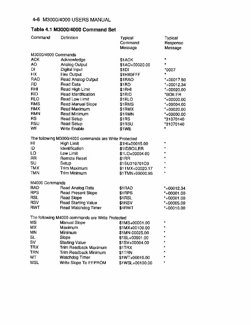
Table 4.1 M3000/4000 Command Set Command Definition
M3000/4000 Commands ACK Acknowledge A 0 Analog Output DI Digital Input HX Hex Output RAO Read Analog Output RD Read Data RHI Read High Limit RID Read Identification RLO Read Low Limit RMS Read Manual Slope RMX Read Maximum RMN Read Minimum RS Read Setup RSU Read Setup WE Write Enable
Typical Command Message
$1 ACK $1 A0+00020.00 $1 DI $1 HXOFFF $1 RAO $1 RD $1 RHI $1 RID $1 RLO $1 RMS $1 RMX $1 RMN $1 RS $1 RSU $1 WE
The following M3000/4000 commands are Write Protected HI High Limit $1 H1+00015.00 ID Identification $1 IDBOILER LO Low Limit $1 LO+00004.00 RR Remote Reset $1 RR su Setup $1 SU310701 CO TM X Trim Maximum $1 TMX+00020.17 TM N Trim Minimum $1 TMN+00000.95
M4000 Commands RAD Read Analog Data $1 RAD RPS Read Present Slope $1 RPS RSL Read Slope $1 RSL RSV Read Starting Value $1 RSV R W Read Watchdog Timer $1 R W
The following M4000 commands are Write Protected MS Manual Slope $1 MS+00001 .OO MX Maximum $1 MX+00100.00
SL Slope $1sL+oooo1 .oo MN Minimum $1 MN-00025.00
sv Starting Value $1SV+00004.00 TRX Trim Readback Maximum $lTRX TR N Trim Readback Minimum $1TRN WT Watchdog Timer $1wT+00010.00 WSL Write Slope To EEPROM $1 wsL+00100.00
Typical Response Message
'0007
*+00017.50 'iOOO12.34 '+00020.00 *BOILER *+ooooo.oo '+00004.00 '+00020.00
'31 070140 '31070140
~+00000.00
'+00012.34 '+00001 .oo *+00001 .oo '+00005.00 '+00010.00

Command Set 4-7
Acknowledge (ACK) The ACKnowledge command is a hand-shaking command used in conjunction with the Analog Output (AO) command. It is used to confirm the data sent to a module. See the Analog Output (AO) command for examples of ACK usage.
Command: $lACK Response: *
Command: #IACK Response: *I ACKPA
Analog Output (AO) The Analog Output (AO) command is the primary command used to control the analog output, whether it is current or voltage. The A 0 command can function in two different ways, depending on whether the '$' or the ' # command prompt is used. In either case the analog output is specified in the standard MetraByte data format:
Command: $lA0+00010.00 Response: t
If the analog output is scaled in milliamps, this particular command will direct the M3000 to produce 10mA. In this example, the '$'command prompt is used to obtain an analog output immediately after the command is received by the module. The module performs the output function and responds with a '*I to provide a simple acknowledgement that the command has been executed.
The '# form of the A 0 command requires the host to verify and acknowledge the command data before the module will execute the command. The data is acknowl- edged by the host with the ACKnowledge (ACK) command. Here is a typical command sequence:
Command: # I A0+00010.00 Response: '1 A0+00010.0095
The host command is echoed back along with a checksum as is true with any command when used with the '#I command prompt. At this point the module has not performed the A 0 command. It is waiting for the host to acknowledge the command by sending an ACK command. This allows the host to examine the command as received by the module and verify that the data is correct. If the host is satisfied that the command data and the checksum are correct, it directs the module to go ahead and perform the A 0 by sending the ACK command. To complete the sequence:
Command: $1 ACK Response: *
At this point the A 0 command will be performed by the module.
4-8 M3000/4000 USERS MANUAL
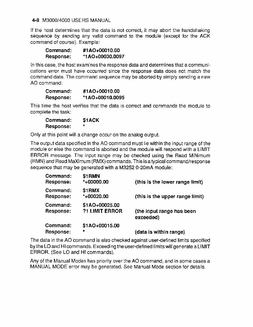
If the host determines that the data is not correct, it may abort the handshaking sequence by sending any valid command to the module (except for the ACK command of course). Example:
Command: # I A0+00010.00 Response: *I A0+00030.0097
In this case, the host examines the response data and determines that a communi- cations error must have occurred since the response data does not match the command data. The command sequence may be aborted by simply sending a new A 0 command:
Command: #I A0+00010.00 Response: *I A0+00010.0095
This time the host verifies that the data is correct and commands the module to complete the task:
Command: $1 ACK Response: *
Only at this point will a change occur on the analog output.
The output data specified in the A 0 command must lie within the input range of the module or else the command is aborted and the module will respond with a LIMIT ERROR message. The input range may be checked using the Read MiNimum (RMN) and Read Maximum (RMX) commands. This is atypical cornmand/response sequence that may be generated with a M3252 0-20mA module:
Command: $1 RMN Response: *+ooooo.oo (this is the lower range limit)
Command: $1 RMX Response: *+00020.00 (this is the upper range limit)
Command: $1 A0+00025.00 Response: ? I LIMIT ERROR (the input range has been
Command: $1 A0+00015.00
exceeded)
Response: * (data is within range)
The data in the A 0 command is also checked against user-defined limits specified by the LO and HI commands. Exceeding the user-defined limits will generate a LIMIT ERROR. (See LO and l i t commands).
Any of the Manual Modes has priority over the A 0 command, and in some cases a MANUAL MODE error may be generated. See Manual Mode section for details.
Command Set 4-9
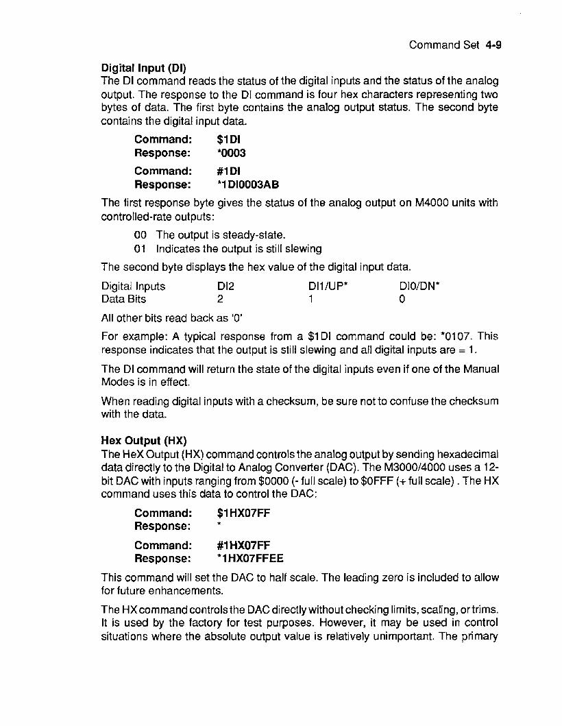
Digital Input (DI) The DI command reads the status of the digital inputs and the status of the analog output. The response to the D1 command is four hex characters representing two bytes of data. The first byte contains the analog output status. The second byte contains the digital input data.
Command: $1 DI Response: *0003
Command: #I DI Response: *I D10003AB
The first response byte gives the status of the analog output on M4000 units with cont rolled-rate out puts :
00 The output is steady-state. 01 Indicates the output is still slewing
The second byte displays the hex value of the digital input data.
Digital Inputs D12 DIl/UP* D I O/D N * Data Bits 2 1 0
All other bits read back as '0'
For example: A typical response from a $1 DI command could be: *0107. This response indicates that the output is still slewing and all digital inputs are = 1.
The DI command will return the state of the digital inputs even if one of the Manual Modes is in effect.
When reading digital inputs with a checksum, be sure not to confuse the checksum with the data.
Hex Output (HX) The Hex Output (HX) command controls the analog output by sending hexadecimal data directly to the Digital to Analog Converter (DAC). The M3000/4000 uses a 12- bit DAC with inputs ranging from $0000 (- full scale) to $OFFF (+full scale) . The HX command uses this data to control the DAC:
Command: $1 HX07FF Response:
Command: #1 HX07FF Response: *I HX07FFEE
*
This command will set the DAC to half scale. The leading zero is included to allow for future enhancements.
The HXcommand controls the DAC directly without checking limits, scaling, ortrims. It is used by the factory for test purposes. However, it may be used in control situations where the absolute output value is relatively unimportant. The primary
4-10 M3000/4000 USERS MANUAL
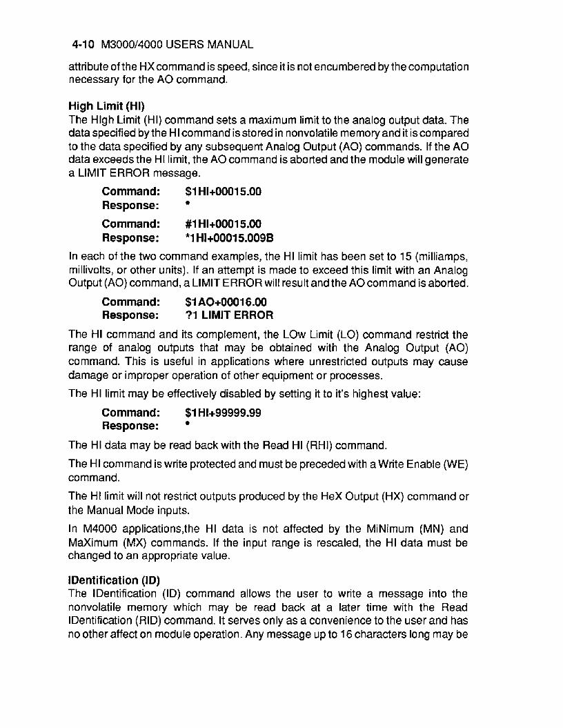
attribute of the HXcommand is speed, since it is not encumbered by the computation necessary for the A 0 command.
High Limit (HI) The Hlgh Limit (HI) command sets a maximum limit to the analog output data. The data specified by the HI command is stored in nonvolatile memory and it iscompared to the data specified by any subsequent Analog Output (AO) commands. If the A 0 data exceeds the HI limit, the A 0 command is aborted and the module will generate a LIMIT ERROR message.
Command: $1 H1+00015.O0 Response :
Command: #1 H1+00015.00 Response: *1 H1+00015.0098
In each of the two command examples, the HI limit has been set to 15 (milliamps, millivolts, or other units). If an attempt is made to exceed this limit with an Analog Output (AO) command, a LIMIT ERROR will result and the AOcommand is aborted.
Command: $1 A0+00016.00 Response: ?I LIMIT ERROR
The HI command and its complement, the LOW Limit (LO) command restrict the range of analog outputs that may be obtained with the Analog Output (AO) command. This is useful in applications where unrestricted outputs may cause damage or improper operation of other equipment or processes.
The HI limit may be effectively disabled by setting it to it’s highest value:
Command: $1 H1+99999.99 Response:
The HI data may be read back with the Read HI (RHI) command.
The HI command is write protected and must be preceded with a Write Enable (WE) command.
The HI limit will not restrict outputs produced by the Hex Output (HX) command or the Manual Mode inputs.
In M4000 applications,the HI data is not affected by the MiNimum (MN) and Maximum (MX) commands. If the input range is rescaled, the HI data must be changed to an appropriate value.
I Dent if icat i on (ID) The IDentification (ID) command allows the user to write a message into the nonvolatile memory which may be read back at a later time with the Read IDentification (RID) command. It serves only as a convenience to the user and has no other affect on module operation. Any message up to 16 characters long may be
Command Set 4-11
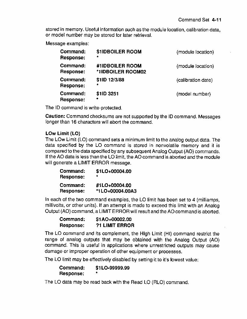
stored in memory. Useful information such as the module location, calibration data, or model number may be stored for later retrieval.
Message examples:
Command: $1 IDBOILER ROOM Response: *
Command: #1 IDBOILER ROOM Response: * I IDBOILER ROOM02
Command: $1 ID 12/3/88
Command: $1 ID 3251 Response:
Response: *
The ID command is write-protected.
(module location)
(module location)
(calibration date)
(model number)
Caution: Command checksums are not supported by the ID command. Messages longer than 16 characters will abort the command.
LOW Limit (LO) The LOW Limit (LO) command sets a minimum limit to the analog output data. The data specified by the LO command is stored in nonvolatile memory and it is compared to the data specified by any subsequent Analog Output (AO) commands. If the A 0 data is less than the LO limit, the A 0 command is aborted and the module will generate a LIMIT ERROR message.
Command: $1 LO+OOOO4.OU Response: *
Command: #1 L0+00004.00 Response: *1 LO+00004.00A3
In each of the two command examples, the LO limit has been set to 4 (milliamps, millivolts, or other units). If an attempt is made to exceed this limit with an Analog Output (AO) command, a LIMIT ERROR will result and the AOcommand is aborted.
Command: $1 A0+00002.00 Response: ?1 LIMIT ERROR
The LO command and its complement, the Hlgh Limit (HI) command restrict the range of analog outputs that may be obtained with the Analog Output (AO) command. This is useful in applications where unrestricted outputs may cause damage or improper operation of other equipment or processes.
The LO limit may be effectively disabled by setting it to it’s lowest value:
Command: $1 LO-99999.99 Response: *
The LO data may be read back with the Read LO (RLO) command.
4-12 M3000/4000 USERS MANUAL
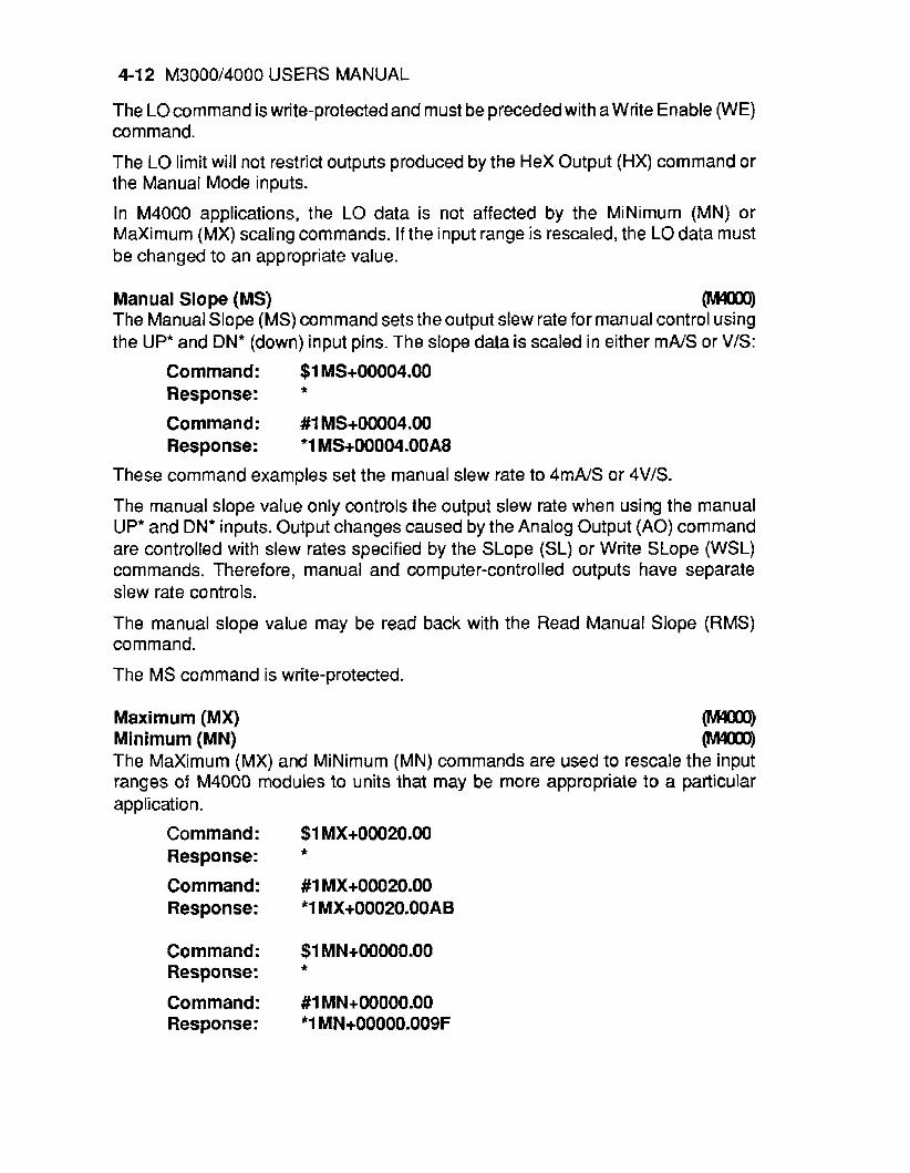
The Locommand is write-protected and must be preceded with a Write Enable (WE) command.
The LO limit will not restrict outputs produced by the Hex Output (HX) command or the Manual Mode inputs.
In M4000 applications, the LO data is not affected by the MiNimum (MN) or Maximum (MX) scaling commands. If the input range is rescaled, the LOdata must be changed to an appropriate value.
Manual Slope (MS) o The Manual Slope (MS) command sets the output slew rate for manual control using the UP* and DN* (down) input pins. The slope data is scaled in either mNS or V/S:
Command: $1 MS+00004.OO
Command: #I MS+00004.00 Response: *I MS+00004.00A8
Response: *
These command examples set the manual slew rate to 4mNS or 4V/S.
The manual slope value only controls the output slew rate when using the manual UP* and DN* inputs. Output changes caused by the Analog Output (AO) command are controlled with slew rates specified by the SLope (SL) or Write SLope (WSL) commands. Therefore, manual and computer-controlled outputs have separate slew rate controls.
The manual slope value may be read back with the Read Manual Slope (RMS) co m m and.
The MS command is write-protected.
Maximum (MX) m Minimum (MN) rn The Maximum (MX) and MiNimum (MN) commands are used to rescale the input ranges of M4000 modules to units that may be more appropriate to a particular application.
Command: $1 MX+00020.00
Command: #1 MX+00020.00 Response: *1 MX+00020.00AB
Response: *
Command: $1 MN+00000.00
Command: #1 MN+00000.00 Response: *1 MN+00000.009F
Response: *

Command Set 4-13
The MiNimum (MN) command assigns an input data value corresponding to the -full scale analog output value.
The Maximum (MX) command assignsan input datavaluecorresponding to the+full scale analog output value.
The MN and MX commands are covered thoroughly in chapter 10.
The MN and MXvalues are saved in nonvolatile memory and may be read back with the Read MiNirnum (RMN) and Read Maximum (RMX) commands.
The MN and MX commands are write-protected.
Read Analog Data (RAD) rn All M4000 modules contain an Analog-to-Digital Converter (ADC) which may be used to directly monitorthe analog output signal. The ADC data is obtained with the Read Analog Data (RAD) command. The data is scaled in the same units as used with the Analog Output (AO) command. The ADC data obtained with the RAD command provides a check to assure the user that the module is working properly and no output fault conditions exist. Referto the M4000 section for more information.
Command: $1 RAD Response: *+00012.30
Command: #1 RAD Response: *1 RAD+00012.30El
Read Analog Output (RAO) The Read Analog Output (RAO) command is used to read backthe data sent by the most recent Analog Output (AO) command. It is particularly useful when the M4000 is used with very low output slope values. The RAO gives the eventual final output of the analog output.
The RAOsimplyreads backtheargumentofthe most recent AOcommandanddoes not necessarily correlate with the actual analog output. See the RD command.
Command: $1 RAO Response: *+00017.50
Command: #1 RAO Response : *1 RA0+00017.50F3
Read Data (RD) The Read Data (RD) command reads back the digital data being sent to the DAC at the time the RD command is performed. It is used to obtain the status of the output

4-14 M3000/4000 USERS MANUAL
signal at any time. The data obtained is scaled in the same units as used with the Analog Output (AO) command.
Command: $1 RD
Command: #1 RD Response: *1 RD+00010.009B
Response: *+00010.00
The RD command will read back instantaneous DAC data even if the output is being changed with the Manual Mode inputs or with the controlled output slew rates that may be obtained in M4000 units.
Since the RD command is the primary means of monitoring output data, a special short form of the command is available for faster response. If a M3000/4000 unit is addressed without a command, the RD command is assumed by default:
Command: $1 Response : *+00012.34
Command: #1 Response: *1 RD+00010.003B
Note that the RD command returns the digital data that the microprocessor is currently sending to the DAC. It provides no guarantee that the analog output signal is being generated properly and that no output fault conditions exist. However, for a module that has been installed and verified for proper operation, the RD command is a reliable indicator of the output signal.
Read Hlgh Limit (RHI) The Read Hlgh Limit (RHI) command reads back the HI Limit value stored in the nonvolatile memory. The HI limit may be changed by the HI command.
Command: $1 RHI
Command: #I RHI Response: * I RH1+00020.00E9
Response: *+00020.00
Read IDentification (RID) The Read IDentification (RID) command reads out the user data stored by the IDentification (ID) command. The ID and RID commands are included as a convenience to the user to store information in the module’s nonvolatile memory.
Command: $1 RID Response: *BOILER ROOM (example) Command: # I RID Response: ‘1 RIDBOILER ROOM54 (exam p I e)
In this case the RID command has read back the message “BOILER ROOM” previously stored by the ID command. See ID command.
Command Set 4-15
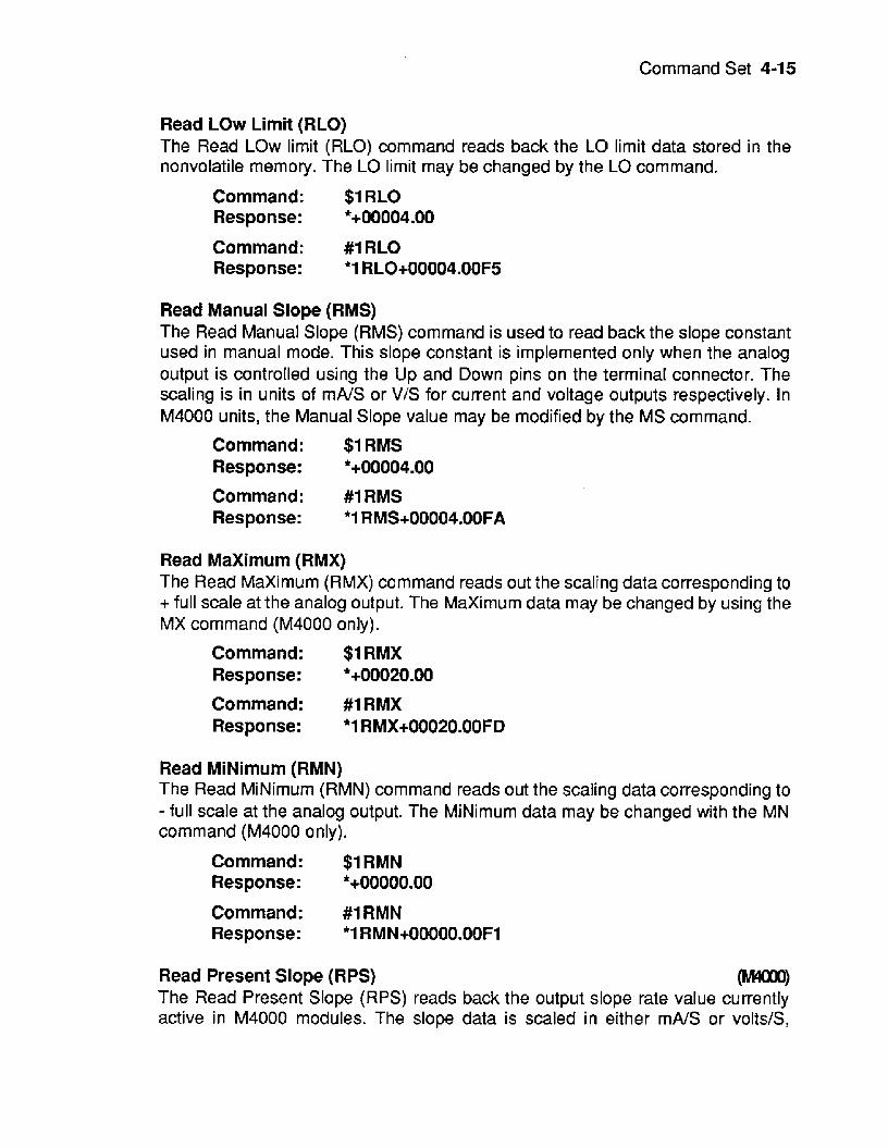
Read LOW Limit (RLO) The Read LOW limit (RLO) command reads back the LO limit data stored in the nonvolatile memory. The LO limit may be changed by the LO command.
Command: $1 RLO Response: *+00004.00
Command: #1 RLO Response: '1 RL0+00004.00F5
Read Manual Slope (RMS) The Read Manual Slope (RMS) command is used to read back the slope constant used in manual mode. This slope constant is implemented only when the analog output is controlled using the Up and Down pins on the terminal connector. The scaling is in units of mA/S or V/S for current and voltage outputs respectively. In M4000 units, the Manual Slope value may be modified by the MS command.
Command: $1 RMS
Command: #1 RMS Response: *1 RMS+00004.00FA
Response: *+ooo04.00
Read Maximum (RMX) The Read Maximum (RMX) command reads out the scaling datacorresponding to + full scale at the analog output. The Maximum data may be changed by using the MX command (M4000 only).
Command: $1 RMX Response: **00020.00
Command: #1 RMX Response: *l RMX+00020.00FD
Read MiNimum (RMN) The Read MiNimum (RMN) command reads out the scaling data corresponding to - full scale at the analog output. The MiNimum data may be changed with the MN command (M4000 only).
Command: $1 RMN
Command: #1 RMN Response: *1 RMN+OOOOO.OOF1
Response: *+00000.00
Read Present Slope (RPS) m The Read Present Slope (RPS) reads back the output slope rate value currently active in M4000 modules. The slope data is scaled in either mA/S or volts/S,
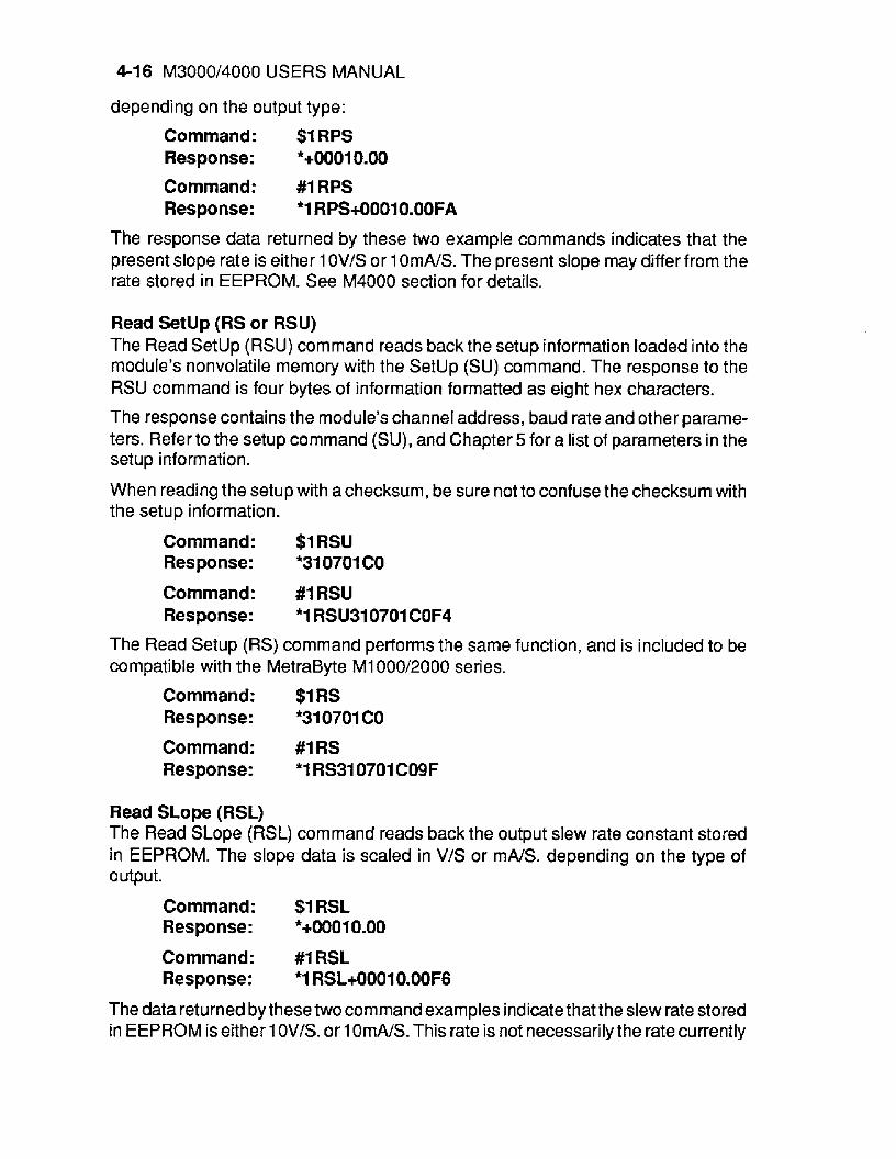
4-1 6 M3000/4000 USERS MANUAL
depending on the output type:
Command: $1 RPS
Command: # I RPS Response: *1 RPS+OOOlO.OOFA
Response: *+00010.00
The response data returned by these two example commands indicates that the present slope rate is either 1 OV/S or 1 OmA/S. The present slope may differfrom the rate stored in EEPROM. See M4000 section for details.
Read Setup (RS or RSU) The Read Setup (RSU) command reads back the setup information loaded into the module's nonvolatile memory with the Setup (SU) command. The response to the RSU command is four bytes of information formatted as eight hex characters.
The response contains the module's channel address, baud rate and other parame- ters. Refer to the setup command (SU), and Chapter 5 for a list of parameters in the setup information.
When reading the setup with achecksum, be sure not to confuse the checksum with the setup information.
Command: $1 RSU Response: *310701 CO
Command: #1 RSU Response: *1 RSU310701 COF4
The Read Setup (RS) command performs the same function, and is included to be compatible with the MetraByte MI 000/2000 series.
Command: $1 RS Response: *310701 CO
Command: #1 RS Response: *I RS310701 CO9F
Read SLope (RSL) The Read SLope (RSL) command reads back the output slew rate constant stored in EEPROM. The slope data is scaled in V/S or mA/S. depending on the type of output.
Command: $1 RSL
Command: #I RSL Response: '1 RSL+0001 O.OOF6
Response: '*00010.00
The data returned by these two command examples indicate that the slew rate stored in EEPROM is either 1 OV/S. or 1 OmNS. This rate is not necessarily the rate currently
Command Set 4-17
used by the analog output. See M4000 section.
Read Starting Value (RSV) m The Read Starting Value command reads the value of the desired start-up analog output which has been programmed by the user.
Command: $1 RSV Response : *+00005.00
Command: #I RSV Response: *I RSV+00005.0004
Read Watchdog Timer (RWT) rn The Read Watchdog Timer (RWT) command reads the time interval necessary to activate the watchdog timer. The data is scaled in minutes.
Command: $1 RWT Response: *+00010*00 (10 minutes)
Command: #1 RWT Response: *I RWT+00010.0002 (10 minutes)
In each of the two example commands, the response data indicates that the watchdog timer period is 10 minutes. The watchdog timer value may be set with the Watchdog Timer (WT) command. See M4000 section for watchdog timer informa- tion.
Remote Reset (RR) The Remote Reset (RR) command allows the host to perform a program reset on the module’s microcomputer. This may be necessary if the module’s internal program is disrupted by static or other electrical disturbances.
Command: $1 RR Response:
Command: #1 RR Response : *I RRFF
The RR command will halt any analog output to it‘s present value.
The RR command is write-protected.
The RR command is required for a baud rate change.
Setup (SU) Each module contains an EEPROM (Electrically Erasable Programmable Read Only Memory) which is used to store module setup information such as address, baud rate, parity, etc. The EEPROM is a special type of memory that will retain information even if power is removed from the module. The EEPROM is used to replace the usual array of DIP switches normally used to configure electronic equipment.

4-18 M300014000 USERS MANUAL
The Setup command is used to modify the user-specified parameters contained in the EEPROM to tailor the module to your application. Since the Setup command is so important to the proper operation of a module, a whole section of this manual has been devoted to its description. See Chapter 5.
The SU command requires an argument of eight hexadecimal digits to describe four bytes of setup information:
Command: $lSU31070182
Command: #lSU31070182 Response: *1 SU3107018299
Response: *
SLope (SL) The SLope (SL) command is used to set the output slew rate for analog outputs performed by the Analog Output (AO) command. The slope data is scaled in either VIS or mAIS:
Command: $1SL+00100.00 Response:
Command: #I sL+00100.00 Response: '1 SL+OOl OO.OOA4
These two sample commands will set the output slope rate to 100 V/S or 100 mA/ S .
The SLope (SL) command dataissavedonlyin Random Access Memory (RAM) and is not stored in EEPROM. The SLcommand is not write protected. The SLcommand is used in applications where frequent changes in the output slope rate is desired. See M4000 section for further details.
Starting Value (SV) m The Starting Value (SV) command is used to program the desired analog output value when the unit is powered up. The output will automatically go to the programmed value with the slew rate stored in EEPROM.
Command: $1 SV+00005.00
Command: #I SV+00005.00 Response: *I SV+OOOOS.OOB2
Response: t
Each of the two example commands sets the starting value to +00005.00. This value is stored in EEPROM. When the M4000 unit is powered up, it automatically petforms an internal Analog Output (AO) command with the stored data. If the A 0 command would have resulted in an error (LIMIT ERROR, MANUAL MODE) the start-up command is aborted and the M4000 will start up at - Full Scale. The scaling of the

Command Set 4-1 9
start-updataisdetermined bythe input scaling range fixed by the MiNimum (MN) and Maximum (MX) limits.
The Starting Value is the ‘safe’ output value used when the watchdog timertimes out. See M4000 section.
The SV command is write-protected.
Trim Maximum (TMX) Trim MiNimum (TMN) The TMX and TMN commands are used to calibrate the analog output circuitry of the module. These commands are used to communicate actual measured output data to the modules so that a trim calculation may be performed:
Command: $1 TMN+00000.12
Command: #I TMX+00019.98 Response: ‘1 TMX+00019.9818
Response: *
Referto the Calibration section for details on output trims and the use of the TMN and TMX commands.
Caution: Unwarranted use of the TMN and TMX commands will destroy the calibration of the unit. These commands must be used with acalibrated voltmeter or ammeter to assure output accuracy.
Trim Readback Maximum (TRX) m Trim Readback MiNimum (TRN) m The TRX and TRN commands are used on M4000 modules to trim the Analog-to- Digital Converter (ADC) which provides the analog readback of the output signal. Refer to the Calibration section.
Command: $ITRN Response :
Command: #ITRN Response : *I TRN4F
Watchdog Timer (WT) m The Watchdog Timer (WT) command stores adatavalue in EEPROM specifying the time-out value of the watchdog timer. The time data is scaled in minutes:
Command: $1 WT+O0010.00 Response: *
Command: #I WT+#0010.00 Response: *I WT+OOO10.00BO
These two command examples set the watchdog time value to 10 minutes. In this example, if the module does not receive avalid command for a period of 10 minutes,
4-20 M3000/4000 USERS MANUAL
the analog output will automatically be forced to the Starting Value. See M4000 section.
The watchdog timer may be disabled by setting the timer value to +99999.99.
WT command data less than 0.16 minutes will result in a VALUE ERROR. The WT command is write protected.
Write Enable (WE) The Write Enable (WE) command must precedecommands that are write-protected. This is to guard against accidentally writing over valuable data in EEPROM. To change any write protected parameter, the WE command must precede the write- protected command. The response to the WEcommand is an asteriskindicating that the module is ready to accept a write-protected command. After the write-protected command is successfully completed, the module becomes automatically write disabled. Each write-protected command must be preceded individually with a WE command. For example:
Command: $1 WE Response:
Command: #1 WE Response: *1 W E R
*
If a module is write enabled and the execution of a command results in an error message other than WRITE PROTECTED, the module will remain write enabled until acommand is successfully completed resulting in an '*' prompt. This allows the userto correct the command errorwithout having to execute another WE command.
Write SLope To EEPROM M The Write SLope (WSL) command is used to set the output slew rate for analog outputs performed by the Analog Output (AO) command. The slope data is scaled in either V/S or mA/S:
Command: $1 WSL+OO100.00 Response:
Command: #1 wsL+00100.00 Response: *1 WSL+OOlOO.OOFB
These two sample commands will set the output slope rate to 1 OOV/S or 1 OOmNS.
The Write SLope (WSL) command stores the rate data in Random Access Memory (RAM) and in nonvolatile EEPROM.
The WSL command is write protected.
ERROR MESSAGES All modules feature extensive errorchecking on input commands to avoid erroneous operation. Any errors detected will result in an error message and the command will be aborted.

Command Set 4-21
All error messages begin with "?", followed by the channel address, a space and error description. The error messages have the same format for either the ' $ ' or ' # ' prompts. For example:
There are nine error messages, and each error message begins with a different character. Host computer software can identify an error by the first character; it is not necessary to read the whole string.
?1 SYNTAX ERROR
ADDRESS ERROR There are four ASCII values that are illegal for use as a module address: NULL ($OO), CR ($OD), $ ($24), and # ($23). The ADDRESS ERROR will occurwhen an attempt is made to load an illegal address into a module with the Setup (SU) command. An attempt to load an address greater than $7F will also produce an error.
BAD CHECKSUM This error is caused by an incorrect checksum included in the command string. The module recognizes any two hex characters appended to a command string as a checksum. Usually a BAD CHECKSUM error is due to noise or interference on the communications line. Often, repeating the command solves the problem. If the error persists, either the checksum is calculated incorrectly or there is a problem with the communications channel. More reliable transmissions might be obtained by using a lower baud rate.
COMMAND ERROR This error occurs when acommand is not recognized by the module. Often this error results when the command is sent with lower-case letters. All valid commands are u ppe r-case.
LIMIT ERROR A LIMIT ERROR may occur when using the Analog Output (AO) command if:
a) the A 0 data exceeds the input span range defined by the MiNirnum
b) the A 0 data exceeds a limit set by the LOW Limit (LO) or Hlgh Limit
c) the output is inhibited by a limit switch (see Manual Modes)
(MN) and Maximum (MX) values
(HI) commands
MANUAL MODE This error may occur when using the Analog Output (AO) or Hex Output (HX) commands while the output is being controlled by either the Up/Down Manual Mode or the Controller Input Manual Mode. The Manual Modes have priority overthe host- generated commands.
4-22 M3000/4000 USERS MANUAL
PARITY ERROR A parity errorcan only occur if the module is setup with parity on (see Setup). Usually a parity error results from a bit error caused by interference on the communications line. Random parity errors are usually overcome by simply repeating the command. If too many errors occur, the communications channel may have to be improved or a slower baud rate may be used.
Aconsistent parity errorwill result if the host parity does not match the module parity. In this situation, the easiest solution may be to change the parity in the host to obtain communication. At this point the parity in the module may be changed to the desired value with the Setup (SU) command.
The parity may be changed or turned off by using Default Mode.
SYNTAX ERROR A SYNTAX ERROR will result if the structure of the command is not correct. This is caused by having too few or too many characters, signs or decimal points missing or in the wrong place. Table 4.1 lists the correct syntax for all commands.
VALUE ERROR This error results when an incorrect character is used as a numerical value. Data values can only contain decimal digits 0-9. Hex values used in the Setup (SU) and Hex Output (HX) commands can range from O-F.
AVALUE ERRORwilI begeneratedbyaM4000 moduleifaTMN,TMX,TRN,orTRX command is attempted while the output is slewing.
A VALUE ERROR is generated by TMN and TMX commands when an attempt is made to calibrate a module beyond the allowed trim range.
WRITE PROTECTED All commands that write data into nonvolatile memory are write-protected to prevent accidental erasures. These commands must be preceded with a Write Enable (WE) command or else a WRITE PROTECTED error will result.
Chapter 5 Setup Information/SetUp Command
The MetraByte modules feature a wide choice of user configurable options which gives them the flexibility to operate on virtually any computer or terminal based system. The user options include a choice of baud rate, parity, address, and many other parameters. The particular choice of options for a module is referred to as the setup information.
The setup information is loaded into the module using the Setup (SU) command. The SU command stores 4 bytes (32 bits) of setup information into a nonvolatile memory contained in the module. Once the information is stored, the module can be powered down indefinitely (1 0 years minimum) without losing the setup data. The nonvolatile memory is implemented with EEPROM so there are no batteries to replace.
The EEPROM has many advantages over DIP switches or jumpers normally used for option selection. The module never has to be opened because all of the options are selected through the communications port. This allows the setup to be changed at any time even though the module may be located thousands of feet away from the host computer or terminal. The setup information stored in a module may be read back at any time using the Read Setup command (RS).
The following options can be specified by the Setup command: Channel address (1 24 values) Linefeeds Parity (odd, even, none) Baud rate (300 to 38,400) Echo Communication delay (0-6 characters) Number of displayed digits Limits enable/disable Continuous Input enable/disable (M4000) Manual Mode enable/disable Manual Up/Down Inputs Controller Inputs Limit Switches: Normally Open/Normally Closed
Each of these options will be described in detail below. For a quick look-up chart on all options, refer to Tables 5.1-4.
5-2 M3000/4000 USERS MANUAL
Command Syntax The general format for the Setup (SU) command is:
$lSU[bytel][byte 2][byte 3][byte 41
A typical Setup command would look like: $1 SU31070180.
Notice that each byte is represented by its two-character ASCII equivalent. In this example, byte 1 is described by the ASCII characters ‘31’ which is the equivalent of binary 001 1 0001 (31 hex). The operand of a SU command must contain exactly 8 hex (0-F) characters. Any deviation from this format will result in aSYNTAX ERROR. Appendix A contains a convenient hex-to-binary conversion chart.
Forthe purposesof describing the SetUpcommand, ‘bit 7’ refers to the highest-order bit of a byte of data. ’Bit 0’ refers to lowest-order bit:
’bit number’: 7 6 5 4 3 2 1 0 binary data: 0 0 1 1 0 0 0 1 =$31 (hex)
The SU command is write protected to guard against erroneous changes in the setup data; therefore each SU command must be preceded by a Write Enable (WE) command. To abort an SU command in progress, simply send a non-hex character (an ‘X’ for example) to generate a SYNTAX ERROR, and try again.
Caution: Care must be exercised in using the SU command. Improper use may result in changing communications parameters (address, baud rate, parity) which will result in a loss of communications between the host and the module. In some cases the user may have to resort to using Default Mode to restore the proper setups. The recommended procedure is to first use the Read Setup (RS) command to to examine the existing setup data before proceeding with the SU command.
Byte 1 Byte 1 contains the module (channel) address. The address is stored as the ASCII code for the string character used to address the module. In our example command $?SU31070180 , the first byte ‘31’ is the ASCII code for the character ‘1’. If our sample command is sent to a module, the EEPROM will be loaded with the address ‘1 ’, which in this particularcase remains unchanged. To change the module address to ‘2’ , byte 1 of the Setup command becomes ‘32’, which is the ASCII code for the character ‘2’. Now the command will look like this: $lSU32070180. When this command is sent, the module address is changed from ‘1’ to ‘2’. The module will no longer respond to address ‘1’.
When using the SU command to change the address of a module, be sure to record the new address in a place that is easily retrievable. The only way to communicate with a module with an unknown address is with the Default Mode.
The most significant bit of byte 1 (bit 7) must be set to ‘0’. In addition, there are four ASCII codes that are illegal for use as an address. These codes are $00, $OD, $24,
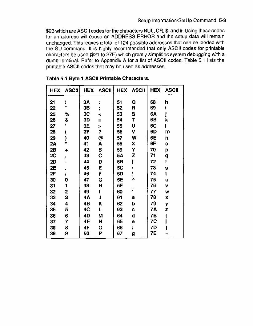
Setup lnformation/SetUp Command 5-3
$23 which are ASCII codes for the characters NUL, CR, $, and #. Using these codes for an address will cause an ADDRESS ERROR and the setup data will remain unchanged. This leaves a totaI of 124 possible addresses that can be loaded with the SU command. It is highly recommended that only ASCII codes for printable characters be used ($21 to $7E) which greatly simplifies system debugging with a dumb terminal. Refer to Appendix A for a list of ASCII codes. Table 5.1 lists the printable ASCII codes that may be used as addresses.
Table 5.1 Byte 1 ASCII Printable Characters.
HEX ASCII
21 ! 22 L 6
25 Yo 26 & 27 ' 28 ( 29 1 2A * 2B + 2c Y
2D - 2E . 2F I 30 0 31 1 32 2 33 3 34 4 3 5 5 36 6 37 7 38 8 39 9
HEX ASCII
3A : 38 ; 3 c < 3D = 3E > 3F ? 40 @ 41 A 42 B 43 c 44 D 45 E 46 F 47 G 48 H 49 I 4A J 4B K 4c L 4D M 4E N 4F 0 50 P
HEX ASCII
51 Q 52 R 53 s 54 T 55 u 56 V 57 w 58 X 59 Y 5A Z 5B 5 c \ 5D 1 5E A
5F - 60 ' 61 a 62 b 63 c 64 d 65 e 66 f 67 g
HEX ASCII
68 h 69 i 6A j 6B k 6C I 6D m 6E n 6F o 70 P 71 9 72 r 73 s 74 t 75 u 76 v 77 w 78 x 79 Y 7A z 7B { 7 c I 7D 1 7E -
5-4 M3000/4000 USERS MANUAL
Byte 2 Byte 2 is used to configure some of the characteristics of the communications channel; linefeeds, parity, and baud rate.
Linefeeds The most significant bit of byte 2 (bit 7) controls linefeed generation by the module. This option can be useful when using the modulewith adumb terminal. All responses from the modules are terminated with a carriage return (ASCII $OD). Most terminals will generate a automatic linefeed when a carriage return is detected. However, for terminals that do not have this capability, the modules can generate the linefeed if desired. By setting bit 7 to ‘1 ’the module will send a linefeed (ASCII $OA) before and after each response. If bit 7 is cleared (0), no linefeeds are transmitted.
When using the ‘#I command prompt, the linefeed characters are not included in the ch ecksu rn calculation.
Parity Bits 5 and 6 select the parity to be used by the module. Bit 5 turns the parity on and off. If bit 5 is ‘0l3 the panty of the command string is ignored and the parity bit of characters transmitted by the module is set to ‘1’.
If bit 5 is ‘ l ’ , the parity of command strings is checked and the parity of characters output by the module is calculated as specified by bit 6 .
If bit 6 is ‘O’, parity is even; if bit 6 is ‘ A ’ , parity is odd. If a parity error is detected by the module, it will respond with a PARITY ERROR message. This is usually caused by noise on the communications line.
If parity setup values are changed with the SU command, the response to the SU command will be transmitted with the old panty setup. The new parity setup becomes effective immediately after the response message from the SU command.
Baud Rate Bits 0-2 specify the communications baud rate. The baud rate can be setected from eight values between 300 and 38400 baud. Referto Table 5.2 for the desired code.
The baud rate selection is the only setup data that is not implemented directly after an SU command. In order for the baud rate to be actually changed, a module reset must occur. A reset is performed by sending a Remote Reset (FIR) command or powering down. This extra level of write protection is necessary to ensure that communications to the module is not accidently lost. This is very important when changing the baud rate of an RS-232C string.
Let’s run through an example of changing the baud rate. Assume oursample module contains the setup data value of ‘31 0701 80‘. Byte 2 is ‘07’. By referring to the SU

Setup Information/SetUp Command 5-5
command chart we can determine that the module is set for no linefeeds, no panty, and baud rate 300. If we perform the Read Setup command with this module we would get:
Command: $1 RS Response: ‘31 0701 80
Let’s say we wish to change the baud rate to 9600 baud. The code for 9600 baud is ‘01 0 (from Table 5.2). This would change byte 2 to ‘02’. To perform the SU command we must first send a Write Enable command because SU is write protected:
Command: $1 WE Response:
Command: $1 SU31020180 Response: *
This sequence of messages is done in 300 baud because that was the original baud rate of the module. The module remains in 300 baud afterthis sequence. We can use the Read Setup (RS) command to check the setup data:
Command: $1 RS Response: 31020180
Notice that although the module is communicating in 300 baud, the setup data indicates a baud rate of 9600 (byte 2 = ‘02’). To actuallychange the baud rate to 9600, send a Remote Reset (RR) command (RR is write protected):
Command: $1WE Response: * Command: $1 RR Response: *
Up to this point all communications have been sent at 300 baud. The module will not respond to any further communications at 300 baud because it is now running at 9600 baud. At this point the host computer or terminal must be set to 9600 baud to continue ope ration.
If the module does not respond to the new baud rate, most likely the setup data is
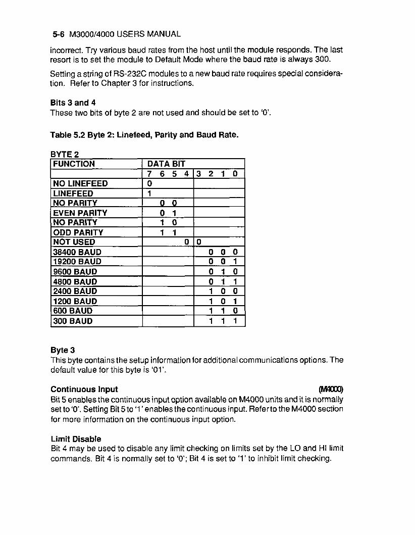
5 6 M3000/4000 USERS MANUAL
incorrect. Try various baud rates from the host until the module responds. The last resort is to set the module to Default Mode where the baud rate is always 300.
Setting a string of RS-232C modules to a new baud rate requires special considera- tion. Refer to Chapter 3 for instructions.
Bits 3 and 4 These two bits of byte 2 are not used and should be set to ‘0’
Table 5.2 Byte 2: Linefeed, Parity and Baud Rate.
BYTE 2
Byte 3 This byte contains the setup information for additional communications options. The default value for this byte is ‘01’.
Continuous Input Wm Bit 5 enables the continuous input option available on M4000 units and it is normaliy set to ‘0’. Setting Bit 510 ‘1 ’ enables the continuous input. Refer to the M4000 section for more information on the continuous input option.
Limit Disable Bit 4 may be used to disable any limit checking on limits set by the LO and HI limit commands. Bit 4 is normally set to ‘0’; Bit 4 is set to ‘1’ to inhibit limit checking.
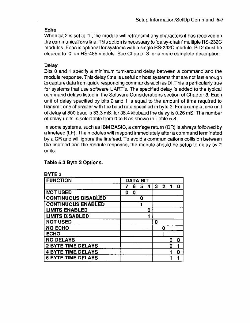
Setup Information/SetUp Command 5-7
Echo When bit 2 is set to ‘1 ’, the module will retransmit any characters it has received on the communications line. This option is necessaryto ‘daisy-chain’ multiple RS-232C modules. Echo is optional for systems with a single RS-232C module. Bit 2 must be cleared to ‘0’ on RS-485 models. See Chapter 3 for a more complete description.
Delay Bits 0 and 1 specify a minimum turn-around delay between a command and the module response. This delay time is useful on host systems that are not fast enough tocapture data from quick-responding commands such as Dt. This is particularly true for systems that use software UART’s. The specified delay is added to the typical command delays listed in the Software Considerations section of Chapter 3. Each unit of delay specified by bits 0 and 1 is equal to the amount of time required to transmit one character with the baud rate specified in byte 2. For example, one unit of delay at 300 baud is 33.3 mS; for 38.4 kilobaud the delay is 0.26 mS. The number of delay units is selectable from 0 to 6 as shown in Table 5.3.
In some systems, such as IBM BASIC, a carriage return (CR) is always followed by a linefeed (LF). The modules will respond immediately after a command terminated by a CR and will ignore the linefeed. To avoid a communications collision between the linefeed and the module response, the module should be setup to delay by 2 units.
Table 5.3 Byte 3 Options.
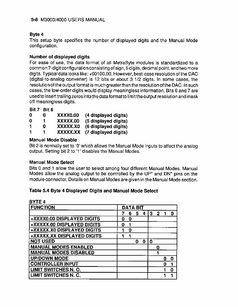
5-8 M3000/4000 USERS MANUAL
Byte 4 This setup byte specifies the number of displayed digits and the Manual Mode configuration.
Nu m ber of displayed digits For ease of use, the data format of all MetraByte modules is standardized to a common 7-digit configuration consisting of sign, 5digits, decimal point, andtwo more digits. Typical data looks like: +00100.00. However, best-case resolution of the DAC (digital-to-analog converter) is 12 bits or about 3 1/2 digits. In some cases, the resolution of the output format is much greaterthan the resolution of the DAC. In such cases, the low-order digits would display meaningless information. Bits 6 and 7 are used to insert trailing zeros into the data format to limit the output resolution and mask off mean i ng less digits.
Bit 7 Bit 6 0 0 XXXXO.00 (4 displayed digits) 0 1 XXXXX.00 (5 displayed digits) 1 0 XXXXX.XO (6 disptayed digits) 1 1 XXXXX.XX (7 displayed digits)
Manual Mode Disable Bit 2 is normally set to ‘0’ which allows the Manual Mode inputs to affect the analog output. Setting bit 2 to ‘1 ’ disables the Manual Modes.
Manual Mode Select Bits 0 and 1 allow the user to select among four different Manual Modes. Manual Modes allow the analog output to be controlled by the UP* and DN* pins on the module connector. Details on Manual Modes are given in the Manual Mode section.
BYTE 4
Table 5.4 Byte 4 Displayed Digits and Manual Mode Select
Setup InformatioiVSetUp Command 5-9
Setup Hints Until you become completely familiar with the Setup command, the best method of changing setups is to change one parameter at a time and to verify that the change has been made correctly. Attempting to modify all the setups at once can often lead to confusion. If you reach’a state of total confusion, the best recourse is to reload the factory setup as shown in Table 5.5 and try again, changing one parameter at a time. Use the Read Setup (RS) command to examine the setup information currently in the module as a basis for creating a new setup. For example:
Assume you have a M3000 unit and you wish to setup the unit to echo so that it may be used in adaisy-chain (See Communications). Read out the current setup with the Read Setup command:
Command: $1 RS Response: 310701 CO
By referring to Table 5.3, we find that the echo is controlled by bit 2 of byte 3. From the RS command we see that byte 3 is currently set to 01. This is the hexadecimal representation of binary 0000 0001. To set echo, bit 2 must be set to ‘1 ’. This results in binary 0000 01 01. The new hexadecimal value of byte 3 is 05. To perform the SU command, use the data read out with the RS command, changing only byte 3:
Command: $iWE (SU is write-protected) Response: *
Command: $fSU310705CO Response: *
Verify that the module is echoing characters and the setup is correct.
By using the RS command and changing one setup parameter at a time, any problems associated with incorrect setups may be identified immediately. Once a satisfactory setup has been developed, recordthe setupvalue and use itto configure similar modules.
If you commit an error in using the Setup command, it is possible to lose communi- cations with the module. In this case, it may be necessary to use the Default Mode to re-establish communications.
Table 5.5 Factory Setups by Model. (All modules from the factory are set for address ‘ l ’ , 300 baud, no parity)
Model Setup Message M312X1 M316X, M412X, M416X 31 0701 80 M313X1 M314X, M317X, M318X 31 0701 40 M413X, M414X, M417X, M418X 31 0701 40 M325X, M425X 31 0701 CO

5-10 M3000/4000 USERS MANUAL
Setup Software S3000 setup software for the IBM PC and compatibles is available to facilitate module setup. Contact factory for details.

Chapter 6 Digital UO Funcions and Manual Mode
MANUAL MODES/DIGITAL INPUTS Each M3000/4000 module has three digital input connections designated as DIO/ DN*, DI1 /UP*, and 012. These inputs have a dual function; they may be used as control inputs which influence the analog output or they may be used as general- purpose digital inputs. The function of the input pins is programmable with the Setup (SU) command.
The inputs are protected to voltages up to +30V and are normally pulled up to the logic “1” condition (see Figure 6.1). Digital inputs can be read with the Digital Input (DI) command. Voltage inputs less than 1 V are read back as ‘0’. Signals greater than 3.5V are read as ‘1 ’.
Switch closures can be read by the digital input by simply connecting the switch between GND terminal and a digital input. Internal pull-ups are used so additional parts are unnecessary.
The pull-ups supply only 0.5mA ;therefore, self-wiping switches designed for low current operation should be used. For other types of switches, it may be necessary to provide extra pull-up current with an external resistor. The resistor should be tied between the switch and +V.
Digital inputs may be used to sense AC voltages by using isofated sensing modules offered by many manufacturers.

6-2 M3000/4000 USERS MANUAL
Figure 6.1 Digital Inputs
MANUAL MODES The M3000/4000 modules may be configured to use the digital inputs to control the analog output. These functions are called Manual Modes. Four different Manual Modes may be specified:
Up/Down Controller Input Limit Switch NO Limit Switch NC
These modes are selected by Bits 0 and 1 of Byte 4 in the Setup data. (See Setup section). Also, the Manual Mode Disable bit (Bit 2, Byte 4) must be cleared to enable Manual Modes.
UP/DOWN Manual Up/Down control is the standard configuration when the module is shipped from the factory. This configuration provides a local operator interface to control the analog output value independent of the host computer. The analog output may be moved up or down by manipulating the UP* and DN* inputs. The control inputs may come from simple switches or may be logicsignals originating from otherequipment. Figure 6.2 shows the simplest connection. With the two switches, four different input combinations are possible:
UP*DN* 0 0 Hold 0 1 Slope Up 1 0 Slope Down 1 1 No Action

Digital I/O Functions and Manual Mode 6-3
D I1 IU P’
D IWDN’
GND
Figure 6.2 Manual Up/Down Control.
Since the digital inputs are pulled up internally, no connection or an open pushbutton generates a logic ‘1’. Shorting the input line to ground or closing the pushbutton generates a logic ‘0’. The ‘*’ in the terminal labels indicate that the inputs are negative true.
If both switchesareopen, a logic 1,l isgeneratedand no manual action is performed.
If the UP* signal input is grounded by closing the UP pushbutton, the analog output will slope up to + Full Scale. A smooth slope in the output is generated by incrernenting the DAC approximately 1000 times a second. If only the DN* input is grounded, the analog output will slope towards - Full Scale. The analog output will stop moving when the switches are released.
The slope rate on M3000 modules is fixed and cannot be changed. The manual slope on M3000 units is scaled so that a full-scale output change requires 5 seconds to complete. The manual slope rate on M4000 units may be programmedto any desired value with the Manual Slope (MS) command.
The Manual Modes have priority over host-generated output commands. If either or both ofthe UP* and DN* inputs is held low, an Analog Output (AO) or Hex output (HX) command generated by the host will result in a MANUAL MODE error message and the host command is aborted. This brings us to the fourth switch combination, when both input switchesare on. If both UP* and DN* signalsare held at Iogic‘O’, the analog output will hold its present value. Any attempts by the host computer to change the output will result in a MANUAL MODE error.
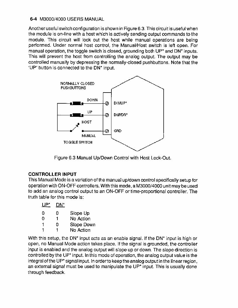
6-4 M3000/4000 USERS MANUAL
Another useful switch configuration isshown in Figure 6.3. This circuit is useful when the module is on-line with a host which is actively sending output commands to the module. This circuit will lock out the host while manual operations are being performed. Under normal host control, the ManuaVHost switch is left open. f o r manual operation, the toggle switch is closed, grounding both UP* and DN* inputs. This will prevent the host from controlling the analog output. The output may be controlled manually by depressing the normally-closed pushbuttons. Note that the 'UP' button is connected to the DN* input.
NORM4LLY CLOSED PUSHBUTrONS
M N U A L
TOGGLE SWITCH
Figure 6.3 Manual Up/Down Control with Host Lock-Out.
CONTROLLER INPUT This Manual Mode is a variation of the manual up/down control specifically setup for operation with ON-OFF controllers. With this mode, a M3000/4000 unit may be used to add an analog control output to an ON-OFF or time-proportional controller. The truth table for this mode is: - - UP* DN*
0 0 Slope Up 0 1 No Action 1 0 Slope Down 1 1 No Action
With this setup, the DN' input acts as an enable signal. If the DN* input is high or open, no Manual Mode action takes place. If the signal is grounded, the controller input is enabled and the analog output will slope up or down. The slope direction is controlled by the UP* input. In this mode of operation, the analog output value is the integral of the UP* signal input. In orderto keep the analog output in the linear region, an external signal must be used to manipulate the UP* input. This is usually done through feedback.
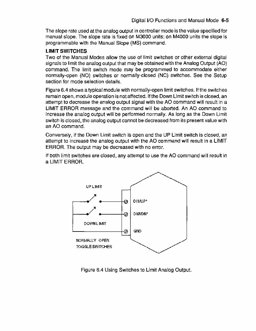
Digital I/O Functions and Manual Mode 6-5
The slope rate used at the analog output in controller mode is the value specified for manual slope. The slope rate is fixed on M3000 units; on M4000 units the slope is programmable with the Manual Slope (MS) command.
LIMIT SWITCHES Two of the Manual Modes allow the use of limit switches or other external digital signals to limit the analog output that may be obtained with the Analog Output (AO) command. The limit switch mode may be programmed to accommodate either normally-open (NO) switches or normally-closed (NC) switches. See the Setup section for mode selection details.
Figure 6.4 shows a typical module with normally-open limit switches. If the switches remain open, module operation is not affected. If the Down Limit switch is closed, an attempt to decrease the analog output signal with the A 0 command will result in a LIMIT ERROR message and the command will be aborted. An A 0 command to increase the analog output will be performed normally. As long as the Down Limit switch is closed, the analog output cannot be decreased from its present value with an A 0 command.
Conversely, if the Down Limit switch is open and the UP Limit switch is closed, an attempt to increase the analog output with the A 0 command will result in a LIMIT ERROR. The output may be decreased with no error.
If both limit switches are closed, any attempt to use the A 0 command will result in a LIMIT ERROR.
4 4 - 4 4 I=;a DOWN L IMlT S4l
DOWN L IMlT I 1 D IllU P+
DIWDN'
GND
NQRM4LLY OPEN TOGGLE SWITCHES
Figure 6.4 Using Switches to Limit Analog Output.
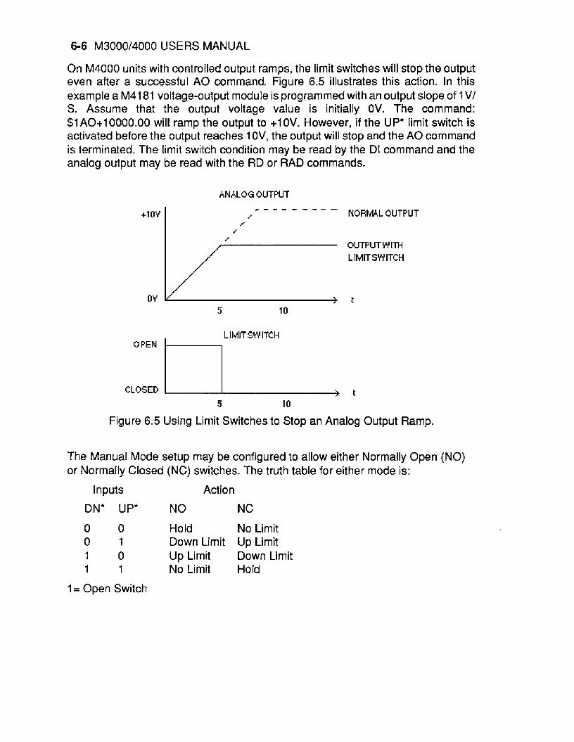
6-6 M3000/4000 USERS MANUAL
+1 OY
On M4000 units with controlled output ramps, the limit switches will stop the output even after a successful A 0 command. Figure 6.5 illustrates this action. In this example a M4181 voltage-output module is programmed with an output slope of 1 V/ S. Assume that the output voltage value is initially OV. The command: $1A0+10000.00 will ramp the output to +1OV. However, if the UP* limit switch is activated before the output reaches 1 OV, the output will stop and the A 0 command is terminated. The limit switch condition may be read by the DI command and the analog output may be read with the RD or RAD commands.
NORMAL OUTPUT r - - - l - - - -
/ /
/ a-
LlMlTSW ITCH
CLOSED OPEN 1 5 10 t
Figure 6.5 Using Limit Switches to Stop an Analog Output Ramp.
The Manual Mode setup may be configured to allow either Normally Open (NO) or Normatly Closed (NC) switches. The truth table for either mode is:
Inputs Action
DN* UP* NO NC
0 0 Hold No Limit 0 1 Down Limit Up Limit 1 0 Up Limit Down Limit 1 1 No Limit Hold
1 = Open Switch

Chapter 7 Power Supply
M3000/4000 modules may be powered with an unregulated +10 to +30Vdc supply. Power-supply ripple must be limited to 5V peak-to-peak, and the instantaneous ripple voltage must be maintained between the 10 and 30 volt limits at all times. All power supply specifications are referred to the module connector; the effects of line voltage drops must be considered when the module is powered remotely.
All M3000/4000 modules employ an on-board switching regulator to maintain good efficiency over the 10 to 30 volt input range; therefore the actual current draw is inversely proportional to the line voltage. M3000/4000 voltage output modules consume a maximum of 0.75 watts and M3Q00/4000 current output models consume 1 .O watts maximum. The power consumption figures should be used in determining the power supply current requirement. For example, assume a 24 volt power supply will be used to power four voltage output modules. The total power requirement is 4 X 0.75 = 3 watts. The power supply must be able to provide 3 + 24 = 0.1 25 amps.
In somecases, asmall numberof modules may be operated by"stealing"powerfrom a host computer or terminal. Many computers provide a +15 volt output on the RS- 232C D25 connector.
Small systems may be powered by using wall-mounted calculator-type modular power supplies. These units are inexpensive and may be obtained from many retail elect ro n ics outlets.
For best reliability, modules operated on long communications lines (9500 feet) should be powered locally using small calculator-type power units. This eliminates the voltage drops on the Ground lead which may interfere with communications signals. In this case the V+ terminal is connected only to the local power supply. The Ground terminal must be connected back to the host to provide a ground return for the communications loop. All M3000/4000 modules are protected against power supply reversals.

Chapter 8 Troubleshooting
No module response. Assuming that the module is in a system, complete the following steps before removing it from the system. These steps will check the obvious things before removing.
1. Using a voltmeter, measure the power supply voltage at the module +Vs and Ground terminals to ensure that the power supplied is between +10 and +30Vdc.
2. Check to see that the communications lines are connected properly and that there are no breaks in the lines.
3. If you are using the RS-232C to RS-485 converter, make sure the baud rate switch is set to the correct position.
If the above steps do not correct the problem, remove the module from the system and return to the bench. Complete the following steps.
1. Connect a working power supply (between +10 and +30Vdc) to the Vs and Ground terminals on the module.
2. Connect the module to a dumb terminal as in the Quick Hook Up procedure. Your terminal should be set to 300 baud rate and no parity. Also if you are u s i n g the RS-485 converter, make sure its baud rate is set to 300 baud.
3. Connect a jumper wire from the Ground terminal to the Default* terminal.
4. Turn the power supply on, type $1 RD on the terminal and press the Return key.
If the module still does not respond, call the factory for assistance. If the module responds, send a $1 RS command to see if the information in the module's setup message is correct.
1. Check that the baud rate is correct.
2. If daisy-chaining RS-232C modules, be sure that the echo bit is set to 1.
3. ff using byte time delay make sure that the proper delay is set. The above procedure basically makes sure that the module and the system are speaking the same language. Reinstall module in the system and try again.
Chapter 9 Cali bration
M3000/4000 units feature state-of-the art digital trimming techniques to eliminate the need for calibration pots or other hardware trims. Calibration is performed with trim commands through the communications port. The on-board microprocessor is used to calculate calibration constants which are then stored in the nonvolatile EEPROM. Fieldcalibration of the units may be performed without the need to physically access the device.
Digital calibration is made possible by reserving a small portion of the DAC scale for trim purposes. The DAC hardware is capable of producing outputs in excess of the full scale range normally accessed by the Analog Output (AO) command. This may be demonstrated by using the Hex Output (HX) command, which controls the DAC directly without trims. For example, a M3181 module has a nominal output of 0 to IOV. The absolute maximum output of the DAC may be obtained with the HX corn m an d :
Command: $1 HXOFFF Response:
A measurement of the output signal would typically read about +10.2 volts. This shows that 0.2 volts is the excess DAC range available fortrimming. Typically about 2% of the DAC range is reserved for trim purposes.
The only equipment necessary for calibration is a suitable voltmeter or ammeter (0.02% accurate) to monitor the output signal and a terminal or computer to communicate to the device.
Calibration is performed by comparing the ideal desired output to the actual measured output. The ideal output is set by using the Analog Output (AO) command. After the actual output value is measured with a calibrated meter, the actual value is communicated to the module with the Trim MiNimum (TMN) or Trim Maximum (TMX) commands. The TMN command trims the - full scale output; TMX trims +full scale. After receiving a TMN or TMX command, the module compares the A 0 data to the actual output value and computes a new calibration factor to reduce the error to zero.
The actual data specified by the TMN and TMX command must be presented in standard MetraByte format, in units of millivolts or rnilliamps:

9-2 M3000/4000 USERS MANUAL
$1 TMX+10012.00 (10.01 2v)
$1 TMN-04990.00 (-4.99V)
$1 TMX+00020.05 (20.05mA)
$1 TMN+00000.02 (+.02mA)
Trim resolution is 1 LSB of the DAC which is full scale + 4096.
Calibration Procedure-Voltage units 1) Connect voltmeter to analog output
2) Set the output to -full scale with Analog Output (AO) command.
3) Measure the output voltage.
4) Report the actual output value to the module with the Trim MiNimum (TMN) command. The module will adjust the output to a new value.
5) Check the output value with the meter. If the output is not within 1 LSB, repeat step 4.
6) Set the output to + full scale with the Analog Output (AO) command.
7) Measure the output voltage.
8) Report the actual output voltage to the module with the Trim Maximum (TMX) command. The module will adjust the output value.
9> Check the output value with the meter. If the output is not within 1 LSB, repeat step 8.
To further illustrate the calibration procedure, here is a typical sequence used to calibration a M3181 which has an output of 0 to 1 OV:
Set the output to - full scale: Command: $1 A 0 +OOOOO.OO Response: t
Measure the output voltage. Inthiscase,the measuredoutput is -1 2 millivolts. Report the actual value to the module with the TMN command:
Command: $I WE Response: Command: $1 TMN-00012.00 Response: *
Measure the output value with the meter. The output measures +1 mV, which is within 1 LSB (2.5mV).
Now set the output to + full scale:
Command: $1 A0+10000.00 Response:

Calibration 9-3
The measured output is +10.123V. Report the measured output to the module with the Trim Maximum (TMX) command:
Command: $1 WE Response:
Command: $lTMX+lOf23.00 Response:
The output now measures +1 O.O05V, which is still not within specification. Repeat the TMX command with the new value:
Command: $I WE Response:
Command: $1 TMX+10005.O0 Response: *
The output now measures 9.999V, which is within 1 LSB (2.5mV).
Current Output Calibration Modules with current outputs are trimmed in exactly the same manner as voltage outputs with one exception. Since the current outputs are unipolar and cannot sink current, errors will result if an attempt is made to calibrate the - full scale output at OmA. On 0-20mA units, - full scale trim should be performed at some small positive value such as 0.5mA. This is done by simply using the A 0 command to output the desired trim point:
Command: $1 A0+00000.50(0.5mA) Response: *
Assume that in this case the actual output is measured to be +0.63mA. Use the TMN command to report the actual output to the module:
Command: $1 WE Response:
Command: $1 TMN+00000.63 (actuakO.63mA) Response:
*
*
The microprocessor will calculate a trim value to force the output to the ideal output of 0.5mA.
M4000 CALIBRATION M4000 modules offer the ability to re-scale the input data to any desired engineering units. This may cause problems in calibration since it may be difficult to correlate the input scaling to the output signals. In thiscase it may be easierto re-scale the M4000 to standard voltage and current ranges that may be compared directly with measured output values. Calibration is then performed with the same procedure as described above. After calibration, the module may be re-scaled back to any desired engineer- ing units with the MN and MX commands.

9-4 M3000/4000 USERS MANUAL
Analog Readback Calibration The analog-to-digital converter (ADC) used for readback is trimmed independently of the DAC. The trim commands used to calibrate the ADC are Trim Readback MiNimum (TRN) and Trim Readback Maximum (TRX).
Unipolar Ouput: To Trim the ADC, be sure the DAC output has been calibrated. Set the output to - full scale with the Analog Output (AO) command. Then perform the Trim Readback MiNimum command:
Command: $1 WE (TRN is write protected) Response:
Command: $1 TRN Response:
*
The microprocessor will calculate calibration values to fix that point on the ADC scale. The calibration factors are automatically stored in EEPROM.
Now set the output to + full scale with the Analog Output (AO) command. Perform the Trim Readback Maximum command:
Command: $1 WE (TRX is write protected) Response: *
Command: $1 TRX Response: *
This command fixes the maximum point on the ADC scale and stores the data in EEPROM.
For proper ADC calibration, the analog output must be set exactly to the -full scale and +full scale values before using the TRN and TRX commands. If these valuesare unknown, they may be read back using the RMN and RMX commands.
Bipolar Ouput: To Trim the ADC, be sure the DAC output has been calibrated. Read the -full scale value by using the Read MiNimum (RMN) command:
Command: $1 RMN Response: *10000.00 (typical data)
Record the -full scale data for later use.
Rescale the -full scale data to ‘0’ using the MiNimum (MN) command:
Command: $1 WE Response: *
Command: $1 MN+00000.00 Response: *
Set the analog output data to ‘0’:
Command: $1 A0+00000.00 Response : *
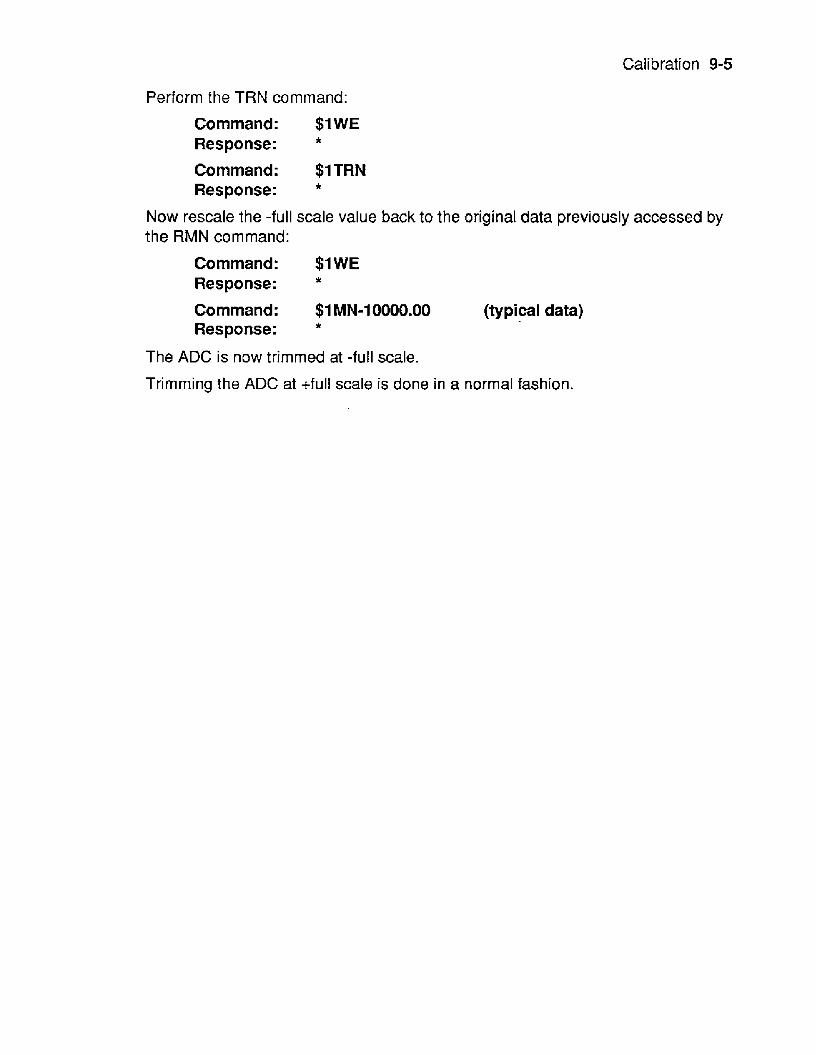
Calibration 9-5
Perform the TRN command:
Command: $1 WE
Command: $1TRN
Response: *
Response: *
Now rescale the -full scale value back to the original data previously accessed by the RMN command:
Command: $1 WE
Command: $1 MN-10000.00 (typical data) Response: t
Response: *
The ADC is now trimmed at -full scale.
Trimming the ADC at +full scale is done in a normal fashion.

Chapter 10 M4000 Features
The M4000 series of computer-to-analog output modules contain many intelligent enhancements not found in the M3000. The M4000 accepts all of the M3000 commands and contains several additional commands which take full advantage of the computational power of the on-board microprocessor. These additional features are :
Programmable output slew rates Programmable data scaling Programmable start-up values Watchdog timer True analog readback Continuous Input
Slope Controt The operation of most digital to analog converters (including the M3000) provides only for a step function when a new output value is desired. That is, the analog output change is instantaneous subject only to the settling time of the device. In many applications this characteristic is undesirable and a gradual controlled output slew rate is more appropriate. In a typical system where controlled output rates are desired, precious host computer time must be used to continually monitor and step the digital to analog converter (DAC) until the desired output is obtained.
The M4000 allows the system designer to obtain controlled output slew rates automatically without host computer intervention. Programmable output slope rates may be specified bythe userand stored in nonvolatile memory. If acornmand isgiven to the M4000 to change the output value, the output will automatically slope to the new value at the specified rate. The slope value is nonvolatile and will be restored each time the module is powered up. The slope rate is specified with write-protected slope commands in units of volts per second on voltage output models and milliamps per second on current models. Slopes may be specified from a range of +99999.99 (step output) down to +00000.01 volts or mA per second in .01 increments. A slope of .01 rnNsecond requires more than 33 minutes to perform an output change of 20mA!
The microprocessor in the M4000 controls the output slew rate by updating the DAC of a rate of 1000 conversions per second at precise 1 ms. intervals. Slope data is
10-2 M3000/4000 USERS MANUAL
represented in the microprocessor with high-resolution floating point numbers. Before each D-to-A conversion the slope increment is added to the present output value. The new output data is then rounded off to the nearest value that can be represented by the 12-bit D-to-A converter and a new output is obtained. In this manner the DAC is smoothly stepped until the final output value is reached as specified by the Analog Output (AO) command. The incremental steps obtainable from the 12-bit converter and the 1 ms conversion rate combine to make the output change appear to be a linear ramp.
Slope Commands The M4000 commands that are directly related to the slope functions are:
RPS Read Present Slope RSL Read Slope SL Slope (RAM) WSL Write Slope (EEPROM)
These commands are described in detail in the commands section (Chapter4) of this manual. However, a few clarifications are necessary to fully understand the function of these commands. In the M4000 , slope data is held in two memory areas: EEPROM and RAM. The RAM (Random Access Memory) contains the working copy of the slope data used by the microprocessor. It is in RAM that the microprocessor obtains the slope value used to modify the output data. RAM data may be read or written any number of times; however, RAM data is lost when the M4000 is powered down.
The EEPROM (Electrically Erasable Programmable Read Only Memory) also stores the slope value. The EEPROM is nonvolatile and is used to store the slope value (as well as other data) when power to the module is turned off. When power is applied to the unit, or a Remote Reset (RR) command is performed, the slope data is transferred from the EEPROM to RAM where it is used by the microprocessor. The EEPROM data may be read an unlimited number of times; however the EEPROM is limited to 10,000 write cycles, after which data reliability is not guaranteed.
The Write Slope (WSL) command writes the desired slope rate into both EEPROM and RAM. This command will satisfy most applications where the desired slope is fixed and does not change during normal operation.
The Slope (SL) command writes the slope data into RAM only and does not affect data in EEPROM. The St command is used in special situations where it is desirable to change the slope frequently under control of the host computer. By writing the slope data into RAM only, the 10,000 cycle write limit of the EEPROM is circum- vented. For example, a voltage output M4000 may be used to provide the input to a motor speed controller, Under control of the host computer, the motor speed is cycled up and down once every minute. Using the slope Commands, the host computer may specify different rates to accelerate and decelerate the motor. If the Write Slope (WSL) command is used twice a minute to control acceleration and

M4000 Features 10-3
deceleration, the 10,000 cycle write limit of the EEPROM will be exceeded within 4 days of operation. To overcome this limitation, the Slope (SL)command may be used to dynamically change the slew rate. Since the SLcommand writes only to RAM, the slope data may be changed an unlimited number of times.
The Read Present Slope (RPS) command reads the slope datacontained in RAM. This data might not match the data held in EEPROM if the slope has been altered by the SL command. The Read Slope (RSL) command reads the slope data contained in EEPROM. It may differ from the value held in RAM.
Other Commands The M4000 controls the DAC output as a background function; most commands may be performedwithoutaffecting an outputwhich is ramping toanewvalue. Exceptions are :
Analog Output (AO) command. The A 0 command may be performed even if the output has not reached the final value specified by a previous A 0 command. The A 0 command may be performed “on the fly”at any time. The output will simply ramp to the new value specified. In some cases the slope direction may change to reach the new value.
Write Slope (WSL) and Slope (SL) commands. The WSL and SL commands may be performed “on the fly” even if the output is changing. The output will simply ramp to the final value with the new slope specified by the WSL or SL command.
Remote Reset (RR). The RR command will immediately freeze the output to its current condition.
Watchdog Timer (WT). If a watchdog timeout occurs, the timer will take control of the output even if the output is still slewing as the result of an A 0 command. See description of Watchdog Timer below.
Digital Inputs: The digital UP/DN and limit switch inputs have priority over the A 0 command and will affect the outputs if activated. See section on digital inputs.
Status Commands The RD command may be used at any time to read the data being fed to the DAC. This is useful when using slow slew rates to monitor the present output data.
The Digital Input (DI) command may be used as a quick status check to see if the output signal has reached its final value. Refer to DI command in chapter 4.
Manual Slopes The M4000 allows the user fo specify the output slew rate when the output is controlled by the manual UP/DN inputs. The Manual Slope (MS) command is used to write the rate data in EEPROM. The manual slope rate is totally independent of the slew rates used with the computercontrolled output (AOcommand). The manual slope rate may be read back with the Read Manual Slope (RMS) command.
10-4 M3000/4000 USERS MANUAL
INPUT DATA SCALING All M3000 and M4000 modules are factory set with datavalues set in units of millivolts or milliamps. For example, the command
$1 A0+00020.00
sent to a current output module tells the module to output 20mA. This command sent to a voltage output module will tell the output to go to 20mV.
The M4000 allows the user to scale the input data to any desired units. In many applicationsachange in input scaling may makethedataeasierto readandinterpret. For example, a M4000 used to control a valve actuator may be easier to use if the data is scaled with a range of 0-1 00% rather than 4-20mA.
The input scaling may be changed by using the Maximum (MX) and Minimum (MN) commands. These commands are used to assign input data values to correspond with the maximum and minimum output values obtainable from the module.
The MiNimum (MN) command assigns an input data value to the -full scale output of the module. The actual -full scale analog output signal is not affected; the MN command only changes the ASCII data value that represents the -full scale output. For example, a M4141 has a -full scale output of -1 OV. The module is scaled at the factory in units of millivolts so that a data value of -1 0000.00 represents -1 OV. The MN command may be used to change the data value corresponding to -lOV:
Command: $IWE Response:
Command: $1 MN+00000.00 Response:
Command: $1 A0+00000.00 Response: *
Now, the output command:
will produce an output of -1 OV.
The Maximum (MX) command assigns the data value corresponding to +full scale.
Example: A M4181 voltage output module is used to supply the control signal to a motor speed controller. The full scale range of the M4181 is 0 to +1 OV. With this voltage input the motor speed varies from 100 to 3000 RPM. To command the motor to turn at a specified RPM requiressome computation to obtain the correct command data. For instance, to command the motor to run at 1500 RPM requires the command:
Command: $1 A0+04666.00
The data is difficult to read and interpret.
Response: *
M4000 Features 10-5
A solution to this problem is to scale the input data directly in units of RPM.
The -full scale output of OV is assigned the value 100 RPM with the command:
Command: $1 MN+000100.00 Response: *
The +full scale output of +1 OV is assigned the value of 3000 RPM with the Maximum (MX) command:
Command: $1 MX+03000.00 Response:
Once the endpoint values are assigned, all other data values are interpolated linearly. Now to set the motor to 1500 RPM requires the command:
Command: $1A0+01500.00 Response:
The data is much easier to interpret since the scaling is directly in units of RPM. The actual output voltage resulting from this command is +4.666 volts.
Example: A valve actuator accepts a 4-20mA signal: at 4mA the valve is fully closed and at 20mA the valve is fully open. We wish to rescale a M4251 0-20mA module to accept data of 0% open to 100% open.
The Minimum (MN) command assigns an input data value to the - full scale output of the module, which in this case is OmA.
Using the two scaling points (4mA, 0%) and (ZOmA, 100%) and a bit of computation, we find that OmA interpolates to a value of -25%. This value is used in the argument of the MN command:
Command: $1 MN-00025.00 Response: *
The maximum scaling point of 20mA is straight forward and is assigned the input value of 100%:
Command: $1 MX+00100.00 Response: *
The module is now scaled in percentage of valve opening. To set the valve to 50% opening:
Command: $1 A0+00050.00 Response: *
In this case the M4000 module produces an output of 12mA, opening the valve halfway.
If a M4000 module has been rescaled, the readback data obtained from the Read Data (RD) and Read Analog Data (RAD) commands are automatically rescaled to the new units.
10-6 M3000/4000 USERS MANUAL
The HI and LO limitvalues (if used) are not affected by rescaling the M4000, and must be individually reassigned to values appropriate to the new scaling.
The starting value not affected.
Slope rate data is not affected by changes in scaling and are always in units of volts per second or milliamps per second.
The Maximum and MiNimum scaling points may be assigned to any values within the limitations of the standard data format. Negative scalings and inverse scalings are acceptable.
It is important to understand that rescaling only modifies the way datais represented in the module. The output range is not affected. It is not possible for the userto alter the output range or resolution.
In some applications, it may be necessary to adjust the ‘number of displayed digits’ as described in the Setup Chapter. The number of digits should be chosen to allow the full resolution of the DAC (4096 counts) to be represented while suppressing unwanted lower-order digits. The number of digits displayed affects only the RD and RAD commands.
STARTING VALUE When a M4000 module is powered up from a cold start, the analog output is automatically forced to a pre-determined starting value. This value may be specified with the Starting Value (SV) command. This feature is useful for cold-starting systems in a controlled manner. Usually the starting value is specified as a “safe” condition to protect equipment and material from damage.
The Starting Value may be read back with the Read Starting Value (RSV) command.
The SV and RSV commands are detailed in the command section of chapter 4.
WATCHDOG TIMER M4000 units contain a programmable software timer to provide an orderly shutdown of the output signal in the event of host computer or communications failure. The timer is preset using the Watchdog Timer (WT) command to specify a timer interval in minutes. The timer is continually incremented in software. Each time the M4000 module receives a valid command, the timer is cleared to zero and restarted again. If the timer count reaches the preset value, the output will automatically be forced to the starting value (see SVcommand). The output will slew to the starting value using the present output slope rate.
The purpose of the Watchdog Timer is to safeguard against host or communications failure. The Starting Value should be programmed to provide a ‘safe’ output value to minimize damage and disruption to the system under control.
During normal operation, the host system should periodically read the status or update the module to prevent the watchdog from reaching the timeout value. Under these conditions, the watchdog has no effect on the module output. However, if the
M4000 Features 10-7
timer reaches the preset value, the M4000 assumes that the host system or communications channel is inoperative and will force the output to a safe value.
The preset value may be read back with the Read Watchdog Timer (RWT) command.
The WT and RWT commands are detailed in the command section.
ANALOG READBACK The Read Data (RD) command is contained in all M3000 and M4000 units to provide a status report of the output of a module. For a properly functioning and calibrated module,the RDdata returnsaveryaccurate readbackoftheoutput signal. However, the data obtained with the RD command only indicates the digital data that is being transferred from the on-board microprocessor to the DAC. It provides no indication as to whether the analog signal being produced by the DAC is correct. Fault conditions such as shorts on voltage output modules or open circuits on current output models cannot be detected by the RD command.
To provide a true readback of the analog output signal, the M4000 models contain a simple analog to digital converter (ADC) which is totally independent of the DAC. The ADC is tied directly to the analog output signal and provides readback data to the microprocessor. The analog data may be read back with the Read Analog Data (RAD) command. The RAD data provides true analog readback scaled in the same units as provided with the RD command.
The ADC is not intended to be a highly accurate measurement of the output signal. Typical accuracy is about 1 %of full scale (see specifications). However, when used properly,the RADcommandcan greatlyenhance the user’sconfidence level that the analog output is being produced as intended. Output fault conditions from improper wiring or loads can be easily detected. The A DC also provides aform of redundancy to ensure that all the circuits in the M4000 module are working properly.
To utilize the ADC most effectively, the output should be in a steady-state condition. Slewing outputs decrease accuracy. First obtain a status reading with the RD command. This reading gives the data value being fed to the DAC. Now obtain a readback with the RAD command. This data represents the actual analog output signal. The two data readings are scaled identically. Compare the two readings; they should differ by less than 1 % of full scale (refer to specifications). If the error is within specifications, it is a very positive indication that the output is correct. Large errors indicate improper output loading or module failure.
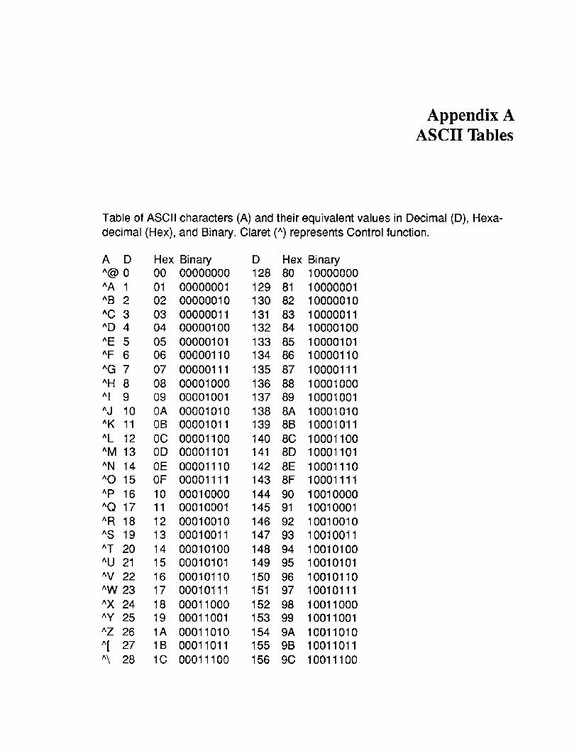
Appendix A ASCII Tables
Table of ASCII characters (A) and their equivalent values in Decimal (D), Hexa- decimal (Hex), and Binary. Claret (") represents Control function.
A D "43 0 "A 1 "B 2 "C 3 "D 4 "E 5 "F 6 "G 7 "H 8 "I 9 "J 10 "K 11 "L 12 "M 13 "N 14 "0 15 "P 16 "Q 17 "R 18 "S 19 "T 20 "U 21 "V 22 "W 23 "X 24 "'t 25 "Z 26 "[ 27 "\ 28
Hex 00 01 02 03 04 05 06 07 08 09 OA OB oc OD OE OF 10 11 12 13 14 15 16 17 18 19 1A 1B 1 c
Binary 00000000 00000001 0000001 0 0000001 1 000001 00 000001 01 000001 10 000001 I 1 00001 000 00001001 0000101 0 0000101 1 00001 100 00001 101 00001 11 0 00001 11 1 0001 0000 0001 0001 0001 001 0 0001001 1 0001 01 00 0001 01 01 0001 01 10 0001 01 1 1 0001 1000 0001 1001 0001 101 0 0001 101 1 0001 1 100
D Hex Binary 128 80 10000000 129 81 10000001 130 82 10000010 131 83 10000011 132 84 10000100 133 85 10000101 134 86 10000110 135 87 10000111 136 88 10001000 137 89 10001001 138 8A 10001010 139 8B 10001011 140 8C 10001100 141 8D 10001101 142 8E 10001110 143 8F 10001111 144 90 10010000 145 91 10010001 146 92 10010010 147 93 10010011 148 94 10010100 149 95 10010101 150 96 10010110 151 97 10010111 152 98 10011000 153 99 10011001 154 9A 10011010 155 9B 10011011 156 9C 10011100
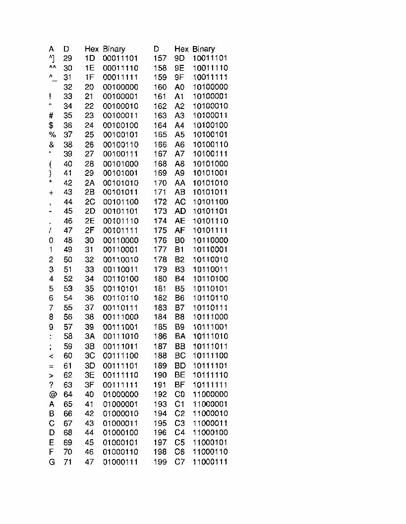
A D "1 29
30 " - 31
32 ! 33 c' 34 # 35 $ 36 % 37 & 38 ' 39 ( 40 1 41 * 42 + 43 I 44 - 45 . 46 I 47 0 48 1 49 2 50 3 51 4 52 5 53 6 54 7 55 8 56 9 57 : 58 ; 59 < 60 = 61 > 62 ? 63 @ 64 A 65 B 66 C 67 D 68 E 69 F 70 G 71
Hex Binary 1D 00011101 1E 00011110 1F 00011111 20 00100000 21 00100001 22 00100010 23 00100011 24 00100100 25 00100101 26 00100110 27 00100111 28 00101000 29 00101001 2A 00101010 2B 00101011 2 c 00101100 2D 00101101 2E 00101110 2F 00f01111 30 00110000 31 00110001 32 00110010 33 00110011 34 00110100 35 00110101 36 00110110 37 00110111 38 00111000 39 00111001 3A 00111010 36 00111011 3c 00111100 3D 00111101 3E 00111110 3F 00111111 40 01000000 41 01000001 42 01000010 43 01000011 44 01000100 45 01000101 46 01000110 47 01000111
D 157 158 159 160 161 162 163 164 165 166 167 168 169 170 171 172 173 174 175 176 177 178 179 180 181 182 183 184 185 186 187 188 189 190 191 192 193 194 195 196 197 198 199
Hex Binary 9D 10011101 9E 10011110 9F 10011111 A0 10100000 A1 10100001 A2 10100010 A3 10100011 A4 10100100 A5 10100101 A6 10100110 A7 10100111 A8 10101000 A9 10101001 AA f0101010 AB 10101011 AC 10101100 AD 10101101 AE 10101110 AF 10101111 BO 10110000 B1 10110001 62 10110010 B3 10110011 B4 10110100 65 10110101 B6 10110110 B7 10110111 88 10111000 69 10111001 BA 10111010 BB 10111011 BC 10111100 8D 10111101 BE 10111110 BF 10711111 co 11000000 c 1 11000001 c 2 11000010 c3 11000011 c 4 11000100 c 5 11000101 C6 11000110 c 7 11000111
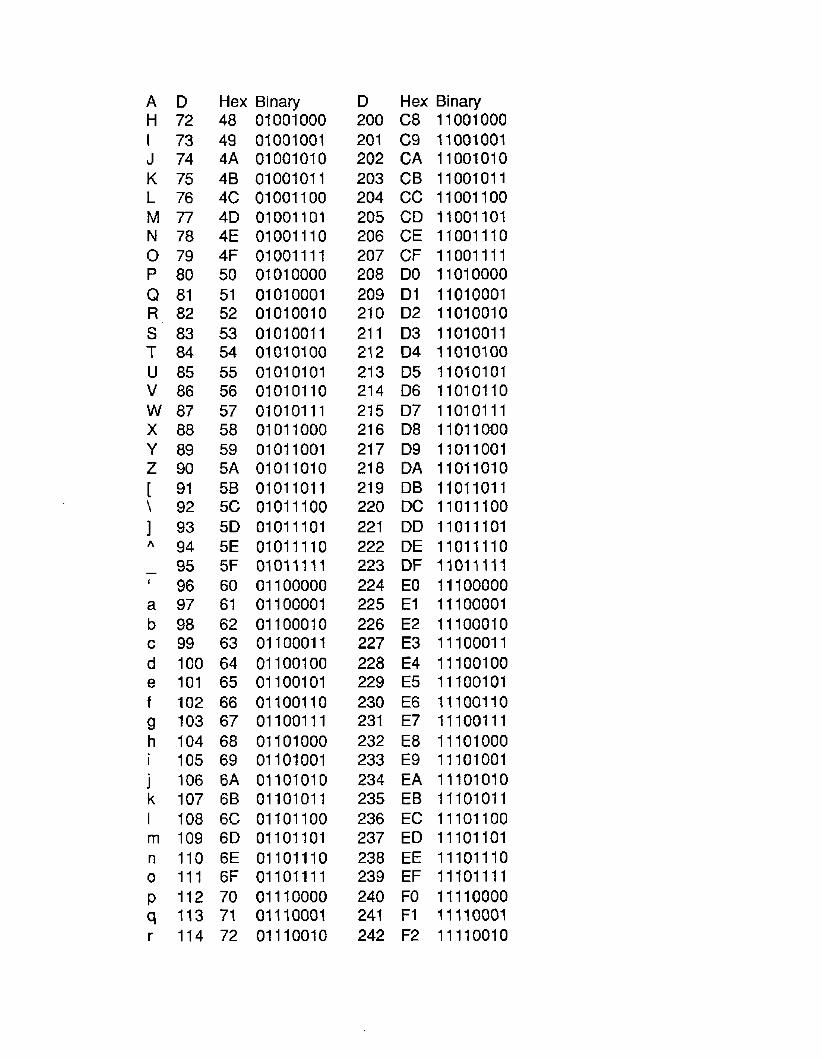
A D H 72 I 73 J 74 K 75 L 76 M 77 N 78 0 79 P 80 Q 81 R 82 S 83 T 84 u 85 V 86 W 87 x a8 Y 89 z 90 [ 91 \ 92 1 93
94 - 95 ' 96 a 97 b 98 c 99 d 100 e 101 f 102 g 103 h 104 i 105 j 106 k 107 I 108 rn 109 n 110 0 111 p 112 q 113
Hex Binary 48 01001000 49 01001001 4A 01001010 4B 01001011 4 c 01001100 4D 01001101 4E 01001110 4F 01001111 50 01010000 51 01010001 52 01010010 53 01010011 54 01010100 55 01010101 56 01010110 57 01010111 58 01011000 59 01011001 5A 01011010 58 01011011 5c 01011100 5 0 01011101 5E 01011110 5F 01011111 60 01100000 61 01100001 62 01100010 63 01100011 64 01100100 65 01100101 66 01100110 67 01100111 68 01101000 69 01101001 6A 01101010 6B 01101011 6C 01101100 6D 01101101 6E 01101110 6F 01101111 70 01110000 71 01110001
r 114 72 01110010
D 200 20 1 202 203 204 205 206 207 208 209 21 0 21 1 21 2 21 3 21 4 21 5 21 6 21 7 21 8 21 9 220 22 1 222 223 224 225 226 227 228 229 230 23 1 232 233 234 235 236 237 238 239 240 241 242
Hex C8 c9 CA CB cc CD CE CF DO D1 D2 03 D4 D5 D6 D7 D8 D9 DA DB DC DD DE DF EO E l E2 E3 E4 €5 E6 E7 €8 E9 EA EB EC ED EE EF FO F1 F2
Binary 1 1001 000 11 001 001 1 1 001 01 0 1 1 001 01 1 11 001 100 11 001 101 11 001 11 0 11 001 11 1 1 101 0000 1 101 0001 11010010 1101001 1 1 101 01 00 11010101 11010110 1 101 01 11 1101 1000 1 101 1 001 11011010 1101 101 1 1101 1100 1101 1101 1101 11 10 1101 11 11 1 1 100000 1 11 00001 11100010 11 10001 1 11 100100 11 100101 1 1 1001 10 1 1 1001 1 1 11 101000 11 101001 11 101010 11 10101 1 11101100 11 101 101 1 1 101 1 10 11 101 11 1 11 110000 11 110001 11 11001 0
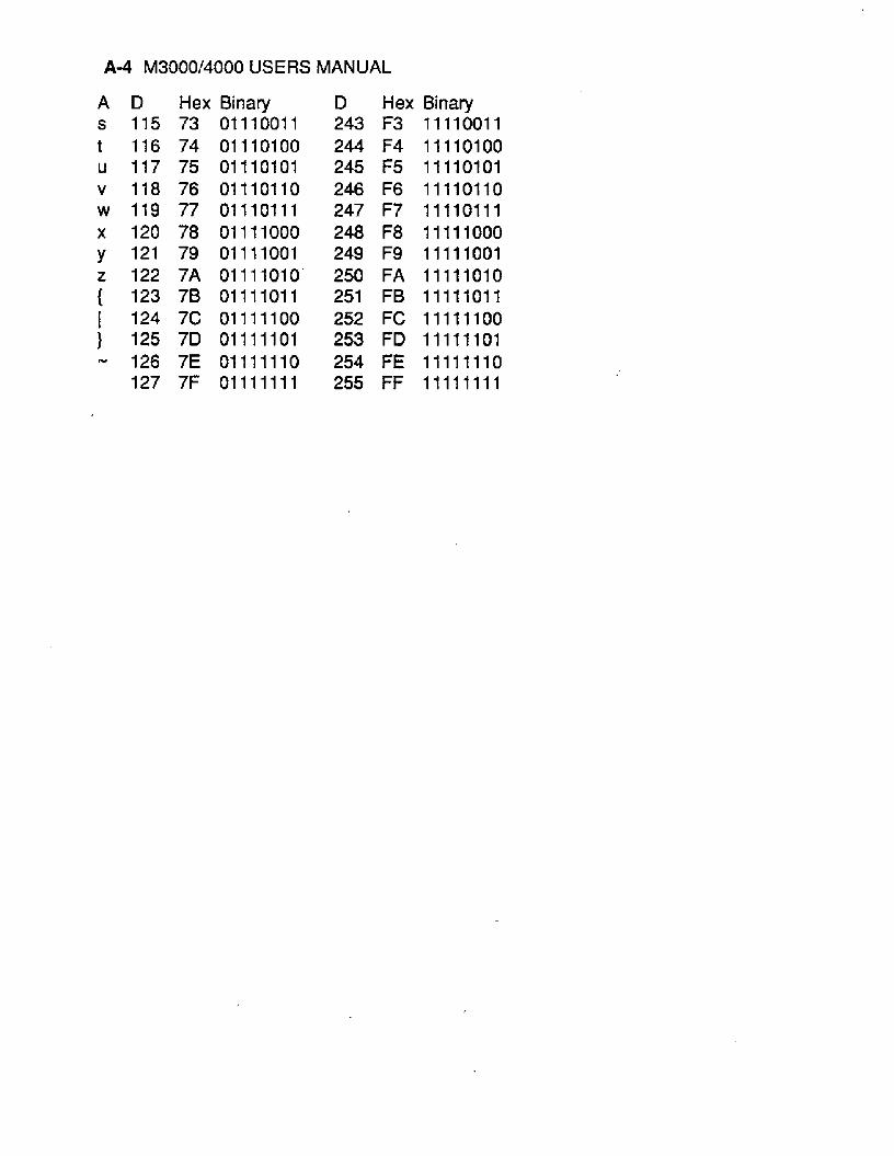
A 4 M3000/4000 USERS MANUAL
A D Hex Binary s 115 73 01110011 t 116 74 01110100 u 117 75 01110101 v 118 76 01110110 w 119 77 01110111 x 120 78 01111000 y 121 79 01111001 z 122 7A 01111010' { 123 78 01111011 I 124 7C 01111100 } 125 7D 01111101 - 126 7E 01111110
127 7F 01111111
D 243 244 245 246 247 248 249 250 251 252 253 254 255
Hex Binary F3 11110011 F4 11110100 F5 11110101 F6 11110110 F7 11110111 F8 11111000 F9 11111001 FA 111t1010 FB 11111011 FC 11111100 FD 11111101 FE 11111110 FF 11111111
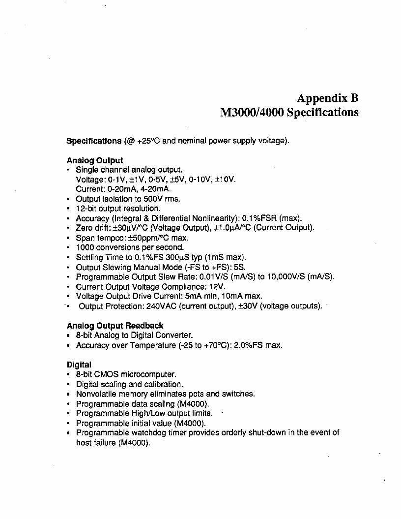
Appendix B M3000/4000 Specifications
Specifications (@ +25% and nominal power supply voltage).
Analog Output Single channel analog output. Voltage: 0-1 V, fl V, 0-5V, EN, 0-1 OV, f l OV. Current: 0-20mA, 4-20mA. Output isolation to 500V rms. 12-bit output resolution. Accuracy (Integral & Differential Nonlinearity): 0.1 %FSR (max). Zero drift: *3OpV/OC (Voltage Output), 21 .OclA/”C (Current Output). Span tempco: *50ppmPC m a . 1000 conversions per second. Settling Time to 0.1 %FS 300pS typ (1 mS max). Output Slewing Manual Mode (-FS to +FS): 5s. Programmable Output Slew Rate: O.OlV/S (mA/S) to lO,OOOV/S (mA/S). Current Output Voltage Compliance: 12V. Voltage Output Drive Current: 5mA min, 1 OmA m a . Output Protection: 24OVAC (current output), k30V (voltage outputs).
Analog Output Readback 8-bit Analog to Digital Converter. Accuracy over Temperature (-25 to +70°C): 2.0%FS max.
Digital 8-bit CMOS microcomputer. Digital scaling and calibration. Nonvolatile memory eliminates pots and switches. Programmable data scaling (M4000). Programmable High/Low output limits. -
Programmable initial value (M4000). Programmable watchdog timer provides orderly shut-down in the event of host failure (M4000)-
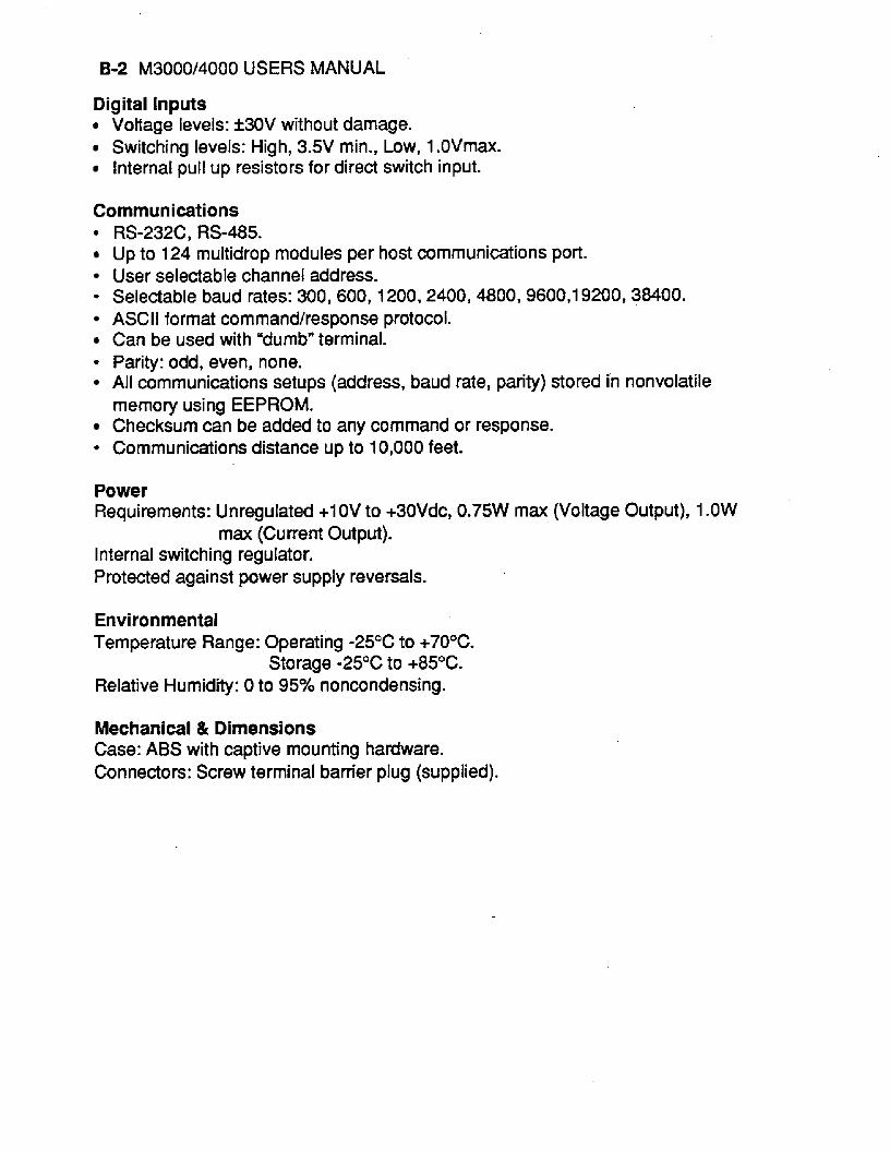
B-2 M3000/4000 USERS MANUAL
Digital inputs Voltage levels: +30V without damage. Switching levels: High, 3.5V min., Low, 1 .OVmax. InternaI pull up resistors for direct switch input.
Communications
Up to 124 multidrop modules per host communications port. User selectable channel address. - Selectable baud rates: 300, 600, 1200,2400, 4800,9600,19200,38400. ASCII format commandhesponse protocol. Can be used with "dumb" terminal.
* Parity: odd, even, none. All communications setups (address, baud rate, parity) stored in nonvolatile memory using EEPROM. Checksum can be added to any command or response.
* Communications distance up to 10,000 feet.
RS-232C, RS-485.
Power Requirements: Unregulated +1 OV to +30Vdc, 0.75W m a (Voltage Output), 1 .OW
Internal switching regulator. Protected against power supply reversals.
max (Current Output).
Environmental Temperature Range: Operating -25OC to +70°C.
Relative Humidity: 0 to 95% noncondensing. Storage -25°C to +85OC.
Mechanical & Dimensions Case: ABS with captive mounting hardware. Connectors: Screw terminal barrier plug (supplied).

Specifications are subject to change without notice.
All Keithley trademarks and trade names are the property of Keithley Instruments, Inc. All othertrademarks and trade names are the property of their respective companies.
Keithley Instruments, Inc. 28775 Aurora Road • Cleveland, Ohio 44139 • 440-248-0400 • Fax: 440-248-61681-888-KEITHLEY (534-8453) • www.keithley.com
Sales Offices: BELGIUM: Bergensesteenweg 709 • B-1600 Sint-Pieters-Leeuw • 02-363 00 40 • Fax: 02/363 00 64 CHINA: Yuan Chen Xin Building, Room 705 • 12 Yumin Road, Dewai, Madian • Beijing 100029 • 8610-6202-2886 • Fax: 8610-6202-2892FINLAND: Tietäjäntie 2 • 02130 Espoo • Phone: 09-54 75 08 10 • Fax: 09-25 10 51 00FRANCE: 3, allée des Garays • 91127 Palaiseau Cédex • 01-64 53 20 20 • Fax: 01-60 11 77 26GERMANY: Landsberger Strasse 65 • 82110 Germering • 089/84 93 07-40 • Fax: 089/84 93 07-34GREAT BRITAIN: Unit 2 Commerce Park, Brunel Road • Theale • Berkshire RG7 4AB • 0118 929 7500 • Fax: 0118 929 7519INDIA: Flat 2B, Willocrissa • 14, Rest House Crescent • Bangalore 560 001 • 91-80-509-1320/21 • Fax: 91-80-509-1322ITALY: Viale San Gimignano, 38 • 20146 Milano • 02-48 39 16 01 • Fax: 02-48 30 22 74JAPAN: New Pier Takeshiba North Tower 13F • 11-1, Kaigan 1-chome • Minato-ku, Tokyo 105-0022 • 81-3-5733-7555 • Fax: 81-3-5733-7556KOREA: 2FL., URI Building • 2-14 Yangjae-Dong • Seocho-Gu, Seoul 137-888 • 82-2-574-7778 • Fax: 82-2-574-7838NETHERLANDS: Postbus 559 • 4200 AN Gorinchem • 0183-635333 • Fax: 0183-630821SWEDEN: c/o Regus Business Centre • Frosundaviks Allé 15, 4tr • 169 70 Solna • 08-509 04 679 • Fax: 08-655 26 10SWITZERLAND: Kriesbachstrasse 4 • 8600 Dübendorf • 01-821 94 44 • Fax: 01-820 30 81TAIWAN: 1FL., 85 Po Ai Street • Hsinchu, Taiwan, R.O.C. • 886-3-572-9077• Fax: 886-3-572-9031
© Copyright 2001 Keithley Instruments, Inc.Printed in the U.S.A.
4/02


