Embed Size (px)
Citation preview

Lecture - 17
DESIGN OF COIL SPRINGS
(2 )
B y
P R O F . M . NAUSHAD ALAM
M E C H A N I C A L E N G I N E E R I N G D E P T .
A . M . U . A L I G A R H
k
MACHINE DESIGN II MEC 3110
1

HELICAL COMPRESSION SPRING DESIGN
2
Terminology
d = wire diameter of spring (mm)
Di = inside diameter of spring coil (mm)
Do = outside diameter of spring coil (mm)
D = mean coil diameter (mm)
C = The spring index
p = Pitch of coils
L f = Free length
L a = Assembled length
L m = Minimum working length
L s = Shut height
p = Lf x ( Nt –-1 )

Helical Compression Spring Design
3
Nomenclature :
A Material constant
C Spring index=D/d
d Wire diameter
D Mean coil diameter
f Natural frequency of the spring
F Force/Load
G Shear Modulus (of Rigidity)
J Polar Moment of Inertia
k Spring rate or spring stiffness
K Stress correction factor
L Length
N Number of coils
T Torsional Moment
U Strain energy
Helix angle
y Deflection
γ Density
τ Shear stress in spring

Design of Compression Coil Springs
4
Design Consideration :
The design of a new spring involves the following considerations:-Space into which the
spring must fit and operate. -Values of working forces and deflections. -Accuracy and
reliability needed
The primary consideration in the design of the coil springs are that the induced
stresses are below the permissible limits while subjected to or exerting the external
force F capable of providing the needed deflection or maintaining the spring rate
desired.

DESIGN OF HELICAL SPRINGS 5
There are three objectives for the design of the helical spring. They are as follows:
(i) It should possess suffi cient strength to withstand the external load.
(ii) It should have the required load-deflection characteristic.
(iii) It should not buckle under the external load.

Factor of Safety 6
The factor of safety in the design of springs is usually 1.5 or less. The use of a relatively low factor of safety is justified on the following grounds:
(i) In most of the applications, springs operate with well defined deflections. Therefore, the forces acting on the spring and corresponding stresses can be precisely calculated.
It is not necessary to take higher factor of safety to account for uncertainty in external forces acting on the spring.
(ii) In case of helical compression springs, an overload will simply close up the gaps between coils without a dangerous increase in deflection and stresses.
(iii) In case of helical extension springs, usually overload stops are provided to prevent excessive deflection and stresses.
… 7
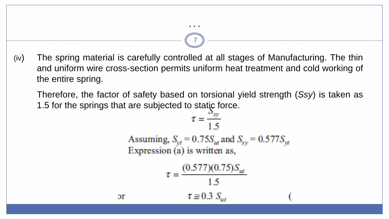
(iv) The spring material is carefully controlled at all stages of Manufacturing. The thin
and uniform wire cross-section permits uniform heat treatment and cold working of
the entire spring.
Therefore, the factor of safety based on torsional yield strength (Ssy) is taken as
1.5 for the springs that are subjected to static force.

… 8
The permissible shear stress is, therefore, 30% of the ultimate tensile strength of the
spring wire.
The Indian Standard 4454–1981 has recommended a much higher value for the
permissible shear stress.
According to this standard,
𝝈 = 𝑺𝒖𝒕
This is due to higher tensile yield strengths exhibited by the spring wires.
In design of helical springs, the permissible shear stress (t) is taken from 30% to
50% of the ultimate tensile strength (Sut).

… 9
The basic procedure for the design of helical spring consists of the following steps:
(i) For the given application, estimate the maximum spring force (P) and the corresponding required deflection (d) of the spring.
In some cases, maximum spring force (P) and stiffness k, which is (P/d), are specified.
(ii) Select a suitable spring material and find out ultimate tensile strength (Sut) from the data.
Calculate the permissible shear stress for the spring wire by following relationship:
t = 0.30 Sut or 0.50 Sut
(iii) Assume a suitable value for the spring index (C).
For industrial applications, the spring index varies from 8 to 10.
A spring index of 8 is considered as a good value. The spring index for springs in valves and clutches is 5. The spring index should never be less than 3.

…. 10

…. 11
(viii) Decide the style of ends for the spring depending upon the configuration of the application.
Determine the number of inactive coils. Adding active and inactive coils, find out the total number of coils (Nt).
(ix) Determine the solid length of the spring by the following relationship:
Solid length = Ntd
(x) Determine the actual deflection of the spring by Equation
(xi) Assume a gap of 0.5 to 2 mm between adjacent coils, when the spring is under the action of maximum load. The total axial gap between coils is given by,
total gap = (Nt – 1) \ gap between two adjacent coils
In some cases, the total axial gap is taken as 15% of the maximum deflection:

…. 12
(xii) Determine the free length of the spring by the following relationship:
free length = solid length + total gap + d
(xiii) Determine the pitch of the coil by the following relationship:
(xiv) Determine the rate of spring by Eq. (10.9).
(xv) Prepare a list of spring specifications.

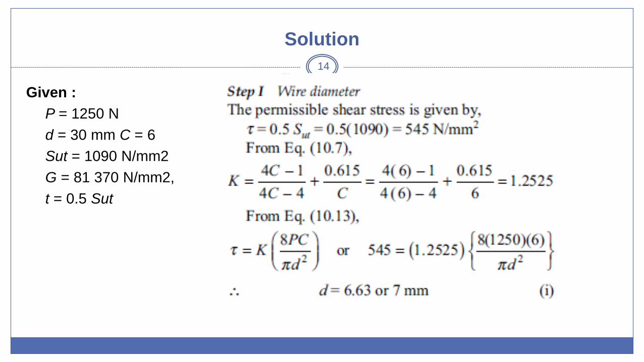
Problem 13
It is required to design a helical compression spring subjected to a maximum force of 1250 N. The deflection of the spring corresponding to the maximum force should be approximately 30 mm. The spring index can be taken as 6. The spring is made of patented and cold-drawn steel wire. The ultimate tensile strength and modulus of rigidity of the spring material are 1090 and 81 370 N/mm2 respectively. The permissible shear stress for the spring wire should be taken as 50% of the ultimate tensile strength. Design the spring and calculate:
(i) wire diameter;
(ii) mean coil diameter;
(iii) number of active coils;
(iv) total number of coils;
(v) free length of the spring; and
(vi) pitch of the coil.
Draw a neat sketch of the spring showing various dimensions.
Solution
14
Given :
P = 1250 N
d = 30 mm C = 6
Sut = 1090 N/mm2
G = 81 370 N/mm2,
t = 0.5 Sut

… 15

…. 16

… 17

DESIGN AGAINST FLUCTUATING LOAD
18
In many applications, the force acting on the spring is not constant but varies in
magnitude with time.
The valve spring of an automotive engine is subjected to millions of stress cycles
during its lifetime.
On the other hand, the springs in linkages and mechanisms are subjected to
comparatively less number of stress cycles.
The springs subjected to fluctuating stresses are designed on the basis of two
criteria—design for infinite life and design for finite life.
Let us consider a spring subjected to an external fluctuating force, which changes its
magnitude from
Pmax. to Pmin. in the load cycle.

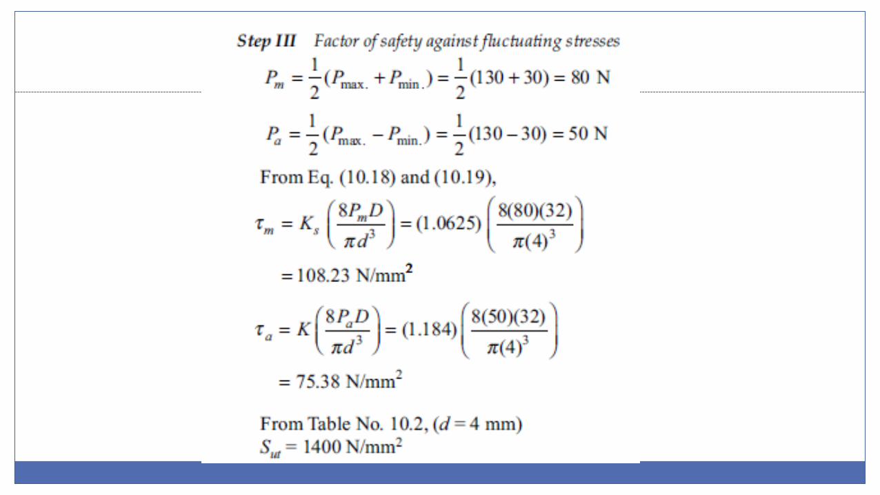
.. 19
The mean force Pm and the force amplitude Pa are given by
The mean stress (tm) is calculated from mean force (Pm) by using shear stress
correction factor (Ks). It is given by

…. 20
Ks is the correction factor for direct shear stress and it is applicable to mean stress only.
For torsional stress amplitude (ta), it is necessary to also consider the effect of stress
concentration due to curvature in addition to direct shear stress. Therefore,
For Patented and cold-drawn steel wires (Grade-1 to 4)

…. 21
For oil-hardened and tempered steel wires (SW) and VW grade),
where Sut is the ultimate tensile strength

…. 22
To consider the effect of the factor of safety, a line DC is constructed from the point D
on the abscissa in such a way that
The line DC is parallel to the line BA.
Any point on the line CD, such as X,
represents a stress situation with the
same factor of safety.

…. 23
Line CD is called the design line because it is used to find out permissible stresses with
a particular factor of safety.
The line GH is called load line. It is drawn
from the point G on the abscissa at a
distance ti from the origin.
The torsional shear stress due to initial
pre-load on the spring (Pi) is ti. The line
GH is constructed in such a way that its
slope q is given by,

…. 24
The point of intersection between design line DC and load line GH is X.
The coordinates of the point X are (tm, ta).

Problem
25
The constructional details of an exhaust valve of a
diesel engine are shown in Fig. 10.22. The
diameter of the valve is 32 mm and the suction
pressure in the cylinder is 0.03 N/mm2. The mass
of the valve is 50 g. The maximum valve lift is 10
mm. The stiffness of the spring for the valve is 10
N/mm. The spring index can be assumed as 8.
The permissible shear stress in the spring wire is
recommended as 30% of the ultimate tensile
strength. Neglecting the effect of inertia forces,
design the spring for static considerations and
determine the factor of safety against fluctuating
stresses.

Solution 26
Given
k = 10 N/mm
C = 8
t = 0.3 Sut
Step I Maximum spring force
The spring is subjected to fluctuating stresses. Therefore, oil-hardened and tempered valve spring wire of Grade-VW is selected for this application.
Initially, the spring is fitted with a pre-load. The initial pre-load should be sufficient to hold the valve on its seat against the negative pressure inside the cylinder during the suction stroke.
Since the cylinder is vertical, additional pre-load should be provided to account for the weight of the valve.

…. 27
To be on the safer side, the initial pre-load is taken as 30 N.
During the exhaust stroke, the spring is further compressed by 10 mm (valve-lift).
The maximum force acting on the spring is given by
Pmax. = Pmin. + kd = 30 + 10(10) = 130 N

… 28
Step II Design against static load

…. 29
The permissible shear stress is
denoted by td in order to
differentiate it from the induced
stress t. It is given by,

… 30
The design is satisfactory and the wire diameter should be 3 mm.
However, the spring is subjected to fluctuating stresses and to account for these
stresses, the wire diameter is increased to 4 mm.
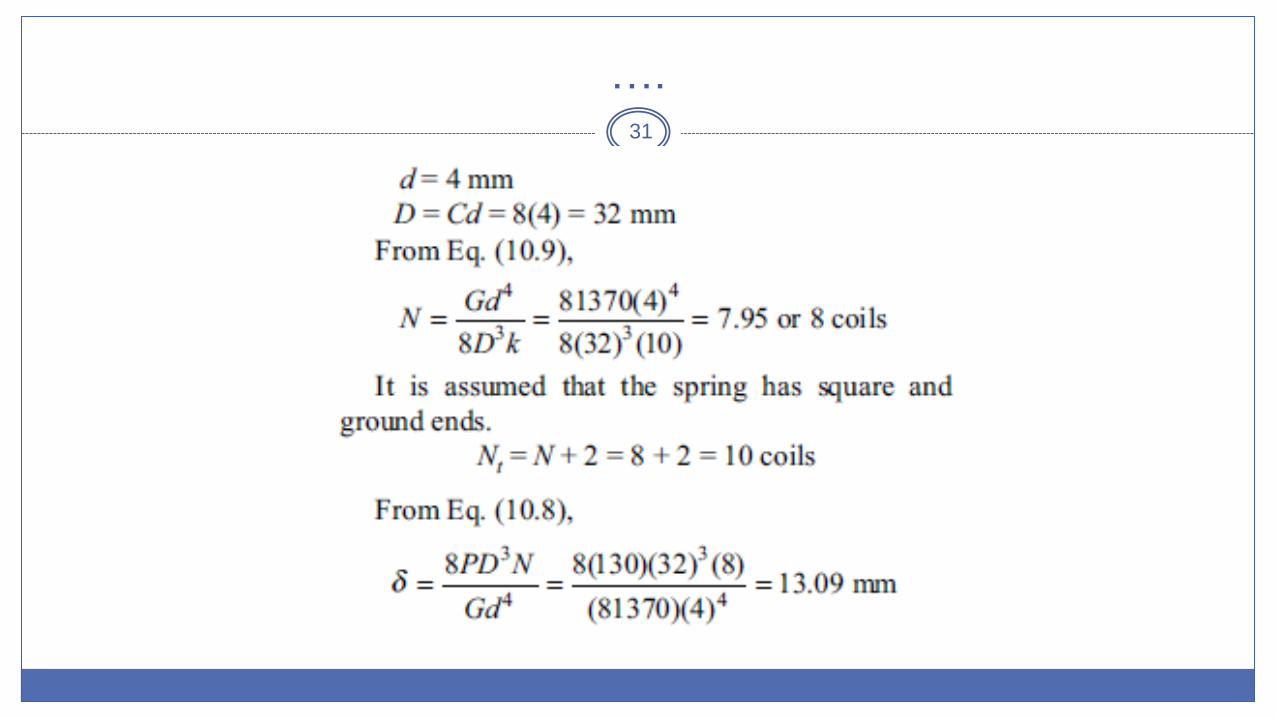
…. 31

… 32
Solid length of spring = Ntd = 10(4) = 40 mm
It is assumed that there will be a gap of 0.5 mm between consecutive coils when the
spring is subjected to the maximum force.
The total number of coils is 10. The total axial gap between the coils will be (10 – 1) \
0.5 = 4.5 mm.
Free length = solid length + total axial gap + d
Free length = 40 + 4.5 + 13.09 = 57.59 or 60 mm
… 33

…. 34
From. Eq. (10.21), the relationships
for oil hardened and tempered steel
wire are as follows:
S¢se = 0.22 Sut = 0.22(1400) = 308
N/mm2
Ssy = 0.45 Sut = 0.45(1400) = 630
N/mm2
From Eq. (10.22),

… 35
Step IV Spring specifications
(i) Material = oil-hardened and tempered steel wire of Grade-VW
(ii) Wire diameter = 4 mm
(iii) Mean coil diameter = 32 mm
(iv) Free length = 60 mm
(v) Total number of coils = 10
(vi) Style of ends = square and ground
…. 36
End of Part II


