Embed Size (px)
Citation preview

www.mrcet.ac.in
A N E W P E D A G O G Y I S E M E R G I N G
DIGITALCLASSROOM
ENVIRONMENT
C. Daksheeswara ReddyAssistant Professor,
Mechanical Engineering

(Source: TASK Training material)
DEPARTMENT OF MECHANICAL ENGINEERING

www.mrcet.ac.in
MACHINE DESIGN-I
(R18A0314 )3 RD YE A R B . T EC H I - S E M , M EC H A N I C A L EN G I N E E R I N G
COURSE OBJECTIVES
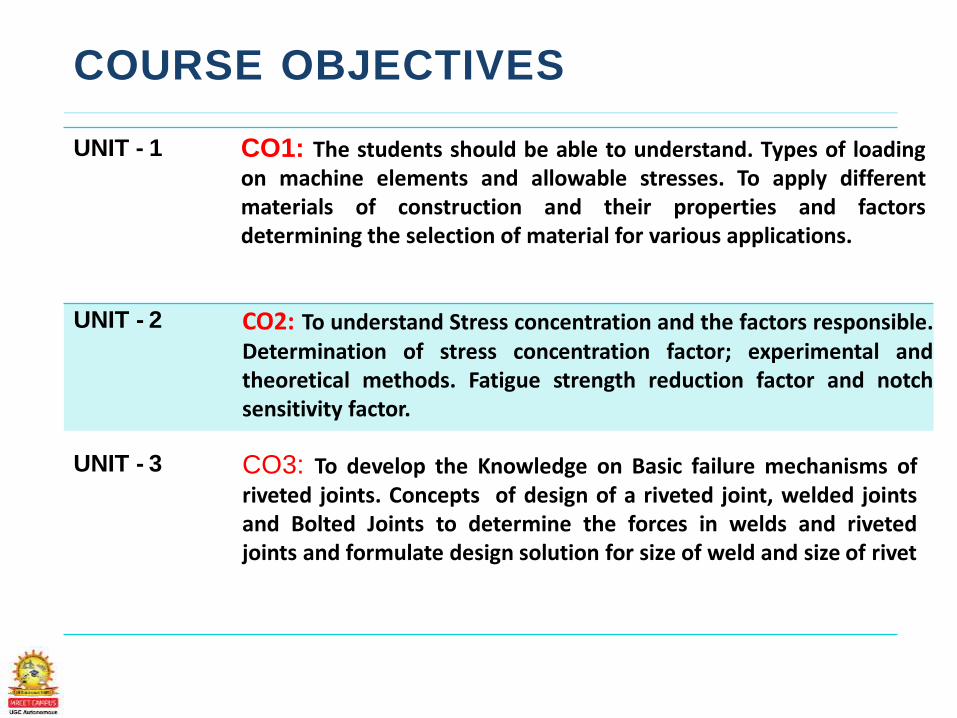
UNIT - 1 CO1: The students should be able to understand. Types of loadingon machine elements and allowable stresses. To apply differentmaterials of construction and their properties and factorsdetermining the selection of material for various applications.
UNIT - 2 CO2: To understand Stress concentration and the factors responsible.Determination of stress concentration factor; experimental andtheoretical methods. Fatigue strength reduction factor and notchsensitivity factor.
UNIT - 3 CO3: To develop the Knowledge on Basic failure mechanisms ofriveted joints. Concepts of design of a riveted joint, welded jointsand Bolted Joints to determine the forces in welds and rivetedjoints and formulate design solution for size of weld and size of rivet
UNIT - 4 CO4: To learn the design Procedure for the different machineelements such as fasteners, couplings, keys, axially loaded joints etc.
CO5: To learn the design Procedure for the different Shaftsunder loading condition, able to know various shaftscoupling.
UNIT - 5
TEXT BOOKS
1. A Textbook of Machine Design by R S
Khurmi and J K Gupta
2. Design of Machine Elements by V.B.Bhandari
3.Machine Design by S.Md.Jalaludeen
4.Design Data Hand book by S.Md.Jalaludeen
UNIT 1CO1: The students should be able to understand. Types of
loading on machine elements and allowable stresses. To apply
different materials of construction and their properties and
factors determining the selection of material for various
applications.
UNIT – I (SYLLABUS)
Introduction
• General Considerations in the Design of Engineering
materials
• Properties of the materials
• Manufacturing Consideration in design
• BIS Codes for Steels
Design for Static Strength
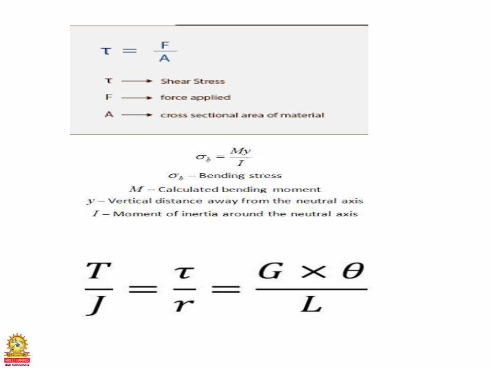
• Simple and Combined stresses
• Torsional ,Bending and Impact stresses
• Various Theories of failure
DEPARTMENT OF MECHANICAL ENGINEERING
• Factor of safety
• Design for strength and Regidity
• Concept of stiffnes in tension , Bending ,Torsion
and combined situations
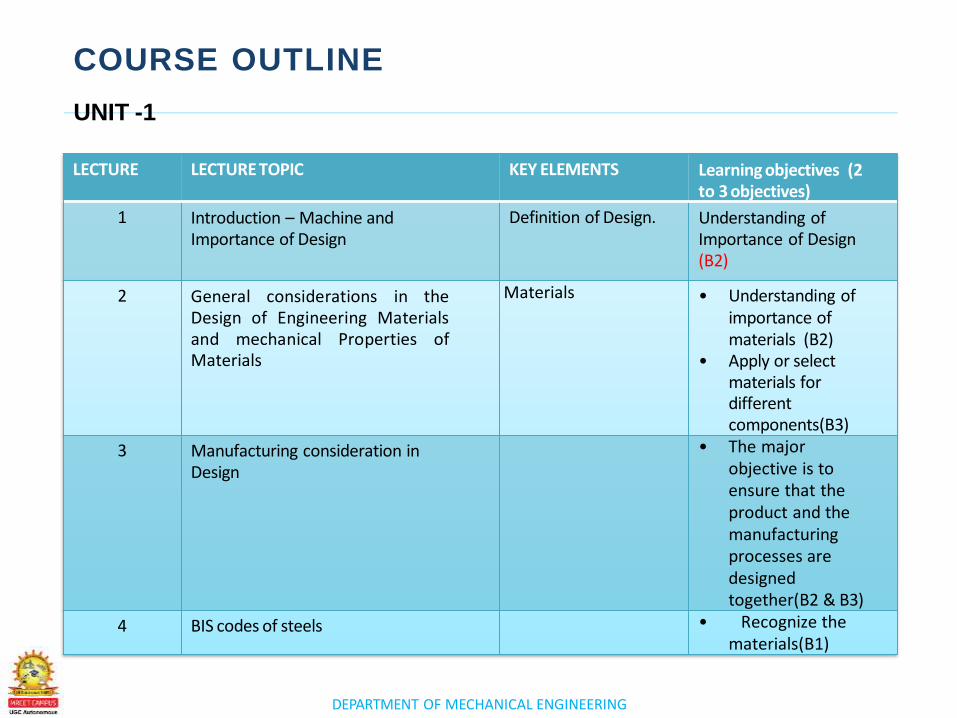
COURSE OUTLINE
LECTURE LECTURE TOPIC KEY ELEMENTS Learning objectives (2 to 3 objectives)
1 Introduction – Machine and Importance of Design
Definition of Design. Understanding ofImportance of Design(B2)
2 General considerations in theDesign of Engineering Materialsand mechanical Properties ofMaterials
Materials • Understanding of importance of materials (B2)
• Apply or select materials for different components(B3)
3 Manufacturing consideration in Design
• The major objective is to ensure that the product and the manufacturing processes are designed together(B2 & B3)
4 BIS codes of steels • Recognize the materials(B1)
UNIT -1
DEPARTMENT OF MECHANICAL ENGINEERING
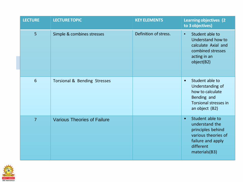
LECTURE LECTURE TOPIC KEY ELEMENTS Learning objectives (2 to 3 objectives)
5 Simple & combines stresses Definition of stress. • Student able to Understand how to calculate Axial and combined stresses acting in an object(B2)
6 Torsional & Bending Stresses • Student able to Understanding of how to calculate Bending and Torsional stresses in an object (B2)
7 Various Theories of Failure • Student able to understand the principles behind various theories of failure and apply different materials(B3)
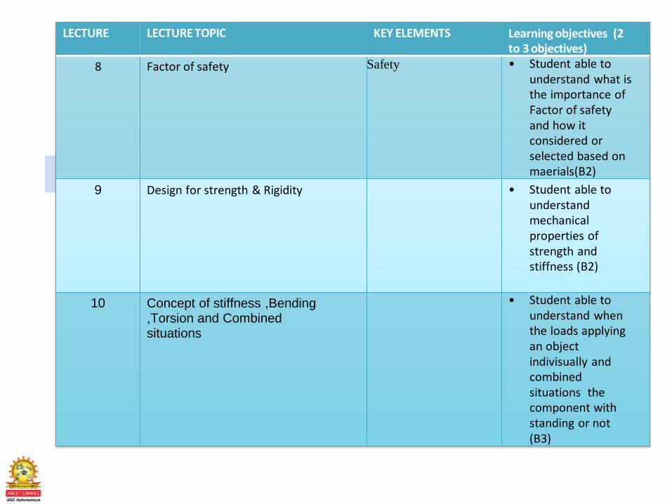
LECTURE LECTURE TOPIC KEY ELEMENTS Learning objectives (2 to 3 objectives)
8 Factor of safety Safety • Student able to understand what is the importance of Factor of safety and how itconsidered or selected based on maerials(B2)
9 Design for strength & Rigidity • Student able to understand mechanical properties of strength and stiffness (B2)
10 Concept of stiffness ,Bending ,Torsion and Combined situations
• Student able to understand when the loads applying an object indivisually and combined situations the component with standing or not (B3)
LECTURE 1Introduction to Machine and Importance of Design
10 – 15
slides
DEPARTMENT OF MECHANICAL ENGINEERING
Basic concept of design in general
Concept of machine design and their types
Factors to be considered in machine design
Design is essentially a decision making process
For every problem, we need to design a solution
Defination :
Design is to formulate a plan to satisfy a particular
need and to create something with a physical reality
(Or)
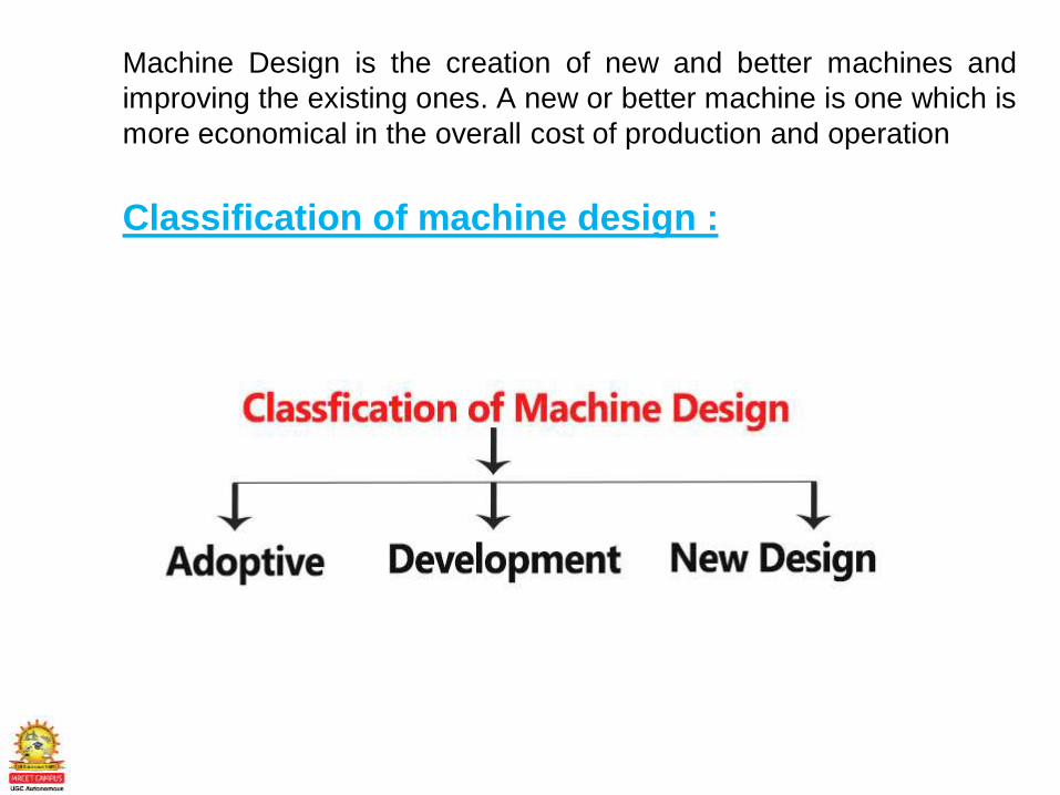
Machine Design is the creation of new and better machines and
improving the existing ones. A new or better machine is one which is
more economical in the overall cost of production and operation
Classification of machine design :

Adoptive Design :
In this design the work on existing product with adopt ofexisting design. These types of design need no specialknowledge or skill.
Development Design:
In development design to modify the existing design into a new idea by adopting material different method.
New Design:
This type of design needs lots of research and technical knowledge.
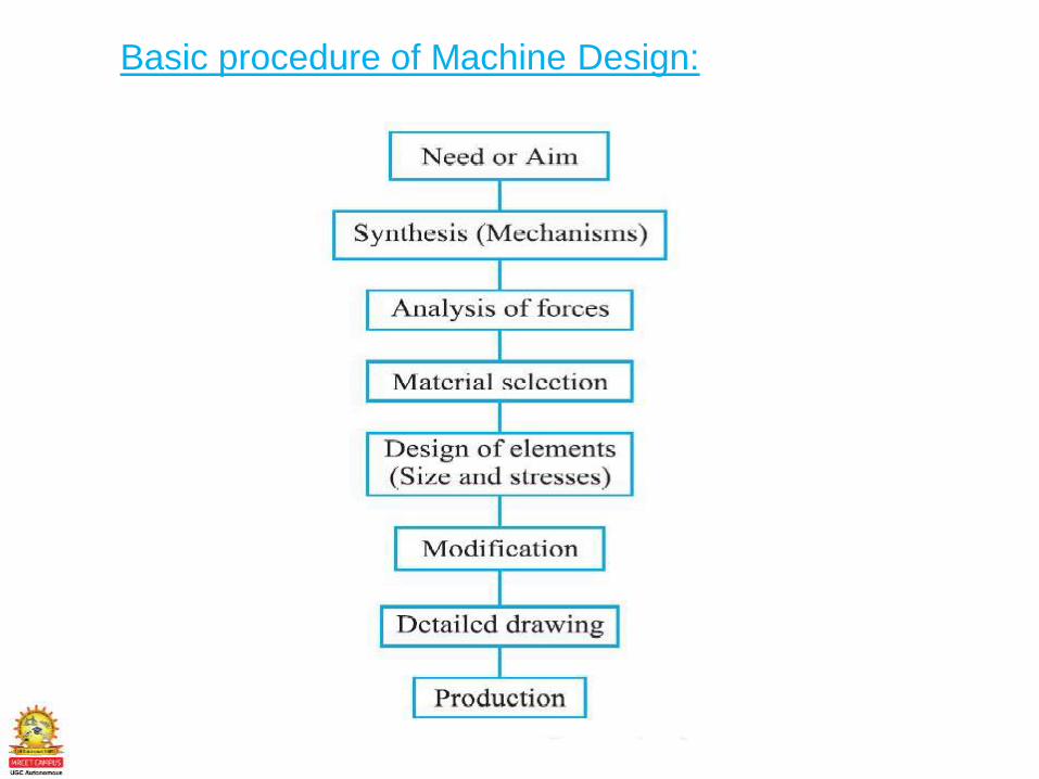
Basic procedure of Machine Design:
Revision Questions
1. What is Machine
2. What is Design
3. What is Adaptive design
4. What is Development Design
5. What is New Design
6. Explain Steps involved in Design
LECTURE 2General considerations in Designing a Machine
Component
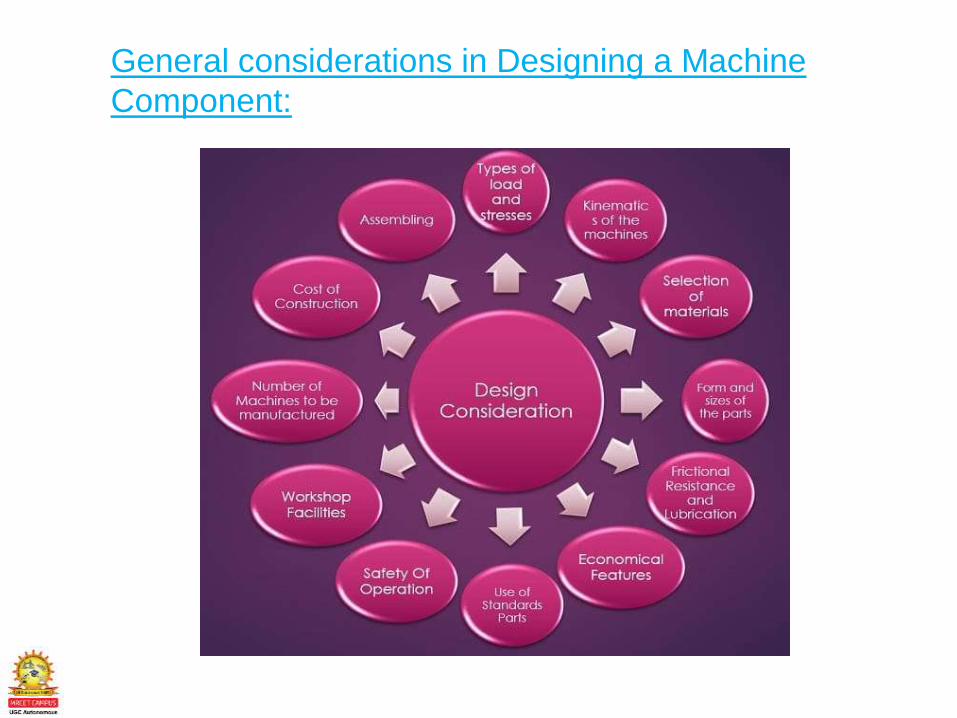
General considerations in Designing a Machine
Component:
Revision Questions
1. What are the general considerations of
Machine design
LECTURE 3Manufacturing Consideration in machine
Design
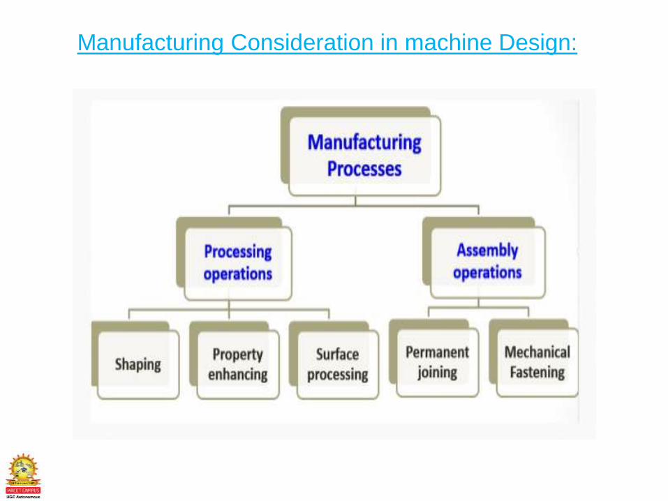
Manufacturing Consideration in machine Design:
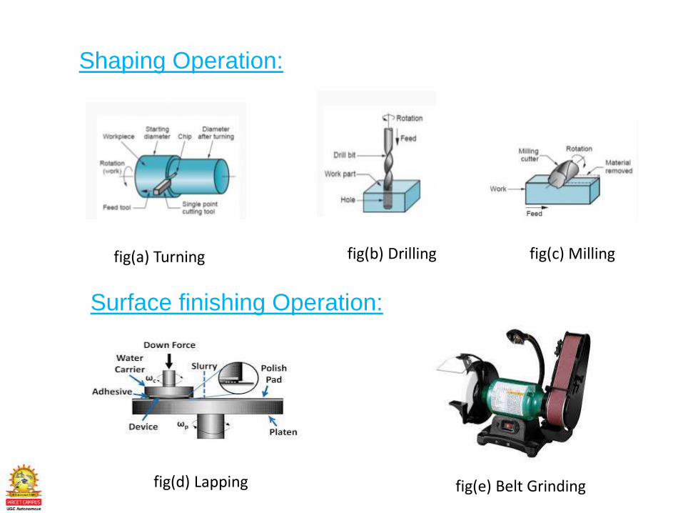
Shaping Operation:
fig(a) Turning fig(b) Drilling fig(c) Milling
Surface finishing Operation:
fig(e) Belt Grinding fig(d) Lapping
Revision Questions
1. What are the manufacturing consideration in
machine design
LECTURE 4BIS Codes for Steel

BIS Codes for Steel:
According’s to Bureau of Indian Standards,
steels can be designated either based on letter
symbols {IS: 1962 (Part I)—1974} or based on
numerals {IS: 1962 (Part II)}. Minimum number of
symbols is recommended to be used in
designating any steel.

LECTURE 5Simple & Combined stresses
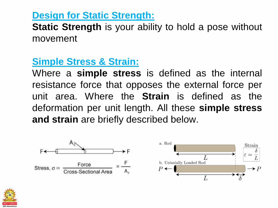
Design for Static Strength:
Static Strength is your ability to hold a pose without
movement
Simple Stress & Strain:
Where a simple stress is defined as the internal
resistance force that opposes the external force per
unit area. Where the Strain is defined as the
deformation per unit length. All these simple stress
and strain are briefly described below.
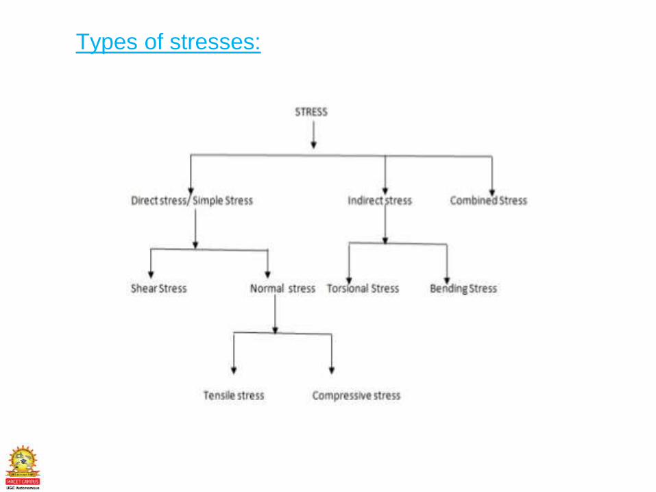
Types of stresses:
LECTURE 6Torsional and Bending Stresses
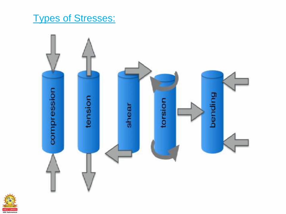
Types of Stresses:
LECTURE 7Various Theories of Failure
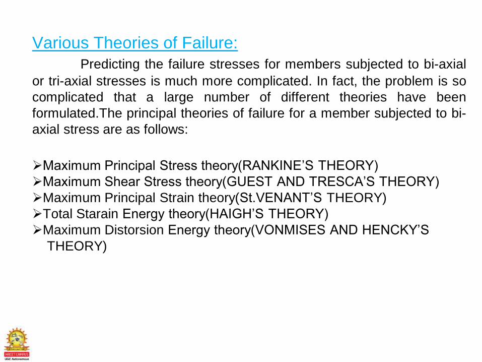
Various Theories of Failure:
Predicting the failure stresses for members subjected to bi-axial
or tri-axial stresses is much more complicated. In fact, the problem is so
complicated that a large number of different theories have been
formulated.The principal theories of failure for a member subjected to bi-
axial stress are as follows:
Maximum Principal Stress theory(RANKINE’S THEORY)
Maximum Shear Stress theory(GUEST AND TRESCA’S THEORY)
Maximum Principal Strain theory(St.VENANT’S THEORY)
Total Starain Energy theory(HAIGH’S THEORY)
Maximum Distorsion Energy theory(VONMISES AND HENCKY’S
THEORY)
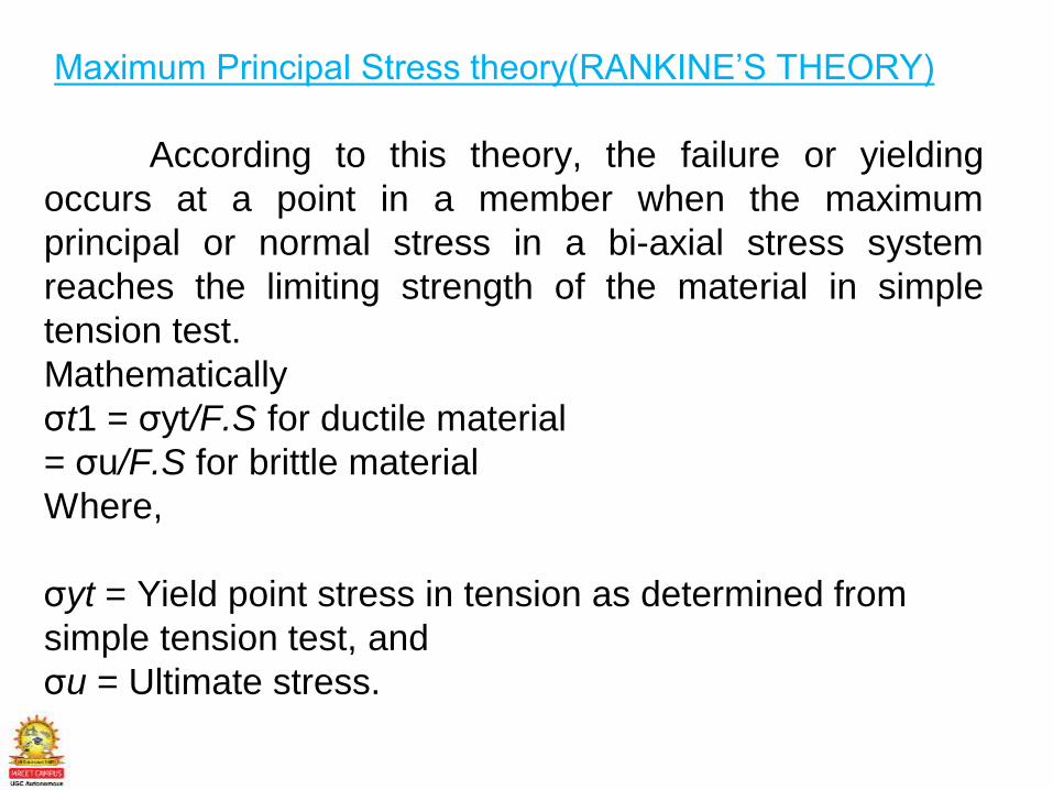
Maximum Principal Stress theory(RANKINE’S THEORY)
According to this theory, the failure or yielding
occurs at a point in a member when the maximum
principal or normal stress in a bi-axial stress system
reaches the limiting strength of the material in simple
tension test.
Mathematically
σt1 = σyt/F.S for ductile material
= σu/F.S for brittle material
Where,
σyt = Yield point stress in tension as determined from
simple tension test, and
σu = Ultimate stress.
Maximum Shear Stress theory(GUEST AND
TRESCA’S THEORY)
According to this theory, the failure or yielding occurs at a point in a
member when the maximum shear stress in a bi-axial stress system reaches a
value equal to the shear stress at yield point in a simple tension test.
Mathematically
Conditionfor safedesign,
Maximum shear stress induced at a critical tensile point under triaxial combined
stress
≤ Permissible shear stress (Ƭper)
S
yt
2N
or
(Sys)T.T
NAbsolute max ≤
Maximum Principal Strain theory(St.VENANT’STHEORY)According to this theory, the failure or yielding occurs at a point in a memberwhen the maximum principal strain in a bi-axial stress system reaches thelimiting value of strain as determined from a simple tension test.
Єmax= (σt1/E)-( σt2/m*E)According to the above theory,
Єmax= (σt1/E)-( σt2/m.E)= Є= (σyt/E*F.O.S)…(1)Where,σt1 and σt2 = Maximum and minimum principal stresses in a bi-axial stress system,ε = Strain at yield point as determined from simple tension test,1/m = Poisson’s ratio,E = Young’s modulus, andF.O.S. = Factor of safety.From equation (i), we may write that
σt1-( σt2/m)= (σyt/F.O.S)This theory is not used, in general, because it only gives reliable results
in particular cases.
Maximum Starain Energy theory(HAIGH’S
THEORY)
According to this theory, the failure or yielding occurs at a point in
a member when the strain energy per unit volume in a bi-axial stress
system reaches the limiting strain energy per unit volume as determined
from simple tension test. We know that strain energy per unit volume in a bi-
axial stress system,
U1=1/2E[σt12 + σt2
2 – ((2σt1* σt2)/M)]
U2=1/2E[σyt/F.O.S]2
According to the above theory U1=U2
1/2E[σt12 + σt2
2 – ((2σt1* σt2)/M)] =1/2E[σyt/F.O.S]2
Or [σt12 + σt2
2 – ((2σt1* σt2)/M)] = [σyt/F.O.S]2
This theory may be used for ductile materials.
Maximum Distorsion Energy theory(VONMISES
AND HENCKY’S THEORY) According to this theory, the failure or yielding occurs at a point in
a member when the distortion strain energy (also called shear strain
energy) per unit volume in a bi-axial stress system reaches the limiting
distortion energy (i.e. distortion energy at yield point) per unit volume as
determined from a simple tension test. Mathematically, the maximum
distortion energy theory for yielding is expressed as
(σt1)2 + (σt2)2 – 2σt1 × σt2 = (σyt /F.O.S) 2
Where,σyt is yield stressF.O.S. = Factor of safety.
This theory is mostly used for ductile materials in place of maximum strain energy theory.
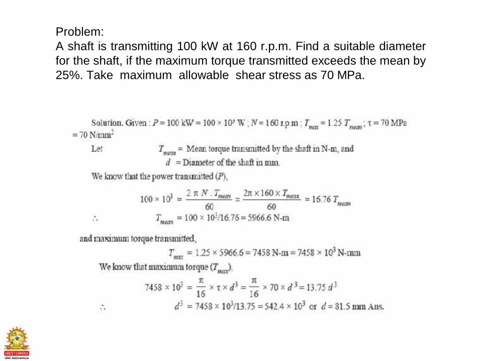
Problem:
A shaft is transmitting 100 kW at 160 r.p.m. Find a suitable diameter
for the shaft, if the maximum torque transmitted exceeds the mean by
25%. Take maximum allowable shear stress as 70 MPa.
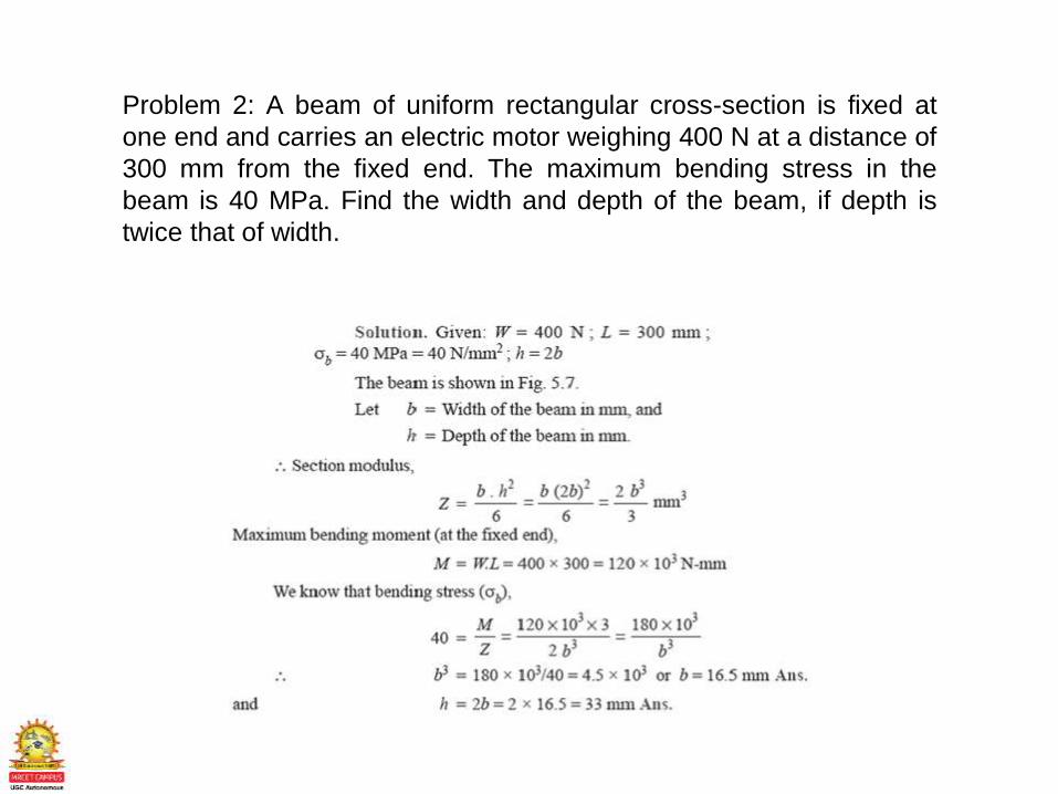
Problem 2: A beam of uniform rectangular cross-section is fixed at
one end and carries an electric motor weighing 400 N at a distance of
300 mm from the fixed end. The maximum bending stress in the
beam is 40 MPa. Find the width and depth of the beam, if depth is
twice that of width.
Revision Questions
1. Explain Importance of Failure Theory
2. What is maximum Principal stress theory
3. What is shear stress theory
4. What is maximum shear strain Theory
5. What is maximum Distorsion energy theory
6. What is maximum principal starin theory
LECTURE 8
Factor of Safety
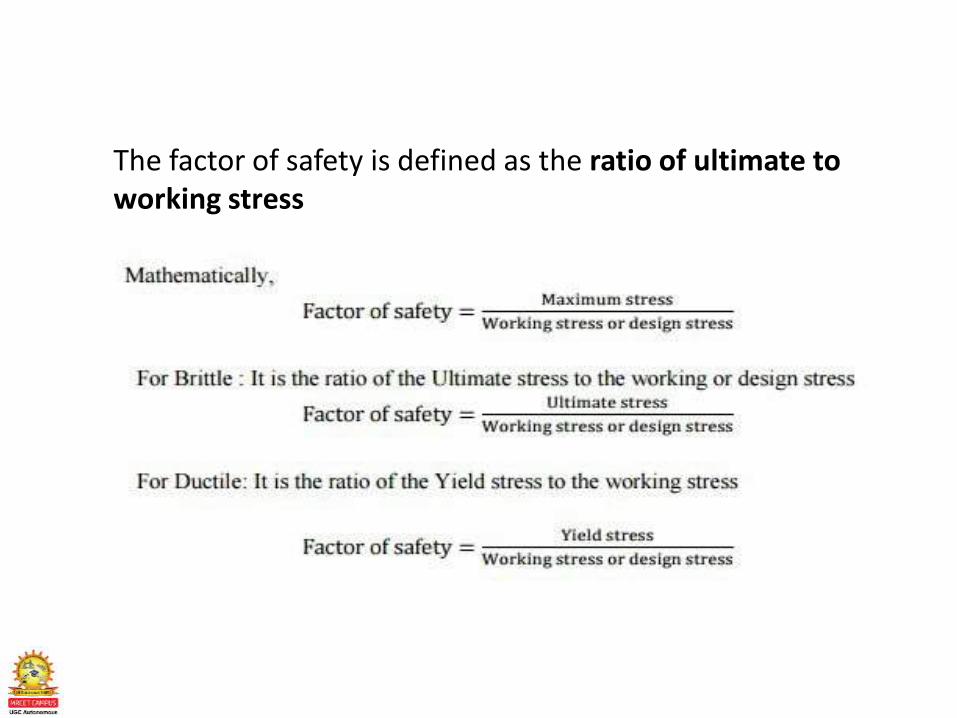
The factor of safety is defined as the ratio of ultimate to working stress
Revision Questions
1. What is Factor of safety
2. Importance of Factor of safety

DIGITALCLASSROOM
ENVIRONM ENTA N E W P E D A G O G Y I S E M E R G I N G
C. Daksheeswara ReddyAssistant Professor,
Mechanical Engineering

(Source: TASK Training material)
DEPARTMENT OF MECHANICAL ENGINEERING
UNIT 2CO2: To understand Stress concentration and the factors
responsible. Determination of stress concentration factor;
experimental and theoretical methods. Fatigue strength
reduction factor and notch sensitivity factor
• Stress Concentration ,Theoretical and Fatigue stress concentration Factor
• Design for fluctuating stresses ,Repeated and Reversed stress tor
• Fatigue Failure and Endurance Limit & Endurance limit estimation
• Low cycle and High cycle fatigue finite & infinite life
• Goodman line, Soderberg line , Gerber line and modified Goodman line
UNIT – II (SYLLABUS)Introduction to Fatigue
Fatigue Failure Under Variable Loading
COURSE OUTLINEUNIT -2
LECTURE LECTURE TOPIC KEY ELEMENTS Learning objectives (2 to 3 objectives)
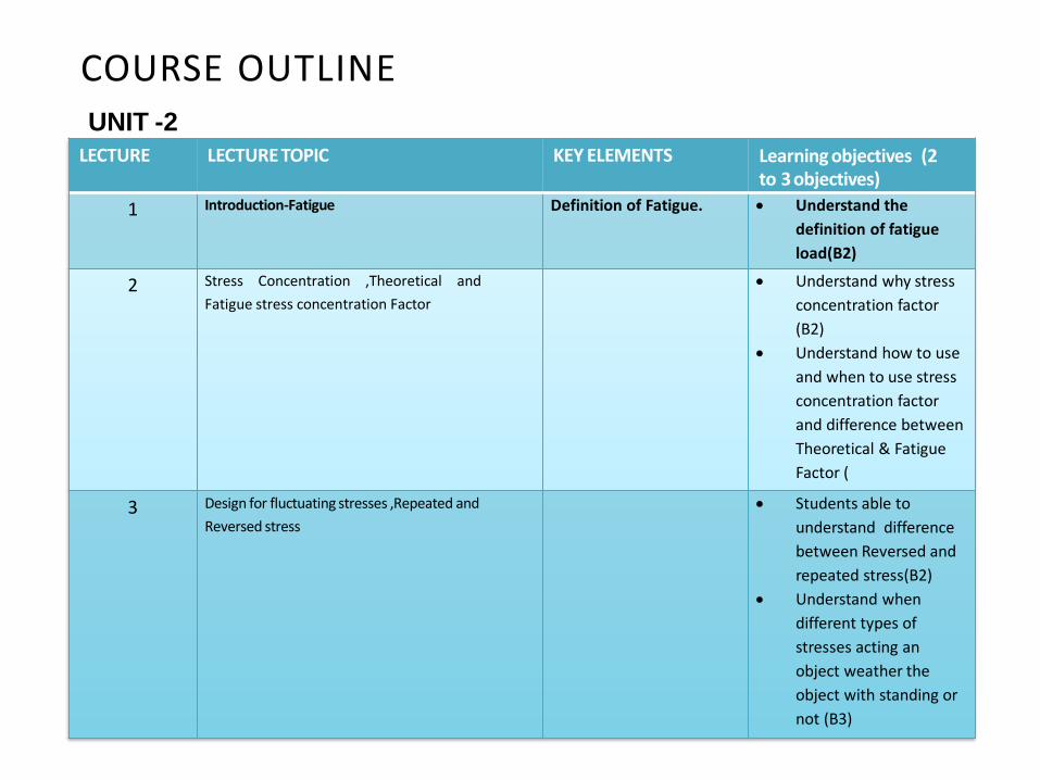
1 Introduction-Fatigue Definition of Fatigue. Understand the
definition of fatigue
load(B2)
2 Stress Concentration ,Theoretical and
Fatigue stress concentration Factor
Understand why stress
concentration factor
(B2)
Understand how to use
and when to use stress
concentration factor
and difference between
Theoretical & Fatigue
Factor (
3 Design for fluctuating stresses ,Repeated and
Reversed stress
Students able to
understand difference
between Reversed and
repeated stress(B2)
Understand when
different types of
stresses acting an
object weather the
object with standing or
not (B3)
LECTURE LECTURE TOPIC KEY ELEMENTS Learning objectives (2 to 3 objectives)
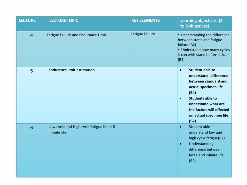
4 Fatigue Failure and Endurance Limit Fatigue Failure • understanding the difference between static and fatigue failure (B2)• Understand how many cycles it can with stand before failure (B3)
5 Endurance limit estimation Student able to
understand difference
between standard and
actual specimen life
(B4)
Students able to
understand what are
the factors will effected
on actual specimen life
(B2)
6 Low cycle and High cycle fatigue finite &
infinite life
Student able
understand low and
high cycle fatigue(B2)
Understanding
difference between
finite and infinite life
(B2)
LECTURE LECTURE TOPIC KEY ELEMENTS Learning objectives (2 to 3 objectives)
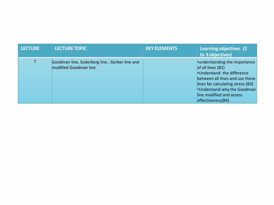
7 Goodman line, Soderberg line , Gerber line and modified Goodman line
•understanding the importance of all lines (B2)•Understand the difference between all lines and use these lines for calculating stress (B3)•Understand why the Goodman line modified and assess effectiveness(B4)

LECTURE 1Introduction-Fatigue

UNIT IIDESIGN FOR FATIGUE STRENGTH
Introduction: A condition characterized by a lessened capacity for work and reduced efficiency of accomplishment

LECTURE 2Stress Concentration
STRESS CONCENTRATION
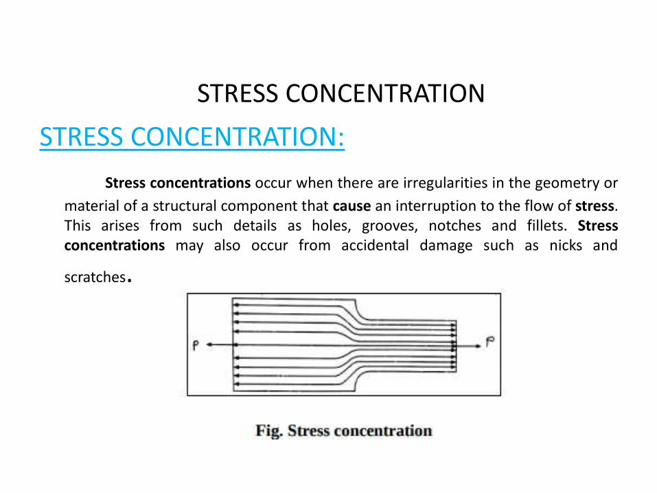
STRESS CONCENTRATION:
Stress concentrations occur when there are irregularities in the geometry or
material of a structural component that cause an interruption to the flow of stress.This arises from such details as holes, grooves, notches and fillets. Stressconcentrations may also occur from accidental damage such as nicks and
scratches.
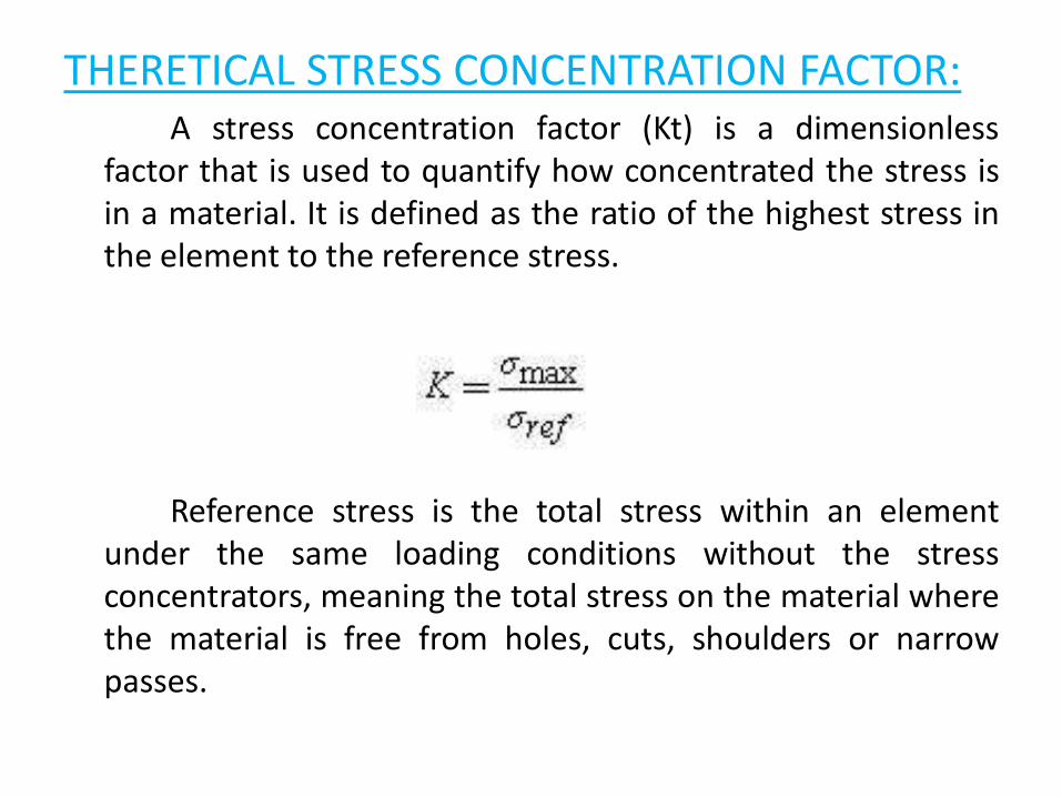
THERETICAL STRESS CONCENTRATION FACTOR:A stress concentration factor (Kt) is a dimensionless
factor that is used to quantify how concentrated the stress isin a material. It is defined as the ratio of the highest stress inthe element to the reference stress.
Reference stress is the total stress within an elementunder the same loading conditions without the stressconcentrators, meaning the total stress on the material wherethe material is free from holes, cuts, shoulders or narrowpasses.
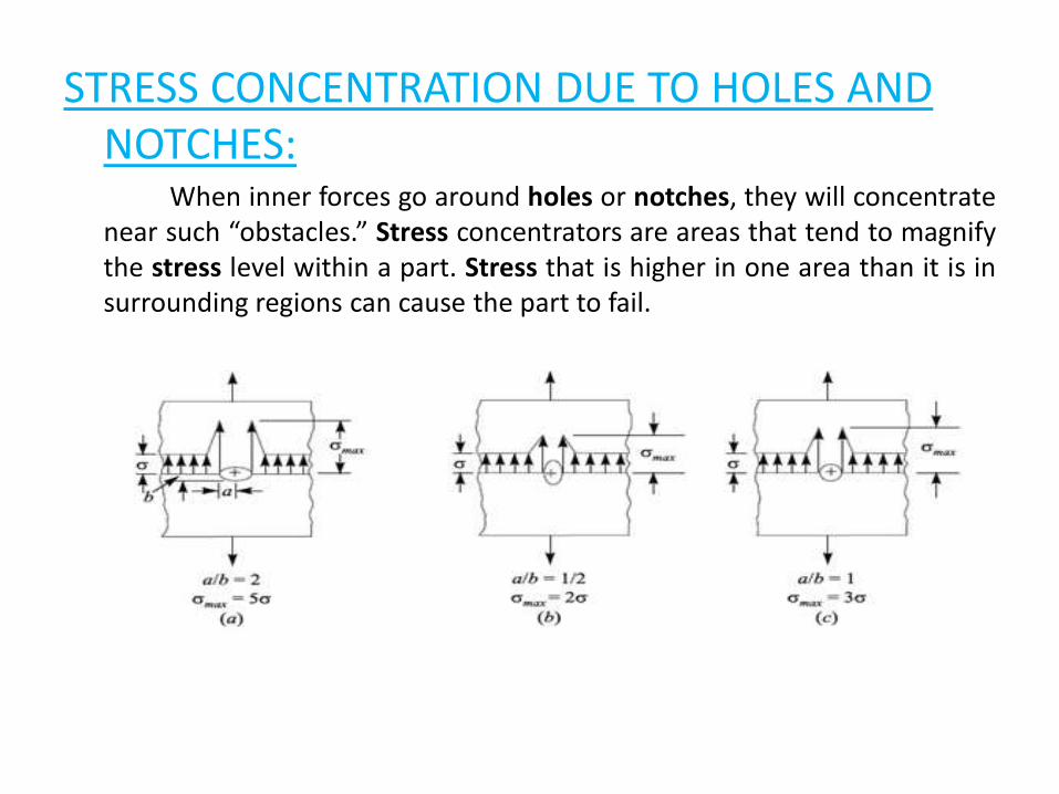
STRESS CONCENTRATION DUE TO HOLES AND NOTCHES:
When inner forces go around holes or notches, they will concentratenear such “obstacles.” Stress concentrators are areas that tend to magnifythe stress level within a part. Stress that is higher in one area than it is insurrounding regions can cause the part to fail.
METHODS OF REDUCING STRESS CONCENTRATION:
The presence of stress concentration can not be totally eliminated but itmay reduced to some extent
Additional Notches and Holes in Tension member
Fillet Radius ,Under Cutting and Notch for member in Bending
Drilling Additional Holes for Shaft
Reduction of Stress Concentration in Threaded members
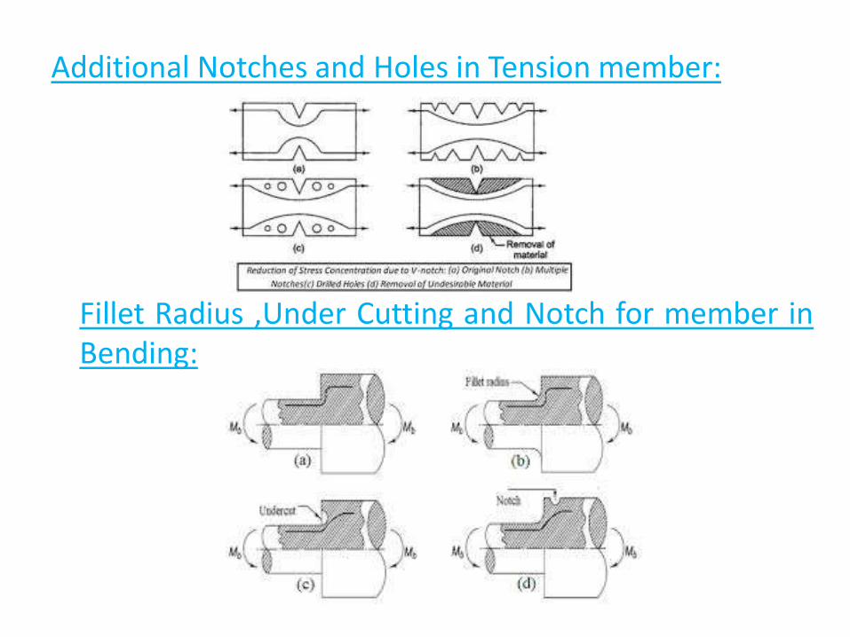
Additional Notches and Holes in Tension member:
Fillet Radius ,Under Cutting and Notch for member inBending:
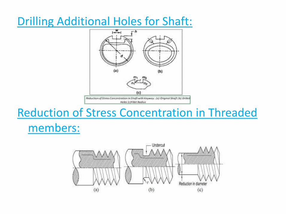
Drilling Additional Holes for Shaft:
Reduction of Stress Concentration in Threaded members:
Revision Questions
1. What is Fatigue
2. What is stress concentration
3. What are reasons for stress concentration
4. How to reduce stress concentration and explain
LECTURE 3Design For Fluctuating Stresses
Fluctuating Stresses:
The components are subjected to forces, which are not static, but vary in magnitude with respect to time. The stresses induced due to such forces are called Fluctuating Stresses.
The most popular model for stress–time relationship is the sine curve.
There are three types of mathematical models for cyclic stresses:
(a) Fluctuating or alternating stresses,
(b) Repeated stresses and
(c) Reversed stresses.
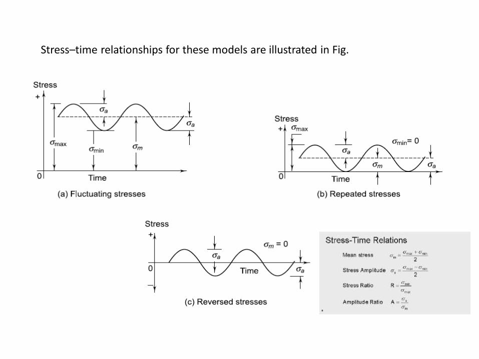
Stress–time relationships for these models are illustrated in Fig.
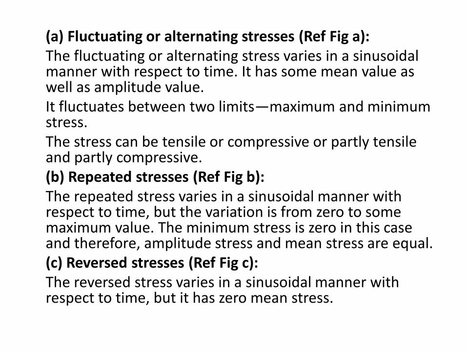
(a) Fluctuating or alternating stresses (Ref Fig a):The fluctuating or alternating stress varies in a sinusoidal manner with respect to time. It has some mean value as well as amplitude value.It fluctuates between two limits—maximum and minimum stress.The stress can be tensile or compressive or partly tensile and partly compressive.(b) Repeated stresses (Ref Fig b):The repeated stress varies in a sinusoidal manner with respect to time, but the variation is from zero to some maximum value. The minimum stress is zero in this case and therefore, amplitude stress and mean stress are equal.(c) Reversed stresses (Ref Fig c):The reversed stress varies in a sinusoidal manner with respect to time, but it has zero mean stress.
Revision Questions
1. What is fluctuating stress
2. What is reversed stress
3. What is repeated stress

LECTURE 4Design for Fatigue Failure
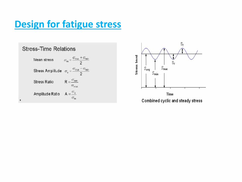
Design for fatigue stress
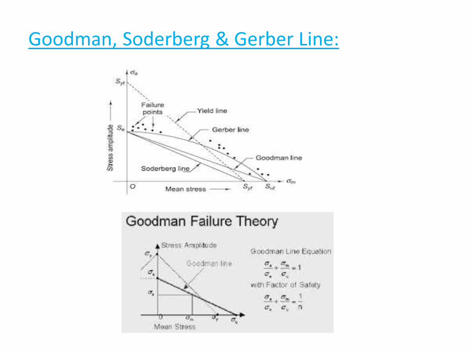
Goodman, Soderberg & Gerber Line:
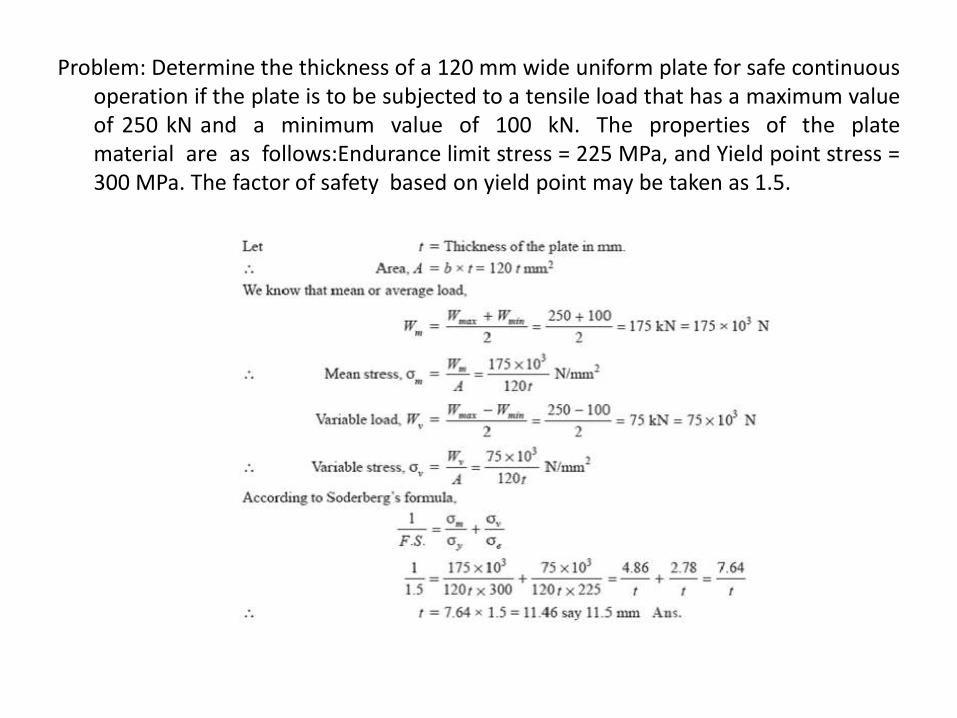
Problem: Determine the thickness of a 120 mm wide uniform plate for safe continuousoperation if the plate is to be subjected to a tensile load that has a maximum valueof 250 kN and a minimum value of 100 kN. The properties of the platematerial are as follows:Endurance limit stress = 225 MPa, and Yield point stress =300 MPa. The factor of safety based on yield point may be taken as 1.5.
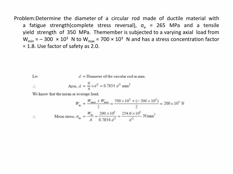
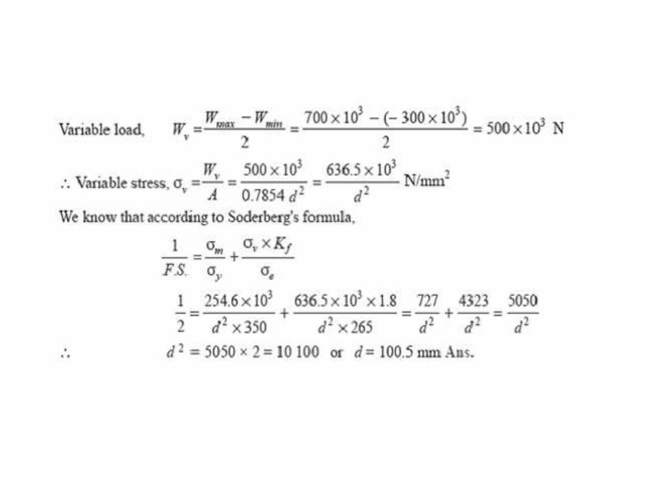
Problem:Determine the diameter of a circular rod made of ductile material witha fatigue strength(complete stress reversal), σe = 265 MPa and a tensileyield strength of 350 MPa. Themember is subjected to a varying axial load fromWmin = – 300 × 103 N to Wmax = 700 × 103 N and has a stress concentration factor= 1.8. Use factor of safety as 2.0.
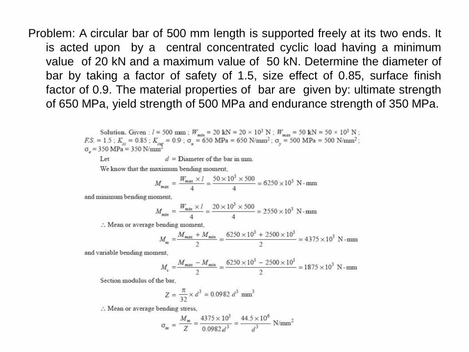
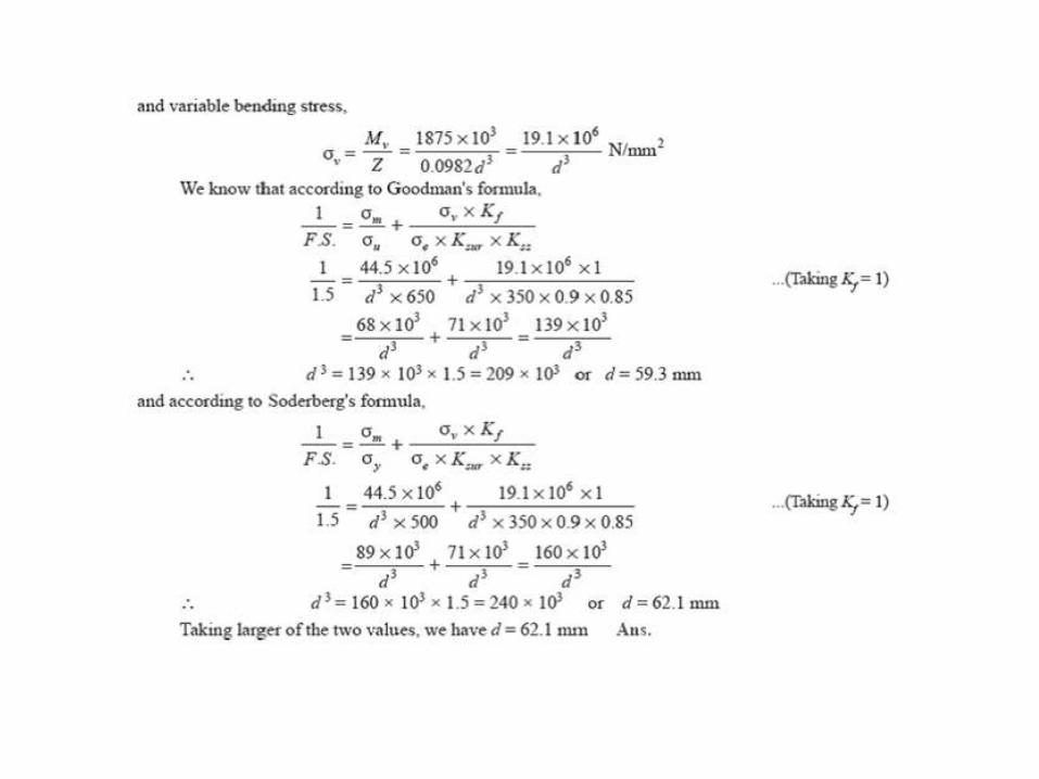
Problem: A circular bar of 500 mm length is supported freely at its two ends. It
is acted upon by a central concentrated cyclic load having a minimum
value of 20 kN and a maximum value of 50 kN. Determine the diameter of
bar by taking a factor of safety of 1.5, size effect of 0.85, surface finish
factor of 0.9. The material properties of bar are given by: ultimate strength
of 650 MPa, yield strength of 500 MPa and endurance strength of 350 MPa.

DIGITAL CLASSROOM
ENVIRONM ENT A N E W P E D A G O G Y I S E M E R G I N G
C. Daksheeswara Reddy Assistant Professor,
Mechanical Engineering

(Source: TASK Training material)
DEPARTMENT OF MECHANICAL ENGINEERING
UNIT 3 CO3: To develop the Knowledge on Basic failure mechanisms
of riveted joints. Concepts of design of a riveted joint, welded
joints and Bolted Joints to determine the forces in welds and
riveted joints and formulate design solution for size of weld
and size of rivet
UNIT – 3 (SYLLABUS)
• Introduction to joints and Types of joints
• Methods of Riveting and Failure
• Strength equations
• Introduction to welded oints and Types of welded joints
• Design of fillet welds
Riveted Joints
Welded Joints
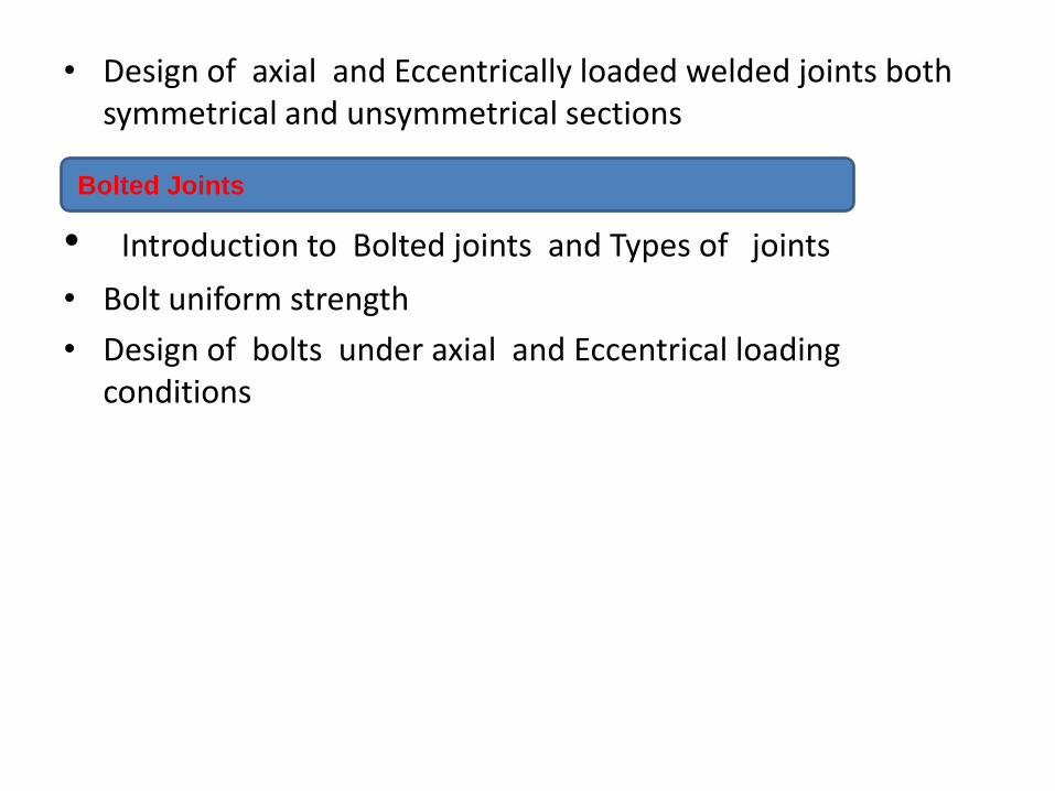
• Design of axial and Eccentrically loaded welded joints both symmetrical and unsymmetrical sections
• Introduction to Bolted joints and Types of joints
• Bolt uniform strength
• Design of bolts under axial and Eccentrical loading conditions
Bolted Joints
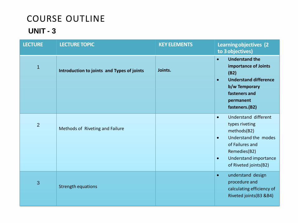
COURSE OUTLINE UNIT - 3
LECTURE LECTURE TOPIC KEY ELEMENTS Learning objectives (2 to 3 objectives)
1
Introduction to joints and Types of joints
Joints.
Understand the
importance of Joints
(B2)
Understand difference
b/w Temporary
fasteners and
permanent
fasteners.(B2)
2
Methods of Riveting and Failure
Understand different
types riveting
methods(B2)
Understand the modes
of Failures and
Remedies(B2)
Understand importance
of Riveted joints(B2)
3
Strength equations
understand design
procedure and
calculating efficiency of
Riveted joints(B3 &B4)
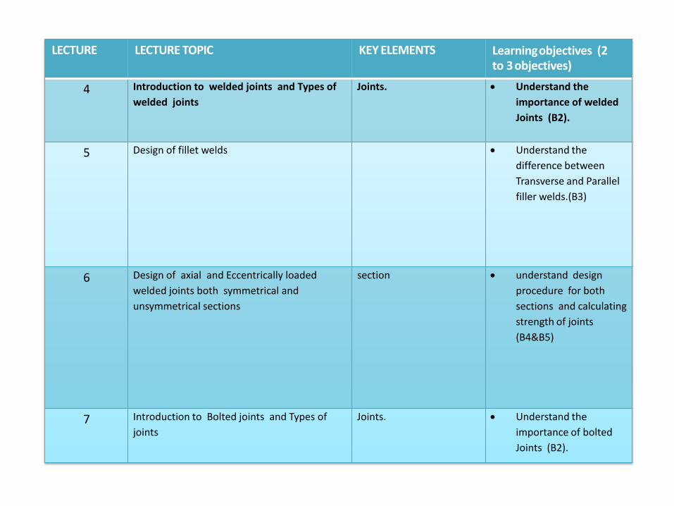
LECTURE LECTURE TOPIC KEY ELEMENTS Learning objectives (2 to 3 objectives)
4 Introduction to welded joints and Types of
welded joints
Joints. Understand the
importance of welded
Joints (B2).
5 Design of fillet welds Understand the
difference between
Transverse and Parallel
filler welds.(B3)
6 Design of axial and Eccentrically loaded
welded joints both symmetrical and
unsymmetrical sections
section understand design
procedure for both
sections and calculating
strength of joints
(B4&B5)
7 Introduction to Bolted joints and Types of
joints
Joints. Understand the
importance of bolted
Joints (B2).
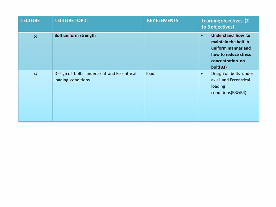
LECTURE LECTURE TOPIC KEY ELEMENTS Learning objectives (2 to 3 objectives)
8 Bolt uniform strength Understand how to
maintain the bolt in
uniform manner and
how to reduce stress
concentration on
bolt(B3)
9 Design of bolts under axial and Eccentrical
loading conditions
load Design of bolts under
axial and Eccentrical
loading
conditions(B3&B4)
LECTURE 1 Introduction to joints and Types of joints
The student will be able to: •Understand the procedure of design (w.r.t. Basic failures) under various loading condition. •Understand the applications of joints in various loading condition.
RIVETED JOINTS
Introduction :
• The function of rivets in a joint is to make a connection that has strength & tightness.
• Strength is necessary to prevent failure of the joint while tightness is necessary in order to contribute to strength & to prevent leakage.
• Rivets may be driven by hand or by riveting machines.
• Rivets are commonly used in a) Tanks & pressure vessels b) bridges ,building, cranes and machinery c)Hulls of Ships
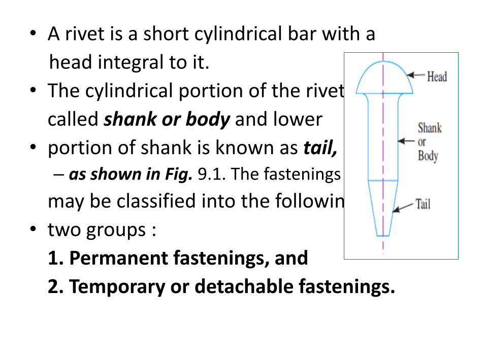
• A rivet is a short cylindrical bar with a
head integral to it.
• The cylindrical portion of the rivet is
called shank or body and lower
• portion of shank is known as tail, – as shown in Fig. 9.1. The fastenings (i.e. joints)
may be classified into the following
• two groups :
1. Permanent fastenings, and
2. Temporary or detachable fastenings.
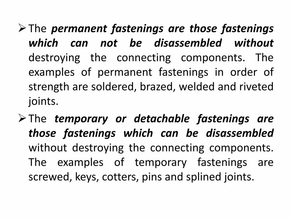
The permanent fastenings are those fastenings which can not be disassembled without destroying the connecting components. The examples of permanent fastenings in order of strength are soldered, brazed, welded and riveted joints.
The temporary or detachable fastenings are those fastenings which can be disassembled without destroying the connecting components. The examples of temporary fastenings are screwed, keys, cotters, pins and splined joints.
Revision Questions
1. Function of Rivet
2. What are parts of rivet
3. Difference between Temporary fastening and permanent fastening
LECTURE 2 Methods of Riveting and Failure
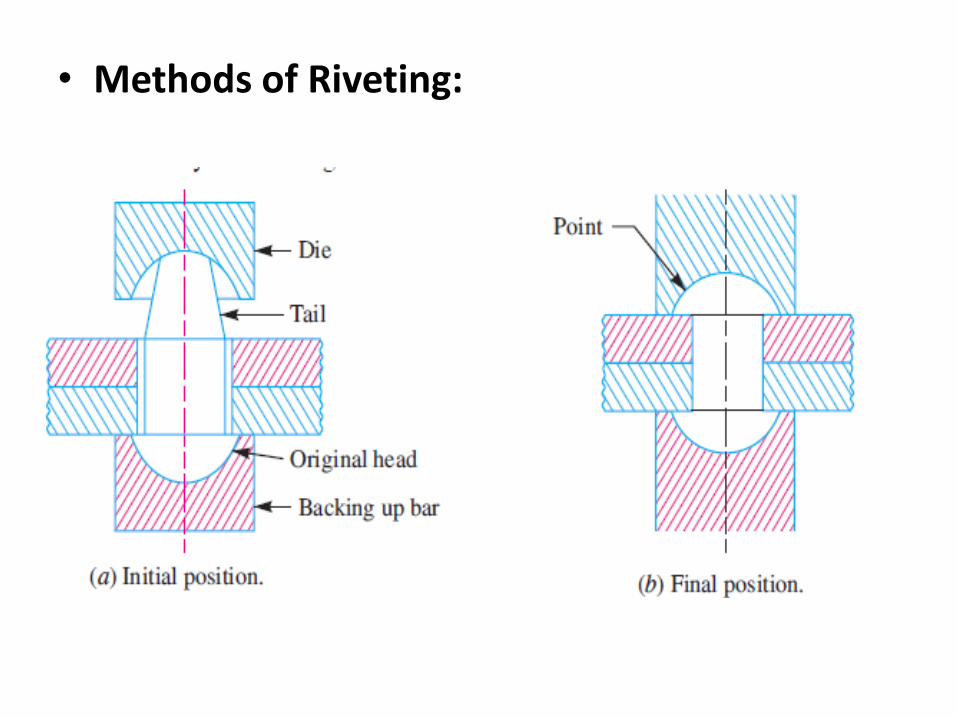
• Methods of Riveting:
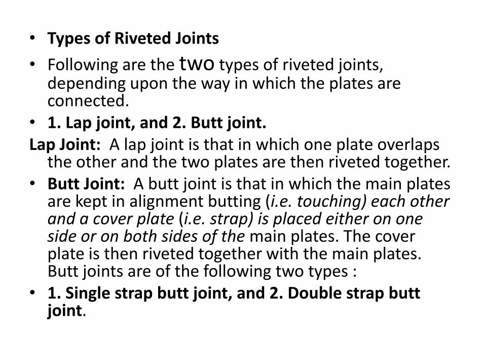
• Types of Riveted Joints
• Following are the two types of riveted joints, depending upon the way in which the plates are connected.
• 1. Lap joint, and 2. Butt joint. Lap Joint: A lap joint is that in which one plate overlaps
the other and the two plates are then riveted together. • Butt Joint: A butt joint is that in which the main plates
are kept in alignment butting (i.e. touching) each other and a cover plate (i.e. strap) is placed either on one side or on both sides of the main plates. The cover plate is then riveted together with the main plates. Butt joints are of the following two types :
• 1. Single strap butt joint, and 2. Double strap butt joint.
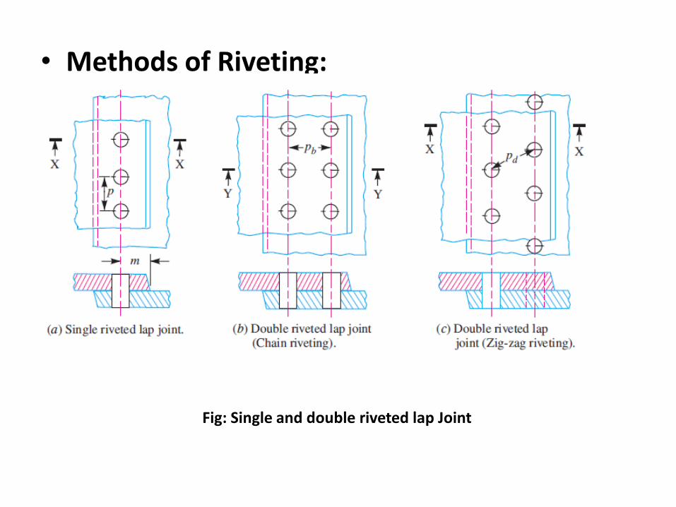
• Methods of Riveting:
Fig: Single and double riveted lap Joint
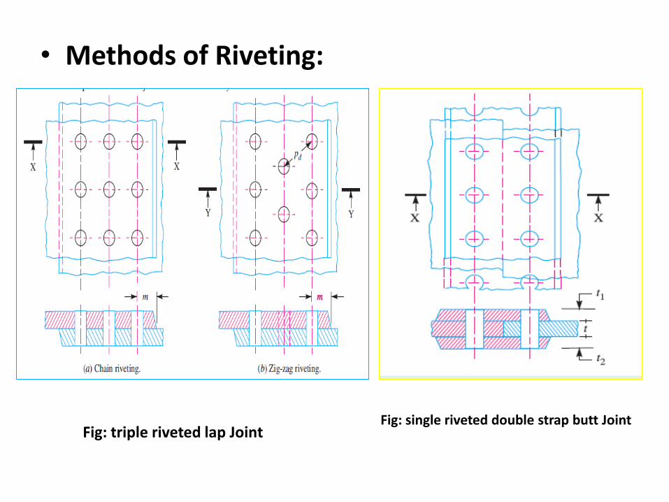
• Methods of Riveting:
Fig: triple riveted lap Joint Fig: single riveted double strap butt Joint
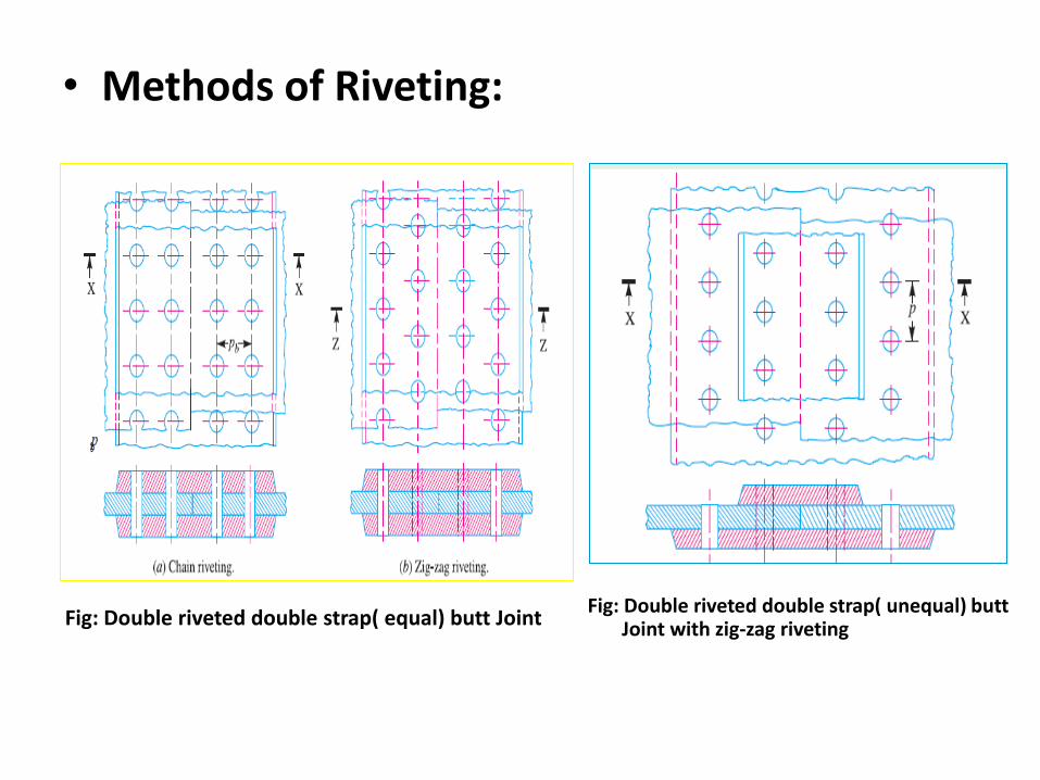
• Methods of Riveting:
Fig: Double riveted double strap( equal) butt Joint Fig: Double riveted double strap( unequal) butt
Joint with zig-zag riveting
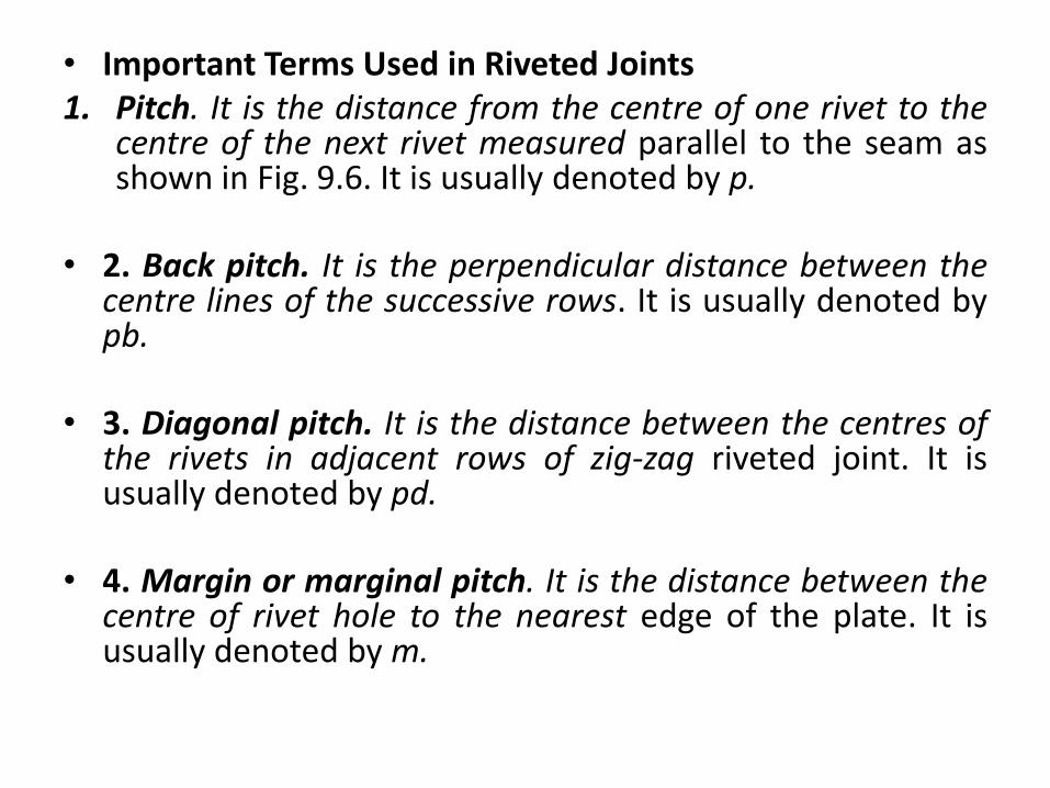
• Important Terms Used in Riveted Joints 1. Pitch. It is the distance from the centre of one rivet to the
centre of the next rivet measured parallel to the seam as shown in Fig. 9.6. It is usually denoted by p.
• 2. Back pitch. It is the perpendicular distance between the centre lines of the successive rows. It is usually denoted by pb.
• 3. Diagonal pitch. It is the distance between the centres of the rivets in adjacent rows of zig-zag riveted joint. It is usually denoted by pd.
• 4. Margin or marginal pitch. It is the distance between the centre of rivet hole to the nearest edge of the plate. It is usually denoted by m.
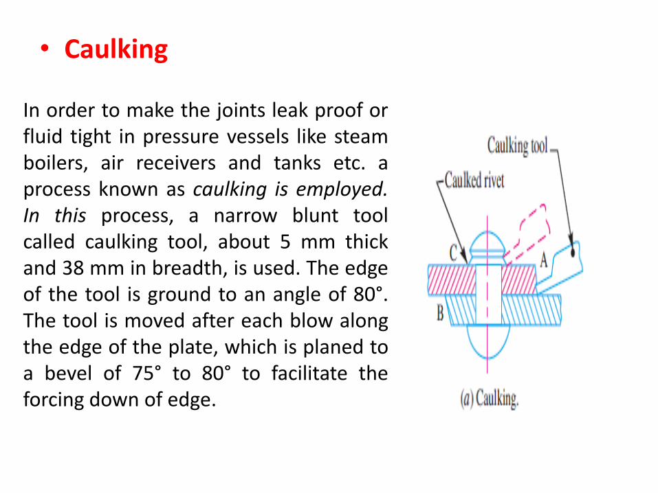
• Caulking
In order to make the joints leak proof or fluid tight in pressure vessels like steam boilers, air receivers and tanks etc. a process known as caulking is employed. In this process, a narrow blunt tool called caulking tool, about 5 mm thick and 38 mm in breadth, is used. The edge of the tool is ground to an angle of 80°. The tool is moved after each blow along the edge of the plate, which is planed to a bevel of 75° to 80° to facilitate the forcing down of edge.
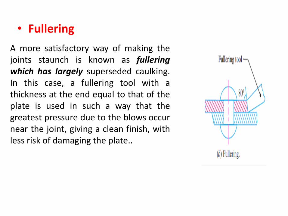
• Fullering
A more satisfactory way of making the joints staunch is known as fullering which has largely superseded caulking. In this case, a fullering tool with a thickness at the end equal to that of the plate is used in such a way that the greatest pressure due to the blows occur near the joint, giving a clean finish, with less risk of damaging the plate..
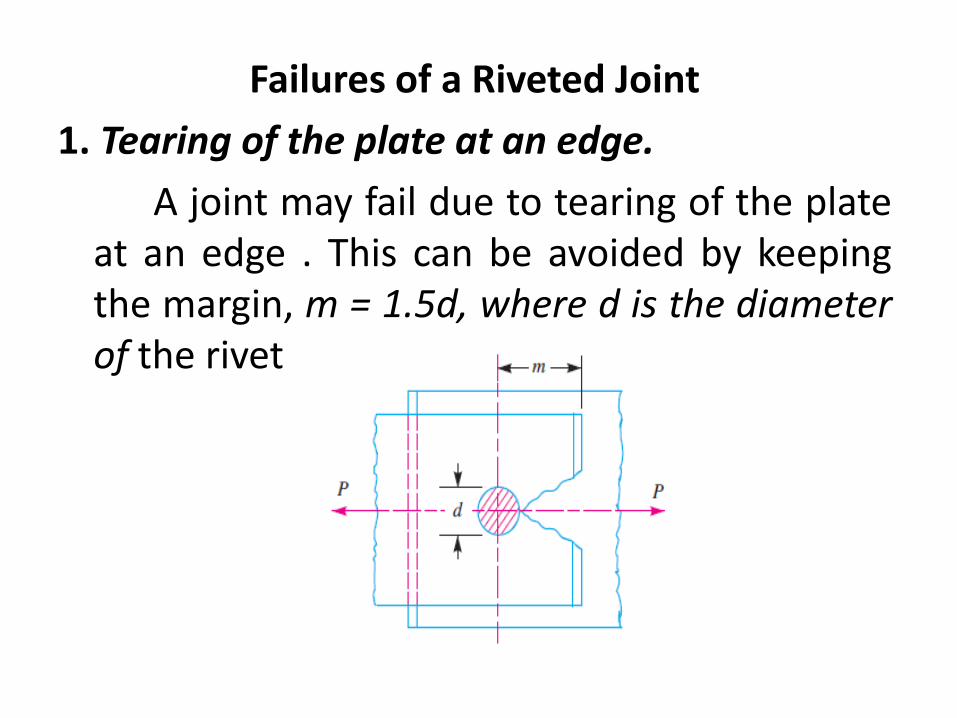
Failures of a Riveted Joint
1. Tearing of the plate at an edge.
A joint may fail due to tearing of the plate at an edge . This can be avoided by keeping the margin, m = 1.5d, where d is the diameter of the rivet hole.
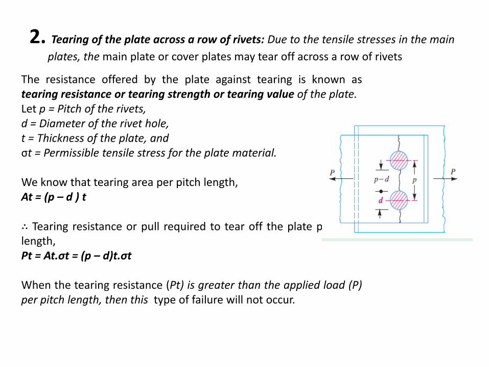
2. Tearing of the plate across a row of rivets: Due to the tensile stresses in the main
plates, the main plate or cover plates may tear off across a row of rivets
The resistance offered by the plate against tearing is known as tearing resistance or tearing strength or tearing value of the plate. Let p = Pitch of the rivets, d = Diameter of the rivet hole, t = Thickness of the plate, and σt = Permissible tensile stress for the plate material. We know that tearing area per pitch length, At = (p – d ) t ∴ Tearing resistance or pull required to tear off the plate per pitch length, Pt = At.σt = (p – d)t.σt When the tearing resistance (Pt) is greater than the applied load (P) per pitch length, then this type of failure will not occur.
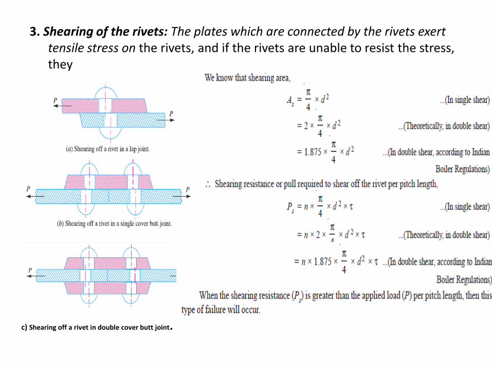
3. Shearing of the rivets: The plates which are connected by the rivets exert tensile stress on the rivets, and if the rivets are unable to resist the stress, they
are sheared off as shown in Fig.
c) Shearing off a rivet in double cover butt joint.
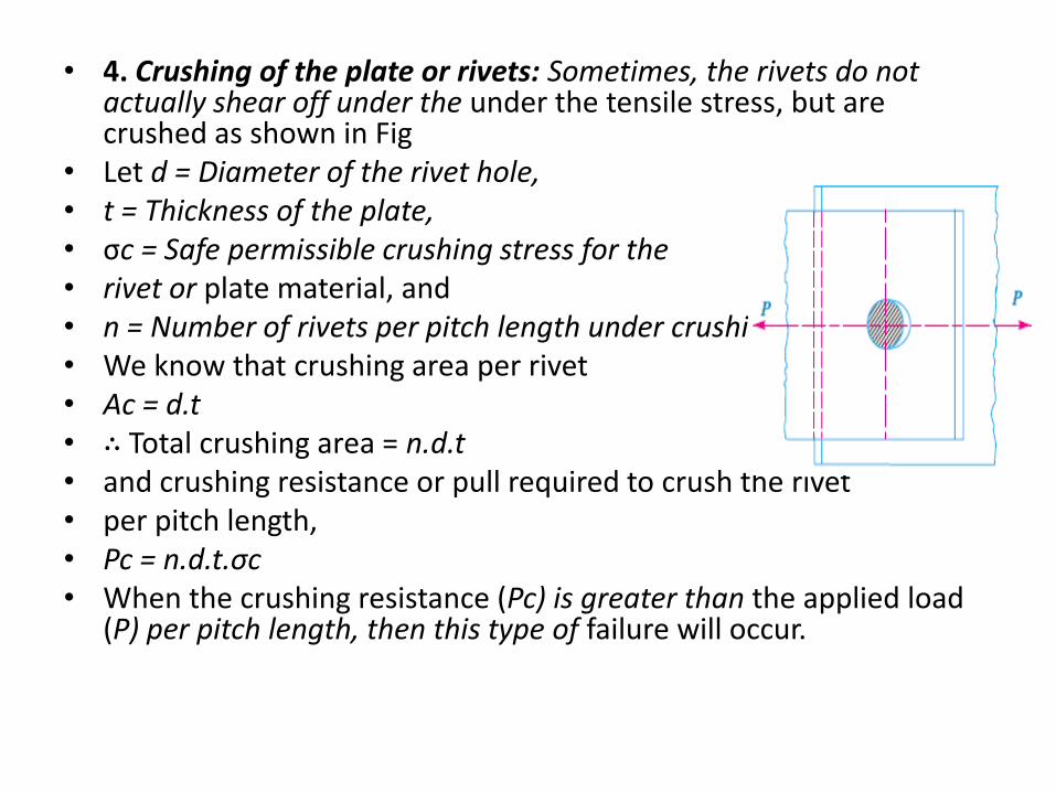
• 4. Crushing of the plate or rivets: Sometimes, the rivets do not actually shear off under the under the tensile stress, but are crushed as shown in Fig
• Let d = Diameter of the rivet hole, • t = Thickness of the plate, • σc = Safe permissible crushing stress for the • rivet or plate material, and • n = Number of rivets per pitch length under crushing. • We know that crushing area per rivet • Ac = d.t • ∴ Total crushing area = n.d.t • and crushing resistance or pull required to crush the rivet • per pitch length, • Pc = n.d.t.σc • When the crushing resistance (Pc) is greater than the applied load
(P) per pitch length, then this type of failure will occur.
Revision Questions
1. Explain methods of riveting
2. Explain Type of joints
3. Explain Failures in riveted joints
LECTURE 3 Design of Longitudinal Joints
Longitudinal joint
Design of Longitudinal Butt Joint for a Boiler
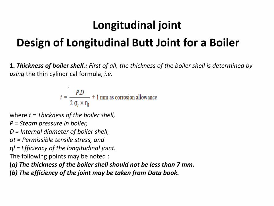
1. Thickness of boiler shell.: First of all, the thickness of the boiler shell is determined by using the thin cylindrical formula, i.e. where t = Thickness of the boiler shell, P = Steam pressure in boiler, D = Internal diameter of boiler shell, σt = Permissible tensile stress, and ηl = Efficiency of the longitudinal joint. The following points may be noted : (a) The thickness of the boiler shell should not be less than 7 mm. (b) The efficiency of the joint may be taken from Data book.
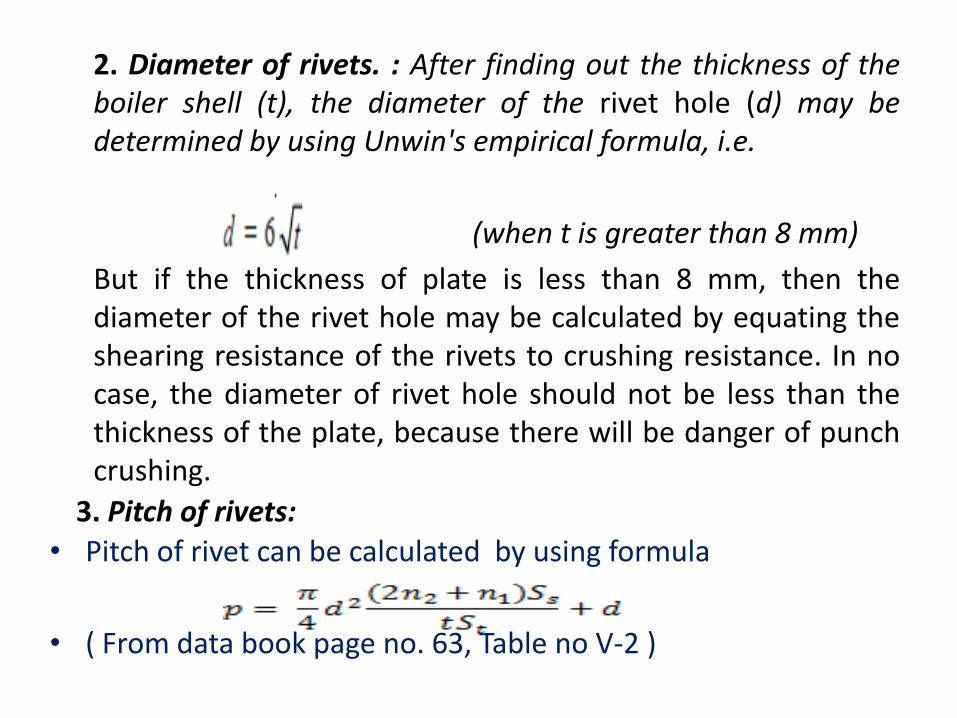
2. Diameter of rivets. : After finding out the thickness of the boiler shell (t), the diameter of the rivet hole (d) may be determined by using Unwin's empirical formula, i.e.
• (when t is greater than 8 mm)
But if the thickness of plate is less than 8 mm, then the diameter of the rivet hole may be calculated by equating the shearing resistance of the rivets to crushing resistance. In no case, the diameter of rivet hole should not be less than the thickness of the plate, because there will be danger of punch crushing.
3. Pitch of rivets: • Pitch of rivet can be calculated by using formula
• ( From data book page no. 63, Table no V-2 )
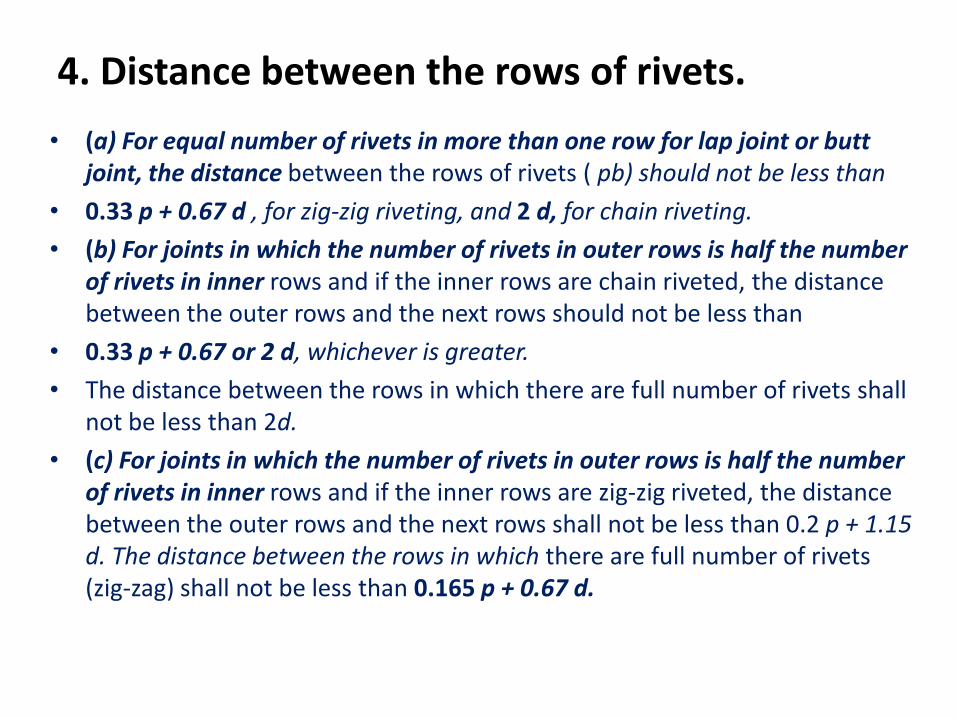
4. Distance between the rows of rivets.
• (a) For equal number of rivets in more than one row for lap joint or butt joint, the distance between the rows of rivets ( pb) should not be less than
• 0.33 p + 0.67 d , for zig-zig riveting, and 2 d, for chain riveting.
• (b) For joints in which the number of rivets in outer rows is half the number of rivets in inner rows and if the inner rows are chain riveted, the distance between the outer rows and the next rows should not be less than
• 0.33 p + 0.67 or 2 d, whichever is greater.
• The distance between the rows in which there are full number of rivets shall not be less than 2d.
• (c) For joints in which the number of rivets in outer rows is half the number of rivets in inner rows and if the inner rows are zig-zig riveted, the distance between the outer rows and the next rows shall not be less than 0.2 p + 1.15 d. The distance between the rows in which there are full number of rivets (zig-zag) shall not be less than 0.165 p + 0.67 d.
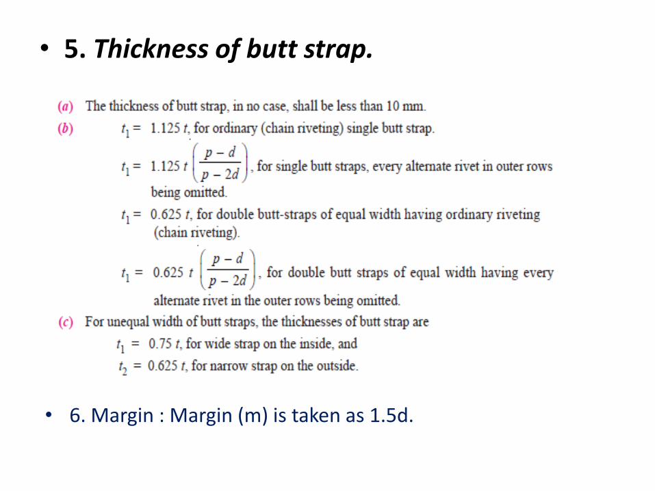
• 5. Thickness of butt strap.
• 6. Margin : Margin (m) is taken as 1.5d.
LECTURE 4 Design of Circumferential Joints
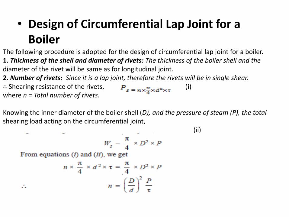
• Design of Circumferential Lap Joint for a Boiler
The following procedure is adopted for the design of circumferential lap joint for a boiler. 1. Thickness of the shell and diameter of rivets: The thickness of the boiler shell and the diameter of the rivet will be same as for longitudinal joint. 2. Number of rivets: Since it is a lap joint, therefore the rivets will be in single shear. ∴ Shearing resistance of the rivets, (i) where n = Total number of rivets. Knowing the inner diameter of the boiler shell (D), and the pressure of steam (P), the total shearing load acting on the circumferential joint, (ii)
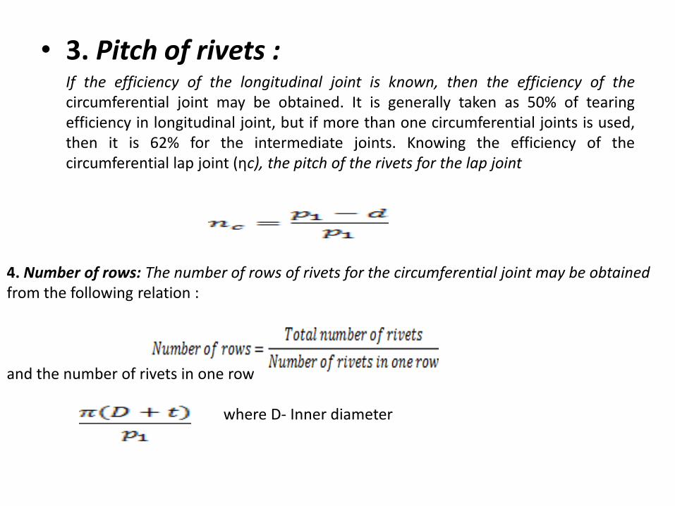
• 3. Pitch of rivets : If the efficiency of the longitudinal joint is known, then the efficiency of the
circumferential joint may be obtained. It is generally taken as 50% of tearing efficiency in longitudinal joint, but if more than one circumferential joints is used, then it is 62% for the intermediate joints. Knowing the efficiency of the circumferential lap joint (ηc), the pitch of the rivets for the lap joint
4. Number of rows: The number of rows of rivets for the circumferential joint may be obtained from the following relation : and the number of rivets in one row where D- Inner diameter
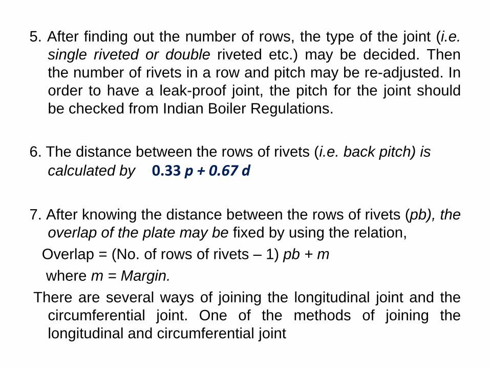
5. After finding out the number of rows, the type of the joint (i.e.
single riveted or double riveted etc.) may be decided. Then
the number of rivets in a row and pitch may be re-adjusted. In
order to have a leak-proof joint, the pitch for the joint should
be checked from Indian Boiler Regulations.
6. The distance between the rows of rivets (i.e. back pitch) is
calculated by 0.33 p + 0.67 d
7. After knowing the distance between the rows of rivets (pb), the
overlap of the plate may be fixed by using the relation,
Overlap = (No. of rows of rivets – 1) pb + m
where m = Margin.
There are several ways of joining the longitudinal joint and the
circumferential joint. One of the methods of joining the
longitudinal and circumferential joint
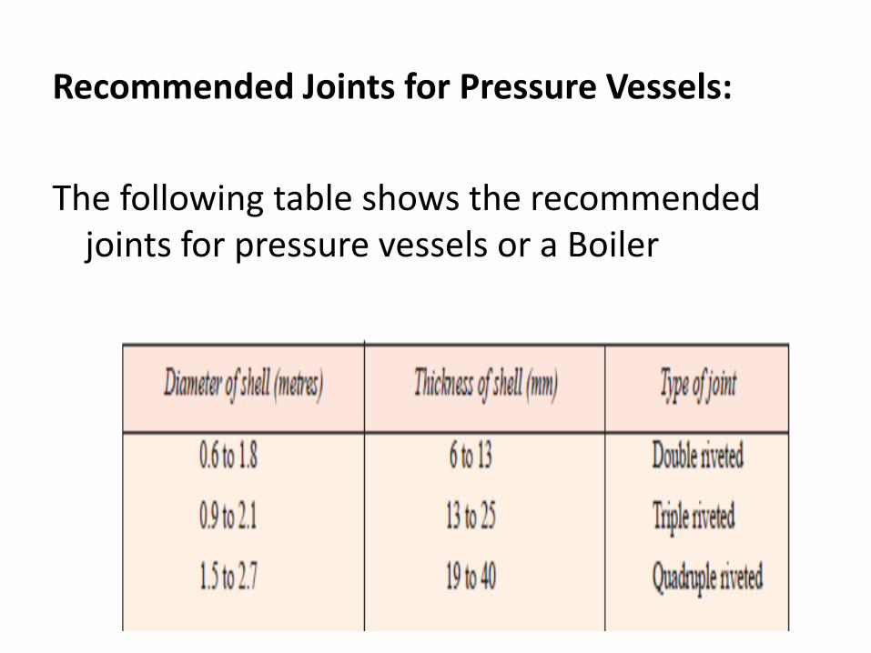
Recommended Joints for Pressure Vessels:
The following table shows the recommended joints for pressure vessels or a Boiler
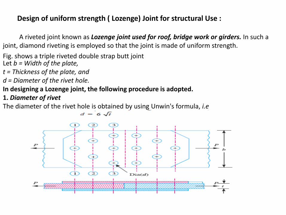
Design of uniform strength ( Lozenge) Joint for structural Use :
A riveted joint known as Lozenge joint used for roof, bridge work or girders. In such a joint, diamond riveting is employed so that the joint is made of uniform strength.
Fig. shows a triple riveted double strap butt joint Let b = Width of the plate, t = Thickness of the plate, and d = Diameter of the rivet hole. In designing a Lozenge joint, the following procedure is adopted. 1. Diameter of rivet The diameter of the rivet hole is obtained by using Unwin's formula, i.e
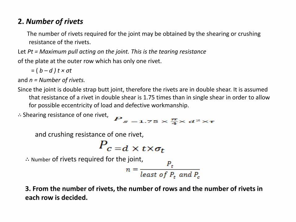
2. Number of rivets
The number of rivets required for the joint may be obtained by the shearing or crushing
resistance of the rivets.
Let Pt = Maximum pull acting on the joint. This is the tearing resistance
of the plate at the outer row which has only one rivet.
= ( b – d ) t × σt
and n = Number of rivets.
Since the joint is double strap butt joint, therefore the rivets are in double shear. It is assumed that resistance of a rivet in double shear is 1.75 times than in single shear in order to allow for possible eccentricity of load and defective workmanship.
∴ Shearing resistance of one rivet,
and crushing resistance of one rivet,
∴ Number of rivets required for the joint,
3. From the number of rivets, the number of rows and the number of rivets in each row is decided.
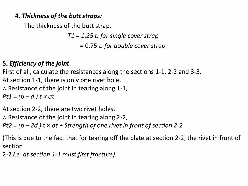
4. Thickness of the butt straps:
The thickness of the butt strap,
T1 = 1.25 t, for single cover strap
= 0.75 t, for double cover strap
5. Efficiency of the joint First of all, calculate the resistances along the sections 1-1, 2-2 and 3-3. At section 1-1, there is only one rivet hole. ∴ Resistance of the joint in tearing along 1-1, Pt1 = (b – d ) t × σt
At section 2-2, there are two rivet holes. ∴ Resistance of the joint in tearing along 2-2, Pt2 = (b – 2d ) t × σt + Strength of one rivet in front of section 2-2
(This is due to the fact that for tearing off the plate at section 2-2, the rivet in front of section 2-2 i.e. at section 1-1 must first fracture).
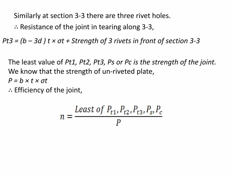
Similarly at section 3-3 there are three rivet holes.
∴ Resistance of the joint in tearing along 3-3,
Pt3 = (b – 3d ) t × σt + Strength of 3 rivets in front of section 3-3
The least value of Pt1, Pt2, Pt3, Ps or Pc is the strength of the joint. We know that the strength of un-riveted plate, P = b × t × σt ∴ Efficiency of the joint,
LECTURE 6 Design of Eccentrically loaded Riveted Joints
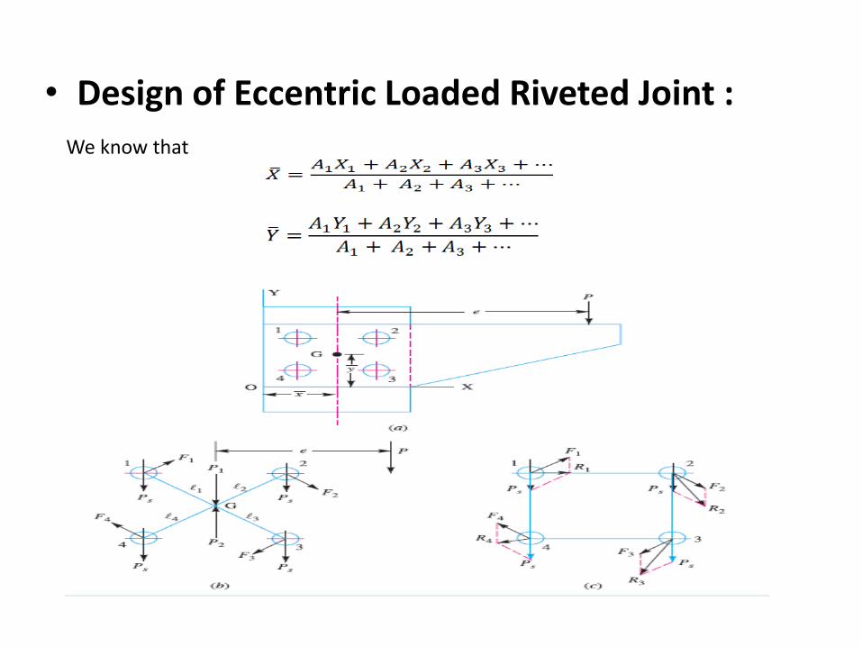
Design of Eccentric Loaded Riveted Joint :
When the line of action of the load does not pass through the centroid of the rivet system and thus all rivets are not equally loaded, then the joint is said to be an eccentric loaded riveted joint, The eccentric loading results in secondary shear caused by the tendency of force to twist the joint about the centre of gravity in addition to direct shear or primary shear. Let P = Eccentric load on the joint, and e = Eccentricity of the load i.e. the distance between the line of action of the load and the centroid of the rivet system i.e. G. The following procedure is adopted for the design of an eccentrically loaded riveted joint.
1. First of all, find the centre of gravity G of the rivet system. Let A = Cross-sectional area of each rivet, x1, x2, x3 etc. = Distances of rivets from OY, and y1, y2, y3 etc. = Distances of rivets from OX.
• Design of Eccentric Loaded Riveted Joint :
We know that
2. Introduce two forces P1 and P2 at the centre of gravity ‘G’ of the rivet system. These forces are equal and opposite to P as shown in Fig. (b).
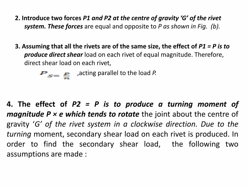
3. Assuming that all the rivets are of the same size, the effect of P1 = P is to produce direct shear load on each rivet of equal magnitude. Therefore, direct shear load on each rivet,
,acting parallel to the load P.
4. The effect of P2 = P is to produce a turning moment of magnitude P × e which tends to rotate the joint about the centre of gravity ‘G’ of the rivet system in a clockwise direction. Due to the turning moment, secondary shear load on each rivet is produced. In order to find the secondary shear load, the following two assumptions are made :
Design of Eccentric Loaded Riveted Joint :
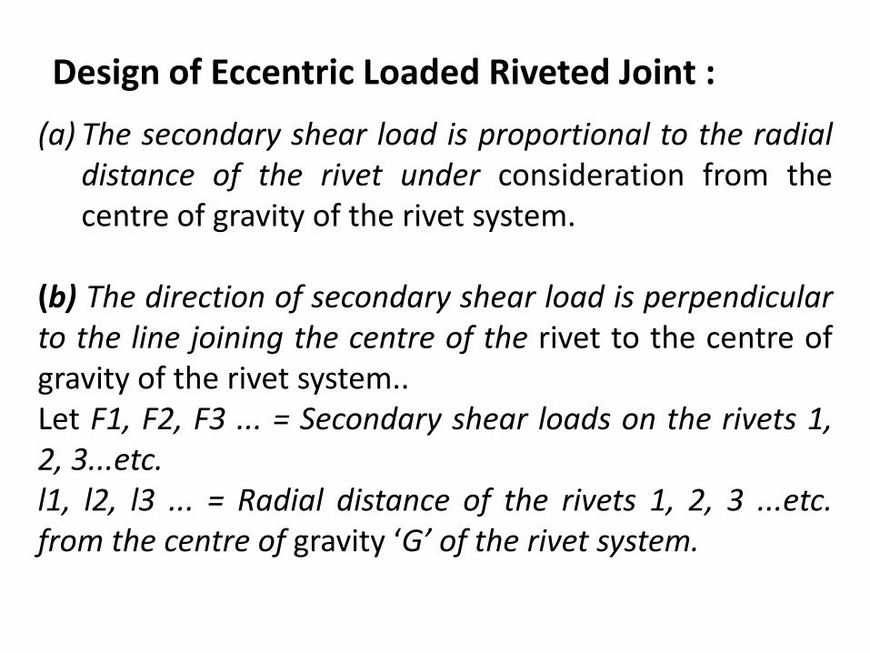
(a) The secondary shear load is proportional to the radial distance of the rivet under consideration from the centre of gravity of the rivet system.
(b) The direction of secondary shear load is perpendicular to the line joining the centre of the rivet to the centre of gravity of the rivet system.. Let F1, F2, F3 ... = Secondary shear loads on the rivets 1, 2, 3...etc. l1, l2, l3 ... = Radial distance of the rivets 1, 2, 3 ...etc. from the centre of gravity ‘G’ of the rivet system.
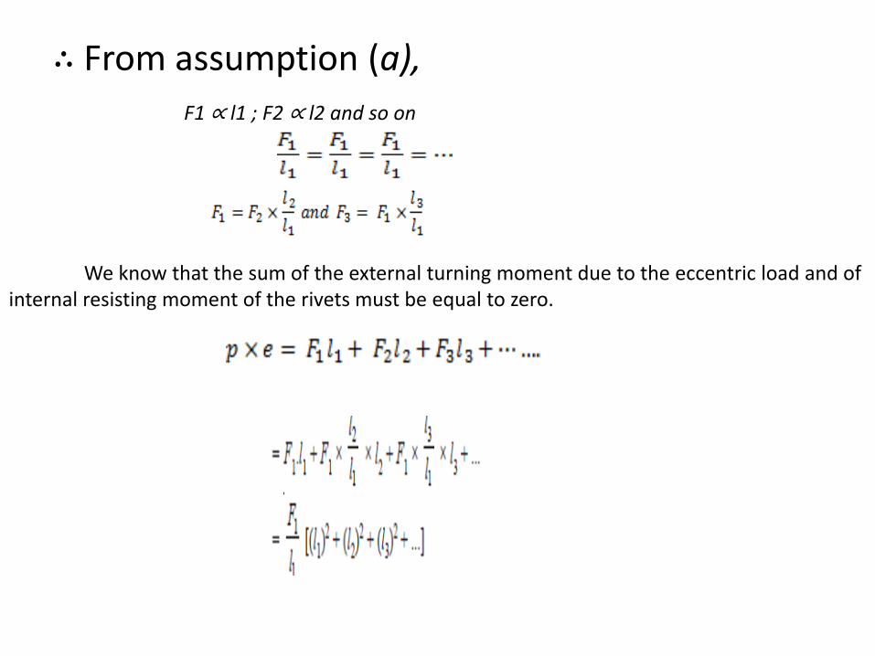
∴ From assumption (a),
F1 ∝ l1 ; F2 ∝ l2 and so on
We know that the sum of the external turning moment due to the eccentric load and of internal resisting moment of the rivets must be equal to zero.
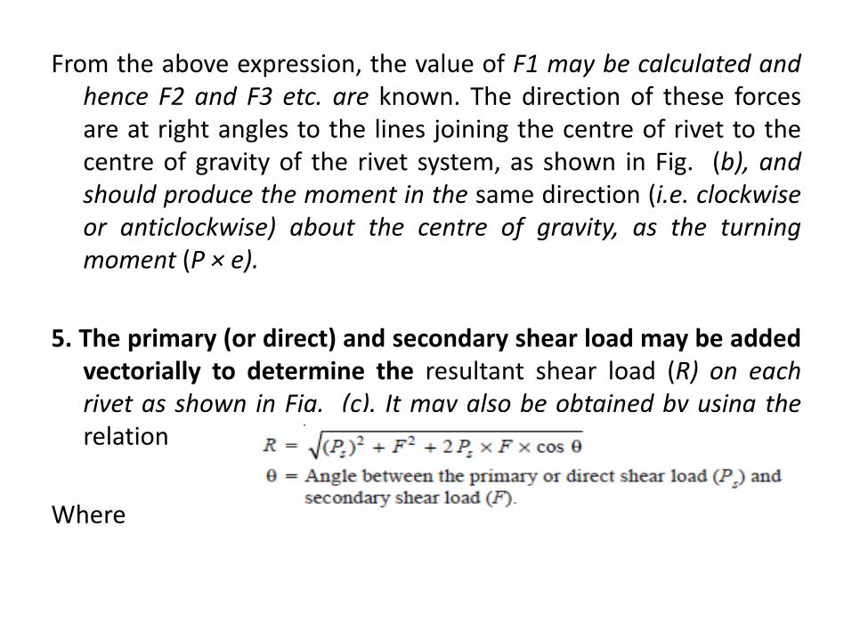
From the above expression, the value of F1 may be calculated and hence F2 and F3 etc. are known. The direction of these forces are at right angles to the lines joining the centre of rivet to the centre of gravity of the rivet system, as shown in Fig. (b), and should produce the moment in the same direction (i.e. clockwise or anticlockwise) about the centre of gravity, as the turning moment (P × e).
5. The primary (or direct) and secondary shear load may be added vectorially to determine the resultant shear load (R) on each rivet as shown in Fig. (c). It may also be obtained by using the relation
Where
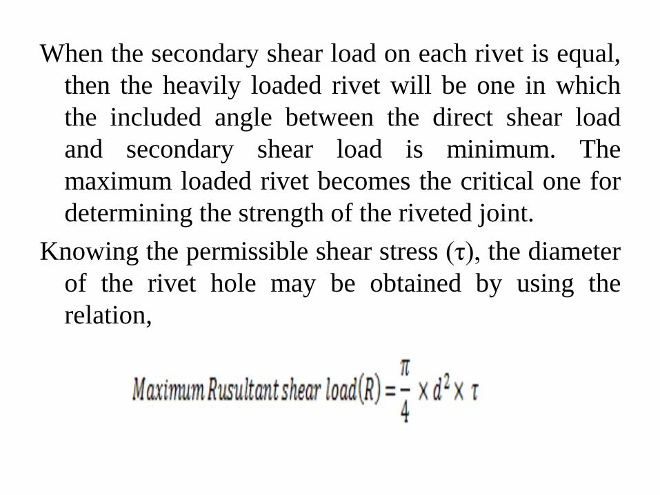
When the secondary shear load on each rivet is equal,
then the heavily loaded rivet will be one in which
the included angle between the direct shear load
and secondary shear load is minimum. The
maximum loaded rivet becomes the critical one for
determining the strength of the riveted joint.
Knowing the permissible shear stress (τ), the diameter
of the rivet hole may be obtained by using the
relation,

LECTURE 7 Introduction to welded joints
Welded Joint Introduction A welded joint is a permanent joint which is obtained by the fusion of the edges of the two parts to be joined together, with or without the application of pressure and a filler material. The heat required for the fusion of the material may be obtained by burning of gas (in case of gas welding) or by an electric arc (in case of electric arc welding). The latter method is extensively used because of greater speed of welding. Welding is extensively used in fabrication as an alternative method for casting or forging and as a replacement for bolted and riveted joints. It is also used as a repair medium e.g. to reunite metal at a crack, to build up a small part that has broken off such as gear tooth or to repair a worn surface such as a bearing surface.
Advantages and Disadvantages of Welded Joints over Riveted Joints
Advantages 1. The welded structures are usually lighter than riveted structures. This is due to the reason, that in welding, gussets or other connecting components are not used. 2. The welded joints provide maximum efficiency (may be 100%) which is not possible in case of riveted joints. 3. Alterations and additions can be easily made in the existing structures. 4. As the welded structure is smooth in appearance, therefore it looks pleasing. 5. In welded connections, the tension members are not weakened as in the case of riveted joints. 6. A welded joint has a great strength. Often a welded joint has the strength of the parent metal itself. 7. Sometimes, the members are of such a shape (i.e. circular steel pipes) that they afford difficulty for riveting. But they can be easily welded.
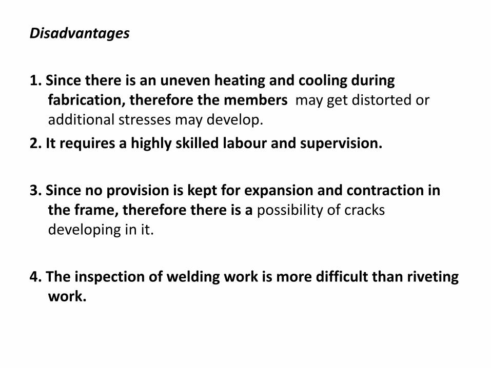
Disadvantages
1. Since there is an uneven heating and cooling during fabrication, therefore the members may get distorted or additional stresses may develop.
2. It requires a highly skilled labour and supervision.
3. Since no provision is kept for expansion and contraction in the frame, therefore there is a possibility of cracks developing in it.
4. The inspection of welding work is more difficult than riveting work.
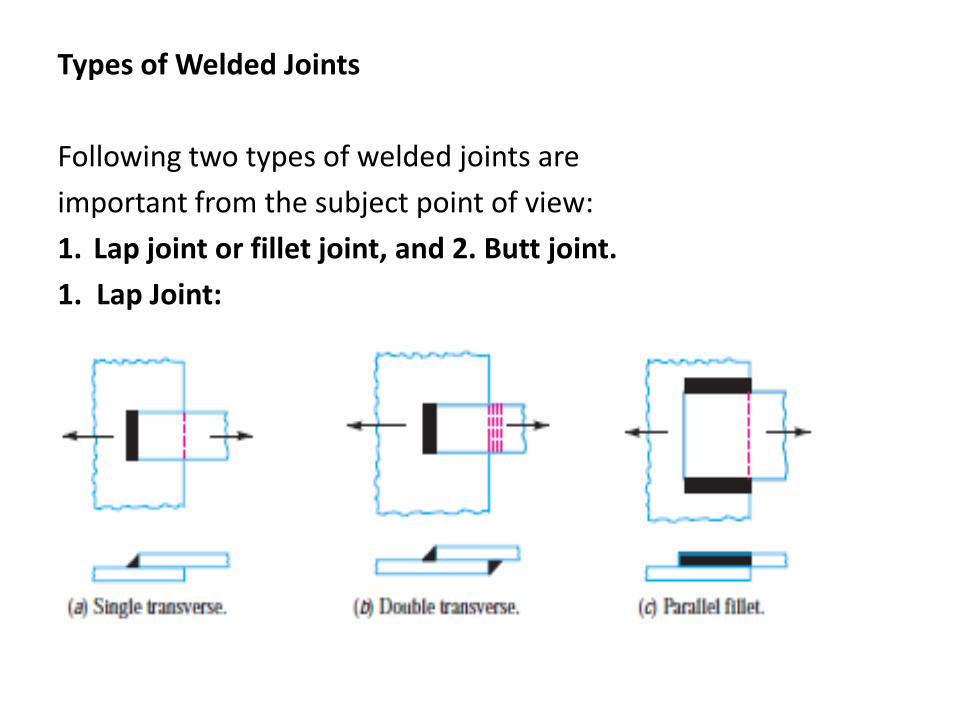
Types of Welded Joints
Following two types of welded joints are
important from the subject point of view:
1. Lap joint or fillet joint, and 2. Butt joint.
1. Lap Joint:
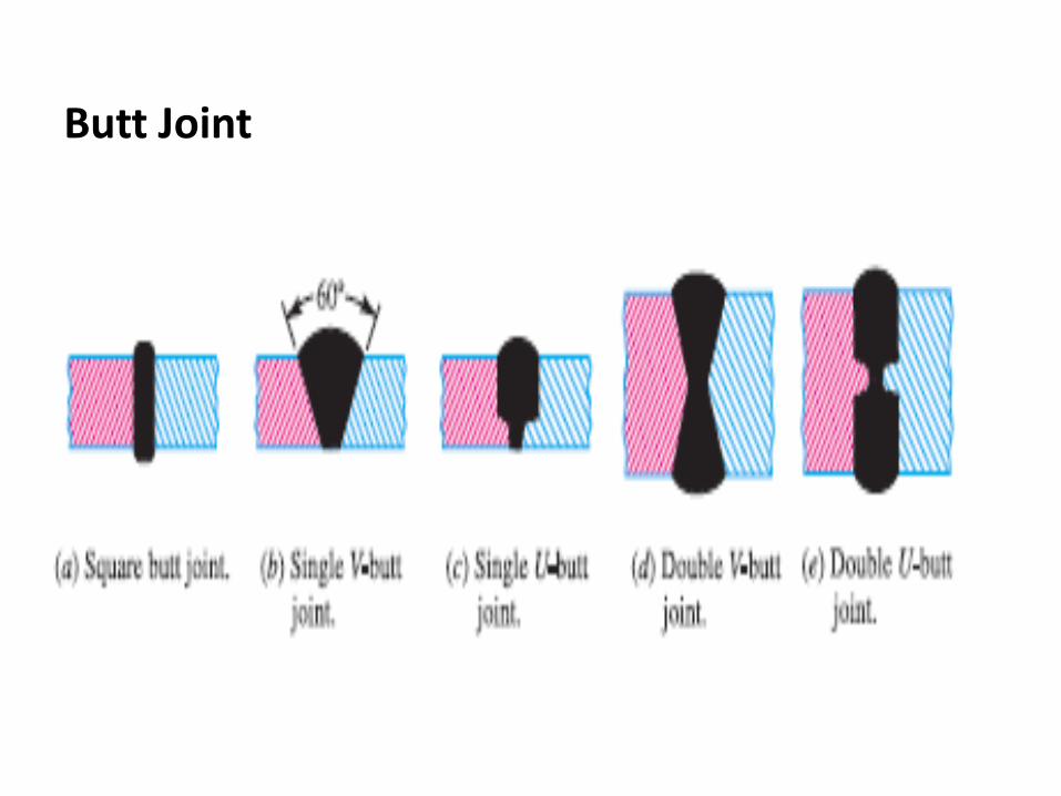
Butt Joint
LECTURE 8 Stresses Acting on Welded Joints
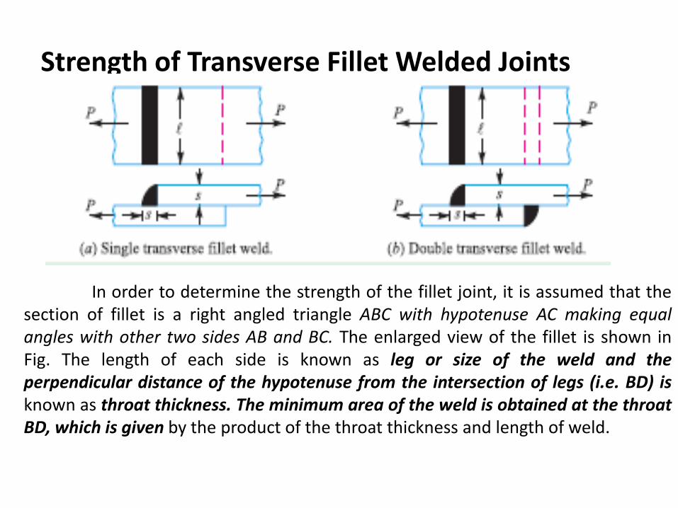
Strength of Transverse Fillet Welded Joints
In order to determine the strength of the fillet joint, it is assumed that the section of fillet is a right angled triangle ABC with hypotenuse AC making equal angles with other two sides AB and BC. The enlarged view of the fillet is shown in Fig. The length of each side is known as leg or size of the weld and the perpendicular distance of the hypotenuse from the intersection of legs (i.e. BD) is known as throat thickness. The minimum area of the weld is obtained at the throat BD, which is given by the product of the throat thickness and length of weld.
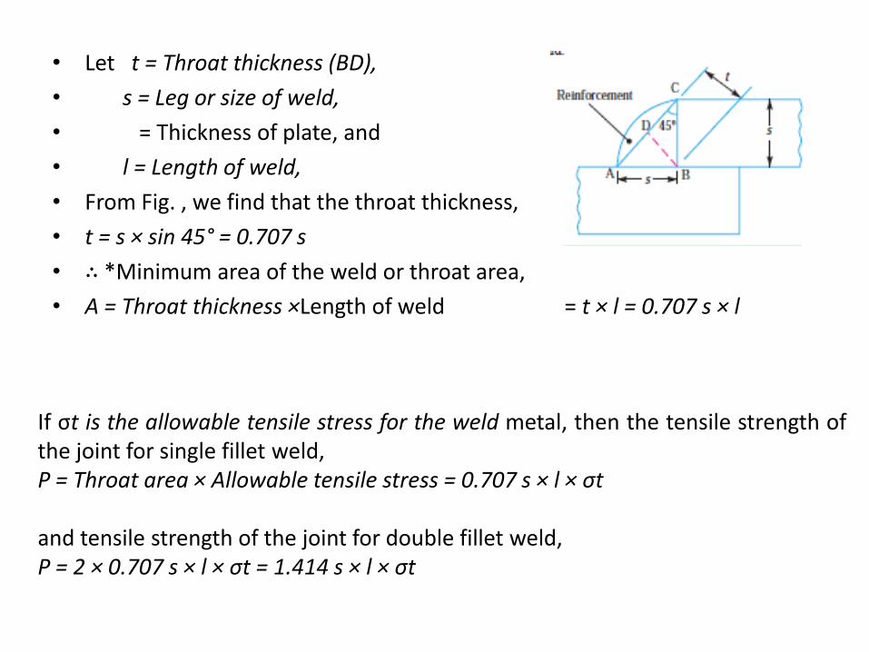
• Let t = Throat thickness (BD),
• s = Leg or size of weld,
• = Thickness of plate, and
• l = Length of weld,
• From Fig. , we find that the throat thickness,
• t = s × sin 45° = 0.707 s
• ∴ *Minimum area of the weld or throat area,
• A = Throat thickness ×Length of weld = t × l = 0.707 s × l
If σt is the allowable tensile stress for the weld metal, then the tensile strength of the joint for single fillet weld, P = Throat area × Allowable tensile stress = 0.707 s × l × σt and tensile strength of the joint for double fillet weld, P = 2 × 0.707 s × l × σt = 1.414 s × l × σt
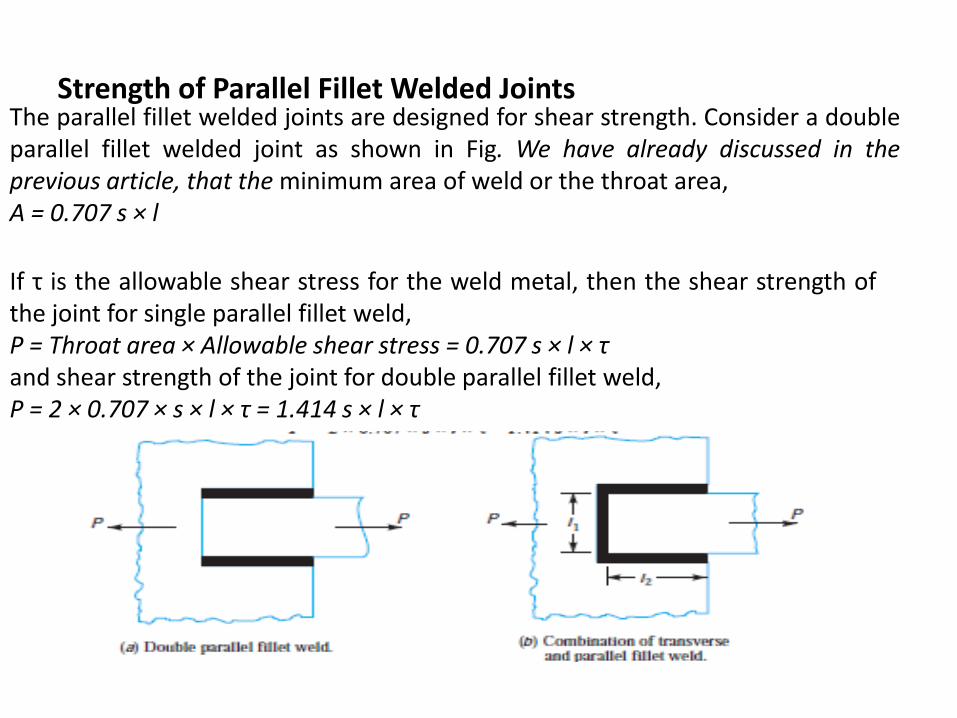
Strength of Parallel Fillet Welded Joints
The parallel fillet welded joints are designed for shear strength. Consider a double parallel fillet welded joint as shown in Fig. We have already discussed in the previous article, that the minimum area of weld or the throat area, A = 0.707 s × l
If τ is the allowable shear stress for the weld metal, then the shear strength of the joint for single parallel fillet weld, P = Throat area × Allowable shear stress = 0.707 s × l × τ and shear strength of the joint for double parallel fillet weld, P = 2 × 0.707 × s × l × τ = 1.414 s × l × τ
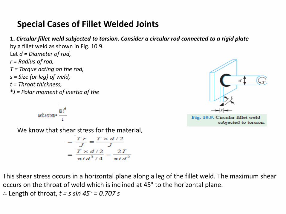
Special Cases of Fillet Welded Joints
1. Circular fillet weld subjected to torsion. Consider a circular rod connected to a rigid plate by a fillet weld as shown in Fig. 10.9. Let d = Diameter of rod, r = Radius of rod, T = Torque acting on the rod, s = Size (or leg) of weld, t = Throat thickness, *J = Polar moment of inertia of the
We know that shear stress for the material,
This shear stress occurs in a horizontal plane along a leg of the fillet weld. The maximum shear occurs on the throat of weld which is inclined at 45° to the horizontal plane. ∴ Length of throat, t = s sin 45° = 0.707 s
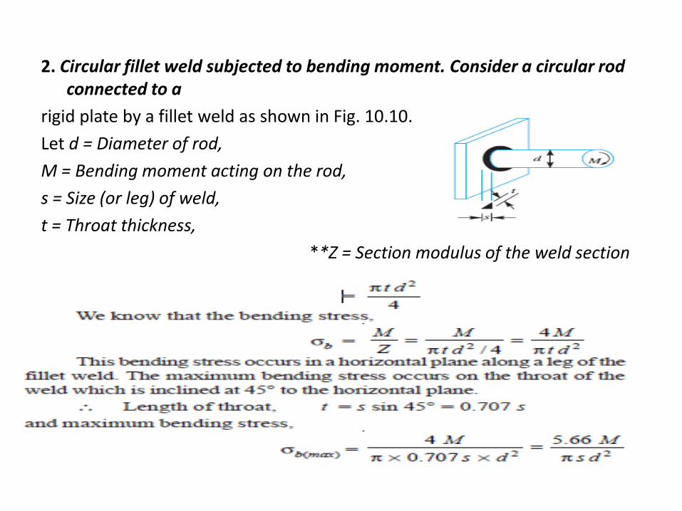
2. Circular fillet weld subjected to bending moment. Consider a circular rod connected to a
rigid plate by a fillet weld as shown in Fig. 10.10.
Let d = Diameter of rod,
M = Bending moment acting on the rod,
s = Size (or leg) of weld,
t = Throat thickness,
**Z = Section modulus of the weld section
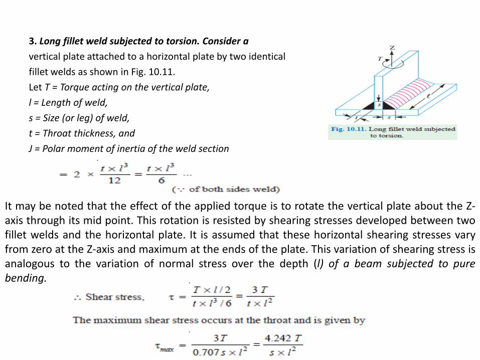
3. Long fillet weld subjected to torsion. Consider a
vertical plate attached to a horizontal plate by two identical
fillet welds as shown in Fig. 10.11.
Let T = Torque acting on the vertical plate,
l = Length of weld,
s = Size (or leg) of weld,
t = Throat thickness, and
J = Polar moment of inertia of the weld section
It may be noted that the effect of the applied torque is to rotate the vertical plate about the Z-axis through its mid point. This rotation is resisted by shearing stresses developed between two fillet welds and the horizontal plate. It is assumed that these horizontal shearing stresses vary from zero at the Z-axis and maximum at the ends of the plate. This variation of shearing stress is analogous to the variation of normal stress over the depth (l) of a beam subjected to pure bending.
LECTURE 9 Introduction-Bolted Joints
Bolted Joints: Introduction: • A screw thread is formed by cutting a continuous helical
groove on a cylindrical surface. • A screw made by cutting a single helical groove on the
cylinder is known as single threaded (or single-start) screw and if a second thread is cut in the space between the grooves of the first, a double threaded (or double-start) screw is formed.
• Similarly, triple and quadruple (i.e. multiple-start) threads may be formed. The helical grooves may be cut either right hand or left hand.
• A screwed joint is mainly composed of two elements i.e. a bolt and nut. The screwed joints are widely used where the machine parts are required to be readily connected or disconnected without damage to the machine or the fastening.
• Advantages and Disadvantages of Screwed Joints
• Advantages – Screwed joints are highly reliable in operation.
– Screwed joints are convenient to assemble and disassemble.
– A wide range of screwed joints may be adopted to various operating conditions.
– Screws are relatively cheap to produce due to standardization and highly efficient manufacturing processes.
• Disadvantages
• The main disadvantage of the screwed joints is the stress concentration in the threaded portions which are vulnerable points under variable load conditions.
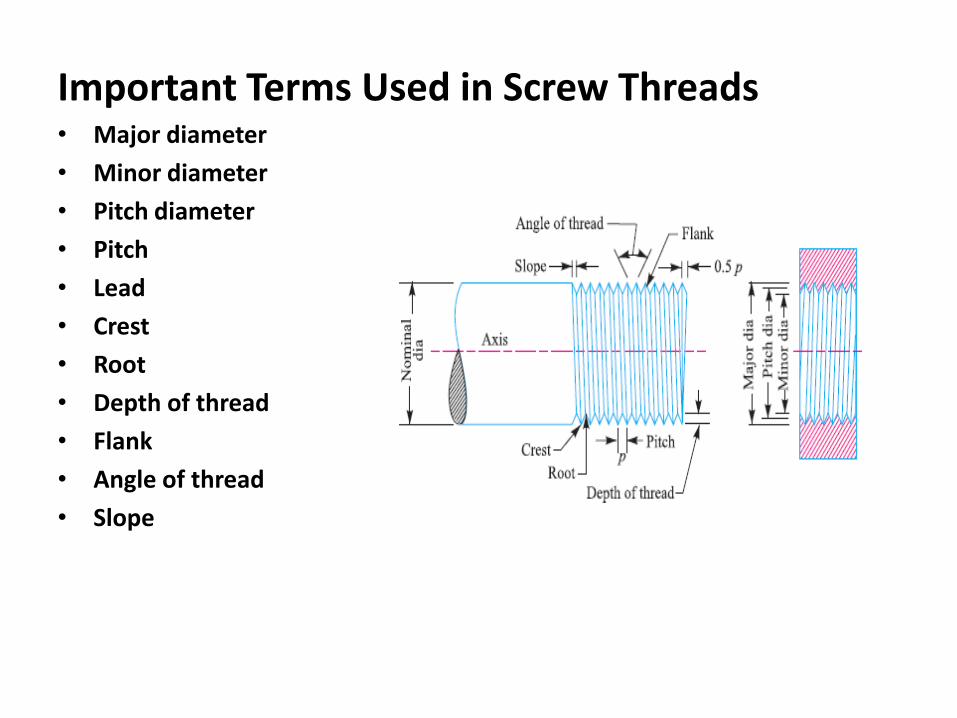
Important Terms Used in Screw Threads • Major diameter
• Minor diameter
• Pitch diameter
• Pitch
• Lead
• Crest
• Root
• Depth of thread
• Flank
• Angle of thread
• Slope
Forms of Screw Threads
• British standard Whitworth (B.S.W.) thread.
• British association (B.A.) thread
• American national standard thread
• Square thread
• Acme thread
• Knuckle thread
• Buttress thread
• Buttress thread
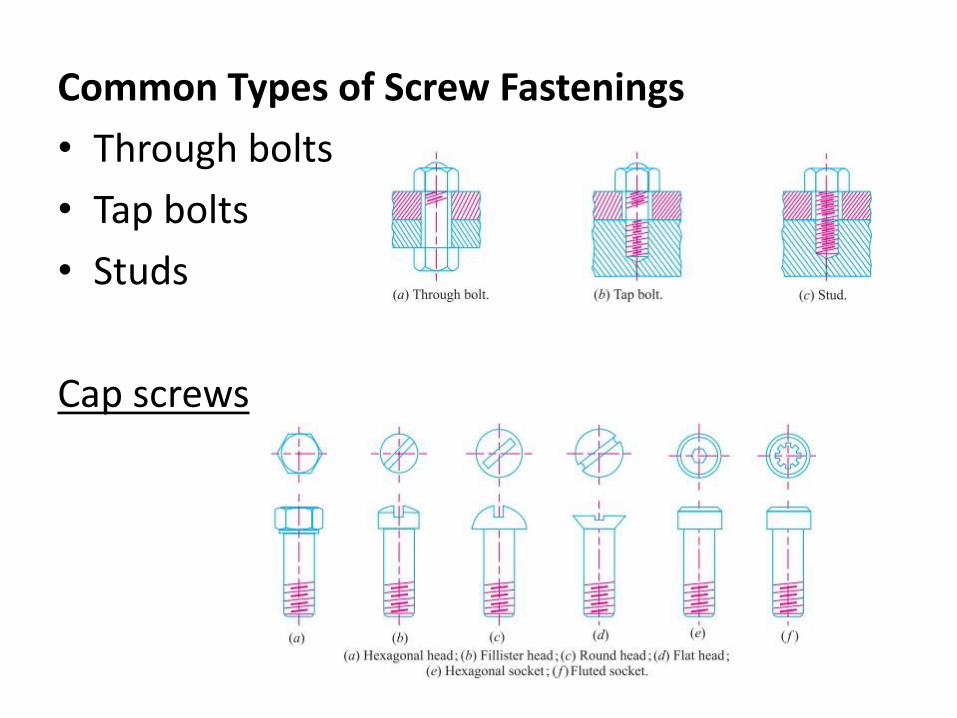
Common Types of Screw Fastenings
• Through bolts
• Tap bolts
• Studs
Cap screws
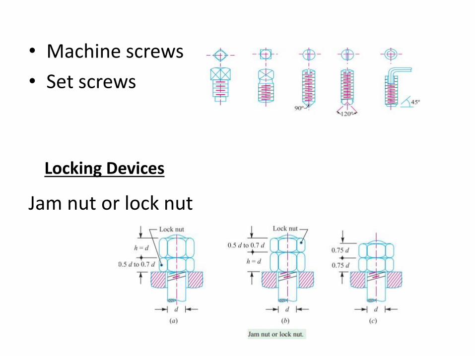
• Machine screws
• Set screws
Jam nut or lock nut
Locking Devices
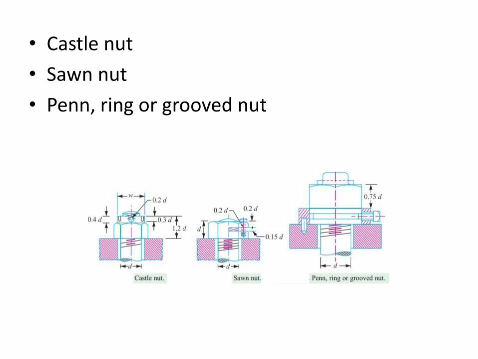
• Castle nut
• Sawn nut
• Penn, ring or grooved nut
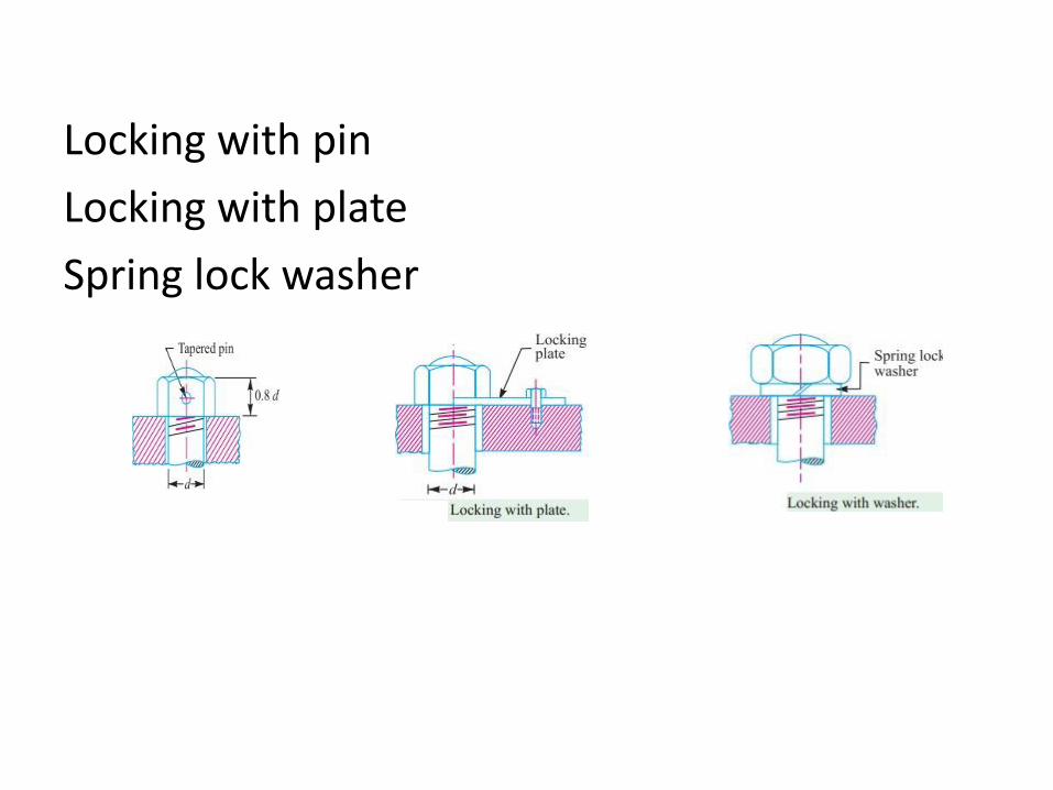
Locking with pin
Locking with plate
Spring lock washer
LECTURE 10 Stresses on bolted joints
Stresses in Screwed Fastening due to Static Loading
• Internal stresses due to screwing up forces,
• Stresses due to external forces, and
• Stress due to combination of stresses at (1) and (2).
Initial Stresses due to Screwing up Forces
1. Tensile stress due to stretching of bolt
The initial tension in a bolt, based on experiments, may be found by the relation
Pi= 2840 d N
Pi= Initial tension in a bolt, and
d= Nominal diameter of bolt, in mm.
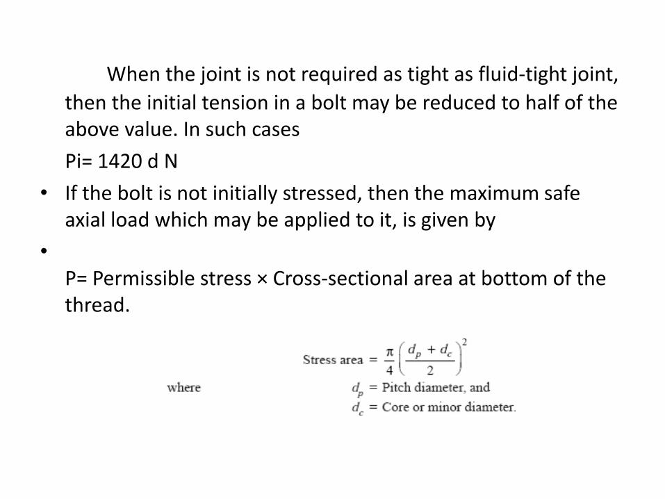
When the joint is not required as tight as fluid-tight joint,
then the initial tension in a bolt may be reduced to half of the above value. In such cases
Pi= 1420 d N
• If the bolt is not initially stressed, then the maximum safe axial load which may be applied to it, is given by
• P= Permissible stress × Cross-sectional area at bottom of the thread.
Design of a Nut – When a bolt and nut is made of mild steel, then the
effective height of nut is made equal to the nominal diameter of the bolt.
– If the nut is made of weaker material than the bolt, then the height of nut should be larger, such as 1.5 d for gun metal, 2 d for cast iron and 2.5 d for aluminium alloys (where d is the nominal diameter of the bolt).
– In case cast iron or aluminium nut is used, then V-threads are permissible only for permanent fastenings, because threads in these materials are damaged due to repeated screwing and unscrewing.
• Bolted Joints under Eccentric Loading
•
• There are many applications of the bolted joints which are subjected to eccentric loading such as a wall bracket, pillar crane, etc. The eccentric load may be
• Parallel to the axis of the bolts,
• Perpendicular to the axis of the bolts, and
• In the plane containing the bolts.
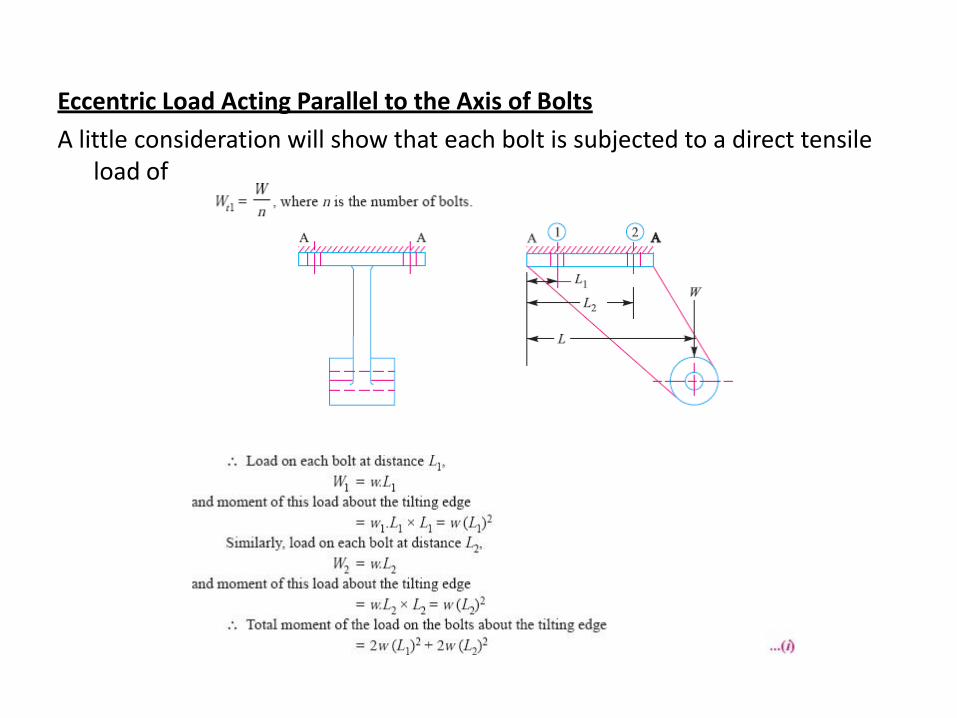
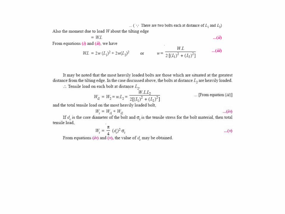
Eccentric Load Acting Parallel to the Axis of Bolts
A little consideration will show that each bolt is subjected to a direct tensile load of
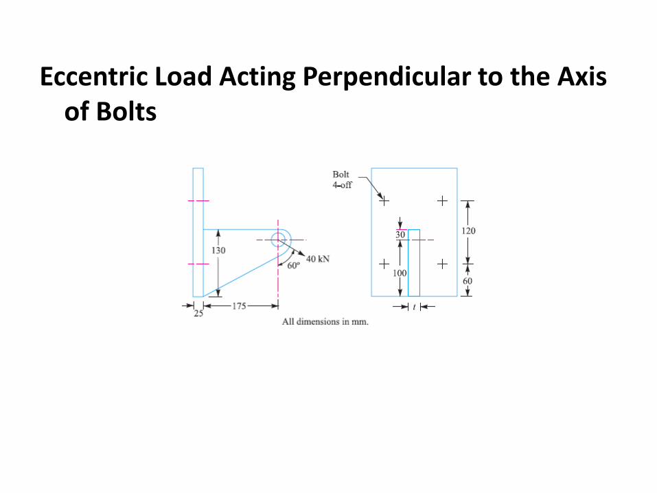
Eccentric Load Acting Perpendicular to the Axis of Bolts
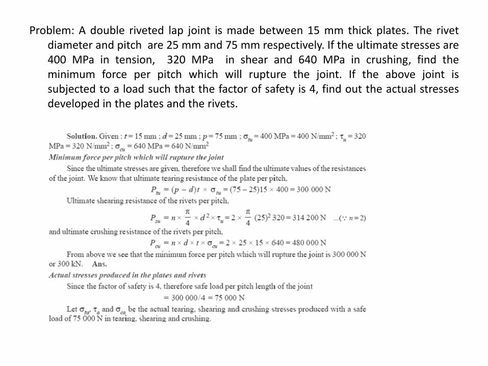
Problem: A double riveted lap joint is made between 15 mm thick plates. The rivet diameter and pitch are 25 mm and 75 mm respectively. If the ultimate stresses are 400 MPa in tension, 320 MPa in shear and 640 MPa in crushing, find the minimum force per pitch which will rupture the joint. If the above joint is subjected to a load such that the factor of safety is 4, find out the actual stresses developed in the plates and the rivets.
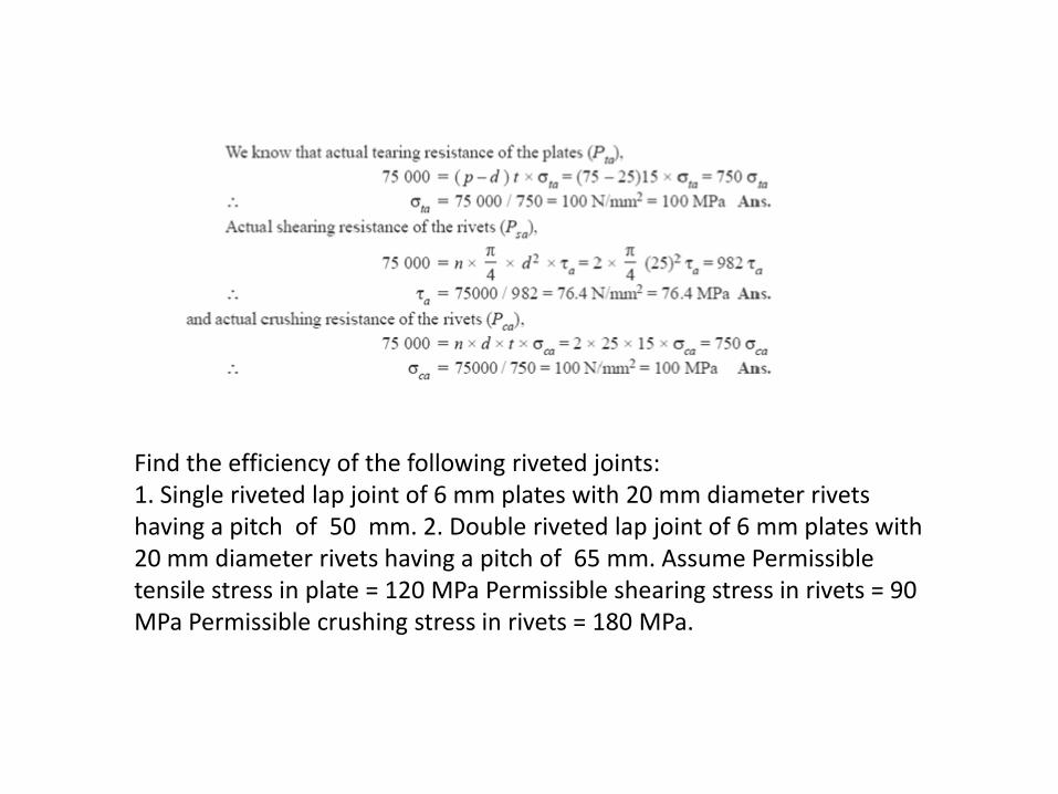
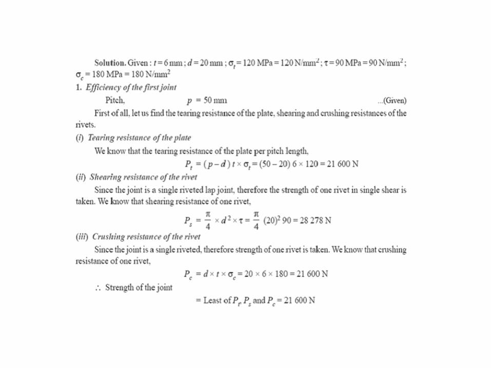
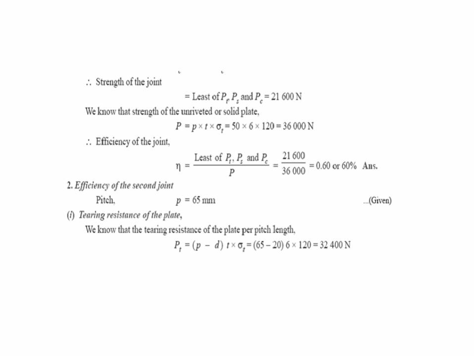
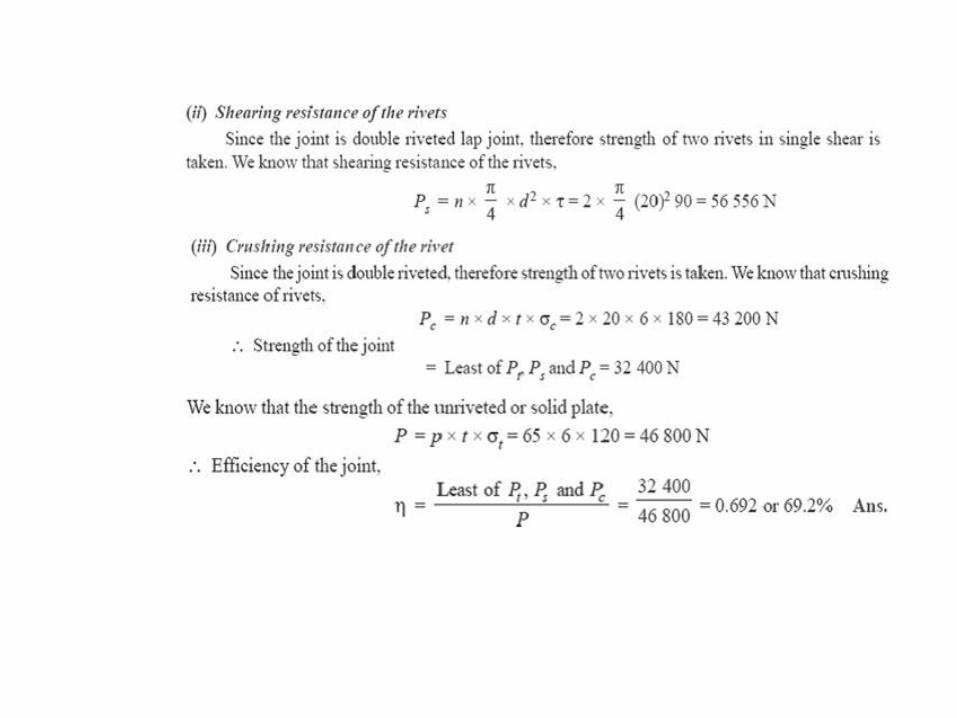
Find the efficiency of the following riveted joints: 1. Single riveted lap joint of 6 mm plates with 20 mm diameter rivets having a pitch of 50 mm. 2. Double riveted lap joint of 6 mm plates with 20 mm diameter rivets having a pitch of 65 mm. Assume Permissible tensile stress in plate = 120 MPa Permissible shearing stress in rivets = 90 MPa Permissible crushing stress in rivets = 180 MPa.
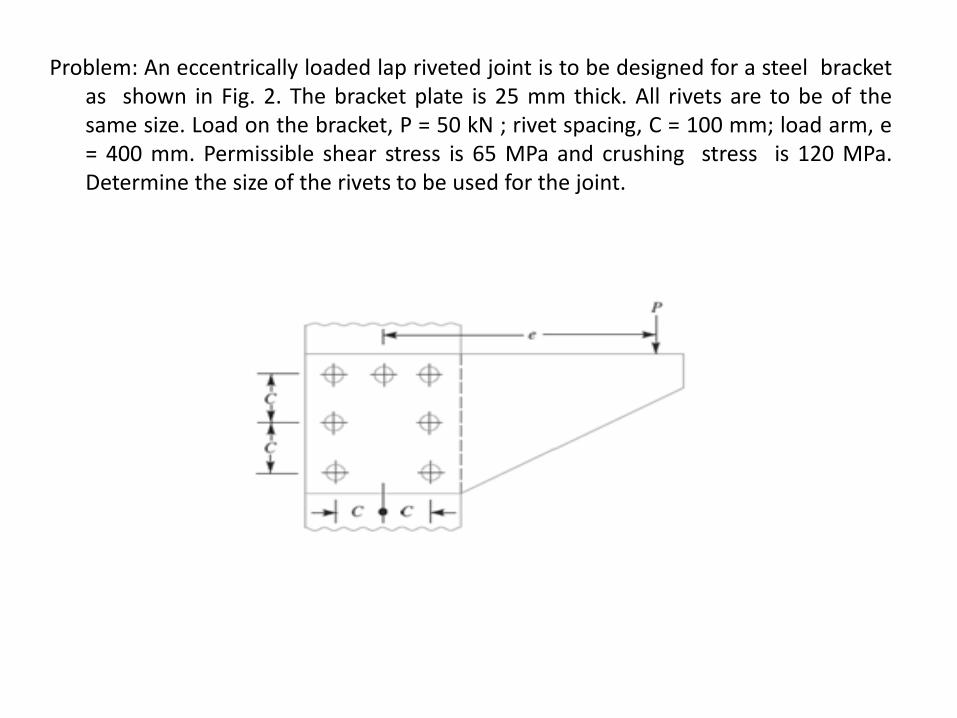
Problem: An eccentrically loaded lap riveted joint is to be designed for a steel bracket as shown in Fig. 2. The bracket plate is 25 mm thick. All rivets are to be of the same size. Load on the bracket, P = 50 kN ; rivet spacing, C = 100 mm; load arm, e = 400 mm. Permissible shear stress is 65 MPa and crushing stress is 120 MPa. Determine the size of the rivets to be used for the joint.

DIGITALCLASSROOM
ENVIRONM ENTA N E W P E D A G O G Y I S E M E R G I N G
C. Daksheeswara ReddyAssistant Professor,
Mechanical Engineering

(Source: TASK Training material)
DEPARTMENT OF MECHANICAL ENGINEERING
UNIT 4CO4: To learn the design Procedure for the different
machine elements such as fasteners, couplings, keys, axially
loaded joints etc.
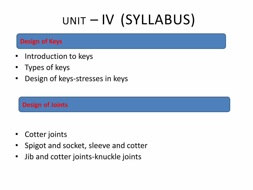
• Introduction to keys
• Types of keys
• Design of keys-stresses in keys
• Cotter joints
• Spigot and socket, sleeve and cotter
• Jib and cotter joints-knuckle joints
UNIT – IV (SYLLABUS)Design of Keys
Design of Joints
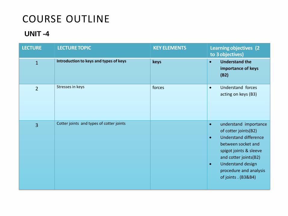
COURSE OUTLINEUNIT -4
LECTURE LECTURE TOPIC KEY ELEMENTS Learning objectives (2 to 3objectives)
1 Introduction to keys and types of keys keys Understand the
importance of keys
(B2)
2 Stresses in keys forces Understand forces
acting on keys (B3)
3 Cotter joints and types of cotter joints understand importance
of cotter joints(B2)
Understand difference
between socket and
spigot joints & sleeve
and cotter joints(B2)
Understand design
procedure and analysis
of joints . (B3&B4)

LECTURE 1Introduction-Keys
UNIT IVKEYS, COTTERS AND KNUCKLE JOINTS
Introduction to Keys:
A key is a piece of mild steel inserted between the shaft and hub or boss of
the pulley to connect these together in order to prevent relativemotion between them. It is always inserted parallel to the axis of the shaft.
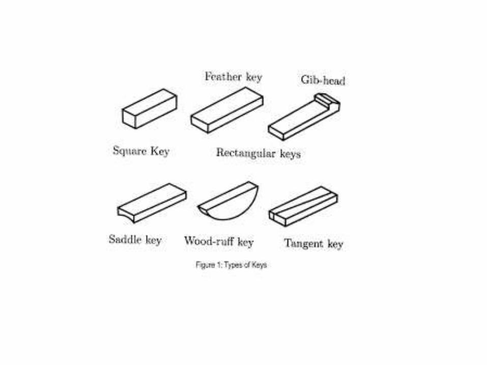
Types of Keys:There are five main types of keys: sunk, saddle, tangent, round, and spline.
•Sunk key. Types of sunk keys: rectangular, square, parallel sunk, gib-head, feather, andWoodruff.
•Saddle keys
•Tangent keys
•Spline keys
Revision Questions
1. What is the function of key
2. Explain Types of keys

LECTURE 2Stresses acting on keys
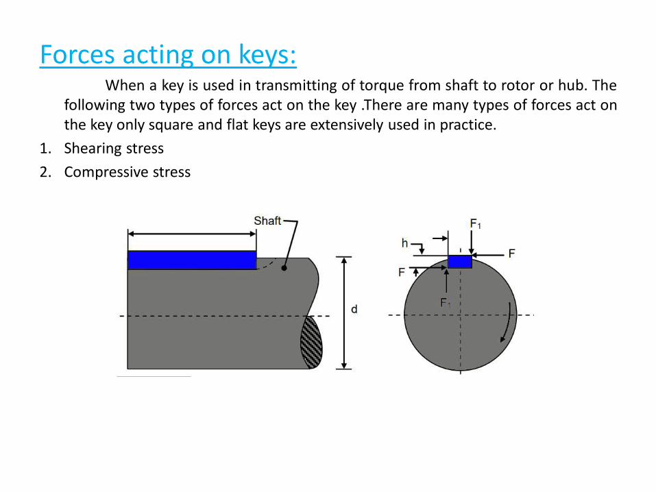
Forces acting on keys:When a key is used in transmitting of torque from shaft to rotor or hub. The
following two types of forces act on the key .There are many types of forces act onthe key only square and flat keys are extensively used in practice.
1. Shearing stress
2. Compressive stress
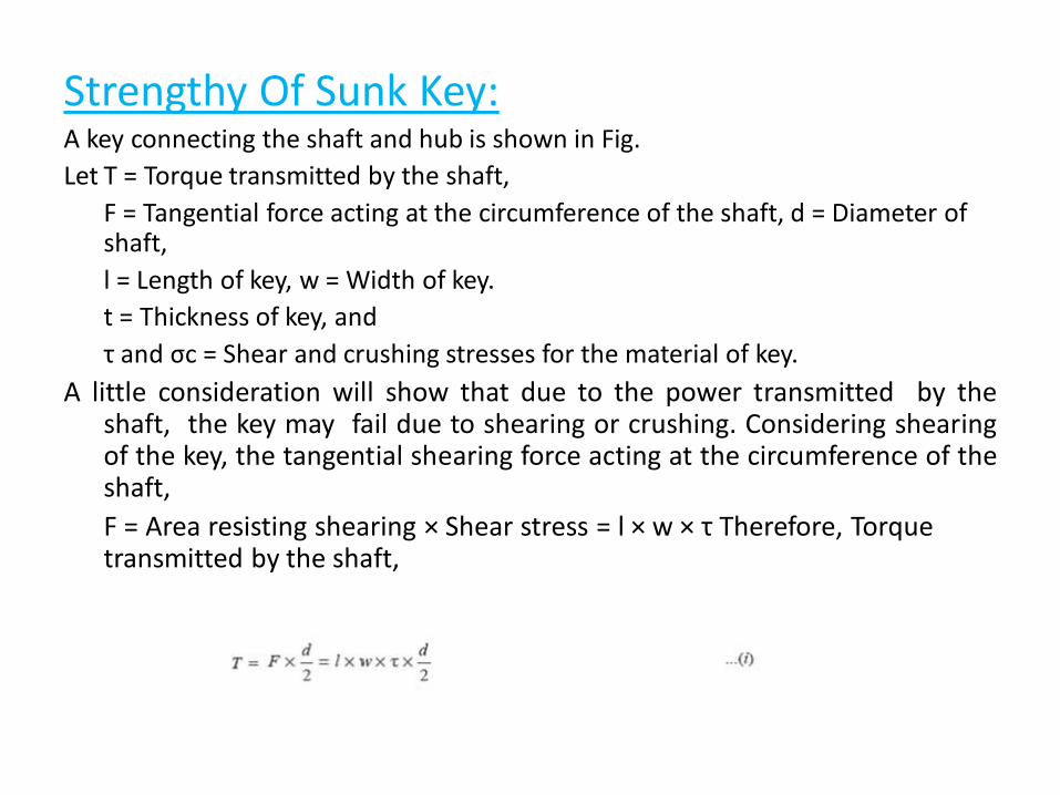
Strengthy Of Sunk Key:A key connecting the shaft and hub is shown in Fig.
Let T = Torque transmitted by the shaft,
F = Tangential force acting at the circumference of the shaft, d = Diameter of shaft,
l = Length of key, w = Width of key.
t = Thickness of key, and
τ and σc = Shear and crushing stresses for the material of key.
A little consideration will show that due to the power transmitted by theshaft, the key may fail due to shearing or crushing. Considering shearingof the key, the tangential shearing force acting at the circumference of theshaft,
F = Area resisting shearing × Shear stress = l × w × τ Therefore, Torque transmitted by the shaft,
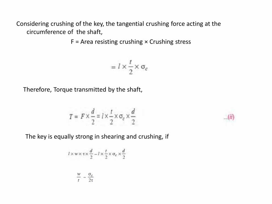
Considering crushing of the key, the tangential crushing force acting at the circumference of the shaft,
F = Area resisting crushing × Crushing stress
Therefore, Torque transmitted by the shaft,
The key is equally strong in shearing and crushing, if
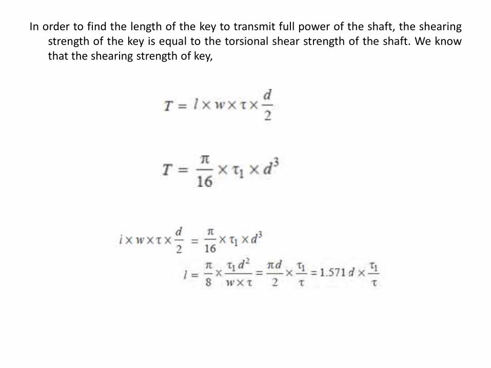
In order to find the length of the key to transmit full power of the shaft, the shearingstrength of the key is equal to the torsional shear strength of the shaft. We knowthat the shearing strength of key,
Revision Questions
1. What are the forces acting on keys
LECTURE 3Design of cotter joints
Cotter Joints:Cotter joint is widely used to connect the piston rod between the piston rod
and the tailor pump rod, foundation bolt etc. ... A cotter is a wedge and crossheadof a steam engine, as a jointshaped piece made of a steel plate. It has uniformthickness and the width dimension is given a slight taper.
Cotter joint is a flat wedge shaped piece of steel. ... cotter is used to connectrigidly two rods which transmit motion in the axial direction, without rotation. •These joints may be subjected to tensile or compressive forces along the axes ofthe rods.
Types of Cotter Joints:1. Socket and spigot cotter joint
1. Sleeve and cotter joint
1. Gib and cotter joint
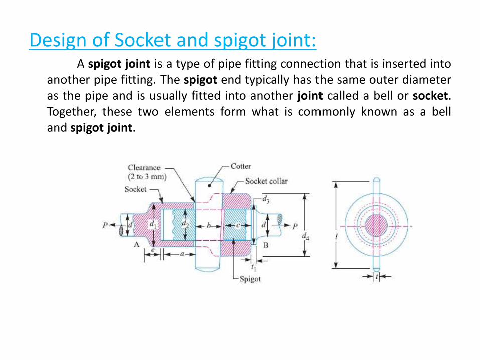
Design of Socket and spigot joint:A spigot joint is a type of pipe fitting connection that is inserted into
another pipe fitting. The spigot end typically has the same outer diameteras the pipe and is usually fitted into another joint called a bell or socket.Together, these two elements form what is commonly known as a belland spigot joint.
The socket and spigot cotter joint is shown in Fig. Let
P = Load carried by the rods,
d = Diameter of the rods,d1 = Outside diameter of socket,
d2 = Diameter of spigot or inside diameter of socket, d3 = Outside diameter of spigot collar,
t1= Thickness of spigot collar, d4 = Diameter of socket collar, c = Thickness of socket collar, b = Mean width of cotter,
t = Thickness of cotter, l = Length of cotter,
a = Distance from the end of the slot to the end of rod, σt = Permissible tensile stress for the rods material,
τ = Permissible shear stress for the cotter material, and σc = Permissible crushing stress for the cotter material.
The dimensions for a socket and spigot cotter joint may be obtained by considering the various modes of failure as discussed below:
1. Failure of the rods in tension
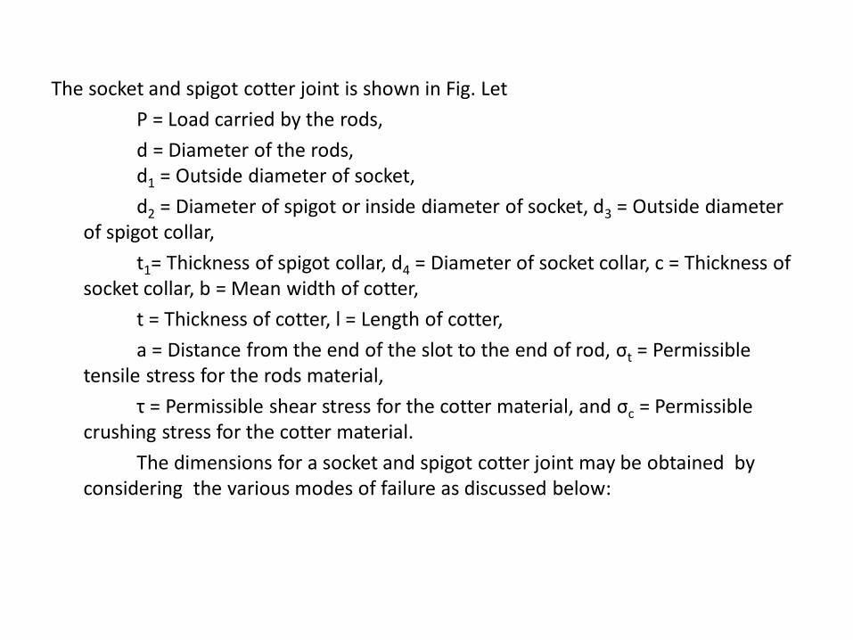
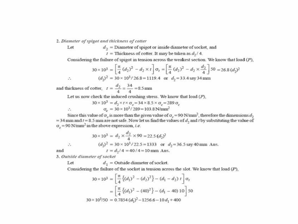
2. Failure of spigot in tension across the weakest section (or slot)
From this equation, the diameter of spigot or inside diameter of socket d2
may be determined. In actual practice, the thickness of cotter is usually taken as d2 / 4.
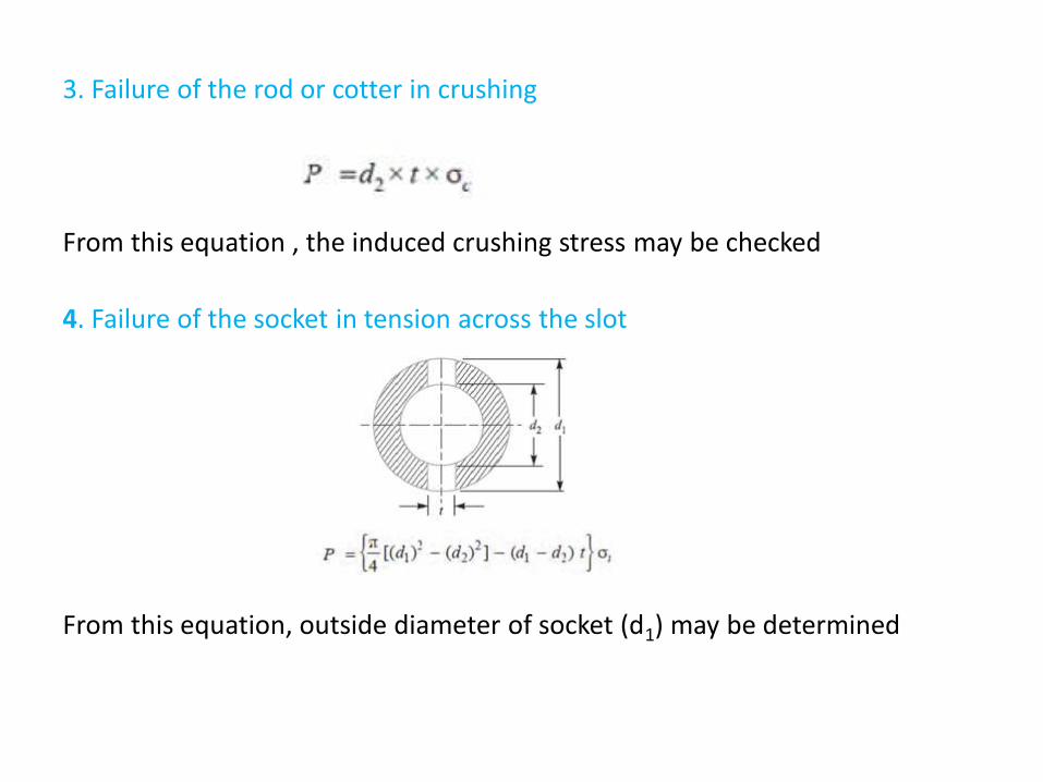
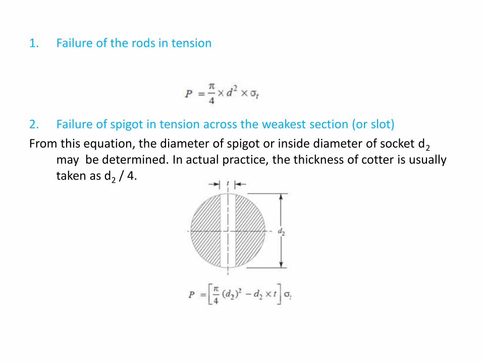
3. Failure of the rod or cotter in crushing
From this equation , the induced crushing stress may be checked
4. Failure of the socket in tension across the slot
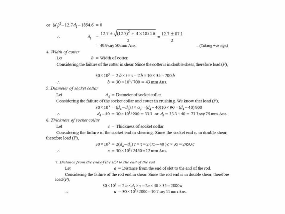
From this equation, outside diameter of socket (d1) may be determined
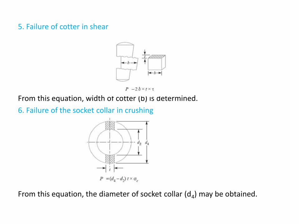
5. Failure of cotter in shear
From this equation, width of cotter (b) is determined.
6. Failure of the socket collar in crushing
From this equation, the diameter of socket collar (d4) may be obtained.
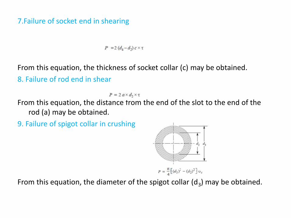
7.Failure of socket end in shearing
From this equation, the thickness of socket collar (c) may be obtained.
8. Failure of rod end in shear
From this equation, the distance from the end of the slot to the end of the rod (a) may be obtained.
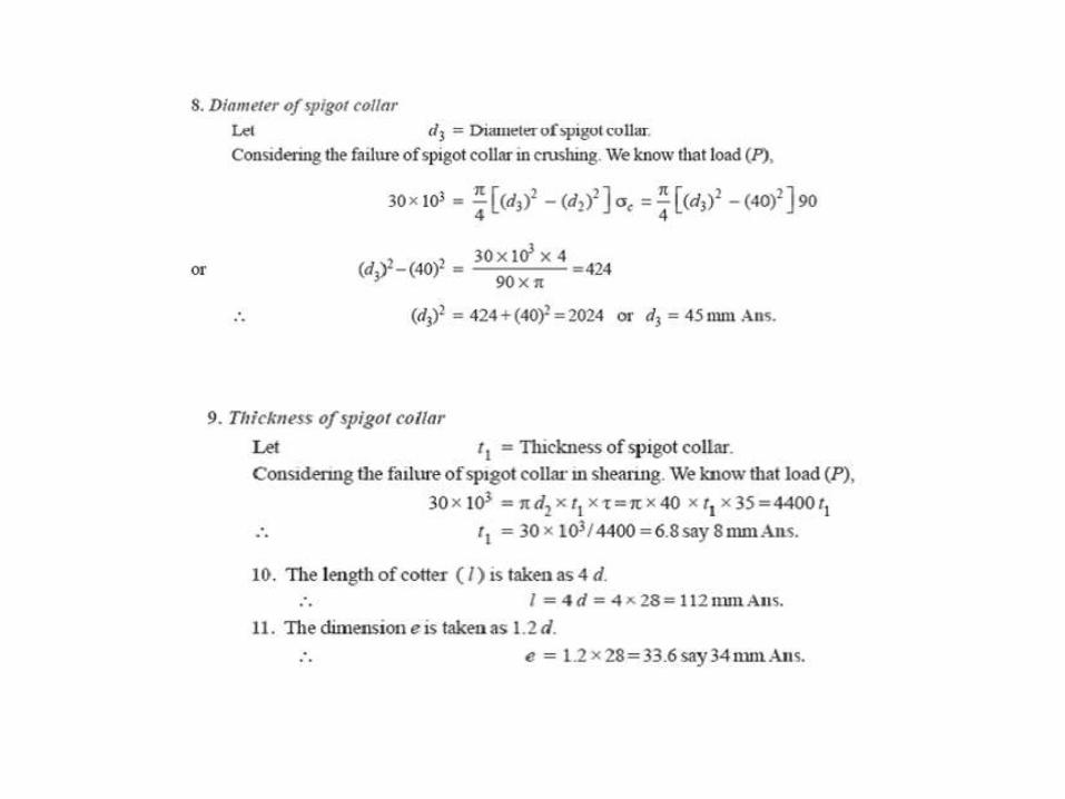
9. Failure of spigot collar in crushing
From this equation, the diameter of the spigot collar (d3) may be obtained.
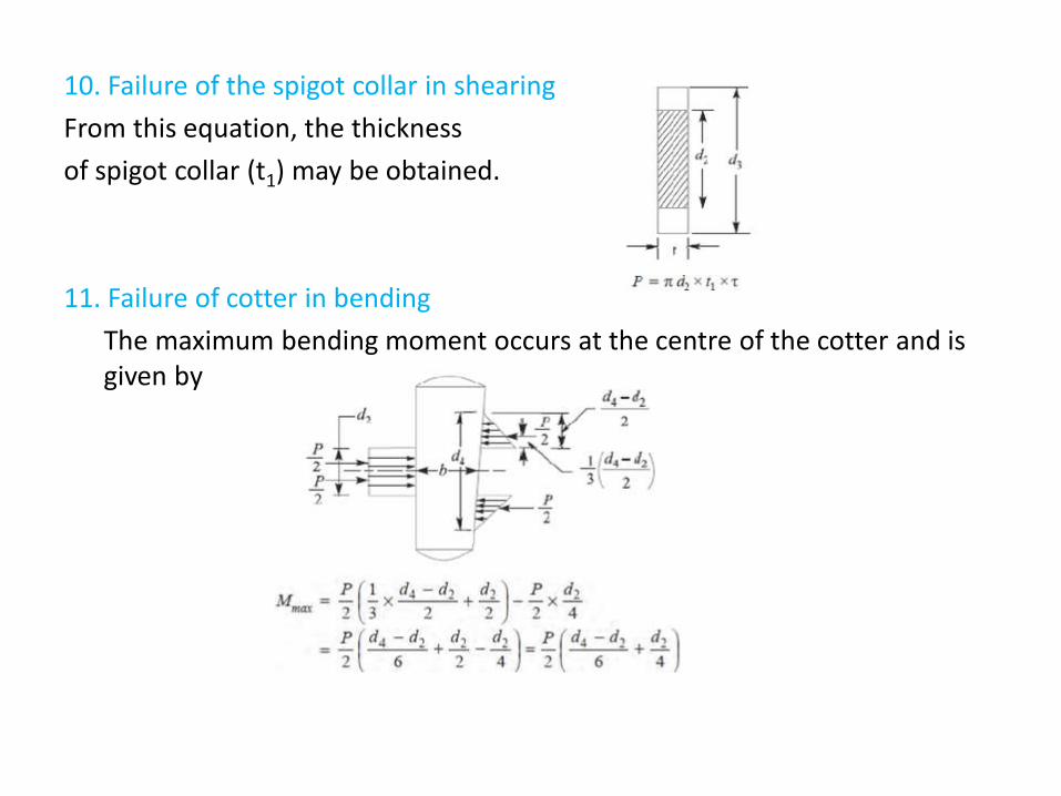
10. Failure of the spigot collar in shearing
From this equation, the thickness
of spigot collar (t1) may be obtained.
11. Failure of cotter in bending
The maximum bending moment occurs at the centre of the cotter and is given by
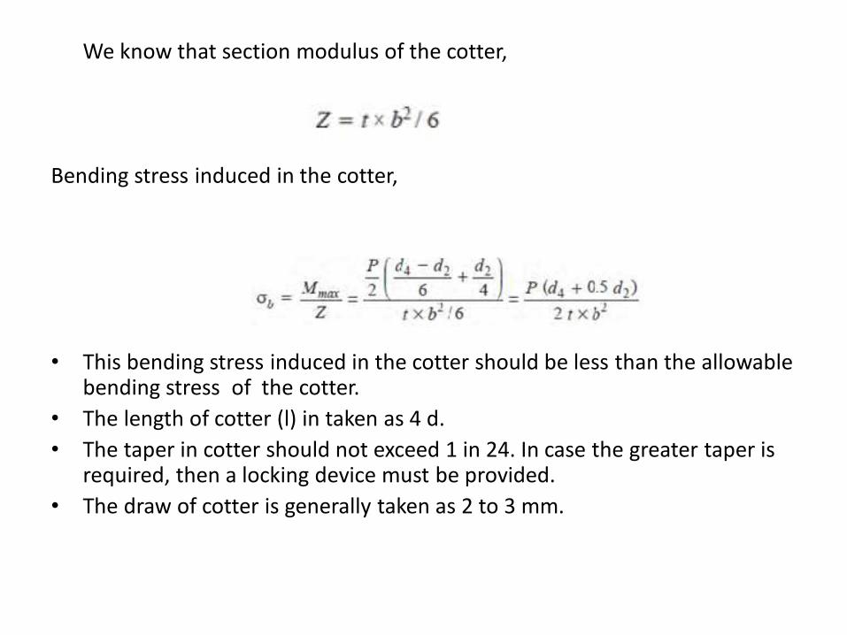
We know that section modulus of the cotter,
Bending stress induced in the cotter,
• This bending stress induced in the cotter should be less than the allowable bending stress of the cotter.
• The length of cotter (l) in taken as 4 d.
• The taper in cotter should not exceed 1 in 24. In case the greater taper is required, then a locking device must be provided.
• The draw of cotter is generally taken as 2 to 3 mm.
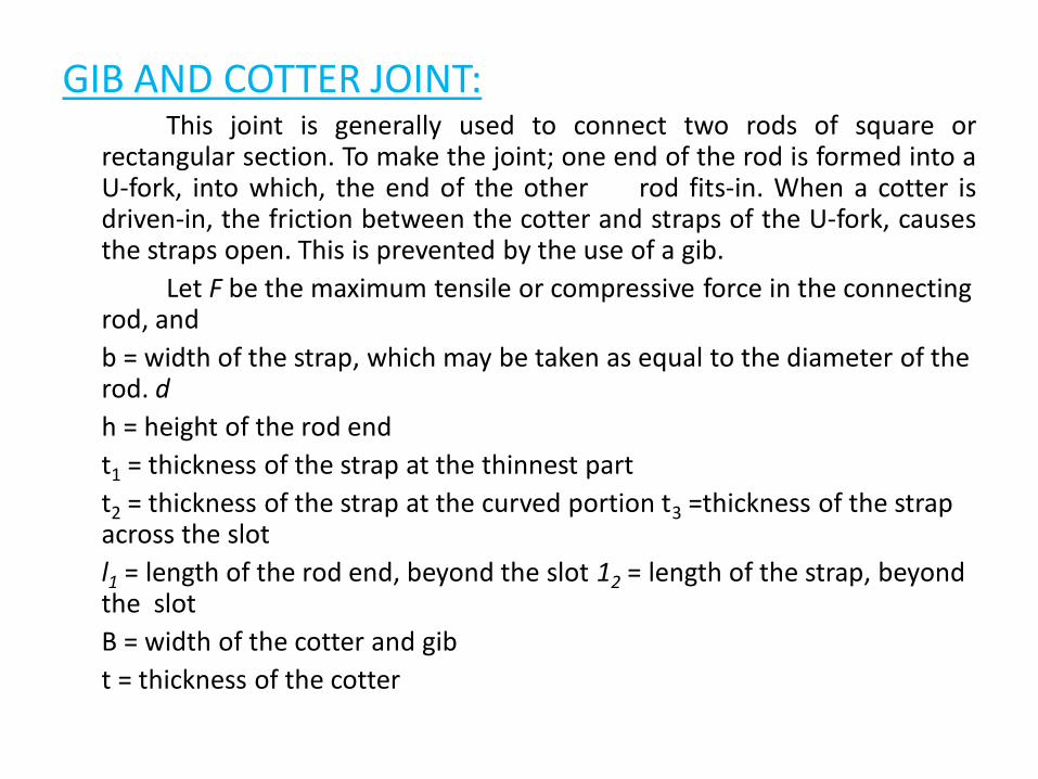
GIB AND COTTER JOINT:This joint is generally used to connect two rods of square or
rectangular section. To make the joint; one end of the rod is formed into aU-fork, into which, the end of the other rod fits-in. When a cotter isdriven-in, the friction between the cotter and straps of the U-fork, causesthe straps open. This is prevented by the use of a gib.
Let F be the maximum tensile or compressive force in the connecting rod, and
b = width of the strap, which may be taken as equal to the diameter of the rod. d
h = height of the rod end
t1 = thickness of the strap at the thinnest part
t2 = thickness of the strap at the curved portion t3 =thickness of the strap across the slot
l1 = length of the rod end, beyond the slot 12 = length of the strap, beyond the slot
B = width of the cotter and gib
t = thickness of the cotter
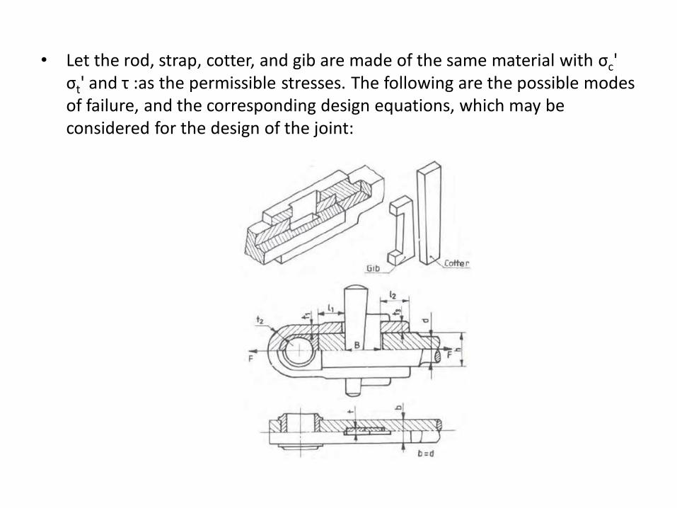
• Let the rod, strap, cotter, and gib are made of the same material with σc' σt' and τ :as the permissible stresses. The following are the possible modes of failure, and the corresponding design equations, which may be considered for the design of the joint:
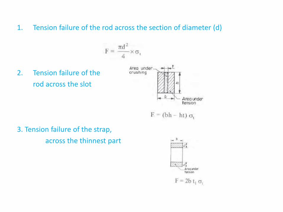
1. Tension failure of the rod across the section of diameter (d)
2. Tension failure of the
rod across the slot
3. Tension failure of the strap,
across the thinnest part
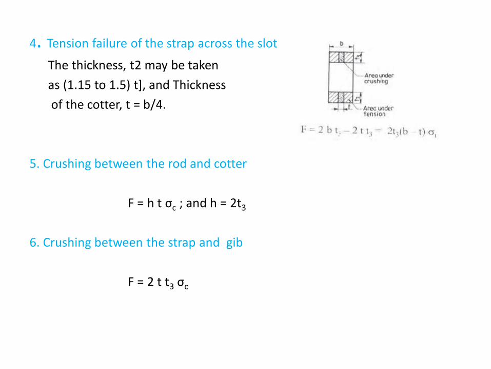
4. Tension failure of the strap across the slot
The thickness, t2 may be taken
as (1.15 to 1.5) t], and Thickness
of the cotter, t = b/4.
5. Crushing between the rod and cotter
F = h t σc ; and h = 2t3
6. Crushing between the strap and gib
F = 2 t t3 σc
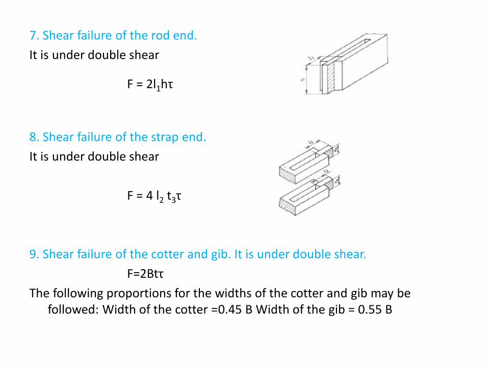
7. Shear failure of the rod end.
It is under double shear
F = 2l1hτ
8. Shear failure of the strap end.
It is under double shear
F = 4 l2 t3τ
9. Shear failure of the cotter and gib. It is under double shear.
F=2Btτ
The following proportions for the widths of the cotter and gib may be followed: Width of the cotter =0.45 B Width of the gib = 0.55 B
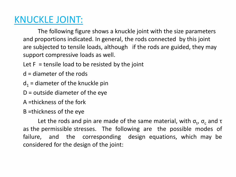
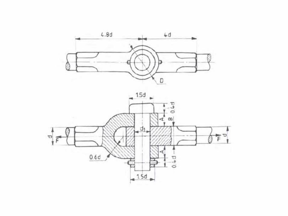
KNUCKLE JOINT:The following figure shows a knuckle joint with the size parameters
and proportions indicated. In general, the rods connected by this joint are subjected to tensile loads, although if the rods are guided, they may support compressive loads as well.
Let F = tensile load to be resisted by the joint
d = diameter of the rods
d1 = diameter of the knuckle pin
D = outside diameter of the eye
A =thickness of the fork
B =thickness of the eye
Let the rods and pin are made of the same material, with σt, σc and τas the permissible stresses. The following are the possible modes offailure, and the corresponding design equations, which may beconsidered for the design of the joint:
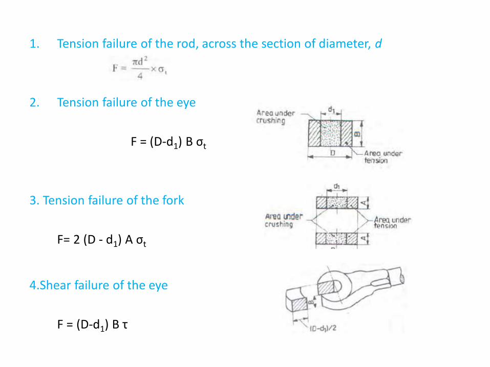
1. Tension failure of the rod, across the section of diameter, d
2. Tension failure of the eye
F = (D-d1) B σt
3. Tension failure of the fork
F= 2 (D - d1) A σt
4.Shear failure of the eye
F = (D-d1) B τ
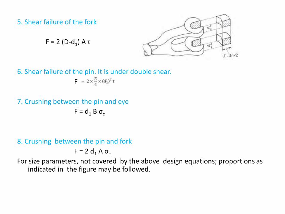
5. Shear failure of the fork
F = 2 (D-d1) A τ
6. Shear failure of the pin. It is under double shear.
F
7. Crushing between the pin and eye
F = d1 B σc
8. Crushing between the pin and fork
F = 2 d1 A σc
For size parameters, not covered by the above design equations; proportions as indicated in the figure may be followed.
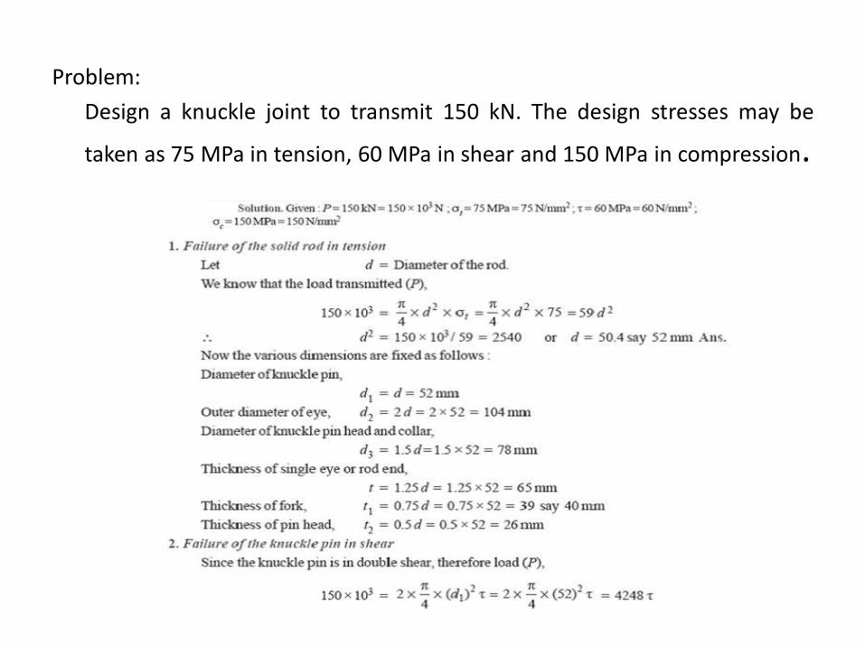
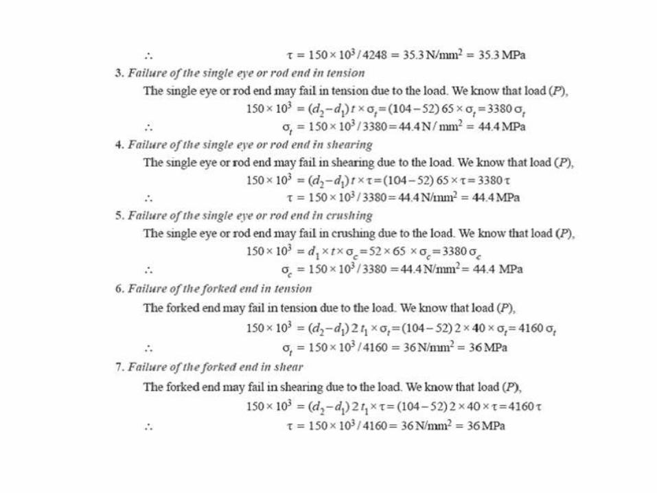
Problem:
Design a knuckle joint to transmit 150 kN. The design stresses may be
taken as 75 MPa in tension, 60 MPa in shear and 150 MPa in compression.
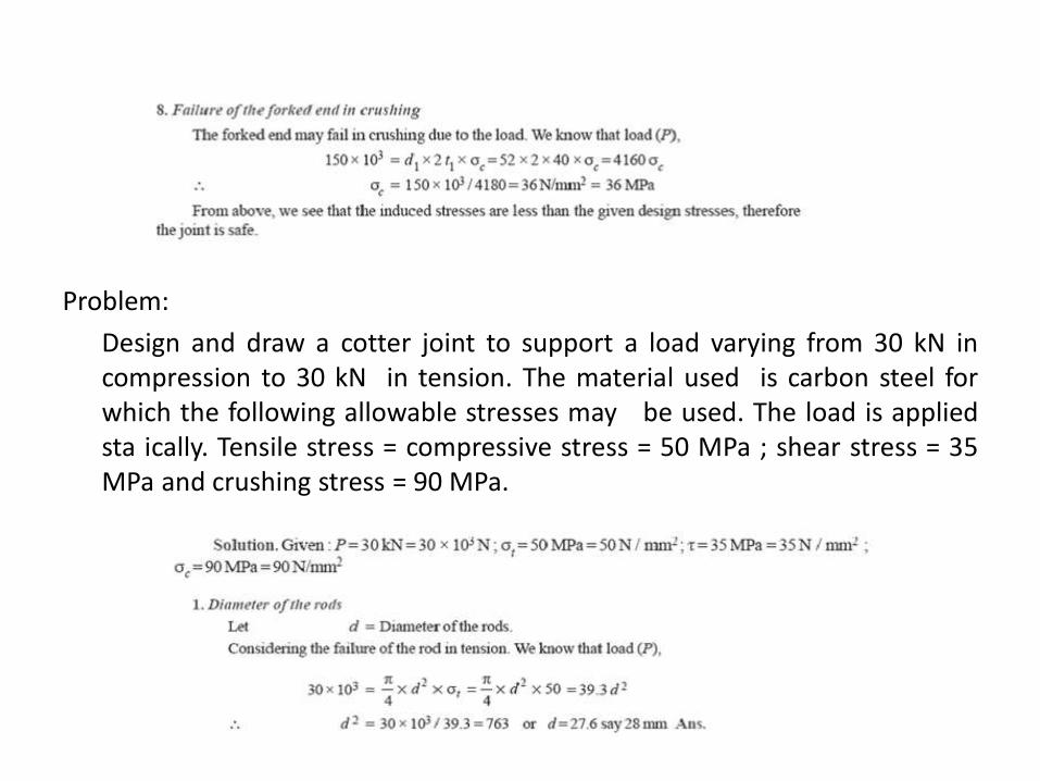
Problem:
Design and draw a cotter joint to support a load varying from 30 kN incompression to 30 kN in tension. The material used is carbon steel forwhich the following allowable stresses may be used. The load is appliedsta ically. Tensile stress = compressive stress = 50 MPa ; shear stress = 35MPa and crushing stress = 90 MPa.
Problem:
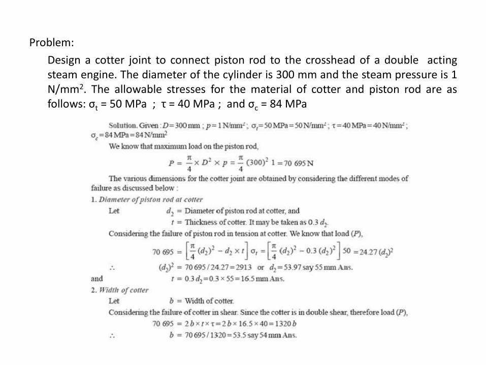
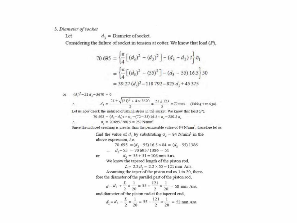
Design a cotter joint to connect piston rod to the crosshead of a double actingsteam engine. The diameter of the cylinder is 300 mm and the steam pressure is 1N/mm2. The allowable stresses for the material of cotter and piston rod are asfollows: σt = 50 MPa ; τ = 40 MPa ; and σc = 84 MPa

DIGITALCLASSROOM
ENVIRONM ENTA N E W P E D A G O G Y I S E M E R G I N G
C. Daksheeswara ReddyAssistant Professor,
Mechanical Engineering

(Source: TASK Training material)
DEPARTMENT OF MECHANICAL ENGINEERING
UNIT 5CO5: To learn the design Procedure for the different Shafts
under loading condition, able to know various shafts
coupling.
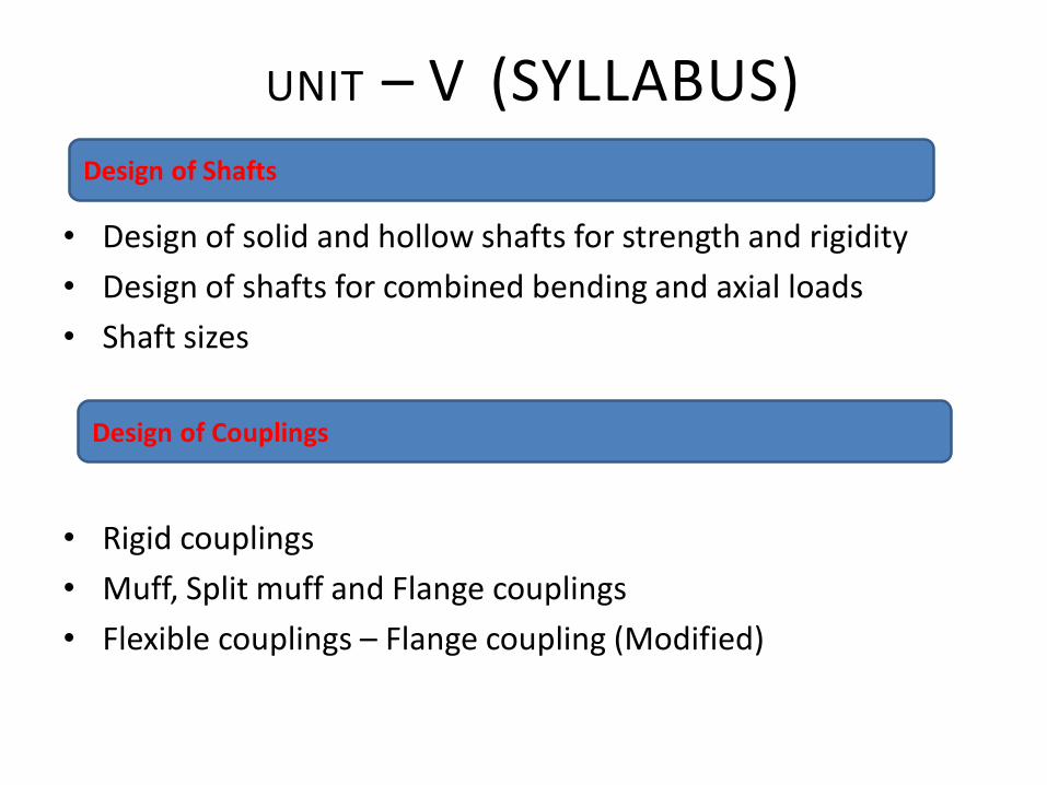
• Design of solid and hollow shafts for strength and rigidity
• Design of shafts for combined bending and axial loads
• Shaft sizes
• Rigid couplings
• Muff, Split muff and Flange couplings
• Flexible couplings – Flange coupling (Modified)
UNIT – V (SYLLABUS)Design of Shafts
Design of Couplings
COURSE OUTLINEUNIT -5
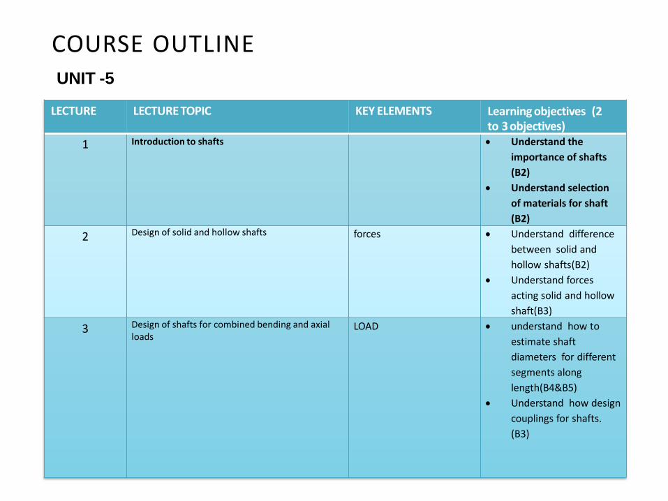
LECTURE LECTURE TOPIC KEY ELEMENTS Learning objectives (2 to 3objectives)
1 Introduction to shafts Understand the
importance of shafts
(B2)
Understand selection
of materials for shaft
(B2)
2 Design of solid and hollow shafts forces Understand difference
between solid and
hollow shafts(B2)
Understand forces
acting solid and hollow
shaft(B3)
3 Design of shafts for combined bending and axial loads
LOAD understand how to
estimate shaft
diameters for different
segments along
length(B4&B5)
Understand how design
couplings for shafts.
(B3)
LECTURE LECTURE TOPIC KEY ELEMENTS Learning objectives (2 to 3 objectives)
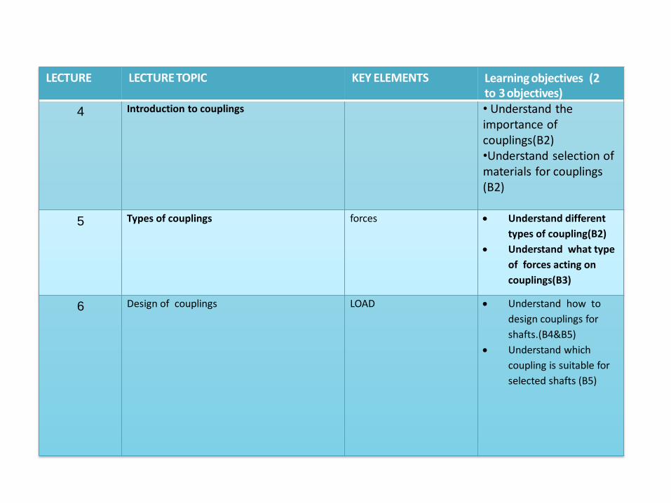
4 Introduction to couplings • Understand the importance of couplings(B2)•Understand selection of materials for couplings (B2)
5 Types of couplings forces Understand different
types of coupling(B2)
Understand what type
of forces acting on
couplings(B3)
6 Design of couplings LOAD Understand how to
design couplings for
shafts.(B4&B5)
Understand which
coupling is suitable for
selected shafts (B5)

LECTURE 1Introduction-Shafts
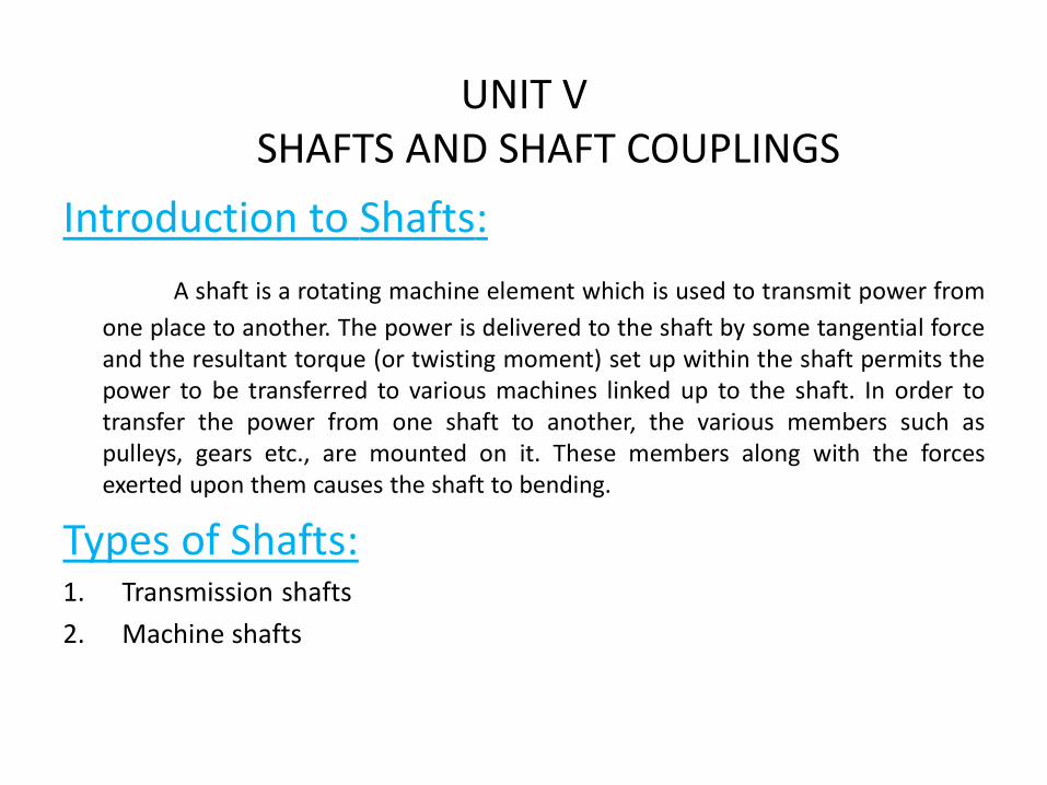
UNIT VSHAFTS AND SHAFT COUPLINGS
Introduction to Shafts:
A shaft is a rotating machine element which is used to transmit power from
one place to another. The power is delivered to the shaft by some tangential forceand the resultant torque (or twisting moment) set up within the shaft permits thepower to be transferred to various machines linked up to the shaft. In order totransfer the power from one shaft to another, the various members such aspulleys, gears etc., are mounted on it. These members along with the forcesexerted upon them causes the shaft to bending.
Types of Shafts:1. Transmission shafts
2. Machine shafts
Revision Questions
1. Define shaft
2. Classify the shafts
LECTURE 2Design of solid and hallow Shafts
Stresses in Shafts
The following stresses are induced in the shafts:
1. Shear stresses due to the transmission of torque (i.e. due to torsional load).
2.Bending stresses (tensile or compressive) due to the forces acting upon machineelements like gears, pulleys etc. as well as due to the weight of the shaftitself.
3. Stresses due to combined torsional and bending loads.
Design of Shafts
The shafts may be designed on the basis of
1. Strength, and 2. Rigidity and stiffness.
In designing shafts on the basis of strength, the following cases may be considered:
1. Shafts subjected to twisting moment or torque only,
2. Shafts subjected to bending moment only,
3. Shafts subjected to combined twisting and bending moments, and
4. Shafts subjected to axial loads in addition to combined torsional and bending loads.
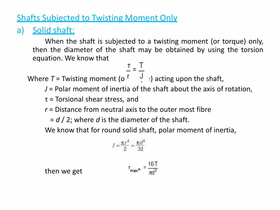
Shafts Subjected to Twisting Moment Only
a) Solid shaft:When the shaft is subjected to a twisting moment (or torque) only,
then the diameter of the shaft may be obtained by using the torsionequation. We know that
Where T = Twisting moment (or torque) acting upon the shaft,
J = Polar moment of inertia of the shaft about the axis of rotation,
τ = Torsional shear stress, and
r = Distance from neutral axis to the outer most fibre
= d / 2; where d is the diameter of the shaft.
We know that for round solid shaft, polar moment of inertia,
then we get
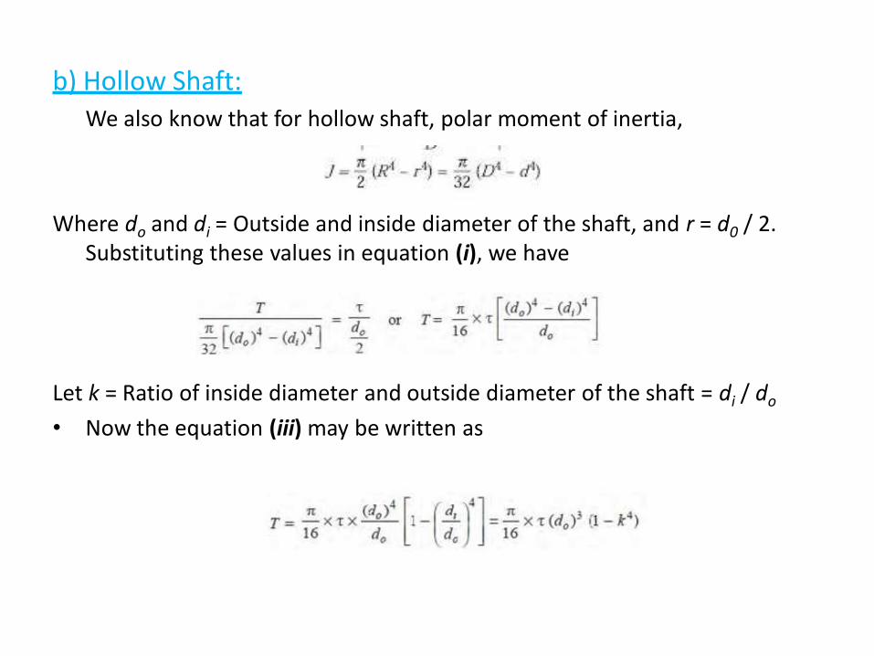
b) Hollow Shaft:We also know that for hollow shaft, polar moment of inertia,
Where do and di = Outside and inside diameter of the shaft, and r = d0 / 2. Substituting these values in equation (i), we have
Let k = Ratio of inside diameter and outside diameter of the shaft = di / do
• Now the equation (iii) may be written as
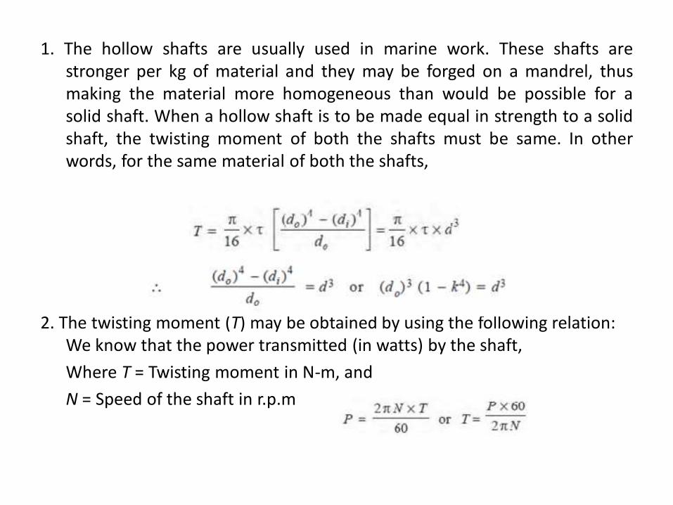
1. The hollow shafts are usually used in marine work. These shafts arestronger per kg of material and they may be forged on a mandrel, thusmaking the material more homogeneous than would be possible for asolid shaft. When a hollow shaft is to be made equal in strength to a solidshaft, the twisting moment of both the shafts must be same. In otherwords, for the same material of both the shafts,
2. The twisting moment (T) may be obtained by using the following relation: We know that the power transmitted (in watts) by the shaft,
Where T = Twisting moment in N-m, and
N = Speed of the shaft in r.p.m
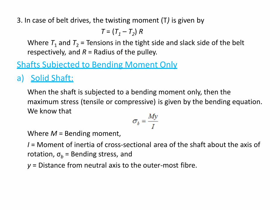
3. In case of belt drives, the twisting moment (T) is given by
T = (T1 – T2) R
Where T1 and T2 = Tensions in the tight side and slack side of the belt respectively, and R = Radius of the pulley.
Shafts Subjected to Bending Moment Only
a) Solid Shaft:
When the shaft is subjected to a bending moment only, then the
maximum stress (tensile or compressive) is given by the bending equation. We know that
Where M = Bending moment,
I = Moment of inertia of cross-sectional area of the shaft about the axis of rotation, σb = Bending stress, and
y = Distance from neutral axis to the outer-most fibre.
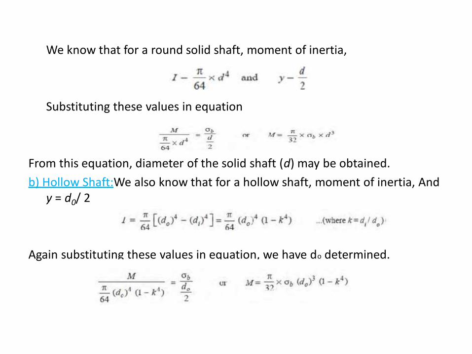
We know that for a round solid shaft, moment of inertia,
Substituting these values in equation
From this equation, diameter of the solid shaft (d) may be obtained.
b) Hollow Shaft:We also know that for a hollow shaft, moment of inertia, And y = d0/ 2
Again substituting these values in equation, we have do determined.
LECTURE 3Shafts subjected to combined bending & twisting
Shafts Subjected to Combined Twisting Moment and Bending Moment
When the shaft is subjected to combined twisting moment and bendingmoment, then the shaft must be designed on the basis of the twomoments simultaneously. Various theories have been suggested toaccount for the elastic failure of the materials when they are subjected tovarious types of combined stresses. The following two theories areimportant from the subject point of view:
1. Maximum shear stress theory or Guest's theory. It is used for ductilematerials such as mild steel.
2. Maximum normal stress theory or Rankine’s theory. It is used for brittlematerials such as cast iron.
`Let τ = Shear stress induced due to twisting moment, and
` σb = Bending stress (tensile or compressive) induced due to bending
moment.
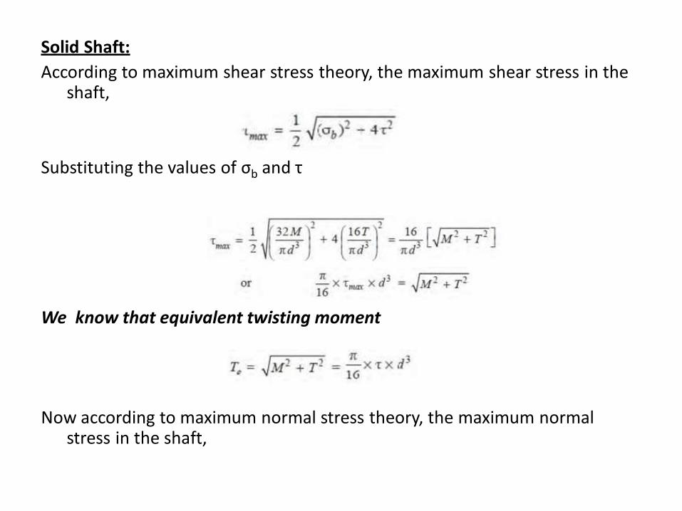
Solid Shaft:
According to maximum shear stress theory, the maximum shear stress in the shaft,
Substituting the values of σb and τ
We know that equivalent twisting moment
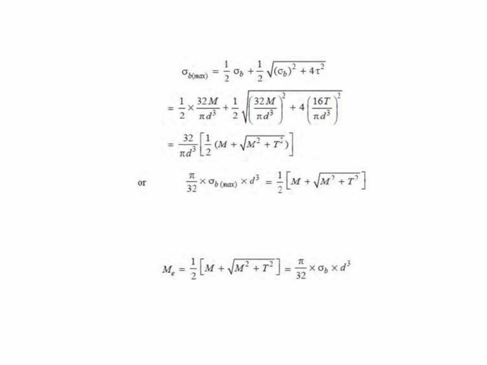
Now according to maximum normal stress theory, the maximum normal stress in the shaft,
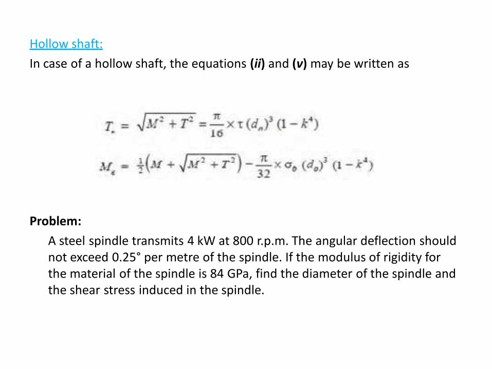
Hollow shaft:
In case of a hollow shaft, the equations (ii) and (v) may be written as
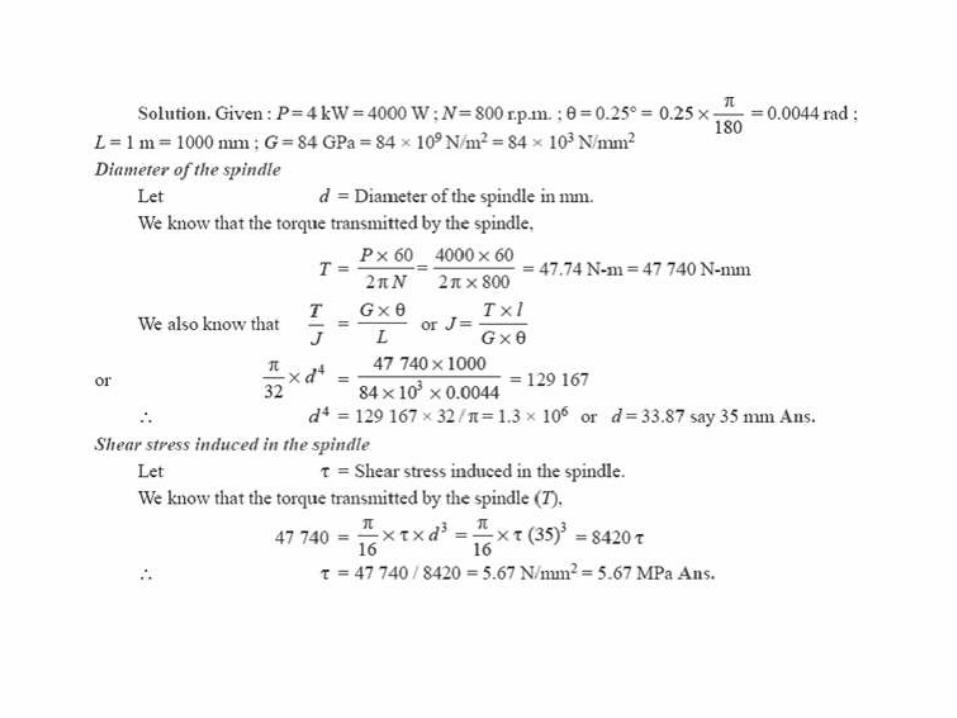
Problem:
A steel spindle transmits 4 kW at 800 r.p.m. The angular deflection should not exceed 0.25° per metre of the spindle. If the modulus of rigidity for the material of the spindle is 84 GPa, find the diameter of the spindle and the shear stress induced in the spindle.
LECTURE 4Introduction to couplings
Shaft Coupling:
Shafts are usually available up to 7 meters length due to inconvenience intransport. In order to have a greater length, it becomes necessary to jointwo or more pieces of the shaft by means of a coupling.
Advantages:
• Shaft couplings are used in machinery for several purposes, the mostcommon of which are the following:
• To provide for the connection of shafts of units those are manufacturedseparately such as a motor and generator and to provide for disconnectionfor repairs or alternations.
• To provide for misalignment of the shafts or to introduce mechanicalflexibility.
• To reduce the transmission of shock loads from one shaft to another.
• To introduce protection against overloads.
• It should have no projecting parts.
Revision Questions
1. What is the function of coupling
2. Classify the couplings
LECTURE 5Types of couplings
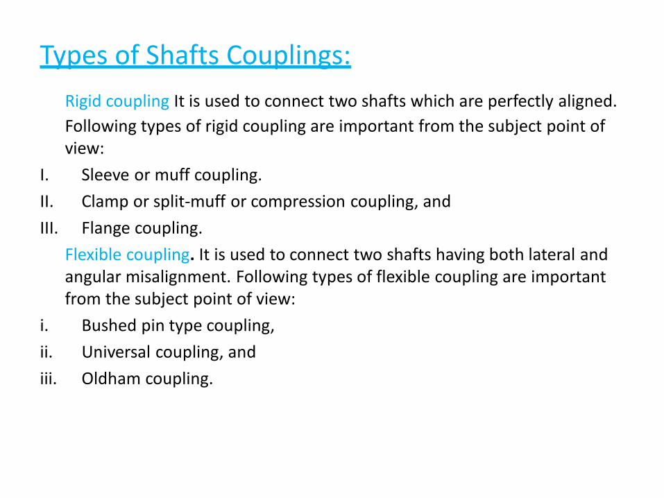
Types of Shafts Couplings:
Rigid coupling It is used to connect two shafts which are perfectly aligned.
Following types of rigid coupling are important from the subject point of view:
I. Sleeve or muff coupling.
II. Clamp or split-muff or compression coupling, and
III. Flange coupling.
Flexible coupling. It is used to connect two shafts having both lateral and angular misalignment. Following types of flexible coupling are important from the subject point of view:
i. Bushed pin type coupling,
ii. Universal coupling, and
iii. Oldham coupling.
LECTURE 6Design of couplings
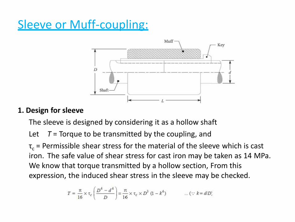
Sleeve or Muff-coupling:
1. Design for sleeve
The sleeve is designed by considering it as a hollow shaft
Let T = Torque to be transmitted by the coupling, and
τc = Permissible shear stress for the material of the sleeve which is cast iron. The safe value of shear stress for cast iron may be taken as 14 MPa. We know that torque transmitted by a hollow section, From this expression, the induced shear stress in the sleeve may be checked.
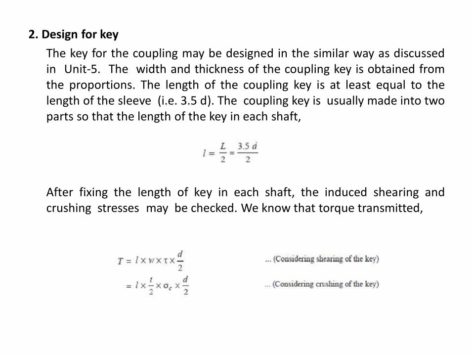
2. Design for key
The key for the coupling may be designed in the similar way as discussedin Unit-5. The width and thickness of the coupling key is obtained fromthe proportions. The length of the coupling key is at least equal to thelength of the sleeve (i.e. 3.5 d). The coupling key is usually made into twoparts so that the length of the key in each shaft,
After fixing the length of key in each shaft, the induced shearing andcrushing stresses may be checked. We know that torque transmitted,
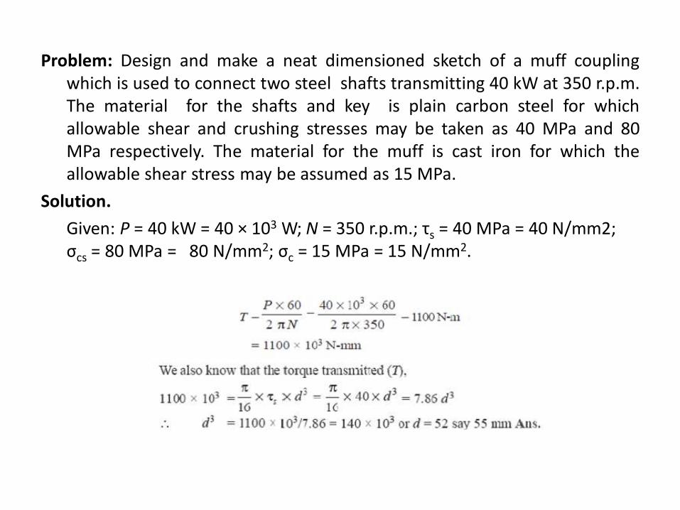
Problem: Design and make a neat dimensioned sketch of a muff couplingwhich is used to connect two steel shafts transmitting 40 kW at 350 r.p.m.The material for the shafts and key is plain carbon steel for whichallowable shear and crushing stresses may be taken as 40 MPa and 80MPa respectively. The material for the muff is cast iron for which theallowable shear stress may be assumed as 15 MPa.
Solution.
Given: P = 40 kW = 40 × 103 W; N = 350 r.p.m.; τs = 40 MPa = 40 N/mm2; σcs = 80 MPa = 80 N/mm2; σc = 15 MPa = 15 N/mm2.
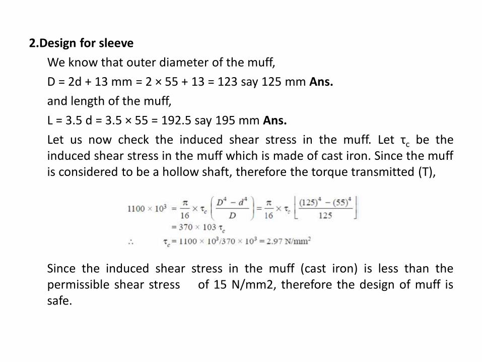
2.Design for sleeve
We know that outer diameter of the muff,
D = 2d + 13 mm = 2 × 55 + 13 = 123 say 125 mm Ans.
and length of the muff,
L = 3.5 d = 3.5 × 55 = 192.5 say 195 mm Ans.
Let us now check the induced shear stress in the muff. Let τc be theinduced shear stress in the muff which is made of cast iron. Since the muffis considered to be a hollow shaft, therefore the torque transmitted (T),
Since the induced shear stress in the muff (cast iron) is less than thepermissible shear stress of 15 N/mm2, therefore the design of muff issafe.
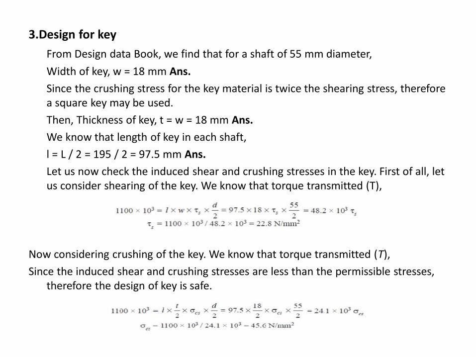
3.Design for key
From Design data Book, we find that for a shaft of 55 mm diameter,
Width of key, w = 18 mm Ans.
Since the crushing stress for the key material is twice the shearing stress, therefore a square key may be used.
Then, Thickness of key, t = w = 18 mm Ans.
We know that length of key in each shaft,
l = L / 2 = 195 / 2 = 97.5 mm Ans.
Let us now check the induced shear and crushing stresses in the key. First of all, let us consider shearing of the key. We know that torque transmitted (T),
Now considering crushing of the key. We know that torque transmitted (T),
Since the induced shear and crushing stresses are less than the permissible stresses, therefore the design of key is safe.
Clamp or Compression Coupling or split muff coupling
It is also known as split muff coupling. In this case, the muff orsleeve is made into two halves and are bolted together as shown in Fig.The halves of the muff are made of cast iron. The shaft ends are made to abutt each other and a single key is fitted directly in the keyways of boththe shafts. One-half of the muff is fixed from below and the other half isplaced from above. Both the halves are held together by means of mildsteel studs or bolts and nuts. The number of bolts may be two, four or six.The nuts are recessed into the bodies of the muff castings. This couplingmay be used for heavy duty and moderate speeds.
In the clamp or compression coupling, the power is transmitted fromone shaft to the other by means of key and the friction between the muffand shaft. In designing this type of coupling, the following procedure maybe adopted.
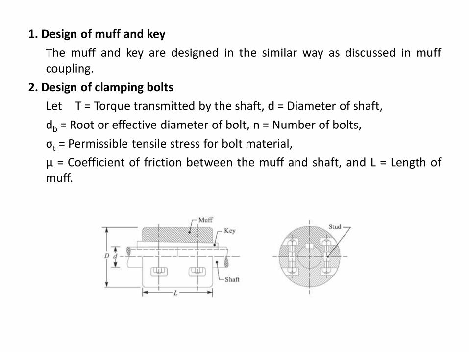
1. Design of muff and key
The muff and key are designed in the similar way as discussed in muffcoupling.
2. Design of clamping bolts
Let T = Torque transmitted by the shaft, d = Diameter of shaft,
db = Root or effective diameter of bolt, n = Number of bolts,
σt = Permissible tensile stress for bolt material,
μ = Coefficient of friction between the muff and shaft, and L = Length ofmuff.
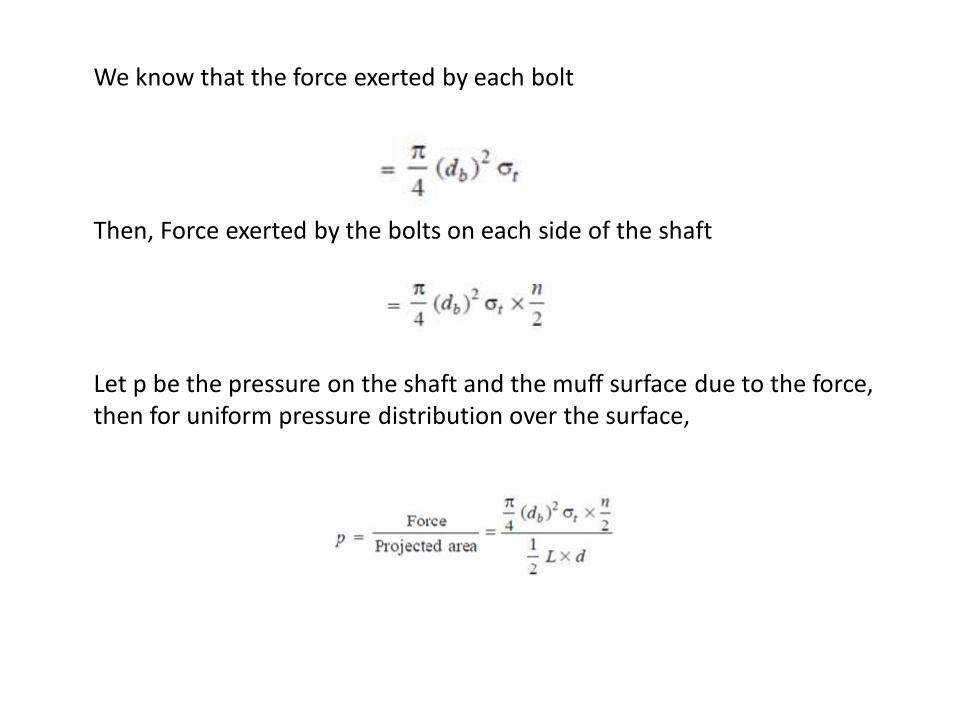
We know that the force exerted by each bolt
Then, Force exerted by the bolts on each side of the shaft
Let p be the pressure on the shaft and the muff surface due to the force, then for uniform pressure distribution over the surface,
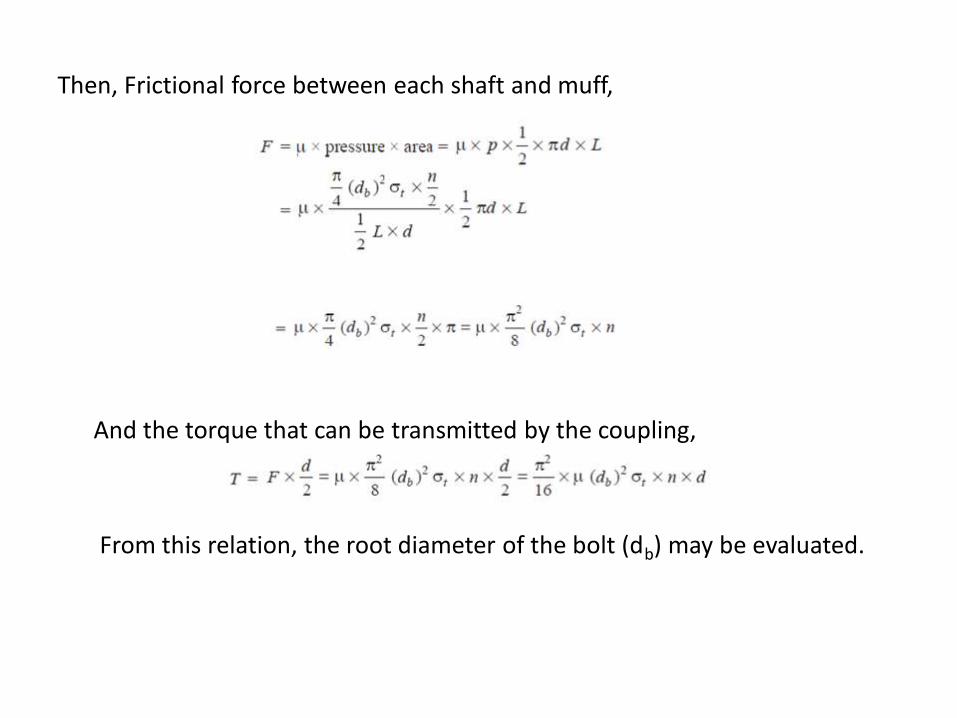
Then, Frictional force between each shaft and muff,
And the torque that can be transmitted by the coupling,
From this relation, the root diameter of the bolt (db) may be evaluated.
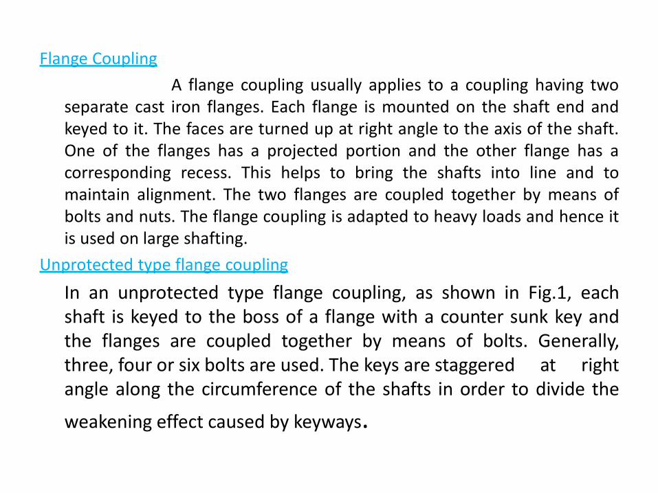
Flange Coupling
A flange coupling usually applies to a coupling having twoseparate cast iron flanges. Each flange is mounted on the shaft end andkeyed to it. The faces are turned up at right angle to the axis of the shaft.One of the flanges has a projected portion and the other flange has acorresponding recess. This helps to bring the shafts into line and tomaintain alignment. The two flanges are coupled together by means ofbolts and nuts. The flange coupling is adapted to heavy loads and hence itis used on large shafting.
Unprotected type flange coupling
In an unprotected type flange coupling, as shown in Fig.1, eachshaft is keyed to the boss of a flange with a counter sunk key andthe flanges are coupled together by means of bolts. Generally,three, four or six bolts are used. The keys are staggered at rightangle along the circumference of the shafts in order to divide the
weakening effect caused by keyways.
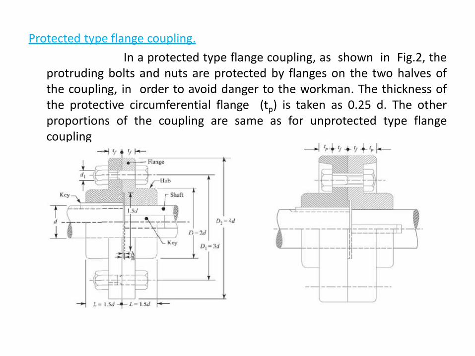
Protected type flange coupling.
In a protected type flange coupling, as shown in Fig.2, theprotruding bolts and nuts are protected by flanges on the two halves ofthe coupling, in order to avoid danger to the workman. The thickness ofthe protective circumferential flange (tp) is taken as 0.25 d. The otherproportions of the coupling are same as for unprotected type flangecoupling
Design of Flange Coupling
Consider a flange coupling as shown in Fig.1 and Fig.2. Let d = Diameter of shaft or inner diameter of hub,
D = Outer diameter of hub,
D1 = Nominal or outside diameter of bolt, D1 = Diameter of bolt circle,
n = Number of bolts,
tf = Thickness of flange,
τs, τb and τk = Allowable shear stress for shaft, bolt and key material respectively τc = Allowable shear stress for the flange material i.e. cast iron,
σcb, and σck = Allowable crushing stress for bolt and key material respectively.
The flange coupling is designed as discussed below:
1. Design for hub
The hub is designed by considering it as a hollow shaft, transmitting the same torque (T) as that of a solid shaft.
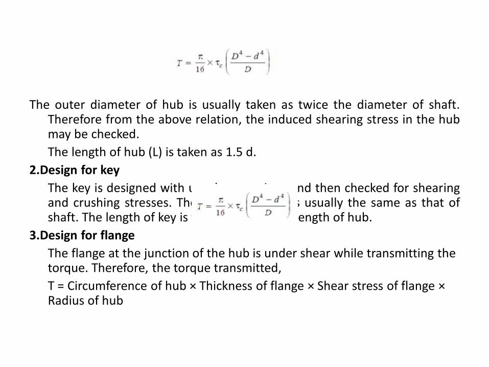
The outer diameter of hub is usually taken as twice the diameter of shaft.Therefore from the above relation, the induced shearing stress in the hubmay be checked.
The length of hub (L) is taken as 1.5 d.
2.Design for key
The key is designed with usual proportions and then checked for shearingand crushing stresses. The material of key is usually the same as that ofshaft. The length of key is taken equal to the length of hub.
3.Design for flange
The flange at the junction of the hub is under shear while transmitting the torque. Therefore, the torque transmitted,
T = Circumference of hub × Thickness of flange × Shear stress of flange ×Radius of hub
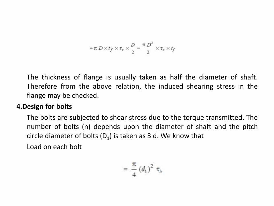
The thickness of flange is usually taken as half the diameter of shaft.Therefore from the above relation, the induced shearing stress in theflange may be checked.
4.Design for bolts
The bolts are subjected to shear stress due to the torque transmitted. Thenumber of bolts (n) depends upon the diameter of shaft and the pitchcircle diameter of bolts (D1) is taken as 3 d. We know that
Load on each bolt
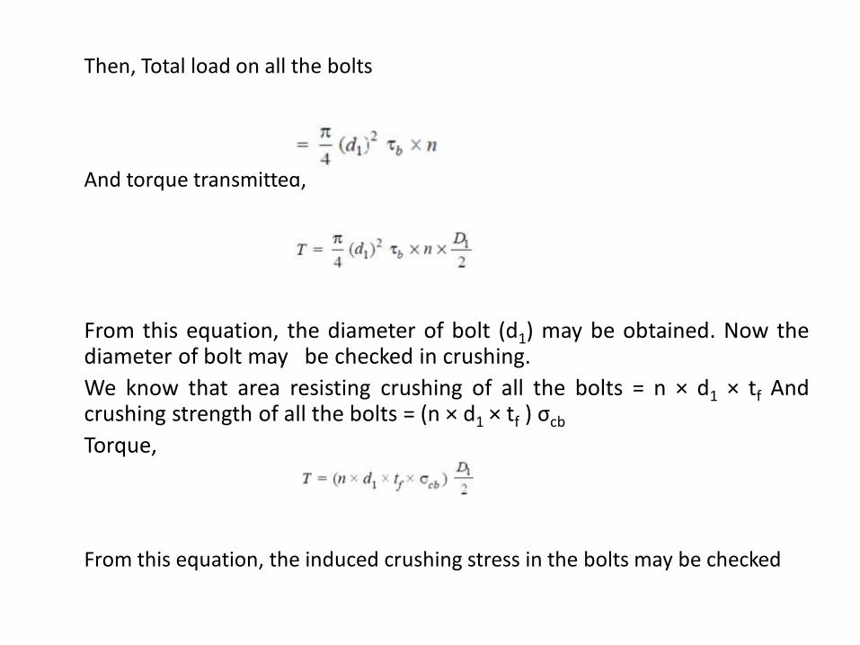
Then, Total load on all the bolts
And torque transmitted,
From this equation, the diameter of bolt (d1) may be obtained. Now thediameter of bolt may be checked in crushing.
We know that area resisting crushing of all the bolts = n × d1 × tf Andcrushing strength of all the bolts = (n × d1 × tf ) σcb
Torque,
From this equation, the induced crushing stress in the bolts may be checked
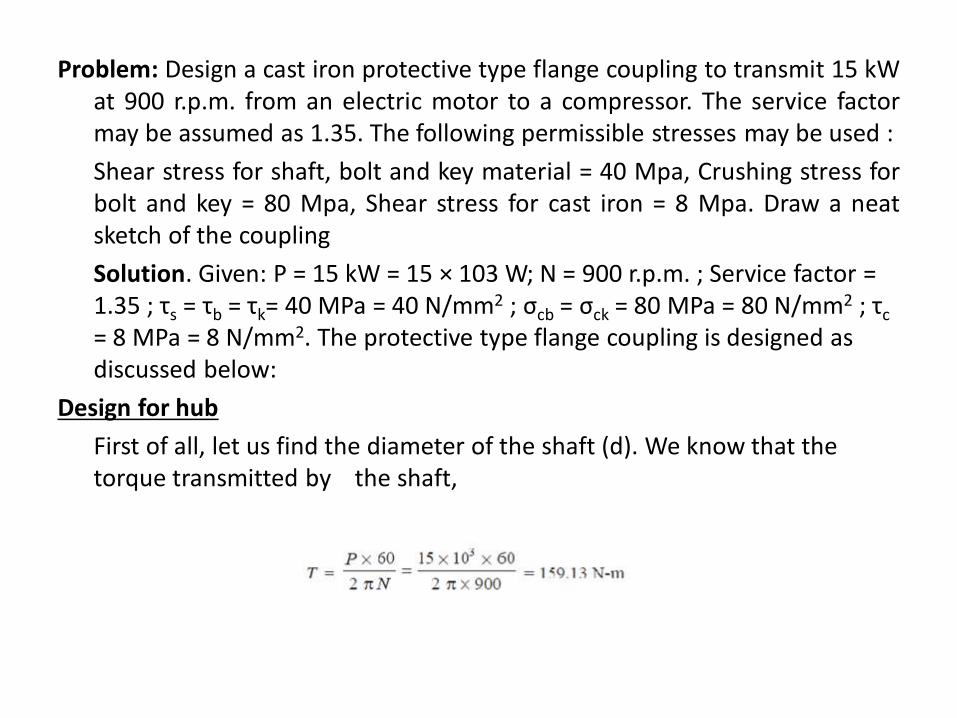
Problem: Design a cast iron protective type flange coupling to transmit 15 kWat 900 r.p.m. from an electric motor to a compressor. The service factormay be assumed as 1.35. The following permissible stresses may be used :
Shear stress for shaft, bolt and key material = 40 Mpa, Crushing stress forbolt and key = 80 Mpa, Shear stress for cast iron = 8 Mpa. Draw a neatsketch of the coupling
Solution. Given: P = 15 kW = 15 × 103 W; N = 900 r.p.m. ; Service factor = 1.35 ; τs = τb = τk= 40 MPa = 40 N/mm2 ; σcb = σck = 80 MPa = 80 N/mm2 ; τc
= 8 MPa = 8 N/mm2. The protective type flange coupling is designed as discussed below:
Design for hub
First of all, let us find the diameter of the shaft (d). We know that the torque transmitted by the shaft,
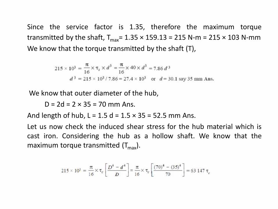
Since the service factor is 1.35, therefore the maximum torque
transmitted by the shaft, Tmax= 1.35 × 159.13 = 215 N-m = 215 × 103 N-mm
We know that the torque transmitted by the shaft (T),
We know that outer diameter of the hub,
D = 2d = 2 × 35 = 70 mm Ans.
And length of hub, L = 1.5 d = 1.5 × 35 = 52.5 mm Ans.
Let us now check the induced shear stress for the hub material which iscast iron. Considering the hub as a hollow shaft. We know that themaximum torque transmitted (Tmax).
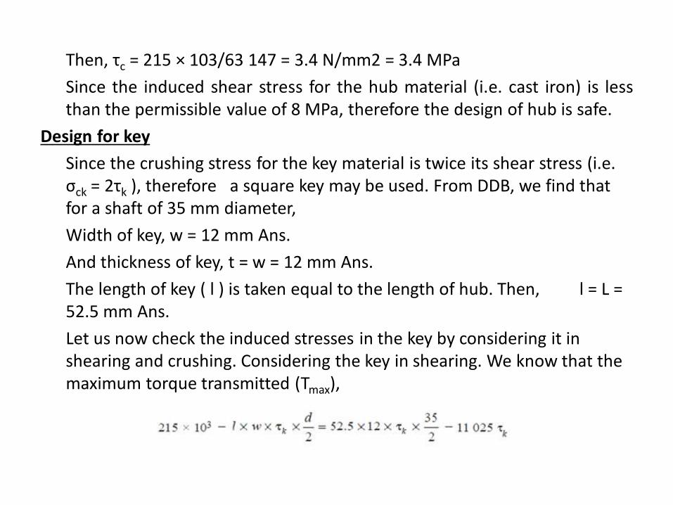
Then, τc = 215 × 103/63 147 = 3.4 N/mm2 = 3.4 MPa
Since the induced shear stress for the hub material (i.e. cast iron) is lessthan the permissible value of 8 MPa, therefore the design of hub is safe.
Design for key
Since the crushing stress for the key material is twice its shear stress (i.e. σck = 2τk ), therefore a square key may be used. From DDB, we find that for a shaft of 35 mm diameter,
Width of key, w = 12 mm Ans.
And thickness of key, t = w = 12 mm Ans.
The length of key ( l ) is taken equal to the length of hub. Then, l = L = 52.5 mm Ans.
Let us now check the induced stresses in the key by considering it in shearing and crushing. Considering the key in shearing. We know that the maximum torque transmitted (Tmax),
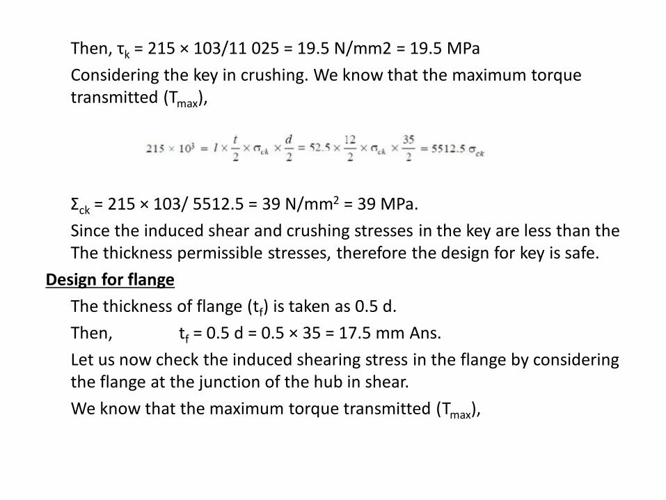
Then, τk = 215 × 103/11 025 = 19.5 N/mm2 = 19.5 MPa
Considering the key in crushing. We know that the maximum torque transmitted (Tmax),
Σck = 215 × 103/ 5512.5 = 39 N/mm2 = 39 MPa.
Since the induced shear and crushing stresses in the key are less than the The thickness permissible stresses, therefore the design for key is safe.
Design for flange
The thickness of flange (tf) is taken as 0.5 d.
Then, tf = 0.5 d = 0.5 × 35 = 17.5 mm Ans.
Let us now check the induced shearing stress in the flange by considering the flange at the junction of the hub in shear.
We know that the maximum torque transmitted (Tmax),
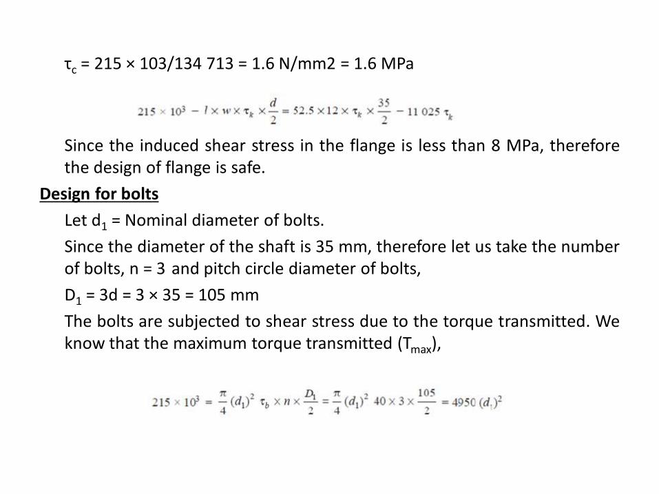
τc = 215 × 103/134 713 = 1.6 N/mm2 = 1.6 MPa
Since the induced shear stress in the flange is less than 8 MPa, thereforethe design of flange is safe.
Design for bolts
Let d1 = Nominal diameter of bolts.
Since the diameter of the shaft is 35 mm, therefore let us take the numberof bolts, n = 3 and pitch circle diameter of bolts,
D1 = 3d = 3 × 35 = 105 mm
The bolts are subjected to shear stress due to the torque transmitted. Weknow that the maximum torque transmitted (Tmax),
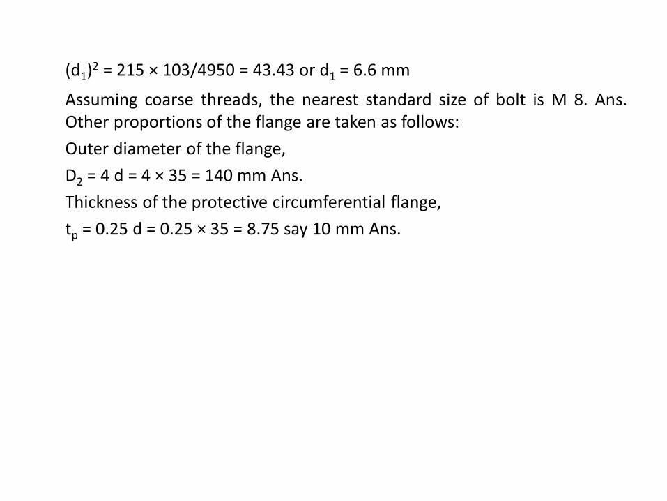
(d1)2 = 215 × 103/4950 = 43.43 or d1 = 6.6 mm
Assuming coarse threads, the nearest standard size of bolt is M 8. Ans.Other proportions of the flange are taken as follows:
Outer diameter of the flange,
D2 = 4 d = 4 × 35 = 140 mm Ans.
Thickness of the protective circumferential flange,
tp = 0.25 d = 0.25 × 35 = 8.75 say 10 mm Ans.

THANK YOU