Embed Size (px)
Citation preview

QuickStick HTUser Manual
Catalog Numbers: 700-1384-01, 700-1483-00, 700-1483-01, 700-1483-03, 700-1563-00, 700-1616-00, 700-1616-01, 700-1616-02, 700-1616-03, 700-1616-04, 700-1616-05, 700-1616-06, 700-1618-00, 700-1618-01, 700-1618-02, 700-1618-03, 700-1618-04, 700-1618-05, 700-1618-06, 700-1642-00, MMI-HT-C2198-D032
Original Instructions
2 MagneMotionRockwell Automation Publication MMI-UM007G-EN-P - August2021
Although every effort is made to keep this manual accurate and up-to-date, MagneMotion® assumes no responsibility forany errors, omissions, or inaccuracies. Information that is provided in this manual is subject to change without notice. Anysample code that is referenced in this manual or included with MagneMotion software is included for illustration only andis, therefore, unsupported.
This product is protected under one or more U.S. and International patents. Additional U.S. and International patentspending.
The information that is included in this manual is proprietary or confidential to MagneMotion, Inc. Any disclosure,reproduction, use, or redistribution of this information by or to an unintended recipient is prohibited. In no event willMagneMotion, Inc. be responsible or liable for indirect or consequential damage that results from the use or application ofthis equipment.
MagneMotion, Inc.A Rockwell Automation Company139 Barnum RoadDevens, MA 01434USAPhone: +1 978-757-9100Fax: +1 978-757-9200rok.auto/ict
This technology is subject to United States Export Administration Regulations and authorized to the destination only;diversion contrary to U.S. law is prohibited.
Printed in the U.S.A.
QuickStick HT User Manual 3Rockwell Automation Publication MMI-UM007G-EN-P - August2021
Contents
Figures ............................................................................................................... 11
Tables................................................................................................................. 15
ChangesOverview............................................................................................................................19
Rev. A ..........................................................................................................................19Rev. B ..........................................................................................................................19Rev. C ..........................................................................................................................19Ver. 04 .........................................................................................................................20Rev. E...........................................................................................................................21Rev. F...........................................................................................................................22Rev. G ..........................................................................................................................23
About This ManualOverview............................................................................................................................25
Purpose.........................................................................................................................25Audience ......................................................................................................................25Prerequisites.................................................................................................................25
MagneMotion Documentation ...........................................................................................26Manual Conventions ....................................................................................................26Notes, Safety Notices, and Symbols ............................................................................27
Notes ......................................................................................................................27Safety Notices ........................................................................................................27
Manual Structure..........................................................................................................29Related Documentation................................................................................................29
1 IntroductionOverview............................................................................................................................31QuickStick HT Transport System Overview .....................................................................32
QSHT Transport System Components ........................................................................34Transport System Components Overview .........................................................................36Transport System Software Overview...............................................................................37
Utilities.........................................................................................................................38File Types ....................................................................................................................38
Contents
4 MagneMotionRockwell Automation Publication MMI-UM007G-EN-P - August2021
Getting Started with the QuickStick HT Transport System ..............................................40
2 Safety GuidelinesOverview............................................................................................................................43Regulatory Compliance .....................................................................................................44
Agency Compliance.....................................................................................................45Safety Considerations ........................................................................................................46
Personnel Safety Guidelines ........................................................................................46Equipment Safety Guidelines ......................................................................................47QSHT Transport System Hazard Locations ................................................................48
Symbol Identification ........................................................................................................49Labels.................................................................................................................................51Mechanical Hazards...........................................................................................................52Electrical Hazards ..............................................................................................................53Magnetic Hazards ..............................................................................................................54
Handling Magnet Arrays .............................................................................................55Shipping Magnet Arrays ..............................................................................................56
Recycling and Disposal Information .................................................................................57Waste Electrical and Electronic Equipment (WEEE)..................................................57QuickStick HT Transport System................................................................................57Motor Stators ...............................................................................................................57QSMC Motor Controllers ............................................................................................57QSHT 5700 Inverters...................................................................................................58Magnet Arrays .............................................................................................................58Packaging.....................................................................................................................58
3 Design GuidelinesOverview............................................................................................................................59Transport System Layout...................................................................................................60
Transport System Overview ........................................................................................60Motors, Motor Drives, Switches, and Vehicles ...........................................................61Paths.............................................................................................................................62Nodes ...........................................................................................................................63Node Controllers..........................................................................................................64Additional Connections ...............................................................................................65
Transport System Design...................................................................................................66Overview......................................................................................................................66Design Guidelines........................................................................................................66Motors ..........................................................................................................................67
Available Thrust ....................................................................................................69Required Thrust .....................................................................................................70Motor Gap..............................................................................................................71Downstream Gap ...................................................................................................71Motor Cogging.......................................................................................................72Motors on a Curve .................................................................................................73Motor Drives..........................................................................................................74
Contents
QuickStick HT User Manual 5Rockwell Automation Publication MMI-UM007G-EN-P - August2021
Electrical Wiring..........................................................................................................74Wiring QSHT Motors Using QSMC Controllers ..................................................74Wiring QSHT Motors Using QSHT 5700 Inverters ..............................................75Power Wiring.........................................................................................................75Signal Wiring.........................................................................................................76Ground ...................................................................................................................77Ethernet Motor Communication Recommendations .............................................80Ethernet Motor Connection Examples...................................................................81Using Both RS-422 and Ethernet Motors ..............................................................87
Ethernet Motor MICS File ...........................................................................................90Magnet Arrays .............................................................................................................91
High Flux Magnet Arrays ......................................................................................91Magnet Array Length and Attractive Force...........................................................92Number of Cycles ..................................................................................................92Magnet Array Forces .............................................................................................93Magnet Array Use..................................................................................................93
Vehicles .......................................................................................................................95Vehicle Gap ...........................................................................................................97Single Array Vehicle .............................................................................................98Dual Array Vehicle ................................................................................................98Vehicle Design.......................................................................................................99Mounting Magnet Arrays to Vehicles .................................................................100
Guideways .................................................................................................................101Guideway Design.................................................................................................101Guideway and Support Materials ........................................................................102Motor Mounts ......................................................................................................102Motor Mounting Methods....................................................................................103Guideway Examples ............................................................................................105
Transport System Configuration......................................................................................108Straight Track Configuration .....................................................................................108Curve Track Configuration ........................................................................................109Switch Configuration.................................................................................................110Moving Path Configuration .......................................................................................111
4 Specifications and Site RequirementsOverview..........................................................................................................................113Mechanical Specifications ...............................................................................................114
1 Meter Motor ............................................................................................................1141/2 Meter Motor.........................................................................................................1151/2 Meter Double-wide Motor ...................................................................................116QSMC Motor Controller............................................................................................117QSMC-2 Motor Controller ........................................................................................118QSMC Rack Mounting Bracket.................................................................................119QuickStick HT 5700 Inverter ....................................................................................120QSMC to 1 m Motor Drive Cable .............................................................................121QSMC to 1/2 m Motor Drive Cable ..........................................................................123QSMC to Motor Sense Cable ....................................................................................125
Contents
6 MagneMotionRockwell Automation Publication MMI-UM007G-EN-P - August2021
QSMC HVDC Power Cable ......................................................................................126QSMC LVDC Power Cable.......................................................................................127QSHT 5700 Inverter to 1 m Motor Drive Cable........................................................128QSHT 5700 Inverter to 1/2 m Motor Drive Cable.....................................................129QSHT 5700 Inverter to Motor Sense Cable...............................................................130Magnet Array, High Flux...........................................................................................131
Electrical Specifications ..................................................................................................133Motors (Stators) .........................................................................................................133
QSMC to 1 m Motor Drive Cable .......................................................................135QSMC to 1/2 m Motor Drive Cable ....................................................................136QSMC to Motor Sense Cable ..............................................................................137QSHT 5700 Inverter to 1 m Motor Drive Cable..................................................139QSHT 5700 Inverter to 1/2 m Motor Drive Cable...............................................141QSHT 5700 Inverter to Motor Sense Cable.........................................................142
QSMC Motor Controller............................................................................................143QSMC-2 Motor Controller ........................................................................................148
QSMC HVDC Power Cable ................................................................................153QSMC LVDC Power Cable.................................................................................154
QSHT 5700 Inverter ..................................................................................................155QuickStick HT 5700 Inverter Connectors ...........................................................158QuickStick HT 5700 Inverter Controls and Indicators ........................................163
Communication................................................................................................................169Ethernet Connection ..................................................................................................169
TCP/IP Communication – Host Controller to HLC.............................................169TCP/IP Communication – Node Controller to Motor Drive ...............................170TCP/IP Communication – Motor Drive to Motor Drive .....................................170EtherNet/IP Communication – Host Controller to HLC .....................................170
RS-232 Serial Interface Connection ..........................................................................171RS-422 Serial Interface Connection ..........................................................................171
Node Controller to Motor Drive ..........................................................................171Motor Drive to Motor Drive ................................................................................172
Ethernet Interface Connection ...................................................................................173Site Requirements ............................................................................................................174
Environment...............................................................................................................174Motors ..................................................................................................................174QSMC Motor Controllers ....................................................................................174QSHT 5700 Inverters...........................................................................................174Magnet Arrays .....................................................................................................174Derating at High Altitude ....................................................................................174
Lighting, Site .............................................................................................................175Floor Space and Loading ...........................................................................................175Facilities.....................................................................................................................175Service Access ...........................................................................................................175
5 InstallationOverview..........................................................................................................................177Unpacking and Inspection ...............................................................................................178

Contents
QuickStick HT User Manual 7Rockwell Automation Publication MMI-UM007G-EN-P - August2021
Unpacking and Moving .............................................................................................179Required Tools and Equipment ...........................................................................179Unpacking and Moving Instructions....................................................................179
Transport System Installation ..........................................................................................181Installing Hardware....................................................................................................181
Required Tools and Materials..............................................................................181Installation Overview...........................................................................................182
System Installation.....................................................................................................183Assembling the Guideway ...................................................................................183Leveling the Transport System ............................................................................183Securing the Transport System ............................................................................183Mounting the Motors ...........................................................................................183
Installing Electronics .................................................................................................185Installing Electronics on the Transport System ...................................................185Mounting QSMC Motor Controllers ...................................................................186Mounting the QuickStick HT 5700 Inverters ......................................................187Mounting the 2198-Pxxx DC-bus Power Supplies..............................................188
Connecting Motors and Electronics...........................................................................192Wire Routing........................................................................................................192RS-422 Motor Communication ...........................................................................194Ethernet Motor Communications.........................................................................198Digital I/O ............................................................................................................203Installing QSMC Motor Controller Power Cables ..............................................208Installing QSHT 5700 Inverter Power .................................................................211
Installing Magnet Arrays/Vehicles ............................................................................214Magnet Array Installation....................................................................................214
Installing Vehicles .....................................................................................................216Facilities Connections......................................................................................................217
Network Connections ................................................................................................217Electrical Connections ...............................................................................................218
E-stop Circuit .......................................................................................................220Interlock Circuit ...................................................................................................220Light Stack Circuit...............................................................................................220General Purpose Digital I/O ................................................................................220Node Electronics..................................................................................................221
Software ...........................................................................................................................222Software Overview ....................................................................................................222Software Configuration..............................................................................................222
Node Controller Software Installation.................................................................223Motor Software Installation .................................................................................223
Check-out and Power-up .................................................................................................224System Check-out ......................................................................................................224
Mechanical Checks ..............................................................................................224Facility Checks ....................................................................................................224Pre-operation Checks ...........................................................................................224
System Power-up .......................................................................................................225System Testing.................................................................................................................228
Contents
8 MagneMotionRockwell Automation Publication MMI-UM007G-EN-P - August2021
6 OperationOverview..........................................................................................................................231Theory of Operation.........................................................................................................232
QuickStick HT Transport System Advantages ..........................................................232Motion Control ..........................................................................................................233Motor Topology.........................................................................................................233Motor Operation ........................................................................................................234
Motor Cogging.....................................................................................................235Motor Blocks .............................................................................................................236
Block Acquisition ................................................................................................236Block Ownership .................................................................................................237Block Release ......................................................................................................237
Anti-Collision ............................................................................................................237Safe Stopping Distance ........................................................................................238Thrust Limitations................................................................................................238Vehicles In Queue................................................................................................239Vehicle Length Through Curves and Switches ...................................................240
Locating Vehicles During Startup .............................................................................240Moving Vehicles by Hand ...................................................................................241
Electrical System .......................................................................................................243Power Regenerated by a Vehicle .........................................................................243Power Management Within the Motor ................................................................243QSMC Motor Controller Power-Related Warnings and Faults...........................244QSMC Power-Related Warnings and Faults .......................................................246QSMC Power-Related Fault Resolution..............................................................248QSHT 5700 Inverter Power-Related Warnings and Faults .................................248QSHT 5700 Inverter Power-Related Warnings and Faults .................................250QSHT 5700 Inverter Power-Related Power-Related Fault Resolution ...............251
Node Controllers........................................................................................................253Node Controller Communications .......................................................................253
Controls and Indicators ....................................................................................................254Track Display.............................................................................................................254E-stops .......................................................................................................................255Interlocks ...................................................................................................................255Light Stacks ...............................................................................................................256FastStop .....................................................................................................................256Digital I/O ..................................................................................................................256Software Status Indicators .........................................................................................257
Transport System Simulation...........................................................................................258Configuring a Simulation...........................................................................................258Running a Simulation ................................................................................................260Stopping a Simulation................................................................................................262Return the System to Normal Operation....................................................................262
Transport System Operation ............................................................................................264Power-up....................................................................................................................264Normal Running ........................................................................................................264Shut-down..................................................................................................................265
Contents
QuickStick HT User Manual 9Rockwell Automation Publication MMI-UM007G-EN-P - August2021
7 QSHT 5700 Inverter Safe Torque-off FunctionOverview..........................................................................................................................267Introduction......................................................................................................................268
Certification ...............................................................................................................268Important Safety Considerations .........................................................................268Stop Category Definition .....................................................................................268Performance Level (PL) and Safety Integrity Level (SIL) ..................................269
Average Frequency of a Dangerous Failure ..............................................................269Safe Torque-off Feature.............................................................................................270Safe Torque-off Status ...............................................................................................271
Hardwired Safe Torque-off..............................................................................................273Description of Operation ...........................................................................................273Troubleshoot the Safe Torque-off Function ..............................................................276Safe Torque-off Connector Data................................................................................278Wire the Safe Torque-off Circuit...............................................................................279
Install the Safety Connector Plug ........................................................................279Safe Torque-off Wiring Requirements ......................................................................280Safe Torque-off Feature Bypass ................................................................................281Cascade the Safe Torque-off Signal ..........................................................................282Hardwired Safe Torque-off Electrical Specifications................................................283
8 MaintenanceOverview..........................................................................................................................285Preventive Maintenance...................................................................................................286
Cleaning .....................................................................................................................287Wear Surface Maintenance ........................................................................................287Cable Connection Inspection .....................................................................................289Hardware Inspection ..................................................................................................289Transfer Log Files......................................................................................................289Cleaning Magnet Arrays ............................................................................................290
Troubleshooting ...............................................................................................................291Initial Troubleshooting ..............................................................................................291Power-Related Troubleshooting ................................................................................292Node Controller Troubleshooting..............................................................................298Communication Troubleshooting ..............................................................................299Motion Control Troubleshooting ...............................................................................300Light Stack Troubleshooting .....................................................................................301QSHT 5700 Inverter Fault Troubleshooting..............................................................302
Contact Rockwell Automation Technical Support ..........................................................306Repair...............................................................................................................................307
Replacing Motors.......................................................................................................308Remove the Existing Motor .................................................................................308Install the New Motor ..........................................................................................309
Replacing Motor Drives.............................................................................................310Remove the Existing Motor Drive.......................................................................310Install the New Motor Drive ................................................................................310
Programming Motors .................................................................................................312
Contents
10 MagneMotionRockwell Automation Publication MMI-UM007G-EN-P - August2021
Separating Magnet Arrays .........................................................................................313Cleaning or Replacing the Motor Controller Fan Filter ............................................314
Ordering Parts ..................................................................................................................315Shipping ...........................................................................................................................316
Required Tools and Equipment ...........................................................................316Packing Procedure .....................................................................................................317Shipping Components................................................................................................318
AppendixOverview..........................................................................................................................319Interconnect Diagrams.....................................................................................................320
Interconnect Diagram Notes ......................................................................................320Power Wiring Examples ............................................................................................322
Data for Transport System Design Calculations..............................................................323Thrust Force Data ......................................................................................................324Attractive Force Data.................................................................................................326Determining Thrust Force..........................................................................................327Determining Attractive Force ....................................................................................328
File Maintenance..............................................................................................................329Backup Files ..............................................................................................................329Creating Backup Files................................................................................................329Restoring from Backup Files .....................................................................................329
Additional Documentation...............................................................................................330Release Notes.............................................................................................................330Upgrade Procedure ....................................................................................................330
Transport System Limits..................................................................................................331
Glossary ........................................................................................................... 333
Index ................................................................................................................ 341
QuickStick HT User Manual 11Rockwell Automation Publication MMI-UM007G-EN-P - August2021
Figures
1-1 Detailed View of QuickStick HT Transport System Components .............................341-2 Simplified View of the QuickStick HT Transport System Components ....................361-3 Simplified View of Transport System Software Organization ...................................37
2-1 Locations of Hazardous Points on the QuickStick HT Transport System ..................48
3-1 Sample QSHT Transport System Layout Showing Motors ........................................613-2 Sample QSHT Transport System Layout Showing Paths ..........................................623-3 Sample QSHT Transport System Layout Showing Nodes .........................................633-4 Sample QSHT Transport System Layout Showing Node Controllers .......................643-5 Sample QSHT Transport System Layout Showing Additional Connections .............653-6 QuickStick HT System, Single Array Vehicle ...........................................................663-7 Available Thrust Examples .........................................................................................703-8 Motor Gaps .................................................................................................................713-9 Downstream Gaps .......................................................................................................723-10 Motors on Curves ........................................................................................................733-11 System Wiring Block Diagram, QSMC Connections ................................................783-12 System Wiring Block Diagram, QSHT 5700 Inverter Connections ...........................793-13 Ethernet Wiring – Power Supply In-line with Inverters .............................................813-14 Ethernet Wiring – Power Supply Separate from Inverters .........................................823-15 Ethernet Motor Wiring – One Path, One Ethernet Chain ...........................................823-16 Ethernet Motor Wiring – One Path, Two Ethernet Chains .........................................823-17 Ethernet Motor Wiring – One Path, Ethernet Star ......................................................833-18 Ethernet Motor Wiring – One Path, Ethernet Star, Multiple Ethernet Switches ........833-19 Ethernet Motor Wiring – Two Paths, Ethernet Star, Multiple Node Controllers .......833-20 Ethernet Motor Wiring – One Path, One Ethernet Chain ...........................................843-21 Ethernet Motor Wiring – One Path, Two Ethernet Chains .........................................853-22 Ethernet Motor Wiring – One Path, Ethernet Star ......................................................853-23 Ethernet Motor Wiring – Three Paths, Two Ethernet Chains, Main Loop and Spur .863-24 Ethernet Motor Wiring – Three Paths, One Ethernet Chain, Main Loop and Spur ....863-25 Ethernet Motor Wiring – Two Paths, Ethernet Chain and RS-422 Chain ..................873-26 Ethernet Motor Wiring – Two Paths, Ethernet Chain and RS-422 Chain ..................883-27 Ethernet Motor Wiring – Three Paths, Ethernet Chain Main Loop, RS-422 Spur .....893-28 High Flux Magnet Array, 3 Cycles, 7 Poles ...............................................................913-29 Typical Vehicle on Guideway ....................................................................................953-30 Magnet Array to Motor Alignment .............................................................................963-31 Vehicle Gap ................................................................................................................97
12 MagneMotionRockwell Automation Publication MMI-UM007G-EN-P - August2021
3-32 Single Array Vehicle Configuration ...........................................................................983-33 Dual Array Vehicle Configuration .............................................................................983-34 Magnet Array Mounting ...........................................................................................1003-35 Guideway Detail .......................................................................................................1013-36 Motor Mounting to Flat Surface ...............................................................................1033-37 Motor Mounting Using Brackets ..............................................................................1043-38 Guideway Example #1 ..............................................................................................1053-39 Guideway Example #2 ..............................................................................................1063-40 Guideway Example #3 ..............................................................................................1073-41 Straight Track Configuration ....................................................................................1083-42 Curve Track Configuration .......................................................................................1093-43 Switch Configuration ................................................................................................1103-44 Moving Path Configuration ......................................................................................111
4-1 1 Meter Motor Mechanical Drawing ........................................................................1144-2 1/2 Meter Motor Mechanical Drawing .....................................................................1154-3 1/2 Meter Double-wide Motor Mechanical Drawing ...............................................1164-4 QSMC Motor Controller Mechanical Drawing ........................................................1174-5 QSMC-2 Motor Controller Mechanical Drawing .....................................................1184-6 Rack Mounting Bracket Mechanical Drawing .........................................................1194-7 QuickStick HT 5700 Inverter Mechanical Drawing .................................................1204-8 QSMC to 1 m Motor Drive Cable Mechanical Drawing ..........................................1214-9 QSMC to 1/2 m Motor Drive Cable Mechanical Drawing .......................................1234-10 QSMC to Motor Sense Cable Mechanical Drawing .................................................1254-11 QSMC HVDC Power Cable Mechanical Drawing ...................................................1264-12 QSMC LVDC Power Cable Mechanical Drawing ...................................................1274-13 QSHT 5700 Inverter to 1 m Motor Drive Cable Mechanical Drawing ....................1284-14 QSHT 5700 Inverter to 1/2 m Motor Drive Cable Mechanical Drawing .................1294-15 QSHT 5700 Inverter to Motor Sense Cable Mechanical Drawing ...........................1304-16 Standard High Flux Magnet Array Mechanical Drawing .........................................1314-17 Motor Electrical Connections ...................................................................................1334-18 QSMC to 1 m Motor Drive Cable ............................................................................1354-19 QSMC to 1/2 m Motor Drive Cable .........................................................................1364-20 QSMC to Motor Sense Cable ...................................................................................1374-21 QSHT 5700 Inverter to 1 m Motor Drive Cable .......................................................1394-22 QSHT 5700 Inverter to 1/2 m Motor Drive Cable ....................................................1414-23 QSHT 5700 Inverter to Motor Sense Cable ..............................................................1424-24 QSMC Motor Controller Electrical Connections .....................................................1444-25 QSMC-2 Motor Controller Electrical Connections ..................................................1494-26 QSMC HVDC Power Cable .....................................................................................1534-27 QSMC LVDC Power Cable ......................................................................................1544-28 QSHT 5700 Inverter Connections, Controls, and Indicators ....................................1564-29 Main Menu Page and Layout Description ................................................................1654-30 RS-422 Cables ..........................................................................................................172
5-1 QSMC and QSMC-2 Motor Controller Mounting Brackets ....................................1865-2 QSHT 5700 Inverter Mounting .................................................................................187
QuickStick HT User Manual 13Rockwell Automation Publication MMI-UM007G-EN-P - August2021
5-3 2198-Pxxx DC-bus Power Supply Ground Screw ....................................................1895-4 Install the QSHT 5700 Inverter Ground Screw ........................................................1905-5 Simplified Representation of RS-422 Motor Connections .......................................1945-6 Simplified Representation of RS-422 Motor Connections in a Merge Switch .........1945-7 QSHT Motor and QSMC RS-422 Communications Connections ...........................1955-8 Simplified Representation of Ethernet Motor Connections ......................................1985-9 Simplified Representation of Ethernet Motor Connections in a Merge Switch .......1985-10 QSHT Motor and QSHT 5700 Inverter Communications Connections ...................1995-11 QSHT 5700 Inverter Cable Clamp ...........................................................................2015-12 Feedback Cable .........................................................................................................2045-13 Wiring the Connector Kit .........................................................................................2055-14 Connector Kit Pinout ................................................................................................2065-15 QSHT Power Connections ........................................................................................2085-16 QSHT Power Connections ........................................................................................2115-17 QSHT 5700 Inverter Grounding ...............................................................................2135-18 Network Cable Connections .....................................................................................217
6-1 Linear Synchronous Motor Derived From Rotary Motor .........................................2326-2 Representation of Stationary Vehicles Per Motor Block ..........................................2346-3 Representation of Moving Vehicles Per Motor Block ..............................................2346-4 Representation of Block Ownership by Vehicle .......................................................2376-5 Vehicle Motion Profile .............................................................................................2386-6 Vehicle Motion Profile Showing Thrust Limitations ...............................................2396-7 Power Cycle Timing .................................................................................................2446-8 Individual Block Current vs. Internal Propulsion Bus Voltage ................................2456-9 Power Dissipation Per Block vs. Internal Propulsion Bus Voltage ..........................2456-10 Individual Block Current vs. Internal Propulsion Bus Voltage ................................2496-11 Power Dissipation Per Block vs. Internal Propulsion Bus Voltage ..........................2496-12 The Graphics Window ..............................................................................................254
7-1 Normal System Operation ........................................................................................2757-2 System Operation in the Event of STO Inputs Discrepancy (fault case 1) ...............2767-3 System Operation in the Event of STO Inputs Discrepancy (fault case 2) ...............2767-4 System Operation in the Event of STO Inputs Discrepancy (fault case 3) ...............2777-5 Pin Orientation for 16-Pin Safe Torque-off (STO) Connector .................................2787-6 Insert the Safety Connector Plug ..............................................................................2797-7 Safe Torque-off (STO) Terminal Plug ......................................................................2807-8 Safe Torque-off Bypass Wiring ................................................................................2817-9 Cascaded STO Wiring - Dual Inverters with Two Safety Devices ..........................2827-10 Cascaded STO Wiring - Dual Inverter with Single Safety Device ...........................282
8-1 Replacing QSMC Fan Filter .....................................................................................314
A-1 DC-bus Power Supply (single converter) Configuration ..........................................322A-2 Thrust Force vs. Magnet Array Cycles, High Flux Magnet Array ...........................325A-3 Thrust Force vs. Vehicle Gap, High Flux Magnet Array .........................................325A-4 Attractive Force Data Curves, High Flux Magnet Array ..........................................326

14 MagneMotionRockwell Automation Publication MMI-UM007G-EN-P - August2021
This page intentionally left blank.
QuickStick HT User Manual 15Rockwell Automation Publication MMI-UM007G-EN-P - August2021
Tables
2-1 Regulatory Information ...............................................................................................442-2 Hazard Alert Symbol Identification ............................................................................492-3 Mandatory Action Symbol Identification ...................................................................502-4 Prohibited Action Symbol Identification ....................................................................50
3-1 Motor Assignments .....................................................................................................623-2 Motor Blocks ..............................................................................................................683-3 Thrust and Attractive Force, High Flux Magnet Array ..............................................68
4-1 QSMC to 1 m Motor Drive Cable Mechanical Specifications .................................1214-2 QSMC to 1/2 m Motor Drive Cable Mechanical Specifications ..............................1234-3 QSMC to Motor Sense Cable Mechanical Specifications ........................................1254-4 QSHT 5700 Inverter to 1 m Motor Drive Cable Mechanical Specifications ...........1284-5 QSHT 5700 Inverter to 1/2 m Motor Drive Mechanical Specifications ...................1294-6 QSHT 5700 Inverter to Motor Sense Cable Mechanical Specifications ..................1304-7 Standard High Flux Magnet Array Mechanical Specifications ................................1324-8 Motor Connections ...................................................................................................1334-9 Stator Drive Connector Pinout ..................................................................................1344-10 Stator Sense Connector Pinout .................................................................................1344-11 QSMC to 1 m Motor Drive Cable Pinouts ...............................................................1354-12 QSMC to 1/2 m Motor Drive Cable Pinouts ............................................................1364-13 QSMC to Motor Sense Cable Pinouts ......................................................................1374-14 Stator Sense Cable Wire Gauge Chart ......................................................................1384-15 QSHT 5700 Inverter to 1 m Motor Drive Cable Pinouts ..........................................1394-16 QSHT 5700 Inverter to 1/2 m Motor Drive Cable Pinouts .......................................1414-17 QSHT 5700 Inverter to Motor Sense Cable Pinouts .................................................1424-18 1 m Motor Power Requirements ...............................................................................1434-19 QSMC Motor Controller Connections ......................................................................1444-20 QSMC Motor Controller Indicators ..........................................................................1454-21 QSMC Motor Controller Stator Sense Connector Pinout .........................................1454-22 QSMC Motor Controller Ethernet Pinout .................................................................1454-23 QSMC Motor Controller RS-422 Connector Pinouts ...............................................1464-24 QSMC Motor Controller LVDC Power Pinout ........................................................1464-25 QSMC Motor Controller Stator Drive Connector Pinout .........................................1474-26 QSMC Motor Controller HVDC Power Connector Pinout ......................................1474-27 1/2 m Motor Power Requirements ............................................................................1484-28 QSMC-2 Motor Controller Connections ..................................................................149
16 MagneMotionRockwell Automation Publication MMI-UM007G-EN-P - August2021
4-29 QSMC-2 Motor Controller Indicators ......................................................................1504-30 QSMC-2 Motor Controller Stator Sense Connector Pinout .....................................1504-31 QSMC-2 Motor Controller Ethernet Pinout .............................................................1504-32 QSMC-2 Motor Controller RS-422 Connector Pinouts ...........................................1514-33 QSMC-2 Motor Controller LVDC Power Pinout .....................................................1514-34 QSMC-2 Motor Controller HVDC Power Connector Pinout ...................................1524-35 QSMC-2 Motor Controller Stator Drive Connector Pinout ......................................1524-36 QSMC HVDC Power Cable Pinouts ........................................................................1534-37 QSMC DC Power Cable Pinouts ..............................................................................1544-38 QSHT 5700 Inverter/Motor Power Requirements ....................................................1554-39 QSHT 5700 Inverter Connections ............................................................................1564-40 QSHT 5700 Inverter Controls ...................................................................................1574-41 QSHT 5700 Inverter Indicators ................................................................................1574-42 QSHT 5700 Inverter DC Power Bus Pinout .............................................................1584-43 QSHT 5700 Inverter 24V DC Control Power Connector Pinout .............................1584-44 QSHT 5700 Inverter Safety Connector Pinout .........................................................1594-45 QSHT 5700 Inverter Ethernet Connector Pinout ......................................................1594-46 QSHT 5700 Inverter Stator Sense Connector Pinout ...............................................1604-47 QSHT 5700 Inverter Connector Pinout ....................................................................1604-48 QSHT 5700 Inverter Digital Input Connector Pinout ...............................................1614-49 QuickStick HT 5700 Wiring Requirements ..............................................................1624-50 Module Status Indicator ............................................................................................1634-51 Network Status Indicator ..........................................................................................1634-52 Ethernet Link Speed Status Indicator .......................................................................1644-53 Ethernet Link/Activity Status Indicator ....................................................................1644-54 LCD Home Page .......................................................................................................1654-55 Home Screen Functions ............................................................................................1654-56 Soft Menu Functions .................................................................................................1664-57 Navigating the QSHT 5700 Setup Menu ..................................................................1664-58 Navigating the QSHT 5700 Menu ............................................................................1674-59 Safety Supervisor States ...........................................................................................1684-60 RS-422 Cable Pinouts ...............................................................................................172
5-1 QuickStick HT Packing Checklist Reference ...........................................................1785-2 Ground Screw/Jumper Setting for the DC-bus Power Supply .................................1885-3 Ground Screw/Jumper Setting for the QSHT 5700 Inverter ....................................1895-4 QSHT 5700 Inverter Ground Screw Configurations ................................................1915-5 Universal Feedback Connector Kit Wiring Requirements .......................................2075-6 QSHT 5700 Inverter Digital Input Configurable Functions .....................................2215-7 Startup Indicators ......................................................................................................226
6-1 Propulsion Voltage Range- QSMC Controllers ........................................................2466-2 Propulsion Voltage Range- QSHT 5700 Inverter .....................................................2506-3 QSHT Faults Status ..................................................................................................2576-4 Simulated Operation Differences ..............................................................................260
7-1 Safety Circuit Relevant Parameters ..........................................................................269
QuickStick HT User Manual 17Rockwell Automation Publication MMI-UM007G-EN-P - August2021
7-2 Safety-Related Axis Tags – MMI_path_qs_ht_faults_status ...................................2717-3 Normal System Operation (legend) ..........................................................................2757-4 Safe Torque-off Connector Pinouts ..........................................................................2787-5 Safe Torque-off (STO) Connector Plug Wiring .......................................................2807-6 Hardwired STO Electrical Specifications .................................................................283
8-1 QuickStick HT Transport System Preventive Maintenance Schedule .....................2868-2 Initial Troubleshooting .............................................................................................2918-3 Power-Related Troubleshooting ...............................................................................2928-4 Node Controller Related Troubleshooting ................................................................2988-5 Communication-Related Troubleshooting ................................................................2998-6 Motion Control Related Troubleshooting .................................................................3008-7 Light Stack Related Troubleshooting .......................................................................3018-8 QuickStick HT MMI_path_qs_ht_faults_status Motor Faults .................................3028-9 QuickStick HT Transport System Repair Procedures ..............................................307
A-1 Interconnect Diagram Notes .....................................................................................320A-2 Thrust Force Data, High Flux Magnet Array ...........................................................324A-3 Attractive Force Data, High Flux Magnet Array ......................................................326A-4 MagneMotion Transport System Limits ...................................................................331A-5 MagneMotion Transport System Motion Limits ......................................................331

18 MagneMotionRockwell Automation Publication MMI-UM007G-EN-P - August2021
This page intentionally left blank.
QuickStick HT User Manual 19Rockwell Automation Publication MMI-UM007G-EN-P - August2021
Changes
Overview
This manual is changed as required to keep it accurate and up-to-date to provide the most complete documentation possible for the QuickStick® High Thrust transport system. This sec-tion provides a brief description of each significant change.
NOTE: Distribution of this manual and all addenda and attachments is not controlled. To identify the current revision, see the Literature Library on the Rockwell Automation website.
Rev. A
Initial release.
Rev. B
Added the following:• In Chapter 4, Specifications and Site Requirements, added information about repeated
cycling of the HVDC power to the QSMC motor controllers that causes undervoltage faults.
Updated the following:• In Chapter 8, Maintenance, updated all troubleshooting tables.
Rev. C
Added the following:• In Chapter 2, Safety Guidelines, added Handling Magnet Arrays.• In Chapter 3, Design Guidelines, added Motor Cogging, Electrical Wiring, and Mag-
net Array Use to the Transport System Design section.• In Chapter 4, Specifications and Site Requirements, added exposed materials identifi-
cation to the Mechanical Specifications. Added motor grounding and the operating
Changes
20 MagneMotionRockwell Automation Publication MMI-UM007G-EN-P - August2021
voltage range for the motors and a note about the PTC (positive temperature coeffi-cient) resistor that is used in the motors to the Electrical Specifications. Added cable length information to the Electrical Specifications.
• In Chapter 5, Installation, added rack mounting for the QSMC and NC-12 controllers to Mounting QSMC Motor Controllers and Mounting the NC-12 node controller. Added cable sizing and grounding to Installing QSMC Motor Controller Power Cables.
• In Chapter 6, Operation, added descriptions of Motor Cogging, Safe Stopping Dis-tance, Moving Vehicles by Hand, and the Electrical System to the Theory of Operation section. Added information about Transport System Simulation.
• In Chapter 8, Maintenance, added a procedure for Cleaning Magnet Arrays to the Pre-ventive Maintenance section. Added Light Stack Troubleshooting. Added Separating Magnet Arrays to the Repair section.
Updated the following:• Changed safety notices from CAUTION to WARNING as appropriate.• In Chapter 3, Design Guidelines, clarified the description of the Gateway Node. Cor-
rected motor thrust per magnet array cycle to 182 N at 10.9 A stator current. Moved the Magnet Array Types information from Specifications and Site Requirements to Design Guidelines. Updated figures to show the static brush that is used for grounding vehicles. Updated Vehicle Gap information to show minimum and maximum.
• In Chapter 4, Specifications and Site Requirements, corrected the NC-12 node control-ler input power to 22…30V DC. Updated the Digital I/O Connection description. Cor-rected the temperature range for the magnet arrays.
• In Chapter 6, Operation, moved QuickStick HT Transport System Advantages forward in the Theory of Operation. Updated the descriptions of Vehicles In Queue and Vehicle Length Through Curves and Switches.
• In Chapter 8, Maintenance, updated the troubleshooting tables.• In the Appendix, updated the Data for Transport System Design Calculations. Cor-
rected the thrust spec in the Transport System Limits.
Removed the following:• In the Appendix, removed HLC VM Slaves per Master reference from the Transport
System Limits.
Ver. 04
Added the following:• In Chapter 4, Specifications and Site Requirements, added data for the NC-12 node
controller, M12 Ethernet. Added data for the QSMC LVDC Power Cable.• In Chapter 5, Installation, added Wire Routing and information for cable spacing.
Changes
QuickStick HT User Manual 21Rockwell Automation Publication MMI-UM007G-EN-P - August2021
• In Chapter 6, Operation, added a description of Block Release to the Theory of Opera-tion. Added information about QSMC Motor Controller Power-Related Warnings and Faults and the Soft Start circuit.
• Added the Back Cover.
Updated the following:• The revision from alpha (Rev. D) to numeric (Ver. 04).• Changed the logo to “A Rockwell Automation Company” version.• Trademark and copyright information.• The graphic used for pinch/crush hazards.• The structure of these changes descriptions.• In Chapter 1, Introduction, updated the Transport System Software Overview.• In Chapter 2, Safety Guidelines, updated the Recycling and Disposal Information.• In Chapter 4, Specifications and Site Requirements, updated the RS-422 Cable Pinouts
description. Updated the Site Requirements to identify each component.• In Chapter 6, Operation, updated the Simulated Operation Differences to identify
functions that are not simulated.• In Chapter 8, Maintenance, updated the Power-Related Troubleshooting and Light
Stack Troubleshooting.• In the Appendix, updated the Transport System Limits.• Updated the Glossary.
Rev. E
Added the following:• Added information about the NC-E and NC-S node controllers.• Added information on the QSHT double-wide motor.• In Chapter 1, Introduction, added description of the NC-E node controller. Added
descriptions of Restricted Parameter files and MICS files.• In Chapter 2, Safety Guidelines, added the Loose Material Hazard caution.• In Chapter 3, Design Guidelines, added information about mounting two magnet
arrays end-to-end to Magnet Array Length and Attractive Force on page 92.• In Chapter 6, Operation, added a description of Block Ownership. Added power man-
agement and fault information. Added an overview of the node controllers. Detailed information is in the Node Controller Hardware User Manual, MMI-UM013.
Updated the following:• The revision from numeric (Ver. 05) to alpha (Rev. E).• Changed all Customer Support references from MagneMotion® to ICT.
Changes
22 MagneMotionRockwell Automation Publication MMI-UM007G-EN-P - August2021
Removed the following:• Removed all labeling, recycling, mechanical specifications, electrical specifications,
digital I/O specs, environmental specifications, and installation procedures for the node controllers and Ethernet switch. This information is now in the Node Controller Hardware User Manual, MMI-UM013.
• In Chapter 2, Safety Guidelines, removed all label identification and location informa-tion.
• In Chapter 6, Operation, removed detailed information about E-stops, Interlocks, Light Stacks, FastStop, and Digital I/O. This information is now in the Node Control-ler Hardware User Manual, MMI-UM013.
Rev. F
Added the following:• Added information about the QuickStick HT 5700 Inverter as described.• In Chapter 2, Safety Guidelines, added Agency Compliance for the QuickStick HT
5700 Inverter. Added information for recycling the QSHT 5700 inverter.• In Chapter 3, Design Guidelines, added Ethernet Motor Communication Recommen-
dations and additional support for Ethernet motors including creating the Ethernet Motor MICS File.
• In Chapter 4, Specifications and Site Requirements, added information on the Ethernet Interface Connection.to the QSHT 5700 inverters.
• In Chapter 5, Installation, added installation for the QSHT 5700 inverters.• In Chapter 6, Operation, added Chapter , Electrical System• Added Chapter 7, QSHT 5700 Inverter Safe Torque-off Function.• In the Appendix, added Interconnect Diagrams for the QSHT 5700 inverter.
Updated the following:• Updated the appearance of the safety notices to match Rockwell Automation stan-
dards.• Updated all trademark and copyright information and moved to the back cover.• Changed motor length description from 500 mm or 0.5 m to 1/2 m.• In the About This Manual chapter, updated the descriptions of the safety notices.• In Chapter 2, Safety Guidelines, updated information for recycling packaging mate-
rial.• In Chapter 3, Design Guidelines, updated the information about the Electrical Wiring.• In Chapter 4, Specifications and Site Requirements, updated the communication
descriptions.• In Chapter 6, Operation, updated Electrical System information to include the QSHT
5700 inverter.• Changed Chapter 7, Maintenance to Chapter 8, Maintenance.
Changes
QuickStick HT User Manual 23Rockwell Automation Publication MMI-UM007G-EN-P - August2021
Rev. G
Added the following:• In Chapter 1, Introduction, added descriptions of new utilities (NC File Retrieval Tool
and Ethernet Motor Commissioning Tool).• In Chapter 4, Specifications and Site Requirements, added mechanical drawings for
cables.• In Chapter 5, Installation, added caution about coiling power cables in the Motor
Sense and Drive Cables section.
Updated the following:• Updated all references for contacting ICT Customer Support to referencing Rockwell
Automation Support on page 350, TechConnect℠ (rockwellautomation.custhelp.com), and the Literature Library and Product Configurator.
• In Chapter 3, Design Guidelines, updated the description of path connections to node controllers. Updated the Typical Vehicle on Guideway figure to correct the wheel iden-tification.
• In Chapter 4, Specifications and Site Requirements, updated the QSHT 5700 Inverter to Motor Sense Cable wiring description. Updated the Stator Inverter Output descrip-tion. Updated the LCD Display information.
• In the Appendix, updated Note 5 in the Interconnect Diagram Notes, updated the QSHT specs in the MagneMotion Transport System Limits.
Removed the following:• Removed all references to the Mitsubishi PLC TCP/IP Library User Manual.• In Chapter 3, Design Guidelines, removed the pinout for the QSHT 5700 Inverter
Safety Connector and referenced the pinout and wiring information in Chapter 7, QSHT 5700 Inverter Safe Torque-off Function.

Changes
24 MagneMotionRockwell Automation Publication MMI-UM007G-EN-P - August2021
This page intentionally left blank.
QuickStick HT User Manual 25Rockwell Automation Publication MMI-UM007G-EN-P - August2021
About This Manual
Overview
This section provides information about the use of this manual, including the manual struc-ture, related documentation, format conventions, and safety conventions.
Purpose
This manual explains how to install, operate, and maintain the QuickStick® High Thrust (QSHT) transport system. This manual also provides information about basic troubleshooting.
Use this manual in combination with the other manuals and documentation that accompanies the transport system to design, install, configure, test, and operate a QSHT transport system. MagneMotion® offers instructor-led training classes that provide additional instruction in the installation, configuration, testing, and operation of a QSHT transport system.
Audience
This manual is intended for all users of QuickStick HT (QSHT) transport systems and pro-vides information on how to install, configure, and operate the QSHT transport system.
Prerequisites
The information and procedures that are provided in this manual assume the following:
• Basic familiarity with general-purpose computers and with the Windows® operating system, web browsers, and terminal emulators.
• Complete design specifications, including the physical layout of the transport system, are available.
• All personnel who configure, operate, or service the transport system are properly trained.

About This Manual
26 MagneMotionRockwell Automation Publication MMI-UM007G-EN-P - August2021
MagneMotion Documentation
The documentation that is provided with the QuickStick HT components includes this man-ual, which provides complete documentation for the installation, operation, and use of the QSHT components as a transport system. Other manuals in the document set, which are listed in the Related Documentation section, support installation, configuration, and operation of the transport system.
The examples in this manual are included solely for illustrative purposes. Because of the many variables and requirements that are associated with any LSM system installation, Mag-neMotion cannot assume responsibility or liability for actual use that is based on these exam-ples.
Manual Conventions
The following conventions are used throughout this manual:
• Bulleted lists provide information in no specific order, they are not procedural steps.
• Numbered lists provide procedural steps or hierarchical information.
• Keyboard keys and key combinations (pressing multiple keys at a time) are shown enclosed in angle brackets. Examples: <F2>, <Enter>, <Ctrl>, <Ctrl-x>.
• Dialog box titles or headers are shown in bold type, capitalized exactly as they appear in the software. Example: the Open XML Configuration File dialog box.
• Responses to user actions are shown in italics. Example: Motion on all specified paths is enabled.
• Selectable menu choices, option titles, function titles, and area or field titles in dialog boxes are shown in bold type and are capitalized exactly as they appear in the soft-ware. Examples: Add to End..., Paths, Path Details, OK.
• Dialog Box – A window that solicits a user response.
• Click or Left-click – Press and release the left mouse button*.
• Right-click – Press and release the right mouse button.
• Double-click – Press and release the left mouse button twice in quick succession.
• Control-click – Hold down <Ctrl> and press and release the left mouse button.
• Click-and-hold – Press down the left mouse button and hold it down while moving the mouse.
• Select – Highlight a menu item with the mouse or the tab or arrow keys.
• Code Samples – Shown in monospaced text. Example: Paths.
* Mouse usage terms assume typical ‘right-hand’ mouse configuration.
About This Manual
QuickStick HT User Manual 27Rockwell Automation Publication MMI-UM007G-EN-P - August2021
• Data Entry – There are several conventions for data entry:
• Exact – The text is shown in single quotes. Example: Enter the name ‘Origin’ in the text field.
• Variable – The text is shown in italics. Example: Save the file as file_name.xml.
• Numbers – All numbers are assumed to be decimal unless otherwise noted and use the US number format; that is, one thousand = 1,000.00. Non-decimal numbers (binary or hexadecimal) are explicitly stated.
• Binary – Followed by 2, for example, 1100 0001 01012, 1111 1111 1111 11112.
• Hex – Preceded by 0x, for example, 0xC15, 0xFFFF.
• Measurements – All measurements are SI (International System of Units). The for-mat for dual dimensions is SI_units [English_units]; for example, 250 mm [9.8 in].
• Part Numbers – All part numbers that are shown are the catalog numbers for ordering the item being referenced. These numbers are shown in different formats, for example; 700-1483-00, MMI-HT-C2198-D032, 2198-KITCON-D032-L.
• Text in blue is a hyperlink. These links are active when viewing the manual as a PDF. Select a hyperlink to change the manual view to the page of the item referenced. In some cases, the item that is referenced is on the same page, so no change in the view occurs.
Notes, Safety Notices, and Symbols
Notes, Safety Notices, and Symbols that are used in this manual have specific meanings and formats. Examples of notes, the different types of safety notices, and their general meanings are provided in this section. Adhere to all safety notices provided throughout this manual to help achieve safe installation and use.
Notes
Notes are set apart from other text and provide additional or explanatory information. The text for Notes is in standard type as shown in the following example.
NOTE: A note provides additional or explanatory information.
Safety Notices
Safety Notices are set apart from other text. The symbol on the left of the notice identifies the type of hazard (see Symbol Identification on page 49 for symbol descriptions). The text in the message panel identifies the hazard, methods to avoid the hazard, and the consequences of not avoiding the hazard.
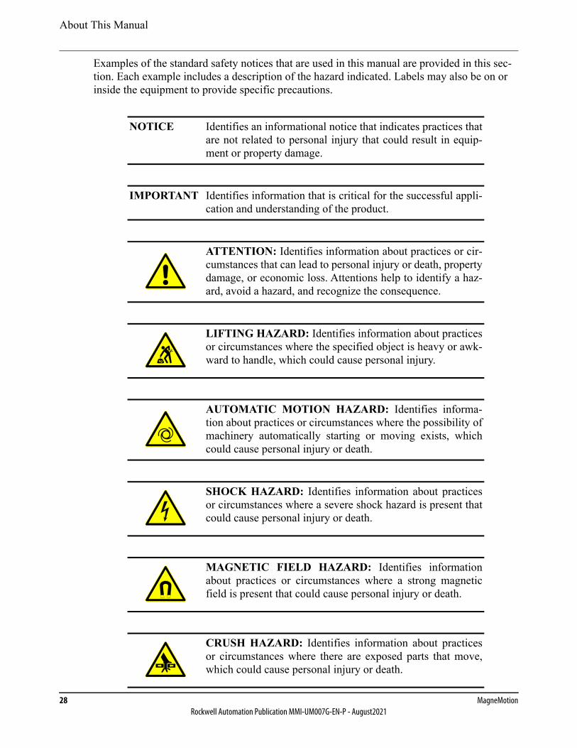
About This Manual
28 MagneMotionRockwell Automation Publication MMI-UM007G-EN-P - August2021
Examples of the standard safety notices that are used in this manual are provided in this sec-tion. Each example includes a description of the hazard indicated. Labels may also be on or inside the equipment to provide specific precautions.
NOTICE Identifies an informational notice that indicates practices thatare not related to personal injury that could result in equip-ment or property damage.
IMPORTANT Identifies information that is critical for the successful appli-cation and understanding of the product.
ATTENTION: Identifies information about practices or cir-cumstances that can lead to personal injury or death, propertydamage, or economic loss. Attentions help to identify a haz-ard, avoid a hazard, and recognize the consequence.
LIFTING HAZARD: Identifies information about practicesor circumstances where the specified object is heavy or awk-ward to handle, which could cause personal injury.
AUTOMATIC MOTION HAZARD: Identifies informa-tion about practices or circumstances where the possibility ofmachinery automatically starting or moving exists, whichcould cause personal injury or death.
SHOCK HAZARD: Identifies information about practicesor circumstances where a severe shock hazard is present thatcould cause personal injury or death.
MAGNETIC FIELD HAZARD: Identifies informationabout practices or circumstances where a strong magneticfield is present that could cause personal injury or death.
CRUSH HAZARD: Identifies information about practicesor circumstances where there are exposed parts that move,which could cause personal injury or death.
kg
About This Manual
QuickStick HT User Manual 29Rockwell Automation Publication MMI-UM007G-EN-P - August2021
Manual Structure
This manual contains the following chapters:
• Introduction: Provides an overview of the QuickStick HT components and their use in a transport system. The QSHT motors are used to provide fast, precise motion, posi-tioning, and tracking of very heavy loads.
• Safety Guidelines: Identifies safety concerns and requirements for the QuickStick HT components and the personnel operating and servicing the QSHT motors and the transport system where they are installed.
• Design Guidelines: Provides guidelines for designing a QuickStick HT transport sys-tem.
• Specifications and Site Requirements: Provides specifications and the requirements for installation of the QuickStick HT motors as a transport system.
• Installation: Provides complete installation procedures for the QSHT components.
• Operation: Provides complete operation directions for the QSHT components as part of a transport system.
• QSHT 5700 Inverter Safe Torque-off Function. Provides an overview of the hardwired safe torque-off function in the QuickStick HT 5700 Inverter.
• Maintenance: Provides maintenance schedules and procedures for the QSHT compo-nents.
• Appendix: Provides additional information that is related to QSHT transport systems.
• Glossary: A list of terms and definitions that are used in this manual and for the trans-port system and its components.
• Index: A cross-reference to this manual organized by subject.
Related Documentation
Before configuring or running the QuickStick HT components, consult the following Magne-Motion documentation:
• QuickStick Configurator User Manual, MMI-UM009.
• Node Controller Interface User Manual, MMI-UM001.
• NCHost TCP Interface Utility User Manual, MMI-UM010.
• Host Controller TCP/IP Communication Protocol User Manual, MMI-UM003.orHost Controller EtherNet/IP Communication Protocol User Manual, MMI-UM004.
• QuickStick HT User Manual, MMI-UM007 (this manual).
• Node Controller Hardware User Manual, MMI-UM013.
• Virtual Scope Utility User Manual, MMI-UM011.
About This Manual
30 MagneMotionRockwell Automation Publication MMI-UM007G-EN-P - August2021
Before configuring or running the QuickStick HT 5700 Inverters, consult the following Rock-well Automation documentation:
• Kinetix 5700 Servo Drives User Manual, 2198-UM002.
• Kinetix Motion Accessories Specifications Technical Data, 2198-IN010.
• Kinetix 5700 DC-bus Power Supply Installation Instructions, 2198-IN009.
• Industrial Automation Wiring and Grounding Guidelines, 1770-4.1.
• Wiring and Grounding Guidelines for Pulse-width Modulated (PWM) AC Drives, DRIVES-IN001.
• System Design for Control of Electrical Noise Reference Manual, GMC-RM001.
• Kinetix Servo Drives Specifications Technical Data, KNX-TD003.
• Kinetix Motion Accessories Specifications Technical Data, KNX-TD004.
NOTE: Distribution of this manual and all addenda and attachments are not controlled. Changes to the document set or the software can be made at any time. To identify the current revisions or to obtain a current version, see Rockwell Automation Support on page 350.

QuickStick HT User Manual 31Rockwell Automation Publication MMI-UM007G-EN-P - August2021
Introduction 1
Overview
This chapter provides an overview of the QuickStick® High Thrust (QSHT) component hard-ware and software. It includes an overview of the basic tasks that are used to install and use the QSHT components in a transport system.
Use this manual to install, test, and debug the QSHT components in a transport system. Some procedures can vary based on the transport system configuration, communication, and other variables.
This manual supports:
• QuickStick HT transport systems.
Included in this chapter are overviews of:
• The QuickStick HT components in a transport system.
• The transport system components.
• The transport system software.
• Getting started with a QuickStick HT transport system.
IntroductionQuickStick HT Transport System Overview
32 MagneMotionRockwell Automation Publication MMI-UM007G-EN-P - August2021
QuickStick HT Transport System Overview
The QuickStick High Thrust (QSHT) is an intelligent transport system that provides fast, pre-cise motion, and positioning and tracking of large loads being transported in a transport sys-tem. The QSHT transport system is a configuration of linear synchronous motors and related control electronics that move independently commanded material carriers (vehicles). All vehi-cle movement is done in a controlled manner at various acceleration/deceleration and velocity profiles while carrying a wide range of payloads with high precision. The QSHT transport system consists of the following components:
• QuickStick High Thrust motors and motor drives.
• User-designed and supplied vehicles with QSHT magnet arrays.
• Node controllers.
• Power supplies.
• Paths and nodes.
• User-supplied host controller.
• User-designed and supplied guideway and track system.
QuickStick HT transport systems use proven linear synchronous motor (LSM) and control technology from MagneMotion®. These systems offer an excellent alternative to conventional belt and chain conveyors for OEM/in-machine applications and for demanding product con-veyance requirements.
• QuickStick HT motors provide repeatable positioning with no hard stops required, bidirectional travel, smooth motion, and continuous vehicle tracking and reporting.
• Vehicle positioning and guidance are built into the motor with external drive electronics.
• Servo repeatability at any position: ± 1.0 mm [0.04 in] (dependent on the size of the gap between the motor and the vehicle-mounted magnet array). Repeat-ability can vary based on the PID settings that are used and track and vehicle design/structure, repeatability is not applicable over the gaps between motors.
• Vehicles are controlled individually allowing the host controller to prioritize the routing of individual vehicles over different paths.
• Motion is provided by user-designed vehicles with magnet arrays that are attached to the surface closest to the motor.
• Up to two vehicles in queue or in motion per meter* (238 mm [9.4 in] vehicle length).
• Speeds up to 5.0 m/s [11.2 mph] and acceleration up to 60 m/s2 [6.1 g].
* Maximum number of vehicles per meter is determined using the shortest magnet array that is allowed on a straight guideway. Using a longer magnet array or a curved guideway decreases the number of vehicles that fit per meter.
IntroductionQuickStick HT Transport System Overview
QuickStick HT User Manual 33Rockwell Automation Publication MMI-UM007G-EN-P - August2021
• QSHT motors are capable of moving payloads up to 4,500 kg [9,900 lb] (the vehicle and track system must be designed to support the load).
• Minimum magnet array length is 238 mm [9.4 in].
• Configuration and simulation software tools simplify transport system design and optimization.
• Versions available for use in cleanrooms and IP68 environments (motors and magnet arrays only).
• Less wear and tear – no belts, chains, gears, or external sensors required – few moving parts means less maintenance.
• Standard industrial communication protocols and software configured move profiles (PID control loop) for fast and easy changeovers to new configurations.
• Standard motor and configuration elements provide plug-and-play capability and make it easy to implement layout changes.
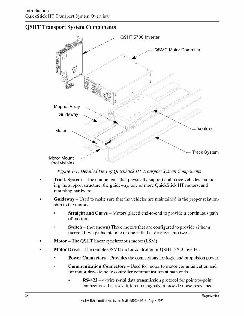
IntroductionQuickStick HT Transport System Overview
34 MagneMotionRockwell Automation Publication MMI-UM007G-EN-P - August2021
QSHT Transport System Components
Figure 1-1: Detailed View of QuickStick HT Transport System Components
• Track System – The components that physically support and move vehicles, includ-ing the support structure, the guideway, one or more QuickStick HT motors, and mounting hardware.
• Guideway – Used to make sure that the vehicles are maintained in the proper relation-ship to the motors.
• Straight and Curve – Motors placed end-to-end to provide a continuous path of motion.
• Switch – (not shown) Three motors that are configured to provide either a merge of two paths into one or one path that diverges into two.
• Motor – The QSHT linear synchronous motor (LSM).
• Motor Drive – The remote QSMC motor controller or QSHT 5700 inverter.
• Power Connectors – Provides the connections for logic and propulsion power.
• Communication Connectors – Used for motor to motor communication and for motor drive to node controller communication at path ends.
• RS-422 – 4-wire serial data transmission protocol for point-to-point connections that uses differential signals to provide noise resistance.
Guideway
Motor Mount
VehicleMotor
Track System
Magnet Array
(not visible)
QSHT 5700 Inverter
QSMC Motor Controller
IntroductionQuickStick HT Transport System Overview
QuickStick HT User Manual 35Rockwell Automation Publication MMI-UM007G-EN-P - August2021
• Ethernet – 4-wire data transmission protocol for network connections that uses differential signals to provide noise resistance.
• Stator Sense Connector – Provides the connection for the motor control sig-nals.
• Stator Drive Connector – Provides the connection for the motor phase power.
• Motor Mount – Used to mount the motor to the guideway.
• Vehicle with Magnet Array – Carries the payload through the QSHT transport sys-tem as directed. The magnet array is mounted to the vehicle and interacts with the motors, which moves the vehicle.
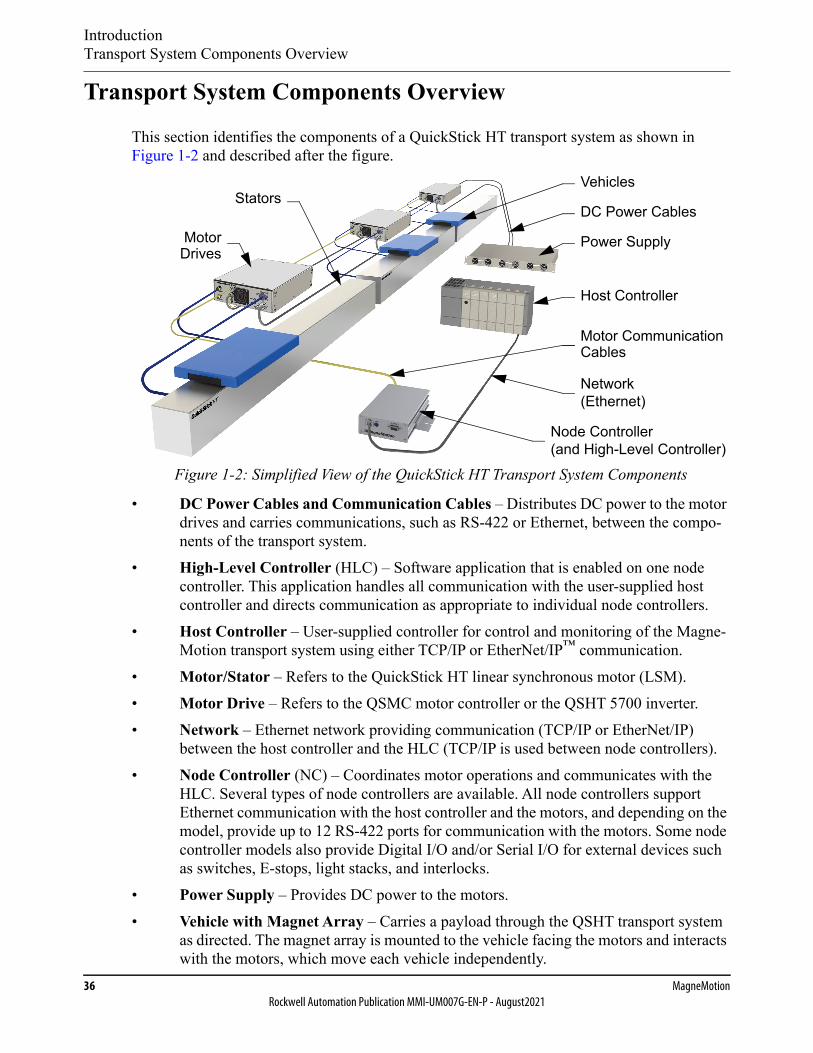
IntroductionTransport System Components Overview
36 MagneMotionRockwell Automation Publication MMI-UM007G-EN-P - August2021
Transport System Components Overview
This section identifies the components of a QuickStick HT transport system as shown in Figure 1-2 and described after the figure.
Figure 1-2: Simplified View of the QuickStick HT Transport System Components
• DC Power Cables and Communication Cables – Distributes DC power to the motor drives and carries communications, such as RS-422 or Ethernet, between the compo-nents of the transport system.
• High-Level Controller (HLC) – Software application that is enabled on one node controller. This application handles all communication with the user-supplied host controller and directs communication as appropriate to individual node controllers.
• Host Controller – User-supplied controller for control and monitoring of the Magne-Motion transport system using either TCP/IP or EtherNet/IP™ communication.
• Motor/Stator – Refers to the QuickStick HT linear synchronous motor (LSM).• Motor Drive – Refers to the QSMC motor controller or the QSHT 5700 inverter.• Network – Ethernet network providing communication (TCP/IP or EtherNet/IP)
between the host controller and the HLC (TCP/IP is used between node controllers).• Node Controller (NC) – Coordinates motor operations and communicates with the
HLC. Several types of node controllers are available. All node controllers support Ethernet communication with the host controller and the motors, and depending on the model, provide up to 12 RS-422 ports for communication with the motors. Some node controller models also provide Digital I/O and/or Serial I/O for external devices such as switches, E-stops, light stacks, and interlocks.
• Power Supply – Provides DC power to the motors.• Vehicle with Magnet Array – Carries a payload through the QSHT transport system
as directed. The magnet array is mounted to the vehicle facing the motors and interacts with the motors, which move each vehicle independently.
Host Controller
VehiclesStators
Motor Communication
Node Controller(and High-Level Controller)
Network(Ethernet)
MotorDrives
Power Supply
DC Power Cables
Cables
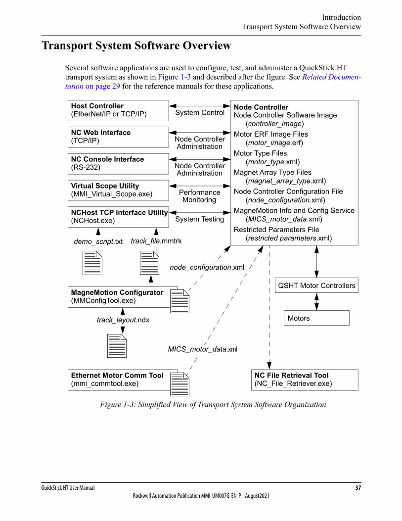
IntroductionTransport System Software Overview
QuickStick HT User Manual 37Rockwell Automation Publication MMI-UM007G-EN-P - August2021
Transport System Software Overview
Several software applications are used to configure, test, and administer a QuickStick HT transport system as shown in Figure 1-3 and described after the figure. See Related Documen-tation on page 29 for the reference manuals for these applications.
Figure 1-3: Simplified View of Transport System Software Organization
QSHT Motor Controllers
Host Controller(EtherNet/IP or TCP/IP)
MagneMotion Configurator
NC Web Interface
NCHost TCP Interface Utility
Node Controller Software Image(controller_image)
Motor ERF Image Files(motor_image.erf)
Motor Type Files(motor_type.xml)
Magnet Array Type Files(magnet_array_type.xml)
Node Controller Configuration File(node_configuration.xml)
MagneMotion Info and Config Service(MICS_motor_data.xml)
Restricted Parameters File(restricted parameters.xml)
System Control
System Testing(NCHost.exe)
(MMConfigTool.exe)
track_file.mmtrkdemo_script.txt
track_layout.ndx
Virtual Scope Utility
NC Console Interface
(MMI_Virtual_Scope.exe)
(TCP/IP)
(RS-232)
Node Controller
Node ControllerAdministration
PerformanceMonitoring
Node ControllerAdministration
node_configuration.xml
Ethernet Motor Comm Tool(mmi_commtool.exe)
NC File Retrieval Tool(NC_File_Retriever.exe)
MICS_motor_data.xml
Motors
IntroductionTransport System Software Overview
38 MagneMotionRockwell Automation Publication MMI-UM007G-EN-P - August2021
Utilities• NC Web Interface – A web-based software application that is supplied by MagneMo-
tion and resident on the node controllers, for administration of the transport system components.
• NC Console Interface – A serial communication software application that is supplied by MagneMotion and resident on the node controllers, for administration of the node controller.
• Virtual Scope Utility – A Windows software application that is supplied by Magne-Motion to monitor and record the change of motor performance parameters. These parameters are displayed as waveforms to analyze the performance of the motors.
• NCHost TCP Interface Utility – A Windows® software application that is supplied by MagneMotion to move vehicles for test or demonstration purposes. This applica-tion supports system testing without the host controller to verify that vehicles move correctly before integrating a transport system into a production environment.
• MagneMotion Configurator Utility (Configurator) – A Windows software applica-tion that is supplied by MagneMotion to create or change the Node Controller Config-uration File. This utility is available in both MagneMover LITE and QuickStick versions. The MM LITE version is also used to create or change the Track File and Track Layout File for MagneMover LITE transport systems.
• Ethernet Motor Commissioning Tool – A Windows software application that is sup-plied by MagneMotion to create and edit MagneMotion Information and Configura-tion Service (MICS) files.
• NC File Retrieval Tool – A Windows software application that is supplied by Magne-Motion to download configuration and operation files from the specified HLC and all node controllers in the transport system.
File Types• Node Controller Software Image File (IMG file) – The software file for the node
controllers (controller_image), includes the node controller and HLC applications. The Node Controller Software Image file is uploaded to all node controllers in the transport system.
• Motor ERF Image Files (ERF file) – The software files for the MagneMotion motors (motor_image.erf). The Motor ERF Image files are uploaded to all node controllers in the transport system and then programmed into all motors.
• Motor Type Files – XML files (motor_type.xml) that contain basic information about the specific QuickStick HT motor types being used. The Motor Type files are uploaded to all node controllers in the transport system.
• Magnet Array Type File – An XML file (magnet_array_type.xml) that contains basic information about the specific MagneMotion magnet array type that is used on the vehicles in the QuickStick HT transport system. The Magnet Array Type file is uploaded to all node controllers in the transport system.
IntroductionTransport System Software Overview
QuickStick HT User Manual 39Rockwell Automation Publication MMI-UM007G-EN-P - August2021
• Node Controller Configuration Files (Configuration file) – An XML file (node_con-figuration.xml) that contains all parameters for the components in the transport sys-tem. Multiple Node Controller Configuration Files can be uploaded to all node controllers in the transport system, but only one is active.
• MagneMotion Information and Configuration Service (MICS) File – An XML file (MICS_motor_data.xml) that contains the network topology parameters for the trans-port system when using Ethernet communication with the motors. The file includes the MAC address of each motor and the location of each motor on a path. The MICS file is uploaded to all node controllers in the transport system.
• Restricted Parameters File – An XML file (restricted_parameters.xml) that provides access to restricted configuration elements for specific transport systems. The Restricted Parameters file is uploaded to the HLC. For the development of a custom Restricted Parameters file for a specific transport system, see Rockwell Automation Support on page 350.
• Demo Script – A text file (demo_script.txt) uploaded to the NCHost TCP Interface Utility to move vehicles on the transport system for test or demonstration purposes.
• Track File – A text file (track_file.mmtrk) that contains graphical path and motor information about the transport system. The Track file is used by the NCHost TCP Interface Utility to provide a graphical representation of the transport system to moni-tor system operation. For the development of a custom Track File file for a specific QuickStick transport system, see Rockwell Automation Support on page 350.
• Track Layout File – An XML file (track_layout.ndx) that contains all parameters for the graphical representation of a MagneMover LITE transport system. The Track Lay-out file is used by the MagneMover LITE Configurator to generate the Node Control-ler Configuration File and the Track file for MagneMover LITE systems.
NOTICE Modifications to the Image or Type files could causeimproper operation of the transport system.

IntroductionGetting Started with the QuickStick HT Transport System
40 MagneMotionRockwell Automation Publication MMI-UM007G-EN-P - August2021
Getting Started with the QuickStick HT Transport System
Use this manual as a guide and reference when installing or servicing the QuickStick HT com-ponents in a transport system. Follow the steps in this section to get the entire transport system operational quickly with the aid of the other MagneMotion manuals (see Related Documenta-tion on page 29).
NOTE: Make sure that all components and complete design specifications, including the physical layout of the transport system, are available before starting to install or test the QSHT transport system.
To get started quickly with the transport system:
1. Download the software for the QSHT transport system and the MagneMotion Utilities from rok.auto/pcdc.
2. Save the files and folders from the QSHT transport system software package to a folder on a computer for user access.
NOTE: The minimum requirements for running MagneMotion software applications are a general-purpose computer running Microsoft® Windows® 7 with .NET 4.0. An Ethernet port (web interface) and an optional RS-232 port (console interface) are required to connect to the node controllers.
3. Install the components of the QSHT transport system as described in the following sections of this manual:
A. Prepare the facility for the installation:
• Safety Considerations on page 46.
• Design Guidelines on page 59.
• Site Requirements on page 174.
B. Prepare the components for installation and install:
• Unpacking and Inspection on page 178.
• Transport System Installation on page 181.
C. Install the node controllers as described in the Node Controller Hardware User Manual, MMI-UM013.
4. Install the QuickStick Configurator on a computer for user access (see Software Con-figuration on page 222 and the QuickStick Configurator User Manual, MMI-UM009).
A. Define the motors and paths and their relationships in the transport system to create the Node Controller Configuration File (node_configuration.xml).
IntroductionGetting Started with the QuickStick HT Transport System
QuickStick HT User Manual 41Rockwell Automation Publication MMI-UM007G-EN-P - August2021
5. Set the IP address for each node controller and specify the node controller to be used as the high-level controller (see the Node Controller Interface User Manual, MMI-UM001).
6. Verify that the installation is complete and the system is ready for use:
• System Check-out on page 224.
• System Power-up on page 225.
7. Upload the configuration, image, and type files to each node controller using the node controller web interface (see Node Controller Software Installation on page 223 and the Node Controller Interface User Manual, MMI-UM001).
Once configured, the node controllers can be used to simulate the transport system, see Transport System Simulation on page 258.
8. When using motors with Ethernet communication, create the MICS file (see Ethernet Motor MICS File on page 90) and provision the motors (see Step 11 of System Power-up on page 225).
9. Program the motors using the Motor ERF Image files (see Motor Software Installation on page 223, the Node Controller Interface User Manual, MMI-UM001, and the NCHost TCP Interface Utility User Manual, MMI-UM010).
10. Test and debug the transport system by using the NCHost TCP Interface Utility and Demo Scripts (see Check-out and Power-up on page 224 and the NCHost TCP Inter-face Utility User Manual, MMI-UM010). NCHost provides an easy method to verify proper operation and make adjustments such as refining the control loop tuning.
NOTE: The NCHost TCP Interface Utility is for test and verification trials only. The host controller must be used to control the QSHT transport system after veri-fication of functionality.
11. Configure the host controller to control the QSHT transport system as required to meet the material movement needs of the facility where the system is installed. See:
• Transport System Operation on page 264.
• Shut-down on page 265.
When using TCP/IP communication, see the Host Controller TCP/IP Communication Protocol User Manual, MMI-UM003. When using EtherNet/IP communication, see the Host Controller EtherNet/IP Communication Protocol User Manual, MMI-UM004.

Introduction
42 MagneMotionRockwell Automation Publication MMI-UM007G-EN-P - August2021
This page intentionally left blank.

QuickStick HT User Manual 43Rockwell Automation Publication MMI-UM007G-EN-P - August2021
Safety Guidelines 2
Overview
This chapter describes safety guidelines for the QuickStick® HT components and their use in a transport system. All personnel that are involved in the installation, operation, or mainte-nance of the QSHT components and the transport system must be familiar with the safety pre-cautions that are outlined in this chapter.
NOTE: These safety recommendations are basic guidelines. If the facility where the Quick-Stick HT components are installed has additional safety guidelines, they must be fol-lowed as well, along with the applicable local and national safety codes.
Included in this chapter are:
• Regulatory compliance information.
• Personnel and equipment safety guidelines.
• Symbol identification.
• Label identification and locations.
• Identification of mechanical, electrical, and magnetic hazards.
• Recycling and disposal Information.
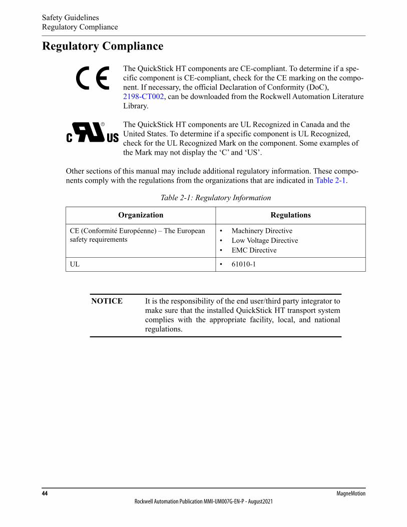
Safety GuidelinesRegulatory Compliance
44 MagneMotionRockwell Automation Publication MMI-UM007G-EN-P - August2021
Regulatory Compliance
The QuickStick HT components are CE-compliant. To determine if a spe-cific component is CE-compliant, check for the CE marking on the compo-nent. If necessary, the official Declaration of Conformity (DoC), 2198-CT002, can be downloaded from the Rockwell Automation Literature Library.
The QuickStick HT components are UL Recognized in Canada and the United States. To determine if a specific component is UL Recognized, check for the UL Recognized Mark on the component. Some examples of the Mark may not display the ‘C’ and ‘US’.
Other sections of this manual may include additional regulatory information. These compo-nents comply with the regulations from the organizations that are indicated in Table 2-1.
Table 2-1: Regulatory Information
Organization Regulations
CE (Conformité Européenne) – The European safety requirements
• Machinery Directive• Low Voltage Directive• EMC Directive
UL • 61010-1
NOTICE It is the responsibility of the end user/third party integrator tomake sure that the installed QuickStick HT transport systemcomplies with the appropriate facility, local, and nationalregulations.
Safety GuidelinesRegulatory Compliance
QuickStick HT User Manual 45Rockwell Automation Publication MMI-UM007G-EN-P - August2021
Agency Compliance
If a QuickStick HT transport system using QuickStick HT 5700 inverters is installed within the European Union and has CE marking, the following regulations apply.
For more information on electrical noise reduction, see the System Design for Control of Electrical Noise Reference Manual, GMC-RM001. See Interconnect Diagrams on page 320 in the appendix for input power wiring and drive/motor interconnect diagrams. To meet CE requirements for compliance with IEC61800-3 and FS requirements for compliance with IEC61800-5-2, these requirements apply:
• Install an AC line filter (catalog number 2198-DBRxx-F) for input power as close to the 2198-Pxxx DC-bus power supplies as possible.
• Bond DC-bus power supplies, inverter modules, capacitor modules, and line filter grounding screws by using a braided ground strap as shown in Figure 5-17 on page 213.
• When using the 2198-P070 DC-bus power supplies above 45 °C (113 °F) with stranded input power wiring, conductors must be single-core 6 mm2 stranded copper with 90 °C minimum rating.
• Use MMI-HT-CBP05-xx and MMI-HT-CBS00-xx motor power and feedback cables for QuickStick HT motors. The motor cable shield-clamp on the drive with clamp spacers must be used.
• Combined motor power cable length for all axes on the same DC bus must not exceed:• 1200 m (3937 ft) for 2198-P070, 2198-P141, and 2198-P208.• 400 m (1312 ft) for 2198-Pxxx DC-bus power supplies when paired with
2198-DBxx-F line filters.• 400 m (1312 ft) for 2198-P031 DC-bus power supplies when paired with
2198-DBxx-F or 2198-DBRxx-F line filters.
• Drive-to-motor feedback cables must not exceed 30 m (98 ft), depending on system components.
• Install the QSHT 5700 inverters system inside an approved metal enclosure (IP54 min). Run the input power wiring in conduit (grounded to the enclosure) outside of the enclosure. See the Kinetix 5700 Servo Drives User Manual, 2198-UM002, for enclo-sure selection and installation guidelines, including heat dissipation.
• Separate input power wiring from control wiring and motor cables.
ATTENTION: Meeting CE requires a grounded system, andthe method of grounding the AC line filter and drive modulemust match. Failure to do this renders the filter ineffectiveand can cause damage to the filter. For grounding examples,see the Kinetix 5700 Servo Drives User Manual,2198-UM002.
Safety GuidelinesSafety Considerations
46 MagneMotionRockwell Automation Publication MMI-UM007G-EN-P - August2021
Safety Considerations
Personnel Safety Guidelines
QuickStick HT components and transport systems can provide several direct safety hazards to personnel if not properly installed or operated. General safety guidelines are provided in this section, specific cautions are provided as needed (see Mechanical Hazards on page 52, Elec-trical Hazards on page 53, and Magnetic Hazards on page 54).
• Personnel operating or servicing the QuickStick HT transport system must be properly trained.
• Be aware of the hazardous points of the QuickStick HT transport system as described in this chapter.
• High-strength Neodymium Iron Boron magnets are used with the QSHT motors.• To avoid severe injury, people with pacemakers and other medical electronic
implants must not handle or approach the magnet arrays. These individuals must consult their physician to determine the susceptibility of their device to static magnetic fields and to determine a safe distance between themselves and the magnet array.
• Handle only one vehicle/magnet array at a time. Do not place any body parts, such as fingers, between a magnet array and any QSHT motors, ferrous mate-rial, or another magnet array to avoid injury from strong magnetic attractive forces.
• Vehicles and magnet arrays not on the QuickStick HT transport system must be secured individually in isolated packaging.
• Moving mechanisms have no obstruction sensors and can cause personal injury.
• Know the location of the following:• Fire extinguisher.• First Aid Station.• Emergency eyewash and/or shower.• Emergency exit.
• The following safety equipment, used according to the instructions provided by the manufacturer, must be donned before installing, testing, or servicing the QSHT trans-port system:• Eye protection – Breaking material can produce flying shards. When running
a setup or test procedure, always wear protective eyewear to guard against pos-sible eye injuries.
• Foot protection – Always wear shoes with protective toes to help protect feet from falling tools or parts.
Safety GuidelinesSafety Considerations
QuickStick HT User Manual 47Rockwell Automation Publication MMI-UM007G-EN-P - August2021
• Observe the facility guidelines that are related to loose clothing while working around or operating the QSHT transport system.
• It may be recommended that hazardous materials, such as cleaning fluids, be used during routine maintenance procedures. Read and understand the hazardous materials policies for the facility and the Safety Data Sheet (provided by the manufacturer) for each substance.
• Whenever power is applied, the possibility of automatic motion of the vehicles or user-supplied equipment in the QSHT transport system exists. It is the responsibility of the user to provide appropriate safeguards.
• Make sure that propulsion power is disabled whenever maintenance is being per-formed on the vehicles, track system, or motors.
• Make sure that the QSHT motors and related components are properly decontaminated before performing any service by following the decontamination procedures at the facility. Follow all facility, local, and national procedures for the disposal of any haz-ardous materials.
• Ergonomic hazards can exist with certain installation or service operations that are related to the QSHT transport system.
Equipment Safety Guidelines
The following safety considerations are provided to aid in the placement and use of the Quick-Stick HT transport system.
• If hazardous materials are to be present, proper safety precautions must be observed. Make sure that all materials that are used are compatible with the materials from which the QSHT components are fabricated.
• If the QSHT transport system is to be installed in an earthquake prone environment, install the equipment accordingly.
• The QSHT components are not provided with an Emergency Off (EMO) circuit. The facility where the system is installed is responsible for an EMO circuit (see E-stops on page 255 for more information).
• Do not place the power and communication cables for the QSHT transport system where they could cause a trip hazard.
• Do not place the QSHT transport system in a location where it could be subject to physical damage.
• Make sure that all electrical connections to the QSHT components are made in accor-dance with the appropriate facility, local, and national regulations.
• Make sure that the QSHT components receive proper airflow for cooling.
• Do not remove safety labels or equipment identification labels.
• Turn OFF power before inserting or removing the power cables.
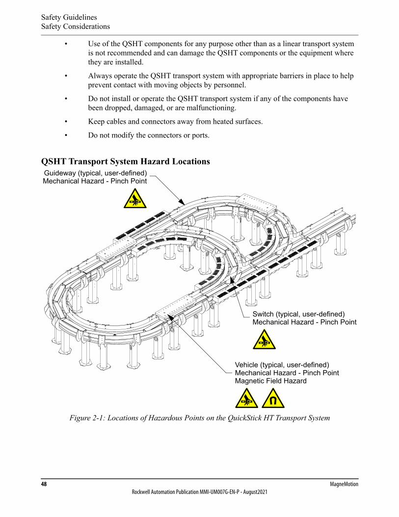
Safety GuidelinesSafety Considerations
48 MagneMotionRockwell Automation Publication MMI-UM007G-EN-P - August2021
• Use of the QSHT components for any purpose other than as a linear transport system is not recommended and can damage the QSHT components or the equipment where they are installed.
• Always operate the QSHT transport system with appropriate barriers in place to help prevent contact with moving objects by personnel.
• Do not install or operate the QSHT transport system if any of the components have been dropped, damaged, or are malfunctioning.
• Keep cables and connectors away from heated surfaces.
• Do not modify the connectors or ports.
QSHT Transport System Hazard Locations
Figure 2-1: Locations of Hazardous Points on the QuickStick HT Transport System
Guideway (typical, user-defined)Mechanical Hazard - Pinch Point
Vehicle (typical, user-defined)Mechanical Hazard - Pinch PointMagnetic Field Hazard
Switch (typical, user-defined)Mechanical Hazard - Pinch Point
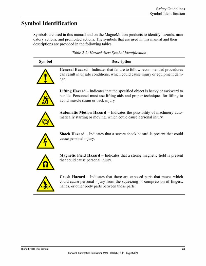
Safety GuidelinesSymbol Identification
QuickStick HT User Manual 49Rockwell Automation Publication MMI-UM007G-EN-P - August2021
Symbol Identification
Symbols are used in this manual and on the MagneMotion products to identify hazards, man-datory actions, and prohibited actions. The symbols that are used in this manual and their descriptions are provided in the following tables.
Table 2-2: Hazard Alert Symbol Identification
Symbol Description
General Hazard – Indicates that failure to follow recommended procedurescan result in unsafe conditions, which could cause injury or equipment dam-age.
Lifting Hazard – Indicates that the specified object is heavy or awkward tohandle. Personnel must use lifting aids and proper techniques for lifting toavoid muscle strain or back injury.
Automatic Motion Hazard – Indicates the possibility of machinery auto-matically starting or moving, which could cause personal injury.
Shock Hazard – Indicates that a severe shock hazard is present that couldcause personal injury.
Magnetic Field Hazard – Indicates that a strong magnetic field is presentthat could cause personal injury.
Crush Hazard – Indicates that there are exposed parts that move, whichcould cause personal injury from the squeezing or compression of fingers,hands, or other body parts between those parts.
kg
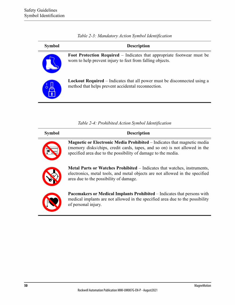
Safety GuidelinesSymbol Identification
50 MagneMotionRockwell Automation Publication MMI-UM007G-EN-P - August2021
Table 2-3: Mandatory Action Symbol Identification
Symbol Description
Foot Protection Required – Indicates that appropriate footwear must beworn to help prevent injury to feet from falling objects.
Lockout Required – Indicates that all power must be disconnected using amethod that helps prevent accidental reconnection.
Table 2-4: Prohibited Action Symbol Identification
Symbol Description
Magnetic or Electronic Media Prohibited – Indicates that magnetic media(memory disks/chips, credit cards, tapes, and so on) is not allowed in thespecified area due to the possibility of damage to the media.
Metal Parts or Watches Prohibited – Indicates that watches, instruments,electronics, metal tools, and metal objects are not allowed in the specifiedarea due to the possibility of damage.
Pacemakers or Medical Implants Prohibited – Indicates that persons withmedical implants are not allowed in the specified area due to the possibilityof personal injury.
Safety GuidelinesLabels
QuickStick HT User Manual 51Rockwell Automation Publication MMI-UM007G-EN-P - August2021
Labels
Safety labels and identification labels are placed on those QuickStick HT components that require them. These labels provide operators and service personnel with hazard identification and information about the QSHT components at the point of use.
NOTE: Label placement can cause labels to be visible only during maintenance operations.
To replace a lost or damaged label, contact Technical Support (see Rockwell Automation Sup-port on page 350).
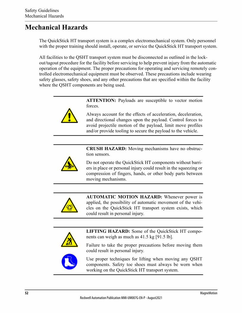
Safety GuidelinesMechanical Hazards
52 MagneMotionRockwell Automation Publication MMI-UM007G-EN-P - August2021
Mechanical Hazards
The QuickStick HT transport system is a complex electromechanical system. Only personnel with the proper training should install, operate, or service the QuickStick HT transport system.
All facilities to the QSHT transport system must be disconnected as outlined in the lock-out/tagout procedure for the facility before servicing to help prevent injury from the automatic operation of the equipment. The proper precautions for operating and servicing remotely con-trolled electromechanical equipment must be observed. These precautions include wearing safety glasses, safety shoes, and any other precautions that are specified within the facility where the QSHT components are being used.
ATTENTION: Payloads are susceptible to vector motionforces.
Always account for the effects of acceleration, deceleration,and directional changes upon the payload. Control forces toavoid projectile motion of the payload, limit move profilesand/or provide tooling to secure the payload to the vehicle.
CRUSH HAZARD: Moving mechanisms have no obstruc-tion sensors.
Do not operate the QuickStick HT components without barri-ers in place or personal injury could result in the squeezing orcompression of fingers, hands, or other body parts betweenmoving mechanisms.
AUTOMATIC MOTION HAZARD: Whenever power isapplied, the possibility of automatic movement of the vehi-cles on the QuickStick HT transport system exists, whichcould result in personal injury.
LIFTING HAZARD: Some of the QuickStick HT compo-nents can weigh as much as 41.5 kg [91.5 lb].
Failure to take the proper precautions before moving themcould result in personal injury.
Use proper techniques for lifting when moving any QSHTcomponents. Safety toe shoes must always be worn whenworking on the QuickStick HT transport system.
kg

Safety GuidelinesElectrical Hazards
QuickStick HT User Manual 53Rockwell Automation Publication MMI-UM007G-EN-P - August2021
Electrical Hazards
The QuickStick High Thrust motors and QSMC motor controllers are capable of drawing +300…400V DC at 15 A at maximum load. The QuickStick High Thrust motors and Quick-Stick HT 5700 Inverters are capable of drawing +276…747V DC at 13.0 A at maximum load.
The QuickStick HT motor controllers, power supplies, node controllers, network switches, and power modules are connected to the AC Mains of the facility and can generate hazardous energy. The proper precautions for operating and servicing electrical equipment must be observed. These precautions include following facility lockout/tagout procedures, and any other specified action within the facility where the QSHT components are being used.
SHOCK HAZARD: To avoid electric shock, all electricalpower to the QuickStick HT transport system must be dis-connected per the facility lockout/tagout procedure beforeservicing to help prevent the risk of electrical shock.
SHOCK HAZARD: To avoid electric shock, do not openany QuickStick HT component. Motors, controllers, andother components do not contain any user-serviceable parts.
Do not turn on power to the power supplies, motor control-lers, and node controllers until after connecting all othertransport system components.
NOTICE To avoid equipment damage:• Make sure that the transport system is properly grounded.• Make sure that all vehicles are grounded to the guideway
through conductive wheels or static brushes.• Do not connect or disconnect any components while the
transport system has power, QuickStick HT motors are not hot-pluggable.
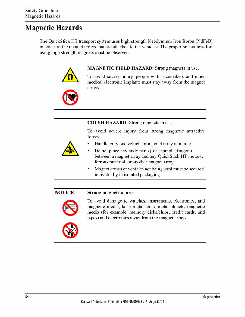
Safety GuidelinesMagnetic Hazards
54 MagneMotionRockwell Automation Publication MMI-UM007G-EN-P - August2021
Magnetic Hazards
The QuickStick HT transport system uses high-strength Neodymium Iron Boron (NdFeB) magnets in the magnet arrays that are attached to the vehicles. The proper precautions for using high strength magnets must be observed.
MAGNETIC FIELD HAZARD: Strong magnets in use.
To avoid severe injury, people with pacemakers and othermedical electronic implants must stay away from the magnetarrays.
CRUSH HAZARD: Strong magnets in use.
To avoid severe injury from strong magnetic attractiveforces:• Handle only one vehicle or magnet array at a time.• Do not place any body parts (for example, fingers)
between a magnet array and any QuickStick HT motors, ferrous material, or another magnet array.
• Magnet arrays or vehicles not being used must be secured individually in isolated packaging.
NOTICE Strong magnets in use.
To avoid damage to watches, instruments, electronics, andmagnetic media, keep metal tools, metal objects, magneticmedia (for example, memory disks/chips, credit cards, andtapes) and electronics away from the magnet arrays.

Safety GuidelinesMagnetic Hazards
QuickStick HT User Manual 55Rockwell Automation Publication MMI-UM007G-EN-P - August2021
Handling Magnet Arrays
The Neodymium Iron Boron (NdFeB) magnets that are used in the QSHT magnet arrays require special handling. General handling guidelines and cautions are provided in this sec-tion. It is the responsibility of the user to define and implement their own handling guidelines in accordance with the applicable facility, local, and national safety codes for the installation site.
• Pacemakers and other Medical Implants – Individuals with pacemakers or internal medical devices must use caution when handling the magnet arrays as the magnetic fields can affect the operation of these devices. These individuals must consult their physician and the manufacturer of their medical device to determine its susceptibility to static magnetic fields before handling the magnet arrays and to determine the safe distance from the arrays, or if they must not handle the arrays.
• Electronic Equipment Damage – Do not allow any magnet arrays near sensitive electronics, equipment with cathode ray tubes (CRTs) or other displays, or magnetic storage media (for example, disks, credit cards, cell phones).
• Pinch/Crush – The magnet arrays that are used with the MagneMotion linear motors are very strong. The magnet arrays have a very high attractive force to each other and ferromagnetic materials like steel, iron, some stainless steels, and nickel. Pinching happens if the magnet arrays are allowed to come together against a body part – usu-ally fingers. Do not try to stop moving objects or magnet arrays that have been attracted to each other.
• Impact – Do not strike the magnet arrays as the magnets within them can shatter and break. The magnets within the magnet arrays can spark on impact. Handle carefully in explosive atmospheres.
• Sharp Fragments – The magnet arrays are very strong and unsecured magnet arrays can accelerate toward other magnets, magnet arrays, or ferromagnetic materials. The magnets in the arrays are brittle, and if allowed to collide, the magnets in the arrays can shatter and break, possibly sending particles flying at high speed.
• Debris Accumulation – Protect all magnet arrays in a transport system to help pre-vent the accumulation of debris. If debris is accumulated, it can get caught between the magnet array and the motor, which affects system performance and can damage the cover of the motor.
• Corrosion – The magnets in all MagneMotion magnet arrays are protected against corrosion. However, damage (for example, scratches, chips) to the magnet array or the magnets creates the potential for corrosion. NdFeB rare-earth magnets that have cor-roded have changed their physical properties. The Safety Data Sheets (SDS) for the component materials (Iron, Neodymium, Boron, Nickel, and Copper) must be con-sulted before the use, handling, or transportation of corroded magnets.
• Machining – Do not drill, grind, machine, or sand the magnets or the magnet arrays. The magnets can shatter or break when drilled or machined. The magnet dust that machining creates is hazardous and can be harmful if inhaled or allowed to get into eyes. Drilling, grinding, and machining can produce metal powder, which is flamma-

Safety GuidelinesMagnetic Hazards
56 MagneMotionRockwell Automation Publication MMI-UM007G-EN-P - August2021
ble and can ignite and burn at high intensity, which creates toxic fumes. Additionally, machining can cause high heat to develop resulting in demagnetization.
• Use – The magnet arrays must never be used to lift any objects. The MagneMotion magnet arrays must only be used for propulsion with a MagneMotion motor by attach-ing the array to a vehicle.
• Storage – Store magnet arrays in appropriate storage or shipping containers (shielded with steel or isolated). Never leave magnet arrays unattended outside the storage con-tainers. If unshielded magnet arrays must be left unattended, the area must be marked with a Magnetic Hazard Sign in accordance with the applicable facility, local, and national safety codes for the installation site.
• Handling – Appropriate handling is required. Handle only one magnet array at a time. If an array is attracted to another object, DO NOT attempt to stop it. Wearing gloves and safety glasses when handling the magnet arrays is recommended. Inspect the area before handling the magnet arrays and make sure it is free of other magnet arrays or ferromagnetic materials.
• Temperature – If the temperature of the magnet arrays gets over approximately 80° C [176° F], the magnets begin to lose field strength irreversibly. A maximum operating temperature of 50° C [122° F] and maximum storage and shipping temperatures of 60° C [140° F] is recommended.
• Signage – Make sure that appropriate cautionary signage is in place in all locations where the magnet arrays are located. Signage must be in accordance with the applica-ble facility, local, and national safety codes for the installation site.
Shipping Magnet Arrays
Magnet arrays being shipped, for return to MagneMotion or to another facility, must be shipped per U.S. Department of Transportation and The International Air Transport Associa-tion (IATA) Dangerous Goods Regulations.
Safety GuidelinesRecycling and Disposal Information
QuickStick HT User Manual 57Rockwell Automation Publication MMI-UM007G-EN-P - August2021
Recycling and Disposal Information
Waste Electrical and Electronic Equipment (WEEE)
Information regarding disposal and recycling are provided in this section. The modules of the QuickStick HT transport system use the following items that require special han-dling for disposal or recycling. At the end of its life, this equipment must be collected separately from any unsorted municipal waste and disposed of as described in this sec-tion. Rockwell Automation maintains current product environmental information on its website at https://rok.auto/pec.
For China RoHS information, see https://literature.rockwellautomation.com/idc/groups/literature/documents/td/pec-td003_-en-e.pdf and reference Table B.
QuickStick HT Transport System
No hazardous materials, other than the materials identified in this section, are used in the QuickStick HT components. The following items require special handling for disposal or recycling.
Motor Stators
The stators contain the following materials and must be disposed of by following all facility, local, and national procedures for the disposal of electronic equipment:
• Aluminum alloy with chromate over cadmium plating.
• Stainless steel.
• Rubber.
• Nickel plated brass.
• Circuit board with connectors and semiconductors.
• Oxy-Cast 607 epoxy.
QSMC Motor Controllers
The motor controllers contain the following materials and must be disposed of by following all facility, local, and national procedures for the disposal of electronic equipment:
• Anodized Aluminum.
• Circuit board with connectors and semiconductors.
• Zinc-plated Low Carbon Steel Screws.
Safety GuidelinesRecycling and Disposal Information
58 MagneMotionRockwell Automation Publication MMI-UM007G-EN-P - August2021
QSHT 5700 Inverters
The inverters contain the following materials and must be disposed of by following all facility, local, and national procedures for the disposal of electronic equipment:
• Die cast Aluminum.
• Circuit board with connectors and semiconductors.
• Zinc-plated Low Carbon Steel Screws.
Magnet Arrays
The magnet arrays (attached to the vehicles) as the motor secondary contain Neodymium Iron Boron (NdFeB) magnets and must be disposed of by following all facility, local, and national procedures for the disposal of hazardous materials. Follow all safety procedures for the han-dling of high strength magnets (see Magnetic Hazards). All strong permanent magnets must be demagnetized before disposal. The magnet arrays contain the following materials:
• Neodymium Iron Boron (NdFeB) magnets.
• Stainless Steel.
• 316L/316L #2 Stainless Steel.
Packaging
The packaging for the QuickStick HT motors and components contains the following materi-als. If the packaging is not being saved, it must be disposed of by following all facility, local, and national procedures for the disposal of packaging material:
• Cardboard.
• Wood.
• Polyethylene Foam.

QuickStick HT User Manual 59Rockwell Automation Publication MMI-UM007G-EN-P - August2021
Design Guidelines 3
Overview
This chapter provides guidelines for designing a QuickStick® HT transport system.
Included in this chapter are:
• Design guidelines for laying out the QuickStick HT transport system and creating the interfaces to the system.
• Design guidelines for using QuickStick HT motors and magnet arrays.
• Guidelines for electrical wiring.
• Design guidelines for the vehicles and guideways.
• Guidelines for motor mounting.
• Guidelines for transport system configuration.
Design GuidelinesTransport System Layout
60 MagneMotionRockwell Automation Publication MMI-UM007G-EN-P - August2021
Transport System Layout
Before installing a QuickStick HT transport system, a transport system layout must be created that defines the following:
• Type and location of all motors (all motors provide bidirectional motion) and switch-ing mechanisms.
• Type and location of all motor drives.
• The number of vehicles on the transport system.
• Locations of all interfaces to other equipment in the facility.
• All paths and the direction of forward motion (downstream).
• All nodes and the type of the nodes.
• All node controllers, their type, and connections.
• Identification of the node controller that is assigned as the high-level controller (HLC).
• Additional connections such as motor communication, power, and network.
• Additional functions such as E-stop, interlock, and light stack.
The transport system layout is used to locate the motors and other transport system compo-nents in the facility. It is also used as a reference when connecting the components of the transport system and defining the elements of the Node Controller Configuration File (see the QuickStick Configurator User Manual, MMI-UM009). See Table A-4 on page 331 for a list of system limits.
To use the installed transport system, create an application that runs on the host controller. This host application provides all monitoring and control of the transport system.
Transport System Overview
The QuickStick HT components consist of a set of basic building-blocks that provides an easy to assemble and implement transport system. The modular nature of the QSHT components makes it easy to implement layout or control changes. An example of how the basic build-ing-blocks are used is provided in the following sections:
• Motors, Motor Drives, Switches, and Vehicles on page 61
• Paths on page 62
• Nodes on page 63
• Node Controllers on page 64
• Additional Connections on page 65
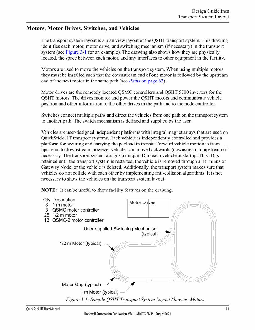
Design GuidelinesTransport System Layout
QuickStick HT User Manual 61Rockwell Automation Publication MMI-UM007G-EN-P - August2021
Motors, Motor Drives, Switches, and Vehicles
The transport system layout is a plan view layout of the QSHT transport system. This drawing identifies each motor, motor drive, and switching mechanism (if necessary) in the transport system (see Figure 3-1 for an example). The drawing also shows how they are physically located, the space between each motor, and any interfaces to other equipment in the facility.
Motors are used to move the vehicles on the transport system. When using multiple motors, they must be installed such that the downstream end of one motor is followed by the upstream end of the next motor in the same path (see Paths on page 62).
Motor drives are the remotely located QSMC controllers and QSHT 5700 inverters for the QSHT motors. The drives monitor and power the QSHT motors and communicate vehicle position and other information to the other drives in the path and to the node controller.
Switches connect multiple paths and direct the vehicles from one path on the transport system to another path. The switch mechanism is defined and supplied by the user.
Vehicles are user-designed independent platforms with integral magnet arrays that are used on QuickStick HT transport systems. Each vehicle is independently controlled and provides a platform for securing and carrying the payload in transit. Forward vehicle motion is from upstream to downstream, however vehicles can move backwards (downstream to upstream) if necessary. The transport system assigns a unique ID to each vehicle at startup. This ID is retained until the transport system is restarted, the vehicle is removed through a Terminus or Gateway Node, or the vehicle is deleted. Additionally, the transport system makes sure that vehicles do not collide with each other by implementing anti-collision algorithms. It is not necessary to show the vehicles on the transport system layout.
NOTE: It can be useful to show facility features on the drawing.
Figure 3-1: Sample QSHT Transport System Layout Showing Motors1 m Motor (typical)
1/2 m Motor (typical)
Motor Gap (typical)
User-supplied Switching Mechanism(typical)
Motor Drives1 m motorQty
QSMC motor controller1/2 m motorQSMC-2 motor controller
Description33
2513
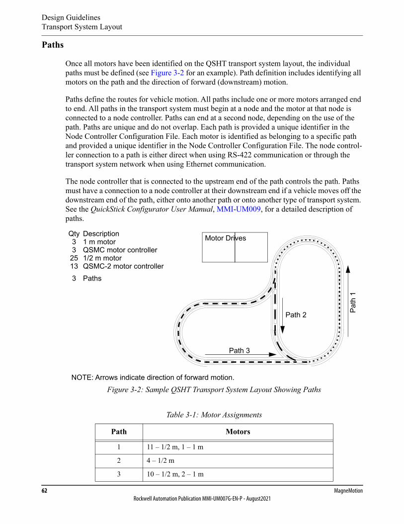
Design GuidelinesTransport System Layout
62 MagneMotionRockwell Automation Publication MMI-UM007G-EN-P - August2021
Paths
Once all motors have been identified on the QSHT transport system layout, the individual paths must be defined (see Figure 3-2 for an example). Path definition includes identifying all motors on the path and the direction of forward (downstream) motion.
Paths define the routes for vehicle motion. All paths include one or more motors arranged end to end. All paths in the transport system must begin at a node and the motor at that node is connected to a node controller. Paths can end at a second node, depending on the use of the path. Paths are unique and do not overlap. Each path is provided a unique identifier in the Node Controller Configuration File. Each motor is identified as belonging to a specific path and provided a unique identifier in the Node Controller Configuration File. The node control-ler connection to a path is either direct when using RS-422 communication or through the transport system network when using Ethernet communication.
The node controller that is connected to the upstream end of the path controls the path. Paths must have a connection to a node controller at their downstream end if a vehicle moves off the downstream end of the path, either onto another path or onto another type of transport system. See the QuickStick Configurator User Manual, MMI-UM009, for a detailed description of paths.
Figure 3-2: Sample QSHT Transport System Layout Showing Paths
Table 3-1: Motor Assignments
Path Motors
1 11 – 1/2 m, 1 – 1 m
2 4 – 1/2 m
3 10 – 1/2 m, 2 – 1 m
Path 2
Path 3
NOTE: Arrows indicate direction of forward motion.
Path
1
Motor Drives1 m motorQty
QSMC motor controller1/2 m motorQSMC-2 motor controllerPaths
Description33
25133
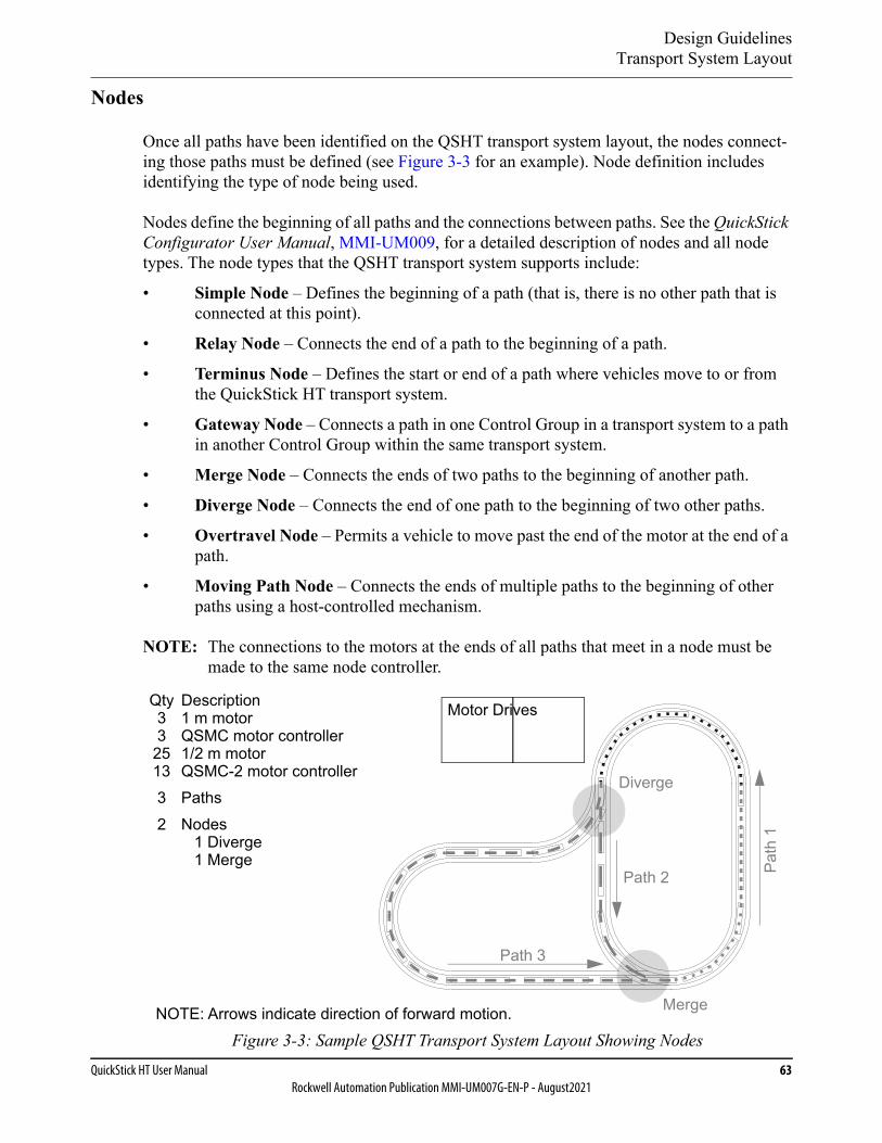
Design GuidelinesTransport System Layout
QuickStick HT User Manual 63Rockwell Automation Publication MMI-UM007G-EN-P - August2021
Nodes
Once all paths have been identified on the QSHT transport system layout, the nodes connect-ing those paths must be defined (see Figure 3-3 for an example). Node definition includes identifying the type of node being used.
Nodes define the beginning of all paths and the connections between paths. See the QuickStick Configurator User Manual, MMI-UM009, for a detailed description of nodes and all node types. The node types that the QSHT transport system supports include:
• Simple Node – Defines the beginning of a path (that is, there is no other path that is connected at this point).
• Relay Node – Connects the end of a path to the beginning of a path.
• Terminus Node – Defines the start or end of a path where vehicles move to or from the QuickStick HT transport system.
• Gateway Node – Connects a path in one Control Group in a transport system to a path in another Control Group within the same transport system.
• Merge Node – Connects the ends of two paths to the beginning of another path.
• Diverge Node – Connects the end of one path to the beginning of two other paths.
• Overtravel Node – Permits a vehicle to move past the end of the motor at the end of a path.
• Moving Path Node – Connects the ends of multiple paths to the beginning of other paths using a host-controlled mechanism.
NOTE: The connections to the motors at the ends of all paths that meet in a node must be made to the same node controller.
Figure 3-3: Sample QSHT Transport System Layout Showing Nodes
Diverge
Merge
Path 2
NOTE: Arrows indicate direction of forward motion.
Path
1
Path 3
Motor Drives
Nodes1 Diverge1 Merge
1 m motorQty
QSMC motor controller1/2 m motorQSMC-2 motor controllerPaths
Description33
251332
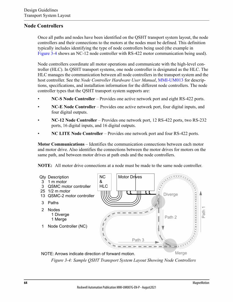
Design GuidelinesTransport System Layout
64 MagneMotionRockwell Automation Publication MMI-UM007G-EN-P - August2021
Node Controllers
Once all paths and nodes have been identified on the QSHT transport system layout, the node controllers and their connections to the motors at the nodes must be defined. This definition typically includes identifying the type of node controllers being used (the example in Figure 3-4 shows an NC-12 node controller with RS-422 motor communication being used).
Node controllers coordinate all motor operations and communicate with the high-level con-troller (HLC). In QSHT transport systems, one node controller is designated as the HLC. The HLC manages the communication between all node controllers in the transport system and the host controller. See the Node Controller Hardware User Manual, MMI-UM013 for descrip-tions, specifications, and installation information for the different node controllers. The node controller types that the QSHT transport system supports are:
• NC-S Node Controller – Provides one active network port and eight RS-422 ports.
• NC-E Node Controller – Provides one active network port, four digital inputs, and four digital outputs.
• NC-12 Node Controller – Provides one network port, 12 RS-422 ports, two RS-232 ports, 16 digital inputs, and 16 digital outputs.
• NC LITE Node Controller – Provides one network port and four RS-422 ports.
Motor Communications – Identifies the communication connections between each motor and motor drive. Also identifies the connections between the motor drives for motors on the same path, and between motor drives at path ends and the node controllers.
NOTE: All motor drive connections at a node must be made to the same node controller.
Figure 3-4: Sample QSHT Transport System Layout Showing Node Controllers
Diverge
Merge
Path 2
Path 3
NOTE: Arrows indicate direction of forward motion.
Path
1
Motor DrivesNC&HLC
Node Controller (NC)
Nodes1 Diverge1 Merge
1 m motorQty
QSMC motor controller1/2 m motorQSMC-2 motor controllerPaths
Description33
251332
1
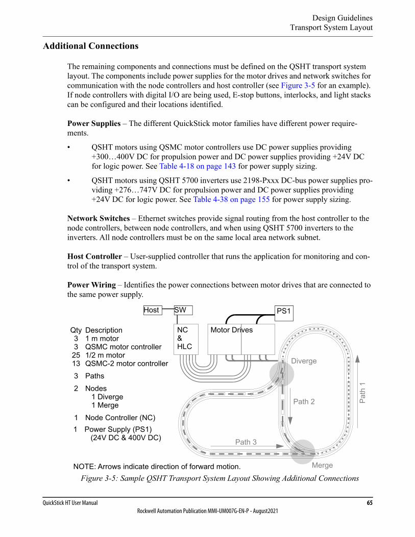
Design GuidelinesTransport System Layout
QuickStick HT User Manual 65Rockwell Automation Publication MMI-UM007G-EN-P - August2021
Additional Connections
The remaining components and connections must be defined on the QSHT transport system layout. The components include power supplies for the motor drives and network switches for communication with the node controllers and host controller (see Figure 3-5 for an example). If node controllers with digital I/O are being used, E-stop buttons, interlocks, and light stacks can be configured and their locations identified.
Power Supplies – The different QuickStick motor families have different power require-ments.
• QSHT motors using QSMC motor controllers use DC power supplies providing +300…400V DC for propulsion power and DC power supplies providing +24V DC for logic power. See Table 4-18 on page 143 for power supply sizing.
• QSHT motors using QSHT 5700 inverters use 2198-Pxxx DC-bus power supplies pro-viding +276…747V DC for propulsion power and DC power supplies providing +24V DC for logic power. See Table 4-38 on page 155 for power supply sizing.
Network Switches – Ethernet switches provide signal routing from the host controller to the node controllers, between node controllers, and when using QSHT 5700 inverters to the inverters. All node controllers must be on the same local area network subnet.
Host Controller – User-supplied controller that runs the application for monitoring and con-trol of the transport system.
Power Wiring – Identifies the power connections between motor drives that are connected to the same power supply.
Figure 3-5: Sample QSHT Transport System Layout Showing Additional Connections
Diverge
Merge
Path 2
Path 3
NOTE: Arrows indicate direction of forward motion.
Path
1
Motor DrivesNC&HLC
Node Controller (NC)
Nodes1 Diverge1 Merge
1 m motorQty
QSMC motor controller1/2 m motorQSMC-2 motor controllerPaths
Description33
251332
1Power Supply (PS1)
(24V DC & 400V DC)1
SWHost PS1
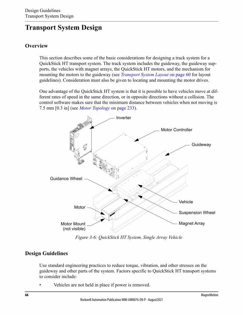
Design GuidelinesTransport System Design
66 MagneMotionRockwell Automation Publication MMI-UM007G-EN-P - August2021
Transport System Design
Overview
This section describes some of the basic considerations for designing a track system for a QuickStick HT transport system. The track system includes the guideway, the guideway sup-ports, the vehicles with magnet arrays, the QuickStick HT motors, and the mechanism for mounting the motors to the guideway (see Transport System Layout on page 60 for layout guidelines). Consideration must also be given to locating and mounting the motor drives.
One advantage of the QuickStick HT system is that it is possible to have vehicles move at dif-ferent rates of speed in the same direction, or in opposite directions without a collision. The control software makes sure that the minimum distance between vehicles when not moving is 7.5 mm [0.3 in] (see Motor Topology on page 233).
Figure 3-6: QuickStick HT System, Single Array Vehicle
Design Guidelines
Use standard engineering practices to reduce torque, vibration, and other stresses on the guideway and other parts of the system. Factors specific to QuickStick HT transport systems to consider include:
• Vehicles are not held in place if power is removed.
Guideway
Motor Mount
MotorSuspension Wheel
Magnet Array(not visible)
Guidance Wheel
Vehicle
Motor Controller
Inverter
Design GuidelinesTransport System Design
QuickStick HT User Manual 67Rockwell Automation Publication MMI-UM007G-EN-P - August2021
• The magnetic attractive force between the magnet array and the QuickStick HT motors is constant (assuming the Vehicle Gap is maintained) regardless of the power that is applied to the motors (see Determining Attractive Force on page 328).
• The Vehicle Gap (distance between magnet array and motor, see Figure 3-31) must be maintained throughout the system.
• Keep the Downstream Gap (distance between motors, see Figure 3-8) as small as pos-sible to make sure that there is enough thrust to move the vehicle over the gap.
• Do not locate process stations where the center of the magnet array would be within the Downstream Gap between motors when the vehicle is at the station as settling time and repeatability can be negatively affected.
• Make sure that the track system configuration accounts for power and communication connections and all cables.
• Make sure that the track system configuration accounts for points for grounding the track to earth ground in the facility and for grounding of all motors.
• When choosing the materials for the vehicle and guideway, consider the stresses applied to the vehicle and guideway during use.
• When choosing the materials for the vehicle and guideway, consider those materials that provide low friction and low wear.
• When choosing the materials for the vehicle and guideway, consider static electricity dissipation between the vehicles and the guideway.
• The vehicle (magnet array) must remain centered over the motors throughout the sys-tem.
• When choosing the materials for the wheels, consider the life expectancy of the wheel material and the noise level as they move on the guideway. Noise can be created when moving across the joints in a straight/curved guideway or into a switch.
• Off-centered and/or large payloads can affect system performance.
Motors
The QuickStick HT motors can be mounted in any orientation: right side up, sideways, upside down, and vertically. QSHT motors have a required direction, with an upstream end and a downstream end (see Mechanical Specifications on page 114 for identification). The Quick-Stick HT motors must always be installed with the upstream end of one motor following the downstream end of the previous motor. Forward vehicle motion for the QuickStick HT motors is from upstream to downstream, however vehicles can move backwards (downstream to upstream) if necessary.
NOTE: If the motor is mounted on an incline or vertically, the motor does not hold a vehicle in place during startup, restarts, or if power is lost.
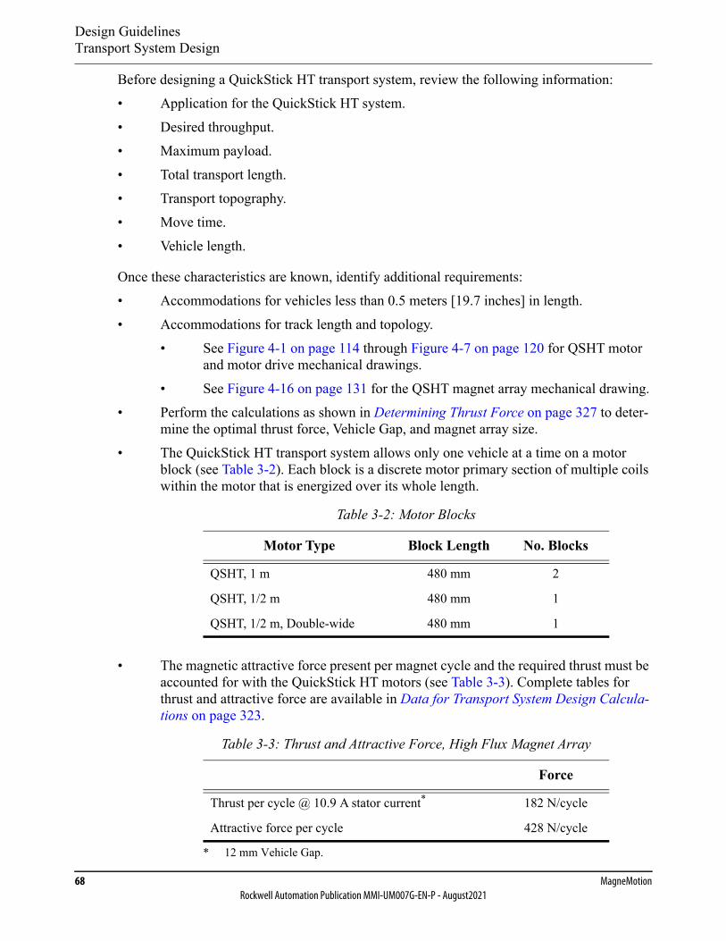
Design GuidelinesTransport System Design
68 MagneMotionRockwell Automation Publication MMI-UM007G-EN-P - August2021
Before designing a QuickStick HT transport system, review the following information:• Application for the QuickStick HT system.• Desired throughput.• Maximum payload.• Total transport length.• Transport topography.• Move time.• Vehicle length.
Once these characteristics are known, identify additional requirements:• Accommodations for vehicles less than 0.5 meters [19.7 inches] in length.• Accommodations for track length and topology.
• See Figure 4-1 on page 114 through Figure 4-7 on page 120 for QSHT motor and motor drive mechanical drawings.
• See Figure 4-16 on page 131 for the QSHT magnet array mechanical drawing.• Perform the calculations as shown in Determining Thrust Force on page 327 to deter-
mine the optimal thrust force, Vehicle Gap, and magnet array size.• The QuickStick HT transport system allows only one vehicle at a time on a motor
block (see Table 3-2). Each block is a discrete motor primary section of multiple coils within the motor that is energized over its whole length.
• The magnetic attractive force present per magnet cycle and the required thrust must be accounted for with the QuickStick HT motors (see Table 3-3). Complete tables for thrust and attractive force are available in Data for Transport System Design Calcula-tions on page 323.
Table 3-2: Motor Blocks
Motor Type Block Length No. Blocks
QSHT, 1 m 480 mm 2
QSHT, 1/2 m 480 mm 1
QSHT, 1/2 m, Double-wide 480 mm 1
Table 3-3: Thrust and Attractive Force, High Flux Magnet Array
Force
Thrust per cycle @ 10.9 A stator current*
* 12 mm Vehicle Gap.
182 N/cycle
Attractive force per cycle 428 N/cycle
Design GuidelinesTransport System Design
QuickStick HT User Manual 69Rockwell Automation Publication MMI-UM007G-EN-P - August2021
Available Thrust
Several variables determine the thrust available from the QSHT motor to move a vehicle:• Magnet array length (in cycles).• Vehicle Gap (distance between the magnet array that is attached to the vehicle and the
motor).• Friction or drag between the vehicle and the guideway.• Motor Gap (physical distance between motors) and Downstream Gap (actual distance
between motor blocks in adjacent motors) (see Figure 3-8).
The effect of the first two variables, the number of cycles of magnet array and the Vehicle Gap are shown best in Data for Transport System Design Calculations on page 323. Equations that use all of these variables are provided in Determining Thrust Force on page 327.
At the nominal Vehicle Gap of 12 mm [0.47 in] (gap between the magnet array and the top of the QuickStick HT motor) the QSHT motors provide approximately 182 N thrust per magnet array cycle at 10.9 A stator current (see Table 3-3). The magnet arrays are available in various lengths to provide the appropriate thrust for the application. Two arrays can be used in a dual array vehicle (see Dual Array Vehicle on page 98), which effectively doubles the length of the magnet array. By increasing the length of the magnet arrays the number of motors in the sys-tem can be decreased, however the loss of thrust in the gaps between the motors must be accounted for (see Figure 3-7).
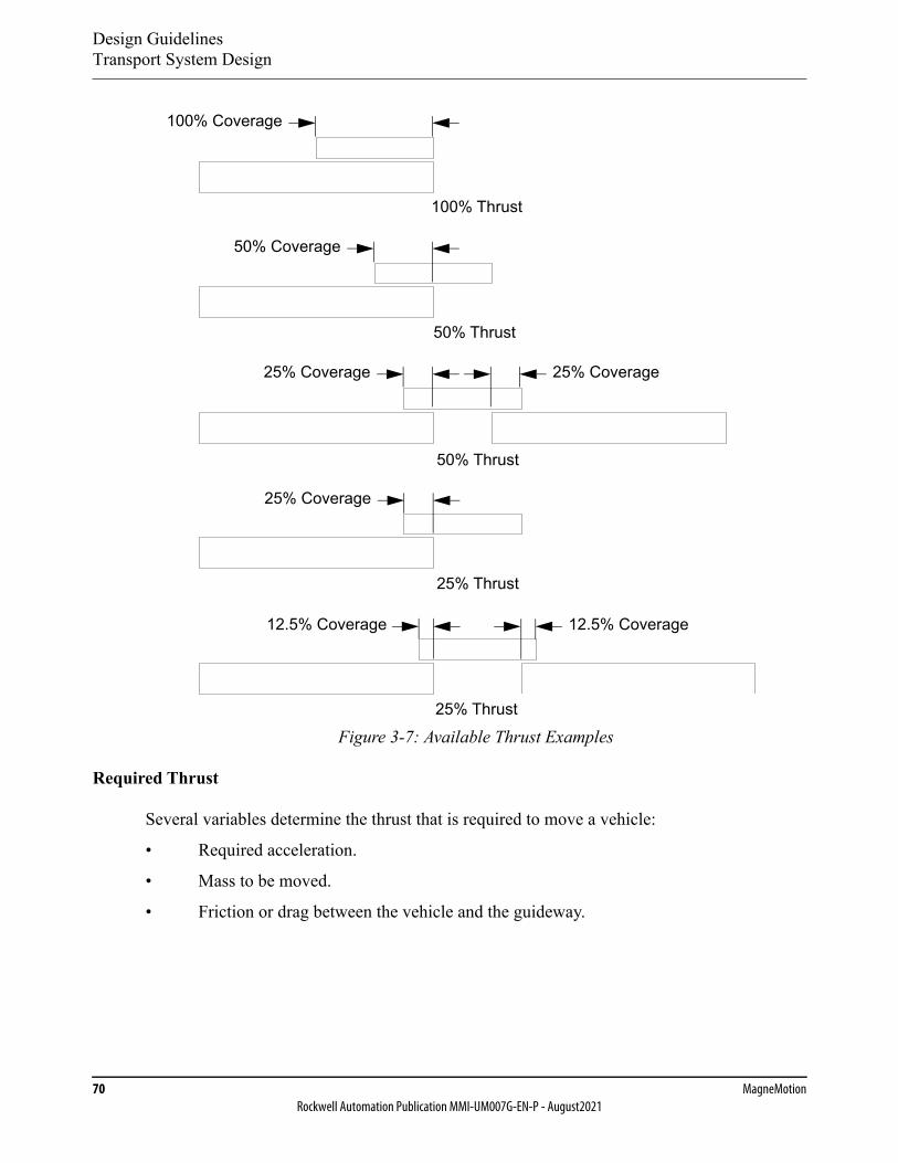
Design GuidelinesTransport System Design
70 MagneMotionRockwell Automation Publication MMI-UM007G-EN-P - August2021
Figure 3-7: Available Thrust Examples
Required Thrust
Several variables determine the thrust that is required to move a vehicle:
• Required acceleration.
• Mass to be moved.
• Friction or drag between the vehicle and the guideway.
100% Thrust
50% Thrust
50% Thrust
25% Thrust
100% Coverage
50% Coverage
25% Coverage 25% Coverage
25% Thrust
12.5% Coverage 12.5% Coverage
25% Coverage
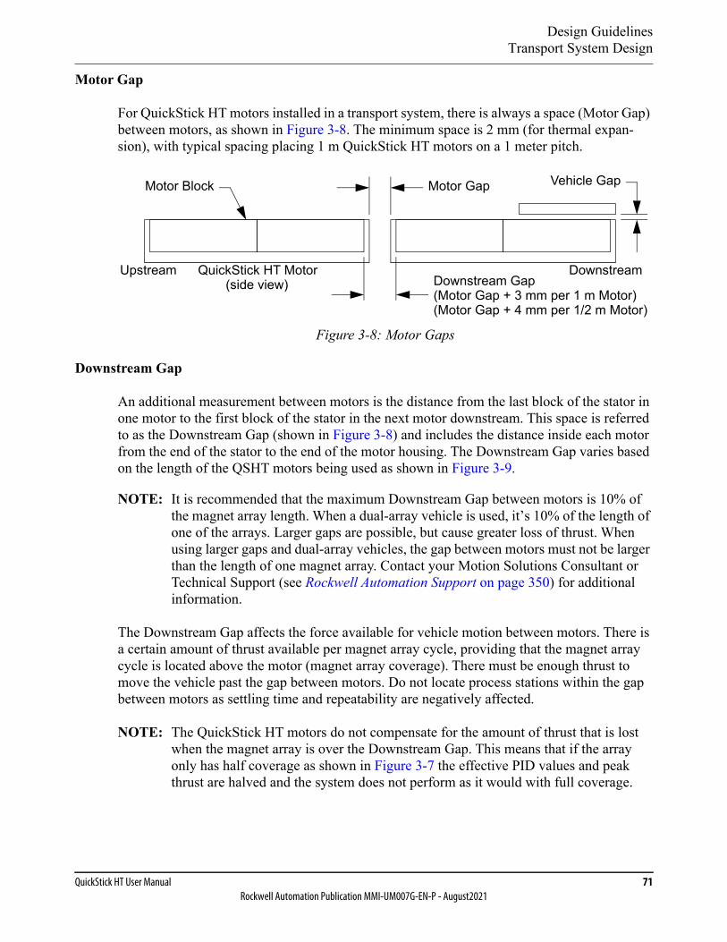
Design GuidelinesTransport System Design
QuickStick HT User Manual 71Rockwell Automation Publication MMI-UM007G-EN-P - August2021
Motor Gap
For QuickStick HT motors installed in a transport system, there is always a space (Motor Gap) between motors, as shown in Figure 3-8. The minimum space is 2 mm (for thermal expan-sion), with typical spacing placing 1 m QuickStick HT motors on a 1 meter pitch.
Figure 3-8: Motor Gaps
Downstream Gap
An additional measurement between motors is the distance from the last block of the stator in one motor to the first block of the stator in the next motor downstream. This space is referred to as the Downstream Gap (shown in Figure 3-8) and includes the distance inside each motor from the end of the stator to the end of the motor housing. The Downstream Gap varies based on the length of the QSHT motors being used as shown in Figure 3-9.
NOTE: It is recommended that the maximum Downstream Gap between motors is 10% of the magnet array length. When a dual-array vehicle is used, it’s 10% of the length of one of the arrays. Larger gaps are possible, but cause greater loss of thrust. When using larger gaps and dual-array vehicles, the gap between motors must not be larger than the length of one magnet array. Contact your Motion Solutions Consultant or Technical Support (see Rockwell Automation Support on page 350) for additional information.
The Downstream Gap affects the force available for vehicle motion between motors. There is a certain amount of thrust available per magnet array cycle, providing that the magnet array cycle is located above the motor (magnet array coverage). There must be enough thrust to move the vehicle past the gap between motors. Do not locate process stations within the gap between motors as settling time and repeatability are negatively affected.
NOTE: The QuickStick HT motors do not compensate for the amount of thrust that is lost when the magnet array is over the Downstream Gap. This means that if the array only has half coverage as shown in Figure 3-7 the effective PID values and peak thrust are halved and the system does not perform as it would with full coverage.
Motor Gap
Downstream GapQuickStick HT Motor
Motor Block Vehicle Gap
(Motor Gap + 3 mm per 1 m Motor)(side view)
Upstream Downstream
(Motor Gap + 4 mm per 1/2 m Motor)
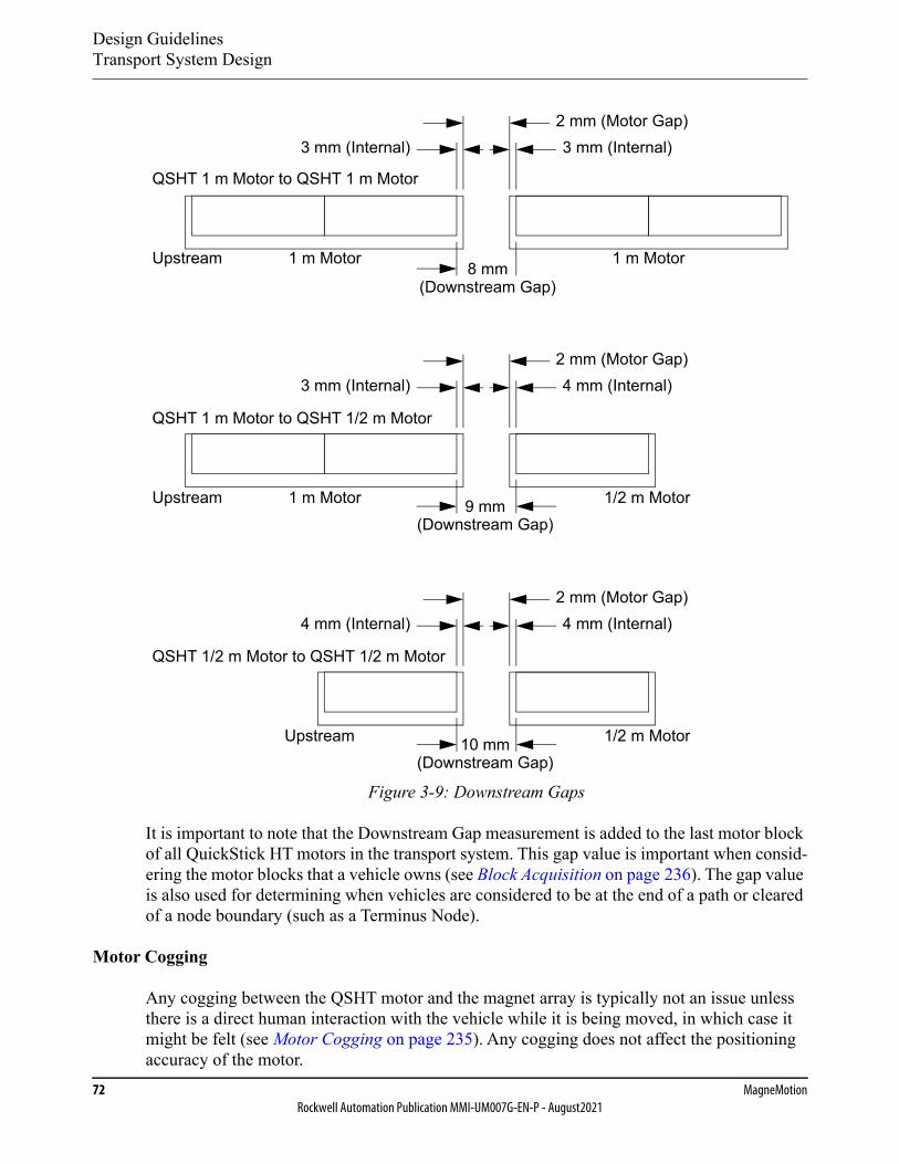
Design GuidelinesTransport System Design
72 MagneMotionRockwell Automation Publication MMI-UM007G-EN-P - August2021
Figure 3-9: Downstream Gaps
It is important to note that the Downstream Gap measurement is added to the last motor block of all QuickStick HT motors in the transport system. This gap value is important when consid-ering the motor blocks that a vehicle owns (see Block Acquisition on page 236). The gap value is also used for determining when vehicles are considered to be at the end of a path or cleared of a node boundary (such as a Terminus Node).
Motor Cogging
Any cogging between the QSHT motor and the magnet array is typically not an issue unless there is a direct human interaction with the vehicle while it is being moved, in which case it might be felt (see Motor Cogging on page 235). Any cogging does not affect the positioning accuracy of the motor.
1 m Motor
1/2 m Motor
Upstream
Upstream
Upstream
8 mm
QSHT 1 m Motor to QSHT 1 m Motor
QSHT 1 m Motor to QSHT 1/2 m Motor
QSHT 1/2 m Motor to QSHT 1/2 m Motor
1 m Motor
1 m Motor
1/2 m Motor
2 mm (Motor Gap)
(Downstream Gap)
9 mm(Downstream Gap)
10 mm(Downstream Gap)
3 mm (Internal)3 mm (Internal)
2 mm (Motor Gap)4 mm (Internal)3 mm (Internal)
2 mm (Motor Gap)4 mm (Internal)4 mm (Internal)
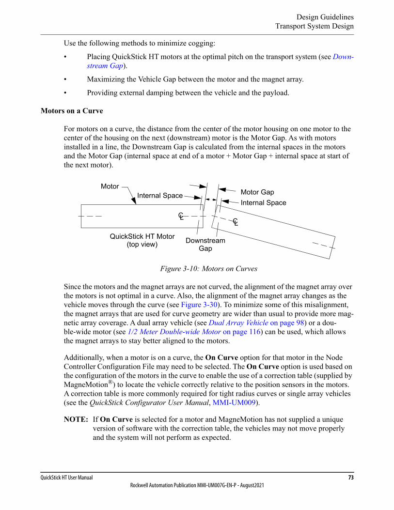
Design GuidelinesTransport System Design
QuickStick HT User Manual 73Rockwell Automation Publication MMI-UM007G-EN-P - August2021
Use the following methods to minimize cogging:
• Placing QuickStick HT motors at the optimal pitch on the transport system (see Down-stream Gap).
• Maximizing the Vehicle Gap between the motor and the magnet array.
• Providing external damping between the vehicle and the payload.
Motors on a Curve
For motors on a curve, the distance from the center of the motor housing on one motor to the center of the housing on the next (downstream) motor is the Motor Gap. As with motors installed in a line, the Downstream Gap is calculated from the internal spaces in the motors and the Motor Gap (internal space at end of a motor + Motor Gap + internal space at start of the next motor).
Figure 3-10: Motors on Curves
Since the motors and the magnet arrays are not curved, the alignment of the magnet array over the motors is not optimal in a curve. Also, the alignment of the magnet array changes as the vehicle moves through the curve (see Figure 3-30). To minimize some of this misalignment, the magnet arrays that are used for curve geometry are wider than usual to provide more mag-netic array coverage. A dual array vehicle (see Dual Array Vehicle on page 98) or a dou-ble-wide motor (see 1/2 Meter Double-wide Motor on page 116) can be used, which allows the magnet arrays to stay better aligned to the motors.
Additionally, when a motor is on a curve, the On Curve option for that motor in the Node Controller Configuration File may need to be selected. The On Curve option is used based on the configuration of the motors in the curve to enable the use of a correction table (supplied by MagneMotion®) to locate the vehicle correctly relative to the position sensors in the motors. A correction table is more commonly required for tight radius curves or single array vehicles (see the QuickStick Configurator User Manual, MMI-UM009).
NOTE: If On Curve is selected for a motor and MagneMotion has not supplied a unique version of software with the correction table, the vehicles may not move properly and the system will not perform as expected.
Motor GapMotor
CLCL
QuickStick HT Motor(top view)
Internal Space
DownstreamGap
Internal Space
Design GuidelinesTransport System Design
74 MagneMotionRockwell Automation Publication MMI-UM007G-EN-P - August2021
Motor Drives
The motor drive for each QuickStick HT motor is located externally to the motor. Each QSHT motor has one motor drive, either a QSMC or QSHT 5700 Inverter. When there are two con-secutive 1/2 m motors, they can share a drive. The motor drive is responsible for controlling the thrust that is applied to each vehicle by the motor and reading the sensors in the motor to determine vehicle position.
Using QSMC Motor Controllers
Each QSMC motor controller can control one 1 m QSHT motor or one 1/2 m double-wide QSHT motor. Each QSMC-2 motor controller can control two consecutive 1/2 m QSHT motors on the same path. The QSMC motor controllers communicate with each other and a node controller via RS-422 serial communication.
Using QSHT 5700 Inverters
Each QSHT 5700 inverter can control one 1 m motor, or one or two consecutive 1/2 m motors on the same path, or one 1/2 m double-wide motor. The QSHT 5700 inverters communicate with each other and a node controller via Ethernet communication.
Electrical Wiring
Wiring QSHT Motors Using QSMC Controllers
The QSMC motor controllers are designed to operate at a nominal +300…400V DC. How-ever, voltage drops in the power distribution system when delivering power to the motor con-trollers and voltage increases during regeneration events cause fluctuations in the voltage that is seen at the motor controller power terminals. The power supplies and wiring for the system must be designed to minimize these fluctuations. A block diagram of a QSHT system sche-matic using QSMC controllers is provided in Figure 3-11. Any part numbers that are shown are for reference only and are subject to change.
The acceptable voltage range for the QSMC motor controllers is between +270V DC and +420V DC, with a nominal voltage of +300…400V DC. Operation below or above this range can result in the motor controller turning off or the motor controller being damaged. The motor controller has protections in place to help prevent damage. The power supply system must be designed so that the voltage limits are not exceeded during normal operating condi-tions and provide protection to the power supply if these limits are exceeded. To supplement any external power management schemes for the QSHT transport system, a means of inter-nally consuming regenerated power within a QSHT motor is incorporated as a product feature (see Electrical System on page 243).
The QSHT motor controllers are enabled when the internal propulsion bus rises above +270V DC. Until this voltage is reached, the motor controller reports an undervoltage fault and the motor controller does not allow vehicle motion to occur. Once this internal voltage is reached, the motor can support vehicle motion and operate as intended. If the internal bus voltage drops
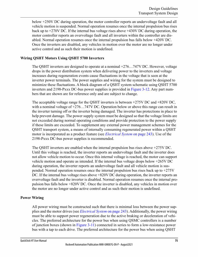
Design GuidelinesTransport System Design
QuickStick HT User Manual 75Rockwell Automation Publication MMI-UM007G-EN-P - August2021
below +250V DC during operation, the motor controller reports an undervoltage fault and all vehicle motion is suspended. Normal operation resumes once the internal propulsion bus rises back up to +270V DC. If the internal bus voltage rises above +430V DC during operation, the motor controller reports an overvoltage fault and all inverters within the controller are dis-abled. Normal operation resumes once the internal propulsion bus falls below +420V DC. Once the inverters are disabled, any vehicles in motion over the motor are no longer under active control and as such their motion is undefined.
Wiring QSHT Motors Using QSHT 5700 Inverters
The QSHT inverters are designed to operate at a nominal +276…747V DC. However, voltage drops in the power distribution system when delivering power to the inverters and voltage increases during regeneration events cause fluctuations in the voltage that is seen at the inverter power terminals. The power supplies and wiring for the system must be designed to minimize these fluctuations. A block diagram of a QSHT system schematic using QSHT 5700 inverters and 2198-Pxxx DC-bus power supplies is provided in Figure 3-12. Any part num-bers that are shown are for reference only and are subject to change.
The acceptable voltage range for the QSHT inverters is between +275V DC and +820V DC, with a nominal voltage of +276…747V DC. Operation below or above this range can result in the inverter turning off or the inverter being damaged. The inverter has protections in place to help prevent damage. The power supply system must be designed so that the voltage limits are not exceeded during normal operating conditions and provide protection to the power supply if these limits are exceeded. To supplement any external power management schemes for the QSHT transport system, a means of internally consuming regenerated power within a QSHT motor is incorporated as a product feature (see Electrical System on page 243). Use of the 2198-Pxxx DC-bus power supplies is recommended.
The QSHT inverters are enabled when the internal propulsion bus rises above +275V DC. Until this voltage is reached, the inverter reports an undervoltage fault and the inverter does not allow vehicle motion to occur. Once this internal voltage is reached, the motor can support vehicle motion and operate as intended. If the internal bus voltage drops below +265V DC during operation, the inverter reports an undervoltage fault and all vehicle motion is sus-pended. Normal operation resumes once the internal propulsion bus rises back up to +275V DC. If the internal bus voltage rises above +820V DC during operation, the inverter reports an overvoltage fault and the inverter is disabled. Normal operation resumes once the internal pro-pulsion bus falls below +820V DC. Once the inverter is disabled, any vehicles in motion over the motor are no longer under active control and as such their motion is undefined.
Power Wiring
All power wiring must be constructed such that there is minimal loss between the power sup-plies and the motor drives (see Electrical System on page 243). Additionally, the power wiring must be able to support power regeneration due to the active braking or deceleration of vehi-cles. The preferred architecture for the power bus when using QSMC controllers is a number of junction boxes (shown in Figure 3-11) connected in series to form a low-resistance power bus with a tap to each drive. The preferred architecture for the power bus when using QSHT
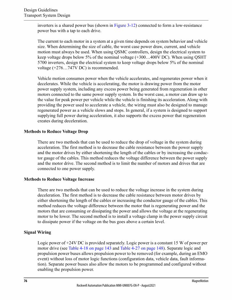
Design GuidelinesTransport System Design
76 MagneMotionRockwell Automation Publication MMI-UM007G-EN-P - August2021
inverters is a shared power bus (shown in Figure 3-12) connected to form a low-resistance power bus with a tap to each drive.
The current to each motor in a system at a given time depends on system behavior and vehicle size. When determining the size of cable, the worst case power draw, current, and vehicle motion must always be used. When using QSMC controllers, design the electrical system to keep voltage drops below 5% of the nominal voltage (+300…400V DC). When using QSHT 5700 inverters, design the electrical system to keep voltage drops below 5% of the nominal voltage (+276…747V DC) is recommended.
Vehicle motion consumes power when the vehicle accelerates, and regenerates power when it decelerates. While the vehicle is accelerating, the motor is drawing power from the motor power supply system, including any excess power being generated from regeneration in other motors connected to the same power supply system. In the worst case, a motor can draw up to the value for peak power per vehicle while the vehicle is finishing its acceleration. Along with providing the power used to accelerate a vehicle, the wiring must also be designed to manage regenerated power as a vehicle slows and stops. In general, if a system is designed to support supplying full power during acceleration, it also supports the excess power that regeneration creates during deceleration.
Methods to Reduce Voltage Drop
There are two methods that can be used to reduce the drop of voltage in the system during acceleration. The first method is to decrease the cable resistance between the power supply and the motor drives by either shortening the length of the cables or by increasing the conduc-tor gauge of the cables. This method reduces the voltage difference between the power supply and the motor drive. The second method is to limit the number of motors and drives that are connected to one power supply.
Methods to Reduce Voltage Increase
There are two methods that can be used to reduce the voltage increase in the system during deceleration. The first method is to decrease the cable resistance between motor drives by either shortening the length of the cables or increasing the conductor gauge of the cables. This method reduces the voltage difference between the motor that is regenerating power and the motors that are consuming or dissipating the power and allows the voltage at the regenerating motor to be lower. The second method is to install a voltage clamp in the power supply circuit to dissipate power if the voltage on the bus goes above a certain level.
Signal Wiring
Logic power of +24V DC is provided separately. Logic power is a constant 15 W of power per motor drive (see Table 4-18 on page 143 and Table 4-27 on page 148). Separate logic and propulsion power buses allows propulsion power to be removed (for example, during an EMO event) without loss of motor logic functions (configuration data, vehicle data, fault informa-tion). Separate power buses also allow the motors to be programmed and configured without enabling the propulsion power.

Design GuidelinesTransport System Design
QuickStick HT User Manual 77Rockwell Automation Publication MMI-UM007G-EN-P - August2021
Ground
Proper grounding of the QuickStick HT transport system is required to make sure of proper operation and to minimize electrical safety issues.
• The bodies of the motors are grounded through the GND terminal on the motor.
• The QSMC and QSMC-2 are grounded through the GND stud on the motor control-lers.
• The QSHT 5700 inverter is grounded through the GND stud on the inverter.
• The NC LITE is not grounded through its power connection. The case of the NC LITE must be grounded to an electrical safety ground (PE) through the mounting features.
• The NC-12 is grounded through the GND stud on the node controller.
• The NC-E and NC-S are grounded through the power connection.
• All power supplies must be grounded to an electrical safety ground (PE) via the safety ground in the AC input connector.
• All junction boxes must be grounded to an electrical safety ground (PE).
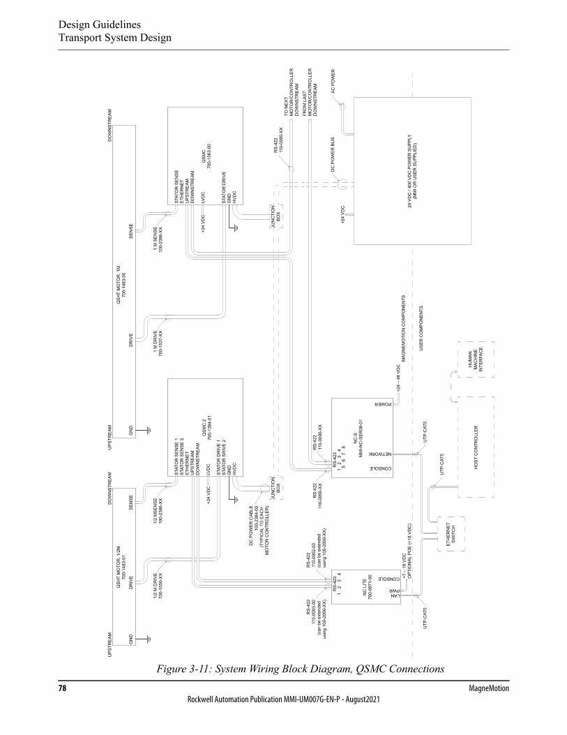
Design GuidelinesTransport System Design
78 MagneMotionRockwell Automation Publication MMI-UM007G-EN-P - August2021
Figure 3-11: System Wiring Block Diagram, QSMC Connections
DO
WN
STR
EAM
FRO
M L
AST
MO
TOR
/CO
NTR
OLL
ERD
OW
NST
REA
M
TO N
EXT
MO
TOR
/CO
NTR
OLL
ERD
OW
NST
REA
M
UPS
TREA
M
QSH
T M
OTO
R, 1
M70
0-14
83-0
0Q
SHT
MO
TOR
, 1/2
M70
0-14
83-0
1
DO
WN
STR
EAM
SEN
SED
RIV
EG
ND
SEN
SED
RIV
EG
ND
UPS
TREA
M
NC
LIT
E70
0-08
71-0
0
JUN
CTI
ON
BOX
JUN
CTI
ON
BOX
NC
-SM
MI-N
C-S
ER08
-01
AC P
OW
ERD
C P
OW
ER B
US
RS-
422
110-
0002
-00
(can
be
exte
nded
usin
g 10
0-20
90-X
X)
RS-
422
110-
0003
-00
(can
be
exte
nded
usin
g 10
0-20
90-X
X)
DC
PO
WER
CAB
LE10
0-23
84-0
0(T
YPIC
AL T
O E
ACH
MO
TOR
CO
NTR
OLL
ER)
RS-
422
110-
0090
-XX
RS-
422
110-
0090
-XX
RS-
422
110-
0090
-XX
1/2
MSE
NSE
100-
2386
-XX
1/2
M D
RIV
E70
0-15
50-X
X1
M S
ENSE
100
-238
6-XX
1 M
DR
IVE
700-
1537
-XX
ETH
ERN
ETSW
ITC
H
+7 –
18
VDC
OPT
ION
AL P
OE
(+18
VD
C)
+24
VDC
+24
VDC
+24
VDC
+24
– 48
VD
C
USE
R C
OM
PON
ENTS
MAG
NEM
OTI
ON
CO
MPO
NEN
TS
HO
ST C
ON
TRO
LLER
HU
MAN
MAC
HIN
EIN
TER
FAC
E
UTP
-CAT
5U
TP-C
AT5
UTP
-CAT
5
LAN
CONSOLE
PWR
RS-
422 NETWORK
POWER
CONSOLE
12
34
RS-
422
12
34
56
78
QSM
C70
0-15
63-0
0Q
SMC
270
0-13
84-0
1
STAT
OR
DR
IVE
GN
DH
VDC
STAT
OR
SEN
SEET
HER
NET
UPS
TREA
MD
OW
NST
REA
M
LVD
C
STAT
OR
DR
IVE
1ST
ATO
R S
RIV
E 2
GN
DH
VDC
STAT
OR
SEN
SE 1
STAT
OR
SEN
SE 2
ETH
ERN
ETU
PSTR
EAM
DO
WN
STR
EAM
LVD
C
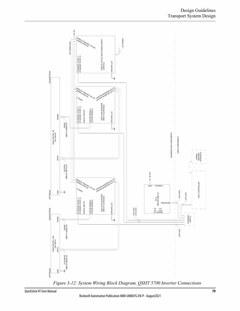
Design GuidelinesTransport System Design
QuickStick HT User Manual 79Rockwell Automation Publication MMI-UM007G-EN-P - August2021
Figure 3-12: System Wiring Block Diagram, QSHT 5700 Inverter Connections
DO
WN
STR
EAM
UPS
TREA
M
QSH
T M
OTO
R, 1
M70
0-14
83-0
0Q
SHT
MO
TOR
, 1/2
M70
0-14
83-0
1
DO
WN
STR
EAM
SEN
SED
RIV
EG
ND
SEN
SED
RIV
EG
ND
UPS
TREA
M
DC
PO
WER
BU
S
24V
DC
1/2
M D
RIV
EM
MI-H
T-C
BP05
-XX
SEN
SEM
MI-H
T-C
BS00
-XX
1M D
RIV
EM
MI-H
T-C
BP10
-XX
SEN
SEM
MI-H
T-C
BS00
-XX
ETH
ERN
ETSW
ITC
H
USE
R C
OM
PON
ENTS
MAG
NEM
OTI
ON
CO
MPO
NEN
TS
HO
ST C
ON
TRO
LLER
HU
MAN
MAC
HIN
EIN
TER
FAC
E
UTP
-CAT
5U
TP-C
AT5
UTP
-CAT
5
QSH
T 57
00 IN
VER
TER
MM
I-HT-
C21
98-D
032
ETH
ERN
ET (P
OR
T 1)
ETH
ERN
ET (P
OR
T 2)
DIG
ITAL
INPU
TS
STAT
OR
SEN
SE A
STAT
OR
SEN
SE B
STATOR INVERTER OUT B
STATOR INVERTER OUT A
DC BUS POWER
SAFETY 24V DC CONTROL POWER
GR
OU
ND
LU
G
QSH
T 57
00 IN
VER
TER
MM
I-HT-
C21
98-D
032
ETH
ERN
ET (P
OR
T 1)
ETH
ERN
ET (P
OR
T 2)
DIG
ITAL
INPU
TS
STAT
OR
SEN
SE A
STAT
OR
SEN
SE B
STATOR INVERTER OUT B
STATOR INVERTER OUT A
DC BUS POWER
SAFETY 24V DC CONTROL POWER
GR
OU
ND
LU
G
KIN
ETIX
570
0 D
C-B
US
POW
ER S
UPP
LY21
98-P
xxx
ETH
ERN
ET (P
OR
T 1)
ETH
ERN
ET (P
OR
T 2)
DC BUS POWER
24V DC CONTROL POWER
GR
OU
ND
LU
G
NC
-EM
MI-N
C-E
NE
T-01
+6 -
36 V
DC
NETWORK
CONSOLEPWR
DIGITAL I/OOUT0-3
IN0-3
UTP
-CAT
5U
TP-C
AT5
AC P
OW
ER
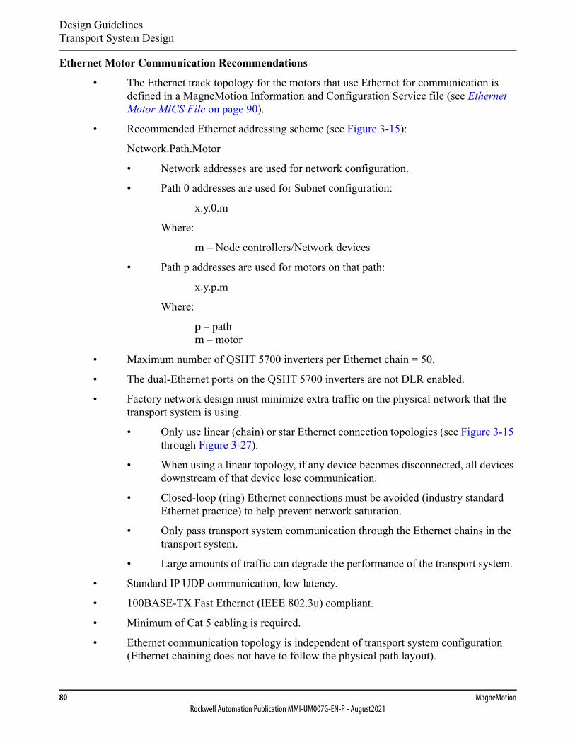
Design GuidelinesTransport System Design
80 MagneMotionRockwell Automation Publication MMI-UM007G-EN-P - August2021
Ethernet Motor Communication Recommendations
• The Ethernet track topology for the motors that use Ethernet for communication is defined in a MagneMotion Information and Configuration Service file (see Ethernet Motor MICS File on page 90).
• Recommended Ethernet addressing scheme (see Figure 3-15):
Network.Path.Motor
• Network addresses are used for network configuration.
• Path 0 addresses are used for Subnet configuration:
x.y.0.m
Where:
m – Node controllers/Network devices
• Path p addresses are used for motors on that path:
x.y.p.m
Where:
p – path m – motor
• Maximum number of QSHT 5700 inverters per Ethernet chain = 50.
• The dual-Ethernet ports on the QSHT 5700 inverters are not DLR enabled.
• Factory network design must minimize extra traffic on the physical network that the transport system is using.
• Only use linear (chain) or star Ethernet connection topologies (see Figure 3-15 through Figure 3-27).
• When using a linear topology, if any device becomes disconnected, all devices downstream of that device lose communication.
• Closed-loop (ring) Ethernet connections must be avoided (industry standard Ethernet practice) to help prevent network saturation.
• Only pass transport system communication through the Ethernet chains in the transport system.
• Large amounts of traffic can degrade the performance of the transport system.
• Standard IP UDP communication, low latency.
• 100BASE-TX Fast Ethernet (IEEE 802.3u) compliant.
• Minimum of Cat 5 cabling is required.
• Ethernet communication topology is independent of transport system configuration (Ethernet chaining does not have to follow the physical path layout).

Design GuidelinesTransport System Design
QuickStick HT User Manual 81Rockwell Automation Publication MMI-UM007G-EN-P - August2021
• The use of Allen-Bradley® Stratix® Managed Ethernet Switches is recommended to deliver the required network performance.
• Ethernet chains can consist of multiple paths (as defined in the transport system layout drawing).
• Chains do not need to start at the beginning of a path.
• If all motors in a path are not part of the same Ethernet chain, all chains the path is a member of must connect to the same network as the node controller.
Ethernet Motor Connection Examples
The QuickStick HT 5700 Inverters, which use Ethernet for inverter to inverter communication and for inverter to node controller communication can use different network topologies depending on the application. When using Ethernet communication, the inverters for all motors in a specific path must be on the same network as the node controller (see Figure 3-15 through Figure 3-26). Additionally, the inverters for all motors and the location of the motors in the transport system must be defined in the MICS file (see Ethernet Motor MICS File on page 90).
Order of Modules
When using linear (chained) Ethernet communication with the QSHT motors, the order of the modules on the chain is important. This is because if a module on the chain experiences an anomaly, all modules after it on the chain could lose their communication to the network switch and node controller.
To make sure that an anomaly in a QSHT 5700 inverter does not interrupt power to all invert-ers in the chain, the 2198-Pxxx DC-bus power supplies for the inverters in the chain must be the first modules in the chain as shown in Figure 3-13. There is a maximum of 16 inverters per power supply, power dependent. The power supplies can also be connected directly to the Ethernet switch and not part of the Ethernet chain as shown in Figure 3-14.
Figure 3-13: Ethernet Wiring – Power Supply In-line with Inverters
P1M1x.y.1.1
P1M2x.y.1.2
P1M3x.y.1.3
P1M4x.y.1.4
SimpleNode QSHT Motor
Host Controller
Enet Switch
QSHT 5700Inverter
Ethernet
QSHT Motor
QSHT 5700Inverter
QSHT Motor
QSHT 5700Inverter
QSHT 5700Inverter
TermNodeQSHT Motor
x.y.0.10
HLC & Node
Controller
Straight Transport System (Recommended):One Ethernet Connection to SwitchPower Supply - InlineOne ChainOne Path
Power Supply
x.y.0.11
Shared-bus Connection Systems(DC-bus and 24V DC)
EthernetPower
DriveSense
Downstream
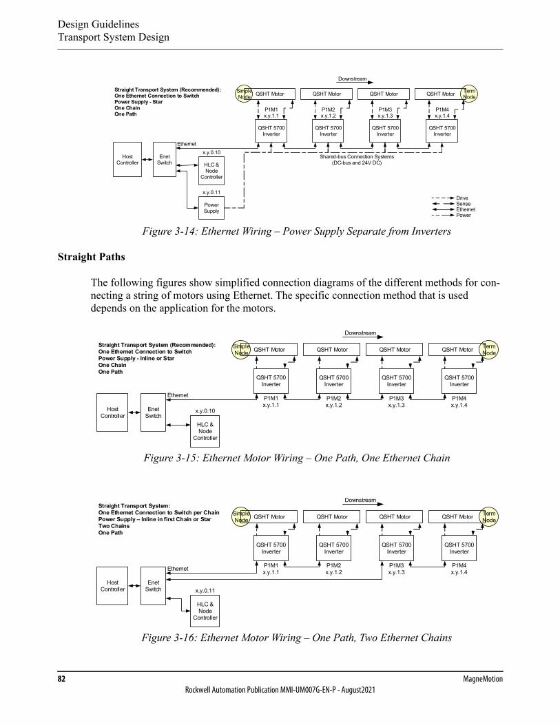
Design GuidelinesTransport System Design
82 MagneMotionRockwell Automation Publication MMI-UM007G-EN-P - August2021
Figure 3-14: Ethernet Wiring – Power Supply Separate from Inverters
Straight Paths
The following figures show simplified connection diagrams of the different methods for con-necting a string of motors using Ethernet. The specific connection method that is used depends on the application for the motors.
Figure 3-15: Ethernet Motor Wiring – One Path, One Ethernet Chain
Figure 3-16: Ethernet Motor Wiring – One Path, Two Ethernet Chains
SimpleNode QSHT Motor
Host Controller
Enet Switch
QSHT 5700Inverter
Ethernet
QSHT Motor
QSHT 5700Inverter
QSHT Motor
QSHT 5700Inverter
QSHT 5700Inverter
TermNodeQSHT Motor
x.y.0.10
HLC & Node
Controller
Straight Transport System (Recommended):One Ethernet Connection to SwitchPower Supply - StarOne ChainOne Path
Power Supply
x.y.0.11
P1M1x.y.1.1
P1M2x.y.1.2
P1M3x.y.1.3
P1M4x.y.1.4
Shared-bus Connection Systems(DC-bus and 24V DC)
EthernetPower
DriveSense
Downstream
P1M1x.y.1.1
P1M2x.y.1.2
P1M3x.y.1.3
P1M4x.y.1.4
SimpleNode QSHT Motor
Host Controller
Enet Switch
QSHT 5700Inverter
Ethernet
QSHT Motor
QSHT 5700Inverter
QSHT Motor
QSHT 5700Inverter
QSHT 5700Inverter
TermNodeQSHT Motor
x.y.0.10
HLC & Node
Controller
Straight Transport System (Recommended):One Ethernet Connection to SwitchPower Supply - Inline or StarOne ChainOne Path
Downstream
Host Controller
Enet Switch
HLC & Node
Controller
Straight Transport System:One Ethernet Connection to Switch per ChainPower Supply – Inline in first Chain or StarTwo ChainsOne Path
x.y.0.11
SimpleNode QSHT Motor
QSHT 5700Inverter
QSHT Motor
QSHT 5700Inverter
QSHT Motor
QSHT 5700Inverter
QSHT 5700Inverter
TermNodeQSHT Motor
Ethernet P1M1x.y.1.1
P1M2x.y.1.2
P1M3x.y.1.3
P1M4x.y.1.4
Downstream
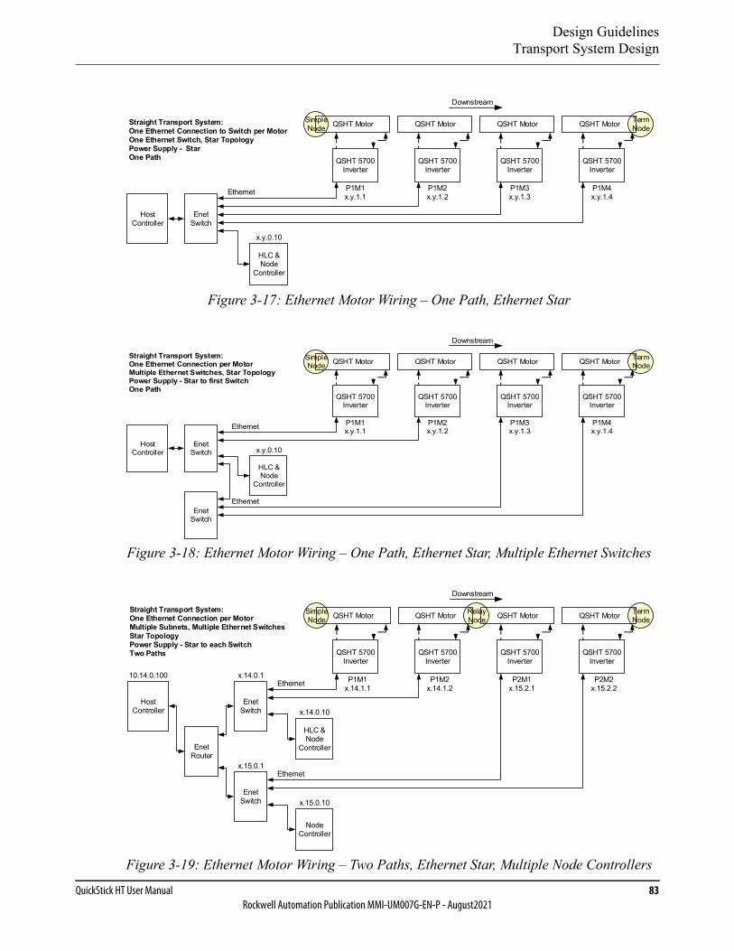
Design GuidelinesTransport System Design
QuickStick HT User Manual 83Rockwell Automation Publication MMI-UM007G-EN-P - August2021
Figure 3-17: Ethernet Motor Wiring – One Path, Ethernet Star
Figure 3-18: Ethernet Motor Wiring – One Path, Ethernet Star, Multiple Ethernet Switches
Figure 3-19: Ethernet Motor Wiring – Two Paths, Ethernet Star, Multiple Node Controllers
Host Controller
Enet Switch
HLC & Node
Controller
Straight Transport System:One Ethernet Connection to Switch per MotorOne Ethernet Switch, Star TopologyPower Supply - StarOne Path
x.y.0.10
SimpleNode QSHT Motor
QSHT 5700Inverter
QSHT Motor
QSHT 5700Inverter
QSHT Motor
QSHT 5700Inverter
QSHT 5700Inverter
TermNodeQSHT Motor
P1M1x.y.1.1
P1M2x.y.1.2
P1M3x.y.1.3
P1M4x.y.1.4Ethernet
Downstream
Host Controller
Enet Switch
Enet Switch
SimpleNode QSHT Motor
QSHT 5700Inverter
QSHT Motor
QSHT 5700Inverter
QSHT Motor
QSHT 5700Inverter
QSHT 5700Inverter
TermNodeQSHT Motor
P1M1x.y.1.1
P1M2x.y.1.2
P1M3x.y.1.3
P1M4x.y.1.4Ethernet
Straight Transport System:One Ethernet Connection per MotorMultiple Ethernet Switches, Star TopologyPower Supply - Star to first SwitchOne Path
HLC & Node
Controller
x.y.0.10
Ethernet
Downstream
RelayNode
Host Controller
Enet Switch
Node Controller
Enet Switch
HLC & Node
ControllerEnet Router
Straight Transport System:One Ethernet Connection per MotorMultiple Subnets, Multiple Ethernet SwitchesStar TopologyPower Supply - Star to each SwitchTwo Paths
x.14.0.10
x.15.0.10
10.14.0.100 x.14.0.1
x.15.0.1
Ethernet
SimpleNode QSHT Motor
QSHT 5700Inverter
QSHT Motor
QSHT 5700Inverter
QSHT Motor
QSHT 5700Inverter
QSHT 5700Inverter
TermNodeQSHT Motor
P1M1x.14.1.1
P1M2x.14.1.2
P2M1x.15.2.1
P2M2x.15.2.2
Ethernet
Downstream
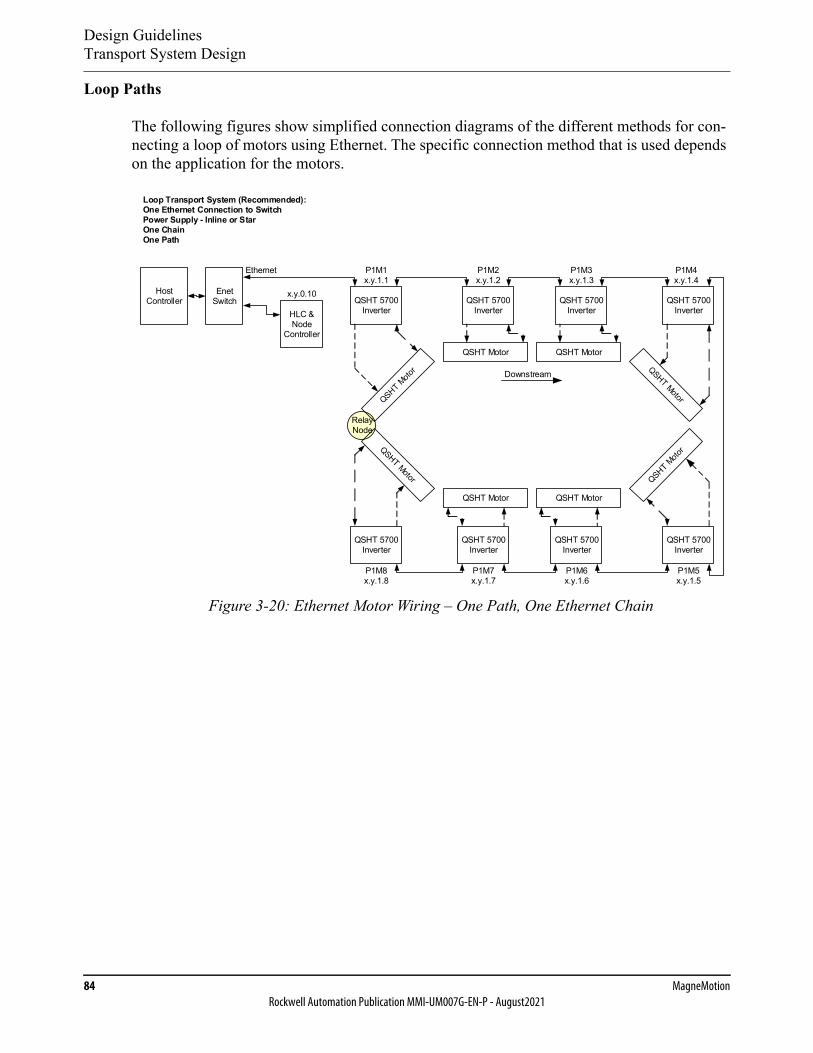
Design GuidelinesTransport System Design
84 MagneMotionRockwell Automation Publication MMI-UM007G-EN-P - August2021
Loop Paths
The following figures show simplified connection diagrams of the different methods for con-necting a loop of motors using Ethernet. The specific connection method that is used depends on the application for the motors.
Figure 3-20: Ethernet Motor Wiring – One Path, One Ethernet Chain
RelayNode
Host Controller
Loop Transport System (Recommended):One Ethernet Connection to SwitchPower Supply - Inline or StarOne ChainOne Path
P1M1x.y.1.1
P1M4x.y.1.4
P1M5x.y.1.5
P1M8x.y.1.8
P1M2x.y.1.2
QSHT Motor
QSHT Motor
QSHT 5700Inverter
P1M7x.y.1.7
P1M3x.y.1.3
QSHT Motor
QSHT 5700Inverter
P1M6x.y.1.6
QSHT 5700Inverter
QSHT 5700Inverter
QSHT 5700Inverter
QSHT 5700Inverter
QSHT Motor
QSHT 5700Inverter
QSHT 5700Inverter
Enet Switch
Ethernet
x.y.0.10
HLC & Node
Controller
Downstream
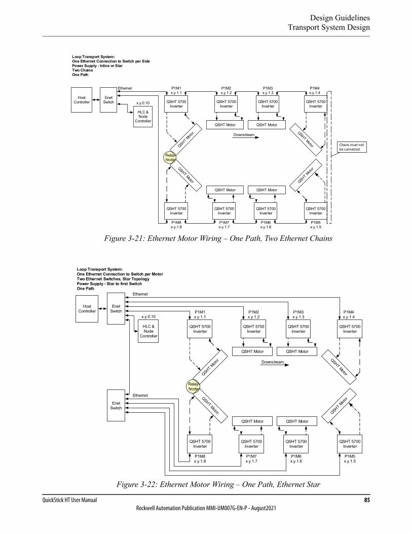
Design GuidelinesTransport System Design
QuickStick HT User Manual 85Rockwell Automation Publication MMI-UM007G-EN-P - August2021
Figure 3-21: Ethernet Motor Wiring – One Path, Two Ethernet Chains
Figure 3-22: Ethernet Motor Wiring – One Path, Ethernet Star
RelayNode
Loop Transport System:One Ethernet Connection to Switch per SidePower Supply - Inline or StarTwo ChainsOne Path
Host Controller
P1M1x.y.1.1
P1M4x.y.1.4
P1M5x.y.1.5
P1M8x.y.1.8
P1M2x.y.1.2
QSHT Motor
QSHT Motor
QSHT 5700Inverter
P1M7x.y.1.7
P1M3x.y.1.3
QSHT Motor
QSHT 5700Inverter
P1M6x.y.1.6
QSHT 5700Inverter
QSHT 5700Inverter
QSHT 5700Inverter
QSHT 5700Inverter
QSHT Motor
QSHT 5700Inverter
QSHT 5700Inverter
Enet Switch
Ethernet
x.y.0.10
HLC & Node
Controller
Downstream
Chains must not be connected
RelayNode
Host Controller
HLC & Node
Controller
x.y.0.10
Enet Switch
Enet Switch
Loop Transport System:One Ethernet Connection to Switch per MotorTwo Ethernet Switches, Star TopologyPower Supply - Star to first SwitchOne Path
Ethernet
Ethernet
P1M1x.y.1.1
P1M4x.y.1.4
P1M5x.y.1.5
P1M8x.y.1.8
P1M2x.y.1.2
QSHT Motor
QSHT Motor
QSHT 5700Inverter
P1M7x.y.1.7
P1M3x.y.1.3
QSHT Motor
QSHT 5700Inverter
P1M6x.y.1.6
QSHT 5700Inverter
QSHT 5700Inverter
QSHT 5700Inverter
QSHT 5700Inverter
QSHT Motor
QSHT 5700Inverter
QSHT 5700Inverter
Downstream
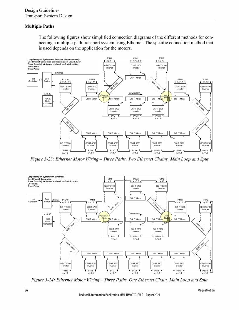
Design GuidelinesTransport System Design
86 MagneMotionRockwell Automation Publication MMI-UM007G-EN-P - August2021
Multiple Paths
The following figures show simplified connection diagrams of the different methods for con-necting a multiple-path transport system using Ethernet. The specific connection method that is used depends on the application for the motors.
Figure 3-23: Ethernet Motor Wiring – Three Paths, Two Ethernet Chains, Main Loop and Spur
Figure 3-24: Ethernet Motor Wiring – Three Paths, One Ethernet Chain, Main Loop and Spur
MergeNode
DivergeNode
QSHT MotorHost Controller
P1M10x.y.1.10
P1M9x.y.1.9
QSHT 5700Inverter
P1M8x.y.1.8
P2M1x.y.2.1
QSHT 5700Inverter
P1M7x.y.1.7
QSHT 5700Inverter
QSHT 5700Inverter
QSHT Motor
QSHT 5700Inverter
HLC & Node
Controller
x.y.0.10
Enet Switch
P2M2x.y.2.2
QSHT 5700Inverter
P1M6x.y.1.6
P2M3x.y.2.3
QSHT 5700Inverter
P1M5x.y.1.5
P1M1x.y.1.1
QSHT 5700Inverter
P1M4x.y.1.4
QSHT 5700Inverter
P3M1x.y.3.1
P3M3x.y.3.3
P3M2x.y.3.2
QSHT 5700Inverter
QSHT 5700Inverter
QSHT 5700Inverter
P1M2x.y.1.2
P1M3x.y.1.3
QSHT 5700Inverter
QSHT 5700Inverter
QSHT 5700Inverter
QSHT 5700Inverter
QSHT 5700Inverter
P1M11x.y.1.11
Loop Transport System with Switches (Recommended):One Ethernet Connection per Section (Main Loop & Spur)Power Supply (not shown) – Inline from Switch or StarTwo ChainsThree Paths
Ethernet
Downstream
QSHT Motor
QSHT Motor
QSHT MotorQSHT MotorQSHT MotorQSHT Motor
QSHT Motor QSHT Motor QSHT Motor
MergeNode
Host Controller
Loop Transport System with Switches:One Ethernet ConnectionPower Supply (not shown) – Inline from Switch or StarOne ChainThree Paths
DivergeNode
QSHT MotorP1M10x.y.1.10
P1M9x.y.1.9
QSHT 5700Inverter
P1M8x.y.1.8
P2M1x.y.2.1
QSHT 5700Inverter
P1M7x.y.1.7
QSHT 5700Inverter
QSHT 5700Inverter
QSHT Motor
QSHT 5700Inverter
HLC & Node
Controller
x.y.0.10
Enet Switch
P2M2x.y.2.2
QSHT 5700Inverter
P1M6x.y.1.6
P2M3x.y.2.3
QSHT 5700Inverter
P1M5x.y.1.5
P1M1x.y.1.1
QSHT 5700Inverter
P1M4x.y.1.4
QSHT 5700Inverter
P3M1x.y.3.1
P3M3x.y.3.3
P3M2x.y.3.2
QSHT 5700Inverter
QSHT 5700Inverter
QSHT 5700Inverter
P1M2x.y.1.2
P1M3x.y.1.3
QSHT 5700Inverter
QSHT 5700Inverter
QSHT 5700Inverter
QSHT 5700Inverter
QSHT 5700Inverter
P1M11x.y.1.11
Ethernet
Downstream
QSHT Motor
QSHT Motor
QSHT MotorQSHT MotorQSHT MotorQSHT Motor
QSHT Motor QSHT Motor QSHT Motor
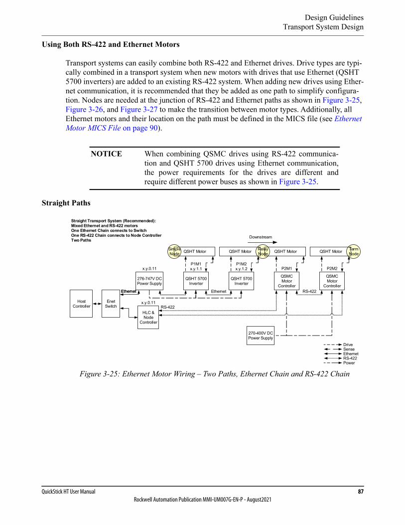
Design GuidelinesTransport System Design
QuickStick HT User Manual 87Rockwell Automation Publication MMI-UM007G-EN-P - August2021
Using Both RS-422 and Ethernet Motors
Transport systems can easily combine both RS-422 and Ethernet drives. Drive types are typi-cally combined in a transport system when new motors with drives that use Ethernet (QSHT 5700 inverters) are added to an existing RS-422 system. When adding new drives using Ether-net communication, it is recommended that they be added as one path to simplify configura-tion. Nodes are needed at the junction of RS-422 and Ethernet paths as shown in Figure 3-25, Figure 3-26, and Figure 3-27 to make the transition between motor types. Additionally, all Ethernet motors and their location on the path must be defined in the MICS file (see Ethernet Motor MICS File on page 90).
Straight Paths
Figure 3-25: Ethernet Motor Wiring – Two Paths, Ethernet Chain and RS-422 Chain
NOTICE When combining QSMC drives using RS-422 communica-tion and QSHT 5700 drives using Ethernet communication,the power requirements for the drives are different andrequire different power buses as shown in Figure 3-25.
Straight Transport System (Recommended):Mixed Ethernet and RS-422 motorsOne Ethernet Chain connects to SwitchOne RS-422 Chain connects to Node ControllerTwo Paths
Ethernet
RelayNode
SimpleNode QSHT Motor
QSHT 5700Inverter
QSHT Motor
QSHT 5700Inverter
QSHT Motor
QSMCMotor
Controller
QSMCMotor
Controller
TermNodeQSHT Motor
P1M1x.y.1.1
P1M2x.y.1.2 P2M1 P2M2
Host Controller
HLC & Node
Controller
RS-422
RS-422Enet
Switchx.y.0.11
Ethernet
RS-422
DriveSenseEthernet
Downstream
Power
270-400V DC Power Supply
Ethernet
276-747V DC Power Supply
x.y.0.11
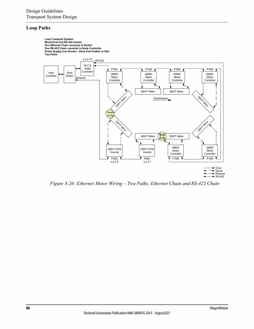
Design GuidelinesTransport System Design
88 MagneMotionRockwell Automation Publication MMI-UM007G-EN-P - August2021
Loop Paths
Figure 3-26: Ethernet Motor Wiring – Two Paths, Ethernet Chain and RS-422 Chain
RelayNode
RelayNode
Loop Transport System:Mixed Enet and RS-422 motorsOne Ethernet Chain connects to SwitchOne RS-422 Chain connects to Node ControllerPower Supply (not shown) - Inline from Switch or StarTwo Paths
Host Controller
Enet Switch
x.y.0.10
P1M1
P1M5P2M2x.y.2.2
QSHT Motor
QSHT Motor
QSHT 5700Inverter
P2M1x.y.2.1
P1M3
QSHT Motor
QSMCMotor
Controller
P1M6
QSMCMotor
Controller
QSHT 5700Inverter
QSMCMotor
Controller
QSMCMotor
Controller
QSHT Motor
QSMCMotor
Controller
QSMCMotor
Controller
HLC & Node
ControllerP1M2 P1M4
RS-422
Ethernet
RS-422
DriveSenseEthernet
Downstream
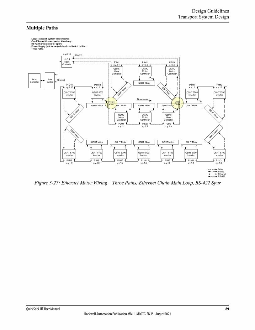
Design GuidelinesTransport System Design
QuickStick HT User Manual 89Rockwell Automation Publication MMI-UM007G-EN-P - August2021
Multiple Paths
Figure 3-27: Ethernet Motor Wiring – Three Paths, Ethernet Chain Main Loop, RS-422 Spur
MergeNode
QSHT 5700Inverter
Host Controller
x.y.0.10
Enet Switch
Loop Transport System with Switches:One Ethernet Connection for Main LoopRS-422 Connections for SpursPower Supply (not shown) – Inline from Switch or StarThree Paths
HLC & Node
Controller
Ethernet
RS-422
DivergeNode
QSHT MotorP1M10x.y.1.10
P1M9x.y.1.9
QSHT 5700Inverter
P1M8x.y.1.8
P2M1x.y.2.1
QSHT 5700Inverter
P1M7x.y.1.7
QSHT 5700Inverter
QSHT 5700Inverter
QSHT Motor
P2M2x.y.2.2
QSHT 5700Inverter
P1M6x.y.1.6
P2M3x.y.2.3
QSHT 5700Inverter
P1M5x.y.1.5
P1M1x.y.1.1
QSHT 5700Inverter
P1M4x.y.1.4
QSHT 5700Inverter
P3M1x.y.3.1
P3M3x.y.3.3
P3M2x.y.3.2
QSMC Motor
Controller
QSMC Motor
Controller
QSMC Motor
Controller
P1M2x.y.1.2
P1M3x.y.1.3
QSHT 5700Inverter
QSHT 5700Inverter
QSMC Motor
Controller
QSMC Motor
Controller
QSMC Motor
Controller
P1M11x.y.1.11
Downstream
QSHT Motor
QSHT Motor
QSHT MotorQSHT MotorQSHT MotorQSHT Motor
QSHT Motor QSHT Motor QSHT Motor
RS-422
DriveSenseEthernet
Design GuidelinesTransport System Design
90 MagneMotionRockwell Automation Publication MMI-UM007G-EN-P - August2021
Ethernet Motor MICS File
The MagneMotion Information and Configuration Service (MICS) file is used to define the Ethernet track topology for the motors that use Ethernet for communication in a transport sys-tem. The file also describes the interfaces and physical hardware connections to the motors.
The MICS file works with the Node Controller Configuration File, which specifies the config-uration of components within the transport system, such as; node controllers, paths, nodes, and motors. Each path that is defined in the Node Controller Configuration File defines the specific motors and their relationships to the motors on that path. The MICS file then defines the MAC address and IP address for each of those motors.
The MICS file contains the following:
• MAC address for each motor.
• IP address for each motor.
• Transport system location for each motor.
• Physical orientation of the motors.
The MICS files are written in XML, which allows the file to be backward and forward com-patible and easily extended. A newer version of software can easily ignore older unused XML tags. An older version of software can ignore newer, unknown XML tags. The XML file for-mat is human readable, which allows manual editing. XML files can be viewed with browsers or code editors in tree fashion (with the ability to expand or contract elements that contain other elements).
The Ethernet Motor Commissioning Tool is a Windows® software application that is used to create and edit the MICS file without having to access the XML directly. The Commissioning Tool provides a graphical interface to define or modify the various elements of the MICS file. The tool has a help system that provides full instructions for creating and editing the MICS file and an overview of all of the XML tags.
When a motor powers up, its network and topology information (from the MICS file) is pro-vided to it dynamically by the node controller that is responsible for its path. The topology information the motor receives includes its IP address, subnet mask, default gateway, and information about its neighboring motor connections.
The MagneMotion transport systems that use Ethernet for motor communication accept any valid IPv4 address scheme to operate. The motors with those addresses must be on the same subnet as the node controller responsible for them. It is important to keep unnecessary broad-cast traffic off the transport system network as it can impact overall system performance. For a large transport system, it is typically useful to organize the IP structure that includes the path/motor information in as shown in Ethernet Motor Communication Recommendations on page 80.
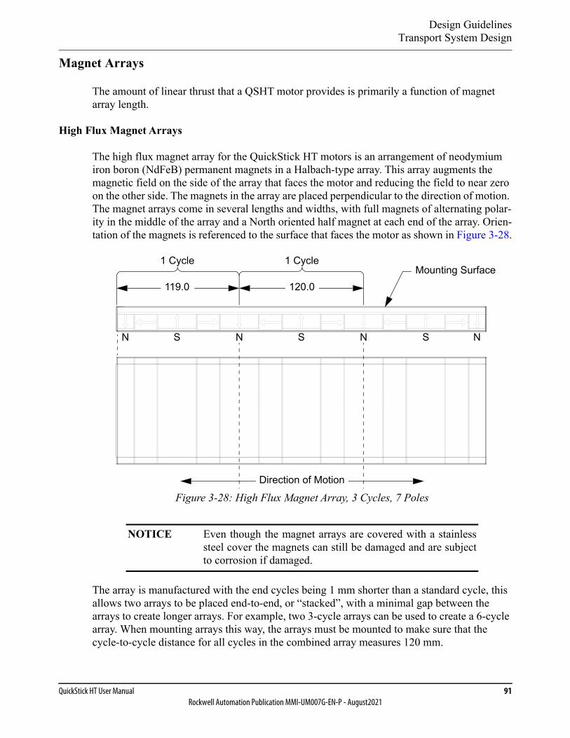
Design GuidelinesTransport System Design
QuickStick HT User Manual 91Rockwell Automation Publication MMI-UM007G-EN-P - August2021
Magnet Arrays
The amount of linear thrust that a QSHT motor provides is primarily a function of magnet array length.
High Flux Magnet Arrays
The high flux magnet array for the QuickStick HT motors is an arrangement of neodymium iron boron (NdFeB) permanent magnets in a Halbach-type array. This array augments the magnetic field on the side of the array that faces the motor and reducing the field to near zero on the other side. The magnets in the array are placed perpendicular to the direction of motion. The magnet arrays come in several lengths and widths, with full magnets of alternating polar-ity in the middle of the array and a North oriented half magnet at each end of the array. Orien-tation of the magnets is referenced to the surface that faces the motor as shown in Figure 3-28.
Figure 3-28: High Flux Magnet Array, 3 Cycles, 7 Poles
The array is manufactured with the end cycles being 1 mm shorter than a standard cycle, this allows two arrays to be placed end-to-end, or “stacked”, with a minimal gap between the arrays to create longer arrays. For example, two 3-cycle arrays can be used to create a 6-cycle array. When mounting arrays this way, the arrays must be mounted to make sure that the cycle-to-cycle distance for all cycles in the combined array measures 120 mm.
NOTICE Even though the magnet arrays are covered with a stainlesssteel cover the magnets can still be damaged and are subjectto corrosion if damaged.
1 Cycle
Direction of Motion
N S N S N
Mounting Surface120.0
N S
1 Cycle
119.0

Design GuidelinesTransport System Design
92 MagneMotionRockwell Automation Publication MMI-UM007G-EN-P - August2021
Physical Length
The physical length of the high flux magnet arrays can be measured using a non-ferrous mea-suring tool. The physical length can also be calculated, if the number of cycles is known.
The equation to calculate the physical length of a high flux magnet array is:
MagnetArrayLength = (Cycles x 120) - 2 mm
Where:
MagnetArrayLength – The length of the array, in millimeters.
Cycles – The number of cycles in the array.
2 mm is subtracted from the overall length to allow ‘stacking’ of magnet arrays end-to-end.
Magnet Array Length and Attractive Force
There is a strong magnetic attractive force present between the magnet array and the Quick-Stick HT motor. This force is an important consideration in designing the support structure for the QuickStick HT transport system and in determining the force that is required to move a vehicle. The magnetic attractive force is always present, even if there is no power to the motor. The amount of magnetic attractive force present is also dependent on the length of the magnet array, see Figure A-4 on page 326.
Choose a magnet array length that is no longer than the vehicle length. Based on the applica-tion, multiple magnet arrays can be used for each vehicle, side-by-side or end-to-end.
Magnet array length is measured in three ways:
• Number of cycles.
• Physical length in millimeters.
• Number of poles.
Number of Cycles
The amount of thrust force and attractive force is reported as force per magnet array cycle. The more cycles in the magnet array, the greater the thrust and attractive forces. A magnet array cycle is:
• The distance from the edge of a half North oriented magnet to the center line of a full North oriented magnet as shown in Figure 3-28.
• The distance from the center line of one full North oriented magnet to the centerline of the next full North oriented magnet as shown in Figure 3-28.
• For QSHT magnet arrays, the cycle length is always 120 mm.

Design GuidelinesTransport System Design
QuickStick HT User Manual 93Rockwell Automation Publication MMI-UM007G-EN-P - August2021
The smallest magnet array available for use with QSHT motors is 2 cycles (238 mm [9.4 in]). With a 2 cycle magnet array the recommended maximum Motor Gap (distance between motors) is 24 mm (see Downstream Gap on page 71).
NOTE: When determining the number of cycles that are required for the magnet array, be sure to account for the Downstream Gap.
Number of Poles
The number of poles in a magnet array is simply the number of North and South-oriented poles in the magnet array. The number of poles is always an odd number (see Figure 3-28) as it includes the half magnets at each end of the array. The number of poles can also be calcu-lated from the number of cycles (cycles * 2 + 1).
Magnet Array Width
Magnet arrays are available in several different widths. The application determines the width that is used.
Regular width arrays are used in applications where the array does not need to be wider than the motor. These applications are typically when QSHT motors are arranged in a straight line.
Wide arrays are used in applications where the array must be wider than the motor. This array width is typically used when QSHT motors are arranged in a curve to provide coverage when there is a misalignment between the motor and the magnet array. This loss of coverage due to misalignment leads to a loss of thrust.
Magnet Array Forces
As mentioned previously, there is a certain amount of thrust and attractive force available per magnet array cycle; however, the number of cycles is not the only variable that affects avail-able thrust. Other variables are the Vehicle Gap and the Downstream Gap. These other vari-ables and their effect on available thrust are discussed later in this chapter.
Magnet Array Use
The QuickStick HT magnet arrays are intended for use as the QSHT motor secondary as part of the vehicle only and must not be used for any other purpose.
Protect all magnet arrays on the transport system from debris accumulation. If debris is accu-mulated, it can get caught between the magnet array and the motor. Any accumulated debris affects the performance and can damage the cover of the motor or the magnet array, see Cleaning Magnet Arrays on page 290.
Proper precautions must be taken when magnet arrays with stainless steel covers that are not welded are used in wash down applications or in environments where water or fluids are con-tacting the array. The mounting must secure the array with a suitable form of gasketing to

Design GuidelinesTransport System Design
94 MagneMotionRockwell Automation Publication MMI-UM007G-EN-P - August2021
avoid water ingress into the array through either its back surface or the seam where the cover meets the back iron of the array. The top surface and sides of the cover are water-resistant.
Available Magnet Arrays
The magnet arrays are available in different widths and lengths (see Magnet Array, High Flux on page 131).
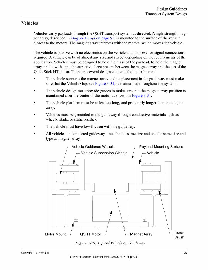
Design GuidelinesTransport System Design
QuickStick HT User Manual 95Rockwell Automation Publication MMI-UM007G-EN-P - August2021
Vehicles
Vehicles carry payloads through the QSHT transport system as directed. A high-strength mag-net array, described in Magnet Arrays on page 91, is mounted to the surface of the vehicle closest to the motors. The magnet array interacts with the motors, which moves the vehicle.
The vehicle is passive with no electronics on the vehicle and no power or signal connections required. A vehicle can be of almost any size and shape, depending on the requirements of the application. Vehicles must be designed to hold the mass of the payload, to hold the magnet array, and to withstand the attractive force present between the magnet array and the top of the QuickStick HT motor. There are several design elements that must be met:
• The vehicle supports the magnet array and its placement in the guideway must make sure that the Vehicle Gap, see Figure 3-31, is maintained throughout the system.
• The vehicle design must provide guides to make sure that the magnet array position is maintained over the center of the motor as shown in Figure 3-31.
• The vehicle platform must be at least as long, and preferably longer than the magnet array.
• Vehicles must be grounded to the guideway through conductive materials such as wheels, skids, or static brushes.
• The vehicle must have low friction with the guideway.
• All vehicles on connected guideways must be the same size and use the same size and type of magnet array.
Figure 3-29: Typical Vehicle on Guideway
QSHT Motor
Vehicle Guidance WheelsVehicle
Magnet Array
Payload Mounting Surface
Motor Mount
Vehicle Suspension Wheels
StaticBrush
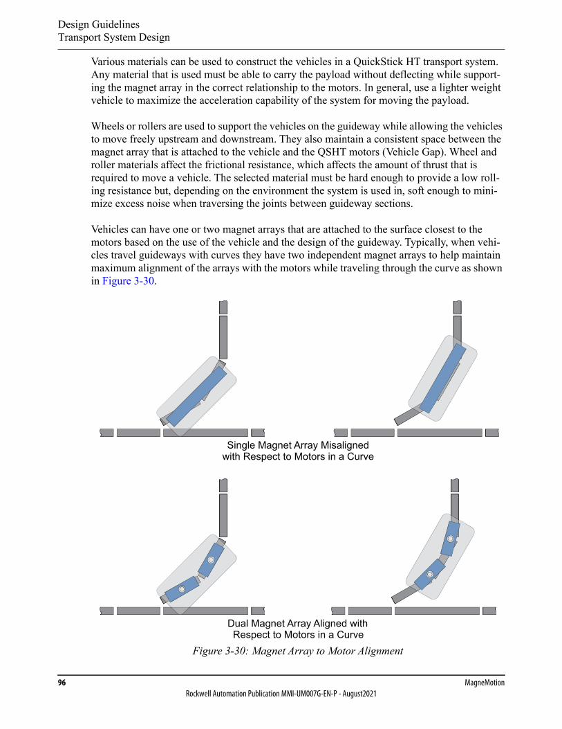
Design GuidelinesTransport System Design
96 MagneMotionRockwell Automation Publication MMI-UM007G-EN-P - August2021
Various materials can be used to construct the vehicles in a QuickStick HT transport system. Any material that is used must be able to carry the payload without deflecting while support-ing the magnet array in the correct relationship to the motors. In general, use a lighter weight vehicle to maximize the acceleration capability of the system for moving the payload.
Wheels or rollers are used to support the vehicles on the guideway while allowing the vehicles to move freely upstream and downstream. They also maintain a consistent space between the magnet array that is attached to the vehicle and the QSHT motors (Vehicle Gap). Wheel and roller materials affect the frictional resistance, which affects the amount of thrust that is required to move a vehicle. The selected material must be hard enough to provide a low roll-ing resistance but, depending on the environment the system is used in, soft enough to mini-mize excess noise when traversing the joints between guideway sections.
Vehicles can have one or two magnet arrays that are attached to the surface closest to the motors based on the use of the vehicle and the design of the guideway. Typically, when vehi-cles travel guideways with curves they have two independent magnet arrays to help maintain maximum alignment of the arrays with the motors while traveling through the curve as shown in Figure 3-30.
Figure 3-30: Magnet Array to Motor Alignment
Dual Magnet Array Aligned withRespect to Motors in a Curve
Single Magnet Array Misalignedwith Respect to Motors in a Curve
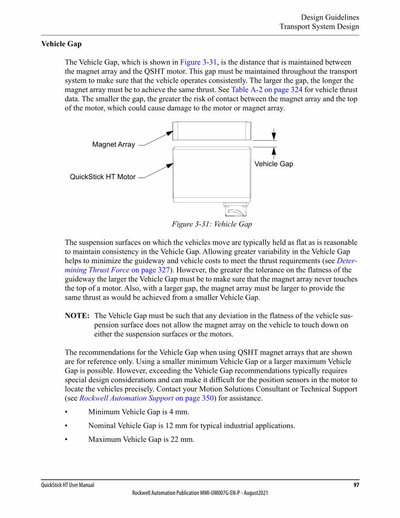
Design GuidelinesTransport System Design
QuickStick HT User Manual 97Rockwell Automation Publication MMI-UM007G-EN-P - August2021
Vehicle Gap
The Vehicle Gap, which is shown in Figure 3-31, is the distance that is maintained between the magnet array and the QSHT motor. This gap must be maintained throughout the transport system to make sure that the vehicle operates consistently. The larger the gap, the longer the magnet array must be to achieve the same thrust. See Table A-2 on page 324 for vehicle thrust data. The smaller the gap, the greater the risk of contact between the magnet array and the top of the motor, which could cause damage to the motor or magnet array.
Figure 3-31: Vehicle Gap
The suspension surfaces on which the vehicles move are typically held as flat as is reasonable to maintain consistency in the Vehicle Gap. Allowing greater variability in the Vehicle Gap helps to minimize the guideway and vehicle costs to meet the thrust requirements (see Deter-mining Thrust Force on page 327). However, the greater the tolerance on the flatness of the guideway the larger the Vehicle Gap must be to make sure that the magnet array never touches the top of a motor. Also, with a larger gap, the magnet array must be larger to provide the same thrust as would be achieved from a smaller Vehicle Gap.
NOTE: The Vehicle Gap must be such that any deviation in the flatness of the vehicle sus-pension surface does not allow the magnet array on the vehicle to touch down on either the suspension surfaces or the motors.
The recommendations for the Vehicle Gap when using QSHT magnet arrays that are shown are for reference only. Using a smaller minimum Vehicle Gap or a larger maximum Vehicle Gap is possible. However, exceeding the Vehicle Gap recommendations typically requires special design considerations and can make it difficult for the position sensors in the motor to locate the vehicles precisely. Contact your Motion Solutions Consultant or Technical Support (see Rockwell Automation Support on page 350) for assistance.
• Minimum Vehicle Gap is 4 mm.
• Nominal Vehicle Gap is 12 mm for typical industrial applications.
• Maximum Vehicle Gap is 22 mm.
Magnet Array
QuickStick HT Motor
Vehicle Gap
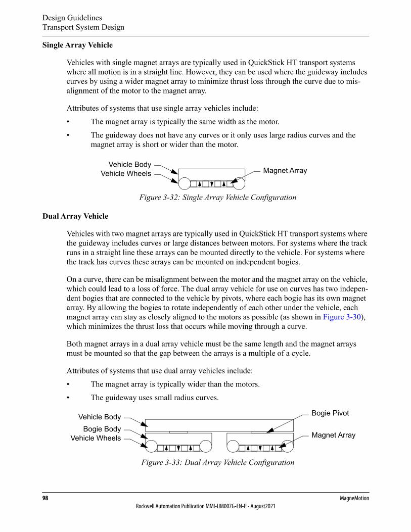
Design GuidelinesTransport System Design
98 MagneMotionRockwell Automation Publication MMI-UM007G-EN-P - August2021
Single Array Vehicle
Vehicles with single magnet arrays are typically used in QuickStick HT transport systems where all motion is in a straight line. However, they can be used where the guideway includes curves by using a wider magnet array to minimize thrust loss through the curve due to mis-alignment of the motor to the magnet array.
Attributes of systems that use single array vehicles include:• The magnet array is typically the same width as the motor.• The guideway does not have any curves or it only uses large radius curves and the
magnet array is short or wider than the motor.
Figure 3-32: Single Array Vehicle Configuration
Dual Array Vehicle
Vehicles with two magnet arrays are typically used in QuickStick HT transport systems where the guideway includes curves or large distances between motors. For systems where the track runs in a straight line these arrays can be mounted directly to the vehicle. For systems where the track has curves these arrays can be mounted on independent bogies.
On a curve, there can be misalignment between the motor and the magnet array on the vehicle, which could lead to a loss of force. The dual array vehicle for use on curves has two indepen-dent bogies that are connected to the vehicle by pivots, where each bogie has its own magnet array. By allowing the bogies to rotate independently of each other under the vehicle, each magnet array can stay as closely aligned to the motors as possible (as shown in Figure 3-30), which minimizes the thrust loss that occurs while moving through a curve.
Both magnet arrays in a dual array vehicle must be the same length and the magnet arrays must be mounted so that the gap between the arrays is a multiple of a cycle.
Attributes of systems that use dual array vehicles include:• The magnet array is typically wider than the motors.• The guideway uses small radius curves.
Figure 3-33: Dual Array Vehicle Configuration
Vehicle BodyVehicle Wheels Magnet Array
Magnet Array
Vehicle Body
Vehicle WheelsBogie Body
Bogie Pivot
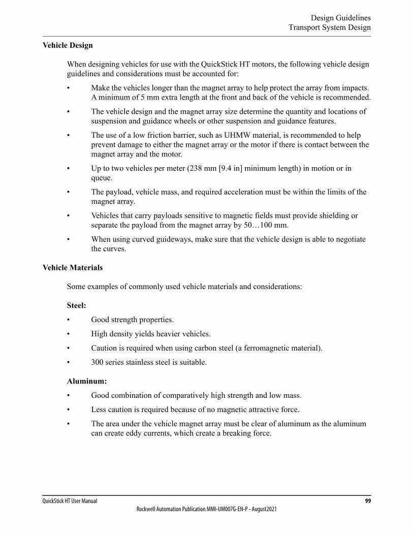
Design GuidelinesTransport System Design
QuickStick HT User Manual 99Rockwell Automation Publication MMI-UM007G-EN-P - August2021
Vehicle Design
When designing vehicles for use with the QuickStick HT motors, the following vehicle design guidelines and considerations must be accounted for:
• Make the vehicles longer than the magnet array to help protect the array from impacts. A minimum of 5 mm extra length at the front and back of the vehicle is recommended.
• The vehicle design and the magnet array size determine the quantity and locations of suspension and guidance wheels or other suspension and guidance features.
• The use of a low friction barrier, such as UHMW material, is recommended to help prevent damage to either the magnet array or the motor if there is contact between the magnet array and the motor.
• Up to two vehicles per meter (238 mm [9.4 in] minimum length) in motion or in queue.
• The payload, vehicle mass, and required acceleration must be within the limits of the magnet array.
• Vehicles that carry payloads sensitive to magnetic fields must provide shielding or separate the payload from the magnet array by 50…100 mm.
• When using curved guideways, make sure that the vehicle design is able to negotiate the curves.
Vehicle Materials
Some examples of commonly used vehicle materials and considerations:
Steel:
• Good strength properties.
• High density yields heavier vehicles.
• Caution is required when using carbon steel (a ferromagnetic material).
• 300 series stainless steel is suitable.
Aluminum:
• Good combination of comparatively high strength and low mass.
• Less caution is required because of no magnetic attractive force.
• The area under the vehicle magnet array must be clear of aluminum as the aluminum can create eddy currents, which create a breaking force.
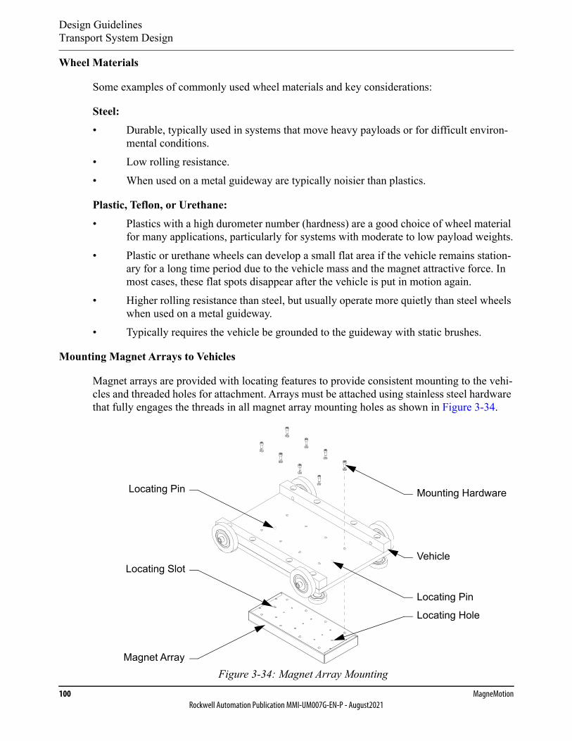
Design GuidelinesTransport System Design
100 MagneMotionRockwell Automation Publication MMI-UM007G-EN-P - August2021
Wheel Materials
Some examples of commonly used wheel materials and key considerations:
Steel:• Durable, typically used in systems that move heavy payloads or for difficult environ-
mental conditions.• Low rolling resistance.• When used on a metal guideway are typically noisier than plastics.
Plastic, Teflon, or Urethane:• Plastics with a high durometer number (hardness) are a good choice of wheel material
for many applications, particularly for systems with moderate to low payload weights.• Plastic or urethane wheels can develop a small flat area if the vehicle remains station-
ary for a long time period due to the vehicle mass and the magnet attractive force. In most cases, these flat spots disappear after the vehicle is put in motion again.
• Higher rolling resistance than steel, but usually operate more quietly than steel wheels when used on a metal guideway.
• Typically requires the vehicle be grounded to the guideway with static brushes.
Mounting Magnet Arrays to Vehicles
Magnet arrays are provided with locating features to provide consistent mounting to the vehi-cles and threaded holes for attachment. Arrays must be attached using stainless steel hardware that fully engages the threads in all magnet array mounting holes as shown in Figure 3-34.
Figure 3-34: Magnet Array Mounting
Locating Hole
Mounting Hardware
Locating Pin
Vehicle
Locating Pin
Locating Slot
Magnet Array
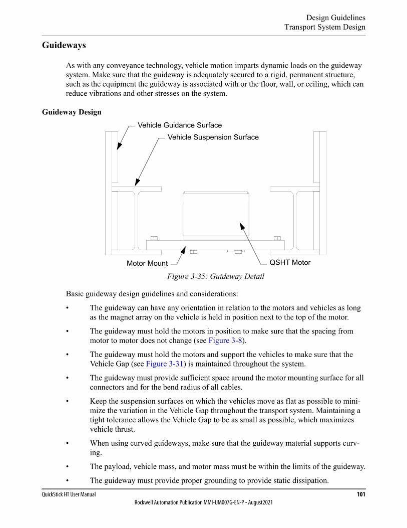
Design GuidelinesTransport System Design
QuickStick HT User Manual 101Rockwell Automation Publication MMI-UM007G-EN-P - August2021
Guideways
As with any conveyance technology, vehicle motion imparts dynamic loads on the guideway system. Make sure that the guideway is adequately secured to a rigid, permanent structure, such as the equipment the guideway is associated with or the floor, wall, or ceiling, which can reduce vibrations and other stresses on the system.
Guideway Design
Figure 3-35: Guideway Detail
Basic guideway design guidelines and considerations:
• The guideway can have any orientation in relation to the motors and vehicles as long as the magnet array on the vehicle is held in position next to the top of the motor.
• The guideway must hold the motors in position to make sure that the spacing from motor to motor does not change (see Figure 3-8).
• The guideway must hold the motors and support the vehicles to make sure that the Vehicle Gap (see Figure 3-31) is maintained throughout the system.
• The guideway must provide sufficient space around the motor mounting surface for all connectors and for the bend radius of all cables.
• Keep the suspension surfaces on which the vehicles move as flat as possible to mini-mize the variation in the Vehicle Gap throughout the transport system. Maintaining a tight tolerance allows the Vehicle Gap to be as small as possible, which maximizes vehicle thrust.
• When using curved guideways, make sure that the guideway material supports curv-ing.
• The payload, vehicle mass, and motor mass must be within the limits of the guideway.
• The guideway must provide proper grounding to provide static dissipation.
QSHT MotorMotor Mount
Vehicle Suspension SurfaceVehicle Guidance Surface
Design GuidelinesTransport System Design
102 MagneMotionRockwell Automation Publication MMI-UM007G-EN-P - August2021
• Keep the joints between sections of the guideway as smooth as possible to minimize noise and wear on the wheels.
• The guideway must provide features to allow the vehicle to maintain its position on the guideway (see Figure 3-35).
Guideway and Support Materials
As with any installation, the operational environment must be considered when choosing compatible support structure materials. Some examples of commonly used guideway structure materials and key considerations follow:
Steel:• Good strength properties.• Strong and provides a stable platform for vehicle motion.• Can be heavier than is necessary.• Caution is required when using carbon steel (a ferromagnetic material).• Can be more expensive than other alternatives.
Aluminum:• Good combination of comparatively high strength and low mass.• Less caution is required because of no magnetic attractive force.• The area under the vehicle magnet array must be clear of aluminum as the aluminum
can create eddy currents, which create a breaking force.• Available in various weights, thicknesses, and prices.
Motor Mounts
The QuickStick HT motors provide fixed mounting features on the bottom (see Mechanical Specifications on page 114), which provides for a simple mounting scheme. The following guidelines are provided for designing the motor mounts to interface with those mounting fea-tures.• Design the mounts to allow the motors to have a small amount of movement relative to
each other for adjustment of the motor to motor gap during installation.• Design the mounts to support consistent spacing between the motors, which simplifies
the creation of the Node Controller Configuration File and provides consistent thrust.• Design the mounts to make sure that the tops of all motors are coplanar to each other
to meet the standard thrust requirements. The tolerance requirement for motor top coplanarity is dictated by the tolerance stack that is associated with the overall system guideway and structure design.
• Design the mounts to make sure that the motor is securely fastened and cannot move.• Make sure that all motor mount locations are used and all bolts for the mounts are fully
secured.
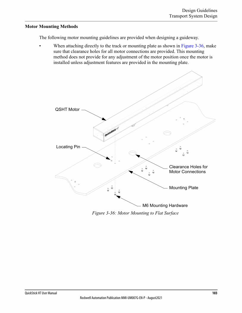
Design GuidelinesTransport System Design
QuickStick HT User Manual 103Rockwell Automation Publication MMI-UM007G-EN-P - August2021
Motor Mounting Methods
The following motor mounting guidelines are provided when designing a guideway.
• When attaching directly to the track or mounting plate as shown in Figure 3-36, make sure that clearance holes for all motor connections are provided. This mounting method does not provide for any adjustment of the motor position once the motor is installed unless adjustment features are provided in the mounting plate.
Figure 3-36: Motor Mounting to Flat Surface
Clearance Holes forMotor Connections
M6 Mounting Hardware
QSHT Motor
Locating Pin
Mounting Plate
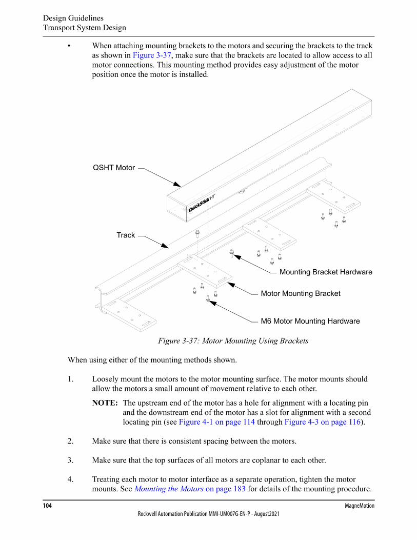
Design GuidelinesTransport System Design
104 MagneMotionRockwell Automation Publication MMI-UM007G-EN-P - August2021
• When attaching mounting brackets to the motors and securing the brackets to the track as shown in Figure 3-37, make sure that the brackets are located to allow access to all motor connections. This mounting method provides easy adjustment of the motor position once the motor is installed.
Figure 3-37: Motor Mounting Using Brackets
When using either of the mounting methods shown.
1. Loosely mount the motors to the motor mounting surface. The motor mounts should allow the motors a small amount of movement relative to each other.
NOTE: The upstream end of the motor has a hole for alignment with a locating pin and the downstream end of the motor has a slot for alignment with a second locating pin (see Figure 4-1 on page 114 through Figure 4-3 on page 116).
2. Make sure that there is consistent spacing between the motors.
3. Make sure that the top surfaces of all motors are coplanar to each other.
4. Treating each motor to motor interface as a separate operation, tighten the motor mounts. See Mounting the Motors on page 183 for details of the mounting procedure.
M6 Motor Mounting Hardware
QSHT Motor
Motor Mounting Bracket
Track
Mounting Bracket Hardware

Design GuidelinesTransport System Design
QuickStick HT User Manual 105Rockwell Automation Publication MMI-UM007G-EN-P - August2021
Guideway Examples
Figure 3-38 provides an example of a guideway and vehicle where the guideway is con-structed of stiff steel sides and a sheet metal base. The vehicle has flanged wheels that ride on the top of the side plates, which holds the vehicle and magnet array in the correct relationship to the motors.
NOTE: Vehicles are not held in place if power is removed.
Figure 3-38: Guideway Example #1
Vehicle
Motor
Guideway

Design GuidelinesTransport System Design
106 MagneMotionRockwell Automation Publication MMI-UM007G-EN-P - August2021
Figure 3-39 provides an example of a guideway and vehicle where the guideway is con-structed of extruded aluminum with linear bearing guide rails. The vehicle has linear bearing slides that ride on the rails, and holds the vehicle and magnet array in the correct relationship to the motors. This guideway can be used in any orientation as the vehicles are captive.
NOTE: Vehicles are not held in place if power is removed.
Figure 3-39: Guideway Example #2
Vehicle
Motor
Guideway

Design GuidelinesTransport System Design
QuickStick HT User Manual 107Rockwell Automation Publication MMI-UM007G-EN-P - August2021
Figure 3-40 provides an example of a guideway and vehicle where the guideway is con-structed of extruded aluminum with rollers that are mounted along the top of the guideway. The vehicle sits on the rollers and between the side plates, which hold the vehicle and magnet array in the correct relationship to the motors.
NOTE: Vehicles are not held in place if power is removed.
Figure 3-40: Guideway Example #3
Motor
Vehicle
Side Plate
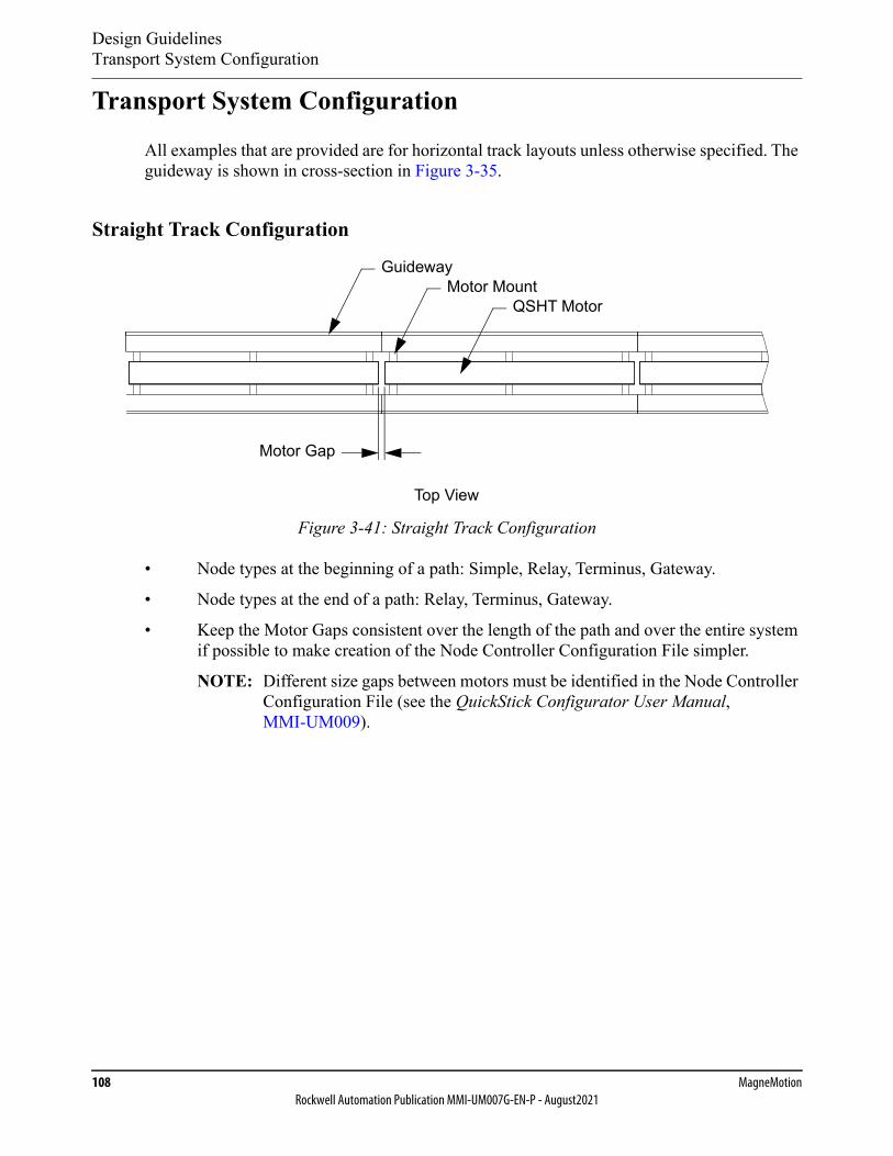
Design GuidelinesTransport System Configuration
108 MagneMotionRockwell Automation Publication MMI-UM007G-EN-P - August2021
Transport System Configuration
All examples that are provided are for horizontal track layouts unless otherwise specified. The guideway is shown in cross-section in Figure 3-35.
Straight Track Configuration
Figure 3-41: Straight Track Configuration
• Node types at the beginning of a path: Simple, Relay, Terminus, Gateway.
• Node types at the end of a path: Relay, Terminus, Gateway.
• Keep the Motor Gaps consistent over the length of the path and over the entire system if possible to make creation of the Node Controller Configuration File simpler.
NOTE: Different size gaps between motors must be identified in the Node Controller Configuration File (see the QuickStick Configurator User Manual, MMI-UM009).
GuidewayMotor Mount
QSHT Motor
Top View
Motor Gap
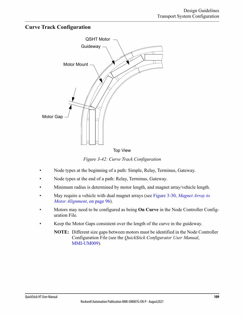
Design GuidelinesTransport System Configuration
QuickStick HT User Manual 109Rockwell Automation Publication MMI-UM007G-EN-P - August2021
Curve Track Configuration
Figure 3-42: Curve Track Configuration
• Node types at the beginning of a path: Simple, Relay, Terminus, Gateway.
• Node types at the end of a path: Relay, Terminus, Gateway.
• Minimum radius is determined by motor length, and magnet array/vehicle length.
• May require a vehicle with dual magnet arrays (see Figure 3-30, Magnet Array to Motor Alignment, on page 96).
• Motors may need to be configured as being On Curve in the Node Controller Config-uration File.
• Keep the Motor Gaps consistent over the length of the curve in the guideway.
NOTE: Different size gaps between motors must be identified in the Node Controller Configuration File (see the QuickStick Configurator User Manual, MMI-UM009).
Guideway
Motor Mount
QSHT Motor
Motor Gap
Top View
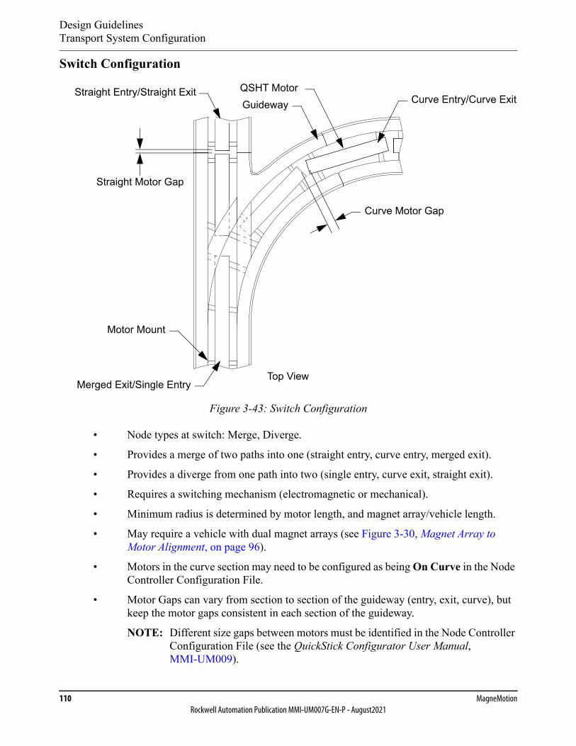
Design GuidelinesTransport System Configuration
110 MagneMotionRockwell Automation Publication MMI-UM007G-EN-P - August2021
Switch Configuration
Figure 3-43: Switch Configuration
• Node types at switch: Merge, Diverge.
• Provides a merge of two paths into one (straight entry, curve entry, merged exit).
• Provides a diverge from one path into two (single entry, curve exit, straight exit).
• Requires a switching mechanism (electromagnetic or mechanical).
• Minimum radius is determined by motor length, and magnet array/vehicle length.
• May require a vehicle with dual magnet arrays (see Figure 3-30, Magnet Array to Motor Alignment, on page 96).
• Motors in the curve section may need to be configured as being On Curve in the Node Controller Configuration File.
• Motor Gaps can vary from section to section of the guideway (entry, exit, curve), but keep the motor gaps consistent in each section of the guideway.
NOTE: Different size gaps between motors must be identified in the Node Controller Configuration File (see the QuickStick Configurator User Manual, MMI-UM009).
GuidewayStraight Entry/Straight Exit QSHT Motor
Straight Motor Gap
Curve Entry/Curve Exit
Merged Exit/Single Entry
Motor Mount
Curve Motor Gap
Top View
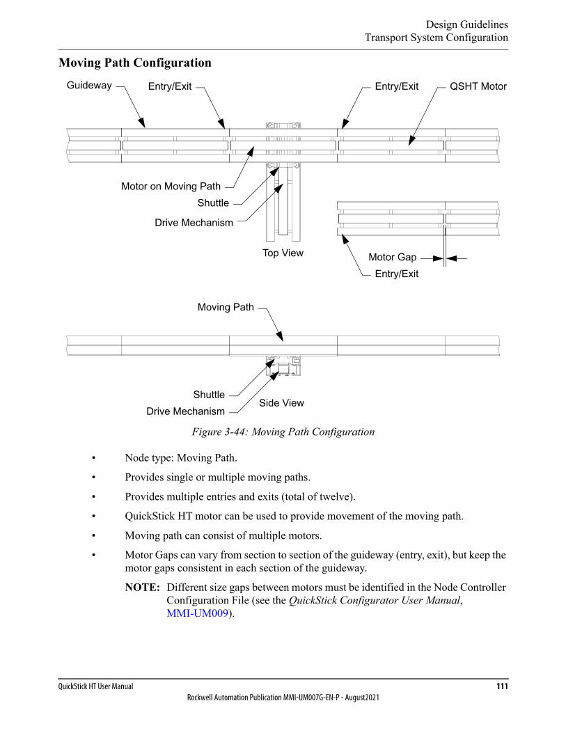
Design GuidelinesTransport System Configuration
QuickStick HT User Manual 111Rockwell Automation Publication MMI-UM007G-EN-P - August2021
Moving Path Configuration
Figure 3-44: Moving Path Configuration
• Node type: Moving Path.
• Provides single or multiple moving paths.
• Provides multiple entries and exits (total of twelve).
• QuickStick HT motor can be used to provide movement of the moving path.
• Moving path can consist of multiple motors.
• Motor Gaps can vary from section to section of the guideway (entry, exit), but keep the motor gaps consistent in each section of the guideway.
NOTE: Different size gaps between motors must be identified in the Node Controller Configuration File (see the QuickStick Configurator User Manual, MMI-UM009).
Guideway QSHT Motor
Motor GapEntry/Exit
Side View
Top View
Drive Mechanism
Entry/Exit
Motor on Moving Path
Entry/Exit
Shuttle
Drive MechanismShuttle
Moving Path

Design Guidelines
112 MagneMotionRockwell Automation Publication MMI-UM007G-EN-P - August2021
This page intentionally left blank.

QuickStick HT User Manual 113Rockwell Automation Publication MMI-UM007G-EN-P - August2021
Specifications and Site Requirements 4
Overview
This chapter describes specifications for the QuickStick® High Thrust transport system com-ponents and the requirements for installation.
Included in this chapter are:
• Mechanical specifications for all QuickStick HT components including dimensions.
• Electrical specifications for power and communication, including connector pinouts.
• Site requirements, including environmental and service access.
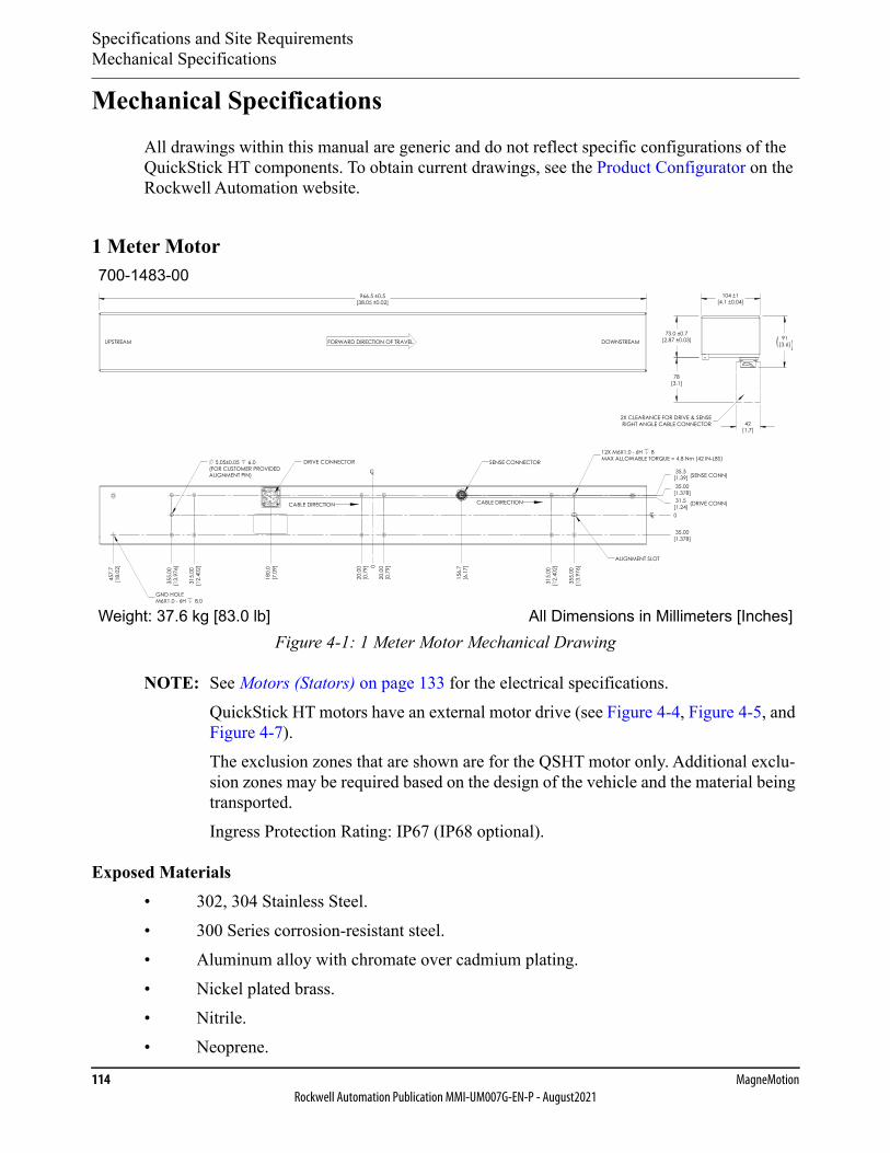
Specifications and Site RequirementsMechanical Specifications
114 MagneMotionRockwell Automation Publication MMI-UM007G-EN-P - August2021
Mechanical SpecificationsAll drawings within this manual are generic and do not reflect specific configurations of the QuickStick HT components. To obtain current drawings, see the Product Configurator on the Rockwell Automation website.
1 Meter Motor
Figure 4-1: 1 Meter Motor Mechanical Drawing
NOTE: See Motors (Stators) on page 133 for the electrical specifications.QuickStick HT motors have an external motor drive (see Figure 4-4, Figure 4-5, and Figure 4-7).The exclusion zones that are shown are for the QSHT motor only. Additional exclu-sion zones may be required based on the design of the vehicle and the material being transported.Ingress Protection Rating: IP67 (IP68 optional).
Exposed Materials• 302, 304 Stainless Steel.• 300 Series corrosion-resistant steel.• Aluminum alloy with chromate over cadmium plating.• Nickel plated brass.• Nitrile.• Neoprene.
0
0
20.0
0[0
.79]
20.0
0[0
.79]
156.
7[6
.17]
315.
00[1
2.40
2]
355.
00[1
3.97
6]
315.
00[1
2.40
2]
355.
00[1
3.97
6]
35.3[1.39]
180.
0[7
.09]
457.
7[1
8.02
]
35.00[1.378]
35.00[1.378]31.5
[1.24]CL
CL
DRIVE CONNECTOR
CABLE DIRECTION
FORWARD DIRECTION OF TRAVELUPSTREAM DOWNSTREAM
SENSE CONNECTOR
ALIGNMENT SLOT
MAX ALLOWABLE TORQUE = 4.8 Nm (42 IN-LBS)12X M6X1.0 - 6H 8
5.05±0.05 6.0
GND HOLEM6X1.0 - 6H 8.0
(FOR CUSTOMER PROVIDEDALIGNMENT PIN) (SENSE CONN)
(DRIVE CONN)
42[1.7]
78[3.1]
2X CLEARANCE FOR DRIVE & SENSERIGHT ANGLE CABLE CONNECTOR
73.0 ±0.7[2.87 ±0.03]
104 ±1[4.1 ±0.04]
91[3.6]
966.5 ±0.5[38.05 ±0.02]
CABLE DIRECTION
All Dimensions in Millimeters [Inches]Weight: 37.6 kg [83.0 lb]
700-1483-00
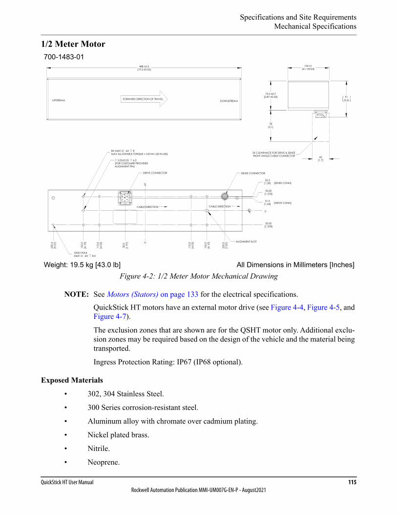
Specifications and Site RequirementsMechanical Specifications
QuickStick HT User Manual 115Rockwell Automation Publication MMI-UM007G-EN-P - August2021
1/2 Meter Motor
Figure 4-2: 1/2 Meter Motor Mechanical Drawing
NOTE: See Motors (Stators) on page 133 for the electrical specifications.QuickStick HT motors have an external motor drive (see Figure 4-4, Figure 4-5, and Figure 4-7).
The exclusion zones that are shown are for the QSHT motor only. Additional exclu-sion zones may be required based on the design of the vehicle and the material being transported.
Ingress Protection Rating: IP67 (IP68 optional).
Exposed Materials
• 302, 304 Stainless Steel.
• 300 Series corrosion-resistant steel.
• Aluminum alloy with chromate over cadmium plating.
• Nickel plated brass.
• Nitrile.
• Neoprene.
All Dimensions in Millimeters [Inches]Weight: 19.5 kg [43.0 lb]
CABLE DIRECTION
FORWARD DIRECTION OF TRAVEL
CABLE DIRECTION
UPSTREAM DOWNSTREAM
488 ±0.5[19.2 ±0.02]
42[1.7]
78[3.1]
2X CLEARANCE FOR DRIVE & SENSERIGHT ANGLE CABLE CONNECTOR
73.0 ±0.7[2.87 ±0.03]
104 ±1[4.1 ±0.04]
91[3.6]
0
115.
0[4
.53]
115.
0[4
.53]
155.
0[6
.10]
155.
0[6
.10]
200.
0[7
.87]
50.0
[1.9
7]
230.
5[9
.07]
CL
SENSE CONNECTORDRIVE CONNECTOR
(FOR CUSTOMER PROVIDEDALIGNMENT PIN)
8X M6X1.0 - 6H 8
GND HOLEM6X1.0 - 6H 8.0
MAX ALLOWABLE TORQUE = 4.8 Nm (42 IN-LBS)
0
35.3[1.39]
35.00[1.378]
35.00[1.378]
31.5[1.24]
CL
(SENSE CONN)
(DRIVE CONN)
5.05±0.05 6.0
ALIGNMENT SLOT
700-1483-01
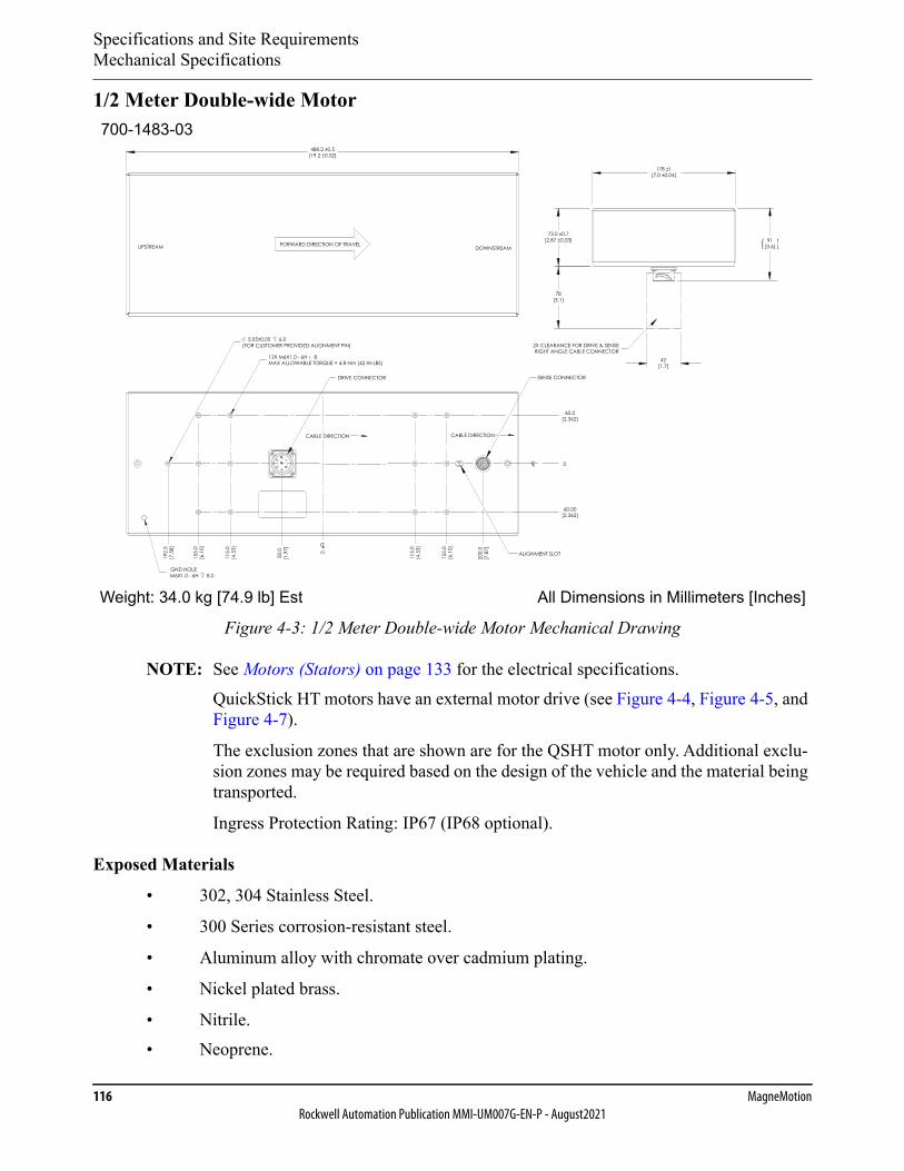
Specifications and Site RequirementsMechanical Specifications
116 MagneMotionRockwell Automation Publication MMI-UM007G-EN-P - August2021
1/2 Meter Double-wide Motor
Figure 4-3: 1/2 Meter Double-wide Motor Mechanical Drawing
NOTE: See Motors (Stators) on page 133 for the electrical specifications.QuickStick HT motors have an external motor drive (see Figure 4-4, Figure 4-5, and Figure 4-7).
The exclusion zones that are shown are for the QSHT motor only. Additional exclu-sion zones may be required based on the design of the vehicle and the material being transported.
Ingress Protection Rating: IP67 (IP68 optional).
Exposed Materials
• 302, 304 Stainless Steel.
• 300 Series corrosion-resistant steel.
• Aluminum alloy with chromate over cadmium plating.
• Nickel plated brass.
• Nitrile.• Neoprene.
All Dimensions in Millimeters [Inches]Weight: 34.0 kg [74.9 lb] Est
GND HOLEM6X1.0 - 6H 8.0
CABLE DIRECTIONCABLE DIRECTION
ALIGNMENT SLOT
(FOR CUSTOMER PROVIDED ALIGNMENT PIN)
12X M6X1.0 - 6H 8MAX ALLOWABLE TORQUE = 4.8 Nm (42 IN-LBS)
5.05±0.05 6.0
CL
0
CL
115.
0[4
.53]
115.
0[4
.53]
155.
0[6
.10]
155.
0[6
.10]
192.
5[7
.58]
0
200.
0[7
.87]
50.0
[1.9
7]
SENSE CONNECTORDRIVE CONNECTOR
42[1.7]
78[3.1]
2X CLEARANCE FOR DRIVE & SENSERIGHT ANGLE CABLE CONNECTOR
73.0 ±0.7[2.87 ±0.03]
178 ±1[7.0 ±0.04]
60.00[2.362]
60.0[2.362]
91[3.6]
488.2 ±0.5[19.2 ±0.02]
FORWARD DIRECTION OF TRAVELUPSTREAM DOWNSTREAM
700-1483-03

Specifications and Site RequirementsMechanical Specifications
QuickStick HT User Manual 117Rockwell Automation Publication MMI-UM007G-EN-P - August2021
QSMC Motor Controller
The QSMC motor controller is the external motor drive for the 1 m QSHT motors and the 1/2 m QSHT double-wide motors. One controller is required for each motor.
Figure 4-4: QSMC Motor Controller Mechanical Drawing
NOTE: See QSMC Motor Controller on page 143 for the electrical specifications.
Each vent must be clear for unobstructed airflow.
Mounting kit is available for standard 19 inch electronics rack.
Ingress Protection Rating: IP20.
Exposed Materials
The motor controller provides openings for airflow and must not be installed where harsh con-ditions exist.
All Dimensions in Millimeters [Inches]Weight: 3.6 kg [7.9 lb]
KEEP AREA FREEFOR AIRFLOW
KEEP AREA FREEFOR AIRFLOW
AIR FLOW
AIR FLOW
CABLE / CONNECTORCLEARANCE AREA
M6 GND STUD
CUSTOMER SERVICEABLEFAN FILTER MEDIA
[6.0]152
[3.44]87.3
[9.98]253.5
[10.3]261
[13.87]352.3
[12.99]330.0
[0.65]16.5
700-1563-00

Specifications and Site RequirementsMechanical Specifications
118 MagneMotionRockwell Automation Publication MMI-UM007G-EN-P - August2021
QSMC-2 Motor Controller
The QSMC-2 motor controller is the external motor drive for the 1/2 m QSHT motors. One controller is required for every two consecutive 1/2 m motors.
Figure 4-5: QSMC-2 Motor Controller Mechanical Drawing
NOTE: See QSMC-2 Motor Controller on page 148 for the electrical specifications.
Each vent must be clear for unobstructed airflow.
Mounting kit is available for standard 19 inch electronics rack.
Ingress Protection Rating: IP20.
Exposed Materials
The motor controller provides openings for airflow and must not be installed where harsh con-ditions exist.
All Dimensions in Millimeters [Inches]Weight: 3.6 kg [7.9 lb]
KEEP AREA FREEFOR AIRFLOW
KEEP AREA FREEFOR AIRFLOW
AIR FLOW
AIR FLOW
CABLE / CONNECTORCLEARANCE AREA
M6 GND STUD
CUSTOMER SERVICEABLEFAN FILTER MEDIA
[6.0]152
[3.44]87.3
[9.98]253.5
[10.3]261
[13.92]353.6
[12.99]330.0
[0.67]17.0
700-1384-01
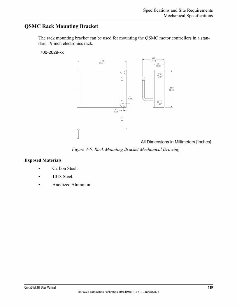
Specifications and Site RequirementsMechanical Specifications
QuickStick HT User Manual 119Rockwell Automation Publication MMI-UM007G-EN-P - August2021
QSMC Rack Mounting Bracket
The rack mounting bracket can be used for mounting the QSMC motor controllers in a stan-dard 19 inch electronics rack.
Figure 4-6: Rack Mounting Bracket Mechanical Drawing
Exposed Materials
• Carbon Steel.
• 1018 Steel.
• Anodized Aluminum.
All Dimensions in Millimeters [Inches]
3.3[0.13]
114.5[4.51]
7.1[0.28]
25.4[1.00]
86.9[3.42]
50.8[2.00]
700-2029-xx
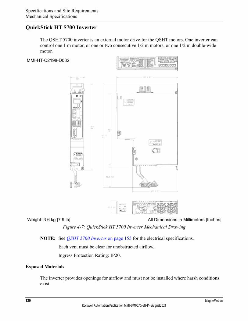
Specifications and Site RequirementsMechanical Specifications
120 MagneMotionRockwell Automation Publication MMI-UM007G-EN-P - August2021
QuickStick HT 5700 Inverter
The QSHT 5700 inverter is an external motor drive for the QSHT motors. One inverter can control one 1 m motor, or one or two consecutive 1/2 m motors, or one 1/2 m double-wide motor.
Figure 4-7: QuickStick HT 5700 Inverter Mechanical Drawing
NOTE: See QSHT 5700 Inverter on page 155 for the electrical specifications.
Each vent must be clear for unobstructed airflow.
Ingress Protection Rating: IP20.
Exposed Materials
The inverter provides openings for airflow and must not be installed where harsh conditions exist.
All Dimensions in Millimeters [Inches]Weight: 3.6 kg [7.9 lb]
MMI-HT-C2198-D032
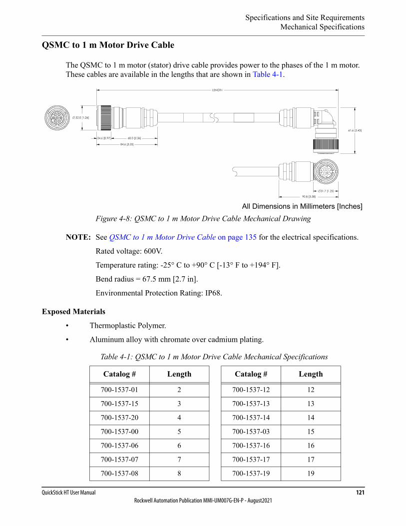
Specifications and Site RequirementsMechanical Specifications
QuickStick HT User Manual 121Rockwell Automation Publication MMI-UM007G-EN-P - August2021
QSMC to 1 m Motor Drive Cable
The QSMC to 1 m motor (stator) drive cable provides power to the phases of the 1 m motor. These cables are available in the lengths that are shown in Table 4-1.
Figure 4-8: QSMC to 1 m Motor Drive Cable Mechanical Drawing
NOTE: See QSMC to 1 m Motor Drive Cable on page 135 for the electrical specifications.
Rated voltage: 600V.
Temperature rating: -25° C to +90° C [-13° F to +194° F].
Bend radius = 67.5 mm [2.7 in].
Environmental Protection Rating: IP68.
Exposed Materials
• Thermoplastic Polymer.
• Aluminum alloy with chromate over cadmium plating.
Table 4-1: QSMC to 1 m Motor Drive Cable Mechanical Specifications
Catalog # Length Catalog # Length
700-1537-01 2 700-1537-12 12
700-1537-15 3 700-1537-13 13
700-1537-20 4 700-1537-14 14
700-1537-00 5 700-1537-03 15
700-1537-06 6 700-1537-16 16
700-1537-07 7 700-1537-17 17
700-1537-08 8 700-1537-19 19
All Dimensions in Millimeters [Inches]
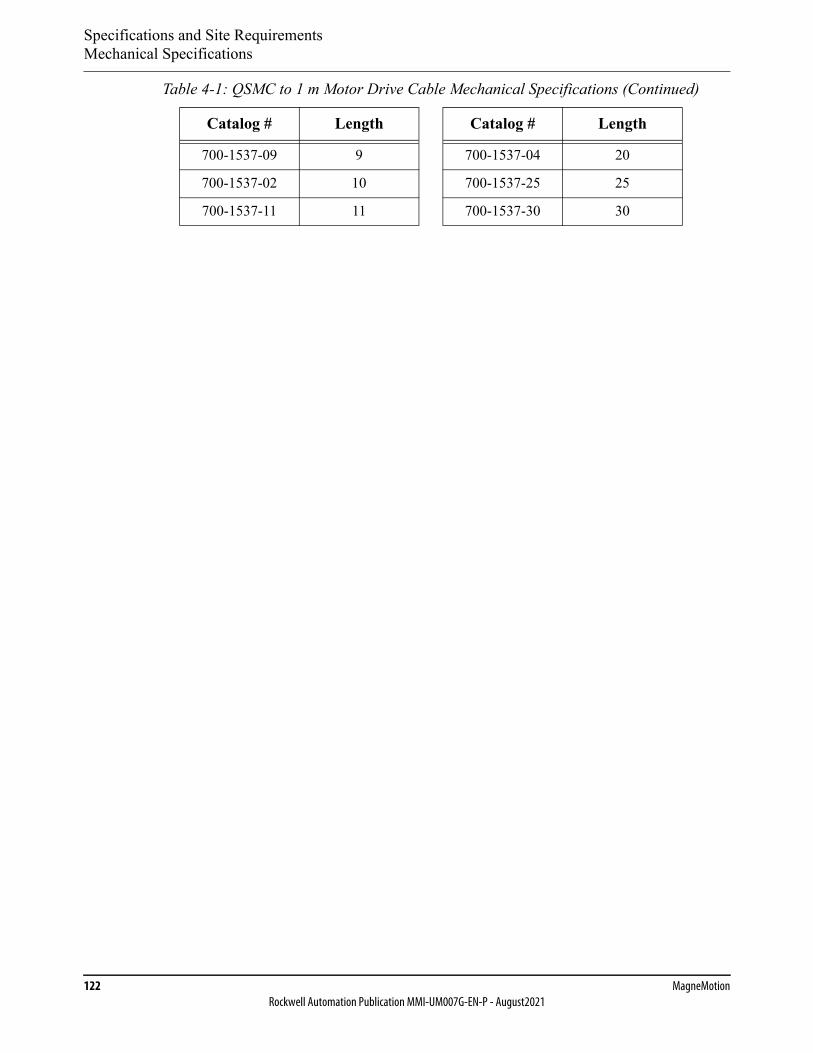
Specifications and Site RequirementsMechanical Specifications
122 MagneMotionRockwell Automation Publication MMI-UM007G-EN-P - August2021
700-1537-09 9 700-1537-04 20
700-1537-02 10 700-1537-25 25
700-1537-11 11 700-1537-30 30
Table 4-1: QSMC to 1 m Motor Drive Cable Mechanical Specifications (Continued)
Catalog # Length Catalog # Length

Specifications and Site RequirementsMechanical Specifications
QuickStick HT User Manual 123Rockwell Automation Publication MMI-UM007G-EN-P - August2021
QSMC to 1/2 m Motor Drive Cable
The QSMC to 1/2 m motor (stator) drive cable provides power to the phases of the 1/2 m motor. These cables are available in the lengths that are shown in Table 4-2.
Figure 4-9: QSMC to 1/2 m Motor Drive Cable Mechanical Drawing
NOTE: See QSMC to 1/2 m Motor Drive Cable on page 136 for the electrical specifications.
Rated voltage: 600V.
Temperature rating: -25° C to +90° C [-13° F to +194° F].
Bend radius = 96.6 mm [3.8 in].
Environmental Protection Rating: IP67.
Exposed Materials
• Black PVC.
• Nickel plated copper alloy.
• Aluminum alloy with chromate over cadmium plating.
Table 4-2: QSMC to 1/2 m Motor Drive Cable Mechanical Specifications
Catalog # Length Catalog # Length
700-1550-01 2 700-1550-13 13
700-1550-15 3 700-1550-14 14
700-1550-20 4 700-1550-03 15
700-1550-00 5 700-1550-16 16
700-1550-06 6 700-1550-17 17
700-1550-07 7 700-1550-18 18
All Dimensions in Millimeters [Inches]
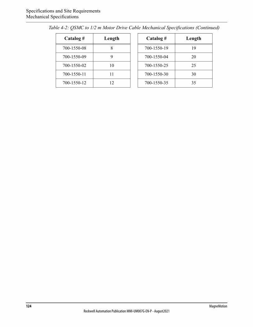
Specifications and Site RequirementsMechanical Specifications
124 MagneMotionRockwell Automation Publication MMI-UM007G-EN-P - August2021
700-1550-08 8 700-1550-19 19
700-1550-09 9 700-1550-04 20
700-1550-02 10 700-1550-25 25
700-1550-11 11 700-1550-30 30
700-1550-12 12 700-1550-35 35
Table 4-2: QSMC to 1/2 m Motor Drive Cable Mechanical Specifications (Continued)
Catalog # Length Catalog # Length
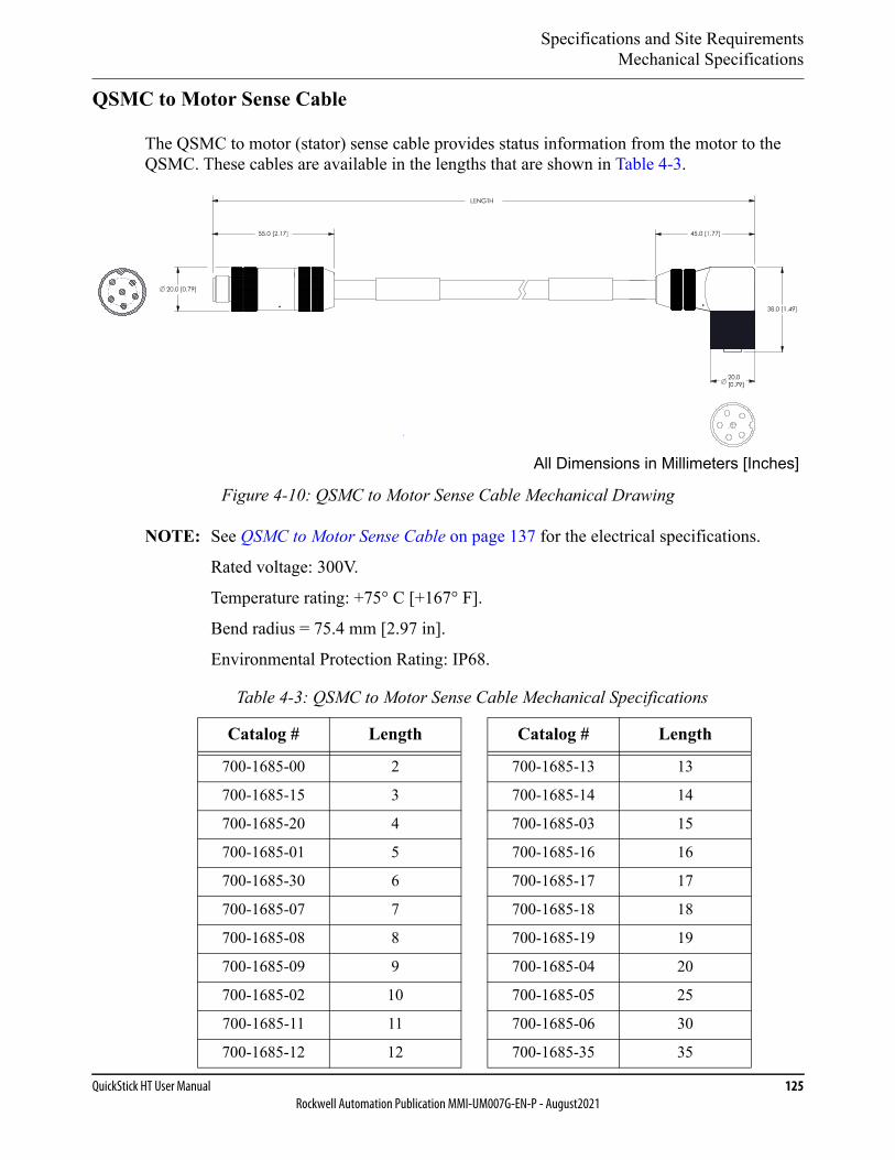
Specifications and Site RequirementsMechanical Specifications
QuickStick HT User Manual 125Rockwell Automation Publication MMI-UM007G-EN-P - August2021
QSMC to Motor Sense Cable
The QSMC to motor (stator) sense cable provides status information from the motor to the QSMC. These cables are available in the lengths that are shown in Table 4-3.
Figure 4-10: QSMC to Motor Sense Cable Mechanical Drawing
NOTE: See QSMC to Motor Sense Cable on page 137 for the electrical specifications.
Rated voltage: 300V.
Temperature rating: +75° C [+167° F].
Bend radius = 75.4 mm [2.97 in].
Environmental Protection Rating: IP68.
Table 4-3: QSMC to Motor Sense Cable Mechanical Specifications
Catalog # Length Catalog # Length
700-1685-00 2 700-1685-13 13
700-1685-15 3 700-1685-14 14
700-1685-20 4 700-1685-03 15
700-1685-01 5 700-1685-16 16
700-1685-30 6 700-1685-17 17
700-1685-07 7 700-1685-18 18
700-1685-08 8 700-1685-19 19
700-1685-09 9 700-1685-04 20
700-1685-02 10 700-1685-05 25
700-1685-11 11 700-1685-06 30
700-1685-12 12 700-1685-35 35
All Dimensions in Millimeters [Inches]
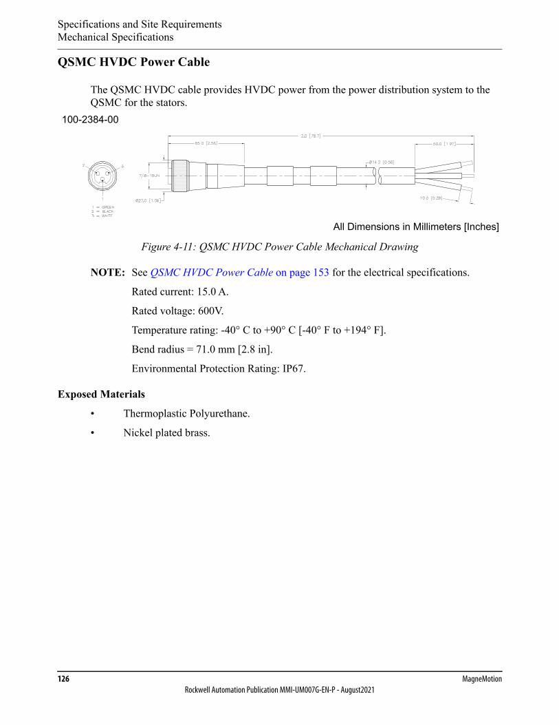
Specifications and Site RequirementsMechanical Specifications
126 MagneMotionRockwell Automation Publication MMI-UM007G-EN-P - August2021
QSMC HVDC Power Cable
The QSMC HVDC cable provides HVDC power from the power distribution system to the QSMC for the stators.
Figure 4-11: QSMC HVDC Power Cable Mechanical Drawing
NOTE: See QSMC HVDC Power Cable on page 153 for the electrical specifications.
Rated current: 15.0 A.
Rated voltage: 600V.
Temperature rating: -40° C to +90° C [-40° F to +194° F].
Bend radius = 71.0 mm [2.8 in].
Environmental Protection Rating: IP67.
Exposed Materials
• Thermoplastic Polyurethane.
• Nickel plated brass.
All Dimensions in Millimeters [Inches]
100-2384-00
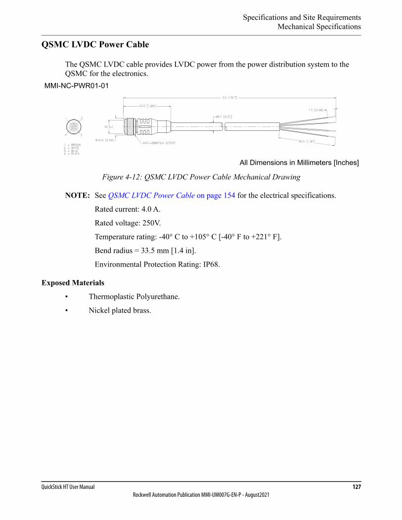
Specifications and Site RequirementsMechanical Specifications
QuickStick HT User Manual 127Rockwell Automation Publication MMI-UM007G-EN-P - August2021
QSMC LVDC Power Cable
The QSMC LVDC cable provides LVDC power from the power distribution system to the QSMC for the electronics.
Figure 4-12: QSMC LVDC Power Cable Mechanical Drawing
NOTE: See QSMC LVDC Power Cable on page 154 for the electrical specifications.
Rated current: 4.0 A.
Rated voltage: 250V.
Temperature rating: -40° C to +105° C [-40° F to +221° F].
Bend radius = 33.5 mm [1.4 in].
Environmental Protection Rating: IP68.
Exposed Materials
• Thermoplastic Polyurethane.
• Nickel plated brass.
All Dimensions in Millimeters [Inches]
MMI-NC-PWR01-01
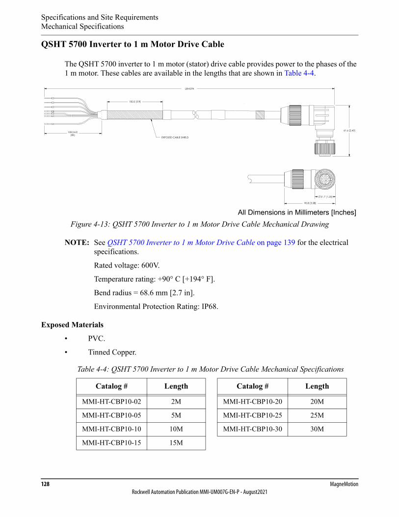
Specifications and Site RequirementsMechanical Specifications
128 MagneMotionRockwell Automation Publication MMI-UM007G-EN-P - August2021
QSHT 5700 Inverter to 1 m Motor Drive Cable
The QSHT 5700 inverter to 1 m motor (stator) drive cable provides power to the phases of the 1 m motor. These cables are available in the lengths that are shown in Table 4-4.
Figure 4-13: QSHT 5700 Inverter to 1 m Motor Drive Cable Mechanical Drawing
NOTE: See QSHT 5700 Inverter to 1 m Motor Drive Cable on page 139 for the electrical specifications.
Rated voltage: 600V.
Temperature rating: +90° C [+194° F].
Bend radius = 68.6 mm [2.7 in].
Environmental Protection Rating: IP68.
Exposed Materials
• PVC.
• Tinned Copper.
Table 4-4: QSHT 5700 Inverter to 1 m Motor Drive Cable Mechanical Specifications
Catalog # Length Catalog # Length
MMI-HT-CBP10-02 2M MMI-HT-CBP10-20 20M
MMI-HT-CBP10-05 5M MMI-HT-CBP10-25 25M
MMI-HT-CBP10-10 10M MMI-HT-CBP10-30 30M
MMI-HT-CBP10-15 15M
All Dimensions in Millimeters [Inches]
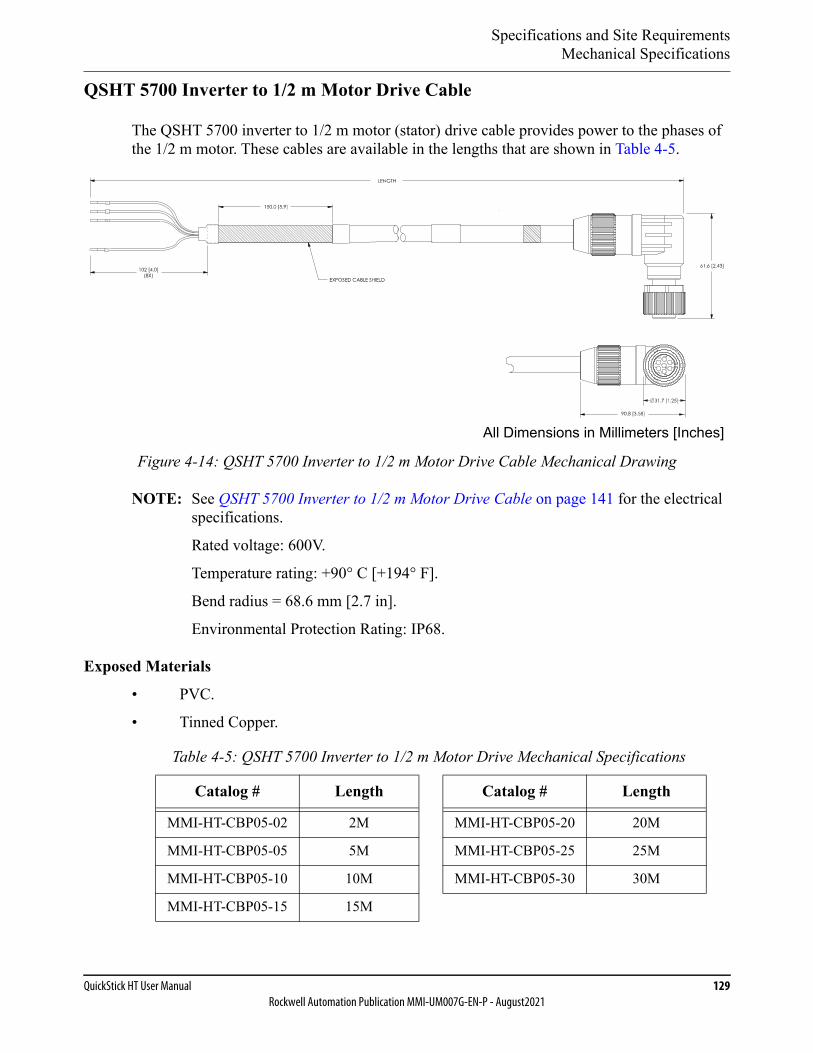
Specifications and Site RequirementsMechanical Specifications
QuickStick HT User Manual 129Rockwell Automation Publication MMI-UM007G-EN-P - August2021
QSHT 5700 Inverter to 1/2 m Motor Drive Cable
The QSHT 5700 inverter to 1/2 m motor (stator) drive cable provides power to the phases of the 1/2 m motor. These cables are available in the lengths that are shown in Table 4-5.
Figure 4-14: QSHT 5700 Inverter to 1/2 m Motor Drive Cable Mechanical Drawing
NOTE: See QSHT 5700 Inverter to 1/2 m Motor Drive Cable on page 141 for the electrical specifications.
Rated voltage: 600V.
Temperature rating: +90° C [+194° F].
Bend radius = 68.6 mm [2.7 in].
Environmental Protection Rating: IP68.
Exposed Materials
• PVC.
• Tinned Copper.
Table 4-5: QSHT 5700 Inverter to 1/2 m Motor Drive Mechanical Specifications
Catalog # Length Catalog # Length
MMI-HT-CBP05-02 2M MMI-HT-CBP05-20 20M
MMI-HT-CBP05-05 5M MMI-HT-CBP05-25 25M
MMI-HT-CBP05-10 10M MMI-HT-CBP05-30 30M
MMI-HT-CBP05-15 15M
All Dimensions in Millimeters [Inches]
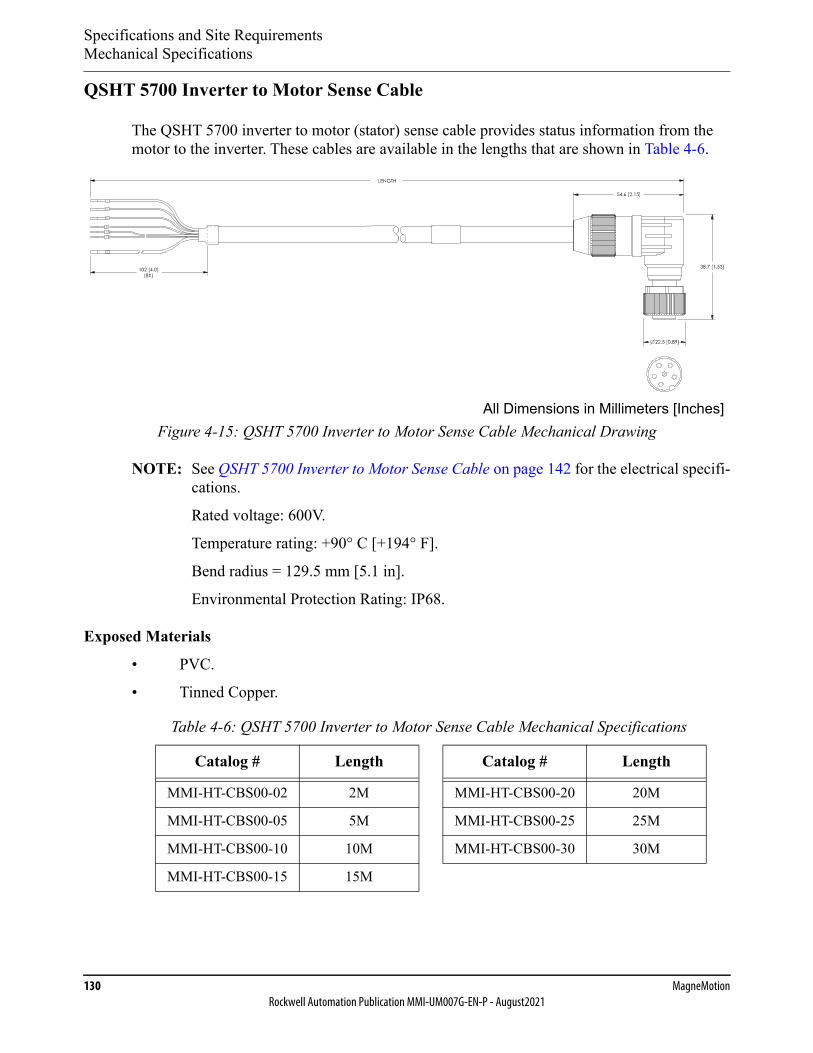
Specifications and Site RequirementsMechanical Specifications
130 MagneMotionRockwell Automation Publication MMI-UM007G-EN-P - August2021
QSHT 5700 Inverter to Motor Sense Cable
The QSHT 5700 inverter to motor (stator) sense cable provides status information from the motor to the inverter. These cables are available in the lengths that are shown in Table 4-6.
Figure 4-15: QSHT 5700 Inverter to Motor Sense Cable Mechanical Drawing
NOTE: See QSHT 5700 Inverter to Motor Sense Cable on page 142 for the electrical specifi-cations.
Rated voltage: 600V.
Temperature rating: +90° C [+194° F].
Bend radius = 129.5 mm [5.1 in].
Environmental Protection Rating: IP68.
Exposed Materials
• PVC.
• Tinned Copper.
Table 4-6: QSHT 5700 Inverter to Motor Sense Cable Mechanical Specifications
Catalog # Length Catalog # Length
MMI-HT-CBS00-02 2M MMI-HT-CBS00-20 20M
MMI-HT-CBS00-05 5M MMI-HT-CBS00-25 25M
MMI-HT-CBS00-10 10M MMI-HT-CBS00-30 30M
MMI-HT-CBS00-15 15M
All Dimensions in Millimeters [Inches]

Specifications and Site RequirementsMechanical Specifications
QuickStick HT User Manual 131Rockwell Automation Publication MMI-UM007G-EN-P - August2021
Magnet Array, High Flux
High flux magnet arrays (see High Flux Magnet Arrays on page 91) are available in lengths from 2 cycles to 8 cycles as shown in Table 4-7. Contact Technical Support for information on specific magnet arrays (see Rockwell Automation Support on page 350). Figure 4-16 shows a 104.0 mm wide 8 cycle array for reference, the number, quantity, and locations of the mounting holes vary based on the size of the array. Contact Technical Support on the avail-ability of other widths.
Figure 4-16: Standard High Flux Magnet Array Mechanical Drawing
NOTE: Ingress Protection Rating: IP50 (IP68 optional).
Exposed Materials
• Low Carbon Steel.
• Hardened Steel.
• Nd-Fe-B magnets with Ni-Cu-Ni coating.
• 304 Stainless Steel, 18-8 Stainless Steel.
All Dimensions in Millimeters [Inches]Weight: Varies by length
24.5±0.7
CL
CL
478±1
104±1
2X16
0.00
0
0
5X 40.00
5X 40.00
2X80
.00
2X16
0.00
2X80
.00
210.
00
420.00
210.
00C L SECTIONA-A
SCALE 1 : 1.5
(FOR LOCATINGTO M5 DOWELPIN
5.155.02 5.0
10X M5X0.8 - 6H 6.5
Standard High Flux: 700-1618-xxWide High Flux: 700-1616-xxHigh Temperature High Flux: 700-1642-xx
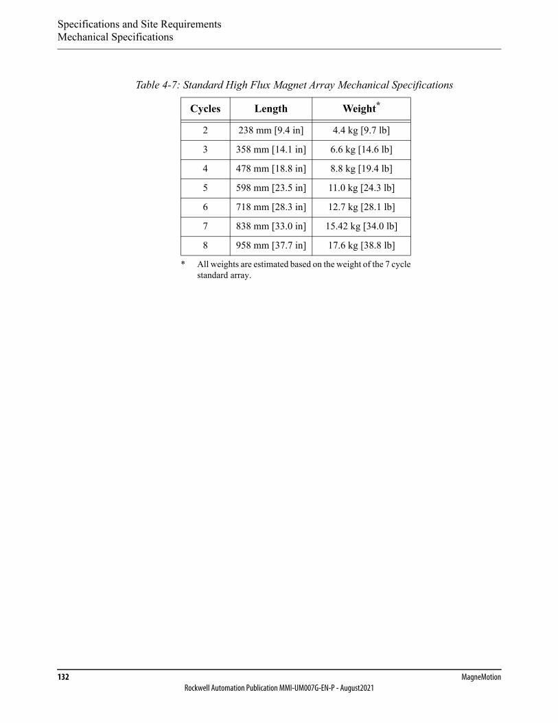
Specifications and Site RequirementsMechanical Specifications
132 MagneMotionRockwell Automation Publication MMI-UM007G-EN-P - August2021
Table 4-7: Standard High Flux Magnet Array Mechanical Specifications
Cycles Length Weight*
* All weights are estimated based on the weight of the 7 cyclestandard array.
2 238 mm [9.4 in] 4.4 kg [9.7 lb]
3 358 mm [14.1 in] 6.6 kg [14.6 lb]
4 478 mm [18.8 in] 8.8 kg [19.4 lb]
5 598 mm [23.5 in] 11.0 kg [24.3 lb]
6 718 mm [28.3 in] 12.7 kg [28.1 lb]
7 838 mm [33.0 in] 15.42 kg [34.0 lb]
8 958 mm [37.7 in] 17.6 kg [38.8 lb]

Specifications and Site RequirementsElectrical Specifications
QuickStick HT User Manual 133Rockwell Automation Publication MMI-UM007G-EN-P - August2021
Electrical Specifications
Motors (Stators)• 1 m – See QSMC Motor Controller on page 117 for the electrical specifications. See 1
Meter Motor on page 114 for the mechanical drawing.
• 1/2 m – See QSMC-2 Motor Controller on page 118 for the electrical specifications. See 1/2 Meter Motor on page 115 for the mechanical drawing.
• 1/2 m Double-wide – See QSMC Motor Controller on page 117 for the electrical spec-ifications. See 1/2 Meter Double-wide Motor on page 116 for the mechanical drawing.
NOTE: The motor power is supplied by the external QSMC motor controller or QSHT 5700 inverter, see QSMC Motor Controller on page 143 or QSHT 5700 Inverter on page 155 as appropriate for power requirements. All power wiring between the motor drive and the motor must be capable of carrying the full load.
Figure 4-17: Motor Electrical Connections
NOTE: The drive and sense cables have a 90° bend at the motor connector. The bend is located such that the cable direction is as shown in Figure 4-17 when connected.
Table 4-8: Motor Connections
Label Description Connector Type
Drive Motor block phase power 3-Point Bayonet, Size 16S, 7-Pin, Plug
Sense Motor block control signals M12 Eurofast, 6-Pin, Plug
Ground Motor chassis ground M6 x 1–6H, 8.0 mm max depth
SHOCK HAZARD: 400V DC maximum, 15 A maximum.DC power must be disconnected before servicing.
Bottom View
SenseDrive
Upstream Downstream
Ground
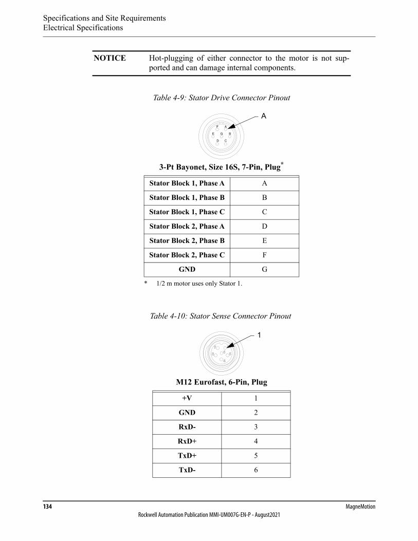
Specifications and Site RequirementsElectrical Specifications
134 MagneMotionRockwell Automation Publication MMI-UM007G-EN-P - August2021
NOTICE Hot-plugging of either connector to the motor is not sup-ported and can damage internal components.
Table 4-9: Stator Drive Connector Pinout
3-Pt Bayonet, Size 16S, 7-Pin, Plug*
* 1/2 m motor uses only Stator 1.
Stator Block 1, Phase A A
Stator Block 1, Phase B B
Stator Block 1, Phase C C
Stator Block 2, Phase A D
Stator Block 2, Phase B E
Stator Block 2, Phase C F
GND G
Table 4-10: Stator Sense Connector Pinout
M12 Eurofast, 6-Pin, Plug
+V 1
GND 2
RxD- 3
RxD+ 4
TxD+ 5
TxD- 6
A
1
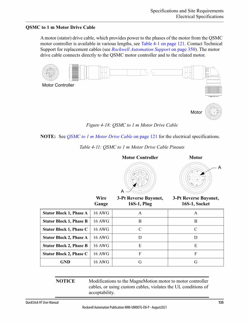
Specifications and Site RequirementsElectrical Specifications
QuickStick HT User Manual 135Rockwell Automation Publication MMI-UM007G-EN-P - August2021
QSMC to 1 m Motor Drive Cable
A motor (stator) drive cable, which provides power to the phases of the motor from the QSMC motor controller is available in various lengths, see Table 4-1 on page 121. Contact Technical Support for replacement cables (see Rockwell Automation Support on page 350). The motor drive cable connects directly to the QSMC motor controller and to the related motor.
Figure 4-18: QSMC to 1 m Motor Drive Cable
NOTE: See QSMC to 1 m Motor Drive Cable on page 121 for the electrical specifications.
Table 4-11: QSMC to 1 m Motor Drive Cable Pinouts
Wire Gauge
Motor Controller
3-Pt Reverse Bayonet, 16S-1, Plug
Motor
3-Pt Reverse Bayonet, 16S-1, Socket
Stator Block 1, Phase A 16 AWG A A
Stator Block 1, Phase B 16 AWG B B
Stator Block 1, Phase C 16 AWG C C
Stator Block 2, Phase A 16 AWG D D
Stator Block 2, Phase B 16 AWG E E
Stator Block 2, Phase C 16 AWG F F
GND 16 AWG G G
NOTICE Modifications to the MagneMotion motor to motor controllercables, or using custom cables, violates the UL conditions ofacceptability.
Motor
Motor Controller
A
A
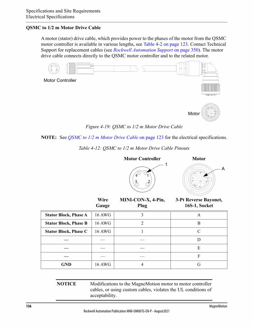
Specifications and Site RequirementsElectrical Specifications
136 MagneMotionRockwell Automation Publication MMI-UM007G-EN-P - August2021
QSMC to 1/2 m Motor Drive Cable
A motor (stator) drive cable, which provides power to the phases of the motor from the QSMC motor controller is available in various lengths, see Table 4-2 on page 123. Contact Technical Support for replacement cables (see Rockwell Automation Support on page 350). The motor drive cable connects directly to the QSMC motor controller and to the related motor.
Figure 4-19: QSMC to 1/2 m Motor Drive Cable
NOTE: See QSMC to 1/2 m Motor Drive Cable on page 123 for the electrical specifications.
Table 4-12: QSMC to 1/2 m Motor Drive Cable Pinouts
Wire Gauge
Motor Controller
MINI-CON-X, 4-Pin, Plug
Motor
3-Pt Reverse Bayonet, 16S-1, Socket
Stator Block, Phase A 16 AWG 3 A
Stator Block, Phase B 16 AWG 2 B
Stator Block, Phase C 16 AWG 1 C
— — — D
— — — E
— — — F
GND 16 AWG 4 G
NOTICE Modifications to the MagneMotion motor to motor controllercables, or using custom cables, violates the UL conditions ofacceptability.
Motor
Motor Controller
1A
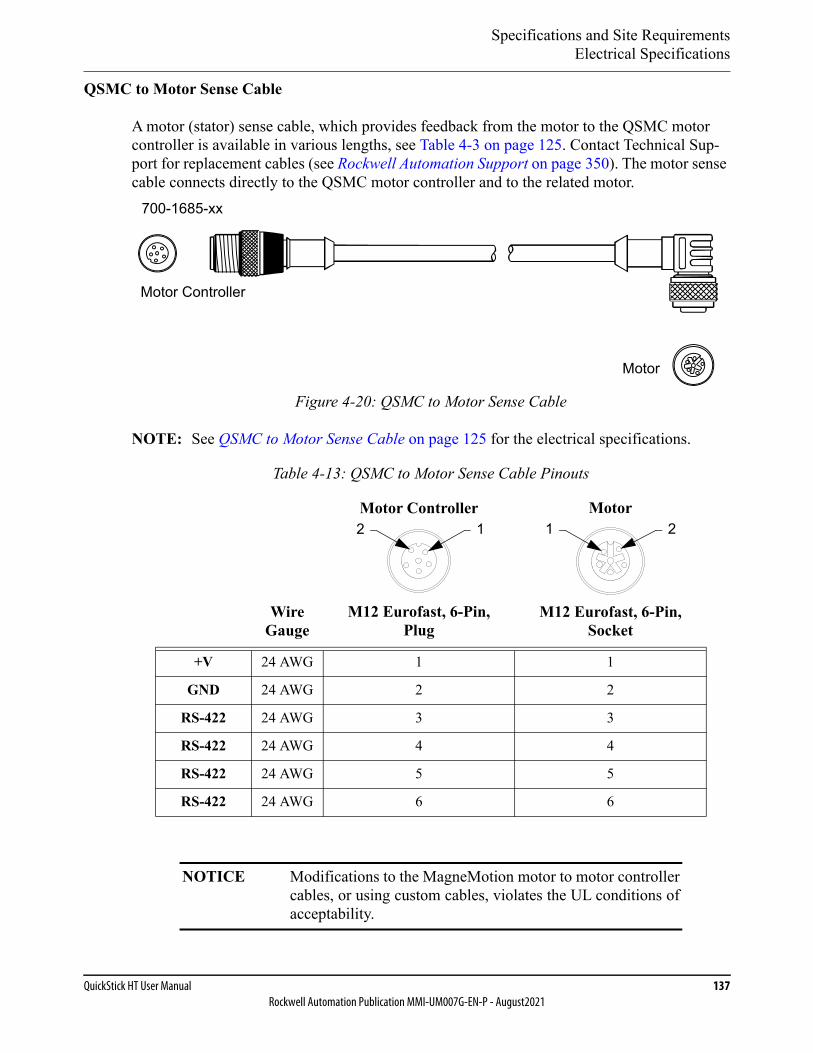
Specifications and Site RequirementsElectrical Specifications
QuickStick HT User Manual 137Rockwell Automation Publication MMI-UM007G-EN-P - August2021
QSMC to Motor Sense Cable
A motor (stator) sense cable, which provides feedback from the motor to the QSMC motor controller is available in various lengths, see Table 4-3 on page 125. Contact Technical Sup-port for replacement cables (see Rockwell Automation Support on page 350). The motor sense cable connects directly to the QSMC motor controller and to the related motor.
Figure 4-20: QSMC to Motor Sense Cable
NOTE: See QSMC to Motor Sense Cable on page 125 for the electrical specifications.
Table 4-13: QSMC to Motor Sense Cable Pinouts
Wire Gauge
Motor Controller
M12 Eurofast, 6-Pin, Plug
Motor
M12 Eurofast, 6-Pin, Socket
+V 24 AWG 1 1
GND 24 AWG 2 2
RS-422 24 AWG 3 3
RS-422 24 AWG 4 4
RS-422 24 AWG 5 5
RS-422 24 AWG 6 6
NOTICE Modifications to the MagneMotion motor to motor controllercables, or using custom cables, violates the UL conditions ofacceptability.
Motor
Motor Controller
700-1685-xx
12 1 2
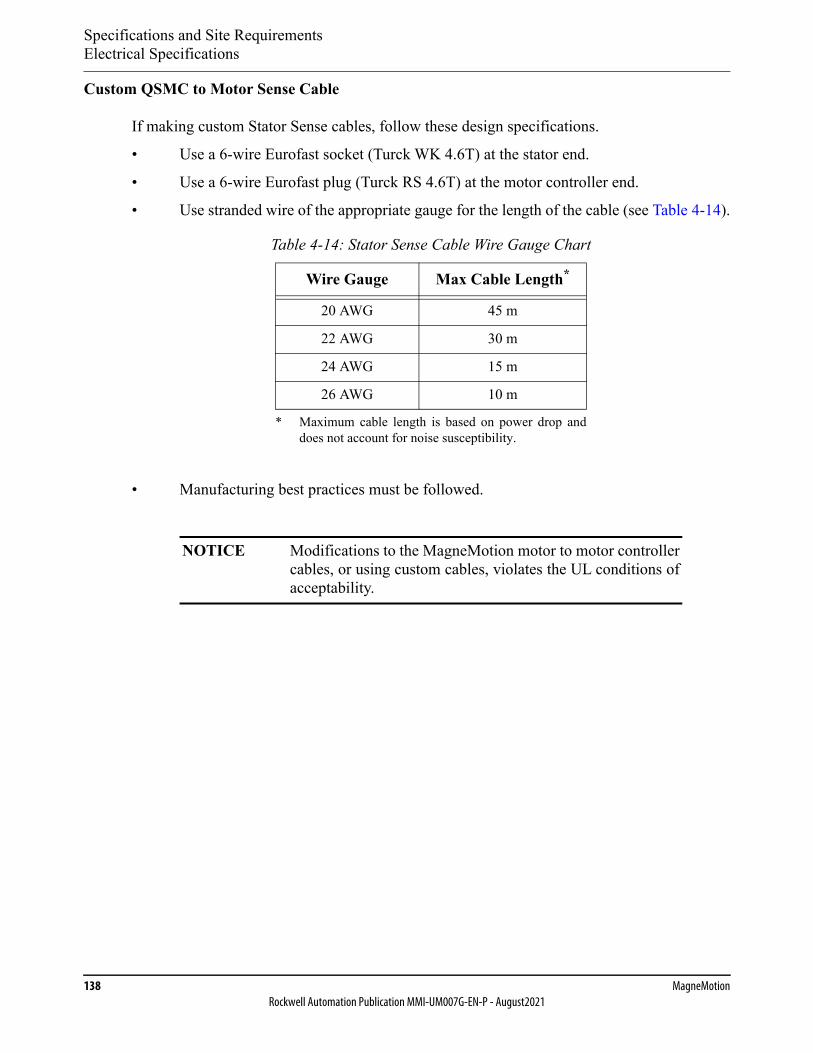
Specifications and Site RequirementsElectrical Specifications
138 MagneMotionRockwell Automation Publication MMI-UM007G-EN-P - August2021
Custom QSMC to Motor Sense Cable
If making custom Stator Sense cables, follow these design specifications.
• Use a 6-wire Eurofast socket (Turck WK 4.6T) at the stator end.
• Use a 6-wire Eurofast plug (Turck RS 4.6T) at the motor controller end.
• Use stranded wire of the appropriate gauge for the length of the cable (see Table 4-14).
• Manufacturing best practices must be followed.
Table 4-14: Stator Sense Cable Wire Gauge Chart
Wire Gauge Max Cable Length*
* Maximum cable length is based on power drop anddoes not account for noise susceptibility.
20 AWG 45 m
22 AWG 30 m
24 AWG 15 m
26 AWG 10 m
NOTICE Modifications to the MagneMotion motor to motor controllercables, or using custom cables, violates the UL conditions ofacceptability.
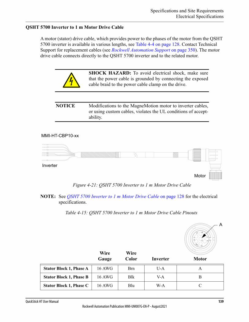
Specifications and Site RequirementsElectrical Specifications
QuickStick HT User Manual 139Rockwell Automation Publication MMI-UM007G-EN-P - August2021
QSHT 5700 Inverter to 1 m Motor Drive Cable
A motor (stator) drive cable, which provides power to the phases of the motor from the QSHT 5700 inverter is available in various lengths, see Table 4-4 on page 128. Contact Technical Support for replacement cables (see Rockwell Automation Support on page 350). The motor drive cable connects directly to the QSHT 5700 inverter and to the related motor.
Figure 4-21: QSHT 5700 Inverter to 1 m Motor Drive Cable
NOTE: See QSHT 5700 Inverter to 1 m Motor Drive Cable on page 128 for the electrical specifications.
SHOCK HAZARD: To avoid electrical shock, make surethat the power cable is grounded by connecting the exposedcable braid to the power cable clamp on the drive.
NOTICE Modifications to the MagneMotion motor to inverter cables,or using custom cables, violates the UL conditions of accept-ability.
Table 4-15: QSHT 5700 Inverter to 1 m Motor Drive Cable Pinouts
Wire Gauge
Wire Color Inverter Motor
Stator Block 1, Phase A 16 AWG Brn U-A A
Stator Block 1, Phase B 16 AWG Blk V-A B
Stator Block 1, Phase C 16 AWG Blu W-A C
Motor
Inverter
MMI-HT-CBP10-xx
A
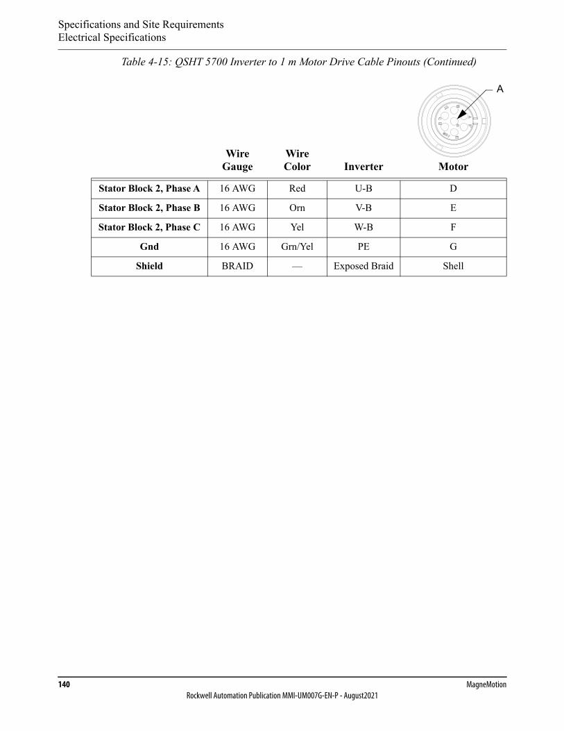
Specifications and Site RequirementsElectrical Specifications
140 MagneMotionRockwell Automation Publication MMI-UM007G-EN-P - August2021
Stator Block 2, Phase A 16 AWG Red U-B D
Stator Block 2, Phase B 16 AWG Orn V-B E
Stator Block 2, Phase C 16 AWG Yel W-B F
Gnd 16 AWG Grn/Yel PE G
Shield BRAID — Exposed Braid Shell
Table 4-15: QSHT 5700 Inverter to 1 m Motor Drive Cable Pinouts (Continued)
Wire Gauge
Wire Color Inverter Motor
A
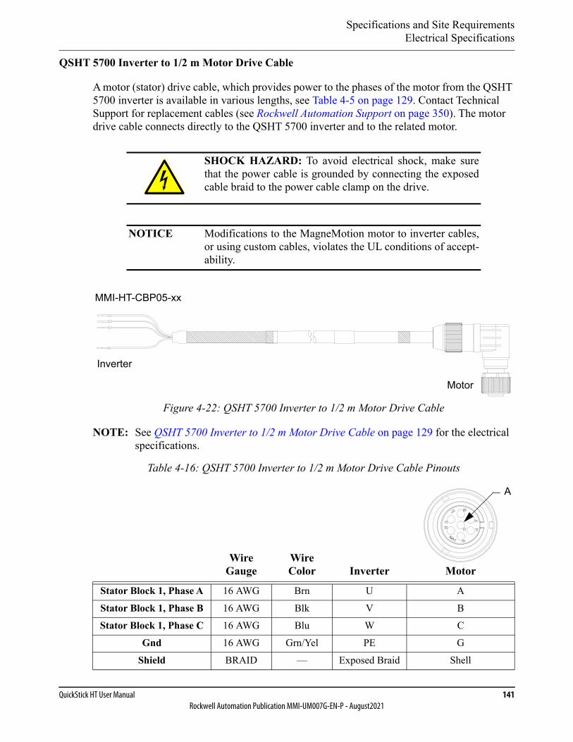
Specifications and Site RequirementsElectrical Specifications
QuickStick HT User Manual 141Rockwell Automation Publication MMI-UM007G-EN-P - August2021
QSHT 5700 Inverter to 1/2 m Motor Drive Cable
A motor (stator) drive cable, which provides power to the phases of the motor from the QSHT 5700 inverter is available in various lengths, see Table 4-5 on page 129. Contact Technical Support for replacement cables (see Rockwell Automation Support on page 350). The motor drive cable connects directly to the QSHT 5700 inverter and to the related motor.
Figure 4-22: QSHT 5700 Inverter to 1/2 m Motor Drive Cable
NOTE: See QSHT 5700 Inverter to 1/2 m Motor Drive Cable on page 129 for the electrical specifications.
SHOCK HAZARD: To avoid electrical shock, make surethat the power cable is grounded by connecting the exposedcable braid to the power cable clamp on the drive.
NOTICE Modifications to the MagneMotion motor to inverter cables,or using custom cables, violates the UL conditions of accept-ability.
Table 4-16: QSHT 5700 Inverter to 1/2 m Motor Drive Cable Pinouts
Wire Gauge
Wire Color Inverter Motor
Stator Block 1, Phase A 16 AWG Brn U A
Stator Block 1, Phase B 16 AWG Blk V BStator Block 1, Phase C 16 AWG Blu W C
Gnd 16 AWG Grn/Yel PE G
Shield BRAID — Exposed Braid Shell
Motor
Inverter
MMI-HT-CBP05-xx
A
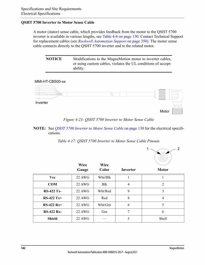
Specifications and Site RequirementsElectrical Specifications
142 MagneMotionRockwell Automation Publication MMI-UM007G-EN-P - August2021
QSHT 5700 Inverter to Motor Sense Cable
A motor (stator) sense cable, which provides feedback from the motor to the QSHT 5700 inverter is available in various lengths, see Table 4-6 on page 130. Contact Technical Support for replacement cables (see Rockwell Automation Support on page 350). The motor sense cable connects directly to the QSHT 5700 inverter and to the related motor.
Figure 4-23: QSHT 5700 Inverter to Motor Sense Cable
NOTE: See QSHT 5700 Inverter to Motor Sense Cable on page 130 for the electrical specifi-cations.
NOTICE Modifications to the MagneMotion motor to inverter cables,or using custom cables, violates the UL conditions of accept-ability.
Table 4-17: QSHT 5700 Inverter to Motor Sense Cable Pinouts
Wire Gauge
Wire Color Inverter Motor
Vcc 22 AWG Wht/Blk 1 1
COM 22 AWG Blk 4 2
RS-422 Tx- 22 AWG Wht/Red 9 3
RS-422 Tx+ 22 AWG Red 8 4
RS-422 Rx+ 22 AWG Wht/Grn 6 5
RS-422 Rx- 22 AWG Grn 7 6
Shield 22 AWG — 5 Shell
Motor
Inverter
MMI-HT-CBS00-xx
1 2

Specifications and Site RequirementsElectrical Specifications
QuickStick HT User Manual 143Rockwell Automation Publication MMI-UM007G-EN-P - August2021
QSMC Motor Controller
The QSMC motor controller is a remote motor controller for the QSHT 1 m motor and the 1/2 m double-wide motor. One QSMC is used for each QSHT 1 m or double-wide motor.
• Input power: 270…400V DC, 5 A typical, 15 A max (2 sec max).24V DC ±5%, 0.6 A (0.75 A max).
• Output Power: 400V max, 3-phase, 10 A rms cont., 15 A rms maximum.
• See QSMC Motor Controller on page 117 for the mechanical drawing.
NOTE: The motor controllers draw additional power when the vehicle is moving or acceler-ating. The amount of additional power that is drawn depends on the velocity and acceleration of the vehicle, the number of vehicles accelerating at once, and the mag-net array length. All power wiring must be sized to carry the full load.
The propulsion power input (HVDC) uses a PTC (positive temperature coefficient) resistor to limit inrush current upon application of power. The PTC is only used for inrush current limiting and is bypassed in normal operation. Limit cycling of the pro-pulsion power to 2 minutes between each turn on and 20 seconds between turn off and turn on (power cycle). Additionally, make sure the Soft Start Off bit in the motor fault data is set before turning on propulsion power to allow the soft start circuit to reset for the next power on.
Providing a separate power source for the logic power (LVDC) allows the motors to be programmed and configured without enabling the propulsion power.
Table 4-18: 1 m Motor Power Requirements
Component Maximum Power
QSMC Motor Controller – Logic power 15 W
Vehicle – Propulsion power Variable*
* The propulsion power for the controller is fused at 15 A. The motor draws maxi-mum power when the vehicle is moving at maximum acceleration or velocity.Contact TechConnect℠ (rockwellautomation.custhelp.com) for questions aboutpower supply size based on the motor application and the size of the magnet array.
SHOCK HAZARD: 400V DC maximum, 15 A maximum.
DC power must be disconnected before servicing.
NOTICE Any user-supplied power supply must be NRTL/ATLapproved.
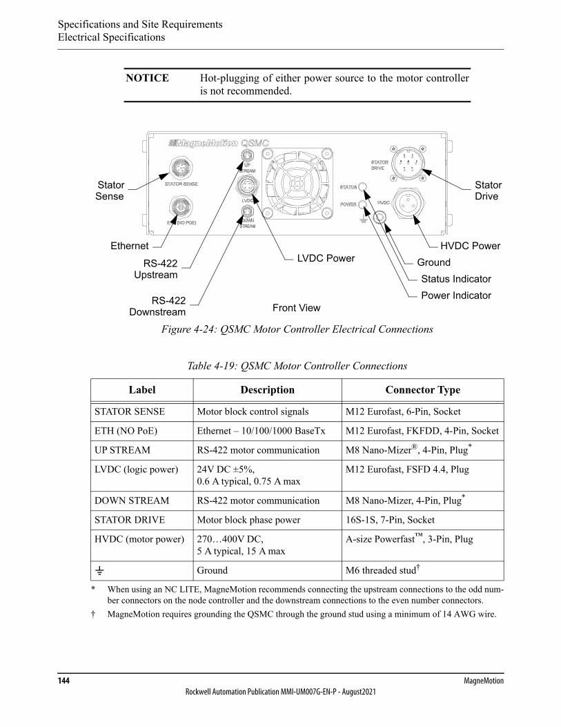
Specifications and Site RequirementsElectrical Specifications
144 MagneMotionRockwell Automation Publication MMI-UM007G-EN-P - August2021
Figure 4-24: QSMC Motor Controller Electrical Connections
NOTICE Hot-plugging of either power source to the motor controlleris not recommended.
Table 4-19: QSMC Motor Controller Connections
Label Description Connector Type
STATOR SENSE Motor block control signals M12 Eurofast, 6-Pin, Socket
ETH (NO PoE) Ethernet – 10/100/1000 BaseTx M12 Eurofast, FKFDD, 4-Pin, Socket
UP STREAM RS-422 motor communication M8 Nano-Mizer®, 4-Pin, Plug*
* When using an NC LITE, MagneMotion recommends connecting the upstream connections to the odd num-ber connectors on the node controller and the downstream connections to the even number connectors.
LVDC (logic power) 24V DC ±5%, 0.6 A typical, 0.75 A max
M12 Eurofast, FSFD 4.4, Plug
DOWN STREAM RS-422 motor communication M8 Nano-Mizer, 4-Pin, Plug*
STATOR DRIVE Motor block phase power 16S-1S, 7-Pin, Socket
HVDC (motor power) 270…400V DC, 5 A typical, 15 A max
A-size Powerfast™, 3-Pin, Plug
Ground M6 threaded stud†
† MagneMotion requires grounding the QSMC through the ground stud using a minimum of 14 AWG wire.
Status Indicator
Front View
Stator
Ethernet
RS-422
Stator
HVDC Power
Power Indicator
LVDC Power Ground
Sense Drive
Upstream
RS-422Downstream
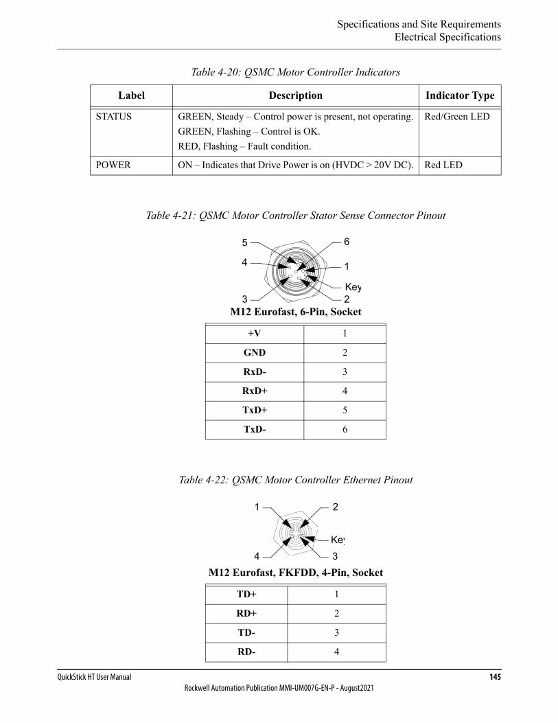
Specifications and Site RequirementsElectrical Specifications
QuickStick HT User Manual 145Rockwell Automation Publication MMI-UM007G-EN-P - August2021
Table 4-20: QSMC Motor Controller Indicators
Label Description Indicator Type
STATUS GREEN, Steady – Control power is present, not operating.GREEN, Flashing – Control is OK.RED, Flashing – Fault condition.
Red/Green LED
POWER ON – Indicates that Drive Power is on (HVDC > 20V DC). Red LED
Table 4-21: QSMC Motor Controller Stator Sense Connector Pinout
M12 Eurofast, 6-Pin, Socket
+V 1
GND 2
RxD- 3
RxD+ 4
TxD+ 5
TxD- 6
Table 4-22: QSMC Motor Controller Ethernet Pinout
M12 Eurofast, FKFDD, 4-Pin, Socket
TD+ 1
RD+ 2
TD- 3
RD- 4
5 6
3Key
1
2
4
4
1 2
3Key
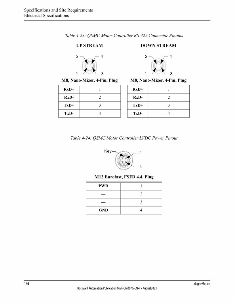
Specifications and Site RequirementsElectrical Specifications
146 MagneMotionRockwell Automation Publication MMI-UM007G-EN-P - August2021
Table 4-23: QSMC Motor Controller RS-422 Connector Pinouts
UP STREAM DOWN STREAM
M8, Nano-Mizer, 4-Pin, Plug M8, Nano-Mizer, 4-Pin, Plug
RxD+ 1 RxD+ 1
RxD- 2 RxD- 2
TxD+ 3 TxD+ 3
TxD- 4 TxD- 4
Table 4-24: QSMC Motor Controller LVDC Power Pinout
M12 Eurofast, FSFD 4.4, Plug
PWR 1
— 2
— 3
GND 4
3
4
1
2
3
4
1
2
Key 1
4
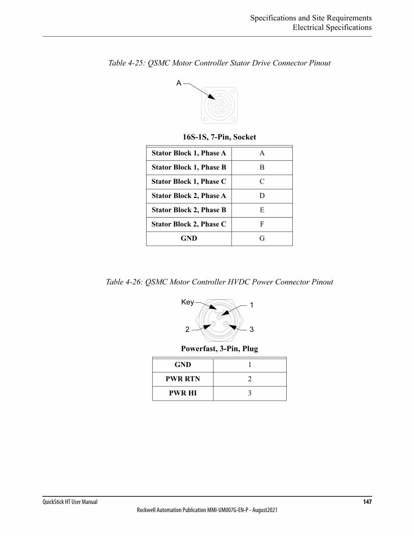
Specifications and Site RequirementsElectrical Specifications
QuickStick HT User Manual 147Rockwell Automation Publication MMI-UM007G-EN-P - August2021
Table 4-25: QSMC Motor Controller Stator Drive Connector Pinout
16S-1S, 7-Pin, Socket
Stator Block 1, Phase A A
Stator Block 1, Phase B B
Stator Block 1, Phase C C
Stator Block 2, Phase A D
Stator Block 2, Phase B E
Stator Block 2, Phase C F
GND G
Table 4-26: QSMC Motor Controller HVDC Power Connector Pinout
Powerfast, 3-Pin, Plug
GND 1
PWR RTN 2
PWR HI 3
A
2
1
3
Key
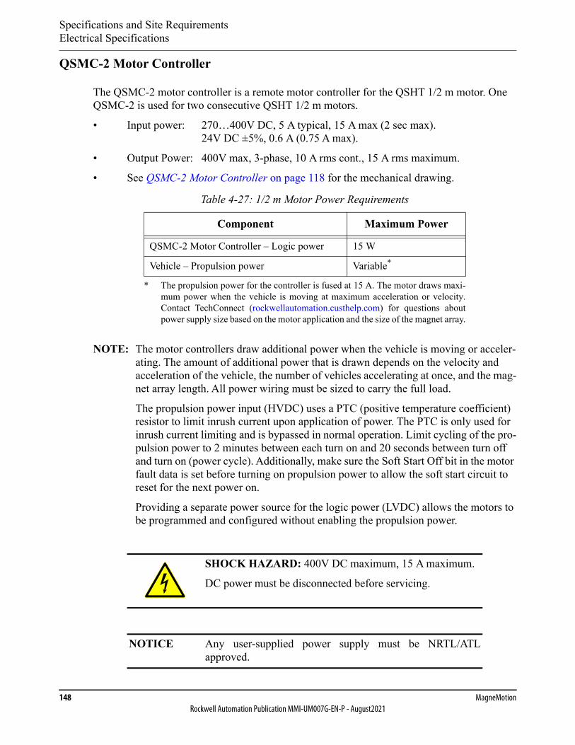
Specifications and Site RequirementsElectrical Specifications
148 MagneMotionRockwell Automation Publication MMI-UM007G-EN-P - August2021
QSMC-2 Motor Controller
The QSMC-2 motor controller is a remote motor controller for the QSHT 1/2 m motor. One QSMC-2 is used for two consecutive QSHT 1/2 m motors.
• Input power: 270…400V DC, 5 A typical, 15 A max (2 sec max).24V DC ±5%, 0.6 A (0.75 A max).
• Output Power: 400V max, 3-phase, 10 A rms cont., 15 A rms maximum.
• See QSMC-2 Motor Controller on page 118 for the mechanical drawing.
NOTE: The motor controllers draw additional power when the vehicle is moving or acceler-ating. The amount of additional power that is drawn depends on the velocity and acceleration of the vehicle, the number of vehicles accelerating at once, and the mag-net array length. All power wiring must be sized to carry the full load.
The propulsion power input (HVDC) uses a PTC (positive temperature coefficient) resistor to limit inrush current upon application of power. The PTC is only used for inrush current limiting and is bypassed in normal operation. Limit cycling of the pro-pulsion power to 2 minutes between each turn on and 20 seconds between turn off and turn on (power cycle). Additionally, make sure the Soft Start Off bit in the motor fault data is set before turning on propulsion power to allow the soft start circuit to reset for the next power on.
Providing a separate power source for the logic power (LVDC) allows the motors to be programmed and configured without enabling the propulsion power.
Table 4-27: 1/2 m Motor Power Requirements
Component Maximum Power
QSMC-2 Motor Controller – Logic power 15 W
Vehicle – Propulsion power Variable*
* The propulsion power for the controller is fused at 15 A. The motor draws maxi-mum power when the vehicle is moving at maximum acceleration or velocity.Contact TechConnect (rockwellautomation.custhelp.com) for questions aboutpower supply size based on the motor application and the size of the magnet array.
SHOCK HAZARD: 400V DC maximum, 15 A maximum.
DC power must be disconnected before servicing.
NOTICE Any user-supplied power supply must be NRTL/ATLapproved.
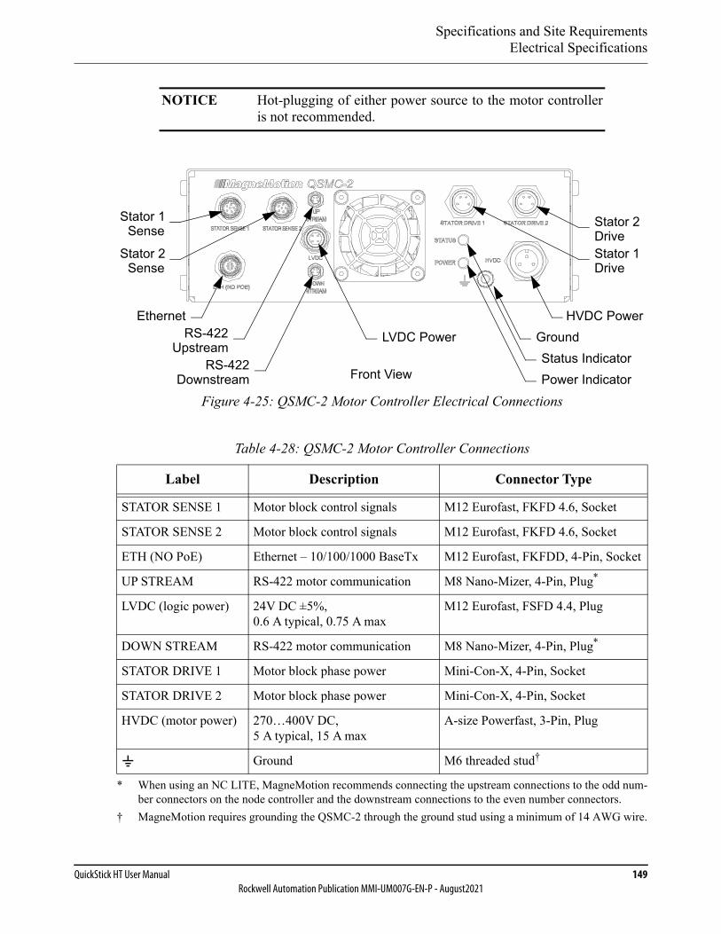
Specifications and Site RequirementsElectrical Specifications
QuickStick HT User Manual 149Rockwell Automation Publication MMI-UM007G-EN-P - August2021
Figure 4-25: QSMC-2 Motor Controller Electrical Connections
NOTICE Hot-plugging of either power source to the motor controlleris not recommended.
Table 4-28: QSMC-2 Motor Controller Connections
Label Description Connector Type
STATOR SENSE 1 Motor block control signals M12 Eurofast, FKFD 4.6, Socket
STATOR SENSE 2 Motor block control signals M12 Eurofast, FKFD 4.6, Socket
ETH (NO PoE) Ethernet – 10/100/1000 BaseTx M12 Eurofast, FKFDD, 4-Pin, Socket
UP STREAM RS-422 motor communication M8 Nano-Mizer, 4-Pin, Plug*
* When using an NC LITE, MagneMotion recommends connecting the upstream connections to the odd num-ber connectors on the node controller and the downstream connections to the even number connectors.
LVDC (logic power) 24V DC ±5%, 0.6 A typical, 0.75 A max
M12 Eurofast, FSFD 4.4, Plug
DOWN STREAM RS-422 motor communication M8 Nano-Mizer, 4-Pin, Plug*
STATOR DRIVE 1 Motor block phase power Mini-Con-X, 4-Pin, Socket
STATOR DRIVE 2 Motor block phase power Mini-Con-X, 4-Pin, Socket
HVDC (motor power) 270…400V DC, 5 A typical, 15 A max
A-size Powerfast, 3-Pin, Plug
Ground M6 threaded stud†
† MagneMotion requires grounding the QSMC-2 through the ground stud using a minimum of 14 AWG wire.
Status IndicatorFront View
Stator 1 Stator 2
HVDC Power
Power Indicator
LVDC Power Ground
Sense Drive
RS-422Downstream
Stator 1Drive
Stator 2Sense
EthernetRS-422
Upstream
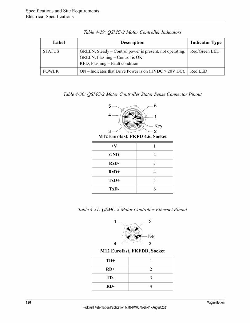
Specifications and Site RequirementsElectrical Specifications
150 MagneMotionRockwell Automation Publication MMI-UM007G-EN-P - August2021
Table 4-29: QSMC-2 Motor Controller Indicators
Label Description Indicator Type
STATUS GREEN, Steady – Control power is present, not operating.GREEN, Flashing – Control is OK.RED, Flashing – Fault condition.
Red/Green LED
POWER ON – Indicates that Drive Power is on (HVDC > 20V DC). Red LED
Table 4-30: QSMC-2 Motor Controller Stator Sense Connector Pinout
M12 Eurofast, FKFD 4.6, Socket
+V 1
GND 2
RxD- 3
RxD+ 4
TxD+ 5
TxD- 6
Table 4-31: QSMC-2 Motor Controller Ethernet Pinout
M12 Eurofast, FKFDD, Socket
TD+ 1
RD+ 2
TD- 3
RD- 4
5 6
3Key
1
2
4
4
1 2
3Key
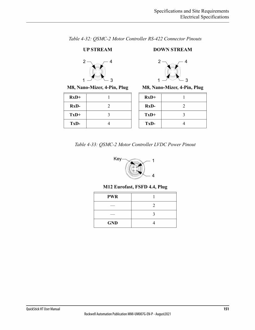
Specifications and Site RequirementsElectrical Specifications
QuickStick HT User Manual 151Rockwell Automation Publication MMI-UM007G-EN-P - August2021
Table 4-32: QSMC-2 Motor Controller RS-422 Connector Pinouts
UP STREAM DOWN STREAM
M8, Nano-Mizer, 4-Pin, Plug M8, Nano-Mizer, 4-Pin, Plug
RxD+ 1 RxD+ 1
RxD- 2 RxD- 2
TxD+ 3 TxD+ 3
TxD- 4 TxD- 4
Table 4-33: QSMC-2 Motor Controller LVDC Power Pinout
M12 Eurofast, FSFD 4.4, Plug
PWR 1
— 2
— 3
GND 4
3
4
1
2
3
4
1
2
Key 1
4
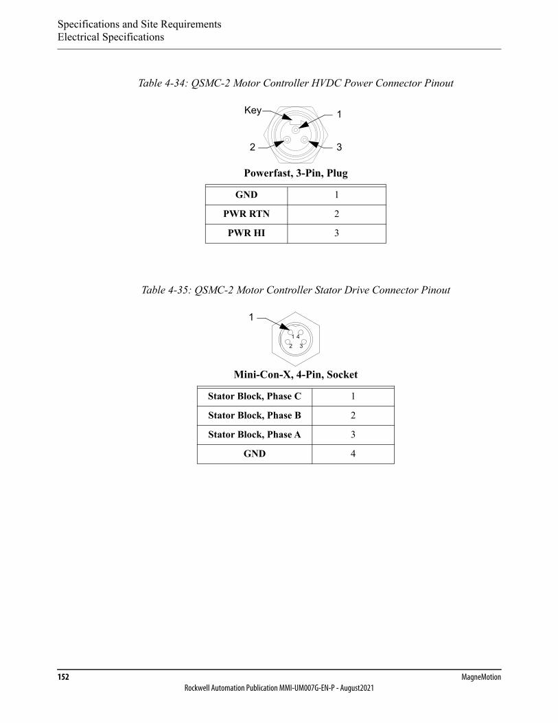
Specifications and Site RequirementsElectrical Specifications
152 MagneMotionRockwell Automation Publication MMI-UM007G-EN-P - August2021
Table 4-34: QSMC-2 Motor Controller HVDC Power Connector Pinout
Powerfast, 3-Pin, Plug
GND 1
PWR RTN 2
PWR HI 3
Table 4-35: QSMC-2 Motor Controller Stator Drive Connector Pinout
Mini-Con-X, 4-Pin, Socket
Stator Block, Phase C 1
Stator Block, Phase B 2
Stator Block, Phase A 3
GND 4
2
1
3
Key
12 3
4
1
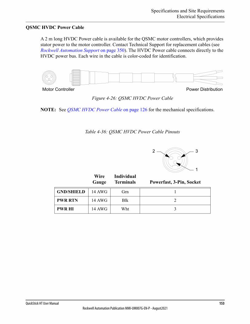
Specifications and Site RequirementsElectrical Specifications
QuickStick HT User Manual 153Rockwell Automation Publication MMI-UM007G-EN-P - August2021
QSMC HVDC Power Cable
A 2 m long HVDC Power cable is available for the QSMC motor controllers, which provides stator power to the motor controller. Contact Technical Support for replacement cables (see Rockwell Automation Support on page 350). The HVDC Power cable connects directly to the HVDC power bus. Each wire in the cable is color-coded for identification.
Figure 4-26: QSMC HVDC Power Cable
NOTE: See QSMC HVDC Power Cable on page 126 for the mechanical specifications.
Table 4-36: QSMC HVDC Power Cable Pinouts
Wire Gauge
Individual Terminals Powerfast, 3-Pin, Socket
GND/SHIELD 14 AWG Grn 1
PWR RTN 14 AWG Blk 2
PWR HI 14 AWG Wht 3
Motor Controller Power Distribution
3
1
2
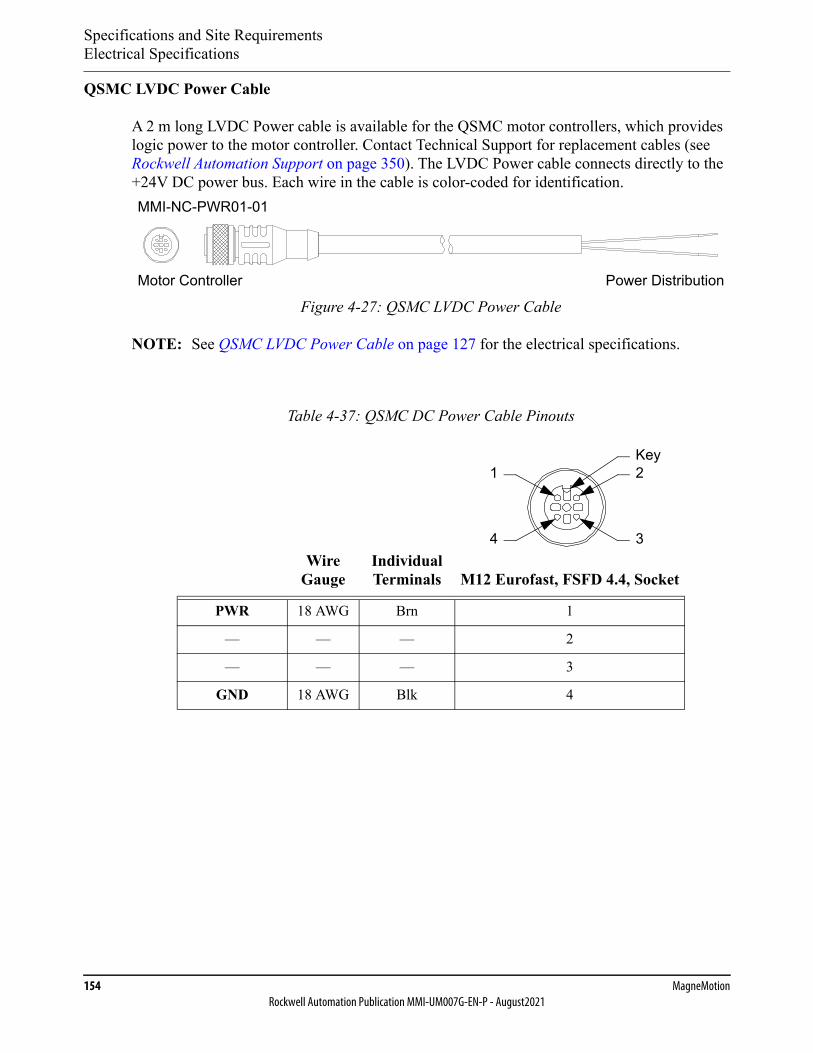
Specifications and Site RequirementsElectrical Specifications
154 MagneMotionRockwell Automation Publication MMI-UM007G-EN-P - August2021
QSMC LVDC Power Cable
A 2 m long LVDC Power cable is available for the QSMC motor controllers, which provides logic power to the motor controller. Contact Technical Support for replacement cables (see Rockwell Automation Support on page 350). The LVDC Power cable connects directly to the +24V DC power bus. Each wire in the cable is color-coded for identification.
Figure 4-27: QSMC LVDC Power Cable
NOTE: See QSMC LVDC Power Cable on page 127 for the electrical specifications.
Table 4-37: QSMC DC Power Cable Pinouts
Wire Gauge
Individual Terminals M12 Eurofast, FSFD 4.4, Socket
PWR 18 AWG Brn 1
— — — 2
— — — 3
GND 18 AWG Blk 4
Motor Controller Power Distribution
MMI-NC-PWR01-01
2
34
1Key
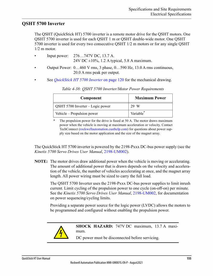
Specifications and Site RequirementsElectrical Specifications
QuickStick HT User Manual 155Rockwell Automation Publication MMI-UM007G-EN-P - August2021
QSHT 5700 Inverter
The QSHT (QuickStick HT) 5700 inverter is a remote motor drive for the QSHT motors. One QSHT 5700 inverter is used for each QSHT 1 m or QSHT double-wide motor. One QSHT 5700 inverter is used for every two consecutive QSHT 1/2 m motors or for any single QSHT 1/2 m motor.• Input power: 276…747V DC, 13.7 A.
24V DC ±10%, 1.2 A typical, 5.8 A maximum.• Output Power: 0…460 V rms, 3 phase, 0…590 Hz, 13.0 A rms continuous,
20.0 A rms peak per output.
• See QuickStick HT 5700 Inverter on page 120 for the mechanical drawing.
The QuickStick HT 5700 inverter is powered by the 2198-Pxxx DC-bus power supply (see the Kinetix 5700 Servo Drives User Manual, 2198-UM002).
NOTE: The motor drives draw additional power when the vehicle is moving or accelerating. The amount of additional power that is drawn depends on the velocity and accelera-tion of the vehicle, the number of vehicles accelerating at once, and the magnet array length. All power wiring must be sized to carry the full load.
The QSHT 5700 Inverter uses the 2198-Pxxx DC-bus power supplies to limit inrush current. Limit cycling of the propulsion power to one cycle (on-off-on) per minute. See the Kinetix 5700 Servo Drives User Manual, 2198-UM002, for documentation on power sequencing/cycling limits.
Providing a separate power source for the logic power (LVDC) allows the motors to be programmed and configured without enabling the propulsion power.
Table 4-38: QSHT 5700 Inverter/Motor Power Requirements
Component Maximum Power
QSHT 5700 Inverter – Logic power 29 W
Vehicle – Propulsion power Variable*
* The propulsion power for the drive is fused at 50 A. The motor draws maximumpower when the vehicle is moving at maximum acceleration or velocity. ContactTechConnect (rockwellautomation.custhelp.com) for questions about power sup-ply size based on the motor application and the size of the magnet array.
SHOCK HAZARD: 747V DC maximum, 13.7 A maxi-mum.DC power must be disconnected before servicing.
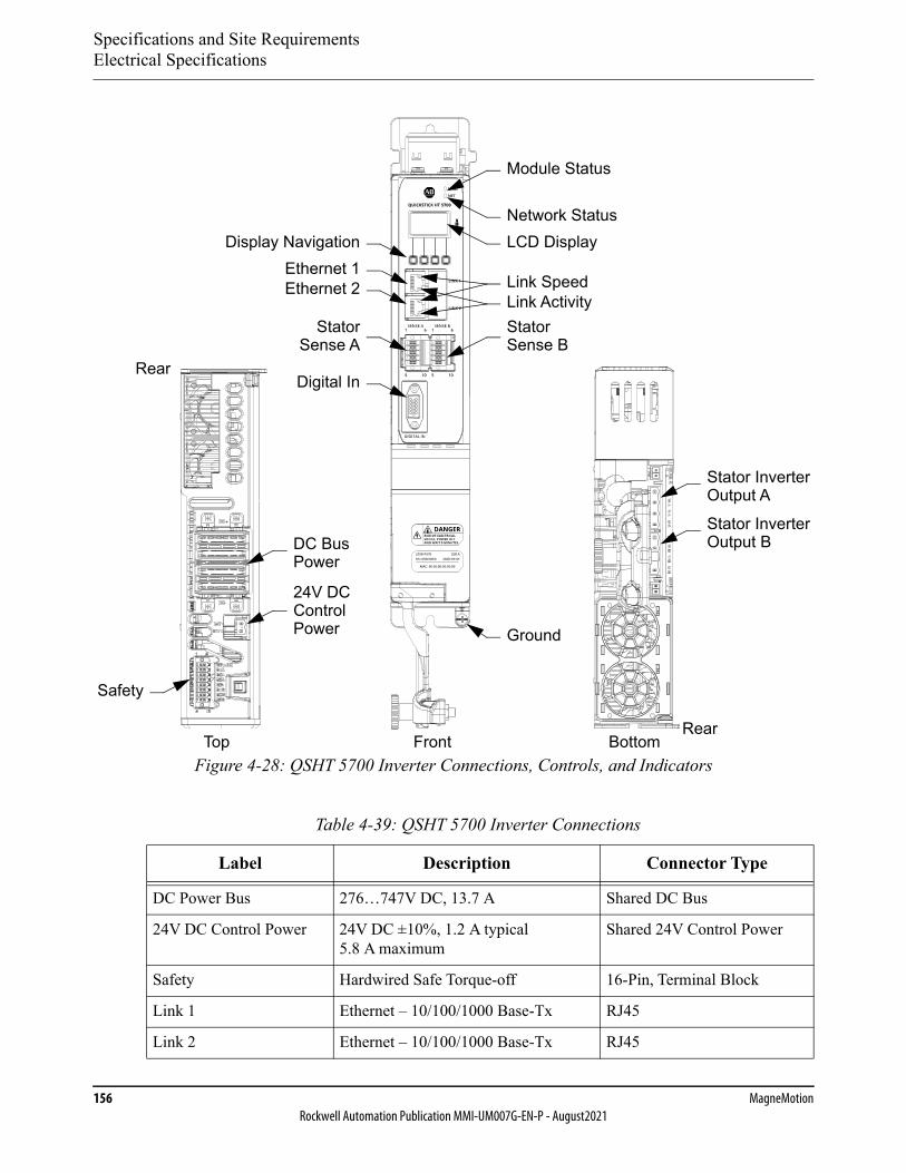
Specifications and Site RequirementsElectrical Specifications
156 MagneMotionRockwell Automation Publication MMI-UM007G-EN-P - August2021
Figure 4-28: QSHT 5700 Inverter Connections, Controls, and Indicators
Table 4-39: QSHT 5700 Inverter Connections
Label Description Connector Type
DC Power Bus 276…747V DC, 13.7 A Shared DC Bus
24V DC Control Power 24V DC ±10%, 1.2 A typical5.8 A maximum
Shared 24V Control Power
Safety Hardwired Safe Torque-off 16-Pin, Terminal Block
Link 1 Ethernet – 10/100/1000 Base-Tx RJ45
Link 2 Ethernet – 10/100/1000 Base-Tx RJ45
24V DCControl
DC BusPower
Module Status
Network StatusLCD Display
Ground
Stator Inverter
Safety
BottomFrontTop
Digital In
Stator
Ethernet 1Display Navigation
Output A
Rear
Rear
Stator InverterOutput B
Stator
Ethernet 2
Sense BSense A
Power
Link SpeedLink Activity
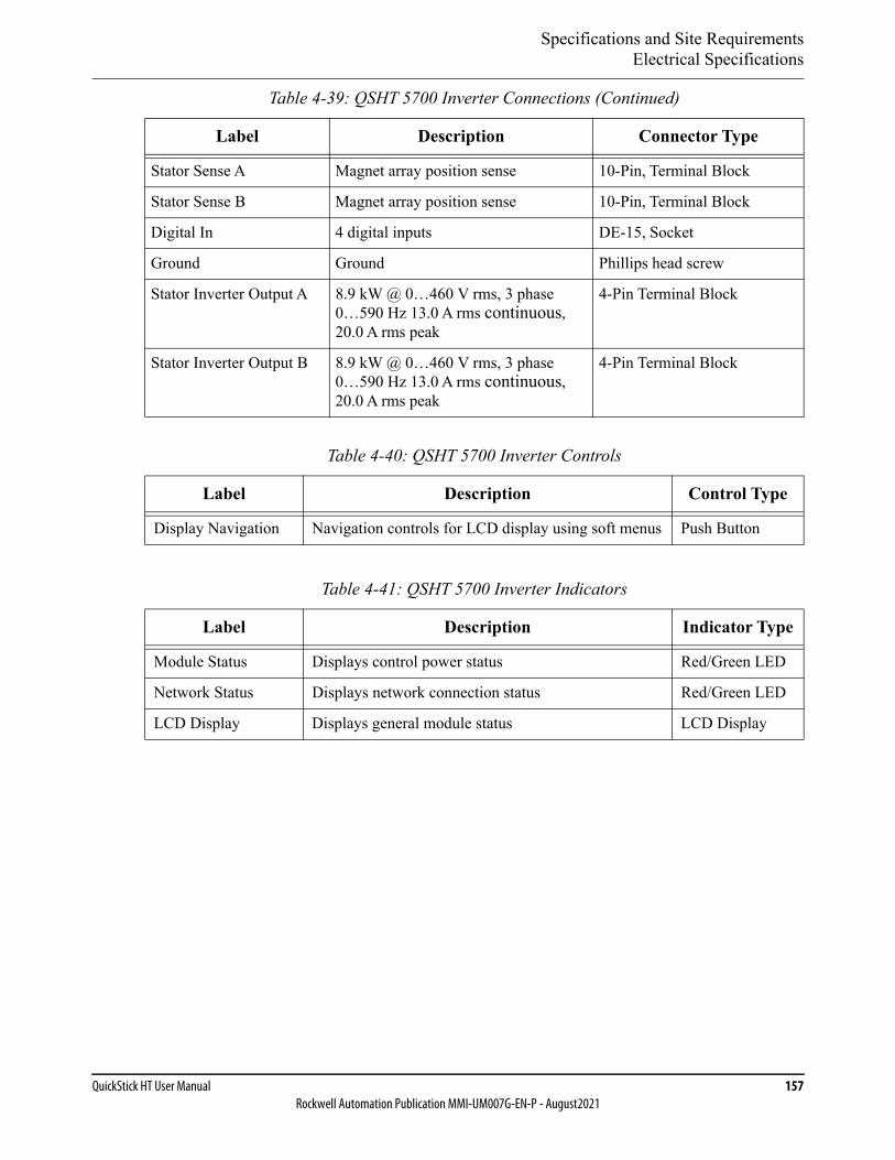
Specifications and Site RequirementsElectrical Specifications
QuickStick HT User Manual 157Rockwell Automation Publication MMI-UM007G-EN-P - August2021
Stator Sense A Magnet array position sense 10-Pin, Terminal Block
Stator Sense B Magnet array position sense 10-Pin, Terminal Block
Digital In 4 digital inputs DE-15, Socket
Ground Ground Phillips head screw
Stator Inverter Output A 8.9 kW @ 0…460 V rms, 3 phase 0…590 Hz 13.0 A rms continuous, 20.0 A rms peak
4-Pin Terminal Block
Stator Inverter Output B 8.9 kW @ 0…460 V rms, 3 phase 0…590 Hz 13.0 A rms continuous, 20.0 A rms peak
4-Pin Terminal Block
Table 4-40: QSHT 5700 Inverter Controls
Label Description Control Type
Display Navigation Navigation controls for LCD display using soft menus Push Button
Table 4-41: QSHT 5700 Inverter Indicators
Label Description Indicator Type
Module Status Displays control power status Red/Green LED
Network Status Displays network connection status Red/Green LED
LCD Display Displays general module status LCD Display
Table 4-39: QSHT 5700 Inverter Connections (Continued)
Label Description Connector Type
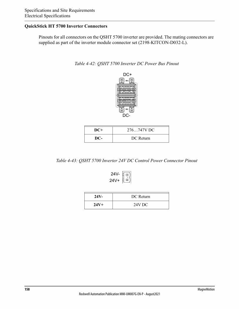
Specifications and Site RequirementsElectrical Specifications
158 MagneMotionRockwell Automation Publication MMI-UM007G-EN-P - August2021
QuickStick HT 5700 Inverter Connectors
Pinouts for all connectors on the QSHT 5700 inverter are provided. The mating connectors are supplied as part of the inverter module connector set (2198-KITCON-D032-L).
Table 4-42: QSHT 5700 Inverter DC Power Bus Pinout
DC+ 276…747V DC
DC- DC Return
Table 4-43: QSHT 5700 Inverter 24V DC Control Power Connector Pinout
24V- DC Return
24V+ 24V DC
DC+
DC-
24V-24V+
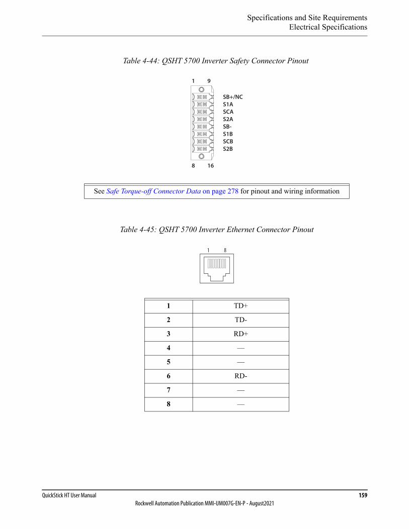
Specifications and Site RequirementsElectrical Specifications
QuickStick HT User Manual 159Rockwell Automation Publication MMI-UM007G-EN-P - August2021
Table 4-44: QSHT 5700 Inverter Safety Connector Pinout
See Safe Torque-off Connector Data on page 278 for pinout and wiring information
Table 4-45: QSHT 5700 Inverter Ethernet Connector Pinout
1 TD+
2 TD-
3 RD+
4 —
5 —
6 RD-
7 —
8 —
SB+/NCS1ASCAS2ASB-S1BSCBS2B
1 9
8 16
1 8
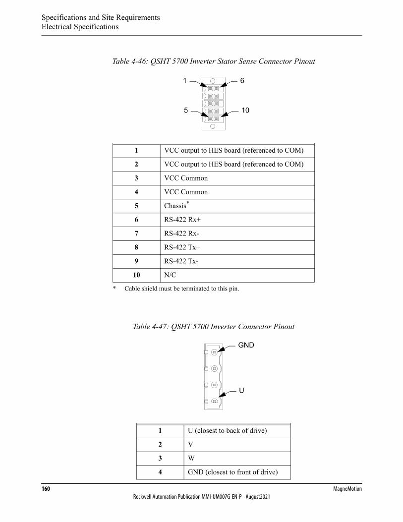
Specifications and Site RequirementsElectrical Specifications
160 MagneMotionRockwell Automation Publication MMI-UM007G-EN-P - August2021
Table 4-46: QSHT 5700 Inverter Stator Sense Connector Pinout
1 VCC output to HES board (referenced to COM)
2 VCC output to HES board (referenced to COM)
3 VCC Common
4 VCC Common
5 Chassis*
* Cable shield must be terminated to this pin.
6 RS-422 Rx+
7 RS-422 Rx-
8 RS-422 Tx+
9 RS-422 Tx-
10 N/C
Table 4-47: QSHT 5700 Inverter Connector Pinout
1 U (closest to back of drive)
2 V
3 W
4 GND (closest to front of drive)
1 6
5 10
GND
U

Specifications and Site RequirementsElectrical Specifications
QuickStick HT User Manual 161Rockwell Automation Publication MMI-UM007G-EN-P - August2021
Table 4-48: QSHT 5700 Inverter Digital Input Connector Pinout*
* Use 2198-K57CK-D15M universal feedback kit tosupport connecting discrete wires to this connector,see Digital I/O on page 203.
1 Digital In Common
2 Digital In Common
3 No Connect
4 Digital In 1
5 Digital In 2
6 Digital In 3
7 Digital In 4
8 Digital In Common
9 Digital In Common
10 No Connect
11 No Connect
12 Digital In 4
13 Digital In 3
14 Digital In 2
15 Digital In 1
10
5
1
15
11
6
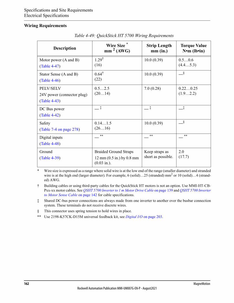
Specifications and Site RequirementsElectrical Specifications
162 MagneMotionRockwell Automation Publication MMI-UM007G-EN-P - August2021
Wiring Requirements
Table 4-49: QuickStick HT 5700 Wiring Requirements
Description Wire Size *mm 2 (AWG)
* Wire size is expressed as a range where solid wire is at the low end of the range (smaller diameter) and strandedwire is at the high end (larger diameter). For example, 6 (solid)…25 (stranded) mm2 or 10 (solid)…4 (strand-ed) AWG.
Strip Lengthmm (in.)
Torque ValueN•m (lb•in)
Motor power (A and B)(Table 4-47)
1.29†
(16)
† Building cables or using third-party cables for the QuickStick HT motors is not an option. Use MMI-HT-CB-Pxx-xx motor cables. See QSHT 5700 Inverter to 1 m Motor Drive Cable on page 139 and QSHT 5700 Inverterto Motor Sense Cable on page 142 for cable specifications.
10.0 (0.39) 0.5…0.6(4.4…5.3)
Stator Sense (A and B)(Table 4-46)
0.64†
(22)10.0 (0.39) —§
PELV/SELV24V power (connector plug)(Table 4-43)
0.5…2.5(20…14)
7.0 (0.28) 0.22…0.25(1.9…2.2)
DC Bus power(Table 4-42)
— ‡
‡ Shared DC-bus power connections are always made from one inverter to another over the busbar connectionsystem. These terminals do not receive discrete wires.
— ‡ —‡
Safety(Table 7-4 on page 278)
0.14…1.5(26…16)
10.0 (0.39) —§
§ This connector uses spring tension to hold wires in place.
Digital inputs(Table 4-48)
— **
** Use 2198-K57CK-D15M universal feedback kit, see Digital I/O on page 203.
— ** — **
Ground(Table 4-39)
Braided Ground Straps12 mm (0.5 in.) by 0.8 mm (0.03 in.).
Keep straps as short as possible.
2.0(17.7)

Specifications and Site RequirementsElectrical Specifications
QuickStick HT User Manual 163Rockwell Automation Publication MMI-UM007G-EN-P - August2021
QuickStick HT 5700 Inverter Controls and Indicators
The QSHT 5700 inverter has two status indicators and an LCD status display, which is shown in Figure 4-28. The indicators and display are used to monitor the system status, set network parameters, and troubleshoot faults. There are additional status indicators on the network con-nectors. Four navigation buttons, directly below the display, are used to select items from a soft menu.
Indicators
IMPORTANT Status indicators are not reliable for safety functions. Usethem only for general diagnostics during commissioning ortroubleshooting. Do not attempt to use status indicators todetermine operational status.
Table 4-50: Module Status Indicator
Condition Status
Steady Off No power is applied to the drive.
Steady Green —
Flashing green Drive is operational. No faults or failures.
Flashing red Major recoverable fault. The drive detected a recoverable fault, for example, an Incorrect or Inconsistent configuration.
Steady Red Major fault. The drive detected a nonrecoverable fault.
Flashing Green/Red Self-test. The drive performs self-test during power-up.
Table 4-51: Network Status Indicator
Condition Status
Steady Off No power is applied to the drive.
Steady Green Drive has obtained an IP address.
Flashing green —
Flashing red IP Address is not configured.
Steady Red Duplicate IP address. The IP address that is specified is already in use.
Flashing Green/Red Self-test. The drive performs self-test during power-up.
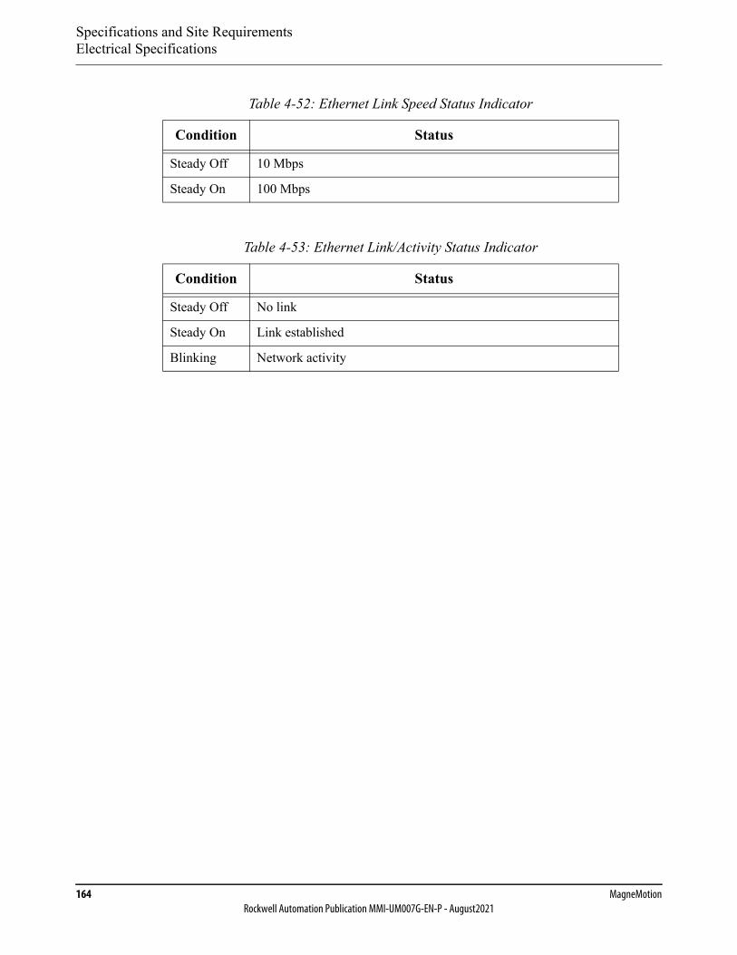
Specifications and Site RequirementsElectrical Specifications
164 MagneMotionRockwell Automation Publication MMI-UM007G-EN-P - August2021
Table 4-52: Ethernet Link Speed Status Indicator
Condition Status
Steady Off 10 Mbps
Steady On 100 Mbps
Table 4-53: Ethernet Link/Activity Status Indicator
Condition Status
Steady Off No link
Steady On Link established
Blinking Network activity
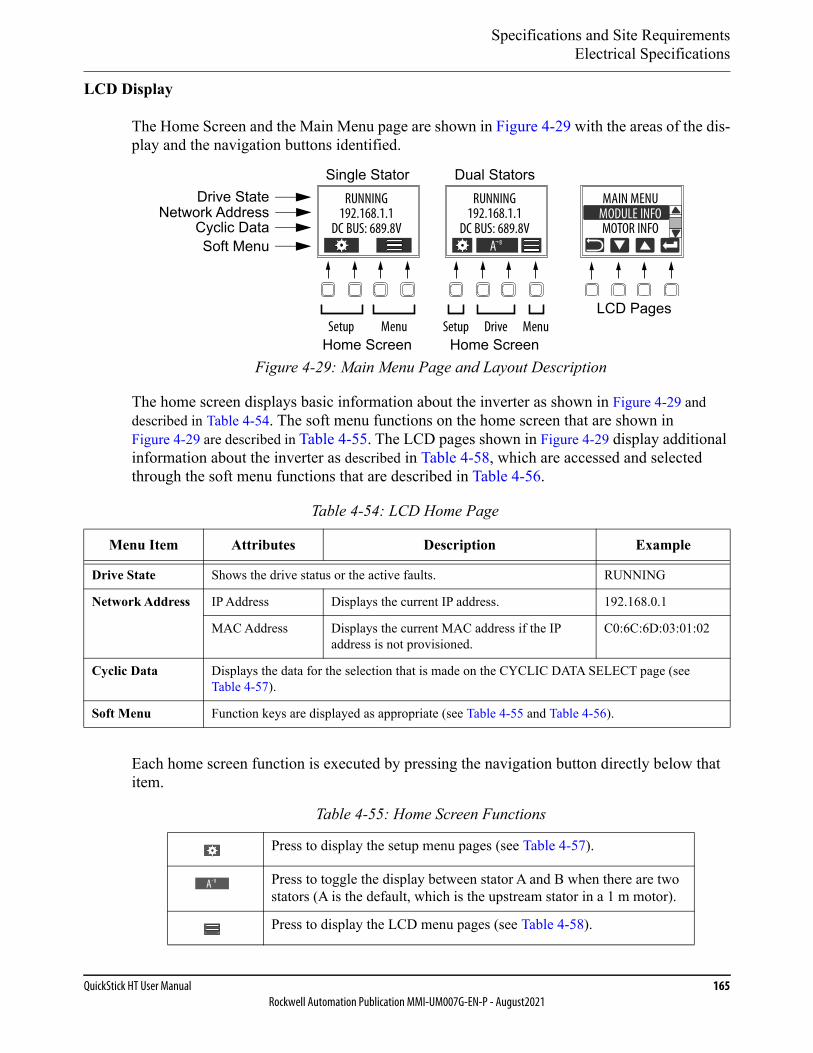
Specifications and Site RequirementsElectrical Specifications
QuickStick HT User Manual 165Rockwell Automation Publication MMI-UM007G-EN-P - August2021
LCD Display
The Home Screen and the Main Menu page are shown in Figure 4-29 with the areas of the dis-play and the navigation buttons identified.
Figure 4-29: Main Menu Page and Layout Description
The home screen displays basic information about the inverter as shown in Figure 4-29 and described in Table 4-54. The soft menu functions on the home screen that are shown in Figure 4-29 are described in Table 4-55. The LCD pages shown in Figure 4-29 display additional information about the inverter as described in Table 4-58, which are accessed and selected through the soft menu functions that are described in Table 4-56.
Each home screen function is executed by pressing the navigation button directly below that item.
Table 4-54: LCD Home Page
Menu Item Attributes Description Example
Drive State Shows the drive status or the active faults. RUNNING
Network Address IP Address Displays the current IP address. 192.168.0.1
MAC Address Displays the current MAC address if the IP address is not provisioned.
C0:6C:6D:03:01:02
Cyclic Data Displays the data for the selection that is made on the CYCLIC DATA SELECT page (see Table 4-57).
Soft Menu Function keys are displayed as appropriate (see Table 4-55 and Table 4-56).
Table 4-55: Home Screen Functions
Press to display the setup menu pages (see Table 4-57).
Press to toggle the display between stator A and B when there are two stators (A is the default, which is the upstream stator in a 1 m motor).
Press to display the LCD menu pages (see Table 4-58).
MAIN MENU
MOTOR INFOMODULE INFO
RUNNING192.168.1.1
DC BUS: 689.8V
Setup Drive Menu
A B
Home Screen
LCD Pages
Drive StateNetwork Address
Cyclic DataSoft Menu
Home Screen
Dual StatorsSingle StatorRUNNING
192.168.1.1DC BUS: 689.8V
Setup Menu
A B

Specifications and Site RequirementsElectrical Specifications
166 MagneMotionRockwell Automation Publication MMI-UM007G-EN-P - August2021
Each soft menu item is executed by pressing the navigation button directly below that item. The soft menu provides a changing selection that corresponds to the current screen. The func-tions available through the soft menu display are shown in Table 4-56.
LCD Setup Screens
The setup screens provide the means of changing the drive settings, for example, the data that is displayed on the home screen. Use the soft menu items (Table 4-55) and navigation buttons below the display (Table 4-56) to view the information. Press the setup button to access the menu.
Table 4-56: Soft Menu Functions
Press to return. Pressing enough times returns to the Home screen.
Pressing the button for either arrow moves the selection to the next (or previous) item.
Press to select the highlighted menu item.
Press to return to the Home screen (see Table 4-54).
Table 4-57: Navigating the QSHT 5700 Setup Menu
Menu/Submenu Attributes Description
DISPLAY> BACKLIGHT TIMEOUT
30 sec…NEVER(NEVER = no timeout period, the backlight is always on)
Sets backlight timeout period of the display. The default is 3 minutes.
DISPLAY> CYCLIC DATA SELECT
Selects the operating status data to display on the home screen. An arrow (<-) is displayed after the currently selected value.
DC BUS DC bus voltage of the currently selected drive is displayed in the home page in V.
INV TEMP Temperature of the currently selected drive is displayed in the home page in °C.
MOTOR TEMP Temperature of the motor, which is supplied by the currently selected drive, is displayed in the home page in °C.
OUT CUR Output current as commanded by the currently selected drive is displayed in the home page in A.
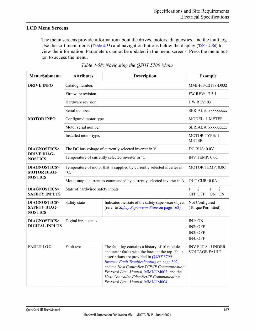
Specifications and Site RequirementsElectrical Specifications
QuickStick HT User Manual 167Rockwell Automation Publication MMI-UM007G-EN-P - August2021
LCD Menu Screens
The menu screens provide information about the drives, motors, diagnostics, and the fault log. Use the soft menu items (Table 4-55) and navigation buttons below the display (Table 4-56) to view the information. Parameters cannot be updated in the menu screens. Press the menu but-ton to access the menu.
Table 4-58: Navigating the QSHT 5700 Menu
Menu/Submenu Attributes Description Example
DRIVE INFO Catalog number. MMI-HT-C2198-D032
Firmware revision. FW REV: 17.3.1
Hardware revision. HW REV: 03
Serial number. SERIAL #: xxxxxxxxx
MOTOR INFO Configured motor type. MODEL: 1 METER
Motor serial number. SERIAL #: xxxxxxxxx
Installed motor type. MOTOR TYPE: 1 METER
DIAGNOSTICS> DRIVE DIAG-NOSTICS
The DC bus voltage of currently selected inverter in V DC BUS: 0.0V
Temperature of currently selected inverter in °C. INV TEMP: 0.0C
DIAGNOSTICS> MOTOR DIAG-NOSTICS
Temperature of motor that is supplied by currently selected inverter in °C.
MOTOR TEMP: 0.0C
Motor output current as commanded by currently selected inverter in A. OUT CUR: 0.0A
DIAGNOSTICS> SAFETY INPUTS
State of hardwired safety inputs 1 2OFF OFF
1 2ON ON
DIAGNOSTICS> SAFETY DIAG-NOSTICS
Safety state Indicates the state of the safety supervisor object (refer to Safety Supervisor State on page 168).
Not Configured (Torque Permitted)
DIAGNOSTICS> DIGITAL INPUTS
Digital input status. IN1: ONIN2: OFFIN3: OFFIN4: OFF
FAULT LOG Fault text The fault log contains a history of 10 module and stator faults with the latest at the top. Fault descriptions are provided in QSHT 5700 Inverter Fault Troubleshooting on page 302, and the Host Controller TCP/IP Communication Protocol User Manual, MMI-UM003, and the Host Controller EtherNet/IP Communication Protocol User Manual, MMI-UM004.
INV FLT A - UNDER VOLTAGE FAULT
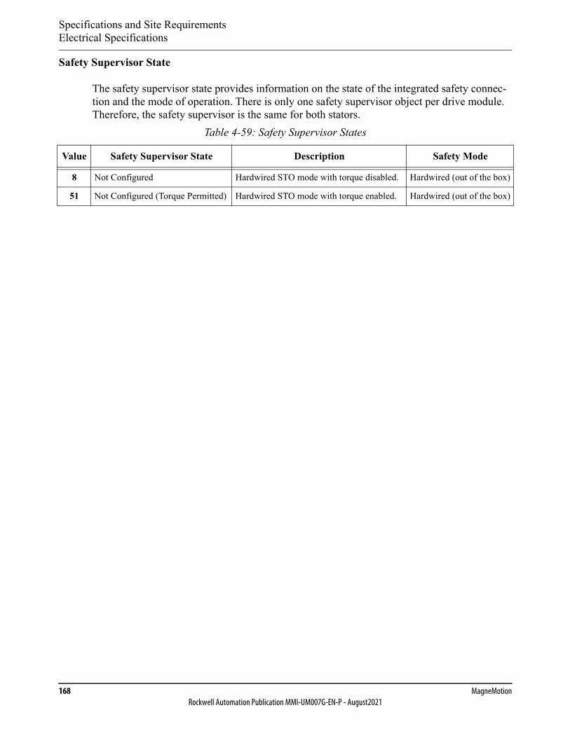
Specifications and Site RequirementsElectrical Specifications
168 MagneMotionRockwell Automation Publication MMI-UM007G-EN-P - August2021
Safety Supervisor State
The safety supervisor state provides information on the state of the integrated safety connec-tion and the mode of operation. There is only one safety supervisor object per drive module. Therefore, the safety supervisor is the same for both stators.
Table 4-59: Safety Supervisor States
Value Safety Supervisor State Description Safety Mode
8 Not Configured Hardwired STO mode with torque disabled. Hardwired (out of the box)
51 Not Configured (Torque Permitted) Hardwired STO mode with torque enabled. Hardwired (out of the box)
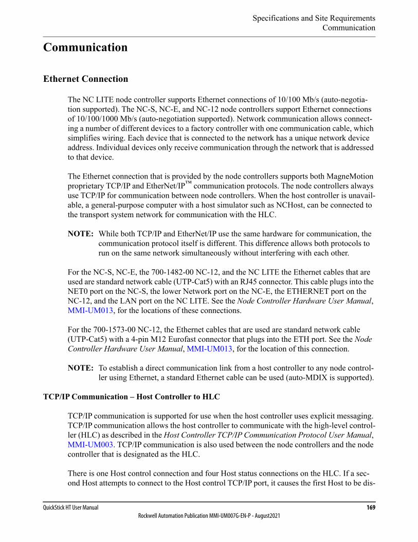
Specifications and Site RequirementsCommunication
QuickStick HT User Manual 169Rockwell Automation Publication MMI-UM007G-EN-P - August2021
Communication
Ethernet Connection
The NC LITE node controller supports Ethernet connections of 10/100 Mb/s (auto-negotia-tion supported). The NC-S, NC-E, and NC-12 node controllers support Ethernet connections of 10/100/1000 Mb/s (auto-negotiation supported). Network communication allows connect-ing a number of different devices to a factory controller with one communication cable, which simplifies wiring. Each device that is connected to the network has a unique network device address. Individual devices only receive communication through the network that is addressed to that device.
The Ethernet connection that is provided by the node controllers supports both MagneMotion proprietary TCP/IP and EtherNet/IP™ communication protocols. The node controllers always use TCP/IP for communication between node controllers. When the host controller is unavail-able, a general-purpose computer with a host simulator such as NCHost, can be connected to the transport system network for communication with the HLC.
NOTE: While both TCP/IP and EtherNet/IP use the same hardware for communication, the communication protocol itself is different. This difference allows both protocols to run on the same network simultaneously without interfering with each other.
For the NC-S, NC-E, the 700-1482-00 NC-12, and the NC LITE the Ethernet cables that are used are standard network cable (UTP-Cat5) with an RJ45 connector. This cable plugs into the NET0 port on the NC-S, the lower Network port on the NC-E, the ETHERNET port on the NC-12, and the LAN port on the NC LITE. See the Node Controller Hardware User Manual, MMI-UM013, for the locations of these connections.
For the 700-1573-00 NC-12, the Ethernet cables that are used are standard network cable (UTP-Cat5) with a 4-pin M12 Eurofast connector that plugs into the ETH port. See the Node Controller Hardware User Manual, MMI-UM013, for the location of this connection.
NOTE: To establish a direct communication link from a host controller to any node control-ler using Ethernet, a standard Ethernet cable can be used (auto-MDIX is supported).
TCP/IP Communication – Host Controller to HLC
TCP/IP communication is supported for use when the host controller uses explicit messaging. TCP/IP communication allows the host controller to communicate with the high-level control-ler (HLC) as described in the Host Controller TCP/IP Communication Protocol User Manual, MMI-UM003. TCP/IP communication is also used between the node controllers and the node controller that is designated as the HLC.
There is one Host control connection and four Host status connections on the HLC. If a sec-ond Host attempts to connect to the Host control TCP/IP port, it causes the first Host to be dis-
Specifications and Site RequirementsCommunication
170 MagneMotionRockwell Automation Publication MMI-UM007G-EN-P - August2021
connected. If a fifth connection to the status TCP/IP port is attempted, it causes the first status connection to be disconnected.
The TCP/IP connection to all node controllers uses standard Ethernet network wiring. If mul-tiple node controllers are connected to the same network, the IP address of each additional node controller must be changed to a unique address to avoid IP conflicts. The TCP/IP address that is used on the node controllers must be configured as specified in the Node Controller Interface User Manual, MMI-UM001.
TCP/IP Communication – Node Controller to Motor Drive
When using QSHT 5700 inverters, the NC-S, NC-E, NC-12, and NC LITE node controllers are connected to the drives for the motors in a network using standard Cat 5 cable. The motors can use different network style connection schemes depending on the application (see Ether-net Motor Communication Recommendations on page 80).
When using Ethernet, the motor drives for all motors in a specific path must be connected to the same node controller (see Figure 3-15 on page 82 through Figure 3-26 on page 88). Addi-tionally, multiple paths can be connected to the node controller using the same Ethernet chain. See Figure 4-28 for the location of these connections on the QSHT 5700 inverter. See the Node Controller Hardware User Manual, MMI-UM013, for the locations of these connec-tions on the node controllers.
TCP/IP Communication – Motor Drive to Motor Drive
When using QSHT 5700 inverters, which support Ethernet communication, the motor drives are connected to each other or the network, depending on the connection scheme being used (see Ethernet Motor Connection Examples on page 81), using standard Cat 5 cable. If multiple motor drives are connected to the same network, the IP address of each drive must be unique to avoid IP conflicts. The TCP/IP address that is used on the motor drives must be configured as specified in Ethernet Motor Communication Recommendations on page 80.
EtherNet/IP Communication – Host Controller to HLC
EtherNet/IP communication is supported for use when the host controller uses UDP-based implicit messaging. EtherNet/IP communication allows the host controller to communicate with the HLC as described in the Host Controller EtherNet/IP Communication Protocol User Manual, MMI-UM004.
The connection from the host controller to the node controller that is configured as the HLC uses standard Ethernet network wiring. The EtherNet/IP address that is used on the node con-troller that is configured as the HLC must be configured as specified in the Node Controller Interface User Manual, MMI-UM001.
Specifications and Site RequirementsCommunication
QuickStick HT User Manual 171Rockwell Automation Publication MMI-UM007G-EN-P - August2021
RS-232 Serial Interface Connection
RS-232 serial communication on the NC-12 node controller is not used with QuickStick HT transport systems.
RS-422 Serial Interface Connection
Node Controller to Motor Drive
When using QSMC motor controllers, which support RS-422 communication, the NC-S, NC-12, and NC LITE node controllers are connected to the motor drives in a daisy-chain with a 4-wire cable. See Figure 4-30 for cable identification and Table 4-60 for cable pinouts. See Figure 4-24 and Figure 4-25 for the location of these connections on the QSMC motor con-trollers. See the Node Controller Hardware User Manual, MMI-UM013, for the locations of these connections on the node controllers. There is no need to construct any of the cables as all cabling is available for the transport system. Contact Technical Support for additional or replacement cables (see Rockwell Automation Support on page 350).
When using an NC LITE, the RS-422 cables for upstream communication connect to the node controller with a 9-pin ‘D’ socket at any of the odd numbered RS-422 ports. When using an NC-S or NC-12, the RS-422 cables for upstream communication connect to the node control-ler with a 4-pin M8 socket at any of the RS-422 ports. These cables connect to the first motor drive in a path with a 4-pin M8 socket on the end of the cable that plugs into the upstream communication port.
When using an NC LITE, the RS-422 cables for downstream communication connect to the node controller with a 9-pin ‘D’ plug at any of the even numbered RS-422 ports. When using an NC-S or NC-12, the RS-422 cables for downstream communication connect to the node controller with a 4-pin M8 socket at any of the RS-422 ports. These cables connect to the last motor drive in a path with a 4-pin M8 socket on the end of the cable that plugs into the down-stream communication port.
It is recommended that the upstream connections to the NC LITE node controller are made to an odd numbered (DE-9 plug) RS-422 port and the downstream connections are made to an even numbered (DE-9 socket) RS-422 port. However, a custom crossover adapter can be used to connect an RS-422 DE-9 connector of the wrong type to any port on the NC LITE node controller.
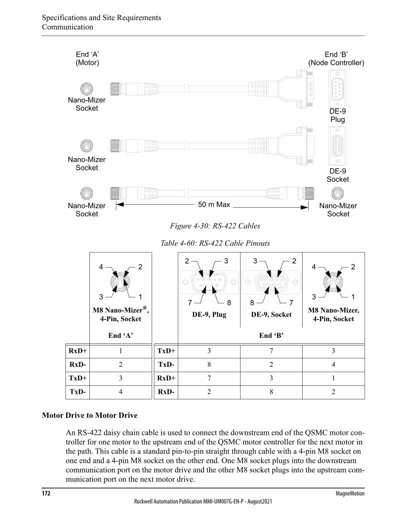
Specifications and Site RequirementsCommunication
172 MagneMotionRockwell Automation Publication MMI-UM007G-EN-P - August2021
Figure 4-30: RS-422 Cables
Motor Drive to Motor Drive
An RS-422 daisy chain cable is used to connect the downstream end of the QSMC motor con-troller for one motor to the upstream end of the QSMC motor controller for the next motor in the path. This cable is a standard pin-to-pin straight through cable with a 4-pin M8 socket on one end and a 4-pin M8 socket on the other end. One M8 socket plugs into the downstream communication port on the motor drive and the other M8 socket plugs into the upstream com-munication port on the next motor drive.
Table 4-60: RS-422 Cable Pinouts
M8 Nano-Mizer®, 4-Pin, Socket DE-9, Plug DE-9, Socket M8 Nano-Mizer,
4-Pin, Socket
End ‘A’ End ‘B’
RxD+ 1 TxD+ 3 7 3
RxD- 2 TxD- 8 2 4
TxD+ 3 RxD+ 7 3 1
TxD- 4 RxD- 2 8 2
DE-9
DE-9
Nano-Mizer
End ‘A’ End ‘B’(Motor) (Node Controller)
50 m Max
Socket
Socket
Plug
Nano-MizerSocket
Nano-MizerSocket
Nano-MizerSocket
1
2
3
42 3
7 8 78
23
1
2
3
4
Specifications and Site RequirementsCommunication
QuickStick HT User Manual 173Rockwell Automation Publication MMI-UM007G-EN-P - August2021
Ethernet Interface Connection
Ethernet communication allows connecting the node controllers to the QSHT 5700 inverters through a network switch, using a standard 4-wire Ethernet cable. See Figure 4-28 for the location of this connection on the motor drive. See the Node Controller Hardware User Man-ual, MMI-UM013, for the locations of these connections on the node controllers. There is no need to construct the Ethernet cables as all cabling is available for the transport system. Con-tact Technical Support for additional or replacement cables (see Rockwell Automation Sup-port on page 350).
The QuickStick HT motors with QSHT 5700 inverters can use different network connection schemes depending on the application. When using Ethernet, all motors in a specific path must be connected to the same node controller. Additionally, multiple paths can be connected to one node controller using the same Ethernet chain.
The Ethernet cables for network connections to the NC-12 node controllers use either a 4-pin M12 plug or an RJ45 connector at the end that plugs into the node controller. The Ethernet cables for network connections to the NC-S, NC-E, and NC LITE node controllers use an RJ45 connector at the end that plugs into the node controller. In each case, the end of the cable that plugs into the network switch must have a connector appropriate for the switch.
The Ethernet cables for network to motor connections use an RJ45 connector on the end that plugs into the motor drive and a connector appropriate for the network switch on the other end of the cable. The Ethernet daisy chain cables for motor drive-to-motor drive connections use an RJ45 connector that plugs into one motor drive at the Ethernet Port 2 connector on the motor drive and another RJ45 connector that plugs into the next motor drive in the chain at the Ethernet Port 1 connector.
Specifications and Site RequirementsSite Requirements
174 MagneMotionRockwell Automation Publication MMI-UM007G-EN-P - August2021
Site Requirements
Environment
Motors
Temperature:
Operating: 0° C to 50° C [32° F to 122° F]Storage: -18° C to +50° C [0° F to +122° F]
Humidity:
85% Maximum (relative, noncondensing)
QSMC Motor Controllers
Temperature:
Operating: 0° C to 50° C [32° F to 122° F]Storage: -18° C to +50° C [0° F to +122° F]
Humidity:
85% Maximum (relative, noncondensing)
QSHT 5700 Inverters
Temperature:
Operating: 0° C to 50° C [32° F to 122° F]Storage: -40° C to +70° C [-40° F to +158° F]
Humidity:
5…95% Maximum (relative, noncondensing)
Magnet Arrays
Temperature:
Operating: 0° C to 50° C [32° F to 122° F]Storage: -18° C to +60° C [0° F to +140° F]
Humidity:
85% Maximum (relative, noncondensing)
Derating at High Altitude
When operating in a high altitude environment with lower air pressure, the operating tempera-ture range must be derated compared to that of sea level.

Specifications and Site RequirementsSite Requirements
QuickStick HT User Manual 175Rockwell Automation Publication MMI-UM007G-EN-P - August2021
Lighting, Site
No special lighting is required for proper operation of the QuickStick HT transport system. Maintenance can require a user-supplied service lamp (for example, a flashlight).
Floor Space and Loading
The site for the QuickStick HT transport system must meet the minimum space requirements that are defined after developing the layout as defined in Transport System Layout on page 60. See the Mechanical Specifications on page 114 to make sure that there is proper clearance for installation, operation, and servicing of the QSHT motors and other components. The dimen-sions that are given are for the QSHT motors and other components only. The user must make sure that there is adequate space for operation and service around the equipment that is based on their needs and any vehicle overhang.
Facilities
The facility is responsible for providing the facilities that are specified in Electrical Specifica-tions on page 133 to support proper operation of the QuickStick HT motors and other compo-nents. See Facilities Connections on page 217 for the connection of all facilities to the QSHT transport system.
The facility is responsible for the main disconnect device between the QuickStick HT trans-port system and the power source, making sure it complies with the appropriate facility, local, and national electrical codes. Service to the QuickStick HT transport system must have the appropriate circuit breaker rating.
Service Access
The QuickStick HT transport system requires adequate space for service access and for proper operation. The typical service space that is required for the QSHT motors is shown in Figure 4-1 through Figure 4-3. Typical service space that is required for the QSMC motor drives is shown in Figure 4-4 through Figure 4-7. See the Node Controller Hardware User Manual, MMI-UM013, for the service space required for the node controllers.
Make sure that installation of the QuickStick HT transport system is such that it provides access to items required for service after installation, such as power and communication con-nections.
NOTE: The Exclusion Zones that are shown are for the QuickStick HT transport system components only. Additional exclusion zones may be required based on the design of the vehicle and the material that the QuickStick HT transport system is moving.

Specifications and Site Requirements
176 MagneMotionRockwell Automation Publication MMI-UM007G-EN-P - August2021
This page intentionally left blank.

QuickStick HT User Manual 177Rockwell Automation Publication MMI-UM007G-EN-P - August2021
Installation 5
Overview
This chapter provides complete installation procedures for the various configurations of the QuickStick® HT components that are used in a transport system.
Included in this chapter are:
• Unpacking and inspection of the QuickStick HT transport system components.
• QuickStick HT component installation including: hardware installation, facilities con-nections, and software installation and configuration.
• Initial power-up and check-out.
• Testing the transport system using demo scripts.

InstallationUnpacking and Inspection
178 MagneMotionRockwell Automation Publication MMI-UM007G-EN-P - August2021
Unpacking and Inspection
The QuickStick HT transport system components are shipped in separate packages. Open each package carefully following the steps that are provided in Unpacking and Moving on page 179; inspect and verify the contents against the shipping documents. Report any damage immediately to the shipper and to MagneMotion®.
One set of shipping documents is attached to the outside of the main shipping crate for easy access.
NOTE: The number and contents of the shipping packages depends on the items that are pur-chased. See the shipping documents for the exact contents. The checklist in Table 5-1 is provided for reference only.
Table 5-1: QuickStick HT Packing Checklist Reference
Package Contents
QuickStick HT Motors QuickStick HT linear synchronous motors.
Motor Drives Controllers or inverters for the QSHT motors.
Magnet Arrays Magnet arrays to be attached to the vehicles as the motor second-ary to provide material movement on the transport system.
Node Controllers MagneMotion node controllers for managing the nodes in the transport system.
Power Supplies Power supplies to provide logic and propulsion power to the QuickStick HT motors.
Installation Kit • Miscellaneous hardware.• Cables.• User Manuals, drawings, and so on.
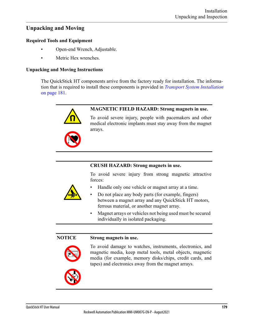
InstallationUnpacking and Inspection
QuickStick HT User Manual 179Rockwell Automation Publication MMI-UM007G-EN-P - August2021
Unpacking and Moving
Required Tools and Equipment
• Open-end Wrench, Adjustable.
• Metric Hex wrenches.
Unpacking and Moving Instructions
The QuickStick HT components arrive from the factory ready for installation. The informa-tion that is required to install these components is provided in Transport System Installation on page 181.
MAGNETIC FIELD HAZARD: Strong magnets in use.
To avoid severe injury, people with pacemakers and othermedical electronic implants must stay away from the magnetarrays.
CRUSH HAZARD: Strong magnets in use.
To avoid severe injury from strong magnetic attractiveforces:• Handle only one vehicle or magnet array at a time.• Do not place any body parts (for example, fingers)
between a magnet array and any QuickStick HT motors, ferrous material, or another magnet array.
• Magnet arrays or vehicles not being used must be secured individually in isolated packaging.
NOTICE Strong magnets in use.
To avoid damage to watches, instruments, electronics, andmagnetic media, keep metal tools, metal objects, magneticmedia (for example, memory disks/chips, credit cards, andtapes) and electronics away from the magnet arrays.

InstallationUnpacking and Inspection
180 MagneMotionRockwell Automation Publication MMI-UM007G-EN-P - August2021
1. Upon receiving the packages, visually verify that the packaging is not damaged. Inform the freight carrier and MagneMotion of any inspection discrepancy.
2. Open each shipping package and verify the contents against the shipping documents.
3. Carefully inspect the QuickStick HT components and all additional items for signs of shipping damage.
4. Move all items to their destination (see Transport System Installation on page 181).
LIFTING HAZARD: Some of the QuickStick HT compo-nents can weigh as much as 41.5 kg [91.5 lb].
Failure to take the proper precautions before moving themcould result in personal injury.
Use proper techniques for lifting when moving any QSHTcomponents. Safety toe shoes must always be worn whenworking on the QuickStick HT transport system.
kg

InstallationTransport System Installation
QuickStick HT User Manual 181Rockwell Automation Publication MMI-UM007G-EN-P - August2021
Transport System Installation
The QuickStick HT transport system must be properly located within the facility so that other equipment can interface to it as required. The location must also make sure that there is ade-quate space for service access and for proper operation. Make sure that installation of the QuickStick HT components provides access to items required for service after installation, such as connection panels. Once properly located, the QSHT transport system must be leveled and secured to the floor or other rigid mounting points to help prevent any movement.
Installing Hardware
To install the motors on user-supplied supports, make sure that the supports are properly pre-pared to receive the motors (see Mechanical Specifications on page 114). Install the motors (see Mounting the Motors on page 183) and make any adjustments necessary to account for the custom supports.
NOTE: Any bolts with plastic caps have been pre-tightened at the factory to the appropriate torque specification and do not need to be tightened during installation.
When performing any of the following procedures, adhere to and follow all safety warnings and instructions.
Required Tools and Materials
• Metric Hex wrench set.
• Torque wrench (0.9…4.8 N•m [8…42 in•lb] range) with metric and Torx bits.
• Soft jaw pliers.
• Screwdriver, Small flat blade.
• Screwdriver, Phillips.
• 12” Machinist Square.
• Laser level, rotary.
• Digital Multimeter.
InstallationTransport System Installation
182 MagneMotionRockwell Automation Publication MMI-UM007G-EN-P - August2021
Installation Overview
The following sequence provides an overview of the installation of the QuickStick HT motors and other QSHT components on user equipment or a custom track system.
1. Assemble a section of the track, including guideway, motor mounts, and stand (see Assembling the Guideway on page 183 and Installing Vehicles on page 216).
2. Prepare and level the equipment where the motors are going to be mounted (see Level-ing the Transport System on page 183).
3. Secure the track to the floor or other equipment as required (see Securing the Trans-port System on page 183).
4. Install the motors, make sure that the motor bodies are collinear to each other and the tops of all motors are coplanar to each other. Tighten the motor mounting bolts (see Mounting the Motors on page 183).NOTE: Make sure that there is sufficient space around the motor mounting surface
for all connectors and for the bend radius of all cables.
5. Install the power supplies, node controllers, motor drives, network switches, and cables (see Installing Electronics on page 185).
6. Install magnet arrays on the vehicles and install the vehicles on the system (see Install-ing Vehicles on page 216).NOTE: Install vehicles on captive closed loop systems before closing the loop to
eliminate the need to remove a section of the guideway.
7. Make all communication, network, and power connections (see Facilities Connections on page 217).
8. Assemble the next section of the system following Step 1 through Step 7 and connect it to the previously installed section verifying that both sections are in the same plane and level to each other.
9. Continue assembling and installing sections of track until the system is complete.
10. Create the Node Controller Configuration File (see Software on page 222).
11. Power up the system and check all operating features, safety features, and connections (see Check-out and Power-up on page 224) and install software (see System Power-up on page 225).
NOTICE Make sure that the equipment or stand system for mountingthe QuickStick HT motors and the motor mounting surfacesare properly grounded to safety ground (earth).

InstallationTransport System Installation
QuickStick HT User Manual 183Rockwell Automation Publication MMI-UM007G-EN-P - August2021
System Installation
Assembling the Guideway
The guideway with the motor mounts must be located and attached to stands or other equip-ment as required. Each guideway section must be connected to the guideway sections on either side of it to form the complete system layout. The layout can be broken into sections for ease of assembly. When breaking the layout into sections, make sure that each section is as self-contained as possible.
NOTE: Before completing a closed guideway, add the vehicles by sliding them onto a sec-tion of guideway that has been installed (see Installing Vehicles on page 216).
Leveling the Transport System
Once the track assembly is complete, make sure that it is properly located and that all sections of the track are level.
1. Establish a datum for the system (interface to existing equipment, and so on).
2. Use a laser level to identify the datum throughout the installation area.
3. Make sure that all sections of the track are level and correctly referenced to the datum and adjust the track as necessary.
Securing the Transport System
Secure the QuickStick HT transport system to the floor to help prevent system movement. Tie-downs for facilities that require earthquake protection are the responsibility of the user. Secure the transport system to the floor and to any other equipment as required.
Mounting the Motors
The motors must be attached to the motor mounts on the guideway (see Figure 3-35 on page 101 for an overview) using the mounting features that are built into the motors. Make sure that all motors are flat and level once mounted.
1. Locate all QSHT motors (if not already installed) by placing the bottom of the motor on the motor mounts installed on the guideway. Secure the motor to the mounts using M6 bolts and M6 split lock washers through the motor mount into each threaded mounting hole on the motor and finger tighten.
NOTE: Locking features such as thread locker or lock washers must be used.
NOTICE Make sure that the transport system is properly grounded tosafety ground (earth).
InstallationTransport System Installation
184 MagneMotionRockwell Automation Publication MMI-UM007G-EN-P - August2021
The locating features on the bottom of the motor can be used to aid in posi-tioning.
Make sure that there is sufficient space around the motor mounting surface for all connectors and for the bend radius of all cables.
2. Adjust the position of all motors to make sure that the motors are collinear to each other and the space between motor bodies is consistent with the system layout.
3. Make sure that the tops of all motors are coplanar to each other (adjust the motor mounts as required).
4. Tighten all QSHT motor mounting hardware to 4.8 N•m [42 in•lb] maximum.
NOTE: Make sure that the tip of the mounting bolt does not extend beyond the depth of the mounting hole to avoid damage to the motor housing.
See the engineering drawings for the locations, depths, and torques for all mounting features.
5. Verify that all motors are properly mounted and the Motor Gap between all motors is identified and recorded. Make sure that the top surfaces of all motors are coplanar to each other, all vehicle guides are collinear, and all motor mounting bolts are tightened.
NOTE: The Motor Gap must be entered for the motors in the Node Controller Con-figuration File. If all motors on a path have the same Motor Gap, it can be entered once in the Motor Defaults before defining the individual motors on the path (see the QuickStick Configurator User Manual, MMI-UM009).
InstallationTransport System Installation
QuickStick HT User Manual 185Rockwell Automation Publication MMI-UM007G-EN-P - August2021
Installing Electronics
The electronics for the QSHT transport system can be attached to the transport system stands or positioned elsewhere in the facility in an appropriate location.
Installing Electronics on the Transport System
Some track systems are designed to accept mounting of the electronic components of the transport system (motor drives, node controllers, network switches, and power supplies). For these systems, mount these components to the system as required. For track systems that are not designed for mounting the electronic components, mount the components in racks or other cabinets.
Installing Node Controllers
Locate the node controllers close to the nodes they are responsible for to minimize the length of all wiring. The node controllers can be oriented in any direction that is required. See the Node Controller Hardware User Manual, MMI-UM013, for mounting information, making sure that all service and exclusion zones are maintained.
Installing Node Controller Power Supplies
If the node controllers are powered using a remote power supply (instead of using PoE), locate the power supply close to the node controller it is powering to minimize the length of all wir-ing (see the Node Controller Hardware User Manual, MMI-UM013). The supplied power supply can be oriented in any direction required. For other power supplies, see the installation directions from the manufacturer, making sure that any service and exclusion zones are main-tained.
Installing Network Switches
Locate the network switches close to the node controllers they are responsible for to minimize the length of all wiring. See the network switch user documentation for mounting information, making sure that any service and exclusion zones are maintained.
Installing Network Switch Power Supplies
If the network switches are powered using a remote power supply (instead of using PoE), locate the power supply close to the network switch it is powering to minimize the length of all wiring. The supplied power supply can be oriented in any direction required. For other power supplies, see the installation directions from the manufacturer, making sure that any service and exclusion zones are maintained.
NOTICE Make sure that all mounting surfaces and mounting hardwareprovide a conductive path to the transport system groundconnection.

InstallationTransport System Installation
186 MagneMotionRockwell Automation Publication MMI-UM007G-EN-P - August2021
Mounting QSMC Motor Controllers
Locate the motor controllers close to the motors they are responsible for to minimize the length of all wiring. The QSMC and QSMC-2 controllers can be mounted oriented in any direction. Or, the controllers can be mounted in a standard 19 inch rack by attaching the optional mounting brackets (see Figure 4-6 on page 119) to their sides as shown in Figure 5-1. Make sure that the service and exclusion zones that are identified in Figure 4-4 on page 117 and Figure 4-5 on page 118 are maintained.
Figure 5-1: QSMC and QSMC-2 Motor Controller Mounting Brackets
Install the mounting brackets onto the motor controller, if not already installed.
1. Remove the two M5 x 10 mm screws from the front of each side (four screws total).
2. Install two M5 x 12 mm flat head screws to secure each bracket and tighten to 2.0 Nm [18 in-lb] (four screws total).
3. Locate the controller in the rack and secure it with four screws (two per mounting bracket) as specified by the rack manufacturer.
4. Install cable management as required to secure the cables running to the controller.
Attachment Screw(4X)
Mounting Bracket(2X)
M5 x 10 mm(4X)
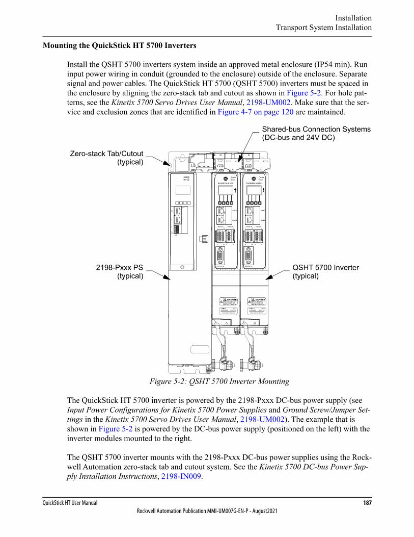
InstallationTransport System Installation
QuickStick HT User Manual 187Rockwell Automation Publication MMI-UM007G-EN-P - August2021
Mounting the QuickStick HT 5700 Inverters
Install the QSHT 5700 inverters system inside an approved metal enclosure (IP54 min). Run input power wiring in conduit (grounded to the enclosure) outside of the enclosure. Separate signal and power cables. The QuickStick HT 5700 (QSHT 5700) inverters must be spaced in the enclosure by aligning the zero-stack tab and cutout as shown in Figure 5-2. For hole pat-terns, see the Kinetix 5700 Servo Drives User Manual, 2198-UM002. Make sure that the ser-vice and exclusion zones that are identified in Figure 4-7 on page 120 are maintained.
Figure 5-2: QSHT 5700 Inverter Mounting
The QuickStick HT 5700 inverter is powered by the 2198-Pxxx DC-bus power supply (see Input Power Configurations for Kinetix 5700 Power Supplies and Ground Screw/Jumper Set-tings in the Kinetix 5700 Servo Drives User Manual, 2198-UM002). The example that is shown in Figure 5-2 is powered by the DC-bus power supply (positioned on the left) with the inverter modules mounted to the right.
The QSHT 5700 inverter mounts with the 2198-Pxxx DC-bus power supplies using the Rock-well Automation zero-stack tab and cutout system. See the Kinetix 5700 DC-bus Power Sup-ply Installation Instructions, 2198-IN009.
QSHT 5700 Inverter(typical)
2198-Pxxx PS(typical)
MODNET
2
1
1
4
I/O
Shared-bus Connection Systems(DC-bus and 24V DC)
Zero-stack Tab/Cutout(typical)

InstallationTransport System Installation
188 MagneMotionRockwell Automation Publication MMI-UM007G-EN-P - August2021
Mounting the 2198-Pxxx DC-bus Power Supplies
Install the 2198-Pxxx DC-bus power supplies inside the approved metal enclosure (IP54 min) where the inverters are installed. Run input power wiring in conduit (grounded to the enclo-sure) outside of the enclosure. Separate signal and power cables. The 2198-Pxxx DC-bus power supplies and QSHT 5700 inverters must be spaced in the enclosure by aligning the zero-stack tab and cutout as shown in Figure 5-2. For hole patterns, see the Kinetix 5700 Servo Drives User Manual, 2198-UM002.
QSHT 5700 Drive System Power Supply Ground Screw/Jumper Settings
Determine the ground screw/jumper setting for the 2198-Pxxx DC-bus power supply and QSHT 5700 inverters. The 2198-Pxxx DC-bus power supplies have a factory-installed ground screw for grounded-wye power distribution. Table 5-2 details the ground screw/jumper set-tings for the 2198-Pxxx DC-bus power supply.
To access the ground screw on the 2198-Pxxx DC-bus power supplies, open the small plastic door on the right side of the module as shown in Figure 5-3. It is recommended that the ground screw be installed with the power supply removed from the panel and placed on its side on a solid surface that is equipped as a grounded static-safe workstation.
Table 5-2: Ground Screw/Jumper Setting for the DC-bus Power Supply
Ground Configuration 2198-Pxxx DC-bus Power Supply
Grounded (wye) Ground screw installed (default setting)*
* Ground screw is factory installed.
• Impedance grounded• Corner grounded• AC-fed ungrounded
Remove ground screw/jumper
IMPORTANT If the facility uses a grounded-wye power distribution, do notremove the ground screw from the DC-bus power supply.Remove the ground screw when using ungrounded, cor-ner-grounded, or impedance-grounded power.
IMPORTANT If grounded-wye power distribution is being used with a2198-Pxxx DC-bus power supply, install the ground screw.For grounded-wye power distribution, EMC performancecan be affected if the ground screw is not installed.
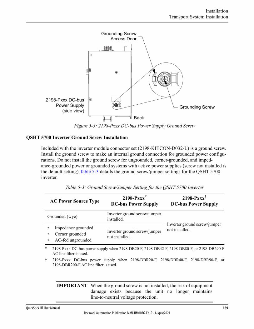
InstallationTransport System Installation
QuickStick HT User Manual 189Rockwell Automation Publication MMI-UM007G-EN-P - August2021
Figure 5-3: 2198-Pxxx DC-bus Power Supply Ground Screw
QSHT 5700 Inverter Ground Screw Installation
Included with the inverter module connector set (2198-KITCON-D032-L) is a ground screw. Install the ground screw to make an internal ground connection for grounded power configu-rations. Do not install the ground screw for ungrounded, corner-grounded, and imped-ance-grounded power or grounded systems with active power supplies (screw not installed is the default setting).Table 5-3 details the ground screw/jumper settings for the QSHT 5700 inverter.
Table 5-3: Ground Screw/Jumper Setting for the QSHT 5700 Inverter
AC Power Source Type 2198-Pxxx*
DC-bus Power Supply
* 2198-Pxxx DC-bus power supply when 2198-DB20-F, 2198-DB42-F, 2198-DB80-F, or 2198-DB290-FAC line filter is used.
2198-Pxxx†
DC-bus Power Supply
† 2198-Pxxx DC-bus power supply when 2198-DBR20-F, 2198-DBR40-F, 2198-DBR90-F, or2198-DBR200-F AC line filter is used.
Grounded (wye) Inverter ground screw/jumper installed.
Inverter ground screw/jumper not installed.• Impedance grounded
• Corner grounded• AC-fed ungrounded
Inverter ground screw/jumper not installed.
IMPORTANT When the ground screw is not installed, the risk of equipmentdamage exists because the unit no longer maintainsline-to-neutral voltage protection.
2198-Pxxx DC-busPower Supply
(side view)Grounding Screw
Grounding ScrewAccess Door
Back
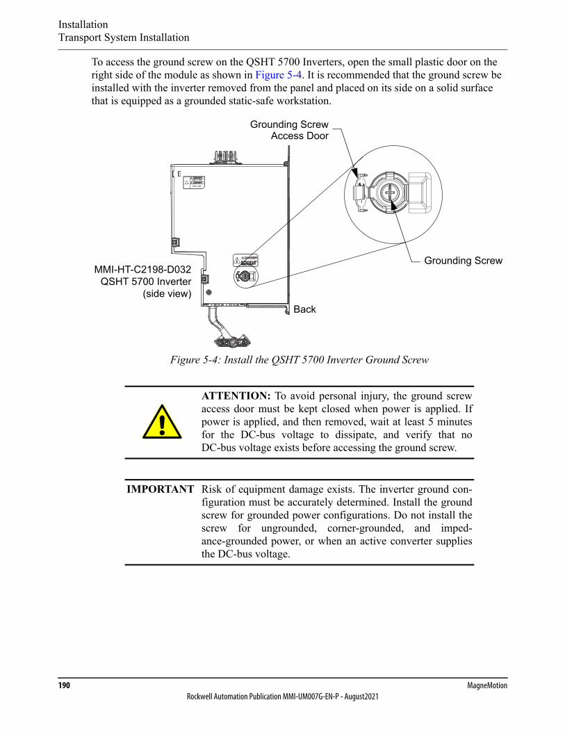
InstallationTransport System Installation
190 MagneMotionRockwell Automation Publication MMI-UM007G-EN-P - August2021
To access the ground screw on the QSHT 5700 Inverters, open the small plastic door on the right side of the module as shown in Figure 5-4. It is recommended that the ground screw be installed with the inverter removed from the panel and placed on its side on a solid surface that is equipped as a grounded static-safe workstation.
Figure 5-4: Install the QSHT 5700 Inverter Ground Screw
ATTENTION: To avoid personal injury, the ground screwaccess door must be kept closed when power is applied. Ifpower is applied, and then removed, wait at least 5 minutesfor the DC-bus voltage to dissipate, and verify that noDC-bus voltage exists before accessing the ground screw.
IMPORTANT Risk of equipment damage exists. The inverter ground con-figuration must be accurately determined. Install the groundscrew for grounded power configurations. Do not install thescrew for ungrounded, corner-grounded, and imped-ance-grounded power, or when an active converter suppliesthe DC-bus voltage.
MMI-HT-C2198-D032QSHT 5700 Inverter
(side view)
Grounding Screw
Grounding ScrewAccess Door
Back
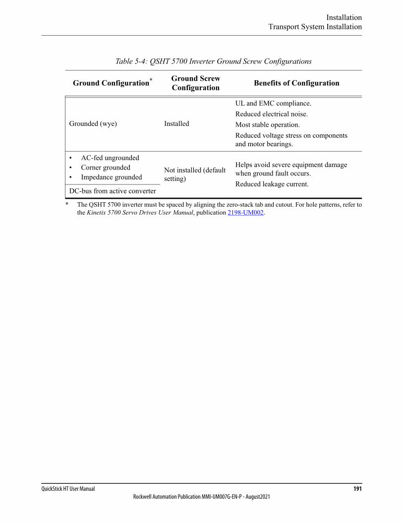
InstallationTransport System Installation
QuickStick HT User Manual 191Rockwell Automation Publication MMI-UM007G-EN-P - August2021
Table 5-4: QSHT 5700 Inverter Ground Screw Configurations
Ground Configuration*
* The QSHT 5700 inverter must be spaced by aligning the zero-stack tab and cutout. For hole patterns, refer tothe Kinetix 5700 Servo Drives User Manual, publication 2198-UM002.
Ground Screw Configuration Benefits of Configuration
Grounded (wye) Installed
UL and EMC compliance.Reduced electrical noise.Most stable operation.Reduced voltage stress on components and motor bearings.
• AC-fed ungrounded• Corner grounded• Impedance grounded
Not installed (default setting)
Helps avoid severe equipment damage when ground fault occurs.Reduced leakage current.
DC-bus from active converter
InstallationTransport System Installation
192 MagneMotionRockwell Automation Publication MMI-UM007G-EN-P - August2021
Connecting Motors and Electronics
The QuickStick HT transport system uses either RS-422 communication or Ethernet commu-nication with the motors in the transport system.
• When using RS-422, all motors in a specific path are daisy-chained together. The upstream end of the chain is connected to a node controller and the downstream end is only connected to a node controller if it ends at a node. All paths in a node must con-nect to the same node controller.
• When using Ethernet, all motors in a specific path are connected to a node controller through an Ethernet chain (see Ethernet Motor Connection Examples on page 81). All paths in a node must connect to the same node controller. Multiple paths can be con-nected to a node controller through the same Ethernet chain.
Power and communication cables must be run such that they are shielded from damage and can be easily accessed for service. The following procedure provides the information that is required to make all motor connections as shown in Figure 4-17, Figure 4-24, Figure 4-25, and Figure 4-28. Connections to the node controllers are described in the Node Controller Hardware User Manual, MMI-UM013.
Basic information is provided in this section. For detailed guidelines, see the following publi-cations.
• Industrial Automation Wiring and Grounding Guidelines, 1770-4.1.
• Wiring and Grounding Guidelines for Pulse-width Modulated (PWM) AC Drives, DRIVES-IN001.
Wire Routing
When routing wiring to a motor or motor drive, separate the high-voltage propulsion power from the logic power leads as described in Wiring and Grounding Guidelines for Pulse-width
NOTICE Never connect or disconnect the power lines while power isapplied to the QuickStick HT transport system as damage tointernal components can result.
NOTICE The NC LITE only supports the custom 18V DC Power overEthernet (PoE) used by MagneMotion. Never connect theNC LITE to a standard PoE network as damage to internalcomponents can result.
The NC-S, NC-E, and NC-12 node controllers do not supportPower over Ethernet (PoE). Never connect these componentsto a powered Ethernet network as damage to internal compo-nents can result.

InstallationTransport System Installation
QuickStick HT User Manual 193Rockwell Automation Publication MMI-UM007G-EN-P - August2021
Modulated (PWM) AC Drives, DRIVES-IN001. To maintain separate routes, route these wires in separate conduit or use tray dividers. See the following reference documents when design-ing the wiring system for the QSHT transport system:
• System Design for Control of Electrical Noise Reference Manual, GMC-RM001.
• Industrial Automation Wiring and Grounding Guidelines, 1770-4.1.
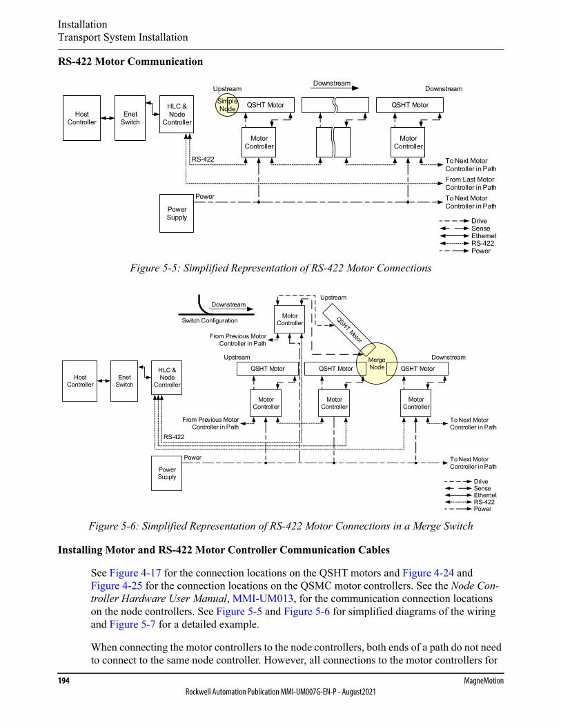
InstallationTransport System Installation
194 MagneMotionRockwell Automation Publication MMI-UM007G-EN-P - August2021
RS-422 Motor Communication
Figure 5-5: Simplified Representation of RS-422 Motor Connections
Figure 5-6: Simplified Representation of RS-422 Motor Connections in a Merge Switch
Installing Motor and RS-422 Motor Controller Communication Cables
See Figure 4-17 for the connection locations on the QSHT motors and Figure 4-24 and Figure 4-25 for the connection locations on the QSMC motor controllers. See the Node Con-troller Hardware User Manual, MMI-UM013, for the communication connection locations on the node controllers. See Figure 5-5 and Figure 5-6 for simplified diagrams of the wiring and Figure 5-7 for a detailed example.
When connecting the motor controllers to the node controllers, both ends of a path do not need to connect to the same node controller. However, all connections to the motor controllers for
SimpleNode QSHT Motor
Host Controller
QSHT MotorEnet
Switch
HLC & Node
Controller
Power Supply
Power
To Next MotorController in Path
Upstream Downstream
To Next Motor Controller in Path
From Last Motor Controller in Path
RS-422
Downstream
Motor Controller
Motor Controller
RS-422Power
DriveSenseEthernet
MergeNode
Enet Switch
HLC & Node
Controller
RS-422
Upstream Downstream
From Previous Motor Controller in Path
Upstream
Switch Configuration
Downstream
To Next Motor Controller in Path
QSHT Motor QSHT Motor QSHT Motor
Motor Controller
Motor Controller
Motor Controller
Motor Controller
Power Supply
Power To Next Motor Controller in Path
From Previous Motor Controller in Path
RS-422Power
DriveSenseEthernet
Host Controller
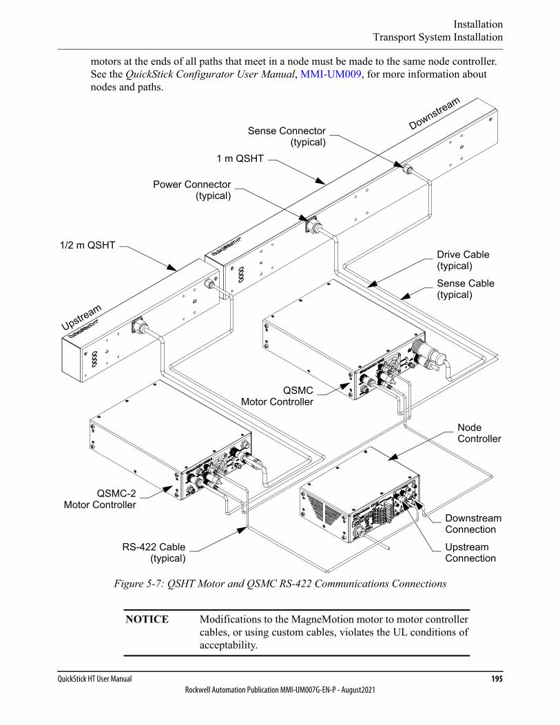
InstallationTransport System Installation
QuickStick HT User Manual 195Rockwell Automation Publication MMI-UM007G-EN-P - August2021
motors at the ends of all paths that meet in a node must be made to the same node controller. See the QuickStick Configurator User Manual, MMI-UM009, for more information about nodes and paths.
Figure 5-7: QSHT Motor and QSMC RS-422 Communications Connections
NOTICE Modifications to the MagneMotion motor to motor controllercables, or using custom cables, violates the UL conditions ofacceptability.
Sense Connector
Node
1/2 m QSHT
QSMCMotor Controller
Downstream
(typical)
Power Connector(typical)
Upstream
1 m QSHT
RS-422 Cable(typical)
Controller
Downstream
Upstream
Connection
Connection
QSMC-2Motor Controller
Drive Cable(typical)
Sense Cable(typical)
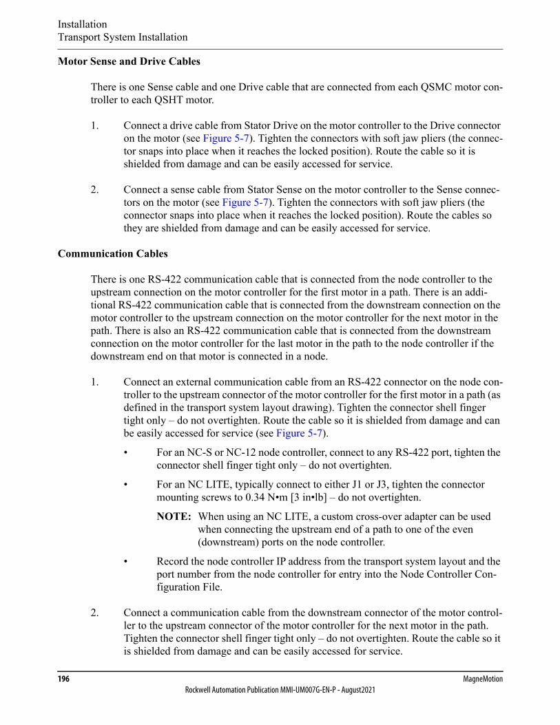
InstallationTransport System Installation
196 MagneMotionRockwell Automation Publication MMI-UM007G-EN-P - August2021
Motor Sense and Drive Cables
There is one Sense cable and one Drive cable that are connected from each QSMC motor con-troller to each QSHT motor.
1. Connect a drive cable from Stator Drive on the motor controller to the Drive connector on the motor (see Figure 5-7). Tighten the connectors with soft jaw pliers (the connec-tor snaps into place when it reaches the locked position). Route the cable so it is shielded from damage and can be easily accessed for service.
2. Connect a sense cable from Stator Sense on the motor controller to the Sense connec-tors on the motor (see Figure 5-7). Tighten the connectors with soft jaw pliers (the connector snaps into place when it reaches the locked position). Route the cables so they are shielded from damage and can be easily accessed for service.
Communication Cables
There is one RS-422 communication cable that is connected from the node controller to the upstream connection on the motor controller for the first motor in a path. There is an addi-tional RS-422 communication cable that is connected from the downstream connection on the motor controller to the upstream connection on the motor controller for the next motor in the path. There is also an RS-422 communication cable that is connected from the downstream connection on the motor controller for the last motor in the path to the node controller if the downstream end on that motor is connected in a node.
1. Connect an external communication cable from an RS-422 connector on the node con-troller to the upstream connector of the motor controller for the first motor in a path (as defined in the transport system layout drawing). Tighten the connector shell finger tight only – do not overtighten. Route the cable so it is shielded from damage and can be easily accessed for service (see Figure 5-7).
• For an NC-S or NC-12 node controller, connect to any RS-422 port, tighten the connector shell finger tight only – do not overtighten.
• For an NC LITE, typically connect to either J1 or J3, tighten the connector mounting screws to 0.34 N•m [3 in•lb] – do not overtighten.
NOTE: When using an NC LITE, a custom cross-over adapter can be used when connecting the upstream end of a path to one of the even (downstream) ports on the node controller.
• Record the node controller IP address from the transport system layout and the port number from the node controller for entry into the Node Controller Con-figuration File.
2. Connect a communication cable from the downstream connector of the motor control-ler to the upstream connector of the motor controller for the next motor in the path. Tighten the connector shell finger tight only – do not overtighten. Route the cable so it is shielded from damage and can be easily accessed for service.
InstallationTransport System Installation
QuickStick HT User Manual 197Rockwell Automation Publication MMI-UM007G-EN-P - August2021
3. Continue to connect the remaining motor controllers/motors in the path with the com-munication cables.
4. Connect an external communication cable from the downstream connector of the motor controller for the last motor in the path to an RS-422 connector on the node con-troller if that path ends at a node (for example, Relay Node, switch node, or Terminus Node). Tighten the connector shell finger tight only – do not overtighten. Route the cable so it is shielded from damage and can be easily accessed for service.
• For an NC-S or NC-12 node controller, connect to any RS-422 port, tighten the connector shell finger tight only – do not overtighten.
• For an NC LITE, typically connect to either J2 or J4, tighten the connector mounting screws to 0.34 N•m [3 in•lb] – do not overtighten.
NOTE: When using an NC LITE, a custom cross-over adapter can be used when connecting the downstream end of a path to one of the odd (upstream) ports on the node controller.
• Record the node controller IP address from the transport system layout and the port number from the node controller for entry into the Node Controller Con-figuration File.
5. Repeat Step 1 through Step 4 for each path in the QSHT transport system.
NOTE: The motor controllers for the motors at the ends of all paths that are con-nected in the same node must be connected to the same node controller.
6. Bundle and dress all cables (use nylon cable-ties) as required to keep all cable routing clean.
7. Connect the Ground stud on all QSMC and QSMC-2 motor controllers to GND (PE).
8. Connect the grounding point on all motors to GND (PE) and tighten to 4.8 N•m [42 in•lb] max).
9. Make sure that each node controller is properly grounded.
10. See Facilities Connections on page 217 for external communication connections.
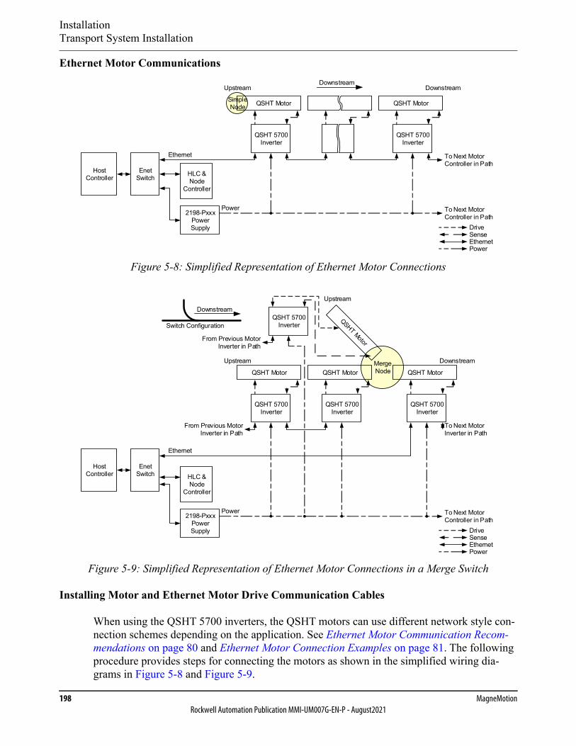
InstallationTransport System Installation
198 MagneMotionRockwell Automation Publication MMI-UM007G-EN-P - August2021
Ethernet Motor Communications
Figure 5-8: Simplified Representation of Ethernet Motor Connections
Figure 5-9: Simplified Representation of Ethernet Motor Connections in a Merge Switch
Installing Motor and Ethernet Motor Drive Communication Cables
When using the QSHT 5700 inverters, the QSHT motors can use different network style con-nection schemes depending on the application. See Ethernet Motor Communication Recom-mendations on page 80 and Ethernet Motor Connection Examples on page 81. The following procedure provides steps for connecting the motors as shown in the simplified wiring dia-grams in Figure 5-8 and Figure 5-9.
SimpleNode QSHT Motor
Host Controller
QSHT Motor
Enet Switch HLC &
Node Controller
Power
To Next MotorController in Path
Upstream Downstream
To Next Motor Controller in Path
Downstream
QSHT 5700Inverter
QSHT 5700Inverter
Ethernet
2198-Pxxx Power Supply
Power
DriveSenseEthernet
MergeNode
Host Controller
Enet Switch
Upstream Downstream
From Previous Motor Inverter in Path
Upstream
Switch Configuration
Downstream
To Next Motor Inverter in Path
QSHT Motor QSHT Motor QSHT Motor
Power To Next Motor Controller in Path
From Previous Motor Inverter in Path
Ethernet
QSHT 5700Inverter
QSHT 5700Inverter
QSHT 5700Inverter
QSHT 5700Inverter
HLC & Node
Controller
2198-Pxxx Power Supply
Power
DriveSenseEthernet
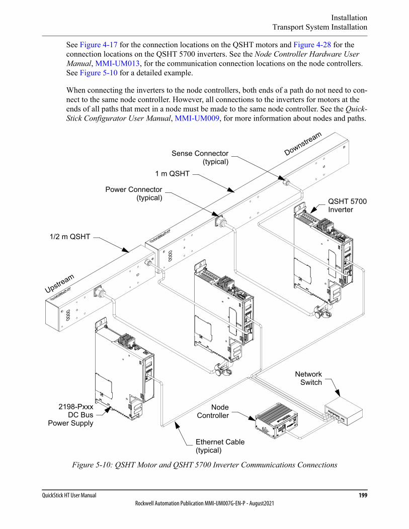
InstallationTransport System Installation
QuickStick HT User Manual 199Rockwell Automation Publication MMI-UM007G-EN-P - August2021
See Figure 4-17 for the connection locations on the QSHT motors and Figure 4-28 for the connection locations on the QSHT 5700 inverters. See the Node Controller Hardware User Manual, MMI-UM013, for the communication connection locations on the node controllers. See Figure 5-10 for a detailed example.
When connecting the inverters to the node controllers, both ends of a path do not need to con-nect to the same node controller. However, all connections to the inverters for motors at the ends of all paths that meet in a node must be made to the same node controller. See the Quick-Stick Configurator User Manual, MMI-UM009, for more information about nodes and paths.
Figure 5-10: QSHT Motor and QSHT 5700 Inverter Communications Connections
Sense Connector
Node
1/2 m QSHT
QSHT 5700Inverter
Downstream
(typical)
Power Connector(typical)
Upstream
1 m QSHT
Controller
NetworkSwitch
2198-PxxxDC Bus
Power Supply
Ethernet Cable(typical)
InstallationTransport System Installation
200 MagneMotionRockwell Automation Publication MMI-UM007G-EN-P - August2021
Motor Sense and Drive Cables
When using a 1 m QSHT motor, there is one Sense cable and one Drive cable that is con-nected from each inverter to each motor. When using two consecutive 1/2 m QSHT motors, there are two Sense cables and two Drive cables, one set per motor.
1. For 1 m motors, connect a drive cable from Stator Inverter Output A and Stator Inverter Output B on the inverter to the Drive connector on the motor (see Figure 5-10). Tighten the connector on the motor with soft jaw pliers (the connector snaps into place when it reaches the locked position). Route the cable so it is shielded from damage and can be easily accessed for service.For 1/2 m motors, connect a drive cable from Stator Inverter Output A on the inverter to the Drive connector on the first 1/2 m motor (see Figure 5-10). Connect a drive cable from Stator Inverter Output B on the inverter to the Drive connector on the sec-ond (consecutive) 1/2 m motor (see Figure 5-10). Tighten the connector with soft jaw pliers (the connector snaps into place when it reaches the locked position). Route the cable so it is shielded from damage and can be easily accessed for service.
The factory-supplied MMI-HT-Series motor cables are shielded and the braided cable shield must terminate at the inverter during installation as shown in Figure 5-11. The exposed area must be clamped (with the clamp provided) at the bottom front of the inverter. Clamp spacers, included with the inverters and held captive by rivets, are needed for all cable installations, and must not be removed.
A. Loosen the clamp knob.
The drive cable shield attaches to the inverter cable clamp. Clamp spacers are included to make sure of a tight fit within the drive clamp.
B. Position the exposed portion of each cable braid directly in line with the clamp.
C. Hand tighten the clamp knob.
Make sure that the cable clamp tightens around the cable shield and provides a good bond between the cable shield and the drive chassis. Only finger-tight torque on the clamp knob is required. The cable should not move within the clamp under its own weight or when slight pressure is applied by hand.
ATTENTION: Do not tightly gather or coil theexcess length of a drive cable. Heat is generatedwithin a cable whenever power is applied. Alwaysposition a drive cable so it can freely dissipate heat.
Do not coil a drive cable except for temporary usewhen building or testing a machine. If a drive cable istemporarily coiled, the cable must be derated to meetlocal code or follow an authoritative directive, suchas Engineering Section 310.15(C) of the NEC Hand-book.
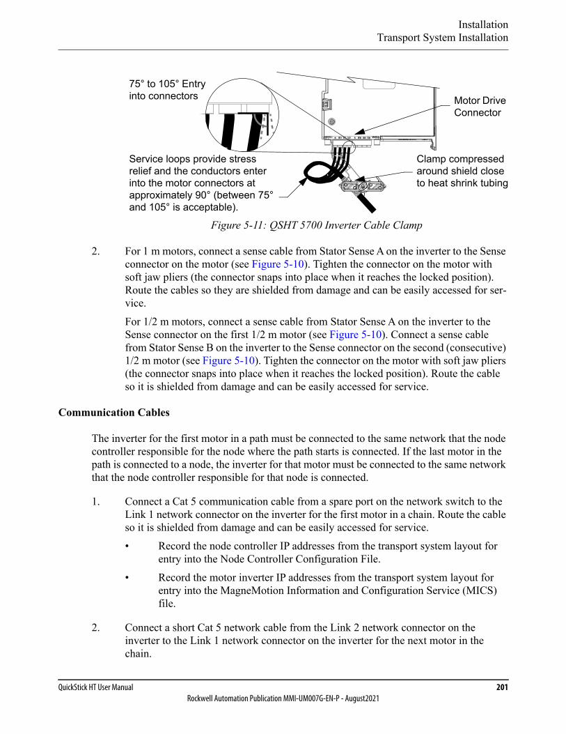
InstallationTransport System Installation
QuickStick HT User Manual 201Rockwell Automation Publication MMI-UM007G-EN-P - August2021
Figure 5-11: QSHT 5700 Inverter Cable Clamp
2. For 1 m motors, connect a sense cable from Stator Sense A on the inverter to the Sense connector on the motor (see Figure 5-10). Tighten the connector on the motor with soft jaw pliers (the connector snaps into place when it reaches the locked position). Route the cables so they are shielded from damage and can be easily accessed for ser-vice.For 1/2 m motors, connect a sense cable from Stator Sense A on the inverter to the Sense connector on the first 1/2 m motor (see Figure 5-10). Connect a sense cable from Stator Sense B on the inverter to the Sense connector on the second (consecutive) 1/2 m motor (see Figure 5-10). Tighten the connector on the motor with soft jaw pliers (the connector snaps into place when it reaches the locked position). Route the cable so it is shielded from damage and can be easily accessed for service.
Communication Cables
The inverter for the first motor in a path must be connected to the same network that the node controller responsible for the node where the path starts is connected. If the last motor in the path is connected to a node, the inverter for that motor must be connected to the same network that the node controller responsible for that node is connected.
1. Connect a Cat 5 communication cable from a spare port on the network switch to the Link 1 network connector on the inverter for the first motor in a chain. Route the cable so it is shielded from damage and can be easily accessed for service.• Record the node controller IP addresses from the transport system layout for
entry into the Node Controller Configuration File.• Record the motor inverter IP addresses from the transport system layout for
entry into the MagneMotion Information and Configuration Service (MICS) file.
2. Connect a short Cat 5 network cable from the Link 2 network connector on the inverter to the Link 1 network connector on the inverter for the next motor in the chain.
Service loops provide stress relief and the conductors enter into the motor connectors at approximately 90° (between 75° and 105° is acceptable).
75° to 105° Entry into connectors
Clamp compressed around shield close to heat shrink tubing
Motor Drive Connector
InstallationTransport System Installation
202 MagneMotionRockwell Automation Publication MMI-UM007G-EN-P - August2021
3. Continue to connect the remaining motors in the chain with Cat 5 network cables.
4. Repeat Step 1 through Step 3 for each chain in the QuickStick HT transport system.
• The inverters for the motors at the ends of all paths that are connected in a node must be connected through the network to the same node controller.
• The inverters for the motors at the end of a chain must not have their down-stream Ethernet port connected.
5. Bundle and dress all cables (use nylon cable-ties) as required to keep all cable routing clean.
6. Connect the Ground stud on the bottom of all QSHT 5700 inverters to GND (PE).
7. Connect the grounding point on all motors to GND (PE) and tighten to 4.8 N•m [42 in•lb] max).
8. See Facilities Connections on page 217 for external communication connections.
Network Communications
See the Node Controller Hardware User Manual, MMI-UM013, for the network connection locations on the node controllers. See Figure 5-18 for a simplified diagram of the network wiring.
NOTE: Make sure that the network for the transport system is a dedicated, separate subnet to minimize any unrelated network traffic.
1. Connect a Category 5 (Cat 5) cable for network communication to the node controller.
• For an NC-S node controller, connect from a dedicated standard network switch to NET0 (auto-MDIX and auto-negotiation are supported). Route the cable so it is shielded from damage and can be easily accessed for service.
• For an NC-E node controller, connect from a dedicated standard network switch to the lower Network port (auto-MDIX and auto-negotiation are sup-ported). Route the cable in the cable chase so it is shielded from damage and can be easily accessed for service.
NOTICE The NC-S node controller does not supportPower over Ethernet (PoE). Never connectthese node controllers to a PoE network asdamage to internal components can result.
InstallationTransport System Installation
QuickStick HT User Manual 203Rockwell Automation Publication MMI-UM007G-EN-P - August2021
• For an NC-12 node controller, connect from a dedicated standard network switch to ETHERNET (auto-MDIX and auto-negotiation are supported). Route the cable so it is shielded from damage and can be easily accessed for service.
• For an NC LITE node controller, connect from a network switch to LAN (auto-MDIX and auto-negotiation are supported). Route the cable so it is shielded from damage and can be easily accessed for service.
• When supplying power to the NC LITE through PoE, connect from a dedicated network switch with 18V DC PoE.
• When supplying power directly to the NC LITE, connect from a dedi-cated standard network switch.
2. Bundle and dress all cables (use nylon cable-ties) as required to make sure of clean cable routing.
3. See Facilities Connections on page 217 for external network connections.
Digital I/O
If node controllers with digital I/O are being used, wiring for discrete digital inputs and out-puts can be connected to the node controllers and used for E-stops, interlocks, light stacks, and general-purpose I/O. See the Node Controller Hardware User Manual, MMI-UM013, for the digital I/O connection locations and wiring diagrams.
The QuickStick HT 5700 inverter has four digital inputs that are available for user-configured functions as described in Table 5-6 on page 221. See QSHT 5700 Inverter on page 155 for the digital I/O connection location and pinout. The digital inputs require a 24V DC @ 15 mA sup-ply. These are sinking inputs that require a sourcing device. A common connection is pro-vided on the connector for each of the digital inputs.
The Universal Feedback Connector Kit, 2198-K57CK-D15M can be used to provide wire ter-minations for the digital I/O signals connecting to the QSHT 5700 inverter digital input con-
NOTICE The NC-E node controller does not supportPower over Ethernet (PoE). Never connectthese node controllers to a PoE network asdamage to internal components can result.
NOTICE The NC-12 node controller does not supportPower over Ethernet (PoE). Never connectthese node controllers to a PoE network asdamage to internal components can result.
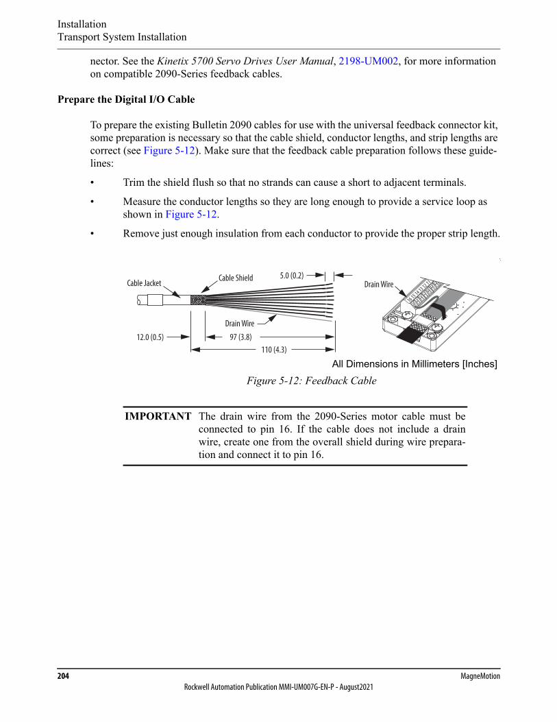
InstallationTransport System Installation
204 MagneMotionRockwell Automation Publication MMI-UM007G-EN-P - August2021
nector. See the Kinetix 5700 Servo Drives User Manual, 2198-UM002, for more information on compatible 2090-Series feedback cables.
Prepare the Digital I/O Cable
To prepare the existing Bulletin 2090 cables for use with the universal feedback connector kit, some preparation is necessary so that the cable shield, conductor lengths, and strip lengths are correct (see Figure 5-12). Make sure that the feedback cable preparation follows these guide-lines:
• Trim the shield flush so that no strands can cause a short to adjacent terminals.
• Measure the conductor lengths so they are long enough to provide a service loop as shown in Figure 5-12.
• Remove just enough insulation from each conductor to provide the proper strip length.
Figure 5-12: Feedback Cable
IMPORTANT The drain wire from the 2090-Series motor cable must beconnected to pin 16. If the cable does not include a drainwire, create one from the overall shield during wire prepara-tion and connect it to pin 16.
16 15 14 13 12 11 10
12.0 (0.5)
Cable ShieldDrain WireCable Jacket
5.0 (0.2)
110 (4.3)97 (3.8)
Drain Wire
All Dimensions in Millimeters [Inches]
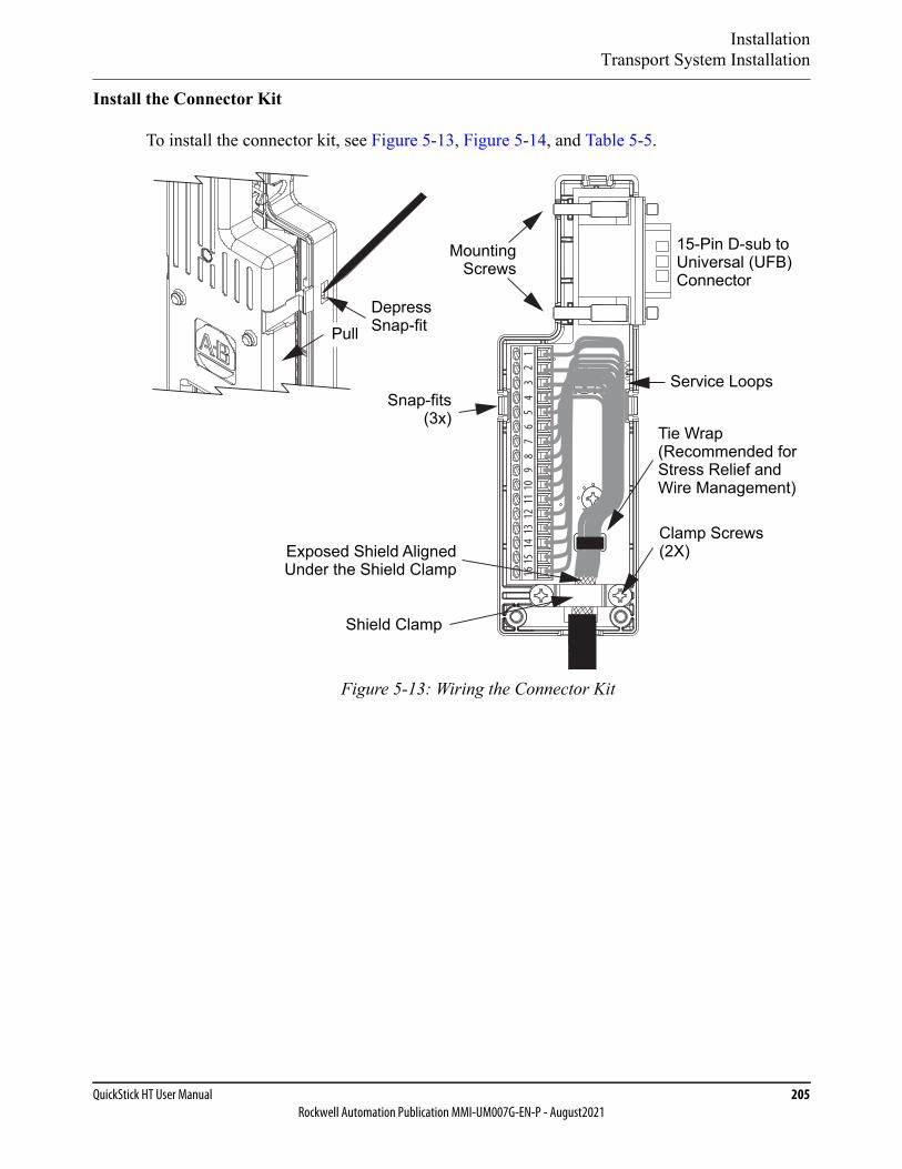
InstallationTransport System Installation
QuickStick HT User Manual 205Rockwell Automation Publication MMI-UM007G-EN-P - August2021
Install the Connector Kit
To install the connector kit, see Figure 5-13, Figure 5-14, and Table 5-5.
Figure 5-13: Wiring the Connector Kit
12
34
56
78
910
1112
1314
1516
PullDepressSnap-fit
MountingScrews
Snap-fits(3x)
Clamp ScrewsExposed Shield Aligned (2X)
15-Pin D-sub toUniversal (UFB)Connector
Service Loops
Tie Wrap(Recommended forStress Relief andWire Management)
Under the Shield Clamp
Shield Clamp

InstallationTransport System Installation
206 MagneMotionRockwell Automation Publication MMI-UM007G-EN-P - August2021
Figure 5-14: Connector Kit Pinout
1. Depress the snap-fits with a small screw driver or probe to remove the cover.
2. Route signal wires/drain wire to the proper terminals. See Figure 5-14, for the 16-pin terminal pinout.
3. Tighten terminal screws to achieve 0.25 N•m (2.2 lb•in), maximum torque.
4. Apply the shield clamp to the 12 mm (0.5 in) of exposed cable shield to achieve a high-frequency bond between the shield braid and clamp.
5. Attach a tie wrap (customer-supplied) for stress relief.
6. Tighten clamp screws to achieve 0.34 N•m (3.0 lb•in), maximum torque.
7. Replace the cover and install cover screw. Tighten cover screw to achieve 0.34 N•m (3.0 lb•in), maximum torque.
IMPORTANT The purpose of the shield clamp is to provide a properground and improve system performance. To achievethis, clamping the exposed braid under the shieldclamp is critical.
12
34
56
78
910
1112
1314
1516
Terminal Signal
1 Digital In Common2 Digital In Common3 No Connect4 Digital In 15 Digital In 26 Digital In 37 Digital In 48 Digital In Common9 Digital In Common
10 No Connect11 No Connect12 Digital In 413 Digital In 314 Digital In 215 Digital In 1
16-PinConnector
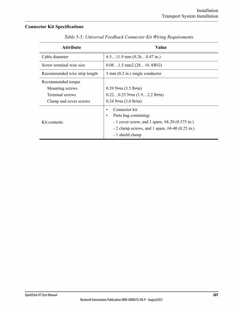
InstallationTransport System Installation
QuickStick HT User Manual 207Rockwell Automation Publication MMI-UM007G-EN-P - August2021
Connector Kit Specifications
Table 5-5: Universal Feedback Connector Kit Wiring Requirements
Attribute Value
Cable diameter 6.5…11.9 mm (0.26…0.47 in.)
Screw terminal wire size 0.08…1.5 mm2 (28…16 AWG)
Recommended wire strip length 5 mm (0.2 in.) single conductor
Recommended torque Mounting screws Terminal screws Clamp and cover screws
0.39 N•m (3.5 lb•in)0.22…0.25 N•m (1.9…2.2 lb•in)0.34 N•m (3.0 lb•in)
Kit contents
• Connector kit• Parts bag containing:
- 1 cover screw, and 1 spare, #4-20 (0.375 in.)- 2 clamp screws, and 1 spare, #4-40 (0.25 in.)- 1 shield clamp

InstallationTransport System Installation
208 MagneMotionRockwell Automation Publication MMI-UM007G-EN-P - August2021
Installing QSMC Motor Controller Power Cables
See Figure 4-24 and Figure 4-25 for the power connection locations on the QSMC motor con-trollers in the QSHT transport system. See Figure 5-5 and Figure 5-6 for simplified diagrams of the wiring. Figure 5-15 shows the power connections being made to the motor controllers.
Figure 5-15: QSHT Power Connections
NOTICE If a user-supplied power supply is used, it must beNRTL/ATL approved.
Node
1/2 m QSHT QSMCMotor Controller
Downstream
Upstream
1 m QSHT
24V DC Cable
Controller
HVDC Cable(typical) Power Junction Box
QSMC-2Motor Controller
Ground
GroundGround
Ground
(typical)
(typical)
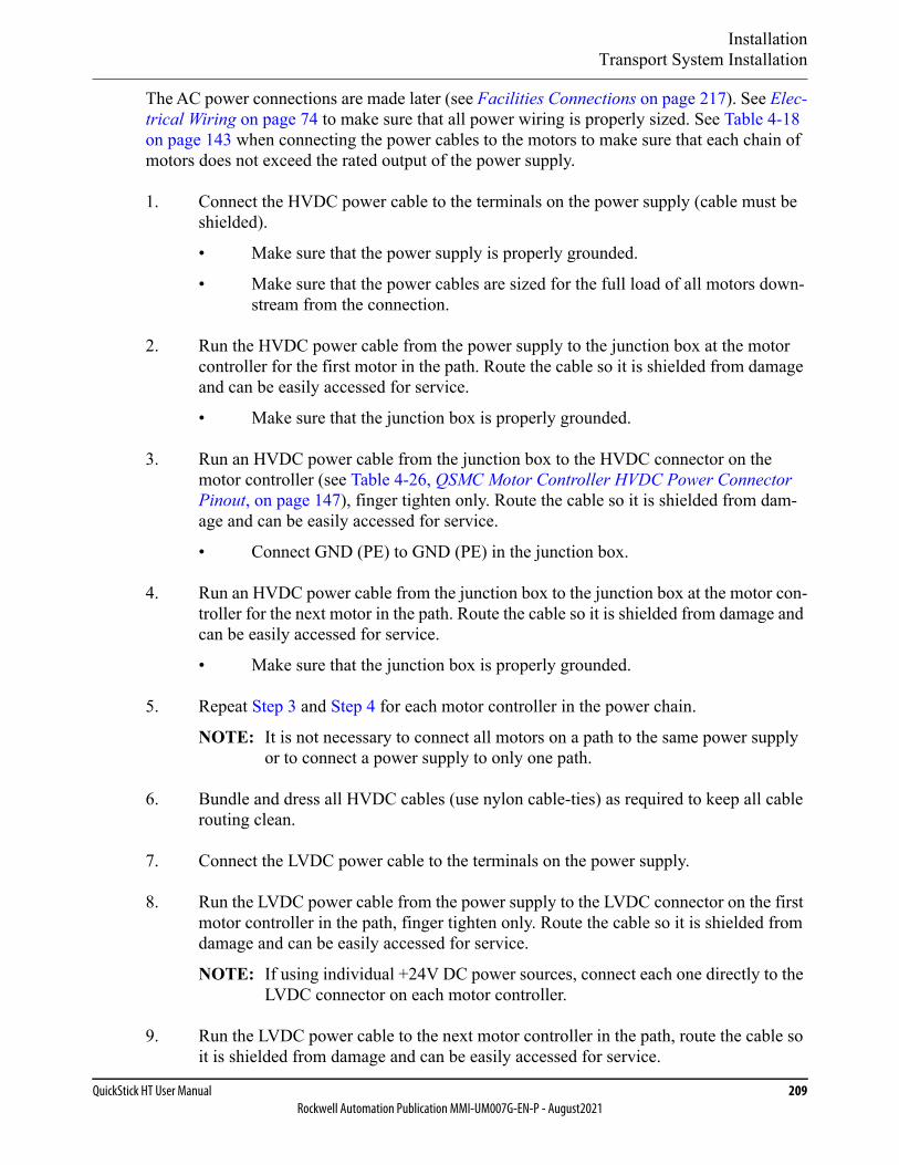
InstallationTransport System Installation
QuickStick HT User Manual 209Rockwell Automation Publication MMI-UM007G-EN-P - August2021
The AC power connections are made later (see Facilities Connections on page 217). See Elec-trical Wiring on page 74 to make sure that all power wiring is properly sized. See Table 4-18 on page 143 when connecting the power cables to the motors to make sure that each chain of motors does not exceed the rated output of the power supply.
1. Connect the HVDC power cable to the terminals on the power supply (cable must be shielded).
• Make sure that the power supply is properly grounded.
• Make sure that the power cables are sized for the full load of all motors down-stream from the connection.
2. Run the HVDC power cable from the power supply to the junction box at the motor controller for the first motor in the path. Route the cable so it is shielded from damage and can be easily accessed for service.
• Make sure that the junction box is properly grounded.
3. Run an HVDC power cable from the junction box to the HVDC connector on the motor controller (see Table 4-26, QSMC Motor Controller HVDC Power Connector Pinout, on page 147), finger tighten only. Route the cable so it is shielded from dam-age and can be easily accessed for service.
• Connect GND (PE) to GND (PE) in the junction box.
4. Run an HVDC power cable from the junction box to the junction box at the motor con-troller for the next motor in the path. Route the cable so it is shielded from damage and can be easily accessed for service.
• Make sure that the junction box is properly grounded.
5. Repeat Step 3 and Step 4 for each motor controller in the power chain.
NOTE: It is not necessary to connect all motors on a path to the same power supply or to connect a power supply to only one path.
6. Bundle and dress all HVDC cables (use nylon cable-ties) as required to keep all cable routing clean.
7. Connect the LVDC power cable to the terminals on the power supply.
8. Run the LVDC power cable from the power supply to the LVDC connector on the first motor controller in the path, finger tighten only. Route the cable so it is shielded from damage and can be easily accessed for service.
NOTE: If using individual +24V DC power sources, connect each one directly to the LVDC connector on each motor controller.
9. Run the LVDC power cable to the next motor controller in the path, route the cable so it is shielded from damage and can be easily accessed for service.

InstallationTransport System Installation
210 MagneMotionRockwell Automation Publication MMI-UM007G-EN-P - August2021
10. Repeat Step 9 for each motor controller in the power chain.
NOTE: It is not necessary to connect all motors on a path to the same power supply or to connect a power supply to only one path.
11. Bundle and dress all power cables (use nylon cable-ties) as required to keep all cable routing clean.
12. Make sure that all NC LITE node controllers are mounted to grounded surfaces.
13. Make sure that the Ground stud on all NC-12 node controllers is connected to GND (PE).
14. Make sure that all NC-E and NC-S node controllers are grounded through the chassis ground connection in their power connectors.
15. See Facilities Connections on page 217 for external power connections.
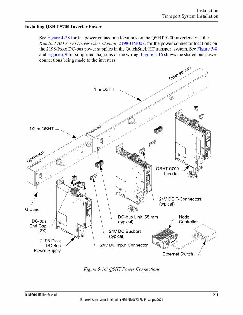
InstallationTransport System Installation
QuickStick HT User Manual 211Rockwell Automation Publication MMI-UM007G-EN-P - August2021
Installing QSHT 5700 Inverter Power
See Figure 4-28 for the power connection locations on the QSHT 5700 inverters. See the Kinetix 5700 Servo Drives User Manual, 2198-UM002, for the power connector locations on the 2198-Pxxx DC-bus power supplies in the QuickStick HT transport system. See Figure 5-8 and Figure 5-9 for simplified diagrams of the wiring. Figure 5-16 shows the shared bus power connections being made to the inverters.
Figure 5-16: QSHT Power Connections
Node
1/2 m QSHT
Downstream
Upstream
1 m QSHT
24V DC Busbars
Controller
Ground
QSHT 5700Inverter
2198-PxxxDC Bus
Power SupplyEthernet Switch
24V DC T-Connectors
24V DC Input Connector
DC-bus Link, 55 mmDC-bus
End Cap(2X)
(typical)
(typical)
(typical)
InstallationTransport System Installation
212 MagneMotionRockwell Automation Publication MMI-UM007G-EN-P - August2021
DC-bus Connection System
The DC-bus connection system is required and composed of these two components:• DC-bus links that are inserted between modules to extend the DC-bus from one mod-
ule to another.• DC-bus end-caps that are inserted into the first and last modules to cover the exposed
DC-bus connector on both ends of the bus.
24V Input Power Connection System
The optional 24V input power connection system always feeds 24V DC from left to right and is composed of three components:• The 24V input wiring connector that plugs into the 2198-Pxxx DC-bus power supply
or the first module that is supplied by the 24V external power.• 24V DC T-connectors that plug into the modules downstream from the power supply
or the first module that is supplied by the 24V external power where the 24V control power is shared.
• Busbars that connect between drive modules to extend the 24V control power from one drive module to another.
Wiring the Power Connections
NOTE: The AC power connections are made later (see Facilities Connections on page 217).See Input Power Configurations for Kinetix 5700 Power Supplies and Ground Screw/Jumper Settings in the Kinetix 5700 Servo Drives User Manual, 2198-UM002.See Electrical Wiring on page 74 to make sure that all power wiring is properly sized.See Table 4-38 on page 155 when connecting the power cables to the motors to make sure that each chain of motors does not exceed the rated output of the power supply.
1. Connect a DC Power-bus connector to the terminals on the power supply and to the first QSHT 5700 inverter.• Make sure that the power supply is properly grounded (see the Kinetix 5700
Servo Drives User Manual, 2198-UM002).• See the Kinetix 5700 Servo Drives User Manual, 2198-UM002 for bus installa-
tion.
2. For each inverter, connect a DC Power-bus connector to the terminals on the inverter and to the next QSHT 5700 inverter.NOTE: It is not necessary to connect all motors on a path to the same power supply
or to connect a power supply to only one path.
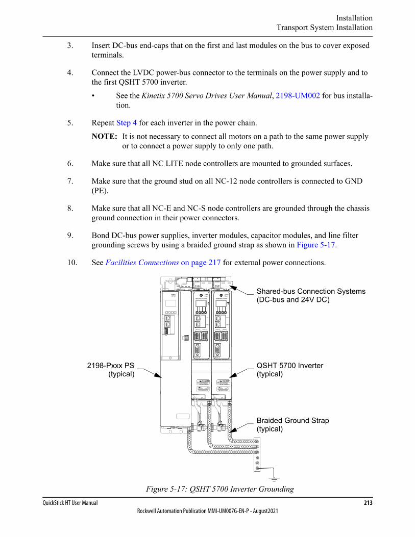
InstallationTransport System Installation
QuickStick HT User Manual 213Rockwell Automation Publication MMI-UM007G-EN-P - August2021
3. Insert DC-bus end-caps that on the first and last modules on the bus to cover exposed terminals.
4. Connect the LVDC power-bus connector to the terminals on the power supply and to the first QSHT 5700 inverter.• See the Kinetix 5700 Servo Drives User Manual, 2198-UM002 for bus installa-
tion.
5. Repeat Step 4 for each inverter in the power chain.NOTE: It is not necessary to connect all motors on a path to the same power supply
or to connect a power supply to only one path.
6. Make sure that all NC LITE node controllers are mounted to grounded surfaces.
7. Make sure that the ground stud on all NC-12 node controllers is connected to GND (PE).
8. Make sure that all NC-E and NC-S node controllers are grounded through the chassis ground connection in their power connectors.
9. Bond DC-bus power supplies, inverter modules, capacitor modules, and line filter grounding screws by using a braided ground strap as shown in Figure 5-17.
10. See Facilities Connections on page 217 for external power connections.
Figure 5-17: QSHT 5700 Inverter Grounding
MODNET
2
1
1
4
I/O
QSHT 5700 Inverter(typical)
2198-Pxxx PS(typical)
Shared-bus Connection Systems(DC-bus and 24V DC)
Braided Ground Strap(typical)
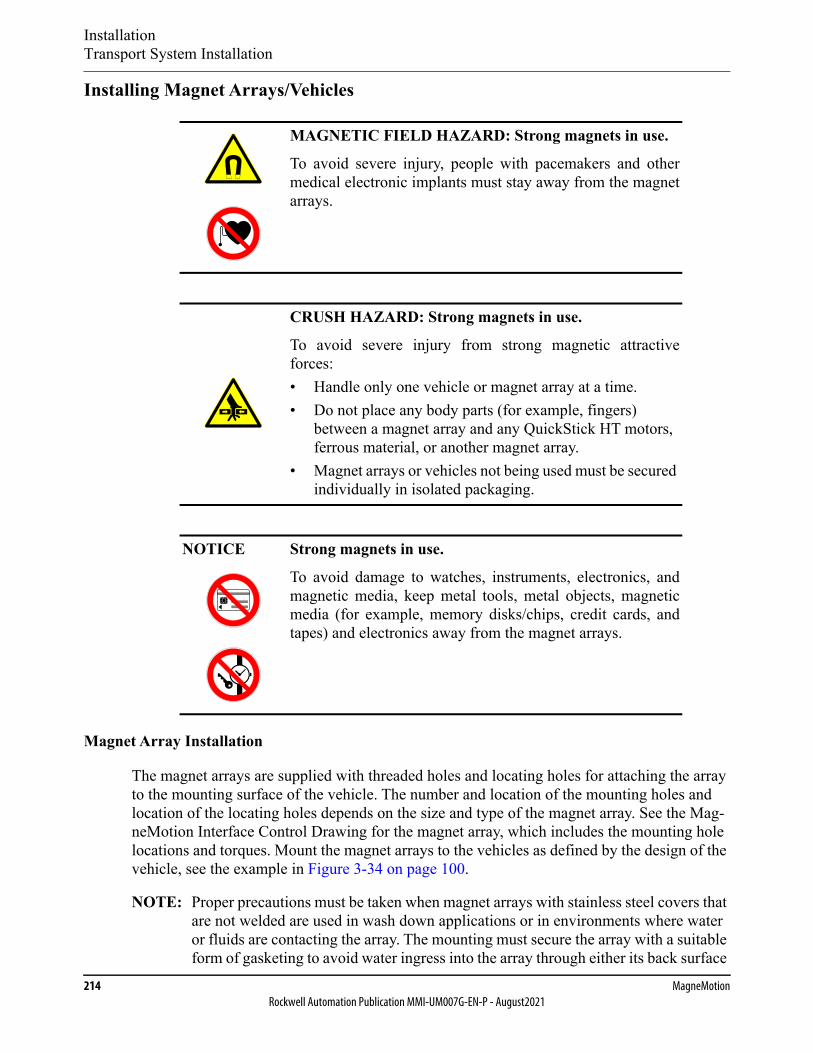
InstallationTransport System Installation
214 MagneMotionRockwell Automation Publication MMI-UM007G-EN-P - August2021
Installing Magnet Arrays/Vehicles
Magnet Array Installation
The magnet arrays are supplied with threaded holes and locating holes for attaching the array to the mounting surface of the vehicle. The number and location of the mounting holes and location of the locating holes depends on the size and type of the magnet array. See the Mag-neMotion Interface Control Drawing for the magnet array, which includes the mounting hole locations and torques. Mount the magnet arrays to the vehicles as defined by the design of the vehicle, see the example in Figure 3-34 on page 100.
NOTE: Proper precautions must be taken when magnet arrays with stainless steel covers that are not welded are used in wash down applications or in environments where water or fluids are contacting the array. The mounting must secure the array with a suitable form of gasketing to avoid water ingress into the array through either its back surface
MAGNETIC FIELD HAZARD: Strong magnets in use.
To avoid severe injury, people with pacemakers and othermedical electronic implants must stay away from the magnetarrays.
CRUSH HAZARD: Strong magnets in use.
To avoid severe injury from strong magnetic attractiveforces:• Handle only one vehicle or magnet array at a time.• Do not place any body parts (for example, fingers)
between a magnet array and any QuickStick HT motors, ferrous material, or another magnet array.
• Magnet arrays or vehicles not being used must be secured individually in isolated packaging.
NOTICE Strong magnets in use.
To avoid damage to watches, instruments, electronics, andmagnetic media, keep metal tools, metal objects, magneticmedia (for example, memory disks/chips, credit cards, andtapes) and electronics away from the magnet arrays.

InstallationTransport System Installation
QuickStick HT User Manual 215Rockwell Automation Publication MMI-UM007G-EN-P - August2021
or the seam where the cover meets the back iron of the array. The top surface and sides of the cover are water-resistant.
Mounting A Single Array
When installing one magnet array on one vehicle:
1. Work on only one vehicle at a time.
2. Make sure that the vehicle is secured to a work surface that is clear of any magnet arrays or ferrous material.
3. Move only one magnet array at a time and make sure that the magnet array stays as far away from all other magnets and any ferrous material as possible.
4. Locate the magnet array on the vehicle using the locating features on the magnet array as defined by the design of the vehicle.
5. Secure the magnet array to the vehicle using all provided mounting holes.
6. Once the array is secured to the vehicle, install the vehicle on the guideway.
Mounting Multiple Arrays
When installing multiple magnet arrays on one vehicle:
1. Work on only one vehicle at a time.
2. Make sure that the vehicle is secured to a work surface that is clear of any magnet arrays or ferrous material.
3. Place the first magnet array as described in Mounting A Single Array.
4. Cover the installed magnet array with non-ferrous material (for example, wood) thick enough to shield the attractive force from the magnet array (use a tool such as a steel screwdriver to test).
5. Bring each additional magnet array to the vehicle from the opposite direction of the installed magnet arrays.NOTE: When a magnet array is being installed butted up against the existing magnet
array, the existing magnet array repels that magnet array. Being repelled can cause the magnet array to attempt to twist away from the existing magnet array.
6. Locate the magnet array on the vehicle with the locating features on the magnet array.
7. Secure each additional magnet array to the vehicle as defined by the design of the vehicle.
8. Once all arrays are secured to the vehicle, install the vehicle on the track.
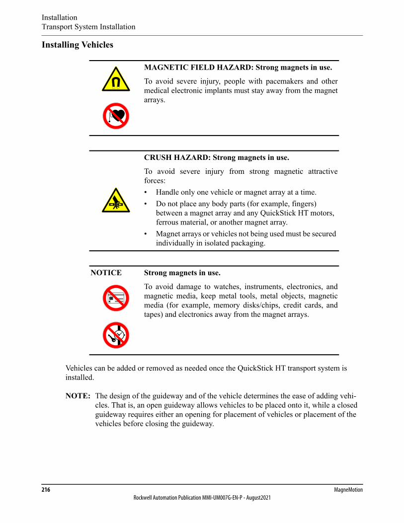
InstallationTransport System Installation
216 MagneMotionRockwell Automation Publication MMI-UM007G-EN-P - August2021
Installing Vehicles
Vehicles can be added or removed as needed once the QuickStick HT transport system is installed.
NOTE: The design of the guideway and of the vehicle determines the ease of adding vehi-cles. That is, an open guideway allows vehicles to be placed onto it, while a closed guideway requires either an opening for placement of vehicles or placement of the vehicles before closing the guideway.
MAGNETIC FIELD HAZARD: Strong magnets in use.
To avoid severe injury, people with pacemakers and othermedical electronic implants must stay away from the magnetarrays.
CRUSH HAZARD: Strong magnets in use.
To avoid severe injury from strong magnetic attractiveforces:• Handle only one vehicle or magnet array at a time.• Do not place any body parts (for example, fingers)
between a magnet array and any QuickStick HT motors, ferrous material, or another magnet array.
• Magnet arrays or vehicles not being used must be secured individually in isolated packaging.
NOTICE Strong magnets in use.
To avoid damage to watches, instruments, electronics, andmagnetic media, keep metal tools, metal objects, magneticmedia (for example, memory disks/chips, credit cards, andtapes) and electronics away from the magnet arrays.
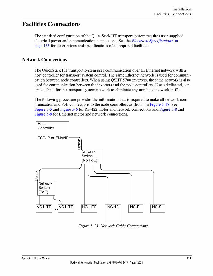
InstallationFacilities Connections
QuickStick HT User Manual 217Rockwell Automation Publication MMI-UM007G-EN-P - August2021
Facilities Connections
The standard configuration of the QuickStick HT transport system requires user-supplied electrical power and communication connections. See the Electrical Specifications on page 133 for descriptions and specifications of all required facilities.
Network Connections
The QuickStick HT transport system uses communication over an Ethernet network with a host controller for transport system control. The same Ethernet network is used for communi-cation between node controllers. When using QSHT 5700 inverters, the same network is also used for communication between the inverters and the node controllers. Use a dedicated, sep-arate subnet for the transport system network to eliminate any unrelated network traffic.
The following procedure provides the information that is required to make all network com-munication and PoE connections to the node controllers as shown in Figure 5-18. See Figure 5-5 and Figure 5-6 for RS-422 motor and network connections and Figure 5-8 and Figure 5-9 for Ethernet motor and network connections.
Figure 5-18: Network Cable Connections
HostController
TCP/IP or ENet/IP
Upl
ink
Upl
ink
NC LITE
NetworkSwitch(PoE)
. . .NC LITE NC-12 NC-SNC LITE NC-E
NetworkSwitch(No PoE)
InstallationFacilities Connections
218 MagneMotionRockwell Automation Publication MMI-UM007G-EN-P - August2021
1. Connect a Cat 5 network cable for transport system network communication from the host controller to the Uplink connector on the network switch as shown in Figure 5-18.
NOTE: When using multiple network switches to connect all node controllers, use one switch as a master and connect all other network switches to it as shown in Figure 5-18.
When using multiple MagneMotion PoE network switches, connect the Uplink from each switch to a master network switch as shown in Figure 5-18, do not daisy chain the PoE network switches.
2. Connect a Cat 5 cable for network communication from the network switch to each node controller, the Node Controller Hardware User Manual, MMI-UM013, for the connection locations.
Electrical Connections
Electrical power is connected to the QuickStick HT transport system for operation of the motors and other subsystems. An AC electrical connection is provided on those components that require facility power. See Electrical Specifications on page 133 for electrical require-ments. Make sure that all electrical connections are for the appropriate voltage and power rat-ing.
1. Connect power to each NC-S:
• Connect the AC power cable from either the optional remote power supply or a user-supplied power supply to the power distribution from the main power dis-connect for the facility. Then, connect the DC power cable to the power con-nector on each NC-S node controller.
NOTICE The Ethernet cable that connects a PoE networkswitch to the host controller or other networkswitches must connect to the Uplink port. Connectingto other ports can damage the network switches orother devices that are connected to the networkswitches.
NOTICE Do not turn on facility power until all installation procedureshave been completed.
NOTICE The NC-S node controller does not support Powerover Ethernet (PoE). Never connect these node con-trollers to a powered Ethernet network as damage tointernal components can result.
InstallationFacilities Connections
QuickStick HT User Manual 219Rockwell Automation Publication MMI-UM007G-EN-P - August2021
• Make sure that the NC-S node controllers are grounded through the DC power connection.
2. Connect power to each NC-E:
• Connect the AC power cable from the user-supplied power supply to the power distribution from the main power disconnect. Then, connect the DC power cable to the power connector on each NC-E node controller.
3. Connect power to each NC-12:
• Connect the AC power cable from either the optional remote power supply or a user-supplied power supply to the power distribution from the main power dis-connect for the facility. Then, connect the DC power cable to the power con-nector on each NC-12 node controller.
• Connect the Ground stud on all NC-12 node controllers to GND (PE).
4. Connect power to each NC LITE:
• When supplying Power over Ethernet to the NC LITE, make sure that the Ethernet connection goes to a +18V DC PoE enabled network switch. Plug the network switch power supply into the power distribution from the main power disconnect for the facility. Then, connect the cable from the switch power sup-ply to the switch.
• When supplying power directly to the NC LITE, plug the power supply into the power distribution from the main power disconnect for the facility. Then, connect the cable from the NC LITE power supply to the NC LITE.
• Make sure that the NC LITE node controllers are mounted to grounded sur-faces.
5. Connect an AC power cable from the power distribution on the main power disconnect for the facility to the power connector on the power supplies.
NOTICE The NC-E node controller does not support Powerover Ethernet (PoE). Never connect these node con-trollers to a powered Ethernet network as damage tointernal components can result.
NOTICE The NC-12 node controller does not support Powerover Ethernet (PoE). Never connect these node con-trollers to a powered Ethernet network as damage tointernal components can result.

InstallationFacilities Connections
220 MagneMotionRockwell Automation Publication MMI-UM007G-EN-P - August2021
E-stop Circuit
The QuickStick HT transport system can use digital I/O, provided through a node controller, for monitoring and control of local options such as an E-stop. The optional E-stop circuit is the responsibility of the user and requires a user-supplied E-stop button and DC power supply for the digital input. See the Node Controller Hardware User Manual, MMI-UM013, for the digital I/O equivalent circuits. See the QuickStick Configurator User Manual, MMI-UM009, for information on configuring an E-stop.
Interlock Circuit
The QuickStick HT transport system can use digital I/O, provided through a node controller, for monitoring and control of local options such as interlocks. The optional interlock circuit is the responsibility of the user and requires a user-supplied +3…24V DC power supply for the digital input. See the Node Controller Hardware User Manual, MMI-UM013, for the digital I/O equivalent circuits. See the QuickStick Configurator User Manual, MMI-UM009, for information on configuring an interlock.
Light Stack Circuit
The QuickStick HT transport system can use digital I/O, provided through a node controller, for monitoring and control of local options such as a light stack. The optional light stack cir-cuit is the responsibility of the user and requires a user-supplied 3-color light stack and +5…35V DC power supply (sized for the light stack) for the digital outputs. See the Node Controller Hardware User Manual, MMI-UM013, for the digital I/O equivalent circuits. See the QuickStick Configurator User Manual, MMI-UM009, for information on configuring a light stack.
General Purpose Digital I/O
The QuickStick HT transport system can use digital I/O, provided through a node controller to allow the host controller to monitor and control digital inputs and outputs, respectively. For node controller digital I/O, see the Node Controller Hardware User Manual, MMI-UM013, for the digital I/O equivalent circuits. See the Host Controller TCP/IP Communication Proto-col User Manual, MMI-UM003, or the Host Controller EtherNet/IP Communication Protocol User Manual, MMI-UM004 for the command details on performing these operations.
The QuickStick HT inverter provides four digital inputs with fast response times that can be configured for specific functions as shown in Table 5-6. See Figure 4-28 for the location of the digital in connector and Table 4-48 for the pinout.
SHOCK HAZARD: The E-stop is not the same as an EMO(Emergency Off), which removes power to the QuickStickHT transport system.

InstallationFacilities Connections
QuickStick HT User Manual 221Rockwell Automation Publication MMI-UM007G-EN-P - August2021
Node Electronics
The Merge and Diverge Nodes in the QuickStick HT transport system rely on external devices to provide the switching. This switching mechanism can be controlled through the digital I/O, provided through a node controller.
For Merge and Diverge Nodes that use digital I/O, control and status signals are used for each switch position. See the QuickStick Configurator User Manual, MMI-UM009, for informa-tion on configuring these nodes.
Table 5-6: QSHT 5700 Inverter Digital Input Configurable Functions
Function Description
Unassigned • No action is taken at the motor or inverter.• Status of the input is passed to the HLC through the
MMI_path_qs_ht_faults_status tag.
FastStop. • FastStop the motor connected to the inverter. No other motors on the path are affected.
• Status of the input is passed to the HLC through the MMI_path_qs_ht_faults_status tag.
Suspend. • Suspend the motor connected to the inverter. No other motors on the path are affected.
• Status of the input is passed to the HLC through the MMI_path_qs_ht_faults_status tag.

InstallationSoftware
222 MagneMotionRockwell Automation Publication MMI-UM007G-EN-P - August2021
Software
The QuickStick HT transport system requires user creation of the Node Controller Configura-tion File to define the transport system. And, creation of host controller software to direct vehicle motion for the particular application and to monitor transport system performance. MagneMotion provides software tools to simplify the creation of the Node Controller Config-uration File, for system testing, and for system monitoring. See Transport System Software Overview on page 37 for identification and descriptions of all software components.
Software Overview
Node controllers that are supplied with the QuickStick HT transport system ship with just a basic node controller software image installed. This image is only used for testing during manufacturing and must not be used to run the transport system. Since different systems run different versions of the software, this basic software must be replaced with the software being used for the transport system where the node controller is installed. All node control-ler-related files (node controller image, motor images and type files, and magnet array type files) must be uploaded to the node controller and activated before using the transport system. See the Node Controller Interface User Manual, MMI-UM001, for details.
All QuickStick HT motors ship with just a basic software image installed. This image is used for testing during manufacturing and must not be used to run the motors as part of a transport system. Since different systems run different versions of the software, this basic software must be replaced with the software being used for the transport system where the motors are installed.
Upgrades to the software can be uploaded through the network communication link. See the Upgrade Procedure in the Release Notes that are supplied with the software upgrade.
NOTE: Specific builds of the MagneMotion software may not implement all features that are described in this manual. See the Release Notes that are provided with the soft-ware for additional information.
All software running on the QuickStick HT transport system must be part of the same release. See the Release Notes that are provided with the software for addi-tional information.
Only qualified MagneMotion personnel or personnel that are directed by MagneMo-tion should make alterations or changes to the software.
Software Configuration
Create the Node Controller Configuration File (node_configuration.xml) with the QuickStick Configurator to define the components of the transport system and their relationship to each other. See Design Guidelines on page 59 and the QuickStick Configurator User Manual, MMI-UM009, for more details. The Node Controller Configuration File must then be
InstallationSoftware
QuickStick HT User Manual 223Rockwell Automation Publication MMI-UM007G-EN-P - August2021
uploaded to each node controller in the transport system before using the system. See the Node Controller Interface User Manual, MMI-UM001, for details.
Configure the host controller to control the transport system. See the Host Controller TCP/IP Communication Protocol User Manual, MMI-UM003, or the Host Controller EtherNet/IP Communication Protocol User Manual, MMI-UM004, depending on the host controller type.
Node Controller Software Installation
1. Upload the node controller image files to each node controller with the node controller web interface. See the Node Controller Interface User Manual, MMI-UM001, for details.
NOTE: Activate the image and reboot the node controller for the changes to take effect.
2. Upload the configuration files through the node controller web interface to each node controller. See the Node Controller Interface User Manual, MMI-UM001, for details.
NOTE: Restart the node controller for the changes to take effect.
Motor Software Installation
1. When using QSHT 5700 inverters:
A. Create a MICS file to define the network topology for the motors (see Ethernet Motor MICS File on page 90).
B. Upload the MICS file to each node controller using the node controller web interface and program (see the Node Controller Interface User Manual, MMI-UM001).
C. Cycle logic power to the inverters to force the motors to request their network provisioning.
2. Upload the Motor ERF Image files (motor_image.erf) to each node controller using the node controller web interface and program the motor masters and slaves. See Pro-gramming Motors on page 312 and the Node Controller Interface User Manual, MMI-UM001, for details.
NOTE: Restart the node controller for the changes to take effect.
3. Reset the paths where the motors were programmed (for example, use the NCHost TCP Interface Utility, see the NCHost TCP Interface Utility User Manual, MMI-UM010, for details).

InstallationCheck-out and Power-up
224 MagneMotionRockwell Automation Publication MMI-UM007G-EN-P - August2021
Check-out and Power-up
System Check-out
Before the QuickStick HT transport system is started for the first time, or after servicing the transport system, it is necessary to check all operating and safety features.
The following startup procedure is used to apply power to the QuickStick HT transport system in an orderly manner to make sure that all components are in known states. This procedure is used to prepare the transport system for full operation.
Mechanical Checks
• Verify that all shipping brackets have been removed.
• Make sure that all QuickStick HT components are properly and securely installed in the facility.
• Make sure that all hardware is secure.
• If the optional E-stop circuit is being used, make sure that the button is functional.
• Manually move a vehicle through the entire QSHT transport system to verify free vehicle motion (no binding).
Facility Checks
• Make sure that all facilities meet, or exceed, the requirements as described in the Elec-trical Specifications on page 133 and Site Requirements on page 174.
• Make sure that all system power and communication connections have been com-pleted.
• Check all cables. Verify that the connectors are fully seated and screws/locks are secured to make sure of good continuity.
• Verify that all cables are routed so they are shielded from damage and can be easily accessed for service and are away from any travel areas.
• Inspect all cables for restricting bend radii, excessive tension, or physical damage.
Pre-operation Checks
• Make sure that there are no obstructions in the travel path of the vehicles.

InstallationCheck-out and Power-up
QuickStick HT User Manual 225Rockwell Automation Publication MMI-UM007G-EN-P - August2021
System Power-up
After the QuickStick HT transport system has been installed, all connections must be checked. Then, an initial power-up must be performed before proceeding any further with the installa-tion process. This section describes the procedure for the initial installation check-out.
1. Make sure that all installation procedures that are previously described in this chapter have been completed.
2. Make sure that the system is properly grounded.
3. Connect the QuickStick HT transport system to the electrical services for the facility. Make sure that the power remains off.
4. Perform a Ground Continuity check from the surfaces of the QuickStick HT transport system to a known good ground.
5. Apply power to the QuickStick HT transport system.
CRUSH HAZARD: Moving mechanisms (vehicles) haveno obstruction sensors.
Do not operate the QuickStick HT transport system withoutbarriers in place or personal injury could result in the squeez-ing or compression of fingers, hands, or other body partsbetween moving mechanisms.
AUTOMATIC MOTION HAZARD: Whenever power isapplied, the possibility of automatic movement of the vehi-cles on the QuickStick HT transport system exists, whichcould result in personal injury.
SHOCK HAZARD: Each motor drive can draw400V DC maximum @ 15 A maximum. Make surethat the AC circuit suppling power to the power sup-plies for the motor drives is properly sized and prop-erly shielded.
NOTICE Use a current-limited power supply to verify thepolarity of all connections before using the systempower supply.
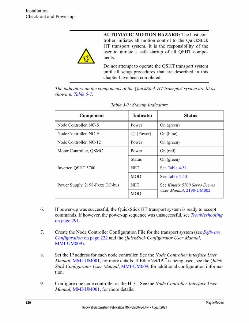
InstallationCheck-out and Power-up
226 MagneMotionRockwell Automation Publication MMI-UM007G-EN-P - August2021
The indicators on the components of the QuickStick HT transport system are lit as shown in Table 5-7.
6. If power-up was successful, the QuickStick HT transport system is ready to accept commands. If however, the power-up sequence was unsuccessful, see Troubleshooting on page 291.
7. Create the Node Controller Configuration File for the transport system (see Software Configuration on page 222 and the QuickStick Configurator User Manual, MMI-UM009).
8. Set the IP address for each node controller. See the Node Controller Interface User Manual, MMI-UM001, for more details. If EtherNet/IP™ is being used, see the Quick-Stick Configurator User Manual, MMI-UM009, for additional configuration informa-tion.
9. Configure one node controller as the HLC. See the Node Controller Interface User Manual, MMI-UM001, for more details.
AUTOMATIC MOTION HAZARD: The host con-troller initiates all motion control to the QuickStickHT transport system. It is the responsibility of theuser to initiate a safe startup of all QSHT compo-nents.
Do not attempt to operate the QSHT transport systemuntil all setup procedures that are described in thischapter have been completed.
Table 5-7: Startup Indicators
Component Indicator Status
Node Controller, NC-S Power On (green)
Node Controller, NC-E (Power) On (blue)
Node Controller, NC-12 Power On (green)
Motor Controller, QSMC Power On (red)
Status On (green)
Inverter, QSHT 5700 NET See Table 4-51
MOD See Table 4-50
Power Supply, 2198-Pxxx DC-bus NET See Kinetix 5700 Servo Drives User Manual, 2198-UM002
MOD

InstallationCheck-out and Power-up
QuickStick HT User Manual 227Rockwell Automation Publication MMI-UM007G-EN-P - August2021
10. Upload the configuration, image, and type files to each node controller (see the Node Controller Interface User Manual, MMI-UM001).
11. When using QSHT 5700 inverters:
A. Create a MICS file (see Ethernet Motor MICS File on page 90).
B. Upload the MICS file to all node controllers (see the Node Controller Interface User Manual, MMI-UM001).
C. Cycle logic power to the motors to force the motors to request their network provisioning.
12. Program the masters and slaves for the motors. See the Node Controller Interface User Manual, MMI-UM001, for details.
13. Review the log files for each node controller to make sure that the system has been programmed and configured properly (see the Node Controller Interface User Man-ual, MMI-UM001).
InstallationSystem Testing
228 MagneMotionRockwell Automation Publication MMI-UM007G-EN-P - August2021
System Testing
Test the QuickStick HT transport system to verify proper operation of all nodes, paths, and vehicles. Testing can be accomplished using the MagneMotion NCHost application to move vehicles without the host controller to verify proper operation before integrating a transport system into a production environment. Create Demo Scripts to perform repetitive testing throughout the transport system (see the NCHost TCP Interface Utility User Manual, MMI-UM010, for details). If any problems are encountered, see Troubleshooting on page 291.
1. Make sure that the transport system is fully configured.
2. Make sure that the Node Controller Configuration File is fully defined and has been uploaded to all node controllers (see the Node Controller Interface User Manual, MMI-UM001).
3. Make sure that the web interface for each node controller shows a status of run-ning/valid (see the Node Controller Interface User Manual, MMI-UM001).
4. Issue a Restart Services command for each node controller (see the Node Controller Interface User Manual, MMI-UM001).
5. Issue a Reset command for all paths (see the Node Controller Interface User Manual, MMI-UM001).All motors on the paths in the transport system are reset.
6. Issue a Startup command to all paths (see the Node Controller Interface User Manual, MMI-UM001).Motion on all paths is enabled, all vehicles on the paths are identified and located, and the paths become operational.
CRUSH HAZARD: Moving mechanisms (vehicles) haveno obstruction sensors.
Do not operate the QuickStick HT transport system withoutbarriers in place or personal injury could result in the squeez-ing or compression of fingers, hands, or other body partsbetween moving mechanisms.
CRUSH HAZARD: The vehicles move during thestartup sequence.

InstallationSystem Testing
QuickStick HT User Manual 229Rockwell Automation Publication MMI-UM007G-EN-P - August2021
7. Verify that the host controller has identified all vehicles in the transport system (see the NCHost TCP Interface Utility User Manual, MMI-UM010).
8. Move vehicles individually or create a Demo Script for repetitive testing (see the NCHost TCP Interface Utility User Manual, MMI-UM010).
9. Monitor transport system operation with the NCHost TCP Interface Utility.

Installation
230 MagneMotionRockwell Automation Publication MMI-UM007G-EN-P - August2021
This page intentionally left blank.

QuickStick HT User Manual 231Rockwell Automation Publication MMI-UM007G-EN-P - August2021
Operation 6
Overview
This chapter provides an overview of operation for the QuickStick® High Thrust transport system. The operation of the QSHT transport system is covered for both normal conditions and emergency conditions.
Included in this chapter are:
• Theory of operation of the MagneMotion® linear synchronous motors and the Quick-Stick HT transport system.
• Controls and indicators that are provided on the system.
• Simulation of QSHT transport system operation.
• Operational startup and shutdown.
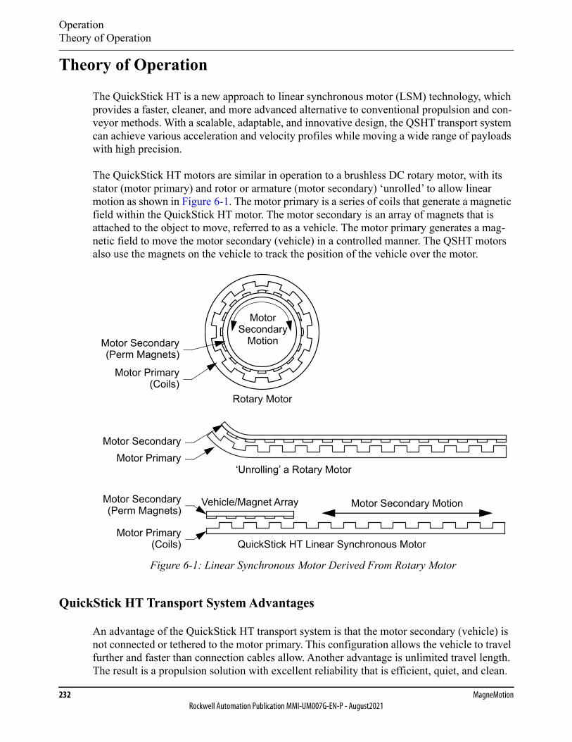
OperationTheory of Operation
232 MagneMotionRockwell Automation Publication MMI-UM007G-EN-P - August2021
Theory of Operation
The QuickStick HT is a new approach to linear synchronous motor (LSM) technology, which provides a faster, cleaner, and more advanced alternative to conventional propulsion and con-veyor methods. With a scalable, adaptable, and innovative design, the QSHT transport system can achieve various acceleration and velocity profiles while moving a wide range of payloads with high precision.
The QuickStick HT motors are similar in operation to a brushless DC rotary motor, with its stator (motor primary) and rotor or armature (motor secondary) ‘unrolled’ to allow linear motion as shown in Figure 6-1. The motor primary is a series of coils that generate a magnetic field within the QuickStick HT motor. The motor secondary is an array of magnets that is attached to the object to move, referred to as a vehicle. The motor primary generates a mag-netic field to move the motor secondary (vehicle) in a controlled manner. The QSHT motors also use the magnets on the vehicle to track the position of the vehicle over the motor.
Figure 6-1: Linear Synchronous Motor Derived From Rotary Motor
QuickStick HT Transport System Advantages
An advantage of the QuickStick HT transport system is that the motor secondary (vehicle) is not connected or tethered to the motor primary. This configuration allows the vehicle to travel further and faster than connection cables allow. Another advantage is unlimited travel length. The result is a propulsion solution with excellent reliability that is efficient, quiet, and clean.
Rotary Motor
‘Unrolling’ a Rotary Motor
Motor Secondary MotionVehicle/Magnet Array
QuickStick HT Linear Synchronous Motor
Motor SecondaryMotor Primary
Motor Primary
Motor Secondary
MotorSecondary
Motion(Perm Magnets)
(Coils)
Motor Secondary(Perm Magnets)
Motor Primary(Coils)
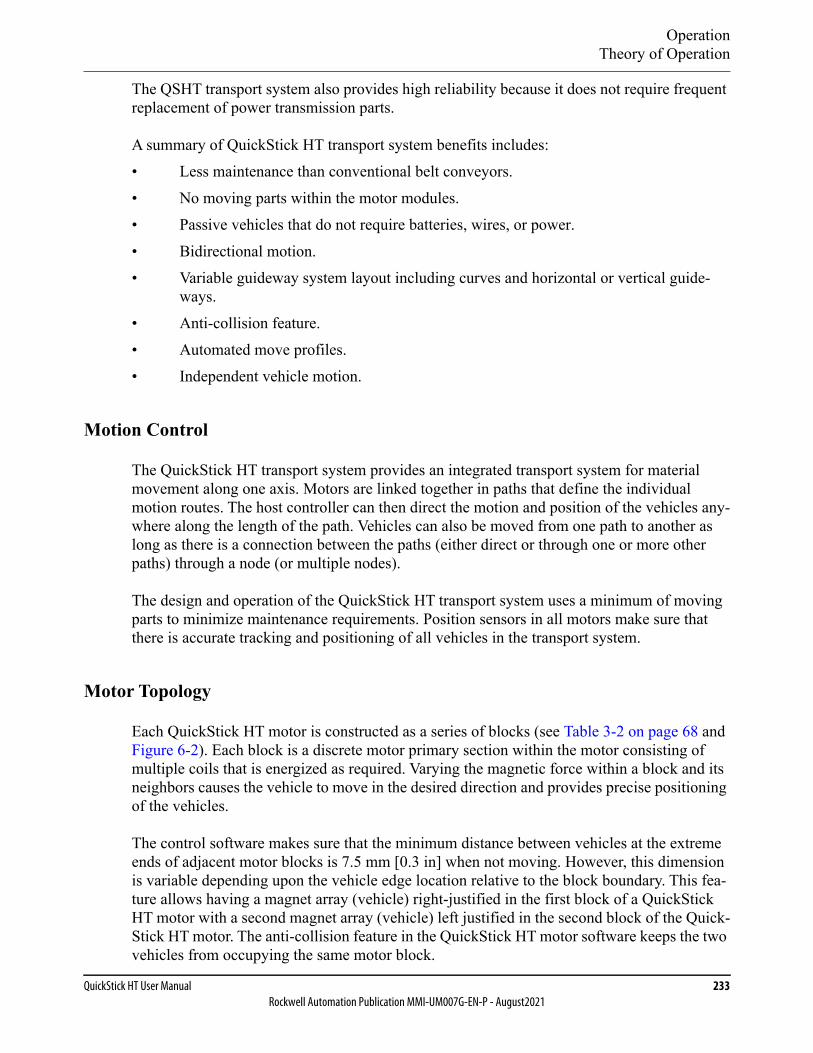
OperationTheory of Operation
QuickStick HT User Manual 233Rockwell Automation Publication MMI-UM007G-EN-P - August2021
The QSHT transport system also provides high reliability because it does not require frequent replacement of power transmission parts.
A summary of QuickStick HT transport system benefits includes:• Less maintenance than conventional belt conveyors.• No moving parts within the motor modules.• Passive vehicles that do not require batteries, wires, or power.• Bidirectional motion.• Variable guideway system layout including curves and horizontal or vertical guide-
ways.• Anti-collision feature.• Automated move profiles.• Independent vehicle motion.
Motion Control
The QuickStick HT transport system provides an integrated transport system for material movement along one axis. Motors are linked together in paths that define the individual motion routes. The host controller can then direct the motion and position of the vehicles any-where along the length of the path. Vehicles can also be moved from one path to another as long as there is a connection between the paths (either direct or through one or more other paths) through a node (or multiple nodes).
The design and operation of the QuickStick HT transport system uses a minimum of moving parts to minimize maintenance requirements. Position sensors in all motors make sure that there is accurate tracking and positioning of all vehicles in the transport system.
Motor Topology
Each QuickStick HT motor is constructed as a series of blocks (see Table 3-2 on page 68 and Figure 6-2). Each block is a discrete motor primary section within the motor consisting of multiple coils that is energized as required. Varying the magnetic force within a block and its neighbors causes the vehicle to move in the desired direction and provides precise positioning of the vehicles.
The control software makes sure that the minimum distance between vehicles at the extreme ends of adjacent motor blocks is 7.5 mm [0.3 in] when not moving. However, this dimension is variable depending upon the vehicle edge location relative to the block boundary. This fea-ture allows having a magnet array (vehicle) right-justified in the first block of a QuickStick HT motor with a second magnet array (vehicle) left justified in the second block of the Quick-Stick HT motor. The anti-collision feature in the QuickStick HT motor software keeps the two vehicles from occupying the same motor block.
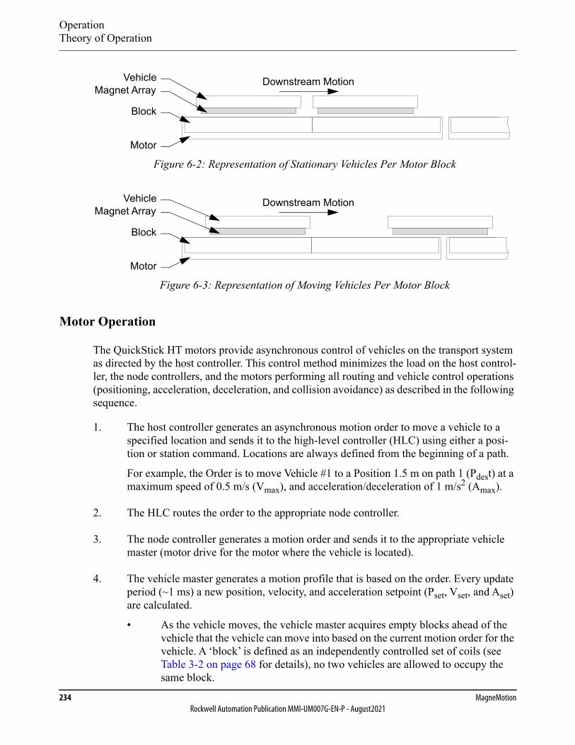
OperationTheory of Operation
234 MagneMotionRockwell Automation Publication MMI-UM007G-EN-P - August2021
Figure 6-2: Representation of Stationary Vehicles Per Motor Block
Figure 6-3: Representation of Moving Vehicles Per Motor Block
Motor Operation
The QuickStick HT motors provide asynchronous control of vehicles on the transport system as directed by the host controller. This control method minimizes the load on the host control-ler, the node controllers, and the motors performing all routing and vehicle control operations (positioning, acceleration, deceleration, and collision avoidance) as described in the following sequence.
1. The host controller generates an asynchronous motion order to move a vehicle to a specified location and sends it to the high-level controller (HLC) using either a posi-tion or station command. Locations are always defined from the beginning of a path.
For example, the Order is to move Vehicle #1 to a Position 1.5 m on path 1 (Pdest) at a maximum speed of 0.5 m/s (Vmax), and acceleration/deceleration of 1 m/s2 (Amax).
2. The HLC routes the order to the appropriate node controller.
3. The node controller generates a motion order and sends it to the appropriate vehicle master (motor drive for the motor where the vehicle is located).
4. The vehicle master generates a motion profile that is based on the order. Every update period (~1 ms) a new position, velocity, and acceleration setpoint (Pset, Vset, and Aset) are calculated.
• As the vehicle moves, the vehicle master acquires empty blocks ahead of the vehicle that the vehicle can move into based on the current motion order for the vehicle. A ‘block’ is defined as an independently controlled set of coils (see Table 3-2 on page 68 for details), no two vehicles are allowed to occupy the same block.
Vehicle
Motor
Block
Magnet ArrayDownstream Motion
Vehicle
Motor
Block
Magnet ArrayDownstream Motion
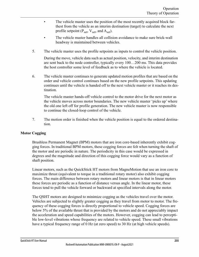
OperationTheory of Operation
QuickStick HT User Manual 235Rockwell Automation Publication MMI-UM007G-EN-P - August2021
• The vehicle master uses the position of the most recently acquired block far-thest from the vehicle as an interim destination (target) to calculate the next profile setpoint (Pset, Vset, and Aset).
• The vehicle master handles all collision avoidance to make sure brick-wall headway is maintained between vehicles.
5. The vehicle master uses the profile setpoints as inputs to control the vehicle position.
During the move, vehicle data such as actual position, velocity, and interim destination are sent back to the node controller, typically every 100…200 ms. This data provides the host controller some level of feedback as to where the vehicle is located.
6. The vehicle master continues to generate updated motion profiles that are based on the order and vehicle control continues based on the new profile setpoints. This updating continues until the vehicle is handed off to the next vehicle master or it reaches its des-tination.
The vehicle master hands-off vehicle control to the motor drive for the next motor as the vehicle moves across motor boundaries. The new vehicle master ‘picks up’ where the old one left off for profile generation. The new vehicle master is now responsible to continue the closed-loop control of the vehicle.
7. The motion order is finished when the vehicle position is equal to the ordered destina-tion.
Motor Cogging
Brushless Permanent Magnet (BPM) motors that are iron core-based inherently exhibit cog-ging forces. In traditional BPM motors, these cogging forces are felt when turning the shaft of the motor and are periodic in nature. The periodicity in this case would be expressed in degrees and the magnitude and direction of this cogging force would vary as a function of shaft position.
Linear motors, such as the QuickStick HT motors from MagneMotion that use an iron core to maximize thrust (equivalent to torque in a traditional rotary motor) also exhibit cogging forces. The main difference between rotary motors and linear motors is that in linear motors these forces are periodic as a function of distance versus angle. In the linear motor, these forces tend to pull the vehicle forward or backward at specified intervals along the motor.
The QSHT motors are designed to minimize cogging as the vehicles travel over the motor. Vehicles are subjected to slightly greater cogging as they travel from motor to motor. The fre-quency of these cogging forces is directly proportional to vehicle speed. Cogging forces are below 5% of the available thrust that is provided by the motors and do not appreciably impact the acceleration and speed capabilities of the motors. However, cogging can lead to percepti-ble low-level vibrations whose frequency are related to vehicle speed. These small vibrations have a typical frequency range of 0 Hz (at zero speed) to 30 Hz (at high vehicle speeds).

OperationTheory of Operation
236 MagneMotionRockwell Automation Publication MMI-UM007G-EN-P - August2021
For general transport and conveyance applications, cogging effects are not observable or per-ceptible if the vehicle, track, and payload design do not exhibit a sharp resonance within the 0…30 Hz range. However, for payloads susceptible to vibration, these cogging effects can have an impact and require special attention to suppress them. See Motor Cogging on page 72 for installation methods to minimize cogging.
Motor Blocks
A motor block is a discrete motor section within each QuickStick HT motor as shown in Figure 6-2 and Figure 6-3. Each block is a set of independently controlled copper windings that are driven by one inverter, with multiple blocks creating the motor primary (stator). Each of the copper windings has an iron core, which creates an attractive force between the magnet array and motor even when the motor is not powered.
Block Acquisition
The drive for each motor takes ownership of vehicles when they enter the motor or are identi-fied during startup and maintains that ownership the entire time the vehicle is on the motor. Ownership includes identification of the final destination, maximum acceleration, and maxi-mum velocity as defined in the current motion order and determination of the interim destina-tion for the vehicle and current acceleration and velocity setpoints.
The drive makes sure that the vehicle has acquired sufficient empty blocks ahead of the vehi-cle in the direction of motion to maintain brick-wall headway with the current motion profile. The vehicle is said to own these blocks until they are released. Headway is maintained by communicating with the motors ahead of the vehicle to make sure that sufficient blocks can be acquired to define new interim destinations.
• The vehicle master uses the position of the most recently acquired block farthest from the vehicle as an interim destination (target) to calculate the next profile setpoint (Pset, Vset, and Aset).
• A new interim destination (target) block is only granted if the block has not been allo-cated to another vehicle (that is, permission is granted for only one vehicle per motor block).
• A new target is requested only immediately before the vehicle must start slowing down for its current target to minimize the number of committed blocks and to make sure brick-wall headway is maintained.
• Permission to enter a motor block is only granted after the previous vehicle has exited the block and released ownership.
• Each vehicle is controlled in such a manner that it is always able to stop in the last motor block it was granted permission to enter.
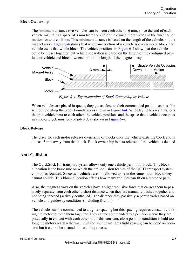
OperationTheory of Operation
QuickStick HT User Manual 237Rockwell Automation Publication MMI-UM007G-EN-P - August2021
Block Ownership
The minimum distance two vehicles can be from each other is 6 mm, since the end of each vehicle maintains a space of 3 mm from the end of the owned motor block in the direction of motion for anti-collision. This minimum distance is based on the length of the vehicle, not the magnet array. Figure 6-4 shows that when any portion of a vehicle is over a motor block, the vehicle owns that whole block. The vehicle positions in Figure 6-4 show that the vehicles could be closer together, but vehicle separation is based on the length of the configured pay-load or vehicle and block ownership, not the length of the magnet array.
Figure 6-4: Representation of Block Ownership by Vehicle
When vehicles are placed in queue, they get as close to their commanded position as possible without violating the block boundaries as shown in Figure 6-4. When trying to create stations that put vehicle next to each other, the vehicle positions and the space that a vehicle occupies in a motor block must be considered, as shown in Figure 6-4.
Block Release
The drive for each motor releases ownership of blocks once the vehicle exits the block and is at least 3 mm away from that block. Block ownership is also released if the vehicle is deleted.
Anti-Collision
The QuickStick HT transport system allows only one vehicle per motor block. This block allocation is the basic rule on which the anti-collision feature of the QSHT transport system controls is founded. Since two vehicles are not allowed to be in the same motor block, they cannot collide. This block allocation affects how many vehicles can fit on a motor or path.
Also, the magnet arrays on the vehicles have a slight repulsive force that causes them to pas-sively separate from each other a short distance when they are manually pushed together and not being servoed (actively controlled). The distance they passively separate varies based on vehicle and guideway conditions (including friction).
The vehicles can be commanded to a tighter spacing but this spacing requires constantly driv-ing the motor to force them together. They can be commanded to a position where they are practically in contact with each other but if this constant, close position condition is held too long the motors reach a thermal limit and shut down. This tight spacing can be done on occa-sion but it cannot be a standard part of a process.
3 mmSpace Vehicle Occupies
Downstream MotionVehicle
Motor
Block
Magnet Array
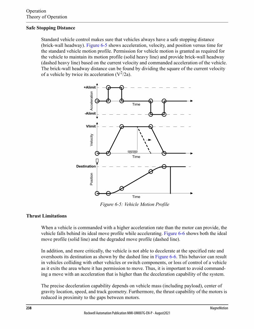
OperationTheory of Operation
238 MagneMotionRockwell Automation Publication MMI-UM007G-EN-P - August2021
Safe Stopping Distance
Standard vehicle control makes sure that vehicles always have a safe stopping distance (brick-wall headway). Figure 6-5 shows acceleration, velocity, and position versus time for the standard vehicle motion profile. Permission for vehicle motion is granted as required for the vehicle to maintain its motion profile (solid heavy line) and provide brick-wall headway (dashed heavy line) based on the current velocity and commanded acceleration of the vehicle. The brick-wall headway distance can be found by dividing the square of the current velocity of a vehicle by twice its acceleration (V2/2a).
Figure 6-5: Vehicle Motion Profile
Thrust Limitations
When a vehicle is commanded with a higher acceleration rate than the motor can provide, the vehicle falls behind its ideal move profile while accelerating. Figure 6-6 shows both the ideal move profile (solid line) and the degraded move profile (dashed line).
In addition, and more critically, the vehicle is not able to decelerate at the specified rate and overshoots its destination as shown by the dashed line in Figure 6-6. This behavior can result in vehicles colliding with other vehicles or switch components, or loss of control of a vehicle as it exits the area where it has permission to move. Thus, it is important to avoid command-ing a move with an acceleration that is higher than the deceleration capability of the system.
The precise deceleration capability depends on vehicle mass (including payload), center of gravity location, speed, and track geometry. Furthermore, the thrust capability of the motors is reduced in proximity to the gaps between motors.
Destination
Vlimit
-Alimit
+Alimit
Time
Time
Time
Posi
tion
Velo
city
Acce
lera
tion
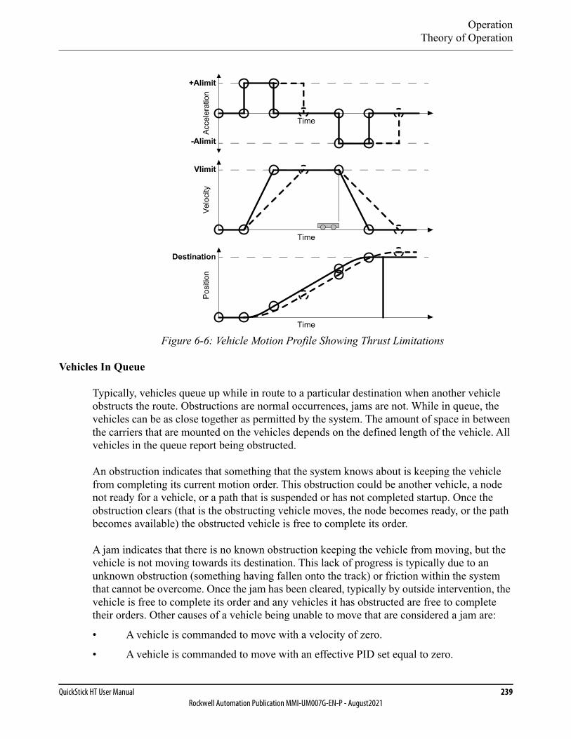
OperationTheory of Operation
QuickStick HT User Manual 239Rockwell Automation Publication MMI-UM007G-EN-P - August2021
Figure 6-6: Vehicle Motion Profile Showing Thrust Limitations
Vehicles In Queue
Typically, vehicles queue up while in route to a particular destination when another vehicle obstructs the route. Obstructions are normal occurrences, jams are not. While in queue, the vehicles can be as close together as permitted by the system. The amount of space in between the carriers that are mounted on the vehicles depends on the defined length of the vehicle. All vehicles in the queue report being obstructed.
An obstruction indicates that something that the system knows about is keeping the vehicle from completing its current motion order. This obstruction could be another vehicle, a node not ready for a vehicle, or a path that is suspended or has not completed startup. Once the obstruction clears (that is the obstructing vehicle moves, the node becomes ready, or the path becomes available) the obstructed vehicle is free to complete its order.
A jam indicates that there is no known obstruction keeping the vehicle from moving, but the vehicle is not moving towards its destination. This lack of progress is typically due to an unknown obstruction (something having fallen onto the track) or friction within the system that cannot be overcome. Once the jam has been cleared, typically by outside intervention, the vehicle is free to complete its order and any vehicles it has obstructed are free to complete their orders. Other causes of a vehicle being unable to move that are considered a jam are:
• A vehicle is commanded to move with a velocity of zero.
• A vehicle is commanded to move with an effective PID set equal to zero.
OperationTheory of Operation
240 MagneMotionRockwell Automation Publication MMI-UM007G-EN-P - August2021
Vehicle Length Through Curves and Switches
The width of the vehicles is not defined in the Node Controller Configuration File. To make sure that multiple vehicles can move on curved sections of the transport system without col-liding, the vehicle length must be defined longer than it actually is to account for the width of the vehicle in a curve. The value of the defined length must be calculated using basic trigo-nometry, see the QuickStick Configurator User Manual, MMI-UM009.
Locating Vehicles During Startup
The node controller scans for the magnet array on the vehicles starting from the upstream end of a path and scanning towards the downstream end of the path. When the node controller detects a magnet array (vehicle), it attempts to locate it precisely by moving the vehicle into the adjacent motor block in the downstream direction to determine its position (using the sen-sors in the next motor block). If the node controller is able to move the vehicle, it assigns the vehicle a Vehicle ID. If another vehicle occupies the adjacent motor block (or there are no more motor blocks downstream), it looks to the next detected vehicle and tries to move it. The node controller continues scanning for vehicles until it locates a new one. It will try to move an already located vehicle to make room to locate a new detected vehicle if there is additional room to move the already located vehicle that is in the way.
If the node controller scans to the end of the path, and it was unable to move any detected new vehicles into a downstream motor block or it is unable to move existing vehicles for room, it switches directions and begins scanning in the upstream direction from the downstream end of the path. The node controller assigns a vehicle ID to the next vehicle it can move into an adja-cent upstream motor block to determine its position.
NOTE: There must be at least one motor block free per path for startup to succeed.
The node controller continues to scan back and forth in the downstream and upstream direc-tions until all vehicles detected have been assigned a vehicle ID. This scanning could take sev-eral seconds to several minutes depending on how many vehicles are on a path. If the node controller scans in the downstream direction and then scans in the upstream direction of a path without being able to move any vehicles, startup fails for that path. This failure could be due to either due to no space to move a detected vehicle or a jammed vehicle.
Once a vehicle ID is assigned, it remains with that vehicle until the vehicle is removed from the QuickStick HT transport system, the vehicle is deleted, or a Reset is issued for the path. Vehicles are removed via a Terminus Node or deleted with a Delete Vehicle command.
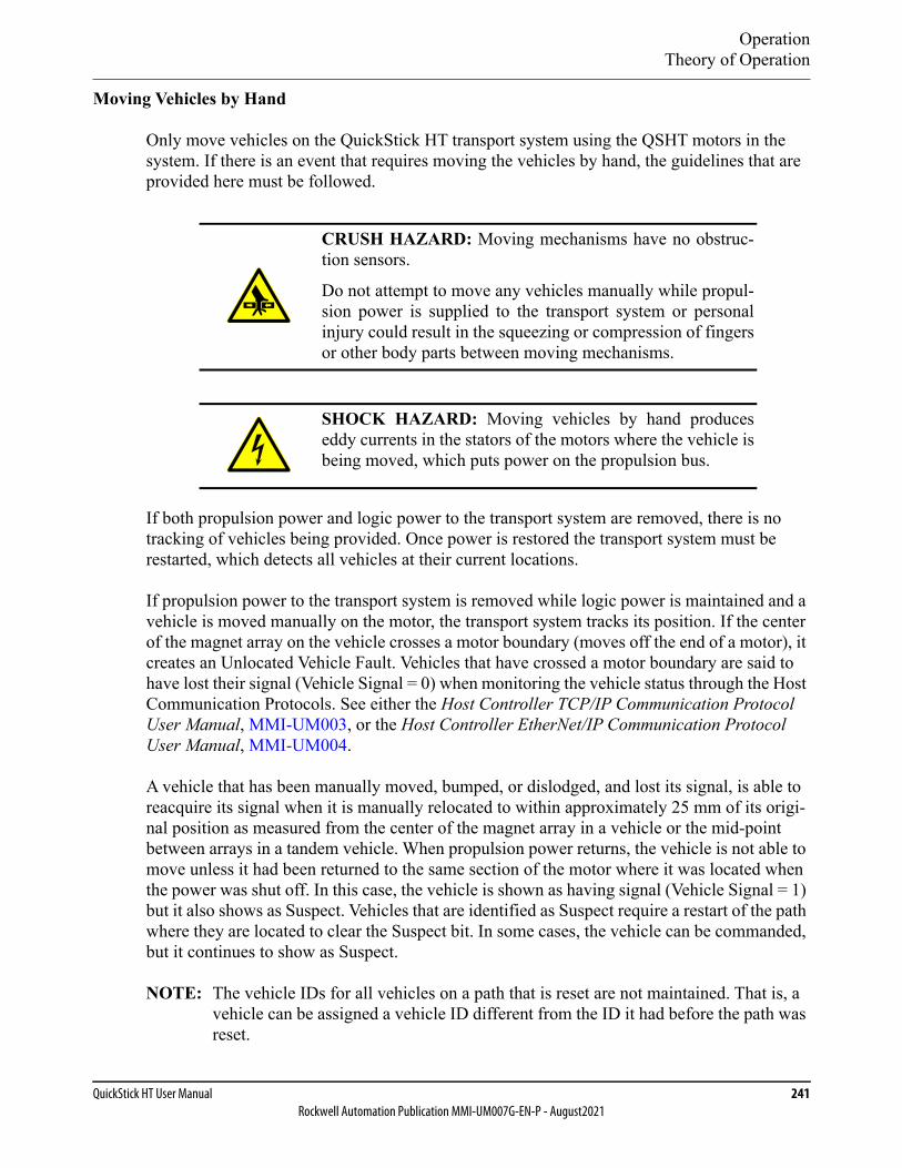
OperationTheory of Operation
QuickStick HT User Manual 241Rockwell Automation Publication MMI-UM007G-EN-P - August2021
Moving Vehicles by Hand
Only move vehicles on the QuickStick HT transport system using the QSHT motors in the system. If there is an event that requires moving the vehicles by hand, the guidelines that are provided here must be followed.
If both propulsion power and logic power to the transport system are removed, there is no tracking of vehicles being provided. Once power is restored the transport system must be restarted, which detects all vehicles at their current locations.
If propulsion power to the transport system is removed while logic power is maintained and a vehicle is moved manually on the motor, the transport system tracks its position. If the center of the magnet array on the vehicle crosses a motor boundary (moves off the end of a motor), it creates an Unlocated Vehicle Fault. Vehicles that have crossed a motor boundary are said to have lost their signal (Vehicle Signal = 0) when monitoring the vehicle status through the Host Communication Protocols. See either the Host Controller TCP/IP Communication Protocol User Manual, MMI-UM003, or the Host Controller EtherNet/IP Communication Protocol User Manual, MMI-UM004.
A vehicle that has been manually moved, bumped, or dislodged, and lost its signal, is able to reacquire its signal when it is manually relocated to within approximately 25 mm of its origi-nal position as measured from the center of the magnet array in a vehicle or the mid-point between arrays in a tandem vehicle. When propulsion power returns, the vehicle is not able to move unless it had been returned to the same section of the motor where it was located when the power was shut off. In this case, the vehicle is shown as having signal (Vehicle Signal = 1) but it also shows as Suspect. Vehicles that are identified as Suspect require a restart of the path where they are located to clear the Suspect bit. In some cases, the vehicle can be commanded, but it continues to show as Suspect.
NOTE: The vehicle IDs for all vehicles on a path that is reset are not maintained. That is, a vehicle can be assigned a vehicle ID different from the ID it had before the path was reset.
CRUSH HAZARD: Moving mechanisms have no obstruc-tion sensors.
Do not attempt to move any vehicles manually while propul-sion power is supplied to the transport system or personalinjury could result in the squeezing or compression of fingersor other body parts between moving mechanisms.
SHOCK HAZARD: Moving vehicles by hand produceseddy currents in the stators of the motors where the vehicle isbeing moved, which puts power on the propulsion bus.

OperationTheory of Operation
242 MagneMotionRockwell Automation Publication MMI-UM007G-EN-P - August2021
If both propulsion power and logic power are maintained and a vehicle is moved manually, the motor resists motion of the vehicle. Once the vehicle is released, it snaps back to its original position if it has not been moved vary far (less than 25 mm) unless the center of the magnet array on the vehicle crossed a motor boundary.
Vehicles that have been moved too far can be recovered by deleting the moved vehicles and restarting the section of the transport system where they are located to detect them.
OperationTheory of Operation
QuickStick HT User Manual 243Rockwell Automation Publication MMI-UM007G-EN-P - August2021
Electrical System
Voltage drops in the power distribution system when the motors consume power while mov-ing vehicles and voltage increases during regeneration events lead to fluctuations in the volt-age seen at the motor power terminals. Under normal operating conditions, these fluctuations are minimal and can be ignored. The power supplies and wiring for the system must be designed to minimize these fluctuations (see Electrical Wiring on page 74).
Using QSMC Motor Controllers
The QSMC motor controllers are designed to operate at a nominal +300…400V DC. The inverters that power the individual blocks within the motor are enabled when the internal pro-pulsion bus for the motor rises above +270V DC, which allows normal motor operation and are shut down if the voltage falls below +250V DC. The inverters in the motor are also shut down when the internal propulsion bus rises above +430V DC to help protect internal cir-cuitry and are enabled when the voltage falls below +420V DC. The logic circuits in the motor are designed to operate at a nominal +24V DC, but start to function once the logic bus rises above +20V DC, which allows reporting of all motor warnings and faults.
Using QSHT 5700 Inverters
The QSHT motors are designed to operate at a nominal +276…747V DC. The inverters that power the individual blocks within the motor are enabled when the internal propulsion bus for the motor rises above +275V DC, which allows normal motor operation and are shut down if the voltage falls below +265V DC. The inverters in the motor are also shut down when the internal propulsion bus rises above +830V DC to help protect internal circuitry and are enabled when the voltage falls below +820V DC. The logic circuits in the motor are designed to operate at a nominal +24V DC, but start to function once the logic bus rises above +21.6V DC, which allows reporting of all motor warnings and faults.
Power Regenerated by a Vehicle
When a vehicle slows to a stop, the mechanical energy of the vehicle is converted to electrical energy, which is applied to the internal propulsion bus of the motor. This energy must then be dissipated to avoid raising the voltage of the bus beyond the maximum recommended operating voltage.
Power is provided to the motor to slow down the vehicle actively so the net effective regener-ation power is lower than the power required to accelerate the vehicle. The reduction is based on a number of factors, but a conservative estimate is that the net effective regeneration power is about 75% of the acceleration power. As the vehicle slows down under constant decelera-tion, the regeneration power drops linearly with speed.
Power Management Within the Motor
To supplement any external power management schemes that are applied to a QuickStick HT transport system, several means of internally consuming regenerated power within a QSHT
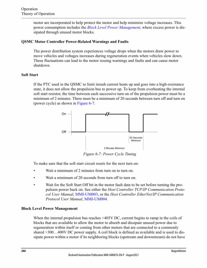
OperationTheory of Operation
244 MagneMotionRockwell Automation Publication MMI-UM007G-EN-P - August2021
motor are incorporated to help protect the motor and help minimize voltage increases. This power consumption includes the Block Level Power Management, where excess power is dis-sipated through unused motor blocks.
QSMC Motor Controller Power-Related Warnings and Faults
The power distribution system experiences voltage drops when the motors draw power to move vehicles and voltages increases during regeneration events when vehicles slow down. These fluctuations can lead to the motor issuing warnings and faults and can cause motor shutdown.
Soft Start
If the PTC used in the QSMC to limit inrush current heats up and goes into a high-resistance state, it does not allow the propulsion bus to power up. To keep from overheating the internal soft start resistor, the time between each successive turn on of the propulsion power must be a minimum of 2 minutes. There must be a minimum of 20 seconds between turn off and turn on (power cycle) as shown in Figure 6-7.
Figure 6-7: Power Cycle Timing
To make sure that the soft start circuit resets for the next turn on:
• Wait a minimum of 2 minutes from turn on to turn on.
• Wait a minimum of 20 seconds from turn off to turn on.
• Wait for the Soft Start Off bit in the motor fault data to be set before turning the pro-pulsion power back on. See either the Host Controller TCP/IP Communication Proto-col User Manual, MMI-UM003, or the Host Controller EtherNet/IP Communication Protocol User Manual, MMI-UM004.
Block Level Power Management
When the internal propulsion bus reaches +405V DC, current begins to ramp in the coils of blocks that are available to allow the motor to absorb and dissipate unused power due to regeneration within itself or coming from other motors that are connected to a commonly shared +300…400V DC power supply. A coil block is defined as available and is used to dis-sipate power within a motor if its neighboring blocks (upstream and downstream) do not have
Off
2 Minutes Minimum
20 SecondsMinimum
On
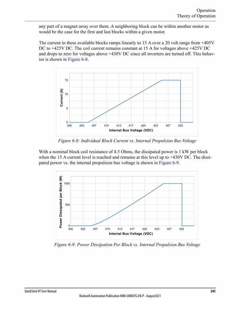
OperationTheory of Operation
QuickStick HT User Manual 245Rockwell Automation Publication MMI-UM007G-EN-P - August2021
any part of a magnet array over them. A neighboring block can be within another motor as would be the case for the first and last blocks within a given motor.
The current in these available blocks ramps linearly to 15 A over a 20 volt range from +405V DC to +425V DC. The coil current remains constant at 15 A for voltages above +425V DC and drops to zero for voltages above +430V DC since all inverters are turned off. This behav-ior is shown in Figure 6-8.
Figure 6-8: Individual Block Current vs. Internal Propulsion Bus Voltage
With a nominal block coil resistance of 4.5 Ohms, the dissipated power is 1 kW per block when the 15 A current level is reached and remains at this level up to +430V DC. The dissi-pated power vs. the internal propulsion bus voltage is shown in Figure 6-9.
Figure 6-9: Power Dissipation Per Block vs. Internal Propulsion Bus Voltage
Cur
rent
(A)
Internal Bus Voltage (VDC)400 403 407 410 413 417 420 423 427 430
0
5
10
15
Internal Bus Voltage (VDC)400 403 407 410 413 417 420 423 427 4300
1000
500
Pow
er D
issa
pate
d pe
r Blo
ck (W
)
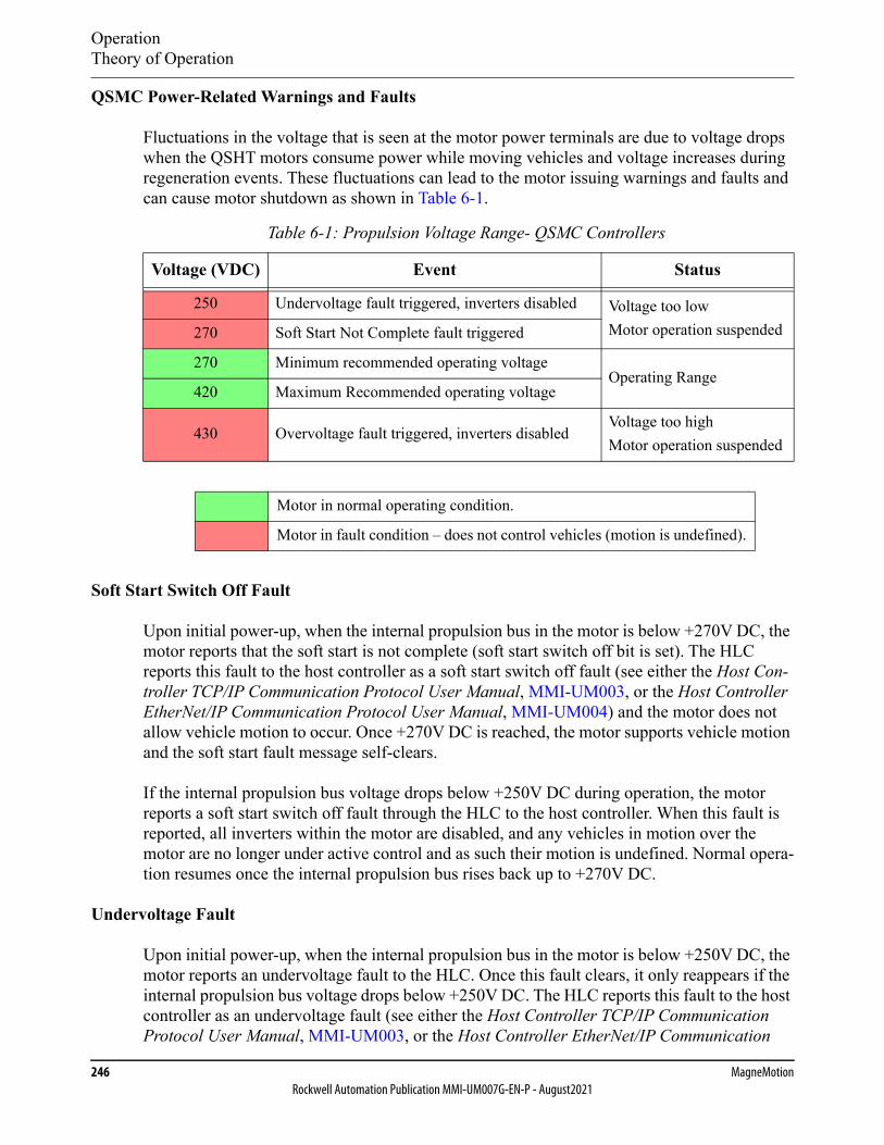
OperationTheory of Operation
246 MagneMotionRockwell Automation Publication MMI-UM007G-EN-P - August2021
QSMC Power-Related Warnings and Faults
Fluctuations in the voltage that is seen at the motor power terminals are due to voltage drops when the QSHT motors consume power while moving vehicles and voltage increases during regeneration events. These fluctuations can lead to the motor issuing warnings and faults and can cause motor shutdown as shown in Table 6-1.
Soft Start Switch Off Fault
Upon initial power-up, when the internal propulsion bus in the motor is below +270V DC, the motor reports that the soft start is not complete (soft start switch off bit is set). The HLC reports this fault to the host controller as a soft start switch off fault (see either the Host Con-troller TCP/IP Communication Protocol User Manual, MMI-UM003, or the Host Controller EtherNet/IP Communication Protocol User Manual, MMI-UM004) and the motor does not allow vehicle motion to occur. Once +270V DC is reached, the motor supports vehicle motion and the soft start fault message self-clears.
If the internal propulsion bus voltage drops below +250V DC during operation, the motor reports a soft start switch off fault through the HLC to the host controller. When this fault is reported, all inverters within the motor are disabled, and any vehicles in motion over the motor are no longer under active control and as such their motion is undefined. Normal opera-tion resumes once the internal propulsion bus rises back up to +270V DC.
Undervoltage Fault
Upon initial power-up, when the internal propulsion bus in the motor is below +250V DC, the motor reports an undervoltage fault to the HLC. Once this fault clears, it only reappears if the internal propulsion bus voltage drops below +250V DC. The HLC reports this fault to the host controller as an undervoltage fault (see either the Host Controller TCP/IP Communication Protocol User Manual, MMI-UM003, or the Host Controller EtherNet/IP Communication
Table 6-1: Propulsion Voltage Range- QSMC Controllers
Voltage (VDC) Event Status
250 Undervoltage fault triggered, inverters disabled Voltage too lowMotor operation suspended270 Soft Start Not Complete fault triggered
270 Minimum recommended operating voltageOperating Range
420 Maximum Recommended operating voltage
430 Overvoltage fault triggered, inverters disabledVoltage too highMotor operation suspended
Motor in normal operating condition.
Motor in fault condition – does not control vehicles (motion is undefined).
OperationTheory of Operation
QuickStick HT User Manual 247Rockwell Automation Publication MMI-UM007G-EN-P - August2021
Protocol User Manual, MMI-UM004). This fault self-clears when the internal propulsion bus voltage rises above +270V DC.
If the internal propulsion bus voltage drops below +250V DC during operation, the motor reports an undervoltage fault through the HLC to the host controller. When this fault is reported, vehicle motion over the motor is suspended. Normal operation resumes once the internal propulsion bus rises back up to +270V DC.
This fault is likely due to excessive +300…400V DC power cable and +300…400V DC return cable resistance from the power source to the motor.
Overvoltage Fault
When the internal propulsion bus in the motor rises above +430V DC, the motor reports an overvoltage fault to the HLC. The HLC reports this fault to the host controller as an overvolt-age fault (see either the Host Controller TCP/IP Communication Protocol User Manual, MMI-UM003, or the Host Controller EtherNet/IP Communication Protocol User Manual, MMI-UM004).
When this fault is reported, all inverters within the motor are disabled, and any vehicles in motion over the motor are no longer under active control and as such their motion is unde-fined. This fault self-clears and normal operation resumes once the internal propulsion bus voltage falls below +420V DC. To avoid issuing an overvoltage fault to the host controller due to spurious noise, the internal propulsion bus that is used to trigger this event is filtered.
Based on the specific system wiring and vehicle activity, it is possible for regenerated power resulting from vehicle decelerations to cause the internal propulsion bus voltage to rise to excessive levels. To help protect against this, protective features guard against operating con-ditions that could damage the motor. Since the source of such a condition is due to regenera-tion effects associated with active braking or deceleration of a vehicle (loaded or unloaded), a means (among others) of mitigating such regenerated power is to shut down the inverters in the motor.
Hardware Overcurrent Warning
When any phase current or the propulsion power input current exceeds ±25 A, the motor reports an overcurrent warning. The HLC reports this warning to the host controller as a Hard-ware Overcurrent Warning (see either the Host Controller TCP/IP Communication Protocol User Manual, MMI-UM003, or the Host Controller EtherNet/IP Communication Protocol User Manual, MMI-UM004).
When this warning is reported, the inverter clears the fault and retries 10 ms after the fault has occurred. If the fault is still active, or another fault happens within 5 seconds, the inverter latches off. Once the inverter latches off, the HLC reports a Hardware Overcurrent Fault to the host controller. If 5 seconds pass and another fault has NOT happened, the inverter is allowed to retry if a subsequent overcurrent fault occurs.
OperationTheory of Operation
248 MagneMotionRockwell Automation Publication MMI-UM007G-EN-P - August2021
Hardware Overcurrent Fault
When a Hardware Overcurrent Warning fails to clear, the HLC reports this fault to the host controller as a Hardware Overcurrent Fault (see either the Host Controller TCP/IP Communi-cation Protocol User Manual, MMI-UM003, or the Host Controller EtherNet/IP Communica-tion Protocol User Manual, MMI-UM004). Once this fault is reported, the motor controller must be reset.
QSMC Power-Related Fault Resolution
The power-related error messages and the associated faults persist until the voltage of the internal propulsion bus in the motor is between +250V and +430V DC. Once the voltage is within the operating range, the system attempts to resume active control of the vehicle. There are several possible solutions available to mitigate faults of these types.
• Reduce the cable resistance between motors that share a common +300…400V DC power supply if a voltage drop in these cables leads to under voltage on motors that are accelerating vehicles or excessive voltage on motors that are undergoing regeneration.
• Reduce the cable resistance between the power supply and the motors if a voltage drop in these cables leads to under voltage on motors that are accelerating vehicles.
• Reduce the maximum speeds and/or maximum accelerations to reduce the amount of power that is drawn and the regenerated power flowing back into the system.
• Reduce the number of vehicles accelerating on motors that are connected to the same common +300…400V DC power supply.
• Split the power bus into smaller sections and install additional power supplies.
• Increase the spacing between vehicles on motors sharing a common +300…400V DC power supply to increase the number of blocks available to absorb power during regeneration.
• Connect more motors to a common +300…400V DC power supply to increase the number of blocks available to absorb regenerated power.
If all of these resolution paths have been explored and excessive voltage problems still persist, add an active voltage clamp across the +300…400V DC power supply local to the power sup-ply or to the motors that are exhibiting this issue. The clamping voltage can be set above the expected operating voltage, but should not be set any higher than +420V DC, which is the point where the motor controller starts to dump energy to empty blocks.
QSHT 5700 Inverter Power-Related Warnings and Faults
The power distribution system experiences voltage drops when the motors draw power to move vehicles and voltages increases during regeneration events when vehicles slow down. These fluctuations can lead to the motor issuing warnings and faults and can cause motor shutdown.
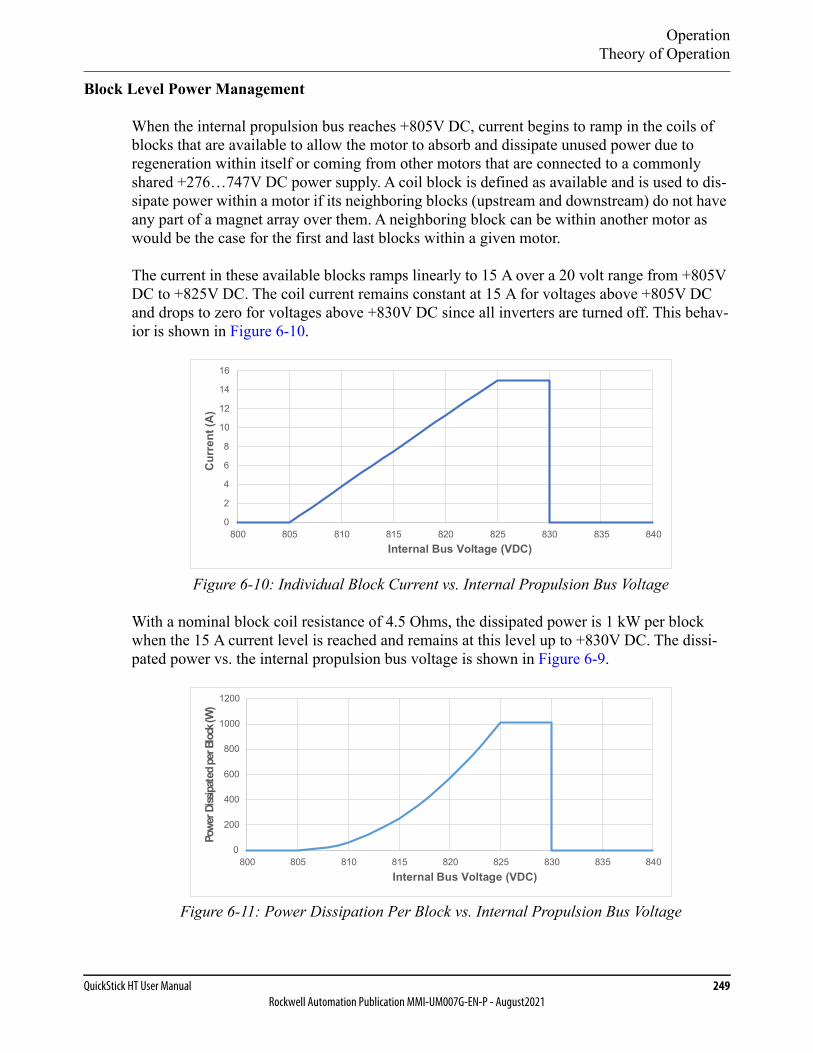
OperationTheory of Operation
QuickStick HT User Manual 249Rockwell Automation Publication MMI-UM007G-EN-P - August2021
Block Level Power Management
When the internal propulsion bus reaches +805V DC, current begins to ramp in the coils of blocks that are available to allow the motor to absorb and dissipate unused power due to regeneration within itself or coming from other motors that are connected to a commonly shared +276…747V DC power supply. A coil block is defined as available and is used to dis-sipate power within a motor if its neighboring blocks (upstream and downstream) do not have any part of a magnet array over them. A neighboring block can be within another motor as would be the case for the first and last blocks within a given motor.
The current in these available blocks ramps linearly to 15 A over a 20 volt range from +805V DC to +825V DC. The coil current remains constant at 15 A for voltages above +805V DC and drops to zero for voltages above +830V DC since all inverters are turned off. This behav-ior is shown in Figure 6-10.
Figure 6-10: Individual Block Current vs. Internal Propulsion Bus Voltage
With a nominal block coil resistance of 4.5 Ohms, the dissipated power is 1 kW per block when the 15 A current level is reached and remains at this level up to +830V DC. The dissi-pated power vs. the internal propulsion bus voltage is shown in Figure 6-9.
Figure 6-11: Power Dissipation Per Block vs. Internal Propulsion Bus Voltage
0
2
4
6
8
10
12
14
16
800 805 810 815 820 825 830 835 840
Cur
rent
(A)
Internal Bus Voltage (VDC)
0
200
400
600
800
1000
1200
800 805 810 815 820 825 830 835 840
)W(kcolBrepdetapissiDrewoP
Internal Bus Voltage (VDC)
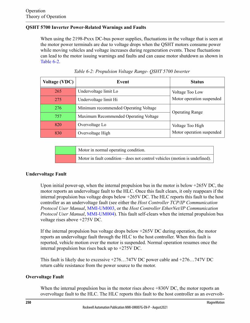
OperationTheory of Operation
250 MagneMotionRockwell Automation Publication MMI-UM007G-EN-P - August2021
QSHT 5700 Inverter Power-Related Warnings and Faults
When using the 2198-Pxxx DC-bus power supplies, fluctuations in the voltage that is seen at the motor power terminals are due to voltage drops when the QSHT motors consume power while moving vehicles and voltage increases during regeneration events. These fluctuations can lead to the motor issuing warnings and faults and can cause motor shutdown as shown in Table 6-2.
Undervoltage Fault
Upon initial power-up, when the internal propulsion bus in the motor is below +265V DC, the motor reports an undervoltage fault to the HLC. Once this fault clears, it only reappears if the internal propulsion bus voltage drops below +265V DC. The HLC reports this fault to the host controller as an undervoltage fault (see either the Host Controller TCP/IP Communication Protocol User Manual, MMI-UM003, or the Host Controller EtherNet/IP Communication Protocol User Manual, MMI-UM004). This fault self-clears when the internal propulsion bus voltage rises above +275V DC.
If the internal propulsion bus voltage drops below +265V DC during operation, the motor reports an undervoltage fault through the HLC to the host controller. When this fault is reported, vehicle motion over the motor is suspended. Normal operation resumes once the internal propulsion bus rises back up to +275V DC.
This fault is likely due to excessive +276…747V DC power cable and +276…747V DC return cable resistance from the power source to the motor.
Overvoltage Fault
When the internal propulsion bus in the motor rises above +830V DC, the motor reports an overvoltage fault to the HLC. The HLC reports this fault to the host controller as an overvolt-
Table 6-2: Propulsion Voltage Range- QSHT 5700 Inverter
Voltage (VDC) Event Status
265 Undervoltage limit Lo Voltage Too LowMotor operation suspended275 Undervoltage limit Hi
276 Minimum recommended Operating VoltageOperating Range
757 Maximum Recommended Operating Voltage
820 Overvoltage Lo Voltage Too HighMotor operation suspended830 Overvoltage High
Motor in normal operating condition.
Motor in fault condition – does not control vehicles (motion is undefined).

OperationTheory of Operation
QuickStick HT User Manual 251Rockwell Automation Publication MMI-UM007G-EN-P - August2021
age fault (see either the Host Controller TCP/IP Communication Protocol User Manual, MMI-UM003, or the Host Controller EtherNet/IP Communication Protocol User Manual, MMI-UM004).
When this fault is reported, all inverters within the motor are disabled, and any vehicles in motion over the motor are no longer under active control and as such their motion is unde-fined. This fault self-clears and normal operation resumes once the internal propulsion bus voltage falls below +820V DC. To avoid issuing an overvoltage fault to the host controller due to spurious noise, the internal propulsion bus that is used to trigger this event is filtered.
Based on the specific system wiring and vehicle activity, it is possible for regenerated power resulting from vehicle decelerations to cause the internal propulsion bus voltage to rise to excessive levels. To help protect against this, protective features guard against operating con-ditions that could damage the motor. Since the source of such a condition is due to regenera-tion effects associated with active braking or deceleration of a vehicle (loaded or unloaded), a means (among others) of mitigating such regenerated power is to shut down the inverters in the motor. Shunt resistors can be connected to the 2198-Pxxx DC-bus power supplies to pro-vide additional shunt capacity for applications where the DC-bus power supply’s internal shunt capacity is exceeded during power regeneration when braking. See the Kinetix 5700 Servo Drives User Manual, 2198-UM002.
Hardware Overcurrent Warning
When the inverter power devices detect a short-circuit event, the motor reports an overcurrent warning. The HLC reports this warning to the host controller as a Hardware Overcurrent Warning (see either the Host Controller TCP/IP Communication Protocol User Manual, MMI-UM003, or the Host Controller EtherNet/IP Communication Protocol User Manual, MMI-UM004).
When this warning is reported, the inverter clears the fault and retries 10 ms after the fault has occurred. If the fault is still active, or another fault happens within 5 seconds, the inverter latches off. Once the inverter latches off, the HLC reports a Hardware Overcurrent Fault to the host controller. If 5 seconds pass and another fault has NOT happened, the inverter is allowed to retry if a subsequent overcurrent fault occurs.
Hardware Overcurrent Fault
When a Hardware Overcurrent Warning fails to clear, the HLC reports this fault to the host controller as a Hardware Overcurrent Fault (see either the Host Controller TCP/IP Communi-cation Protocol User Manual, MMI-UM003, or the Host Controller EtherNet/IP Communica-tion Protocol User Manual, MMI-UM004). Once this fault is reported, the inverter must be reset.
QSHT 5700 Inverter Power-Related Power-Related Fault Resolution
The power-related error messages and the associated faults persist until the voltage of the internal propulsion bus in the motor is between +265V and +830V DC. Once the voltage is
OperationTheory of Operation
252 MagneMotionRockwell Automation Publication MMI-UM007G-EN-P - August2021
within the operating range, the system attempts to resume active control of the vehicle. There are several possible solutions available to mitigate faults of these types.
• Reduce the cable resistance between motors that share a common +276…747V DC power supply if a voltage drop in these cables leads to under voltage on motors accel-erating vehicles or excessive voltage on motors undergoing regeneration.
• Reduce the cable resistance between the power supply and the motors if a voltage drop in these cables leads to under voltage on motors accelerating vehicles.
• Reduce the maximum speeds and/or maximum accelerations to reduce the amount of power that is drawn and the regenerated power flowing back into the system.
• Reduce the number of vehicles accelerating on motors that are connected to the same common +276…747V DC power supply.
• Split the power bus into smaller sections and install additional power supplies.
• Increase the spacing between vehicles on motors sharing a common +276…747V DC power supply to increase the number of blocks available to absorb power during regeneration.
• Connect more motors to a common +276…747V DC power supply to increase the number of blocks available to absorb regenerated power.
If all of these resolution paths have been explored and excessive voltage problems still persist, add an active voltage clamp across the +276…747V DC power supply local to the power sup-ply or to the motors that are exhibiting this issue. The clamping voltage can be set above the expected operating voltage, but should not be set any higher than +805V DC, which is the point where the inverter starts to dump energy to empty blocks.
OperationTheory of Operation
QuickStick HT User Manual 253Rockwell Automation Publication MMI-UM007G-EN-P - August2021
Node Controllers
The MagneMotion node controller is used to monitor vehicles and control the motors and other components of a QuickStick HT transport system based on the commands from the host controller. The node controller also provides status information to the host controller. There can be multiple node controllers in a transport system, each responsible for a subset of the transport system. Each node controller is connected to the local area network (LAN) for the transport system. Providing all communication to the node controllers through a LAN allows the node controllers to be located near the motors they are controlling, which minimizes the length of all cabling.
Each node controller is responsible for coordinating vehicle motion through the nodes that are assigned to it and along the paths that are connected to those nodes. The node controllers are also used to program the motors on the paths that are connected to the nodes assigned to it.
One node controller in the transport system also functions as the high-level controller (HLC). The HLC provides one point of contact for all communication with the host controller through either TCP/IP or EtherNet/IP™. The HLC distributes any commands or requests that are received to the appropriate node controller through the LAN using TCP/IP and passes any messages from the node controllers to the host controller. The HLC also assigns vehicle IDs and tracks vehicle movement from node controller to node controller to make sure vehicle IDs are maintained.
NOTE: All TCP communication is unicast. Do not connect the node controllers to a network with large amounts of broadcast traffic as this extra traffic could impact node con-troller communication.
Node Controller Communications
All node controllers constantly communicate with the node controller configured as the HLC through a LAN. Additionally, the node controller that is designated as the HLC communicates with the host controller through the same network.
All node controllers have the same IP address when they leave the factory. Individual node controllers with the same IP address cannot be distinguished on a network and must not be connected to the network until provisioned. Set the IP address of each node controller to a unique address that matches the addressing structure of the network for the transport system before connecting it to the network (see the Node Controller Interface User Manual, MMI-UM001).
See the Node Controller Hardware User Manual, MMI-UM013, for mechanical dimensions, detailed connector identification and pinouts, and procedures for mounting and connecting the node controllers to the transport system.
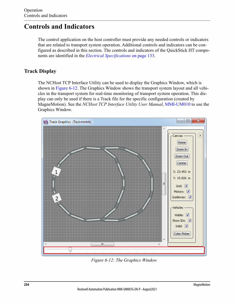
OperationControls and Indicators
254 MagneMotionRockwell Automation Publication MMI-UM007G-EN-P - August2021
Controls and Indicators
The control application on the host controller must provide any needed controls or indicators that are related to transport system operation. Additional controls and indicators can be con-figured as described in this section. The controls and indicators of the QuickStick HT compo-nents are identified in the Electrical Specifications on page 133.
Track Display
The NCHost TCP Interface Utility can be used to display the Graphics Window, which is shown in Figure 6-12. The Graphics Window shows the transport system layout and all vehi-cles in the transport system for real-time monitoring of transport system operation. This dis-play can only be used if there is a Track file for the specific configuration (created by MagneMotion). See the NCHost TCP Interface Utility User Manual, MMI-UM010 to use the Graphics Window.
Figure 6-12: The Graphics Window
OperationControls and Indicators
QuickStick HT User Manual 255Rockwell Automation Publication MMI-UM007G-EN-P - August2021
E-stops
When using a node controller with digital I/O, the node controller can be connected directly to an E-stop circuit. An E-stop is a user-supplied button (typically locking) that an operator can press if an emergency situation arises to halt all motion on the specified paths. When the node controller detects that the E-stop button is activated, it commands all paths that are associated with that E-stop to suspend vehicle motion. All motors on those paths suspend vehicle target requests and permissions and all vehicles come to a controlled stop and are held in position by the motors. Stopping time for each vehicle is dependent on the load on the vehicle and the acceleration setting of the current motion command for the vehicle. See the Node Controller Hardware User Manual, MMI-UM013, for additional details and equivalent circuits.
NOTE: Motion cannot resume until the button is released and the host controller issues a Resume command to the paths associated with the E-stop.
Interlocks
When using a node controller with digital I/O, the node controller can be connected directly to an interlock circuit. An interlock is a user-installed circuit that another piece of equipment in the facility activates to halt all motion on the specified paths temporarily. When the node con-troller detects that the interlock circuit is activated, it commands all paths that are associated with that interlock to suspend vehicle motion. All motors on those paths suspend vehicle tar-get requests and permissions and all vehicles come to a controlled stop and are held in posi-tion by the motors. Stopping time for each vehicle is dependent on the load on the vehicle and the acceleration setting of the current motion command for the vehicle. See the Node Control-ler Hardware User Manual, MMI-UM013, for additional details and equivalent circuits.
SHOCK HAZARD: The E-stop only executes the actionsthat are described, it is not the same as an EMO (EmergencyOff), which removes power to the transport system.
AUTOMATIC MOTION HAZARD: When the interlock iscleared, automatic movement of the vehicles on the Quick-Stick HT transport system is automatically resumed, whichcould result in personal injury.
OperationControls and Indicators
256 MagneMotionRockwell Automation Publication MMI-UM007G-EN-P - August2021
Light Stacks
When using a node controller with digital I/O, the node controller can be connected directly to a light stack. A light stack is a user-installed visual signal that is used to provide transport sys-tem status. The QuickStick HT transport system supports standard three color light stacks (typically green, yellow, and red). The light stack can be used to monitor the status of any, or all, paths on the node controller where it is connected. See the Node Controller Hardware User Manual, MMI-UM013, for additional details and equivalent circuits. See the QuickStick Configurator User Manual, MMI-UM009, to configure the QSHT transport system to use a light stack.
FastStop
The host controller can send a FastStop command to the node controller, on a per-path basis. This command suspends all motion on the specified paths. Vehicles immediately decelerate with maximum thrust opposing their motion. Previously commanded motion does not resume until a Resume Motion command is received. The control loop is still enabled while motion is suspended holding all vehicles in place. See the Host Controller TCP/IP Communication Pro-tocol User Manual, MMI-UM003, or the Host Controller EtherNet/IP Communication Proto-col User Manual, MMI-UM004 for details on the use of the FastStop command.
Digital I/O
When using a node controller with digital I/O, digital inputs and outputs can be monitored and controlled, respectively. These circuits can be wired directly to the digital I/O terminals on the node controller. The host controller can then issue commands to set the value of the digital outputs, or read the value of the digital inputs. See the Node Controller Hardware User Man-ual, MMI-UM013, for additional details and equivalent circuits. See the Host Controller TCP/IP Communication Protocol User Manual, MMI-UM003, or the Host Controller Ether-Net/IP Communication Protocol User Manual, MMI-UM004 for details on the use of the dig-ital I/O commands.
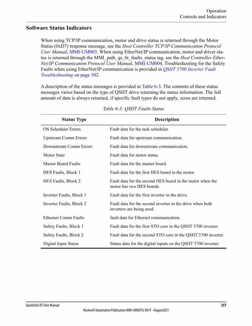
OperationControls and Indicators
QuickStick HT User Manual 257Rockwell Automation Publication MMI-UM007G-EN-P - August2021
Software Status Indicators
When using TCP/IP communication, motor and drive status is returned through the Motor Status (0xD7) response message, see the Host Controller TCP/IP Communication Protocol User Manual, MMI-UM003. When using EtherNet/IP communication, motor and driver sta-tus is returned through the MMI_path_qs_ht_faults_status tag, see the Host Controller Ether-Net/IP Communication Protocol User Manual, MMI-UM004. Troubleshooting for the Safety Faults when using EtherNet/IP communication is provided in QSHT 5700 Inverter Fault Troubleshooting on page 302.
A description of the status messages is provided in Table 6-3. The contents of these status messages varies based on the type of QSHT drive returning the status information. The full amount of data is always returned, if specific fault types do not apply, zeros are returned.
Table 6-3: QSHT Faults Status
Status Type Description
OS Scheduler Errors Fault data for the task scheduler.
Upstream Comm Errors Fault data for upstream communication.
Downstream Comm Errors Fault data for downstream communication.
Motor State Fault data for motor status.
Master Board Faults Fault data for the master board.
HES Faults, Block 1 Fault data for the first HES board in the motor.
HES Faults, Block 2 Fault data for the second HES board in the motor when the motor has two HES boards.
Inverter Faults, Block 1 Fault data for the first inverter in the drive.
Inverter Faults, Block 2 Fault data for the second inverter in the drive when both inverters are being used.
Ethernet Comm Faults fault data for Ethernet communication.
Safety Faults, Block 1 Fault data for the first STO core in the QSHT 5700 inverter.
Safety Faults, Block 2 Fault data for the second STO core in the QSHT 5700 inverter.
Digital Input Status Status data for the digital inputs on the QSHT 5700 inverter.
OperationTransport System Simulation
258 MagneMotionRockwell Automation Publication MMI-UM007G-EN-P - August2021
Transport System SimulationThe QuickStick HT transport system can be simulated to verify proper configuration of all nodes and paths and proper motion of commanded vehicles within the transport system. Sim-ulations can be useful to test and observe system behavior without physically moving any vehicles on the transport system. To run a simulation, the system must be fully defined in a Node Controller Configuration File (see the QuickStick Configurator User Manual, MMI-UM009) and that file must be loaded onto the node controller being used for simulation (see the Node Controller Interface User Manual, MMI-UM001).
Simulated vehicles can be moved during the simulation to verify basic functionality. The motion profile of all simulated vehicles is an ideal profile. This profile assumes that there is no friction between the vehicle and the guideway and that the vehicle is not overloaded for the PID set being specified. The vehicle accelerates and decelerates at the rates that are specified in the command, with a maximum of the values specified in the Node Controller Configura-tion File.
Simulating the transport system requires one node controller, a fully defined Node Controller Configuration File, and a host controller (either the controller for the transport system or the NCHost TCP Interface Utility). The simulated transport system cannot exceed the limits of a physical transport system as described in Transport System Limits on page 331.
Configuring a Simulation
1. Configure a node controller to run in Simulation Mode.
A. Run the node controller web interface (see the Node Controller Interface User Manual, MMI-UM001).
B. Select IP Settings on the main menu.
C. In the Configured Functions section, make sure that This box is a High Level Controller Simulator is selected.
D. In the Configured Functions section, make sure that This box is a Node Con-troller is cleared.
E. In the Configured Functions section, make sure that This box is the High Level Controller is cleared.
F. Select Apply Changes.
The selected changes are applied.
G. Select Reboot Controller on the main menu.
The Reboot Controller page is displayed.
H. Select Reboot Controller.
The reboot status is temporarily displayed, then the General Status page is dis-played once the node controller has rebooted.
OperationTransport System Simulation
QuickStick HT User Manual 259Rockwell Automation Publication MMI-UM007G-EN-P - August2021
2. Download the Node Controller Configuration File from the node controller. If a Node Controller Configuration File does not exist, see the QuickStick Configurator User Manual, MMI-UM009, to create one.
A. From the node controller web interface, select Configuration Files on the Main Menu.
B. Under Node Controller Configuration File, select Download.
C. Specify a location for the file download, change the file name as appropriate, and select Save.
The file is named and saved as specified.
3. Edit the Node Controller Configuration File to add simulated vehicles.
NOTE: The Simulated Vehicle is a simulated version of the vehicle that is defined in the Vehicle section of the Motor Defaults.
A. Open the copy of the Node Controller Configuration File in the QuickStick Configurator (see the QuickStick Configurator User Manual, MMI-UM009).
B. Select Show Simulated Vehicles from the Options menu.
C. For each path where simulated vehicles start, define the simulated vehicles and enter the starting location for each vehicle.
1. In the Configuration Tree, open the Paths list.
2. Select the path where the simulated vehicle is initially located.
3. Right-click on Simulated Vehicles and select Add to End to add a simulated vehicle.
4. Select the simulated vehicle just added and specify its starting location on the path.
5. Repeat Step 2 through Step 4 for each vehicle to be added.
D. For Merge and Diverge nodes, specify the Simulated Move Time for the switching mechanism to accurately simulate switching. This time is the actual amount of time it takes the switching mechanism to move from one position to the other position.
1. In the Configuration Tree, open the Nodes list.
2. Select either a Merge or Diverge node.
3. In the Simulated Move Time field, enter the amount of time it takes for the switch mechanism to change directions.
4. Repeat Step 2 through Step 3 for each Merge/Diverge node in the con-figuration.
E. Save the updated Node Controller Configuration File.
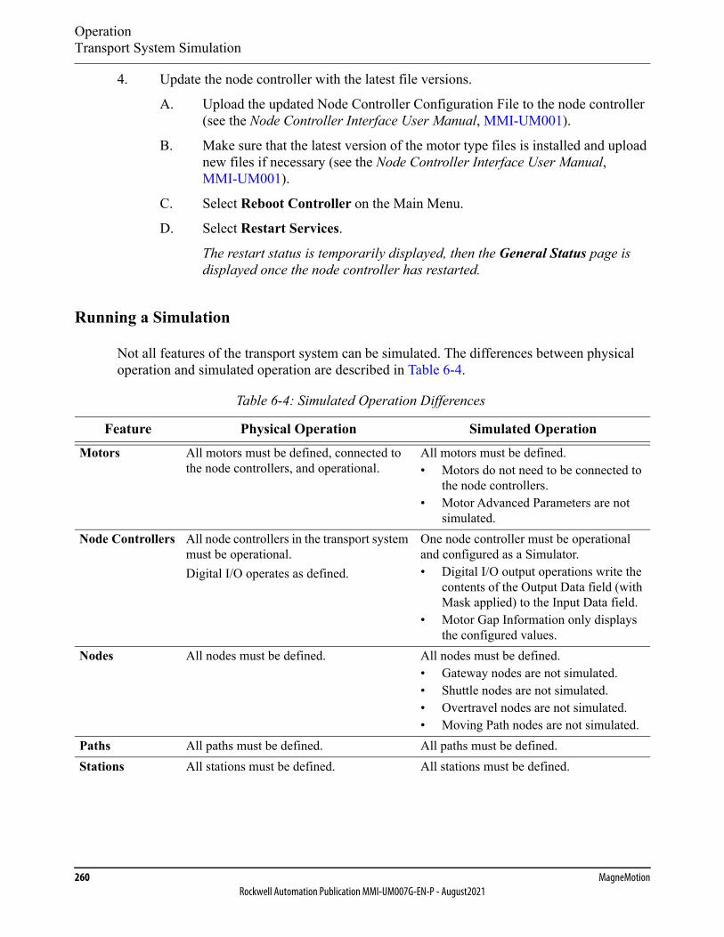
OperationTransport System Simulation
260 MagneMotionRockwell Automation Publication MMI-UM007G-EN-P - August2021
4. Update the node controller with the latest file versions.
A. Upload the updated Node Controller Configuration File to the node controller (see the Node Controller Interface User Manual, MMI-UM001).
B. Make sure that the latest version of the motor type files is installed and upload new files if necessary (see the Node Controller Interface User Manual, MMI-UM001).
C. Select Reboot Controller on the Main Menu.
D. Select Restart Services.
The restart status is temporarily displayed, then the General Status page is displayed once the node controller has restarted.
Running a Simulation
Not all features of the transport system can be simulated. The differences between physical operation and simulated operation are described in Table 6-4.
Table 6-4: Simulated Operation Differences
Feature Physical Operation Simulated OperationMotors All motors must be defined, connected to
the node controllers, and operational.All motors must be defined.• Motors do not need to be connected to
the node controllers.• Motor Advanced Parameters are not
simulated.Node Controllers All node controllers in the transport system
must be operational.Digital I/O operates as defined.
One node controller must be operational and configured as a Simulator.• Digital I/O output operations write the
contents of the Output Data field (with Mask applied) to the Input Data field.
• Motor Gap Information only displays the configured values.
Nodes All nodes must be defined. All nodes must be defined.• Gateway nodes are not simulated.• Shuttle nodes are not simulated.• Overtravel nodes are not simulated.• Moving Path nodes are not simulated.
Paths All paths must be defined. All paths must be defined.Stations All stations must be defined. All stations must be defined.
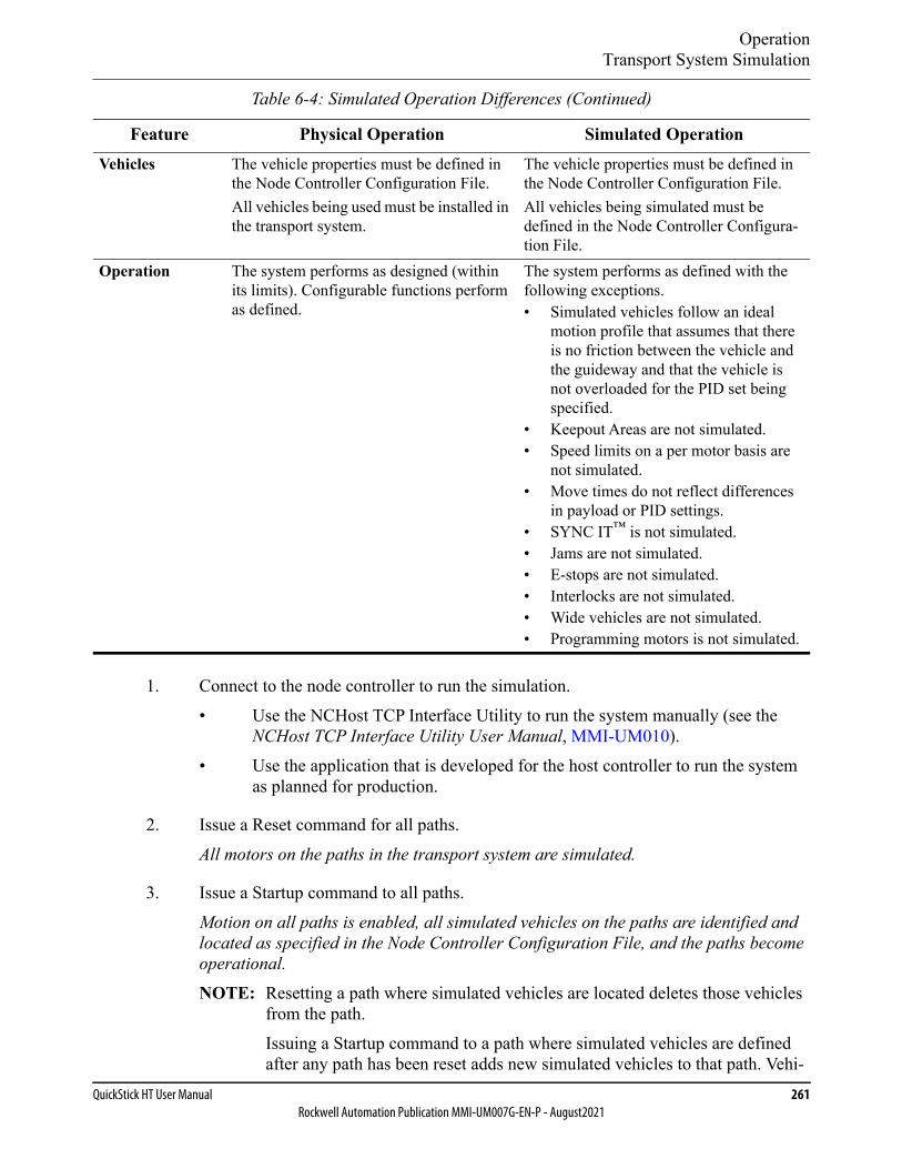
OperationTransport System Simulation
QuickStick HT User Manual 261Rockwell Automation Publication MMI-UM007G-EN-P - August2021
1. Connect to the node controller to run the simulation.• Use the NCHost TCP Interface Utility to run the system manually (see the
NCHost TCP Interface Utility User Manual, MMI-UM010).• Use the application that is developed for the host controller to run the system
as planned for production.
2. Issue a Reset command for all paths.All motors on the paths in the transport system are simulated.
3. Issue a Startup command to all paths.Motion on all paths is enabled, all simulated vehicles on the paths are identified and located as specified in the Node Controller Configuration File, and the paths become operational.
NOTE: Resetting a path where simulated vehicles are located deletes those vehicles from the path.Issuing a Startup command to a path where simulated vehicles are defined after any path has been reset adds new simulated vehicles to that path. Vehi-
Vehicles The vehicle properties must be defined in the Node Controller Configuration File.All vehicles being used must be installed in the transport system.
The vehicle properties must be defined in the Node Controller Configuration File.All vehicles being simulated must be defined in the Node Controller Configura-tion File.
Operation The system performs as designed (within its limits). Configurable functions perform as defined.
The system performs as defined with the following exceptions.• Simulated vehicles follow an ideal
motion profile that assumes that there is no friction between the vehicle and the guideway and that the vehicle is not overloaded for the PID set being specified.
• Keepout Areas are not simulated.• Speed limits on a per motor basis are
not simulated.• Move times do not reflect differences
in payload or PID settings.• SYNC IT™ is not simulated.• Jams are not simulated.• E-stops are not simulated.• Interlocks are not simulated.• Wide vehicles are not simulated.• Programming motors is not simulated.
Table 6-4: Simulated Operation Differences (Continued)
Feature Physical Operation Simulated Operation

OperationTransport System Simulation
262 MagneMotionRockwell Automation Publication MMI-UM007G-EN-P - August2021
cles are added at either the location that is specified in the Node Controller Configuration File or in the next available space downstream.
4. Move vehicles as required.
• Use the NCHost TCP Interface Utility to move vehicles individually or create a Demo Script for repetitive testing (see the NCHost TCP Interface Utility User Manual, MMI-UM010).
• Use the host controller application to run the system as planned for production.
All QSHT transport system elements are simulated as previously described.
Stopping a Simulation
1. Issue a Suspend Motion command for all paths.
All vehicles come to a controlled stop.
2. Once all motion has stopped, issue a Reset command for all paths.
All vehicle records are cleared.
Return the System to Normal Operation
1. Configure the node controller to run in Normal Mode.
NOTE: It is not necessary to remove the simulated vehicles from the Node Controller Configuration File as they are ignored during normal operation.
A. Run the node controller web interface.
B. Select IP Settings on the Main Menu.
The IP Settings page is displayed.
C. In the Configured Functions section, make sure that This box is a High Level Controller Simulator is cleared.
D. In the Configured Functions section, make sure that This box is a Node Con-troller is selected as appropriate.
E. In the Configured Functions section, make sure that This box is the High Level Controller is selected as appropriate.
F. Select Apply Changes.
The selected changes are applied.
G. Select Reboot Controller on the Main Menu.
The Reboot Controller page is displayed.
OperationTransport System Simulation
QuickStick HT User Manual 263Rockwell Automation Publication MMI-UM007G-EN-P - August2021
H. Select Reboot Controller.
The reboot status is temporarily displayed, then the General Status page is dis-played once the node controller has rebooted.
2. From the host interface, issue a Reset command for all paths.
All motors on the paths in the transport system are reset.
3. Issue a Startup command to all paths.
Motion on all paths is enabled, all vehicles on the paths are identified and located, and the paths become operational.
4. Move vehicles as required.
• Use the NCHost TCP Interface Utility to move vehicles individually or create a Demo Script for repetitive testing (see the NCHost TCP Interface Utility User Manual, MMI-UM010).
• Use the host controller application to run the system as required.
All QSHT transport system elements move as directed.
OperationTransport System Operation
264 MagneMotionRockwell Automation Publication MMI-UM007G-EN-P - August2021
Transport System Operation
Power-up
The QuickStick HT transport system is started by applying power as previously specified (see Check-out and Power-up on page 224). Once the system completes startup, the QSHT compo-nents are ready to operate. If the host controller is in control of the QSHT transport system, the system accepts commands from the host controller through the network connection.
Normal Running
During normal operation, the host controller controls the QuickStick HT transport system. The user must determine the exact usage of the QSHT transport system. See the Host Control-ler TCP/IP Communication Protocol User Manual, MMI-UM003, for details of each com-mand to use TCP/IP communication. See the Host Controller EtherNet/IP Communication Protocol User Manual, MMI-UM004, for details of each user-defined tag and the interface to use EtherNet/IP communication.
NOTICE All network switch settings, communication connections,and power connections must be made before power isapplied.
CRUSH HAZARD: Moving mechanisms (vehicles) haveno obstruction sensors.
Do not operate the QuickStick HT transport system withoutbarriers in place or personal injury could result in the squeez-ing or compression of fingers, hands, or other body partsbetween moving mechanisms.
OperationTransport System Operation
QuickStick HT User Manual 265Rockwell Automation Publication MMI-UM007G-EN-P - August2021
Shut-down
The following shut-down procedure is used to remove power from the QuickStick HT trans-port system in an orderly manner and place the components in known conditions. This proce-dure is used to prepare the components for removal, replacement, or maintenance.
The QuickStick HT transport system requires no special shut-down procedures. When shut-ting down the host controller, the QSHT components must be shut down first.
1. All material transfers must be completed (move all material to the appropriate loca-tions).
2. Command all vehicles to known positions.
3. Issue a Suspend Motion command for all paths.
All vehicles come to a controlled stop.
4. Once all motion has stopped, issue a Reset command for all paths.
The HLC clears all vehicle records.
5. Turn off all power to the motor drives.
6. Turn off power to the node controllers.
7. Turn off power to the host controller.
8. Turn off the main power disconnect for the QuickStick HT transport system.
NOTE: This procedure only shuts down facilities to the QuickStick HT motors, motor drives, their subsystems, and the host controller. Any user equipment remains pow-ered up.
SHOCK HAZARD: The shut-down procedure is used in thenormal shut-down of the QuickStick HT transport system.This procedure removes the power source and all other facil-ities to the components and provides guidelines for lock-out/tagout. This procedure is NOT the same as an EMOcircuit or other safety interlock.

Operation
266 MagneMotionRockwell Automation Publication MMI-UM007G-EN-P - August2021
This page intentionally left blank.

QuickStick HT User Manual 267Rockwell Automation Publication MMI-UM007G-EN-P - August2021
QSHT 5700 Inverter Safe Torque-off Function 7
Overview
This chapter provides an overview of the safe torque-off (STO) functionality that is built into the QSHT 5700 Inverter.
Included in this chapter are:
• Overview of the safe torque-off functionality.
• Hardwired safe torque-off.

QSHT 5700 Inverter Safe Torque-off FunctionIntroduction
268 MagneMotionRockwell Automation Publication MMI-UM007G-EN-P - August2021
Introduction
The QSHT 5700 inverters are equipped for hardwired safe torque-off (STO). Hardwired STO mode, as described in this chapter, applies to the MMI-HT-C2198-D032 inverters.
The hardwired STO function meets the requirements of Performance Level e (PL e) per ISO 13849-1 and SIL CL 3 per IEC 61508, IEC 61800-5-2 and IEC 62061.
Certification
The TÜV Rheinland group has approved the MMI-HT-C2198-D032 inverter with hardwired safe torque-off for use in safety-related applications up to ISO 13849-1 Performance Level e (PL e), SIL CL 3 per IEC 61508, IEC 61800-5-2, and IEC 62061, in which removing the motion producing power is considered to be the safe state.
For product certifications currently available from Rockwell Automation, go to rok.auto/certi-fications.
Important Safety Considerations
The system user is responsible for the following:
• Validation of any sensors or actuators that are connected to the system
• Completing a machine-level risk assessment
• Certification of the machine to the desired ISO 13849 Performance Level or IEC 62061 SIL level
• Project management and proof testing in accordance with ISO 13849
Stop Category Definition
Stop Category 0 as defined in IEC 60204 or safe torque-off as defined by IEC 61800-5-2 is achieved with immediate removal of force producing power to the actuator.
IMPORTANT In the event of a malfunction, the most likely stop category isStop Category 0. When designing the machine application,timing and distance must be considered for a coast-to-stop.For more information regarding stop categories, see IEC60204-1.
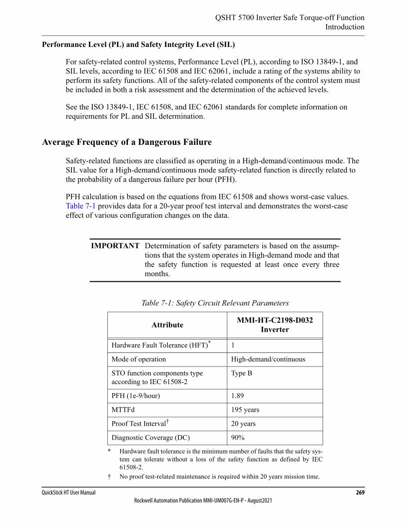
QSHT 5700 Inverter Safe Torque-off FunctionIntroduction
QuickStick HT User Manual 269Rockwell Automation Publication MMI-UM007G-EN-P - August2021
Performance Level (PL) and Safety Integrity Level (SIL)
For safety-related control systems, Performance Level (PL), according to ISO 13849-1, and SIL levels, according to IEC 61508 and IEC 62061, include a rating of the systems ability to perform its safety functions. All of the safety-related components of the control system must be included in both a risk assessment and the determination of the achieved levels.
See the ISO 13849-1, IEC 61508, and IEC 62061 standards for complete information on requirements for PL and SIL determination.
Average Frequency of a Dangerous Failure
Safety-related functions are classified as operating in a High-demand/continuous mode. The SIL value for a High-demand/continuous mode safety-related function is directly related to the probability of a dangerous failure per hour (PFH).
PFH calculation is based on the equations from IEC 61508 and shows worst-case values. Table 7-1 provides data for a 20-year proof test interval and demonstrates the worst-case effect of various configuration changes on the data.
IMPORTANT Determination of safety parameters is based on the assump-tions that the system operates in High-demand mode and thatthe safety function is requested at least once every threemonths.
Table 7-1: Safety Circuit Relevant Parameters
Attribute MMI-HT-C2198-D032Inverter
Hardware Fault Tolerance (HFT)*
* Hardware fault tolerance is the minimum number of faults that the safety sys-tem can tolerate without a loss of the safety function as defined by IEC61508-2.
1
Mode of operation High-demand/continuous
STO function components type according to IEC 61508-2
Type B
PFH (1e-9/hour) 1.89
MTTFd 195 years
Proof Test Interval†
† No proof test-related maintenance is required within 20 years mission time.
20 years
Diagnostic Coverage (DC) 90%
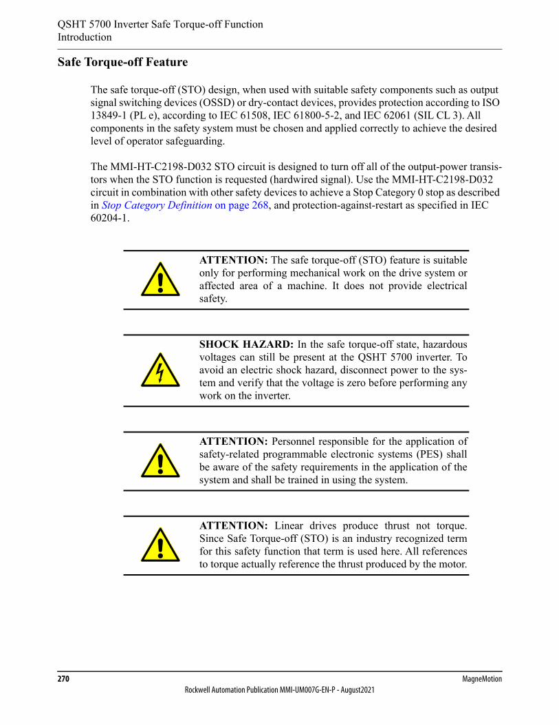
QSHT 5700 Inverter Safe Torque-off FunctionIntroduction
270 MagneMotionRockwell Automation Publication MMI-UM007G-EN-P - August2021
Safe Torque-off Feature
The safe torque-off (STO) design, when used with suitable safety components such as output signal switching devices (OSSD) or dry-contact devices, provides protection according to ISO 13849-1 (PL e), according to IEC 61508, IEC 61800-5-2, and IEC 62061 (SIL CL 3). All components in the safety system must be chosen and applied correctly to achieve the desired level of operator safeguarding.
The MMI-HT-C2198-D032 STO circuit is designed to turn off all of the output-power transis-tors when the STO function is requested (hardwired signal). Use the MMI-HT-C2198-D032 circuit in combination with other safety devices to achieve a Stop Category 0 stop as described in Stop Category Definition on page 268, and protection-against-restart as specified in IEC 60204-1.
ATTENTION: The safe torque-off (STO) feature is suitableonly for performing mechanical work on the drive system oraffected area of a machine. It does not provide electricalsafety.
SHOCK HAZARD: In the safe torque-off state, hazardousvoltages can still be present at the QSHT 5700 inverter. Toavoid an electric shock hazard, disconnect power to the sys-tem and verify that the voltage is zero before performing anywork on the inverter.
ATTENTION: Personnel responsible for the application ofsafety-related programmable electronic systems (PES) shallbe aware of the safety requirements in the application of thesystem and shall be trained in using the system.
ATTENTION: Linear drives produce thrust not torque.Since Safe Torque-off (STO) is an industry recognized termfor this safety function that term is used here. All referencesto torque actually reference the thrust produced by the motor.

QSHT 5700 Inverter Safe Torque-off FunctionIntroduction
QuickStick HT User Manual 271Rockwell Automation Publication MMI-UM007G-EN-P - August2021
Safe Torque-off Status
This section describes the safety-related status data that is available to the host controller.
When a QSHT 5700 inverter user-defined tag (UDT) is added to a Logix Designer applica-tion, fault tags are added to the inverter tags. Table 7-2 lists the safety-related tags and other new tags that are added to the MMI_path_qs_ht_faults_status tag described in Software Status Indicators on page 257. See the Host Controller EtherNet/IP Communication Protocol User Manual, MMI-UM004, for a complete description of the tag and descriptions of the faults and their resolution. See QSHT 5700 Inverter Fault Troubleshooting on page 302 for details of the safety faults and user actions.
IMPORTANT The status data described in this section is STANDARD data(not SAFETY data) and cannot be used as part of a safetyfunction.
Table 7-2: Safety-Related Axis Tags – MMI_path_qs_ht_faults_status
Name Bit Fault Definition Action
Master Board Faults
3 Safety Core Fault
Communication to the safety core has timed out.
• Reset the unit.• Program the core.• If problem persists, return the unit.
4 Aux Core Fault
Communication to the aux core has timed out.
• Reset the unit.• Program the core.• If problem persists, return the unit.
Block n Inverter Faults
4 Guard Stop Request Status
The inverter's gate drivers are disabled due to a STO function from the safety core.
• Check the Safety Core Faults.• If problem persists after a power cycle,
replace the motor controller.
7 Gate driver undervolt-age lockout
The inverter board detects an undervoltage level on the gate drivers.
If problem persists after a power cycle, replace the motor controller.
9 Power Sup-ply Not Ready
The inverter board has not received a state update that the power supply is in the running state.
—
10 Fuse Open The inverter board fuse is detected open.
Replace the motor controller.
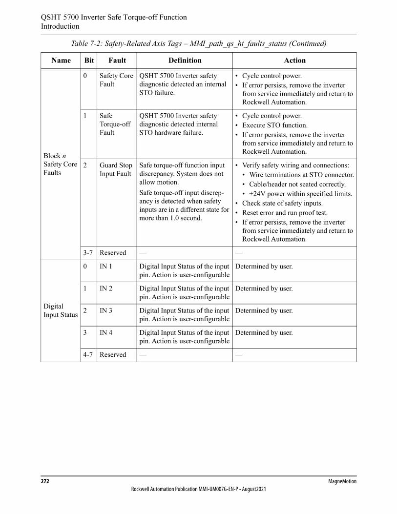
QSHT 5700 Inverter Safe Torque-off FunctionIntroduction
272 MagneMotionRockwell Automation Publication MMI-UM007G-EN-P - August2021
Block n Safety Core Faults
0 Safety Core Fault
QSHT 5700 Inverter safety diagnostic detected an internal STO failure.
• Cycle control power.• If error persists, remove the inverter
from service immediately and return to Rockwell Automation.
1 Safe Torque-off Fault
QSHT 5700 Inverter safety diagnostic detected internal STO hardware failure.
• Cycle control power.• Execute STO function.• If error persists, remove the inverter
from service immediately and return to Rockwell Automation.
2 Guard Stop Input Fault
Safe torque-off function input discrepancy. System does not allow motion.Safe torque-off input discrep-ancy is detected when safety inputs are in a different state for more than 1.0 second.
• Verify safety wiring and connections:• Wire terminations at STO connector.• Cable/header not seated correctly.• +24V power within specified limits.
• Check state of safety inputs.• Reset error and run proof test.• If error persists, remove the inverter
from service immediately and return to Rockwell Automation.
3-7 Reserved — —
Digital Input Status
0 IN 1 Digital Input Status of the input pin. Action is user-configurable
Determined by user.
1 IN 2 Digital Input Status of the input pin. Action is user-configurable
Determined by user.
2 IN 3 Digital Input Status of the input pin. Action is user-configurable
Determined by user.
3 IN 4 Digital Input Status of the input pin. Action is user-configurable
Determined by user.
4-7 Reserved — —
Table 7-2: Safety-Related Axis Tags – MMI_path_qs_ht_faults_status (Continued)
Name Bit Fault Definition Action
QSHT 5700 Inverter Safe Torque-off FunctionHardwired Safe Torque-off
QuickStick HT User Manual 273Rockwell Automation Publication MMI-UM007G-EN-P - August2021
Hardwired Safe Torque-off
This section introduces the QuickStick HT 5700 inverter hardwired safe torque-off (STO) fea-ture that meets the requirements of Performance Level e (PL e) per ISO 13849-1 and SIL CL 3 per IEC 61508, IEC 61800-5-2, and IEC 62061.
The MMI-HT-C2198-D032 inverter uses the STO connector for wiring external safety devices and cascading hardwired safety connections from inverter-to-inverter.
Description of Operation
The safe torque-off feature provides a method, with sufficiently low probability of failure, to force the power-transistor control signals to a disabled state. When disabled, or any time power is removed from the STO inputs, all of the QSHT 5700 inverter output-power transis-tors are released from the ON-state. This results in a condition where the inverter performs a Category 0 Stop (see Stop Category Definition on page 268).
For hardwired control of the safe torque-off (STO) function the appropriate wiring must be connected to the Safety (STO) connector plug. See Hardwired Safe Torque-off Electrical Specifications on page 283 for more information on the safety inputs.
Falling of suspended or inclined loads, or a stopped position where one end of the vehicle magnet array is engaged by the coils in a stator but the other end is not creates potential energy that could result in unintended motion. In these cases, the force from gravity acting on the load, or the asymmetric force from magnetic attraction between the magnet array and the stators, can cause motion. Note that these scenarios are in effect without cause from any sort of system failure.
Under normal operation, shown in Figure 7-1 and described in Table 7-3, the safe torque-off inputs are energized. If either of the STO inputs are de-energized, then all of the output power transistors turn off and both axes will fault with the same error. The safe torque-off response time is less than 12 ms.
ATTENTION: Disabling the power transistor output doesnot provide physical isolation of the electrical output that isrequired for some applications.
ATTENTION: In circumstances where external influences(for example, falling of suspended or inclined loads, or astopped position where one end of the mover magnet array isengaged by a stator but the other end is not) are present, addi-tional measures (for example, mechanical brakes) are neces-sary to prevent any hazard.
QSHT 5700 Inverter Safe Torque-off FunctionHardwired Safe Torque-off
274 MagneMotionRockwell Automation Publication MMI-UM007G-EN-P - August2021
A simultaneous fault in two of the power switching devices in the QSHT 5700 inverter can result in a large but stationary stator current. This current will result in a force versus position characteristic that is a repeating cyclic (generally sinusoidal) pattern. This pattern has both stable and unstable equilibrium points, and the motor will seek the nearest stable point. Because the pattern is roughly sinusoidal, the nearest stable point can be up to 180 electrical degrees away from any given arbitrary initial position, which corresponds to a distance of 60 mm.
ATTENTION: Once there is a GuardStopInputFault, recov-ery occurs once the STO inputs for both axes (regardless ofwhich one has faulted) are switched OFF simultaneously forat least one second. After 1 sec, if no abnormal condition ispresent then the inverter can be returned to normal operationand the fault is reset.
ATTENTION: Linear permanent magnet motors can, in theevent of two simultaneous faults of the IGBT circuit, resultin a movement of up to 180 electrical degrees, which corre-sponds to a distance of 60 mm for QSHT 5700 motors.
ATTENTION: If any of the STO inputs de-energize, theBlock n Inverter Faults GuardStopRequestStatus bit in theMMI_path_qs_ht_faults_status tag is set to 1.
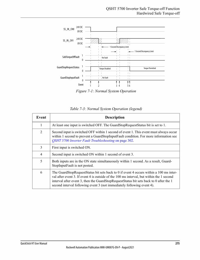
QSHT 5700 Inverter Safe Torque-off FunctionHardwired Safe Torque-off
QuickStick HT User Manual 275Rockwell Automation Publication MMI-UM007G-EN-P - August2021
Figure 7-1: Normal System Operation
Table 7-3: Normal System Operation (legend)
Event Description
1 At least one input is switched OFF. The GuardStopRequestStatus bit is set to 1.
2 Second input is switched OFF within 1 second of event 1. This event must always occur within 1 second to prevent a GuardStopInputFault condition. For more information see QSHT 5700 Inverter Fault Troubleshooting on page 302.
3 First input is switched ON.
4 Second input is switched ON within 1 second of event 3.
5 Both inputs are in the ON state simultaneously within 1 second. As a result, Guard-StopInputFault is not posted.
6 The GuardStopRequestStatus bit sets back to 0 if event 4 occurs within a 100 ms inter-val after event 3. If event 4 is outside of the 100 ms interval, but within the 1 second interval after event 3, then the GuardStopRequestStatus bit sets back to 0 after the 1 second interval following event 3 (not immediately following event 4).
1 3 4 5 6
24V DC
24V DC
0V DC
0V DC
0
1
0
1
0
1
2
SS_IN_CH0
SS_IN_CH1
GuardStopInputFault
SafeTorqueOffFault
GuardStopRequestStatus
No Fault
1 Second Discrepancy Limit
1 Second Discrepancy Limit
Torque PermittedTorque Disabled
No Fault
Event
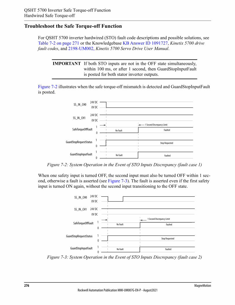
QSHT 5700 Inverter Safe Torque-off FunctionHardwired Safe Torque-off
276 MagneMotionRockwell Automation Publication MMI-UM007G-EN-P - August2021
Troubleshoot the Safe Torque-off Function
For QSHT 5700 inverter hardwired (STO) fault code descriptions and possible solutions, see Table 7-2 on page 271 or the Knowledgebase KB Answer ID 1091727, Kinetix 5700 drive fault codes, and 2198-UM002, Kinetix 5700 Servo Drive User Manual.
Figure 7-2 illustrates when the safe torque-off mismatch is detected and GuardStopInputFault is posted.
Figure 7-2: System Operation in the Event of STO Inputs Discrepancy (fault case 1)
When one safety input is turned OFF, the second input must also be turned OFF within 1 sec-ond, otherwise a fault is asserted (see Figure 7-3). The fault is asserted even if the first safety input is turned ON again, without the second input transitioning to the OFF state.
Figure 7-3: System Operation in the Event of STO Inputs Discrepancy (fault case 2)
IMPORTANT If both STO inputs are not in the OFF state simultaneously,within 100 ms, or after 1 second, then GuardStopInputFaultis posted for both stator inverter outputs.
24V DC
24V DC
0V DC
0V DC
0
1
0
1
0
1
No Fault
1 Second Discrepancy Limit
Faulted
SS_IN_CH0
SS_IN_CH1
GuardStopInputFault
SafeTorqueOffFault
GuardStopRequestStatus Stop Requested
FaultedNo Fault
24V DC
24V DC
0V DC
0V DC
0
1
01
01
GuardStopRequestStatus
SS_IN_CH0
SS_IN_CH1
SafeTorqueOffFault
GuardStopInputFault
No Fault
1 Second Discrepancy Limit
Faulted
Stop Requested
FaultedNo Fault
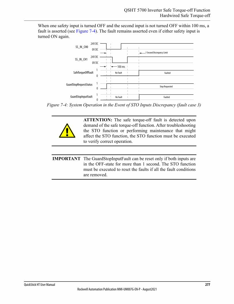
QSHT 5700 Inverter Safe Torque-off FunctionHardwired Safe Torque-off
QuickStick HT User Manual 277Rockwell Automation Publication MMI-UM007G-EN-P - August2021
When one safety input is turned OFF and the second input is not turned OFF within 100 ms, a fault is asserted (see Figure 7-4). The fault remains asserted even if either safety input is turned ON again.
Figure 7-4: System Operation in the Event of STO Inputs Discrepancy (fault case 3)
ATTENTION: The safe torque-off fault is detected upondemand of the safe torque-off function. After troubleshootingthe STO function or performing maintenance that mightaffect the STO function, the STO function must be executedto verify correct operation.
IMPORTANT The GuardStopInputFault can be reset only if both inputs arein the OFF-state for more than 1 second. The STO functionmust be executed to reset the faults if all the fault conditionsare removed.
24V DC
24V DC
0V DC
0V DC
0
1
01
01
100 ms
SS_IN_CH0
SS_IN_CH1
GuardStopRequestStatus
SafeTorqueOffFault
GuardStopInputFault
1 Second Discrepancy Limit
No Fault Faulted
Stop Requested
FaultedNo Fault
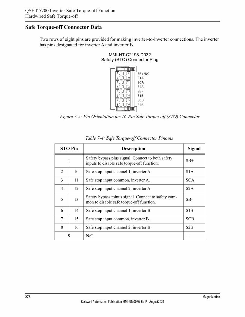
QSHT 5700 Inverter Safe Torque-off FunctionHardwired Safe Torque-off
278 MagneMotionRockwell Automation Publication MMI-UM007G-EN-P - August2021
Safe Torque-off Connector Data
Two rows of eight pins are provided for making inverter-to-inverter connections. The inverter has pins designated for inverter A and inverter B.
Figure 7-5: Pin Orientation for 16-Pin Safe Torque-off (STO) Connector
Table 7-4: Safe Torque-off Connector Pinouts
STO Pin Description Signal
1 Safety bypass plus signal. Connect to both safety inputs to disable safe torque-off function. SB+
2 10 Safe stop input channel 1, inverter A. S1A
3 11 Safe stop input common, inverter A. SCA
4 12 Safe stop input channel 2, inverter A. S2A
5 13 Safety bypass minus signal. Connect to safety com-mon to disable safe torque-off function. SB-
6 14 Safe stop input channel 1, inverter B. S1B
7 15 Safe stop input common, inverter B. SCB
8 16 Safe stop input channel 2, inverter B. S2B
9 N/C —
S1ASCAS2ASB-S1BSCB
12345678
910111213141516
SB+/NC
S2B
MMI-HT-C2198-D032Safety (STO) Connector Plug
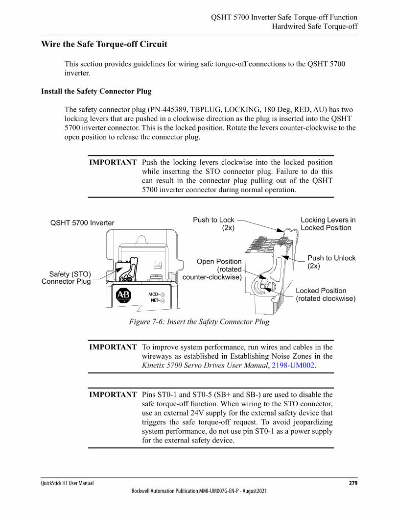
QSHT 5700 Inverter Safe Torque-off FunctionHardwired Safe Torque-off
QuickStick HT User Manual 279Rockwell Automation Publication MMI-UM007G-EN-P - August2021
Wire the Safe Torque-off Circuit
This section provides guidelines for wiring safe torque-off connections to the QSHT 5700 inverter.
Install the Safety Connector Plug
The safety connector plug (PN-445389, TBPLUG, LOCKING, 180 Deg, RED, AU) has two locking levers that are pushed in a clockwise direction as the plug is inserted into the QSHT 5700 inverter connector. This is the locked position. Rotate the levers counter-clockwise to the open position to release the connector plug.
Figure 7-6: Insert the Safety Connector Plug
IMPORTANT Push the locking levers clockwise into the locked positionwhile inserting the STO connector plug. Failure to do thiscan result in the connector plug pulling out of the QSHT5700 inverter connector during normal operation.
IMPORTANT To improve system performance, run wires and cables in thewireways as established in Establishing Noise Zones in theKinetix 5700 Servo Drives User Manual, 2198-UM002.
IMPORTANT Pins ST0-1 and ST0-5 (SB+ and SB-) are used to disable thesafe torque-off function. When wiring to the STO connector,use an external 24V supply for the external safety device thattriggers the safe torque-off request. To avoid jeopardizingsystem performance, do not use pin ST0-1 as a power supplyfor the external safety device.
Locking Levers in Locked Position
Locked Position(rotated clockwise)
QSHT 5700 Inverter
Open Position(rotated
counter-clockwise)
Push to Lock(2x)
Push to Unlock(2x)
Safety (STO)Connector Plug
MOD–NET–
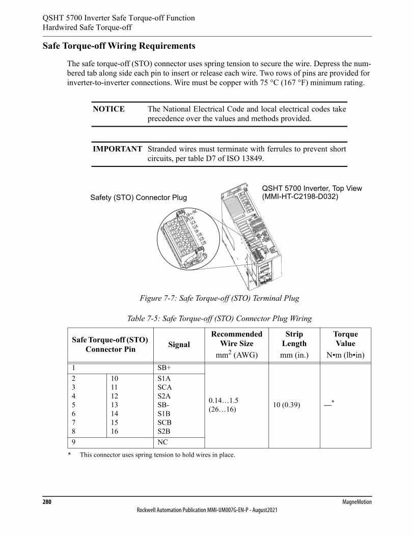
QSHT 5700 Inverter Safe Torque-off FunctionHardwired Safe Torque-off
280 MagneMotionRockwell Automation Publication MMI-UM007G-EN-P - August2021
Safe Torque-off Wiring Requirements
The safe torque-off (STO) connector uses spring tension to secure the wire. Depress the num-bered tab along side each pin to insert or release each wire. Two rows of pins are provided for inverter-to-inverter connections. Wire must be copper with 75 °C (167 °F) minimum rating.
Figure 7-7: Safe Torque-off (STO) Terminal Plug
NOTICE The National Electrical Code and local electrical codes takeprecedence over the values and methods provided.
IMPORTANT Stranded wires must terminate with ferrules to prevent shortcircuits, per table D7 of ISO 13849.
Table 7-5: Safe Torque-off (STO) Connector Plug Wiring
Safe Torque-off (STO) Connector Pin Signal
Recommended Wire Size
mm2 (AWG)
Strip Lengthmm (in.)
Torque Value
N•m (lb•in)1 SB+
0.14…1.5(26…16) 10 (0.39) —*
* This connector uses spring tension to hold wires in place.
2345678
10111213141516
S1ASCAS2ASB-S1BSCBS2B
9 NC
SB+/NC
S1ASCA
S2ASB-
S1BSCB
S2B
12
34
56
78
1615
1413
1211
109
QSHT 5700 Inverter, Top View(MMI-HT-C2198-D032)Safety (STO) Connector Plug
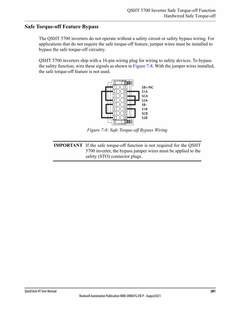
QSHT 5700 Inverter Safe Torque-off FunctionHardwired Safe Torque-off
QuickStick HT User Manual 281Rockwell Automation Publication MMI-UM007G-EN-P - August2021
Safe Torque-off Feature Bypass
The QSHT 5700 inverters do not operate without a safety circuit or safety bypass wiring. For applications that do not require the safe torque-off feature, jumper wires must be installed to bypass the safe torque-off circuitry.
QSHT 5700 inverters ship with a 16-pin wiring plug for wiring to safety devices. To bypass the safety function, wire these signals as shown in Figure 7-8. With the jumper wires installed, the safe torque-off feature is not used.
Figure 7-8: Safe Torque-off Bypass Wiring
IMPORTANT If the safe torque-off function is not required for the QSHT5700 inverter, the bypass jumper wires must be applied to thesafety (STO) connector plugs.
SB+/NCS1ASCAS2ASB-S1BSCBS2B
12
12345678
91011
13141516
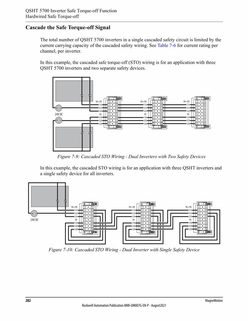
QSHT 5700 Inverter Safe Torque-off FunctionHardwired Safe Torque-off
282 MagneMotionRockwell Automation Publication MMI-UM007G-EN-P - August2021
Cascade the Safe Torque-off Signal
The total number of QSHT 5700 inverters in a single cascaded safety circuit is limited by the current carrying capacity of the cascaded safety wiring. See Table 7-6 for current rating per channel, per inverter.
In this example, the cascaded safe torque-off (STO) wiring is for an application with three QSHT 5700 inverters and two separate safety devices.
Figure 7-9: Cascaded STO Wiring - Dual Inverters with Two Safety Devices
In this example, the cascaded STO wiring is for an application with three QSHT inverters and a single safety device for all inverters.
Figure 7-10: Cascaded STO Wiring - Dual Inverter with Single Safety Device
SB+/NCS1ASCAS2ASB-S1BSCBS2B
SB+/NCS1ASCAS2ASB-S1BSCBS2B
24V DC
SB+/NCS1ASCAS2ASB-S1BSCBS2B
12
12345678
91011
13141516
12
12345678
91011
13141516
12
12345678
91011
13141516
24V DC
SB+/NCS1ASCAS2ASB-S1BSCBS2B
SB+/NCS1ASCAS2ASB-S1BSCBS2B
SB+/NCS1ASCAS2ASB-S1BSCBS2B
12
12345678
91011
13141516
12
12345678
91011
13141516
12
12345678
91011
13141516
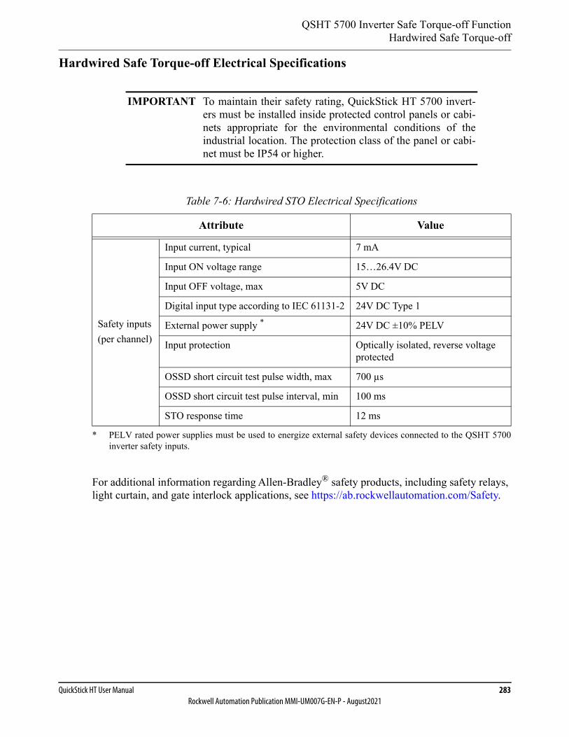
QSHT 5700 Inverter Safe Torque-off FunctionHardwired Safe Torque-off
QuickStick HT User Manual 283Rockwell Automation Publication MMI-UM007G-EN-P - August2021
Hardwired Safe Torque-off Electrical Specifications
For additional information regarding Allen-Bradley® safety products, including safety relays, light curtain, and gate interlock applications, see https://ab.rockwellautomation.com/Safety.
IMPORTANT To maintain their safety rating, QuickStick HT 5700 invert-ers must be installed inside protected control panels or cabi-nets appropriate for the environmental conditions of theindustrial location. The protection class of the panel or cabi-net must be IP54 or higher.
Table 7-6: Hardwired STO Electrical Specifications
Attribute Value
Safety inputs(per channel)
Input current, typical 7 mA
Input ON voltage range 15…26.4V DC
Input OFF voltage, max 5V DC
Digital input type according to IEC 61131-2 24V DC Type 1
External power supply *
* PELV rated power supplies must be used to energize external safety devices connected to the QSHT 5700inverter safety inputs.
24V DC ±10% PELV
Input protection Optically isolated, reverse voltage protected
OSSD short circuit test pulse width, max 700 µs
OSSD short circuit test pulse interval, min 100 ms
STO response time 12 ms

QSHT 5700 Inverter Safe Torque-off Function
284 MagneMotionRockwell Automation Publication MMI-UM007G-EN-P - August2021
This page intentionally left blank.

QuickStick HT User Manual 285Rockwell Automation Publication MMI-UM007G-EN-P - August2021
Maintenance 8
Overview
This chapter provides maintenance schedules and procedures for the QuickStick® HT compo-nents. Only trained, qualified personnel should perform maintenance or troubleshooting on the QSHT transport system. MagneMotion® provides training in the troubleshooting and repair of the QSHT transport system.
Included in this chapter are:
• Preventive maintenance procedures.
• Troubleshooting procedures.
• Contacting Technical Support and Sales.
• Basic repair procedures.
• Component shipping procedures.
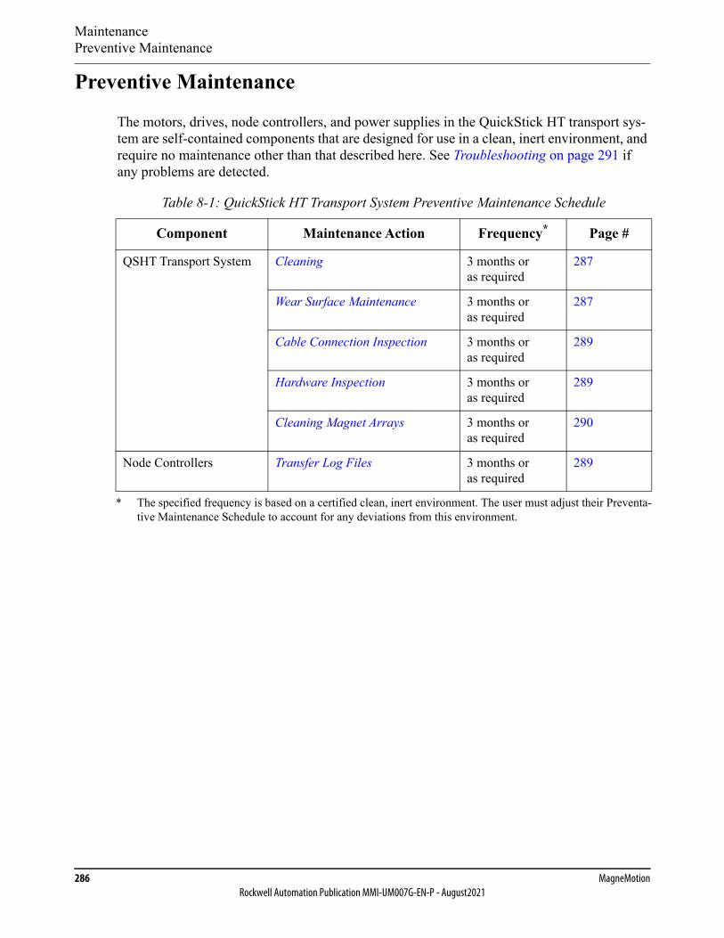
MaintenancePreventive Maintenance
286 MagneMotionRockwell Automation Publication MMI-UM007G-EN-P - August2021
Preventive Maintenance
The motors, drives, node controllers, and power supplies in the QuickStick HT transport sys-tem are self-contained components that are designed for use in a clean, inert environment, and require no maintenance other than that described here. See Troubleshooting on page 291 if any problems are detected.
Table 8-1: QuickStick HT Transport System Preventive Maintenance Schedule
Component Maintenance Action Frequency*
* The specified frequency is based on a certified clean, inert environment. The user must adjust their Preventa-tive Maintenance Schedule to account for any deviations from this environment.
Page #
QSHT Transport System Cleaning 3 months or as required
287
Wear Surface Maintenance 3 months or as required
287
Cable Connection Inspection 3 months or as required
289
Hardware Inspection 3 months or as required
289
Cleaning Magnet Arrays 3 months or as required
290
Node Controllers Transfer Log Files 3 months or as required
289

MaintenancePreventive Maintenance
QuickStick HT User Manual 287Rockwell Automation Publication MMI-UM007G-EN-P - August2021
Cleaning
General cleaning of the QuickStick HT transport system consists of cleaning the transport sys-tem surfaces as described.
Required Tools and Equipment
• Disposable gloves.
• Microfiber cleaning cloth.
• Deionized water.
• Isopropyl alcohol (optional).
Procedure
1. Stop all motion on the sections of the QSHT transport system to be cleaned.
2. While wearing gloves, clean all exposed transport system surfaces and cables with a clean microfiber cloth slightly dampened with deionized water or Isopropyl alcohol. Wipe in the direction of the grain on all surfaces that have a grain.
3. Make sure that all components are dry.
4. Resume motion on the sections of the QSHT transport system that were stopped.
Wear Surface Maintenance
The vehicles that are used on the QSHT transport system may need to be rotated to make sure that there is even wear on the wheels. This is especially true for vehicles that are used in a transport system where all motion is in one direction, for bogies in a tandem vehicle configu-ration, or for vehicles that have a cantilevered or high inertia payload.
NOTE: Rotating vehicles is only done for vehicles where the magnet array is centered on the vehicle. For vehicles where the magnet array is not centered, the design of the vehi-cle determines if it is possible to rotate the vehicle.
MAGNETIC FIELD HAZARD: Strong magnets in use.
To avoid severe injury, people with pacemakers and othermedical electronic implants must stay away from the magnetarrays on the vehicles.
MaintenancePreventive Maintenance
288 MagneMotionRockwell Automation Publication MMI-UM007G-EN-P - August2021
1. Stop all motion on the QSHT transport system.
2. Remove the vehicles from the QSHT transport system.
3. Inspect the vehicles for excessive or uneven wear.
• For vehicles that experience uneven wear, rotate the vehicles 180°.
• For vehicles that experience excessive wear, replace the worn components.
4. Replace the vehicles on the QSHT transport system.
CRUSH HAZARD: Strong magnets in use.
To avoid severe injury from strong magnetic attractiveforces:• Handle only one vehicle or magnet array at a time.• Do not place any body parts (for example, fingers)
between a magnet array and any QuickStick HT motors, ferrous material, or another magnet array.
• Magnet arrays or vehicles not being used must be secured individually in isolated packaging.
NOTICE Strong magnets in use.
To avoid damage to watches, instruments, electronics, andmagnetic media, keep metal tools, metal objects, magneticmedia (for example, memory disks/chips, credit cards, andtapes) and electronics away from the magnet arrays.

MaintenancePreventive Maintenance
QuickStick HT User Manual 289Rockwell Automation Publication MMI-UM007G-EN-P - August2021
Cable Connection Inspection
1. Stop all motion on the sections of the QSHT transport system to be inspected.
2. Verify that all cable connectors are fully seated and screws/locks are secured to achieve good continuity.
3. Inspect all cables for restricting bend radii, excessive tension, or physical damage.
4. Return the QSHT transport system to normal operation.
Hardware Inspection
1. Stop all motion on the sections of the QSHT transport system to be inspected.
2. Turn off all QSHT transport system components with accessible power controls.
3. Make sure that all motor stand hardware is secure.
4. Make sure that all motor mounting hardware is secure.
5. Make sure that all guideway mounting hardware is secure.
6. Make sure that all vehicle grounding materials (for example, static brushes) are secure and functioning properly.
7. Make sure that all vehicle hardware, especially the hardware that holds the magnet array, is secure.
8. Make sure that the Vehicle Gap (distance between the magnet array on the vehicle and the motor) is within tolerance for all vehicles on all motors.
9. Return the QSHT transport system to normal operation.
Transfer Log Files
Review the log files for each node controller and the HLC periodically to look for unexpected messages.
Log files can be transferred from the node controller or SysLog server to a network server so they can be archived or e-mailed to Technical Support, see the Node Controller Interface User Manual, MMI-UM001.
MaintenancePreventive Maintenance
290 MagneMotionRockwell Automation Publication MMI-UM007G-EN-P - August2021
Cleaning Magnet Arrays
The magnet arrays attract ferrous particles from the air and surrounding surfaces. These parti-cles accumulate and appear as small “hairs” on the surface of the array.
• Use adhesive tape to capture the ferrous particles on the magnet arrays.
• To combat accumulated debris, keep magnet arrays not being used in their original container.
• Proper precautions must be taken when magnet arrays with stainless steel covers that are not welded onto the back iron are used in wash down applications or in environ-ments where water or fluids are contacting the array. The mounting must secure the array with a suitable form of gasketing to avoid water ingress into the array through either its back surface or the seam where the cover meets the back iron of the array. The top surface and sides of the cover are water-resistant.
MAGNETIC FIELD HAZARD: Strong magnets in use.
To avoid severe injury, people with pacemakers and othermedical electronic implants must stay away from the magnetarrays.
CRUSH HAZARD: Strong magnets in use.
To avoid severe injury from strong magnetic attractiveforces:• Handle only one vehicle or magnet array at a time.• Do not place any body parts (for example, fingers)
between a magnet array and any QuickStick HT motors, ferrous material, or another magnet array.
• Magnet arrays or vehicles not being used must be secured individually in isolated packaging.
NOTICE Strong magnets in use.
To avoid damage to watches, instruments, electronics, andmagnetic media, keep metal tools, metal objects, magneticmedia (for example, memory disks/chips, credit cards, andtapes) and electronics away from the magnet arrays.
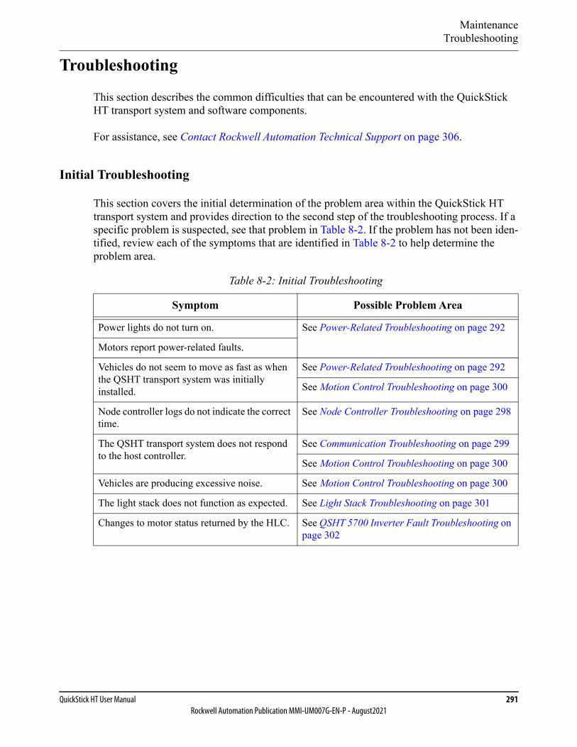
MaintenanceTroubleshooting
QuickStick HT User Manual 291Rockwell Automation Publication MMI-UM007G-EN-P - August2021
Troubleshooting
This section describes the common difficulties that can be encountered with the QuickStick HT transport system and software components.
For assistance, see Contact Rockwell Automation Technical Support on page 306.
Initial Troubleshooting
This section covers the initial determination of the problem area within the QuickStick HT transport system and provides direction to the second step of the troubleshooting process. If a specific problem is suspected, see that problem in Table 8-2. If the problem has not been iden-tified, review each of the symptoms that are identified in Table 8-2 to help determine the problem area.
Table 8-2: Initial Troubleshooting
Symptom Possible Problem Area
Power lights do not turn on. See Power-Related Troubleshooting on page 292
Motors report power-related faults.
Vehicles do not seem to move as fast as when the QSHT transport system was initially installed.
See Power-Related Troubleshooting on page 292
See Motion Control Troubleshooting on page 300
Node controller logs do not indicate the correct time.
See Node Controller Troubleshooting on page 298
The QSHT transport system does not respond to the host controller.
See Communication Troubleshooting on page 299
See Motion Control Troubleshooting on page 300
Vehicles are producing excessive noise. See Motion Control Troubleshooting on page 300
The light stack does not function as expected. See Light Stack Troubleshooting on page 301
Changes to motor status returned by the HLC. See QSHT 5700 Inverter Fault Troubleshooting on page 302
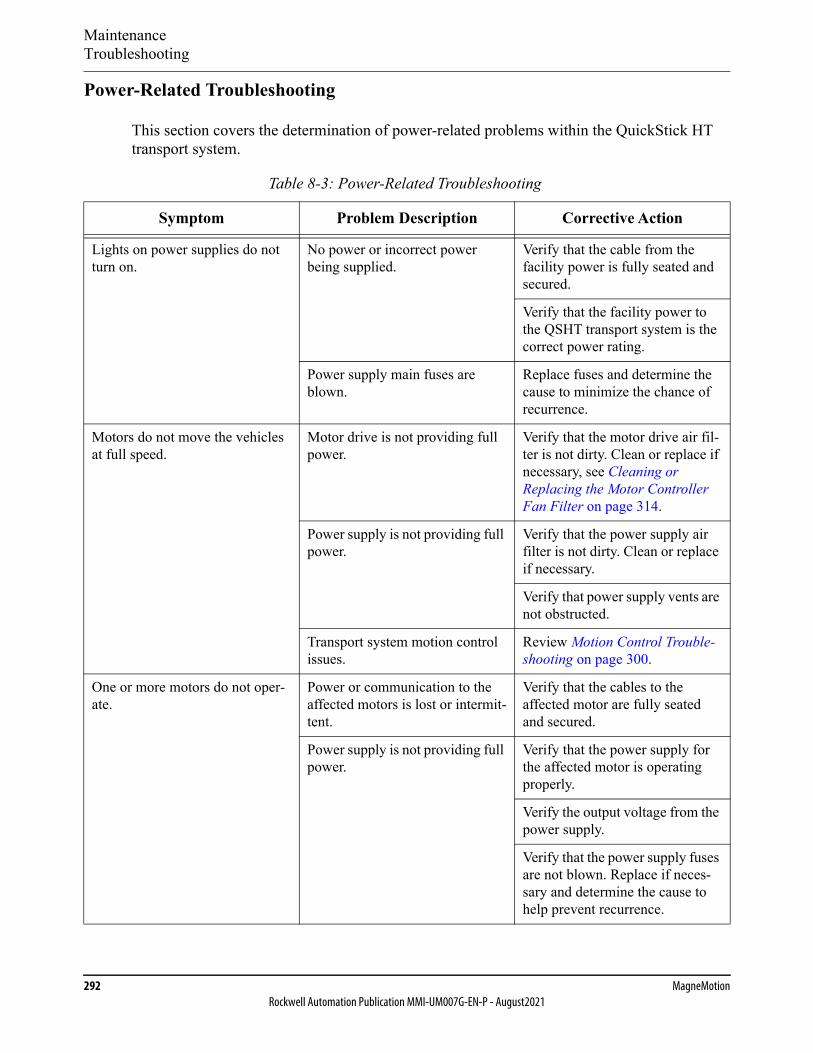
MaintenanceTroubleshooting
292 MagneMotionRockwell Automation Publication MMI-UM007G-EN-P - August2021
Power-Related Troubleshooting
This section covers the determination of power-related problems within the QuickStick HT transport system.
Table 8-3: Power-Related Troubleshooting
Symptom Problem Description Corrective Action
Lights on power supplies do not turn on.
No power or incorrect power being supplied.
Verify that the cable from the facility power is fully seated and secured.
Verify that the facility power to the QSHT transport system is the correct power rating.
Power supply main fuses are blown.
Replace fuses and determine the cause to minimize the chance of recurrence.
Motors do not move the vehicles at full speed.
Motor drive is not providing full power.
Verify that the motor drive air fil-ter is not dirty. Clean or replace if necessary, see Cleaning or Replacing the Motor Controller Fan Filter on page 314.
Power supply is not providing full power.
Verify that the power supply air filter is not dirty. Clean or replace if necessary.
Verify that power supply vents are not obstructed.
Transport system motion control issues.
Review Motion Control Trouble-shooting on page 300.
One or more motors do not oper-ate.
Power or communication to the affected motors is lost or intermit-tent.
Verify that the cables to the affected motor are fully seated and secured.
Power supply is not providing full power.
Verify that the power supply for the affected motor is operating properly.
Verify the output voltage from the power supply.
Verify that the power supply fuses are not blown. Replace if neces-sary and determine the cause to help prevent recurrence.
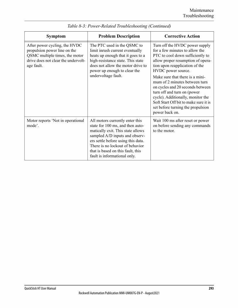
MaintenanceTroubleshooting
QuickStick HT User Manual 293Rockwell Automation Publication MMI-UM007G-EN-P - August2021
After power cycling, the HVDC propulsion power line on the QSMC multiple times, the motor drive does not clear the undervolt-age fault.
The PTC used in the QSMC to limit inrush current eventually heats up enough that it goes to a high-resistance state. This state does not allow the motor drive to power up enough to clear the undervoltage fault.
Turn off the HVDC power supply for a few minutes to allow the PTC to cool down sufficiently to allow proper resumption of opera-tion upon reapplication of the HVDC power source.Make sure that there is a mini-mum of 2 minutes between turn on cycles and 20 seconds between turn off and turn on (power cycle). Additionally, monitor the Soft Start Off bit to make sure it is set before turning the propulsion power back on.
Motor reports ‘Not in operational mode’.
All motors currently enter this state for 100 ms, and then auto-matically exit. This state allows sampled A/D inputs and observ-ers settle before using this data. There is no lockout of behavior that is based on this fault, this fault is informational only.
Wait 100 ms after reset or power on before sending any commands to the motor.
Table 8-3: Power-Related Troubleshooting (Continued)
Symptom Problem Description Corrective Action
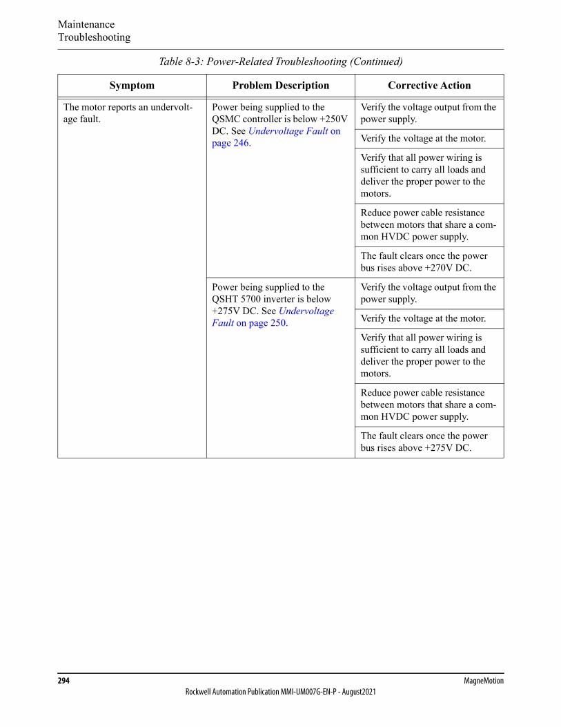
MaintenanceTroubleshooting
294 MagneMotionRockwell Automation Publication MMI-UM007G-EN-P - August2021
The motor reports an undervolt-age fault.
Power being supplied to the QSMC controller is below +250V DC. See Undervoltage Fault on page 246.
Verify the voltage output from the power supply.
Verify the voltage at the motor.
Verify that all power wiring is sufficient to carry all loads and deliver the proper power to the motors.
Reduce power cable resistance between motors that share a com-mon HVDC power supply.
The fault clears once the power bus rises above +270V DC.
Power being supplied to the QSHT 5700 inverter is below +275V DC. See Undervoltage Fault on page 250.
Verify the voltage output from the power supply.
Verify the voltage at the motor.
Verify that all power wiring is sufficient to carry all loads and deliver the proper power to the motors.
Reduce power cable resistance between motors that share a com-mon HVDC power supply.
The fault clears once the power bus rises above +275V DC.
Table 8-3: Power-Related Troubleshooting (Continued)
Symptom Problem Description Corrective Action
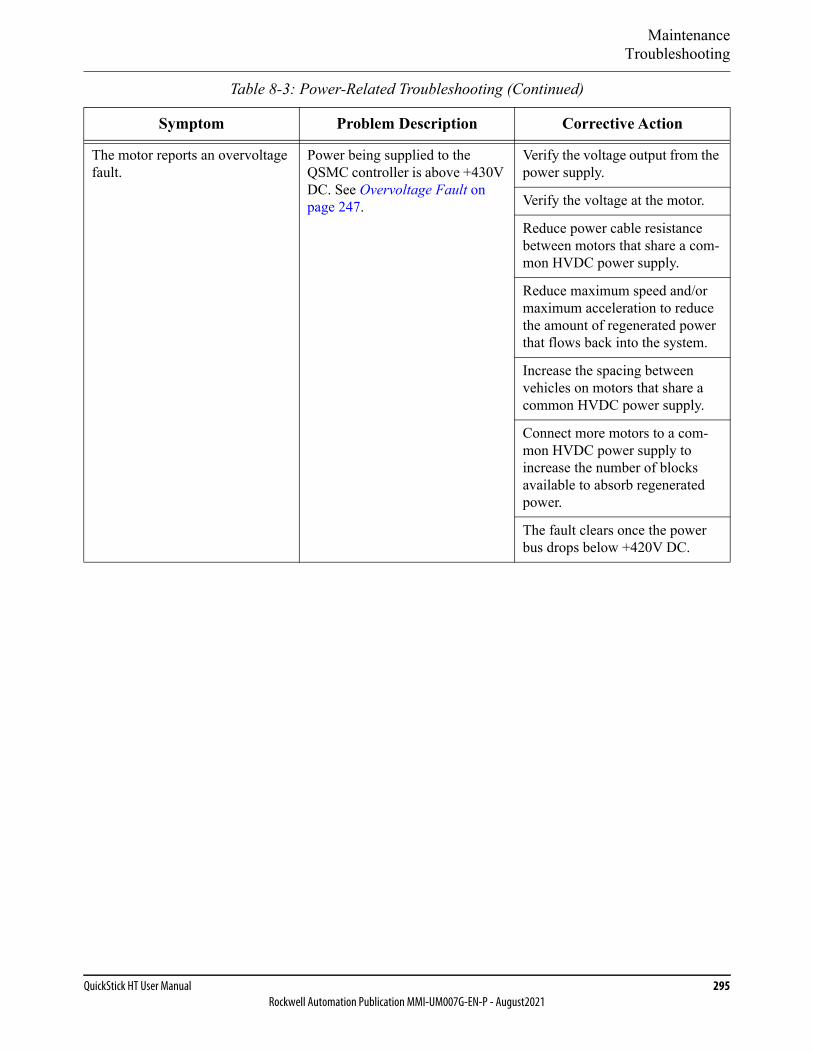
MaintenanceTroubleshooting
QuickStick HT User Manual 295Rockwell Automation Publication MMI-UM007G-EN-P - August2021
The motor reports an overvoltage fault.
Power being supplied to the QSMC controller is above +430V DC. See Overvoltage Fault on page 247.
Verify the voltage output from the power supply.
Verify the voltage at the motor.
Reduce power cable resistance between motors that share a com-mon HVDC power supply.
Reduce maximum speed and/or maximum acceleration to reduce the amount of regenerated power that flows back into the system.
Increase the spacing between vehicles on motors that share a common HVDC power supply.
Connect more motors to a com-mon HVDC power supply to increase the number of blocks available to absorb regenerated power.
The fault clears once the power bus drops below +420V DC.
Table 8-3: Power-Related Troubleshooting (Continued)
Symptom Problem Description Corrective Action
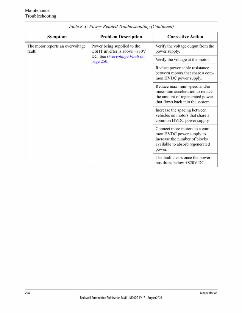
MaintenanceTroubleshooting
296 MagneMotionRockwell Automation Publication MMI-UM007G-EN-P - August2021
The motor reports an overvoltage fault.
Power being supplied to the QSHT inverter is above +830V DC. See Overvoltage Fault on page 250.
Verify the voltage output from the power supply.
Verify the voltage at the motor.
Reduce power cable resistance between motors that share a com-mon HVDC power supply.
Reduce maximum speed and/or maximum acceleration to reduce the amount of regenerated power that flows back into the system.
Increase the spacing between vehicles on motors that share a common HVDC power supply.
Connect more motors to a com-mon HVDC power supply to increase the number of blocks available to absorb regenerated power.
The fault clears once the power bus drops below +820V DC.
Table 8-3: Power-Related Troubleshooting (Continued)
Symptom Problem Description Corrective Action
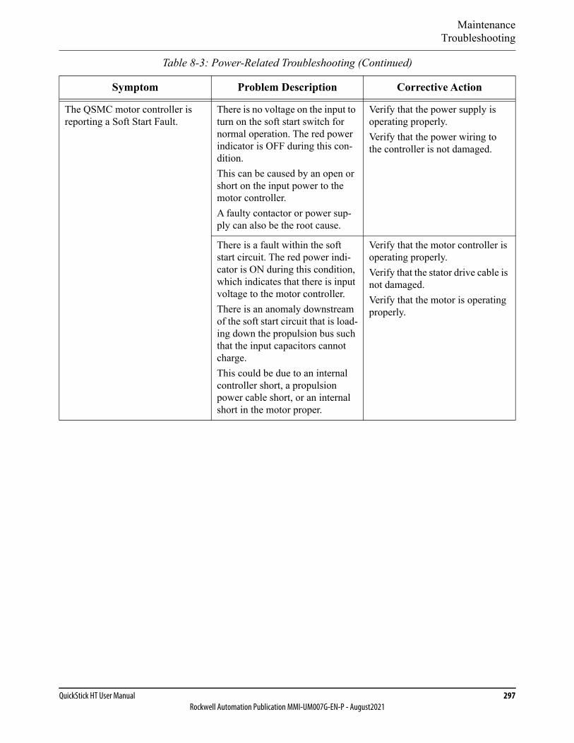
MaintenanceTroubleshooting
QuickStick HT User Manual 297Rockwell Automation Publication MMI-UM007G-EN-P - August2021
The QSMC motor controller is reporting a Soft Start Fault.
There is no voltage on the input to turn on the soft start switch for normal operation. The red power indicator is OFF during this con-dition.This can be caused by an open or short on the input power to the motor controller.A faulty contactor or power sup-ply can also be the root cause.
Verify that the power supply is operating properly.Verify that the power wiring to the controller is not damaged.
There is a fault within the soft start circuit. The red power indi-cator is ON during this condition, which indicates that there is input voltage to the motor controller.There is an anomaly downstream of the soft start circuit that is load-ing down the propulsion bus such that the input capacitors cannot charge.This could be due to an internal controller short, a propulsion power cable short, or an internal short in the motor proper.
Verify that the motor controller is operating properly.Verify that the stator drive cable is not damaged.Verify that the motor is operating properly.
Table 8-3: Power-Related Troubleshooting (Continued)
Symptom Problem Description Corrective Action
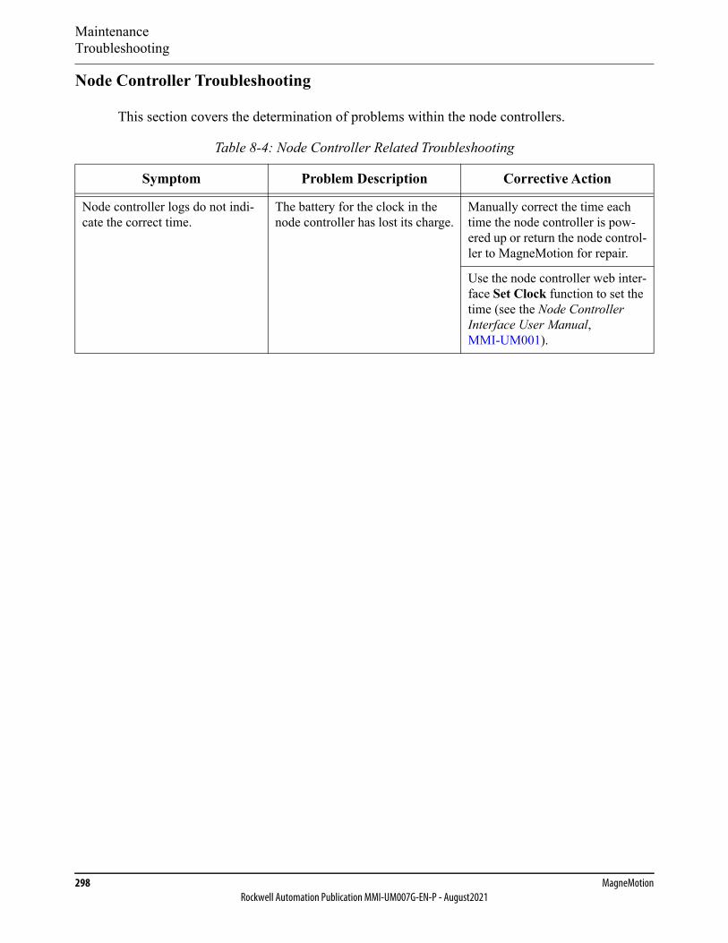
MaintenanceTroubleshooting
298 MagneMotionRockwell Automation Publication MMI-UM007G-EN-P - August2021
Node Controller Troubleshooting
This section covers the determination of problems within the node controllers.
Table 8-4: Node Controller Related Troubleshooting
Symptom Problem Description Corrective Action
Node controller logs do not indi-cate the correct time.
The battery for the clock in the node controller has lost its charge.
Manually correct the time each time the node controller is pow-ered up or return the node control-ler to MagneMotion for repair.
Use the node controller web inter-face Set Clock function to set the time (see the Node Controller Interface User Manual, MMI-UM001).
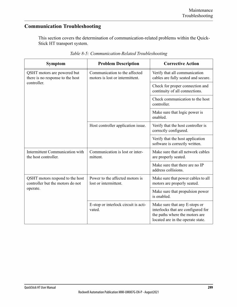
MaintenanceTroubleshooting
QuickStick HT User Manual 299Rockwell Automation Publication MMI-UM007G-EN-P - August2021
Communication Troubleshooting
This section covers the determination of communication-related problems within the Quick-Stick HT transport system.
Table 8-5: Communication-Related Troubleshooting
Symptom Problem Description Corrective Action
QSHT motors are powered but there is no response to the host controller.
Communication to the affected motors is lost or intermittent.
Verify that all communication cables are fully seated and secure.
Check for proper connection and continuity of all connections.
Check communication to the host controller.
Make sure that logic power is enabled.
Host controller application issue. Verify that the host controller is correctly configured.
Verify that the host application software is correctly written.
Intermittent Communication with the host controller.
Communication is lost or inter-mittent.
Make sure that all network cables are properly seated.
Make sure that there are no IP address collisions.
QSHT motors respond to the host controller but the motors do not operate.
Power to the affected motors is lost or intermittent.
Make sure that power cables to all motors are properly seated.
Make sure that propulsion power is enabled.
E-stop or interlock circuit is acti-vated.
Make sure that any E-stops or interlocks that are configured for the paths where the motors are located are in the operate state.
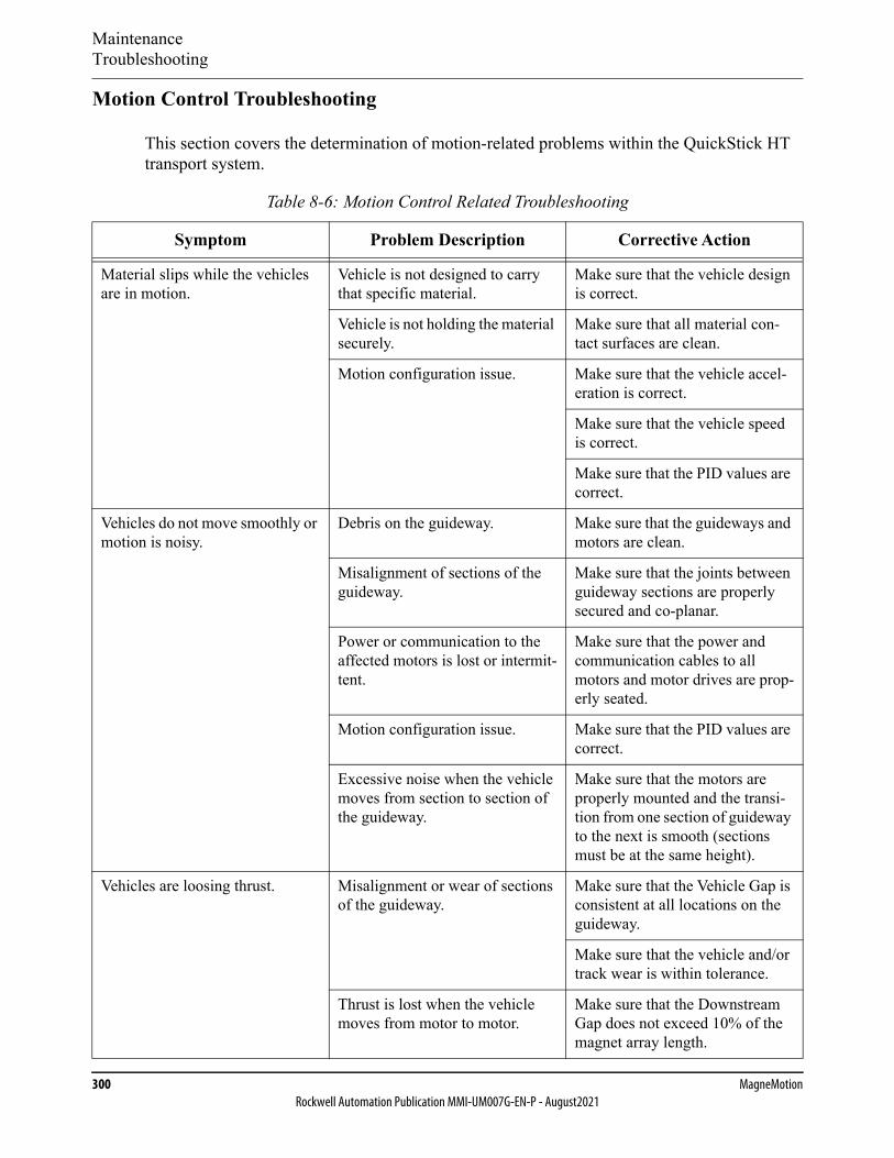
MaintenanceTroubleshooting
300 MagneMotionRockwell Automation Publication MMI-UM007G-EN-P - August2021
Motion Control Troubleshooting
This section covers the determination of motion-related problems within the QuickStick HT transport system.
Table 8-6: Motion Control Related Troubleshooting
Symptom Problem Description Corrective Action
Material slips while the vehicles are in motion.
Vehicle is not designed to carry that specific material.
Make sure that the vehicle design is correct.
Vehicle is not holding the material securely.
Make sure that all material con-tact surfaces are clean.
Motion configuration issue. Make sure that the vehicle accel-eration is correct.
Make sure that the vehicle speed is correct.
Make sure that the PID values are correct.
Vehicles do not move smoothly or motion is noisy.
Debris on the guideway. Make sure that the guideways and motors are clean.
Misalignment of sections of the guideway.
Make sure that the joints between guideway sections are properly secured and co-planar.
Power or communication to the affected motors is lost or intermit-tent.
Make sure that the power and communication cables to all motors and motor drives are prop-erly seated.
Motion configuration issue. Make sure that the PID values are correct.
Excessive noise when the vehicle moves from section to section of the guideway.
Make sure that the motors are properly mounted and the transi-tion from one section of guideway to the next is smooth (sections must be at the same height).
Vehicles are loosing thrust. Misalignment or wear of sections of the guideway.
Make sure that the Vehicle Gap is consistent at all locations on the guideway.
Make sure that the vehicle and/or track wear is within tolerance.
Thrust is lost when the vehicle moves from motor to motor.
Make sure that the Downstream Gap does not exceed 10% of the magnet array length.

MaintenanceTroubleshooting
QuickStick HT User Manual 301Rockwell Automation Publication MMI-UM007G-EN-P - August2021
Light Stack Troubleshooting
This section covers the determination of light stack-related problems within the QuickStick HT transport system.
Table 8-7: Light Stack Related Troubleshooting
Symptom Problem Description Corrective Action
Lights do not turn on. Power to the light stack is lost or intermittent.
Make sure that all wiring to the light stack is properly seated.
Verify voltage output from the power supply.
Light stack is not wired properly. Make sure that all connections to the light stack are properly wired (see Light Stacks on page 256).
Make sure that the bits specified in the Node Controller Configura-tion File are the bits connected to the light stack.
Light stack is not configured properly.
Make sure that the light stack is configured to monitor the appro-priate paths and/or nodes.
Yellow light does not turn off. Light indicates one or more faults. Review the log file to determine the fault (see the Node Controller Interface User Manual, MMI-UM001).
Red light does not turn off. Light indicates that vehicles are stopped.
Send a move vehicle command to any vehicle on the paths or nodes that the light stack monitors.
Light indicates that vehicles are stopped even though there is motion.
Verify that the light stack is prop-erly wired.

MaintenanceTroubleshooting
302 MagneMotionRockwell Automation Publication MMI-UM007G-EN-P - August2021
QSHT 5700 Inverter Fault Troubleshooting
Table 8-8 provides detailed descriptions and solutions for the QuickStick HT safety faults as identified through the Motor Status command response or the MMI_path_qs_ht_faults_status tag. See the Host Controller TCP/IP Communication Protocol User Manual, MMI-UM003, or the Host Controller EtherNet/IP Communication Protocol User Manual, MMI-UM004, for a complete description of all faults and their resolution.
In the QuickStick HT motor error descriptions that are provided in Table 8-8, the Motor Sus-pend Fault field shows when motion on the motor is suspended. Motion cannot resume until the fault is cleared. Vehicles are not allowed to enter the section of the Path where the motor is located while the motor is suspended.
Table 8-8: QuickStick HT MMI_path_qs_ht_faults_status Motor Faults
Master Board Faults
3 Safety Core Fault
Definition Communication to the safety core has timed out after 100 ms.
Set condition The master board has detected a communication fault and has timed out.
Clear condition Safety Core communication is re-established to the Master.
User action • Power cycle the unit.• If problem persists, return the unit.
Motor Suspend Fault Yes
4 Auxiliary Core Fault
Definition Communication to the auxiliary core has communication issues and has not received a response in 10 ms.
Set condition The master board has detected a communication fault and has timed out.
Clear condition Aux Core communication is re-established to the Master.
User action • Power cycle the unit.• If problem persists, return the unit.
Motor Suspend Fault No
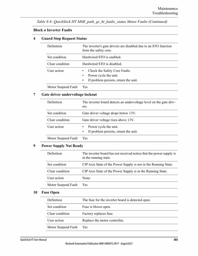
MaintenanceTroubleshooting
QuickStick HT User Manual 303Rockwell Automation Publication MMI-UM007G-EN-P - August2021
Block n Inverter Faults
4 Guard Stop Request Status
Definition The inverter's gate drivers are disabled due to an STO function from the safety core.
Set condition Hardwired STO is enabled.
Clear condition Hardwired STO is disabled.
User action • Check the Safety Core Faults.• Power cycle the unit.• If problem persists, return the unit.
Motor Suspend Fault Yes
7 Gate driver undervoltage lockout
Definition The inverter board detects an undervoltage level on the gate driv-ers.
Set condition Gate driver voltage drops below 13V.
Clear condition Gate driver voltage rises above 13V.
User action • Power cycle the unit.• If problem persists, return the unit.
Motor Suspend Fault Yes
9 Power Supply Not Ready
Definition The inverter board has not received notice that the power supply is in the running state.
Set condition CIP Axis State of the Power Supply is not in the Running State.
Clear condition CIP Axis State of the Power Supply is in the Running State.
User action None
Motor Suspend Fault Yes
10 Fuse Open
Definition The fuse for the inverter board is detected open.
Set condition Fuse is blown open.
Clear condition Factory replaces fuse.
User action Replace the motor controller.
Motor Suspend Fault Yes
Table 8-8: QuickStick HT MMI_path_qs_ht_faults_status Motor Faults (Continued)
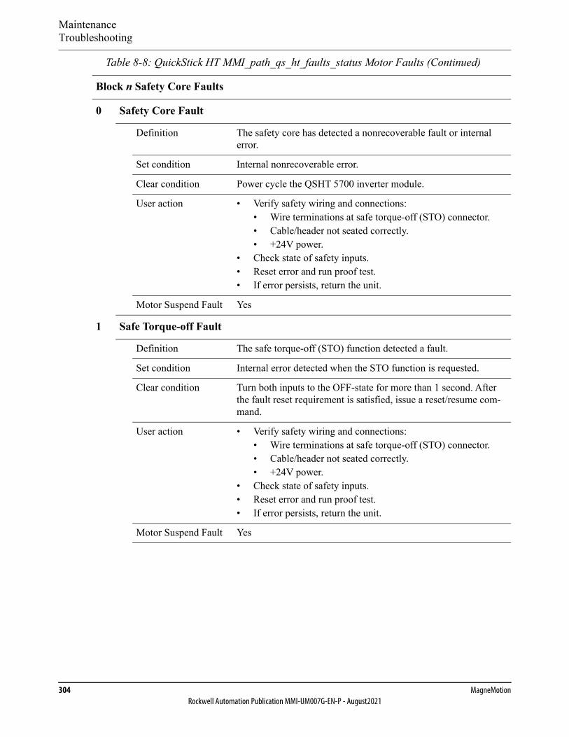
MaintenanceTroubleshooting
304 MagneMotionRockwell Automation Publication MMI-UM007G-EN-P - August2021
Block n Safety Core Faults
0 Safety Core Fault
Definition The safety core has detected a nonrecoverable fault or internal error.
Set condition Internal nonrecoverable error.
Clear condition Power cycle the QSHT 5700 inverter module.
User action • Verify safety wiring and connections:• Wire terminations at safe torque-off (STO) connector.• Cable/header not seated correctly.• +24V power.
• Check state of safety inputs.• Reset error and run proof test.• If error persists, return the unit.
Motor Suspend Fault Yes
1 Safe Torque-off Fault
Definition The safe torque-off (STO) function detected a fault.
Set condition Internal error detected when the STO function is requested.
Clear condition Turn both inputs to the OFF-state for more than 1 second. After the fault reset requirement is satisfied, issue a reset/resume com-mand.
User action • Verify safety wiring and connections:• Wire terminations at safe torque-off (STO) connector.• Cable/header not seated correctly.• +24V power.
• Check state of safety inputs.• Reset error and run proof test.• If error persists, return the unit.
Motor Suspend Fault Yes
Table 8-8: QuickStick HT MMI_path_qs_ht_faults_status Motor Faults (Continued)

MaintenanceTroubleshooting
QuickStick HT User Manual 305Rockwell Automation Publication MMI-UM007G-EN-P - August2021
2 Guard Stop Input Fault
Definition Monitors the safe torque-off (STO) function inputs.
Set condition Safe torque-off mismatch is detected when safety inputs are in dif-ferent state for more than one second.
Clear condition Turn both inputs to the OFF-state for more than 1 second. After the fault reset requirement is satisfied, issue a reset/resume com-mand.
User action • Verify safety wiring and connections:• Wire terminations at safe torque-off (STO) connector.• Cable/header not seated correctly.• +24V power.
• Check state of safety inputs.• Reset error and run proof test.• If error persists, return the unit.
Motor Suspend Fault Yes
Digital Input Status
0-3 Digital Input n (four digital inputs)
Definition Status of the digital input pin.
Set condition Input is held HIGH (+24V).
Clear condition Input is held LOW (0V) or not connected.
User action Action is user-configurable.
Motor Suspend Fault No
Table 8-8: QuickStick HT MMI_path_qs_ht_faults_status Motor Faults (Continued)

MaintenanceContact Rockwell Automation Technical Support
306 MagneMotionRockwell Automation Publication MMI-UM007G-EN-P - August2021
Contact Rockwell Automation Technical Support
Before contacting Technical Support, have the following information ready.
1. The name, email address, and telephone number of the person to contact.
2. The facility address where the system is located and the project name.
3. The date, time, and a detailed description of the anomaly, including:
• The command the equipment was executing when the anomaly occurred.
• The effect on system performance (for example, stalled vehicles, overheating).
• How was the system operating before the anomaly occurred and for how long?
• Any recent changes to the system (physical reconfiguration, speed/acceleration changes, configuration file changes).
• Any corrective actions performed (for example, system reset, replaced parts, loaded software, power cycle). Describe the results of those actions.
• Any special system environmental conditions (for example, vacuum, high heat, high humidity).
• Any potential non-MagneMotion causes of the issue (for example, power out-age, mechanical interference, host failure).
• Reproducibility of the anomaly.
4. The equipment type, part number, serial number, and location in the system (path, motor id).
5. Include the following files from the time of the anomaly.
• Node controller and high-level controller log files.
• Node Controller Configuration Files.
• Host controller command logs (if available).
• Any product-related faults and error messages observed through the system host, NCHost, the web interface, and so on.
6. Is there any other information that can assist our Specialist?
Contact Rockwell Automation TechConnect℠ (rockwellautomation.custhelp.com).
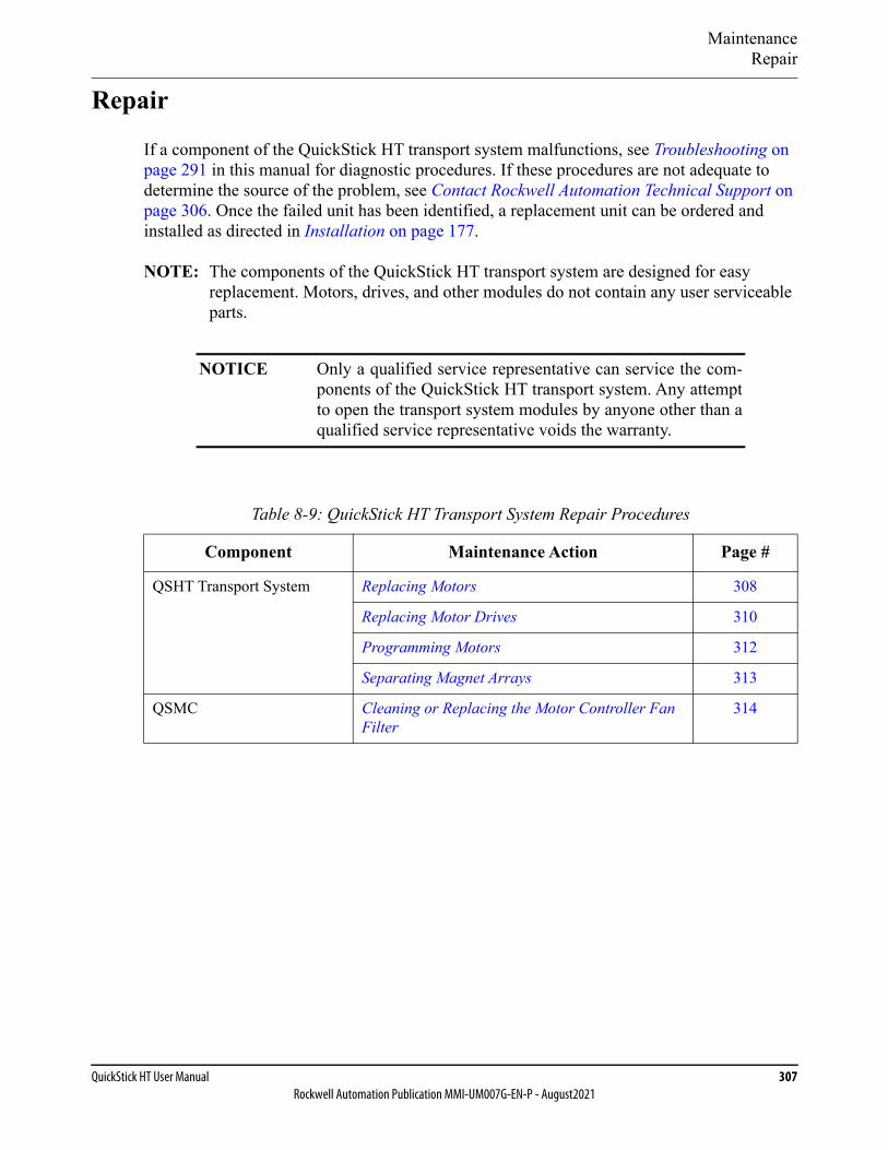
MaintenanceRepair
QuickStick HT User Manual 307Rockwell Automation Publication MMI-UM007G-EN-P - August2021
Repair
If a component of the QuickStick HT transport system malfunctions, see Troubleshooting on page 291 in this manual for diagnostic procedures. If these procedures are not adequate to determine the source of the problem, see Contact Rockwell Automation Technical Support on page 306. Once the failed unit has been identified, a replacement unit can be ordered and installed as directed in Installation on page 177.
NOTE: The components of the QuickStick HT transport system are designed for easy replacement. Motors, drives, and other modules do not contain any user serviceable parts.
NOTICE Only a qualified service representative can service the com-ponents of the QuickStick HT transport system. Any attemptto open the transport system modules by anyone other than aqualified service representative voids the warranty.
Table 8-9: QuickStick HT Transport System Repair Procedures
Component Maintenance Action Page #
QSHT Transport System Replacing Motors 308
Replacing Motor Drives 310
Programming Motors 312
Separating Magnet Arrays 313
QSMC Cleaning or Replacing the Motor Controller Fan Filter
314

MaintenanceRepair
308 MagneMotionRockwell Automation Publication MMI-UM007G-EN-P - August2021
Replacing Motors
The QuickStick HT motors can typically be replaced easily depending upon the location and mounting method for the motor.
Required Tools and Equipment• Torque wrench.• Computer with an Ethernet port and a web browser.
Remove the Existing Motor
1. Complete all material transfers (move all material to the appropriate locations) on the section of the QSHT transport system where the motor is being replaced.
2. Command all vehicles to positions off the path where the motor is being replaced.
3. Issue a Suspend Motion command for the path where the motor is being replaced.
All vehicles come to a controlled stop.
4. Once all motion has stopped, issue a Reset command for the path where the motor is being replaced.
The HLC clears all vehicle records.
5. Turn off all power to the section of the QSHT transport system where the motor is being replaced.
6. Label the power and sense connections to the motor.
7. Disconnect all connections.
8. Remove the M6 bolts that secure the motor to the motor mounts.
9. Remove the motor from the transport system.
10. Store the motor in a secure location.
11. See Shipping on page 316 to return the motor to MagneMotion.
LIFTING HAZARD: The QuickStick HT motorscan weigh as much as 41.5 kg [91.5 lb]. Failure totake the proper precautions before moving themcould result in personal injury.
Use proper techniques for lifting and safety toe shoeswhen moving any QuickStick HT components.
kg

MaintenanceRepair
QuickStick HT User Manual 309Rockwell Automation Publication MMI-UM007G-EN-P - August2021
Install the New Motor
1. See Mounting the Motors on page 183 for detailed installation instructions.
2. Reconnect the power and sense connections to the motor (refer to the labels previously placed on the cables).
3. Restore power to the section of the QSHT transport system where the motor was replaced.
4. Program the masters and slaves on the new motor with the current Motor ERF Image files (see Programming Motors on page 312).
5. Resume motion on the section of the QSHT transport system where the motor was replaced.

MaintenanceRepair
310 MagneMotionRockwell Automation Publication MMI-UM007G-EN-P - August2021
Replacing Motor Drives
The QuickStick HT motor drives can typically be replaced easily depending upon the location and mounting method for the drive.
Required Tools and Equipment• Torque wrench.• Computer with an Ethernet port and a web browser.
Remove the Existing Motor Drive
1. Complete all material transfers (move all material to the appropriate locations) on the section of the QSHT transport system where the motor drive is being replaced.
2. Command all vehicles to positions off the path where the motor drive is being replaced.
3. Issue a Suspend Motion command for the path where the motor drive is being replaced.
All vehicles come to a controlled stop.
4. Once all motion has stopped, issue a Reset command for the path where the motor drive is being replaced.
The HLC clears all vehicle records.
5. Turn off all power to the section of the QSHT transport system where the motor drive is being replaced.
6. Label all connections to the motor drive.
7. Disconnect all connections.
8. Remove the bolts that secure the motor drive to its mounting.
9. Remove the motor drive from the transport system.
10. Store the motor drive in a secure location.
11. See Shipping on page 316 to return the motor drive to MagneMotion.
Install the New Motor Drive
1. See Mounting QSMC Motor Controllers on page 186 or Mounting the QuickStick HT 5700 Inverters on page 187 for detailed installation instructions.

MaintenanceRepair
QuickStick HT User Manual 311Rockwell Automation Publication MMI-UM007G-EN-P - August2021
2. Reconnect all cables to the motor drive (refer to the labels previously placed on the cables).
3. Restore power to the section of the QSHT transport system where the motor drive was replaced.
4. If the drive being replaced is a QSHT 5700 inverter:
A. Update the MICS file (see Ethernet Motor MICS File on page 90) with the new MAC address and static IPv4 address of the inverter.
B. Upload the MICS file to all node controllers (see the Node Controller Interface User Manual, MMI-UM001).
C. Cycle logic power to the motors to force the motors to request their network provisioning.
5. Program the masters and slaves on the new motor drive with the current Motor ERF Image files (see Programming Motors on page 312).
6. Resume motion on the section of the QSHT transport system where the motor drive was replaced.

MaintenanceRepair
312 MagneMotionRockwell Automation Publication MMI-UM007G-EN-P - August2021
Programming Motors
When a new QuickStick HT motor or motor drive is installed, either as part of a new system installation or as a replacement for an existing component it must be programmed using the appropriate Motor ERF Image file (motor_image.erf).
NOTE: QuickStick HT motors and motor drives are shipped from the factory with basic software images installed. They must be programmed with the software that is sup-plied with the motors before use.
Required Tools and Equipment
• Computer with an Ethernet port and a web browser.
• Motor ERF Image files.
Procedure
1. If the drive being replaced is a QSHT 5700 inverter:
A. Update the MICS file (see Ethernet Motor MICS File on page 90) with the new MAC address and static IPv4 address of the inverter.
B. Upload the MICS file to all node controllers (see the Node Controller Interface User Manual, MMI-UM001).
C. Cycle logic power to the motors to force the motors to request their network provisioning.
2. For all drives, upload the Motor ERF Image files (motor_image.erf) to each node con-troller by using the node controller web interface and program the motor masters and slaves. See the Node Controller Interface User Manual, MMI-UM001, for details.
NOTE: Restart the node controller for the changes to take effect.
3. Reset the paths where the motors or motor controllers were programmed (for example, use the NCHost TCP Interface Utility, see the NCHost TCP Interface Utility User Manual, MMI-UM010 for details).
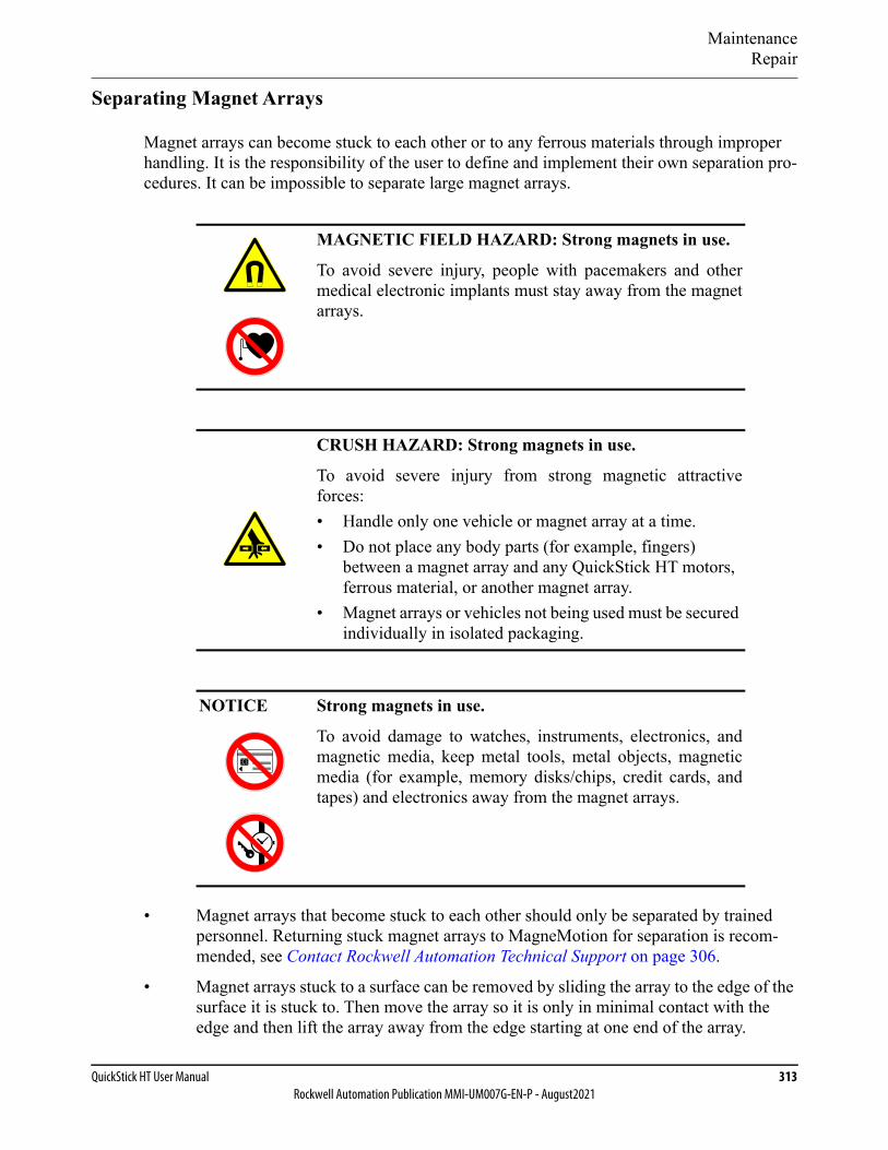
MaintenanceRepair
QuickStick HT User Manual 313Rockwell Automation Publication MMI-UM007G-EN-P - August2021
Separating Magnet Arrays
Magnet arrays can become stuck to each other or to any ferrous materials through improper handling. It is the responsibility of the user to define and implement their own separation pro-cedures. It can be impossible to separate large magnet arrays.
• Magnet arrays that become stuck to each other should only be separated by trained personnel. Returning stuck magnet arrays to MagneMotion for separation is recom-mended, see Contact Rockwell Automation Technical Support on page 306.
• Magnet arrays stuck to a surface can be removed by sliding the array to the edge of the surface it is stuck to. Then move the array so it is only in minimal contact with the edge and then lift the array away from the edge starting at one end of the array.
MAGNETIC FIELD HAZARD: Strong magnets in use.
To avoid severe injury, people with pacemakers and othermedical electronic implants must stay away from the magnetarrays.
CRUSH HAZARD: Strong magnets in use.
To avoid severe injury from strong magnetic attractiveforces:• Handle only one vehicle or magnet array at a time.• Do not place any body parts (for example, fingers)
between a magnet array and any QuickStick HT motors, ferrous material, or another magnet array.
• Magnet arrays or vehicles not being used must be secured individually in isolated packaging.
NOTICE Strong magnets in use.
To avoid damage to watches, instruments, electronics, andmagnetic media, keep metal tools, metal objects, magneticmedia (for example, memory disks/chips, credit cards, andtapes) and electronics away from the magnet arrays.

MaintenanceRepair
314 MagneMotionRockwell Automation Publication MMI-UM007G-EN-P - August2021
Cleaning or Replacing the Motor Controller Fan Filter
The filter in the QSMC motor controller must be removed and cleaned if it is dirty or replaced if it is damaged.
Required Tools and Equipment• Small screwdriver, flat blade.• Filter replacement (if needed).
Procedure
Figure 8-1: Replacing QSMC Fan Filter
1. Turn off power to the motor controller.NOTE: Do not use the motor controller when the filter is not installed.
2. Visually inspect the air filter. If the filter is damaged or requires cleaning, remove the filter from the motor controller. Use a small screwdriver with a flat blade and gently insert it between the front plate and the bezel of the filter housing near one of the retaining clips and twist it slightly to release the front plate.
3. Remove the front plate and the filter.
4. To clean, wash both the front plate and the filter in warm soapy water, rinse using clean water, and pat dry using paper towels.
5. To replace, discard the old filter and unpack the new filter.A replacement 60 mm x 60 mm filter can be ordered from a hardware supplier, such as McMaster-Carr (#19155K7).
6. Replace the air filter in the motor controller by positioning it and snapping the cover into place over it.
7. Return the motor controller to normal operation.
Filter
Front Plate

MaintenanceOrdering Parts
QuickStick HT User Manual 315Rockwell Automation Publication MMI-UM007G-EN-P - August2021
Ordering Parts
If new or replacement parts are needed, see Contact Rockwell Automation Technical Support on page 306.
MaintenanceShipping
316 MagneMotionRockwell Automation Publication MMI-UM007G-EN-P - August2021
Shipping
If a QuickStick HT component must be shipped, either for return to MagneMotion or to another location, it must be packaged properly to make sure it arrives undamaged. The follow-ing procedure provides the correct method for handling and packaging QSHT components for shipment.
Required Tools and Equipment
• Metric hex wrenches.
• English hex wrenches.
• Open-end wrench, adjustable.
• Fork truck or appropriate lift as required.
SHOCK HAZARD: Before beginning this procedure, theQuickStick HT transport system must be shut down follow-ing the procedure that is provided in Shut-down on page 265.
LIFTING HAZARD: The QuickStick HT motors canweigh as much as 41.5 kg [91.5 lb]. Failure to take the properprecautions before moving them could result in personalinjury.
Use proper techniques for lifting and safety toe shoes whenmoving any QuickStick HT components.
kg
MaintenanceShipping
QuickStick HT User Manual 317Rockwell Automation Publication MMI-UM007G-EN-P - August2021
Packing Procedure
When any of the QuickStick HT components are shipped, either for return to MagneMotion for service or to another location, they must be properly packaged to make sure that they arrive undamaged. The following procedure provides the correct method of handling and packaging the QuickStick HT components for shipment.
NOTE: Material being returned must be properly packaged to make sure that it arrives undamaged. It is recommended that products be shipped in their original packaging to help prevent further damage.
MAGNETIC FIELD HAZARD: Strong magnets in use.
To avoid severe injury, people with pacemakers and othermedical electronic implants must stay away from the magnetarrays.
CRUSH HAZARD: Strong magnets in use.
To avoid severe injury from strong magnetic attractiveforces:• Handle only one vehicle or magnet array at a time.• Do not place any body parts (for example, fingers)
between a magnet array and any QuickStick HT motors, ferrous material, or another magnet array.
• Magnet arrays or vehicles not being used must be secured individually in isolated packaging.
NOTICE Strong magnets in use.
To avoid damage to watches, instruments, electronics, andmagnetic media, keep metal tools, metal objects, magneticmedia (for example, memory disks/chips, credit cards, andtapes) and electronics away from the magnet arrays.

MaintenanceShipping
318 MagneMotionRockwell Automation Publication MMI-UM007G-EN-P - August2021
1. Turn off and disconnect all power connections as detailed in Shut-down on page 265.
2. Disconnect all communication connections as described in Shut-down on page 265.
3. Make sure that the component has been properly decontaminated following the decon-tamination procedures for the facility. Follow all facility, local, and national proce-dures for the disposal of any hazardous materials.
4. When shipping individual components, remove all components to be shipped (see Transport System Installation on page 181 and reverse the sequence to remove the components) and see Shipping Components on page 318.
Shipping Components
Each component must be wrapped, bagged, and packed following standard packing proce-dures.
1. If possible, use the box that the component was originally shipped in. Set the compo-nent into the box and secure using the packing material in the box. If the original ship-ping box is not available, package the component appropriately to prevent damage and secure in the shipping box.
2. Make sure that the container is properly labeled (This End Up, Caution – Heavy, and so on) and all shipping documents are attached to the outside of the container.
3. When shipping to MagneMotion, make sure that the RMA number is clearly visible on the outside of the container.
LIFTING HAZARD: The QuickStick HT motors canweigh as much as 41.5 kg [91.5 lb]. Failure to take the properprecautions before moving them could result in personalinjury.
Use proper techniques for lifting and safety toe shoes whenmoving any QuickStick HT components.
MAGNETIC FIELD HAZARD: When shipping magnetarrays, make sure that the shipping container properly iso-lates the magnet arrays or identifies the Magnetic Field Haz-ard.
kg

QuickStick HT User Manual 319Rockwell Automation Publication MMI-UM007G-EN-P - August2021
Appendix
Overview
The following appendices are included to provide the user with one location for additional information that is related to the QuickStick® HT transport system.
Included in this appendix are:
• Interconnect diagrams for the QSHT 5700 inverter.
• Data for QuickStick HT transport system design calculations.
• File maintenance.
• Additional documentation.
• Transport system configuration limits.

AppendixInterconnect Diagrams
320 MagneMotionRockwell Automation Publication MMI-UM007G-EN-P - August2021
Interconnect Diagrams
This appendix provides wiring examples and system block diagrams for the QuickStick HT transport system when using the QSHT 5700 inverter and the Kinetix® 2198-Pxxx DC-bus Power Supply.
Interconnect Diagram Notes
This appendix provides wiring examples to assist in wiring the QSHT 5700 drive system. These notes apply to the wiring examples on the following pages.
Table A-1: Interconnect Diagram Notes
Note Information
1 For power wiring specifications, see Wiring Requirements in the Kinetix Servo Drives Specifica-tions Technical Data, KNX-TD003.
2 For input fuse and circuit breaker sizes, see Circuit Breaker/Fuse Selection in the Kinetix Servo Drives Specifications Technical Data, KNX-TD003.
3 An AC (EMC) line filter is required for CE compliance. Place the line filter as close to the drive as possible and do not route very dirty wires in wireway. If routing in wireway is unavoidable, use shielded cable with shields that are grounded to the drive chassis and filter case. For AC line filter specifications, see Kinetix Servo Drives Specifications Technical Data, KNX-TD003. 2198-DBRxx-F line filters are preferred.
4 Cable shield clamp with clamp spacers must be used to meet CE requirements with Bulletin 2090 power cables 2 AWG and smaller. See Customer-supplied Motor Power Cables in the Kinetix Servo Drives Specifications Technical Data, KNX-TD003, to meet CE when wiring 2198-S263-ERSx and 2198-S312-ERSx drives with power cables larger than 2 AWG.
5 QSHT 5700 inverters include stator feedback and stator power wiring plugs for each axis, and separate digital inputs.
6 See Digital Inputs Connector Pinouts in the Kinetix Servo Drives Specifications Technical Data, KNX-TD003, for digital input configurable functions and default settings.
7 PE ground connection bonded to the panel must be used to meet CE requirements. See Ground the Drive System in the Kinetix Servo Drives Specifications Technical Data, KNX-TD003.
8 For M1 contactor selection and specifications, see Contactor Selection in the Kinetix Servo Drives Specifications Technical Data, KNX-TD003.
9 Internal shunt wired to the RC connector is default configuration. Remove internal shunt wires to attach external shunt wires.
10 Default configuration for ground screws or jumper is for grounded power at customer site. For impedance-grounded power configurations, remove the screws/jumper. See Input Power Configu-rations for Kinetix 5700 Power Supplies in the Kinetix Servo Drives Specifications Technical Data, KNX-TD003 for more information.
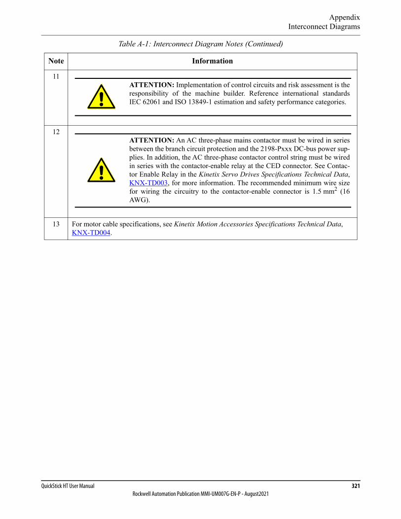
AppendixInterconnect Diagrams
QuickStick HT User Manual 321Rockwell Automation Publication MMI-UM007G-EN-P - August2021
11
12
13 For motor cable specifications, see Kinetix Motion Accessories Specifications Technical Data, KNX-TD004.
Table A-1: Interconnect Diagram Notes (Continued)
Note Information
ATTENTION: Implementation of control circuits and risk assessment is theresponsibility of the machine builder. Reference international standardsIEC 62061 and ISO 13849-1 estimation and safety performance categories.
ATTENTION: An AC three-phase mains contactor must be wired in seriesbetween the branch circuit protection and the 2198-Pxxx DC-bus power sup-plies. In addition, the AC three-phase contactor control string must be wiredin series with the contactor-enable relay at the CED connector. See Contac-tor Enable Relay in the Kinetix Servo Drives Specifications Technical Data,KNX-TD003, for more information. The recommended minimum wire sizefor wiring the circuitry to the contactor-enable connector is 1.5 mm2 (16AWG).
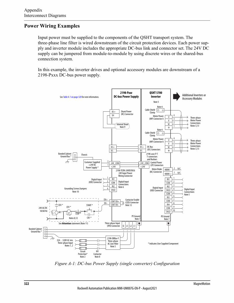
AppendixInterconnect Diagrams
322 MagneMotionRockwell Automation Publication MMI-UM007G-EN-P - August2021
Power Wiring Examples
Input power must be supplied to the components of the QSHT transport system. The three-phase line filter is wired downstream of the circuit protection devices. Each power sup-ply and inverter module includes the appropriate DC-bus link and connector set. The 24V DC supply can be jumpered from module-to-module by using discrete wires or the shared-bus connection system.
In this example, the inverter drives and optional accessory modules are downstream of a 2198-Pxxx DC-bus power supply.
Figure A-1: DC-bus Power Supply (single converter) Configuration
24V_COM+24V
21
24V_COM+24V
DC+DC-
DC+DC-
DC+SH
123456789
10
UVW
4321
UVW
4321
L3 L2 L1
EN+EN–
CONT EN+CONT EN–
IN1COMIN2
SHLD
1234
IN1COMIN2
SHLDCOMIN3
COMIN4
COMSHLD
MBRK -
MBRK +
N/C
N/C
2
1
324…528V AC rmsThree-phase Input
Notes 1, 2
Bonded CabinetGround Bus *
Control Power (CP) Connectors
Three-phase Input(IPD) Connector
2198-DBRxx-F Three-phase AC Line Filter
Note 3* Indicates User Supplied Component
Chassis
Customer Supplied +24V DC
Power Supply *
See Table A-1 on page 320 for note information.
DC Bus (DC) Connectors
2198-Pxxx DC-bus Power Supply
QSHT 5700 Inverter
PE GroundNote 7
Contactor Enable (CED) Connector Note 12
See Attention statement (Note 11)
STOP *PE Ground
Note 7
Bonded CabinetGround Bus *
Shunt Power (RC) Connector
Internal Shunt Note 9
START *
CR1 *
CR1 *CR1 *
M1 *
Notes 8,12
24V AC/DC50/60 Hz
Grounding Screws/Jumpers Note 10
Circuit Protection*
Note 2
Motor Brake(BC) Connector
Three-phase Motor Power Connections Notes 5,13
Motor Power(MP) Connector A
Cable ShieldClamp
Digital Input(IOD) Connector Digital Input
Connections Note 5
Additional Inverters or Accessory Modules
Note 4
Digital Input(IOD) Connector Digital Input
Connections Note 6
M1Contactor
Note 8
Note 5
2198-TCON-24VDCIN36 24V Input Power Wiring Connector
2198-xxxx-P-T T-connectors and Busbars
Motor Power(MP) Connector A
Cable ShieldClamp
Note 4
Three-phase Motor Power Connections Notes 5,13
AppendixData for Transport System Design Calculations
QuickStick HT User Manual 323Rockwell Automation Publication MMI-UM007G-EN-P - August2021
Data for Transport System Design Calculations
The tables and curves (charts) in this appendix provide data to help in determining the optimal QuickStick HT thrust force, Vehicle Gap, or magnet array size for a QuickStick HT transport system design. The theoretical attractive force, which is based on Vehicle Gap and magnet length is also provided. These values reflect simplified, optimal conditions to provide basic guidance for determining the optimal value. Consult MagneMotion® for precise values.
See Determining Thrust Force on page 327 for more information about using thrust and attractive forces calculations.
See Magnet Arrays on page 91 for magnet array size information.
To use the following force charts, choose two parameters to determine the third. All calcula-tions are based on motors running at a 25% duty cycle (thrust must be limited at 100% duty cycle to help prevent overheating of the motor).
• Determine Thrust Force – Choose a magnet array length (number of cycles) from the X-axis and then choose the curve for the Vehicle Gap that is being maintained throughout the transport system. Read the corresponding amount of force (thrust) from the Y-axis or the table. See Determining Thrust Force on page 327 for more informa-tion about calculating the thrust force.
• Determine Vehicle Gap – From the figures, choose the force (thrust) to maintain from the Y-axis, and then choose a magnet array length from the X-axis. Determine which Vehicle Gap curves come closest to the intersection point. As Vehicle Gap increases, the magnetic attractive force decreases. See Table A-3, Attractive Force Data, High Flux Magnet Array, on page 326 for more information.
• Determine Magnet Array Length – Choose the force (thrust) to maintain from the Y-axis and then choose the curve for the Vehicle Gap that is being maintained through-out the transport system. Read the corresponding magnet array length (cycles) from the X-axis.

AppendixData for Transport System Design Calculations
324 MagneMotionRockwell Automation Publication MMI-UM007G-EN-P - August2021
Thrust Force Data
The data that is provided in Table A-2 shows the available thrust for QSHT motors at 10.9 Amps stator current using a high flux magnet array. This data is graphed in Figure A-2, which shows how the available thrust increases with an increase in the number of magnet array cycles. The chart also shows that as the Vehicle Gap increases, the available thrust decreases.
Table A-2: Thrust Force Data, High Flux Magnet Array
Maximum Thrust (N) at 10.9 Amps Stator Current
Length Vehicle Gap (mm)
Cycles mm 4 7 10 13 16 19 22
2 238 571 483 408 345 292 246 208
3 358 856 724 612 517 437 370 313
4 478 1142 965 816 690 583 493 417
5 598 1427 1207 1020 862 729 616 521
6 718 1713 1448 1224 1035 875 739 625
7 838 1998 1689 1428 1207 1021 863 729
8 958 2284 1931 1632 1380 1166 986 833
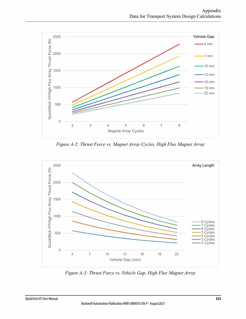
AppendixData for Transport System Design Calculations
QuickStick HT User Manual 325Rockwell Automation Publication MMI-UM007G-EN-P - August2021
Figure A-2: Thrust Force vs. Magnet Array Cycles, High Flux Magnet Array
Figure A-3: Thrust Force vs. Vehicle Gap, High Flux Magnet Array
0
500
1000
1500
2000
2500
2 3 4 5 6 7 8
Qui
ckSt
ick
HTH
igh
Flux
Arra
yTh
rust
Forc
e(N
)
Magnet Array Cycles
Vehicle Gap
4 mm
7 mm
10 mm
13 mm
16 mm
19 mm22 mm
0
500
1000
1500
2000
2500
4 7 10 13 16 19 22
Qui
ckSt
ick
HTH
igh
Flux
Arra
yTh
rust
Forc
e(N
)
Vehicle Gap (mm)
Array Length
2 Cycles3 Cycles4 Cycles5 Cycles6 Cycles7 Cycles8 Cycles
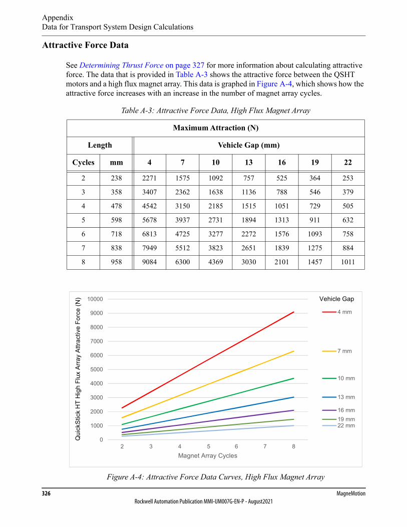
AppendixData for Transport System Design Calculations
326 MagneMotionRockwell Automation Publication MMI-UM007G-EN-P - August2021
Attractive Force Data
See Determining Thrust Force on page 327 for more information about calculating attractive force. The data that is provided in Table A-3 shows the attractive force between the QSHT motors and a high flux magnet array. This data is graphed in Figure A-4, which shows how the attractive force increases with an increase in the number of magnet array cycles.
Figure A-4: Attractive Force Data Curves, High Flux Magnet Array
Table A-3: Attractive Force Data, High Flux Magnet Array
Maximum Attraction (N)
Length Vehicle Gap (mm)
Cycles mm 4 7 10 13 16 19 22
2 238 2271 1575 1092 757 525 364 253
3 358 3407 2362 1638 1136 788 546 379
4 478 4542 3150 2185 1515 1051 729 505
5 598 5678 3937 2731 1894 1313 911 632
6 718 6813 4725 3277 2272 1576 1093 758
7 838 7949 5512 3823 2651 1839 1275 884
8 958 9084 6300 4369 3030 2101 1457 1011
0
1000
2000
3000
4000
5000
6000
7000
8000
9000
10000
2 3 4 5 6 7 8Magnet Array Cycles
Vehicle Gap
4 mm
7 mm
10 mm
13 mm
16 mm19 mm22 mm
Qui
ckSt
ick
HT
Hig
hFl
uxAr
ray
Attra
ctiv
eFo
rce
(N)

AppendixData for Transport System Design Calculations
QuickStick HT User Manual 327Rockwell Automation Publication MMI-UM007G-EN-P - August2021
Determining Thrust Force
The thrust obtainable from a QuickStick HT motor is dependent on several operational param-eters, including the length of magnet array engaged by the stators, the magnitude of the stator drive current, and the gap between the magnet array and stators. Further, the allowable magni-tude of the stator drive current is limited by thermal considerations. Thus the obtainable thrust can be impacted by ambient temperature or the duty cycle of the drive current.
Laboratory measurements of the thrust that is obtained with a QuickStick HT motor at various operational parameter values were used to derive a model describing the thrust produced. The thrust that is produced roughly varies with each of the operating parameters as follows.
• The thrust that is produced varies roughly in proportion to the length of magnet array engaged by stators. For example, an eight cycle long magnet array yields twice the thrust of a 4 cycle array, assuming that both arrays are fully engaged by stators, with the same drive current and gap values (see Figure A-2).
• The thrust that is produced varies roughly in proportion to the stator drive current. For example, a drive current of 5 A yields approximately twice the thrust that is obtained with a drive current of 2.5 A, assuming the same magnet array engagement and gap.
• The thrust that is produced decreases roughly in an exponential fashion as the gap between the motor and the magnet array is increased (see Figure A-3).
The model equation that describes the thrust that a QuickStick HT motor produces with a high flux magnet array is:
Thrust (N) = (((-0.209 * Istator2) + (35.04 * Istator)) * EXP(-0.056 * PhysGap)) * NumCy-
cles
Thrust (Lb) = ((((-0.209 * Istator2) + (35.04 * Istator)) * EXP(-0.056 * PhysGap)) * Num-
Cycles) / 4.4482
Where:
NumCycles – The length of the array that is engaged by the stators, in cycles (from 2 to 8 cycles) (a cycle for the QuickStick HT is 120 mm).
Istator – The stator current, in Amps.
PhysGap – The distance from the top of the stator to the bottom of the magnet array, in mm (4…22 mm).
Thrust – The force produced.

AppendixData for Transport System Design Calculations
328 MagneMotionRockwell Automation Publication MMI-UM007G-EN-P - August2021
Determining Attractive Force
In addition to the thrust force produced by the QuickStick HT motor, there is an attractive force between the steel laminations in the stator and the magnet array. This attraction, or hold-down force, is roughly proportional to the length of magnet array engaged by the stators, and decreases roughly in an exponential fashion as the gap is increased (see Figure A-4). The hold-down force is nearly independent of stator current, and thus has the same value whether or not the stator is powered.
Laboratory measurements of the hold-down force that is obtained with a QuickStick HT motor at various operational parameter values were used to derive a model that describes the hold-down force produced.
The model equation describing the hold-down force of a QuickStick HT motor using a high flux magnet array is:
HDForce (N) = (1850 * EXP(-0.122 * PhysGap)) * NumCycles
HDForce (Lb) = ((1850 * EXP(-0.122 * PhysGap)) * NumCycles) / 4.4482
Where:
NumCycles – The length of the array that is engaged by the stators, in cycles (a cycle for the QuickStick HT is 120 mm).
PhysGap – The distance from the top of the stator to the bottom of the magnet array, in mm (4…22 mm).
HDForce – The hold-down force that is produced. The hold-down force is indepen-dent of stator current.

AppendixFile Maintenance
QuickStick HT User Manual 329Rockwell Automation Publication MMI-UM007G-EN-P - August2021
File Maintenance
Backup Files
Making regular backups of all files that have been changed is recommended. Keep copies of all original and backup files at a remote location for safety.
Creating Backup Files
Backup files are not created automatically. It is the responsibility of the user to create backups of all files by copying them to a secure location.
Restoring from Backup Files
Damaged files can be restored by copying the backup files into the appropriate locations.

AppendixAdditional Documentation
330 MagneMotionRockwell Automation Publication MMI-UM007G-EN-P - August2021
Additional Documentation
Release Notes
The release notes that are supplied with MagneMotion software include special instructions, identification of software versions, identification of new features and enhancements, and a list of known issues. Reading this file is recommended before using the software.
Upgrade Procedure
The upgrade procedures that are supplied with MagneMotion software provide instructions for upgrading from one version of MagneMotion software to another. They also include the procedures for file and driver upgrades that are associated with the software.
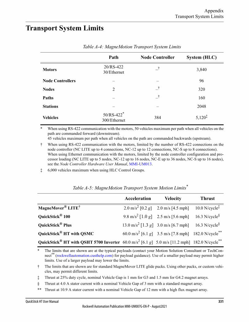
AppendixTransport System Limits
QuickStick HT User Manual 331Rockwell Automation Publication MMI-UM007G-EN-P - August2021
Transport System Limits
Table A-4: MagneMotion Transport System Limits
Path Node Controller System (HLC)
Motors 20/RS-42230/Ethernet –†
† When using RS-422 communication with the motors, limited by the number of RS-422 connections on thenode controller (NC LITE up to 4 connections, NC-12 up to 12 connections, NC-S up to 8 connections).When using Ethernet communication with the motors, limited by the node controller configuration and pro-cessor loading (NC LITE up to 5 nodes, NC-12 up to 16 nodes, NC-E up to 36 nodes, NC-S up to 16 nodes),see the Node Controller Hardware User Manual, MMI-UM013.
3,840
Node Controllers – – 96
Nodes 2 –† 320
Paths – –† 160
Stations – – 2048
Vehicles 50/RS-422*
300/Ethernet
* When using RS-422 communication with the motors, 50 vehicles maximum per path when all vehicles on thepath are commanded forward (downstream).45 vehicles maximum per path when all vehicles on the path are commanded backwards (upstream).
384 5,120‡
‡ 6,000 vehicles maximum when using HLC Control Groups.
Table A-5: MagneMotion Transport System Motion Limits*
* The limits that are shown are at the typical payloads (contact your Motion Solution Consultant or TechCon-nect℠ (rockwellautomation.custhelp.com) for payload guidance). Use of a smaller payload may permit higherlimits. Use of a larger payload may lower the limits.
Acceleration Velocity Thrust
MagneMover® LITE†
† The limits that are shown are for standard MagneMover LITE glide pucks. Using other pucks, or custom vehi-cles, may permit different limits.
2.0 m/s2 [0.2 g] 2.0 m/s [4.5 mph] 10.0 N/cycle‡
‡ Thrust at 25% duty cycle, nominal Vehicle Gap is 1 mm for G3 and 1.5 mm for G4.2 magnet arrays.
QuickStick® 100 9.8 m/s2 [1.0 g] 2.5 m/s [5.6 mph] 16.3 N/cycle§
§ Thrust at 4.0 A stator current with a nominal Vehicle Gap of 3 mm with a standard magnet array.
QuickStick® Plus 13.0 m/s2 [1.3 g] 3.0 m/s [6.7 mph] 16.3 N/cycle§
QuickStick® HT with QSMC 60.0 m/s2 [6.1 g] 3.5 m/s [7.8 mph] 182.0 N/cycle**
** Thrust at 10.9 A stator current with a nominal Vehicle Gap of 12 mm with a high flux magnet array.
QuickStick® HT with QSHT 5700 Inverter 60.0 m/s2 [6.1 g] 5.0 m/s [11.2 mph] 182.0 N/cycle**

Appendix
332 MagneMotionRockwell Automation Publication MMI-UM007G-EN-P - August2021
This page intentionally left blank.
QuickStick HT User Manual 333Rockwell Automation Publication MMI-UM007G-EN-P - August2021
Glossary
Block: See Motor Block.
Bogie: A structure underneath a vehicle to which a magnet array is attached. The structure is then attached to the vehicle. For vehicles that travel over curves, the attachment is through a bearing that allows independent rotation.
Brick-wall Headway: The space that is maintained between vehicles to make sure that a trailing vehicle is able to stop safely if the lead vehicle stops suddenly (‘hits a brick wall’).
Byte: An octet of data (8 bits).
Clearance Distance: The distance from a node where the trailing edge of a vehicle is considered cleared from a node.
Component: The main parts that form a MagneMotion® Transport System. Also called sys-tem components, these include the High-Level Controller, Motors, Nodes, Node Controllers, Paths, and Vehicles.
Configuration File: See Node Controller Configuration File.
Configurator: The application that is used to define and edit the basic operating parameters of the transport system that are stored in the Node Controller Configuration File.
Controller: A device that monitors and controls the operating conditions of the equipment being monitored. In a MagneMotion transport system, the types of controllers include the High-Level Controller, Node Controller, and Host Controller.
Couple: The joining of a vehicle into a platoon, where one vehicle follows another vehicle at a defined distance.
Cycle Length: The distance between the centerlines of two like poles on the magnet array.
Demo Script: A text file that is used with the NCHost TCP Interface Utility for test or demonstration purposes to move vehicles on the transport system.
Design Specifications: The unique parameters for a specific MagneMotion transport system.
Downstream: The end of a motor or path as defined by the logical forward direction. Vehi-cles typically enter the motor or path on the Upstream end.
Downstream Gap: The physical distance from the end of the stator in one motor to the beginning of the stator in the next motor downstream on the same path. This distance includes the Motor Gap.
Drive
334 MagneMotionRockwell Automation Publication MMI-UM007G-EN-P - August2021
Drive: The remote QSMC motor controller or the QSHT 5700 inverter for a QSHT motor.
Emergency Off: A user-supplied device that disconnects AC power to the transport system.
Emergency Stop: A user-supplied circuit with a locking button that anyone can press to stop motion in the transport system. It can be wired through the digital I/O on some Node Controllers.
EMO: See Emergency Off.
Entry Gate: The position on a path associated with a node where the leading edge of a vehi-cle is considered cleared from the node. See Node Clearance Distance.
Entry Path: A path whose downstream end is a member of a node. A vehicle that is moving downstream enters a node on an entry path.
E-stop: See Emergency Stop.
Ethernet Chain: Ethernet chains allow devices to be connected in series with standard Ethernet cable, without the need for additional network switches. A daisy chain device has two embedded Ethernet ports that function as an Ethernet switch and an interface to the local device. This embedded switch allows information to flow to the device, or flow through the ports to other devices in the chain.
Exit Path: A path whose upstream end is a member of a node. A vehicle that is moving downstream exits a node on an exit path.
Following Vehicle: A vehicle following another vehicle in a platoon. This vehicle can be following either the lead vehicle or another following vehicle.
Forward Direction: The default direction of motion, from Upstream to Downstream, on a Magne-Motion transport system.
Glide Puck: A preconfigured vehicle for use on MagneMover® LITE transport systems that uses low friction skids to slide on the integral rails.
Global Directives: The Demo Script commands that define the general operating characteristics for all vehicles specified. See also Vehicle Directives.
Ground: The reference point in an electrical circuit from which voltages are measured. This point is typically a common return path for electric current. See also PE.
Guideway: A component of the Track System that consists of rails or other devices in con-tact with the Vehicle, either through wheels or low friction runners on the vehi-cle. The guideway maintains the proper relationship between the vehicles and the motors. In the MagneMover LITE transport system, the guideway is the integral rails that are mounted on the motors.
Hall Effect Sensor: A transducer that varies its output in response to changes in a magnetic field. Hall Effect Sensors (HES) are used by MagneMotion LSMs for vehicle posi-tioning and speed detection.
Headway: The space that is maintained before a vehicle to make sure that the vehicle is able to stop safely. See Brick-wall Headway.

LSB
QuickStick HT User Manual 335Rockwell Automation Publication MMI-UM007G-EN-P - August2021
High-Level Controller: The application in a node controller that communicates with the host con-troller. Only one node controller per HLC Control Group runs the high-level controller application. In a transport system with only one node controller, it runs both the node controller and high-level controller applications.
HLC: See High-Level Controller.
HLC Control Group: The portion of a multi-HLC LSM transport system under control of a specific HLC.
Host Application: The software on the host controller that provides monitoring and control of the transport system.
Host Control Session: A session between a host controller application (such as the NCHost TCP Interface Utility) and an HLC that allows control of all aspects of transport sys-tem operation. The Host Control Session also allows active monitoring of transport system status.
Host Controller: The user-supplied controller that provides control and sequencing for the oper-ation of the transport system.
Host Status Session: A session between a host controller application (such as the NCHost TCP Interface Utility) and an HLC that only provides active monitoring of transport system status.
ICT: See Independent Cart Technology.
ID: The software labels used to identify various components of the transport sys-tem to make sure proper execution of commands involving vehicle position, vehicle destination, and transport system configuration. ID types include vehi-cle and path.
Independent Cart Technology: A programmable intelligent conveyor system that uses linear syn-chronous motors for moving multiple independently controlled vehicles.
Interlock: A user-supplied circuit that is used to stop motion in the transport system. It is wired through the digital I/O on the Node Controller.
Inverter: The hardware that converts DC from the propulsion power bus to pulse-width modulated AC to energize the coils in a Motor Block and contains the Master and the Inverter for QSHT motors. See Drive.
Keep-out Area: A unidirectional area of a Path. A vehicle that is moving in the specified direc-tion of the area is not allowed to enter the area unless it has permission from the motors to either move past or stop within the area. Once a vehicle enters the keep-out area in the specified direction, all other vehicles that are moving in the same direction must wait to enter the area until that vehicle exits.
Lead Vehicle: The vehicle at the front of a platoon. This vehicle determines the destination, acceleration, and velocity of the platoon.
Logic Power: The power that is used for the controllers and signals. See also, Propulsion Power.
LSB: Least Significant Byte.
LSM
336 MagneMotionRockwell Automation Publication MMI-UM007G-EN-P - August2021
LSM: Linear Synchronous Motor. See MagneMover LITE and QuickStick.
MagneMover LITE: A MagneMotion linear synchronous motor with integrated guideways and vehicles that enable quick, efficient conveyance of small loads.
MagneMover LITE System: A group of specific components that contribute to a Transport System. These components include MagneMover LITE motors, Node Controllers, Pucks, and other parts available from MagneMotion.
Magnet Array: The magnets that are attached to the Vehicle. It is the motor secondary, moved by the primary in the motor.
Master (also Master Controller): The supervisory controller for each motor, it communicates with the Slaves to direct Motor Block operation and read motor sensors. It commu-nicates vehicle positions and other information to the Node Controller and upstream and downstream motors. It is internal to the motor assembly on Mag-neMover LITE and QuickStick® 100 motors. For QuickStick HT motors the master is in the Drive.
MM LITE™: See MagneMover LITE.
MML™: See MagneMover LITE.
Motion Controller: The user-supplied controller for direct control of vehicles through the LSM Synchronization option. It can reside on the host controller.
Motor: See LSM.
Motor Block: A discrete motor primary section (coil or set of coils) in a motor that can be energized independently. This section can contain only one vehicle during transport system operation.
Motor Controller: The hardware that converts DC from the propulsion power bus to AC to ener-gize the coils in a Motor Block and contains the Master and the Inverter for QuickStick HT motors. See Drive.
Motor Gap: The physical distance between two motors that are mounted end to end. This gap excludes the distance from the end of the stator to the end of the motor housing.
MSB: Most Significant Byte.
NC: See Node Controller.
Node: A junction that is defined as the beginning, end, or intersection of Paths. The different node types define their use: Simple, Relay, Terminus, Merge, Diverge, and so on.
Node Clearance Distance: The position on a path associated with a node where the trailing edge of a vehicle is considered cleared from the node. See Entry Gate.
Node Controller: The hardware and the application running on that hardware that coordinates vehicle motions along a path or paths of motors. The node controller is respon-sible for the motors on all paths that begin at nodes that the node controller is responsible for.
Protected Area
QuickStick HT User Manual 337Rockwell Automation Publication MMI-UM007G-EN-P - August2021
There can be multiple node controllers in a transport system, each responsible for a subset of the nodes within the transport system.
Node Controller Configuration File: The XML file unique to the transport system that defines the basic operating parameters of the transport system. A copy of the Node Con-troller Configuration File is uploaded to each node controller in the transport system.
NRTL/ATL: Nationally Recognized Test Lab/Accredited Test Lab.OSHA recognizes NRTL organizations in accordance with 29 CFR 1910.7 to test and certify equipment or materials (products).Accreditation bodies evaluate ATL organizations to ISO/IEC 17025 for testing and calibration laboratories.
OSSD: Output Signal Switching Device. The interface of a sensor (such as a light cur-tain) designed for reliably signaling a safety-related event. OSSD signals are outputs from the protective device to a safety relay.
Path: A designation for one or more motors placed end to end, which defines a linear route for vehicle travel. A path begins at the Upstream end of the first motor in the series and ends at the Downstream end of the last motor in the series. All paths must begin at a Node and the beginning of a path is always the zero posi-tion for determining positions along that path.
PE: Protective Earth. A conductor that is provided for safety purposes (for exam-ple, against the risk of electric shock) and which also provides a conductive path to earth. See also, Ground.
Pitch: The distance between a point on one coil and the corresponding point on an adjacent coil in the same motor or an adjacent motor. Or, the distance between a point on one magnet and the corresponding point on an adjacent equivalent magnet in the same array.
Platooning: A group of vehicles that are moving together and following a lead vehicle. This group of vehicles is allowed to maintain a distance between each other while in motion that is less than the Brick-wall Headway.
Position: A specific location on a Path, which is measured from the beginning of that path, which is used as a vehicle destination. Position zero on any path is defined as the leading edge of the first LSM in the path.
A vehicle at a specific position has its midpoint over that location on the path.
Power Supply: The equipment that is used to convert facility AC power to the correct voltages for the transport system.
Propulsion Power: The power that is used for vehicle motion. See also, Logic Power.
Protected Area: The area around a node that is defined by the entry gates and clearance dis-tances. This area is used to make sure that vehicles do not collide with other vehicles in the node or with the mechanism that is related to the node.
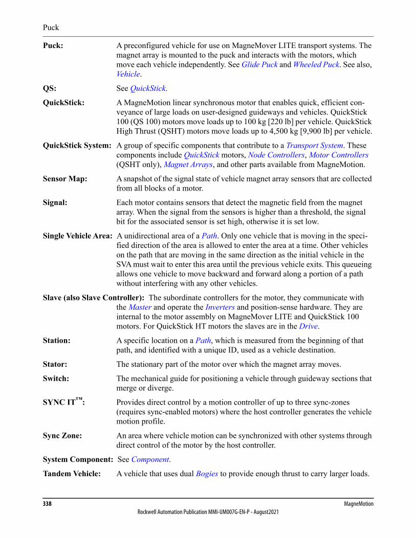
Puck
338 MagneMotionRockwell Automation Publication MMI-UM007G-EN-P - August2021
Puck: A preconfigured vehicle for use on MagneMover LITE transport systems. The magnet array is mounted to the puck and interacts with the motors, which move each vehicle independently. See Glide Puck and Wheeled Puck. See also, Vehicle.
QS: See QuickStick.
QuickStick: A MagneMotion linear synchronous motor that enables quick, efficient con-veyance of large loads on user-designed guideways and vehicles. QuickStick 100 (QS 100) motors move loads up to 100 kg [220 lb] per vehicle. QuickStick High Thrust (QSHT) motors move loads up to 4,500 kg [9,900 lb] per vehicle.
QuickStick System: A group of specific components that contribute to a Transport System. These components include QuickStick motors, Node Controllers, Motor Controllers (QSHT only), Magnet Arrays, and other parts available from MagneMotion.
Sensor Map: A snapshot of the signal state of vehicle magnet array sensors that are collected from all blocks of a motor.
Signal: Each motor contains sensors that detect the magnetic field from the magnet array. When the signal from the sensors is higher than a threshold, the signal bit for the associated sensor is set high, otherwise it is set low.
Single Vehicle Area: A unidirectional area of a Path. Only one vehicle that is moving in the speci-fied direction of the area is allowed to enter the area at a time. Other vehicles on the path that are moving in the same direction as the initial vehicle in the SVA must wait to enter this area until the previous vehicle exits. This queueing allows one vehicle to move backward and forward along a portion of a path without interfering with any other vehicles.
Slave (also Slave Controller): The subordinate controllers for the motor, they communicate with the Master and operate the Inverters and position-sense hardware. They are internal to the motor assembly on MagneMover LITE and QuickStick 100 motors. For QuickStick HT motors the slaves are in the Drive.
Station: A specific location on a Path, which is measured from the beginning of that path, and identified with a unique ID, used as a vehicle destination.
Stator: The stationary part of the motor over which the magnet array moves.
Switch: The mechanical guide for positioning a vehicle through guideway sections that merge or diverge.
SYNC IT™: Provides direct control by a motion controller of up to three sync-zones (requires sync-enabled motors) where the host controller generates the vehicle motion profile.
Sync Zone: An area where vehicle motion can be synchronized with other systems through direct control of the motor by the host controller.
System Component: See Component.
Tandem Vehicle: A vehicle that uses dual Bogies to provide enough thrust to carry larger loads.
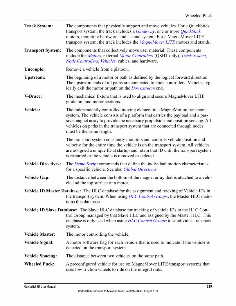
Wheeled Puck
QuickStick HT User Manual 339Rockwell Automation Publication MMI-UM007G-EN-P - August2021
Track System: The components that physically support and move vehicles. For a QuickStick transport system, the track includes a Guideway, one or more QuickStick motors, mounting hardware, and a stand system. For a MagneMover LITE transport system, the track includes the MagneMover LITE motors and stands.
Transport System: The components that collectively move user material. These components include the Motors, external Motor Controllers (QSHT only), Track System, Node Controllers, Vehicles, cables, and hardware.
Uncouple: Remove a vehicle from a platoon.
Upstream: The beginning of a motor or path as defined by the logical forward direction. The upstream ends of all paths are connected to node controllers. Vehicles typ-ically exit the motor or path on the Downstream end.
V-Brace: The mechanical fixture that is used to align and secure MagneMover LITE guide rail and motor sections.
Vehicle: The independently controlled moving element in a MagneMotion transport system. The vehicle consists of a platform that carries the payload and a pas-sive magnet array to provide the necessary propulsion and position sensing. All vehicles on paths in the transport system that are connected through nodes must be the same length.
The transport system constantly monitors and controls vehicle position and velocity for the entire time the vehicle is on the transport system. All vehicles are assigned a unique ID at startup and retain that ID until the transport system is restarted or the vehicle is removed or deleted.
Vehicle Directives: The Demo Script commands that define the individual motion characteristics for a specific vehicle. See also Global Directives.
Vehicle Gap: The distance between the bottom of the magnet array that is attached to a vehi-cle and the top surface of a motor.
Vehicle ID Master Database: The HLC database for the assignment and tracking of Vehicle IDs in the transport system. When using HLC Control Groups, the Master HLC main-tains this database.
Vehicle ID Slave Database: The Slave HLC database for tracking of vehicle IDs in the HLC Con-trol Group managed by that Slave HLC and assigned by the Master HLC. This database is only used when using HLC Control Groups to subdivide a transport system.
Vehicle Master: The motor controlling the vehicle.
Vehicle Signal: A motor software flag for each vehicle that is used to indicate if the vehicle is detected on the transport system.
Vehicle Spacing: The distance between two vehicles on the same path.
Wheeled Puck: A preconfigured vehicle for use on MagneMover LITE transport systems that uses low friction wheels to ride on the integral rails.

Zero Point
340 MagneMotionRockwell Automation Publication MMI-UM007G-EN-P - August2021
Zero Point: The position on the Upstream end of a Path that denotes the first part on which a Vehicle travels.
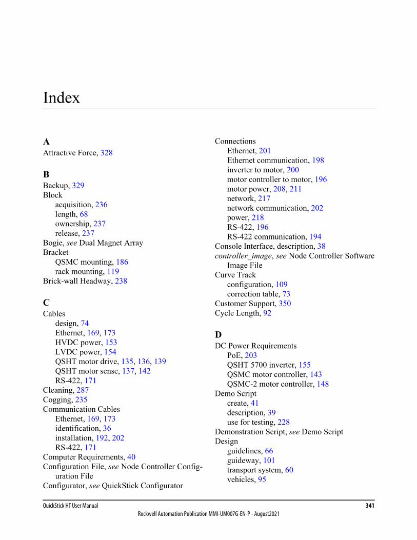
QuickStick HT User Manual 341Rockwell Automation Publication MMI-UM007G-EN-P - August2021
Index
AAttractive Force, 328
BBackup, 329Block
acquisition, 236length, 68ownership, 237release, 237
Bogie, see Dual Magnet ArrayBracket
QSMC mounting, 186rack mounting, 119
Brick-wall Headway, 238
CCables
design, 74Ethernet, 169, 173HVDC power, 153LVDC power, 154QSHT motor drive, 135, 136, 139QSHT motor sense, 137, 142RS-422, 171
Cleaning, 287Cogging, 235Communication Cables
Ethernet, 169, 173identification, 36installation, 192, 202RS-422, 171
Computer Requirements, 40Configuration File, see Node Controller Config-
uration FileConfigurator, see QuickStick Configurator
ConnectionsEthernet, 201Ethernet communication, 198inverter to motor, 200motor controller to motor, 196motor power, 208, 211network, 217network communication, 202power, 218RS-422, 196RS-422 communication, 194
Console Interface, description, 38controller_image, see Node Controller Software
Image FileCurve Track
configuration, 109correction table, 73
Customer Support, 350Cycle Length, 92
DDC Power Requirements
PoE, 203QSHT 5700 inverter, 155QSMC motor controller, 143QSMC-2 motor controller, 148
Demo Scriptcreate, 41description, 39use for testing, 228
Demonstration Script, see Demo ScriptDesign
guidelines, 66guideway, 101transport system, 60vehicles, 95
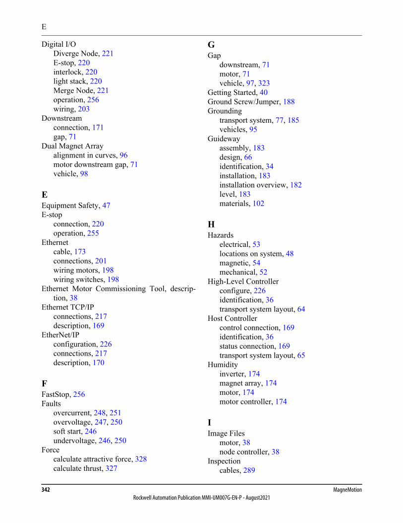
E
342 MagneMotionRockwell Automation Publication MMI-UM007G-EN-P - August2021
Digital I/ODiverge Node, 221E-stop, 220interlock, 220light stack, 220Merge Node, 221operation, 256wiring, 203
Downstreamconnection, 171gap, 71
Dual Magnet Arrayalignment in curves, 96motor downstream gap, 71vehicle, 98
EEquipment Safety, 47E-stop
connection, 220operation, 255
Ethernetcable, 173connections, 201wiring motors, 198wiring switches, 198
Ethernet Motor Commissioning Tool, descrip-tion, 38
Ethernet TCP/IPconnections, 217description, 169
EtherNet/IPconfiguration, 226connections, 217description, 170
FFastStop, 256Faults
overcurrent, 248, 251overvoltage, 247, 250soft start, 246undervoltage, 246, 250
Forcecalculate attractive force, 328calculate thrust, 327
GGap
downstream, 71motor, 71vehicle, 97, 323
Getting Started, 40Ground Screw/Jumper, 188Grounding
transport system, 77, 185vehicles, 95
Guidewayassembly, 183design, 66identification, 34installation, 183installation overview, 182level, 183materials, 102
HHazards
electrical, 53locations on system, 48magnetic, 54mechanical, 52
High-Level Controllerconfigure, 226identification, 36transport system layout, 64
Host Controllercontrol connection, 169identification, 36status connection, 169transport system layout, 65
Humidityinverter, 174magnet array, 174motor, 174motor controller, 174
IImage Files
motor, 38node controller, 38
Inspectioncables, 289
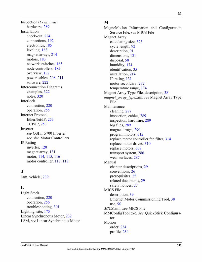
M
QuickStick HT User Manual 343Rockwell Automation Publication MMI-UM007G-EN-P - August2021
Inspection (Continued)hardware, 289
Installationcheck-out, 224connections, 192electronics, 185leveling, 183magnet arrays, 214motors, 183network switches, 185node controllers, 185overview, 182power cables, 208, 211software, 222
Interconnection Diagramsexamples, 322notes, 320
Interlockconnection, 220operation, 255
Internet ProtocolEtherNet/IP, 253TCP/IP, 253
Invertersee QSHT 5700 Invertersee also Motor Controllers
IP Ratinginverter, 120magnet array, 131motor, 114, 115, 116motor controller, 117, 118
JJam, vehicle, 239
LLight Stack
connection, 220operation, 256troubleshooting, 301
Lighting, site, 175Linear Synchronous Motor, 232LSM, see Linear Synchronous Motor
MMagneMotion Information and Configuration
Service File, see MICS FileMagnet Array
calculating size, 323cycle length, 92description, 91dimensions, 131disposal, 58humidity, 174identification, 35installation, 214IP rating, 131motor secondary, 232temperature range, 174
Magnet Array Type File, description, 38magnet_array_type.xml, see Magnet Array Type
FileMaintenance
cleaning, 287inspection, cables, 289inspection, hardware, 289log files, 289magnet arrays, 290program motors, 312replace motor controller fan filter, 314replace motor drives, 310replace motors, 308transport system, 286wear surfaces, 287
Manualchapter descriptions, 29conventions, 26prerequisites, 25related documents, 29safety notices, 27
MICS Filedescription, 39Ethernet Motor Commissioning Tool, 38use, 90
MICS.xml, see MICS FileMMConfigTool.exe, see QuickStick Configura-
torMotion
order, 234profile, 234
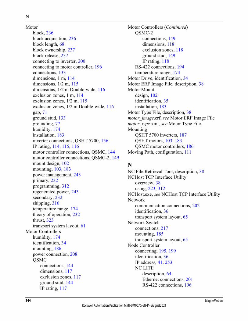
N
344 MagneMotionRockwell Automation Publication MMI-UM007G-EN-P - August2021
Motorblock, 236block acquisition, 236block length, 68block ownership, 237block release, 237connecting to inverter, 200connecting to motor controller, 196connections, 133dimensions, 1 m, 114dimensions, 1/2 m, 115dimensions, 1/2 m Double-wide, 116exclusion zones, 1 m, 114exclusion zones, 1/2 m, 115exclusion zones, 1/2 m Double-wide, 116gap, 71ground stud, 133grounding, 77humidity, 174installation, 183inverter connections, QSHT 5700, 156IP rating, 114, 115, 116motor controller connections, QSMC, 144motor controller connections, QSMC-2, 149mount design, 102mounting, 103, 183power management, 243primary, 232programming, 312regenerated power, 243secondary, 232shipping, 316temperature range, 174theory of operation, 232thrust, 323transport system layout, 61
Motor Controllershumidity, 174identification, 34mounting, 186power connection, 208QSMC
connections, 144dimensions, 117exclusion zones, 117ground stud, 144IP rating, 117
Motor Controllers (Continued)QSMC-2
connections, 149dimensions, 118exclusion zones, 118ground stud, 149IP rating, 118
RS-422 connections, 194temperature range, 174
Motor Drive, identification, 34Motor ERF Image File, description, 38Motor Mount
design, 102identification, 35installation, 183
Motor Type File, description, 38motor_image.erf, see Motor ERF Image Filemotor_type.xml, see Motor Type FileMounting
QSHT 5700 inverters, 187QSHT motors, 103, 183QSMC motor controllers, 186
Moving Path, configuration, 111
NNC File Retrieval Tool, description, 38NCHost TCP Interface Utility
overview, 38using, 223, 312
NCHost.exe, see NCHost TCP Interface UtilityNetwork
communication connections, 202identification, 36transport system layout, 65
Network Switchconnections, 217mounting, 185transport system layout, 65
Node Controllerconnecting, 195, 199identification, 36IP address, 41, 253NC LITE
description, 64Ethernet connections, 201RS-422 connections, 196
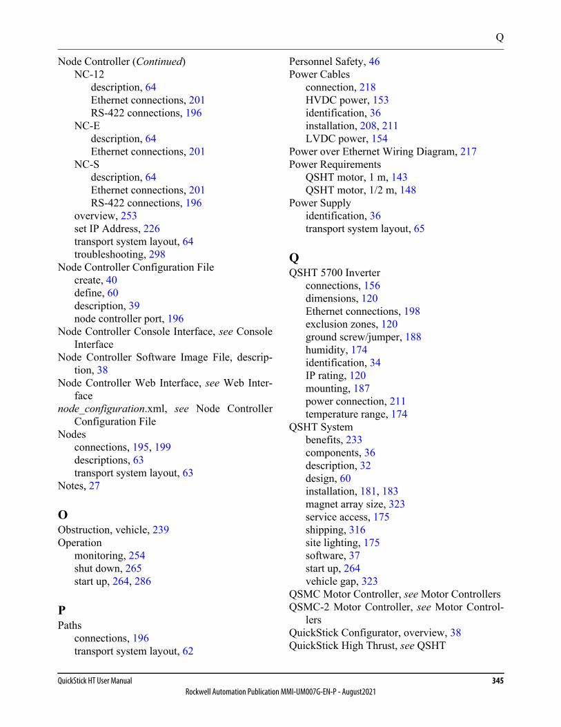
Q
QuickStick HT User Manual 345Rockwell Automation Publication MMI-UM007G-EN-P - August2021
Node Controller (Continued)NC-12
description, 64Ethernet connections, 201RS-422 connections, 196
NC-Edescription, 64Ethernet connections, 201
NC-Sdescription, 64Ethernet connections, 201RS-422 connections, 196
overview, 253set IP Address, 226transport system layout, 64troubleshooting, 298
Node Controller Configuration Filecreate, 40define, 60description, 39node controller port, 196
Node Controller Console Interface, see ConsoleInterface
Node Controller Software Image File, descrip-tion, 38
Node Controller Web Interface, see Web Inter-face
node_configuration.xml, see Node ControllerConfiguration File
Nodesconnections, 195, 199descriptions, 63transport system layout, 63
Notes, 27
OObstruction, vehicle, 239Operation
monitoring, 254shut down, 265start up, 264, 286
PPaths
connections, 196transport system layout, 62
Personnel Safety, 46Power Cables
connection, 218HVDC power, 153identification, 36installation, 208, 211LVDC power, 154
Power over Ethernet Wiring Diagram, 217Power Requirements
QSHT motor, 1 m, 143QSHT motor, 1/2 m, 148
Power Supplyidentification, 36transport system layout, 65
QQSHT 5700 Inverter
connections, 156dimensions, 120Ethernet connections, 198exclusion zones, 120ground screw/jumper, 188humidity, 174identification, 34IP rating, 120mounting, 187power connection, 211temperature range, 174
QSHT Systembenefits, 233components, 36description, 32design, 60installation, 181, 183magnet array size, 323service access, 175shipping, 316site lighting, 175software, 37start up, 264vehicle gap, 323
QSMC Motor Controller, see Motor ControllersQSMC-2 Motor Controller, see Motor Control-
lersQuickStick Configurator, overview, 38QuickStick High Thrust, see QSHT
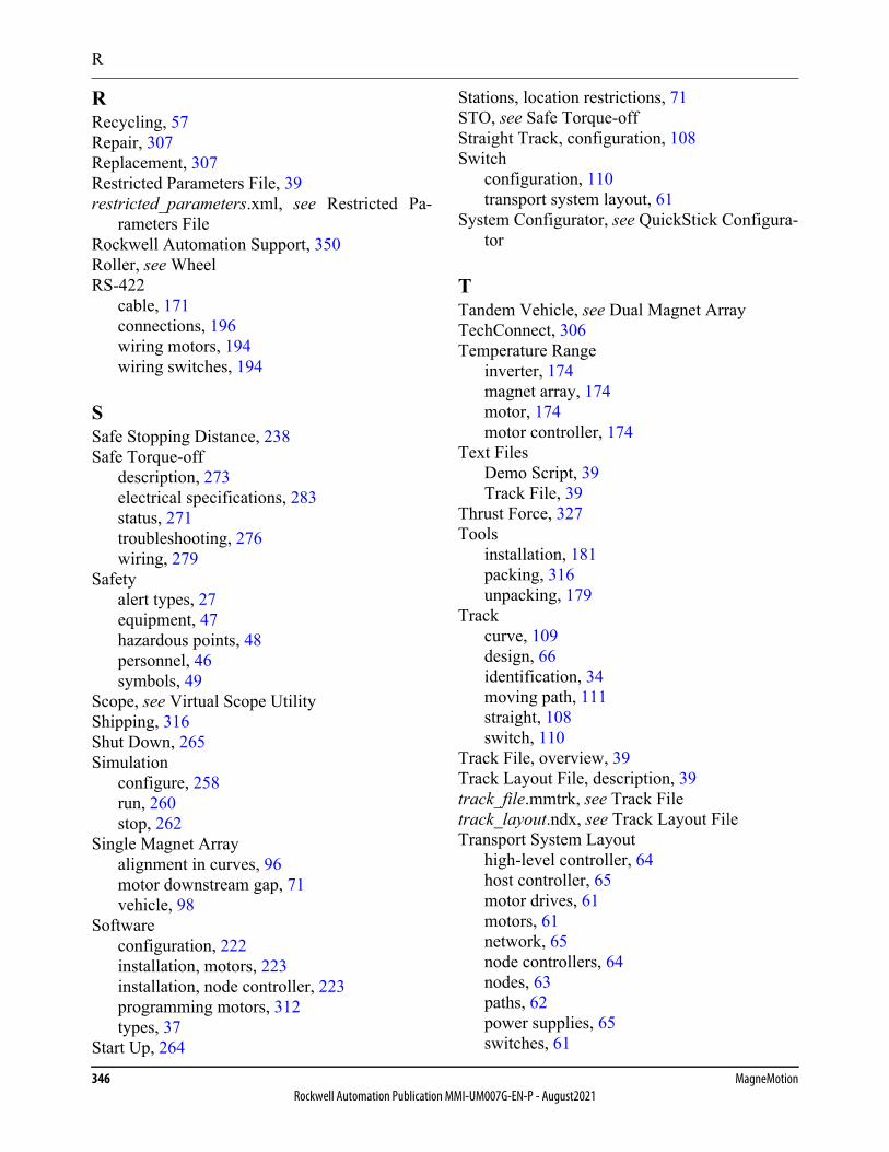
R
346 MagneMotionRockwell Automation Publication MMI-UM007G-EN-P - August2021
RRecycling, 57Repair, 307Replacement, 307Restricted Parameters File, 39restricted_parameters.xml, see Restricted Pa-
rameters FileRockwell Automation Support, 350Roller, see WheelRS-422
cable, 171connections, 196wiring motors, 194wiring switches, 194
SSafe Stopping Distance, 238Safe Torque-off
description, 273electrical specifications, 283status, 271troubleshooting, 276wiring, 279
Safetyalert types, 27equipment, 47hazardous points, 48personnel, 46symbols, 49
Scope, see Virtual Scope UtilityShipping, 316Shut Down, 265Simulation
configure, 258run, 260stop, 262
Single Magnet Arrayalignment in curves, 96motor downstream gap, 71vehicle, 98
Softwareconfiguration, 222installation, motors, 223installation, node controller, 223programming motors, 312types, 37
Start Up, 264
Stations, location restrictions, 71STO, see Safe Torque-offStraight Track, configuration, 108Switch
configuration, 110transport system layout, 61
System Configurator, see QuickStick Configura-tor
TTandem Vehicle, see Dual Magnet ArrayTechConnect, 306Temperature Range
inverter, 174magnet array, 174motor, 174motor controller, 174
Text FilesDemo Script, 39Track File, 39
Thrust Force, 327Tools
installation, 181packing, 316unpacking, 179
Trackcurve, 109design, 66identification, 34moving path, 111straight, 108switch, 110
Track File, overview, 39Track Layout File, description, 39track_file.mmtrk, see Track Filetrack_layout.ndx, see Track Layout FileTransport System Layout
high-level controller, 64host controller, 65motor drives, 61motors, 61network, 65node controllers, 64nodes, 63paths, 62power supplies, 65switches, 61
X
QuickStick HT User Manual 347Rockwell Automation Publication MMI-UM007G-EN-P - August2021
Transport System, see QSHT SystemTroubleshooting
communication, 299initial, 291light stack, 301motion, 300node controller, 298power, 292safe torque-off, 276
Type Filesmagnet array, 38motor, 38
UUniversal Feedback Connector Kit, 203Unpacking, 179Upstream, 171
VVehicle
anti-collision, 237design, 95detected, 240dual magnet array, 98gap, 97, 323identification, 35installation, 216jammed, 239locating during startup, 240materials, 99obstructed, 239simulated, 259single magnet array, 98
Virtual Scope Utility, description, 38
WWarnings, overcurrent, 247, 251Web Interface
description, 38file upload, 223program motors, 223upload MICS files, 223, 227, 311, 312upload Motor ERF files, 223using, 312
Wheel Materials, 100
Wiringnetwork communication, 202power, 75signal, 76transport system layout, 65
XXML Files
magnet array type file, 38MICS file, 39Motor Type file, 38Node Controller Configuration File, 39restricted parameters file, 39Track Layout File, 39

348 MagneMotionRockwell Automation Publication MMI-UM007G-EN-P - August2021
This page intentionally left blank.

QuickStick HT User Manual 349Rockwell Automation Publication MMI-UM007G-EN-P - August2021
Notes:
Rockwell Otomasyon Ticaret A.Ş., Kar Plaza İş Merkezi E Blok Kat:6 34752 İçerenköy, İstanbul, Tel: +90 (216) 5698400
Copyright © 2015–2021 MagneMotion, A Rockwell Automation Company. All Rights Reserved.139 Barnum Road, Devens, MA 01434, USA+1 978-757-9100Publication MMI-UM007G-EN-P - August 2021 DIR 990000496Supersedes MMI-UM007F-EN-P
Rockwell Automation SupportUse the following resources to access support information.
Documentation FeedbackYour comments will help us serve your documentation needs better. If you have any suggestions on how to improve this document, complete the How Are We Doing? form at https://rok.auto/docfeedback.
Technical Support Center Knowledgebase Articles, How-to Videos, FAQs, Chat, User Forums, Product Notification Updates, and the Direct Dial Code for your product. rok.auto/support
Literature Library Installation Instructions, Manuals, Brochures, and Technical Data. rok.auto/literature
Product Compatibility and Download Center (PCDC) Get help determining how products interact, check features and capabilities, and find associated firmware. rok.auto/pcdc
Product Catalog and Configurator Additional product information including CAD drawing files, 3D models, photos, and more. rok.auto/productdrawings
Rockwell Automation maintains current product environmental information on its website at rok.auto/pec.
Product certificates are available on the Rockwell Automation website at rok.auto/certifications.
Allen-Bradley®, Kinetix®, MagneMotion®, MagneMover®, MML™, MM LITE™, QuickStick®, Rockwell Automation®, Stratix®, and SYNC IT™ are trademarks of Rockwell Automation, Inc.Microsoft® and Windows® are registered trademarks of Microsoft Corporation. EtherNet/IP™ is a trademark of ODVA®, Inc. PuTTY is copyright 1997–2020 Simon Tatham. Trademarks not belonging to Rockwell Automation are property of their respective companies.
Back CoverRockwell Automation Support


