Embed Size (px)
Citation preview
G D D Installation and System Management for VM
--------- -------- - ---- - - ----------_ .-
TM

Front Cover Pattern: Electronic Sunflower
The pattern on the front cover was produced by a GDDM program. The program to produce this pattern, and many variations of the pattern, is published in:
• GDDM Application Programming Guide • GDDM Base Programming Reference

G
SC33·0323·2 File No. S370/4300/VM·34
D D Installation and System Management for VM
GDDM/VM, 5664·200 GDDM Interactive Map Definition, 5668·801 GDDM·PGF, 5668·812 GDDM/VMXA,5684·007 GDDM·IVU, 5668·723 GDDM.GKS, 5668-802 GDDM·REXX, 5664·336
Licensed Programs
--------- -------- - ---- - - --------_____ t_
Version 2 Release 2 Version 2 Release 1 Version 2 Release 1 Version 2 Release 2 Release 1 Release 1 Release 1

Third Edition (January 1988)
This edition applies to the following IBM GDDM+-series licensed programs:
Program name
GDDM/VM (Graphical Data Display Manager) GDDM/VMXA GDDM-PGF (Presentation Graphics Facility) GDDM Interactive Map Defmition (GDDM-IMD) GDDM-IVU (Image View Utility) GDDM-GKS (Graphical Kernel System) GDDM-REXX
program number
5664-200 5684-007 5668-812 5668-801 5668-723 5668-802 5664-336
program level
Version 2 Release 2 Modification 0 Version 2 Release 2 Modification 0 Version 2 Release 1 Modification 0 Version 2 Release 1 Modification 0 Release 1 Release 1 Release 1
Changes and additions to the text and illustrations are indicated by revision bars (vertical lines) to the left of the change.
A summary of changes is given on page xvii.
Information about IBM publications and how to submit comments is given on page vii.
References in this publication to IBM products, programs, or services do not imply that IBM intends to make these available in all countries in which IBM operates. Any reference to an IBM licensed program in this publication is not intended to state or imply that only IBM's licensed program may be used. Any functionally equivalent program may be used instead.
No part of this GDDM Installation and System Management manual may be reproduced in any form or by any means, including storing in a data processing system, without permission in writing from IBM. Permission is hereby granted to licensees of GDDM/VM Version 2 Release 2 Modification 0, or GDDM/VMXA Version 2 Release 2 Modification 0, but to no other person, to copy and store the sample programs included in this manual into a data processing system and to modify and use the stored programs in accordance with their Agreement for Licensed Program. No permission is granted to use the sample programs in any other circumstances.
THE PUBLICATION OF THE INFORMATION CONTAINED HEREIN IS NOT INTENDED TO AND DOES NOT CONVEY ANY RIGHTS OR LICENSES, EXPRESS OR IMPLIED, UNDER ANY IBM PATENTS, COPYRIGHTS, TRADEMARKS, MASK WORKS OR ANY OTHER INTELLECTUAL PROPERTY RIGHTS 01lIER THAN THE LIMITED PERMISSION GIVEN ABOVE.
+ GDDM is a trademark of International Business Machines Corporation.
© Copyright International Business Machines Corporation 1980, 1981, 1983, 1984, 1986, 1987, 1988 All rights reserved.

preface
Preface
What this book Is about This book provides the infonnation needed to install and manage the following licensed programs:
• GDDM"/VM, program number 5664-200 • GDDM/VMXA, program number 5684-007 • GDDM-PGF, program number 5668-812 • GDDM Interactive Map Definition (GDDM-IMD), program number 5668-801 • GDDM Image View Utility (GDDM-IVU), program number 5668-723 • GDDM-GKS, program number 5668-802 • GDDM-REXX, program number 5664-336.
GDDM-GKS is an implementation of the Graphical Keme1 System. GDDM-REXX is a productivity tool that lets GDDM be used from EXECs written for the VM/SP or VM/XA SP System Product Interpreter.
Who this book Is for This book is for system programmers experienced in installing IBM licensed programs.
What you need to know This book assumes that you have experience in using CMS EXECs.
How to use this book
Terminology
This book is divided into three parts, corresponding to before installation, installation, and after installation, followed by a number of appendixes. It should be used sequentiallj to install GDDM. After installation it can be used for reference.
Throughout this book, unless otherwise specifically detailed, all references to VM can be taken to include VM/XA; details are given in Chapter 1.
Throughout this book the term GDDM is used to apply to the licensed programs listed on page 3, together with the National Language (NL) no-charge special features of GDDM/yM, GDDM/VMXA, GDDM-PGF, GDDM-IVtJ, and GDDM-GKS, and the PCLKF feature of GDDM/VM or GDDM/VMXA.
" GDDM is a trademark of International Business Machines Corporation
Preface iii

books
The GDDM library
Introduction GDDM General Information and brochures GBOF-0058 GDDM General Information GC33-0319 GDDM If you make business presentations ... (brochure) GC33-0455 GDDM If you're an engineer ... (brochure) GC33-0456 GDDM Release Guide GC33-0320
General GDDM Image View Utility SC33-0479 GDDM-REXX Guide SC33-0478 GDDM Interactive Map Definition SC33-0338 GDDM-PCLK Guide
User's Guides GDDM Guide for Users SC33-0327 GDDM-PGF Interactive Chart Utility SC33-0328 GDDM Image Symbol Editor SC33-0329 GDDM-PGF Vector Symbol Editor SC33-0330 GDDM-PCLK Reference Summary (booklet) SX33-6067 GDDM-CSPF User's Guide SC33-0552 GDDM Typefaces and Shading Patterns SC33-0554
Programming GDDM Application Programming Guide (two volumes) SC33-0337 GDDM Base Programming Reference (two volumes) SC33-0332 GDDM Base Programming Reference Summary (booklet) SX33-6053 GDDM-PGF Programming Reference SC33-0333 GDDM-PGF Programming Reference Summary (booklet) SX33-6054 GDDM-GKS Programming Guide and Reference SC33-0334
Systems GDDM Installation and System Management for MVS SC33-032l GDDM Installation and System Managementfor VM SC33-0323 +- this book GDDM Installation and System Managementfor VSE SC33-0322 GDDM Performance Guide SC33-0324 GDDM-CSPF Installation Guide SC33-0SS3
Diagnosis GDDM Messages SC33-0325 GDDM Diagnosis and Problem Determination Guide SC33-0326
iv GDDM Installation and System Management for VM

books
Books from related libraries In addition to the GDDM library, you may need to refer to some of the following manuals:
VM/SP VMjSP Installation Guide, SC24-5237 VMjSP Planning Guide and Reference, SC19-6201 VMjSP Operator's Guide. SC19-6202 VMjSP CP Command Referencefor General Users. GC19-6212 VMjSP System Programmer's Guide. SC19-6203 VMjSP CMS Command and Macro Reference, SC19-6209 VMjSP System Messages and Codes, SC19-6204 VMjSP System Product Interpreter Reference. SC24-5239
VM/XA SP VM/XA SP Planning. GC23-0378 VMjXA SP Installation and Service. SC23-0364 VMjXA SP Administration, SC23-0353 VMjXA SP CP Command Reference, SC23-0358 VMjXA SP CMS Command Reference, SC23-0354 VMjXA SP System Product Interpreter Reference, SC23-0374
API. VS APL for CMS: Terminal User's Guide, SH20-9067 APL2 Installation and Customization under CMS, SH20-9221
VM/VCNA VM/VCNA General Information, GC27-0501 VM/VCNA Installation, Operation and Terminal Use, SC27-0502
Networking Network Program Products Samples: VM SNA. SC30-3309
GDDM/ graPHIGS Installing GDDM/graPHIGS, SC33-SlOl Licensed Program Specifications, GH23-0001 Introducing graPHIGS, SC33-S100 Understanding graPHIGS, SC33-S102 Writing Applications with graPl/lGS, SC33-S103 Programmer's Reference/or graPHIGS. SC33-S104 Messages and Error Codes for graPHIGS, SC33-SlOS Programmer's Pocket Reference for graPHIGS, SC33-8107 Problem Diagnosis for graPHIGS, SC33-S10S
I)rint Services Facility System Programmer's Guide for VM, S544-3511
Composed Document Installation and Operations, SC33-6135 Printing Facility
IPDS Intelligent Printer Data Stream Reference, S544-3417
3117 Scanner IBM 3117 Scanner and IBM 3117 PC Adapter Guide to Operations, GA18-2477 IBM 3117 Scanner and Extension Unit Guide to Operations, GA1S-2478 IBM 3117 Scanner Hardware Maintenance and Service, SY18-21S9 IBM 3117 Scanner Technical Reference, SC18-21OS
Preface V

books
3118 Scanner
3179-G, 3192-G
3193 Display station
3270-family devices
3270-PC/G and 3270-PC/GX work stations
3274
3812 ))rinter
4224 Printer
4234 Printer
4250 Printer
Scanner Guide to Operations, GAIS-2475 High Speed Adapter Guide to Operations, GA18-2476 IBM 3118 Scanner Hardware Maintenance and Service, 8Y18-2158 High Speed Adapter Hardware Maintenance and Service, 8YIS-2167 Scanner Technical Reference, 8ClS-2104 High Speed Adapter Technical Reference, 8C1S-2117
3179-G and 3192-G Color Graphics Display Station Description, GA18-2589
Description, GA lS-2364 Setup Instruction, GA18-2366 Operator's GUide, GA1S-2365 Problem Solving Quick Check Guide, GAIS-2443 Problem Solving Guide, GAI8-2444
3270 Information Display System Configurator, GA27-2849 3270 Information Display System Data Stream Programmeris Reference, GA23-0059 8775 Display Terminal: Component Description, GA33-3044
Introducing the IBM 3270 Personal ComputerlG and IGX Ranges of Work Stations, GA33-3I57
3270-PCIG Personal ComputerlG and IGX Ranges of Work Stations,' Planning Guide, GA33-3I58
3270-PC/G Guide to Operations, GA33-3140 3270-PC/GX Guide to Operations, GA33-3139 Graphics Control Program User's Guide and Reference, 8C33-0207 (for IBM 3270-PC/G
and PC/GX) Graphics Control Program Version 3.2 User's Guide, 8C33-0368 (for IBM 3270-PC AT/G
and PC AT IGX) Graphics Control Program Version 3.2 User's Reference, 8C33-0372 (for IBM 3270-PC
AT/G and PC AT/GX)
3274 Control Unit Description and Programmer's Guide, GA23-0061 3274 Control Unit Planning, Setup and Customization Guide, GA23-2827
IPDS Handbook, 8544-3102 IPDS NDS Attachment Feature Installation and Programming Instructions, 8544-3101 Guide to Operations, 8544-3267
Printer Product and Programming Description Manual, GC31-2551 Operating Instructions, GC31-2546 Guide to Operations, GC31-3621
Operation Instructions for Modell, GC31-2556
Operator's Guide, GA33- 1551
vi GDDM Installation and System Management for VM
5550 Multistation (available in Japanese only)
IBM manuals
5550 Japanese 3270-PC User's Guide, N:SC18-2059 How To Use 5550 Japanese 3270-PC, N:SC18-2060 5550 Japanese 3270-PC/G User's Guide, N:SC18-207l How To Use 5550 Japanese 3270-PC/G, N:SC18-2072 5550 Small Cluster User's Guide, N:SC18-2092 How To Use 5550 Small Cluster, N:SCI8-209l 5550 Small Cluster/Graphics User's Guide. N:SC18-2l07 How To Use 5550 Small Cluster/Graphics, N:SClS-21OS 55503270 Kanji Emulation Description, N:SC1S-2020 55503270 Kanji Emulation Operator's Guide, N:SClS-2021
books
Changes are periodically made to the information herein; before using this publication in connection with the operation of IBM systems or equipment, refer to the latest IBM System/370, 30xx, and 4300 Processors Bibliography, GC20-000l, for the editions that are applicable and current.
Publications are not stocked at the addresses given below. Requests for IBM publications should be made to your IBM representative or to the IBM branch office serving your locality.
A form for readers' comments is provided at the back of this publication. If the form has been removed, comments may be addressed to either:
International Business Machines Corporation, Department 6RlH, ISO Kost Road. Mechanicsburg, Pennsylvania 17055, U.S.A.
or:
IBM United Kingdom Laboratories Limited. Information Development and Release. Mail Point 95, Hursley Park, Winchester. Hampshire. England, S021 2JN.
IBM may use or distribute whatever information you supply in any way it believes appropriate without incurring any obligation to you.
Preface vii

contents
Book structure Preinstallation
Chapter 1. Introduction to GDDM ... pages I through 22 contains a brief introduction to the GDDM family of licensed programs, and to the hardware and software supported by GDDM.
Chapter 2. Overview of GDDM installation ... pages 23 through 31 gives an overview of installation, including the storage requirements.
Chapter 3. Preinstallation planning ... pages 33 through 39 discusses what you should consider before installing GDDM.
Installation
Chapter 4. Installing GDDM from tape .•. pages 43 through 55 describes what is on the tapes that IBM supplies, and how to run the installation EXECs.
Chapter 5. Steps after using the installation EXECs ... pages 57 through 99 describes tailoring GDDM to meet the needs of your users, and testing the system.
Postinstallation
Chapter 6. Postinstallation tasks ... pages 103 through 111 describes how to apply service to GDDM, managing GDDM objects, and repackaging.
Appendixes ... pages 113 through 258 contain reference material that you may need during installation, or later. A summary of the contents of each appendix is given on page 113.
Glossary ... pages 259 through 265
Index ... pages 267 through end
viii GDDM Installation and System Management for VM

contents
Contents
Part t. Preinstallation ............................................. 1
Chapter 1. Introduction to GDDM .......................... 3 What is in this book ................................... 5 Hardware and software supported ........................... 5
Processors ....................................... 5 Control units ...................................... 5 Devices ......................................... 6 System and subsystem software .......................... 16
GDDM support on CICS/OS/VS and CICS/DOS/VS ........... 18 GDDM support on IMS/VS .......................... 18 GDDM support on MVS/Batch and TSO/Batch .............. 19 GDDM support on TSO ............................ 20 GDDM support on CMS ............................ 20
Programming languages and compilers ...................... 21 GDDM storage requirements ............................. 22 Servicing ......................................... 22 Security and auditability ................................ 22
Chapter 2. Overview of GDDM installation .................... 23 Conventions used in this book . . . . . . . . . . . . . . . . . . . . . . . . . .. 23
Overview ofthe installation process ......................... 24 Storage requirements and capacity planning . . . . . . . . . . . . . . . . . . . .. 26
GDDM objects and use of DASD space ..................... 26 Virtual storage requirement of GDDM ...................... 29
Chapter 3. Preinstallation planning ......................... 33 Step 1: Preinstallation planning ............................ 34
Deciding which licensed programs you are going to install ........... 34 National Language features ........................... 35
Preinstallation planning - DASD requirements ................. 37 PreinstaUation planning - virtual machine size ................. 38 Estimated time .................................... 38 Instructions for preinstaUation planning ..................... 38
Step 2: Changing GDDM naming defaults ..................... 39
Part 2. Installation .............................................. 41
Chapter 4. Installing GDDM from tape . . . . . . . . . . . . . . . . . . . . . .. 43 Step 3: Checking the tapes . . . . . . . . . . . . . . . . . . . . . . . . . . . . . .. 44
What IBM supplies ............................... 44 Use of the Program Directory ......................... 45
Tape contents .................................... 45 Step 4: Read in and execute the installation EXEC ................ 50
Step 4A: Setting up VM to load the installation EXEC ............ 51
Contents ix

contents
Step 4B: Installing GDDM licensed programs .......... . Step 4C: Upgrading associated GDDM programs to 2.2 level .. Step 4D: Installing other GDDM programs ........ .
Chapter 5. Steps after using the installation EXECs Step 5: Tailor the print utility ............ .
Automatic invocation of the print utility Sending output to another virtual machine .. Transmitting print mes to a disconnected virtual machine
Instructions for tailoring the print utility ...... . Step 6: Customize GDDM ............... .
Naming conventions ................ . Buffer sizes, paging, and other performance factors Time, date, and number punctuation conventions Language of messages and ICU panels ..... Debugging factors ...... . . . . . Nicknames ............ . ... . Country-extended code pages . . . . . APL and printing ..... Character code translation . . . . 4250 code-page names ...... . . . . . . GDDM-GKS workstation types ..... . GDDM-IVU and image devices ..... . Double-byte character set (DBCS) defaults ............... . Changing the default vector symbol set to a language other than
53 55 55
57 57 57 58 58 59 61 63 63 63 63 63 63 66 66 66 66 67 67 68
American-English ................... . . . . . . . 68 Differing default requirements ......................... 69 Instructions for changing the defaults ..................... 69
Step 7: Create GDDM discontiguous saved segments (DCSS) . . . . .. 71 Potential servicing problems with DCSSs .......... 72
Migration and previously existing DCSSs ........... 72 Saved segments for other GDDM-series licensed programs 72 Names of saved segments ................... ...... 73 Overview of how to deal with saved segments . . . . . 73
Overlapping of old and new GDDM DCSS . . . . . . 75 Saved segment contents and sizing . . . . . 75
GDDM Base DCSS . . . . . 77 GDDM-PGF DCSS 79 GDDM-IMD DCSS 79 GDDM-IVU DeSS . . . . . 79 GDDM-GKS DeSS . . . . . 79 GDDM-REXX DCSS . . . . . 79
Instructions for creating DCSSs Step 8: Review telecommunications network Step 9: Test the installation ............. .
Instructions for testing ............... . Instructions if you have GDDM-PGF installed Instructions if you do not have GDDM-PGF installed Testing GDDM-IMD .... . Testing GDDM-IVU ....... . Testing GDDM-GKS Testing GDDM-REXX
80 84 85 85 87 88 88 89 89 90
X GDDM Installation and System Management for VM

contents
Testing the print utility 90 Testing the network 91 Testing GDDM Base PCLKF 91
What to do if the tests fail ...... . . . .. 92 Step 10: Provide suitable EXECs for users . . . .. 93
EXECs for accessing GDDM and compiling and loading applications 93 EXEC for ICU using composed-page printers ............... 94 EXEC for printing image mes ................... 94 EXECs for browsing and printing composite documents .... 94 EXEC for me transfer with the 3270-PCfG and 3270-PC/GX 95 Program for tagging GDDM object mes 95 EXECs for using GDDM-REXX ..... . . . . . 95
Instructions for providing suitable EXECs .. 95 Step 11: Regenerate existing program modules 96
Migrating from GDDM Version 1 Releases 1 and 2 96 Migrating from GDDM Version I Releases 3 and 4 96 Migrating from GDDM Version 2 Release I 96
Step 12: Inform users about GDDM ............. .. . . . 97
Part 3. Postinstallation
Chapter 6. Postinstallation tasks Step 13: Perfonn postinstallation tasks . Servicing ................. .
Service considerations ...... . Using ADMSERV EXEC to apply corrective service ..
Replacing GDDM modules after installation ........ . How to replace a GDDM module that you've changed
Managing GDDM objects ............ . Contents and use of GDDM objects .... .
Chart format, data, and data defmition files Symbol sets ................. . Graphics data format (GDF) files. Image data mes .......... . Projection definition files Saved pictures (FSSAVE files) Maps .............. . Composed-page print image files . GKS metafiles .......... .
What you may need to do about GDDM objects Repackaging GDDM objects after servicing .....
Tagging GDDM objects for country-extended code page support Methods of holding GDDM objects ...... .
GDDM objects ............... . ... . Moving GDDM objects between subsystems Security considerations
Editing GDDM-IVU panels Repackaging GDDM Saved segments ...... .
Contents
101
103 103 103 104 104 105 105 106 107 107 107 107 107 107 108 108 108 108 108 109 109 110 110 110 III 111 111 III
xi

contents
Appendixes 113
Appendix A. GDDM defaults and nicknames .................. 115 User default specifications (UDSs) .......... . . . . . . . . .. 116
External defaults ..................... ............. 117 Alphabetical list of default descriptions ................... 120 NicknaJIles ................. . . . . . . . . . . . . 128
Source format of a nickname UDS . . . . . . . . . . . . . . 128
Appendix B. Character code interpretation . . . . . . . . . . . . .. 133 Code page conversion ............ . . . . . . . . . . . 134
Structure of the alphanumeric defaults module . . . . . . . . . . . . .. 137 Compatibility of ADMDATRN with previous releases .......... 139
Basic control information ........... . . . . . . . . . . . . . . .. 139 Translation types supplied by GDDM ....... . . . . . . . 141
Translation-type descriptor block .............. . . . . . . . 143 Translation tables ..................... 145
How GDDM translates alphanumeric fields ...... 145 Instructions on setting up a new translation table . . . . . . . 146
Device dependent translation tables . . . . . . . . . . . . 147 CECP lookup table ........................ 148 Code-page-to-code-page translation tables ........ . . . . . . . . .. 149 National-language-to-CECP lookup table ..................... 149 CECP upper case translation table ......................... 150 How to use the alphanumeric defaults module ............ 150
How to make the default translation table Katakana ....... 151
Appendix C. Device characteristics tokens GDDM-supplied device tokens .
Where device tokens are held .... . Creating your own device tokens .......... .
The ADMM3270 macro Example of coding a device characteristics token ..
The ADMMSYSP macro . . . . . . . . . . The ADMMIMAG macro ............ .
Appendix». GDDM default symbol sets ..... . Changing the default symbol sets or making another set the default
Changing the default vector symbol set from American-English . How and where saJIlple symbol sets are held .......... .
Setting up pattern sets available to ICU users on your installation . EXaJIlple of changing the default symbol sets ............ .
EXaJIlple - Making the French vector symbol set the default
Appendix E. Checking a VT AM network ....... . Queriable terminals and printers . . . . . . .
Instructions for checking a vr AM network ...... . The PSERVIC operand of the MODEENT macro .
Bytes 1 through 6, and 12 ................ . Bytes 7 through 11 . . . . . . . .
Default logmodes ...................... .
153 153 153 162 162 174 177 178
179 182 183 183 183 184 184
185 185 186 188 188 189 190
xii GDDM Installation and System Management for VM

contents
Appendix F. Customizing devices ......................... 191 3270-PC/G and 3270-PC/GX customi7..ation ................... 191
Plotters ....................................... 191 3274 configuration .................................. 191 3270-PC/G and /GX segment storage requirement for GDDM ........ 192 5550 customization .................................. 192 3812 IPDS printer customization .......................... 192 3193 customization for GDDM-IVU ....................... 193
Appendix G. APL and GDDM .......................... 195 APL character sets .................................. 195 VM print ....................................... 195 VM/VCNA display terminals ............................ 196 Installation with a mixture of terminal types ................... 196
Appendix H. Repackaging for performance or for differing defaults ...... 197 Background to repackaging ............................. 197
How repackaging is done ............................. 198 Provisos about packaging . . . . . . . . . . . . . . . . . . . . . . . . . . . .. 200
Link-editing and possible future releases .................. 200 Retaining original libraries for service .................... 200
Repackaging the GDDM executable code on its own ............ 200 Levels of packaging stubs ........................... 201 The contents of packaging stubs ....................... 201 Which stubs to use ............................... 206
Repackaging executable code with a utility or application program ..... 207 Special requirements for utilities ....................... 207 Eliminating dynamic loading completely .................. 207
Repackaging to get a special defaults module ................. 208 Differing defaults ................................ 208 Special requirements .............................. 208
Instructions for repackaging ............................. 209 Examples ofrepackaging . . . . . . . . . . . . . . . . . . . . . . . . . . . . . .. 210
Repackaging application program with executable code .......... 210 Overriding saved segment defaults module ................. 210
Appendix J. GDDM font and conversion tables ................. 211 GDDM font emulation table ............................ 211
Changing the ADMMFONT macro ..................... 211 Installing a new font table ........................... 212
GDDM AFPDS to IPDS conversion table .................... 213 Changing the ADMDKFNT table ...................... 213 Installing a new conversion table ....................... 214
Appendix J. Installation module directory .................... 215 National language modules .......................... 215
TXTLIBs ....................................... 215 MACLIB ....................................... 216 Module flies ...................................... 216 Packaging stubs .................................... 217 Directory of GDDM-IMD frames ......................... 218 Directory of GDDM/VM PCLKF or GDDM/VMXA PCLKF objects 220
Contents xiii

contents
Directory of sample material ........................... . Sample symbol sets ............................... . Sample programs and data ........................... . Default materials . . . . . . . . . . . . . . . . . . . . . . . . . . . . . . . . . .
Installation and service material ...................... .
Appendix K. What to do if things go wrong .................. . Checking out hardware characteristics ...................... .
3179-0 and 3192-0 graphics diagnosis .................... . 3270 graphics diagnosis ............................. .
3270 EDCB verification ........................... . 3287 printer diagnosis .............................. . 3268 printer diagnosis .............................. . 4224 printer ................................... . 3193 display station ............................... . 3274 controUer diagnosis ............................ .
Common errors and pitfalls ............................ . Problems associated with abends ....................... .
User abend code 1064 ............................ . User abend code 1201
Problems associated with incorrect output .................. . Thick black lines on 3812 output ..................... . User session logoff .............................. .
Problems associated with messages ...................... . Messages beginning ADM ......................... . Message ADM0275 ............................. . Message ADM0275, reason code 9 ..................... . Messages beginning AEM .......................... . Message DMKDID5461 ........................... . Message DMSLIO 169S ........................... . Messages beginning GQD .......................... . Message HCPMHT21501 .......................... .
Problems involving system performance ................... . Line time-outs ................................ . Missing interrupt conditions ........................ .
Problems involving device checks ....................... . Machine check 207 .............................. .
Appendix L. Listings of user EXECs
220 220 221 222 222
225 226 226 226 226 228 229 230 230 230 231 232 232 232 232 232 232 233 233 233 233 233 234 234 234 234 235 235 235 235 235
237
Appendix M. Installation checklist ......................... 253
GDDM glossary 259
Index .......................................... 267
xiv GDDM Installation and System Management for VM

Figures
1. 2.
3. 4. 5. 6. 7. 8. 9.
10. 11. 12. 13. 14. 15. 16. 17. 18. 19. 20. 21. 22. 23. 24. 25. 26. 27. 28. 29. 30. 31. 32. 33. 34. 35. 36. 37. 38. 39. 40. 41. 42. 43. 44. 45. 46. 47.
figures
GDDM device support .............................. 7 Minimum level support for sdftware for GDDM Version 2 Release 2 Modification 0 ........1.......................... 16 Programming languages and ~ompilers for GDDM ............. 21 GDDM object contents and sfe table .................... 27 GDDM minimum virtual sto~age requirement (in bytes) .......... 29 GDDM virtual storage requirement (in bytes) ................ 30 GDDM national language feature ftles .................... 36 Space required for GDDM j.......................... 37 GDDM names that can be c~anged if unsuitable .............. 39 Feature numbers of tapes and Program Directories supplied with GDDM 44 Contents of GDDM/VM ins¥tation tape .................. 45 Contents of GDDM/VM nat~onal1anguage installation tape ....... 45 Contents of GDDM/VM PCLKF installation tape ............. 46 Contents of GDDM/VMXA ~stallation tape ................ 46 Contents of GDDM/VMXA national language installation tape ..... 46 Contents of GDDM/VMXA iPCLKF installation tape ........... 47 Contents of GDDM-PGF in~tallation tape . . . . . . . . . . . . . . . . .. 47 Contents of GDDM-PGF national language installation tape ....... 47 Contents of GDDM-IMD.inftalla~ion tape ................. 48 Contents of GDDM- IVU msr.~tabon ~ape for VM ............. 48 Contents of GDDM-IVU ~~ mst~llatton tape for VM .......... 48 Contents of GDDM-GKS mstallabon tape for VM ............. 49 Contents of GDDM-GKS NL installation tape for VM .......... 49 Contents of GDDM-REXX installation tape ................ 49
I
Checklist for the GDDM installation EXECs ................ 52 What is installed and how to Ido it for each product . . . . . . . . . . . .. 54 Suggested ADMQPOST EXtC ........................ 59 Suggested EXEC to print fro a disconnected virtual machine ...... 60 Checklist of items to change n defaults module ............... 62 GDDM/VM saved segment names ...................... 73 Names of the saved segments with GDDM/VMXA ............ 73 Sizes of items in the GDDM Base saved segment .............. 76 Sizes of items in the GDDM-PGF saved segment .............. 76 Sizes of items in the GDDM-IMD saved segment ............. , 76 Sizes of items in the GDDM-IVU saved segment .............. 77 Sizes of items in the GDDM-GKS saved segment . . . . . . . . . . . . .. 77 Sizes of items in the GDDM-REXX saved segment ............ 77 Checklist for the GDDM saved segments .... . . . . . . . . . . . . . .. 78 Sample system name table entries for GDDMjVM saved segment 82 Calculating values for DMKSNT entries ................... 82 GDDM TXTLIBs, their contents and uses ................. 85 Suggested EXEC to access GDDM disk ................... 93 Suggested EXEC to access the PL/I declarations and compile ....... 94 Suggested EXEC to load a program containing GDDM calls ....... 94 Suggested skeleton memo about first-time GDDM installation ...... 98 Suggested skeleton memo about update of GDDM release level ..... 99 Source-format of user-default specifications ................ 117
Figures XV

figures
48. Processing options ............................... 132 49. Code page conversion ............................. 134 50. GDDM default EBCDIC character codes ................. 135 51. GDDM default Katakana character codes ................. 136 52. Example country extended code page (CECP 00037) ........... 137 53. Format of the alphanumeric defaults module ............... 138 54. Alphanumeric defaults module, basic control information ........ 139 55. Translation tables in the alphanumeric defaults module ......... 142 56. Alphanumeric defaults module, translation-type descriptor block .... 143 57. Translation tables used for GDDM alphanumeric fields ......... 146 58. Alphanumeric defaults module, CECP lookup table ........... 148 59. Alphanumeric defaults module, national language lookup table ..... 149 60. National language and code page identifiers ................ 150 61. GDDM-supplied device tokens for queriable tenninals and printers 154 62. GDDM-supplied device tokens for IPDS devices ............. 156 63. GDDM-supplied device tokens for Kanji devices, and 8775 and 3290
displays ..................................... 157 64. GDDM-supplied device tokens for nonqueriable terminals and printers 158 65. GDDM-supplied device tokens for PC displays, printers, and plotters 159 66. GDDM-supplied device tokens for system printers ............ 160 67. GDDM-supplied device tokens for composed-page printers ....... 161 68. Example of coding a device token ...................... 175 69. Last letters of sample symbol set names .................. 180 70. Sample symbol set names and usage in load module and editable formats 181 71. Examples of MODEENT macro instructions ............... 188 72. Examples of LU, TERMINAL, and LOCAL macros .......... 190 73. 3270-PC/G segment storage requirements ................. 192 74. Default order of loading during GDDM utilities and programs ..... 198 75. Possible loading combinations ........................ 199 76. How packaging stubs are used to repackage the executable code 20 I 77. Names of initially-loaded modules ...................... 201 78. GDDM frrst-Ievel packaging stubs ...................... 202 79. Full screen manager second-level packaging stubs ............. 205 80. ICU second-level packaging stubs ...................... 206 81. Names of invoking routines for GDDM utilities .............. 207 82. Letters for national language mes . . . . . . . . . . . . . . . . .. 215 83. Meaning of the PCIA on the 3287 printer ................. 228 84. Meaning of the PCIA on the 3268 printer ................. 229 85. Supplied EXEC ADMUCIMV for producing a composed-page printer
me on the ICU ................................. 238 86. Supplied EXEC ADMUIMP for printing ADMIMG files ........ 242 87. Supplied EXEC ADMUBCDV to browse and print composite
documents ................................... 245 88. Supplied EXEC ADMUPCFV for me transfer with the 3270-PC/G and
3270-PC/GX .................................. 247 89. Installation checklist .............................. 254
xvi GDDM Installation and System Management ror VM

changes
Summary of Changes
Changes for Version 2 Release 2
Changes to the installation process for Version 2 Release 2 The installation process for Version 2 Release 2 is broadly the same as that for Version 2 Release 1 Modification 1. A new EXEC is available, to aid migration from Version 2 Release 1.
Changes in documentation for Version 2 Release 2 The book now incorporates instructions for installing GDDM/VMXA, GDDM-IVU, GDDM-GKS, and GDDM-REXX.
Changes for previous releases
Changes to the installation process for Version 2 Release 1 Modification 1 A new EXEC is available, to aid migration from Version 2 Release I Modification O.
Changes in documentation for Version 2 Release 1 Modification 1 • Example EXECs for printing are added. The user EXECs are now in a new
Appendix. • Some insubstantial changes and editorial corrections have been made; these are
not normally shown with revision bars. • Information about the GDDM/VM PCLKF feature is added in TNL
SN33-6323.
Changes to the installation process for Version 2 Release 1 The following major changes have been made to the installation process between GDDM Version I Release 4 and GDDM Version 2 Release 1.
• The National Language features allow individual languages to be selected for installation.
• GDDM can be installed using the INSTFPP process under VM/SP. • Separate saved segments are used for GDDM/VM, GDDM-PGF, and
GDDM-IMD.
Summary of Changes xvii

cbanges
Changes in documentation for Version 2 The manual, which used to deal with all subsystems, has been split into three separate manuals, one each for MVS, VM, and VSE.
In previous GDDM installation manuals there was a chapter on performance, and a chapter on tuning and customization. These have been removed and can now be found in the GDDM Performance Guide. The information on storage requirements is in both the GDDM Performance Guide and in this manual, as the information is required during installation and also when improved performance is being considered.
xviii GDDM Installation and System Management for VM

Part 1. Preinstallation
Part 1. Preinstallation 1
introduction
Chapter 1. Introduction to GDDM
GDDM (the Graphical Data Display Manager) consists of the following licensed programs:
Program name Number Applicable systems
GDDM/MVS 5665-356 MVS GDDMjVM 5664-200 VMjSP GDDM/VMXA 5684-007 VM/XASP GDDMjVSE 5666-328 VSE
GDDM-PGF (Presentation Graphics 5668-812 MVS, VM, VSE Facility) GDDM Interactive Map Definition 5668-801 MVS, VM, VSE (GDDM-IMD) GDDM-IVU (Image View Utility) 5668-723 MVS, VM, VSE GDDM-GKS (Graphical Kernel System) 5668-802 MVS, VM GDDM-REXX 5664-336 VM GDDM/graPHIGS (+) 5668-792 MVS, VM GDDM-PCLK Version 1.1 (+) MVS, VM, VSE GDDM-CSPF (+) 5668-013 MVS, VM
Notes:
l. The rlfst four programs are informally called "GDDM Base." Of them, only GDDM/VM and GDDM/VMXA are considered in this book. For GDDM/MVS, see the GDDM Installation and System Management for MVS manual. For GDDM/VSE, see the GDDM Installation and Sy.rtem Management for VSE manual.
2. In the table above, and throughout the rest of this book, the generic term "VM" means VMjSP and VM/XA, and the generic term "GDDM Base" means GDDM/VM and GDDM/VMXA. In general, the GDDM/VMXA installation process is identical to that for GDDM/VM. Where there are differences, the specific terms are used to identify them.
3. This book also deals with the other programs that can be installed on GDDM/VM or GDDM/yMXA systems, except for those indicated by an asterisk (+); they have separate documentation and are not considered here -see the Preface for details.
These licensed programs enable your applications to communicate with many of IBM's advanced terminals, printers, and plotters. They handle graphics and alphanumerics in color and monochrome and can work under IBM's major software subsystems.
If you have the GDDM/VM or GDDMjVMXA Hcensed program, you can:
• Create graphics, including drawing primitives such as lines and shaded areas, and setting graphics attributes such as color
• Handle images, including reading from a scanner
Chapter 1. Introduction to GDDM 3

introduction
• Process alphanumerics, both mapped and unmapped • Send graphics, images, and alphanumerics to a terminal or printer, and read
input from a terminal • Use the Image Symbol Editor; an image symbol is a pattern of dots such as a
company logo, reproduced to a predetermined size.
If you have the associated GDDM-PGF licensed program you can:
• Use the ICU (Interactive Chart Utility); the ICU is a widely-used, menu-based utility that enables non-DP personnel to draw business charts on display terminals, and print and plot them. Also, you can create multiple charts on one page.
• Use the Vector Symbol Editor; a vector symbol is formed by lines and curves, not dots, and GDDM-PGF can show vector symbols at any size. They can also be sheared (sloped, as in italic type faces), rotated, or shaded. Compared with image symbols, they are more versatile in use, but they display less accurately when very small.
If you have the GDDM-IMD licensed program, you can create interactively screen and printer alphanumeric maps during program development.
If you have the GDDM-PCLK licensed program, you can use an IBM PC with an appropriate emulator as a graphics terminal; this includes GDDM-emulated images, and printing and plotting to PC-attached devices.
If you have the GDDM-IVU licensed program, you can scan and display documents as images, scale, trim, and merge such images, and create image output for printers.
If you have the GDDM-GKS licensed program, you can code applications to the Graphical Kernel System (GKS) standard application programming interface. GDDM-GKS supports all family-l and -2 devices supported for graphics by GDDM under TSO and CMS.
If you have the GDDM-REXX licensed program, you can code GDDM calls in EXECs that use the VM System Product Interpreter (REXX) language.
You must install the GDDM/VM or GDDM/VMXA licensed program in order to use GDDM-PGF, GDDM-IMD, GDDM-PCLK, GDDM-IVU, GDDM-GKS, or GDDM-REXX.
GDDM is a prerequisite for a number of licensed programs that use it for graphics and alphanumeric support.
4 GDDM Installation and System Management for VM
introduction
What is In this book This book tells you how to install GDDM. Because it also explains how GDDM fits in with other pieces of software, it helps you to smooth the path for your GDDMusers.
Hardware and software supported
Processors
Control units
This section is not system-specific. If you have mUltiple systems, this helps you to have a complete picture of the hardware and software supported by GDDM.
In general, GDDM Version 2 Release 2 Modification 0 will run on all processors that support the System/370 architecture (or extended architecture) and have the Floating Point feature installed. This includes all models in the following processor families:
System/370 303x 308x 309x 43xx 937x.
The PC code of the GDDM-PCLK licensed program runs on a variety of IBM Personal Computers, as detailed in Figure I on page 6.
The supported control units are:
3174 3271 3272 3274 3276 3708 Network Conversion Unit 5088 7171 ASCII control unit (for ASCII terminals) 8100 (through the 3270 Data Stream Compatibility Licensed Program) direct TP line.
Some operating systems and subsystems may not support all models of these controllers. You should consult the relevant system and subsystem manuals for further details.
Not aU devices attach to aU controllers. You should consult the relevant device specification to determine the controller, model, and microcode level for any particular device.
Chapter l. Introduction to GDDM 5

introduction
Devices
Other than requiring that a device is attached to the correct controller type and model, GDDM is generally insensitive to the precise attachment of any device.
Notes:
1. For some 3274 Configuration Support levels, 3274 microcode fixes are required as follows:
• Configuration Support C level 46 - PTR3174, PTR312B • Configuration Support D level 60 - PTR3144, PTR3174, PTR312B.
Further microcode level and fix requirements for specific devices are listed in the notes in the next section.
2. The 7171 provides ASCII-to-3270 protocol conversion. The 7171 appears to the host processor as a 3274 Model ID control unit. The attached ASCII display terminals and printers appear as (nonqueriable) 3278 or 3277 terminals and 3286 printers.
The supported presentation devices are listed in this section.
All GDDM functions are supported on all devices unless the description of the function in the GDDM Base Programming Reference manual states otherwise.
All applicable models of a listed device are supported unless a specific model is given in the table below.
Support of some devices is subject to system or subsystem restrictions described in "System and subsystem software" on page 16.
The "GDDM Function" column contains the following codes:
A: Supported af; an alphanumeric device. The GDDM alphanumeric functions (the Axxxxx and Mxxxxx functions) will work on the device.
c: Supported for display or printing of composite documents.
G: Supported as a graphics device. The GDDM graphics functions (the Gxxxxx and similar functions) will work on the device. Graphics is done via Programmed Symbols (PS), vector graphics. or some other method. In some cases, a particular model or feature may be required beyond the base in order to do graphics.
I: Supported as an image device: GDDM image functions (the Ixxxxx functions) will work on the device.
6 GDDM Installation and System Management for VM

introduction
Device GDDM Title Notes function
3270 displays and printers (see notes I and 2)
3104 Model BI, B2 A ... Display 3178 A ... Display 3179 Modell A ... Color display 3179-G ACGI Color graphics display 3 3180 Model I A ... Display 4
3191 A ... Display 3192-C A ... Color display 3192-D A ... Display 4 3192-G ACGI Color graphics display 3 3193 A .. I Display 5
3194 A ... Display 3230 Model I, 2 A ... Printer 6 3232 Model I, II A ... Keyboard printer 7 3262 Model 3, 13 A ... Line printer 3268 A ... Printer
3268 Model 2C ACGI Color printer 8 3270-PC ACGI Work station 9.10 3270-PC/G ACGI Work station 9,11 3270-PC/GX ACGI Work station 9,11 3275 Model 2, 12 A ... Display
3276 A ... Control unit display 3277 Model I, 2 A ... Display 3278 ACGI Display 12 3278 Model 52 A ... Display 3279 ACGI Color display 13
3283 Model 52 A ... Printer 3284 Model 2, 3 A ... Printer 3286 Model 2 A ... Printer 3287 ACGI Printer 14 3288 A ... Line printer
3290 ACGI Infonnation panel 15 3812 Model 2 ACGI IPDS Printer 16 4224 Model2XX ACGI IPDS Printer 16 4234 Modell A ... Dot band printer 8775 ACGI Display 17
Figure I (Part 1 of 3). GDDM device support
Chapter 1. Introduction to GDDM 7

introduction
Device GDDM Title Notes function
Plotters (see note 18; see also PC plotters below)
6180 ., GI Color Plotter (8-Pen A4-size) 6182 .. GI Color Plotter (8-Pen A3-size) 6184 .. GI Color Plotter (8-Pen A4-size) 6186 .. GI Color Plotter (8-Pen AO-size) 7371 .. GI Color Plotter (2-Pen A4-size)
7372 .. OI Color Plotter (6-Pen A3-size) 7374 .. GI Color Plotter (8-Pen AI-size) 7375 .. GI Color Plotter (8-Pen AO-size)
Scanners (see note 19)
3117 ... I Scanner and extension unit 3118 · .. I Scanner
mM PS/55 and 5550-family displays and printers (see note 20)
Displays A.OI DBCS displays 21 Printers A ... DBCS printers
Other display terminals
5081 ACGI High-function graphics display 22
System printers (see note 23)
1403 A ... Printer 3203 Model 5 A ... Printer 3211 A ... Printer 3262 Model I, II, 5 A ... Line printer 3800 Model I, 2, 3, 6 A ... Printing subsystem
4245 A ... Line printer 4248 A ... Printer
Composed-page printers (see note 24)
3800 Model 3, 6, 8 · CGI Printing subsystem 3812 · COl Page printer 25 3820 · CGI Page printer 4250 .. GI Printer
Figure I (Part 2 of 3). GDDM device support
8 GDDM Installation and System Management for YM

introduction
Device GDDM Title function
IBM Personal Computers (see note 26)
PC ACGI IBM Personal Computer PC Xl' ACGI IBM Personal Computer Xl' PC XT-286 ACGI IBM Personal Computer XT-286 PC AT ACGI IBM Personal Computer AT® 3270-PC ACGI IBM Personal Computer
3270-PC AT ACGI IBM Personal Computer Personal System/2™ ACGI IBM Personal System
Model 25, 30, 50, 60, 80
IBM PC printers and plotters (see note 27)
3852 Model I, 2 A. GI Color Jetprinter 4201 Model I A. GI Proprinter 4201 Model 2 A. GI Pro printer II 4202 A .GI Proprinter XL 4207 A. GI Proprinter X24
4208 A.GI Proprinter X124 5152 A. GI Mono graphics printer 5182 A. GI Color impact printer 5201 A. GI Quietwriter 5202 A.GI Quiet writer III
6180 .. GI Color Plotter 6182 .. GI Color Plotter 6184 .. GI Color Plotter 6186 .. GI Color Plotter 7371 .. GI Color Plotter
7372 .. GI ('...olor Plotter 7374 .. GI Color Plotter 7375 .. GI Color Plotter
Figure 1 (Part 3 of 3). GDDM device support
Notes for Figure I:
I. Any terminal emulating the 3270 architecture can be used if it is fully compatible with one of the listed devices.
Notes
2. Some devices, such as the 3179 and 319x, support a keyboard definition utility that allows the user to define code points associated with keys when the keyboard is in native mode. Because the default GDDM character set may cause translation of some inbound non-EBCDIC code points, native mode is only supported by GDDM for applications that specify ASTYPE(I) to suppress translations.
Chapter 1. Introduction to GDDM 9

introduction
Such devices are supported normally by GDOM when they are in keyboard emulation mode (emulating the 3278/3279).
3. When using remote non-SNA (DSC) attachment:
• 3274 WACK (wait before transmit positive acknowledgement) support must be configured. To configure WACK support, specify 1 in reply to 3274 Customization question 176 (DSC Enhanced Communication Option for Distributed Function Terminals).
• Fixes to NCP and SSP APARs described in note 28 are required.
On IMS/VS, supported through SNA attachment only. This device is not supported on IMS/VS in DTAM or non-SNA configurations.
Support for graphics and image requires 3274 Configuration Support D not less than level 64.
The 3192-G color graphics display is functionally equivalent to the 3179 Model G.
4. Can be dynamically configured in anyone of 8 modes (Model IDs 2 through 9). GDDM support of Model IDs 6 through 9 provides no extra function above that provided for Model IDs 2 through 5.
The 3192 Model D is functionally equivalent to the 3180 Model 1.
5. Requires 3274 Models 31A, 31C, 31D, 41A, 41C, 41D, 5lC, or 61C with Configuration Support 0, and microcode of release level 65.0 or higher, or 3174 Models lL, lR, 2R, 3R, 51R, 52R, or 53R, and microcode of release level 1.0 or higher.
When using remote non-SNA (DSC) attachment:
• 3274 WACK support must be configured. To configure WACK support, specify 1 in reply to 3274 Customization question 176 (DSC Enhanced Communication Option for Distributed Function Terminals).
• Fixes to NCP and SSP APARs described in note 28 are required.
On IMS/VS, supported through SNA attachment only. This device is not supported on IMS/VS in DT AM or non-SNA configurations.
6. Supported as a 3287 printer.
7. Supported for output only (no keyboard input).
8. Support for graphics and image requires RPQ S30277. On IMS/VS, BC A21615 should be installed for correct operation of GDOM.
9. The AT version of this device is also supported.
10. Support for graphics and image requires an additional feature, namely, 5790 Programmed Symbols.
GDDM-PCLK supports the 3270-PC (with or without Programmed Symbols) but support is limited to CGA emulation display mode (see note 26).
11. Corresponding software, the IBM 3270-PC Graphics Control Program (GCP), is also required. The following fixes to GCP APARs (according to the GCP Release) should be installed for correct operation of GDDM:
• GCP Release 1.12 - IR67978 and IR67982.
10 GDDM Installation and System Management for VM

• GCP Release 2.10 - IR67980 and IR67985. • GCP Release 3.10 and 3.20 - IR67981 and IR67986.
3270-PC AT/O and AT/OX require at least OCP Release 2.0.
When using link-attached (remote) non-SNA (BSC) attachment:
introduction
• 3274 WACK support must be configured. To configure WACK support, specify 1 in reply to 3274 Customization question 176 (BSC Enhanced Conununication Option for Distributed Function Terminals).
• Fixes to NCP and SSP APARs described in note 28 are required.
On IMS/VS, supported through SNA attachment only. These devices are not supported on IMS/VS in BTAM or non-SNA configurations.
Support for graphics and image:
• Requires that the 5371/5373 be attached to the 3274 in Distributed Function Terminal (OFT) mode.
• Requires 3274 Configuration Support 0 not less than level 61. The 3274 requires patch number 3537 for level 61.1, or patch numbers 3537 and 3538 for level 63. For level 64, the 3274 requires that you tum on bit 3 ('xxxlxxxx'B) in reply to 3274 Customization question 125 (Miscellaneous Feature Option).
12. Support for graphics and image requires additional features, namely:
• 5790 Programmed Symbols • 3620 Character Set Extension.
These functions are not available on 3278 Models I and 5.
13. Support for graphics and image on 3279 Models 3B, S3B, S30, and 03X only. Except for 3279 Model S30, this support requires additional features, namely:
• 5790 Programmed Symbols • 3850 Extended Function.
The 3279 Model 03X also supports the 8750 Video Output feature, which enables graphics to be copied from the terminal to another device such as a camera or TV screen.
14. Support for graphics and image requires additional features, namely:
• Models I, 2: 5781 Programmed Symbols (2) and, optionally, 5782 Progranuned Symbols (4)
• Models I C. 2C: 5783 Programmed Symbols (4A).
All these features have features 3610, 3880, and 9661 as prerequisites.
15. Requires 3274 Configuration Support D.
16. The 3812 Model 2 is supported as an IPDS printer when it has the 3270 Attachment Feature (number 3190). The 3812 Model 2 without the 3270 Attachment Feature and the 3812 Modell are supported as composed-page printers (see note 25).
ODDM conununicates with IPDS printers using the Intelligent Printer Data Stream (IPDS).
Chapter 1. Introduction to GDDM 11

introduction
• IPDS-mode operation using a 3274 Control Unit requires a 3274 with configuration support level D and release 65.1.
• IPDS-mode operation using a 3174 Control Unit requires a 3174 with Release 2 or higher.
• IPDS-mode operation using a 4300 workstation adapter requires a 4361 WSA specify code 9261, Engineering Change (EC) 364436 and Request for Engineering Action (REA) 6421544.
When using remote non-SNA (BSC) attachment, fixes to NCP and SSP AP ARs described in note 28 are required.
GDDM can print on IPDS printers attached as follows:
• VM
LU-O (non-SNA) locally attached printer attached to a single user virtual machine. LU-O (non-SNA) attached printer attached through RSCS 2.2. LU-l (SNA) attached printer attached through RSCS 2.2.
GDDM/VM can spool IPDS print flIes to RSCS for subsequent printing on IPDS printers. IPDS printing through RSCS requires RSCS Version 2 Release 2 with APAR VM27763 and VM28573. For SNA printing APAR VM28392 is required.
For LU-l attached printers attached to RSCS 2.2, GDDM generates a LV-O IPDS data stream which is converted to a LV-I IPDS data stream by RSCS. In this case use a LU-O (non-SNA) IPDS device token for subsequent LU-I (SNA) printing.
• MVS
- LV-O (non-SNA) attached printer accessed through VTAM. - LV-I (SNA) attached printer accessed through VT AM.
• CICS
- LU-I (SNA) attached printer accessed through CICS (and VTAM).
Some graphics applications may not run satisfactorily on 4224 printers without expanded storage. Por printing of complex graphics and composite documents the expanded storage models (4224-2E2 and 4224-2C2) are recommended. 3812 IPDS printers have no such memory limitation.
The 4224 is also supported when attached through RSCS.
17. Support for graphics and image requires an additional feature, namely, 5790 Programmed Symbols.
The 8775 requires down-stream loading to support Enhanced Function, Enhanced Function with Magnetics, or Multiple Partitions and Scrolling. This loading can be performed by DPPX or DPCX (if attached via 8100), or by the Downstream Load Utility (DSLV) Licensed Program (5668-006) which is supported on VSE and MVS. Consult the specifications of this program for further details.
18. When attached to 3270-PC/G or 3270-PC/GX work stations, support is through the IBM 3270-PC Graphics Control Program. The plotter must be
12 GDDM Installation and System Management for VM

introduction
attached to an IEEE adapter in the 5371 system unit, or you require a GPIB card in the 5170 or 5373 system units.
For 3179-G or 3192-G, support is by an IEEE attaclunent through a 3979 Expansion Unit.
For Personal System/55 and 5550-family graphics members, support is by an IEEE attaclunent.
Fonnfeed options are triggered from the device type; they can be overridden by specifying a processing option. Refer to Appendix A, "GDDM defaults and nicknames" on page 115 for details.
19. Supported when attached to a 3193 Display.
20. A 5550-Family multistation typically consists of:
• Monitor (for example, 5555) • System unit (for example, 5541, 5551, 5561) • Keyboard (for example, 5556) • Microcode, being any DBCS country version 3270-PC that is equivalent to
Japanese 3270-PC or 3270-PC/G in the DBCS support • Printer (for example, 5557, 5563, 5575, 5577).
GDDM supports any valid 5550-Family configuration.
GDDM also supports IBM Personal System/55 as 3270, fully compatible with IBM 5550 as 3270.
GDDM supports alphanumeric fields containing mixed DBCS data (that is, containing both EBCDIC and double-byte character set (DBCS) data). Support for mixed DBCS data without SO/SI separators taking positions requires Japanese 3270-PC microcode not less than Version 6 or Japanese 3270-PC/G microcode not less than Version 5, or DBCS country equivalent.
21. Support for graphics and image requires Japanese 3270-PC/G microcode, or DBCS cour-try equivalent.
Support for Outboard DBCS Vector Symbol Sets (VSSs) requires Japanese 3270-PC/G microcode not less than Version 6, or OBCS country equivalent.
For non-SNA attaclunent:
• Support for local non-SNA (SLHA) attachment requires Japanese 3270·PC/G microcode not less than Version 3.0, or OBCS country equivalent.
• Support for remote non-SNA (BSC) attachment requires Japanese 3270-PC/G microcode not less than Version 5.0, or DBCS country equivalent.
For remote nOll-SNA (BSC) attaclunent when using Japanese 3270·PC/G microcode, or OBCS country equivalent:
• 3274 WACK support must be configured. To configure WACK support, specify 1 in reply to 3274 Custorni7..ation question 176 (BSC Enhanced Communication Option for Distributed Function Terminals).
• Fixes to NCP and SSP APARs described in note 28 are required.
On IMS/VS, Japanese 3270-PC/G microcode, or DBCS country equivalent, is supported through SNA attaclunent only. Japanese 3270-PC/G microcode, or
Chapter 1. Introduction to GDDM 13

introduction
Dncs country equivalent, is not supported on IMS/VS in BT AM or non-SNA configurations.
22. Supported as a component of the IBM 5080 Graphics System. GDDM supports two modes of a 5081:
• A standard mode, supported only for graphics and image. The standard mode is supported only through GDDM/graPHIGS (5668-792), and is subject to any configuration requirements imposed by that product.
• A 3270 mode, supported only for alphanumeric functions. The 3270 mode is supported through standard subsystem and system mechanisms.
Applications that use both alphanumeric and graphic data are supported by GDDM combining the 5080 standard mode with either a separate 3270 device or the 5080 3270 mode, such that the two appear as one logical device to the program.
When the 5080 standard mode is combined with a separate 3270 device, the terminal user should be aware that prompting messages (for example, PF = ... ) appearing on the alphanumeric (3270) screen may be referring to the graphic (5080) screen/keyboard.
When the 5080 standard mode is combined with the 5080 3270 mode, the alpha screen (in 3270 mode) and the graphic screen (in standard mode) cannot be viewed simultaneously.
23. Supported for alphanumerics, through system or subsystem spooling support.
24. Supported for graphics and image, tluough system or subsystem spooling support, such as, for example, the Print Services Facility (PSF/MVS 5665-275 or PSF/VSE 5666-319).
25. The 3812 Model 2 (without the 3270 Attachment feature) and the 3812 Modell are supported for composite document printing through a device access method such as VM3812 Version 1 Release 1 or later (5798-DTE).
The 3812 Mociel 2 with the 3270 Attachment feature is supported as a directly-attached 3270 IPDS printer (see also note 16).
26. Supported by a display adapter, such as one of those listed below, using the GDDM·PCLK V 1.1 licensed program. The PC terminal requires PC-DOS 2.1 or later, 512K bytes of storage, and a suitable terminal emulator.
14 GDDM Installation and System Management for VM

introduction
Adapter name Acronym Resolution Colors
Color/Graphics Adapter CGA 640 x 200 2 Enhanced Graphics Adapter (64Kb) (Note a) EGA 640 x 200 16 Enhanced Graphics Adapter (128Kb) (Note b) EGA 640 x 350 16 Multi Color Graphics Adapter (Note c) MCGA 640 x 480 2 Video Graphics Array (Notes d and e) VGA 640 x 480 16 IBM Personal System/2 Display Adapter 640 x 480 16
(Note e) IBM Personal System/2 Display Adapter 8514/A 640 x 480 16 IBM Personal System/2 Display Adapter 8514/A 1024 x 768 16
Notes: a. Attached to Color Display or Enhanced Color Display. b. Attached to Enhanced Color Display. c. In IBM Personal System/2 Models 25 and 30. d. In IBM Personal System/2 Models 50, 60, and 80. e. Attached to IBM Personal System/2 Color Display.
27. Supported when attached to one of the IBM PCs, as described above.
Plotters are supported through an RS232 attachment.
28. The following fixes to NCP and SSP APARs (according to the NCP or SSP release) are required:
ACFjNCP V3j3705 - APAR IR64663 ACFjNCP V3j3725 - APAR IR64663 ACFjNCP V4 - APAR IR64663
SSP V2 R2.2 SSP V3 OS/MVS SSP V3 VM
- APAR IR64682 - APAR IR64938 - APAR IR65021
Chapter 1. Introduction to GDDM 15

introduction
System and subsystem software Figure 2 shows the minimum software levels (see note 1) for the operating systems, subsystems, and access methods for GDDM Version 2 Release 2 Modification 0 function.
System System Subsystem Access method Notes Subsystem level level (note 2) level (note 3)
Access method
VSE/Advanced Functions V2 Rl or VSE/SP 3.1.1 4
CICS/DOS/VS VI R7 5 BTAM/ES AsVSE ACF/VTAM V2 Rl
VSE/BATCH AsVSE 6
OS/VS2 (MVS) SP1.3.6 CICS/OS/VS VI R7
BTAM As OS ACF/VTAM V2 RI
IMS/VS VI R3 BTAM As OS ACF/VTAM V2 Rl
TSO As OS 7,8 ACF/VTAM V2 Rl
MVS/BATCH As OS 7, 8
MVS/XA SP2.1.7 CICS/OS/VS VI R7
BTAM/SP AsMVS ACF/VTAM V2 Rl 9
IMS/VS VI R3 BTAM/SP AsMVS ACF/VTAM V2 Rl 9
TSO AsMVS 7, 8 ACF/VTAM V2 Rl 9
MVS/BATCH AsMVS 7,8
VM/SP with or without HPO R4 CMS AsVM 7
Figure 2 (Part 1 of 2). Minimum level support for software for GDDM Version 2 Release 2 Modification 0
16 G D D M Installation and System Management for VM
introduction
System System Subsystem Access method Notes Subsystem level level (note 2) level (note 3)
Access method
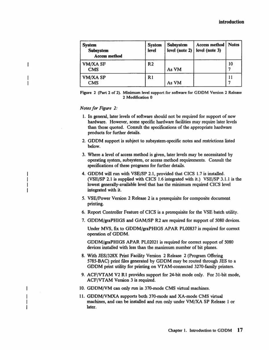
VM/XASF R2 10 CMS AsVM 7
VM/XA SP RI II eMS AsVM 7
Figure 2 (Part 2 of 2). Minimum level support for software for GDDM Version 2 Release 2 Modification 0
Notes for Figure 2:
1. In general, later levels of software should not be required for support of new hardware. However, some specific hardware facilities may require later levels than those quoted. Consult the specifications of the appropriate hardware products for further details.
2. GOOM support is subject to subsystem-specific notes and restrictions listed below.
3. Where a level of access method is given, later levels may be necessitated by operating system, subsystem, or access method requirements. Consult the specifications of these programs for further details.
4. GDDM will run with VSE/SP 2.1, provided that CICS 1.7 is installed. (VSE/SP 2.1 is supplied with CICS 1.6 integrated with it.) VSE/SP 3.1.1 is the lowest generally-available level that has the minimum required CICS level integrated with it.
5. VSE/power Version 2 Release 2 is a prerequisite for composite document printing.
6. Report Controller Feature of CICS is a prerequisite for the VSE batch utility.
7. GDDM/graPHIGS and GAM/SP R2 are required for support of 5080 devices.
Under MVS, fix to GDDM/graPHIGS APAR PL00837 is required for correct operation of GODM.
GODM/graPHIGS APAR PL02021 is required for correct support of 5080 devices installed with less than the maximum number of bit planes.
8. With JES/328X Print Facility Version 2 Release 2 (Program Offering 5785-BAC) print rues generated by GODM may be routed through JES to a GO OM print utility for printing on VT AM-connected 3270-family printers.
9. ACF/VTAM V2 RI provides support for 24-bit mode only. For 31-bit mode, ACF/VTAM Version 3 is required.
10. GODM/VM can only run in 370-mode CMS virtual machines.
11. GDDM/VMXA supports both 370-mode and XA-mode CMS virtual machines, and can be installed and run only under VM/XA SP Release 1 or later.
Chapter 1. Introduction to GDDM 17

introduction
GDDM support on CICS/OS/VS and CICS/DOS/VS GDDM support under CICS/VS is subject to the following restrictions and considerations:
1. No support for 5080 devices.
2. Both the GDDM Composite Document Print Utility (for text, graphics, and image printing on the 3800-3 and 3820) and the creation of ADM IMAGE tiles (page segments and documents) suitable for composed-page printers (such as 4250,3800-3, and 3820) are supported in VSE/Batch only.
3. For correct printing of page segments on 4250 printers, the following CDPF APAR fix is required: PL09163.
4. Operator windowing API functions are supported, but cannot be used to coordinate multiple instances of GDDM.
5. The Interactive Chart Utility (ICU) Data Import function is not supported.
6. The GDDM PC File Transfer and PIF/GGXC File Conversion facilities are not available.
7. Under CICS/OS/VS, a fix to the following CICS APAR is required for correct operation of GDDM:
• PP56636 for correct operation when running on MVS/XA.
8. There is no support for GDDM-GKS or GDDM-REXX.
9. Support for GDDM-PCLK Vl.l, except when the following GDOM processing options are specified:
• BMS coordination mode (BMSCOORD,YES) • Pseudoconversational mode (PSCNVCTL,START/CONTINUE).
GDDM support on IMS/VS Unlike the other subsystems under which GDOM operates, IMSjVS does not provide a direct interface to a terminal. Instead, it uses message queues. This imposes a number of additional restrictions on ODOM's operations on IMSjVS when compared with operations on other subsystems. These restrictions are included below.
1. No support for IPDS printers.
2. No support for 5080 devices.
3. No support for plotters or scanners.
4. No support for VTAM-attached remote non-SNA devices.
5. Support for 3179-0, 3192-G, 3193, 3270-PC/G,/GX, AT/G, AT/GX, and 5550-Family devices with SNA attachment only. They are not supported in BT AM or non-SNA configurations.
6. No support for the direct production of mes containing graphics or images, in formats suitable for use, for example, by composed-page printers (such as 4250, 3820, 3800-3). (Specifically, the GDDM DSOPEN function does not support device-family 4 under IMS/VS.)
18 GDDM Installation and System Management for VM

introduction
However, image-oriented applications can use GDDM image functions to retrieve image (but not graphic) data in such fonnats.
7. No support for operator windowing API functions.
8. No support for interactive graphics and control mode functions.
9. Input is not allowed in alphanumeric fields except to specify the name of the next transaction to be executed.
10. Terminal characteristics cannot be determined at execution but must be obtained from a preallocated table.
11. The Interactive Chart Utility (ICU) can be used interactively only in stand-alone mode. A user transaction can call the ICU to display a chart to the terminal user, but no interaction is possible in this circumstance.
The ICU Data Import function is not supported.
12. The Image Symbol Editor and the Vector Symbol Editor can be used interactively only in stand-alone mode.
13. GDDM-IMD is not directly supported. Run-time mapping is supported. That is, maps generated by GDDM-IMD operating under other subsystems (such as TSO) can be imported using a GDDM-supplied utility, and can be used for output-only operations in transactions.
14. The GDDM PC File Transfer and PIF/GGXC File Conversion facilities are not available.
15. Fix to IMS APAR PP39371 is required for GDDM applications written using PL/I.
16. There is no support for GDDM-GKS, GDDM-IVU, GDDM-REXX, or GDDM-PCLK.
17. There is no support for composite document printing.
GDDM support on MVS/Batch and TSO/Batch TSO Extensions (TSO/E) (5665-285) provides a batch support capability, referred to here as TSO/Batch.
GDDM support under MVS/Batch and TSO/Batch is subject to the following restrictions and considerations:
1. No support for directly-connected 3270 and 5550 devices. (Specifically, the GDDM DSOPEN function does not support device-family-l under MVS/Batch and TSO/Batch, other than for dummy devices.)
GDDM does support the production of queued printer mes for printing through the GDDM TSO Print Utility.
GDDM also supports the direct production of mes containing graphics or images, in fonnats suitable for use, for example, by composed-page printers (such as 4250, 3820, 3800-3).
2. There is no support for GDDM-IVU, GDDM-REXX, or GDDM-PCLK.
Chapter 1. Introduction to GDDM 19

I I' I I
introduction
3. There is no support for composite document printing on 3812, except through queued printer mes for 3812 Model 2 with the 3270 Attachment feature, as described in note 1.
GDDM support on TSO GDDM support under TSO is subject to the following restrictions and considerations:
1. ACF/VTAM V2 Rl and fixes to TSO/VTAM APAR OZ65553 and VTAM APAR OZ65555 are required for extended 3290 function on TSO/VTAM.
2. There is no support for composite document printing on 3812 Model 1. 3812 Model 2 (IPDS) with the 3270 Attachment feature is supported as a directly-attached device for composite document printing and standard GDDM page printing.
3. There is no support for GDDM-REXX.
GDDM support on eMS GDDM support under CMS is subject to the following restrictions and considerations:
1. No support in the CMS DOS environment.
2. Where applicable, the VM/SP High Performance Option (5664-173) reduces the system overhead of the GDDM saved segment.
3. Under VM/SP Release 4 or later, with or without the associated HPO, VM SNA Console Support (VSCS), part ofVTAM Version 3 for VM (5664-280), allows supported SNA, BSC, or local devices in SNA networks to be used as virtual machine consoles.
Consult the specifications of these programs for lists of the supported devices.
Fix to VM/VCNA APAR OX28032 is required for support of 3270 Extended data streams.
4. RSCS Networking Version 2 on VM/SP Release 4 or later, with or without HPO, supports the printing on RSCS-connected 3270-family printers of print data streams generated by GDDM, except for non-IPDS LUI (SCS) printers.
Support of LU-l (SCS) 4224 IPDS printers connected by RSCS requires RSCS 2.2 with the fixes to APARs VM27763 and VM28573. For SNA printing, the fix to APAR VM28392 is also required. The 3812 Model 2 with the 3270 Attachment Feature is not supported by RSCS as an IPDS printer.
5. On VM/SP Release 4, the fix to APAR VM24666 is required to increase the maximum number of members of a TXTLIB.
20 GDDM Installation and System Management for VM

introduction
Programming languages and compilers GDDM function is accessible from application programs that use standard OS/370 call interfaces. This includes application programs written using the programming languages and compilers shown in Figure 3.
Language Compiler Notes
Assembler System/370 Assembler COBOL DOS/VSE
OS/VS ANS V2, V3, V4
FORTRAN G Compiler I H Compiler VSFORTRAN
PL/I DOS Optimizing Compiler OS Optimizing Compiler Checkout Compiler
BASIC IBM BASIC 2 VSAPL Release 4 3,4 APL2 3, 5 REXX VM/SP or VM/XA SP
System Product Interpreter 6
Figure 3. Programming languages and compilers for GDDM
Notes for Figure 3:
1. CICS/VS and IMS/VS do not in general support application programs written in FORTRAN.
GDDM-IMD does not generate application data structures in FORTRAN; this does not preclude use of mapping by FORTRAN applications where progranuners create their own data structures.
2. IBM BASICJVM and IBM BASIC/MVS each provide a CALL statement that can be used to call GDDM.
GDDM·IMD does not generate application data structures in IBM BASIC; this does not preclude use of mapping by IBM BASIC programs where progranuners create their own data structures.
3. The GDDM auxiliary processor (AP126) gives full screen control and allows access by APL programs to the functional capabilities of GDDM Base and GDDM-PGF.
GDDM-IMD does not generate application data structures for VS APL or APL2.
Chapter 1. Introduction to GDDM 21

introduction
4. Fixes to the following VS APL APARs are required for correct operation of GDDM:
• CICS/OS/VS and TSO operation
PP23423 and PP27242 for general GDDM support - PP21528 and PP29200 for correct JCLIN (TSO only) - PP28645 to correct control parameters passed to GDDM (TSO only).
• CICS/DOS/VS and VM/CMS operation
- PP23423 for general GDDM support.
5. Fix to APL2 APAR PP57267 is required for support of GDDM under MVS/XA.
6. The GDDM·REXX licensed program is required for REXX support.
GDDM storage requirements
Servicing
The storage required by GDDM depends on configuration, workload, device type, screen size, PS storage, or graphics storage available at the device, message rates, and the general processing environment. More information is given in "Storage requirements and capacity planning" on page 26.
GDDM is serviced as an IBM licensed program through central service including the IBM support center. The GDDM·PCLK licensed program is serviced through the GDDM Base PCLKF feature.
Security and auditability GDDM relies on the security features available in the subsystem being used. See "Security considerations" on page III for more about these security features.
22 GDDM Installation and System Management for VM
overview
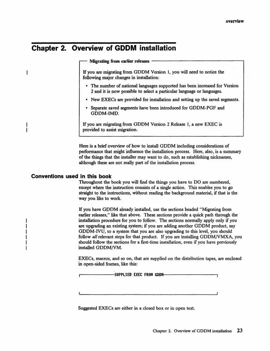
Chapter 2. Overview of GDDM installation
Migrating from earlier releases -------------------,
If you are migrating from GDDM Version 1, you will need to notice the following major changes in installation:
• The number of national languages supported has been increased for Version 2 and it is now possible to select a particular language or languages.
• New EXECs are provided for installation and setting up the saved segments.
• Separate saved segments have been introduced for GDDM-PGF and GDDM-IMD.
If you are migrating from GDDM Version 2 Release 1, a new EXEC is provided to assist migration.
Here is a brief overview of how to install GDDM including considerations of performance that might influence the installation process. Here, also, is a summary of the things that the installer may want to do, such as establishing nicknames, although these are not really part of the installation process.
Conventions used in this book Throughout the book you will fmd the things you have to DO are numbered, except where the instruction consists of a single action. This enables you to go straight to the instructions, without reading the background material, if that is the way you like to work.
If you have GDOM already installed, use the sections headed "Migrating from earlier releases," like that above. These sections provide a quick path through the installation procedure for you to follow. The sections normally apply only if you are upgrading an existing system; if you are adding another GDDM product, say GDDM-IVU, to a system that you are also upgrading to this level, you should follow all relevant steps for that product. If you are installing GDDM/yMXA, you should follow the sections for a first-time installation, even if you have previously installed GDDM/YM.
EXECs, macros, and so on, that are supplied on the distribution tapes, are enclosed in open-sided frames, like this:
.--------:SUPPLIED EXEC FROM GDDM-M---------,
Suggested EXECs are either in a closed box. or in open tex.t.
Chapter 2. Overview of GDDM installation 23

overview
GDDM allows you to specify some information through its defaults mechanism. This is described in detail in Appendix A. Whenever we refer to one of these defaults, we use phrases like "the ADMMDFT NATLANG default."
Other information can be supplied when you open a device, using the processing options associated with a DSOPEN call statement. These are referred to as "the LCLMODE processing option," and so on.
Overview of the installation process When you install GDDM, you use an EXEC supplied on the GDDM tape to load the information from the installation tape onto the system. You then have to make some changes to the VM environment.
The operation consists of the following steps:
Step I Preinstallation planning:
Step 2
Step 3
Step 4
Decide which GDDM products to install. Look in the program directory for possible updates to this manual. Decide on whether to change GDDM's naming conventions. Determine space requirements and plan use of storage. Check for prerequisites, known errors, and so on.
Note the naming defaults to be changed.
Check the installation tapes.
Read in and run the installation EXEC.
a. Do this fIrst for GDDM Base, and then for the National Language feature if you require NL support.
b. Repeat this for the GDDM Base PCLKF feature if you require GDDM-PCLK support.
c. Repeat this for GDDM-PGF if you are installing Presentation Graphics Facility, and then for the GDDM-PGF National Language feature if you require NL support.
d. Repeat this for GDDM-IMD if you are installing Interactive Map Defmition.
e. Repeat this for GDDM-IVU if you are installing that program, and then for the GDDM-IVU National Language feature if you require NL support.
f. Repeat this for GDDM-GKS if you are installing that program, and then for the GDDM-GKS National Language feature if you require NL support.
g. Repeat this for GDDM-REXX if you are installing that program.
h. If you are upgrading your system from Version 2 Release 1 to Version 2 Release 2, use the new migration EXEC.
24 GDDM Installation and System Management for VM

Step 5
Step 6
Step 7
Step 8
overview
i. Repeat this for any other GDDM programs you are installing - check in the documentation for these programs for details.
Tailor the print utility.
Customize GDDM.
Create GDDM Discontiguous Saved Segments.
Review the telecommunications network.
Modify the telecommunications network to ensure that it is adequate for GDDM. (GDDM uses the advanced features of all terminals, printers, and controllers and therefore an existing network frequently has to be respecified before GDDM will work.)
If you are installing GDDM/VM to run on terminals connected to VM/SP through VCNA, you should check the telecommunications access method (VT AM) carefully.
Step 9 Test the installation.
Step 10 Provide suitable EXECs for users.
Step II If necessary, regenerate program modules, incll1ding IBM program products that were generated with Version I Release I or Release 2, such as APL.
Step 12 Inform users of the availability of this release of GDDM and how it can be accessed.
Step 13 Perform postinstallation tasks.
There is a checklist for VM/CMS installation on page 254. You are advised to use it during the installation process for indicating the stage you have reached.
Chapter 2. Overview of GDDM installation 2S

oveniew
Storage requirements and capacity planning For the best performance, and also to reduce virtual storage requirements, GDDM should be installed in saved segments. In Version 2 each GOOM licensed program except GDDM-PCLK has its own segment.
To assist you, this section shows the sizes of GO OM and its associated licensed programs and tells you how to estimate how much of the various system resources your GO OM users require.
Read it to fmd out how to calculate:
• The amount of DASO space required for GODM objects
• The amount of virtual storage required by the various GDOM functions in the different subsystem environments
• How much segment storage to allocate to the GODM host session running in the 3270-PC/G or IGX
• The processor/link/3274 utilizations caused by GDDM for:
Mapped and procedural alphanumerics applications Graphics applications executed on 3179G, 3192G, 3279, 3287, 3270-PC/G or IGX, or the SSSO Image applications.
GDDM objects and use of DASD space GODM users can produce a number of objects (such as saved charts) from application programs that use GDDM or from the GDDM interactive utilities. These objects require direct-access storage, and you may fmd it necessary to produce a system to manage them and to prevent unauthorized access to them.
The objects that may be produced are:
• Graphics data format files (ADMGDF) • Alphanumeric maps in various fonns • Chart data files (AOMCOATA) • Chart defmition files (ADMCDEF) • Chart format ftles (ADMCFORM) • GKS metafdes (ADMGKSM) • Composed-page printer image files (ADMIMAGE) • Image data files (ADMIMG) • Projection definition files (ADMPROJ) • Saved picture files (ADMSA VEl • Symbol sets (ADMSYMBL).
Figure 4 shows their contents, the features of GDOM with which they are associated, how many you may expect your users to produce, and their likely size. Estimates are necessarily approximate. Image projections, image data, and 1/0 operations can vary enormously according to the usage made of GDDM, but the figure should give you a usable estimation.
26 GDDM Installation and System Management for VM

overview
Object type Contents Produced by How many Average size of each object
ICU Chart data Data values for GDDM-PGF Many: 4+400-byte
ICU charts - ICU 20 per user records
Chart format Formats for ICU GDDM-PGF Many: 4+400-byte charts -ICU 15 per user records
Chart data Data definitions for GDDM-PGF Many: 4+400-byte definitions leu charts - ICU 5 per user records
Image Projection GDDM Base & Not many: (2-5)+400-byte Projections Information GDDM-IVU 0.5 per user records (ADMPROJ) programs
Image Data Image Information GDDM Base & Many per (150-350)+ (ADMIMG) GDDM-IVU image user 400-byte
programs records
Symbol sets Image Dot-pattern symbols GDDM Base Not many: 1O+400-byte
for logos and Image 0.5 per user records special characters Symbol
Editor
Vector Line symbols for GDDM-PGF Not many: 20+400-byte logos and special Vector 0.5 per user records characters Symbol
Editor (This applies to user-created symbol sets only)
Saved picture GDDM pictures held GDDM Base Not many: 40+400-byte (ADMSA VE mes) in device-dependent programs 0.5 per user records
data-stream format
Saved GDF GDDM pictures held GDDM Base & Many: 20+400-byte (ADMGDF mes) in device-independent GDDM-GKS 10 per user records
Graphic Data Format programs and ICU
Composed-page GDDM pictures held GDDM Base Not many: 70000 bytes print images in device-dependent programs 0.5 per user (3800-3)
data stream format 200 000 bytes
(4250)
Figure 4 (Part 1 of 2). GDDM object contents and size table
Chapter 2. Overview of GDDM installation 27

overview
Object type Contents Produced by How many Average size of each object
Maps MSL Library of maps in GDDM-IMD Not many: 1 per S+256-byte
a form for editing GDDM-IMD records user + 2 or per map 3 common. Many maps per MSL
Generated Maps in usable form GDDM-IMD Not many: 4+400-byte mapgroups for execution I + per records
mapping program
Generated Data structures GDDM-IMD Not many: SO+SO-byte ADS that correspond to 5 per records
maps mapping program
GKS Metaftle GDDM-GKS S per user 500 400-byte metaftles input/output records
Figure 4 (Part 2 of 2). GDDM object contents and size table
28 GDDM Installation and System Management for VM

overview
Virtual storage requirement of GDDM The GDDM virtual storage requirement comprises two elements:
1. The GDDM code size
2. The dynamic storage requirement for each GDDM user.
The code requirement is dependent upon the functions that your applications use and the devices on which they execute. Device type also influences the user dynamic storage requirement, although picture content is a more critical factor.
You should be aware that there are ways of reducing the code storage requirements by selectively loading parts of GDDM. These ways are discussed under "Petformance background" in Chapter I and under "Tuning and customization by subsystem" in Chapter 2 of the GDDM Performance Guide. Appendix H, "Repackaging for petformance or for differing defaults" on page 197 of this book gives a detailed explanation of how to go about tuning with a more precise sizing of each of the GDDM functional areas.
Figure S gives you approximate minimum sizes for doing various functions under GDDM. It should be treated with some caution as usage varies enormously in different installations. This is particularly true of the User Dynamic Storage requirement. These figures are not guaranteed.
The symbol K, when used in this book, represents the quantity 1024.
GDDM Base Programming 1900K + 60K per additional user
GDDM-PGF Programming 2100K + 80K per additional user
Interactive Chart Utility 2480K + 90K per additional user
GDDM-IMD 1400K + 60K per additional user
Image Symbol Editor 2000K + 60K per additional user
Vector Symbol Editor 2100K + 60K per additional user
GDDM-IVU 1400K + 550K per additional user
GDDM-GKS 2200K + 120K per additional user
GDDM-REXX SOK + other GDDM requirements
Calculating the size you will need To calculate the size of the address space, region, or virtual machine you will need, subtract any items held in shared storage, and add storage for other system requirements.
Method used to arrive at these figures These figures were calculated using the table in the next figure and adding 10%. You should understand that the User Storage requirement is dependent on picture content and can vary considerably. Numbers quoted here are our best guess for typical GDDM usage.
There are various ways of reducing the code requirement. Read the GDDM Performance Guide for more information.
Chapter 2. Overview of GDDM installation 29

overview
GDDM function
a. Base GDDM alphanumerics
b. Base GDDM graphics
c. Base GDDM image
d. Presentation Graphics Routines
e. Interactive Chart Utility
f. Vector Symbol Editor
g. Image Symbol Editor
h. Print Utility
i. Run-time Mapping
j. Interactive Map Defmition
Figure 5. GDDM minimum virtual storage requirement (in bytes)
Figure 6 is a more detailed version of the same infonnation, which you can use to get an estimate of how much storage you are likely to use.
You can reduce your use of virtual storage by putting GDDM in a shared area like a discontiguous saved segment in VM. In this case, the virtual storage requirement of the GDDM code determines the size of the shareable area that GDDM will occupy.
Code size Dynamic storage Dynamic storage Dynamic storage per user per user per user
3279/3287 3179-G,4224, 3193 3270-PC/G,/GX, 5550
880K 20-30K 20-30K 20-30K
770K + a Typically 40-90K 20-60K Not applicable (See note 1) Likely maximum Likely maximum
250-350K 200-300K
8SK + a Typically Typically 50-60K direct 150-200K 150-200K transfer, ISO-200K Likely maximum Likely maximum indirect transfer 300K 300K
220K + a + b 60-100K 40-60K Not applicable (See note 2) (See note 2)
390K + a + b 100-150K 60-80K Not applicable +d (See note 2) (See note 2)
(See note 3)
210K + a + b 40·60K 30-50K Not applicable
130K + a + b 40-60K 40·60K 40-60K
10K + a + b 40·80K 40·80K 40·80K (See note 2) (See note 2) (See note 2)
55K + a 20·40K 20·40K 20·40K
37SK + a + h 40·S0K 40-S0K 40·50K
Figure 6 (Part 1 of 2). GDDM virtual storage requirement (in bytes)
30 GDDM Installation and System Management for YM

overview
GDDM function Code size Dynamic storage Dynamic storage Dynamic storage per user per user per user
3279/3287 3179-G, 4224, 3193 3270-PC/G,/GX, 5550
k. GDDM-IVU 230K + a + c Typically Typically Typically + i 4S0-SS0K 4S0-SS0K 3S0-4S0K
Likely maximum Likely maximum Likely maximum 6S0K 6S0K 600K
1. GDDM-GKS 3S0K + a + b Typically Typically Not applicable graphics lOO-ISOK 80-120K
Likely maximum Likely maximum 300-400K 300-400K
m. GDDM-REXX SOK + other S-lSK + other GDDM requirements (as above) requirements (see above)
Figure 6 (Part 2 of 2). GDDM virtual storage requirement (in bytes)
Example: To calculate the size of Presentation Graphics Routines add:
Presentation Graphics Routines Base GDDM with alphanumerics Base GDDM graphics
(Each item is included once only.)
Notes:
220K (d) + 880K (a) + 770K (b) = 1870K total.
1. 770K is obtained using rust-level packaging stubs. Using second-level packaging stubs to omit unwanted items such as high-resolution printing, can reduce this value. Letting GDDM load dynamically reduces the figure further. For example, for an output-only graphics application on a display terminal the size can can be reduced to around 600K.
The packaging stubs are described in Appendix H, "Repackaging for performance or for differing defaults" on page 197.
2. User storage size depends on picture type; in particular on how many graphics primitives (lines, arcs, and so on) are used, or on the size of the image. Typical values are quoted. Maxima can be much higher: see item (b). In particular. enabling quality defaults in the ICU, enabling user control, and use of step by step charts in the ICU will increase storage requirements.
3. Add 3S0K if leu English-language Help panels are packaged with GDDM.
Chapter 2. Overview of GDDM installation 31

planning
Chapter 3. Preinstallation planning
This chapter contains:
• Information on planning the installation of the GDDM base product plus all the associated products in a single installation process.
• Information to help you to determine what space requirements you need, and also to plan the use of the storage available.
• Information to help you to check on prerequisites and known errors and so on.
• A table in which you should list any GDDM names that you need to change.
You should also look in the Program Directory supplied with the tape to see if there are any updates to this manual.
Chapter 3. Preinstallation planning 33

planning
Step 1: Prelnstallation planning Migrating from earlier releases ------------------.
You will need to perfonn this step.
When you install Version 2 Release 2 of GDDM you should use different DASD storage from the old version. This enables you to use both versions of GDDM during the changeover period. Note also that Version 2 Release 2 requires more storage than previous versions.
You can use the different versions by accessing the disks on which they are stored. If you use a saved segment you can use both versions, because the saved segment names are different for both versions.
If you are upgrading from Version I Release 1 or 2, you need to regenerate any existing CMS modules that use GDDM before they can use the later version. This applies both to application programs and to IBM licensed programs, such as APL.
If you have a GDDM DCSS named ADMASSOO already on the system, refer to "Migration and previously existing DCSSs" on page 72 for guidance on hnw to allow for this.
Deciding which licensed programs you are going to install Before you start to install GDDM, you must decide which associated licensed programs and features you are going to install.
GDDM is structured as a base licensed program, GDDM/VM or GDDM/VMXA, and a number of a~sociated licensed programs. The base licensed program and the associated licensed programs, GDDM-PGF, GDDM-IVU, GDDM-GKS, and GDDM-REXX, each have a no-charge special feature that provides national language support. The structure is:
• GDDMjVM or GDDMjVMXA with
GDDM/YM or GDDMjVMXA National Language feature. GDDM/VM or GDDM/VMXA PCLKF feature.
The GDDM/VM or GDDM/VMXA PCLKF feature gives access to the GDDM-PCLK licensed program (see below).
• GDDM-PGF with
GDDM-PGF National Language feature.
This provides various methods of producing business and other charts (including the leu and the Vector Symbol Editor).
• GDDM-IMD
This lets alphanumeric maps be produced interactively at the terminal. The maps are later used by user-written GDDM programs to determine the format of display screens and printer pages.
34 GDDM Installation and System Management for VM

planning
• GDDM-IVU with
GDDM-IVU National Language feature
This provides facilities for creating and handling image mes, and for viewing or printing the resultant images.
• GDDM-GKS with
GDDM-GKS National Language feature
This is an implementation of the Graphical Kernel System, which is an International Standards Organisation (ISO) graphics standard.
• GDDM-REXX
This lets you write CMS EXECs that use GDDM calls. (The distribution tape contains the files for all supported national languages - there is no separate NL tape.) GDDM/graPHIGS calls are not supported through GDDM-REXX.
• GDDM-PCLK
This lets you use an IBM PC/XT, PC/AT, or Personal System/2 as an output device for GDDM graphics. You can view, print, and plot your pictures using your PC.
Other GDDM-series licensed programs are listed on page 3.
National Language features The national language no-charge special features let you use one or more other national languages in addition to American-English. The GDDM Base NL feature changes the language of messages. The GDDM-PGF NL feature changes the language of the ICU panels and messages. The GDDM-IVU NL feature changes the language of IVU messages and panels. The GDDM-GKS NL feature changes the language of GKS messages.
Each national language feature provides national language files for some or all of the languages listed in Figure 7. Some of these ftles do not contain translations; they have the American-English text in them instead. Figure 7 indicates, for each language, the features for which files are available, and which files contain translated text.
Chapter 3. Preinstallation planning 35

planning
Language Base PGF IVU GKS
Brazilian Y Y Y Y
PRe Chinese (Simplified, DnCS) Y N N N
Danish Y Y Y Y
French Y Y Y Y
German Y Y Y Y
Korean (Hangeul OneS) y Y Y Y
Italian Y Y Y Y
Japanese (Kanji DnCS) y Y Y Y
Norwegian Y Y Y Y
French (Canadian) y N N N
Spanish y Y Y Y
Taiwan Chinese (Traditional, DnCS) y N N N
Swedish Y Y Y Y
Notes:
1. The Y or N (Yes or No) indicates whether a language is available. 2. DBCS is an abbreviation for double-byte character set. 3. PRC is an abbreviation for People's Republic of China.
Figure 7. GDDM nationallanguage feature files
If you are installing the national language features, you must decide which languages you require. You must make your choice before running the installation EXECs.
[fyou are installing GDDM Base NL, and the national language file for another GDDM-series licensed program that you are installing is available, you must also install the national language feature for that program. If you do not do so, results are unpredictable.
[fyou are installing GDDM Base NL, and the nationallanguagefileJor another GDDM-series program that you are installing is NOT available, panels and messages for that program will appear in American-English.
These considerations do not apply to GDDM-REXX; all supported national languages are supplied on the GDDM-REXX installation tape, and you select one of them as the default language during installation.
36 GDDM Installalion and System Management for VM

planning
Preinstallation planning - DASD requirements
Licensed program (or feature)
GDDM Base GDDM-PGF GDDM-IMD GDDM-IVU GDDM-GKS GDDM-REXX Kanji Symbol Sets GDDM Base NL (for each language) GDDM-PGF NL (for each language) GDDM-IVU NL (for each language) GDDM-GKS NL (for each language) GDDM Base PCLKF
The space requirements for GDDM and its features are given in Figure 8. These figures show the space required in terms of DASD cylinders and fixed block architecture (FBA) storage blocks.
3330 3340 3350 3375 3380 FDA cylinders cylinders cylinders cylinders cylinders storage
blocks
52 129 24 36 24 22000 + 15 +36 +7 + 10 +7 +6000 +13 +31 +6 +9 +6 +5200 +3 +7 + 1.2 + 1.8 + 1.2 + 1100 +5 +11 +2 +3 +2 +2000 +3 +7 + 1.3 +2 + 1.2 + 1100 +7 + 12 +3 +4 +3 +2800
+0.5 + 1.2 +0.3 +0.4 +0.2 +200
+4 +9 +2 +3 +2 + 1600
+0.6 + 1.5 +0.3 +0.5 +0.3 +250
+0.1 +0.2 +0.1 +0.1 +0.1 +40 +7 + 12 +3 +4 +3 +2800
Figure 8. Space required for GDDM
Method of space estimation: The figures shown in Figure 8 were measured for the 3380 device and 25% added for service. Figures for other devices were estimated as follows:
Number of 1024-byte blocks per cylinder
3330 3340 3350 3375 3380
209 84 450 300 465
FBA: 400 512-byte blocks = 1 3330 cylinder
Chapter 3. Preinstallation planning 37

planning
Preinstallatlon planning - virtual machine size
Estimated time
The size of virtual machine needed to run GDDM depends very much on which features are installed, which parts of GDDM are being used, and what else is being done on the machine.
Estimated usable sizes and the method used for estimation are shown in "Virtual storage requirement of GDDM" on page 29. You should refer to this section to determine what virtual machine sizes are needed by your users.
Installing GDDM on VM/CMS is a fairly short process, as it consists basically of running a supplied EXEC for each of the GDDM licensed programs.
If you are installing GDDM for the fIrst time, some extra work may be needed in setting up the network because GDDM uses the advanced features of terminals and controllers, and it may well be the fIrst program in your installation that does this.
Instructions for preinstallation planning 1. Decide which GDDM licensed programs and features you are going to install.
2. Ensure that you have the GDDM installation tapes you require.
3. Check if the Program Directories supplied with the tapes contain any corrections to this manual. They are listed under the heading "Updates to GDDM Installation and System Management for VM manual." Make the corrections if necessary .
4. Check with the PSP "bucket" for late information about installation. The name of the PSP bucket is given in the Program Directory. (Ask your IBM representative if you do not understand this.)
5. Check in "Hardware and software supported" on page 5 to ensure that your system is one that GDDM can support. Check that the various components of your system have been brought up to the required levels.
6. Check in "Hardware and software supported" on page 5, and also in the Program Directory, for prerequisite PTFs to the subsystem and apply them if necessary. They are listed under the heading .. Prerequisite System/Subsystem APARs."
7. If you are installing any of the national language features, you should decide which languages you will install.
8. Use Figure 8 on page 37 to determine the space you need for GDDM.
9. Ensure that you have enough space on the disk you intend to use.
38 GDDM Installation and System Management for VM

planning
Step 2: Changing GDDM naming defaults Migrating from earlier releases ----------------,
You should review this step.
You will need to reestablish naming defaults.
By default, GDDM names begin with the letters ADM. Many of these names can be changed if they conflict with your installation standards, but there are good reasons for not changing them. The most important are:
• Some of the names are used in GDDM documentation and changing them will probably lead to confusion.
• Some names need changing in more than one place and changes may lead to inadvertent discrepancies.
Do not change the names unless you have to. If you are going to change the names, you should note down the new names in the table below, so that you can refer back to them at various points in the installation process.
Default name Item named New name (if any)
ADMCDATA Filetype of ICU data ................ ADMCDEF Filetype of ICU data defmition ................. ADMCFORM Filetype of ICU formats ............... ADMCOLn Filetypes of family 4 output (color) ........... ADMOECK Filetype of symbol set decks ................ ADMGDF Filetype of GOF files ............. ADMGGMAr Filetype of generated maps ............. It
AOMGKSM Filetype of GOOM-GKS metaftles ............... AOMIFMT Filetype of GDOM-IMO Import/Export file .. ,. ....... ADM IMAGE Filetype of family 4 output (monochrome) ............. ADMIMG Filetype of image files ................. ADM LIST Filetype of system printer data ............. ADMMSL Filetype of GDDM-IMD MSL ............... ADMPC Filetype of GDDM-PCLK fIles .,. ..... ,. .. ADMPRINT Filetype of print flies .......... ADMPROJ Filetype of image projections ............... ADMSAVE Filetype of saved pictures .............. ADMSYMBL Filetype of symbol sets .............. ADMTRACE Filetype of trace output ................ ADMUTI Filetype of work fIles ............... ADMOOOOI Filename of trace output ............ COpy Filetype of generated ADS (Application
Data Structures of maps) ...............
Figure 9. GDDM names that can be changed if unsuitable
Chapter 3. PreinstaUation planning 39

Part 2. Installation
Part 2. Installation 41

Chapter 4. Installing GDDM from tape
Step 1 was "Preinstallation Planning" in Chapter 3.
Step 2 was "Changing GDDM naming defaults" in Chapter 3.
This chapter contains:
Step 3 - a description of the GDDM installation tapes.
Step 4 - instructions for executing the installation EXECs for
GDDM/VM or GDDM/VMXA GDDM/VM or GDDM/VMXA National Language (NL) GDDM/VM or GDDM/VMXA PCLKF GDDM-PGF GDDM-PGF NL GDDM-IMD GDDM-IVU GDDM-GKS GDDM-REXX.
tapes
Chapter 4. Installing GDDM from tape 43

tapes
Step 3: Checking the tapes
What IBM supplies
Migrating from earlier releases -----------------,
You will need to perform this step.
If you are upgrading from GDDM Version 2 Release I, and you have previously installed GDDM-PGF or GDDM-IMD, you will need to reinstall those programs. If you choose to do this from tape (see page 50). ensure that you have the tapes available.
IBM supplies GDDM/VM or GDDM/VMXA and its associated programs on tape. A separate tape is supplied for each feature and program. The tapes can be supplied in 6250 or 1600 bpi format or formatted for 3480 tape cartridge. All fIles on the tape are in VMFPLC2 DUMP format.
A tape plus a Program Directory is supplied for GDDM/VM or GDDM/VMXA and each of its associated programs.
Licensed program 1600 bpi 6250 bpi 3480 tape (or feature) tape tape cartridge
GDDM/VM 5870 5871 5872
GDDM/VM NL 6870 6871 6872
GDDM/VM PCLKF 6880 6881 6882
GDDM/VMXA 5870 5871 5872
GDDM/VMXA NL 6870 6871 6872
GDDM/VMXA PCLKF 6880 6881 6882
GDDM-PGF 5870 5871 5872
GDDM-PGF NL 6870 6871 6872
GDDM-IMD 5870 5871 5872
GDDM-IVU 5870 5871 5872
GDDM-IVU NL 6870 6871 6872
GDDM-GKS 5870 5871 5872
GDDM-GKS NL 6870 6871 6872
GDDM-REXX 5870 5871 5872
Figure 10. Feature numbers of tapes and Program Directories supplied with GDDM
44 GDDM Installation and System Management for VM

tapes
Use of the Program Directory
Tape contents
The Program Directory contains information about the tape contents, any prerequisite PTFs that should be applied to other parts of the system, and other information. This manual is printed earlier than the Program Directory. You should therefore look in the directory for any last-minute alterations to this manual. Any alterations are listed in the section headed "Updates to Installation and System Management for VM Manual" in the Program Directory.
The program numbers of the tapes for GDDM/VM or GDDM/VMXA and the associated programs on VM are given in Figure 10 on page 44. You should ensure that you have the correct tapes. The next set of figures shows the contents of the various tapes.
File No. Contents
1 15664200 022006 program identifier 15664200 Installation EXEC
2 15664200 MEMO for GDDM/VM, relevant for installation using INSTFPP
3 Sample files
4 Symbol Sets
5 GDDM/VM object code
6 Kanji DBCS
7 Null file
Figure 11. Contents of G DDMJVM installation tape
File No. Contents
I 15664200 022005NL program identifier 15664200 Installation EXEC
2 15664200 MEMONL for GDDM/VM NL, relevant for installation using INSTFPP
3 Null me
4 Null me
5 GDDM/VM NL object code
6 Null me
Figure 12. Contents of GDDMJVM national language installation tape
Chapter 4. Installing GDDM from tape 45

tapes
File No. Contents
1 15664200 022005PC program identifier 15664200 Installation EXEC
2 15664200 MEMOPC for GDDM/VM PCLKF, relevant for installation using INSTFPP
3 Null file
4 Null file
5 GDDM·PCLK objects including national language files
6 Null file
Figure 13. Contents of GDDM/YM PCLKF installation tape
File No. Contents
I 15684007 022006 program identifier 15684007 Installation EXEC
2 15684007 MEMO for GDDM/VMXA, relevant for installation using INSTFPP
3 Sample files
4 Symbol Sets
5 GDDM/VMXA object code
6 Kanji DBCS
7 Null file
Figure 14. Contents ofGDDM/yMXA installation tape
File No. Contents
I 15684007 022005NL program identifier 15684007 Installation EXEC
2 15684007 MEMONL for GDDM/VMXA NL, relevant for installation using INSTFPP
3 Null file
4 Null file
5 GDDM/VMXA NL object code
6 Null file
figure 15. Contents of GDDM/yMXA national language installation tape
46 GDDM Installation and System Management for VM
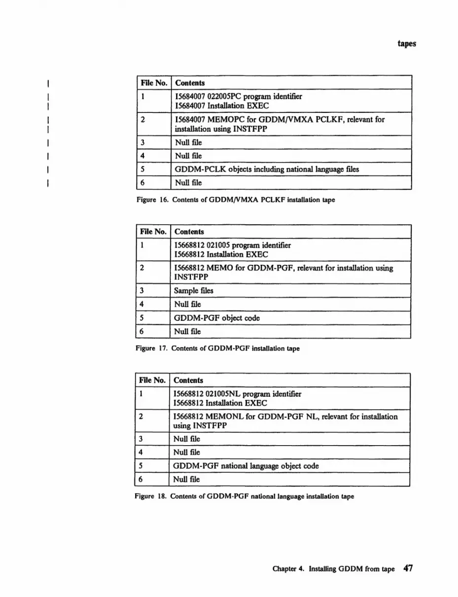
tapes
File No. Contents
1 15684007 022005PC program identifier 15684007 Installation EXEC
2 15684007 MEMOPC for GDDM/VMXA PCLKF, relevant for installation using INSTFPP
3 Null fIle
4 Null fIle
5 GDDM-PCLK objects including national language fIles
6 Null file
Figure 16. Contents of GOOM/VMXA PCLKF installation tape
File No. Contents
1 15668812021005 program identifier 15668812 Installation EXEC
2 15668812 MEMO for GDDM-PGF, relevant for installation using INSTFPP
3 Sample fIles
4 Null file
5 GDDM-PGF object code
6 Null fIle
Figure 17. Contents of GOOM·PGF installation tape
File No. Contents
1 15668812 021005NL program identifier 15668812 Installation EXEC
2 15668812 MEMONL for GDDM-PGF NL, relevant for installation using INSTFPP
3 Null file
4 Null fIle
5 GDDM-PGF national language object code
6 Null fIle
Figure 18. Contents of GOOM·PGF national language installation tape
Chapter 4. Installing GO OM from tape 47

tapes
File No. Contents
1 15668801 021005 program identifier 15668801 Installation EXEC
2 15668801 MEMO for GDDM-IMD, relevant for installation using INSTFPP
3 Sample files
4 Maps and tutorial topic panels
5 GDDM-IMD object code
6 Null file
Figure 19. Contents of GDDM·IMD installation tape
File no. Contents
1 15668723 011005 program identifier 15668723 Installation EXEC
2 15668723 MEMO for GDDM-IVU, relevant for installation using INSTFPP
3 Sample files
4 Menu and help panel maps
5 GDDM-IVU object code
6 Null file
Figure 20. Contents of GDDM-IVU installation tape for VM
File No. Contents
1 15668723 011005NL program identifier 15668723 Installation EXEC
2 15668723 MEMONL for GDDM-IVU NL, relevant for installation using INSTFPP
3 Sample files
4 Menu and help panel maps
5 GDDM-IVU national language object code for all supported languages
6 Null file
Figure 21. Contents of GDDM-IVU NL installation tape for VM
48 GDDM Installation and System Management for VM

tapes
File no. Contents
1 15668802011005 program identifier 15668802 Installation EXEC
2 15668802 MEMO for GDDM-GKS, relevant for installation using INSTFPP
3 Sample files
4 Null file
5 GDDM-GKS object code
6 Null file
Figure 22. Contents ofGDDM-GKS installation tape for VM
File No. Contents
1 15668802 011 005NL program identifier 15668802 Installation EXEC
2 15668802 MEMONL for GDDM-GKS NL, relevant for installation using INSTFPP
3 Null me
4 Null me
5 GDDM-GKS national language object code for all supported languages
6 Null me
Figure 23. Contents of GDDM-GKS NL installation tape for VM
File No. Contents
I 15664336011005 program identifier 15664336 Installation EXEC
2 15664336 MEMO for GDDM-REXX, relevant for installation using INSTFPP
3 Sample and utility files
4 Null me
5 GDDM-REXX object code
6 Null me
Figure 24. Contents of GDDM-REXX installation tape
Chapter 4. Installing GDDM from tape 49

installation EXECs
Step 4: Read in and execute the installation EXEC Migrating from earlier releases ------------------,
You need to perform this step.
If you are upgrading from GDDM Version 2 Release 1, and you use GDDM-PGF or other GDDM series programs, you will need to reinstall them. You can either install these programs from tape, or use the supplied ADMUP220 EXEC to copy the versions previously used onto your new system.
On earlier releases than Version I Release 4, it was possible to merge the TXTLIBs installed for GDDM and PGF. This is no longer possible because of the size of the TXTLIBs.
Note that for Version 2 the names of the installation EXECs have been changed, and that the ADMINST EXECs supplied with Version I no longer exist.
Note that GDDM Version 2 Release 2 is not supported on VM earlier than VM/SP Release 4, or VM/XA SP Release 1.
If you are installing GDDM/VM using the INSTFPP procedure, omit this step and refer to the VM/SP Installation Guide for instructions on how to install an optional licensed program, indexed under "Optional feature program products."
GDDM and its associated licensed programs and features are supplied on separate tapes. Each tape contains the installation EXEC and this is fIrst read in and then used to complete the installation.
It is suggested that if you are installing any of the licensed programs or features associated with GDDM, they should be installed immediately after GDDM Base. Any other tasks should be done after all the features and licensed programs have been installed. If you prefer to install the licensed programs one by one, the only reason why you should not do so, is that it may mean some duplication of subsequent tasks.
50 GDDM Installation and System Management for VM

installation EXECs
Step 4A: Setting up VM to load the installation EXEC To install on VM you load an installation EXEC from the distribution tape into a virtual machine, and then use the EXEC to complete the installation.
The disk on which GDDM is being installed must be linked in read/write mode. None of the disks you access may contain any files of the same name as those on the tape. (If they do, they will be overwritten.)
1. Decide on the size of disk you require for GDDM, using Figure 8 on page 37.
2. Log on to a virtual machine with a large enough disk to hold GDDM, as decided above. You are recommended to use an empty disk. Access this disk using an available filemode. Note the letter you use in Figure 25 on page 52.
Suggested commands are:
LINK gddmdisk xxx yyy W pword
where LI NK ••• W means link to installation disk in read/write mode gddmdi sk xxx identifies the disk to be used for the installation yyy is the virtual address to be used in your virtual machine pword is the write password; if your installation uses the password
suppression facility, the password cannot be entered on the LINK command. (See the manuals VM/SP CP Command Reference for General Users and VM/XA SP CP Command Reference for details.)
ACCESS yyy filemode (access installation disk)
3. Fill in the details of your installation in Figure 25 on page 52 so that you have a checklist to answer the prompts in the installation EXECs. See "National Language features" on page 35 for guidance about your choice of national languages.
Note: Some releases of CMS restrict the number of members of a TXTLIB. This may limit the number of languages you can install. (See the manuals VM/SP CMS Command and Macro Reference and VM/XA SP eMS Command Reference for details.)
4. Ensure that you do not have any other disks accessed containing previously installed releases of GDDM. If you have, release them.
Chapter 4. Installing GDDM from tape 51

installation EXECs
INSTALLATION EXEC CHECKLIST
Which filemode do you intend to use
Do you wish to install GDDM/VM or GODM/VMXA (YIN)
00 you wish to install the Kanji double-byte character sets? (These are for Japanese installations) (YIN)
Do you wish to install GODM/VM NL or GDOM/VMXA NL ? (No need if your language is American-English) (YIN)
Which National Languages do you want: B = Brazilian C = PRC Chinese (Simplified) o = Danish F = French G = German H = Korean (Hangeul) I = Ital ian
K = Japanese (Kanji) N = Norwegian Q = French (Canadian) S = Spanish T = Taiwan Chinese (Traditional) V = Swedish
Enter the code letter(s) for the language(s) you want
Do you wish to install GOOM-PGF (YIN)
Do you wish to install GOOM-PGF NL (see Note) (YIN)
00 you wish to install GDOM-IMD (YIN)
00 you wish to install GOOM-IVU (YIN)
00 you wish to install GDDM-IVU NL (see Note) (YIN)
Do you wish to install GDDM-GKS (YIN)
00 you wish to install GDDM-GKS NL (see Note) (YIN)
DO you wish to install GDDM-REXX (YIN)
What default language do you want for GDDl4-REXX ? (A = U.S. English t B = Brazilian t H = Hangeul t
I = Italian t K = Kanji t S = Spanish)
Note: If national language features are being installed, see "National Language features" on page 35 for considerations of appropriate choices.
Figure 25. Checklist for the GDDM installation EXECs. Write your answers to these questions; you will be asked for them by the installation EXEC.
52 GDDM Installation and System Management for VM

installation EXECs
Step 4B: Installing GDDM licensed ~rograms Migrating from earlier releases ------------------,
You will need to perfonn this step.
If you are upgrading from GDDM Version 2 Release 1 and you already have GDDM-PGF or GDDM-IMD on your system, you will need to reinstall them. There are two ways of doing this (do not do it both ways):
1. Reinstall them from tape, as if for the fIrSt time; you should follow this step for all the relevant programs.
2. Use the ADMUP220 EXEC, to reinstall the versions previously used; in this case, follow this step for GDDM/VM and GDDM/VM NL only, and use Step 4C for the other programs.
The procedure for each GDDM licensed program is essentially the same; the only changes are the names of objects loaded and EXECs used. The following instructions show how GDDM/VM or GDDM/VMXA is installed; Figure 26 shows the names for each of the programs.
1. Mount the distribution tape on virtual tape unit 181 (as described in the VM/SP Operator's Guide).
2. Enter the following commands at the tenninal:
When installing from tape:
VMFPLC2 REW VMFPLC2 MODESET (9TRACK DEN nnnn
(where nnnn is 1609 for a 1600 bpi tape or 6250 for a 6250 bpi tape) VMFPLC2 LOAD * * filemode
(where fi 1 emode is the mode of the disk you are installing on)
When installing from a 3480 tape cartridge:
VMFPLC2 REW VMFPLC2 MODESET (18TRACK DEN 38K VMFPLC2 LOAD * * fflemode
(where fi 1 emode is the mode of the disk you are installing on)
3. Execute the installation EXEC with the appropriate command from Figure 26, for example, 156642e9 for GDDM/VM.
4. Use the infonnation in Figure 25 on page 52 to answer the prompts given by the EXEC. The EXEC also issues infonnational messages. You may receive a nonzero return code (for example 111 or 777); refer to the comments at the start of the EXEC for an explanation.
Note that the installation EXEC loads a MACLIB called ADMLIB that contains sample call declarations. Your installation may fmd it necessary to rename this library or to merge it with other macro libraries. GDDM-PGF and other GDDM product installations, however, add further entries and, if you are also installing other GDDM products, you should not change the name until after installing these licensed programs.
Chapter 4. Installing GDDM from tape 53
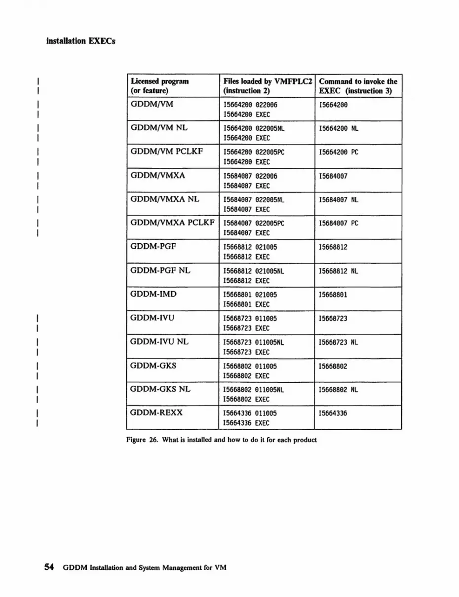
Installation EXECs
Licensed program Files loaded by VMFPLC1 Command to invoke the (or feature) (instruction 1) EXEC (instruction 3)
GDDM/VM 15664299 922996 15664299 15664299 EXEC
GDDM/VM NL 15664299 922995NL 15664299 NL 15664299 EXEC
GDDM/VM PCLKF 15664209 022995PC 15664209 PC 15664209 EXEC
GDDM/VMXA 15684997 922996 15684997 15684997 EXEC
GDDM/VMXA NL 15684997 922995NL 15684997 NL 15684997 EXEC
GDDM/VMXA PCLKF 15684997 922995PC 15684997 PC 15684997 EXEC
GDDM-PGF 156688i2 921995 15668812 15668812 EXEC
GDDM-PGFNL 15668812 921995NL 15668812 NL 15668812 EXEC
GDDM-IMD 15668891 921995 15668891 15668891 EXEC
GDDM-IVU 15668723 9U995 15668723 15668723 EXEC
GDDM-IVUNL 15668723 911995NL 15668723 NL 15668723 EXEC
GDDM-GKS 15668802 9Ue95 15668892 15668892 EXEC
GDDM-GKS NL 15668892 911e95NL 15668892 NL 15668892 EXEC
GDDM-REXX 15664336 ElllElEl5 15664336 15664336 EXEC
Figure 26. What is installed and how to do it for each product
54 GDDM Installation and System Management for VM

installation EXECs
Step 4C: Upgrading associated GDDM programs to 2.2 level Migrating from earlier releases ------------------,
If you are upgrading from GDDM Version 1, do not perform this step.
You should perform this step if you have previously installed GDDM Version 2 Release 1, and you have GDDM-PGF (including its NL feature) or other GDDM programs at that level.
If you reinstalled the associated programs from tape in Step 4B, do not perform this step.
1. Access, in read/write mode, the disk on which you have installed GDDM/VM Version 2 Release 2.
2. Access, in read-only mode, the disk on which you previously installed GDDM Version 2 Release 1 Modification 0 or 1.
3. Note the ftlemodes of these disks.
4. Enter the command AOMUP220. You will be prompted for the two ftlemodes, and you will be asked whether you want to reinstall aU programs previously installed, or to reinstall them selectively.
Step 4D: Installing other GDDM programs If you are installing any other GDDM programs, this is probably the best point to read in and execute their installation EXECs. Check in the documentation for these programs for the detailed procedures to foUow, including any special considerations.
Chapter 4. Installing GDDM from tape 55

printing
Chapter 5. steps after using the installation EXECs
Step 1 was "Preinstallation planning" in Chapter 3.
Step 2 was "Changing GDDM naming defaults" in Chapter 3.
Step 3 was "Checking the tapes" in Chapter 4.
Step 4 was "Read in and execute the installation EXEC" in Chapter 4.
Step 5: Tailor the print utility Migrating from earlier releases ------------------,
Follow this step to tailor the print utility. If you are upgrading from GDDM Version 2 Release I, there are no special considerations and you may omit this step, unless you plan to use different defaults.
On VM/CMS, in the absence of any of the options described below, a request from a GDDM application program or from the ICU for printing on a 3270-family printer, causes a print me to be created on the user's A-disk. The user then has to invoke the GDDM print utility (ADMOPUV) separately, to cause the me to be printed on a specified directly attached printer.
Various options provided in GDDM Version 2 enable you to modify this processing. These options are described below.
Automatic Invocation of the print utility A DSOPEN processing option, INVKOPUV, can be specified to cause GDDM print utility processing to be invoked automatically whenever a print file is created.
If this option is specified, a temporary print ftle is createdj the name specified by the application program or the leu user is taken to identify a printer on which the ftle should be printed. GDDM processing equivalent to that performed by ADMOPUV is then done automatically and immediately (in the user's virtual machine), to cause the print me to be printed on the named printer. After that, the temporary file is deleted.
A full description of the INVKOPUV processing option appears in the GDDM Base Programming Reference manual.
lbe option can be applied to your installation by adding suitable nickname statements to the GDDM external defaults module, as described in "Step 6: Customize GDDM" on page 61, and in Appendix A, "GDDM defaults and nicknames" on page 115. The following nickname statement would apply the option for a printer attached as 062:
[label] ADMMNICK FAM=2,NAME=062,PROCOPT=((INVKOPUV,YES))
Chapter 5. Steps after using the installation EXECs 57

printing
and this statement would apply the option for all 3270-family printers:
[label] ADMMNICK FAM=2,PROCOPT=((INVKOPUV,YES))
Sending output to another virtual machine A special printer address of PUNCH is recognized by the GDDM print utility (ADMOPUV) as indicating that the printer data stream should be sent to the virtual punch instead of to a real 3270 printer.
If you use RSCS to transmit the data, and you issue suitable CP SPOOL and CP TAG commands frrst, the command
AOMOPUV filename ON PUNCH (DEV devtok
can be used to direct a printer data stream to a suitable virtual machine capable of printing such data streams. In the above command, devtok is a device token that provides GDDM with a description of the intended printer device. (See Appendix C, "Device characteristics tokens" on page 153.)
The device token, CP SPOOL, and CP TAG commands, and the printer address of PUNCH can be built into your installation by adding suitable nickname statements to the GDDM external defaults module (see "Step 6: Customize GDDM" on page 61 and Appendix A, "GDDM defaults and nicknames" on page 115).
For example, if an installation is using RSCS, the following nickname statement:
[label] AOMMNICK FAM=1,NAME=3287Na3,TONAME=PUNCH,DEVTOK=L87, X PROCOPT=((CPSPOOL,TO,RSCS), X (CPTAG,CHICAGO,3287Na3,50,PRT=GRAF))
would cause the command:
AOMOPUV filename ON 3287N03
to punch a 3287 data stream to RSCS node id CHICAGO with a tag of '3287N03 PRT=GRAF' applied, and with a transmission priority of 50.
This nickname could successfully be used together with an INVKOPUV nickname described earlier.
Transmitting print flies to a disconnected virtual machine If your installation does not have a suitable virtual machine capable of printing data streams generated by the PUNCH facility described above, you can take advantage of a separate facility for transmitting the print mes, when created, to a disconnected virtual machine for printing.
In this mode, you would need to attach your printers to the disconnected machine, and then cause the virtual machine to invoke the GDDM print utility as required. This would enable you to centralize printing of GDDM print mes, and also to avoid your users having to wait while the print mes were being processed.
To transmit the print mes to a disconnected virtual machine, you should make an EXEC, ADMQPOST, available to your users, to be invoked automatically by GDDM whenever a print me is created. Figure 27 on page 59 lists a sample
58 GDDM InstaUation and System Management for VM

printing
ADMQPOST EXEC. Note that GDDM enters CMS subset mode to invoke the EXEC; this will limit the range of functions that you can perform.
/********************************************/ /* ILLUSTRATIVE ADMQPOST EXEC */ /* */ /* THIS EXEC IS EXECUTED WHEN A PRINT FILE */ /* IS CLOSED. * / /* */ /* PARAMETERS - FILENAME FILETYPE FILEMODE */ /* OF PRINT FILE CREATED. */ /* */ /* THIS EXEC ASSUMES A CONVENTION THAT THE */ /* FILENAME IS THE NAME OF A DISCONNECTED */ /* VIRTUAL MACHINE THAT WILL PRINT THE */ /* FILE. */ /********************************************/ parse arg filename filetype filemode CP SPOOL PUN CLOSE NOHOLD NOCONT CP SPOOL PUN TO filename PUNCH filename filetype filemode (NOHEADER ERASE filename filetype filemode CP SPOOL PUN CLOSE
Figure 27. Suggested ADMQPOST EXEC
You will also need to provide an EXEC to control the operation of the discoIUlected virtual machine. A sample EXEC is shown in Figure 28 on page 60. (Note that the EXEC listed fulfills only the basic requirements and you may well want to produce something more sophisticated.)
If your EXECs require your users to name their print ftles in any special way (as do the sample EXECs shown) remember to inform your users of these requirements.
Instructions for tailoring the print utility 1. Read the background information above and see if you want to create any
nicknames or an ADMQPOST EXEC.
2. Write down any nicknames you may want in Figure 29 on page 62.
3. If you want to create EXECs to let you print on a discoIUlected virtual machine, use the ones shown in this section as models.
4. If your EXECs require the user to name the print ftle in a special way, remember to inform users of this fact.
Chapter 5. Steps after using the installation EXECs 59

printing
)
********************************************** ** ILLUSTRATIVE DISCONNECTED VIRTUAL ** ** MACHINE CONTROL EXEC FOR PRINTING ** ** GDDM PRINT FILES. ** ** ** ** THIS EXEC IS EXECUTED CONTINUOUSLY ** ** IN A DISCONNECTED MACHINE. ** ********************************************** &CONTROL OFF CP SPOOL RDR NOHOLD NOCONT * &PRTER = &1 &SLEEP = &2 &IF &INDEX = 2 &GOTO -READ &BEGTYPE
TWO PARAMETERS REQUIRED 1. THE NAME OF THE PRINTER 2. THE NUMBER OF SECONDS TO WAIT BETWEEN
POLLS OF THE READER &END &EXIT 4 * ********************************************** ** CHECK THE READER ** ********************************************** * -READ READCARD PRTFILE AOMPRINT A &IF &RETCODE ~= e &GOTO -SLEEP * ********************************************** ** PRINT THE FILE ** ********************************************** * AOMOPUV PRTFILE ON &PRTER &IF &RETCODE ~ e &TYPE PRINT FAILED. RC= &RETCODE &IF &RETCOOE = e ERASE PRTFILE ADMPRINT A * ********************************************** ** WAIT FOR SOMETHING TO DO ** ********************************************** * -SLEEP CP SLEEP &SLEEP SEC &GOTO -READ
Figure 28. Suggested EXEC to print from a disconnected virtual machine. This EXEC is designed to run on a basic VM system. If you have the WAKEUP module, it is more efficient than using the SLEEP command. There may also be other changes that you may want to make.
60 GDDM Installation and System Management for VM
customizing
Step 6: Customize GDDM Migrating from earlier releases ------------------,
If you are migrating from a version of GDDM earlier than Version 1 Release 4, there are additional methods of changing the defaults. In addition, you may like to use the functions for defIning nicknames.
If you are upgrading from GDDM Version 1 Release 4 or Version 2 Release 1, you will need to follow this step to reestablish any defaults you need.
Version 2 Release 2 of GDDM introduces support for "country-extended code pages," which associate GDDM objects (symbol sets, charts, and so on) with the environment in which they are used. An object that is tagged with a code page does not need any special action to make it usable in a different linguistic environment, provided that GDDM is suitably set up. (See "Country-extended code pages" on page 66.) You should consider the advantages of using this new function in your installation.
You can tailor the following elements of GDDM during installation:
• Naming conventions. • Buffer sizes, paging, and other performance factors. • Time, date, and number punctuation conventions. • Language of messages and language of ICU panels. (This is only relevant if you
have the GDDM Base and GDDM-PGF National Language features.) • Debugging factors (error thresholds and trace values). • Nicknames. • Character code translation (for example, for Katakana terminals). • APL and printing. • 4250 code page names. • Country-extended code pages. • GKS workstation types.
All items except the Katakana character code translation are GDDM defaults, and can be specifted in the external defaults module. Translation of Katakana characters is controlled by the alphanumeric defaults module, ADMDATRN, or by defaults.
A full discussion of the GDDM defaults is given in Appendix A, "GDDM defaults and nicknames" on page 115 and Appendix H, "Character code interpretation" on page 133. A short discussion is given below to give you a quick idea of what you can change. Figure 29 on page 62 is provided to note down any changes that you want to make.
Note that you can change defaults later if you prefer. (See "Replacing GDDM modules after installation" on page 105 for details.)
Chapter 5. Steps after using the installation EXECs 61

customizing
Checklist of items to change in defaults module
As you go through other steps you may decide to make changes that involve changing the defaults module. This space is provided so that you can note the changes and implement them all at once.
Figure 29. Checklist of items to change in defaults module
62 GDDM Installation and System Management for VM

customizing
Naming conventions You should have already decided whether to change any names, because some names, if they are to be changed, need changing in several places.
Look back at Figure 9 on page 39 to see what you decided.
If you need to make changes, you can fmd the ADMMDFT keywords to use in Figure 47 on page 117.
Buffer sizes, paging, and other performance factors These items are discussed in broader terms in the GDDM Performance Guide under "Performance background" in Chapter 1 and under "Tuning and customization by subsystem" in Chapter 2.
The user default specifications are ADMMDFT IOBFSZ (transmission buffer size) and ADMMDFT SAVBFSZ (FSSAVE buffer size).
The value specified for IOBFSZ must not be greater than the RSCS buffer size if you use RSCS with 3287 or 4224 printers.
Time, date, and number punctuation conventions GDDM gives you the choice of a number of conventions that can be used for these items. (For example, whether the date is presented in the form 25/12/86 or 12/25/86 for 25 December 1986.) The user default specifications are:
Time ADMMDFT TIMEFRM=l (HH:MM AM or PM) Date ADMMDFT DATEFRM=4 (DO MMM YYYY) Number punctuation ADMMDFT NUMBFRM=l (NN,NNN,NNN.NNN)
Language of messages and leu panels
Debugging factors
Nicknames
If you have installed the National Language features, you must specify the language you require by using the ADMMDFT NAT LANG default.
The main use of changing error threshold or trace defaults is to help find any errors in the interactive utilities as described in the GDDM Diagnosis and Problem Determination Guide.
The standard defaults should not normally be changed.
Nicknames are a type of user default specification that lets you defme all aspects of a device in advance of using a DSOPEN statement, and then reference that device on DSOPEN by using the nickname. A full discussion of nicknames is given in Appendix A, "GDDM defaults and nicknames" on page lIS.
The next few paragraphs describe some typical uses for nicknames.
User control enables users to pan and zoom on their pictures, and also lets them print or plot their screen contents. User control can be turned off by use of nicknames. (It is on by default.) Note that, if you tum it off, you will not be able to test the print utility in the way suggested in the next step. Instead, if you are not
Chapter S. Steps afier using the installation EXECs 63

customizing
able to use the ICU, you will have to compile and link-edit one of the sample programs.
When printing output from the ICU, if you intend to use any printer other than a 3287 with standard paper you must set up a nicknames fde containing the correct device token for the printer. Device tokens are supplied by GDDM to enable you to use most devices. There are instructions on how to create your own device tokens if you need them. (See Appendix C, "Device characteristics tokens" on page 153.)
Nicknames for plotters: Nicknames are particularly useful with local plotters. Plotters attached to the IEEE-488 port of various work stations can be driven by GDDM, and are referenced using a composite name of the form:
(session-device-address,auxiliary-plotter-name)
For example, (* ,AOMPLOT) would reference the first customized plotter (ADMPLOT) on the user's terminal (*). A set of nickname examples is described in Appendix A, "GDDM defaults and nicknames" on page liS.
By using nicknames (as described in Appendix A) it is possible to transform references to a queued printer name from an application or from the ICU, and references to an attached printer name from the GDDM print utility, into references to a directly attached plotter. Such nicknames can be built into your installation by adding suitable nickname statements to the GDDM external defaults module.
For example, the nickname statement
[label] AOMMNICK FAM=2,NAME=*PLOT,TOFAM=1,TONAME=(*,AOMPLOT)
would cause a request from an ICU user for printing on device *PLOT to be performed immediately on an attached plotter without going through GDDM print utility processing. (Note, however, that this will inhibit multiple-copy requests.)
The statement
[label] AOMMNICK FAM=l,NAME=*PLOT,TOFAM=l,TONAME=(*,AOMPLOT)
would cause the command AOMOPUV fi 1 ename ON *PLOT to plot the identified fde on an attached plotter.
The following set of nicknames combines a number of the available options to permit a directly-attached plotter to be driven indirectly by means of GDDM print utility processing from the ICU. All the user need do is enter the name *PLOT on the ICU Print Panel.
[label] AOMMNICK FAM=2,NAME=*PLOT,DEVTOK=L7371, PROCOPT=«INVKOPUV,YES»
[label] AOMMNICK FAM=l,NAME=*PLOT,TONAME=(*,AOMPLOT)
x
Nicknames for printing and controlling work stations: If you use RSCS to send fdes for printing on an MVS system, you may find these nicknames useful as models:
64 GDDM Installation and System Management for VM

[label) ADMMNICK NA~IE=RSCS3287 ,FAM=2,DEVTOK=L87, PROCOPT=«INVKOPUV,YES»
[1 abel] ADMMNI CK NA~'E=RSCS3287, FAM=1, TONAME=PUNCH, DEVTOK=L87 , PROCOPT=«CPSPOOL,TO,RSCSV2,FORM,STD), (CPTAG,V3287A,SYSTEM,S0,PRT=GRAF»
[label] ADMMNICK NAME=RSCS4224,FAM=2,DEVTOK=X4224SE, PROCOPT=«INVKOPUV,YES»
[label] ADMMNICK NAME=RSCS4224,FAM=l,TONAME=PUNCH,DEVTOK=X4224SE, PROCOPT=«CPSPOOL,TO,RSCSV2,FORM,STD), (CPTAG,LAF2A20,SYSTEM,50,PRT=GRAF»
customizing
Some devices, such as the 3179-G, 3270-PC/G and 3270'PCfGX, and 5550, have predetennined symbol sets stored within their hardware. With these devices, GDDM uses the hardware symbol sets in preference to its own. If, however, you want to change the symbol sets that GDDM uses, you must ftrst change the GDDM default as shown in "Changing the default symbol sets or making another set the default" on page 182, and then load them using the LOADDSYM DSOPEN processing option, thus:
[label] ADMMNICK PROCOPT=«LOADDSYM,YES»
PA3 is the default key used by GDDM for switching to user control mode (which allows the user to pan and zoom pictures, copy screen contents to a printer, do windowing, and so on). Some terminals do not have a PA3 key, so you can set a different one as the default using the CTLKEY processing option. For example, to set the control key to PF3, use:
[label] ADMMNICK PROCOPT=«CTLKEY,l,3»
There is a processing option, PCLK, described in the GDDM·PCLK Guide. If you are installing GDDM Base PCLKF, you should consider setting the PCLK processing option to YES; if you do not, your users will have to set it themselves. If you set this processing option, it will cause a prompt to appear when GDDM cannot detcnnine whether a display device can show graphics. So it affects use with nongraphics displays, such as 3278s. Use:
[label] ADMMNICK PROCOPT=«PCLK,YES»
Nicknames for GDDM·GKS: GDDM·GKS applications use connection identifier numbers when referring to particular workstations. For the workstation types 6 through 13, GDDM-GKS uses a nickname, corresponding to the connection identifier, to access the device. Normally, the nicknames to be used are specified in an external defaults file provided by the user; however, you can use the external defaults module to provide nicknames for local printers, plotters, and other devices.
Each nickname to be provided for GDDM·GKS applications must be defmcd with the options FAM=l and NAME=GK\dSnnnn, where nnnn is a number in the range 0000 through 9999. The number given by nnnn is the connection identifier that GDDM·GKS applications will use to refer to the device. For example, if applications will use connection identifter 7 to open attached plotters, you could provide the following nickname:
[label] ADMMNICK FAM=l,NAME=GKWS0007,TONAME=(*,ADMPLOT)
Chapter 5. Steps after using the installation EXECs 65 .

customizing
Country-extended code pages
APL and printing
GDDM Version 2 Release 2 now adds to most GDDM objects an indication of their linguistic origin. This indication allows characters that are specific to a national language to be converted into the most appropriate form for any other national environment in which they are used.
You should consider setting up an installation-wide specification of the linguistic environment so that your application programs can use and produce objects that can be processed in other environments. H you do this, GDDM will automatically handle much of the language-dependent processing of data, and you can avoid much of the lengthy customization that was previously needed to achieve this support. Set up the defaults:
ADMMDFT INSCPG=nnnnn.APPCPG=nnnnn
where nnnnn is one of the "country-extended code-page" tags defIned on page 120.
H you want to inhibit the keyboard input of extended CECP characters (for devices that support this), specify the ADMMDFT CECPINP default.
In addition, you should consider tagging existing GDDM objects on your system, as described in "Managing GDDM objects" on page 106.
If you are using APL with your printers, you may have to specify the ADMMDFT CMSAPLF default to indicate the APL character set they use. (See Appendix G, "APL and GDDM" on page 195 if you think you need to know more.)
Character code translation If you are using Katakana, you may need to change the values in ADMDATRN, the alphanumeric defaults module. See Appendix B, "Character code interpretation" on page 133 for details. Alternatively, you can specify that Katakana is the default using the new country-extended code page support, new in Version 2 Release 2. Specify:
ADMMDFT APPCPG=ee2ge,INSCPG=ee2ge
Otherwise, the standard defaults should not normally be changed.
4250 code-page names If your installation uses 4250 composed-page printers and the IBM Typographic Fonts for the IBM 4250 Printer (initial program numbers 577I-AAA to 577l-AAW plus later additions), you can use the ADMMDFT CPN4250 default to change the system default code page name. This identifIes a default national language (or APL or mathematical symbols) for your 4250 symbol sets.
66 GDDM Installation and System Management for VM

customizing
GDDM-GKS workstation types GDDM-GKS applications use workstation type numbers when referring to the characteristics of workstations. GDDM-GKS allows users to derme the type of physical devices they intend to use when GKS workstation type numbers 6 through 13 are given. Normally, the workstation types are specified in an external defaults ftle provided by the user; however, you can use the external default GKSWS to provide default values.
The default values are specified by the following external default:
ADMMDFT GKSWS=(dtl,dt2, •.. ,dt8)
where dtl through dt8 are device characteristic tokens for family-l and family-2 graphics devices. The device tokens given by dtl through dt8 indicate the device characteristics associated with workstation type numbers 6 through 13 respectively. Each device token is optional and can be omitted. You must ensure that the device tokens you specify are held in the GDDM table ADMLSYSl.
GDDM-IVU and Image devices In the GDDM Image View Utility manual, users are instructed to list their image files by entering CMS subset mode; you should therefore check that your GDDM Base installation defaults allow this. The processing option that controls access to subset mode is CMSINTRP, and you should ensure that this is set to PAIPA2 (the default) or PA2 by a default specification such as:
ADMMDFT PROCOPT=((CMSINTRP,PAIPA2»
You should consider increasing the default value that controls the buffer size for input/output transmissions, if you are using a 3117 or 3118 scanner. A value of 3000 is recommended; the required default specification is:
ADMMDFT IOBFSZ=3000
You should consider increasing the default value that controls the mapgroup storage threshold, to improve the performance of your system. It has the form:
ADMMOFT MAPGSTG=n
where n should be 20000 if you are not planning to use the help panels, or 70000 if you are.
IBM 3193 Display: For this type of terminal, it is recommended that the WINDOW and CTLMODE processing options are left at their default values of NO and + respectively. Other values will prevent GDDM-IVU using real partitions, which is detrimental to performance.
IBM 3270-PC/G and IGX work stations: It is recommended that these terminals are used with the GDDM SEGSTORE processing option set to NO to minimize response times. This can be done by the following nickname statement:
[label] ADMMNICK FAt4=1,PROCOPT=((SEGSTORE,NO»
Chapter 5. Steps after using the installation EXECs 67

customizing
Double-byte character set (DBCS) defaults If the Kanji symbol set has been installed, or if someone has sent you a DDCS ftle, you must set the ADMMDFT MIXSOSI default to YES to enable mixed strings of one byte and DDCS (2-byte) characters to be used. You will need to do this if you are using GDDM utility programs like the ICU on a device with Kanji.
The ADMMDFT DDCSLNG= K default dermes the default DDCS language for both image and vector sets as Kanji. If another Asian language is to be supported, this must be defined to GDDM by means of DDCSLNG, and the character used (for example, H for Hangeul) must be included in the symbol-set name, as the K is for Kanji symbol sets.
If you want to emulate SO/SI characters on a device that does not support them, specify the ADMMDFT SOSIEMC default.
Note that if a chart is created on the ICU with MIXSOSI enabled, it will not display for a user without MIXSOSI enabled, even if it contains no double-byte characters.
The DDCSDFT default controls GDDM support for error message destinations in a DDCS environment. The ADMUDBCS EXEC is supplied to control the setting of this default.
EXEC AOMUDBCS {GOOMINOIVES}
This EXEC updates or creates a PROFILE ADMDEFS A file. If the fJ.1e does not exist, one is created with a single record:
DEFAULT DBSCDFT=option
If the fJ.1e exists, this record is added at the end. If the fJ.1e already contains a fmal record of this form, that record is replaced; this means that the EXEC may be used more than once with different options, without causing the fJ.1e to increase in size.
Changing the default vector symbol set to a language other than American-English Do not follow this section if you plan to use the support for country-extended code pages, that is new in Version 2 Release 2.
GDDM provides the following versions of the default vector symbol set:
Bra7..ilian Danish U.S.-English French German Italian I
Japanese (Katakana) Norwegian Spanish Swedish.
If your installation uses one of these languages, you can change the default set to the language you require. Instructions are given in Appendix D, "GDDM default symbol sets" on page 179.
68 GDDM Installation and System Management for VM

customizing
Differing default requirements It may be that your installation requires different default modules for different applications. (An installation where both French and English are used is an example.) This may have to be done by having two different default modules and linking them with the applications. Methods of doing this are discussed in Appendix H, "Repackaging for performance or for differing defaults" on page 197.
Note, however, that many GDDM defaults can be specified in an application program using GDDM call statements, and it may not be necessary to create different defaults modules for this purpose. See the section on defaults in the GDDM Base Programming Reference manual for details.
Instructions for changing the defaults Do not alter the sample library versions. Take a copy to alter and leave the sample library entries intact because you may need to apply service to them.
1. After reading the discussions above, and any other relevant material, decide if you are going to change any default values.
2. Make a list of the user default specifications that you want to specify in the external defaults module, ADMADFV. Use Figure 29 on page 62 for this. This list should include the specifications for the defaults and the nicknames that you want.
3. Log on to a virtual machine and access the source me (or one of the mes) you intend to change.
ADMADFV ASSEMBLE - external defaults module ADMDATRN ASSEMBLE - alphanumerics defaults module.
4. Make the changes using a suitable editor.
S. Assemble the new modules with the commands:
GLOBAL MACLIB ADMLIB ASSEMBLE ADMADFV ASSEMBLE ADMDATRN
to access the GDDM macros external defaults alphanumeric defaults
6. Place the reassembled modules in the ADMGLIB TXTLIB. The commands are:
TXTLIB DEL ADMGLIB ADMADFV external defaults TXTLIB ADD ADMGLIB ADMADFV TXTLIB DEL ADMGLIB ADMDATRN alphanumeric defaults TXTLIB ADD ADMGLIB ADMDATRN
7. If you want a non-American-English default vector symbol set, change it as discussed in Appendix D, "GDDM default symbol sets" on page 179.
8. If you created a DCSS before changing the defaults modules, you must recreate the DCSS. (This will not be necessary if you have followed the suggested order in this book.)
You can use an external defaults me (described in the GDDM Base Programming Reference manual) instead of an external defaults module to do your testing. You will not need to recreate the ncss until you change the defaults module.
Chapter 5. Steps after using the instaUation EXECs 69

customizing
Note that you can change the external defaults module after you have installed and tested GDDM Base, if you fmd that any of the defaults need altering. See "Replacing GDDM modules after installation" on page lOS for more infonnation.
70 GDDM Installation and System Management for VM

saved segments
Step 7: Create GDDM discontiguous saved segments (DCSS) Migrating from earlier releases -------------------,
You need to perform this step, paying particular attention to "Migration and previously existing DCSSs" on page 72.
If you are upgrading from GDDM Version 2 Release I, you will probably also need to recreate your saved segments for GDDM-PGF and other GDDM programs because the GDDM Base segment has increased in size. If you don't, you may find that your new Base segment overlays those previously created for other GDDM programs.
To reduce the amount of storage required by GDDM, most of the executable code is dynamically loaded during execution. Under VM this loading can be extremely time-consuming and has to be done for each virtual machine.
To get satisfactory performance it is necessary either to create saved segments (DCSSs) that contain GDDM loadable code or to link individual programs or GDDM utilities with their loadable code.
Unless only the ICU and symbol editors are to be used, saved segments are normally the best solution. If only the ICU and symbol editors are used, you may prefer to package them with their associated code as described in Appendix H, "Repackaging for performance or for differing defaults" on page 197.
A DCSS is a segment of storage to which a number of virtual machines have access. See the manuals VM/SP Installation Guide, VM/SP System Programmer's Guide, VM/XA SP Installation and Service, and VM/XA SP Administration for details.
Each GDDM-scries licensed program has its own DCSS.
You can choose which parts of GDDM loadable code are to be included in a DCSS. You may include all the code or the parts that are most frequently used in your installation.
An EXEC called ADMBLSEG that enables you to create DCSSs is provided on the installation tape. An equivalent EXEC, ERXBLSEG, enables you to create a DCSS for GDDM-REXX.
Chapter 5. Steps after using the installation EXECs 71

saved segments
Potential servicing problems with Desss If one of the modules in the GDDM TXTLlBs is serviced, the corresponding DCSS must be recreated before the fix is available to users.
Notes:
1. A module on your A-disk is not used if there is a module of the same name already in a DCSS. This prevents you from trying a fIX before recreating the DCSS.
2. The original copies of modules in the DCSS must be retained for service, because service cannot be applied directly to a DCSS.
Migration and previously existing DCSSs GDDM has adopted a naming convention for DCSSs that:
• Allows modules generated for a previous release to run with the new release
• Enables the new release DCSS to be tested while the old version is still available
• Allows modules that need a previous release to run with that release.
Note the one exception to the rules above. Modules generated for releases before GDDM Version I Release 3 need regenerating to run on later releases. This needs doing once only. When a module has been regenerated it will automatically run on later releases,
The naming system works by having a default name for the current DCSS, and a release-specific name for the DCSS for each release. If a DCSS with a specific name exists, it is used by modules generated for that release. If it does not exist, the default name is used.
Saved segments for other GDDM-serles licensed programs With Version 2 of GDDM, separate saved segments have been introduced for GDDM-PGF, GDDM-IMD, GDDM-IVU, GDDM-GKS, and GDDM-REXX. All of these have a similar naming scheme.
72 GDDM Installation and System Management for VM

saved segments
Names of saved segments Figure 30 shows the names of the GDDM/YM saved segments:
Changes in GDDM V.R.M Default name Release-specific name
Original naming 1.1.0 ADMASSSV ADMASSSV
Defaults introduced 1.3.0 ADMASSOO ADMASS30 1.4.0 ADMASSOO ADMASS40
Separate segments GDDM/VM 2.1.0 ADMASSOO ADMBA210 GDDM/VM 2.1.1 ADMASSOO ADMBA211 GDDM/VM 2.2.0 ADMASSOO ADMBA220
GDDM-PGF 2.1.0 ADMPGOOO ADMPG210 GDDM-IMD 2.1.0 ADMIMOOO ADMIM210 GDDM/IVU 1.1.0 ADMIVIIO ADMIVIIO GDDM/GKS 1.1.0 ADMGKOOO ADMGKIlO GDDM-REXX 1.1.0 ERXRXIlO ERXRX110
Note: V.R.M is the Version Release Modification level
Figure 30. GDDMjVM saved segment names
Figure 31 shows the names of the saved segments when you use GDDM/yMXA, and the number of I-megabyte segments they occupy.
Product V.R.M Default name Release-specific Number of name segments
GDDM/yMXA 2.2.0 ADMXSSOO ADMXA220 3 GDDM-PGF 2.1.0 ADMPGOOO ADMPG210 2 GDDM-IMD 2.1.0 ADMIMOOO ADMIM210 1 GDDM-IVU 1.1.0 ADMIVIIO ADMIVllO I GDDM-GKS 1.1.0 ADMGKOOO ADMGKllO 1 GDDM-REXX 1.1.0 ERXRXIIO ERXRXIIO I
Note: V.R.M is the Version Release Modification level
Figure 31. Names of the saved segmenls with GDDM/yMXA
Overview of how to deal with saved segments You should plan to continue as follows (the details come later):
1. Set up testing versions of saved segments for current release
a. Create the GDDM/VM or GDDM/VMXA Version 2 Release 2 DCSS with the name ADMBA220 or ADMXA220, respectively.
Chapter 5. Steps after using the installation EXECs 73

saved segments
b. For GDDM-PGF, if installed, create the GDDM-PGF Version 2 Release 1 Dess with the name ADMPG21O.
c. For GDDM-IMD, if installed, create the GDDM-IMD Version 2 Release 1 DeSS with the name ADMIM210.
d. For GDDM-IVU, if installed, create the GDDM-IVU Version 1 Release 1 DeSS with the name ADMIVIIO.
e. For GDDM·GKS, if installed, create the GDDM-GKS Version I Release I DeSS with the name ADMGKIIO.
f. For GDDM·REXX, if installed, create the GDDM·REXX Version I Release I DeSS with the name ERXRX 110.
2. Test the new saved segments
a. Ensure that you do not have any disks accessed that contain back levels of GDDM.
b. Use the leu for GDDM Version 2, or, if you have not installed GDDM-PGF, use the Image Symbol Editor for basic testing.
c. Test any other saved segments you have created by using the programs.
d. If there are any applications from previous releases that you want to test on the new system before making it generally available, you will have to generate them on the new release and test them.
3. Make the new release generally available
a. Recreate the saved segments with the default names as follows:
Program Test name Default name
GDDM/VM ADMBA220 ADMASSOO GDDM/yMXA ADMXA220 ADMXSSOO GDDM-PGF ADMPG210 ADMPGOOO GDDM-IMD ADMIM210 ADMIMOOO GDDM-IVU ADMIVI10 ADMIVl10 GDDM-GKS ADMGKllO ADMGKIIO GDDM·REXX ERXRXIIO ERXRXIIO
This means that all modules will use the new saved segment. If your previous saved segment was called ADMASSOO, you must ensure that it is no longer accessible.
4. Make previous DCSSs available, if necessary
Note: Version 2 of GDDM has withdrawn support for 3277GA terminals. If you have any of these terminals, you will need to keep the saved segments from an earlier release to let you use them with GDDM.
a. If you want to retain saved segments containing previous releases, you must give them the specific name of the release to which they apply. For example the Dess for Version I Release 4 should be ADMASS40.
b. If you want any modules for that release to use the current release, you must regenerate them using the new release.
74 GDDM Installation and System Management for VM

saved segments
Overlapping of old and new GDDM DCSS If you intend to have both old and new saved segments for GDDM, to enable you to use two different releases, you can use overlapping main storage address ranges. This is possible because only one of the segments will be in use at anyone time by a virtual machine. The new segments for GDDM Base, GDDM-PGF, GDDM-IMD, GDDM-IVU, GDDM-GKS, and GDDM-REXX must not overlap if they are ever needed to be used concurrently. If any of these segments will never be used concurrently, you may choose to allow them to overlap. This may cause storage problems if you use GDDM/VMXA in 370-mode, because the segments are in I-megabyte blocks, and they will all have to reside in storage below 16-megabytes.
The next section of this chapter discusses the contents of the saved segment, so you can decide what you want to include.
Saved segment contents and sizing GDDM Desss are made up of sections of GDDM code. The Desss must always contain licensed program code and associated messages. You can choose whether to include other code sections. The contents of typical Desss are shown in the figures that follow.
In principle, the more of the sections you include the better the performance you get. Of course, you should not include messages or languages that are not to be used, but, apart from that, there are no obvious candidates for exclusion.
GDDM/graPHIGS code is not included in the GDDM Base Dess. Only the stub modules are required by GDDM Base to access GDDM/graPHIGS code.
The DeSSs for GDDM-IMD, GDDM-IVU, GDDM-GKS, and GDDM-REXX contain only the associated program routines; there are no optional contents for these Desss.
The use of the various optional sections and the consequences of excluding or including them is described after the figures.
Sizes are approximate and include an allowance for service changes.
Chapter s. Steps after using the installation EXECs 75

saved segments
Contents of GDDM Base saved segment Size in bytes
Items that are always included:
Graphics, alphanumerics (both mapped and unmapped), tenninal I/O, fIrst-language
X'24E000' (2360K) messages for all GDDM programs
Optional items:
Image Symbol Editor X '258e0' (15eK)
Image processing routines X '4Be00' (30eK)
GDDM/graPHIGS stubs X '800' (2K)
Total, including all optional items X'2BF00e' (2812K)
National language support (messages) for each additional language:
GDDM Base X '0000' (52K)
GDDM-PGF X '96000' (600K)
GDDM-IVU X '19000' (100K)
GDDM-GKS X 'IC00' (7K)
Figure 32. Sizes of items in the GDDM Base saved segment
Contents of GDDM-PGI<" saved segment Bytes
Presentation Graphics routines X '3E800' (2S0K)
Optional items
leu frrst Janbf\Jage (panels) X 'AF000' (700K)
Vector Symbol Editor X '4B0e0' (300K)
Total, including both optional items X'1388e0' (12SeK)
National language support (menus and panels) X '96e00' (600K) for each additional language:
Figure 33. Sizes of items in the GDDM-PGF saved segment
Contents of GDDM-IMD saved segment Bytes
Interactive Map Definition routines X '64000' (400K)
Figure 34. Sizes of items in the GDDM-IMD saved segment
76 GDDM Installation and System Management for VM

GDDM Base Dess
saved segments
Contents of GDDM-IVU saved segment Bytes
GDDM-IVU routines X 'BUlae' (516K)
Figure 35. Sizes of items in the GDDM-IVU saved segment
Contents of GDDM-GKS saved segment Bytes
GDDM-GKS routines X '5780e' (35aK)
Figure 36. Sizes of items in the GDDM-GKS saved segment
Contents of GDDM-REXX saved segment Bytes
GDDM-REXX routines X 'Mae' (4aK)
Figure 37. Sizes of items in the GDDM-REXX saved segment
The GDDM Base DCSS contains the messages and product descriptor tables for most other GDDM licensed programs, including GDDM-PGF, GDDM-IMD, GDDM-IVU, and GDDM-GKS. So if you install one of these associated programs into a system that already has GDDM Base, you will need to regenerate the Base DCSS.
National language routines: If you intend to use the ICU and are a multilanguage organization, you should include all Janguages that you use - language modules when loaded into the saved segment for the ICU significantly improve performance. You should exclude all other languages.
Similarly, include all languages that you will use for GDDM-IVU and GDDM-GKS.
Image Symbol Editor: If the Image Symbol Editor will not be used extensively in your installation, you should exclude it from the Base DCSS. The most common use for the Image Symbol Editor is the production of company logos or scientific symbols for use on charts. See the GDDM Image Symbol Editor manual for information on the Image Symbol Editor.
Image Processing Routines: If image processing is not used in your installation, exclude the image-processing routines from the Base DCSS. The most common use for image processing is associated with scanners and facsimile devices, and printing composite documents containing images.
GDDM/graPHIGS stub modules: The GDDM/graPHIGS stub modules could be excluded in installations that do not make extensive use of GDDM/graPHIGS. However they are very small, and are automatically excluded from installations that do not have GDDM/graPHIGS.
Chapter 5. Steps after using the installation EXECs 77

saved segments
SAVED SEGMENTS CHECKLIST
Decide which saved segments (DCSSs) you want to create. Enter the segment names. Use the release-specific names for testing, and the default names to make the segment generally available.
Product Default name Release-specific name GDDMjVM ADMASSee ADMBA22e GDDMjVMXA ADMXSSee ADMXA22e GDDM-PGF AOMPGeee AOMPG21e GDOM-IMD AOMIMeee AOMIM21e GDOM-IVU AOMIVlle ADMIVlle GOOM-GKS AOMGKeee ADMGKlle GDD~'-REXX ERXRXlle ERXRXUe
Which national languages do you want in the saved segments?
A = American English B = Brazil ian C = PRC Chinese (Simplified) D = Danish F = French G = German H = Korean (Hangeul) I = Italian K = Japanese (Kanji) N = Norwegian Q = French (Canadian) S = Spanish T = Taiwan Chinese (Traditional) V = Swedish
Enter the code jetter(s) for the language(s) you want. Note that you can only include languages that you specified in the installation EXEC.
00 you want: The Image Symbol Editor in the Base OCSS? (Yes or No)
The Image Processing routine in the Base DCSS? (Yes or No)
The GDDMjgraPHIGS stubs in the Base DCSS? (Yes or No)
The Interactive Chart Utility in the PGF DCSS? (Yes or No)
The Vector Symbol Editor in the PGF DCSS? (Yes or No)
· ......... · ......... .......... · ......... .......... · ......... · .........
Figure 38. Checklist for the GDDM saved segments. Write your answers to these questions; you wiU be asked for them by the ADMBLSEG EXEC. Some of the prompts only appear if you have particular features installed.
78 GDDM Installation and System Management for VM

GDDM-IVU DCSS
GDDM-REXX DCSS
saved segments
Interactive Chart Utility: The Interactive Chart Utility (ICU) is the interactive program used for drawing charts. Most installations use it frequently but it is possible that your installation may not use this method of producing charts. If your installation does not use the ICU, it should be excluded. See the GDDM-PGF Interactive Chart Utility manual for information on the ICU.
Vector Symbol Editor: If the Vector Symbol Editor is not widely used in your installation,you should exclude it from the GDDM-PGF DCSS. The most conunon use for the Vector Symbol Editor is the production of company logos or scientific symbols for use on charts. See the GDDM-PGF Vector Symbol Editor manual for information.
The GDDM-IMD saved segment does not contain any optional items. If your installation does not make extensive use of GDDM-IMD, you should not create the GDDM-IMD saved segment.
See the GDDM Interactive Map Definition manual for information on GDDM-IMD.
The GDDM-IVU saved segment does not contain any optional items. If your installation does not make extensive use of GDDM-IVU, you should not create the GDDM-IVU saved segment.
See the GDDM Image View Utility manual for information on GDDM-IVU.
The GDDM-GKS saved segment does not contain any optional items. If your installation does not make extensive use of GDDM-GKS, you should not create the GDDM-GKS s:lved segment.
See the GDDM-GKS Programming Guide and Reference manual for information on GDDM-GKS.
The GDDM-REXX saved segment does not contain any optional items. If your installation does not make extensive use of GDDM-REXX, you should not create the GDDM-REXX saved segment.
If you decide not to create a DCSS for GDDM-REXX, most of the GDDM-REXX code will be loaded as a nucleus extension when a user initializes GDDM-REXX (by issuing the conunand GODMREXX INIT). This will use approximately 40K bytes of virtual storage in the user's machine.
The GDDMREXX module can also be loaded manually into the nucleus, especially if it is likely to interfere with other modules loaded at address X I 20000 I. If that is likely to be a problem for your users, you should consider advising them to NUCXLOAO GODMREXX. They will 'need to do this if EXECs are to be run from CMS subset.
Chapter S. Steps after using the installation EXECs 79

saved segments
See the GDDM-REXX Guide for infonnation on GDDM-REXX.
Instructions for creating DCSSs If you have decided to create saved segments, continue as follows:
I. Decide which segments you are going to create and which items you are going to include in the segments. (The previous section is a discussion on this topic.) Mark the items you are going to include in the DCSS in Figure 38 on page 78.
2. Decide on whether you are going to name your segments with a release-specific name for testing, or a default name to make them the generally used segments. (There is a discussion of this in "Migration and previously existing DCSSs" on page 72.)
3. Calculate how much storage you will require using Figures 32 through 37 as a reference. (For example, you will require X '2BFOOO' or 2812K bytes if all of the optional items are included in the GDDM saved segment, without any additional national languages. )
4. Determine at what address DCSSs will start. This is not the same as the SYSSTRT operand of the NAMESYS macro. For VM/SP systems, the address of a DCSS must be higher than the size of any virtual machine that uses it. However, for both VM/SP and VM/XA SP systems, do not make the address unnecessarily high, because this will use extra space in VM tables. (See the VM/SP System Programmer's Guide and the VM/XA SP Administration manual for more guidance.)
Ensure that any DeSS that you create will not overwrite any other saved segment or saved system/or any program related to GDDM. The exception to this is the GDDM saved segment from a previous release which you may overwrite.
S. For VM/SP systems: Generate entries in the DMKSNT system name table.
Figure 39 on page 82 gives a sample DMKSNT table entry for GDDM/VM. The defmed Dess is large enough to contain all GDDM facilities for a single national language. The method used to calculate the values in tbe example is shown in Figure 40 on page 82. Use this method to create a table entry for each DCSS, using the starting address and size calculated in the preceding steps. Note that if you are going to create a segment for testing and another to make the new release generally available, you should create two sets of names.
Do not use the infonnation without checking with the system programmer doing the saved segment generation. (See VM/SP Planning and System Generation Guide and the VM/SP System Programmer's Guide for details.)
For VM/XA SP systems: In VM/XA SP, saved segments are defmed dynamically using the CP DEFSEG command. The CP DEFSEG command replaces the DMKSNT installation step used in VM/SP. Information about handling saved segments in VM/XA SP may be found in the VM/XA SP Administration manual.
This is the DEFSEG command required to defme the GDDM/VMXA saved segments:
DEFSEG segname aa99-bbFF SR
80 GDDM Installation and System Management for VM

saved segments
You should choose the storage page numbers to suit your installation's environment. Here are some examples:
To defme the default base segment to occupy segments 8, 9, and A, use:
OEFSEG ADMxssee aee-AFF SR
To define the release-specific PGF saved segment to occupy segments 20 and 21, use:
DEFSEG ADMPG21e 2eee-21FF SR
To defme the default IMD saved segment to occupy segment C, use:
DEFSEG ADMIMeee cee-CFF SR
6. Log on to a virtual machine with "E" class privilege (or which has a class that allows you to use the SA VESYS command) and a virtual machine size at least X '20000' bytes larger than the end of the highest placed DCSS.
7. IPL CMS, immediately issue the command
SET LDRTBLS 8
and access the disk(s) on which GDDM Base and its associated programs have been installed. Associated programs include GDDM NL, GDDM-PGF, GDDM-IMD, GDDM/graPHIGS, and so on.
8. Enter the command ADMBLSEG (or ERXBLSEG for GDDM-REXX).
The ADMBLSEG EXEC determines what you have installed and only asks you to select appropriate segments. It goes through the segments in the order GDDM Base, GDDM-PGF, GDDM-IMD, GDDM-IVU, and GDDM-GKS, and it prompts you for the answers you have prepared in Figure 38 on page 78.
Note: The EXEC issues a GLOBAL TXTLIB command for all required GDDM libraries. If you are installing on VM/SP Release 4, there is a limit of eight text libraries that can be specified in this command. If necessary, you should merge some of these libraries, so that the number is within the limits of the command.
9. Do not delete the original copies of the text libraries after they have been copied into saved segments. They may be needed for service as described in "Potential servicing problems with DCSSs" on page 72.
Chapter 5. Steps after using the installation EXECs 81

saved segments
Sample system name table entrics for GDDM/VM
Do NOT use thcse figurcs without checking for overlays
Choose name ADMBA220 for tcst and ADMASSOO for general use
segname NAMESYS SYSNAME=segname, name of GDDM Base saved segment SYSPGCT=588, count of pages in segment SYSPGNM=(136e-1947) , page numbers used SYSHRSG=(85-121), numbers of segments made up by
these pages SYSVOL=GDDMVM, SYSSTRT=(e99,5e), SYSSIZE=1924K, (operand ignored; you can always use this value) VSYSRES=IGNORE, VSYSADR=IGNORE
This will define a saved segment of 2352K (X '24COOO') bytes starting at X'550000'.
Figure 39. Sample system name table entries for GDDMfVM saved segment
Calculating values for DMKSNT entries
In this figure, names and sizes are for the GDDM Base saved segment, but the process is the same for all DCSSs.
The SYSNAME parameter defmes the DCSS name. If you want to test the segment, use ADMBA220 for GDDM/VM, or ADMXA220 for GDDM/VMXA; if you want to make it available for general use, use ADMASSOO for GDDM/VM, or ADMXSSOO for GDDM/VMXA.
SYSVOL and SYSSTRT give the location of the cylinders on which the DCSS is to be saved. (SYSSTRT is not the starting address of the saved segment.)
The SYSPGCT, SYSPGNM, and SYSHRSG parameters must be specifted to match the saved segment length and starting address. Here is how to calculate the values:
SYSPGCT is the number of 4K-byte pages contained in the saved segment.
Example: Assume DCSS size = X'24ceee'
Number of 4K-byte pages = X'24Ceee'/X'leee' = X'24C' = 588
SYSPGCT=S88
Figure 40 (Part 1 of 2). Calculating values for DMKSNT entries
82 GDDM Installation and System Management for VM

saved segments
Calculating values for DMKSNT entries
SYSPGNM gives the numbers of the pages to be saved in 4K-byte pages
Example: Assume starting address = X'5500ee '
First page number
Number of 4K pages
Last page number
SYSPGNM = (1369-1947)
= X'5500ee ' /X ' 1000 1
= X'550 1
= 1369
= 588 (from SYSPGNM, above)
= First page number + number of 4K pages - 1
= 1360 + 588 - 1 = 1947
SYSHRSG is the address range of the saved segment in 64K-byte segments
Example: First segment = first page/16 = 1360/16 = 85.0 Last segment = last page/16 = 1947/16 = 121.6875
Note: Both numbers are rounded down: 85, 121
SYSHRSG=(85-121)
The next segment is 122, so the next usable page number is 122 x 16 = 1952
Figure 40 (Part 2 of 2). Calculating values for DMKSNT entries
Chapter 5. Steps after using the installation EXECs 83

saved segments
Step 8: Review telecommunications network Migrating from earlier releases ------------------,
If you intend to use GDDM with any new devices, you should review the telecommunications network.
The telecommunications network must be made suitable for GDDM. Because GDDM uses advanced features of terminals and controllers, the installation of GDDM frequently shows up shortcomings in existing networks that otherwise seem to be adequate.
If you are inst;illing GDDM to run on terminals connected to VM/SP through VCNA, you should check the telecommunications access method (VT AM) carefully. See Appendix E, "Checking a VTAM network" on page 185 for details. VT AM access is not supported on VM/XA.
If you are installing 3270-PC/G or IGX work stations, you should note that highly complex graphic output can sometimes incur processing that leads to VM's default "missing interrupt time interval" being exceeded. See the GDDM Performance Guide, indexed under "time-outs VM/CMS," for information on increasing this time interval.
When you have checked the access method, return and continue with the next step.
84 GDDM Installation and System Management for VM

testing
Step 9: Test the installation Migrating from earlier releases -----------------,
Perform this step to test the new release.
To test the installation of GDDM Base and its associated programs you will need to test the basic function, the print utility, the network (as far as is possible), and GDDM-PCLK.
Most of the basic function can be tested by using the interactive utilities. If you have installed GDDM-PGF, the best method is to use the ICU and try to create a small chart. If you have only installed GDDM Base you can use the Image Symbol Editor. If you have installed GDDM-IMD, test it by using it.
The sample programs can be used, but they are not as convenient as the interactive utilities, because they need compiling.
Instructions for testing - Before GDDM can be run, the necessary GLOBAL commands must be issued for
the TXTLIBs unless the relevant code has been included in a saved segment. The names and contents of the TXTLIBs are shown in Figure 41. If you have installed any GDDM products besides GDDM Base, you must issue ADMGLIB as the last parameter in the GLOBAL command parameters list. Failure to do so results in GDDM abend code 1064.
If you decide you need to use the TXTLIBs and you still have an earlier release of GDDM in a DCSS, you will need to repackage GDDM - see Appendix H, "Repackaging for performance or for differing defaults" on page 197 for details.
GDDM TXTLlBs
You may have any of the following TXTLIBs in your system, depending on the features installed.
General purpose libraries
Required for utilities and application programs. If you have put everything into a saved segment, these libraries are not needed.
ADM GLIB - GDDM Base general purpose library ADMPLIB - GDDM-PGF general purpose library ADMILIB - GDDM-IMD general purpose library
Figure 41 (Part 1 of 3). GDDM TXTLI8s, their contents and uses
Chapter 5. Steps after using the installation EXECs 85

testing
GDDM TXTLIDs
GDDMBase
You need the GDDM Base library only: ADMGLIB
GDDMBaseNL
You need GDDM Base NL and GDDM Base libraries: ADMHLIB and ADMGLIB
GDDM-PGF
You need GDDM-PGF and GDDM Base libraries: ADMPLIB and ADMGLIB
GDDM-PGFNL
You need GDDM Base NL, GDDM-PGF, GDDM-PGF NL, and GDDM Base libraries:
ADMHLIB, ADMPLIB, ADMQLIB, and ADMGLIB
GDDM-IMD
You need GDDM-IMD and GDDM Base libraries: ADMILIB and ADMGLIB
GDDM-IVU
You need GDDM-IVU and GDDM Base libraries: ADMVLlB and ADMGLlB
GDDM-IVUNL
You need GDDM Base NL, GDDM-IVU, GDDM-IVU NL, and GDDM Base libraries:
ADMHUB, ADMVLIB, ADMWLIB, and ADMGLIB
GDDM-GKS
You need GDDM-GKS and GDDM Base libraries: ADMKLlB and ADMGLlB
GDDM-GKSNL
You need GDDM Base NL, GDDM-GKS, GDDM-GKS NL, and GDDM Base libraries:
ADMHLIB, ADMKLIB, ADMLLIB, and ADMGLIB
GDDM-REXX
You need GDDM-REXX and GDDM Base libraries: ERXLIB and ADMGLlB
Figure 41 (Part 2 of 3). GDDM TXTLlBs, their contents and uses
86 GDDM Installation and System Management for VM

GDDM TXTLIBs
Programming libraries
One only required for application programs including sample programs (but not utilities).
testing
IT you have put everything into a saved segment, you need only consider these: ADMNLIB - Non-reentrant interface programming library ADMRLIB - Reentrant interface programming library
Figure 41 (Part 3 of 3). GDDM TXTLlBs, their contents and uses
Instructions If you have GDDM-PGF Installed 1. Issue a GLOBAL command for the GDDM Base and GDDM-PGF . general-purpose libraries if necessary: GLOBAL TXTLIB ADMPLIB
ADMGLIB.
2. Issue the command to run the ICU - ADMCHART.
You will probably be able to use the ICU without any help. However, there is a Help facility, which you can view by pressing the PFI key, and you can refer to the introductory manual, GDDM-PGF Interactive Chart Utility.
When you start, the following should happen:
a. The Home panel of the ICU should appear.
b. Type 2 to move to the Data Entry panel.
c. Type 1 for Data Entry and Initialization.
d. On the Command line, type sampl e to get the sample data supplied with the ICU.
e. Display the chart by pressing PF5, the Display key.
f. If you have a printer, you should create a print me at this point so that you can test the GDDM print utility.
1) Press the Print key, PF4.
2) In the PRINTER NAME field you can type in any valid me name, for example GDDMPRTI, subject to any tailoring you did in "Step 5: Tailor the print utility" on page 57.
3) Press ENTER and the message "CHART SUCCESSFULLY OUTPUT" should appear. This means that a me with the metype of ADMPRINT has been created. You will have to print the me with a separate command, unless you have performed additional tailoring of the print utility, as described in "Step 5: Tailor the print utility" on page 57.
g. Return to the Home panel - PFI2.
h. End the ICU - PF9 twice.
Chapter 5. Steps after using the installation EXECs 87

testing
This will test both the graphic and alphanumeric functions of GDDM Base and GDDM-PGF. It will also test GDDM-PGF NL if you have installed it. (H you have installed GDDM-PGF NL, the language of the leu panels should be the one that you specified in the defaults module.)
Instructions If you do not have GDDM-PGF Installed
Testing GDDM-IMD
1. Issue a GLOBAL command for the GDDM Base general purpose library if necessary - GLOBAL TXTLIB ADMGLlB.
2. Issue the command to run the Image Symbol Editor - ADMISSB.
You will probably be able to use the Image Symbol Editor without any help. However, there is a Help facility, which you can view by pressing the PFI key, and you can refer to the introductory manual, GDDM Image Symbol Editor.
When you start the editor, the following should happen:
a. The first panel of the editor should appear. It is called Step Selection.
b. Type in the symbol set name AOMDHI I. (note the fmal dot), and choose option 2, Edit Symbol Set. Press the ENTER key and the next panel will appear.
c. Press PF6; a smaller set of characters appears (they are all "?" characters if message ADM0824 appearsj this message does not invalidate the test).
d. Move the cursor to a non-blank character in the main selection area (not one in reverse-video), and press ENTER again.
e. Leave the cursor where it is, and type in the command TEST ON.
f. If you have programmed symbols on your device, a small pattern, produced by GDDM graphics support, should appear at the bottom of the screen.
Otherwise, message ADM0861 will appear.
g. End the Image Symbol Editor by pressing PF3 three times.
This will test both the graphic and alphanumeric functions of GDDM Base.
If you are using a work station that is capable of showing graphics, but does not have programmed symbols, you can test the graphic functions of GDDM by running one of the sample programs, described in the GDDM Base Programming Reference manual.
1. Issue a GLOBAL command for the GDDM Base and GDDM-IMD general purpose libraries if necessary - GLOBAL TXTLIB ADMILIB ADMGLlB.
2. Issue the command to run GDDM-IMD - ADMIMD.
3. The GDDM-IMD frame numbered 0.2 will appear with the message
AEMSaS33A NO MSL ACCESSED. PRESS PFI IF YOU NEED HELP.
(An MSL is a map specification library, used by GDDM-IMD to hold maps.)
88 GDDM Installation and System Management for VM

Testing GDDM-IVU
testing
4. Press the Help PF key, PFl, and a tutorial frame should appear. This frame will teU you about MSLs. In the tutorial page, press the End PF key, PF3, and return to GDDM-IMD frame 0.2.
S. In frame 0.2, in the field where the cursor is positioned, enter any valid fde name for an MSL, for example MSLTESTl, and press ENTER.
6. Press PF3 and GDDM-IMD frame 0.0 will be displayed. If the MSL name you specified was a new one, a message will teU you that the MSL is empty.
7. Try all the options in panel 0.0, returning to frame 0.0 by pressing PF3.
8. End GDDM-IMD by pressing PF3.
A sample image fUe, called ADMUSIMG, is provided on the GDDM-IVU tape for checking the success of the installation procedure.
1. Invoke GDDM-IVU, as follows (see the GDDM Image View Utility manual for details):
Enter ADMIVU.
2. Select option 2 (View) on the Home Panel and press Enter.
3. Type ADMU5IMG in the Vi ew Image field and press Enter.
4. Press Enter after the Input Selection panel is displayed.
5. Observe the image displayed on the screen - it should show details of a job application form. This image is shown in the GDDM Image View Utility manual.
6. As an additional optional check, you can enter the name of the sample projection, ADMU5PRJ, in the Projection field and press Enter again. You should then see selected parts of the sample image arranged in the fonn of a badge.
Testing GDDM-GKS Testing consists of compiling, linking, and running the ADMJROOM sample program. The program has been written so that it can be compiled and run using one of the FORTRAN compilers:
VSFORTRAN FORTRAN IVG FORTRAN IV H.
If FORTRAN is not available on your system, you will not be able to test your installation now.
If you are using the VS FORTRAN 4.1 compiler:
1. Compile the sample program:
FORTVS ADMJROOM
2. Make the GDDM-GKS and FORTRAN libraries available:
Chapter S. Steps aner using the installation EXECs 89

testing
SET LDRTBLS 6 GLOBAL LOADLIB VFLODLIB GLOBAL TXTLIB VFORTLIB CMSLIB ADMNLIB AOMKLIB AOMGLIB
3. Load and run the sample program:
LOAD ADMJROOM AOMJB77 START *
If you are using a FORTRAN IV compiler, you must use the FORTRAN IV compilation command and programming libraries. Also, when loading the program, you must use the GDDM-<;JKS FORTRAN IV binding routine, ADMJBIV, and not the VS FORTRAN binding routine, ADMJB77, in Step 3 above.
Testing GDDM-REXX If you have installed GDDM-REXX, and built your saved segment (if required), you should test that the system works satisfactorily. The simplest way of doing this is by running one of the sample EXECs. If GDDM Base has not been installed into a saved segment, you will need to issue a GLOBAL TXTLIB ADMRLIB ADMGLIB command for the GDDM libraries. (Other GDDM programs may need other text libraries.) .
I. Enter the command ERXMODEL from a terminal that can display graphics. The result is a random colored pattern, with the large characters "GDDM-REXX" near the top of the screen. Your terminal is not suitable for graphics if you see a message saying AOMf:)275 W GRAPHICS CANNOT BE SHOWN.
Testing the print utility 1. Before you can test the print utility, you must have produced a GDDM ftle for
it to print. If you have installed GDDM-PGF you should have done this while testing the ICU.
If you have not installed GDDM-PGF, you must create a print ftle using the sample program ADMUSCI (COBOL), ADMUSFI (FORTRAN), or ADMUSPI (PL/I).
2. Find the program you want to use on the disk onto which GDDM has been installed. Compile and load the chosen program as shown in the sample program appendix of the GDDM Base Programming Reference manual. Suggested commands are:
a. COBOL: To compile - COBOL ADMUSCI (APOST To access libraries - GLOBAL TXTLIB AOMNLIB AOMGLIB COBUBVS (where COBLIBVS is name of your COBOL Library) To execute - LOAD ADMUSCI (START
b. PL/I: To access macro libraries - GLOBAL MACLIB ADMLIB To compile - PLIOPT AOMUSPI (INCLUDE To access libraries - GLOBAL TXTUB ADMNUB ADMGUB PULIB (where PUUB is the name of your PL/I Library) To execute - LOAD ADMUSPI (START
90 GDDM Installation and System Management for VM

testing
c. FORTRAN: To compile - FORTGI ADMUSFl To access libraries - GLOBAL TXTLIB ADMNLIB ADMGLIB FORTLIB (where FORTLIB is the name of your FORTRAN Library) To execute - LOAD ADMUSFl (START
3. Subject to any tailoring that you did in "Step 5: Tailor the print utility" on page 57, test the print utility by using the ADMOPUV command. To do this you need to have created a print me as described above. You may have to attach the printer and, unless you have created a saved segment, you must use a GLOBAL command for the GDDM general purpose TXTLIB.
The commands you will need are:
GLOBAL TXTLIB ADMGLIB (not necessary if you have saved segment)
Take the necessary action to attach printer.
ADMOPUV fil e ON pri nter (where pri nter is as above)
Note: You will not be able to use your virtual machine during printing, because the command is executed on the virtual machine.
Testing the network To test the network you should try GDDM on all the types of terminals and different types of connections that you have. Ensure that terminals you do not test are set up in the same way as terminals that have been tested successfully.
Testing GDDM Base PCLKF If you have installed GDDM Base PCLKF, test it as follows. You may want to alter the details depending on the configuration of your PC. For this test you require a host-attached PC with a suitable terminal emulator.
1. Ensure that your host VM session has access to the disks on which you installed GnDM Base and the GDDM Base PCLKF feature. If you receive message ADM9397 E FILE 'a' NOT FOUND during this test, check to see that your session has not dropped a disk.
2. Ensure that you have customized GDDM to include the nickname
ADMMNICK FAM=l,PROCOPT=((PCLK,YES))
in the external defaults module, as described above. If you have not done this, put an entry in your PROFILE ADMDEFS me.
3. Insert the diskette supplied with GDDM-PCLK (not with GDDM Base PCLKF) in drive A of your PC. Issue the command a: from your PC DOS session, so that the default drive is that containing your GDDM-PCLK diskette.
4. Issue the command pclkinst c: Ius - this will put the U.S.-English version of GDDM-PCLK onto drive C. If you want it on a different drive, or you need a different language, specify that instead.
5. Issue the command c: to change the default drive to C.
6. Issue the command \pclk\pclk - the GDDM-PCLK logo panel appears.
7. Press any key. The GDDM-PCLK main panel appears.
Chapter 5. Steps after using the installaiJoll EXECs 91

testing
8. Select option 1 for GDDM application support.
9. When the message GQoeeHl PCLK ready_ Press "Esc" to quit appears, "hot-key" to the host session. (Hot-keying means using a key or combination of keys to switch between the host session and the PC DOS session - it is dependent on the characteristics of your terminal emulator.)
to. Then, depending on whether you have installed GDDM-PGF or not, follow the instructions given in the earlier section on testing (see pages 87 and 88) for testing with the ICU or the Image Symbol Editor. (The Image Symbol Editor does not display graphics on a GDDM-PCLK device, 50 you may prefer instead to use one of the supplied sample programs, such as ADMUSP 1 - see the GDDM Base Programming Reference manual for details.)
Before the home panel of the ICU or editor appears, you will see a prompt asking you to select PCLK. At this point you must:
a. Hot-key to the DOS session. You will see several messages about files being transferred; the screen will clear, except for a horizontal line at the bottom.
b. Press F9. The message GQOe020 Either "hot-keyA to Host Sessi on or press F9 to resume PCLK will appear.
c. Hot-key to the host session; the main panel of the ICU or Image Symbol Editor will appear.
What to do if the tests fail If an error message appears, look in the appropriate messages manual. The following messages are described in the GDDM Messages manual:
ADMxxxx GDDM Base, GDDM-PGF, GDDM-IVU, and GDDM-GKS messages
AEMxxxx GDDM-IMD messages ERXxxxx GDDM-REXX messages
GDDM-PCLK messages start with GQDxxxx, and are described in the GDDM-PCLK Guide.
If graphics cannot be shown on one or more of the terminals when you test the network, see Appendix K, "What to do if things go wrong" on page 225.
92 GDDM Installation and System Management for VM

user EXECs
Step 10: Provide suitable EXECs for users Migrating from earlier releases ------------------,
Check this step if you have any EXECs for users. You may want to consider providing these in any case.
If you have EXECs that refer to ADMGPLIB TXTLIB you have to change them to use ADMPLIB and ADMGLIB instead.
You may want to provide your users with suitable EXECs so that they can easily perform some GDDM-related tasks. The users of GDDM will want simple access to the various interactive programs such as the ICU, and the symbol editors. This will mean that they must link and access the disks on which GDDM and its features have been installed. In addition, programmers will want to load their programs, and PL/I users will want access to the sample PL/I declarations for inclusion when the programs are compiled. All this will be greatly simplified if you provide suitable EXECs.
Some EXECs are shown below for each of these activities. You may like to copy them. If you are an ISPF installation, you may prefer to set up suitable ISPF panels that give your users access to the various functions they will need.
Other EXECs are shown in Appendix L, "Listings of user EXECs" on page 237. GDDM provides an EXEC to enable users to generate image ftles for composed-page printers. It provides an EXEC that enables users who have created image ftles to print them on composed-page printers. It also provides an EXEC to help you transfer specific types of ftles to and from the auxiliary storage of a 3270-PC/G or /GX work station. You may want to change these to suit your installation.
EXECs for accessing GDDM and compiling and loading applications The figures that follow show suggested EXECs for accessing GDDM, and for compiling and loading GDDM application programs.
Note: The EXEC shown in Figure 44 uses the non-reentrant interface. Issuing a GLOBAL command for ADMRLIB instead of ADMNLIB would make the reentrant interface available instead.
Suggested name: GDACC
LINK SYSTEM xxx yyy RR pword - Link to disk containing GDDM, read only.
ACCESS yyy K
SYSTEM xxx is system disk name, yyy is user disk address, pword is the read password (if you are not using the CP password suppression facility).
Access with suitable mode.
Figure 42. Suggested EXEC to access GDDM disk
Chapter 5. Steps after using the installation EXECs 93

user EXECs
Suggested name: PLCOMP
GLOBAL MACLIB ADMLIB PLIOPT &1 (INCLUDE &2 &3 &4 &5 &6 &7
Note the use of the INCLUDE option to call in the sample declarations.
Figure 43. Suggested EXEC to access the PL/I declarations and compile
Suggested name: GDLOAD
GLOBAL TXTLIB ADMNLIB ADMPLIB ADMGLIB otherl i bs - where ADMNLIB, ADMPLIB, and ADMGUB are the GDDM libraries, and otherl i bs are other libraries, PULIB for example. Include ADMKLIB if you use GDDM-GKS.
LOAD &1
Figure 44. Suggested EXEC to load a program containing GDDM calls
EXEC for ICU using composed-page printers You may want to prepare ICU charts or graphics data format (GDF) mes for a composed-page printer, where a special DSOPEN call is necessary. GDDM provides a program module that makes the DSOPEN call and then calls the ICU or processes the GDF me. To support the program, a sample EXEC is provided.
The program is called ADMUCDSO, and the EXEC is called ADMUCIMV.
You may want to change this EXEC to suit your installation. The EXEC is shown in Figure 85 on page 238. If you want to change it you will fmd more details in the GDDM-PGF Programming Reference and GDDM Base Programming Reference manuals to fmd the meanings of the CHART and DSOPEN calls respectively.
The items you are most likely to want to change are the device token for the printer (if you are using a printer other than a 4250), the size of the final image, and the data stream type. (You may want output that can be imbedded in DCF or other documents.)
EXEC for printing Image flies ADMUIMP EXEC (see Figure 86 on page 242) is supplied with GDDM, and can be used to take an image me (with ftletype ADMIMG) and create a page segment or document ftle for a family 4 printer.
EXECs for browsing and printing composite documents You might want to use the supplied ADMUBCDV EXEC as a basis for your own EXECs to help your users to print down or browse composite documents (for example, LIST38xx and PSEG38xx mes). See Figure 87 on page 245.
94 GDDM Installation and System Management for VM

user EXECs
EXEC for file transfer with the 3270-PC/G and 3270-PC/GX A sample EXEC (ADMUPCFV - see Figure 88 on page 247) is provided that will automatically invoke the GDF/PIF conversion program when transferring graphics ftles to or from the 3270-PC/G and 3270-PC/GX. For more information about this program, see the GDDM Base Programming Reference manual.
You should create your own EXEC from this sample, calling it by the name used by the PC ftle transfer (normally IND$FILE).
Note that if you are using GDDM/VMXA, ftle transfer must be done in 370-mode.
Program for tagging GDDM object flies A utility program (ADMUOT) is supplied with GDDM, and is described in "Tagging GDDM objects for country-extended code page support" on page 109. It can be used to add code-page tags to existing GDDM object ftles. If your users are likely to need this frequently, you should consider providing an EXEC to invoke it with suitable parameters.
EXECs for using GDDM-REXX The EXECs supplied on the installation tape should be sufficient for your users to see how to develop their own programs.
In addition, you might consider providing them with a simple EXEC that links and accesses the disks on which you have installed GDDM-REXX and GDDM Base, and issues a GLOBAL TXTLIB command if you have not installed a saved segment for GDDM-REXX.
Instructions for providing suitable EXECs 1. Consider writing and providing general purpose GDDM EXECs as shown in
Figures 42 to 43.
2. If you have a composed-page printer that you want to use with GDDM, examine the supplied EXEC ADMUCIMV as shown in Figure 85 on page 238, make any necessary changes, and make the EXEC available to users.
3. If you want to print (on a composed-page printer) image ftles that you have created, examine the supplied EXEC ftle, ADMUIMP,listed on page 242, make any necessary changes, and make the EXEC available to users. Following the listing of ADMUIMP are examples of EXEC files you could use for printing composite documents on various printers.
4. If you have 3270-PC/G or /GX work stations and your users may need to transfer graphics ftles between your host computer and their work stations, use the supplied ADMUPCFV EXEC, as shown in Figure 88 on page 247, with any necessary changes.
5. Make the ADMUOT EXEC available to users, for tagging existing GDDM object ftles.
6. If you have installed GDDM-REXX, but not in a saved segment, consider supplying an EXEC to access the GDDM TXTLIBs.
Chapter 5. Steps after using the installation EXECs 95

old programs
Step 11: Regenerate existing program modules Migrating from earlier releases ------------------,
You must check if you need to perform this step.
This step only applies when you are migrating from a previous release.
If you have installed GDDM Version I Release I or 2, you will need to regenerate any existing program modules that use GDDM. This includes IBM licensed programs, such as APL, that have GDDM as a prerequisite. Note, however that regenerating these program modules will not automatically mean that GDDM Version 2 Release I function will be available with them. It will only mean that they will function with the Version 2 libraries.
Migrating from GDDM Version 1 Releases 1 and 2 GDDM Version I Release I or 2 applications that have been generated into MODULE ftles are release-dependent. They must only be executed with TXTLIBs, or saved segments, or with both, at the same release level.
If you have such applications, the modules must either be regenerated for Version 2, or the TXTLIBs, or saved segment, or both, of the old release must be retained.
Because GDDM Version 2 uses saved segments with a different name from that used for Version 1 Releases I and 2, it is possible for applications that use Version 2 to coexist with applications that use those previous releases.
Migrating from GDDM Version 1 Releases 3 and 4 GDDM Version 1 Release 3 or 4 applications that have been generated into MODULE ftles should continue to run with Version 2 Release 2 without regenerating.
To make them run with the new release, you must do the following:
• Install the saved segments for the new release with the release-independent (default) names
• Stop the saved segments for previous releases being accessible.
There is more about saved segment naming and migration in "Step 7: Create GDDM discontiguous saved segments (DCSS)" on page 71.
Migrating from GDDM Version 2 Release 1 While you are testing the new version, you should use the saved segment for Version 2 Release 1 as your production level. The name of the release-specific segment is ADMBA210 (for Modification level 0) or ADMBA211 (for Modification I), and for production use it is ADMASSOO. When testing of the new level is complete, regenerate its saved segment as ADMASSOO, and your users will automatically pick it up.
96 GDDM Installation and System Management for VM

tell users
Step 12: Inform users about GDDM Migrating from earlier releases -------------------,
Perform this step and inform your users of GO OM Version 2 Release 2.
Figure 46 on page 99 is a suggested memo that you may like to use.
When you have instaUed GODM, and created EXECs for your users, you will want to inform them of the availability of GDDM Version 2 Release 2 on the system. Figures 45 and 46 show two skeleton memos that you may like to use as a basis for this information. Figure 45 is a suggested memo for installations that are installing GODM for the frrst time. Figure 46 is a suggested memo for installations that are changing to Version 2 Release 2 of GDDM from a previous release.
If you are upgrading from GDDM Version 2 Release I Modification I, use the change bars on the left as a guide to what is new in Version 2 Release 2.
To use the suggested memos you should:
1. Delete from the frrst paragraph the programs you have not installed.
2. Change the names of the EXECs as necessary.
3. Fill in the mode of the disk that the GDDM access EXEC will use.
4. Fill in the estimated virtual machine size for GDDM based on the values described in "Preinstallation planning - virtual machine size" on page 38.
5. Add a list of the manuals you believe are most appropriate to your users, based on the list on page iv.
6. Add a name to whom comments should be addressed.
Chapter 5. Steps after using the installation EXECs 97

tell users
Memo to all system users (first-time GDDM installation)
Graphics, Image, and Alphanumeric Functions Available with GDDM Version 2 Release 2.
GDDM/VM (or GDDM/yMXA) Version 2 Release 2 is now available on the system. It has been installed with the associated programs GDDM-PGF, GDDM-IMD, GDDM-REXX, GDDM-GKS, and GDDM-IVU. It offers the following facilities:
• Printing of composite documents. • The ICU - a stand-alone menu-driven utility that draws business charts on display terminals and
prints and plots them. • A programming interface for the ICU for interactive and non-interactive drawing of charts. • The presentation graphics routines, an application programming interface (API) for drawing graphic
charts. • A general-purpose graphics, image, and alphanumerics API. • Two symbol editors for producing symbols such as company logos. • Portable picture meso • Windowing of display devices. • Interactive production of screen menus and layouts (maps). • Access to GDDM from an IBM PC through the GDDM-PCLK program. • Messages in a choice of national languages.
EXECs and conunands are provided to give you access to the following facilities:
GDACC - links and accesses the GDDM disk as your ... disk. When you have executed this EXEC:
ADMCHART - gives access to the ICU. ADMISSE - gives access to the Image Symbol Editor. ADMVSSE - gives access to the Vector Symbol Editor. ADMIMD - gives access to GDDM-IMD. GDLOAD - loads a program containing GDDM calls. PLCOMP - compiles a PL/I program that includes the GDDM sample declarations. ADMUCIMV - produces composed-page printer fLIes from ICU charts and GDF meso ADMUPCFV - allows fLle transfer v.ith the 3270-PC/G or /GX. ADMUIMP - converts image fLIes into a form suitable for composed-page printers. CD38SAMP and CD42SAMP - print composite documents.
You will need a virtual machine of approximately ...... bytes storage to run GDDM.
The following external defaults have been changed:
The following extra device tokens have been set up:
The following system-wide nicknames have been generated: .... , ........... , .•.............•
The following IBM manuals are available that describe GDDM and its associated programs:
(The GDDM General Information manual should be used as an introduction to the product.)
Any questions or suggestions about the use of GDDM should be addressed to:
Figure 45. Suggested skeleton memo about first-time GDDM installation
98 GDDM Installation and System Management for VM

tell users
Memo to all system users (upgrading from earlier release)
New Graphics, Image, and Alphanumeric Functions Available with GDDM Version 2 Release 2.
GDDM/VM Version 2 Release 2 is now available on the system. It replaces Version 2 Release I, and has been installed with the associated programs GDDM-PGF, GDDM-IMD, GDDM-REXX, GDDM-GKS, and GDDM-IVU.
It offers the following NEW facilities:
• More characters in GDDM symbol sets. • Character code conversion for data from other countries. • Perl'ormance improvements in handling family-4 output. • Support for new devices - 6182 auto-feed plotters. • New national language support for messages in Canadian French and simplified (for the People's
Republic of China) and traditional (for Taiwan - Republic of China) Chinese. • Composite document printing. • Improved performance when printing newly-created page segments on 3800-3. • Access to GDDM from an IBM PC or PS/2 through the GDDM-PCLK program.
EXECs and commands are provided to give you access to the following facilities:
GDACC - links and accesses the GDDM disk as your. .. disk. When you have executed this EXEC:
ADMCHART - gives access to the ICU. ADMISSE - gives access to the Image Symbol Editor. ADMVSSE - gives access to the Vector Symbol Editor. ADMIMD - gives access to GDDM-IMD. GDWAD - loads a program containing GDDM calls. PLCOMP - compiles a PL/I program that includes the GDDM sample declarations. ADMUCIMV - produces composed-page printer files from ICU charts and GDF files. ADMUPCFV - allows file transfer with the 3270-PC/G or IGX. ADMUIMP - converts image mes into a form suitable for composed-page printers. CD38SAMP and CD42SAMP - print composite documents.
You will need a virtual machine of approximately ..•... bytes storage to run GDDM.
The following external defaults have been changed:
The following extra device tokens have been set up:
The following system-wide nicknames have been generated: ..•.........•....••.••.••.•.•••••
The following IBM manuals are available that describe GDDM and its associated programs:
(The GDDM General Information manual should be used as an introduction to the product.)
Any questions or suggestions about the use of GDDM should be addressed to:
Figure 46. Suggested skeleton memo about update of GDDM release level
Olapter 5. Steps after using the installation EXECs 99

Part 3. Postinstallation
Part 3. Postinstallation 101

after installation
Chapter 6. Postinstallation tasks
Step 13: Perform postinstallation tasks I Migrating from earlier releases
Servicing
I You need to check this section.
Use this chapter to fmd out about the postinstallation tasks that you may need to do. This chapter covers:
• Servicing and the requirements to link again after service
• Replacing GDDM modules after installation
• Advice on managing libraries of GDDM objects
• How to tag GDDM objects for country-extended code page support
• Editing IVU panels
• A note on repackaging GDDM
• Reorganizing your GDDM discontiguous saved segments under VM.
All GDDM-series licensed programs whose installation is described in this manual have central service including IBM Support Center, and are serviced in the normal manner for IBM licensed programs. GDDM-PCLK is serviced through the GDDM/VM or GDDM/VMXA PCLKF feature. For further information about servicing GDDM-PCLK, see "Reporting problems to IBM" in the GDDM-PCLK Guide.
Care should be taken after service because some of the installation jobs may need to be repeated. For example, if service is applied to any of the modules in a saved segment, the saved segment will need regenerating.
General rule: Just as GDDM installation requires further action after reading GDDM in from the installation tape, it may require further action after service.
As a general rule, you should look at the installation procedure and see if any of the actions taken for installation apply to the code that has been serviced. If it does, the action should be repeated.
Chapter 6. Postinstallation tasks 103

after installation
Service considerations When applying service, care must be taken over disk access as described in the service documentation.
[n addition, if any items that have been included in a saved segment are serviced, the saved segment must be recreated. This is because any changed modules are not picked up until they are put into the saved segment. Service modules on your A-disk are not picked up if the saved segment contains modules with the same name. Note that copies of modules in their installed form must be retained for service.
Using ADMSERV EXEC to apply corrective service The ADMSERV EXEC, which is supplied on the GDDM Base installation tape, is used to apply corrective service to all GDDM Version 2 products.
If you need to apply corrective service do the following:
1. Put the replacement ftles on an empty disk. Note that there must be no other ftles on this disk. Link the disk in read/write mode and note the ftlemode for use while running the ADMSERV EXEC.
2. Link the disk containing the program to be serviced in read/write mode and note the ftlemode for use while running the ADMSERV EXEC.
3. Ensure that none of the disks you have accessed contains other levels of GDDM.
4. Start the service EXEC by typing ADMSERV, and use the filemode letters you noted in response to the prompts.
5. If the service includes any user-modified files, the new version will be left on the service disk and the EXEC will warn you that you need to merge the changes into the modified copy.
6. The existing level of all files that are replaced will be left on the GDDM disk and @ added to the start of the ftletype. This will allow you to remove the service changes if you want to.
7. If you have created a DCSS for the program that is being serviced, you must recreate them to make the service update available.
104 GDDM Installation and System Management for VM

after installation
Replacing GDDM modules after installation After installation, you may need to replace a GDDM module (for example, if you are creating an installation-specific external defaults module). You may need to replace the following modules:
• External defaults module - ADMADFV (see page J 16)
• Alphanumeric Defaults Module - ADMDATRN (see Appendix B, "Character code interpretation" on page 133)
• GDDM default symbol sets (see Appendix D, "GDDM default symbol sets" on page 179)
• Color table module - ADMDJCOL (see the manual GDDM Base Programming Reference, Volume 2 indexed under "color master tables" for information concerning color tables)
• Font table module - ADM4FONT (see "GDDM font emulation table" on page 21 J for more about font tables)
• AFPDS to IPDS conversion table module - ADMDKFNT (see "GDDM AFPDS to IPDS conversion table" on page 213 for more about conversion tables)
• Device Characteristics Tables (see Appendix C, "Device characteristics tokens" on page 153).
How to replace a GDDM module that you've changed This paragraph refers only to replacing a GDDM module based on source that IBM has supplied. When you modify the module for your own purposes, keep a copy somewhere other than within the GDDM libraries, so that ifit is updated by PTF activity you will not lose any modifications you have inserted.
l. Take a copy of the source fde, as a back-up in case something goes wrong.
2. Edit the file, making the appropriate changes.
If you are not using an assembler that supports the AMODE and RMODE instructions, remove any such instructions that may be included in the source file.
Be careful that you do not erase entries you may need from the supplied me. (This is why you are advised to take a backup copy - you may fwd that you need other supplied entries later.)
3. (Omit this step for symbol sets.)
Assemble the ftle, using the system assembler. You will need to specify the following macro library:
GLOBAL MACLIB ADMLIB
This will generate an object deck.
4. Place this object (text) deck into the ADM GLIB TXTLIB library.
5. If you have created a DCSS for GDDM Base, rebuild it to make the updates available.
Chapter 6. PostinstaUation tasks 105

after installation
If you modify the font table module, ADM4FONT, you will need to link-edit the Composite Document Print Utility module, ADM4CDU, again, so that it picks up the new font tables.
If you modify the AFPDS to IPDS conversion table module, ADMDKFNT, you will need to link-edit the Print Data Stream Processor module, ADMDKO, again, so that it picks up the new conversion table.
Managing GDDM objects GDDM users can create or read a number of objects (such as saved charts) using their GDDM application programs or the GDDM interactive utilities. These objects will require direct-access storage, and you may find it necessary to create a system to manage them and to prevent unauthorized access to them.
The objects that may be produced are:
• Chart format ftles • Chart data ftles • Chart definition ftles • Composed-page printer image ftles • Symbol sets • Graphics data format (GDF) ftles • Saved pictures (FSSA VE) ftles • Generated mapgroups from GDDM-IMD • Image projection defmition ftles • Image data ftles • GKS metafues.
• The table in Figure 4 on page 27 shows their contents, the products of GDDM with which they are associated, how many you may expect your users to produce, and their likely sizc. Some of these can vary enormously according to the usage made of GDDM, but the table should give you a figure that you can use for estimating.
The ICU contains a facility for listing chart format and data ftles, symbol sets, GDF ftles, saved pictures, and generated mapgroups. It also enables a description to be retained and listed with the names.
If you use GDDM-CSPF, you will also need to manage ADMPRINT meso (GDDM-CSPF lets you add backgrounds to print ftles, so that you can record them on fUm for transparencies; see GDDM-CSPF User's Guide for more information.)
106 GDDM Installation and System Management for VM

after installation
Contents and use of GDDM objects
Chart format, data, and data definition files
Symbol sets
Chart format and data files are usually the most important type of GDDM object in an installation. They are the files in which users save their charts. Charts are saved into two files, one containing the fonnat and the other containing the data. This simplifies the production and storage of a number of charts with the same format.
Chart data definition files are used for importing data into the ICU from ordinary data files (flat files). Chart data definition files defme how the data will be interpreted by the ICU. They are used when files of a common format are regularly imported into the ICU to produce charts.
Although GDDM-supplied symbol sets are vital to the operation of GDDM, user-produced symbol sets are nonnally only used for special purpose characters, company logos, and typographical ornaments to smarten up charts. You are unlikely to use a large number of symbol sets.
There are two types of symbol set. Image symbol sets are dot patterns that can be reproduced at only one size. Vector symbols are like small pictures, reproducible at any size. Vector symbols have a perfonnance overhead, and cannot give such accurate definition as do image symbols on 3270 devices.
Graphics data format (GDF) flies
Image data flies
GDF files consist of a series of orders that are effectively an encoded fonn of the GDDM call statements that may be used to create a picture. As such, they are independent of any particular device.
GDF ftles are produced by a GSSAVE call to GDDM, and retrieved by GSLOAD. They can also be produced by the ICU.
GDF orders are described in the GDDM Base Programming Reference manual.
GDF files can also be produced by GDDM-GKS users. Such ftles consist of a series of orders that are an encoded form of the GDDM call statements used by GDDM-GKS to create a picture. As such, they are independent of any particular device. GDF files are produced by use of the GDF workstation in GDDM-GKS.
Image data files are the files in which images are held. They have a format similar to other GDDM objects. The data is held in a compressed form that is interpreted byGDDM.
Projection definition files Image projection definitions defme how image data is to be moved from a source image to a target image during an image transfer operation. The data in the projection definition file is held in a compressed form and is in a format similar to other GDDM objects.
Chapter 6. Postlnstallation tasks 1 07

after installation
Saved pictures (FSSAVE files)
Maps
By using the FSSAVE call, it is possible to save GDDM pictures in a data-stream format. Such pictures can only be reproduced on a type of device having at least the required characteristics of the saved ftle (for example, the same usable area, or the same PS requirements, if these are used).
Maps, which are produced by the GDDM-IMD product, are held in three forms:
• Editable, source form • Execution time or generated form in mapgroups • Exportable form for use on other systems.
Editable maps are held in libraries known as MSLs (Map Specification Libraries). GDDM-IMD contains a mechanism for deleting, copying, and general housekeeping within MSLs.
Generated mapgroups are held in the same way as symbol sets, saved pictures, and saved charts.
Only small numbers of any of these object types are likely to be produced unless your installation is producing a large number of menu-driven programs.
Composed-page print Image flies
GKS metaflles
These ftles contain picture data encoded in a device-dependent manner, such as the 4250 and 3800-3 printers. They form the input to either Composed Document Printing Facility (CDPF) for the 4250, or Print Services Facility (PSF) for the 3800-3 and similar printers. These programs control the printing of the data contained within the ftles. The ftles are produced by an ASREAD or FSFRCE call to GDDM, after a DSOPEN call has been issued for a family-4 device.
GKS metaftles (GKSM) are sequential ftles that can be used for long-term storage, transmittal, and transferal, of graphical information. Metafde contents can be interpreted to provide graphical output identical to that produced by direct invocation of the relevant GDDM-GKS functions.
What you may need to do about GDDM objects As an installer, what you do about GDDM objects depends very much on the interactive subsystem you are using. The actions you will need to take during the installation itself are described in the installation chapter.
After the installation you may have to do any of the following:
• Provide a housekeeping scheme • Provide a security scheme for sensitive data • Give general access to some of the objects.
The ICU and GDDM-IMD both provide listing facilities that can be used as part of a housekeeping scheme. (The ICU lists chart format and data ftles, symbol sets, saved pictures, GDF ftles, images and projections, and generated mapgroups.
108 GDDM Installation and System Management for VM

after installation
GDDM-IMD lists maps, mapgroups, and attention identifier (AID) translate tables.)
For security (restricted access) and general access you must use the facilities provided by the operating system and interactive subsystem. The methods used to hold GDDM objects are described below.
Repackaging GDDM objects after servicing After applying service to any GDDM objects supplied as part of the product, you will be told to repackage the objects using the service utility ADMUJOBJ. Base your job to do this on the following, where ADMOBJNM is the name of the object to be repackaged:
liS 1 EXEC PGM=AOMUJOBJ,REGION=256K,COND=EVEN IISTEPLIB DO DSN=GDDM.OSPID.GDOMLOAD,DISP=SHR IIIN DO OSN=GODM.OSPID.GOOMSAM(ADMOBJNM), II OCB=(RECFM=FB,LRECL=80),OISP=OLO IIOUT 00 OSN=GOOM.OSPIO.GOOMSAM(AOMOBJNM), II OCB=(RECFM=FB,LRECL=80),OISP=OLO
Tagging GDDM objects for country-extended code page support If you are upgrading your system from an earlier release of GDDM, when you first install GDDM Version 2 Release 2, most of the GDDM objects on your system will not have any code-page tags; that is, they are not identified to GDDM as being associated with any specific national language environment. GDDM Version 2 Release 2 introduces a powerful new technique that allows objects to be tagged with an identification of their linguistic origin; GDDM then converts such objects to whatever form is most appropriate to the environment in which they are to be used.
For example, a symbol set that is generated in a French installation can be used in a German one, or used with displays that are customized for German use.
If yours is a new GDDM installation, your objects will automatically receive the appropriate tags, provided that you set up defaults for your installation and for application programs. Use
[label] AOMMOFT INSCPG=nnnnn,APPCPG=nnnnn
in your external defaults module, where nnnnn is the code-page tag that is appropriate to your installation (see page 120 for details).
If you are migrating from an earlier release of GDDM, you will have many untagged objects on your system already. So, as well as setting up the defaults, you should consider adding tags to these objects. (GDDM does not attempt to perform any conversions on objects that have no tag.)
A module is supplied, that allows users to add a tag to a GDDM object; you should consider running this program for all the objects for which you are responsible. The command is:
AOMUOT object-name object-type cpgid
where object-name and object-type (a number from the list of GDDM objects on page 110) identify the object, and cpgid is the number of the code-page.
Chapter 6. Postinstallation tasks 109

after installation
Methods of holding GDDM objects
GDDM objects Objects are normally written onto the A-disk of the user who creates them. They are distinguished by fIletypes defmed by external defaults. Unless changed. the fIletypes will be as follows (the numbers are used in the ADMUOT utility program):
Chart data Chart fonnat Chart data defmition Color-separation masters Composed-page printer image files GDFfIles Generated mapgroups Image data Image projection GDDM-IMD AOSs GDDM-IMO export files GDDM-IMD MSLs Saved pictures Symbol sets GKS metaflles
ADMCDATA ADMCFORM ADMCDEF ADMCOln ADM I MAG E ADMGDF AOMGGMAP ADMIMG ADMPROJ COpy ADMIFMT AOMMSl ADMSAVE ADMSYMBL ADMGKSM
5 4 9
7 2 11 10
3 1 8
Disk access and password protection can be used to give general or restricted access.
Moving GDDM objects between subsystems The fonowing types of GDDM objects are held in a fonnat that enables them to be moved easily between subsystems:
Chart fonnat files Chart data me:; Chart data defmition files (not YSE) Symbol sets Graphics data fonnat (GOF) files Saved pictures (FSSAYE files) Generated mapgroups Image data files Projection definition files GKS metafiles.
AU these types of objects are held as collections of fixed-length 400-byte records on all subsystems. Each record contains a 20-byte "source key." which includes the name that GDDM last used to store the object.
On YM/CMS. a GDDM object is retrieved using a name external to the content of the object (that is. a filename). and the internal source key is checked only for consistency; the name in the source key does not have to match the external name.
Moving one of these objects between systems involves simply transporting the 400-byte records using whatever method is available to the installation.
110 GDDM Installation and System Management for VM

after installation
When such an object is read into a VM/CMS subsystem, it should be stored as a separate file with a filename of the user's choosing, and a fIletype according to the type of object as described in "Methods of holding GDDM objects."
GDDM objects that you import from another country and that have code page tags are managed automatically by GDDM, with the exception of ADMCDATA and ADMCFORM chart fIles. A PLjI sample program, ADMUSP7, is supplied with GDDM, to allow you to import these. If you use ADMUSP7, you need to link-edit the supplied text deck, in much the same way as other PL/I programs are link-edited. (See the GDDM Base Programming Reference, Volume 2 for details.)
Security considerations For security, you can use password-protected minidisks and other VM security facilities.
Editing GDDM-IVU panels If you have installed GDDM Interactive Map Defmition (GDDM-IMD), you may want to edit the panels supplied with GDDM-IVU, to change any of the fields in them, or to add further information for your users. You will need to understand how IMD is used, and you should consult the GDDM Interactive Map Definition manual.
You should also read the section dealing with tailoring of GDDM-IVU panels in the GDDM Image View Utility manual.
You will need to use GDDM-IMD to import the panels from the ADM5IUx ADMIFMT fIles (x is the national language character.) Then edit the maps, and generate your required mapgroups.
Repackaging GDDM You should consider deleting any unwanted symbol sets, particularly those based on DBCS.
Examine the repackaging considerations for GDDM (see "Repackaging GDDM," and Appendix H, "Repackaging for performance or for differing defaults," which includes "Special requirements" on page 208).
Saved segments The procedure described in "Migration and previously existing DCSSs" on page 72 will have enabled you to create and test saved segments for GDDM Version 2 Release 2 users, without affecting your users of earlier versions and releases. After you have tested this release successfully, you should consider changing your system name table (DMKSNT), removing the discontiguous saved segments for earlier releases, thereby migrating your users automatically to Version 2 Release 2.
Otapter 6. Postinstallation tasks 1 t 1

appendixes
Appendixes
The Appendixes give infonnation that may be of interest to your installation. They generally deal with topics that are not specific to a particular subsystem, though where there are subsystem dependencies these are covered.
Appendix A covers the GDDM defaults mechanism, which changed in Version 1 Release 4. You should read this to decide which system defaults to apply. It also describes the nicknames facility, which allows you to define devices, like plotters and local printers, to give your application programs a degree of device-independence. Nicknames are also used to derme the routing of output to such devices.
Appendix B describes the country-extended code pages and the alphanumeric defaults module. Refer to it to set code pages so that national language symbols are always interpreted correctly, or if your instaJlation uses APL or has Katakana devices.
Appendix C describes the device characteristics tokens, which are GDDM's way of identifying the properties of particular types of device. GDDM tables derme a wide range of IBM devices, or you can usc some macros to derme your own.
Appendix D contains the descriptions of the default symbol sets that are provided as part of the product. It explains how you can change the defaults from one set to another.
Appendix E discusses the things you may need to check if your access method is VT AM.
Appendix F gives guidance on how to customize your 3270-PC/G or 3270-PC/GX work stations, and other devices being used with GDDM.
Appendix G gives guidance on some of the things you may need to do if you are using GDDM with APL.
Appendix H discusses the options available to you to package GDDM modules for optimum perfonnance on your system.
Appendix I describes how to add new fonts or change the fonts used by GDDM by coding entries in the font emulation table.
Appendix J contains a list of all the modules, macros, sample programs, and other items that are on the installation tape.
Appendixes 113

appendixes
Appendix K gives guidance on some of the things that might go wrong when you test your system. If you come up against problems like graphics not being shown on your displays, then you should look here.
Appendix L is a' set of listings of suggested and supplied EXECs that you may fmd useful. They are described in "Step 10: Provide suitable EXECs for users" on page 93.
Appendix M is a fold-out table, intended to be used as a checklist when you install GDDM.
114 GDDM Installation and System Management for VM

defaults and nicknames
Appendix A. GDDM defaults and nicknames
GDDM defaults can contain values that control elements such as:
• Data set and transaction names • Buffer sizes • Time, date, and number punctuation conventions • Language used in leu menu panels (if GDDM-PGF NL feature is installed) • Trace and error record defaults.
Nicknames simplify access to devices. For example, you can use them to change the destination of a request for hardcopy output from a printer to a plotter.
Before GDDM Version I Release 4, you changed GDDM defaults by modifying and assembling a GDDM-supplied environmental defaults module, the contents of which changed with each release. From Version I Release 4, GDDM has provided new ways of specifying defaults and nicknames:
• Using an external defaults module • Using an external defaults source rue • Using the SPINIT application program call • Using the ESEUDS or ESSUDS application program calls.
As the installer of GDDM, you will be concerned only with the frrst of these mechanisms. Details of routes other than the external defaults module are described in the GDDM Base Programming Reference manual and in the GDDM Application Programming Guide.
These methods allow you to establish defaults tailored to suit your own installation, and enables your users to add their own defaults. A significant benefit is that the defaults module you create does not depend on the release levels.
When you are upgrading from an earlier release of GDDM than Version Release 4, you will need to respecify any defaults in a defaults module. You cannot use your old environmental defaults module. However, when you are upgrading from Version I Release 4, you can continue using the new format module.
Appendix A. GDDM defaults and nicknames 115

defaults
User default specifications (UDSs) When you install GDDM, you can change many general defaults by defIning user default specifications (UDSs) and assembling them into an external defaults module. (This is a text deck on CMS.) Sample source for this module is provided on the installation tape. It is called ADMADFV. This source me contains assembler language macro statements, and follows the normal rules for assembler language source. Here is an example of such a me:
ADMADFV CSECT t VM/CMS version ADMMDFT START Indicates start of defaults ADMMDFT TRACE=X'eeeeeeee' No tracing ADMMDFT NATLANG=F French language support ADMMDFT END Indicates end of defaults END
If you defme any nicknames, using ADMMNICK macro statements, they must precede the ADMMDFT END macro.
This appendix lists the various defaults that you can specify in an external defaults module. Information on how to assemble the source me is given in "How to replace a GDDM module that you've changed" on page 105.
There is another type of user default specification that you can include in your external defaults module, the nickname. For full details you should look in the GDDM Base Programming Reference manual and in the GDDM Application Programming Guide, or for a brief description, see "Nicknames" on page 128 in this book.
You might consider preparing a set of nicknames for local printers, plotters, and other devices, that your programmers may want to use.
It is possible to specify a partiCUlar UDS more than once, either in the external defaults module or using one of the other routes. In this case, the defaults are cumulative and the defaults specified in the external defaults module can be overridden by those specified through the other routes.
The following conventions apply to the default specifications:
Square brackets ( I specify optional parameters Braces { } specify a choice of options from which one must be chosen GDDM default values are shown where applicable.
116 GDDM Installation and System Management for VM

defaults
External defaults Figure 47 shows the defaults that you can change by the external defaults module for the VM environment, together with their specifications. Full descriptions of the defaults are given under "Alphabetical list of default descriptions" on page 120, where they are listed in alphabetical order of keyword. For example, for the "always-unlock-keyboard" default you would look up AUNLOCK in the list.
In addition to the ADMADFV external defaults text fIle, which is normally placed in a TXTLIB, the defaults can be obtained from a source fIle (see the CMSOFTS default later in this Appendix).
Defaults you can change How you specify the user defaults GDDM defaults
Always-unlock -keyboard ADMMDFT AUNLOCK={NOIVES} NO
APL default specification ADMMDFT CMSAPLF={DATAANALIAPLTEXT} APLTEXT
Application code page ADMMDFT APPCPG=n 00351
Comment ADMMDFT COMMENT=(xxxxxxxx (none) [txxxxxxxx) .•. )
Composed-page printer fIles for ADMMDFT CMSMONO=aaaaaaaa ADM IMAGE image generation; monochrome fIletype
Composed-page printer fIles for ADMMDFT CMSCOLM=aaaaaaaa ADMCOL+ image generation; color fIletype
Composed-page printer fIles for image AOMMDFT CPN42SEl=aaaaaaaa AFTC039S generation; 4250 code page name
Compressed PS loads ADMMDFT IOCOMPR={NOIVES} YES
Date convention ADMMDFT DATEFRM={1121314} 4
DBCS component in-storage threshold ADMMDFT DBCSLIM=n 4
ones default selection ADMMDFT OBCSDFT={NOIVESIGDDM} GDDM
DBCS strings with shift-out/shift-in ADMMDFT MIXSOSI={NOIVES} NO
DBCS SO/SI emulation character ADMMDFT SOSIEMC=x n
oncs symbol set language ADMMDFT DBCSLNG=x K
Deck fIletype ADMMOFT CMSDECK=aaaaaaaa AOMDECK
Defaults me fIlename and fIletype ADMMDFT CMSDFTS=(aaaaaaaa t PROFILE bbbbbbbb) ADMDEFS
Device attachment AOMMDFT AM3270=({LOCALIREMOTEILOCREM}t LOCREM t {SNAINONSNAlsNANOSNA}) SNANOSNA
Figure 47 (Part 1 of 3). Source-format of user-default specifications
Appendix A. GDDM defaults and nicknames 117

defaults
Defaults you can change How you specify the user defaults GDDM defaults
Error threshold value ADMMDFT ERRTHRS=n 4
Fonn feed ADMMDFT FF327ep={NOIAFTERIBEFOREIBOTH} AFTER
FSSA VE buffer size ADMMDFT SAVBFSZ=n H)24
GDDM-IMD ADS flletype ADMMDFT CMSIADS=aaaaaaaa COpy
GDDM-IMD export utility flletype ADMMDFT CMSIFMT=aaaaaaaa ADMIFMT
GDDM-IMD MSL flletype ADMMDFT CMSMSLT=aaaaaaaa ADMMSL
ICU fonnat defaults ADMMDFT ICUFMDF={aI112} e
ICU isolate value ADMMDFT ICUISOL={eI112} e
ICU panel color ADMMDFT ICUPANC={BLUEITURQ} TURQ
ICU symbol set use ADMMDFT ICUFMSS={eI112} e
Installation code page ADMMDFT INSCPG=n eee37
Keyboard input of extended CECP ADMMDFT CECPINP={YESINO} YES characters
Mapgroup storage threshold ADMMDFT MAPGSTG=n 8192
Naming conventions for: ADMMDFT OBJFILE=([aaaaaaaa] [t bbbbbbbb] ••• )
Symbol set object aaaaaaaa ADMSYMBL Generated mapgroups bbbbbbbb ADMGGMAP Saved pictures cecceeee ADMSAVE Chart formats dddddddd AOMCFORM Chart data eeeeeeee ADMCDATA GDDM-IMD tutorial pages ffffffff ADMTUTPG GDF files gggggggg ADMGDF (reserved) hhhhhhhh -Chart data definitions iiiiiiii ADMCDEF Projection definitions jjjjjjjj ADMPROJ Image data kkkkkkkk ADMIMG GDDM-PCLK objects 11111111 AOMPC
National language AOMMDFT NATLANG={AIBICIDIFIGIHIII A KINIQlsITIV}
Number convention ADMMDFT NUMBFRM={11213} 1
Print flletype ADMMDFT CMSPRNT=aaaaaaaa AOMPRINT
System printer flletype ADMMDFT CMSSYSP=aaaaaaaa ADMLIST
Figure 47 (Part 2 of 3). Source-format of user-default specifications
118 GDDM Installation and System Management for VM

defaults
Defaults you can change How you specify the user defaults GDDM defaults
Time convention ADMMDFT TIMEFRM={1121314} 1
Trace ftlename and ftletype ADMMDFT CMSTRCE=(aaaaaaaa, AOM0eelH bbbbbbbb) AOMTRACE
Trace ftle sharing ADMMDFT TRCESHR={NOIYES} NO
Trace string ADMMDFT TRCESTR='aaaaaaaa' (none)
Trace table size, in-storage AOMMDFT TRTABLE=n 100
Trace output width ADMMDFT TRCEWID={SINGLEIDOUBLE} SINGLE
Trace control value ADMMDFT TRACE={eln} 0
Transmission buffer size ADMMDFT IOBFSZ=n 1536
User-controlled save ADMMDFT CTLSAVE={YESINO} YES
Work-ftle ftletype ADMMDFT CMSTEMP=aaaaaaaa ADMUTl
Figure 47 (Part 3 of 3). Source-format of user-default specifications
Appendix A. GDDM defaults and nicknames 119
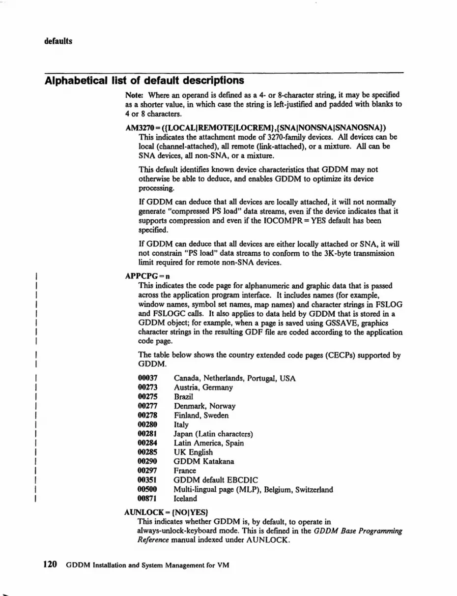
defaults
Alphabetical list of default descriptions Note: Where an operand is dermed as a 4- or 8-character string, it may be specified as a shorter value, in which case the string is left-justified and padded with blanks to 4 or 8 characters.
AM3270 = ({LOCALIREMOTEILOCREM},{SNAINONSNAISNANOSNA}) This indicates the attachment mode of 3270-family devices. All devices can be local (channel-attached), all remote (link-attached), or a mixture. All can be SNA devices, all non-SNA, or a mixture.
This default identifies known device characteristics that GDDM may not otherwise be able to deduce, and enables GDDM to optimize its device processing.
If GDDM can deduce that all devices are locally attached, it will not normally generate "compressed PS load" data streams, even if the device indicates that it supports compression and even if the IOCOMPR = YES default has been specified.
If GDDM can deduce that all devices are either locally attached or SNA, it will not constrain lipS load" data streams to conform to the 3K-byte transmission limit required for remote non-SNA devices.
APPCPG=n This indicates the code page for alphanumeric and graphic data that is passed across the application program interface. It includes names (for example, window names, symbol set names, map names) and character strings in FSLOG and FSLOGC calls. It also applies to data held by GDDM that is stored in a GDDM object; for example, when a page is saved using GSSAVE, graphics character strings in the resulting GDF file are coded according to the application code page.
The table below shows the country extended code pages (CECPs) supported by GDDM.
00037 Canada, Netherlands, Portugal, USA 00273 Austria, Germany 00275 Brazil 00277 Denmark, Norway 00278 Finland, Sweden 00280 Italy 00281 Japan (Latin characters) 00284 Latin America, Spain 00285 UK English 00290 GDDM Katakana 00297 France 00351 GDDM default EBCDIC 00500 Multi-lingual page (MLP), Belgium, Switzerland 00871 Iceland
AUNLOCK = (NOIYES} This indicates whether GDDM is, by default, to operate in always-unlock-keyboard mode. This is dermed in the GDDM Base Programming Reference manual indexed under AUNLOCK.
120 GDDM InstaUation and System Management for VM

defaults
CECPINP = {YESINO} Some GDDM family 1 devices, such as the 3179-G, allow the host application program to specify whether keyboard input of extended CECP characters is to be allowed or inhibited. This default controls this function for GDDM programs.
CMSAPLF= {DATAANALIAPLTEXT} Indicates the APL feature that is installed on nonqueriable IBM 3270 printer devices.
DATAANAL: GDDM is to assume that any APL feature installed on any printer of the above type is the Data Analysis - APL feature, unless specific application program device-defmition information indicates otherwise. The Data Analysis - APL feature is applicable to such terminals as the IBM 3284, 3286, and 3288.
APLTEXT: GDDM is to assume that any APL feature installed on any printer of the above type is the APL/Text feature, unless specific application program device-defmition information indicates otherwise. The APL/Text feature is applicable to such terminals as the IBM 3287 and 3289.
CMSCOLM = aaaaaaaa An 8-character string derming the default flletype used by GDDM for multicolored output resulting from ftles containing graphics or images suitable for use by composed-page printers. Such printers are defmed by means of the DSOPEN GDDM function described in the GDDM Base Programming Reference manual.
The character string must contain a "+ .. substitution character.
CMSDECK = aaaaaaaa An 8-character string, which is the flletype used by GDDM for object module output resulting from requests through the Image Symbol Editor or the Vector Symbol Editor.
CMSDfiS = (aaaaaaaa,bbbbbbbb) Two 8-character strings, which are the ftlename and ftletype of the external defaults flle.
CMSIADS = aaaaaaaa An 8-character string, which is the default ftletype used by GDDM for the output of ADSs (application data structures) reSUlting from the use of GDDM-IMD.
CMSIFMT::: aaaaaaaa An 8-character string, which is the default ftIetype used by GDDM for exporting data as a result of using GDDM-IMD's Export Utility.
CMSMONO = aaaaaaaa An 8-character string derming the default flletype used by GDDM for monochrome output resulting from files containing graphics or images suitable for use by composed-page printers.
CMSMSLT = aaaaaaaa An 8-character string, which is the fIletype used by GDDM·IMD map specification libraries (MSLs).
Appendix A. GDDM defaults and nicknames 121

defaults
CMSPRNT = aaaaaaaa An 8-character string, which is the ftletype used by GDDM for generating ftles to be printed by the GDDM/VM or GDDMNMXA Print Utility.
CMSSYSP = aaaaaaaa An 8-character string, which is the default ftletype used by GDDM for disk ftle output resulting from system printer devices.
CMSTEMP = aaaaaaaa An 8-character string, which is the fJ.1etype used by GDDM Base for intermediate file operations.
CMSfRCE = (aaaaaaaa,bbbbbbbb) Two 8-character strings, which are the ftlename and ftletype used by GDDM for trace output.
COMMENT = (xxxxxx"",xxxxxxxx, ... ) Specifies a comment in the form of a list of strings of 8 or less nonblank characters, which will be ignored by GDDM default processing. The list must not contain more than 8000 such strings. This can be used to imbed a comment into a defaults module for documentation pwposes.
CPN4250 = aaaaaaaa An 8-character string defining the default code page name used for a 4250 printer. Refer to the description of the GSCPG call in the GDDM Base Programming Reference manual for details.
CTLSAVE = {YESINO} This allows applications to control picture saving.
DATEFRM= {1I21314J The date convention to be used by GDDM and GDDM-PGF, as follows:
1-MM/DO/YYYY (U.S. convention) 2 - DO.MM. YYYY (European convention) 3 - YYYY-MM-OO (ISO and Japanese convention) 4 - 00 MMM YYYY (MMM are the farst 3 characters of the month name).
Note that GDDM-IMD always displays the date in an abbreviated form, that is, the farst two digits of the year (YYYY) are omitted.
DBCSDFf = {NOIYESIGDDMJ This default, which only has meaning when NATLANG specilles a double-byte character set (DBCS) language, introduces the concept of the default error message destination, and gives the user control over DBCS support for it. DBCSDFT allows the user to specify, or to ask GDDM to specify, whether the default error message destination is capable of supporting DBCS languages. The default is that GDDM should determine this.
NO means that the device is not capable of supporting DBCS YES means that the device is capable of supporting DBCS GDDM means that GDDM should determine whether the device is capable of supporting DBCS.
Some examples of default error message destinations are:
User console FSQERR destination
122 GDDM InstaUation and System Management for VM

defaults
FSEXIT destination.
This default can be set using the supplied ADMUDDCS EXEC.
DBCSLIM=n An integer, in the range 1 through 16, that is the DBCS symbol set component in-storage threshold. GDDM will normally optimize DDCS symbol-set functions by retaining loaded DDCS symbol-set components in main storage up to the specified number of components.
DBCSLNG=c The language used for DDCS symbol sets. The GDDM-supplied default is K for Kanji. If another language is used, the character chosen must be used in the symbol-set names as a replacement for K. The meaning of "c" is the same as that for the NATLANG option.
ERRTHRS=n A non-negative integer that is the default error threshold value. This value has the same meaning as the error severity value specified in the FSEXIT call. However, the specified threshold can have effect from the start of initialization.
The error threshold value can also be changed in the FSEXIT call. See the GDDM Base Programming Reference manual.
FF3270P = {NO I AFTER I BEFOREI BOTH} Indicates whether GDDM, including the GDDM Print Utility, will, by default, perform a form feed (page eject) at the start, end, or start and end of processing on a 3270-farnily printer. It does not apply to cut-sheet devices.
On IPDS printers a form feed will cause a blank page to be ejected.
ICUFMDF = {Ol t 12} This enables you to control the use of chart format defaults in the ICU. All applications on your system (new, old, or stand-alone ICU) have their chart format defaults controlled by this one parameter. The values that can be specified are:
o - Release-dependent ICU choice.
This allows the ICU to choose the chart format defaults. The actual defaults may change from one release to the next. It is normally the same as choosing 2 except when the ICU is invoked by CHART with FORMNAME = 1: and DISPLAY equal to any value other than 1 or 2. In this case ICUFMDF is set as if I had been chosen.
t - Use the chart format defaults as in Version I Release 4.
2 - Use the chart format defaults as specified in Version 2 Release 1.
ICUFMSS = {Ol t 12} This specifies the symbol sets used in the chart format defaults for the ICU.
The values that can be specified in this option are:
0- Release-dependent ICU choice.
This allows the ICU to choose the symbol sets. The ICU choice is currently the same as setting an option value of 2 but it may change from one release to another.
Appendix A. GDDM defaults and nicknames 123

defaults
1 - Use "*" for all symbol sets in the fonnat defaults. Thus, by default, charts do not use named symbol sets and so they draw faster.
2 - Use the vector symbol sets as named in the fonnat defaults.
ICUISOL = {01112} This specifies the default isolate value for the ICU. This value is inspected only if the chart-control parameter ofGDDM-PGF's CHART call has the isolate value set to zero.
The values that can be specified in the defaults option are:
o - The Save, Restore, and Directory panels of the ICU are made available to the operator.
I - The Save, Restore, and Directory panels are not made available to the operator.
2 - The Save and Restore panels are made available to the operator, but the Directory panel is not.
ICUPANC = {BLUEITURQ} This specifies whether blue or turquoise is to be used for the ICU panels.
INSCPG=n This indicates the code page of the installation. It applies to all character data that is not explicitly tagged, for example, object names in auxiliary storage.
The table below shows the country extended code pages (CECPs) supported by GDDM.
00037 00273 00275 00277 00278 00280 00281 00284 00285 00290 00297 00351 00500 00871
IOBFSZ=n
Canada, Netherlands, Portugal, USA Austria, Gennany Brazil Denmark, Norway Finland, Sweden Italy Japan (Latin characters) Latin America, Spain UK English GDDM Katakana France GDDM default EBCDIC Multi-lingual page (MLP), Belgium, Switzerland Iceland
An integer, in the range 1024 to 32000, which is the Transmission Buffer size used by GDDM for 3270-family devices. GDDM splits outgoing terminal transmissions to fit within this buffer size.
For a 3179-GI, 3179-G2, 3270-PC/G, or 3270-PC/GX work station or a 5550 multistation, on a non-SNA connection, the outgoing transmission size is restricted to approximately 3500 bytes to avoid possible controller timeouts.
For a 3193, it is restricted to about 7000 bytes.
Incoming transmission sizes are regulated as follows:
124 GDDM InstallaLion and System Management for VM

defaults
IOBFSZ determines the default incoming transmission buffer size used by GDDM. GDDM acquires temporary buffers of 32000 bytes for larger incoming terminal data streams (resulting from 3270 READ MODIFIED commands).
IOCOMPR = {NOIYES} Indicates whether GDDM is to create compressed PS load data streams. See also the description of the AM3270 default option.
Some IBM 3270 series terminals may (optionally) support compression of programmed symbol (PS) data streams. If such compression is to be inhibited, it is generally recommended that this be done on a specific basis by way of device configuration parameters. However, the IOCOMPR option can be used to inhibit compression, on a global basis, of all PS load data streams generated byGDDM.
MAPGSTG=n An integer defining the mapgroup storage threshold. GDDM will normally optimize mapping functions by retaining loaded mapgroups in main storage up to the specified threshold value.
MIXSOSI = {NOIYES} Indicates whether character strings may contain shift-out/shift-in characters to mix one-byte characters with two-byte (DBCS) characters.
NATLANG=c The language used by GDDM and by the GDDM-PGF Interactive Chart Utility and Presentation Graphics Routines in generating messages, menu panels, help panels, and generated charts. The meanings of "c" are defined as:
A - American-English B - Brazilian C - PRC Chinese (Simplifled) (GDDM Base NL only) D- Danish F - French G - German H - Korean (Hangeul) I - Italian K - Japanese (Kanji) N - Norwegian Q - French (Canadian) (GDDM Base NL only) S - Spanish T - Taiwan Chinese (Traditional) (GDDM Base NL only) V - Swedish.
Languages other than American-English are supported only if the corresponding National Language Feature is available and installed.
NUMBFRM = {11213} The number representation convention to be used by GDDM, as follows:
1 - N,NNN,NNN.MMM (Period decimal convention) 2 - N. NNN. NNN,MMM (Comma decimal convention) 3 - N NNN NNN,MMM (French decimal convention).
OBJFILE = (laaaaaaaa),lbbbbbbbb), ... ) Up to twelve 8-character strings, which indicate the default fUetypes for various GDDM objects, as follows:
Appendix A. GDDM defaults and nicknames 125
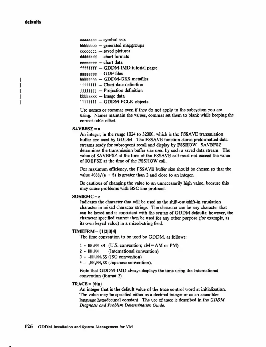
..
defaults
aaaaaaaa - symbol sets bbbbbbbb - generated mapgroups cccccccc - saved pictures dddddddd - chart formats eeeeeeee - chart data ffffffff - GDDM-IMD tutorial pages gggggggg - GDF ftles hhhhhhhh - GDDM-GKS metaftles iii iii i i-Chart data definition jjjjjjjj - Projection definition kkkkkkkk - Image data 11111111 - GDDM-PCLK objects.
Use names or commas even if they do not apply to the subsystem you are using. Names maintain the values, commas set them to blank while keeping the correct table offset.
SAVBFSZ=n An integer, in the range 1024 to 32000, which is the FSSAVE transmission buffer size used by GDDM. The FSSAVE function stores preformatted data streams ready for subsequent recall and display by FSSHOW. SA VBFSZ determines the transmission buffer size used by such a saved data stream. The value of SA VBFSZ at the time of the FSSA VE call must not exceed the value of IOBFSZ at the time of the FSSHOW call.
For maximum efficiency, the FSSAVE buffer size should be chosen so that the value 4888/(n + 5) is greater than 2 and close to an integer.
Be cautious of changing the value to an unnecessarily high value, because this may cause problems with BSC line protocol.
SOSIEMC=c Indicates the character that will be used as the shift-out/shift-in emulation character in mixed character strings. The character can be any character that can be keyed and is consistent with the syntax of GDDM defaults; however, the character specified cannot then be used for any other purpose (for example, as its own keyed value) in a mixed-string field.
TlMEFRM= {1121314} The time convention to be used by GDDM, as foUows:
1 - HH:MM xM (U.S. convention; xM = AM or PM) 2 - HH.MM (International convention) 3 - -HH.MM.SS (ISO convention) 4 - ,HH,MM,SS (Japanese convention).
Note that GDDM-IMD always displays the time using the International convention (format 2).
TRACE = {Oln} An integer that is the default value of the trace control word at initialization. The value may be specified either as a decimal integer or as an assembler language hexadecimal constant. The use of trace is described in the GDDM Diagnosis and Problem Determination Guide.
126 GDDM Installation and System Management for VM

defaults
TRCESHR = {NOIYES} Indicates whether multiple instances of GDDM are allowed to share a trace rue. This causes a three-digit identifier to be placed in front of each trace record. The coordinating instance (the frrst instance to start tracing with this default) has the prefix 00 I, and for each subsequent instance the identifier increments by one.
TRCESTR = 'aaaaaaaa' This parameter, which may be up to 256 characters long, indicates the type of trace; the use of trace is described in the GDDM Diagnosis and Problem Determination Guide. The string must be enclosed in quotes.
TRCEWID = {SINGLEIDOUBLE} This parameter controls the width of printed output. It has onJy two options, SINGLEIDOUBLE. SINGLE is the default and produces a 4-word hexadecimal output. DOUBLE produces an S-word hexadecimal output, and using this reduces the amount of paper used.
TRTABLE=n An integer, in the range 5 to 1000, defining the number of trace entries to be held in the cyclic in-storage trace table.
PossilJle error messages from ADMMDFT macro
ADM5101E INVALID POSITIONAL OPERAND(S) 'al,a2' ADM5102E INVALID VALUE SYNTAX IN 'a' ADM5103E WRONG NUMBER OF ARGUMENTS IN 'a'
Appendix A. GDDM defaults and nicknames 127

nicknames
Nicknames Another type of user default specification (UDS) is a nickname. Nicknames provide a way of defining all the characteristics of a device in a table, and then referencing that device on DSOPEN just by using the nickname.
Nicknames can be used in this way to extend the range of devices supported by current applications, often without requiring any modification to the applications.
Nicknames also extend the range of devices supported by the GDDM Print Utilities, by providing a mechanism for passing complex device definitions to the asynchronously invoked utilities.
Nicknames also enable complex devices to be predefmed by the installation programmer, thus simplifying the tasks of the application programmer and end user. The application programmer and end user retain the ability to override such predefinitions.
Refer to the GDDM Application Programming Guide for details and examples of how to use nicknames. The GDDM Base Programming Reference manual gives details of the full syntax of nicknames, and describes the way in which nicknames are processed and applied.
Source format of a nickname UDS The source-fonnat syntax of a nickname UDS is as follows:
[label] ADMMNICK [REPLACE I APPEND]
label
[,FAMcfamily] [,NAME=name-list] [,TOFAM=to-family] [,TONAME=to-name-list] [,DEVTOK=device-token] [,PROCOPT=procopt-list]
This is optional (ignored - it is not part of the VDS).
REPLACE I APPEND On anyone scan or rescan of a nickname list, a number of nickname VDSs may be found to match the current source DSOPEN parameter list.
If REPLACE is specified in a matching nickname, it causes any preceding matching nickname in the current scan or rescan to be ignored.
If APPEND is specified in a matching nickname, the effect of the nickname is merged with that of any preceding nickname in the current scan or rescan.
FAM=family This is a positive integer, which must be 0 or the same as the current source-family for the nickname to match the current source DSOPEN parameter list.
The default is PAM = 0, which wiu match any source-family.
128 GDDM Installation and System Management for VM

nicknames
NAME = name-list This is a name-list in the form of name-parts, each being a string of from 0 through 8 nonblank characters. The following are valid name-lists:
NAME=namel, NAME=(namel), NAME=O, NAME=(namel,name2,name3), NAME=(namel"name3),
NAME=,
- one nonblank name-part - one non blank name-part - one blank name-part - three nonblank name-parts - two nonblank name-parts and one
blank name-part - null name
For the nickname to match the current source DSOPEN parameter list, the name-list must either be nuU or must match the current source name-list.
The two name-lists are considered to match if the corresponding name-parts are the same (after left-justification, translation to uppercase, and padding with blanks). In this respect, if the name-lists do not contain the same number of name-parts, the shorter name-list is extended with u." name-parts for the purpose of comparison. For example:
• FRED' and • (FRED) • ) • FRED' and • (FRED, *) • ) match 'FRED' and • (FRED,*,*) , )
but 'FRED' and' (FRED,ADMPiUNT)' do not match
A name-part in the NAME parameter can also contain a leading or trailing (or both) "?" generic character. Such a character is considered to match any combination of characters in the same position as the "?" Thus:
'abc?' - matches any name-part starting with 'abc' , ? ' - matches any name-part
The default is null (that is, NAME=,); this matches any source-name-Iist.
TOFAM = to-family This is a positive integer. If the nickname is found to match the current source DSOPEN parameter list, GDDM updates the target-family in the target DSOPEN parameter list according to the value of the TOFAM parameter, as follows:
to-family = 0 The target-family is not changed. This is the default.
to-family = nonzero The target-family is changed to the value to-family.
TONAME = to-name-list This is a name-list in the same form as the NAME parameter (except that "?" generic characters are not allowed).
If the nickname is found to match the current source DSOPEN parameter list, GDDM updates the target-name-list in the target DSOPEN parameter list according to the value of the TONAME parameter, as follows:
to-name-list = null The target-name-list is not changed. This is the default.
Appendix A. GDDM defaults and nicknames 129

nicknames
to-name-list = n~t-null The target-name-list is changed to be the value to-name-list.
DEVTOK == device-token This is a string of 0 through 8 nonblank characters.
If the nickname matches the current source DSOPEN parameter list, GDDM updates the target-device-token in the target DSOPEN parameter list according to the value of the DEVfOK parameter, as follows:
device-token = null (that is, DEVfOK = ,) The target-device-token is not changed. This is the default.
device-token = not-null If the current source-device-token is "*" or null, the target-device-token is changed to be the value device-token. Otherwise, the target-device-token is not changed.
The DEVTOK parameter enables an explicit non-"*" or nonblank device token to be used, but only if the application program specified a DSOPEN device token of "*" (or blank). An explicit (that is, non-"*" or nonblank) device token specified in the DSOPEN call cannot be overridden.
PROCOPT == procopt-list This is a list of procopt-specifications (procopt-specs), thus:
PROCOPT=«procopt-spec),(procopt-spec), ... )
Each procopt-spec is a keyword identifying a specific DSOPEN processing option (see below) followed by a number of arguments valid for that processing option, thus:
PROCOPT=«keyword,argument,argument) , (keyword,argument), ..• )
If the nickname is found to match the current source DSOPEN parameter list, GDDM updates the target-pro copt-list in the target DSOPEN parameter list according to the value of the PROCOPT parameter, as follows:
procopt-list = null (that is, PROCOPT = ,) The target-procopt-Iist is not changed. This is the default.
procopt-list = «procopt-spec), .... ) The pro copt-list is inserted into the target-procopt-list such that it follows any procopt-lists added so far during the current scan or rescan, but precedes any procopt-lists that were present at the start of the current scan or rescan.
Note that, in a DSOPEN pro copt-list, the latest procopt-specifications take priority; that is to say, where a procopt-list contains two or more procopt-specs for the same processing option, the latest will apply. (Exceptions to this rule are the mergeable PRINTCTL and ORIGINID processing optionsj see below.) This means that the PROCOPT parameter enables an explicit procopt-spec to be applied, if the application program did not specify the corresponding processing option group in the DSOPEN call. A processing option group specified in the DSOPEN call cannot be overridden.
Note: In a DSOPEN procopt-list, any pro copt-specifications that are not applicable to the DSOPEN device family and device name-list are ignored.
130 GDDM Installation and System Management for VM

nicknames
The processing options that can be specified are described in Figure 48 on page 131. Refer to the discussion of DSOPEN in the GDDM Base Programming Reference manual for full details. INRESRCE and PCLK are described in the GDDM Release Guide and the GDDM-PCLK Guide respectively.
Appendix A. GDDM defaults and nicknames 131

nicknames
DSOPEN Keyword Argument(s) Examples Group (default, if any, Code is [val first) 1 BMSCOORD NO YES (BMSCOORD,NO) 2 OUTONlV NO YES (OUTONlV, NO) 3 AUNlOCK NO YES (AUNlOCK, NO) 4 PRINTCTl n,n,n,n, ••••• (PRINTCTl,9,1,66,9,9,
PRIMlsEC 9,89,9)
5 CDPFTVPE (CDPFTVPE,PRIM) 6 HRISPILl VEslNO (HRISPILL,VES) 7 HRISWATH n (HRISWATH,19) 8 HRIPSIZE n,n,TENTHsIMILLS (HRIPSIZE,5,3,TENTHS) 9 HRIFORMT CDPF I BITMAP (HRI FORMT ,BITMAP) 19 PLTFORMF YEslNO (Pl TFORt~F ,NO) 11 PLTPENV n (PlTPENV,39) 12 PLTPENI~ n (PLTPENW, 19) 13 PLTPENP n (PLTPENP, 19) 14 PLTAREA xminrXmaX,ymin,ymaX (PLTAREA,0,70,9,70) 15 PLTPAPSZ *IA4 A31 ... IAIBI ... (PLTPAPSZ,A4) 16 PLTROTAT NolvES (PLTROTAT,NO) 17 SEGSTORE VEslNO (SEGSTORE,NO) 18 STAGE2ID xxxxxxxx,xxxxxxxx, ... (STAGE2ID,*,AUX2) 19 LOADDSVM NO YES (LOADDSYM,VES) 29 ORIGINID NO YES (ORIGINID, YES) 21 LCWODE NO YES (LCLMODE,NO) 22 HRIDOCNM xxxxxxxx (HRIDOCNM,FINALPRT) 23 SPECDEV IBM59891*,ddnamelblank (SPECDEV,IBM50S0,
NolvES FTl0F0el)
24 WINDOW (WINDOW,NO) 26 FASTUPD n (FASTUPD,I) 27 CTlFAST NOIVES (CTLFAST, NO) 28 CTLMODE *lvEsiNO (CTLMODE,*) 29 CTLKEV type,value (CTLKEV,4,1) 30 CTLPRIIH VESINO (CTLPRINT,YES) 31 CTLSAVE YES NO (CTlSAVE,YES) 32 INRESRCE N°IVES (INRESRCE,NO) 33 PCLK NO YES (PCLK,YES) 34 DEVCPG n (DEVCPG,00273) 35 IPDSQUAL *IDPIDPQIDPTIDPTQINLQ (IPDSQUAL,*) 36 PCLKEVIS NolvES (PCLKEVIS,YES) 10ae CMSINTRP PA1PA21PA21PA11NONE (CMSINTRP,PA1PA2) 19a1 CMSATTN BASIC I EXTENDED,n,addr (CMSATTN,BASIC,e,0) 1002 CPSPOOL xxxxxxxx,xxxxxxxx, ... (CPSPOOL,TO,RSCS) 1003 CPTAG xxxxxxxx,xxxxxxxx, .•• (CPTAG,CHICAGO,
NolvES 32S7N03,PRT=GRAF)
1004 I NVKOPUV (I NVKOPUV , YES) 3a00 COLORMAS n (COLORMAS,2)
Figure 48. Processing options
Possible error messages/rom ADMMNICK macro
ADM5101E INVALID POSITIONAL OPERAND(S) 'a1,a2' ADM51e2E INVALID VALUE SYNTAX IN 'a'
132 GDDM Installation and System Management for VM

character codes
Appendix B. Character code interpretation
The alphanumeric defaults module (ADMDATRN) is a set of translation tables used by GDDM to ensure that character codes managed by the program appear the same on any device in any country. For example, a word containing e entered as data in France will be displayed correctly as e on a terminal in Germany. ADMDA TRN is also needed in installations that use APL, and those that use Personal Services/370 (PS/370) under CICS.
Applications can use:
• Country extended c()de pages (CECPs)
• GDDM's default EBCDIC character codes
• Katakana character codes.
An example CECP is shown on page Figure 52 on page 137. The GDDM Typefaces and Shading Patterns manual shows the other CECPs. The code page numbers for CECPs are shown on page 120. The EBCDIC character codes are shown in Figure 50 on page 135. The Katakana character codes are shown in Figure 51 on page 136.
To ensure that character codes are always interpreted in the same way, GDDM uses a set of 256 character tables. Pointers enable the characters in one table to be mapped onto those in any other table.
Programs written prior to GDDM Version 2 Release 2 that used an extended EBCDIC character code interpretation, will still work as designed. This means that (f()r example) XI 31 1 appears as a superscript I if the device to which it is being sent can process it. (If the device cannot process it, what happens is explained later.)
Katakana can now be specified by the APPCPG external default (see page 120). For compatibility with earlier releases, Katakana codes can be specified by default if a small change is made to the alphanumeric defaults module.
Appendix n. Character code interpretation 133

character codes
Code page conversion To enable character codes to be interpreted correctly. more than one conversion between code pages may take place. Figure 49 shows the conversions that are possible.
Device CP A p
0 t t p b . . 1 j ......... ...... ~ i e c A P P L I CAT ION c G D D M a .-t t PRO G RAM
~ .................. i C 0
P ......... n . i- C
P Installation CP
i OPE RAT I N G SYSTEM
Name 1-
GDDM object file Key: Data ...... ~ Code
transfer . page r converSlon Figure 49. Code page conversion
134 GDDM Installal.ion and System Management for VM

First Second hex digit hex digit ...
0
1
2
3
4
5
6
7
8
9
A
B
C
0
E
F
0 1 2
NUL
" ( ) +
0 1 2
SP A B -& J K - -
/ S - -¢ A
.. ,....,
a b
0 j k - NU
9 S
oc: e I
NU A B 10
NU J K 11
NU S =
12 -0 1 2
,.. = superscript
... = subscript
SP = space
BS= backspace
3
-
3
C -L
T -1
c
I
t
P
C
L
T
3
4 5 6
{ PT
NL BS
} LF I -
4 "5 "6
D E F
M N 0 - -U V W - - -
... 2 3 n
d e f
m n 0
u v w
w • x
D E F
M N 0
U V W
4 5 6 PT = program tab
FF = form feed
NUL = null
NL = new line
7
"7
G -P
X -0
9
p
x
\ G
P
X
7
figure SO. GDDM default EBCDIC character codes
8 9 A B
I I 1-,
§
8 "9 ~ IT
H I NU
- 1
Q R NU 2 -
y Z NU
- - 3
NU V
4 . .
h i 1
q r ~
y z n . • V -. H I
,...., A
Q R I
Y Z f
8 9 @]
NU = national use
LF = line feed
. NU
, NU
l
c
u
l!.
,...., V
!
\ ,...., V
CR = carriage return
5
6
character codes
C 0 E F
FF CR
- L W I~ i-I- I- -I
e I 1 -I r 1 -(
NU < + 13
* ) NU . , 8
0/0 - > ? NU , NU
7 - 14
s r L .... ):( 0 ::I: +-
.L [ ~ 0
T ] ;II! I 0 cI> lSI {\}
t .. [!] jill
iii .. e l' . !! • .!
Appendix B. Character code interpretation 135

character codes
First Second hex digit hex digit 0 1 2 3 4 6 6 7 8 9 A B C 0 E F ..
0 NUL PT FF CR SO SI
1 NL BS
2 LF
3
4 SP r ..J .. "7 7 l' J £ < ( + I 0 . . 6 & I t t .:L 3 ':J - ! ¥ * ) . -, ,
6 - / % > 7 , -7 . # @ , - " . -8 7 l' j I ~ tJ ~ ? ,. :J "I] V ~ t 9 ') ~ T ':J T ~ ) - ::;l ;t. ) J' t 7 -
- 'J' J..,. } "t t .:L 3 ~ J~ A ....... -:t - 5 --B V 0 7 ;J \\ 0
c A B C D E F G H I
0 J K L M N 0 P Q R
E $ S T U V W X Y Z
F 0 1 2 3 4 5 6 7 8 9
.... ~ lowercase Katakana character
Figure 51. GDDM deCault Katakana character codes
136 GDDM Installation and System Management Cor YM

character codes
xO x1 x2 x3 x4 x5 x6 x7 x8 x9 xA xB xC xD xE xF
4x A •• " , - 0
Q - C ( I a a a a a a n • < + 5x &e88ei i .. ...
B , $ * ) I I • .. • , 6x - /AAAAAACA I 1- > ? I , - • 7x " E ~ ! E f , y ) ...
I: @' - .. • • -
8x 0 a bed e f 9 h • » 6 y b + I « -9x
0 • k I i! 2 Be .. JEO J mn o p q r Ax - t • Oyi:» ® II s uvwxyzi (,
Bx A £¥ ©§11~~*[ ] - .. , . x
Cx { ABCDEFGHI - 6tio66 Dx } JKLMNOPQR 1 A. .. ... , .. u u u u Y Ex \ • STU V WX y Z 2 00060 -• Fx 0123456789 3 OOOu
Figure 52. Example country extended code page (CECP 00037)
Structure of the alphanumeric defaults module The alphanumeric defaults module consists of sets of tables for various national languages and devices, and control information on how the tables are to be used and how they are to be associated with a particular language and type of device. In addition, the module contains tables used for uppercase translation. The format of the alphanumeric defaults module is shown in Figure 53. As the figure shows, it includes:
• The basic control information • Translation-type descriptor blocks for each allowed translation-type value • Translation tables • CECPs that relate translation tables to code page identifiers.
The translation tables are 256-byte tables and arc held within the module.
The contents of the fields shown in Figure S3 arc described below. The basic control information is in Figure 54 on page 139. The module as supplied with GDDM includes several translation-type descriptor blocks; the format of such a block is shown in Figure 56 on page 143.
In addition to the fields described in Figure 53, the module contains the default translation tables to which they refer.
Appendix n. Character code interpretation 137
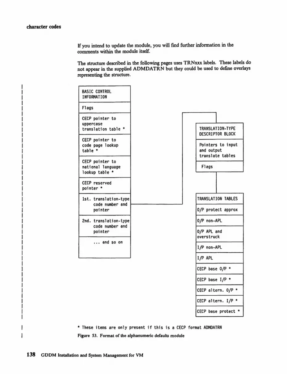
character codes
If you intend to update the module, you will fmd further information in the comments within the module itself.
The structure described in the following pages uses TRNxxx labels. These labels do not appear in the supplied ADMDATRN but they could be used to define overlays representing the structure.
BASIC CONTROL INFORMATION
Flags
CECP pointer to uppercase translation table * TRANSLATION-TYPE
DESCRIPTOR BLOCK CECP pointer to code page lookup Pointers to input table * and output
translate tables CECP pointer to national language Flags lookup table *
CECP reserved pointer *
1st. translation-type TRANSLATION TABLES code number and pointer O/P protect approx
2nd. translation-type O/P non-APL code number and pointer O/P APL and
overstruck .•• and so on
liP non-APL
liP APL
CECP base DIP '"
CECP base liP *
CECP altern. O/P '"
CECP altern. liP '"
CECP base protect '"
'" These items are only present if this is a CECP format ADMOATRN
Figure 53. Format of the alphanumeric defaults module
138 GDDM Installation and System Management for VM

character codes
Compatibility of ADMDATRN with previous releases For GDDM Version 2 Release 2 changes have been made to ADMDATRN to incorporate CECP. In particular:
• TRNTYPE and TRNYPEP are now grouped under TRNTYPES which is the array of device types. This has enabled the new CECP pointers, grouped under TRNCECPP, to be defmed on TRNTYPES.
• The translation type descriptor block has been extended to include pointers for CECP.
For GDDM Version 1 Release 4 the meanings of the TRNIGM and TRNIG flags (previously called TRNGAM and TRNGA) were extended to cover the 3179-G, the 3270-PCjG, 3270-PC/GX, the 5550, and any other terminals supporting the APL2 character set. Unless entries "5279" and "52791" are incorporated in any customized versions of ADMDATRN from GDDM Version I Releases 1,2, or 3, then abend 1201 will occur when attempting to use a 3270-PC/G or a 3270-PC/GX.
Basic control information This is the frrst part of the alphanumeric defaults module.
Field name Field offset Field length IDM default value (where applicable)
TRNUCTP e 4 address TRNPTP 4 4 address TRNFMASK 8 3 -
TRN3277M x ....... Bits in TRNFMASK 1 TRNDISPM • x •••••• 1 TRNAPlM • • x ••••• 1 TRNNlCM • •• x •••• 1 TRNSYSPM • ••• x ••• 1 TRNIGM • ••••. x. 1 TRN293M • •••••• x 1
TRNFCECP 11 1 -TRNCECP x ••••••• Bits in TRNFCECP 1
TRNNTYPE 12 4 36 TRNTYPES(*) 16+ -
TRNTYPE 4 e TRNTYPEP 4 address
TRNCECPP -TRNMUCTP 4 address TRNCPl 4 address TRNNATP 4 address reserved 4 -
Figure 54. Alphanumeric defaults module, basic control information
TRNUCTP This is the address of the uppercase translation table. The GDDM-supplied table translates lowercase EBCDIC characters to uppercase, and leaves all other characters unchanged.
The address must not be zero.
Appendix B. Character code interpretation 139

character codes
TRNPTP This is the address of the invalid character translation table. The GDDM-supplied table translates the character codes X '01' through X 13F' and X I FF I to the character code X '40 I on output.
The address must not be zero.
TRNFMASK A set of flags that correspond to device characteristic flags in the translation type-descriptor blocks. If these flags are set on, the corresponding flags in the type-descriptor blocks are tested when searching for a translation table set for a particular device.
TRN3277M Older 3270 or those that support highlighting, color, and PS.
TRNDISPM Display or printer.
TRNAPLM APL or non-APL devices.
TRNNLCM Device displays lowercase characters in recognizable form or does not.
TRNSYSPM System printers or other devices. (System printers are characterized by the use of carriage contro1.)
TRMGM Interactive graphics devices or others.
TRN293M Device supports APL code page 293.
TRNFCECP A set of flags relating to CECP.
TRNCECP Country extended code page available.
Reserved Seven unused bits.
TRNNTYPE This is a fullword integer (or string offour characters) specifying the number of entries in TRNTYPES. Each entry consists of one TRNTYPE and one TRNTYPEP. The list is scanned at GDDM device initialization to determine which translation type to use. There must be at least one entry.
The translation types supplied with GDDM are listed in Figure 55 on page 142.
TRNTYPES(n) Array of device types.
TRNfYPE This is a fullword integer (or string of four characters) naming the translation-type identifier for this entry. This must be different from all other values of TRNTYPE in the list.
140 GDDM Installation and System Management for VM

character codes
TRNTYPEP This is the address of a translation-type descriptor block. Each TRNTYPEP in the list should address a different descriptor block. This address must not be zero.
TRNCECPP This is an array of four pointers defined over the TRNTYPES array for use by CECP.
TRNMUCTP Pointer to CECP uppercase translation table.
TRNCPL Pointer to CECP lookup table.
TRNNATP Pointer to national-Ianguage-to-CECP lookup table.
Reserved Unused.
Translation types supplied by GDDM GDDM uses the translation types shown in Figure 55 on page 142. When GDDM is choosing a translation type, it starts at 0 and goes to the point specilled by the 0 group. By default, this is 2 but may have been changed to 3. It then goes to the point specilled by 2 or 3 and searches until it fmds a translation-type number that matches the device in use.
If an ASTYPE call is used to override character code assignments, Figure 55 on page 142 is used as follows:
Type parameter Translation used
Zero Default (from application code-page to device code-page for output and from device code-page to application code-page for input).
Non-zero Default is overridden and the associated table is used.
Note: DUP(+) means unprintable character
Appendix B. Character code interpretation 141

character codes
Translate type number Device "Invalid" character
GROUP SELECTIONS - these derme the points in the table at which the search will start.
0 Points to 2 by default (can be altered to be same as Katakana or other group)
2 Points to EBCDIC group 3 Points to Katakana group
SPECIFIC SELECTIONS - these can be specified only in an ASTYPE call
I No translation except output protection using TRNPTP. -3288 3288 ASTERISK (*) 32881 3288-TN ASTERISK (*) 3289 3289 ASTERISK (*) 32891 3289-TN ASTERISK (*)
KATAKANA group (falling through to EBCDIC group) - one of these values is selected by GDDM if group selection 0 is set to point to 3 and a suitable match is found.
32772 Katakana 3277 DUP (+) 32792 Katakana 3279 or 5550 DUP (*) 32793 Katakana 3279 - APL DUP (+) 3179 Katakana 3179-G DUP (*) 31791 Katakana 3179-G - APL DUP (*) 5553 Katakana 5553 or 5557 DUP (+) 55531 Katakana 5553 or 5557 - APL DUP (+) 4224 Katakana 4224 DUP (*) 42241 Katakana 4224 - APL DUP (+) 3812 Katakana 3812 DUP (+) 38121 Katakana 3812 - APL DUP (+)
EBCDIC group (may be selected by GDDM by default) - one of these values is selected by GDDM if group selection 0 is set to point to 2, or if it is set to point to 3 but no suitable match is found in the Katakana group.
Note: For 3290 and 8775 terminals GDDM selects translation types as it does for 3278 terminals.
5279 3270-PC/G, 3270-PC/GX, 3179-G DUP (+) 52791 3270-PC/G, 3270-PC/GX, 3179-G - APL2 DUP (+) 3277 3277 DUP (+) 3279 3278, 3279 DUP (*) 32771 3277-APL/DE DUP (+) 32791 3278·APL/DE, 3279-APL/DE DUP (+) 713287 3271/3287 DUP (*) 743287 3274/3287 DUP (+) 7132871 3271/3287-APL OUP (+) 7432871 3274/3287-APL OUP (+) 1403 1403, 3211 -744224 3274/4224 OUP (+) 7442241 3274/4224-APL OUP (+) 743812 3274/3812 DUP (+) 7438121 3274/3812-APL DUP (+)
Figure 55. Translation tables in the alphanumeric defaults module
142 GDDM Installation and System Management for VM

character codes
Translation-type descriptor block This is the second part of the alphanumeric defaults module.
Field name Field offset Field length IBM default value
TRNDEFRT 0 4 number TRNBOP 0 4 address or 0 TRNBIP 4 4 address or 0 TRNAOP 8 4 address or 0 TRNAIP 12 4 address or e TRNBPOP 16 4 address or e TRNCOP 20 4 address or 0 TRNCIP 24 4 address or 0 TRNCAOP 28 4 address or 0 TRNCAIP 32 4 address or 0 TRNCPOP 36 4 address or 0 TRNFLAGS 40 3 -
TRN3277 x .••.••. Bits -TRNDISP .x ...... within -TRNAPL • • x ••••• TRNFLAGS -TRNNLC • •• x •••• -TRNSYSP • ••• x ••• -TRNDEFR ..... x .. -TRNIG ...... x. -TRN293 ....... x -TRNNONU x ••••••• -
TRNIIC 43 1 -
Figure 56. Alphanumeric defaults module. translation-type descriptor block
TRNDEFRT This is only referred to if TRNDEFR = I, contains the type number at which search should continue. It is used to bypass standard defaults by nonstandard defaults such as Katakana.
TRNBOP This is the address of output symbol set 0 (non-APL) translation table. If zero, this translation does not occur.
TRNBlP This is the address of input symbol set 0 (non-APL) translation table. If zero, this translation does not occur.
TRNAOP This is the address of output symbol set I (APL) translation table. It is also used as overstruck-character translation table. If zero, this translation does not occur.
TRNAIP This is the address of input symbol set I (APL) translation table. If zero, this translation does not occur and character codes revert automatically to symbol store O.
Appendix B. Character code interpretation 143

character codes
TRNBPOP This is the address of output-protected approximation translation table. If zero, this translation does not occur.
TRNCOP This is the address of the CECP base output table. It maybe zero when TRNDEFR=O.
TRNCIP This is the address of the CECP base input table. It maybe zero. It is used when TRNDEFR=O and must be 0 when TRNDEFR= 1.
TRNCAOP 1ms is the address of the CECP alternate output table. It maybe zero. It is used when TRNDEFR = 0 and must be 0 when TRNDEFR = 1.
TRNCAIP This is the address of the CECP alternate input table. It maybe zero. It is used when TRNDEFR = 0 and must be 0 when TRNDEFR = 1.
TRNCPOP This is the address of CECP base protected output table. It maybe zero. It is used to approximate protected field output when TRNDEFR = 0 and must be 0 when TRNDEFR = 1.
TRNFLAGS This is a set of flags that specifies the combination of device characteristics for which the translate table will be used. Flags not shown are not used. Some flags may be ignored, depending on the setting of TRNFMASK in the basic control information.
TRN3277 I = the device must be an older type (that is, a 3277).
o = opposite to 1.
TRNDISP 1 = the device must be a display.
o = the device must be a printer.
TRNAPL 1 = the device must have an APL character set.
o = opposite to 1.
TRNNLC I = the device must be one that does not display lowercase characters in a recognizable form (for example, a Katakana device). This setting affects the operation of the ASCGET can when ASFTRN has been used to specify uppercase translation of alphanumeric input.
o = the device must display lowercase characters in a recognizable form. This includes those devices that display lowercase characters as uppercase.
This flag is not used in device characteristic matching.
144 GDDM Installation and System Management for VM

character codes
TRNSYSP I = the device must be a system printer (for example, 1403 or 3211).
o = opposite to 1.
TRNDEFR I = do not process this type number; go to the translation-type number found in TRNDEFRT, and continue searching from there.
o = process in the nonnal manner.
This flag is not used in device characteristic matching.
TRNIG I = the device is an interactive graphics device that supports the APL2 character set (for example, a 3179-G or a 3270-PC/G).
o = opposite to 1.
TRN293 I = the device supports APL code page 293.
o = opposite to 1.
TRNNONU I = the device has no national use characters.
o = opposite to 1.
TRNIIC Invalid character replacement.
Translation tables This is the third part of the alphanumeric defaults module.
How GDDM translates alphanumeric fields The object of GDDM translation of alphanumeric fields is to:
• Give consistency of interpretation of hexadecimal character codes between different languages
• Give consistency of interpretation of hexadecimal character codes between different devices
• Give an approximation of undisplayable codes where this is likely to help the user
• Allow for APL characters.
ADMDATR N contains two sets each of five tables, three for output and two for input, for each device type. These tables are used to translate alphanumeric fields. One set of tables handles non-CECP applications (as in earlier releases); the other set is for CECP applications running on non-CECP devices. Figure 57 on page 146 shows how the tables are used. Both sets of tables work in the same way. The tables and their uses are described below.
Appendix B. Character code interpretation 145

character codes
-Input~ GDDM ~Output-
Output Protected Approximation Table
APL APL r-Translate Table Translate Table
Non-APL Non-APL Translate Table Translate Table
+ , Terminal
Figure 57. Translation tables used for GDDM alphanumeric fields
The non-CECP translation tables are only used for the read-only symbol sets supplied in the hardware. No translation is done if you use other symbol sets in alphanumeric fields.
Translation is only done on one-byte characters that use ASCPUT. Two-byte characters using ASGPUT (such as Kanji) are not translated.
Instructions on setting up a new translation table Brief instructions on setting up a new translation table to be accessed by an ASTYPE call are given below. The task should not be attempted unless you have studied the module and the comments it contains.
1. Set up a new translation group by copying either group 3 if you are interested in Katakana terminals or group 2 if you are interested in other terminals. Make this group number 4.
2. Change the numbers, such as 5279, to unique numbers such as 45279. (Any number can be used if it is unique within the module.)
146 GDDM Installation and System Management for VM

character codes
3. Set up the appropriate translate tables, using those in ADMDATRN as a model.
4. Set the entries in group 4 so that they point to the appropriate translate tables.
5. If you want the new table to become the default, change group 0 so that it points to group 4. If you do not want it is as the default, it can be specified explicitly by using ASTYPE(4).
6. Reassemble and link-edit the defaults module as described under "How to replace a GDDM module that you've changed" on page 105.
7. Replace ADMDATRN as described under "Replacing GDDM modules after installation" on page 105.
Device dependent translation tables Device dependent translation tables are used to handle both CECP and non-CECP alphanumeric fields. The pointers to the tables are all in the Translation Type Descriptor Block.
Output-protected approximation table For protected fields only. Translates characters that cannot be shown on the device to the nearest possible equivalent. (For example, superscript values may be shown as ordinary values.) The table is only used for protected fields because the data stream could be corrupted if the translated value was returned. Where the character cannot be approximated, a blank is used.
Addressed by TRNBPOP for non-CECP. Addressed by TRNCPOP for CECP.
Output symbol set 0 (non-APL) translate table This translates the hexadecimal code sent by GDDM to the code that will result in the desired character appearing on the tenninal.
Addressed by TRNBOP for non-CECP. Addressed by TRNCOP for CECP.
Output symbol set 1 (APL) translate table This table is used to translate APL characters for interactive devices. APL characters are known in GDDM as hexadecimal values (for example ~ (A underscore) is represented as X '41 ' ). On some devices ~ is represented as X I 81 ' in symbol set 1. The output symbol set 1 translate table, translates X '41' to X I 81 ' and sets a marker to indicate that symbol set I is to be used.
For system printers, the table is used in a similar manner to generate overstruck characters.
APL translation is done after output-protect translation and before non-APL translation. As shown in Figure 57 on page 146, characters translated by the APL-translate table are not passed through the non-APL translate table.
Addressed by TRNAOP for non-CECP. Addressed by TRNCAOP for CECP.
Input symbol set 0 (non-APL) translate table This translates the hexadecimal code sent by the device to the code that will be expected by GDDM, which is the reverse of the equivalent output table.
Addressed by TRNBIP for non-CECP. Addressed by TRNCIP for CECP.
Appendix B. Character code interpretation 147

character codes
Input symbol set I (APL) translate table This table is used to translate APL characters back into the format recognized byGDDM.
Addressed by TRNAIP for non-CECP. Addressed by TRNCAIP for CECP.
In addition to this translation, GDDM removes invalid characters that might corrupt the device and replaces them with the Invalid Device Character. A record is kept of the position of these characters and they are replaced in the field on input if they have not been changed.
CECP lookup table
Field name Field offset Field length IBM default value (where applicable)
TRNCSID e 4 -TRNCPID 4 4 -TRNCPFG 8 1 -
TRNCECPF x .••..•• Bits 1 TRNACPF • x ••..•• within 1 TRNAROSF •• x ••.•. TRNCPFG 1 Reserved ••• xxxxx -
TRNTMLP 12 4 address TRNFMLP 16 4 address
Figure 58. Alphanumeric defaults module, CECP lookup table
TRNCSID Character set identifier.
TRNCPID Code page identifier.
TRNCPFG Code page flags.
TRNCECPF CECP flag. Sct if there is a CECP coded character set.
TRNACPF Application code page flag. Set if the code page is supported as an application or installation code page. If not set, the coded character set is used as a device code page for input/output operations.
TRNAROSF ROS translation flag. Set for coded character sets on devices supporting 94 EBCDIC characters.
Reserved Five unused bits.
TRNTMLP Pointer to the translate-to-code-page-500 table.
148 GDDM InstaUation and System Management for VM

character codes
TRNFMLP Pointer to the translate-from-code-page-500 table.
There is no set order for the entries in this table except that:
• Entries for possible application code pages must be placed fIrst. See TRNACPF.
• The last entry must have a zero TRNCSID and TRNCPID.
Other entries can be arranged to optimize performance.
This table is used to validate and interpret code page identillers. It has an entry for each coded character set recognized by GDDM. These correspond to:
• Pages which can be supported as the application or installation code page • Additional device code pages.
Each entry contains character set and code page identillers, flags, and pointers to translation tables.
Addressed by TRNCPL in the Basic Control Information.
Code-page-to-code-page translation tables Translation tables from code page 500 to every other supported code page, and vice versa.
Addressed by TRNFMLP in the CECP lookup table for translating from code page 500.
Addressed by TRNTMLP in the CECP lookup table for translating to code page 500.
National-Ianguage-to-CECP lookup table
Field name Field offset Field length IDM default value (where applicable)
TRNNATl e 1 -TRNNLCP 1 4 -
Figure 59. Alphanumeric defaults module, national language lookup table
TRNNATL National language identifier.
TRNNLCP Code page identiller.
Appendix B. Character code interpretation 149

character codes
Valid combinations of national language identifier and code page identifier are:'
National language A B C D F G H I K N Q S T V o
Code page 00037 00275 00037 00277 00297 00273 00037 00280 00037 00277 00037 00284 00037 00278 00000
Language American English Brazilian Portuguese PRC Chinese Danish French German Korean (Hangeul) Italian Japanese (Kanji) Norwegian Canadian French Spanish (Latin America) Taiwan Chinese Swedish End of table
Figure 60. Nationallanguage and code page identifiers
This lookup table is used to access the message data set.
Addressed by TRNNA TP in the Basic Control Information.
CECP upper case translation table Translation table for code page 500 used by ASFTRN to translate to upper case on input.
Addressed by TRNMUCTP in the Basic Control Information.
How to use the alphanumeric defaults module By changing the alphanumeric defaults module you can:
• Change the default translation so that 3270-family devices (including work stations that use 3270 data-stream architecture) are assumed to be Katakana rather than EBCDIC where there is such a choice. (This enables Katakana to be correctly processed.)
• Set up special translation tables of your own that will cater for a nonstandard device or a group of nonstandard devices. If you use a CECP you may not need any special translation tables.
Instructions for making the change to Katakana are given in "How to make the default translation table Katakana" on page 151. If you do need to set up special translation tables, you will have to read and understand the description of the alphanumeric defaults module that performs the Katakana instructions.
150 GDDM Installation and System Management for VM

character codes
How to make the default translation table Katakana Katakana can be specified by the APPCPG external default (see page 120). but for compatibility with earlier releases it can be made the default by using the method described here.
PTFs may have replaced this table. so check that it is still valid for your installation.
The GDDM Katakana character codes are shown in Figure 51 on page 136. These codes can be explicitly specified in a program by use of the ASTYPE(3) call or can be made the default for an installation.
To make the Katakana codes the default for the installation:
1. Find the source of the alphanumeric defaults module ADMDATRN. It is provided as part of the installation process.
2. Within the module fmd the assembler label TO. 3. On the next line change F"2' to F"3'. 4. Reassemble and link-edit the defaults module as described under "How to
replace a GDDM module that you've changed" on page 105. 5. Replace ADMDATRN as described under "Replacing GDDM modules after
installation" on page 105.
This action will make the default table the Katakana table (number 3) instead of the EBCDIC table (number 2) and will make Katakana display and printing the same across all Katakana devices supported by GDDM.
Appendix D. Character code interpretation 151

device tokens
Appendix C. Device characteristics tokens
There are four families of devices supported by GDDM/VM or GDDM/VMXA. These are:
Family 1 Family 2 Family 3 Family'"
3270-based devices Queued-printer devices System-printer devices Composed-page devices.
This appendix describes device characteristics tokens (normally called device tokens) and the macros that are used to generate them. Device tokens describe the characteristics of devices. They should only be used if you want to override the answer for a queriable device.
• They are used to specify some special types of device such as the 4250 composed-page printer in a DSOPEN call.
• They override the information obtained by GDDM about a particular device so that device information will be taken from the token rather than the usual source (normally the device itself but in some cases a table).
GDDM-supplied device tokens The GDDM-supplied device tokens are shown in Figures 61 through 67. The meanings of the tokens are in terms of typical devices that they can be used with. You may need to study the meanings of the macro operands fully to understand the tokens. The operands are explained in "The ADMM3270 macro" on page 162, "The ADMMSYSP macro" on page 177, and "The ADMMlMAG macro" on page 178.
Some of the tokens do not apply in all operating environments; the same set of tokens is supplied in all GDDM operating environments (MVS, VM, and VSE).
Note that the tokens that start with the letters ADMK are automatically generclted the frrst time the related macro is invoked.
Where device tokens are held The device tokens are held in tables with the following names:
ADMLSYSI for family I (3270) and family 2 (queued printer) ADMLSYS3 for family 3 (system printer) ADMLSYS4 for family 4 (composed-page printer ftles).
The source of these modules is individual rues on the GDDM installation disk.
Appendix C. Device characteristics tokens 153

device tokens
GDDM-supplied device tokens for queriable terminals and printers
This set of token defInitions is part of ADMLSYS 1.
• Locally attached 3179 Models Gland G2 displays. L3179G 3179·G, 32 rows by 80 columns L3179GM 3179·G, 32 rows by 80 columns with mouse
• Locally attached 3270·PC displays. L3270PC 3270·PC displays
• Locally attached 3270· PC/G work stations. L5279Al 3270·PCjG, 32 rows by 80 columns L5279AIM 3270·PC/G, 32 rows by 80 columns, with mouse L5279AIT 3270·PC/G, 32 rows by 80 columns, with tablet L5279A2 3270·PC/G, 49 rows by 80 columns L5279A2M 3270·PC/G, 49 rows by 80 columns, with mouse L5279A2T 3270·PC/G, 49 rows by 80 columns. with tablet ADMKPCAI copy of L5279Al, generated for use by ADMUPC utility
for dummy device
• Locally attached 3270·PCjGX work stations (32 rows, 80 columns). L5379CS 3270·PC/GX, color L5379CSM 3270·PC/GX, color, with mouse L5379CST 3270·PC/GX, color, with tablet L5379MS 3270·PC/GX, monochrome L5379MSM 3270·PC/GX, monochrome, with mouse L5379MST 3270· PC/GX. monochrome, with tablet L5379CD 3270·PC/GX, color, dual screen L5379CDM 3270·PC/GX, color, dual screen, with mouse L5379CDT 3270·PC/GX, color, dual screen, with tablet L5379MD 3270·PC/GX, monochrome, dual screen L5379MDM 3270·PC/GX, monochrome, dual screen, with mouse L5379MDT 3270·PC/GX, monochrome, dual screen, with tablet
• Locally attached 3278 and 3279 displays - no PS compression is specified on the assumption that this is most efficient for a channel·attached controller. The "buffer code" corresponds to the code in the "dev" parameter of the ADMM3270 macro.
L 78A2 3278, buffer code 2 L 78A3 3278, buffer code 3 L 78A4 3278, buffer code 4 L78A5 3278, buffer code 5 L79A2 3279, buffer code 2 L79A3 3279, buffer code 3
• Locally attached 3193 display with 3117 or 3118 scanner. 1..3193 3193 display L319317 3193 display with 3117 flat·bed scanner L319318 3193 display with 3118 feed·through scanner
Figure 61 (Part I of2). GDDM-supplied device tokens for queriable terminals and printers
154 GDDM Installation and System Management ror VM

device tokens
GDDM-supplied device tokens for queriable terminals and printers
• Plotters attached to 3179 Models Gland G2 displays. L3179G80 6180 plotter L3179G82 6182 plotter L3179G84 6184 plotter L3179G86 6186 plotter L3179G71 7371 plotter L3179G72 7372 plotter
• Plotters attached to 3270-PC/G and /GX work stations. L6180 6180 plotter L6182 6182 plotter L6184 6184 plotter L6186 6186 plotter L7371 7371 plotter L7372 7372 plotter L7374 7374 plotter L7375 7375 plotter
• Plotters attached to 5550 family multistations. L5550G71 7371 plotter L5550G72 7372 plotter
• Locally attached 3268, 3287, and 3262 printers, with no compression. L68 3268, LV type 3 protocols L87 3287, LV type 3 protocols L87S 3287, LV type 1 (SCS) protocols L3262 3262 belt printer
• Remotely attached 3278 and 3279 displays - PS compression is specified on the assumption that this is most efficient for a link-attached controller. The "buffer code" corresponds to the code in the "dev" parameter of the ADMM3270 macro.
R 78A2 Remote 3278, buffer code 2 R 78A3 Remote 3278, buffer code 3 R 78A4 Remote 3278, buffer code 4 R79A2 Remote 3279, buffer code 2 R79A3 Remote 3279, buffer code 3
• Remote 3287 printers, again with compression. R87 Remote 3287, LV type 3 protocols R87S Remote 3287, LV type 1 (SCS) protocols
Figure 61 (Part 2 of 2). GDDM-suppJied device tokens for queriable terminals and printers
Appendix C. Device characteristics tokens 155

..
device tokens
GDDM-supplied device tokens for IPDS devices
This set of token deftnitions is generated as part of ADMLSYS 1.
These tokens require the 4224 printer to be set to 10 characters per inch and 8 lines per inch.
• 4224 Printers, LV type 0 protocols. X4224SS 64K byte RAM, no loadable alphanumeric symbol sets,
68 rows by 132 columns X4224SE 5I2K byte RAM, up to 610adable alphanumeric symbol
sets, 68 rows by 132 columns X4224QS 64K byte RAM, no loadable alphanumeric symbol sets,
88 rows by 85 columns X4224QE 512K byte RAM, up to 610adable alphanumeric symbol
sets, 88 rows by 85 columns
• 4224 Printers, LV type I (SCS) protocols. S42248S 64K byte RAM, no loadable alphanumeric symbol sets,
68 rows by 132 columns S4224SE 5I2K byte RAM, up to 6 load able alphanumeric symbol
sets, 68 rows by 132 columns S4224QS 64K byte RAM, no loadable alphanumeric symbol sets,
88 rows by 85 columns S4224QE 512K byte RAM, up to 610adable alphanumeric symbol
sets, 88 rows by 85 columns
These tokens are for the 3812 Model 2 (IPDS) printer.
• 3812 Printers, LV type 0 protocols. X3812A4 A4 paper, 93 rows by 82 columns X3812Q Quarto paper, 88 rows by 85 columns
• 3812 Printers, LV type 1 (SCS) protocols. S3812A4 A4 paper, 93 rows by 82 columns S3812Q Quarto paper, 88 rows by 85 columns
Figure 62. GDDM-supplied device tokens for IPDS devices
156 GDDM Installation and System Management for VM

device tokens
GDDM-supplied device tokens for Kanji devices, and 8775 and 3290 displays
This set of token defmitions is generated as part of ADMLSYS 1.
• KANJI displays and printers. KANJI Kanji 3278 Model 2 display KANJIP Kanji 3283 printer, LV type I (SCS) protocols K78A2 Kanji 3278 Model 2 display K83S Kanji 3283 printer, LV type I (SCS) protocols K83 Kanji 3283 Model 2 printer, LV type 3 protocols
• 5550 family multistations (non-graphics). L5550A Japanese 3270 emulation display, monochrome L5553A Japanese 3270 emulation printer, LV type 3 protocols L5553AI Japanese 3270 emulation display, LV type I (SCS)
L5550G4 L5550H4 L5553Bl4 L5553B34
protocols Japanese 3270-PC V4.0 display, monochrome Japanese 3270-PC V4.0 display, color Japanese 3270-PC V4.0 printer, LV type 1 protocols Japanese 3270-PC V4.0 printer, LV type 3 protocols
• 5550 family multistations (graphics). L5550GC2 Japanese 3270-PC/G V2.0 display, 16 dot font L5550GH2 Japanese 3270-PC/G V2.0 display, 24 dot font L5550GC3 Japanese 3270-PC/G V3.0 display, 16 dot font, with APL2 L5550GH3 Japanese 3270-PC/G V3.0 display, 24 dot font, with APL2 L5550GC5 Japanese 3270-PC/G V5.0 display, 16 dot font, with APL2 L5550GH5 Japanese 3270-PC/G V5.0 display, 24 dot font, with APL2 L5550GC6 Japanese 3270-PC/G V6.0 display, 16 dot font, with APL2 L5550GH6 Japanese 3270-PC/G V6.0 display, 24 dot font, with APL2
The foUowing tokens are produced automatically by the ADMM3270 macro and cannot be altered.
• 8775 displays with PS and partitions. ADMK7510 8775, 12 rows by 80 columns ADMK7520 8775, 24 rows by 80 columns ADMK7530 8775, 32 rows by 80 columns ADMK7540 8775, 43 rows by 80 columns
• 8775 displays with partitions and scrolling. ADMK751S 8775, 12 rows by 80 columns ADMK752S 8775, 24 rows by 80 columns ADMK753S 8775, 32 rows by 80 columns ADMK754S 8775, 43 rows by 80 columns
Figure 63 (Part 1 or 2). GDDM-supplied device tokens ror Kanji devices, and 8775 and 3290 displays
Appendix C. Device characteristics tokens 157

tf
device tokens
GDDM-supplled device tokens for Kanji devices, and 8775 and 3290 displays
• 3290 displays. ADMK9020 3290, 24 rows by 80 columns ADMK9030 3290, 32 rows by 80 columns ADMK9040 3290, 43 rows by 80 columns ADMK90S0 3290, 27 rows by 132 columns ADMK9060 3290,62 rows by 160 columns
Figure 63 (Part 2 of 2). GDDM-supplied device tokens for Kanji devices. and 8775 and 3290 displays
GDDM-supplied device tokens for nonqueriable terminals and printers
This set of token defmitions is generated as part of ADMLSYS I.
These tokens are produced automatically by the ADMM3270 macro and cannot be altered.
• Nonqueriable display terminals. ADMK7710 3277 Modell ADMK77lA 3277 Model I with APL ADMK7720 3277 Model 2 ADMK772A 3277 Model 2 with APL ADMK7810 3278 Modell ADMK78lA 3278 Modell with APL ADMK7820 3278 Model 2 ADMK782A 3278 Model 2 with APL ADMK7830 3278 Model 3 ADMK783A 3278 Model 3 with API.., ADMK7840 3278 Model 4 ADMK784A 3278 Model 4 with APL ADMK78S0 3278 ModelS ADMK785A 3278 ModelS with APL
• Other nonqueriable printers. ADMKQUEP default token for Family 2 (queued) printers ADMK8710 3287 Model I ADMK871A 3287 Modell with APL
Figure 64. GDDM-supplied device tokens for nonqueriahle terminals and printers
158 GDDM Installation and System Management for VM

GDDM-supplied device tokens for PC displays, printers, and plotters
This set of token definitions is in ADMLSYSl.
• Locally-attached PC displays.
device tokens
LPCM PC, CGA, monochrome, 80 columns by 24 rows, 640 by 200 pixels
LPCCI PC, EGA, 16-colof, 80 columns by 24 rows, 640 by 200 pixels
LPCC2 PC, EGA, 16-color, 80 columns by 24 rows, 640 by 350 pixels
• Plotters attached to PC displays. LPC737I 7371 plotter LPC7372 7372 plotter LPC7374 7374 plotter LPC7375 7375 plotter LPC6180 6180 plotter LPC6184 6184 plotter
• Printers attached to PC displays. LPC5182 5182 Color impact printer LPC3852 3852 Color Jet printer LPC5152 5152 Mono Graphics printer LPC4201 4201 Proprinter LPC4202 4202 Proprinter XL LPC520 I 5201 Quietwriter
Figure 65. GDDM-supplied device tokens for PC displays, printers, and plotters
Appendix C. Device characteristics tokens 159

device tokens
GDDM-supplied device tokens for system printers
This set of token defmitions is in ADMLSYS3.
• System printers. ADMKSYSP default token for Family 3 non-3800 printers
• Various non-3800 printers. SI403N6 1403,66 rows by 85 columns, 6 lines per inch S1403N8 1403, 88 rows by 85 columns, 8 lines per inch S 1403W6 1403, 66 rows by 132 columns, 6 lines per inch Sl403W8 1403, 88 rows by 132 columns, 8 lines per inch
• Various 3800 printers. S3800N6 3800, 60 rows by 85 columns, 6 lines per inch S3800N8 3800, 80 rows by 85 columns, 8 lines per inch S3800N12 3800, 120 rows by 85 columns, 12 lines per inch S3800W6 3800,60 rows by 136 columns, 6 lines per inch S3800W8 3800, 80 rows by 136 columns, 8 lines per inch S3800WI2 3800, 117 rows by 136 columns, 12 lines per inch S3800N6S 3800, 45 rows by 110 columns, 6 lines per inch S3800N8S 3800, 60 rows by 110 columns, 8 lines per inch S3800W6S 3800, 45 rows by 136 columns, 6 lines per inch S3800W8S 3800, 60 rows by 136 columns, 8 lines per inch
Figure 66. GDDM-supplied device tokens for system printers
160 GDDM Installation and System Management for VM

device tokens
GDDM-supplied device tokens for composed-page printers
This set of token deftnitions is in ADMLSYS4.
• Composed-page printers - this token is used when the DSOPEN device token is given as "+," and no nicknames are in force to alter it. It describes a 4250 printer at 23.62 pixels per mm (600 pixels per inch), 6 pixels per unit line width, with an output image width of 216 mm (8.5 inches), and a depth of 280 mm (11.0 inches).
ADMKHRIG default token for Family 4 (composed-page) printers
• 3800 or 3820 printer at 4.725 pixels per mm (120 pixels per inch), 3 pixels per unit line width.
IMGl20 3800, width 216 mm (8.5 in), depth 280 mm (11.0 in).
• 3800 or 3820 printer at 9.45 pixels per mm (240 pixels per inch), 3 pixels per unit line width.
IMG240 IMG240X LEITER LEGAL A4 EXECUTIV P38PPN3
3800, width 216 mm (8.5 in), depth 280 mm (11.0 in) 3800, width 353 mm (13.9 in), depth 317 mm (12.5 in) 3800, width 216 mm (8.5 in), depth 280 mm (11.0 in) 3800, width 216 mm (8.5 in), depth 356 mm (14.0 in) 3800, width 211 mm (8.3 in), depth 300 nun (11.8 in) 3800, width 190 mm (7.5 in), depth 267 mm (10.5 in) 3800, width 216 nun (8.5 in), depth 254 mm (10.0 in)
• 3800 or 3820 printer at 9.45 pixels per mm (240 pixels per inch), 1 pixel per unit line width.
FINE240 P38PPNI IMG2401
3800, width 353 nun (13.9 in), depth 317 nun (12.5 in) 3800, width 216 nun (8.5 in), depth 254 mm (10.0 in) 3800, width 216 mm (8.5 in), depth 280 nun (11.0 in)
• 4250 printer at 23.62 pixels per mm (600 pixels per inch), 6 pixels per unit line width.
IMG85 IMGI17 IMG600X IMG600Y IMGA3X
4250, width 216 nun (8.5 in), depth 280 nun (11.0 in) 4250, width 297 mm (l1.7 in), depth 254 mm (10.0 in) 4250, width 297 mm (11.7 in), depth 356 mm (14.0 in) 4250, width 432 mm (17.0 in), depth 280 mm (11.0 in) 4250, width 297, depth 420 millimeters
• 4250 printer at 23.62 pixels per mm (600 pixels per inch), I pixel per unit line width.
FINE600 4250, width 297 mm (1l.7 in), depth 356 mm (14.0 in)
• Canonical (unformatted) bit image output (note that the values given in DSOPEN processing option groups 5, 8, and 9 are overridden when you use the following tokens).
CAN512 Unfonnatted bit image output, 512 x 512 pixels CAN 1024 Unfonnatted bit image output, 1024 x 1024 pixels
Figure 67. GDDM-supplied device tokens for composed-page printers
Appendix C. Device characteristics tokens 161

device tokens
Creating your own device tokens The GDDM-supplied device tokens are designed to cater for most subsystems.
For family-l devices, you will not normally need to specify a device token unless:
• The device is a dummy device • The device is nonqueriable.
You may need to alter the supplied tokens under particular conditions:
• If you have unusual devices • If the work-station setup is different from that defined in the supplied tokens
(for example, the plotter name is different from that suggested).
The entries within the tables are generated by macros. The names of the macros are:
ADMM3270 to generate the entries in ADMLSYS I (for 3270-family devices) ADMMSYSP to generate the entries in ADMLSYS3 (for system printers) ADMMIMAG to generate the entries in ADMLSYS4 (for high-resolution image files).
The general form of the assembler input to generate the tables is:
ADMlSYSx CSECT
T1 T2
ADMMxxxx START ADMMxxxx ADMMxxxx
ADMMxxxx END END
DEFINITION FOR TOKEN Tl DEFINITION FOR TOKEN T2
The CSECT name must be either ADMlSYSl, ADMlSYS3, or ADMlSYS4 as appropriate, there must be at least one token defmed, and the last macro invocation in the list must contain the single parameter END. Refer to "How to replace a GDDM module that you've changed" on page 105 for further information about how to replace these tables.
Each macro is described in more detail below.
The ADMM3270 macro The ADMM3270 macro is used to defme the characteristics of 3270-family devices. The properties of devices of this family are described in the manual 3270 Information Display System: 3274 Control Unit Description and Programmer's Guide, which is referred to below as the Control Unit Description manual.
A device token is a chain of query reply structured fields, organized as follows:
• At least one non-IPDS structured field (all devices) • A sense type and model (STM) header field, followed by at least one STM
structured field (IPDS devices only)
162 GDDM Installation and System Management for VM

device tokens
• At least three request printer information (RPI) structured fields (IPDS devices only).
The syntax of the macro invocation is as follows:
name ADMM3270 dev, unit-code I DISPLAY I PRINTER I PLOTTER I START I END
type, APL=, ANOMALY=, AUXDEV=, AUXONLY=, BGTRAN=, BUFFER=, COLOR:::, COMPRES=, DBCS=, DDM=, FLDOUT:::, FMH:::, GCOLEX=, GCOLOR=, GSSETnn=, GSSHDR=, GSSPSK=, HILITE=, IMAGE=, IMAUX=, IMPART=, KANJI=, LCID=, LINETYP=, MAXPAGE=, OEMAUXn=, OUTBND=, PART=, PDEST=, PORTn=, PNAME=, PROC=, PTYPE=, PS=, REPLY=, REPLYn=, SCS=, SCSSET=, SEGI4ENT=, STGPOOL=, TEXT::, UAREA=, UNSPEC=, VALID=,
BASE I EXTENDED YES I NO reply-field reply-field YES I NO reply-field (rows cOlumns) MONO I NO I reply-field YES I NO reply-field reply-field reply-field YES I NO reply-field reply-field sdp-field (for nn=00 to 19) reply-field sdp-field NO I reply-field reply-field reply-field reply-field YES I NO (lcid-l,lcid-2, .•.. ) reply-field (rows,columns) reply-field (n=0 to 9) YES I NO reply-field plotter-destinationjorigin-id reply-field (for n=0 to 9) plotter-user-name (PLOTTERn) reply-field IBM737x I IBM618x Nol 0 I 2 I 4 I 6 I reply-field FIELD EFIELD I CHAR general-reply (for n=0 to 9) YES I NO «BASEl FULL> ,<BEL I NOBEL» reply-field reply-field YES I NO reply-field unspecified-hex-string reply-field
Appendix C. Device characteristics tokens 163

device tokens
The following parameters are only associated with tokens for IPDS devices:
OATCHN=, OSTXBL=, IPOS=, STMBC=, STMOCc, STMDR=, STMIM=, STMIO=, STMLF=, SmOL=, STMPS=, STMPT=, RPIFA=, RPIFC=, RPIFI"', RPIFR=, RPIPA=, RPIPAn=, RPIPQ=, RPIRFnn=, RPISPD"', RPISPn=, RPISSF=, RPISSV=,
reply-field reply-field stm-model stm-field stm-field stm-field stm-field stm-field stm-field stm-field stm-field stm-field rpi-field rpi-field rpi-field rpi-field rpi-field rpi-field (for n=0 through 3) rpi-field sdp-field (for nn=01 through 19) sdp-field sdp-field (for n=l through 9) sdp-field sdp-field
The keyword parameters can be arranged in any order; the last keyword parameter must not be delimited with a comma.
The explanations of the operands of the ADMM3270 macro instruction are in the order: reply-field, general-reply, sdp-field, 8tm-model, 8tm-field, rpi-field, name, dey, type, followed by the keywords in the order given above.
reply-field This is the value of a query reply structured field of the appropriate type from the fifth byte onwards. Its format is either a single data constant. or a list of data constants enclosed within parentheses. These are used as operands to one or more assembler DC instructions. The content of the structured field is described in the Control Unit Description manual. Some examples are shown in Figure 68 on page 175.
A Query Reply structured field consists of:
1. A 2-byte length field 2. A code byte, X I 81 ' • identifying it as a query reply 3. A type byte, referred to in the descriptions of the parameters that follow 4. The reply-field. as specified for the parameter.
Use a reply-field to specify the values to be assumed by GDDM for devices that GDDM itself cannot query (dummy devices or nonqueriable devices).
general-reply This is the value of a query reply structured field from the fourth byte onwards. It is similar to a reply-field. but it also includes the type byte.
164 GDDM Installation and System Management for VM

device tokens
sdp-field This is a more general form of reply-field, which is intended for the unusual types of query reply structured field that cannot be defmed using one of the supplied keywords. The reply-field for some non-IPDS keywords and the rpi-field for some IPDS keywords contain one or more self-defIDing parameters (SDP). These consist of:
• A I-byte length field • A I-byte type field, referred to in the descriptions of parameters given below • The sdp-field as specified for the parameter.
stm-model This is a 3-byte data constant, specifying the IPDS product and model numbers. It forms part of the STM header field, which comprises:
• A header byte X I FF I • A 2-byte product number • A I-byte model number • A reserved field, X I 0000 I •
stm-field This is the value of an STM query reply· structured field of the appropriate type from the sixth byte onwards. Its format is a single-digit level number optionally followed by a list of 16-bit data constants. The whole value must be enclosed within parentheses unless the parameter comprises only the level number. An STM structured field consists of:
• A 2-byte length field • A 2-byte type field, referred to in the descriptions of the STM parameters
below • A 2-byte level field of the form X'FFnO ' where "n" is the single-digit level
number • A sequence of 2-byte property fields.
rpi-field This is the value of an RPI query reply structured field of the appropriate type from the fifth byte onwards. An RPI structured field consists of:
• A 2-byte length field • A 2-byte type field, referred to in the descriptions of the RPI parameters
below • The rpi-field, as specified for the parameter.
name
dey
This is the name of the device characteristics token. It is from I through 8 characters long and must follow the rules for assembler labels. It must be present on aU invocations of the macro except those with START and END, where it must be omitted. The name must not start with the letters ADM.
This indicates the type of device for which the token is defined. The type of device can be:
unit-code, PRINTER, PLOTTER, or DISPLAY. END is coded when the list of device token defmitions is terminated. ST ART can be specified the first time the macro is invoked.
Appendix C. Device characteristics tokens 165
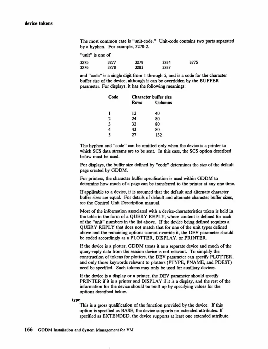
device tokens
The most common case is "unit-code." Unit-code contains two parts separated by a hyphen. For example, 3278-2.
"unit" is one of
3275 3276
3277 3278
3279 3283
3284 3287
8775
and "code" is a single digit from I through 5, and is a code for the character buffer size of the device, although it can be overridden by the BUFFER parameter. For displays, it has the following meanings:
Code Character butTer size Rows Columns
I 12 40 2 24 80 3 32 80 4 43 80 5 27 132
The hyphen and "code" can be omitted only when the device is a printer to which SCS data streams are to be sent. In this case, the SCS option described below must be used.
For displays, the buffer size defmed by "code" determines the size of the default page created by GDDM.
For printers, the character buffer specification is used within GDDM to determine how much of a page can be transferred to the printer at anyone time.
If applicable to a device, it is assumed that the default and alternate character buffer sizes are equal. For details of default and alternate character buffer sizes, see the Control Unit Description manual.
Most of the information associated with a device-characteristics token is held in the table in the form of a QUERY REPLY, whose content is defmed for each of the "unit" numbers in the list above. If the device being defined requires a QUERY REPLY that does not match that for one of the unit types defmed above and the remaining options cannot override it, the DEV parameter should be coded accordingly as a PLOTTER, DISPLAY, or PRINTER.
Ifthe device is a plotter, GDDM treats it as a separate device and much of the query-reply data from the session device is not relevant. To simplify the construction of tokens for plotters. the DEV parameter can specify PLOTTER, and only those keywords relevant to plotters (PTYPE, PNAME, and PDEST) need be specified. Such tokens may only be used for auxiliary devices.
Ifthe device is a display or a printer. the DEV parameter should specify PRINTER if it is a printer and DISPLAY if it is a display, and the rest of the information for the device should be built up by specifying values for the options described below.
type This is a gross qualification of the function provided by the device. If this option is specified as BASE, the device supports no extended attributes. If specified as EXTENDED. the device supports at least one extended attribute.
166 GDDM Installation and System Management for VM

device tokens
By default, all attributes are assumed supported, but this may be overridden by the COLOR, HI LITE, and PS options described below.
APL This indicates (YES) that the device contains the APL character set and has the APL keyboard, or (NO) that the device does not support the APL characters.
This option may be coded for any device. The default is NO for all devices except the 3279 and 3287. for which the default is YES. APL= YES and TEXT = YES cannot both be specified.
When a PS = reply-field is also specified, you should ensure that it is consistent with respect to "graphic-escape supported."
ANOMALY This specifies the reply-field for type X '9D' (anomaly implementation) query reply structured fields.
AUXDEV This specifies the reply-field for type X '99' (auxiliary device) query reply structured fields.
AUXONLY This specifies whether the device is an auxiliary-only device (a plotter). but is not necessary when PLOTTER is specified.
BGTRAN This specifies the reply-field for type X' A8' (background transparency) query reply structured fields.
BUFFER This is an explicit specification of the character buffer size. and consists of two subfields, rows and columns. This parameter may be specified only for EXTENDED type devices. It is required for the generic DISPLAY or the generic non-SCS PRINTER devices. It is optional for generic IPDS PRINTER devices, and invalid for generic SCS PRINTER devices.
COLOR This indicates that the device supports the color attribute.
NO indicates that the device does not support Set-Attribute orders for color.
MONO indicates that Set-Attribute orders may be sent to the device but that each color is displayed or printed in the default color.
If neither of the above two options is coded, the value specified is assumed to be a reply-field for type X' 86' (color) query reply structured fields.
COMPRES This indicates the type of load PS data format that may be sent to the device. YES indicates that the device will accept formats in which the definitions of each character have been compressed to reduce line traffic. NO indicates that only the fulJy expanded form of symbol defmitions may be sent to the device.
The option may be coded only for EXTENDED devices and defaults to NO.
DBeS This specifies the reply-field for type X '91' (DBCS-Asian node) query reply structured fields.
Appendix C. Device characteristics tokens 167

device tokens
OOM lms specifies the reply-field for type X '95' (distributed data management) query reply structured fields.
FLOOUT This specifies the reply-field for type X' se' (field outlining) query reply structured fields.
FMH This indicates that Function Management Headers Type 1 (FMH-l) may be sent (YES) or may not be sent (NO) to an ses device.
If this parameter is omitted for an ses device, the default is YES if the device supports the ses data structured field, and NO if it does not.
GCOLEX This can be used as an extension of the GeO LO R parameter, when the specification exceeds the assembler limit of 455 characters for macro operands.
GCOLOR This specifies the reply-field for type X' B4' (graphics color) query reply structured fields.
GSSETOO through GSSET19 This specifies the sdp-field for the type X' 01' (symbol store definition) self-defining parameter for the graphics symbol sets query reply structured field. The value is from the third byte onwards.
GSSHOR This specifies the first part of the reply-field for type X' B6' (graphics symbol sets) query reply structured fields. The remainder of the reply-field may be specified by one or more GSSETOO through GSSET19 operands and a GSSPSK operand.
GSSPSK lms specifies the sdp-field for the type X' 02' (proportional spacing and kerning) self-defming parameter for the graphics symbol sets query reply structured field. Like the GSSETnn operand, the value is from the third byte onwards.
HILITE This indicates support for the Set Attribute (extended highlighting) order by the device. If NO is coded, the device does not support the order. If the option is not NO, the value specified is assumed to be a reply-field for type X'S7' (highlighting) query reply structured fields.
IMAGE This specifies the reply-field for type X'S2' (image device) query reply structured fields.
IMAUX This specifies the reply-field for type X I AA I (image auxiliary device) query reply structured fields.
IMPART This specifies the reply-field for type X' A6' (implicit partitions) query reply structured fields.
168 GDDM Installation and System Management for VM

device tokens
This option is necessary in those cases where UAREA does not define the buffer size explicitly (for example, for the IBM 3290).
KANJI This indicates (YES) that the device supports the KANJI character set, or (NO) that it does not.
This parameter may be coded only if the DEV parameter is 3278-2, 3283-2 or (if SCS = YES) 3283.
LCID This is a list of symbol-set identifiers, one for each loadable symbol set. Each identifter must be two hexadecimal digits. See the Control Unit Description manual for valid values of these identifiers.
LINETYP This speciftes the reply-field for type X I B2' (line types) query reply structured fields.
MAXPAGE This is an explicit speciftcation of the page size that will be used by GDDM if the default page is created. (The default page is created as page 0 by GDDM if no explicit FSPCRT call is used.) MAXPAGE consists of two subfields, rows and columns.
The rows and colUIIUls values must be positive. For display devices, they must be less than or equal to the rows and columns values of the character buffer size respectively.
For both displays and printers, rows + columns + 2 must be less than or equal to 32000.
If the MAXPAGE parameter is not explicitly specifted in the device token, GDDM applies default values as follows:
For displays, the default values are detennined by the character buffer size. For prir.ters with SCS = YES, GDDM selects appropriate defaults according to the contents of the UAREA field of the device token, and the limits defined above. For IPDS printers, GDDM selects appropriate defaults according to the contents of the RPIPA field of the device token, and the limits defined above. For non-IPDS non-SCS printers, GDDM applies a default value of (80,132).
OEMAUXO through OEMAUX9 These specify the reply-fields for type X' 8F' (OEM auxiliary device) query reply structured fields.
OUTBND This indicates support for the outbound 3270 structured field for displays or, for SCS printers, the support of the SCS data structured field.
If coded as YE..~, the relevant structured field may be sent to the device. NO indicates that the device does not support the structured field.
Appendix C. Device characteristics tokens 169

device tokens
This option may be coded only for EXTENDED types of device. and must not be coded for the generic devices PRINTER and DISPLAY. The default is YES for devices described as "unit-code" which are extended.
PART This specifies the reply-field for type X '84' (partitions) query reply structured fields.
If this option is not coded. the device is assumed to have no partition capability.
PDEST This is the IEEE address of an attached plotter.
PORTO through PORT9 These specify the reply-fields for type X' B3 1 (port) query reply structured fields.
PNAME This is the name of an attached plotter. It must match the name specified when you customize your work station. The suggested names are of the form PLOTTERn.
PROC This specifies the reply-field for type X' B I' (procedure) query reply structured fields.
PTYPE
PS
This is the type of an attached plotter. Supported values are: IBM6180, IBM6182, IBM6186, IBM7371, IBM7372, IBM7374, IBM7375
This indicates the number of programmed symbols set stores in the device. The value can be 0, 2, 4, 6. NO means the same as O. The value 6 may be coded only for displays.
If the option is none of the above. it is assumed to be a reply-field for type X '85' (character sets) query reply structured fields.
REPLY This indicates the reply modes supported by the device. The values coded may be one of FIELD. EFIELD. and CHAR. These indicate support for Field Mode. Extended Field Mode. and Character Mode incoming data streams. respectively. These modes are further described in the Control Unit Description manual.
REPL YO through REPLY9 These specify query reply structured field values from the fourth byte onward.
SCS This indicates (YES) that SCS data streams are accepted or (NO) are not accepted by the device. IfSCS=YES. a type X'A2' (data stream) query reply structured field is generated. The "reply-field" defaults to either X' 00' for non-IPDS tokens or X' 0002' for IPDS tokens.
This keyword may be coded only for PRINTER devices. The default is NO.
170 GDDM Installation and System Management for VM

device tokens
SCSSET This indicates the subset of SCS data streams accepted by a device for which SCS = YES has been specified. It consists of two subfields, the second of which is optional.
The first may be FULL or BASE. The former indicates the FULL BASE subset, the latter the BASE subset. The content of these two subsets of SCS is dermed in the Control Unit Description manual.
The second may be BEL or NOBEL. The former indicates that BEL may be sent to the device, the latter that it may not.
This option may be coded only for devices for which SCS = YES. The default is FULL,BEL for EXTENDED devices, and BASE, NOBEL for BASE devices.
SEGMENT This specifies the reply-field for type X I BO I (segment) query reply structured fields.
STGPOOL This specifies the reply-field for type X 1961 (storage pools) query reply structured fields.
TEXT This indicates (YES) that the device contains the TEXT character set and has a Data Entry keyboard, or (NO) that it does not.
This option may be coded for any device. The default is NO for all devices. APL = YES and TEXT = YES cannot both be specified.
If PS = reply-field is also specified, you should ensure that it is consistent with respect to "graphic-escape supported."
UAREA This specifies the reply-field for type X ISII (usable area) query reply structured fields.
UNSPEC This specifies a complete query reply structured field from the first byte onward.
VALID This specifies the reply-field for type X I SA I (validation) query reply structured fields.
If this option is not coded. the device is assumed to have no validation feature.
DATCHN This specifies the reply-field for type X 1981 (Data chaining) query reply structured fields. This keyword is only valid for IPDS PRINTER devices, and it must be specified if SCS data streams are not accepted.
DSTXBL This specifies the reply-field for type X 19A I (LU-O data stream type, and transfer buffer limit) query reply structured fields. This keyword is only valid for IPDS PRINTER devices, and it must be specified if SCS data streams are not accepted.
Appendix C. Device characteristics tokens 171

device tokens
IPDS This identifies an IPDS token and therefore:
It validates the inclusion of STM and RPI keywords. It dermes the product and model numbers. These are stored in the STM reply-list header.
STMBC This specifies the stm-field for type X I C2C3 1 (bar code) STM query reply structured field.
STMDC This specifies the stm-field for type X I C4C3 1 (IPDS device control) STM query reply structured field.
STMDR This specifies the stm-field for type X I ESC7 I (vector graphics) STM query reply structured field.
STMIM This specifies the stm-field for type X I C9D4 1 (Advanced Function Presentation Datastream - AFPDS - image) STM query reply structured field.
STMIO This specifies the stm-field for type X'C9D61 (IDF image) STM query reply structured field.
STMLF This specifies the stm-field for type X 'C3C61 (loaded font) STM query reply structured field. Three levels are supported with the following dependencies:
LF / I - coded fonts only LF /2 - loaded symbol sets only LF /3 - coded fonts and loaded symbol sets.
STMOL This specifics the stm-field for type X I 0603 1 (overlay) STM query reply structured field.
STMPS This specifies the stm-field for type X I D7E21 (page segment) STM query reply structured field.
STMPT This specifies the stm-field for type X I D7E3 1 (presentation text) STM query reply structured field.
RPIFA This specifies the rpi-field for type X 100071 (features available) RPI query reply structured field.
RPIFC This specifies the rpi-field for type X 100051 (foreground colors) RPI query reply structured field.
172 GDDM Installation and System Management for VM

device tokens
RPIFI This specifies the rpi-field for type X' 0006' (features installed) RPI query reply structured field.
RPIFR This specifies the rpi-field for type X' 0003' (font resolution) RPI query reply structured field.
RPIPA, RPIPAn These specify the rpi-field for type X'OOO}' (printable area defmition) RPI query reply structured field. n is the bin number, for multiple bin printers.
RPIPQ This specifies the rpi-field for type X '0009' (print quality) RPI query reply structured field.
RPIRFnn This specifies the sdp-field for type X' O}' (resident font code page support) self-defming parameter. A number of these parameters are concatenated together to form the rpi-field for type X' 0008' (resident font list) RPI query reply structured field.
RPISPD This specifies the sdp-field for type X' 0 I' (storage pool) self-defming parameter. This default parameter always forms the first or only part of a type X'0004' (storage pool list) RPI query reply structured field.
RPISPn This specifies the sdp-field for type X' 0 I' (storage pool). These supplementary parameters are concatenated together with the default parameter to form the rpi-field of a type X '0004' (storage pool list) RPI query reply structured field.
RPISSF This specifies the sdp-field for type X '01' (symbol set, fixed block size) self-defming parameter. This parameter forms the first or only part of the RPI field for a type X'0002' (symbol set) RPI query reply structured field.
RPISSV This specifies the sdp-field for type X' 02' (symbol set, variable block size) self-defming parameter. This parameter forms the second or only part of the RPI field for a type X' 0002' (symbol set) RPJ query reply structured field.
Notes relating to IPDS tokens:
l. The IPDS keyword may be coded only for PRINTER devices.
2. The IPDS device supports LU- I mode (SCS = YES), or LU-O mode (SCS = NO), LU-O being the default.
3. A data-stream query reply structured field is generated either (1) as described by the SCS keyword for LU-} mode tokens, or (2) as described by the DSTXBL keyword for LU-O mode tokens.
4. The BUFFER keyword can be omitted. This is equivalent to BUFFER = (0,0).
Appendix C. Device characteristics tokens 173

device tokens
S. All objects that are not specified in supplementary storage pools are stored in the default storage pool.
6. If a null parameter is coded for features available, the default will be a copy of the features-installed parameter.
7. The keywords STMDC, RPIFR, RPIPA, and RPISDP must be specified. All the other STM or RPI keywords are optional.
Possible error messages/rom ADMM3170 macro
ADMsse1 E DEVICE PARAMETER OMITTED ADMSeS2 E DEVICE PARAMETER la l IS INVALID ADMSeS3 E THE NAME PARAMETER IS REQUIRED ADMSSe4 E USER NAMES MUST NOT START WITH IADMI ADMS8SS E CODE Inl IS INVALID FOR DEVICE la l AOMS886 E A VALUE FOR KEYWORD la l IS REQUIRED AOMS897 E la1=a21 IS INVALID FOR GENERIC DEVICES AOMS888 E la1 1 MAY NOT BE CODED FOR la21 DEVICES ADMSe89 E THE VALUE la21 FOR KEYWORD la1 1 IS INVALID ADMSB1B E MAIN CONTROL SECTION NAME MUST BE la l ADMSB11 E TOO MANY LCIDS ARE SPECIFIED ADM5e12 E GENERIC DEVICES MUST NOT BE SPECIFIED AS BASE ADMSB13 W NO DATA GENERATED FOR THIS DEVICE AOM5B14 E END PROCESSING HAS ALREADY OCCURRED AOMSelS E TOO MANY POSITIONAL OPERANDS ADMSB24 E KEYWORD la1 1 IS REQUIRED WITH la21 ADMSB2S E KEYWORD la l MUST HAVE 2 VALUES ADMSB26 E THE la l AREA (n) EXCEEDS 16SeB ADMS827 E la11 MAY NOT BE CODED WITH la2=REPLY-FIELDI ADM5928 E KEYWORD la l IS ONLY VALID FOR PRINTER DEVICES AOMSe29 E KEYWORD la l IS ONLY VALID FOR IPDS DEVICES ADM583B E INVALID LU-MODE SPECIFICATION ADM5831 E LEVEL n IS NOT VALID FOR KEYWORD la l AOM5832 E KEYWORD la l DOES NOT EXIST ADM5e33 E INVALID VALUE SYNTAX FOR KEYWORD la l
Example of coding a device characteristics token . Some device tokens can be defined using only the "unit-code," BUFFER, and
COMPRES options. If only these options are coded, the remainder of the options default to the maximum function or capability. For example, for 3279 devices it is assumed by default that all the extended attributes are supported, and that the maximum number of loadable PS stores is available. Thus, one of the GDDM-supplied tokens for a 3279 Model 3 is:
L79A3 ADMM327B 3279-3
An example of the coding for a device characteristics token using the UAREA and other values is given in Figure 68.
174 GDDM InstaUatlon a!,d System Management for VM

device tokens
********************************************************************** * * * * * *
EXAMPLE OF FULL SPECIFICATION OF DEVICE TOKEN. * * * * * *
(The following hexadecimal Reply-fields specify Query Reply structured fields from the fifth byte onwards.)
********************************************************************** ADMKge6a ADMM3279 DISPLAY,EXTENDED,BUFFER=(62,16a),REPLY=CHAR,APL=YES, X
UAREA=(X'93ABe3caa2EFeleeB5aeeEaea5geeEB6BcaeB9B6BClBlF'X ), X HILITE=(X'B499FBFIFlF2F2F4F4'), X PART=(X'la6Seese',x'e7S2929aaeeaBS'), X IMPART=(X'8eea',X'SBSlSSSB5SBa18SSASBB3E',X'SBS2esaeS6sex scsse6SBSC'}, X PS=(X'BSaee91e6eaeeBS895',x'aseaaea91e' ,X 'aeeeeee91e ' , XIX elSBF199l9',x'e199FlS91B',X'B28aFFa91e',x'a38BFFe91e',XIX e4S9FF991B',x'e5seFFe91B',X'B6SBFFe9la',x'e7SBFFS91B'}, X COLOR=(X'9aeSeeFAFlseF2eaF3eeF4eaF5aeF6eaF7ae'}
**********************************************************************
For detailed descriptions of each of the above reply-fields, see the Control Unit Description manual. The query reply structured fields generated by the macro are as follows:
ADMIBllA EQU DC DC DC
ADMlaUB EQU AOMla14A EQU
DC DC DC
ADM1814B EQU ADM1815A EQU
DC DC DC
ADM1815B EQU ADMle16A EQU
DC DC DC
ADMIB16B EQU
* AL2(ADMIBIIB-AOMI811A) X'SlSl' USABLE AREA x'e3Aee3cea2EFelaea5eeaEeessee9EB69CB9aeS6eC191F' * * AL2(ADM1S14B-ADMI914A} X'SlS4' PARTITIONS X'le6eSBSS' ,X , S7S2e2BeeeS98S , * * AL2(ADM1915B-ADMlSlSA} X 'SlSS' CHARACTER SETS X'BSB9991B6geBeaeBBS' ,X'8se88Be919',X'B89Beee91e' ,x'el X
eBF19919',X'81e9F19919',X'8288FF8919',X'8388FFe91S',X'e4X SSFFe91e' ,x'e589FFe91S' ,X'86seFFe919',x'e78eFF9919'
* * AL2(ADMI816B-ADMlaI6A} X '81S6 ' COLOR REPLY X'9aasaeFAF1geF28aF3S8F4e9FS98F6eeF7e8' *
Figure 68 (Part 1 of 2). Example of coding a device token
Appendix C. Device characteristics tokens t 75

device tokens
ADMltl17A EQU DC DC DC
ADMltl17B EQU ADMltl18A EQU
DC DC DC
ADMltl18B EQU ADMltl16E EQU
DC DC DC
ADMle16F EQU
* AL2(ADMltl17B-ADMltl17A) X'8187 1 HIGHLIGHTING X' tl4tltlFeFIFIF2F2F4F4 1 * * AL2(ADMltl18B-ADMle18A) X 18188 I REPLY MODES X 'etleltl2 I * * AL2(ADMltl16F-AOMltl16E) X'81A6 1 IMPLICIT PARTITIONS X' tltletl ' ,X ' tlBtlltltltltl5tltltl18tltlAtltltl3E',X 'eBe2eeeee6eeeCeee6X
tleeCI *
Figure 68 (Part 2 of 2). Example of coding a device token
176 GDDM InstaUalion and System Management for VM

device tokens
The ADMMSYSP macro The ADMMSYSP macro is used to defme the device characteristics of a system printer (family 3) that is accessed using GDDM functions. The syntax of the macro is given below:
name ADMMSYSP
name
type. MAXPAGE=. SPACING=
3800 I * I omitted (rows.columns) (lines/inch,columns/inch)
This is the name of the device characteristics token. It is from 1 to 8 characters long and must follow the rules for assembler labels. It must be present on all invocations of the macro except the last where it must be omitted. The name must not start with the letters ADM.
type This determines whether one- or two-character carriage control sequences are to be used. If this parameter is omitted or coded as *, a single carriage-control character will be used. If 3800 is coded, the additional Table Reference Characters for 3800 printers will be used.
MAXPAGE This is two integer values in the range 1 through 32767. The first is the maximum number of rows that may be created on a GDDM page, the second the number of columns. The number of columns does not include space required for carriage control. The output print me will be 1 or 2 characters wider than the size given.
The default value is (66,132).
SPACING These are two integer values in the range 1 through 32767. The first is the number of lines per inch, and the second the number of columns per inch on the device.
The default value is (6,10).
Possible error messagesfrom ADMMSYSP macro
ADMS003 E THE NAME PARAMETER IS REQUIRED ADMS0e4 E USER NAMES MUST NOT START l~ITH 'ADM' AOMS8S9 E THE VALUE 'a2' FOR KEYWORD 'aI' IS INVALID ADMS8l0 E MAIN CONTROL SECTION NAME MUST BE 'a' ADMS813 W NO DATA GENERATED FOR THIS DEVICE ADMS014 E END PROCESSING HAS ALREADY OCCURRED ADMS01S E TOO MANY POSITIONAL OPERANDS ADMS016 E INVALID DEVICE TYPE 'a'
Appendix C. Device characteristics tokens 177

device tokens
The ADMMIMAG macro To generate device tokens for family 4 (composed-page) devices you need the ADMMIMAG macro instruction. The syntax of the macro invocation is as follows:
name ADMMIMAG type, PPI=value,
device number pixels per inch
LI NE=va 1 ue, PAPER=(width,
depth, units)
pixels per unit line width default paper width default paper depth units (1/10 inch or mm)
name This is the name of the device characteristics token. It is from 1 to 8 characters long and must follow the rules for assembler labels. It must be present on all invocations of the macro except the last, from which it must be omitted. The name must not start with the letters ADM.
type This is the device number, and it is required if the image data is to be formatted according to specific device requirements. Specify 4250 for the IBM 4250 Printer or 3800 for the IBM 3800 Printing subsystem (composed-page printer). (The 3820 and 3812 printers are treated as being 3800 composed-page printers.)
PPI This is the factor to be used in converting the image size from inches to pixels.
LINE This is the factor to be used in calculating line widths. The value indicates the number of pixels per unit line width.
PAPER This defmes the default size of the medium on which the image is to be drawn. The width and depth are specified in units of tenths of inches or millimeters according to the units parameter.
units = 0 1
tenths of inches millimeters
Possible error messages from ADMMIMAG macro
ADMS993 E THE NAME PARAMETER IS REQUIRED ADMS004 E USER NAMES MUST NOT START WITH IADMI ADMS009 E THE VALUE la21 FOR KEYWORD la1 1 IS INVALID ADMS010 E MAIN CONTROL SECTION NAME MUST BE la l ADMS913 W NO DATA GENERATED FOR THIS DEVICE ADMS914 E END PROCESSING HAS ALREADY OCCURRED ADMS01S E TOO MANY POSITIONAL OPERANDS ADMS016 E INVALID DEVICE TYPE la l
Example of the ADMMIMAG macro
IMG8S ADMMIMAG 42S0,PPI=600,LINE=6,PAPER=(8S,110,O)
178 GDDM Installation and System Management for VM

symbol sets
Appendix D. GDDM default symbol sets
See "Symbol sets" on page 107 for a brief description of what symbol sets are and how they are used. Full descriptions of using symbol sets are in the GDDM Image Symbol Editor and GDDM-PGF Vector Symbol Editor manuals. The GDDM Typefaces and Shading Patterns booklet illustrates and summarizes the supplied symbol sets.
Default symbol sets are the symbol sets that GDDM uses to display character strings, to shade areas, and to draw markers when the user has not specified an alternative.
Some of the symbol sets used by GDDM are provided both within load modules and, separately, in editable source fonnat. The symbol sets in the load modules are used by default when GDDM displays text or graphics. The editable fonnats allow installations to change the defaults if they want to, or they can be used as a basis for creating your own symbol sets, for example, to change currency symbols.
Figure 70 on page 181 shows the names and uses ofthe symbol sets. Note that, for some of the vector symbol sets, the name within the load module is not the same as that of the editable symbol set. Use Figure 69 on page 180 to give a last letter that corresponds to the smallest containing cell size. Figure 69 also lists the devices for which each set may be suitable.
Appendix D. GDDM default symbol sets 179

symbol sets
Last Matrix Monochrome Suitable devices letter size or multicolor
A 9 x 16 Monochrome 3278 Display Station Models 2 and 3 8775 Display Terminal Models 1 and 11 8775 Display Terminal Models 2 and 12
(can be either 9 x 16 or 9 x 12) 3270-PC Work station
(symbol size is 9 x 14) 3270-PC/G Work station 3290 Panel display, all models
C 9 x 12 Monochrome 3278 Display Station Model 4 8775 Display Terminal Models 2 and 12
(can be either 9 x 16 or 9 x 12) IBM PC EGA high-resolution display
adapter IBM Personal System/2 display adapter
D 9 x 12 Multicolor 3179 Model G Color Display 3279 Color Display Station, all models
E 9 x 10 Monochrome 3270-PC/G alphanumerics only IBM PC CGA display adapter IBM PC EGA low-resolution display
adapter
G lOx 8 Monochrome 3268, 3287 Printers, all models
H 10 x 8 Multicolor 3268, 3287 Printers, all models
J - Monochrome 4250 Printer (high-resolution symbol sets, 400 pels per inch or greater)
K 20 x 18 Monochrome 4224 Printer
L - Monochrome 3800 Printer (medium-resolution symbol sets, less than 400 pels per inch)
N 8 x 16 Multicolor 3270-PC/G, all models (graphics only)
Q 24 x 30 Monochrome 3812 Model 2 Printer
R 12 x 20 Multicolor 3270-PC/GX, all models
12 x 24 5550 multistation IBM Personal System/2 8514/A display
adapter
U - Multicolor 618x and 737x plotters
Figure 69. Last leUers of sample symbol set names
180 GDDM Installation and System Management for VM

symbol sets
If the device has a cell size that is not one listed above, GDDM selects the character that corresponds to the smallest containing cell size. For example, for a device cell size of 9 by 14, such as 3270-PC, GDDM selects an image symbol set with a cell size of 9 by 16 (last letter A). This means that the 3270-PC can suffer from bars across shaded patterns giving an effect known as the "venetian blind" effect.
Name within Editable set Type Usage and size load module name if different
ADMDHHVN ADMDVIH ... Vector Mode 3 text ( 8 by 16) ADMDHHVR ADMDVIH ... Vector Mode 3 text (12 by 20)
ADMDHIIA ADMDHHIA Image Mode 2 text ( 9 by 16) ADMDHIIC ADMDHHIC Image Mode 2 text ( 9 by 12) ADMDHIIG ADMDHHIG Image Mode 2 text (10 by 8) ADMDHIIK ADMDHHIK Image Mode 2 text (20 by 18) ADMDHIIN ADMDHHIN Image Mode 2 text ( 8 by 16) ADMDHIIQ ADMDHHIQ Image Mode 2 text (24 by 30) ADMDHIIR ADMDHHIR Image Mode 2 text (12 by 20)
ADMDHIMA Image Markers ( 9 by 16) ADMDHIMC Image Markers ( 9 by 12) ADMDHIMG Image Markers (10 by 8) ADMDHIMJ Vector Markers ADMDHIMK Image Markers (20 by 18) ADMDHIMN Image Markers ( 8 by 16) ADMDHIMQ Image Markers (24 by 30) ADMDHIMR Image Markers (12 by 20) ADMDHIMV Vector Markers
ADMDHIPA Image Patterns ( 9 by 16) ADMDHIPC Image Patterns ( 9 by 12) ADMDHIPG Image Patterns (10 by 8) ADMDHIPJ Image Patterns (32 by 32) ADMDHIPK Image Patterns (32 by 32) ADMDHIPM Image Patterns (32 by 32)
ADMDHIVA ADMDVSS Vector Mode 3 text ( 9 by 16) ADMDHIVC ADMDVSS Vector Mode 3 text ( 9 by 12) ADMDHIVG ADMDVSS Vector Mode 3 text (10 by 8) ADMDHIVJ Vector Modes I, 2 and 3 text ADMDHIVK ADMDVSS Vector Mode 3 text (20 by 18) ADMDHIVM Vector Modes 1,2 and 3 text
(See Note)
ADMDHIVN ADMDVSS Vector Mode 3 text ( 8 by 16) (See Note)
ADMDHIVQ ADMDVSS Vector Mode 3 text (24 by 30) ADMDHIVR ADMDVSS Vector Mode 3 text (12 by 20) ADMDHIVW ADMDVSS Vector Mode 3 text (plotters)
Figure 70 (Part 1 of 2). Sample symbol set names and usage in load module and editable formats
Appendix D. GDDM default symbol sets 181

symbol sets
Name within Editable set Type Usage and size load module name if different
ADMDHJIA ADMDHIIA Image Mode 2 text ( 9 by 16) ADMDHJIC ADMDHIIC Image Mode 2 text ( 9 by 12) ADMDHJIG ADMDHIIG Image Mode 2 text (10 by 8) ADMDHJIK ADMDHIIK Image Mode 2 text (20 by 18) ADMDHJIN ADMDHIIN Image Mode 2 text (8 by 16) ADMDHJIQ ADMDHIIQ Image Mode 2 text (24 by 30) ADMDHJIR ADMDHIIR Image Mode 2 text (12 by 20)
ADMDHNA ADMDVECP Vector Mode 3 text ( 9 by 16) ADMDHNC ADMDVECP Vector Mode 3 text ( 9 by 12) ADMDHJVG ADM DVECP Vector Mode 3 text (10 by 8) ADMDHJVJ Vector Modes I, 2 and 3 text ADMDHNK ADMDVECP Vector Mode 3 text (20 by 18) ADMDHNM Vector Modes I, 2 and 3 text
(See Note)
ADMDHNN ADMDVECP Vector Mode 3 text (8 by 16) (See Note)
ADMDHJVQ ADMDVECP Vector Mode 3 text (24 by 30) ADMDHJVR ADMDVECP Vector Mode 3 text (12 by 20) ADMDHJVW ADMDVECP Vector Mode 3 text (plotters)
figure 70 (Part 2 of 2). Sample symbol set names and usage in load module and editable formats
Note: + means equivalent to a symbol set built into the device
Symbol set load modules ADMDHIxx are compatible with previous releases of GDDM and are used for non-CECP processing; the ADMDHJxx modules are CECP sets, tagged with country-extended code page 00037.
You should carefully note the relationship between symbol set names and load module names for image sets.
Changing the default symbol sets or making another set the default If you want to change any of the default symbol sets or make another symbol set the default, you must replace the version in the ADMGLIB TXTLIB. To do this you create a deck version of the symbol set with the name shown in the "Name within Load Module" column in Figure 70 on page 181. You then replace it in ADMGLIB. If you use a DCSS for GDDM Base, you will need to rebuild it.
You must also ensure that GDDM uses the changed default by issuing the LOADDSYM processing option. The easiest way to do this is by the nickname
[label] ADMMNICK PROCOPT=((lOADDSYM,YES»
Examples of changing symbol sets are given at the end of this appendix.
182 GDDM Installation and System Management ror VM

symbol sets
Changing the default vector symbol set from American-English The country-extended code-page support, which is new in GDDM Version 2 Release 2, makes the provision of default vector symbol sets for national language use very much simpler than before. If you specify a CECP as your installation and application code-page, then your application programs, including the GDDM utility programs, will produce the correct national-use characters, without any further action on your part.
The external defaults to use are:
[label] ADMMDFT INSCPG=nnnnn,APPCPG=nnnnn
where nnnnn is the code-page number (see page 120).
If you decide to change a supplied symbol set that is tagged with a country-extended code page, set the application code page to 00037 before you use the symbol editor.
National language vector symbol sets, including items such as accented letters, can also be made the default vector symbol set for non-CECP processing by using the Vector Symbol Editor to generate deck versions and linking them into a TXTLIB.
An example of how to do this is shown at the end of this appendix.
The following image symbol sets also support Katakana:
Name Cell size Description
ADMDISKA 9 x 16 Katakana ADMDISKC 9 x 12 Katakana ADMDISKG 10 x 08 Katakana ADMDISKN 8 x 16 Katakana for 16 x 16 5550 ADMDISKR 12 x 24 Katakana for 24 x 24 5550
How and where sample symbol sets are held The editable versions of the symbol sets exist with the ftletype of ADMSYMBL. The deck formats generated by the symbol editors have a default ftletype of ADMDECK. The load module formats used by GDDM exist as TEXT decks contained in the relevant TXTLI8s or saved segments.
Note that the CECP load modules ADMDIIJI+ correspond to the sample sets ADMDHII+.
Setting up pattern sets available to leu users on your installation If you want to set up an extended pattern set to be generally available to ICU users in an installation, create a user-dermed pattern set with the name ADMICUPx, where "x" can be either "D" or "C," depending upon the device type in use.
For example, the sample 64-color shading pattern set supplied on the distribution tape under the name ADMCOLSD need only be copied under the name
Appendix D. GDDM default symbol sets 183

symbol sets
ADMICUPD to become available to ICU users with pattern values 65 through 128. The copying can be done with the Copy command of the ICU Directory panel. For further infonnation on setting up your own pattern sets, see the GDDM-PGF Programming Reference manual.
Example of changing the default symbol sets
Example - Making the French vector symbol set the default The same instructions can be followed for any of the national language symbol sets. Note that the ADMDVSS vector symbol set has six load module fonnat names but only one editable fonnat. All load module fonnats are identical.
I. Start the Vector Symbol Editor. The command is ADMVSSE.
2. Start editing the French symbol set by entering it in the symbol set field thus:
Symbol Set ==> ADMDVSSF
3. Save the symbol set in deck fonn with the following names ADMDHIV A, ADMDHIVC, ADMDHIVG, ADMDHIVN, ADMDHIVR, and ADMDHIVW, in the manner shown below:
a. Rename the set to ADMDHIV A with the command RENAME ADMDHIVA
b. Save the deck with this name with the command SAVE DECK c. Repeat the process for the other names.
4. Replace the saved decks in ADMGLIB.
a. Leave the Vector Symbol Editor, using PF3.
b. Rename the files to a fIletype of TEXT.
c. Replace the members of the ADM GLIB TXTLIB with commands like TXTLIB ADD ADMGLIB ADMDHIVA.
5. If you have created a DCSS for GDDM Base, rebuild it to make the updates available.
184 GDDM Installation and System Management for VM

VTAM
Appendix E. Checking a VT AM network
This section does not apply if you are installing GDDM on a VM/XA system.
The following two licensed programs enable tenninals running under CMS to have access to VTAM·attached devices.
• The Virtual Machine/VT AM Communications Network Application (VM/VCNA)
• VM SNA Console Support (VSCS), part of Advanced Communication Function for VTAM Version 3 for VM,licensed program 5664·280.
IfGDDM is to be used with VTAM, the VTAM network definition should be reviewed. Particular attention should be paid to the bind images that are set in the PSERVIC operand of the MODEENT macro. The bind image is used by GDDM to determine the type of device to which it is sending the data stream. If the bind image is wrong, GDDM will not work.
GDDM requires that a logmode table should exist and that the LU, TERMINAL, or LOCAL macros in the system defmition should nominate the logmode table and the MODEENT entry within the table.
For details on the use of these VT AM macros, see the appropriate ACF /VTAM installation manuals and the manual Network Program Products Samples: VM SNA. The instructions that follow, however, should be enough to let you do the work necessary to install GDDM.
In addition to checking these macros, you may also consider using VPACING, and enlarging the IOBUF area to improve performance.
Queriable terminals and printers The term "queriable" is used to describe those devices which support the Write Structured Field (WSF) command and the Read Partition (Query) Structured Field, within the 3270 Data Stream.
lbe 3270 Data Stream is described in the IBM 3270 Information Display System Data Stream Programmer's Reference manual. Typical devices within this category, such as any 3270·PC work station, 5550 multistation, or 8775 display, support some of the following:
Programmed Symbols (PS) 7-color Extended highlighting Partitions Graphics (using GDDM) Image IPDS-mode operation.
Appendix E. Checking a vr AM network 185
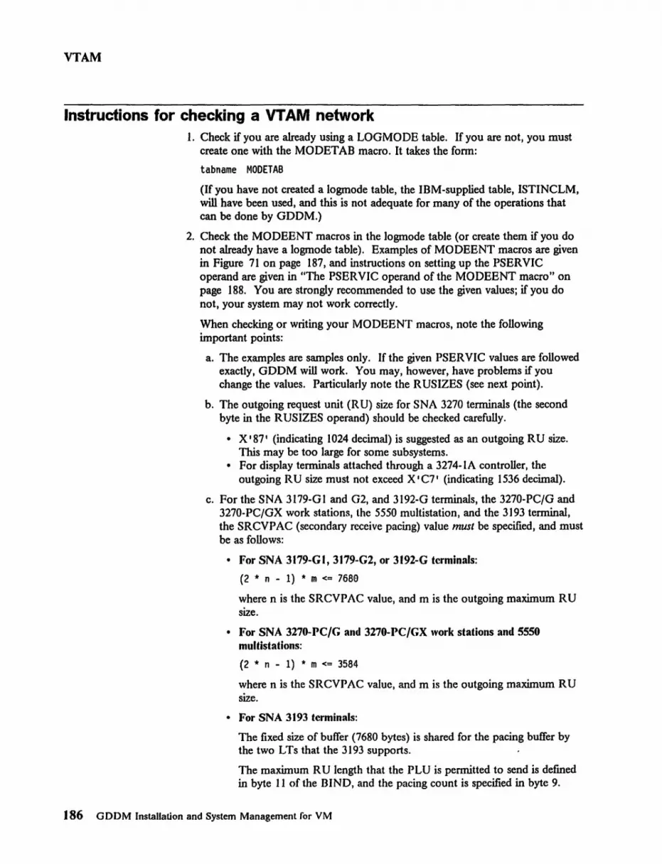
VTAM
Instructions for checking a VT AM network 1. Check if you are already using a LOGMODE table. If you are not, you must
create one with the MODETAB macro. It takes the form:
tabname MODETAB
(If you have not created a logmode table, the IBM-supplied table, ISTINCLM, will have been used, and this is not adequate for many of the operations that can be done by GDDM.)
2. Check the MODEENT macros in the logmode table (or create them if you do not already have a logmode table). Examples of MODEENT macros are given in Figure 71 on page 187, and instructions on setting up the PSERVIC operand are given in "The PSERVIC operand of the MODEENT macro" on page 188. You are strongly recommended to use the given values; if you do not, your system may not work correctly.
When checking or writing your MODEENT macros, note the following important points:
a. The examples are samples only. If the given PSERVIC values are followed exactly, GDDM will work. You may, however, have problems if you change the values. Particularly note the R USIZES (see next point).
b. The outgoing request unit (R U) size for SNA 3270 terminals (the second byte in the RUSIZES operand) should be checked carefully.
• X I 87 I (indicating 1024 decimal) is suggested as an outgoing R U size. This may be too large for some subsystems.
• For display terminals attached through a 3274-IA controller, the outgoing R U size must not exceed X I C7 I (indicating 1536 decimal).
c. For the SNA 3179-Gl and G2, and 3192-G terminals, the 3270-PC/G and 3270-PC/GX work stations, the 5550 multistation, and the 3193 terminal, the SRCVPAC (secondary receive pacing) value must be specified, and must be as follows:
• For SNA 3179-GI, 3179-G2, or 3192-G terminals:
(2 * n - 1) * m <= 7680
where n is the SRCVPAC value, and m is the outgoing maximum RU size.
• For SNA 3270-PC/G and 3270-PC/GX work stations and SSSO multistations:
(2 * n - 1) * m <= 3584
where n is the SRCVPAC value, and m is the outgoing maximum RU size.
• For SNA 3193 terminals:
The fixed size of buffer (7680 bytes) is shared for the pacing buffer by the two LTs that the 3193 supports.
The maximum R U length that the PLU is permitted to send is defined in byte 11 of the BIND, and the pacing count is specified in byte 9.
J 86 G DDM Installation and System Management for VM

VTAM
The 3193 accepts a maximum R U size and a pacing count within the following limits:
The BIND to one (LT-l or LT-2) is accepted if the following formula is met:
(2 * n - 1) * m <= 6144
where n is the SRCVPAC value, and m is the outgoing maximum RU size.
The BIND to the other LT is accepted if:
(2 * n - 1) * m <= 768e - buffer
where buffer is the buffer size already allocated to the fust LT.
d. On non-SNA (LUO) display terminals for VM/VCNA, VM/VCNA (and therefore GDDM) relies on the setting of byte 2 of the PSERVIC operand to distinguish 3277 displays from other types of display tenninal. Ensure that this byte is set correctly, as shown in "The PSERVIC operand of the MODEENT macro" on page 188.
3. Check that the MODETAB and DLOGMOD operands have been included in your system-defmition table and that they point to the correct logmode tables and MODEENT entries for the terminals.
You should specifically ensure that the DLOGMOD operands are always explicitly included, and not permitted to default.
The MODETAB and DLOGMOD operands may be coded for individual terminals in the LU, LOCAL, or TERMINAL macros or for a number of terminals in the GROUP, LINE, or CLUSTER macros. Examples of the use of these macros are shown in Figure 72 on page 189.
4. For queriable non-SNA terminals, FEATUR2= EDATS must be included in the TERMINAL macro for individual tenninaIs, or at a higher level for a number of terminals in the GROUP, LINE, or CLUSTER macros.
5. Consider the use of VPACING to improve perfonnance because of the large data streams genr:rated by GDDM. (See under "Performance background" in Chapter 1 and under "Tuning and customization by subsystem" in Chapter 2 of the GDDM Performance GUide.)
6. If non-SNA displays are in use, consider the size of the I/O buffer pool as specified by the IOBUF parameter in VT AMLST. The large size of data streams generated by GDDM and the mode in which they are transmitted by GDDM may require an increase in the value of this parameter.
Appendix E. Checking a vr AM network 187

VTAM
The MODEENT macro for non-SNA 3270 terminals:
MODEENT LOGMODE=modname, TYPE=1, FMPROF=X'02', TSPROF=X'02', PRIPROT=X'71' , SECPROT=X'40', COMPROT=X'2ee0', PSERVIC=X' ..•..
C C C C C C C
The MODEENT macro for SNA 3179-Gl and 3179-G2 tenninals, 3270-PC/G and 3270-PC/GX work stations, 3193 displays, and 5550 multistations:
MODEENT LOGMODE=modname, C TYPE=1, C FMPROF=x'e3', C TSPROF=X'03', C PRIPROT=X'Bl', C SECPROT=X'90', C COMPROT=X'308e', C RUSIZES=X'8587', C PSNDPAC=X'01' C SRCVPAC=X'01' C PSERVIC=X' .....
The MODEENT macro for other SNA 3270 terminals excluded from the above:
MODEENT LOGMODE=modname, TYPE=l, FMPROF=X '03', TSPROF=X '(=)3 , ,
PRIPROT=X'Bl', SECPROT =X '90' , COMPROT =X ' 3080 ' , RUSIZES=X'8587', PSERVIC=X' .....
Figure 71. Examples or MODEENT macro instructions
C C C C C C C C
The PSERVIC operand of the MODEENT macro
Bytes 1 through 6, and 12 These bytes defme the terminal and should be set as follows:
Nonqueriable devices
X'0ee0ee0eeee0 .......... 00' for a non-SNA display tenninal (LUO) X' 02e000e0e00e .......... ee' for an SNA display terminal (LU2)
188 GDDM Installation and System Management ror VM

Bytes 7 through 11
Queriable devices
X I eeseeeeeeeee •••••••••• ee I for a non-SNA display terminal (LUO) X I e2SeeeEleeeee •••••••••• eEl I for an SNA display tenninal (LU2)
VTAM
Under VM/VCNA and under VM SNA, the following must be coded for non-SNA (LUO) display terminals that are not 3277s:
X I •• 4e •••••••••••••••••••• I nonqueriable terminal X I .. ce .................... I queriable terminal
These defme the "screen sizes."
For display terminals
X I •••••••••••• EleeeeEleee1. • I for size 480 (12x40) X I •••••••••••• eeeeeeeee2 •• I for size 1920 (24x80) Xl •••••••••••• eC28ecse7F •• I for dual sizes 480,960 (12x40,12x80) X I •••••••••••• 18Se18SEl7F •• I for dual sizes 1920,1920 (24x80,24x80) X I •••••••••••• 18SEl2eSe7F •• I for dual sizes 1920,2560 (24x80,32x80) X I •••••••••••• lSSEl2BSEl7F •• I for dual sizes 1920,3440 (24x80,43x80) X I •••••••••••• 18selB847F •• I for dual sizes 1920,3564 (24x80,27xI32)
For 3290 Information Display Panel, 5279 and 5379 Displays (the 5279 and 5379 displays are part of the 3270-PC/G and IGX work stations).
The 3290, 5279, and 5379 displays may be set up to have any of a large number of screen sizes. Their PSERVIC operands should be:
X I •••••••••••• rdcdraca7F •• I
where: (rd,cd) is the default screen size in rows and columns (ra,ca) is the alternate screen size in rows and columns rd, cd, ra, and ca are single-byte hexadecimal numbers
A typical configuration for such a display (and the standard configuration for 5279s and 5379s) would specify a default screen size of 24 x 80 and an alternate screen size of 32 x 80.
Particular subsystem levels may restrict the values that can be supported. (This depends on how the device was customized.) For an SNA device, the value here will override a customized value. For non-SNA devices, the values must match.
Appendix E. Checking a vr AM network 189

VTAM
Default log modes
The LU macro for SNA 3270 terminals:
LU LOCADDR=addr t
MODETAB=tabname t
DLOGMOD=modname,
other parameters
C C C
The MODETAB and DLOGMOD operands can also be specified on the PU macro.
The LOCAL macro for non-SNA 3270 terminals:
LOCAL CUADDR=addr, MODETAB=tabname, DLOGMOD=modname,
other parameters
C C C
The TERMINAL macro for non-SNA 3270 tenninals:
TERMINAL ADDR=addr, C MODETAB=tabname, C DLOGMOD=modname, C FEATUR2=EDATS, C
other parameters
FEATUR2 = EDA TS must only be specified for queriable terminals.
Verify that FEATURE2= MODELl is not implicitly specified for devices that have a default buffer size larger than 480 bytes.
The FEATUR2, MODETAB, and DLOGMOD operands can also be specified on the GROUP, LINE, and CLUSTER macros.
The DLOGMOD operand should always be specified explicitly. It should not be allowed to default.
Figure 72. Examples of LU, TERMINAL, and LOCAL macros
The specification of the logmode on the macros provides only the default logmode. VT AM provides a mechanism to override the default. For example, the tenninal operator may be able to specify the logmode on the LOGON command, or a logmode may be added to the LOGO N command as a result of command conversion driven by the USSTAB defmition table. You should therefore ensure that a suitable logmode name is selected whatever the source of the name.
190 GDDM Installation and System Management for VM

customizing devices
I Appendix F. Customizing devices
3270-PC/G and 3270-PC/GX customization
Plotters
If you are using GDDM with IBM 3270-PC/G or 3270-PC/GX work stations (the 5279 and 5379 displays), you will need to customize the work stations using the Graphics Control Program. When you customize a 3270-PC/G or 3270-PC/GX work station, you will need to specify several things:
• The name to be used for your plotter (see "Plotters" below).
• The identifications of, and number of, host sessions. This will depend on how you customized your 3274 controller. If you are going to use complex graphics in GDDM, you should try to restrict the number of host sessions so that performance is not impaired.
• The storage for each session (host or PC). You should try to allocate as much storage as possible if you are using GDDM. Storage sizes depend on the type of application you plan to run. Simple alphanumeric pictures will require significantly less storage in the work station than complex graphics. See below for guidance on this topic.
Full details of the customization procedures for these work stations can be found in these manuals:
• Introduction to the IBM 3270-PC/G and /GX • 3270-PC/G Guide to Operations • 3270-PC/GX Guide to Operations • Graphics Control Program User's Guide.
If you are using a plotter attached to the IEEE-488 port of a 3270-PC/G or /GX, you will have supplied a plotter name during the customization of the device (as described in the Graphic.r Control Program User's Guide). This plotter name corresponds to the "auxiliary-device-name" referenced by GDDM in a DSOPEN call or in a nickname (see "Nicknames" on page 63).
GDDM recognizes the reserved name ADMPLOT as a reference to the frrst plotter attached to a work station.
3274 configuration When using a remote non-SNA (BSC) attachment, the 3270-PC/G and /GX also require that 3274 WACK support is configured. If this is not done, you may experience line timeouts.
To configure WACK support, specify 1 in reply to 3274 Customization question 176 BSC Enhanced Communication Option (Distributed Function Terminals).
Appendix F. Customizing devices 191

customizing devices
3270-PC/G and IGX segment storage requirement for GDDM To fully exploit the capabilities of the 3270-PC/G and /GX work stations, such as dragging or local pan and zoom, GDDM must be able to operate in retained mode to these devices. This is the default case, when sufficient segment storage has been allocated to the GDDM host session in the work station.
In addition to the increased function that retained mode operation offers, there are also potential performance advantages, particularly in the area of data-stream reduction.
Figure 73 and its following notes should be used as a starting point for 3270-PC/G and /GX segment storage allocation.
GDDM picture type
1. ICU business charts 2. Simple GDDM Base graphics 3. Scientific and engineering graphics 4. Complex cartographic or seismological applications 5. Image applications
Figure 73. 3270·PCjG segment storage requirements
Notes:
Segment storage size
5-15K bytes 10K bytes 5-30K bytes 30 - 60K bytes 200 - 350K bytes
1. The above figures do not include the requirements for characters from any nondefault GDDM symbol sets that might be used in the picture. Allow 8K bytes for each GDDM-supplied symbol set. User-dermed symbol sets may need more than this.
2. The range quoted for complex pictures (type 4) is thought to be reasonable. You should be aware, however, that there is no limit to the size of picture that GDDM can create for display on these work stations, excepting those imposed by the computing power and storage available in the mainframe host processor.
5550 customization For details of how to customize a 5550 multistation, refer to the 5550 Operations Guide.
3812 IPDS printer customization When an "Intervention Required" condition exists in the 3812 (such as running out of paper, or a paper jam), the condition is normally reported to GDDM after a delay of one minute. GDDM's response is to terminate printing of the current document.
If you prefer the 3812 to handle such conditions internally, change the setting of the 3812's Configuration Switch Cl7 to "suppress timeout = yes" (value 001). See the
]92 GDDM Installation and System Management for VM

customizing devices
IBM Page printer 3812, IPDS NDS Attachment Feature Installation and Programming Inrtructions for information about changing the Configuration Switch settings.
If you make this change, "Intervention Required" conditions that do not involve loss of data do not cause GDDM to terminate printing and issue an error message; instead, printing continues when the problem at the printer is corrected.
3193 customization for GDDM-IVU If you are using 3193 displays, it is recommended that the 3193 is set up as follows, so that GDDM-IVU can make the most effective use of the device. However, other applications may have conflicting requirements. If the terminal set up differs from these recommendations, GDDM-IVU will still work, but perhaps less effectively.
l. Power-on the display. After the 3193 has completed its power-on tests, the data at the left side of the operator information area should contain the symbols
ALT-1
2. Hold down the Alt key and press the Setup key. This switches the 3193 into level 1 setup mode.
3. Look at the line of information at the bottom of the screen in the Operator Information Area. It should be similar to (though not necessarily exactly the same as) this:
<1> Aa LP [][A][I] CL0 ALl <1>
4. Check that none of the fields [ ], [A], or [I] is in reverse video. If any are, move the cursor under each one in turn and press the Cursr Sel key. The fields will alternate between normal and reverse video.
5. Move the cursor under the <1> at the right hand end, overtype with a 2 and press the ClIrsr Sel key. This puts the terminal into level 2 setup mode. There should be a row of boxes numbered 1 through 6 across the lower part of the screen. In each of the boxes 3 through 5, two sets of letters and numbers are shown. You can ignore the lower sct, because only the upper one affeets the logical terminal used by GDDM-IVU.
6. Carry out the following steps. The cursor move keys wilt skip the cursor from one box to the next, and from one item to the next within a box.
a. In box I, check that two partially overlapping rectangles are shown, indicating that the 3193's two logical terminals both occupy the full screen. If they do not, move the cursor into box 1 and press the Cursr Se 1 key repeatedly until one rectangle is shown partially overlapping the other.
b. In box 2, check that the model number in the upper rectangle is 48R. If it is something different, move the cursor under the rectangle and press the Cursr Se 1 key until 48R appears.
c. In box 3, check that the upper entry has ...., EAB selected. If it shows EAB without the""', move the cursor under it and press the Cursr Sel key. The field will alternate between EAB and"'" EAB.
d. In box 4, check that the upper entry shows the number of partitions as 2. If it does not, overtype it with a 2.
Appendix F. Customizing devices 193

customizing devices
7. Press the Alt and Setup keys again to leave setup mode.
8. Hold down the Alt key and press the Jump key if necessary to ensure that logical terminall LT -1 is selected.
t 94 GDDM Installation and System Management for VM

APL
Appendix G. APL and GDDM
APL uses GDDM for its character handling and its graphics. If APL is to work efficiently both GDDM and APL must be installed correctly.
APL character sets
VM print
For APL, GDDM needs to be able to distinguish between two different ways of supporting the APL character set. If it assumes the wrong way, garbage will appear instead of the APL characters. For VM printers and for VM/VCNA displays, it is necessary to understand the methods used by GDDM to ensure that you take the correct actions.
Two types of devices are involved:
1. Devices with the APL-Data-Analysis feature number 1066.
This is available on a number of devices such as 3277-2, 3284-2, 3286-2, and 3287 attached to 3271 or 3272 controllers.
2. Devices with the APL/Text feature number 1120.
This is available on a number of devices such as 3179-G, 3276, 3278, 3279, 3287, 5279, and 5379 attached to 3274 controllers.
APL/Text (feature number 1120) is available with the more recent devices that support programmed symbols, color, extended highlighting, and alternate sizes. Only devices that support "Read Partition Query" can use APL/Text.
In most situations GDDM can discover the type of APL on a terminal, either by querying the terminal or by looking at subsystem tables. However it cannot tell for nonqueriable printers on VM. For VM printers, GDDM relies on the ADMMDFT CMSAPLF default. Additionally, for VM/VCNA display terminals, GDDM relies on subsystem tables having been defined correctly.
If your users use APL characters, you should set code page 00351 as the default. If, instead, you set a CECP code page as the system default, warn your APL users that they should set their own default code page to 00351.
For VM print, GDDM uses the ADMMDFT CMSAPLF default to determine the type of APL feature for nonqueriable printers. If DA T AANAL has been specified, APL-Data analysis is assumed, otherwise APL/Text is assumed.
Por nonqueriable display tenninals, GDDM assumes that the terminal supports APL in one or other of its forms. If the device docs not support APL at all, this may cause errors unless care is taken in using APL characters.
Appendix G. APL and GDDM 195

APL
VM/VCNA display terminals For VM/VCNA display terminals, GDDM relies on subsystem tables having been defmed correctly. Specifically, a bit in the associated VTAM BIND parameter must be set to identify a non-SNA (LUO) display terminal that is not a 3277. Refer to Appendix E, "Checking a VTAM network" on page 185 for full details.
Installation with a mixture of terminal types In the cases where GDDM depends on the ADMMDFT CMSAPLF default, it is possible that there will be a mixture of terminals that have different types of APL feature. When this occurs, different defaults must be used, either using different versions of the default modules, as described in "Repackaging to get a special defaults module" on page 208, or by using appropriate external default ftles, as described in Appendix A, "GDDM defaults and nicknames" on page 115.
Possible combinations that might cause this situation are 3286 and 3287 printers attached to a 3271 or 3272, combined with a nonqueriable 3287 attached to a 3274.
196 GDDM InslallatioJ" and System Management for VM

repackaging
Appendix H. Repackaging for performance or for differing defaults
Migrating from earlier releases ------------------,
If you repackaged for perfonnance when you installed a previous release, you must use the new samples. The method has changed.
There are new packaging groups compared with Version 2 Release I Modification O.
Use this appendix to:
• Repackage the GDDM executable code to reduce dynamic loading. The pros and cons of doing this are discussed under "Performance background" in Chapter I of the GDDM Performance Guide.
• Repackage a GDDM utility or GDDM application program so that dynamic loading is eliminated or reduced. Again, this is discussed in the GDDM Performance Guide.
• Run versions of GDDM with different defaults modules, or override saved defaults modules such as those in a VM base saved segment. See "Differing defaults" on page 208 for information on how to do this.
Background to repackaging GDDM executable code modules are, by default, loaded dynamically as needed. They can be repackaged so that some or all of them are to be loaded during program initialization. They can also be repackaged with a GDDM utility or application program so that everything is loaded together, eliminating dynamic loading entirely.
To understand this, and the similar techniques used to run with different defaults modules, you must understand how dynamic loading takes place.
If no packaging is done, the following series of loads takes place when a GDDM application program or GDDM utility is executed.
1. The GDDM utility or application program is loaded.
2. The GDDM initially-loaded modules are loaded. These are:
a. The application interface initialization module h. The external defaults module c. The subsystem initializer.
3. Subsequently, other GDDM modules are loaded as needed by the GDDM subsystem initializer, unless they are on a DCSS.
This process is shown in Figure 74 on page 198.
Appendix H. Repackaging 197

repackaging
Inltta IIzatlon
GDDM Library
Application Program
D D DDDDD DDDDD DDDDD
Initially Loaded
As needed modules
Figure 74. Default order ofloading during GDDM utilities and programs
You can reduce the number of loads by packaging the items together. This can be done in a number of ways, the most important of which are:
• Repackaging the GDDM executable code so that "as needed" modules are loaded with the subsystem initializer.
• Repackaging a utility or application program with all or part of the GDDM executable code.
• Repackaging a utility or application program with a version of the GDDM external defaults module.
These options are shown in Figure 75 on page 199. Note that any module that is not repackaged will be loaded dynamically as needed. GDDM will still work regardless of what you put in or leave out of the repackaged modules.
How repackaging is done In this appendix, the term link-editing refers to the process of using the LOAD and INCLUDE commands followed by the GENMOD command to create program modules, nonrelocatable ftles whose external references have been resolved. These files have a ftletype of MODULE.
Repackaging is done using the linkage editor. However, the linking of the GDDM modules that are "loaded as needed" has to be done in a special manner.
198 GDDM Installation and System Management for YM
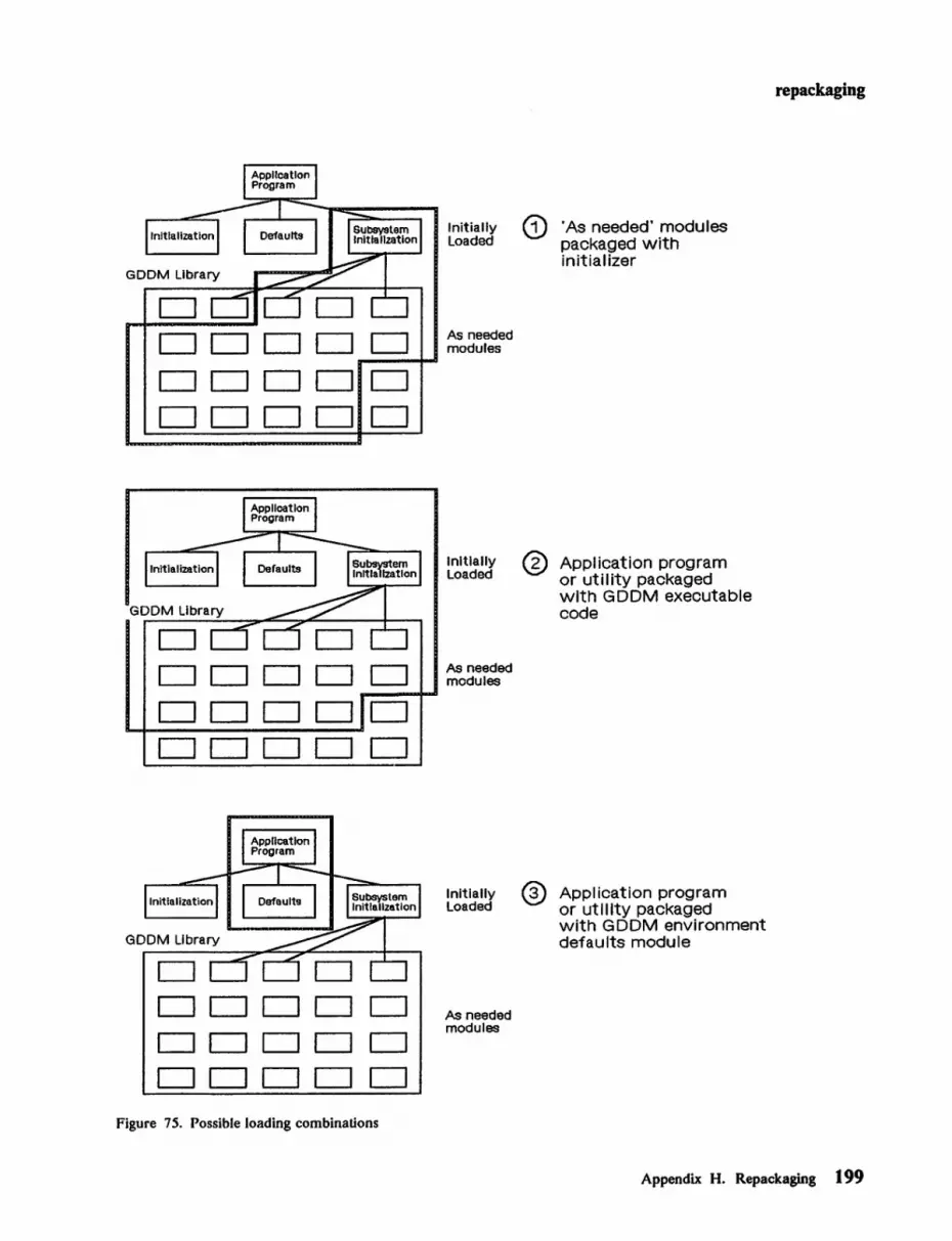
CJ CJ CJ CJ CJ CJ CJ CJ CJ CJ CJ CJ CJ CJ CJ CJ CJ
CJ CJ CJ CJ CJ CJ CJ CJ CJ CJ CJ LJ CJ CJ CJ CJ CJ
CJ CJ CJ CJ CJ CJ CJ CJ CJ LJ CJ LJ CJ CJ CJ CJ CJ
Figure 75. Possible loading combinations
Initially Loaded
As needed modules
Initially Loaded
As needed modules
Initially Loaded
As needed modules
®
'As needed' modules packaged with initializer
Application program or utility packaged with GDDM executable code
Application program or ut Illty packaged with GDDM environment defaults module
repackaging
Appendix H. Repackaging 199

repackaging
GDDM supplies modules known as packaging stubs that contain references (V-cons) to groups of associated modules. These packaging stubs must be linked with the subsystem initialization module to "drag in" the associated modules. This is shown in Figure 76 on page 201.
Provisos about packaging Before you consider packaging you should be aware of the following consequences.
Link-editing and possible future releases GDDM Releases from Version I Release 3 have been designed with the intention that application programs will not have to be link-edited again as a matter of course for any subsequent releases of GDDM.
If packaging options that involve link-editing the application are used, the application will have to be link-edited again for any subsequent release ofGDDM.
Retaining original libraries for service IBM service procedures (PTF Tapes) assume that the GDDM libraries have not been repackaged. This may cause problems if one of the modules that has been repackaged needs to be changed by service.
Repackaged GDDM routines should therefore be placed in libraries other than the original installation libraries.
The original libraries should be retained and service applied to these libraries. Packaged application programs or repackaged GDDM routines should be regenerated to include the serviced modules.
Repackaging the GDDM executable code on its own GDDM executable code is repackaged using the subsystem initialization module and packaging stubs. The subsystem initialization module is always loaded at the start of a program. As shown in Figure 77, it is called ADMEOOOV.
To repackage the executable code, link-edit the module, ADMEOOOV, with one or more packaging stubs. The packaging stubs "drag in" other routines to form a load module that contains all the modules referenced in the packaging stubs. The composite module is given the same name as the ADMEOOOV module. Note that this can only be done with the ADMEOOOV module, and that this module can discern if it has been linked with executable code only when this has been done through packaging stubs.
The effect of repackaging the GDDM executable code is shown in Figure 76.
200 GDDM Installation and System Management for VM

repackaging
ADM EOOOV ADM EOOOV Subsystem Initialization Subsystem Initialization
D Pacl<aging Stubs
D D D
D
Ordinary Modules
DDDO DDDD DODD
DDDD Before
Packaging Stubs
D DODD After
Figure 76. How packaging stubs are used to repackage the executable code
Figure 77 shows the name of the subsystem initialization module.
Application interface External defaults Subsystem initialization initialization module module module
ADMACIN ADMADFV ADMEOOOV
Figure 77. Names of initially-loaded modules
Levels of packaging stubs Two levels of packaging stub are provided to give you more control of the modules you repackage. The full screen manager and the ICU can both be subdivided by use of second-level packaging stubs. (The full screen manager does most of the graphic and alphanumeric processing within GDDM.)
The contents of packaging stubs Figure 78 shows the contents of the frrsi-Ievel packaging stubs. Figure 79 and Figure 80 show the contents of the second-level packaging stubs for the full screen manager and the ICU respectively. Note that the use of a frrst-Ievel stub automatically includes all the associated second-level stubs. Code sizes quoted are approximate and for guidance only.
Appendix H. Repackaging 201

repackaging
Name Contents Size (in bytes)
GDDM Base subsystem-adapter routines ADMUXOOO - common (used on all subsystems) 66K ADMUXOOV - subsystem-dependent - VM/CMS 80K
ADMUXAOO Application-adapter routines - common 202K
ADMUXAOx Messages · ....... A - American-English 43K · ....... B - Brazilian 47K · ....... C - PRC Chinese (Simplified) 43K · ....... D - Danish 43K · ....... F - French 43K · ....... G - German 43K · ........ H - Korean (Hangeul) 43K · ....... I - Italian 48K ......... K - Japanese (Kanji) 47K · ....... N - Norwegian 42K · ....... Q - French (Canadian) 43K · ....... S - Spanish 47K · ....... T - Taiwan Chinese (Traditional) 43K · ....... V - Swedish 42K
ADMUXDOO Full-screen manager routines 1408K (see Figure 79 on page 205)
ADMUXIOO Image Symbol Editor subroutines 127K
ADMUXOOO Print utility subroutines 9K
ADMUX300 Image routines 279K
ADMUX400 Composite document routines 42K
ADMUXBOO GDDM-PGF Presentation Graphics 214K routines
ADMUXBOx Day/date routines · ....... A - American-English IK · ....... B - Brazilian IK · ....... D - Danish IK · ....... F - French IK · ....... G - German IK · ....... H - Korean (Hangeul) IK · ....... I - Italian IK · ....... K - Japanese (Kanji) IK · ....... N - Norwegian IK · ....... S - Spanish lK · ....... V - Swedish IK
Figure 78 (Part 1 of 3). GDDM first-level packaging stub:.
202 GDDM Installation and System Management for VM

repackaging
Name Contents Size (in bytes)
ADMUXPAx GDDM-PGF and ICU messages ............. A - American-English 20K .............. B - Brazilian 21K ............... D - Danish 21K ................ F - French 20K ............... G - German 20K ............... H - Korean (Hangeul) 19K ................ I - Italian 22K .............. K - Japanese (Kanji) 20K ............... N - Norwegian 19K ................ S - Spanish 21K .............. V - Swedish 19K
ADMUXPOO ICU routines (see Figure 80 on page 205) 316K ADMUXPOx Menus and HELP ............... A - American-English 396K .............. B - Brazilian 417K ................ D - Danish 413K ............... F - French 405K .............. G - German 394K .............. H - Korean (Hangeul) 318K .............. I - Italian 427K ............... K - Japanese (Kanji) 391K ............... N - Norwegian 331K ............... S - Spanish 407K ................ V - Swedish 291K
ADMUXVOO Vector Symbol Editor subroutines 202K
ADMUXIOO GDDM-IMD subroutines 335K ADMUXIOA GDDM-IMD messages 20K
ADMUXJOO GDDM-GKS routines 350K ADMUXJAx GDDM-GKS messages ............... A - American-English 7K ................ B - Brazilian 7K ................ D - Danish 7K ................ F - French 7K ............... G - German 7K ................ H - Korean (Hangeul) 7K .............. I - Italian 7K ............... K - Japanese (Kanji) 7K ................ N - Norwegian 7K ............... S - Spanish 7K .............. V - Swedish 7K
Figure 78 (Part 2 of 3). GDDM first-level packaging stubs
Appendix H. Repackaging 203

repackaging
Name Contents Size (in bytes)
ADMUX500 GDDM-IVU routines 650K ADMUX5Ax GDDM-IVU messages · ........ A - American-English lOOK · ....... B - Brazilian lOOK · ....... D - Danish lOOK · ....... F - French lOOK · ....... G - Gennan lOOK · ....... H - Korean (J-Iangeul) lOOK · ....... I - Italian lOOK · ..... , . K - Japanese (Kanji) lOOK · ........ N - Norwegian lOOK · ....... S - Spanish lOOK · ....... V - Swedish lOOK
Figure 78 (Part 3 of 3). GDDM first-level packaging stubs
204 GDDM Installation and System Management for VM

repackaging
Name Contents Size (in bytes)
Alphanumeric For alphanumeric-only support use all the stubs following: ADMUXDAO Alphanumerics 35K ADMUXDBO Partitions 6K ADMUXDCO Common device processor 34K ADMUXDEO Partition sets 7K ADMUXDNO Window control processor 11K ADMUXDPO Direct printer support 41K ADMUXDSO Supervisor 115K ADMUXDWO Data stream generator 240K
Total 489K
Graphic stubs For basic graphics support use all the alphanumeric stubs plus:
ADMUXDGO Graphics device processor 556K ADMUXDHO Graphics generator (for PS graphics) 42K
Image stub For image support use all the alpha-numeric stubs plus:
ADMUXD30 Image processor 85K
Mapping stub For runtime mapping support use all the alphanumeric stubs plus:
ADMUXDMO Mapping processor 56K
Miscellaneous Miscellaneous individual stubs to be added stubs as needed: ADMUXDIO Queued printer support (input) 16K ADMUXDJO Composed page printers 48K ADMUXDKO IPDS 44K ADMUXDLO System printers 5K ADMUXDOO Queued printer support (output) 15K ADMUXDTO Plotters 73K ADMUXD40 Text processor 26K
Total 227K
Figure 79. Full screen manager second-level packaging slubs
Appendix H. Repackaging 205

repackaging
Which stubs to use
Name Contents Size (in bytes)
ADMUXPMx Menus, messages: choose from list ......... A - American-English 61K ......... B - Brazilian 65K ......... D - Danish 63K ......... F - French 64K ......... G - German 60K ......... H - Korean (Hangeul) 62K · ........ I - Italian 64K ......... K - Japanese (Kanji) 68K ......... N - Norwegian 62K ......... S - Spanish 63K ......... V - Swedish 62K
ADMUXPHx Help menus: choose from list ......... A - American-English 336K ......... B - Brazilian 353K ......... D - Danish 352K ......... F - French 342K ......... G - German 335K · .\ ....... H - Korean (Hangeul) 318K · ........ I - Italian 365K ......... K - Japanese (Kanji) 324K ......... N - Norwegian 331K ......... S - Spanish 345K ......... V - Swedish 291K
'--
Figure 80. leu second-level packaging slubs
You should include only those packaging stubs that are of interest to you. This means that you will exclude any message routines that are in languages that you do not use (for instance, exclude French, English, and so on if you use German).
When you have excluded these obvious stubs, you should consider the processing code.
The main processing for all graphics in both GDDM Base and GDDM·PGF is done by the full screen manager and major savings can be made by including this in any repackaging.
For the full screen manager and the leU, second levels of packaging stubs are supplied, to enable their functions to be subdivided.
You may consider excluding the utility subroutines from the package and repackaging them separately. If you are doing this, the Image Symbol Editor and Vector Symbol Editor stubs are candidates for exclusion, as is the print utility stub.
Before you exclude the leu stub, you should remember that the leu can be called by an application program. Also with the leu you should remember that the leu
206 GDDM Installation and System Management for VM

repackaging
makes use of the GDDM-PGF processing routines, which in turn make use of the full screen manager.
For application image handling, the image routines, ADMUX300, can be used without the full screen manager
For device image handling, ADMUX300 is required as well as ADMUXD30.
Rather than using ADMUXDOO, which gives the whole of the full screen manager, individual functions can be packaged. Figure 79 on page 205 shows the stubs required to do this. You could use these stubs if, for example, you used GDDM only for its alphanumeric support.
Rather than using ADMUXPOx, which gives all the ICU frames, you can separate the HELP panels from the menu panels. Figure 80 on page 205 shows the stubs required to do this. You could use these stubs, for example, to repackage only the working code, and have the HELP panels loaded as needed.
Repackaging executable code with a utility or application program When you repackage GDDM executable code with an application program or the invoking routine for a GDDM utility, you use the linkage editor to link the program and the subsystem-initialization module. This, in tum, is linked with the executable code. In practice this means packaging:
• The application program or the invoking routine for a GDDM utility
• The subsystem-initialization module
• Any packaging stubs that are relevant.
Special requirements for utilities
Image Symbol Editor
ADMISSEV
When repackaging the invoking routine for a GDDM utility, the intema1link-edit name of the utility-invoking routine must be used. These names are shown in Figure 81. If utilities are not listed in this figure, they may not be repackaged.
Vector Symbol Chart utility Print utility GDDM-IMD Editor
ADMVSSEV ADMPSTBV ADMOPUV ADMlIMDV
Figure 81. Names ofinvoking routines for GDDM utilities
Eliminating dynamic loading completely There is no need to eliminate dynamic loading completely. Any modules that are needed, but are not included in the package, will be loaded dynamically when required.
If you want to eliminate dynamic loading completely, you must include in the repackaged module the initially-loaded modules and all the modules that would otherwise be loaded as needed.
Appendix H. Repackaging 207

repackaging
All the initially-loaded modules can be included by using packaging stubs. The common adapter stub (ADMUXOOO) automatically includes the application interface controller. The subsystem adapter stub (ADMUXOOV) automatically· includes the corresponding external defaults module and subsystem-initialization module.
Repackaging to get a special defaults module
Differing defaults
It is possible to override a shared defaults module by packaging an application with a special external defaults module. This is done by linking the application with the external defaults module and using normal linkage editor methods.
The same method can be used if you want to use two sets of defaults in an installation; for example, if you wanted to use the ICU in both French and English. Assuming English was specified in the normal defaults module, you would link a copy of the ICU-invoking routine with a defaults module that specified French, and make the resulting load module available with a different name. French users would use this version. You will have to assemble a suitable version of the defaults module before doing the packaging.
If you are repackaging with a utility-invoking routine, you will have to use the internal linkage-editor name for that utility-invoking routine as shown in Figure 81 on page 207.
This use of a defaults module is in addition to other methods of specifying user defaults, which are described in the GDDM Base Programming Reference manual, and are listed in Appendix A of this manual.
Special requirements Under VM/CMS the packaging facilities are used in the construction and operation of discontiguous saved segments (DCSS). This is more fully described in "Step 7: Create GDDM discontiguous saved segments (DCSS)" on page 71.
If the packaging stubs ADMUXOOV and ADMUXAOO are loaded with an application program, they will suppress use of the saved segment.
208 GDDM Installation and System Management for VM

repackaging
Instructions for repackaging The list below is a suggested order for repackaging:
1. Decide on the type of repackaging you are trying to do.
This is discussed earlier in this appendix and in broader terms under "Performance background" in Chapter 1 and under "Tuning and customization by subsystem" in Chapter 2 of the GDDM Performance Guide.
2. If you are repackaging the defaults module, go to 5.
3. Look at "The contents of packaging stubs" on page 201 and decide what packaging stubs to include.
4. The name of your subsystem initialization module (see Figure 77 on page 201) is ADMEOOOV.
5. If you are changing the defaults module:
a. The name (see Figure 77 on page 201) is ADMADFV.
b. Change the defaults module as required. See Appendix A, "GDDM defaults and nicknames" on page 115 for details.
c. Reassemble the defaults module.
6. If you are linking with a GDDM utility-invoking routine, fmd its internal link-edit name from Figure 81 on page 207.
7. Use the linkage editor to create a module containing the required elements and having the correct name.
The examples that follow can be used as models. Further information on link-editing with GDDM can be found in the GDDM Base Programming Reference manual.
Appendix H. Repackaging 209

repackaging
Examples of repackaging
Repackaging application program with executable code The following example shows the commands entered to create a composite load module for an application program and to execute the composite module. All GDDM routines other than those required for the production of language-dependent error messages are included in the composite module. The language-dependent routines would be dynamically loaded should the application program require the generation of an error message.
The commands shown suppress the use of any copy of GDDM Base installed into a discontiguous saved segment (DCSS).
GLOBAL TXTLIB AOMPLIB AOMRLIB AOMGLIB PLILIB LOAD appl-name AOMUXeee AOMUXeeV ADMUXAee AOMUXOee (START
Loaded items are:
The application The common subsystem adapter routine (ADMUXOOO) The VM subsystem adapter routine (ADMUXOOV) The common application adapter routine (ADMUXAOO) The full screen manager (ADMUXDOO).
Overriding saved segment defaults module A saved segment is frequently used to reduce the dynamic loading that would otherwise be done for each separate virtual machine. Sometimes it is necessary to override the use of the defaults module for a particular program. A typical example is to use the trace facilities on the ICU, or to have the ICU panels appear in a language other than the default provided for your installation.
The following example shows the commands entered to invoke a GDDM application program, using a GDDM external defaults module other than that available in a discontiguous saved segment (DCSS).
The commands shown would pennit the use of any other GDDM Base and GDDM-PGF routines that were present in a discontiguous saved segment (DCSS).
1. Create a suitably modified defaults module and generate it (as described in Appendix A, "GDDM defaults and nicknames" on page 115).
2. Ensure it is present either as a me of type TEXT, or in a TXTLIB of name, say, DFTLIB.
3. Issue the commands:
GLOBAL TXTLIB OFTlIB AOMRlIB PLIlIB LOAD appl-name ADMADFV (START
Loaded items are:
The application The VM environment defaults module (ADMADFV).
2tO GDDM Installation and System Management for VM

Appendix I. GDDM font and conversion tables
This appendix contains information about two GDDM tables:
• GDDM font emulation table
• GDDM AFPDS (Advanced Function Presentation Data Stream) to IPDS (Intelligent Printer Data Stream) conversion table.
GDDM font emulation table The GDDM font emulation table contains information about coded fonts that GDDM uses to emulate composite documents on screens. The font emulation table specifies:
• GDOM symbol set • Character width • Character height • Character shear • Font weight.
fonts
The GDDM font emulation table is a module (ADM4FONn that is link-edited with GDDM. A copy of this module is supplied with GDDM for installations that want to add new fonts, or to change the fonts used by GDDM.
Changing the ADMMFONT macro ADM4FONT contains an invocation of the ADMMFONT macro for each font, coded font, or code page. Entries in the GDOM font table are generated by coding invocations of the AOMMFONT macro. The syntax of the macro is:
FONTNAME AOMMFONT SSETNAM=, a GODM vector symbol set name CWIDTH=, in units of 1/144eth inch CHEIGHT=, in units of 1/1440th inch WEIGHT=, MEDIUM I BOLD I 1 .• 8 SPACING=, FIXED I PROPORTIONAL SHEAR=, float between 0.0 and 1.0 CODEID=, see notes be 1 o\~ CECP= CECP identifier
FONTNAME The label specifies the CPOS font, coded font, or code page being defmed.
1. The invocations of AOMMFONT should be coded in ascending order of FONTNAME or CODEID.
2. To allow both the unrotated and rotated versions of a font to be specified with a single macro invocation, the FONTNAME label may have a wild card as its second character. Coding:
C#A0SS0e ADMMFONT
will defme font emulation table entries for:
CIA05500
Appendix I. GDDM font and conversion tables 211

fonts
C2A05500 C3A05500 C4A05500.
It is possible to override some or all of the entries specified with a wild card by explicitly defming a given font. In the GDDM-supplied ADM4FONT, this is done for fonts CIZ05640, C2Z05640, C3Z05640, and C4Z05640.
3. Use FONTNAME or CODEID, not both.
SSElNAM = 'ADMDVSS' Name (up to 8 characters) of a GDDM symbol set to be used for this font.
CWiDTH = 200 The width of the character box for the font. The default is equivalent to 10-point text.
CHEIGHT = 200 The height of the character box for the font. The default is equivalent to IO-point text.
WEIGHT = MEDIUMIBOLDltl1131415161718 The weight of the font. This is interpreted as a GDDM color. MEDIUM is turquoise, and BOLD is neutral.
SPACING = PROPORTIONAL I FIXED The spacing of the font. This attribute, whether specified explicitly or by default, will override the characteristics of the GDDM symbol set specified.
SHEAR = 0.0 The shear (specified as a quoted floating point value) to be applied to the character. For a description of how GDDM interprets shear, see the description of GSCH in the GDDM Base Programming Reference. The shear specified will form the dx component of the shear. The dy component will always be 1.0.
CODEID This is provided as an alternative syntax to allow fonts with a numeric name to be specified. The GDDM-supplied ADM4FONT contains an example of its use for fonts 163,84,86, and 87.
Use FONTNAME or CODEID, not both.
CECP = The code page identifier corresponding to the coded font or code page name specified for the FONTNAME label.
Installing a new font table When you have assembled the font emulation table you will have a text deck which is also called ADM4FONT. You can link this text deck with an application or replace it in the system version of GDDM using the same facility that you used when installing it originally. (See also the section "Replacing GDDM modules after installation" on page 1 OS.)
212 GDDM Inslallation and System Management for VM

fonts
GDDM AFPDS to IPDS conversion table GDDM uses the GDDM AFDPS to IPDS conversion table to convert information from the AFPDS font, code page, or coded font format into a suitable IPDS format, to allow AFPDS documents to be printed on IPDS printers. The conversion table supplied with GDDM is suitable for most applications; you need not change it unless you have special requirements.
The conversion table specifies:
• AFPDS resource name (font, code page, or coded font) • IPDS printer product number • IPDS font number • IPDS code page number • Font weight • Font width • Font descriptor.
The AFPDS to IPDS font conversion table is a module (ADMDKFNT) that is link-edited with GDDM. A copy of this module is supplied with GDDM for installations that want to add new fonts, or to change existing entries.
Changing the ADMDKFNT table ADMDKFNT contains an invocation of the ADMMKFNT macro for each AFPDS resource name. Entries in the conversion table are generated by coding invocations of the ADMMKFNT macro. The syntax of the macro is:
AFPDS ADMMKFNT MODEL=, IPDS printer model number FONT=, IPDS font number CDPG=, IPDS code page number BOLD=, YES NO ITAlIC=, YES NO WIDE=, YES NO DOUBlE=, YES NO CODEIO= see notes below
AFPDS The label specifies the AFPDS resource name being defmed.
1. The invocations of ADMMKFNT must be coded in ascending order of AFPDS or CODEID.
2. To allow both the un rotated and rotated versions of an AFPDS resource to be specified with a single macro invocation, the AFPDS label may have a wild card as its second character. Coding:
C#A05500 ADMMKFNT
will defme conversion tables entries for:
CIA05500 C2A05500 C3A05500 C4A05500.
Appendix I. GDDM font and conversion tables 213

fonts
It is possible to override some or all of the entries specified with a wild card by explicitly defining a given AFPDS resource.
3. Use AFPDS or CODEID, not both.
FONT=- 8S The IPDS font number (decimal) that is to be used instead of the AFPDS name. The default IPDS font is Courier 12.
MODEL= 3812 The IPDS printer model number for which this table entry is valid (for example, 3812,4224).
CDPG= 500 The IPDS code page number (decimal) that is to be used instead of the AFPDS name.
WIDE= NOIYES When YES is specified, the IPDS font will be printed using wide characters.
ITALIC = NOIYES When YES is specified, the IPDS font will be printed using italic characters.
BOLD = NOIYES When YES is specified, the IPDS font will be printed using bold characters.
DOUBLE = NOIYES When YES is specified, the IPDS font will be printed twice; that is each character will be double-struck.
CODEID This is provided as an alternative syntax to allow fonts with a numeric name to be specified. The GDDM-supplied ADMDKFNT contains an example of its use for fonts 163, 84, 86, and 87.
Use AFPDS or CODEID, not both.
Installing a new conversion table When you have assembled the conversion table you will have a text deck which is also called ADMDKFNT. You can link this text deck with an application or replace it in the system version of GDDM using the same facility that you used when installing it originally. (See also the section "Replacing GDDM modules after installation" on page 105.)
214 GDDM Installation and System Management for VM

directory
Appendix J. Installation module directory
This appendix contains a list of modules that are included on the GDDM installation tape. References are made to it throughout the rest of the manual.
Revision bars are not used in this appendix. You should assume that all the information has changed.
National language modules
TXTLIBs
Where there is one module for each national language, the module name is shown with a lowercase x as part of the name; replace the lowercase x with the relevant letters from this table:
National language Letter ...
Brazilian B PRC Chinese (Simplified) C (GDDM Base NL only) Danish D French F German G Korean (Hangeul) H Italian I Japanese (Kanji) K Norwegian N French (Canadian) Q (GDDM Base NL only) Spanish S Taiwan Chinese (Traditional) T (GDDM Base NL only) Swedish V
Figure 82. Letters for national language files
GDDM/VMor GDDM/VMXA
ADMGLIB ADMNLIB ADMRLIB
GDDM/VM NL or GDDM/VMXA NL
Am~HxLIB where x is a letter from Figure 82.
GDDM-PGF
ADMPLIB
GDDM-PGFNL
ADMQxLIB where x is a letter from Figure 82.
Appendix J. Installation module directory 215

directory
MACLIB
Module files
GDDM-IMD
AOMILIB
GDDM-IVU
AOMVLIB
GDDM-IVU NL
AOMWxLIB where x is a letter from Figure 82 on page 21S.
GDDM-GKS
AOMKLIB
GDDM-GKS NL
AOMLxLIB where x is a letter from Figure 82 on page 21S.
GDDM-REXX
ERXLIB
GDDM/VM or GDDM/VMXA
AOMLIB
The installation procedure will have generated the following module files onto the appropriate disk. .
GDDM/VM or GDDM/VMXA
AOMISSE ADMOPUV
GDDM-PGF
AOMCHART
GDDM-IMD
ADMIMD
AOMUIMPV AOMUPCV
AOMUCDSO ADMVSSE
AOMMSL
ADMUPGV ADM4CDUV
216 GDDM Installation and System Management for VM

GDDM-IVU
ADMIVU
GDDM-REXX
ERXASCOM ERXTMSGA ERXTMSGH ERXASTUB ERXTMSGB ERXTMSGI ERXTEMSG (for the default language)
Packaging stubs GDDM/VM or GDDM/VMXA
AOMUXAeA ADMUXOHfl ADMUXOO0 AOMUXAe0 ADMUXOI0 ADMUXOP0 Aor~UXDA0 ADMUXDJfl ADMUXOS0 AOMUXDB0 ADMUXDK0 AOMUXDT0 ADMUXDCfl AOMUXDL0 AOMUXOW0 ADMUXDEfl AOMUXDMfl ADMUXDe0 AOMUXDGe ADMUXDN0 ADMUXD30
GDDM/VM NL or GDDM/VMXA NL
ERXTMSGK ERXTMSGS
AOMUXD40 AOMUXEBV AOMUXEFV ADMUXEFe ADMUXI0e AOMUXL0V AOMUXL0fl
GDOMREXX
AOMUX00e AOMUX0AV AOMUX00V ADMUX000 ADMUX300 ADMUX400
ADMUXAex where x is a letter from Figure 82 on page 215.
GDDM-PGF
AOMUXB0A ADMUXBGG
AOMUXPAA AOMUXPHA
GDDM-PGFNL
ADMuxpr~A
ADMUXPGA ADMUXP80
ADMUXBex AOMUXPAx AOMUXPHx AOMUXPMx where x is a letter from Figure 82 on page 215.
GDDM-IMD
AOMUXIGfl AOMUXIMfl
GDDM-IVU
MMUX5AA
ADMUXIPfl ADMUXlSfl
ADMUX50e
GDDM-IVU NL
ADMUXIHl ADMUXlUe
AOMUXIGA
ADMUXVG9
AOMUXP0x
AOMUX10fl
ADMUX5Ax where x is a letter from Figure 82 on page 215.
directory
Appendix J. Installation module directory 217

directory
GDDM-GKS
ADMUXJAA ADMUXJ99
GDDM-GKS NL
AOMUXJAx where x is a letter from Figure 82 on page 215.
Directory of GDDM-IMD frames The following GDDM-IMD frames are provided as part of the installation process.
GDDM-IMD
AEMCU209 AEMMU5D9 AEMMIZD9 AEMM2YD9 AEMM31D9 AEMCU3D9 AEMMU609 AEMMle09 AEMM2ZD9 AEMM3209 AEMC39D9 AEMMU709 AEMMl109 AEM~I2009 AEMM3309 AEMMDB09 AEMMXX09 AEMM1209 AEMM21D9 AEMM34D9 AEMMTT09 AEMM9909 AEMM1309 AEMM2209 AEMM4009 AEMMU0D9 AEMM9109 AEMM2S09 AEMM2309 AEMM41D9 AEMMUI09 AEMM0209 AEMM2TD9 AEMM2409 AEMVU209 AEMMU209 AEMMlS09 AEMM2U09 AEMf42509 AEMVU309 AEMMU309 AEMMIX09 AEMf42V09 AEMM3909 AEMV3909 AEMMU409 AEMMIY09 AEMM2X09
AEMYUSAA AEMYUSAI AEMYUSCK AEMYUSGM AEMYUSLQ AEMYUSAB AEMYUSA2 AEMYUSCL AEMYUSGO AEMYUSLS AEMYUSAC AEMYUSA3 AEMYUSCM AEMYUSHL AEMYUSLU AEMYUSAO AEMYUSA4 AEMYUSCN AEMYUSIU AEMYUSLV AEMYUSAE AEMYUSA5 AEMYUSCO AEMYUSIl AEMYUSLW AEMYUSAF AEMYiJSA6 AEMYUSCP AEMYUSI3 AEMYUSLX AEMYUSAG AEMYUSBA AEMYUSCQ AEMYUSI4 AEMYUSLY AEMYUSAH AEMYUSBB AEMYUSCR AEMYUSK3 AEMYUSMA AEMYUSAI AEMYUSBC AEMYUSCS AEMYUSK4 AEMYUSMB AEMYUSAJ AEMYUSBD AEMYUSCT AEMYUSK5 AEMYUSMC AEMYUSAK AEMYUSBE AEMYUSCU AEMYUSK6 AEMYUSMD AEMYUSAL AEMYUSBF AEt4YUSCV AEMYUSLA AEMYUSMG AEMYUSAM AEMYUSBI AnlYUSCZ AEMYUSLB AEMYUSMH AEMYUSAN AEMYUSB2 AEMYUSCI AEMYUSLC AEMYUSMJ AEMYUSAO AEMYUSB4 AEMYUSC9 AEMYUSLO AEMYUSMK AEMYUSAP AEMYUSCA AEMYUSOB AEMYUSLE AEMYUSML AEMYUSAR AEMYUSCB AE~1YUSDV AEMYUSLF AEMYUSMM AEMYUSAS AEt4YUSCC AEMYUSER AEMYUSLH AEMYUSMN AEMYUSAT AEMYUSCO AEMYUSES AEMYUSLI AEMYUSMO AEMYUSAU AEMYUSCE AEMYUSEX AEMYUSLJ AEMYUSMQ AEMYUSAV AEMYUSCF AEMYUSEY AEMYUSLM AEMYUSMY AEMYUSAW AEMYUSCG AEMYUSFP AHIYUSLN AEMYUSMl AEMYUSAY AEMYUSCH AEMYUSGA AEMYUSLO AEMYUSM2 AEMYUSAZ AEMYUSCI AEMYUSGB AEMYUSLP AEMYUSM3
218 GDDM Installation and System Management for VM

directory
AEMYUSM7 AEMYUSQL AEMYUSTS AEMYUSIL AEMYUS2X AEMYUSM8 AEMYUSQM AEMYUSTU AEMYUSIM AEMYUS2Y AEMYUSM9 AEMYUSQN AEMYUSU0 AEMYUSIN AEMYUS2Z AEMYUSNA AEMYUSQO AEMYUSUl AEMYUSIO AEMYUS29 AEMYUSNC AEMYUSQP AEMYUSU2 AEMYUSIQ AEMYUS21 AEMYUSNF AEMYUSQQ AEMYUSU3 AEMYUS1S AEMYUS22 AEMYUSNG AEMYUSQR AEMYUSU4 AEMYUSlU AEMYUS23 AEMYUSNM AEMYUSQS AEMYUSU5 AEMYUSIV AEMYUS24 AEMYUSNO AEMYUSQT AEMYUSU6 AEMYUSIW AEMYUS25 AEMYUSNP AEMYUSQU AEMYUSU7 AEMYUSIX AEMYUS3A AEMYUSNQ AEMYUSQV AEMYUSXl AEMYUSlY AEMYUS3B AEMYUSNR AEMYUSQY AEMYUSX2 AEMYUSIZ AEMYUS3C AEMYUSNS AEMYUSQZ AEMYUSZZ AEI~YUSH) AEMYUS3D AEMYUSNT AEMYUSQ0 AEMYUSZl AEMYUSll AEMYUS3E AEMYUSNU AEMYUSQl AEMYUSZ2 AEMYUS12 A01YUS3F AEMYUSNX AEMYUSQ2 AEMYUS0e AEr~YUS13 AEMYUS30 AEMYUSPF AEMYUSQ3 AEMYUS01 AEMYUS2A AEMYUS31 AEMYUSQA AEMYUSQ4 AEMYUSe2 AEMYUS2B AEMYUS32 AEMYUSQB AEMYUSQ5 AEMYUSe8 AEMYUS2C AEMYUS33 AEMYUSQC AEMYUSQ7 AEMYUSIB AEMYUS20 AEMYUS34 AEMYUSQD AEMYUSQ8 AEMYUSIC AEMYUS2E AEMYUS4B AEMYUSQE AEMYUSTA AEMYUSIO AEMYUS2F AEMYUS40 AEMYUSQF AEMYUSTC AEMYUSIE AEMYUS2N AEMYUS41 AEMYUSQG AEMYUSTD AEMYUSIF AEMYUS2R AEMYUS5A AEMYUSQH AEMYUSTE AEMYUSIG AEMYUS2S AEMYUS5F AEMYUSQI AEMYUSTF AEMYUSIH AEMYUS2T AEMYUS50 AEMYUSQJ AEMYUSTH AEMYUSIJ AEI~YUS2U AEMYUS5P AEMYUSQK AEMYUSTJ AEMYUSIK AEMYUS2V AEMYUS5Z
GDDM-IVU
AOM51AD6 AOM52AD6 ADM53A06 ADM54AD6 ADM55AD6
GDDM-IVU NL
AOM5lx06 ADM52x06 ADM53xD6 ADM54xD6 AD~155xD6
where x is a letter from Figure 82 on page 215, except for H and K.
ADM51HK5 ADM52HK5 AO~'53HK5 ADM54HK5 AOM55HK5 AOM51KK5 AOM52KK5 AD~'53KK5 AOM54KK5 AOM55KK5
Appendix: J. Installation module directory 219

directory
Directory of GDDM/VM PCLKF or GDDM/VMXA PCLKF objects The following objects are on the GDDM/VM PCLKF or GDDM/VMXA PCLKF tape:
ADMPCjiles
GQDKMAP GQDNLFR GQDRPD3A GQDSYS GQD12V23 GQDLEV GQDNLGR GQDRPD4 GQDSYSA GQD12V39 GQDLEVA GQDNLIT GQDRPD4A GQDSYX GQD7V27 GQDNLACF GQDNLSP GQDRPD5 GQDXXBM GQD8I19 GQDNLAFR GQDNLUS GQDRPD5A GQDXXBMA GQD8I14 GQDNLAGR GQDRPDl GQDRPD6 GQDXX06 GQ08119 GQONLAIT GQDRPDIA GQDRPD6A GQDXX06A GQ0818 GQDNLASP GQDRPD2 GQDRPD7A GQOXX10 GQ08V14 GQDNLAUS GQDRPD2A GQDSIF GQDXX19A GQD8V19 GQDNLOA GQDRPD3 GQDSTRCA GQ012V17
Maintenance flle
GQDMAINT DATA
Directory of sample material The following sample materials are provided as part of the installation process.
Sample symbol sets GDDM/VMwGDDM/VMXA
AD~lCOLSD ADMOiHMV ADMDHJIR ADMDVSSN ADMUUARP ADMCOLSN ADMDHIPA ADMOHJVJ AOMDVSSP ADMUUCIP ADMCOLSR ADMDHIPC AD~mHJVK ADMDVSSS AOMUUCRP ADMDHIIA ADMOHIPG ADMDHJVM ADMDVSSV AOMUUCSP ADMDHIIC ADMDHIPJ ADMDISKA ADMDVSSW ADMUUDRP ADMDHIIE ADMDHIPK ADMDISKC ADM I PATA ADMUUFSS ADMDHIIG ADMDHIPL ADMDISKG ADMIPATC ADMUUGEP ADMDHIIK ADMDHIPM ADMDISKN ADmPATG ADMUUGGP ADMDHIIN ADMDHIPN Aot4DISKR ADMIPATN ADMUUGIP ADMOHIIQ AOMDHIPR ADMDVECP AOMIPATR AOMUUKRF AOMDHIIR AOMOHIVJ AOMOVIH ADMITALA ADMUUKRO Aot40HIMA ADMDHIVM ADMDVSS ADMITALC ADMUUKSF ADMDHIMC ADMDHIVQ AOMDVSSB ADMITALG AOMUUKSO ADMDHIMG AOMDHJIA ADr40VSSD ADMITALK ADMUUMOD ADMDHIMJ ADMDHJIC ADMOVSSE ADMPATTA AOMUUNSF ADMDHIMK ADMDHJIG ADMDVSSF AOMPATTC ADMUUNSO AOMDHIMN ADMDHJIK ADMDVSSG ADMPATTG ADMUUORP ADMDHIMQ ADMDHJIN ADMDVSSI ADMPATTN ADMUUSHD ADMDHIMR AOMOHJIQ AOMDVSSK ADMPATTR ADMUUSRP
220 GDDM Installation and System Management for VM

directory
ADMUUTIP ADMUVGGP ADMUVORP ADI~UWCSP ADMUWMOD ADMUUTRP ADMUVGIP ADMUVSHD ADMUWDRP ADMUWNSF ADMUUTSS ADMUVKRF ADMUVSRP ADMUWGEP ADMUWNSO ADMUVCIP ADMUVKRO ADMUVTIP ADMUWGGP ADMUWORP ADMUVCRP AOMUVKSF ADMUVTRP ADMUWGIP ADMUWSHD ADMUVCSP ADMUVKSO ADMUVTSS ADMUWKRF ADMUWSRP ADMUVDRP ADMUVMOD ADMUWARP ADMU~JKRO ADMUWTIP ADMUVFSS AOMUVNSF ADMUWCIP ADI~UWKSF AOMUWTRP ADMUVGEP ADMUVNSO ADMUWCRP ADMUWKSO
GDDM/VM or GDDM/VMXA KANJI
ADMIK4A ADMIK5B ADMIK61 ADMVK43 ADMVK53 ADMIK4B ADMIK5C ADMIK62 ADMVK44 ADMVK54 ADMIK4C AOMIK50 AOMIK63 ADMVK45 ADMVK55 ADMIK4D ADMIK5E ADMIK64 ADMVK46 ADMVK56 ADMIK4E ADMIKSF ADMIK6S ADMVK47 ADMVKS7 AOMIK4F ADMIKS0 ADMIK66 ADMVK48 ADMVKS8 AOMIK41 ADMIKSI ADMIK67 ADMVK49 ADMVK59 ADMIK42 ADMIKS2 AOMIK68 ADMVKSA AOMVK60 AOMIK43 AOMIKS3 ADMVK4A ADMVK5B AOMVK61 AOMIK44 AOMIKS4 AOMVK4B AOMVKSC AOMVK62 ADMIK45 AOMIK55 AOMVK4C AOMVK5D ADMVK63 AOMIK46 AOMIKS6 AOMVK4D ADMVK5E ADMVK64 ADMIK47 AOMIK57 AOMVK4E ADMVKSF AOMVK6S ADMIK48 ADMIK58 AOMVK4F ADMVKS0 AOMVK66 AOMIK49 ADMIK59 ADMVK41 ADMVKSI AOMVK67 AOMIK5A AOMIK60 ADMVK42 ADMVKS2 AOMVK68
Sample programs and data GDDM/VMorGDDM/VMXA
AOMUBCDV EXEC AOMUSPI PLI AOMUTMOV ASSEMBLE ADMUIMP EXEC AOMUSP2 PLI ADMUTMIV ASSEMBLE AOMUPCFV EXEC AOMUSP3 PLI AOMUTMPV ASSEMBLE AOMUSCI COBOL Aot4USP4 PLI AOMUTMSV ASSEMBLE ADMUSC2 COBOL ADMUSP7 PLI ADMUTMTV ASSEMBLE ADMUSFl FORTRAN AOMUTMAV ASSHIBLE AOMUTMV PLI ADMUSF2 FORTRAN ADMUTMCV ASSEMBLE
GDDM-PGF
ADMUCS HI OAT A ADMUPLNO COPY ADMUSFS FORTRAN ADMUPINC COPY AOMUPLRO COPY ADMUSF6 FORTRAN ADMUPINV COPY ADl4URCPO COpy ADl4USPS PLI AOMUCIMV EXEC ADMUSC5 COBOL AOMUSP6 PLI ADMUPIRC COPY AOMUSC6 COBOL ADMUSP60 ASSEMBLE ADMUPIRV COpy
Appendix J. Installation module directory 221

•
directory
Default materials
GDDM-IMD
AOMUAIMC COPY AOMUCIMC COpy ADMUPIMC COpy
GDDM-IVU
ADM51UA (containing mapgroups AOM51A, ADMS2A, AOMS3A, ADM54A, and ADM55A) AOMUSIMG ADMIMG AOMUPIN5 COpy AOMUPIR5 COPY AOMU5PRJ AOMPROJ
GDDM-IVU NL
AOM51Ux (containing mapgroups AOM51x, ADM52x, ADM53x, AOM54x, and ADM55x) where x is a letter from Figure 82 on page 215.
GDDM-GKS
AOMJROOM FORTRAN
GDDM-REXX
ERXCHART EXEC ERXMENU EXEC ERXMODEL ADMGDF ERXMODEL EXEC
ADMJBIV ASSEMBLE
ERXMSVAR EXEC ERXOPWI N EXEC
ADMJB77 FORTRAN
ERXORDER EXEC ERXPROTO EXEC
ERXORDD6 AOMGGMAP ERXTRY EXEC ERXORDER AOMIFMT
GDDM/VM or GDDM/VMXA
AOMADFV ASSEMBLE AOMLSYSl ASSEMBLE ADMUDBCS EXEC AOMDATRN ASSEMBLE ADMLSYS3 ASSHfBLE ADM4CP ASSEMBLE ADMDJCOL ASSEMBLE AOMLSYS4 ASSEMBLE ADM4FONT ASSEMBLE ADMDKFNT ASSEMBLE
Installation and service material GDDM/VM
5664299 DATA ADMBLSEG EXEC 15664299 EXEC
GDDM/VM NL
15664299 MEMONL
GDDM/VM PCLKF
15664299 EXEC
15664299 MEMO AOMSERV EXEC
15664299 922906 AOMUP229 EXEC
15664299 022005NL 15664290 EXEC
15664209 MEMOPC 15664209 022eesPC
222 GDDM Installation and System Management for VM

directory
GDDM/VMXA
5684667 DATA 15684667 MEMO 15684667 622666 ADMBLSEG EXEC ADMSERV EXEC ADMUP226 EXEC 1 5684e(;)7
GDDM/VMXA NL
15684667 MEMONL 15684667 622065NL 15684667 EXEC
GDDM/VMXA PCLKF
15684667 EXEC 15684667 MEMOPC 15684607 622605PC
GDDM-PGF
5668812 DATA 15668812 MEMO 15668812 021665 15668812 EXEC
GDDM-PGFNL
15668812 MEMONL 15668812 621005NL 15668812 EXEC
GDDM-IMD
5668861 DATA 15668861 MEMO 15668861 021e05 156688(:>1 EXEC
GDDM-IVU
5668723 DATA 15668723 MEMO 15668723 611605 15668723 EXEC
GDDM-IVU NL
15668723 MEMONL 15668723 011665NL 15668723 EXEC
GDDM-GKS
15668802 EXEC
GDDM-GKS NL
15668802 EXEC
GDDM-REXX
5664336 DATA 15664336 MEMO 15664336 611605 ERXBLSEG EXEC 15664336 EXEC
Appendix J. Installation module directory 223

trouble-shooting
Appendix K. What to do if things go wrong
If you fmd that you cannot get GDDM to work satisfactorily when you try to test it, there are several things you should check out before calling for assistance.
• Refer to the GDDM Diagnosis and Problem Determination Guide for full details of any of these checks.
• Check in the section "Common errors and pitfalls" on page 231 for the symptoms of your problem. If you cannot fmd your problem described in that section, continue with the following checks.
• Refer to Chapter 1 of tlus manual and check that you have the correct levels of:
System Subsystem Access method Controller microcode Control program (where appropriate) Hardware features (specifically for graphics).
Check any relevant notes, restrictions, or prerequisites that are mentioned in Chapter 2.
• If an error message appears, either on a display screen or on your console log, you should look it up in the appropriate manual. Most GDDM messages start with the letters ADM; GDDM-IMD messages start with AEM, and GDDM-CSPF messages start with EAK. They are all documented in the GDDM Messages manual.
GDDM-PCLK messages start with GQD and are described in the GDDM-PCLK Guide.
• If an abnormal termination (abend) occurs, you should check in the appropriate system or subsystem manual. The GDDM Diagnosis and Problem Determination Guide contains details of all GDDM abends.
• If these measures fail to solve the problem, check through the steps you have completed thus far, and examine the console log for any unusual messages.
• You should also review the whole installation process from the start, and check for errors. In particular:
Check the items in "Instructions for preinstallation planning" on page 38. Check the VT AM bind parameters. Check for consistency any defaults you have changed.
If you have some terminals working successfully on GDDM, compare the defmitions for the successful terminals against the one you are presently diagnosing.
If these checks show up no unusual circumstances, check out your hardware devices; it could be that they are not set up correctly to show GDDM graphics. The section "Checking out hardware characteristics" on page 226 gives you advice on doing this.
Appendix K. What to do if things go wrong 225
/

trouble-shooting
If your problem is still unresolved, check with your IBM Support Center or NSD PSP "bucket" for late infonnation about installation. Further guidance on debugging problems can be found in the GDDM Diagnosis and Problem Determination Guide, which also contains infonnation about reporting problems to IBM.
Checking out hardware characteristics In the course of determining your problem, you may need to check out your hardware characteristics. The following sections give you advice on doing this, and may enable you to isolate the problem to a specific terminal or controller. Checking a screen will require about one minute, a controller another ten to fifteen minutes.
3179-G and 3192-G graphics diagnosis First check that you have a 3179 Model G. 3179 terminals, other than the 3179-G, do not show graphics. Next refer to the documentation that is provided with the terminal, IBM 3179 Color Display Station Operator Reference and Problem Solving Guide, GAIS-21S0.
Similar considerations apply to the 3192-G color display station.
3270 graphics diagnosis This is not applicable to 3179-G color display stations or 3270-PC work stations.
Is the terminal built for graphics?
To test for installed graphics features (Program Symbol Sets 2 and 4), hold the Alternate key down and press the TEST key on the lower left-hand row of the keyboard. Enter the data "'S" and press the ENTER key.
If graphics is available you will see the PS fields A through F with a symbol. Absence of a PS (Program Symbol) set is signified by a period ".". Triple-plane PS stores are marked with a red and white triangle.
Absence of the PS feature means that you require graphics capabilities installed on your terminal. Ask your IBM representative to verify the terminal configuration. If you receive the stick man message "operation not permitted" in the Operator Infonnation area, check the controller for graphics (see the next section), and then review the screen functions again.
3270 EDCB verification This is not applicable to 3/79-G color display stations or 3270-PC work stations.
3270-devices that have been configured for extended functions (more correctly known as SFAP - Structured Field and Attribute Processing) should normally operate with an extended DCB (Device Control Block) allocated by the controller and created during customization.
As part of problem determination, the following test can be performed to confmn that the device is indeed operating with an extended DCB. This test is more fully
226 GDDM Installation and System Management for VM

trouble-shooting
documented in the Error Codes Appendix of the 3274 Control Unit Description and Programmer's Guide.
On any 3278 or 3279 display attached to the same controller as the display or printer being diagnosed:
• Enter TEST Mode by holding down the ALT key and pressing the TEST key.
• Enter AA/6 to display the DCB for the device in question; AA is the coax port number in question (00-31). (Ifthe device being used for the test is the port in question, 16 will suffice.)
• Press the ENTER key. The fIrst X 1401 bytes of the DCB in question will be displayed on lines 3 - 6. The fIrst two bytes of the displacement from the start of the control block of the data being displayed, will be displayed on line 2 (initially 00).
• Continue to press the ENTER key. Line 2 should change to 04, 08, ~C, 10, 14, 18, 1 C for each pressing. Lines 3 - 6 will change to display further bytes of the DCB.
If the test display stops at OC (with the keyboard inhibited with the minus function indicator on the fifth pressing of the ENTER key), the device in question is not operating with an extended DCB.
The reason for this lies either with the controller or customization or with the features installed on the aevice. TEST 18 (displays), described above, or TEST 5 (printers), described below, can be used to verify the features installed on the device.
If the test display stops at IC, the device is operating with an extended DCB.
Appendix K. What to do if things go wrong 227

trouble-shooting
3287 printer diagnosis To test for installed graphics features on a 3287 printer, you must use the print control information area (PCIA), which can be printed out by the printer. To produce the PCIA, do the following:
1. Press and hold down the TEST button.
2. Press and release the 5 button.
3. Release the TEST button.
The meaning of the PCIA is shown in Figure 83. The complete information is in the 3287 Maintenance Information manual provided with the product.
80 = ECSA 40 = APL/Text 2O=PS 102=960 10 = scs 04 = 1920 OE = Size - 06 = 2560 01 = Printer OC = 3564
OE = 3440
10 • Extended COlO') 0000 00 08 00 00 00 00 00 00 00 00 00 10 ED 10 0 84 0010 00 00 00 00 00 00 00 00 00 00 00 00 00 00 00 00 0020 00 00 00 00 00 00 00 00 00 00 00 00 00 00 00 00 0030 00 00 00 00 00 00 00 00 00 00 00 00 00 00 00 00 0040 00 00 00 00 00 00 00 00 00 00 AA 32 74 AA 00 00
Cant,oll ... nu"".,~ 08 = 2K buffer } ____ --' 10 = 4K buffer
20 = Color } 10 = SCS SFAP -------'
40 = PS2 } CO,: PS2 and PS4 -------84 = PS4A
Figure 83. Meaning of the PCIA on the 3287 printer
228 GDDM Installation and System Management for VM

trouble-shooting
3268 printer diagnosis To test for installed graphics features on a 3268 printer, you must use the test procedure that can print out the print control information area (PCIA). To produce this PCIA, do the foUowing:
1. Press and hold down the TEST button
2. Press and release the 4 button
3. Release the TEST button.
The meaning of the PCIA is shown in Figure 84. The complete information is in the 3268 Maintenance Information manual provided with the machine.
Note: To enable use of the triple plane PS, language switch I must be in the On position.
80 = EAB 40 = APL/Text 20=PS 102=960 10 = ses 04 = 1920 1----' OE = Size -- 06 = 2560 01 = Printer OC = 3564
OE = 3440
40 = Printer type Is 3268 ---~
80 = Underlining supported } 10 = PS t ... oslate table ,,,,,ul'ed )
0000 20 OC 00 00 00 00 00 00 00 00 10 40 FF 10·0 4 0010 06 06 00 50 00 DE 03 60 00 00 00 00 00 00 00 00 0020 00 00 00 00 00 00 00 00 00 00 00 00 00 00 00 00 0030 00 00 00 00 00 00 00 00 00 00 00 00 00 00 00 00 0040 00 00 00 00 00 00 00 00 00 00 AA 32 74 AA 00 00
Controller number---------)
10 ::: 4K buffer---------J
20 = Color } 10=SCSSFAP ---------~
80 = PS2 - 5 single plane PS } CO = PS2 - 7 single plane P6 ______ J
04 = PSS Is triple plane PS
Figure 84. Meaning of the PCIA on the 3268 prinler
Appendix K. Whal to do if things go wrong 229

trouble-shooting
4224 printer If you have a problem when using the 4224 printer, check that your printer has been set up with the correct page size. The printer page size is checked and changed using the printer operator panel; for more information refer to the 4224 Printer Operating Instructions.
It is not important what lines per inch (Ipi) or characters per inch (cpi) settings are used, provided that the resulting page size is correct.
Page depth in inches = Maximum Page Length (MPL) I lpi Page width in inches = Maximum Print Position (MPP) I cpi
Other printer settings can be set as most convenient.
If device tokens are being used, the page size defmed to the printer must be at least as large as that defmed to GDDM by the device token. (It does not matter if the printer has a larger page sized defmed to it than that defmed by the device token.)
3193 display station Check the stand-alone TEST procedure and the device set-up procedure. The set-up procedure allows you to change many attributes of the display, for example:
• Whether extended attributes are supported, such as blink or reverse video.
• How many hardware partitions are available in each of the two logical terminals.
• The size of each logical terminal's viewport.
• The volume of the alarm.
All these may affect how the application runs. Another potential problem is that Image is only supported on Logical Terminal 1 (LT-l).
3274 controller diagnosis To permit graphics, a 3274 must be configured for graphics. Any 3274 Model 31 is eligible for graphics, as are the 3274-1A, 3274-1C, 3274-1D, or 3274-51C with sufficient storage. Any 3274 Model 21 or a 3274 Model 18 is not eligible for graphics. All these models can be upgraded to be graphics-compatible.
Ensure that you have the correct model and enough storage (96K bytes are required for 3278,3279,3287, but later devices may need more; 3274 Model 31s all have sufficient storage). Then check if the diskettes that have been customized are Configuration Cor D for 3278,3279, and 3287,.or D or T for 3270-PC/G and IGX, 3290, and 5550. If not, get the level of support and customize as described in the IBM 3274 Control Unit Planning, Setup, and Customization Guide. Specific questions, given in the Guide, must be answered to support graphics. These may be any of the following:
Q.121 Is this correctly selected for your language requirement?
Q.161 Color A. 1 .. Yes
230 GDDM Installation and System Management for VM

Q.162 SFAP A. 1.. Yes
Q.l63 Extended Character Set Adapter (ECSA). A. I .. for every device on the controller that
has [CSA, but not greater than quantity in Q.ll2.
Q.l64 PS A. 1.. Yes
Q.l65 Decompression. Normal recommendation is: A. e .. for 3274 A and D models,
l .• for 3274 C models.
Q.l66 Attribute Select Keyboard. A. C •• This encompasses all options.
Q.l76 Decompression. Normal recommendation is: A. l •• for SSC Enhanced Communication Option (Distributed
Function Terminals) applied to 327e-PC/G and 327e-PC/Gx. This is known as ~JACK support.
trouble-shooting
If you already have the 3274 correctly customized, use the modification procedure described in the IBM 3274 Control Unit Planning, Setup, and Customization Guide, to verify that the ,above options are defined. Then complete the documentation card held with the controller for future reference.
Common errors and pitfalls The following section contains a list of common (and some not so common) errors and pitfalls that you may encounter during the installation process.
If you have a problem. you should check if it is described in this section.
The problems are listed in the following categories:
Problems associated with abends: The host software program is terminated, with an abend code displayed or printed.
Problems associated with incorrect output: The output did not correspond to that expected, or did not appear.
Problem.f associated with messages: An unexpected message was encountered.
Problems involving system performance: A degradation in performance occurred, whic* could not be accounted for.
Problems involving device checks: A device "PROG" code or other code was displ~yed in the device's Operator Information Area.
Problems associctted with SNA sense codes: An unexpected SNA sense code was encountered.
Appendix K. What to do if things go wrong 231

trouble-shooting
Within each category, the errors and pitfalls are listed in order of the code, message number, or other characteristic associated with the error.
You should check for your problem in any of the categories that may seem appropriate. (Scan the "Contents" list at the front of this book for likely items.)
Problems associated with abends
User abend code 1064 Problem Description
ADMGLIB is not the last parameter in the GLOBAL command parameter list. When any other GDDM licensed program is installed with GDDM Base, you must issue ADMGLIB as the last parameter in the GLOBAL command parameter list.
Problem Resolution
User abend code 1201
Repeat with ADMGLIB in its correct place in the GLOBAL command parameter list.
Applicable Devices: 3179-GI, 3179-G2, 3270-PC/G, or 3270-PC/GX, or 5550.
Problem Resolution: This abend occurs if an incomplete Alphanumerics Defaults Module (ADMDATRN) is used with a 3179-GI or 3179-G2 color display station, or with a 3270-PC/G or /GX work station or a 5550 multistation. Refer to "Compatibility of ADMDATRN with previous releases" on page 139.
Problems associated with incorrect output
Thick black lines on 3812 output Symptoms:
Thick black lines appear on 3812 output.
Applicable Devices: 3812.
Problem Resolution: Either the required font has not been loaded, or the wrong level of the VM3812 program is in use.
User session logoff Symptoms:
Missing Interrupt conditions and consequent user session logoff.
Applicable Devices: 3179-Gl, 3179-G2, 3270-PC/G, or 3270-PC/GX.
Problem Resolution: For GDDM/VM systems, refer to the description of message DMKDID5461 in "Message DMKDID546I" on page 234. This message is sent to the operator, not the user.
232 GDDM Installation and System Management for VM

trouble-shooting
For GDDM/VMXA systems, the matching message is HCPMHT2150I; this message is described in "Message HCPMHT2150I" on page 234.
Problems associated with messages
Messages beginning ADM Symptoms:
Message ADM0275
ADM ••••• Any message beginning with the letters ADM.
Problem Description: The message may appear on the display screen, on printer output, or in a console log.
Problem Resolution: Look up the message in the GDDM Messages manual. The manual contains an explanation of the message and an indication of what to do. Also, check this section for additional information relating to the specific message.
Symptoms: AD~10275 GRAPHICS {{IMAGE)} CANNOT BE SHOWN, REASON CODE n
Problem Resolution: Look up the message in the GDDM Messages manual. If the reason code indicates that system tables are at fault, check the system tables, including VT AM bind defmitions where appropriate.
If the reason code indicates that the device is at fault, read the section "Checking out hardware characteristics" on page 226.
Message ADM0275, reason code 9 Symptoms:
AOM0275 GR~PHICS {{IMAGE)} CANNOT BE SHOWN, REASON CODE 9
Applicable Devices: 3270-PC/G and /GX work stations.
Problem Resolution: Message ADM0275, reason code 9, will occur for a 3270·PC/G or /GX when the device has PS support but no graphics support.
Even when such a device has been customized with graphics support, it will dynamically suppress the graphics support when it is SNA-attached and its VTAM MODEENT SRCVPAC specification is incorrect. Refer to Appendix E, "Checking a VTAM network" on page 185 for more information.
Messages beginning AEM Symptoms:
AEM ••••• Any message beginning with the letters AEM.
Problem Description: The message may appear on the display screen, on printer output, or in a console Jog.
Appendix K. What to do if things go wrong 233

trouble-shooting
Problem Resolution: Look up the message in the GDDM Messages manual. The manual contains an explanation of the message and an indication of what to do.
Message DMKDID5461 Symptoms:
DMKDIDS46I INTERRUPTION <PENDINGICLEARED>
Applicable Devices: 3l79-Gl, 3l79-G2, 3270-PC/G, or 3270-PC/GX.
Problem Resolution: Highly complex graphic output can sometimes incur a significant length of processing time in 3l79-Gl or 3179-G2 color display stations, or in 3270-PC/G or /GX work stations before they indicate the completion of an I/O operation. If the time interval involved exceeds the host system's "missing interrupt time interval" an error condition may be raised and the user session logged off. On VM/CMS, the default time interval is 30 seconds. See the GDDM Performance Guide, indexed under "time-outs VM/CMS," for information on increasing this time interval.
Message DMSLl0169S Symptoms:
DMSLI0169S ESDIO TABLE OVERFLOW
Other Limitations: PL/I application programs.
Problem Resolution: On some levels of VM/CMS, there is a limit of 255 to the number of external names allowed for a text deck. This limit may be exceeded by a PL/I application program that includes aU the GDDM sample declarations. Refer to the GDDM Base Programming Reference manual for further information. The limit is removed by PUT tape 8505 for VM/SP3.
Messages beginning GQD Symptoms:
GQD •.••• Any message beginning with the letters GQD.
Problem Description: The message may appear on the display screen, on printer output, or in a console log.
Problem Resolution: Look up the message in the GDDM-PCLK Guide. The manual contains an explanation of the message and an indication of what to do.
Message HCPMHT21501 Symptoms:
HCPMHT21saI devtype addr AN INTERRUPT IS PENDING
Applicable Devices: 3179-Gl, 3l79-G2, 3270-PC/G, or 3270-PC/GX.
234 GDDM Installation and System Management for VM

trouble-shooting
Problem Resolution: Highly complex graphic output can sometimes incur a significant length of processing time in 3179-GI or 3179-G2 color display stations, or in 3270-PC/G or /GX work stations before they indicate the completion of an I/O operation. If the time interval involved exceeds the host system's "missing interrupt time interval" an error condition may be raised and the user session logged off. On VM/CMS, the default time interval is 30 seconds. See the GDDM Performance Guide, indexed under "time-outs VM/CMS," for information on increasing this time interval.
Problems involving system performance
Line time-outs Symptoms:
Line time-outs.
Applicable Devices: 3179-GI, 3179-G2, 3270-PC/G, or 3270-PC/GX, or 5550.
Applicable Access Methods: Remote (link-attached) non-SNA environments.
Problem Resolution: Communication line time-outs may occur for a 3179-GI or 3179-G2 color display station, or for a 3270-PC/G or /GX work station, or a 5550 multistation if the device is BSC-attached but the associated 3274 controller has not been configured with WACK support. For more information refer to Appendix F, "Customizing devices" on page 191.
Missing Interrupt conditions Symptoms:
Missing interrupt conditions and consequent user session logoff.
Applicable Devices: 3179-Gl, 3179-G2, 3270-PC/G, or 3270-PC/GX.
Problem Resolution: For GDDM/VM systems, refer to the description in "Message DMKDID546I" on page 234.
For GDDM/VMXA systems, refer to the description in "Message HCPMHT2150I" on page 234.
Problems involving device checks
Machine check 207 "207"
Symptoms: Machine check 207.
Applicable Devices: 3270-PC/G and IGX work stations.
Appendix K. What to do if things go wrong 235

trouble-shooting
Problem Resolution:
-..
This machine check may be indicated on a 3270-PC/G or /GX if required patches or customization options have not been applied to the associated 3274 controller. See "Control unitsU on page S.
236 GDDM Installation and System Management for VM

user EXECs
Appendix L. Listings of user EXECs
This appendix contains listings of the supplied EXECs that you might want to provide for your users. Review "Step 10: Provide suitable EXECs for users" on page 93 for more infonnation. The EXECs are:
Figure Page Function Status
85 238 Generate family-4 printer me from a chart or Supplied as GDFme ADMUCIMV
86 242 Generate family-4 printer me from an image Supplied as me ADMUIMP
87 245 Browse or print composite documents Supplied as ADMUBCDV
88 247 File transfer with 3270-PC/G or /GX Supplied as ADMUPCFV
Appendix L. Listings of user EXECs 237

user EXECs
..------:SUPPLIED EXEC FROM GDDM-M -----------,
*********************************************************************** * * NAME: *
ADMUCIMV
* FUNCTION: DRIVE MODULE ADMUCDSO TO OUTPUT CHARTS OR GDF * FOR A COMPOSED PAGE (FAMILY-4) PRINTER * * INPUT: *
* * * * * * * *
*********************************************************************** * * * * *
5668-812 (C) COPYRIGHT IBM CORP. 1979,1986 LICENSED MATERIALS - PROPERTY OF IBM
* * * * *
*********************************************************************** &CONTROL ERROR * *********************************************************************** * REQUEST INPUT PARAMETERS IF NOT PRESENT ON ENTRY *********************************************************************** &IF &INDEX > a &GOTO -PARMOK &SPACE &BEGTYPE ==> ENTER FILENAME OF CHART DATA (AND FORMAT IF DIFFERENT): &END &READ ARGS &IF &INDEX = a &EXIT 4 * ******************************************************************w**** * PROCESS CHART DATA NAME * CHART FJRMAT NAME (OPTIONAL) *********************************************************************** -PARMOK &CD .. &1 &CF = = &IF &INDEX = 1 &TYPE *** CHART FORMAT NAME ASSUMED = CHART DATA NAME. &IF &INDEX > 1 &CF = &2 * *********************************************************************** * ICU DISPLAY OPTION: DEFAULT DISPLAY .. 6 * IF THE DATA FILE IS GDF THEN DISPLAY = 99 * THIS CAUSES ADMUCDSO TO LOAD THE GDF AND DISPLAY * DIRECTLY ONTO THE REQUESTED DEVICE. * THIS IS NOT A CHART DISPLAY OPTION. *********************************************************************** &Dp .. 6 &IF &CF = GDF &DP .. 99
continued •••
Figure 8S (Part 1 of 4). Supplied EXEC ADMUCIMV for producing a composed-page printer me on the ICU
238 GDDM Installation and System Management for VM

user EXECs
r-------SUPPLIEO EXEC FROM GOOM (continued)------.,
* *********************************************************************** * DEFINE DEVICE TOKEN: (IMG6eeX) 4256 PRINTER * (IMG246X) 3866-3/3829 PRINTER *********************************************************************** &DT = IMG6e6X * *********************************************************************** * DSOPEN OPTION GROUP 5 * ===================== * DEFINE DATA STREAM TYPE: (6) DOCUMENT (PRIMARY D/STREAM) * (1) PAGE SEGMENT (SECONDARY D/STREAM) *********************************************************************** &DS = e * *********************************************************************** * DSOPEN OPTION GROUP 6 * ===================== * DEFINE SPILL FILE USAGE: (6) KEEP INTERNAL DATA IN A SPILL FILE * (1) KEEP INTERNAL DATA IN MAIN STORAGE *********************************************************************** &SP = 9 * *********************************************************************** * DSOPEN OPTION GROUP 7 * ===================== * DEFINE THE NUMBER OF SWATHES THAT MAKE UP THE COMPLETE IMAGE *********************************************************************** &N c 8
* *********************************************************************** * DSOPEN OPTION GROUP 8 * ==========:::======== * DEFINE IMAGE WIDTH * DEPTH * UNITS: (6) TENTHS OF AN INCH * (1) MILLIMETERS *********************************************************************** &W = 69 &0 46 &U = e *
continued ••.
Figure 85 (Part 2 of 4). Supplied EXEC ADMUCIMV for producing a composed-page printer file on the ICU
Appendix L. Listings of user EXECs 239

user EXECs
....-------:SUPPLIED EXEC FROM GDDM (cont1nued)--------,
*********************************************************************** * DSOPEN OPTION GROUP 9 * ==---=== * DEFINE IMAGE FORMAT: (e) UNFORMATTED (BIT ARRAY) * *
(1) FORMATTED D/STREAM TO CDPF/PSF REQUIREMENTS: (CDPF IS THE 4259 DEVICE DRIVER)
* (PSF IS THE 38ge-3/3829 DEVICE DRIVER) *********************************************************************** &FO == 1 * *********************************************************************** * DSOPEN NAMELIST PARAMETERS * ====================== * DEFINE OUTPUT IMAGE FILE_NAME * FILE_TYPE * FILE MODE *********************************************************************** &F = &CD &T = * &M :: A1 * *********************************************************************** * PRINTOUT OF ALL VARIABLES FOR A VISUAL CHECK *********************************************************************** &SPACE &TYPE • CHART DATA NAME = &CD &TYPE CHART FORMAT NAME = &CF &TYPE .••• DEVICE TOKEN == &DT &IF &DS = e &IF &FO = 1 &TYPE .DATA STREAM TYPE = DOCUMENT &IF &OS = 1 &IF &FO = 1 &TYPE .DATA STREAM TYPE = PAGE SEGMENT &IF &SP = e &TYPE .SPILL FILE USAGE:: REQUIRED &IF &SP = 1 &TYPE .SPILL FILE USAGE = NOT REQUIRED &TYPE NUMBER OF SWATHES = &N &TYPE .•••• IMAGE WIDTH = &W &TYPE ••••• IMAGE DEPTH = &0 &IF &U = e &TYPE • IMAGE SIZE UNITS = TENTHS OF AN INCH &IF &U :: 1 &TYPE • IMAGE SIZE UNITS = MILLIMETERS &IF &FO = e &TYPE .... IMAGE FORMAT = BIT ARRAY &IF &FO = 1 &IF &DT = IMG6eeX &TYPE IMAGE FORMAT = CDPF D/STREAM &IF &FO = 1 &IF &OT = IMG24eX &TYPE •... IMAGE FORMAT = PSF O/STREAM &TYPE OUTPUT FILENAr4E :: &F &TYPE OUTPUT FILETYPE = &T &TYPE OUTPUT FILEMODE = &M *
continued •••
Figure 85 (Part 3 of 4). Supplied EXEC ADMUCIMV for producing a composed-page printer file on the ICU
240 GDDM InstaUation and System Management for VM
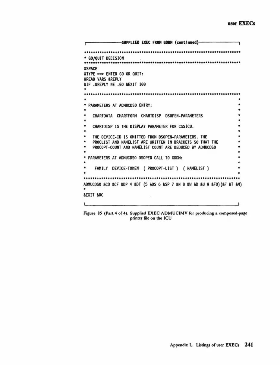
user EXECs
.-------:SUPPLIED EXEC FROM GOON (conttnued)------....,
*********************************************************************** * GO/QUIT DECISION *********************************************************************** &SPACE &TYPE =--> ENTER GO OR QUIT: &READ VARS &REPLY &IF .&REPLY NE .GO &EXIT lee * *********************************************************************** * * PARAMETERS AT ADMUCDSO ENTRY: * * CHARTDATA CHART FORM CHARTDISP DSOPEN-PARAMETERS * * CHARTDISP IS THE DISPLAY PARAMETER FOR CSSICU. *
* * * * * * *
* THE DEVICE-ID IS OMITTED FROM DSOPEN-PARAMETERS. THE * * PROCLIST AND NAMELIST ARE WRITTEN IN BRACKETS SO THAT THE * * PROCOPT-COUNT AND NAMELIST COUNT ARE DEDUCED BY ADMUCDSO * * * PARAMETERS AT ADMUCDSO DSOPEN CALL TO GDDM: * * *
FAMILY DEVICE-TOKEN (PROCOPT-LIST) (NAMELIST)
* * * * *
*********************************************************************** ADMUCDSO &CD &CF &DP 4 &DT (5 &DS 6 &SP 7 &N 8 &W &0 &U 9 &FO)(&F &T &M) * &EXIT &RC
Figure 8S (Part 4 of 4). Supplied EXEC ADMUCIMV for producing a composed-page printer file on the ICU
Appendix L. Listings of user EXECs 241

user EXECs
.-------SUPPLIED EXEC FROM GDD~M-I----------..
/*********************************************************************/ /* */ /* GDDM/VM */ r ~ /* 5664-2ae (C) COPYRIGHT IBM CORP. 1987 */ /* ALL RIGHTS RESERVED */ /* LICENSED MATERIAL - PROGRAM PROPERTY OF IBM */ /* */ /*********************************************************************/
/* Name : ADMUIMP EXEC */
/* This is a sample user exec which reads in a GDDM image save file */ r (type ADMIMG) and restores it to create a page segment or - * / /* document file for a family 4 printer. */ /* NOTE. This exec assumes that the GDDM default image file type */ /* ADMIMG has been used. If the GDDM default has been */ /* changed for your installation, all references to ADMIMG in */ /* this exec should also be changed (and this note updated). */
Arg fn ft fm . n(" token fieldh fieldv fields.
/* Check invocation parameters
If fn = I?I I fn :::: II
then signal prompt /* If parameters are incorrect /* prompt user •••••
*/
*/ */
1* Substitute default values for unspecified parameters *1
Parse Value ft nADMIMG" With ft . /* liP file type *1 Parse Value fm ,,*n With fm • r liP file mode */ Parse Value token "IMG24an With token • 1* GDOM Device Token *1 Parse Value fieldh "6a" With fieldh • 1* Horizontal size */ Parse Value fieldv n4a n With fieldv . 1* Vertical Size *1 Parse Value fields "a" With fields. r in inches *1
1* e = tenths of inches *1 1* 1:::: millimeters *1
/* Set default parameters */
scale:::: "2n /* scale e = image size */ /* field size will be ignored */ /* scale 1 :::: no image scaling *1 /* image may be clipped *1 /* scale 2 :::: exact fit *1 1* image may be distorted *1 /* scale 3 :::: maintain aspect ratio*1 /* image may have space in 1 dim *1
continued •••
Figure 86 (Part 1 of 3). Supplied EXEC ADMUIMP for printing ADMIMG files
242 GDDM Installation and System Management for VM

user EXECs
.-------SUPPLIEO EXEC FROM GOON (continued)--------,
type = n6 n 1* type 6 = document *1 1* type 1 = page segment *1
outft = ILIST38PP" /* Document for 3866-3 * I /* "PSEG38PP" = page segment for 3866-3 *1 /* IPSEG3626" = page segment for 3826 *1 /* "LIST36PP" = document for 3866-3 *1 1* ILIST4256" = document for 4256 *1
1* Check that the fi1etype is ADMIMG (see NOTE at top of file) *1
If ft ~ 'ADMIMG' then do;
say
1* If not, issue error message *1 1* and exit with return code=166 *1 1* *1
say 'Speci fi ed say
file type must be ADMIMG'
exit 16a end;
1* /* /*
*1 *1 *1
1* Check that the specified Image file exists *1
address command 'STATE' fn ft fm If rc ....,= a then
do; say say fn ft fm 'NOT FOUND' say exit rc
end;
1* Look for specified file *1 1* If not, issue error message *1 1* and exit with CMS return code *1 /* *1 1* *1 /* *1 /* *1 /* *1
1* Check that the specified page segment file does not exist *1
address command 'STATE' fn outft 'AI' If rc = 6 then 1* If file exists, erase it *1
address command 'ERASE' fn outft 'AI'
1* Tell user what he is likely to get *1
name = fn ft fm n1ist = fn outft 'AI' p1ist = '5' type field = fie1dh fie1dv fields string = '('name')('sca1e')('n1ist')('plist')('token')('fie1d')' clear say 'Image file =' name say 'Output file =' nlist say 'Procopts are =' plist say 'Printer token =' token if fields = e then units = 'tenths of inches'
else units = 'millimeters' continued
Figure 86 (Part 2 of 3). Supplied EXEC ADMUIMP for printing ADMIMG files
Appendix L. Listings of user EXECs 243

user EXECs
,-------:SUPPLIED EXEC FROM GDDM (continued)-------,
say 'Field size =' fieldh 'x' fie1dv 'in' units if scale = 0 I fieldh = 0 I fieldv = 0 then
say 'Image will be same size as original (field ignored)' if scale = 1 then
say 'Image may be clipped and/or spaced to fit field' if scale = 2 then
say 'Image may be distorted to fit the specified field' if scale = 3 then
say 'Image proportion will be maintained to fit without clipping' say 'About to issue the command:' say 'AOMUIMPV' string say 'Enter Go to continue, or Quit' pull comm if comm ~ 'GO' then exit 200
/* Start the GOOM Page Segment generation module */
address command 'AOMUIMPV' string
exit rc
/* Provide a description of the invocation parameters for this exec */
prompt : parse source • • exec name •
say 'This exec reads a GOOM Image file (AOMIMG) and restores it to say 'create a page segment or document file. say , say' Format:-say' say' 'execname' filename filetype filemode ( token h v s say , say' where filename is the input filename say I fi1etype is the input fi1etype (default ADMIMG) , say' fi1emode is the input filemode (default *) say' token is the GODM device token (default IMG240) , say' h is the horizontal size (default 60) say , v is the vertical size (default 40) say's is the scale (0 = tenths of inches(default)) say' (1 = millimeters) say ,
exit 0
Figure 86 (Part 3 of 3). Supplied EXEC ADMUIMP for printing ADMIMG files
244 GDDM Installation and System Management for VM

user EXECs
.-------:SUPPLIED EXEC FROM GDDM-M ------------,
/**********************************************************************/ r ~ /* GDDM/VM */ r */ /* 5664-20e (C) COPYRIGHT IBM CORP. 1979, 1988 */ /* ALL RIGHTS RESERVED *1 1* LICENSED MATERIAL - PROGRAM PROPERTY OF IBM *1 r ~ 1**********************************************************************/ r */ /* PROGRAM NAME - ADMUBCDV EXEC *1 r ~ 1* DESCRIPTIVE NAME - Browse Composite Document files on a terminal. *1 r ~ 1* FUNCTION - To browse LIST38xx, PSEG38xx, OVLY38xx, LIST425e, */ /* PSEG42S0, OVLY425e, LISTAPA, LISTCDP and ADM IMAGE */ 1* files on a terminal. */ r ~ 1* ENTRY CONDITIONS - None */ r ~ /* EXIT-NORMAL RETURN CODES - */ 1* */ /* e When the file has been displayed correctly *1 r ~ 1* EXIT-ERROR RETURN CODES - *1 1* *1 1* Any return code other than 0 would indicate an error */ 1* which will be explained in an accompanying message. *1 r ~ /* NOTES - None */ /* */ I*************t'********************************************************/
Arg fn ft fm •
1* Check invocation parameters
If ~n = '?' I fn = " then signal prompt
1* If parameters are incorrect 1* prompt user ••••.
*/
*1 *1
/* Substitute default value for filetype & filemode if not specified */
Parse Value ft "ADMIMAGEn With ft Parse Value fm "*n With fm
/* liP file type 1* liP file mode
continued •••
*1 *1
Figure 87 (Part I of 2). Supplied EXEC ADMUBCDV to browse and print composite documents
Appendix L. Listings of user EXECs 245

user EXECs
~-----SUPPLIED EXEC FROM GDDN (continued)--------.
/* Set default parameters for ADM4CDUV
copies = nln
duplex = "1"
procopts ::: nn
devtok = Un
family = nln
namelist ::: lin
/* number of copies /* 1 = simplex /* 2 = normal duplex /* 3 = tumble duplex /* Procopts /* Device token /* GDDM Family /* Namelist entry
/* Check that the specified AFPDS/CDPDS file exists
*/
*/ */ */ */ */ */ */ */
*/
address command 'STATE' fn ft fm If rc -.= e then
do; say
/* Look for specified file */ /* If not t issue error message */ /* and exit with CMS return code */ /* */
say fn ft fm 'NOT FOUND' say
/* */ /* */
exit rc /* */ end; /* */
/* Start the GDDM Composite Document Print Utility */
address command 'ADM4CDUV ' fn ft fm '(I copies duplex 'lit '(I namelist ')(' procopts ')(' devtok ')(' family')'
exit rc
/* Provide a description of the invocation parameters for this exec */
prompt : parse source • • exec name •
say say 'This exec reads an Advanced Function Presentation Data Stream say '(AFPDS) file (e.g LIST38PP t PSEG42S0 t OVLY3829 t LISTAPA t ADMIMAGE), say 'or a Composite Document Presentation Data Stream (CDPDS) file say '(ego LISTCDP), and displays the composite document on the terminal. say say Format :-say' say 'execname' filename filetype filemode say say say say say
exit 0
where filename is the input filename filetype is the input filetype filemode is the input filemode
Figure 87 (Part 2 of 2). Supplied EXEC ADMUBCDV to browse and print composite documents
246 GDDM Installation and System Management for VM

user EXECs
r-------SUPPLIED EXEC FROM GDDM-M-----------,
/********************************************************************/ /* */ /* 5664-28e,5665-356,5666-328 */ /* (C) COPYRIGHT IBM CORP. 1979,1986 */ /* LICENSED MATERIALS - PROPERTY OF IBM */ /* */ /* *** Note *** */ /* The name of this EXEC should be the same as the name of */ /* the command sent to the host by the 327e-PC file transfer */ /* commands 'SEND ' and 'RECEIVE'. The default command name */ /* used by SEND and RECEIVE is IND$FILE, where 1$1 is the */ /* national currency symbol. */ r ~ /* This REXX EXEC intercepts the PC/DOS 'IND$FILE' command and */ /* pre or post processes picture files when triggered by the */ /* option 'ADMGDF' in the 'IND$FILE' command */ r ~ /* 'GET' -> retrieve file from GDF object library */ /* 'PUT' -> Store file on GDF object library */ r */ /* The I CHART , option can also be used on the EXEC. This has */ /* no effect when transfer is from host to workstation. On */ /* transfer from workstation to host it will convert the file */ /* into a GDDM PGF ICU chart file. */ /* */ /* The EXEC takes the GDF object name to be the same as the */ /* filename specified in the send or receive command. */ r ~ /* A temporary 'Picture Interchange File ' is created at the */ /* host. Its file identifier is supplied on the send and receive */ /* commands. If the file type and file mode are omitted they */ /* default to 'PIF All. IPIFI is also used as the file type if */ /* graphic conversion has been requested and the file type */ /* parameter has been specified as IADMGDFI. */ r ~ /* A typical send command will look like: */ r ~ /* SEND pc.picture picture ( admgdf */ r ~ /* This will create a GDF object 'PICTURE ADMGDF All and use */ /* a temporary file 'PICTURE PIF A', */ r ~ r ~ /********************************************************************/
continued •••
Figure 88 (Part I of 5). Supplied EXEC ADMUPCFV for file transfer with the 3270-PC/G and 3270-PC/GX
Appendix L. Listings of user EXECs 247

user EXECs
.------SUPPLIED EXEC FROM GOON (conttnued)-------.
/********************************************************************/ /* get parameters */ /********************************************************************/ parse upper arg operation fn ft fm '(' options ')' • if operation ~ 'PUT' & operation ~ 'GET' then
do call help exit 12
end i f ftc II then
do if pos('CHART',options)~a then
ft"'CHF' else
ft='PIF' end
if fmr-" then fm='A1' /********************************************************************/ /* remove chart option from list */ /********************************************************************/ chart_trans ferc (1=9) /* set chart transfer flag off */ i=pos('CHART',options) if i ...... 9 then
do /****************************************************************/ /* pre or post process picture and transfer */ /****************************************************************/ options = substr(optfons,1,i-1) II substr(options,i+5)
/* remove CHART from options */ chart_transferc(1=1) address command 'STATE' if rc :: a then
/* set chart transfer flag on */ fn ft fm
/* Stop Transfer with no filename do address command 'INO$FILE GET' say 'Temporary file' fn ft fm 'exists.' say" exit 12 end
*/
end
conttnued .••
Figure 88 (Part 2 of 5). Supplied EXEC ADMUPCFV for file transfer with the 3270-PC/G and 3270-PC/GX
248 GDDM Installation and System Management for VM
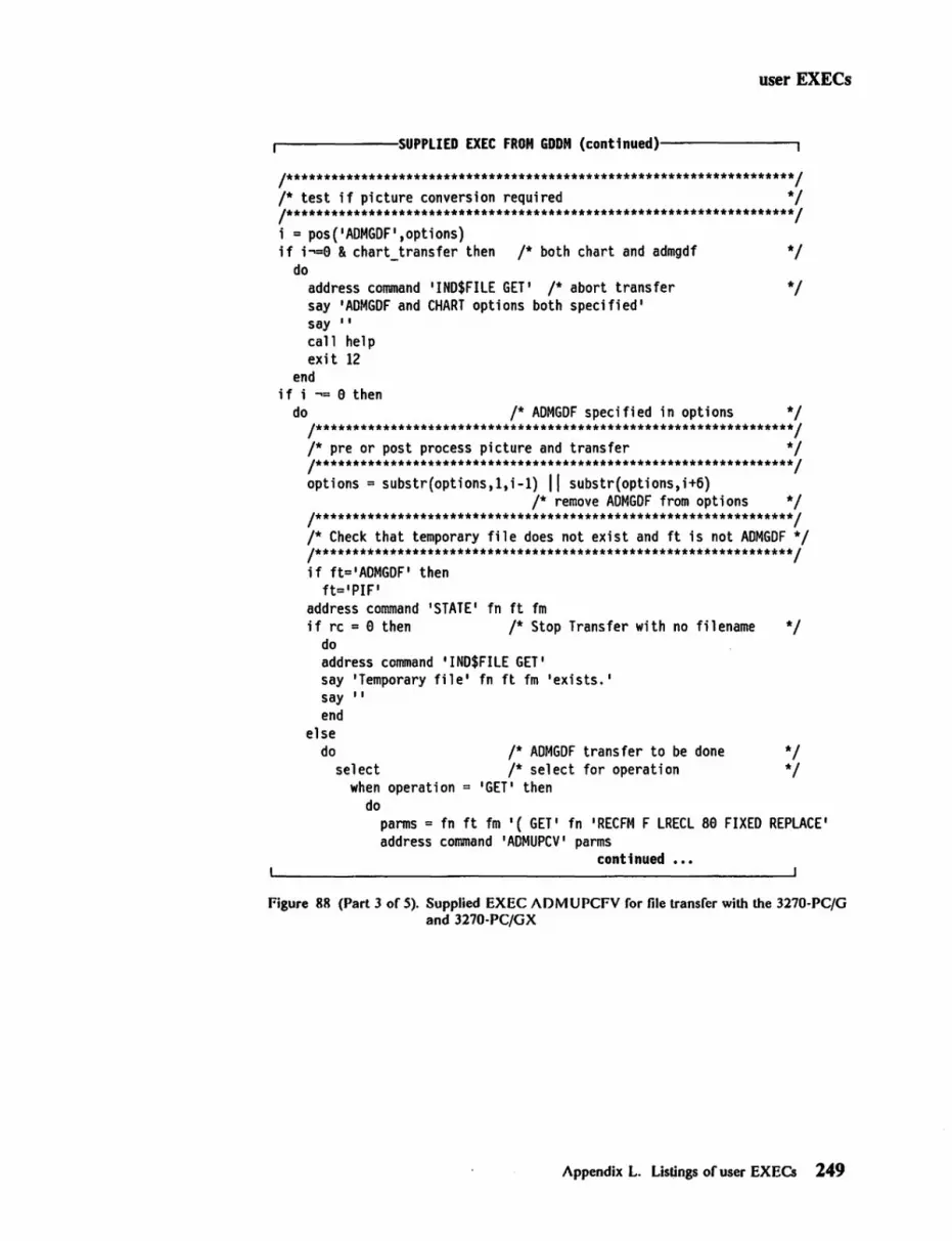
user EXECs
...-------SUPPLIED EXEC FROM GDDN (continued)--------,
/********************************************************************/ /* test if picture conversion required */ /********************************************************************/ i = pos('ADMGDF',options) if i~e & chart transfer then /* both chart and admgdf */
do address command 'IND$FILE GET' /* abort transfer */ say 'ADMGDF and CHART options both specified ' say I' call help exit 12
end if i -.= e then
do /* ADMGDF specified in options */ /****************************************************************/ /* pre or post process picture and transfer */ /****************************************************************/ options = sUbstr(options,1,i-1) II substr(options,i+6)
/* remove ADMGDF from options */ /****************************************************************/ /* Check that temporary file does not exist and ft is not ADMGDF */ /****************************************************************/ if ft='ADMGDF' then
ft='PIF' address command ISTATEI fn ft fm if rc = e then /* Stop Transfer with no filename */
do address command 'IND$FILE GET' say 'Temporary file' fn ft fm 'exists,' say II end
else do /* ADMGDF transfer to be done */
select /* select for operation */ when operation 'GET' then
do parms = fn ft fm '( GET' fn IRECFM F LRECL 8e FIXED REPLACE' address command 'ADMUPCV I parms
continued , •.
Figure 88 (Part 3 of 5). Supplied EXEC ADMUPCFV for file transfer with the 3270-PC/G and 3270-PC/GX
Appendix L. Listings of user EXECs 249

user EXECs
.------:SUPPLIED EXEC FROM GOON {continued)--------,
end
if rc = e I rc = 4 then/* conversion ran ok */ do
say fn 'ADMGDF converted to' fn ft fm address command 'IND$FIlE GET' fn ft fm '(I options I)' if rc = e I rc = 4 then
do /* transfer ran ok */ say 'File' fn ft fm 'transferred to PC' address command 'ERASE' fn ft fm end
end else /* conversion failed */
end
do /* send 'file not found' to pc */ address command 'STATE' fn ft fm if rc = e then/* if temporary file exists erase it*/
address command 'ERASE' fn ft fm /* to stop IND$FIlE */
address command 'IND$FILE GET' fn ft fm end
/* GET processing */
when operation = 'PUT' then do
end end
address command 'IND$FILE PUT' fn ft fm '(I options I)' if rc = e I rc = 4 then/* transfer ran ok */
end
do say 'File' fn ft fm 'transferred to Host' parms = fn ft fm '( PUT' fn 'FLOAT REPLACE' address command 'ADMUPCV' parms if rc = e I rc = 4 then
do /* conversion ran ok */ say fn ft fm 'converted to' fn ADMGDF address command 'ERASE' fn ft fm end
end /* PUT processing
/* select for operation /* ADMGDF transfer to be done /* ADMGDF specified in options
continued •••
*/ */ */ */
Figure 88 (Parl4 of 5). Supplied EXEC ADMUPCFV for file transfer with the 3270-PC/G and 3270-PC/GX
250 GOOM Installation and System Management for VM

user EXECs
..-------SUPPLIED EXEC FROM GDON (continued)--------.
else do
/****************************************************************/ /* picture conversion not requested */ /****************************************************************/ address command 'IND$FILE' operation fn ft fm '(' options ')' /****************************************************************/ /* post process any chart transfer if needed */ /* (NOTE: There is no possible pre processing) */ /****************************************************************/ if chart_transfer & rc=O then
do if operation=IPUT' then/* operate only on transfer to host */
end
do say 'File ' fn ft fm 'transferred to Host' address command 'ADMUPGV' fn ft fm '( CHART I tn I REPLACE I if rc=0 then
say fn ft fm Iconverted to CHART file ' fn if rc=O&, /* good conversion */
ft~='ADMCFORM'&,/* not a chart format file type */ ft~='ADMCDATA' then /* or a chart data one */
address command 'ERASE' fn ft fm end
end
exit rc
help: procedure parse source .• function • say 'HELP fori function say function 'GETlpUT file-id ( optionsll<ADMGDFICHART>1 loptions I say 'GET - relrieve object from GDDM GDF object libraryl say 'PUT - store object in GDDM GDF object library' say 'file-id identifier of PIF file, file-name - name of GDF object' say 'options - for File Transfer Program I say 'ADMGDF - trigger for graphic conversion I say 'CHART - trigger for GGXC/ICU conversion '
return
Figure 88 (Part 5 of 5). Supplied EXEC ADMUPCFV for file transfer with the 3270-PC/G and 3270·PCjGX
Appendix L. Listings of user EXECs 251

GDDM glossary
This glossary defines various terms used in this manual.
In the definitions, the qualification "in GDDM" means in the GDDM/VM or GDDM/VMXA program or in GDDM-PGF (or both). "In GDDM-PGF" means in GDDM-PGF, which includes the ICU.
This glossary includes terms and definitions from the IBM Dictionary o/Computing, SC20-1699.
A
Advanced Function Presentation Data Stream (AFPDS). A data stream, sometimes known as Composed Page Data Stream (CPDS), sent to composed-page printers such as the 3800-3 and 4250.
B
blank character. An empty character represented by X'40' in the EBCDIC code. In GDDM-PGF, such a character occupies one position in a label or a key and may be used for positioning purposes.
business graphics. The methods and techniques for presenting commercial and administrative information in chart form. For example, the creation and display of a sales bar chart.
c CDPF. Composed Document Printing Facility, a program that supports the advanced printing capabilities of the 4250 printer.
character cell. The physical, rectangular space in which any single character or symbol is displayed on a screen or printer device. The size and position of a character cell are fixed. Size is usually specified in pixels on a given device, for example, 9 by 12 on an IBM 3279 Model 3 display. Position is addressed by row and column coordinates.
character mode. In GDDM, the type of characters to be used. There are three modes:
• Mode-} characters are loadable into PS and are of device-dependent fixed size, spacing, and orientation, as are hardware characters.
glossary
• Mode-2 characters are image (ISS) characters. Size and orientation are fixed. Spacing is variable by program.
• Mode-3 characters are vector (VSS) characters. Box size, position, spacing, orientation, and shear of individual characters are variable by program.
CICS/VS. Customer Information Control System/Virtual Storage. A subsystem of MVS or VSE under which GDDM can be used.
clipping. In computer graphics, removing parts of a display image that lie outside a viewport.
CMS. Conversational Monitor System. A time-sharing subsystem that runs under VM.
code page. Defines the relationship between a set of code points and graphic characters. This relationship covers both the standard alphanumeric characters and the national language variations. GDDM supports a set of code pages used with typographic fonts for the IBM 4250 printer.
Composed Document Presentation Data Stream (CDPDS). A data stream containing graphics, images, and text, that is the input to the GDDM Composed Document Presentation Utility.
composed-page printer. A printer, such as the IBM 4250 or IBM 3800 Model 3, to which the host computer transmits data in the form of a succession of formatted pages. Such devices can print pictorial data and text, and can position all output to pixel accuracy. The density of pixels and the general print quality are often high enough for the output to be used as camera-ready copy for publications.
composite document. A document that contains both formatted text, such as that produced by the Document Composition Facility program, and graphic or image data, such as that produced by GDDM.
country-cxtended code page (CECP). An extension of a normal EDCDIC code page that includes definitions of all code points in the range X '41' - X 'FE'. Each CECP contains the same 190 characters, but the mapping between code points and graphic characters depends upon the country for which the code page is defined.
GDDM glossary 259

glossary
o data-stream compatibility (DSC). In 8100 systems, the facility that provides access to System/370 applications that communicate with 3270 Information Display System terminals.
data-stream compression. The shortening of an I/O data stream for more efficient transmission between link -attached units.
DCSS. Discontiguous Saved Segment (VM).
DCT. Destination control table (CICSJVS).
default value. A value chosen by GDDM when no value is explicitly specified by the user. For example, the default line type is a solid line.
device family. In GDDM, a device classification that governs the general way in which I/O will be processed. See also processing options. For example:
• Family 1: 3270 display or printer
• Family 2: queued printer
• Family 3: system printer (alphanumerics only)
• Family 4: Composed-page printer.
device token. In GDDM, an 8-byte code giving entry to a table of pre-established device hardware characteristics that are required when the device is opened (initialized).
display point. Synonym for pixel.
double-byte character set (DDCS). A set of characters in which each character occupies two byte positions in internal storage and in display buffers. Used, for example, for Kanji symbols.
DPCX. Distributed Processing Control Executive. An 8100 system control program.
DPPX. Distributed Processing Programming Executive. An 8100 system control program.
DSC. Data-stream compatibility.
dual characters. In GDDM, characters that each occupy two bytes in internal storage and in display buffers. They are used to display, for example, Kanji symbols.
dummy device. An output destination for which GDDM does all the normal processing but for which no actual
260 GDDM Installation and System Management for VM
output is generated. Used, for example, to test programming for an unavailable output device.
E extended data stream. For 3179, 3278, 3279, and 3287 devices, input/output data formatted and encoded in support of color, programmed symbols, and extended highlighting. These features extend the 3270 data-stream architecture.
extended highlighting. The emphasizing of a displayed character's appearance by blinking, underscore, or reverse video.
external defaults. GDDM-supplied values that users can change to suit their own needs.
F
Fer. File control table (CICSNS).
field. An area on the screen or the printed or plotted page.
nat file. A file that contains only data, that is, a file that is not part of a hierarchical data structure. A flat file can contain fixed or variable length records, usually sequentially organized.
font. A particular style of typeface (for example, Gothic English). In GDDM, a font may exist as a programmed symbol set.
frame. In GDDM-IMD, synonym for panel.
full-screen processor. A host software component that, together with display terminal functions, supports display terminal input/output in full-screen mode.
G GDDM. Graphical Data Display Manager.
GDDM-IMD. GDDM Interactive Map Definition.
GDDM storage. The portion of host computer main storage used by GDDM.
GDF. Graphics data formaL
graphics data stream. The data stream that produces graphics on the screen, printer, or plotter.

H
hardware symbols. The characters that are supplied with the device. The term is loosely used also for GDDM mode-l symbols that are loaded into a PS store for subsequent display.
ICU. Interactive Chart Utility.
Image Symbol Editor (ISE). A GDDM-supplied interactive editor that lets users create or modify their own image symbol sets (ISS).
image symbol set (ISS). A set of symbols each of which was created as a pattern of dots. Contrast with vector symbol set (VSS).
IMS/VS. Information Management SystemjVirtual Storage. A subsystem of MVS under which GDDM can be used.
include member. A collection of source statements stored as a library member for later inclusion in a compilation.
Intelligent Printer Data Stream (IPDS). A structured-field data stream for managing and controlling printer processes. IPDS uses all-points addressability. a printing concept that allows users to position text, images. graphic pictures. bar codes. and overlays at any defined point on a printed page.
Interactive Chart Utility (ICU). A GDDM-PGF menu-driven program that allows business charts to be created interactively by nonprogrammers.
interactive graphics. In GDDM. those graphics that can be moved or manipulated by a user at a terminal.
Interactive Map Definition. A member of the GDDM family of licensed programs. It enables users to create alphanumeric layouts at the terminal. The operator defines the position of each field within the layout and may assign attributes, default data, and associated variable names to each field. The resultant map may be tested from within the utility.
interactive mode. A mode of application operation in which each entry receives a response from a system or program, as in an inquiry system or an airline reservation system. An interactive system may also be conversational, implying a continuous dialog between the user and the system.
interactive subsystem. (l) One or more terminals. printers, and any associated local controllers capable of
glossary
operation in interactive mode. (2) One or more system programs or licensed programs that enable user applications to operate in interactive mode. For example, CICSjVS.
ISE. Image Symbol Editor.
ISS. Image symbol set.
J JCL. Job Control Language.
K
Kanji. A character set of symbols used in Japanese ideographic alphabets.
L
Iink-cdit. To create a load able computer program by means of a linkage editor.
load module. A program unit that is suitable for loading into main storage for execution; it is usually the output of a linkage editor.
local character set identifier. A hexadecimal value stored with a GDDM symbol set, which may be used by symbol-set-loading means other than GDDM in the context of local copy on a printer.
logical input device. A concept that allows application programs to be written in a device-independent manner. The logical input devices to which the program refers may be subsequently associated with different physical parts of a terminal, depending on which device is used at run-time.
LTERM. In I MSjVS, logical terminal.
M
map. A predefined alphanumeric layout, defining the position, attributes, and default data for each constituent alphanumeric field.
map specification library (MSL). The data set in which maps are held in their source form.
mapgroup. A data item that contains a number of maps and information about the device on which those maps will be used. All maps on a GDDM page must come from the same mapgroup.
GDDM glossary 261

glossary
mapped alphanumerics. The creation of alphanumeric displays via predefined maps.
mapped lield. An area of a page whose layout is defined by a map.
mapped graphics. Graphics placed in a graphics area within a mapped field.
mapped page. A GDDM page whose content is defined by maps in a mapgroup.
mapping. The use of a map to produce a panel from an output record, or an Input record from a panel.
marker. In GDDM, a symbol centered on a point. Line graphs and polar charts may use markers to indicate the plotted points.
MDT. Modified data tag.
menu. A displayed list of logically grouped functions from which the operator may make a selection. Sometimes called a menu panel.
menu-driven. Describes a program that is driven by an operator responding to one or more displayed menus.
MFS. Message format service.
missing values. In GDDM-PGF or the ICU, x or y values that are omitted from a chart. For example. one line on a graph might represent a sales forecast and extend to the end of the year on the x axis, while a second line might represent actual sales and extend only to the current month.
mixed character string. A string containing a mixture of Latin (one-byte) and Kanji (two-byte) characters.
mixed chart. In GDDM-PGF or the ICU, the combination of more than one chart type in a business graph. For example, the overlaying of a line graph on top of a bar chart.
MSIIP. Maintain system history program.
MSL. Map specification library.
multiple charts. Two or more charts appearing together on the display screen or page. Multiple charts can be of the same type or different types, and can be derived from one or more sets of data.
262 GDDM Installation and System Management for VM
N
National Language (NL) feature. The translations of the ICU panels and GDDM messages into a variety of languages other than English.
nickname. In GDDM. a quick and easy means of referring to a device, the characteristics and identity of which have been predefined.
o object code. Output from a compiler or assembler that is in itself executable machine code or is suitable for processing to produce executable machine code.
object deck. Synonym for object module.
object libraries. An area on a direct access storage device used to store object programs and routines.
object module. A module that is the output of an assembler or a compiler and is input to a linkage editor.
outbound structured lield. An element in 3270 data streams from host to terminal with formatting that permits variable-length and multiple-field data to be sequentially translated by the receiver into its component fields without having to examine every byte.
p
panel. A predefined display that defines the locations and characteristics of alphanumeric fields on a display terminal. When the panel offers the operator a selection of alternatives it may be called a menu panel. Synonymous with frame.
PCD. Program communication block (IMSfVS).
PCT. Program control table (CICSfVS).
PDS. In OS{fSO, a partitioned data set.
pel (picture element). Synonym for pixel.
PGF. Presentation Graphics Facility.
picture element (pel). Synonym for pixel.
picture interchange format (PIF) file. In graphics systems, the type of file, containing picture data. that can be transferred between GDDM and a 3270-PC/G or 3270-PC/GX work station.
PIF. Picture interchange format (PIF) file.

pixel. The smallest area of a display screen capable of being addressed and switched between visible and invisible states. Synonymous with display point, pel, and picture element.
plotter. An output device that uses pens to draw its output on paper or transparency foils.
PPT. Processing program control table (CICS/VS).
presentation graphics. Computer graphics products or systems, the functions of which are primarily concerned with graphics output presentation. For example, the display of business planning bar charts.
Presentation Graphics Facility (PGF). A member of the GDDM family of licensed programs. It is concerned with business graphics. as opposed to general graphics.
primary device. In GDDM, the main destination device for the application program's output, usually a display terminal. The default primary device is the user console.
print utility. A subsystem-dependent utility that sends print files from various origins to a queued printer.
processing options. Describe how a device's I/O will be processed. These device-family-dependent and subsystem-dependent options are specified when the device is opened. An example is the choice between CMS attention-handling protocols.
program library. (1) A collection of available computer programs and routines. (2) An organized collection of computer programs. (3) Synonym for partitioned data set.
programmed symbols (PS). Dot patterns loaded by GDDM into the PS stores of an output device.
projection. In GDDM image processing, an application-defined function that specifies operations to be performed on data extracted from a source image.
PS. Programmed symbols.
PS overflow. A condition where the graphics cannot be displayed in its entirety because the picture is too complex to be contained in the device's PS stores.
PSB. In IMS;VS, a program specification block.
PSF. Print Services Facility. a program that support.o; the advanced printing capabilities of the 3800 model 3 printing subsystem.
glossary
Q
QSAM. Queued sequential access method.
QT AM. Queued telecommunications access method.
queued printer. A printer belonging to the subsystem under which GDDM runs, to which output is sent indirectly by means of the GDDM Print Utility program. In some subsystems, this may allow the printer to be shared between multiple users. Contrast with system printer.
R
RCP. Request control parameter.
reentrant. The attribute of a program or routine that allows the same copy of the program or routine to be used concurrently by two or more tasks.
resolution. In graphics and image processing, the number of pixels per unit of measure (inch or meter).
s scanner. A device that produces a digital image from a document.
scrolling. In computer graphics, moving a display image vertically or horizontally in a manner such that new data appears at one edge as existing data disappears at the opposite edge.
SCS. SNA character string.
SMF. System management facilities.
SMI). System management program.
SNA. Systems network architecture.
SPI. System programmer interface.
SPIB. System programmer interface block.
stand-alone (mode). Operation that is independent of another device. program, or system.
swathe. A horizontal slice of printer output, forming part of a complete picture. Composed·page printer images are onen constructed in swathes to reduce the amount of storage required.
GDDM glossary 263

glossary
symbol. Synonymous with character. For example, the following terms all have the same meaning: vector symbols, vector characters, vector text.
symbol cell. Synonym for character cell.
symbol matrix. Synonym for dot matrix.
symbol set. A collection of symbols, usually but not necessarily forming a font. GDDM applications may use the hardware device's own symbol set. Alternatively, they can use image or vector symbol sets, which the user may have created.
symbol set identifier. In GDDM, an integer (or the equivalent EnCDlC character) by which the programmer refers to a loaded symbol set.
system printer. A printer belonging to the subsystem under which GDDM runs, to which output is sent indirectly by means of system spooling facilities. Contrast with queued printer.
T
TCT. Terminal control table (CICSjVS).
terminal. A device, usually equipped with a keyboard and a display unit, capable of sending and receiving information over a link.
transfer operation. In GDDM image processing, an operation in which a projection is applied to a source image, and the result placed in a target image. The source and target images can be device or application images in any combination, or one or other of ihem (but not both) can be image data within the application program.
transform. (1) The action of modifying a picture for display; for example, by scaling, rotating, shearing, or displacing. (2) The object that performs or defines such a modification; also referred to as a transformation. (3) In G DDM image processing, a definition of three aspects of the data manipulation to be done by a projection:
I. A transform element or sequence of transform elements, and
2. A resolution conversion or scaling algorithm, and 3. A location within the target image for the result.
Only item 3 is mandatory.
transform element. In GDDM image processing, a specific function in a transform, which may be one of the following: define sub-image, scale, orient, reflect, negate, define place in target image.
264 GDDM Installation and System Management for VM
TSO. lime sharing option. A subsystem of OSjVS under which GDDM can be used.
u UDS. User default specification.
UDSL. A list of user default specifications (UDSs).
unformatted data. In GDDM image processing, compressed or uncompressed binary image data that has no headers, trailers, or embedded control fields other than any defined by the compression algorithm, if applicable. The data is in row major order, beginning with the top left of the picture.
user default specification (UDS). The means of changing a GDDM default value. The default values that a UDS can change are those of the GDDM or subsystem environment, GDDM user exits, and device definitions.
user exit. A point in GDDM execution where a user routine witt gain control if such has been requested.
v variable cell size. In most devices, the hardware cell size is fixed. Dut the 3290 Information Panel has a cell size that can be varied. This in turn causes the number of rows or columns on the device to alter.
VCNA. VrAM communications network application.
vector. (I) In computer graphics, a directed line segment. (2) In the GDDM-PGF Vector Symbol Editor, a straight line between two points.
vector device. A device capable of displaying lines and curves directly.
vector symbol. A character or shape made up of a series of lines or curves.
Vector Symbol Editor. A program supplied with GDDM-PGF, the function of which is to create and edit vector symhol sets (VSS).
vector symbol set (VSS). A set of symbols each of which was originally created as a series of lines and curves. Contrast with image symbol set (ISS).
VM/SP CMS. IBM Virtual MachinejSystem Product Conversational Monitor System. A system under which GDDM can be used.

VM/XA. IBM Virtual Machine/Extended Architecture. A system under which GDDMfVM or GDDMfVMXA and associated programs can be used.
VSE. Virtual storage extended. An operating system consisting of VSE/Advanced Functions and other IBM programs. A system under which GDDM can be used. In GDDM, the abbreviation VSE has sometimes been used to refer to the Vector Symbol Editor, but to avoid confusion. this usage is deprecated.
VSS. Vector symbol set.
VT AM. Virtual Telecommunications Access Method.
glossary
w window. (1) In GDDM. an independent rectangular subdivision of the screen. Several can exist at the same time, and each can receive output from, and send input to, either a separate GDDM program or a separate function of a single GDDM program. (2) A defined section of world coordinates. In GDDM. the window can be regarded as a set of coordinates that are overlaid on the viewport. (3) The "graphics window" is the set of coordinates used for defining the primitives that make up a graphics display. By default. both x and y coordinates run from 0 through 100. (4) The "page window" defines which part of a deep or wide page should currently be displayed.
work station. A display screen together with attachments such as a local copy device or a tablet.
WTP. Write-to-programmer.
GDDM glossary 265

Index
A abend code ] 064 85 abend code 1201 232 access method, VTAM 185 address space requirements 29 ADMA ...
ADMACIN, application interface initializer 201 ADMADFx, external defaults modules 115
repackaging 201 ADMASSSV, GDDM Release I and 2 DesS 73 ADMASSOO, name of DesS 73
ADMD ... ADMDA210, GDDM DesS 73 ADMDA21I, GDDM DCSS 73
ADMC. .. ADMCOLM, changing default filetype J 21
ADM D ... ADMDATRN, alphanumeric defaults module 133 ADMDHIIx, default image symbol sets 181 ADMDHIMx, default marker symbol sets ]81 ADMDHlPx, default pattern symbol sel~ 181 ADMDHIVx, default names for vector symbol
sets 181 ADMDlUJx, default CECP image symbol sets 181 ADMDHJVx, default names for CECP vector
symbol sets 181 ADMDKFNT AFPDS to IPDS conversion
module 106. 213 ADMDKO Print Data Steeam Processor 106
ADM E ... ADMEOOOx, subsystem initialization modules 201
ADMG ... ADMGLlD, GDDM Base general purpose
TXTLID 85 ADMI...
ADM]L1D, GDDM-IMD general purpose TX'I'LIB 85
ADMIMG files, how held 107 ADMIM21O. GDDM Dc..<;S 73 ADMISSEx. image symbol editor link-edit
names 207 ADMJROOM program 89 ADML. ..
ADMLSYS], device token table for 3270s and queued printers 153
ADMLSYS3, device token table for system printers 153
ADMLSYS4. device token table for composed-page printer files 153
ADMM ... ADMMDFT
See separate index entry ADMMFONT, macro 211
index
ADMMIMAG, family 4 device token macro 178 ADMMKFNT, macro 213 ADMMSYSP, macro 160,177 ADMM3270. macro 162
ADMMDFT 67 AM3270, device attachment 120 APPCPG, application code page 120 AUNLOCK. always-unlock-keyboard 120 CMS ....
CMSAPLF. APL default specification 121 CMSCOLM. ADMCOLM filetype 121 CMSDECK. deck filetype 121 CMSDFTS. defaults filename and filetype 121 CMSIADS, ADS filetype 121 CMSIFMT, export utility filetype 121 CMSMONO. monochrome filetype 121 CMSMSLT. MSL filetype 121 CMSPRNT. print filetype 122 CMSSYSP. system printer filetype 122 CMSTEMP, work-file filetype 122 CMSTRCE, trace filenamejfiletype 122
COMMENT. comments in defaults module 122 CPN4250. 4250 code page name 122 DATEFRM, date convention 122 DBc..<;DFf. symbol set select 122 DBCSLIM, symbol set component 123 DnCSLNG, symbol set language 123 ERRTHRS, error threshold 123 FF3270P. form feed 123 ICUFMOF, ICU format defaults 123 ICUFMSS, ICU default symbol set use 123 ICUISOL, ICU default isolate value 124 ICUPANC. ICU panel color 124 INSCPG. installation code page 124 IODfSZ, transmission buffer size 124 IOCOMPR. compressed PS loads 125 MA PGSTG. mapgroup storage threshold 125 MIXSOSI. default specification 125 NATLANG. national language specification 125 NUMDFRM, number convention 125 OOJFILE, naming conventions 125 SAVOFSZ, FSSAVE buffer size 126 SOSIEMC, SOSI emulation character 126 TIMEFRM. time convention J 26 'I'M CE, trace word value J 26 TRCESHR. sharing trace files 127 TRCES'I'R, in-storage trace table string 127
Index 267
index
ADMMDFT (continued) TRCEWID, in-storage trace width 127 TRTABLE, in-storage trace table size 127
ADMN ... ADMNLlB, nonreentrant programming
TXTLIB 85 ADMO ...
ADMOPUV 57 ADMOPUx, print utility link-edit names 207
ADMP ... ADMPG21O, GDDM DCSS 73 ADMPLlB, GDDM-PGF general purpose
TXTLIB 85 ADMPRINT, filetype of printer files 36 ADMPROJ files, how held 107 ADMPSTDx, ICU link-edit names 207
ADMQ ... ADMQPOST EXEC 58, 59
ADMR ... ADMRLIB, reentrant programming TXTLIO 85
ADMS ... ADMSA VE files
space requirements 26 ADMSA VE, filetype of saved pictures 36 ADMSERV, service EXEC 104 ADMSNAP, filetype of SNAP output 36 ADMSYMDL, filetype of symbol sets 36
ADMT ... ADMTRACE, filetype of trace output 36
ADMU ... ADMUDCDV EXEC for browsing and printing
composite documents 245 ADMUCDSO program for running ICU 94 ADMUCIMV EXEC for composed-page printer file
on ICU 94,238 ADMUIMP EXEC for printing ADMIMG
files 94, 242 ADMUOT program for tagging GDDM objects 95 ADMUPCFV EXEC for file transfer with
3270-PCjG and /GX 95, 247 ADM UTI , filetype of work files 36 ADMUXxxx, packaging stubs 201
ADMV ... ADMVSSEx, vector symbol editor link-edit
names 207 ADMO ...
ADMOOOOI, filename of trace output 36 ADM0275 message, graphics (image) cannot be
shown 233 ADM4 ...
ADM4CDU Composite Document Print Utility 105 ADM4FONT font table module lOS, 211
ADS filetype 121 AFPDS to IPDS conversion table module
ADMDKFNT 106, 213
268 GDDM Installation and System Management for VM
allocating data sets 34 alphanumeric defaults module 133
format of 137 alphanumeric field translation 145 always-unlock-keyboard, AUNLOCK 120 AM3270, device attachment 120 APARs, taking no effect with DCSS 72 APL 195
character translation 145 CMSAPLF, APL default specification 121 main description 195 VM print problems 195 with mixture of terminal types 196
APPCPG, application code page 120 APPEND parameter (for nicknames) 128 application code page default 120 API26 21 assembling GDDM modules 105 ASTYPE(3) use of, for Katakana 151 AT version of IBM PC 10 auditability 22 AUNLOCK, always·unlock-keyboard 120
B BASIC 21 bind image, VT AM 188 bind parameters, outgoing pacing count and maximum
request unit size 186 black lines 232 Brazilian vector symbol set 183 browsing composite documents 94, 245 BTAM 10 bucket, PSP 38 buITer sizes 63
C canonical (bit image output) device tokens 161 capacity planning 26
main discussion 26 virtual storage requirement 29
carriage control 140 CECP (country extended code page) 133 CECP example 137 changing default symbol sets, examples of 184 character code translation, Katakana 66 character sets, APL 195 chart
See also ICU data and format files 107
moving between subsystems 110 space requirements 26
checklist 254

CICS/DOSjVS restrictions 18, 21
CICS/OSjVS restrictions 18, 21
CMSAPLF, APL default specification 121 CMSCOLM, ADMCOLM filetype 121 CMSDECK, deck filetype 121 CMSDFTS, defaults filename and filetype 121 CMSIADS, ADS filetype 121 CMSIFMT, export utility filetype 121 CMSMONO, monochrome filetype 121 CMSMSLT, MSL filetype 121 CMSPRNT, print filetype 122 CMSSYSP, system printer filetype 122 CMSTEMP, work-file filetype 122 CMSTRCE, trace filename/filetype 122 code page example 137 code, repackaging GDDM executable 200 coexistence with previous releases 96 commands
DEFSEG 80 COMMENT, comments in defaults module 122 compatibility of character code interpretation 133 composed-page printer file on lCU 238 composed-page printers 94
See also 3800 and 4250 Composite Document Print Utility, ADM4CDU 105 composite documents, browsing 94 composite documents, printing 94 compressed PS loads, IOCOMPR 125 contents of GDDM objects 107 controller diagnosis 230 COPY filetype of GDDM-IMD ADS 36 country extended code page (CECP)
introduction 133 valid numbers 120, 124
CPN4250, 4250 code page name 122 CPSPOOL processing option 58 CPTAG processing option 58 creating device tokens 162 creating saved segments 80 customization, 3270-PC/G and 3270-PC/GX 191
D Danish vector symbol set 183 DASD requirements 37
GDDM objects 27 data files, for charts 107 date punctuation conventions 63
DATEFRM, default 122 DATEFRM, date convention 122 DnCS files, MIXSOSI defaults 68 DnCSDFT, symbol set select 122
DBCSLNG, symbol set component 123 DBCSLNG, symbol set language 123 DCSS
instructions for creating 80 potential servicing problems with 72 what to put in 75
deck filetype 121 defaults
changing default symbol sets 182 customizing 61 default symbol sets 179 EBCDIC character codes 135 fileid 121 files containing 117 Katakana character codes 136 logmode defaults 190 overriding shared module 208 use of two or more versions 208 vector symbol set 183
defaults module alphanumeric 133 external 115 overriding shared module 208 use of two or more versions 208
defining device tokens 153 defining pattern sets 183 DEFSEG command 80 device attachment, AM3270 120 device characteristic tokens 67 device tokens
creating your own 162 main description 153
devices supported by GDDM 7 DEVTOK parameter (for nicknames) 130 OFT mode of 3274 II diagnosis
controller 230 graphics 226 printer 228, 229
differing defaults 208 directing output by RSCS networking 58 directory of modules 215 disconnected virtual machine 58 discontiguous saved segment 71 DMKDID5461 message 234 DMKSNT and savcd segment 80 DMSLl0l69S message 234 DPCX 12 DPPX 12 DSLU 12 dynamic loading, eliminating 207
index
Index 269

index
E EBCDIC
default character codes 135 EDCn verification 226 editing IVU panels III eliminating dynamic loading 207 environment defaults module
See external defaults module error threshold 123 errors
common pitfalls 231 unexpected message encountered 233 user abends 232
ERRTHRS, error threshold 123 ERXBLSEG 81 ERXRXIIO
GDDM·REXX saved segment name 73 example CECP 137 EXEC
ADMQPOST printing EXEC 59 ADMUCIMV EXEC for ICU on 4250 94 ADMUPCFV for file transfer on 3270·PC/G and
/GX 95 for browsing composite documents 94 for printing composite documents 94 suggested EXECs for users 93 VM installation EXEC 50
executable code, repackaging 200 export files, GDDM·IMD, space requirements 26 export utility, filetype 121 external defaults module 115, 117
overriding shared module 208 use of two or more versions 208
F FAM parameter (for nicknames) 128 family 1 and 2 device token macro 162 family 3 device token macro 177 family 4 device token macro 178 FF3270P, form feed 123 file names and types 36 file transfer EXEC 247 file transfer program 95 file transfer willi 3270·PC/G and /GX 247 font emulation table 211 font table module, ADM4FONT 105 form feed default specification 123 format files, for charts 107 French
See also ICU, changing language vector symbol set 183
FSSA VE buffer size 126 FSSA VE files, saved pictures 108
270 GDDM Installation and System Management for VM
G GCPAPARS 10 GDDM
module repackaging 197 objects
details of 106 space requirements 26
storage requirements 29 supplied device tokens 153 using willi APL 195
GDDM objects, moving between subsystems 110 GDDM·CSPF 3 GDDM·GKS 3
testing installation 89 workstation types 67
GDDM·IMD maps, space requirements 26 testing 88
GDDM·IVU testing installation 89
GDDM·PCLK 3, 34, 35 GDDM·REXX 3, 35
testing installation 90 GDDM/graPHIGS 3, 14 GDDMJVM or GDDMJVMXA PCLKF feature 34 GDDMJVMXA 3
differences from GDDMJVM 3,17,73,80 GDF files
how held 107 moving between subsystems 110 space requirements 26
GDF/PIF file transfer program 95 generated mapgroups
moving between subsystems 110 space requirements 26
generating modules, DCSS names 72 German
See also ICU, changing language vector symbol set 183
GKS metafiles (GKSM) 108 space requirements 28
GKSWS 67 GLODAL commands to run GDDM 87 GPIn card 12
H Hangeul (Korean DDCS) vector symbol set 183 hardware characteristics, checking 226 HCPMIIT21501 message 234 high'resolution printers
See also composed·page printers EXEC for using ICU 94

IBM PS/55 8 ICU
chan~nglanguage 63 chart data and format files 107 default isolate value 124 default symbol set use 123 failure to display charts 68 format defaults 123 panel color 124 saved charts space requirements 26
ICUFMDF. format defaults 123 lCUFMSS. default symbol set use 123 ICUISOL. default isolate value for ICU 124 ICUPANC. ICU panel color 124 IEEE 12 image symbol sets
defaults and changing them 179 how held 107 space requirements 26
import/export files. GDDM-IMD. space requirements 26
I MSjVS restrictions 18. 21
inform users about GDDM 97 input translation tables 147 INSCPG. installation code page 124 installation code page default 124 INSTFPP 50 Interactive Chart Utility
See ICU INVKOPUV 57 IOBFSZ. transmission buffer size 124 IOCOMPR. compressed PS loads 125 Italian
See also ICU. changing language vector symbol set 183
IVU panels. editing 111
J Japanese
Katakana character codes 66 Katakana translation 133
JES/328X print facility 17
K Kanji (Japanese DnCS) vector symbol set 183 Katakana
L
See also ICU. chan~ng language character code translation 66 compatibility with previous release 133 default character codes 136 main discussion 133 setting as default translation type 151
language of ICU panels 63 language of messages 63 levels of system support 16 libraries. repacking GDDM 200 line time-outs 235 link -attached devices. tokens for 155 link -editing
DCSS considerations 72 existing applications 96 repackaging considerations 200
link-editing GDDM modules again 105 load module format of symbol sets 181 loading. reducing by repackaging 197 LOCAL macro. VTAM 190 LOGMODE table. VTAM 188 logoff 232.234.235 lowercase characters. devices that do not display
them 140 LU macro. VTAM 190
M machine check 235 macros
ADMMIMAG 178 ADMMSYSP 177 ADMM3270 162
mapgroup storage threshold. MAPGSTG 125 MAPGSTG. mapgroup storage threshold 125 maps
contents and use of 107 how held 108 map space requirements 26 mapgroup space requirements 26
memo. suggested skeleton 97 message
ADM0275 233 beginning ADM 233 beginning GQD 234 DMKDID5461 234 DMSLl0l69S 234 HCPMHT2150I 234
index
Index 271

index
minimum storage requirements 29 missing interrupt condition 232, 234, 235 mixed S0/81 13 MIXSOSI
default specification 125 use of default 68
mixture of terminal types, installation with APL 196 MODEENT macro, VTAM 188 module
alphanumeric defaults 133 directory of modules 215 external defaults 115 packaging facilities 197 regenerate after VM installation 96 regeneration and DCSS names 72
monochrome filetype 121 MSLs, filetype 121 MVS/Batch
restrictions 19
N NAME parameter (for nicknames) 129 names
default symbol sets 181 GDDM saved segment names 73
naming conventions 63 changing default 125
national language default specification 125 vector symbol set 183
NATLANG, national language specification 125 network, checking VT AM 185 nicknames 115
APPEND parameter 128 D EVTO K parameter 130 F AM parameter 128 NAME parameter 129 PROCOPT parameter 130 procopt specifications 131 REPLACE parameter 128 source-format UDS parameters 128 TOFAM parameter 129 TONAME parameter 129
Norwegian vector symbol set 183 nucleus extension for GDDM-REXX 79 NUCXLOAD GDDMREXX 79 number punctuation conventions 63
default specification 125 NUMBFRM, number convention 125
272 GDDM Installation and System Management for VM
o objects, GDDM 26, 106 OBJFILE, naming conventions 125 output translation tables 147 overriding
defaults module 197 saved segment 197
overstruck characters 143, 145
p pacing 186 packaging
See repackaging packaging stubs 201 panels, editing IVU III password protection of mini-disks 111 PCLK
See GDDM-PCLK PCLKF
See GDDM/YM or GDDM/yMXA PCLKF Personal Services/370
character code translation 133 planning, preinstallation 34 plotters 64, 191 preinstallalion planning 34 previous GDDM releases, updating from 34,96 print
APL and VM 66 EXEC for running ICU on 4250 or 3800-3 94
Print Data Stream Processor, ADMDKO 106 print filetype 122 print utility
tailor print for VM 57 testing 90 VM and APL problems 195
printer diagnosis 228, 229 queriable, VTAM 185 system filetype 122 3270-PC 185 5550 multistation 185 8775 under 8100 controller 185
printing ADMIMG files 242 printing composite documents 94, 245 printing files using a disconnected virtual machine 58 printing quality 232 problems
APL and VM printing 66 common errors 231 unexpected message encountered 233 user abends 232
processor storage. minimum requirements 29 PROCOPT parameter (for nicknames) 130

procopt specifications for nicknames 131 Program Directory 45 program number of tapes 44 PS/370
character code translation 133 PSERVIC operand 188 PSP bucket 38 PTF. applying to repackaged modules 200 PUNCH. use with ADMOPUV 58
Q queriable terminals and printers. VTAM 185
R re-link-editing 96. 105 region size requirements 29 remote devices. tokens for 155 repackaging
how to do it 197 provisos about 200 serviceability considerations 200 summary 111
REPLACE parameter (for nicknames) 128 replacing GDDM modules 105 Report Controller Feature of CICS 17 RPI. request printer information 163 RSCS networking 58 RUSIZES 186
S sample program 89 sample symbol sets. defaults and changing them 179 SA VBFSZ, FSSAVE buffer size 126 savcd charts. space requirements 26 saved pictures
FSSA VE files 108 moving between subsystems 110 space requirements 26
saved segment disabling previous release 111 GDDM saved segment names 73 instructions for creating 80 link-editing 72 overriding by repackaging 210 potential servicing problems with 72 what to put in 75
saved segments creating and defining 80
secondary receive pacing 186 security 22 security considerations. summary III
segment, saved See DCSS
segment. shared See DCSS
index
sending print files to a disconnected virtual machine 58 service 103 serviceability
ADMSERV exec to apply service 104 potential problems with DCSS 72 repackaging considerations 200
setting up GDDM 67 setting up 3193 193 setting up 3270-PCjG and /GX 67 SFAP. structured field and attribute processing 226 shared segment
See also discontiguous.saved segment See also saved segment introduction to 71
shared system See DCSS
skeleton memos to users 97 SOSI emulation character 126 SOSIEMC. SOSI emulation character 126 Spanish
See also ICU. changing language vector symbol set 183
SRCVPAC 186 STM. sense type and model 162 storage
DASD requirements 37 GDDM objects use of DASD 27 processor storage
minimum requirements 29 storage requirements 26 Swedish vector symbol set 183 symbol set component. DOCS 122. 123 symbol set language. DOCS 123 symbol sets
defaults and changing them 1 79 how held 107 moving between subsystems 110 space requirements 26
SYS .... parameters and saved segment (SYSNAME. and so on) 80
T tagging GDDM objects 95 tailoring GDDM-IVU
and VM 67 tapes 44 TERMINAL macro. VTAM 190 terminal, 3270-PC/G and /GX. setting up 67 terminals
APL installations with different types 196
Index 273

index
terminals (continued) setting up 193 VM/VCNA terminals and APL 196
terminals, queriable, VfAM testing 85 time punctuation conventions 63
changing default 126 time-outs 84, 234, 235 TIMEFRM, time convention 126 TOFAM parameter (for nicknames) 129 TONAME parameter (for nicknames) 129 t.race
allowing sharing trace table in multiple instances 127
changing in-storage trace table size, TRTABLE 127 changing trace word value, TRACE 126 filename/filetype 122 specification using TRCESTR 127 width of in-storage trace 127
translation alphanumeric fields 145 Katakana 133 tables 137, 150 type descriptor blocks 142 types 142
transmission bulfer size 124 TRCESTR, trace specification 126 TRN .... , all fields beginning TRN 139 TRTABLE
in-storage trace table size 127 in-storage trace table string 127 in-storage trace width 127 sharing trace files 127
1'80 restrictions 20
TSO/Batch restrictions 19
TXTLlBs, list of 85 type descriptor blocks 142
U undisplayable character translation ]45 updating from previous release 34 use ofGDDM objects 107 user ahend code 1201 232 user session logolf 232, 234, 235 USSTAB definition table, VfAM 190
274 GDDM Installation and System Management for VM
V vector symbol sets
defaults and changing them 179 how held 107 space requirements 26
virtual machine size requirements 29 virtual machine size, VM 38 virtual storage requirement 38 VM/CMS
APL print problems 195 external defaults module 117 GDDM objects, how held 110 installation steps
executing installation EXECs 50 GDDM defaults 61 GDDM/VM or GDDM/VMXA installation 51 preinstallation planning 34 regenerating existing program modules 96 suggested EXECs for users 93 tailor print utility 57
overriding DCSS defaults module on 210 password protection of mini-disks III repackaging, special considerations 208 restrictions 20 security considerations 111 testing installation 85
VM/VCNA, APL problems 196 VM/XA 3,17 VMFPLC2 commands 53 VMXA
See GDDM/VMXA VPACING 185,187 V8E
See CICS/D08/VS VSE/Power 17 VTAM network
bind image 188 checking 185
w WACK support 10, 231 work -file filetype 122 workstation types (GDDM-GKS) 67
Numerics 1403 8
device tokens 160 translation type 142
3104 7 3117 8
device tokens 153 3118 8
device tokens 153

3178 7 3179 7
problems 230 3179-G 7
device tokens 153 symbol sets 0180
3180 7 3191 7 3192-C 7 3192-D 7 3192-G 7 3193 7
device tokens 153 pacing 186
3193 display setting up 193
3194 7 3203 8 32ll 8 3230 7 3232 7 3262 7,8 3268 7
symbol sets 180 3270-PC 7
device tokens 153 3270-PCfG 7
customization 191 device tokens 153 segment storage 192 symbol sets 180
3270-PC/G and IGX work stations 67 3270-PC/GX 7
customization 191 device tokens 153 segment storage 192-
3274 10,11,231 DFTmode 11 patches required 11 support ror 4224 11
3275 7 3276 7 3277 7
device tokens 158 translation type 142
3277GA retaining support 74
3278 7 device tokens 153, 158 Kanji device tokens 157 symbol sets 180
3279 7 device tokens 153 symbol sets 180 translation type 142
3283 7 Kanji device tokens 157
3284 7 3286 7 3287 7
device tokens 158 symbol sets 180 translation type 142
3288 7 translation type 142
3289 translation lype 142
3290 7 device tokens 157 symbol sets 180 translation type 142
3620 character set extension 11 3800 8
device tokens 160, 161 EXEC ror running ICU 94 symbol sets 180. 0
3812 7,8,232 symbol sets 180 translation type 142
3820 8 device tokens 161
3852 9 4201 9 4202 9 4207 9 4208 9 4224 7,11
device tokens 156 problems 230 symbol sets 180 translation lype 142
4234 7 4245 8 4248 8 4250 8
code-page names 66 derault code page name 122 device tokens 161 EXEC ror running ICU 94 symbol sets t 80
5080 14 5081 8 5152 9 5170 12 5182 9 5201 9 5202 9 5279
See also 3270-PC/G device tokens 153
index
Index 275

index
5371 11, 12 5373 11,12 5379
See also 3270-PC/GX device tokens 1 53
5541 13 5550 8,13
customization 192 Kanji device tokens 157 symbol sels 180
5551 13 5553 13 5555 13 5556 13 5557 13 5561 13 5563 13 5577 13 6180 8
device tokens I 53 symbol sels 180
6182 8 device tokens 153 symbol sels 180
6184 8 device tokens 153
6186 8 device tokens 153 symbol sels 180
64-color pattern sels 183 . definition of 183
7371 8 device tokens I 53 symbol sels 180
7372 8 device tokens ] 53 symbol sels 180
7374 8 device tokens 153 symbol sels 180
7375 8 device tokens 153 symbol sels 180
8775 7, 12 device tokens 157 symbol sels 180
276 GDDM Installation and System Management for VM

D '0 z
Graphical Data Display Manager Version 2 Release 2 Installation and System Management for VM
Order No. SC33-0323-2
READER'S COMMENT FORM
This manual is part of a library that serves as a reference source for systems analysts. programmers. and operators of IBM systems. You may use this form to communicate your comments about this publication. its organization, or subject matter. with the understanding that IBM may use or distribute whatever information you supply in any way it believes appropriate without incurring any obligation to you. Your comments will be sent to the author's department for whatever review and action. if any. are deemed appropriate.
Note: Copies of IBM publications are not stocked at tile location to which this form is addressed. Please direct any requests for copies of publications, or for 4fsistance in using your IBM system, to your IBM representative. or the IBM branch office serving your locality.
Number of latest Technical Newsletter for this publication ...
If you want an acknowledgement, give your name and address below.
Name .............................................................. .
Job Title. . . . . . . . . . . . . . . . . . . . . . . . . . . .. Company ...................... .
Address ............................................................. .
. . . . . . . . . . . . . . . . . . . . . . . . . . . . . . . . . . . . . . . . . . . . . . . Zip ..............•.
Thank you for your cooperation. No postage stamp is necessary if mailed in the U.S.A. (Elsewhere. an IBM office or representative will be happy to forward your comments or you may mail directly to the address in the Edition Notice on the back of the title page.)

SC33-0323-2
Reader's Comment Form
Fold and tape Please do not staple
BUSINESS REPLY MAIL FIRST CLASS PERMIT NO. 40 ARMONK, NY
POSTAGE WILL BE PAID BY ADDRESSEE:
International Business Machines Corporation Department 6R 1 H 180 Kost Road Mechanicsburg, PA 17055, USA
Fold and tape Please do nat staple
--.- -18\ --- -\Val - - ------- -.... ---__ ___ .a
------~-'-
II II Fold ond tape
NO POSTAGE
NECESSARY
IF MAILED
IN THE
UNITED STATES
Fold and tape

C'I Q) C1'l til Q) -Q)
~~ C':lC'l
~s:: 00 ~ ·en C':lJ.< OQ)
00:>
GDDM Installation and System Management for VM Printed in U.S.A. SC33-0323·2
N <:)
I (V)
N (V) <:)
I (V) (V)
u Vl
@)
Ihl"ll 11'-1111111
jl:lI:n 11""11


