Embed Size (px)
Citation preview
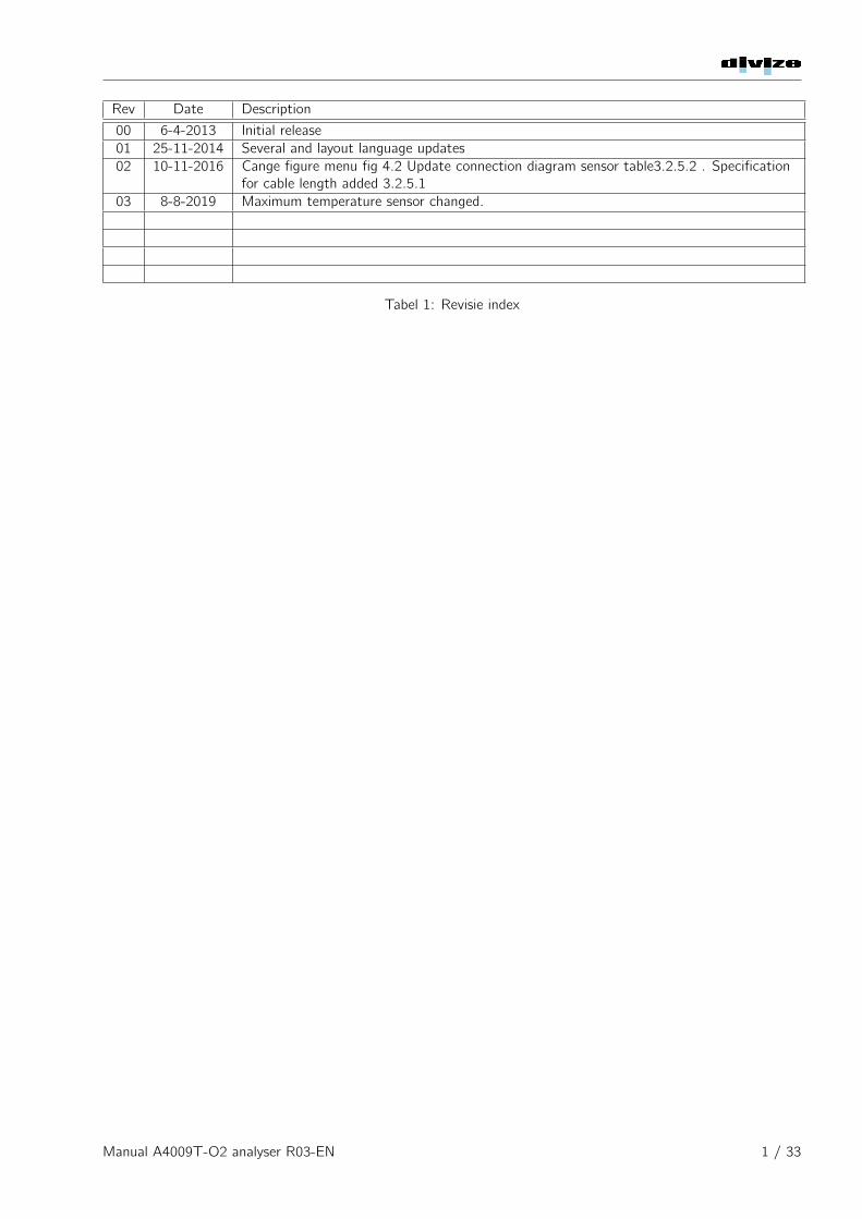
Rev Date Description
00 6-4-2013 Initial release01 25-11-2014 Several and layout language updates02 10-11-2016 Cange figure menu fig 4.2 Update connection diagram sensor table3.2.5.2 . Specification
for cable length added 3.2.5.103 8-8-2019 Maximum temperature sensor changed.
Tabel 1: Revisie index
Manual A4009T-O2 analyser R03-EN 1 / 33
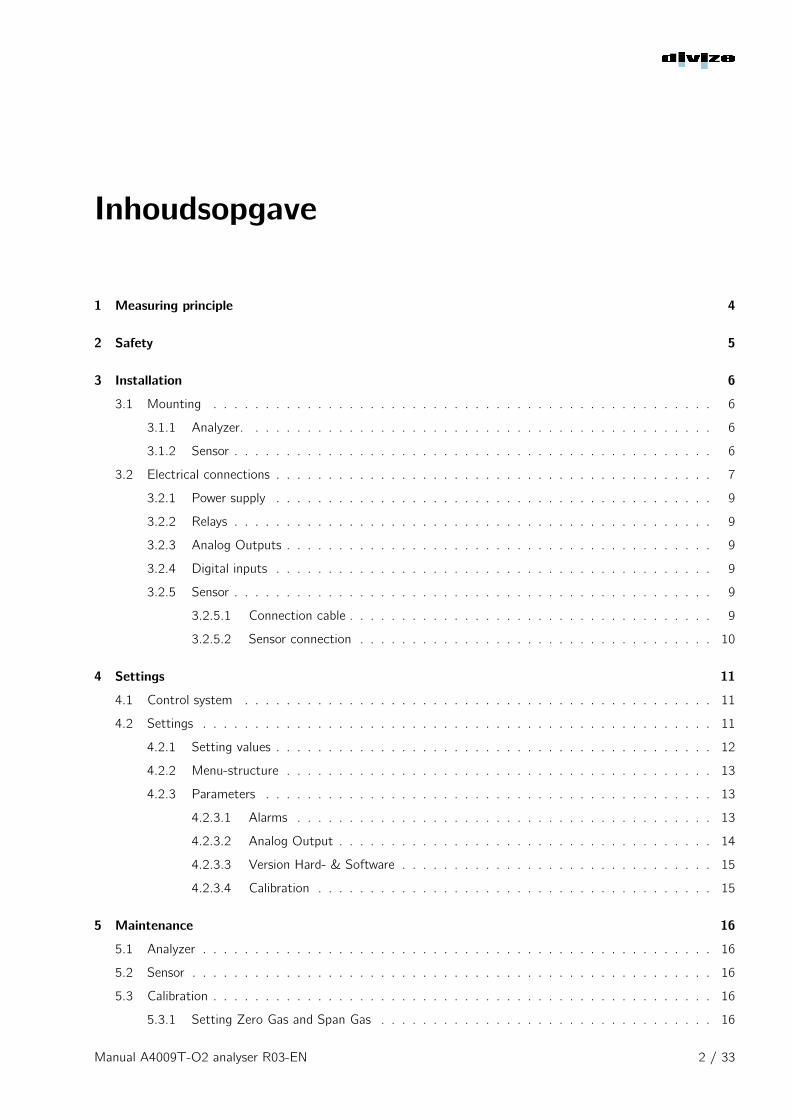
Inhoudsopgave
1 Measuring principle 4
2 Safety 5
3 Installation 6
3.1 Mounting . . . . . . . . . . . . . . . . . . . . . . . . . . . . . . . . . . . . . . . . . . . . . . . . 6
3.1.1 Analyzer. . . . . . . . . . . . . . . . . . . . . . . . . . . . . . . . . . . . . . . . . . . . . 6
3.1.2 Sensor . . . . . . . . . . . . . . . . . . . . . . . . . . . . . . . . . . . . . . . . . . . . . . 6
3.2 Electrical connections . . . . . . . . . . . . . . . . . . . . . . . . . . . . . . . . . . . . . . . . . . 7
3.2.1 Power supply . . . . . . . . . . . . . . . . . . . . . . . . . . . . . . . . . . . . . . . . . . 9
3.2.2 Relays . . . . . . . . . . . . . . . . . . . . . . . . . . . . . . . . . . . . . . . . . . . . . . 9
3.2.3 Analog Outputs . . . . . . . . . . . . . . . . . . . . . . . . . . . . . . . . . . . . . . . . . 9
3.2.4 Digital inputs . . . . . . . . . . . . . . . . . . . . . . . . . . . . . . . . . . . . . . . . . . 9
3.2.5 Sensor . . . . . . . . . . . . . . . . . . . . . . . . . . . . . . . . . . . . . . . . . . . . . . 9
3.2.5.1 Connection cable . . . . . . . . . . . . . . . . . . . . . . . . . . . . . . . . . . . 9
3.2.5.2 Sensor connection . . . . . . . . . . . . . . . . . . . . . . . . . . . . . . . . . . 10
4 Settings 11
4.1 Control system . . . . . . . . . . . . . . . . . . . . . . . . . . . . . . . . . . . . . . . . . . . . . 11
4.2 Settings . . . . . . . . . . . . . . . . . . . . . . . . . . . . . . . . . . . . . . . . . . . . . . . . . 11
4.2.1 Setting values . . . . . . . . . . . . . . . . . . . . . . . . . . . . . . . . . . . . . . . . . . 12
4.2.2 Menu-structure . . . . . . . . . . . . . . . . . . . . . . . . . . . . . . . . . . . . . . . . . 13
4.2.3 Parameters . . . . . . . . . . . . . . . . . . . . . . . . . . . . . . . . . . . . . . . . . . . 13
4.2.3.1 Alarms . . . . . . . . . . . . . . . . . . . . . . . . . . . . . . . . . . . . . . . . 13
4.2.3.2 Analog Output . . . . . . . . . . . . . . . . . . . . . . . . . . . . . . . . . . . . 14
4.2.3.3 Version Hard- & Software . . . . . . . . . . . . . . . . . . . . . . . . . . . . . . 15
4.2.3.4 Calibration . . . . . . . . . . . . . . . . . . . . . . . . . . . . . . . . . . . . . . 15
5 Maintenance 16
5.1 Analyzer . . . . . . . . . . . . . . . . . . . . . . . . . . . . . . . . . . . . . . . . . . . . . . . . . 16
5.2 Sensor . . . . . . . . . . . . . . . . . . . . . . . . . . . . . . . . . . . . . . . . . . . . . . . . . . 16
5.3 Calibration . . . . . . . . . . . . . . . . . . . . . . . . . . . . . . . . . . . . . . . . . . . . . . . . 16
5.3.1 Setting Zero Gas and Span Gas . . . . . . . . . . . . . . . . . . . . . . . . . . . . . . . . 16
Manual A4009T-O2 analyser R03-EN 2 / 33
INHOUDSOPGAVE
5.3.1.1 Zero Gas . . . . . . . . . . . . . . . . . . . . . . . . . . . . . . . . . . . . . . . 16
5.3.1.2 Span Gas . . . . . . . . . . . . . . . . . . . . . . . . . . . . . . . . . . . . . . . 17
5.3.2 Manual Calibration . . . . . . . . . . . . . . . . . . . . . . . . . . . . . . . . . . . . . . . 18
5.3.2.1 Zero Gas . . . . . . . . . . . . . . . . . . . . . . . . . . . . . . . . . . . . . . . 18
5.3.2.2 Span Gas . . . . . . . . . . . . . . . . . . . . . . . . . . . . . . . . . . . . . . . 19
6 Failure analysis 20
6.1 Status display . . . . . . . . . . . . . . . . . . . . . . . . . . . . . . . . . . . . . . . . . . . . . . 20
6.2 Alarm display . . . . . . . . . . . . . . . . . . . . . . . . . . . . . . . . . . . . . . . . . . . . . . 20
6.3 Failure . . . . . . . . . . . . . . . . . . . . . . . . . . . . . . . . . . . . . . . . . . . . . . . . . . 21
6.4 Storing . . . . . . . . . . . . . . . . . . . . . . . . . . . . . . . . . . . . . . . . . . . . . . . . . . 22
7 Automatic Calibration 23
7.1 Installation. . . . . . . . . . . . . . . . . . . . . . . . . . . . . . . . . . . . . . . . . . . . . . . . 23
7.1.1 Connection diagram automatic calibration valves. . . . . . . . . . . . . . . . . . . . . . . . 24
7.1.2 Electrical connection for automatic calibration . . . . . . . . . . . . . . . . . . . . . . . . 24
7.2 Configuration . . . . . . . . . . . . . . . . . . . . . . . . . . . . . . . . . . . . . . . . . . . . . . 25
7.2.1 Setting the auto calibration parameters. . . . . . . . . . . . . . . . . . . . . . . . . . . . . 25
7.2.1.1 Selecting the automatic calibration menu. . . . . . . . . . . . . . . . . . . . . . 25
7.2.1.2 Auto cal parameters . . . . . . . . . . . . . . . . . . . . . . . . . . . . . . . . . 25
7.2.1.3 Enable-/disable automatic calibration . . . . . . . . . . . . . . . . . . . . . . . . 26
7.2.1.4 Setting the zero gas time. . . . . . . . . . . . . . . . . . . . . . . . . . . . . . . 26
7.2.1.5 Setting the Span Gas Time . . . . . . . . . . . . . . . . . . . . . . . . . . . . . 27
7.2.1.6 Setting the maximum difference from the calibration gas. . . . . . . . . . . . . . 27
7.2.2 Starting automatic calibration. . . . . . . . . . . . . . . . . . . . . . . . . . . . . . . . . . 27
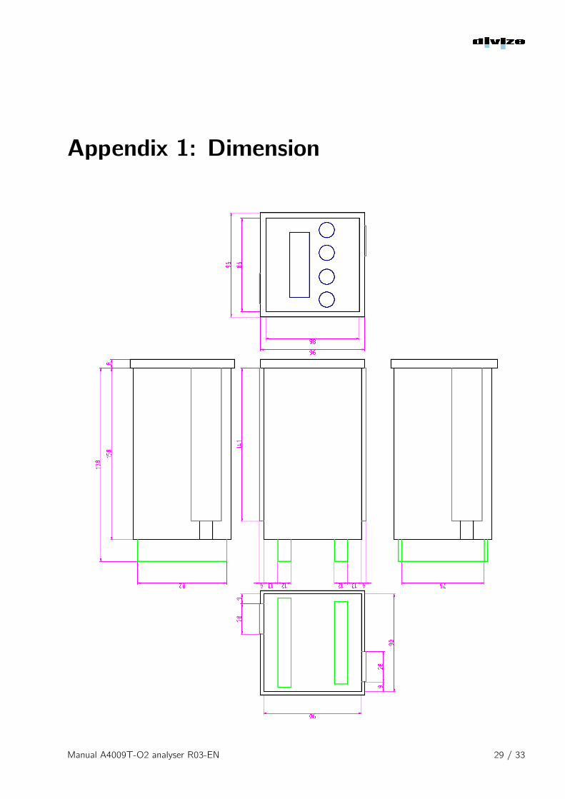
Appendix 1 : Dimension 29
Appendix 2: Specification 30
General . . . . . . . . . . . . . . . . . . . . . . . . . . . . . . . . . . . . . . . . . . . . . . . . . 30
Power Supply . . . . . . . . . . . . . . . . . . . . . . . . . . . . . . . . . . . . . . . . . . . . . . 30
Digital Inputs . . . . . . . . . . . . . . . . . . . . . . . . . . . . . . . . . . . . . . . . . . . . . . 30
Relay Contacts . . . . . . . . . . . . . . . . . . . . . . . . . . . . . . . . . . . . . . . . . . . . . 31
Analog Output . . . . . . . . . . . . . . . . . . . . . . . . . . . . . . . . . . . . . . . . . . . . . 31
Sensor . . . . . . . . . . . . . . . . . . . . . . . . . . . . . . . . . . . . . . . . . . . . . . . . . . 32
Manual A4009T-O2 analyser R03-EN 3 / 33
Chapter 1
Measuring principle
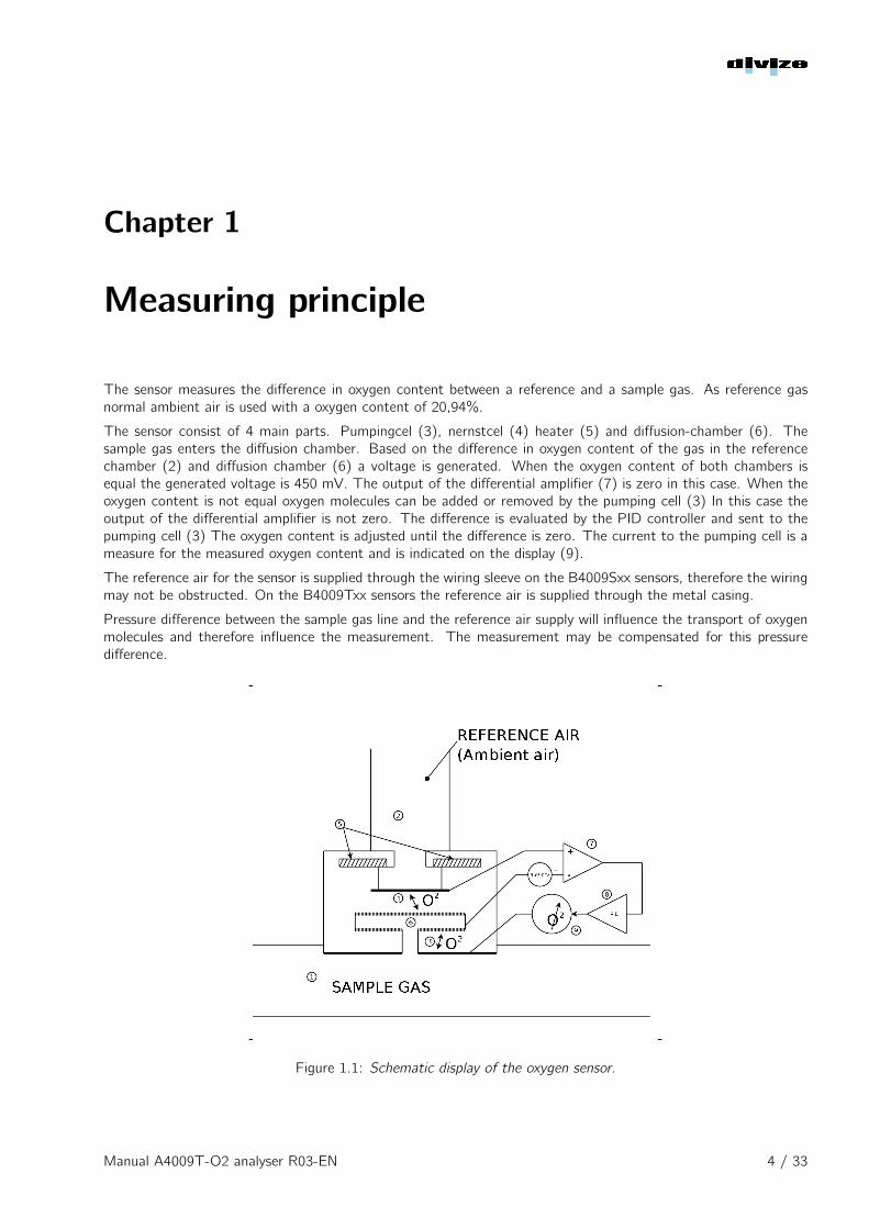
The sensor measures the difference in oxygen content between a reference and a sample gas. As reference gasnormal ambient air is used with a oxygen content of 20,94%.
The sensor consist of 4 main parts. Pumpingcel (3), nernstcel (4) heater (5) and diffusion-chamber (6). Thesample gas enters the diffusion chamber. Based on the difference in oxygen content of the gas in the referencechamber (2) and diffusion chamber (6) a voltage is generated. When the oxygen content of both chambers isequal the generated voltage is 450 mV. The output of the differential amplifier (7) is zero in this case. When theoxygen content is not equal oxygen molecules can be added or removed by the pumping cell (3) In this case theoutput of the differential amplifier is not zero. The difference is evaluated by the PID controller and sent to thepumping cell (3) The oxygen content is adjusted until the difference is zero. The current to the pumping cell is ameasure for the measured oxygen content and is indicated on the display (9).
The reference air for the sensor is supplied through the wiring sleeve on the B4009Sxx sensors, therefore the wiringmay not be obstructed. On the B4009Txx sensors the reference air is supplied through the metal casing.
Pressure difference between the sample gas line and the reference air supply will influence the transport of oxygenmolecules and therefore influence the measurement. The measurement may be compensated for this pressuredifference.
Figure 1.1: Schematic display of the oxygen sensor.
Manual A4009T-O2 analyser R03-EN 4 / 33
Chapter 2
Safety
• The analyzer may only be installed and controlled by skilled personnel.
• Follow the instructions in this manual.
• Verify the electrical connections before applying power to the unit.
• The analyzer is only suitable for installation in a safe environment, the analyzer may not be installed in aexplosion hazardous area unless sufficient protection is in place.
The analyzer is intended for the measurement of gas with low oxygen content. Gas with low oxygen content isdangerous to humans. It is necessary to make sure there is sufficient ventilation while working with the analyzer.
Manual A4009T-O2 analyser R03-EN 5 / 33
Chapter 3
Installation
3.1 Mounting
3.1.1 Analyzer.
The analyzer housing is designed to be mounted inside a (control) panel. The control elements and display areeasy accessible at the front, the wiring can be connected at the backside inside the panel.
• The analyzer shall be mounted in a clean place, away from dust, moisture and oil.
• The analyzer shall be mounted in a by maintenance personnel easy accessible location.
• The ambient temperature at the mounting location shall not exceed 50°C.
3.1.2 Sensor
The sensor shall be mounted in the gas flow that needs to be analyzed. The mounting assembly M4009R01 canbe used for mounting the sensor. The sensor shall be placed in a sufficient ventilated area as the reference air forthe sensor is the surrounding air. The measurement accuracy may be influenced when sufficient ventilation is notavailable.
• The sensor will be hot during operation. it may be necessary to provide a heat shield to protect personnel.
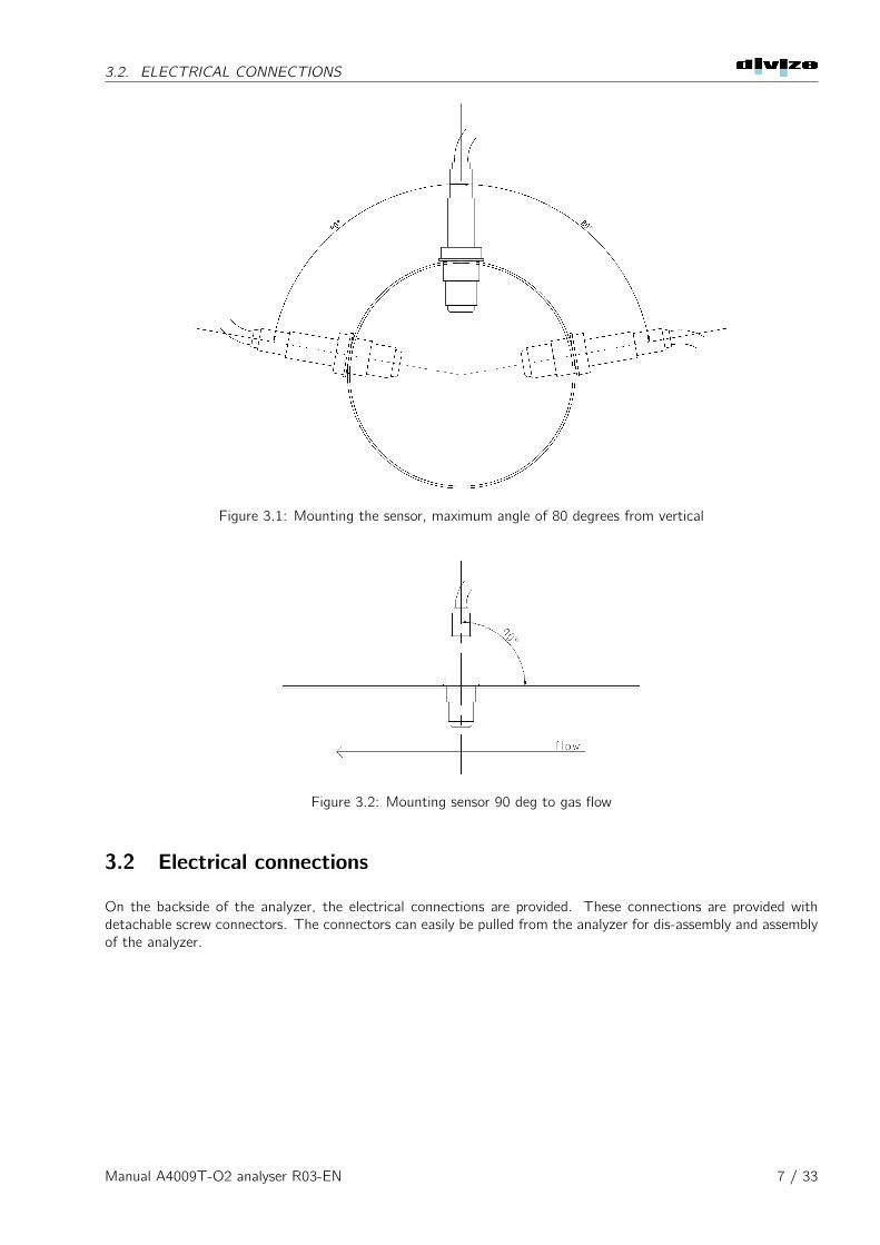
• The sensor must be mounted in a 90 degree angel to the gas flow see figure 3.1.
• When the sample gas temperature is higher then 450°C the cross section of the mounting boss needs to beat least 25mm and the thread in the boss needs to be at least 13 mm to guarantee sufficient heat transferfrom the sensor housing for cooling purpose.
• To prevent moisture entering the sensor the sensor shall be mounted straight upwards if possible. If this isnot possible the sensor may be mounted in an angle of maximum 80 degrees to the vertical, as shown infigure 3.2.
• The sensor must be protected from water.
• The sensor cable shall be mounted stress free as this is the supply for reference air to the sensor.
• The sensor may not be connected to a power supply other then the analyzer as this may damage the sensor.
Manual A4009T-O2 analyser R03-EN 6 / 33
3.2. ELECTRICAL CONNECTIONS
Figure 3.1: Mounting the sensor, maximum angle of 80 degrees from vertical
Figure 3.2: Mounting sensor 90 deg to gas flow
3.2 Electrical connections
On the backside of the analyzer, the electrical connections are provided. These connections are provided withdetachable screw connectors. The connectors can easily be pulled from the analyzer for dis-assembly and assemblyof the analyzer.
Manual A4009T-O2 analyser R03-EN 7 / 33
3.2. ELECTRICAL CONNECTIONS
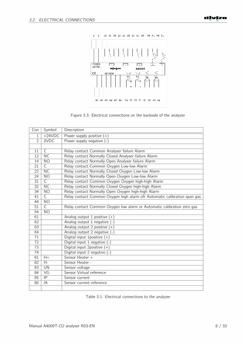
Figure 3.3: Electrical connections on the backside of the analyzer
Con Symbol Description
1 +24VDC Power supply positive (+)2 0VDC Power supply negative (-)
11 C Relay contact Common Analyser failure Alarm12 NC Relay contact Normally Closed Analyser failure Alarm14 NO Relay contact Normally Open Analyser failure Alarm21 C Relay contact Common Oxygen Low-low Alarm22 NC Relay contact Normally Closed Oxygen Low-low Alarm24 NO Relay contact Normally Open Oxygen Low-low Alarm31 C Relay contact Common Oxygen Oxygen high-high Alarm32 NC Relay contact Normally Closed Oxygen high-high Alarm34 NO Relay contact Normally Open Oxygen high-high Alarm41 C Relay contact Common Oxygen high alarm ofr Automatic calibration span gas44 NO51 C Relay contact Common Oxygen low alarm or Automatic calibration zero gas54 NO61 Analog output 1 positive (+)62 Analog output 1 negative (-)63 Analog output 2 positive (+)64 Analog output 2 negative (-)71 Digital input 1positive (+)72 Digital input 1 negative (-)73 Digital input 2positive (+)74 Digital input 2 negative (-)81 H+ Sensor Heater +82 H- Sensor Heater -83 UN Sensor voltage84 VG Sensor Virtual reference85 IP Sensor current86 IA Sensor current reference
Table 3.1: Electrical connections to the analyzer
Manual A4009T-O2 analyser R03-EN 8 / 33
3.2. ELECTRICAL CONNECTIONS
3.2.1 Power supply
The power supply shall be connected to terminal 1 (+) and 2 (-). A stabilized DC supply of 24 VDC is requiredfor reliable operation of the analyzer. The power supply shall be capable of delivering at least 1,3 Ampere.
3.2.2 Relays
The analyzer consist of 5 relay contacts, 3 changeover contacts and 2 normally open contacts. All relay contactsare fail-safe, this means the relay is energized when there is no failure. In case of a failure the relay will bede-energized.
Both normally open contacts serve a double function. When automatic calibration is selected the contacts areused to control the calibration gas valves. When automatic calibration is disabled the contacts are used for thehigh and low oxygen alarms. More information about calibration can be found in chapter 7
3.2.3 Analog Outputs
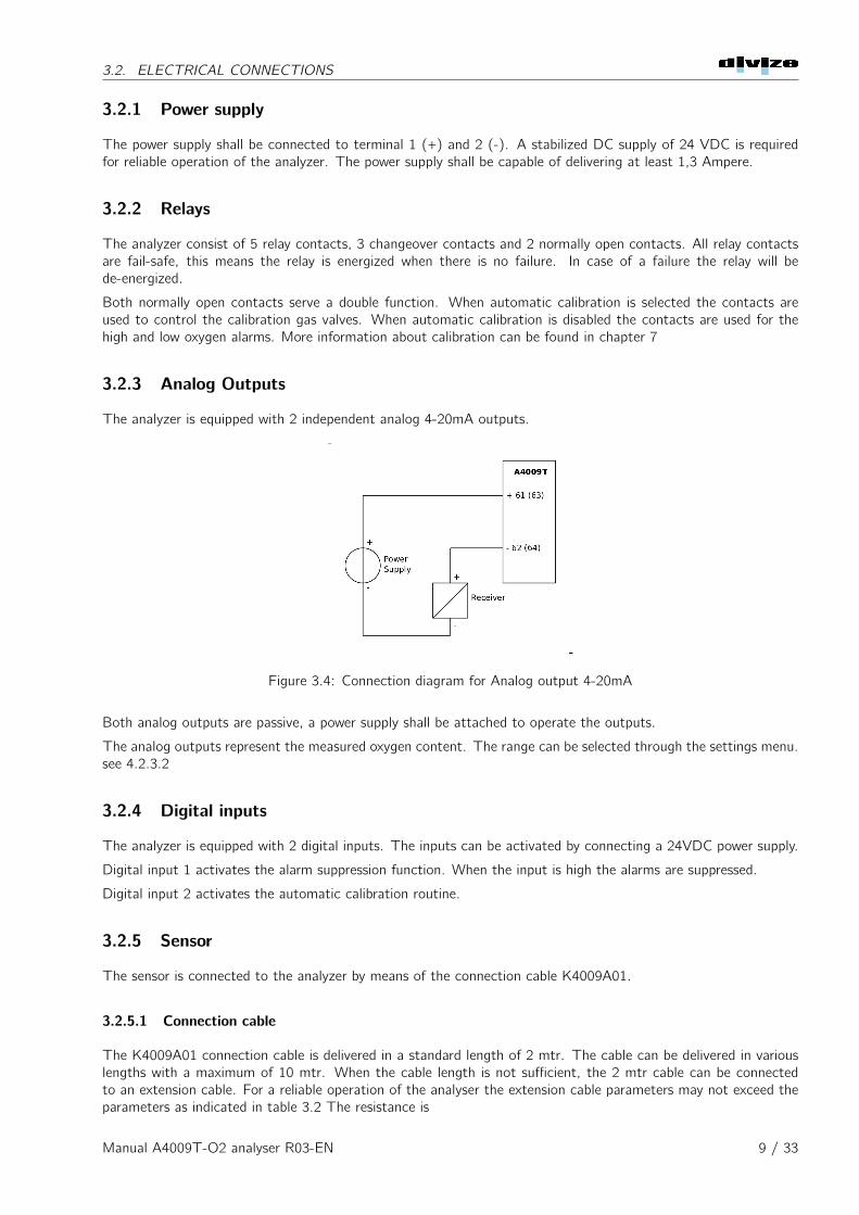
The analyzer is equipped with 2 independent analog 4-20mA outputs.
Figure 3.4: Connection diagram for Analog output 4-20mA
Both analog outputs are passive, a power supply shall be attached to operate the outputs.
The analog outputs represent the measured oxygen content. The range can be selected through the settings menu.see 4.2.3.2
3.2.4 Digital inputs
The analyzer is equipped with 2 digital inputs. The inputs can be activated by connecting a 24VDC power supply.
Digital input 1 activates the alarm suppression function. When the input is high the alarms are suppressed.
Digital input 2 activates the automatic calibration routine.
3.2.5 Sensor
The sensor is connected to the analyzer by means of the connection cable K4009A01.
3.2.5.1 Connection cable
The K4009A01 connection cable is delivered in a standard length of 2 mtr. The cable can be delivered in variouslengths with a maximum of 10 mtr. When the cable length is not sufficient, the 2 mtr cable can be connectedto an extension cable. For a reliable operation of the analyser the extension cable parameters may not exceed theparameters as indicated in table 3.2 The resistance is
Manual A4009T-O2 analyser R03-EN 9 / 33
3.2. ELECTRICAL CONNECTIONS
Parameter Value Unit
Maximum resistance for each wire 0,4 ohmMaximum capacity between 2 wires 8,0 nF
Tabel 3.2: Maximum parameters extension cable
3.2.5.2 Sensor connection
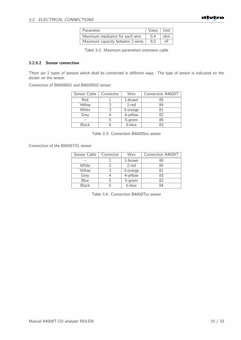
There are 2 types of sensors which shall be connected in different ways. The type of sensor is indicated on thesticker on the sensor.
Connection of B4009S01 and B4009S02 sensor.
Sensor Cable Connector Wire Connection A4009T
Red 1 1-brown 85Yellow 2 2-red 84White 3 3-orange 81Grey 4 4-yellow 82– 5 5-green 86
Black 6 6-blue 83
Table 3.3: Connection B4009Sxx sensor
Connection of the B4009T01 sensor
Sensor Cable Connector Wire Connection A4009T
– 1 1-brown 86White 2 2-red 85Yellow 3 3-orange 81Grey 4 4-yellow 83Blue 5 5-green 82Black 6 6-blue 84
Table 3.4: Connection B4009Txx sensor
Manual A4009T-O2 analyser R03-EN 10 / 33
Chapter 4
Settings
4.1 Control system
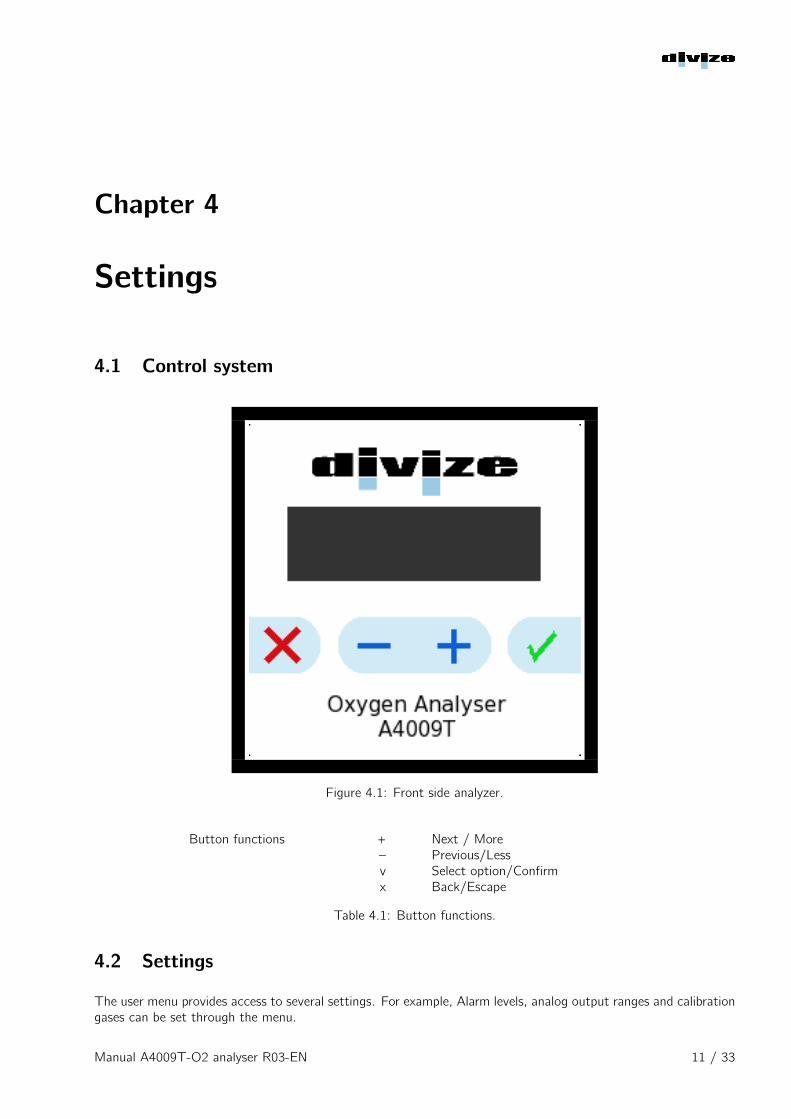
Figure 4.1: Front side analyzer.
Button functions + Next / More– Previous/Lessv Select option/Confirmx Back/Escape
Table 4.1: Button functions.
4.2 Settings
The user menu provides access to several settings. For example, Alarm levels, analog output ranges and calibrationgases can be set through the menu.
Manual A4009T-O2 analyser R03-EN 11 / 33
4.2. SETTINGS
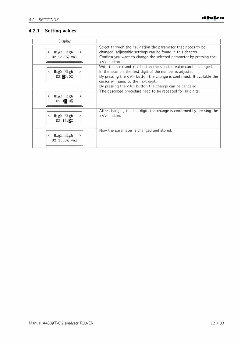
4.2.1 Setting values
Display
< High High >O2 25.0% val
Select through the navigation the parameter that needs to bechanged, adjustable settings can be found in this chapter.Confirm you want to change the selected parameter by pressing the<V> button
< High High >O2 25.0%
With the <+> and <-> button the selected value can be changed.In the example the first digit of the number is adjustedBy pressing the <V> button the change is confirmed. If available thecursor will jump to the next digit.By pressing the <X> button the change can be canceled.
< High High >O2 15.0%
The described procedure need to be repeated for all digits.
< High High >O2 15.0%
After changing the last digit, the change is confirmed by pressing the<V> button.
< High High >O2 15.0% val
Now the parameter is changed and stored.
Manual A4009T-O2 analyser R03-EN 12 / 33
4.2. SETTINGS
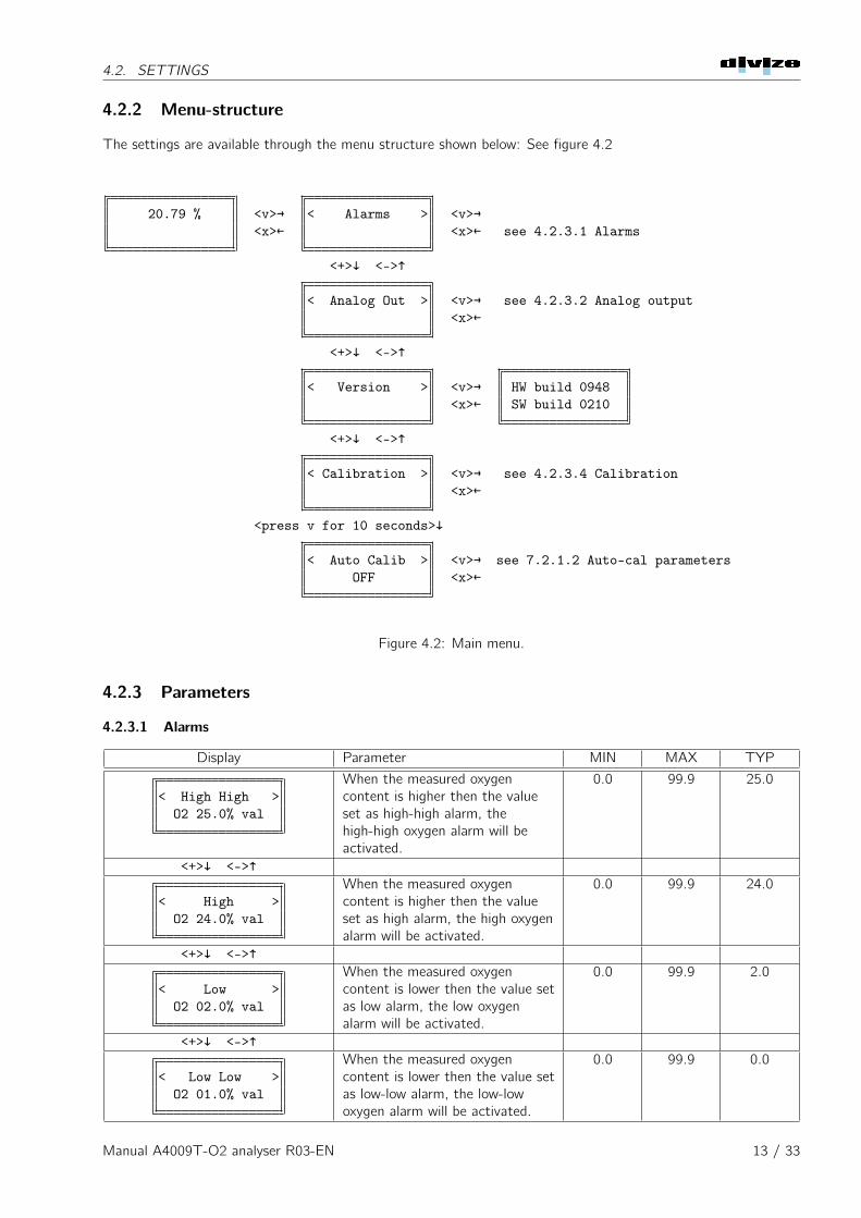
4.2.2 Menu-structure
The settings are available through the menu structure shown below: See figure 4.2
20.79 % <v>→ < Alarms > <v>→<x>← <x>← see 4.2.3.1 Alarms
<+>↓ <->↑
< Analog Out > <v>→ see 4.2.3.2 Analog output<x>←
<+>↓ <->↑
< Version > <v>→ HW build 0948<x>← SW build 0210
<+>↓ <->↑
< Calibration > <v>→ see 4.2.3.4 Calibration<x>←
<press v for 10 seconds>↓
< Auto Calib > <v>→ see 7.2.1.2 Auto-cal parametersOFF <x>←
Figure 4.2: Main menu.
4.2.3 Parameters
4.2.3.1 Alarms
Display Parameter MIN MAX TYP
< High High >O2 25.0% val
When the measured oxygencontent is higher then the valueset as high-high alarm, thehigh-high oxygen alarm will beactivated.
0.0 99.9 25.0
<+>↓ <->↑
< High >O2 24.0% val
When the measured oxygencontent is higher then the valueset as high alarm, the high oxygenalarm will be activated.
0.0 99.9 24.0
<+>↓ <->↑
< Low >O2 02.0% val
When the measured oxygencontent is lower then the value setas low alarm, the low oxygenalarm will be activated.
0.0 99.9 2.0
<+>↓ <->↑
< Low Low >O2 01.0% val
When the measured oxygencontent is lower then the value setas low-low alarm, the low-lowoxygen alarm will be activated.
0.0 99.9 0.0
Manual A4009T-O2 analyser R03-EN 13 / 33
4.2. SETTINGS
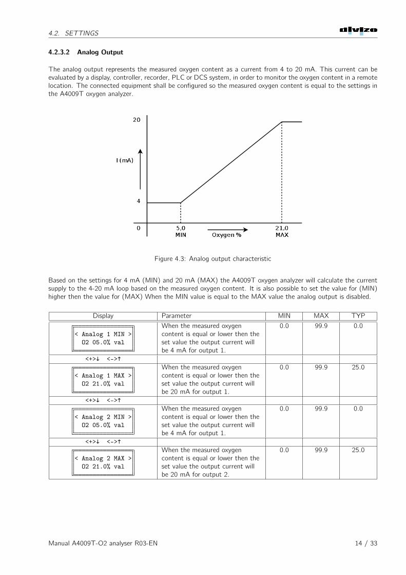
4.2.3.2 Analog Output
The analog output represents the measured oxygen content as a current from 4 to 20 mA. This current can beevaluated by a display, controller, recorder, PLC or DCS system, in order to monitor the oxygen content in a remotelocation. The connected equipment shall be configured so the measured oxygen content is equal to the settings inthe A4009T oxygen analyzer.
Figure 4.3: Analog output characteristic
Based on the settings for 4 mA (MIN) and 20 mA (MAX) the A4009T oxygen analyzer will calculate the currentsupply to the 4-20 mA loop based on the measured oxygen content. It is also possible to set the value for (MIN)higher then the value for (MAX) When the MIN value is equal to the MAX value the analog output is disabled.
Display Parameter MIN MAX TYP
< Analog 1 MIN >O2 05.0% val
When the measured oxygencontent is equal or lower then theset value the output current willbe 4 mA for output 1.
0.0 99.9 0.0
<+>↓ <->↑
< Analog 1 MAX >O2 21.0% val
When the measured oxygencontent is equal or lower then theset value the output current willbe 20 mA for output 1.
0.0 99.9 25.0
<+>↓ <->↑
< Analog 2 MIN >O2 05.0% val
When the measured oxygencontent is equal or lower then theset value the output current willbe 4 mA for output 1.
0.0 99.9 0.0
<+>↓ <->↑
< Analog 2 MAX >O2 21.0% val
When the measured oxygencontent is equal or lower then theset value the output current willbe 20 mA for output 2.
0.0 99.9 25.0
Manual A4009T-O2 analyser R03-EN 14 / 33
4.2. SETTINGS
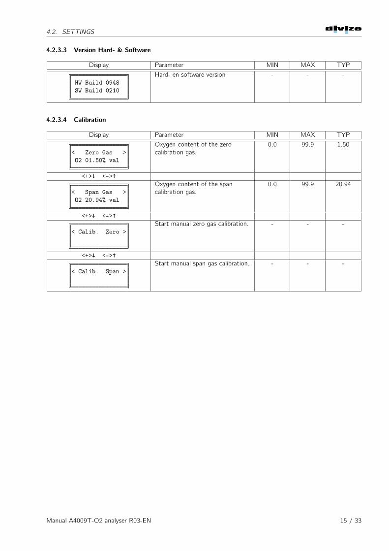
4.2.3.3 Version Hard- & Software
Display Parameter MIN MAX TYP
HW Build 0948SW Build 0210
Hard- en software version - - -
4.2.3.4 Calibration
Display Parameter MIN MAX TYP
< Zero Gas >O2 01.50% val
Oxygen content of the zerocalibration gas.
0.0 99.9 1.50
<+>↓ <->↑
< Span Gas >O2 20.94% val
Oxygen content of the spancalibration gas.
0.0 99.9 20.94
<+>↓ <->↑
< Calib. Zero >Start manual zero gas calibration. - - -
<+>↓ <->↑
< Calib. Span >Start manual span gas calibration. - - -
Manual A4009T-O2 analyser R03-EN 15 / 33
Chapter 5
Maintenance
5.1 Analyzer
The analyzer does no require much maintenance. The control panel shall be cleaned regularly with a soft cloth.
5.2 Sensor
The sensor does not require a lot of maintenance during it’s life span.
• Check the sensor for contamination and clean if necessary. In case of severe contamination the sensor shallbe replaced.
• Check the wiring to the sensor, check if the protection sleeve to the wiring is not pinched as this is thereference air supply to the sensor.
5.3 Calibration
Depending on the usage, the analyzer need to be calibrated regularly.
• Before calibration is started the sensor need to be heated at a stable temperature.
• "Zero Calibration" shall be done with a gas mixture with certified composition.
• "Span gas" shall be instrument air with 20.94% oxygen; (Normal ambient air)
• The pressure for the "Zero" and "Span" gas shall be equal to the measured gas.
5.3.1 Setting Zero Gas and Span Gas
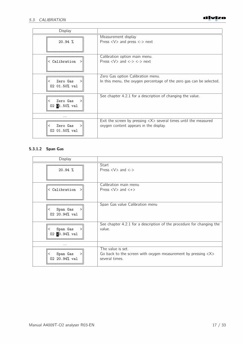
5.3.1.1 Zero Gas
The oxygen concentration in the zero gas shall be set prior to calibration.
Manual A4009T-O2 analyser R03-EN 16 / 33
5.3. CALIBRATION
Display
20.94 %Measurement displayPress <V> and press <-> next
< Calibration >Calibration option main menu.Press <V> and <-> <-> next
< Zero Gas >O2 01.50% val
Zero Gas option Calibration menu.In this menu, the oxygen percentage of the zero gas can be selected.
< Zero Gas >O2 01.50% val
See chapter 4.2.1 for a description of changing the value.
...
< Zero Gas >O2 01.50% val
Exit the screen by pressing <X> several times until the measuredoxygen content appears in the display.
5.3.1.2 Span Gas
Display
20.94 %StartPress <V> and <->
< Calibration >Calibration main menuPress <V> and <+>
< Span Gas >O2 20.94% val
Span Gas value Calibration menu
< Span Gas >O2 20.94% val
See chapter 4.2.1 for a description of the procedure for changing thevalue.
...
< Span Gas >O2 20.94% val
The value is set.Go back to the screen with oxygen measurement by pressing <X>several times.
Manual A4009T-O2 analyser R03-EN 17 / 33
5.3. CALIBRATION
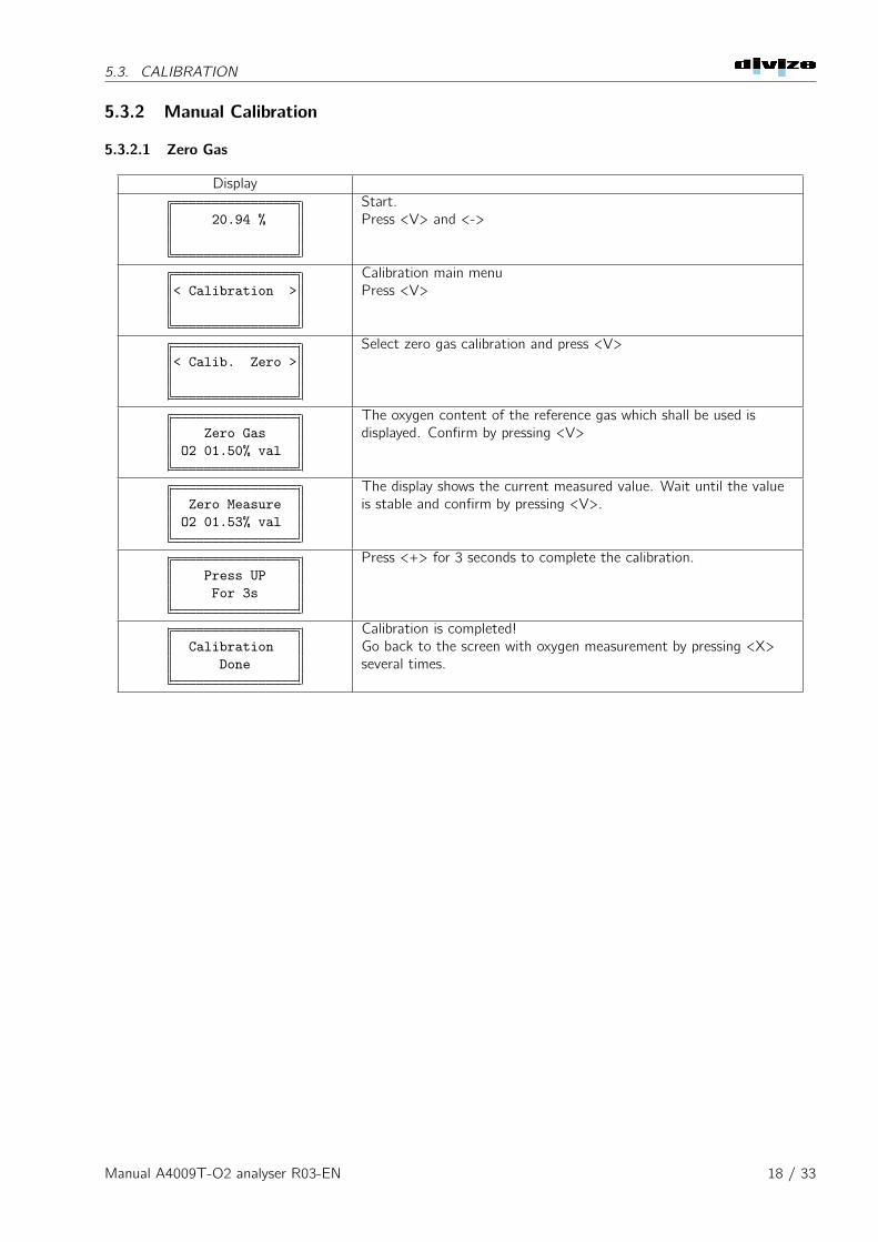
5.3.2 Manual Calibration
5.3.2.1 Zero Gas
Display
20.94 %Start.Press <V> and <->
< Calibration >Calibration main menuPress <V>
< Calib. Zero >Select zero gas calibration and press <V>
Zero GasO2 01.50% val
The oxygen content of the reference gas which shall be used isdisplayed. Confirm by pressing <V>
Zero MeasureO2 01.53% val
The display shows the current measured value. Wait until the valueis stable and confirm by pressing <V>.
Press UPFor 3s
Press <+> for 3 seconds to complete the calibration.
CalibrationDone
Calibration is completed!Go back to the screen with oxygen measurement by pressing <X>several times.
Manual A4009T-O2 analyser R03-EN 18 / 33
5.3. CALIBRATION
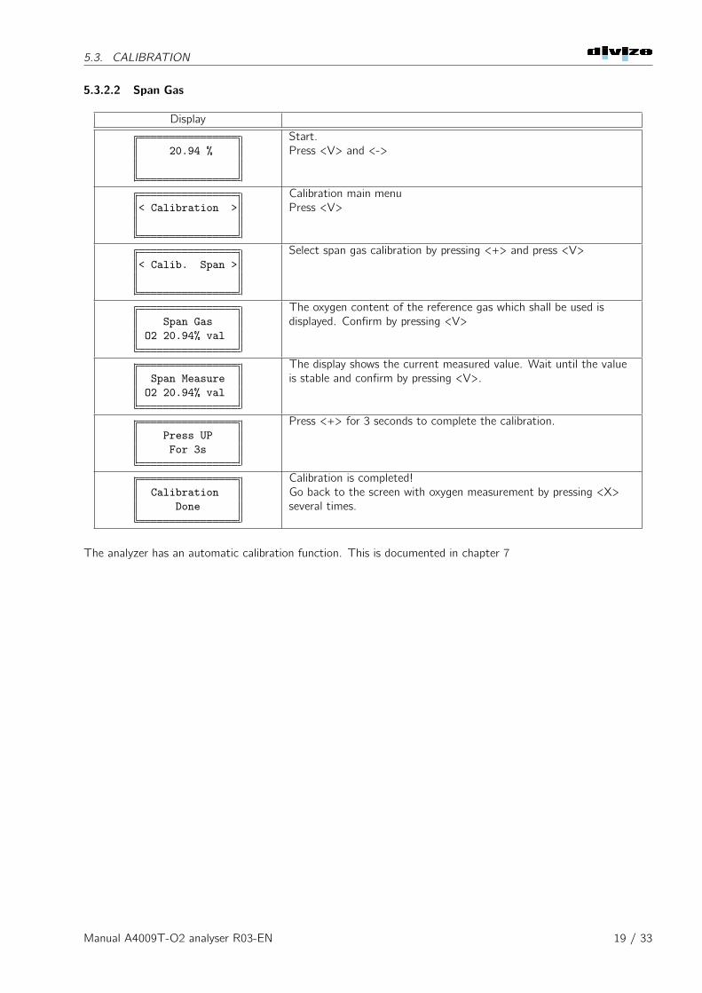
5.3.2.2 Span Gas
Display
20.94 %Start.Press <V> and <->
< Calibration >Calibration main menuPress <V>
< Calib. Span >Select span gas calibration by pressing <+> and press <V>
Span GasO2 20.94% val
The oxygen content of the reference gas which shall be used isdisplayed. Confirm by pressing <V>
Span MeasureO2 20.94% val
The display shows the current measured value. Wait until the valueis stable and confirm by pressing <V>.
Press UPFor 3s
Press <+> for 3 seconds to complete the calibration.
CalibrationDone
Calibration is completed!Go back to the screen with oxygen measurement by pressing <X>several times.
The analyzer has an automatic calibration function. This is documented in chapter 7
Manual A4009T-O2 analyser R03-EN 19 / 33
Chapter 6
Failure analysis
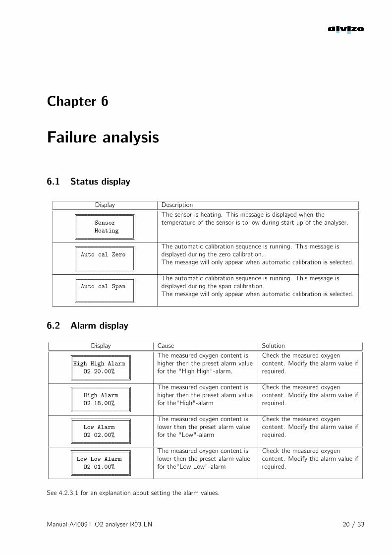
6.1 Status display
Display Description
SensorHeating
The sensor is heating. This message is displayed when thetemperature of the sensor is to low during start up of the analyser.
Auto cal ZeroThe automatic calibration sequence is running. This message isdisplayed during the zero calibration.The message will only appear when automatic calibration is selected.
Auto cal SpanThe automatic calibration sequence is running. This message isdisplayed during the span calibration.The message will only appear when automatic calibration is selected.
6.2 Alarm display
Display Cause Solution
High High AlarmO2 20.00%
The measured oxygen content ishigher then the preset alarm valuefor the "High High"-alarm.
Check the measured oxygencontent. Modify the alarm value ifrequired.
High AlarmO2 18.00%
The measured oxygen content ishigher then the preset alarm valuefor the"High"-alarm
Check the measured oxygencontent. Modify the alarm value ifrequired.
Low AlarmO2 02.00%
The measured oxygen content islower then the preset alarm valuefor the "Low"-alarm
Check the measured oxygencontent. Modify the alarm value ifrequired.
Low Low AlarmO2 01.00%
The measured oxygen content islower then the preset alarm valuefor the"Low Low"-alarm
Check the measured oxygencontent. Modify the alarm value ifrequired.
See 4.2.3.1 for an explanation about setting the alarm values.
Manual A4009T-O2 analyser R03-EN 20 / 33
6.3. FAILURE
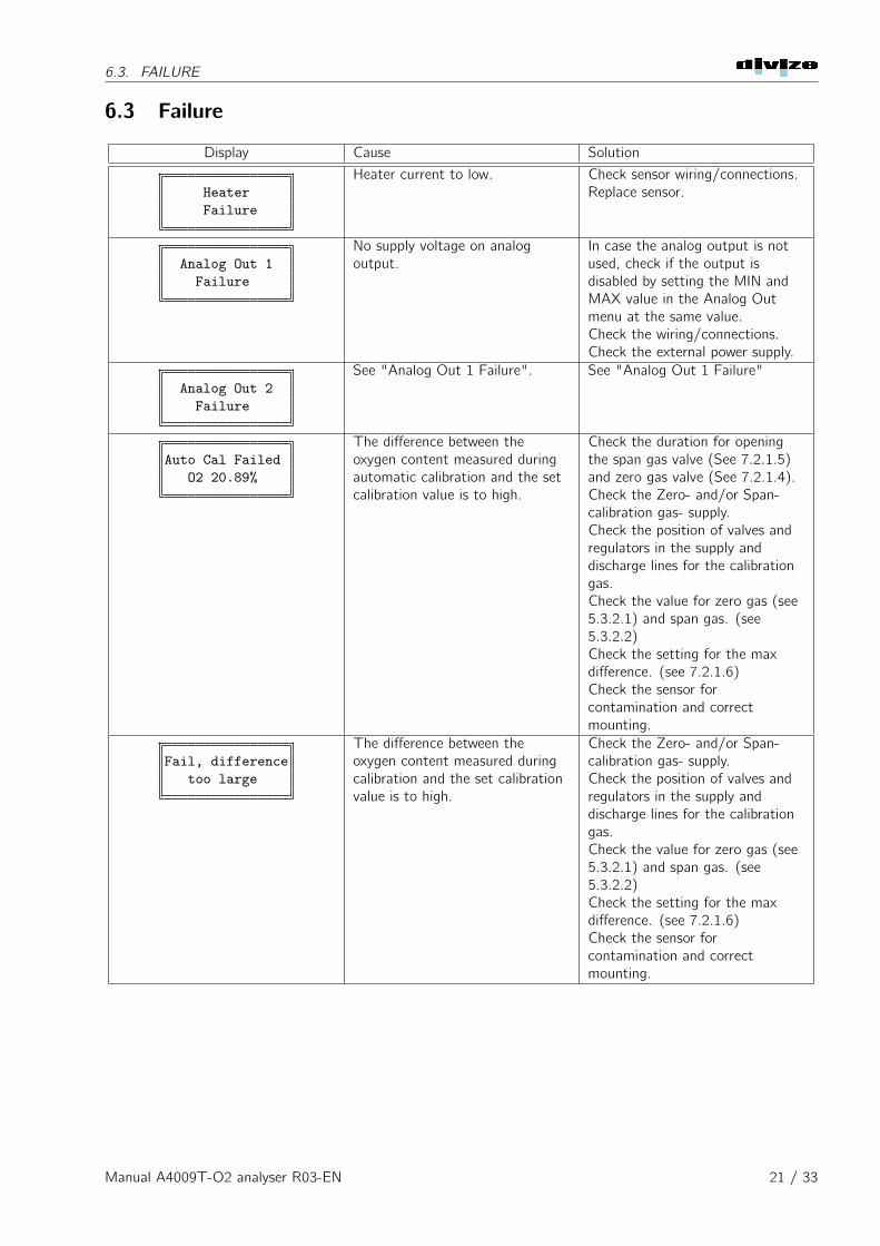
6.3 Failure
Display Cause Solution
HeaterFailure
Heater current to low. Check sensor wiring/connections.Replace sensor.
Analog Out 1Failure
No supply voltage on analogoutput.
In case the analog output is notused, check if the output isdisabled by setting the MIN andMAX value in the Analog Outmenu at the same value.Check the wiring/connections.Check the external power supply.
Analog Out 2Failure
See "Analog Out 1 Failure". See "Analog Out 1 Failure"
Auto Cal FailedO2 20.89%
The difference between theoxygen content measured duringautomatic calibration and the setcalibration value is to high.
Check the duration for openingthe span gas valve (See 7.2.1.5)and zero gas valve (See 7.2.1.4).Check the Zero- and/or Span-calibration gas- supply.Check the position of valves andregulators in the supply anddischarge lines for the calibrationgas.Check the value for zero gas (see5.3.2.1) and span gas. (see5.3.2.2)Check the setting for the maxdifference. (see 7.2.1.6)Check the sensor forcontamination and correctmounting.
Fail, differencetoo large
The difference between theoxygen content measured duringcalibration and the set calibrationvalue is to high.
Check the Zero- and/or Span-calibration gas- supply.Check the position of valves andregulators in the supply anddischarge lines for the calibrationgas.Check the value for zero gas (see5.3.2.1) and span gas. (see5.3.2.2)Check the setting for the maxdifference. (see 7.2.1.6)Check the sensor forcontamination and correctmounting.
Manual A4009T-O2 analyser R03-EN 21 / 33
6.4. STORING
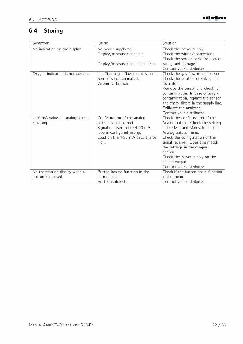
6.4 Storing
Symptom Cause Solution
No indication on the display No power supply toDisplay/measurement unit..Display/measurement unit defect.
Check the power supply.Check the wiring/connectionsCheck the sensor cable for correctwiring and damage.Contact your distributor
Oxygen indication is not correct.. Insufficient gas flow to the sensor.Sensor is contaminated.Wrong calibration.
Check the gas flow to the sensor.Check the position of valves andregulators.Remove the sensor and check forcontamination. In case of severecontamination, replace the sensorand check filters in the supply line.Calibrate the analyser.Contact your distributor.
4-20 mA value on analog outputis wrong.
Configuration of the analogoutput is not correct.Signal receiver in the 4-20 mAloop is configured wrong.Load on the 4-20 mA circuit is tohigh.
Check the configuration of theAnalog output. Check the settingof the Min and Max value in theAnalog output menu.Check the configuration of thesignal receiver. Does this matchthe settings in the oxygenanalyser.Check the power supply on theanalog output.Contact your distributor.
No reaction on display when abutton is pressed.
Button has no function in thecurrent menu.Button is defect.
Check if the button has a functionin the menu.Contact your distributor.
Manual A4009T-O2 analyser R03-EN 22 / 33
Chapter 7
Automatic Calibration
The automatic calibration allows for periodic calibration of the analyzer without human interaction. In this way theit is guaranteed the analyzer measures correctly.
7.1 Installation.
To use the automatic calibration function 2 extra valves are required to switch on and off the span and zero gassupply to the sensor. Also an electrical 24VDC signal is required to start the automatic calibration procedure.
Warning: Make sure the process where the analyzer is used allows automatic calibration. During theautomatic calibration the analyzer is not available.
The 4-20 mA current loop output and alarm contacts will keep there function during automatic calibration.
Manual A4009T-O2 analyser R03-EN 23 / 33
7.1. INSTALLATION.
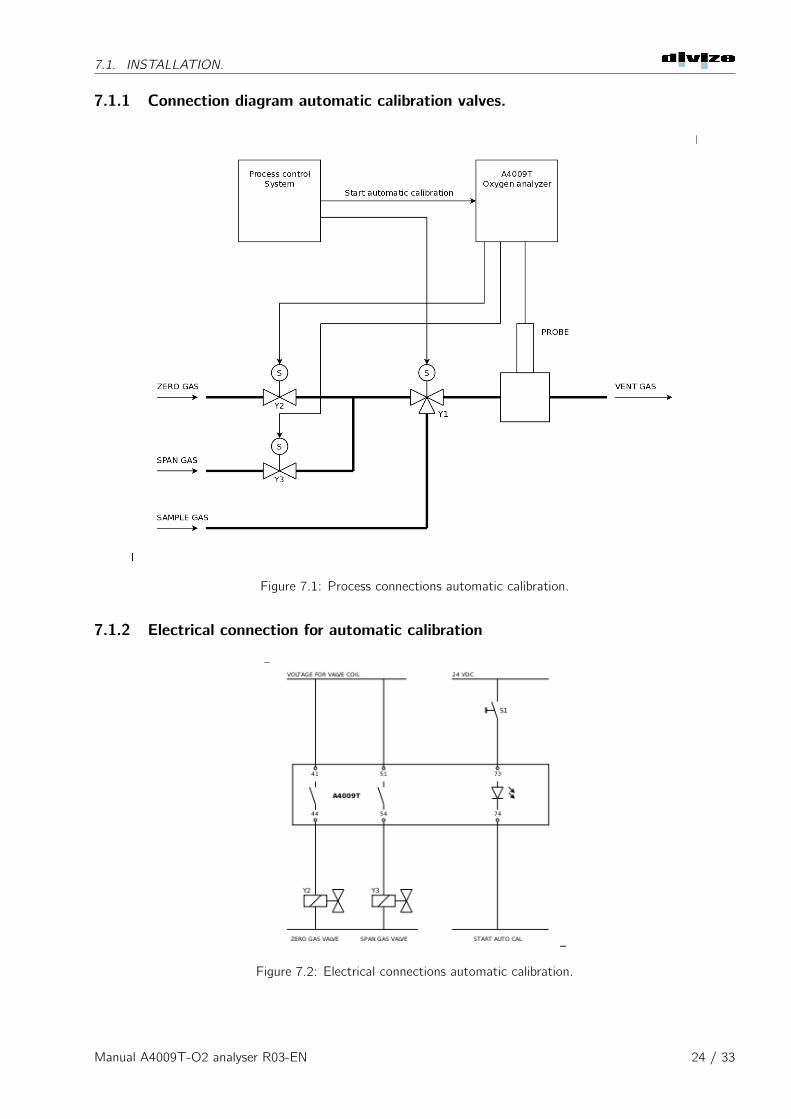
7.1.1 Connection diagram automatic calibration valves.
Figure 7.1: Process connections automatic calibration.
7.1.2 Electrical connection for automatic calibration
Figure 7.2: Electrical connections automatic calibration.
Manual A4009T-O2 analyser R03-EN 24 / 33
7.2. CONFIGURATION
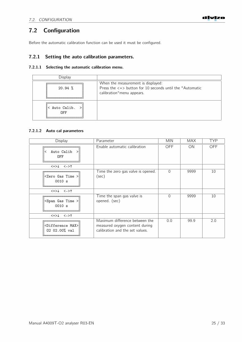
7.2 Configuration
Before the automatic calibration function can be used it must be configured.
7.2.1 Setting the auto calibration parameters.
7.2.1.1 Selecting the automatic calibration menu.
Display
20.94 %When the measurement is displayed:Press the <+> button for 10 seconds until the "Automaticcalibration"menu appears.
< Auto Calib. >OFF
7.2.1.2 Auto cal parameters
Display Parameter MIN MAX TYP
< Auto Calib >OFF
Enable automatic calibration OFF ON OFF
<+>↓ <->↑
<Zero Gas Time >0010 s
Time the zero gas valve is opened.(sec)
0 9999 10
<+>↓ <->↑
<Span Gas Time >0010 s
Time the span gas valve isopened. (sec)
0 9999 10
<+>↓ <->↑
<Difference MAX>O2 02.00% val
Maximum difference between themeasured oxygen content duringcalibration and the set values.
0.0 99.9 2.0
Manual A4009T-O2 analyser R03-EN 25 / 33
7.2. CONFIGURATION
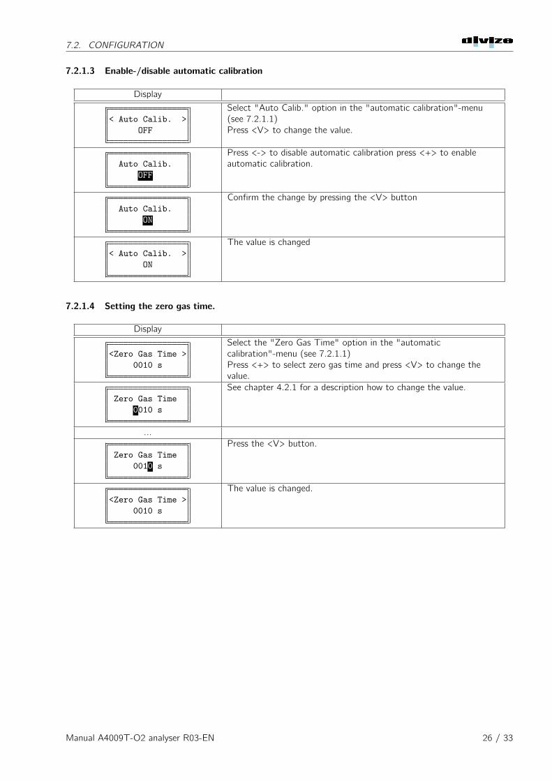
7.2.1.3 Enable-/disable automatic calibration
Display
< Auto Calib. >OFF
Select "Auto Calib." option in the "automatic calibration"-menu(see 7.2.1.1)Press <V> to change the value.
Auto Calib.OFF
Press <-> to disable automatic calibration press <+> to enableautomatic calibration.
Auto Calib.ON
Confirm the change by pressing the <V> button
< Auto Calib. >ON
The value is changed
7.2.1.4 Setting the zero gas time.
Display
<Zero Gas Time >0010 s
Select the "Zero Gas Time" option in the "automaticcalibration"-menu (see 7.2.1.1)Press <+> to select zero gas time and press <V> to change thevalue.
Zero Gas Time0010 s
See chapter 4.2.1 for a description how to change the value.
...
Zero Gas Time0010 s
Press the <V> button.
<Zero Gas Time >0010 s
The value is changed.
Manual A4009T-O2 analyser R03-EN 26 / 33
7.2. CONFIGURATION
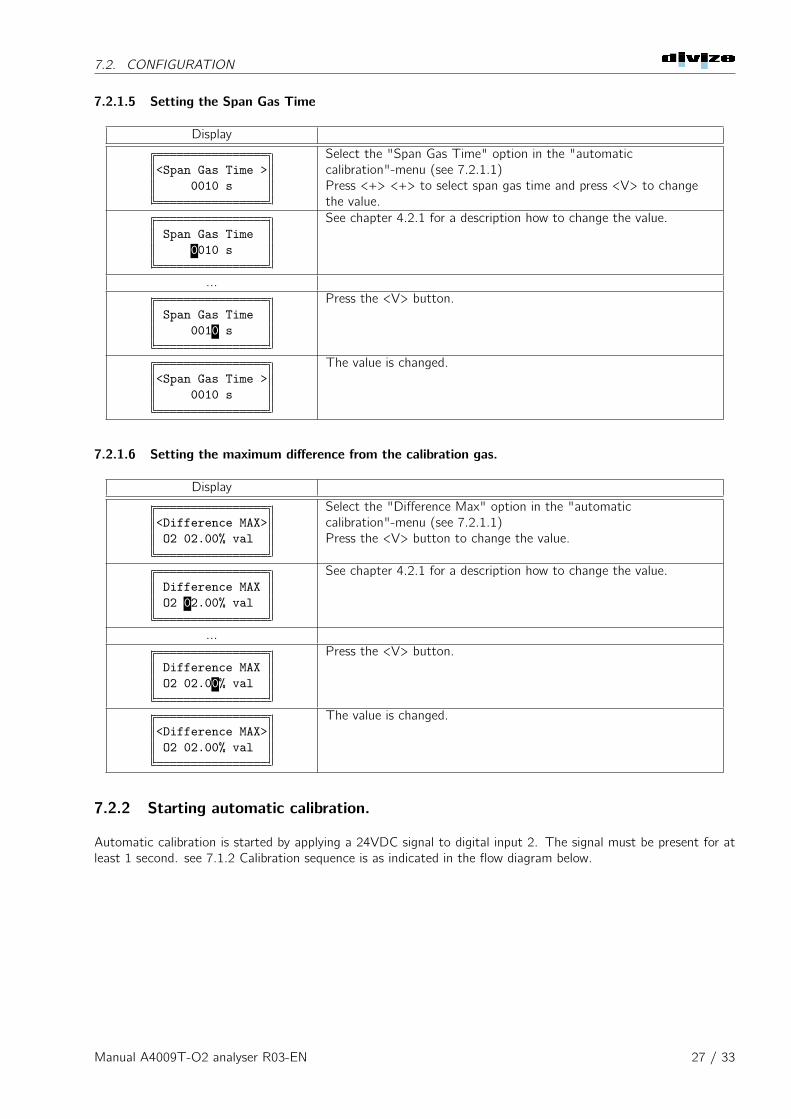
7.2.1.5 Setting the Span Gas Time
Display
<Span Gas Time >0010 s
Select the "Span Gas Time" option in the "automaticcalibration"-menu (see 7.2.1.1)Press <+> <+> to select span gas time and press <V> to changethe value.
Span Gas Time0010 s
See chapter 4.2.1 for a description how to change the value.
...
Span Gas Time0010 s
Press the <V> button.
<Span Gas Time >0010 s
The value is changed.
7.2.1.6 Setting the maximum difference from the calibration gas.
Display
<Difference MAX>O2 02.00% val
Select the "Difference Max" option in the "automaticcalibration"-menu (see 7.2.1.1)Press the <V> button to change the value.
Difference MAXO2 02.00% val
See chapter 4.2.1 for a description how to change the value.
...
Difference MAXO2 02.00% val
Press the <V> button.
<Difference MAX>O2 02.00% val
The value is changed.
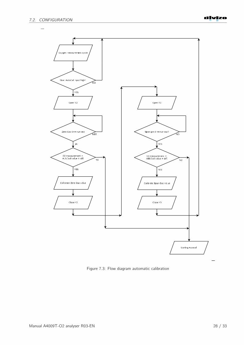
7.2.2 Starting automatic calibration.
Automatic calibration is started by applying a 24VDC signal to digital input 2. The signal must be present for atleast 1 second. see 7.1.2 Calibration sequence is as indicated in the flow diagram below.
Manual A4009T-O2 analyser R03-EN 27 / 33
7.2. CONFIGURATION
Figure 7.3: Flow diagram automatic calibration
Manual A4009T-O2 analyser R03-EN 28 / 33
Appendix 2: Specification
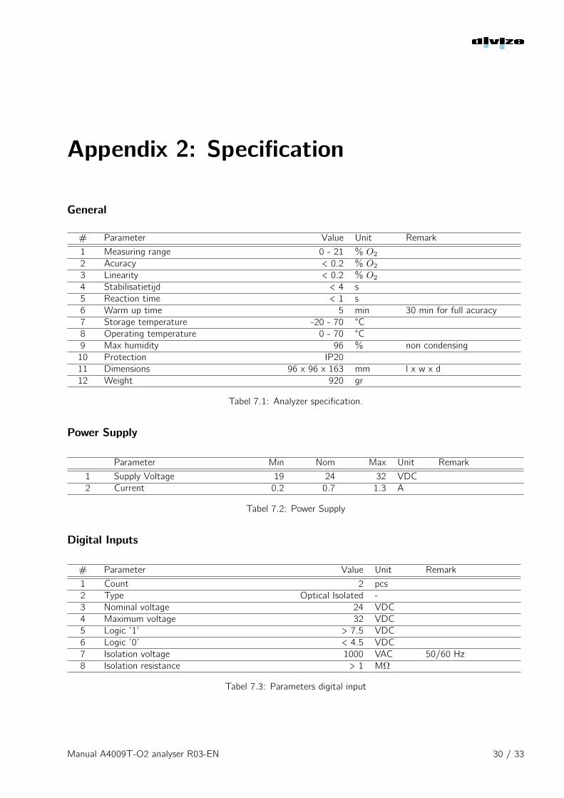
General
# Parameter Value Unit Remark
1 Measuring range 0 - 21 % O2
2 Acuracy < 0.2 % O2
3 Linearity < 0.2 % O2
4 Stabilisatietijd < 4 s5 Reaction time < 1 s6 Warm up time 5 min 30 min for full acuracy7 Storage temperature -20 - 70 °C8 Operating temperature 0 - 70 °C9 Max humidity 96 % non condensing10 Protection IP2011 Dimensions 96 x 96 x 163 mm l x w x d12 Weight 920 gr
Tabel 7.1: Analyzer specification.
Power Supply
Parameter Min Nom Max Unit Remark
1 Supply Voltage 19 24 32 VDC2 Current 0.2 0.7 1.3 A
Tabel 7.2: Power Supply
Digital Inputs
# Parameter Value Unit Remark
1 Count 2 pcs2 Type Optical Isolated -3 Nominal voltage 24 VDC4 Maximum voltage 32 VDC5 Logic ’1’ > 7.5 VDC6 Logic ’0’ < 4.5 VDC7 Isolation voltage 1000 VAC 50/60 Hz8 Isolation resistance > 1 MΩ
Tabel 7.3: Parameters digital input
Manual A4009T-O2 analyser R03-EN 30 / 33
Appendix 2: Specification
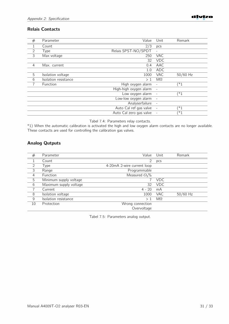
Relais Contacts
# Parameter Value Unit Remark
1 Count 2/3 pcs2 Type Relais SPST-NO/SPDT -3 Max voltage 250 VAC
32 VDC4 Max. current 0.4 AAC
1.0 ADC5 Isolation voltage 1000 VAC 50/60 Hz6 Isolation resistance > 1 MΩ7 Function High oxygen alarm - (*1
High-high oxygen alarm -Low oxygen alarm - (*1
Low-low oxygen alarm -Analyserfailure -
Auto Cal ref gas valve - (*1Auto Cal zero gas valve - (*1
Tabel 7.4: Parameters relay contacts.*1) When the automatic calibration is activated the high and low oxygen alarm contacts are no longer available.These contacts are used for controlling the calibration gas valves.
Analog Qutputs
# Parameter Value Unit Remark
1 Count 2 pcs2 Type 4-20mA 2-wire current loop3 Range Programmable4 Function Measured O2%5 Minimum supply voltage 7 VDC6 Maximum supply voltage 32 VDC7 Current 4 - 20 mA8 Isolation voltage 1000 VAC 50/60 Hz9 Isolation resistance > 1 MΩ10 Protection Wrong connection
Overvoltage
Tabel 7.5: Parameters analog output.
Manual A4009T-O2 analyser R03-EN 31 / 33
Appendix 2: Specification
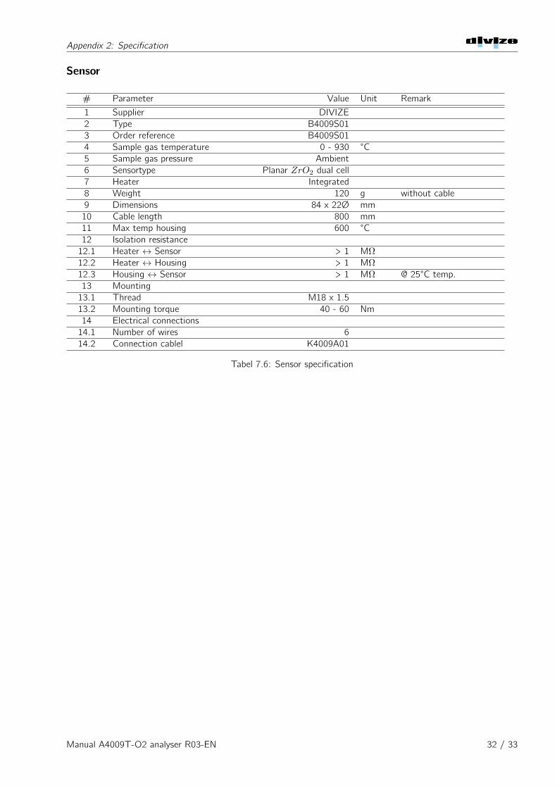
Sensor
# Parameter Value Unit Remark
1 Supplier DIVIZE2 Type B4009S013 Order reference B4009S014 Sample gas temperature 0 - 930 °C5 Sample gas pressure Ambient6 Sensortype Planar ZrO2 dual cell7 Heater Integrated8 Weight 120 g without cable9 Dimensions 84 x 22Ø mm10 Cable length 800 mm11 Max temp housing 600 °C12 Isolation resistance12.1 Heater ↔ Sensor > 1 MΩ12.2 Heater ↔ Housing > 1 MΩ12.3 Housing ↔ Sensor > 1 MΩ @ 25°C temp.13 Mounting13.1 Thread M18 x 1.513.2 Mounting torque 40 - 60 Nm14 Electrical connections14.1 Number of wires 614.2 Connection cablel K4009A01
Tabel 7.6: Sensor specification
Manual A4009T-O2 analyser R03-EN 32 / 33
DIVIZE b.v.
Industrieweg 26
2254AE VOORSCHOTEN
The Netherlands
Tel: +31 (0)88-7733733
www.divize.com
Revision 03-EN : August 8, 2019