Embed Size (px)
Citation preview

EnvironTec
Manual Gas Flare FAI
Installation Manual
Installation Manual - manual gasflare FAI 2.
The Bilgeri EnvironTec GmbH reserves the right to make changes at any time, in order to adapt the operating manual to the current state of technology.
Copying and distributing this operating manual, or excerpts thereof also its translations, requires the written approval from Bilgeri EnvironTec GmbH.
Ali trademarks mentioned in this operating manual and its respective proprietors are acknowledged. Bilgeri EnvironTec GmbH does not lay any claims to the rights of these trademarks.
The scope of delivery and delivery execution may deviate from the illustration on the title page.
Article number of this installation number: FAI_ENG_v2014-02.
Bilgeri EnvlronTec GmbH Schilfweg 1 A- 6972 Fussach Telefon: +43 (0) 55 78 7 70 OS Fax: +43 (0) SS 78 7 70 05-300 E-Mail:[email protected] Internet: www.environtec.at
© 2013 Status: 2013, translation of the originial Ali rights reserved
Pnnted in Austna.
lnstallat1on Manual - manual gasflare FAI 3
Contents: 1. GENERAL .................................................................................................... ....... .. ................. ... 5
1.1 To the operating personnel .•....... .. ..•... .. .............................. .... .. ......................................•. s 1.2 Supportlng documents ..................................................................... .......... .. .................... 5
1.3 Safekeeplng thls manual ................................................................................................... s 1.4 To understand thlS manual bette, ..................................................................................... 5
2. Safety.................................................................................................................................... 6
2.1 Correct use ....... ...... ....... .......... .. ........ .... .......................................................................... 6 2.2 l mproper use .. ...................... ................... ..... .. ............... ........ ..................•.•.••..•.•..........• 7
2.3 Operatlng personnel quahficabon ..................................................... ................................. 7
2.4 Warnlng, mandatory and information sIgns on the devtce .................. ............. ...... .......... 8
2.5 Basic safety Instructions ............................ ... ..... ... ............................................................ 9
2.6 Due diligence of operator ............................................ ...................................... .... ......... 10
2.7 Product liab,hty .............................................................................................................. 11
3. Aufbau und Funkbon ...................................................................................... ..... .. .................. 12
3.1 General lnformation ......... ............................................................................... ................ 12
3.2 Assembly ..................................... . ................... ..... Fehler! Textmarke nlcht definlert.
3.3 Func:t10nal pnnaple of the gas Hare ................................. ... . .......................................... 13
3.4 Gas tiare, standard commponetns ................................................................................. 13
3.4.l Hauptkompooenten, mechamsch •.•...•.••..•.............. Fehlerl Textmarke nlcht definlert.
3.4.2 Mam components, e!ectric, contrai.. ........................................ ....... .... ..... ... ... ........... 16
3.5 Gas tiare, add-on equlpment and options .. .......... .......... .............................................. .... 18
4. Transportabon and storage ....................................... ............................................................. 19
4.1 Transport. ........................ .... ............................................................... .. ......... .............. 19
4.2 Storage ............................. ...... ... ........ .. .............................................. .... ..... ... ... ............ 19
5. Ueferumrang ..................................................................... Fehler! Textmarke nichtdefiniert.
5.1 Gas flare FAJ .................................................................................................................. 20
5.2 accessones ..... .... ........................................................................................................... 20
6. JdentiflC1!tlOl1 plate ............................................................................................ ........ .............. 21
6.1 l dentificatlOn plate gas Rare FAl ..... .............................................. ... ...... .............. ............ 21
7. technlcal data .. ... ... ....... ...... ......................................... ..... .... .. .................... ....... ~····•··· ........... 22 7.1 Gas Rare general informatlOll .............................. ......................... ................................... 22
7.2 Gas nare by mode! size ................................................................................................... 22
7.3 Accessories .................. ... ....... ....... ........................................................ ....................... .. 22
8. l nsta llatlOll ................ ....... ....... ... .. ...... ..................................................... .... ............................ 23
8.1 Place ofuse ......... ... •.. ....... .............................••........ .............................. ........•............•.• 23
8.2 Installation and setup ............................................................................•........................ 24
8.3 Alter mstallatlOn and before initial start up ....................................................................... 28
9. Start up and operat,on ............................................................................................................. 30
9.1 Initial start up ..... ..... .. ....... ................. .. ................. ......... ................................................ 30
9.2 Start-up ...................... ...... ........ ..................................................................................... 31
lnstallat,on Manual - manual gasflare FAI 4
9.3 Operat,on ........ .... ...... ..................... ... ........ .......................... ... .. ...... ... .................. ... ....... 32
9.4 Takmg out of operat10n ...... .. ... .. ........ .. .......................... ..... ... .... ... ......... .. .................. ..... 34
10.Malfunct,ons and removal malfunct10ns .. ............. ...... ... .. ........ .. ......... .. ................... ..... .... .... ..... 35
10.1 Behav,our in case of malfunct,ons ................. ...... ....... .. .... .... ....................... .................... 35
10.2 Troubleshootmg .. ........ ........ ................ .... ..... .. ..... ...... ... .. ...... .... .... .. ..... ... ........................ 35
11.Maintenance .. ......... ..... ..... .............. ..................................... ... ... ... ..................... ...... .......... .. ... 37
11.1 Safety dunng maintenance ............. .... ... ..... ..... ...... .. ..... ..•... .... ..•.... ......... ........................ 37
11.2 Record ....... .... ......... .... ..................••.... .................. .•.... •.•.... ..• .•.. ....... ..••... .. .•. .. ... .... ......... 37
11.3 lnspekt10ns- und Wartungsplan .............. ..... ......................................... ..................... ... ... 38
11.4 Torques .......... ................. .. ........ ... .... .. ....... ........ ..... .. ..... ....................................... ..... .... 39
11.5 lnspect,on and maintenance work ... ... ............................ ..... .......... .. .. ....... ....................... 39
11 6 Restart .... ... ..... .. .... .. ........... ..... ........... ...... ...................................... ............ ....... ............ 44
11.7 Spare and weanng parts .. ... ... ..... .... . ..... ........... .... ... .... .... .... ... .. .. ......... .. .. ...... ........ ... .. ... . 44
12.Appendix ..... ....... ......... ..... ... ...... ...... ....... ...... ... ......... ... ....... .... ........... .... ................. ................ 45
12.1 Checklist for mItIal start-up ..... .... .................... ............... ...... .. .. ................. ..... ...... ..... .... .. 45
12.2 Proof of repair work and leak tests ......... ............................. ..... ...... ........ .. .... ................... 46
12.3 Annex .. .... ...................... ......... ... ... .. .. •........•. .••.• .....•............... .............................•.. ........ 47

Installation Manual - manual gasflare FAI s
1. GENERAL 1.1 To the operating personnel
This operating ma nuai informs about the safety, assembly, function, ope ration and maintenance of the gas tiare. If properly following the instruction, a long, trouble free and safe operation is guaranteed.
1.2 Supporting documents
See Annex
1.3 Safekeeping this manual
The manual (including supporting documents) is always kept in legible condition, available completely at the operating location!
1.4 To understand this manual better
Conventions
f1iM:Hfüi This danger symbol refers to an imminent threatening, serious, danger, which leads with certainty to serious injuries or even to death, if the danger is not avolded.
-This danger symbol refers to a possible danger, wh1ch can lead to serious injuries or even to death, if the danger is not avolded.
!AVORSICHT ! This danger symbol refers to a potentially, dangerous situation, which can lead to medium or light injuries or property damages, if it is not avolded.
IMM3€1 This symbol refers to supportlng information.
Cross-references Cross references are presented in italics.
Installation Manual - manual gasflare FAI 6
2. SAFETY
The Bilgeri EnvironTec GmbH gas tiares are designed and constructed taking into conslderation the highest safety requirements, and upon carefully choosing other matching standards to follow, as well as other technical specifications. It meets the current state of technology and guarantees the highest measure of safety. However, in operating conditions this safety can only be achieved if all necessary measures are followed. It is subject to the due diligence of the operator to plan and execute these measures and to contrai its execution.
2.1 Correct use
The gas tiares of type FA! are conceptualized for burning of explosive gases of the Group IIA temperature class Tl (methane with C02 biogas plants or water treatment plants).
f1ibdiHfüi Danger of explosion!
The FA! type gas tiare is only permitted for using outside of the Ex zones.
• From the customer sicle it must be made sure that unintentional operation in and explosive atmosphere is safely prevented. See operator Ex-protection zone plan.
• The operation of the manual gasflare must be carried out under the supervision of the operating staffs! When uncontrolled tlame extinction (eg by a gust of wind), butterfly valve must be closed immediately in order to prevent the further gas flow. Ther starting procedure must be performed again. If automatic option is chosen, the gasflare is monitored automatically and the procedure discribed above is not applicable.
The burning of explosive gas/air mixtures in the gas tiare in not permitted!
Any other use is considered as unauthorized and is thus explicitly prohibited.
The operator of the gas tiare is responsible for all damages caused if not operating the unit properlyl
Proper use lncludes:
• Following all notes in this operating manual
• following the mandatory, prohibition and warning signs on the system
• Complying with the inspection and maintenance lntervals.

Installation Manual - manual gasflare FAI
2.2 Improper use
If not usmg as lnstructed (improper use), for example:
• 1f not usmg m accordance with the conformity statement.
• incorrect mstallatJOn m the system
• if the gas flare, including contrai cabinet are not ready for operation, or were mod1fied
• by taking the safety devices out of operation
• by unauthorized access ta the sw1tch cabinet and wmng
• by using other types of gasses
.•• the system may be destroyed.
This results m the operatar being exposed ta incalculable increased danger potential, for example by:
• hot parts
• explosion
• electrocut1on
• uncontrolled gas leak
• creat1ng an explosive atrnosphere
• poisoning with health damag1ng gas components, etc.
The system must 1mmediately be shut-down if there are any changes!
2.3 Operating personnel qualification
7
Only trained and mstructed personnel is allowed ta operate the gas flare. The completJOn of the instruction should be documented in writing.
Only a qualified electrical engineer is allowed ta work on the electncal equipment!
Installation Manual - manual gasflare FAI
2.4 Waming, mandatory and information signs on the device
The following signs can be found on the gas flare (OIN 4844):
Unauthorized access is prohibited !
Fire, open light and smoking is prohibited !
Warnmg of explosive atmosphere
Warning hot surface
Warning of dangerous electrical current
Observe operating manual
8
Installation Manual - manual gasflare FAI 9
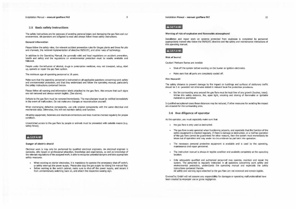
2.5 Basic safety instructions
The safety instructions are for purposes rK avoiding persona! injury and darnaging the gas flare and our environment. Ali operatars are obligated ta read and always follow these safety instructions.
General Information
Please follow the safety rules, the relevant accident prevention rules for biogas plants and those for pits and channels, the national implementation of directive 99/92/EC, and other rules of technology.
In addition ta the Operating Manual, the generally valid and local regulations on accident prevention, health and safety and the regulations on environmental protection must be readily available and followed.
People under the influence of alcohol, drugs or prescription medicine, may not transport, setup, start up, operate or repair the gas flare system.
The minimum age of operating personnel 1s 18 years.
Make sure that the operating personnel 1s instructed on ail applicable questions conceming work safety and environmental protection, and that they understand and follow the operating manual, particularly the safety instructions contained therein.
Please follow ail warning and information labels attached ta the gas flare. Also ensure that such signs are not removed and always remain legible. (See above).
Defects ta the gas flare must be removed immediately. The manufacturer must be notilied immediately in the event of malfunction. Do not make any changes or reconstruction yourself.
When exchanging defective components, use only original components with the same electrical and mechanical data. Otherwise, this will not maintain safety and function.
Ali safety equipment, fasteners and electrical connections and lines must be checked regularly for proper condition.
Unrestricted access ta the gas flare by people or animais must be prevented with suitable means (e.g. safety fence).
6i5Htifüi Danger of electrlc shockl
Electrical work is may only be performed by qualified electrical engineers. An electrical engineer is someone, who based on professional education, knowledge and experiences, as well as knowledge of the relevant regulations of the assigned work, is able ta recognize potential dangers and take appropriate safety measures.
• When working on starter electrodes, it is mandatary ta operate the emergency shut-off switch, or safely interrupt the power supply. Please also stop the gas supply by closing the manual tlap.
• Before working in the switch cabinet, rnake sure ta shut-off the power supply, and secure it from unintentionally switching back on, and attach the respective waning sign.
Installation Manual - manual gasflare FAI 10
tiiSHiHfüi Wamlng of risk of explosion and flammable atmospherel
Installation and repair work on systems protected frorn explosion is completed by personnel appropriately trained who follow the 99/92/EC directive and the safety and maintenance instructions of this operating manual.
tîib#iHfüi Rlsk of bums!
caution! Methane flames are invisible
• Shut-off the system before working on the burner or ignition electrodes.
• Make sure that all parts are completely cooled off.
Rre Hazard!
The safety distance ta prevent damage by lire impact on buildings and surfaces of stationary traffic should be 5 m •provided not otherwise stated in relevant local fire protection provisions.
• the Sm surrounding area around the gas nare must be kept free of any growth (bushes, trees). Within this safety distance, fire, open light, smoking and storing of flammable or ignitable materials is prohibited.
In justilied exceptional cases these distances may be reduced, if other measures for avoiding fire impact are ensured for the surrounding area.
2.6 Due diligence of operator
As the operatar, you must especially make sure that
• the gas tiare is only used as instructed.
• The gas nare is only operated when functioning properly, and especially that the function of the safety equipment is checked regularly. If there is damage or destruction, or a riskfree operation of the gas tiare cannot be guaranteed for other reasons, then the system must immediately be taken out of operation and may under no circumstance be put back into operation.
• The necessary persona! protective equipment is available and is used by the operating, maintenarice and repair personnel.
• The instruction manual is always in legible condition and available completely at the operating location.
• Only adequately qualified and authorized personnel may operate, maintain and repair the system. The personnel is regularly instructed in all questions coriceming work safety and environmental protection, understands the operating manual and especially the safety instructions contained therein. Ali safety and waming signs attached ta the gas tiare are not removed and remain legible.
EnvironTec GmbH will not assume any responsibility for damages or operating malfunctionsthat have been created by improper use or gross negligence.

Installation Manual - manual gasflare FAI 11
2.7 Product liability
Llablllty exduslons
For persona! injury, property damage, environmental and/or operating damages caused by not followrng, or not completely follow,ng the operat,ng manual, Bllgeri EnvironTec GmbH will not assume fiability. Unauthonzed contact with the system will result in termrnation of the warranty. Brlgen EnvironTec GmbH will not assume liability or warranty, if another spare part rs used instead of the ongrnal spare part recommended in the operating manual or in the spare part lrst, and the use of non· original spare parts has led to persona! rnJury, material damages and/or failure of the system.
Warranty and liabilrty claims for persona! inJury, property and environmental damages are excluded if the damage or injury is attributable to one or more of the followrng causes:
• Improper transportation, assembly, start-up, operatron or repair of gas flare
• Not observing the instructions in the operatrng manual regarding assembly, start-up, operation and maintenance.
• Unauthorized contact or structural changes of the gas tiare
• Poor monitoring of parts that are subject to wear or agrng
• Improperly completed reparrs
• Improper use of the gas flare
IMMMI The descnptions and rnstructJons rn th1s operatrng and maintenance manual refer to the standard designs. Therefore, not ail details and condrtrons have been mentioned. If missing informatron, please contact Env1ronTec GmbH immediately.
For details about our warranty please refer trJ our general terms and conditions, or your agreement documentation.
lnstallatKJn Manual - manual gasflare FAI 12
3. COMPONENTS AND USE
3.1 General information
When operating biogas or water treatment plants it may be necessary under certain circumstances to safely burn excess gas, for example during start·up, maintenance, in cases of consumer accidents or ln case of failure of gas flow (CHP [Cogeneration Unit], etc.).
The FA! gas flare 1s a safety device that functions manualy (optronal: fully automatic). It is manufactured completely from stainless steel and equipped with high quality components and instruments.
Safety Features
With the respective dimensionrng of the flow cross-sections, blowrng out or return of the flame 1s prevented. If the flame should return anyway, it is stopped by the deflagration protection. Damage to other systems parts its thus excluded.
The entire electrical equipment was configured according to DIN VDE 0116, and meets the highest safety engineering standards.
3.2 Structure
The gas tiare can be obtarned rn varrous srzes. See 7.2 Gas llare by mode! sae.

Installation Manual - manual gasflare FAI 13
3.3 Functional principle of the gas flare
Manual operatlon
To start the flare, first the butterfly valve must be opened and the ON button must be pressed lmmediately after. Pressing the on button will sparc the flare and the flare starts buming. After the flare starts buming, stop pressing on the ON button. To stop the flare, close the butterlfy valve.
Automatlc operatlon (Option)
The start/stop command is issued by an external signal (e.g. gas storage fill level). The monitoring/autornatic functions described for the hand operation will take place as described above.
Automatlc operatlon / pressure contrai (Option)
As an option the flare may be equipped with an additional pressure control. If exceeding the pressure previously defined on the pressure controller ( =max. controller), the flare starts automatically (as in normal autornatic operation) . If the pressure falls below the specified shut-off pressure ( =min. pressure controller), the flare is automat1cally shut off (time delayed).
The funct1ons of the hand and automatic operation will proœed as described above.
3.4 Gas flare standard components
3.4.1 Principal mecanical components
Butterfty valve
Fg. 2: butœrfly KWe
The manual vavle ls used for manually opening and closing the gas supply lines for repairs or when taking out of operation as an additional shut-off valve. lt is equipped with a hand lever and an opening regulator.
Installation Manual - manual gasflare FAI 14
Deftagratlon·protectlon
Fig. 3: Deffé1gralion prolEdion in the instalfatbn positkJn!+ f1ame Hier in detal
Prevents the effective creation of pipe deflagrations (accelerates deflagration in the piping, which is moving in the pipe axle direction with a flame extension speed below the sound of speed).
A statically dry flame protector made of spiralled bound metal bands with flame extinguishing gaps is used. The flame is extinguished by heat output in the boundary layer "s" to the larger surface of the gap, in relation to the gap width D and lowering the temperature below the ignition temperature of the product.
As an option, the deflagration protection may be equipped with a temperature gauge on the "hot'' side.
Burner head / combustion chamber
Fig. 4: Lw buner hei1d in the ambustial chamber
By default one (or more) diffusion burner heads are used. There 1s a mixture of fuel and oxidant (air) in the combustion chamber. The mtxing is essentially completed by diffusion and leads to the formation of a diffusion flame. Below the burner head, there is a air dise to regulate the air flow.
The burner heads are replaceable and are manufactured from temperature resistant stainless steel.
Flare base, plplng and combustion chamber
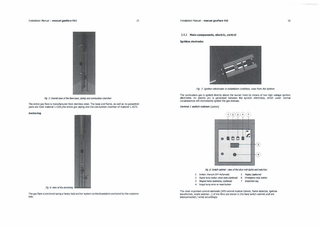
Installation Manual - manual gasflare FAI 15
Fig. 5: OveraH v.av of the /lare base, pPhg and axnbustbn chamber
The entire gas flare is manufactured from stainless steel. The base and frame, as well as no gaswetted parts are from matenal 1.4301,the entIre gas piping and the combustion chamber of material 1.4571.
Anchoring
Fig. 6: view of the andlorhg
The gas flare is anchored using a heavy load anchor system on the foundation anchored by the customer sîde.
Installation Manual - manual gasflare FAI
3.4.2 Main components, electric, control
Ignition electrodes
F,g. 7: Ignit,on electrodes m mstallation condlàon, v,ew from the bottom
16
The combustion gas is ignited directly above the burner head by means of two high voltage ignition electrodes. An electric arc is generated between the ignition electrodes, which under normal circumstances will immediately Ignited the gas mixture.
Control / swltch cabinet (option)
Fig. 8: Swi/d1 cabinet· view of the door wlth lghts and SWitches
1 Swltch: Manual-OFF-Automatic
2 Signal lamp motor valve open(optiona/)
3 Slngnal lamp operating (opt;onalj
4 Slngal lamp errer or reset button
5 Dlsplay (optional)
6 Emergency stop button
7 Inspection tag
The most important control elements (SPS control module Omron, flame detector, ignition transformer, mode selector ••• ) of the flare are stored m the flare switch cabinet and are mterconnected / wired accordingly.

Installation Manual - manual gasflare FAI
The switch cabinet is delivered in the series production made from plastic (protection type IP 54), including switch cabinet heating, emergency stop button (formerly emergency off button)
17
and signal lamps. As an option the delivery may be made in a stainless steel design. As an option an autornatic burner contrai could be chosen.
The power supply needed is 230 V, 50 Hz. The respective operating conditions of the gas flare are displayed by means of pilot lights on the switch cabinet.
Communication (only available if automatic option is taken)
The flare contrai can be directly incorporated in the control/visualization of the respective operating plant (biogas plant, digester gas, or similar). The following signais are planned for this purpose:
Central Control Gas Flare • external on or off (for "on" signal the
flare signal "on" is withdrawn, it will stop)
• Fault acknowledgement
Grounding connectlon
Gas Rare - Central Control • Automatic valve open - without limit
position monitoringVâlvula automâtica abierta - sin control de limite de posicién
• Operating message • Malfunction
Fig. 9: Grounding connection of the gas nare (with identification label}
In the standard production the gas flare is equipped with a grounding connection to a gas flare base. From the customer side, the connection must be completed according to the local or national regulations.
Installation Manual - manual gasflare FAI 18
3.5 Gas tiare, add-on equipment and options
Display on the tiare switch cabinet
Ftg. 10: Display on the switr:h cabinet 1. Dlsplay
Optionally, a LCD display may be integrated in the flare switch cabinet. Depending on customer request /need displays about the current flare status, combustion temperature or other parameters may be implemented.
Electrical heatlng of the fittlngs
Generally, biogas is 100% humidity saturating. To prevent iœ format10n or freezing of the valves, an electrical support heater with thermostat may be used, and the fitt1ngs can be insulated additionally. For this purpose the valves and applicable piping sections are covered by a heating cable. The temperature contrai occurs via a thermostat in a manner that the fittings are always kept at > O °C. The heated system parts are then also insulated.
Installation Manual - manual gasflare FAI 19
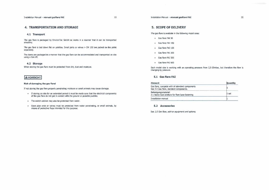
4. TRANSPORTATION AND STORAGE
4.1 Transport
The gas flare is packaged by Env,ronTec GmbH ex works in a manner that it can be transported smoothly.
The gas flare ,s t,ed down fiat on palettes. Small parts or valves > DN 150 are packed on the pallet separately.
The items are packaged tn a manner that the gas flare can be accommodated and transported on site ustng a fork lift.
4.2 Storage When storing the gas flare must be protected from dirt, dust and moisture.
!AVORSICHT ! Rlsk of damaglng the gas tiare!
If not storing the gas flare properly penetrattng moisture or small animais may cause damage.
• If stonng on site for an extended penod it must be made sure that the electrical components of the gas flare do not get in contact with the ground or possible puddles.
• The switch cabinet may also be protected from water.
• Open pipe ends or valves must be protected from water penetrattng, or small animais, by means of protect,ve flaps intended for this purpose.
Installation Manual - manual gasflare FAI 20
S. SCOPE OF DELIVERY
The gas flare is available in the following mode! sizes:
• Gas flare FA! 50
• Gas flare FA! 100
• Gas flare FA! 150
• Gas flare FA! 300
• Gas flare FA! 500
• Gas flare FA! 600
Each mode! size is working with an operating pressure from 2,5· 20mbar, but therefore the flow is chang1ng by pressure.
5.1 Gas flare FAI
Element
Gas flare, complete with ail standard components See 3.4 Gas flare, standard components.
Befestigungsmaterial: 3 x heavy-load anchors for flare base fastening
Installation manual
5.2 Accessories
See 3.5 Gas nare, add-on equipment and options.
IQuantity
1 set

Installation Manual - manual gasflare FAI
6. IDENTIFICATION PLATE
6.1 Identification plate gas tiare FAI
Das Typenschild der Gasfackel is placed on the gas flare.
Rg. 11: 111e identKication plaœ of the gas 11are
When calling our customer service m case of malfunctions and for ordering spare parts, please provide us with the identification plate, the serial number and year built.
Other identification plates are found on the components.
21 Installation Manual - manual gasflare FAI
7. TECHNICAL DATA
7.1 Gas tiare general information
Gas primary pressure (mbar)
Heating value (kWh/ Nm 3)
Medium*
Methane content (%)
Operating and contrai voltage
Power supply
12,S - 20
= flow rate x 6,5
Biogas (65% CH4, 34% C02, 1 % H25)
45-70
24 VDC ( only if automatic mode is hoosen)
230 VAC, 50 Hz, others on request
22
*The percentages listed are assumed biogas compositions common for biogas or digester gas plants.
7.2 Gas tiare by model size (standard)
rlJFlametube Gas MaxAowrate Max Flow rate Model slze lnlet at2,Smbar at20mbar
mm ON Nm•/h Nm•/h FAI 50 DM350 40 50 80 FAI 100 DM 350 50 70 140 FAI 150 DM450 65 150 230 FAI 300 DM450 80 160 300 FAI 500 DM636 100 250 530 FAI 600 DM636 125 500 600
FAI 50 Auto DM350 40 40 80 FAI lO0Auto DM350 50 60 130 FAI 150Auto DM450 65 130 210 FAI 300Auto DM450 80 140 300 FAI SO0Auto DM636 100 230 510 FAI 600Auto DM636 125 410 600
The information about the type specifications can be found in the prospectus sheet "Biogas Flare FA!".
7.3 Accessories
Descrintion Switch cabinet Display for flare status
Data Comrnents Stainless steel LCD 2-lines In the switch cabinet door

Installation Manual - manual gasflare FAI
8. INSTALLATION
f•[email protected]ü;• Danger of persona! lnjury, property and envlronmental damage!
Please follow the safety instructions in Chapter 2. Safety.
8.1 Place of use
Danger of explosion!
The gas flare is not permitted to be used in Ex zones. • When positioning the gas tiare, please observe the ex zone plan of the biogas or digester
system!
Requirements
• The gas tiare may only be setup outside.
• Addit10nal roofing 1s not permitted.
• No w1res (power etc.) may be run in the v1cinity of the bumer head or above it.
23
• Fire protection distances to buildings, areas of stat10nary traffic and bushes and trees must be maintained. For this purpose see the warning signs in Chapter 2.
• The manual shut-off tlap must always be easily accessible without using any aids.
• To avoid risks of mechanical damage (e.g. with start-up), the traffic areas should be a safe distance away from the gas tiare.
• The structure of the foundation (Static) for the gas tiare may only be implemented according to the respective foundation drawings.
• When preparing the installation make sure that possible concrete fixtures (lines, etc.) are not damaged.
IMMMI Make sure that for the gas tiare location the gas line cannot freeze, 1.e. no condensation may form and the gas line must have a slope adjusted for the terrain.
8.2 Installation and setup
Pii34ihfüi Danger of persona! injury, property and environmental damage!
Electrical and gas pressure engineering connect1on conditions must coincide with the information in Chapter ''fechrncal Data".
Electrical connection
The electrlcal connection may only be completed by instructed and qualified spec1alized engineering comparnes.
To reduce the probability of electrical corrosion, the entire electrical installation of the system should be designed in a network configuration TN-C-5 or TN-5.
For operating the gas tiare a wiring provlded by the customer is necessary.
Potential equallzation
The customer s1de (operator) must ensure potential equalizat1on
F,g. 12: Groundilg aJf1l1ec/ion a the gas ffare
The standard release of the gas tiare is equipped with a labelled grounding connection.
lightenlng protection
The customer (operator) must prov1de lightmng protection.
Gas connection
The electrical connect1on or gas pipe connectlon may only be completed by instructed and qualified specialized engineering companies.

Installation Manual - manual gasftare FAI
Assembly
• Unload flare from truck / container, remove transport locks, place crane hook.
• Place a strap or steel cable and fasten it to the flare as showed in Figure 13.
fig. 13: S1rap lixalion
• Lift the flare until it 1s completely ln vertical position
Fig. 14: Flare/illing
• Place the flare on the foundation.
Knmhoken , cranehaol< 1
25 Installation Manual - manual gasftare FAI
Attached gas flare
Fig. 15: Attached gas ffate
• Verticalty set gas flare on concrete foundation.
!AVORSICHT!
Danger of persona! lnjury and property damage!
26
There is risk of inJury and damage to the gas flare, because of bpping before the gas flare is correctty attached to the concrete foundabon, and is secured with guy ropes.
• Unhook crane hook only after fixing the anchor of the lift belt.
Fig. 16: View of anchor.;
• Attach gas flare with fix anchor M 16 (1) on the concrete foundat1on (2)

Installation Manual - manual gasflare FAI
Fig. 17: lnsert inst11Jction !br dn:p-in anchor.
Follow the insert instruction for drop-in anchor.
• Drill hole
• Clean hole bore
• Insert anchor
• Set anchor
• Set torque
Connect gas flare
Fig. 18: Connect gas fiare
• Attach fiange piece (2) and manual folcl (1).
• Connect manual gas fiap with gas pipe.
27 Installationsanleitung - manuelle Gasfackel FAI
8.3 After installation and before initial start up
Settings
Electrode distances
F,g. 19: Eleclrode distances
• Check the electrode distances {A and B), and if necessary readjust. o A = max. 8 mm / min. 5 mm o B = Electrodes must be placed inside the pipe B.
Air supply
• Check distance of air regulating dise (factory setting: 10mm)
EE ------ 1E
._..1.1--__.11----s' EE
F,g 20: Ar regulatIng dise
28

Other necessary activlties before Initial start up
The following activities must be completed:
• Check the function of the condensate drain cock, and empty condensate. See also 11.5
• Inspection and mamtenance work.
• Ali fastenlng parts used for the installation of the gas flare at the place of utilization must be checked, and if necessary tightened. Please observe the tightening torque of the respective fastenlng element. See 11.4 Torques. The flare body must be firmly anchored and tightened using three steel ropes.
• Make sure that ail safety equipment such as protective covers, emergency switch/button (formerly emergency shut-off), main switch etc. are available, correctly installed, and are functioning.
• Check the gas flare for visible damage and immediately remove the defects noted. The gas flare may only be operated if in perfect condition!
• Check the marked protective area to make sure that it ts free of
• people or vehicles and
• dangerous materials and substances,
• no objects (e.g. curtains, flags, birds' nests, etc) could blow or walk from the buildings or building parts into the protective area.
• Remove ail objects and other materials not needed for operation from the work area.
• Check and make sure that the electrical connection was made according to the valid provisions. The cable feed through must be tightly screwed in and water tight.
• Make sure that ail components for ensurlng the potential equalization are correctly attached as specified in DIN or the EC guidelines, and were checked by the electrical engineer.
• Check and make sure that the gas connection was made according to the valid provisions.
• Make sure that an adequate quality of gas is available. The quantity, quality and pressure is prevalent for proper operation.
IMM@i The minimum gas quantity required to start up the gas flare can be obtained from the technical data of the gas flare according to data table 7.2 or the "project specific data sheet" in the Annex.
Installation Manual - manual gasflare FAI
9. START UP AND OPERATION
f•iM=Hfüi Danger of persona! lnjury, property and envlronmental damage!
P/ease lbllow the salèty instructions in Chapter 2. Salèty.
9,1 Initial start up
Before putting the gas flare ,nto operation the first time,
• make sure you are well familiar with it:
• the equipment and operating elements, see under operation
• the measures in case of an emergency.
30
• Make sure that ail control activities have been completed before initial start up. See 8.3. Alter installation and before initial start up.
• Complete the check list. See 12.2 Check list for initial start up .
Logs
• Document the first inspection of the gas seal and initial start up. See 12.J Proof of repair work and /eak tests.
9.2 Start-up
Only alter you are convmced that the gas flare 1s ready for operation, can you put the gas flare mto operation.
• Before connect1ng the supply voltage, check that ...
o the selector switch is off
o the manual tlap is open
o the distance of the ignition electrodes is between 5 and B mm
o the ignition electrodes are correctly positioned
o there 1s enough gas in adequate quahty available
• Turn the power supply on, i.e. turn on fuse. If necessary unlock emergency stop switch (previously emergency button).
• Make sure that the PLC contrai is set to "Run" (Optional).
• If the reset button/light is on (may be possible) • push to reset (confirm) (Optional).
• Check if ...
the message from the tlame indicator is 1n queue (check by using a lighter).
o the function of the malfunction confirmation button
o the function of the interfaces.
Conduct a test operatton:
• Set the selector switch to MANUAL The automat,c valve shoulcl open and alter about two seconds ignition will start. VALVE OPEN lights up (optional).
• If the flare burns and the contrai light is on OPERATION, then one can assume that the confirmatton ON of the gas flap works properly and the tiare systems works. OPERATION only lights up tf the tlame monitoring detects a flame. Alter a few seconds the ignition stops (optional).
• Slowly close the manual flap unttl no more gas escapes. As soon as the tlame is ext1nguished, the automattc flap must close immediately and alter a few seconds the tiare makes aoother attempt at start1ng. This will s1mulate oon-combustible or too httle gas.
(If the flare malfunctions then ail possible faults must be examtned and removed. See 10.2 Troubleshoottng).
• Turn the gas tiare to AUTOMATIC to contrai operation externally (optional).
9.3 Operation
Standard:
Alter the flare started when pressing the ignition button ON, the button can be released. The flare wlll burn as long there is gas. If closing the butterfly valve, the tiare will stop burning.
OPTION: Automatic:
Alter the ON request from the superior contrai or fill level contact on the gas storage has been issued, the operating cycle of the tiare system will start (opttonally the tiare can also be operated with help from pressure switches).
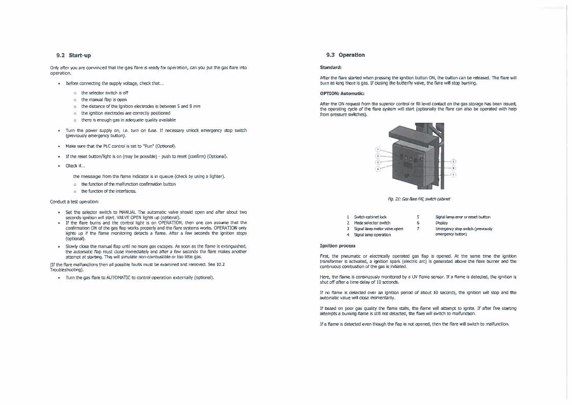
Fig. 21: Gis' tiare FA/, switd1 cabinet
Swilth cabinet Iock 2 Mode selector switch
3 SiÇ11ill lamp motor valve apen 4 SiÇ11i!l lamp operatlon
Ignition process
5 6 7
Sigoal lamp error or reset button Display Eme<gency stop switch (prl!VIOUSly emergency button)
First, the pneumattc or electncally operated gas flap is opened. At the same time the ignition transformer is activated, a ignition spark (electric arc) is generated above the tiare burner and the contmuous combustion of the gas is imbated.
Here, the tlame is contmuously monitored by a UV flame sensor. If a flame is detected, the ignitton is shut off alter a t1me delay of 10 seconds.
If oo flame is detected over an ignition pertod of about 10 seconds, the ignition will stop and the automattc value wtll close momentarily.
If based on poor gas quality the tlame stalls, the tlame will attempt to ignite. If alter five starting attempts a burning flame is still oot detected, the flare will switch to malfunction.
If a flame is detected even though the flap 1s not opened, then the flare will switch to malfunction.

Installation Manual - manual gasflare FAI 33
Pressure control (optional, only with automatlc)
Via two pressure switches the turn-on and shut-off point for the nare is defined. Here the turn-on Signal for the Hare is generated by the pressure switch, and the ignition process runs automatically as described above. The pressure contrai functions via the contrai, if the selection switch is turned to AUTOMATIC.
Furthermore, the flare can be activated via an external starting signal or the manual contrai.
Operating mode ON/MANUAL (optlonal)
In this switch position, the ignition of the gas nare occurs the same way as in AUTOMATIC OPERATION. As a result, dunng start-up drive the gas can be manually burned off.
Operating mode OFF (optional)
In the OFF position of the switch attached to the switch cabinet, the burn off and ignition is not possible.
Air regulation:
To contrai the combustion air supply, there is one airregulating dise placed below the burner.
An adjustment of the airregulating dise is necessary if the flame burns unstable. That means: • If the name is strang and blows out based on the high name speed, or burns far above the
combustion chamber, then the airregulating dise must be closed.
• If the flame burns far below, directly on the burner, and if the combustion is instable, then more air is needed and the airregulating dise must be opened.
To adjust airregulating dise, proceed as follows:
• T urn the selection switch to FLARE OFF.
• Loosen counter nuts and slightly move airregulating dise
• Tighten the counter nuts again.
EMERGENCY STOP procedure
• Press the Emergency Stop switch to interrupt the supply voltage. The emergency stop switch catches and with a slight turn can be deactivated again.
Wintermode
See Electrical heating of the valve route on page 22.
IMM%i Communication
The flare contrai is designed to be directly incorporated in the control and visualization of the respective operating system (only if automatic option is choosen).
9.4 Taking out of operation
If the gas flare must be taken out of operation because or for example greater maintenance work, then only trained qualified employees who have read the operating manual and have the respective authorization can complete this work.
• Complete the following steps:
• Stop pressing the ignition buttin, Mode selector switch to "0"
• Engage the emergency stop switch
• Interrupt power supply (turn off fuse) and secure fram restarting.
• Close butterfly valve

Installation Manual - manual gasflare FAI
10.MALFUNCTIONS AND REMOVAL MALFUNCTIONS
f1iM=Hfüi Danger of persona! injury, property and environmental damage!
Please fbl/ow the safety instructions m C/iapter 2. Safety.
10.1 Behaviour in case of malfunctions
• In case of malfunction of the electrical system or contrai units always contact EnvironTec GmbH or the blogas plant manufacturer.
35
You can reach us on business day from 8 am to 5 pm at +43 (0) 55 78 7 70 05 (outside of these hours leave a message on voicemail , fax or email). See contact information on page 2 of this document.
• in case of fire, 1mmediately contact the lire department, Tel: 112!
For malfunctions that last more than 24 hours, suitable measures must be mitiated such as reducing the feed quantities, 50 that the gas product10n is reduced, and it 1s no longer necessary to use the gas fiare m contmuous operation.
Ali spare parts (except for valves) can be obtained withm one day by couner service. See 11.7 Spare parts.
•MM@I Please inform us at any time about your system malfunct1ons. We depend on the expenences you make with the system, 50 that we can always make improvements.
10.2 Troubleshooting
A maJQrity of the malfunctions that occur can usually be attributed to a small error in the system of your system. Stay cairn and think about the situation. Sorne malfunctions can easily be localized and removed if thinking about the problem logically.
For this purpose use the following list of malfunction messages.
For malfunctions that cannot easily be removed, please contact EnvironTec GmbH, or the manufacturer of the system in which the gas fiare is installed.
Troubleshooting table
Malfunctlon General malfunctlons
Power supply 1s Fuse was triggered Check flare on site
interrupted or ready Power cable is defect Loosen emergency off switch, check
message 1s not seen Emergency stop switch was fuse pressed Check power supply
SPS is defect Contact manufacturer and follows
Malfunction contrai Switch is not in "Automatic" mode test instructions, Check fiare Tighten flange connection, replace
System is no longer Loose fiange, defect seals, seals, check valves.
technically sealed mechanical load Oleck, if mechanical forces are Other exterior effects working (e.g. by setting
the terrain severe weather etc.1 Ramefault
Not enough gas, poor gas quality. Gas feed is interrupted Test gas UV sen50r is dirty or defective, Check gas supply
Flame monitoring (UV wiring error Clean UV sen50r, check flame sen50r, fiame detector) Defect high voltage line to the ig- monitoring does not detect a fiame nition electrodes or corroded Check ignition alter ignition process plug. Ignition electrodes - check
Distance between the electrodes distances and if necessary correct (between 0.5 and 0.8 cm) Check ignition transformer Ianition transformer is defective
After fifth successful Very poor gas quality Test gas. ignition process, the Gas pressure is tel0 high or too fiame stalls and burns low Check gas supply
for less than 30 seconds Fame monitorioo is defect Check fiame monitoring
Even though the flap is Flame monitoring is defective, Check fiame monitoring closed, the fiame is detected
fiap does not close Check wmng
No ignition Electrodes or cable or plug are Check ignition defective
Fault acknowledgement (only if automatic option 1s choosen)
A malfunction is identified when the indicator light on the tiare cabinet is lit and displays the message "Malfunction".
With the acknowledgment key on the switch cabinet (longer than 2 s), or the remote acknowledgement key (see communication), the occurring disturbance can be reset at any time.

11.MAINTENANCE
The maintenance measures include inspection, maintenance and repair.
11.1 Safety during maintenance
fiiMiHfüi Danger of persona! injury, property and envlronmental damage!
Pfease fol/ow the safèty instructions in Chapter 2. Saœty.
Waming of rlsk of explosion and flammable atmospherel
For maintenance work on the gas nare make sure that there is no potential explosive atmosphere while working! Only alter turning off the affected system part can you work on the gas lines and the accumulated gas can be released and the system rinsed (inerting). Smoking is prohibited !
• ALWAYS use the relevant, required personal safety equipment (gas warnlng device, safety toecap shoes, safety gloves, hat, etc.)!
• Ali Ignition sources (e.g. open flame, hot heat sources, not spark-free tools, not explosion protected electrical equiprnent, cell phones) MUST be kept away from the explosion area (ex zones)!
• ONLY use spark free tools (also applies to boring machines, drills, core drills, chisels, etc.)! Work that can generate weid, burn and sparks may NEVER be clone ln the vicmity of the explosion zones!
Before working on the electncal equipment • Press and engage the emergency stop swltch.
• Set mode selector switch to 0
• Interrupt power supply (turn off fuse) and secure from restarting.
• Close manual flap.
• Lock all work areas of the system, and make sure that no animais, chiklren or unauthorized people are in the work area.
11.2Record
The inspection and maintenance work, as well as sealing checks completed must be documented without fail. See 12.3 Proof of repa1r work and leak tests.
Installat1011 Manual - manual gasflare FAI 38
11.3 Inspection and maintenance plan
lntervals Components Check (for) / Operatlng resource / Actlvltv comments
AH safety equipment, must be checked If necessary, repair (have Daily fasteners and electrical regularly for proper done ). Replace defect parts
connections and lines condition /have done\ Weekly
Empty the condensate See under inspection and (depending Condensate discharge on case\
container maintenance work
Monthlv Manual ooeration Funct1on
Semi-Fame monitoring Function
annually Maonet/Enoinevalve Function dirtvinn
With help from foaming material, ex. leakage
Visual check for leak detection spray for gas lines
Piping connections tightness
or a suitable gas detection Annually devlce, a qualified persan
will check for leaks Record the results in a IOQ
Ignition electrodes Distances of the See 11.5 Inspection and electrodes maintenance work Check for corrosion, dirt
Flame overvoltage and possible
The check is performed by As needed discoloration of the
protection (flame grid) steel, which denotes
an authorised persan
deflanration
Every 3 Switch cabinet and ail See 11.5 Inspection and electronic and electrical Clamps are stuck
years. comoonents
maintenance work
*e.g. leak detector in the canister with frost protection according to DIN DVGW No. 8801 E 582 plus frost protection or in a spray can.

Installationsanleitung - manuelle Gasfackel FAI 39
11,4 Torques
Infonnat10n in Nm
To hold screws by tightemng us1ng the specified tension, they may only be tightened up to the maximum permitted t19htening torque. If exceeding the tlghtemng torque, the screw may stretch out and the tension force is lost.
Screw MS
Quallty A2/A4-70 drv u = 0.14 17.7 Lubricated* u = 0.10 13
Quallty 8.8 zinc plated drv u = 0.14 25.4
*lubricated with OKS white ail-round or comparable lubncating agent.
11.5 Inspection and maintenance work
Interval: see inspection and mamtenance plan
Drain condensate water
Explosion hazard because of gas escaping !
When opening the condensate water discharge drain, gas may escape
MlO M12 34.8 59.9 28 45 49.5 85.2
• Before opening the discharge drain, set the selection switch to FLARE OFF
Rg. 22: Condensate Kffie" discmtge drain
The discharge drain is located at the lowest pomt of the flare piping.
• Turn the select1on switch to FLARE OFF.
• Place collect1ng tray beneath the drain.
M16 148 105 211
Installat10nsanleitung - manuelle Gasfackel FAI 40
• Open discharge drain and drain condensate container

Installationsanleitung - manuelle Gasfackel FAI 41
Ignition electrodes and flame sensor
f•iMiHfüi Danger of surge
See the safèty precautions in 2 Safèty
See also 11.5 Inspection and mamœnanœ work - Before working on the electnœl equipment
Clean Ignition electrodes
Fig. 23: Gis tiare FA/, ignitkn electrodes
• Turn the selection switch to FLARE OFF.
• Carefully loosen the electrode bracket
• Remove existing deposits with a wire brush.
• Tighten electrode hokler. Caution! Ceramic can easily break.
Installatfonsanleitung - manuelle Gasfackel FAI 42
Check Ignition electrode distance
F1g. 23: gas tiare FA/, ched< lgnitbn eectro1e distanœ
If the distance of the ignition electrode is incorrect, then there is either not ignitfon spark or the ignition spark is too weak to ignlte the gasses.
• Turn the selection switch ID FLARE OFF.
• Carefully loosen the electrode container
• Check Electrode distance according to informatfon in the illustration above. If necessary reset.
• Tighten electrode .holder. Caution! Ceramic can easily break.
Check fla me sensor for functlon and cleanliness ( optional)
Ag. 24: Rame sensor (W Sensor) with heat protedlon 591 1 Heat protedlon 591 2 W Sensor
• Remove sensor
• Check cleanliness of lense, if necessary clean with cloth and water.

Installation Manual - manual gasflare FAI 43
Flamearrestor and bumer head
Check and clean flame backlash protection and burner head
For disassembly, maintenance and installation of the flame backlash protection, please see the respective instructions in the detail documentation (in the Annex under supporting documents). These must be checked periochcally for functionahty, especrally if the flare is not being operated or only rarely.
Butterfly valve • Turn the selection switch on the switch cabinet ta OFF.
• Open and close the latching lever of the manual flap until stop and check Free movement.
• Check for leaks using a leak detection agent.
• Watch for corrosion. For external corrosion, see manufacturer maintenance instructions.
Motor valve/solenoid valve (Optronal)
For disassembly, maintenance and installalJon of the motar valve, please see the respective instructions ln the detail documentation (in Annex under supportrng documentation)
Switch cabinet, electronic and electric
Fl{l. 25: Test plate an the switr:h cabnet
• Every 3 years check the switch cabinet and inspect ail electronic and electrical components.
• Record the results in a log. Apply inspection sticker.
Installationsanleitung - manuelle Gasfackel FAI 44
11.6 Restait
The following points must be followed, after concluding the maintenance work and before restarting the gas flare:
• Check again ail previously loosened screw connections for a tight fit.
• Make sure that ail prevrously removed protectrve installatron, covers, etc. are installed again properly.
• Make sure that ail the tcrols, materrals and other equipment used are removed from the work area. Thereafter clean the work area.
• Make sure that ail safety equipment 1s working properly agarn.
After completing the maintenance, the operator or service personnel must make sure that ail work ls completed and only then can the system be released for operation.
11.7 Spare and wearing parts
The lifetime of the wearing parts 1s depending of the hours of using the flare, weather conditions and temperature.
Ali spare and wearing parts can be obtained from EnvironTec GmbH upon request, and be delivered quickly by courrer service.
To order spare parts for the gas flare, please contact us directly.
Please ta speed up the ordering process, take note of the information of the flare's identification plate (e.g. The identification plate, senal number, year made).
•MIMI We recommend keeping a spare part package on hand ta allow immediate repairs.
See contact information on page 2 of this document

Installation Manual - manual gasflare FAI
12.APPENDIX
12.1 Checklist for initial start-up
Please use this page as your template
Ooerator Address Zio / Citv Phone Device / Serial N umber FAI/50/ 15/ 500-05-08 /Giraud
Guideline for evaluatlng initial operation* Yes Comments:
Are all documents (conformity statement, operating 1 manual) completed, in the country's language and D
accessible?
2 Is it used properly as defined in the operating manual? D
3 Were an safety and installation specifications of the
D Operating Manual followed/implementecl?
4 Was the installation completed properly and checked D (torque, seals, fastenings)?
5 Is there adequate protection from mechanical hazards, D through jamming, clip, eut, record, pull-in, hit and friction?
Is there adequate protection from electrical hazards caused 6 by a short circuit, overload, error conditions, touching live D
parts and electro-static charge7
7 Is there adequate protection from noise, vibrations, heat D and hazardous materials?
8 Is a safe, proper operation and hazardous-free operation D provided (if necessary determine in the test operation)7
Were all ignition sources and flammable materials removed 9 from the fire protection area, or avoided in the area of the D
system7
*Depending on the scope and risk potential of the technical system, a detailed assessment method may be necessary for the initial start-up.
Responsible for the assembly:
Signature
Responsible for the electrical installation:
Signature
Responsible for the start up:
Signature
4S Installation Manual - manual gasflare FAI 46
12.2 Proof of repair work and leak tests
P91fo.1'Ndby .,... Opallllnghoun Workpeib1ned (stamp, llgnaba9)

lnstalla~on Ma nuai - manual gastlare FAI 47
12.3Annexes


