Embed Size (px)
Citation preview
MAS Methodology for HMS
Adriana Giret, Vicente Botti, and Soledad Valero
Departamento de Sistemas Informaticos y Computacion,Universidad Politecnica de Valencia, Spain
46022 Valencia, SpainPhone: +34 96 387 7000
{agiret, vbotti, svalero}@dsic.upv.es
Abstract. Developments in Holonic Manufacturing Systems (HMS)have been reported in three main areas: architectures, algorithms, andmethodologies for HMS. Despite the advancements obtained in the firsttwo areas the methodologies for HMS have not received great attention.To date, many of the developments in HMS have been conducted in analmost “empirical way”, without design methodology. There is a definiteneed to have methodologies for HMS that can assist the system designerat every development steps. This methodology should also provide clearand unambiguous analysis and design guidelines. To this end, in this workwe present a Multi Agent Methodology for HMS analysis and design.1
1 Introduction
In the last ten years, an increasing amount of research has been devoted toholonic manufacturing (HMS) over a broad range of both theoretical issues andindustrial applications. We can divide these research efforts into three groups[1]: (i) Holonic Control Architectures, (ii) Holonic Control Algorithms and (iii)Methodologies for HMS. In spite of the large number of developments reported inthe first two areas (for a detailed study see [1]), there is very little work reportedon Methodologies for HMS. In [2], a formal specification approach for HMS con-trol is presented, but it is still in a developmental stage. There are no defineddevelopment phases, and no detailed descriptions to explain how to model issuessuch as cooperation in the holarchy, holon autonomy and system flexibility. In[3], it is proposed an agent organization to model each holon/holarchy that is in-dependent of any holon architecture. However, it is focused only on the holarchydefinition and does not define the development phases.
There is a definite need to have methodologies for holonic systems [1], that arebased on software engineering principles in order to assist the system designer ateach stage of development. This methodology should provide clear, unambiguousanalysis and design guidelines. We believe that methodologies from the MultiAgent Technology (MAS) are good candidates for modeling HMS due to thefollowing: the similarities between the holonic and the agent approaches, the wide1 This work is partially supported by research grants TIC2003-07369-C02-01 from the
Spanish Education Department and CICYT DPI2002-04434-C04-02.
V. Marık, R.W. Brennan, M. Pechoucek (Eds.): HoloMAS 2005, LNAI 3593, pp. 39–49, 2005.c© Springer-Verlag Berlin Heidelberg 2005
40 A. Giret, V. Botti, and S. Valero
use of agents as the implementation tool for holonic systems, and the availabilityof complete MAS Methodologies. However, there are some extensions that mustbe included in a MAS methodology to be able to model the HMS requirements ina proper way: holon recursive structure, system abstraction levels, HMS specificguidelines, and a mixed top-down and bottom-up development approach.
In this work we present a MAS Methodology for HMS analysis and design.Section 1, introduces the Abstract Agent notion to model the holon recursivestructure. Section 2, lists the requirements for a methodology for HMS andSection 3, presents it. Finally, in Section 4, we summarize the conclusions andfuture works.
2 Abstract Agent and Holon
The HMS consortium has defined the following holon characteristics and holonicconcepts [4]:
– Holon - an autonomous and cooperative building block of a manufacturingsystem for transforming, transporting, storing and/or validating informationand physical objects. The holon consists of an information processing partand often a physical processing part. A holon can be part of another holon.
– Autonomy - the capability of a holon to create and control the execution ofits own plans and/or strategies (and to maintain its own functions).
– Cooperation - the process whereby a set of holons develops mutually accept-able plans and executes them.
– Self-organization - the ability of holons to collect and arrange themselves inorder to achieve a production goal.
– Holarchy - a system of holons that can cooperate to achieve a goal or objec-tive. The holarchy defines the basic rules for cooperation of the holons andthereby limits their autonomy.
An agent is an autonomous and flexible computational system that is ableto act in an environment [5].
Holons and agents are very similar concepts (for a detailed comparison ofthese two notions see [6]). In [6], we pointed out that the recursive structure is theonly holon property that is not presented as such in the agent definition. To copewith this limitation, in [7] we proposed the Abstract Agent notion as a modelingartifact for autonomous entities with recursive structures. The Abstract Agentextends the traditional agent definition adding a structural perspective to theagent concept: ”... an Abstract Agent can be an agent; or it can be a MAS madeup of Abstract Agents ...”.
The Abstract Agent is an attempt to unify the concepts of holons and agentsand to simplify and close the gap between holons and agents in the analysis anddesign steps. This will make it easer to translate the modelling products that areobtained from methodologies for HMS into coding elements for the implemen-tation of the holonic system. Thanks to the integration of the holon recursiveproperty into an Abstract Agent, the Abstract Agent is useful not only for HMS
MAS Methodology for HMS 41
but for the modeling of complex systems as well. An Abstract Agent that acts inorganizational structures can encapsulate the complexity of subsystems (simpli-fying representation and design) and can modularize its functionality (providingthe basis for integration of pre-existing Multi Agent Systems and incrementaldevelopment). The Abstract Agent facilitates the modelling of organization oforganizations (as well as, Multi Agent Systems of Multi Agent Systems).
3 Requirements of a Methodology for HMS
Manufacturing requirements impose important properties on HMS [4]. Theseproperties define functional attributes and specific requirements for the HMSstructure and the HMS development process which must be considered in themethodology. We have defined a HMS methodology requirements list based onthe study of the developments reported in HMS and on our experience withsoftware methodologies:
1. Manufacturing control systems require autonomous entities to be organizedin hierarchy and heterarchy structures [4].
2. Manufacturing control units require a routine-based behavior that is botheffective and timely [8].
3. A methodology for HMS should lead straight-forward from the control taskon a factory resource or factory function to autonomous entities [8,4].
4. A methodology for HMS should define a development process that is guidedby abstraction levels, and should also provide modeling artifacts, tools andguidelines to manage this process.
5. A methodology for HMS should define a mixed top-down and bottom-updevelopment process.
6. A methodology for HMS should integrate the entire range of manufacturingactivities (from order booking through design, production, and marketing)to model the agile manufacturing enterprise [4].
Bearing these requirements in mind we have studied software engineeringmethodologies which are best suited for problems of this kind. This study hasdemonstrated that MAS methodologies are good candidates to work with. To thisend, we have defined a MAS methodology for HMS which is based on INGENIAS[9] (a complete MAS methodology that has good performance in the developmentof complex systems). Our approach attempts to satisfy the requirements listedin this section.
4 Methodology
In this section, we present a MAS methodology for HMS analysis and designthat is based on the Abstract Agent notion. Every software engineering method-ology must define and provide notation, tools, and a development process. In thefollowings sub-section, we present the notation and the development process ofour methodology. The development tools for this methodology will be availablein the near future. We use Abstract Agent and holon as similar notions [6].
42 A. Giret, V. Botti, and S. Valero
4.1 Notation
In our approach, the HMS is specified by dividing it in more specific character-istics that form different views of the system. These views are defined in termsof MAS technology; therefore, we talk about agents, roles, goals, beliefs, organi-zations, etc. The views can be considered as general MAS models that can alsobe applied to other domains. The way in which the views (models) are defined[10,11] is inspired by the INGENIAS methodology. The extensions we have madeto the INGENIAS meta-models deal with the following: the addition of the Ab-stract Agent notion and the properties to model real-time behaviours [12], theredefinition of some relations to conform to the new modeling entities and thedependencies between them. These extensions are motivated by requirements 1and 2 of Section 3. Here we summarize the models:
– The agent model is concerned with the functionality of each Abstract Agent:responsibilities and capabilities.
– The organization model describes how system components (Abstract Agents,roles, resources, and applications) are grouped together.
– The interaction model addresses the exchange of information or requestsbetween Abstract Agents.
– The environment model defines the non-autonomous entities with which theAbstract Agents interacts.
– The task/goal model describes relationships among goals and tasks, goalstructures, and task structures.
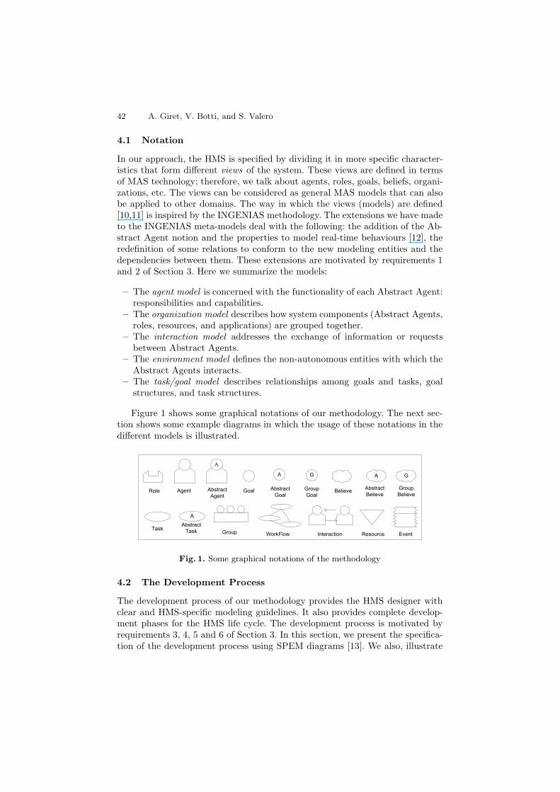
Figure 1 shows some graphical notations of our methodology. The next sec-tion shows some example diagrams in which the usage of these notations in thedifferent models is illustrated.
G
GroupGoal
A
AbstractGoal
GoalAgentRole
Task
G
GroupBelieve
A
AbstractBelieve
Believe
EventResourceInteractionWorkFlowGroup
A
AbstractAgent
AAbstract
Task
Fig. 1. Some graphical notations of the methodology
4.2 The Development Process
The development process of our methodology provides the HMS designer withclear and HMS-specific modeling guidelines. It also provides complete develop-ment phases for the HMS life cycle. The development process is motivated byrequirements 3, 4, 5 and 6 of Section 3. In this section, we present the specifica-tion of the development process using SPEM diagrams [13]. We also, illustrate
MAS Methodology for HMS 43
System RequirementAnalysis
Client/User
Use CaseDiagram
AnalysisModels
SystemArchitecture
ExecutableCode
Requirements
Operation andMaintenance
SetUp andConfiguration
HolonsImplementation
HolonsDesign
Holons Identification andSpecification
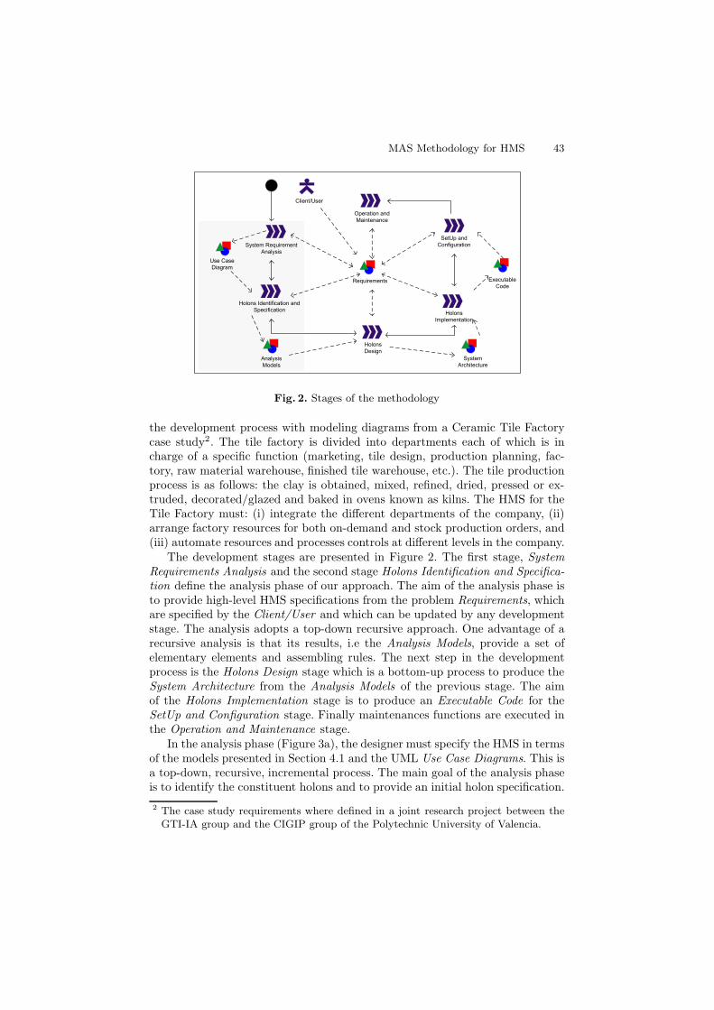
Fig. 2. Stages of the methodology
the development process with modeling diagrams from a Ceramic Tile Factorycase study2. The tile factory is divided into departments each of which is incharge of a specific function (marketing, tile design, production planning, fac-tory, raw material warehouse, finished tile warehouse, etc.). The tile productionprocess is as follows: the clay is obtained, mixed, refined, dried, pressed or ex-truded, decorated/glazed and baked in ovens known as kilns. The HMS for theTile Factory must: (i) integrate the different departments of the company, (ii)arrange factory resources for both on-demand and stock production orders, and(iii) automate resources and processes controls at different levels in the company.
The development stages are presented in Figure 2. The first stage, SystemRequirements Analysis and the second stage Holons Identification and Specifica-tion define the analysis phase of our approach. The aim of the analysis phase isto provide high-level HMS specifications from the problem Requirements, whichare specified by the Client/User and which can be updated by any developmentstage. The analysis adopts a top-down recursive approach. One advantage of arecursive analysis is that its results, i.e the Analysis Models, provide a set ofelementary elements and assembling rules. The next step in the developmentprocess is the Holons Design stage which is a bottom-up process to produce theSystem Architecture from the Analysis Models of the previous stage. The aimof the Holons Implementation stage is to produce an Executable Code for theSetUp and Configuration stage. Finally maintenances functions are executed inthe Operation and Maintenance stage.
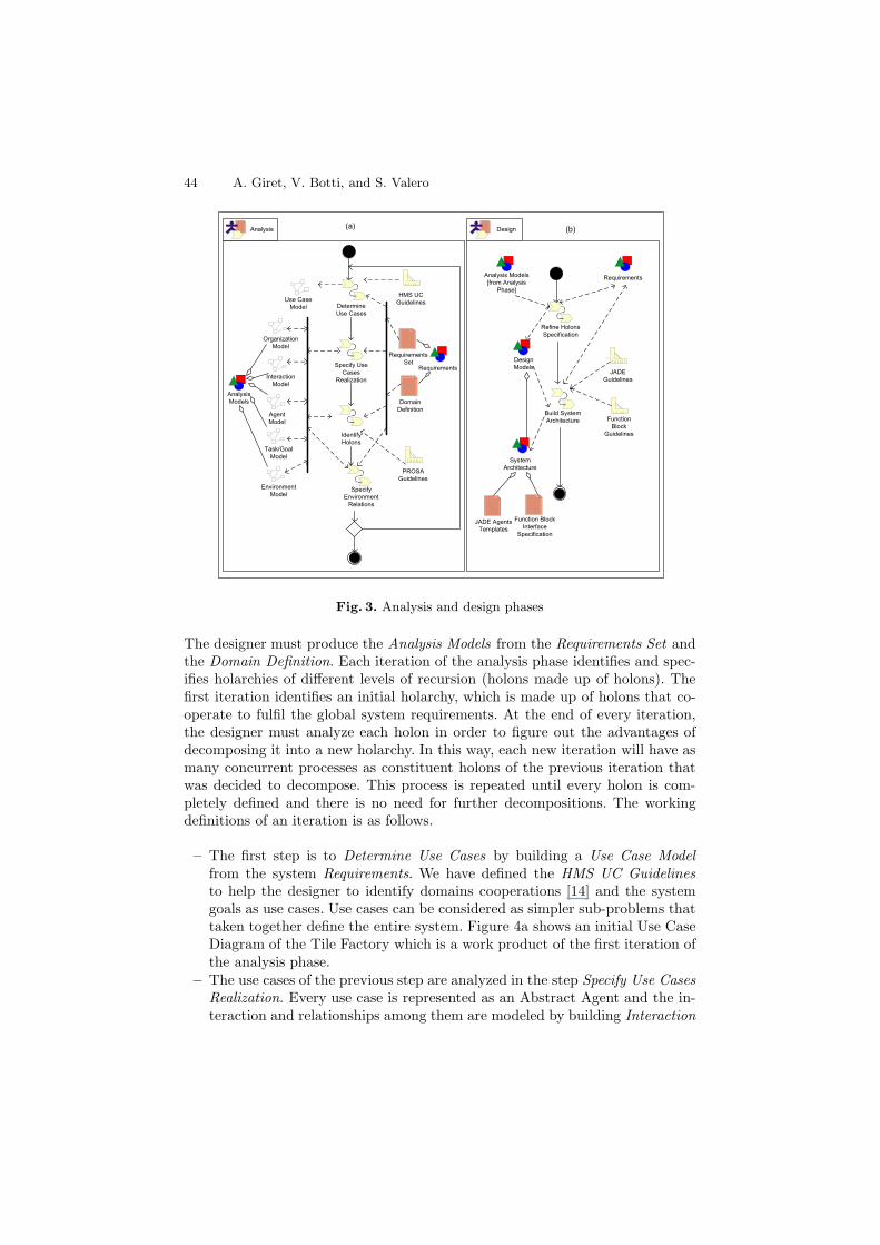
In the analysis phase (Figure 3a), the designer must specify the HMS in termsof the models presented in Section 4.1 and the UML Use Case Diagrams. This isa top-down, recursive, incremental process. The main goal of the analysis phaseis to identify the constituent holons and to provide an initial holon specification.
2 The case study requirements where defined in a joint research project between theGTI-IA group and the CIGIP group of the Polytechnic University of Valencia.
44 A. Giret, V. Botti, and S. Valero
RequirementsSet
DomainDefinition
Use CaseModel
Requirements
HMS UCGuidelinesDetermine
Use Cases
Specify UseCases
RealizationInteractionModel
OrganizationModel
IdentifyHolons
PROSAGuidelines
Task/GoalModel
EnvironmentModel
SpecifyEnvironment
Relations
AnalysisModels
Analysis Design
AgentModel
Refine HolonsSpecification
Build SystemArchitecture
DesignModels
Analysis Models[from Analysis
Phase]
Requirements
JADEGuidelines
FunctionBlock
Guidelines
SystemArchitecture
Function BlockInterface
Specification
JADE AgentsTemplates
(a) (b)
Fig. 3. Analysis and design phases
The designer must produce the Analysis Models from the Requirements Set andthe Domain Definition. Each iteration of the analysis phase identifies and spec-ifies holarchies of different levels of recursion (holons made up of holons). Thefirst iteration identifies an initial holarchy, which is made up of holons that co-operate to fulfil the global system requirements. At the end of every iteration,the designer must analyze each holon in order to figure out the advantages ofdecomposing it into a new holarchy. In this way, each new iteration will have asmany concurrent processes as constituent holons of the previous iteration thatwas decided to decompose. This process is repeated until every holon is com-pletely defined and there is no need for further decompositions. The workingdefinitions of an iteration is as follows.
– The first step is to Determine Use Cases by building a Use Case Modelfrom the system Requirements. We have defined the HMS UC Guidelinesto help the designer to identify domains cooperations [14] and the systemgoals as use cases. Use cases can be considered as simpler sub-problems thattaken together define the entire system. Figure 4a shows an initial Use CaseDiagram of the Tile Factory which is a work product of the first iteration ofthe analysis phase.
– The use cases of the previous step are analyzed in the step Specify Use CasesRealization. Every use case is represented as an Abstract Agent and the in-teraction and relationships among them are modeled by building Interaction
MAS Methodology for HMS 45
Sell Tile
Buy RawMaterials
Tile Design
ManufactureCeramic Tile
Analysis ofForecasted Sales
Plan ProductionProcess
Schedule and Controlof Production Tasks Make Tile
Store FinishedProducts
<<Extends>>
<<Extends>>
<<Extends>>
<<Extends>>
<<Extends>>
(a) UML Use Case Model
(b) Interaction Model
Factory
A
Scheduler
APlanner
Alot scheduling<<iniciates>>
<<cooperates>>
Define NewSchedule
ModifySchedule
A
Plan
<<consumes>>
ANew
Schedule
<<produces>>
AInitial
Schedule
<<consumes>>
AModifiedSchedule
<<produces>>
NewOrder
FactoryFailure
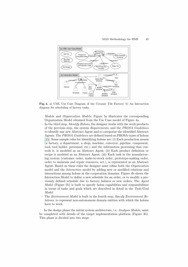
Fig. 4. a) UML Use Case Diagram of the Ceramic Tile Factory. b) An Interaction
diagram for scheduling of factory tasks.
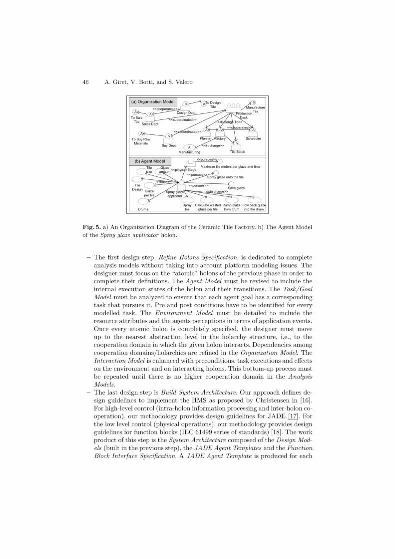
Models and Organization Models. Figure 5a illustrates the correspondingOrganization Model obtained from the Use Case model of Figure 4a.
– In the third step, Identify Holons, the designer works with the work productsof the previous step, the system Requirements, and the PROSA Guidelinesto identify any new Abstract Agent and to categorize the identified AbstractAgents. The PROSA Guidelines are defined based on PROSA types of holons[15]. Some sample rules for identifying holons are: (i) Each production means(a factory, a department, a shop, machine, conveyor, pipeline, component,tool, tool holder, personnel, etc.) and the information processing that con-trols it, is modeled as an Abstract Agent; (ii) Each product definition orrecipe is modeled as an Abstract Agent; (iii) Each task in the manufactur-ing system (customer order, make-to-stock order, prototype-making order,order to maintain and repair resources, ect.), is represented as an AbstractAgent. Based on these rules the designer must refine both the Organizationmodel and the Interaction model by adding new or modified relations andinteractions among holons in the cooperation domains. Figure 4b shows theInteraction Model to define a new schedule for an order, or to modify a pre-viously defined schedule due to factory failures or new orders. The AgentModel (Figure 5b) is built to specify holon capabilities and responsibilitiesin terms of tasks and goals which are described in detail in the Task/GoalModel.
– The Environment Model is built in the fourth step, Specify Environment Re-lations, to represent non-autonomous domain entities with which the holonshave to work.
In the design phase the initial system architecture, i.e. Analysis Models, mustbe completed with details of the target implementation platform (Figure 3b).This phase is divided into two steps.
46 A. Giret, V. Botti, and S. Valero
(a) Organization Model
(b) Agent Model
Tile Stock
AScheduler
A
Factory
A
Planner
A
Buy Dept.
A
A
Sales Dept.
Design Dept.
A
<<Belongs To>>
GManufacture
TileProductionDept.
<<cooperates>>
<<subordinated>>
<<subordinated>>To SaleTile
To DesignTile
A
A
A
To Buy RawMaterials <<in charge>>
<<cooperates>>
ManufacturingA
Spray glazeapplicator
Spray glaze onto the tile
Save glaze
<<pursues>>
<<pursues>>Glazeper tile
Glazeamount
TileDesign
Tilesize
Flow back glazeinto the drum
Pump glazefrom drum
Calculate wastedglaze per tile
SpraytileDrums
<<has>>
Stage<<plays>>Maximize tile meters per glaze and time
<<pursues>>
<<in charge>>
Fig. 5. a) An Organization Diagram of the Ceramic Tile Factory. b) The Agent Model
of the Spray glaze applicator holon.
– The first design step, Refine Holons Specification, is dedicated to completeanalysis models without taking into account platform modeling issues. Thedesigner must focus on the “atomic” holons of the previous phase in order tocomplete their definitions. The Agent Model must be revised to include theinternal execution states of the holon and their transitions. The Task/GoalModel must be analyzed to ensure that each agent goal has a correspondingtask that pursues it. Pre and post conditions have to be identified for everymodelled task. The Environment Model must be detailed to include theresource attributes and the agents perceptions in terms of application events.Once every atomic holon is completely specified, the designer must moveup to the nearest abstraction level in the holarchy structure, i.e., to thecooperation domain in which the given holon interacts. Dependencies amongcooperation domains/holarchies are refined in the Organization Model. TheInteraction Model is enhanced with preconditions, task executions and effectson the environment and on interacting holons. This bottom-up process mustbe repeated until there is no higher cooperation domain in the AnalysisModels.
– The last design step is Build System Architecture. Our approach defines de-sign guidelines to implement the HMS as proposed by Christensen in [16].For high-level control (intra-holon information processing and inter-holon co-operation), our methodology provides design guidelines for JADE [17]. Forthe low level control (physical operations), our methodology provides designguidelines for function blocks (IEC 61499 series of standards) [18]. The workproduct of this step is the System Architecture composed of the Design Mod-els (built in the previous step), the JADE Agent Templates and the FunctionBlock Interface Specification. A JADE Agent Template is produced for each
MAS Methodology for HMS 47
Function Block InterfaceSpecification
Agent ID
Normal Operation Sequence
Agent Platform
Resource BehaviourCommand
2ns
FB template code
Abnormal Operation Sequence
Actuator Sensor Output Time
3ns1ns1ns
Agent Task
Conveyor BeltHolon Factory KT, WD, MT
Divert Tile to BeltHC2
Incoming Tile detectedTarget Belt detectedConnect BeltsTile in target Belt
INIT
E_SEN_IN SEN_INSTOPPER_OUT E_SET_STOPPERE_SEND_STR A_ID
SEN_OUT_STRAIGHTE_SEND_STRE_RECV_ID NEW_ID
Can’t connect beltsStop source beltConnect BeltsTile in target Belt
Incoming Tile detectedTarget Belt detected
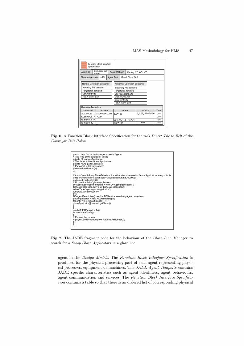
Fig. 6. A Function Block Interface Specification for the task Divert Tile to Belt of the
Conveyor Belt Holon
public class GlazeLineManager extends Agent {// The type of the applicator to findprivate String typeApplicator;// The list of known Glaze Applicatorsprivate AID[] glazeApplicator;// Put agent initializations hereprotected void setup() {….
//Add a SearchSprayGlazeBehaiour that schedules a request to Glaze Applicators every minuteaddBehaviour(new SearchSprayGlazeBehaiour(this, 60000) {protected void onTick() {// Update the list of glaze applicatorsDFAgentDescription template = new DFAgentDescription();ServiceDescription sd = new ServiceDescription();sd.setType(“spray-glaze-applicator”);template.addServices(sd);try {DFAgentDescription[] result = DFService.search(myAgent, template);glazeApplicator = new AID[result.length];for (int i = 0; i < result.length; ++i) {glazeApplicator[i] = result.getName();}}catch (FIPAException fe) {fe.printStackTrace();}// Perform the requestmyAgent.addBehaviour(new RequestPerformer());}} );...
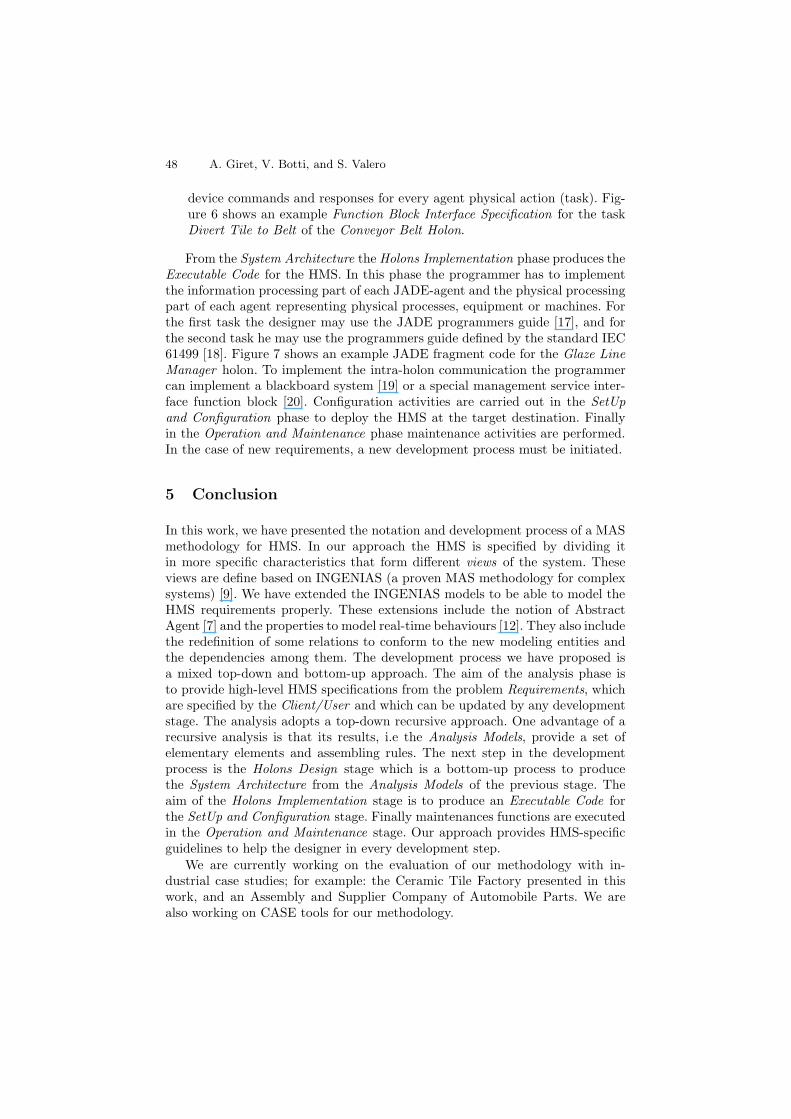
Fig. 7. The JADE fragment code for the behaviour of the Glaze Line Manager to
search for a Spray Glaze Applicators in a glaze line
agent in the Design Models. The Function Block Interface Specification isproduced for the physical processing part of each agent representing physi-cal processes, equipment or machines. The JADE Agent Template containsJADE specific characteristics such as agent identifiers, agent behaviours,agent communication and services. The Function Block Interface Specifica-tion contains a table so that there is an ordered list of corresponding physical
48 A. Giret, V. Botti, and S. Valero
device commands and responses for every agent physical action (task). Fig-ure 6 shows an example Function Block Interface Specification for the taskDivert Tile to Belt of the Conveyor Belt Holon.
From the System Architecture the Holons Implementation phase produces theExecutable Code for the HMS. In this phase the programmer has to implementthe information processing part of each JADE-agent and the physical processingpart of each agent representing physical processes, equipment or machines. Forthe first task the designer may use the JADE programmers guide [17], and forthe second task he may use the programmers guide defined by the standard IEC61499 [18]. Figure 7 shows an example JADE fragment code for the Glaze LineManager holon. To implement the intra-holon communication the programmercan implement a blackboard system [19] or a special management service inter-face function block [20]. Configuration activities are carried out in the SetUpand Configuration phase to deploy the HMS at the target destination. Finallyin the Operation and Maintenance phase maintenance activities are performed.In the case of new requirements, a new development process must be initiated.
5 Conclusion
In this work, we have presented the notation and development process of a MASmethodology for HMS. In our approach the HMS is specified by dividing itin more specific characteristics that form different views of the system. Theseviews are define based on INGENIAS (a proven MAS methodology for complexsystems) [9]. We have extended the INGENIAS models to be able to model theHMS requirements properly. These extensions include the notion of AbstractAgent [7] and the properties to model real-time behaviours [12]. They also includethe redefinition of some relations to conform to the new modeling entities andthe dependencies among them. The development process we have proposed isa mixed top-down and bottom-up approach. The aim of the analysis phase isto provide high-level HMS specifications from the problem Requirements, whichare specified by the Client/User and which can be updated by any developmentstage. The analysis adopts a top-down recursive approach. One advantage of arecursive analysis is that its results, i.e the Analysis Models, provide a set ofelementary elements and assembling rules. The next step in the developmentprocess is the Holons Design stage which is a bottom-up process to producethe System Architecture from the Analysis Models of the previous stage. Theaim of the Holons Implementation stage is to produce an Executable Code forthe SetUp and Configuration stage. Finally maintenances functions are executedin the Operation and Maintenance stage. Our approach provides HMS-specificguidelines to help the designer in every development step.
We are currently working on the evaluation of our methodology with in-dustrial case studies; for example: the Ceramic Tile Factory presented in thiswork, and an Assembly and Supplier Company of Automobile Parts. We arealso working on CASE tools for our methodology.
MAS Methodology for HMS 49
References
1. McFarlane, D., S., B.: Holonic Manufacturing Control: Rationales, Developmentsand Open Issues. In: Agent-Based Manufacturing. Advances in the Holonic Ap-proach. Springer-Verlag (2003) 301–326
2. Leitao, P., Restivo, F.: An Approach to the Formal Specification of Holonic ControlSystems. Holonic and Multi-Agent Systems for Manufacturing. LNAI 2744. ISSN0302-9743 (2003) 59–70
3. Fischer, K., Schillo, M., Siekmann, J.: Holonic Multiagent Systems: A Foundationfo Organisation of Multiagent Systems. Holonic and Multi-Agent Systems forManufacturing. LNAI 2744. ISSN 0302-9743 (2003) 71–80
4. HMS, P.R.: HMS Requirements. HMS Server, http://hms.ifw.uni-hannover.de/(1994)
5. Wooldridge, M., Jennings, N.R.: Intelligent Agents - Theories, Architectures, andLanguages. Lecture Notes in Artificia Intelligence, Springer-Verlag. ISBN 3-540-58855-8 890 (1995)
6. Giret, A., Botti, V.: Holons and Agents. Journal of Intelligent Manufacturing 15(2004) 645–659
7. Giret, A., Botti, V.: Towards an Abstract Recursive Agent. Integrated Computer-Aided Engineering 11 (2004) 165–177
8. Bussmann, S., Jennings, N., Wooldridge, M.: Multiagent Systems for Manufactur-ing Control. A design Methodology. Springer Verlag (2004)
9. Pavon, J., Gomez, J.: Agent Oriented Software Engineering with INGENIAS. 3rdInternational Central and Eastern European Conference on Multi-Agent Systems(CEEMAS 2003) : V. Marik, J. Mller, M. Pechoucek:Multi-Agent Systems andApplications II, LNAI 2691 (2003) 394–403
10. Giret, A., Botti, V.: Towards a Recursive Agent Oriented Methodology for Large-Scale MAS. Agent-Oriented Software Engineering IV. LNCS 2935 (2004) 25–35
11. Giret, A., Botti, V.: On the definition of meta-models for analysis of large-scaleMAS. In: Multiagent System Technologies. LNAI 3187 (2004) 273–286
12. Julian, V., Botti, V.: Developing real-time multiagent systems. IntegratedComputer-Aided Engineering 11 (2004) 135–149
13. OMG, O.M.G.: Software Process Engineering Metamodel Specification Version1.0. http://www.omg.org/docs/formal/02-11-14.pdf (2002)
14. Fletcher, M., Garcia-Herreros, E., Chritensen, J., Deen, S., Mittmann, R.: AnOpen Architecture for Holonic Cooperation and Autonomy. Proceeding of Holo-MAS’2000 (2000)
15. Van Brussel, H., Wyns, J., Valckenaers, P., Bongaerts, L., Peeters, P.: ReferenceArchitecture for Holonic Manufacturing Systems: PROSA. Computers In Industry37 (1998) 255–274
16. Christensen, J.: HMS/FB Architecture and Its Implementation. In: Agent-BasedManufacturing. Advances in the Holonic Approach. Springer Verlag (2003) 53–88
17. JADE: Java Agent DEvelopment Framework. http://jade.tilab.com/ (2005)18. IEC: International Electrotechnical Commission: Function Blocks, Part 1 - Soft-
ware Tool Requirenments.PAS 61499-2. (2001)19. McFarlane, D., Kollingbaum, M., Matson, J., Valckenaers, P.: Development of
algorithms for agent-oriented control of manufacturing flow shops. In: Proceedingsof the IEEE International Conference on Systems, Man and Cybernetics. (2001)
20. Fletcher, M., Brennan, R.: Designing a holonic control system with iec 61499function blocks. In: Proceedings of the International Conference on IntelligentModeling and Control. (2001)


