Embed Size (px)
Citation preview

Master Control
Tally ProcessorUser’s Guide
Miranda Technologies Inc.3499 Douglas B. Floreani
Montreal, QuebecCanada H4S 2C6
NV5100MC / NV5128-MC User’s Guide• Revision: 1.0
• Software Version: 7.2.0.0
• Part Number: UG0068-00
• Copyright: © 2011 Miranda Technologies. All rights reserved.
• No part of this manual may be reproduced in any form by photocopy, microfilm, xerography or any other means, or incorporated into any information retrieval system, electronic or mechani-cal, without the written permission of Miranda Technologies, Inc.
• The information contained in this manual is subject to change without notice or obligation.
• All title and copyrights as well as trade secret, patent and other proprietary rights in and to the Software Product (including but not limited to any images, photographs, animations, video, audio, music, test, and “applets” incorporated into the Software Product), the accompanying printed materials, and any copies of the Software Product, are owned by Miranda Technologies, Inc. The Software Product is protected by copyright laws and international treaty provisions. Customer shall not copy the printed materials accompanying the software product.
NoticeThe software contains proprietary information of Miranda Technologies, Inc. It is provided under a license agreement containing restrictions on use and disclosure and is also protected by copyright law. Reverse engineering of the software is prohibited.
Due to continued product development, the accuracy of the information in this document may change without notice. The information and intellectual property contained herein is confidential between Miranda and the client and remains the exclusive property of Miranda. If you find any problems in the documentation, please report them to us in writing. Miranda does not warrant that this document is error-free.
FCC Statement This equipment has been tested and found to comply with the limits for a Class A digital device, pursuant to part 15 of the FCC Rules. These limits are designed to provide reasonable protection against harmful interference when the equipment is operated in a commercial environment. This equipment generates, uses, and can radiate radio frequency energy and, if not installed and used in accordance with the instruction manual, may cause harmful interference to radio communications. Operation of this equipment in a residential area is likely to cause harmful interference in which case the user will be required to correct the interference at his own expense.
Declaration of Conformance (CE) All of the equipment described in this manual has been designed to conform with the required safety and emissions standards of the European Community. Products tested and verified to meet these standards are marked as required by law with the CE mark. (See Symbols and Their Mean-ings on page v.)
ii Rev 1.0 • 29 Nov 11
When shipped into member countries of the European Community, this equipment is accompanied by authentic copies of original Declarations of Conformance on file in Miranda GVD offices in Grass Valley, California USA.
TrademarksMiranda is a registered trademark of Miranda Technologies, Inc.
Brand and product names mentioned in this manual may be trademarks, registered trademarks or copyrights of their respective holders. All brand and product names mentioned in this manual serve as comments or examples and are not to be understood as advertising for the products or their man-ufactures.
Software License Agreement and Warranty InformationContact Miranda for details on the software license agreement and product warranty.
Technical Support Contact Information Miranda has made every effort to ensure that the equipment you receive is in perfect working order and that the equipment fits your needs. In the event that problems arise that you cannot resolve, or if there are any questions regarding this equipment or information about other products manufac-tured by Miranda, please contact your local representative or contact Miranda directly through one of the appropriate means listed here.
• Main telephone: 530-265-1000 (9 am to 9 pm PST)Fax: 530-265-1021
In the Americas, call toll-free: +1-800-224-7882 (9 am to 9 pm EST)In Europe, the Middle East, Africa, or the UK, call +44 118 952 3444 (9 am to 6 pm, GMT)In France, call +33 1 55 86 87 88 (9 am to 5 pm, GMT + 1)In Asia, call +852-2539-6987 (9 am to 5 pm, GMT + 8)In China, call +86-10-5873-1814
• Emergency after hours: toll-free: +1-800-224-7882Tel: +1-514-333-1772
• E-Mail:
In the Americas, [email protected] Europe, the Middle East, African or the UK, [email protected] France, [email protected] Asia, [email protected] China, [email protected]
• Website: http://www.miranda.com
• Mail Shipping
Miranda GVD Miranda GVDP.O. Box 1658 125 Crown Point CourtNevada City, CA 95959, USA Grass Valley, CA 95945, USA
Note Return Material Authorization (RMA) required for all returns.
Master Control • Tally Processor User’s Guide iii

Change HistoryThe table below lists the changes to the Master Control User’s Guide.
• User’s Guide Part # UG0068-00
• Software version: 7.2.0.0
Rev Date ECO Description Approved By
1.0 29 Nov 11 17941 Conforms to software version 7.2.0. This document started as a copy of UG0036.
D. Cox
iv Rev 1.0 • 29 Nov 11
Important Safeguards and NoticesThis section provides important safety guidelines for operators and service personnel. Specific warnings and cautions appear throughout the manual where they apply. Please read and follow this important information, especially those instructions related to the risk of electric shock or injury to persons.
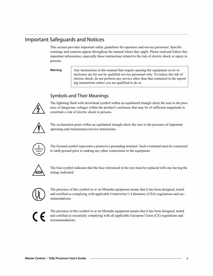
Symbols and Their Meanings
The lightning flash with arrowhead symbol within an equilateral triangle alerts the user to the pres-ence of dangerous voltages within the product’s enclosure that may be of sufficient magnitude to constitute a risk of electric shock to persons.
The exclamation point within an equilateral triangle alerts the user to the presence of important operating and maintenance/service instructions.
The Ground symbol represents a protective grounding terminal. Such a terminal must be connected to earth ground prior to making any other connections to the equipment.
The fuse symbol indicates that the fuse referenced in the text must be replaced with one having the ratings indicated.
The presence of this symbol in or on Miranda equipment means that it has been designed, tested and certified as complying with applicable Underwriter’s Laboratory (USA) regulations and rec-ommendations.
The presence of this symbol in or on Miranda equipment means that it has been designed, tested and certified as essentially complying with all applicable European Union (CE) regulations and recommendations.
Warning Any instructions in this manual that require opening the equipment cover or enclosure are for use by qualified service personnel only. To reduce the risk of electric shock, do not perform any service other than that contained in the operat-ing instructions unless you are qualified to do so.
Master Control • Tally Processor User’s Guide v
General Warnings
A warning indicates a possible hazard to personnel which may cause injury or death. Observe the following general warnings when using or working on this equipment:
• Heed all warnings on the unit and in the operating instructions.
• Do not use this equipment in or near water.
• This equipment is grounded through the grounding conductor of the power cord. To avoid elec-trical shock, plug the power cord into a properly wired receptacle before connecting the equip-ment inputs or outputs.
• Route power cords and other cables so they are not likely to be damaged.
• Disconnect power before cleaning the equipment. Do not use liquid or aerosol cleaners; use only a damp cloth.
• Dangerous voltages may exist at several points in this equipment. To avoid injury, do not touch exposed connections and components while power is on.
• Do not wear rings or wristwatches when troubleshooting high current circuits such as the power supplies.
• To avoid fire hazard, use only the specified fuse(s) with the correct type number, voltage and current ratings as referenced in the appropriate locations in the service instructions or on the equipment. Always refer fuse replacements to qualified service personnel.
• To avoid explosion, do not operate this equipment in an explosive atmosphere.
• Have qualified service personnel perform safety checks after any service.
General Cautions
A caution indicates a possible hazard to equipment that could result in equipment damage. Observe the following cautions when operating or working on this equipment:
• When installing this equipment, do not attach the power cord to building surfaces.
• To prevent damage to equipment when replacing fuses, locate and correct the problem that caused the fuse to blow before re-applying power.
• Use only the specified replacement parts.
• Follow static precautions at all times when handling this equipment.
• This product should only be powered as described in the manual. To prevent equipment dam-age, select the proper line voltage on the power supply(ies) as described in the installation doc-umentation.
• To prevent damage to the equipment, read the instructions in the equipment manual for proper input voltage range selection.
• Some products include a backup battery. There is a risk of explosion if the battery is replaced by a battery of an incorrect type. Dispose of batteries according to instructions.
• Products that have (1) no on/off switch and (2) use an external power supply must be installed in proximity to a main power output that is easily accessible.
vi Rev 1.0 • 29 Nov 11
Table of Contents
Chapter 1 Tally Processor . . . . . . . . . . . . . . . . . . . . . . . . . . . . . . . . . . . . . . . . . . . . . . . . . . . . . . . . . . . . 1Introduction . . . . . . . . . . . . . . . . . . . . . . . . . . . . . . . . . . . . . . . . . . . . . . . . . . . . . . . . . . . . . . . . . . . 1External Features . . . . . . . . . . . . . . . . . . . . . . . . . . . . . . . . . . . . . . . . . . . . . . . . . . . . . . . . . . . . . . . 2
Front . . . . . . . . . . . . . . . . . . . . . . . . . . . . . . . . . . . . . . . . . . . . . . . . . . . . . . . . . . . . . . . . . . . . . 2Rear . . . . . . . . . . . . . . . . . . . . . . . . . . . . . . . . . . . . . . . . . . . . . . . . . . . . . . . . . . . . . . . . . . . . . 2
Initial Setup . . . . . . . . . . . . . . . . . . . . . . . . . . . . . . . . . . . . . . . . . . . . . . . . . . . . . . . . . . . . . . . . . . . 3Entering IP and Mask. . . . . . . . . . . . . . . . . . . . . . . . . . . . . . . . . . . . . . . . . . . . . . . . . . . . . . . . 3
Set the IP address . . . . . . . . . . . . . . . . . . . . . . . . . . . . . . . . . . . . . . . . . . . . . . . . . . . . . . . 3Using the Configuration Tool . . . . . . . . . . . . . . . . . . . . . . . . . . . . . . . . . . . . . . . . . . . . . . . . . . . . . 4
System . . . . . . . . . . . . . . . . . . . . . . . . . . . . . . . . . . . . . . . . . . . . . . . . . . . . . . . . . . . . . . . . . . . 5Protocol Assignment . . . . . . . . . . . . . . . . . . . . . . . . . . . . . . . . . . . . . . . . . . . . . . . . . . . . . . . . 6
PHY Config . . . . . . . . . . . . . . . . . . . . . . . . . . . . . . . . . . . . . . . . . . . . . . . . . . . . . . . . . . . 6Event Definitions . . . . . . . . . . . . . . . . . . . . . . . . . . . . . . . . . . . . . . . . . . . . . . . . . . . . . . . 6
Event Monitoring . . . . . . . . . . . . . . . . . . . . . . . . . . . . . . . . . . . . . . . . . . . . . . . . . . . . . . . . . . . 9GPI . . . . . . . . . . . . . . . . . . . . . . . . . . . . . . . . . . . . . . . . . . . . . . . . . . . . . . . . . . . . . . . . . . . . 11GPO . . . . . . . . . . . . . . . . . . . . . . . . . . . . . . . . . . . . . . . . . . . . . . . . . . . . . . . . . . . . . . . . . . . . 12Combinational Events . . . . . . . . . . . . . . . . . . . . . . . . . . . . . . . . . . . . . . . . . . . . . . . . . . . . . . 13Remote Events . . . . . . . . . . . . . . . . . . . . . . . . . . . . . . . . . . . . . . . . . . . . . . . . . . . . . . . . . . . 15
Chapter 2 Misc. Topics . . . . . . . . . . . . . . . . . . . . . . . . . . . . . . . . . . . . . . . . . . . . . . . . . . . . . . . . . . . . . . 17PC Configuration . . . . . . . . . . . . . . . . . . . . . . . . . . . . . . . . . . . . . . . . . . . . . . . . . . . . . . . . . . . . . 17Connectors . . . . . . . . . . . . . . . . . . . . . . . . . . . . . . . . . . . . . . . . . . . . . . . . . . . . . . . . . . . . . . . . . . 19
GPIO . . . . . . . . . . . . . . . . . . . . . . . . . . . . . . . . . . . . . . . . . . . . . . . . . . . . . . . . . . . . . . . . . . . 19Power . . . . . . . . . . . . . . . . . . . . . . . . . . . . . . . . . . . . . . . . . . . . . . . . . . . . . . . . . . . . . . . . . . . 20
Notes . . . . . . . . . . . . . . . . . . . . . . . . . . . . . . . . . . . . . . . . . . . . . . . . . . . . . . . . . . . . . . . . . . . . . . . 20General . . . . . . . . . . . . . . . . . . . . . . . . . . . . . . . . . . . . . . . . . . . . . . . . . . . . . . . . . . . . . . 20Saved Files . . . . . . . . . . . . . . . . . . . . . . . . . . . . . . . . . . . . . . . . . . . . . . . . . . . . . . . . . . . 20Under System Menu. . . . . . . . . . . . . . . . . . . . . . . . . . . . . . . . . . . . . . . . . . . . . . . . . . . . 20
Index . . . . . . . . . . . . . . . . . . . . . . . . . . . . . . . . . . . . . . . . . . . . . . . . . . . . . . . . . . . . . . . . . . . . . . . . . . 21
Master Control • Tally Processor User’s Guide vii

Table of Contents
viii Rev 1.0 • 15 Jul 11
1. Tally Processor
Miranda offers a third-party “tally processor” as an adjunct to its master control system. It is a GTP-32 from DNF Controls. Because it is third-party equipment, support for it is limited.
This brief guide is the only documentation for the tally processor. There is none from the manufac-turer.
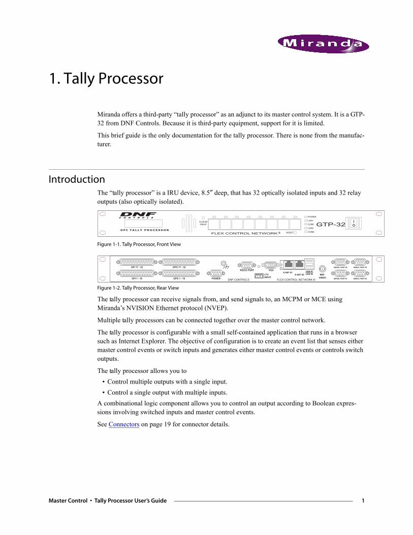
IntroductionThe “tally processor” is a IRU device, 8.5″ deep, that has 32 optically isolated inputs and 32 relay outputs (also optically isolated).
Figure 1-1. Tally Processor, Front View
Figure 1-2. Tally Processor, Rear View
The tally processor can receive signals from, and send signals to, an MCPM or MCE using Miranda’s NVISION Ethernet protocol (NVEP).
Multiple tally processors can be connected together over the master control network.
The tally processor is configurable with a small self-contained application that runs in a browser such as Internet Explorer. The objective of configuration is to create an event list that senses either master control events or switch inputs and generates either master control events or controls switch outputs.
The tally processor allows you to • Control multiple outputs with a single input.• Control a single output with multiple inputs.
A combinational logic component allows you to control an output according to Boolean expres-sions involving switched inputs and master control events.
See Connectors on page 19 for connector details.
�����
��
���
��
���
����� �������������������������
����������� ��
������������ ���
���� � � � � �
���������
����������
���������
���������� �� ��
������� ���
��������������
�������������
�������������
��������������
���������
���������������
��������������������
��������
!���������
�����������
Master Control • Tally Processor User’s Guide 1
1. Tally ProcessorExternal Features
External Features
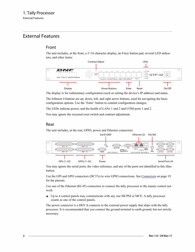
FrontThe unit includes, at the front, a 2×16 character display, an 8-key button pad, several LED indica-tors, and other items:
The display is for rudimentary configuration (such as setting the device’s IP address) and status.
The leftmost 4 buttons are up, down, left, and right arrow buttons, used for navigating the basic configuration options. Use the ‘Enter’ button to commit configuration changes.
The LEDs indicate power, and the health of LANs 1 and 2 and COM ports 1 and 2.
You may ignore the recessed reset switch and contrast adjustment.
RearThe unit includes, at the rear, GPIO, power and Ethernet connectors:
You may ignore the serial ports, the video reference, and any of the ports not identified in this illus-tration.
Use the GPI and GPO connectors (DC37s) to wire GPIO connections. See Connectors on page 19 for the pinouts.
Use one of the Ethernet (RJ-45) connectors to connect the tally processor to the master control net-work.
Up to 4 control panels may communicate with any one MCPM or MCE. A tally processor counts as one of the control panels.
The power connector is a DE9. It connects to the external power supply that ships with the tally processor. It is recommended that you connect the ground terminal to earth ground, but not strictly necessary.
�����
��
���
��
���
����� �������������������������
����������� ��
������������ ���
���� � � � � �
Display Arrow Buttons Reset On/Off
Contrast Adjust
Enter
LEDs
���������
����������
���������
���������� �� ��
������� ���
��������������
�������������
�������������
��������������
���������
���������������
��������������������
��������
!���������
�����������
GPIs (1–32) Serial Ports (4)
Earth GND
Power
Vid. Ref.
GPOs (1–32)
Ethernet (2)
2 Rev 1.0 • 29 Nov 11
1. Tally ProcessorInitial Setup
Initial SetupThis is the basic procedure.
1 Plug in the tally processor at the DE9 power connection. Use the external power supply pro-vided.
2 Use a CAT5 Ethernet cable to connect the tally processor to the Ethernet switch servicing the master control network. Use the port labeled “E-net #1.” Using the front panel of the tally processor, enter its IP address on the master control network and verify that its mask is 255.255.255.0.
3 Cable the GPIOs (on the 4 DC37 connectors) to whatever devices you are using according to the design of your system. See Connectors on page 19 for the pinouts.
4 Using your configuration PC (presumed to be on the master control network already), launch your browser (e.g., Internet Explorer). Enter the IP address of the tally processor as the URL:
http://192.168.102.112 (This is just an example)The tally processor will run its self-contained configuration application:
http://192.168.102.112/cgi-bin/index.cgi
in which you may configure the tally processor’s event list, inputs, and outputs.
Before you can configure anything, you must enter your ID and password. The default or initial ID and password are (admin, controls). You can change the ID and password.
(You can change the time and date using the ‘System’ option of the configuration software.)
Entering IP and MaskThe front panel has a 2×16 character display and 8 function buttons.
Four of the function buttons (at the left) are arrows. The sixth button is ‘Enter’. These buttons are used to navigate through the tally processor’s menu system.
To scroll through the list of options, press the up or down arrows until you come to an option you want to set or change.
Set the IP address
Scroll up or down so that the display shows ‘Current IP1’. Press ‘Enter’.
An underline cursor appears at the first digit of the IP address. Use the left and right arrows to move to a digit you want to change. Then use the up/down arrows to change the value of the digit. When you have finished, press ‘Enter’ once again.
Pressing the ‘Esc’ button terminates the operation and leaves the value unchanged.
Do the same for the IP subnet mask. (The display should read ‘Current Mask1’.) The value should be 255.255.255.0.
Master Control • Tally Processor User’s Guide 3
1. Tally ProcessorUsing the Configuration Tool
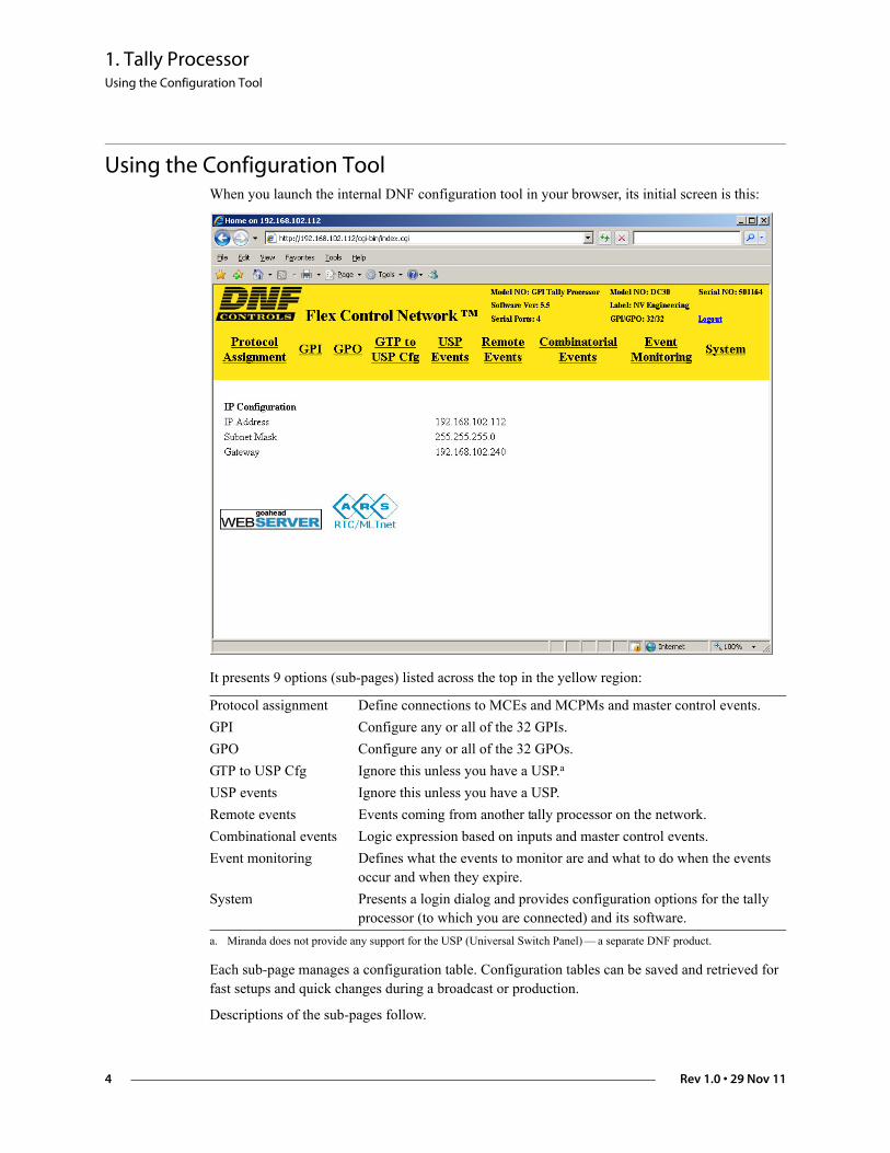
Using the Configuration ToolWhen you launch the internal DNF configuration tool in your browser, its initial screen is this:
It presents 9 options (sub-pages) listed across the top in the yellow region:
Each sub-page manages a configuration table. Configuration tables can be saved and retrieved for fast setups and quick changes during a broadcast or production.
Descriptions of the sub-pages follow.
Protocol assignment Define connections to MCEs and MCPMs and master control events.GPI Configure any or all of the 32 GPIs.GPO Configure any or all of the 32 GPOs.GTP to USP Cfg Ignore this unless you have a USP.a
a. Miranda does not provide any support for the USP (Universal Switch Panel) — a separate DNF product.
USP events Ignore this unless you have a USP.Remote events Events coming from another tally processor on the network.Combinational events Logic expression based on inputs and master control events. Event monitoring Defines what the events to monitor are and what to do when the events
occur and when they expire.System Presents a login dialog and provides configuration options for the tally
processor (to which you are connected) and its software.
4 Rev 1.0 • 29 Nov 11
1. Tally ProcessorUsing the Configuration Tool
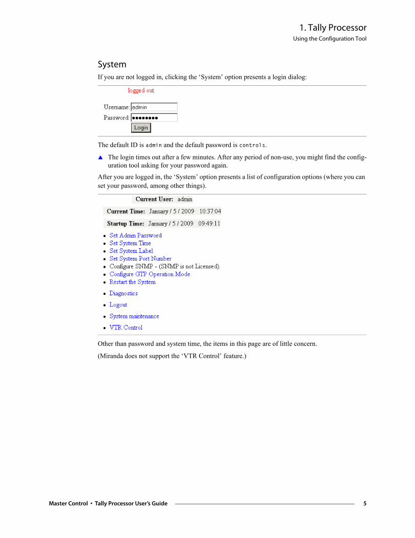
SystemIf you are not logged in, clicking the ‘System’ option presents a login dialog:
The default ID is admin and the default password is controls.
The login times out after a few minutes. After any period of non-use, you might find the config-uration tool asking for your password again.
After you are logged in, the ‘System’ option presents a list of configuration options (where you can set your password, among other things).
Other than password and system time, the items in this page are of little concern.
(Miranda does not support the ‘VTR Control’ feature.)
Master Control • Tally Processor User’s Guide 5
1. Tally ProcessorUsing the Configuration Tool
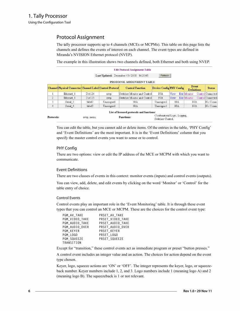
Protocol Assignment The tally processor supports up to 4 channels (MCEs or MCPMs). This table on this page lists the channels and defines the events of interest on each channel. The event types are defined in Miranda’s NVISION Ethernet protocol (NVEP).
The example in this illustration shows two channels defined, both Ethernet and both using NVEP.
You can edit the table, but you cannot add or delete items. Of the entries in the table, ‘PHY Config’ and ‘Event Definitions’ are the most important. It is in the ‘Event Definitions’ column that you specify the master control events you want to sense or to control.
PHY Config
There are two options: view or edit the IP address of the MCE or MCPM with which you want to communicate.
Event Definitions
There are two classes of events in this context: monitor events (inputs) and control events (outputs).
You can view, add, delete, and edit events by clicking on the word ‘Monitor’ or ‘Control’ for the table entry of choice.
Control Events
Control events play an important role in the ‘Event Monitoring’ table. It is through these event types that you can control an MCE or MCPM. These are the choices for the control event type:
PGM_AV_TAKE PRSET_AV_TAKEPGM_VIDEO_TAKE PRSET_VIDEO_TAKEPGM_AUDIO_TAKE PRSET_AUDIO_TAKEPGM_AUDIO_OVER PRSET_AUDIO_OVERPGM_KEYER PRSET_KEYERPGM_LOGO PRSET_LOGOPGM_SQUEEZE PRSET_SQUEEZETRANSITION
Except for “transition,” these control events act as immediate program or preset “button presses.” A control event includes an integer value and an action. The choices for action depend on the event type chosen. Keyer, logo, squeeze actions are ‘ON’ or ‘OFF’. The integer represents the keyer, logo, or squeeze-back number. Keyer numbers include 1, 2, and 3. Logo numbers include 1 (meaning logo A) and 2 (meaning logo B). The squeezeback is 1 or not relevant.
6 Rev 1.0 • 29 Nov 11
1. Tally ProcessorUsing the Configuration Tool
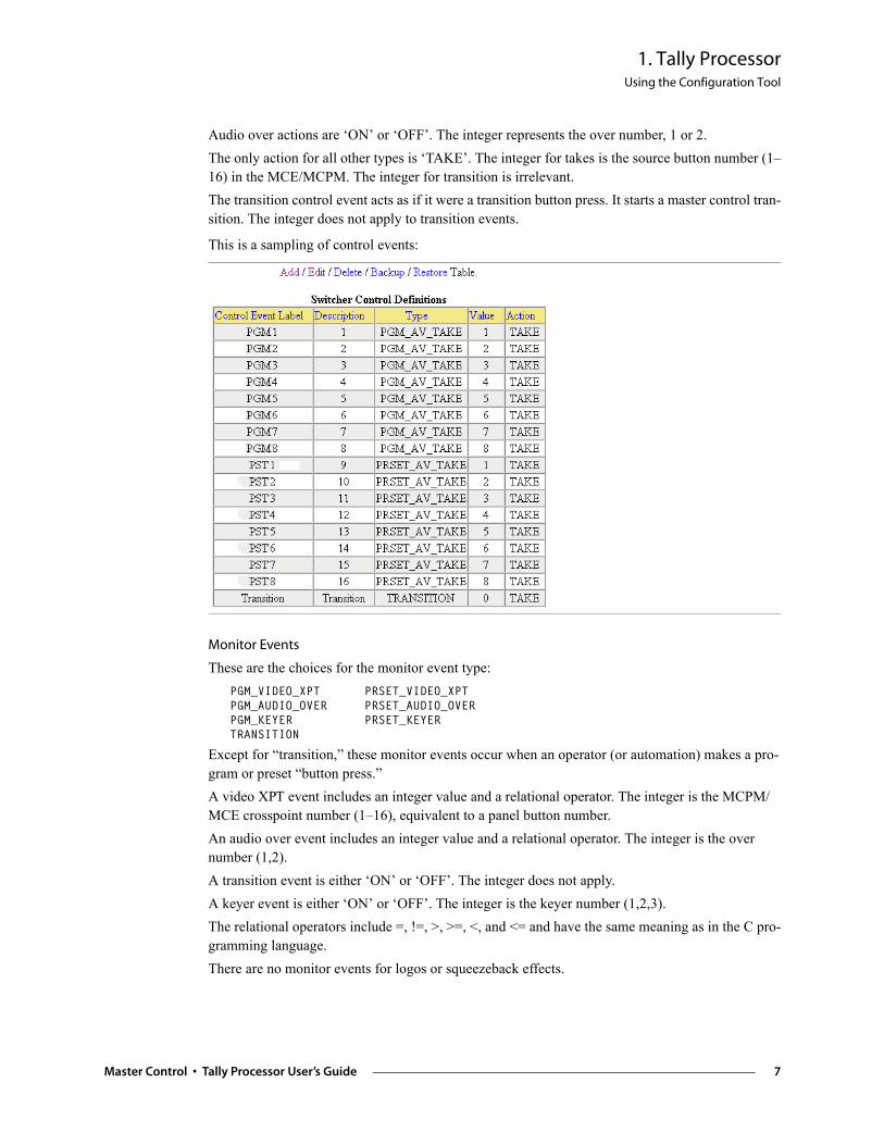
Audio over actions are ‘ON’ or ‘OFF’. The integer represents the over number, 1 or 2. The only action for all other types is ‘TAKE’. The integer for takes is the source button number (1–16) in the MCE/MCPM. The integer for transition is irrelevant.The transition control event acts as if it were a transition button press. It starts a master control tran-sition. The integer does not apply to transition events.
This is a sampling of control events:
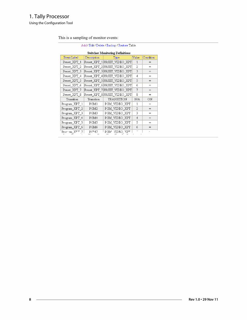
Monitor Events
These are the choices for the monitor event type: PGM_VIDEO_XPT PRSET_VIDEO_XPTPGM_AUDIO_OVER PRSET_AUDIO_OVERPGM_KEYER PRSET_KEYERTRANSITION
Except for “transition,” these monitor events occur when an operator (or automation) makes a pro-gram or preset “button press.” A video XPT event includes an integer value and a relational operator. The integer is the MCPM/MCE crosspoint number (1–16), equivalent to a panel button number.An audio over event includes an integer value and a relational operator. The integer is the over number (1,2).A transition event is either ‘ON’ or ‘OFF’. The integer does not apply.A keyer event is either ‘ON’ or ‘OFF’. The integer is the keyer number (1,2,3).The relational operators include =, !=, >, >=, <, and <= and have the same meaning as in the C pro-gramming language. There are no monitor events for logos or squeezeback effects.
Master Control • Tally Processor User’s Guide 7
1. Tally ProcessorUsing the Configuration Tool
This is a sampling of monitor events:
8 Rev 1.0 • 29 Nov 11
1. Tally ProcessorUsing the Configuration Tool
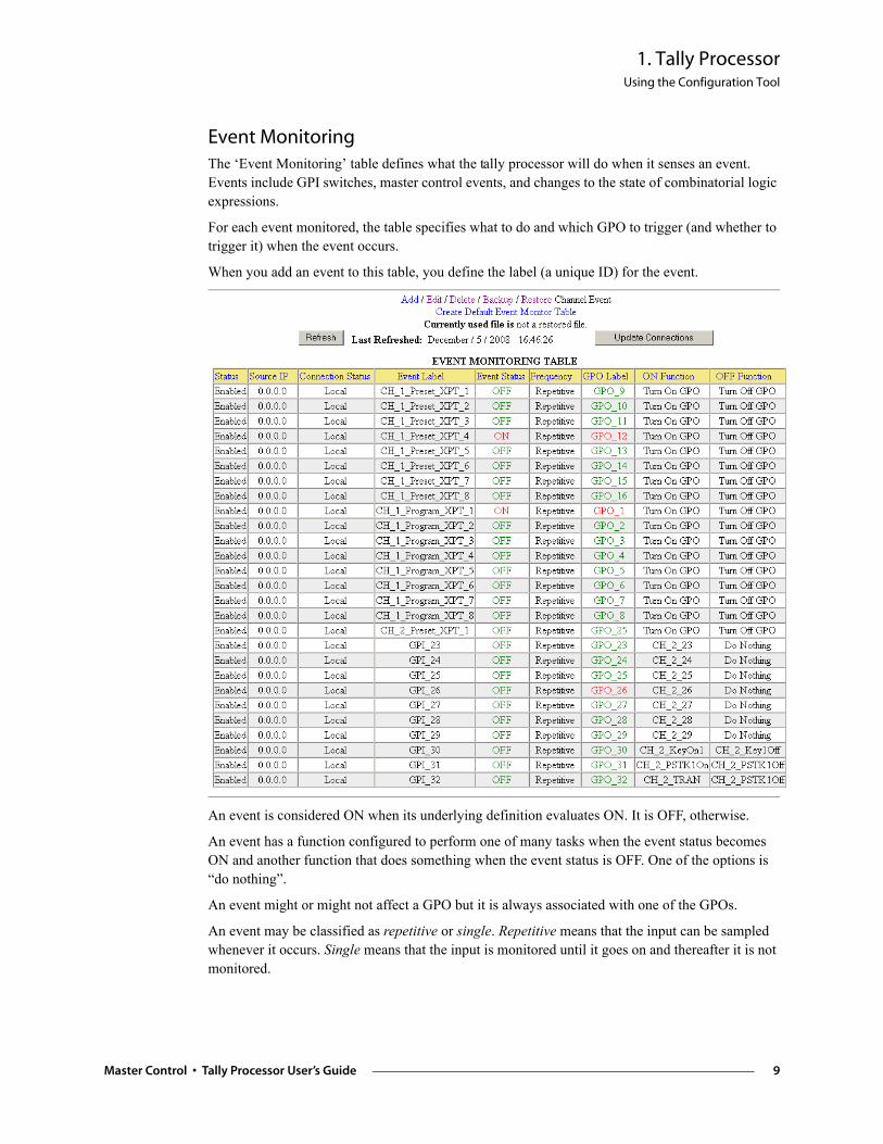
Event Monitoring The ‘Event Monitoring’ table defines what the tally processor will do when it senses an event. Events include GPI switches, master control events, and changes to the state of combinatorial logic expressions.
For each event monitored, the table specifies what to do and which GPO to trigger (and whether to trigger it) when the event occurs.
When you add an event to this table, you define the label (a unique ID) for the event.
An event is considered ON when its underlying definition evaluates ON. It is OFF, otherwise.
An event has a function configured to perform one of many tasks when the event status becomes ON and another function that does something when the event status is OFF. One of the options is “do nothing”.
An event might or might not affect a GPO but it is always associated with one of the GPOs.
An event may be classified as repetitive or single. Repetitive means that the input can be sampled whenever it occurs. Single means that the input is monitored until it goes on and thereafter it is not monitored.
Master Control • Tally Processor User’s Guide 9
1. Tally ProcessorUsing the Configuration Tool
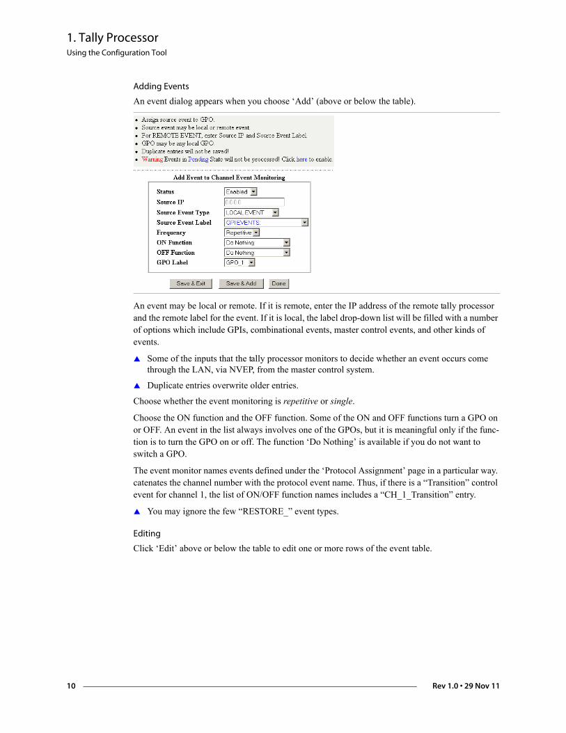
Adding Events
An event dialog appears when you choose ‘Add’ (above or below the table).
An event may be local or remote. If it is remote, enter the IP address of the remote tally processor and the remote label for the event. If it is local, the label drop-down list will be filled with a number of options which include GPIs, combinational events, master control events, and other kinds of events.
Some of the inputs that the tally processor monitors to decide whether an event occurs come through the LAN, via NVEP, from the master control system.
Duplicate entries overwrite older entries.
Choose whether the event monitoring is repetitive or single.
Choose the ON function and the OFF function. Some of the ON and OFF functions turn a GPO on or OFF. An event in the list always involves one of the GPOs, but it is meaningful only if the func-tion is to turn the GPO on or off. The function ‘Do Nothing’ is available if you do not want to switch a GPO.
The event monitor names events defined under the ‘Protocol Assignment’ page in a particular way. catenates the channel number with the protocol event name. Thus, if there is a “Transition” control event for channel 1, the list of ON/OFF function names includes a “CH_1_Transition” entry.
You may ignore the few “RESTORE_” event types.
Editing
Click ‘Edit’ above or below the table to edit one or more rows of the event table.
10 Rev 1.0 • 29 Nov 11
1. Tally ProcessorUsing the Configuration Tool
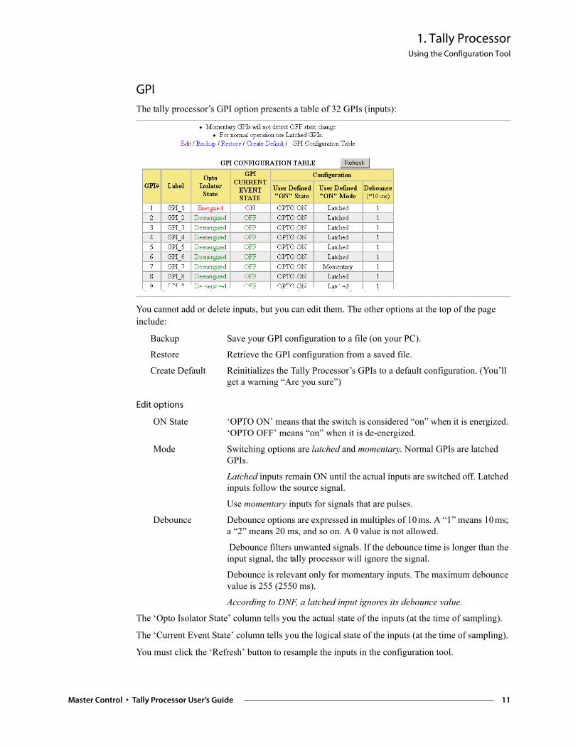
GPI
The tally processor’s GPI option presents a table of 32 GPIs (inputs):
You cannot add or delete inputs, but you can edit them. The other options at the top of the page include:
Backup Save your GPI configuration to a file (on your PC).
Restore Retrieve the GPI configuration from a saved file.
Create Default Reinitializes the Tally Processor’s GPIs to a default configuration. (You’ll get a warning “Are you sure”)
Edit options
ON State ‘OPTO ON’ means that the switch is considered “on” when it is energized. ‘OPTO OFF’ means “on” when it is de-energized.
Mode Switching options are latched and momentary. Normal GPIs are latched GPIs.
Latched inputs remain ON until the actual inputs are switched off. Latched inputs follow the source signal.
Use momentary inputs for signals that are pulses.
Debounce Debounce options are expressed in multiples of 10 ms. A “1” means 10ms; a “2” means 20 ms, and so on. A 0 value is not allowed.
Debounce filters unwanted signals. If the debounce time is longer than the input signal, the tally processor will ignore the signal.
Debounce is relevant only for momentary inputs. The maximum debounce value is 255 (2550 ms).
According to DNF, a latched input ignores its debounce value.
The ‘Opto Isolator State’ column tells you the actual state of the inputs (at the time of sampling).
The ‘Current Event State’ column tells you the logical state of the inputs (at the time of sampling).
You must click the ‘Refresh’ button to resample the inputs in the configuration tool.
Master Control • Tally Processor User’s Guide 11
1. Tally ProcessorUsing the Configuration Tool
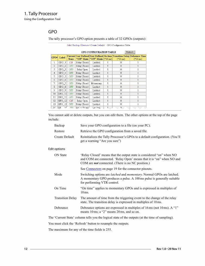
GPO
The tally processor’s GPO option presents a table of 32 GPIOs (outputs):
You cannot add or delete outputs, but you can edit them. The other options at the top of the page include:
Backup Save your GPO configuration to a file (on your PC).
Restore Retrieve the GPO configuration from a saved file.
Create Default Reinitializes the Tally Processor’s GPOs to a default configuration. (You’ll get a warning “Are you sure”)
Edit options
ON State ‘Relay Closed’ means that the output state is considered “on” when NO and COM are connected. ‘Relay Open’ means that it is “on” when NO and COM are not connected. (There is no NC position.)
See Connectors on page 19 for the connector pinouts.
Mode Switching options are latched and momentary. Normal GPOs are latched. A momentary GPO produces a pulse. A 100 ms pulse is generally suitable for performing VTR control.
On Time “On time” applies to momentary GPOs and is expressed in multiples of 10 ms.
Transition Delay The amount of time from the triggering event to the change of the relay state. The transition delay is expressed in multiples of 10 ms.
Debounce Debounce options are expressed in multiples of 16 ms (not 10ms). A “1” means 10 ms; a “2” means 20 ms, and so on.
The ‘Current State’ column tells you the logical state of the outputs (at the time of sampling).
You must click the ‘Refresh’ button to resample the outputs.
The maximum for any of the time fields is 255.
12 Rev 1.0 • 29 Nov 11
1. Tally ProcessorUsing the Configuration Tool
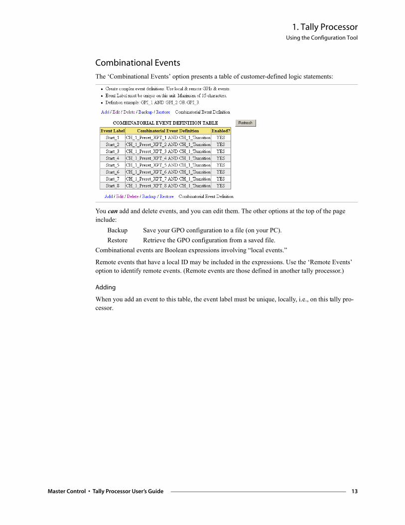
Combinational Events
The ‘Combinational Events’ option presents a table of customer-defined logic statements:
You can add and delete events, and you can edit them. The other options at the top of the page include:
Backup Save your GPO configuration to a file (on your PC).Restore Retrieve the GPO configuration from a saved file.
Combinational events are Boolean expressions involving “local events.”
Remote events that have a local ID may be included in the expressions. Use the ‘Remote Events’ option to identify remote events. (Remote events are those defined in another tally processor.)
Adding
When you add an event to this table, the event label must be unique, locally, i.e., on this tally pro-cessor.
Master Control • Tally Processor User’s Guide 13
1. Tally ProcessorUsing the Configuration Tool
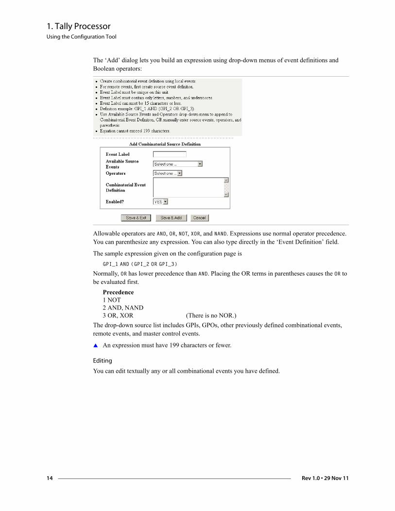
The ‘Add’ dialog lets you build an expression using drop-down menus of event definitions and Boolean operators:
Allowable operators are AND, OR, NOT, XOR, and NAND. Expressions use normal operator precedence. You can parenthesize any expression. You can also type directly in the ‘Event Definition’ field.
The sample expression given on the configuration page isGPI_1 AND (GPI_2 OR GPI_3)
Normally, OR has lower precedence than AND. Placing the OR terms in parentheses causes the OR to be evaluated first.
Precedence1 NOT2 AND, NAND3 OR, XOR (There is no NOR.)
The drop-down source list includes GPIs, GPOs, other previously defined combinational events, remote events, and master control events.
An expression must have 199 characters or fewer.
Editing
You can edit textually any or all combinational events you have defined.
14 Rev 1.0 • 29 Nov 11
1. Tally ProcessorUsing the Configuration Tool
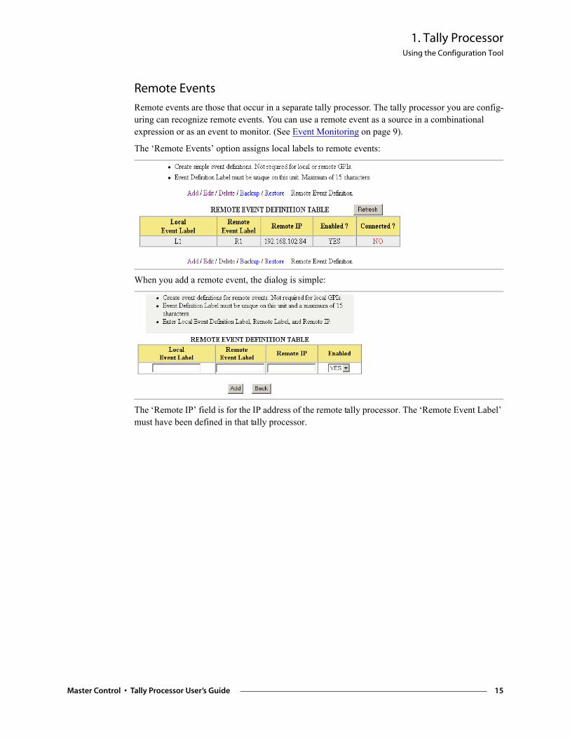
Remote Events
Remote events are those that occur in a separate tally processor. The tally processor you are config-uring can recognize remote events. You can use a remote event as a source in a combinational expression or as an event to monitor. (See Event Monitoring on page 9).
The ‘Remote Events’ option assigns local labels to remote events:
When you add a remote event, the dialog is simple:
The ‘Remote IP’ field is for the IP address of the remote tally processor. The ‘Remote Event Label’ must have been defined in that tally processor.
Master Control • Tally Processor User’s Guide 15

1. Tally ProcessorUsing the Configuration Tool
16 Rev 1.0 • 29 Nov 11
2. Misc. Topics
Chapter 2 provides miscellaneous information about tally processor. It presents the following top-ics:
• PC Configuration • Connectors • Notes
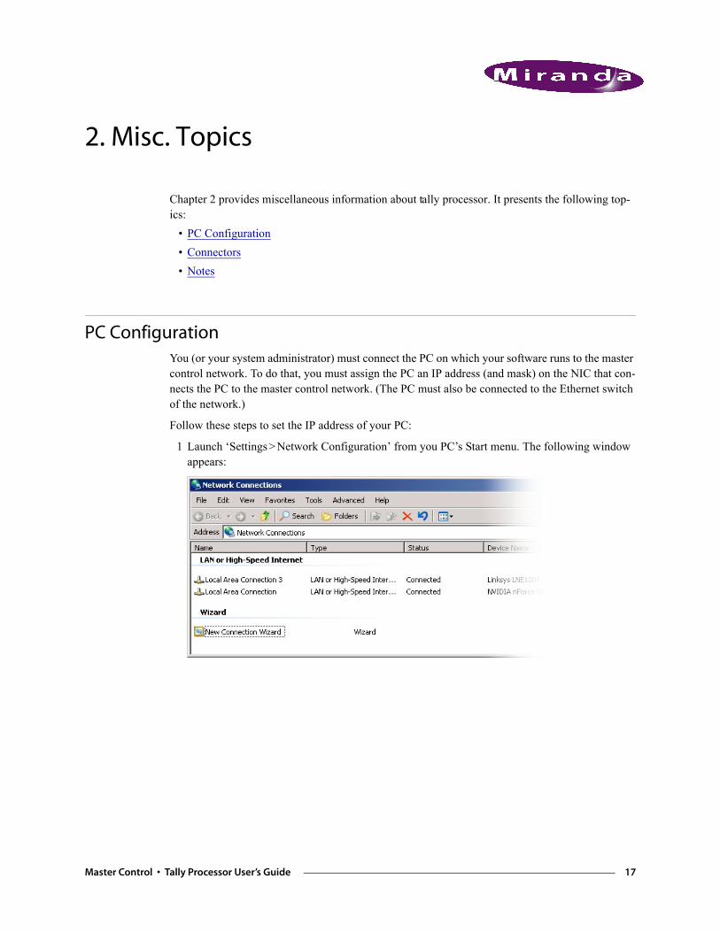
PC Configuration You (or your system administrator) must connect the PC on which your software runs to the master control network. To do that, you must assign the PC an IP address (and mask) on the NIC that con-nects the PC to the master control network. (The PC must also be connected to the Ethernet switch of the network.)
Follow these steps to set the IP address of your PC:
1 Launch ‘Settings > Network Configuration’ from you PC’s Start menu. The following window appears:
Master Control • Tally Processor User’s Guide 17
2. Misc. TopicsPC Configuration
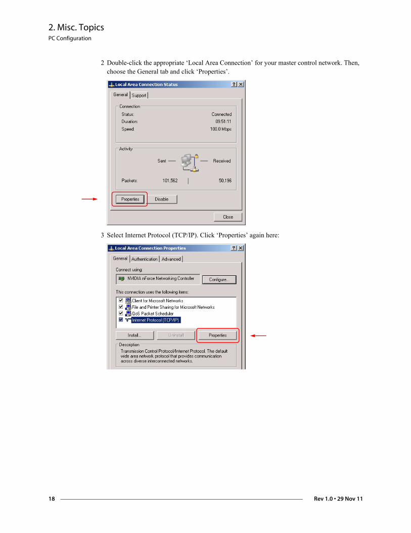
2 Double-click the appropriate ‘Local Area Connection’ for your master control network. Then, choose the General tab and click ‘Properties’.
3 Select Internet Protocol (TCP/IP). Click ‘Properties’ again here:
18 Rev 1.0 • 29 Nov 11
2. Misc. TopicsConnectors
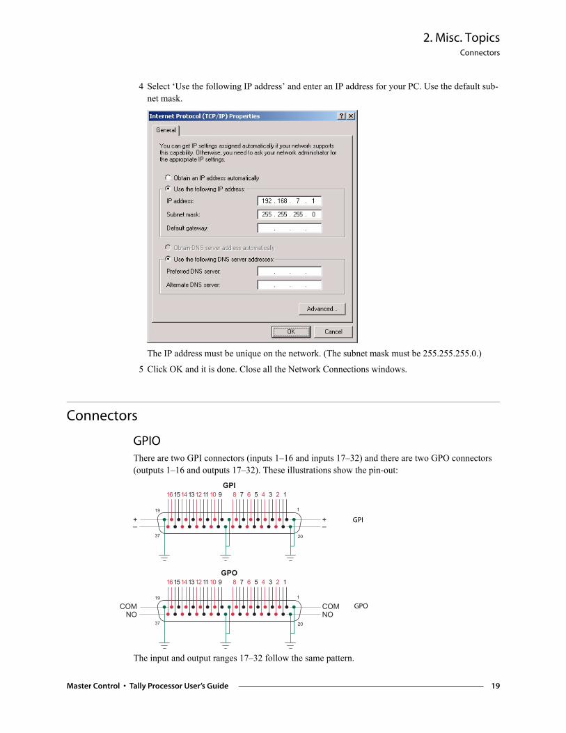
4 Select ‘Use the following IP address’ and enter an IP address for your PC. Use the default sub-net mask.
The IP address must be unique on the network. (The subnet mask must be 255.255.255.0.)
5 Click OK and it is done. Close all the Network Connections windows.
Connectors
GPIOThere are two GPI connectors (inputs 1–16 and inputs 17–32) and there are two GPO connectors (outputs 1–16 and outputs 17–32). These illustrations show the pin-out:
The input and output ranges 17–32 follow the same pattern.
���"
#�$
%
&'� # % ( $ " & ' �
)*
)*
���"
#�$
%
&'� # % ( $ " & ' �
����
���� GPO
GPI
Master Control • Tally Processor User’s Guide 19
2. Misc. TopicsNotes
GPI limits:5 VDC–12 VDC (or 24 VDC with a resistor of 680 to 820 ohms).20 mA maximum current.GPO limits:0.5 A at 125 VAC.1.0 A at 24 VDC.1.0 A maximum current.
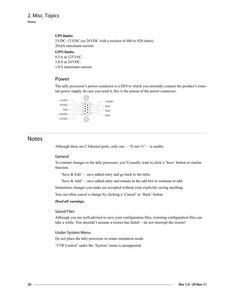
PowerThe tally processor’s power connector is a DE9 to which you normally connect the product’s exter-nal power supply. In case you need it, this is the pinout of the power connector:
Notes Although there are 2 Ethernet ports, only one — “E-net #1”— is usable.
General
To commit changes to the tally processor, you’ll usually want to click a ‘Save’ button or similar function.
‘Save & Edit’ — save added entry and go back to the table.
‘Save & Add’ — save added entry and remain in the add box to continue to add.
Sometimes changes you make are accepted without your explicitly saving anything.
You can often cancel a change by clicking a ‘Cancel’ or ‘Back’ button.
Heed all warnings.
Saved Files
Although you are well-advised to save your configuration files, restoring configuration files can take a while. You shouldn’t assume a restore has failed — do not interrupt the restore!
Under System Menu
Do not place the tally processor in router emulation mode.
‘VTR Control’ under the ‘System’ menu is unsupported.
&%
"
*&+!�
*&+!�
���
* +!�
) +!�
*&+!�
���
���
���
20 Rev 1.0 • 29 Nov 11
Index
AAdding events . . . . . . . . . . . . . . . . . . . . . . . . . . . . . .10Address
mailing . . . . . . . . . . . . . . . . . . . . . . . . . . . . . . . . iiishipping . . . . . . . . . . . . . . . . . . . . . . . . . . . . . . . iii
Address, IP . . . . . . . . . . . . . . . . . . . . . . . . . . . . .17, 19Arrow buttons . . . . . . . . . . . . . . . . . . . . . . . . . . . . .2–3
BBack button . . . . . . . . . . . . . . . . . . . . . . . . . . . . . . .20Boolean expressions . . . . . . . . . . . . . . . . . . . . . . . . .13Button pad . . . . . . . . . . . . . . . . . . . . . . . . . . . . . . .2–3
CCancel button . . . . . . . . . . . . . . . . . . . . . . . . . . . . . .20CE declaration . . . . . . . . . . . . . . . . . . . . . . . . . . . . . .iiChannels . . . . . . . . . . . . . . . . . . . . . . . . . . . . . . . . . .6Chapters
1, Tally Processor . . . . . . . . . . . . . . . . . . . . . . . . .12, Misc. Topics . . . . . . . . . . . . . . . . . . . . . . . . . .17
Combinational events (page) . . . . . . . . . . . . . . . . .4, 13Combinational logic . . . . . . . . . . . . . . . . . . . . . . .9, 14Configuration application . . . . . . . . . . . . . . . . . . .1, 3–4Configuration PC . . . . . . . . . . . . . . . . . . . . . . . . . . .17Configuration tables . . . . . . . . . . . . . . . . . . . . . . . . . .4Connectors . . . . . . . . . . . . . . . . . . . . . . . . . . . . . .2, 19Contact information
technical support . . . . . . . . . . . . . . . . . . . . . . . . . iiiControl events . . . . . . . . . . . . . . . . . . . . . . . . . . . . . . .6Copyright notice . . . . . . . . . . . . . . . . . . . . . . . . . . . . .iiCurrent IP1 . . . . . . . . . . . . . . . . . . . . . . . . . . . . . . . . .3Current Mask1 . . . . . . . . . . . . . . . . . . . . . . . . . . . . . .3
DDC37 connectors . . . . . . . . . . . . . . . . . . . . . . . . . . .2–3DE9 connector . . . . . . . . . . . . . . . . . . . . . . . . . . . . . .2Debounce . . . . . . . . . . . . . . . . . . . . . . . . . . . . . .11–12Declaration of conformance (CE) . . . . . . . . . . . . . . . . .iiDefault password . . . . . . . . . . . . . . . . . . . . . . . . . . . .5
Default user ID . . . . . . . . . . . . . . . . . . . . . . . . . . . . . 5DNF Controls . . . . . . . . . . . . . . . . . . . . . . . . . . . . . . 1Document
part number . . . . . . . . . . . . . . . . . . . . . . . . . . . . . iirevision . . . . . . . . . . . . . . . . . . . . . . . . . . . . . . . . ii
EEmail address
tech support . . . . . . . . . . . . . . . . . . . . . . . . . . . . .iiiEnter button . . . . . . . . . . . . . . . . . . . . . . . . . . . . . . 2–3Esc button . . . . . . . . . . . . . . . . . . . . . . . . . . . . . . . . . 3Ethernet connectors . . . . . . . . . . . . . . . . . . . . . . . . . . 2Event definitions . . . . . . . . . . . . . . . . . . . . . . . . . . . . 6Event functions . . . . . . . . . . . . . . . . . . . . . . . . . . . . . 9Event list . . . . . . . . . . . . . . . . . . . . . . . . . . . . . . . . 1, 3Event monitoring (page) . . . . . . . . . . . . . . . . . . . . . 4, 9Events, adding . . . . . . . . . . . . . . . . . . . . . . . . . . . . . 10Events, master control . . . . . . . . . . . . . . . . . . . . . . . . 1
FFCC statement . . . . . . . . . . . . . . . . . . . . . . . . . . . . . . ii
GGPI (page) . . . . . . . . . . . . . . . . . . . . . . . . . . . . . . 4, 11GPI connectors . . . . . . . . . . . . . . . . . . . . . . . . . . . . 19GPI mode . . . . . . . . . . . . . . . . . . . . . . . . . . . . . . . . 11GPI state . . . . . . . . . . . . . . . . . . . . . . . . . . . . . . . . . 11GPO (page) . . . . . . . . . . . . . . . . . . . . . . . . . . . . . 4, 12GPO connectors . . . . . . . . . . . . . . . . . . . . . . . . . . . . 19GPO mode . . . . . . . . . . . . . . . . . . . . . . . . . . . . . . . 12GPO state . . . . . . . . . . . . . . . . . . . . . . . . . . . . . . . . 12GTP-32 . . . . . . . . . . . . . . . . . . . . . . . . . . . . . . . . . . . 1
IInputs, optically isolated . . . . . . . . . . . . . . . . . . . . . . . 1Internet Protocol (TCP/IP) . . . . . . . . . . . . . . . . . . . . 18Introduction . . . . . . . . . . . . . . . . . . . . . . . . . . . . . . . . 1IP address . . . . . . . . . . . . . . . . . . . . . . 2–3, 10, 17, 19
Master Control • Tally Processor User’s Guide 21
Index
IP subnet mask . . . . . . . . . . . . . . . . . . . . . . . . . . . . . .3
LLatched (option) . . . . . . . . . . . . . . . . . . . . . . . . .11–12LCD, 2×16 . . . . . . . . . . . . . . . . . . . . . . . . . . . . . . .2–3LEDs . . . . . . . . . . . . . . . . . . . . . . . . . . . . . . . . . . . . .2Local Area Connection . . . . . . . . . . . . . . . . . . . . . . .18Local events . . . . . . . . . . . . . . . . . . . . . . . . . . . . . . .10
MMailing address . . . . . . . . . . . . . . . . . . . . . . . . . . . . . iiiMaster control events . . . . . . . . . . . . . . . . . . .1, 6, 9–10MCEs . . . . . . . . . . . . . . . . . . . . . . . . . . . .1–2, 4, 6–7MCPMs . . . . . . . . . . . . . . . . . . . . . . . . . . .1–2, 4, 6–7Miranda
email, tech support . . . . . . . . . . . . . . . . . . . . . . . iiimailing address . . . . . . . . . . . . . . . . . . . . . . . . . . iiimain number . . . . . . . . . . . . . . . . . . . . . . . . . . . . iiisales number . . . . . . . . . . . . . . . . . . . . . . . . . . . . iiishipping address . . . . . . . . . . . . . . . . . . . . . . . . . iiitechnical support . . . . . . . . . . . . . . . . . . . . . . . . . iiiwebsite address . . . . . . . . . . . . . . . . . . . . . . . . . . iii
Momentary (option) . . . . . . . . . . . . . . . . . . . . . .11–12Monitor events . . . . . . . . . . . . . . . . . . . . . . . . . . . . . .7
NNetwork Configuration . . . . . . . . . . . . . . . . . . . . . . .17Network Connections . . . . . . . . . . . . . . . . . . . . . . . .19Notes . . . . . . . . . . . . . . . . . . . . . . . . . . . . . . . . . . . .20NVEP . . . . . . . . . . . . . . . . . . . . . . . . . . . . . . .1, 6, 10NVISION Ethernet protocol
see NVEP
OOn time . . . . . . . . . . . . . . . . . . . . . . . . . . . . . . . . . .12Outputs, relay . . . . . . . . . . . . . . . . . . . . . . . . . . . . . . .1
PPart number, document . . . . . . . . . . . . . . . . . . . . . . . .iiPC Configuration . . . . . . . . . . . . . . . . . . . . . . . . . . .17PHY Config . . . . . . . . . . . . . . . . . . . . . . . . . . . . . . . .6Power supply . . . . . . . . . . . . . . . . . . . . . . . . . . . . . . .2Protocol assignment (page) . . . . . . . . . . . . . . . . . . .4, 6
RRefresh button . . . . . . . . . . . . . . . . . . . . . . . . . . 11–12Relational operators . . . . . . . . . . . . . . . . . . . . . . . . . . 7Relay outputs . . . . . . . . . . . . . . . . . . . . . . . . . . . . . . . 1Remote events . . . . . . . . . . . . . . . . . . . . . . . . . . . . . 10Remote events (page) . . . . . . . . . . . . . . . . . . . . . . 4, 15Repetitive (option) . . . . . . . . . . . . . . . . . . . . . . . . 9–10Return Material Authorization (RMA) . . . . . . . . . . . . .iiiRevision
document . . . . . . . . . . . . . . . . . . . . . . . . . . . . . . iiRJ-45 connectors . . . . . . . . . . . . . . . . . . . . . . . . . . . . 2RMA . . . . . . . . . . . . . . . . . . . . . . . . . . . . . . . . . . . .iii
SSales number . . . . . . . . . . . . . . . . . . . . . . . . . . . . . . .iiiSave & add button . . . . . . . . . . . . . . . . . . . . . . . . . . 20Save & edit button . . . . . . . . . . . . . . . . . . . . . . . . . . 20Settings, Windows . . . . . . . . . . . . . . . . . . . . . . . . . . 17Shipping address . . . . . . . . . . . . . . . . . . . . . . . . . . . .iiiSingle (option) . . . . . . . . . . . . . . . . . . . . . . . . . . . 9–10Software version . . . . . . . . . . . . . . . . . . . . . . . . . . . . iiSub-pages, configuration application . . . . . . . . . . . . . . 4System (page) . . . . . . . . . . . . . . . . . . . . . . . . . . . 4, 20System option . . . . . . . . . . . . . . . . . . . . . . . . . . . . . . 3
TTables . . . . . . . . . . . . . . . . . . . . . . . . . . . . . . . . . . 4, 9Technical support . . . . . . . . . . . . . . . . . . . . . . . . . . . .iiiTelephone number
main . . . . . . . . . . . . . . . . . . . . . . . . . . . . . . . . . .iiisales . . . . . . . . . . . . . . . . . . . . . . . . . . . . . . . . . .iiitechnical support . . . . . . . . . . . . . . . . . . . . . . . . .iii
Time-out . . . . . . . . . . . . . . . . . . . . . . . . . . . . . . . . . . 5Trademarks . . . . . . . . . . . . . . . . . . . . . . . . . . . . . . . .iiiTransition delay . . . . . . . . . . . . . . . . . . . . . . . . . . . . 12
VVersion, software . . . . . . . . . . . . . . . . . . . . . . . . . . . . ii
WWebsite, Miranda . . . . . . . . . . . . . . . . . . . . . . . . . . . .iiiWindows, settings . . . . . . . . . . . . . . . . . . . . . . . . . . 17
22 Rev 1.0 • 15 Jul 11


